proposed design for the wpi foisie innovation studio · professor guillermo salazar . 23 march,...
TRANSCRIPT

LDA – 1601 GFS – 1601
Submitted by:
Ethan Collins
Vincent D’Ambrosio
Connor Flanagan
Kyle Foley
Advisors:
Professor Leonard Albano
Professor Guillermo Salazar
23 March, 2016
Proposed Design for the WPI Foisie Innovation Studio A MAJOR QUALIFYING PROJECT REPORT SUBMITTED TO THE FACULTY OF WORCESTER POLYTECHNIC
INSTITUTE IN PARTIAL FULFILLMENT OF THE REQUIREMENTS FOR THE DEGREE OF BACHELOR OF SCIENCE IN CIVIL ENGINEERING

i
Abstract
Worcester Polytechnic Institute has approved plans to construct a new mixed-use
academic and residential building on campus, the Foisie Innovation Studio. The goal for the
building is to foster the innovative and collaborative skills of WPI students while displaying various
project work completed at the school. This project proposes a schematic design for the building
emphasizing the structural system as well as cost estimates, schedules and a 5D model visually
communicating the building’s earned value and feasibility of construction. The project focuses on
the utilization of Building Information Modeling as a tool for managing and facilitating construction
from the design phase onward.

ii
Authorship While all team members contributed to the completion of the project and report, the principal
responsibilities for each group member are listed by report section.
Abstract - Connor Capstone Design Statement - Kyle Professional Licensure Statement - Vinny 1.0 Introduction - Connor 2.0 Background Chapter 3.0 Architectural Model - Ethan 4.0 BIM Structural Model - Ethan and Kyle 5.0 Construction Scheduling - Connor 6.0 Cost-Estimating - Vinny 7.0 Construction Simulation: 5D Model - Connor 8.0 Conclusions - Connor

iii
Capstone Design Statement
To produce the design for this building, the Foisie Innovation Studio, some primary
constraints set forth by ASCE as part of the criteria for a capstone design experience have been
considered. These constraints include economic, social, sustainability, constructability and
health/safety factors.
The final deliverables for the project have been produced through a standard engineering
process, involving iterative analysis and synthesis. This process began with an architectural
model for the building used to help visualize the final desired state of the project. Using the
architectural model as a point of reference, a structural plan was developed and designed to fit
the original layout to the greatest degree possible. At this stage the iteration of analysis and
synthesis came into play. If an aspect of the architectural model was discovered to be
incompatible with the structural requirements, then the design was refined in order to make the
proposed structure completely stable. The structural members were designed through strength
analysis utilizing various load combinations (specifically Dead and Live Loads), after which they
were analyzed under both wind and seismic loading to ensure the stability of the structure under
extreme conditions.
The final portion of the project involves construction scheduling in Primavera, cost
estimation from the RS Means database, and 5D modeling of the project in Navisworks in order
to analyze the elements of time and cost in the project. Certain aspects of the design were taken
under consideration to ensure that they do not pose scheduling or financial burdens on the project.
Some steps of this project, such as demolition of Alumni Gymnasium, site preparation for new
construction, and interior system design, were included in the schedule and cost, but were not
modeled in depth.

iv
The following constraints listed by ASCE have been addressed in the scope of work for
this project:
● Economic
The design takes into consideration the economic implications of the building and
construction process. The financial aspect is not a limitation of the design, but rather a
consideration for the quality of the building. Throughout the cost estimation process, methods
have been sought to improve upon the cost of the proposed project. One main example of this
occurred by minimizing the variation of structural steel beam sizes. By minimizing the variety of
beam sizes, those charged with the project are capable of ordering in bulk and saving money by
minimizing confusion and waste.
● Social
The demolition of Alumni Gym to construct the Foisie Innovation Studio is a significant
social conflict that underlies the project. The combination of academic and residential space in
one building raises a social constraint for the project. It is important that the residential space
provides all the necessary comforts while ensuring an optimal experience for residents and
visitors alike. A few steps have been taken to ensure that these constraints are met. To help with
the combination of residents and visitors in the same building, work and living spaces for the
students have been designed to be located on the 3rd and 4th floors. With all of the “showcase”
activity to occur on the 1st and 2nd floors and with additional work and classroom space in the
basement, the residents and visitors will be able to coexist without issue.
v
● Sustainability
WPI as an intellectual community has put a large emphasis in sustainability in the last few
decades, most evidently in the development of new buildings on the campus. Buildings such as
the Recreation Center, East Hall, and Faraday Hall are all either LEED Gold or Silver certified.
Thus sustainable practices for design and strategies for whole-building sustainability were
considered. One of the first sustainable practices utilized in the design of the proposed Foisie
Innovation Studio was selection of materials. Throughout the building structural steel was used
as the main structural frame because it required less overall material than a concrete alternative
and accordingly less production was necessary. On the architectural side, many materials used
for the interior finishes and the exterior enclosures were researched and local manufacturers were
used to reduce lengthy transportation.
Though MEP systems were out of the scope of this project, some strategies to aid the
building’s energy efficiency were considered. Through the use of energy efficient windows and
extensive glazing substantial energy can be conserved. Glazing along the south façade of the
building had the potential to make it very hot in the atrium; however, the use of motorized curtains
will regulate the sun at times of the day when it is very direct and reduce excess heat.
● Constructability / Manufacturability
The use of Building Information Modeling (BIM) is an integral part of determining the
constructability of the building. By designing the architectural and structural models in the same
program (Autodesk Revit), inconsistencies were easily identified and the alignment of all elements
has been ensured. Manufacturability has also been considered by choosing standard and locally
available materials when possible. Clash detection software has been utilized to ensure that the
building has been modeled as intended. Additionally, various aspects of the structural design
were designed with constructability as a main consideration. For example, the foundation walls

vi
that border the basement level were designed as cantilever retaining walls to allow large overturn
loads in the vicinity of the building footprint throughout construction. Also in the design of all
connections ease of field assembly was a major factor. For all beam-to-girder connections, the
angles are to be shop bolted to the girders in advance to save field assembly time and effort.
One of the aspects of manufacturability that was addressed was the use of commonly
produced plate sizes. For base plate and footing designs, it was determined that rounding the
size to an even 16” x 16” square plate would be beneficial based on the regularity of the size and
shape. Also the plate thicknesses were selected in ¼” increments to ensure that the sizes would
be readily available from a fabricator.
● Health/Safety
The construction of this building in the heart of campus creates a few potential issues.
First, the high noise level of the construction site is a threat to disturb the members of the
community. Next, there is a safety concern regarding the flow of traffic between Alumni Gym and
Higgins Labs. Access to this path has been designed to be restricted in order to ensure the
protection of students from site-related hazards. It has also been planned to secure the site when
not in use to prevent trespassing and any related injuries. Any inconvenience caused by these
restrictions will be mitigated with detours on campus, specifically blocking access to the path
between the current Alumni Gym and Higgins Laboratories, commonly referred to on campus as
the “wind tunnel”. Pedestrians will be encouraged to instead take a path across the front of Higgins
Laboratories, passing Beech Tree Circle, and proceeding north past Stratton Hall to access the
rest of campus. Access from behind Alumni Gym to the rooftop field and parking garage would
be blocked during construction as well. Once this plan had been established, it was determined
that trucks and other construction equipment would enter the site via the road between Daniels

vii
and Riley Halls, and would exit via a temporary access road to be paved from between Harrington
Auditorium and Alumni Gym down to the Higgins House Lot and Salisbury Street.
Building codes are another aspect affecting the health and safety of the project. These
codes provide an across-the-board standard for all aspects of the design (mechanical,
architectural, structural, and fire safety) which allow for all parties to work in unison during the
design process. Ensuring that the codes are followed closely in all aspects of the design has
helped guarantee that the structure is sound. Building codes also mitigate the risk of designing a
system that is unsafe.
Lastly, due to the mixed-use nature of this building, student safety was a concern. With so
many people coming through this building on a regular basis, it was important to make a distinction
between public and private space. The proposed design features stair ways in both the front and
rear of the building, with the front stairs providing access to the basement, main floor, and loft
floor. These floors are all designed for use by the public and visitors. Only the stairways at the
rear of the building will reach the residential floors, and the proposed design states that these
stair wells will require card-key access, available only to residents. Elevator access to the
residential floors will also be restricted from all visitors by requiring card-key access. By separating
the lives of residents from other activities occurring in the building, the well-being and safety of
students has been improved.

viii
Professional Licensure Statement
Licensure is a way for the government to ensure that qualified professionals are held
responsible for the work they perform and that such work is regarded to the highest degree. For
engineers, there are many standards and restrictions that must be taken into consideration when
performing design work. It is important that licensed engineers act in a professional and ethical
manner when producing high quality design work while abiding to specifications.
To obtain a professional engineering license, one must first pass the Fundamentals of
Engineering exam that, upon passing, qualifies the person as an engineer in training. The next
step is to work as a designer under a licensed engineer for five years. Once a formidable resume
is produced detailing the design work, the engineer in training is brought before a board of
licensed engineers to make a case for receiving their professional license. If their design work
demonstrates high quality and ethical standards, and they pass their Professional Engineering
exam, then they will be granted a professional engineering license.
Maintaining this professional license requires holders to continue their design work and
education to help adapt to the ever changing specifications, laws, and responsibilities of a
professional engineer.
Licensure is exceptionally important both for the individual and for the industry as a whole.
For the individual, the license dictates how one should design as well as the ethics and level of
professionalism required. The license creates expectations for the engineer and serves as a guide
for their careers. In terms of the industry, the license reflects experience and professionalism.
Licensed engineers hold more value in their thoughts and designs when performing a project than
an unlicensed person. Publically, it is reassuring to have a licensed professional review the design
before it is put to use. For example, people may be concerned about driving over a newly

ix
completed bridge if it was not approved by a professional engineer. It is in this way that licensure
provides a degree of certainty and assurance for society.

x
Table of Contents
Abstract .......................................................................................................................................................... i
Authorship ..................................................................................................................................................... ii
Capstone Design Statement ......................................................................................................................... iii
Professional Licensure Statement .............................................................................................................. viii
Table of Contents .......................................................................................................................................... x
List of Tables, Figures, & Equations ............................................................................................................ xii
1.0 Introduction: ............................................................................................................................................ 1
2.0 Background ............................................................................................................................................. 3
2.1 History of Alumni Gym ........................................................................................................................ 3
2.2 Mixed Use Academic/Residential Spaces .......................................................................................... 5
2.3 Building Information Modeling ............................................................................................................. 7
2.3.1 BIM and Architectural Functions .................................................................................................. 7
2.3.2 BIM and Structural Functions ....................................................................................................... 8
2.3.3 BIM Planning/Scheduling/Cost Estimating ................................................................................... 9
2.4 Design Considerations ...................................................................................................................... 12
2.4.1 Architectural Design ................................................................................................................... 12
2.4.2 Structural Design ........................................................................................................................ 14
2.4.3 Construction Planning ................................................................................................................ 16
3.0 BIM Architectural Model ........................................................................................................................ 18
3.1 Building Intent/Architect Programming .............................................................................................. 18
3.2 Architectural Design .......................................................................................................................... 20
3.3 Building Codes .................................................................................................................................. 23
4.0 BIM Structural Model ............................................................................................................................. 25
4.1 Building Codes .................................................................................................................................. 25
4.2 Loads................................................................................................................................................. 26
4.3 Structural Grid ................................................................................................................................... 28
4.4 Floor Systems ................................................................................................................................... 30
4.4.1 Joist & Girder Sizing ................................................................................................................... 30
4.4.2 Staggered Truss System............................................................................................................ 36
4.4.3 Reinforced Concrete Alternative ................................................................................................ 41
4.5 Roof Design ...................................................................................................................................... 42
4.6 Lateral Load Analysis ........................................................................................................................ 44

xi
4.7 Column Design .................................................................................................................................. 46
4.8 Connections ...................................................................................................................................... 48
4.9 Base Plates & Footings ..................................................................................................................... 52
5.0 Construction Scheduling ....................................................................................................................... 55
5.1 Identification of Activities ................................................................................................................... 55
5.2 Determination of Durations ............................................................................................................... 58
5.3 Determination of Precedence and Order .......................................................................................... 59
5.4 Input of Information into Primavera ................................................................................................... 60
5.5 Final Critical Path and Key Portions of Diagram ............................................................................... 61
6.0 Cost Estimating ..................................................................................................................................... 65
6.1 Unit Cost Method .............................................................................................................................. 66
6.2 Square Foot Method ......................................................................................................................... 67
6.3 Cost Analysis Alternatives................................................................................................................. 67
6.4 Calculating Total Cost ....................................................................................................................... 68
7.0 Construction Simulation - 5D Model ..................................................................................................... 70
7.1 Phasing of Revit Models ................................................................................................................... 70
7.2 Importing Models into Navisworks .................................................................................................... 71
7.3 Importing Schedule and Cost-Estimates ........................................................................................... 73
7.4 Linking Building Elements & Corresponding Schedule Tasks .......................................................... 75
7.5 Creating a Simulation ........................................................................................................................ 78
8.0 Conclusions ........................................................................................................................................... 82
References .................................................................................................................................................. 84
Appendix A: Project Proposal ..................................................................................................................... 86
Appendix B: BIM Architectural Images ..................................................................................................... 128
Appendix C: BIM Structural Images .......................................................................................................... 133
Appendix D: Sample Calculations ............................................................................................................. 138
Appendix E: Reinforced Concrete Alternative Preliminary Design ........................................................... 154
Appendix F: Primavera Activity List .......................................................................................................... 158
Appendix G: List of E-Files........................................................................................................................ 163

xii
List of Tables, Figures, & Equations Table 1: Applicable Software ...................................................................................................................... 11 Table 2: Design Specification vs. State Building Code ............................................................................... 24 Table 3: Live Loads for Calculations, based on ASCE 7-05 ...................................................................... 27 Table 4: Joist Sizes Used Per Floor ............................................................................................................ 33 Table 5: Dimensions and Loading Conditions for Trusses ......................................................................... 39 Table 6: Compression Members in Trusses ............................................................................................... 40 Table 7: Tension Members in Trusses ........................................................................................................ 41 Table 8: Beam-to-Girder Connection Requirements by Beam Size ........................................................... 50 Table 9: Girder-to-Column Connection Requirements by Shear Force ...................................................... 51 Table 10: Base Plate Thickness by Factored Column Load ....................................................................... 53 Table 11: Concrete Column Footing Sizes by Range of Maximum Service Loads .................................... 53 Table 12: Duration Estimation Breakdown .................................................................................................. 59 Table 13: Cost Estimating Approaches ....................................................................................................... 66 Figure 1: One of 34 Grotesques on Alumni Gym, Photo by Michael Voorhis ............................................... 4 Figure 2: Aerial View of Walkway between Alumni Gym and Higgins Labs, Image by GoogleMaps......... 16 Figure 3: Breakdown of Usable Space ....................................................................................................... 19 Figure 4: Proposed Showcase Atrium, Rendering from Autodesk Revit .................................................... 20 Figure 5: Proposed I-Shaped Design, Rendering from Autodesk Revit ..................................................... 21 Figure 6: Proposed Residential Floor Layout, Image from Autodesk Revit ................................................ 22 Figure 7: Structural Grid with Overlaid 2nd Floor Mezzanine ..................................................................... 29 Figure 8: South Elevation of Proposed Foisie Innovation Studio, Image from Autodesk Revit .................. 31 Figure 9: Girder Schedule with Sizes and Counts, Image from Autodesk Revit ........................................ 33 Figure 10: 2nd Floor Mezzanine Framing Plan, Image from Autodesk Revit ............................................. 34 Figure 11: 3rd Floor Structural Framing Plan, Image from Autodesk Revit ................................................ 35 Figure 12: Staggered Truss System, Image from Autodesk Revit.............................................................. 36 Figure 13: Proposed Vierendeel Truss, Image from Risa-2D ..................................................................... 38 Figure 14: Roof Hip Alternative to Shorten Span, Image from Autodesk Revit .......................................... 43 Figure 15: Structural and Architectural Representation of the Roof, Image from Autodesk Revit ............. 43 Figure 16: Structural Representation of East & South Wall Framing Systems, Image from Autodesk Revit
.................................................................................................................................................. 44 Figure 17: Plan View of Framing System, Image from Autodesk Revit ...................................................... 45 Figure 18: South Elevation of Steel Framing, Image from Autodesk Revit ................................................ 48 Figure 19: Typical Beam-to-Girder Connection with Coped Flanges ......................................................... 50 Figure 20: Typical Girder-to-Column Connection with Coped Top Flange ................................................. 51 Figure 21: Engineering Sketch of Typical Column Base Plate ................................................................... 54 Figure 22: ASTM Uniformat Classification, Image from National Institute of Standards and Technology
[17] ............................................................................................................................................ 56 Figure 22: Final Critical Path, Image from Primavera ................................................................................. 62 Figure 24: Project Management and Design Activities after Project Start, Image from Primavera ............ 63 Figure 25: Foundation Construction, Image from Primavera ...................................................................... 63 Figure 26: Construction of Exterior Walls, Image from Primavera.............................................................. 64 Figure 27: Total Square Foot Method, Image from Microsoft Excel ........................................................... 67 Figure 28: Square Foot Method, Image from Microsoft Excel .................................................................... 68

xiii
Figure 29: Summary of Construction Cost, Image from Microsoft Excel .................................................... 69 Figure 30: Breakdown of Structural Steel Pods, Image from Autodesk Navisworks .................................. 71 Figure 31: Foisie Innovation Studio Rendering of the Integrated Structural and Architectural Models,
Image from Autodesk Navisworks............................................................................................. 72 Figure 32: Clash Detection test, Image from Autodesk Navisworks ........................................................... 72 Figure 33: Navisworks Schedule and Timeline, Image from Autodesk Navisworks ................................... 74 Figure 34: Standard Selection Tree, Image from Autodesk Navisworks .................................................... 76 Figure 35: Foisie Innovation Studio Earned Value Plot, Image from Microsoft Excel ................................ 77 Figure 36: 5D Simulation, Foundation Completed, Week 38, $4,890,103.28, Image from Autodesk
Navisworks ................................................................................................................................ 78 Figure 37: 5D Model, Structural Steel Completed, Week 53, $8,680,824.04, Image from Autodesk
Navisworks ................................................................................................................................ 79 Figure 38: 5D Model, Floors and Roofing Completed, Week 73, $11,840,052.11, Image from Autodesk
Navisworks ................................................................................................................................ 79 Figure 39: 5D Model, Exterior Enclosure Completed, Week 87, $15,254,407.40, Image from Autodesk
Navisworks ................................................................................................................................ 80 Figure 40: 5D Model, Partitions & Utilities Completed, Week 103, $22,730,923.05, Image from Autodesk
Navisworks ................................................................................................................................ 80 Figure 41: 5D Model, Project Completed, Week 115, $24,676,644.58, Image from Autodesk Navisworks
.................................................................................................................................................. 81 Equation 1: Deflection ................................................................................................................................. 32 Equation 2: Shear Force ............................................................................................................................. 32 Equation 3: Shear Capacity ........................................................................................................................ 32 Equation 4: Interaction Equation H1-1a ...................................................................................................... 47 Equation 5: Interaction Equation H1-1b ...................................................................................................... 47 Equation 6: Connection Stability ................................................................................................................. 49

1
1.0 Introduction:
Located in the northeast corner of the campus quadrangle, Alumni Gym has been a
centerpiece of WPI campus life for 100 years. However, for the past four years, due to the
construction of the school’s new Sports and Recreation Center in 2012, the building has remained
vacant in an otherwise bustling area of campus. Despite the current situation, WPI has been
making a consistent effort to maintain the building while actively seeking an alternative use for
the space. In 2013, the school commissioned a study to convert the gym into an innovation center,
but the resulting design was estimated to cost over $18 million and yield only a limited amount of
usable space. According to Mr. Alfredo DiMauro, Assistant Vice President of Facilities at WPI,
this study led the school to conclude that “modernizing the building (was) impractical” because “it
would create a financial hardship and an inefficient use of (the) building” [1]. These findings have
led to the school’s decision to demolish the gym in favor of designing and constructing a new
building. The proposed plan for this new building is a mixed-use academic-residential space
named the “Foisie Innovation Studio”, which will be designed to highlight the innovative nature
that sets WPI apart.
The goal for the Foisie Innovation Studio is to foster the innovative and collaborative skills
of WPI students while displaying various project work completed at the school. Gensler
Associates, a design and architecture firm based in San Francisco, has been chosen as the
architect for the building, while Boston-based Shawmut Design and Construction will serve as the
general contractor for the project. According to a campus-wide email from WPI President Laurie
Leshin on October 14, 2015 with the subject line Announcement Regarding the Foisie Innovation
Studio, demolition of Alumni Gym is scheduled to start during the summer of 2016, following the
graduation ceremony in May [2].

2
This MQP proposes a schematic design emphasizing the structural system for the Foisie
Innovation Studio as well as cost estimates, schedules and a 5D model simulating the
construction sequence and the building’s earned value. The construction simulation illustrates the
process from site preparation to the conclusion of building construction. The goal for the project’s
final deliverables remained constant throughout the project and is two-fold, focusing on both
structural integrity and project management. In terms of structural integrity of the building, it has
been ensured that construction plans respond to all safety requirements by following building
codes, ensuring a secure construction site, and limiting access to residential space through
building design. In terms of project management, it has been ensured that construction for the
proposed design is feasible and clear to all parties involved, by providing cost-estimates and a
construction schedule along with a simulation for building construction.
This report proceeds by first providing background on Alumni Gym and mixed-use
academic/residential spaces, as well as Building Information Modeling (BIM) and all
considerations taken into account during the design process. The background chapter is followed
by chapters detailing both the BIM architectural model and BIM structural model. The report
continues with information detailing the work performed on construction scheduling and cost
estimation, and finally concludes with details on the 5D model and simulation illustrating the
construction process.

3
2.0 Background
Founded in 1865 by two entrepreneurs from Worcester, Massachusetts, WPI has held
true to its roots by maintaining a focus on innovation and collaboration. As illustrated by the
school’s motto “Lehr and Kuntz” (Theory and Practice), WPI students are encouraged to learn
not only in the classroom, but by working on real-world projects. Two campus buildings,
Boynton Hall and Washburn Labs, have for years served as symbols for the two pillars in the
school’s philosophy. WPI now seems to be adding a third dimension to its philosophy:
Innovation. With its construction following the razing of Alumni Gym, the Foisie Innovation
Studio will complement the role of the Boynton Hall and Washburn Labs, while symbolizing the
new added educational dimension at WPI.
2.1 History of Alumni Gym
At the time of its construction in 1916, Alumni Gym was the hub of athletics on campus,
consisting of three stories above ground and two below. With the necessary $100,000 raised by
Arthur D. Butterfield, a WPI professor spearheading the fundraising effort, the building was
constructed in time for WPI’s 50th anniversary. Due to the immense amount of support from faculty
and alumni, WPI had a surplus of funds which it was able to direct towards an indoor pool,
currently located in the sub-basement of the gym [1].
Throughout the 20th century, Alumni Gym satisfied the demand for a home for athletics on
campus. With the construction of the school’s Sports and Recreation Center, it has become clear
that this need no longer exists. The Foisie Innovation Studio will aim to serve campus by
responding to a different need: the need for a home for innovation and collaboration on campus.

4
Although no existing features of Alumni Gym will appear in the new “Foisie Innovation
Studio”, there remains an element of nostalgia for the history that the gym represents. As noted
in the Worcester Telegram [3], while WPI is not located within a local historic district, Alumni Gym
is listed on the National Register of Historic Places, a list which recognizes properties for a number
of reasons, including significant contribution to America’s history and heritage.
The elements that make Alumni Gym unique were important to keep in mind as the design
and construction of the Foisie Innovation Studio progressed. One of these elements is something
that many students walk by every day, yet perhaps few notice - the “grotesques” located on the
side of the gym. These 34 grotesques take a number of different forms: some are athletes and
spectators, while others depict singers or musicians [4]. With 6 grotesques on both the east and
west walls and 11 on the north and south, the grotesques are a subtle yet charming piece of not
only the building, but the school’s character. As of the winter of 2016, the removal and
preservation process for the grotesques has begun, with future plans yet to be determined,
perhaps incorporating them into the design of the Foisie Innovation Studio. A plaque will also be
placed on the site of the new building to honor the importance of Alumni Gym to the WPI
community [3].
Figure 1: One of 34 Grotesques on Alumni Gym, Photo by Michael Voorhis

5
A major focus of the architectural design is paying homage to the nostalgic element of the
old building while producing a modern final product responding to the previously noted design
goals. The design incorporates the wishes and requirements of WPI’s Board of Trustees as well,
who have laid out a number of items to consider for this center of innovation. These plans include
housing space for 140 new residents, a necessity for a school accepting an increasing number of
students with each passing year, along with new classrooms and workspaces for the Great
Problems Seminars, a showcase lobby with digital displays, a robotics engineering lab, maker
space, and a center for innovation and entrepreneurship. Additionally, the school aims to include
tech suites with flexible configurations in order to encourage collaboration among students looking
to share ideas. As the expansive project-based curriculum at WPI continues to develop, it is hoped
that these spaces will provide both the resources necessary for students to work to their full
potential, and the opportunity for external parties to better appreciate their work.
2.2 Mixed Use Academic/Residential Spaces
By deciding to construct a building which provides both residential and academic spaces,
WPI is demonstrating that it understands the trends of today’s education. According to a recent
study, students perform roughly 30 percent of their school work while in residence halls [5]. If
students have access to tech suites and designated study areas without leaving their building,
this time could be spent more productively and would likely increase. WPI isn’t the only school to
make an investment into this type of building either - universities such as the University of
Colorado, Rutgers University, and the University of Michigan are just three of the many institutions
making progress towards blurring the lines between academic and residential spaces [6].

6
While mixing these two seemingly unrelated aspects of college life appears
unconventional, there is emerging research to show that it has its merits. At the University of
Michigan, the school’s mixed-use residence hall was designed to help students “address some of
the world’s thorniest problems” [6] by increasing their opportunity for collaboration. At WPI, many
first-year students participate in the previously mentioned “Great Problems Seminars”, where
students tackle real-life problems in teams of 4 to 5, focusing on topics from sustainability to public
health. These students will undoubtedly benefit from an increase in space designed for
collaboration and the sharing of ideas.
The proposed design for the building comprises a total of roughly 75,000 gross square
feet, with 40,000 square feet dedicated to academic space, and 35,000 square feet dedicated to
residential space.
There are a number of functions required of the 40,000 square feet of academic space.
While this space will hold the previously mentioned tech suites and lecture halls, it will also be
used as a display area. There are two types of projects required for upperclassmen at WPI: the
IQP (Interdisciplinary Qualitative Project) and MQP (Major Qualifying Project). Selected projects
will be placed on display to encourage new students to take on global issues, and they may one
day receive the same recognition for their project work. The academic space will also serve as a
place for innovation and collaboration, with areas designated for a business incubator as well as
a laboratory containing resources for students to perform project work.
For the residential space, the goal is to be able to house 140 students in the Foisie
Innovation Studio. Housing will be consistent with other WPI freshman residence halls, consisting
of 3 students per room, equipped with 3 beds, desks, and closets. Residential space has also
been designed to include additional tech suites and collaboration spaces for the students’
convenience. Since students spend roughly 70 percent of their time in their residence halls [7], it

7
is important to note that the residential floors will also include common rooms for extracurricular
activities.
2.3 Building Information Modeling
In recent years, the construction industry has utilized and implemented innovative
technologies to improve the quality and efficiency of the construction process. Of these newly
emerging and industry driving technologies, the most influential is Building Information Modeling
(BIM). BIM is the intelligent process of planning, designing, constructing, and managing projects
[8]. BIM allows for better 3D visualization of the project while also facilitating coordination and
interoperability amongst the design team, contracting team, and owner, thus promoting
collaboration. This “techno-social” trend is expected to propel the construction industry with the
aid of a model-based process capable of being easily manipulated and adapted so that all parties
involved are provided with a clear and consistent interpretation of the project [8].
2.3.1 BIM and Architectural Functions
Visual displays are one of the most powerful tools available in architectural design. The
ability to view a building or structure in a 3D model enables users to see all elements in a clear
and realistic manner. This feature aids the architectural design process in terms of design clarity
amongst the designer, owner and contractor. Additionally, this clarity and more comprehensive
understanding of the design allows all parties to provide input and contribute to solutions.
Some of the principal ways in which BIM is useful in architectural design include
dimensioning floor plans, fostering general spatial awareness, visualizing exterior appearance,

8
and assisting in overall placement of a structure within the context of a surrounding area. Floor
plans and interior layouts are the cornerstone of architectural design communication and have
much to do with the eventual flow of people and activities through a building. The production of
these views is a fully coordinated process with the use of BIM software tools. The development
of these plans involves finding the appropriate balance between sizing of various rooms and their
integration within the footprint of the building - a process which often involves numerous revisions
and adjustments. BIM’s ability to quickly and consistently alter dimensions and locations of walls
simplifies this process, making it more efficient than previously imagined. Additionally, the ability
to virtually walk through drafted floor plans offers more spatial awareness in comparison to the
traditional 2D layout, making errors and omissions easier to identify than ever before.
2.3.2 BIM and Structural Functions
A key feature of BIM is its structural modeling capability in relation to the architectural
design. For example, the relationship between the architectural design of floor plans and interior
layouts directly affects the placement of framing columns. The interior layout and intended flow of
a building dictate where columns can be placed to minimize interference or to promote improved
aesthetics. It is also imperative that the framework agrees with all of the exterior enclosures of
the building in order to ensure an accurate design.
Another feature that makes BIM practical and useful is the ability to detect clashes
between structural and architectural items during the design phase and even as construction
progresses. The application of the clash detection feature allows designers to identify any and all
design errors and avoid facing similar issues in the field. This results in reduced construction costs
to mitigate as well as fewer requests for information (RFI’s) and schedule delays. Clash detection

9
can identify unwanted intersections among beams, walls, and ceilings, as well as between
columns and floors. This process of early detection can play a large role in simplifying the task of
accurately modeling a structural frame.
One last function of BIM in structural design is the ability to facilitate structural analysis
through its interoperability with structural analysis software. Upon completion of numerous hand
calculations and analyzing a major structure piece by piece, BIM allows the user to highlight areas
of concern. Using structural analysis software, the user can submit the problem areas to various
loading conditions and check how the previously selected members respond. Though both
manual and computer methods are limited by human input error, the speed and capability of BIM
to discover problem areas of a frame is just another example of BIM analysis saving large
amounts of time and making the structural design process more efficient.
2.3.3 BIM Planning/Scheduling/Cost Estimating
One of the primary tasks of this project was to create a schedule for the construction of
the new Foisie Innovation Studio. This is no simple task, and requires an understanding of building
permits, zoning regulations, and the construction activities that must be scheduled while the
campus is operating regularly. Utilizing BIM to aid in the development of the schedule saves
contractors and designers a significant amount of time and money while also helping them
visualize the project. BIM allows users to produce a 5D (cost+time) model, which is advantageous
in that it interconnects cost, time, and the 3D building model. This starts construction virtually,
which allows for a deeper analysis and evaluation of the project structure before the ground
breaks and the project is actually undertaken. For example, if there is a fixed budget for the
project, the designer can utilize the program to make sure that the model reflects what is
requested.

10
Using scheduling software, a schedule can quickly be developed to organize the sequence
of activities necessary for construction. A widely used program in the industry is Primavera, which
involves inputting construction activities, linking them together according to their logical
dependencies, and producing an effective working schedule. Additionally, a work breakdown
structure can be used to organize the construction activities into manageable sections or phases.
This simplifies the complex process of coordinating the wide variety of activities done on different
sections of the building. This is especially useful given the multi-phase nature of the project.
In addition to the project schedule, cost estimation of procurement and construction must
be determined before developing the 5D model. There are many methods used in the industry to
forecast the cost of the project. Given the information from the 3D building model and the
projected schedule, a quantity takeoff measuring amounts of materials and multiplying them by
the unit price provided by data sources, such as RSMeans 2014, can be performed. This database
provides different cost information that helps to generate a more accurate cost estimate.
Depending on the unit to be estimated, a different approach may be taken, such as square feet
or unit cost. This creates a hybrid process where certain elements are calculated using square
feet or cubic yard and others using the details from the 3D model, such as quantity or type. For
example, curtain walls may be priced based on square footage of wall area while the structural
beams can be calculated by summing the cost of each individual member used in the model.
Table 1 below lists some relevant BIM software along with their capabilities and
applications as used in this project. They are referenced frequently throughout this report.

11
Table 1: Applicable Software
Software Capabilities Application
Autodesk Revit 3D Modeling Architectural/Structural design
Primavera Scheduling Work breakdown structure, critical
path determination
Navisworks 4D/5D Modeling Full integration of 3D model with cost
and schedule for enhanced
visualization
Robot Structural Analysis Vertical and lateral load analysis for
structural design
THIS SPACE HAS BEEN INTENTIONALLY LEFT BLANK

12
2.4 Design Considerations
For projects of this scope and magnitude, there is a wide array of topics which must be
considered before and during design production. Examining these potential issues and finding
viable solutions is an integral part of the engineering profession. Addressing these issues plays a
major role in fulfilling the Capstone Design element included in the project. Specifically, design
issues fall into three related yet separate categories: architectural design, structural design, and
construction planning. The primary aspects inherent to design decisions include but are not limited
to: sustainability, cost, and structural reliability.
2.4.1 Architectural Design
The architectural challenges associated with the design of this building involve not only
the aesthetic view of the structure but more importantly its functionality. In terms of aesthetics,
the intention of this proposed design is a building that looks sleek and modern, while still staying
true to the current theme of the campus which consists primarily of traditional brick buildings.
Similar examples include the architecture of other recently constructed buildings on campus such
as the Rubin Campus Center, the Bartlett Center, and the Sports and Recreation Center.
In terms of functionality, the layout of the building poses an important architectural
challenge. Since it is a multipurpose building, separation of residential and academic space is
essential. The new building will contain large lecture halls, residential floors, student collaboration
areas, and a showcase atrium for displaying WPI project work (exact specifications and
requirements can be found in Section 3.1.1). The placement of these areas is crucial in order to
ensure the flow of the building. Additionally, the residential area must be secluded from the more
public areas of the building to ensure safety and comfort for students. Although the scope of this

13
project did not cover plans for HVAC, mechanical, electrical, or plumbing systems, it was
important for the architectural design to consider the integration of these systems and possible
issues they could cause. A few ways these issues were considered was with partition wall
thickness, utility shafts spanning the full height of the building, and locating restrooms and
showers for vertical alignment of plumbing.
In addition to safety considerations involving the separation of residents and visitors, it is
also absolutely necessary for the building to be accessible and safe in the case of an emergency.
When developing floor plans, there are a number of major factors to consider to ensure this level
of safety. These include the amount of space available per person, means of egress from the
building in case of a fire or other emergency, and handicapped accessibility. Engineers and
architects have developed professional tools and practices to aid in determining many of these
factors. Building codes cover all aspects of structural and architectural design and are in place to
ensure that all buildings provide a standard of safety. The most widely accepted and commonly
used building code is the International Building Code (IBC) [9]. The IBC is a model code and
provides an industry-accepted baseline of standards for designers to follow for a wide array of
topics. However, individual states have specific building codes that account for factors not found
in other parts of the country. For example, the Massachusetts Building Code (MBC) [10] is the
standard building code for the Commonwealth of Massachusetts and has largely adopted the IBC
with amendments to address exceptions, such as snow loads.
The architectural portion of the code can be broken up into three components:
architectural, MEP systems, and fire safety. The architectural provisions set standards for the
building layout such as permissible building height and area, hallway widths, and ceiling heights,
which partially contribute to egress and other fire safety standards. The MEP standards control
the internal operations of the structure such as elevators, HVAC, electrical wiring, and plumbing.
Fire safety standards go more in depth to control design aspects including emergency exits and

14
systems for fire prevention and suppression. Although fire safety design fell outside the scope of
this project, there are fire safety guidelines which proved valuable during the design process. For
example, when modeling the building, it is necessary to ensure that all doors swing outwards
instead of inwards, as a means to ensure that egress guidelines have been followed. By having
one code which covers all aspects of design, the process becomes much simpler for all parties
involved. Structural engineers are able to work seamlessly with architects as a result of this
uniform and widely accepted set of codes and standards
2.4.2 Structural Design There were a number of structural design issues contemplated for the duration of this
project. One major aspect of the architectural design that required critical thinking involved the
multiple floors of residential space located above a large and predominantly open showcase
atrium. On the residential floors, the design aimed to utilize all available space by incorporating
living spaces with common rooms, bathrooms, tech suites and laundry rooms. This intention to
support so many people and necessities over a long span with minimal intermediate support
produced large loads in the center block of the residential floors. These loads are dictated by the
usage of the building as outlined in the IBC. The extensive spans incorporated in a large, open
showcase atrium required the consideration of staggered truss or arch systems to limit the
frequency of columns.
Another feature of the building that required special structural consideration is the frequent
use of curtain walls in the design. Curtain walls cause loads to be carried by the structure as
opposed to bearing loads themselves [11]. Placing brick walls for the residential floors above the
curtain walls encompassing the entire lower south façade presented challenges in the design and

15
demanded the consideration of brick facing or veneer instead of full bricks. Additionally, there
were requirements of the foundation that called for investigation. The bearing strength of the soil
on site needed to be determined to inform whether a shallow foundation system would sufficiently
transfer the load from the superstructure to the subsoil, or whether piles would need to be
employed [12]. Preliminary plans for the design involved curving exterior walls to give the building
a sleek and somewhat modern look. Curved walls introduced multiple design challenges including
wind effects and shaping of the framing to follow a smooth curve.
In order to properly analyze the performance of this structure, it was crucial to conduct
several types of load analyses. The first and most basic analysis was for gravity loads which the
structure will be subjected to on a regular basis. Next, wind loading on the building was
considered, ensuring that the building is capable of withstanding lateral loads even in the most
extreme weather. Lastly is a seismic analysis, useful for examining the effects of oscillation and
vibrations in the event of an earthquake. Some of these tests may seem excessive, especially in
New England where there is very limited exposure to hurricanes or earthquakes. However, these
code-mandated checks ensured the stability of the structure under the worst circumstances. The
IBC in conjunction with the MBC assisted in determining not only the standard loads for these
situations, but also the necessary load factors and load combinations. For the design of structural
components, the IBC references separate standards and specifications that outline the details of
design using certain materials. The American Institute of Steel Construction (AISC) [14] manual
was used for structural steel design while the published standards by American Concrete Institute
(ACI) were referenced for concrete design.

16
2.4.3 Construction Planning
The existing Alumni Gym is located centrally on the campus of WPI. This could lead to
some challenges in terms of accessing the building throughout the construction process and
coordinating campus operations. The heavy flow of pedestrian traffic near the Campus Center
and Higgins Laboratories (see Figure 2 below) could potentially lead to problems regarding safety.
Some phases where this issue could produce a challenge are demolition, site preparation, and
construction of the new building. Construction must be done adequately to protect the workers
and community from hazardous conditions which could affect their health, safety and overall well-
being.
Figure 2: Aerial View of Walkway between Alumni Gym and Higgins Labs, Image by GoogleMaps
The site preparation phase requires the mass movement of ground material as well as its
transportation to and from the project. An issue that could arise involves the access to the area
given its challenging location in the heart of campus. There are no existing roads that lead directly

17
to this site, so alternative access methods must be proposed and built to address this issue.
Additionally, excavating the foundation can be challenging since it requires protecting existing
underground utilities. Another issue that arises is establishing enough laydown area for materials
and prefabricated elements. The project site may not be large enough to optimize this area while
limiting interruption of pedestrian traffic flow.
Naturally, the physical construction of the building poses the greatest challenge in terms
of disturbing the environment of the campus. Similar to other phases, accessing the centralized
building site may be difficult when transporting steel, concrete, and other larger elements of the
final product. Even positioning cranes and other large equipment while protecting pedestrians is
difficult. In addition, there are disconcerting impacts such as the loud noise created. Noise is a
sensitive subject since many of the freshmen residential halls are located across the quad near
the construction site. Construction noise could affect student’s sleeping and studying habits,
therefore preventing the project management team from utilizing overnight shifts to meet
deadlines. Lastly, there is the issue of controlling dust created on the job site as to limit harm to
members of the community. To limit the negative effects of these constraints, the team analyzed
alternatives for site access from different hot spots around the campus. One potential option is
from the circle located by the parking garage up behind Harrington Auditorium. Additionally,
laydown area was determined for utilization throughout the project. A suitable area is the existing
parking lot currently located between Alumni Gym and the Bartlett Center. Lastly, the schedule
only permits work between the hours of 8:00am and 5:00pm. This caters to the daily activities of
the campus.

18
3.0 BIM Architectural Model
The scope of work for this project involved an architectural design, structural design, and
construction plan for the Foisie Innovation Studio. The architectural design was developed as a
3D computer model that displays the end state of the building, taking into consideration the
aesthetics, floor plans, zoning regulations, fire safety in terms of egress, and MEP spacing
requirements for the structure.
3.1 Building Intent/Architect Programming The start of the project was based on a simple statement of intent of the actual project that
was distributed to the student body by the Board of Trustees, outlining basic requirements for the
design of the Foisie Innovation Studio. These requirements were:
● 76,000 GSF building
● 41,000 GSF dedicated to Academic space
● Residential space for approximately 140 undergraduate students
● Placement on current site of Alumni Gymnasium
● Enhancement of current building visibility and pedestrian accessibility
Although these details provided some valuable information, the goal was to make this
design as close to the real intent of the new building as possible. Unfortunately, determining more
of the school’s intent proved difficult because detailed plans for the building had yet to be fully
developed. After several conversations with Professors Leonard Albano and Guillermo Salazar,

19
as well as with the Vice President of Facilities for WPI, Mr. Alfredo DiMauro, a number of additional
requirements for the building were established:
● Two lecture halls to house Great Problem Seminars (approx. 70 students each)
● Area dedicated to robotics engineering program
● Tech Suites in residential space
● Additional areas dedicated to classes and offices
● Area dedicated to showcasing WPI student project work
● Maker space to foster and enable student creativity
These requirements reflect the overall goal for the building, as defined by WPI and the
Board of Trustees, to highlight the innovative and collaborative skills of WPI students. With these
requirements and some idea of the school’s general goals for the building, an architectural vision
of the building was formed. Using the vision and spatial requirements, a design was developed
with defined spaces for each aspect of the architectural program. The classification of usable
space for the building as designed is shown in Figure 3 below.
Figure 3: Breakdown of Usable Space

20
3.2 Architectural Design Based on the outlined requirements for the project, an Architectural BIM model for the
building was produced in Autodesk Revit. The purpose of this architectural model was to develop
an intended appearance for the building, develop a plan for the interior and exterior layouts of the
building, and provide an outline to allow the structural design to proceed. As the structural design
progressed through various stages, the working architectural model was revised to be conducive
to the placement of structural members. However, careful consideration was taken to ensure that
the architectural layouts were consistent with the original spirit of the design. Continuous iterations
of both models ensured cohesion between both architectural and structural layouts.
A key concept desired in the architectural design was the idea of a showcase with
maximum visibility and openness. One way this idea was addressed was by designing an atrium
on the main floor with a 25’ ceiling. Bordered by a mezzanine level for visitors to look out over
project displays (Figure 4), this atrium will be the first impression for guests entering the building.
In addition to the atrium, open staircases and wide door-less entryways were included. These
elements will allow visitors to flow from one area to the next with minimum interruption and
maximum visibility.
Figure 4: Proposed Showcase Atrium, Rendering from Autodesk Revit

21
Another way the subject of visibility and showcasing student work was addressed was by
including interior windows into lab spaces and a curtain wall for a glass elevator. Curtain walls
along the lower levels of the south facade also allow visibility into the main academic floors of the
building from the quad and provide large amounts of natural light for the interior. The curtain walls
on the south facade and on each of the corners also serve as a visual link to some of the other
more modern buildings located on the quad. Additionally, curved north and south facades were
incorporated to create an original and innovative building outline. By curving these facades and
squaring off at the corners, the building forms the shape of an I for “innovation” (Figure 5), much
like Kaven Hall is shaped somewhat like a C for “civil engineering” and Atwater Kent used to
resemble an E for “electrical engineering”.
Figure 5: Proposed I-Shaped Design, Rendering from Autodesk Revit

22
Some more practical aspects of the architectural design include the standardized location
of bathrooms on each of the lower three floors to consolidate plumbing and simplify pipe work.
On the 3rd and 4th floors, the bathrooms were situated in the center block of the building so as
not to waste perimeter space where dorm rooms could be located. With these bathrooms located
directly above the atrium, it was determined that it would be efficient to create a pair of MEP shafts
adjacent to the elevator to seamlessly link to all floors of the building. Another space requirement
of MEP involves the interior partition walls. To allow for all services to travel through common
partitions wherever necessary, typical partition walls have been designed for a thickness of one
foot. These and other aspects of the layouts can be seen in Figure 6.
Figure 6: Proposed Residential Floor Layout, Image from Autodesk Revit

23
Considerations of functionality were also prevalent within the architectural design. Using
dimensions of existing triples on the campus, each dorm room on the residential third and fourth
floors was designed with sufficient square footage for three students. Additionally, every dorm
room was designed with a window as they were placed on the perimeter of the layout. To make
certain of this, common rooms, bathrooms, laundry rooms, and collaborative work areas were
located in the center block of the building. The social aspect of residence halls was also
considered. Since the hallways of residential floors are commonly used as gathering places for
students, the design contains hallways that are 9.5’ wide.
When considering functionality on the academic floors, it was determined that offices
would have windows as well. On the other hand, since windows were deemed less necessary for
lecture halls, tech suites, and lab spaces, these rooms were placed in the basement level.
Additional floor layouts and images or the architectural design can be found in Appendix B.
3.3 Building Codes
The International Building Code (IBC), and Mass Building Code (MBC) were used in the
design of the structure to ensure that the building meets the standards set forth by the governing
authorities. The building codes were referred to when designing architectural aspects such as
building height and area, hallway widths, egress, handicapped accessibility, and other safety
features. Some of the key factors that were followed are listed below, compared to the actual
design dimensions.

24
Table 2: Design Specification vs. State Building Code
Factor Mass Building Code Requirement
Proposed Design
Building height (Stories) 4 4
Floor area per story (Avg. SQFT) 25667 (Avg. between occupancies)
16506 (Avg. by floors)
Minimum stairway width (in) 44 72
Minimum corridor width (in) 44 81
Minimum dormitory room area (SQFT)
120 301

25
4.0 BIM Structural Model
The structural design of the building encompasses the skeletal structure including floor
systems, roof systems, and vertical supports. The completed design contains plans for all
supporting members, joints, and foundations in the structure. Additionally, there is an in-depth
analysis of the strength and serviceability performance of the design with calculations for the
gravity loads, wind loads, and seismic loads. To display these plans, a 3D Autodesk Revit
structural model was developed to coordinate seamlessly with the architectural model. This model
displays locations and sizes of the primary structural members as well as typical connections. The
Autodesk Revit model has other purposes that are discussed later in this section.
4.1 Building Codes The structural design of the building adheres to the 8th edition of the MBC. This document
acts as the governing code for Massachusetts and as an amending document to the 2009 version
of the IBC. Chapters 16 (Structural Design) and 17 (Structural Tests and Special Inspections) of
the MBC/IBC were the primary sections used for the structural design process. Chapter 16
explains requirements of structural design and contains tables that list the live load factors for all
occupancy types (defined in IBC Chapter 3: Use and Occupancy Classification). These factors
determined the necessary strength of the framing in each part of the building. Chapter 17 outlines
the necessary tests performed on the structure to ensure construction and material quality and
proper execution of the design. Additionally, this chapter explains the requirements for testing in
areas such as basic load resistance, wind load resistance, and seismic load resistance. Although
these standards are set forth through the IBC, other specifications are also referenced. The

26
common source for structural design loads is ASCE 7-05: Minimum Design Loads for Buildings
and Other Structures [13].
While Chapters 16 and 17 of the IBC outline general structural design requirements,
Chapters 18 through 26 provide guidance in the use of various materials in design and
construction. The most important sections to note in this project were Chapters 18 (Soils and
Foundations), 19 (Concrete), 21(Masonry), 22 (Steel), and 24 (Glass and Glazing). Although
these chapters have some information on the requirements of the design of these materials, they
primarily reference other standards and specifications. For example, the chapter on steel refers
to sections of the American Institute of Steel Construction (AISC) specification that was used in
the design of steel members. Therefore, these external standards were essential in the design of
all components of the building.
4.2 Loads The loading conditions for this building were determined using the IBC and the standards
set forth by ASCE 7-05, Minimum Design Loads for Buildings and Other Structures [13] as well
as snow, wind, and seismic loads for Worcester from the MBC. The minimum standards were
followed in every case, but some areas were over-designed for constructability purposes. In these
circumstances the members and components were initially sized to accommodate the minimum
standard loads. However, final sizes were increased to make beam sizes more consistent which
will, in turn, make construction easier. The live loads used for calculations are displayed in Table
2 below.

27
Table 3: Live Loads for Calculations, based on ASCE 7-05 Minimum Design Loads for Buildings and Other Structures
Occupancy/Use Uniform (psf) Concentrated (lb)
Offices 50 2,000
Classrooms 40 1,000
First Floor Corridors (others same as surrounding
occupancy)
80 1,000
Roofs (flat ordinary) 20 -
Roofs (gardens or assembly) 60 -
Lobbies 100 -
Stairs and exit ways 100 -
Walkways and elevated platforms
60 -
Elevator machine room grating
- 300
Manufacturing (light) 125 2,000
Manufacturing (heavy) 250 3,000
Dormitories (Hotels and multifamily houses Private rooms and corridors)
50 -
The load conditions were defined according to LRFD standards, using 1.6L + 1.2D as the
load combination for all loads within the floors of the building, and 1.2D + 1.6 (Lr or R or S) as the
load combination for roof loads. For columns extending to the roof level 1.2D + 1.6L + 0.5S was
the governing load combination.

28
4.3 Structural Grid
The geometries and dimensions of the functional spaces in the architectural model were
critical in determining the structural grid of the frame. As stated earlier, through an iterative
process the architectural layout was formed in a manner conducive to the placement of the vertical
members in the structural grid. Using the architectural model, appropriate column locations were
determined within the framework of the layout that would be non-intrusive. Establishing
reasonable span lengths between these vertical members was integral to sizing members and
defining spacing of floor joists. In addition, to limit superfluous material and construction time,
members were spaced efficiently while still observing architectural floor thicknesses. Span lengths
between columns were limited to no more than 35’ in locations where common floor systems
would be used. The structural grid is displayed below in Figure 7.
A primary area where columns were avoided was the showcase atrium. This created a
necessity for trusses to span these larger openings. Upon placement of the columns and
determination of each individual span length, the beam and girder systems were orientated with
the beams spanning the shorter distances wherever possible. However, since all beam and girder
systems were orientated in the same direction, beams span the longer dimension in a few
instances. Utilizing the loads classified earlier, these columns, beams, and girders were sized
appropriately as shown in section 4.5.

29
Figu
re 7
: Stru
ctur
al G
rid w
ith O
verla
id 2
nd F
loor
Mez
zani
ne
30
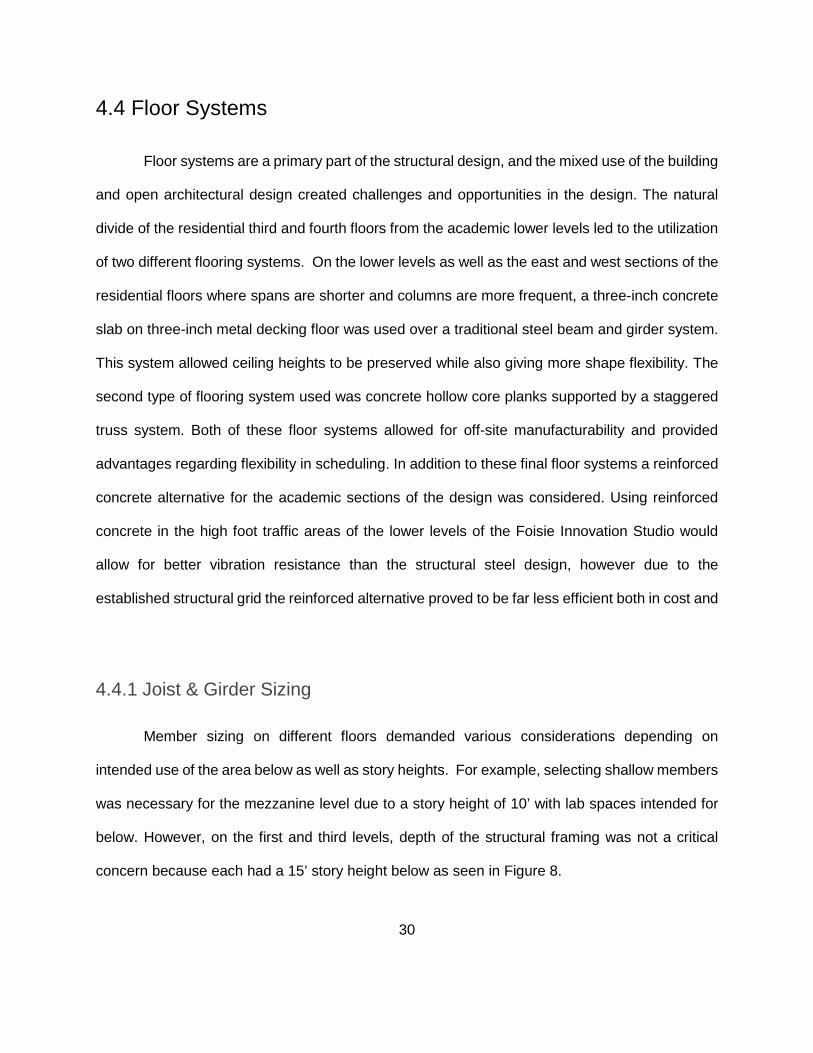
4.4 Floor Systems
Floor systems are a primary part of the structural design, and the mixed use of the building
and open architectural design created challenges and opportunities in the design. The natural
divide of the residential third and fourth floors from the academic lower levels led to the utilization
of two different flooring systems. On the lower levels as well as the east and west sections of the
residential floors where spans are shorter and columns are more frequent, a three-inch concrete
slab on three-inch metal decking floor was used over a traditional steel beam and girder system.
This system allowed ceiling heights to be preserved while also giving more shape flexibility. The
second type of flooring system used was concrete hollow core planks supported by a staggered
truss system. Both of these floor systems allowed for off-site manufacturability and provided
advantages regarding flexibility in scheduling. In addition to these final floor systems a reinforced
concrete alternative for the academic sections of the design was considered. Using reinforced
concrete in the high foot traffic areas of the lower levels of the Foisie Innovation Studio would
allow for better vibration resistance than the structural steel design, however due to the
established structural grid the reinforced alternative proved to be far less efficient both in cost and
4.4.1 Joist & Girder Sizing Member sizing on different floors demanded various considerations depending on
intended use of the area below as well as story heights. For example, selecting shallow members
was necessary for the mezzanine level due to a story height of 10’ with lab spaces intended for
below. However, on the first and third levels, depth of the structural framing was not a critical
concern because each had a 15’ story height below as seen in Figure 8.

31
Figure 8: South Elevation of Proposed Foisie Innovation Studio, Image from Autodesk Revit
Another consideration for the framing of various floors was the number of joists and girders
necessary to ensure serviceability. On every floor, there will be a significant amount of foot traffic,
and it is important that the floor systems are stiff enough to not deflect noticeably. Therefore, the
spacing of the beams was limited within each system, and members were designed to deflect
minimally while also meeting the bending and shear requirements of the loads. One last
consideration when sizing exterior supporting members was that exterior finishes, such as curtain
walls and brick veneer, have differing loads. So, in certain locations throughout the building, an
exterior beam could be tasked with supporting one finish below and another finish above.
The structural members of the building were designed in many phases, beginning with
joists, then sizing exterior beams, then progressing to girders. Each member system was
designed for bending using the designed spans from the column placement, the loads for each
span and occupancy, and a determined tributary spacing. Once the member was sized based on
required bending moment capacity, the AISC Steel Construction Manual [14] was consulted to
check that the size met compact section criteria and calculated the deflection of the beam under
dead and 50% live loads using the equation:

32
Equation 1: Deflection
∆=5𝑤𝑤𝑤𝑤4
384𝐸𝐸𝐸𝐸
This calculated deflection was then compared to the serviceability limit of deflection using
span length (L)/ 360 with a max allowable deflection of 1 inch. If the calculated deflection eclipsed
the serviceability deflection, a larger beam size was selected. This process was iterated until the
joist had acceptable deflection. Due to the earlier determined spacing of joists, the loads on each
joist were relatively small and thus the deflection criteria often governed the member size. Upon
completion of the deflection check, a check of the beam’s shear capacity was conducted to
complete safety. Using the following LRFD relationships for shear capacity and maximum shear
formulas, it was verified that the each member satisfied the AISC Specification for shear:
Equation 2: Shear Force
𝑉𝑉𝑢𝑢 = 𝑤𝑤𝑢𝑢 ∗𝑤𝑤2
Equation 3: Shear Capacity
𝜙𝜙𝑉𝑉𝑛𝑛 = 𝜙𝜙𝐴𝐴𝑤𝑤𝐶𝐶𝑣𝑣(.6𝐹𝐹𝑦𝑦)
Samples of these calculations can be found in Appendix D. Once the beams were sized
appropriately, the next step was to standardize the sizes to aid constructability and
manufacturability of the design. Thus sizes that were infrequent were increased to the next
frequently used size. The sizes used on each floor can be seen in Table 4 below:

33
Table 4: Joist Sizes Used Per Floor
Floor Joist Sizes Used 1st W12x26, W18x35, W18x40 Mezzanine (2nd) W12x26, W12x53, W12x106 3rd W12x16, W16x31 4th W12x16, W12x50
Following the finalization of joist sizes, the girders were sized using the same process
while keeping in mind that for the practicality and ease of connection, each girder had to be at
least as deep as the beams that would be connected to it. Also, in the case of the girders, the
weight of the beams that bear on them was included in the load combination equation. The
member sizes used for the girders can be seen in Figure 9. The framing plans of the second floor
mezzanine and third floor can be seen below in Figures 10 and 11.
Figure 9: Girder Schedule with Sizes and Counts, Image from Autodesk Revit

34
Figu
re 1
0: 2
nd F
loor
Mez
zani
ne F
ram
ing
Pla
n, Im
age
from
Aut
odes
k R
evit

35
Figu
re 1
1: 3
rd F
loor
Stru
ctur
al F
ram
ing
Pla
n, Im
age
from
Aut
odes
k R
evit
Additional structural framing plans and images can be found in Appendix C.

36
Figure 12: Staggered Truss System, Image from Autodesk Revit
4.4.2 Staggered Truss System The use of a staggered truss system allows several advantages over a classic beam and
girder set up. Staggered trusses allow for large open spaces and flexibility which is ideal for the
architectural layout of this design. The constructability of these systems has proven to be much
more effective due to their simple nature and ability to be assembled off site. Therefore, this
system seemed to be a great option to use within the center portion of the proposed design.
The system works by using Pratt trusses in a staggered position in order to minimize the
amount of supports needed. The geometry of a Pratt truss was selected because it is able to
effectively sustain loads on both its top and bottom chords and the diagonal members are in
tension, leaving the shorter vertical members in compression. This allowed for a lighter distribution
of steel members, as steel members offer greater strength in tension. The truss carries loads in
both the top and bottom chords from the floor at the level of the truss and the floor at the next
level above (as can be seen in Figures 12 and 13).

37
Due to the layout of the building, the hallways run through portions of the trusses because
the trusses are hidden in the walls, therefore a solution had to be developed so that the trusses
could meet these constraints. A mixture between a Pratt truss and a Vierendeel truss was
developed in order to allow space for the hallways to pass unhindered (as can be viewed in Figure
13). The only significant difference with this design was that the connections for the members in
the Vierendeel panels had to be designed with moment-resisting joints in order to maintain a
stable truss system.
The spans between trusses are supported by a concrete system known as hollow core
plank. The plank is precast in the factory and comes in a variety of sizes to hold a wide range of
loads over different spans. These floor systems can be used for spans of up to 60’ between
trusses. This system is also very effective because many of the components can be assembled
in steel mills and concrete factories which allow for quick erection on the construction site. Most
parts of the system can be delivered and installed in a short amount of time. Manufacturers claim
that up to 3500 square feet of hollow core plank can be installed in one day [15].
The use of a staggered system instead of traditional methods was an easy decision. The
design of this system was not much different than that of any other truss systems. The biggest
difference was that loads for two floors were carried by each truss. Some loads being carried
were very significant and required large members, which proved to be a challenge to design the
truss so that it could fit within the walls of the building. There were eight different truss designs
developed for varying lengths and depths depending on the location of the truss.

38
Figure 13: Proposed Vierendeel Truss, Image from Risa-2D
The trusses were modeled in RISA 2D Software in order to perform an analysis of the
internal forces in each member. The model was made as simply supported with pinned fixtures
for the connections, with the exception of the Vierendeel panels which required moment-resisting
connections. Once the internal forces for each member were determined, they were designed to
standard based on if they were in tension or compression. Members were sized using AISC Steel
Construction Manual, Parts 4 & 5 for design of compression members and design of tension
members. Vierendeel sections were designed using Part 6 of the manual for combined flexural
and axial forces [14].
The hollow core plank was designed based on the sizing chart provided by the
manufacturer for the thickness needed to support the loading conditions and span of the design
[15]. It was determined that 10” thick plank would be needed to support the loading conditions
across the span between trusses. The manufacturers advertise that the sizing tables are accurate
but the actual size of the planking would be designed by their engineers. The dimensions and
loading conditions for the trusses are as follows:

39
Table 5: Dimensions and Loading Conditions for Trusses
Length (ft) Height (ft) Tributary Width (ft) Loading* (K/ft)
24 10 30 5.31
31 10 30 5.32
100 10 18 3.62
104 10 18 3.62
112 (Gable) 9 30 2.23
104 (Gable) 9 24 3.14
100 (Gable) 9 24 3.14
24 5 30 5.36
31 5 30 5.32
50 5 18 4.81
100 5 42.5 3.16
(*Loading uses the load conditions for the corresponding floors of the building with LRFD
combination 1.6L+1.2D, 1.6 (L, R, or S) + 1.2D for gabled roof trusses)
The biggest concern in the design for compression is buckling due to the slenderness of
a member. Therefore, the most important parameter for selecting members (using AISC Table 4-
1 [14]) is the KL factor, K being an effective length factor and L being the length of the member.
K is the coefficient that converts a given column and boundary conditions into an equivalent Euler
Column, (K Factors found in AISC Specification Appendix 7). The K factors used for the selection
of members for these truss systems was 1.0 for all members as outlined in Chapter 4 of the AISC
Steel Construction Manual [14]. The design strength of each member (ϕcPn) was calculated by
dividing all forces found in the RISA analysis by 0.9 (ϕc).

40
The design of tension members was performed using AISC Table 5-1 [14]. All members
were demonstrated to satisfy conditions for both yield and rupture strength to negate any failures
in the system. The design strength of each member (ϕtPn) was calculated by dividing all forces
found in the RISA analysis by 0.9 for yield strength and .75 for rupture strength (ϕt).
For constructability purposes, members were grouped based on their strength
requirements and two series of members were chosen that satisfied the needs of the design, one
set of sizes for tension members and another for compression members. A range of design
strengths were assigned to each size W shape beam that would be used in the design. W14
shapes were chosen for consistency. Moreover, W14 sections seemed to offer the lightest
members for the required strength required when performing a preliminary member selection. The
selected member sizes used and their available strength values are displayed in the tables below.
Table 6: Compression Members in Trusses
Member Sizes Available Strength (Kips)
W14x48 475
W14x82 910
W14x109 1340
W14x132 1620
W14x159 1970
W14x176 2180
W14x193 2560
W14x211 2680
W14x233 2960

41
Table 7: Tension Members in Trusses
Member Size Available Strength (Kips)
W14x38 410
W14x61 650
W14x99 1060
W14x120 1290
W14x145 1560
W14x159 1710
W14x176 1900
W14x233 233
The practice of categorizing member sizes rather than fitting sizes to each individual
member greatly enhances the constructability and design process of the system. Although it may
cost more in materials, the truss assembly becomes much simpler when each truss follows a
similar pattern in member sizes, and all the sizes are similar in geometry. It also sped up the
design process because rather than referring to the tables on every member there was already a
predetermined size for each load condition. It also saved a lot of time with checking designs,
because many of the members were designed to withstand much more load than is required, and
not much time was spent redesigning members that fail checks.
4.4.3 Reinforced Concrete Alternative Using reinforced concrete in the high foot traffic areas of the lower levels of the Foisie
Innovation Studio would allow for better vibration resistance than the structural steel design;
however, due to the established structural grid the reinforced alternative proved to be far less
efficient both in cost and floor depth. The structural grid required the consistent use of a beam-

42
slab system with the slabs acting as one-way slabs based on the long rectangular bays. As a
result of the bay sizes, the beam sizes were rather large and the slabs were far thicker than the
three-inch slab on three-inch decking of final floor design. With the thicker slabs and large
beam sizes, it was determined that reinforced concrete was not an appropriate alternative to fit
the architectural design and the established structural grid. The preliminary design work for the
reinforced concrete alternative can be found in Appendix E.
4.5 Roof Design The roof was designed as a system of gabled trusses in conjunction with connecting
beams to support loads that the top of the building may encounter. These gabled trusses were
designed in the same process as the staggered truss system, with the exception of the use of
Vierendeel panels for the latter. The basic loading combination used when analyzing member
forces was 1.2D + 1.6 (Lr, R, or S). Due to the high annual accumulation of snow in the city of
Worcester, snow was the dictating load in design which was 55 PSF, as set forth by the MBC.
Other considerations that were used in the calculation of dead loads were shingles, MEP, metal
decking, ceiling, and sheathing. The roof was designed to have a 10.2° pitch, where the trusses
rise 9 feet in the center; this would provide adequate runoff for rain water or accumulated ice and
snow.
Most of the design for this system was very standard, however distributing the loads to the
corners of each building proved difficult at first because of the span from the top of the last truss
in the series to the corner of the building.

43
Figure 14: Roof Hip Alternative to Shorten Span, Image from Autodesk Revit
After several alternatives were reviewed it was determined that placing columns at the
corners of the stairwell sufficiently shortened the span of the hip support (Figure 14). This span
reduction greatly reduced the required size of the hip supports. The four corners of the building
were designed to have no pitch, this was for design and constructability purposes. Where the
north and south facing walls are curved, it proved more efficient to eliminate part of the pitched
portion of the roof in order to keep the majority of the system square rather than designing a
curved system for the roof as well. Rather than having excess water and snow runoff at the
corners, a drain system will lead to the gutters along the sides of the building.
Figure 15: Structural and Architectural Representation of the Roof, Image from Autodesk Revit

44
4.6 Lateral Load Analysis
Upon completion of the BIM structural model, a structural analysis was performed using
Autodesk Robot. This program allowed for testing of seismic and wind loads to be performed on
a model of the building’s frame. The frame was designed to be a rigid structure to avoid the need
for additional support for the building. The frames for the building are made up of the exterior
walls, two frames for lateral stability in each direction (North/South and East/West). The frames
running from North to South are comprised of 7 columns, while the East to West frames are made
up of 10 columns. Each frame was modeled separately rather than a model of the entire lateral-
load resisting system. This is because it is much simpler to model and analyze one frame at a
time. In order to analyze the lateral loading effects in both the North/South and East/West
directions, separate models were made of the frames that span those directions. Due to the
varying load paths of the wind analysis, both models had to be constructed in 3D.
Figure 16: Structural Representation of East & South Wall Framing Systems, Image from Autodesk Revit

45
Figure 17: Plan View of Framing System, Image from Autodesk Revit
The wind analysis was conducted for the Main Wind Force Resisting System, using the
method for buildings of any height as outlined in ASCE 7-05 [13] in accordance with the MBC.
This method essentially examines the effects of external pressures produced by wind loads on
the frame in four different “cases”. Case 1 examines the forces perpendicular to the face of the
frame being examined. Case 2 applies both a perpendicular force to the frame coupled with
translational moment around the corners. The third case involves applying forces in both the X
and Y directions. The fourth case examines the effects of all three forces acting on the building at
the same time. The wind forces were based on building dimensions, roof type, surrounding
conditions, and wind speed (found in MBC, identified by city).

46
The Seismic analysis was similar to the wind analysis; however, it was much simpler
because it did not involve varying cases and conditions. The shear force for each story of the
building was calculated based on the dimensions and total weight of the building, as well as the
spectral response acceleration values for the city of Worcester (found in the MBC). This produced
a shear force that could be applied to the base of the building in order to simulate the effects of
an earthquake on the frame. The results of both the seismic and wind analyses were used to
perform a second-order analysis in order to check the stability of the columns for excessive lateral
translation due to either lateral forces or moments.
Autodesk Robot is capable of performing P-Delta Analyses in order to observe the effects
of combined lateral and gravity loads. This was used to draw conclusions on the frame’s design
and determine any flaws. The software was used to identify the columns in the frame that would
accumulate the most stress due to lateral forces. Since all the columns were designed to be the
same size (more detail to follow in 4.7 Column Design), only the global extreme values from the
model were examined. The member subjected to the highest translational moment and axial force
was selected for further analysis to confirm sufficient stability.
4.7 Column Design
Finally, upon completion of all horizontal spanning members, column sizes were calculated,
first using axial compressive strength and then by investigating their capacity for combined
bending and axial forces using interaction equations in chapter H of the AISC Specification. The
columns were analyzed as part of a rigid frame, and a few key assumptions were made to
determine the effective length factor K:

47
● Behavior is purely elastic
● All members are prismatic
● All Joints are moment resisting
● Joint resistance is proportional to I/L for members
● All columns buckle simultaneously
A preliminary size for each column was calculated using the available strength in axial
compression found in Table 4-1 of The AISC Steel Construction Manual [14] compared to the Pu
value calculated from totaling the loads from the girders acting on each column. A top-to-bottom
approach was employed when sizing the columns to account for loads throughout the structure.
Once the axial load was calculated and a few sufficient column sizes were identified, the column
with the lowest rx/ry ratio was selected for stability in both axes. Then to standardize the sizes a
W14x90 was selected for each column. Following a structural analysis of combined gravity and
lateral forces based on the preliminary W14x90 size, the columns were checked for combined
bending and axial force using the following interaction equations:
Equation 4: Interaction Equation H1-1a
𝑃𝑃𝑟𝑟𝑃𝑃𝑐𝑐≥ 0.2 ∶ 𝑃𝑃𝑟𝑟𝑃𝑃𝑐𝑐
+ 89 (𝑀𝑀𝑟𝑟𝑟𝑟𝑀𝑀𝑐𝑐𝑟𝑟
+𝑀𝑀𝑟𝑟𝑟𝑟𝑀𝑀𝑐𝑐𝑟𝑟
) ≤ 1.0
Equation 5: Interaction Equation H1-1b
𝑃𝑃𝑟𝑟𝑃𝑃𝑐𝑐
< 0.2 ∶ 𝑃𝑃𝑟𝑟2𝑃𝑃𝑐𝑐+ (𝑀𝑀𝑟𝑟𝑟𝑟
𝑀𝑀𝑐𝑐𝑟𝑟+𝑀𝑀𝑟𝑟𝑟𝑟𝑀𝑀𝑐𝑐𝑟𝑟
) ≤ 1.0

48
Figure 18: South Elevation of Steel Framing, Image from Autodesk Revit
4.8 Connections
In both the steel truss systems and the overall superstructure, bolted connections were
used to connect members within the truss, beams to girders, and girders to columns. For
practicality, one typical beam-to-girder connection and one typical girder-to-column connection
were designed based on a range of loading conditions. The number of rows, plate sizes, and bolt
sizes necessary to account for the forces acting on the girders and columns were determined
using techniques outlined in Structural Steel Design [16]. Connections for the Vierendeel truss
panels were determined to be full penetration welds which would be fabricated by the
manufacturer prior to truss assembly.
For the beam-to-girder connections a single angle shear connection was used. The single
angle allows for easy field assembly as the angle will be bolted to the girder off-site and then the
beam will be attached in place. Using A325-N, ¾” diameter bolts, the following processes and
checks were used to determine the number of bolts and angle thickness of a sufficient connection:

49
• Required # of bolts based on Bolt shear capacity
• Connection Stability
• Bolt Bearing on Angle (Tear out vs. Bearing):
• Angle Shear Rupture
• Angle Shear Yield
• Block Shear Rupture of Beam (for coped flanges)
• Tension Rupture of Beam (for coped flanges)
• Shear Yield of Beam
• Bolt Bearing on Beam Web
• Bearing on the Girder Web
For an example of these calculations refer to Appendix D. The beam-to-girder connections
typically did not need to withstand large forces and were often governed by connection stability
equation:
Equation 6: Connection Stability
𝑇𝑇 ≥ 𝑤𝑤𝐴𝐴 ≥𝑇𝑇2
Where LA is the length of the single angle and T is a detailing property of the supported beam
found in Table 1-1 of The AISC Steel Construction Manual [14].
To ensure the connections were stable an additional bolt was added and the angle was
lengthened. This was even more critical for deeper beam sizes such as W16x31. The following
table shows the beam size (nominal depth), the required number of bolts, and the thickness of
the angle.

50
Table 8: Beam-to-Girder Connection Requirements by Beam Size
Beam Size (nominal depth) # of Bolts Required Angle Thickness
W12x 2 3/8”
W16x 3 1/4”
W18x 3 1/4"
An additional concideration was that some beams would require coped flanges in order
to reach the web of the girders. This was the case when the beam and the girder were the same
depth as shown in Figure 19. To aid in field constructability the plates will be shop bolted to the
girders as denoted by the red through lines in Figure 19.
Figure 19: Typical Beam-to-Girder Connection with Coped Flanges
The girder-to-column connections utilized double-angle shear connections with bolted
flange plates to resist moment. Although a double-angle connection typically would utilize coped
flanges for ease of field assembly, the moment resisting aspects of the connection require the
flanges to remain un-coped. The same processes and checks were performed for these
connections as for the beam-to-girder connections, only substituting the girder for the beam and

51
the column flange for the girder web. Due to the larger loads carried by the girders these
connection were not typically governed by the stability equation, and thus the number of bolts is
more related to the shear forces. Table 9 displays the required number of bolts and angle
thickness for ranges of shear force.
Table 9: Girder-to-Column Connection Requirements by Shear Force
Shear Force # of Bolts Required Angle Thickness
0 – 71.56 [kips] 2 1/4”
71.56 – 107.34 [kips] 3 5/16”
107.34 – 143.12 [kips] 4 5/16”
Though it is important to note that in a few specific cases the girders were still governed
by the length of the angle and thus the same process of adding a bolt was used. This is the case
in Figure 20. This sample calculation can be referenced in Appendix D.
Figure 20: Typical Girder-to-Column Connection with Coped Top Flange

52
4.9 Base Plates & Footings
The substructure, also referred to as the foundation, was included in the structural design
through the design of base plates and spread footings for the columns. The purpose of a
foundation is to transfer the loads of the building to the subsoil below. The subsoil was determined
to have a bearing strength of 8 ksf by a geotechnical study [12] which the foundation has to match
in order to prevent excessive total and differential settlement. In the case of this project, the WPI
campus has glacial till, which is a strong soil and doesn’t require a deep foundation system. To
match the bearing strength of the subsoil below, strip footings on the foundation walls and spread
footings on the columns were used. Additionally cantilever retaining foundation walls were utilized
to benefit constructability in the early stages of construction. This wall detail permits heavy
construction equipment and construction materials to be placed in the vicinity of the foundation
wall prior to the framing of the first floor level. Accommodating these large overburdens adjacent
to the foundation walls will conserve space in areas where strict site restrictions exist.
The base plates for the columns were established by first calculating a minimum area A1
based on both the bearing strength of the concrete footing and the column factored load Pu. Next,
using the higher of the column property dbf and dA1, the minimum dimensions of the plate N and
B were calculated. These dimensions were then used to calculate the actual A1 value. Then the
corresponding bearing stress in the concrete footing was used to determine the thickness of the
plate t. Due to all of the columns being W14x90 and for the sake of practicality, the base plates
were a consistent 16” x 16” with varying thicknesses. By selecting square plates and using a
square arrangement of anchor bolts, field and shop work were simplified. Table 10 displays the
thickness based on ranges of the factored column load Pu. Sample calculations can be found in
Appendix D.

53
Table 10: Base Plate Thickness by Factored Column Load
Factored Column Load Pu Plate Thickness
81.7 – 183.9 [kips] 3/4”
183.9 – 326.9 [kips] 1”
326.9 – 510.7 [kips] 1 1/4”
510.7 – 735.5 [kips] 1 1/2"
735.5 – 1001.0 [kips] 1 3/4"
The concrete footing sizes were obtained by calculating the allowable soil pressure and
the maximum service load P. The allowable soil pressure (S) was calculated to be 7.255 ksf for a
footing 36 in thick. Then using the footing area equation a minimum was calculated. Finally, the
dimensions of the footing were determined from the minimum footing area. Table 11 displays
selected footing sizes based on the maximum service load. Additionally, an engineering sketch
of the smallest footing case can be seen in Figure 21.
Table 11: Concrete Column Footing Sizes by Range of Maximum Service Loads
Maximum Service Load P Footing Sizes
0 – 261.2 [kips] 6’ x 6’ x 3’
261.2 – 464.3 [kips] 8’ x 8’ x 3’
464.3 – 725.5 [kips] 10’ x 10’ x 3’

54
Figure 21: Engineering Sketch of Typical Column Base Plate

55
5.0 Construction Scheduling
In order to verify the feasibility of this proposal within the constraints set by WPI President
Laurie Leshin in a campus-wide email on October 14th 2015, the team set forth to create a
schedule for the construction of the building. With the start and end dates for construction defined,
the activities necessary to complete the building were identified and arranged in a logical
sequence, which was presented as a network diagram. The Critical Path Method, which is a
network-based scheduling approach, was then used to assemble this information and to
determine the critical activities for the execution of the project. .
5.1 Identification of Activities
A number of web sources were consulted to acquire foundational knowledge about the
construction process and the range of activities that are involved in erecting a building of this
nature. This information was organized using the Construction Specifications Institute (CSI)
classification system for design (Uniformat) and construction (Masterformat) work. Having first
consulted the Masterformat standard, Uniformat was ultimately settled upon as a means to
organize activities. While Masterformat organizes activities based on materials and trades,
Uniformat arranges construction information based on functional elements or parts of a facility
without regard to the materials and methods used to accomplish them. Uniformat’s approach to
organizing data is also important to the continued development of Building Information Modeling
(BIM) software, as its system organization allows objects to be placed before their properties have
been further defined.
As shown in Figure 22 on the next page, the ASTM Uniformat II Classification for Building

56
Elements organizes by three different levels. The levels are Major Group Elements (Level 1),
Group Elements (Level 2), and Individual Elements (Level3).
Figure 22: ASTM Uniformat Classification, Image from National Institute of Standards and Technology [17]

57
There are eight Major Group Elements: General Conditions, Site Work, Substructure,
Shell, Interiors, Services, Equipment and Furnishings, and Special Construction and Demolition.
Considering these eight Major Group Elements created an umbrella under which any necessary
activities for the project could be organized. These Major Group Elements are divided into smaller
Group Elements (Level 2). For example, the Shell Major Group is divided into Superstructure,
Exterior Enclosure, and Roofing. By carefully examining the Level 2 elements and considering
the proposed building design and plan for construction, a base of activities to start was
established.
With this activity breakdown to work from, similar construction projects from both the past
and present were examined in order to identify Level 3 elements applicable to the construction of
the Foisie Innovation Studio. Some of the first sources consulted were Major Qualifying Projects
from previous years. One of the more relevant projects, titled “Design of the New WPI Residence
Hall” [18] focused on the construction of East Hall; one of WPI’s more recently constructed
residential buildings. Constructed in 2008, East Hall “provides apartment-style housing and an
eco-friendly environment for about 230 upperclassmen” and showcases WPI’s movement toward
sustainable design [18]. While the Foisie Innovation Studio is not designed solely for the purpose
of housing students, many construction activities were determined that would overlap for the two
projects. In addition to these overlapping elements, it was important to consider activities that
would only apply for the academic component of the building, such as the installation of equipment
for the robotics engineering lab, or lecture hall furnishings.
Included in the 2008 MQP is the construction schedule for East Hall which provides a list
of activities [18] as well as durations for a multitude of elements. This schedule proved extremely
helpful as parallels could often be drawn between the Foisie Innovation Studio and East Hall,
despite differences regarding the specific layout and usages of the two buildings.

58
5.2 Determination of Durations
In addition to examining the aforementioned East Hall construction schedule, other
sources were utilized to determine durations for the already identified activities. One of these
sources was a construction simulation video [19] for a new 50-million dollar wellness center at
Worcester State University. The video shows the entire completion of the building from start to
finish, and timestamps allowed for a better understanding of how long common activities would
take for a building of this scale.
For activities with the highest level of design detail, such as the erection of structural steel,
it was possible to perform a calculation to obtain a more specific estimate for the activity’s
duration. For example, according to RS Means, a crew of 8 people working 56 labor hours per
day, one linear foot of steel can be erected in 0.072 labor hours [20]. This calculation for a
segment of steel in the proposed design for the Foisie Innovation Studio is shown below.
- 1 Linear Foot / 0.072 hours = 13.89 Linear Feet per crew per labor hour
- 13.89 Linear Feet / labor hour * 56 labor hours = 777 Linear Feet per day
- Among the 12 segments of structural steel in the design (4 Eastern, 4 Central, 4
Western) are roughly 19,000 linear feet of structural steel (average 1600/segment)
- 1600 LF / 777 LF per day = 2.06 days per segment
- A rate of 3 days per segment was defined for the schedule to account for the steel being
erected in the winter in Worcester, MA
Using these productivity rates, it became possible to acquire a specific duration for each
section of steel to be erected. Table below illustrates how durations were determined by type of
activity.

59
Table 12: Duration Estimation Breakdown
Type of Activity Duration Estimation Source
Site Prep / Foundation Worcester State Simulation
Structural Steel Erection RS Means Calculation
Enclosure, Services, Furnishings East Hall Schedule
More than any other phase of the scheduling process, common sense and careful
judgement was relied upon in order to determine durations for the nearly 200 activities comprising
the Foisie Innovation Studio construction schedule. While references served to provide a
reasonable first estimate, each individual construction project is different and therefore presents
different challenges. The ultimate goal was to provide realistic estimates that would also respond
to the fast pace and deadline communicated by President Leshin.
5.3 Determination of Precedence and Order
The construction simulation video [19] for the Worcester State Wellness Center also
proved most advantageous for determining the precedence and order of activities for construction
scheduling. The time-lapse video provided by W.T Rich Company starts with site preparation,
continues with foundations, and concludes with the enclosure of the building. Beyond watching
this time-lapse video, a visit was made to a construction site in Worcester, where Skanska was
constructing a new building for the Worcester Regional Transit Authority. Listening to those
charged with the project and observing their progress provided insight into which tasks would be
complete at a certain stage of the project, and also shed light on some techniques for scheduling
real-world projects.

60
5.4 Input of Information into Primavera
In order to organize the construction schedule in the most concise and visually appealing
manner, Oracle’s Primavera software was utilized. Primavera was chosen from a group of
scheduling software available at WPI due to its ease of use and its industry-wide popularity. The
first step in the process was to create a new project for the Foisie Innovation Studio. After the
project had been established, all of the individual activities which had been identified were added
to the schedule, along with their respective durations. The next step in Primavera was to establish
the precedence of activities, or the network diagram. The network diagram could be formed
through a couple of strategies. First, by clicking on an activity, the user is able to choose activities
from a list and identify if they proceed or follow the chosen activity. Perhaps the simpler option is
to draw arrows from one activity to the next, showing precedence in the network diagram provided
by Primavera. After listing all precedence in the project and giving each individual activity its place
in the network diagram, the “Schedule” button can be used. This button first determines the critical
path, which identifies the “critical” activities. Critical activities are those with no “float”, which
means that any delay in their completion will cause a delay in the completion of the overall project.
Activities which have a float of greater than zero can be delayed for a certain amount of time
without impacting the project’s completion. The “schedule” function also served to provide start
and end dates for each activity and the project as a whole. This process was completed multiple
times over the course of the project in order to incorporate new knowledge about the construction
process and refine the schedule as much as possible

61
5.5 Final Critical Path and Key Portions of Diagram
The figure below displays the final network diagram for the project. This network diagram
shows the overall sequencing for all 200-plus project activities and demonstrates how sections of
the project flow together. Activities along the critical path are shown in red.
THIS SPACE HAS BEEN INTENTIONALLY LEFT BLANK

62
Figu
re 2
3: F
inal
Crit
ical
Pat
h, Im
age
from
Prim
aver
a

63
The below figures are included to display sequencing for some key areas in the building’s
construction. Many of these areas are located on the critical path, and thus timely completion of
these activities will be crucial to the project’s success.
Figure 24: Project Management and Design Activities after Project Start, Image from Primavera
Figure 25: Foundation Construction, Image from Primavera

64
Figure 26: Construction of Exterior Walls, Image from Primavera

65
6.0 Cost Estimating
While the architectural model, structural model, and schedule were being completed,
estimating the cost of construction began. As previously discussed, a hybrid approach was used
to determine the total cost based on the type of unit installation to be estimated. This involved a
level of detail analysis that determined the accuracy of the estimate. There are three classes of
cost estimating with progressively less detail that were used: Class A, B, and C. Class A uses a
detailed breakdown of labor, materials, and equipment with exact unit prices. This was utilized for
the structural model takeoff. Class B uses building component format with composite unit pricing.
This was used for the architectural model takeoff. Class C is solely a cost per square foot
summarizing building components based on historical data. This was used for demolition, site
work, and building services.
To aid in calculating cost estimation information, a Microsoft Excel spreadsheet was
developed that organized each element based on how the cost was determined and displayed
values for the appropriate units of measure, such as quantity, weight, or volume. This was
beneficial when performing the cost estimating calculations and determining the cost of the
construction activities. The spreadsheet helped organize the unit prices of each element so they
could be assigned to construction activities in the schedule. Table 13 below illustrates the
approach to estimating the different types of building systems.

66
Table 13: Cost Estimating Approaches
Building System Approach Comments
Earthwork Cost ($)/square foot of site area
For excavation and site prep
Foundation Cost ($)/cubic foot of concrete
Footings, foundation wall, basement floors
Structural Steel Cost ($)/member Based on member size and weight
Flooring Cost ($)/square foot of floor Based on floor type
Exterior Walls Cost ($)/square foot of exterior wall
Brick wall, curtain wall
Interior Walls Cost ($)/square foot of interior wall
Double sided, steel stud drywall
Ceilings Cost ($)/square foot of ceiling Matrix and foam tiles
Roofing Cost ($)/square foot of roofing
Shingles and EPDM
Fixtures Cost ($)/unit Toilets, elevator, furniture
Windows Cost ($)/window Depending on size and type
Doors Cost ($)/door Depending on size and type
6.1 Unit Cost Method
For the majority of building features, quantity takeoffs were used to retrieve the design
information from the Revit model. The quantity was then multiplied by the unit price from the
RSMeans 2014 database to establish cost. This process involved using the schedules created by
the BIM model to ascertain information such as unit quantity and size. For structural features,
such as steel beams, concrete, or curtain wall, the exact size of the elements was known, so the
quantity and unit price were used to calculate the cost per linear foot.

67
6.2 Square Foot Method
For activities and features associated with demolition, site work, and building services, the
square foot costs provided by RSMeans 2011 was utilized and multiplied by the square footage
of the building. Since design work in these fields was not performed, the square foot method
proved to be the most efficient means of estimating the cost. While the level of detail may be
lower, given the scope of the project, estimating these features using square footage was more
suitable.
6.3 Cost Analysis Alternatives
In an effort to “double-check” the total cost estimate, three separate calculations with
different levels of detail were developed. First, the total footprint of the building was utilized and
multiplied by a cost factor in RSMeans 2011 based on the type of exterior wall and framing used.
Figure 27 below illustrates the calculation to determine the construction cost.
Figure 27: Total Square Foot Method, Image from Microsoft Excel
Next, the cost was quantified for each division by square foot, increasing the level of detail.
For example, cost per square foot to install HVAC systems in a college classroom is $19 [20].

68
Figure 28 below illustrates how building components were subdivided and priced. The total cost
includes a time factor to escalate the price to 2016.
Figure 28: Square Foot Method, Image from Microsoft Excel
Finally, to most accurately estimate the cost of construction, a hybrid approach of unit cost
for features designed either architecturally or structurally and square foot cost for demolition, site
work, and building services was completed, as outlined above in sections 6.1 and 6.2. This
allowed for an estimate of internally designed work.
6.4 Calculating Total Cost
The construction cost includes the cost of transportation, installation, and completion of
each building feature. After totaling those costs, to scale the project properly, a location and time
index was used to account for the geographic and inflation factors. Figure 29 below illustrates a
summary of the construction cost estimate. This cost is consistent with the value displayed in
Figure 27, demonstrating a high level of accuracy succeeding the double check.
SF SF

69
Figure 29: Summary of Construction Cost, Image from Microsoft Excel
To calculate the total project cost, costs associated with designing, permitting, contracting,
and managing, or soft costs, were added. Based on RSMeans 2014, this required adding 33% of
the construction cost; 25% for general contractor fees and 8% for architect fees. This produced
the final total project cost of $25 Million. Given the total square footage of the building is roughly
82,500 SF, the total cost per square foot is $300/SF, comparing consistently to standard
academic-residential projects of this type and size.

70
7.0 Construction Simulation - 5D Model
After completion of the schedule and cost estimates along with architectural and structural
models, the 5D model was prepared. While a CPM network and Excel documents do a fine job of
documenting schedules and cost estimates, they do not illustrate this information in a visual and
comprehensive manner. A 5D model allows both the owner and all parties working on the project
to visualize how the building will come together and the earned value of each element or phase
as construction progresses. In this project, the 5D model is a simulation that starts from a fully
prepared site and concludes with the finished building.
With the first three dimensions of the process having been established (length, width, and
height of the building from the 3D BIM model), the next dimension to be incorporated was time.
Autodesk’s Navisworks Manage was utilized to create a model simulating the construction
process over time, starting with a structural shell of the building, and gradually adding all other
structural and architectural elements. As these elements accumulate in the simulation, the
software also displays a number representing the earned value for the building based on its actual
progress as it compares to actual progress; that is to say, it illustrates how each additional element
adds to the cost and value of the building. This simulation has been made as thorough and in-
depth as possible, and it allows the user to easily visualize how each phase contributes to the
overall completion of the process.
7.1 Phasing of Revit Models
The first step before creating the 5D model in Navisworks was to organize elements from
the architectural and structural BIM models into phases of construction. By completing this task,

71
the selection of individual elements would be much simpler when it came time to finalize the
simulation. Phasing elements in Revit is a fairly straightforward process, as one simply needs to
select a building element and assign it to the corresponding phase in which the element is built.
Revit also allows the user to select all similar elements in the project, so it is often not necessary
to select and assign elements too many times for an individual phase. Phases for the architectural
model include Demolition, Site Work, Foundation, Concrete Slabs, Stairs, Exterior Walls, Utilities,
Partitions, Doors and Windows, Interior Finishes, and Furnishings. As shown below in Figure 30,
the structural model is broken into phases including Eastern Pod Steel, Central Pod Steel,
Western Pod Steel, and Roofing. Once these phases have been created in Revit, the models can
be exported to Navisworks for the creation of the 5D model.
Figure 30: Breakdown of Structural Steel Pods, Image from AutodeskNavisworks
7.2 Importing Models into Navisworks
When phasing for both the structural and architectural models had been completed, the
models were imported separately into a shared Navisworks file. The files were already linked in
Revit to make work easier, but had to be imported separately for the purpose of the Navisworks
simulation. This task was accomplished by opening one of the models in the file, and then
appending the other file onto it. Since the BIM models were created on the same footprint, all
elements lined up correctly and with no clashing. After importing the models, the user can

72
visualize how the building will look with structural and architectural elements in the same view
(shown below).
Figure 31: Foisie Innovation Studio Rendering of the Integrated Structural and Architectural Models, Image from Autodesk Navisworks
As shown in Figure 32 below, a clash-detection can be performed in Navisworks in order
to identify any problems of compatibility between the elements contained in the two Revit models.
While many clashes were found between the two models, they were caused by discrepancies
between the comprehension levels of Revit and Navisworks, and not by spacing issues.
Figure 32: Clash Detection test, Image from Autodesk Navisworks

73
7.3 Importing Schedule and Cost-Estimates
With the 3D spatial and object representations added into the Navisworks model, it was
necessary to add the fourth and fifth elements of cost and time. Both of these dimensions were
added by linking the Primavera schedule to the Navisworks model. For reasons of compatibility,
it was first necessary to convert the Primavera file to an MPX (Microsoft Project) file before
importing. After this step was completed, the MPX file was imported, complete with scheduling
and cost data, into the Navisworks file. Cost data can also be added directly into the Navisworks
model, if preferred. When this was completed, the schedule appeared in the timeline section of
the model as illustrated in Figure 33.
THIS SPACE HAS BEEN INTENTIONALLY LEFT BLANK

74
Figu
re 3
3: N
avis
wor
ks S
ched
ule
and
Tim
elin
e, Im
age
from
Aut
odes
k N
avis
wor
ks

75
7.4 Linking Building Elements & Corresponding Schedule Tasks
When all elements for the Navisworks model were in place, the final step was to link
activities with their respective schedule and cost elements. The most important tool for this task
is Navisworks’ “selection tree”. The selection tree allows users to select elements existing in the
model without having to click on the model itself. There are three ways to use the selection tree,
either utilizing the “Standard”, “Compact”, or “Properties” setting. Standard selection, which is
illustrated in Figure 34, displays elements by floor and breaks elements up by category where
they can be selected individually. The next option, Compact selection was not used as it only
serves to help users select a whole floor. Properties selection allows the user to choose elements
by phase created, material, or any other property characteristic of an individual element. This
option allowed the phases identified earlier in the process to be selected with ease. The
combination of the Standard and Properties options for the selection tree ensured that any desired
element or group of elements in the 3D model could be selected without difficulty before linking
the elements to a schedule activity.
THIS SPACE HAS BEEN INTENTIONALLY LEFT BLANK

76
Figure 34: Standard Selection Tree, Image from Autodesk Navisworks
After an element or group of elements had been selected, the only remaining task was to
create a link with the appropriate schedule activity. When the 3D elements were selected, it was
simply necessary to right-click on the relevant schedule activity or activities and select “Attach
Current Selection”. When this has been completed, the task type must be chosen as “Construct”.
When this process has been completed for all desired 3D elements, the simulation is ready to be
executed, demonstrating how both the building and its cost or earned value progress over time.
A plot illustrating the buildings earned value over the course of the project is shown=below.

77
Figure 35: Foisie Innovation Studio Earned Value Plot, Image from Microsoft Excel
As demonstrated by the above figure, the cost, or earned value, of the building increases
at a relatively low rate at the beginning and end of the project, and somewhat steeper at certain
points in the middle of the project. This curve can be referred to as a “lazy-s” curve, and is
characteristic of the typical earned value of a building during construction. As shown in the figure,
there are two main areas where the cost seems to spike, reaching a higher slope than other parts
of the graph. These points of inflexion are located between weeks 50 and 60 and weeks 85 and
90 respectively. While the erection of structural steel is taking place during the first period, utilities
and the conveying system are being finalized between weeks 85 and 90. The areas of lesser
slope, located at the beginning and end of construction, are times when site preparation and
finalization tasks are being completed, which do not add greatly to the cost of the project.
0
5000000
10000000
15000000
20000000
25000000
30000000
0 5 10 15 20 25 30 35 40 45 50 55 60 65 70 75 80 85 90 95 100 105 110 115
Cost
(dol
lars
)
Week Number
Earned Value Plot - Foisie Innovation Studio

78
7.5 Creating a Simulation
After completing the previously detailed steps, the 5D simulation was nearly finalized, the
only remaining task being to manage the settings for the simulation. The settings tab allows the
user to choose the interval time, playback duration, and any text to be overlaid in the video. For
example, the video for the Foisie Innovation Studio includes the percent completion for the project,
the week number, and cost (shown in green). When the Foisie Innovation Studio simulation was
completed it was exported as a Windows AVI file where it could be saved and uploaded wherever
desired. The simulation proceeds as shown by the highlights below.
Figure 36: 5D Simulation, Foundation Completed, Week 38, $4,890,103.28, Image from Autodesk Navisworks
After demolition and site preparation are completed, the footings and foundation walls are
the first parts of the building to be constructed. This stage is followed by the erection of structural
steel, shown in Figure 37.

79
Figure 37: 5D Model, Structural Steel Completed, Week 53, $8,680,824.04, Image from Autodesk Navisworks
As illustrated by the earned value plot, the erection of structural steel represents a
substantial portion of the total cost of the project. As shown in the figure, the cost is already nearly
$9 million after this stage.
Figure 38: 5D Model, Floors and Roofing Completed, Week 73, $11,840,052.11, Image from Autodesk Navisworks

80
Figure 39: 5D Model, Exterior Enclosure Completed, Week 87, $15,254,407.40, Image from Autodesk Navisworks
Following erection of structural steel, concrete floors were placed as well as stairs. This
process was designed to be completed from the ground up, starting at the basement floors and
continuing to the upper residential floors. Next, brick and stone walls are added followed by all
glazing for the building, including curtain walls and windows.
Figure 40: 5D Model, Partitions & Utilities Completed, Week 103, $22,730,923.05, Image from Autodesk Navisworks

81
Figure 41: 5D Model, Project Completed, Week 115, $24,676,644.58, Image from Autodesk Navisworks
Once the exterior enclosure is finalized, the only remaining phases are the addition of
partitions and utilities, and then the finalization of the building site. These two stages are illustrated
in Figures 40 and 41.
Link to current simulation: https://www.youtube.com/watch?v=dGwUXYA23gs Link to walkthrough video: https://www.youtube.com/watch?v=GLzmuD22c8Y

82
8.0 Conclusions After much consideration, WPI and its Board of Trustees decided to demolish Alumni Gym
in favor of constructing a new, mixed-use academic-residential space named the “Foisie
Innovation Studio”. There were a number of objectives set forth by WPI related to the usage of
this new building. These objectives included but were not limited to: giving students a home to
foster their collaborative and innovative pursuits, allowing for a space to showcase the work done
by all WPI students, and creating more living space for the growing student population.
With these objectives for the project in mind, the goal became to carry out an alternative
design for this building, including architectural, structural, and project management components.
In terms of architectural design, this alternative design in the form of an architectural BIM
model responds to the wishes of WPI and its Board of Trustees. Creating a very open and free-
flowing environment was pivotal to ensure that a large amount of students’ accomplishments and
ideas could be put on display. Collaborative spaces and a multitude of labs have also been
included to make sure that this type of work can continue to be produced by WPI students.
Structural design and analysis also comprise a large component of the work accomplished
in this report. A structural BIM model was created, illustrating the layout of all structural
components. All necessary calculations were performed in order to size members and ensure
that the building is structurally sound.
For the project management component, a schedule with a high level of detail was created
to show the proposed timeline for this alternative design. Cost estimates were also produced in
order to gain an understanding of the final cost and cost drivers for a project of this nature and to
benchmark the proposed design against comparable projects.

83
These architectural, structural, and project management components were combined to
produce a 5D model and simulation illustrating the construction process. This simulation has been
included in order to provide a clear visual for how the proposed building would be constructed.
These project components have provided a great deal of insight into a wide range of
subjects, predominantly an improved sense of the feasibility of different projects, whether it be
architectural and structural feasibility, or determining if a project’s schedule or budget is both
feasible and reasonable. The results of this project have shown that this particular plan for the
building is feasible, but required an iterative process to meet all final requirements. This MQP has
also shown the links between different areas of a project. While different group members focused
and specialized in different domains for the project, it was necessary for all members to spend a
great deal of time working together, due to the nature of this type of project and building
construction in general.
All the aforementioned components combine to form an insightful MQP relating to the
construction of a new, mixed-use academic and residential building on campus. Future MQP
groups will be able to benefit from this report by finding a depth of information on how to perform
work related to Building Information Modeling and its architectural and structural components, as
well as cost-estimation, construction scheduling and 5D simulations.
The project could serve as a reference for WPI when it is looking to construct a new
residence hall or showcase building. In terms of future MQP projects, groups could look at this
design and attempt to incorporate more specific design for mechanical, electrical, and plumbing
equipment, or fire safety equipment. While these elements were considered, a team with
specialties in these domains would gain experience by learning how to incorporate this type of
equipment into a design where their inclusion was not a top priority.

84
References
[1] Antonopoulos, John, Ehab Hamdan, Michael Potter, and Joseph Rubino. Renovation of
Alumni Gymnasium. Worcester Polytechnic Institute, 29 Apr. 2014. Web.
[2] Leshin, Laurie. "Announcement Regarding the Foisie Innovation Studio." 14 Oct. 2015. E-mail.
[3] Kostopoulos, Nick. "WPI Considers Razing Alumni Gym." Worcester Telegram, 28 June 2015.
Web.
[4] Brueck, Lora. The Gargoyles of Alumni Gymnasium: Photographs by Michael Voorhis." WPI,
31 Aug. 2015. Web.
[5] Alborz, Nakisa. A Post Occupancy Evaluation (POE) Framework for Certified Sustainable
Higher Education (HE) Residence Halls. Worcester Polytechnic Institute, 25 July 2014.
Web.
[6] Metea, Julie. Munger Graduate Residences to Open Residential-academic Setting Aug. 1. The
University Record. University of Michigan, 20 July 2015. Web.
[7] Cameron, Tracey, and Joan B. Hirt. "Where You Live Influences Who You Know: Differences
in Student Interaction Based on Residence Hall Design" The Journal of College and
University Student Housing, 2008. Web.
[8] Reinhardt, Jan. (2010). The Contractor’s Guide to BIM: Introduction to BIM Concepts. BIM
Forum.
[9] International Building Code International Code Council, 2009. Web.
[10] Massachusetts Amendments to the IBC: 8th Edition Commonwealth of Massachusetts, 2015.
Web.
[11] Vigener, N and Brown, M (2012). Building Envelope Design Guide - Curtain Walls. Whole
Building Design Guide.

85
[12] Haley & Aldrich. (2008). Report on Geotechnical Investigation: Recreation/Athletic Building.
Worcester.
[13] "Minimum Design Loads for Buildings and Other Structures." ASCE Standard 7-05.
American Society of Civil Engineers, n.d. Web.
[14] American Institute of Steel Construction. (2005). Steel Construction Manual. United States of
America.
[15] "Advantages of Using a Hollowcore Flooring System." Kerksa Precast, n.d. Web.19 Feb.
2016.
[16] McCormac, Jack C., and Stephen F. Csernak. Structural Steel Design. 5th ed. N.p.:
Prentice Hall, 2012. Print.
[17] Charette, Robert P., and Harold E. Marshall. "Uniformat II Classification for Building
Specifications, Cost Estimating, and Cost Analysis." National Institute of Standards and
Technology. US Department of Commerce, n.d. Web. 22 Mar. 2016.
[18] Kashef, Babak, Pauline Bassil, Berk Ucar, and Faith Ucar. WPI Major Qualifying Project,
Design of the New WPI Residence Hall. Worcester Polytechnic Institute, n.d. Web.
[19] "Wellness Center - Campus Renewal." Worcester State University, n.d. Web. 19 Feb. 2016.
[20] Waier, Phillip R., ed. RSMeans Building Construction Cost Data 2014. Norwell, MA:
RSMeans, 2013. Print.

86
Appendix A: Project Proposal
2.0 Background Founded in 1865 by two entrepreneurs from Worcester, Massachusetts, WPI has held
true to its roots by maintaining a focus on innovation and collaboration. As illustrated by the
school’s motto “Theory and Practice”, WPI students are encouraged to learn not only in the
classroom, but by working on real-world projects. In order to provide a workspace for these
projects and also display previous work, WPI has chosen to construct the Foisie Innovation
Studio following the razing of Alumni Gym.
2.1 History of Alumni Gym
At the time of its construction in 1916, Alumni Gym was the hub of athletics on campus,
consisting of three stories above ground and two below. With the necessary $100,000 raised by
Arthur D. Butterfield, a WPI professor spearheading the fundraising effort, the building was
constructed in time for WPI’s 50th anniversary. Due to the immense amount of support from faculty
and alumni, WPI had a surplus of funds which it was able to direct towards an indoor pool,
currently located in the sub-basement of the gym.
Throughout the 20th century, Alumni Gym satisfied the demand for a home for athletics on
campus. With the construction of the school’s Sports and Recreation Center, it has become clear
that this need no longer exists. The Foisie Innovation Studio will aim to serve campus by
responding to a different need; the need for a home for innovation and collaboration on campus.
Although none of the existing features of Alumni Gym will appear in the new “Foisie
Innovation Studio”, there remains an element of nostalgia for the history that the gym represents.

87
As noted in the Worcester Telegram [10], while WPI is not located within a local historic district,
Alumni Gym is listed on the National Register of Historic Places, a list which recognizes properties
for a number of reasons, including significant contribution to America’s history and heritage.
The elements that make Alumni Gym unique are important to keep in mind as the design
and construction of the Foisie Innovation Studio progress. One of these elements is something
that many students walk by every day and never notice - the gargoyles located on the side of the
gym. These 34 gargoyles take a number of different forms: some are athletes and spectators,
while others depict singers or musicians [4]. With 6 gargoyles on both the east and west walls
and 11 on the north and south, the gargoyles are a subtle yet charming piece of not only the
building, but the school’s character. A plaque will also be placed on the site of the new building to
honor the importance of Alumni Gym to the WPI community [10].
Figure 1: One of 34 Gargoyles on Alumni Gym, Photo by Michael Voorhis
A major focus of the architectural design is paying homage to the nostalgic element of the
old building while producing a modern final product responding to the previously noted design
goals. The design will incorporate the wishes and requirements of WPI’s Board of Trustees as

88
well, who have laid out a number of items to consider for this center of innovation. These plans
include housing space for 140 new residents, a necessity for a school accepting an increasing
number of students with each passing year, along with new classrooms and workspaces for the
Great Problems Seminars, a showcase lobby with digital displays, and a center for innovation and
entrepreneurship. Additionally, the school aims to include tech suites with flexible configurations
in order to encourage collaboration among students looking to share ideas. As the expansive
project-based curriculum at WPI continues to develop, these spaces will provide students with
the resources necessary to work to their full potential.
2.2 Mixed Use Academic/Residential Spaces
By deciding to construct a building which provides both residential and academic space,
WPI is demonstrating that it understands the trends of today’s education. According to a recent
study, students perform roughly 30 percent of their school work while in residence halls [1]. If
students have access to tech suites and designated study areas without leaving their building,
this time could be spent more productively and would likely increase. WPI isn’t the only school to
investigate this type of building either - universities such as the University of Colorado, Rutgers
University, and the University of Michigan are just three of the many institutions making progress
towards blurring the lines between academic and residential spaces [11].
While mixing these two seemingly unrelated aspects of college life may seem
unconventional, there is emerging research to show that it has its merits. At the University of
Michigan, the school’s mixed-use residence hall was designed to help students “address some of
the world’s thorniest problems” [9] by increasing their opportunity for collaboration. At WPI, many
first-year students participate in the previously mentioned “Great Problems Seminars”, where
students tackle real-life problems in teams of 4 to 5, focusing on topics from sustainability to public

89
health. These students will undoubtedly benefit from an increase in space designed for
collaboration and the sharing of ideas.
The proposed design for the building will comprise a total of roughly 75,000 gross square
feet, with 40,000 square feet dedicated to academic space, and 35,000 square feet dedicated to
residential space.
There will be a number of functions required of the 40,000 square feet of academic space.
While this space will hold the previously mentioned tech suites and lecture halls, it will also be
used as a display area. There are two types of projects required for upperclassmen at WPI: the
IQP (Interdisciplinary Qualitative Project) and MQP (Major Qualifying Project). Selected projects
will be placed on display to encourage new students to take on global issues and receive the
same recognition for their project work one day. The academic space will also serve as a place
for innovation and collaboration, with areas designated for a business incubator as well as a
laboratory containing resources for students to perform project work.
For the residential space, the goal is to be able to house 140 students in the Foisie
Innovation Studio. Housing will be consistent with other WPI freshman residence halls, consisting
of 3 students per room equipped with 3 beds, desks, and closets. Residential space will also
include additional tech suite and collaboration space for the student’s convenience. Since
students spend roughly 70 percent of their time in their residence halls [6], it is important to note
that the residential floors will include common rooms for extracurricular activities.
2.3 Building Information Modeling
In recent years, the construction industry has utilized and implemented innovative
technologies to improve the quality and efficiency of the construction process. Of these newly
emerging and industry driving technologies, the most influential is Building Information Modeling

90
(BIM). BIM is the intelligent process of planning, designing, constructing, and managing projects
[13]. BIM allows for better 3D visualization of the project while also facilitating coordination and
interoperability amongst the design team, contracting team, and owner, thus promoting
collaboration. This techno-social trend is expected to propel the construction industry with the aid
of a model-based process capable of being easily manipulated and adapted so that all parties
involved are provided with a clear and consistent interpretation of the project [13].
2.3.1 BIM and Architectural Functions
Visual displays are one of the most powerful tools available in architectural design. The
ability to view a building or structure in a 3D model enables users to see all elements in a clear
and realistic manner. This feature is beneficial because it facilitates the architectural design
process in terms of communication between the owner, designer, and contractor.
Some of the principal ways in which BIM is useful in architectural design include the
dimensioning of floor plans, general spatial awareness, visualization of exterior appearance, and
overall placement of a structure within the context of a surrounding area. Floor plans and interior
layouts are the cornerstone of architectural design communication and have much to do with the
eventual flow of traffic through a building. The development of these plans involves finding the
appropriate balance between sizing of various rooms and their integration within the footprint of
the building - a process which often involves numerous revisions and adjustments. BIM’s ability
to quickly and consistently alter dimensions and locations of walls simplifies this process, making
it more efficient than previously imagined. Additionally, the ability to virtually walk through drafted
floor plans offers more spatial awareness in comparison to the traditional 2D layout, making errors
and omissions easier to identify than ever before.
91
2.3.2 BIM and Structural Functions
Another key feature of BIM is the structural modeling capability in relation to the
architectural design. For example, the relationship between the architectural design of floor plans
and interior layouts directly affects the placement of framing columns. The interior layout and
intended flow of a building dictate where columns can be placed to minimize interference or poor
aesthetics. It is also imperative that the framework agrees with all of the exterior enclosures of
the building in order to ensure an accurate design.
Another feature that makes BIM practical and useful is the ability to detect clashes
between structural and architectural items in the design. The application of the clash detection
feature allows designers to identify any and all design errors and avoid facing similar issues in
the field. Clash detection can identify unwanted intersections among beams, walls, and ceilings,
as well as between columns and floors. This process of early detection can play a large role in
simplifying the task of accurately modeling a structural frame.
One last function of BIM in structural design is the ability to perform structural analysis of
a building frame and determine areas of weakness or inefficiency within the model. Upon
completion of numerous hand calculations and analyzing a major structure piece by piece, BIM
allows the user to highlight areas of renewed concern. The use of structural analysis software to
check member sizes and their response to various loading conditions will catch errors and
omissions. Discovering problem areas of a frame is just another example of BIM analysis saving
large amounts of time and making the structural design process more efficient.
2.3.3 BIM Planning/Scheduling/Cost Estimating

92
One of the premier aspects of our project is to design the schedule for the construction of
the new Foisie Innovation Studio. This is no easy task, and requires an understanding of building
permits, zoning regulations, and the construction activities that must be scheduled while the
campus is operating regularly. Utilizing BIM to aid in the development of the schedule saves
contractors and designers a significant amount of time and money while also helping them
visualize the project. BIM allows users to produce a 5D (cost+time) model, which is advantageous
in that it interconnects the cost, time, and architectural and structural model. This allows for a
deeper analysis and evaluation of the project structure before the ground breaks as we undertake
the project virtually. For example, if there is a fixed budget for the project, the designer can utilize
the program to make sure that the model reflects what is requested.
Using scheduling software, a schedule can be developed to organize the sequence of
activities necessary for construction. A widely used program in the industry is Primavera, which
involves inputting construction activities, linking them together, and producing an effective working
schedule. Additionally, a work breakdown structure can be used to organize the construction
activities into manageable sections or phases. This simplifies the complex process of coordinating
the wide variety of activities done on different sections of the building. This is especially useful
given the multi-phase nature of the project.
In addition to the project schedule, cost estimation of the construction must be determined
before developing the 5D model. There are many methods used in the industry to forecast the
cost of the project. Given the information from the 3D model layout and the projected schedule, a
quantity takeoff measuring amounts of materials and multiplying them by the unit price provided
by data sources such as RSMeans can be performed. This database provides different cost
information that helps to generate a more accurate cost estimate. Depending on the unit to be
estimated, a different approach may be taken, such as square feet or number of units. This
creates a hybrid process where certain units are calculated using square feet or pounds and

93
others using the details from the 3D model such as quantity or type. For example, curtain walls
will be priced based on square footage while the structural beams can be calculated by the cost
of each individual member used in the model.
Table 14 below lists some relevant BIM software and highlights their capabilities and
applications for this project. They will be referenced frequently throughout this paper.
Table 14: Applicable Software
Software Capabilities Application
Autodesk Revit 3D Modeling Architectural/Structural design
Primavera Scheduling Work breakdown structure, critical
path determination
Navisworks 4D/5D Modeling Full integration of 3D model with cost
and schedule for enhanced
visualization
Robot Structural Analysis Vertical and lateral load analysis for
structural design
2.4 Design Considerations For projects of this type in scope and magnitude, there is a wide array of topics which
must be considered before and while producing a design. Looking at these potential issues and
finding viable solutions is an integral part of the profession of engineering. Addressing these
issues will play a major role in fulfilling the Capstone Design element included in the project.

94
Specifically, design issues will fall into three related yet separate categories: architectural design,
structural design, and construction planning. Other aspects which will require the group’s
consideration include but are not limited to: sustainability, cost, and innovation in design.
2.4.1 Architectural Design The architectural challenges associated with the design of this building involve not only
the aesthetic view of the structure but more importantly its functionality. In terms of aesthetics,
our intention is for the building is to look sleek and modern, while still staying true to the current
theme of campus which consists primarily of traditional brick buildings. Similar examples include
the architecture of other recently constructed buildings on campus such as the Rubin Campus
Center and the Sports and Recreation Center.
In terms of functionality, the layout of the building poses an important architectural
challenge. Since it is a multipurpose building, separation of residential and academic space is
essential. The new building will contain large lecture halls, residential floors, student collaboration
areas, and a showcase lobby for displaying WPI project work (exact specifications and
requirements can be found in Section 3.1.1). The placement of these areas is crucial in order to
ensure the flow of the building. Additionally, the residential area must be secluded from the rest
of the building to ensure safety and comfort for students. Although the scope of this project will
not cover plans for HVAC, mechanical, electrical, or plumbing systems, it is important for the
architectural design to consider the integration of these systems and possible issues they could
cause.
In addition to safety considerations involving the separation of residents and visitors, it is
also absolutely necessary that the building is designed to be accessible and safe in the case of
an emergency. When developing floor plans, there are a number of major factors to consider to

95
ensure this level of safety. These include the amount of space available per person, egress from
the building in case of a fire or other emergency, and handicapped accessibility. Engineers and
architects have developed professional tools and practices to aid in determining many of these
factors. Building codes cover all aspects of structural and architectural design and are in place to
ensure that all buildings provide a standard of safety. The most widely accepted and commonly
used building code is the International Building Code (IBC). The IBC provides an industry-
accepted baseline of standards for designers to follow for a vast array of topics. In addition to the
IBC, each state has its own unique list of guidelines to be followed. For example, the
Massachusetts Building Code (MBC) accounts for factors not found in other parts of the country,
such as snow loads.
The architectural portion of the code can be broken up into three components:
architectural, MEP systems, and fire safety. The architectural codes set standards for the building
layout such as building height, hallway widths, and ceiling heights, which partially contribute to
egress and other fire safety standards. The MEP standards control the internal operations of the
structure such as elevators, HVAC, electrical wiring, and plumbing. Fire safety standards go more
in depth to control design aspects including emergency exits and systems for fire prevention and
suppression. Although fire safety is another entire design process in itself which falls outside the
scope of this project, there are fire safety guidelines which will prove valuable during the design
process. By having one code which covers all aspects of design, the process becomes much
simpler for all parties involved. Structural engineers are able to work seamlessly with architects
as a result of this uniform and widely accepted set of codes and standards
2.4.2 Structural Design

96
There will be a number of structural design issues to keep in mind for the duration of this
project. One major aspect of the architectural design that could require critical thinking involves
the multiple floors of residential space located above a large and predominantly open display hall.
On the residential floors, the design will look to utilize all available space by incorporating living
spaces with common rooms, bathrooms, tech suites and laundry rooms. This intention to support
so many people and necessities in a relatively small area will produce large dead and live loads
from the two residential floors. These loads are dictated by the usage of the building as outlined
in the IBC. The extensive spans incorporated in a large open display hall will likely involve truss
or joist systems to limit the frequency of columns. Another feature of the building that will produce
a structural challenge is the frequent use of curtain walls in the design. Curtain walls cause loads
to be carried by the structure as opposed to bearing loads themselves. Placing large brick walls
for the residential floors above the curtain walls encompassing the entire lower south façade could
present challenges in the design. Additionally, there are requirements of the foundation that will
need to be investigated. Determining the bearing strength of the soil on site will inform whether
a shallow foundation system will sufficiently transfer the load from the superstructure to the
subsoil, or whether piles will need to be employed. Preliminary plans for the design involve
curving exterior walls to give the building a sleek and somewhat modern look. This creates the
challenge of determining how to support these curved walls.
In order to properly analyze the performance of this structure, it will be crucial to conduct
several types of load analyses. The first and most basic analysis will be for gravity loads which
the structure will be subjected to on a regular basis. Next, wind loading on the building shall be
considered, ensuring that the building is capable of withstanding lateral loads even in the most
extreme weather. Lastly is a seismic analysis, useful for examining the effects of oscillation and
vibrations in the event of an earthquake. Some of these tests may seem excessive, especially in
New England where there is very limited exposure to hurricanes or earthquakes. However, they

97
ensure the stability of the structure even under the worst circumstances. The IBC in conjunction
with the MBC will assist in determining not only the standard loads for these situations, but also
the necessary factors of safety. For the design of structural components, the IBC references
separate standards and specifications that outline the details of design using certain materials.
The American Institute of Steel Construction (AISC) manual is used for steel design while the
published standards by American Concrete Institute (ACI) are to be referenced for concrete
design.
2.4.3 LEED Certification
Leadership in Energy and Environmental Design (LEED) is a program which accredits
people and certifies buildings for developing sustainable design and promoting community
wellness. There are several categories for LEED certification including: Building Design and
Construction, Building Operations and Maintenance, Interior Design and Construction, Homes,
and Neighborhood Development [12]. Each different type of project has its own evaluation criteria
to determine if the project meets the certification requirements. Projects are evaluated in many
different areas pertaining to their operation and design. The criteria can range from the use of
recycled materials during construction of a building to the use of low energy light bulbs during
operations. When applying for certification, a design team member will evaluate the project and
determine how many points should be awarded in all aspects of the design using a LEED
scorecard noted in Appendix A [12]. A portfolio for the project is then compiled and submitted to
LEED for evaluation. This portfolio is reviewed by the LEED Council and a composite score is
generated to determine whether or not the project meets the requirements for certification. Based
upon the number of points earned by the project, it is awarded one of the four certifications (in
order of increasing quality): LEED Certified, LEED Silver, LEED Gold, and LEED Platinum [12].

98
It is important that the Foisie Innovation Studio consider LEED because in the last few
years, WPI has implemented a policy that all new buildings will be LEED Certified. While a large
portion of the points needed for certification do not fall under the scope of this project, it is still
crucial to examine the aspects that could be utilized such as recycling construction materials.
2.4.4 Construction Coordination
The existing Alumni Gym is located centrally on the campus of WPI. This will lead to some
challenges in terms of accessing the building throughout the construction process and
coordinating campus operations. The heavy flow of traffic near the Campus Center and Higgins
Laboratories (see Figure 2 below) may lead to problems regarding safety. The major phases
where this issue will produce a challenge are site preparation and construction of the new building.
Construction must be done adequately to protect the workers and community from hazardous
conditions which could affect their health, safety and overall well-being (OSHA).

99
Figure 2: Aerial View of Walkway between Alumni and Higgins, Photo by GoogleMaps
The site preparation phase requires the mass movement of ground material as well as its
transportation to and from the project. An issue that could arise involves the access to the area
given its challenging location in the heart of campus. There are no existing roads that lead directly
to this site, so alternative access methods must be designed to address this issue. Additionally,
excavating the existing foundation can be challenging since it requires special machinery to dig
up or blast. Another issue that arises is establishing enough laydown area for materials and
prefabricated elements. The project site may not be large enough to optimize this area while
limiting interruption of pedestrian traffic flow.
Naturally, the physical construction of the building will pose the greatest challenge in terms
of disturbing the environment of the campus. Similar to other phases, accessing the centralized
building site will be difficult when transporting steel, concrete, and other larger elements of the
final product. Even positioning cranes and other large equipment while protecting pedestrians will
be difficult. In addition, there are disconcerting impacts such as the loud noise created. Noise is
a sensitive subject since many of the freshmen residential halls are located near the construction

100
site. Construction noise could affect student’s sleeping and studying habits, therefore preventing
the project management team from utilizing overnight shifts to meet deadlines. Lastly, there is the
issue of controlling dust created on the job site as to limit harm to members of the community.

101
3.0 Methodology The scope of work for this project involves an architectural design, structural design, and
construction plan for the Foisie Innovation Studio. The architectural design will be a 3D computer
model that displays the end state of the building, taking into consideration the aesthetics, floor
plans, zoning regulations, and MEP spacing requirements for the structure. The architectural
model will lead into the structural design of the building which involves the design of the skeletal
structure. The completed design will have plans for all supporting members, joints, and
foundations in the structure. There will also be an in-depth analysis of the strength and
serviceability performance of the design with calculations for the normal loads, wind loads, and
seismic loads on the building.
While the designs of the physical structure are being completed, the plans for construction
will be conducted. First, the schedule for the project will be laid out showing the planned duration
of each phase of the project in real time. After completion of the architectural and structural
models, the 5D model can be prepared. Upon completion, cost estimates and an approximate
schedule will show the progress of the building’s construction. Once these deliverables have been
completed, they will be compiled into a professional proposal as if these were designs from a
professional design firm.
3.1 Architectural Model 3.1.1 Building Intent/Architect Programming To start the project, we were given a simple statement of intent that outlined basic
requirements for the design of this building. These requirements are:

102
• 75,000 GSF building
• 40,000 GSF dedicated to Academic space
• Residential space for approximately 140 undergraduate students
• Placement on current site of Alumni Gymnasium
• Enhancement of current building visibility and pedestrian accessibility
Although these are informative initial directions, we want to make this design as close to
the real intent of the new building as possible. However, this is difficult because detailed plans for
the building have yet to be developed. After several conversations with our advisors, Professors
Albano and Salazar, as well as the Vice President of Facilities for WPI, Alfredo DiMauro, we have
been able to realize the following requirements for the building:
• Two lecture halls to house Great Problem Seminars (approx. 70 students each)
• Area dedicated to robotics department
• Tech Suites in residential space
• Additional areas dedicated to classes and offices
• Area dedicated to showcasing WPI student project work
These requirements will highlight outstanding research and innovation conducted by
students which helps to show the caliber of work that the WPI community is capable of producing
on a regular basis.
3.1.2 Architectural BIM

103
Based on the outlined requirements for the project, a 3D computer model of the building
will be produced in Autodesk Revit as an architectural reference. This model will include general
concepts of how the internal and external layout of the building will look. The purpose of this
preliminary model is to develop a sense of what we want the building to look like from the site,
develop a plan for the layout of the building, and give us an idea to work with to create the
structural design. The architectural model will display the concept as closely as possible to what
the final building should look like. However, as the design progresses through various stages, it
may need to be revised. Should we discover components that create obstacles in the structural
design or constructability of the building itself, we will resolve these early on in the process.
3.1.3 Building Codes
The International Building Code (IBC), and Mass Building Code (MBC) will be used in the
design of our structure to ensure that the building meets the standards set forth by the governing
authorities. The building codes will be referred to when designing architectural aspects such as
building height, hallway widths, egress, handicapped accessibility, and other safety features.
3.1.4 Zoning In addition to the IBC and MBC, there are zoning ordinances specific to the city of
Worcester. They provide specifications for zoning building height, setbacks, allowable space
buildings, and the amount of usable space in a lot.
3.2 BIM Structural Model There are three main aspects of this project, each with a primary BIM deliverable. For the
structural portion of the project, the main deliverable is a 3D Autodesk Revit structural model that

104
coordinates seamlessly with the architectural model. This model will clearly display locations and
sizes of the primary structural members as well as typical connections. Additionally, Autodesk
Revit will be used in various ways throughout the design process to be discussed further in this
section.
3.2.1 Building Codes The structural design of the building will refer to the 8th edition of the MBC. This
document acts as the governing code for the location of the project and as an amending document
to the 2009 printing of the IBC. Chapters 16 (Structural Design) and 17 (Structural Tests and
Special Inspections) of the MBC/IBC are the primary chapters used for the structural design
process. Chapter 16 explains the requirements for structural design, specifically the classification
of loads. There are different loads that will be used in the structural design based upon the
occupancy type of the building (found in IBC Chapter 3: Use and Occupancy Classification).
Chapter 16 contains tables that list the live load factors for all occupancy types. These factors
will determine the necessary strength of the structure in each part of the building. Chapter 17
refers to tests on the structure to ensure its stability. This chapter explains the requirements for
testing in areas such as basic load resistance, wind load resistance, and seismic load resistance.
Although these standards are set forth through the IBC, there are portions that reference other
specifications. The common source for general structural design is ASCE 7-05 (American Society
of Civil Engineers) [13].
While chapters 16 and 17 of the IBC outline general structural design requirements,
chapters 18-26 provide guidance in the use of various materials in design and construction. The
requirements for a variety are given in these chapters. The most important sections to note in this
project will be chapters 18 (Soils and Foundations), 19 (Concrete), 21(Masonry), 22 (Steel), and

105
24 (Glass and Glazing). Although these chapters have some information on the requirements of
the design of these materials, they primarily reference other standards and specifications. For
example, the chapter on steel refers to sections of the American Institute of Steel Construction
(AISC) code that should be used in the design of steel members. Therefore, these external
standards will be used when designing the portions of the building made from these materials.
3.2.2 Loads
Throughout the process of designing the structural support for the Foisie Innovation
Studio, we will need to determine whether concrete or steel is best suited for the loading cases
faced by our building. However, we must determine the governing design loads for different
areas of the building. Using our architectural model and the building codes, we will designate
the corresponding occupancy and live loads for the functions of different rooms.
The vertical or gravity loads that will be considered in the structural design process are
dead, live, and snow. Dead loads will be calculated based on the thickness of the floor slabs,
the weight of structural members, and the permanent contents of the floor plan. Live loads will
be determined by referencing the MBC and IBC for occupancy loads and typical live loads
based on intended use. Additionally, in circumstances where there may be multiple functions
over one span, we will select the application with the highest typical live load for our
calculations. Also using the MBC and IBC, we will determine the necessary snow loads for the
Worcester area to ensure the safety of our design. The horizontal loads that will be considered
in the structural design process are wind and seismic. These loads will be found in the MBC
and will be tested in our structural analysis software.
3.2.3 Superstructure

106
The superstructure is a primary part of the structural design. The superstructure will be
comprised mostly of steel, but may also contain concrete components when spanning larger
distances such as the display hall. Based on the loading cases outlined above, both concrete
and steel solutions will be evaluated and the most efficient, aesthetically pleasing, and
constructible solution will be selected. Though steel boasts advantages such as higher tensile
strength and off-site manufacturability, there are cases in which concrete may be preferred. For
example, if the trusses are too large to be aesthetically pleasing, concrete arches could be
favored. Upon selection of the most appropriate material, we will create an Autodesk Revit
structural model through which we can do further analysis and ensure agreement with the
Autodesk Revit architectural model.
3.2.4 Frame Shape The shape of the superstructure and its general placement are critical in determining the
span lengths. This is crucial when sizing members and making decisions regarding the use of
concrete or steel. Using the architectural model that we have developed, we will be able to
determine the most appropriate column locations within the framework of the anticipated design.
We will choose column locations that will cooperate with the model but are also as frequent as
possible in order to limit span lengths when feasible. With the columns placed in the structural
Autodesk Revit model, we will determine the span lengths that either girder-beam systems or
girder-truss systems will need to span. Then, we will define simple beam and girder systems to
cover the resultant spans. These column, beam, and girder systems will then be sized
appropriately using the following processes.

107
3.2.5 Member Sizing Using the resultant spans from the placement of columns in the initial frame shape and
the loads for each span, we will use techniques outlined in Structural Steel Design or Design of
Reinforced Concrete to size the beams, girders and columns. While sizing each beam and
girder, we will run checks for bending, shear, and deflection to ensure that the members won’t
fail or deflect excessively. Additionally, while sizing the columns, we will run checks for buckling
and shear. We will also employ a top to bottom approach when sizing the members in order to
carry loads down through the structure properly.
3.2.6 Trusses Trusses will be considered for the largest spans in our design such as the first floor
display hall. In order to design the truss system, we will start by selecting a sample
configuration and then solve for the member forces both manually using the Method of Joints
and the Method of Sections, as well as electronically using Risa 2D. Manually obtaining the
member forces will allow us to find the members that are subjected to the highest forces and
thus select appropriately sized members. Then, we could use those selected sizes in the Risa
2D analysis to ensure deflection limits are satisfied.
3.2.7 Structural Analysis Upon completion of the Autodesk Revit structural model, we will be perform structural
analysis using the plugin for Autodesk Revit called Robot. We will use Robot to further check
member sizing to ensure adequate stiffness of the frame. Also, we will be able to identify
members both under the most stress and deflecting excessively. When we identify these

108
problematic members, we will resize and reconfigure the frame to increase support.
Furthermore, we will be doing seismic and wind analyses using the Robot program.
3.2.8 Connections In both the steel truss systems and the overall superstructure, we will be using bolted
connections to connect members within the truss, beams to girders, and girders to columns.
For practicality, we will be designing one typical beam to girder connection and one typical
girder to column connection based on the most intense loading conditions. We will determine
the number of rows, plate sizes, fillet weld sizes, and bolt sizes necessary to account for the
forces acting on the girders and columns using techniques outlined in Structural Steel Design.
Additionally, using bolted connections for the truss members will ensure that they do not resist
moment as they would if a weld connection was used.
3.2.9 Substructure The substructure, also referred to as the foundation, is the next aspect of structural
design. The purpose of a foundation is to transfer the loads of the building to the subsoil below.
All subsoil has an associated bearing strength which the foundation has to match in order to
prevent excessive total and differential settlement. To match the bearing strength of the subsoil
below, foundations can be of different depth and footing styles. In the case of this project, the
WPI campus typically has glacial till, which is a strong soil and thus doesn’t require a deep
foundation system. We will design a shallow foundation system which will include retaining
foundation walls and footings. However, the necessary retaining strength of the foundation
walls is limited due to the minimal risk of overturning or horizontal sliding.

109
The size of the footings in the foundation will be determined using a Load and
Resistance Factor Design (LRFD) method to sum the load acting through the columns. Based
on the total axial load and the amount of area covered by the footings, we will decide which
footing type to use. If the total area of the footings is less than 50% of the building’s floor area,
then spread footings will be appropriate. If the total area is more than 50%, then a mat
foundation is appropriate.
3.3 Scheduling / Planning: While advancing with the architectural and structural models, we will also conduct work
on the planning and scheduling for the project. Planning represents a large part of the project’s
scope and is an integral step in both major and minor construction projects. Good planning allows
the owner to limit site disturbance and develop the most cost and time efficient means for
construction. The first stage of the planning process involves breaking down the construction into
phases; in our case, site preparation and new construction.
3.3.1 Phasing and Durations With the project phases defined, we will generate the required activities included in each
phase, along with their individual durations. These durations will be determined by consulting
different sources such as RSMeans. We’ll also examine the durations of similar projects by
consulting experts and researching the construction of other mixed-use buildings with a similar
scale. Next, we will determine the work breakdown structure and establish the order of activities
based on precedence. By determining these relationships, we are able to create a schedule for
the project, including the identification of a critical path. Although the schedule and its critical

110
path(s) may continue to be refined throughout the project, they will provide the owner with a strong
idea of the project’s direction and total duration.
3.3.2 Schedule Calculation In order to effectively calculate a construction schedule, it is useful to utilize a form of
available project management software. In the case of this project, Oracle’s Primavera will be
relied upon heavily in order to perform these otherwise tedious tasks. Primavera was chosen due
to its user-friendly design and wide range of functions and capabilities. These tools make
Primavera fully capable of supporting the completion of the three main tasks for planning: first, to
define tasks and the logic network for the construction process, then to determine the critical path,
and finally to organize and illustrate all data in order to provide a comprehensive and clear model.
3.4 Cost Estimating
While the architectural model, structural model, and schedule are being completed, we
will begin to estimate the cost of construction. As previously discussed, we will be using a hybrid
approach to determine the total cost based on the type of unit installation we are trying to estimate.
This involves a level of detail (LOD) analysis that determines how precise the estimation will be.
Since we know the exact details of the structural model, those elements will be estimated with a
higher LOD.
3.4.1 Square Foot and Unit Cost Methods
For any non-structural features, such as fixtures, flooring, windows, or ceilings, we will
retrieve the unit price from the RSMeans database and multiply it by the number of designated
units to determine the cost, whether they be square feet, size, or quantity. For structural features,

111
such as steel beams, concrete, or curtain wall, we will know the exact size of the elements and
can use the quantity and unit price to determine the cost. Gathering this information involves
performing quantity takeoffs, where we will use the schedules created by the BIM model to
ascertain information such as square footage or number of units. In addition, we will incorporate
the time of installation of each element to determine the total cost of fabrication, transportation,
and erection/installation.
3.4.2 Software
To aid us in calculating cost estimation information, we will develop a Microsoft Excel
spreadsheet that will organize each element based on how it was determined and display its
quantity and size provided by the RSMeans cost database. This will be beneficial when
performing the cost estimating calculations. The significant component of the cost estimation is
determining the cost of the construction activities. The spreadsheet will help us organize the unit
prices of each element so we may divide them into construction activities in the schedule. We will
also utilize DProfiler, a computer program that allows for automatic cost estimation as a 3D model
is created. The table below outlines the building systems and our anticipated approach to
determine their cost estimations.
Table 15: Cost Estimating Strategy
Building System Approach Comments
Earthwork Cost ($)/cubic foot For excavation and site prep
Foundation Cost ($)/cubic foot Footings, foundation wall
Structural Steel Cost ($)/member Based on member size and weight
Steel Trusses Cost ($)/ Based on size and type

112
Structural Concrete Cost ($)/cubic foot Beams, walls, floors
Flooring Cost ($)/square foot Assuming generic flooring
Exterior Walls Cost ($)/square foot Assuming universal thickness
Interior Walls Cost ($)/square foot Assuming universal thickness
Ceilings Cost ($)/square foot Assuming universal thickness
Roofing Cost ($)/square foot Given uniform thickness
Fixtures Cost ($)/unit Toilets, elevator, railings
Windows Cost ($)/unit Depending on size and type
Doors Cost ($)/unit Depending on size and type
3.5 Construction Simulation - 5D model
While a CPM network and Excel documents do a fine job of documenting schedules and
cost estimates, they do not illustrate this information in a clear and comprehensive manner. It is
for this reason that the group will create a 5D model for the construction process of the new
building. This simulation will start from a fully prepared site and conclude with the finished building.
After the first three dimensions of the process have been established (length, width, and
height of the building from the 3D BIM model), the next dimension to be incorporated is time. We
will utilize Navisworks to create a model simulating the construction process over time starting
with a structural shell of the building, and gradually adding all other structural and architectural
elements. This simulation will be made as thorough and in-depth as possible. The software does
a great job of illustrating the establishment of each phase, and allows the user to easily visualize
how each phase contributes to the overall completion of the process.
To complete our 5D model, we will incorporate the cost estimate in Navisworks. This

113
allows us to see how the cost correlates with project schedule throughout the construction phases.
To create this feature, we must use the assigned costs associated with the construction activities
so they appear in the simulation of the construction process.

114
4.0 Deliverables
Our deliverables will be a 3D BIM architectural and structural model, a corresponding
construction schedule and cost estimation, and a 5D model simulating the construction sequence
while incorporating time and money. The current version of the architectural model is displayed
in the screenshots below. This model will continue to be adapted in order to respond to the demands
of the structural model.

115
4.1 BIM Model Exterior:
Figure 3: South View of Building
Figure 4: Northeast View of Building

116
Basement Floor:
Figure 5: Conference Room Figure 6: Lecture Hall
Figure 7: Basement Floor Plan

117
1st Floor:
Figure 8: Rear Lobby/Exhibition Area Figure 9: Welcome Desk
Figure 10: 1st Floor Plan
2nd (Loft) Floor:

118
Figure 1142: Loft Conference Room Figure 12: Loft Area
Figure 13: 2nd Floor Plan
3rd and 4th Floors:

119
Figure 14: Collaborative Work Area Figure 15: Dorm Room
Figure 16: Residential Floor Plan
4.2 Current Plan for Usage of Space:

120
5.0 B/C-Term Project Schedule

121

122
6.0 Assignment of Responsibilities
- Architectural and Structural Design: Ethan
- Structural Analysis: Kyle
- Construction Scheduling: Connor
- Cost-Estimating: Vincent
- Construction Simulation: Vincent, Connor

123
7.0 Documentation of A-Term Work 7.1 A-Term Gantt chart

124
7.2 Proposal Authorship Abstract - Connor Capstone Design Statement - Kyle Professional Licensure Statement - Vinny 1.0 Introduction - Connor 2.0 Background Chapter 2.1 History of Alumni Gym - Connor 2.2 Mixed-Use Residential and Academic Buildings - Connor 2.3 Building Information Modeling - Ethan, Vinny 2.4 Design Considerations - Ethan, Vinny, Kyle 3.0 Methodology Chapter 3.1 Architectural Model - Kyle 3.2 Structural Model - Ethan, Kyle 3.3 Scheduling / Planning - Connor 3.4 Cost Estimating - Vinny 3.5 Construction Simulation - 4D and 5D Models - Vinny, Connor 4.0 Deliverables 4.1 Revit Architectural Model - All
References

125
[1] Alborz, Nakisa. "A Post Occupancy Evaluation (POE) Framework for Certified Sustainable Higher
Education (HE) Residence Halls." Worcester Polytechnic Institute, 25 July 2014. Web.
<http://www.wpi.edu/Pubs/ETD/Available/etd-072814-174326/unrestricted/NAlborz.pdf>.
[2] American Institute of Steel Construction. (2005). Steel Construction Manual. United States of
America.
[3] Antonopoulos, John, Ehab Hamdan, Michael Potter, and Joseph Rubino. "Renovation of Alumni
Gymnasium." Worcester Polytechnic Institute, 29 Apr. 2014. Web. <https://www.wpi.edu/Pubs/E-
project/Available/E-project-043014-
133111/unrestricted/2014_4_29_Final_Report_Alumni_Gym.pdf>.
[4] Brueck, Lora. "The Gargoyles of Alumni Gymnasium: Photographs by Michael Voorhis." WPI, 31
Aug. 2015. Web.
[5] Cabrera, J, Cheu, C, Deschene, N, Magee, G, (2009), Structural Design of WPI Recreation Center.
Worcester Polytechnic Institute <https://www.wpi.edu/Pubs/E-project/Available/E-project-
030609-132130/unrestricted/Structural_Design_of_WPI_Recreation_Center.pdf>.
[6] Cameron, Tracey, and Joan B. Hirt. "Where You Live Influences Who You Know: Differences in
Student Interaction Based on Residence Hall Design" The Journal of College and University
Student Housing, 2008. Web.
[7] Ching, F., & Adams, C. (2001). Building Construction Illustrated. New York: John Wiley & Sons.
[8] “Massachusetts Amendments to the IBC: 8th Edition” Commonwealth of Massachusetts, 2015.
Web.
[9] “International Building Code” International Code Council, 2009. Web.

126
[10] Kostopoulos, Nick. "WPI Considers Razing Alumni Gym." Worcester Telegram, 28 June 2015. Web.
<http://www.telegram.com/article/20150628/NEWS/150629160>.
[11] Metea, Julie. "Munger Graduate Residences to Open Residential-academic Setting Aug. 1." The
University Record. University of Michigan, 20 July 2015. Web.
<https://record.umich.edu/articles/munger-graduate-residences-will-offer-unique-residential-
academic-setting>.
[12] Mrema, G, Gumbe, L, Chepte, H, Agullo, J (2011). Rural Structures in The Tropics <
http://www.fao.org/docrep/015/i2433e/i2433e04.pdf>
[13] Vigener, N, Brown, M (2012). "Building Envelope Design Guide - Curtain Walls." Whole Building
Design Guide. <https://www.wbdg.org/design/env_fenestration_cw.php>
[14] "LEED V4 for Building Design and Construction Checklist." US. Green Building Council, 6 June
2014. Web.
[15] Reinhardt, Jan. (2010). The Contractor’s Guide to BIM: Introduction to BIM Concepts. BIM
Forum.
[16] "Simplified Explanation of Typical Retaining Walls." Omega Masonry. N.p., n.d. Web. 28 Sept.
2015.

127
Appendix A

128
Appendix B: BIM Architectural Images
Basement Layout

129
Main Floor Layout

130
2nd Floor Mezzanine Layout

131
3rd & 4th Residential Floors Layout

132
Collaborative Project Display Area
Dorm Room

133
Appendix C: BIM Structural Images
Ground Level Structural Layout

134
Mezzanine Structural Layout

135
Residential Structural Layout

136
Roof Structural Layout

137
3D Structural View

138
Appendix D: Sample Calculations
Beam, Girder, Exterior Member Calculation

139
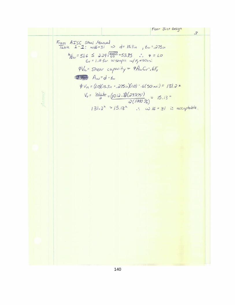
140

141
Beam System Calculation Example Sheet: (Entire Workbook can be found in Appendix F)
Exterior Beam Calculation Example Sheet: (Entire Workbook can be found in Appendix F)
LL [PSF]Tributary Width [ftpan Length (L) [ft]
Con 54 60 5.083 29.875 1
Deck 3Strength
(Fy)(Vy) [ksi]Youngs Modulus
(Es)[Steel] PSISelf Weight
[lb/ft]Moment of Inertia
(I) [in^4] ZxArea (As) bf/2tf h/tw d (in) tw
MEP 10 50 29000000 53 425 77.9 15.6 8.69 28.1 12.1 0.345
TOTAL 67
960.2412 lb/ft107.13 ft-k
28.57 in^31.00 in 1" max
0.794 in
14344125235
Mu=(Wu * L^2)/8000Wu=1.2DL +1.6LL
DL (PSF) Beam Properties
Other
W 12 x 53
Shear Chk Vu=Wu *L/2hear Capacity (Phi)Vn = (Phi)*Aw* Cv*.6
Zx > Mu/.9FyMaxDef=L/360
Act Def=(5Wu*L4)/(384*E*I)
LL [PSF] Trib. Ht. (ft)Trib Width [ft]pan Length (L) [ft]Brick Veneer 48 Con 54 100 5 14.9375 15.333 1
Glass 0.00 Deck 3
Strength (Fy)(Vy)
[ksi]Youngs Modulus
(Es)[Steel] PSISelf Weight
[lb/ft]Moment of Inertia
(I) [in^4] ZxArea (As) bf/2tf h/tw d (in) tw
MEP 10 # Beams. 2 50 29000000 35 510 66.5 10 7.06 53.5 17.7 0.3Bm Wt. 13.77 Size 18 x 35
TOTAL 48 TOTAL 80.77 Trib width 5' 1"
4167.8023 lb/ft122.48 ft-k
32.66 in^30.51 in 1" max
0.187 in
31952159300
Floor DL (PSF)Wall DL (PSF)W 18 x 35
Beam Properties
Mu=(Wu * L^2)/8000Wu=1.2DL +1.6LL
MaxDef=L/360Act Def=(5Wu*L4)/(384*E*I)
Shear Capacity (Phi)Vn = (Phi)*Aw* Cv*.6Fy
Zx > Mu/.9Fy
Shear Chk Vu=Wu *L/2

142
Girder Calculation Example Sheet: (Entire Workbook can be found in Appendix F)
Column Calculation Example Sheet: (Entire Workbook can be found in Appendix F)
LL [PSF]Trib Width Left [ft Width Righpan Length (L) [ft]Con 54 Con 54 100 7.6875 7.25 19.4167 1
Deck 3 Deck 3
Strength (Fy)(Vy)
[ksi]Youngs Modulus
(Es)[Steel] PSI Self Weight [lb/ft]
Moment of Inertia (I)
[in^4] Zx [in^3]Area (As) bf/2tf h/tw d (in) tw
MEP 10 MEP 10 50 29000000 31 375 54 9.13 6.28 51.6 15.9 0.28BM WT. 1.649 BM WT. 1.6TOTAL 68.65 TOTAL 69
3657.733325 lb/ft172.37 ft-k
45.97 in^30.65 in 1" max
0.530 in
35511131175
Shear Chk Vu=Wu *L/2
MaxDef=L/360Act Def=(5Wu*L4)/(384*E*I)
Wu=1.2DL +1.6LL
DL (PSF) left
Shear Capacity (Phi)Vn = (Phi)*Aw* Cv*.6Fy
Mu=(Wu * L^2)/8000Zx > Mu/.9Fy
DL (PSF) rightW 16 x 31
Beam Properties
Column Length(L) [ft] π Ky KxWest East Southeast South West East Southeast South 15 3.142 1 1.2
1st 0 1694.1 0 2787.5 0 7.7 12.45 9.75 180
2nd 0 3822.8 0 2669.3
3rd 0 3822.8 0 2669.34th 0 3108.9 0 2229.9
Roof 0 1349.2 1648 1062.8
238.1 k ==> Select W14x483197.87 k W12x40
42.1 ksi W10x39
120.94 ksi W8x35
1003.0 k
Trib. Width [ft]LoadingColumn Strength Analysis
Pc = φPn = φ*Fcr*Ag
Fe = π2*E/(KL/r)2
Fcr = (0.658^Fy/Fe)Fy
Pu
Pcr = π2*E*I/L2

143
Beam-Girder Connection

144

145

146
Beam-to-Girder Example Excel Sheet: (Entire Workbook can be found in Appendix F)
Vu = Wu*L/2 35.5 [kips]
φVn = φv.6*Fy*Aw*Cv 236.07 [kips]
φRn = φb*Fv*Ab 17.89 [k/bolt]
1.982.00
used n 2.00Wu 2304 [lb/ft]
L 30.83 [ft] LA = 2*Le"+(n-1)*3" 6 [in]
φv 1.0 Necessary YES
Fy 50 [ksi] Cope min 2
Fu 65 [ksi]
Aw 7.87 [in 2 ]
Cv 1.0 Lc = 1.5"-0.5(db+1/8") 1.0625 [in]
T 9.125 [in]
tw 0.61 [in] t ≥ 0.266 [in]
d 12.9 [in]
Cope 2 [in] t ≥ 0.320 [in]
φv 1.0 t ≥ 0.365 [in]
Fy 50 [ksi]
Fu 65 [ksi]
Aw 7.87 [in 2 ]
Cv 1.0 Net Shear Area Anv = 1.94 [in 2 ]
T 9.125 [in] 0.6 Fu Anv 75.83 [kips]
tw 0.61 [in] Net Tension Area Ant= 0.65 [in 2 ]
tf 0.99 [in] UbsFuAnt 42.13 [kips]
d 12.9 [in] Gross Shear Area Agv= 2.75 [in 2 ]
0.6 Fy Agv 82.35 [kips]
Fv 54 [ksi] Rn = 117.96 ≤ 124.48
Ab = π/4 * db2 0.4418 [in 2 ] φRn = 88.47 [kips]
φb 0.75
Ubs 1.0 17.89 [k/bolt]35.78 [kips]
Fy 36 [ksi]
Fu 58 [ksi] Lc = Lev-0.5(db+1/8") 1.0625 [in]t 0.375 [in] Rn = 37.92 ≤ 53.5275
φRn = 91.44 [kips]L to angle edge 1.5 [in] tw ≥ t of bolt bearing
Lev (beam) 1.5 [in] t = 0.266 [in]
Leh 1.5 [in] tw = 0.610 [in]
Use angle 3.5" x 3.5" x t (gage dist. = 2")
Cope:
Compact Section
All of the members used were passed compact section criteria:
#bolts n = Vu/φRnh/tw≤ 2.24√(E/Fy)
W 12x106 Beam
Block Shear Rupture:
Determine Angle Thickness (t)
Bolt Bearing on Angle:
φRn = 1.2*φb*Lc*t*Fu≤ 2.4*φb*db*t*Fu
1.2*φb*Lc*t*Fu + (n-1)2.4*φb*db*t*Fu ≥ VU
Angle Shear Rupture:
φRn = 0.6φbFu(LA-n(db+1/8"))t≥ Vu
Bolt Bearing on Beam Web:
φRn = 1.2*φb*Lc*tw*Fu≤ 2.4*φb*db*tw*Fu
Check Girder web for Bearing:
W 12x106 Girder
Rn = 0.6FuAnv+UbsFuAnt ≤ 0.6FyAgv+UbsFuAnt
Angle Properties
Tension Rupture:
Shear Yield:
Connection Geometry:
Bolt Shear Check:
φRn = φb*Fv*Ab
Angle Shear Yield:
φRn = 0.6φbFyLAt≥ Vu
A325-N 3/4" Dia. Bolts
Use angle 3.5" x 3.5" x 3/8" (gage dist. = 2")
Beam Checks

147
Girder-Column Calculation:

148

149

150
Girder-Column Connection Example Excel Sheet: (Entire Workbook can be found in Appendix F)
Vu = Wu*L/2 129.8 [kips]
φVn = φv.6*Fy*Aw*Cv 463.32 [kips]
φRn = 2 φb*Fv*Ab 35.78 [k/bolt]
3.634.00
used n 5.00Wu 8214.1 [lb/ft]
L 31.6 [ft] LA = 2*1.5"+(n-1)*3" 15 [in]
φv 1.0
Fy 50 [ksi]
Fu 65 [ksi] Lc = 1.5"-0.5(db+1/8") 1.0625 [in]
Aw 15.44 [in 2 ]
Cv 1.0 t ≥ 0.176 [in]
T 26.5 [in]
tw 0.52 [in] t ≥ 0.234 [in]
d 29.7 [in]
Cope 0 [in] t ≥ 0.267 [in]
Fv 54 [ksi]
Ab = π/4 * db2 0.4418 [in 2 ] Rn = 0.6FuAnv+UbsFuAnt ≤ 0.6FyAgv+UbsFuAnt
φb 0.75 Net Shear Area Anv = 5.49 [in 2 ]
Ubs 1.0 0.6 Fu Anv 214.21 [kips]
Net Tension Area Ant= 0.55 [in 2 ]
Fy 36 [ksi] UbsFuAnt 35.91 [kips]
Fu 58 [ksi] Gross Shear Area Agv= 7.54 [in 2 ]
t 0.31 [in] 0.6 Fy Agv 226.20 [kips]
Rn = 250.12 ≤ 262.11
L to angle edge 1.5 [in] φRn = 187.59 [kips]Lev 2.5 [in]
Leh 1.5 [in] 35.78 [k/bolt]
178.92 [kips]
Lc = Lev-0.5(db+1/8") 2.0625 [in]
Rn = 62.74125 ≤ 45.63
φRn = 228.15 [kips]
tf ≥ t of bolt bearingt = 0.176 [in]tf = 0.710 [in]
tw = 0.440 [in]
Check Column Flange for Bearing:
Determine Angle Thickness (t)
Bolt Shear Check: φRn = 2 φb*Fv*Ab
Girder & Column Checks
φRn = 1.2*φb*Lc*tw*Fu≤ 2.4*φb*db*tw*FuBolt Bearing on Girder Web:
Use angle 3.5" x 3.5" x 5/16" (gage dist. = 2")
φRn = 1.2*φb*Lc*t*Fu≤ 2.4*φb*db*t*Fu
1.2*φb*Lc*t*Fu + (n-1)2.4*φb*db*t*Fu ≥ 0.5 VU
φRn = 0.6φbFu(LA-n(db+1/8"))t≥ 0.5 Vu
φRn = 0.6φbFyLAt≥ 0.5 Vu
Connection Geometry:
Compact Section
All of the members used were passed compact section criteria:
#bolts n = Vu/φRnh/tw≤ 2.24√(E/Fy)
W 30x99 GirderUse angle 3.5" x 3.5" x t (gage dist. = 2")
Angle Properties
Block Shear Rupture:
Tension Rupture:Shear Yield:
Bolt Bearing on Angle:
Angle Shear Rupture:
A325-N 3/4" Dia. Bolts
Angle Shear Yield:

151
Base Plate and Footing Calculation

152

153
Base Plate & Column Footing Example Excel Sheet: (Entire Workbook can be found in Appendix F)
4 Af = P/S 32.22 [ft 2 ]36 5.68
6.00bf [in] 14.5 6 [ft]d [in] 14
233.87.255 [in 2 ]
327.3 A 1 min = d*b f 203.00 [in 2 ]
[in]15.10
0.65 16 [in]12.69
16 [in]
A 1 256 [in 2 ]
[kips] >Pu
[in]
[in]
[in]
1 [in]
BASE PLATE16 in x 16 in x 1 inCOLUMN FOOTING6 ft x 6 ft
74.05
P (column load) [kips]S (allowable soil pressure)[ksf]
f'c [ksi]fy [ksi] Dimensions of FootingColumn Properties: W14x90
Pu (factored P) [kips]
2.00.85
φc
3.56
1.00
1131.52
1.35
2.2
𝐴𝐴2𝐴𝐴1
𝐴𝐴1 =𝑃𝑃𝑢𝑢
0.85𝜙𝜙𝑐𝑓𝑐′𝐴𝐴2𝐴𝐴1
Δ =0.95𝑑 − 0.8𝑏𝑓
2
𝑁 = 𝐴𝐴1 + Δ
𝐵 =𝐴𝐴1𝑁
𝜙𝜙𝑐𝑃𝑃𝑝 = 0.85𝜙𝜙𝑐𝑓𝑐′𝐴𝐴1𝐴𝐴2𝐴𝐴1
𝑚 =𝑁− 0.95𝑑
2
𝑛 =𝐵 − 0.8𝑏𝑓
2
𝑛′ =𝑑𝑏𝑓4 = 𝑙
𝑡 = 𝑙2𝑃𝑃𝑢𝑢
0.9𝐹𝐹𝑦𝑦𝐵𝑁

154
Appendix E: Reinforced Concrete Alternative Preliminary Design
Floor Slab Calculation Sheet:
4 4000 Wu=1.2 DL +1.6 LL 364 [lb/ft] for 12" strip60 60000
10.80 Midspan 8.42 [ft-kip]
Exterior 4.91 [ft-kip]
18 Interior 13.10 [ft-kip]-MEP 10-Flooring 10-Self 135.0-Partitions 15.0Total 170
10014
16.8312.00 Assume #5 bars d bars 0.62513.0012.00 Check d=h-cover-d bars /2 9.74
Assume a= 1/2 0.5 [in]
0.85 a= Asf y /.85f'cb 0.290 [in] a= Asf y /.85f'cb 0.451 [in]0.0030.005
0.9 a= Asf y /.85f'cb 0.287 [in] a= Asf y /.85f'cb 0.450 [in]0.75
0.0018a= Asf y /.85f'cb 0.287 [in] a= Asf y /.85f'cb 0.450 [in]
As min = ρmin bh 0.233 [in 2 ]
V u = 1.15w u l/2-w u d 3.472 [kips]11.085 [kips]
ρmin
0.115 [in 2 ]
0.306 [in 2 ]εt
φφ (shear)
0.195 [in 2 ] 0.306
εu
0.195 [in 2 ]
[in 2 ]
[in 2 ] 0.307 [in 2 ]β1
0.197
l n [ft]b [in]h [in]d [in]
0.0181
3.999 [in]LL [psf]column dim c [in]
f'c [ksi]fy [ksi]
l [ft]
DL [psf]
ℎ𝑚𝑖𝑛𝑛 = 𝑙
20𝑀𝑀𝑢𝑢 =
𝑤𝑤𝑢𝑢𝑙𝑛𝑛2
14
𝑀𝑀𝑢𝑢 =𝑤𝑤𝑢𝑢𝑙𝑛𝑛2
9
𝑀𝑀𝑢𝑢 =𝑤𝑤𝑢𝑢𝑙𝑛𝑛2
24
𝜌 = .85 𝛽1𝑓′𝑐𝑐𝑓𝑦𝑦
𝜀𝑢𝑢
𝜀𝑢𝑢 + 𝜀𝑡
𝑑 = 𝑀𝑀𝑚𝑎𝑥
𝜑𝜌𝑓𝑦𝑦𝑏(1− .59𝜌𝑓𝑦𝑦𝑓𝑐′
)
𝐴𝐴𝑠𝑚𝑖𝑑 = 𝑀𝑀𝑢𝑢
𝜑𝑓𝑦𝑦(𝑑 − 𝑎2)
𝐴𝐴𝑠𝑚𝑖𝑑 = 𝑀𝑀𝑢𝑢
𝜑𝑓𝑦𝑦(𝑑 − 𝑎2)
𝐴𝐴𝑠𝑚𝑖𝑑 = 𝑀𝑀𝑢𝑢
𝜑𝑓𝑦𝑦(𝑑 − 𝑎2)
𝐴𝐴𝑠𝑒𝑥𝑡 = 𝑀𝑀𝑢𝑢
𝜑𝑓𝑦𝑦(𝑑 − 𝑎2)
𝜑𝑉𝑉𝑐 = 𝜑2 𝑓𝑐′𝑏𝑑
𝐴𝐴𝑠𝑖𝑛𝑛𝑡 = 𝑀𝑀𝑢𝑢
𝜑𝑓𝑦𝑦(𝑑 − 𝑎2)
𝐴𝐴𝑠𝑖𝑛𝑛𝑡 = 𝑀𝑀𝑢𝑢
𝜑𝑓𝑦𝑦(𝑑 − 𝑎2)
𝐴𝐴𝑠𝑖𝑛𝑛𝑡 = 𝑀𝑀𝑢𝑢
𝜑𝑓𝑦𝑦(𝑑 − 𝑎2)

155
Beam Calculation Sheet:
During the preliminary design, a concrete alternative for the bottom two floors was considered instead of steel. Calculations were done to determine the adequacy of the alternative. The necessary depth of a one way slab was calculated to be between 9”-11” in various parts of the building with necessary supports of 8”x15” beams. The slab thickness was greater than expected due to the extensive spans and open rectangular bays in the building. With this information, construction cost and duration were calculated. Overall, the concrete alternative was determined to be more expensive and time consuming and, since the bays were too large, did not prove to be an efficient alternative. Therefore, we chose steel for the structure of the bottom two floors.
f'c [ksi] 4 4000 Wu=1.2 DL +1.6 LL 1497.5 [lb/ft]fy [ksi] 60 60000 74875 [lb-ft]DL [psf] 170 898.5 [k-in]LL [psf] 100l [ft] 20Trib Width [ft] 3.125Self Wt. [lb/ft] 300initial b [in] 12 bd2 ≥ 1096.46initial h [in] 24 0 = d3 +2.5d2 - 2(bd2)β1 0.85 d 12.5 [in]εu 0.003 b 7.02 [in]
εt 0.005 8 [in]φ 0.9 h = d + 2.5 15 [in]φ (shear) 0.75 Self Wt. 125 [lb/ft]
Wu=1.2 DL +1.6 LL 1287.5 [lb/ft]64375 [lb-ft]
772.5 [k-in]0.100070.01292
As = ρbd 1.29223 [in2]
3 #6 bars with 1.5" cover and #3 tiesAs=1.32[in2]
0.0181
ρ

156
3D view of Reinforced Concrete Alternative
1st Floor Structural Layout of Reinforced Concrete Alternative

157
Mezzanine 2nd Floor Structural Layout for Reinforced Concrete Alternative

158
Appendix F: Primavera Activity List

159

160

161

162

163
Appendix G: List of E-Files • Proposed Foisie Cost Estimate ……………………..…Proposed Foisie Cost Estimate.xlsx • Proposed Foisie 5D Model ……………………………..……Proposed Foisie 5D Model.nwf
............................................................................................Proposed Foisie 5D Model.nwd ……………………………………………………………...………..Proposed Architectural.nwc …………………………………………………………………………..Proposed Structural.nwc
• Proposed Foisie Schedule …………………………...……….Proposed Foisie Schedule.xer • Proposed Foisie Construction Simulation ……………………………...……………………….
……………………………………..…… https://www.youtube.com/watch?v=dGwUXYA23gs • Proposed Foisie Walkthrough ……......https://www.youtube.com/watch?v=GLzmuD22c8Y • Proposed Foisie Structural Model ……………………Proposed Foisie Structural Model.rvt • Proposed Foisie Architectural Model ……………..Proposed Foisie Architectural Model.rvt • Proposed Foisie Structural Analysis Models……………………………………………………
…………………………………………………………….……Proposed Foisie East Frame.rtd ……………………………………………………..………....Proposed Foisie South Frame.rtd
• Proposed Foisie Design Workbooks…………………………………………………………….. ………………………………………..Proposed Foisie Beam System Design Workbook.xlsx ……………………………………………….. Proposed Foisie Girder Design Workbook.xlsx …………………………………….Proposed Foisie Exterior Member Design Workbook.xlsx …………………………………………Proposed Foisie Stair Bearing Design Workbook.xlsx ………………………………………..Proposed Foisie Roof Member Design Workbook.xlsx ……………………………………………….Proposed Foisie Column Design Workbook.xlsx ……………………………….Proposed Foisie Base Plate & Footing Design Workbook.xlsx …………………………………………..Proposed Foisie Connection Design Workbook.xlsx …………………………………………………………..Proposed Foisie Truss Workbook.xlsx