proposal for the extrusion of a glow-in-the-dark plasticgeoff/writing/sample_proposal.pdf ·...
TRANSCRIPT
PROPOSAL FOR THE EXTRUSION OF A GLOW-IN-THE-DARK PLASTIC
by Group B
Weston Eldredge Ryan Martin Daniel Reese
Lauren Whatley
Chemical and Fuels Engineering 4905 Professor E.G. Eddings
Assigned: January 8, 2003 Due: February 12, 2003
Submitted: February 12, 2003
Weston Eldredge Ryan Martin Daniel Reese Lauren Whatley

ii
TABLE OF CONTENTS
ABSTRACT……...……………………...…………………………………………………………iv
I. TECHNICAL BACKGROUND
A. IDENTIFICATION OF THE PROBLEM………………………………...….………...1
B. JUSTIFICATION OF PROPOSED WORK
i. THEORY ………………………………...………………………...……….1
ii. THEORETICAL MODELING……………..…………………...……....….3
iii. IDENTIFICATION OF CRITICAL NEEDS ………………..……….……5
II. TECHNICAL APPROACH
A. OBJECTIVES …………………………………..…………………….………………..7
B. STATEMENT OF WORK
i. PROJECT TASKS.……….………..………………………………….……8
ii. PROJECT SCHEDULE ......……..…………………………………………8
iii. ESTIMATED COSTS ………..………………………………………….…9
III. CAPABILITIES
A. PROJECT TEAM AND KEY PERSONNEL …………..…………………………….11
B. EQUIPMENT AND FACILITIES………………………..…………………………...13
IV. ANTICIPATED BENEFITS OF PROPOSED WORK …...……...…………………………..17
V. ANTICIPATED ENVIRONMENTAL IMPACT OF PROPOSED WORK ...…...…………...18
NOMENCLATURE ……………………………………………………………………………....19
REFERENCES ……………………………………………………………………..………....…..20
APPENDICES
A. CALIBRATION ….……………………………………...…………...………………..……...21
B. EXPERIMENTAL DATA…. …………………....……………………….………..………....22
C. POLYETHYLENE PROPERTIES …………………………………………………………...23
D. PROGLOW PROPERTIES…………………………………………………………………....24
E. MSDS INFORMATION ……………………………………………………………………...28

iii
LIST OF FIGURES No. Title Page
1. Project budget calculation 10
2. Flow chart for team organization 12
3. Photograph of the extruder 13
4. Schematic of extruder apparatus 14
5. Photograph of the take-up rollers 15
6. Schema tic of the take-up rollers 15
7. Photograph of the three polyethylene diameters 16
8. Photograph of the polyethylene string with ProGlow 17
A-1 Plot of roller speed vs. rpm 21
LIST OF TABLES No. Title Page
1. Draw ratio correlations 4
2. Work schedule 9
A-1 Data for the plot of roller speed vs. rpm 21
B-1. Diameter data from the experiment 22
C-1. Physical properties of PE 23
C-2. Physical properties of PE (cont.) 23

iv
ABSTRACT
In this proposal, the members of Group B (Weston Eldredge, Ryan Martin, Daniel Reese, and
Lauren Whatley) experimented with the extruder located in the Chemical Engineering Projects
Laboratory to produce a round, thin string (diameters less than one-tenth of an inch) of high-
density polyethylene. Various flow rates and draw ratios were explored to find a desirable
product. Favorable qualities included a consistent diameter, smooth surface, and even appearance.
The operating temperature was 150°C.
After determining sufficient operating parameters, we selected an appropriate glow additive. The
ProGlow company produces a ready-made glow product (MasterBatch) that is compatible with
our polyethylene in the laboratory. The ProGlow is simply added to the polyethylene in the
following ratio: three parts polyethylene to one part ProGlow for the maximum luminosity. We
received a small sample of the ProGlow MasterBatch. It was mixed with the polyethylene and ran
through the extruder at 150°C, and we successfully produced glow-in-the-dark string. We are
requesting $43 to purchase one-half kilogram of the MasterBatch—which is available from
ProGlow and can be shipped in a few days. We will develop three stocks of the glowing string
(three different diameters). We plan to mix the ProGlow with the polyethylene at various ratios to
find the optimal ratio for the lowest amount of glow additive without compromising the glow
intensity. We will quantifiably measure the luminescence of the glow products with the use of a
light meter (with permission from the Industrial Assessment Center), and thus establish a
correlation between luminosity and ratio of ProGlow in the feed stock.
In this proposal, we describe the many applications for glow-in-the-dark products. We will also
discuss the benefits of the work, cost, environmental impact, and a detailed schedule of the tasks
necessary to accomplish the project.

1
1. TECHNICAL BACKGROUND
1.1 Identification of the Problem
A single-screw-polymer extruder is located in room 3520 of the Merrill Engineering Building at
the University of Utah. Currently, the extrusion apparatus is employed to perform several
experiments involving the extrusion of high-density polyethylene (HDPE) through a rectangular-
shaped die. Recently, the extruder apparatus was equipped with a cylindrical die, including a
newly machined sleeve insert with a 0.125-inch diameter opening. At present the Chemical
Engineering Department’s catalog of experiments for the extruder apparatus does not include an
experiment that is specifically based on the use of the cylindrical die. Furthermore, there does
not appear to be an experiment that involves the investigation of mixing polymer pellets with
other materials to produce an extrudate with unique properties.
The results of the work outlined in this proposal will likely provide a basis for the development
of several new experiments involving the use of the extruder apparatus and the newly equipped
cylindrical die. Future participants in the Chemical Engineering Projects Laboratory course will
benefit from an augmented inventory of interesting experiments involving the extruder.
Additionally, the unique products that result from the proposed work will be of value to the
Beehive State Engineers. Not only will these products have the potential to be produced and
sold for profit, but also the process for their production would make up an intriguing
demonstration during the High School Engineering Days and other such exhibitions of the
University of Utah Chemical Engineering Department. Moreover, the resulting products would
provide a one-of-a-kind souvenir gift for the viewers of the demonstration.
1.2 Justification of Proposed Work
1.2.1 Theory
Extrusion is the process of molding a plastic or other malleable substance into a specific shape
using pressure. Historically, metals, especially aluminum, have been extruded by the use of ram-

2
driven machines. Today, the most common way to apply pressure to the plastic material is with
a screw. An Archimedean screw is commonly used and is found in the apparatus for this project.
The screw consists of a shaft and a thread, whose diameter is constant from the feed point to the
die. The constant diameter of the screw portion allows a tight fit in the barrel of the extruder
apparatus as well as a consistent flow of polymer material through the machine. The shaft
portion of the screw increases in diameter as the polymer approaches the die. The greater the
diameter of the shaft, the lower the depth of the channel and the greater the pressure exerted on
the polymer. This pressure is what drives the polymer through the extruder. Almost every
material that is extruded must be heated until it can be deformed under the pressure of the
extruder.
The extrusion process has four phases. The purpose of the first phase, or feed phase, is to
preheat the polymer and deliver it to the next phase. During the feed phase the diameter of the
shaft portion of the screw is kept constant to allow a consistent delivery of the material. The
second phase is the compression phase where the shaft of the screw increases in diameter, and
pressure is applied to the polymer. The pressure eliminates any air bubbles in the polymer. Also,
because the channel decreases in depth, the heat transfer to the thinner polymer increases. An
interesting feature of the compression phase is that the zone for compression will vary depending
on the polymer used. For polymers that melt quickly, the compression zone is relatively small
(nylon is an example). For polymers that are very difficult to compress, the compression zone
almost occupies the whole screw (PVC plastic is a good example of this type of polymer). High-
density polyethylene, the polymer used for this project, is moderate in its resistance to
deformation in the extruder. The compression zone on a polyethylene screw is about the same
length as the other zones.
The next phase is the metering phase. Here, the diameter of the shaft remains constant to supply
the melted polymer to the die at a constant temperature and pressure. The last phase in the
extrusion process is the die phase. The die contains a perforated steel plate called a breaker
plate, and a sieve pack of several layers of wire gauze. These components serve to filter out any
foreign material (dirt, unmelted polymer pellets, etc.). They also create a pressure head by
providing resistance to the pumping action of the metering zone. Lastly, they remove any
3
“turning memory” from the melted polymer, so that the final product can be shaped to any
desired form.
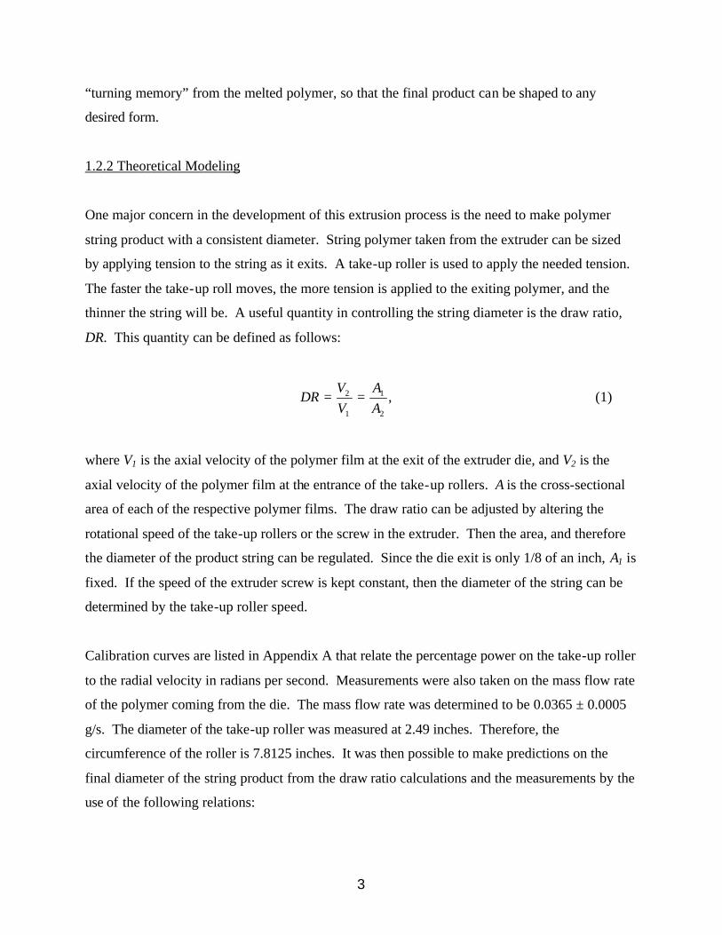
1.2.2 Theoretical Modeling
One major concern in the development of this extrusion process is the need to make polymer
string product with a consistent diameter. String polymer taken from the extruder can be sized
by applying tension to the string as it exits. A take-up roller is used to apply the needed tension.
The faster the take-up roll moves, the more tension is applied to the exiting polymer, and the
thinner the string will be. A useful quantity in controlling the string diameter is the draw ratio,
DR. This quantity can be defined as follows:
,2
1
1
2
AA
VV
DR == (1)
where V1 is the axial velocity of the polymer film at the exit of the extruder die, and V2 is the
axial velocity of the polymer film at the entrance of the take-up rollers. A is the cross-sectional
area of each of the respective polymer films. The draw ratio can be adjusted by altering the
rotational speed of the take-up rollers or the screw in the extruder. Then the area, and therefore
the diameter of the product string can be regulated. Since the die exit is only 1/8 of an inch, A1 is
fixed. If the speed of the extruder screw is kept constant, then the diameter of the string can be
determined by the take-up roller speed.
Calibration curves are listed in Appendix A that relate the percentage power on the take-up roller
to the radial velocity in radians per second. Measurements were also taken on the mass flow rate
of the polymer coming from the die. The mass flow rate was determined to be 0.0365 ± 0.0005
g/s. The diameter of the take-up roller was measured at 2.49 inches. Therefore, the
circumference of the roller is 7.8125 inches. It was then possible to make predictions on the
final diameter of the string product from the draw ratio calculations and the measurements by the
use of the following relations:

4
22
1 .0123.04
)125(.in
inA == π (2)
( )( ) min/46.11/385.4691.7/950
/0000365.023
1
.
1 insmememkg
skgAmV =−=
−==
ρ. (3)
πωRDV =2 . (4)
2
112 V
VAA = . (5)
π2
1
4AD = . (6)
In these relations DR is the diameter of the roller, ω is the radial velocity of the roller in radians
per second, and D1 is the diameter of the string product. Table 1 below shows the speed of the
roller with the predicted and measured diameters for the string product.
Table 1 . This table compares the actual measured diameters of string product from the extruder to the predicted values given by the model. The model is based on draw ratios.
The model shows a very large degree of error. This is likely due to measurement error (mass
flow rates, lengths, radial velocities, etc.) This shouldn’t affect the product quality since a
consistent diameter has already been produced from determined settings obtained through trial-
and-error.
Roller Speed 15% 100% Predicted Diameter 0.0079 0.0222 Measured Diameter 0.1105 0.0286 Error 0.928507 0.223776

5
Another technical issue affecting the quality of the string is the cool-down time for the string
when it leaves the extruder. If the string does not cool down past its deformation temperature
(assumed to be at 60°C) before it enters the take-up roller, the shape of the string could deform,
thus effecting the quality of the product. The heat-transfer coefficient for a cylinder in stagnant
fluid conditions was calculated by the use of methods summarized by Dewitt and Incropera
(2001). The calculation assumed free convection, and it calculated the time it would take for
string leaving the extruder to cool from 150°C to 60°C. Lumped capacitance assumption was
employed to simplify the calculation once the properties of polyethylene and the heat-transfer
coefficient were known. The estimated cool-down time for the string (1/8-inch diameter) was
2.2 minutes. Since the string will be stretched to a thinner diameter, the actual cool-down time
will be less. For example, at 1/16-inch diameter the cool-down time is predicted to be no more
than 47 seconds. The problem comes if the roller pulls the string so quickly that the string has
not cooled below deformation temperature (estimated at around 60 degrees) when it enters the
roller apparatus. In cases of higher roller speeds this is a potential problem. To address the
problem, a fan is placed next to the die where it delivers a small current of air to raise the heat-
transfer coefficient and thus allow the string to cool before it enters the roller. The fan is not
used for larger diameter strings since they cool before they enter the roller (because the roller
isn’t moving as fast). Also, the fan tends to warp the shape of the string at lower roller speeds.
1.2.3 Critical Needs
The last technical issue to be addressed for this project is the mixing of glow additive with the
regular polyethylene feed stock. The manufacturer of the glow material recommends a mixture
of one part glow material to three parts (by volume) polymer for optimal glow effect. So far
only a one-to-four ratio has been applied. Pictures of a sample of product with glow material at a
one-to-four ratio are included in Figure 8 in section 5.2. If an acceptable level of glow can be
obtained from a larger ratio of glow material to polymer, then it will be economically viable to
go with the higher ratio. The only difficulty will be to ensure that the glow material and the
polymer are well-mixed. Without good mixing of the two components, the product will not have
a uniform, attractive glow. A previous test run of the apparatus has shown that the extruder
tends to distribute the two components well when they travel through the screw. Additionally,

6
the material will already be well-mixed when it enters the hopper. Several ratios of the mixtures
will be used and compared in the duration of this project.

7
2. TECHNICAL APPROACH
2.1 Objectives
Several major objectives are contained within this project. They include the following:
a. We will determine a set of operating conditions that will produce a favorable product
using the cylindrical die and a mixture of the ProGlow additive with the existing high-
density polyethylene (HDPE) pellets. For the purposes of this project, a favorable
product will be defined as having a smooth surface, constant diameter, and consistently
round polymer string.
b. We will use the polymer and glow additive mixture to extrude three different rolls of
feed stock material, each a different diameter between 0.02 to 0.10 inches. In so doing,
the concept of draw down is to be employed.
c. We anticipate experimenting with different mixture ratios of the ProGlow additive and
polyethylene pellets in an effort to find optimal ratios for maximum luminosity while at
the same time economically using the ProGlow additive. As part of this objective,
each of the three rolls of polymer string from Objective 2 will be composed of a
different mixture ratio of glow additive and will be labeled with its corresponding
luminescent light output, in lumens, as measured by a standard light-sensing meter.
d. We will develop a prototype of at least one potentially marketable product from each of
the three rolls of polymer string that will be produced.
The fulfillment of these objectives will potentially lead to the development of several new Senior
Projects Laboratory experiments, involving the use of the extruder apparatus and the newly
equipped die. Additionally, the product prototypes that will be developed could eventually be
carried to production and distribution.

8
2.2 Statement of Work
2.2.1 Project Tasks
Group B has established four primary tasks required to create glow-in-the-dark products. In the
work completed thus far in the project, we have determined appropriate screw speed and draw
ratio parameters for the maximum diameter (1/10 inch) from the circular die on the extruder. In
Task 1, we will establish appropriate parameters for two other diameters—one with a very small
diameter and the other in between the two. Task 2 includes finding mix ratios between the
polyethylene and the ProGlow MasterBatch glow material that provide optimal glow
luminescence while minimizing the amount of MasterBatch used. For example, we will ascertain
whether there is a significant difference in mixing three parts polyethylene to one part
MasterBatch versus five parts polyethylene to one part MasterBatch. In so doing, we can find the
most economic product without compromising glow properties. In Task 3, we will quantify the
results from Task 2 by directly measuring the luminescence of the different MasterBatch to
polyethylene mix ratios. We anticipate using the Industrial Assessment Center’s (IAC) light
meter. To reduce variability and error, all samples will be kept in a dark box or equivalent and
then placed under a light for a uniform amount of time before the luminosity is measured in a dark
room. Finally, Task 4 involves putting together prototypes of the various glow-in-the-dark
products that we suggest be made.
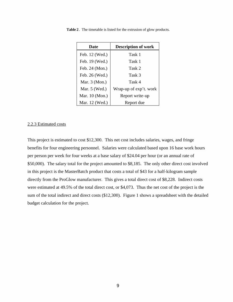
2.2.2 Project Schedule
A timetable for the project to extrude glow-in-the-dark products is given in Table XX. It includes
all tasks mentioned in the previous sections, time to wrap up any last minute laboratory work, and
the time required to prepare a detailed report on the project—including findings, conclusions and
recommendations. The schedule also provides a contingency for unanticipated delays related to
equipment or product problems as well as unforeseen employee illness.
9
Table 2 . The timetable is listed for the extrusion of glow products.
Date Description of work
Feb. 12 (Wed.) Task 1 Feb. 19 (Wed.) Task 1 Feb. 24 (Mon.) Task 2 Feb. 26 (Wed.) Task 3 Mar. 3 (Mon.) Task 4 Mar. 5 (Wed.) Wrap-up of exp’t. work Mar. 10 (Mon.) Report write-up Mar. 12 (Wed.) Report due
2.2.3 Estimated costs
This project is estimated to cost $12,300. This net cost includes salaries, wages, and fringe
benefits for four engineering personnel. Salaries were calculated based upon 16 base work hours
per person per week for four weeks at a base salary of $24.04 per hour (or an annual rate of
$50,000). The salary total for the project amounted to $8,185. The only other direct cost involved
in this project is the MasterBatch product that costs a total of $43 for a half-kilogram sample
directly from the ProGlow manufacturer. This gives a total direct cost of $8,228. Indirect costs
were estimated at 49.5% of the total direct cost, or $4,073. Thus the net cost of the project is the
sum of the total indirect and direct costs ($12,300). Figure 1 shows a spreadsheet with the detailed
budget calculation for the project.

10
Budget Calculation for "Extruder-Group B"Lab hours per week
Labor Weekly Dollar 8A. Senior Personnel (l ist names below) Weeks Rate* Amount Work hours outside of class1 Weston Eldredge 1.6 961.54$ 1,538.46$ 82 Ryan Martin 1.6 961.54$ 1,538.46$ Total hours per week3 Daniel Reese 1.6 961.54$ 1,538.46$ 164 Lauren Whatley 1.6 961.54$ 1,538.46$ Number of weeks in project5 -$ 46 -$ to ta l labor weeks
A. Subtotal 6,154$ 1.6* calculated on Labor_Rate_Calc sheet (see tabs at bottom of this sheet)
Labor Weekly Dollar B Other Personnel Weeks Rate* Amount
Engineering Staff 865.38$ -$ Other Professionals (Technician, Programmer, etc.) 680.00$ -$ Secretarial/clerical 440.00$ -$ Other -$
B. Total Salaries (A+ B) 6,154$
C. Fringe Benefits CalculationPercentage 33% 2,031$
C. Total Salaries Wages and Fringe Benefits 8,185$
D. Equipment ( i temize and dol lar amount for each) Item CostMulti-species gas analyzer
D. Equipment Subtotal -$
E. Travel SubtotalDomest icForeign
E. Total Travel -$
F. Trainee/Participants Costs N/A
G. Other Direct Costs SubtotalsMaterials and Supplies 43$ Publ icat ion CostsConsultant ServicesComputer ServicesSubcontractsOther
G. Total Other Direct Costs 43$
H. Total Direct Costs 8,228$
I. Indirect Costs Percentage 49.5%
I . Indirect Costs 4,073$
J. Total Direct and Indirect Costs 12,300$ This represents total actual cost of the project
K. Cost Sharing -$
L. Net Cost of Project 12,300$
Figure 1. A spreadsheet is shown for the proposed budget.

11
3. CAPABILITIES
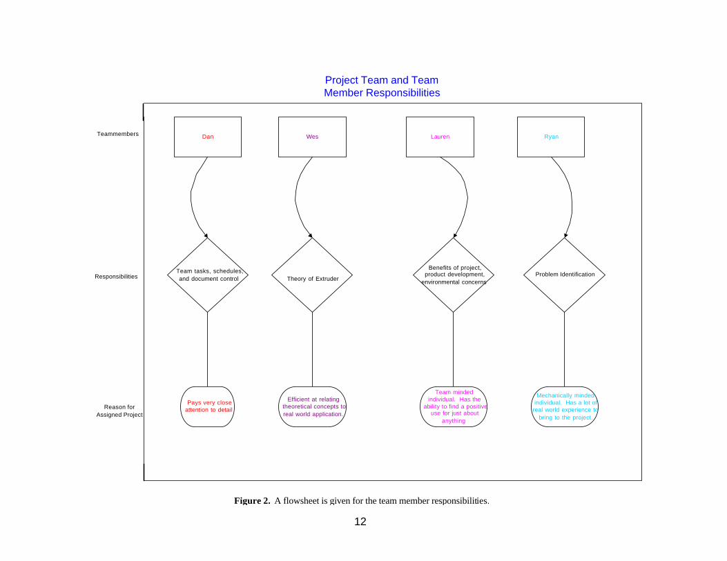
3.1 Project Team and Key Personnel
The workload to formulate the proposal was divided equally among the team members of Group
B. It is summarized in the following flow diagram in Figure 2.
12
Dan Wes Lauren Ryan
Project Team and TeamMember Responsibilities
Team tasks, schedules,and document control Theory of Extruder
Benefits of project,product development,
environmental concernsProblem Identification
Teammembers
Responsibilities
Pays very closeattention to detail
Efficient at relatingtheoretical concepts toreal world application.
Team mindedindividual. Has the
ability to find a positiveuse for just about
anything
Mechanically mindedindividual. Has a lot ofreal world experience to
bring to the project.
Reason forAssigned Project
5.1
Figure 2. A flowsheet is given for the team member responsibilities.

13
3.2 Equipment and Facilties
The Chemical Engineering Laboratory is equipped with a C.W. Brabender manufactured single-
screw extruder. A 3.4-horsepower electric motor drives the extruder screw. An Opto 22 control
system and a PC computer provide control of the extruder apparatus. Recently, the extruder was
equipped with a cylindrical die, including a newly machined sleeve insert with a 0.125-inch
diameter opening. A photograph of the single screw extruder is shown in Figure 3 and a
schematic drawing is shown in Figure 4. The feed hopper and the four zones of the extruder are
displayed and labeled in the drawing.
Figure 3. A photograph of the single screw extruder, used in this project, is shown here. The PC computer and the Opto 22 controller are located behind the apparatus as it is shown here.

14
Figure 4. A schematic diagram of the single screw extruder used in this experiment is shown here. The feed section corresponds to zone 1 of the extruder apparatus. The compression section, the metering section, and the die correspond to zones two, three, and four, respectively. The feed hopper, heaters, breaker plate, and screen pack are also shown. The narrowing screw channel in the compression zone is well demonstrated in this diagram.
The laboratory is also equipped with a UNIVEX TAKE-OFF, CW Brabender, type SFP-100, take-
up roller apparatus. The take-up assembly consists of two large water-cooled rollers, a small roller
located above the large rollers, and a reel-up roller that collects the polymer product. The main
take-up roller is powered by an electric motor. A dial, labeled in units of percentage of full scale,
on the take-up apparatus instrumentation console controls the roller speed. Control of the roller
speed is independent of the Opto 22 control system. A photograph of the take-up assembly is
shown in Figure 5 and a schematic drawing is shown in Figure 6.

15
Figure 5. A photograph of the take-up apparatus used in this experiment is shown here. The two lower rollers are water-cooled and assist in the hardening of the polymer effluent. The roller speed control instrumentation is located at the upper right-hand corner of the apparatus.
Figure 6. A schematic diagram of the take-up apparatus used in this experiment is shown here. The gray line that enters the rollers from the die represents the polymer effluent. The main take-up roller shown is powered by a small electric motor. The turn of a small dial controls the rotational speed of the powered roller.
16
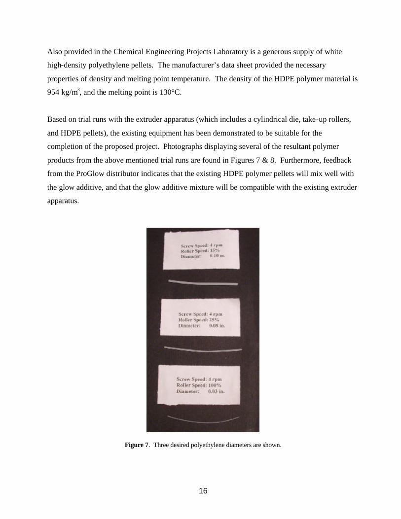
Also provided in the Chemical Engineering Projects Laboratory is a generous supply of white
high-density polyethylene pellets. The manufacturer’s data sheet provided the necessary
properties of density and melting point temperature. The density of the HDPE polymer material is
954 kg/m3, and the melting point is 130°C.
Based on trial runs with the extruder apparatus (which includes a cylindrical die, take-up rollers,
and HDPE pellets), the existing equipment has been demonstrated to be suitable for the
completion of the proposed project. Photographs displaying several of the resultant polymer
products from the above mentioned trial runs are found in Figures 7 & 8. Furthermore, feedback
from the ProGlow distributor indicates that the existing HDPE polymer pellets will mix well with
the glow additive, and that the glow additive mixture will be compatible with the existing extruder
apparatus.
Figure 7. Three desired polyethylene diameters are shown.

17
Figure 8. Our glow product is shown in the dark.
The only equipment or material purchase that is anticipated to be necessary for the completion of
this project is the ProGlow MasterBatch glow additive. The cost of this additive was quoted at
$85.97 per kilogram. We anticipate that one half kilogram of this glow additive will be sufficient
to complete the project.
18
4. ANTICIPATED BENEFITS OF PROPOSED WORK
Currently, several markets are in need of a glow-in-the-dark product that essentially never dies.
ProGlow lasts for up to 20 hours and only needs to be recharged for approximately 20 minutes to
return to its original intensity. There are several possible uses for the final extruded glow-in-the-
dark product manufactured in this experiment. These benefits will not only reap a hefty economic
profit, but also provide an overall service to society in the area of public safety.
We plan to use the final extruded product to make glow-in-the-dark jewelry to accommodate the
ever-growing teen rave party scene. Longer lasting necklaces and bracelets will soon become the
expected norm for these all-night party animals. The product can also be used in the fishing tackle
industry. The power of the glow-in-the-dark lure has just recently become apparent to the savvy
fisherman. Traditionally, those lures that have the reputation to catch the most fish sell the
strongest in the retail market. Glow-in-the-dark fishing flies are already used by fishermen. It is
projected that we can sell our long-lasting glow lures at a competitive retail price, obtaining profit
through the sheer volume of sales at the wholesale level.
Glow components add an extra degree of safety to almost anything. Our thin, tube-shaped product
can potentially be used around traffic signs in order to illuminate them during the night. It can
also be used in bike helmets and construction hard hats. Glow-in-the-dark tubing can also be used
in pet collars to avoid the tragic loss of a loved pet. An illuminated collar allows a driver to be
aware of the presence of an animal before it is too late.
The uses of a long-lasting, glow-in-the-dark product are endless. We have presented only a few
potential economically-viable product options. Our equipment has the ability to manufacture a
plethora of different die diameters. If another product is desired we can consider the feasibility to
manufacture this product as the issue arises.

19
5. ANTICIPATED ENVIORNMENTAL IMPACT OF PROPOSED WORK
The extrusion of polyethylene delivers little environmental impact, although proper handling and
safety precautions must be followed in order to ensure safety. The polyethylene pellets and
ProGlow used in the experiment are both non-flammable. Heating polyethylene to temperatures
greater than 200°C may release a toxic fume, though. Therefore, during the extrusion process,
careful attention should be paid to the temperature profile of the extruder to avoid the accidental
release of these toxic fumes. As long as the operators pay careful attention to the temperature
along the length of the extruder, especially in the die region, no environmental complications
should arise. Polyethylene is safe to throw away, but also easy to recycle. The proposed
experiment will not produce enough polyethylene waste to be of any environmental concern.
According to its ma terial safety data sheet (MSDS), ProGlow is as benign as HDPE (high density
polyethylene). The only warning given by the manufacturer is that it should not come into
contact with acids. ProGlow can be disposed of in the same manner as polyethylene.

20
NOMENCLATURE
A Cross-sectional area
DR Roller diameter
DR Draw ratio
m& Mass flow rate
V Axial velocity
ρ Density
ω Radial velocity of the roller
HDPE High density polyethylene
MSDS Material safety data sheet

21
REFERENCES
Goodfellow website. http://www.goodfellow.com/csp/active/static/A/ET32.HTML. (accessed January 20, 2003).
Incropera, F.P. and D.P. DeWitt. Fundamentals of Heat and Mass Transfer. John Wiley and
Sons, Inc.: New York. 2002.
Morton-Jones, D.H. Polymer Processing. Chapman and Hall: New York. 1989.
Polymerwide website. http://www.polymerwide.com/productinfo/certi/08hdpe/03msds/XL6500.
(accessed February 10, 2003).
ProGlow website. http://www.proglow.com (accessed January 20, 2003).

22
APPENDIX A: CALIBRATION
Table A-1. Data are given for the roller speed vs. rpm.
Roller Speed (% of full-scale) Rotations
Time (sec.) rad/sec
Linear Take-up speed
(in./min.)
0 0 0 0 0 Circumference (in.): 7.8125
20 1 30 0.2094 98.17477 Diameter (in.): 2.4868 30 1 14 0.4488 210.3745 40 2 18 0.6981 327.2492 50 3 21 0.8976 420.749 60 3 17 1.1088 519.7488 70 4 19 1.3228 620.0512 80 4 17 1.4784 692.9984 90 5 18 1.7453 818.1231
100 5 16 1.9635 920.3885
ROLLER SPEED vs. RPM CALIBRATION CURVE
y = 0.0204x - 0.1123R2 = 0.9932
0
0.5
1
1.5
2
2.5
0 20 40 60 80 100
Roller Speed (% of full-scale)
rad
/sec
rad/sec
Linear(rad/se
Figure A-1. A plot of rollers speed vs. revolutions per minute is shown.
23
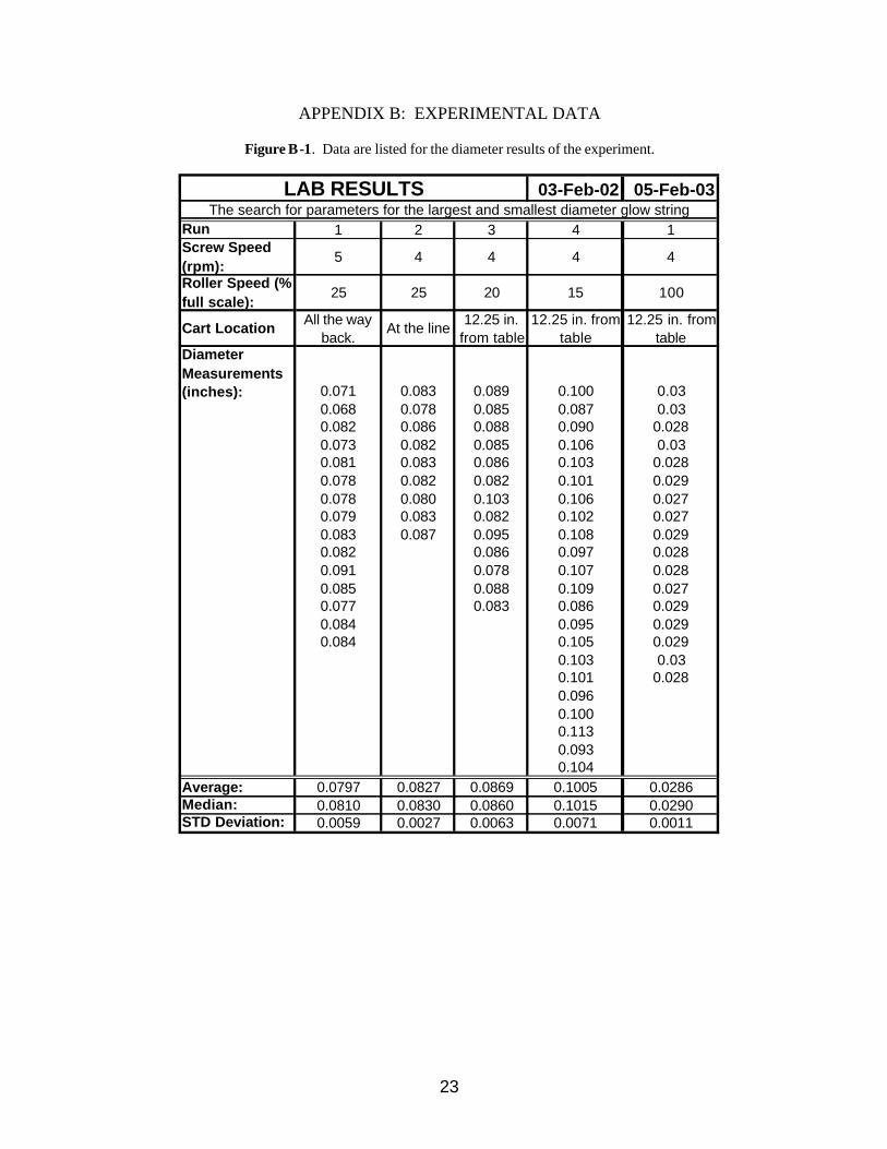
APPENDIX B: EXPERIMENTAL DATA
Figure B-1. Data are listed for the diameter results of the experiment.
03-Feb-02 05-Feb-03
Run 1 2 3 4 1Screw Speed (rpm):
5 4 4 4 4
Roller Speed (% full scale):
25 25 20 15 100
Cart Location All the way back.
At the line 12.25 in. from table
12.25 in. from table
12.25 in. from table
Diameter Measurements (inches): 0.071 0.083 0.089 0.100 0.03
0.068 0.078 0.085 0.087 0.030.082 0.086 0.088 0.090 0.0280.073 0.082 0.085 0.106 0.030.081 0.083 0.086 0.103 0.0280.078 0.082 0.082 0.101 0.0290.078 0.080 0.103 0.106 0.0270.079 0.083 0.082 0.102 0.0270.083 0.087 0.095 0.108 0.0290.082 0.086 0.097 0.0280.091 0.078 0.107 0.0280.085 0.088 0.109 0.0270.077 0.083 0.086 0.0290.084 0.095 0.0290.084 0.105 0.029
0.103 0.030.101 0.0280.0960.1000.1130.0930.104
Average: 0.0797 0.0827 0.0869 0.1005 0.0286Median: 0.0810 0.0830 0.0860 0.1015 0.0290STD Deviation: 0.0059 0.0027 0.0063 0.0071 0.0011
LAB RESULTSThe search for parameters for the largest and smallest diameter glow string