proportional valves - bucher hydraulics · proportional valves model description flow cavity 11 1 1...
TRANSCRIPT

ProportionalValves
MODEL DESCRIPTION FLOW CAVITY
11
1
1
2
3
1 2
2
1
2
1
1
32
1
2 3
EPRT-08 PROPORTIONAL PRESS. REDUCING/RELIEVING 7 GPM C0830/AM
1
2 3
PDFC-4M
PDFC-4L
4/3 PROPORTIONAL DIRECTIONAL VALVE 8 GPM C1040
EPRR-10 PROPORTIONAL PRESS. REDUCING/RELIEVING 1 GPM C1030
EPRS-10EPRS-12
PROP. P.O. PRESSURE REDUCING/RELIEVING 12 GPM24 GPM
C1030C1230
ERVP-10ERVP-12
PROPORTIONAL P.O. PRESSURE RELIEF 25 GPM60 GPM
C1020C1220
ERVD-10 PROPORTIONAL PRESS. RELIEF, LOW FLOW 1 GPM C1020
EPFI-10EPFI-12EPFC-16
8 GPM15 GPM
C1020C1220
20 GPM C1620
EPFB-10EPFB-12EPFD-16
8 GPM15 GPM
C1030C1230
20 GPM C1630
PFCV-10PFCV-12PFCV-16
16 GPM24 GPM36 GPM
C1020C1220C1620
PROPORTIONAL NON-COMP. FLOW CONTROL
PROP. PRIORITY PRESS. COMP. FLOW CONTROL
PROPORTIONAL PRESS. COMP. FLOW CONTROL
1
2
2
a b
b
a
2
31
4
2
31
4
Reference: 520-P-110000-EN-01/02.2016

2
2MVRPSBA-2G PROPORTIONAL THR OTTLE CARTRIGE 13 GPM C0820/AL
1
2
REGIN
B-PREG
IN
PIFC-10PIFC-12PIFC-16
16 GPM24 GPM36 GPM
C1020C1220C1620
PROP. FLOW CONTROL WITH COMPENSATOR
PBFC-10PBFC-12PBFC-16
16 GPM24 GPM36 GPM
C1030C1230C1630
PROP. PRIORITY FLOW CONTROL WITH COMP.
MDR42A PROPORTIONAL 4 /2 THROTTLE CARTRIGE 8 GPM AN
MDR32GN PROPORTIONAL 3/2 THROTTLE CARTRIGE 8 GPM AM
MODEL DESCRIPTION FLOW CAVITY
1 3
Proportional Valves
PWM-1400PWM-1401PWM-1404
PWM MICRO PROPORTIONAL VALVE DRIVER
PWM PROPORTIONAL DRIVER CONTROL BOXPWM PROPORTIONAL DRIVER, COIL MOUNTED
3
1 4
Reference: 520-P-110000-EN-01/02.2016

4/3 Proportional Directional Valve, Size SAE 10Qmax = 8.0 gpm �[30�l/min],�pmax = 4000�psi [280�bar]Direct acting, sliding-spool design, with solenoid operationSeries PDFC-10…
1/5
Reference: 520-P-113020-EN-01
Issue: 10.2015
� Compact construction for
cavity type C1040 – 7/8-14 UNF
� Operated by a proportional high pressure wet-armature
solenoid
� Minimum current threshold/ dead band (position b) is
factory set for better consistency
� Manual over-ride optionally available,
detented in neutral position
� Excellent reproducibility and repeatability,and low hysteresis
� All exposed parts with zinc-nickel plating
� The slip-on coil can be rotated, and it can be
replaced without opening the hydraulic envelope
� Various plug-connector systems and voltages
are available
� Can be fitted in a line-mounting body
1 Description
Series PDFC10… proportional directional valves are direct
acting screwin cartridges with a sliding spool design and a
7/814 UNF mounting thread. In the neutral position, port 3
is closed and depending on the spool type, ports 2 and 4 are
connected to tank (1) (spool configuration M) or ports 1, 2
and 4 are all blocked (spool configuration L). The version
with the M spool is used in motor control circuits where
freewheeling in the neutral position is required. The L con
figuration is the version to use for cylinder applications.
These cartridges are particularly suitable for precise and
controlled lifting and lowering movements and can also be
used for reliable operation in mobile and industrial applica
tions. Best controllability is achieved when using the valve
with a bypass pressure compensator to control pressure
drop through the valve. Using the valve without pressure
compensator is not recommended because higher
pressure drops cause the flow to be more restricted (see
performance graph). The proportional directional valves is
optionally equipped with a manual override which is deten
ted in the neutral position. To unlatch the detent mechan
ism, the button on the back can be pushed. That allows shift
ing the valve in both directions. Pushing the knob shifts the
valve to position (a) (32 and 41) and pulling shifts it to
position (b) (34 and 21). All external parts of the cart
ridge are zinc plated and chromited (CrVI-free). The slip-on
coils can be replaced without opening the hydraulic enve
lope and can be positioned at any angle through 360°. If you
intend to manufacture your own cavities or are designing a
line-mounting installation, please refer to the section “Rela
ted data sheets”.
2 Symbol
PDFC-10-…-4M-M… PDFC-10-…-4L-M… PDFC-10-…-4M-0… PDFC-10-…-4L-0…

520-P-113020-EN-01/10.2015
Series PDFC-10…2/5
3 Technical data
General characteristics Description, value, unit
Designation 4/3 proportional directional valve
Design sliding-spool design, direct acting, with solenoid operation
Mounting method screw-in cartridge 7/8-14 UNF
Tightening torque 40…45 ft-lbs [54…61�Nm]
Size size SAE 10, cavity type C1040
Weight 1.65 lbs [0.75�kg]
Mounting attitude unrestricted (preferably vertical, coil down)
Ambient temperature range -15�°F … +125�°F [-25�°C … +50�°C]
Hydraulic characteristics Description, value, unit
Maximum operating pressure - ports 2, 3, 4
- port 1
4000�psi [280�bar]
2000�psi [140�bar]
higher pressure, please consult BUCHER
Maximum flow rate - port 3 4 and 2 1
- port 3 2 and 4 1
7.0 gpm at p 140 psi [26�l/min at p 10 bar]
6.2 gpm at p 140 psi [24�l/min at p 10 bar]
at 100% duty cycle
Leakage flow rate (port to port) 15�inch3 at 3000�psi [245�ml/min at 210�bar]
Hydraulic fluid HL and HLP mineral oil to DIN 51 524;
for other fluids, please contact BUCHER
Hydraulic fluid temperature range -15�°F … +160�°F [-25�°C … +70�°C]
Viscosity range 15…380�mm2/s (cSt), recommended 20...130�mm2/s (cSt)
Minimum fluid cleanliness
Cleanliness class to ISO 4406�:�1999
class 18/16/13
Electrical characteristics Description, value, unit
Supply voltage 12�V�DC, 24�V�DC
Control current 12 V = 0…1400�mA, 24 V = 0…750 mA (100% duty cycle)
12 V = 0…1600�mA, 24 V = 0…880 mA (50% duty cycle)
Power consumption at max. control current max. 19�W
Coil resistance R - cold value at 20�°C
- max. warm value
12 V = 5.8��/�24�V = 20.9�12 V = 9.1��/�24�V = 32.7�
Recommended PWM frequency (dither) 200 Hz
Hysteresis with PWM 2…5 % IN
Reversal error with PWM 2…5 % IN
Sensitivity with PWM < 1.5 % IN
Reproducibility with PWM < 3 % pN
Relative duty cycle 100 % / 50 %
Protection class to ISO�20�653 / EN�60�529 IP 65 / IP 67 / IP 69K, see “Ordering code”
(with appropriate mating connector and
proper fitting and sealing)
Electrical connection 3-pin square plug to ISO 4400 / DIN 43 650 (standard)
for other connectors, see “Ordering code”

520-P-113020-EN-01/10.2015
Series PDFC-10…3/5
4 Performance graphs
Q = f (I; p) Flow rate adjustment characteristic 4MB)A)A)B)
EL_P0019.ai0
1
2
3
4
5
10
[3.5]
[7.5]
[19]
[23]
[34]
[38]
I [mA]
9
6
[30]
[15]
7 [26]
8
[11]
1000500400300100300 1006001000 0 200 600500 200900 800 700 400 700 800 90020001000800600200600 20012002000 0 400 12001000 4001800 1600 1400 800 1400 1600 1800
Q [gpm]
Coil b, connections 3 � 4 ; 2 � 1 Coil a, connections 3 � 2 ; 4 � 1
Q [l/min]
��p = 145 psi
��p = 290 psi
��p = 725 psi
��p = 145 psi
��p = 290 psi
��p = 725 psi
��p = 2900 psi
��p = 1450 psi
��p = 2900 psi
��p = 1450 psi
A) 100% duty cycle
B) 50% duty cycle
--- depending on coil temperature, solenoid may draw a voltage higher than the nominal voltage
Q = f (I; p) Flow rate adjustment characteristic 4LB)A)A)B)
EL_P0019.ai0
1
2
3
4
5
10
[3.5]
[7.5]
[19]
[23]
[34]
[38]
I [mA]
9
6
[30]
[15]
7 [26]
8
[11]
1000500400300100300 1006001000 0 200 600500 200900 800 700 400 700 800 90020001000800600200600 20012002000 0 400 12001000 4001800 1600 1400 800 1400 1600 1800
Q [gpm]
Coil b, connections 3 � 4 ; 2 � 1 Coil a, connections 3 � 2 ; 4 � 1
Q [l/min]
��p = 145 psi
��p = 290 psi
��p = 725 psi
��p = 145 psi
��p = 290 psi
��p = 725 psi
��p = 2900 psi
��p = 1450 psi
��p = 2900 psi
��p = 1450 psi
A) 100% duty cycle
B) 50% duty cycle
--- depending on coil temperature, solenoid may draw a voltage higher than the nominal voltage
p = f (Q) Pressure drop - Flow rate characteristic 4M
P0020.ai
4M, coil b 750 [mA]4M, coil b 750 [mA]
4M, coil a 750 [mA]4M, coil a 750 [mA]
Valve completly openValve completly open
0
1
3
5
7
8
Q [l
/min
]
Q [g
pm]
55 110 140 195
400 1200 1600 2800�
0
4
8
19
23
30
�
2
4
6
800 2000 2400
85 170
26
15
12
27p [bar]
p 3 � 4 [psi]� p 3 � 2 [psi]
p = f (Q) Pressure drop - Flow rate characteristic 4L
P0021.ai0
1
3
5
7
8
Q [g
pm]
55 110 140 195
400 1200 1600 28000
4
8
19
23
30
2
4
6
800 2000 2400
85 170
26
15
12
4L, coil b 750 [mA]4L, coil b 750 [mA]
4L, coil a 750 [mA]4L, coil a 750 [mA]
Valve completly openValve completly open
27
Q [l
/min
]
�
�p [bar]
p 3 � 4 [psi]� p 3 � 2 [psi]
520-P-113020-EN-01/10.2015
Series PDFC-10…4/5
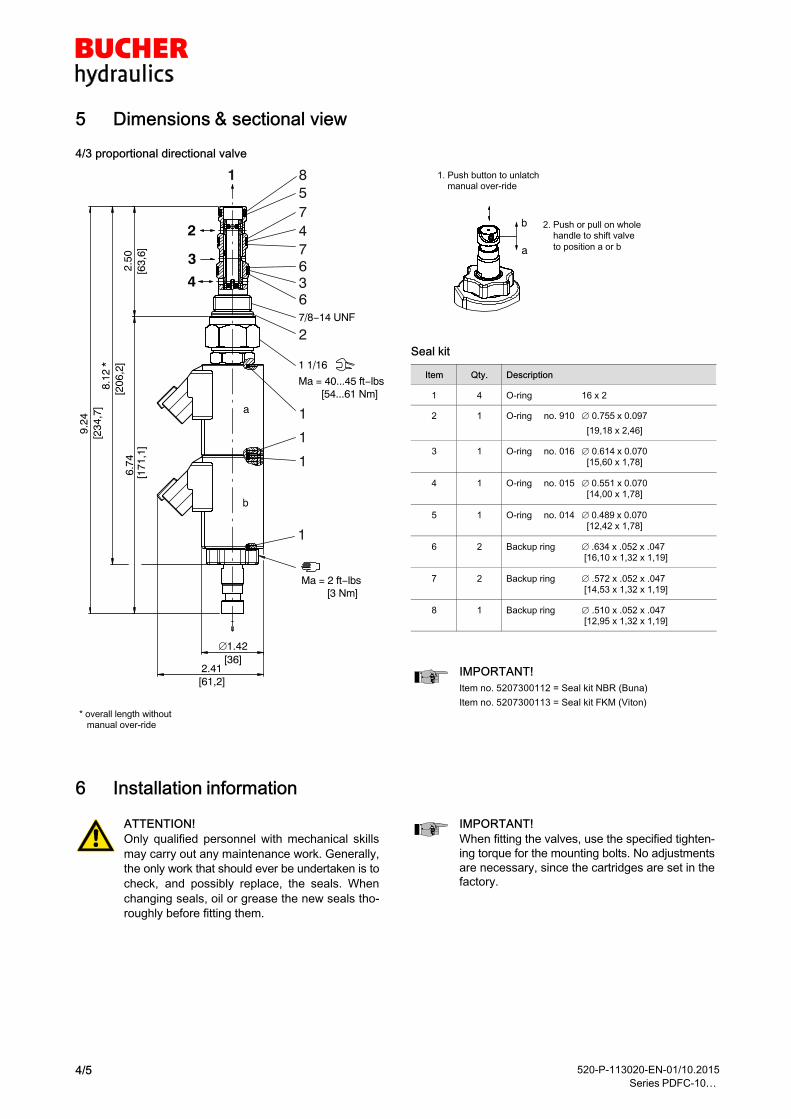
5 Dimensions & sectional view
4/3 proportional directional valve
1
2
3
4
a
76
1
b
1 1/16
Ma = 40...45 ft−lbs [54...61 Nm]
Ma = 2 ft−lbs [3 Nm]
2.50
[63,
6]
8.12
*[2
06,2
]
9.24
[234
,7]
1.42[36]
2.41[61,2]
6.74
[171
,1]
7/8−14 UNF
85
4
3
2
1
1
7
6
1
* overall length without manual over-ride
b
a
1. Push button to unlatch manual over-ride
2. Push or pull on whole handle to shift valve
to position a or b
Seal kit
Item Qty. Description
1 4 O-ring 16 x 2
2 1 O-ring no. 910 0.755�x 0.097
[19,18 x 2,46]
3 1 O-ring no. 016 0.614�x 0.070 [15,60 x 1,78]
4 1 O-ring no. 015 �0.551�x�0.070 [14,00 x 1,78]
5 1 O-ring no. 014 �0.489�x 0.070 [12,42 x 1,78]
6 2 Backup ring �.634 x .052 x .047 [16,10 x 1,32 x 1,19]
7 2 Backup ring .572 x .052 x .047 [14,53 x 1,32 x 1,19]
8 1 Backup ring .510 x .052 x .047 [12,95 x 1,32 x 1,19]
IMPORTANT!
Item no. 5207300112 = Seal kit NBR (Buna)
Item no. 5207300113 = Seal kit FKM (Viton)
6 Installation information
ATTENTION!
Only qualified personnel with mechanical skills
may carry out any maintenance work. Generally,
the only work that should ever be undertaken is to
check, and possibly replace, the seals. When
changing seals, oil or grease the new seals tho
roughly before fitting them.
IMPORTANT!
When fitting the valves, use the specified tighten
ing torque for the mounting bolts. No adjustments
are necessary, since the cartridges are set in the
factory.
520-P-113020-EN-01/10.2015
Series PDFC-10…5/5
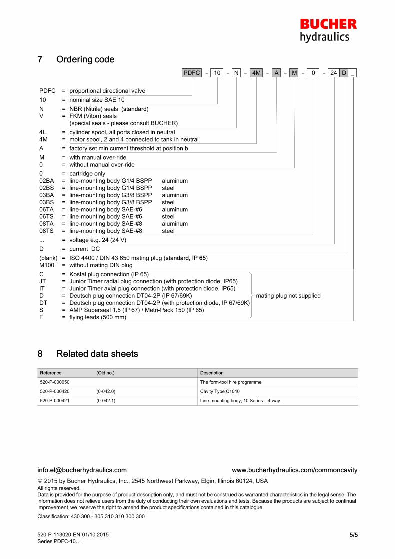
7 Ordering code
N
PDFC = proportional directional valve
10 = nominal size SAE 10
N = NBR (Nitrile) seals (standard)
V = FKM (Viton) seals
(special seals - please consult BUCHER)
4L = cylinder spool, all ports closed in neutral
4M = motor spool, 2 and 4 connected to tank in neutral
A = factory set min current threshold at position b
M = with manual over-ride
0 = without manual over-ride
0 = cartridge only
02BA = line-mounting body G1/4 BSPP aluminum
02BS = line-mounting body G1/4 BSPP steel
03BA = line-mounting body G3/8 BSPP aluminum
03BS = line-mounting body G3/8 BSPP steel
06TA = line-mounting body SAE-#6 aluminum
06TS = line-mounting body SAE-#6 steel
08TA = line-mounting body SAE-#8 aluminum
08TS = line-mounting body SAE-#8 steel
... = voltage e.g. 24 (24 V)
D = current DC
(blank) = ISO 4400 / DIN 43 650 mating plug (standard, IP�65)
M100 = without mating DIN plug
C = Kostal plug connection (IP�65)
JT = Junior Timer radial plug connection (with protection diode, IP65)
IT = Junior Timer axial plug connection (with protection diode, IP65)
D = Deutsch plug connection DT04-2P (IP�67/69K) mating plug not supplied
DT = Deutsch plug connection DT04-2P (with protection diode, IP�67/69K)
S = AMP Superseal 1.5 (IP�67) / Metri-Pack 150 (IP�65)
F = flying leads (500 mm)
_0 -M ---PDFC 24 DA -4M10 --
8 Related data sheets
Reference (Old no.) Description
520-P-000050 The form-tool hire programme
520-P-000420 (0-042.0) Cavity Type C1040
520-P-000421 (0-042.1) Line-mounting body, 10 Series – 4-way
� 2015 by Bucher Hydraulics, Inc., 2545 Northwest Parkway, Elgin, Illinois 60124, USA
www.bucherhydraulics.com/[email protected]
All rights reserved.
Data is provided for the purpose of product description only, and must not be construed as warranted characteristics in the legal sense. The
information does not relieve users from the duty of conducting their own evaluations and tests. Because the products are subject to continual
improvement, we reserve the right to amend the product specifications contained in this catalogue.
Classification: 430.300.-.305.310.310.300.300

TYPE "L" COIL TYPE "L" COIL SEE PAGE SEE PAGE 10-001.210-001.2
1
32
= BUNA "N"= BUNA "N"= VITON= VITON
SEALSSEALSNV
SIZESIZE10 = 7/8"-14UNF10 = 7/8"-14UNF
BASICBASIC
PORTSPORTS0
02BX02BX03BX03BX06TX06TX08TX08TX
= CARTRIDGE ONLY= CARTRIDGE ONLY= G 1/4" BSPP= G 1/4" BSPP= G 3/8" BSPP= G 3/8" BSPP= SAE - #6= SAE - #6= SAE - #8= SAE - #8 "A" = ALUM. HOUSING "A" = ALUM. HOUSING "S" = STEEL HOUSING "S" = STEEL HOUSING
REGULATED PRESSUREREGULATED PRESSURE02020303040405050606070708081010
= 0 TO 200 PSI= 0 TO 200 PSI= 0 TO 300 PSI= 0 TO 300 PSI= 0 TO 400 PSI= 0 TO 400 PSI= 0 TO 500 PSI= 0 TO 500 PSI= 0 TO 600 PSI= 0 TO 600 PSI= 0 TO 700 PSI= 0 TO 700 PSI= 0 TO 800 PSI= 0 TO 800 PSI= 0 TO 1000 PSI= 0 TO 1000 PSI
NOTES:NOTES:1. FOR ALUMINUM OR STEEL VALVE HOUSING CONFIGURATIONS SEE PAGE 0-032.11. FOR ALUMINUM OR STEEL VALVE HOUSING CONFIGURATIONS SEE PAGE 0-032.12. SOLENOIDS AVAILABLE WITH DIODES - CONSULT FACTORY.2. SOLENOIDS AVAILABLE WITH DIODES - CONSULT FACTORY.
LTBGWDM
TERMINALS TERMINALS=18GA. 24" LEADS=18GA. 24" LEADS=SPADE TERM.=SPADE TERM.=BOLT TERM.=BOLT TERM.=DIN43650=DIN43650=WEATHER-PACK=WEATHER-PACK=DEUTSCH-DT04-2P=DEUTSCH-DT04-2P=METRI-PACK CONN.=METRI-PACK CONN.
12D12D24D24D
VOLTAGE VOLTAGE= 12 VDC= 12 VDC= 24 VDC= 24 VDC
AMPSAMPS 3.00 3.00 1.50 1.50
M ADJUSTMENT OPTIONS ADJUSTMENT OPTIONS= MANUAL OVERRIDE= MANUAL OVERRIDE
EPRR-10-X-XX-X-X-XXX XEPRR-10-X-XX-X-X-XXX X
REGULATED PRESSURE
REGULATED PRESSURE
0.900.90PSIPSI
0.600.600.300.30
200200
400400
2.102.101.501.501.201.20 1.801.80BARBAR
2.402.40
13,8 13,8
27,6 27,6
AMPERAGE (AMPS) @ 24 VDCAMPERAGE (AMPS) @ 24 VDC
0.450.45
600600
800800
100010000.300.300.150.15 1.051.050.750.750.600.60 0.900.90
41,4 41,4
55,255,2
69,069,01.201.20
RELIEVING. DIRECT ACTING, SPOOL TYPE. RELIEVING. DIRECT ACTING, SPOOL TYPE.
PROPORTIONAL PRESSURE REDUCING/PROPORTIONAL PRESSURE REDUCING/
AMPERAGE (AMPS) @ 12 VDCAMPERAGE (AMPS) @ 12 VDC
[46,5][46,5]1.83"1.83"
[45,2][45,2]
[111.8][111.8] 4.40" 4.40"
MANUAL OVERRIDEMANUAL OVERRIDE( SCREW TYPE )( SCREW TYPE )
1.78"1.78"
2.75" 2.75"
2.50" 2.50"[63,5][63,5]
[69,9][69,9]
[27,0][27,0] 1.06" 1.06" HEX HEX
1
2
3
Steel = 55/60 Ft-Lb. [74/81 Nm] Steel = 55/60 Ft-Lb. [74/81 Nm]
TORQUE:TORQUE:
Aluminum = 35/40 Ft-Lb. [47/54 Nm]Aluminum = 35/40 Ft-Lb. [47/54 Nm]
Reference: 520-P-110120-EN-00/09.2015
EPRR-10

FEATURES AND BENEFITSFEATURES AND BENEFITS
OPERATIONSOPERATIONS
DESCRIPTIONDESCRIPTION
Industry common cavity.Industry common cavity.All cartridge valves are 100% functionally tested.All cartridge valves are 100% functionally tested.All external carbon steel parts are plated for longer life against the elements.All external carbon steel parts are plated for longer life against the elements.Very efficient wet - armature solenoid core tube construction.Very efficient wet - armature solenoid core tube construction.
pressure control valve.pressure control valve.style, direct acting, spool type, pressure reducing/relieving flowstyle, direct acting, spool type, pressure reducing/relieving flowThis unit is a electro-hydraulic, proportional, screw in cartridgeThis unit is a electro-hydraulic, proportional, screw in cartridge
Hardened precision fitted spool & sleeve provides reliable, long life.Hardened precision fitted spool & sleeve provides reliable, long life.Interchangeable solenoid coils & terminations options available.Interchangeable solenoid coils & terminations options available.Continuous-duty, very low heat rise & waterproof solenoid coil.Continuous-duty, very low heat rise & waterproof solenoid coil.
PRESSURE AT PORT 1 TO ZERO.PRESSURE AT PORT 1 TO ZERO.IN THE EVENT OF POWER FAILURE THE VALVE WILL REDUCE REGULATEDIN THE EVENT OF POWER FAILURE THE VALVE WILL REDUCE REGULATED
the coil the pressure will increase and when decreased it will decrease.the coil the pressure will increase and when decreased it will decrease.proportional to the curent input. When the current is increased toproportional to the curent input. When the current is increased toagainst the metering spool thus varying the pressure at port 1 (Reg.)against the metering spool thus varying the pressure at port 1 (Reg.)When the coil is energized the armature moves a precision bias springWhen the coil is energized the armature moves a precision bias springflow and pressure between ports 2 and 1 and blocks port 3 (tank).flow and pressure between ports 2 and 1 and blocks port 3 (tank).When the coil is energized, the spool in this valve shifts and allowsWhen the coil is energized, the spool in this valve shifts and allowsfrom port 2 to 1 and port 1 is open to (tank) port 3.from port 2 to 1 and port 1 is open to (tank) port 3.When the coil is de-energized, this valve allows no flow or pressureWhen the coil is de-energized, this valve allows no flow or pressure
ELECTRO-HYDRAULIC, PROPORTIONAL, ELECTRO-HYDRAULIC, PROPORTIONAL, PRESSURE REDUCING/RELIEVING VALVE. PRESSURE REDUCING/RELIEVING VALVE.
Reference: 520-P-110120-EN-00/09.2015
EPRR-10

SPECIFICATIONSSPECIFICATIONS
VALVE CAVITY: #C1030, See Page 0-032.0.VALVE CAVITY: #C1030, See Page 0-032.0.WEIGHT: 1.95 lb [.88 kg] cartridge with coil only.WEIGHT: 1.95 lb [.88 kg] cartridge with coil only.INSTALLATION: No restrictions.INSTALLATION: No restrictions. SKV-1031 Viton SKV-1031 VitonSEAL KIT: SKN-1031 Buna "N"SEAL KIT: SKN-1031 Buna "N"
24 VDC, Operating current 0.1 to 1.2 AMPS. 24 VDC, Operating current 0.1 to 1.2 AMPS.POWER REQUIREMENTS: 12 VDC, Operating current 0.2 to 2.4 AMPS.POWER REQUIREMENTS: 12 VDC, Operating current 0.2 to 2.4 AMPS. current control and a 50 Hz dither. current control and a 50 Hz dither.RESPONSE: The most efficient method to control this valve is withRESPONSE: The most efficient method to control this valve is with
INTERNAL LEAKAGE: 10 cu.in/min [164 cc/m] @ 5,000 PSI [350 Bar]INTERNAL LEAKAGE: 10 cu.in/min [164 cc/m] @ 5,000 PSI [350 Bar]
REGULATED PRESSURE: 0 to 1,000 PSI [0 to 69,0 Bar] See performance chartREGULATED PRESSURE: 0 to 1,000 PSI [0 to 69,0 Bar] See performance chartPROOF PRESSURE: 10,000 PSI [700 Bar]PROOF PRESSURE: 10,000 PSI [700 Bar]OPERATING PRESSURE: 5,000 PSI [350 Bar]OPERATING PRESSURE: 5,000 PSI [350 Bar]
FLOW: 1.0 GPM (3.8 l/m) nominalFLOW: 1.0 GPM (3.8 l/m) nominal
ELECTRO-HYDRAULIC, PROPORTIONAL, ELECTRO-HYDRAULIC, PROPORTIONAL, PRESSURE REDUCING/RELIEVING VALVE. PRESSURE REDUCING/RELIEVING VALVE.
MIL-H-5606, SAE-#10, SAE-#20, etc. MIL-H-5606, SAE-#10, SAE-#20, etc.OPERATING MEDIA: All general purpose hydraulic fluids such asOPERATING MEDIA: All general purpose hydraulic fluids such asOPERATING TEMPERATURE: -40° to +250° F. [-40° to +120° C.]OPERATING TEMPERATURE: -40° to +250° F. [-40° to +120° C.] 5000 PSI [350 Bar] = Steel - Unplated. 5000 PSI [350 Bar] = Steel - Unplated.VALVE HOUSINGS: 2500 PSI [175 Bar] = Aluminum - Anodized.VALVE HOUSINGS: 2500 PSI [175 Bar] = Aluminum - Anodized.
[email protected] www.bucherhydraulics.com/commoncavity
2015 by Bucher Hydraulics, Inc., 2545 Northwest Parkway, Elgin, Illinois 60124, USAAll rights reserved.The technical information in this catalog, may contain calculated figures (for reference only) and not actual performance data for this product.Data is provided for the purpose of product description only, and must not be construed as warranted characteristics in the legal sense. The information does not relieve users from the duty of conducting their own evaluations and tests. Because the products are subject to continual improvement, we reserve the right to amend the product specifications contained in this catalogue.
©
Reference: 520-P-110120-EN-00/09.2015
EPRR-10

Prop. Pressure-Reducing�/�Relieving Cartridge, Size SAE 08Qmax = 7.0 gpm �[26�l/min],�pmax = 3400�psi [240�bar]Seated pilot,�spool-type main stageSeries EPRT-08…
1/6
Reference: 520-P-110260-EN-01
Issue: 09.2015
� Compact construction for cavity types:
C0830 and AM - 3/4-16 UNF
� Operated by a proportional solenoid
� 3 pressure ranges available
� Full-flow secondary pressure relief
� Internal pilot-oil drain
� Pilot stage protected from dirt by gap filter
� Excellent stability over the whole pressureand flow range
� All exposed parts with zinc-nickel plating
� High pressure wet-armature solenoids
� The slip-on coil can be rotated, and it can bereplaced without opening the hydraulic envelope
� Various plug-connector systems and voltages
are available
� Can be fitted in a line-mounting body
1 Description
Series EPRT-08… proportional pressure-reducing / relie
ving valves are size SAE 08 / NG 5, high performance
screw-in cartridges with a 3/4-16 UNF mounting thread.
Using the leak-free seat-type pilot cartridge, the secondary
pressure in port 1 is dependent on the electrical control si
gnal and it can be continuously varied and set at any desired
level. In control mode, the connection 2��1 opens until the
pressure in port 1 reaches the preset level. If the pressure
rises above the preset level, the control spool opens the 1
3 connection until balance is attained. These pressure-
reducing / relieving cartridges function as full-flow pressure
relief valves from port 1 3 as soon as the reduced pres
sure rises above the valve pressure setting. A high degree
of functional stability is reached even if the back pressure in
the tank line fluctuates. Three pressure ranges are availa
ble in order to obtain precise pressure settings over the
whole pressure range. These pressure-reducing / relieving
cartridges are predominantly used in mobile and industrial
applications for reducing a system pressure. All external
parts of the cartridge are zinc-nickel plated to DIN 50�979
and are thus suitable for use in the harshest operating envi
ronments. The slip-on coils can be replaced without ope
ning the hydraulic envelope and can be positioned at any
angle through 360°. If you intend to manufacture your own
cavities or are designing a line-mounting installation, please
refer to the section “Related data sheets”.
2 Symbol
1
2 3
3 Technical data
General characteristics Description, value, unit
Designation proportional pressure-reducing / relieving cartridge
Design seated pilot, spool-type main stage
Mounting method screw-in cartridge 3/4-16 UNF
Tightening torque 30 ft-lbs ± 10 % [40�Nm ± 10 %]

520-P-110260-EN-01/09.2015
Series EPRT-08…2/6
Description, value, unitGeneral characteristics
Size size SAE 08 for cavity type C0830
NG 5 for cavity type AM
Weight 0.93 lbs [0.42�kg]
Mounting attitude unrestricted (preferably vertical, coil down)
Ambient temperature range -13�°F … +122�°F [-25�°C … +50�°C]
Hydraulic characteristics Description, value, unit
Maximum operating pressure - ports 1, 2
- port 3
3400�psi [240�bar]
3000�psi [210�bar] 1)
Maximum flow rate 7 gpm [26�l/min]
Nominal pressure ranges 1500, 2500, 3000 psi [100, 175, 210 bar]
For further pressure ranges, please contact BUCHER
Pilot-oil consumption 0.05… 0.08 gpm [0,2 … 0,3�l/min]
Flow direction 2 1 pressure reducing
1 3 pressure relieving
Hydraulic fluid HL and HLP mineral oil to DIN 51 524;
for other fluids, please contact BUCHER
Hydraulic fluid temperature range -13�°F … +158�°F [-25�°C … +70�°C]
Viscosity range 15…380�mm2/s (cSt), recommended 20...130�mm2/s (cSt)
Minimum fluid cleanliness
Cleanliness class to ISO 4406�:�1999
class 18/16/13
ATTENTION!1) To prevent any pressure surges, port 3 must
be routed to tank with the least possible back-
pressure.
Electrical characteristics Description, value, unit
Supply voltage 12�V DC, 24�V DC
Supply voltage tolerance 10�%
Control current 12 V = 0…1400 mA, 24 V = 0…750 mA
Power consumption at max. control current max. 19�W
Coil resistance R - cold value at 20�°C
- max. warm value
12 V = 5.8��/�24�V = 21�12 V = 8.6��/�24�V = 32�
Recommended PWM frequency (dither) 200 Hz
Hysteresis with PWM 2…4 % IN
Reversal error with PWM 1…3 % IN
Sensitivity with PWM 1 % IN
Reproducibility with PWM < 2 % pN
Switching time Pressure-reducing function:
38 … 45 ms (solenoid ON)
8 … 12 ms (solenoid OFF)
Pressure-relief function:
41 … 51 ms (solenoid ON)
6 … 12 ms (solenoid OFF)
The switching times are strongly influenced by flow rate, pressure, viscosity and the dwellperiod under pressure.

520-P-110260-EN-01/09.2015
Series EPRT-08…3/6
Description, value, unitElectrical characteristics
Relative duty cycle 100�%
Protection class to ISO�20�653 / EN�60�529 IP 65 / IP 67 / IP 69K, see “Ordering code”
(with appropriate mating connector and
proper fitting and sealing)
Electrical connection 3-pin square plug to ISO 4400 / DIN 43 650 (standard)
for other connectors, see “Ordering code”
4 Performance graphs measured with oil viscosity 33�mm2/s (cSt)
p = f (I) Pressure adjustment characteristic
EL0011.ai
0
3500
2800
2100
1400
700
I [mA]0 200 400 500 600 700I [mA]
100200 400
300600 800 1000 1200 1400
p1 [psi]
[250]
[200]
[150]
[100]
[50]
p1 [bar]
pN
3000 psipN
3000 psi
pN
2500 psipN
2500 psi
pN 1500 psipN 1500 psi
520-P-110260-EN-01/09.2015
Series EPRT-08…4/6
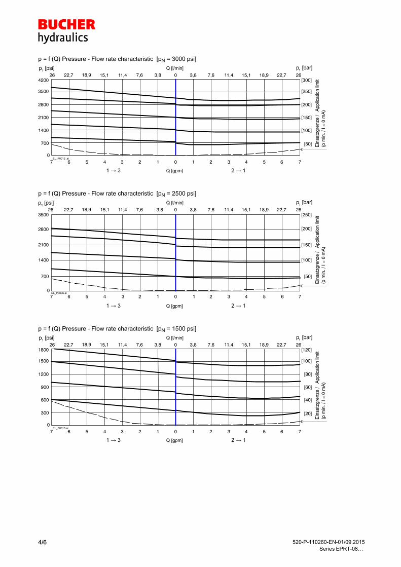
p = f (Q) Pressure - Flow rate characteristic [pN = 3000�psi]
EL_P0012 .ai0
700
1400
2100
2800
3500
4200
[50]
[100]
[150]
[200]
[250]
[300]
p1 [bar]
Q [gpm]
754313 157 0
p1 [psi]
Ein
satz
gren
ze /
App
licat
ion
limit
(p m
in. /
I =
0 m
A)
2618,911,47,63,87,6 3,811,418,922,7 0
Q [l/min]
26 15,1 15,1 22,7
2 64 26
p = f (Q) Pressure - Flow rate characteristic [pN = 2500�psi]
EL_P0026.ai0
700
1400
2100
2800
3500
[50]
[100]
[150]
[200]
[250]
Ein
satz
gren
ze /
App
licat
ion
limit
(p m
in. /
I =
0 m
A)
Q [gpm]
p1 [bar]
754313 1567 0
p1 [psi]2618,911,47,63,87,6 3,811,418,922,7 0
Q [l/min]
26 15,1 15,1 22,7
2 64 2
p = f (Q) Pressure - Flow rate characteristic [pN = 1500�psi]
EL_P0013.ai0
300
600
900
1200
1500
1800
[20]
[40]
[60]
[80]
[100]
[120]
p1 [bar]
Q [gpm]
754313 157 0
p1 [psi]
Ein
satz
gren
ze /
App
licat
ion
limit
(p m
in. /
I =
0 m
A)
2618,911,47,63,87,6 3,811,418,922,7 0
Q [l/min]
26 15,1 15,1 22,7
2 64 26

520-P-110260-EN-01/09.2015
Series EPRT-08…5/6
5 Dimensions & sectional view1
2
3
7
6 4
3
2
1
1
2.41[61,2]
1.42[36]
1.60
[40,
6]
5.9
[151
]5.
00[1
26,9
]
5
4.3
[110
]
MA= 2 ft−lbs [2.7 Nm]
2 2)
3/4−16 UNF
1 1/16
MA= 30 ft−lbs 10%[40 Nm 10%]
6 Installation information
IMPORTANT!
To achieve the proportional pressure-reducing
cartridge's maximum performance rating, fit the
solenoid coil as shown (with the plug pins at the
bottom). When fitting the cartridges, note the
mounting attitude (preferably vertical, with coil
down automatic air bleed) and use the speci
fied tightening torque. No adjustments are neces
sary, since the cartridges are set in the factory.
ATTENTION!
Only qualified personnel with mechanical skills
may carry out any maintenance work. Generally,
the only work that should ever be undertaken is to
check, and possibly replace, the seals. When
changing seals, oil or grease the new seals tho
roughly before fitting them.
Seal kit NBR no. SKN-0832-12-S1 1)
Item Qty. Description
1 2 O-ring �16,00�x 2,00 FKM mm
2 1 O-ring �18,00�x 2,00 FKM mm
3 1 O-ring no. 908 �0,644�x 0,087 N70 Inch
4 1 O-ring no. 014 �0,489�x 0,070 N70 Inch
5 2 O-ring no. 013 �0,426�x 0,070 N70 Inch
6 1 Backup ring �0,421�x�0,057�x�0,039FI0751
Inch
7 2 Backup ring �0,370�x�0,057�x�0,039FI0751
Inch
IMPORTANT!
1) Seal kit with FKM (Viton) seals, no.
SKV-0832-12-S1
2) vent screw to vent valve when mounted coil
up screw torqued hand tight.

520-P-110260-EN-01/09.2015
Series EPRT-08…6/6
7 Ordering code
EPRT = prop. pressure-reducing / relieving valve, two stage
08 = nominal size SAE 08
N = NBR (Nitrile) seals (standard)
V = FKM (Viton) seals
(special seals - please contact BUCHER)
30 = Pressure option 3000 psi
25 = Pressure option 2500 psi
15 = Pressure option 1500 psi
0 = cartridge only
02BA = line-mounting body G1/4 BSPP aluminum
02BS = line-mounting body G1/4 BSPP steel
03BA = line-mounting body G3/8 BSPP aluminum
03BS = line-mounting body G3/8 BSPP steel
06TA = line-mounting body SAE-6 aluminum
06TS = line-mounting body SAE-6 steel
08TA = line-mounting body SAE-8 aluminum
08TS = line-mounting body SAE-8 steel
... = voltage e.g. 24 (24 V)
D = current DC
(blank) = ISO 4400 / DIN 43 650 mating plug (standard, IP�65)
M100 = without mating DIN plug
C = Kostal plug connection (IP�65)
JT = Junior Timer radial plug connection (with protection diode, IP65)
IT = Junior Timer axial plug connection (with protection diode, IP65)
D = Deutsch plug connection DT04-2P (IP�67/69K) mating plug not supplied
DT = Deutsch plug connection DT04-2P (with protection diode, IP�67/69K)
S = AMP Superseal 1.5 (IP�67) / Metri-Pack 150 (IP�65)
F = flying leads (500 mm)
_-Ex. N ---08EPRT 30 0 24 D-
8 Related data sheets
Reference (Old no.) Description
520-P-000050 The form-tool loan program
520-P-000310 (0-031.0) Cavity type C0830
400-P-040181 Cavity type AM
400-P-120110 (W-2.141) Coils for screw-in cartridge valves
400-P-510101 Amplifier unit for proportional valves (1-channel) PBS�-�3A
400-P-511101 (P-3) Amplifier card, 1-channel for valves with one solenoid, type SAN-535…
520-P-000311 (0-031.1) Line-mounting body, 8 Series -3-way
400-P-720111 (G-4.20) Line-mounting body, type GAMA (G 3/8”)
� 2015 by Bucher Hydraulics, Inc., 2545 Northwest Parkway, Elgin, Illinois 60124, USA
www.bucherhydraulics.com/[email protected]
All rights reserved.
Data is provided for the purpose of product description only, and must not be construed as warranted characteristics in the legal sense. The
information does not relieve users from the duty of conducting their own evaluations and tests. Because the products are subject to continual
improvement, we reserve the right to amend the product specifications contained in this catalogue.
Classification: 430.300.305.305.320.310

TYPE "L" COIL TYPE "L" COIL SEE PAGE SEE PAGE 10-001.210-001.2
1
32
REGULATED PRESSURE
REGULATED PRESSURE
AMPERAGE (AMPS) @ 12 VDCAMPERAGE (AMPS) @ 12 VDC
0.900.90PSIPSI
0.600.600.300.30
10001000
20002000
2.102.101.501.501.201.20 1.801.80BARBAR
2.402.40
138138
69 69
AMPERAGE (AMPS) @ 24 VDCAMPERAGE (AMPS) @ 24 VDC
0.450.45
30003000
40004000
500050000.300.300.150.15
[47,0][47,0]1.85"1.85"
1.051.050.750.750.600.60 0.900.90
207207
276276
3453451.201.20
[129,5][129,5]5.10"5.10"
[45,2][45,2]1.78"1.78"
[63,5][63,5] 2.50" 2.50"
[69,9][69,9] 2.75" 2.75"
( SCREW TYPE )( SCREW TYPE )MANUAL OVERRIDEMANUAL OVERRIDE
3
2
1
1.06" [27,0] HEX1.06" [27,0] HEX
LTBGWDM
TERMINALS TERMINALS=18GA. 24" LEADS=18GA. 24" LEADS=SPADE TERM.=SPADE TERM.=BOLT TERM.=BOLT TERM.=DIN43650=DIN43650=WEATHER-PACK=WEATHER-PACK=DEUTSCH-DT04-2P=DEUTSCH-DT04-2P=METRI-PACK CONN.=METRI-PACK CONN.
12D12D24D24D
VOLTAGE VOLTAGE= 12 VDC= 12 VDC= 24 VDC= 24 VDC
AMPSAMPS 3.00 3.00 1.50 1.50
= BUNA "N" = BUNA "N" = VITON= VITON
SEALSSEALSNV
SIZESIZE10 = 7/8"-14UNF10 = 7/8"-14UNF
BASICBASIC
REGULATED PRESSUREREGULATED PRESSURE151530305050
= 50 TO 1500 PSI= 50 TO 1500 PSI= 50 TO 3000 PSI= 50 TO 3000 PSI= 50 TO 5000 PSI= 50 TO 5000 PSI
PORTSPORTS0
02BX02BX06BX06BX06TX06TX08TX08TX
= CARTRIDGE ONLY= CARTRIDGE ONLY= G 1/4" BSPP= G 1/4" BSPP= G 3/8" BSPP= G 3/8" BSPP= SAE - #6= SAE - #6= SAE - #8= SAE - #8 "A" = ALUM. HOUSING "A" = ALUM. HOUSING "S" = STEEL HOUSING "S" = STEEL HOUSING
= MANUAL OVERRIDE= MANUAL OVERRIDEADJUSTMENT OPTIONSADJUSTMENT OPTIONSM
EPRS-10-X-XX-X-X-XXX XEPRS-10-X-XX-X-X-XXX X
RELIEVING. PILOT OPERATED, SLIDING SPOOL RELIEVING. PILOT OPERATED, SLIDING SPOOL
PROPORTIONAL PRESSURE REDUCING/PROPORTIONAL PRESSURE REDUCING/
Steel = 55/60 Ft-Lb. [74/81 Nm] Steel = 55/60 Ft-Lb. [74/81 Nm]
TORQUE:TORQUE:
Aluminum = 35/40 Ft-Lb. [47/54 Nm]Aluminum = 35/40 Ft-Lb. [47/54 Nm]
Reference: 520-P-110220-EN-00/09.2015
EPRS-10

FEATURES AND BENEFITSFEATURES AND BENEFITS
OPERATIONSOPERATIONS
DESCRIPTIONDESCRIPTION
Industry common cavity.Industry common cavity.All cartridge valves are 100% functionally tested.All cartridge valves are 100% functionally tested.All external carbon steel parts are plated for longer life against the elements.All external carbon steel parts are plated for longer life against the elements.Very efficient wet - armature solenoid core tube construction.Very efficient wet - armature solenoid core tube construction.
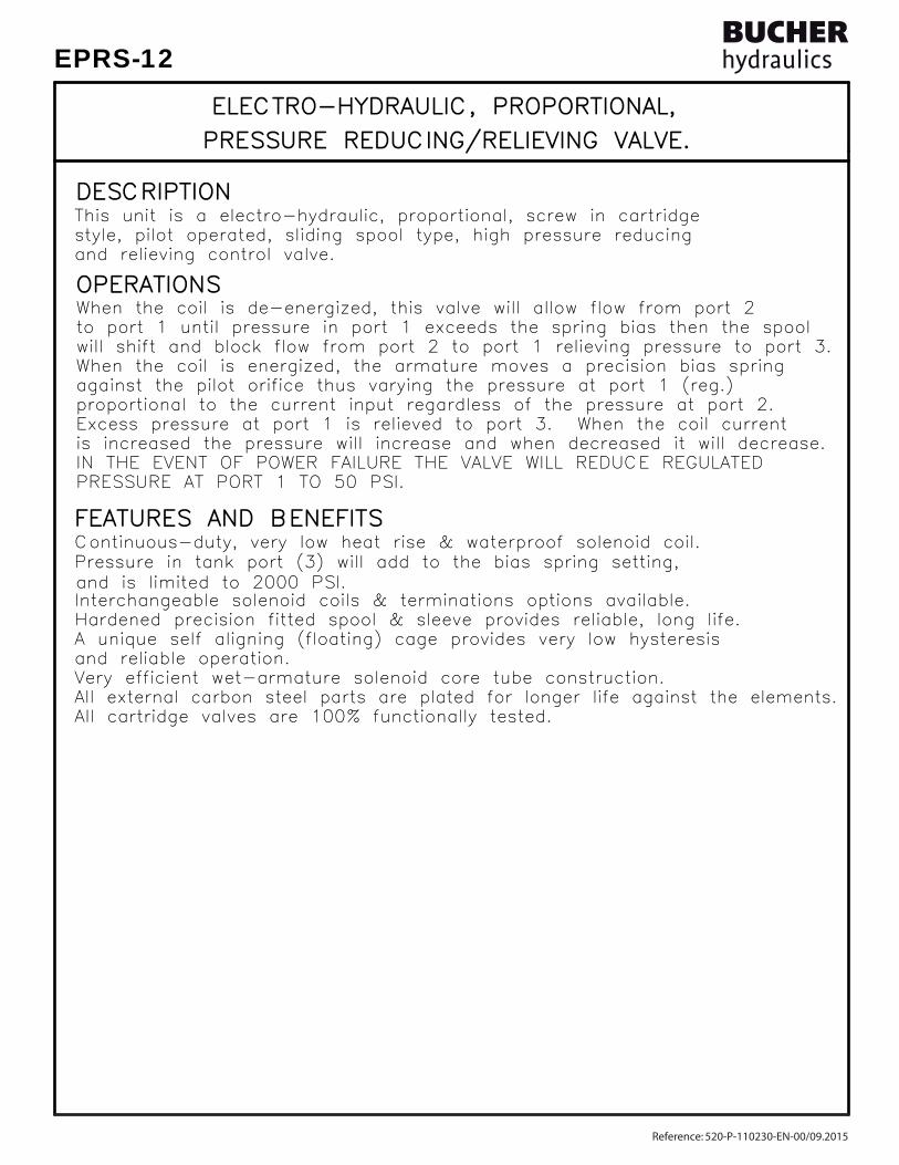
and relieving control valve.and relieving control valve.style, pilot operated, sliding spool type, high pressure reducingstyle, pilot operated, sliding spool type, high pressure reducingThis unit is a electro-hydraulic, proportional, screw in cartridgeThis unit is a electro-hydraulic, proportional, screw in cartridge
and reliable operation.and reliable operation.A unique self aligning (floating) cage provides very low hysteresisA unique self aligning (floating) cage provides very low hysteresisHardened precision fitted spool & sleeve provides reliable, long life.Hardened precision fitted spool & sleeve provides reliable, long life.Interchangeable solenoid coils & terminations options available.Interchangeable solenoid coils & terminations options available.
Continuous-duty, very low heat rise & waterproof solenoid coil.Continuous-duty, very low heat rise & waterproof solenoid coil.
PRESSURE AT PORT 1 TO 50 PSI.PRESSURE AT PORT 1 TO 50 PSI.IN THE EVENT OF POWER FAILURE THE VALVE WILL REDUCE REGULATEDIN THE EVENT OF POWER FAILURE THE VALVE WILL REDUCE REGULATEDis increased the pressure will increase and when decreased it will decrease.is increased the pressure will increase and when decreased it will decrease.
proportional to the current input regardless of the pressure at port 2.proportional to the current input regardless of the pressure at port 2.against the pilot orifice thus varying the pressure at port 1 (reg.)against the pilot orifice thus varying the pressure at port 1 (reg.)When the coil is energized, the armature moves a precision bias springWhen the coil is energized, the armature moves a precision bias springwill shift and block flow from port 2 to port 1 relieving pressure to port 3.will shift and block flow from port 2 to port 1 relieving pressure to port 3.to port 1 until pressure in port 1 exceeds the spring bias then the spoolto port 1 until pressure in port 1 exceeds the spring bias then the spoolWhen the coil is de-energized, this valve will allow flow from port 2When the coil is de-energized, this valve will allow flow from port 2
Excess pressure at port 1 is relieved to port 3. When the coil currentExcess pressure at port 1 is relieved to port 3. When the coil current
Pressure in tank port (3) will add to the bias spring setting,Pressure in tank port (3) will add to the bias spring setting,and is limited to 2000 PSI.and is limited to 2000 PSI.
ELECTRO-HYDRAULIC, PROPORTIONAL, ELECTRO-HYDRAULIC, PROPORTIONAL,
PRESSURE REDUCING/RELIEVING VALVE. PRESSURE REDUCING/RELIEVING VALVE.
Reference: 520-P-110220-EN-00/09.2015
EPRS-10

SPECIFICATIONSSPECIFICATIONS
VALVE CAVITY: #C1030, See Page 0-032.0.VALVE CAVITY: #C1030, See Page 0-032.0.WEIGHT: 1.95 lb [.88 kg] cartridge with coil only.WEIGHT: 1.95 lb [.88 kg] cartridge with coil only.INSTALLATION: No restrictions.INSTALLATION: No restrictions. SKV-1031 Viton SKV-1031 VitonSEAL KIT: SKN-1031 Buna "N"SEAL KIT: SKN-1031 Buna "N"
24 VDC, Operating current 0.1 to 1.2 AMPS. 24 VDC, Operating current 0.1 to 1.2 AMPS.POWER REQUIREMENTS: 12 VDC, Operating current 0.2 to 2.4 AMPS.POWER REQUIREMENTS: 12 VDC, Operating current 0.2 to 2.4 AMPS. current control and a 50 Hz dither. current control and a 50 Hz dither.RESPONSE: The most efficient method to control this valve is withRESPONSE: The most efficient method to control this valve is with
INTERNAL PILOT FLOW: 20 cu.in/min [0,50 l/m] @ 5,000 PSI [350 Bar]INTERNAL PILOT FLOW: 20 cu.in/min [0,50 l/m] @ 5,000 PSI [350 Bar]FLOW: 12.0 GPM [46,0 L/M] nominal.FLOW: 12.0 GPM [46,0 L/M] nominal.REGULATED PRESSURE: 50 to 5000 PSI [3,5 to 345] See performance chart.REGULATED PRESSURE: 50 to 5000 PSI [3,5 to 345] See performance chart.PROOF PRESSURE: 10,000 PSI [700 Bar]PROOF PRESSURE: 10,000 PSI [700 Bar]OPERATING PRESSURE: 5,000 PSI [350 Bar]OPERATING PRESSURE: 5,000 PSI [350 Bar]
ELECTRO-HYDRAULIC, PROPORTIONAL, ELECTRO-HYDRAULIC, PROPORTIONAL,
PRESSURE REDUCING/RELIEVING VALVE. PRESSURE REDUCING/RELIEVING VALVE.
MIL-H-5606, SAE-#10, SAE-#20, etc. MIL-H-5606, SAE-#10, SAE-#20, etc.OPERATING MEDIA: All general purpose hydraulic fluids such asOPERATING MEDIA: All general purpose hydraulic fluids such asOPERATING TEMPERATURE: -40° to +250° F. [-40° to +120° C.]OPERATING TEMPERATURE: -40° to +250° F. [-40° to +120° C.] 5000 PSI [350 Bar] = Steel - Unplated. 5000 PSI [350 Bar] = Steel - Unplated.VALVE HOUSINGS: 2500 PSI [175 Bar] = Aluminum - Anodized.VALVE HOUSINGS: 2500 PSI [175 Bar] = Aluminum - Anodized.
[email protected] www.bucherhydraulics.com/commoncavity
2015 by Bucher Hydraulics, Inc., 2545 Northwest Parkway, Elgin, Illinois 60124, USAAll rights reserved.The technical information in this catalog, may contain calculated figures (for reference only) and not actual performance data for this product.Data is provided for the purpose of product description only, and must not be construed as warranted characteristics in the legal sense. The information does not relieve users from the duty of conducting their own evaluations and tests. Because the products are subject to continual improvement, we reserve the right to amend the product specifications contained in this catalogue.
©
Reference: 520-P-110220-EN-00/09.2015
EPRS-10
TYPE "L" COIL TYPE "L" COIL SEE PAGE SEE PAGE 10-001.210-001.2
1
32
REGULATED PRESSURE
REGULATED PRESSURE
AMPERAGE (AMPS) @ 12 VDCAMPERAGE (AMPS) @ 12 VDC0.900.90
PSIPSI0.600.600.300.30
10001000
20002000
2.102.101.501.501.201.20 1.801.80BARBAR
2.402.40
138138
69 69
AMPERAGE (AMPS) @ 24 VDCAMPERAGE (AMPS) @ 24 VDC
0.450.45
30003000
40004000
500050000.300.300.150.15
[67,6][67,6]2.66"2.66"
1.051.050.750.750.600.60 0.900.90
207207
276276
3453451.201.20
[131,3][131,3]5.17"5.17"
MANUAL OVERRIDEMANUAL OVERRIDE( SCREW TYPE )( SCREW TYPE )
[45,2][45,2]1.78"1.78"
[101,6][101,6]
[88,9][88,9] 3.50" 3.50"
4.00" 4.00" 1.31" 1.31"
HEXHEX
[33,4] [33,4]
3
2
1NOTES:NOTES:1. FOR ALUMINUM OR STEEL VALVE HOUSING CONFIGURATIONS SEE PAGE 0-033.11. FOR ALUMINUM OR STEEL VALVE HOUSING CONFIGURATIONS SEE PAGE 0-033.12. SOLENOIDS AVAILABLE WITH DIODES - CONSULT FACTORY.2. SOLENOIDS AVAILABLE WITH DIODES - CONSULT FACTORY.
LTBGWDM
TERMINALS TERMINALS=18GA. 24" LEADS=18GA. 24" LEADS=SPADE TERM.=SPADE TERM.=BOLT TERM.=BOLT TERM.=DIN43650=DIN43650=WEATHER-PACK=WEATHER-PACK=DEUTSCH-DT04-2P=DEUTSCH-DT04-2P=METRI-PACK CONN.=METRI-PACK CONN.
12D12D24D24D
VOLTAGE VOLTAGE= 12 VDC= 12 VDC= 24 VDC= 24 VDC
AMPSAMPS 3.00 3.00 1.50 1.50
= BUNA "N"= BUNA "N"= VITON= VITON
SEALSSEALSNV
SIZESIZE12 = 1.062"-12UNF12 = 1.062"-12UNF
BASICBASIC
REGULATED PRESSUREREGULATED PRESSURE151530305050
= 50 TO 1500 PSI= 50 TO 1500 PSI= 50 TO 3000 PSI= 50 TO 3000 PSI= 50 TO 5000 PSI= 50 TO 5000 PSI
12TX = SAE - #12 12TX = SAE - #12 10TX = SAE - #10 10TX = SAE - #10 6BX = G 3/4" BSPP 6BX = G 3/4" BSPP 4BX = G 1/2" BSPP 4BX = G 1/2" BSPP 0 = CARTRIDGE 0 = CARTRIDGE PORTS PORTS
"S" - STEEL HOUSING"S" - STEEL HOUSING"A" - ALUM. HOUSING"A" - ALUM. HOUSING
= MANUAL OVERRIDE= MANUAL OVERRIDEADJUSTMENT OPTIONSADJUSTMENT OPTIONSM
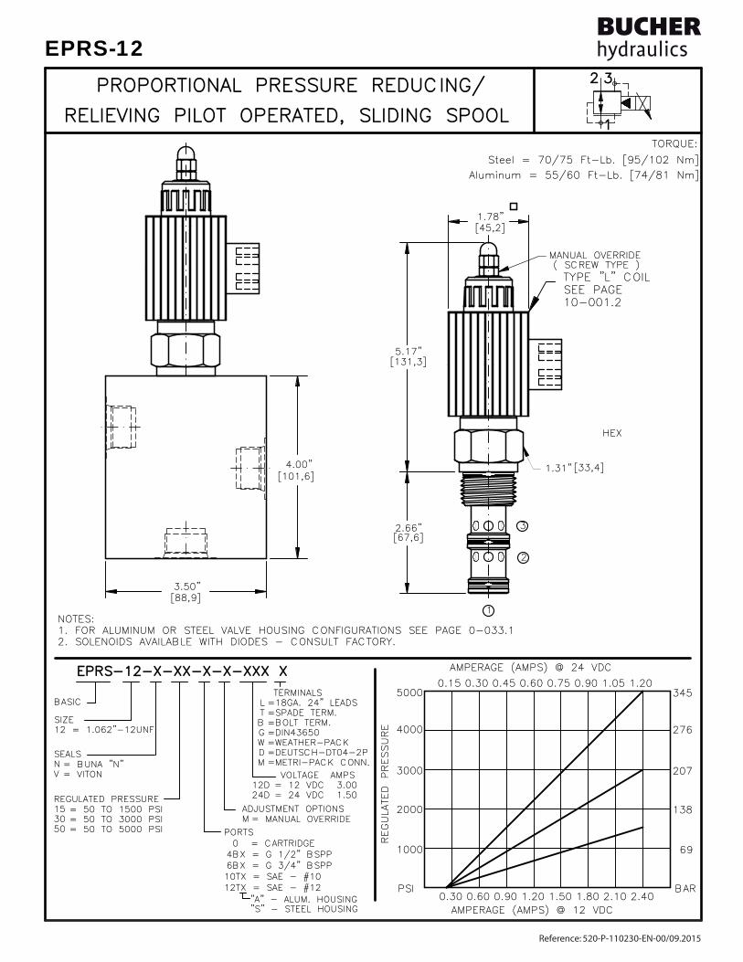
EPRS-12-X-XX-X-X-XXX XEPRS-12-X-XX-X-X-XXX X
RELIEVING PILOT OPERATED, SLIDING SPOOL RELIEVING PILOT OPERATED, SLIDING SPOOL
PROPORTIONAL PRESSURE REDUCING/PROPORTIONAL PRESSURE REDUCING/
Steel = 70/75 Ft-Lb. [95/102 Nm] Steel = 70/75 Ft-Lb. [95/102 Nm]
TORQUE:TORQUE:
Aluminum = 55/60 Ft-Lb. [74/81 Nm]Aluminum = 55/60 Ft-Lb. [74/81 Nm]
Reference: 520-P-110230-EN-00/09.2015
EPRS-12
FEATURES AND BENEFITSFEATURES AND BENEFITS
OPERATIONSOPERATIONS
DESCRIPTIONDESCRIPTION
and reliable operation.and reliable operation.
All cartridge valves are 100% functionally tested.All cartridge valves are 100% functionally tested.All external carbon steel parts are plated for longer life against the elements.All external carbon steel parts are plated for longer life against the elements.Very efficient wet-armature solenoid core tube construction.Very efficient wet-armature solenoid core tube construction.
and relieving control valve.and relieving control valve.style, pilot operated, sliding spool type, high pressure reducingstyle, pilot operated, sliding spool type, high pressure reducingThis unit is a electro-hydraulic, proportional, screw in cartridgeThis unit is a electro-hydraulic, proportional, screw in cartridge
A unique self aligning (floating) cage provides very low hysteresisA unique self aligning (floating) cage provides very low hysteresisHardened precision fitted spool & sleeve provides reliable, long life.Hardened precision fitted spool & sleeve provides reliable, long life.Interchangeable solenoid coils & terminations options available.Interchangeable solenoid coils & terminations options available.
Continuous-duty, very low heat rise & waterproof solenoid coil.Continuous-duty, very low heat rise & waterproof solenoid coil.Pressure in tank port (3) will add to the bias spring setting,Pressure in tank port (3) will add to the bias spring setting,and is limited to 2000 PSI.and is limited to 2000 PSI.
ELECTRO-HYDRAULIC, PROPORTIONAL,ELECTRO-HYDRAULIC, PROPORTIONAL,
PRESSURE REDUCING/RELIEVING VALVE. PRESSURE REDUCING/RELIEVING VALVE.
PRESSURE AT PORT 1 TO 50 PSI.PRESSURE AT PORT 1 TO 50 PSI.IN THE EVENT OF POWER FAILURE THE VALVE WILL REDUCE REGULATEDIN THE EVENT OF POWER FAILURE THE VALVE WILL REDUCE REGULATEDis increased the pressure will increase and when decreased it will decrease.is increased the pressure will increase and when decreased it will decrease.
proportional to the current input regardless of the pressure at port 2.proportional to the current input regardless of the pressure at port 2.against the pilot orifice thus varying the pressure at port 1 (reg.)against the pilot orifice thus varying the pressure at port 1 (reg.)When the coil is energized, the armature moves a precision bias springWhen the coil is energized, the armature moves a precision bias springwill shift and block flow from port 2 to port 1 relieving pressure to port 3.will shift and block flow from port 2 to port 1 relieving pressure to port 3.to port 1 until pressure in port 1 exceeds the spring bias then the spoolto port 1 until pressure in port 1 exceeds the spring bias then the spoolWhen the coil is de-energized, this valve will allow flow from port 2When the coil is de-energized, this valve will allow flow from port 2
Excess pressure at port 1 is relieved to port 3. When the coil currentExcess pressure at port 1 is relieved to port 3. When the coil current
Reference: 520-P-110230-EN-00/09.2015
EPRS-12
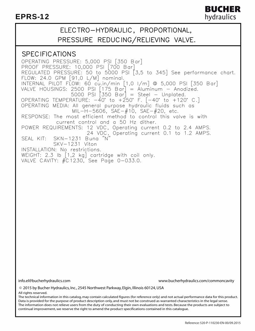
SPECIFICATIONSSPECIFICATIONS
VALVE CAVITY: #C1230, See Page 0-033.0.VALVE CAVITY: #C1230, See Page 0-033.0.WEIGHT: 2.3 lb [1,2 kg] cartridge with coil only.WEIGHT: 2.3 lb [1,2 kg] cartridge with coil only.INSTALLATION: No restrictions.INSTALLATION: No restrictions. SKV-1231 Viton SKV-1231 VitonSEAL KIT: SKN-1231 Buna "N"SEAL KIT: SKN-1231 Buna "N"
24 VDC, Operating current 0.1 to 1.2 AMPS. 24 VDC, Operating current 0.1 to 1.2 AMPS.POWER REQUIREMENTS: 12 VDC, Operating current 0.2 to 2.4 AMPS.POWER REQUIREMENTS: 12 VDC, Operating current 0.2 to 2.4 AMPS. current control and a 50 Hz dither. current control and a 50 Hz dither.RESPONSE: The most efficient method to control this valve is withRESPONSE: The most efficient method to control this valve is with
INTERNAL PILOT FLOW: 60 cu.in/min [1,0 l/m] @ 5,000 PSI [350 Bar]INTERNAL PILOT FLOW: 60 cu.in/min [1,0 l/m] @ 5,000 PSI [350 Bar]FLOW: 24.0 GPM [91,0 L/M] nominal.FLOW: 24.0 GPM [91,0 L/M] nominal.REGULATED PRESSURE: 50 to 5000 PSI [3,5 to 345] See performance chart.REGULATED PRESSURE: 50 to 5000 PSI [3,5 to 345] See performance chart.PROOF PRESSURE: 10,000 PSI [700 Bar]PROOF PRESSURE: 10,000 PSI [700 Bar]OPERATING PRESSURE: 5,000 PSI [350 Bar]OPERATING PRESSURE: 5,000 PSI [350 Bar]
ELECTRO-HYDRAULIC, PROPORTIONAL,ELECTRO-HYDRAULIC, PROPORTIONAL,
PRESSURE REDUCING/RELIEVING VALVE. PRESSURE REDUCING/RELIEVING VALVE.
MIL-H-5606, SAE-#10, SAE-#20, etc. MIL-H-5606, SAE-#10, SAE-#20, etc.OPERATING MEDIA: All general purpose hydraulic fluids such asOPERATING MEDIA: All general purpose hydraulic fluids such asOPERATING TEMPERATURE: -40° to +250° F. [-40° to +120° C.]OPERATING TEMPERATURE: -40° to +250° F. [-40° to +120° C.] 5000 PSI [350 Bar] = Steel - Unplated. 5000 PSI [350 Bar] = Steel - Unplated.VALVE HOUSINGS: 2500 PSI [175 Bar] = Aluminum - Anodized.VALVE HOUSINGS: 2500 PSI [175 Bar] = Aluminum - Anodized.
[email protected] www.bucherhydraulics.com/commoncavity
2015 by Bucher Hydraulics, Inc., 2545 Northwest Parkway, Elgin, Illinois 60124, USAAll rights reserved.The technical information in this catalog, may contain calculated figures (for reference only) and not actual performance data for this product.Data is provided for the purpose of product description only, and must not be construed as warranted characteristics in the legal sense. The information does not relieve users from the duty of conducting their own evaluations and tests. Because the products are subject to continual improvement, we reserve the right to amend the product specifications contained in this catalogue.
©
Reference: 520-P-110230-EN-00/09.2015
EPRS-12

TYPE "L" COIL TYPE "L" COIL SEE PAGE SEE PAGE 10-001.210-001.2
2
1
REGULATED PRESSURE
REGULATED PRESSURE
0.900.90PSIPSI
0.600.600.300.30
10001000
20002000
2.102.101.501.501.201.20 1.801.80BARBAR
2.402.40
138138
69 69
AMPERAGE (AMPS) @ 24 VDCAMPERAGE (AMPS) @ 24 VDC
0.450.45
30003000
40004000
500050000.300.300.150.15
[32,5][32,5]1.28"1.28"
1.051.050.750.750.600.60 0.900.90
207207
276276
3503501.201.20
Pat.#5,546,980Pat.#5,546,980
2.00" 2.00"[50,8][50,8]
2.00" 2.00"[50,8][50,8]
1
2
5.10"5.10"[129,5][129,5]
MANUAL OVERRIDEMANUAL OVERRIDE( SCREW TYPE )( SCREW TYPE )
1.78"1.78"[45,2][45,2]
1.06" [27,0] HEX1.06" [27,0] HEX
AMPERAGE (AMPS) @ 12 VDCAMPERAGE (AMPS) @ 12 VDC
NOTES:NOTES:1. FOR ALUMINUM OR STEEL VALVE HOUSING CONFIGURATIONS SEE PAGE 0-012.11. FOR ALUMINUM OR STEEL VALVE HOUSING CONFIGURATIONS SEE PAGE 0-012.12. SOLENOIDS AVAILABLE WITH DIODES - CONSULT FACTORY.2. SOLENOIDS AVAILABLE WITH DIODES - CONSULT FACTORY.
LTBGWDM
TERMINALS TERMINALS=18GA. 24" LEADS=18GA. 24" LEADS=SPADE TERM.=SPADE TERM.=BOLT TERM.=BOLT TERM.=DIN43650=DIN43650=WEATHER-PACK=WEATHER-PACK=DEUTSCH-DT04-2P=DEUTSCH-DT04-2P=METRI-PACK CONN.=METRI-PACK CONN.
12D12D24D24D
VOLTAGE VOLTAGE= 12 VDC= 12 VDC= 24 VDC= 24 VDC
AMPSAMPS 3.00 3.00 1.50 1.50
= BUNA "N"= BUNA "N"= VITON= VITON
SEALSSEALSNV
SIZESIZE10 = 7/8"-14UNF10 = 7/8"-14UNF
BASICBASIC
REGULATED PRESSUREREGULATED PRESSURE151530305050
= 50 TO 1500 PSI= 50 TO 1500 PSI= 50 TO 3000 PSI= 50 TO 3000 PSI= 50 TO 5000 PSI= 50 TO 5000 PSI
PORTSPORTS0
02BX02BX06BX06BX06TX06TX08TX08TX
= CARTRIDGE ONLY= CARTRIDGE ONLY= G 1/4" BSPP= G 1/4" BSPP= G 3/8" BSPP= G 3/8" BSPP= SAE - #6= SAE - #6= SAE - #8= SAE - #8 "A" = ALUM. HOUSING "A" = ALUM. HOUSING "S" = STEEL HOUSING "S" = STEEL HOUSING
= MANUAL OVERRIDE= MANUAL OVERRIDEADJUSTMENT OPTIONSADJUSTMENT OPTIONSM
ERVP-10-X-XX-X-X-XXX XERVP-10-X-XX-X-X-XXX X
PROPORTIONAL PRESSURE RELIEF VALVE.PROPORTIONAL PRESSURE RELIEF VALVE.
PILOT OPERATED, SLIDING SPOOL TYPE.PILOT OPERATED, SLIDING SPOOL TYPE.
Steel = 55/60 Ft-Lb. [74/81 Nm] Steel = 55/60 Ft-Lb. [74/81 Nm]
TORQUE:TORQUE:
Aluminum = 35/40 Ft-Lb. [47/54 Nm]Aluminum = 35/40 Ft-Lb. [47/54 Nm]
Reference: 520-P-110320-EN-00/09.2015
ERVP-10

FEATURES AND BENEFITSFEATURES AND BENEFITS
OPERATIONSOPERATIONS
DESCRIPTIONDESCRIPTION
Very efficient wet - armature solenoid core tube construction.Very efficient wet - armature solenoid core tube construction.
Industry common cavity.Industry common cavity.All cartridge valves are 100% functionally tested.All cartridge valves are 100% functionally tested.All external carbon steel parts are plated for longer life against the elements.All external carbon steel parts are plated for longer life against the elements.
AT PORT 1 WILL BE THE SPRING BIAS.AT PORT 1 WILL BE THE SPRING BIAS.IN THE EVENT OF POWER FAILURE THE VALVE RELIEF PRESSURE SETTINGIN THE EVENT OF POWER FAILURE THE VALVE RELIEF PRESSURE SETTINGcoil the relief pressure will increase and when decreased it will decrease.coil the relief pressure will increase and when decreased it will decrease.proportional to the current input. When the current is increased to theproportional to the current input. When the current is increased to theagainst the pilot orifice thus varying the pressure setting at port 1against the pilot orifice thus varying the pressure setting at port 1When the coil is energized the armature moves a precision bias springWhen the coil is energized the armature moves a precision bias springfrom port 1 to port 2 if pressure exceeds the spring bias (50 psi).from port 1 to port 2 if pressure exceeds the spring bias (50 psi).When the coil is de-energized, this valve allows flow and pressureWhen the coil is de-energized, this valve allows flow and pressure
and reliable operation.and reliable operation.A unique self aligning (floating) cage provides very low hysteresisA unique self aligning (floating) cage provides very low hysteresisHardened precision fitted spool & sleeve provides reliable, long life.Hardened precision fitted spool & sleeve provides reliable, long life.Interchangeable solenoid coils & terminations options available.Interchangeable solenoid coils & terminations options available.
Continuous-duty, very low heat rise & waterproof solenoid coil.Continuous-duty, very low heat rise & waterproof solenoid coil.
pilot operated, sliding spool type, high pressure relief valve.pilot operated, sliding spool type, high pressure relief valve.This unit is a electro-hydraulic, proportional, screw in cartridge style,This unit is a electro-hydraulic, proportional, screw in cartridge style,
Pressure in tank port (2) will add to the bias spring setting,Pressure in tank port (2) will add to the bias spring setting,and is limited to 2000 PSI.and is limited to 2000 PSI.
ELECTRO-HYDRAULIC, PROPORTIONAL, ELECTRO-HYDRAULIC, PROPORTIONAL,
PRESSURE RELIEF VALVE. PRESSURE RELIEF VALVE.
Reference: 520-P-110320-EN-00/09.2015
ERVP-10

SPECIFICATIONSSPECIFICATIONS
VALVE CAVITY: #C1020, See Page 0-012.0.VALVE CAVITY: #C1020, See Page 0-012.0.WEIGHT: 1.95 lb [.88 kg] cartridge with coil only.WEIGHT: 1.95 lb [.88 kg] cartridge with coil only.INSTALLATION: No restrictions.INSTALLATION: No restrictions.
SKV-1022 Viton SKV-1022 VitonSEAL KIT: SKN-1022 Buna "N"SEAL KIT: SKN-1022 Buna "N"
24 VDC, Operating current 0.1 to 1.2 AMPS. 24 VDC, Operating current 0.1 to 1.2 AMPS.POWER REQUIREMENTS: 12 VDC, Operating current 0.2 to 2.4 AMPS.POWER REQUIREMENTS: 12 VDC, Operating current 0.2 to 2.4 AMPS. current control and a 50 Hz dither. current control and a 50 Hz dither.RESPONSE: The most efficient method to control this valve is withRESPONSE: The most efficient method to control this valve is with
INTERNAL PILOT FLOW: 60 cu.in/min [1,0 l/m] @ 3000 PSI [210 Bar]INTERNAL PILOT FLOW: 60 cu.in/min [1,0 l/m] @ 3000 PSI [210 Bar]FLOW: 25.0 GPM [95,0 L/M] nominal.FLOW: 25.0 GPM [95,0 L/M] nominal.REGULATED PRESSURE: 50 to 5000 PSI [3,5 to 345] See performance chart.REGULATED PRESSURE: 50 to 5000 PSI [3,5 to 345] See performance chart.PROOF PRESSURE: 10,000 PSI [700 Bar]PROOF PRESSURE: 10,000 PSI [700 Bar]OPERATING PRESSURE: 5000 PSI [350 Bar]OPERATING PRESSURE: 5000 PSI [350 Bar]
ELECTRO-HYDRAULIC, PROPORTIONAL, ELECTRO-HYDRAULIC, PROPORTIONAL,
PRESSURE RELIEF VALVE. PRESSURE RELIEF VALVE.
MIL-H-5606, SAE-#10, SAE-#20, etc. MIL-H-5606, SAE-#10, SAE-#20, etc.OPERATING MEDIA: All general purpose hydraulic fluids such asOPERATING MEDIA: All general purpose hydraulic fluids such asOPERATING TEMPERATURE: -40° to +250° F. [-40° to +120° C.]OPERATING TEMPERATURE: -40° to +250° F. [-40° to +120° C.] 5000 PSI [350 Bar] = Steel - Unplated. 5000 PSI [350 Bar] = Steel - Unplated.VALVE HOUSINGS: 2500 PSI [175 Bar] = Aluminum - Anodized.VALVE HOUSINGS: 2500 PSI [175 Bar] = Aluminum - Anodized.
[email protected] www.bucherhydraulics.com/commoncavity
2015 by Bucher Hydraulics, Inc., 2545 Northwest Parkway, Elgin, Illinois 60124, USAAll rights reserved.The technical information in this catalog, may contain calculated figures (for reference only) and not actual performance data for this product.Data is provided for the purpose of product description only, and must not be construed as warranted characteristics in the legal sense. The information does not relieve users from the duty of conducting their own evaluations and tests. Because the products are subject to continual improvement, we reserve the right to amend the product specifications contained in this catalogue.
©
Reference: 520-P-110320-EN-00/09.2015
ERVP-10

TYPE "L" COIL TYPE "L" COIL SEE PAGE SEE PAGE 10-001.210-001.2
2
1
REGULATED PRESSURE
REGULATED PRESSURE
0.900.90PSIPSI
0.600.600.300.30
10001000
20002000
2.102.101.501.501.201.20 1.801.80BARBAR
2.402.40
138138
69 69
0.450.45
AMPERAGE (AMPS) @ 24 VDCAMPERAGE (AMPS) @ 24 VDC
30003000
40004000
500050000.300.300.150.15 1.051.050.750.750.600.60 0.900.90
276276
207207
3503501.201.20
Pat.#5,546,980Pat.#5,546,980
2.75"2.75"
2.75"2.75"[69,9][69,9]
[69,9][69,9]
2
1
[131,3][131,3]
( SCREW TYPE )( SCREW TYPE )MANUAL OVERRIDEMANUAL OVERRIDE
5.17"5.17"
1.31" 1.31"
1.78"1.78"[45,2][45,2]
HEXHEX
[33,4] [33,4]
[44,5][44,5]1.75"1.75"
AMPERAGE (AMPS) @ 12 VDCAMPERAGE (AMPS) @ 12 VDC
NOTES:NOTES:1. FOR ALUMINUM OR STEEL VALVE HOUSING CONFIGURATIONS SEE PAGE 0-013.11. FOR ALUMINUM OR STEEL VALVE HOUSING CONFIGURATIONS SEE PAGE 0-013.12. SOLENOIDS AVAILABLE WITH DIODES - CONSULT FACTORY.2. SOLENOIDS AVAILABLE WITH DIODES - CONSULT FACTORY.
LTBGWDM
TERMINALS TERMINALS=18GA. 24" LEADS=18GA. 24" LEADS=SPADE TERM.=SPADE TERM.=BOLT TERM.=BOLT TERM.=DIN43650=DIN43650=WEATHER-PACK=WEATHER-PACK=DEUTSCH-DT04-2P=DEUTSCH-DT04-2P=METRI-PACK CONN.=METRI-PACK CONN.
12D12D24D24D
VOLTAGE VOLTAGE= 12 VDC= 12 VDC= 24 VDC= 24 VDC
AMPSAMPS 3.00 3.00 1.50 1.50
= BUNA "N"= BUNA "N"= VITON= VITON
SEALSSEALSNV
SIZESIZE12 = 1.062"-12UNF12 = 1.062"-12UNF
BASICBASIC
REGULATED PRESSUREREGULATED PRESSURE151530305050
= 50 TO 1500 PSI= 50 TO 1500 PSI= 50 TO 3000 PSI= 50 TO 3000 PSI= 50 TO 5000 PSI= 50 TO 5000 PSI
12TX = SAE - #12 12TX = SAE - #12 10TX = SAE - #10 10TX = SAE - #10 6BX = G 3/4" BSPP 6BX = G 3/4" BSPP 4BX = G 1/2" BSPP 4BX = G 1/2" BSPP 0 = CARTRIDGE 0 = CARTRIDGE PORTS PORTS
"S" - STEEL HOUSING"S" - STEEL HOUSING"A" - ALUM. HOUSING"A" - ALUM. HOUSING
= MANUAL OVERRIDE= MANUAL OVERRIDEADJUSTMENT OPTIONSADJUSTMENT OPTIONSM
ERVP-12-X-XX-X-X-XXX XERVP-12-X-XX-X-X-XXX X
PILOT OPERATED, SLIDING SPOOL TYPE.PILOT OPERATED, SLIDING SPOOL TYPE.
PROPORTIONAL PRESSURE RELIEF VALVE.PROPORTIONAL PRESSURE RELIEF VALVE.
Steel = 70/75 Ft-Lb. [95/102 Nm] Steel = 70/75 Ft-Lb. [95/102 Nm]
TORQUE:TORQUE:
Aluminum = 55/60 Ft-Lb. [74/81 Nm]Aluminum = 55/60 Ft-Lb. [74/81 Nm]
Reference: 520-P-110330-EN-00/09.2015
ERVP-12

FEATURES AND BENEFITSFEATURES AND BENEFITS
OPERATIONSOPERATIONS
DESCRIPTIONDESCRIPTION
Very efficient wet - armature solenoid core tube construction.Very efficient wet - armature solenoid core tube construction.
All cartridge valves are 100% functionally tested.All cartridge valves are 100% functionally tested.All external carbon steel parts are plated for longer life against the elements.All external carbon steel parts are plated for longer life against the elements.
pilot operated, sliding spool type, high pressure relief valve.pilot operated, sliding spool type, high pressure relief valve.This unit is a electro-hydraulic, proportional, screw in cartridge style,This unit is a electro-hydraulic, proportional, screw in cartridge style,
and reliable operation.and reliable operation.A unique self aligning (floating) cage provides very low hysteresisA unique self aligning (floating) cage provides very low hysteresisHardened precision fitted spool & sleeve provides reliable, long life.Hardened precision fitted spool & sleeve provides reliable, long life.Interchangeable solenoid coils & terminations options available.Interchangeable solenoid coils & terminations options available.
Continuous-duty, very low heat rise & waterproof solenoid coil.Continuous-duty, very low heat rise & waterproof solenoid coil.Pressure in tank port (2) will add to the bias spring setting,Pressure in tank port (2) will add to the bias spring setting,and is limited to 2000 PSI.and is limited to 2000 PSI.
ELECTRO-HYDRAULIC, PROPORTIONAL, ELECTRO-HYDRAULIC, PROPORTIONAL,
PRESSURE RELIEF VALVE. PRESSURE RELIEF VALVE.
AT PORT 1 WILL BE THE SPRING BIAS.AT PORT 1 WILL BE THE SPRING BIAS.IN THE EVENT OF POWER FAILURE THE VALVE RELIEF PRESSURE SETTINGIN THE EVENT OF POWER FAILURE THE VALVE RELIEF PRESSURE SETTINGcoil the relief pressure will increase and when decreased it will decrease.coil the relief pressure will increase and when decreased it will decrease.proportional to the current input. When the current is increased to theproportional to the current input. When the current is increased to theagainst the pilot orifice thus varying the pressure setting at port 1against the pilot orifice thus varying the pressure setting at port 1When the coil is energized the armature moves a precision bias springWhen the coil is energized the armature moves a precision bias springfrom port 1 to port 2 if pressure exceeds the spring bias (50 psi).from port 1 to port 2 if pressure exceeds the spring bias (50 psi).When the coil is de-energized, this valve allows flow and pressureWhen the coil is de-energized, this valve allows flow and pressure
Reference: 520-P-110330-EN-00/09.2015
ERVP-12
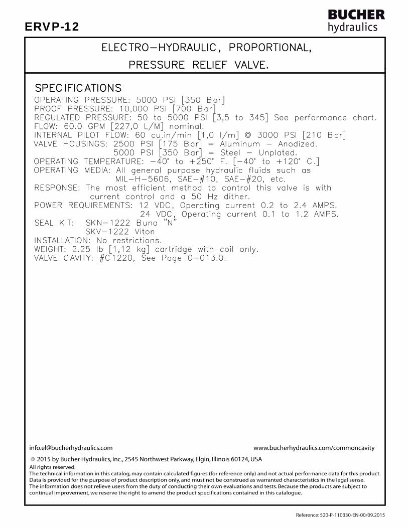
SPECIFICATIONSSPECIFICATIONS
VALVE CAVITY: #C1220, See Page 0-013.0.VALVE CAVITY: #C1220, See Page 0-013.0.WEIGHT: 2.25 lb [1,12 kg] cartridge with coil only.WEIGHT: 2.25 lb [1,12 kg] cartridge with coil only.INSTALLATION: No restrictions.INSTALLATION: No restrictions. SKV-1222 Viton SKV-1222 VitonSEAL KIT: SKN-1222 Buna "N"SEAL KIT: SKN-1222 Buna "N"
24 VDC, Operating current 0.1 to 1.2 AMPS. 24 VDC, Operating current 0.1 to 1.2 AMPS.POWER REQUIREMENTS: 12 VDC, Operating current 0.2 to 2.4 AMPS.POWER REQUIREMENTS: 12 VDC, Operating current 0.2 to 2.4 AMPS. current control and a 50 Hz dither. current control and a 50 Hz dither.RESPONSE: The most efficient method to control this valve is withRESPONSE: The most efficient method to control this valve is with
INTERNAL PILOT FLOW: 60 cu.in/min [1,0 l/m] @ 3000 PSI [210 Bar]INTERNAL PILOT FLOW: 60 cu.in/min [1,0 l/m] @ 3000 PSI [210 Bar]FLOW: 60.0 GPM [227,0 L/M] nominal.FLOW: 60.0 GPM [227,0 L/M] nominal.REGULATED PRESSURE: 50 to 5000 PSI [3,5 to 345] See performance chart.REGULATED PRESSURE: 50 to 5000 PSI [3,5 to 345] See performance chart.PROOF PRESSURE: 10,000 PSI [700 Bar]PROOF PRESSURE: 10,000 PSI [700 Bar]OPERATING PRESSURE: 5000 PSI [350 Bar]OPERATING PRESSURE: 5000 PSI [350 Bar]
ELECTRO-HYDRAULIC, PROPORTIONAL, ELECTRO-HYDRAULIC, PROPORTIONAL,
PRESSURE RELIEF VALVE. PRESSURE RELIEF VALVE.
MIL-H-5606, SAE-#10, SAE-#20, etc. MIL-H-5606, SAE-#10, SAE-#20, etc.OPERATING MEDIA: All general purpose hydraulic fluids such asOPERATING MEDIA: All general purpose hydraulic fluids such asOPERATING TEMPERATURE: -40° to +250° F. [-40° to +120° C.]OPERATING TEMPERATURE: -40° to +250° F. [-40° to +120° C.] 5000 PSI [350 Bar] = Steel - Unplated. 5000 PSI [350 Bar] = Steel - Unplated.VALVE HOUSINGS: 2500 PSI [175 Bar] = Aluminum - Anodized.VALVE HOUSINGS: 2500 PSI [175 Bar] = Aluminum - Anodized.
[email protected] www.bucherhydraulics.com/commoncavity
2015 by Bucher Hydraulics, Inc., 2545 Northwest Parkway, Elgin, Illinois 60124, USAAll rights reserved.The technical information in this catalog, may contain calculated figures (for reference only) and not actual performance data for this product.Data is provided for the purpose of product description only, and must not be construed as warranted characteristics in the legal sense. The information does not relieve users from the duty of conducting their own evaluations and tests. Because the products are subject to continual improvement, we reserve the right to amend the product specifications contained in this catalogue.
©
Reference: 520-P-110330-EN-00/09.2015
ERVP-12

TYPE "L" COIL TYPE "L" COIL SEE PAGE SEE PAGE 10-001.210-001.2
2
1
REGULATED PRESSURE
REGULATED PRESSURE
0.900.90PSIPSI
0.600.600.300.30
10001000
20002000
2.102.101.501.501.201.20 1.801.80BARBAR
2.402.40
138138
69 69
AMPERAGE (AMPS) @ 24 VDCAMPERAGE (AMPS) @ 24 VDC
0.450.45
30003000
40004000
500050000.300.300.150.15
[32,5][32,5]1.28"1.28"
1.051.050.750.750.600.60 0.900.90
207207
276276
3453451.201.20
Pat.#5,546,980Pat.#5,546,980
[50,8][50,8]
[50,8][50,8] 2.00" 2.00"
2.00" 2.00"
1
2
5.10"5.10"[129,5][129,5]
1.06" [27,0] HEX1.06" [27,0] HEX
MANUAL OVERRIDEMANUAL OVERRIDE( SCREW TYPE )( SCREW TYPE )
1.78"1.78"[45,2][45,2]
AMPERAGE (AMPS) @ 12 VDCAMPERAGE (AMPS) @ 12 VDC
NOTES:NOTES:1. FOR ALUMINUM OR STEEL VALVE HOUSING CONFIGURATIONS SEE PAGE 0-012.11. FOR ALUMINUM OR STEEL VALVE HOUSING CONFIGURATIONS SEE PAGE 0-012.12. SOLENOIDS AVAILABLE WITH DIODES - CONSULT FACTORY.2. SOLENOIDS AVAILABLE WITH DIODES - CONSULT FACTORY.
LTBGWDM
TERMINALS TERMINALS=18GA. 24" LEADS=18GA. 24" LEADS=SPADE TERM.=SPADE TERM.=BOLT TERM.=BOLT TERM.=DIN43650=DIN43650=WEATHER-PACK=WEATHER-PACK=DEUTSCH-DT04-2P=DEUTSCH-DT04-2P=METRI-PACK CONN.=METRI-PACK CONN.
12D12D24D24D
VOLTAGE VOLTAGE= 12 VDC= 12 VDC= 24 VDC= 24 VDC
AMPSAMPS 3.00 3.00 1.50 1.50
= BUNA "N"= BUNA "N"= VITON= VITON
SEALSSEALSNV
SIZESIZE10 = 7/8"-14UNF10 = 7/8"-14UNF
BASICBASIC
REGULATED PRESSUREREGULATED PRESSURE151530305050
= 0 TO 1500 PSI= 0 TO 1500 PSI= 0 TO 3000 PSI= 0 TO 3000 PSI= 0 TO 5000 PSI= 0 TO 5000 PSI PORTSPORTS
002BX02BX06BX06BX06TX06TX08TX08TX
= CARTRIDGE ONLY= CARTRIDGE ONLY= G 1/4" BSPP= G 1/4" BSPP= G 3/8" BSPP= G 3/8" BSPP= SAE - #6= SAE - #6= SAE - #8= SAE - #8 "A" = ALUM. HOUSING "A" = ALUM. HOUSING "S" = STEEL HOUSING "S" = STEEL HOUSING
= MANUAL OVERRIDE= MANUAL OVERRIDEADJUSTMENT OPTIONSADJUSTMENT OPTIONSM
ERVD-10-X-XX-X-X-XXX XERVD-10-X-XX-X-X-XXX X
PROPORTIONAL PRESSURE RELIEF VALVE.PROPORTIONAL PRESSURE RELIEF VALVE.DIRECT ACTING, LOW FLOW, POPPET TYPE.DIRECT ACTING, LOW FLOW, POPPET TYPE.
Steel = 55/60 Ft-Lb. [74/81 Nm] Steel = 55/60 Ft-Lb. [74/81 Nm]
TORQUE:TORQUE:
Aluminum = 35/40 Ft-Lb. [47/54 Nm]Aluminum = 35/40 Ft-Lb. [47/54 Nm]
Reference: 520-P-110420-EN-00/09.2015
ERVD-10

FEATURES AND BENEFITSFEATURES AND BENEFITS
OPERATIONSOPERATIONS
DESCRIPTIONDESCRIPTION
Very efficient wet - armature solenoid core tube construction.Very efficient wet - armature solenoid core tube construction.
Industry common cavity.Industry common cavity.All cartridge valves are 100% functionally tested.All cartridge valves are 100% functionally tested.All external carbon steel parts are plated for longer life against the elements.All external carbon steel parts are plated for longer life against the elements.
PRESSURE AT PORT 1 TO 0 PSI.PRESSURE AT PORT 1 TO 0 PSI.IN THE EVENT OF POWER FAILURE THE VALVE WILL REDUCE REGULATEDIN THE EVENT OF POWER FAILURE THE VALVE WILL REDUCE REGULATEDthe coil the pressure will increase and when decreased it will decrease.the coil the pressure will increase and when decreased it will decrease.proportional to the curent input. When the current is increased toproportional to the curent input. When the current is increased toagainst the metering poppet thus varying the pressure at port 1against the metering poppet thus varying the pressure at port 1When the coil is energized the armature moves a precision bias springWhen the coil is energized the armature moves a precision bias springfrom port 1 to port 2 (tank).from port 1 to port 2 (tank).When the coil is de-energized, this valve allows flow and pressureWhen the coil is de-energized, this valve allows flow and pressure
and reliable operation.and reliable operation.A unique self aligning (floating) cage provides very low hysteresisA unique self aligning (floating) cage provides very low hysteresisHardened precision poppet & pilot seat provides reliable, long life.Hardened precision poppet & pilot seat provides reliable, long life.Interchangeable solenoid coils & terminations options available.Interchangeable solenoid coils & terminations options available.
Continuous-duty, very low heat rise & waterproof solenoid coil.Continuous-duty, very low heat rise & waterproof solenoid coil.
style, direct acting, low flow, poppet type, high pressure reliefstyle, direct acting, low flow, poppet type, high pressure reliefThis unit is a electro-hydraulic, proportional, screw in cartridgeThis unit is a electro-hydraulic, proportional, screw in cartridge
valve.valve.
Pressure in tank port (2) will add to the bias spring setting,Pressure in tank port (2) will add to the bias spring setting,and is limited to 2000 PSI.and is limited to 2000 PSI.
ELECTRO-HYDRAULIC, PROPORTIONAL, ELECTRO-HYDRAULIC, PROPORTIONAL,
PRESSURE RELIEF VALVE. PRESSURE RELIEF VALVE.
Reference: 520-P-110420-EN-00/09.2015
ERVD-10

SPECIFICATIONSSPECIFICATIONS
VALVE CAVITY: #C1020, See Page 0-012.0.VALVE CAVITY: #C1020, See Page 0-012.0.WEIGHT: 1.95 lb [.88 kg] cartridge with coil only.WEIGHT: 1.95 lb [.88 kg] cartridge with coil only.INSTALLATION: No restrictions.INSTALLATION: No restrictions. SKV-1022 Viton SKV-1022 VitonSEAL KIT: SKN-1022 Buna "N"SEAL KIT: SKN-1022 Buna "N"
24 VDC, Operating current 0.1 to 1.2 AMPS. 24 VDC, Operating current 0.1 to 1.2 AMPS.POWER REQUIREMENTS: 12 VDC, Operating current 0.2 to 2.4 AMPS.POWER REQUIREMENTS: 12 VDC, Operating current 0.2 to 2.4 AMPS. current control and a 50 Hz dither. current control and a 50 Hz dither.
RESPONSE: The most efficient method to control this valve is withRESPONSE: The most efficient method to control this valve is with
FLOW: 1.0 GPM [3.8 L/M] nominal.FLOW: 1.0 GPM [3.8 L/M] nominal.REGULATED PRESSURE: 0 to 5000 PSI [0 to 350] See performance chart.REGULATED PRESSURE: 0 to 5000 PSI [0 to 350] See performance chart.PROOF PRESSURE: 10,000 PSI [700 Bar]PROOF PRESSURE: 10,000 PSI [700 Bar]OPERATING PRESSURE: 5000 PSI [350 Bar]OPERATING PRESSURE: 5000 PSI [350 Bar]
ELECTRO-HYDRAULIC, PROPORTIONAL, ELECTRO-HYDRAULIC, PROPORTIONAL,
PRESSURE RELIEF VALVE. PRESSURE RELIEF VALVE.
MIL-H-5606, SAE-#10, SAE-#20, etc. MIL-H-5606, SAE-#10, SAE-#20, etc.OPERATING MEDIA: All general purpose hydraulic fluids such asOPERATING MEDIA: All general purpose hydraulic fluids such asOPERATING TEMPERATURE: -40° to +250° F. [-40° to +120° C.]OPERATING TEMPERATURE: -40° to +250° F. [-40° to +120° C.] 5000 PSI [350 Bar] = Steel - Unplated. 5000 PSI [350 Bar] = Steel - Unplated.VALVE HOUSINGS: 2500 PSI [175 Bar] = Aluminum - Anodized.VALVE HOUSINGS: 2500 PSI [175 Bar] = Aluminum - Anodized.
[email protected] www.bucherhydraulics.com/commoncavity
2015 by Bucher Hydraulics, Inc., 2545 Northwest Parkway, Elgin, Illinois 60124, USAAll rights reserved.The technical information in this catalog, may contain calculated figures (for reference only) and not actual performance data for this product.Data is provided for the purpose of product description only, and must not be construed as warranted characteristics in the legal sense. The information does not relieve users from the duty of conducting their own evaluations and tests. Because the products are subject to continual improvement, we reserve the right to amend the product specifications contained in this catalogue.
©
Reference: 520-P-110420-EN-00/09.2015
ERVD-10

EPFI-10-X-X-XX-X-X-XXX XEPFI-10-X-X-XX-X-X-XXX X
PRESSURE COMP, FLOW CONTROL VALVE.PRESSURE COMP, FLOW CONTROL VALVE.
ELECTRO-HYDRAULIC, PROPORTIONAL, ELECTRO-HYDRAULIC, PROPORTIONAL, 1 2
[33,3][33,3]1.31"1.31"
[45,2][45,2]
5.03" 5.03"[127,7][127,7]
1.78"1.78"
[50,8][50,8]
2.00" 2.00"[50,8][50,8]
2.00" 2.00"
1.06" [27.0] HEX1.06" [27.0] HEX
1
2
NOTES:NOTES:1. FOR ALUMINUM OR STEEL VALVE HOUSING CONFIGURATIONS SEE PAGE 0-012.11. FOR ALUMINUM OR STEEL VALVE HOUSING CONFIGURATIONS SEE PAGE 0-012.12. SOLENOIDS AVAILABLE WITH DIODES - CONSULT FACTORY.2. SOLENOIDS AVAILABLE WITH DIODES - CONSULT FACTORY.
REGULATED FLOW
REGULATED FLOW
0.90.9GPMGPM
0.60.60.30.3 2.12.11.51.51.21.2 1.81.8L/ML/M
2.42.4
AMPERAGE (AMPS) @ 24 VDCAMPERAGE (AMPS) @ 24 VDC0.450.450.300.300.150.15 1.051.050.750.750.600.60 0.900.90 1.201.20
1
2
3
4
5
6
7
8
3.8 3.8
7.67.6
11.411.4
15.115.1
18.918.9
22.722.7
26.526.5
30.330.3NORMALLYNORMALLYOPENOPEN
NORMALLYNORMALLYCLOSEDCLOSED
LTBGWDM
TERMINALS TERMINALS=18GA. 24" LEADS=18GA. 24" LEADS=SPADE TERM.=SPADE TERM.=BOLT TERM.=BOLT TERM.=DIN43650=DIN43650=WEATHER-PACK=WEATHER-PACK=DEUTSCH-DT04-2P=DEUTSCH-DT04-2P=METRI-PACK CONN.=METRI-PACK CONN.
12D12D24D24D
VOLTAGE VOLTAGE= 12 VDC= 12 VDC= 24 VDC= 24 VDC
AMPSAMPS 3.00 3.00 1.50 1.50
= BUNA "N" = BUNA "N" = VITON= VITON
SEALSSEALSNV
SIZESIZE10 = 7/8"-14UNF10 = 7/8"-14UNF
PORTSPORTS0
02BX02BX06BX06BX06TX06TX08TX08TX
= CARTRIDGE ONLY= CARTRIDGE ONLY= G 1/4" BSPP= G 1/4" BSPP= G 3/8" BSPP= G 3/8" BSPP= SAE - #6= SAE - #6= SAE - #8= SAE - #8 "A" = ALUM. HOUSING "A" = ALUM. HOUSING "S" = STEEL HOUSING "S" = STEEL HOUSING
REGULATED FLOWREGULATED FLOW04040808
= 0 TO 4.0 GPM= 0 TO 4.0 GPM= 0 TO 8.0 GPM= 0 TO 8.0 GPM
BASICBASIC
= NORMALLY CLOSED= NORMALLY CLOSED= NORMALLY OPEN= NORMALLY OPEN
STYLESTYLECO
AMPERAGE (AMPS) @ 12 VDCAMPERAGE (AMPS) @ 12 VDC
= NONE= NONE= MANUAL OVERRIDE= MANUAL OVERRIDE
ADJUSTMENT OPTIONSADJUSTMENT OPTIONS0M
( SCREW TYPE )( SCREW TYPE )MANUAL OVERRIDEMANUAL OVERRIDE
TYPE "L" COIL TYPE "L" COIL SEE PAGE SEE PAGE 10-001.210-001.2
Steel = 55/60 Ft-Lb. [74/81 Nm] Steel = 55/60 Ft-Lb. [74/81 Nm]
TORQUE:TORQUE:
Aluminum = 35/40 Ft-Lb. [47/54 Nm]Aluminum = 35/40 Ft-Lb. [47/54 Nm]
Reference: 520-P-111020-EN-00/09.2015
EPFI-10

FEATURES AND BENEFITSFEATURES AND BENEFITS
OPERATIONSOPERATIONS
DESCRIPTIONDESCRIPTION
Interchangeable solenoid coils & termination options available.Interchangeable solenoid coils & termination options available.
All cartridge valves are 100% functionally tested.All cartridge valves are 100% functionally tested.All external carbon steel parts are plated for longer life against the elements.All external carbon steel parts are plated for longer life against the elements.Very efficient wet - armature solenoid core tube construction.Very efficient wet - armature solenoid core tube construction.Hardened precision fitted spool & sleeve provides reliable, long life.Hardened precision fitted spool & sleeve provides reliable, long life.
Continuous-duty, very low heat rise & waterproof solenoid coil.Continuous-duty, very low heat rise & waterproof solenoid coil.
This unit is a direct acting (NO PILOT FLOW), electro hydraulic, proportional, This unit is a direct acting (NO PILOT FLOW), electro hydraulic, proportional, pressure compensated flow control valve. When the coil is energized the arpressure compensated flow control valve. When the coil is energized the ar-mature moves the metering orifice open against a precision bias spring varying mature moves the metering orifice open against a precision bias spring varying the flow. A pressure compensatory spool (HYDROSTAT) modulates the flow at the flow. A pressure compensatory spool (HYDROSTAT) modulates the flow at 100 PSI/6,9 Bar delta "P" providing the valve with a constant regulated flow 100 PSI/6,9 Bar delta "P" providing the valve with a constant regulated flow regardless of load or system pressure. For the normally closed product when regardless of load or system pressure. For the normally closed product when the current is increased to the coil the flow will increase. For the normally the current is increased to the coil the flow will increase. For the normally open product as the current is increased to the coil the flow will decrease. IN open product as the current is increased to the coil the flow will decrease. IN THE EVENT OF POWER FAILURE THE NORMALLY CLOSED VALVE WILL CLOSE AND THE EVENT OF POWER FAILURE THE NORMALLY CLOSED VALVE WILL CLOSE AND THE NORMALLY OPEN VALVE WILL OPEN.THE NORMALLY OPEN VALVE WILL OPEN.
input regardless of load or system pressure.input regardless of load or system pressure.Regulated flow 8.0 GPM [30,2 L/M] max. is proportional to the currentRegulated flow 8.0 GPM [30,2 L/M] max. is proportional to the currentin-line (RESTRICTIVE) type, pressure compensated, hydraulic flow control.in-line (RESTRICTIVE) type, pressure compensated, hydraulic flow control.This valve is a cartridge style, electro-hydraulic, proportional,This valve is a cartridge style, electro-hydraulic, proportional,
PROPORTIONAL, PRESSURE COMPENSATED, PROPORTIONAL, PRESSURE COMPENSATED,
FLOW CONTROL VALVE. FLOW CONTROL VALVE.
Reference: 520-P-111020-EN-00/09.2015
EPFI-10

SPECIFICATIONSSPECIFICATIONS
VALVE CAVITY: #C1020, See Page 0-012.0.VALVE CAVITY: #C1020, See Page 0-012.0.WEIGHT: 1.9 lb [0,86 kg] cartridge with coil only.WEIGHT: 1.9 lb [0,86 kg] cartridge with coil only.INSTALLATION: No restrictions.INSTALLATION: No restrictions.
SKV-1022 Viton SKV-1022 VitonSEAL KIT: SKN-1022 Buna "N"SEAL KIT: SKN-1022 Buna "N"
24 VDC, Operating current 0.1 to 1.1 AMPS. 24 VDC, Operating current 0.1 to 1.1 AMPS.POWER REQUIREMENTS: 12 VDC, Operating current 0.2 to 2.2 AMPS.POWER REQUIREMENTS: 12 VDC, Operating current 0.2 to 2.2 AMPS. current control and a 50 Hz dither. current control and a 50 Hz dither.RESPONSE: The most efficient method to control this valve is withRESPONSE: The most efficient method to control this valve is with
REGULATED FLOW: 8.0 GPM [30,2 l/m] Max. See performance chart.REGULATED FLOW: 8.0 GPM [30,2 l/m] Max. See performance chart.PROOF PRESSURE: 10,000 PSI [700 Bar]PROOF PRESSURE: 10,000 PSI [700 Bar]OPERATING PRESSURE: 5,000 PSI [350 Bar]OPERATING PRESSURE: 5,000 PSI [350 Bar]
INTERNAL LEAKAGE: 20/40 inINTERNAL LEAKAGE: 20/40 in³/min [328/655 cc/m]@3/5K PSI [175/350 Bar]/min [328/655 cc/m]@3/5K PSI [175/350 Bar]
PROPORTIONAL, PRESSURE COMPENSATED, PROPORTIONAL, PRESSURE COMPENSATED,
FLOW CONTROL VALVE. FLOW CONTROL VALVE.
MIL-H-5606, SAE-#10, SAE-#20, etc. MIL-H-5606, SAE-#10, SAE-#20, etc.OPERATING MEDIA: All general purpose hydraulic fluids such asOPERATING MEDIA: All general purpose hydraulic fluids such asOPERATING TEMPERATURE: -40° to +250° F. [-40° to +120° C.]OPERATING TEMPERATURE: -40° to +250° F. [-40° to +120° C.] 5000 PSI [350 Bar] = Steel - Unplated. 5000 PSI [350 Bar] = Steel - Unplated.VALVE HOUSINGS: 2500 PSI [175 Bar] = Aluminum - Anodized.VALVE HOUSINGS: 2500 PSI [175 Bar] = Aluminum - Anodized.
[email protected] www.bucherhydraulics.com/commoncavity
2015 by Bucher Hydraulics, Inc., 2545 Northwest Parkway, Elgin, Illinois 60124, USAAll rights reserved.The technical information in this catalog, may contain calculated figures (for reference only) and not actual performance data for this product.Data is provided for the purpose of product description only, and must not be construed as warranted characteristics in the legal sense. The information does not relieve users from the duty of conducting their own evaluations and tests. Because the products are subject to continual improvement, we reserve the right to amend the product specifications contained in this catalogue.
©
Reference: 520-P-111020-EN-00/09.2015
EPFI-10

EPFI-12-N-X-XX-X-X-XXX XEPFI-12-N-X-XX-X-X-XXX X
PRESSURE COMP, FLOW CONTROL VALVE.PRESSURE COMP, FLOW CONTROL VALVE.
ELECTRO-HYDRAULIC, PROPORTIONAL, ELECTRO-HYDRAULIC, PROPORTIONAL, 1 2
12TX = SAE - #12 12TX = SAE - #12 10TX = SAE - #10 10TX = SAE - #10 6BX = G 3/4" BSPP 6BX = G 3/4" BSPP 4BX = G 1/2" BSPP 4BX = G 1/2" BSPP 0 = CARTRIDGE 0 = CARTRIDGE PORTS PORTS
24D = 24 VDC 1.50 24D = 24 VDC 1.50 12D = 12 VDC 3.00 12D = 12 VDC 3.00
15 = 0 TO 15.0 GPM15 = 0 TO 15.0 GPM10 = 0 TO 10.0 GPM10 = 0 TO 10.0 GPM05 = 0 TO 5.0 GPM05 = 0 TO 5.0 GPMREGULATED FLOWREGULATED FLOW
12=1.062"-12UNF12=1.062"-12UNF
V = VITONV = VITONN = BUNA "N"N = BUNA "N"SEALSSEALS
SIZESIZE
BASICBASIC
"S" - STEEL HOUSING"S" - STEEL HOUSING"A" - ALUM. HOUSING"A" - ALUM. HOUSING
VOLTAGE AMPS VOLTAGE AMPS
TERMINALS TERMINALS
O = NORMALLY OPENO = NORMALLY OPENC = NORMALLY CLOSEDC = NORMALLY CLOSEDTYPETYPE
[44,4][44,4] 1.75" 1.75"
5.92" 5.92"[150,4][150,4]
[69,9][69,9]2.75"2.75"
[69,9][69,9]2.75"2.75"
TORQUE to 80/90 Ft-Lb.TORQUE to 80/90 Ft-Lb. [100/120 N-m]. [100/120 N-m].
1
2
1.31" [33,3] HEX.1.31" [33,3] HEX.
[45,2][45,2]1.78"1.78"
L=18GA. 24" LEADSL=18GA. 24" LEADST=SPADE TERM.T=SPADE TERM.B=BOLT TERM.B=BOLT TERM.G=DIN43650G=DIN43650W=WEATHER-PACKW=WEATHER-PACKD=DEUTSCH-DT04-2PD=DEUTSCH-DT04-2PM=METRI-PACK CONN.M=METRI-PACK CONN.
REGULATED FLOW
REGULATED FLOW
AMPERAGE (AMPS) @ 12 VDCAMPERAGE (AMPS) @ 12 VDC0.90.9
GPMGPM0.60.60.30.3 2.12.11.51.51.21.2 1.81.8
L/ML/M2.42.4
AMPERAGE (AMPS) @ 24 VDCAMPERAGE (AMPS) @ 24 VDC0.450.450.300.300.150.15 1.051.050.750.750.600.60 0.900.90 1.201.20
2
4
6
8
1010
1212
1414
1616
7.6 7.6
15.115.1
22.722.7
30.330.3
37.937.9
45.445.4
53.053.0
60.660.6
NORMALLYNORMALLYOPENOPEN
NORMALLYNORMALLYCLOSEDCLOSED
= NONE= NONE= MANUAL OVERRIDE= MANUAL OVERRIDE
ADJUSTMENT OPTIONSADJUSTMENT OPTIONS0M
( SCREW TYPE )( SCREW TYPE )MANUAL OVERRIDEMANUAL OVERRIDE
TYPE "L" COIL TYPE "L" COIL SEE PAGE SEE PAGE 10-001.210-001.2
NOTES:NOTES:1. FOR ALUMINUM OR STEEL VALVE HOUSING CONFIGURATIONS SEE PAGE 0-013.11. FOR ALUMINUM OR STEEL VALVE HOUSING CONFIGURATIONS SEE PAGE 0-013.12. SOLENOIDS AVAILABLE WITH DIODES - CONSULT FACTORY.2. SOLENOIDS AVAILABLE WITH DIODES - CONSULT FACTORY.
Reference: 520-P-111030-EN-00/09.2015
EPFI-12

FEATURES AND BENEFITSFEATURES AND BENEFITS
OPERATIONSOPERATIONS
DESCRIPTIONDESCRIPTION
Interchangeable solenoid coils & termination options available.Interchangeable solenoid coils & termination options available.
All cartridge valves are 100% functionally tested.All cartridge valves are 100% functionally tested.All external carbon steel parts are plated for longer life against the elements.All external carbon steel parts are plated for longer life against the elements.Very efficient wet - armature solenoid core tube construction.Very efficient wet - armature solenoid core tube construction.Hardened precision fitted spool & sleeve provides reliable, long life.Hardened precision fitted spool & sleeve provides reliable, long life.
Continuous-duty, very low heat rise & waterproof solenoid coil.Continuous-duty, very low heat rise & waterproof solenoid coil.
input regardless of load or system pressure.input regardless of load or system pressure.Regulated flow 15.0 GPM [56,8 l/m] max. is proportional to the currentRegulated flow 15.0 GPM [56,8 l/m] max. is proportional to the currentin-line (RESTRICTIVE) type, pressure compensated, hydraulic flow control.in-line (RESTRICTIVE) type, pressure compensated, hydraulic flow control.This valve is a cartridge style, electro-hydraulic, proportional,This valve is a cartridge style, electro-hydraulic, proportional,
PROPORTIONAL, PRESSURE COMPENSATED, PROPORTIONAL, PRESSURE COMPENSATED,
FLOW CONTROL VALVE. FLOW CONTROL VALVE.
This unit is a direct acting (NO PILOT FLOW), electro hydraulic, proportional, This unit is a direct acting (NO PILOT FLOW), electro hydraulic, proportional, pressure compensated flow control valve. When the coil is energized, the arpressure compensated flow control valve. When the coil is energized, the ar-mature moves the metering orifice open against a precision bias spring varying mature moves the metering orifice open against a precision bias spring varying the flow. A pressure compensator spool (HYDROSTAT) modulates the flow at the flow. A pressure compensator spool (HYDROSTAT) modulates the flow at 100 PSI/6,9 Bar delta "P" providing the valve with a constant regulated flow 100 PSI/6,9 Bar delta "P" providing the valve with a constant regulated flow regardless of load or system pressure. For the normally closed product when regardless of load or system pressure. For the normally closed product when the current is increased to the coil, the flow will increase. For the normally the current is increased to the coil, the flow will increase. For the normally open product as the current is increased to the coil the flow will decrease. open product as the current is increased to the coil the flow will decrease. IN THE EVENT OF POWER FAILURE, THE NORMALLY CLOSED VALVE WILL CLOSE IN THE EVENT OF POWER FAILURE, THE NORMALLY CLOSED VALVE WILL CLOSE AND THE NORMALLY OPEN VALVE WILL OPEN.AND THE NORMALLY OPEN VALVE WILL OPEN.
Reference: 520-P-111030-EN-00/09.2015
EPFI-12

SPECIFICATIONSSPECIFICATIONS
VALVE CAVITY: #C1220, See Page 0-013.0.VALVE CAVITY: #C1220, See Page 0-013.0.WEIGHT: 2.27 lb [1,03 kg] cartridge with coil only.WEIGHT: 2.27 lb [1,03 kg] cartridge with coil only.INSTALLATION: No restrictions.INSTALLATION: No restrictions.
SKV-1222 Viton SKV-1222 VitonSEAL KIT: SKN-1222 Buna "N"SEAL KIT: SKN-1222 Buna "N"
24 VDC, Operating current 0.1 to 1.1 AMPS. 24 VDC, Operating current 0.1 to 1.1 AMPS.POWER REQUIREMENTS: 12 VDC, Operating current 0.2 to 2.2 AMPS.POWER REQUIREMENTS: 12 VDC, Operating current 0.2 to 2.2 AMPS. current control and a 50 Hz dither. current control and a 50 Hz dither.RESPONSE: The most efficient method to control this valve is withRESPONSE: The most efficient method to control this valve is with
REGULATED FLOW: 15.0 GPM [56,8 l/m] Max. See performance chart.REGULATED FLOW: 15.0 GPM [56,8 l/m] Max. See performance chart.PROOF PRESSURE: 10,000 PSI [700 Bar]PROOF PRESSURE: 10,000 PSI [700 Bar]OPERATING PRESSURE: 5,000 PSI [350 Bar]OPERATING PRESSURE: 5,000 PSI [350 Bar]
INTERNAL LEAKAGE: 20/40 inINTERNAL LEAKAGE: 20/40 in³/min [328/655 cc/m] @ 3/5K PSI [175/350 Bar]/min [328/655 cc/m] @ 3/5K PSI [175/350 Bar]
PROPORTIONAL, PRESSURE COMPENSATED, PROPORTIONAL, PRESSURE COMPENSATED,
FLOW CONTROL VALVE. FLOW CONTROL VALVE.
MIL-H-5606, SAE-#10, SAE-#20, etc. MIL-H-5606, SAE-#10, SAE-#20, etc.OPERATING MEDIA: All general purpose hydraulic fluids such asOPERATING MEDIA: All general purpose hydraulic fluids such asOPERATING TEMPERATURE: -40° to +250° F. [-40° to +120° C.]OPERATING TEMPERATURE: -40° to +250° F. [-40° to +120° C.] 5000 PSI [350 Bar] = Steel - Unplated. 5000 PSI [350 Bar] = Steel - Unplated.VALVE HOUSINGS: 2500 PSI [175 Bar] = Aluminum - Anodized.VALVE HOUSINGS: 2500 PSI [175 Bar] = Aluminum - Anodized.
[email protected] www.bucherhydraulics.com/commoncavity
2015 by Bucher Hydraulics, Inc., 2545 Northwest Parkway, Elgin, Illinois 60124, USAAll rights reserved.The technical information in this catalog, may contain calculated figures (for reference only) and not actual performance data for this product.Data is provided for the purpose of product description only, and must not be construed as warranted characteristics in the legal sense. The information does not relieve users from the duty of conducting their own evaluations and tests. Because the products are subject to continual improvement, we reserve the right to amend the product specifications contained in this catalogue.
©
Reference: 520-P-111030-EN-00/09.2015
EPFI-12

TYPE "L" COIL TYPE "L" COIL SEE PAGE SEE PAGE 10-001.210-001.2
1 2
REGULATED FLOW
REGULATED FLOW
0.900.90AMPERAGE (AMPS) @ 12 VDCAMPERAGE (AMPS) @ 12 VDC
GPMGPM0.600.600.300.30
5
10 10
2.102.101.501.501.201.20 1.801.80L/ML/M
2.402.40
3838
19 19
0.450.45
AMPERAGE (AMPS) @ 24 VDCAMPERAGE (AMPS) @ 24 VDC
15 15
20 20
25 250.300.300.150.15
[45,7][45,7]1.80"1.80"
1.051.050.750.750.600.60 0.900.90
7676
5757
95951.201.20
[142,2][142,2]5.60"5.60"
( SCREW TYPE )( SCREW TYPE )MANUAL OVERRIDEMANUAL OVERRIDE
[45,2][45,2]1.78"1.78"
1
2[76,2][76,2]
[76,2][76,2]3.00"3.00"
3.00"3.00"
1.50" [38,1] Hex.1.50" [38,1] Hex.
LTBGWDM
TERMINALS TERMINALS=18GA. 24" LEADS=18GA. 24" LEADS=SPADE TERM.=SPADE TERM.=BOLT TERM.=BOLT TERM.=DIN43650=DIN43650=WEATHER-PACK=WEATHER-PACK=DEUTSCH-DT04-2P=DEUTSCH-DT04-2P=METRI-PACK CONN.=METRI-PACK CONN.
12D12D24D24D
VOLTAGE VOLTAGE= 12 VDC= 12 VDC= 24 VDC= 24 VDC
AMPSAMPS 3.00 3.00 1.50 1.50
= BUNA "N" = BUNA "N" = VITON= VITON
SEALSSEALSNV
SIZESIZE16 = 1.312"-12UNF16 = 1.312"-12UNF
BASICBASIC
PORTSPORTS0
06BX06BX08BX08BX12TX12TX16TX16TX
= CARTRIDGE ONLY= CARTRIDGE ONLY= G 3/4" BSPP= G 3/4" BSPP= G 1" BSPP= G 1" BSPP= SAE - #12= SAE - #12= SAE - #16= SAE - #16 "A" = ALUM. HOUSING "A" = ALUM. HOUSING "S" = STEEL HOUSING "S" = STEEL HOUSING
REGULATED FLOWREGULATED FLOW0505101015152020
= 0 TO 5.0 GPM= 0 TO 5.0 GPM= 0 TO 10.0 GPM= 0 TO 10.0 GPM= 0 TO 15.0 GPM= 0 TO 15.0 GPM= 0 TO 20.0 GPM= 0 TO 20.0 GPM
= MANUAL OVERRIDE= MANUAL OVERRIDEADJUSTMENT OPTIONSADJUSTMENT OPTIONSM
EPFC-16-X-XX-X-X-XXX XEPFC-16-X-XX-X-X-XXX X
PRESSURE COMP, FLOW CONTROL VALVE.PRESSURE COMP, FLOW CONTROL VALVE.
ELECTRO-HYDRAULIC, PROPORTIONAL, IN-LINE,ELECTRO-HYDRAULIC, PROPORTIONAL, IN-LINE,
Steel = 95/100 Ft-Lb. [129/136 Nm] Steel = 95/100 Ft-Lb. [129/136 Nm]
TORQUE:TORQUE:
Aluminum = 70/75 Ft-Lb. [95/102 Nm]Aluminum = 70/75 Ft-Lb. [95/102 Nm]
Reference: 520-P-111040-EN-00/09.2015
EPFC-16
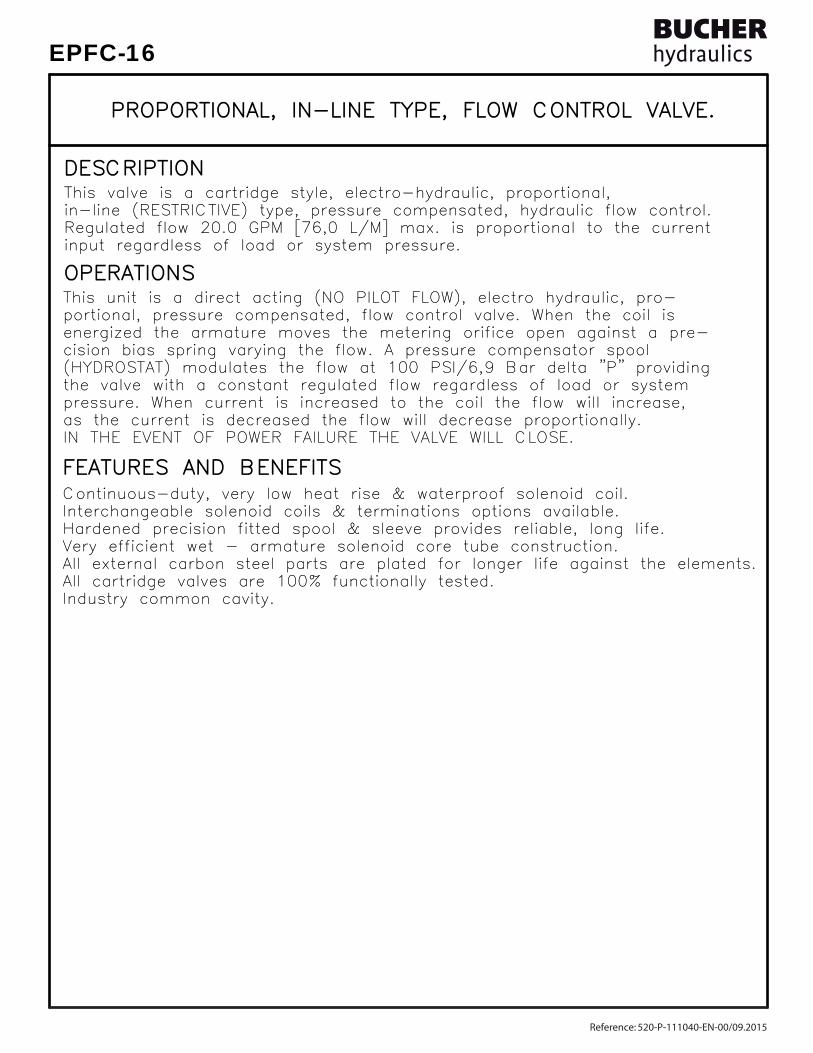
FEATURES AND BENEFITSFEATURES AND BENEFITS
OPERATIONSOPERATIONS
DESCRIPTIONDESCRIPTION
Hardened precision fitted spool & sleeve provides reliable, long life.Hardened precision fitted spool & sleeve provides reliable, long life.
All cartridge valves are 100% functionally tested.All cartridge valves are 100% functionally tested.All external carbon steel parts are plated for longer life against the elements.All external carbon steel parts are plated for longer life against the elements.Very efficient wet - armature solenoid core tube construction.Very efficient wet - armature solenoid core tube construction.
Industry common cavity.Industry common cavity.
input regardless of load or system pressure.input regardless of load or system pressure.Regulated flow 20.0 GPM [76,0 L/M] max. is proportional to the currentRegulated flow 20.0 GPM [76,0 L/M] max. is proportional to the currentin-line (RESTRICTIVE) type, pressure compensated, hydraulic flow control.in-line (RESTRICTIVE) type, pressure compensated, hydraulic flow control.This valve is a cartridge style, electro-hydraulic, proportional,This valve is a cartridge style, electro-hydraulic, proportional,
IN THE EVENT OF POWER FAILURE THE VALVE WILL CLOSE.IN THE EVENT OF POWER FAILURE THE VALVE WILL CLOSE.as the current is decreased the flow will decrease proportionally.as the current is decreased the flow will decrease proportionally.pressure. When current is increased to the coil the flow will increase,pressure. When current is increased to the coil the flow will increase,the valve with a constant regulated flow regardless of load or systemthe valve with a constant regulated flow regardless of load or system(HYDROSTAT) modulates the flow at 100 PSI/6,9 Bar delta "P" providing(HYDROSTAT) modulates the flow at 100 PSI/6,9 Bar delta "P" providingcision bias spring varying the flow. A pressure compensator spoolcision bias spring varying the flow. A pressure compensator spoolenergized the armature moves the metering orifice open against a pre-energized the armature moves the metering orifice open against a pre-portional, pressure compensated, flow control valve. When the coil isportional, pressure compensated, flow control valve. When the coil isThis unit is a direct acting (NO PILOT FLOW), electro hydraulic, pro-This unit is a direct acting (NO PILOT FLOW), electro hydraulic, pro-
Interchangeable solenoid coils & terminations options available.Interchangeable solenoid coils & terminations options available.Continuous-duty, very low heat rise & waterproof solenoid coil.Continuous-duty, very low heat rise & waterproof solenoid coil.
PROPORTIONAL, IN-LINE TYPE, FLOW CONTROL VALVE.PROPORTIONAL, IN-LINE TYPE, FLOW CONTROL VALVE.
Reference: 520-P-111040-EN-00/09.2015
EPFC-16

SPECIFICATIONSSPECIFICATIONS
VALVE CAVITY: #C1620, See Page 0-014.0.VALVE CAVITY: #C1620, See Page 0-014.0.WEIGHT: 2.58 lb [1,17 kg] cartridge with coil only.WEIGHT: 2.58 lb [1,17 kg] cartridge with coil only.INSTALLATION: No restrictions.INSTALLATION: No restrictions. SKV-1622 Viton SKV-1622 Viton
SEAL KIT: SKN-1622 Buna "N"SEAL KIT: SKN-1622 Buna "N" 24 VDC, Operating current 0.1 to 1.1 AMPS. 24 VDC, Operating current 0.1 to 1.1 AMPS.POWER REQUIREMENTS: 12 VDC, Operating current 0.2 to 2.2 AMPS.POWER REQUIREMENTS: 12 VDC, Operating current 0.2 to 2.2 AMPS. current control and a 50 Hz dither. current control and a 50 Hz dither.RESPONSE: The most efficient method to control this valve is withRESPONSE: The most efficient method to control this valve is with
INTERNAL LEAKAGE: 20 cu.in/min [330 cc/m] @ 5,000 PSI [350 Bar]INTERNAL LEAKAGE: 20 cu.in/min [330 cc/m] @ 5,000 PSI [350 Bar]REGULATED FLOW: 20.0 GPM [76,0 l/m] Max. See performance chart.REGULATED FLOW: 20.0 GPM [76,0 l/m] Max. See performance chart.PROOF PRESSURE: 10,000 PSI [700 Bar]PROOF PRESSURE: 10,000 PSI [700 Bar]OPERATING PRESSURE: 5,000 PSI [350 Bar]OPERATING PRESSURE: 5,000 PSI [350 Bar]
PROPORTIONAL, IN-LINE TYPE, FLOW CONTROL VALVE.PROPORTIONAL, IN-LINE TYPE, FLOW CONTROL VALVE.
MIL-H-5606, SAE-#10, SAE-#20, etc. MIL-H-5606, SAE-#10, SAE-#20, etc.OPERATING MEDIA: All general purpose hydraulic fluids such asOPERATING MEDIA: All general purpose hydraulic fluids such asOPERATING TEMPERATURE: -40° to +250° F. [-40° to +120° C.]OPERATING TEMPERATURE: -40° to +250° F. [-40° to +120° C.] 5000 PSI [350 Bar] = Steel - Unplated. 5000 PSI [350 Bar] = Steel - Unplated.VALVE HOUSINGS: 2500 PSI [175 Bar] = Aluminum - Anodized.VALVE HOUSINGS: 2500 PSI [175 Bar] = Aluminum - Anodized.
[email protected] www.bucherhydraulics.com/commoncavity
2015 by Bucher Hydraulics, Inc., 2545 Northwest Parkway, Elgin, Illinois 60124, USAAll rights reserved.The technical information in this catalog, may contain calculated figures (for reference only) and not actual performance data for this product.Data is provided for the purpose of product description only, and must not be construed as warranted characteristics in the legal sense. The information does not relieve users from the duty of conducting their own evaluations and tests. Because the products are subject to continual improvement, we reserve the right to amend the product specifications contained in this catalogue.
©
Reference: 520-P-111040-EN-00/09.2015
EPFC-16
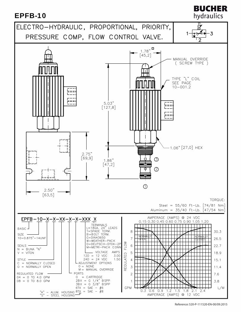
EPFB-10-X-X-XX-X-X-XXX XEPFB-10-X-X-XX-X-X-XXX X
PRESSURE COMP, FLOW CONTROL VALVE.PRESSURE COMP, FLOW CONTROL VALVE.
ELECTRO-HYDRAULIC, PROPORTIONAL, PRIORITY,ELECTRO-HYDRAULIC, PROPORTIONAL, PRIORITY,
[47,2][47,2]1.86"1.86"
[45,2][45,2]
[127,8][127,8] 5.03" 5.03"
MANUAL OVERRIDEMANUAL OVERRIDE( SCREW TYPE )( SCREW TYPE )
1.78"1.78"
2.75" 2.75"
2.50" 2.50"[63,5][63,5]
[69,9][69,9]
[27,0][27,0] 1.06" 1.06" HEX HEX
1
23
8TX = SAE - #8 8TX = SAE - #8 6TX = SAE - #6 6TX = SAE - #6 3BX = G 3/8" BSPP 3BX = G 3/8" BSPP 2BX = G 1/4" BSPP 2BX = G 1/4" BSPP 0 = CARTRIDGE 0 = CARTRIDGE PORTS PORTS
24D = 24 VDC 1.50 24D = 24 VDC 1.50 12D = 12 VDC 3.00 12D = 12 VDC 3.00
08 = 0 TO 8.0 GPM08 = 0 TO 8.0 GPM04 = 0 TO 4.0 GPM04 = 0 TO 4.0 GPMREGULATED FLOWREGULATED FLOW
10=0.875"-14UNF10=0.875"-14UNF
V = VITONV = VITONN = BUNA "N"N = BUNA "N"SEALSSEALS
SIZESIZE
BASICBASIC
"S" - STEEL HOUSING"S" - STEEL HOUSING"A" - ALUM. HOUSING"A" - ALUM. HOUSING
VOLTAGE AMPS VOLTAGE AMPS
TERMINALS TERMINALS
O = NORMALLY OPENO = NORMALLY OPENC = NORMALLY CLOSEDC = NORMALLY CLOSEDSTYLESTYLE
L=18GA. 24" LEADSL=18GA. 24" LEADST=SPADE TERM.T=SPADE TERM.B=BOLT TERM.B=BOLT TERM.G=DIN43650G=DIN43650W=WEATHER-PACKW=WEATHER-PACKD=DEUTSCH-DT04-2PD=DEUTSCH-DT04-2PM=METRI-PACK CONN.M=METRI-PACK CONN.
= NONE= NONE= MANUAL OVERRIDE= MANUAL OVERRIDE
ADJUSTMENT OPTIONSADJUSTMENT OPTIONS0M R
EGULATED FLOW
REGULATED FLOW
0.90.9GPMGPM
0.60.60.30.3 2.12.11.51.51.21.2 1.81.8L/ML/M
2.42.4
AMPERAGE (AMPS) @ 24 VDCAMPERAGE (AMPS) @ 24 VDC0.450.450.300.300.150.15 1.051.050.750.750.600.60 0.900.90 1.201.20
1
2
3
4
5
6
7
8
3.8 3.8
7.67.6
11.411.4
15.115.1
18.918.9
22.722.7
26.526.5
30.330.3NORMALLYNORMALLYOPENOPEN
NORMALLYNORMALLYCLOSEDCLOSED
AMPERAGE (AMPS) @ 12 VDCAMPERAGE (AMPS) @ 12 VDC
TYPE "L" COIL TYPE "L" COIL SEE PAGE SEE PAGE 10-001.210-001.2
1
2
3
Steel = 55/60 Ft-Lb. [74/81 Nm] Steel = 55/60 Ft-Lb. [74/81 Nm]
TORQUE:TORQUE:
Aluminum = 35/40 Ft-Lb. [47/54 Nm]Aluminum = 35/40 Ft-Lb. [47/54 Nm]
Reference: 520-P-111520-EN-00/09.2015
EPFB-10

FEATURES AND BENEFITSFEATURES AND BENEFITS
OPERATIONSOPERATIONS
DESCRIPTIONDESCRIPTION
Interchangeable solenoid coils & termination options available.Interchangeable solenoid coils & termination options available.
All cartridge valves are 100% functionally tested.All cartridge valves are 100% functionally tested.All external parts are zinc plated for longer life against elements.All external parts are zinc plated for longer life against elements.Very efficient wet - armature solenoid core tube construction.Very efficient wet - armature solenoid core tube construction.Hardened precision fitted spool & sleeve provides reliable, long life.Hardened precision fitted spool & sleeve provides reliable, long life.
tank. Maximum inlet flow is 10.0 GPM [37,9 L/M].tank. Maximum inlet flow is 10.0 GPM [37,9 L/M].is satisfied the excess flow is diverted to a secondary circuit or tois satisfied the excess flow is diverted to a secondary circuit or toinput regardless of load or system pressure. After the priority flowinput regardless of load or system pressure. After the priority flowRegulated flow 8.0 GPM [30,3 L/M] max. is proportional to the currentRegulated flow 8.0 GPM [30,3 L/M] max. is proportional to the currentpriority (BY-PASS) type, pressure compensated, hydraulic flow control.priority (BY-PASS) type, pressure compensated, hydraulic flow control.This valve is a cartridge style, electro-hydraulic, proportional,This valve is a cartridge style, electro-hydraulic, proportional,
Continuous-duty, very low heat rise & waterproof solenoid coil.Continuous-duty, very low heat rise & waterproof solenoid coil.
PROPORTIONAL, PRIORITY TYPE, PRESSURE COMP, PROPORTIONAL, PRIORITY TYPE, PRESSURE COMP,
FLOW CONTROL VALVE. FLOW CONTROL VALVE.
This unit is a direct acting (NO PILOT FLOW), electro hydraulic, proportional, This unit is a direct acting (NO PILOT FLOW), electro hydraulic, proportional, pressure compensated flow control valve. When the coil is energized, the arpressure compensated flow control valve. When the coil is energized, the ar-mature moves the metering orifice open against a precision bias spring varying mature moves the metering orifice open against a precision bias spring varying the flow. A pressure compensator spool (HYDROSTAT) modulates the flow at the flow. A pressure compensator spool (HYDROSTAT) modulates the flow at 100 PSI/6,9 Bar delta "P" providing the valve with a constant regulated flow 100 PSI/6,9 Bar delta "P" providing the valve with a constant regulated flow regardless of load or system pressure. For the normally closed product when regardless of load or system pressure. For the normally closed product when the current is increased to the coil, the flow will increase. For the normally the current is increased to the coil, the flow will increase. For the normally open product as the current is increased to the coil the flow will decrease. open product as the current is increased to the coil the flow will decrease. IN THE EVENT OF POWER FAILURE, THE NORMALLY CLOSED VALVE WILL CLOSE IN THE EVENT OF POWER FAILURE, THE NORMALLY CLOSED VALVE WILL CLOSE AND THE NORMALLY OPEN VALVE WILL OPEN.AND THE NORMALLY OPEN VALVE WILL OPEN.
Reference: 520-P-111520-EN-00/09.2015
EPFB-10

SPECIFICATIONSSPECIFICATIONS
VALVE CAVITY: #C1030, See Page 0-032.0.VALVE CAVITY: #C1030, See Page 0-032.0.WEIGHT: 1.93 lb [0,90 kg] cartridge with coil only.WEIGHT: 1.93 lb [0,90 kg] cartridge with coil only.INSTALLATION: No restrictions.INSTALLATION: No restrictions.
SKV-1032 Viton SKV-1032 VitonSEAL KIT: SKN-1032 Buna "N"SEAL KIT: SKN-1032 Buna "N"
24 VDC, Operating current 0.1 to 1.1 AMPS. 24 VDC, Operating current 0.1 to 1.1 AMPS.POWER REQUIREMENTS: 12 VDC, Operating current 0.2 to 2.2 AMPS.POWER REQUIREMENTS: 12 VDC, Operating current 0.2 to 2.2 AMPS. current control and a 50 Hz dither. current control and a 50 Hz dither.RESPONSE: The most efficient method to control this valve is withRESPONSE: The most efficient method to control this valve is with
INTERNAL LEAKAGE: 20 cu.in/min [328 cc/m] @ 5,000 PSI [350 Bar]INTERNAL LEAKAGE: 20 cu.in/min [328 cc/m] @ 5,000 PSI [350 Bar]REGULATED FLOW: 8.0 GPM [30,3 l/m] Max. See performance chart.REGULATED FLOW: 8.0 GPM [30,3 l/m] Max. See performance chart.PROOF PRESSURE: 10,000 PSI [700 Bar]PROOF PRESSURE: 10,000 PSI [700 Bar]OPERATING PRESSURE: 5,000 PSI [350 Bar]OPERATING PRESSURE: 5,000 PSI [350 Bar]
MIL-H-5606, SAE-#10, SAE-#20, etc. MIL-H-5606, SAE-#10, SAE-#20, etc.OPERATING MEDIA: All general purpose hydraulic fluids such asOPERATING MEDIA: All general purpose hydraulic fluids such asOPERATING TEMPERATURE: -40° to +250° F. [-40° to +120° C.]OPERATING TEMPERATURE: -40° to +250° F. [-40° to +120° C.] 5000 PSI [350 Bar] = Steel - Unplated. 5000 PSI [350 Bar] = Steel - Unplated.VALVE HOUSINGS: 2500 PSI [175 Bar] = Aluminum - Anodized.VALVE HOUSINGS: 2500 PSI [175 Bar] = Aluminum - Anodized.
PROPORTIONAL, PRIORITY TYPE, PRESSURE COMP, PROPORTIONAL, PRIORITY TYPE, PRESSURE COMP,
FLOW CONTROL VALVE. FLOW CONTROL VALVE.
[email protected] www.bucherhydraulics.com/commoncavity
2015 by Bucher Hydraulics, Inc., 2545 Northwest Parkway, Elgin, Illinois 60124, USAAll rights reserved.The technical information in this catalog, may contain calculated figures (for reference only) and not actual performance data for this product.Data is provided for the purpose of product description only, and must not be construed as warranted characteristics in the legal sense. The information does not relieve users from the duty of conducting their own evaluations and tests. Because the products are subject to continual improvement, we reserve the right to amend the product specifications contained in this catalogue.
©
Reference: 520-P-111520-EN-00/09.2015
EPFB-10

EPFB-12-X-X-XX-X-X-XXX XEPFB-12-X-X-XX-X-X-XXX X
PRESSURE COMP, FLOW CONTROL VALVE.PRESSURE COMP, FLOW CONTROL VALVE.
ELECTRO-HYDRAULIC, PROPORTIONAL, PRIORITY,ELECTRO-HYDRAULIC, PROPORTIONAL, PRIORITY,1
23
FOR ALUMINUM OR STEEL VALVE HOUSING CONFIGURATIONS SEE PAGE 0-033.1FOR ALUMINUM OR STEEL VALVE HOUSING CONFIGURATIONS SEE PAGE 0-033.1
[101,6][101,6]
[88,9][88,9] 3.50" 3.50"
4.00" 4.00" [100/120 N-m]. [100/120 N-m].
1
2
3
1.31" [33,3] Hex.1.31" [33,3] Hex.TORQUE to 80/90 Ft-Lb.TORQUE to 80/90 Ft-Lb.
1.78" 1.78"[45,2][45,2]
( SCREW TYPE )( SCREW TYPE )MANUAL OVERRIDEMANUAL OVERRIDE
[67,3][67,3]
[118,9][118,9]
2.65" 2.65"
4.68" 4.68"
REGULATED FLOW
REGULATED FLOW
AMPERAGE (AMPS) @ 12 VDCAMPERAGE (AMPS) @ 12 VDC0.90.9
GPMGPM0.60.60.30.3 2.12.11.51.51.21.2 1.81.8
L/ML/M2.42.4
AMPERAGE (AMPS) @ 24 VDCAMPERAGE (AMPS) @ 24 VDC0.450.450.300.300.150.15 1.051.050.750.750.600.60 0.900.90 1.201.20
2
4
6
8
1010
1212
1414
1616
7.6 7.6
15.115.1
22.722.7
30.330.3
37.937.9
45.445.4
53.053.0
60.660.6NORMALLYNORMALLYOPENOPEN
NORMALLYNORMALLYCLOSEDCLOSED
LTBGWDM
TERMINALS TERMINALS=18GA. 24" LEADS=18GA. 24" LEADS=SPADE TERM.=SPADE TERM.=BOLT TERM.=BOLT TERM.=DIN43650=DIN43650=WEATHER-PACK=WEATHER-PACK=DEUTSCH-DT04-2P=DEUTSCH-DT04-2P=METRI-PACK CONN.=METRI-PACK CONN.
12D12D24D24D
VOLTAGE VOLTAGE= 12 VDC= 12 VDC= 24 VDC= 24 VDC
AMPSAMPS 3.00 3.00 1.50 1.50
= BUNA "N"= BUNA "N"= VITON= VITON
SEALSSEALSNV
SIZESIZE12 = 1.062"-12UNF12 = 1.062"-12UNF
PORTSPORTS0
04BX04BX06BX06BX10TX10TX12TX12TX
= CARTRIDGE ONLY= CARTRIDGE ONLY= G 1/2"-14 BSPP= G 1/2"-14 BSPP= G 3/4"-14 BSPP= G 3/4"-14 BSPP= SAE - #10= SAE - #10= SAE - #12 = SAE - #12
REGULATED FLOWREGULATED FLOW050510101515
= 0 TO 5.0 GPM= 0 TO 5.0 GPM= 0 TO 10.0 GPM= 0 TO 10.0 GPM= 0 TO 15.0 GPM= 0 TO 15.0 GPM
BASICBASIC
= NORMALLY CLOSED= NORMALLY CLOSED= NORMALLY OPEN= NORMALLY OPEN
STYLESTYLECO
= NONE= NONE= MANUAL OVERRIDE= MANUAL OVERRIDE
ADJUSTMENT OPTIONSADJUSTMENT OPTIONS0M
"A" = ALUM. HOUSING "A" = ALUM. HOUSING "S" = STEEL HOUSING "S" = STEEL HOUSING
TYPE "L" COIL TYPE "L" COIL SEE PAGE SEE PAGE 10-001.210-001.2
Reference: 520-P-111530-EN-01/06.2017
EPFB-12
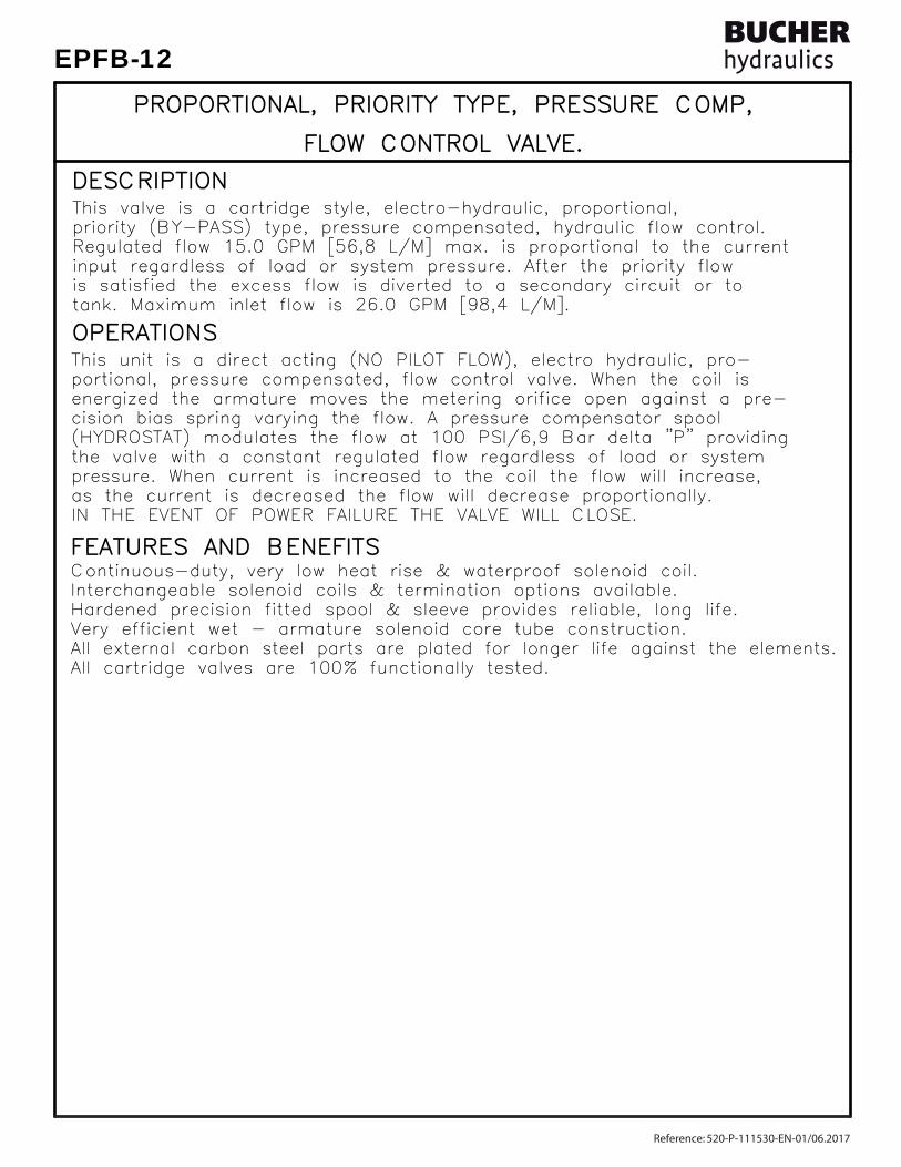
FEATURES AND BENEFITSFEATURES AND BENEFITS
OPERATIONSOPERATIONS
DESCRIPTIONDESCRIPTION
Interchangeable solenoid coils & termination options available.Interchangeable solenoid coils & termination options available.
All cartridge valves are 100% functionally tested.All cartridge valves are 100% functionally tested.All external carbon steel parts are plated for longer life against the elements.All external carbon steel parts are plated for longer life against the elements.Very efficient wet - armature solenoid core tube construction.Very efficient wet - armature solenoid core tube construction.Hardened precision fitted spool & sleeve provides reliable, long life.Hardened precision fitted spool & sleeve provides reliable, long life.
tank. Maximum inlet flow is 26.0 GPM [98,4 L/M].tank. Maximum inlet flow is 26.0 GPM [98,4 L/M].is satisfied the excess flow is diverted to a secondary circuit or tois satisfied the excess flow is diverted to a secondary circuit or toinput regardless of load or system pressure. After the priority flowinput regardless of load or system pressure. After the priority flowRegulated flow 15.0 GPM [56,8 L/M] max. is proportional to the currentRegulated flow 15.0 GPM [56,8 L/M] max. is proportional to the currentpriority (BY-PASS) type, pressure compensated, hydraulic flow control.priority (BY-PASS) type, pressure compensated, hydraulic flow control.This valve is a cartridge style, electro-hydraulic, proportional,This valve is a cartridge style, electro-hydraulic, proportional,
IN THE EVENT OF POWER FAILURE THE VALVE WILL CLOSE.IN THE EVENT OF POWER FAILURE THE VALVE WILL CLOSE.as the current is decreased the flow will decrease proportionally.as the current is decreased the flow will decrease proportionally.pressure. When current is increased to the coil the flow will increase,pressure. When current is increased to the coil the flow will increase,the valve with a constant regulated flow regardless of load or systemthe valve with a constant regulated flow regardless of load or system(HYDROSTAT) modulates the flow at 100 PSI/6,9 Bar delta "P" providing(HYDROSTAT) modulates the flow at 100 PSI/6,9 Bar delta "P" providingcision bias spring varying the flow. A pressure compensator spoolcision bias spring varying the flow. A pressure compensator spoolenergized the armature moves the metering orifice open against a pre-energized the armature moves the metering orifice open against a pre-portional, pressure compensated, flow control valve. When the coil isportional, pressure compensated, flow control valve. When the coil isThis unit is a direct acting (NO PILOT FLOW), electro hydraulic, pro-This unit is a direct acting (NO PILOT FLOW), electro hydraulic, pro-
Continuous-duty, very low heat rise & waterproof solenoid coil.Continuous-duty, very low heat rise & waterproof solenoid coil.
PROPORTIONAL, PRIORITY TYPE, PRESSURE COMP, PROPORTIONAL, PRIORITY TYPE, PRESSURE COMP,
FLOW CONTROL VALVE. FLOW CONTROL VALVE.
Reference: 520-P-111530-EN-01/06.2017
EPFB-12

SPECIFICATIONSSPECIFICATIONS
VALVE CAVITY: #C1230, See Page 0-033.0.VALVE CAVITY: #C1230, See Page 0-033.0.WEIGHT: 2.66 lb [1,20 kg] cartridge with coil only.WEIGHT: 2.66 lb [1,20 kg] cartridge with coil only.INSTALLATION: No restrictions.INSTALLATION: No restrictions. SKV-1232 Viton SKV-1232 VitonSEAL KIT: SKN-1232 Buna "N"SEAL KIT: SKN-1232 Buna "N"
24 VDC, Operating current 0.1 to 1.1 AMPS. 24 VDC, Operating current 0.1 to 1.1 AMPS.POWER REQUIREMENTS: 12 VDC, Operating current 0.2 to 2.2 AMPS.POWER REQUIREMENTS: 12 VDC, Operating current 0.2 to 2.2 AMPS. current control and a 50 Hz dither. current control and a 50 Hz dither.RESPONSE: The most efficient method to control this valve is withRESPONSE: The most efficient method to control this valve is with
INTERNAL LEAKAGE: 20 cu.in/min [330 cc/m] @ 5,000 PSI [350 Bar]INTERNAL LEAKAGE: 20 cu.in/min [330 cc/m] @ 5,000 PSI [350 Bar]REGULATED FLOW: 15.0 GPM [56,7 l/m] Max. See performance chart.REGULATED FLOW: 15.0 GPM [56,7 l/m] Max. See performance chart.PROOF PRESSURE: 10,000 PSI [700 Bar]PROOF PRESSURE: 10,000 PSI [700 Bar]OPERATING PRESSURE: 5,000 PSI [350 Bar]OPERATING PRESSURE: 5,000 PSI [350 Bar]
PROPORTIONAL, PRIORITY TYPE, PRESSURE COMP, PROPORTIONAL, PRIORITY TYPE, PRESSURE COMP,
FLOW CONTROL VALVE. FLOW CONTROL VALVE.
MIL-H-5606, SAE-#10, SAE-#20, etc. MIL-H-5606, SAE-#10, SAE-#20, etc.OPERATING MEDIA: All general purpose hydraulic fluids such asOPERATING MEDIA: All general purpose hydraulic fluids such asOPERATING TEMPERATURE: -40° to +250° F. [-40° to +120° C.]OPERATING TEMPERATURE: -40° to +250° F. [-40° to +120° C.] 5000 PSI [350 Bar] = Steel - Unplated. 5000 PSI [350 Bar] = Steel - Unplated.VALVE HOUSINGS: 2500 PSI [175 Bar] = Aluminum - Anodized.VALVE HOUSINGS: 2500 PSI [175 Bar] = Aluminum - Anodized.
[email protected] www.bucherhydraulics.com/commoncavity
2015 by Bucher Hydraulics, Inc., 2545 Northwest Parkway, Elgin, Illinois 60124, USAAll rights reserved.The technical information in this catalog, may contain calculated figures (for reference only) and not actual performance data for this product.Data is provided for the purpose of product description only, and must not be construed as warranted characteristics in the legal sense. The information does not relieve users from the duty of conducting their own evaluations and tests. Because the products are subject to continual improvement, we reserve the right to amend the product specifications contained in this catalogue.
©
Reference: 520-P-111530-EN-01/06.2017
EPFB-12

TYPE "L" COIL TYPE "L" COIL SEE PAGE SEE PAGE 10-001.210-001.2
1
23
[101,6][101,6] 4.00" 4.00"
REGULATED FLOW
REGULATED FLOW
AMPERAGE (AMPS) @ 12 VDCAMPERAGE (AMPS) @ 12 VDC0.900.90
GPMGPM0.600.600.300.30
5
10 10
2.102.101.501.501.201.20 1.801.80L/ML/M
2.402.40
19 19
AMPERAGE (AMPS) @ 24 VDCAMPERAGE (AMPS) @ 24 VDC0.450.45
15 15
20 20
25 250.300.300.150.15
[101,6][101,6]
1.051.050.750.750.600.60 0.900.90
5757
7676
95951.201.20
4.00" 4.00"
1.50" [38,1] Hex.1.50" [38,1] Hex.
1
2
( SCREW TYPE )( SCREW TYPE )MANUAL OVERRIDEMANUAL OVERRIDE
3
[73,7][73,7] 2.90" 2.90"
5.60" 5.60"[142,2][142,2]
LTBGWDM
TERMINALS TERMINALS=18GA. 24" LEADS=18GA. 24" LEADS=SPADE TERM.=SPADE TERM.=BOLT TERM.=BOLT TERM.=DIN43650=DIN43650=WEATHER-PACK=WEATHER-PACK=DEUTSCH-DT04-2P=DEUTSCH-DT04-2P=METRI-PACK CONN.=METRI-PACK CONN.
12D12D24D24D
VOLTAGE VOLTAGE= 12 VDC= 12 VDC= 24 VDC= 24 VDC
AMPSAMPS 3.00 3.00 1.50 1.50
= BUNA "N"= BUNA "N"= VITON= VITON
SEALSSEALSNV
SIZESIZE16 = 1.312"-12UNF16 = 1.312"-12UNF
BASICBASIC
PORTSPORTS0
06BX06BX08BX08BX12TX12TX16TX16TX
= CARTRIDGE ONLY= CARTRIDGE ONLY= G 3/4" BSPP= G 3/4" BSPP= G 1" BSPP= G 1" BSPP= SAE - #12= SAE - #12= SAE - #16= SAE - #16 "A" = ALUM. HOUSING "A" = ALUM. HOUSING "S" = STEEL HOUSING "S" = STEEL HOUSING
REGULATED FLOWREGULATED FLOW0505101015152020
= 0 TO 5.0 GPM= 0 TO 5.0 GPM= 0 TO 10.0 GPM= 0 TO 10.0 GPM= 0 TO 15.0 GPM= 0 TO 15.0 GPM= 0 TO 20.0 GPM= 0 TO 20.0 GPM
[45,2][45,2]1.78"1.78"
= MANUAL OVERRIDE= MANUAL OVERRIDEADJUSTMENT OPTIONSADJUSTMENT OPTIONSM
EPFD-16-X-XX-X-X-XXX XEPFD-16-X-XX-X-X-XXX X
3838
PRESSURE COMP, FLOW CONTROL VALVE.PRESSURE COMP, FLOW CONTROL VALVE.
ELECTRO-HYDRAULIC, PROPORTIONAL, PRIORITY,ELECTRO-HYDRAULIC, PROPORTIONAL, PRIORITY,
Steel = 95/100 Ft-Lb. [129/136 Nm] Steel = 95/100 Ft-Lb. [129/136 Nm]
TORQUE:TORQUE:
Aluminum = 70/75 Ft-Lb. [95/102 Nm]Aluminum = 70/75 Ft-Lb. [95/102 Nm]
Reference: 520-P-111540-EN-00/09.2015
EPFD-16

FEATURES AND BENEFITSFEATURES AND BENEFITS
OPERATIONSOPERATIONS
DESCRIPTIONDESCRIPTION
Interchangeable solenoid coils & terminations options available.Interchangeable solenoid coils & terminations options available.
All cartridge valves are 100% functionally tested.All cartridge valves are 100% functionally tested.All external carbon steel parts are plated for longer life against the elements.All external carbon steel parts are plated for longer life against the elements.Very efficient wet - armature solenoid core tube construction.Very efficient wet - armature solenoid core tube construction.Hardened precision fitted spool & sleeve provides reliable, long life.Hardened precision fitted spool & sleeve provides reliable, long life.
tank. Maximum inlet flow is 35.0 GPM [130,0 L/M].tank. Maximum inlet flow is 35.0 GPM [130,0 L/M].is satisfied the excess flow is diverted to a secondary circuit or tois satisfied the excess flow is diverted to a secondary circuit or toinput regardless of load or system pressure. After the priority flowinput regardless of load or system pressure. After the priority flowRegulated flow 20.0 GPM [76,0 L/M] max. is proportional to the currentRegulated flow 20.0 GPM [76,0 L/M] max. is proportional to the currentpriority (BY-PASS) type, pressure compensated, hydraulic flow control.priority (BY-PASS) type, pressure compensated, hydraulic flow control.This valve is a cartridge style, electro-hydraulic, proportional,This valve is a cartridge style, electro-hydraulic, proportional,
IN THE EVENT OF POWER FAILURE THE VALVE WILL CLOSE.IN THE EVENT OF POWER FAILURE THE VALVE WILL CLOSE.as the current is decreased the flow will decrease proportionally.as the current is decreased the flow will decrease proportionally.pressure. When current is increased to the coil the flow will increase,pressure. When current is increased to the coil the flow will increase,the valve with a constant regulated flow regardless of load or systemthe valve with a constant regulated flow regardless of load or system(HYDROSTAT) modulates the flow at 100 PSI/6,9 Bar delta "P" providing(HYDROSTAT) modulates the flow at 100 PSI/6,9 Bar delta "P" providingcision bias spring varying the flow. A pressure compensator spoolcision bias spring varying the flow. A pressure compensator spoolenergized the armature moves the metering orifice open against a pre-energized the armature moves the metering orifice open against a pre-portional, pressure compensated, flow control valve. When the coil isportional, pressure compensated, flow control valve. When the coil isThis unit is a direct acting (NO PILOT FLOW), electro hydraulic, pro-This unit is a direct acting (NO PILOT FLOW), electro hydraulic, pro-
Continuous-duty, very low heat rise & waterproof solenoid coil.Continuous-duty, very low heat rise & waterproof solenoid coil.
PROPORTIONAL, PRIORITY TYPE, PRESSURE COMP, PROPORTIONAL, PRIORITY TYPE, PRESSURE COMP,
FLOW CONTROL VALVE. FLOW CONTROL VALVE.
Reference: 520-P-111540-EN-00/09.2015
EPFD-16

SPECIFICATIONSSPECIFICATIONS
VALVE CAVITY: #C1630, See Page 0-034.0.VALVE CAVITY: #C1630, See Page 0-034.0.WEIGHT: 2.66 lb [1,20 kg] cartridge with coil only.WEIGHT: 2.66 lb [1,20 kg] cartridge with coil only.INSTALLATION: No restrictions.INSTALLATION: No restrictions. SKV-1632 Viton SKV-1632 VitonSEAL KIT: SKN-1632 Buna "N"SEAL KIT: SKN-1632 Buna "N"
24 VDC, Operating current 0.1 to 1.1 AMPS. 24 VDC, Operating current 0.1 to 1.1 AMPS.POWER REQUIREMENTS: 12 VDC, Operating current 0.2 to 2.2 AMPS.POWER REQUIREMENTS: 12 VDC, Operating current 0.2 to 2.2 AMPS. current control and a 50 Hz dither. current control and a 50 Hz dither.RESPONSE: The most efficient method to control this valve is withRESPONSE: The most efficient method to control this valve is with
INTERNAL LEAKAGE: 20 cu.in/min [330 cc/m] @ 5,000 PSI [350 Bar]INTERNAL LEAKAGE: 20 cu.in/min [330 cc/m] @ 5,000 PSI [350 Bar]REGULATED FLOW: 20.0 GPM [76,0 l/m] Max. See performance chart.REGULATED FLOW: 20.0 GPM [76,0 l/m] Max. See performance chart.PROOF PRESSURE: 10,000 PSI [700 Bar]PROOF PRESSURE: 10,000 PSI [700 Bar]OPERATING PRESSURE: 5,000 PSI [350 Bar]OPERATING PRESSURE: 5,000 PSI [350 Bar]
PROPORTIONAL, PRIORITY TYPE, PRESSURE COMP, PROPORTIONAL, PRIORITY TYPE, PRESSURE COMP,
FLOW CONTROL VALVE. FLOW CONTROL VALVE.
MIL-H-5606, SAE-#10, SAE-#20, etc. MIL-H-5606, SAE-#10, SAE-#20, etc.OPERATING MEDIA: All general purpose hydraulic fluids such asOPERATING MEDIA: All general purpose hydraulic fluids such asOPERATING TEMPERATURE: -40° to +250° F. [-40° to +120° C.]OPERATING TEMPERATURE: -40° to +250° F. [-40° to +120° C.] 5000 PSI [350 Bar] = Steel - Unplated. 5000 PSI [350 Bar] = Steel - Unplated.VALVE HOUSINGS: 2500 PSI [175 Bar] = Aluminum - Anodized.VALVE HOUSINGS: 2500 PSI [175 Bar] = Aluminum - Anodized.
[email protected] www.bucherhydraulics.com/commoncavity
2015 by Bucher Hydraulics, Inc., 2545 Northwest Parkway, Elgin, Illinois 60124, USAAll rights reserved.The technical information in this catalog, may contain calculated figures (for reference only) and not actual performance data for this product.Data is provided for the purpose of product description only, and must not be construed as warranted characteristics in the legal sense. The information does not relieve users from the duty of conducting their own evaluations and tests. Because the products are subject to continual improvement, we reserve the right to amend the product specifications contained in this catalogue.
©
Reference: 520-P-111540-EN-00/09.2015
EPFD-16

TYPE "L" COIL TYPE "L" COIL SEE PAGE SEE PAGE 10-001.210-001.2
2
1
2
1
[50.8][50.8]
1
2.00"2.00"
[50.8][50.8]
2 2.00" 2.00"
[110,5][110,5]4.35"4.35"
1.06" [27.0] HEX1.06" [27.0] HEX
7/8"-14 UNF-2A THD.7/8"-14 UNF-2A THD.1.27"1.27"[32,3][32,3]
1
2
5.04"5.04"[128,0][128,0]
1.78"1.78"[45,2][45,2]
( SCREW TYPE )( SCREW TYPE )MANUAL OVERRIDEMANUAL OVERRIDE
1.201.20AMPERAGE (AMPS) @ 12 VDCAMPERAGE (AMPS) @ 12 VDC
AMPERAGE (AMPS) @ 24 VDCAMPERAGE (AMPS) @ 24 VDC0.600.60
GPMGPM
0404
0.300.30 0.600.60 0.900.90
08 08
12 12
16 16
OPEN OPENNORMALLYNORMALLY
0.150.15 0.300.30 0.450.45
2.402.401.801.80 2.102.101.501.50L/ML/M
1515
1.201.20
NORMALLYNORMALLY CLOSED CLOSED
0.900.900.750.75 1.051.05
3030
4545
6060
UL approved coil, IP68 and IP69K rated UL approved coil, IP68 and IP69K rated when used with waterproof connector.when used with waterproof connector.R
NOTES:NOTES:1. FOR ALUMINUM OR STEEL VALVE HOUSING CONFIGURATIONS SEE PAGE 0-012.11. FOR ALUMINUM OR STEEL VALVE HOUSING CONFIGURATIONS SEE PAGE 0-012.12. SOLENOIDS AVAILABLE WITH DIODES - CONSULT FACTORY.2. SOLENOIDS AVAILABLE WITH DIODES - CONSULT FACTORY.
LTBGWDM
TERMINALS TERMINALS=18GA. 24" LEADS=18GA. 24" LEADS=SPADE TERM.=SPADE TERM.=BOLT TERM.=BOLT TERM.=DIN43650=DIN43650=WEATHER-PACK=WEATHER-PACK=DEUTSCH-DT04-2P=DEUTSCH-DT04-2P=METRI-PACK CONN.=METRI-PACK CONN.
12D12D24D24D
VOLTAGE VOLTAGE= 12 VDC= 12 VDC= 24 VDC= 24 VDC
= BUNA "N"= BUNA "N"= VITON= VITON
SEALSSEALSNV
SIZESIZE10 = 7/8"-14UNF10 = 7/8"-14UNF
PORTSPORTS0
02BX02BX03BX03BX06TX06TX08TX08TX
= CARTRIDGE ONLY= CARTRIDGE ONLY= G 1/4" BSPP= G 1/4" BSPP= G 3/8" BSPP= G 3/8" BSPP= SAE - #6= SAE - #6= SAE - #8= SAE - #8
REGULATED FLOWREGULATED FLOW0404080812121616
= 0 TO 4.0 GPM= 0 TO 4.0 GPM= 0 TO 8.0 GPM= 0 TO 8.0 GPM= 0 TO 12.0 GPM= 0 TO 12.0 GPM= 0 TO 16.0 GPM= 0 TO 16.0 GPM
BASICBASIC
STYLESTYLECO
"A" = ALUM. HOUSING "A" = ALUM. HOUSING "S" = STEEL HOUSING "S" = STEEL HOUSING
= NONE= NONE= MANUAL OVERRIDE= MANUAL OVERRIDE
ADJUSTMENT OPTIONSADJUSTMENT OPTIONSOM
AMPSAMPS 3.00 3.00 1.50 1.50
= NORMALLY CLOSED= NORMALLY CLOSED= NORMALLY OPEN= NORMALLY OPEN
REGULATED FLOW (1-2) @ 160 PSI P
REGULATED FLOW (1-2) @ 160 PSI PPFCV-10-X-X-XX-X-X-XXX XPFCV-10-X-X-XX-X-X-XXX X
IN-LINE, NON-COMPENSATED FLOW CONTROL VALVE.IN-LINE, NON-COMPENSATED FLOW CONTROL VALVE.
PROPORTIONAL, NORMALLY CLOSED OR NORMALLY OPEN,PROPORTIONAL, NORMALLY CLOSED OR NORMALLY OPEN,
Steel = 55/60 Ft-Lb. [74/81 Nm] Steel = 55/60 Ft-Lb. [74/81 Nm]
TORQUE:TORQUE:
Aluminum = 35/40 Ft-Lb. [47/54 Nm]Aluminum = 35/40 Ft-Lb. [47/54 Nm]
Reference: 520-P-112020-EN-00/09.2015
PFCV-10

DESCRIPTIONDESCRIPTION
OPERATIONSOPERATIONS
FEATURES AND BENEFITSFEATURES AND BENEFITS
Flow is proportional to the current input.Flow is proportional to the current input.Normally Open 16.0 to 0 GPM [61,0 to 0 L/m] @ 160 PSI DELTA P.Normally Open 16.0 to 0 GPM [61,0 to 0 L/m] @ 160 PSI DELTA P.Regulated flow Normally Closed 0 to 16.0 GPM [0 to 61,0 L/m] max.Regulated flow Normally Closed 0 to 16.0 GPM [0 to 61,0 L/m] max.in-line (RESTRICTIVE) type, hydraulic non-compensated flow control.in-line (RESTRICTIVE) type, hydraulic non-compensated flow control.This valve is a cartridge style, electro-hydraulic, proportional,This valve is a cartridge style, electro-hydraulic, proportional,
ON THE VALVE VERSION.ON THE VALVE VERSION.IN THE EVENT OF POWER FAILURE THE VALVE WILL CLOSE OR OPEN DEPENDINGIN THE EVENT OF POWER FAILURE THE VALVE WILL CLOSE OR OPEN DEPENDINGincrease or decrease proportionally.increase or decrease proportionally.When current is increased or decreased to the coil, the flow willWhen current is increased or decreased to the coil, the flow willposition against a precision bias spring varying the flow.position against a precision bias spring varying the flow.energized the armature moves the metering orifice to open or to closedenergized the armature moves the metering orifice to open or to closedportional, non-compensated, flow control valve. When the coil isportional, non-compensated, flow control valve. When the coil isThis unit is a direct acting (NO PILOT FLOW), electro hydraulic, pro-This unit is a direct acting (NO PILOT FLOW), electro hydraulic, pro-
Industry common cavity.Industry common cavity.All cartridge valves are 100% functionally tested.All cartridge valves are 100% functionally tested.All external carbon steel parts are plated for longer life against the elements.All external carbon steel parts are plated for longer life against the elements.Very efficient wet - armature solenoid core tube construction.Very efficient wet - armature solenoid core tube construction.Hardened precision fitted spool & sleeve provides reliable, long life.Hardened precision fitted spool & sleeve provides reliable, long life.Interchangeable solenoid coils & termination options available.Interchangeable solenoid coils & termination options available.Continuous-duty, very low heat rise & waterproof solenoid coil.Continuous-duty, very low heat rise & waterproof solenoid coil.
PROPORTIONAL, IN-LINE TYPE, FLOW CONTROL VALVE.PROPORTIONAL, IN-LINE TYPE, FLOW CONTROL VALVE.
Reference: 520-P-112020-EN-00/09.2015
PFCV-10

SPECIFICATIONSSPECIFICATIONS
VALVE CAVITY: #C1020, See Page 0-012.0.VALVE CAVITY: #C1020, See Page 0-012.0. 1.20 lbs [0,54 kg] steel body. 1.20 lbs [0,54 kg] steel body. 0.35 lbs [0,16 kg] aluminum body. 0.35 lbs [0,16 kg] aluminum body. 1.09 lbs [0,50 kg] coil & housing. 1.09 lbs [0,50 kg] coil & housing.WEIGHT: 0.74 lbs [0,34 kg] cartridge only.WEIGHT: 0.74 lbs [0,34 kg] cartridge only.
SKV-1022 Viton SKV-1022 VitonSEAL KIT: SKN-1022 Buna "N"SEAL KIT: SKN-1022 Buna "N"
24 VDC, Operating current 0.2 to 1.2 AMPS. 24 VDC, Operating current 0.2 to 1.2 AMPS.POWER REQUIREMENTS: 12 VDC, Operating current 0.4 to 2.4 AMPS.POWER REQUIREMENTS: 12 VDC, Operating current 0.4 to 2.4 AMPS. current control and a 50 Hz dither. current control and a 50 Hz dither.RESPONSE: The most efficient method to control this valve is withRESPONSE: The most efficient method to control this valve is with
INTERNAL LEAKAGE: 20 cu.in/min [330 cc/m] @ 160 PSI DELTA P [11 Bar]INTERNAL LEAKAGE: 20 cu.in/min [330 cc/m] @ 160 PSI DELTA P [11 Bar]REGULATED FLOW: 16.0 GPM [61,0 L/m] Max. See performance chart.REGULATED FLOW: 16.0 GPM [61,0 L/m] Max. See performance chart.PROOF PRESSURE: 10,000 PSI [700 Bar]PROOF PRESSURE: 10,000 PSI [700 Bar]OPERATING PRESSURE: 5,000 PSI [350 Bar]OPERATING PRESSURE: 5,000 PSI [350 Bar]
INSTALLATION: Flow 1-2 preferred, Max Flow 2-1 lower than shown on INSTALLATION: Flow 1-2 preferred, Max Flow 2-1 lower than shown on graph. Use undercuts in cavity to obtain max rated flow when using a graph. Use undercuts in cavity to obtain max rated flow when using a pressure compensator in series. Pressure drop across valve must not pressure compensator in series. Pressure drop across valve must not exceed 300 PSI [21] bar.exceed 300 PSI [21] bar.
PROPORTIONAL, IN-LINE TYPE, FLOW CONTROL VALVE.PROPORTIONAL, IN-LINE TYPE, FLOW CONTROL VALVE.
MIL-H-5606, SAE-#10, SAE-#20, etc. MIL-H-5606, SAE-#10, SAE-#20, etc.OPERATING MEDIA: All general purpose hydraulic fluids such asOPERATING MEDIA: All general purpose hydraulic fluids such asOPERATING TEMPERATURE: -40° to +250° F. [-40° to +120° C.]OPERATING TEMPERATURE: -40° to +250° F. [-40° to +120° C.] 5000 PSI [350 Bar] = Steel - Unplated. 5000 PSI [350 Bar] = Steel - Unplated.VALVE HOUSINGS: 2500 PSI [175 Bar] = Aluminum - Anodized.VALVE HOUSINGS: 2500 PSI [175 Bar] = Aluminum - Anodized.
[email protected] www.bucherhydraulics.com/commoncavity
2015 by Bucher Hydraulics, Inc., 2545 Northwest Parkway, Elgin, Illinois 60124, USAAll rights reserved.The technical information in this catalog, may contain calculated figures (for reference only) and not actual performance data for this product.Data is provided for the purpose of product description only, and must not be construed as warranted characteristics in the legal sense. The information does not relieve users from the duty of conducting their own evaluations and tests. Because the products are subject to continual improvement, we reserve the right to amend the product specifications contained in this catalogue.
©
Reference: 520-P-112020-EN-00/09.2015
PFCV-10
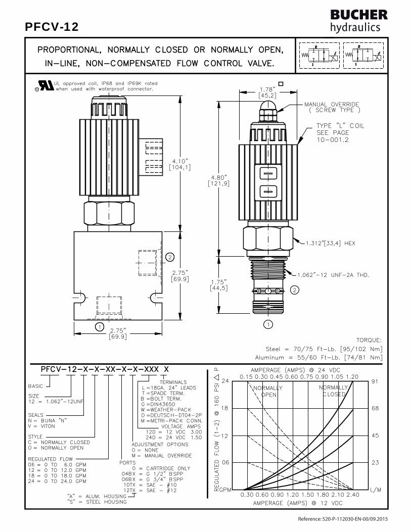
TYPE "L" COIL TYPE "L" COIL SEE PAGE SEE PAGE 10-001.210-001.2
2
1
2
1
AMPERAGE (AMPS) @ 12 VDCAMPERAGE (AMPS) @ 12 VDC
[69.9][69.9]2.75"2.75"
( SCREW TYPE )( SCREW TYPE )MANUAL OVERRIDEMANUAL OVERRIDE
[45,2][45,2]1.78"1.78"
1.312"[33,4] HEX1.312"[33,4] HEX
[69.9][69.9]2.75"2.75"
[44,5][44,5]1.75"1.75"
[121,9][121,9]4.80"4.80"
[104,1][104,1]4.10"4.10"
1.062"-12 UNF-2A THD.1.062"-12 UNF-2A THD.
1
2
1
2
0.750.75
1.501.50
AMPERAGE (AMPS) @ 24 VDCAMPERAGE (AMPS) @ 24 VDC
0.300.30
0606
GPMGPM
1212
0.900.900.600.60 1.201.20
0.150.15
NORMALLYNORMALLY OPEN OPEN
2424
1818
0.450.450.300.30 0.600.60
4545
L/ML/M2.102.101.801.80 2.402.40
2323
9191
6868
1.051.05
CLOSED CLOSEDNORMALLYNORMALLY
0.900.90 1.201.20
R when used with waterproof connector.when used with waterproof connector.UL approved coil, IP68 and IP69K rated UL approved coil, IP68 and IP69K rated
LTBGWDM
TERMINALS TERMINALS=18GA. 24" LEADS=18GA. 24" LEADS=SPADE TERM.=SPADE TERM.=BOLT TERM.=BOLT TERM.=DIN43650=DIN43650=WEATHER-PACK=WEATHER-PACK=DEUTSCH-DT04-2P=DEUTSCH-DT04-2P=METRI-PACK CONN.=METRI-PACK CONN.
12D12D24D24D
VOLTAGE VOLTAGE= 12 VDC= 12 VDC= 24 VDC= 24 VDC
= BUNA "N"= BUNA "N"= VITON= VITON
SEALSSEALSNV
SIZESIZE12 = 1.062"-12UNF12 = 1.062"-12UNF
PORTSPORTS0
04BX04BX06BX06BX10TX10TX12TX12TX
= CARTRIDGE ONLY= CARTRIDGE ONLY= G 1/2" BSPP= G 1/2" BSPP= G 3/4" BSPP= G 3/4" BSPP= SAE - #10= SAE - #10= SAE - #12= SAE - #12
REGULATED FLOWREGULATED FLOW0606121218182424
= 0 TO 6.0 GPM= 0 TO 6.0 GPM= 0 TO 12.0 GPM= 0 TO 12.0 GPM= 0 TO 18.0 GPM= 0 TO 18.0 GPM= 0 TO 24.0 GPM= 0 TO 24.0 GPM
BASICBASIC
STYLESTYLECO
"A" = ALUM. HOUSING "A" = ALUM. HOUSING "S" = STEEL HOUSING "S" = STEEL HOUSING
= NONE= NONE= MANUAL OVERRIDE= MANUAL OVERRIDE
ADJUSTMENT OPTIONSADJUSTMENT OPTIONSOM
AMPSAMPS 3.00 3.00 1.50 1.50
= NORMALLY CLOSED= NORMALLY CLOSED= NORMALLY OPEN= NORMALLY OPEN
REGULATED FLOW (1-2) @ 160 PSI P
REGULATED FLOW (1-2) @ 160 PSI PPFCV-12-X-X-XX-X-X-XXX XPFCV-12-X-X-XX-X-X-XXX X
PROPORTIONAL, NORMALLY CLOSED OR NORMALLY OPEN,PROPORTIONAL, NORMALLY CLOSED OR NORMALLY OPEN,
IN-LINE, NON-COMPENSATED FLOW CONTROL VALVE.IN-LINE, NON-COMPENSATED FLOW CONTROL VALVE.
Steel = 70/75 Ft-Lb. [95/102 Nm] Steel = 70/75 Ft-Lb. [95/102 Nm]
TORQUE:TORQUE:
Aluminum = 55/60 Ft-Lb. [74/81 Nm]Aluminum = 55/60 Ft-Lb. [74/81 Nm]
Reference: 520-P-112030-EN-00/09.2015
PFCV-12

DESCRIPTIONDESCRIPTION
OPERATIONSOPERATIONS
FEATURES AND BENEFITSFEATURES AND BENEFITS
Flow is proportional to the current input.Flow is proportional to the current input.Normally Open 24.0 to 0 GPM [91,2 to 0 L/m] @ 160 PSI DELTA P.Normally Open 24.0 to 0 GPM [91,2 to 0 L/m] @ 160 PSI DELTA P.Regulated flow Normally Closed 0 to 24.0 GPM [0 to 91,2 L/M] max.Regulated flow Normally Closed 0 to 24.0 GPM [0 to 91,2 L/M] max.in-line (RESTRICTIVE) type, hydraulic non-compensated flow control.in-line (RESTRICTIVE) type, hydraulic non-compensated flow control.This valve is a cartridge style, electro-hydraulic, proportional,This valve is a cartridge style, electro-hydraulic, proportional,
ON THE VALVE VERSION.ON THE VALVE VERSION.IN THE EVENT OF POWER FAILURE THE VALVE WILL CLOSE OR OPEN DEPENDINGIN THE EVENT OF POWER FAILURE THE VALVE WILL CLOSE OR OPEN DEPENDINGincrease or decrease proportionally.increase or decrease proportionally.When current is increased or decreased to the coil the flow willWhen current is increased or decreased to the coil the flow willposition against a precision bias spring varying the flow.position against a precision bias spring varying the flow.energized the armature moves the metering orifice to open or to closedenergized the armature moves the metering orifice to open or to closedportional, non-compensated, flow control valve. When the coil isportional, non-compensated, flow control valve. When the coil isThis unit is a direct acting (NO PILOT FLOW), electro-hydraulic, pro-This unit is a direct acting (NO PILOT FLOW), electro-hydraulic, pro-
All cartridge valves are 100% functionally tested.All cartridge valves are 100% functionally tested.All external carbon steel parts are plated for longer life against the elements.All external carbon steel parts are plated for longer life against the elements.Very efficient wet - armature solenoid core tube construction.Very efficient wet - armature solenoid core tube construction.Hardened precision fitted spool & sleeve provides reliable, long life.Hardened precision fitted spool & sleeve provides reliable, long life.Interchangeable solenoid coils & terminations options available.Interchangeable solenoid coils & terminations options available.Continuous-duty, very low heat rise & waterproof solenoid coil.Continuous-duty, very low heat rise & waterproof solenoid coil.
PROPORTIONAL, IN-LINE TYPE, FLOW CONTROL VALVE.PROPORTIONAL, IN-LINE TYPE, FLOW CONTROL VALVE.
Reference: 520-P-112030-EN-00/09.2015
PFCV-12

SPECIFICATIONSSPECIFICATIONS
VALVE CAVITY: #C1220, See Page 0-013.0.VALVE CAVITY: #C1220, See Page 0-013.0. 4.20 lbs [1,90 kg] steel body. 4.20 lbs [1,90 kg] steel body. 1.10 lbs [0,50 kg] aluminum body. 1.10 lbs [0,50 kg] aluminum body. 1.09 lbs [0,50 kg] coil & housing. 1.09 lbs [0,50 kg] coil & housing.WEIGHT: 0.84 lbs [0,38 kg] cartridge only.WEIGHT: 0.84 lbs [0,38 kg] cartridge only.
SKV-1222 Viton SKV-1222 VitonSEAL KIT: SKN-1222 Buna "N"SEAL KIT: SKN-1222 Buna "N"
24 VDC, Operating current 0.2 to 1.2 AMPS. 24 VDC, Operating current 0.2 to 1.2 AMPS.POWER REQUIREMENTS: 12 VDC, Operating current 0.4 to 2.4 AMPS.POWER REQUIREMENTS: 12 VDC, Operating current 0.4 to 2.4 AMPS. current control and a 50 Hz dither. current control and a 50 Hz dither.RESPONSE: The most efficient method to control this valve is withRESPONSE: The most efficient method to control this valve is with
INTERNAL LEAKAGE: 30 cu.in/min [495 cc/m] @ 160 PSI DELTA P [11 Bar]INTERNAL LEAKAGE: 30 cu.in/min [495 cc/m] @ 160 PSI DELTA P [11 Bar]REGULATED FLOW: 25.0 GPM [94,5 l/m] Max. See performance chart.REGULATED FLOW: 25.0 GPM [94,5 l/m] Max. See performance chart.PROOF PRESSURE: 10,000 PSI [700 Bar]PROOF PRESSURE: 10,000 PSI [700 Bar]OPERATING PRESSURE: 5,000 PSI [350 Bar]OPERATING PRESSURE: 5,000 PSI [350 Bar]
INSTALLATION: Flow 1-2 preferred, Max Flow 2-1 lower than shown on INSTALLATION: Flow 1-2 preferred, Max Flow 2-1 lower than shown on graph. Use undercuts in cavity to obtain max rated flow when using a graph. Use undercuts in cavity to obtain max rated flow when using a pressure compensator in series. Pressure drop across valve must not pressure compensator in series. Pressure drop across valve must not exceed 300 PSI [21] bar.exceed 300 PSI [21] bar.
PROPORTIONAL, IN-LINE TYPE, FLOW CONTROL VALVE.PROPORTIONAL, IN-LINE TYPE, FLOW CONTROL VALVE.
MIL-H-5606, SAE-#10, SAE-#20, etc. MIL-H-5606, SAE-#10, SAE-#20, etc.OPERATING MEDIA: All general purpose hydraulic fluids such asOPERATING MEDIA: All general purpose hydraulic fluids such asOPERATING TEMPERATURE: -40° to +250° F. [-40° to +120° C.]OPERATING TEMPERATURE: -40° to +250° F. [-40° to +120° C.] 5000 PSI [350 Bar] = Steel - Unplated. 5000 PSI [350 Bar] = Steel - Unplated.VALVE HOUSINGS: 2500 PSI [175 Bar] = Aluminum - Anodized.VALVE HOUSINGS: 2500 PSI [175 Bar] = Aluminum - Anodized.
[email protected] www.bucherhydraulics.com/commoncavity
2015 by Bucher Hydraulics, Inc., 2545 Northwest Parkway, Elgin, Illinois 60124, USAAll rights reserved.The technical information in this catalog, may contain calculated figures (for reference only) and not actual performance data for this product.Data is provided for the purpose of product description only, and must not be construed as warranted characteristics in the legal sense. The information does not relieve users from the duty of conducting their own evaluations and tests. Because the products are subject to continual improvement, we reserve the right to amend the product specifications contained in this catalogue.
©
Reference: 520-P-112030-EN-00/09.2015
PFCV-12

TYPE "L" COIL TYPE "L" COIL SEE PAGE SEE PAGE 10-001.210-001.2
2
1
2
1
1361360.150.15 0.300.30 0.600.60 0.900.90 1.201.200.450.45 0.750.75 1.051.05
0.900.90 1.501.50 2.102.10
AMPERAGE (AMPS) @ 24 VDCAMPERAGE (AMPS) @ 24 VDC
AMPERAGE (AMPS) @ 12 VDCAMPERAGE (AMPS) @ 12 VDC2.402.401.801.801.201.200.600.600.300.30
24 24
18 18
12 12
0606
GPMGPM L/ML/M
[121,9][121,9]4.80"4.80"
( SCREW TYPE )( SCREW TYPE )MANUAL OVERRIDEMANUAL OVERRIDE
[45.2][45.2]1.78"1.78"
[76,2][76,2]3.00"3.00"
[76,2][76,2]3.00"3.00"
30 30
36 36
114114
91 91
68 68
46 46
23 23
1.312"-12 UNF THD.1.312"-12 UNF THD.
[45.7][45.7]1.80"1.80"
[104,1][104,1]4.10"4.10"
1.50" [38,1] HEX1.50" [38,1] HEX
REGULATED FLOW (1-2) @ 160 PSI P
REGULATED FLOW (1-2) @ 160 PSI P
CLOSED CLOSEDNORMALLYNORMALLY
OPEN OPENNORMALLYNORMALLY
1
2
2
1
UL approved coil, IP68 and IP69K rated UL approved coil, IP68 and IP69K rated when used with waterproof connector.when used with waterproof connector.R
LTBGWDM
TERMINALS TERMINALS=18GA. 24" LEADS=18GA. 24" LEADS=SPADE TERM.=SPADE TERM.=BOLT TERM.=BOLT TERM.=DIN43650=DIN43650=WEATHER-PACK=WEATHER-PACK=DEUTSCH-DT04-2P=DEUTSCH-DT04-2P=METRI-PACK CONN.=METRI-PACK CONN.
12D12D24D24D
VOLTAGE VOLTAGE= 12 VDC= 12 VDC= 24 VDC= 24 VDC
= BUNA "N"= BUNA "N"= VITON= VITON
SEALSSEALSNV
SIZESIZE16 = 1.312"-12UNF16 = 1.312"-12UNF
PORTSPORTS0
06BX06BX08BX08BX12TX12TX16TX16TX
= CARTRIDGE ONLY= CARTRIDGE ONLY= G 3/4" BSPP= G 3/4" BSPP= G 1" BSPP= G 1" BSPP= SAE - #12= SAE - #12= SAE - #16 = SAE - #16
REGULATED FLOWREGULATED FLOW060612121818242430303636
= 0 TO 6.0 GPM= 0 TO 6.0 GPM= 0 TO 12.0 GPM= 0 TO 12.0 GPM= 0 TO 18.0 GPM= 0 TO 18.0 GPM= 0 TO 24.0 GPM= 0 TO 24.0 GPM= 0 TO 30.0 GPM= 0 TO 30.0 GPM= 0 TO 36.0 GPM= 0 TO 36.0 GPM
BASICBASIC
STYLESTYLECO
"A" = ALUM. HOUSING "A" = ALUM. HOUSING "S" = STEEL HOUSING "S" = STEEL HOUSING
= NONE= NONE= MANUAL OVERRIDE= MANUAL OVERRIDE
ADJUSTMENT OPTIONSADJUSTMENT OPTIONSOM
AMPSAMPS 3.00 3.00 1.50 1.50
= NORMALLY CLOSED= NORMALLY CLOSED= NORMALLY OPEN= NORMALLY OPEN
PFCV-16-X-X-XX-X-X-XXX XPFCV-16-X-X-XX-X-X-XXX X
IN-LINE, NON-COMPENSATED FLOW CONTROL VALVE.IN-LINE, NON-COMPENSATED FLOW CONTROL VALVE.
PROPORTIONAL, NORMALLY CLOSED OR NORMALLY OPEN,PROPORTIONAL, NORMALLY CLOSED OR NORMALLY OPEN,
Steel = 95/100 Ft-Lb. [129/136 Nm] Steel = 95/100 Ft-Lb. [129/136 Nm]
TORQUE:TORQUE:
Aluminum = 70/75 Ft-Lb. [95/102 Nm]Aluminum = 70/75 Ft-Lb. [95/102 Nm]
Reference: 520-P-112040-EN-00/09.2015
PFCV-16

DESCRIPTIONDESCRIPTION
OPERATIONSOPERATIONS
FEATURES AND BENEFITSFEATURES AND BENEFITS
Flow is proportional to the current input.Flow is proportional to the current input.Normally Open 36.0 to 0 GPM [137,0 to 0 L/m] @ 160 PSI DELTA P.Normally Open 36.0 to 0 GPM [137,0 to 0 L/m] @ 160 PSI DELTA P.Regulated flow Normally Closed 0 to 36.0 GPM [0 to 137,0 L/M] max.Regulated flow Normally Closed 0 to 36.0 GPM [0 to 137,0 L/M] max.in-line (RESTRICTIVE) type, hydraulic non-compensated flow control.in-line (RESTRICTIVE) type, hydraulic non-compensated flow control.This valve is a cartridge style, electro-hydraulic, proportional,This valve is a cartridge style, electro-hydraulic, proportional,
ON THE VALVE VERSION.ON THE VALVE VERSION.IN THE EVENT OF POWER FAILURE THE VALVE WILL CLOSE OR OPEN DEPENDINGIN THE EVENT OF POWER FAILURE THE VALVE WILL CLOSE OR OPEN DEPENDINGincrease or decrease proportionally.increase or decrease proportionally.When current is increased or decreased to the coil the flow willWhen current is increased or decreased to the coil the flow willposition against a precision bias spring varying the flow.position against a precision bias spring varying the flow.energized the armature moves the metering orifice to open or to closedenergized the armature moves the metering orifice to open or to closedportional, non-compensated, flow control valve. When the coil isportional, non-compensated, flow control valve. When the coil isThis unit is a direct acting (NO PILOT FLOW), electro-hydraulic, pro-This unit is a direct acting (NO PILOT FLOW), electro-hydraulic, pro-
Industry common cavity.Industry common cavity.All cartridge valves are 100% functionally tested.All cartridge valves are 100% functionally tested.All external carbon steel parts are plated for longer life against the elements.All external carbon steel parts are plated for longer life against the elements.Very efficient wet - armature solenoid core tube construction.Very efficient wet - armature solenoid core tube construction.Hardened precision fitted spool & sleeve provides reliable, long life.Hardened precision fitted spool & sleeve provides reliable, long life.Interchangeable solenoid coils & terminations options available.Interchangeable solenoid coils & terminations options available.Continuous-duty, very low heat rise & waterproof solenoid coil.Continuous-duty, very low heat rise & waterproof solenoid coil.
PROPORTIONAL, IN-LINE TYPE, FLOW CONTROL VALVE.PROPORTIONAL, IN-LINE TYPE, FLOW CONTROL VALVE.
Reference: 520-P-112040-EN-00/09.2015
PFCV-16

SPECIFICATIONSSPECIFICATIONS
VALVE CAVITY: #C1620, See Page 0-014.0.VALVE CAVITY: #C1620, See Page 0-014.0. 4.65 lbs [2,10 kg] steel body. 4.65 lbs [2,10 kg] steel body. 1.25 lbs [0,57 kg] aluminum body. 1.25 lbs [0,57 kg] aluminum body. 1.09 lbs [0,50 kg] coil & housing. 1.09 lbs [0,50 kg] coil & housing.WEIGHT: 0.95 lbs [0,42 kg] cartridge only.WEIGHT: 0.95 lbs [0,42 kg] cartridge only.
SKV-1622 Viton SKV-1622 VitonSEAL KIT: SKN-1622 Buna "N"SEAL KIT: SKN-1622 Buna "N"
24 VDC, Operating current 0.2 to 1.2 AMPS. 24 VDC, Operating current 0.2 to 1.2 AMPS.POWER REQUIREMENTS: 12 VDC, Operating current 0.4 to 2.4 AMPS.POWER REQUIREMENTS: 12 VDC, Operating current 0.4 to 2.4 AMPS. current control and a 50 Hz dither. current control and a 50 Hz dither.RESPONSE: The most efficient method to control this valve is withRESPONSE: The most efficient method to control this valve is with
INTERNAL LEAKAGE: 40 cu.in/min [660 cc/m] @ 160 PSI DELTA P [11 Bar]INTERNAL LEAKAGE: 40 cu.in/min [660 cc/m] @ 160 PSI DELTA P [11 Bar]REGULATED FLOW: 36.0 GPM [136,0 l/m] Max. See performance chart.REGULATED FLOW: 36.0 GPM [136,0 l/m] Max. See performance chart.PROOF PRESSURE: 10,000 PSI [700 Bar]PROOF PRESSURE: 10,000 PSI [700 Bar]OPERATING PRESSURE: 5,000 PSI [350 Bar]OPERATING PRESSURE: 5,000 PSI [350 Bar]
INSTALLATION: Flow 1-2 preferred, Max Flow 2-1 lower than shown on INSTALLATION: Flow 1-2 preferred, Max Flow 2-1 lower than shown on graph. Use undercuts in cavity to obtain max rated flow when using a graph. Use undercuts in cavity to obtain max rated flow when using a pressure compensator in series. Pressure drop across valve must not pressure compensator in series. Pressure drop across valve must not exceed 300 PSI [21] bar.exceed 300 PSI [21] bar.
PROPORTIONAL, IN-LINE TYPE, FLOW CONTROL VALVE.PROPORTIONAL, IN-LINE TYPE, FLOW CONTROL VALVE.
MIL-H-5606, SAE-#10, SAE-#20, etc. MIL-H-5606, SAE-#10, SAE-#20, etc.OPERATING MEDIA: All general purpose hydraulic fluids such asOPERATING MEDIA: All general purpose hydraulic fluids such asOPERATING TEMPERATURE: -40° to +250° F. [-40° to +120° C.]OPERATING TEMPERATURE: -40° to +250° F. [-40° to +120° C.] 5000 PSI [350 Bar] = Steel - Unplated. 5000 PSI [350 Bar] = Steel - Unplated.VALVE HOUSINGS: 2500 PSI [175 Bar] = Aluminum - Anodized.VALVE HOUSINGS: 2500 PSI [175 Bar] = Aluminum - Anodized.
[email protected] www.bucherhydraulics.com/commoncavity
2015 by Bucher Hydraulics, Inc., 2545 Northwest Parkway, Elgin, Illinois 60124, USAAll rights reserved.The technical information in this catalog, may contain calculated figures (for reference only) and not actual performance data for this product.Data is provided for the purpose of product description only, and must not be construed as warranted characteristics in the legal sense. The information does not relieve users from the duty of conducting their own evaluations and tests. Because the products are subject to continual improvement, we reserve the right to amend the product specifications contained in this catalogue.
©
Reference: 520-P-112040-EN-00/09.2015
PFCV-16
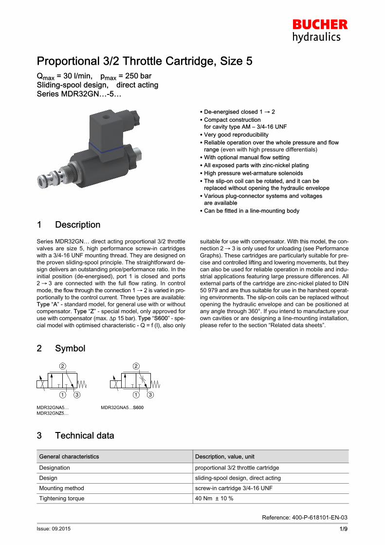
Proportional 3/2 Throttle Cartridge, Size 5Qmax = 30�l/min,�pmax = 250�barSliding-spool design,�direct actingSeries MDR32GN…-5…
1/9
Reference: 400-P-618101-EN-03
Issue: 09.2015
� De-energised closed 1 � 2
� Compact construction
for cavity type AM – 3/4-16 UNF
� Very good reproducibility
� Reliable operation over the whole pressure and flow
range (even with high pressure differentials)
� With optional manual flow setting
� All exposed parts with zinc-nickel plating
� High pressure wet-armature solenoids
� The slip-on coil can be rotated, and it can be
replaced without opening the hydraulic envelope
� Various plug-connector systems and voltages
are available
� Can be fitted in a line-mounting body
1 Description
Series MDR32GN… direct acting proportional 3/2 throttle
valves are size 5, high performance screw-in cartridges
with a 3/4-16 UNF mounting thread. They are designed on
the proven sliding-spool principle. The straightforward de
sign delivers an outstanding price/performance ratio. In the
initial position (de-energised), port 1 is closed and ports
2��3 are connected with the full flow rating. In control
mode, the flow through the connection 1 2 is varied in pro
portionally to the control current. Three types are available:
Type “A” - standard model, for general use with or without
compensator. Type “Z” - special model, only approved for
use with compensator (max. p 15 bar). Type “S600” - spe
cial model with optimised characteristic - Q = f (I), also only
suitable for use with compensator. With this model, the con
nection 2 3 is only used for unloading (see Performance
Graphs). These cartridges are particularly suitable for pre
cise and controlled lifting and lowering movements, but they
can also be used for reliable operation in mobile and indu
strial applications featuring large pressure differences. All
external parts of the cartridge are zinc-nickel plated to DIN
50�979 and are thus suitable for use in the harshest operat
ing environments. The slip-on coils can be replaced without
opening the hydraulic envelope and can be positioned at
any angle through 360°. If you intend to manufacture your
own cavities or are designing a line-mounting installation,
please refer to the section “Related data sheets”.
2 Symbol
2
1 3
2
1 3
MDR32GNA5… MDR32GNA5…S600
MDR32GNZ5…
3 Technical data
General characteristics Description, value, unit
Designation proportional 3/2 throttle cartridge
Design sliding-spool design, direct acting
Mounting method screw-in cartridge 3/4-16�UNF
Tightening torque 40 Nm �± 10�%

400-P-618101-EN-03/09.2015
Series MDR32GN…-5…2/9
Description, value, unitGeneral characteristics
Size nominal size 5, cavity type AM
Weight 0.40 kg
Mounting attitude unrestricted (preferably vertical, coil down)
Ambient temperature range -25�°C … +50�°C
Hydraulic characteristics Description, value, unit
Maximum operating pressure 250 bar
Maximum flow rate 30�l/min
Nominal flow rate 1 2 25 l/min at p = 10 bar
Leakage flow rate < 150 cm3/min (with pN 250 bar)
with oil viscosity 33 mm2/s (cSt)
Flow direction see symbols
Hydraulic fluid HL and HLP mineral oil to DIN 51 524;
for other fluids, please contact BUCHER
Hydraulic fluid temperature range -25�°C … +70�°C
Viscosity range 15…380�mm2/s (cSt), recommended 20...130�mm2/s (cSt)
Minimum fluid cleanliness
Cleanliness class to ISO 4406�:�1999
class 18/16/13
Electrical characteristics Description, value, unit
Supply voltage 12�V DC, 24�V DC
Control current 12 V = 0…1400 mA, 24 V = 0…760 mA
Power consumption at max. control current max. 19�W
Coil resistance R - cold value at 20�°C
- max. warm value
12 V = 5.8��/�24�V = 21�12 V = 8.6��/�24�V = 32�
Recommended PWM frequency (dither) 200 Hz
Hysteresis with PWM 2…4 % IN
Reversal error with PWM 2…4 % IN
Sensitivity with PWM < 1 % IN
Reproducibility with PWM < 2 % pN
Relative duty cycle 100�%
Protection class to ISO�20�653 / EN�60�529 IP 65 / IP 67 / IP 69K, see “Ordering code”
(with appropriate mating connector and
proper fitting and sealing)
Electrical connection 3-pin square plug to ISO 4400 / DIN 43 650 (standard)
for other connectors, see “Ordering code”

400-P-618101-EN-03/09.2015
Series MDR32GN…-5…3/9
4 Performance graphs measured with oil viscosity 33�mm2/s (cSt)
For general use with / without compensator – type “A”
p = f (Q) Pressure drop - Flow rate characteristic
P0150.ai
0
5
10
15
20
25
30
Q [l/min]302520151050
p [bar]
Q = f (I; p) Flow rate adjustment characteristic
P0151.ai
0
25
30
20
15
10
5
I [mA]200 300 400 500 600 700I [mA]400 600 800 1000 1200 1400
Q [l/min]
50 bar
150 bar
100 bar
200 bar250 bar
For use with compensator (max. �p = 15 bar) – type “Z”
p = f (Q) Pressure drop - Flow rate characteristic
P0152.ai
0
2
4
6
8
10
12
Q [l/min]20151050
p [bar]
Q = f (I; p) Flow rate adjustment characteristic
P0154.ai
0
20
15
10
5
I [mA]200 300 400 500 600 700I [mA]400 600 800 1000 1200 1400
Q [l/min]
DW = F061)
Q = f (p; I) Flow rate adjustment characteristic
P0153.ai
0
20
15
10
5
Q [l/min]
250200150100500 p2 [bar]
I = 700 / 1400 mAI = 700 / 1400 mA
I = 600 / 1200 mAI = 600 / 1200 mA
I = 650 / 1300 mAI = 650 / 1300 mA
I = 500 / 1000 mAI = 500 / 1000 mA
I = 550 / 1100 mAI = 550 / 1100 mA
DW = F06 1)
IMPORTANT!
1) Performance graphs measured with compensator model DWDPA-5D-10-F06-2

400-P-618101-EN-03/09.2015
Series MDR32GN…-5…4/9
With optimised characteristic - Q = f (I), type “S600” – with compensator (max. �p = 15 bar)
p = f (Q) Pressure drop - Flow rate characteristic
0
2
4
6
8
10
Q [l/min]20151050
p [bar]P0155.ai
Q = f (I; p) Flow rate adjustment characteristic
P0157.ai
0
20
15
10
5
I [mA]200 300 400 500 600 700I [mA]400 600 800 1000 1200 1400
Q [l/min]
DW = F061)
Q = f (p; I) Flow rate adjustment characteristic
P0156.ai
0
20
15
10
5
Q [l/min]
250200150100500 p2 [bar]
I = 700 / 1400 mAI = 700 / 1400 mA
I = 600 / 1200 mAI = 600 / 1200 mA
I = 400 / 800 mAI = 400 / 800 mA
I = 500 / 1000 mAI = 500 / 1000 mA
DW = F06 1)
IMPORTANT!
1) Performance graphs measured with compensator model DWDPA-5D-10-F06-2
5 Installation information
IMPORTANT!
To achieve the proportional 3/2 throttle cartridge's
maximum performance rating, fit the solenoid coil
as shown (with the plug pins at the bottom). When
fitting the cartridges, note the mounting attitude
(preferably vertical, with coil down automatic
air bleed) and use the specified tightening torque.
No adjustments are necessary, since the cartrid
ges are set in the factory.
ATTENTION!
Only qualified personnel with mechanical skills
may carry out any maintenance work. Generally,
the only work that should ever be undertaken is to
check, and possibly replace, the seals. When
changing seals, oil or grease the new seals tho
roughly before fitting them.

400-P-618101-EN-03/09.2015
Series MDR32GN…-5…5/9
6 Dimensions & sectional view
Without manual flow setting – standard
56.4
40
81
120
39
74.4
36
1
2
5
3
6
4
7
5
1
2
24
3
Ma = 2.7 [Nm] 10 %
Ma = 15 [Nm] 10 %
13
Ma = 2.7 [Nm] 10 %
Ma = 40 [Nm] 10 %
A
B
Seal kit NBR no. DS-247-N 2)
Item Qty. Description
1 1 O-ring �18,00�x�2,00 FKM
2 1 O-ring no. 017 �17,17�x�1,78 N90
3 1 O-ring no.�014 �12,42�x�1,78 N90
4 1 O-ring no.�013 �10,82�x�1,78 N90
5 2 O-ring �16,00�x�2,00 FKM
6 2 Backup ring �10.70�x�1.45�x�1.40 FI0751
7 2 Backup ring �09.40�x�1.45�x�1.00 FI0751
IMPORTANT!
2) Seal kit with FKM (Viton) seals no. DS-247-V
Air-bleeding
If necessary, air can be purged from these proportional
throttle cartridges by using the cap nut (Item B). The pro
cedure is as follows:
A Knurled nut
B Cap nut
Steps:
1. Slacken and remove the knurled nut.
2. Slacken the cap nut approx. 1.5 turns.
Caution:
Slackening the cap nut allows oil to spray out!
3. Switch the proportional throttle cartridge ON/OFF
several times until no more air bubbles escape.
4. Tighten the cap nut.
5. Refit the knurled nut and tighten it.

400-P-618101-EN-03/09.2015
Series MDR32GN…-5…6/9
With manual flow setting – Option “E”39
107.
4
146.
4
56.4
66.4
36
74.4
1
2
3
2
C
D
Ma = 1 [Nm] 10%
4
13Ma = 10 [Nm] 10 %
2
1 3
2
1 3
Integral air-bleeding
If necessary, air can be purged from these proportional
throttle cartridges by using the integral air-bleed screw
(Item D). The procedure is as follows:
C Protective cap
D Air-bleed screw
Steps:
1. Remove the protective cap.
2. Slacken the air-bleed screw approx. 2 turns.
3. Switch the proportional throttle cartridge ON/OFF
several times until no more air bubbles escape.
4. Tighten the air-bleed screw.
5. Fit the protective cap.
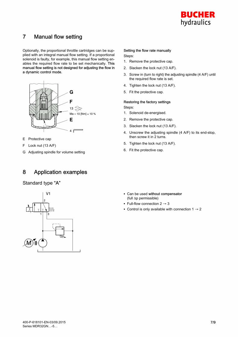
400-P-618101-EN-03/09.2015
Series MDR32GN…-5…7/9
7 Manual flow setting
Optionally, the proportional throttle cartridges can be sup
plied with an integral manual flow setting. If a proportional
solenoid is faulty, for example, this manual flow setting en
ables the required flow rate to be set mechanically. This
manual flow setting is not designed for adjusting the flow in
a dynamic control mode.
4
E
G
F13
Ma = 10 [Nm] 10 %
E Protective cap
F Lock nut (13 A/F)
G Adjusting spindle for volume setting
Setting the flow rate manually
Steps:
1. Remove the protective cap.
2. Slacken the lock nut (13 A/F).
3. Screw in (turn to right) the adjusting spindle (4 A/F) until
the required flow rate is set.
4. Tighten the lock nut (13 A/F).
5. Fit the protective cap.
Restoring the factory settings
Steps:
1. Solenoid de-energised.
2. Remove the protective cap.
3. Slacken the lock nut (13 A/F).
4. Unscrew the adjusting spindle (4 A/F) to its end-stop,
then screw it in 2 turns.
5. Tighten the lock nut (13 A/F).
6. Fit the protective cap.
8 Application examples
Standard type “A”
M
2
31
V1 � Can be used without compensator
(full p permissible)
� Full-flow connection 2 3
� Control is only available with connection 1 2
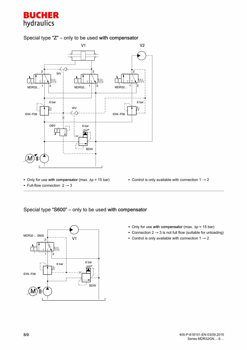
400-P-618101-EN-03/09.2015
Series MDR32GN…-5…8/9
Special type “Z” – only to be used with compensator
M
2
31
V1 V2
8 bar
6 bar 6 bar
IDW−F06 IDW−F06
DBV
WV
WV
BDW
MDR32... MDR32...
2
31
2
31MDR32...
� Only for use with compensator (max. p = 15 bar)
� Full-flow connection 2 3
� Control is only available with connection 1 2
Special type “S600” – only to be used with compensator
M
V1
8 bar6 bar
IDW−F06
BDW
MDR32 ... S6002
31
� Only for use with compensator (max. p = 15 bar)
� Connection 2 3 is not full flow (suitable for unloading)
� Control is only available with connection 1 2
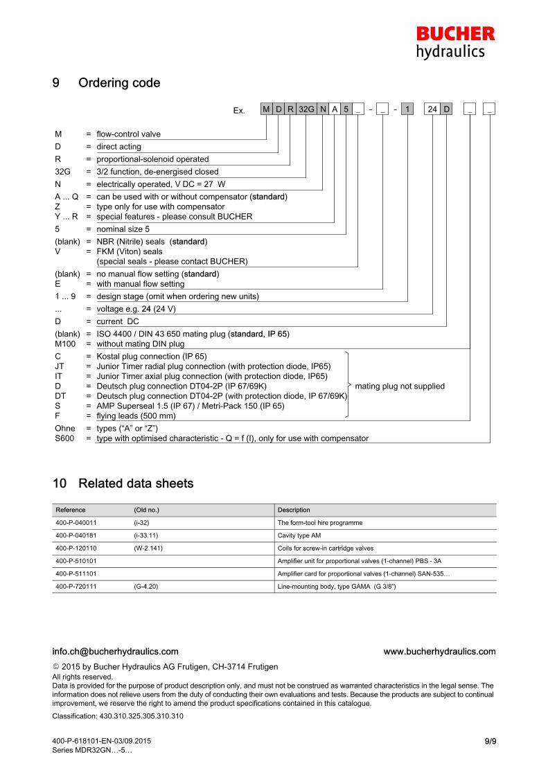
400-P-618101-EN-03/09.2015
Series MDR32GN…-5…9/9
9 Ordering code
32G
M = flow-control valve
D = direct acting
R = proportional-solenoid operated
32G = 3/2 function, de-energised closed
N = electrically operated, V�DC = 27� W
A ... Q = can be used with or without compensator (standard)
Z = type only for use with compensator
Y ... R = special features - please consult BUCHER
5 = nominal size 5
(blank) = NBR (Nitrile) seals (standard)
V = FKM (Viton) seals
(special seals - please contact BUCHER)
(blank) = no manual flow setting (standard)
E = with manual flow setting
1 ... 9 = design stage (omit when ordering new units)
... = voltage e.g. 24 (24 V)
D = current DC
(blank) = ISO 4400 / DIN 43 650 mating plug (standard, IP�65)
M100 = without mating DIN plug
C = Kostal plug connection (IP�65)
JT = Junior Timer radial plug connection (with protection diode, IP65)
IT = Junior Timer axial plug connection (with protection diode, IP65)
D = Deutsch plug connection DT04-2P (IP�67/69K) mating plug not supplied
DT = Deutsch plug connection DT04-2P (with protection diode, IP�67/69K)
S = AMP Superseal 1.5 (IP�67) / Metri-Pack 150 (IP�65)
F = flying leads (500 mm)
Ohne = types (“A” or “Z”)
S600 = type with optimised characteristic - Q = f (I), only for use with compensator
_-Ex. _AR N 5DM -_ _1 24 D
10 Related data sheets
Reference (Old no.) Description
400-P-040011 (i-32) The form-tool hire programme
400-P-040181 (i-33.11) Cavity type AM
400-P-120110 (W-2.141) Coils for screw-in cartridge valves
400-P-510101 Amplifier unit for proportional valves (1-channel) PBS�-�3A
400-P-511101 Amplifier card for proportional valves (1-channel) SAN-535…
400-P-720111 (G-4.20) Line-mounting body, type GAMA (G 3/8”)
� 2015 by Bucher Hydraulics AG Frutigen, CH-3714 Frutigen
All rights reserved.
Data is provided for the purpose of product description only, and must not be construed as warranted characteristics in the legal sense. The
information does not relieve users from the duty of conducting their own evaluations and tests. Because the products are subject to continual
improvement, we reserve the right to amend the product specifications contained in this catalogue.
Classification: 430.310.325.305.310.310

Proportional 4/2 Throttle Cartridge, Size 5Qmax = 30 l/min,�pmax = 250�barSliding-spool design, direct actingSeries MDR42…-5…
1/7
Reference: 400-P-618201-EN-02
Issue: 06.2016
� Compact construction
for cavity type AN – 3/4-16 UNF
� Dual flow paths for higher flow rate
� Low headloss
� For use with inline or bypass
pressure-compensator cartridges
� Reliable operation over the whole pressure
and flow range
� With optional manual flow setting
� All exposed parts with zinc-nickel plating
� High pressure wet-armature solenoids
� The slip-on coil can be rotated, and it can bereplaced without opening the hydraulic envelope
� Various plug-connector systems and voltages
are available
1 Description
Series MDR42… direct acting proportional 4/2 throttle val
ves are size 5, high performance screw-in cartridges with a
3/4-16 UNF mounting thread. They are designed on the pro
ven sliding-spool principle. The straightforward design deli
vers an outstanding price/performance ratio. "De-energised
closed" and "de-energised open" functions are available. In
control mode, the flow through the connections 1 3 und
4 2 is varied in proportion to the control current. Thanks
to these dual flow paths, a higher flow rate is achieved with
low headloss. It is essential that ports 1�+�4, and likewise 2
+ 3, are joined together in the valve housing (manifold
block). In combination with inline or bypass compensators,
these 4/2 throttle cartridges are predominantly used in mo
bile and industrial applications to allow a flow in hydraulic in
stallations to be controlled electro-proportionally. All exter
nal parts of the cartridge are zinc-nickel plated to DIN
50�979 and are thus suitable for use in the harshest operat
ing environments. The slip-on coils can be replaced without
opening the hydraulic envelope and can be positioned at
any angle through 360°. If you intend to manufacture your
own cavities or are designing a line-mounting installation,
please refer to the section “Related data sheets”.
2 Symbol
Dual flow paths2
1
3
4
2
1
3
4
2
1
3
4
MDR42AD…-E MDR42AD… MDR42ANK…
IMPORTANT!
To enable the dual flow-path function, ports 1 + 4
and 2 + 3 must be connected within the valve hou
sing (manifold block).

400-P-618201-EN-02/06.2016
Series MDR42…-5…2/7
3 Technical data
General characteristics Description, value, unit
Designation proportional 4/2 throttle cartridge
Design sliding-spool design, direct acting
Mounting method screw-in cartridge 3/4-16�UNF
Tightening torque 40 Nm �± 10�%
Size nominal size 5, cavity type AN
Weight 0.40 kg
Mounting attitude unrestricted (preferably vertical, coil down)
Ambient temperature range -25�°C … +50�°C
Hydraulic characteristics Description, value, unit
Maximum operating pressure 250 bar
Maximum flow rate 30�l/min
Nominal flow rate 1�+�4 2�+�3 25�l/min at p = 4�bar
Leakage flow rate < 150 cm3/min (with pN 250 bar)
with oil viscosity 33 mm2/s (cSt)
Flow direction see symbols
Hydraulic fluid HL and HLP mineral oil to DIN 51 524;
for other fluids, please contact BUCHER
Hydraulic fluid temperature range -25�°C … +70�°C
Viscosity range 15…380�mm2/s (cSt), recommended 20...130�mm2/s (cSt)
Minimum fluid cleanliness
Cleanliness class to ISO 4406�:�1999
class 18/16/13
Electrical characteristics Description, value, unit
Supply voltage 12�V DC, 24�V DC
Control current 12 V = 0…1400 mA, 24 V = 0…760 mA
Power consumption at max. control current max. 19�W
Coil resistance R - cold value at 20�°C
- max. warm value
12 V = 5.8��/�24�V = 21�12 V = 8.6��/�24�V = 32�
Recommended PWM frequency (dither) 200 Hz
Hysteresis with PWM 2…4 % IN
Reversal error with PWM 2…4 % IN
Sensitivity with PWM < 1 % IN
Reproducibility with PWM < 2 % pN
Relative duty cycle 100�%
Protection class to ISO�20�653 / EN�60�529 IP 65 / IP 67 / IP 69K, see “Ordering code”
(with appropriate mating connector and
proper fitting and sealing)
Electrical connection 3-pin square plug to ISO 4400 / DIN 43 650 (standard)
for other connectors, see “Ordering code”
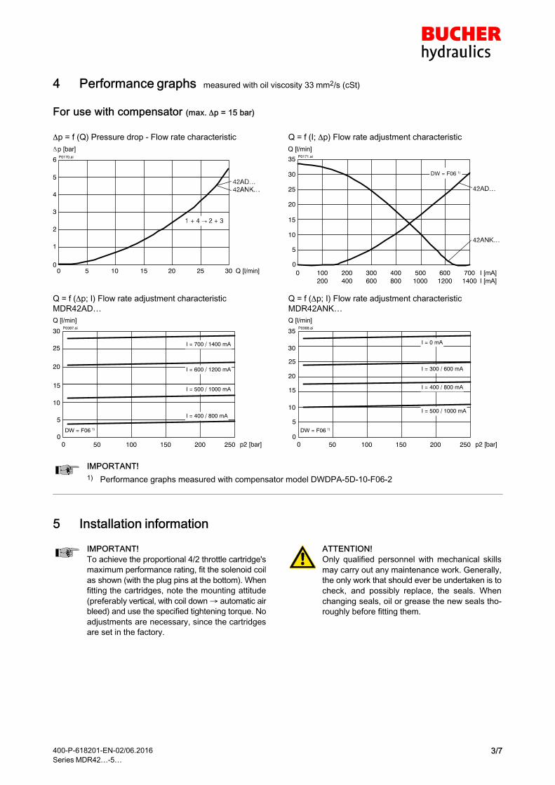
400-P-618201-EN-02/06.2016
Series MDR42…-5…3/7
4 Performance graphs measured with oil viscosity 33�mm2/s (cSt)
For use with compensator (max. �p = 15 bar)
p = f (Q) Pressure drop - Flow rate characteristic
P0170.ai
0
1
2
3
4
5
6
Q [l/min]302520151050
p [bar]
Q = f (I; p) Flow rate adjustment characteristic
P0171.ai
0
35
15
20
25
10
5
I [mA]200 300 400 500 600 700I [mA]400
100200
0600 800 1000 1200 1400
Q [l/min]
30 DW = F06 1)DW = F06 1)
Q = f (p; I) Flow rate adjustment characteristic
MDR42AD…
P0387.ai
0
30
20
10
5
Q [l/min]
250200150100500 p2 [bar]
I = 700 / 1400 mAI = 700 / 1400 mA
I = 600 / 1200 mAI = 600 / 1200 mA
I = 400 / 800 mAI = 400 / 800 mA
I = 500 / 1000 mAI = 500 / 1000 mA
DW = F06 1)
25
15
Q = f (p; I) Flow rate adjustment characteristic
MDR42ANK…
P0388.ai
0
35
20
10
5
Q [l/min]
250200150100500 p2 [bar]
I = 0 mAI = 0 mA
I = 300 / 600 mAI = 300 / 600 mA
I = 500 / 1000 mAI = 500 / 1000 mA
I = 400 / 800 mAI = 400 / 800 mA
DW = F06 1)
30
15
25
IMPORTANT!
1) Performance graphs measured with compensator model DWDPA-5D-10-F06-2
5 Installation information
IMPORTANT!
To achieve the proportional 4/2 throttle cartridge's
maximum performance rating, fit the solenoid coil
as shown (with the plug pins at the bottom). When
fitting the cartridges, note the mounting attitude
(preferably vertical, with coil down automatic air
bleed) and use the specified tightening torque. No
adjustments are necessary, since the cartridges
are set in the factory.
ATTENTION!
Only qualified personnel with mechanical skills
may carry out any maintenance work. Generally,
the only work that should ever be undertaken is to
check, and possibly replace, the seals. When
changing seals, oil or grease the new seals tho
roughly before fitting them.

400-P-618201-EN-02/06.2016
Series MDR42…-5…4/7
6 Dimensions & sectional view
Without manual flow setting – standard
MA = 15 [Nm] ± 10 %
13
MA = 2.7 [Nm] ± 10 %
A
B
Ø
3/4-16UNF
9
5
8
4
3
7
2
1
6
6
1
2
3
4
MA = 2.7 [Nm] ± 10 %
24
MA = 40 [Nm] ± 10 %
53
13
4
81
40
74.4
56.4
36
MDR42AD...
1
2
3
4
MDR42ANK...
Seal kit no. DS-248-N 2)
Item Qty. Description
1 1 O-ring �18,00�x�2,00 FKM
2 1 O-ring no. 017 �17,17�x�1,78 N90
3 1 O-ring no.�014 �12,42�x�1,78 N90
4 1 O-ring no.�013 �10,82�x�1,78 N90
5 1 O-ring no. 012 �09,25�x�1,78 N90
6 2 O-ring � �16,00�x�2,00 FkM
7 1 Backup ring �10.70�x�1.45�x�1.40 FI0751
8 1 Backup ring �09.40�x�1.45�x�1.00 FI0751
9 1 Backup ring �07.80�x�1.45�x�1.00 FI0751
IMPORTANT!
2) Seal kit with FKM (Viton) seals no. DS-248-V
Air-bleeding
If necessary, air can be purged from these proportional
throttle cartridges by using the cap nut (Item B). The pro
cedure is as follows:
A Knurled nut
B Cap nut
Steps:
1. Slacken and remove the knurled nut.
2. Slacken the cap nut approx. 1.5 turns.
Caution: Slackening the cap nut allows oil to spray out!
3. Switch the proportional throttle cartridge ON/OFF
several times until no more air bubbles escape.
4. Tighten the cap nut.
5. Refit the knurled nut and tighten it.

400-P-618201-EN-02/06.2016
Series MDR42…-5…5/7
With manual flow setting – Option “E”
Ø 36
4
3
1
2
53
16
0.4
10
7.4
66
.4
56.4
74.4
MA = 10 [Nm] ± 10 %2
C
D
MA = 1 [Nm] ±10%
2
1
3
4
Integral air-bleeding
If necessary, air can be purged from these proportional
throttle cartridges by using the integral air-bleed screw
(Item D). The procedure is as follows:
C Protective cap
D Air-bleed screw
Steps:
1. Remove the protective cap.
2. Slacken the air-bleed screw approx. 2 turns.
3. Switch the proportional throttle cartridge ON/OFF
several times until no more air bubbles escape.
4. Tighten the air-bleed screw.
5. Fit the protective cap.

400-P-618201-EN-02/06.2016
Series MDR42…-5…6/7
7 Manual flow setting
Optionally, the proportional throttle cartridges can be sup
plied with an integral manual flow setting. If a proportional
solenoid is faulty, for example, this manual flow setting en
ables the required flow rate to be set mechanically. This
manual flow setting is not designed for adjusting the flow ina dynamic control mode.
4
E
G
F
13
MA = 10 [Nm] ± 10 %
E Protective cap
F Lock nut (13 A/F)
G Adjusting spindle for volume setting
Setting the flow rate manually
Steps:
1. Remove the protective cap.
2. Slacken the lock nut (13 A/F).
3. Screw in (turn to right) the adjusting spindle (4 A/F) until
the required flow rate is set.
4. Tighten the lock nut (13 A/F).
5. Fit the protective cap.
Restoring the factory settings
Steps:
1. Solenoid de-energised.
2. Remove the protective cap.
3. Slacken the lock nut (13 A/F).
4. Unscrew the adjusting spindle (4 A/F) to its end-stop,
then screw it in 2 1/8 turns.
5. Tighten the lock nut (13 A/F).
6. Fit the protective cap.
8 Application examples
Used with bypass pressure-compensator cartridge
M
V1
8 bar
BDW
MDR42ADN...
2 3
41
Classic combination with inline and bypass pressure-com
pensator cartridges
M
V1 V2
8 bar
6 bar 6 bar
IDW−F06 IDW−F06
WV
BDW
MDR42ADN... MDR42ADN...
2 3
41
2 3
41

400-P-618201-EN-02/06.2016
Series MDR42…-5…7/7
9 Ordering code
M 42AD
M = flow-control valve
D = direct acting
R = proportional solenoid
42AD = 4/2 function (de-energised closed)
42ANK = 4/2 function (de-energised open)
N = electrically operated, V�DC = 27� W
A ... Q = type only for use with compensator (standard)
Z ... R = special features - please consult BUCHER
5 = nominal size 5
(blank) = NBR (Nitrile) seals (standard)
V = FKM (Viton) seals
(special seals - please contact BUCHER)
(blank) = no manual flow setting (standard)
E = with manual flow setting
1 ... 9 = design stage (omit when ordering new units)
... = voltage e.g. 24 (24 V)
D = current DC
(blank) = ISO 4400 / DIN 43 650 connection with mating plug (standard, IP�65)
M100 = ISO 4400 / DIN 43 650 connection without mating plug
C = Kostal plug connection (IP�65)
JT = Junior Timer radial plug connection (with protection diode, IP65)
IT = Junior Timer axial plug connection (with protection diode, IP65)
D = Deutsch plug connection DT04-2P (IP�67/69K) mating plug not supplied
DT = Deutsch plug connection DT04-2P (with protection diode, IP�67/69K)
S = AMP Superseal 1.5 (IP67) / Metri-Pack 150 (IP65) plug connection
F = flying leads (500 mm)
_-Ex. _AR N 5D -_ 1 24 D
10 Related data sheets
Reference (Old no.) Description
400-P-040011 (i-32) The form-tool hire programme
400-P-040181 (i-33.12) Cavity type AN
400-P-120110 (W-2.141) Coils for screw-in cartridge valves series D36
400-P-510101 Amplifier unit for proportional valves (1-channel) PBS�-�3A
400-P-511101 Amplifier card for proportional valves (1-channel) SAN-535…
� 2016 by Bucher Hydraulics AG Frutigen, CH-3714 Frutigen
All rights reserved.
Data is provided for the purpose of product description only, and must not be construed as warranted characteristics in the legal sense. The
information does not relieve users from the duty of conducting their own evaluations and tests. Because the products are subject to continual
improvement, we reserve the right to amend the product specifications contained in this catalogue.
Classification: 430.310.325.305.310.310
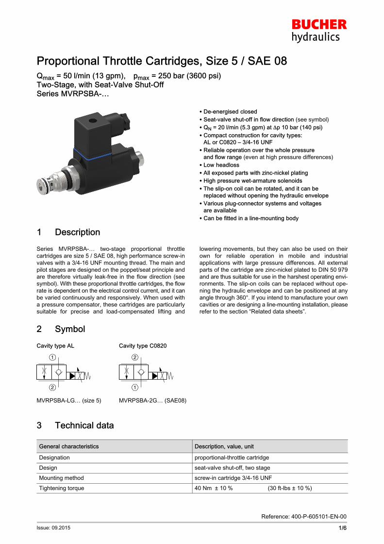
Proportional Throttle Cartridges, Size�5 / SAE 08Qmax = 50�l/min (13 gpm),�pmax = 250�bar (3600 psi)Two-Stage, with Seat-Valve Shut-OffSeries MVRPSBA-…
1/6
Reference: 400-P-605101-EN-00
Issue: 09.2015
� De-energised closed
� Seat-valve shut-off in flow direction (see symbol)
� QN = 20 l/min (5.3 gpm) at �p 10 bar (140 psi)
� Compact construction for cavity types:
AL or C0820 – 3/4-16 UNF
� Reliable operation over the whole pressure
and flow range (even at high pressure differences)
� Low headloss
� All exposed parts with zinc-nickel plating
� High pressure wet-armature solenoids
� The slip-on coil can be rotated, and it can be
replaced without opening the hydraulic envelope
� Various plug-connector systems and voltages
are available
� Can be fitted in a line-mounting body
1 Description
Series MVRPSBA… twostage proportional throttle
cartridges are size 5 / SAE 08, high performance screwin
valves with a 3/416 UNF mounting thread. The main and
pilot stages are designed on the poppet/seat principle and
are therefore virtually leakfree in the flow direction (see
symbol). With these proportional throttle cartridges, the flow
rate is dependent on the electrical control current, and it can
be varied continuously and responsively. When used with
a pressure compensator, these cartridges are particularly
suitable for precise and loadcompensated lifting and
lowering movements, but they can also be used on their
own for reliable operation in mobile and industrial
applications with large pressure differences. All external
parts of the cartridge are zinc-nickel plated to DIN 50�979
and are thus suitable for use in the harshest operating envi
ronments. The slip-on coils can be replaced without ope
ning the hydraulic envelope and can be positioned at any
angle through 360°. If you intend to manufacture your own
cavities or are designing a line-mounting installation, please
refer to the section “Related data sheets”.
2 Symbol
Cavity type AL Cavity type C0820
1
2
2
1
MVRPSBA-LG… (size 5) MVRPSBA-2G… (SAE08)
3 Technical data
General characteristics Description, value, unit
Designation proportional-throttle cartridge
Design seat-valve shut-off, two stage
Mounting method screw-in cartridge 3/4-16 UNF
Tightening torque 40 Nm �± 10�% (30 ft-lbs ± 10�%)

400-P-605101-EN-00/09.2015
Series MVRPSBA-…2/6
Description, value, unitGeneral characteristics
Size nominal size 5 for cavity type AL
size SAE 08 for cavity type C0820
Weight 0.40 kg (0.9 lbs)
Mounting attitude unrestricted (preferably vertical, coil down)
Ambient temperature range -25�°C … +50�°C (-13 °F … +122 °F)
Hydraulic characteristics Description, value, unit
Maximum operating pressure 250�bar (3600 psi)
Maximum flow rate 50�l/min (13 gpm)
Nominal flow rate 20�l/min at p = 10�bar (5.3 gpm at p = 140 psi)
Leakage flow rate < 0,2�cm3/min (max. 5 drops/min)
with oil viscosity 33�mm2/s (cSt)
Flow direction see symbol
Hydraulic fluid HL and HLP mineral oil to DIN 51 524;
for other fluids, please contact BUCHER
Hydraulic fluid temperature range -25�°C … +70�°C (-13 °F … +158 °F)
Viscosity range 15…380�mm2/s (cSt), recommended 20...130�mm2/s (cSt)
Minimum fluid cleanliness
Cleanliness class to ISO 4406�:�1999
class 18/16/13
Electrical characteristics Description, value, unit
Supply voltage 12�V DC, 24�V DC
Control current 12 V = 0…1400 mA, 24 V = 0…760 mA
Coil resistance R - cold value at 20�°C
- max. warm value
12 V = 5.8��/�24�V = 20.9�12 V = 9.1��/�24�V = 32.7�
Recommended PWM frequency (dither) 200 Hz
Hysteresis with PWM 3…6 % IN
Reversal error with PWM 3…6 % IN
Sensitivity with PWM < 2 % IN
Reproducibility with PWM < 3 % pN
Switching time see performance graphs
Relative duty cycle 100�%
Protection class to ISO�20�653 / EN�60�529 IP 65 / IP 67 / IP 69K, see “Ordering code”
(with appropriate mating connector and
proper fitting and sealing)
Electrical connection 3-pin square plug to ISO 4400 / DIN 43 650 (standard)
for other connectors, see “Ordering code”

400-P-605101-EN-00/09.2015
Series MVRPSBA-…3/6
4 Performance graphs
measured with oil viscosity 33�mm2/s (cSt) – for cavity type AL and C0820
p = f (Q) Pressure drop - Flow rate characteristic
“energized”
P0363.ai
(0)0
10
20
40
30
50
60
Q [l/min (gpm)]
50454035302520151050(0)
p [bar (psi)]
(140)
(285)
(570)
(430)
(700)
(860)
(13)(12)(11)(9)(8)(6.6)(5.3)(4)(2.6)(1.3)
I = 750 / 1400 mAI = 750 / 1400 mA
p = f (Q) Pressure drop - Flow rate characteristic
“de-energized - through check valve”
P0364.ai
(0)0
10
20
40
30
50
60
Q [l/min (gpm)]
50454035302520151050(0)
p [bar (psi)]
(140)
(285)
(570)
(430)
(700)
(860)
(13)(12)(11)(9)(8)(6.6)(5.3)(4)(2.6)(1.3)
I = 0 mAI = 0 mA
Attention:
When flow passes through the check valve and
there is a large pressure difference, the poppet in
the main stage can be damaged.
Q = f (p; I) Flow rate adjustment characteristic
I = 600 / 1150 mAI = 600 / 1150 mA
I = 650 / 1250 mAI = 650 / 1250 mA
I = 500 / 1000 mAI = 500 / 1000 mA
I = 750 / 1400 mAI = 750 / 1400 mA
P0365.ai
(0)0
30
20
40
50
250200150100500(0)
p [bar (psi)]
10 (2.6)
(8)
(5.3)
(11)
(13)
(3600)(2900)(2100)(1400)(700)
Q [l/min (gpm)]
Q = f (I; p) Flow rate adjustment characteristic
(0)0
30
20
40
10 (2.6)
(8)
(5.3)
(11)
Q [l/min (gpm)]P0366.ai
I [mA]
150 300 600 750280 560 1120 1400
450840
30 bar (430 psi)30 bar (430 psi)
20 bar (285 psi)20 bar (285 psi)
15 bar (215 psi)15 bar (215 psi)
10 bar (140 psi)10 bar (140 psi)
7 bar (70 psi)7 bar (70 psi)
Switching time measured up to 80�% change in the pressure difference. Electrical operation with DC power supply.
t = f (I; p) Switching time characteristic Opening
at p = 10 … 50�bar (140 … 700�psi)
P0367.ai
0
100
80
60
40
20
t [ms]
I [mA]450 525 675 750I [mA]840 980 1260 1400
6001120
t = f (I; p) Switching time characteristic Closing
at p = 10 … 50�bar (140 … 700�psi])
P0368.ai
0
50
40
30
20
10
t [ms]
I [mA]450 525 675 750I [mA]840 980 1260 1400
6001120

400-P-605101-EN-00/09.2015
Series MVRPSBA-…4/6
5 Dimensions & sectional view
Dimensions in millimeters (inches)
5.1 Insertion in cavity type “AL” 5.2 Insertion in cavity type “C0820”
29(1
.14) 2
1
24(0.95)
4
2
4
81.5
(3.2
)
Ø 36(1.42)
52.5
(2.0
7)
56.4(2.22)
74.4(2.93)
29(1
.14)
110.
5(4
.35)
3/4−16 UNFMVRPSBA−LG−5...
2
1
24(0.95)
1
2
4
4
3
3
3/4−16 UNFMVRPSBA−2G−8...
6 Installation information
Important:
When fitting the cartridges, note the mounting atti
tude (preferably vertical, with coil down auto
matic air bleed) and use the specified tightening
torque. No adjustments are necessary, since the
cartridges are set in the factory.
ATTENTION!
Only qualified personnel with mechanical skills
may carry out any maintenance work. Generally,
the only work that should ever be undertaken is to
check, and possibly replace, the seals. When
changing seals, oil or grease the new seals tho
roughly before fitting them.
Seal kit NBR no. DS-447-N (cavity type AL) 1)
Item Qty. Description
1 1 O-ring no.�017 �17.17�x�1.78 N90
2 1 O-ring no.�014 �12.42�x�1.78 N90
3 2 O-ring �16.00�x�2.00 FKM
4 2 Backup ring �10.70�x�1.45�x�1.00 FI0751
IMPORTANT!
1) Seal kit with FKM (Viton) seals, no. DS-447-V
Seal kit NBR no. DS-448-N (cavity type C0820) 2)
Item Qty. Description
1 1 O-ring no.�017 �17.17�x�1.78 N90
2 1 O-ring no.�012 �9.25�x�1.78 N90
3 2 O-ring �16.00�x�2.00 FKM
4 2 Backup ring �7.80�x�1.45�x�1.00 FI0751
IMPORTANT!
2) Seal kit with FKM (Viton) seals, no. DS-448-V

400-P-605101-EN-00/09.2015
Series MVRPSBA-…5/6
7 Application examples
MVRPSBA−...
M
V2
WR22G.. .WR22G.. .
WR22G.. .
V1
Lif t mast
Additiona lactuator s
Potential applications
� Lifting and lowering movements on industrial trucks
� In agricultural machines, e.g. proportional scraper-floorcontrols in selfloading trailers
� In all applications where a load-independent function is
required, in combination with our in-line or bypasspressure compensators

400-P-605101-EN-00/09.2015
Series MVRPSBA-…6/6
8 Ordering code
MV = throttle valve, two-stage
R = proportional-solenoid operated
P = cartridge design
S = seat-valve design
B = pressurised oil enters at the side
A ... Q = standard model - see relevant data sheets
Z ... R = special features - please consult BUCHER
L = cavity type AL (only for nominal size 5)
2 = cavity type C0820 (only for size SAE 08)
G = normally closed
5 = nominal size 5 (only for cavity type AL)
8 = size SAE 08 (only for cavity type C0820)
20 = nominal flow rate 20�l/min atp = 10�bar (5.3�l/min bei p = 140�psi)
(blank) = NBR (Nitrile) seals (standard)
V = FKM (Viton) seals
(special seals - please contact BUCHER)
1 ... 9 = design stage (omit when ordering new units)
... = voltage e.g. 24 (24 V)
D = current DC
(blank) = ISO 4400 / DIN 43 650 mating plug (standard, IP�65)
M100 = without mating DIN plug
C = Kostal plug connection (IP�65)
JT = Junior Timer radial plug connection (with protection diode, IP65)
IT = Junior Timer axial plug connection (with protection diode, IP65)
D = Deutsch plug connection DT04-2P (IP�67/69K) mating plug not supplied
DT = Deutsch plug connection DT04-2P (with protection diode, IP�67/69K)
S = AMP Superseal 1.5 (IP�67) / Metri-Pack 150 (IP�65)
F = flying leads (500 mm)
1 _20 -_ G _-A _--BSPRMV 24 D
9 Related data sheets
Reference (Old no.) Description
400-P-040011 (i-32) The form-tool hire programme
400-P-040171 Cavity type AL
520-P-000110 Cavity type C0820
400-P-120110 (W-2.141) Coils for screw-in cartridge valves
400-P-510101 Amplifier unit for proportional valves (1-channel) PBS�-�3A
400-P-511101 Amplifier card for proportional valves (1-channel) SAN-535…
400-P-720101 Line-mounting body, type GALA (G�3/8”)
520-P-000111 Line-mounting body, size SAE 08 (G�3/8”)
� 2015 by Bucher Hydraulics AG Frutigen, CH-3714 Frutigen
All rights reserved.
Data is provided for the purpose of product description only, and must not be construed as warranted characteristics in the legal sense. The
information does not relieve users from the duty of conducting their own evaluations and tests. Because the products are subject to continual
improvement, we reserve the right to amend the product specifications contained in this catalogue.
Classification: 430.310.325.305.310.310

TYPE "L" COIL TYPE "L" COIL SEE PAGE SEE PAGE 10-001.210-001.2
REGREGININ
.34" DIA. 2 MTG.HOLES.34" DIA. 2 MTG.HOLES
( SCREW TYPE ) ( SCREW TYPE )LIMITED RANGE ADJUSTMENTLIMITED RANGE ADJUSTMENT
( SCREW TYPE )( SCREW TYPE )MANUAL OVERRIDEMANUAL OVERRIDE
.88".88"
1.80"1.80"
.88".88"
3.00"3.00"
4.10"4.10"
.38".38"
1.57"1.57"
4.00"4.00"
MODEL NUMBERMODEL NUMBER
Elgin, Illinois. U.S.A.Elgin, Illinois. U.S.A.Command Controls Corp.Command Controls Corp.
2.25"2.25"
4.80"4.80"
1.90"1.90"
1.78"1.78"[45,2][45,2]
[121,9][121,9]
[104,1][104,1]
[101,6][101,6]
[9,7][9,7]
[39,9][39,9]
[48,3][48,3]
[57,2][57,2]
[22,4][22,4]
[45,7][45,7]
[76,2][76,2]
[22,4][22,4]
GPMGPM
0404
08 08
12 12
16 16
AMPERAGE (AMPS) @ 12 VDCAMPERAGE (AMPS) @ 12 VDC1.801.800.900.900.300.30 0.600.60 1.201.20 1.501.50 2.102.10 2.402.40
L/ML/M
1515
AMPERAGE (AMPS) @ 24 VDCAMPERAGE (AMPS) @ 24 VDC
NORMALLYNORMALLY
0.900.900.450.45
NORMALLYNORMALLY
0.150.15
OPEN OPEN
0.300.30 0.600.60 0.750.75
CLOSED CLOSED
1.051.05 1.201.20
3030
4545
6060
R when used with waterproof connector.when used with waterproof connector.UL approved coil, IP68 and IP69K rated UL approved coil, IP68 and IP69K rated
NOTES:NOTES:1. SOLENOIDS AVAILABLE WITH DIODES - CONSULT FACTORY.1. SOLENOIDS AVAILABLE WITH DIODES - CONSULT FACTORY.
REGULATED FLOW @ 160 PSI
REGULATED FLOW @ 160 PSI
LTBGWDM
TERMINALSTERMINALS=18GA. 24" LEADS=18GA. 24" LEADS=SPADE TERM.=SPADE TERM.=BOLT TERM.=BOLT TERM.=DIN43650=DIN43650=WEATHER-PACK=WEATHER-PACK=DEUTSCH-DT04-2P=DEUTSCH-DT04-2P=METRI-PACK CONN.=METRI-PACK CONN.
12D12D24D24D
VOLTAGE VOLTAGE= 12 VDC= 12 VDC= 24 VDC= 24 VDC
= BUNA "N"= BUNA "N"= VITON= VITON
SEALSSEALSNV
PORTSPORTS10TX10TX = SAE - #10= SAE - #10
BASICBASIC
STYLESTYLECO
"A" = ALUM. HOUSING "A" = ALUM. HOUSING "S" = STEEL HOUSING "S" = STEEL HOUSING
= NONE= NONE= MANUAL OVERRIDE= MANUAL OVERRIDE= LIMITED RANGE ADJ.= LIMITED RANGE ADJ.= BOTH MO/LTD ADJ= BOTH MO/LTD ADJ
ADJUSTMENT OPTIONSADJUSTMENT OPTIONSO-F-100O-F-100M-F-100M-F-1000-S-1600-S-160M-S-160M-S-160
= NORMALLY CLOSED= NORMALLY CLOSED= NORMALLY OPEN= NORMALLY OPEN
AMPSAMPS 3.00 3.00 1.50 1.50
SIZESIZE10= 7/8"-14UNF10= 7/8"-14UNF
REGULATED FLOWREGULATED FLOW0404080812121616
= 0 TO 4.0 GPM= 0 TO 4.0 GPM= 0 TO 8.0 GPM= 0 TO 8.0 GPM= 0 TO 12.0 GPM= 0 TO 12.0 GPM= 0 TO 16.0 GPM= 0 TO 16.0 GPM
ININREGREG
PIFC-10-X-X-XX-X-X-X-XXX-XXX XPIFC-10-X-X-XX-X-X-X-XXX-XXX X
OPEN PROPORTIONAL, IN-LINE FLOW CONTROL VALVE.OPEN PROPORTIONAL, IN-LINE FLOW CONTROL VALVE.
PRESSURE COMPENSATED, NORMALLY CLOSED OR NORMALLYPRESSURE COMPENSATED, NORMALLY CLOSED OR NORMALLY
Reference: 520-P-112120-EN-00/09.2015
PIFC-10
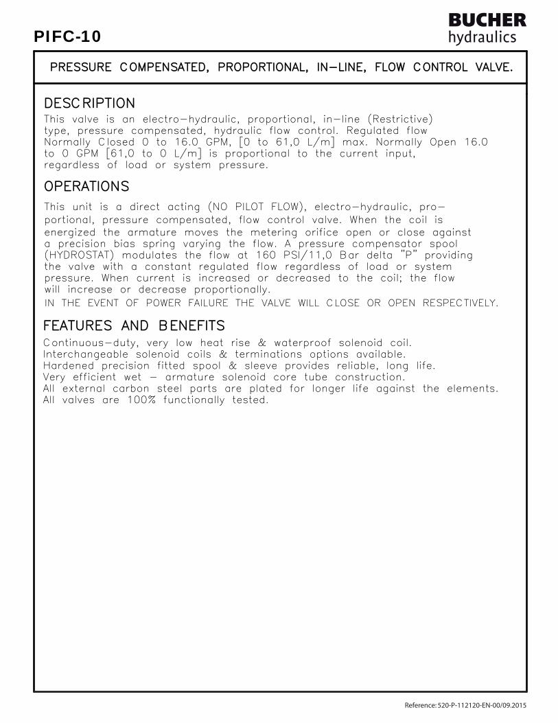
OPERATIONSOPERATIONS
FEATURES AND BENEFITSFEATURES AND BENEFITS
DESCRIPTIONDESCRIPTION
All valves are 100% functionally tested.All valves are 100% functionally tested.All external carbon steel parts are plated for longer life against the elements.All external carbon steel parts are plated for longer life against the elements.Very efficient wet - armature solenoid core tube construction.Very efficient wet - armature solenoid core tube construction.Hardened precision fitted spool & sleeve provides reliable, long life.Hardened precision fitted spool & sleeve provides reliable, long life.Interchangeable solenoid coils & terminations options available.Interchangeable solenoid coils & terminations options available.Continuous-duty, very low heat rise & waterproof solenoid coil.Continuous-duty, very low heat rise & waterproof solenoid coil.
regardless of load or system pressure.regardless of load or system pressure.to 0 GPM [61,0 to 0 L/m] is proportional to the current input,to 0 GPM [61,0 to 0 L/m] is proportional to the current input,Normally Closed 0 to 16.0 GPM, [0 to 61,0 L/m] max. Normally Open 16.0Normally Closed 0 to 16.0 GPM, [0 to 61,0 L/m] max. Normally Open 16.0type, pressure compensated, hydraulic flow control. Regulated flowtype, pressure compensated, hydraulic flow control. Regulated flowThis valve is an electro-hydraulic, proportional, in-line (Restrictive)This valve is an electro-hydraulic, proportional, in-line (Restrictive)
This unit is a direct acting (NO PILOT FLOW), electro-hydraulic, pro-This unit is a direct acting (NO PILOT FLOW), electro-hydraulic, pro-portional, pressure compensated, flow control valve. When the coil isportional, pressure compensated, flow control valve. When the coil is
the valve with a constant regulated flow regardless of load or systemthe valve with a constant regulated flow regardless of load or system(HYDROSTAT) modulates the flow at 160 PSI/11,0 Bar delta "P" providing(HYDROSTAT) modulates the flow at 160 PSI/11,0 Bar delta "P" providinga precision bias spring varying the flow. A pressure compensator spoola precision bias spring varying the flow. A pressure compensator spoolenergized the armature moves the metering orifice open or close againstenergized the armature moves the metering orifice open or close against
pressure. When current is increased or decreased to the coil; the flow pressure. When current is increased or decreased to the coil; the flow
IN THE EVENT OF POWER FAILURE THE VALVE WILL CLOSE OR OPEN RESPECTIVELY.IN THE EVENT OF POWER FAILURE THE VALVE WILL CLOSE OR OPEN RESPECTIVELY.will increase or decrease proportionally.will increase or decrease proportionally.
PRESSURE COMPENSATED, PROPORTIONAL, IN-LINE, FLOW CONTROL VALVE.PRESSURE COMPENSATED, PROPORTIONAL, IN-LINE, FLOW CONTROL VALVE.
Reference: 520-P-112120-EN-00/09.2015
PIFC-10

SPECIFICATIONSSPECIFICATIONS
7.65 lbs [3,48 kg]. steel body. 7.65 lbs [3,48 kg]. steel body.WEIGHT: 4.58 lbs [2,09 kg]. aluminum body.WEIGHT: 4.58 lbs [2,09 kg]. aluminum body.INSTALLATION: No restrictions.INSTALLATION: No restrictions.
24 VDC, Operating current 0.2 to 1.2 AMPS. 24 VDC, Operating current 0.2 to 1.2 AMPS.POWER REQUIREMENTS: 12 VDC, Operating current 0.4 to 2.4 AMPS.POWER REQUIREMENTS: 12 VDC, Operating current 0.4 to 2.4 AMPS. current control and a 50 Hz dither. current control and a 50 Hz dither.RESPONSE: The most efficient method to control this valve is withRESPONSE: The most efficient method to control this valve is with
INTERNAL LEAKAGE: 15 cu.in/min [245 cc/m] @ 5,000 PSI [350 Bar]INTERNAL LEAKAGE: 15 cu.in/min [245 cc/m] @ 5,000 PSI [350 Bar]REGULATED FLOW: 16.0 GPM [61,0 L/m] Max. See performance chart.REGULATED FLOW: 16.0 GPM [61,0 L/m] Max. See performance chart.PROOF PRESSURE: 10,000 PSI [700 Bar]PROOF PRESSURE: 10,000 PSI [700 Bar]OPERATING PRESSURE: 5,000 PSI [350 Bar]OPERATING PRESSURE: 5,000 PSI [350 Bar]
SEAL KIT: Buna "N": SKN-1022, SKN-1032SEAL KIT: Buna "N": SKN-1022, SKN-1032VITON: SKV-1022, SKV-1032VITON: SKV-1022, SKV-1032
PRESSURE COMPENSATED, PROPORTIONAL, IN-LINE, FLOW CONTROL VALVE.PRESSURE COMPENSATED, PROPORTIONAL, IN-LINE, FLOW CONTROL VALVE.
MIL-H-5606, SAE-#10, SAE-#20, etc. MIL-H-5606, SAE-#10, SAE-#20, etc.OPERATING MEDIA: All general purpose hydraulic fluids such asOPERATING MEDIA: All general purpose hydraulic fluids such asOPERATING TEMPERATURE: -40° to +250° F. [-40° to +120° C.]OPERATING TEMPERATURE: -40° to +250° F. [-40° to +120° C.] 5000 PSI [350 Bar] = Steel - Unplated. 5000 PSI [350 Bar] = Steel - Unplated.VALVE HOUSINGS: 2500 PSI [175 Bar] = Aluminum - Anodized.VALVE HOUSINGS: 2500 PSI [175 Bar] = Aluminum - Anodized.
[email protected] www.bucherhydraulics.com/commoncavity
2015 by Bucher Hydraulics, Inc., 2545 Northwest Parkway, Elgin, Illinois 60124, USAAll rights reserved.The technical information in this catalog, may contain calculated figures (for reference only) and not actual performance data for this product.Data is provided for the purpose of product description only, and must not be construed as warranted characteristics in the legal sense. The information does not relieve users from the duty of conducting their own evaluations and tests. Because the products are subject to continual improvement, we reserve the right to amend the product specifications contained in this catalogue.
©
Reference: 520-P-112120-EN-00/09.2015
PIFC-10

TYPE "L" COIL TYPE "L" COIL SEE PAGE SEE PAGE 10-001.210-001.2
REGREGININ
.40" DIA. 2 MTG. HOLES.40" DIA. 2 MTG. HOLES
( SCREW TYPE ) ( SCREW TYPE )
LIMITED RANGE ADJUSTMENTLIMITED RANGE ADJUSTMENT
1.98"1.98"
.50".50"
4.75"4.75"
4.00"4.00"
1.00"1.00"
1.00"1.00"
2.00"2.00"
3.00"3.00"
1.95"1.95"
L/ML/MGPMGPM
0505
10 10
15 15
20 20
0.300.30 0.600.60 1.201.20 1.801.80 2.402.40AMPERAGE (AMPS) @ 12 VDCAMPERAGE (AMPS) @ 12 VDC
2.102.101.501.500.900.90
1.051.050.750.750.450.45 1.201.200.900.900.600.600.300.300.150.15 25 25
19 19
3838
5757
7676
9595
AMPERAGE (AMPS) @ 24 VDCAMPERAGE (AMPS) @ 24 VDC
[45,2][45,2]1.78"1.78"
[50,3][50,3]
[12,7][12,7]
[120,7][120,7]
[25,4][25,4]
[50,8][50,8]
[49,5][49,5]
[76,2][76,2][101,6][101,6]
[25,4][25,4]
NORMALLYNORMALLY CLOSED CLOSED
NORMALLYNORMALLY OPEN OPEN
( SCREW TYPE )( SCREW TYPE )MANUAL OVERRIDEMANUAL OVERRIDE
when used with waterproof connector.when used with waterproof connector.UL approved coil, IP68 and IP69K rated UL approved coil, IP68 and IP69K rated
R
NOTES:NOTES:1. SOLENOIDS AVAILABLE WITH DIODES - CONSULT FACTORY.1. SOLENOIDS AVAILABLE WITH DIODES - CONSULT FACTORY.
REGULATED FLOW @ 160 PSI
REGULATED FLOW @ 160 PSI
4.10"4.10"
4.80"4.80"[121,9][121,9]
[104,1][104,1]
LTBGWDM
TERMINALSTERMINALS=18GA. 24" LEADS=18GA. 24" LEADS=SPADE TERM.=SPADE TERM.=BOLT TERM.=BOLT TERM.=DIN43650=DIN43650=WEATHER-PACK=WEATHER-PACK=DEUTSCH-DT04-2P=DEUTSCH-DT04-2P=METRI-PACK CONN.=METRI-PACK CONN.
12D12D24D24D
VOLTAGE VOLTAGE= 12 VDC= 12 VDC= 24 VDC= 24 VDC
= BUNA "N"= BUNA "N"= VITON= VITON
SEALSSEALSNV
PORTSPORTS12TX12TX = SAE - #12= SAE - #12
BASICBASIC
STYLESTYLECO
"A" = ALUM. HOUSING "A" = ALUM. HOUSING "S" = STEEL HOUSING "S" = STEEL HOUSING
= NONE= NONE= MANUAL OVERRIDE= MANUAL OVERRIDE= LIMITED RANGE ADJ.= LIMITED RANGE ADJ.= BOTH MO/LTD ADJ= BOTH MO/LTD ADJ
ADJUSTMENT OPTIONSADJUSTMENT OPTIONSO-F-100O-F-100M-F-100M-F-1000-S-1600-S-160M-S-160M-S-160
AMPSAMPS 3.00 3.00 1.50 1.50
= NORMALLY CLOSED= NORMALLY CLOSED= NORMALLY OPEN= NORMALLY OPEN
REGULATED FLOWREGULATED FLOW0606121218182424
= 0 TO 6.0 GPM= 0 TO 6.0 GPM= 0 TO 12.0 GPM= 0 TO 12.0 GPM= 0 TO 18.0 GPM= 0 TO 18.0 GPM= 0 TO 24.0 GPM= 0 TO 24.0 GPM
SIZESIZE12=1.062"-12UNF12=1.062"-12UNF
ININ
REGREG
PIFC-12-X-X-XX-X-X-X-XXX-XXX XPIFC-12-X-X-XX-X-X-X-XXX-XXX X
OPEN PROPORTIONAL, IN-LINE FLOW CONTROL VALVE.OPEN PROPORTIONAL, IN-LINE FLOW CONTROL VALVE.
PRESSURE COMPENSATED, NORMALLY CLOSED OR NORMALLYPRESSURE COMPENSATED, NORMALLY CLOSED OR NORMALLY
Reference: 520-P-112130-EN-00/09.2015
PIFC-12

OPERATIONSOPERATIONS
FEATURES AND BENEFITSFEATURES AND BENEFITS
DESCRIPTIONDESCRIPTION
All valves are 100% functionally tested.All valves are 100% functionally tested.All external carbon steel parts are plated for longer life against the elements.All external carbon steel parts are plated for longer life against the elements.Very efficient wet - armature solenoid core tube construction.Very efficient wet - armature solenoid core tube construction.Hardened precision fitted spool & sleeve provides reliable, long life.Hardened precision fitted spool & sleeve provides reliable, long life.Interchangeable solenoid coils & terminations options available.Interchangeable solenoid coils & terminations options available.Continuous-duty, very low heat rise & waterproof solenoid coil.Continuous-duty, very low heat rise & waterproof solenoid coil.
regardless of load or system pressure.regardless of load or system pressure.to 0 GPM [91,2 to 0 L/M] is proportional to the current input,to 0 GPM [91,2 to 0 L/M] is proportional to the current input,Normally Closed 0 to 24.0 GPM, [0 to 91,2 L/M] max. Normally Open 24.0Normally Closed 0 to 24.0 GPM, [0 to 91,2 L/M] max. Normally Open 24.0type, pressure compensated, hydraulic flow control. Regulated flowtype, pressure compensated, hydraulic flow control. Regulated flowThis valve is an electro-hydraulic, proportional, in-line (Restrictive)This valve is an electro-hydraulic, proportional, in-line (Restrictive)
This unit is a direct acting (NO PILOT FLOW), electro-hydraulic, pro-This unit is a direct acting (NO PILOT FLOW), electro-hydraulic, pro-portional, pressure compensated, flow control valve. When the coil isportional, pressure compensated, flow control valve. When the coil is
the valve with a constant regulated flow regardless of load or systemthe valve with a constant regulated flow regardless of load or system(HYDROSTAT) modulates the flow at 160 PSI/11,0 Bar delta "P" providing(HYDROSTAT) modulates the flow at 160 PSI/11,0 Bar delta "P" providinga precision bias spring varying the flow. A pressure compensator spoola precision bias spring varying the flow. A pressure compensator spoolenergized the armature moves the metering orifice open or close againstenergized the armature moves the metering orifice open or close against
pressure. When current is increased or decreased to the coil; the flow pressure. When current is increased or decreased to the coil; the flow
IN THE EVENT OF POWER FAILURE THE VALVE WILL CLOSE OR OPEN RESPECTIVELY.IN THE EVENT OF POWER FAILURE THE VALVE WILL CLOSE OR OPEN RESPECTIVELY.will increase or decrease proportionally.will increase or decrease proportionally.
PRESSURE COMPENSATED, PROPORTIONAL, IN-LINE, FLOW CONTROL VALVE.PRESSURE COMPENSATED, PROPORTIONAL, IN-LINE, FLOW CONTROL VALVE.
Reference: 520-P-112130-EN-00/09.2015
PIFC-12

SPECIFICATIONSSPECIFICATIONS
15.60 lbs [7,10 kg]. steel body. 15.60 lbs [7,10 kg]. steel body.WEIGHT: 5.52 lbs [2,51 kg]. aluminum body.WEIGHT: 5.52 lbs [2,51 kg]. aluminum body.INSTALLATION: No restrictions.INSTALLATION: No restrictions.
24 VDC, Operating current 0.2 to 1.2 AMPS. 24 VDC, Operating current 0.2 to 1.2 AMPS.POWER REQUIREMENTS: 12 VDC, Operating current 0.4 to 2.4 AMPS.POWER REQUIREMENTS: 12 VDC, Operating current 0.4 to 2.4 AMPS. current control and a 50 Hz dither. current control and a 50 Hz dither.RESPONSE: The most efficient method to control this valve is withRESPONSE: The most efficient method to control this valve is with
INTERNAL LEAKAGE: 30 cu.in/min [495 cc/m] @ 5,000 PSI [350 Bar]INTERNAL LEAKAGE: 30 cu.in/min [495 cc/m] @ 5,000 PSI [350 Bar]REGULATED FLOW: 24.0 GPM [90,7 L/M] Max. See performance chart.REGULATED FLOW: 24.0 GPM [90,7 L/M] Max. See performance chart.PROOF PRESSURE: 10,000 PSI [700 Bar]PROOF PRESSURE: 10,000 PSI [700 Bar]OPERATING PRESSURE: 5,000 PSI [350 Bar]OPERATING PRESSURE: 5,000 PSI [350 Bar]
SEAL KIT: Buna "N": SKN-1222, SKN-1232SEAL KIT: Buna "N": SKN-1222, SKN-1232VITON: SKV-1222, SKV-1232VITON: SKV-1222, SKV-1232
PRESSURE COMPENSATED, PROPORTIONAL, IN-LINE, FLOW CONTROL VALVE.PRESSURE COMPENSATED, PROPORTIONAL, IN-LINE, FLOW CONTROL VALVE.
MIL-H-5606, SAE-#10, SAE-#20, etc. MIL-H-5606, SAE-#10, SAE-#20, etc.OPERATING MEDIA: All general purpose hydraulic fluids such asOPERATING MEDIA: All general purpose hydraulic fluids such asOPERATING TEMPERATURE: -40° to +250° F. [-40° to +120° C.]OPERATING TEMPERATURE: -40° to +250° F. [-40° to +120° C.] 5000 PSI [350 Bar] = Steel - Unplated. 5000 PSI [350 Bar] = Steel - Unplated.VALVE HOUSINGS: 2500 PSI [175 Bar] = Aluminum - Anodized.VALVE HOUSINGS: 2500 PSI [175 Bar] = Aluminum - Anodized.
[email protected] www.bucherhydraulics.com/commoncavity
2015 by Bucher Hydraulics, Inc., 2545 Northwest Parkway, Elgin, Illinois 60124, USAAll rights reserved.The technical information in this catalog, may contain calculated figures (for reference only) and not actual performance data for this product.Data is provided for the purpose of product description only, and must not be construed as warranted characteristics in the legal sense. The information does not relieve users from the duty of conducting their own evaluations and tests. Because the products are subject to continual improvement, we reserve the right to amend the product specifications contained in this catalogue.
©
Reference: 520-P-112130-EN-00/09.2015
PIFC-12
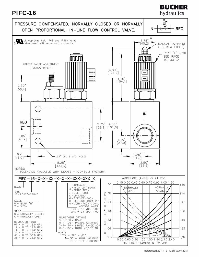
TYPE "L" COIL TYPE "L" COIL SEE PAGE SEE PAGE 10-001.210-001.2
REGREGININ
( SCREW TYPE )( SCREW TYPE )MANUAL OVERRIDEMANUAL OVERRIDE
4.00"4.00"
2.30"2.30"
5.25"5.25"
2.75"2.75"
2.50"2.50"
.63".63"
1.85"1.85"
1.25"1.25"
1.10"1.10"
.53" DIA. 2 MTG. HOLES.53" DIA. 2 MTG. HOLES
( SCREW TYPE ) ( SCREW TYPE )
LIMITED RANGE ADJUSTMENTLIMITED RANGE ADJUSTMENT
1.78"1.78"[45,2][45,2]
[58,4][58,4]
[46,9][46,9]
[16,0][16,0]
[133,3][133,3]
[31,8][31,8]
[63,5][63,5]
[27,9][27,9]
[101,6][101,6][69,9][69,9]
24 24
18 18
12 12
0606
GPMGPM0.300.30 0.600.60 1.201.200.900.90 1.501.50 2.102.101.801.80 2.402.40
L/ML/M
23 23
46 46
68 68
91 91
30 30
36 36
AMPERAGE (AMPS) @ 24 VDCAMPERAGE (AMPS) @ 24 VDC
OPEN OPENNORMALLYNORMALLY
0.300.300.150.15 0.750.750.600.600.450.45 1.201.201.051.050.900.90
CLOSED CLOSEDNORMALLYNORMALLY
114114
136136
AMPERAGE (AMPS) @ 12 VDCAMPERAGE (AMPS) @ 12 VDC
UL approved coil, IP68 and IP69K rated UL approved coil, IP68 and IP69K rated when used with waterproof connector.when used with waterproof connector.R
NOTES:NOTES:1. SOLENOIDS AVAILABLE WITH DIODES - CONSULT FACTORY.1. SOLENOIDS AVAILABLE WITH DIODES - CONSULT FACTORY.
REGULATED FLOWREGULATED FLOW060612121818242430303636
= 0 TO 6.0 GPM= 0 TO 6.0 GPM= 0 TO 12.0 GPM= 0 TO 12.0 GPM= 0 TO 18.0 GPM= 0 TO 18.0 GPM= 0 TO 24.0 GPM= 0 TO 24.0 GPM= 0 TO 30.0 GPM= 0 TO 30.0 GPM= 0 TO 36.0 GPM= 0 TO 36.0 GPM
REGULATED FLOW @ 160 PSI
REGULATED FLOW @ 160 PSI
4.10"4.10"
4.80"4.80"[121,9][121,9]
[104,1][104,1]
LTBGWDM
TERMINALSTERMINALS=18GA. 24" LEADS=18GA. 24" LEADS=SPADE TERM.=SPADE TERM.=BOLT TERM.=BOLT TERM.=DIN43650=DIN43650=WEATHER-PACK=WEATHER-PACK=DEUTSCH-DT04-2P=DEUTSCH-DT04-2P=METRI-PACK CONN.=METRI-PACK CONN.
12D12D24D24D
VOLTAGE VOLTAGE= 12 VDC= 12 VDC= 24 VDC= 24 VDC
= BUNA "N"= BUNA "N"= VITON= VITON
SEALSSEALSNV
PORTSPORTS16TX16TX = SAE - #16= SAE - #16
BASICBASIC
STYLESTYLECO
"A" = ALUM. HOUSING "A" = ALUM. HOUSING "S" = STEEL HOUSING "S" = STEEL HOUSING
= NONE= NONE= MANUAL OVERRIDE= MANUAL OVERRIDE= LIMITED RANGE ADJ.= LIMITED RANGE ADJ.= BOTH MO/LTD ADJ= BOTH MO/LTD ADJ
ADJUSTMENT OPTIONSADJUSTMENT OPTIONSO-F-100O-F-100M-F-100M-F-1000-S-1800-S-180M-S-180M-S-180
AMPSAMPS 3.00 3.00 1.50 1.50
= NORMALLY CLOSED= NORMALLY CLOSED= NORMALLY OPEN= NORMALLY OPEN
SIZESIZE16=1.312"-12UNF16=1.312"-12UNF
ININ
REGREG
PIFC-16-X-X-XX-X-X-X-XXX-XXX XPIFC-16-X-X-XX-X-X-X-XXX-XXX X
OPEN PROPORTIONAL, IN-LINE FLOW CONTROL VALVE.OPEN PROPORTIONAL, IN-LINE FLOW CONTROL VALVE.
PRESSURE COMPENSATED, NORMALLY CLOSED OR NORMALLYPRESSURE COMPENSATED, NORMALLY CLOSED OR NORMALLY
Reference: 520-P-112140-EN-00/09.2015
PIFC-16

All valves are 100% functionally tested.All valves are 100% functionally tested.All external carbon steel parts are plated for longer life against the elements.All external carbon steel parts are plated for longer life against the elements.Very efficient wet - armature solenoid core tube construction.Very efficient wet - armature solenoid core tube construction.Hardened precision fitted spool & sleeve provides reliable, long life.Hardened precision fitted spool & sleeve provides reliable, long life.Interchangeable solenoid coils & terminations options available.Interchangeable solenoid coils & terminations options available.Continuous-duty, very low heat rise & waterproof solenoid coil.Continuous-duty, very low heat rise & waterproof solenoid coil.
regardless of load or system pressure.regardless of load or system pressure.to 0 GPM [137,0 to 0 L/M] is proportional to the current input,to 0 GPM [137,0 to 0 L/M] is proportional to the current input,Normally Closed 0 to 36.0 GPM, [0 to 137,0 L/M] max. Normally Open 36.0Normally Closed 0 to 36.0 GPM, [0 to 137,0 L/M] max. Normally Open 36.0type, pressure compensated, hydraulic flow control. Regulated flowtype, pressure compensated, hydraulic flow control. Regulated flowThis valve is an electro-hydraulic, proportional, in-line (Restrictive)This valve is an electro-hydraulic, proportional, in-line (Restrictive)
This unit is a direct acting (NO PILOT FLOW), electro-hydraulic, pro-This unit is a direct acting (NO PILOT FLOW), electro-hydraulic, pro-portional, pressure compensated, flow control valve. When the coil isportional, pressure compensated, flow control valve. When the coil is
the valve with a constant regulated flow regardless of load or systemthe valve with a constant regulated flow regardless of load or system(HYDROSTAT) modulates the flow at 160 PSI/11,0 Bar delta "P" providing(HYDROSTAT) modulates the flow at 160 PSI/11,0 Bar delta "P" providinga precision bias spring varying the flow. A pressure compensator spoola precision bias spring varying the flow. A pressure compensator spoolenergized the armature moves the metering orifice open or close againstenergized the armature moves the metering orifice open or close against
pressure. When current is increased or decreased to the coil; the flow pressure. When current is increased or decreased to the coil; the flow
IN THE EVENT OF POWER FAILURE THE VALVE WILL CLOSE OR OPEN RESPECTIVELY.IN THE EVENT OF POWER FAILURE THE VALVE WILL CLOSE OR OPEN RESPECTIVELY.will increase or decrease proportionally.will increase or decrease proportionally.
PRESSURE COMPENSATED, PROPORTIONAL, IN-LINE, FLOW CONTROL VALVE.PRESSURE COMPENSATED, PROPORTIONAL, IN-LINE, FLOW CONTROL VALVE.
OPERATIONSOPERATIONS
FEATURES AND BENEFITSFEATURES AND BENEFITS
DESCRIPTIONDESCRIPTION
Reference: 520-P-112140-EN-00/09.2015
PIFC-16

21.70 lbs [9,86 kg]. steel body. 21.70 lbs [9,86 kg]. steel body.WEIGHT: 7.42 lbs [3,37 kg]. aluminum body.WEIGHT: 7.42 lbs [3,37 kg]. aluminum body.INSTALLATION: No restrictions.INSTALLATION: No restrictions.
24 VDC, Operating current 0.2 to 1.2 AMPS. 24 VDC, Operating current 0.2 to 1.2 AMPS.POWER REQUIREMENTS: 12 VDC, Operating current 0.4 to 2.4 AMPS.POWER REQUIREMENTS: 12 VDC, Operating current 0.4 to 2.4 AMPS. current control and a 50 Hz dither. current control and a 50 Hz dither.RESPONSE: The most efficient method to control this valve is withRESPONSE: The most efficient method to control this valve is with
INTERNAL LEAKAGE: 40 cu.in/min [660 cc/m] @ 5,000 PSI [350 Bar]INTERNAL LEAKAGE: 40 cu.in/min [660 cc/m] @ 5,000 PSI [350 Bar]REGULATED FLOW: 36.0 GPM [136,0 L/M] Max. See performance chart.REGULATED FLOW: 36.0 GPM [136,0 L/M] Max. See performance chart.PROOF PRESSURE: 10,000 PSI [700 Bar]PROOF PRESSURE: 10,000 PSI [700 Bar]OPERATING PRESSURE: 5,000 PSI [350 Bar]OPERATING PRESSURE: 5,000 PSI [350 Bar]
SEAL KIT: Buna "N": SKN-1622, SKN-1632SEAL KIT: Buna "N": SKN-1622, SKN-1632VITON: SKV-1622, SKV-1632VITON: SKV-1622, SKV-1632
PRESSURE COMPENSATED, PROPORTIONAL, IN-LINE, FLOW CONTROL VALVE.PRESSURE COMPENSATED, PROPORTIONAL, IN-LINE, FLOW CONTROL VALVE.
SPECIFICATIONSSPECIFICATIONS
MIL-H-5606, SAE-#10, SAE-#20, etc. MIL-H-5606, SAE-#10, SAE-#20, etc.OPERATING MEDIA: All general purpose hydraulic fluids such asOPERATING MEDIA: All general purpose hydraulic fluids such asOPERATING TEMPERATURE: -40° to +250° F. [-40° to +120° C.]OPERATING TEMPERATURE: -40° to +250° F. [-40° to +120° C.] 5000 PSI [350 Bar] = Steel - Unplated. 5000 PSI [350 Bar] = Steel - Unplated.VALVE HOUSINGS: 2500 PSI [175 Bar] = Aluminum - Anodized.VALVE HOUSINGS: 2500 PSI [175 Bar] = Aluminum - Anodized.
[email protected] www.bucherhydraulics.com/commoncavity
2015 by Bucher Hydraulics, Inc., 2545 Northwest Parkway, Elgin, Illinois 60124, USAAll rights reserved.The technical information in this catalog, may contain calculated figures (for reference only) and not actual performance data for this product.Data is provided for the purpose of product description only, and must not be construed as warranted characteristics in the legal sense. The information does not relieve users from the duty of conducting their own evaluations and tests. Because the products are subject to continual improvement, we reserve the right to amend the product specifications contained in this catalogue.
©
Reference: 520-P-112140-EN-00/09.2015
PIFC-16
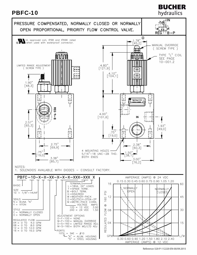
TYPE "L" COIL TYPE "L" COIL SEE PAGE SEE PAGE 10-001.210-001.2
ININ
REGREG B-PB-P
BOTH ENDSBOTH ENDS5/16"-18 UNC-2B THD.5/16"-18 UNC-2B THD.4 M0UNTING HOLES4 M0UNTING HOLES
[19,0][19,0].75".75"
[65,3][65,3]2.57"2.57"
[38,1][38,1]1.50"1.50"
Command Controls Corp.Command Controls Corp.Elgin, Illinois. U.S.A.Elgin, Illinois. U.S.A.
MODEL NUMBERMODEL NUMBER
[76,2][76,2]3.00"3.00"
[101,6][101,6]4.00"4.00"
[69,9][69,9]2.75"2.75"
[60,3][60,3]2.38"2.38"
[48,3][48,3]1.90"1.90"
[85,7][85,7]3.38"3.38"
[49,0][49,0]1.93"1.93"
[19,0][19,0].75".75"
[45,2][45,2]1.78"1.78"
GPMGPM
0404
08 08
12 12
16 16
AMPERAGE (AMPS) @ 12 VDCAMPERAGE (AMPS) @ 12 VDC1.801.800.900.900.300.30 0.600.60 1.201.20 1.501.50 2.102.10 2.402.40
L/ML/M
1515
AMPERAGE (AMPS) @ 24 VDCAMPERAGE (AMPS) @ 24 VDC
NORMALLYNORMALLY
0.900.900.450.45
NORMALLYNORMALLY
0.150.15
OPEN OPEN
0.300.30 0.600.60 0.750.75
CLOSED CLOSED
1.051.05 1.201.20
3030
4545
6060
MANUAL OVERRIDEMANUAL OVERRIDE( SCREW TYPE )( SCREW TYPE )
LIMITED RANGE ADJUSTMENTLIMITED RANGE ADJUSTMENT ( SCREW TYPE ) ( SCREW TYPE )
UL approved coil, IP68 and IP69K rated UL approved coil, IP68 and IP69K rated when used with waterproof connector.when used with waterproof connector.R
NOTES:NOTES:1. SOLENOIDS AVAILABLE WITH DIODES - CONSULT FACTORY.1. SOLENOIDS AVAILABLE WITH DIODES - CONSULT FACTORY.
REGULATED FLOW @ 160 PSI
REGULATED FLOW @ 160 PSI
4.10"4.10"
4.80"4.80"[121,9][121,9]
[104,1][104,1]
LTBGWDM
TERMINALSTERMINALS=18GA. 24" LEADS=18GA. 24" LEADS=SPADE TERM.=SPADE TERM.=BOLT TERM.=BOLT TERM.=DIN43650=DIN43650=WEATHER-PACK=WEATHER-PACK=DEUTSCH-DT04-2P=DEUTSCH-DT04-2P=METRI-PACK CONN.=METRI-PACK CONN.
12D12D24D24D
VOLTAGE VOLTAGE= 12 VDC= 12 VDC= 24 VDC= 24 VDC
= BUNA "N"= BUNA "N"= VITON= VITON
SEALSSEALSNV
PORTSPORTS10TX10TX = SAE - #10= SAE - #10
BASICBASIC
STYLESTYLECO
"A" = ALUM. HOUSING "A" = ALUM. HOUSING "S" = STEEL HOUSING "S" = STEEL HOUSING
= NONE= NONE= MANUAL OVERRIDE= MANUAL OVERRIDE= LIMITED RANGE ADJ.= LIMITED RANGE ADJ.= BOTH MO/LTD ADJ= BOTH MO/LTD ADJ
ADJUSTMENT OPTIONSADJUSTMENT OPTIONSO-F-100O-F-100M-F-100M-F-1000-S-1600-S-160M-S-160M-S-160
= NORMALLY CLOSED= NORMALLY CLOSED= NORMALLY OPEN= NORMALLY OPEN
AMPSAMPS 3.00 3.00 1.50 1.50
SIZESIZE10 = 7/8"-14UNF10 = 7/8"-14UNF
REGULATED FLOWREGULATED FLOW0404080812121616
= 0 TO 4.0 GPM= 0 TO 4.0 GPM= 0 TO 8.0 GPM= 0 TO 8.0 GPM= 0 TO 12.0 GPM= 0 TO 12.0 GPM= 0 TO 16.0 GPM= 0 TO 16.0 GPM
ININ
REG
REG
PBFC-10-X-X-XX-X-X-X-XXX-XXX XPBFC-10-X-X-XX-X-X-X-XXX-XXX X
PRESSURE COMPENSATED, NORMALLY CLOSED OR NORMALLYPRESSURE COMPENSATED, NORMALLY CLOSED OR NORMALLY
OPEN PROPORTIONAL, PRIORITY FLOW CONTROL VALVE.OPEN PROPORTIONAL, PRIORITY FLOW CONTROL VALVE.
B-P
B-P
Reference: 520-P-112220-EN-00/09.2015
PBFC-10

DESCRIPTIONDESCRIPTION
FEATURES AND BENEFITSFEATURES AND BENEFITS
OPERATIONSOPERATIONScircuit or to tank. Maximum inlet flow is 25.0 GPM [95,0 L/m].circuit or to tank. Maximum inlet flow is 25.0 GPM [95,0 L/m].priority flow is satisfied the excess flow is diverted to a secondarypriority flow is satisfied the excess flow is diverted to a secondarycurrent input regardless of load or system pressure. After thecurrent input regardless of load or system pressure. After theto 0 GPM [61,0 to 0 L/m] @ 160 PSI DELTA P. is proportional to theto 0 GPM [61,0 to 0 L/m] @ 160 PSI DELTA P. is proportional to thenormally closed 0 to 16.0 GPM [0 to 61,0 L/m] or normally open 16.0normally closed 0 to 16.0 GPM [0 to 61,0 L/m] or normally open 16.0type, pressure compensated, hydraulic flow control. Regulated flowtype, pressure compensated, hydraulic flow control. Regulated flowThis valve is an electro-hydraulic, proportional, priority (By-Pass)This valve is an electro-hydraulic, proportional, priority (By-Pass)
All valves are 100% functionally tested.All valves are 100% functionally tested.All external carbon steel parts are plated for longer life against the elements.All external carbon steel parts are plated for longer life against the elements.Very efficient wet - armature solenoid core tube construction.Very efficient wet - armature solenoid core tube construction.Hardened precision fitted spool & sleeve provides reliable, long life.Hardened precision fitted spool & sleeve provides reliable, long life.Interchangeable solenoid coils & terminations options available.Interchangeable solenoid coils & terminations options available.Continuous-duty, very low heat rise & waterproof solenoid coil.Continuous-duty, very low heat rise & waterproof solenoid coil.
IN THE EVENT OF POWER FAILURE THE VALVE WILL CLOSE OR OPEN RESPECTIVELY.IN THE EVENT OF POWER FAILURE THE VALVE WILL CLOSE OR OPEN RESPECTIVELY.
energized the armature moves the metering orifice open or closed againstenergized the armature moves the metering orifice open or closed againsta precision bias spring varying the flow. A pressure compensator spoola precision bias spring varying the flow. A pressure compensator spool(HYDROSTAT) modulates the flow at 160 PSI/11,0 Bar delta "P" providing(HYDROSTAT) modulates the flow at 160 PSI/11,0 Bar delta "P" providingpressure. When current is increased or decreased to the coil; the flow pressure. When current is increased or decreased to the coil; the flow will increase or decrease proportionally.will increase or decrease proportionally.
portional, pressure compensated, flow control valve. When the coil isportional, pressure compensated, flow control valve. When the coil isThis unit is a direct acting (NO PILOT FLOW), electro-hydraulic, pro-This unit is a direct acting (NO PILOT FLOW), electro-hydraulic, pro-
PRESSURE COMPENSATED, PROPORTIONAL, PRIORITY FLOW CONTROL VALVE.PRESSURE COMPENSATED, PROPORTIONAL, PRIORITY FLOW CONTROL VALVE.
Reference: 520-P-112220-EN-00/09.2015
PBFC-10
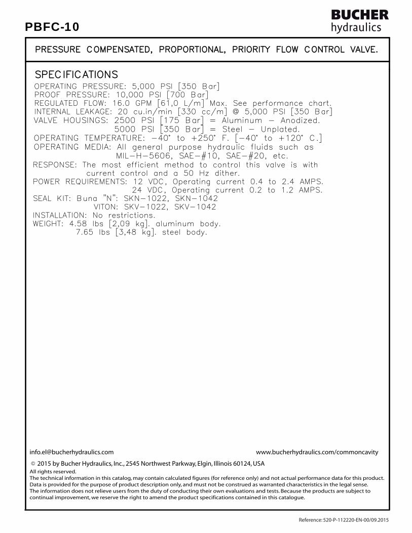
SPECIFICATIONSSPECIFICATIONS
7.65 lbs [3,48 kg]. steel body. 7.65 lbs [3,48 kg]. steel body.WEIGHT: 4.58 lbs [2,09 kg]. aluminum body.WEIGHT: 4.58 lbs [2,09 kg]. aluminum body.INSTALLATION: No restrictions.INSTALLATION: No restrictions.
24 VDC, Operating current 0.2 to 1.2 AMPS. 24 VDC, Operating current 0.2 to 1.2 AMPS.POWER REQUIREMENTS: 12 VDC, Operating current 0.4 to 2.4 AMPS.POWER REQUIREMENTS: 12 VDC, Operating current 0.4 to 2.4 AMPS. current control and a 50 Hz dither. current control and a 50 Hz dither.RESPONSE: The most efficient method to control this valve is withRESPONSE: The most efficient method to control this valve is with
INTERNAL LEAKAGE: 20 cu.in/min [330 cc/m] @ 5,000 PSI [350 Bar]INTERNAL LEAKAGE: 20 cu.in/min [330 cc/m] @ 5,000 PSI [350 Bar]REGULATED FLOW: 16.0 GPM [61,0 L/m] Max. See performance chart.REGULATED FLOW: 16.0 GPM [61,0 L/m] Max. See performance chart.PROOF PRESSURE: 10,000 PSI [700 Bar]PROOF PRESSURE: 10,000 PSI [700 Bar]OPERATING PRESSURE: 5,000 PSI [350 Bar]OPERATING PRESSURE: 5,000 PSI [350 Bar]
SEAL KIT: Buna "N": SKN-1022, SKN-1042SEAL KIT: Buna "N": SKN-1022, SKN-1042VITON: SKV-1022, SKV-1042VITON: SKV-1022, SKV-1042
PRESSURE COMPENSATED, PROPORTIONAL, PRIORITY FLOW CONTROL VALVE.PRESSURE COMPENSATED, PROPORTIONAL, PRIORITY FLOW CONTROL VALVE.
MIL-H-5606, SAE-#10, SAE-#20, etc. MIL-H-5606, SAE-#10, SAE-#20, etc.OPERATING MEDIA: All general purpose hydraulic fluids such asOPERATING MEDIA: All general purpose hydraulic fluids such asOPERATING TEMPERATURE: -40° to +250° F. [-40° to +120° C.]OPERATING TEMPERATURE: -40° to +250° F. [-40° to +120° C.] 5000 PSI [350 Bar] = Steel - Unplated. 5000 PSI [350 Bar] = Steel - Unplated.VALVE HOUSINGS: 2500 PSI [175 Bar] = Aluminum - Anodized.VALVE HOUSINGS: 2500 PSI [175 Bar] = Aluminum - Anodized.
[email protected] www.bucherhydraulics.com/commoncavity
2015 by Bucher Hydraulics, Inc., 2545 Northwest Parkway, Elgin, Illinois 60124, USAAll rights reserved.The technical information in this catalog, may contain calculated figures (for reference only) and not actual performance data for this product.Data is provided for the purpose of product description only, and must not be construed as warranted characteristics in the legal sense. The information does not relieve users from the duty of conducting their own evaluations and tests. Because the products are subject to continual improvement, we reserve the right to amend the product specifications contained in this catalogue.
©
Reference: 520-P-112220-EN-00/09.2015
PBFC-10
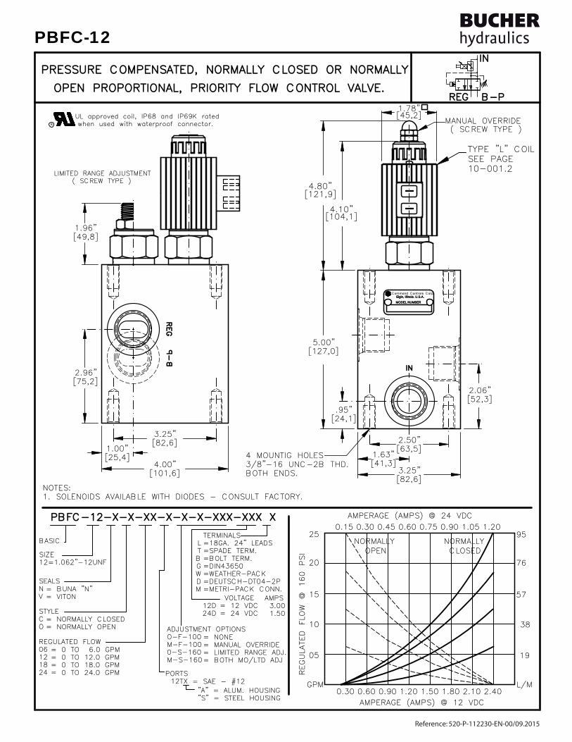
TYPE "L" COIL TYPE "L" COIL SEE PAGE SEE PAGE 10-001.210-001.2
B-PB-PREGREG
ININ
BOTH ENDS.BOTH ENDS.3/8"-16 UNC-2B THD.3/8"-16 UNC-2B THD.
[127,0][127,0]5.00"5.00"
4 MOUNTIG HOLES4 MOUNTIG HOLES
25 25
20 20
15 15
10 10
0505
GPMGPM
[49,8][49,8]1.96"1.96"
[75,2][75,2]2.96"2.96"
[101,6][101,6]4.00"4.00"
[25,4][25,4]1.00"1.00"
[82,6][82,6]3.25"3.25"
Command Controls Corp.Command Controls Corp.Elgin, Illinois. U.S.A.Elgin, Illinois. U.S.A.
MODEL NUMBERMODEL NUMBER
9595
7676
5757
3838
19 19
0.150.15 0.300.30 0.600.60 0.900.90 1.201.200.450.45 0.750.75 1.051.05
0.900.90 1.501.50 2.102.10AMPERAGE (AMPS) @ 12 VDCAMPERAGE (AMPS) @ 12 VDC
2.402.401.801.801.201.200.600.600.300.30L/ML/M
CLOSED CLOSEDNORMALLYNORMALLY
OPEN OPENNORMALLYNORMALLY
[24,1][24,1].95".95"
[82,6][82,6]3.25"3.25"
[63,5][63,5]2.50"2.50"
[41,3][41,3]1.63"1.63"
[52,3][52,3]2.06"2.06"
1.78"1.78"[45,2][45,2]
AMPERAGE (AMPS) @ 24 VDCAMPERAGE (AMPS) @ 24 VDC
MANUAL OVERRIDEMANUAL OVERRIDE( SCREW TYPE )( SCREW TYPE )
LIMITED RANGE ADJUSTMENTLIMITED RANGE ADJUSTMENT ( SCREW TYPE ) ( SCREW TYPE )
R when used with waterproof connector.when used with waterproof connector.UL approved coil, IP68 and IP69K rated UL approved coil, IP68 and IP69K rated
NOTES:NOTES:1. SOLENOIDS AVAILABLE WITH DIODES - CONSULT FACTORY.1. SOLENOIDS AVAILABLE WITH DIODES - CONSULT FACTORY.
SIZESIZE12=1.062"-12UNF12=1.062"-12UNF
REGULATED FLOWREGULATED FLOW0606121218182424
= 0 TO 6.0 GPM= 0 TO 6.0 GPM= 0 TO 12.0 GPM= 0 TO 12.0 GPM= 0 TO 18.0 GPM= 0 TO 18.0 GPM= 0 TO 24.0 GPM= 0 TO 24.0 GPM R
EGULATED FLOW @ 160 PSI
REGULATED FLOW @ 160 PSI
4.10"4.10"
4.80"4.80"[121,9][121,9]
[104,1][104,1]
LTBGWDM
TERMINALSTERMINALS=18GA. 24" LEADS=18GA. 24" LEADS=SPADE TERM.=SPADE TERM.=BOLT TERM.=BOLT TERM.=DIN43650=DIN43650=WEATHER-PACK=WEATHER-PACK=DEUTSCH-DT04-2P=DEUTSCH-DT04-2P=METRI-PACK CONN.=METRI-PACK CONN.
12D12D24D24D
VOLTAGE VOLTAGE= 12 VDC= 12 VDC= 24 VDC= 24 VDC
= BUNA "N"= BUNA "N"= VITON= VITON
SEALSSEALSNV
PORTSPORTS12TX12TX = SAE - #12= SAE - #12
BASICBASIC
STYLESTYLECO
"A" = ALUM. HOUSING "A" = ALUM. HOUSING "S" = STEEL HOUSING "S" = STEEL HOUSING
= NONE= NONE= MANUAL OVERRIDE= MANUAL OVERRIDE= LIMITED RANGE ADJ.= LIMITED RANGE ADJ.= BOTH MO/LTD ADJ= BOTH MO/LTD ADJ
ADJUSTMENT OPTIONSADJUSTMENT OPTIONSO-F-100O-F-100M-F-100M-F-1000-S-1600-S-160M-S-160M-S-160
= NORMALLY CLOSED= NORMALLY CLOSED= NORMALLY OPEN= NORMALLY OPEN
AMPSAMPS 3.00 3.00 1.50 1.50
REG
REG
ININ
PBFC-12-X-X-XX-X-X-X-XXX-XXX XPBFC-12-X-X-XX-X-X-X-XXX-XXX X
OPEN PROPORTIONAL, PRIORITY FLOW CONTROL VALVE.OPEN PROPORTIONAL, PRIORITY FLOW CONTROL VALVE.
PRESSURE COMPENSATED, NORMALLY CLOSED OR NORMALLYPRESSURE COMPENSATED, NORMALLY CLOSED OR NORMALLY
B-P
B-P
Reference: 520-P-112230-EN-00/09.2015
PBFC-12

DESCRIPTIONDESCRIPTION
FEATURES AND BENEFITSFEATURES AND BENEFITS
OPERATIONSOPERATIONScircuit or to tank. Maximum inlet flow is 35.0 GPM [130,0 L/M].circuit or to tank. Maximum inlet flow is 35.0 GPM [130,0 L/M].priority flow is satisfied the excess flow is diverted to a secondarypriority flow is satisfied the excess flow is diverted to a secondarycurrent input regardless of load or system pressure. After thecurrent input regardless of load or system pressure. After theto 0 GPM [91,2 to 0 L/M] @ 160 PSI DELTA P. is proportional to theto 0 GPM [91,2 to 0 L/M] @ 160 PSI DELTA P. is proportional to thenormally closed 0 to 24.0 GPM [0 to 91,2 L/M] or normally open 24.0normally closed 0 to 24.0 GPM [0 to 91,2 L/M] or normally open 24.0type, pressure compensated, hydraulic flow control. Regulated flowtype, pressure compensated, hydraulic flow control. Regulated flowThis valve is an electro-hydraulic, proportional, priority (By-Pass)This valve is an electro-hydraulic, proportional, priority (By-Pass)
All valves are 100% functionally tested.All valves are 100% functionally tested.All external carbon steel parts are plated for longer life against the elements.All external carbon steel parts are plated for longer life against the elements.Very efficient wet - armature solenoid core tube construction.Very efficient wet - armature solenoid core tube construction.Hardened precision fitted spool & sleeve provides reliable, long life.Hardened precision fitted spool & sleeve provides reliable, long life.Interchangeable solenoid coils & terminations options available.Interchangeable solenoid coils & terminations options available.Continuous-duty, very low heat rise & waterproof solenoid coil.Continuous-duty, very low heat rise & waterproof solenoid coil.
IN THE EVENT OF POWER FAILURE THE VALVE WILL CLOSE OR OPEN RESPECTIVELY.IN THE EVENT OF POWER FAILURE THE VALVE WILL CLOSE OR OPEN RESPECTIVELY.
energized the armature moves the metering orifice open or closed againstenergized the armature moves the metering orifice open or closed againsta precision bias spring varying the flow. A pressure compensator spoola precision bias spring varying the flow. A pressure compensator spool(HYDROSTAT) modulates the flow at 160 PSI/11,0 Bar delta "P" providing(HYDROSTAT) modulates the flow at 160 PSI/11,0 Bar delta "P" providingpressure. When current is increased or decreased to the coil; the flow pressure. When current is increased or decreased to the coil; the flow will increase or decrease proportionally.will increase or decrease proportionally.
portional, pressure compensated, flow control valve. When the coil isportional, pressure compensated, flow control valve. When the coil isThis unit is a direct acting (NO PILOT FLOW), electro-hydraulic, pro-This unit is a direct acting (NO PILOT FLOW), electro-hydraulic, pro-
PRESSURE COMPENSATED, PROPORTIONAL, PRIORITY FLOW CONTROL VALVE.PRESSURE COMPENSATED, PROPORTIONAL, PRIORITY FLOW CONTROL VALVE.
Reference: 520-P-112230-EN-00/09.2015
PBFC-12

SPECIFICATIONSSPECIFICATIONS
9.65 lbs [4,38 kg]. steel body. 9.65 lbs [4,38 kg]. steel body.WEIGHT: 5.58 lbs [2,54 kg]. aluminum body.WEIGHT: 5.58 lbs [2,54 kg]. aluminum body.INSTALLATION: No restrictions.INSTALLATION: No restrictions.
24 VDC, Operating current 0.2 to 1.2 AMPS. 24 VDC, Operating current 0.2 to 1.2 AMPS.POWER REQUIREMENTS: 12 VDC, Operating current 0.4 to 2.4 AMPS.POWER REQUIREMENTS: 12 VDC, Operating current 0.4 to 2.4 AMPS. current control and a 50 Hz dither. current control and a 50 Hz dither.RESPONSE: The most efficient method to control this valve is withRESPONSE: The most efficient method to control this valve is with
INTERNAL LEAKAGE: 30 cu.in/min [495 cc/m] @ 5,000 PSI [350 Bar]INTERNAL LEAKAGE: 30 cu.in/min [495 cc/m] @ 5,000 PSI [350 Bar]REGULATED FLOW: 24.0 GPM [91,2 l/m] Max. See performance chart.REGULATED FLOW: 24.0 GPM [91,2 l/m] Max. See performance chart.PROOF PRESSURE: 10,000 PSI [700 Bar]PROOF PRESSURE: 10,000 PSI [700 Bar]OPERATING PRESSURE: 5,000 PSI [350 Bar]OPERATING PRESSURE: 5,000 PSI [350 Bar]
SEAL KIT: Buna "N": SKN-1222, SKN-1242SEAL KIT: Buna "N": SKN-1222, SKN-1242VITON: SKV-1222, SKV-1242VITON: SKV-1222, SKV-1242
PRESSURE COMPENSATED, PROPORTIONAL, PRIORITY FLOW CONTROL VALVE.PRESSURE COMPENSATED, PROPORTIONAL, PRIORITY FLOW CONTROL VALVE.
MIL-H-5606, SAE-#10, SAE-#20, etc. MIL-H-5606, SAE-#10, SAE-#20, etc.OPERATING MEDIA: All general purpose hydraulic fluids such asOPERATING MEDIA: All general purpose hydraulic fluids such asOPERATING TEMPERATURE: -40° to +250° F. [-40° to +120° C.]OPERATING TEMPERATURE: -40° to +250° F. [-40° to +120° C.] 5000 PSI [350 Bar] = Steel - Unplated. 5000 PSI [350 Bar] = Steel - Unplated.VALVE HOUSINGS: 2500 PSI [175 Bar] = Aluminum - Anodized.VALVE HOUSINGS: 2500 PSI [175 Bar] = Aluminum - Anodized.
[email protected] www.bucherhydraulics.com/commoncavity
2015 by Bucher Hydraulics, Inc., 2545 Northwest Parkway, Elgin, Illinois 60124, USAAll rights reserved.The technical information in this catalog, may contain calculated figures (for reference only) and not actual performance data for this product.Data is provided for the purpose of product description only, and must not be construed as warranted characteristics in the legal sense. The information does not relieve users from the duty of conducting their own evaluations and tests. Because the products are subject to continual improvement, we reserve the right to amend the product specifications contained in this catalogue.
©
Reference: 520-P-112230-EN-00/09.2015
PBFC-12

TYPE "L" COIL TYPE "L" COIL SEE PAGE SEE PAGE 10-001.210-001.2
ININ
REGREG B-PB-P
( SCREW TYPE ) ( SCREW TYPE )LIMITED RANGE ADJUSTMENTLIMITED RANGE ADJUSTMENT
[95,3][95,3]3.75"3.75"
BOTH ENDSBOTH ENDS3/8"-16 UNC-2B THD.3/8"-16 UNC-2B THD.4 MOUNTING HOLES4 MOUNTING HOLES
Command Controls Corp.Command Controls Corp.Elgin, Illinois. U.S.A.Elgin, Illinois. U.S.A.
MODEL NUMBERMODEL NUMBER
[31,8][31,8]1.25"1.25"
[50,8][50,8]2.00"2.00"
[31,8][31,8]1.25"1.25"
[98,5][98,5]3.88"3.88"
[152,4][152,4]6.00"6.00"
[101,6][101,6]4.00"4.00"
[82,6][82,6]3.25"3.25"
[60,9][60,9]2.40"2.40"
[68,0][68,0]2.68"2.68"
[114,3][114,3]4.50"4.50"
[45,2][45,2]1.78"1.78"
24 24
18 18
12 12
0606
GPMGPM
AMPERAGE (AMPS) @ 12 VDCAMPERAGE (AMPS) @ 12 VDC0.300.30 0.600.60 1.201.200.900.90 1.501.50 2.102.101.801.80 2.402.40
L/ML/M
23 23
46 46
68 68
91 91
30 30
36 36
AMPERAGE (AMPS) @ 24 VDCAMPERAGE (AMPS) @ 24 VDC
OPEN OPENNORMALLYNORMALLY
0.300.300.150.15 0.750.750.600.600.450.45 1.201.201.051.050.900.90
CLOSED CLOSEDNORMALLYNORMALLY
114114
136136
MANUAL OVERRIDEMANUAL OVERRIDE( SCREW TYPE )( SCREW TYPE )
UL approved coil, IP68 and IP69K rated UL approved coil, IP68 and IP69K rated when used with waterproof connector.when used with waterproof connector.R
NOTES:NOTES:1. SOLENOIDS AVAILABLE WITH DIODES - CONSULT FACTORY.1. SOLENOIDS AVAILABLE WITH DIODES - CONSULT FACTORY.
REGULATED FLOW @ 160 PSI
REGULATED FLOW @ 160 PSI
4.10"4.10"
4.80"4.80"[121,9][121,9]
[104,1][104,1]
LTBGWDM
TERMINALSTERMINALS=18GA. 24" LEADS=18GA. 24" LEADS=SPADE TERM.=SPADE TERM.=BOLT TERM.=BOLT TERM.=DIN43650=DIN43650=WEATHER-PACK=WEATHER-PACK=DEUTSCH-DT04-2P=DEUTSCH-DT04-2P=METRI-PACK CONN.=METRI-PACK CONN.
12D12D24D24D
VOLTAGE VOLTAGE= 12 VDC= 12 VDC= 24 VDC= 24 VDC
= BUNA "N"= BUNA "N"= VITON= VITON
SEALSSEALSNV
PORTSPORTS16TX16TX = SAE - #16= SAE - #16
BASICBASIC
STYLESTYLECO
"A" = ALUM. HOUSING "A" = ALUM. HOUSING "S" = STEEL HOUSING "S" = STEEL HOUSING
= NONE= NONE= MANUAL OVERRIDE= MANUAL OVERRIDE= LIMITED RANGE ADJ.= LIMITED RANGE ADJ.= BOTH MO/LTD ADJ= BOTH MO/LTD ADJ
ADJUSTMENT OPTIONSADJUSTMENT OPTIONSO-F-100O-F-100M-F-100M-F-1000-S-1800-S-180M-S-180M-S-180
= NORMALLY CLOSED= NORMALLY CLOSED= NORMALLY OPEN= NORMALLY OPEN
REGULATED FLOWREGULATED FLOW060612121818242430303636
= 0 TO 6.0 GPM= 0 TO 6.0 GPM= 0 TO 12.0 GPM= 0 TO 12.0 GPM= 0 TO 18.0 GPM= 0 TO 18.0 GPM= 0 TO 24.0 GPM= 0 TO 24.0 GPM= 0 TO 30.0 GPM= 0 TO 30.0 GPM= 0 TO 36.0 GPM= 0 TO 36.0 GPM
SIZESIZE16= 1.312"-12UNF16= 1.312"-12UNF
AMPSAMPS 3.00 3.00 1.50 1.50
REG
REG
ININ
PBFC-16-X-X-XX-X-X-X-XXX-XXX XPBFC-16-X-X-XX-X-X-X-XXX-XXX X
OPEN PROPORTIONAL, PRIORITY FLOW CONTROL VALVE.OPEN PROPORTIONAL, PRIORITY FLOW CONTROL VALVE.
PRESSURE COMPENSATED, NORMALLY CLOSED OR NORMALLYPRESSURE COMPENSATED, NORMALLY CLOSED OR NORMALLY
B-P
B-P
Reference: 520-P-112240-EN-00/09.2015
PBFC-16

DESCRIPTIONDESCRIPTION
FEATURES AND BENEFITSFEATURES AND BENEFITS
OPERATIONSOPERATIONS
circuit or to tank. Maximum inlet flow is 50.0 GPM [190,0 L/M].circuit or to tank. Maximum inlet flow is 50.0 GPM [190,0 L/M].priority flow is satisfied the excess flow is diverted to a secondarypriority flow is satisfied the excess flow is diverted to a secondarycurrent input regardless of load or system pressure. After thecurrent input regardless of load or system pressure. After theto 0 GPM [136,8 to 0 L/M] @ 160 PSI DELTA P. is proportional to theto 0 GPM [136,8 to 0 L/M] @ 160 PSI DELTA P. is proportional to thenormally closed 0 to 36.0 GPM [0 to 136,8 L/M] or normally open 36.0normally closed 0 to 36.0 GPM [0 to 136,8 L/M] or normally open 36.0type, pressure compensated, hydraulic flow control. Regulated flowtype, pressure compensated, hydraulic flow control. Regulated flowThis valve is an electro-hydraulic, proportional, priority (By-Pass)This valve is an electro-hydraulic, proportional, priority (By-Pass)
All valves are 100% functionally tested.All valves are 100% functionally tested.All external carbon steel parts are plated for longer life against the elements.All external carbon steel parts are plated for longer life against the elements.Very efficient wet - armature solenoid core tube construction.Very efficient wet - armature solenoid core tube construction.Hardened precision fitted spool & sleeve provides reliable, long life.Hardened precision fitted spool & sleeve provides reliable, long life.Interchangeable solenoid coils & terminations options available.Interchangeable solenoid coils & terminations options available.Continuous-duty, very low heat rise & waterproof solenoid coil.Continuous-duty, very low heat rise & waterproof solenoid coil.
IN THE EVENT OF POWER FAILURE THE VALVE WILL CLOSE OR OPEN RESPECTIVELY.IN THE EVENT OF POWER FAILURE THE VALVE WILL CLOSE OR OPEN RESPECTIVELY.
energized the armature moves the metering orifice open or closed againstenergized the armature moves the metering orifice open or closed againsta precision bias spring varying the flow. A pressure compensator spoola precision bias spring varying the flow. A pressure compensator spool(HYDROSTAT) modulates the flow at 160 PSI/11,0 Bar delta "P" providing(HYDROSTAT) modulates the flow at 160 PSI/11,0 Bar delta "P" providingpressure. When current is increased or decreased to the coil; the flow pressure. When current is increased or decreased to the coil; the flow will increase or decrease proportionally.will increase or decrease proportionally.
portional, pressure compensated, flow control valve. When the coil isportional, pressure compensated, flow control valve. When the coil isThis unit is a direct acting (NO PILOT FLOW), electro-hydraulic, pro-This unit is a direct acting (NO PILOT FLOW), electro-hydraulic, pro-
PRESSURE COMPENSATED, PROPORTIONAL, PRIORITY FLOW CONTROL VALVE.PRESSURE COMPENSATED, PROPORTIONAL, PRIORITY FLOW CONTROL VALVE.
Reference: 520-P-112240-EN-00/09.2015
PBFC-16

SPECIFICATIONSSPECIFICATIONS
9.89 lbs [4,50 kg] steel body. 9.89 lbs [4,50 kg] steel body.WEIGHT: 6.78 lbs [2,54 kg] aluminum body.WEIGHT: 6.78 lbs [2,54 kg] aluminum body.INSTALLATION: No restrictions.INSTALLATION: No restrictions.
SEAL KIT: Buna "N": SKN-1622, SKN-1642SEAL KIT: Buna "N": SKN-1622, SKN-1642 24 VDC, Operating current 0.2 to 1.2 AMPS. 24 VDC, Operating current 0.2 to 1.2 AMPS.POWER REQUIREMENTS: 12 VDC, Operating current 0.4 to 2.4 AMPS.POWER REQUIREMENTS: 12 VDC, Operating current 0.4 to 2.4 AMPS. current control and a 50 Hz dither. current control and a 50 Hz dither.RESPONSE: The most efficient method to control this valve is withRESPONSE: The most efficient method to control this valve is with
INTERNAL LEAKAGE: 40 cu.in/min [660 cc/m] @ 5,000 PSI [350 Bar]INTERNAL LEAKAGE: 40 cu.in/min [660 cc/m] @ 5,000 PSI [350 Bar]REGULATED FLOW: 36.0 GPM [136,8 l/m] Max. See performance chart.REGULATED FLOW: 36.0 GPM [136,8 l/m] Max. See performance chart.PROOF PRESSURE: 10,000 PSI [700 Bar]PROOF PRESSURE: 10,000 PSI [700 Bar]OPERATING PRESSURE: 5,000 PSI [350 Bar]OPERATING PRESSURE: 5,000 PSI [350 Bar]
VITON: SKV-1622, SKV-1642VITON: SKV-1622, SKV-1642
PRESSURE COMPENSATED, PROPORTIONAL, PRIORITY FLOW CONTROL VALVE.PRESSURE COMPENSATED, PROPORTIONAL, PRIORITY FLOW CONTROL VALVE.
MIL-H-5606, SAE-#10, SAE-#20, etc. MIL-H-5606, SAE-#10, SAE-#20, etc.OPERATING MEDIA: All general purpose hydraulic fluids such asOPERATING MEDIA: All general purpose hydraulic fluids such asOPERATING TEMPERATURE: -40° to +250° F. [-40° to +120° C.]OPERATING TEMPERATURE: -40° to +250° F. [-40° to +120° C.] 5000 PSI [350 Bar] = Steel - Unplated. 5000 PSI [350 Bar] = Steel - Unplated.VALVE HOUSINGS: 2500 PSI [175 Bar] = Aluminum - Anodized.VALVE HOUSINGS: 2500 PSI [175 Bar] = Aluminum - Anodized.
[email protected] www.bucherhydraulics.com/commoncavity
2015 by Bucher Hydraulics, Inc., 2545 Northwest Parkway, Elgin, Illinois 60124, USAAll rights reserved.The technical information in this catalog, may contain calculated figures (for reference only) and not actual performance data for this product.Data is provided for the purpose of product description only, and must not be construed as warranted characteristics in the legal sense. The information does not relieve users from the duty of conducting their own evaluations and tests. Because the products are subject to continual improvement, we reserve the right to amend the product specifications contained in this catalogue.
©
Reference: 520-P-112240-EN-00/09.2015
PBFC-16

10K POT
PWM MICRO PROPORTIONAL VALVE DRIVERPWM MICRO PROPORTIONAL VALVE DRIVER
Ø.250".250"
MOUNTING HOLEMOUNTING HOLE[6,4][6,4]
YELLOW OUTPUT INDICATOR LEDYELLOW OUTPUT INDICATOR LED
[50,9][50,9]2.00"2.00"
[18,7][18,7].740".740"
[12,7][12,7].500".500"
[25,4][25,4]1.00"1.00"
[50,8][50,8]2.00"2.00"
[76,2][76,2]3.00"3.00"
supplysupplyDC power DC power
valve coilvalve coilProportional Proportional
INDICATOR LEDINDICATOR LEDRED POWER RED POWER
MAXMAX
MINMIN
2=VOLT2=VOLT
3=REF3=REF
1=CUR1=CUR
6=COIL -6=COIL -
7=COIL +7=COIL +
5=PWR +5=PWR +
PWR -PWR -
RAMP UPRAMP UP
I. MAX.I. MAX.
RAMP DNRAMP DN
I MIN.I MIN.
DITH FRQDITH FRQ
DITH AMPDITH AMP
Command
Command
Controls
Controls
Corp.
Corp.
P/N XXXXXX
P/N XXXXXX
-
+
PWM-1400-12........... for use with 12 V.D.C.
PWM-1400-24........... for use with 24 V.D.C.
1234
65
7
Reference: 520-P-110020-EN-00/09.2015
PWM-1400

PWM MICRO PROPORTIONAL VALVE DRIVERPWM MICRO PROPORTIONAL VALVE DRIVER
TECHNICAL DATA:TECHNICAL DATA:
DESCRIPTION:DESCRIPTION:
OROR
and a variable intensity yellow LED, to indicate output level, for onboard diagnostics.and a variable intensity yellow LED, to indicate output level, for onboard diagnostics.on the top surface of the block. The block also includes a red power indicator LEDon the top surface of the block. The block also includes a red power indicator LEDAdjustments made to the unit are made by turning the adjustment screws located Adjustments made to the unit are made by turning the adjustment screws located of the block. of the block. [Ø3,0] wire, up to to the miniature header that is provided on the top surface[Ø3,0] wire, up to to the miniature header that is provided on the top surfaceAssembly of the unit is accomplished by connecting stranded or solid #10 AWGAssembly of the unit is accomplished by connecting stranded or solid #10 AWGThe BMPD provides a Ø0.25 [6,4] mounting hole that is built in the body. The BMPD provides a Ø0.25 [6,4] mounting hole that is built in the body.
enclosure designed to proportionally control the flow of our solenoid valves.enclosure designed to proportionally control the flow of our solenoid valves.The Block Micro Proportional Driver is a electrical circuit built into an epoxy potted The Block Micro Proportional Driver is a electrical circuit built into an epoxy potted
ALL VERSIONSALL VERSIONS
45 mA max. (no load)45 mA max. (no load)
PARAMETERPARAMETER
SUPPLY VOLTAGESUPPLY VOLTAGE
SUPPLY CURRENTSUPPLY CURRENT
1.2 KHz fixed1.2 KHz fixed
0 - 500 mA peak to peak0 - 500 mA peak to peak
5.0V +/- 5% regulated5.0V +/- 5% regulated
-25 to 85 °C-25 to 85 °C
30 - 150 Hz30 - 150 Hz
VOLTAGEVOLTAGE
CURRENTCURRENT
PWM FREQUENCYPWM FREQUENCY
OPERATING TEMP.OPERATING TEMP.
VOLTAGE REFERENCEVOLTAGE REFERENCE
DITHERING FREQUENCYDITHERING FREQUENCY
DITHERING AMPLITUDEDITHERING AMPLITUDE
RAMPING UP/DOWN TIMERAMPING UP/DOWN TIME
OUTPUT LEAP TO I MINOUTPUT LEAP TO I MIN
INPUT CONTROL SIGNALINPUT CONTROL SIGNAL
9.0 V DC min. -32 VDC max.9.0 V DC min. -32 VDC max.
0 - 5 VDC (300 K ohm impedance)0 - 5 VDC (300 K ohm impedance)
0-20 mA (100 ohm impedance)0-20 mA (100 ohm impedance)
0.1 - 20 sec. linear (+/- 0.1%/°C)0.1 - 20 sec. linear (+/- 0.1%/°C)
@ 0.1 V or 0.4 mA control (+/- 15%)@ 0.1 V or 0.4 mA control (+/- 15%)
+/- 0.2% / V+/- 0.2% / V
0 - 1.0A max.0 - 1.0A max.
Imin. + 2.0A max.Imin. + 2.0A max.
17.0A max.17.0A max.
3.0 Amps max.3.0 Amps max.
+/- 0.1% / °C+/- 0.1% / °C
1.5 Amps max.1.5 Amps max.
0 - 0.5A max.0 - 0.5A max.
Imin. + 1.0A max.Imin. + 1.0A max.
4.7A max.4.7A max.
CONTINUOUSCONTINUOUS
REGULATION REGULATION DV
I MIN. (+/- 20%)I MIN. (+/- 20%)
I MAX. (+/- 20%)I MAX. (+/- 20%)
PEAK PULSED (16ms)PEAK PULSED (16ms)
REGULATION REGULATION DT
OUTPUT CURRENT @ 25 °C TaOUTPUT CURRENT @ 25 °C Ta
PARAMETERPARAMETER PWM-1400-24PWM-1400-24PWM-1400-12PWM-1400-12
Reference: 520-P-110020-EN-00/09.2015
PWM-1400

PWM MICRO PROPORTIONAL VALVE DRIVERPWM MICRO PROPORTIONAL VALVE DRIVER
PWM-1401-12........... for use with 12 V.D.C.PWM-1401-24........... for use with 24 V.D.C.
+ + + + +
OUTPUT TO OUTPUT TO VALVEVALVE
0.63"0.63"[16,0][16,0]
DIN 43650/ISO DIN 43650/ISO 4400 FORM "A" 4400 FORM "A" CONNECTORCONNECTOR
POWER POWER SUPPLYSUPPLY
12 - 30 VDC12 - 30 VDC
1.06"1.06"[27,2][27,2]
1.26"1.26"[32,0][32,0]
3.11"3.11"[78,9][78,9]
3.76"3.76"[95,5][95,5]
STATUS
STATUS
POWER
POWER
OUTPUT
OUTPUT
P/N PWM-1401-24
P/N PWM-1401-24
12-30VDC/1.5A MAX.
12-30VDC/1.5A MAX.
Corp.
Corp.
Controls
Controls
Command
Command
PWM Freq
PWM Freq
Ramp Down
Ramp Down
Ramp Up
Ramp Up
I max
I max
I min
I min
PotentiometerPotentiometer
VoltageVoltage
INPUTINPUTINDICATOR LEDINDICATOR LEDYELLOW OUTPUT LEVELYELLOW OUTPUT LEVEL
INDICATOR LEDINDICATOR LEDRED POWER RED POWER
to increase)to increase)adjustment (CW adjustment (CW
15 Turn 15 Turn
INPUTINPUT
ControlControl
ControlControl
OROR
10K POT10K POT
MINMINMAXMAX+
+_
_ _
_+
+
_+ + _
+_
Reference: 520-P-110030-EN-00/09.2015
PWM-1401

TECHNICAL DATA:TECHNICAL DATA:
DESCRIPTION:DESCRIPTION:
PWM MICRO PROPORTIONAL VALVE DRIVERPWM MICRO PROPORTIONAL VALVE DRIVER
The unit meets NEMA 4 environment standards. The unit meets NEMA 4 environment standards.
chemicals, foreign substances, and moisture. chemicals, foreign substances, and moisture. The case for the driver is made from engineered polymers to resist harsh The case for the driver is made from engineered polymers to resist harsh
mounting screw. mounting screw. connector male and female interface, and it is mounted on our coils using a connector male and female interface, and it is mounted on our coils using a resistant miniature enclosure. It incorporates a DIN 43650/ISO 4400 form "A" resistant miniature enclosure. It incorporates a DIN 43650/ISO 4400 form "A" The electronic circuit for the Micro Proportional Driver is built into an environment The electronic circuit for the Micro Proportional Driver is built into an environment
control the flow of our solenoid valves.control the flow of our solenoid valves.The Micro Proportional Driver is a coil mounted driver unit used to proportionally The Micro Proportional Driver is a coil mounted driver unit used to proportionally
I MAX. (+/- 20%)I MAX. (+/- 20%)
I MIN. (+/- 20%)I MIN. (+/- 20%)
+/- 0.1+/- 0.1% / °C% / °C
+/- 0.2+/- 0.2% / V% / V
45 mA max. (no load)45 mA max. (no load)
@ 0.2 V or 0.4 mA control (+/- 15@ 0.2 V or 0.4 mA control (+/- 15%)%)
0.1 - 20 sec. linear (+/- 0.10.1 - 20 sec. linear (+/- 0.1% / °C)% / °C)
0 - 10 VDC (500 K ohm impedance)0 - 10 VDC (500 K ohm impedance)
12 V DC min. - 30 VDC max.12 V DC min. - 30 VDC max.
ALL VERSIONSALL VERSIONS
OUTPUT LEAP TO I MINOUTPUT LEAP TO I MIN
RAMPING UP/DOWN TIMERAMPING UP/DOWN TIME
PWM FREQUENCYPWM FREQUENCY
PARAMETERPARAMETER
OPERATING TEMP.OPERATING TEMP.
PEAK PULSED (16ms)PEAK PULSED (16ms)
OUTPUT CURRENT @ 25°C TaOUTPUT CURRENT @ 25°C Ta
CONTINUOUSCONTINUOUS
95 - 225 Hz95 - 225 Hz
-25 to 85 °C-25 to 85 °C
INPUT CONTROL SIGNALINPUT CONTROL SIGNAL
SUPPLY CURRENTSUPPLY CURRENT
SUPPLY VOLTAGESUPPLY VOLTAGE
PARAMETERPARAMETER
PWM-1401-24PWM-1401-24
Imin. + 1.0A max.Imin. + 1.0A max.
1.5 Amps max.1.5 Amps max.
4.7A max.4.7A max.
0 - 0.5A max.0 - 0.5A max.
3.0 Amps max.3.0 Amps max.
0 - 1.0A max.0 - 1.0A max.
Imin. + 2.0A max.Imin. + 2.0A max.
17.0A max.17.0A max.
PWM-1401-12PWM-1401-12
REGULATION REGULATION DV
REGULATION REGULATION DT
Reference: 520-P-110030-EN-00/09.2015
PWM-1401

PWM PROPORTIONAL DRIVER CONTROL BOXPWM PROPORTIONAL DRIVER CONTROL BOX
[73,7][73,7]
[51][51]
[81,3][81,3][44,5][44,5]
[4,8][4,8]
[140][140]
[127][127]
∅.19∅.19
1.751.75
5.05.0
2.92.9
3.23.2
2.02.0
5.55.5
4 PIN CONNECTOR TO POWER SUPPLY AND COIL. (SUPPLIED 4 PIN CONNECTOR TO POWER SUPPLY AND COIL. (SUPPLIED MATING CABLE END SOCKET CONNECTOR IS NOT SHOWN)MATING CABLE END SOCKET CONNECTOR IS NOT SHOWN)
RED ON/OFF LIGHTRED ON/OFF LIGHT
YELLOW RUNNING LIGHTYELLOW RUNNING LIGHT
POWERPOWERCommandCommand
ONON
OFFOFF
7070
8080
9090
50504040
6060
0100100
2020
1010
3030
ControlsControlsCorp.Corp.
PWM-1404-12........... for use with 12 V.D.C.
PWM-1404-24........... for use with 24 V.D.C.
Reference: 520-P-110040-EN-00/09.2015
PWM-1404

PWM PROPORTIONAL DRIVER CONTROL BOXPWM PROPORTIONAL DRIVER CONTROL BOX
DESCRIPTION:
TECHNICAL DATA:
WITH FOUR Ø .190 MOUNTING HOLES, FOR EASY MOUNTING. WITH FOUR Ø .190 MOUNTING HOLES, FOR EASY MOUNTING. THE PROPORTIONAL DRIVER CONTROL BOX ALSO INCLUDES A MOUNTING BRACKET THE PROPORTIONAL DRIVER CONTROL BOX ALSO INCLUDES A MOUNTING BRACKET
DIAGNOSTICS AND A PLASTIC KNOB TO MANUALLY OPERATE THE VALVE. DIAGNOSTICS AND A PLASTIC KNOB TO MANUALLY OPERATE THE VALVE. FEATURES INCLUDE A RED AND YELLOW INDICATOR LIGHT FOR ONBOARD FEATURES INCLUDE A RED AND YELLOW INDICATOR LIGHT FOR ONBOARD
SOLENOID COIL. SOLENOID COIL. DRIVER AND A POTENTIOMETER TO CONTROL THE VOLTAGE OR CURRENT TO THE DRIVER AND A POTENTIOMETER TO CONTROL THE VOLTAGE OR CURRENT TO THE MANUALLY CONTROL PROPORTIONAL VALVES. IT USES A MICRO PROPORTIONAL MANUALLY CONTROL PROPORTIONAL VALVES. IT USES A MICRO PROPORTIONAL THE PWM PROPORTIONAL DRIVER CONTROL BOX IS A COMPACT DEVICE, USED TO THE PWM PROPORTIONAL DRIVER CONTROL BOX IS A COMPACT DEVICE, USED TO
PWM-1400-24PWM-1400-24
SPDT AC RATED GENERAL PURPOSESPDT AC RATED GENERAL PURPOSE
28 V INCANDESCENT BULB28 V INCANDESCENT BULB
PWM-1404-24PWM-1404-24
10K SINGLE TURN TRIMMING POT.10K SINGLE TURN TRIMMING POT.
4 PIN PLASTIC CONNECTOR4 PIN PLASTIC CONNECTOR
28 V INCANDESCENT BULB28 V INCANDESCENT BULB
PWM-1400-12PWM-1400-12
SPDT AC RATED GENERAL PURPOSESPDT AC RATED GENERAL PURPOSE
PWM-1404-12PWM-1404-12
10K SINGLE TURN TRIMMING POT.10K SINGLE TURN TRIMMING POT.
4 PIN PLASTIC CONNECTOR4 PIN PLASTIC CONNECTOR
COMPONENTSCOMPONENTS
TOGGLE SWITCHTOGGLE SWITCH
POTENTIOMETERPOTENTIOMETER
LIGHT BULBLIGHT BULB
PWM DRIVERPWM DRIVER
RECEPTACLERECEPTACLE
Reference: 520-P-110040-EN-00/09.2015
PWM-1404