proportional pressure relief valve, pilot operated pdfs/brh prop valve/brh... · linear motion and...
TRANSCRIPT

RA 29158/04.05Replaces: 06.98
Electric Drivesand Controls Hydraulics
Linear Motion andAssembly Technologies Pneumatics Service
Proportional
pressure relief valve,
pilot operated
Model (Z)DBE and (Z)DBEE
Size 6Component series 1XMaximum operating pressure 315 bar (4560 PSI)Maximum flow 30 L/min ()
Features 1
Ordering code 2
Preferred types 2
Symbols 3
Function, section 3, 4
Technical data 5, 6
Control electronics 6, 7
Electrical connection, cable socket 6
Characteristic curves 8, 9
Unit dimensions 10, 11
H/A 3598/93
1/12
Table of contents Features
Contents Page – Valve for limiting a system pressure
– Operation by proportional solenoid
– For subplate mounting or sandwich plate design:
Position of ports to DIN 24340 (without locating bore)
and ISO 4401 (with locating bore)
Subplates to data sheet RE 45052
(separate order, see page 10 and 11)
– Valve and control electronics from a single source
– External control electronics for types DBE and ZDBE:
• Analogue amplifi er type VT-VSPA1-1 in Euro-card
format (separate order), see page 6
• Digital amplifi er type VT-VSPD-1 in Euro-card format
(separate order), see page 6
• Analogue amplifi er of modular design type VT 11131
(separate order), see page 6
– Integrated electronics (OBE) on types DBEE and ZD-
BEE:
• Low manufacturing tolerances for the command
value/pressure characteristic curve
• Up and down ramps can be adjusted independently
of each other
Court
esy
of CM
A/F
lodyn
e/H
ydra
dyn
e ▪
Motion C
ontr
ol ▪
Hyd
raulic
▪ P
neu
mat
ic ▪
Ele
ctrica
l ▪
Mec
han
ical
▪ (
800)
426-5
480 ▪
ww
w.c
maf
h.c
om

Subplate mounting = No code
Sandwich plate = Z
Proportional pressure relief valve
For external control electronics = No code
With integrated electronics (OBE) = E
Size 6 = 6
Subplate mounting = No code
Sandwich plate P → T = VP
Position of cable socket for type ZDBE
Position of housing with electronics (OBE) for type ZDBEE
Component series 10 to19 = 1X
(10 to 19: unchanged installation and connection dimensions)
Max. set pressure
Pressure stage 50 bar (725 PSI) = 50
Pressure stage 100 bar (1450 PSI) = 100
Pressure stage 200 bar (2900 PSI) = 200
Pressure stage 315 bar (4569 PSI) = 315
Ordering code
Further details
in clear text
Seal material
M = NBR seals,
suitable for mineral oil
(HL, HLP) to DIN 51524
V = FKM seals,
suitable for
phosphate esters
K4 =
Electrical connection
for DBE; ZDBE:
Without cable socket,
with component plug to
DIN EN 175301-803
Cable socket– separate
order, see page 6
K31 =
for DBEE; ZDBEE:
Without cable socket,
with component plug to
DIN EN 175201-804
Cable socket– separate
order, see page 6
Supply voltage of electronics
G24 = 24 V DC
No code = Internal pilot oil drain (recommen-
dation: suplate mounting up to qVmax
=15 L/min)
Y = External pilot oil drain
(possible only with subplate mounting)
DBE 6 1X G24 *
S
Type DBEE Type ZDBEE
Further preferred types and standard components
can be found in the EPS (standard price list).
Type Material no.
DBEE 6-1X/50YG24K31M R900954432
DBEE 6 -1X/100YG24K31M R900919359
DBEE 6-1X/200YG24K31M R900954433
DBEE 6-1X/315YG24K31M R900546987
Type Material no.
ZDBEE 6 VP2-1X/50G24K31M R900954434
ZDBEE 6 VP2-1X/100G24K31M R900954435
ZDBEE 6 VP2-1X/200G24K31M R900954436
ZDBEE 6 VP2-1X/315G24K31M R900954437
= 3
= 4= 2
Housing with
electronics (OBE)
Cable socket
= 1
1)
1)
1)
1)
1) Valve mounting side (R-ring recesses in the housing)
2/12 Bosch Rexroth Corp. | Industrial Hydraulics (Z)DBE and (Z)DBEE | RA 29158/04.05
Court
esy
of CM
A/F
lodyn
e/H
ydra
dyn
e ▪
Motion C
ontr
ol ▪
Hyd
raulic
▪ P
neu
mat
ic ▪
Ele
ctrica
l ▪
Mec
han
ical
▪ (
800)
426-5
480 ▪
ww
w.c
maf
h.c
om

YP
YP
P
T
PA TBP
1
2
T
T T
A TBP
1
2
A(Y) T P
1 23 45 6789 12
Function, section
Symbols (for sandwich plate symbol: 1 = component side, 2 = plate side)
Type DBE 6… Type ZDBE 6 VP…Type DBE 6…Y..
Type DBEE 6… Type ZDBEE 6 VP…Type DBEE 6…Y..
Types DBE and ZDBE
Proportional pressure relief valves of types DBE and ZDBE are
operated by means of a proportional solenoid. These valves are
used to limit a system pressure. With these valves it is possible
to infi nitely adjust the system pressure to be limited in relation
to the electrical command value.
These valves basically consist of a proportional solenoid (1),
housing (2), valve insert (3), spool (4) and pilot poppet (8).
The proportional solenoid proportionally converts the electri-
cal current into a mechanical force. An increase in the current
intensity causes a corresponding rise in the magnetic force.
The solenoid armature chamber is fi lled with hydraulic fl uid and
is pressure-balanced.
The system pressure is adjusted by the proportional solenoid
(1) in relation to the command value. Pressure applied by the
system in port P acts on the right hand side of the spool (4). At
the same time, the system pressure acts via the pilot line (6),
which is fi tted with an orifi ce (5), on the spring-loaded side of
the spool (4).
Via a further orifi ce (7) the system pressure acts on the pilot
poppet (8) against the force of the proportional solenoid (1).
Once the system pressure has reached the pre-set value, the
pilot poppet (8) lifts from its seat. Depending on the model,
pilot oil can now drain externally via port A (Y) or internally
into the tank, which results in a limitation of the pressure on
the spring-loaded side of the spool (4). If the system pressure
continues to rise slightly, then the higher pressure on the right
hand side of the spool pushes the spool to the left into control
position P to T.
At a minimum control current - corresponds to a command
value of zero - the minimum settable pressure will be set.
Note!
To ensure optimim function, the valve must be bled during
commissioning:
– Remove bleed screw (9),
– pour hydraulic fl uid into the open threaded hole, item 9,
– when no more bubbles appear, re-fi t screw, item 9.
– The tank should be prevented from draining. Where installa-
tion conditions allow, a pre-load valve should be installed (pre-
load pressure approx. 2 bar).
Type DBE ...K4...
(Z)DBE and (Z)DBEE | RA 29158/04.05 Industrial Hydraulics | Bosch Rexroth Corp. 3/12
Court
esy
of CM
A/F
lodyn
e/H
ydra
dyn
e ▪
Motion C
ontr
ol ▪
Hyd
raulic
▪ P
neu
mat
ic ▪
Ele
ctrica
l ▪
Mec
han
ical
▪ (
800)
426-5
480 ▪
ww
w.c
maf
h.c
om

10
11
Types DBEE …K31… and ZDBEE …K31… – with integrated electronics (OBE)
In terms of function and design, these valves correspond to
types DBE and ZDBE. An additional housing (10) is fi tted on
the proportional solenoid which accommodates the integrated
electronics (OBE). Supply and command value voltages are
connected to the cable socket (11).
Function, section
The command value/pressure characteristic curve (zero point
at the valve insert, see page 3, item 12, and the gradient on the
Imax
potentiometer (R30) in the electronics) is factory pre-set
with minor manufacturing tolerances.
The ramp time for pressure build-up and pressure reduction can
be adjusted independently of each other using two potentiom-
eters.
For further information about the integrated electronics, see page
7.
4/12 Bosch Rexroth Corp. | Industrial Hydraulics (Z)DBE and (Z)DBEE | RA 29158/04.05
Court
esy
of CM
A/F
lodyn
e/H
ydra
dyn
e ▪
Motion C
ontr
ol ▪
Hyd
raulic
▪ P
neu
mat
ic ▪
Ele
ctrica
l ▪
Mec
han
ical
▪ (
800)
426-5
480 ▪
ww
w.c
maf
h.c
om

Technical data (for applications outside these parameters, please consult us!)
General
Weight – DBE and ZDBE kg (lb) 2.4 (5.29)
– DBEE and ZDBEE kg (lb) 2.5 (5.51)
Installation orientation Optional
Storage temperature range °C (°F) – 20 to + 80 (– 68 to + 176)
Ambient – DBE and ZDBE °C (°F) – 20 to + 70 (– 68 to + 158)
temperature range – DBEE and ZDBEE °C (°F) – 20 to + 50 (– 68 to + 122)
Hydraulic [measured with HLP 46 at 40°C ± 5°C (104°F ± 41°F )]
Max. operating pressure – Port P; P1 – P2
A1 – A2; B1 – B2 bar (PSI) 315 (4569)
– Port T bar (PSI) 50 (725)
Max. set pressure – Pressure stage bar (PSI) 50 (725)
– Pressure stage bar (PSI) 100 (1450)
– Pressure stage bar (PSI) 200 (2900)
– Pressure stage bar (PSI) 315 (4569)
Min. set pressure at command value 0 bar (PSI) See characteristic curve on page 9
Return fl ow pressure in port A; with external pilot oil drain (Y) Separate at zero pressure to tank
Pilot oil fl ow L/min (GPM) 0.6 to 1.2 (0.16 to 0.32)
Max. fl ow L/min (GPM) 30 (7.93)
Hydraulic fl uid Mineral oil (HL, HLP) to DIN 51524.
Further hydraulic fl uids on enquiry!
Hydraulic fl uid temperature range °C (°F) – 20 to + 80 (– 68 to + 176)
Viscosity range mm2/s (SUS) 15 to 380 (70 to 1761)
Max. permissible degree of contamination of the Class 20/18/15 1)
hydraulic fl uid - cleanliness class to ISO 4406 (c)
Hysteresis % ± 1.5 of max. set pressure
Repeatability % < ± 2 of max. set pressure
Linearity % ± 3.5 of max. set pressure
Tolerance of the command – DBE and ZDBE % ± 2.5 of max. set pressure
value/pressure curve, – DBEE and ZDBEE % ± 1.5 of max. set pressure
referred to the hysteresis curve, increasing pressure
Step response Tu + T
g 10 % → 90 % ms approx. 80
90 % → 10 % ms approx. 50
1) The cleanliness classes specifi ed for components
must be adhered to in hydraulic systems. Effective
fi ltration prevents malfunction and, at the same time,
increases the service life of components.
For the selection of fi lters, see data sheets RE 50070,
RE 50076, RE 50081, RE 50086 and RE 50088.
depends on system
(Z)DBE and (Z)DBEE | RA 29158/04.05 Industrial Hydraulics | Bosch Rexroth Corp. 5/12
Court
esy
of CM
A/F
lodyn
e/H
ydra
dyn
e ▪
Motion C
ontr
ol ▪
Hyd
raulic
▪ P
neu
mat
ic ▪
Ele
ctrica
l ▪
Mec
han
ical
▪ (
800)
426-5
480 ▪
ww
w.c
maf
h.c
om

27.5
(1.08)
18
(0
.71
)
43
(1.69)
10 (0.39)
34
.2
(1.3
4)
5.5
(0.2
1)1
2
1
210A250V
GDM
PE
1 2
PE
1 2
AF
EDC
B
Ø 6
.5…
Ø 1
1
(Ø 0
.25
...Ø
0.4
3)Ø 2
7
(1.0
6)
91 (3.58)
Technical data (for applications outside these parameters, please consult us!)
Electrical
Supply voltage V 24 DC
Min. control current mA 100
Max. control current mA 1600
Coil resistance – Cold value at 20° C Ω 5.4
– Max. hot value Ω 7.8
Duty cycle % 100
Electrical connection – DBE and ZDBE With component plug to DIN EN 175301-803
Cable socket to DIN EN 175301-803 2)
– DBEE and ZDBEE With component plug to DIN EN 175201-804
Cable socket to DIN EN 175201-804 2)
Type of protection of the valve to EN 60529 IP 65 with cable socket mounted and locked
Control electronics
– For DBEE and ZDBEE Integrated in the valve, see page 7
– For DBE and ZDBE
Amplifi er in Euro-card format analogue VT-VSPA1-1 according to data sheet RE 30111
(separate order) digital VT-VSPD-1 according to data sheet RE 30523
Amplifi er of modular design (separate order) analogue VT 11131 according to data sheet RE 29865
Electrical connection, cable sockets - nominal dimensions in mm (inches)
For the pin assignment, see block circuit diagram on page 7
For types DBEE and ZDBEE – with integrated electronics (OBE)
Cable socket to DIN EN 175201-804
Separate order: Material no. R900021267 (version made of plastic)
For types DBE and ZDBE – for external control electronics
Cable socket to DIN EN 175301-803
Separate order: Material no. R901017011
Connection to cable socket
to amplifier
Connection to component plug
2) Separate order, see below
Note: For details regarding environment simulation
testing in the fi elds of EMC (elec tro ma gne tic
compatibility), climate and mecha nical stress, see
RE 29158-U (declaration on environmental compatibility).
1 Fixing screw M3
Tightening torque MT = 0.5 Nm
6/12 Bosch Rexroth Corp. | Industrial Hydraulics (Z)DBE and (Z)DBEE | RA 29158/04.05
Court
esy
of CM
A/F
lodyn
e/H
ydra
dyn
e ▪
Motion C
ontr
ol ▪
Hyd
raulic
▪ P
neu
mat
ic ▪
Ele
ctrica
l ▪
Mec
han
ical
▪ (
800)
426-5
480 ▪
ww
w.c
maf
h.c
om

R 30 R 43
ImaxR 13+
–
0 V
+U
+7,5 V
-7,5 V
+
R 14
+U
=
=
I
D
E
F
C
B
A
n.c.
IminU
U
300 Hz
=
MP1
MP2
n.c.
1,6 A =
0,352 V
22
24
26
28
30
20
(66)
40
(131)
60
(197)
80
(262)
100
(328)
0.75 mm2
1 mm2
Integrated electronics (OBE) for types DBEE, ZDBEE
Supply voltage
Power supply unit with rectifi er
Single phase rectifi cation or three phase bridge: Ueff
= 22 to 33 V
Residual ripple content at power supply unit: < 5 %
Output current: Ieff
= max. 1.4 A
Supply cable: – Recommended: 5-core 0.75 or 1 mm2
with PE conductor and shield
– Outside diameter 6.5 to 11 mm
– Shield to 0 V supply voltage
– Max. permissible length 100 m
The minimum supply voltage of the power supply unit depends
on the length of the supply cable (see diagram).
For lengths > 50 m a capacitor of 2200 μF must be installed
near the valve in the supply line.
0V reference po ten ti al
Block circuit diagram / pin assignment of integrated electronics
Function
The integrated electronics is controlled via the two differential
amplifi er connections D and E.
The ramp generator generates from a command value step
change (0 to 10 V or 10 to 0 V) a delayed rise or drop in the
solenoid current. The rise time of the solenoid current can be
adjusted by means of potentiometer R14, the drop time by
means of potentiometer R13.
The maximum ramp time of 5 s is only possible over the entire
command value range. With smaller command value changes
the ramp time shortens accordingly.
The command value/solenoid current characteristic curve is
matched to the valve by the characteristic curve generator,
so that non-linearities in the hydraulics can be compensated
for and hence a linear command value/pressure characteristic
curve is obtained.
The current regulator controls the solenoid current independ-
ently of the solenoid coil resistance.
The gradient of the command value/current characteristic
curve, and hence also the gradient of the command value/pres-
sure characteristic curve of the proportional pressure valve may
be altered using potentiometer R30.
Potentiometer R43 is used to adjust the biasing current. This
setting should not be altered. If necessary, the zero point of the
command value/pressure characteristic curve can be adjusted
at the valve seat.
The power stage of the electronics for controlling the propor-
tional solenoid is a chopper amplifi er. It is pulse-width-modu-
lated with a clock frequency of 300 Hz.
The solenoid current can be measured at the two measurement
sockets MP1 and MP2. A voltage drop of 0.352 V at the meas-
urement resistor corresponds a to solenoid current of 1.6 A.
Command value 0 to 10 V
Supply voltage:
Ueff
: 22 to 33 V
Chopper
amplifier
Ramp
"up"
Ramp
"down"
Internal reference point
Measuring resis-
tor R=0.22 Ω
Oscillator
Solenoid
Power supply unit
Ramp
generator
Differential
amplifier
Char. curve
generator
Current
regulator
0 V
Length of supply cable in m (ft) →
Min
. sup
ply
voltag
e in V
→
(Z)DBE and (Z)DBEE | RA 29158/04.05 Industrial Hydraulics | Bosch Rexroth Corp. 7/12
Court
esy
of CM
A/F
lodyn
e/H
ydra
dyn
e ▪
Motion C
ontr
ol ▪
Hyd
raulic
▪ P
neu
mat
ic ▪
Ele
ctrica
l ▪
Mec
han
ical
▪ (
800)
426-5
480 ▪
ww
w.c
maf
h.c
om
60 (870)
50 (725)
40 (580)
30 (435)
20 (290)
10 (145)
0 10 20 30 40 50 60 70 80 90 100
120 (1740)
100 (1450)
80 (1160)
60 (870)
40 (580)
20 (290)
0 10 20 30 40 50 60 70 80 90 100
300 (4351)
250 (3626)
200 (2901)
150 (2176)
100 (1450)
50 (725)
0 10 20 30 40 50 60 70 80 90 100
350 (5075)
240 (3481)
200 (2901)
160 (2321)
120 (1740)
80 (1160)
40 (580)
0 10 20 30 40 50 60 70 80 90 100
0 5
(1.32)
10
(2.64)
15
(3.96)
20
(5.28)
25
(6.60)
30
(7.93)
60 (870)
50 (725)
40 (580)
30 (435)
20 (290)
10 (145)
125 (1813)
100 (1450)
75 (1088)
50 (725)
25 (363)
0 5
(1.32)
10
(2.64)
15
(3.96)
20
(5.28)
25
(6.60)
30
(7.93)
250 (3626)
200 (2901)
150 (2176)
100 (1450)
50 (725)
0
300 (4351)
350 (5075)
400 (5802)
5
(1.32)
10
(2.64)
15
(3.96)
20
(5.28)
25
(6.60)
30
(7.93)
250 (3626)
200 (2901)
150 (2176)
100 (1450)
50 (725)
0 5
(1.32)
10
(2.64)
15
(3.96)
20
(5.28)
25
(6.60)
30
(7.93)
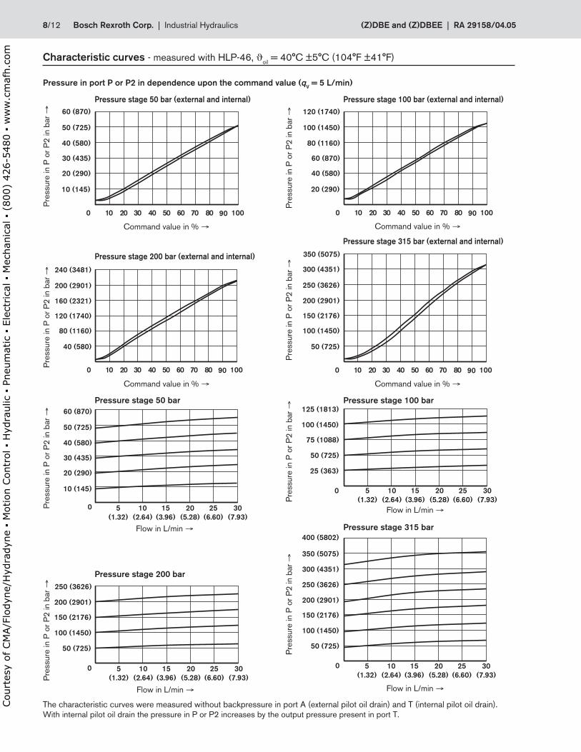
Characteristic curves - measured with HLP-46, ϑoil
= 40°C ±5°C (104°F ±41°F)
Pre
ssure
in P
or
P2
in b
ar →
Command value in % →
Pressure stage 50 bar Pressure stage 100 bar
Pressure stage 200 bar
Pressure stage 315 bar
Pre
ssure
in P
or
P2
in b
ar →
Pre
ssure
in P
or
P2
in b
ar →
Pressure in port P or P2 in dependence upon the command value (qV = 5 L/min)
Pressure stage 50 bar (external and internal)
The characteristic curves were measured without backpressure in port A (external pilot oil drain) and T (internal pilot oil drain).
With internal pilot oil drain the pressure in P or P2 increases by the output pressure present in port T.
Flow in L/min → Flow in L/min →
Flow in L/min →
Pre
ssure
in P
or
P2
in b
ar →
Command value in % →
Pre
ssure
in P
or
P2
in b
ar →
Command value in % →
Pre
ssure
in P
or
P2
in b
ar →
Command value in % →
Pressure stage 200 bar (external and internal)
Pressure stage 315 bar (external and internal)
Pre
ssure
in P
or
P2
in b
ar →
Pre
ssure
in P
or
P2
in b
ar →
Flow in L/min →
Pressure stage 100 bar (external and internal)
8/12 Bosch Rexroth Corp. | Industrial Hydraulics (Z)DBE and (Z)DBEE | RA 29158/04.05
Court
esy
of CM
A/F
lodyn
e/H
ydra
dyn
e ▪
Motion C
ontr
ol ▪
Hyd
raulic
▪ P
neu
mat
ic ▪
Ele
ctrica
l ▪
Mec
han
ical
▪ (
800)
426-5
480 ▪
ww
w.c
maf
h.c
om

4 (58)
6 (87)
8 (116)
10 (145)
12 (174)
14 (203)
2 (29)
5
(1.32)
10
(2.64)
15
(3.96)
20
(5.28)
25
(6.61)
30
(7.93)
0
4 (58)
6 (87)
8 (116)
10 (145)
12 (174)
14 (203)
2 (29)
5
(1.32)
10
(2.64)
15
(3.96)
20
(5.28)
25
(6.61)
30
(7.93)
0
1 (15)
2 (29)
3 (44)
4 (58)
5 (73)
5
(1.32)
10
(2.64)
15
(3.96)
20
(5.28)
25
(6.61)
30
(7.93)
0
1 (15)
2 (29)
3 (44)
4 (58)
5 (73)
5
(1.32)
10
(2.64)
15
(3.96)
20
(5.28)
25
(6.61)
30
(7.93)
0
1 (15)
2 (29)
3 (44)
4 (58)
5 (73)
5
(1.32)
10
(2.64)
15
(3.96)
20
(5.28)
25
(6.61)
30
(7.93)
0
4 (58)
6 (87)
8 (116)
10 (145)
12 (174)
14 (203)
2 (29)
5
(1.32)
10
(2.64)
15
(3.96)
20
(5.28)
25
(6.61)
30
(7.93)
0
4 (58)
6 (87)
8 (116)
10 (145)
12 (174)
14 (203)
2 (29)
5
(1.32)
10
(2.64)
15
(3.96)
20
(5.28)
25
(6.61)
30
(7.93)
0
Pressure stage 50 bar Pressure stage 100 bar
Pressure stage 200 bar Pressure stage 315 bar
Min. set pressure in port P or P2 at command value 0.
Min
. set
pre
ssure
in b
ar →
Min
. set
pre
ssure
in b
ar →
Flow in L/min → Flow in L/min →
Flow in L/min → Flow in L/min →
Min
. set
pre
ssure
in b
ar →
Min
. set
pre
ssure
in b
ar →
The characteristic curves were measured without backpressure in port A (external pilot oil drain) and T (internal pilot oil drain).
With internal pilot oil drain the pressure in P or P2 increases by the output pressure present in port T.
Flow in L/min → Flow in L/min →
Pre
ssure
diffe
rential in
bar →
Pressure differential P1 → P2
Pressure differential T1 → T2
Pressure differential A1 → A2 and B1 → B2
Pre
ssure
diffe
rential in
bar →
Flow in L/min →
Pre
ssure
diffe
rential in
bar →
Characteristic curves - measured with HLP-46, ϑoil
= 40°C ±5°C (104°F ±41°F)
Pilot oil drain –––––– internal – – – external
(Z)DBE and (Z)DBEE | RA 29158/04.05 Industrial Hydraulics | Bosch Rexroth Corp. 9/12
Court
esy
of CM
A/F
lodyn
e/H
ydra
dyn
e ▪
Motion C
ontr
ol ▪
Hyd
raulic
▪ P
neu
mat
ic ▪
Ele
ctrica
l ▪
Mec
han
ical
▪ (
800)
426-5
480 ▪
ww
w.c
maf
h.c
om

204.9 (8.07)
Ø 12.2
(0.48)
+0.1
+0
.1
Ø 10.
(0.39)
Ø 5.5
(0.22)
15
(0.5
9)
87
(3.4
3)
50
(1.9
7)
42
(2.6
5)
1.3
(0.0
5)
45
(1.7
7)
A B
P
133.5 (5.26)
199.6 (7.86)
43.5
(1.71)
99.4 (3.91)
T
271 (10.67) with integrated electronics
2
3 87
1 4 5
6 9
71.4 (2.81)
45
(1.77)
A B
T
P
103 (4.06)
47
(1
.85
)
8
(0.3
1)
F4
F1
F3
F2
10
G
0.01/100mm
Rzmax 4
Unit dimensions: Types DBE and DBEE - nominal dimensions in mm (inches)
Subplates to data sheet RE 45052 and valve fixing screws must
be ordered separately.
Subplates: G 341/01, G 1/4 (SAE-4; 7/16-20)
G 342/01, G 3/8 (SAE-6; 9/16-18)
G 502/01, G 1/2 (SAE-8; 3/4-16)
Valve fixing screws:
4 socket head cap screws M5 x 50 DIN 912 10.9
(10-24 UNC x 2”)
Tightening torque MT = 7 Nm (5.16 lb-ft)
Required
surface quality
of the mating part
1 Valve housing
2 Proportional solenoid
3 Nameplate
4 Identical seal rings for ports A, B, P and T
5 With version Y, pilot oil drain external via port A (Y)
6 Cable socket for type DBE
(separate order, see page 6)
7 Cable socket for type DBEE
(separate order, see page 6)
8 Space required to remove cable socket
9 Integrated electronics (OBE)
10 Machined mounting face, position of ports to
DIN 24340 (without locating bore) and
ISO 4401 (with locating bore)
Tolerances to: – General tolerances ISO 2768-mK
– Tolerancing principle ISO 8015
10/12 Bosch Rexroth Corp. | Industrial Hydraulics (Z)DBE and (Z)DBEE | RA 29158/04.05
Court
esy
of CM
A/F
lodyn
e/H
ydra
dyn
e ▪
Motion C
ontr
ol ▪
Hyd
raulic
▪ P
neu
mat
ic ▪
Ele
ctrica
l ▪
Mec
han
ical
▪ (
800)
426-5
480 ▪
ww
w.c
maf
h.c
om

"3"
"2"
"1"
"4"
174.4 (6.87)
T
B
P
A
21104
6 78 9
240.5 (9.47)30.5 (1.20)
3
F1 F2
F4 F3
11
(0.43)
62
(2.4
4)
62
(2.4
4)
204.9 (8.07)
Ø 5.5
(0.22)
15
(0.5
9)
87
(3.4
3)
50
(1.9
7)
45
(1.7
7)
99.4 (3.91)
271 (10.67) with integrated electronics
0.01/100mm
Rzmax 4
Unit dimensions: Types ZDBE and ZDBEE - nominal dimensions in mm (inches)
Subplates to data sheet RE 45052 and valve fixing screws must
be ordered separately.
Subplates: G 341/01, G 1/4 (SAE-4; 7/16-20)
G 342/01, G 3/8 (SAE-6; 9/16-18)
G 502/01, G 1/2 (SAE-8; 3/4-16)
Valve fixing screws:
4 socket head cap screws M5 x 50 DIN 912 10.9
(10-24 UNC x 2”)
Tightening torque MT = 7 Nm (5.16 lb-ft)
Required
surface quality
of the mating part
1 Valve housing
2 Proportional solenoid
3 Nameplate
4 Identical seal rings for ports A, B, P and T
6 Cable socket for type ZDBE
(separate order, see page 6)
7 Cable socket for type ZDBEE
(separate order, see page 6)
8 Space required to remove cable socket
9 Integrated electronics (OBE)
10 Machined mounting face, position of ports
nach DIN 24340 (without locating bore) and
ISO 4401 (with locating bore)
"1" to "4" – position of cable socket or housing with integrated electronics (see ordering code)
Tolerances to: – General tolerances ISO 2768-mK
– Tolerancing principle ISO 8015
(Z)DBE and (Z)DBEE | RA 29158/04.05 Industrial Hydraulics | Bosch Rexroth Corp. 11/12
Court
esy
of CM
A/F
lodyn
e/H
ydra
dyn
e ▪
Motion C
ontr
ol ▪
Hyd
raulic
▪ P
neu
mat
ic ▪
Ele
ctrica
l ▪
Mec
han
ical
▪ (
800)
426-5
480 ▪
ww
w.c
maf
h.c
om

12/12 Bosch Rexroth Corp. | Industrial Hydraulics (Z)DBE and (Z)DBEE | RA 29158/04.05
Notes
Bosch Rexroth Corp.
Industrial Hydraulics
2315 City Line Road
Bethlehem, PA 18017-2131
USA
Telephone (610) 694-8300
Facsimile (610) 694-8467
www.boschrexroth-us.com
© 2004 Bosch Rexroth Corporation
All rights reserved. Neither this document nor any part of it may be reproduced,
duplicated circulated or disseminated, whether by copy, electronic format or
any other means, without the prior consent and authorization of Bosch Rexroth
Cor po ra tion.
The data and illustrations in this brochure/data sheet are intended only to
describe or depict the products. No representation or warranty, either express
or implied, relating to merchantability or fi tness for intended use, is given or
intended by virtue of the information contained in this brochure/data sheet. The
information contained in this brochure/data sheet in no way relieves the user of it
obligation to insure the proper use of the products for a specifi c use or applica-
tion. All products contained in this brochure/data sheet are subject to normal
wear and tear from usage.
Subject to change.Court
esy
of CM
A/F
lodyn
e/H
ydra
dyn
e ▪
Motion C
ontr
ol ▪
Hyd
raulic
▪ P
neu
mat
ic ▪
Ele
ctrica
l ▪
Mec
han
ical
▪ (
800)
426-5
480 ▪
ww
w.c
maf
h.c
om