properties of fluid and its characteristics
TRANSCRIPT
1
PROPERTIES OF FLUID AND ITS
CHARACTERISTICS
AN INTERNSHIP REPORT
SUBMITTED
BY
SURAJ PANDIYAN. S (AME18202)
BE(ME) - 18

ACADEMY OF MARITIME EDUCATION AND TRAINING(AMET) (Declared as Deemed to be University u/s 3 of UGC Act 1956)
135, EAST COAST ROAD, KANATHUR, CHENNAI - 603 112.
TAMILNADU, INDIA
A Report on Internship
In
Department of BE Marine Engineering
By
Student Name: Suraj Pandiyan S
Register Number: Ame18202
Roll No:2876B Year:2nd Year
Group: 5
Batch:B.E.M.E-18 Subject: Fluid Mechanics
Code: UDMC405
CERTIFICATE
This is to certify that the project entitled “Properties of fluids” is to
bonafide work carried out by the students of AMET UNIVERSITY,
KANATHUR (CHENNAI) during the year 2019 -2020 for the partial
fulfillment of the requirements for the award of the Degree of
Bachelor of a Marine Engineering.
INTERNAL GUIDE EXTERNAL EXAMINER
HEAD OF THE DEPARTMENT
PLACE : AMET UNIVERSITY
BE MARINE ENGINEERING
Properties of fluids And its characteristics:
In this essay we will be seeing the properties of fluid
which greatly influence the working of fluids in both practical
and theoretical practices. The following are some of the
fundamental properties of fluids.
1. Mass density.
2. Specific Weight
3. Specific Volume
4. Specific Gravity
5. Viscosity
6. Compressibility
7. Vapour Pressure
8. Surface Tension
9. Capillary
10. Fluid Dynamics
11. Euler’s Theorem
12. Bernoulli’s Theorem
Mass density:
Mass density is a quantitative expression of the amount of
mass contained per unit volume. The standard unit is
kilograms per meter cubed (kg/m3).
The symbol most often used for density is:
(the Greek letter rho).
Mass density represents the mass (or number of particles)
per unit volume of a substance, material or object. Most
substances (especially gases) increase in density as their
pressure increases or as their temperature decreases.
Mass density can help to predict chances of corrosion of
substances. Measuring mass density can help to predict a
material's inherent defects which can ultimately cause
different forms of corrosion.
Mass density is also known as density.
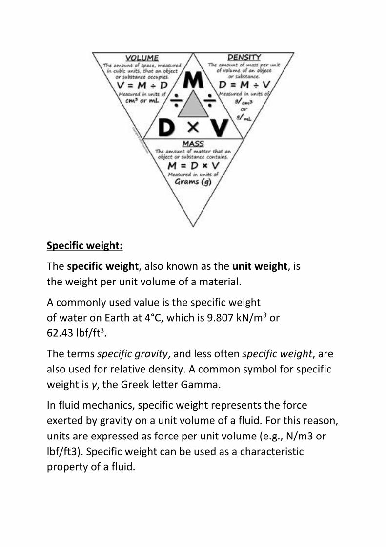
Specific weight:
The specific weight, also known as the unit weight, is
the weight per unit volume of a material.
A commonly used value is the specific weight
of water on Earth at 4°C, which is 9.807 kN/m3 or
62.43 lbf/ft3.
The terms specific gravity, and less often specific weight, are
also used for relative density. A common symbol for specific
weight is γ, the Greek letter Gamma.
In fluid mechanics, specific weight represents the force
exerted by gravity on a unit volume of a fluid. For this reason,
units are expressed as force per unit volume (e.g., N/m3 or
lbf/ft3). Specific weight can be used as a characteristic
property of a fluid.
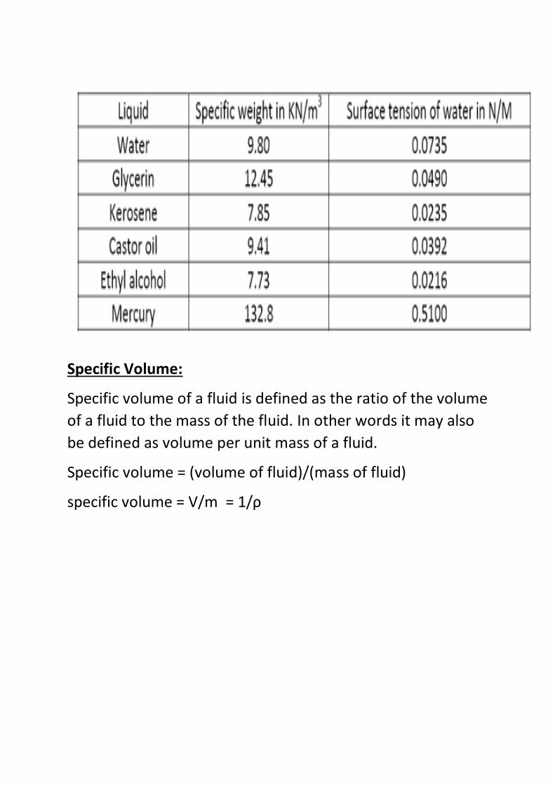
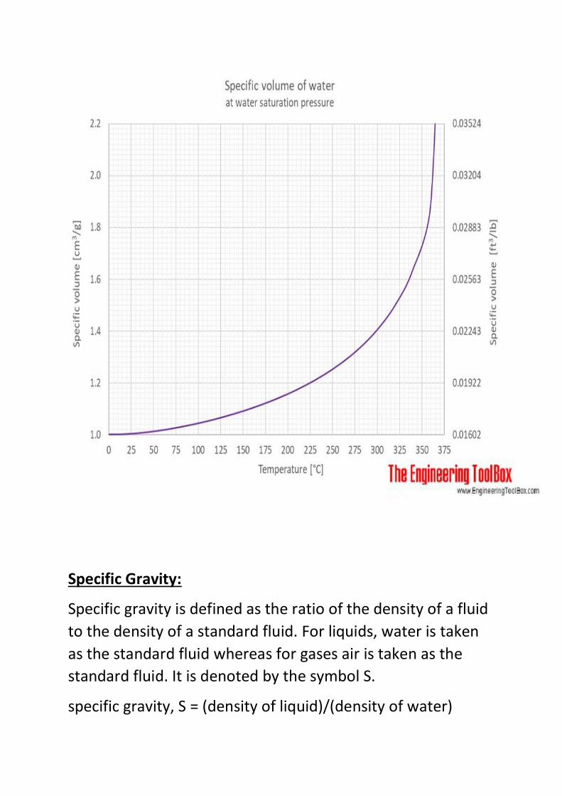
Specific Volume:
Specific volume of a fluid is defined as the ratio of the volume
of a fluid to the mass of the fluid. In other words it may also
be defined as volume per unit mass of a fluid.
Specific volume = (volume of fluid)/(mass of fluid)
specific volume = V/m = 1/ρ
Specific Gravity:
Specific gravity is defined as the ratio of the density of a fluid
to the density of a standard fluid. For liquids, water is taken
as the standard fluid whereas for gases air is taken as the
standard fluid. It is denoted by the symbol S.
specific gravity, S = (density of liquid)/(density of water)
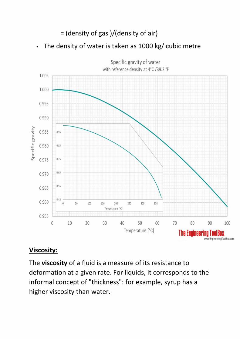
= (density of gas )/(density of air)
The density of water is taken as 1000 kg/ cubic metre
Viscosity:
The viscosity of a fluid is a measure of its resistance to
deformation at a given rate. For liquids, it corresponds to the
informal concept of "thickness": for example, syrup has a
higher viscosity than water.
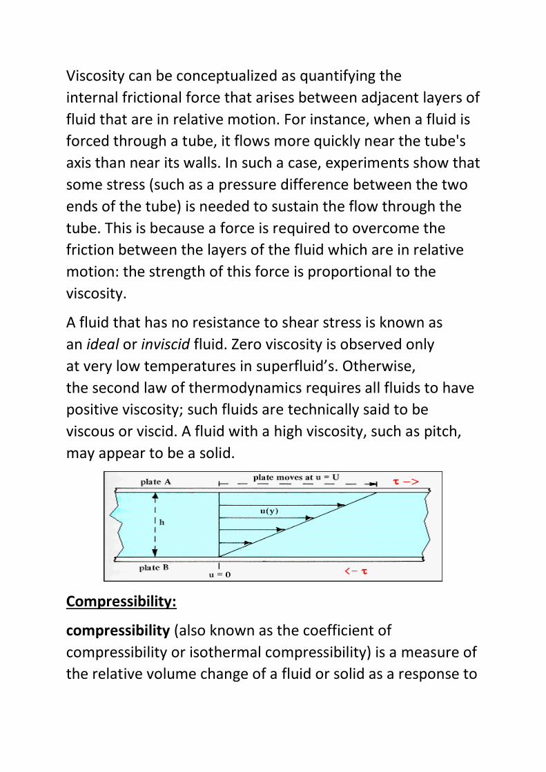
Viscosity can be conceptualized as quantifying the
internal frictional force that arises between adjacent layers of
fluid that are in relative motion. For instance, when a fluid is
forced through a tube, it flows more quickly near the tube's
axis than near its walls. In such a case, experiments show that
some stress (such as a pressure difference between the two
ends of the tube) is needed to sustain the flow through the
tube. This is because a force is required to overcome the
friction between the layers of the fluid which are in relative
motion: the strength of this force is proportional to the
viscosity.
A fluid that has no resistance to shear stress is known as
an ideal or inviscid fluid. Zero viscosity is observed only
at very low temperatures in superfluid’s. Otherwise,
the second law of thermodynamics requires all fluids to have
positive viscosity; such fluids are technically said to be
viscous or viscid. A fluid with a high viscosity, such as pitch,
may appear to be a solid.
Compressibility:
compressibility (also known as the coefficient of
compressibility or isothermal compressibility) is a measure of
the relative volume change of a fluid or solid as a response to
a pressure (or mean stress) change. In its simple form, the
compressibility β may be expressed as
where V is volume and p is pressure. The choice to define
compressibility as the negative of the fraction makes
compressibility positive in the (usual) case that an increase in
pressure induces a reduction in volume.
The specification above is incomplete, because for any object
or system the magnitude of the compressibility depends
strongly on whether the process is isentropic or isothermal.
Accordingly, isothermal compressibility is defined.
Vapour Pressure:
Vapor pressure or equilibrium vapor pressure is defined as
the pressure exerted by a vapor in thermodynamic
equilibrium with its condensed phases (solid or liquid) at a
given temperature in a closed system. The equilibrium vapor
pressure is an indication of a liquid's evaporation rate. It
relates to the tendency of particles to escape from the liquid
(or a solid). A substance with a high vapor pressure at normal
temperatures is often referred to as volatile. The pressure
exhibited by vapor present above a liquid surface is known as
vapor pressure. As the temperature of a liquid increases, the
kinetic energy of its molecules also increases. As the kinetic
energy of the molecules increases, the number of molecules
transitioning into a vapor also increases, thereby increasing
the vapor pressure.
The vapor pressure of any substance increases non-linearly
with temperature according to the Clausius–Clapeyron
relation. The atmospheric pressure boiling point of a liquid
(also known as the normal boiling point) is the temperature
at which the vapor pressure equals the ambient atmospheric
pressure. With any incremental increase in that temperature,
the vapor pressure becomes sufficient to
overcome atmospheric pressure and lift the liquid to form
vapor bubbles inside the bulk of the
substance. Bubble formation deeper in the liquid requires a
higher temperature due to the higher fluid pressure, because
fluid pressure increases above the atmospheric pressure as
the depth increases. More important at shallow depths is the
higher temperature required to start bubble formation. The
surface tension of the bubble wall leads to an overpressure in
the very small, initial bubbles.
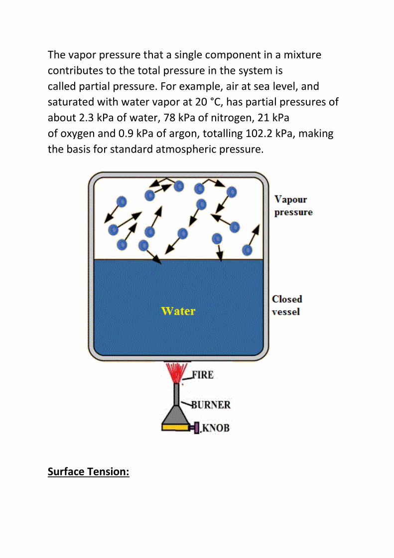
The vapor pressure that a single component in a mixture
contributes to the total pressure in the system is
called partial pressure. For example, air at sea level, and
saturated with water vapor at 20 °C, has partial pressures of
about 2.3 kPa of water, 78 kPa of nitrogen, 21 kPa
of oxygen and 0.9 kPa of argon, totalling 102.2 kPa, making
the basis for standard atmospheric pressure.
Surface Tension:
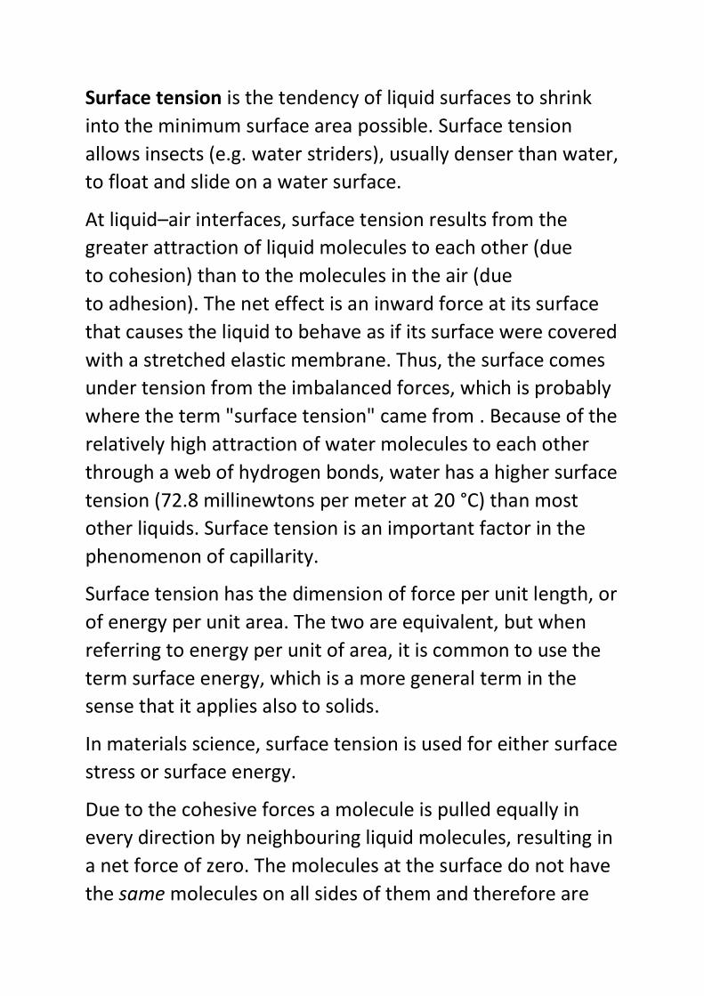
Surface tension is the tendency of liquid surfaces to shrink
into the minimum surface area possible. Surface tension
allows insects (e.g. water striders), usually denser than water,
to float and slide on a water surface.
At liquid–air interfaces, surface tension results from the
greater attraction of liquid molecules to each other (due
to cohesion) than to the molecules in the air (due
to adhesion). The net effect is an inward force at its surface
that causes the liquid to behave as if its surface were covered
with a stretched elastic membrane. Thus, the surface comes
under tension from the imbalanced forces, which is probably
where the term "surface tension" came from . Because of the
relatively high attraction of water molecules to each other
through a web of hydrogen bonds, water has a higher surface
tension (72.8 millinewtons per meter at 20 °C) than most
other liquids. Surface tension is an important factor in the
phenomenon of capillarity.
Surface tension has the dimension of force per unit length, or
of energy per unit area. The two are equivalent, but when
referring to energy per unit of area, it is common to use the
term surface energy, which is a more general term in the
sense that it applies also to solids.
In materials science, surface tension is used for either surface
stress or surface energy.
Due to the cohesive forces a molecule is pulled equally in
every direction by neighbouring liquid molecules, resulting in
a net force of zero. The molecules at the surface do not have
the same molecules on all sides of them and therefore are
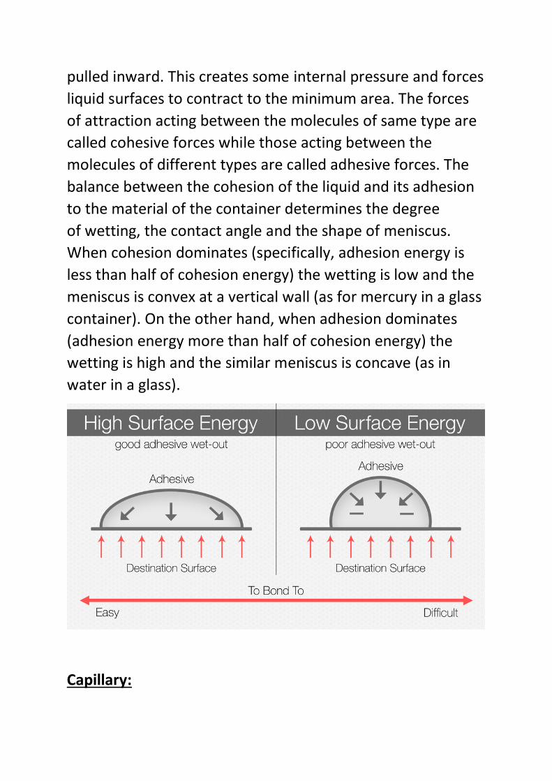
pulled inward. This creates some internal pressure and forces
liquid surfaces to contract to the minimum area. The forces
of attraction acting between the molecules of same type are
called cohesive forces while those acting between the
molecules of different types are called adhesive forces. The
balance between the cohesion of the liquid and its adhesion
to the material of the container determines the degree
of wetting, the contact angle and the shape of meniscus.
When cohesion dominates (specifically, adhesion energy is
less than half of cohesion energy) the wetting is low and the
meniscus is convex at a vertical wall (as for mercury in a glass
container). On the other hand, when adhesion dominates
(adhesion energy more than half of cohesion energy) the
wetting is high and the similar meniscus is concave (as in
water in a glass).
Capillary:
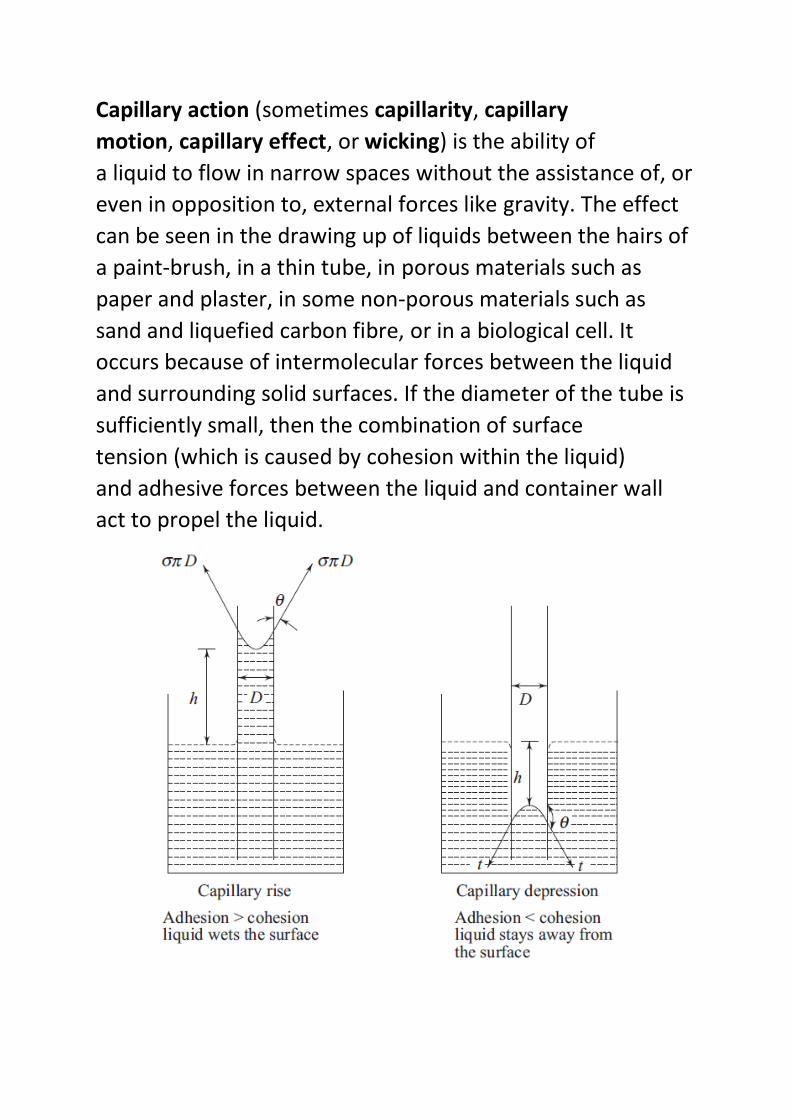
Capillary action (sometimes capillarity, capillary
motion, capillary effect, or wicking) is the ability of
a liquid to flow in narrow spaces without the assistance of, or
even in opposition to, external forces like gravity. The effect
can be seen in the drawing up of liquids between the hairs of
a paint-brush, in a thin tube, in porous materials such as
paper and plaster, in some non-porous materials such as
sand and liquefied carbon fibre, or in a biological cell. It
occurs because of intermolecular forces between the liquid
and surrounding solid surfaces. If the diameter of the tube is
sufficiently small, then the combination of surface
tension (which is caused by cohesion within the liquid)
and adhesive forces between the liquid and container wall
act to propel the liquid.
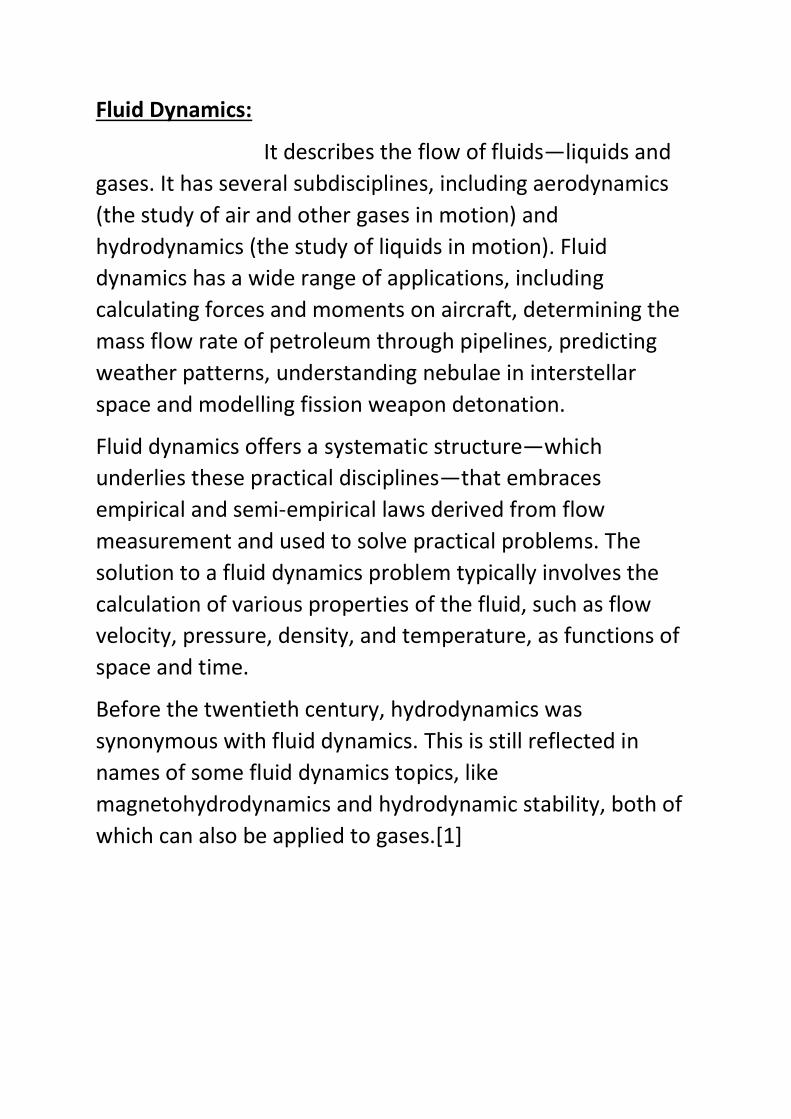
Fluid Dynamics:
It describes the flow of fluids—liquids and
gases. It has several subdisciplines, including aerodynamics
(the study of air and other gases in motion) and
hydrodynamics (the study of liquids in motion). Fluid
dynamics has a wide range of applications, including
calculating forces and moments on aircraft, determining the
mass flow rate of petroleum through pipelines, predicting
weather patterns, understanding nebulae in interstellar
space and modelling fission weapon detonation.
Fluid dynamics offers a systematic structure—which
underlies these practical disciplines—that embraces
empirical and semi-empirical laws derived from flow
measurement and used to solve practical problems. The
solution to a fluid dynamics problem typically involves the
calculation of various properties of the fluid, such as flow
velocity, pressure, density, and temperature, as functions of
space and time.
Before the twentieth century, hydrodynamics was
synonymous with fluid dynamics. This is still reflected in
names of some fluid dynamics topics, like
magnetohydrodynamics and hydrodynamic stability, both of
which can also be applied to gases.[1]
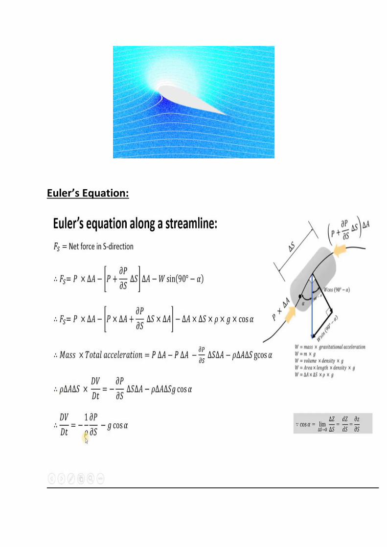
Euler’s Equation:
Bernoulli’s Equation:
Conservation of Energy
Sum of kinetic energy and gravitational potential energy
is constant.
Kinetic energy =
Gravitational potential energy = mg h
To apply this to a falling droplet we have an initial velocity of
zero, and it falls through a height of h.
Initial kinetic energy = 0
Initial potential energy = mg h
Final kinetic energy =
Final potential energy = 0
Notice that the pressure is constant.
Initial kinetic energy + Initial potential energy = Final
kinetic energy + Final potential energy
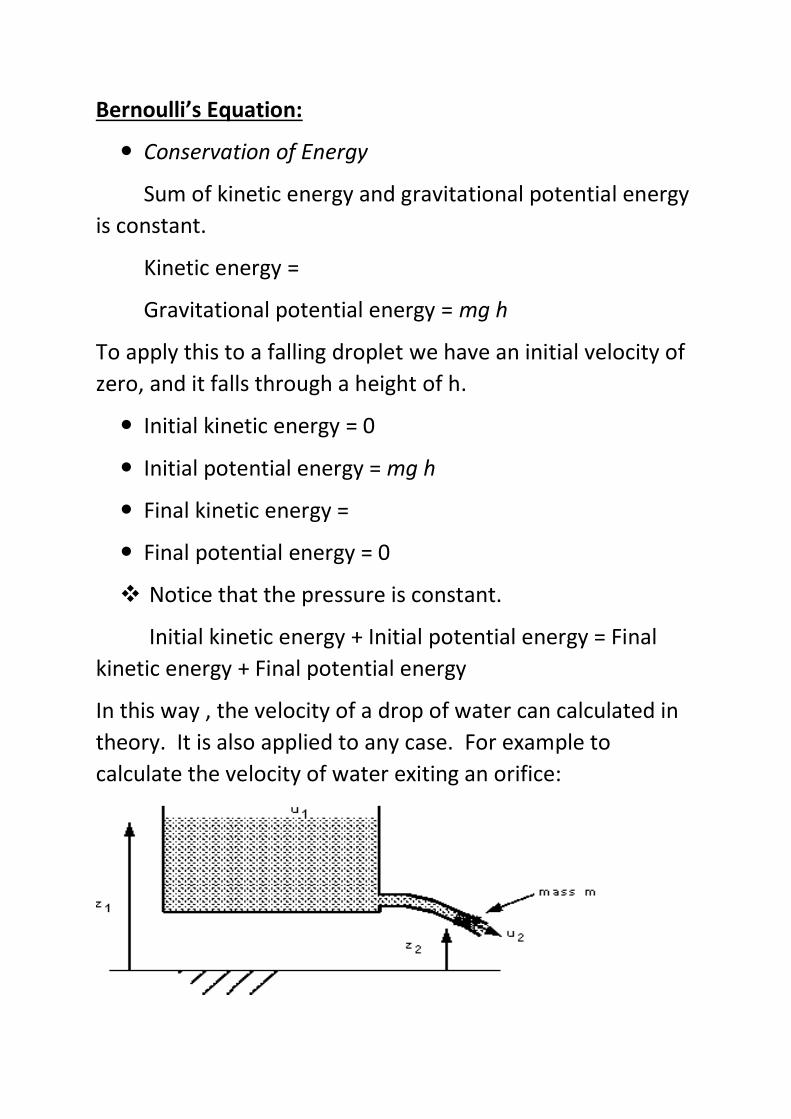
In this way , the velocity of a drop of water can calculated in
theory. It is also applied to any case. For example to
calculate the velocity of water exiting an orifice:
Initial kinetic energy = 0
Initial potential energy = mg z1
Final kinetic energy = 0.5 mu2
Final potential energy = mgz2
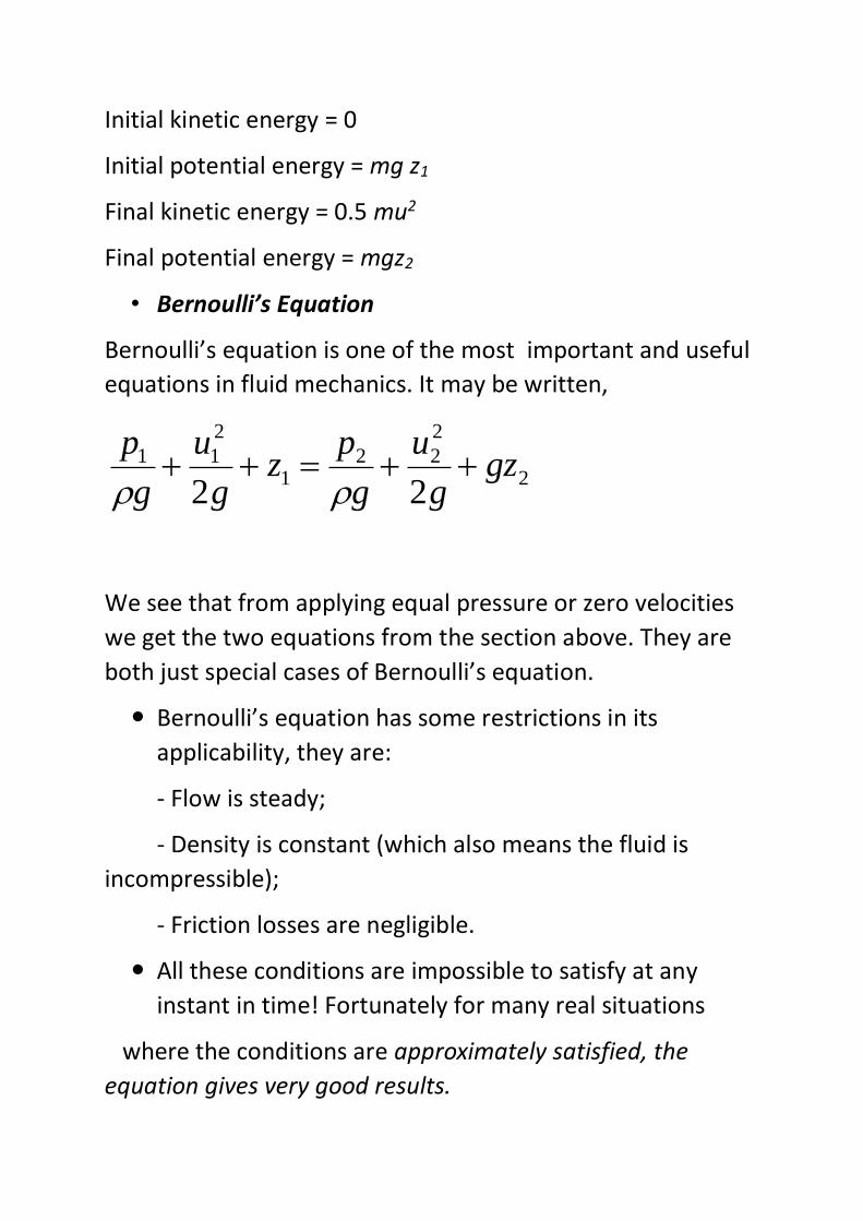
• Bernoulli’s Equation
Bernoulli’s equation is one of the most important and useful
equations in fluid mechanics. It may be written,
2
2
221
2
11
22gz
g
u
g
pz
g
u
g
p
We see that from applying equal pressure or zero velocities
we get the two equations from the section above. They are
both just special cases of Bernoulli’s equation.
Bernoulli’s equation has some restrictions in its
applicability, they are:
- Flow is steady;
- Density is constant (which also means the fluid is
incompressible);
- Friction losses are negligible.
All these conditions are impossible to satisfy at any
instant in time! Fortunately for many real situations
where the conditions are approximately satisfied, the
equation gives very good results.
By the principle of conservation of energy the total
energy in the system does not change, Thus the total
head does not change. So the Bernoulli equation can be
written,
.2
2
constHzg
u
g
p
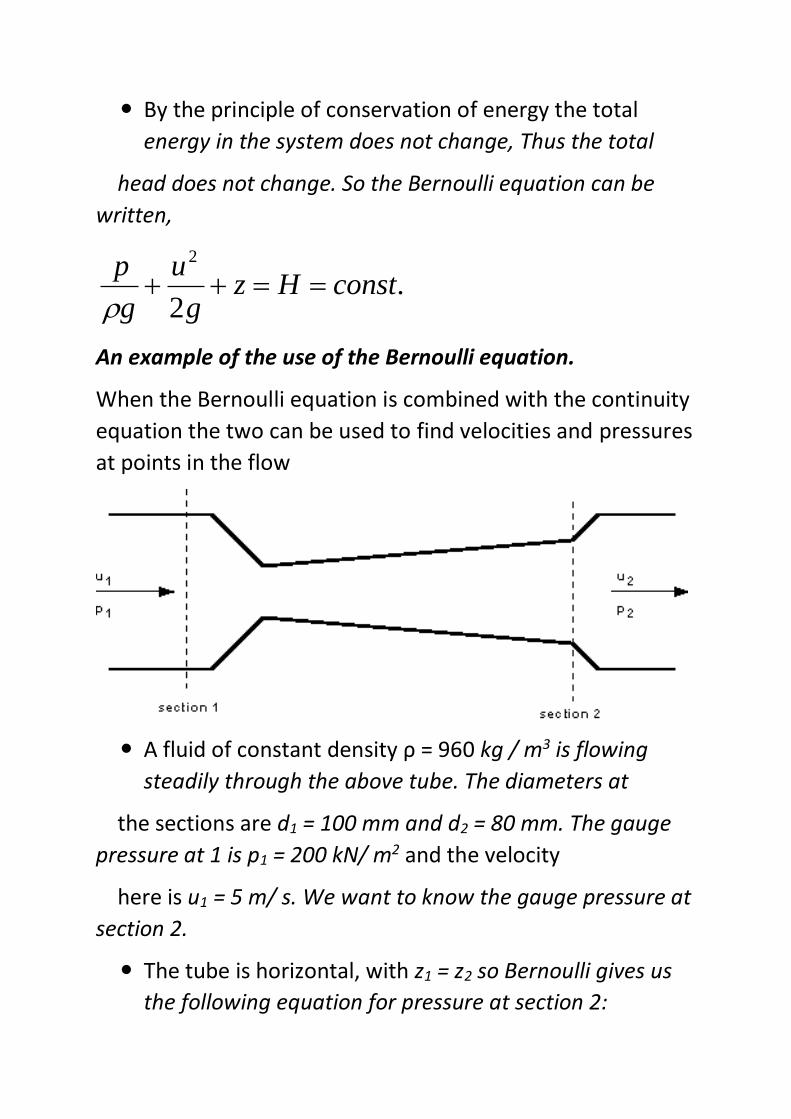
An example of the use of the Bernoulli equation.
When the Bernoulli equation is combined with the continuity
equation the two can be used to find velocities and pressures
at points in the flow
A fluid of constant density ρ = 960 kg / m3 is flowing
steadily through the above tube. The diameters at
the sections are d1 = 100 mm and d2 = 80 mm. The gauge
pressure at 1 is p1 = 200 kN/ m2 and the velocity
here is u1 = 5 m/ s. We want to know the gauge pressure at
section 2.
The tube is horizontal, with z1 = z2 so Bernoulli gives us
the following equation for pressure at section 2:
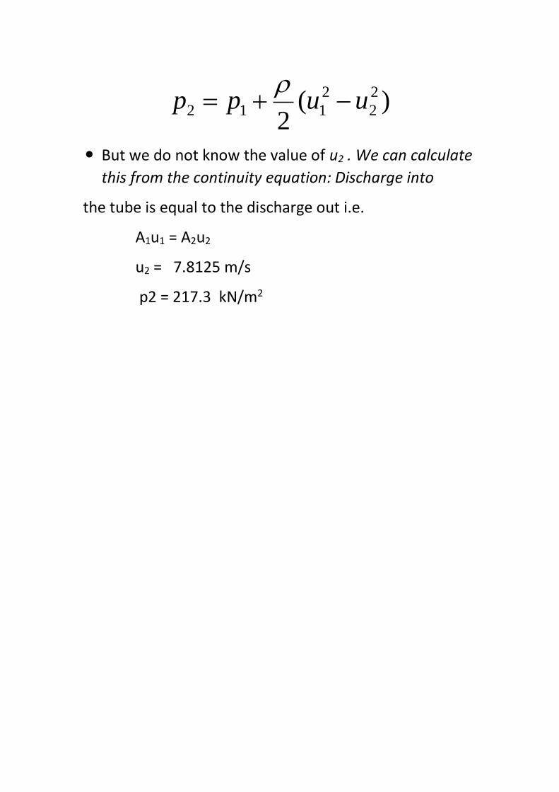
)(2
2
2
2
112 uupp
But we do not know the value of u2 . We can calculate
this from the continuity equation: Discharge into
the tube is equal to the discharge out i.e.
A1u1 = A2u2
u2 = 7.8125 m/s
p2 = 217.3 kN/m2

INTERNSHIP ALLOCATION REPORT 2019-20
Name of the Department: BE MARINE ENGINEERING
(In view of advisory from the AICTE, internships for the year 2019-20 are offered by the
Department itself to facilitate the students to take up required work from their home itself during
the lock down period due to COVID-19 outbreak)
Name of the Programme : MARINE ENGINEERING
Year of study and Batch/Group : 2nd YEAR BE (ME)18 G-4
Name of the Mentor: MR. HARISH KUMAR J
Title of the assigned internship :
FLUID MECHANICS
Nature of Internship : Individual
Reg No of cadet who is assigned with this internship:
AME18202
Total No. of Hours Required to complete the Internship: 45 HOURS
Signature of the Mentor
Signature of the Internal
Examiner
Signature of HoD/Programme
Head

INTERNSHIP EVALUATION REPORT 2019-20
Name of the Department: Marine Engineering
(In view of advisory from the AICTE, internships for the year 2019-20 are offered by the
Department itself to facilitate the students to take up required work from their home itself during
the lock down period due to COVID-19 outbreak)
Name of the Student Suraj Pandiyan S
Register No and Roll No AME18202
2876B
Programme of study FLUID MECHANICS
Year and Batch/Group 2nd YEAR BEME18 G-05
Semester IV
Title of Internship
1) Properties Of Fluids.
2) Bernoulli’s Equation.
Duration of Internship 45 Hours
Mentor of the Student MR. HARISH KUMAR J
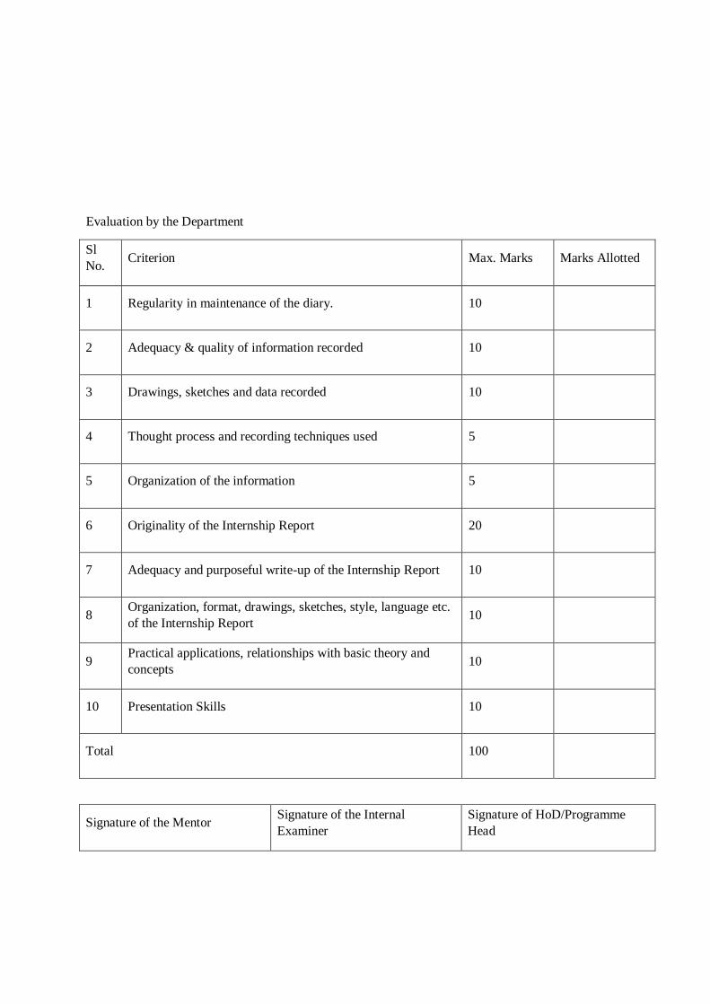
Evaluation by the Department
Sl
No. Criterion Max. Marks Marks Allotted
1 Regularity in maintenance of the diary. 10
2 Adequacy & quality of information recorded 10
3 Drawings, sketches and data recorded 10
4 Thought process and recording techniques used 5
5 Organization of the information 5
6 Originality of the Internship Report 20
7 Adequacy and purposeful write-up of the Internship Report 10
8 Organization, format, drawings, sketches, style, language etc.
of the Internship Report 10
9 Practical applications, relationships with basic theory and
concepts 10
10 Presentation Skills 10
Total 100
Signature of the Mentor Signature of the Internal
Examiner
Signature of HoD/Programme
Head

1
PUMPS AND TURBINES
AN INTERNSHIP REPORT
SUBMITTED
BY
DHURUVA R SHETTY (AME18170)
BE(ME) - 18

ACADEMY OF MARITIME EDUCATION AND TRAINING (AMET)
(Declared as Deemed to be University u/s 3 of UGC Act 1956)
135, EAST COAST ROAD, KANATHUR, CHENNAI - 603 112.
TAMILNADU, INDIA
INTERNSHIP AT HOME
A Report on Internship
In
Department of BE MARINE ENGINEERING
By
Name : DHRUVA R SHETTY
Register Number : AME18170
Roll No : 2844B
Year : 2ND YEAR
Batch : BE(ME)-18
Group : 05
Subject Code : UDMC405
Subject : FLUID MECHANICS
CERTIFICATE
This is to certify that the project entitled “Pumps & Turbines” is to
bonafide work carried out by the students of AMET UNIVERSITY,
KANATHUR (CHENNAI) during the year 2019 -2020 for the partial
fulfillment of the requirements for the award of the Degree of Bachelor
of a Marine Engineering.
INTERNAL GUIDE EXTERNAL EXAMINER
HEAD OF THE DEPARTMENT
PLACE : AMET UNIVERSITY
BE MARINE ENGINEERING
1. INTRODUCTION – Pumps & Turbines
2. Dynamic Pump
• Centrifugal Pumps
• Vertical Centrifugal Pumps
• Horizontal Centrifugal Pumps
• Submersible Pumps
• Fire Hydrant Systems
3. Positive Displacement pumps
• Diaphragm Pumps
• Gear Pumps
• Peristaltic Pumps
• Lobe Pumps
• Piston Pump
4. Turbines
• Water Turbine
• Steam Turbine
• Gas Turbine
• Wind Turbine
5. Conclusion
CONTENT
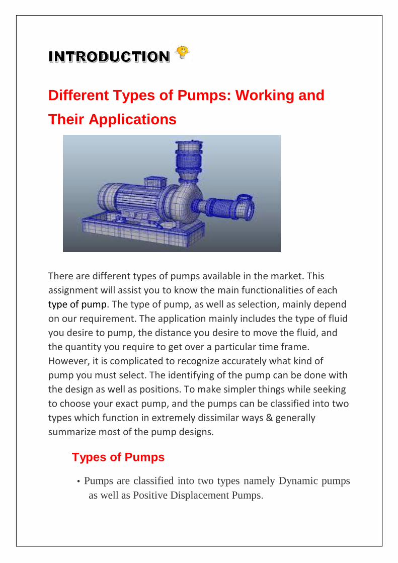
Different Types of Pumps: Working and
Their Applications
There are different types of pumps available in the market. This
assignment will assist you to know the main functionalities of each
type of pump. The type of pump, as well as selection, mainly depend
on our requirement. The application mainly includes the type of fluid
you desire to pump, the distance you desire to move the fluid, and
the quantity you require to get over a particular time frame.
However, it is complicated to recognize accurately what kind of
pump you must select. The identifying of the pump can be done with
the design as well as positions. To make simpler things while seeking
to choose your exact pump, and the pumps can be classified into two
types which function in extremely dissimilar ways & generally
summarize most of the pump designs.
Types of Pumps
• Pumps are classified into two types namely Dynamic pumps
as well as Positive Displacement Pumps.

CLASSIFICATION OF PUMPS
• Dynamic pumps are classified into different types but some of them
are discussed below like Centrifugal, Vertical centrifugal, Horizontal
centrifugal, Submersible, and Fire hydrant systems.
1. Centrifugal pump
Centrifugal Pumps are devices that are used to transport fluids
by the conversion of rotational kinetic energy energy to
hydronamic energy to
the fluid flow. The
rotational energy
typically comes from an .
The impeller and blades rotate, they
electric motor or steam
turbine
transfer momentum to incoming fluid. The fluid accelerates
radially outward from the pump chasing and a vacuum is created
at the impellers eye that continuously draws more fluid into the
pump. As the fluid’s velocity increases its kinetic energy
increases. Fluid of high kinetic energy is forced out of the
impeller area and enters the volute. In the volute the fluid flows
through a continuously increasing cross-sectional area, where
the kinetic energy is converted into fluid pressure.
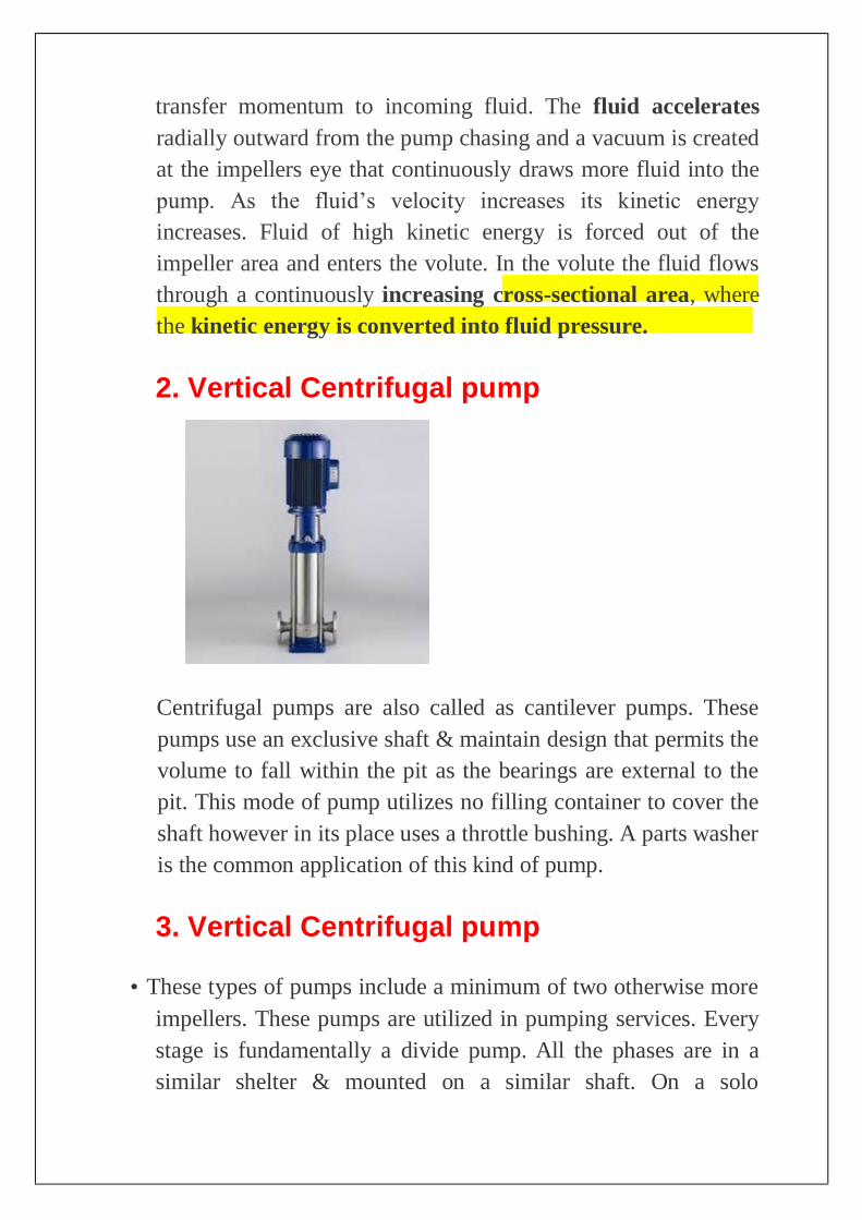
2. Vertical Centrifugal pump
Centrifugal pumps are also called as cantilever pumps. These
pumps use an exclusive shaft & maintain design that permits the
volume to fall within the pit as the bearings are external to the
pit. This mode of pump utilizes no filling container to cover the
shaft however in its place uses a throttle bushing. A parts washer
is the common application of this kind of pump.
3. Vertical Centrifugal pump
• These types of pumps include a minimum of two otherwise more
impellers. These pumps are utilized in pumping services. Every
stage is fundamentally a divide pump. All the phases are in a
similar shelter & mounted on a similar shaft. On a solo

horizontal shaft, minimum eight otherwise additional stages can
be mounted. Every stage enhances the head by around an equal
amount. Multi-stage pumps can also be single otherwise double
suction on the first impeller. All kinds of pumps have been
providing as well as servicing this type of centrifugal pumps.
4. Submersible pump
These pumps are also named as stormwater, sewage, and septic
pumps. The applications of these pumps mainly include building
services, domestic, industrial, commercial, rural, municipal, &
rainwater recycle applications.
• These pumps are apt for shifting
stormwater, subsoil water, sewage, black
water, grey water, rainwater, trade waste,
chemicals, bore water, and foodstuffs. The
applications of these pipes mainly include
in different impellers like closed,
contrablock, vortex, multi-stage, single
channel, cutter, otherwise grinder pumps.
For
different applications, there is an extensive selection is
accessible which includes high flow, low flow, low head,
otherwise high head5).

5. Fire pump system
A fire pump is a part of a fire sprinkler system's water supply and
powered by electric, diesel or steam. The pump intake is either
connected to the public underground water supply piping, or a static
water source (e.g., tank, reservoir, lake). The pump provides water
flow at a higher pressure to the sprinkler system risers and hose
standpipes. A fire pump is tested and listed for its use specifically for
fire service by a third-party testing and listing agency, such as UL or
FM Global Fire hydrant pump systems are also named as hydrant
boosters, fire pumps, & fire water pumps. These are high force water
pumps intended to enhance the capacity of firefighting of
construction by increasing the force within the hydrant service as
mains is not sufficient. The applications of this system mainly include
irrigation as well as water transfer.
• Positive displacement pumps are classified into different types
but some of them are discussed below:
1. Diaphragm pump Diaphragm pumps also known as AOD pumps (Air operated
diaphragms), pneumatic, and AODD pumps. The applications of these
pumps mainly include in continuous applications like in general
plants, industrial and mining. AOD pumps are particularly employed
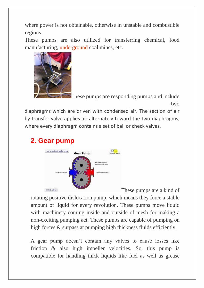
where power is not obtainable, otherwise in unstable and combustible
regions.
These pumps are also utilized for transferring chemical, food
manufacturing, underground coal mines, etc.
These pumps are responding pumps and include
two
diaphragms which are driven with condensed air. The section of air
by transfer valve applies air alternately toward the two diaphragms;
where every diaphragm contains a set of ball or check valves.
2. Gear pump
These pumps are a kind of
rotating positive dislocation pump, which means they force a stable
amount of liquid for every revolution. These pumps move liquid
with machinery coming inside and outside of mesh for making a
non-exciting pumping act. These pumps are capable of pumping on
high forces & surpass at pumping high thickness fluids efficiently.
A gear pump doesn’t contain any valves to cause losses like
friction & also high impeller velocities. So, this pump is
compatible for handling thick liquids like fuel as well as grease
oils. These pumps are not suitable for driving solids as well as
harsh liquids.
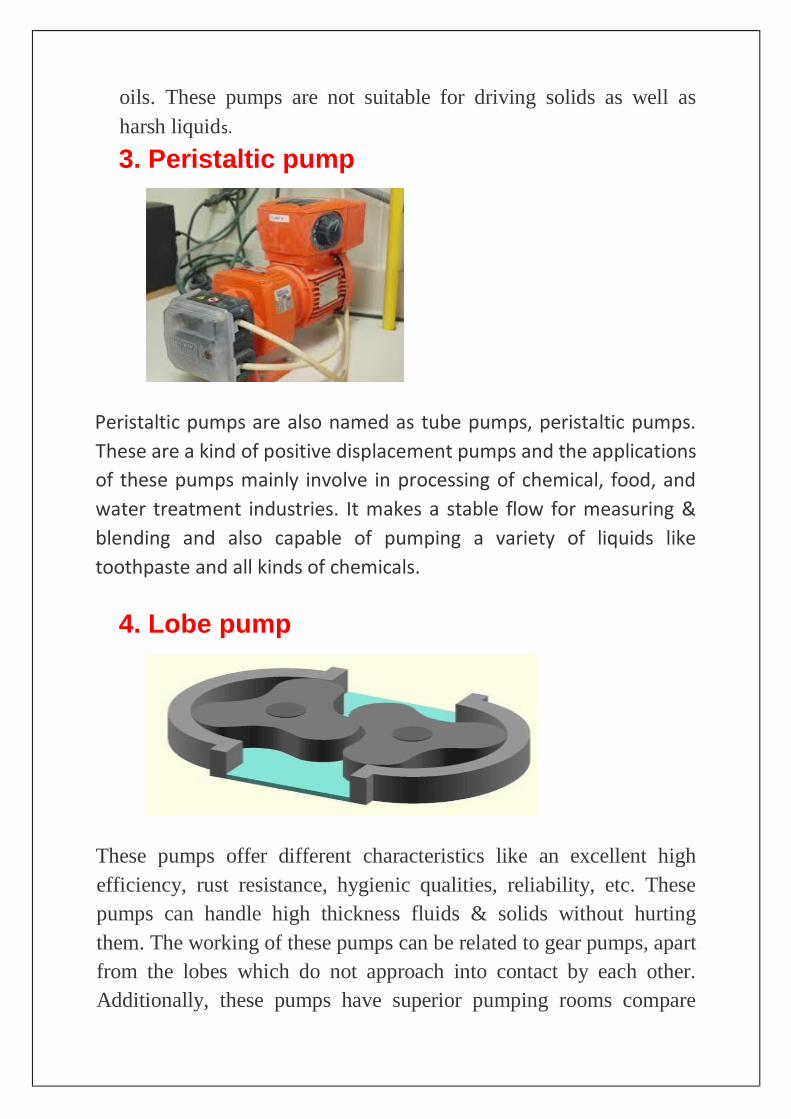
3. Peristaltic pump
Peristaltic pumps are also named as tube pumps, peristaltic pumps.
These are a kind of positive displacement pumps and the applications
of these pumps mainly involve in processing of chemical, food, and
water treatment industries. It makes a stable flow for measuring &
blending and also capable of pumping a variety of liquids like
toothpaste and all kinds of chemicals.
4. Lobe pump
These pumps offer different characteristics like an excellent high
efficiency, rust resistance, hygienic qualities, reliability, etc. These
pumps can handle high thickness fluids & solids without hurting
them. The working of these pumps can be related to gear pumps, apart
from the lobes which do not approach into contact by each other.
Additionally, these pumps have superior pumping rooms compare
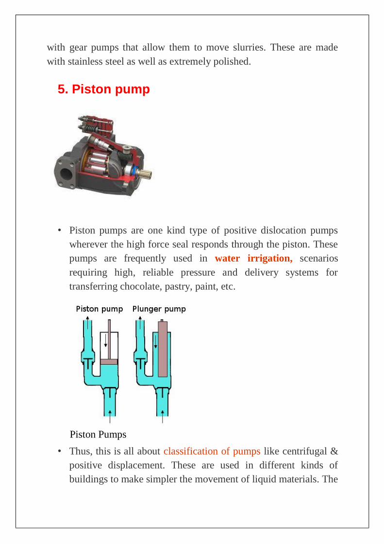
with gear pumps that allow them to move slurries. These are made
with stainless steel as well as extremely polished.
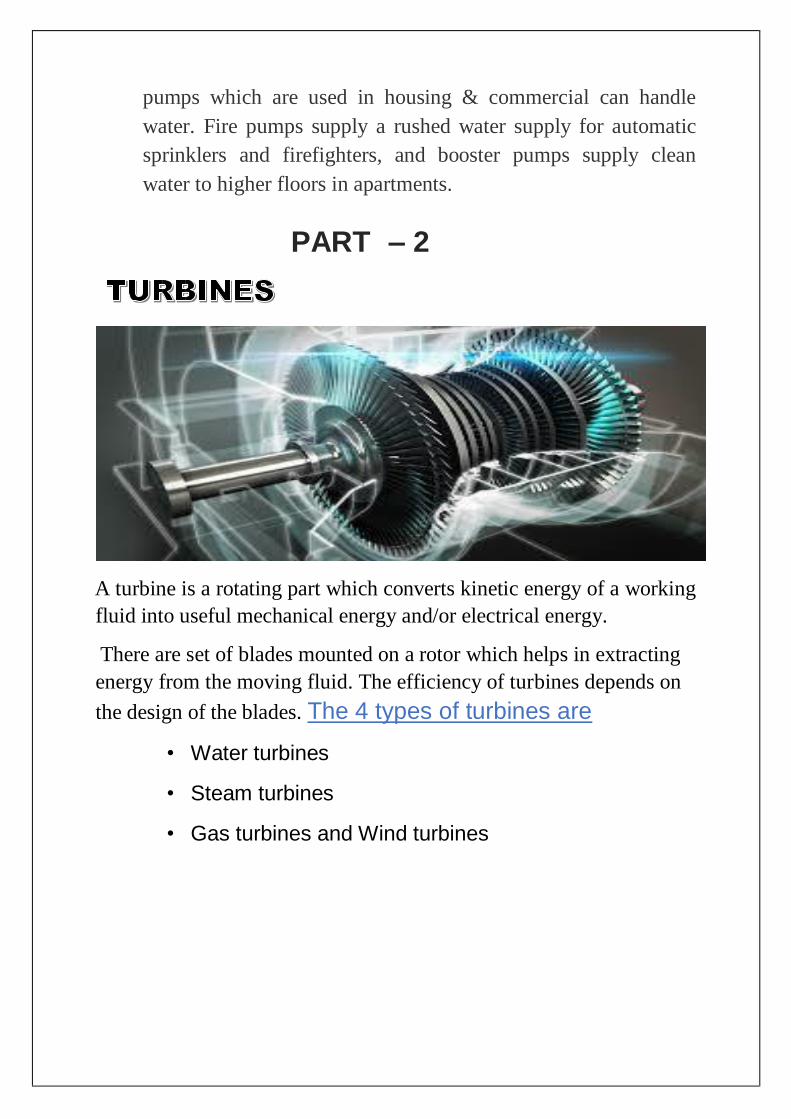
5. Piston pump
• Piston pumps are one kind type of positive dislocation pumps
wherever the high force seal responds through the piston. These
pumps are frequently used in water irrigation, scenarios
requiring high, reliable pressure and delivery systems for
transferring chocolate, pastry, paint, etc.
Piston Pumps
• Thus, this is all about classification of pumps like centrifugal &
positive displacement. These are used in different kinds of
buildings to make simpler the movement of liquid materials. The
pumps which are used in housing & commercial can handle
water. Fire pumps supply a rushed water supply for automatic
sprinklers and firefighters, and booster pumps supply clean
water to higher floors in apartments.
A turbine is a rotating part which converts kinetic energy of a working
fluid into useful mechanical energy and/or electrical energy.
There are set of blades mounted on a rotor which helps in extracting
energy from the moving fluid. The efficiency of turbines depends on
the design of the blades. The 4 types of turbines are
• Water turbines
• Steam turbines
• Gas turbines and Wind turbines
PART – 2

Turbines used in hydro power plants: -
The turbines used in hydroelectric power plants are water turbines
which have water as their working fluid.
First of all, millions of liters of water are collected in the dam. More
the height of dam, more the pressure. The highly pressurized water is
then made to flow via large pipe called as penstock.
The turbine is located at the end of penstock from where the
pressurized water strikes the blades of turbine at high velocity
making it to rotate. This turbine is connected to a generator which
generates electricity. The shape of turbine blades depends upon the
pressure & velocity of water.
Water turbines are classified into 2 types-
1. Impulse type
2. Reaction type
Impulse type turbines- Impulse turbines basically work on Newton’s 2nd law. In impulse
turbines, number of elliptical half sized buckets are fitted instead of
blades on the rotor hub. When water strike the buckets at high speed,
the rotor starts rotating. In short, the kinetic energy of water gets
converted into Mechanical energy. Thus, electricity is generated when
one end of the turbine shaft is connected to generator.
Example – Pelton turbine
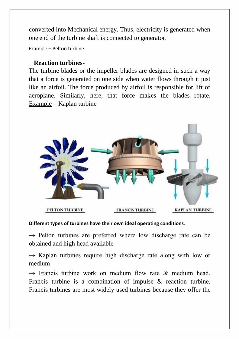
Reaction turbines- The turbine blades or the impeller blades are designed in such a way
that a force is generated on one side when water flows through it just
like an airfoil. The force produced by airfoil is responsible for lift of
aeroplane. Similarly, here, that force makes the blades rotate.
Example – Kaplan turbine
Different types of turbines have their own ideal operating conditions.
→ Pelton turbines are preferred where low discharge rate can be
obtained and high head available
→ Kaplan turbines require high discharge rate along with low or
medium
→ Francis turbine work on medium flow rate & medium head.
Francis turbine is a combination of impulse & reaction turbine.
Francis turbines are most widely used turbines because they offer the
highest efficiency & could also work in wide range of operating
conditions.
1m head of water = 9810 Pa (100m of head is almost 7 times of
atmospheric pressure)
Turbines used in thermal power plants: - Also called as steam turbines, they are used in nuclear & thermal
powerplants where water is heated to form steam & then flowed
through turbines to produce electricity. Alike water turbines, steam
turbines are also classified into impulse & reaction types but the
arrangement & design is different. All the modern steam turbines are
a combination of impulse & reaction type.
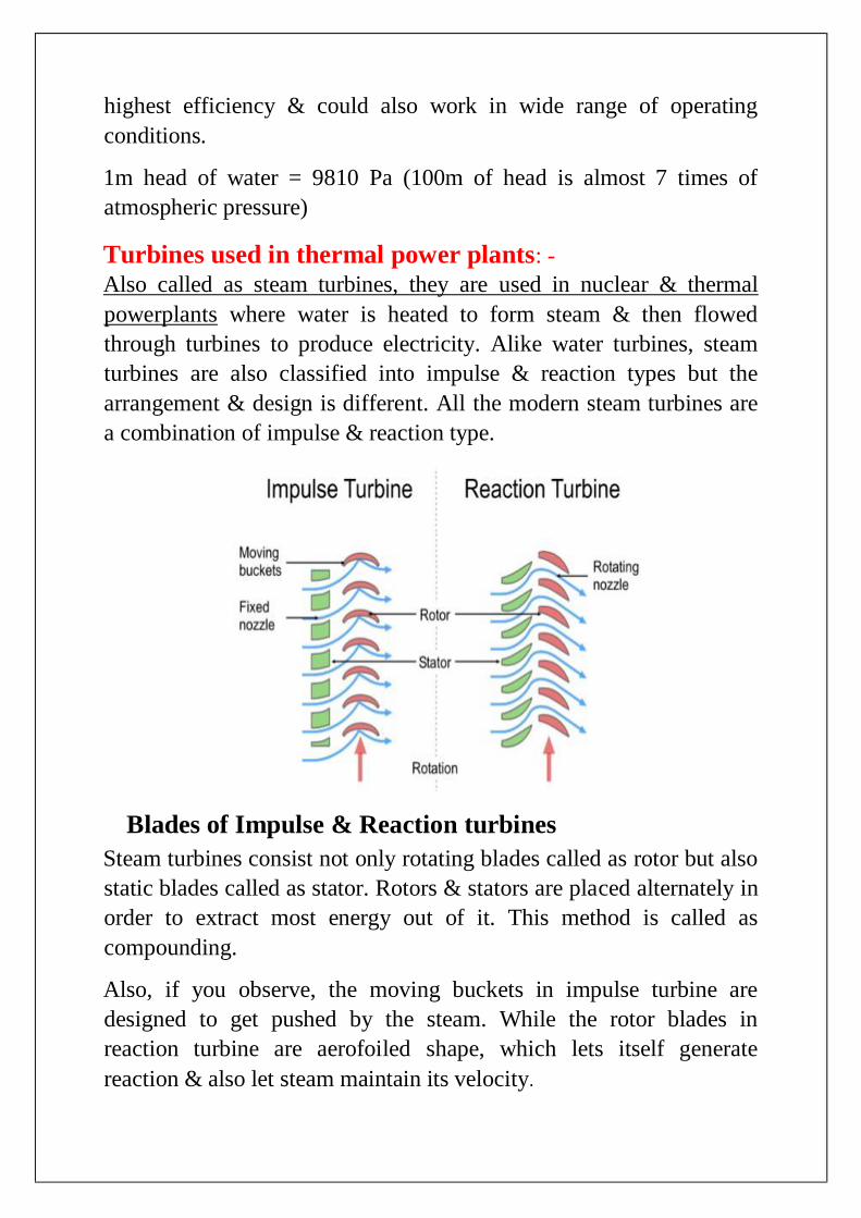
Blades of Impulse & Reaction turbines
Steam turbines consist not only rotating blades called as rotor but also
static blades called as stator. Rotors & stators are placed alternately in
order to extract most energy out of it. This method is called as
compounding.
Also, if you observe, the moving buckets in impulse turbine are
designed to get pushed by the steam. While the rotor blades in
reaction turbine are aerofoiled shape, which lets itself generate
reaction & also let steam maintain its velocity.
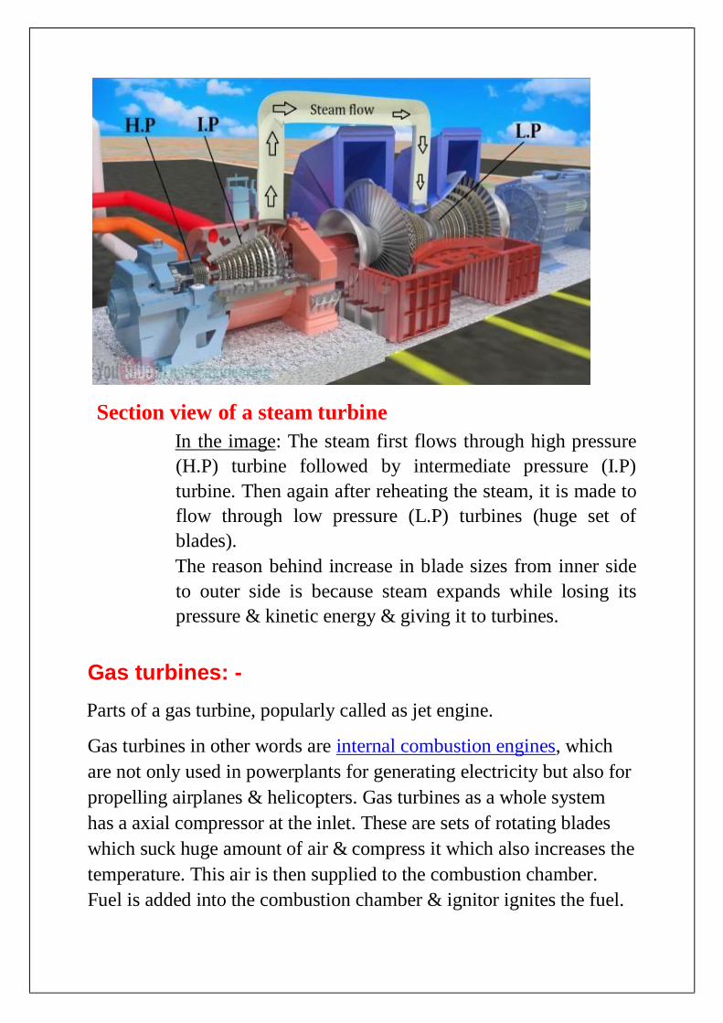
Section view of a steam turbine
In the image: The steam first flows through high pressure
(H.P) turbine followed by intermediate pressure (I.P)
turbine. Then again after reheating the steam, it is made to
flow through low pressure (L.P) turbines (huge set of
blades).
The reason behind increase in blade sizes from inner side
to outer side is because steam expands while losing its
pressure & kinetic energy & giving it to turbines.
Gas turbines: -
Parts of a gas turbine, popularly called as jet engine.
Gas turbines in other words are internal combustion engines, which
are not only used in powerplants for generating electricity but also for
propelling airplanes & helicopters. Gas turbines as a whole system
has a axial compressor at the inlet. These are sets of rotating blades
which suck huge amount of air & compress it which also increases the
temperature. This air is then supplied to the combustion chamber.
Fuel is added into the combustion chamber & ignitor ignites the fuel.

Thus, large amount of exhaust gases is produced which are made to
flow through turbines.
The different types of gas turbines/jet engines are –
1. Turbojet
2. Turbofan
3. Turbojet
4. Turboshaft
5. Ramjet
WIND TURBINE
Wind turbines are a boon to mankind- affordable, clean & sustainable.
Some windfarms are so big that they could produce 50MW of power.
Well, coming to working of wind turbines, the story remains same as
other turbines. The rotor has 3 blades & are designed in such a way
that when wind flows straight through them, they start rotating. The
only problem here is wind turbines rotate at a very low of RPM. The
low RPM doesn’t produce electricity of required frequency & that is
why we require a gearbox which increases the speed of shaft. The
output shaft is then connected to the generator.
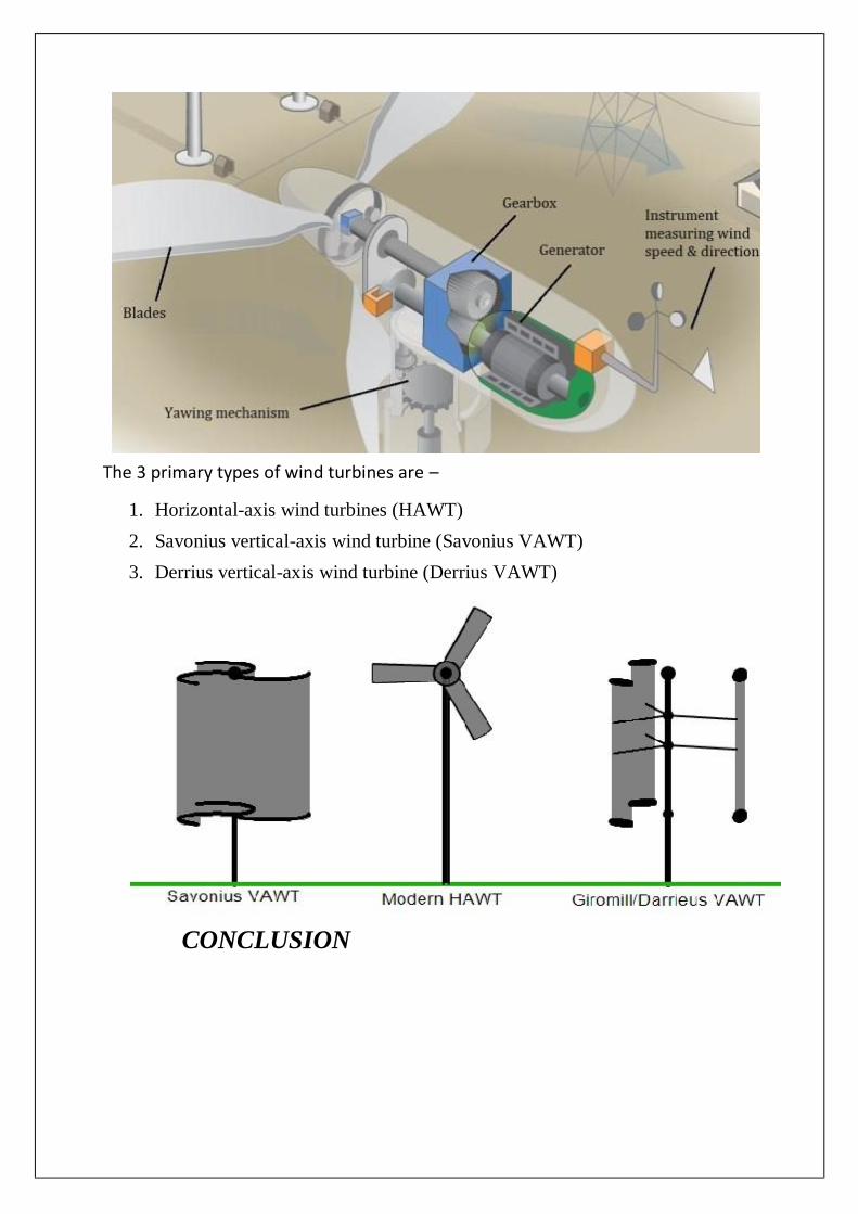
The 3 primary types of wind turbines are –
1. Horizontal-axis wind turbines (HAWT)
2. Savonius vertical-axis wind turbine (Savonius VAWT)
3. Derrius vertical-axis wind turbine (Derrius VAWT)
CONCLUSION

From this assignment I would conclude that pumps and turbines play
a vital role in engineering field, both been a key player in science and
technology advancement which has mainly helped the mankind with
its application in domestic use and in other fields like in agriculture,
firefighting, lifting water from tanks.
While turbines have helped in power generation using steam, water
and wind which is a natural convention of energy freely available in
nature.
Thank you, for giving me an opportunity to do this assignment.
Regards
Shashank.k

INTERNSHIP ALLOCATION REPORT 2019-20
Name of the Department: BE MARINE ENGINEERING
(In view of advisory from the AICTE, internships for the year 2019-20 are offered by the
Department itself to facilitate the students to take up required work from their home itself
during the lock down period due to COVID-19 outbreak)
Name of the Programme: MARINE ENGINEERING
Year of study and Batch/Group : 2nd YEAR BE (ME)18 G-05
Name of the Mentor: MR. HARISH KUMAR J
Title of the assigned internship:
FUEL AND LUBRICATION TECHNOLOGY
Nature of Internship : Individual
Reg No of Cadet who is assigned with this internship:
AME18170
Total No. of Hours Required to complete the Internship: 45 HOURS
Signature of the Mentor
Signature of the Internal
Examiner
Signature of HoD/Programme
Head
INTERNSHIP EVALUATION REPORT 2019-20
Name of the Department: Marine Engineering
(In view of advisory from the AICTE, internships for the year 2019-20 are offered by the
Department itself to facilitate the students to take up required work from their home itself
during the lock down period due to COVID-19 outbreak)
Name of the Student DHRUVA R SHETTY
Register No and Roll No AME18170
2844B
Programme of study FUEL AND LUBRICATION TECHNOLOGY
Year and Batch/Group 2nd YEAR BEME18 G-05
Semester IV
Title of Internship PUMPS
TURBINES
Duration of Internship 45 Hours
Mentor of the Student MR. HARISH KUMAR J

Evaluation by the Department
Sl
No. Criterion Max. Marks Marks Allotted
1 Regularity in maintenance of the diary. 10
2 Adequacy & quality of information recorded 10
3 Drawings, sketches and data recorded 10
4 Thought process and recording techniques used 5
5 Organization of the information 5
6 Originality of the Internship Report 20
7 Adequacy and purposeful write-up of the Internship
Report 10
8 Organization, format, drawings, sketches, style,
language etc. of the Internship Report 10
9 Practical applications, relationships with basic theory
and concepts 10
10 Presentation Skills 10
Total 100
Signature of the Mentor Signature of the Internal
Examiner
Signature of HoD/Programme
Head
1
LEIDEN FROST EFFECT
AN INTERNSHIP REPORT
SUBMITTED
BY
BALAJI PRASAD. N (AME18142)
BE(ME) - 18
ACADEMY OF MARITIME EDUCATION AND TRAINING (AMET)
(Declared as Deemed to be University u/s 3 of UGC Act 1956)
135, EAST COAST ROAD, KANATHUR, CHENNAI - 603 112.
TAMILNADU, INDIA
INTERNSHIP AT HOME
A Report On Internship
In
Department of BE MARINE ENGINEERING
By
Name: Balaji Prasad. N
Register Number: AME18142
Roll No: 2816B
Year: 2nd YEAR
Batch: BE (ME)-18
Group: 4
Subject Code: UDME405
Subject: FLUID MECHANICS
CERTIFICATE
This is to certify that the project entitled “Leiden frost effect” is to bo-
nafide work carried out by the students of AMET UNIVERSITY, KANATHUR (CHENNAI) during the year 2019 -2020 for the partial ful-
fillment of the requirements for the award of the Degree of Bachelor of a
Marine Engineering.
INTERNAL GUIDE EXTERNAL EXAMINER
HEAD OF THE DEPARTMENT
PLACE : AMET UNIVERSITY BE MARINE ENGINEERING

INTRODUCTION
We are going to go through the subject fluid mechanics. We are going to go
through the topics of
LEIDENFROST POINT
HEAT TRANFER CORRELATIONS
PRESSURE FIELD IN LEIDENFROST DROPLET
LEIDENFROST TEMPRATURE AND SURFACE TENTION EFFECT
REACTIVE LEIDENFROST EFFECT
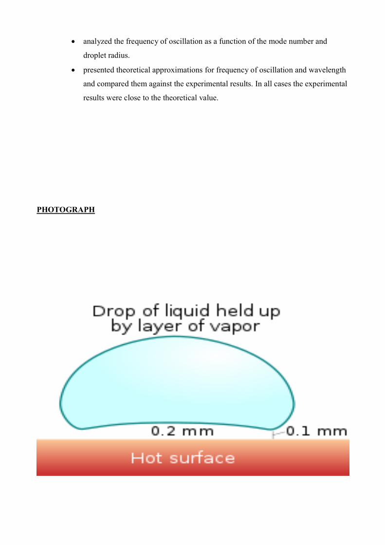
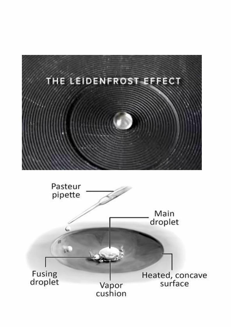
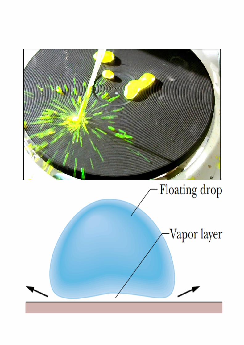
The Leiden frost effect is a physical phenomenon in which a liquid, close to a surface that is
significantly hotter than the liquid's boiling point produces an insulating vapor layer that keeps
the liquid from boiling rapidly. Because of this 'repulsive force', a droplet hovers over the
surface rather than making physical contact with the hot surface.
LEIDENFROST POINT
• The Leidenfrost point signifies the onset of stable film boiling.
• It represents the point on the boiling curve where the heat flux is at the minimum and
the surface is completely covered by a vapor blanket.
• Heat transfer from the surface to the liquid occurs by conduction and radiation through
the vapor. In 1756, Leidenfrost observed that water droplets supported by the vapor film
slowly evaporate as they move about on the hot surface.
• As the surface temperature is increased, radiation through the vapor film becomes more
significant and the heat flux increases with increasing excess temperature.
IN DETAIL
• The effect can be seen as drops of water are sprinkled onto a pan at various times as it
heats up. Initially, as the temperature of the pan is just below 100 °C (212 °F), the water
flattens out and slowly evaporates, or if the temperature of the pan is well below 100 °C
(212 °F), the water stays liquid. As the temperature of the pan goes above 100 °C
(212 °F), the water droplets hiss when touching the pan and these droplets evaporate
quickly. Later, as the temperature exceeds the Leidenfrost point, the Leidenfrost effect
comes into play. On contact with the pan, the water droplets bunch up into small balls of
water and skitter around, lasting much longer than when the temperature of the pan was
lower. This effect works until a much higher temperature causes any further drops of
water to evaporate too quickly to cause this effect.
• This is because at temperatures above the Leidenfrost point, the bottom part of the water
droplet vaporizes immediately on contact with the hot pan. The resulting gas suspends
the rest of the water droplet just above it, preventing any further direct contact between
the liquid water and the hot pan. As steam has much poorer thermal conductivity than
the metal pan, further heat transfer between the pan and the droplet is slowed down dra-
matically. This also results in the drop being able to skid around the pan on the layer of
gas just under it.
• The temperature at which the Leidenfrost effect begins to occur is not easy to predict.
Even if the volume of the drop of liquid stays the same, the Leidenfrost point may be
quite different, with a complicated dependence on the properties of the surface, as well
as any impurities in the liquid. Some research has been conducted into a theoretical
model of the system, but it is quite complicated. As a very rough estimate, the Lei-
denfrost point for a drop of water on a frying pan might occur at 193 °C (379 °F).
• The effect was also described by the eminent Victorian steam boiler designer, Sir Wil-
liam Fairbairn, in reference to its effect on massively reducing heat transfer from a hot
iron surface to water, such as within a boiler. In a pair of lectures on boiler design,he cit-
ed the work of Pierre Hippolyte Boutigny (1798-1884) and Professor Bowman of King's
College, London in studying this. A drop of water that was vaporized almost immediate-ly at 168 °C (334 °F) persisted for 152 seconds at 202 °C (396 °F). Lower temperatures
in a boiler firebox might evaporate water more quickly as a result; compare Mpemba ef-
fect. An alternative approach was to increase the temperature beyond the Leidenfrost
point. Fairbairn considered this too, and may have been contemplating the flash steam
boiler, but considered the technical aspects insurmountable for the time.
• The Leidenfrost point may also be taken to be the temperature for which the hovering
droplet lasts longest.
• It has been demonstrated that it is possible to stabilize the Leidenfrost vapour layer of
water by exploiting superhydrophobic surfaces. In this case, once the vapour layer is es-
tablished, cooling never collapses the layer, and no nucleate boiling occurs; the layer in-
stead slowly relaxes until the surface is cooled.
• Leidenfrost effect has been used for the development of high sensitivity ambient mass
spectrometry. Under the influence of Leidenfrost condition the levitating droplet does
not release molecules out and the molecules are enriched inside the droplet. At the last
moment of droplet evaporation all of the enriched molecules release in a short time do-
main and thus increase the sensitivity
• A heat engine based on the Leidenfrost effect has been prototyped. It has the advantage
of extremely low frictio
ZUBER’S EQUATIONS
The minimum heat flux for a large horizontal plate can be derived from Zuber's equation
Where the properties are evaluated at saturation temperature. Zuber's constant, C is approxi-
mately 0.09 for most fluids at moderate pressures.
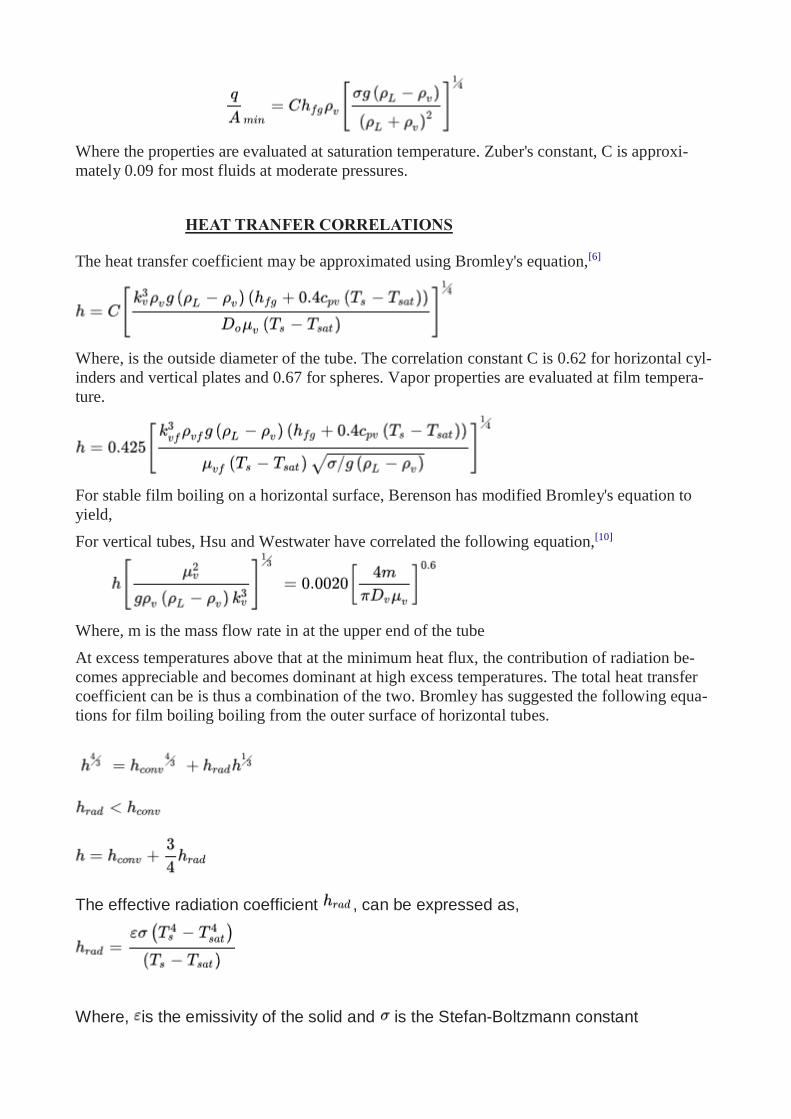
HEAT TRANFER CORRELATIONS
The heat transfer coefficient may be approximated using Bromley's equation,[6]
Where, is the outside diameter of the tube. The correlation constant C is 0.62 for horizontal cyl-
inders and vertical plates and 0.67 for spheres. Vapor properties are evaluated at film tempera-
ture.
For stable film boiling on a horizontal surface, Berenson has modified Bromley's equation to
yield,
For vertical tubes, Hsu and Westwater have correlated the following equation,[10]
Where, m is the mass flow rate in at the upper end of the tube
At excess temperatures above that at the minimum heat flux, the contribution of radiation be-
comes appreciable and becomes dominant at high excess temperatures. The total heat transfer
coefficient can be is thus a combination of the two. Bromley has suggested the following equa-
tions for film boiling boiling from the outer surface of horizontal tubes.
The effective radiation coefficient , can be expressed as,
Where, is the emissivity of the solid and is the Stefan-Boltzmann constant
Pressure field in a Leidenfrost droplet
The equation for the pressure field in the vapor region between the droplet and the solid surface
can be solved for using the standard momentum and continuity equations. For the sake of
simplicity in solving, a linear temperature profile and a parabolic velocity profile are assumed
within the vapor phase. The heat transfer within the vapor phase is assumed to be through
conduction. With these approximations, the Navier-Stokes equation can be solved to get the
pressure field.
Continuity equation
A continuity equation in physics is an equation that describes the transport of some
quantity. It is particularly simple and powerful when applied to a conserved quantity, but
it can be generalized to apply to any extensive quantity.
Since mass, energy, momentum, electric charge and other natural quantities are con-
served under their respective appropriate conditions, a variety of physical phenomena
may be described using continuity equations.
Continuity equations are a stronger, local form of conservation laws. For example, a
weak version of the law of conservation of energy states that energy can neither be cre-
ated nor destroyed—i.e., the total amount of energy in the universe is fixed.
This statement does not rule out the possibility that a quantity of energy could disappear
from one point while simultaneously appearing at another point. A stronger statement is
that energy is locally conserved: energy can neither be created nor destroyed, nor can it
"teleport" from one place to another—it can only move by a continuous flow.
A continuity equation is the mathematical way to express this kind of statement. For ex-
ample, the continuity equation for electric charge states that the amount of electric
charge in any volume of space can only change by the amount of electric current flowing
into or out of that volume through its boundaries
Vapour
In physics, a Vapour and is a substance in the gas phase at a temperature lower than
its critical temperature, which means that the vapor can be condensed to a liquid by in-
creasing the pressure on it without reducing the temperature. A vapor is different from
an aerosol.
An aerosol is a suspension of tiny particles of liquid, solid, or both within a gas.
For example, water has a critical temperature of 647 K (374 °C; 705 °F), which is the
highest temperature at which liquid water can exist.
In the atmosphere at ordinary temperatures, therefore, gaseous water (known as water
vapor) will condense into a liquid if its partial pressure is increased sufficiently.
A vapor may co-exist with a liquid (or a solid). When this is true, the two phases will be
in equilibrium, and the gas-partial pressure will be equal to the equilibrium vapor pres-
sure of the liquid (or solid)
Thermal conduction
Thermal conduction is the transfer of internal energy by microscopic collisions of par-
ticles and movement of electrons within a body.
The colliding particles, which include molecules, atoms and electrons, transfer disor-
ganized microscopic kinetic and potential energy, jointly known as internal energy.
Conduction takes place in all phases: solid, liquid, and gas. The rate at which energy is
conducted as heat between two bodies depends on the temperature difference (and
hence temperature gradient) between the two bodies and the properties of the conductive
interface through which the heat is transferred.
Heat spontaneously flows from a hotter to a colder body. For example, heat is conducted
from the hotplate of an electric stove to the bottom of a saucepan in contact with it.
In the absence of an opposing external driving energy source, within a body or between
bodies, temperature differences decay over time, and thermal equilibrium is approached,
temperature becoming more uniform.
LEIDENFROST TEMPRATURE AND SURFACE TENTION EFFECT
The Leidenfrost temperature is the property of a given set of solid-liquid pair. The
temperature of the solid surface beyond which the liquid undergoes Leidenfrost
phenomenon is termed as Leidenfrost temperature.
The calculation of Leidenfrost temperature involves the calculation of minimum film
boiling temperature of a fluid. Berenson obtained a relation for the minimum film boiling temperature from minimum heat flux arguments.
While the equation for the minimum film boiling temperature, which can be found in the
reference above, is quite complex, the features of it can be understood from a physical
perspective. One critical parameter to consider is the surface tention
The proportional relationship between the minimum film boiling temperature and
surface tension is to be expected since fluids with higher surface tension need higher
quantities of heat flux for the onset of nucleate boling.
Since film boiling occurs after nucleate boiling, the minimum temperature for film
boiling should have a proportional dependence on the surface tension. Henry developed a model for Leidenfrost phenomenon which includes transient wetting
and micro layer evaporation.
Since the Leidenfrost phenomenon is a special case of film boiling, the Leidenfrost
temperature is related to the minimum film boiling temperature via a relation which
factors in the properties of the solid being used.
While the Leidenfrost temperature is not directly related to the surface tension of the
fluid, it is indirectly dependent on it through the film boiling temperature. For fluids with
similar thermo physical properties, the one with higher surface tension usually has a
higher Leidenfrost temperature.
For example, for a saturated water-copper interface, the Leidenfrost temperature is 257 °C (495 °F). The Leidenfrost temperatures for glycerol and common alcohols are
significantly smaller because of their lower surface tension values
Surface tension
Surface tension is the tendency of liquid surfaces to shrink into the minimum surface
area possible. Surface tension allows insects (e.g. water striders), usually denser than
water, to float and slide on a water surface.
At liquid–air interfaces, surface tension results from the greater attraction of liquid mol-
ecules to each other (due to cohesion) than to the molecules in the air (due to adhesion).
The net effect is an inward force at its surface that causes the liquid to behave as if its
surface were covered with a stretched elastic membrane.
Thus, the surface comes under tension from the imbalanced forces, which is probably
where the term "surface tension" came from. Because of the relatively high attraction of
water molecules to each other through a web of hydrogen bonds, water has a higher sur-
face tension (72.8 millinewtons per meter at 20 °C) than most other liquids.
Surface tension is an important factor in the phenomenon of capillarity.
Surface tension has the dimension of force per unit length, or of energy per unit area.
The two are equivalent, but when referring to energy per unit of area, it is common to
use the term surface energy, which is a more general term in the sense that it applies also
to solids.
Nucleate boiling
Nucleate boiling is a type of boiling that takes place when the surface temperature is
hotter than the saturated fluid temperature by a certain amount but where the heat flux is
below the critical heat flux.
For water, as shown in the graph below, nucleate boiling occurs when the surface
temperature is higher than the saturation temperature (TS) by between 10 °C (18 °F) to
30 °C (54 °F). The critical heat flux is the peak on the curve between nucleate boiling
and transition boiling.
The heat transfer from surface to liquid is greater than that in film boiling.
Two different regimes may be distinguished in the nucleate boiling range. When the
temperature difference is between approximately 4 °C (7.2 °F) to 10 °C (18 °F) above
TS, isolated bubbles form at nucleation sites and separate from the surface.
This separation induces considerable fluid mixing near the surface, substantially increas-
ing the convective heat transfer coefficient and the heat flux. In this regime, most of the
heat transfer is through direct transfer from the surface to the liquid in motion at the sur-
face and not through the vapor bubbles rising from the surface.
Between 10 °C (18 °F) and 30 °C (54 °F) above TS, a second flow regime may be ob-
served. As more nucleation sites become active, increased bubble formation caus-
es bubble interference and coalescence. In this region the vapor escapes as jets or col-
umns which subsequently merge into slugs of vapor.
Interference between the densely populated bubbles inhibits the motion of liquid near the
surface. This is observed on the graph as a change in the direction of the gradient of the
curve or an inflection in the boiling curve.
After this point, the heat transfer coefficient starts to reduce as the surface temperature is
further increased although the product of the heat transfer coefficient and the tempera-
ture difference (the heat flux) is still increasing.
When the relative increase in the temperature difference is balanced by the relative re-
duction in the heat transfer coefficient, a maximum heat flux is achieved as observed by
the peak in the graph. This is the critical heat flux.
At this point in the maximum, considerable vapor is being formed, making it difficult for
the liquid to continuously wet the surface to receive heat from the surface. This causes the heat flux to reduce after this point. At extremes, film boiling commonly known as
the Leidenfrost effect is observed.
The process of forming steam bubbles within liquid in micro cavities adjacent to the wall
if the wall temperature at the heat transfer surface rises above the saturation tempera-
ture while the bulk of the liquid (heat exchanger) is sub cooled. The bubbles grow until
they reach some critical size, at which point they separate from the wall and are carried
into the main fluid stream. There the bubbles collapse because the temperature of bulk fluid is not as high as at the heat transfer surface, where the bubbles were created. This
collapsing is also responsible for the sound a water kettle produces during heat up but
before the temperature at which bulk boiling is reached.
Heat transfer and mass transfer during nucleate boiling have a significant effect on the
heat transfer rate. This heat transfer process helps quickly and efficiently to carry away
the energy created at the heat transfer surface and is therefore sometimes desirable—for
example in nuclear power plants, where liquid is used as a coolant.
Viscosity
The viscosity of a fluid is a measure of its resistance to deformation at a given rate. For
liquids, it corresponds to the informal concept of "thickness": for example, syrup has a
higher viscosity than water.
Viscosity can be conceptualized as quantifying the internal frictional force that arises be-
tween adjacent layers of fluid that are in relative motion. For instance, when a fluid is
forced through a tube, it flows more quickly near the tube's axis than near its walls. In
such a case, experiments show that some stress (such as a pressure difference between
the two ends of the tube) is needed to sustain the flow through the tube.
This is because a force is required to overcome the friction between the layers of the flu-
id which are in relative motion: the strength of this force is proportional to the viscosity.
A fluid that has no resistance to shear stress is known as an ideal or in viscid fluid. Zero
viscosity is observed only at very low temperatures in superfluids.
Otherwise, the second law of thermodynamics requires all fluids to have positive viscos-
ity; such fluids are technically said to be viscous or viscid. A fluid with a high viscosity,
such as pitch, may appear to be a solid.
REACTIVE LEIDENFROST EFFECT
Non-volatile materials were discovered in 2015 to also exhibit a 'reactive Leidenfrost
effect,' whereby solid particles were observed to float above hot surfaces and skitter
around erratically. Detailed characterization of the reactive Leidenfrost effect was
completed for small particles of cellulose (~0.5 mm) on high temperature polished surfaces by high speed photography. Cellulose was shown to decompose to short-chain
oligomers which melt and wet smooth surfaces with increasing heat transfer associated
with increasing surface temperature.
Above 675 °C (1,247 °F), cellulose was observed to exhibit transition boiling with
violent bubbling and associated reduction in heat transfer. Lift-off of the cellulose
droplet (depicted at the right) was observed to occur above about 750 °C (1,380 °F)
associated with a dramatic reduction in heat transfer.
High speed photography of the reactive Leidenfrost effect of cellulose on porous
surfaces (macro porous) was also shown to suppress the reactive Leidenfrost effect and
enhance overall heat transfer rates to the particle from the surface.
The new phenomenon of a 'reactive Leidenfrost (RL) effect' was characterized by a dimensionless quantity (φRL= τconv/τrxn), which relates the time constant of solid particle
heat transfer to the time constant of particle reaction, with the reactive Leidenfrost effect
occurring for 10−1< φRL< 10+1.
The reactive Leidenfrost effect with cellulose will occur in numerous high temperature
applications with carbohydrate polymers including biomass conversion to biofuels,
preparation and cooking of food, and tobacco use.
Cellulose
Cellulose is an organic compound with the formula a polysaccharide consisting of a lin-
ear chain of several hundred to many thousands of β(1→4) linked D-
glucose units. Cellulose is an important structural component of the primary cell
wall of green plants, many forms of algae and the oomycetes.
Some species of bacteria secrete it to form biofilms. Cellulose is the most abun-
dant organic polymer on Earth. The cellulose content of cotton fiber is 90%, that
of wood is 40–50%, and that of dried hemp is approximately 57%.
Cellulose is mainly used to produce paperboard and paper. Smaller quantities are con-
verted into a wide variety of derivative products such as cellophane and rayon.
Conversion of cellulose from energy crops into biofuels such as cellulosic ethanol is un-
der development as a renewable fuel source.
Cellulose for industrial use is mainly obtained from wood pulp and cotton.
Some animals, particularly ruminants and termites, can digest cellulose with the help
of symbiotic micro-organisms that live in their guts, such as Trichonympha.
In human nutrition, cellulose is a non-digestible constituent of insoluble dietary fiber,
acting as a hydrophilic bulking agent for feces and potentially aiding in defecation.
Oligomer
An oligomer is a molecular complex of chemicals that consists of a few repeating units,
in contrast to a polymer, where the number of monomers is, in principle, infi-
nite. Dimers, trimers, and tetramers are, for instance, oligomers composed of two, three,
and four monomers, respectively.
In biochemistry, an oligomer usually is a macromolecular complex formed by non-
covalent bonding of a few macromolecules like proteins or nucleic acids.
In this sense, a homo-oligomer would be formed of a few identical molecules and by
contrast, a hetero-oligomer would be made of more than one, different, macromole-cules. An example of a homo-oligomeric protein is collagen, which is composed of three
identical protein chains. The term is used with a meaning similar to that of oligomer in
the context of proteins
Many oils are oligomeric, such as liquid paraffin. Plasticizers are oligomer-
ic esters widely used to soften thermoplastics such as PVC. They may be made
from monomers by linking them together, or by separation from the higher fractions
of crude oil.
Polybutene is an oligomeric oil used to make putty. Greek prefixes are often used to des-
ignate the number of monomer units in the oligomer, for example, a tetramer being
composed of four units and a hexamer of six.
In biochemistry, the term oligonucleotide – or, informally, "oligo" – is used for short, single-stranded nucleic acid fragments, such as DNA or RNA, or similar fragments of
analogs of nucleic acids such as peptide nucleic acid or Morpholinos.
Such oligos are used in hybridization experiments (bound to glass slides
or nylon membranes), as probes for in situ hybridization or in antisense experiments
such as gene knockdowns. It can also refer to a protein complex made of two or
more subunits.
In this case, a complex made of several different protein subunits is called a hetero-
oligomer or heteromer. When only one type of protein subunit is used in the complex, it
is called a homo-oligomer or homomer.
Biofuel

A biofuel is a fuel that is produced through contemporary processes from biomass, ra-
ther than a fuel produced by the very slow geological processes involved in the for-
mation of fossil fuels, such as oil.
Since biomass technically can be used as a fuel directly (e.g. wood logs), some people
use the terms biomass and biofuel interchangeably.
More often than not however, the word biomass simply denotes the biological raw mate-
rial the fuel is made of, or some form of thermally/chemically altered solid end product,
like torrefied pellets or briquettes. The word biofuel is usually reserved for liquid or gas-eous fuels, used for transportation. The EIA (U.S. Energy Information Administration)
follow this naming practice.
If the biomass used in the production of biofuel can regrow quickly, the fuel is generally
considered to be a form of renewable energy.
Biofuels can be produced from plants (i.e. energy crops), or from agricultural, commer-cial, domestic, and/or industrial wastes (if the waste has a biological origin). Renewable
biofuels generally involve contemporary carbon fixation, such as those that occur
in plants or microalgae through the process of photosynthesis.
Some argue that biofuel can be carbon-neutral because all biomass
crops sequester carbon to a certain extent – basically all crops move CO2 from above-
ground circulation to below-ground storage in the roots and the surrounding soil.
For instance, McCalmont et al. found below-ground carbon accumulation ranging from
0.42 to 3.8 tonnes per hectare per year for soils below Miscanthus x giganteus energy
crops, with a mean accumulation rate of 1.84 tonne (0.74 tonnes per acre per year), or
20% of total harvested carbon per year
However, the simple proposal that biofuel is carbon-neutral almost by definition has been superseded by the more nuanced proposal that for a particular biofuel project to be
carbon neutral, the total carbon sequestered by the energy crop's root system must com-
pensate for all the above-ground emissions (related to this particular biofuel project).
This includes any emissions caused by direct or indirect land use change. Many first
generation biofuel projects are not carbon neutral given these demands. Some have even
higher total GHG emissions than some fossil based alternatives.
Some are carbon neutral or even negative, though, especially perennial crops. The
amount of carbon sequestrated and the amount of GHG (greenhouse gases) emitted will
determine if the total GHG life cycle cost of a biofuel project is positive, neutral or nega-
tive. A carbon negative life cycle is possible if the total below-ground carbon accumula-
tion more than compensates for the total life-cycle GHG emissions above ground. In
other words, to achieve carbon neutrality yields should be high and emissions should be
low.
High-yielding energy crops are thus prime candidates for carbon neutrality. The graphic
on the right displays two CO2 negative Miscanthus x giganteus production pathways,
represented in gram CO2-equivalents per megajoule. The yellow diamonds represent
mean values.
Further, successful sequestration is dependent on planting sites, as the best soils for se-
questration are those that are currently low in carbon.
The varied results displayed in the graph highlights this fact. For the UK, successful se-
questration is expected for arable land over most of England and Wales, with unsuccess-
ful sequestration expected in parts of Scotland, due to already carbon rich soils (existing
woodland) plus lower yields.
Soils already rich in carbon includes peatland and mature FROST. Grassland can also be
carbon rich, however Milner et al.
argues that the most successful carbon sequestration in the UK takes place below im-
proved grasslands.
The bottom graphic displays the estimated yield necessary to compensate for related
lifecycle GHG-emissions. The higher the yield, the more likely CO2 negativity becomes.
The two most common types of biofuel are bioethanol and biodiesel.
Bioethanol is an alcohol made by fermentation, mostly from carbohydrates produced
in sugar or starch crops such as corn, sugarcane, or sweet sorghum. Cellulosic biomass,
derived from non-food sources, such as trees and grasses, is also being developed as
a feedstock for ethanol production.
Ethanol can be used as a fuel for vehicles in its pure form (E100), but it is usually used
as a gasoline additive to increase octane and improve vehicle emissions. Bioethanol is
widely used in the United States and in Brazil.
Biodiesel is produced from oils or fats using transesterification and is the most common
biofuel in Europe. It can be used as a fuel for vehicles in its pure form (B100), but it is
usually used as a diesel additive to reduce levels of particulates, carbon monoxide,
and hydrocarbons from diesel-powered vehicles.
CONCLUSION
Thus, in this presentation we saw about the topics:
➢ LEIDENFROST EFFECT
Water droplets at 4 nm and 10 nm were simulated over gold and silicon substrates
at 293 K and 373 K, respectively. At 293 K, both the droplets remained stationary
on the substrate limiting their displacement from their original position. However,
smaller droplets (4 nm) displayed higher random velocity about their mean
position as compared to the 10 nm droplets.
This can be attributed to the fact that smaller droplets have fewer atoms enabling
higher variability for its centroid due to the smaller aggregation pool. The
Leidenfrost effect was observed when droplets were deposited on the heated
substrate at 373 K. This result is in contrast with the Leidenfrost effect at the
macro- and micro-scale which is typically observed for temperatures over 473 K.
At 373 K, the 4 nm droplets presented higher propagation velocities than the
10 nm droplets.
This is due to the fact that smaller droplets have a higher surface to volume ratio
which makes the smaller droplets absorb higher energy per unit volume. Also,
molecules at the surface of the droplet have fewer hydrogen bonds and require
less energy to separate from other molecules.
Thus, when exposed to a heated substrate, the breakage of hydrogen bonds is
accelerated on smaller droplets as they possess proportionally fewer hydrogen
bonds. In addition, the smaller droplets have a lower inertia and thereby are
prominently influenced by the propelling forces of the vapor layer.
Droplets deposited over gold substrate had higher velocities than droplets
deposited over silicon. Silicon substrates are more hydrophilic than gold
substrates, and the affinity between liquid and substrate acts as a restrain to the
droplet movement.
These results reveal the interplay of different process parameters which impact
the Leidenfrost effect, an unexplored phenomenon at the nanoscale.
This research forms a foundation to understand nanoscale droplet propagation
and heat transfer within several droplet based nano- and micro-manufacturing
processes.
This work presented a theoretical background on the Leidenfrost effect and
performed experiments and measurements of the Leidenfrost effect on water
droplets on a hot plate.
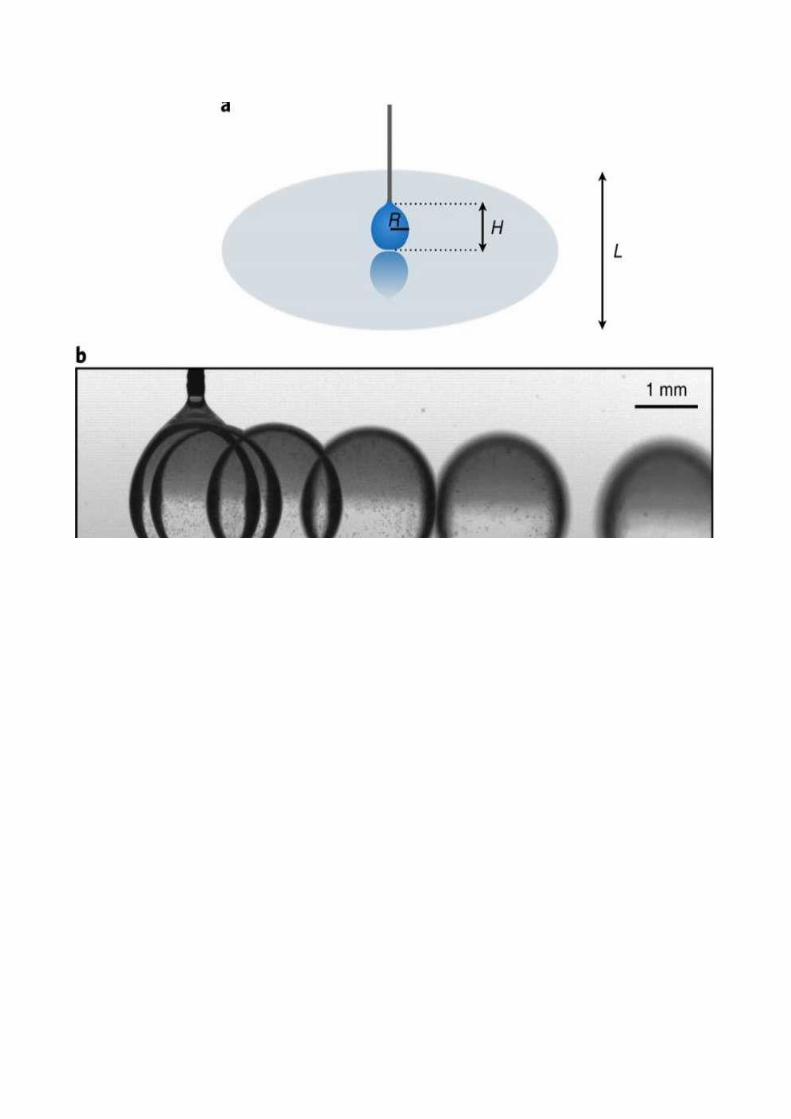
Relationship between Oscillation Frequecny and Radii for droplets under three
different oscillation modes . Frequency as a function of wavelength were
compared against the theoretical approximations.
analyzed the heat transfer mechanisms that occur in the droplet using Rayleigh’s
number and found them to be primarily convection.
We also investigated the droplets geometry based on their Bond numbers,
characterizing them as either spherical or cylindrical.
experimentally induced the oscillations using a mechanical impulse generator
which allowed us to induce several different oscillation modes.
analyzed the frequency of oscillation as a function of the mode number and
droplet radius.
presented theoretical approximations for frequency of oscillation and wavelength
and compared them against the experimental results. In all cases the experimental
results were close to the theoretical value.
PHOTOGRAPH


INTERNSHIP ALLOCATION REPORT 2019-20
Name of the Department: BE MARINE ENGINEERING
(In view of advisory from the AICTE, internships for the year 2019-20 are offered by the
Department itself to facilitate the students to take up required work from their home itself
during the lock down period due to COVID-19 outbreak)
Name of the Programme: MARINE ENGINEERING
Year of study and Batch/Group: 2nd YEAR BE (ME) 18 G-4
Name of the Mentor: HARISH KUMAR. J
Title of the assigned internship:
FLUIED MECHANICS
Nature of Internship: Individual
Reg No of Students who are assigned with this internship:
AME18142
Total No. of Hours Required to complete the Internship: 45 HOURS
Signature of the Mentor
Signature of the Internal
Examiner
Signature of
HOD/Programme Head

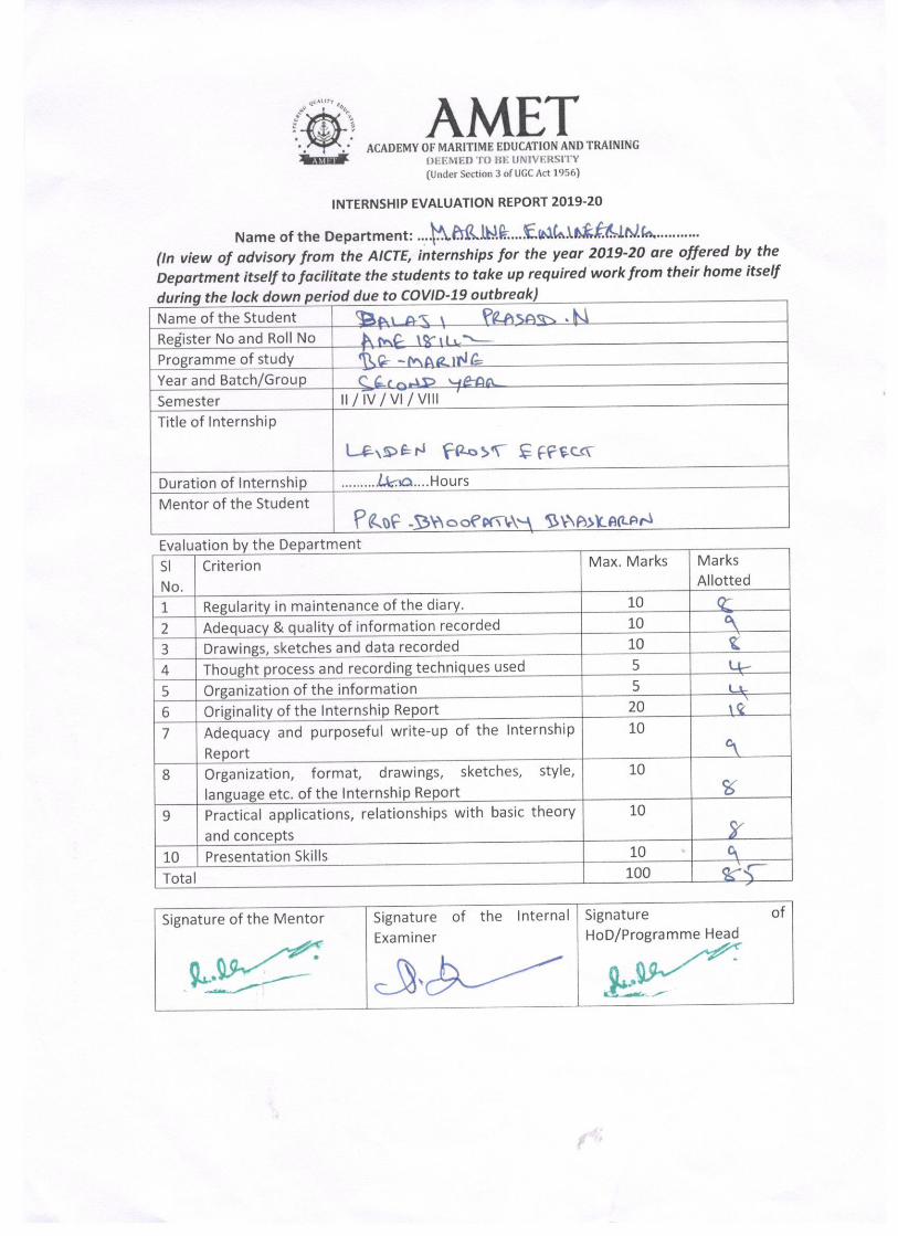
INTERNSHIP EVALUATION REPORT 2019-20
Name of the Department: Marine Engineering
(In view of advisory from the AICTE, internships for the year 2019-20 are offered by the
Department itself to facilitate the students to take up required work from their home itself
during the lock down period due to COVID-19 outbreak)
Name of the Student BALAJI PRASAD.N
Register No and Roll No AME18142
2816B
Programme of study FLUID MECHANICS
Year and Batch/Group 2nd YEAR BE (ME)18 G-4
Semester IV
Title of Internship LEIDENFROST EFFECT
Duration of Internship 45 Hours
Mentor of the Student MR.J. HARISH KUMAR

Evaluation by the Department
Sl
No. Criterion Max. Marks
Marks
Allotted
1 Regularity in maintenance of the diary. 10
2 Adequacy & quality of information recorded 10
3 Drawings, sketches and data recorded 10
4 Thought process and recording techniques used 5
5 Organization of the information 5
6 Originality of the Internship Report 20
7 Adequacy and purposeful write-up of the Internship
Report 10
8 Organization, format, drawings, sketches, style,
language etc. of the Internship Report 10
9 Practical applications, relationships with basic theory
and concepts 10
10 Presentation Skills 10
Total 100
Signature of the Mentor
Signature of the Internal
Examiner
Signature of
HOD/Programme Head