propane powered floor maintenance machines … this manual is furnished with each new propane...
TRANSCRIPT

Propane PoweredFloor
Maintenance Machines
OPERATION MANUAL

OPERATION
Copyright © 2001 Eagle Solutions LLC.
All rights reserved.
Reproduction or translation of any part of this work is beyond that permitted by section 107 or 108 of the 1976 Unites States Copyright Act without the permission ofthe copyright owner is unlawful. Requests for permission or further information should be addressed to thePermission Department, Eagle Solutions LLC. PO Box 443 Adairsville GA. 30103
This publication is designed to provide accurate and authoritative information in regard to the subject matter covered. It is provided with the understanding that thepublisher is not engaged in rendering legal or other professional services.
1. Check fuel cylinder for overfill before taking it into the building or placing it in storage.
2. Install fuel cylinder in a well ventilated place.
2. Be aware of possible leaks of propane gas if odor is present.
3. Check carburetor air filter for cleanness before starting engine.
4. Never run the engine with the throttle in the choke position.
5. Never leave the machine unattended while the engine is running.
6. If the machine is stored inside the building, remove the fuel cylinder & store properly outside.
7. Secure cylinders when being transported. If attached to the machine service valves should be OFF.
8. Never store fuel cylinders in your van where they me be exposed to high temperature.
9. Maintain the propane powered floor machine as directed by the manufacturer.
10. Only trained operators should be allowed to operate propane powered floor machines.
Propane Powered Floor Machine Operation Manual Rev. 5-2001 2
PRECAUTIONARY INSTRUCTIONS
This symbol is used throughout this manual to warn of hazards or unsafe practices whichcould result in personal injury to yourself or others.
ATTENTION! Please read and follow all the instructions in this manual as well as the"Safety Awareness Manual" included in the documentation shipped with this machine beforeoperating the machine.
OPERATION
This manual is furnished with each new propanepowered floor machine. It provides necessary operationand maintenance instructions. Read and understandthe information in this manual before operating orservicing this machine!Additional copies may be ordered through CustomerService.
When ordering replacement parts use the standardParts list in this manual. Before ordering parts orsupplies, be sure to have your machine model numberand serial number handy. Parts and supplies may beordered by phone, Fax, or mail from any AuthorizedService Center or Distributor.
You have purchased one of the finest floor machinesengineered and manufactured. It will provide excellentservice for years to come. However the best results willbe obtained if:
1. The machine is operated with reasonable care.
2. The machine is maintained regularly assuggested by the manufacturer.
TABLE OF CONTENTSPRECAUTIONARY INSTRUCTIONS....................... 2 LIFE OF MACHINE..............................10SAFETY PRECAUTIONS.......................................... 4 FUEL SYSTEM.....................................10MACHINE SETUP......................................................5 CHANGING OIL...................................10
OIL LEVEL & FILTERS................................ 5 ADJUSTING BELT TENSION...............10HANDLE ADJUSTMENT.............................. 5 FILLING AND STORING CYLINDERS............11INSTALLING FUEL CYLINDER...................5 FILLING.................................................11INSTALLING PAD DRIVER & PADS............5 STORING...............................................11
MACHINE OPERATION.............................................6 STORING MACHINE.........................................11STARTING ENGINE.......................................6 TRANSPORTING MACHINE.............................11OPERATING THE CLUTCH...........................6 TROUBLE SHOOTING GUIDE..........................12OPERATION OF TRACKER 3000..................6 STANDARD PARTS............................................13OPERATION OF DUST CONTROL...............7OPERATION OF EASY GLOSS SPRAY.........7STOPPING THE ENGINE...............................7EMERGENCY STOPPING..............................7
CONVERTING THE PRIDE 2100 (STRIP/BUFF).......8MAINTENANCE.........................................................9
DAILY.............................................................9WEEKLY.........................................................9MONTHLY......................................................9QUARTERLY..................................................9
Please fill out for future reference.
Model No.
Date of purchase
Serial No.
NOTE: Specification are subject to change without notice.
MACHINE DATA
3Propane Powered Floor Machine Operation Manual Rev. 5-2001

OPERATION
SAFETY PRECAUTIONS
1. This propane fueled machine is intended forcommercial use only. It is designed to clean floors.Do not use the machine other than described in thisOperator Manual.
2. All operators must read, understand & practicefollowing the safety precautions in this section aswell as the "Safety Awareness Manual" included inthe literature packet.
3. Only trained authorized operators shouldoperate propane powered floor machines.
4. Check fuel cylinders for overfill before takingthem into the building or your van. (See page 11 forinstructions).
BEFORE OPERATING THE MACHINE:Check oil levelCheck air filterCheck pad & pad holderAdjust handle heightInstall fuel cylinder in a well ventilated area.
WHILE OPERATING THE MACHINE:
Even though the 89 db sound level is belowOSHA's PEL it is the course of wisdom to wearhearing protection while operating any internalcombustion engine.
If you smell propane gas stop the engine,remove the cylinder and take it outside forinspection.
Be aware of odors other than propane. Toxicemissions are produced by internal combustionengines. Properly maintained engines produce a smallamount of these gasses. Although Carbon Monoxidehas no odor, the hydrocarbons do, and an elevationof the odor may indicate increased CO as well.
4
Do not allow the machine to run unattended exceptfor short times while moving an obstruction.
Exhaust parts are extremely HOT, be carefulnot to allow them to come in contact with anythingor anyone.
Do not attempt to change pads while engine isrunning.
BEFORE LEAVING THE MACHINE:Stop the engine by closing the service valve on thefuel cylinder.
Remove the key from the switch if applicable.
Remove the cylinder from the machine and storeoutside in a secure cabinet. (See page 12)
Inspect and clean air and dust filters.
SERVICING THE MACHINE:Preventive maintenance is the responsibility of theoperator. It includes:1. Checking oil level2. Checking and cleaning air & dust filters3. Keeping the machine clean and lubricated4. Reporting any damage or worn parts.5. See page 9 for service intervals & instructions.
Servicing or adjusting the propane fuelsystem can only be done by a trained service techni-cian!
Never attempt to adjust the fuel system ofa propane engine! If equipped with an emissionmonitoring or control system never attempt todisconnect it or circumvent it!
Propane Powered Floor Machine Operation Manual Rev. 5-2001

OPERATION
MACHINE SETUP
CHECKING OIL LEVEL & FILTERS:Check oil level prior to starting engine. Use specifiedoil if necessary to add. DO NOT OVER FILL OILLEVEL, to do so may cause damage to the engine.
When checking oil refer to the engine manufacturersinstructions for proper way to check the level. Someengines differ in the correct procedure.
Use 10W30 oil. Always check oil daily before usingthe machine.
Be sure the carburetor air filter is free ofdust/oil etc. Dirty air filters is the most frequentcause of elevated toxic emissions.
Check & clean recoil dust filter if necessary (seeengine owners manual)
ADJUSTING HANDLE HEIGHT
The machine is equipped with an adjustable handlefor comfort and use. Most find it necessary to adjustthe handle to "belt height" for optimum control. A9/16 wrench is used to loosen and tighten the pivotpoints..
INSTALLING THE FUEL CYLINDER
5Propane Powered Floor Machine Operation Manual Rev. 5-2001
Consult an authorized distributor to assist you inselecting the correct pad for your specific needs.
Pad driver installation:
1. Tip machine on the right side (dip stick down).
2. Place pad driver on drive shaft and spin pad driverclockwise to install.
Pad Removal & Installation:
1. Tilt machine back on rear caster or service posi-tion.
2. Remove center-lock from pad driver.
3. Remove pad from pad holder.
4. Center new pad on pad driver & secure withcenter-lock ring.
Pad Driver Removal:
1. Apply down pressure on bell of machine deck.
2. Use 3/4" open end wrench on top of drive shaftexposed on top of deck.
3. Strike the wrench with rubber mallet to breakloose the shaft from the pad driver. (Counterclock-wise)
4. Remove pad driver by spinning it off counter-clockwise.
INSTALLING OR REMOVING PAD DRIVERAND PADS
NOTE: For refueling cylinder see Page 11.1. Take machine to a well ventilated area.
2. Check cylinder for overfill. (See page 11)
3. Install cylinder on machine with tank strap.
4. Connect the fuel cylinder to the machine using the "Rego" connection. Tighten "hand-tight". (Be careful not to cross thread the Rego connection)
5. Open the service valve slowly. Be alert for propane leaks.
.6. To remove cylinder reverse procedure.

OPERATION
OPERATING THE ELECTRIC CLUTCHIf equipped with an optional clutch. Move throttle toslow and engage the clutch by squeezing the "triggerswitch" on the operation handle. Move the throttle to3/4 speed, slowly lower the pad to the floor whilewalking forward slowly,
OPERATING THE TRACKER 3000 MODELSTRIPPING MACHINE
6. Push the throttle lever to the choke position andengage the starter. (Either by using the start buttonor by turning the key switch to start if equipped). Donot engage starter for more than 20 seconds at atime, allowing 10-20 seconds between attempts tostart the engine.
7. When engine starts, ease the throttle back torunning position.
NOTE: Do not run engine with throttle inthe choke position! Excessive harmful emissionswill be produced putting you and others in harmsway!
8. Increase throttle to about 3/4 and carefully lowerthe machine pad to the floor while walking forwardslowly.
6Propane Powered Floor Machine Operation Manual Rev. 5-2001
STARTING MACHINE:1. Check the fuel cylinder for overfill. (See page 11)
2. Install cylinder on the machine (See page 5).
3. Place machine on level surface and check forcorrect oil level.
4. Tilt machine back on rear caster.
5. Slowly open the service valve on the fuel cylinder.NOTE: Opening the service valve too quickly maycause the excess flow valve to stop the flow ofpropane. If this occurs, close the service valve, wait afew seconds and re-open it SLOWLY!
NOTE: some models have 110 volt starting, in thiscase it is necessary to use the short cord suppliedwith the machine. Use the necessary precautionswhen using electricity.
ATTENTION: This machine is only as fast as youallow it to be. It is imperative that you keep the floorwet with stripping solution while stripping andremove the sludge quickly and completely. Rinsingthoroughly before recoating with sealer or floorfinish.1. Clear area of all displays. Remove any dust andstickers from floor.
2. Prepare stripping solution according to instruc-tions on the label.
3. Apply solution to the floor using a mop or othermethod of application. KEEP FLOOR WET WITHSOLUTION!
4. Allow 10 minutes or so for solution to penetratefloor coating.
5. Using a "doodle bug" scrape the edges clear offloor finish.
6. Begin stripping with the machine (one pass isgenerally all that is needed).
MACHINE OPERATION
FOR SAFETY: do not operate themachine until you have read & understood thismanual.
CAUTION: Never engage clutch in the fast runposition or with the pad on the floor, this maycause damage to the clutch and the floor!
WARNING! Be careful not to allow themachine to come in contact with loose tiles orother obstruction on the floor. The pad is turningat approximately 2000 RPM. If loose objects arehit by the revolving pad they could become dangerous missiles.

OPERATING THE DUST CONTROL MODEL
For best results the dust control skirt should be set1/4" off the floor.
Dust is collected in cloth bag inside the deck enclo-sure. Do not operate the machine without a bagattached to the dust receptacle.
Remove and empty the bag as frequently as needed.Shake or vacuum the bag before reinstallation.
9. Restart the machine, set the throttle at mediumhigh speed and buff the entire floor to a deep gloss.
NOTE: If pad overloads and leaves marks on thefloor, stop buffing and clean the pad. It may benecessary to use a weaker solution mix.
The Easy Gloss System is a preventive maintenanceprocedure, it does not replace scrubbing and finish-ing.
OPERATION
7. Follow the machine with the recovery of thesludge and damp mop floor.NOTE: Rinse floor thoroughly!
OPERATING THE EASY GLOSS SPRAY SYS-TEM (OPTIONAL)The Easy Gloss Spray System is used to clean, shineand maintain all floors with a simple two step pro-cess.1. Install a clean cleaning pad on the machine.
2. Mix Easy Gloss Solution according to instructionson the label.
3. Fill container on the machine with solution.
4. Dust mop area to be cleaned.
5. Start the machine and set the throttle lever toMEDIUM speed.
6. Pull easy gloss trigger to apply solution. Once thesolution reaches the floor, move the machine forwardat a slow pace. At intervals of every fourth step, pullthe trigger and hold for about 2 seconds.NOTE: If too much solution is applied the wheelswill leave a track, and if too little the floor will notbe cleaned.
7. While applying solution, stay about 3" away fromedges.NOTE: Remove and clean pad every time you refillthe solution tank.8. When the cleaning process is complete, removethe cleaning pad and replace it with a fine polishingpad.
STOPPING THE MACHINE1. Close the service valve on the fuel cylinder whilethe engine is running. This serves to "purge" the fuelsystem of all flammable gas.
2. Tilt the machine back on its rear caster and allowthe engine to run until it stops.
3. Turn the key switch OFF if equipped.
EMERGENCY STOPPINGIn case of an emergency the machine can be broughtto an instant stop by:1. Pull the throttle back to stop position or turn keyswitch to OFF if equipped.
2. Close service valve on the fuel cylinder.
NOTE: The engine may backfire when stopped inthis manner.
3. If the machine is equipped with a "KILLSWITCH", activate the switch.
7Propane Powered Floor Machine Operation Manual Rev. 5-2001
WHILE OPERATING THE MACHINE
WARNING: Exhaust emissions containharmful toxic gasses. The worst being carbonmonoxide. Do not operate the machine in con-fined areas for prolonged times. Always makecertain that adequate ventilation is had.
1. Refer to "SAFETY PRECAUTIONS" on page 4and the Safety Awareness Manual .2. Keep machine moving. Running in one place formore than a few seconds may damage the floor.

OPERATION3. Do not leave the machine unattended while theengine is running for long periods of time. If neces-sary to leave the machine for short periods to move adisplay etc. move the throttle lever to idle positionand tip machine back on the rear caster.
ATTENTION: It is possible to damagethe engine by allowing it to idle for long periodsof time by affecting proper lubrication.
4. It has been the accepted practice to start buffingfrom the right side of the aisles. Most smaller ma-chines are offset to the right to allow buffing close onthat side.
CONVERTING THE PRIDE 2100 MODEL(STRIP BUFFER)
Tools Required:1. 5/8" (16mm) & 3/4" (19mm) open end wrench2. 9/16" wrench3. 15/16" (24mm) deep-well socket & ratchet4. Belt tensioner wrench (provided with machine).5. Rubber mallet.
CONVERTING FROM BUFF TO STRIP MODE1. With machine upright on the floor, loosen mount-ing bolt of belt tensioner on topside of machine deck.(See fig. 8-1)
2. Apply downward pressure with knee on bell ofdeck.
3. Remove pad driver (See page 5)
4. Remove short belt (BX 40) from upper set ofpulleys (small pulley).
5. Replace with long belt (BX 52) for strip mode.Belt must be placed on lower pulleys (larger pulleys).
6. Using belt tensioner wrench provided, tension beltuntil 1/2" slack in belt on long side. Retighten mount-ing bolt on top side of deck.
7. Replace pad driver with stripping pad or attachoptional brush and turn machine upright.
CONVERTING FROM STRIP TO BUFF MODE
1. Repeat steps 1 & 2 above.
2. Remove long belt (BX 52) from lower pulleys(large pulleys)
3. Replace with short belt (BX 40) for buffing mode.Belt must be placed on upper pullies (small pullies).
4. Complete steps 5 - 7 from above.
8
(fig. 8 - 1)
Propane Powered Floor Machine Operation Manual Rev. 5-2001

OPERATION
9
MAINTENANCE
WARNING: Before attempting any main-tenance procedures on the machine, close theservice valve on the fuel tank and stop the engine.
Repairs and adjustments to the fuel sys-tem must be made by an authorized, properlytrained service technician.
To keep the machine in good working condition,simply follow the daily, weekly, and monthly mainte-nance procedures.
Keeping the machine clean and free from accumu-lated dust, lint and oil allows free air flow across theengine to cool the engine properly. Always use cleanrecoil dust filters. These can be cleaned by washingthem in a flow of water and shaking dry. Extra filtersmay be ordered from customer service.
IMPORTANT: Preventive maintenance isthe responsibility of the operator!
DAILY MAINTENANCE(every 4 hours of operation)
1. Check oil level (use 10W30 oil only)
2. Clean recoil filter.
3. Check & clean carburetor air filter.
4. Check belt tension by pinching belt together. Beltshould deflect only 1/2" (13mm).
5. Make sure all components are secure and tight,(pad holder, fuel cylinder etc.)
6. Check pad holder and pad daily (clean or replace)
7. Clean machine, if compressed air is available blowdust from machine and engine, concentrating on theinside of engine shrouds. Wash undercarriage.
8. On dust collection units, clean dust collection bag.
WEEKLY MAINTENANCE(every 20 hours of operation)1. All checks made on a daily basis plus:
2. Change oil and oil filters at 50 hours of service.Use 10W30 Motor Oil or other no ash motor oilsdesigned for use in propane engines. Use of non-recommended oil may void the engine warranty. (Seeengine manual supplied with documentation).
3. Check for loose nuts and/or bolts on entire ma-chine
4. Examine all propane fuel components for leaks orwear. Replace if necessary.
5. Grease wheels. Use white lithium grease only andno more that 1 pump of grease. More grease thanrecommended will push the seals and dust coversout, allowing dust and other foreign materials topenetrate the bearing, shortening the life of thebearings as well as allowing grease to drop from thewheels to the floor.
MONTHLY MAINTENANCE(every 80 hours of operation)1. Perform all daily and weekly services.
Consult engine owners manual for the following:
2. Torque head bolts.
3. Check valve clearance.
4. Torque valve cover bolts.
5. Inspect spark plug. Repace if necessary.
6. Remove engine shroud and clean cooling fins.
Propane Powered Floor Machine Operation Manual Rev. 5-2001
QUARTERLY MAINTENANCE(EVERY 250 HOURS OF OPERATION)1. Perform all of the monthly maintenance items.
2. Have engine serviced by Authorized Service Cen-ter. Including emissions check.

OPERATION
Propane Powered Floor Machine Operation Manual Rev. 5-2001 10
Maintenance Continued:LIFE TIME OF MACHINE:1. Change oil regularly.
2. Clean recoil filter regularly.
3. Clean carburetor air filter regularly.
4. Keep machine clean from dust, oil, and debris.
5. Keep a log book of maintenance and repairs.
PROPANE FUEL SYSTEM
Adjustments and repairs to the propanefuel system can only be made by properly trainedand certified Service Technicians!
Improper adjustments will cause increasedtoxic emissions of carbon monoxide and may result incarbon monoxide poisoning.
CHANGING OILThe manufacturer recommends 10W30 oil.
1. Run engine for 5 minutes to warm the oil.
2. Make sure machine is on a level surface, pad onthe floor. Place container under drain and open theoil drain valve. Allow oil to drain completely.
3. Close drain valve and add 1 qt. of 10W30 MotorOil. Check level and add if necessary.
4. Replace oil-fill cap assembly. Hand tighten only.
ATTENTION: Do not over fill oil and never runengine with low oil level.
NOTE: When checking oil, remove dip stick,wipe clean, then reinsert the dip stick into theengine, DO NOT SCREW IN, remove dip stickand observe oil level as indicated on the dip stick.
ADJUSTING BELT TENSION (See fig. 10-1)Tools required:
3/4" (19mm) open end wrench
15/16" (24mm) deep-well socket
1. Loosen Mounting Bolt on top side of machinedeck while holding adjusting nut on underside ofdeck.
NOTE: The mounting bolt must be loosened beforeadjustment can be made.
2. Rotate adjusting nut counter clockwise withsocket to apply tension to belt.
3. While holding the tension on the adjusting nut,tighten the mounting bolt on the top of the deck.
4. Check belt tension by pinching belt together. Beltshould depress only 1/2" (12mm)
I(fig. 10-1)
NOTE: Some engines require the dip stick tobe screwed in for accurate readings. Check theengine manual supplied with your machine forthe recommended procedure.

OPERATION
Propane Powered Floor Machine Operation Manual Rev. 5-2001
REFUELING AND STORING CYLINDERS STORING FUEL CYLINDERS
ATTENTION: Propane fuel cylinders wetherfull or empty should be stored outside the building ina secure cylinder storage cabinet in accordance withNFPA 58 5-4.2.1
CAUTION: Vertical propane fuel cylindersmust always be stored in a vertical position. Thisposition assures that the discharge from the pressurerelief valve or other items will be largely vapor andnot liquid which will expand to 270 times to flam-mable vapor.
The manufacturer reminds you that the fuelcylinders should be removed from the machineand placed in the proper storage cabinets outsidethe building.
NOTE: Local Authorities may have additionalrequirements for storage of fuel cylinders. Alwayscheck with the local Authorities!
STORING THE MACHINE
1.Remove the propane cylinder and store outside asabove.
2. Preform all daily maintenance procedures.
3. Store machine in a cool, dry, secure area where itwill not be damaged by other traffic.
4. Tilt the machine back on the rear caster with thepad off of the floor.
TRANSPORTING THE MACHINEWhen transporting the machine from one job toanother secure the machine in your truck or van withthe fuel cylinder installed and the service valve OFF!
Allow the engine to cool down some before loadingit.
The following information refers to regulationswithin the United States of America and Canada. Forother Countries the owner must assure that therequired regulations are met.
National Fire Protection Association (NFPA) hasestablished standards for the Storage and Handling ofLiquefied Petroleum Gasses. This standard is NFPA58.
Liquefied propane will expand 270 times into flam-mable vapor, which is used as fuel for propaneengines. Proper training is recommended for thoseoperating propane powered machines in order tolimit the hazards related to the handling and storageof propane fuel cylinders. (See the "Safety AwarenessManual" included with the documentation shippedwith this machine). If you do not have a copy ofthis document call Customer Service at 1-800-633-0519 for a free copy.
REFILLING PROPANE CYLINDERS
The fuel cylinder supplied with this machineis a DOT 4E240 propane cylinder. Cylinders notbranded with DOT 4E240 on the top collar shouldnever be used. Never use a cylinder from a barbecueetc. on this machine.
The capacity of the 4E240 cylinder is 20#,80% of the total water capacity. Never overfill thecylinder. Have the cylinder filled at a reputablepropane dealer.
To check a cylinder for overfill:1. Take it to a safe area outside2. Open the fixed liquid level gauge. (bleeder valve)3. Observe the gas from the valve:
If white cloud, overfilled!If clear vapor, safe!
4. If overfilled, allow to vent until vapor is clear.
Do not attempt to repair a propane cylinder yourself.Return the cylinder to your propane vendor forauthorized service.
11

12
OPERATION
Excess vibration
Out of fuelFaulty spark plugPad not centered on pad driverIncorrect pad sizeLow oil
Bolts loose on engine or deckPad not centered or damaged padIncorrect oil levelEngine overloadDirty filtersFaulty spark plug
Change fuel cylindersClean adjust or replace spark plugCenter pad on pad holderReplace with proper padAdd oil (see page 9)
Machine stops suddenly
Tighten all boltsCenter or replace padCheck and adjust oil level
Faulty spark plugDirty air cleanersImproper fuel system adjustment
High fuel consumption
Incorrect oil levelEngine overloadBuild up of dirt inside engine shroud
Engine overheats
Belt out of adjustment See "Adjusting Belt Tension"Odor of burned rubber
Improper valve clearanceDirt in fuel lineFaulty spark plugImproper oil levelWorn rings
See engine owners manual forservicing.NOTE: only properly trainedservice technicians shouldadjust or repair fuel system!
Lacks power
No fuel or dirt in fuel lineEngine overloadDirty air cleanerFaulty spark plugSpark plug or head bolts looseBlown head gasketTiming, coil or valves need adjustmentRegulator need adjustmentInsufficient vacuum
Hard to start
CAUSE PROBLEMWill not start
SOLUTION
See engine owners manual forservicing.NOTE: only properly trainedservice technicians shouldadjust or repair fuel system!
See engine owners manual forservicing.
TROUBLE SHOOTING GUIDE
No fuel or dirt in fuel lineBlown head gasketEngine overloadDirty air cleanerFaulty spark plugFuel susyem out of adjustmentDefective ignition coil
See engine owners manual forservicing.NOTE: only properly trainedservice technicians shouldadjust or repair fuel system!
See engine owners manual forservicing.NOTE: only properly trainedservice technicians shouldadjust or repair fuel system!
See engine owners manual forservicing.
Propane Powered Floor Machine Operation Manual Rev. 5-2001

13Propane Powered Floor Machine Operation Manual Rev. 5-2001
PROPANE POWERED FLOORMAINTENANCE
MACHINES
PARTS LISTS
WIRING DIAGRAMS
AND
ISOMETRIC VIEWS

Ref. Part No. Part Description Qty.
1 1550 Honda Starter 12 680187 Kawasaki 17hp (K) 12 H340 Honda 340 11hp 12 H390 Honda 390 13hp 12 680080 Onan E124 13 1300 Pulley 3.5 15 1373 Front Bearing Assy. Complete 16 1310 Pulley 6.2 1N/S 9075 Key Stock 1/4 17 1001 Deck 21” 18 2332 Belt BX40 19 1410 Center Lock 110 68177 Pad Driver 21” Flex 111 1205 Wheel 6” w/BKT 211 1200 Wheel (Only) 2
Pad Driver 21” Flex Complete12 680157 (included 9, 10, 13) 113 1355 Flange 114 1210 Caster 3” 115 1235 Pulley Idler 116 1230EF Tensioner 117 1240 Hour Meter 118 4002 Battery 12 volt (K) 119 1002 Handle 120 680096 Battery Connector Onan E124 120 680215 Battery Connector Onan P248 120 680296 Battery Connector Kawasaki 121 680053 LP Tank (Alum) 121 1705 LP Tank (Steel) 122 680198 Battery Box w/Key (K) 123 N3080385 Key Switch (K) 124 680209 Plastic Holder (K) 125 1003 Toggle 126 1015 Throttle Cable 127 1010 Hand Grip 228 680255 Choke Cable (K) 1
*-Optional (not included)NOTE: For engine information not listed in the StandardParts list, refer to the appropriate Engine Parts Manual.
14
Talon 2100 Burnisher Parts List
Propane Powered Floor Machine Operation Manual Rev. 5-2001


Ref. Part No. Part Description Qty.
1 1550 Starter Honda 12 680187 Kawasaki 17hp 12 H390 Honda 13hp 12 ONAN20 Onan P2482 680080 Onan E124 13 1300 Pulley 3.5 15 1373 Front Bearing Assy. Complete 16 680210 Pulley 8.5 17 3002 Deck 24” 18 3335 Belt BX50 19 1410 Center Lock 110 680238 Pad Driver 24” Flex 111 1205 Wheel 6” w/BKT 211 1200 Wheel (Only) 2
Pad Driver 24” Flex Complete12 680158 (includes 9, 10, 13) 113 1355 Flange 114 1210 Caster 3” 115 1235 Pulley Idler 116 1230EF Tensioner 117 1240 Hour Meter 118 4002 Battery 12 Volt 119 1002 Handle 120 680096 Battery Connector Onan E124 120 680215 Battery Connector Onan P248 120 680296 Battery Connector Kawasaki 121 680053 LP Tank (Alum) 121 1705 LP Tank (Steel) 122 680198 Battery Box w/Key Switch 123 N3080385 Key Switch Complete 124 680209 Plastic Holder 125 1003 Toggle 126 1015 Throttle Cable 127 1010 Hand Grip 228 680255 Choke Cable 1
*-Optional (not included)NOTE: For engine information not listed in the StandardParts list, refer to the appropriate Engine Parts Manual.
Propane Powered Floor Machine Operation Manual Rev. 5-2001
16

Propane Powered Floor Machine Operation Manual Rev. 5-2001 17
2
Talon 2400 Burnisher Isometric View

Talon 2700 Burnisher Parts List
Propane Powered Floor Machine Operation Manual Rev. 5-2001 18
Ref. Part No. Part Description Qty.
1 N1403023 Foam REcoil Filter Onan 20hp 12 680080 Onan E124 12 ONAN20 Onan P240 12 680187 Kawasaki 17hp 12 H390 Honda 13hp 13 1300 Pulley 3.5 15 1373 Front Bearing Assy. Complete 16 680210 Pulley 8.5 17 3005 Deck 27” 18 3335 Belt BX 50 19 1410 Center Lock 110 680178 Pad Driver 27” Flex 111 1205 Wheel 6” w/BKT 211 1200 Wheel (Only) 2
Pad Driver 27” Flex Complete12 680159 (includes 9, 10, 13) 113 1355 Flange 214 680410 Caster 215 1235 Pulley Idler 116 1230EF Tensioner 117 1240 Hour Meter 118 4002 Battery 12 volt 119 680096 Battery Connector Onan E124 119 680215 Battery Connector Onan P248 119 680296 Battery Connector Kawasaki 120 680053 LP Tank (Alum) 120 1705 LP Tank (Steel) 121 1003 Toggle 122 680198 Battery Box w/Key Switch 123 N3080385 Key Switch Complete 124 680209 Plastic Holder 125 680245 20hp Regulator Bracket 126 N1481025 Regulator 127 N1481074 Electric Lock 128 1124 LP Hose to Tank 129 1155 Quick Connect 130 1015 Throttle Cable 131 1010 Hand Grips 232 1002 Handle 1
*-Optional (not included)NOTE: For engine information not listed in the StandardParts list, refer to the appropriate Engine Parts Manual.

Propane Powered Floor Machine Operation Manual Rev. 5-2001 19
Talon 2700 Burnisher Isometric View

Talon 2400 Dust Control Burnisher Parts List
Propane Powered Floor Machine Operation Manual Rev. 5-2001 20
Ref. Eagle P/N Part Description Qty.1 ONAN20 Onan P248 20hp 12 1124 LP Hose 13 1010 Hand Grips 24 1300 Pulley 3.5 x 1 15 N3080385 Key Switch 16 680245 20hp Regulator Bracket 17 1230EF Tension Arm 18 1015 Throttle Cable 19 680198 Battery Box 110 1235 Pulley Idler 111 680215 Battery Connector P248 112 4002 Battery 12 volt 113 1003 Toggle 114 680053 Aluminum LP Tank 115 1240 Hour Meter 116 1355 Flange 117 680092 Latch, Draw 118 680050 Cloth Bag Filter 119 680210 Pulley 8.5 120 680075 Caster 4 x 1.50 121 1415 Rubber Biscuit 122 680056 Disc 24” Dust Control 123 680081 Wheel 8” with Bracket 224 3407 Mighty Face Pad 125 1410 Centerlock 126 680209 Key Switch Housing 127 680098 Pad Driver Dust Control Complete 128 680115 Cover, Belt 129 680164 Brush Skirt 130 680099 Bearing, Front Housing Assy 131 680060 Deck, Dust Control 24” 132 680114 Cover, Bag 133 680116 Belt BX55 133 680117 Belt BX56 (Electric Clutch Only) 134 680093 Hinge 135 1155 Quick Coupling 136 N1481074 Solenoid, Fuel 137 N1481025 LPG Converter 138 600588 Electric Clutch Assembly 139 9034 Clutch Arm 140 9035 Spacer 141 9038 Clutch Switch Assy. Complete w/wire 142 1225 Tension Arm Spacer 1N/S N191194906 Starter (See Engine Manual) 1

21

Propane Powered Floor Machine Operation Manual Rev. 5-2001 22
Pride 2100 Strip / Buff Parts List
Ref. Part No. Part Description Qty.
1 1550 Starter Honda 12 H390 Honda 13hp 13 2302 Pulley 3.0 14 1300 Pulley 3.5 15 1600 Bumper Molding 16 2425 Splash Guard 17 2203 Wheel w/Bkt 27 1200 Wheel (only) 28 1001 Deck 21” 19 1380 Front Bearing Assy. 110 9315 Pulley 7.0 111 2332 Belt BX40 112 3317 SDS 1” 113 2304 Pulley 114 9307 Belt BX51 115 2422 Brush Strip (Only) 116 1355 Flange 117 2420 Brush Strip Complete 118 1410 Center Lock 119 680157 Pad Driver 21” Flex Complete 120 1235 Pulley Idler 221 680177 Pad Driver Flex 21” 122 1355 Flange 123 1230 Tensioner Love Joy 124 1210 Caster 125 2300 Tension ADT Handle 126 1240 Hour Meter 127 1002 Handle 128 1003 Toggle 129 1705 Tank LP Steel 130 680053 Tank LP Aluminum 131 1015 Throttle Cable 132 1010 Hand Grips 2

Propane Powered Floor Machine Operation Manual Rev. 5-2001 23
Pride 2100 Strip / Buff Isometric View

Propane Powered Floor Machine Operation Manual Rev. 5-2001 24
Tracker 3000 Stripper Parts List
Ref. Eagle P/N Part Description Qty.
1 680053 Aluminum LP Tank 12 1010 Hand Grips 23 1015 Throttle Cables 14 1002 Handle 15 N3080985 Switch, Key 16 680209 Key Switch Housing 17 1003 Toggle 18 680198 Battery Box with Key Switch 19 1240 Hour Meter 110 680172 Twin Head Strip Frame 111 680121 Handle Gussett 212 9037 Centrifugal Clutch 113 680173 Hood Assy. Twin (Aluminum) 114 680170 Gear Box Twin Head 215 680031 Coupler Shaft 216 680119 Bracket, Hood Assy 217 680032 Key Stock 3/16 218 680174 M-2 Center Gear Box 119 680244 7.0 x 5/8 Pulley 120 1230EF Tensioner Arm 121 1235 Idler Pulley 122 680155 Drive Shaft 223 680038 Spacer, Drive Shaft 224 680039 Transport Wheel 125 1210 Swivel Caster 126 680113 Brush Plate Clamp 227 680112 Spring Clip 228 680034 Mounting Plate Twin Head 229 680035 Aluminum Hub 230 680026 Centra Flex 231 680029 Strip Brush (1 set) 132 680037 Wheel Spacer 1/2” 233 680109 Delrin Bearing 1” 234 5240 Wheel 10” Air Filled 235 680118 Lugs L-800 636 9075 Key Stock 1/4 x 1/4 x 1 1/4 237 680156 Belt BX49 138 4002 Battery, 12 volt 139 680096 Battery Connector E124 140 680080 Onan E124 Fuel Injection Engine 141 9042 Velcro Tape 242 680254 Splash Guard Tracker 143 680241 Heat Shield Foil Material 144 680242 Heat Shield Support Plate 145 680243 Expanded Metal Plate 4 1/2 x 14 1

Propane Powered Floor Machine Operation Manual Rev. 5-2001 25
Tracker 3000 Stripper Isometric View

Propane Powered Floor Machine Operation Manual Rev. 5-2001 26
Easy Gloss Spray Assembly Parts List
Ref. Eagle P/N Part Description Qty.
1 602675 Clutch Switch Arm & Spring 12 9046 Micro Switch 13 9038 Switch Housing 14 680150 Bottle 1 Gallon 15 680140 Cap 16 680141 Quick Disconnect 17 680282 5/16 Tubing Plastic 45” 18 680142 Brass Disconnect 19 680281 Quick Disconnect 110 680295 Battery Box w/Easy Gloss Bracket 111 680273 Easy Gloss Bottle Bracket 112 7504 Valve, Fleet 113 680147 Electric Valve Bracket 114 680145 3/16 Brass Elbow 115 680069 Bracket 116 680278 Brass Tube 117 680279 Front Bearing Assembly 118 7511 Brass Pipe Nipple 119 1144 Fitting 1/4 Barb x 1/4 MP 120 680143 1/4 Quick Disconnect Adapter 1

Propane Powered Floor Machine Operation Manual Rev. 5-2001 27
Easy Gloss Spray Assembly Isometric View

Propane Powered Floor Machine Operation Manual Rev. 5-2001 28
Kawasaki Automatic Shutdown System Parts List
Ref. Eagle P/N Part Description Qty.
1 680221 Muffler (cat) 12 N1481117 Oxygen Sensor 13 W180497002 Manifold 14 N1481116 Auto Shut Down 15 680225 Support 16 680224 Air Filter (recoil) 17 680187 Kawasaki 17hp 18 680222 Oil Pressure Switch 19 N5040186 Oil Drain Valve 110 680269 Muffler Clamp 111 1118 Fuel Hose 112 1117 Vac. Hose 113 680272 Recoil Filter Support Gasket 114 W211637001 Starter 115 680226 Starter Solenoid 116 680270 Muffler Bracket 21” Only 1

Propane Powered Floor Machine Operation Manual Rev. 5-2001 29
Kawasaki Shutdown System Isometric View
12

Propane Powered Floor Machine Operation Manual Rev. 5-2001 30
Kawasaki Fuel Load Block Parts and Isometric View
Ref. Eagle P/N Part Description Qty.
1 W150032699 Carburetor Assembly 12 680236 Fuel Load Block 13 680235 Rubber Cap 1/4 14 W160737001 Insulator 15 1126 Vacuum Tube 16 W110607003 Gasket Air Filter 17 680229 Stud M-6 x 130 18 680233 Brass Plug 1/8 19 680234 3/8 Hose x 1/4 MP Elbow 110 W110607004 Gasket Air Filter 1
NOTE: For engine information not listed in the StandardParts list, refer to the appropriate Engine Parts Manual.

Propane Powered Floor Machine Operation Manual Rev. 5-2001 31
Kawasaki Wiring Diagram

Propane Powered Floor Machine Operation Manual Rev. 5-2001 32
Kawasaki Fuel System Parts List and Isometric View
Ref. Eagle P/N Part Description Qty.
1 1155 Quick Coupler 12 1124 LP Hose to Tank 13 1142 Fitting 1/4 x 90 Street Elbow 14 1117 Hose, Vac 15 1118 Hose, Fuel 16 1143 Fitting 3/8 Barb x 3/8 MP 17 680350 Regulator 18 680265 Fuel Lock w/filter 12 volt 19 1144 Fitting 1/4 Barb x 1/4 MP 1
NOTE: For engine information not listed in the StandardParts list, refer to the appropriate Engine Parts Manual.

Propane Powered Floor Machine Operation Manual Rev. 5-2001 33
Honda Fuel System Parts List and Isometric View
7
8
Ref. Eagle P/N Part Description Qty.
1 1155 Quick Coupler 12 1124 LP Hose to Tank 13 1142 Fitting 1/4 x 90 Street Elbow 14 1117 Hose, Vac 35 1118 Hose, Fuel 16 1143 Fitting 3/8 Barb x 3/8 MP 17 680059 Regulator 18 680061 Lockoff 19 1144 Fitting 1/4 Barb x 1/4 MP 210 1134 Fitting 3/8 Flare x 1/4 MP 111 9032 Vac Tee 112 1122 LP Hose Reg & Lock 1
NOTE: For engine information not listed in the StandardParts list, refer to the appropriate Engine Parts Manual.

Propane Powered Floor Machine Operation Manual Rev. 5-2001 34
Kawasaki Fuel Load Block Parts List and Isometric View
Ref. Eagle P/N Part Description Qty.
1 W150032699 Carburetor Assembly 12 680236 Fuel Load Block 13 680235 Rubber Cap 1/4 14 W160737001 Insulator 15 1126 Vacuum Tube 16 W110607003 Gasket Air Filter 17 680229 Stud M-6 x 130 18 680233 Brass Plug 1/8 19 680234 3/8 Hose x 1/4 MP Elbow 110 W110607004 Gasket Air Filter 1
NOTE: For engine information not listed in the StandardParts list, refer to the appropriate Engine Parts Manual.

Propane Powered Floor Machine Operation Manual Rev. 5-2001 35
Kill switch Assembly Parts List and Isometric View
Ref. Eagle P/N Part Description Qty.
1 602675 Arm & Springs (2 each) 12 9047 Switch Micro (kill) 13 680332 Kill Switch Assembly Complete 1
NOTE: For engine information not listed in Standardparts list, refer to the appropriate Engine Parts Manual.

Ref. Eagle P/N Part Description Qty.
1 602675 Arm & Springs (2 each) 12 9046 Switch (Clutch) 13 9038 Clutch Switch Asm. Complete 14 9035 Spacer 15 9036 Electric Clutch 16 9034 Clutch Arm 1
NOTE: For engine information not listed in the StandardParts list, refer to the appropriate Engine Parts Manual.
Page 36
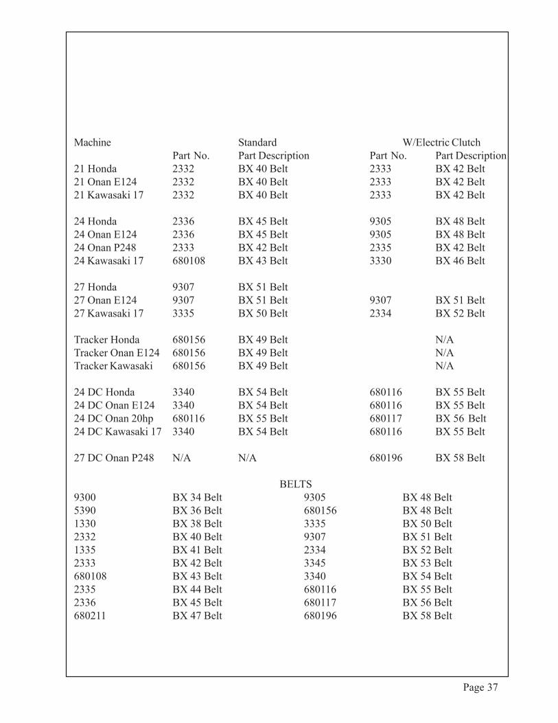
Machine Standard W/Electric ClutchPart No. Part Description Part No. Part Description
21 Honda 2332 BX 40 Belt 2333 BX 42 Belt21 Onan E124 2332 BX 40 Belt 2333 BX 42 Belt21 Kawasaki 17 2332 BX 40 Belt 2333 BX 42 Belt
24 Honda 2336 BX 45 Belt 9305 BX 48 Belt24 Onan E124 2336 BX 45 Belt 9305 BX 48 Belt24 Onan P248 2333 BX 42 Belt 2335 BX 42 Belt24 Kawasaki 17 680108 BX 43 Belt 3330 BX 46 Belt
27 Honda 9307 BX 51 Belt27 Onan E124 9307 BX 51 Belt 9307 BX 51 Belt27 Kawasaki 17 3335 BX 50 Belt 2334 BX 52 Belt
Tracker Honda 680156 BX 49 Belt N/ATracker Onan E124 680156 BX 49 Belt N/ATracker Kawasaki 680156 BX 49 Belt N/A
24 DC Honda 3340 BX 54 Belt 680116 BX 55 Belt24 DC Onan E124 3340 BX 54 Belt 680116 BX 55 Belt24 DC Onan 20hp 680116 BX 55 Belt 680117 BX 56 Belt24 DC Kawasaki 17 3340 BX 54 Belt 680116 BX 55 Belt
27 DC Onan P248 N/A N/A 680196 BX 58 Belt
BELTS9300 BX 34 Belt 9305 BX 48 Belt5390 BX 36 Belt 680156 BX 48 Belt1330 BX 38 Belt 3335 BX 50 Belt2332 BX 40 Belt 9307 BX 51 Belt1335 BX 41 Belt 2334 BX 52 Belt2333 BX 42 Belt 3345 BX 53 Belt680108 BX 43 Belt 3340 BX 54 Belt2335 BX 44 Belt 680116 BX 55 Belt2336 BX 45 Belt 680117 BX 56 Belt680211 BX 47 Belt 680196 BX 58 Belt
Page 37