proofreading - jeet · current setting of relay ri, and its limits are chosen between 1.25 and 2...
TRANSCRIPT

J Electr Eng Technol.2017; 12(?): 1921-718 http://doi.org/10.5370/JEET.2017.12.1.1921
1921Copyright ⓒ The Korean Institute of Electrical Engineers
This is an Open-Access article distributed under the terms of the Creative Commons Attribution Non-Commercial License (http://creativecommons.org/ licenses/by-nc/3.0/) which permits unrestricted non-commercial use, distribution, and reproduction in any medium, provided the original work is properly cited.
New Coordination Approach to Minimize the Number of Re-adjusted Relays When Adding DGs in Interconnected Power Systems
Doaa Khalil Ibrahim†, Essam El Din Abo El Zahab* and Saadoun Abd El Aziz Mostafa**
Abstract – The presence of DGs in power system networks tends to negatively affect the protective relays coordination. The proposed method introduces an approach to minimize the numbers of relays that acquire new settings on contrary to their original settings (case without DG), to achieve relays coordination in case of adding DG, since relays coordination with minimum number of relays of re-adjusted settings represents economical target, especially in networks containing mixture of electromechanical and adaptive digital relays. The scheme decides the possible minimum number of re-adjusted relays and their locations in an optimum manner to achieve proper relays coordination in case of adding DGs. The proposed approach is divided into two successive phases; the first phase is stopped when the first relays coordination solution is achieved. The second phase increases the possibility to keep higher number of relays at their original settings than that obtained in first phase through achieving multi solutions of relays coordination. The proposed approach is implemented and effectively tested on the well-known IEEE-39 bus test system.
Keywords: Distributed Generation (DG), Pickup Current Setting (IP), Relays Coordination, Time-Dial Setting (TDS).
1. Introduction With the rapid increase in electrical energy demand,
utilities are seeking for more power generation capacity. Newer technologies based on renewable energy sources are becoming more acceptable solutions as alternative energy generators. This renewable energy starts to spread electric power over distribution networks in the form of distributed generation (DG) [1]. Adding DG units in distribution networks will have major impacts on these networks' protection systems. These impacts include increasing short circuit levels, loss of protection coordination especially in case of directional overcurrent relays (DOCRs), bidirectionality of protection devices and protection blindness. Losing relays coordination results in unwanted false tripping for some healthy feeders. Furthermore, it may cause long time delay for tripping and isolating faulty feeders, resulting in significant fault currents overstresses on power system equipment and reducing their life time [2].
Various approaches have been proposed and reported in the literature to solve the coordination problem of directional overcurrent relays. These efforts may be categorized in two main categories. The first category is based on topological analysis, including graph theoretic
and functional dependencies techniques [3-6]. The second category to solve the coordination problem of DOCRs is based on using optimization techniques, by which the coordination problem could be formulated as a linear or nonlinear programming problem. In the linear model, the time dial settings are only optimized while the pickup current settings values are fixed [7]. Many efforts have been exerted to solve the relays coordination problem and get optimum solutions by applying different recent evolutionary algorithms (EAs) such as: Particle Swarm Optimization (PSO), Genetic Algorithm (GA), and Biogeography-Based Optimization (BBO) as introduced in [8-10]. In [8], a modified particle swarm optimization method is proposed to formulate DOCRs coordination problem as a mixed integer nonlinear problem to get optimal relays settings taking into consideration the discrete values for the pickup current settings. A method based on GA was developed to solve mis-coordination problem using continuous or discrete time setting multipliers [9]. Furthermore, some other hybrid techniques have been proposed to reach optimal solution of DOCRs coordination and overcome the drawback of low convergence speed of evolutionary algorithms; however, these algorithms such as hybrid BBO with linear programming (BBO-LP) are more complex for implementation [10].
For the sake of fixing relays settings for meshed distribution systems in both cases of with and without DG addition, it is proposed in [11] to ensure maximization of allowable DG penetration level at each bus based on measuring the rate of change of the maximum DG penetration level with respect to the rate of change of
† Corresponding Author: Electrical Power and Machines Dept., Faculty of Engineering, Cairo University, Egypt. ([email protected])
* Electrical Power and Machines Dept., Faculty of Engineering, Cairo University, Egypt .([email protected])
** Arab Contractor Company, Egypt.([email protected]) Received: January 29, 2017; Accepted: November 8, 2016
ISSN(Print) 1975-0102 ISSN(Online) 2093-7423
Proofreading

New Coordination Approach to Minimize the Number of Re-adjusted Relays When Adding DGs in Interconnected Power Systems
1922 │ J Electr Eng Technol.2017; 12(1): 1921-718
coordination time interval which can serve as an effective measure of DG impacts on relays coordination.
Authors believe that there is still much room for developing efficient schemes to solve relays coordination problem in interconnected power systems when adding DGs. Therefore, a coordination scheme is proposed in this paper to overcome the impact of installing DGs on the protection of interconnected power systems. Generally, the proposed method introduces an approach to minimize the numbers of relays that acquire new settings other than their original settings (case without DG), to achieve relays coordination in case of adding DG. The objective function in the proposed approach is the minimization of the total operating time of all primary relays for near end faults. The coordination problem is modeled as a linear programming (LP) problem. In such problems, a linear objective function is subject to linear equality and inequality constraints and can be solved using one of the linear programming techniques, namely: simplex, dual simplex, or two phase simplex technique [12]. To implement the proposed coordination scheme, the two phase simplex technique is applied using the MATLAB optimization function ‘linprog’, which is considered a simple and efficient tool.
The proposed scheme is tested on the meshed power distribution system of the IEEE 39-bus system equipped with synchronous based DGs, since synchronous based DGs generate higher fault current levels than inverter based DGs resulting in much more impact on the protection systems.
2. Conventional Coordination Problem Achieving proper directional overcurrent relays
coordination implies finding TDS and pickup current settings of all the DOCRs in the system so that the sum of operating times of the primary relays for near end faults is minimized while the coordination constraints are satisfied. Accordingly, the objective function is minimizing T as follows [11]:
= ∑ (1)
Where, T is the total time of N primary relays for near
end faults and is the operating time of the primary relay ith for its near end fault. Actually before adding the primary relay operating time to the summation of the objective function of Eq. (1), relay direction either in forward operation (to be added) or reverse operation (to be eliminated) is checked based on the angle between the relay fault current and its polarizing quantity that is not affected by the fault [13].
To ensure relays coordination, the operating time of the backup relay has to be greater than that of the primary relay for the same fault location by a coordination time interval including relay over travel time, breaker operating
time, and safety margin for relay error as follows: , − ≥ , (2)
where , is the operating time of the first back up jth relay for a near end fault at the ith relay, and , is the coordination time interval for backup-primary relay pair (j,i). Based on the preceding conducted studies, coordination time interval can be taken between 0.2 s and 0.5 s.
The boundary conditions of relays settings can be formulated as linear inequality sets by:
, ≤ ≤ , (3) , ≤ ≤ , (4) Where , , , are the minimum and
maximum TDS values of relay Ri respectively which are assumed to be 0.05 and 1.1 respectively. is the pickup current setting of relay Ri, and its limits are chosen between 1.25 and 2 times the maximum load current seen by such relay. Relays characteristics are assumed identical and their functions are approximated by [8]:
, = ., . (5)
Where , is the short circuit current passing through
the relay Rj for a fault at i. For a fixed previously predefined value of within its
boundary limits, Eq. (5) can be expressed by TDS coefficient (,) for relay Rj as follows:
, = , × (6)
where, , = ., . (7)
Based on predefined values of for all relays, the
objective function and the constraints given by Eq. (1), Eq. (2) and Eq. (3) can be expressed by Eq. (8), (9) and (10) respectively:
= ∑ , × (8) , × -, × ≥ , (9) 0.05 ≤ ≤ 1.1 (10) As discussed before, this coordination problem is solved
in terms of TDS, given that values of all the relays are predefined, based on the MATLAB optimization function ‘linprog’ that used with simplex two phase algorithm.
Proofreading

Doaa Khalil Ibrahim, Essam El Din Abo El Zahab and Saadoun Abd El Aziz Mostafa
http://www.jeet.or.kr │ 1923
3. Proposed Approach Formulation for Readjusting Minimum Number of Relays
3.1 Methodology of the first phase of the proposed
approach The flowchart illustrated in Fig .1 shows detailed steps
of the proposed approach. It starts with the solution of conventional coordination problem without DGs addition using previously predefined values of the pickup current for all relays within their limits. The problem of DOCRs coordination could be treated as a LP problem, and then the relays’ TDS are calculated to get optimum solution. When a DG is added, the fault currents for all relays are recalculated using a developed MATLAB code and thus applying the original relays settings will result in some violated constraints.
The basic idea of the proposed approach is to restore overall relays coordination in case of adding DG while keeping most of relays at their original settings. To achieve such goal, the proposed approach is divided into two successive phases, where each phase includes number of trials to achieve relays coordination.
The first phase assumes a set {I} that includes all violated constraints. It divides the relays into two groups. The first group includes the relays that we could have the ability to re-adjust their original settings, it includes backup-primary relay of each pair of violated constraints in set {I}. On the other hand, the second group includes the other remaining relays (not included in set {I}) which are kept fixed at their original settings during all trials of the scheme. Meanwhile, trials are carried out to keep most of relays in set {I} at their original settings and reduce the number of relays that need to re-adjust their original settings with new settings as possible as we can. Nonetheless, changing settings for one of the relays in set {I} may remove an existing violated constraint, but may also generate another violated constraint associated with this relay, and not included in set {I}. Accordingly, a set {K} is constructed, which is defined as the set that contains the violated constraints of set {I} in addition to any other constraints associated with each relay in set {I}, and then tested based on linear programming.
In the first trial, linear programming is carried out on set {K} at this step without any change of relays’. If the relays coordination at this trial is not achieved, the relays’ TDS are changed to their original TDS for N1 randomly selected relays in set {I} that satisfy Eq. (11) condition:
= ± (11)
Where, n is the relay address in set {I} that satisfy Eq.
(11), is the original TDS for relay n that calculated for relays coordination in case without DG, is the TDS of relay n that calculated after completion the first trial, and is the TDS tolerance coefficient which is
Fig. 1. Flowchart of the proposed approach
Proofreading

New Coordination Approach to Minimize the Number of Re-adjusted Relays When Adding DGs in Interconnected Power Systems
1924 │ J Electr Eng Technol.2017; 12(1): 1921-718
chosen so that |e|≤ 0.01 in the first phase. Accordingly, N1 relays are restored their original
settings at the starting of the second trial and the above step is repeated while relays’ are changed for other relays other than N1 relays. Then, linear programming is performed on first modification of set {K} (1st set{K}), and thus if relays coordination is not achieved in this second trial, the relays’ TDS for N2 selected relays in set {I} that satisfy the condition of Eq. (12) will be changed to their original TDS.
= ± (12)
Where, is TDS for relay n in set {I} that
calculated at the completion of the second trial. Consequently, N2 relays are restored their original settings at the starting of the third trial and the above step is repeated while relays’ are changed for the other relays other than N2 relays, then linear programming is carried out on this 2nd set {K}.
If relays coordination is achieved in the third trial, and N3 relays in set {I} are kept at their original settings by the completion of this trial, it will be verified that relays of original settings have been increased due to the N3 relays those gained in set {I} through the three trials where N1∈ 2 ∈ 3. Finally, the first phase is stopped when the first solution for relays coordination is achieved.
3.2 Methodology of the second phase of the proposed
approach The second phase of the proposed scheme is an
extension to the first phase except that TDS tolerance coefficient value will be greater than the zero value (ε ≥ 0). The objective of the second phase is achieving other solutions for relays coordination based on adding extra relays of original settings to those obtained based on first phase.
Suppose that, the trial step m+1 is the trial step at the end of first phase at which first solution of relays coordination occurs, and thus set {I} at this step includes subset {Q} which have only relays of pickup currents identical to those of original settings. The second phase starts with trial step m+2 based on restoring TDS for chosen relays in subset {Q} to their corresponding original TDS, and then the set {K} is modified. Consequently, and upon changing relays’ I , a new set of relays’ TDS are obtained again by applying linear programming.
In case of achieving relays coordination at this trial, it is considered a second solution for relays coordination. Repeating the above steps, third, fourth and more solutions for achieving relays coordination could be obtained with further increased number of relays of original settings as the number of trials increases.
On the other hand, in case of not achieving relays coordination at the trial step m+2, the second phase could
be restarted again but based on a lower number of selected relays in set {Q}. Finally, if there is no other solution for relays coordination, the trials are stopped and the relays have kept their original settings are those obtained by the end of the first phase.
Generally, the second phase trials will be stopped when no other solutions are found for relay coordination, or when more optimum solution for relays coordination is achieved with a total operating time of all primary relays for near end faults less than the other generated solutions and first phase solution.
4. Analysis and Results The tested case study in this paper is the 39-bus IEEE
system as shown in Fig. 2. It has 345, 230 and 22 kV buses, with 34 lines, 10 generators, 12 transformers and 84 directional overcurrent relays.
4.1 Optimal conventional relays coordination results
for the system without DG Continuous TDS & discrete values are allowed in this
study, a fixed value corresponding to 1.25 times maximum load current is firstly chosen when, the actual load current in the forward direction of relay operation. Otherwise, value of 150% (1.5 A) is assigned to relays when the actual load current in their reverse direction of operation as assumed in [14]. The values of Ips plug settings values as percentage of the secondary current tap for all relays are shown in Table 1. As clearly shown in the table, all the 84 relays have discrete values of Ips (50%, 75%, 100%, 125%, 150%, 175%, or 200%), except only one relay which is R3, it has Ip of 60%. The final achieved results upon adding DG, as will introduced later on, ensure that such relay should be an adaptive relay and have modified settings, so Ip of 60% is accepted in the case without adding DG for an adaptive one.
Consequently, by applying the steps illustrated in Section 2, relays TDS are generated to achieve optimal relays coordination. The results are given at CTI = 0.2 sec.
4.2 Examining proposed approach for the system
with DG Then the proposed approach is examined when a
synchronous based DG is added at bus 28, the transient reactance and capacity of the DG are 0.2 pu and 10 MVA respectively. The DG is connected to the network through a transformer of 10 MVA capacity and 0.01 pu reactance. The system is modeled in MATLAB code with all of its detailed parameters. The near-end fault primary and backup relays currents are calculated in the presence of DG.
In fact, the proposed scheme can be applied for DG addition at any location; however, the DG has inserted at
Proofreading

Doaa Khalil Ibrahim, Essam El Din Abo El Zahab and Saadoun Abd El Aziz Mostafa
http://www.jeet.or.kr │ 1925
bus 28 to get a complicated case of relays miscoordination. In such case, 47 violation constraints are found which nearly represent one third of the total constraints (140 constraints), also 61 relays out of total 84 relays have been affected by location of DG addition. According to the original calculated relays settings, Table 2 presents CTI of all backup-primary relay pairs in presence of DG. As shown, all 47 violated constraints are presented in shaded bold cells.
Based on the aforementioned stages of the proposed approach, set {I} of all violated constraints is constructed (47 constraints of 61 relays), and therefore other relays not included in set {I} are kept fixed at their original settings (23 relays). As discussed before, all relays in set {I} are of variable settings, and thus set {K} of all constraints associated to each relay in set {I} is constructed. The constraints before starting trials of the proposed scheme were 140 with no change of. Table 3 shows the results of
re-adjusting minimum number of relays settings in case of adding DG, where: - Symbol '*' indicates relays’ of same original setting
values as calculated in Table 1, - Cells have bold values, either shaded or not, indicate
relays’ TDS obtained at the completion of each trial step (1st, 2nd, 3rd, ..) which are identical to the original TDS,
- Cells have shaded values indicate modified values of relays’ TDS at the starting of each trial step to be identical to the original TDS (N1, N2, N3….),
- Cells have normal values (not bold or not shaded) refer to relays’ re-adjusted settings that obtained at the completion of each trial step.
- Settings of 23 relays: R1, R21, R22, R38, R53, R63, R67, R68, R69, R70, R71, R73, R74, R75, R76, R77, R78, R79, R80, R81, R82, R83 and R84 are kept fixed at original settings during all trials, and thus they are not shown in the table.
Fig. 2. Tested IEEE-39 bus system
Proofreading

New Coordination Approach to Minimize the Number of Re-adjusted Relays When Adding DGs in Interconnected Power Systems
1926 │ J Electr Eng Technol.2017; 12(1): 1921-718
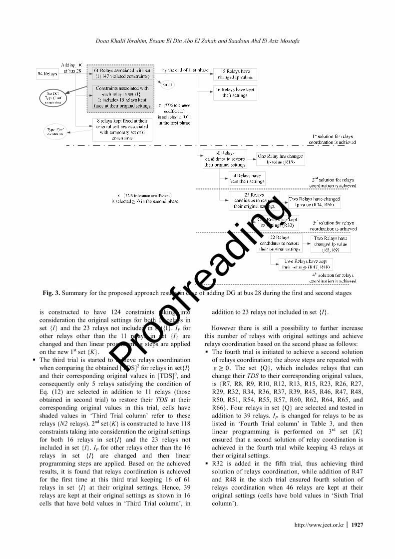
As the objective of the proposed approach is to keep most of relays at their original settings and fulfill relays coordination in case of adding DG, detailed results for gradually reducing the number of relays that need re-adjusting their original settings to achieve relays coordination are shown below: § During the first trial to obtain relays coordination, a set
{K} of 134 constraints associated with 61 relays in set {I} is developed, then linear programming is performed on set {K} with no change of IP for all relays, and thus [TDS]1 is obtained at the end of first trial, where [TDS]1
is the TDS for all relays in set {I} that calculated at the completion of the first trial. By the end of this trial, it is found that relays coordination is not achieved.
§ Consequently, the second trial is initiated by comparing the obtained [TDS]1 for 61 relays in set {I} and their corresponding original values in [TDS]0. Therefore only 11 relays are selected to change their TDS into their corresponding original values (N1 relays). Cells have shaded values in ‘Second Trial column’ refer to these relays (e.g. TDS of R19 is changed from 0.3046 to 0.3052 at the start of the second trial). 1st modified set{K}
Table 1. Ips Plug Settings Values as Percentage of the Secondary Current Tap for Relays in Power System without DG
Ip Value Ip Value Ip Value Ip Value Ip Value Ip Value Ip1 150 Ip15 150 Ip29 150 Ip43 175 Ip57 175 Ip71 125 Ip2 75 Ip16 125 Ip30 50 Ip44 150 Ip58 150 Ip72 150 Ip3 60 Ip17 100 Ip31 150 Ip45 150 Ip59 150 Ip73 125 Ip4 150 Ip18 150 Ip32 100 Ip46 150 Ip60 175 Ip74 150 Ip5 150 Ip19 100 Ip33 175 Ip47 50 Ip61 125 Ip75 125 Ip6 150 Ip20 150 Ip34 150 Ip48 150 Ip62 150 Ip76 175 Ip7 125 Ip21 150 Ip35 150 Ip49 150 Ip63 150 Ip77 125 Ip8 150 Ip22 50 Ip36 150 Ip50 150 Ip64 175 Ip78 175 Ip9 200 Ip23 175 Ip37 150 Ip51 150 Ip65 150 Ip79 150 Ip10 150 Ip24 150 Ip38 175 Ip52 100 Ip66 50 Ip80 125 Ip11 75 Ip25 100 Ip39 150 Ip53 150 Ip67 100 Ip81 150 Ip12 150 IP26 150 Ip40 175 Ip54 100 Ip68 150 Ip82 200 Ip13 150 IP27 150 Ip41 150 Ip55 150 Ip69 150 Ip83 125 Ip14 100 Ip28 100 Ip42 200 Ip56 175 Ip70 100 Ip84 150
* Shaded cells mean actual current is in reverse direction of relay operation.
Table 2. CTI of All Backup-Primary Relay Pairs in Presence of DG at bus 28
CTI Value (in sec) CTI Value
(in sec) CTI Value (in sec) CTI Value
(in sec) CTI Value (in sec)
CTI 4,1 0.2 CTI 54,49 -0.0177 CTI 78,56 0.3295 CTI 12,26 0.2008 CTI 40,73 28.1141 CTI 7,2 0.6361 CTI 52,49 0.0876 CTI 54,51 0.6899 CTI 82,4 0.2000 CTI 76,69 0.5676 CTI 10,2 0.6482 CTI 47,49 0.2336 CTI 47,51 0.8972 CTI 6,4 0.1997 CTI 75,70 2.2586 CTI 81,2 0.6565 CTI 7,9 0.1912 CTI 50,51 0.7187 CTI 82,5 0.2718 CTI 75,67 0.2000 CTI 1,8 0.2005 CTI 1,9 0.2095 CTI 55,52 0.1573 CTI 3,5 0.1991 CTI 69,67 0.2000 CTI 10,8 0.1983 CTI 12,10 0.3610 CTI 78,52 0.5018 CTI 25,11 0.2788 CTI 38,46 0.4091 CTI 81,8 0.2005 CTI 25,10 0.1985 CTI 49,30 0.1769 CTI 9,11 0.4385 CTI 35,46 0.4020 CTI 48,7 0.1915 CTI 29,50 0.1999 CTI 32,29 0.2970 CTI 14,12 0.2001 CTI 14,45 0.2391 CTI 80,7 0.2101 CTI 52,53 0.7327 CTI 27,29 0.3087 CTI 46,12 0.1990 CTI 11,45 0.1983 CTI 8,47 0.1997 CTI 47,53 0.8367 CTI 26,27 0.1998 CTI 41,40 0.1998 CTI 2,3 0.1997
CTI 80,47 0.3153 CTI 50,53 0.6589 CTI 30,28 0.2047 CTI 84,40 0.2005 CTI 42,43 0.1998 CTI 54,48 0.1457 CTI 56,54 0.2517 CTI 32,28 0.2039 CTI 74,39 0.2000 CTI 83,43 1.2895 CTI 52,48 0.2521 CTI 53,55 0.2521 CTI 28,25 0.1981 CTI 37,39 0.1998 CTI 72,43 0.4075 CTI 50,48 0.2174 CTI 51,56 0.1958 CTI 9,26 0.1964 CTI 84,39 0.4840 CTI 44,41 0.1999 CTI 72,41 0.1987 CTI 83,16 0.4133 CTI 11,13 0.4629 CTI 23,21 0.3319 CTI 60,57 0.2000 CTI 39,42 0.1998 CTI 35,37 0.1996 CTI 16,14 0.1999 CTI 19,24 0.1997 CTI 77,57 0.2530 CTI 84,42 0.2677 CTI 45,37 0.2053 CTI 24,14 0.2000 CTI 22,24 0.2833 CTI 65,58 0.1998 CTI 18,44 0.1997 CTI 74,38 0.2855 CTI 5,22 0.2000 CTI 21,6 0.2000 CTI 77,59 0.2000 CTI 83,44 0.2071 CTI 40,38 0.2000 CTI 13,23 0.2969 CTI 66,63 0.5385 CTI 58,59 0.1993 CTI 43,17 0.5030 CTI 33,35 0.1990 CTI 16,23 0.5114 CTI 67,63 0.5342 CTI 64,65 0.2010 CTI 15,17 0.1996 CTI 38,36 0.2001 CTI 31,33 0.1962 CTI 31,63 0.4370 CTI 67,65 0.6035 CTI 83,17 0.7235 CTI 45,36 0.1994 CTI 66,33 0.2903 CTI 34,63 0.5299 CTI 31,65 0.5099 CTI 20,18 0.2000 CTI 30,31 0.1928 CTI 67,33 0.2909 CTI 61,64 0.1998 CTI 34,65 0.6021 CTI 83,18 1.6627 CTI 27,31 0.2039 CTI 36,34 0.1999 CTI 62,60 0.1990 CTI 57,66 0.1995 CTI 24,15 0.4112 CTI 34,32 0.1991 CTI 17,19 0.1997 CTI 79,60 0.2003 CTI 66,68 1.2629 CTI 13,15 0.1997 CTI 66,32 0.2002 CTI 22,20 0.2001 CTI 59,61 0.1999 CTI 64,68 0.8590 CTI 18,16 0.4136 CTI 67,32 0.2002 CTI 23,20 0.1994 CTI 79,61 0.3970 CTI 34,68 1.2603 CTI 43,16 0.1993 CTI 46,13 0.5022 CTI 19,21 1.6215 CTI 63,62 0.2000 CTI 31,68 1.1670
* Shaded bold cells show the mis-coordinated backup-primary relay pairs in presence of DG.
Proofreading
Doaa Khalil Ibrahim, Essam El Din Abo El Zahab and Saadoun Abd El Aziz Mostafa
http://www.jeet.or.kr │ 1927
is constructed to have 124 constraints taking into consideration the original settings for both 11 relays in set {I} and the 23 relays not included in set{I}. IP for other relays other than the 11 relays in set {I} are changed and then linear programming steps are applied on the new 1st set {K}.
§ The third trial is started to achieve relays coordination when comparing the obtained [TDS]2 for relays in set{I} and their corresponding original values in [TDS]0, and consequently only 5 relays satisfying the condition of Eq. (12) are selected in addition to 11 relays (those obtained in second trial) to restore their TDS at their corresponding original values in this trial, cells have shaded values in ‘Third Trial column’ refer to these relays (N2 relays). 2nd set{K} is constructed to have 118 constraints taking into consideration the original settings for both 16 relays in set{I} and the 23 relays not included in set {I}. IP for other relays other than the 16 relays in set {I} are changed and then linear programming steps are applied. Based on the achieved results, it is found that relays coordination is achieved for the first time at this third trial keeping 16 of 61 relays in set {I} at their original settings. Hence, 39 relays are kept at their original settings as shown in 16 cells that have bold values in ‘Third Trial column’, in
addition to 23 relays not included in set {I}. However there is still a possibility to further increase
this number of relays with original settings and achieve relays coordination based on the second phase as follows: § The fourth trial is initiated to achieve a second solution
of relays coordination; the above steps are repeated with ≥ 0 . The set {Q}, which includes relays that can change their TDS to their corresponding original values, is {R7, R8, R9, R10, R12, R13, R15, R23, R26, R27, R29, R32, R34, R36, R37, R39, R45, R46, R47, R48, R50, R51, R54, R55, R57, R60, R62, R64, R65, and R66}. Four relays in set {Q} are selected and tested in addition to 39 relays. IP is changed for relays to be as listed in ‘Fourth Trial column’ in Table 3, and then linear programming is performed on 3rd set {K} ensured that a second solution of relay coordination is achieved in the fourth trial while keeping 43 relays at their original settings.
§ R32 is added in the fifth trial, thus achieving third solution of relays coordination, while addition of R47 and R48 in the sixth trial ensured fourth solution of relays coordination when 46 relays are kept at their original settings (cells have bold values in ‘Sixth Trial column’).
Fig. 3. Summary for the proposed approach results in case of adding DG at bus 28 during the first and second stages
Proofreading

New Coordination Approach to Minimize the Number of Re-adjusted Relays When Adding DGs in Interconnected Power Systems
1928 │ J Electr Eng Technol.2017; 12(1): 1921-718
Table 3. Proposed Approach Results of Re-adjusting Minimum Number of Relays Settings in Case of Adding DG
Relay no.
Original Settings without DG
First Trial Second Trial Third Trial Fourth Trial Fifth Trial Sixth Trial
Ip TDS Ip TDS Ip TDS Ip TDS Ip TDS Ip TDS Ip TDS R2 * 0.3182 * 0.3186 * 0.3182 * 0.3182 * 0.3182 * 0.3182 * 0.3182 R3 * 0.2783 * 0.2786 * 0.2782 75 0.2481 75 0.2481 75 0.2481 75 0.2481 R4 * 0.6574 * 0.6571 * 0.6574 * 0.6574 * 0.6574 * 0.6574 * 0.6574 R5 * 0.5986 * 0.5986 * 0.5986 * 0.5986 * 0.5986 * 0.5986 * 0.5986 R6 * 0.3838 * 0.3838 * 0.3838 300 0.2811 300 0.2811 300 0.2811 300 0.2811 R7 * 0.3371 * 0.3403 * 0.3318 * 0.3162 * 0.3402 * 0.3402 * 0.3198 R8 * 0.6888 * 0.6864 * 0.6459 * 0.6205 * 0.6205 * 0.6205 4800 0.0748 R9 * 0.3704 * 0.3714 * 0.3603 * 0.3401 * 0.3713 * 0.3713 300 0.286 R10 * 0.6329 * 0.6318 * 0.6005 * 0.5809 * 0.5809 * 0.5809 * 0.4072 R11 * 0.4815 * 0.4819 * 0.4804 * 0.4815 * 0.4815 * 0.4815 * 0.4815 R12 * 0.6858 * 0.6834 * 0.6652 * 0.6278 * 0.6858 * 0.6858 * 0.6858 R13 * 0.5096 * 0.6142 * 0.6153 * 0.4757 * 0.5096 * 0.5096 * 0.5096 R14 * 0.4235 * 0.4222 * 0.4231 * 0.4235 * 0.4235 * 0.4235 * 0.4235 R15 * 0.3443 * 0.4321 * 0.4331 * 0.3157 200 0.2793 200 0.2793 200 0.2793 R16 * 0.2445 * 0.2439 * 0.2443 200 0.1602 200 0.1602 200 0.1602 200 0.1602 R17 * 0.2303 * 0.23 * 0.2303 150 0.1669 150 0.1669 150 0.1669 150 0.1669 R18 * 0.319 * 0.319 * 0.319 200 0.2585 200 0.2585 200 0.2585 200 0.2585 R19 * 0.3052 * 0.3046 * 0.3052 * 0.3052 * 0.3052 * 0.3052 * 0.3052 R20 * 0.539 * 0.5391 * 0.539 * 0.539 * 0.539 * 0.539 * 0.539 R23 * 0.2627 * 0.2629 * 0.2628 * 0.2628 * 0.2628 * 0.2628 * 0.2628 R24 * 0.479 * 0.4778 * 0.4786 200 0.426 200 0.426 200 0.426 200 0.426 R25 * 0.702 * 0.7018 * 0.6725 200 0.5324 200 0.5324 200 0.5324 200 0.5324 R26 * 0.766 * 0.7662 * 0.7396 * 0.691 * 0.766 * 0.766 * 0.766 R27 * 0.6594 * 0.6595 * 0.6329 * 0.5843 * 0.6065 * 0.6065 * 0.6065 R28 * 0.5052 * 0.5058 * 0.488 140 0.4074 140 0.4074 140 0.4074 140 0.4074 R29 * 0.6757 * 0.6744 * 0.7107 * 0.6462 * 0.6757 * 0.6757 * 0.6757 R30 * 0.8057 * 0.8125 * 0.7338 100 0.6101 100 0.6101 100 0.6101 100 0.6101 R31 * 0.6529 * 0.6553 * 0.5808 2400 0.1307 2400 0.1307 2400 0.1307 2400 0.1307 R32 * 0.5297 * 0.5283 * 0.5128 * 0.488 * 0.4915 * 0.5297 * 0.5297 R33 * 0.4242 * 0.4245 200 0.3987 200 0.3987 200 0.3987 200 0.3987 200 0.3987 R34 * 0.5943 * 0.5933 * 0.5785 * 0.5548 * 0.5581 200 0.5357 200 0.5357 R35 * 0.6547 * 0.6547 * 0.6547 * 0.6547 * 0.6547 * 0.6547 * 0.6547 R36 * 0.6906 * 0.6897 * 0.675 * 0.6513 * 0.6545 * 0.6851 * 0.6851 R37 * 0.6883 * 0.6879 * 0.688 * 0.6811 * 0.6811 * 0.6811 * 0.6811 R39 * 0.5983 * 0.5979 * 0.5983 * 0.5909 * 0.5909 * 0.5909 * 0.5909 R40 * 0.3427 * 0.3426 * 0.3427 * 0.3427 * 0.3427 * 0.3427 * 0.3427 R41 * 0.6532 * 0.6532 * 0.6532 200 0.5971 200 0.5971 200 0.5971 200 0.5971 R42 * 0.2911 * 0.2908 * 0.2911 240 0.2597 240 0.2597 240 0.2597 240 0.2597 R43 * 0.2706 * 0.2702 * 0.2706 * 0.2706 * 0.2706 * 0.2706 * 0.2706 R44 * 0.7491 * 0.7491 * 0.7491 * 0.7491 * 0.7491 * 0.7491 * 0.7491 R45 * 0.6752 * 0.6747 * 0.6723 * 0.6665 * 0.6665 * 0.6708 * 0.6708 R46 * 0.3281 * 0.3273 * 0.3199 * 0.3046 * 0.3283 * 0.3283 * 0.3283 R47 * 0.5419 * 0.5394 * 0.5011 * 0.4771 * 0.4771 * 0.4771 * 0.5419 R48 * 0.5392 * 0.5472 * 0.5894 * 0.5145 * 0.5471 * 0.5471 * 0.5392 R49 * 0.3516 * 0.3601 * 0.3301 250 0.2305 250 0.2305 250 0.2305 250 0.2305 R50 * 0.5685 * 0.5671 * 0.6035 * 0.539 * 0.567 * 0.567 * 0.5602 R51 * 0.2888 * 0.3077 * 0.2951 * 0.2904 * 0.2904 * 0.2904 * 0.2904 R52 * 0.1544 * 0.1721 * 0.1599 * 0.1544 * 0.1544 * 0.1544 * 0.1544 R54 * 0.1564 * 0.1908 * 0.1772 * 0.1688 * 0.1688 * 0.1688 * 0.1688 R55 * 0.243 * 0.2664 * 0.2664 * 0.26 * 0.26 * 0.26 * 0.26 R56 * 0.1488 * 0.1606 * 0.152 * 0.1488 * 0.1488 * 0.1488 * 0.1488 R57 * 0.2151 * 0.2147 * 0.2101 * 0.2028 * 0.2038 * 0.2032 * 0.2032 R58 * 0.3874 * 0.3877 * 0.3874 * 0.3874 * 0.3874 * 0.3874 * 0.3874 R59 * 0.3787 * 0.3787 * 0.3784 200 0.3449 200 0.3449 200 0.3449 200 0.3449 R60 * 0.4289 * 0.4283 * 0.4213 * 0.4101 * 0.4117 * 0.4108 * 0.4108 R61 * 0.1346 * 0.1346 * 0.1346 * 0.1346 * 0.1346 * 0.1346 * 0.1346 R62 * 0.3315 * 0.3315 * 0.3272 * 0.3204 * 0.3213 * 0.3207 * 0.3207 R64 * 0.1573 * 0.1572 * 0.1571 * 0.1571 * 0.1571 * 0.1571 * 0.1571 R65 * 0.5114 * 0.5118 * 0.5115 * 0.5115 * 0.5115 * 0.5115 * 0.5115 R66 * 0.4016 * 0.4006 * 0.3907 * 0.3746 * 0.3768 100 0.2628 100 0.2628 R72 * 0.2796 * 0.2798 * 0.2798 * 0.2796 * 0.2796 * 0.2796 * 0.2796
Relays coordination is not achieved yet
Relays coordination is
not achieved yet
Relays coordination is not
achieved yet
First relays coordination solution (End of First Phase)
Second solution for relays coordination
is achieved
Third solution for relays coordination is
achieved
Fourth solution for relays coordination is
achieved
Proofreading

Doaa Khalil Ibrahim, Essam El Din Abo El Zahab and Saadoun Abd El Aziz Mostafa
http://www.jeet.or.kr │ 1929
Table 4. Results of Applying Proposed Scheme Based on Assumed value of ε as in Technique [15] for Re-adjusting Relays Settings in case of adding DG
Relay no. Original Settings without DG First Trial Second Trial Third Trial
Ip TDS Ip TDS Ip TDS Ip TDS R2 * 0.3182 * 0.3186 * 0.3186 * 0.3133 R3 * 0.2783 * 0.2786 * 0.2786 75 0.2481 R4 * 0.6574 * 0.6571 * 0.6571 * 0.6574 R5 * 0.5986 * 0.5986 * 0.5986 * 0.5986 R6 * 0.3838 * 0.3838 * 0.3838 300 0.2811 R7 * 0.3371 * 0.3403 * 0.3198 * 0.3162 R8 * 0.6888 * 0.6864 * 0.5692 * 0.6185 R9 * 0.3704 * 0.3714 * 0.3448 * 0.3401
R10 * 0.6329 * 0.6318 * 0.5412 * 0.5793 R11 * 0.4815 * 0.4819 * 0.4453 * 0.4611 R12 * 0.6858 * 0.6834 * 0.6365 * 0.6278 R13 * 0.5096 * 0.6142 * 0.4993 * 0.4583 R14 * 0.4235 * 0.4222 * 0.3975 * 0.3933 R15 * 0.3443 * 0.4321 * 0.3355 * 0.301 R16 * 0.2445 * 0.2439 * 0.2319 200 0.1506 R17 * 0.2303 * 0.23 * 0.2226 150 0.1568 R18 * 0.319 * 0.319 * 0.319 200 0.2585 R19 * 0.3052 * 0.3046 * 0.2926 * 0.2823 R20 * 0.539 * 0.5391 * 0.5391 * 0.5009 R23 * 0.2627 * 0.2629 * 0.2629 * 0.2476 R24 * 0.479 * 0.4778 * 0.4544 200 0.4005 R25 * 0.702 * 0.7018 * 0.6171 200 0.5281 R26 * 0.766 * 0.7662 * 0.7023 * 0.691 R27 * 0.6594 * 0.6595 * 0.5956 * 0.5843 R28 * 0.5052 * 0.5058 * 0.4541 140 0.4046 R29 * 0.6757 * 0.6744 * 0.6119 * 0.6462 R30 * 0.8057 * 0.8125 * 0.7338 100 0.6066 R31 * 0.6529 * 0.6553 * 0.5808 2400 0.1307 R32 * 0.5297 * 0.5283 * 0.4525 * 0.4853 R33 * 0.4242 * 0.4245 200 0.3487 200 0.3987 R34 * 0.5943 * 0.5933 * 0.5208 * 0.5521 R35 * 0.6547 * 0.6547 * 0.6547 * 0.6547 R36 * 0.6906 * 0.6897 * 0.6173 * 0.6486 R37 * 0.6883 * 0.6879 * 0.6183 * 0.6367 R39 * 0.5983 * 0.5979 * 0.5265 * 0.5454 R40 * 0.3427 * 0.3426 * 0.3426 * 0.3427 R41 * 0.6532 * 0.6532 * 0.6532 200 0.5971 R42 * 0.2911 * 0.2908 * 0.2492 240 0.2357 R43 * 0.2706 * 0.2702 * 0.2235 * 0.2404 R44 * 0.7491 * 0.7491 * 0.7491 * 0.7491 R45 * 0.6752 * 0.6747 * 0.6143 * 0.6404 R46 * 0.3281 * 0.3273 * 0.3082 * 0.3046 R47 * 0.5419 * 0.5394 * 0.5011 * 0.4752 R48 * 0.5392 * 0.5472 * 0.5195 * 0.5145 R49 * 0.3516 * 0.3601 * 0.3301 250 0.2276 R50 * 0.5685 * 0.5671 * 0.5432 * 0.539 R51 * 0.2888 * 0.3077 * 0.2951 * 0.2866 R52 * 0.1544 * 0.1721 * 0.1599 * 0.1516 R54 * 0.1564 * 0.1908 * 0.1772 * 0.1681 R55 * 0.243 * 0.2664 * 0.2664 * 0.2568 R56 * 0.1488 * 0.1606 * 0.152 * 0.1461 R57 * 0.2151 * 0.2147 * 0.1923 * 0.202 R58 * 0.3874 * 0.3877 * 0.3877 * 0.385 R59 * 0.3787 * 0.3787 * 0.3787 200 0.3449 R60 * 0.4289 * 0.4283 * 0.394 * 0.4089 R61 * 0.1346 * 0.1346 * 0.1346 * 0.1346 R62 * 0.3315 * 0.3315 * 0.3105 * 0.3196 R64 * 0.1573 * 0.1572 * 0.1572 * 0.1566 R65 * 0.5114 * 0.5118 * 0.5118 * 0.5091 R66 * 0.4016 * 0.4006 * 0.3516 * 0.3728 R72 * 0.2796 * 0.2798 * 0.2798 * 0.2783
Relays coordination is not achieved yet
Relays coordination is not achieved yet
Relays coordination is not achieved yet
Solution for relays coordination is achieved
Proofreading
New Coordination Approach to Minimize the Number of Re-adjusted Relays When Adding DGs in Interconnected Power Systems
1930 │ J Electr Eng Technol.2017; 12(1): 1921-718
As the total operating time of all primary relays for near end faults (∑ , × ) equals 74.803 sec, 75.532 sec, 75.728 sec, and 74.372 sec by the end of first phase (end of 3rd trial), end of 4th trial, end of 5th trial, and end of 6th trial respectively, the second phase will be stopped at the 6th trial at which relays coordination is achieved with a total operating time of all primary relays for near end faults less than the corresponding values of other trials.
Up to the authors’ knowledge, very few published research works have investigated the idea of achieving minimum number of relays that acquire new relays settings in case of adding DG. Reference [15] represents one of such studies where nonlinear / linear optimization models are applied using GAMS. It is worth mentioning that the proposed approach is compared with the published method in [15]. So that, the proposed scheme is applied on IEEE-39 bus system but based on ε = 0 as in technique [15], for re-adjusting relays settings in case of adding DG. The obtained results are shown in Table 4. It is clear that the first trial is the same as achieved by the proposed scheme when relays are initially assumed to be kept at their original settings. At the starting of the second trial, only four relays R5, R35, R44 and R61 are selected to be added to those keeping their original settings where = 0 . During the second trial, IP is only changed for R33 to be as in our study however relays coordination is not achieved. By the third trial completion, the relays coordination is achieved by changing relays’ IP as shown in Table. 4, and keeping the two relays R4, R40 at their original settings, in addition to R5, R35, R44, R61 and the initially 23 relays.
According to the aforementioned results, those are summarized in Fig. 3; the proposed approach has succeeded in achieving its first solution for relays coordination when keeping 39 relays at their original settings, while in the fourth solution 46 relays are obtained for a more optimum relays coordination solution. On the other hand, when applying the proposed approach but based on ε = 0 for re-adjusting relays settings in case of adding DG as in technique [15], it has only kept 29 relays at their original settings to achieve a unique solution for relays coordination.
We can summarize that the proposed method has two merits. The first merit is achieving relays coordination and finding out lower number of relays of new settings compared to the other obtained based on using the proposed method but implemented on ε = 0 as in previous techniques, this can be achieved in first phase. The second merit is obtaining further reduced number of relays of new settings, through generating many other solutions of relays coordination
5. Conclusion Relays coordination with minimum number of relays of
re-adjusted settings represents economical target, especially
in networks containing mixture of electromechanical and adaptive digital relays. The paper introduces a new approach to achieve relays coordination in interconnected power systems utilizing DGs with minimum number of relays of re-adjusted settings. An integrated model, using linear programming based on MATLAB optimization toolbox is introduced to verify the effectiveness of the proposed scheme on IEEE-39 bus test system. The proposed approach calculates re-adjusted settings for minimum number of relays and defines their locations to achieve relays coordination in case of adding DG. Initially, first phase is carried out to decrease the number of relays of re-adjusted settings and obtaining first relays coordination solution, then the second phase is carried out to gradually decrease this number at sequential stages for obtaining different relays coordination solutions.
When comparing the performance of the proposed approach with other published techniques, the achieved results ensured the effectiveness of the proposed approach. In its first phase and by the completion of 3 trials, relays coordination solution is achieved by keeping 39 relays at their original settings, while implementing our approach but, based on assumptions of other published technique, have only succeeded in keeping 29 relays at their original settings. Besides, the number of relays that kept their original settings is increased to be 46 relays in the second phase through more than one solution for relays coordination.
References
[1] M. Dewadasa, A. Ghosh, and G. Ledwich, “Protection of distributed generation connected networks with coordination of overcurrent relays”, in Proceedings of 37th Annual Conference on IEEE Industrial Elec-tronics Society (IECON), Melbourne, VIC, 2011.
[2] T. Amraee, “Coordination of directional overcurrent relays using seeker algorithm”, IEEE Transactions on Power Delivery, Vol. 27, pp. 1415-1422, 2012.
[3] M. Mansour, S. Mekhamar, and N.S. EL-Kharabawe," A modified particle swarm optimizer for the coordi-nation of directional overcurrent relay", IEEE Trans-actions on Power Delivery, Vol. 22, pp. 1400-1410, 2007.
[4] D. Birla, R. P., Maheshwari, H. O., Gupta, “Time-overcurrent relay coordination: a review,” Interna-tional Journal Emerging Electrical Power System, Vol. 2, 2005.
[5] Jenkins, L., Khincha, H., Shivakumar, S., Dash, P., “An Application of Functional Dependencies to the Topological Analysis of Protection Schemes”, IEEE Transactions on Power Delivery, vol. 7, pp. 77-83, 1992.
[6] M. H. Hussain , S. R. A. Rahim, I. Musirin, “Optimal Overcurrent Relay Coordination: A Review,” in
Proofreading

Doaa Khalil Ibrahim, Essam El Din Abo El Zahab and Saadoun Abd El Aziz Mostafa
http://www.jeet.or.kr │ 1931
Proceedings of Malaysian Technical Universities Conference on Engineering & Technology 2012, MUCET 2012 Part 1- Electronic and Electrical Engineering Procedia Engineering, vol. 53, pp. 332-336, 2013.
[7] J. Urdaneta, R. Nadira, L. G. Perez, “Optimal coordination of directional overcurrent relays in interconnected power systems,” IEEE Transactions on Power Delivery, Vol. 3, pp. 903-911, 1988.
[8] H.H. Zeineldin, E.F. El-Saadany, M.M.A. Salama, Optimal coordination of overcurrent relays using a modified particle swarm optimization, Electric Power Systems Research, vol. 76, pp. 988-995, 2006.
[9] F. Razavi, H. A. Abyaneh, M. Al-Dabbagh, R. Mohammadi, H. Torkaman, “A new comprehensive genetic algorithm method for optimal overcurrent relays coordination,” Electric Power Systems Research, vol. 78 pp. 713-725, 2008.
[10] Albasri, F. A.; Alroomi, A. R.; Talaq, J. H., “Optimal Coordination of Directional Overcurrent Relays Using Biogeography-Based Optimization Algorithms," IEEE Transactions on Power Delivery, vol. 3, pp.1810-1820, 2015.
[11] H. H. Zeineldin, , Yasser Abdel-Rady I. Mohamed, Vinod Khadkikar, and V. Ravikumar Pandi, "A Protection Coordination Index for Evaluating Distri-buted Generation Impacts on protection for Meshed Distribution Systems", IEEE Transactions on Smart Grid, vol. 4, pp. 1523-1532, 2013.
[12] Prashant P. Bedekar, Sudhir R. Bhide, Vijay S. Kale., "Optimum coordination of overcurrent relays in distribution system using dual simplex method",in Proceedings of 2nd International Conference on Emerging Trends in Engineering and Technology (ICETET), Nagpur, 2009.
[13] [14] Hebatallah Mohamed Sharaf, H. H. Zeineldin, Doaa
Khalil Ibrahim and Essam EL-Din Abou EL-Zahab, "Protection Coordination of Directional Overcurrent Relays Considering Fault Current Direction", in Proceedings of 5th IEEE conference on Innovative Smart Grid Technologies, ISGT 2014, Istanbul, Turkey, 12-15 Oct 2014.
[15] A.Y. Abdelaziz , H.E.A. Talaat , A.I. Nosseir , Ammar A. Hajjar ., "An adaptive protection scheme for optimal coordination of overcurrent relays", Electric Power Systems Research, vol. 61, pp. 1-9, 2002.
[16] Walid El-Khattam, Tarlochan S. Sidhu, "Resolving the impact of distributed renewable generation on directional overcurrent relay coordination: a case study", IET Renewable Power Generation, Vol. 3, pp. 415-425, 2008.
Doaa Khalil Ibrahim She was born in Egypt in December 1973. She received the M.Sc. and Ph.D. degrees in digital protection from Cairo University, Cairo, Egypt, in 2001 and 2005, respectively. From 1996 to 2005, she was a Demonstrator and Research Assistant with Cairo University. In
2005, she became an Assistant Professor with Cairo University. In 2011, she became an Associate Professor with Cairo University. From 2005 to 2008, she contributed to a World Bank Pr oject in Higher Education Development in Egypt. Since 2009, she has contributed to the Program of Continuous Improvement and Qualifying for Accreditation in Higher Education in Egypt. Her research interests include digital protection of power system as well as utilization and generation of electric power, distributed generation and renewable energy sources.
Essam EL-Din Abou EL-Zahab He received the BSc. and MSc. degrees in electrical power and machines from Cairo University, Giza, Egypt, in 1970 and 1974, respectively. He received the PhD. degree in Electrical Power from Paul Sabatier, Toulouse France, in 1979. Currently he is a Professor in the
department of electrical power and machines at Cairo University. He was an instructor in the department of electrical power and machines at Cairo University from 1970 to 1974. His research areas include protection system, renewable energy, and power distribution. He is also the author or co-author of many referenced journal and conference papers.
Saadoun Abd El Aziz Mostafa He was graduated from Cairo University, Faculty of Engineering, Electrical Power and Machines Department, Egypt, in 1992, and received the M.Sc. from Cairo University at 2006. From 1993 till now, he was an executive engineer and technical manager in
Arab Contractor Company, Egypt. He is currently pursuing the Ph.D. degree in power engineering.
Proofreading