promatect® 100 passive fire protection building
TRANSCRIPT

PROMATECT® 100 Passive Fire ProtectionBuilding & Construction Solutions
www.promat.com.au Solely for distribution in Australia

COnTEnTS
GeneralIntroduction ....................................................................................................................................................................................................6
Principles .......................................................................................................................................................................................................11
About PROMATECT® 100 PROMAXON® mineral board .......................................................................................................................14
Safety data sheet (SDS) ...............................................................................................................................................................................16
Loading/uploading, storage and handling of boards ............................................................................................................................21
Cutting...........................................................................................................................................................................................................22
Fixing and fabrication ..................................................................................................................................................................................24
Flush jointing ................................................................................................................................................................................................27
Finishing ........................................................................................................................................................................................................28
Structural steel fire protectionStructural steel fire protection general information ................................................................................................................................30
Calculation of section factor (Hp/A) ..........................................................................................................................................................33
Guide of section factor (Hp/A) for encasement .......................................................................................................................................35
Structural steel protection
Structural steel column cladding, FRL 150/-/- .....................................................................................................................................49
Structural steel beam cladding, FRL 150/-/- ........................................................................................................................................50
Structural steel column & beam architectural specifications ........................................................................................................52
PartitionsPartitions system index ................................................................................................................................................................................56
Partitions general information ....................................................................................................................................................................57
Steel frame components ........................................................................................................................................................................59
Timber frame components ....................................................................................................................................................................62
Acoustic design .......................................................................................................................................................................................64
General installation details
Wall junctions .....................................................................................................................................................................................67
Deflection head ..................................................................................................................................................................................68
Base details & movement joints .......................................................................................................................................................71
Window & door framings ..................................................................................................................................................................72
Load factors ........................................................................................................................................................................................73
Wet area installation details ..............................................................................................................................................................74
Penetration seals and access hatches ..............................................................................................................................................78
Other details .......................................................................................................................................................................................79
Partition systems
Single steel stud partition (double sided), FRL -/90/60 .....................................................................................................................80
Single steel stud partition (double sided), FRL -/120/120 & 120/120/120 .....................................................................................81
Single steel stud partition (double sided), FRL -/240/240 .................................................................................................................87
Single steel stud partition (double sided) architectural specification .........................................................................................93
Double steel stud partition (double sided), FRL -/120/120 ...............................................................................................................95
Double steel stud partition (double sided) architectural specification .......................................................................................97
Timber stud partition, FRL -/120/120 & 120/120/120 ........................................................................................................................99
Timber stud partition architectural specification ........................................................................................................................ 102
Solid/frameless internal partition, FRL -/120/120 ............................................................................................................................ 103
Solid/frameless internal partition architectural specification .................................................................................................... 105

COnTEnTS
Ceilings and floorsCeilings & floors system index ................................................................................................................................................................ 108
Ceilings & floors general information .................................................................................................................................................... 110
Steel frame components ..................................................................................................................................................................... 113
General installation details
Perimeter details ............................................................................................................................................................................. 115
Control joints details ....................................................................................................................................................................... 116
Access hatch .................................................................................................................................................................................... 117
Ceiling systems
Self-supporting membrane ceiling (fire attack from above), FRL -/120/120 ................................................................................ 118
Self-supporting membrane ceiling (fire attack from below), FRL -/120/120 ................................................................................ 119
Self-supporting membrane ceiling (fire attack from above and below), FRL -/120/120 ............................................................ 120
Self-supporting membrane ceiling (fire attack from above and below), FRL -/240/240 ............................................................ 121
Self-supporting membrane ceiling architectural specification ................................................................................................. 122
Timber floor protection, FRL 60/60/60 ............................................................................................................................................. 124
Timber floor protection, FRL 90/90/90 type 1 .................................................................................................................................. 125
Timber floor protection, FRL 90/90/90 type 2 .................................................................................................................................. 126
Timber floor protection, FRL 120/120/120 ....................................................................................................................................... 127
Timber floor protection architectural specification .................................................................................................................... 128
Mezzanine floor, FRL 60/60/60 ........................................................................................................................................................... 129
Mezzanine floor, FRL 120/120/120 .................................................................................................................................................... 130
Mezzanine floor architectural specification ................................................................................................................................. 131
FAQ's and Promat systems in AustraliaFAQ’s and Promat Systems in Australia .................................................................................................................................................. 134


General

6
InTROduCTIOn
The long term effects of global warming and climate change are without doubt the most important issues confronting the world today. The way ahead, however, is clouded with uncertainty. There are those who believe Planet Earth has gone past its “tipping point”, where man’s constant demands for resources and space mean we have lost the natural ability to self-correct, replace and renew.
Others think that the weather extremes we now see before our very eyes on an almost daily basis is part of a natural cycle of events simply repeating itself and will in time lead naturally to a more balanced and sustainable ecological order. Still others believe that the continued application of science and technology will sooner rather than later provide all the appropriate solutions for balanced sustainability. In the meantime, the lack of integrated geopolitical consensus undermines most but not all good intentions and initiatives.
While it is clear that strategies like using less plastic shopping bags at the supermarket and more recycled paper in the workplace are increasingly important, it is also obvious that the 3Rs — Reduce, Recycle and Re-use — are simply no longer enough.
What is required is a coordinated global plan between and acceptable to all stakeholders — government, the private sector, communities and individuals — that capitalises abundant global goodwill and all available resources. While the politicians continue to debate, it is up to a collective of enlightened businesses, non governmental organisations and concerned individuals to lead the way.
Redefining sustainability
The heart of every responsible business today is sustainability and this basically means being profitable in a way that guarantees a future for employees, customers, society and the business itself. We not only have to make responsible products and systems but ensure that they are installed and used in a responsible way.
This requires enlightened policies that look not only at the way business is done but why, when and how, and the impact the business has both upstream and downstream. Doing whatever is necessary to meet bottomline targets is no longer adequate justify cation. Businesses now have to take a close look at, adopt and respond to wide range of corporate social responsibility factors that customers, communities and regulatory agencies demand.
In the ongoing rush to modernise and prosper, we tend to forget that Mother Nature has always and will continue to hold the key to how man lives, works and survives. For most societies now, lifestyles and expectations have to be adjusted to the realities of true sustainability. We will probably have to make do with less. We will certainly need to be much more effi cient in the utilisation of increasingly rare resources.
The process of change and the built environment
Just as weather patterns continue to change, so too do the structures we build and use. As the late British statesman Sir Winston Churchill once astutely observed, “first we shape buildings, thereafter they shape us”.
Continued on opposite page

7
Indeed, most structures today continue to be designed and built with essentially Victorian technologies, systems and ideas, and mostly inert materials. Ultimately, this is not sustainable. The only way to build genuinely sustainable cities and homes is to connect them to rather than insulate them from nature, as we do now. The best way forward, according to New Wave architects and engineers, is to utilise metabolic or living systems. Research into these new age materials is in the explorative phase at this point in time and so the built environment will remain at least for the foreseeable future mostly a matter of traditional brick and mortar, glass and steel solutions all too susceptible to the unwanted forces and impact of fire.
Nevertheless, the buildings designed and used today are noticeably different from just two, or even one decade ago. And this is not just a matter of architectural and engineering style but also function, and what the building is expected to do for its users and its surrounding communities. Materials are also changing. It is very likely that the built environment of the future will be unrecognisable from what it is today.
One factor is however certain, the bigger and more complex the built environment becomes, the more difficult it is to protect against all forms of threat, particularly fire.
Modern risk management and fire prevention strategies
The level of risk the modern built environment is exposed to nowadays is unimaginable compared to even a decade ago. Terrorism, for example, is a very real threat and one that has quickly become an integral component of virtually every risk management strategy.
At the end of the day however, the danger of unexpected and uncontrolled fire is still the number one threat to buildings and one that continues regrettably to cause thousands of mostly avoidable fatalities each and every year. It is difficult at best to accurately assess total monetary losses of expensive property.
While a bucket of sand in the right hands at the right time and place is still a valid concept, the scale and complexity of the modern built environment demands an expanded approach that integrates numerous scientific methodologies to effectively meet a multiplicity of threats. This means integrating an arsenal of active and passive, cutting edge technologies aimed not just at minimising the occurrence of fire but inhibiting and containing it as effectively as possible, if and when it does occur.
Fortunately, building owners, developers, planners and designers have easy access to a large resource bank of scientific data and empirical evidence to help them make better informed decisions that meet legislative, regulatory and societal expectations in fire safety design.
Huge advances in fire science technology have been made in recent years and the evolution of brilliant, innovative materials for eventual fire safety application are steadily decreasing in cost and becoming increasingly available to more building developers and designers. Companies like Promat — a global leader in the fire sciences industry — are a very good example of this trend. The company’s continuing Research & Development programme, and its evolution of new products and systems, keep Promat business profitably at the top of recognised international success.

8
InTROduCTIOn
Environmental, Health and Safety (EHS) policies
As a significant passive fire protection unit of the Etex Group, Promat companies not just offer a support structure of knowledge, production and research and development but an in-depth commitment to consistently articulate well-defined EHS policies as effective benchmarks for sustainable business development.
Going green, a burning issue for the times?
Despite being surrounded by the steel, concrete and glass of crowded, modern urbanity, Promat is profoundly aware that Mother Nature will always hold the key to a successful and sustainable built environment, an undeniable fact of life often overlooked in cities dominated by personal, climate-controlled space. Recycling plastic bags and using less fossil fuels for example, is praiseworthy but no longer enough. It is obvious that society must do much more for the environment, both directly and indirectly.
The policies of Etex Group and its Promat companies are based on a sound value system of corporate social responsibility. The group’s very own EHS department is dedicated solely to environmental, health and safety issues of our factories and offices, our people and the communities in which we work.
In the Asia Pacific region, environmental awareness varies, reflecting contrasts in the different stages of socioeconomic development and maturity. Environmental issues are clearly on the agenda and destined to generate more significance in the years ahead.
A good example, for instance, is the support, adherence to and respect for environmental issues highlighted by the Green Building Council of Australia. The Singapore Building and
Construction Authority’s Green Building Structure programme is another good strategy for encouraging green building design. Similar green principles are core Promat corporate beliefs.
In other Asia Pacific areas, plans are well underway to ensure that all future buildings will address and resolve numerous environmental concerns.
Sensible and pragmatic Environment Management Systems are tools for the effective management of the impact of a building’s footprint and an organisation's activities on the environment. Certified to the international standard ISO 14001, Promat Asia Pacific organisation aims to achieve environmental gains through the implementation of effective environmental management. Adherence to this standard ensures environmental issues are integral components of routine decision-making practices.
Promat’s EHS policy is a long term commitment to the future
Promat remains alert and mindful of the fact that the future is sure to demand much more of us in environmental initiatives. There will certainly be daunting challenges ahead, requiring constant adaption, as in the past.
The company’s new production lines in factories across the world are very reassuring. There’s very little waste and considerable attention given to energy saving. Clearly, environmental responsibility and good business are not mutually exclusive, particularly if the accumulated experience and considerable resources available to Promat are used wisely.

9
As a global leader in the business of the proactive fire protection, Promat fittingly also takes a proactive approach to environmental, health and safety issues.
Starting in 2005, Promat Asia Pacific organisation implemented its own Environment, Health & Safety policy, entitled “Promat - Towards Sustainable Growth”. In doing so, the organisation is committed to:
• the creation of a safe working environment for all its employees and the societies in which the company works,
• control and minimise possible negative impact on the environment,
• include EHS concerns in the development of its products and systems,
• continuous improvement of its EHS performance,
• transparency and open dialogue based on facts and figures with all its stakeholders, and
• the principle that EHS Due Diligence shall be used as standard practice for Mergers and Acquisitions, Investments and Divestments.
The policy applies to all Promat entities and necessary resources are allocated to enable correct implementation of its EHS policy.
Before making critical investment or acquisition decisions, the environmental, health and safety aspect is systematically evaluated.
Accordingly, Promat has developed a checklist which enables the organisation to form an accurate overview of the relevant EHS aspects in a relatively short space of time.
Environmental policies are a continuing and evolutionary progress
It should always be noted that — to be relevant, meaningful and accurate — realistic environmental policies must continually evolve…after all, the world around us is constantly changing, too.
A good reflection of this point of view are the recent additions to the Etex Group’s EHS policies.
These take a broad view of pertinent ecological issues, along a time line from 2008 and 2011, while looking at specific considerations, which include:
• Occupational Health & Safety Assessment Series (OHSAS) Certification*
• Environmental reporting
• Accident analysis
*The Etex Group and Promat companies are rightly concerned with all matters related to ISO 14001 certification, the universally recognised principles for most environmental management matters. Now, however, the group insists that all group factories comply with OHSAS certification. Implementation is expected to be completed before 2010. Although not an international standard, OHSAS Certification attracts increasing recognition around the world. It is formulated and implemented on a framework of corporate occupational health and safety policies, planning, implementation and operations, checking and corrective action, management reviews and continual improvement.

10
InTROduCTIOn
Research and development drives growth of sophisticated fire protection technologies
Fire protection nowadays is divided into two broad categories. These are described as “active” and “passive” systems.
Active fire protection measures are those that use an integrated system consisting of sprinklers and alarms that require electricity and water to realise their full potential in fire situations.
On the other hand, passive fire protection systems do not require power or water to operate in the event of a fire. They are designed and built into the structure to protect on demand, as and when necessary.
It is the research and development of passive fire protection that Promat has devoted many years and considerable resources. Today, Promat is long recogised worldwide as a leading provider of passive fire protection systems, a reputation reinforced by more than six decades of cutting edge research and development.
Promat run continual investigation programmes at the PRTC facilities in Belgium. The PRTC testing laboratories are accredited to EN 45001. The PRTC furnaces are state-of-the-art and offer multiple possibilities for the testing of construction systems under development. Promat also has R&D facilities in Australia and Malaysia which are used extensively to ensure all Promat systems are suited to the Asia Pacific markets.
All Promat materials are manufactured in accordance with accredited EN ISO 9001: 2000 and ISO 14001 quality and environmental management systems. Comprehensive testing of all Promat products and systems has been carried out by independent and nationally approved laboratories around the world in order to meet the relevant sections of BS 476, AS 1530, EN and ISO etc, as well as many other international test standards.
The accumulated knowledge and technical expertise is available to all clients and customers who specify Promat proactive fire protection. Full technical and sales support teams are available to provide information and assistance to help in the design and installation of all Promat fire protection solutions.
Defining modern era passive fire protection
An active fire protection system reacts to conditions caused by a fire such as heat, smoke or light and then tries to control the blaze. This is usually done either by drenching via a sprinkler system, by creating a warning via a smoke alarm, or by activating a fire defence system such as a fire curtain.
Active fire protection is undoubtedly very effective, but has the inherent disadvantage of being dependent upon each of the various elements of the chosen system working, as and when they should. Any vandalism of the water feed mechanism, damage to the operating valves, or simply ignorance, can render the system inoperative. It would be unwise, therefore, to construct a building’s fire defence around a single system that cannot always be guaranteed.
A passive fire protection system on the other hand, insulates a structure and prevents the building from collapsing or prevents a fire from spreading beyond the compartment of origin when subjected to the effects of fire. Such protection can buy significant time for the building occupants or users to escape.
It is also the time in which fire fighting services can arrive at the scene, safely enter and remain in the building in order to contain and extinguish the conflagration.
Many passive fire protection materials also give added benefits such as thermal and acoustic insulation. However, to optimise fire protection, active and passive systems must be seen as complementary, not competitive. Legislation frequently recognises this by allowing them to work in tandem. For example, if sprinklers are employed, a reduced degree of passive protection can sometimes be allowed.

1400
Tem
pera
ture
(°C
)
Time (minutes)
120010801029
680680678
986925
822
761
658
250294
556588
12001300
1080
1350
1140
867928
10141068
1078
1300 13001260
1000
800
600
400
200
0 5 10 30 40 50 60 70 80 90 100 110 120
Standard CellulosicTime-TemperatureCurve
1
Hydrocarbon Curve
External FireExposure Curve
Slow Heating Curve
RABT Curve
RWS Curve
2
Modified Hydrocarbon(HCM) Curve
3
6
7
4
5
Figure 1 Fire curves
11
PRInCIPlES
Not all blazes are the same, defining types of fire
The fire resistance performance of a specimen of an element of building construction varies. It depends on the ability of the system to withstand exposure to defined heating and pressure conditions. The defined heating condition refers to recognised temperature/time fire curves (Figure 1).
Fire curves are the simplest hypothesis accurately representing a fire by predefined temperature and time relationships. Fire curves have evolved historically for fire resistance furnace tests of building materials and elements of construction for classification and verification.
Fire curves recognised by national and international standards organisations are as follows:
1 Standard Cellulosic Time-Temperature CurveThis fire curve covers the basic scenario of a fire of general combustible items of building content and materials of construction. It is based on ISO parameters and is used with — in some cases minor modications — in test standards throughout the world, including AS 1530: Part 4, ASTM E119, BS 476: Part 20, BS EN 1363: Part 1, DIN 4102: Part 2 and ISO 834: Part 1. It is a model of a ventilated controlled natural fire of general building materials and contents.
2 Hydrocarbon CurveThis curve is a simulation of a ventilated oil fire with a rapid temperature increase. The curve represents combustible hydrocarbons and is applicable where petroleum fires might occur, i.e. petrol or oil tanks, certain chemical facilities etc. In fact, although the hydrocarbon curve is based on a standardised type fire, there are numerous types of fire associated with petrochemical fuels which have wide variations in the duration of the fire, ranging from seconds to days. Please consult Promat for further information.
3 Modified Hydrocarbon (HCM) CurveAs a result of French tunnel regulations for an enhanced version of the Hydrocarbon Curve, the maximum temperature of HCM is 1300°C, instead of the 1080°C benchmark of Standard Hydrocarbon Curve. However, the temperature gradient in the first few minutes of HCM fire is as severe as all other hydrocarbon based fires (e.g. RWS, HC), possibly causing thermal shock to the surrounding concrete structure and concrete spalling is a likely result.
4 RABT CurveDeveloped in Germany as an outcome of a series of large scale test programmes such as the Eureka project. In the RABT curve (Richtlinien für die Ausstattung und den Betrieb von Straßentunneln or “Guideline for equipment and operation of road tunnels”), temperature rise is very rapid up to 1200°C, typically within 5 minutes. Duration of the 1200°C exposure is shorter than other curves with the temperature drop off starting to occur at 30 or 60 minutes.
5 RWS CurveThe curve was developed by Rijkswaterstaat (RWS), the Ministry of Transport in Netherlands. This model of a petroleum based fire of 300MW load fire in an enclosed space such as a tunnel, is often specified and internationally accepted for use in tunnels. Temperature increase is 1200°C at 5 minutes and after 30 minutes is 1300°C.
6 External Fire Exposure CurveThis model is for fire exposure external to a building and open to the atmosphere, where there are additional avenues for heat dissipation. There is a lower level of heat exposure, and the temperature increase is approximately 680°C after 20 minutes and remains constant throughout.
7 Slow Heating CurveThis curve simulates a slow growing fire. It is basically a combination of two curves, one for the first 21 minutes representing the smouldering effect of materials and one for subsequent periods representing the growth of the fire towards flashover.

12
PRInCIPlES
Fire resistance test standards — fire reaction in testing of materials and products
This category provides details of anticipated extent to which materials or products burn and contribute to the development of fire.
AS 1530: Part 1: 1994“Combustibility tests for materials” This describes a classification of materials as either non combustible or combustible. It is the most stringent standard for fire performance of materials and gives a measure of heat and flames generated by the material under standard heating conditions. Non combustible materials can be used without restriction in any part of building construction and finishing. Their use ensures that hazards due to smoke and toxic gases are minimised and that the fabric of a building makes no contribution to a fire. All Promat board and cementitious spray products are classified as non combustible.
AS 1530: Part 3: 1999“Simultaneous determination of ignitability, flame propagation, heat release and smoke release”This standard is used to assess early fire hazard of building materials and components according to their tendency to ignite and to propagate flame, their heat release once ignition has occurred and the likelihood of smoke release. Four indices generated by the test are ignitability, spread of flame, heat evolved and smoke evolved.
AS/nZS 3837: 1998“Method of test for heat and smoke release rates for materials and products using an oxygen consumption calorimeter”The test method is used to determine the ignitability, heat release rates (HRR), mass loss rates, effective heat of combustion and smoke release of materials and products. The method of performance measurement uses a cone calorimeter for measurement of the HRR time to ignition and smoke production.
Fire resistance test standards — fire reaction in testing of construction systems
This category provides the necessary details related to the ability of a specimen of system construction to prevent the spread of flame or smoke in a fully developed fire and maintain structural stability of the tested specimen.
Testing the fire resistance of a building element involves determining its behaviour when exposed to a particular heating condition and pressure, normally those representing a fire in an enclosed space, e.g. a room. Fire resistance is one of several properties of the structure or system, and thus is not simply a property of the specific materials used in the structure or system.
AS 1530: Part 1: 1994“Combustibility tests for materials” This describes a classification of materials as either non combustible or combustible. It is the most stringent standard for fire performance of materials and gives a measure of heat and flames generated by the material under standard heating conditions. Non combustible materials can be used without restriction in any part of building construction and finishing. Their use ensures that hazards due to smoke and toxic gases are minimised and that the fabric of a building makes no contribution to a fire. All Promat board and cementitious spray products are classified as non combustible.
AS 1530: Part 3: 1999“Simultaneous determination of ignitability, flame propagation, heat release and smoke release”This standard is used to assess early fire hazard of building materials and components according to their tendency to ignite and to propagate flame, their heat release once ignition has occurred and the likelihood of smoke release. Four indices generated by the test are ignitability, spread of flame, heat evolved and smoke evolved.
AS/nZS 3837: 1998“Method of test for heat and smoke release rates for materials and products using an oxygen consumption calorimeter”The test method is used to determine the ignitability, heat release rates (HRR), mass loss rates, effective heat of combustion and smoke release of materials and products. The method of performance measurement uses a cone calorimeter for measurement of the HRR time to ignition and smoke production.
Assessments and/or appraisals
Test reports only state what has been tested and show no variations. Changes to a construction tested to Australian, British or European standards will require either another fire test or an engineering assessment.
An assessment is a desktop study undertaken by an independent fire consultant and allowing some variations from a tested design. The nature and scope of any variation will depend to a large extent on the size and configuration of the test specimen.
Project specific assessments can also be produced, tailored to the specific needs of a building project.

13
PRInCIPlES
Vocabulary of fire resistance performance criteria
Fire resistance
Ability of an item to fulfil for a stated period of time the required fire stability and/or integrity and/or thermal insulation and/or other expected performance specified in a standard fire resistance test.
Integrity
The ability of a specimen of a separating element to contain a fire to specified criteria for collapse, freedom from holes, cracks and fissures and sustained flaming on the unexposed face.
Insulation
The ability of a specimen of a separating element to restrict the temperature rise of the exposed face to below specified levels (140°C mean rise, 180°C maximum rise).
Loadbearing capacity
The ability of a specimen of a loadbearing element to support its test load, where appropriate, without exceeding specified criteria with respect to either the extent or rate of deformation. Please note that within AS 1530: Part 4: 2005, loadbearing capacity is described by the term “structural adequacy”.
Stability
The ability of a system, e.g. ventilation and smoke extraction ductwork, to maintain in place and capable of fulfiling its intended function throughout the duration of exposure to fire. Please note that within AS 1530: Part 4: 2005, stability is described by the term “structural adequacy”.
Fire resistance performance in accordance to EN 13501: Part 2 is described as follows:
R The structural element should not collapse or deflect beyond the permitted levels when subjected to the applied load.
E The integrity of the room must be maintained. No breakthrough of flames is permitted.
I The temperature on the non exposed side of the structural element must not rise more than 140°C above ambient as an average measurement and no more than 180°C at any one location.

14
ABOuT PROMATECT® 100 PROMAXOn® MInERAl BOARd
Autoclaved matrix engineered mineral board
Promat manufactures a number of autoclaved matrix engineered mineral boards, including PROMATECT®-H, PROMATECT®-L500 and PROMATECT® 100. The autoclave process exposes the mixture of raw materials to elevated temperatures and pressures to create the board products with versatile and beneficial properties, such as:
• Non combustibility• Good impact and abrasion resistance• Moisture tolerance• Good dimensional stability• Stability in fire conditions• Good insulation properties when exposed to fire
The fire insulation properties of Promat’s matrix engineered mineral boards are mainly due to the presence of a controlled moisture content held within the board.
PROMATECT®-H is a laminated cementitious board which is subjected to heat and pressure in an autoclave to form a sturdy, multi purpose matrix engineered mineral board.
PROMATECT®-L500 is a monolithic matrix engineered mineral board formed by pressing together autoclaved spheres (known as PROMAXON® technology).
How PROMAXOn® technology works
PROMAXON® is a synthetic hydrated matrix engineered mineral in spherical form. The outer shell of close-knit micropores forms the linking network for the mineral matrix of the PROMATECT® 100 board. This is a key factor in the board’s cohesion and stability in fire conditions. A mineral additive acts as filler in the gaps between the spherical PROMAXON® particles.
In fire, the release of free water within the board, and then the chemically bound water from the mineral matrix, cause a cooling effect which reduces the temperature rise on the non fire side of the board. However, before the water can escape from the board, the PROMAXON® spheres recapture part of the water that has been released. This then creates a further
endothermic process that gradually releases the recaptured water molecules, thus creating a further drop in the rate of temperature rise.
As a result, PROMATECT® 100 is a creation of new generation Promat boards that combine the advantages of traditionally manufactured matrix engineered mineral and gypsum boards AND outstanding advantages of the PROMAXON® technology.
Improved PROMATECT® 100
PROMATECT® 100 is a hybrid development of matrix engineered mineral and gypsum board using PROMAXON® technology. The composition of the new PROMATECT® 100 board contains a key component which improves the fire insulation of the product — thanks to an endothermic process which produces a chemical change accompanied by the absorption of heat!
The critically important component is autoclaved matrix engineered mineral spheres bound in a mineral matrix. It is PROMAXON® technology in combination with the mineral matrix that eventually creates the endothermic process when exposed to fire. The end result is significantly better fire insulation than that provided by either traditional matrix engineered mineral boards or gypsum boards.
The new PROMATECT® 100 boards have both a small amount of free water in the PROMAXON® spheres and chemically bound water in the mineral matrix. By producing more water and retaining it longer within the board, fire insulation is therefore improved.
Advantages:• Superior insulation properties when exposed to fire• Excellent workability and easy to cut• High flexural strength — capable to form curved lining• Low wall section footprint• Installation by carpentry trades• Proven cost effective lightweight drywall systems

15
ABOuT PROMATECT® 100 PROMAXOn® MInERAl BOARd
PROMATECT® 100 comprises autoclaved calcium silicate spheres bound in a mineral matrix. This PROMAXON® technology — a synthetic hydrated calcium silicate in spherical form — provides excellent performance in most fire resistant applications.
All below properties are mean values given for information and guidance only. If certain properties are critical for a particular application, it is advisable to consult Promat. PROMATECT® 100 is manufactured under a quality management system certified in accordance with ISO 9001: 2008. The product has passed the site audit in accordance with the environmental standards of ISO 14001: 2004 and occupational health and safety requirements of OHSAS 18001: 2007.
Material properties
Generic description PROMAXON® mineral board
Surface condition Front face: smooth Back face: sanded
Building regulations Class 0
Alkalinity Approx. pH 9
Coefficient of -16 x 10-6 m/mkexpansion
Thickness tolerance ±0.5mm (standard thickness boards)
dimension tolerance ±0–3mm (standard dimension boards)
Physical performance
Property Test method Test results
density BS EN 323 Nominal 850kg/m³
Flexural strength, BS EN 310 Longitudinal 4.5N/mm²Frupture
Tensile strength, BS 5669: Part 1 Longitudinal 1.02N/mm²Trupture Transverse 0.98N/mm²
Compressive strength BS 5669: Part 1 5.99N/mm²
Combustibilty BS 476: Part 4 Non combustible AS 1530: Part 1 DIN 4102: Part 1
Surface burning BS 476: Part 7 Class 1 (cone calorimeter AS/NZ ISO 53837 test group 1)
Simultaneousdetermination ofignitability, flame AS 1530: Part 3 Indices 0/0/0/0-1propagation, heatand smoke release
Thermal conductivity ASTM C518 Approx. 0.164W/mK at 20°C
Typical moisture BS EN 322 Average 12.72%content
PROMATECT® 100 is off-white in colour. The front face is smooth and is suitable for any forms of architectural/finishing treatment; the reverse face is sanded.
PROMATECT® 100 is resistant to moist conditions and will not physically deteriorate in a humid environment. Whilst its performance characteristics are not degraded by moisture or ages, PROMATECT® 100 is not designed for application in areas subject to continual damp or high temperatures. The product is recommended for interior applications only.
Application
• Structural steel fire protection
• Steel/timber stud and solid/frameless partitions
• Self-supporting ceilings
• Timber floor and mezzanine floor protection
• Access hatches and fire doors
Health and safety
When machining the PROMATECT® 100 product, airborne dust may be released, which may be hazardous to health. Do not inhale the dust. Avoid contact with skin and eyes. Use dust extraction equipment. Respect regulatory occupational exposure limits for total inhalable and respirable dust. A health and safety data sheet is available from Promat and, as with any other material, should be read before working with the product.
PROMATECT® 100 product is not classified as a dangerous substance so no special provisions are required regarding the transportation and the disposal of the product to landfill. The product can be placed in on-site rubbish skips with other general building waste which should then be disposed by a registered contractor in the appropriate and approved manner.
Standard Standard number of boards Surface Weight of boards Weight thickness dimension per pallet per pallet per m² per pallet
8mm 2500mm x 1200mm 50 150m² Approx. 7.1kg Approx. 1140kg
10mm 2500mm x 1200mm 40 120m² Approx. 8.8kg Approx. 1110kg
12mm 2500mm x 1200mm 30 90m² Approx. 10.6kg Approx. 1020kg
15mm 2500mm x 1200mm 25 75m² Approx. 12.8kg Approx. 1010kg
18mm 2500mm x 1200mm 20 60m² Approx. 15.3kg Approx. 965kg
20mm 2500mm x 1200mm 20 60m² Approx. 17.0kg Approx. 1070kg
25mm 2500mm x 1200mm 15 45m² Approx. 21.3kg Approx. 1010kg
Product properties

16
ABOuT PROMATECT® 100 PROMAXOn® MInERAl BOARd
Safety data sheet (SdS)
Product identifier
PRODUCT NAME PROMATECT® 100
PRODUCT FORM Article
TYPE OF PRODUCT Self-supporting mineral board
PRODUCT GROUP Fire protective board
FUNCTION / USE CATEGORY Professional fire protection applications in building and construction industry.
MARKETED BY Promat Asia Pacific organisation
Composition
SUBSTANCE Not applicable
MIXTURE Not applicable
ARTICLE Calcium silicate hydrates, calcium sulphate hydrates, cellulose fibres and glass fibres.
Hazards identification
CLASSIFICATION This product does not meet the criteria for classification in any hazard class according to the CLP Regulation No. (EC) 1272/2008 on classification, labelling and packaging.
OTHER HAZARDS No hazards known for the installed product in its final application. During machining the product (drilling, cutting, sanding etc), airborne dust can be released. As with most types of nuisance dust, excessive inhalation of dust may cause irritation of the bronchial tubes. Eye irritation, irritation of mucous membranes and skin irritation can occur.
First aid measures
SKIN CONTACT Wash off immediately with plenty of soap and water.
EYE CONTACT Do not rub the eye. Rinse immediately with plenty of water. Seek medical attention if irritation or symptoms persist.
INHALATION Remove to fresh air and drink plenty of water.
INGESTION Rinse mouth and drink plenty of water.
SEEK MEDICAL ATTETION IF ILL EFFECT OR IRRITATION DEVELOPS.
PROMATECT® 100 is an article within the meaning of REACH (REGULATION (EC) No. 1907/2006), with its amendment REGULATION (EU) 2015/830, and CLP (REGULATION (EC) No. 1272/2008). SDSs do not have to be provided for articles. Moreover this article, for which safety information is given, does not contain substances of very high concern, substances of which the use is restricted by the Commission or substances on the Candidate List of Substances of Very High Concern for Authorization (last updated list of 8th February 2016). Even if this article is not subjected to any obligation to classify or label (Art 4 of Regulation (EC) No. 1272/2008), Promat has decided to supply several information about identification, first aid and releases measures, exposure control, disposal and transport. This safety information supplies information to industrial and professional users on the safe use of this article.

17
ABOuT PROMATECT® 100 PROMAXOn® MInERAl BOARd
Safety data sheet (SdS)
First aid measures
MOST IMPORTANT SYMPTOMS AND EFFECTS, BOTH ACUTE AND DELAYED:
SKIN CONTACT Prolonged skin contact may lead to skin irritation for sensitive persons.
EYE CONTACT Eye contact with dust may lead to transient eye irritation or inflammation.
INHALATION May cause irritation to the respiratory tract and to other mucous membranes.
INGESTION Not expected to present a significant ingestion hazard under anticipated conditions of normal use.
TREAT SYMPTOMATICALLY FOR INDICATION OF ANY IMMEDIATE MEDICAL ATTENTION AND SPECIAL TREATMENT NEEDED.
Firefighting measures
EXTINGUISHING MEDIA All suitable extinguishing media can be used.
EXPLOSION HAZARD The product is not explosive.
REACTIVITY IN CASE OF FIRE The product is non combustible.
HAZARDOUS DECOMPOSITION Not combustible.PRODUCTS IN CASE OF FIRE
ADVICE FOR FIREFIGHTERS Do not enter fire area without proper protective equipment, including respiratory protection. Wear protection during firefighting.
Accidental release measures
PERSONAL PRECAUTIONS Minimise generation of dust. Avoid breathing dust. Avoid eye and skin contact. Dampen down any dust or use vacuum cleaner with correct filter.
For non emergency personnel Use recommended respiratory protection.
Prevent spread of dust. Dampen down any dust or use vacuum cleaner with correct filter.
For emergency responders Use personal protective equipment as required.
Stop dust release.
ENVIRONMENTAL PRECAUTIONS Prevent spread of dust.
CLEAN UP METHODS Use closed containers to avoid dust release. Shovel up small pieces. Dampen down any dust before putting into appropriate skips.
PROMATECT® 100 is an article within the meaning of REACH (REGULATION (EC) No. 1907/2006), with its amendment REGULATION (EU) 2015/830, and CLP (REGULATION (EC) No. 1272/2008). SDSs do not have to be provided for articles. Moreover this article, for which safety information is given, does not contain substances of very high concern, substances of which the use is restricted by the Commission or substances on the Candidate List of Substances of Very High Concern for Authorization (last updated list of 8th February 2016). Even if this article is not subjected to any obligation to classify or label (Art 4 of Regulation (EC) No. 1272/2008), Promat has decided to supply several information about identification, first aid and releases measures, exposure control, disposal and transport. This safety information supplies information to industrial and professional users on the safe use of this article.

18
ABOuT PROMATECT® 100 PROMAXOn® MInERAl BOARd
Safety data sheet (SdS)
Handling and storage
ADDITIONAL HAZARDS Dust, generated during machining and processing, must be exhausted. The regulatory Occupational Exposure Limits (OEL) for total and respirable dust and respirable quartz dust must be respected.
PRECAUTIONS Always use respiratory protective equipment when exposures are likely or can be foreseen to exceed the local/national OEL. Collect dust with a vacuum cleaner or soak with water before sweeping up. Ensure good ventilation of the work station. Use tools with appropriate dust exhaust equipment.
HYGIENE MEASURES Do not eat, drink or smoke when using the product. Always wash hands after handling the product.
STORAGE CONDITIONS, Store in dry, covered and frost proof area.INCLUDING ANY INCOMPATIBILITIES
Exposure controls / Personal protection
ENGINEERING CONTROLS When machining boards (drilling, cutting, sanding etc), respect OEL for inhalable and respirable dust. Check the latest local/national OEL) for airborne contaminants that are applicable.
PERSONAL PROTECTION Ensure vacuum dust exhaust with correct filter when using motorised machining tools. Use dust mask for dust formation.
RESPIRATORY PROTECTION Avoid breathing dusts. Use appropriate respiratory equipment when exposures are likely or can be foreseen to exceed the OEL (e.g. use at least a P2 type duct mask for exposures up to 10 times).
EYE PROTECTION Avoid contact with eyes. Use safety glasses whenever tools are used and dusts are produced.
SKIN AND BODY PROTECTION Avoid contact with skin. Use working clothes and gloves to protect against mechanical injury and direct skin contact.
ENVIRONMENTAL EXPOSURE Avoid release to the environment.CONTROLS
Physical and chemical properties
PHYSICAL STATE Solid
COLOUR Off white
ODOUR None
pH ≈ 9
FLAMMABILITY (SOLID / GAS) Not flammable
DENSITY ≈ 875kg/m³
PROMATECT® 100 is an article within the meaning of REACH (REGULATION (EC) No. 1907/2006), with its amendment REGULATION (EU) 2015/830, and CLP (REGULATION (EC) No. 1272/2008). SDSs do not have to be provided for articles. Moreover this article, for which safety information is given, does not contain substances of very high concern, substances of which the use is restricted by the Commission or substances on the Candidate List of Substances of Very High Concern for Authorization (last updated list of 8th February 2016). Even if this article is not subjected to any obligation to classify or label (Art 4 of Regulation (EC) No. 1272/2008), Promat has decided to supply several information about identification, first aid and releases measures, exposure control, disposal and transport. This safety information supplies information to industrial and professional users on the safe use of this article.

19
ABOuT PROMATECT® 100 PROMAXOn® MInERAl BOARd
Safety data sheet (SdS)
Stability and reactivity
REACTIVITY Non reactive under normal conditions of use, storage and transport.
CHEMICAL STABILITY Stable under normal conditions.
POSSIBILITY OF HAZARDOUS No dangerous reactions known under normal conditions of use.REACTIONS
CONDITIONS TO AVOID None under recommended storage and handling conditions (see Handling and storage).
INCOMPATIBLE MATERIALS Strong acids
HAZARDOUS DECOMPOSITION Under normal conditions of storage and use, hazardous decomposition products should not be produced.
Toxicological information
TOXICOLOGICAL EFFECTS Not classified. No acute toxicity has been reported, apart from some exceptional cases of transient eye
irritation or inflammation, skin irritation or irritation of the mucosae (throat, bronchial tubes) by excessive exposure to dust.
SKIN CORROSION/IRRITATION Not classified (pH ≈ 9)
SERIOUS EYE DAMAGE/ Not classified (pH ≈ 9)IRRITATION
OTHER INFORMATION The fibres used in this product do not meet the definition of critical or respirable fibre as defined by WHO convention because of their large diameter. Because the fibres are considered as non-respirable, they are not expected to pose a cancer risk.
Ecological information
The product is generally not considered harmful to aquatic organisms nor to cause long-term adverse effects in the environment.
COMPONENT Silicic acid, calcium salt (1344-95-2) This substance/mixture does not meet the PBT criteria of REACH regulation, annex XIII. his substance/mixture does not meet the vPvB criteria of REACH regulation, annex XIII.
Disposal considerations
WASTE TREATMENT METHODS Handle as construction industry waste.
WASTE DISPOSAL Dispose in a safe manner in accordance with local/national regulations.RECOMMENDATIONS
PROMATECT® 100 is an article within the meaning of REACH (REGULATION (EC) No. 1907/2006), with its amendment REGULATION (EU) 2015/830, and CLP (REGULATION (EC) No. 1272/2008). SDSs do not have to be provided for articles. Moreover this article, for which safety information is given, does not contain substances of very high concern, substances of which the use is restricted by the Commission or substances on the Candidate List of Substances of Very High Concern for Authorization (last updated list of 8th February 2016). Even if this article is not subjected to any obligation to classify or label (Art 4 of Regulation (EC) No. 1272/2008), Promat has decided to supply several information about identification, first aid and releases measures, exposure control, disposal and transport. This safety information supplies information to industrial and professional users on the safe use of this article.

20
ABOuT PROMATECT® 100 PROMAXOn® MInERAl BOARd
Safety data sheet (SdS)
Transport information
Not dangerous for the environment in accordance with ADN, ADR, IATA, IMDG and RID.
No marine pollutant in accordance with IMDG.
No special precautions for transport user in air, inland waterway, overland, rail and sea.
Regulatory information
SAFETY, HEALTH AND ENVIRONMENTAL REGULATIONS/LEGISLATION SPECIFIC FOR THE SUBSTANCE OR MIXTURE
EU-REGULATIONS Contains no substance on the REACH candidate list.
CHEMICAL SAFETY ASSESSMENT No assessment has been carried out,
Other information
SAFETY INFORMATION CY;GB;GI;IE;IS;MTAPPLICABLE FOR REGIONS
DISCLAIMER OF LIABILITY The safety information given in this document was obtained from reliable sources. However, the information is provided without any warranty, express or implied, regarding its correctness. The conditions or methods of handling, storage, use or disposal of the product are beyond the control and may be beyond the knowledge of Promat. For this and other reasons, Promat shall not assume responsibility and expressly disclaim liability for loss, damage or expense arising out of or in any way connected with the handling, storage, use or disposal of the product. This safety information was prepared and is to be used only for this product. If the product is used as a component in another product, this safety information may not be applicable. This data sheet and the information it contains is not intended to supersede any terms or conditions of sale and does not constitute a specification. Nothing contained herein is to be construed as a recommendation for use in violation of any patent or applicable laws or regulations.
PROMATECT® 100 is an article within the meaning of REACH (REGULATION (EC) No. 1907/2006), with its amendment REGULATION (EU) 2015/830, and CLP (REGULATION (EC) No. 1272/2008). SDSs do not have to be provided for articles. Moreover this article, for which safety information is given, does not contain substances of very high concern, substances of which the use is restricted by the Commission or substances on the Candidate List of Substances of Very High Concern for Authorization (last updated list of 8th February 2016). Even if this article is not subjected to any obligation to classify or label (Art 4 of Regulation (EC) No. 1272/2008), Promat has decided to supply several information about identification, first aid and releases measures, exposure control, disposal and transport. This safety information supplies information to industrial and professional users on the safe use of this article.

21
lOAdInG/uPlOAdInG, STORAGE And HAndlInG OF BOARdS
loading/uploading, storage and handling of boards
Loading/uploading
PROMATECT® 100 boards are supplied on pallets suitable for fork lift unloading. If off-loading by crane and slings is envisaged, care should be taken to avoid damaging edges of the boards. All pallets and crates can be safely handled by using a fork lift or hoisting equipment and straps. Steel cables or chains should not be used as they will damage both the pallet and the boards. Where crates are removed from a box container, care should be taken not to subject crates and pallets to any impact shock, as this could result in cracking of the boards.
Always drive the delivery vehicle as close as possible to where the boards are to be used. When transporting the boards, it is essential to secure the pallets to prevent sliding. If the boards are subsequently moved around the site, they should be placed on a rigid base suitable for lifting by forklift. PROMATECT® 100 boards should always be stored on a rigid base.
Storage
PROMATECT® 100 boards are supplied with protective plastic sheet wrapped around the timber crates. This protection should not be removed until the boards are ready for use.
In general, the following steps should be taken to ensure that the boards remain in good condition during storage.
a) The boards should be stored and stacked on covered and dry, level ground, away from the working area or mechanical plant.
b) Pallets should be a maximum of 800mm height (h ≤ 800mm) on firm level ground. If two or more pallets are stacked, the total stack height must be less than 3200mm (H ≤ 3200mm).
c) The stacked boards must be stored under cover completely for protection from inclement weather.
Handling
Following recommendation must be always taken into account when handling PROMATECT® 100 boards:
a) Wherever possible, always lift the boards from underside rather than slide the boards on each other on the stack to prevent damage or scratches on surface of the boards.
b) Always carry the boards on edge but do not store on the edge.h
h
H

22
CuTTInG
Cutting
Promat recommends that all cutting be carried out in well ventilated spaces, using dust extraction facilities. Operators should wear protective face masks at all times.
There are a wide variety of applications and fixing methods possible with PROMATECT® 100 boards. The method to be used is dependent on a number of factors, including:
1) The shape of the board’s final application, be it square, rectangular or circular etc.
2) The location where the work is to be carried out, be it industrial, commercial, on or off site etc.
3) The quality of workmanship required.
PROMATECT® 100 boards can be cut on site fairly easily. However, if a large number of boards are to be cut, it is recommended that cutting is carried out off site under controlled conditions as much as possible to ensure good quality of finished edges etc.
A few general rules should be observed when working with the boards as follows:
• For industrial quality cutting and extended cutting life of tools, working with diamond tipped saws is recommended. Experience shows that tools with tungsten carbide blades provide a more than adequate cut.
• High speed electric tools generate very fine dust. Inhaling fine dust can be harmful to health, dust extraction equipment or wet cutting is thus necessary. Although PROMATECT® 100 boards contain no harmful fibres, inhalation of excessive nuisance dust can be detrimental. It is also recommended that when cutting or drilling the boards, appropriate face masks and personal protection equipment (PPE) should always be worn.
• Slow running tools produce coarse dust or chips but are not so efficient at cutting.
• The speed of cutting is best determined by thickness of the board, hardness of the board and condition of the blade.
• Boards must be held securely during cutting to avoid slippage and vibration which can lead to chipping of the board edges.
• The choice of the most appropriate tool for use in each country will depend on custom, practice and local regulations.
Guillotine
The knife of the guillotine is parallel to the board support so that a consistent, even cut is made at the same moment over the entire length of the board. Up to a maximum thickness of 6mm, a reasonably neat, square cut can be achieved but the
edge remains rough. The machine cuts the sheets one by one and is not suitable for textured surfaces.
Tungsten carbide blades
Tungsten carbide tipped saws can be used with either a high or low speed electric motor. The cutting is done in a dry state so dust extraction is essential. The tungsten carbide teeth of the saw have a shorter life span than diamond tipped blades but they can be sharpened by a skilled professional.
Diamond tipped blades
Cutting with diamond tipped blades is carried out using high speed electric motor at 2500-3000rpm depending on diameter of blade. There are two types:
1) Machine with fixed table and moving saw support
2) Machine with fixed saw support and moving table
The saw support can be equipped with several parallel saws for multi cutting in a single pass of the blades over the boards. A diamond tipped blade can be used in either a wet or dry state.
The disadvantage of wet cutting is the generation of cement slurry which forms from the mixture of the dust and water. This must be drained off in an appropriate way. In addition, it is necessary to rinse the saw after each use to maintain the cutting quality. Wet cutting is not an ideal solution for PROMATECT® 100 boards.
The boards should be cleaned after cutting to avoid leaving any dust on the surface.
Diamond blades can be used to cut more than one board at a time, depending on the diameter of the saw blade and the thickness of the boards.
Industrial machines
Industrial machines are used for continuous cutting over long periods of time, for large quantities and for better efficiency. Standard industrial machine is for dry cutting and is available in high and low speed electric motors.
High speed electric motor with diamond tipped blades can be used for other building materials such as concrete, natural stone, brick etc. Low speed motor with tungsten carbide tipped blades is more suitable for cutting fibre cement materials.
Cutting PROMATECT® boards with low speed motor provides a neat cut and smooth edges.

23
CuTTInG
On site machines
While working at site, hand tools and low speed electric tools are generally recommended. When high speed electric tools are used, dust extraction is essential.
Power tools with dust extraction equipment
Sawing machines such as FESTO, Bosch, Makita etc work with a tungsten carbide tipped saw blade on a low speed electric motor and move over a fixed working table. It is a typical machine for occasional use on site producing very good results and is capable of cutting boards with maximum thickness up to 25mm.
A vacuum cleaner is recommended for use while cutting especially when using power saws. As an additional safety precaution, always wear eye, ear and dust protection when using power tools of any type. A portable version of the working table is available for the convenience of board cutting on site.
While working with power saws, the following important points should be observed:
• Ensure that the boards to be cut are continuously and well supported on either side of the cut.
• A straight edge should be clamped in position to guide the cutting operation.
• Care must be taken to ensure the tool remains against the straight edge during the cutting operation.
• The cutting rate should be such that the blade is not labouring or over-heating. Feed speed for fibre cement boards is normally slower than for natural timber.
Jigsaw
This is applicable for panels up to 25mm thick. The panels can be cut easily with a jigsaw to form various shapes. Blades with special hardened teeth are available for cutting PROMATECT® 100 boards. As with all power tools, care should be taken to cut within the capacity of the tool and blade. Do not force the cutting speed.
Scoring knifeThis tool is equipped with a tungsten carbide tipped point. It is suitable for use with panels up to 6mm thick. Several passes using a straight edge to guide the knife are required on the board surface to create an increasingly deep scored groove. The final break is obtained by applying pressure on the unsupported part of the board. The cut is relatively neat but the edge should be finished with glass paper or a manual or electric plane.
Hand saw
Hand sawing is suitable for general cutting operations and for small cuts, notchings or small penetrations. However, this method of cutting can be rather time intensive. The fastest way is to allow the saw to work at its own speed, trying to force the tool to cut faster merely blunts the teeth.
drilling
Drilling can be carried out either by hand drill or any conventional power drill with or without dust extraction. For best results, the boards should be firmly supported behind the location of the holes. Generally when working on PROMATECT® 100 boards, the use of drills with point angles of 60° to 80° rather than the more usual 120° type, are preferable and more efficient.
Rasp/surform
A rasp or surform can be used for edge finishing where necessary in order to trim away rough edging. For optimum edge finishing, dress the edges with fine glass paper.

24
FIXInG And FABRICATIOn
Fixing and fabrication
PROMATECT® 100 boards are easy to handle and work using conventional tools. However, basic standard safety precautions should be routine at all times during installation.
This section highlights some general guidance in fixing and fabrication of the boards for fire resistant applications. Following tools are recommended:
Drywall screw Expansion bolt Clout nail
Rivet Tek screw Staple
The type of fixings used when installing PROMATECT® 100 boards are important as they determine the support of joints and stability of a structure. In general, a fixing should meet these rules and requirements:
1) Corrosion resistant.
2) Stainless steel or galvanised nails are recommended for timber framing. Do not use screws when the board forms part of the structural bracing, unless tested with such fixings.
3) Stainless steel, zinc or other plated self-drilling screws are recommended for steel framing.
4) Fixing points should be located at least 12mm from the board edge and 50mm and 100mm from board corners. Nominal centres of fixing are generally recommended at 200mm throughout this handbook.
Nailing
The most economical method of fastening is to use pneumatic nailing and stapling equipment.
When fixing PROMATECT® 100 boards with nails, the following should be noted clearly:
• Do not over drive the fixings, as this may reduce the holding capacity of the fixing to the board.
• Fixings should be driven straight into the board and
at best embedded no more than 0.5mm below the board surface.
• Do not damage the board around the fixing or at its edges. Cracked sheets should be replaced.
Nails can be driven directly through the boards into timber framing, without predrilling, provided they are at least 12mm from the edge of the board and the back face of the board is fully supported while drilling.
In areas of high humidity, galvanised nails should be used. Panel pins, oval or lost head nails should not be used. Wire or clout nails are acceptable. Nails should be located 50mm and 100mm from corners.
Use below fixing guide in conjunction with the illustration:
From edge From cornerCentres at
edgeCentres from
midpoint
Minimum 12mm
50mm and 100mm
Depends on product and system. Please consult Promat.
Centres at edge
From corner 100mm
Cen
tres
from
mid
poin
tFrom
cor
ner 5
0mm
Cen
tres
at e
dge

25
FIXInG And FABRICATIOn
Fixing and fabrication
Screw fixing
When fixing PROMATECT® 100 boards, especially to steel frames, the following should be noted:
• Always predrill fixing holes unless using specially designed self-drilling screws suitable for fixing fibre cement to steel.
• Use a high torque, variable speed screw gun fitted with a depth gauge.
• Do not over drive, as this may reduce the holding capacity of the screw. Reduce drill speed as the screw pulls the board against the framing.
When fixing to steel framing, always fix to the open side of the flange first in order to maintain a flush outside face (see the illustration for the correct sequence of installation).
Pilot holes should be predrilled not less than 12mm from the edge of the boards and countersunk if required. Use self-drilling or self-tapping screws when securing boards to steel.
In most other situations, drywall screws (e.g. Hilo) are generally suitable. Board thicknesses greater than 15mm can be screwed board to board.
Self-drilling or self-tapping screws are suitable. If fixing board to board, minimum screw penetration should be 25mm or twice the board thickness, whichever is greater. If screws do not have a deep thread, pilot holes should be drilled and care should be taken not to over turn or over drive. Screws should be 50mm and 100mm from corners.
Adhesive fixing
Multi purpose glue or bonding compound can be used for non fire resistant applications. Please consult Promat for further details.
Staple fixing
PROMATECT® 100 boards may be stapled to timber supports using an industrial staple gun. Staples may also be used for edge to edge fixing of boards 15mm or greater in thickness. Staples may be used when fire resistance is required, please consult Promat for further information.
Incorrect sequence of fixing to steel stud
Correct sequence of fixing to steel stud
1 PROMATECT® 100 board of appropriate thickness
2 Stainless steel or galvanised fixings of appropriate size and length
3 Steel stud of appropriate thickness and dimensions
3
3
1 2
12

26
FIXInG And FABRICATIOn
Fixing and fabrication
Forming holes
Apertures often need to be cut within a board to allow for penetration of services such as switchboxes, lights, access panels etc. The following procedures therefore serve as general guidelines only. Any method that allows for cutting of holes without damaging the board is acceptable.
1) For smooth, clean cut circular holes:• Mark the centre of the hole on the board.• Predrill a hole to be used as a guide.• Cut the hole to the require diameter using a hole saw
fitted to a heavy duty electric drill where the central bit is inserted into the predrilled hole or use a jigsaw.
2) For small irregular holes:• Small rectangular apertures can be achieved by forming
a series of small holes (using a drill) around the perimeter of the opening.
• Carefully tap out the waste piece from the panel face. Make sure that the edges are properly supported in order to avoid damage to boards.
• Rough edges can be cleaned with a rasp or 40 grit glass paper.
Below example of nailing and hammering for openings.
3) For large openings or apertures:• Score deeply around the perimeter of the opening using
a sharp tool (for thin boards only).• Form a large round hole in the centre using the method
previously described.• Saw cut from the centre towards the corners of the
opening.• Tap waste pieces from the face side and if necessary
clean rough edges with a rasp or with at least 40 grit sand paper. Radius corners with a half round rasp to eliminate any stress points.
Alternatively, for neater openings:
• Predrill a hole of at least 10mm diameter at the four corners of the openings. Mark lines from hole to hole (forming a rectangular shape) as a guide and cut along the lines using a jigsaw or hand saw.
• Clean rough edges of the hole with a rasp.
Apertures opening using alternative method: Never make holes by using heavy hammers, cold chisels or other “aggressive” methods. This will damage the underside of the boards and adversely effect the fi re performance of the system.

27
FluSH JOInTInG
Flush jointing between boards
PROMATECT® 100 boards can be simply butt jointed with sheets having square edges. If required, a filler may be used to finish joints before decoration.
Flush jointing is applicable to most partition and ceiling constructions. However, in some instances it may be also applicable to external wall constructions.
Generally, installations of concealed framed ceiling and partition systems require crack-free flush jointing. The method of constructing flush joints depends very much on the skills and expertise of the installer, as well as the stability of the supporting construction.
It is recommended that the thickness of panels used for flush jointing should be at least 7mm thick. Thinner boards are used only when they are to be rendered with synthetic binders or textures at a later stage.
Following are some guidelines for joint finishing that will help achieve the required professional appearance. To obtain a good flush joint, it is important that all panels have bevelled or recessed edges at the side where they abut other panels.
Note that when a panel is cut to size on site, the bevel or recessed edge is often cut away. For a flush finish, a flush joint with a double trowel width is required unless the recess is re-applied.
When the boards are ready for joint treatments, follow the steps below to obtain the required finish.
a) After the installation of the boards, wait until the moisture content in the sheet is equivalent with that of the ambient atmosphere. This will normally take approximately 24 to 48 hours to achieve. Once equilibrium moisture content is achieved, moisture induced movement will be lower, reducing the risk of joint cracking.
b) Clean the surface of the joint and surrounding area (approximately 300mm in width on each side of joint).
c) Always work with clean tools and containers.
d) The work should be carried out in an environment where the ambient air temperature is at least 5°C or above.
e) Prepare the joint filler as per instructions prescribed by the filler manufacturer. Always use clean water.
f) Fill the joint with sufficient joint filler.
g) Apply a layer of reinforcing fibre mesh tape over the filler and with a spatula cover the complete surface of the tape with an excessive amount of well-embedded joint filler.
h) Allow to dry completely and sand the surface slightly with fine grade sandpaper.
i) Apply a second layer of joint filler with wide trowel.
j) Wait until it is completely cured and sand the surface again slightly with same grade of sandpaper.
k) Depending on the level of finish required, an eventual final layer of joint finisher can be applied with a 280mm wide (preferably curved) trowel.
Normally joint fillers manufactured for use with plasterboards are suitable for flush jointing of Promat boards when installed within dry areas.
If primer is not going to be used, it is recommended that the areas to which the filler will be applied are pre-soaked. This prevents moisture from the filler being absorbed to rapidly into the boards and reduces the risk of cracking and/or delamination of the filler.
Fill joint with single, thin layer of plaster and then overlay reinforcing mesh.
Apply subsequent covering of plaster compound to finish.
Final joint after finishing with trowel.

28
FInISHInG
Finishing
Plastering
PROMATECT® 100 boards have a high suction factor and while successful skim coats are relatively easy to obtain, some care is needed to retard the rapid drying of plaster coats, especially in areas of high temperature.
It is recommended that a small test area is plastered initially to ensure that the boards have been adequately sealed. Use of self-adhesive or hessian scrim applied over joints and internal angles is considerable. Paper scrim is not recommended.
The bonding agent and plaster manufacturer’s recommendations must be followed at all times.
Tiling
PROMATECT® 100 boards can be tiled, provided due consideration is given to the installation of the boards and the requirements for additional framing prior to applying the tiles.
It should be noted that all PROMATECT® 100 applications are used for their fire resistance performance. Therefore placing additional weight on an application system, such as ceramic or marble tiling for instance, can have significant effect on the overall fire resistance performance of the system.
As such, additional framing is required for partition systems etc which bear the weight of tiles in order to maintain the fire resistance performance.
As a general rule of thumb, partition systems to be tiled should be constructed with framing at nominal 450mm centres in both vertical and horizontal orientations. Minimum board thickness is applicable.
Care must be taken in sealing the boards thoroughly before applying any tile adhesive as the boards’ high suction load will accelerate the setting time of the tile adhesive.
Painting
All coatings should be supplied by a reputable manufacturer and their recommendations regarding surface preparation, sealing and finish coating should be followed at all times.
The original smooth surface of PROMATECT® 100 boards can be painted with emulsion or oil based paints after applying with a universal primer. With water based paints, a diluted first coat should be applied. An alkali resisting primer is not required.
Depending on the type of finish required and the viewing circumstances (e.g. under glancing light), some minor surface imperfections of the painting result may occur.
Plastering the board joints in partitions (left) and the junctions of wall and ceiling (above).

29
Structural steel fire protection

30
STRuCTuRAl STEEl FIRE PROTECTIOn GEnERAl InFORMATIOn
Introduction
Numerous research programmes show that some types of fully stressed steel sections can achieve a 30 minute fire resistance without any additional protection materials being applied. However, these apply to a limited number of steel sections only, based on the allowable Section Factor Hp/A. Section Factor is a common term used in fire protection for steelwork and is discussed in detail below.
Typical building regulations usually require certain elements of structure to be fire resistant for more than 30 minutes and up to a specified minimum period of time. The thickness of any fire protection material depends on a number of factors, such as:
• Duration of fire resistance specified• Type of protection used, e.g. board, paint, spray etc• Perimeter of the part of steel section exposed to fire• Shape and dimensions of the steel section
To determine how these various factors affect the fire resistance, all Promat products and systems have been tested at nationally accredited laboratories around the world to a variety of standards, e.g. BS 476: Part 21, AS 1530: Part 4, ASTM E119 and BS EN 13381.
Tests carried out in accordance with the above standards are performed on both loaded and unloaded beams and columns which are clad with fire protection material. Steel surface temperatures are monitored with thermocouples to assess the performance of the cladding. Steel that is fully stressed in accordance with the design guides BS 449 or BS 5950: Part 1 (Australian equivalent AS 4100), begin to lose their design margin of safety at temperatures around 550°C.
The table below shows how the strength of steel reduces as temperatures rise, i.e. variation of effective yield strength factor of normal structural steels with temperature.
Temperature (°C) 20 100 200 300 400 500 600 700 800
Effective yield strength factor
1.00 1.00 1.00 1.00 1.00 0.78 0.47 0.23 0.11
For example, at 700°C, the effective yield strength of Grade 43 (S275) steel is 0.23 x 275 = 63.25N/mm2.
A range of unloaded sections are also tested to obtain data for analytical calculation, to measure exactly how much protection is needed for the most common steel sections and for providing fire resistance for different time periods.
IMPORTANT: When using Promat protection systems for structural steelwork, conservative limiting temperatures of 550°C and 620°C are referred to for columns and beams respectively and are in general use throughout this brochure. Apart from temperature data, the fire tests also need to demonstrate the ability of cladding to remain in place, usually described as the “stickability” of the material, for the maximum duration for which the protection may be required. The availability of thin materials and the low weight of Promat systems, plus the possibility of prefabrication, ensure maximum cost efficiency.
Section factor (Hp/A)
The degree of fire protection provided depends on the Hp/A Section Factor for the steel section. The Hp/A factor is a function of the area of the steel exposed to the fire and the mass of the steel section. The higher the Hp/A, the faster the steel section heats up and so the greater the thickness of fire protection material required.
It should be noted that in European design standards, the section factor is presented as A/V which has the same numerical value as Hp/A. A/V measures the rate of temperature increase of a steel cross section by the ratio of the heated surface area to the volume. It is likely to gradually replace the use of Hp/A.
Depending on type of material used for protection, the calculation method for Hp/A value may differ. Generally there are two methods of construction for the protection materials: box protection and profile protection.
Box protection using board materials
For box protection, Hp is the sum of the inside dimensions of the smallest possible rectangular or square encasement of the steel section. One exception is circular hollow sections. See page 33.
Where a steel section abuts or is built into a fire resisting wall or floor, the surface in contact with or the surface within the wall or floor is ignored when calculating Hp.

31
However, the value A is always the total cross sectional area of the whole steel section.
Profile protection using spray/paint materials
Encasements following the profile of the steel section will generally have a higher Hp/A section factor than a box encasement. One exception is circular hollow sections. See page 34.
The serial size and mass per metre of most steel sections are available in tables from steel manufacturers. Sometimes such tables also provide Hp/A values calculated for three or four sided box protection.
Following is an example of a calculation for a steel beam section of 406mm x 178mm x 54kg/m serial size to be encased on 3 sides using box protection method:
Serial size = 406mm x 178mmActual size = 402.6mm x 177.6mmHp = B + 2D = 177.6 + 2 x 402.6 = 982.8mm (0.9828m)A = 68.4cm² (0.00684m²)Hp/A = 0.9828 ÷ 0.00684 = 144.7m-1 ≈ 144m-1
The value of A, the cross sectional area, can be obtained either from steelwork tables or by accurate measurement. However, if the mass per metre is known then the Hp/A value can be calculated as follows:
Hp = 7850 x HpA WWhere W = Mass of per metre (kg/m)Where 7850 = Nominal density of steel
Sample calculation using the previous example:
Hp = 7850 x 0.9828 A 54 = 142.87m-1
≈ 143m-1
The shape of the steel section can also play an important role when determining the required thickness of a protection material. Following are some notes for reference. For details on steel profiles not outlined here, please consult Promat.
Castellated sections / cellform beams
These steel members heat up more quickly than the original section from which they were produced. Common practice is that protection thickness should therefore be 20% greater than those calculated from the Hp/A value of the original section from which the castellated section is formed.
However, it should be noted that the above information is now superseded by a new, more scientific approach for the protection of castellated sections. The following is taken from “Fire Protection for Structural Steel in Buildings”, 4th Edition, published by the ASFP (see www.asfp.org.uk).
The recently amended method of obtaining the section factor (Hp/A) for castellated sections is now specific. In fact, the recommendation from the Steel Construction Institute, published as RT 1085, for castellated sections and cellular beams manufactured from all rolled steel sections and from welded plate, the Section Factor for passive protection system is calculated as:
Section factor (m-1) = 1400/t
Where t =the thickness (mm) of the lower steel web and applies for beams made from all steel rolled sections and from welded steel plate.
It should be noted that there are a number of conditions attached to the use of this calculation method, which are detailed in the ASFP “Yellow Book” publication.
Individual protection products, normally quite similar in performance when compared on the basis of rolled steel sections, may require radically different thicknesses for the same cellular beam.

32
STRuCTuRAl STEEl FIRE PROTECTIOn GEnERAl InFORMATIOn
Structural hollow section
The same thickness of board materials can be used on square, rectangular and circular hollow sections as on ‘I’ sections of the same Hp/A value.
Bracing
Bracing is included in a structure to give resistance to wind forces and provide overall stiffness. Masonry walls and steel cladding contribute to a structure’s rigidity but these are rarely taken into account in design. Also, the probability of a major fire occurrence concurrent with maximum wind load is remote (see BS 5950: Part 8). It seems unreasonable therefore to apply the 550°C steel temperature criteria to bracing. While each case must be judged on individual merits, protection to bracing is generally not necessary, but where it is required the Hp/A value of the bracing section or 200m-1 should be used, whichever is the lesser.
Lattice members
As the determination of the protection necessary to protect lattice members requires broad consideration of the lattice design, please consult Promat concerning such steel sections.
Partially exposed members
Where columns or beams are partly built into or are in close contact with walls or floors, the protection afforded to the steelwork by the wall or floor should be taken into account. In those instances where the steel section sits within or against masonry or concrete constructions, this will give protection to the adjacent surface of the steelwork. Thus, for the purpose of determining the heated perimeter (Hp), this should be taken as only that part of the steel section which is exposed. It should be noted that where the steelwork penetrates both sides of a fire resisting construction, e.g. a wall protruding into a space which has an open end, simultaneous attack from fire on both sides may occur on columns partially exposed within the wall. In such an instance, the section factor should be calculated based upon the sum of the areas exposed to fire on either side of the wall and the total volume of the steel section.
Note that separating elements are generally required to offer a performance including the insulation criteria of 140°C or 180°C. Therefore, where a steel section passes through a separating element and is exposed on both sides, consideration must also be given to providing sufficient protection not only to maintain the temperature of the steel section below 550°C but also to ensure the surface temperature on the unexposed face does not exceed the 140°C or 180°C insulation criteria of the separating element. Due allowance for any expected building movement should also be considered.
External lightweight walls
Where the structural elements form portal legs supporting a lightweight external wall, the insulation performance required of the wall may contribute to the protection of any column flange falling within the thickness of the wall. In such cases, please consult Promat to confirm the board thickness and which areas of such columns should be protected.
Internal lightweight partitions/walls
Where a column or beam is built into a fire resistant lightweight wall or partition, the protection to the steelwork can generally be designed on the assumption that only one side of the wall or partition will be exposed to fire at any one time. The wall or partition should be adequately secured to the column in such a way as to ensure the wall or partition will not apply stress on the protection encasement. Due allowance for any expected building movement should be considered.
Floors
Where beams are wholly within the cavity of a timber floor protected by a PROMATECT®-H ceiling, test evidence shows that the cavity air temperature of the floor is such that the beam will be adequately protected to the same fire resistance by the ceiling that protects the floor. Where the beam is wholly or partly below the line of the PROMATECT®-H ceiling then Hp should be based upon the portion of the steel beam that is below ceiling level.
Beams supporting composite floors with profiled metal decking
A series of fire resistance tests has demonstrated that it is not always necessary to fill the void formed between the top flange of a beam and the underside of a profiled steel deck. Recommendations based on the research have been published by the Steel Construction Institute (UK) and for decks running perpendicular to the beams, are as follows:
dOVETAIl dECKSVoids may be left unfilled for all fire resistance period, unless a fire resisting wall or partition is located beneath the beam.
TRAPEZOIdAl dECKSGenerally, voids may be left unfilled for up to 60 minutes fire resistance. Also, for 90 minutes if the board thickness used is appropriate for the Hp/A + 15%. Care should be taken to ensure that if the voids are unfilled, the main encasement will need to be adequately secured. For periods over 90 minutes the voids should be filled.
In all instances, voids should also be filled if a fire wall is located beneath the beam, for all fire resistance periods. These recommendations apply to board encasements. The trapezoidal steel deck slab should be designed to act structurally with the beam. If this is not the case, the voids should be filled for all fire resistance periods.

B
D
B
B
B
B
D
D
D
D
D
33
CAlCulATIOn OF SECTIOn FACTOR (HP/A)
Various box protectionProtection configurations with values of perimeter Hp for use in the calculation of section factor Hp/A (A/V)
Steel section Box protection
Universal beams,universal columns and joists (plain and castellated)
Hp
Four sides
2B + 2D
Three sides
B + 2D
Three sides(partially exposed)
B + 2d
Two sides
B + D
One side(partially exposed)
B
Structural androlled tees
Hp
Four sides
2B + 2D
Three sides(flange to soffit)
B + 2D
Three sides(toe of web to soffit)
B + 2D
Angles
Hp
Four sides
2B + 2D
Three sides(flange to soffit)
B + 2D
Three sides(toe of flange soffit)
B + 2D
Channels
Hp
Four sides
2B + 2D
Three sides(web to soffit)
2B + D
Three sides(flange to soffit)
B + 2D
;
Square or rectangularhollow sections
Hp
Four sides
2B + 2D
Three sides
B + 2D
Circularhollow sections
Hp
Four sides
πD
NOTE: The air space created in boxing a circular section improves the insulation and the value of Hp/A. Therefore, Hp higher than profile protection (p) would be anomalous. Hence, Hp is taken as the circumference of the circular section and not 4D.
Following is an example of calculation for a universal beam section using box protection of 305mm x 305mm x 240kg/m serial size to be encased on three or four sides when A = 305.6cm², B = 317.9mm, D = 352.6mm, t = 23mm.
Four sided profile protection: Three sided profile protection: Hp = 2B + 2D Hp = B + 2D = (2 x 317.9) + (2 x 352.6) = 317.9 + (2 x 352.6) = 1341mm (1.341m) = 1023.1mm (1.023m) Hp/A = 1.341 ÷ 0.03056 Hp/A = 1.023 ÷ 0.03056 = 43.9m-1 = 33.5m-1
The above calculated values are approximate in that radii at corners and roots of all sections are ignored. In these figures, Hp/A = A/V.

B
D t
B
B
B
B
D
D
D
D
D
t
t
t
34
CAlCulATIOn OF SECTIOn FACTOR (HP/A)
Various profile protectionProtection configurations with values of perimeter Hp for use in the calculation of section factor Hp/A (A/V)
Steel section Profile protection
Universal beams,universal columns and joists (plain and castellated)
Hp
Four sides
2B + 2D + 2(B - t)= 4B + 2D - 2t
Three sides
B + 2D + 2(B - t)= 3B + 2D - 2t
Three sides(partially exposed)
B + 2d + (B - t) = 2B + 2d - t
Two sides
B + D + 2(B - t)/2= 2B + D - t
One side(partially exposed)
B
Structural androlled tees
Hp
Four sides
2B + 2D
Three sides(flange to soffit)
B + 2D
Three sides(toe of web to soffit)
B + 2D + (B - t)= 2B + 2D -t
Angles
Hp
Four sides
2B + 2D
Three sides(flange to soffit)
B + 2D
Three sides(toe of flange soffit)
B + 2D + (B - t)= 2B + 2D - t
Channels
Hp
Four sides
2B + 2D + 2(B - t)= 4B + 2D - 2t
Three sides(web to soffit)
2B + D + 2(B - t)= 4B + D - 2t
Three sides(flange to soffit)
B + 2D + 2(B - t)= 3B + 2D - 2t
Square or rectangularhollow sections
Hp
Four sides
2B + 2D
Three sides
B + 2D
Circularhollow sections
Hp
Four sides
πD
Following is an example of calculation for a universal beam section using profile protection of 305mm x 305mm x 240kg/m serial size to be encased on three or four sides when A = 305.6cm², B = 317.9mm, D = 352.6mm, t = 23mm.
Four sided profile protection: Three sided profile protection: Hp = 4B + 2D - 2t Hp = 3B + 2D - 2t = (4 x 317.9) + (2 x 352.6) - (2 x 23) = (3 x 317.9) + (2 x 352.6) - (2 x 23) = 1930.8mm (1.931m) = 1612.9mm (1.613m) Hp/A = 1.931 ÷ 0.03056 Hp/A = 1.613 ÷ 0.03056 = 63.1m-1 = 52.8m-1
The above calculated values are approximate in that radii at corners and roots of all sections are ignored. In these figures, Hp/A = A/V.

B
D
T Three sides
Pro�le protection
Four sides Three sides
Box protection
Four sides
t
35
GuIdE OF SECTIOn FACTOR (HP/A) FOR EnCASEMEnT
universal columns
designation depth of section
d (mm)
Width of section
B (mm)
Thickness Area of section
(cm²)
Profile protection Box protection
Serial size (mm)
Mass(kg/m)
Webt (mm)
FlangeT (mm)
Three sides(m-1)
Four sides(m-1)
Three sides(m-1)
Four sides(m-1)
356 x 406
634 474.7 424.1 47.6 77.0 808.1 25 30 15 20
551 455.7 418.5 42.0 67.5 701.8 30 35 20 25
467 436.6 412.4 35.9 58.0 595.5 35 40 20 30
393 419.1 407.0 30.6 49.2 500.9 40 45 25 35
340 406.4 403.0 26.5 42.9 432.7 45 55 30 35
287 363.7 399.0 22.6 36.5 366.0 50 65 30 45
235 381.0 395.0 18.5 30.2 299.8 65 75 40 50
356 x 368
202 374.7 374.4 16.8 27.0 257.9 70 85 45 60
177 368.3 372.1 14.5 23.8 255.7 80 95 50 65
153 362.0 370.2 12.6 20.7 195.2 90 110 55 75
129 355.6 368.3 10.7 17.5 164.9 105 130 65 90
305 x 305
283 365.3 321.8 26.9 44.1 360.4 45 55 30 40
240 352.6 317.9 23.0 37.7 305.6 50 60 35 45
198 339.9 314.1 19.2 31.4 252.3 60 75 40 50
158 327.6 310.6 15.7 25.0 201.2 75 90 50 65
137 320.5 308.7 13.8 21.7 174.6 85 105 55 70
118 314.5 306.8 11.9 18.7 149.8 100 120 60 85
97 307.8 304.8 9.9 15.4 123.3 120 145 75 100
254 x 254
167 289.1 264.5 19.2 31.7 212.4 60 75 40 50
132 276.4 261.0 15.6 25.3 167.7 75 90 50 65
107 266.7 258.3 13.0 20.5 136.6 90 110 60 75
89 260.4 255.9 10.5 17.3 114.0 110 130 70 90
73 254.0 254.0 8.6 14.2 92.9 130 160 80 110
203 x 203
127 241.4 213.9 18.1 30.1 162.0 65 80 45 55
113 235.0 212.1 16.3 26.9 145.0 75 90 45 60
100 228.6 210.3 14.5 23.7 127.0 80 100 55 70
86 222.3 208.8 13.0 20.5 110.1 95 115 60 80
71 215.9 206.2 10.3 17.3 91.1 110 135 70 95
60 209.6 205.2 9.3 14.2 75.8 130 160 80 110
52 206.2 203.9 8.0 12.5 66.4 150 180 95 125
46 203.2 203.2 7.3 11.0 58.8 170 200 105 140
152 x 152
51 170.2 157.4 11.0 15.7 65.2 120 145 75 100
44 166.0 155.9 9.5 13.6 56.1 132 165 85 115
37 161.8 154.4 8.1 11.5 47.4 160 195 100 135
30 157.5 152.9 6.6 9.4 38.2 195 235 120 160
23 152.4 152.4 6.1 6.8 29.8 245 305 155 205

B
D
T Three sides
Pro�le protection
Four sides Three sides
Box protection
Four sides
t
36
universal beams
designation depth of section
d (mm)
Width of section
B (mm)
Thickness Area of section
(cm²)
Profile protection Box protection
Serial size (mm)
Mass(kg/m)
Webt (mm)
FlangeT (mm)
Three sides(m-1)
Four sides(m-1)
Three sides(m-1)
Four sides(m-1)
1016 x 305
487 1036.1 308.5 30.0 54.1 619.9 45 50 40 45438 1025.9 305.4 26.9 49.0 556.6 50 55 40 50393 1016.0 303.0 24.4 43.9 500.2 55 65 45 55349 1008.1 302.0 21.1 40.0 445.2 65 70 50 60314 1000.0 300.0 19.1 35.9 400.4 70 80 55 65272 990.1 300.0 16.5 31.0 346.9 80 90 65 75249 980.2 300.0 16.5 26.0 316.9 90 95 70 80222 970.3 300.0 16.0 21.1 282.8 95 110 80 90
914 x 419388 920.5 420.5 21.5 36.6 494.5 60 70 45 55343 911.4 418.5 19.4 32.0 437.5 70 80 50 60
914 x 305
289 926.6 307.8 19.6 32.0 368.8 75 80 60 65253 918.5 305.5 17.3 27.9 322.8 85 95 65 75224 910.3 304.1 15.9 23.9 285.3 95 105 75 85201 903.0 303.4 15.2 20.2 256.4 105 115 80 95
838 x 292226 850.9 293.8 16.1 26.8 288.7 85 95 70 80194 840.7 292.4 14.7 21.7 247.2 100 115 80 90176 834.9 291.6 14.0 18.8 224.1 110 125 90 100
762 x 267
197 769.6 268.0 15.6 25.4 250.8 90 100 70 85173 762.0 266.7 14.3 21.6 220.5 105 115 80 95147 753.9 265.3 12.9 17.5 188.1 120 135 95 110134 750.0 264.4 12.0 15.5 170.6 130 145 105 120
686 x 254
170 692.9 255.8 14.5 23.7 216.6 95 110 75 90152 687.6 254.5 13.2 21.0 193.8 105 120 85 95140 683.5 253.7 12.4 19.0 178.6 115 130 90 105125 677.9 253.0 11.7 16.2 159.6 130 145 100 115
610 x 305238 633.0 311.5 18.6 31.4 303.8 70 80 50 60179 617.5 307.0 14.1 23.6 227.9 90 105 70 80149 609.6 304.8 11.9 19.7 190.1 110 125 80 95
610 x 229
140 617.0 230.1 13.1 22.1 178.4 105 120 80 95125 611.9 229.0 11.9 19.6 159.6 115 130 90 105113 607.3 228.2 11.2 17.3 144.5 130 145 100 115101 602.2 227.6 10.6 14.8 129.2 140 160 110 130
610 x 178100 607.4 179.2 11.3 17.2 128.0 135 150 110 12592 603.0 178.8 10.9 15.0 117.0 145 160 120 13582 598.6 177.9 10.0 12.8 104.0 160 180 130 150
533 x 312
273 577.1 320.2 21.1 37.6 348.0 60 70 40 50219 560.3 317.4 18.3 29.2 279.0 70 85 50 65182 550.7 314.5 15.2 24.4 231.0 85 100 60 75151 542.5 312.0 12.7 20.3 192.0 105 120 75 90
533 x 210
138 549.1 213.9 14.7 23.6 176.0 95 110 75 85122 544.6 211.9 12.8 21.3 155.8 110 120 85 95109 539.5 210.7 11.6 18.8 138.6 120 135 95 110101 536.7 210.1 10.9 17.4 129.3 130 145 100 11592 533.1 209.3 10.2 15.6 117.8 140 160 110 12582 528.3 208.7 9.6 13.2 104.4 155 175 120 140
533 x 16585 534.9 166.5 10.3 16.5 108.0 140 155 115 13075 529.1 165.9 9.7 13.6 95.2 160 175 130 14566 524.7 165.1 8.9 11.4 83.7 180 200 145 165
Continued on opposite page
GuIdE OF SECTIOn FACTOR (HP/A) FOR EnCASEMEnT

B
D
T Three sides
Pro�le protection
Four sides Three sides
Box protection
Four sides
t
37
universal beams
designation depth of section
d (mm)
Width of section
B (mm)
Thickness Area of section
(cm²)
Profile protection Box protection
Serial size (mm)
Mass(kg/m)
Webt (mm)
FlangeT (mm)
Three sides(m-1)
Four sides(m-1)
Three sides(m-1)
Four sides(m-1)
457 x 191
161 492.0 199.4 18.0 32.0 206.0 75 85 60 65133 480.6 196.7 15.3 26.3 170.0 90 100 70 80106 469.2 194.0 12.6 20.6 135.0 110 125 85 10098 467.4 192.8 11.4 19.6 125.3 120 135 90 10589 463.6 192.0 10.6 17.7 113.9 130 145 100 11582 460.2 191.3 9.9 16.0 104.5 140 160 105 12574 457.2 190.5 9.1 14.5 95.0 150 175 115 13567 453.6 189.9 8.5 12.7 85.4 170 190 130 150
475 x 152
82 465.1 153.5 10.7 18.9 104.5 130 145 105 12074 461.3 152.7 9.9 17.0 95.0 140 155 115 13067 457.2 151.9 9.1 15.0 85.4 155 175 125 14560 454.7 152.9 8.0 13.3 75.9 175 195 140 16052 449.8 152.4 7.6 10.9 66.5 200 220 160 180
406 x 178
85 417.2 181.9 10.9 18.2 109.0 125 140 95 11074 412.8 179.7 9.7 16.0 95.0 140 160 105 12567 409.4 178.8 8.8 14.3 85.5 155 175 115 14060 406.4 177.8 7.8 12.8 76.0 175 195 130 15554 402.6 177.6 7.6 10.9 68.4 190 215 145 170
406 x 14053 406.6 143.3 7.9 12.9 67.9 180 200 140 16046 402.3 142.4 6.9 11.2 59.0 205 230 160 18539 397.3 141.8 6.3 8.6 49.4 240 270 190 220
356 x 171
67 364.0 173.2 9.1 15.7 85.4 140 160 105 12557 358.6 172.1 8.0 13.0 72.2 165 190 125 14551 355.6 171.5 7.3 11.5 64.6 185 210 135 16545 352.0 171.0 6.9 9.7 57.0 210 240 155 185
356 x 12739 352.8 126.0 6.5 10.7 49.4 215 240 170 19533 348.5 125.4 5.9 8.5 41.8 250 280 195 225
305 x 16554 310.9 166.8 7.7 13.7 68.4 160 185 115 14046 307.1 165.7 6.7 11.8 58.9 185 210 130 16040 303.8 165.1 6.1 10.2 51.5 210 240 150 180
305 x 12748 310.4 125.2 8.9 14.0 60.8 160 180 125 14542 306.6 124.3 8.0 12.1 53.2 180 200 140 16037 303.8 123.5 7.2 10.7 47.5 200 225 155 180
305 x 10233 312.7 102.4 6.6 10.8 41.8 215 240 175 20028 308.9 101.9 6.1 8.9 36.3 245 275 200 22525 304.8 101.6 5.8 6.8 31.4 285 315 255 260
254 x 14643 259.6 147.3 7.3 12.7 55.1 170 195 120 15037 256.0 146.4 6.4 10.9 47.5 195 225 140 17031 251.5 146.1 6.1 8.6 40.0 230 265 160 200
254 x 10228 260.4 102.1 6.4 10.0 36.2 220 250 170 20025 257.0 101.9 6.1 8.4 32.2 245 280 190 22022 254.0 101.6 5.8 6.8 28.4 275 315 215 250
203 x 13330 206.8 133.8 6.3 9.6 38.0 210 245 143 18025 203.2 133.4 5.8 7.8 32.3 240 285 165 210
203 x 102 23 203.2 101.8 5.4 9.3 29.4 235 270 175 205178 x 102 19 177.8 101.2 4.8 7.9 24.3 260 305 190 230152 x 89 16 152.4 88.7 4.5 7.7 20.3 270 315 195 235127 x 76 13 127.0 76.0 4.0 7.6 16.5 280 326 200 245
GuIdE OF SECTIOn FACTOR (HP/A) FOR EnCASEMEnT

Three sides
Pro�le protection
Four sides Three sides
Box protection
Four sides
B
D t
T
Examples of three sides
(b)(a) (c) (e)(d) (f)
Prole protection
Four sides Examples of three sides
Box protection
Four sides
B
D
T
t
38
Joists
designation depth of section
d (mm)
Width of section
B (mm)
Thickness Area of section
(cm²)
Profile protection Box protection
Serial size (mm)
Mass(kg/m)
Webt (mm)
FlangeT (mm)
Three sides(m-1)
Four sides(m-1)
Three sides(m-1)
Four sides(m-1)
254 x 203 81.9 254.0 203.2 10.2 19.9 104.4 95 115 70 90254 x 114 37.2 254.0 114.3 7.6 12.8 47.4 165 190 130 155203 x 152 52.1 203.2 152.4 8.9 16.5 66.4 115 140 85 105203 x 102 25.3 203.2 101.6 5.8 10.4 32.3 205 235 155 190178 x 102 21.5 177.8 101.6 5.3 9.0 27.4 225 260 165 205152 x 127 37.2 152.4 127.0 10.4 13.2 47.5 130 155 90 120152 x 89 17.1 152.4 88.9 4.9 8.3 21.8 245 285 180 220
152 x 768 17.9 152.4 76.2 5.8 9.6 22.8 215 245 165 200127 x 114 29.8 127.0 114.3 10.2 11.5 37.3 140 175 100 130127 x 114 26.8 127.0 114.3 7.4 11.4 34.1 155 190 110 140127 x 76 16.4 127.0 76.2 5.6 9.6 21.0 205 245 155 195127 x 76 13.4 127.0 76.2 4.5 7.6 17.0 265 310 195 240
114 x 114 26.8 114.3 114.3 9.5 10.7 34.4 145 180 100 135102 x 102 23.1 101.6 101.6 9.5 10.3 29.4 150 185 105 140102 x 64 9.7 101.6 63.5 4.1 6.6 12.3 295 345 215 270102 x 44 7.4 101.6 44.4 4.3 6.1 9.5 320 365 260 30589 x 89 19.4 88.9 88.6 9.5 9.9 24.9 155 190 105 14576 x 76 14.7 76.2 80.0 8.9 8.4 19.1 175 220 120 16576 x 76 12.7 76.2 76.2 5.1 8.4 16.3 205 250 140 185
Channels
designation depth of section
d (mm)
Width of section
B (mm)
Thickness Area of section
(cm²)
Profile protection Box protection
Serial size (mm)
Mass(kg/m)
Webt (mm)
FlangeT (mm)
(a)Three sides(m-1)
(b)Three sides(m-1)
(c)Three sides(m-1)
Four sides(m-1)
(d)Three sides(m-1)
(e)Three sides(m-1)
(f)Three sides(m-1)
Four sides(m-1)
430 x 100 64.4 430 100 11.0 19.0 82.1 135 95 75 150 115 75 75 130380 x 100 54.0 380 100 9.5 17.5 68.7 150 110 85 165 125 85 85 140300 x 100 45.5 300 100 9.0 16.5 58.0 150 115 85 165 120 85 85 140300 x 90 41.4 300 90 9.0 15.5 52.8 160 120 90 175 130 90 90 150260 x 90 34.8 260 90 8.0 14.0 44.4 170 135 100 190 135 100 100 160260 x 75 27.6 260 75 7.0 12.0 35.1 205 150 115 225 170 115 115 190230 x 90 32.2 230 90 7.5 14.0 41.0 170 140 100 195 135 100 100 155230 x 75 25.7 230 75 6.5 12.5 32.7 200 155 115 225 165 115 115 185200 x 90 29.7 200 90 7.0 14.0 37.9 170 140 100 195 130 100 100 155200 x 75 23.4 200 75 6.0 12.5 29.9 200 160 115 225 160 115 115 185180 x 90 26.1 180 90 6.5 12.5 33.2 185 155 110 210 135 110 110 165180 x 75 20.3 180 75 6.0 10.5 25.9 215 175 125 245 170 125 125 195150 x 90 23.9 150 90 6.5 12.0 30.4 180 160 110 210 130 110 110 160150 x 75 17.9 150 75 5.5 10.0 22.8 220 190 130 255 165 130 130 200125 x 65 14.8 125 65 5.5 9.5 18.8 225 195 135 260 170 135 135 200100 x 50 10.2 100 50 5.0 8.5 13.0 225 215 155 295 190 155 155 230
GuIdE OF SECTIOn FACTOR (HP/A) FOR EnCASEMEnT

D
D
Examples of three sides
Pro le protection
Four sides Three sides
Box protection
Four sides
t
(b)(a)
39
Equal angles
designationThickness
t (mm)
Area of section
(cm²)
Profile protection Box protection
Size d x d(mm)
Mass(kg/m)
(a) Three sides(m-1)
(b) Three sides(m-1)
Four sides(m-1)
Three sides(m-1)
Four sides(m-1)
200 x 200
71.1 24 90.6 65 85 85 65 90
59.9 20 76.3 75 100 105 80 105
54.2 18 69.1 85 110 115 85 115
48.5 16 61.8 95 125 125 95 130
150 x 150
40.1 18 51.0 85 110 115 90 115
33.8 15 43.0 100 135 135 105 140
27.3 12 34.8 125 165 170 130 170
23.0 10 29.3 150 200 200 155 205
120 x 120
26.6 15 33.9 105 135 140 105 140
21.6 12 27.5 125 170 170 130 175
18.2 10 23.2 150 200 200 155 205
14.7 8 18.7 185 250 250 190 255
100 x 100
21.9 15 27.9 105 135 140 105 145
17.8 12 22.7 130 170 170 130 175
15.0 10 19.2 150 200 205 155 210
12.2 8 15.5 185 250 250 195 260
90 x 90
15.9 12 20.3 130 170 175 135 175
13.4 10 17.1 150 200 205 155 210
10.9 8 13.9 190 245 250 195 260
9.6 7 12.2 215 280 285 220 295
80 x 80
11.9 10 15.1 155 205 205 160 210
9.6 8 12.3 190 250 255 195 260
7.3 6 9.4 250 330 335 255 340
70 x 70
10.3 10 13.1 155 205 210 160 215
8.4 8 10.6 190 250 255 195 260
6.4 6 8.1 250 330 335 255 340
60 x 60
8.7 10 11.1 155 205 210 160 215
7.1 8 9.0 190 250 260 200 265
5.4 6 6.9 250 330 335 260 345
4.6 5 5.8 300 395 400 305 410
50 x 50
5.8 8 7.4 195 255 260 200 270
4.5 6 5.7 255 335 340 260 350
3.8 5 4.8 300 400 405 310 415
45 x 45
4.0 6 5.1 255 335 340 265 350
3.4 5 4.3 300 400 405 310 415
2.7 4 3.5 370 490 495 385 510
40 x 40
3.5 6 4.5 255 340 345 265 355
3.0 5 3.8 305 400 410 315 420
2.4 4 3.1 375 495 500 390 515
25 x 25
1.8 5 2.3 315 415 430 335 445
1.5 4 1.9 390 515 525 405 545
1.1 3 1.4 505 680 685 530 710
GuIdE OF SECTIOn FACTOR (HP/A) FOR EnCASEMEnT

B
D
Examples of three sides
Pro�le protection
Four sides
t
(b)(a) (d)(c)
Examples of three sides
Box protection
Four sides
(f)(e) (h)(g)
40
unequal angles
designationThickness
t (mm)
Area of section
(cm²)
Profile protection Box protection
Size d x B(mm)
Mass(kg/m)
(a)Three sides
(m-1)
(b)Three sides
(m-1)
(c)Three sides
(m-1)
(d)Three sides
(m-1)
Foursides(m-1)
(e)Three sides
(m-1)
(f)Three sides
(m-1)
(g)Three sides
(m-1)
(f)Three sides
(m-1)
Foursides(m-1)
200 x 150
47.1 18 60.0 110 110 90 80 115 90 85 90 85 115
39.6 15 50.5 135 135 105 95 135 110 100 110 100 140
32.0 12 40.8 165 165 130 120 170 135 120 135 120 170
200 x 100
33.7 15 43.0 135 135 115 90 135 115 95 115 95 140
27.3 12 34.8 165 165 140 110 170 145 115 145 115 170
23.0 10 29.2 195 195 165 135 200 170 135 170 135 205
150 x 90
26.6 15 33.9 135 135 110 95 140 115 95 115 95 140
21.6 12 27.5 165 165 140 115 170 140 120 140 120 175
18.2 10 23.2 200 200 165 140 205 170 140 170 140 205
150 x 75
24.8 15 31.6 135 135 115 90 140 120 95 120 95 140
20.2 12 25.7 165 165 140 115 170 145 115 145 115 175
17.0 10 21.6 200 200 170 135 205 175 140 175 140 210
125 x 75
17.8 12 22.7 165 165 140 115 170 145 120 145 120 175
15.0 10 19.1 200 200 165 140 205 170 145 170 145 210
12.2 8 15.5 245 245 205 170 250 210 175 210 175 260
100 x 75
15.4 12 19.7 170 170 135 125 175 140 125 140 125 180
13.0 10 16.6 200 200 160 145 205 165 150 165 150 210
10.6 8 13.5 250 250 200 180 255 205 185 205 185 260
100 x 65
12.3 10 15.6 200 200 165 140 205 170 145 170 145 210
9.9 8 12.7 245 245 200 175 255 210 180 210 180 260
8.8 7 11.2 280 280 230 200 290 235 205 235 205 295
80 x 60
8.3 8 10.6 250 250 200 180 255 210 190 210 190 265
7.4 7 9.4 285 285 225 205 290 235 215 235 215 300
6.4 6 8.1 330 330 265 240 335 270 250 270 250 345
75 x 507.4 8 9.4 250 250 205 180 260 210 185 210 185 265
5.7 6 7.2 330 330 270 235 340 275 240 275 240 345
65 x 50
6.8 8 8.6 250 250 205 185 260 210 190 210 190 265
5.2 6 6.6 335 335 265 245 340 275 250 275 250 350
4.4 5 5.5 395 395 315 290 405 325 295 325 295 415
GuIdE OF SECTIOn FACTOR (HP/A) FOR EnCASEMEnT

B
DExamples of three sides
Pro�le protection
Four sides Examples of three sides
Box protection
Four sidest
(b)(a) (d)(c)
B
D
Examples of three sides
Pro�le protection
Four sides Examples of three sides
Box protection
Four sides
t (b)(a) (d)(c)
41
Structural tees of universal columns
designation depth of section
d (mm)
Width of section
B (mm)
Thickness
t (mm)
Area of section
(cm²)
Profile protection Box protection
Serial size (mm)
Mass(kg/m)
(a) Three sides(m-1)
(b) Three sides(m-1)
Four sides(m-1)
(c) Three sides(m-1)
(d) Three sides(m-1)
Four sides(m-1)
406 x 178 118 190.5 395.0 18.5 149.9 50 75 75 50 50 80
368 x 178
101 187.3 374.4 16.8 129.0 55 85 85 60 60 8589 184.2 372.1 14.5 112.9 65 95 95 65 65 10077 181.0 370.2 12.6 97.6 75 110 110 75 75 11565 177.8 368.3 10.7 82.5 85 130 130 90 90 130
305 x 152
79 163.6 310.6 15.7 100.6 60 90 95 65 65 9569 160.3 308.7 13.8 87.3 70 105 105 70 70 11059 157.2 306.8 11.9 74.9 80 120 120 85 85 12549 153.9 304.8 9.9 61.6 95 145 145 100 100 150
254 x 127
84 144.5 265.2 19.2 106.0 50 75 75 50 50 7566 138.2 261.0 15.6 84.5 65 90 95 65 65 9554 133.4 258.3 13.0 68.3 75 110 115 75 75 11545 130.2 255.9 10.5 57.0 90 130 135 90 90 13537 127.0 254.0 8.6 46.4 105 160 160 110 110 165
203 x 102
64 120.7 213.9 18.1 81.2 55 80 80 55 55 8057 117.5 212.1 16.3 72.3 60 90 90 60 60 9050 114.3 210.3 14.5 63.4 70 100 100 70 70 10043 111.1 208.8 13.0 55.0 75 110 115 80 80 11536 108.0 206.2 10.3 45.5 90 135 135 95 95 14030 104.8 205.2 9.3 37.9 105 160 160 110 110 16526 103.1 203.9 8.0 33.2 120 180 180 125 125 18523 101.6 203.2 7.3 29.4 135 200 205 140 140 205
152 x 76
26 85.1 157.4 11.0 32.6 100 145 145 100 100 15022 83.0 155.9 9.5 28.0 110 165 170 115 115 17019 80.9 154.4 8.1 23.7 130 195 195 135 135 20015 78.7 152.9 6.6 19.1 160 235 240 160 160 24012 76.2 152.4 6.1 14.9 200 300 305 205 205 310
Structural tees of universal beams
designation depth of section
d (mm)
Width of section
B (mm)
Webthickness
t (mm)
Area of section
(cm²)
Profile protection Box protection
Serial size (mm)
Mass(kg/m)
(a) Three sides(m-1)
(b) Three sides(m-1)
Four sides(m-1)
(c) Three sides(m-1)
(d) Three sides(m-1)
Four sides(m-1)
305 x 457127 459.2 305.5 17.3 161.4 75 95 95 75 75 95112 455.2 304.1 15.9 142.6 85 105 105 85 85 105101 451.5 303.4 15.2 128.2 95 115 115 95 95 120
292 x 419113 425.5 293.8 16.1 144.4 80 100 100 80 80 10097 420.4 292.4 14.7 123.6 90 115 115 90 90 11588 417.4 291.6 14.0 112.1 100 125 125 100 100 125
Continued on next page
GuIdE OF SECTIOn FACTOR (HP/A) FOR EnCASEMEnT

B
D
Examples of three sides
Pro�le protection
Four sides Examples of three sides
Box protection
Four sides
t (b)(a) (d)(c)
42
Structural tees of universal beams
designation depth of section
d (mm)
Width of section
B (mm)
Webthickness
t (mm)
Area of section
(cm²)
Profile protection Box protection
Serial size (mm)
Mass(kg/m)
(a) Three sides(m-1)
(b) Three sides(m-1)
Four sides(m-1)
(c) Three sides(m-1)
(d) Three sides(m-1)
Four sides(m-1)
267 x 381
99 384.8 268.0 15.6 125.4 80 100 105 85 85 105
87 381.0 266.7 14.3 110.2 90 115 115 90 90 120
74 376.9 265.3 12.9 94.0 105 135 135 110 110 135
254 x 343
85 346.5 255.8 14.5 108.3 85 10 110 90 90 110
76 343.8 254.5 13.2 96.9 95 120 120 95 95 125
70 341.8 253.7 12.4 89.3 105 130 130 105 105 135
63 339.0 253.0 11.7 79.8 115 145 145 115 115 150
305 x 305
119 316.5 311.8 18.6 151.9 60 80 80 60 60 85
90 308.7 307.0 14.1 114.0 80 105 102 80 80 110
75 304.8 304.8 11.9 95.1 95 125 125 95 95 130
229 x 305
70 308.5 230.1 13.1 89.2 95 120 120 95 95 120
63 305.9 229.0 11.9 79.8 105 130 135 105 105 135
57 303.7 228.2 11.2 72.2 115 145 145 115 115 145
51 301.1 227.6 10.6 64.6 125 160 160 130 130 165
210 x 267
61 272.3 211.9 12.8 77.9 95 120 125 95 95 125
55 269.7 210.7 11.6 69.3 105 135 135 110 110 140
51 268.4 210.1 10.9 64.6 115 145 145 115 115 150
46 266.6 209.3 10.2 58.9 125 160 160 125 125 160
41 264.2 208.7 9.6 52.2 140 175 180 140 140 180
165 x 267
42 267.1 166.5 10.3 54.0 130 155 160 130 130 160
37 264.5 165.9 9.7 47.6 145 175 180 145 145 180
33 262.4 165.1 8.9 41.9 160 200 200 165 165 205
191 x 229
81 246.0 199.4 18.0 103.0 65 85 85 65 65 85
67 240.3 196.7 15.3 84.9 80 100 100 80 80 105
53 234.6 194.0 12.6 67.4 95 125 125 100 100 125
49 233.7 192.8 11.4 62.6 105 135 135 105 105 135
45 231.8 192.0 10.6 57.0 115 145 145 115 115 150
41 230.1 191.3 9.9 52.3 125 160 160 125 125 160
37 228.6 190.5 9.1 47.5 135 175 180 135 135 175
34 226.8 189.9 8.5 42.7 150 135 135 150 150 195
152 x 229
41 232.5 153.5 10.7 52.2 115 145 145 120 120 150
37 230.6 152.7 9.9 47.5 125 155 160 130 130 160
34 228.6 151.9 9.1 42.7 140 175 175 145 145 180
30 227.3 152.9 8.0 38.0 150 190 195 160 160 200
26 224.9 152.4 7.6 33.2 180 220 225 180 180 225
178 x 203
43 208.6 181.9 10.9 54.3 110 140 140 110 110 145
37 206.4 179.7 9.7 47.5 120 160 160 125 125 160
34 204.7 178.8 8.8 42.7 135 175 175 140 140 180
30 203.2 177.8 7.8 38.0 150 195 200 155 155 200
27 201.3 177.6 7.6 34.2 165 215 220 170 170 220
140 x 203
27 203.3 143.3 7.9 34.0 160 200 200 160 160 205
23 201.2 142.4 6.9 29.5 180 230 230 185 185 235
20 198.6 141.8 6.3 24.7 215 270 275 220 220 275
Continued on opposite page
GuIdE OF SECTIOn FACTOR (HP/A) FOR EnCASEMEnT

B
D
Examples of three sides
Pro�le protection
Four sides Examples of three sides
Box protection
Four sides
t (b)(a) (d)(c)
B
D
Examples of three sides
Pro�le protection
Four sides Three sides
Box protection
Four sidest
(b)(a)
43
Structural tees of universal beams
designation depth of section
d (mm)
Width of section
B (mm)
Webthickness
t (mm)
Area of section
(cm²)
Profile protection Box protection
Serial size (mm)
Mass(kg/m)
(a) Three sides(m-1)
(b) Three sides(m-1)
Four sides(m-1)
(c) Three sides(m-1)
(d) Three sides(m-1)
Four sides(m-1)
171 x 178
34 182.0 173.2 9.1 42.7 125 160 165 125 125 165
29 179.3 172.1 8.0 36.1 145 190 190 145 145 195
26 177.8 171.5 7.3 32.3 160 210 215 165 165 215
23 176.0 171.0 6.9 28.5 180 240 240 185 185 245
127 x 17820 176.4 126.0 6.5 24.7 190 240 240 195 195 245
17 174.2 125.4 5.9 20.9 225 280 285 225 225 285
165 x 152
27 155.4 166.8 7.7 34.2 140 185 185 140 140 190
23 153.5 165.7 6.7 29.5 160 210 215 160 160 215
20 151.9 165.1 6.1 25.8 180 240 245 180 180 245
127 x 152
24 155.2 125.2 8.9 30.4 140 180 180 145 145 185
21 153.3 124.3 8.0 26.6 160 200 205 160 160 210
19 151.9 123.5 7.2 23.7 175 225 230 180 180 230
102 x 152
17 156.3 102.4 6.6 20.9 195 240 245 200 200 245
14 154.5 101.9 6.1 18.2 220 275 280 225 225 280
13 152.4 101.6 5.8 15.7 255 320 320 260 260 325
146 x 127
22 129.8 147.3 7.3 27.6 145 195 200 150 150 200
19 128.0 146.4 6.4 23.7 165 225 230 170 170 230
16 125.7 146.1 6.1 20.0 195 265 270 200 200 270
102 x 127
14 130.2 102.1 6.4 18.1 195 250 250 200 200 255
13 128.5 101.9 6.1 16.1 220 280 280 220 220 285
11 127.0 101.6 5.8 14.2 245 315 320 250 250 325
133 x 10215 103.4 133.8 6.3 19.0 175 245 245 180 180 250
13 101.6 133.4 5.8 16.1 205 285 290 210 210 290
Rolled tees
designation depth of section
d (mm)
Width of section
B (mm)
Thickness
t (mm)
Area of section
(cm²)
Profile protection Box protection
Serial size (mm)
Mass(kg/m)
(a) Three sides(m-1)
(b) Three sides(m-1)
Four sides(m-1)
Three sides(m-1)
Four sides(m-1)
51 x 516.9 50.8 50.8 9.5 8.8 175 220 230 175 230
4.8 50.8 50.8 6.4 6.1 250 325 335 250 335
44 x 444.1 44.4 44.4 6.4 5.2 255 325 340 255 340
3.1 44.4 44.4 4.8 4.0 335 430 445 335 445
GuIdE OF SECTIOn FACTOR (HP/A) FOR EnCASEMEnT

D
D
Three sides
Pro�le or box protection
Four sides
t
44
Square hollow sections
DesignationThickness
t (mm)
Area of section
(cm²)
Profile or box protection
Size D x D(mm)
Mass(kg/m)
Three sides(m-1)
Four sides(m-1)
20 x 20 1.1 2.0 1.4 425 5651.4 2.5 1.7 350 465
25 x 25
1.4 2.0 1.8 410 5501.7 2.5 2.2 340 4502.0 3.0 2.6 290 3852.2 3.2 2.7 275 365
30 x 302.1 2.5 2.7 330 4402.5 3.0 3.2 280 3752.6 3.2 3.4 265 355
40 x 40
2.9 2.5 3.7 325 4303.5 3.0 4.4 275 3653.7 3.2 4.7 260 3454.0 3.6 5.1 235 3154.5 4.0 5.7 210 2805.4 5.0 6.9 175 235
50 x 50
3.7 2.5 4.7 320 4254.4 3.0 5.6 270 3554.7 3.2 5.9 255 3355.1 3.6 6.5 230 3055.7 4.0 7.3 205 2757.0 5.0 8.9 170 2258.5 6.3 10.8 140 185
60 x 60
5.4 3.0 6.8 265 3555.7 3.2 7.2 250 3306.3 3.6 8.0 225 3007.0 4.0 8.9 205 2708.5 5.0 10.9 165 220
10.5 6.3 13.3 135 18012.8 8.0 16.3 110 145
70 x 70
6.3 3.0 8.0 260 3506.6 3.2 8.4 250 3357.5 3.6 9.5 220 2958.2 4.0 10.4 205 270
10.1 5.0 12.9 165 21512.5 6.3 15.9 130 17515.3 8.0 19.5 110 145
80 x 80
7.2 3.0 9.2 260 3507.6 3.2 9.7 250 3308.6 3.6 10.9 220 2959.4 4.0 12.0 200 270
11.7 5.0 14.9 160 21514.4 6.3 18.4 130 17517.8 8.0 22.7 105 140
90 x 90
9.7 3.6 12.4 220 29010.7 4.0 13.6 200 26513.3 5.0 16.9 160 21516.4 6.3 20.9 130 17020.4 8.0 25.9 105 140
100 x 100
10.8 3.6 13.7 220 29512.0 4.0 15.3 195 26014.8 5.0 18.9 160 21018.4 6.3 23.4 130 17022.9 8.0 29.1 105 13527.9 10.0 35.5 85 115
120 x 120
14.4 4.0 18.4 195 26018.0 5.0 22.9 155 21022.3 6.3 28.5 125 17027.9 8.0 35.5 100 13534.2 10.0 43.5 85 11041.6 12.5 53.0 70 90
designationThickness
t (mm)
Area of section
(cm²)
Profile or box protection
Size d x d(mm)
Mass(kg/m)
Three sides(m-1)
Four sides(m-1)
140 x 140
21.1 5.0 26.9 155 21026.3 6.3 33.5 125 16532.9 8.0 41.9 100 13540.4 10.0 51.5 80 11049.5 12.5 63.0 65 90
150 x 150
22.7 5.0 28.9 155 21028.3 6.3 36.0 125 16535.4 8.0 45.1 100 13543.6 10.0 55.5 80 11053.4 12.5 68.0 65 9066.4 16.0 84.5 55 70
160 x 160
24.1 5.0 30.7 160 21030.1 6.3 38.3 125 17037.6 8.0 48.0 100 13546.3 10.0 58.9 85 11056.6 12.5 72.1 70 9063.3 14.2 80.7 60 8070.2 16.0 89.4 55 75
180 x 180
27.3 5.0 34.7 155 21034.2 6.3 43.6 125 16543.0 8.0 54.7 100 13053.0 10.0 67.5 80 10565.2 12.5 83.0 65 8572.2 14.2 92.0 60 8081.4 16.0 104.0 50 70
200 x 200
30.4 5.0 38.7 155 21038.2 6.3 48.6 125 16548.0 8.0 61.1 100 13059.3 10.0 75.5 80 10573.0 12.5 93.0 65 8581.1 14.2 103.0 60 8091.5 16.0 117.0 50 70
250 x 250
48.1 6.3 61.2 125 16560.5 8.0 77.1 95 13075.0 10.0 95.5 80 10592.6 12.5 118.0 65 85
117.0 16.0 149.0 50 65
260 x 260
49.9 6.3 63.5 125 16562.8 8.0 80.0 100 13077.7 10.0 98.9 80 10595.8 12.5 122.0 65 85
108.0 14.2 137.0 60 75120.0 16.0 153.0 55 70
300 x 300
57.8 6.3 73.6 125 16572.8 8.0 92.8 100 13090.7 10.0 116.0 80 105
112.0 12.5 143.0 65 85126.0 14.2 160.0 60 75142.0 16.0 181.0 50 65
350 x 350
85.4 8.0 109.0 100 130106.0 10.0 135.0 75 105132.0 12.5 168.0 60 85148.0 14.2 189.0 55 75167.0 16.0 213.0 50 65
400 x 400
97.9 8.0 125.0 100 130122.0 10.0 156.0 75 105152.0 12.5 193.0 60 85170.0 14.2 217.0 55 75192.0 16.0 245.0 50 65235.0 20.0 300.0 40 55

B
D
Examples of three sides
Pro�le or box protection
Four sides
t(b)(a)
45
Rectangular hollow sections
designationThickness
t (mm)
Area of section
(cm²)
Profile or box protection
Size d x B(mm)
Mass(kg/m)
(a) Three sides(m-1)
(b) Three sides(m-1)
Four sides(m-1)
50 x 502.7 2.5 3.5 360 290 4303.2 3.0 4.1 305 245 3653.4 3.2 4.3 290 230 345
50 x 30
2.9 2.5 3.7 350 295 4303.5 3.0 4.4 290 250 3653.7 3.2 4.7 280 235 3454.0 3.6 5.1 255 215 3154.5 4.0 5.7 230 195 2805.4 5.0 6.9 190 160 235
60 x 40
3.7 2.5 4.7 340 295 4254.4 3.0 5.6 285 250 3554.7 3.2 5.9 270 235 3355.1 3.6 6.5 245 215 3055.7 4.0 7.3 220 190 2757.0 5.0 8.9 180 160 2258.5 6.3 10.8 150 130 185
80 x 40
5.3 3.0 6.8 295 235 3555.7 3.2 7.2 275 220 3306.3 3.6 8.0 250 200 3007.0 4.0 8.9 225 180 2708.5 5.0 10.9 185 145 220
10.5 6.3 13.3 150 120 18012.8 8.0 16.3 125 100 145
90 x 50
6.3 3.0 8.0 290 240 3506.6 3.2 8.4 275 225 3357.5 3.6 9.5 240 200 2958.2 4.0 10.4 225 185 270
10.1 5.0 12.9 180 145 21512.5 6.3 15.9 145 120 17515.3 8.0 19.5 120 95 145
100 x 50
6.8 3.0 8.6 290 235 3507.2 3.2 9.1 275 220 3308.0 3.6 10.1 250 200 3008.9 4.0 11.3 220 175 265
10.9 5.0 13.9 180 145 21513.4 6.3 17.1 145 115 17516.6 8.0 21.1 120 95 145
100 x 60
7.2 3.0 9.2 285 240 3507.6 3.2 9.7 270 230 3308.6 3.6 10.9 240 200 2959.4 4.0 12.0 220 185 270
11.7 5.0 14.9 175 150 21514.4 6.3 18.4 140 120 17517.8 8.0 22.7 115 95 140
120 x 60
9.7 3.6 12.4 240 195 29010.7 4.0 13.6 220 180 26513.3 5.0 16.9 180 140 21516.4 6.3 20.9 145 115 17020.4 8.0 25.9 115 95 14024.3 10.0 30.9 100 80 120
120 x 80
10.8 3.6 13.7 235 205 29511.9 4.0 15.2 210 185 26514.8 5.0 18.9 170 150 21018.4 6.3 23.4 135 120 17022.9 8.0 29.1 110 95 13527.9 10.0 35.5 90 80 115
150 x 100
15.1 4.0 19.2 210 185 26018.7 5.0 23.9 165 145 21023.3 6.3 29.7 135 120 17029.1 8.0 37.1 110 95 13535.7 10.0 45.5 90 75 11043.6 12.5 55.5 70 65 90
150 x 125
16.6 4.0 21.2 200 190 26020.6 5.0 26.2 165 155 21025.6 6.3 32.6 130 125 17032.0 8.0 40.8 105 100 13539.2 10.0 49.9 85 80 11047.7 12.5 60.8 70 70 90

B
D
Examples of three sides
Pro�le or box protection
Four sides
t(b)(a)
46
Rectangular hollow sections
designationThickness
t (mm)
Area of section
(cm²)
Profile or box protection
Size d x B(mm)
Mass(kg/m)
(a) Three sides(m-1)
(b) Three sides(m-1)
Four sides(m-1)
160 x 80
14.4 4.0 18.4 220 175 26018.0 5.0 22.9 175 140 21022.3 6.3 28.5 140 110 17027.9 8.0 35.5 115 90 13534.2 10.0 43.5 90 75 11041.6 12.5 53.0 75 60 90
200 x 100
22.6 5.0 28.7 175 140 21028.1 6.3 35.8 140 115 17035.1 8.0 44.8 110 90 13543.1 10.0 54.9 95 75 11052.7 12.5 67.1 75 60 9065.2 16.0 83.0 60 50 75
200 x 120
24.1 5.0 30.7 170 145 21030.1 6.3 38.3 140 115 17037.6 8.0 48.0 110 95 13546.3 10.0 58.9 90 75 11056.6 12.5 72.1 75 65 9063.3 14.2 80.7 65 55 8070.2 16.0 89.4 60 50 75
200 x 150
26.5 5.0 33.7 165 150 21033.0 6.3 42.1 135 120 17041.4 8.0 52.8 105 95 13541.0 10.0 64.9 80 80 11062.5 12.5 79.6 70 65 9070.0 14.2 89.2 65 60 8077.7 16.0 99.0 55 55 70
250 x 100
26.5 5.0 33.7 180 135 21033.0 6.3 42.1 145 110 17041.4 8.0 52.8 115 85 13551.0 10.0 64.9 95 70 11062.5 12.5 79.6 75 60 9070.0 14.2 89.2 70 50 8077.7 16.0 99.0 65 45 70
250 x 150
30.4 5.0 38.7 170 145 21038.0 6.3 48.4 135 115 16547.7 8.0 60.8 110 90 13558.8 10.0 74.9 90 75 11072.3 12.5 92.1 75 60 9081.1 14.2 103.0 65 55 8090.3 16.0 115.0 60 50 70
250 x 20066.7 10.0 84.9 85 80 11082.1 12.5 105.0 70 65 9092.3 14.2 118.0 60 55 80
260 x 140
30.4 5.0 38.7 170 140 21038.0 6.3 48.4 140 115 16547.7 8.0 60.8 110 90 13558.8 10.0 74.9 90 75 11072.3 12.5 92.1 75 60 9081.1 14.2 103.0 65 55 8090.3 16.0 115.0 60 50 70
300 x 100
30.4 5.0 38.7 180 130 21038.0 6.3 48.4 145 105 15647.7 8.0 60.8 115 85 13558.8 10.0 74.9 95 70 11072.3 12.5 92.1 80 55 9081.1 14.2 103.0 70 50 8090.3 16.0 115.0 65 45 70
300 x 150
54.0 8.0 68.8 110 90 13066.7 10.0 84.9 90 70 11082.1 12.5 105.0 75 60 9092.3 14.2 118.0 65 55 80
103.0 16.0 131.0 60 50 70

B
D
Examples of three sides
Pro�le or box protection
Four sides
t(b)(a)
47
Rectangular hollow sections
designationThickness
t (mm)
Area of section
(cm²)
Profile or box protection
Size d x B(mm)
Mass(kg/m)
(a) Three sides(m-1)
(b) Three sides(m-1)
Four sides(m-1)
300 x 200
38.3 5.0 48.7 165 145 20547.9 6.3 61.0 135 115 16560.3 8.0 76.8 105 95 13074.5 10.0 94.9 85 75 10591.9 12.5 117.0 70 60 85
103.0 14.2 132.0 60 55 75115.0 16.0 147.0 55 50 70
300 x 250
52.8 6.3 67.3 130 120 16566.5 8.0 84.8 100 95 13082.4 10.0 105.0 85 80 105
102.0 12.5 130.0 65 65 85115.0 14.2 146.0 60 55 75128.0 16.0 163.0 55 50 70
350 x 150
47.9 6.3 61.0 140 110 16560.3 8.0 76.8 110 85 13074.5 10.0 94.9 90 70 10591.9 12.5 117.0 75 55 85
103.0 14.2 132.0 65 50 75115.0 16.0 147.0 60 45 70
350 x 250
57.8 6.3 73.6 130 115 16572.8 8.0 92.8 105 95 13090.2 10.0 115.0 85 75 105
112.0 12.5 142.0 70 60 85126.0 14.2 160.0 60 55 75141.0 16.0 179.0 55 50 70
400 x 120
49.9 6.3 63.5 145 100 16562.8 8.0 80.0 115 80 13077.7 10.0 98.9 95 65 10595.8 12.5 122.0 75 55 85
108.0 14.2 137.0 70 50 80120.0 16.0 153.0 65 45 70
400 x 150
52.8 6.3 67.3 145 105 16566.5 8.0 84.8 115 85 13082.4 10.0 105.0 90 70 105
102.0 12.5 130.0 75 55 85115.0 14.2 146.0 65 50 75128.0 16.0 163.0 60 45 70
400 x 200
57.8 6.3 73.6 140 110 16572.8 8.0 92.8 110 90 13090.2 10.0 115.0 90 70 105
112.0 12.5 142.0 70 60 85126.0 14.2 160.0 65 50 75141.0 16.0 179.0 60 45 70
400 x 300
85.4 8.0 109.0 105 95 130106.0 10.0 135.0 85 75 105131.0 12.5 167.0 70 60 85148.0 14.2 189.0 60 55 75166.0 16.0 211.0 55 50 70
450 x 250
85.4 8.0 109.0 105 90 130106.0 10.0 135.0 85 70 105131.0 12.5 167.0 70 60 85148.0 14.2 189.0 65 50 75166.0 16.0 211.0 55 45 70
500 x 200
85.4 8.0 109.0 110 85 130106.0 10.0 135.0 90 70 105131.0 12.5 167.0 75 55 85148.0 14.2 189.0 65 50 75166.0 16.0 211.0 60 45 70
500 x 300
97.9 8.0 125.0 105 90 130122.0 10.0 155.0 85 75 105151.0 12.5 192.0 70 60 85170.0 14.2 217.0 60 50 75191.0 16.0 249.0 55 45 70235.0 20.0 300.0 45 40 55

D
Pro�le protection Box protection
t
48
GuIdE OF SECTIOn FACTOR (HP/A) FOR EnCASEMEnT
Circular hollow sections
designationThickness
t (mm)
Area of section
(cm²)
Profile or box
protection
(m-1)Outside diameter
d (mm)Mass
(kg/m)
21.31.2 2.6 1.5 4401.3 2.9 1.7 4001.4 3.2 1.8 370
26.91.6 2.9 2.0 4251.7 2.9 2.2 3851.9 3.2 2.4 355
33.7
2.0 2.6 2.5 4152.2 2.9 2.8 3752.4 3.2 3.1 3452.7 3.6 3.4 3102.9 4.0 3.7 285
42.4
2.6 2.6 3.3 4102.8 2.9 3.6 3703.1 3.2 3.9 3403.4 3.6 4.4 3053.8 4.0 4.8 2754.6 5.0 5.9 230
48.3
3.3 2.9 4.1 3653.6 3.2 4.5 3554.0 3.6 5.1 3004.4 4.0 5.6 2755.3 5.0 6.8 225
60.3
4.1 2.9 5.2 3604.5 3.2 5.7 3305.0 3.6 6.4 2955.6 4.0 7.1 2706.8 5.0 8.7 220
76.1
5.2 2.9 6.7 3585.8 3.2 7.3 3256.4 3.6 8.2 2907.1 4.0 9.1 2658.8 5.0 11.2 215
10.8 6.3 13.8 175
88.9
6.2 2.9 7.8 3556.8 3.2 8.6 3257.6 3.6 9.7 2908.4 4.0 10.7 260
10.3 5.0 13.2 21012.8 6.3 16.3 170
114.3
8.8 3.2 11.2 3209.8 3.6 12.5 285
10.9 4.0 13.9 26013.5 5.0 17.2 21016.6 6.3 21.4 170
139.7
10.8 3.2 13.7 32012.1 3.6 15.4 28513.4 4.0 17.1 25516.6 5.0 21.2 20520.7 6.3 26.4 16526.0 8.0 33.1 13532.0 10.0 40.7 110
168.3
20.1 5.0 25.7 20525.2 6.3 32.1 16531.6 8.0 40.3 13039.0 10.0 49.7 10548.0 12.5 61.2 85
193.7
23.3 5.0 29.6 20525.1 5.4 31.9 19029.1 6.3 37.1 16536.6 8.0 46.7 13045.3 10.0 57.7 10555.9 12.5 71.2 8570.1 16.0 89.3 70
designationThickness
t (mm)
Area of section
(cm²)
Profile or box
protection
(m-1)Outside diameter
d (mm)Mass
(kg/m)
219.1
26.4 5.0 33.6 20533.1 6.3 42.1 16541.6 8.0 53.1 13051.6 10.0 65.7 10563.7 12.5 81.1 8571.8 14.2 91.4 7580.1 16.0 102.0 6598.2 20.0 125.0 55
244.5
29.5 5.0 37.6 20537.0 6.3 47.1 16546.7 8.0 59.4 13057.8 10.0 73.7 10571.5 12.5 91.1 8580.6 14.2 103.0 7590.2 16.0 115.0 65
111.0 20.0 141.0 55
273
33.0 5.0 42.1 20541.4 6.3 52.8 16052.3 8.0 66.6 13064.9 10.0 82.6 10580.3 12.5 102.0 8590.6 14.2 115.0 75
101.0 16.0 129.0 65125.0 20.0 159.0 55153.0 25.0 195.0 45
323.9
39.3 5.0 50.1 20549.3 6.3 62.9 16062.3 8.0 79.4 13077.4 10.0 98.6 10596.0 12.5 122.0 85
108.0 14.2 138.0 75121.0 16.0 155.0 65150.0 20.0 191.0 55184.0 25.0 235.0 45
355.6
54.3 6.3 69.1 16068.6 8.0 87.4 13085.2 10.0 109.0 100
106.0 12.5 135.0 85120.0 14.2 152.0 75134.0 16.0 171.0 65166.0 20.0 211.0 55204.0 25.0 260.0 45
406.4
62.2 6.3 79.2 16078.6 8.0 100.0 13097.8 10.0 125.0 100
121.0 12.5 155.0 80137.0 14.2 175.0 75154.0 16.0 196.0 65191.0 20.0 243.0 55235.0 25.0 300.0 45295.0 32.0 376.0 35
457.0
70.0 6.3 89.2 16088.6 8.0 113.0 130
110.0 10.0 140.0 105137.0 12.5 175.0 80155.0 14.2 198.0 75174.0 16.0 222.0 65216.0 20.0 275.0 50266.0 25.0 339.0 40335.0 32.0 427.0 35411.0 40.0 524.0 25
508.0
77.9 6.3 99.3 16098.6 8.0 126.0 125
123.0 10.0 156.0 100153.0 12.5 195.0 80173.0 14.2 220.0 75194.0 16.0 247.0 65

P100
49
up to 150/-/- fire resistance in accordance with the requirements of AS 1530: Part 4: 2005
1 PROMATECT® 100 board, thickness in accordance with the Hp/A Ratio tables on page 53
2 PROMATECT® 100 soldiers 100mm wide, minimum thickness similar to the board thickness of 1
3 Continuous galvanised steel channel 19mm x 38mm x 19mm x 0.8mm thick or similar, leg of each channel is located against inner surface of flange
4a Continuous galvanised steel angles minimum 32mm x 19mm x 0.8mm thick or similar fixed to the wall using non combustible proprietary anchors at nominal 500mm centres
4b Continuous galvanised steel angles minimum 32mm x 19mm x 0.8mm thick or similar fixed to the fl ange using Teks screws, shot fired nails or welding. Secure edges of side boards at 200mm centres
5 Horizontal joints in adjacent board sides to be staggered at minimum 300mm
For wide columns, it is advisable to include a PROMATECT® 100 cover
strip behind the joints within the web of the steel column to provide additional impact resistance
6a Self-drilling or self-tapping drywall screws fixed to channel/angle at nominal 200mm centres. Screw length should be additional 20mm of the board thickness
6b Self-drilling or self-tapping drywall screws fixed to soldiers at nominal 100mm centres. Screw length should be additional 20mm of the board thickness
6c Steel wire staple fixing in accordance with table below. When edge fixing it is advisable to drill pilot holes, particularly with 15mm thick boards. Please consult Promat for further guidance
Board thickness
Steel wire staples at 150mm centres
15mm 44/10/1mm
20mm 44/10/1mm
25mm 50/10/1mm
30mm 60/10/1mm
7 Structural steel column
8 Concrete wall substrate
01.15STRuCTuRAl STEEl COluMn ClAddInG
4a
4b
6a
6b
8
8
7
7
2
1
1
6c
5
3
6a
1
3
7
7
2
1
11
Mini
mum
300m
m
6a
6c
6b
5
Minim
um 30
0mm
Four sided edge fixingFour sided channel fixing
Three sided channel fixing
Three sided edge fixing

P100
50
up to 150/-/- fire resistance in accordance with the requirements of AS 1530: Part 4: 2005
1 PROMATECT® 100 board, thickness in accordance with the Hp/A Ratio tables on page 53
2 PROMATECT® 100 soldiers 100mm wide, minimum thickness similar to the board thickness of 1, fixed within the web of the steel beam at maximum 1220mm centres behind the board joints using screws at 100mm centres or using staples at 50mm centres
For deep beams clad with thicker boards for greater fire resistance, it is advisable to fix the soldiers at nominal 600mm centres in order to reduce the load on the soldiers. For steel beams greater than 600mm deep, a T-section soldier should be used to provide a stronger support
3 Continuous galvanised steel channel 19mm x 38mm x 19mm x 0.8mm thick or similar located at the bottom flange, leg of each channel is facing inner surface of the flange
4a Continuous galvanised steel angles minimum 32mm x 19mm x 0.8mm thick or similar fixed to the floor slab
using non combustible proprietary anchors at nominal 500mm centres
4b Continuous galvanised steel angles minimum 32mm x 19mm x 0.8mm thick or similar beneath the upper flange
5 Vertical and horizontal joints in adjacent board sides to be staggered at minimum 300mm
6a Self-drilling or self-tapping drywall screws fixed to channel/angle at nominal 200mm centres. Screw length should be additional 20mm of the board thickness
6b Self-drilling or self-tapping drywall screws fixed to soldiers at nominal 100mm centres. Screw length should be additional 20mm of the board thickness
7 Structural steel beam
8 Floor slab
9 Caulk all edges between the board and the floor slab with PROMASEAl®-A Acrylic Sealant, depth in accordance with the required board thickness
02.15STRuCTuRAl STEEl BEAM ClAddInG
9
Three sided channel fixing
2
2
2
2
3
1
1
1
13
Optional three sided channel fixing
7
7
8
8
6b5
6a
6b
6b
6a
4a
4b
6b5

P100
51
up to 150/-/- fire resistance in accordance with the requirements of AS 1530: Part 4: 2005
1 PROMATECT® 100 board, thickness in accordance with the Hp/A Ratio tables on page 53
2 PROMATECT® 100 soldiers 100mm wide, minimum thickness similar to the board thickness of 1, fixed within the web of the steel beam at maximum 1220mm centres behind the board joints using screws at 100mm centres or using staples at 50mm centres
For deep beams clad with thicker boards for greater fire resistance, it is advisable to fix the soldiers at nominal 600mm centres in order to reduce the load on the soldiers. For steel beams greater than 600mm deep, a T-section soldier should be used to provide a stronger support
3 Vertical and horizontal joints in adjacent board sides to be staggered at minimum 300mm
4a Self-drilling or self-tapping drywall screws fixed to soldiers at nominal 100mm centres. Screw length should be additional 20mm of the board thickness
4b Steel wire staple fixing in accordance with table below. When edge fixing it is advisable to drill pilot holes, particularly with 15mm thick boards.
Please consult Promat for further guidance
PROMATECT® 100 board thickness
Steel wire staples at 100mm centres
15mm 44/10/1mm
20mm 44/10/1mm
25mm 50/10/1mm
30mm 60/10/1mm
5 Structural steel beam
6 Floor slab
7 Caulk all edges between the board and the floor slab with PROMASEAl®-A Acrylic Sealant, depth in accordance with the required board thickness
02.15STRuCTuRAl STEEl BEAM ClAddInG
1
1 2
2
2
6
5
4b
4a
4a
3
3
7
Three sided edge fixing

P100
52
01.1502.15
STRuCTuRAl STEEl COluMn & BEAM ARCHITECTuRAl SPECIFICATIOnS
The following is a standard Architectural Specification for structural steel column and beam protection using PROMATECT® 100. Please note that PROMATECT® 100 can be installed by using either screw or staple type of edge fixing. The end user must determine the suitability of any particular design to meet the performance requirements of any application before undertaking any work. If in doubt, please first obtain the advice from a suitably qualified engineer.
The installation methods described herein are suitable for steel sections up to 686mm deep and 325mm wide. For larger section or when protecting multiple sections within a single encasement, please consult Promat.
Where a column box encasement abuts a beam protected with a profiled fire protection system, e.g. intumescent paint, the column webs should be sealed at their tops using PROMATECT® 100.
Fire Exposure & Area of Application
Exposed faces of steelwork internal to building, for up to 150 minute fire resistance in accordance with the requirements of AS 1530: Part 4: 2005.
Location
________________________________________________________________________________________________________________(1)
Type of construction
____________ minute(2) fire resistance to PROMATECT® 100 one sided, two sided, three sided or four sided encasement of structural steel columns and beams.
Lining boards
____________mm(3) thick PROMATECT® 100 PromaX® mineral boards as manufactured by Promat International (Asia Pacific) Ltd, in size ____________mm x ____________mm(4), cut to size on-site/pre cut in accordance with the schedule of sizes(5) and fixed in accordance with the manufacturer’s recommended details and fixing instructions.
Screw fixing
COluMnSPROMATECT® 100 boards to be fixed by board face to board edge using ____________mm(6a) self-drilling, self-tapping screws at nominal 200mm centres.
BEAMSVertical PROMATECT® 100 boards to be screwed to 100mm wide x ____________mm(3) thick PROMATECT® 100 soldiers wedged between flanges at 1200mm centres using ____________mm(6a) self-drilling, self-tapping screws at nominal 100mm centres.
Where mechanical fixing is required for columns or beams, PROMATECT® 100 boards to be fixed by board face to board edge using ____________mm(6a) self-drilling, self-tapping screws at nominal 200mm centres to nominal 19mm x 38mm x 19mm x 0.8mm continuous pressed steel channels or similar at bottom steel flange AND to 32mm x 19mm x 0.8mm continuous pressed steel angles secured to soffit of floor/roof slab or top steel flange. The angles should be fixed at nominal 500mm centres.
Staple fixing
COluMnSPROMATECT® 100 boards to be fixed by board face to board edge using ____________mm(6b) staples at nominal 100mm centres.
BEAMSVertical PROMATECT® 100 boards to be screwed to 100mm wide x ____________mm(3) thick PROMATECT® 100 soldiers wedged between flanges at 1200mm centres using ____________mm(6b) staples at nominal 50mm centres.
Continued on opposite page

P100
53
01.1502.15
STRuCTuRAl STEEl COluMn & BEAM ARCHITECTuRAl SPECIFICATIOnS
Butt jointing for screw fixing
For beam casings only, PROMATECT® 100 board joints in the soffit to be backed with 100mm wide x minimum ____________mm(3) thick PROMATECT® 100 internal cover strips secured with __________mm(7) self-drilling, self-tapping screws at nominal 100mm centres.
Butt jointing for staple fixing
For beam casings only, PROMATECT® 100 board joints in the soffit to be backed with 100mm wide x minimum ____________mm(3) thick PROMATECT® 100 internal cover strips secured with __________mm(7) staples to one side of board joint only.
Follow-on trades
Surface of boards to be prepared for painting/plastering/tiling(8) in accordance with manufacturer’s recommendations.
NOTE:•(1) insert location, e.g. “beams and columns to offices interior”, or provide steelwork drawing reference.•(2) insert required fire resistance level not exceeding 150 minutes.•(3) insert required thickness by reference to section factor (Hp/A) and fire resistance level.•(4) select board size on basis of economy in cutting. Standard board size is 2500mm x 1200mm.•(5), (8) delete as appropriate.•(6a) insert screw length which gives minimum 25mm penetration having regard to encasement thickness.•(6b) insert staple length which gives minimum 25mm penetration having regard to encasement thickness.•(7) insert screw length which is minimum 5mm longer than twice the encasement thickness.
Hp/A ratio table 1 Up to 150/-/- fire resistance in accordance with the requirements of AS 1530: Part 4: 2005 (report no. BRANZ FAR 3015) for structural steel column protection at critical temperature of 550°C
Fire resistancePROMATECT® 100 board thickness (mm)
15 20 25 30 (15 x 2 layers) 35 (20 + 15, 1 layer each) 40 (20 x 2 layers)
30 minutes 260 260 260 260 260 260
60 minutes 260 260 260 260 260 260
90 minutes 114 185 260 260 260 260
120 minutes 68 102 145 201 260 260
150 minutes — 70 96 126 163 190
Hp/A ratio table 2 Up to 150/-/- fire resistance in accordance with the requirements of AS 1530: Part 4: 2005 (report no. BRANZ FAR 3015) for structural steel beam protection at critical temperature of 550°C
Fire resistancePROMATECT® 100 board thickness (mm)
15 20 25 30 (15 x 2 layers) 35 (20 + 15, 1 layer each) 40 (20 x 2 layers)
30 minutes 260 260 260 260 260 260
60 minutes 260 260 260 260 260 260
90 minutes 102 162 249 260 260 260
120 minutes — 92 129 176 238 260
150 minutes — — 87 114 146 168
Hp/A ratio table 3 Up to 150/-/- fire resistance in accordance with the requirements of AS 1530: Part 4: 2005 (report no. BRANZ FAR 3015) for structural steel beam protection at critical temperature of 620°C
Fire resistancePROMATECT® 100 board thickness (mm)
15 20 25 30 (15 x 2 layers) 35 (20 + 15, 1 layer each) 40 (20 x 2 layers)
30 minutes 260 260 260 260 260 260
60 minutes 260 260 260 260 260 260
90 minutes 115 232 249 260 260 260
120 minutes — 94 149 243 260 260
150 minutes — — 85 120 171 213
For single layer application of ≥30mm thick PROMATECT® 100 board, please consult Promat.


Partitions

56
PARTITIOnS SySTEM IndEX
Steel stud partition typeFire
resistance performance
STC Rw
Board layer and thickness
Typical system weight
Total partition thickness
Test/Approval no.Page no.
PROMATECT® 100single steel stud partition
(double sided)
-/90/60Up to50dB
Up to50dB
1 x 15mm(each side)
* From 27kg/m2
From 94mm
WFRA 41096and
WFRA 45883to the requirements ofBS 476: Part 22: 1987
and/orAS 1530: Part 4: 2005
80
-/120/120Up to48dB
Up to50dB
1 x 20mm(each side)
* From 35kg/m2
From 104mm
WFRA 41088and
WFRA 45883to the requirements ofBS 476: Part 22: 1987
and/orAS 1530: Part 4: 2005
81
120/120/120Up to48dB
Up to50dB
PROMATECT® 100single steel stud partition
(double sided)
-/240/240Up to55dB
Up to59dB
2 x 20mm(each side)
* From 70kg/m2
From 164mm
FSRG 2014-054to the requirements ofAS 1530: Part 4: 2005
87
PROMATECT® 100double steel stud partition
(double sided)
-/120/120Up to57dB
Up to60dB
1 x 20mm(each side)
* From 36kg/m2
From 178mm
WFRA 41088to the requirements ofBS 476: Part 22: 1987
andAS 1530: Part 4: 2005
95
PROMATECT® 100timber stud partition
-/120/120Up to 35dB
Up to 39dB
1 x 20mm(each side)
* From 37kg/m2
From 130mm
BRE CC 232158Aand
BRE CC 232158Bto the requirements ofBS 476: Part 22: 1987
and/orAS 1530: Part 4: 2005
99
120/120/120Up to 35dB
Up to 39dB
PROMATECT® 100solid/frameless internal
partition
-/120/120Up to 36dB
Up to 36dB
2 x 20mm* From
34kg/m2 40mm
BRE CC 232158Aand
BRE CC 232158Bto the requirements ofBS 476: Part 22: 1987
and/orAS 1530: Part 4: 2005
103
* For partitions up to 3000mm. Stud sizes may increase for partitions above 3000mm of height. Please consult Promat.

57
PARTITIOnS GEnERAl InFORMATIOn
Introduction
Partitions are used to separate buildings, enclose compartments and contain fire by providing a barrier to the passage of fire from one side or the other, or both. In doing so, they are able to satisfy each of the relevant fire resistant criteria (integrity, insulation and, if the wall is loadbearing, load bearing capacity) from either side for the prescribed period.
The application of partition and external wall systems using Promat boards covers both non loadbearing and loadbearing in commercial, industrial, institutional, residential and high rise constructions, or in the restoration of existing buildings. Promat’s internal partition systems require less material to achieve similar fire resistant level when compared to industry average wallboard partition systems. The single layer board application leads to simplified construction methods over other equivalents and in turn to increased productivity and reduced overall installation cost.
These partition and external wall systems have been developed by Promat International (Asia Pacific) Ltd to satisfy standard requirements for intended applications. Such considerations include:
Time & cost effectiveness
Single layer application reduces installation cost and time compared to traditional wallboard constructions.
Slim walls
Partitions can be as thin as 35mm.
Lightweight
Lighter loads on structures compared to industry average wallboard partition systems for equivalent fire resistance.
Thermal resistance
Excellent thermal resistance performance. Impact resistant PROMATECT®-H partition systems have been tested for resistance to impact, stiffness and robustness in accordance with the criteria of BS 5234: Part 2.
Acoustic performance
Tested and assessed to a range of standards, including ISO 140-3: 1995, ISO 717-1: 1996, AS 1191: 2002, AS/NZS 1276: Part 1, BS 5821: 1984 and BS 2750: Part 3: 1980, to meet the needs of industry. Please refer to pages 64 to 66 for details.
Fire resistance performance
Promat partitions and external wall systems have been extensively tested and assessed in accordance with BS 476: Parts 21 and 22 and AS 1530: Part 4 to satisfy the integrity, insulation and where applicable loadbearing capacity (structural adequacy) criteria.
General design considerations for partitions
Following are some of the factors to take into account when determining correct specifications that ensure a partition provides required design performance under both fire and ambient conditions.
Studwork design
The design of studwork should be adequate for the height of the partition. The studwork details given in the following specifications are suitable up to the maximum heights stated. For greater heights the dimension of the framing members could change depending upon factors such as movement and deflection, and local approvals. Larger or more frequent frame sections will often improve fire and structural performance.
The studwork shall be appropriately designed for the applied loads, e.g. wind load, and where applicable structural load in the case of load bearing systems. The framing for the partition systems must be securely fixed back to a substrate that has an equal or greater fire performance than the designed partition. All fixings must be non combustible and must be those listed in the approval documents. The design shall be in accordance with the relevant British, Australian and/or International Standards.
Non loadbearing partitions
Non loadbearing partitions and external wall systems using Promat boards can be generally categorised as framing systems consisting of steel or timber studs and solid partitions. For steel stud systems, selection of suitable stud size shall be in accordance with the maximum partition height given in the stud selection tables. The partition systems in the following pages, where stated, are designed for lateral loads of up to 0.25kPa using the composite action of the frame and boarding.

58
Loadbearing partitions
Loadbearing capacity of featured partition systems in this handbook are calculated in accordance with BS 5950-8: 2003 and AS 4600: 1996 for load cases defined by AS 1170: 2002. The maximum load bearing capacity is given in kN for a given partition height taking into account the reduction in steel strength at elevated temperature.
Studs are located at 600mm maximum centres with noggings. Loads considered in this manual are for axial compression only. Wind and other loads have not been taken into consideration. For further information on these loads, please consult Promat.
Deflection
Where differential movement is expected between the floor or beam above the construction and/or the floor below, it is generally advisable to incorporate a deflection head track to ensure undue stress is not placed upon the partition. This also allows for the sagging and deflection of a floor or structural beam will be subjected to under fire conditions. Even concrete floors will suffer considerable deflection under fire if exposed for any extended duration.
Some form of movement joint is also required to allow for the expansion of the studs under fire conditions. A partition will also bow at its centre. As the wall bows, it naturally becomes shorter. For this reason alone, use should be made of a top track with long side legs. This will allow the stud to bow and as a result drop down, without the studs dropping out of the head track.
Movement joint
Movement stress from dimensional changes due to varying temperature or moisture conditions can cause cracking and other symptoms of distress in partitions. Other external forces such as impact or vibration can directly affect the structural movement of partitions. This movement can be controlled through a variety of design techniques such as introducing perimeter relief and slip connections to reduce the transfer of stress from the structure to other building sub elements and/or through the use of expansion joints, control joints and construction joints.
In a partition, expansion joints are needed when the partition abuts a rigid mass. A vertical movement joint should be located at maximum 10000mm centres in long runs of partition. However, introducing a control joint into a fire resistant partition creates an opening for flame and temperature transmission. Such openings must also be treated with approved fire stopping systems.
Please refer to page 71 for further details on movement joints.
Caulking & service penetrations
To maintain fire and where applicable acoustic performance of the partition system, gaps at the perimeter must be appropriately filled with suitable caulking material. PROMASEAL®-A Acrylic Sealant or other tested fire and acoustic resistant material of equivalent or better performance must be used.
Care needs to be taken in detailing a suitable fire stopping system around any penetration of the partition by services to ensure that the fire-stopping material remains in situ, and fire and smoke do not penetrate the partition.
Allowance should be made for thermal movement of the services in both ambient and fire conditions to ensure loads are not applied to the partition. Some examples of service penetrations include electrical cables, conduits or wires, switches and power outlets, plastic and metal pipes, air conditioning and ventilation ductwork. Further guidance on the penetration seals of these elements can be obtained on the PENETRATION SEALS section this handbook.
Fire doors & glazing
Tested or assessed door and/or glazed assemblies should always be used. All and any doors or glazed elements with a fire resistant wall should be shown, by fully compliant testing to the appropriate standard, to be capable of providing at least an equal fire performance to the wall itself. This means fire doors should be tested in lightweight partition systems, not just in masonry. In most cases additional framework will be required to prevent loads being applied to the partition. Careful detailing is needed around the perimeter of any door or glazed assembly. Further guidance on the detailing at fire doors and glazing is available on page 72.
Partition junction
Care must be taken to ensure that partition corner junctions and intersections are stable for both fire and ambient conditions. Framing at these locations must be mechanically fastened together. Further information on the detailing these junctions can be found on page 67.
Board fixing
Promat boards can be installed horizontally or vertically.
For steel stud partition system, joints in the boards must be staggered between either side of the framing with all the joints located at a framing member. The boards may be fixed to the studs using No.8 bugle head self-drilling and self-tapping screws of a length appropriate for the board thickness. Needle point screws are normally used to fix boards to light gauge steel frames up to 0.8mm. Drill point screws are generally appropriate for heavy gauge steel frames from 0.8mm to 2.0mm.
When a timber frame is used, Promat boards are fixed to the framework using screws or nails of a length appropriate for the board thickness and the required fire resistance performance at nominal 300mm centres and minimum 12mm from the board edge. Minimum edge distance to fasteners and the maximum spacing between screws or nails must be maintained.
Internal and external corners may be set using a perforated metal corner bead fixed to the board linings at not more than 500mm centres.
PARTITIOnS GEnERAl InFORMATIOn

59
Steel frame components
Components selection
Construction of Promat fire resistant steel stud partitions can be achieved using Rondo stud and track components. Other steel components of equivalent performance can of course be used but it is the responsibility of the manufacturer of the component to substantiate equivalent performance with the recommended component.
Deflection head & bottom tracks
The main function of the ceiling and floor tracks is to hold the studs in position until the board is fitted. They provide a friction fit for the studs and also act as a slip joint to allow for any movement in the structure.
The track sections come in two basic profiles. A standard track has a nominal 32mm flange whilst the deflection head track has a nominal 50mm flange. However, head tracks with wider flange are available but they have to be specially designed for instances where clearance for expansion at the head track exceeds 20mm.
No clearance for expansion is applicable at the head track for a loadbearing partition. Track sections should be fixed at maximum 600mm intervals to the supporting structure. Fixings should be located not more than 100mm from either end of the track section.
Vertical studs
The recommended Rondo studs come in 0.50mm, 0.55mm, 0.75mm and 1.15mm. The 0.50mm to 0.75mm studs have standard 25mm bell-mouthed service holes for electrical cabling. For the 1.15mm stud, round holes are punched at designated centres along the stud.
Spliced extensions are possible in situations where the overall height of the partition is more than the stud length. The 0.50mm to 0.75mm studs may be boxed and the 1.15mm studs may be spliced back to back.
For greater rigidity at fire resistant glazing and door openings, and also at locations where extra load carrying capacity is required, studs of 0.50mm to 0.75mm may be boxed and studs of 1.15mm may be fixed back to back. See guide below on spliced studs and stiffening framing.
PARTITIOnS GEnERAl InFORMATIOn STEEl FRAME COMPOnEnTS
Head track
Vert
ical
stu
ds
Bottom track
Nogging track

60
PARTITIOnS GEnERAl InFORMATIOn STEEl FRAME COMPOnEnTS
Fixing of spliced vertical studs for partition heights up to 7000mm
1. 0.50/0.55/0.75mm studs 2. 1.15mm studs
Splice location in wallMinimum required fasteners
on both sides of studs over the splice
Splice location in wallMinimum required fasteners
on both sides of studs over the splice
Up to 10% 2 pieces Up to 10% 3 pieces
10% to 25% 3 pieces 10% to 25% 5 pieces
nOTE: The splice location percentage refers to the height of the partition. For example, taking a partition 10000mm high, a 10% splice location would be located within 1,000mm of the top or bottom of the wall. A 25% splice location would be within 2000-5000mm of the top or bottom of a 10000mm high wall.
• Splices should be alternate subsequently at top and bottom of wall
• do not splice studs between 25% and 75% of wall height• Splicing of studs is recommended for non loadbearing
partitions only• Where splicing is not possible due to the height, use fully
boxed sections
Nogging track
Noggings are necessary to provide bracing to the partition studs and preventing the studs from twisting when fitting the lining boards. The noggings are to be screwed, riveted or crimped to both flanges of the studs. Continuous nogging tracks 0.55mm and 0.75mm are available from Rondo. This nogging track can be fitted to the stud framing in one length. Alternatively, individual noggings may be cut from the track. Noggings of 0.75mm can be used with 1.15mm studs.
TOP TRACK FIXInGTrack to be structurally designed in accordance with BS 5950 or AS 4600, for the given opening dimensions.
BOTTOM TRACK FIXInGTrack to be fastened to substrate floor and ceiling with M6 anchor bolts 40mm long at maximum 600mm centres. Studs can be installed vertically at 600-610mm centres depending on the board size used.
Bottom track fixing
Min
imum
500
mm
ove
rlap
Steel stud at 600mm centre
s
M6 masonry anchors
at maxim
um 600 centres
Maximum
100 centres
Min
imum
200
mm
ove
rlap
Screw or steel rivet as per below requirements
Screw or steel rivet as
per below requirements

61
PARTITIOnS GEnERAl InFORMATIOn STEEl FRAME COMPOnEnTS
Horizontal track using steel studs
l Studs to be cut to a short length and screwed in between each of the vertical studs.
l Cut the base of the track leaving two short studs either side. Insert the noggings between the vertical steel studs and fix through the studs into the vertical studs on either side, using only steel rivets or screws.
l All horizontal joints of the boards are to be fixed to the noggings.
Horizontal track using steel channels
l Steel channel cut to length and screw fixed to the both sides of the vertical studs.
l All horizontal joints of the boards are fixed to the nogging.
Horizontal joints with board strips
l Cover fillets minimum 75mm wide cut from main lining boards. Fix board to board using stitching screws of a length appropriate to the board thickness, at maximum nominal 200mm centres.
l All horizontal joints of the boards to be covered and fixed by board strips.
Top track fixing
Top track fixing
Top track fixing
Top track fixing
Horizontal track using steel studs
Horizontal track using steel channels
Horizontal joints with board strips
Min
imum
D x
3 ti
mes
DMaximum 50mm

62
Timber Frame Components
Timber frame
Timber has very good performance in fire. It does burn but at a relatively slow and to a predictable depth known as the charring rate. This is one major advantage of using timber over steel because the fire resistance of timber elements of construction may be calculated based on a predictable charring rate.
Timber also has a very low thermal conductivity value and hence does not heat uniformly. Therefore, timber material a few millimetres inside the burning zone is just warm. The formation of a self insulating char provides some resistance to further heat penetration.
Unlike materials with a high thermal conductivity such as steel, there are less problems associated with expansion or loss of strength due to increases in temperature over the whole section in timber. This means that in some instances timber retains its structural integrity better than steel.
There are many different types of timbers and they all char at varying rates. Higher density timbers char generally (but not always) more slowly than those of lower density. Denser hardwoods used for structural purposes, such as jarrah, teak, keruing and greenheart, char at a rate of approximately 15mm in 30 minutes. Lower density (<650kg/m³) softwood timbers such as Western red cedar have an estimated charring rate of 25mm in 30 minutes.
Tables are available which can provide a definitive charring rate for a specific timber species, and can be based on the use of heartwood or sapwood of the given species.
PARTITIOnS GEnERAl InFORMATIOn TIMBER FRAME COMPOnEnTS
Top plate
Studs and cross noggings
Floor plate

63
PARTITIOnS GEnERAl InFORMATIOn TIMBER FRAME COMPOnEnTS
Studs & cross noggings
The frame used in timber stud partitions generally consists of 90mm deep x 45mm wide softwood timber. The fire performance of the partition system accounts for the loss of the timber section due to charring effect without compromising the fire performance of the partition.
Where the boards are to be installed with their long edges vertical, the studs are located at maximum 600mm or 610mm centres (depending on the board width) with cross noggings at 1200mm or 1220mm centres. Where the boards are to be installed with their long edges horizontal, the studs are located at 600mm or 610mm centres with cross noggings at 1200mm or 1220mm centres.
The cross noggings may be fixed to the studs using nails or woodscrews of at least 100mm long. See fixing methods at left. Either method can be adopted to fix the cross noggings.
Top & floor plates
The top and floor plates are to be of the same material and dimensions as the studs. They are to be secured to the surrounding structure with minimum 100mm long M6 masonry anchors at nominal 600mm centres with the drilled depth into the concrete structure of at least 40mm. Polyamide nylon anchor sleeves may be allowed for use with timber framing.
The vertical studs are fixed to the top and floor plates using either nails or woodscrews of at least 100mm long in the manner shown in the left picture.
Loadbearing partition
Where a partition is loadbearing, the required size of the stud shall be calculated by a suitably qualified structural engineer. Care should be taken to ensure that the loadbearing partition has been designed to resist all applied loads and in accordance with BS 5268: Part 4, AS 1720: Part 1 or AS 1684. Generally, the fire performance and the load carrying capacity will improve by increasing the cross-sectional dimensions of the timber elements and/or decreasing the stud spacing.
Cross nogging method 1
Cross nogging method 2
Step one
Floor plate fixing
Step one
Step two
Step two

64
ACOuSTIC dESIGn
Acoustics in building
Sound is a form of energy generated by a source, transmitted through a medium and collected by a receiver. It can be pleasant to be heard, such as music and speeches etc, while some, such as scratching a glass surface with a sharp object, are irritating. This offensive sound is commonly termed noise. The acoustic design of buildings can be divided into two basic requirements, noise control and room acoustics.
Noise control relates to the quantity of sound with an objective to ensure the sound level does not adversely affect the comfort of building occupants. This involves control of sound produced in a room, such as telephones ringing, as well as limiting the noise entering from other rooms or outside the building. A common solution targeting this problem is the introduction of sound absorption systems.
Room acoustics relate to the quality of sound with an objective to enhance the quality of desired sound within a room. This involves factors such as speech intelligibility and perception of musical clarity. The most widely applied solution employed by building designers is the use of a sound insulating system.
A point worth noting is that although both noise control and room acoustics have independent objectives, they are however inter-related in practice. As this section of technical handbook covers partition and ceiling systems, the following concentrates only on issues related to sound insulation which involves transmission loss (TL) of airborne sound.
Sound transmission & classification
The sound transmission loss of a building element, such as a partition, is a measure of how much sound is reduced as it passes through the barrier, expressed in dB or decibels, the unit used to quantify sound. The generally accepted term for the single number ratings for sound transmission loss is the Sound Transmission Class or STC (ASTM E413-87). This is determined by comparing the TL value to the reference curve in ASTM E413-87. Generally the higher the STC value, the better the performance of the system. The following table provides a rough idea of what various STC levels mean in terms of privacy afforded.
STC Privacy afforded
25 Normal speech easily understood
30 Normal speech audible, but unintelligible
35 Loud speech understood
40 Loud speech audible, but unintelligible
45 Loud speech barely audible
50 Shouting barely audible
55 Shouting not audible
Source: U.S. Dept of Commerce/National Bureau of Standards Handbook, “Quieting: A Practical Guide to Noise Control”.
Another widely accepted equivalent term is the Weighted Sound Reduction Index or Rw (ISO 717: Part 1: 1996 or BS 5821: Part 1: 1984). It is determined in a similar manner but instead of TL values, an equivalent Sound Reduction Index (R or Rw), is used.
Note should be taken that results obtained in STC and Rw may have a ±3dB deviation from one another.
Most building structures are not built like laboratories and it is very common that the sound insulation rating measured in ideal test conditions will not be achieved in a building. In order to meet the desired level of performance, building designers should therefore carefully consider the compatibility of the selected system with the supporting structure. Note that field performance is typically lower than laboratory performance by approximately 10%.
General design considerations
With modern design concepts and technology in building construction, acoustic performance within buildings has become an important element for consideration by building designers. There are many factors involved in establishing an ideal noise level for any particular building space, some of which are as follows:
Continued on opposite page

65
ACOuSTIC dESIGn
• To avoid fatigue induced by noise;• To prevent distraction or disturbance;• To maintain a good communication and listening
environment.
Heavy walls such as concrete have good transmission loss. However, there are some drawbacks which limit their performance. Mass law dictates that a wall will increase its transmission loss by only 5dB for every doubling of mass. Therefore, a single 100mm thick concrete wall of 2300kg/m³ density might have an STC 45 rating whereas a 200mm thick concrete wall would only achieve STC 50 for a doubling in mass.
For most owners and builders, a wall of this size and weight is not desirable. Cost may more than double and the decibel-per-dollar achieved is clearly not acceptable. This limitation can be easily overcome by using a lightweight system, i.e. the partition system, where it is more practical to utilise principals such as air cavity, resilient mountings, sound absorbing core materials or a combination of these principals without the large increase in mass required for solid walls.
Following are some common practices that are effective for noise control and room acoustics.
1. Double studding & air cavity
With typical dry wall partitions, sound striking at the wall surface is transmitted through the first surface material into the wall cavity. It then strikes the opposite wall surface, causing it to vibrate and transmit the sound into the air of the adjoining room. This is termed airborne sound. When the sound strikes the wall at the stud, sound is transmitted direct through the stud and is termed structure borne sound.
The principal of double studding basically means separation of two panels of a drywall partition into a double-leaf wall, integrated with appropriate air spacing (cavity) between the leaves. The introduction of an air-space provides some form of separation or discontinuity between the two wall faces in a double-leaves wall.
As an example, a double stud partition creating an air cavity eliminates direct mechanical connection between the surfaces. The sound transmission is reduced by breaking the sound path. In addition, the air cavity provides vibration isolation between the two sides. Sound in one room striking the one side of the wall causes it to vibrate but because of the mechanical separation and the cushioning effect of the cavity, the vibration of the other side is greatly reduced.
2. Sound absorbing core material
Sound absorption is the effectiveness of a material at preventing the reflection of sound. Generally, the more sound absorption, the fewer echoes will exist. The sound absorbing core used in the Promat partition designs can be mineral or rock wool, glass wool or polyester, depending upon fire resistance requirements.
This core will further improve the sound isolation performance of the wall by absorbing sound energy in the cavity before the sound can set the opposite wall surface in motion. They will also provide some damping of the vibrating wall surface.
3. Treatment to flanking paths
When working with acoustic systems, it is critical that strict attention be paid to construction and detailing. The acoustic integrity of a system can be influenced by the combination of elements that make up the system. Single leaf and uninsulated systems are particularly dependent on high quality of installation. For example, if there is a gap of 5mm wide around the perimeter of an STC 45 rated wall of 3m x 3m, the actual performance would degrade to about STC 30. Therefore, to make acoustically rated partitions effective, they must be airtight. Any path for air also means there is a path for sound. In order to achieve the designed STC rating closely, the following factors must also be taken into account:
• Sound paths, e.g. windows, doors, floors and ceilings;• Penetrations through walls, even above ceilings or
below floorings, must be sealed;• Stagger the joints between multiple layers of wall boards
or ceiling linings;• Do not install electrical points back to back
on either side of a wall;• Openings for return air in ceiling plenum systems
must be strictly controlled.
4. Wall & floor intersections
A good acoustic partition is only as good as its joint or intersection at wall and floor, like a chain and its weakest link. If this joint or intersection is not treated properly, the acoustic value may be lost. Many joint defects from flanking paths allow sound to travel via air gaps through the structure.
Acoustic sealants are the simplest means to provide a permanent air tight seal. They are made from materials that are permanently elastic which will allow floor or wall materials to move, as they are prone to do because of expansion and contraction or outside forces such as structural movement. A permanent airtight seal is the most effective way to maintain the acoustic integrity of the wall. Regardless of which system is employed, all openings, cracks and material joints should be made air tight with a permanently elastic acoustical sealant.

66
ACOuSTIC dESIGn
STC ratingApplications for separating
Minimum Average Luxury
45dB 50dB 55dB Bedroom to bedroom
50dB 55dB 60dB Bedroom to living room
50dB 55dB 60dB Bedroom to lobby
45dB 50dB 55dB Office to office
40dB 45dB 50dB Office to general area
45dB 50dB 55dB Office to conference room
45dB 50dB 55dB Office to washroom
40dB 45dB 50dB Conference room to general area
40dB 45dB 50dB Conference room to conference room
45dB – – Classroom to classroom
55dB – – Classroom to shop
45dB – – Classroom to recreation area
60dB – – Classroom to music room
8 6
5
3
2
1
4
9
0
7
Some sources of sound leakage
1 Air leaks through gaps or cracks
2 doors
3 lightweight panels above doors
4 Electrical outlets and service pipes
5 Partition performance
6 Sound transmission via suspended ceilings or partitions
7 Common floor heating duct
8 Common ventilation system without sound absorbents treatment
9 lightweight mullion or partition closer
0 Appliance
System selection guide
As sound insulation requirements may vary from country to country, the table below suggests acoustic values for some typical partition installations, unless otherwise specified by the architects. Please consult Promat for more information.

67
GEnERAl InSTAllATIOn dETAIlS WAll JunCTIOnS
1 PROMATECT® 100 board
2 Steel stud at 600mm centres
3 Floor track
4 40mm long M6 expansion bolts at 500mm centres
5 Set corner with tape and jointing compound
6 Boxed stud at wall intersection
7 Caulk all perimeter gaps with PROMASEAl®-A Acrylic Sealant to achieve the required fire resistance and/or acoustic performance
Corner detail (with decorative lining)
Intersection
Angle wall intersection
Corner detail
Masonry wall intersection
Wall end detail
1
5
2
3
1
1
1
1
54
4
2
5
7
3
3
2
3
4
4
4
35
25
100mm
maximum to
first tr
ack fixin
g
100mm
maximum to
first tra
ck fixing
100mm
maximum
100mm maximum
100mm
maximum
500mm
maximum
10mm
maximum
Fix at 5
00mm
maximum ce
ntres
along track
Fix at 500mm
maximum centre
s
along track
2
7
6

68
1 PROMATECT® 100 board
2 Steel stud at 600mm centres
3a Top track with leg length minimum 35mm to act as deflection head to accommodate vertical movement
3b Extruded aluminium track for 64, 76 or 92mm studs
4 Concealed ceiling framing
5 Fix top track to channel at maximum 600mm centres to ceiling framing
6 no. 6 drywall screws at nominal 200mm centres
7 Clearance minimum 8mm (for 3000mm high partition) to allow for expansion under fire conditions
8 Tape or cornice finishing based on requirement for aesthetic appearance
9 Apply sealant, e.g. PROMASEAl®-A Acrylic Sealant, above track and fix wall track to ceiling framing
0a Finishing bead to protect board edge from damage due to construction of ceiling and fixing of accessories such as lighting, etc
0b (Optional) Allow minimum 8mm clearance to accommodate adjustment. Fixing should start at minimum 100mm from corner edge to prevent unnecessary breakage
GEnERAl InSTAllATIOn dETAIlS dEFlECTIOn HEAd
Wall/ceiling junction
Head using aluminium head track (non-fire resistance)
Head for suspended ceiling
Wall/ceiling junction
Head for suspended tie-locking ceiling
4
4
3a3b
4
4
3a
4953a 953a
5
5
5
1
1
11
11
1
1
6
6
6
6 6
1
1
0b
0a (optional)
0a
8 8
7 7
2
2
2
2
2
NOTE: Additional 100m wide cover fillets/strips are required behind horizontal joints in boards to maintain surface flatness as well as integrity of the partition system
NOTE: This method of construction is not recommended for studs adjacent to windows or doors or studs carrying loads > 0.25kPa
Min
imum
10
0mm
Min
imum
10
0mm
10-1
5mm

69
1 PROMATECT® 100 board
2 Steel stud at 600mm centres
3 Top track with minimum leg length 35mm is fixed in place by anchor bolts. depth of track dependant upon performance requirement and partition height
4 Anchor bolts with minimum 40mm penetration to concrete substrate at maximum 500mm centres
5 no. 6 drywall screws at nominal 200mm centres
6 Minimum 6 - 8mm clearance at wall head to allow vertical expansion of steel studs
7 Allow maximum 5mm clearance between board edge and concrete soffit to accommodate structural movement, if any gap is to be sealed with PROMASEAl®-A Acrylic Sealant
8 PROMASEAl®-A Acrylic Sealant to fill gap and act as an isolator to limit sound transmission in acoustical wall construction
9 Corner finishing, e.g. tape, cornice, angle etc. dependant upon requirement of aesthetic appearance
1 PROMATECT® 100 board
2 Steel stud at 600mm centres
3 Anchor bolts with minimum 40mm penetration into concrete substrate at maximum 500mm centres. For acoustic wall installation if concrete surface is uneven, apply a bead of PROMASEAl®-A Acrylic Sealant between the top track and concrete substrate to seal possible gaps
4 Fixing start 100mm from corner edge to avoid possible breakage under structural movement. nOTE: Should be taken that screw fixing does not fix through the track
5 Allow maximum 20mm gap to accommodate vertical movement of structure. Gap is to be filled wth flexible sealant such as PROMASEAl®-A Acrylic Sealant in order to optimize integrity of partition
6 Edge finishing (optional) based upon performance requirement to protect edge from damage
7 (Optional) Corner finishing, e.g. cornice based upon aesthetic requirement
GEnERAl InSTAllATIOn dETAIlS dEFlECTIOn HEAd
Function fix head
deflection head
Function fix head (with corner finishing)
deflection head
1 1
4 4
6
5 5
11
3
5 5
5 5
7
3
2
22
8 8
44
3 3
9
2
6 67 7
Min
imum
35
mm

70
1 PROMATECT® 100 board
2 use of anchor bolts at maximum 500mm centres to secure continuous angles to concrete soffit
3 no. 6 drywall screws at nominal 200mm centres length dependant upon board thickness
4 Minimum 12mm thick PROMATECT® 100 board runs over wall continuously and fixed to soffit. Joints should be backed by strips of 100mm wide PROMATECT® 100 board of similar thickness
5 Finishing head to protect board edge from damage due to ceiling construction and fixing of accessories such as lighting etc
6 Exposed grid framing system. nOTE: due to large number of joints in ceiling construction, not recommended where high performance acoustic rating required
7 Ceiling panel screw fixed to wall track to secure in position
8 Minimum 50mm thick glass wool or equivalent sound absorbing material held in place with track or angle, should be continuous to minimize sound leakage
9 Bead of PROMASEAl®-A Acrylic Sealant isolator between top track and ceiling panel to reduce conduction of sound frequencies
0 Tape or cornice finishing based upon requirement of aesthetic appearance
1 PROMATECT® 100 board
2 Steel stud at 600mm centres
3 Top track with minimum 35mm leg length fixed to concrete soffit using anchor bolts with minimum 40mm penetration to concrete substrate maximum spacing 500mm centres
4 Fixing point is minimum 100mm from corner edge of board to avoid unnecessary damage due to structure movement. use no. 6 drywall screws
5 Set corner with tape and set or cornice finish
6 Ceiling framing, suspended from concrete soffit
7 Perimeter angle fixed to steel studs of partition wall to receive ceiling panels
8 Finishing bead to protect board edge from damage and for aesthetic appearance
9 Anchor bolts fixed to concrete substrate at maximum 500mm centres. For acoustic wall installation if concrete surface is uneven, apply a bead of PROMASEAl®-A Acrylic Sealant between the top track and concrete substrate to seal possible gap
GEnERAl InSTAllATIOn dETAIlS dEFlECTIOn HEAd
Flanking path for panel ceiling over wall
Wall/ceiling junction
Flanking path for panel ceiling overwall
Wall/ceiling junction
1
1
5
66
1
8
99
72
3 3
2
3 3
0
5
67 7
9
0
9
88
4 4
44
1

71
GEnERAl InSTAllATIOn dETAIlS BASE dETAIlS & MOVEMEnT JOInTS
1 PROMATECT® 100 board
2 Bottom track
3 40mm long M6 expansion anchors at 500mm centres
4 Caulk all perimeter gaps with PROMASEAl®-A Acrylic Sealant to achieve stated fire and/or acoustic performance
5 Continuous bead of PROMASEAl®-A Acrylic Sealant for acoustic integrity
1 PROMATECT® 100 board
2 Steel studs at maximum 600mm centres
3 Fixing point is minimum 100mm from corner edge of board to avoid unnecessary damage due to structural movement. use no. 6 drywall screws
4 PROMASEAl®-A Acrylic Sealant
5 Backing rod
6 ROndO P35 or equivalent control joint profile
7 Finish surface as per external angles
8 Caulk all perimeter gaps with PROMASEAl®-A Acrylic Sealant to achieve the required fire resistance and/or acoustic performance
9 Perforated locating wing
Single layer system
Steel stud frame for masonry wall
double layer system
Steek stud frame
3
6
9
8
8 8
44
22
33
55
7
4
5
11
2
2
15-20mm gap
10mm
100 to 150m
m
Minimum 12mm
ROndO P35 or equivalent control joint profile

72
1 Boxed studs either side of openings, the studs need to be fixed rigidly top and bottom
2 Horizontal noggings
3 Stud track
4 Expansion bolt at 600mm centres
5 no.8 wafer head screws 16mm long or 3mm steel pop rivets
1 PROMATECT® 100 board
2 Timber architrave
3 Timber door jamb
4 Timber studs as reinforcement
5 Steel stud
6 Steel stud boxed
7 Screw fixing (nominal 300mm centres)
8 Screw fixing (nominal 500mm centres)
9 Screw fixing (nominal 200mm centres)
0 Edge metal profile
GEnERAl InSTAllATIOn dETAIlS WIndOW & dOOR FRAMInGS
Installation of door jamb details (with timber reinforcement)
Installation of door jamb details (with boxed steel stud)
detail 2
detail 1
detail 1 detail 2
detail 3
detail 3
1
2
3
3
5
5
3
5
4
11
2
4
8
9
0
7
53
6
3
4
1
1
5
1
1
600/610/625mm
500mm

73
Planned and unplanned loads
PROMATECT® 100 drywalls facilitate easy fixing of most type of loads or fixtures which can be attached either pre or post installation of the PROMATECT® 100 drywall system. The basic concept is that the support or special fixers/fasteners to be used will also employ the support of the framework of the drywall system. A wide range of propriety expanding fasteners are readily available to fix any load onto a PROMATECT® 100 wall or partition system. Use fasteners in accordance with to the manufacturer’s recommendations.
details for planned and unplanned loads on PROMATECT® 100 drywalls.
Positioning fixtures and accessories
Most types of wall hangings such as wash basins, kitchen cabinets and shelving etc can easily be installed to PROMATECT® 100 walls or partition systems.
Typical technical details include the following:• Planned loads up to 25kg (e.g. cabinets and wash basins)
can be easily added by fixing horizontal noggins made of timber members at the desired location and securing to the steel stud frame.
• Unplanned loads up to 5kg (e.g. hanging picture frames, for example) can be added by inserting the screw or cavity fixture inclined downward at the appropriate angle, as shown above.
• For planned loads up to 25kg, horizontal noggins can be fixed to the surface of the board via two additional studs and fixing the load to the strengthening horizontal noggin.
• Fittings and fixtures such as lights and switches are easily fixed to PROMATECT® 100 drywalls. Please refer to page 79 for the recommendations.
• The fitting of toilet fixtures within PROMATECT® 100 wall or partition systems are fully outlined in the recommendations on page 74.
GEnERAl InSTAllATIOn dETAIlS lOAd FACTORS
Typical fixing detail for hangers on wall (up to maximum 5kg)
unplanned load
Hook
PROMATECT® 100 board
Board fixing anchoring eg. Fischer PD
Coarse thread drywall stitching scew
PROMATECT® 100 board
Heavy duty support frame
Steel studs at maximum 610mm spacing
Timber block reinforcement
Heavy duty items
PROMATECT® 100 board
Timber block acts as reinforcement
Cavity within wall to accommodate servi-ces, e.g. pipes
Urinalbowl
Drainage system
Toilet facility
Reinforcement to wall framing for planned loads
Front view
Reverse view
Load support panel, e.g. plywood, chipboard (water resistant for use in wet areas)
Steel studs at maximum 600mm centres
Fixing of hangers to wall (up to maximum 25kg)
Planned load
PROMATECT® 100 board
Typical toggle hook/hanger for cavity fixing
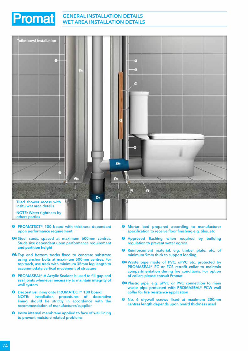
74
GEnERAl InSTAllATIOn dETAIlS WET AREA InSTAllATIOn dETAIlS
1 PROMATECT® 100 board with thickness dependant upon performance requirement
2a Steel studs, spaced at maximum 600mm centres. Studs size dependant upon performance requirement and partition height
2b Top and bottom tracks fixed to concrete substrate using anchor bolts at maximum 500mm centres. For top track, use track with minimum 35mm leg length to accommodate vertical movement of structure
3 PROMASEAl®-A Acrylic Sealant is used to fill gap and seal joints whenever necessary to maintain integrity of wall system
4 decorative lining onto PROMATECT® 100 board nOTE: Installation procedures of decorative
lining should be strictly in accordance with the recommendation of manufacturer/supplier
5 Insitu internal membrane applied to face of wall lining to prevent moisture related problems
6 Mortar bed prepared according to manufacturer specification to receive floor finishing e.g. tiles, etc
7 Approved flashing when required by building regulation to prevent water egress
8 Reinforcement material, e.g. timber plate, etc. of minimum 9mm thick to support loading
9a Waste pipe made of PVC, uPVC etc. protected by PROMASEAl® FC or FCS retrofit collar to maintain compartmentation during fire conditions. For option of collars please consult Promat
9a Plastic pipe, e.g. uPVC or PVC connection to main waste pipe protected with PROMASEAl® FCW wall collar for fire resistance application
0 no. 6 drywall screws fixed at maximum 200mm centres length depends upon board thickness used
Tiled shower recess with insitu wet area details
nOTE: Water tightness by others parties
Toilet bowl installation
1
4
0
5
7
8
1
2a
2b
9a
2b
9b
3 6

75
1 PROMATECT® 100 board with thickness dependant upon performance requirement
2 decorative lining, e.g. ceramic or stone tiles
3 use adhesive to install decorative lining. Type of adhesive and application should strictly follow manufacturers recommendations
4 use of flashing tape to prevent water ingress
5 Bath tub specified by architect or designer. Installation to be carried out according to manufacturer specification
6 Supporting batten fixed to wall framing using appropriate screw fixing to secure bath tub in position
7 Bottom track
8 PROMASEAl®-A Acrylic Sealant
9 Maximum 6mm gap is allow to accommodate fixing of bath tub. Any gap thereafter should be properly sealed with appropriate flexible sealant
0 Anchor bolts bolts at maximum 500mm centres
GEnERAl InSTAllATIOn dETAIlS WET AREA InSTAllATIOn dETAIlS
Bath tub installation
nOTE: Water tightness is responsibility of other parties
9
6
7
7
0
0
8
8
1
1
2
2
3
4
5

76
1 PROMATECT® 100 board with thickness dependant upon performance requirement
2 decorative lining, e.g. ceramic or stone tiles
3a Timber reinforcement
3b Timber block fixed between steel studs acting as reinforcement to support loading from basin fixture
4a Typical shower head (with/without handle) as specified by architect or designer
4b Knob to control water inlet. This is specified by architect or designer
4c Basin as specified by architect or designer
5 Water waste pipe, e.g. uPVC, etc. connecting to main sewage system
6 For fire protection application; PROMASEAl® FCW wall collar can be used to prevent fire spread through opening or gap. In cases where waste pipe penetrates floor slab, PROMASEAl® FC or FCS retrofit collar system may be used instead. For other option please consult Promat
7 PromaSnap® floor waste collar
8 Bottom track
9 Anchor bolt to concrete substrate
0 PROMASEAl®-A Acrylic Sealant
GEnERAl InSTAllATIOn dETAIlS WET AREA InSTAllATIOn dETAIlS
Shower Add-on hand basin with accessories
3a
4a
4c
4b
3b
11
2
2
5
5
6
8
9
9
7
0
0

77
1 PROMATECT® or PROMInA® board with thickness dependant upon performance requirement
2 Timber supporting battern
3 Steel stud
4 PROMASEAl® A Sealant for copper and steel pipes. use PROMASEAl® Intumescent pipe collars for plastic pipes greater than 25mm in diameter
5 uPVC or PVC or copper or steel pipework
6 Ceramic tiles
GEnERAl InSTAllATIOn dETAIlS WET AREA InSTAllATIOn dETAIlS
Typical framing details for water tap support and penetrations
1
4
1
6
2
5
5
6
11
3
3
3
3
2
2

Multiple services penetration through wall
Plastic pipe penetration through wall
78
GEnERAl InSTAllATIOn dETAIlS PEnETRATIOn SEAlS And ACCESS HATCHES
1 One or two layers of PROMATECT® 100 boards, maximum size 700mm x 700mm
2 PROMATECT® 100 board 50mm thick, fixed to concrete/masonry wall using anchor bolts or 75mm x self-tapping Teks screws steel/timber framed lightweight partition at nominal 200mm centres
3 PROMATECT® 100 board 9mm thick
4 Hinges
5 General building services, e.g. electrical cables, metal pipes etc
6 Fire resistant concrete/masonry wall or steel/timber framed lightweight partition
1 PROMASTOP® uniCollar®
2 Suitable fixing, i.e. laminating screws for lightweight partitions OR steel bolt anchors for masonry/concrete floors
3 Various building services, e.g. electrical cables, plastic (uPVC or PEX)pipes and/or insulated copper pipes
4 Fire resistance lightweight partitions
5 All gaps between collars and services filled with PROMASEAl® Grafitex
1 PROMASEAl® Bulkhead Sealer coating (or PROMASEAl®-A Acrylic Sealant), with minimum 100mm length of coating on the penetrating elements measured from the openings
2 One layer of mineral wool 50mm thick x 120kg/m³ for up to -/120/90 fire resistance or two layers of PROMASEAl® Bulkhead batten 50mm thick x minimum 120kg/m³ for up to -/120/120 fire resistance
3 PROMASEAl® Wrap
4 PROMASEAl® Retrofit Collar (square base) fixed through the batt with a threaded rod
5 non combustible plastic pipes with appropriate support within 300mm from both sides of the Bulkhead barrier
6 Electrical cables supported with cable tray or steel trunking within 300mm from both sides of the Bulkhead barrier
7 Fire resistant concrete or masonry walls
PROMASEAl®-A Acrylic Sealant (not shown above) should be liberally applied to all joints and contact points between the Bulkhead barrier and items 3 or 5 And between the barrier and the floor
4
1
5
2
3
7
2
5
6
50mm100mm
Maximum
800mm
Minimum
100mm1
4
3
Wall access hatch
5
6
1
3
2
2
4
4

79
GEnERAl InSTAllATIOn dETAIlS OTHER dETAIlS
1 PROMATECT® 100 board with thickness dependant upon performance requirement
2 Insulation material enhances thermal insulation of building
3 Steel studs at maximum 610mm centres. Stud size dependant upon performance requirement and partition height
4 Fire resistance switchbox based upon performance. Please consult Promat
5 PROMASEAl® Switchbox intumescent infill
6 PROMASEAl®-A Acrylic Sealant is used to seal gap to maintain integrity of partition system
7 PROMASEAl® Expansion Joint Strip
nOTE: Weather tight sealing and structural design under the responsibility of other parties. Please consult Promat
Curtain wall detail
Power outlet/light switch installation
nOTE: For fire resistant walls, steel electrical switch boxes should be employed to avoid degrading fire performance of the wall system
1
1
4
4
5
116
1
6
6
2
3
7

P100
80
1 One layer of PROMATECT® 100 board 15mm thick at both sides of steel studs
2 Galvanised steel studs, measurements in accordance with Studs Tables on page 94 (allow appropriate expansion at top horizontal track, no allowance at this track for loadbearing purposes)
3 25mm long self-tapping screws at maximum 300mm centres
4 40mm long M6 masonry anchors at nominal 500mm centres
5 Caulk all perimeter gaps with PROMASEAl®-A Acrylic Sealant to achieve the required fire resistance and/or acoustic performance
See page 60 and 61 for bottom and top track fixings; pages 67 to 71 for details of wall head, wall base, wall junction and wall movement joints.
Acoustic Table
Stud depth 64mm 76mm 92mm 150mm
Cavity infill # STC / Rw (Ctr)
a) Nil 41/40dB (-10) 42/41dB (-10) 42/42dB (-10) 42/44dB (-7)
b) Bradford R2.0 Soundscreen 50mm x 32kg/m3 46/46dB (-12) 48/47dB (-11) 49/48dB (-11) 50/50dB (-8)
c) Bradford R2.0 Soundscreen 75mm x 32kg/m3 46/46dB (-12) 48/47dB (-11) 49/48dB (-10) 50/50dB (-8)
d) R1.8 Pink Wall Batts 60mm x 9kg/m3 45/45dB (-12) 47/46dB (-11) 49/47dB (-11) 50/49dB (-8)
nOTE: Above values are predicted figures. # Margin of error is generally within ±3dB
Fire
resi
stan
ce
FRl -/90/60
Standard BS 476: Part 22: 1987AS 1530: Part 4: 2005
Approval WFRA 41096WFRA 41096
Aco
usti
c
STC, Rw See acoustic table below
Standard ISO 140: Part 3: 1996ISO 717: Part 1: 1996
Predicted assessment
Marshall Day13th October 2016
Co
nstr
ucti
on
Maximum height* 7800mm
Maximum length Unlimited
Partition thickness From 94mm
Partition mass* From 27kg/m2
* details for walls above 7800mm high are available on request
22.60.1SInGlE STEEl STud PARTITIOn (dOuBlE SIdEd)
5
1
3
4
2
2
Fire attack from both sides / non loadbearing and loadbearing

P100
81
1 One layer of PROMATECT® 100 board 20mm thick at both sides of steel studs
2 Galvanised steel studs, measurements in accordance with Studs Tables on page 94 (allow appropriate expansion at top horizontal track, no allowance at this track for loadbearing purposes)
3 45mm long self-tapping screws at maximum 300mm centres
4 40mm long M6 masonry anchors at nominal 500mm centres
5 Caulk all perimeter gaps with PROMASEAl®-A Acrylic Sealant to achieve the required fire resistance and/or acoustic performance
See page 60 and 61 for bottom and top track fixings; pages 67 to 71 for details of wall head, wall base, wall junction and wall movement joints.
Acoustic Table
Stud depth 64mm 76mm 92mm 150mm
Cavity infill # STC / Rw (Ctr)
a) Nil 42/43dB (-11) 42/43dB (-9) 42/44dB (-9) 42/46dB (-7)
b) Bradford R2.0 Soundscreen 50mm x 32kg/m3 48/48dB (-10) 48/49dB (-10) 48/49dB (-8) 48/51dB (-7)
c) Bradford R2.0 Soundscreen 75mm x 32kg/m3 49/48dB (-10) 49/49dB (-10) 49/50dB (-9) 49/51dB (-7)
d) R1.8 Pink Wall Batts 60mm x 9kg/m3 48/47dB (-11) 48/48dB (-10) 48/49dB (-9) 48/51dB (-8)
nOTE: Above values are predicted figures. # Margin of error is generally within ±3dB
Fire
resi
stan
ce
FRl -/120/120120/120/120
Standard BS 476: Part 22: 1987AS 1530: Part 4: 2005
Approval WFRA 41088WFRA 45883
Aco
usti
c
STC, Rw See acoustic table below
Standard ISO 140: Part 3: 1996ISO 717: Part 1: 1996
Predicted assessment
Marshall Day18th October 2006
Co
nstr
ucti
on
Maximum height* 7800mm
Maximum length Unlimited
Partition thickness From 104mm
Partition mass* From 35kg/m2
* details for walls above 7800mm high are available on request
22.12.122.12.2
SInGlE STEEl STud PARTITIOn (dOuBlE SIdEd)
5
1
3
4
2
2
Fire attack from both sides / non loadbearing and loadbearing

P100
82
1 One layer of PROMATECT® 100 board 20mm thick at both sides of steel studs
2 Cavity infill if required to improve acoustic or thermal insulation
3 Galvanised steel studs, measurements in accordance with Studs Tables on page 94 (allow appropriate expansion at top horizontal track, no allowance at this track for loadbearing purposes)
4 45mm long self-tapping screws at maximum 300mm centres
5 Caulk all perimeter gaps with PROMASEAl®-A Acrylic Sealant to achieve the required fire resistance and/or acoustic performance
See page 60 and 61 for bottom and top track fixings; pages 67 to 71 for details of wall head, wall base, wall junction and wall movement joints.
22.12.122.12.2
SInGlE STEEl STud PARTITIOn (dOuBlE SIdEd)
Vertical sheeting (Below 3000mm) / non loadbearing and loadbearing
1
3
2
4
5
Max
imum
250
00m
m
Max
imum
300
mm

P100
83
1 One layer of PROMATECT® 100 board 20mm thick at both sides of steel studs
2 Cavity infill if required to improve acoustic or thermal insulation
3 Galvanised steel studs, measurements in accordance with Studs Tables on page 94 (allow appropriate expansion at top horizontal track, no allowance at this track for loadbearing purposes)
4 45mm long self-tapping screws at maximum 300mm centres
5 Caulk all perimeter gaps with PROMASEAl®-A Acrylic Sealant to achieve the required fire resistance and/or acoustic performance
See page 60 and 61 for bottom and top track fixings; pages 67 to 71 for details of wall head, wall base, wall junction and wall movement joints.
22.12.122.12.2
SInGlE STEEl STud PARTITIOn (dOuBlE SIdEd)
Vertical sheeting (Above 3000mm) / non loadbearing and loadbearing
12
3
5
4U
p to
780
0mm
Max
imum
300
mm

P100
84
1 One layer of PROMATECT® 100 board 20mm thick at both sides of steel studs
2 Cavity infill if required to improve acoustic or thermal insulation
3 Galvanised steel studs, measurements in accordance with Studs Tables on page 94 (allow appropriate expansion at top horizontal track, no allowance at this track for loadbearing purposes), refer to table below for the distance between stud
4 45mm long self-tapping screws at maximum 300mm centres
5 Caulk all perimeter gaps with PROMASEAl®-A Acrylic Sealant to achieve the required fire resistance and/or acoustic performance
See page 60 and 61 for bottom and top track fixings; pages 67 to 71 for details of wall head, wall base, wall junction and wall movement joints.
22.12.122.12.2
SInGlE STEEl STud PARTITIOn (dOuBlE SIdEd)
Horizontal sheeting with nogging joint / non loadbearing and loadbearing
1
5
4
2
Up
to 7
800m
m
Max
imum
300
mm
3

P100
85
1 One layer of PROMATECT® 100 board 20mm thick at both sides of steel studs
2 Cavity infill if required to improve acoustic or thermal insulation
3 Galvanised steel studs, measurements in accordance with Studs Tables on page 94 (allow appropriate expansion at top horizontal track, no allowance at this track for loadbearing purposes)
4 45mm long self-tapping screws at maximum 300mm centres
5 Caulk all perimeter gaps with PROMASEAl®-A Acrylic Sealant to achieve the required fire resistance and/or acoustic performance
6 20mm thick PROMATECT® 100 cover strips at horizontal board joint
See page 60 and 61 for bottom and top track fixings; pages 67 to 71 for details of wall head, wall base, wall junction and wall movement joints.
22.12.122.12.2
SInGlE STEEl STud PARTITIOn (dOuBlE SIdEd)
Horizontal sheeting with strip joint / non loadbearing and loadbearing
1
5
4
2
6
Up
to 7
800m
m
Max
imum
300
mm
3

P100
86
1 One layer of PROMATECT® 100 board 20mm thick at both sides of steel studs
2 Cavity infill if required to improve acoustic or thermal insulation
3 Galvanised steel studs, measurements in accordance with Studs Tables on page 94 (allow appropriate expansion at top horizontal track, no allowance at this track for loadbearing purposes)
4 45mm long self-tapping screws at maximum 300mm centres
5 Caulk all perimeter gaps with PROMASEAl®-A Acrylic Sealant to achieve the required fire resistance and/or acoustic performance
6 Fixing channel 100mm x 10mm x 0.9mm thick
See page 60 and 61 for bottom and top track fixings; pages 67 to 71 for details of wall head, wall base, wall junction and wall movement joints.
22.12.122.12.2
SInGlE STEEl STud PARTITIOn (dOuBlE SIdEd)
Horizontal sheeting with channel joint / non loadbearing and loadbearing
1
5
4
2
6
Up
to 7
800m
m
Max
imum
300
mm
3

P100
87
22.24.1SInGlE STEEl STud PARTITIOn (dOuBlE SIdEd)
1 Two layer of PROMATECT® 100 board 20mm thick on both sides of steel studs
2 Galvanised steel studs, measurements in accordance with Studs Tables on page 94 (allow appropriate expansion at top horizontal track, no allowance at this track for loadbearing purposes)
3 32mm long self-tapping screws at maximum 300mm centres 50mm long self-tapping screws at maximum 200mm centres to fixed second layer to frame 40mm long stiching screws at maximum 200mm centres to fixed second layer to first layer
4 40mm long M10 masonry anchors at nominal 500mm centres
5 Caulk all perimeter gaps with PROMASEAl®-A Acrylic Sealant to achieve the required fire resistance and/or acoustic performance
See page 60 and 61 for bottom and top track fixings; pages 67 to 71 for details of wall head, wall base, wall junction and wall movement joints.
Acoustic Table
Stud depth 92mm 150mm
Cavity infill # STC / Rw (Ctr)
a) Nil 53/54dB (-7) 53/55dB (-6)
b) Bradford R2.0 Soundscreen 50mm x 32kg/m3 55/58dB (-6) 55/59dB (-6)
c) Bradford R2.0 Soundscreen 75mm x 32kg/m3 55/58dB (-6) 55/59dB (-6)
d) R1.8 Pink Wall Batts 60mm x 9kg/m3 55/58dB (-6) 55/59dB (-6)
nOTE: Above values are predicted figures. # Margin of error is generally within ±3dB
Fire
resi
stan
ce
FRl -/240/240
Standard AS 1530: Part 4: 2005
Approval FSRG 2014-054
Aco
usti
c
STC, Rw See acoustic table below
Standard ISO 140: Part 3: 1996ISO 717: Part 1: 1996
Predicted assessment
Marshall Day13th October 2016
Co
nstr
ucti
on
Maximum height* 3000mm
Maximum length Unlimited
Partition thickness From 164mm
Partition mass* From 70kg/m2
5
1
3
4
2
2
Fire attack from both sides / non loadbearing and loadbearing

P100
88
22.24.1SInGlE STEEl STud PARTITIOn (dOuBlE SIdEd)
1 Two layer of PROMATECT® 100 board 20mm thick on both sides of steel studs
2 Cavity infill if required to improve acoustic or thermal insulation
3 Galvanised steel studs, measurements in accordance with Studs Tables on page 94 (allow appropriate expansion at top horizontal track, no allowance at this track for loadbearing purposes)
4 32mm long self-tapping screws at maximum 300mm centres 50mm long self-tapping screws at maximum 200mm centres to fixed second layer to frame 40mm long stiching screws at maximum 200mm centres to fixed second layer to first layer
5 Caulk all perimeter gaps with PROMASEAl®-A Acrylic Sealant to achieve the required fire resistance and/or acoustic performance
See page 60 and 61 for bottom and top track fixings; pages 67 to 71 for details of wall head, wall base, wall junction and wall movement joints.
Vertical sheeting (Below 3000mm) / non loadbearing and loadbearing
1
3
2
4
5
Max
imum
300
0mm
Max
imum
200
mm

P100
89
22.24.1SInGlE STEEl STud PARTITIOn (dOuBlE SIdEd)
1 Two layer of PROMATECT® 100 board 20mm thick on both sides of steel studs
2 Cavity infill if required to improve acoustic or thermal insulation
3 Galvanised steel studs, measurements in accordance with Studs Tables on page 94 (allow appropriate expansion at top horizontal track, no allowance at this track for loadbearing purposes)
4 32mm long self-tapping screws at maximum 300mm centres 50mm long self-tapping screws at maximum 200mm centres to fixed second layer to frame 40mm long stiching screws at maximum 200mm centres to fixed second layer to first layer
5 Caulk all perimeter gaps with PROMASEAl®-A Acrylic Sealant to achieve the required fire resistance and/or acoustic performance
See page 60 and 61 for bottom and top track fixings; pages 67 to 71 for details of wall head, wall base, wall junction and wall movement joints.
Vertical sheeting (Above 3000mm) / non loadbearing and loadbearing
12
3
5
4
Up
to 3
000m
m
Min
imum
200
mm

P100
90
22.24.1SInGlE STEEl STud PARTITIOn (dOuBlE SIdEd)
1 Two layer of PROMATECT® 100 board 20mm thick on both sides of steel studs
2 Cavity infill if required to improve acoustic or thermal insulation
3 Galvanised steel studs, measurements in accordance with Studs Tables on page 94 (allow appropriate expansion at top horizontal track, no allowance at this track for loadbearing purposes), refer to table below for the distance between stud
3 32mm long self-tapping screws at maximum 300mm centres 50mm long self-tapping screws at maximum 200mm centres to fixed second layer to frame 40mm long stiching screws at maximum 200mm centres to fixed second layer to first layer
5 Caulk all perimeter gaps with PROMASEAl®-A Acrylic Sealant to achieve the required fire resistance and/or acoustic performance
See page 60 and 61 for bottom and top track fixings; pages 67 to 71 for details of wall head, wall base, wall junction and wall movement joints.
Horizontal sheeting with nogging joint / non loadbearing and loadbearing
1
5
4
2
Up
to 3
000m
m
Max
imum
200
mm
3

P100
91
22.24.1SInGlE STEEl STud PARTITIOn (dOuBlE SIdEd)
1 Two layer of PROMATECT® 100 board 20mm thick on both sides of steel studs
2 Cavity infill if required to improve acoustic or thermal insulation
3 Galvanised steel studs, measurements in accordance with Studs Tables on page 94 (allow appropriate expansion at top horizontal track, no allowance at this track for loadbearing purposes)
3 32mm long self-tapping screws at maximum 300mm centres 50mm long self-tapping screws at maximum 200mm centres to fixed second layer to frame 40mm long stiching screws at maximum 200mm centres to fixed second layer to first layer
5 Caulk all perimeter gaps with PROMASEAl®-A Acrylic Sealant to achieve the required fire resistance and/or acoustic performance
6 20mm thick PROMATECT® 100 cover strips at horizontal board joint
See page 60 and 61 for bottom and top track fixings; pages 67 to 71 for details of wall head, wall base, wall junction and wall movement joints.
Horizontal sheeting with strip joint / non loadbearing and loadbearing
1
5
4
2
6
Up
to 3
000m
m
Max
imum
200
mm
3

P100
92
22.24.1SInGlE STEEl STud PARTITIOn (dOuBlE SIdEd)
1 Two layer of PROMATECT® 100 board 20mm thick on both sides of steel studs
2 Cavity infill if required to improve acoustic or thermal insulation
3 Galvanised steel studs, measurements in accordance with Studs Tables on page 94 (allow appropriate expansion at top horizontal track, no allowance at this track for loadbearing purposes)
3 32mm long self-tapping screws at maximum 300mm centres 50mm long self-tapping screws at maximum 200mm centres to fixed second layer to frame 40mm long stiching screws at maximum 200mm centres to fixed second layer to first layer
5 Caulk all perimeter gaps with PROMASEAl®-A Acrylic Sealant to achieve the required fire resistance and/or acoustic performance
6 Fixing channel 100mm x 10mm x 0.9mm thick
See pages 60 and 61 for bottom and top track fixings; pages 67 to 71 for details of wall head, wall base, wall junction and wall movement joints.
Horizontal sheeting with channel joint / non loadbearing and loadbearing
1
5
4
2
6
Up
to 3
000m
m
Max
imum
200
mm
3

P100
93
The following are standard Architectural Specifications for single steel stud partition systems using PROMATECT® 100. The designer must determine the suitability of the design to the application and requirements before undertaking or constructing any works relating to the specifications and where in doubt should obtain the advice of a suitably qualified engineer.
Fire attack from either side / non loadbearing
Up to 240 minute fire resistance, integrity and insulation in accordance with the criteria of BS 476: Part 22: 1987 and AS 1530: Part 4: 2005(1). Lateral load of up to 0.25kPa.
Acoustic performance
The partition system shall have a Weighted Sound Reduction Index up to Rw 50.
Supporting structure
Care should be taken that any structural element that the partition system is supported from, e.g. steel stud or perimeter steel channel, has fire resistance equal to or greater than 120 minutes.
Lining boards
One or two(2) layer on either side of 15mm or 20mm(3) thick PROMATECT® 100 PromaX® mineral boards as manufactured by Promat International (Asia Pacific) Ltd. All joints to be coincident with steel framing. Standard board dimension 1200mm x 2500mm x 20mm thick.
Fixing
Galvanised steel frame made of ceiling and floor tracks will be secured to the floor, ceiling and walls with 40mm long M6 masonry anchors at 500mm centres. Vertical steel studs are then friction fitted into the tracks at 600mm centres for boards to be installed with long edge vertically and at 625mm centres for boards to be installed with long edge horizontally. Adequate clearance for vertical expansion will be allowed at the ceiling/top track. No clearance is necessary at the bottom track. See table below for steel size and clearance at top track for given partition height.
Horizontal noggings, cut out of the steel track material will be friction fitted between the steel studs to coincide with horizontal joints between boards.
22.60.122.12.122.12.222.24.1
SInGlE STEEl STud PARTITIOn (dOuBlE SIdEd) ARCHITECTuRAl SPECIFICATIOn
Continued on next page

P100
94
Studs tablePartitions lined with 20mm thick PROMATECT® 100 using studs at 600mm centres, 0.25kPa, minimum two rows of nogging at 1200mm centres.
Maximum partition height Stud depth Maximum stud
thicknessMaximum partition
thickness Top track Clearance at top track
3000mm 64mm 0.5mm 104mm 64 x 50 x 0.75mm 20mm
3600mm 64mm 0.75mm 104mm Special Design* 24mm
4000mm 64mm 1.15mm 104mm Special Design* 29mm
3500mm 76mm 0.55mm 116mm Special Design* 23mm
4100mm 76mm 0.75mm 116mm Special Design* 28mm
4850mm 76mm 1.15mm 116mm Special Design* 33mm
3733mm 92mm 0.55mm 132mm Special Design* 25mm
4700mm 92mm 0.75mm 132mm Special Design* 32mm
5600mm 92mm 1.15mm 132mm Special Design* 38mm
5867mm 150mm 0.75mm 190mm Special Design* 39mm
7800mm 150mm 1.15mm 190mm Special Design* 50mm
*Top tracks are designed or tested in accordance with AS 4600: 1996 for a clearance between stud and top track as shown above. Please consult Promat for further details.20mm thick PROMATECT® 100 boards will be screw-fixed to the frame with 35mm x No.8 self-tapping screws at maximum 300mm centres.
Tests & standards
Along with all material tests the complete system along with the framing is tested in accordance with the criteria of BS 476: Part 476: 1987 and/or AS 1530: Part 4: 2005(1). The partition system should meet the requirements specified in BCA 2006 Specification Clause 1.8 for static, dynamic and indentation load tests as specified under Clauses 3.1, 3.2 and 3.4.
Jointing
Plain butt joints between machined edges of boards. (4)
Joints filled in preparation for painting. (5)
Joints filled and taped in preparation for decoration. (6)
Follow-on trades
Surface of boards to be prepared for painting/plastering/tiling(5) in accordance with manufacturer’s recommendations.
NOTES:•(1), (2), (3), (4), (5), (6) delete as appropriate.•AllperimetergapscaulkedwithPROMASEAL®-AAcrylicSealant.
22.60.122.12.122.12.222.24.1
SInGlE STEEl STud PARTITIOn (dOuBlE SIdEd) ARCHITECTuRAl SPECIFICATIOn

P100
95
22.12.3
1 One layer of PROMATECT® 100 board 20mm thick at both sides of steel studs
2 Galvanised steel studs, measurements in accordance with Studs Table on page 98 (allow appropriate expansion at top horizontal track, no allowance at this track for loadbearing purposes)
3 45mm long no.8 self-tapping screws at maximum 300mm centres
4 40mm long M6 masonry anchors at nominal 500mm centres
5 Caulk all perimeter gaps with PROMASEAl®-A Acrylic Sealant to achieve the required fire resistance and/or acoustic performance
6 A minimum 10mm air space to be left between the frames to ensure best acoustic performance
Acoustic Table
Stud depth 64mm 76mm 92mm 150mm
Cavity infill # STC / Rw (Ctr)
a) Nil 40/44dB (-6) 41/45dB (-6) 43/46dB (-6) 47/49dB (-7)
b) Glasswool partition batts 50mm x 32kg/m3 58/59dB (-8) 58/60dB (-7) 58/60dB (-6) 58/61dB (-5)
c) Glasswool partition batts 75mm x 32kg/m3 59/59dB (-7) 59/60dB (-7) 59/61dB (-7) 59/62dB (-6)
d) ASB3 / TSB3 Polyester batts 60mm x 8kg/m3 56/57dB (-6) 56/58dB (-6) 56/59dB (-6) 56/59dB (-5)
e) Soundscreen™ R1.6 Batts 60mm 57/58dB (-7) 57/59dB (-7) 57/59dB (-6) 57/60dB (-5)
nOTE: Above values are predicted figures. # Margin of error is generally within ±3dB
Fire
resi
stan
ce FRl -/120/120
Standard BS 476: Part 22: 1987AS 1530: Part 4: 2005
Approval WFRA 41088
Aco
usti
c
STC, Rw See acoustic table below
Standard ISO 140: Part 3: 1996ISO 717: Part 1: 1996
Predicted assessment
Marshall Day18th October 2006
Co
nstr
ucti
on
Maximum height* 3000mm
Maximum length Unlimited
Partition thickness From 178mm
Partition mass* From 36kg/m2
* details for walls above 3000mm high are available on request
dOuBlE STEEl STud PARTITIOn (dOuBlE SIdEd)
5
1
3
46
2
Fire attack from both sides / non loadbearing

P100
96
22.12.3
1 One layer of PROMATECT® 100 board 20mm thick at both sides of steel studs
2 Cavity infill if required to improve acoustic or thermal insulation
3 Galvanised steel studs, measurements in accordance with Studs Table on page 98 (allow appropriate expansion at top horizontal track, no allowance at this track for loadbearing purposes)
4 45mm long no.8 self-tapping screws at maximum 300mm centres
5 Caulk all perimeter gaps with PROMASEAl®-A Acrylic Sealant to achieve the required fire resistance and/or acoustic performance
6 20mm thick PROMATECT® 100 cover strips
7 A minimum 10mm air space to be left between the frames to ensure best acoustic performance
See pages 60 and 61 for bottom and top track fixings; pages 67 to 71 for details of wall head, wall base, wall junction and wall movement joints.
dOuBlE STEEl STud PARTITIOn (dOuBlE SIdEd)
Horizontal sheeting with strip joint / non loadbearing
1
6
7
3
2
4
5
Up
to 7
800m
m
Max
imum
300
mm

P100
97
The following are standard Architectural Specifications for double steel stud partition systems using PROMATECT® 100. The designer must determine the suitability of the design to the application and requirements before undertaking or constructing any works relating to the specifications and where in doubt should obtain the advice of a suitably qualified engineer.
Fire attack from either side / non loadbearing
Up to 120 minute fire resistance, integrity and insulation in accordance with the criteria of BS 476: Part 476: 1987 and/or AS 1530: Part 4: 2005(1).
Acoustic performance
The partition system shall have a Weighted Sound Reduction Index up to Rw 60.
Supporting structure
Care should be taken that any structural element that the partition system is supported from, e.g. steel stud or perimeter steel channel, has a fire resistance equal to or greater than 120 minutes.
Lining boards
Single layer each side 20mm thick PROMATECT® PromaX® mineral boards as manufactured by Promat International (Asia Pacific) Ltd. All joints to be coincident with steel framing. Standard board dimension 1200mm x 2500mm x 20mm thick.
Fixing
2 rows of galvanised steel framing made of ceiling and floor tracks will be secured to the floor, ceiling and walls with 40mm long M6 masonry anchors at 500mm centres. An air gap of 10mm minimum will be provided between the two rows of the galvanised steel frame. Vertical steel studs are then friction fitted into each of the two rows tracks at 600mm centres for boards to be installed vertically and at 625mm centres for boards to be installed horizontally. Adequate clearance for vertical expansion will be allowed at the ceiling/top track. No clearance is necessary at the bottom track. See table below for steel size and clearance at top track for given partition height.
Horizontal noggings, cut out of the steel track material will be friction fitted between the steel studs.
22.12.3dOuBlE STEEl STud PARTITIOn (dOuBlE SIdEd) ARCHITECTuRAl SPECIFICATIOn
Continued on next page

P100
98
Studs table
Partitions lined with 20mm thick PROMATECT® 100 using studs at 600mm centres, 0.25kPa, minimum two rows of nogging.
Maximum partition height Stud depth Maximum stud
thicknessMaximum partition
thickness Top track Clearance at top track
3000mm 64mm 0.5mm 104mm 64 x 50 x 0.75mm 20mm
3600mm 64mm 0.75mm 104mm Special Design* 24mm
4000mm 64mm 1.15mm 104mm Special Design* 29mm
3500mm 76mm 0.55mm 116mm Special Design* 23mm
4100mm 76mm 0.75mm 116mm Special Design* 28mm
4850mm 76mm 1.15mm 116mm Special Design* 33mm
3733mm 92mm 0.55mm 132mm Special Design* 25mm
4700mm 92mm 0.75mm 132mm Special Design* 32mm
5600mm 92mm 1.15mm 132mm Special Design* 38mm
5867mm 150mm 0.75mm 190mm Special Design* 39mm
7800mm 150mm 1.15mm 190mm Special Design* 50mm
*Top tracks are designed or tested in accordance with AS 4600: 1996 for a clearance between stud and top track as shown above. Please consult Promat for further details.20mm thick PROMATECT® 100 boards will be screw fixed to the frame with 35mm long No.8 self-tapping screws at maximum 300mm centres.
Tests & standards
Along with all material tests the complete system along with the framing is tested in accordance with the criteria of BS 476: Part 476: 1987 and/or AS 1530: Part 4: 2005(1).
Jointing
Plain butt joints between machined edges of boards. (2)
Joints filled in preparation for painting. (3)
Joints filled and taped in preparation for decoration. (4)
Follow-on trades
Surface of boards to be prepared for painting/plastering/tiling(5) in accordance with manufacturer’s recommendations.
NOTES:•(1), (2), (3), (4), (5) delete as appropriate.•AllperimetergapscaulkedwithPROMASEAL®-AAcrylicSealant.
22.12.3dOuBlE STEEl STud PARTITIOn (dOuBlE SIdEd) ARCHITECTuRAl SPECIFICATIOn

P100
99
21.12.121.12.2
TIMBER STud PARTITIOn
1 One layer of PROMATECT® 100 board 20mm thick
2 Timber studs 90mm deep x 45mm wide at nominal 600mm or 625mm centres
3 100mm long no.8 woodscrews at 250mm nominal centres or 100mm long nails at 150mm centres
4 M6 expanding anchors at 600mm maximum centres
5 Caulk all perimeter gaps with PROMASEAl®-A Acrylic Sealant to achieve the required fire resistance and/or acoustic performance
For loadbearing partition, the required size of the stud should be calculated by a qualified structural engineer who must allow for the depth of the stud to be reduced by 50mm and width by 10mm through charring and the consequential reduction in loadbearing capability
Fire
resi
stan
ce FRl -/120/120120/120/120
Standard BS 476: Part 22: 1987AS 1530: Part 4: 2005
Approval BRE CC 232158ABRE CC 232158B
Aco
usti
c
# STC# Rw
35dB39dB
Standard ISO 140: Part 3: 1996ISO 717: Part 1: 1996
Predicted assessment
Marshall Day18th October 2006
Co
nstr
ucti
on
Maximum height 3000mm
Maximum length Unlimited
Partition thickness From 130mm
Partition mass* From 37kg/m2
# Margin of error is generally within ±3dB
5
1
3
4
2
Fire attack from both sides / non loadbearing
45
23
1
6
15-20mm gap
Movement joints
nOTE: Top and bottom tracks must be discontinuous at control joints
1 PROMATECT® 100 board
2 PROMASEAl®-A Acrylic Sealant
3 Backing rod
4 ROndO P35 or equivalent control joint profile
5 Finish surface as per external angles
6 Timber studs 63mm x 50mm or 70mm x 38mm at 600mm centres

P100
100
21.12.121.12.2
TIMBER STud PARTITIOn
1 One layer of PROMATECT® 100 board 20mm thick
2 Vertical studs at 600mm centres
3 Horizontal nogging at 1250mm centres
4 100mm x no.8 woodscrews at 250mm nominal centres or 100mm long nails at 150mm centres
5 Caulk all perimeter gaps with PROMASEAl®-A Acrylic Sealant to achieve the required fire resistance and/or acoustic performance
See page 63 for fixings of cross noggings and floor plate; page 99 for detail of wall movement joints.
Vertical sheeting / non loadbearing
1
5
4
3
Up
to 3
000m
m
Max
imum
250
mm
1250
mm
2

P100
101
21.12.121.12.2
TIMBER STud PARTITIOn
1 One layer of PROMATECT® 100 board 20mm thick
2 Vertical studs at 600mm centres
3 Horizontal nogging at 600mm centres
4 100mm long no.8 woodscrews at 250mm nominal centres
5 Caulk all perimeter gaps with PROMASEAl®-A Acrylic Sealant to achieve the required fire resistance and/or acoustic performance
See page 63 for fixings of cross noggings and floor plate; page 99 for detail of wall movement joints.
Horizontal sheeting with nogging joint / loadbearing
1
5
4
3000
mmM
axim
um 2
50m
m
3
600m
m
2

P100
102
21.12.121.12.2
TIMBER STud PARTITIOn ARCHITECTuRAl SPECIFICATIOn
The following are standard Architectural Specifications for timber stud partition systems using PROMATECT® 100. The designer must determine the suitability of the design to the application and requirements before undertaking or constructing any works relating to the specifications and where in doubt should obtain the advice of a suitably qualified engineer.
Fire attack from either side / non loadbearing & loadbearing
Up to 120 minute fire resistance, integrity and insulation in accordance with the criteria of BS 476: Part 22: 1987 and AS 1530: Part 4: 2014(1).
Acoustic performance
The partition system shall have a Weighted Sound Reduction Index up to Rw 39.
Supporting structure
Care should be taken that any structural element that the partition system is supported from, e.g. steel stud or perimeter steel channel, has a fire resistance equal to or greater than 120 minutes.
Lining boards
Single layer each side 20mm thick PROMATECT® 100 PromaX® mineral boards as manufactured by Promat International (Asia Pacific) Ltd. All joints to be coincident with steel framing. Standard board dimension 1200mm x 2500mm x 20mm thick.
Fixing
Softwood timber, 90mm deep x 45mm wide will be fixed to the perimeter of the opening where the partition system is to be installed using M6 expanding anchors at 600mm maximum centres.
Where the boards are to be installed with their long edges vertical, the studs are located at 600mm maximum centres with cross noggings at 1250mm centres. Where the boards are to be installed with their long edges horizontal, the studs are located at 625mm centres with cross noggings at 600mm centres.
The PROMATECT® 100 boards are fixed to the framework using 100mm long No.8 woodscrews at maximum 250mm centres or 100mm long nails at 150mm centres, a minimum of 12mm from the board edge.
Where there is a requirement for loadbearing, the required size of the timber stud will be calculated by a qualified structural engineer who should allow for the depth of the stud to be reduced by 50mm and the width by 10mm through charring.
Tests & standards
Along with all material tests the complete system along with the framing is tested in accordance with the criteria of BS 476: Part 22: 1987 and AS 1530: Part 4: 2014(1).
Jointing
Plain butt joints between machined edges of boards. (2)
Joints filled in preparation for painting. (3)
Joints filled and taped in preparation for decoration. (4)
Follow-on trades
Surface of boards to be prepared for painting/plastering/tiling(5) in accordance with manufacturer’s recommendations.
NOTES:•(1), (2), (3), (4), (5) delete as appropriate.•AllperimetergapscaulkedwithPROMASEAL®-AAcrylicSealant.

P100
103
23.12.1SOlId/FRAMElESS InTERnAl PARTITIOn
Fire
resi
stan
ce FRl -/120/120
Standard BS 476: Part 22: 1987AS 1530: Part 4: 2005
Approval BRANZ FAR 2837 and FAR 3309
Aco
usti
c
# STC# Rw
36dB36dB
Standard ISO 140: Part 3: 1996ISO 717: Part 1: 1996
Predicted assessment
Marshall Day18th October 2006
Co
nstr
ucti
on
Maximum height* 4300mm
Maximum length Unlimited
Partition thickness Nominal 40mm
Partition mass* 34kg/m2
# Margin of error is generally within ±3dB
1 Two layers of PROMATECT® 100 board, 20mm thick each stagger the joints by at least 300mm
2 Galvanised steel perimeter angle 50mm x 50mm x 1mm thick
3 40mm long M6 masonry anchors at nominal 500mm centres
4 32mm long no.8 self-tapping screws at nominal 300mm centres for first layer and 50mm long no.8 self-tapping screws at nominal 200mm centres for second layer
5 40mm long no.10 laminating stitching screws at 200mm centres
Once 1st layer of board is screwed to the perimeter angles, all subsequent layers are:
a) fixed to the perimeter angle, and
b) stitched to the proceeding layers of boards
1 PROMATECT® 100 board
2 Galvanised steel perimeter angle 50mm x 50mm x 1mm thick
3 40mm long M6 masonry anchors at nominal 500mm centres
4 32mm long no.8 self-tapping screws at nominal 300mm centres for first layer and 50mm long no.8 self-tapping screws at nominal 200mm centres for second layer
5 40mm long no.10 laminating stitching screws at 200mm centres
Once first layer of board is screwed to the perimeter angles, all subsequent layers are:
a) fixed to the perimeter angle, and
b) stitched to the proceeding layers of boards
1
2
5
4
3
Fire attack from both sides / non loadbearing
Wall base fixing Wall junction fixing
5
5
4
3
3
2
21
1

P100
104
23.12.1SOlId/FRAMElESS InTERnAl PARTITIOn
1 Two layers of PROMATECT® 100 board, 20mm thick each stagger the joints by at least 300mm
2 Galvanised steel perimeter angle 50mm x 50mm x 1mm thick
3 40mm long M6 masonry anchors at nominal 500mm centres
4 32mm long no.8 self-tapping screws at nominal 300mm centres for first layer and 50mm long no.8 self-tapping screws at nominal 200mm centres for second layer
5 40mm long no.10 laminating stitching screws at 200mm centres
Once first layer of board is screwed to the perimeter angles, all subsequent layers are:
a) fixed to the perimeter angle, and
b) stitched to the proceeding layers of boards
See page 103 for wall connection details
Two layer / non loadbearing
1
2
3
4
5
Up
to 3
000m
m
Max
imum
200
mm

P100
105
The following are standard Architectural Specifications for solid internal partition systems using PROMATECT® 100. The designer must determine the suitability of the design to the application and requirements before undertaking or constructing any works relating to the specifications and where in doubt should obtain the advice of a suitably qualified engineer.
Fire attack from either side / non loadbearing
Up to 120 minute fire resistance, integrity and insulation in accordance with the criteria of BS 476: Part 22: 1987 and AS 1530: Part 4: 2005(1).
Acoustic performance
The partition system shall have a Weighted Sound Reduction Index up to Rw 36.
Supporting structure
Care should be taken that any structural element by which the partition system is supported, e.g. steel stud or perimeter steel channel, has a fire resistance equal to or greater than 120 minutes.
Lining boards
Two layers of 20mm thick PROMATECT® 100 PromaX® mineral boards as manufactured by Promat International (Asia Pacific) Ltd. Stagger joints by at least 300mm. Standard board dimension 1200mm x 2500mm x 20mm thick.
Fixing
Galvanised steel frame made of perimeter steel angle 50mm x 50mm x 1mm thick will be fastened to the wall/floor/ceiling with 40mm long M6 masonry anchors at nominal 500mm centres.
First layer of 20mm thick PROMATECT® 100 boards will be fixed to the perimeter angle using 32mm long No.8 self-drilling or self-tapping screws at 300mm centres. Second layer 20mm, fixed to the first layer using 40mm long No.10 laminating stitching screws at 300mm centres down the centre of each panel at each board joint. Use 50mm x No.8 self-tapping screws at 200mm centres to fix second layer to the perimeter angle.
Tests & standards
The complete system along with material and framing is tested in accordance with the criteria of BS 476: Part 22: 1987 and AS 1530: Part 4: 2005(1).
Jointing
Plain butt joints between machined edges of boards. (2)
Joints filled in preparation for painting. (3)
Joints filled and taped in preparation for decoration. (4)
Follow-on trades
Surface of boards to be prepared for painting/plastering/tiling(5) in accordance with manufacturer’s recommendations.
NOTES:•(1), (2), (3), (4), (5) delete as appropriate.•AllperimetergapscaulkedwithPROMASEAL®-AAcrylicSealant.
23.12.1SOlId/FRAMElESS InTERnAl PARTITIOn ARCHITECTuRAl SPECIFICATIOn


Ceilings and floors

108
CEIlInGS & FlOORS SySTEM IndEX
Ceiling typeFire
resistance performance
Mineral woolthickness x density
Total ceilingthickness
Test/Approval no. Page no.
PROMATECT® 100 self-supporting
membrane ceiling
-/120/120 Not required From 150mmBRE CC 232157A
to the requirements ofAS 1530: Part 4: 2005
118
PROMATECT® 100 self-supporting
membrane ceiling
-/120/120 Not required From 150mmBRE CC 232157A
to the requirements ofAS 1530: Part 4: 2005
119
PROMATECT® 100 self-supporting
membrane ceiling
-/120/120 Not required From 105mmBRANZ FAR 2885
to the requirements ofAS 1530: Part 4: 2005
120
PROMATECT® 100 self-supporting
membrane ceiling
-/240/240 Not required From 156mmBRANZ FAR 4283
to the requirements ofAS 1530: Part 4: 2005
120
PROMATECT® 100timber floor protection
60/60/60 Not required 267mmBRANZ FAR 2886
to the requirements ofAS 1530: Part 4: 2005
124
PROMATECT® 100timber floor protection
90/90/90 Not required 267mmLPC TE90019
to the requirements ofBS 476: Part 21: 1987
125

109
CEIlInGS & FlOORS SySTEM IndEX
Ceiling typeFire
resistance performance
Mineral woolthickness x density
Total ceilingthickness
Test/Approval no. Page no.
PROMATECT® 100timber floor protection
90/90/90 Not required 287mmBRANZ FAR 2886
to the requirements ofAS 1530: Part 4: 2005
126
PROMATECT® 100timber floor protection
120/120/120 Not required 267mmBRANZ FAR 2924
to the requirements ofAS 1530: Part 4: 2005
127
PROMATECT® 100mezzanine floor
60/60/60 Not required 253mmBRE CC 234724
to the requirements ofAS 1530: Part 4: 2005
129
PROMATECT® 100mezzanine floor
120/120/120 Not required 278mmBRE CC 234729
to the requirements ofAS 1530: Part 4: 2005
130

110
Introduction
Promat carries a wide range of fire rated ceiling and floor systems with fire resistance of up to 240 minutes. Generally, Promat’s ceiling and floor systems provide horizontal fire barriers to prevent vertical spread of fire.
Promat’s ceiling and floor systems have been extensively tested and assessed to provide resistance to fire from above, below or above and below. They satisfy the integrity and insulation criteria of BS 476: Parts 20, 21, 22 and 23: 1987 and/or AS 1530 Part 4: 2005. The flooring systems not only meet the integrity and insulation criteria but also meet the loadbearing capacity (structural adequacy) criteria of the British and Australian national standards.
The system design depends on performance requirements but in overall terms, Promat’s ceiling and floor systems can be divided into the following categories.
Self-supporting membrane ceilings
These are normally non loadbearing and, depending on the type of construction, are used to provide protection from fire attack from below and/or above. Ceiling panels are fixed into a steel or timber framing system spanning and supported between two walls.
Self-supporting membrane ceilings should normally be tested or assessed in accordance with BS 476: Part 22: 1987 and/or AS 1530: Part 4: 2005 to satisfy the failure criteria of integrity and insulation.
These ceiling systems allow for the protection to or from services contained within the ceiling void. They will also provide protection to steel beams that are required to meet the criteria of BS 476: Parts 21 and 23: 1987 where exposure to fire is from below.
Suspended membrane Ceilings
These are normally non loadbearing and are used to provide protection from fire attack from below. The ceilings generally incorporate steel grid systems suspended from a structure.
Suspended membrane ceilings should normally be tested or assessed in accordance with BS 476: Part 22: 1987 and/or AS 1530: Part 4: 2005 to satisfy the failure criteria of integrity and insulation.
These ceiling systems allow for the protection to or from services contained within the ceiling void. They also provide protection to steel beams that are required to meet the criteria of BS 476: Parts 21 and 23: 1987 where exposure to fire is from below.
Loadbearing floor systems
The flooring can be of timber or chipboard floor boards supported by either timber joists or steel joists system. Promat boards can be directly fixed onto these joists or fixed to a suspended exposed or concealed metal grid system.
This type of ceiling should normally be tested or assessed in accordance with BS 476: Part 21: 1987 and/or AS 1530: Part 4: 2005 and are required to satisfy the three failure criteria of loadbearing capacity (structural adequacy), integrity and insulation.
Suspended ceiling protection to steel beams
This type of ceiling is used mainly for protection of steel beams supporting a loadbearing concrete floor slab and should be tested or assessed to BS 476: Part 23: 1987 and AS 1530: Part 4: 2005. Promat boards are fixed to a metal exposed or concealed grid system suspended from the structure above.
CEIlInGS & FlOORS GEnERAl InFORMATIOn

111
CEIlInGS & FlOORS GEnERAl InFORMATIOn
Advantages
Promat’s ceiling and floor systems require less material to achieve similar fire resistant levels when compared to the industry average. This can lead to more simplified construction methods than the standard equivalent. Use of Promat boards therefore helps to increase productivity and reduce overall installation costs.
Promat’s ceiling and floor systems have been developed by Promat International to satisfy standard requirements for internal applications. Benefits include:
Time & cost effectiveness
Simple construction methods reduce installation cost and time compared to traditional systems.
Lightweight
Lighter loads on structures compared to industry average systems for equivalent fire rating.
Thermal resistance
Excellent thermal resistance performance.
Design flexibility
Lighter weight allows increased ceiling span, reduced support structure sizes and/or reduced system thickness.
Acoustic performance
Tested and assessed to ISO140-3 1995 and ISO717-1 1996 to meet the needs of the industry. Please refer to the PARTITIONS section for more details.
Board fixing
Longitudinal board joints must coincide with framing members. If the boards are in one layer, the transverse joints must be backed with fillet strips made of Promat boards or timber noggings for traditional timber joist construction. For boards laminated in two layers, the joints must be staggered by at least 600mm.
Promat boards may be fixed to the steel members using No.8 bugle head self-drilling and self-tapping screws. No.8 woodscrews shall be used to fix boards to a timber frame. For boards laminated in two layers, the outer layer boards may be stitched to the preceding layer with No. 10 laminating screws.
Minimum edge distance to fasteners and the maximum spacing between screws must be maintained. Please refer to system details for screw spacing requirements.
General design considerations
Following are some of the factors to consider when determining correct specifications that ensure a ceiling or floor system provides the required design performance, under both fire and ambient conditions. Comprehensive advice is available from local Promat offices.
Supporting structure design
The design of the framing system should be adequate for the design loads of the ceiling and floor. Promat systems are designed for timber or steel framing as described in the system specification.
Timber framing systems used in loadbearing floor applications must be designed in accordance with BS 5268: 2006, AS 1720: Part 1: 2010 and/or AS 1684: 1999. The width, depth and spacing of joists must be carefully specified to ensure that the timber floor serves its intended fire performance.
For steel framed ceiling systems, it is critical to precisely follow the dimensions of the steel sections, the grid spacing, the suspension members (if any) and the fastening methods employed. Framing members could change depending on factors such as ceiling span, movement and deflection, and local regulations.
Larger or more frequent frame sections can often improve the fire and structural performance. The framing for the ceiling systems must be securely fixed back to a substrate that has an equal or greater fire performance than the ceiling. All fixings must be non-combustible and must be similar to those listed in the approval documents.
Non loadbearing ceilings
Promat non loadbearing ceiling systems can be generally divided into steel frame suspended ceiling and self-supporting membrane ceilings. The steel framing as noted in the system specification is appropriate for the given span. Larger dimension of steel sections or more frequent spacing will be required for a ceiling span larger than specified.
At wall connections, mechanical joints are required and these joints must be carefully designed so that they accommodate the required expansion of steel at elevated temperature.
Non loadbearing ceilings in this handbook are not trafficable. Trafficable ceilings for maintenance purposes can be designed and installed. Please consult Promat for complete information.

112
CEIlInGS & FlOORS GEnERAl InFORMATIOn
Loadbearing ceilings
Two types of Promat loadbearing floor systems are available. One is comprised of timber joists while the other is of steel joists. Flooring material, timber type, thickness and jointing are all critical. Timber framing, of solid timber only, must be designed in accordance with BS 5268: 2006, AS 1720.1: 2010 and/or AS 1684: 1999 whereas for steel framing, members must be designed in accordance with BS 5950: 2000 and/or AS 4600: 2005.
Acoustics
Promat ceiling and floor systems also meet specific acoustic requirements. These include ratings for sound transmission, sound impact and sound absorption. Please refer to pages 64 to 66 for further information.
Movement joint
Movement stress from dimensional changes due to varying temperature or moisture conditions can cause cracking and other symptoms of distress in ceiling linings.
Other external forces such as impact or vibration can directly affect structural movement of ceilings. This movement can be controlled through a variety of design techniques such as introducing perimeter relief and slip connections to reduce the transfer of stress from the structure to other building sub elements and/or through the use of expansion joints, control joints and construction joints.
Expansion joints are needed when a ceiling abuts a rigid mass. Where ceiling dimensions exceed 10m in either direction, a control joint should be used. Control joints should also be located to intersect column penetrations, light fixtures and air diffusers. It is however, the introduction of a control joint into a fire resistant system when an opening for flame and temperature transmission is created. This and similar openings have to be properly treated with approved fire stopping materials from Promat.
Caulking & service penetrations
To maintain fire performance and, where applicable, acoustic performance of ceiling systems, perimeter and other gaps must be appropriately filled with suitable caulking material. PROMASEAL®-A Acrylic Sealant or other tested fire and acoustic rated material of equivalent or better performance must be used.
Care needs to be taken in detailing a suitable fire stopping system around any penetration of the ceiling by services to ensure:
a) the fire stopping material remains in situ,
b) fire and smoke do not penetrate the floor cavity,
c) and a premature collapse of the joists and/or penetration of fire and smoke through the time flooring does not occur.
Allowance should be made for thermal movement of the services in both ambient and fire conditions to ensure unacceptable loads are not applied to the ceiling assembly. Some examples of service penetrations include penetrations by electrical cables, conduits or wires, plastic and metal pipes, air conditioning and ventilation ductwork. Further guidance on the sealing of service penetrations can be obtained from the Promat PASSIVE FIRE PROTECTION SYSTEMS APPLICATION & TECHNICAL MANUAL.
Light fittings
Light fittings located within a ceiling cavity should normally be enclosed in an adequately supported fire protection box to prevent fire spreading rapidly into the ceiling cavity. Most light fittings will require ventilation in normal use and this consideration should certainly be factored into light box design. Please consult Promat for details.
Access panels & hatches
Where access into a ceiling void is required, panels and hatches will need to be installed. Please refer to page 117 or consult Promat for details.
Conclusion
Most building regulations stipulate limitations on the use of fire protecting suspended ceilings in certain situations. Care should be therefore taken that the use of a suspended ceiling system is acceptable to the approval authorities.

113
Fixing of primary and secondary profiles
1 Wall u-profile
2 Horizontal C-profile
3 Fixing point
Steel frame components
Components selection
In order to maintain the fire and acoustic performance of Promat ceiling systems, the type of profile used for framing is important. Construction of fire resistant steel framed ceilings can be achieved using standard steel section components. Steel framing may be C or I-sections, furring channels, top hats, trusses or similar members which in all cases should be designed in accordance with BS 5950: 2000, AS 4600: 2005 and/or equivalent standard.
The profiles described in the system specification should be strictly followed at all times. However, the profiles may be amended as long as they possess comparable performances to the specified profiles.
Perimeter tracks & steel joists for self-supporting ceilings
This system is appropriate in most situations, particularly where it is difficult to install a suspended ceiling and/or within narrow rooms or corridors. No hangers are required, creating shorter installation times and provision of a completely free cavity for the accommodation of ductwork and services.
NOTE: For Australia, suitable framing profiles can be obtained from Rondo Building Services who provide comprehensive documentation for ceiling framing systems.
The framing system generally consists of a perimeter track profile and steel joists. During the design stage, choosing the right depth of the profile takes into account the maximum allowable span. The main function of perimeter tracks is to provide friction joints that hold the joists in position until the Promat board is fitted. They also provide allowance for movement of building structure under ambient conditions.
Under fire conditions, perimeter tracks of this nature allow the steel joists to expand, minimising deflection of the ceiling construction that may cause excessive cracking and then delamination of the lining boards. This type of joint is suitable for ceiling membrane systems of up to 3000mm span. Track sections should be fixed to the supporting structure using suitable masonry anchors at maximum 500mm intervals. Fixings should be located not more than 100mm from either end of the track section.
For membrane ceilings with a span of more than 3,000mm, mounting brackets are required at both ends of the steel joists. The mounting brackets will be attached to the wall, at the same time, and shall be designed to allow for expansion of the steel joists.
Please refer to pages 115 and 116 for further details.
CEIlInGS & FlOORS GEnERAl InFORMATIOn STEEl FRAME COMPOnEnTS

114
Steel framing system for suspended ceilingThis system is the most appropriate for the installation of large area suspended ceilings. The steel structure of the suspended ceiling is composed of a grid of C-profiles and accessories, made of galvanised steel. The standard length of the C-profile is either 3000mm or 6000mm.
Typical profiles for ceiling construction
Type: C-60 profile
Dimension: 60mm x 27mm
Application: Primary profile, secondary profile or cross profile
Type: Cross fixer
Dimension: 27mm x 55mm x 25mm (0.8mm)
Application: Fix cross profile to secondary profile
Type: Connector
Dimension: 27mm x 61.5mm x 100mm (0.8mm)
Application: To link two C-60 profiles
Type: Fixing hooks
Dimension: 50mm x 58mm x 0.8mm
Application: Fix secondary profile to primary profile
Type: Cross fixer
Dimension: 27mm x 55mm x 25mm (0.8mm)
Application: Fix cross profile to ceiling
1 Primary profile
2 Secondary profile
3 Fixing hooks
4 Connector
5 Hanger
6 Hanger wire
7 Promat board
nOTE: For details of framing requirements for the installation of access panels and hatches, please refer to the Access Panels section of this handbook.
CEIlInGS & FlOORS GEnERAl InFORMATIOn STEEl FRAME COMPOnEnTS
7
600mm
600mm
600mm
600mm
1200mm
1200mm
detail 1
detail 2
detail 3 and optional hanger types
1
1
64
5
2
23

115
1 Concealed grid suspended ceiling system
2 50mm x M6 expansion bolts at 500mm centres
3 Galvanised steel perimeter angle
4 PROMASEAl®-A Acrylic Sealant to maintain fire and acoustic performance
5 Ceiling trim or coving to perimeter
1 Galvanised steel perimeter channel
2 50mm x M6 expansion bolts at 500mm centres
3 Galvanised steel perimeter angle
4 PROMASEAl®-A Acrylic Sealant to maintain fire and acoustic performance
5 Ceiling trim or coving to perimeter
1 Galvanised steel perimeter channel
2 50mm x M6 expansion bolts at 500mm centres
3 Galvanised steel perimeter angle
4 PROMASEAl®-A Acrylic Sealant to maintain the fire and acoustic performance
5 ROndO P50 Shadowline Trim and set over
6 PROMASEAl® IBS™ Ø 22mm diameter to maintain fire performance (not suitable if acoustic integrity is required)
1 Concealed grid suspended ceiling system
2 50mm x M6 expansion bolts at 500mm centres
3 Galvanised steel perimeter angle
4 PROMASEAl®-A Acrylic Sealant to maintain fire and acoustic performance
5 Ceiling trim or coving to perimeter
6 Timber joists etc
GEnERAl InSTAllATIOn dETAIlS PERIMETER dETAIlS
1
1
1
45
323
3
2
2
4
64
2
2
5
5
Self-supporting ceiling perimeter to wall intersection (case 1)
Self-supporting ceiling perimeter to wall intersection (case 2)
Suspended ceiling perimeter to wall intersection
16 3
5
2
4
Suspended ceiling perimeter to wall intersection (for timber floor protection)

116
1 Steel joists at 600mm nominal centres
2 Galvanised steel perimeter channel
3 Galvanised steel angle bracket 3mm thick
4 50mm x M6 expansion bolts at 500mm centres
5 Two pieces of M8 bolts at each end of joist
6 Two pieces of 60mm x M8 expansion bolts per bracket
7 Expansion allowance according to system specification
1 ROndO P35 control joint with set finish
2 Concealed steel grid framing sections
3 Continuous Promat board strips
4 Fix one side of Promat board strips with laminating screws at 200mm centres
1 ROndO P35 control joint with set finish
2 Concealed steel grid framing sections
3 Continuous Promat board strips
4 Continuously fill gap with PROMASEAl®-A Acrylic Sealant to minimum depth of 1st layer board thickness
5 Fix one side of Promat board strips with laminating screws at 200mm maximum centres or plaster based adhesive
1 ROndO P35 control joint with set finish
2 Fix one side of Promat board strips with laminating screws at 200mm maximum centres or plaster based adhesive
3 Promat board strips between galvanised steel channel
4 Continuously fill gap with PROMASEAl®-A Acrylic Sealant to minimum depth of 1st layer board thickness
5 Continuous galvanised steel channel
GEnERAl InSTAllATIOn dETAIlS PERIMETER dETAIlS And COnTROl JOInTS dETAIlS
1
536
4
2
7
Self-supporting ceiling perimeter framing at masonry wall junction (for ceiling span above 3000mm)
14
32
60 to 70mm
10 to 15mm gap
Parallel to steel framing of single layer self-supporting ceilings
15
432
60 to 70mm
10 to 15mm gap
Parallel to steel framing of double layer self-supporting ceilings
1
5432
Minimum 200mm
10 to 15mm gap
Perpendicular to steel framing of double layerself-supporting ceilings

117
1 PROMATECT® 100 board 30mm thick (maximum size 700mm x 700mm) covered with one layer of medium density fibreboard, 5mm thick on each side
2 PROMASEAl® Intumescent Strip 30mm x 2mm thick at perimeter
3 Access hatch framework with hinges
4 Galvanised steel channel, size in accordance with the existing system of 8
5 Galvanised steel trimming flange (optional)
6 75mm self-tapping screws at nominal 250mm centres
7 lock set, quantity and centres of the locks depend on overall hatch size
8 Fire resistant self-supporting/suspended membrane ceiling or concrete/masonry floor
GEnERAl InSTAllATIOn dETAIlS ACCESS HATCH
3
3 4
7
72 6 5
8
1
Construction details and supporting frame ofsuspended ceiling
5
1
8
Ceiling/floor access hatch

P100
118
1 Two layers of PROMATECT® 100 board, each 20mm thick
2 All longitudinal board joints must be coincident with the steel framework, longitudinal board joints between the two layers must be staggered by 500mm
3 Gap at perimeter to be caulked with PROMASEAl®-A Acrylic Sealant
4 PROMATECT® 100 cover strip 50mm x 20mm thick above of perimeter channel
5 PROMATECT® 100 cover strip 50mm x 20mm thick at transverse joints in the first layer
6 Steel joist at 600mm centres
7 no. 8 steel screws at nominal 250mm centres• 32mm long to secure cover strips to steel• 50mm long to secure first layer board to steel• 72mm long to secure second layer board to steel• 35mm long laminating screws to stitch transverse joints in second layer board to first layer board
8 Steel wall channel fixed to substrate at nominal 500mm centres
Please see pages 115 and 116 for details of perimeter and control joints
Fire
resi
stan
ce FRl -/120/120
Standard AS 1530: Part 4: 2005
Approval BRE CC 232157A
Aco
usti
c
# STC# Rw
36dB36dB
Standard ISO 140: Part 3: 1996ISO 717: Part 1: 1996
Predicted assessment
Marshall Day16th August 2007
Co
nstr
ucti
on Maximum span 3000mm
Ceiling thickness From 150mm
Ceiling mass From 39kg/m2
# Margin of error is generally within ±3dB
14.12.1SElF-SuPPORTInG MEMBRAnE CEIlInG
2
4
1
4
7
2
73
1
6
8
5
2
3
Nominal250mm
Nominal250mm
600mm
Overlapminimum 500mm
Maximum 3000mm
Fire attack from above / non loadbearing

P100
119
1 Two layers of PROMATECT® 100 board, each 20mm thick
2 All longitudinal board joints must be coincident with the steel framework, longitudinal board joints between the two layers must be staggered by 600mm
3 Gap at perimeter to be caulked with PROMASEAl®-A Acrylic Sealant
4 PROMATECT® 100 cover strip 85mm x 20mm thick
5 PROMATECT® 100 cover strip 50mm x 20mm thick at transverse joints in the first layer
6 Steel joist at 600mm centres
7 no. 8 steel screws at nominal 250mm centres• 32mm long to secure cover strips to steel• 50mm long to secure first layer board to steel• 72mm long to secure second layer board to steel• 35mm long laminating screws to stitch transverse joints in second layer board to first layer board
8 Steel wall channel
Please see pages 115 and 116 for details of perimeter and control joints
Fire
resi
stan
ce FRl -/120/120
Standard AS 1530: Part 4: 2005
Approval BRE CC 232157A
Aco
usti
c
# STC# Rw
36dB36dB
Standard ISO 140: Part 3: 1996ISO 717: Part 1: 1996
Predicted assessment
Marshall Day16th August 2007
Co
nstr
ucti
on Maximum span 3000mm
Ceiling thickness From 150mm
Ceiling mass From 39kg/m2
# Margin of error is generally within ±3dB
14.12.2SElF-SuPPORTInG MEMBRAnE CEIlInG
1
5
7
7
5
4
6
1
8
3
2
4
Nominal
250mm
600mm
Overlap
minimum 500mm
Maximum 3000mm
Nominal250mm
Fire attack from below / non loadbearing

P100
120
14.12.3SElF-SuPPORTInG MEMBRAnE CEIlInG
1 PROMATECT® 100 board 20mm thick to each side
2 Steel joists at 600mm nominal centres. For up to 2.5m span, use lipped channel 64mm x 38mm x 13mm x 2.5mm
3 Gap at perimeter to be caulked with PROMASEAl®-A Acrylic Sealant
4 PROMATECT® 100 cover strip 100mm x 20mm thick at transverse joints in the top and bottom boards
5 35mm long screws• no. 8 self tapping/drilling screws at 200mm centres to secure board to steel
• no. 10 laminating screws at 100mm centres to stitch joints to cover strips
6 Steel wall channel
Please see pages 115 and 116 for details of perimeter and control joints
Fire
resi
stan
ce FRl -/120/120
Standard AS 1530: Part 4: 2005
Approval CSIRO FCO2515BRANZ FAR 2885
Aco
usti
c
# STC# Rw
39dB39dB
Standard ISO 140: Part 3: 1996ISO 717: Part 1: 1996
Predicted assessment
Marshall Day16th August 2007
Co
nstr
ucti
on Maximum span 10,000mm
Ceiling thickness From 105mm
Ceiling mass From 38.8kg/m2
# Margin of error is generally within ±3dB
4
5
21
6
3
1
2
600mm
Nominal250mm
Fire attack from above and below / non loadbearing

P100
121
14.24.1SElF-SuPPORTInG MEMBRAnE CEIlInG
1 Two layers of PROMATECT® 100 board, each 20mm thick
2 Steel joists at 600mm nominal centres. For up to 2.5m span, use 92mm x 2.5mm wall stud
3 Gap at perimeter to be caulked with PROMASEAl®-A Acrylic Sealant
4 35mm no. 8 self tapping/drilling screws at 300mm centres to secure inner board to steel40mm no. 10 laminating screws at 100mm centres to stitch joints to steel50mm no. 8 self tapping/drilling screws at 200mm centres to secure outer board to steel
5 Steel wall channel
Please see pages 115 and 116 for details of perimeter and control joints
Fire
resi
stan
ce FRl -/240/240
Standard AS 1530: Part 4: 2005
Approval BRANZ FAR 4283
Aco
usti
c
# STC# Rw
41dB41dB
Standard ISO 140: Part 3: 1996ISO 717: Part 1: 1996
Predicted assessment
Marshall Day16th August 2007
Co
nstr
ucti
on Maximum span 10,000mm
Ceiling thickness From 156mm
Ceiling mass From 70kg/m2
# Margin of error is generally within ±3dB
2
4
1
6
3
1
2
600mm
Nominal250mm
Fire attack from above and below / non loadbearing
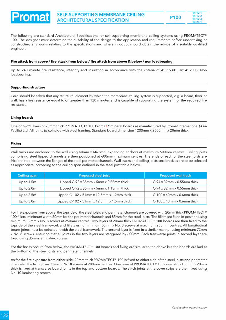
P100
122
The following are standard Architectural Specifications for self-supporting membrane ceiling systems using PROMATECT® 100. The designer must determine the suitability of the design to the application and requirements before undertaking or constructing any works relating to the specifications and where in doubt should obtain the advice of a suitably qualified engineer.
Fire attack from above / fire attack from below / fire attack from above & below / non loadbearing
Up to 240 minute fire resistance, integrity and insulation in accordance with the criteria of AS 1530: Part 4: 2005. Non loadbearing.
Supporting structure
Care should be taken that any structural element by which the membrane ceiling system is supported, e.g. a beam, floor or wall, has a fire resistance equal to or greater than 120 minutes and is capable of supporting the system for the required fire resistance.
Lining boards
One or two(1) layers of 20mm thick PROMATECT® 100 PromaX® mineral boards as manufactured by Promat International (Asia Pacific) Ltd. All joints to coincide with steel framing. Standard board dimension 1200mm x 2500mm x 20mm thick.
Fixing
Wall tracks are anchored to the wall using 60mm x M6 steel expanding anchors at maximum 500mm centres. Ceiling joists comprising steel lipped channels are then positioned at 600mm maximum centres. The ends of each of the steel joists are friction fitted between the flanges of the steel perimeter channels. Wall tracks and ceiling joists section sizes are to be selected as appropriate, according to the ceiling span outlined in the steel joist table below.
Ceiling span Proposed steel joist Proposed wall track
Up to 1.5m Lipped C-92 x 35mm x 5mm x 0.55mm thick C-94 x 32mm x 0.55mm thick
Up to 2.0m Lipped C-92 x 35mm x 5mm x 1.15mm thick C-94 x 32mm x 0.55mm thick
Up to 2.5m Lipped C-102 x 51mm x 12.5mm x 1.2mm thick C-100 x 40mm x 0.6mm thick
Up to 3.0m Lipped C-102 x 51mm x 12.5mm x 1.5mm thick C-100 x 40mm x 0.6mm thick
For fire exposure from above, the topside of the steel joists and perimeter channels are covered with 20mm thick PROMATECT® 100 fillets, minimum width 50mm for the perimeter channels and 85mm for the steel joists. The fillets are fixed in position using minimum 32mm x No. 8 screws at 250mm centres. Two layers of 20mm thick PROMATECT® 100 boards are then fixed to the topside of the steel framework and fillets using minimum 50mm x No. 8 screws at maximum 250mm centres. All longitudinal board joints must be coincident with the steel framework. The second layer is fixed in a similar manner using minimum 72mm x No. 8 screws, ensuring that all joints in the two layers are staggered by 600mm. Each transverse joints in second layer are fixed using 35mm laminating screws.
For the fire exposure from below, the PROMATECT® 100 boards and fixing are similar to the above but the boards are laid at the bottom of the steel joists and perimeter channels.
As for the fire exposure from either side, 20mm thick PROMATECT® 100 is fixed to either side of the steel joists and perimeter channels. The fixing uses 32mm x No. 8 screws at 200mm centres. One layer of PROMATECT® 100 cover strip 100mm x 20mm thick is fixed at transverse board joints in the top and bottom boards. The stitch joints at the cover strips are then fixed using No. 10 laminating screws.
Continued on opposite page
14.12.114.12.214.12.314.24.1
SElF-SuPPORTInG MEMBRAnE CEIlInG ARCHITECTuRAl SPECIFICATIOn

P100
123
14.12.114.12.214.12.314.24.1
SElF-SuPPORTInG MEMBRAnE CEIlInG ARCHITECTuRAl SPECIFICATIOn
Ceiling span Proposed steel joistRondo
Part no.lysaght Part no.
Minimum sectional modulus
Expansion at each end of steel section
Up to 1.5mC-channel
65mm x 50mm x 0.6mm thick251 (493) C10010 2314mm³ 9mm
Up to 2.0mC-channel
65mm x 50mm x 1.15mm thick511 (681) C10010 4330mm³ 12 mm
Up to 2.5mLipped C-channel
65mm x 38mm x 13mm x 2.5mm thick511 (691) C10010 7110mm³ 15mm
Up to 3.0mLipped C-channel
76mm x 44mm x 16mm x 2.5mm thick691 C10015 10300mm³ 18mm
Up to 3.5mC-channel
103mm x 34mm x 3.0mm thickN/A C10019 12840mm³ 21mm
Up to 4.0mLipped C-channel
102mm x 51mm x 18mm x 2.5mm thickN/A C15015 17400mm³ 24mm
Up to 5.0mTwo back to back lipped C-channel
102mm x 51mm x 18mm x 2.5mm thickN/A C20015 34800mm³ 30mm
Up to 6.0mTwo back to back lipped C-channel
127mm x 51mm x 18mm x 2.5mm thickN/A C20024 46800mm³ 36mm
Up to 7.4mLipped C-channel
203mm x 76mm x 24mm x 3.0mm thickN/A C20024 70100mm³ 45mm
Up to 8.3mLipped C-channel
250mm x 75mm x 20mm x 2.3mm thickN/A C20024 91600mm³ 50mm
Up to 9.0mTwo back to back lipped
C-channel 225mm x 75mm x 20mm x 2.3mm thick
N/A C30030 124360mm³ 55mm
Up to 10.0mTwo back to back lipped
C-channel 250mm x 75mm x 20mm x 3.0mm thick
N/A C30030 183200mm³ 60mm
Tests & standards
The complete system along with material and framing is tested and/or assessed to meet the requirements of AS 1530: Part 4: 2005.
Follow-on trades
Surface of boards to be prepared for painting/plastering/tiling(5) in accordance with manufacturer’s recommendations.

P100
124
11.60.1TIMBER FlOOR PROTECTIOn
1 PROMATECT® 100 board 20mm thick
2 longitudinal board joints to coincide with timber joists
3 Gap at perimeter to be caulked with PROMASEAl®-A Acrylic Sealant
4 Timber nogging 38mm x 38mm at 1250mm centres and to coincide with transverse board joints
5 Timber joist minimum 225mm x 48mm at maximum 600 centres
6 Tongue-and-groove floorboards 22mm thick
7 50mm long galvanised clout nails or woodscrews at nominal 150mm centres
Fire
resi
stan
ce FRl 60/60/60
Standard AS 1530: Part 4: 2005
Approval BRANZ FAR 2886
Aco
usti
c
# STC# Rw
43dB43dB
Standard ISO 140: Part 3: 1996ISO 717: Part 1: 1996
Predicted assessment
Marshall Day20th August 2007
Co
nstr
ucti
on Maximum span 3000mm
Ceiling thickness 267mm
Ceiling mass 35kg/m2
# Margin of error is generally within ±3dB* Based on nominal weight of the board
1
6
7
5
3 1
2
4
6
5
5
Nominal150mm
Maximum 600mm
Fire attack from below / loadbearing

P100
125
11.90.1TIMBER FlOOR PROTECTIOn
1 Two layers of PROMATECT® 100 board, each 10mm thick
2 longitudinal board joints to coincide with timber joists, longitudinal board joints between the 2 layers must be staggered by 600mm
3 Gap at perimeter to be caulked with PROMASEAl®-A Acrylic Sealant
4 Timber nogging 38mm x 38mm at 1250mm centres and to coincide with transverse board joints in the 1st layer
5 Timber joist minimum 225mm x 48mm at maximum 600 centres
6 Tongue-and-groove floorboards 22mm thick
7 50mm long galvanised clout nails or woodscrews at nominal 150mm centres
Fire
resi
stan
ce FRl 90/90/90
Standard BS 476: Part 21: 1987
Approval LPC TE90019
Aco
usti
c
# STC# Rw
43dB43dB
Standard ISO 140: Part 3: 1996ISO 717: Part 1: 1996
Predicted assessment
Marshall Day20th August 2007
Co
nstr
ucti
on Maximum span 3000mm
Ceiling thickness 267mm
Ceiling mass 36kg/m2
# Margin of error is generally within ±3dB* Based on nominal weight of the board
1
6
7
7
5
3 1
2
4
6
5
5
Nominal
150mm
Nominal150mm
Maximum 600mm
Fire attack from below / loadbearing

P100
126
11.90.2TIMBER FlOOR PROTECTIOn
1 One layers of PROMATECT® 100 board 20mm thick
2 longitudinal board joints to coincide with timber joists
3 Gap at perimeter to be caulked with PROMASEAl®-A Acrylic Sealant
4 PROMATECT® 100 cover strip 100mm x 20mm thick located on all joists and transverse board joints
5 Timber joist minimum 225mm x 48mm at maximum 600 centres
6 Tongue-and-groove floorboards 22mm thick
7 50mm long galvanised clout nails or woodscrews at nominal 150mm centres
Fire
resi
stan
ce FRl 90/90/90
Standard AS 1530: Part 4: 2005
Approval BRANZ FAR 2886
Aco
usti
c
# STC# Rw
43dB43dB
Standard ISO 140: Part 3: 1996ISO 717: Part 1: 1996
Predicted assessment
Marshall Day20th August 2007
Co
nstr
ucti
on Maximum span 3000mm
Ceiling thickness 287mm
Ceiling mass 18.4kg/m2
# Margin of error is generally within ±3dB* Based on nominal weight of the board
1
6
7
7
5
31
2
4
6
5
5
4
Nominal
150mm
Nominal150mm
Maximum 600mm
Fire attack from below / loadbearing

P100
127
11.12.1TIMBER FlOOR PROTECTIOn
1 Two layers of PROMATECT® 100 board, each 20mm thick
2 longitudinal board joints to coincide with timber joists, longitudinal board joints between the 2 layers must be staggered by 600mm
3 Gap at perimeter to be caulked with PROMASEAl®-A Acrylic Sealant
4 Timber nogging 38mm x 38mm at 1250mm centres and to coincide with transverse board joints in the 1st layer
5 Timber joist minimum 225mm x 48mm at maximum 600 centres
6 Tongue-and-groove floorboards 22mm thick
7 50mm long galvanised clout nails or woodscrews at nominal 150mm centres for first layer, 75mm long for second layer.
Fire
resi
stan
ce FRl 120/120/120
Standard AS 1530: Part 4: 2005
Approval BRANZ FAR 2924
Aco
usti
c
# STC# Rw
43dB43dB
Standard ISO 140: Part 3: 1996ISO 717: Part 1: 1996
Predicted assessment
Marshall Day20th August 2007
Co
nstr
ucti
on Maximum span 3000mm
Ceiling thickness 287mm
Ceiling mass 52.6kg/m2
# Margin of error is generally within ±3dB* Based on nominal weight of the board
1
6
7
7
5
3 1
2
4
6
5
5
Nominal
150mm
Nominal150mm
Maximum 600mm
Fire attack from below / loadbearing

P100
128
The following are standard Architectural Specifications for timber floor protection systems using PROMATECT® 100. The designer must determine the suitability of the design to the application and requirements before undertaking or constructing any works relating to the specifications and where in doubt should obtain the advice of a suitably qualified engineer.
Fire attack from below / loadbearing
Up to ____________ minute(1) fire resistance, loadbearing capacity, integrity and ____________ minute(2) insulation in accordance with the criteria of BS 476: Part 21: 1987.
Supporting structure
Care should be taken that any structural element by which the floor protection system is supported, e.g. a beam, floor or wall, has a fire resistance equal to or greater than ____________ minutes(1) and is capable of supporting the system for the required fire resistance.
Lining boards
Either one or two(3) layers of 20mm or two layer of 10mm thick PROMATECT® 100 PromaX® mineral boards as manufactured by Promat International (Asia Pacific) Ltd. All joints to be coincident with steel framing. Standard board dimension 1200mm x 2500mm x 10mm or 20mm(3) thick.
Fixing
Timber floor comprising of timber joists, 225mm x 48mm, at 600mm centres with tongue-and-groove chipboard flooring of 22mm thickness. Timber cross noggings, 38mm x 38mm, are to be located between the joists and spaced at 1250mm intervals such that they coincide with the transverse 60 minutes joints of the first layer of the PROMATECT® 100 boards.
For 60 minute fire resistance, one layer of 20mm thick PROMATECT® 100 is fixed to the timber framework using either galvanised clout nails or woodscrews of 50mm long at nominal 150mm centres, and a minimum of 12mm from board edge.
For 90 minute fire resistance, first layer of PROMATECT® 100 boards is fixed to the timber framework using either galvanised clout nails or woodscrews of 50mm long at nominal 150mm centres, and a minimum of 12mm from the board edge. The second layer of PROMATECT® 100 boards is then lined against the first layer and fixed to the timber framework with 50mm long nails or screws in a similar manner.
For 120 minute fire resistance, first layer of PROMATECT® 100 boards is fixed to the timber framework using either galvanised clout nails or woodscrews of 50mm long at nominal 150mm centres, and a minimum of 12mm from the board edge. The second layer of PROMATECT® 100 boards is then lined against the first layer and fixed to the timber framework with 75mm long nails or screws in a similar manner.
Tests & standards
The complete system along with material and framing is tested and/or assessed to meet the requirements of BS 476: Part 21: 1987or AS 1530: Part 4: 2005.
Jointing
Plain butt joints between machined edges of boards. (4)
Joints filled in preparation for painting. (5)
Joints filled and taped in preparation for decoration. (6)
Follow-on trades
Surface of boards to be prepared for painting/plastering/tiling(7) in accordance with manufacturer’s recommendations.
NOTES:•(1) insert required fire resistance level not exceeding 120 minutes.•(2) insert required insulation level not exceeding the fire resistance level(1).•(3), (4), (5), (6), (7) delete as appropriate.•AllperimetergapscaulkedwithPROMASEAL®-AAcrylicSealant.
11.60.111.90.1 & 2
11.12.1
TIMBER FlOOR PROTECTIOn ARCHITECTuRAl SPECIFICATIOn

P100
129
13.60.1MEZZAnInE FlOOR
1 PROMATECT® 100 board 20mm thick
2 PROMATECT® 100 cover strip 100mm wide x 20mm thick located behind transverse board joint
3 longitudinal board joint to coincide with steel framework
4 Gap at perimeter to be caulked with PROMASEAl®-A Acrylic Sealant
5 Steel joist channel 200mm x 65mm x 15mm x 1.5mm thick at 600mm centres
6 Tongue-and-groove floorboards 38mm thick
7 35mm x no. 8 steel screws at nominal 200mm centres along all joists
Fire
resi
stan
ce FRl 60/60/60
Standard AS 1530: Part 4: 2005
Approval BRE CC 237274
Aco
usti
c
# STC# Rw
36dB36dB
Standard ISO 140: Part 3: 1996ISO 717: Part 1: 1996
Predicted assessment
Marshall Day20th August 2007
Co
nstr
ucti
on
Floor thickness 253mm
Floor mass From 19.44kg/m2
# Margin of error is generally within ±3dB
1
6
7
5
3
14
2
6
5
Nominal200mm
600mm
Fire attack from below / loadbearing

P100
130
13.12.1MEZZAnInE FlOOR
1 Two layers of PROMATECT® 100 board, each 20mm thick
2 All longitudinal board joints must be coincident with the steel framework, longitudinal board joints between the 2 layers must be staggered by 600mm.
3 Gap at perimeter to be caulked with PROMASEAl®-A Acrylic Sealant
4 Tongue-and-groove floorboards 38mm thick
5 Steel channel 200mm x 65mm x 15mm x 1.5mm thick at 600mm centres
6 no. 8 steel screws at nominal 200mm centres along all joists• 35mm long to screw first layer to joists• 50mm long to screw second layer to joists
Fire
resi
stan
ce FRl 120/120/120
Standard AS 1530: Part 4: 2005
Approval BRE CC 234729
Aco
usti
c
# STC# Rw
39dB39dB
Standard ISO 140: Part 3: 1996ISO 717: Part 1: 1996
Predicted assessment
Marshall Day20th August 2007
Co
nstr
ucti
on
Floor thickness 278mm
Floor mass 52kg/m2
# Margin of error is generally within ±3dB
1
4
6
6
5
13
2
4
5
Nominal200mm
Nominal
200mm
600mm
Fire attack from below / loadbearing

P100
131
13.60.113.12.1
MEZZAnInE FlOOR ARCHITECTuRAl SPECIFICATIOn
The following are standard Architectural Specifications for mezzanine floor systems using PROMATECT® 100. The designer must determine the suitability of the design to the application and requirements before undertaking or constructing any works relating to the specifications and where in doubt should obtain the advice of a suitably qualified engineer.
Fire attack from below / loadbearing
Up to ____________ minute(1) fire resistance, loadbearing capacity, integrity and ____________ minute(2) insulation in accordance with the criteria of AS 1530: Part 4: 2005.
Supporting structure
Care should be taken that any structural element by which the mezzanine floor system is supported, e.g. a beam, floor or wall, has a fire resistance equal to or greater than ____________ minutes(1) and is capable of supporting the system for the required fire resistance.
Lining boards
One or two(3) layers of 20mm thick PROMATECT® 100 PromaX® mineral boards as manufactured by Promat International (Asia Pacific) Ltd. All joints to be coincident with steel framing. Standard board dimension 1200mm x 2500mm x 20mm thick.
Fixing
Mezzanine floor comprising of steel joists, 200mm x 65mm x 15mm x 1.5mm, at 600mm centres with tongue-and-groove chipboard flooring of 38mm thickness.
The first layer of PROMATECT® 100 boards is fixed to the steel framework using 35mm x No. 8 steel screws at nominal 200mm centres, and a minimum of 12mm from the board edge. Where required, one layer of PROMATECT® 100 cover strips 100mm wide x 20mm thick is located behind the transverse board joints. The second layer of PROMATECT® 100 boards, where required, is then lined against the first layer and fixed to the steel framework with 50mm x No. 8 steel screws at nominal 200mm centres.
Tests & standards
The complete system along with material and framing is tested and/or assessed to meet the requirements of AS 1530: Part 4: 2005.
Jointing
Plain butt joints between machined edges of boards. (3)
Joints filled in preparation for painting. (4)
Joints filled and taped in preparation for decoration. (5)
Follow-on trades
Surface of boards to be prepared for painting/plastering/tiling(6) in accordance with manufacturer’s recommendations.
NOTES:•(1) insert required fire resistance level not exceeding 120 minutes.•(2) insert required insulation level not exceeding the fire resistance level(1).•(3), (4), (5), (6) delete as appropriate.•AllperimetergapscaulkedwithPROMASEAL®-AAcrylicSealant.


FAQ's and Promat systems in Australia

134
FAQ’S And PROMAT SySTEMS In AuSTRAlIA
FAQ's
Q1. Is PROMATECT® 100 cheaper than the conventional plasterboard systems?
A. Overall system costs must be treated as that, a SYSTEM COST. This not only includes materials, but also the labour to install them. With the PROMATECT® 100 system, labour rates can be cut by up to 40% and more importantly, the project can be completed much quicker before moving on to another profitable project.
Q2. How quick can I get PROMATECT® 100?A. Immediately. We have stock in every state of Australia and
can provide you with the material you require on short notice. We understand the needs of today’s contractor and will always strive to meet these expectations. Promat Australia has a proud history of a high level of service which we always strive to maintain.
Q3. What technical support can you provide?A. Our trained and experienced sales staff can provide
certification as well as helpful advice on construction methods and other aspects of our system. Our systems are fully designed for the Australian market and are fully compliant to Australian Standards. Therefore PROMATECT® 100 should be the board of choice for your fire rated barriers.
Q4. What kind of finish will I get with the PROMATECT® 100 system?
A. The finish will be as good as or better than plasterboard and is finished using the same techniques you will already be familiar with.
Q5. do we need any mineral wool infills?A. No.
Q6. How come only one layer is needed on each side when plasterboard needs two or three?
A. PROMATECT® 100 is a very different board to plasterboard and has superior performance as it is a dedicated fire resistance board and not a hybrid version of non fire rated combustible material.
Q7. Is it cost competitive to gypsum board alternatives?A. It is a one layer system either side of steel stud providing
up to 120 minute protection. Competitor systems are required to use two layers either side. Labour rates are therefore cut in half making PROMATECT® 100 a competitive alternative.
Q8. What surface finish am I likely to achieve if PROMATECT® 100 is used?
A. You will have a finish that is extremely close if not better than gypsum. The PROMATECT® 100 comes with rebated edges, that allows it to be set. PROMATECT® 100 can be painted and used as a finished surface.
Promat system in Australia
PROMATECT® board systems:
• Air Ducts, plenums and enclosures• M&E Ducts and trunking• Ceilings and floor protection• Concrete, timber and steel protection• Hatches and Panels
PROMASTOP® firestopping systems:
• Pillows• Mortar• Sealants• IBS open cell foam rod and strip• Fyrestrip – high movement gap seals• Collars for plastic pipes• Slab service penetration formers
Brochures:
• Passive Fire Protection Application & Technical Manual• Promat Australia Contractors Guide: Builders• Promat Australia Contractors Guide: Electricians• Promat Australia Contractors Guide: HVAC• Promat Australia Contractors Guide: Plumbers• PROMATECT® 250 PROMAXON® Technology Steelwork
Fire Protection• Tunnel Fire Protection Handbook• Promat SYSTEMPANELTM Quick Solutions for Fire Resistant
Party Walls, Ceilings and Floors• Fire Stopping Training Manual• The Specifiers Guide to Fire Rated Hatches and Access
Panels• PROMASTOP® Fire Stopping Jacket• PROMASEAL® WRAP Insulation Seals for Copper Pipes
and Cable Trays• PromaSnap® Floor Waste System
For information on any of the above applications or specialist advice on• Custom systems• Infrastructure• Energy• High temperature insulation• Marine• Offshore• Process engineering
Please contact your local Promat Australia office listed on the back cover.


© P
rom
at A
ustr
alia
Pty
Ltd
/ 2
016-
12
Promat Australia Pty ltd
Head office
1 Scotland RoadMile End South, SA 5031T 1800 PROMAT (776 628)F +61 (8) 8352 1014E [email protected]
new South Wales office
Unit 1, 175 Briens RoadNorthmead, NSW 2152T 1800 PROMAT (776 628)F +61 (2) 9630 0258E [email protected]
Victoria office
Suite 205, 198 Harbour EsplanadeDocklands, VIC 3008T 1800 PROMAT (776 628)F 1800 334 598E [email protected]
Queensland office
433 Logan RoadStones Corner, QLD 4120T 1800 011 376F 1800 334 598E [email protected]
• The technical data provided in this publication is based on mean values prevalent at time of publication and is thus subject to fluctuation. It should not be regarded as a guarantee to system performance.
• All data contained herein conforms to and frequently surpasses generally accepted fire protection standards recognised by most professional fire science practitioners and regulatory authorities worldwide. The same general principle is equally applicable to all Promat products and systems. Promat has access to a considerable body of test authentication data and this can be provided on a complimentary basis upon request. It should be noted however that this publication replaces all previous editions in its entirety. Any form of reproduction by any means — manual, electronic, digital or otherwise — is strictly prohibited and subject to prior approval in writing from Promat. All rights related or connected to the Promat logo, Promat registered trademarks, featured illustrations, written information and technical reports in this publication are the sole, exclusive and copyright property of Promat and its legal partner companies.
www.promat.com.au
your local Promat supplier
Etex is a Belgian industrial group that specialises and markets high quality building materials and systems. Founded since 1905 and headquartered in Brussels, Belgium, Etex currently operates in 123 factories and 116 subsidiaries across 44 countries, employs more than 18,000 people and is one of the largest fibre cement producers in the world.
Through its subsidiaries, the group offers an extensive range of products: small and large roofing materials, cladding and building boards, passive fire protection systems and ceramic tiles.
Etex aims to be a professional, solid partner for all kinds of building projects.