prolific designer rich uravitch shows off his latest rsai ... · prolific designer rich uravitch...
TRANSCRIPT
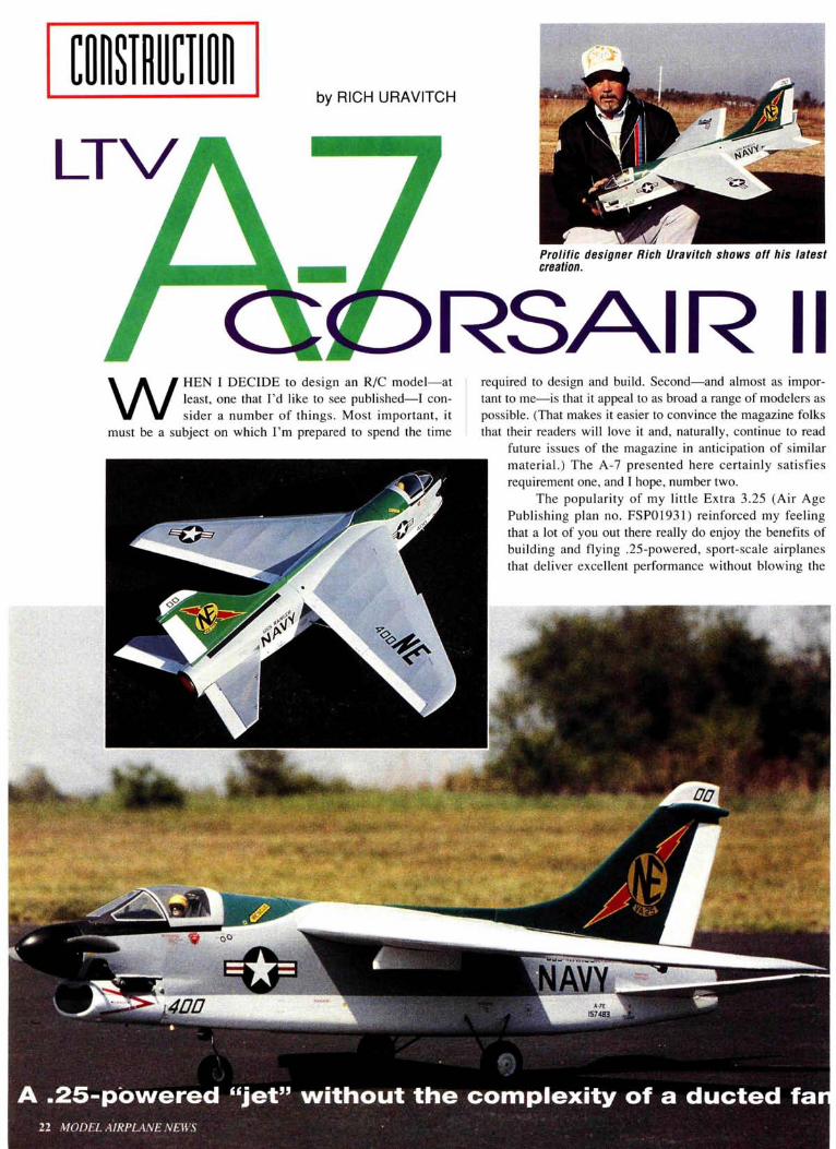
by RICH URAVITCH
LTVProlific designer Rich Uravitch shows off his latestcreation.
RSAIR IIW HEN I DECIDE to design an R/C model—at
least, one that I'd like to see published—I con-sider a number of things. Most important, it
must be a subject on which I'm prepared to spend the time
required to design and build. Second—and almost as impor-tant to me—is that it appeal to as broad a range of modelers aspossible. (That makes it easier to convince the magazine folksthat their readers will love it and, naturally, continue to read
future issues of the magazine in anticipation of similarmaterial.) The A-7 presented here certainly satisfiesrequirement one, and I hope, number two.
The popularity of my little Extra 3.25 (Air AgePublishing plan no. FSP01931) reinforced my feelingthat a lot of you out there really do enjoy the benefits ofbuilding and flying .25-powered, sport-scale airplanesthat deliver excellent performance without blowing the
1574
A .25-powered "jet" without the complexity of a ducted fa11 MODEL AIRPLANE NEWS
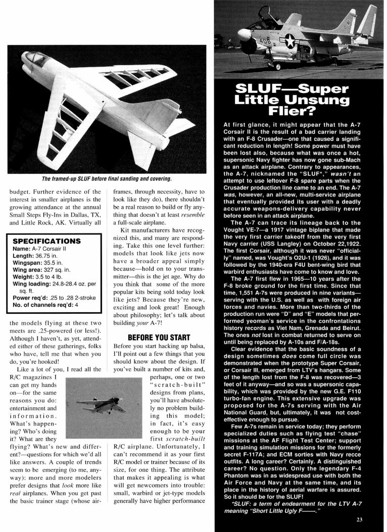
The framed-up SLUF before final sanding and covering.
budget. Further evidence of theinterest in smaller airplanes is thegrowing attendance at the annualSmall Steps Fly-Ins in Dallas, TX,and Little Rock, AK. Virtually all
SPECIFICATIONSName: A-7 Corsair IILength: 36.75 in.Wingspan: 35.5 in.Wing area: 327 sq. in.Weight: 3.5 to 4 Ib.Wing loading: 24.8-28.4 oz. per
sq. ft.Power req'd: .25 to .28 2-strokeNo. of channels req'd: 4
the models flying at these twomeets are .25-powered (or less!).Although I haven't, as yet, attend-ed either of these gatherings, folkswho have, tell me that when youdo, you're hooked!
Like a lot of you, I read all theR/C magazines Ican get my handson—for the samereasons you do:entertainment andi n f o r m a t i o n .What's happen-ing? Who's doingit? What are theyflying? What's new and differ-ent?—questions for which we'd alllike answers. A couple of trendsseem to be emerging (to me, any-way): more and more modelersprefer designs that look more likereal airplanes. When you get pastthe basic trainer stage (whose air-
frames, through necessity, have tolook like they do), there shouldn'tbe a real reason to build or fly any-thing that doesn't at least resemblea full-scale airplane.
Kit manufacturers have recog-nized this, and many are respond-ing. Take this one level further:models that look like jets nowhave a broader appeal simplybecause—hold on to your trans-mitter—this is the jet age. Why doyou think that some of the morepopular kits being sold today looklike jets? Because they're new,exciting and look great! Enoughabout philosophy; let's talk aboutbuilding your A-7!
BEFORE YOU STARTBefore you start hacking up balsa,I'll point out a few things that youshould know about the design. Ifyou've built a number of kits and,
perhaps, one or two" s c r a t c h - b u i l t "designs from plans,you'll have absolute-ly no problem build-ing this model;in fact, it 's easyenough to be yourfirst scratch-built
R/C airplane. Unfortunately, Ican't recommend it as your firstR/C model or trainer because of itssize, for one thing. The attributethat makes it appealing is whatwill get newcomers into trouble:small, warbird or jet-type modelsgenerally have higher performance
uperLittle Unsung
At first glance, it might appear that the A-7Corsair II is the result of a bad carrier landingwith an F-8 Crusader—one that caused a signifi-cant reduction in length! Some power must havebeen lost also, because what was once a hot,supersonic Navy fighter has now gone sub-Machas an attack airplane. Contrary to appearances,the A-7, nicknamed the "SLUF*," wasn't anattempt to use leftover F-8 spare parts when theCrusader production line came to an end. The A-7was, however, an all-new, multi-service airplanethat eventually provided its user with a deadlyaccurate weapons-delivery capability neverbefore seen in an attack airplane.
The A-7 can trace its lineage back to theVought VE-7—a 1917 vintage biplane that madethe very first carrier takeoff from the very firstNavy carrier (USS Langley) on October 22,1922.The first Corsair, although it was never "official-ly" named, was Vought's 02u-1 (1926), and it wasfollowed by the 1940-era F4U bent-wing bird thatwarbird enthusiasts have come to know and love.
The A-7 first flew in 1965—10 years after theF-8 broke ground for the first time. Since thattime, 1,551 A-7s were produced in nine variants—serving with the U.S. as well as with foreign airforces and navies. More than two-thirds of theproduction run were "D" and "E" models that per-formed yeoman's service in the confrontationshistory records as Viet Nam, Grenada and Beirut.The ones not lost in combat returned to serve onuntil being replaced by A-10s and F/A-18s.
Clear evidence that the basic soundness of adesign sometimes does come full circle wasdemonstrated when the prototype Super Corsair,or Corsair III, emerged from LTV's hangars. Someof the length lost from the F-8 was recovered—3feet of it anyway—and so was a supersonic capa-bility, which was provided by the new G.E. F110turbo-fan engine. This extensive upgrade wasproposed for the A-7s serving with the AirNational Guard, but, ultimately, it was not cost-effective enough to pursue.
Few A-7s remain in service today; they performspecialized duties such as flying test "chase"missions at the AF Flight Test Center; supportand training simulation missions for the formerlysecret F-117A; and ECM sorties with Navy recceoutfits. A long career? Certainly. A distinguishedcareer? No question. Only the legendary F-4Phantom was in as widespread use with both theAir Force and Navy at the same time, and itsplace in the history of aerial warfare is assured.So it should be for the SLUF!
*SLUF: a term of endearment for the LTV A-7meaning "Short Little Ugly F_."
A-7 CORSAIR II
Wing ho I d-d own area. Stenciling and markings are available fromDry-Set.
capabilities and higher wing loadings thattake them well out of the trainer category.The A-7 is typical of the breed. If I haven'tfrightened you off and you're ready to takeup the challenge, clear the bench!
To make building your Corsair as easyas possible, we've decided to present theconstruction sequence in the same way aswe did the Extra 3.25—as a step-by-stepsequence, much like many of the more suc-cessful kits are presented. This sequence,used with the notes on the full-size plan.
should make buildingyour A-7 an enjoy-able undertakingrather than an exer-cise in frustration.
To cut down onsome of your build-ing and carving time,I am making avail-able a vacuum-formed set of partsfor this design. Thepackage consists of aclear canopy, andhigh-impact plastic-parts for the cowling,jet exhaust nozzle,and air-refueling
receptacle fairing as used on the Air ForceA-7D variant. Cost of the package, includ-ing shipping, is $19.95 and may beobtained from me directly.
All the tail group parts are cut out ofmedium 3/16-inch balsa and then sanded tofinal shape. Refer to the plan for grain orien-tation and control-linkage installation. Don'tforget the hardwood block on the top of thehorizontal stabilizer halves; it provides bear-ing support for the rudder linkage.
ENGINE INSTALLATIONThe A-7 will accommodate a variety ofengines from .19 through .28 in displace-ment. The prototypes used an O.S.* .28 anda Magnum* .25, and the performance wasterrific. For you speed freaks who arealready considering stuffing a .40 into theengine compartment, I suggest that you for-get it! Though the additional power mightenable you to put your version of the A-7into orbit, the additional weight of the .40will require a huge amount of compensatingweight in the tail, and that will push thewing loading right up there next to thebrick we've all heard about! Stick with therecommended engines; you won't be disap-pointed!
RADIO INSTALLATIONSee all that empty space below the wingbetween bulkheads F4 and F6?—the spacewhere your radio would normally go? Well,that's the way it's going to look forever,because nearly all of the A-7's radio equip-ment goes behind F6. Even with all theradio equipment as far aft as you can get it,you'll probably have to add ballast (deadweight) to the tail. For this reason, I suggestthat you don't close off the end of the fuse-lage with the jet nozzle until you've com-
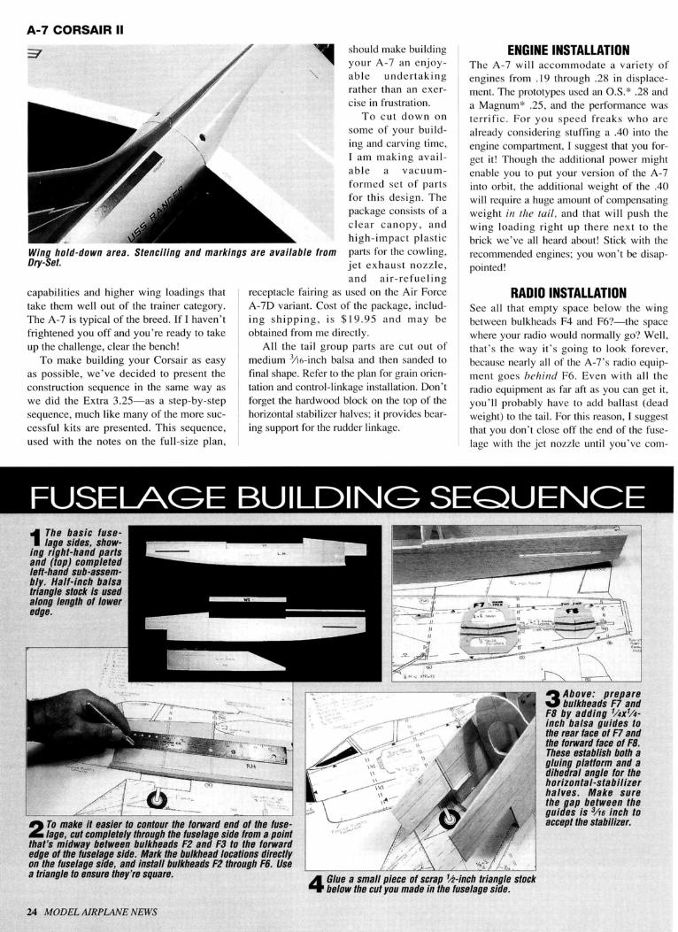
FUSEagE BUILDINg SEQUENCE1 The basic fuse-
lage sides, show-ing right-hand partsand (top) completedleft-hand sub-assem-bly. Half-inch balsatriangle stock is usedalong length of loweredge.
2 To make it easier to contour the forward end of the fuse-lage, cut completely through the fuselage side from a point
that's midway between bulkheads F2 an.d F3 to the forwardedge of the fuselage side. Mark the bulkhead locations directlyon the fuselage side, and install bulkheads F2 through F6. Usea triangle to ensure they're square.
3 Above: preparebulkheads F7 and
F8 by adding 1/4x1/4-inch balsa guides tothe rear face of F7 andthe forward face of F8.These establish both agluing platform and adihedral angle for thehorizontal-stabilizerhalves. Make surethe gap between theguides is 3/16 inch toaccept the stabilizer.
Glue a small piece of scrap1/2-inch triangle stockbelow the cut you made in the fuselage side.
24 MODEL AIRPLANE NEWS

5this is what your fuselage should look like before you addthe upper and lower sheeting. Elevator linkage is short,
uses ball-link connectors (detail shown on plan). Servo accessis through a removable hatch.
8 The engine compartment, showingmount, cowl, hold-down blocks
and engine-cooling "trough." 9 The removable hatch in the lower aftfuselage provides access to three ser-
vos and linkages. A single no. 2 screwholds it securely.
6 The main landing-gear assembliesare removable. They're plugged into
brass tubes and are retained by wheelcollars on the forward struts. Although "9 The nose-gear installation, showing the steering-linkagere work, it makes it easier 7 path. Throttle-linkage routing is similar, but on theit's a little moreto cover and finish the model.
10 The aft end of the fuselage with the10 stabilizers and elevators installed.
Upper sheeting has yet to be added.
opposite side of the fuselage.
JANUARY 1995 25

WINg BUILDINg SEQUENCE
1 After covering the plan with a sheet of clear film or waxpaper, pin the trailing-edge stock, sheeting and capstrips
into position. Apply glue to all seams and joints. Glue thelower 3/16x3/16-inch hard-balsa spar into position, followed byribs W2 through W7. Make certain the ribs are perpendicularto the building surface. Do not glue rib W-1 into place at thistime. Pin the forward end of rib W7 to the building surface,and add the upper spar and thethe 1/16-inch balsa sub-leadingedge. Position a piece of 3/16-inch balsa behind rib W7 asshown. This is a temporary shim that will automatically buildthe required washout into the wing panel.
2 Glue rib W1 into position usingthe anhedral gauge to estab-
lish proper angle. Remember, thewing has anhedral, so the top of therib leans slightly inboard ratherthan outboard as with dihedral.
3 Add all the upper sheeting,the capstrips tip block and
the leading-edge pieces, includ-ing the additional 3/16x1/2-inchbalsa piece that creates theleading-edge "sawtooth." Carvethe leading edge to shape, andfinal-sand the wing panel tosmooth all the seams and gluejoints. Build the right-hand wingpanel in the same way.
'i
1F
/'/
-
4 The wing center section is built over theplan and consists of W1, W1A, W1B, W1C
and WW parts along with the trailing-edge stockand sheeting. The 3/16X3/16-inch "alignmentstubs" have not yet been installed.
5 Above: to help maintainthe proper anhedral
angle when the outer panelsare joined to the center sec-tion, place the center sectionon a piece of3/4-inch materi-al (flake-board shown),attach the outer panels,allowing the leading edge, atthe wingtip, to contact thebuilding surface. Don't forgetto preserve the washoutyou've built in!
6 Above: bulkheads F4Bthrough F6B installed
on the completed wing;center stringer supportssheeting.
7 After the wing panelshave been joined, and
the wing hold-down provi-sions are incorporated;add bulkheads F4Athrough F6A, the uppeistringer and the balsasheeting.
pleted all the CG and balance checks. Nose-
gear steering and throttle pushrods extend
forward and should be anchored securely at
each bulkhead.
COVERINGI chose light gray MonoKotc* to cover the
prototypes because it's a reasonable approx-
imation of the shade used on U.S. Navy
A-7s. Sticking to my allegiances by doing
an Air Force A-7D would have meant paint-
ing a camouflage scheme, which I had con-
sidered, but Mike Anderson of Dry-Set
Model Markings* offered to make a set of
colorful Navy insignias, including all that
neat little stencil-
ing that's so hard
to duplicate.
Shortly after
sending him some
drawings of what I
needed, I received
a package that
included all the
markings you see
in the pictures.
These packages are
now for sale; check
with Dry-Set for
the current prices.
26 MODEL AIRPLANE NEWS

The "office" area. Note extensive stenciling, placards and markings—all available as an A-7 setespecially made for this model by Dry-Set. Pilot figure is a reworked Williams Bros. * item. Keep gapbetween spinner and F1 to a minimum to enhance the "jet" illusion.
Dry-Sel markings, like many others, areof the rub-on type. Unlike most others, how-ever, the material used is paint rather thanMylar film, and that's what makes it possi-ble to duplicate all that, itty-bitty lettering(of the proper type-face) for all that stencil-ing. They don't require clear-coating forfuel-proofing either—another plus.
FINAL COUNTDOWNSo, there it is—the project you've toiled overfor at least 8 hours. Now add the spinner,pilot figure, wheels, canopy and whateverelse you think it needs. Check the CG again,along with the lateral balance, and verify thecontrol throws as indicated on the plan. Beparticularly aware of the aileron deflectionvalues; aileron sensitivity is such that itdoesn't take much to roll the airplane. Alsobe certain that the aileron linkage is slop-freeand that the surfaces return to neutral whenstick pressure is released; if they don't, you'llbe fighting the ailerons and probably over-correcting throughout the flight—as wewere!
Put everything on charge, including yourfield-box batteries, and wait for a test-hopday to arrive.
CLEARED TO LAUNCH!It had to happen, didn't it? No way to avoidit! Inevitable! The day is perfect and youhead for the field to find just a hint of abreeze right down the runway. You fire upthe engine, settle it down to a perfect idle,take the active and, in about 50 feet, yourCorsair II is airborne, with no trim required.
Every maneuver you've ever thoughtabout comes easily, and you line up on final,touch down right on the numbers and taxiback to the rousing applause of fellow club
members who had come to witness the his-toric event. ESPN requests an interview, andyou're on the evening news. You've arrived!
And I hope the first flight of your A-7 goesexactly that way; mine, however, was a littledifferent! The first time my model had lightunder its wheels and wind beneath its wings,it was in the skilled hands of Nick Ziroli Jr.It was a 20-second excursion into terror thatclearly indicated that I had way too muchthrow in the ailerons; they weren't centeringproperly, and the .28 in the nose could haveused some right thrust. Everything else wasprobably perfect!
Returning to the workshop, thankful I stillhad an airplane, I made all the necessarychanges and, a couple of days later, headedfor the field once again. This time, every-thing did work! The little sluf was all that Iexpected it would be—plus a little more. Itzips along at a pretty good clip with thenow-invisible prop enhancing the jet illu-sion. It's a lot of fun to fly and always getsattention from other modelers. Its slow-flightqualities are excellent and become especiallyevident on final approach where you reallycan "drag" it in to touchdown.
If you've been caught up in this whole"jet" thing and prefer smaller airplanes thatdeliver great performance, give the A-7 atry; it's an inexpensive, fun-filled alternativeto some of the larger higher-powered mod-els. If smaller (.25-powered) models havecaptured your heart, interest, or both (as theyhave mine), stick around; there's morewhere the Extra 3.25 and the A-7 camefrom. How about a twin .20-powered N.A.Rockwell OV-1O Bronco? Stay tuned...!
* Addresses are listed in the Index of Manufacturerson page 177. •
40201 Std. Long40602 R.C. Long40101
Std. Short
40502R.C. Short
Fox "RC LONG" glow plugs are thelargest selling glow plugs for manyreasons:
1. Zinc plated core pieces.2. Our use of a patented space-age
insulating material.3. Our method of manufacturing the
idle bar as an integrallymachined portion of the housing,eliminating the risk of a weldfailure.
4. Most engines seem to run betterwith Fox RC LONG glow plugs.
Fox "MIRACLE" plugs work in 2 or4 cycle engines. They are built with apre-combustion chamber rather thanan idle bar. The "MIRACLE" plugretains heat better and produces asmoother response to throttlecommands.
Fox also offers our Standard series ofglow plugs generally used in controlline motors.
Both Fox RC and Standard glow plugsare offered in a short thread version.Also available with 2 volt coils.
The motor pictured is our improvedFox 74. This motor provides thepower and reliability you have cometo expect from Fox motors.
BUY SMART!BUY AMERICAN!
BUY FOX!
FOX MANUFACTURING COMPANY5305 TOWSON AVENUE
FORT SMITH, ARKANSAS 72901PHONE (501) 646-1656 • FAX (501) 646-1757
JANUARY 1995 27