project # t0544 -00 new facility & various site improv ements
TRANSCRIPT

Revised 12/2015
MANDATORY PRE-BID MEETING
PROJECT # T0544-00 New Facility & Various Site Improvements
LOCATION NJDOT Secaucus Maintenance Yard 25 Meadowlands Parkway, Secaucus, NJ
DATE September 27, 2021
TIME 10:00 AM
CONTACT PERSON Ronald Kraemer Design Manager
PHONE # Office #: 609-633-7186
Cell #: 609-203-2532
MEETING LOCATION
NJDOT Secaucus Maintenance Yard 25 Meadowlands Parkway, Secaucus, NJ
ALL BIDDERS ARE URGED TO LIMIT THE NUMBER OF REPRESENTATIVES TO ATTEND THE PRE-BID MEETING IN ORDER TO KEEP THE NUMBER OF ATTENDEES TO A MINIMUM IN ORDER TO COMPLY WITH COVID-19 RELATED SOCIAL DISTANCING GUIDELINES. ALL ATTENDEES MUST WEAR FACE MASK COVERINGS.
MUST ATTEND TO HAVE VALID BID NOTE: It is each bidder’s responsibility to determine the way to the location of the announced
Pre-Bid meeting and to assure their timely arrival at the meeting. A maximum fifteen-minute grace period may be granted by the DPMC Project Manager, at his/her discretion, in case of extenuating circumstances determined prior to the scheduled start time. Bidders will be required to sign in at the beginning of the meeting. After the meeting has officially started, no other bidders will be permitted to sign-in. Failure to sign pre-bid sign in sheet will prohibit the bidder’s proposal from being accepted.

Project #: T0544-00
Project Name: New Maintenance facility and Various Site Improvements
Project Location: NJDOT Secaucus Yard
Directions
Directions to Site:
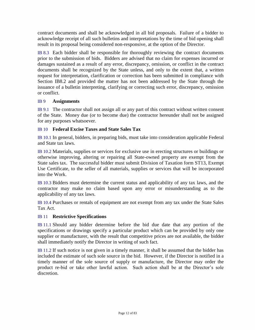
From Route 3, west of Route 95 and the Hackensack River – Follow Route 3 East under Route 95 and over the Hackensack River to Meadowlands Parkway in Secaucus. Take the Meadowlands Parkway exit. Keep right at the fork and merge onto Meadowlands Parkway. Site will be immediately on the left past the Route 3 East overpass, just before the Red Roof Inn.
From Route 3, east of Route 95 and the Hackensack River – Follow Route 3 West to Meadowlands Parkway in Secaucus, just before the Route 3 bridge over the Hackensack River. Take the Meadowlands Parkway exit. Turn left onto Meadowlands Parkway. Site will be on the right past the Route 3 West overpass, just after the Red Roof Inn.
From I-95 (north or south of Route 3) - Take Exit 16W to Sheraton Plaza Drive. Get onto Route 3 East. Follow Route 3 East under Route 95 and over the Hackensack River to Meadowlands Parkway in Secaucus. Take the Meadowlands Parkway exit. Keep right at the fork and merge onto Meadowlands Parkway. Site will be immediately on the left past the Route 3 East overpass, just before the Red Roof Inn.

T0544-00 NJDOT SECAUCUS MAINTENANCE YARD
Legend
NJDOT Secaucus Yard
1000 ft
N
➤➤
N© 2019 Google© 2019 Google

SPECIFICATION
New Maintenance Facility and Various Site Improvements NJDOT Secaucus Maintenance Yard
Secaucus, Hudson County, N.J.
DPMC PROJECT #T0544-00
STATE OF NEW JERSEY Honorable Philip D. Murphy, Governor
Honorable Sheila Y. Oliver, Lt. Governor
DEPARTMENT OF THE TREASURY Elizabeth Maher Muoio, State Treasurer
NEW JERSEY DEPARTMENT OF TRANSPORTATION Diane Gutierrez-Scaccetti, Commissioner
DIVISION OF PROPERTY MANAGEMENT AND CONSTRUCTION Christopher Chianese, Director
NV5 – ARCHITECTURE, PC 7 CAMPUS DRIVE, SUITE 300, PARSIPPANY, NJ 07054-4495
Date: June 23, 2021 – Issued for Bid
Volume 1

New Maintenance Facility and Various Site Improvements
NJDOT Secaucus Maintenance Yard
TOC-1
New Maintenance Facility and Various Site Improvements
NJDOT Secaucus Maintenance Yard
Secaucus, Hudson County, NJ
DPMC PROJECT #T0544-00
TABLE OF CONTENTS
VOLUME 1
PART I
TITLE
Instructions to Bidders and General Conditions (rev 12/15) 1 thru 83
List of drawings LOD-1 thru LOD-3
PART II
TECHNICAL SPECIFICATIONS
Sec. No. Title
DIVISION 1 - GENERAL REQUIREMENTS
01 10 00 SUMMARY
01 22 00 UNIT PRICES
01 31 00 PROJECT MANAGEMENT & COORDINATION
01 40 00 QUALITY REQUIREMENTS
01 50 00 TEMPORARY FACILITIES & CONTROLS
01 56 39 TEMPORARY TREE & PLANT PROTECTION
01 74 19 CONSTRUCTION WASTE MANAGEMENT AND DISPOSAL
01 77 00 CLOSEOUT PROCEDURES
01 78 23 OPERATIONS AND MAINTENANCE DATA
01 78 39 PROJECT RECORD DOCUMENTS
01 79 00 DEMONSTRATION AND TRAINING
DIVISION 2 - EXISTING CONDITIONS
02 41 16 STRUCTURE DEMOLITION
02 82 13 REMOVAL AND DISPOSAL OF ACM
02 82 13.01 HAZARDOUS MATERIAL ASBESTOS ABATEMENT – ROOFING
02 84 33 REMOVAL OF POLYCHLORINATED BIPHENYLS (PCB)
DIVISION 3 - CONCRETE
03 05 05 UNDERSLAB VAPOR BARRIER
03 20 00 CONCRETE REINFORCING
03 30 00 CAST-IN-PLACE CONCRETE
03 30 10 CAST-IN-PLACE SITE WORK CONCRETE
DIVISION 4 - MASONRY
04 20 00 UNIT MASONRY
04 72 00 CAST STONE MASONRY
DIVISION 5 - METALS

New Maintenance Facility and Various Site Improvements
NJDOT Secaucus Maintenance Yard
TOC-2
05 12 00 STRUCTURAL STEEL FRAMING
05 31 00 STEEL DECKING
05 40 00 COLD FORMED METAL FRAMING
05 50 00 METAL FABRICATIONS
05 00 10 METAL FABRICATIONS BOLLARDS
05 51 00 MEZZANINE STAIR AND RAILINGS
05 52 13 PIPE AND TUBE RAILINGS
05 53 13 BAR GRATINGS
DIVISION 6 – WOOD, PLASTICS AND COMPOSITES
06 10 53 MISCELLANEOUS ROUGH CARPENTRY
06 16 00 SHEATHING
06 40 23 INTERIOR ARCHITECTURAL WOODWORK
DIVISION 7 – THERMAL AND MOISTURE PROTECTION
07 14 16 COLD FLUID-APPLIED WATERPROOFING
07 21 00 THERMAL INSULATION
07 41 13 METAL ROOF PANELS
07 41 16 INSULATED CORE METAL ROOF PANELS
07 42 13.13 METAL WALL PANELS
07 42 13.19 INSULATED CORE METAL WALL PANELS
07 62 00 SHEET METAL FLASHING AND TRIM
07 72 53 SNOW GUARDS
07 84 00 FIRESTOPS AND SMOKESEALS
07 92 00 JOINT SEALANTS
DIVISION 8 – OPENINGS
08 11 13 HOLLOW METAL DOORS AND FRAMES
08 15 00 FIBERGLASS REINFORCED PLASTIC DOORS
08 31 13 ACCESS DOORS AND FRAMES
08 36 13 SECTIONAL DOORS
08 41 13 ALUMINUM-FRAMED ENTRANCES AND STOREFRONTS
08 45 23 FIBERGLASS SANDWICH PANEL ASSEMBLIES
08 52 00 ALUMINUM WINDOWS
08 71 00 DOOR HARDWARE
08 80 00 GLAZING
DIVISION 9 – FINISHES
09 22 16 NON-STRUCTURAL METAL FRAMING
09 29 00 GYPSUM BOARD
09 30 00 TILING
09 51 23 ACOUSTICAL TILE CEILINGS
09 65 13 RESILIENT BASE AND ACCESSORIES
09 65 19 RESILIENT TILE FLOORING
09 91 23 PAINTING
DIVISION 10 – SPECIALTIES
10 14 00 BUILDING SIGNAGE
10 15 00 TOILET COMPARTMENTS
10 22 13 WIRE MESH PARTITIONS
10 28 00 TOILET ACCESSORIES

New Maintenance Facility and Various Site Improvements
NJDOT Secaucus Maintenance Yard
TOC-3
10 44 13 FIRE EXTINGUISHERS AND CABINETS
10 50 50 METAL LOCKERS
10 75 00 FLAGPOLES
DIVISION 11 – EQUIPMENT
11 31 00 RESIDENTIAL APPLIANCES
DIVISION 12 – FURNISHINGS
12 48 40 FLOOR MATS
DIVISION 13 – SPECIAL CONSTRUCTION
13 34 19 METAL BUILDING SYSTEMS
VOLUME 2
DIVISION 22 – PLUMBING
22 00 10 BASIC PLUMBING REQUIREMENTS
22 00 50 BASIC MATERIALS AND METHODS (PLUMBING)
22 04 10 FUEL STORAGE SYSTEMS
22 04 20 FACTORY-ASSEMBLED ABOVEGROUND STORAGE TANK (FAST)
SYSTEM
22 05 23 GENERAL-DUTY VALVES FOR PLUMBING PIPING
22 05 29 HANGERS AND SUPPORTS FOR PLUMBING PIPING AND EQUIPMENT
22 07 00 PLUMBING INSULATION
22 11 13 FACILITY WATER DISTRIBUTION PIPING
22 11 16 DOMESTIC WATER PIPING
22 11 19 DOMESTIC WATER PIPING SPECIALTIES
22 13 13 FACILITY SANITARY SEWERS
22 13 16 SANITARY WASTE AND VENT PIPING
22 15 13 GENERAL-SERVICE COMPRESSED-AIR PIPING
DIVISION 23 – HEATING, VENTILATING, AND AIR CONDITIONING
23 00 10 GENERAL MECHANICAL REQUIREMENTS
23 00 30 ELECTRICAL REQUIREMENTS FOR EQUIPMENT
23 00 50 BASIC MATERIALS AND METHODS (MECHANICAL)
23 05 29 HANGERS AND SUPPORTS FOR HVAC PIPING AND EQUIPMENT
23 05 53 IDENTIFICATION FOR PIPING AND EQUIPMENT
23 05 93 TESTING, ADJUSTING, AND BALANCING FOR HVAC
23 07 00 HVAC INSULATION
23 23 00 REFRIGERANT PIPING
23 31 13 METAL AND NONMETAL DUCTS
23 33 00 AIR DUCT ACCESSORIES
DIVISION 26 – ELECTRICAL
26 00 10 GENERAL ELECTRICAL REQUIREMENTS
26 05 19 LOW-VOLTAGE POWER CONDUCTORS AND CABLES
26 05 26 GROUNDING AND BONDING FOR ELECTRICAL SYSTEMS
26 05 30 HANGERS AND SUPPORTS FOR ELECTRICAL SYSTEMS
26 05 33 RACEWAYS FOR ELECTRICAL SYSTEMS
26 05 53 IDENTIFICATION FOR ELECTRICAL SYSTEMS
26 09 45 LIGHTING CONTROL SYSTEM

New Maintenance Facility and Various Site Improvements
NJDOT Secaucus Maintenance Yard
TOC-4
26 09 80 GAS MONITORING AND ALARM SYSTEM
26 12 50 SERVICE ENTRANCE
26 24 16 PANELBOARDS
26 27 26 WIRING DEVICES
26 32 14 ENGINE GENERATOR – DIESEL
26 36 00 TRANSFER SWITCHES
26 51 00 LIGHTING FIXTURES (LED)
26 56 00 EXTERIOR LIGHTING
DIVISION 27 – COMMUNICATIONS
27 15 06 COMMUNICATIONS CABLING
DIVISION 28 – ELECTRONIC SAFETY AND SECURITY
28 23 10 CCTV SYSTEM
28 31 21 FIRE DETECTION AND ALARM SYSTEM
DIVISION 31 – EARTHWORK
31 10 00 SITE CLEARING
31 20 00 EARTH MOVING
31 62 16 STEEL PILES
DIVISION 32 – EXTERIOR IMPROVEMENTS
32 12 16 ASPHALT PAVING
32 13 13 CONCRETE PAVING
32 31 13 CHAIN LING FENCE AND GATES
32 92 00 TURF AND GRASSES
DIVISION 33 – UTILITIES 33 05 00 COMMON WORK RESULTS FOR UTILITIES
33 41 00 STORM UTILITY DRAINAGE PIPING
APPENDIX A HAZARDOUS MATERIALS ASSESSMENT REPORT
APPENDIX B
SOIL AND GROUNDWATER ANALYTICAL DATA
APPENDIX C
GEOTECHNICAL EVALUATION REPORT
APPENDIX D
PRIOR APPROVALS

Page 1 of 83
STATE OF NEW JERSEY
DEPARTMENT OF THE TREASURY
DIVISION OF PROPERTY MANAGEMENT AND CONSTRUCTION
R E V I S E D
DECEMBER 2015
INSTRUCTIONS TO BIDDERS
AND
GENERAL CONDITIONS

Page 2 of 83
TABLE OF CONTENTS
INSTRUCTIONS TO BIDDERS
IB 1 Bid Proposals .............................................................................................................. 5
IB 2 Bid Modification ......................................................................................................... 7
IB 3 Consideration of Bid ................................................................................................... 7
IB 4 Awards ........................................................................................................................ 8
IB 5 Qualification of Bidders .............................................................................................. 8
IB 6 Deposit and Bid Bond ................................................................................................. 9
IB 7 Performance and Payment Bond ............................................................................... 10
IB 8 Bulletins and Interpretations ..................................................................................... 11
IB 9 Assignments .............................................................................................................. 11
IB 10 Federal Excise Taxes and State Sales Tax .............................................................. 11
IB 11 Restrictive Specifications........................................................................................ 12
IB 12 Offer of Gratuities ................................................................................................... 12
GENERAL CONDITIONS
ARTICLE 1 - GENERAL PROVISIONS ........................................................................ 15
1.1 Definitions......................................................................................................... 16
1.2 Contract Documents to be provided by DPMC ................................................ 17
1.3 Intent of the Contract ........................................................................................ 17
1.4 Workdays .......................................................................................................... 19
1.5 Assignments ...................................................................................................... 19
1.6 State Sales Tax .................................................................................................. 19
ARTICLE 2 - OWNER/DPMC ........................................................................................ 20
2.1 DPMC’s Representation ................................................................................... 20
2.2 Right to Perform Work ..................................................................................... 19
2.3 Means and Methods .......................................................................................... 19
ARTICLE 3 - Architect/Engineer..……………………………………………………...20
3.1 Duties and Responsibilities ............................................................................... 21
3.2 Progress Meetings ............................................................................................. 21
3.3 Site Observations .............................................................................................. 21
3.4 Shop Drawings and Submittals and Invoices.................................................... 21
3.5 Payment Approvals ........................................................................................... 21
ARTICLE 4 - THE CONTRACTOR ............................................................................... 22
4.1 Review of the Contract Documents and Field Conditions ................................ 22
4.2 Insurance ........................................................................................................... 23
4.3 Permits, Laws, and Regulations ........................................................................ 23
4.4 Responsibility for the Work .............................................................................. 24
4.5 Indemnification ................................................................................................. 25
4.6 Supervision ....................................................................................................... 25
4.7 Shop Drawings and Other Submittals ............................................................... 26
4.8 As-Built Drawings ............................................................................................ 29
4.9 Excavations, Cutting and Patching ................................................................... 30
4.10 Testing............................................................................................................... 30

Page 3 of 83
4.11 Equipment and Materials .................................................................................. 31
4.12 Temporary Facilities ......................................................................................... 32
4.13 Storage and Site Maintenance ........................................................................... 37
4.14 Cut-overs and interruptions............................................................................... 39
4.15 Protection/Safety ............................................................................................... 39
4.16 Uncovering and Correction of Work ................................................................ 40
4.17 Layout and Dimensional Control ...................................................................... 42
4.18 Project Sign ....................................................................................................... 42
4.19 Security ............................................................................................................. 42
4.20 DPMC Field Office ........................................................................................... 43
4.21 Photographs....................................................................................................... 43
4.22 Repair of Finished Surfaces, Applied Finishes, Glass ...................................... 43
ARTICLE 5 - SUBCONTRACTORS .............................................................................. 44
5.1 Subcontractors and Material Supplier Approvals ............................................. 44
5.2 Contractor-Subcontractor Relationship ............................................................ 44
ARTICLE 6 - CONSTRUCTION PROGRESS SCHEDULE ......................................... 46
6.1 General .............................................................................................................. 46
6.2 Construction Progress Schedule (Critical Path Method -- CPM Consultant
Retained by the State) ................................................................................................... 46
6.3 Construction Progress Scheduling Provided by the Contractor ........................ 55
ARTICLE 7 - CONTRACT DURATION/TIME OF COMPLETION ............................ 58
7.1 Contract Duration/Notice to Proceed ................................................................ 58
7.2 Substantial Completion ..................................................................................... 58
7.3 Final Completion .............................................................................................. 58
7.4 Partial Occupancy for Use ................................................................................ 59
7.5 Delay, Disruption and Interference ................................................................... 59
ARTICLE 8 - CLOSE-OUT ............................................................................................. 62
8.1 Close-out Procedures/Final Payment ................................................................ 62
8.2 Operations, Equipment and Maintenance Manuals .......................................... 62
8.3 Training ............................................................................................................. 62
8.4 Guarantee .......................................................................................................... 63
ARTICLE 9 - PAYMENTS .............................................................................................. 64
9.1 Invoices ............................................................................................................. 64
9.2 Interest............................................................................................................... 64
9.3 Schedule of Values and Final Payment ............................................................ 65
9.4 Certification of Payments to Subcontractor ...................................................... 67
9.5 Stored Materials ................................................................................................ 67
9.6 Allowances ........................................................................................................ 67
9.7 Retainage........................................................................................................... 67
9.8 Miscellaneous 68
ARTICLE 10 - CHANGES IN THE WORK ................................................................... 70
10.1 Changes in the Work ......................................................................................... 70
10.2 Acceleration ...................................................................................................... 72
ARTICLE 11 - CLAIMS AND DISPUTES ..................................................................... 73
11.1 Contractor Claims ............................................................................................. 72
11.2 Mutual Rights and Responsibilities of All Contractors and the A/E ................ 72

Page 4 of 83
ARTICLE 12 - TERMINATION/SUSPENSION ............................................................ 74
12.1 Suspension of the Work / Stop Work ............................................................... 74
12.2 Termination for Cause ...................................................................................... 74
12.3 Owner's Right to Complete the Work ............................................................... 74
12.4 Termination for Convenience ........................................................................... 75
ARTICLE 13 - OTHER REQUIREMENTS .................................................................... 77
13.1 Prevailing Wage ................................................................................................ 77
13.2 Patents ............................................................................................................... 78
13.3 Right to Audit ................................................................................................... 78
13.4 Insurance ........................................................................................................... 79
13.5 Assignment of Antitrust Claims........................................................................ 83
END, GENERAL CONDITIONS .................................................................................... 83

Page 5 of 83
INSTRUCTIONS TO BIDDERS
IB 1 Bid Proposals
IB 1.1 Sealed proposals for the work described herein must be received and time-stamped
in the Plan Room, Division of Property Management and Construction (DPMC), 9th Floor,
33 West State Street, P O Box 034, Trenton, NJ 08625-0034. The closing date and time for
bids will be stated in the Advertisement for Bid. Bidders are cautioned that reliance on the
US Postal Service or other mail delivery or courier service for timely delivery of proposals
is at the bidders’ risk. Failure by a bidder to have a sealed proposal reach DPMC by the
prescribed time will result in rejection of the unopened submission.
IB 1.2 Bids may be accepted on the following branches of work, as applicable:
a. Lump Sum All Trades
b. General Construction
c. Structural Steel
d. Plumbing
e. Heating, Ventilating and Air Conditioning
f. Electrical
g. Special Categories as may be required
IB 1.3 Contractors classified by DPMC may obtain contract documents at the DPMC
address above, or upon written request, subject to payment of applicable fees. Each bidder
is herewith put on notice that its general classification by DPMC is not the sole basis for
qualification for the award of work. The Director reserves the right to deny award to any
bidder that is not clearly responsible, based upon experience, past performance, financial
capability or other material factors, to perform the work required herein.
IB 1.4 The schedule of non-refundable bid fees below is based upon individual trade
construction cost estimates. Upon request and at no cost the DPMC will furnish a set of the
contract documents for review in the offices of the division at the address noted in paragraph
IB1.1 above.
DPMC BID DOCUMENTS FEE SCHEDULE (PER PACKAGE):
TRADE ESTIMATE DOCUMENT FEE MAILING FEE
$100,000 or less No charge $25.00
Greater than $100,000 $ 65.00 $25.00
IB 1.5 Bid proposals based upon the plans, specifications, general, special and
supplementary conditions and bulletins shall be deemed as having been made by the
contractor with full knowledge of the conditions therein. Bidders are required to visit the
site prior to submitting proposals for the work herein described, and to have thoroughly
examined the conditions under which the contract is to be executed, including those
reasonably observable conditions of the premises which would hinder, delay, or otherwise
affect the performance of the contractor required under the terms of the contract. The State
will not allow claims for additional costs as a result of the contractor's failure to become
aware of the reasonably observable conditions affecting its required performance. The
bidder is required to make appropriate allowances in the preparation of the bid for the

Page 6 of 83
accommodation of such conditions. Bidders must warrant in the bid documents that the
bidder is familiar with conditions existing at the site at the time the bid is submitted.
IB 1.6 Bid proposals shall be submitted on the standard form provided by DPMC, enclosed
in a sealed envelope issued by DPMC. The name and address of the bidder must be
indicated on the envelope, as well as indication of the DPMC project number, project
location and other appropriate identification.
IB 1.7 All amounts in the bid documents shall be stated in numerical figures only.
IB 1.8 The bidder must include in the bid envelope: (1) the proposal signed by the bidder,
(2) the executed affidavit of non-collusion, (3) the executed Source Disclosure Certification
Form as further described in section IB1.11, (4) the executed Disclosure of Investment
Activities in Iran Form and (5) bid security as further described in Section IB6.
IB 1.9 Proposals shall remain open for acceptance and may not be withdrawn for a period
of 60 calendar days after the bid opening date.
IB 1.10 Proposals not submitted and filed in accordance with instructions contained herein
and in the Advertisement for Bids may be rejected as non-responsive.
IB 1.11 Procurement Reform
a. RESTRICTIONS ON POLITICAL CONTRIBUTIONS – In accordance with
N.J.S.A. 19:44A-20.13, et seq., bidders submitting a bid on or after October 15,
2004, shall be required to submit a Certification and Disclosure Form and
Ownership Disclosure Form for all Business Entities. These forms must be
submitted by the bidder and approved prior to contract award.
N.J.S.A. 19:44A-20.13, et seq, prohibits State departments, agencies and
authorities from entering into a contract that exceeds $17,500 with an individual
or entity that has made a contribution to that political party committee. N.J.S.A.
19:44A-20.13, et seq, further requires the disclosure of all contribution to any
political organization organized under section 527 of the Internal Revenue Code
that also meets the definition of “continuing political committee” within the
meaning of N.J.S.A. 19:44A-3(n) and N.J.A.C. 19:25-1.7. The successful bidder
shall also be required to adhere to all continuing obligations contained in
N.J.S.A. 19:44A-20.13, et seq, regarding contributions and disclosures as
required in N.J.S.A. 19:44A-20.13, et seq.
b. Source Disclosure Certification - Pursuant to N.J.S.A. 52:34-13.2, et seq., all
bidders submitting a proposal shall be required to complete a Source Disclosure
Certification that all services will be performed in the United States. The bidder
shall disclose the location by country where services under the contract will be
performed and any subcontracted services will be performed. The Source
Disclosure Certification will be attached to the bid proposal.
c. MacBride Principles - Pursuant to N.J.S.A. 52:34-12.2, a bidder must complete a
certification on the DPMC form provided prior to contract award to attest, under
penalty of perjury, that neither the person or entity, nor any of its parents,
subsidiaries, or affiliates pursuant to N.J.S.A. 52:34-12.2, that the bidder has no
ongoing business activities in Northern Ireland and does not maintain a physical

Page 7 of 83
presence therein through the operation of offices, plants, factories, or similar
facilities, either directly or indirectly, through intermediaries, subsidiaries or
affiliated companies over which it maintains effective control; or will take lawful
steps in good faith to conduct any business operations it has in Northern Ireland
in accordance with the MacBride principles of nondiscrimination in employment
as set forth in N.J.S.A. 52:18A-89.8 and in conformance with the United
Kingdom’s Fair Employment (Northern Ireland) Act of 1989, and permit
independent monitoring of their compliance with those principles. If a contractor
who would otherwise be awarded a contract or agreement does not complete the
certification, then the Director may determine, in accordance with applicable law
and rules, it is in the best interest of the State to award the contract or agreement
to the next responsible bidder who has completed the certification. If the
Director finds the contractor to be in violation of the principles which are the
subject of this law, s/he shall take such action as may be appropriate and
provided for by law, rule or contract, including, but not limited to, imposing
sanctions, seeking compliance, recovering damages, declaring the contractor in
default and seeking debarment or suspension of the contractor.
d. Investment Activities in Iran - Pursuant to N.J.S.A. 52, 32-55, et seq., any person
or entity that submits a bid or proposal or otherwise proposes to enter into or
renew a contract must complete a certification with their bid on the DPMC form
provided to attest, under penalty of perjury, that neither the person or entity, nor
any of its parents, subsidiaries, or affiliates, is identified on the Department of
Treasury’s Chapter 25 list as a person or entity engaging in investment activities
in Iran. The Chapter 25 list is found on the Division of Purchase and Property’s
website at www.state.nj.us/treasury/purchase/pdf/Chapter25List.pdf. Bidders
must review this list prior to completing the certification. Failure to complete the
certification may render a bidder’s proposal non-responsive. If the Director finds
a person or entity to be in violation of law, s/he shall take action as may be
appropriate and provided by law, rule or contract, including but not limited to,
imposing sanctions, seeking compliance, recovering damages, declaring the party
in default and seeking debarment or suspension of the party.
IB 2 Bid Modification
IB 2.1 A bidder may modify its bid proposal by electronic mail or letter at any time prior to
the scheduled closing time for receipt of bids, provided such communication is received by
the DPMC prior to such closing time. A mailed confirmation of any modification signed by
the bidder must have been mailed and time-stamped by the US Postal Service prior to the
specified closing time. Such confirmation, whether transmitted electronically or by mail,
shall be accompanied by a newly executed affidavit of non-collusion.
IB 2.2 Communications shall not reveal the basic bid price but shall only provide the
amount to be added, subtracted or modified so that the final prices or terms will not be
revealed until the sealed proposal is opened. If written confirmation of the telegraphic
modification is not received within two working days after the scheduled closing time, no
consideration will be given to the telegraphic modification.

Page 8 of 83
IB 2.3 Bids may be withdrawn upon receipt of a bidder's written request prior to the time
fixed for the bid opening. A bidder's right to withdraw a bid is lost after a bid has been
opened. If an error has been made in the bid amount, request for relief from the bid may be
made in writing to the Director. The written request shall be signed by an authorized
corporate officer. A determination of whether the bidder will be released shall be at the sole
discretion of the Director, who shall issue a finding within five working days of receipt of all
pertinent information relating to such request for relief.
IB 3 Consideration of Bids
IB 3.1 Award of Contracts or Rejection of Bids:
a. Contracts will be awarded to the lowest responsible bidder. The awards will be
made, or the bids rejected, within 60 calendar days from the date of the opening
of bids. At the discretion of the Director, a bid extension may be requested from
the bidders if circumstances warrant an extension.
b. The Director reserves the right to award the contract on the basis of the single bid
for the entire work, or on the basis of a separate bid and alternate, or any
combination of separate bids and alternates, which the Director deems best
serves the interest of the State.
c. The Director reserves the right to waive any bid requirements when such waiver
is in the best interests of the State, and where such waiver is permitted by law.
Such waiver shall be at the sole discretion of the Director.
d. The Director reserves the right to reject any and all bids when such rejection is in
the best interests of the State. The Director also may reject the bid of any bidder
which, in the Director's judgment, is not responsible or capable of performing the
contract obligations based on financial capability, past performance, or
experience. A bidder whose bid is so rejected may request a hearing before the
Director by filing a written notice.
IB 3.2 The bidder to be awarded the contract shall execute and deliver the requisite contract
documents, including payment and performance bonds, within the time specified. Upon the
bidder's failure or refusal to comply in the manner and within the time specified, the
Director may either award the contract to the next low responsible bidder or re-advertise for
new proposals. In either case, the Director may hold the defaulting bidder and its surety
liable for the difference between the applicable sums quoted by the defaulting bidder and the
sum which the State may be obligated to pay to the contractor which is contracted to
perform and complete the work of the defaulting bidder.

Page 9 of 83
IB 4 Awards
IB 4.1 In executing a contract, the successful bidder agrees to perform the required work in
a good and workmanlike manner to the reasonable satisfaction of the Director, and to
complete all work within the number of calendar days specified in its contract.
IB 4.2 Successful bidders will be notified of the time and place for the signing of contracts.
Key requirements in the contract, including, but not limited to, the number of days of
performance of the contract, manner and schedule of payments, and other administrative
details will be reviewed at the award meeting. The time and place of the first job meeting
will be announced at the award meeting.
IB 4.3 The State reserves the right to award the contract upon the basis of a single bid for
the entire work, or on the basis of separate bids for each prime trade when the total of the
separate bids is less than the single bid. Alternates will be accepted or rejected in numerical
sequence as cited in the bid documents and shall not be selected at random except as
provided herein. Add alternates and deduct alternates will be specified separately. The
State may choose from the add and deduct alternates without priority between the two
groups so long as selection within each group is in numerical sequence from the first to the
last. This limitation shall not apply, however, to any alternates concerning proprietary
items. The Director, with the approval of the Using Agency, may accept alternates out of
sequence, provided the Director states the reasons for so doing, in writing, within five
working days following the opening of bids.
IB 4.4 Should submission of unit prices be required for specified items of work in bid
proposals, they will be considered in the evaluation of bids as set forth in the bid proposal
form.
IB 4.5 The successful bidder and all of its subcontractors are required to comply with the
requirements of N.J.S.A. 10:5-31 et seq., regarding Equal Employment Opportunity in
Public Works Contracts.
IB 5 Qualification of Bidders
IB 5.1 If the successful bidder is a corporation not organized under the laws of the State of
New Jersey or is not authorized to do business in this State (foreign corporation), the award
of the contract shall be conditioned upon the prompt filing by the said corporation of a
certificate to do business in this State and complying with the laws of this State in that
regard. This filing must be made with the Division of Revenue. No award of contract will
be made until the Division of Revenue confirms this authorization.
IB 5.2 The State requires that each contractor, except in the case of a single contractor, shall
perform a minimum of 35 percent of the contract work by the contractor's own forces.
However, the Director has the sole discretion to reduce this percentage depending upon the
nature and circumstances in any particular case, if the Director determines that to do so
would be in the best interests of the State, and provided that the bidder submits a written
request with the original bid proposal.
IB 5.3 The State reserves the right to reject a bidder at any time prior to the signing of a
contract if information or data is obtained which, in the opinion of the Director, adversely
affects the responsibility and/or the capability of the bidder to undertake and to complete the
work, regardless of the bidder's previous qualification or classification. The State may

Page 10 of 83
conduct any investigation as it deems necessary to determine the bidder's responsibility and
capacity, and the bidder shall furnish all information and data for this purpose as requested
by the State.
IB 5.4 Each bidder must be classified by DPMC in accordance with the provisions of the
classification statute, NJSA 52:35-1, et seq.,. In the case of a single bid for all of the work,
the bidder shall include in the bid the names of its principal subcontractors (in categories as
listed in IB1.2 above), which must also be classified in accordance with the said statute.
IB 5.5 At the time of the bid due date, the bidder and the subcontractors must be registered
in accordance with “The Public Works Contractor Registration Act”, N.J.S.A. 34:11-56.48,
et seq. All questions regarding registration shall be addressed to:
Contractor Registration Unit
New Jersey Department of Labor
Division of Wage & Hour Compliance
P O Box 389
Trenton NJ 08625-0389
Telephone: 609-292-9464
FAX: 609-633-8591
IB 5.6 In accordance with N.J.S.A. 52:32-44, et seq.Public Law 2001, Chapter 134, all
contractors and subcontractors providing goods/services to State agencies and authorities are
required to provide the contracting agency or authority with proof of registration with the
Department of Treasury, Division of Revenue. The basic registration process involves the
filing of Form NJ-Reg., which can be filed online at www.state.nj.us/njbgs/services.html or
by calling (609) 292-7077 or (609) 292-1730.
IB 6 Deposit and Bid Bond
IB 6.1 The Proposal, when submitted, shall be accompanied by a Bid Bond satisfactory to
the Director, for the sum of not less than fifty percent (50%) of the Total Bid including
alternates, if applicable.
IB 6.2 The Bid Bond shall be properly filled out, signed, and witnessed.
IB 6.3 The Bid Bond shall be accompanied by a copy of the power of attorney executed by
the surety company or companies. The power of attorney shall set forth the authority of the
attorney-in-fact who has signed the bond on behalf of the surety company to bind the
company and shall further certify that such power is in full force and effect as of the date of
the bond.
IB 6.4 If the bidder whose proposal is accepted is unable to provide the performance and
payment bonds or fails to execute a contract, then such bidder and the bid bond surety,
where applicable, shall be obligated to pay to the State the difference between the amount of
the bid and the amount which the State contracts to pay another party to perform the work.
The bidder and the surety shall pay, upon demand, the entire amount of the State’s
difference in cost. Should there be a deficiency in excess of the bid deposit, the bidder shall
make immediate payment to the State for any such deficiency. Nothing contained herein
shall be construed as a waiver of any other legal remedies that the State may have against
the contractor.

Page 11 of 83
IB 6.5 Attorneys-in-fact who sign bid bonds or contract bonds must file a certified power-
of-attorney with the State indicating the effective date of that power.
IB 7 Performance and Payment Bond
IB 7.1 The successful bidder shall furnish within ten (10) calendar days after notice of
award both a performance bond in statutory form in an amount equal to one hundred percent
(100%) of the total contract price as security for the faithful performance of this contract and
a payment bond in statutory form in amount equal to one hundred percent (100%) of the
contract price as security for the payment of all persons and firms performing labor and
furnishing materials in connection with this contract. The performance bond and the
payment bond may be combined or in separate instruments in accordance with law. If
combined, they must be for 200% of the award amount. No contract shall be executed
unless and until each bond is submitted to and approved by the State. The surety must be
presently authorized to do business in the State of New Jersey. In addition to the other
coverage provided, the Bond shall cover all Contract guarantees and any other
guarantees/warranties issued by the Contractor.
IB 7.2 The cost of all performance and payment bonds shall be paid for by the successful
bidder.
IB 7.3 If at any time the State, for justifiable cause, is dissatisfied with any surety which has
issued or proposes to issue a performance or payment bond, the contractor shall, within ten
calendar days after notice from the State to do so, substitute an acceptance bond (or bonds).
The substituted bond(s) shall be in such form and sum and executed by such other surety or
sureties as may be satisfactory to the State. The premiums on such bond(s) shall be paid by
the contractor. No contract shall be executed and/or no payment made under a contract until
the new surety or sureties shall have furnished such an acceptable bond to the State.
IB 7.4 Bonds must be legally effective as of the date the contract is signed. Each must
indicate the contractor's name exactly as it appears on the contract. Current attorney-in-fact
instruments and financial statement of the surety must be included with the bonds. Bonds
must be executed by an authorized officer of the surety. Bonds furnished under this section
shall conform in all respects to the requirement and language of NJSA 2A:44-143 to 147.
IB 8 Bulletins and Interpretations
IB 8.1 No interpretation of the meaning of the plans, specifications or other pre-bid
documents will be provided to any bidder unless such interpretation is made in writing to all
prospective bidders prior to the opening of bids. Any such interpretations must be identified
in bid proposals submitted. Any interpretations which are not entered in accordance with
this provision shall be unauthorized and not binding upon the State.
IB 8.2 Every request for an interpretation relating to clarification or correction of the plans,
specifications, or other bid documents must be made in writing, addressed to the
architect/engineer and the DPMC Director, and must be received at least five (5) working
days prior to the date fixed for the opening of the bids. Any and all interpretations,
clarifications or corrections and any supplemental instructions must be issued by the
Director in the form of written bulletins and mailed by certified mail, return receipt
requested, or by electronic notice to all prospective bidders not later than three (3) working
days prior to the date of the opening of bids. All bulletins issued shall become part of the
Page 12 of 83
contract documents and shall be acknowledged in all bid proposals. Failure of a bidder to
acknowledge receipt of all such bulletins and interpretations by the time of bid opening shall
result in its proposal being considered non-responsive, at the option of the Director.
IB 8.3 Each bidder shall be responsible for thoroughly reviewing the contract documents
prior to the submission of bids. Bidders are advised that no claim for expenses incurred or
damages sustained as a result of any error, discrepancy, omission, or conflict in the contract
documents shall be recognized by the State unless, and only to the extent that, a written
request for interpretation, clarification or correction has been submitted in compliance with
Section IB8.2 and provided the matter has not been addressed by the State through the
issuance of a bulletin interpreting, clarifying or correcting such error, discrepancy, omission
or conflict.
IB 9 Assignments
IB 9.1 The contractor shall not assign all or any part of this contract without written consent
of the State. Money due (or to become due) the contractor hereunder shall not be assigned
for any purposes whatsoever.
IB 10 Federal Excise Taxes and State Sales Tax
IB 10.1 In general, bidders, in preparing bids, must take into consideration applicable Federal
and State tax laws.
IB 10.2 Materials, supplies or services for exclusive use in erecting structures or buildings or
otherwise improving, altering or repairing all State-owned property are exempt from the
State sales tax. The successful bidder must submit Division of Taxation form ST13, Exempt
Use Certificate, to the seller of all materials, supplies or services that will be incorporated
into the Work.
IB 10.3 Bidders must determine the current status and applicability of any tax laws, and the
contractor may make no claim based upon any error or misunderstanding as to the
applicability of any tax laws.
IB 10.4 Purchases or rentals of equipment are not exempt from any tax under the State Sales
Tax Act.
IB 11 Restrictive Specifications
IB 11.1 Should any bidder determine before the bid due date that any portion of the
specifications or drawings specify a particular product which can be provided by only one
supplier or manufacturer, with the result that competitive prices are not available, the bidder
shall immediately notify the Director in writing of such fact.
IB 11.2 If such notice is not given in a timely manner, it shall be assumed that the bidder has
included the estimate of such sole source in the bid. However, if the Director is notified in a
timely manner of the sole source of supply or manufacture, the Director may order the
product re-bid or take other lawful action. Such action shall be at the Director’s sole
discretion.

Page 13 of 83
IB 12 Offer of Gratuities
IB 12.1 Bidders are advised that the laws of New Jersey (NJSA 52:34-19) make it a
misdemeanor to offer, pay or give any fee, commission, compensation, gift or gratuity to
any person employed by the State. Also, Executive Order #189 (1988) requires that all
requests for proposals and contracts issued by the State specify prohibitions on vendor
(contractor) activities, the violation of which shall render the vendor liable to ineligibility for
State contracts, pursuant to the debarment procedures set forth in N.J.A.C. 17:19-4.1., et seq.
These prohibited activities include the following:
a. No vendor shall pay, offer to pay, or agree to pay, either directly or indirectly,
any fee, commission, compensation, gift, gratuity, or other thing of value of any
kind to any State officer or employee or special State officer or employee, as
defined by NJSA 52:34D-13b. and e., in the Department of Treasury or any other
agency with which such vendor transacts or offers or proposes to transact
business, or to any member of the immediate family, as defined by NJSA
52:13D-13i., of any such officer or employee, or any partnership, firm, or
corporation with which they are employed or associated, or in which such officer
or employee has an interest within the meaning of NJSA 52:13D-13g.
b. The solicitation of any fee, commission, compensation, gift, gratuity or other
thing of value by any State officer or employee or special State officer or
employee from any State vendor shall be reported in writing forthwith by the
vendor to the Attorney General and the Executive Commission on Ethical
Standards.
c. No vendor may, directly or indirectly, undertake any private business,
commercial or entrepreneurial relationship with, whether or not pursuant to
employment, contract or other agreement, express or implied, or sell any interest
in such vendor to, any State officer or employee or special State officer or
employee having any duties or responsibilities in connection with the purchase,
acquisition or sale of any property or services by or to any State agency or any
instrumentality thereof, or with any person, firm or entity with which he is
employed or associated or in which he has an interest within the meaning of
NJSA 52:13D-13g. Any relationships subject to this provision shall be reported
in writing forthwith to the Executive Commission on Ethical Standards, which
may grant a waiver of this restriction upon application of the State offer or
employee or special State officer or employee upon a finding that the present or
proposed relationship does not present the potential, actuality or appearance of a
conflict of interest.
d. No vendor shall influence, or attempt to influence or cause to be influenced, any
State officer or employee or special State officer or employee in his official
capacity in any manner which might tend to impair the objectivity or
independence of judgment of said officer or employee.
e. No vendor shall cause or influence, or attempt to cause or influence, any State
officer or employee or special State officer or employee to use, or attempt to use,
his official position to secure unwarranted privileges or advantages for the
vendor or any other person.

Page 14 of 83
f. The provisions cited above in paragraphs IB12.1.a. through e. shall not be
construed to prohibit a State officer or employee or special State officer or
employee from receiving gifts from or contracting with vendors under the
same terms and conditions as are offered or made available to members of the
general public subject to any guidelines the State Ethics Commission on
Ethical Standards may promulgate under paragraph IB12.1.c. above.
END OF INSTRUCTIONS TO BIDDERS

Page 15 of 83
GENERAL CONDITIONS
ARTICLE 1 - GENERAL PROVISIONS
1.1 DEFINITIONS:
1.1.1 Architect/Engineer: The Architect/Engineer (“A/E”) is the consultant engaged by
the DPMC to prepare the design and perform certain contract administration functions in
accordance with the provisions of its contract with the DPMC.
1.1.2 Bulletin: A document, issued by DPMC prior to the opening of bids, which
supplements, revises or modifies the bid document(s).
1.1.3 Change in the Work: A change in the Project and the Contract Documents,
including, but not limited to, an increase or decrease in the Work, an acceleration or
extension of time for the performance of the Work.
1.1.4 Change Order: A written order, directing or authorizing a Change in the Work
executed by the DPMC and agreed to by the Contractor (except in the case of unilateral
change orders executed by DPMC) that includes all adjustments to work, compensation
and/or time warranted by the Change in the Work.
1.1.5 Code Official: the individual licensed by the NJ Department of Community
Affairs authorized to enforce the NJ Uniform Construction Code (UCC) and approve or
reject the Work for NJ UCC compliance.
1.1.6 Construction Management Firm or “CMF”: A person or firm that may be engaged
by the DPMC to assist DPMC in the administration of its contracts.
1.1.7 Contract: The entire and integrated agreement between the Contractor and the
DPMC encompassing all of the Contract Documents.
1.1.8 Contract Documents: The executed form of Contract, General Conditions,
Supplementary Conditions, Supplementary Instructions, Bulletins, plans, specifications,
instructions to bidders, addenda, responses to requests for information, Price Proposal,
Change Orders, other amendments, including construction change directives, and all
exhibits, appendices and documents attached to or referenced in any of the foregoing
materials.
1.1.9 Contract Limit Lines The lines shown on the Contract Drawings that define the
boundaries of the Project, and beyond which no construction work or activities may be
performed by the Contractor unless otherwise noted on the drawings or specifications.
1.1.10 Contractor: The business entity with whom the DPMC enters a contract for the
performance of the construction of a construction Project by the terms set forth in the
Contract Documents.
1.1.11 Contract Price: The sum stated in the Contract, as it may be adjusted in
accordance with the Contract Documents, that represents the total amount payable by the
DPMC to the Contractor for performance of the Work.
1.1.12 Day: A calendar day, unless otherwise designated.

Page 16 of 83
1.1.13 Director: The person authorized by statute to administer the design, engineering
and construction of all State buildings and facilities. The Director is the contracting
officer representing the State personally or through authorized representatives in all
relationships with Contractors, consultants and Architects/Engineers. This includes
designees or an authorized administrative contracting officer acting within the limits of
his or her authority. The Director or his or her duly authorized representative is the
interpreter of the conditions of this contract and the judge of its performance.
1.1.14 Division of Property Management and Construction (DPMC): The State of New
Jersey's contracting agency for the design and construction of State facilities.
1.1.15 Final Acceptance and Completion: The date following receipt and acceptance by
DPMC of all administrative and close-out documents. Following acceptance, the DPMC
will issue a Certificate of Final Acceptance and Completion for the Project.
1.1.16 Generally Accepted Accounting Principles: The common set of accounting
principles, standards and procedures that companies use to compile their financial
statements. Accounting records must identify all labor and material costs and expenses,
whether they are direct or indirect. The identity must include at least the Project number
for direct expenses and/or account number for indirect expenses.
1.1.17 NJUCC or Code: The New Jersey Uniform Construction Code which governs the
permit and approval process for construction projects.
1.1.18 Notice: A written directive or communication given by DPMC to the Contractor
to act or perform work or carry out some other contractual obligation, or a written
communication to be served by the Contractor upon the State. A notice served on the
Contractor will be deemed to have been duly served if delivered to an individual or
member of the firm or entity or to an officer of the corporation for whom it was intended.
This includes regular mail, e-mail, delivery by courier, or registered or certified mail, or
facsimile to the Contractor's business address cited in the Contract documents. A notice
from the Contractor to the State shall be deemed to have been duly served only if
delivered to the Director or the Director’s duly authorized representative.
1.1.19 Notice to Proceed: The written communication issued by the DPMC to the
Contractor directing the Contractor to begin the Work. The contract calendar day
duration period will commence on the effective date noted.
1.1.20 Project: The term for the entire public works engagement. It includes the design,
construction work and all administrative aspects required to fully complete the
engagement.
1.1.21 Punch List: The list of incomplete or defective Work, compiled by DPMC and/or
its authorized representative, which remains to be completed after achievement of
Substantial Completion.
1.1.22 Schedule: The time tracking mechanism that establishes the Project’s allotted time
requirements for completion as more specifically described in Article 6 of these General
Conditions. When the construction activity items of the schedule have a monetary value
associated with them, the schedule is referred to as a “costed” or “cost-loaded” schedule.

Page 17 of 83
1.1.23 Site: The geographical location of the facility or property at which the Work
under the Contract is to be performed.
1.1.24 State or Owner: The State of New Jersey, acting through DPMC.
1.1.25 Subcontractor: The business entity that enters into an agreement with the
Contractor for the performance of work or materials under this Contract. Also refers to
any agreement between a Subcontractor and any of lower tier Subcontractors. Such an
agreement creates no relationship, legal or otherwise, between the DPMC and the
Subcontractor(s) and/or lower tier Subcontractor(s).
1.1.26 Substantial Completion: The date when all essential requirements of the Contract
Documents have been satisfied so that the purpose of the Contract Documents is
accomplished, as determined by the DPMC including training of staff by the Contractor
on all equipment, and resulting in the issuance of a temporary Certificate of Occupancy,
a permanent Certificate of Occupancy or a permanent Certificate of Acceptance and
when the Work and the facility can be safely occupied and used in accordance with its
intended purpose. DPMC may condition issuance of a Certificate of Substantial
Completion upon satisfactory receipt of critical documents.
1.1.27 Unit Schedule Breakdown: A detailed list of the Work activities required for
Project construction, other elements associated with fulfilling the requirements of the
Contract (bonds, insurance, etc.), major items of material, labor or equipment, and the
prices associated with each of them.
1.2.28 Using Agency: The State department or agency for whom the construction project
is being completed.
1.1.29 Work: All construction, supervision, labor, material and equipment necessary to
complete the obligations under the Contract including Operation and Maintenance
Manuals, Punch List completion, and As-Built Documents.
1.2 CONTRACT DOCUMENTS TO BE PROVIDED BY DPMC
Upon Contract award, the DPMC will furnish to the Contractor, free of charge, three
copies of the drawings and specifications, and any additional instructions by means of
supplemental contract documents as otherwise necessary for the proper execution of the
Work, unless otherwise provided in the Contract Documents. Upon request, additional
copies of the contract documents will be furnished at the Contractor's expense.
1.3 INTENT OF THE CONTRACT
1.3.1 The drawings, specifications and all of the Contract Documents are intended to
require the Contractor to provide for everything necessary to accomplish the proper and
complete finishing of all work. For the Project, the Contractor shall perform all of the
obligations and work identified in the Contract Documents, regardless of the manner in
which it is divided among the trades or the order in which it appears in the Contract
Documents. All work and materials included in the specifications and not shown on the
drawings, or shown on the drawings and not in the specifications shall be performed
and/or furnished by the Contractor. The Contractor shall include any incidental materials

Page 18 of 83
and/or Work not indicated in the drawings and/or the specifications which are
nevertheless necessary for the development of the Project and are reasonably inferable
from the contract documents and industry practice. The Contractor shall perform all such
work and furnish all such materials as if particularly delineated or described in the
contract documents as part of the bid proposal.
1.3.2 The Contractor acknowledges that in preparing its bid, the Contractor had the
obligation to raise any reasonably observable errors, omissions, ambiguities or
discrepancies and request an interpretation of the alleged errors, omissions, ambiguities
or discrepancies. If the Contractor failed to do so, it will have waived all rights to a
Change Order or claim and the Contractor will be responsible to complete the Work as
required, consistent with the intent of the Contract Documents as interpreted by the
DPMC, without additional compensation.
1.3.3 No interpretation of the meaning of the plans, specifications or other Contract
Documents provided prior to bid submission shall be binding upon the State for any
purpose unless issued in a Bulletin.
1.3.4 The Contractor shall abide by and comply with the intent and meaning of the
Contract Documents taken as a whole, and shall not take advantage of any error or
omission, should any exist. Should the Contractor become aware of the existence of any
error, omission or discrepancy, the Contractor shall immediately notify the DPMC and
the Architect/Engineer of any such errors, omissions, ambiguities or discrepancies and
seek correction or interpretation thereof prior to commencement of the Work at issue.
The Architect/Engineer shall issue a written interpretation. The Contractor shall do no
work outside of the Contract Documents, unless written authorization to proceed from the
DPMC is received by the Contractor.
1.3.5 Each and every provision required by law to be inserted in the Contract
Documents is deemed to have been inserted therein. If any such provision has been
omitted or has not been correctly inserted, then upon application of either party, the
Contract may be modified to provide for such insertion or correction.
1.3.6 The order of precedence pertaining to interpretation of Contract Documents is as
follows:
a. Executed Contract
b. Bulletins and Instructions
c. Supplemental General Conditions
d. Specifications and General Conditions
e. Drawings, in the following order of precedence:
(1) Notes on drawings
(2) Large scale details
(3) Figured dimensions
(4) Scaled dimensions

Page 19 of 83
1.3.7 Where there may be a conflict in the Contract Documents not resolvable by
application of the provisions of this Article, then the more expensive labor, materials, or
equipment shall be assumed to be required and shall be provided by the Contractor.
1.3.8 On all work, it shall be the responsibility of the Contractor, by personal inspection
of the existing building, facility, plant or utility systems, to ascertain the accuracy of any
information given. This shall be the case, whether or not such information is indicated on
the drawings, included in the specifications, or shown in any other documentation that is
available. The Contractor shall have an affirmative duty to make reasonable inquiry for
all available information. The Contractor shall include the costs of all material and labor
required to complete the Work based on inspection and reasonably observable conditions.
1.4 WORKDAYS
Regular working hours will be defined in the Contract Documents. Changes thereto may
be granted with written approval of the DPMC representative. Any work required to be
performed after regular working hours or on Saturdays, Sundays, or legal holidays as
specially set forth in the Contract documents, as may be reasonably required and
consistent with contractual obligations, shall be performed at the amount set forth in the
Contractor’s bid without additional expense to the State. The Contractor shall obtain
written approval of the DPMC representative for performance of work after regular
working hours or on non-regular workdays at least forty-eight (48) hours prior to the
commencement of overtime, unless such overtime work is caused by an emergency. If
the Contractor seeks such approval for the overtime work, same shall be performed at no
additional cost to the DPMC except in the event of an emergency, at which time, the
DPMC, in its sole discretion, shall determine if the submitted overtime is compensable.
1.5 ASSIGNMENTS
The Contractor shall not assign all or any part of this Contract without the written consent
of the Director. Money due (or to become due) the Contractor hereunder shall not be
assigned for any purpose whatsoever without the written consent of the Director.
1.6 STATE SALES TAX
1.6.1 Materials, supplies or services for exclusive use in the construction of structures
or buildings or otherwise improving, altering or repairing all State-owned property are
exempt from the State sales tax.
1.6.2 Purchases or rentals of equipment are not exempt from any tax under the State
Sales Tax Act.

Page 20 of 83
ARTICLE 2 - OWNER/DPMC
2.1 DPMC’S REPRESENTATION
The DPMC will be represented on the Project by DPMC’s designated representative(s).
DPMC’s designated representative(s) have only those duties that are required of the
Owner under this Contract.
2.2 RIGHT TO PERFORM WORK
The DPMC may, and reserves the right to, enter upon the premises at any and all times
during the progress of the Work, or cause others to do so, for the purpose of performing
any work or installing any apparatus or carrying on any construction not included in the
Contract Documents, or for any other reasonable purpose.
The DPMC shall have the right to defer the beginning of Work or to suspend the whole
or any part of the Work whenever, in the sole discretion of the DPMC, it may be
necessary or expedient for the State to do so.
2.3 MEANS AND METHODS
The State will not be responsible for, nor have control or charge of construction means,
methods, techniques, sequences of procedures, or safety precautions and programs in
connection with the Work. The State will not be responsible for, nor have control or
charge of, the acts or omissions of the Contractor, Subcontractors, or any of their agents
or employees, or any other person performing any of the Work.

Page 21 of 83
ARTICLE 3 - ARCHITECT/ENGINEER
3.1 DUTIES AND RESPONSIBILITIES
3.1.1 The Architect/Engineer (“A/E”) is the consultant engaged by the DPMC to
prepare the design and perform certain contract administration functions in accordance
with the provisions of its contract with the DPMC.
3.2 PROGRESS MEETINGS
The Architect/Engineer will attend, chair and issue record minutes of bi-weekly job
progress meetings.
3.3 SITE OBSERVATIONS
3.3.1 The Architect/Engineer will monitor the execution and progress of the Work. The
Architect/Engineer will at all times be provided access to the Work. The Contractor shall
provide facilities for such access so as to enable the Architect/Engineer to perform its
functions.
3.3.2 The Architect/Engineer will not be responsible for, nor have control or charge of
construction means, methods, techniques, sequences of procedures, or safety precautions
and programs in connection with the Work. The Architect/Engineer will not be
responsible for, nor have control or charge of, the acts or omissions of the Contractor,
Subcontractors, or any of their agents or employees, or any other person performing any
of the Work.
3.4 SHOP DRAWINGS AND SUBMITTALS AND INVOICES
As more specifically described in Article 4, the Architect/Engineer will review, approve
or take other appropriate action relating to Contractor’s submittals, including shop
drawings, product data and samples, and as – built drawings, to assure conformance with
the requirements of the Contract. Such actions shall be taken with reasonable
promptness. Approval of a specific item shall not indicate approval of an assembly of
which the item is a component.
3.5 PAYMENT APPROVALS
3.5.1 The Architect/Engineer is responsible for the timely review of all invoices
submitted by the Contractor. The Architect/Engineer shall inform the Contractor of any
deficiencies therein. When the payment voucher is deemed accurate, the
Architect/Engineer shall recommend approval of Contractor invoices.
3.5.2 The Architect/Engineer will review and recommend approval of Contractor
closeout documentation in conjunction with the final application for payment.

Page 22 of 83
ARTICLE 4 - THE CONTRACTOR
4.1 REVIEW OF THE CONTRACT DOCUMENTS AND FIELD
CONDITIONS
4.1.1 The Contractor has the duty to thoroughly examine and be familiar with all of the
Contract Documents and the Project site. The Contractor shall investigate and accurately
determine the nature and location of the Work, the current building equipment and
systems, labor and material conditions, and all matters which may in any way affect the
Work or its performance.
4.1.2 The Contractor shall be deemed to have verified all reasonably observable
conditions outside the Contract limit lines to determine whether any conflict exists with
the Work that the Contractor is required to perform under the Contract. This includes but
is not limited to a check on elevations, utility connections and other site data. If a
condition changed from the time of the bid to the time of the issuance of the Notice to
Proceed, the Contractor shall notify the Architect/Engineer immediately. The Contractor
shall immediately report any conflicts prior to the bid proposal due date or waive any
claim for additional compensation arising from such conflict.
4.1.3 During the progress of the Work, the Contractor shall immediately report in
writing any alleged error, inconsistency, ambiguity or omission in the Contract
Documents to DPMC. The Contractor shall not continue with any work that is affected
by such alleged error, inconsistency, ambiguity or omission until the DPMC has had the
opportunity to respond. Any error, inconsistency, ambiguity or omission shall be
addressed pursuant to appropriate procedures set forth in these General Conditions.
4.1.4 Following notification of an alleged error, inconsistency, ambiguity or omission,
the DPMC may issue supplemental instructions for the proper execution of the Work.
The Contractor shall do no work without proper supplemental instructions. In giving
such supplemental instructions, the DPMC will have the right to direct the Contractor to
make minor changes in the Work without payment of additional monies. This provision
is not intended to infringe upon or limit the DPMC’s authority to otherwise direct
changes in the Work, described elsewhere in these general conditions.
4.1.5 Where certain work is shown in complete detail, but not repeated in similar detail
in other areas of the drawings, or if there is an indication of continuation with the
remainder being shown only in outlines, the Work shown in detail shall be understood to
be required in other like portions of the Project.
4.1.6 Unless otherwise directed in writing by the DPMC, the Contractor shall perform
no portion of the Work without appropriate approvals as may be applicable and required
by the Contract Documents.
4.1.7 Unless otherwise provided in the Contract Documents, the Contractor shall
provide and pay for all labor, equipment, materials, tools, construction equipment and
machinery, water, heat, utilities, transportation and other facilities and services necessary
for the proper execution, protection, and completion of the Work.

Page 23 of 83
4.2 INSURANCE
The Contractor shall secure and maintain in force, for the term of the Contract, insurance
coverage provided in Section 13.4. The Contractor shall provide the State of New Jersey
with current certificates of insurance for all coverage and renewals thereof which must
contain a provision that the insurance provided in the certificate shall not be canceled for
any reason except after thirty (30) calendar day’s written notice to the State of New
Jersey. If cancellation occurs, the Contractor shall immediately procure new coverage,
not allowing any lapse of coverage to occur.
4.3 PERMITS, LAWS, AND REGULATIONS
4.3.1 The DPMC shall obtain and pay for the construction permits and inspections
(building, plumbing, electrical, elevator and fire), required by the Department of
Community Affairs (DCA). When permits are issued by DCA, the appropriate licensed
Contractors and/or Subcontractors shall be required to fill out the Contractor section of
the Sub-Code Technical Section and sign and affix their raised seal thereto.
4.3.2 Unless otherwise provided in the Contract Documents, the Contractor shall secure
and pay for all other permits and governmental fees, licenses and inspections necessary
for the proper execution and completion of the Work, and which are legally required at
the time of receipt of bids.
4.3.3 All work must be done in accordance with the NJUCC. No work requiring
inspections and approval by construction NJUCC code officials is to be covered or
enclosed prior to inspection and approval by the appropriate NJUCC enforcement
officials.
4.3.4 The Work performed pursuant to this Contract is exempt from local ordinances,
codes and regulations as related to the building and the Site on which it is located, except
in certain limited circumstances, where construction could adversely affect adjacent
property, public sidewalks and/or streets. In those instances, the Contractor shall
coordinate its activities with municipal and/or highway authorities having appropriate
jurisdiction.
4.3.5 Immediately upon receipt of the contract award documents from the DPMC, the
Contractor shall notify all utility companies involved regarding utility services required
for completion of the Work. Such notification shall be in addition to any notification
requirements imposed by law, including, without limitation, the Underground Facility
Protection Act, N.J.S.A. 48:2-73, et seq.
4.3.6 The Contractor shall perform all soil conservation measures in accordance with
County Soil Conservation District requirements.
4.3.7 The Contractor shall perform all sewage disposal work in conformance with the
regulations of the State's Department of Environmental Protection.
4.3.8 The Contractor shall be responsible for obtaining timely NJUCC inspections of
the Work from the applicable State agency. The Contractor shall request such

Page 24 of 83
inspections through DPMC authorized representatives allowing for sufficient notice to
enable NJUCC inspections to be scheduled without delay to the Work.
4.3.9 Consistent with section 4.4 of these General Conditions, the Contractor shall be
responsible for its own actions and protect, defend and indemnify the State from all fines,
penalties or loss incurred for, or by reason of, the violation of any municipal ordinance or
regulation or law of the State while the said work is in progress.
4.3.10 The Contractor shall comply with the Federal Occupational Safety and Health Act
of 1970 and all of the rules and regulations promulgated there under.
4.3.11 If the Contractor causes a substantial violation of a State, local or federal statute
or regulation on the Project, DPMC may declare the Contractor to be in default, and/or
terminate the Contract.
4.3.12 Prior to the start of any crane equipment operations, the Contractor shall make all
necessary applications and obtain all required permits from the Federal Aviation
Administration (F.A.A.). When the F.A.A. has jurisdiction, the sequence of operations,
timing and methods of conducting the Work shall be approved by the F.A.A.
4.3.13 The Contractor will establish an approved Silica Health and Safety Program when
tasks generating crystalline silica dust are being performed. This program shall include
engineering, work practice, and respiratory protection controls to reduce worker exposure
to airborne respirable crystalline dust to levels that are as low as reasonably achievable.
When tasks are performed that generate airborne crystalline dust, the Contractor will
minimize worker exposure to dust by one, or a combination of the following methods:
1) dust suppression with water, 2) local exhaust ventilation to a high-efficiency dust
collector, and/or 3) appropriate respiratory protection devices. The Contractor shall
provide a trained, competent person, as defined by OSHA 29 CFR 1926, on site at all
times to implement the Silica Health and Safety Program when tasks generating
crystalline silca dust are being performed.
4.4 RESPONSIBILITY FOR THE WORK
4.4.1 The Contractor shall be responsible to the State and to any separate Contractors
and/or consultants including, without limitation, the Architect/Engineer, for the acts,
errors and omissions of its employees, Subcontractors and their agents and employees
that injure, damage or delay such other Contractors and/or consultants in the
performance of their work.
4.4.2 The Contractor shall be responsible for all damage or destruction caused directly
or indirectly by its operations to all parts of the Work, both temporary and permanent,
and to all adjoining property.
4.4.3 The Contractor shall, at its own expense, protect all finished work and keep the
same protected until the Project (or identifiable portions thereof, that are declared as
substantially complete and being used) is completed and accepted.
4.4.4 The Contractor shall be responsible for safety and for any damage or injury which
may result from the Contractor's failure or improper construction, maintenance or
operation.

Page 25 of 83
4.4.5 In order to protect the lives and health of its employees, the Contractor shall
comply with all applicable statutes and regulations and pertinent provisions of the
"Manual of Accident Prevention in Construction" issued by the Associated General
Contractors of America, Inc. and shall maintain accurate records of all cases of death,
occupational disease, and injury requiring medical attention or causing loss of time from
work arising out of and in the course of employment on work under the Contract. If a
conflict should exist with the requirements of the Federal Occupational Safety and Health
Act of 1970, then the most stringent statute or pertinent provision shall apply.
4.5 INDEMNIFICATION
4.5.1 The Contractor shall assume all risk of and responsibility for, and agrees to
protect, defend and indemnify the State of New Jersey, its agents, and its employees,
from and against, any and all claims, demands, suits, actions, recoveries, judgment and
costs of expenses in connection therewith on account of the loss of life, property, injury
or damage to the person, body or property of any person or persons whatsoever, resulting
from the Contractor’s performance on the Project or through the use of any improper or
defective machinery, implements or appliances, or through any act or omission on the
part of the Contractor or its agents, employees or servants, which shall arise from or
result directly or indirectly from the Work and/or materials supplied under this Contract.
This indemnification obligation is not limited by, but is in addition to, the insurance
obligations contained in this Contract.
4.5.2 In any and all claims against the State or any of its agents or employees, any
employees of the Contractor or Subcontractor or anyone directly or indirectly employed
by any of them, or anyone for whose acts any of them may be liable, the indemnification
obligation under this section shall not be limited in any way as to the amount or type of
damages, compensation or benefits payable by or for the Contractor or any Subcontractor
under worker’s compensation acts, disability benefit acts, or other employee benefit acts.
4.6 SUPERVISION
4.6.1 The Contractor shall attentively supervise and direct the Work. The Contractor
shall be solely responsible for all construction means, methods, techniques, sequences
and procedures and for coordinating all portions of the Work under the Contract.
4.6.2 The Contractor shall employ a full-time competent superintendent and necessary
foremen and assistants, who shall be in attendance on the Project Site during the progress
of the Work. The superintendent shall represent the Contractor, and all communications
given to the superintendent shall be binding upon the Contractor. The State reserves the
right to require a change in superintendent if the superintendent's performance, as judged
by the DPMC, is deemed to be inadequate. Upon application in writing, and if deemed
appropriate and expressly approved by the DPMC, the requirement for a full-time
superintendent may be waived. If such a waiver is permitted, the Contractor shall employ
a full-time competent foreman who shall be in attendance on the site during the progress
of work and shall represent the Contractor, and all communications given to the foreman

Page 26 of 83
shall be binding upon the Contractor. The Contractor shall not employ persons unfit or
unskilled in the assigned area of work.
4.6.3 The Contractor shall ensure that its Subcontractors shall likewise have competent
superintendents in charge of their respective portions of the Work at all times. Upon
application in writing, and if deemed appropriate and expressly approved by the DPMC,
the requirement for a full-time superintendent may be waived. If such a waiver is
permitted, the Subcontractor shall employ a full-time competent foreman who shall be in
attendance on the site during the progress of work and shall represent the subcontractor,
and all communications given to the foreman shall be binding upon the subontractor.
The Subcontractor shall not employ persons unfit or unskilled in the assigned area of
work. If it becomes apparent that a Subcontractor does not have its portion of the Work
under control of a competent foreman, the Contractor shall have the obligation to take
appropriate steps to immediately provide proper supervision.
4.6.4 The Contractor shall employ qualified competent craftsmen in their respective
lines of work. The State may require evidence that all employees have received
sufficient training to execute the Work.
4.6.5 If, due to a trade agreement or project labor agreement, standby personnel are
required to supervise equipment installation or for any other purpose during the normal
working hours of other trades, the Contractor normally required to provide the standby
services shall be deemed to have evaluated and included the costs thereof in its bid price
and shall provide said services without additional charge.
4.6.6 The Contractor shall at all times enforce strict discipline and good order among its
employees and shall not employ any unfit person or anyone not skilled in the task
assigned.
4.7 SHOP DRAWINGS AND OTHER SUBMITTALS
4.7.1 The Contractor shall, within two weeks of the Notice to Proceed, submit to the
Architect/Engineer, shop drawings and sample submission schedule for approval, which
shall be used as a basis for complying with the overall progress schedule. The Contractor
shall obtain, from its Subcontractor(s), all submittals including shop drawings, details,
and schedules. The Contractor shall review the submittals for completeness and
conformity with the Contract Documents, and shall stamp the submittals “approved”.
The Contractor shall promptly forward two copies of each submittals in reproducible
form to the Architect/Engineer, so as to cause no delay in its own work or that of any
other contractor The DPMC Project number and the drawing and specification references
shall be written or typed on all submissions. Failure to comply with these instructions
will be sufficient reason to return the drawing to the Contractor without approval and any
resulting delay in the Project shall be the sole responsibility of the Contractor.
4.7.2. The Architect/Engineer will review shop drawings and other submittals with
reasonable promptness. The Contractor shall promptly make any corrections, if required
by the Architect/Engineer, and resubmit a reproducible copy for approval. Within five
(5) working days of final approval, the Contractor shall send the Architect/Engineer a

Page 27 of 83
minimum of seven (7) prints of the finally approved shop drawings as well as seven (7)
copies of all catalog cuts.
4.7.3 The Contractor shall prepare original shop drawings, and not simply copy the
Contract Drawings for submission as shop drawings. All shop drawing sizes shall be in
multiples of 9" x 12" (e.g., 18" x 24", 24" x 27", 24" x 36", etc.) as approved by the
Architect/Engineer.
4.7.4 Any deviations or changes from the requirements of the Contract Documents,
must be approved by the Architect/Engineer. A Contractor seeking approval for any
deviations or changes must: a) make a written request for the proposed change; b)
provide to the Architect/Engineer a detailed narrative description of the proposed change;
c) highlight on the applicable drawing the proposed change; and d) furnish a detailed
description of all potential impacts on the schedule and project budget.
4.7.5 Substitutions
4.7.5.1 Where any particular brand or manufactured article is specified, it shall be
regarded as a standard. Similar products of other manufacturers, capable of equal
performance and quality, may be accepted if approved by the Architect/Engineer and
accepted by DPMC in writing.
4.7.5.2 In the event that a Contractor proposes a substitution to the specified equipment
or materials, it shall be the Contractor’s responsibility to submit proof of equality and to
provide and pay for any tests which may be required by the DPMC in order to evaluate
the proposal. If there is a substantial cost savings between the substitution and the
specified equipment or material, the difference will be returned to the State in the form of
a credit Change Order.
4.7.5.3 The application for the approval of a substitution must be submitted on the State
form within 10 days of Notice to Proceed. Further, the submission shall include the
following requirements:
a. A Full and complete identification information;
b. The identification of the paragraph and section of the specifications for
which the substitution is proposed. The attachment of data indicating in detail
whether and how the equipment or material differs, if at all, from the article
specified;
d. A detailed explanation of any effect the proposed substitution will have
on the scope of the Work and a certification that the Contractor agrees to be
responsible for any and all resulting added costs to its Work and to any additional
costs incurred by the Architect/Engineer in time, labor and/or redesign of the
Contract Documents;
e. The submission of documents that demonstrate proof of equality, along
with an agreement to have such tests performed at the Contractor's own expense
as may be required for approval by the DPMC and/or the Architect/Engineer. The
Contractor shall be responsible for the cost of reviews by the Architect/Engineer
of subsequent submissions of additional information.

Page 28 of 83
4.7.5.4 No Contractor shall base a bid on a substitution that may have been approved on
previous Projects. Bids shall be based solely on plans and specifications of this Project.
4.7.5.5 The Contractor shall not proceed with the purchase or installation of a substitution
without the written approval of DPMC. Any such installation may result in the
assessment of costs for its removal at the Contractor’s expense, and/or other damages
and/or termination of the Contract for default.
4.7.6 Additional Submissions
4.7.6.1 Samples: The Contractor shall furnish, for approval, all required samples. Such
samples shall be submitted in accordance with the shop drawing and sample submittal
schedule. All work must be installed in accordance with approved samples.
4.7.6.2 Utility Service Connections: With respect to plumbing, fire-protection, HVAC,
electrical and other machinery and mechanical equipment items requiring utility service
connections, the Contractor must submit the respective shop drawings with the
manufacturer’s certified rough-in drawings, indicating accurate locations and sizes of all
service utility connections.
4.7.6.3 Sleeve and Opening Drawings: Prior to installing service utilities or other piping,
through structural elements of the building, the Contractor shall prepare and submit, for
approval by the Architect/Engineer, accurate dimensional drawings indicating the
positions and sizes of all sleeves and openings required to accommodate the Work and
installation of the Contractor's piping, equipment, etc. All such drawings must contain
reference to the established dimensional grid of the building. Such drawings must be
submitted in accordance with the approved shop drawing and sample submission
schedule.
4.7.6.4 Control Valve and Circuit Location Charts and Diagrams: For all plumbing, fire-
protection, HVAC and electrical work, the Contractor shall prepare a complete set of
inked or typewritten control valve and circuit location diagrams, charts and lists
identifying and locating all such items, and shall place the charts, diagrams and lists
under frame glass in designated equipment rooms. The Contractor shall also furnish one-
line diagrams, as well as such color-coding of piping, wiring and other necessary
identifications as specified or required. This information is to be framed under glass and
displayed where directed.
4.7.6.5 Coordination Drawings: The Contractor shall create and update a complete,
composite set of Coordination Drawings. The purpose of these drawings is to identify
coordination and interference problems prior to installation. Coordination Drawings are
required for all equipment rooms, above ceiling spaces, shared chases, and other areas
where the Work of two or more trades is to be installed. The drawings shall be drawn to
a scale not smaller than 1/4"=1'-0" (30"x42" sheet size) and shall show clearly in both
plan and elevation that all Work can be installed without interference. At a minimum
these drawings shall indicate:
a. The interrelationship of equipment and systems;
b. Required installation sequences;

Page 29 of 83
c. Equipment foundations and pads, equipment, piping, conduits, racks,
ductwork, insulation, panels, control centers, sprinkler and fire protection
systems etc. and required clearances.
The Contractor shall prepare the coordination drawings based on the submitted shop
drawings and Contract Documents. The Contractor shall prepare, submit and receive
approvals for the Coordination Drawings before any sleeves or inserts are set, any floor
openings are core drilled, or any equipment, equipment foundations, or related work is
installed. The cost of preparing approved Coordination Drawings shall be included in the
Contractor's price. DPMC may require the Contractor to identify Coordination Drawings
as an item within the Schedule of Values, and incorporate them into in the Project
schedule.
4.8 AS-BUILT DRAWINGS
4.8.1 The Contractor and each Subcontractor shall maintain on the Project Site at all
times one set of drawings to be marked "AS-BUILT." The DPMC has the right to rely on
accuracy of the “as-built” drawings provided by the Contractor. During the course of the
Project, the Contractor shall mark these drawings with colored pencils to reflect any
changes, as well as the dimension and the location of all pipe runs, conduits, traps,
sprinkler and fire protection lines, footing depths or any other information not already
shown on the drawings or differing therefrom. All buried utilities outside the building
shall be located by a survey performed by a licensed surveyor who shall certify as to its
accuracy. These marked-up drawings and surveys shall remain current and shall be made
available to the DPMC or Architect/Engineer at all times during the progress of the
Work.
4.8.2 In instances where shop drawings and/or erection drawings, of a scale larger than
the Contract Drawings, are prepared by the Contractor, such drawings may be acceptable
“as-built” drawings provided they are updated. A master sheet of the same dimensions as
the Contract Drawings shall be prepared by the Contractor that shall indicate, sheet by
sheet, a cross-reference to all shop drawings pertaining to that drawing.
4.8.3 The Contractor shall submit the "as-built" documents to the Architect/Engineer
with a certification as to the accuracy of the information thereon at the time of Contract
completion and before final payment will be made to the Contractor. After acceptance by
the Architect/Engineer, the Contractor will furnish two sets of all shop drawings used for
"as-built" documentation.
4.8.4 All "as-built" drawings as submitted by Contractors shall be dated and labeled
"AS-BUILT" above the title block. This information shall be checked, edited and
certified by the Architect/Engineer, who will then transpose such information from the
Contractor's "as-built" drawings to the original drawings. Where shop drawings have
been used by the Contractor for "as-built" documentation, the master sheet providing
cross reference information, as described in section 4.8.2, shall be included in the set of
"as-built" drawings furnished to DPMC.

Page 30 of 83
4.9 EXCAVATIONS, CUTTING AND PATCHING
4.9.1 Soil borings, test pits or other subsurface information may be secured by an
independent Contractor retained by the State prior to design and construction of the
Project and, if obtained, may be included in the Contract Documents for the Contractor's
use. The Contractor assumes full responsibility for interpretation of said information.
4.9.2 The Contractor shall be responsible for furnishing and setting of sleeves, built-in
items, anchors, inserts, and other necessary materials for its work and for all cutting,
fitting, closing in, patching, finishing, or adjusting of its work in new and/or existing
construction, as required for the completed installation.
4.9.3 Approval in writing from the DPMC and the Architect/Engineer must first be
obtained by the Contractor before cutting or boring through any roof, floor beams, floor
construction or structural members.
4.10 TESTING
4.10.1 The Contractor shall notify the DPMC in writing of all work required to be
inspected or tested. The notice shall be provided no later than five working days prior to
the scheduled inspection or test. The Contractor shall bear all costs of such inspections or
tests, except for Code inspections as stated in section 4.3 of this document.
4.10.2 When mechanical, electrical or other equipment is installed, it shall be the
responsibility of the installing Contractor to maintain, warrant and operate it for such
period of time as required by the Contract Documents or as necessary for the proper
inspection and testing of the equipment and for adequately instructing the State’s
operating personnel. All costs associated with the maintenance, warranty, operations,
inspection and testing of equipment, as well as instructing State personnel, shall be borne
by the Contractor installing the equipment. All tests shall be conducted in the presence
of, and upon timely notice to, the DPMC, prior to acceptance of the equipment.
4.10.3 DPMC shall have the authority to direct in writing that special or additional
inspections or tests be performed. The Contractor shall comply and give notice as
detailed above.
4.10.4 In the event such special or additional inspections or testing reveal a failure of the
Work to comply with the terms and conditions of the Contract, the Contractor shall bear
all costs thereof, including all costs incurred by the State made necessary by such
failures.
4.10.5 The Contractor shall utilize inspection or testing from those firms/entities pre-
qualified by DPMC. Failure to use a firm/entity pre-qualified by DPMC shall be grounds
for rejection of the inspection or test as non-conforming.
4.10.6 All submittals of inspections, test reports or requests for approval shall be
accompanied by a certification signed by the Contractor, attesting to: the Contractor's
knowledge of the submittal; acceptance of its findings; acknowledgment that material
testing meets the required standards; and a certification of the report's representation of

Page 31 of 83
the facts. Failure to provide the written certification shall be grounds for rejection of the
submittal.
4.10.7 The Contractor shall ensure that a copy of the inspection report is transmitted
directly to the Architect/Engineer and the DPMC. The Contractor shall ensure that it
includes in all of its subcontracts and purchase orders for inspection and testing, the
requirement for the inspection or testing firm/entity to submit a copy of the report directly
to the DPMC representative. The Contractor shall ensure that all such reports are
submitted within fourteen (14) calendar days of the test or inspection.
4.10.8 In addition to tests performed by the Contractor, the State reserves the right to
engage an independent testing agency or firm to perform testing inspections. The
Contractor shall provide full access, provide samples, and cooperate fully with this
testing agency.
4.10.9 Testing requirements for real property installed equipment (RPIE) to be furnished
by the Contractor, when such testing is required by Code, Contract, or the manufacturer,
shall be performed by a testing laboratory pre-qualified by DPMC, or in the absence of
such, by the manufacturer or its authorized representative. The Contractor shall provide
five working days’ notice to the DPMC representative, to allow sufficient opportunity to
witness the test.
4.10.10 The DPMC may order that any part of the Work be re-examined by the DPMC,
and if so ordered, the Contractor shall open or uncover such work for re-inspection by the
DPMC. If such work is found to be in accordance with the Contract, the DPMC shall pay
the cost of re-inspection; however, if such work is not found to be in accordance with the
Contract, the Contractor shall be responsible for the cost of re-inspection and replacement
of any defective or non-conforming work.
4.11 EQUIPMENT AND MATERIALS
4.11.1 The Contractor warrants that all materials and equipment furnished under the
Contract will be new, unless otherwise specified, and that all work will be of good
quality, free from faults, defects, and installed in conformance with the Contract
Documents. All work not conforming to these requirements, including substitutions not
properly approved and authorized, may be considered defective and rejected by the
DPMC or the Architect/Engineer. If required by the Architect/Engineer or the DPMC,
the Contractor shall furnish satisfactory evidence as to the kind and quality of materials
and equipment. This warranty shall be in addition to but not in lieu of any other warranty
or guarantee provided for in the Contract.
4.11.2 The Contractor shall submit to the Architect/Engineer an original and six copies
of the request for approval of materials on the form provided by DPMC for approval.
Each item of material listed shall be marked "As Specified", “Substitution” or
"Unspecified" as appropriate.
4.11.3 The Contractor shall furnish and deliver the necessary equipment and materials in
ample quantities and as frequently as required to avoid delay in the progress of the Work
and shall store them so as not to cause interference with the orderly progress of the
Project.

Page 32 of 83
4.11.4 The Contractor shall furnish and pay for all necessary transportation, storage,
scaffolding, centering, forms, water, labor, tools, light and power and mechanical
appliances and all other means, materials and supplies for properly executing the Work
under this Contract, unless expressly specified otherwise in the Contract Documents. The
Contractor shall have its representatives at the Site to accept delivered materials. State
agencies employees and/or representatives will not accept materials, nor will State
agency employees and/or representatives be responsible for damage, theft, or
disappearance of the Contractor's materials, equipment, tools, or other property.
4.11.5 Products manufactured in the United States shall be used in this work, whenever
available. Wherever practicable, preference shall be given at all times to material and
equipment manufactured or produced in the State of New Jersey, where such preference
is reasonable and will best serve the interest of the State.
4.11.6 No materials, equipment, or supplies for the Work shall be purchased by the
Contractor subject to any lien or encumbrance or other agreement by which an interest is
retained by the seller. This clause shall be a condition included in all agreements
between the Contractor and its Subcontractors. The Contractor warrants, by signing its
invoice, that it has good and sufficient title to all such material, equipment and supplies
used by it in the Work, free from all liens, claims or encumbrances.
4.12 TEMPORARY FACILITIES
The Contractor shall be responsible for providing for its own storage areas, employee
vehicular parking and staging areas, excavation borrow/spoils designated areas,
commercial canteen areas, and all other areas necessary for use by the Contractor. The
Contractor shall locate these areas to suit Project requirements, subject to DPMC
approval.
4.12.1 Field Offices - The Contractor will provide and maintain during the contract
duration an on-Site suitable weather-tight insulated field office conveniently located, and
shall maintain therein a complete set of Contract Documents including plans,
specifications, CPM network diagrams, Change Orders, logs and other details and Project
correspondence. Subject to the DPMC’s written approval and at a date designated by
DPMC, the field office may be removed upon enclosure of the building and space may be
allocated for field offices within the building. The contents and operations will be
transferred to the interior of the Project building by the Contractor, and said office(s)
shall be maintained by the Contractor until final acceptance or until the DPMC approves
its removal. The Contractor will be responsible to obtain and pay for all permits required
for the Contractor’s field offices.
4.12.2 Telephones - The Contractor shall provide its own telephones. The State will be
responsible only for the cost of calls made by State employees. if there is a documented
cost for same.
4.12.3 Storage - The Contractor will provide and maintain, for its own use suitable and
safe temporary storage, tool shops, and employees' sheds for proper protection, storage
work and shelter. The Contractor shall maintain these structures properly and remove the
structures at the completion of work. The Contractor shall be responsible to maintain

Page 33 of 83
these facilities and the areas around the facilities in a clear and clean manner. The
Contractor shall be responsible for correcting defects and damage caused by such use.
Rooms in buildings at the Project Site may be used as shops and storerooms, conditioned
upon written approval from DPMC.
4.12.4 Toilet Facilities
a. The Contractor shall provide and pay for suitable temporary toilets at an
approved location on the Site and prior to the start of any field work. The
toilet facilities shall comply with federal, State and local laws and
regulations. The Contractor will be responsible for maintenance, removal
and relocation as described hereinafter.
b. The Contractor shall provide a temporary toilet and/or indoor toilet
connected to water and sewer to accommodate the meeting room and the
Architect/Engineer's office, as well as the DPMC office.
c. Toilets shall be serviced by a qualified and experienced firm authorized to
maintain services.
d. Each portable toilet facility shall be maintained in a neat and clean
condition and serviced at least twice a week, including the removal of
waste matter, sterilizing, recharging tank, refilling tissue holders, and
thoroughly cleaning and scrubbing entire interior.
e. Toilet facilities in a multiple-story building shall be located on no less than
every other floor, unless otherwise directed in writing.
f. Toilet service shall be relocated inside the building and connected to water
and sewer as the progress of the Work will allow.
g. When temporary toilets are connected to water and sewer lines,
precautions shall be taken to prevent freezing.
h. The Contractor shall remove the temporary toilet units from the Work Site
at the completion of the Work, or when so directed by the DPMC or the
Architect/Engineer.
i. Workers are not to use the finished bathroom and toilet facilities in the
Project buildings. Reasonable steps must be taken by the Contractor to
enforce this rule.
4.12.5 Access, Roads and Walks
a. The Contractor shall be responsible for providing and maintaining
unobstructed traffic lanes on the designated construction access routes shown on
the Contract Drawings or as reasonably required so as to perform the Work. The
Contractor shall provide and maintain all reasonably required safety devices. The
Contractor shall provide any necessary additional materials, grading and
compaction, and shall remove snow and debris as necessary to provide and
maintain the access roadbed and pedestrian ways in serviceable condition.
b. The Contractor shall be responsible for constructing and maintaining all
roadways, drives and parking areas within or proximate to the Site free and clear

Page 34 of 83
of debris, gravel, mud, snow, ice, or any other Site materials, by ensuring that all
reasonably necessary measures are taken to prevent such materials from being
deposited on such surfaces. This includes, as may be appropriate, the cleaning of
vehicle wheels and/or other necessary maintenance, prior to exit from the
Construction Site. Should such surface require cleaning, the Contractor will clean
these surfaces without additional cost to the State. The Contractor will be held
accountable for any citations, fines, or penalties imposed on the State for failing
to comply with local rules and regulations related to Site and off-Site
maintenance.
c. The Contractor shall not commence final construction of permanent
driveways, parking areas or walks without the written approval of the DPMC.
The Contractor shall provide additional materials and labor for maintaining and
reworking the sub-grade prior to completion of the Work, to ensure improvements
conform fully to the specifications.
d. The Contractor shall obtain written permission from the State for the use
of any existing driveways or parking areas not specifically designated for such use
in the Contract Documents. If permission is granted, the Contractor shall
maintain such driveways and areas in good condition during the construction
period, and at the completion of the Project, shall leave them in the same or better
condition as at the start of the Work. Conditions before use shall be carefully
photographed and documented by the Contractor.
4.12.6 Light and Power
a. The Contractor shall extend electrical service to the building or buildings
at locations approved by the DPMC. Temporary electrical service shall be
independent of the existing permanent service. Initial temporary service shall be
three phase or single phase as indicated in the Contract Documents. The
Contractor is responsible to investigate and verify the appropriateness and
availability of electrical service with the local utility company prior to the bid
date. The Contractor’s bid shall be deemed to include all costs associated with
providing this power. Temporary light and power installations, wiring, and
miscellaneous electrical hardware must meet the electrical Code and will be
inspected by NJUCC officials. The Contractor shall provide the necessary
distributing facilities and a meter, and shall pay the cost of running temporary
services from the nearest utility company power pole. All costs shall be included
in the Contractor's bid.
b. In the event that a water well is the source of water supply for the Project,
the extension of electrical service shall include the necessary wiring of sufficient
capacity to the location of the well for the operation of the well pump. Where
service of a type other than herein mentioned is required, the Contractor requiring
it shall install and pay all costs of such special service. The size and incoming
service and main distribution switch and panel shall be sized as any service by
NEC requirements.
c. The Contractor shall provide all electrical service for the operation of
elevator equipment during construction.

Page 35 of 83
d. The Contractor shall pay for the cost of all electric energy used on
distribution lines installed.
e. The Contractor shall provide and pay for all maintenance, servicing,
operation and supervision of the service and distribution facilities.
f. If the Contractor fails to carry out its responsibility in the supplying
uninterrupted light and power as set forth herein, the Contractor shall be held
responsible for such failure, and the DPMC shall have the right to take such
action as is deemed proper for the protection and conduct of the Work. Any costs
associated with DPMC obtaining or supplying light and power shall be deducted
from any payment due to the Contractor.
g. The Contractor shall comply with the requirements of the Federal
Occupational Safety and Health Act of 1970 with regard to temporary light and
power.
4.12.7 Temporary Enclosures
Whenever necessary in order to maintain proper temperatures for the execution or
protection of the Work, the Contractor shall furnish and maintain temporary enclosures
for all openings in exterior walls that are not enclosed with finished materials.
Temporary wood doors shall be provided at door openings.
4.12.8 Temporary Heating, Ventilation and Air Conditioning
a. Prior to Enclosure - Prior to the building being enclosed by walls and roof,
if the outside temperatures falls below 45 degrees Fahrenheit (“F”) at any time
during the day or night, and heat is required for work in progress or for its
protection or curing, the Contractor shall furnish, at its expense, acceptable means
to provide sufficient temporary heat to maintain a temperature required by the
Work being performed but in no case less than 45 degrees F.
b. Generally Enclosed
(1) For the purposes of establishing the beginning of the Contractor's
obligation to provide temporary heat, a building or major unit thereof shall
be considered generally enclosed when (a) the exterior walls have been
erected, (b) a temporary roof or permanent roof is installed and in a
watertight condition, and (c) temporary or permanent doors are hung and
window openings are closed with either permanent or temporary weather-
tight enclosures. A major unit of buildings as referred to herein shall be:
(a) an entire separate structure, or (b) a fully enclosed wing which shall
have a floor area equal to at least 50% (fifty percent) of the total floor area
of the Project.
(2) As soon as the DPMC determines that the building, or a major unit
thereof, is "generally enclosed" by walls and roof, and when the outside
temperature falls below 55 degrees F. at any time during the day or night,
the Contractor shall furnish sufficient heat by the use and maintenance of
LP gas heaters or other acceptable means to maintain a temperature of not
less than 55 degrees F. within the enclosed area of the building at all

Page 36 of 83
times, and shall remove such heaters when no longer required. The
Contractor will be held responsible for providing temporary heat and for
all damages resulting from freeze-ups, for the duration of the Project from
the time the building is generally enclosed to final acceptance and
occupancy. The Contractor shall remove soot, smudges, and other
deposits from walls, ceilings, and all exposed surfaces which are the result
of the use of heating equipment, including the permanent heating system,
during the period of its use for supplying heat. The Contractor shall not
do any finish work until the areas are properly cleaned. The Contractor
shall provide or arrange, at its own expense, supervision of the heating
equipment at all times prior to providing heat, using the permanent heating
system. This obligation shall commence immediately after the
acknowledged permanent enclosure of the building or buildings, as
confirmed by the DPMC. The Contractor shall furnish and pay for all fuel
for heat required during the period when the building is generally or
permanently enclosed.
(3) The Contractor shall not assume that the permanent heating system
or any part thereof will be available for furnishing of temporary heat
during the period for which temporary heat is required. The Contractor's
base bid price shall therefore include the cost of all equipment necessary
for providing temporary heat as required by the Contract Documents. The
Contractor may use the permanent heating system, with written approval
from DPMC. Such use however does not cause to commence the
equipment’s warranties and guarantees. The equipment’s warranties and
guarantees shall not commence to run until the State takes beneficial use
of the Project and facility for the purposes intended.
(4) All heating equipment shall be NFPA-approved and connected to
approved flues to the atmosphere. Heaters shall be approved by a
recognized testing laboratory and must be equipped with a positive shut-
off safety valve.
(5) Storage of gas cylinders within the building will not be permitted
at any time.
(6) The Contractor shall provide fire extinguishers on each floor where
heaters are used, and the areas must be adequately ventilated.
c. Permanent Enclosure
(1) When the building enclosure has been confirmed by the
Architect/Engineer has been completed in accordance with the Contract
Documents, and to the satisfaction of DPMC, it shall be considered
permanently enclosed. The Architect/Engineer will also confirm in the job
meeting minutes that the building, or a major unit thereof, is permanently
enclosed.
(3) The Contractor shall install adequate controls to make such
temporary connection as required for the operation of the HVAC system.

Page 37 of 83
Should the heating system be designed for the tie-in to existing steam lines
for resource of heat, the State will provide steam for temporary heat
through the Project permanent heating system, at no cost to the Contractor,
after the tie-in is completed by the Contractor.
(4) When the building enclosure has been confirmed by the A/E as
completed, the Contractor may request permission to operate the
permanent HVAC system to meet its temporary HVAC obligation. The
Contractor shall maintain a minimum temperature of 55 degrees F., or a
higher temperature, not to exceed 75 degrees F., as may be directed by the
Contract Documents for the proper conduct and protection of the Work.
The Contractor shall do so until such time as its work is completed and
accepted and the Contractor is relieved of this requirement in writing by
the DPMC. The Contractor shall pay for and be responsible for the
maintenance in accordance with the manufacturer’s recommendations,
operation and supervision of the HVAC system, including the cost of all
water, electricity, and fuel, until the State assumes beneficial
occupancy/use of the Project.
4.12.10 Temporary Water
a. The Contractor shall provide, protect and maintain an adequate valved
water supply. If the source of water supply is a well, provisions covering the
supply water will include the installation of necessary power-driven pumping
facilities. The well shall be protected against contamination. The water supply
shall be tested periodically by the Contractor, and if necessary, shall be
chlorinated and filtered. All costs of providing water will be paid for by the
Contractor.
b. The Contractor is responsible to protect all temporary and permanent
water lines from damage or freezing. Should water connections be made to an
existing line, the Contractor shall provide a positive shut-off valve at its own cost
and expense.
4.12.11 Standby Personnel
If, pursuant to trade agreement to which the Contractor is a party, the Contractor is
obligated, to employ standby personnel then the Contractor shall determine and include
all such costs thereof in its bid proposal. The Contractor shall not, at any time, make a
claim to the State for costs relating to standby maintenance or standby supervision for
electric motor-driven or other equipment.
4.12.12 Dust Control
a. The Contractor shall provide and maintain necessary temporary dust-proof
partitions around areas of Work in any existing building or in new building areas
as directed by the Architect/Engineer or the DPMC.
b. The Contractor shall provide and maintain Site dust control of Projects
with on-Site construction as directed by the Architect/Engineer or the DPMC.

Page 38 of 83
4.13 STORAGE AND SITE MAINTENANCE
4.13.1 The Contractor shall confine its apparatus, the storage of its equipment, tools and
materials, and its operations and workers to areas permitted by law, ordinances, permits,
and Contract as set forth in the Contract Documents, the rules and regulations of the
State, or as ordered by the DPMC. The Contractor shall not unreasonably encumber the
Site or the premises with materials, tools and equipment.
4.13.2 The Contractor shall, at all times during the progress of the Work keep the
premises and the job Site free from the accumulation of all refuse, rubbish, scrap
materials and debris caused by its operations and/or the actions of its employees,
Subcontractors and/or workers, to ensure that, at all times, the premises and Site shall
present a neat, orderly and workmanlike appearance. This is to be accomplished as
frequently as is necessary by the removal of such refuse, rubbish, scrap materials and
debris from the Site and the State's premises. Loading, cartage, hauling and dumping of
same will be at the Contractor's expense.
4.13.3 At the completion of the Work, the Contractor shall remove all of its tools,
construction equipment, machinery, temporary staging, false work, mock-ups, form
work, shoring, bracing, protective enclosures, scaffolding, stairs, chutes, ramps, runways,
hoisting equipment, elevators, derricks, cranes, and any other materials and equipment
brought onto the Project Site.
4.13.4 Should the Contractor not promptly and properly discharge its obligation relating
to Site maintenance and/or final clean up, the State shall have the right to employ others
and to charge the resulting cost to the Contractor after first having given the Contractor a
three-working day written notice of such intent.
4.13.5 The Contractor's responsibilities for final clean up shall include:
a. Removal of all debris and rubbish resulting from or relating to the
Contractor's work. Rubbish shall not be thrown from building openings
above the ground floor unless contained within chutes.
b. Removal of stains from glass and mirrors. Glass shall be washed and
polished inside and outside.
c. Removal of marks, stains, fingerprints, soil, dust or dirt from painted,
decorated or stained woodwork, plaster or plasterboard, metal acoustic tile
and equipment surfaces.
d. Removal of spots, paint and soil from resilient, glazed and unglazed
masonry and ceramic flooring and wall work.
e. Removal of temporary floor protections; and cleaning, washing or
otherwise treating and/or polishing, as directed, all finished floors.
f. Cleaning of exterior and interior metal surfaces, including doors, window
frames and hardware, of oil stains, dust, dirt, paint, etc. Polishing and
removal of fingerprints or blemishes from such surfaces shall be
completed, as applicable.

Page 39 of 83
g. Restoration of all landscaping, roadways and walkways to preexisting
condition. Damage to trees and plantings shall be repaired in the next
planting season, and such shall be guaranteed for one year from the date of
repair and/or replanting.
4.13.6 All construction equipment, materials and/or supplies of any kind,
character or description, regardless of value, which remain on the job Site for
more than 30 (thirty) calendar days from the date of the Certificate of Final
Acceptance, shall become the property of the State. Such construction equipment,
materials and/or supplies will be disposed of in any manner the State shall deem
reasonable and proper. The cost of this disposal will be deducted from any sums
due the Contractor. If the payments then or thereafter due the Contractor are not
sufficient to cover such amount, the Contractor shall pay the difference to the
State.
4.14 CUT-OVERS AND INTERRUPTIONS
All cut-overs of mechanical and electrical services to existing buildings shall be
approved, scheduled and coordinated in advance with the DPMC's representative and
performed at a time convenient to the occupants of said buildings so as not to
unreasonably interfere with its operations.
4.15 PROTECTION/SAFETY
4.15.1 Safety Precautions and Programs – The Contractor shall be responsible for
initiating, maintaining and supervising all required safety precautions and programs in
connection with the Work. The Contractor shall designate a responsible member of its
organization at the Site whose duty shall be the prevention of accidents. This person
shall be competent to review, implement and coordinate the safety programs being
performed as required by Occupational Safety and Health Administration (OSHA) or any
other agency having authority over safety on a State Construction Site.
4.15.2 Protection of Persons
a. The Contractor shall take all reasonable precautions for the safety of, and
shall provide all reasonable protection to prevent damage, injury or loss to:
(1) Every employee on the Site and all other persons who may be
affected thereby;
(2) All the Work and all materials and equipment to be incorporated
therein, whether in storage on or off the Site, under the care,
custody or control of the Contractor, or any of its Subcontractor(s)
or lower tier sub-Subcontractor(s); and
(3) Other property at the Site or adjacent thereto (whether owned by
the State or not), including but not limited to trees, shrubs, lawns,
walks, pavements, roadways, structures and utilities not designated
for removal, relocation or replacement in the course of
construction.

Page 40 of 83
b. The Contractor shall give all notices and comply with all applicable laws,
ordinances, rules, regulations and lawful orders of any public authority bearing on
the safety of persons or property or their protection from damage, injury or loss.
c The Contractor shall erect and maintain, as required by existing conditions
and progress of the Work, all reasonable safeguards for safety and protection,
including but not limited to rails, night-lights, aircraft warning lights, the posting
of danger signs and other warnings against hazards, promulgating safety
regulations, notifying Owners and users of adjacent utilities and other means of
protection against accidental injury or damage to persons and property.
d. The Contractor shall not load or permit any part of the Work to be loaded
so as to endanger the safety of the project, its employees, or any other person on
the project Site.
e. The Contractor shall promptly remedy all damage or loss to any property
caused in whole or in part by the Contractor, any of its Subcontractors, lower tier
Subcontractors, or anyone directly or indirectly employed by any of them, or by
anyone for whose acts any of them may be liable and for which the Contractor is
responsible. These obligations are in addition to those stated elsewhere herein.
4.15.3 Protection of Property
The Contractor shall have full responsibility to install, protect, and maintain all materials
and supplies in proper condition whether in storage or off the site and to immediately
repair and/or replace any such damage until Final Acceptance. The Contractor shall
maintain an inventory of all materials and supplies for the Work at the Site, that are
delivered to the site, or delivered to approved off-site storage facilities. The State shall
not be liable for any damage, theft or negligent injury to the Contractor's property.
4.15.4 Hazardous Materials
a. When the use or storage of explosives or other hazardous materials or
equipment is necessary for the execution of the Work, the Contractor shall
exercise the utmost care and shall carry on such activities under the supervision of
properly qualified personnel.
b. The Contractor shall maintain all records, reports and files of the general
storage and handling of hazardous materials as required by any and all federal,
State and/or local regulatory agencies.
4.16.5 Emergencies
In any emergency affecting the safety of persons or property, the Contractor shall act
with diligence to prevent threatening injury, damage or loss. In such case, the Contractor
shall immediately, but in no case, not more than 24-hours following the emergency,
notify the DPMC and the Architect/Engineer of the action taken.
4.16 UNCOVERING AND CORRECTION OF WORK
4.16.1 Uncovering of Work

Page 41 of 83
a. The Contractor is obligated to provide reasonable notice to the DPMC
and/or the Architect/Engineer of all work scheduled to be covered, to permit
DPMC and the Architect/Engineer the opportunity to inspect the Work prior to
actual covering. If any portion of the Work is covered prior to inspection by the
DPMC or the Architect/Engineer, it shall be uncovered for observation.
Uncovering and replacement of the covering shall be at the Contractor's expense.
b. The DPMC and/or the Architect/Engineer may request any work be
uncovered by the Contractor for inspection. If such work is found to be in
accordance with the Contract Documents, the cost of uncovering and replacement
shall, by appropriate Change Order, be reimbursed to the Contractor. If such
work is found not to be in accordance with the Contract Documents, the
Contractor shall pay all associated costs.
4.16.2 Correction of Work
a. The Contractor shall promptly correct all work rejected by the DPMC or
the Architect/Engineer as defective or failing to conform to the Contract
Documents, whether observed before or after final acceptance and whether or not
fabricated, installed or completed. The Contractor shall bear all costs of
correcting such rejected work, including the costs of all consultant services
including but not limited to the Architect/Engineer's additional services.
b. The Contractor shall remove from the site, at its own expense, all portions
of the Work which are defective or non-conforming and which have not been
corrected, unless removal is waived by the DPMC.
c. If the Contractor fails to correct defective or non-conforming work in a
reasonable time fixed by written notice from DPMC, then DPMC may make
arrangements for such correction by others and charge the cost of so doing to the
Contractor.
d. If the Contractor does not proceed with the removal and correction of such
defective or non-conforming work within a reasonable time, fixed by written
notice from the DPMC or the Architect/Engineer, any materials or equipment
shall become the property of the State and the DPMC may remove and dispose
the non-conforming work in any manner to best meet the interest of the State. If
such material is sold and the proceeds of the sale do not cover all costs which the
Contractor should have borne and any additional cost incurred by the State in the
uncovering, removal, disposal and correction of non-conforming work, the
difference shall be charged to the Contractor and an appropriate credit Change
Order shall be issued. If the payments then or thereafter due the Contractor are
not sufficient to cover such amount, the Contractor shall pay the difference to the
State.
e. The Contractor shall be responsible for the cost of making good all work
destroyed or damaged by such correction or removal.

Page 42 of 83
f. Notwithstanding other obligations within the Contract Documents, nothing
contained herein shall be construed to establish a time or date limitation upon
which the DPMC must discover non-conforming work.
4.16.3 Acceptance of Non-Conforming Work
The DPMC may determine that the best interests of the State will be served by accepting
defective or non-conforming work instead of requiring its removal and correction. In
such instance, the DPMC may, by any means available, exact an appropriate reduction in
the Contract sum. Such adjustment shall be effected regardless of final payment having
previously been made, and the Contractor and/or its surety shall be responsible for
promptly remitting any funds due the State as a result thereof.
4.17 LAYOUT AND DIMENSIONAL CONTROL
4.17.1 The Contractor shall be responsible for locating and laying out the building and
all of its parts on the site, in strict accordance with the Contract Documents, and shall
accurately establish and maintain dimensional control. The Contractor shall employ and
pay for the services of a competent and licensed New Jersey engineer or land surveyor
who shall be pre-qualified by DPMC to perform all layout work, and to test the level of
excavations, footing base plates, columns, walls and floor and roof lines, and furnish to
the Architect/Engineer, as the Work progresses, certifications that each of such levels is
as required by the drawings. The plumb lines of walls, shall be tested and certified by the
surveyor as the Work progresses.
4.17.2 The Contractor’s engineer/surveyor, in the course of layout work either on the site
or within any building, shall establish all points, lines, elevations, grades and bench
marks for proper control and execution of the Work. The Contractor’s engineer/surveyor
shall establish a single permanent benchmark as set forth in the Contract Documents to
which all three coordinates of dimensional control shall be referenced. The Contractor’s
engineer/surveyor shall verify all Owner-furnished survey data including but not limited
to topographical and utility location points, lines, elevations, grades and benchmarks, and
buildings. Should any discrepancies be found between information given on the Contract
Documents and the actual site or field conditions, the Contractor shall notify DPMC and
the Architect/Engineer in writing of such discrepancy, and shall not proceed with any
work affected until receipt of written instructions from the DPMC.
4.18 PROJECT SIGN
The Contractor shall erect and maintain one sign at the Project Site, as set forth in the
Contract Documents and located as directed by the Architect/Engineer. Painting shall be
done by a professional sign painter, with two coats of exterior paint, colors, letter face
and layout as shown. No other sign will be permitted at the site. Upon completion of the
Project, and when directed by the Architect/Engineer or the DPMC, the Contractor shall
remove the sign.
4.19 SECURITY

Page 43 of 83
4.19.1 The Contractor shall provide all locks, doors and security construction and
personnel as required to secure the Project building throughout the period of construction.
4.19.2 The Contractor shall be responsible for the security of any temporary structures
located on the premises outside of the building and/or any stored materials.
4.20 DPMC FIELD OFFICE
4.20.1 The Contractor will provide on-site, suitable, separate, weather-tight, insulated
(floor, walls, ceilings) field office facilities for the use of DPMC personnel, as more fully
described in the Contract Documents. At a minimum, the Contractor is to supply this
field office with toilet facilities, heating and air conditioning, tables and chairs, and phone
and data communication lines. At a time determined by the DPMC or the
Architect/Engineer, the Contractor shall remove field facilities upon enclosure of the
Project building and shall relocate the contents and operations of the field office to the
interior of the Project building until completion of the Project.
4.20.2 The Contractor shall be responsible for the maintenance of both offices and the
meeting room, including the cost of heating, air conditioning, electric current, and
janitorial service.
4.21 PHOTOGRAPHS
4.21.1 The Contractor shall submit monthly progress photographs in duplicate to the
DPMC, giving six (6) views of the Work with each application for payment until the
Project is completed,.
4.21.2 The photographs shall be 8" by 10" shall bear the date and time of the exposure,
the DPMC Project number and title, the names of the Contractor and the name of the
Architect/Engineer. All photographs shall also be submitted in digital format.
4.22 REPAIR OF FINISHED SURFACES, APPLIED FINISHES, GLASS
4.22.1 The Contractor accepts sole responsibility for repair of uncontrolled dislodging,
cracking, delaminating or peeling of finished surfaces such as concrete, pre-cast concrete,
cast and natural stone, unit masonry, millwork, plaster, glass and applied finishes such as
compound, paint, and special coatings, within the Contract Work and the limits of
specified guarantee periods, regardless of the cause.
4.22.2 The Contractor shall be responsible for replacement of all broken glass, regardless
of the cause. The Contractor shall replace all broken, scratched or otherwise damaged
glass before the completion and acceptance of the Work. If breakage is caused by the
Owner, the Contractor will be reimbursed for the replacement costs. The Contractor shall
wash all glass on both sides at completion, or when directed, removing all paint spots,
stains, plaster, and other materials.

Page 44 of 83
ARTICLE 5 - SUBCONTRACTORS
5.1 SUBCONTRACTORS AND MATERIAL SUPPLIER APPROVALS
5.1.1 Upon their execution, but not less than fourteen (14) calendar days prior to
Subcontractor mobilization on the site, and/or Subcontractor billing, the Contractor shall
forward to the Architect/Engineer on the form provided by the DPMC the names of all its
Subcontractors and suppliers, of such others as the DPMC may direct, proposed to
perform the principal parts of the Work. The Contractor shall forward the appropriate
DPMC form to the Architect/Engineer for approval. Department of Labor Contractor
Registration and New Jersey Business Registration Certificate are required for all
Subcontractors.
5.1.2 If the DPMC has objection to any proposed or approved Subcontractor and/or
material supplier, the Contractor shall substitute another Subcontractor and/or material
supplier acceptable to DPMC. Under no circumstances shall the State be obligated for
additional cost due to such substitution.
5.1.3 After the acceptance of bids, the Contractor shall make no substitution of any
Subcontractor person or firm previously selected and approved, without prior written
approval from the Architect/Engineer and DPMC. A Contractor seeking to substitute a
Subcontractor person or firm shall provide written request for substitution no less than
fourteen (14) calendar days prior to the execution of Work by the Subcontractor or
material supplier.
5.1.4 Approval of a Subcontractor or material supplier by the DPMC and
Architect/Engineer shall not relieve the Contractor of the responsibility of complying
with all provisions of the Contract Documents. The approval of a Subcontractor or
material supplier does not imply approval of any construction, material, equipment or
supplies.
5.2 CONTRACTOR-SUBCONTRACTOR RELATIONSHIP
5.2.1 The Contractor acknowledges its full responsibility to the State for the acts and
omissions of its Subcontractors and lower tier subcontractors, and of persons and firms
either directly or indirectly employed by them, equally to the extent that the Contractor is
responsible for the acts and omissions of persons and firms directly or indirectly
employed by it. The Contractor acknowledges that it remains fully responsible for the
proper performance of its Contract regardless of whether work is performed by the
Contractor's own forces or by Subcontractors engaged by the Contractor.
5.2.2 Nothing contained in the Contract Documents shall create any contractual
relationship between any Subcontractor and the State. Further, no Subcontractor or
material supplier shall be deemed an intended third party beneficiary under this Contract.
5.2.3 The Contractor and all Subcontractors agree that, in the employment of both
skilled and unskilled labor, preference shall be given to residents of the State of New
Jersey, if such labor force is available.

Page 45 of 83
5.2.4 The Contractor shall require, in its agreements with Subcontractors and as a
condition of agreement, that each Subcontractor require in its agreement(s) with lower
tier Subcontractors and Suppliers, that the Subcontractor understands that there is no
contractual obligation of any kind between the State and Subcontractor and the
Subcontractor’s sole recourse lies with the Contractor and/or the surety, and not with the
State, that each Subcontractor and lower tier Subcontractor, bound by the terms of the
Contract Documents for this Contract, and assume toward the Contractor all the
obligations and responsibilities which the Contractor assumes, pursuant to the Contract
Documents.

Page 46 of 83
ARTICLE 6 - CONSTRUCTION PROGRESS SCHEDULE
6.1 GENERAL
The State may contract for the services of a Critical Path Method (CPM) scheduling
consultant for Project planning, scheduling and cost control. If such has been arranged,
then section 6.2 shall apply to the Contract between the State and the Contractor. In the
absence of a statement in the bid documents that a CPM consultant has been retained by
the State, then section 6.3 shall apply.
6.2 CONSTRUCTION PROGRESS SCHEDULE (CRITICAL PATH
METHOD -- CPM CONSULTANT RETAINED BY THE STATE)
6.2.1 Critical Path Method
a. The Project will be monitored by a detailed critical path method
scheduling system. This system shall be the basis for the evaluation of the
Contractor’s performance and for progress payments to the Contractor.
b. The Contractor shall provide all the information necessary for the CPM
consultant employed by DPMC to develop a CPM network plan demonstrating
complete fulfillment of all construction Contract requirements and, as necessary,
for the CPM consultant to maintain an accurate CPM schedule throughout the
Project. The Contractor, in consultation with the CPM consultant, will establish
construction logic and activity time duration consistent with Contract documents
and Project requirements. The CPM consultant will establish the level of detail to
be reflected on the CPM schedule. The Contractor shall utilize the schedule in
planning, coordinating and performing the Work, including all activities of
Subcontractors, equipment vendors and material suppliers.
c. The Contractor agrees that the CPM consultant's Project network schedule
is the designated plan for completion of all work in the allotted time, and the
Contractor will assume full responsibility for the execution of the Work as shown.
The Contractor shall indicate formal acceptance of the schedule by signing the
final initial (baseline) network diagrams and computer schedule listing.
d. The Contractor shall furnish sufficient labor and construction equipment
to ensure the execution of the Work in accordance with the approved CPM
progress schedule. If, in the opinion of the DPMC, a Contractor falls behind the
CPM progress schedule, the Contractor shall take any and all such steps as may
be necessary to bring its work into compliance with the CPM progress schedule.
The DPMC may require the Contractor to increase the number of shifts, days of
work and/or the amount of construction labor, plant and equipment, all without
additional cost to the State.
e. The Contractor shall make no claim for, and have no right to, additional
payment or extension of time for completion of the Work, or any other concession
because of any misinterpretation or misunderstanding on the Contractor's part of
the CPM progress schedule, the Contractor's failure to attend the pre-bid

Page 47 of 83
conference, or because of any failure on the Contractor's part to become fully
acquainted with all conditions relating to the CPM progress schedule and the
manner in which it will be used on the Project, or because of any Subcontractor's
failure to properly participate in the development of a CPM progress schedule or
to perform the Contract in accordance with the CPM progress schedule.
6.2.2 Initial Submittal
a. To the extent necessary for the CPM consultant to reflect in the network
diagrams the plan for completion of this Contract, the Contractor shall meet with
and assist the CPM consultant and furnish, within ten (10) calendar days after
award of this Contract, all necessary information for the preparation of the CPM
progress schedule. This information shall include, but not necessarily be limited
to, a logical sequencing of work operations, activity time estimates, intended crew
flow, activity costs and estimated manpower requirements for each activity.
(1) The network diagram shall show the sequence and interdependence
of activities required for the Project. In preparing the network diagram,
the Contractor shall assist the CPM consultant by breaking up the Work
into activities of a duration of no longer than ten (10) working days each,
except as to non-construction activities (such as procurement of materials,
delivery of equipment and concrete curing) and any other activities for
which the CPM consultant may approve the showing of longer duration.
The diagram shall show not only the activities for actual construction but
also such activities as the Contractor's submittal of shop drawings,
templates and equipment, material fabrication, delivery of equipment and
material, substantial completion, final completion, punch list and closeout,
and the delivery of Owner-furnished equipment, if applicable. The
Contractor shall provide activity durations to the CPM consultant for each
activity on the diagram.
(2) If requested by the CPM consultant, the Contractor shall furnish
any information needed to justify the reasonableness of activity time
duration. Such information shall include, but not be limited to, estimated
activity manpower, unit quantities, and production rates.
(3) Failure by either the Contractor or the CPM consultant to include
any element of work required for the performance of the Contract shall not
excuse the Contractor from completing all work required within any
applicable date, notwithstanding DPMC approval of the network
diagrams.
(4) The CPM consultant will establish the level of detail to be
reflected in the CPM system.
(5) Seasonal weather conditions shall be considered in the planning
and scheduling of all work influenced by high or low ambient
temperatures for the completion of all Contract work within the allotted
Contract duration. In addition, appropriate allowances shall be made for
anticipated time losses due to normal rain and snow conditions based on

Page 48 of 83
the previous five year average for that geographical area, by statistically
expanding the estimated time duration for weather-sensitive activities, to
ensure that the required completion date is achieved.
b. The Contractor shall be prepared to meet as many times as necessary with
the CPM consultant to develop the information required for the timely
development of the progress CPM schedule.
c. The Contractor shall furnish a breakdown of its total Contract price by
assigning dollar values to each applicable network activity, coded for the
Contractor and each Subcontractor, which cumulatively equals the total Contract
amount. Upon acceptance by DPMC, the values will be used as a basis for
determining progress payments. Progress payments to the Contractor shall be
dependent upon final acceptance by DPMC of the cost-loaded progress CPM
schedule.
d. Accompanying the network diagram and computer scheduling listing, the
CPM consultant will furnish a computer-generated cost requisition listing, which
will provide a separate tabulation of each activity shown on the CPM schedule in
order of bid item or trade responsibility code as agreed to by DPMC. This listing
will show, for each activity, the Contractor and each Subcontractor, the estimated
dollar value of Work in place for totally or partially completed activities,
including subtotals by bid items and grand totals for the entire Project. The cost
requisition listing will also contain monthly activities reflecting the cost of Project
overhead and administrative expenses, and activities reflecting the monthly cost
of administering Project General Conditions.
6.2.3 Review and Approval:
a. After receipt of the initial network diagram, computer-produced schedule
and cost requisition listing, the DPMC representative shall meet with the
Contractor and CPM consultant for joint review, correction, or adjustment of the
proposed plan and progress CPM schedule to evaluate the cost values assigned to
each activity. Within ten (10) calendar days after the joint review, the CPM
consultant will revise the network diagram and/or computer-produced schedule in
accordance with agreements reached during the joint review, and shall submit two
(2) copies each of the revised network diagram, computer-produced schedule and
cost requisition listing to DPMC. The revised schedule documents will be
reviewed by DPMC and, if found to be as agreed upon, will be approved. A copy
of each will be returned to the CPM consultant for distribution and the CPM
consultant shall forward same to the Contractor by email and/or overnight mail.
The Contractor shall review these documents and shall indicate acceptance by
signing the schedule documents. If the Contractor objects to the schedule
documents, the Contractor shall forward these objections in writing to DPMC
within ten (10) calendar days of the date of receipt of same or be deemed to have
accepted the schedule documents. Objections shall include the precise activities of
the schedule to which the Contractor objects and identify the basis of the
objection. The Contractor will then meet with the DPMC representative and the
CPM consultant to review the Contractor’s objections. The CPM consultant may

Page 49 of 83
revise the network diagram and the computer-produced schedule in accordance
with the agreements reached during this final review and shall submit two (2)
copies each of the revised network diagram, computer-produced schedule and
cost requisition listing to DPMC. The re-submission will be reviewed by DPMC
and, if found to be as agreed upon, will be approved and a copy of each will be
returned to the CPM consultant for distribution and the CPM consultant shall
forward same to the Contractor by email and/or overnight mail. The Contractor
shall review these schedule documents to ensure that that the documents reflect
all changes agreed upon, accept and sign. The Contractor shall indicate its
acceptance by signing the scheduling documents, computer-produced schedule
and cost requisition. Approval will be without reservation, and the Contractor will
be deemed to have accepted the schedule as adequate, proper and binding in all
respects and shall not raise further objections to the schedule.
b. After the network diagrams and computer-produced schedule have been signed
by the Contractor, the CPM consultant shall forward to the Contractor and DPMC
one set of copies of the network diagrams and computer-produced schedule. The
network diagram and the computer-produced schedule with approved signatures
shall constitute the Project work schedule until subsequently revised in
accordance with the requirements of this section.
6.2.4 Progress Reporting and Changes:
a. Once every month, or more often if required by DPMC, the Contractor
shall meet with the CPM consultant and DPMC's representative(s) and provide
the information necessary for the CPM consultant to prepare and submit to DPMC
a revised (updated) network diagram and computer-generated schedule listing
showing:
(1) Approved changes in activity sequencing;
(2) Changes in activity duration for activities not started or partially
completed where agreed upon;
(3) The effect on the network of any delays in any activities in
progress, and/or the impact of known delays which are expected to affect
future work;
(4) The effect of Contractor modifications (activity duration, logic and
cost estimates) to the network;
(5) Changes to activity logic, where agreed upon, to reflect revision in
the Contractor's work plan, i.e., changes in activity duration, cost
estimates, and activity sequences for the purposes of regaining lost time or
improving progress; and
(6) Changes to milestones, due dates, and the overall Contract
completion date which have been agreed upon by DPMC since the last
revision of the CPM schedule.
b. The CPM schedule shall accurately reflect the manner in which the
Contractor intends to proceed with the Project and shall incorporate the impact of
Page 50 of 83
all delays, Change Orders and change events as soon as these factors can be
defined. All changes made to the schedule shall be subject to approval by DPMC
prior to inclusion in the CPM schedule. If the DPMC representative and the
Contractor are unable to agree as to the amount of time to be allowed for Change
Order work, or the manner in which the Work is to be reflected on the network
diagram, the CPM consultant will reflect the logic and time duration furnished by
the Contractor for the Change Order work pending final DPMC decision. If non-
approved Contractor logic and time durations are used, the Contractor agrees that
any time which is projected to be lost on the Project as a result of these schedule
changes will be considered the responsibility of the Contractor until a final
agreement has been made or a final decision rendered by DPMC regarding the
manner in which the Change Order work is to be reflected on the schedule. When
this final decision has been made by DPMC, the CPM consultant shall revise the
CPM schedule in accordance with such decision and issue a final analysis of the
effect of the change on the Project.
c. If the Contractor desires to revise the logic of the approved progress CPM
schedule to reflect a sequence of construction that differs from that to which was
previously agreed, the Contractor must first obtain the approval of DPMC.
(1) Once each month, at the same time the network is updated, the
CPM consultant, the Contractor and the DPMC representative(s) shall
jointly make entries on the preceding network diagram schedule to show
actual progress, identify those activities started by date and those
completed by date during the previous period, show the estimated time
required to complete each activity started but not yet completed, show
activity percent completed and/or dollars earned, and reflect any changes
in the network diagram approved in accordance with the preceding
paragraph. After completion of the joint review and DPMC's approval of
all entries, the CPM consultant will submit updated network diagrams, an
updated computer-produced calendar-dated schedule and cost requisition
listing to DPMC.
(2) The resultant monthly CPM computer printout and network
diagrams shall be recognized by the Contractor as its sole updated
construction schedule to complete all remaining Contract work.
(3) In addition to the foregoing, once each month the Contractor will
receive a narrative report prepared by the CPM consultant. The narrative
report will include a description of the amount of progress made during
the last month in terms of completed activities in the plan currently in
effect, a description of problem areas, current and anticipated delaying
factors and the estimated impacts the delays have on the performance of
other activities and completion dates, and recommendations on corrective
action for the Contractor. Within seven (7) calendar days after receipt of
this report, the Contractor shall submit to DPMC a written explanation of
corrective action taken or proposed. The DPMC, after reviewing the
written submission, may take appropriate action.

Page 51 of 83
6.2.5 Payments to Contractor
a. The monthly submission of the computer-produced calendar-dated
schedule shall be an integral part and basic element of the estimate upon which
progress payments shall be made pursuant to the provisions of Article 9 of these
General Conditions. The Contractor shall be entitled to progress payments only
upon receipt by DPMC of an updated computer-produced calendar-dated schedule
and cost requisition listing.
b. Payments to the Contractor shall be based upon the results of the
computer-generated cost requisition listing which shall be prepared in conjunction
with each updating of the CPM system as described above. The Contractors shall
provide sufficient documentation to confirm reported progress for any cost items
appearing in the scheduling and requisition system.
c. Payments to the Contractor shall be dependent upon the Contractor
furnishing all of the information which, in the judgment of DPMC, is necessary to
ascertain actual progress, and all the information and data necessary to prepare
any necessary revisions to the computer-produced calendar-dated schedule, cost
requisition listing and/or the network diagram. DPMC’s determination that the
Contractor has failed or refused to furnish the required information shall
constitute a basis for withholding payments until the required information is
furnished and the schedule and/or diagram is prepared or revised on the basis of
such information.
6.2.6 Biweekly Progress Meetings
a. Every two (2) weeks or as otherwise directed by DPMC, the Contractor
shall attend a coordination and CPM scheduling meeting on the job site. At this
meeting, the Contractor shall provide detailed information regarding the Work
schedule to be performed during the upcoming two weeks to permit the CPM
consultant to prepare schedules for the subsequent two week period. Biweekly
scheduling by the Contractor shall be in accordance with the priorities and degree
of concurrent work required by the official CPM schedule for the Project. The
Contractor shall be prepared to explain any difference between the Contractor's
biweekly schedules and the priorities required by the latest updating of the official
CPM schedule.
b. At the biweekly scheduling meeting, the CPM consultant shall review the
schedule for the preceding two (2) weeks, and the Contractor shall report the
progress actually achieved for each activity which was scheduled to be performed
during the two weeks, including the actual dates on which the Work was
performed. The Contractor agrees that this information shall constitute the official
historical record of Project progress.
c. At each biweekly scheduling meeting, the Contractor shall document any
current delays to work operations. In addition, the Contractor shall provide any
available information regarding any potential delays.
(1) Following the biweekly scheduling meeting, the CPM consultant
will issue to the Contractor a two-week look-ahead schedule as developed

Page 52 of 83
at the meeting that shall constitute the construction schedule for the
coming two weeks. The CPM consultant will also issue a narrative
biweekly progress analysis documenting progress achieved during the
preceding two weeks and analyze delays reported to constitute current or
anticipated impacts to timely construction.
(2) The Contractor shall be represented at the biweekly scheduling
meeting by its superintendent, who shall have complete authority to
provide the information required for the development of the next two (2)
weeks schedule, which includes documentation of past progress and
documentation of delays. The Contractor’s representatives shall also be
authorized to commit to the implementation of corrective action planned
to overcome delaying conditions.
6.2.7 Responsibility for Completion
a. The Contractor agrees that, when it becomes apparent from the current
project CPM schedule that any Contract completion date will not be met, the
Contractor will take any or all of the following actions, as required, at no
additional cost to the State:
(1) Increase construction manpower.
(2) Increase the number of working hours per shift, shifts per working
days, working days per week, or the amount of construction equipment, or
any combination of the above; and/or
(3) Reschedule activities to achieve maximum practical concurrence.
6.2.8 Adjustment of Contract Completion Date
a. The Contract completion dates will not be adjusted except under the
specific and limited conditions set forth in the Contract Documents. In the event
that the Contractor requests an extension of any Contract completion date, the
Contractor shall furnish a justification of such extension and provide any and all
supporting evidence that DPMC requires to evaluate the Contractor's request. The
DPMC shall either approve, in whole or in part, or reject the Contractor’s request
and will advise the Contractor in writing of its decision. If the DPMC finds that
the Contractor is entitled to any extension of any Contract completion date under
the provisions of this Contract, the determination as to the total number of
calendar days extension permitted shall be based upon the currently approved
Project CPM schedule and on all data relevant to the extension request. Such data
will be included in the next updating of the CPM schedule.
b. The Contractor acknowledges and agrees that the evaluation of Project
delays and determinations regarding Project time extension will be based upon the
Project CPM schedule and the following criteria:
(1) Float time shown on the Project CPM schedule is not for the
exclusive use of either the Contractor or DPMC. It is agreed that float
time is available for use by all performing Work on the Project, including
the Contractor, other contractors, subcontractor, lower tier subcontractors,

Page 53 of 83
and suppliers to facilitate the effective use of available resources and to
minimize the impact of problems of Change Orders which may arise
during construction. The Contractor specifically agrees that float time
may be used by DPMC or its representatives or consultants in conjunction
with the review activities or to resolve Project problems. The Contractor
agrees that there will be no basis for a Project time extension as a result of
any Project problem, Change Order or delay which only results in the loss
of available positive float on the Project CPM schedule. The Contractor
further agrees that there will be no basis for a claim for cost escalation for
any activity which is completed on or before its initially required late end
date as shown on the initial approved Project CPM schedule, regardless of
the justifiability or any delaying factors which might have resulted in the
elimination of float which was originally available for the activity. If the
Contractor refuses to perform work that is available to it, the DPMC may
consider, the Contractor to be in breach of the Contract, regardless of the
float shown to be available for the Work. In such instances, the DPMC
may, without prejudice to any other right or remedy, declare the
Contractor to be in default and terminate the employment of the
Contractor pursuant to Article 12 of the General Conditions.
(2) The Contractor agrees that no time extension will be granted for
time lost due to normal seasonal weather conditions. In order to qualify
for consideration for a time extension due to adverse weather conditions, it
must be shown by clear and convincing evidence that the weather
conditions during a given quarterly period (summer, fall, winter, spring)
were more severe than the previous five-year (5) average for the Project
geographical area, and that these weather conditions critically impacted
the final Project completion date by delaying the performance of work on
the main Project critical path. If abnormal weather losses can be shown to
have affected the Project critical path, a non-compensable time extension
will be considered for that portion of the proven weather-related delays,
which exceeded normal weather losses that should have been anticipated
for the quarterly period in question.
(3) No time extensions will be considered for any weather conditions
that do not affect work on the Project critical path as set forth on the
current Project CPM schedule. The Contractor agrees that there will be no
basis for a claim for any additional compensation resulting from any time
extension issued for weather-related delays.
(4) In order for a given cause (i.e., delay, Change Order, etc.) to be
considered as a basis for a total Project time extension, it must meet both
of the following criteria:
(a) It must be totally beyond the control of the Contractor and
due to no direct or indirect fault of the Contractor; and
(b) It must result in a direct delay to work on the main Project
critical path.

Page 54 of 83
(5) The Contractor acknowledges and agrees that actual delays to
activities that, according to the Project CPM schedule, do not directly
affect the main Project critical path and do not have any effect on the
Contract completion date or dates, will not be the basis for a change
therein.
(6) Concurrent delays are defined as two or more delays or areas of
work slippage that are totally independent of one another and which, if
considered individually, would each affect the final Project completion
date according to the Project CPM schedule. Where the CPM consultant
determines that concurrent delays exist, the Contractor acknowledges and
agrees that the following criteria will be used to evaluate time extension:
(a) If the current Project CPM schedule shows two (2) or more
concurrent delays, with one analyzed to be the responsibility
of DPMC and the other analyzed to be the responsibility of the
Contractor, a non-compensable time extension will be
considered only if the excusable delay affects the main Project
critical path and this delay is shown to be a greater amount
than the other concurrent delays when the impacts of the
concurrent delays are independently considered. In this event,
a compensable time extension will be considered only for that
portion of time by which the excusable delay exceeds all
concurrent non-DPMC caused delays. For example, if an
excusable impact delays the Project by one-hundred (100)
calendar days and concurrent contract-caused slippage
independently delays the final completion date by ninety (90)
calendar days, a time extension will only be considered for a
maximum of ten (10) calendar days, provided the excusable
delay is on the project critical path.
(b) If the CPM schedule shows concurrent delays with some
excusable delays and some the fault of the Contractor, and if
the Contractor-caused delays are analyzed to be the main
determining impact to the main Project critical path, then there
will be no basis for a total Project time extension regardless of
the nature of the concurrent excusable delays. A concurrent
time extension may, however, be considered for that portion of
the total Project slippage which is shown on the CPM
schedule to be totally attributable to excusable delays.
(c) If a time extension request is being made for concurrent delays
which did not affect the Project critical path, this must be
clearly stated in the Contractor's time extension request and all
CPM activities which are claimed to have been affected by the
cited delay must be specifically identified with all applicable
impact dates.

Page 55 of 83
6.3 CONSTRUCTION PROGRESS SCHEDULING PROVIDED BY
THE CONTRACTOR
6.3.1 The Project shall be completed within the specified number of calendar days from
the effective date of the Notice to Proceed.
6.3.2 The Contractor shall be responsible for preparing and furnishing to the DPMC
through the Architect/Engineer before the first Contract requisition date, but in no event
later than 30 (thirty) days after the effective date of the Notice to Proceed, a coordinated
combined progress schedule that incorporates the progress schedules of the Contractors
and all Subcontractors engaged on the Project. The schedule shall be in the form of a
network diagram or other recognized graphic critical path progress schedule format that
indicates, among other things, predecessor and successor activities, and major and
intermediate milestones, in sufficient detail to satisfy the DPMC. (See also section 6.3.4
below.) The Contractor’s initial invoice will not be processed by the DPMC until and
unless such a single coordinated progress schedule has been submitted to and approved
by the DPMC. Thereafter, the Contractor shall submit an updated coordinated progress
schedule on a monthly basis. Receipt and approval of the updates will be a mandatory
condition to payment.
6.3.3 Once each month, or more often if required by the DPMC, the Contractor shall
meet with the Architect/Engineer and the DPMC representative to gather the information
necessary for the Contractor’s preparation of the revised/updated computer generated
scheduling reports.
6.3.4 The progress schedule, based upon the logic and time estimates, shall indicate in
suitable detail for display, all significant features of the Work of the Contractor and each
Subcontractor, including but not limited to, the placing of orders, manufacturing
durations, anticipated delivery dates for critical and long-lead items, submissions and
approvals of shop drawings, construction activities, all work activities to be performed by
the Contractor and its Subcontractors, the beginning and time duration thereof, and the
dates of all milestones, substantial and final completion of the various elements of the
Work, including punch list and close-out. Reports shall be in booklets, indexed and
separated as categorized below. Each activity listed on the Schedule shall include, as a
minimum, the following:
a. The activity description;
b. The trade (A/E, Owner, GC, Electrical, Plumbing, HVAC);
c. The duration in calendar days;
d. The Early Start date;
e. The Late Start Date;
f. The Early Finish date;
g. The Late Finish date;
h. The Total Float

Page 56 of 83
6.3.5 The Contractor agrees that no time extension will be granted for time lost due to
normal seasonal weather conditions. In order to qualify for consideration for a time
extension due to adverse weather conditions, it must be shown by clear and convincing
evidence that the weather conditions during a given quarterly period (summer, fall,
winter, spring) were more severe than the previous five-year (5) average for the Project
geographical area, and that these weather conditions critically impacted the final Project
completion date by delaying the performance of work. If abnormal weather losses can be
shown to have impacted the Project completion date, a non-compensable time extension
will be considered for that portion of the proven weather-related delays, which exceeded
normal weather losses that should have been anticipated for the quarterly period in
question.
6.3.6 Immediately upon approval by DPMC, the Contractor shall prepare and distribute
four copies of the progress schedule to the DPMC plus two copies to the
Architect/Engineer. Each monthly updated coordinated schedule shall be signed and
dated by the Contractor.
6.3.7 The Contractor shall furnish sufficient labor and construction plant and equipment
to ensure the execution of the Work in accordance with the approved progress schedule.
If any updated completion time or date for any activity does not conform to the durations
or milestones shown in the approved progress schedule, the sequence of activities and/or
the time for performance of activities shall be updated on the progress schedule to be
approved by the DPMC and cured by the Contractor by any means, including performing
concurrent operations, additional manpower, additional shifts, and overtime. No
additional charges to the State will be allowed the Contractor for overtime, additional
manpower, equipment, additional shifts, etc. (except as may be provided elsewhere in the
Contract), if such expediting procedures or measures are necessary to meet the Contract
completion date.
6.3.8 The progress schedule shall show:
a. Recommended Changes in activity sequencing;
b. Changes in activity duration for activities not started or partially
completed, where agreed upon;
c. The effect on the network of the modifications (activity duration,
Predecessors and Successors);
d. Changes for the purposes of regaining lost time or improving progress,
and;
e. Changes to milestones, due dates, and the overall Contract completion
date, which have been agreed upon by the DPMC’s project manager since the last
revision of the progress schedule.
6.3.9 The progress schedule shall accurately reflect the manner in which the Contractor
intends to proceed with the Project and shall immediately incorporate and reflect the
impact of all delays and change orders. All changes made to the schedule shall be subject
to approval by the DPMC.

Page 57 of 83
6.3.10 The DPMC will not authorize or approve any claims for additional payment or
extension of time for completion of the Work, or any other concession because of any
alleged misinterpretation or misunderstanding on the Contractor's part of the Project
schedule, the Contractor's failure to attend the pre-bid conference, because of any failure
on the Contractor's part to become fully acquainted with all conditions relating to the
Project schedule and the manner in which it will be used on the Project, or because of any
other failure by the Contractor to properly participate in the development of a progress
schedule or to perform the Contract in accordance with the progress schedule.

Page 58 of 83
ARTICLE 7 - TIME OF COMPLETION
7.1 CONTRACT DURATION/NOTICE TO PROCEED
7.1.1 Contract duration shall commence on the effective date set forth on the written
Notice to Proceed. The Notice to Proceed will be issued by the DPMC after the DPMC’s
receipt and acceptance of properly executed Contract Documents, including performance
and payment bonds, proof of insurance and permit technical information submitted by the
Contractor and/or Subcontractors. The Contractor shall not be entitled to delay,
disruption, acceleration or any other claims arising from a deferred issuance of the Notice
to Proceed.
7.1.2 The Contractor shall perform no work at the Contract Site prior to the issuance of
the Notice to Proceed.
7.2 SUBSTANTIAL COMPLETION
7.2.1 At the request of the Contractor, the Architect/Engineer or the DPMC, the
Contractor and the DPMC representative may make a joint inspection of the Work for the
purpose of determining if the Work is substantially completed in accordance with the
definition provided in Article 1. If DPMC, in its sole discretion, finds that the Work is
substantially complete, then the DPMC will issue a written Notice of Substantial
Completion for Beneficial Use. Such Notice shall in no way relieve the Contractor of
any contractual obligation(s) or relieve the Contractor from responsibility to promptly
complete all remaining Contract Work including, but not limited to, punch list items.
7.2.2 The standard guarantee period for equipment, workmanship and materials shall
commence on the date DPMC issues the Notification of Substantial Completion for
Beneficial Use, or from the time of completion and acceptance of equipment, work or
materials in question, whichever is later.
7.2.3 In the event that the Project is completed in phases or stages, and/or in the event
that the DPMC takes possession of any part of the Work pursuant to Section 7.4 of these
General Conditions, no part of the Project shall be deemed substantially complete for
purposes of the New Jersey Statute of Repose, N.J.S.A. 2A:14-1.1, prior to the issuance
of a formal Notice of Substantial Completion for Beneficial Use for the all of the Work.
7.3 FINAL COMPLETION
7.3.1 Final completion of the Contract shall occur when:
a. The DPMC and the Architect/Engineer have determined that the punch list
has been completed;
b. The Contractor has complied with the Contract Document’s closeout
requirements;
c. The Contractor has submitted all Contract deliverables as required by the
Contract Documents including but not limited to the following: “as-built”

Page 59 of 83
documents, operating and maintenance manuals, attic stock, parts lists, repair
source lists, training and certificates; and
d. The Contractor has submitted all warranties, guarantees and/or
maintenance bonds required under the Contract.
7.4 PARTIAL OCCUPANCY FOR USE
7.4.1 Use and possession prior to completion: The DPMC shall have the right to take
possession or use of any completed or partially completed part of the Project. Said
possession or use shall not be deemed acceptance of the Work performed on the Project.
7.4.2 Prior to such possession or use, the DPMC shall furnish the Contractor with an
itemized list of Work remaining to be performed or corrected on such portions of the
Project that are to be possessed or used by the State. Failure by the DPMC to list any
item of work shall not be deemed an acceptance of any Work under the Contract.
7.4.3 The Contractor shall not be entitled to recovery of money damages for any delays,
disruptions or inefficiencies caused by such partial occupancy.
7.5 DELAY, DISRUPTION AND INTERFERENCE
7.5.1 Delay - Time Extension. If the Contractor's work is delayed, disrupted or
interfered with by act, neglect or default of any party, including the State, the
Architect/Engineer, or by strikes, lockouts, fire, unusual delay by common carriers,
natural disasters, or by any cause for which the Contractor is not responsible; then for all
such delays and suspensions, the Contractor shall be allowed one (1) calendar day
addition to the time herein stated for each and every calendar day of such delay so caused
in the completion of the Work as specified above, the same to be determined by the
DPMC. No such extension shall be granted for any delay unless, within ten (10) calendar
days after the beginning of such delay, a written request for additional time shall be filed
with the DPMC.
7.5.2 Contractor's Damages for Delay, Disruption or Interference
The Contractor shall not be entitled to recovery of money damages from the DPMC
caused by delay, disruption or interference with the Contractor's Work except as
expressly provided under section 7.5.2 of these General Conditions paragraph. The
Contractor expressly agrees that the Contractor's remedy for delay, disruption of
interference shall be limited to an extension of time only and that there shall be no
recovery of money damages by the Contractor for any delay, disruption or interference
with the Contractor's work attributable to any cause whatsoever (other than the State's
negligence, bad faith, active interference or other tortuous conduct). The Contractor
expressly agrees that it shall not be entitled to recover damages due to delay, disruption
or interference caused by any of the following:
a. Delayed execution of the contract or any of the causes referenced in
paragraph 7.5.2;
b. Any act or omission by any party other than the State, including, but not
limited to, the Architect-Engineer, any other Contractor or Subcontractor, any

Page 60 of 83
CPM or other consultant retained by the State, any construction manager retained
by the State, any agency or instrumentality of the federal government or of any
local governmental entity or any utility (e.g., gas, electric, telephone, cable);
c. Any act or omission of any agency or instrumentality of the State , other
than the DPMC, including, without limitation, the Department of Environmental
Protection and the Department of Community Affairs;
d. Weather;
e. Subsurface conditions of any type including, without limitation rock and
underground utilities, whether or not such conditions were reasonably
ascertainable to the Contractor at the time of bidding;
f. Use of all or any portion the Project premises prior to completion of the
Work to the extent that such use is permitted under the terms of the Contract;
g. Delay in obtaining any permit or approval;
h. Delay caused by the issuance of any court order, injunction or restraining
order;
i. Any delay which does not entitle the Contractor to an extension of the
Contract Completion Time under Section 6.2.8 of these General Conditions; or
j. Delay attributable to any other cause, other than a cause for which the
State is legally restricted from enforcing a contractual “no damage for delay”
clause under N.J.S.A. 2A:58B-3 or any other provision of law restricting or
barring the enforcement of such clauses.
In interpreting this provision, the negligence or other wrongful conduct of others,
including, without limitation, the Architect/Engineer, the CPM consultant, any
construction management firm and any other firm or person retained by the State shall
not be imputed to the State. Further, to the extent that the Contractor is entitled to
recover monetary damages for delay under this Contract, such recovery shall be limited
to actual direct costs incurred on account of the delay, and shall not include profit or
other markup on such costs, home office overhead calculated under the Eichleay formula
or any other kind of consequential or indirect cost or damage, including but not limited to
any alleged cost or damage under the total cost method, the modified total cost method,
or productivity factors (costs for inefficiency based on industry productivity factors such
as those provided by the Mechanical Contractors Association of America (MCAA)
Factors Affecting Labor Productivity).
7.5.3 In the event of the failure of the Contractor to complete its work within the time
stated in its Contract, the Contractor shall be liable to the State in the sum as set forth as
liquidated damages in the Contract, for each and every calendar day that the Contractor
fails to attain contract completion of the work. This sum shall be treated as liquidated
damages to compensate for the loss to the State of the use of premises in a completed
state of construction, alteration or repair, and for added administrative and inspection
costs to the State on account of the delay; provided, however, that the said liquidated
damages shall be in addition to other compensatory or consequential losses or damages

Page 61 of 83
that the State may incur by reason of such delay, such as, but not limited to, added costs
of the Project and the cost of furnishing temporary services, if any. Any such sums for
which the Contractor is liable may be deducted by the State from any moneys due or to
become due to the Contractor.
7.5.4 It is hereby understood and mutually agreed by and between the Contractor and
the State that the start date in the Notice to Proceed, the dates of all required intermediate
milestones, and the times for substantial and final completion, as specified in the Contract
Documents, are essential conditions of this Contract.
7.5.5 The Contractor agrees that said work shall be executed diligently, at such rate of
progress as will ensure full completion of the Work within the time specified. It is
expressly understood and agreed, by and between the Contractor and the State, that the
time for the completion of the Work herein is a reasonable time, taking into consideration
the average climactic range and usual industry conditions prevailing in this locality. If
the said Contractor shall neglect, fail or refuse to complete the Work within the time
herein specified, or any proper extension thereof granted by the DPMC, then the
Contractor does hereby agree, as a part of the consideration for the awarding of its
Contract, to pay the State the amount specified in section 7.5.3 above, as liquidated
damages for loss of use of the Project as hereinafter set forth, for each and every calendar
day that the Contractor may have exceeded the stipulated date in the Contract for
substantially completing the Work.
7.5.6 It is further agreed that time is of the essence of each and every portion of this
Contract and of the specifications wherein a definite and certain length of time is fixed
for the performance of any act whatsoever; and where under the Contract an additional
time is allowed for the completion of any Work, the new time limit fixed by such
extension shall similarly be of the essence.

Page 62 of 83
ARTICLE 8 - CLOSE-OUT
8.1 CLOSE-OUT PROCEDURES/FINAL PAYMENT
As part of the final completion procedures described in Article 7 and the requirements for
payment as described in Article 9, the Contractor must complete all of the Close-out
procedures as follows:
a. Submit the “as-built” record documents as described in Article 4;
b. Submit all operating and maintenance manuals, parts lists, repair source
parts, and certificates as defined in 8.2 below;
c. Provide the necessary training for operating systems and equipment as
defined in 8.3 below; and
d. Submit all guarantees as defined in 8.4 below.
8.2 OPERATIONS, EQUIPMENT AND MAINTENANCE MANUALS
8.2.1 The Contractor shall provide six (6) copies of all operating, equipment and
maintenance manuals, and applicable warranties, as identified and described in the
Contract Documents. The operating, equipment and maintenance manuals and
warranties, including contact personnel, addresses and telephone numbers, must include a
complete description of all systems and equipment and the method of operating and
maintaining the equipment. These manuals must be submitted to the Architect/Engineer
for review and approval at the earliest date possible following substantial completion, but
in all cases prior to final acceptance. Included within the manuals shall be a list of
names, addresses and telephone numbers of all the Subcontractors involved in the
installations and of firms capable of performing services for each mechanical item.
8.2.2 As a pre-condition to the Final acceptance of a facility for beneficial use, the
Contractor shall provide a "throw-away" copy of operations and maintenance manuals to
allow the Using Agency's staff to operate the equipment prior to receiving the hard bound
copies required by this Contract.
8.3 TRAINING
The Contractor shall provide formal instruction for DPMC-designated personnel,
addressing the operation and maintenance of the facilities and all installed equipment for
each operating system or major item of equipment or as otherwise specified. The
operations and maintenance manuals shall be used as training materials. Unless
otherwise accepted by the DPMC, training course format shall be split equally between
classroom instruction and field exercise. All classroom instruction may be videotaped by
the DPMC. Classroom instruction may be supported by professionally made videotapes.
If used, a copy of each professional video that was utilized shall be provided to the
DPMC at no cost for future training and reference.

Page 63 of 83
8.4 GUARANTEE
8.4.1 The issuance of a final certificate for payment and/or partial or complete
occupancy of the premises shall not be deemed an acceptance of Work not completed in
accordance with the Contract Documents. The issuance of a final certificate for payment
and/or partial or complete occupancy of the premises shall not relieve the Contractor or
its surety of liability with respect to any express or implied warranties or responsibility
for faulty materials or workmanship.
8.4.2 The Contractor shall guarantee and warrant, in writing, the Work performed and
all materials furnished under this Contract against defects in materials and/or
workmanship The Contractor shall be responsible for the value or repair of any damage
to other Work or to the building premises resulting from the performance of the Contract.
8.4.3 The Contractor is responsible for the above-stated obligations for a period of one
(1) year from the date established in 7.2.2 above. All guarantees, including bonds and
registrations, required by the Contract Documents shall be in writing and delivered to the
DPMC with submission of the invoice for final payment.
8.4.4 The Contractor shall, at its own expense and without cost to the State, promptly
after receipt of written notice thereof, make good any defects in materials or
workmanship which may develop during stipulated guarantee periods, as well as any
damage to other Work caused by such defects or by repairs. Any other defects in
materials or workmanship not discovered during the guarantee period shall be repaired
and/or replaced at the Contractor's expense, and such shall be completed within a
reasonable time after written notice is given to the Contractor.
8.4.5 Pursuant to the Contract Documents, certain permanent equipment, including
elevators and HVAC systems, will have to be activated during construction of the Project
to support construction operations. Despite any early activation during the construction
of the Project, any and all equipment warranties must extend for the time periods required
in the Contract Documents, starting at the date set forth in paragraph 7.2.2.
8.4.5 It is expressly acknowledged and agreed that the express and implied warranties
and guarantees to which the State is entitled as well as all warranty and guarantee bonds
issued by any surety, shall be in addition to and not in lieu of the State's right to seek
recourse against the Contractor and the Contractor's surety for defective work.

Page 64 of 83
ARTICLE 9 - PAYMENTS
9.1 INVOICES
9.1.1 Requests for payment under the Contract for materials delivered or services
rendered require the proper completion and submittal of specific forms including, but not
limited to, the following:
a. DPMC Form 11/AR50-1 - DPMC Invoice;
b. DPMC Form 11-2 - Monthly Estimate for Payment to Contractor;
c. DPMC Form 11-2a - Certification of Prime Contractor;
d. DPMC Form 11-2b – Certification of Subcontractor;
e. Copies of Subcontractor(s) invoices;
d. DPMC Form 11-3 - Prime Contractors Summary of Stored Materials;
e. DPMC Form 11-3A - Agreement and Bill of Sale Certification for Stored
Materials;
f. Consent of Surety forms;
g. Certified Payroll Records;
h. Updated project schedule
i. Any other information or documentation required by other provisions of
the Contract documents.
9.1.3 The Contractor shall submit the completed request for payment on a monthly
basis for all properly completed billable work to the DPMC Project representative and at
the address identified at the pre-construction conference.
9.1.4 One (1) original and one (1) copy of the request for payment packets shall be
prepared and submitted unless otherwise specified.
9.1.2 No request for payment shall be deemed to be formally submitted and received
for payment until all dollar amounts and completion percentages for each line item in the
invoice has been determined and agreed upon by the State and the Contractor.
9.1.5 For the purpose of the State's Prompt Payment Act (N.J.S.A. 2A:30A-1 et seq.):
a. A proper invoice will be deemed to have been received by the owner when
it is received by the person or entity designated by the State to review and sign the
invoice on the State’s behalf at the address designated in the pre-construction
conference for receipt of invoices. Receipt of an invoice by such person or entity
shall commence the running of the 20-day period for formal approval and
certification as provided under N.J.S.A. 2A:30A-2(a);
b. The “billing date”, as the term is used in N.J.S.A. 2A:30A-2, shall be the
earlier of the date upon which an invoice for payment is approved for payment or
twenty (20) days after the invoice is received, unless within such 20-day period

Page 65 of 83
the invoice is found to be incomplete or otherwise unacceptable and returned to
the contractor, with a written explanation of deficiencies;
c. In the event that an invoice is found to be deficient and returned to the
contractor, the “billing date” shall be calculated from the date that a corrected
invoice is received.
d. Payment shall be considered to have been made on the date on which a
check for such payment is dated;
e. Payment terms (e.g., “net 20”) offered by the contractor shall not govern
the State’s obligation to make payment;
f. The following periods of time will not be included in the calculation of the
due date of any contractor invoice:
(1) Any time elapsed between receipt of an improper invoice and its
return to the contractor, not to exceed twenty (20) calendar days; or
(2) Any time elapsed between the State’s return of an improper
invoice to the contractor and the State’s receipt of a corrected invoice.
9.1.6 The provisions of this Article 9 shall not govern the State’s payment obligations
nor shall they supersede or modify any other contractual provision allowing the
withholding of monies from the contractor to the extent that the contractor has not
performed in accordance with the provisions of the contract. Nor shall this Article 9
govern the State’s payment obligations nor supersede or modify any other contractual
provision governing contractor claims for additional compensation beyond the base
contract price and approved change orders.
9.2 INTEREST
9.2.1 Interest shall be payable on amounts due the contractor if not paid within thirty
(30) calendar days after the billing date specified in the above subparagraph 9.1.5(b), as
provided under the State’s Prompt Payment of Contractors and Subcontractors Act
(N.J.S.A. 2A:30A-01, et seq.) Interest on amounts due shall be payable to the contractor
for the period beginning on the day after the required payment date and ending on the
date on which the check for payment is drawn.
9.2.2 Interest may be paid by separate payment to the contractor, but shall be paid
within thirty (30) calendar days of payment of the principal amount of the approved
invoice.
9.2.3 Nothing in this Article 9 shall be construed as entitling the Contractor to payment
of interest on any sum withheld by the State for any reason permitted under the contract
or applicable law, or on any claim for additional compensation, over and above sums due
under the base contract or approved change orders.
9.3 SCHEDULE OF VALUES AND FINAL PAYMENT
9.3.1 Unless otherwise directed, the Contractor shall furnish a schedule of amounts for
Contract payments (Unit Schedule Breakdown,) of the total Contract price, showing the
amount included therein for each principal category of the Work and for each Contractor

Page 66 of 83
and Subcontractor, in such detail as requested, to provide a basis for determining progress
payments. The schedule, as approved, shall be used only as a basis for the Contractor's
estimates for progress payments, and approval by the DPMC does not constitute
acceptance of the allocability and allowability of costs to a specific element of Work.
The Contractor is cautioned that no payment requests shall be approved until the Unit
Schedule Breakdown has been approved in writing by the DPMC.
9.3.2 The State will make progress payments monthly as the Work proceeds based upon
the Unit Schedule Breakdown.
9.3.2 All material and Work paid pursuant to progress payments shall thereupon
become the sole property of the State. This provision shall not be construed as relieving
the Contractor from the sole responsibility for the protection of all material and Work
upon which payments have been made for the restoration of any damaged work, or as
waiving the right of the State to require the fulfillment of all of the terms and conditions
of the Contract.
9.3.3 Following completion and acceptance of all work, the amount due the Contractor
under this Contract shall be paid only upon satisfactory completion, by the Contractor, of
all Contract close-out requirements, completion of a State audit on all Contract values
and payments, and after the Contractor has furnished the State with a release of claims
against the State, arising by virtue of this Contract, other than claims in stated amounts as
may be specifically excepted by the Contractor from the release.
9.3.4 If for any reason the Contractor refuses final payment, the Project may be closed
out by the State by the processing of a Final Contract Acceptance certification. The lack
of such certificate shall not toll the limitations period applicable to Contractor claims
against the State.
9.3.5 In addition to other warranties required by provisions of the Contract and
specifications, the Contractor warrants that title to all Work, materials and equipment
covered by an application for payment will pass to the State free and clear of all liens,
claims, security interests or encumbrances, either upon incorporation into the
construction or upon receipt of payment to the Contractor, whichever occurs first. This
provision shall not be construed as relieving the Contractor from sole responsibility for
the care and protection of materials and work upon which payments have been made, or
for the restoration of any damaged work, or as a waiver by the State of its rights to
require fulfillment of all terms of the Contract.
9.3.6 By recommending approval of any invoice, the Architect/Engineer shall not be
deemed to represent that it has made exhaustive or continuous on-Site inspections to
check the quality or quantity of the Work, or that it has reviewed the construction means,
methods, techniques, sequences or procedures, or that it has made any examination to
ascertain how and for what purpose the Contractor has used the moneys previously paid.
The payment of an invoice does not constitute an acceptance of the Work. The State
reserves the right to further inspect the Work and to withhold retainage and any
additional funds required to pay for any corrective action for non-conforming work.
9.3.7 If any corporation licensed to do business in New Jersey shall be or become
delinquent in the payment of taxes, assessments or fees due the State, unless under an

Page 67 of 83
active appeal process or any final judgment in the State's favor against the Contractor, the
DPMC may, in accordance with N.J.S.A. 54:49-19 or other applicable law withhold
moneys due the said corporation for the purpose of assuring the payment to the State of
such taxes, assessments, fees or judgment.
9.4 CERTIFICATION OF PAYMENTS TO SUBCONTRACTOR
Pursuant to N.J.S.A. 52:32-40, 41 and N.J.S.A. 2A:44-148; the Contractor shall submit a
Certification of Prime Contractors form and a Certification of Subcontractor form for
each Subcontractor identified in the Unit Schedule Breakdown, as part of the submission
for each invoiced progress payment.
9.5 STORED MATERIALS
9.5.1 Unless specifically allowed in the Contract Documents, all materials and
equipment must be delivered and installed or stored on the Site prior to payment for such
material or equipment.
9.5.2 The DPMC may at its discretion allow payment for equipment stored off Site
provided that the following has occurred:
a. The DPMC has approved the Contractor's written request;
b. The equipment has been properly stored in an approved location;
c. The Contractor has established the Owner’s title to the specific equipment;
d. The Contractor has provided sufficient proof of insurance for the
materials, equipment and the storage facility;
e. The Contractor has submitted a release of liens on said stored equipment;
f. The Contractor has submitted a statement agreeing to assume all costs
for storage of material and equipment off Site, including, if required by the
DPMC, the cost of storing such material and equipment in a bonded warehouse;
and
g. The Contractor furnishes the "Prime Contractor's Summary of Stored
Materials" and "Agreement and Bill of Sale Certification for Stored Materials,"
forms respectively.
9.6 ALLOWANCES
9.6.1 The Contractor shall include in its bid all allowances as may be set forth in the
Contract Documents. The Contractor shall purchase the "allowed materials" as directed
by the DPMC on the basis of the lowest acceptable quote from at least three competitive
offers or as a negotiated cost subject to DPMC approval. If the actual cost of the
"allowed materials" is more or less than the stipulated allowance, the Contract price may
be adjusted accordingly. The adjustment in Contract price shall be made on the basis of
the actual purchase cost without additional charges for overhead, profit, bond premium or
any other incidental expenses. The cost of installation of the "allowed materials," unless

Page 68 of 83
otherwise specified, is to be included as the responsibility of the Contractor in whose
Contract the allowance is included, and the Contractor installing such "allowed materials"
shall not be entitled to additional payment for such installation.
9.6.2 Unless otherwise provided in the Contract Documents:
a. These allowances shall cover the Contractor's true costs, including credit
for any trade discount, of the materials and equipment required by the allowance,
delivered at the Site, including all applicable taxes;
b. The Contractor's costs for unloading and handling, labor, installation
costs, overhead, profit and other expenses reasonably required in connection with
such allowance items shall be included in the Contract sum and not as part of the
allowances.
9.7 RETAINAGE
9.7.1 In making progress payments for Contract work completed, the State will retain
ten percent (10%) of the approved invoice amount until final acceptance and completion
of all work covered by the Contract.
9.7.2 The Contractor may, after 50% (fifty percent) of the Contract work is in place,
and if the Work is proceeding on schedule, apply for a reduction in the amount retained
by the State for the duration of the Contract. Such application must be in writing and
accompanied by documentation granting formal consent of surety to the reduction in
retainage request. If the DPMC determines that the Contractor’s performance has been
satisfactory and that the reduction is warranted and appropriate, the State may, with the
next progress payment, release any portion of the accumulated retainage in excess of five
percent (5%) of the Work in place and retain an amount equal to five percent (5%) of the
Work in place for the duration of the Contract. If progress of the Work is not maintained
in accordance with the approved schedule, the DPMC may elect to re-institute retainage
of ten percent (10%) of the Work in place for the duration of the Contract.
9.7.3 Withholding Payment for Non-Delivery of Data:
a. If technical data such as “as-built” drawings, reports, spare parts lists,
repair parts lists, or instruction books (including additional and maintenance
manuals), or any part thereof, are not delivered within the time specified by this
Contract or are deficient upon delivery, the DPMC has the discretion to withhold
from each invoice a percentage (in addition to any other retainage required by the
Contract) of the Contract price in accordance with the following table:
When total contract price is: Percentage to be withheld is:
Less than $250,000. 10%
$250,000.01 through $1,000,000 5.0%
Over $1,000,000 2.0%
b. The withholding of any sums pursuant to this article shall not be construed
as, or constitute in any manner, a waiver by the State of the Contractor’s
obligation to furnish the data required under this Contract. In the event the

Page 69 of 83
Contractor fails to furnish these items, the State shall have those rights and
remedies provided by law and pursuant to this Contract, in addition to, and not in
lieu of, the sums withheld in accordance with this article.
9.8 MISCELLANEOUS
9.8.1 Disputes regarding nonpayment of a Contractor’s invoice under this Article 9 may
be submitted to non-binding Alternative Dispute Resolution (ADR) upon mutual
agreement of the State and the Contractor. In such event, the State and the Contractor
shall share equally the fees and expenses of the selected mediator, arbitrator, umpire or
other ADR neutral. Provided, however, that nothing herein shall be construed, in whole
or in part, as a waiver, release or modification of the provisions of the New Jersey
Contractual Act, N.J.S.A. 59:13-1, et seq., which governs claims against the DPMC.
9.8.2 A Contractor not paid sums due under an approved invoice within thirty (30) days
of the billing date may suspend performance without penalty for breach of contract, but
only after providing the State with seven (7) days written notice of non-payment, and
only in the event that the State fails to furnish the Contractor, within that seven-day
period, a written statement of the amount withheld and the reasons for the withholding.
Nothing herein shall be construed to excuse the Contractor’s nonperformance, or to limit
the State’s rights and remedies relating to such non-performance, with regard to any
monies withheld from the Contractor upon the proper notice provided under this Article
9, or with regard to any Contractor claim disputed by the DPMC.

Page 70 of 83
ARTICLE 10 - CHANGES IN THE WORK
10.1 CHANGES IN THE WORK
10.1.1 The DPMC may at any time, issue a written Change Order which shall direct a
change in the Work within the general scope of the Contract, including, but not limited
to, changes:
a. In the plans and/or specifications;
b. In the method or manner of performance of the Work;
c. In the State-furnished facilities, equipment, materials, services, or site; or
directing acceleration in the performance of the Work; and/or
d. In the time for the completion of the Work.
10.1.2 Change Orders
10.1.2.1 The Contractor agrees to prepare and submit, within ten (10) calendar days
of encountering any conditions it considers a change, or upon receiving official notice of
a proposed change or written direction to proceed with a change, a current DPMC form
entitled “Contractor Change Order Request,” to the DPMC. The Contractor shall submit
an original of the form. Failure to submit a timely form may be grounds for rejection of
the request for Change Order, at the DPMC’s discretion.
10.1.2.2 All requests for Contract time extensions must be submitted in accordance
with the requirements set forth in Articles 6 and 7, accompanied by copies of the current
approved progress schedule and copies of a proposed progress schedule detailing the
incorporation of the changed work and the effects of such incorporation on progress.
Failure to provide all required information shall be grounds for rejection of the request.
10.1.2.3 DPMC will only consider a contract duration extension Change Order
request arising from changes in the Work, if that change is proven by the Contractor to
have caused a delay in the completion of the Project. When the Contract duration is
increased as a result of a change, the resulting change in Contract amount will include the
costs of extended performance, computed in accordance with the terms of this Section,
and no further consideration of such costs arising from the specific modification will be
given.
10.1.2.4 Every Change Order request submitted by the Contractor shall furnish a
price breakdown, which shall cover all work involved in the change whether such work
was deleted, added or changed and shall be in sufficient detail to permit an analysis of all
material, labor, equipment, subcontract, overhead costs and profit. Any amount
proposed for subcontracts shall be supported by an equally detailed breakdown. In
addition, if the request includes a time extension, a justification (see section 10.1.4.) shall
also be furnished. The request, together with the price breakdown and time extension
justification, shall be furnished by the date specified by the DPMC.
10.1.2.5 The following rates shall apply in computing overhead (indirect costs) and
profit for Change Orders that do not exceed $25,000. The percentages shall be applicable
for deleted work as well as additional work. When a change consists of both added and

Page 71 of 83
deleted work, the applicable percentages shall be applied to the net cost or credit. In any
event, the percentages shall not exceed the following:
a. Overhead will be the sum of:
(1) fifteen percent (15%) of direct labor costs. NOTE: For the
purpose of this article, the term "direct labor" shall include all foremen
(identified by name and not included in the Project as the full-time
superintendent or full time foreman as required elsewhere in the contract
documents), equipment operators and skilled, semi-skilled and common
laborers directly assigned to the specified operation. The term "direct
labor costs" shall consist of the Contract or actual payroll rate of wage per
hour and fringe benefits paid for each and every hour that such employees
are actually engaged in the performance of the Work.
(2) fifteen percent (15%) of direct material costs. NOTE: For the
purpose of this article, the term "direct material costs" shall consist of the
actual costs of the materials including applicable tax and transportation
charges.
b. For rented equipment, an hourly rental rate will be used which will be
determined based upon the monthly rental rates in the current edition of the
Rental Rate Blue Book for Construction Equipment (Rental Book)and dividing it
by 176. An allowance will be made for operating costs for each and every hour
the equipment is actually operating in accordance with the rates listed in the
Rental Book. The Contractor will be allowed only 65% (sixty-five percent) of the
rental rate on Contractor-owned equipment.
c. Bond premiums and payroll taxes, if applicable, will be allowed at actual
cost. The Contractor shall submit from the surety to DPMC a letter for the bond
premiums.
d. The Contractor's profit on Subcontractor's work will be six percent (6%)
of the Subcontractor's costs. Subcontractor indirect costs will be computed in the
same manner as for the Contractor. The Contractor agrees to incorporate this
article in each of its subcontracts. NOTE: When more than one tier of
Subcontractor exists, for the purpose of markups, they shall be treated as one
Subcontractor.
e. A profit of six percent (6%), where profit is allowable by the terms of the
applicable Contract provision, shall be added to the Contractor's total cost.
Indirect costs shall not be duplicated in direct costs.
10.1.2.6 For Change Orders in excess of $25,000 the maximum allowable
percentages of 15% overhead and 6% profit applies unless negotiated lower based upon
the nature, extent and complexity of the Work involved.
10.1.2.7 The DPMC, in order to avoid delays in the progress of work or when in
the best interests of the State, has the discretion to direct the Contractor, in writing, to
proceed with work claimed by the Contractor to be extra work , and/or to accelerate its
work without a prior agreement on entitlement or costs. Such direction shall be in the
form of a Letter of Direction. The Contractor may submit a claim for evaluation by

Page 72 of 83
DPMC, for costs or for time on account of such work and/or acceleration on the form
entitled "Contractor Change Order Request," completed in sufficient detail and in
accordance with this article within ten (10) calendar days after receipt of the Letter of
Direction. Nothing in this article shall excuse the Contractor from proceeding with the
Work identified in the Letter of Direction and all other Contract Work. Issuance of a
Letter of Direction under this article shall not be intended nor construed as an admission
or acknowledgment by the State that the Contractor is entitled to additional compensation
and/or time on account of such Work and/or acceleration.
10.2 ACCELERATION
The DPMC may order and direct the Contractor to accelerate its Work at any location(s)
by increasing its forces, working overtime and/or working on Saturdays, Sundays, and
holidays. If acceleration is required by the DPMC, and not due to any delays on the part
of the Contractor, the Contractor will be reimbursed for additional costs.

Page 73 of 83
ARTICLE 11 - CLAIMS AND DISPUTES
11.1 CONTRACTOR CLAIMS
11.1.1 Any claims made by a Contractor against the DPMC for damages, extra costs or
any other claim made pursuant to the contract are governed by and subject to the New
Jersey Contractual Liability Act, N.J.S.A. 59:13-1 et seq., as well as all the provisions in
this Contract.
11.1.2 Upon presentation by the Contractor of a request in writing, the DPMC may
review any decision or determination of the State or the Architect/Engineer as to any
claim, dispute or any other matter in question relating to the execution or progress of the
Work or the interpretation of the Contract Documents. Consistent with the intent of this
Contract, the DPMC may schedule a conference for the purpose of settling or resolving
such claims, disputes or other matters. Where such a conference is conducted, the
Contractor and/or the Architect/Engineer shall be afforded the opportunity to be heard on
the matter in question. Following review of the Contractor's request, the DPMC and the
Contractor may settle or resolve the disputed matter, provided however that any such
negotiations, conferences, settlement or resolution shall be subject to all requirements
imposed by law, including where applicable, the New Jersey Contractual Liability Act
(N.J.S.A. 59:13-1 et seq.). The DPMC’s participation in any effort to negotiate, settle or
resolve any such claim or dispute with the Contractor shall not operate to toll or extend
the time limitations for notice or suit under the New Jersey Contractual Liability Act.
11.2 MUTUAL RIGHTS AND RESPONSIBILITIES OF ALL
CONTRACTORS AND THE ARCHITECT/ENGINEER
11.2.1 Any Contractor or the Architect/Engineer which by its own acts, errors or
omissions, damages or unnecessarily delays the Work or otherwise causes damage to the
State, any other Contractor or the Architect/Engineer, shall be directly responsible to the
aggrieved party or parties, for all costs and expenses incurred due to any such delays
and/or damages whether by settlement, compromise or arbitration or judgment.
11.2.2 Any Contractor damaged by the actions of another Contractor or
Architect/Engineer shall have a direct right to recovery against the party causing such
damages, but shall not have a right to recover such damages against the State.
11.2.3 In addition, the party responsible for causing such damages agrees to defend,
indemnify and save harmless the State from all such claims and damages. Nothing
contained in this paragraph shall be construed to relieve the responsible party from any
liability or damage sustained on account of such acts, errors or omissions.
11.2.4 The State shall not be held vicariously liable to any Contractor for any damages or
extra costs caused by any acts or omissions by another party including but not limited to
actions of the Architect/Engineer as specified in the above paragraph. The Contractor's
exclusive remedy shall be against the party directly responsible for causing such damages
or extra costs.

Page 74 of 83
ARTICLE 12 - TERMINATION/SUSPENSION
12.1 SUSPENSION OF THE WORK / STOP WORK
12.1.1 If the Contractor fails to correct defective work or persistently fails to carry out
the Work in accordance with the Contract Documents, or if the DPMC determines that it
is in the best interest of the Project to do so, the DPMC may order the Contractor to stop
the Work, or any portion thereof, until the cause for such order has been eliminated and
the DPMC provides written notice to the Contractor that the stopped Work may resume.
12.1.2 The DPMC shall have the right to defer the beginning or to suspend the whole or
any part of the Work herein contracted to be done whenever, in the opinion of the DPMC,
it may be necessary or expedient for the State to do so.
12.2 TERMINATION FOR CAUSE
12.2.1 If the Contractor persistently or repeatedly refuses or fails to supply enough
properly skilled workers or proper materials so as to avoid or eliminate delays in the
orderly progress of the Work in accordance with the approved schedule; or if the
Contractor fails to make prompt payment to any Subcontractor or for materials or labor;
or persistently disregards laws, ordinances, rules, regulations or orders of any public
authority having jurisdiction; or if the Contractor is guilty of a material breach of a
provision of the Contract Documents or otherwise fails to carry out the Work in
accordance with the Contract Documents, then the DPMC may, without prejudice to any
other right or remedy, and after giving the Contractor and its surety three (3) working
days written Notice to forthwith address such breach and default with diligence and
promptness, terminate the employment of the Contractor by the issuance of a written
Notice to that effect to the Contractor and its surety, should the Contractor fail to comply
with the demands of the original above mentioned Three Day Notice.
12.2.2 Upon such termination, the DPMC may take possession of the Site and of all the
materials, equipment, and tools on the Site and of any materials stored off Site paid for by
DPMC, and may finish the Work by whatever method the DPMC may deem expedient.
In such case, the Contractor shall not be entitled to receive any further payment until the
Work is finished.
12.2.3 In the event of termination for default, the surety shall either complete the
principal’s work or finance the completion of the Work. The surety shall not have the
right to do nothing. In the event of the surety’s breach of its obligations to the State, the
surety shall be subject to all available damages under the law, including but not limited to
debarment and the penalties imposed by New Jersey’s Consumer Fraud Act.
12.2.4 Within seven (7) calendar days following receipt of Notice of Termination by the
surety, the surety shall submit in writing its intention to satisfy its bond obligation to the
State as obligee, and to explain its plan to complete the Work, tender a completing
Contractor or finance the completion of the Work.
12.2.5 If the surety elects to take over the Work and complete same or to tender a
completing Contractor, it must furnish notice of its intent to do so in writing over the

Page 75 of 83
signature of an authorized representative and such notice shall be served upon the DPMC
within seven (7) calendar days after service upon the surety of the Notice of Termination.
This document shall identify the Contractor to perform this work.
12.2.6 If the surety elects to satisfy its bond obligation by financing the completion of
the Work, in lieu of taking over same, the surety and State shall enter into an agreement,
within thirty (30) days of the termination Notice, setting forth the details of the payments
to be made by the surety. All current obligations for labor and materials incurred and
outstanding by the defaulting Contractor on this Project shall be paid by the surety
without delay, subject to allowance of reasonable time to verify such claims by the
surety.
12.2.7 If the surety fails to satisfy its bond obligations within the time frames established
above, the DPMC may undertake the completion of the Project in any manner deemed
appropriate. In that circumstance, the surety shall not be relieved of any of its payment
and performance bond obligations.
12.2.8 If the unpaid balance of the Contract sum exceeds the cost of finishing the Work
(including but not limited to liquidated damages for delays and all other remaining
damages sustained by the State originating from such breach of Contract), such excess
shall be paid to the Contractor. If such costs exceed the unpaid balance, the Contractor
and its surety shall be obligated to pay the difference to the DPMC promptly upon receipt
of billing from the State, and this obligation shall survive the termination of the Contract.
12.3 OWNER’S RIGHT TO COMPLETE THE WORK
12.3.1 Alternatively, should the Contractor fail or refuse to correct its breach and default
after receiving the required notice as provided under Section 12.2 hereof, the DPMC, in
lieu of terminating the Contractor’s employment, may provide for the correction and
completion of all remaining Work by other means, and deduct all costs associated with
such correction and completion from any undisbursed balance of funds (including earned
retainage) remaining under the Contract. Such deduction may be documented by
issuance of one or more deductive change orders. DPMC’s correction or completion of
Work under this paragraph shall not operate to waive, release or diminish the liability of
the Contractor and its surety to the State for any breach or default by the Contractor.
12.4 TERMINATION FOR CONVENIENCE
12.4.1 The DPMC may, at any time, terminate the Contract in whole or in any part for
the DPMC’s convenience and without cause when the DPMC in its sole discretion views
termination to be in the public interest.
12.4.2 Upon receipt of an order of Termination for Convenience, the Contractor shall not
proceed with any item of work which is not specified in the Order of Termination. The
Contractor shall complete all items of work specified in the termination order. Such
work shall include punch list items and all work necessary to ensure the safety of the
public, to properly secure existing work already constructed or partially constructed and
to secure the Project Site. This work so ordered shall be performed in accordance with
the Contract Documents, and may include items of work not in the original Contract.
The Work performed shall be considered substantially complete upon completion and

Page 76 of 83
acceptance of all items of work specified in the Order, except punch list items. After
completion of the punch list items and all documents required by the Contract, the
Contract shall terminate upon issuance of a Final Certificate and payment. The DPMC
reserves the right to declare in default a Contractor who fails to carry out the conditions
set forth in an Order of Termination for Convenience.
12.4.3 When the DPMC orders termination of the Contract for Convenience, all
completed items of work as of that date will be paid for at the Contract prices.
12.4.3.1Payment for partially completed work will be paid for at agreed prices.
12.4.3.2 Payment for new items, if any, will be made either at agreed prices or in
accordance with Article 10.
12.4.3.3Materials obtained by the Contractor for the Work but which have not been
incorporated therein may, at the option of the State, be purchased from the Contractor at
actual cost delivered to a prescribed location, or otherwise disposed of as mutually
agreed.
12.4.4 Within sixty (60) days of the effective termination date, the Contractor shall
submit claims for additional costs actually incurred, not covered above or elsewhere in
the Contract. Such claims may include reasonable mobilization costs, overhead expenses
attributable to the Work performed, Subcontractor costs not otherwise paid for, actual
idle labor costs if Work is stopped in advance of the termination date. The DPMC will
not compensate the Contractor for costs prohibited under provisions of the Contract
and/or anticipated profits on work not performed.
12.4.5 If the DPMC terminates the Contractor for cause as provided under Article 12.2
of the General Conditions, and if a court of law subsequently determines such termination
for cause to have been undertaken without lawful justification, then such termination
shall be deemed a termination for convenience governed by this Article 12.4. In that
event, recovery by the Contractor and/or the Contractor’s surety shall be limited to those
costs which are recoverable following a termination for convenience under this Article
12.4.

Page 77 of 83
ARTICLE 13 – OTHER REQUIREMENTS
13.1 PREVAILING WAGE
13.1.1 The Contractor shall comply with the New Jersey Prevailing Wage Act Laws of
1963, Chapter 150, (N.J.S.A. 34:11-56.25 et seq.) and all amendments thereto, and this
act is hereby made a part of every Contract entered into on behalf of the State of New
Jersey through the DPMC, except those Contracts which are not within the contemplation
of the Act. Provisions of the Act include the following stipulations and requirements:
a. All workers employed in the performance of every Contract in which the
Contract sum is in excess of $2,000 and to which the DPMC is a party shall be
paid not less than the prevailing wage rate as designated by the Commissioner,
Division of Labor or his or her duly authorized representative.
(1) The Contractor performing public work for the DPMC and which
is subject to the provisions of the Prevailing Wage Act, shall post the
prevailing wage rates for each craft and classification involved as
determined by the Commissioner, Division of Labor. This posting shall
include the effective date of any changes thereof, and shall be displayed in
prominent and easily accessible places at the Site of the Work or at such
place or places as are used by the Contractor/Subcontractor to pay
workers' wages.
(2) At the time of the bid due date, the Bidder and any Subcontractors
identified by the Bidder must be registered in accordance with “The Public
Works Contractor Registration Act” (N.J.S.A. 34:11-56.48 et seq.) All
questions regarding registration shall be addressed to:
Contractor Registration Unit
New Jersey Department of Labor
Division of Wage & Hour Compliance
P O Box 389
Trenton NJ 08625-0389
Telephone: 609-292-9464
FAX: 609-633-8591
b. In the event it is found that any worker, employed by any Contractor
covered by any Contract in excess of $2,000 for any public work to which the
DPMC is a party, has been paid a rate of wages less than the prevailing wage
required by such Contract, DPMC may terminate the Contractor's right to proceed
with the Work, or such part of the Work as to which there has been failure to pay
required wages, and may otherwise execute the Work to completion.
c. In the event that any Subcontractor retained by a Contractor on any Contract in
excess of $2,000 for any public work to which the DPMC is a party, has been paid
a rate of wages less than the prevailing wage required by such Contract, DPMC
may terminate the Contractor's right to proceed with the Work, or such part of the
Work as to which there has been failure to pay required wages, and may

Page 78 of 83
otherwise execute the Work to completion or may require that the Contractor
immediately substitute a new Subcontractor at the costs set forth in the Contract.
d Nothing contained in the Prevailing Wage Act shall prohibit the payment
of more than the prevailing wage rate to any worker employed on a Project.
e. The Contractor shall, as a condition of subcontract with any tier
Subcontractor, require compliance with this section as a condition of Subcontract.
f. The State may audit the Contractor’s conformance with the Prevailing
Wage Act. If the result of such audit determines that the Contractor has not
complied with the Prevailing Wage Act then such Contractor shall be responsible
for the cost of this audit.
13.2 PATENTS
13.2.1 The Contractor shall hold and save the State and its officers, agents, servants, and
employees harmless from liability of any nature or kind, including cost and expenses for
or on account of any patented or non-patented design, devise, invention, process, article
or appliance manufactured or used in the performance of the Contract, including its use
by the State, unless otherwise specifically stipulated in the Contract Documents.
13.2.2 License and/or royalty fees for the use design, devise, invention, process, article
or appliance which is authorized by the State must be reasonable, and paid to the holder
of the patent or his or her authorized licensee directly by the State and not by or through
the Contractor.
13.2.3 If the Contractor uses any design, devise, invention, process, article or appliance
covered by letters, patent or copyright, it shall provide for such use by suitable agreement
with the State of such patented or copyrighted design, device or material. It is mutually
agreed and understood that, without exception, the Contract prices shall include all
royalties or costs arising from the use of such design, devise, invention, process, article or
appliance in any way involved in the Work.
13.2.4 The Contractor and/or its surety shall indemnify and save harmless the State from
any and all claims for infringement by reason of the use of such patented or copyrighted
devise, invention, process, article or appliance, or any trademark or copyright in
connection with Work performed under this Contract, and shall defend and indemnify the
State for any cost, expense or damage which it may be obliged to pay by reason of such
infringement at any time during the execution of the Work or after the completion of the
Work. This section shall survive the termination of the Contract.
13.3 RIGHT TO AUDIT
13.3.1 The State reserves the right to audit the records of the Contractor in connection
with all matters related to its Contract. The Contractor agrees to maintain its records in
accordance with “Generally Accepted Accounting Principles,” for a period of not less
than five (5) years after receipt of final payment. All charges must be supported by
appropriate documentation, including, but not limited to canceled checks. All records

Page 79 of 83
shall be made available to the New Jersey Office of the State Comptroller or other State
audit agency upon request and at no cost to the State.
13.3.2 The Contractor shall maintain all documentation related to products, transactions
or services under this contract for a period of five years from the date of final payment.
Such records shall be made available to the New Jersey Office of the State Comptroller
or other State audit agency upon request and at no cost to the State.
13.3.2 The Contractor shall develop, maintain and make available to the DPMC on
request such schedule of quantities and costs, progress schedules, payrolls, reports,
estimates, Change Orders, all original estimates, takeoffs and other bidding documents,
all Subcontractor and supplier Contracts and changes, all records showing all costs and
liabilities incurred or to be incurred in connection with the Project (including all
Subcontractor and supplier costs), all payment records and all records showing all costs
incurred in labor and personnel of any kind, records and other data as the State may
request concerning work performed or to be performed under this Contract.
13.3.3 The Contractor acknowledges and agrees that no claim for payment which is
premised to any degree upon actual costs of the Contractor shall be recognized or payable
by the State except and to the extent that such actual costs are substantiated by records
required to be maintained under these provisions.
13.3.4 The Contractor acknowledges and agrees that its obligation to establish, maintain
and make available records and the State's right to audit as delineated herein shall extend
to actual costs incurred by Subcontractors in performing work required under the
Contract Documents. The Contractor shall require in each subcontract that the
Subcontractor establish, maintain and make available to the State all records as defined
and delineated herein, relating to all work performed under the Subcontractor including
work performed by a sub-Subcontractor.
13.4 INSURANCE
13.4.1 Insurance To Be Carried By The Contractor:
The Contractor shall obtain and maintain, at its expense and for the duration of the
contract, minimum insurance coverage set forth below. By requiring such minimum
insurance, the State of New Jersey shall not be deemed or construed to have assessed the
risk that may be applicable to the Contractor under this contract. The Contractor shall
assess its own risks and if it deems appropriate and/or prudent, maintain higher limits
and/or broader coverage. The Contractor is not relieved of any liability or other
obligations assumed or pursuant to the Contract by reason of its failure to obtain or
maintain insurance in sufficient amounts, duration or types.
a Commercial General Liability:
(1) Commercial General Liability (CGL)-ISO occurrence form CG001 or
a substitute form providing a minimum coverage of $2,000,000 per
occurrence for bodily injury liability and $2,000,000 per occurrence
for property damage liability and shall cover liability arising from:
Premises/Operations

Page 80 of 83
Independent Contractors
Products/Completed Operations
Personal and Advertising Injury
Liability assumed under an insured contract (including defense
cost assumed)
(2) The State of New Jersey shall be included as an additional insured
under the CGL using ISO additional insured endorsement CG 20 10
and CG 20 37 or a substitute providing equivalent coverage, which
endorsement shall include coverage for the State of New Jersey arising
out of the completed operations of the contractor, and which coverage
shall be maintained in effect for the benefit of the State of New Jersey
for a period of three (3) years following the completion of the work
specified in section 7.3 of this contract. Additional Insured coverage as
required in this subparagraph shall apply as primary insurance with
respect to any other insurance or self-insurance programs afforded to
the State of New Jersey.
(3) The CGL general aggregate shall apply separately to this project using
ISO CG 2503 form – designated construction projects(s) General
Aggregate Limit.
(4) There shall be no endorsement or modification of the CGL limiting the
scope of coverage for liability arising from explosion, collapse or
underground property damage.
(5) If not included in the policy form the CGL policy must be endorsed
with a separation of insureds (severability of interests) endorsement.
(6) CGL policy must provide or be endorsed (ISO form CG 24 04) to
provide for waiver of subrogation.
b Business Automobile Liability:
(1) Contractor and subcontractors shall maintain business auto liability
insurance and such insurance shall cover liability arising out of any
auto (including owned, hired and non-owned autos).
(2) The limits of liability shall be not less than $1,000,000 per occurrence
for both bodily injury and property damage liability.
(3) Business Automobile coverage shall be written on ISO form CA 00 01
or a substitute form providing equivalent liability coverage. If
necessary, the policy shall be endorsed to provide contractual liability
coverage equivalent to that provided in the 1990 and later additions of
CA 00 01.
(4) If required by law, the business auto policy shall be endorsed to
provide pollution liability coverage equivalent to that provided under
the ISO pollution liability broadened coverage for covered autos form

Page 81 of 83
CA 99 48 and the Motor Carrier Act endorsement (MCS 90) shall be
attached.
(5) Waiver of Subrogation -- Contractor waives all rights against the State
of New Jersey for recovery of damages to the extent these damages are
covered by the business auto liability insurance obtained by Contractor
pursuant to Paragraph 2.0 of this Agreement.
c Workers Compensation: Workers Compensation Insurance applicable to
the laws of the State of New Jersey and other State or Federal jurisdiction
is required to protect the employees of the Contractor or any
Subcontractor who will be engaged in the performance of this Contract.
This insurance shall include employers' liability protection with a limit of
liability not less than $500,000.
d Umbrella Liability: Contractor must maintain an Umbrella Liability Policy
excess of the Commercial General Liability, Automobile Liability and
Employer Liability coverage.
(1) The coverages of the umbrella policy must be as broad as the primary
policies covered by this policy and include a “drop-down” provision if
the primary coverage becomes impaired or exhausted.
13.4.2 Insurance To Be Carried By The State of New Jersey:
a Builders Risk Insurance: Unless otherwise provided in this agreement the
State of New Jersey shall provide and maintain, in a company or
companies lawfully authorized to do business in the jurisdiction which this
project is located, Builders Risk Insurance in the amount of the initial
contract amount as well as subsequent modifications for the entire project
at the site on a replacement cost basis.
(1) The Builders Risk coverage shall be on an “All Risk of direct physical
loss or damage” or equivalent policy form and include theft,
earthquake, flood, temporary structures, demolition and increased cost
of construction, architects fees and expenses.
Also the insurance must include coverage for Equipment Breakdown
Coverage (a.k.a. Boiler & Machinery) which shall cover insured
Equipment during installation and testing. The Builders Risk insurance
shall include the interest of the State of New Jersey, the general
Contractor, subcontractors and sub-tier contractors in the project.
(2) The Builders Risk Policy shall cover all materials equipment and
supplies, assemblies and furnishings intended for specific installation
in the project while located at the site. The policy will cover portions
of the work off site and portions of the work in transit subject to the
policy sub-limits for these coverages.
(3) Waivers of Subrogation -- The State of New Jersey and Contractor
waive all rights against (1) each other and any of their subcontractors,
sub-subcontractors, agents and employees and (2) the

Page 82 of 83
Architect/Engineer, Architect/Engineer’s Consultants, and any of their
subcontractors, Sub-subcontractors, agents and employees for damages
caused by fire or other causes of loss to the extent covered by the
Builders Risk insurance or any other property insurance applicable to
the work.
(4) The Builders Risk policy will provide for a waiver of subrogation
against all interested parties covered by the policy but only to the
extent the loss is covered by the policy.
(5) The above insurance shall apply only to the work described in this
contract, and shall not apply to alterations, repairs, maintenance and
installations of systems, equipment and other items of work which do
not result in creating additional habitable space. This insurance shall
not protect against damage or loss to any of the Contractor's or
Subcontractor's tools, equipment, scaffolding, staging towers or forms
and Contractor's materials stored on Site which are not part of the
construction Project,. It is understood that the Contractor will, at its
own expense, carry all insurance which may be required to provide the
necessary protection against such loss or damage herein described
which shall contain a waiver of any right of subrogation against the
State of New Jersey.
(6) Deductible Provisions -- The insurance protection described herein
may contain a deductible clause. The State of New Jersey agrees to
bear the cost of all deductibles of the Builders Risk Policy.
(7) Loss Reporting and Loss Adjustment – The Contractor will receive a
Loss Reporting Form whenever Builders’ Risk Insurance is written.
This form includes appropriate loss reporting instructions. In the event
of loss, the Contractor shall immediately notify the State of New
Jersey, DPMC, in writing, and take any other appropriate steps as may
be required under the standard builders' risk insurance policy in effect.
Upon the occurrence of any loss or damage prior to the acceptance of
the building by the State, the Contractor shall, at the State's option,
replace and repair the damaged work as originally provided in the
drawings and specifications at no additional compensation to that
provided in the original Contract.
(8) Status Trustee for Loss Adjustment -- All losses will be adjusted with,
and payable to, the State of New Jersey, as trustee for the insured as
their interests may appear. The Contractor shall be named jointly with
the State in all policies of insurance, all of which shall be open to
inspection by the State.
(9) This provision shall not relieve the Contractor from its obligation to
complete, according to plans and specifications, the Project covered by
the Contract, and the Contractor and its surety shall be obligated to full
performance of the Contractor's undertaking.

Page 83 of 83
13.5 ASSIGNMENT OF ANTITRUST CLAIMS
13.5.1 The Contractor recognizes that in actual economic practice, overcharges resulting
from antitrust violations are in fact usually borne by the ultimate purchaser. Therefore,
and as consideration for executing this Contract, the Contractor, acting herein by and
through its duly authorized agent, hereby conveys, sells, assigns, and transfers to the
State of New Jersey, for itself and on behalf of its political subdivisions,
instrumentalities, and public agencies, all right, title and interest to all claims and causes
of action it may now or hereafter acquire under the antitrust laws of the United States or
the State of New Jersey, relating to the particular goods or services purchased or acquired
by the State of New Jersey or any of its political subdivisions or public agencies pursuant
to this Contract.
13.5.2 In connection with this assignment, the following are the express obligations of the
Contractor:
a. The Contractor will take no action which will in any way diminish the
value of the rights conveyed or assigned hereunder.
b. The Contractor will advise the Attorney General of New Jersey and
DPMC:
(1) in advance of its intention to commence any action on its own
behalf regarding any such claim or cause(s) of action; and/or
(2) immediately upon becoming aware of the fact that an action has
been commenced on its behalf by some other person(s) of the tendency of
such action.
c. The Contractor will notify the defendants in any antitrust suit of the fact of
the within assignment at the earliest practicable opportunity after the
Contractor has initiated an action on its own behalf or becomes aware that
such an action has been filed on its behalf by another person. A copy of
such Notice will be sent to the Attorney General of New Jersey and the
DPMC.
13.5.3 It is understood and agreed that in the event any payment under any such claim or
cause of action is made to the Contractor, it shall promptly pay over to the State of New
Jersey the allotted share thereof, if any, assigned to the State hereunder.
END, GENERAL CONDITIONS


LOD-1
LIST OF DRAWINGS
New Maintenance Facility and Various Site Improvements
NJDOT Secaucus Maintenance Yard
Secaucus, Hudson County, NJ
DPMC PROJECT #T0544-00
DRAWING NUMBER TITLE SHEET
GENERAL:
G-001 TITLE SHEET
CIVIL:
C-101 EXISTING CONDITIONS AND DEMOLITION PLAN
C-102 SITE LAYOUT PLAN
C-103 GRADING AND DRAINAGE PLAN
C-104 SITE UTILITY PLAN
C-105 SOIL EROSION AND SEDIMENT CONTROL PLAN
C-106 SITE LIGHTING PLAN
C-107 ENVIRONMENT PLAN 1: ENVIRONMENTAL NOTES
C-108 ENVIRONMENT PLAN
C-109 CONSTRUCTION DETAILS -SHEET 1
C-110 CONSTRUCTION DETAILS -SHEET 2
C-111 CONSTRUCTION DETAILS -SHEET 3
C-112 CONSTRUCTION DETAILS -SHEET 4
C-113 CONSTRUCTION DETAILS -SHEET 5
C-114 CONSTRUCTION DETAILS -SHEET 6
C-115 CONSTRUCTION DETAILS -SHEET 7
C-116 CONSTRUCTION DETAILS -SHEET 8
SITE DEMOLITION DRAWING
AD-101 DEMOLITION DRAWING AND NOTES
AD-102 EXISTING CREW BUILDING DEMOLITION FLOOR PLAN AND ELEVATIONS
CREW BUILDING
ARCHITECTURAL:
G1-001 BUILDING CODE ANALYSIS & CREW BUILDING EGRESS PLAN
A1-101 CREW BUILDING FLOOR PLAN
A1-121 CREW BUILDING REFLECTED CEILING PLAN
A1-131 CREW BUILDING ROOF PLAN & DETAILS
A1-132 CREW BUILDING ROOF DETAILS
A1-201 CREW BUILDING ELEVATIONS
A1-301 CREW BUILDING SECTIONS
A1-311 CREW BUILDING WALL SECTIONS
A1-312 CREW BUILDING WALL SECTIONS

LOD-2
A1-401 CREW BUILDING TOILET ROOM PLANS AND INTERIOR ELEVATIONS
A1-501 CREW BUILDING DETAILS
A1-502 MEZZANINE STAIR DETAILS
A1-601 CREW BUILDING DOOR SCHEDULE & DETAILS
A1-701 FOUNDATION DETAILS
A1-702 TYPICAL FOUNDATION DETAILS
A1-801 CREW BUILDING FINISH SCHEDULE & DETAILS
STRUCTURAL:
B1-S101 CREW BUILDING FOUNDATION PLAN 7 SECTIONS
B1-S102 CREW BUILDING FRAMING PLAN
B1-S201 B1-S202
CREW BUILDING SECTIONS CREW BUILDING SECTIONS
B1-S301 GENERAL NOTES
B1-S401 GENERAL NOTES
MECHANICAL:
M1-001 GENERAL NOTES & SYMBOL LIST
M1-100 CREW BUILDING FLOOR PLAN – MECHANICAL
M1-500 DETAILS
M1-600 SCHEDULES
M1-601 SCHEDULES
ELECTRICAL
E1-001 GENERAL NOTES & SYMBOL LIST
E1-002 SITE PLAN & DETAILS
E1-100 CREW BUILDING FLOOR PLANS - POWER
E1-102 CREW BUILDING FLOOR PLAN - LIGHTING
E1-500 DETAILS
E1-600 E1-601
SCHEDULES DETAILS AND SCHEDULES
PLUMBING:
P1-001 GENERAL NOTES & SYMBOL LIST
P1-100 CREW BUILDING FLOOR PLAN – PLUMBING
P1-500 DETAILS
P1-501 DETAILS
P1-502 DETAILS
P1-600 SCHEDULES
COVERED MATERIAL STORAGE BINS
ARCHITECTURAL:
G2-001 BUILDING CODE ANALYSIS & COVERED MATERIAL STORAGE EGRESS PLAN
A2-101 COVERED MATERIAL STORAGE FLOOR PLAN & ELEVATIONS

LOD-3
A2-102 COVERED MATERIAL STORAGE SECTIONS & DETAILS
STRUCTURAL:
B2-S101 COVERED MATERIAL STORAGE FOUNDATION PLAN AND SECTIONS
B2-S201 COVERED MATERIAL STORAGE FRAMING PLAN
B2-S201 GENERAL DETAILS
B2-S301 GENERAL NOTES
ELECTRICAL:
E3-001 GENERAL NOTES & SYMBOL LIST
E3-100 COVERED MATERIAL STORAGE FLOOR PLAN - POWER
PLUMBING:
P3-001 GENERAL NOTES & SYMBOL LIST
P3-100 COVERED MATERIAL STORAGE FLOOR PLAN - PLUMBING
ABOVE GROUND TANK PAD
STRUCTURAL:
B3-S101 FOUNDATION PLAN
B3-S201 GENERAL NOTES

New Maintenance Facility and Various Site Improvements
NJDOT Secaucus Maintenance Yard
SUMMARY
011000-1
DPMC #T0544-00
DIVISION 1
SECTION 011000 - SUMMARY
PART 1 - GENERAL
1.1 RELATED DOCUMENTS
A. Drawings and general provisions of the Contract, including General and Supplementary General
Conditions and Instructions to Bidders and other Division 01 Specification Sections, apply to
this Section.
1.2 SUMMARY
A. This Section includes the following:
1. Work covered by the Contract Documents.
2. Type of the Contract.
3. Construction duration.
4. Work under other contracts.
5. Owner-furnished products.
6. Use of premises.
7. Owner's occupancy requirements.
8. Work restrictions.
9. Specification formats and conventions.
B. Related Sections include the following:
1. Division 01 Section "Temporary Facilities and Controls" for limitations and procedures
governing temporary use of Owner's facilities.
1.3 WORK COVERED BY CONTRACT DOCUMENTS
A. Project Identification: New Maintenance Facility and Various Site Improvements, DPMC
Project No. T0544-00.
1. Project Location: NJDOT Secaucus Maintenance Yard, Secaucus, NJ
B. Owner: State of New Jersey Department of Transportation, 1035 Parkway Avenue, PO Box
600, Ewing, NJ 08618.
1. Owner’s Representative: Mr. Chris Sagliocco, Project Manager, State of New Jersey
Department of Transportation, 1035 Parkway Avenue, PO Box 600, Ewing, NJ 08618.

New Maintenance Facility and Various Site Improvements
NJDOT Secaucus Maintenance Yard
SUMMARY
011000-2
2. State of NJ, Department of Property Management & Construction Representative: Mr. Ron
Kraemer, Project Manager, State of New Jersey Department of Treasury, Division of
Property Management and Construction, 20 W. State Street, 3rd Floor, Trenton, NJ 08625.
C. Architect: NV5 – Architecture PC, 800 Lanidex Plaza, Suite 300, Parsippany, NJ 07054.
D. Description of Work: The scope of this project includes, but is not limited to:
1. Demolition, including the removal and legal disposal of waste of buildings and site
features noted on the drawings.
2. Removal and legal disposal of hazardous building materials.
3. Construction of a new crew and vehicle storage building. The building will contain
administrative and support areas for the crew, with an attached six (6) bay, heated storage
garage and mezzanine.
4. Construction of covered material storage bin structure with (6) six bins.
5. Site improvements and modifications to the existing maintenance yard, including but not
limited to paving, lighting, security, new fueling island with dual compartment 2,000-
gallon tank (1,000-gallon gas/1,000-gallon diesel), and new brine storage pad.
6. New emergency generator.
7. All required third-party testing and inspections.
1.4 TYPE OF CONTRACT
A. Project will be constructed under a single prime contract.
1.5 CONTRACT DURATION
A. Construction Duration:
1. All specified work shall be completed within 480 calendar days of the issuance of a
Notice to proceed by the State.
1.6 WORK UNDER OTHER CONTRACTS
A. General: Cooperate fully with separate contractors so work on those contracts may be carried
out smoothly, without interfering with or delaying work under this Contract. Coordinate the
Work of this Contract with work performed under separate contracts.
1.7 USE OF PREMISES
A. General: Contractor shall have use of premises for construction operations as indicated on
Drawings by the Contract limits.

New Maintenance Facility and Various Site Improvements
NJDOT Secaucus Maintenance Yard
SUMMARY
011000-3
B. Use of Site: Limit use of premises to areas within the Contract limits indicated. Do not disturb
portions of Project site beyond areas in which the Work is indicated.
1. Limits:
a. Limit site disturbance, including earthwork and clearing of vegetation, to
designated work Area
b. Coordinate construction staging operations with architect, facility and DPMC
representative prior to start of work.
2. Driveways and Entrances: Keep driveways and entrances serving premises clear and
available to Owner, Owner's employees, and emergency vehicles at all times. Do not use
these areas for parking or storage of materials.
a. Schedule deliveries to minimize space and time requirements for storage of
materials and equipment on-site.
1.8 WORK RESTRICTIONS
A. On-Site Work Hours: Work shall be generally performed during normal business working
hours of 8 a.m. to 4 p.m., Monday through Friday, except as otherwise indicated.
1. Weekend Hours: Contractor to coordinate and local ordinance regarding acceptable
noise levels and work on weekends.
2. Holiday Hours: No work is allowed on public holidays.
B. Nonsmoking Building: Smoking is not permitted within the building or within 25 feet of
entrances, operable windows, or outdoor air intakes.
1.9 SPECIFICATION FORMATS AND CONVENTIONS
A. Specification Format: The Specifications are organized into Divisions and Sections using the
50-division format and CSI/CSC's "MasterFormat" numbering system.
1. Section Identification: The Specifications use Section numbers and titles to help cross-
referencing in the Contract Documents. Sections in the Project Manual are in numeric
sequence; however, the sequence is incomplete because all available Section numbers are
not used. Consult the table of contents at the beginning of the Project Manual to
determine numbers and names of Sections in the Contract Documents.
2. Division 01: Sections in Division 01 as well as provisions in the Instructions to Bidders
and General Conditions, govern the execution of the Work of all Sections in the
Specifications.
B. Specification Content: The Specifications use certain conventions for the style of language and
the intended meaning of certain terms, words, and phrases when used in particular situations.
These conventions are as follows:

New Maintenance Facility and Various Site Improvements
NJDOT Secaucus Maintenance Yard
SUMMARY
011000-4
1. Abbreviated Language: Language used in the Specifications and other Contract
Documents is abbreviated. Words and meanings shall be interpreted as appropriate.
Words implied, but not stated, shall be inferred as the sense requires. Singular words
shall be interpreted as plural, and plural words shall be interpreted as singular where
applicable as the context of the Contract Documents indicates.
2. Imperative mood and streamlined language are generally used in the Specifications.
Requirements expressed in the imperative mood are to be performed by Contractor.
Occasionally, the indicative or subjunctive mood may be used in the Section Text for
clarity to describe responsibilities that must be fulfilled indirectly by Contractor or by
others when so noted.
a. The words "shall," "shall be," or "shall comply with," depending on the context,
are implied where a colon (:) is used within a sentence or phrase.
1.10 MISCELLANEOUS PROVISIONS
PART 2 - PRODUCTS (Not Used)
PART 3 - EXECUTION (Not Used)
END OF SECTION 011000

New Maintenance Facility and Various Site Improvements
NJDOT Secaucus Maintenance Yard
UNIT PRICES
012200-1
DPMC #T0544-00
DIVISION 1
SECTION 012200 - UNIT PRICES
PART 1 - GENERAL
1.1 RELATED DOCUMENTS
A. Drawings and general provisions of the Contract, including General and Supplementary
Conditions and other Division 01 Specification Sections, apply to this Section.
1.2 SUMMARY
A. This Section includes administrative and procedural requirements for unit prices.
B. Related Sections include the following:
1. Instructions to Bidders and General Conditions for procedures for submitting and handling
Change Orders.
2. Division 01 Section "Quality Requirements" for general testing and inspecting
requirements.
1.3 DEFINITIONS
A. Unit price is an amount proposed by bidders, stated on the Bid Form, as a price per unit of
measurement for materials or services added to or deducted from the Contract Sum by appropriate
modification, if estimated quantities of Work required by the Contract Documents are increased
or decreased.
1.4 PROCEDURES
A. Unit prices include all necessary material, plus cost for delivery, installation, insurance,
applicable taxes, overhead, and profit.
B. Measurement and Payment: Refer to individual Specification Sections for work that requires
establishment of unit prices. Methods of measurement and payment for unit prices are specified
in those Sections.
C. Owner reserves the right to reject Contractor's measurement of work-in-place that involves use
of established unit prices and to have this work measured, at Owner's expense, by an independent
surveyor acceptable to Contractor.

New Maintenance Facility and Various Site Improvements
NJDOT Secaucus Maintenance Yard
UNIT PRICES
012200-2
D. List of Unit Prices: A list of unit prices is included in Part 3. Specification Sections referenced
in the schedule contain requirements for materials described under each unit price.
PART 2 - PRODUCTS (Not Used)
PART 3 - EXECUTION
3.1 LIST OF UNIT PRICES
A. Unit Price No. 1:
1. Description: For any affected areas beyond that shown on drawings or indicated in the
specifications, install HP 12 Piles, price to include all required testing (as per Section
316216 – Steel Piles).
2. Unit of Measurement: $__________ Lineal Foot
B. Unit Price No. 2:
1. Description: For any affected areas beyond that shown on drawings or indicated in the
specifications, install PZ22 Sheet Piles, price to include all required testing (as per Section
316216 – Steel Piles).
2. Unit of Measurement: $__________ Lineal Foot
C. Unit Price No. 3:
1. Description: As part of their base bid, the Contractor shall include 1,000 cubic yards of
over-excavation of unsuitable soils, backfill with engineered fill or DGA, and disposal of
excess unsuitable soil (as per Section 312000 – Earth Moving). It is anticipated that a
majority, if not all of the material will need to be disposed offsite. Per the contact
documents, all excess soil material must be disposed of as regulated material. Payment for
additional unsuitable soil excavation, disposal, and backfill in excess of 1,000 cubic yards
or credit for excavation less than 1,000 cubic yards will be in accordance with unit costs
provided by the Contractor. The unit cost shall include all testing, materials, labor, and
equipment necessary to perform required work. Measurement will be made by field survey
of actual depths and areas of over-excavation, verified by fill import tickets and soil
disposal tickets.
2. Unit of Measurement: $__________ Cubic Yard
END OF SECTION 012200

New Maintenance Facility and Various Site Improvements
NJDOT Secaucus Maintenance Yard PROJECT MANAGEMENT AND COORDINATION
013100-1
DPMC # T0544-00
DIVISION 1
SECTION 013100 - PROJECT MANAGEMENT AND COORDINATION
PART 1 - GENERAL
1.1 RELATED DOCUMENTS
A. Drawings and general provisions of the Contract, including General and Supplementary General
Conditions and Instructions to Bidders and other Division 01 Specification Sections, apply to
this Section.
1.2 SUMMARY
A. This Section includes administrative provisions for coordinating construction operations on
Project including, but not limited to, the following:
1. Coordination Drawings as set forth in “DPMC General Conditions & Instructions to
Bidders”
2. Administrative and supervisory personnel.
3. Project meetings.
4. Requests for Interpretation (RFIs).
B. Each contractor shall participate in coordination requirements. Certain areas of responsibility
will be assigned to a specific contractor.
1.3 DEFINITIONS
A. RFI: Request from Contractor seeking interpretation or clarification of the Contract
Documents.
1.4 COORDINATION
A. Coordination: Coordinate construction operations included in different Sections of the
Specifications to ensure efficient and orderly installation of each part of the Work. Coordinate
construction operations, included in different Sections that depend on each other for proper
installation, connection, and operation.
B. Coordination: Each trade contractor shall coordinate its construction operations with those of
other contractors and entities to ensure efficient and orderly installation of each part of the
Work. Each contractor shall coordinate its operations with operations, included in different
Sections that depend on each other for proper installation, connection, and operation.

NJDOT Secaucus Maintenance Yard
013100-2
1. Schedule construction operations in sequence required to obtain the best results where
installation of one part of the Work depends on installation of other components, before
or after its own installation.
2. Coordinate installation of different components with other contractors to ensure
maximum accessibility for required maintenance, service, and repair.
3. Make adequate provisions to accommodate items scheduled for later installation.
4. Where availability of space is limited, coordinate installation of different components to
ensure maximum performance and accessibility for required maintenance, service, and
repair of all components, including mechanical and electrical.
C. Prepare memoranda for distribution to each party involved, outlining special procedures
required for coordination. Include such items as required notices, reports, and list of attendees
at meetings.
1. Prepare similar memoranda for Owner and separate contractors if coordination of their
Work is required.
D. Administrative Procedures: Coordinate scheduling and timing of required administrative
procedures with other construction activities and activities of other contractors to avoid conflicts
and to ensure orderly progress of the Work. Such administrative activities include, but are not
limited to, the following:
1. Preparation of Contractor's Construction Schedule.
2. Preparation of the Schedule of Values.
3. Installation and removal of temporary facilities and controls.
4. Delivery and processing of submittals.
5. Progress meetings.
6. Pre-installation conferences.
7. Project closeout activities.
8. Startup and adjustment of systems.
9. Project closeout activities.
1.5 SUBMITTALS
A. Key Personnel Names: Within 15 days of starting construction operations, submit a list of key
personnel assignments, including superintendent and other personnel in attendance at Project
site. Identify individuals and their duties and responsibilities; list addresses and telephone
numbers, including home and office telephone numbers. Provide names, addresses, and
telephone numbers of individuals assigned as standbys in the absence of individuals assigned to
Project.
1. Post copies of list in Project meeting room, in temporary field office, and by each
temporary telephone. Keep list current at all times.
B. Shop Drawings and other submittals shall be submitted to Architect as set forth in the DPMC
General Conditions & instructions to bidders.

New Maintenance Facility and Various Site Improvements
NJDOT Secaucus Maintenance Yard PROJECT MANAGEMENT AND COORDINATION
013100-3
1.6 ADMINISTRATIVE AND SUPERVISORY PERSONNEL
A. General: In addition to Project superintendent, provide other administrative and supervisory
personnel as required for proper performance of the Work.
1. Include special personnel required for coordination of operations with other contractors.
1.7 PROJECT MEETINGS
A. General: Schedule and conduct meetings and conferences at Project site, unless otherwise
indicated.
1. Attendees: Inform participants and others involved, and individuals whose presence is
required, of date and time of each meeting. Notify Owner and Architect of scheduled
meeting dates and times.
2. Agenda: Prepare the meeting agenda. Distribute the agenda to all invited attendees.
3. Minutes: Record significant discussions and agreements achieved. Distribute the
meeting minutes to everyone concerned, including Owner and Architect, within 5 days of
the meeting.
B. Preconstruction Conference: DPMC will schedule a preconstruction conference before the start
of construction, but no later than 15 days after execution of the Agreement. Conference will be
held at Project site or another convenient location. The meeting will be conducted to review
responsibilities and personnel assignments.
1. Attendees: Authorized representatives of Owner, Architect, and their consultants;
Contractor and its superintendent; major subcontractors; suppliers; and other concerned
parties shall attend the conference. All participants at the conference shall be familiar
with Project and authorized to conclude matters relating to the Work.
2. Agenda: Discuss items of significance that could affect progress, including but not
limited to the following:
a. Tentative construction schedule.
b. Phasing.
c. Critical work sequencing and long-lead items.
d. Designation of key personnel and their duties.
e. Procedures for processing field decisions and Change Orders.
f. Procedures for RFIs.
g. Procedures for testing and inspecting.
h. Procedures for processing Applications for Payment.
i. Distribution of the Contract Documents.
j. Submittal procedures.
k. Preparation of Record Documents.
l. Use of the premises and existing building.
m. Work restrictions.
n. Owner's occupancy requirements.
o. Responsibility for temporary facilities and controls.
p. Construction waste management and recycling.
q. Parking availability.

NJDOT Secaucus Maintenance Yard
013100-4
r. Office, work, and storage areas.
s. Equipment deliveries and priorities.
t. First aid.
u. Security.
v. Progress cleaning.
w. Working hours.
3. Minutes: Architect will record and distribute meeting minutes.
C. Pre-installation Conferences: Conduct a pre-installation conference at Project site before each
construction activity that requires coordination with other construction.
1. Attendees: Installer and representatives of manufacturers and fabricators involved in or
affected by the installation and its coordination or integration with other materials and
installations that have preceded or will follow, shall attend the meeting. Advise Owner
and Architect of scheduled meeting dates.
2. Agenda: Review progress of other construction activities and preparations for the
particular activity under consideration, including requirements for the following:
a. The Contract Documents.
b. Options.
c. Related RFIs.
d. Related Change Orders.
e. Purchases.
f. Deliveries.
g. Submittals.
h. Review of mockups.
i. Possible conflicts.
j. Compatibility problems.
k. Time schedules.
l. Weather limitations.
m. Manufacturer's written recommendations.
n. Warranty requirements.
o. Compatibility of materials.
p. Acceptability of substrates.
q. Temporary facilities and controls.
r. Space and access limitations.
s. Regulations of authorities having jurisdiction.
t. Testing and inspecting requirements.
u. Installation procedures.
v. Coordination with other work.
w. Required performance results.
x. Protection of adjacent work.
y. Protection of construction and personnel.
3. Record significant conference discussions, agreements, and disagreements, including
required corrective measures and actions.
4. Reporting: Distribute minutes of the meeting to each party present and to parties who
should have been present.
5. Do not proceed with installation if the conference cannot be successfully concluded.
Initiate whatever actions are necessary to resolve impediments to performance of the
Work and reconvene the conference at earliest feasible date.

New Maintenance Facility and Various Site Improvements
NJDOT Secaucus Maintenance Yard PROJECT MANAGEMENT AND COORDINATION
013100-5
D. Progress Meetings: Architect will conduct progress meetings at biweekly intervals. Meeting
dates will be coordinated with preparation of payment requests.
1. Attendees: In addition to representatives of Owner and Architect, each contractor,
subcontractor, supplier, and other entity concerned with current progress or involved in
planning, coordination, or performance of future activities shall be represented at these
meetings. All participants at the conference shall be familiar with Project and authorized
to conclude matters relating to the Work.
2. Agenda: Review and correct or approve minutes of previous progress meeting. Review
other items of significance that could affect progress. Include topics for discussion as
appropriate to status of Project.
a. Contractor's Construction Schedule: Review progress since the last meeting.
Determine whether each activity is on time, ahead of schedule, or behind schedule,
in relation to Contractor's Construction Schedule. Determine how construction
behind schedule will be expedited; secure commitments from parties involved to
do so. Discuss whether schedule revisions are required to ensure that current and
subsequent activities will be completed within the Contract Time.
1) Review schedule for next period.
b. Review present and future needs of each entity present, including the following:
1) Interface requirements.
2) Sequence of operations.
3) Status of submittals.
4) Deliveries.
5) Off-site fabrication.
6) Access.
7) Site utilization.
8) Temporary facilities and controls.
9) Work hours.
10) Hazards and risks.
11) Progress cleaning.
12) Quality and work standards.
13) Status of correction of deficient items.
14) Field observations.
15) RFIs.
16) Status of proposal requests.
17) Pending changes.
18) Status of Change Orders.
19) Pending claims and disputes.
20) Documentation of information for payment requests.
3. Minutes: Architect will record and distribute the meeting minutes to each party present
and to parties who should have been present.
a. Schedule Updating: Revise Contractor's Construction Schedule after each progress
meeting where revisions to the schedule have been made or recognized. Issue
revised schedule concurrently with the report of each meeting.

NJDOT Secaucus Maintenance Yard
013100-6
1.8 REQUESTS FOR INTERPRETATION (RFIs)
A. Procedure: Immediately on discovery of the need for interpretation of the Contract Documents,
and if not possible to request interpretation at Project meeting, prepare and submit an RFI in the
form specified.
1. RFIs shall originate with Contractor. RFIs submitted by entities other than Contractor
will be returned with no response.
2. Coordinate and submit RFIs in a prompt manner so as to avoid delays in Contractor's
work or work of subcontractors.
B. Content of the RFI: Include a detailed, legible description of item needing interpretation and
the following:
1. Project name.
2. Date.
3. Name of Contractor.
4. Name of Architect.
5. RFI number, numbered sequentially.
6. Specification Section number and title and related paragraphs, as appropriate.
7. Drawing number and detail references, as appropriate.
8. Field dimensions and conditions, as appropriate.
9. Contractor's suggested solution(s). If Contractor's solution(s) impact the Contract Time
or the Contract Sum, Contractor shall state impact in the RFI.
10. Contractor's signature.
11. Attachments: Include drawings, descriptions, measurements, photos, Product Data, Shop
Drawings, and other information necessary to fully describe items needing interpretation.
a. Supplementary drawings prepared by Contractor shall include dimensions,
thicknesses, structural grid references, and details of affected materials,
assemblies, and attachments.
C. Hard-Copy RFIs: DPMC RFI Form.
1. Identify each page of attachments with the RFI number and sequential page number.
D. Software-Generated RFIs: Software-generated form with substantially the same content as
indicated above.
1. Attachments shall be electronic files in Adobe Acrobat PDF format.
E. Architect's Action: Architect will review each RFI, determine action required, and return it.
Allow seven working days for Architect's response for each RFI. RFIs received after 1:00 p.m.
will be considered as received the following working day.
1. The following RFIs will be returned without action:
a. Requests for approval of submittals.
b. Requests for approval of substitutions.
c. Requests for coordination information already indicated in the Contract
Documents.
d. Requests for adjustments in the Contract Time or the Contract Sum.
e. Requests for interpretation of Architect's actions on submittals.

New Maintenance Facility and Various Site Improvements
NJDOT Secaucus Maintenance Yard PROJECT MANAGEMENT AND COORDINATION
013100-7
f. Incomplete RFIs or RFIs with numerous errors.
2. Architect's action may include a request for additional information, in which case
Architect's time for response will start again.
3. Architect's action on RFIs that may result in a change to the Contract Time or the
Contract Sum may be eligible for Contractor to submit Change Proposal according to the
Instructions to Bidders and General Conditions.
a. If Contractor believes the RFI response warrants change in the Contract Time or
the Contract Sum, notify Architect in writing within 7 days of receipt of the RFI
response.
F. On receipt of Architect's action, update the RFI log and immediately distribute the RFI response
to affected parties. Review response and notify Architect within 7 days if Contractor disagrees
with response.
G. RFI Log: Prepare, maintain, and submit a tabular log of RFIs organized by the RFI number.
Submit log at each progress meeting. Use CSI Log Form 13.2B or other equivalent. Software
log with not less than the following information:
1. Project name.
2. Name and address of Contractor.
3. Name and address of Architect.
4. RFI number including RFIs that were dropped and not submitted.
5. RFI description.
6. Date the RFI was submitted.
7. Date Architect's response was received.
8. Identification of related Minor Change in the Work, Construction Change Directive, and
Proposal Request, as appropriate.
9. Identification of related Field Order, Work Change Directive, and Proposal Request, as
appropriate.
PART 2 - PRODUCTS (Not Used)
PART 3 - EXECUTION (Not Used)
END OF SECTION 013100

New Maintenance Facility and Various Site Improvements
NJDOT Secaucus Maintenance Yard
QUALITY REQUIREMENTS
014000-1
DPMC # T0544-00
DIVISION 1
SECTION 014000 - QUALITY REQUIREMENTS
PART 1 - GENERAL
1.1 RELATED DOCUMENTS
A. Drawings and general provisions of the Contract, including General and Supplementary General
Conditions and Instructions to Bidders and other Division 01 Specification Sections, apply to
this Section.
1.2 SUMMARY
A. This Section includes administrative and procedural requirements for quality assurance and
quality control.
1. All testing required by code or specification are procured and paid for by the Contractor.
Costs to be included in bid. Testing agency must be pre-qualified for same by DPMC.
B. Testing and inspecting services are required to verify compliance with requirements specified or
indicated. These services do not relieve Contractor of responsibility for compliance with the
Contract Document requirements.
1. Specific quality-assurance and control requirements for individual construction activities
are specified in the Sections that specify those activities. Requirements in those Sections
may also cover production of standard products.
2. Specified tests, inspections, and related actions do not limit Contractor's other quality-
assurance and -control procedures that facilitate compliance with the Contract Document
requirements.
3. Requirements for Contractor to provide quality-assurance and -control services required
by Architect, Owner, or authorities having jurisdiction are not limited by provisions of
this Section.
1.3 DEFINITIONS
A. Quality-Assurance Services: Activities, actions, and procedures performed before and during
execution of the Work to guard against defects and deficiencies and substantiate that proposed
construction will comply with requirements.
B. Quality-Control Services: Tests, inspections, procedures, and related actions during and after
execution of the Work to evaluate that actual products incorporated into the Work and

NJDOT Secaucus Maintenance Yard
014000-2
completed construction comply with requirements. Services do not include contract
enforcement activities performed by Architect.
C. Mockups: Full-size, physical assemblies that are constructed on-site. Mockups are used to
verify selections made under sample submittals, to demonstrate aesthetic effects and, where
indicated, qualities of materials and execution, and to review construction, coordination, testing,
or operation; they are not Samples. Approved mockups establish the standard by which the
Work will be judged.
D. Laboratory Mockups: Full-size, physical assemblies that are constructed at testing facility to
verify performance characteristics.
E. Preconstruction Testing: Tests and inspections that are performed specifically for the Project
before products and materials are incorporated into the Work to verify performance or
compliance with specified criteria.
F. Product Testing: Tests and inspections that are performed by an NRTL, an NVLAP, or a testing
agency qualified to conduct product testing and acceptable to authorities having jurisdiction, to
establish product performance and compliance with industry standards.
G. Source Quality-Control Testing: Tests and inspections that are performed at the source, i.e.,
plant, mill, factory, or shop.
H. Field Quality-Control Testing: Tests and inspections that are performed on-site for installation
of the Work and for completed Work.
I. Testing Agency: An entity engaged to perform specific tests, inspections, or both. Testing
laboratory shall mean the same as testing agency.
J. Installer/Applicator/Erector: Contractor or another entity engaged by Contractor as an
employee, Subcontractor, or Sub-subcontractor, to perform a particular construction operation,
including installation, erection, application, and similar operations.
1. Using a term such as "carpentry" does not imply that certain construction activities must
be performed by accredited or unionized individuals of a corresponding generic name,
such as "carpenter." It also does not imply that requirements specified apply exclusively
to tradespeople of the corresponding generic name.
K. Experienced: When used with an entity, "experienced" means having successfully completed
projects similar in size and scope to this Project; being familiar with special requirements
indicated; and having complied with requirements of authorities having jurisdiction.
1.4 CONFLICTING REQUIREMENTS
A. General: If compliance with two or more standards is specified and the standards establish
different or conflicting requirements for minimum quantities or quality levels, comply with the
most stringent requirement. Refer uncertainties and requirements that are different, but
apparently equal, to Architect for a decision before proceeding.

New Maintenance Facility and Various Site Improvements
NJDOT Secaucus Maintenance Yard
QUALITY REQUIREMENTS
014000-3
B. Minimum Quantity or Quality Levels: The quantity or quality level shown or specified shall be
the minimum provided or performed. The actual installation may comply exactly with the
minimum quantity or quality specified, or it may exceed the minimum within reasonable limits.
To comply with these requirements, indicated numeric values are minimum or maximum, as
appropriate, for the context of requirements. Refer uncertainties to Architect for a decision
before proceeding.
1.5 SUBMITTALS
A. Qualification Data: For testing agencies specified in "Quality Assurance" Article to
demonstrate their capabilities and experience. Include proof of DPMC Classification.
B. Schedule of Tests and Inspections: Prepare in tabular form and include the following:
1. Specification Section number and title.
2. Description of test and inspection.
3. Identification of applicable standards.
4. Identification of test and inspection methods.
5. Number of tests and inspections required.
6. Time schedule or time span for tests and inspections.
7. Entity responsible for performing tests and inspections.
8. Requirements for obtaining samples.
9. Unique characteristics of each quality-control service.
C. Reports: Prepare and submit certified written reports that include the following:
1. Date of issue.
2. Project title and number.
3. Name, address, and telephone number of testing agency.
4. Dates and locations of samples and tests or inspections.
5. Names of individuals making tests and inspections.
6. Description of the Work and test and inspection method.
7. Identification of product and Specification Section.
8. Complete test or inspection data.
9. Test and inspection results and an interpretation of test results.
10. Record of temperature and weather conditions at time of sample taking and testing and
inspecting.
11. Comments or professional opinion on whether tested or inspected Work complies with
the Contract Document requirements.
12. Name and signature of laboratory inspector.
13. Recommendations on retesting and reinspecting.
D. Permits, Licenses, and Certificates: For Owner's records, submit copies of permits, licenses,
certifications, inspection reports, releases, jurisdictional settlements, notices, receipts for fee
payments, judgments, correspondence, records, and similar documents, established for
compliance with standards and regulations bearing on performance of the Work.

NJDOT Secaucus Maintenance Yard
014000-4
1.6 QUALITY ASSURANCE
A. General: Qualifications paragraphs in this Article establish the minimum qualification levels
required; individual Specification Sections specify additional requirements.
B. Installer Qualifications: A firm or individual experienced in installing, erecting, or assembling
work similar in material, design, and extent to that indicated for this Project, whose work has
resulted in construction with a record of successful in-service performance.
C. Manufacturer Qualifications: A firm experienced in manufacturing products or systems similar
to those indicated for this Project and with a record of successful in-service performance, as
well as sufficient production capacity to produce required units.
D. Fabricator Qualifications: A firm experienced in producing products similar to those indicated
for this Project and with a record of successful in-service performance, as well as sufficient
production capacity to produce required units.
E. Professional Engineer Qualifications: A professional engineer who is legally qualified to
practice in jurisdiction where Project is located and who is experienced in providing
engineering services of the kind indicated. Engineering services are defined as those performed
for installations of the system, assembly, or product that are similar to those indicated for this
Project in material, design, and extent.
F. Specialists: Certain sections of the Specifications require that specific construction activities
shall be performed by entities who are recognized experts in those operations. Specialists shall
satisfy qualification requirements indicated and shall be engaged for the activities indicated.
1. Requirement for specialists shall not supersede building codes and regulations governing
the Work.
G. Testing Agency Qualifications: An NRTL, an NVLAP, or an independent agency with the
experience and capability to conduct testing and inspecting indicated, as documented according
to ASTM E 548; and with additional qualifications specified in individual Sections; and where
required by authorities having jurisdiction, that is acceptable to authorities.
1. NRTL: A nationally recognized testing laboratory according to 29 CFR 1910.7.
2. NVLAP: A testing agency accredited according to NIST's National Voluntary
Laboratory Accreditation Program.
H. Factory-Authorized Service Representative Qualifications: An authorized representative of
manufacturer who is trained and approved by manufacturer to inspect installation of
manufacturer's products that are similar in material, design, and extent to those indicated for this
Project.
I. Preconstruction Testing: Where testing agency is indicated to perform preconstruction testing
for compliance with specified requirements for performance and test methods, comply with the
following:
1. Contractor responsibilities include the following:
a. Provide test specimens representative of proposed products and construction.

New Maintenance Facility and Various Site Improvements
NJDOT Secaucus Maintenance Yard
QUALITY REQUIREMENTS
014000-5
b. Submit specimens in a timely manner with sufficient time for testing and analyzing
results to prevent delaying the Work.
c. Provide sizes and configurations of test assemblies, mockups, and laboratory
mockups to adequately demonstrate capability of products to comply with
performance requirements.
d. Build site-assembled test assemblies and mockups using installers who will
perform same tasks for Project.
e. Build laboratory mockups at testing facility using personnel, products, and
methods of construction indicated for the completed Work.
f. When testing is complete, remove test specimens, assemblies, mockups, and
laboratory mockups; do not reuse products on Project.
2. Testing Agency Responsibilities: Submit a certified written report of each test,
inspection, and similar quality-assurance service to Architect, with copy to Contractor.
Interpret tests and inspections and state in each report whether tested and inspected work
complies with or deviates from the Contract Documents.
J. Mockups: Before installing portions of the Work requiring mockups, build mockups for each
form of construction and finish required to comply with the following requirements, using
materials indicated for the completed Work:
1. Build mockups in location and of size indicated or, if not indicated, as directed by
Architect.
2. Notify Architect 7 days in advance of dates and times when mockups will be constructed.
3. Demonstrate the proposed range of aesthetic effects and workmanship.
4. Obtain Architect's approval of mockups before starting work, fabrication, or construction.
a. Allow 7 days for initial review and each re-review of each mockup.
5. Maintain mockups during construction in an undisturbed condition as a standard for
judging the completed Work.
6. Demolish and remove mockups when directed, unless otherwise indicated.
K. Laboratory Mockups: Comply with requirements of preconstruction testing and those specified
in individual Sections in Divisions 02 through 49.
1.7 QUALITY CONTROL
A. Tests and inspections are Contractor's responsibility. Unless otherwise indicated, provide
quality-control services specified and those required by authorities having jurisdiction. Perform
quality-control services required of Contractor by authorities having jurisdiction, whether
specified or not.
1. Where services are indicated, engage a qualified testing agency to perform these quality-
control services.
2. Notify testing agencies at least 24 hours in advance of time when Work that requires
testing or inspecting will be performed.
3. Where quality-control services are indicated, submit a certified written report, in
duplicate, of each quality-control service.
4. Submit additional copies of each written report directly to authorities having jurisdiction,
when they so direct.

NJDOT Secaucus Maintenance Yard
014000-6
B. Manufacturer's Field Services: Where indicated, engage a factory-authorized service
representative to inspect field-assembled components and equipment installation, including
service connections. Report results in writing as specified in Division 01 Section "Submittal
Procedures."
C. Retesting/Reinspecting: Provide quality-control services, including retesting and reinspecting,
for construction that replaced Work that failed to comply with the Contract Documents.
D. Testing Agency Responsibilities: Cooperate with Architect and Contractor in performance of
duties. Provide qualified personnel to perform required tests and inspections.
1. Notify Architect and Contractor promptly of irregularities or deficiencies observed in the
Work during performance of its services.
2. Determine the location from which test samples will be taken and in which in-situ tests
are conducted.
3. Conduct and interpret tests and inspections and state in each report whether tested and
inspected work complies with or deviates from requirements.
4. Submit a certified written report, in duplicate, of each test, inspection, and similar
quality-control service through Contractor.
5. Do not release, revoke, alter, or increase the Contract Document requirements or approve
or accept any portion of the Work.
6. Do not perform any duties of Contractor.
E. Associated Services: Cooperate with agencies performing required tests, inspections, and
similar quality-control services, and provide reasonable auxiliary services as requested. Notify
agency sufficiently in advance of operations to permit assignment of personnel. Provide the
following:
1. Access to the Work.
2. Incidental labor and facilities necessary to facilitate tests and inspections.
3. Adequate quantities of representative samples of materials that require testing and
inspecting. Assist agency in obtaining samples.
4. Facilities for storage and field curing of test samples.
5. Delivery of samples to testing agencies.
6. Preliminary design mix proposed for use for material mixes that require control by testing
agency.
7. Security and protection for samples and for testing and inspecting equipment at Project
site.
F. Coordination: Coordinate sequence of activities to accommodate required quality-assurance
and -control services with a minimum of delay and to avoid necessity of removing and
replacing construction to accommodate testing and inspecting.
1. Schedule times for tests, inspections, obtaining samples, and similar activities.
G. Schedule of Tests and Inspections: Prepare a schedule of tests, inspections, and similar quality-
control services required by the Contract Documents. Submit schedule within 30 days of date
established for the Notice to Proceed.

New Maintenance Facility and Various Site Improvements
NJDOT Secaucus Maintenance Yard
QUALITY REQUIREMENTS
014000-7
1. Distribution: Distribute schedule to Owner, Architect, testing agencies, and each party
involved in performance of portions of the Work where tests and inspections are required.
1.8 SPECIAL TESTS AND INSPECTIONS
A. Special Tests and Inspections: Engage a qualified testing agency to conduct special tests and
inspections required by authorities having jurisdiction as the responsibility of Owner, and as
follows:
B. Special Tests and Inspections: Conducted by a qualified testing agency as required by
authorities having jurisdiction, as indicated in individual Specification Sections, and as follows:
1. Verifying that manufacturer maintains detailed fabrication and quality-control procedures
and reviewing the completeness and adequacy of those procedures to perform the Work.
2. Notifying Architect and Contractor promptly of irregularities and deficiencies observed
in the Work during performance of its services.
3. Submitting a certified written report of each test, inspection, and similar quality-control
service to Architect with copy to Contractor and to authorities having jurisdiction.
4. Submitting a final report of special tests and inspections at Substantial Completion,
which includes a list of unresolved deficiencies.
5. Interpreting tests and inspections and stating in each report whether tested and inspected
work complies with or deviates from the Contract Documents.
6. Retesting and reinspecting corrected work.
PART 2 - PRODUCTS (Not Used)
PART 3 - EXECUTION
3.1 TEST AND INSPECTION LOG
A. Prepare a record of tests and inspections. Include the following:
1. Date test or inspection was conducted.
2. Description of the Work tested or inspected.
3. Date test or inspection results were transmitted to Architect.
4. Identification of testing agency or special inspector conducting test or inspection.
B. Maintain log at Project site. Post changes and modifications as they occur. Provide access to
test and inspection log for Architect's reference during normal working hours.
3.2 REPAIR AND PROTECTION
A. General: On completion of testing, inspecting, sample taking, and similar services, repair
damaged construction and restore substrates and finishes.

NJDOT Secaucus Maintenance Yard
014000-8
1. Provide materials and comply with installation requirements specified in other
Specification Sections. Restore patched areas and extend restoration into adjoining areas
with durable seams that are as invisible as possible.
2. Comply with the Contract Document requirements for Division 01 Section "Cutting and
Patching."
B. Protect construction exposed by or for quality-control service activities.
C. Repair and protection are Contractor's responsibility, regardless of the assignment of
responsibility for quality-control services.
END OF SECTION 014000

New Maintenance Facility and Various Site Improvements
NJDOT Secaucus Maintenance Yard TEMPORARY FACILITIES AND CONTROLS
015000-1
DPMC # T0544-00
DIVISION 1
SECTION 015000 - TEMPORARY FACILITIES AND CONTROLS
PART 1 - GENERAL
1.1 RELATED DOCUMENTS
A. Drawings and general provisions of the Contract, including General and Supplementary General
Conditions and Instructions to Bidders and other Division 01 Specification Sections, apply to
this Section.
1.2 SUMMARY
A. This Section includes requirements for temporary utilities, support facilities, construction
trailer, and security and protection facilities.
B. Related Sections include the following:
1. Division 01 Section "Summary" for limitations on utility interruptions and other work
restrictions.
2. Divisions 02 through 49 Sections for temporary heat, ventilation, and humidity
requirements for products in those Sections.
1.3 DEFINITIONS
A. Permanent Enclosure: As determined by Architect, permanent or temporary roofing is
complete, insulated, and weathertight; exterior walls are insulated and weathertight; and all
openings are closed with permanent construction or substantial temporary closures.
1.4 USE CHARGES
A. General: Cost or use charges for temporary facilities shall be included in the Contract Sum.
Allow other entities to use temporary services and facilities without cost, including, but not
limited to, Owner's construction forces, Architect, Commissioning Authority, testing agencies,
and authorities having jurisdiction.
B. Water Service: Provide temporary connections and extensions of services as required for
construction operations.
C. Electric Power Service: Provide temporary connections and extensions of services as required
for construction operations.

New Maintenance Facility and Various Site Improvements
NJDOT Secaucus Maintenance Yard TEMPORARY FACILITIES AND CONTROLS
015000-2
1.5 SUBMITTALS
A. Site Plan: Show temporary facilities, utility hookups, staging areas, and parking areas for
construction personnel.
1.6 QUALITY ASSURANCE
A. Electric Service: Comply with NECA, NEMA, and UL standards and regulations for temporary
electric service. Install service to comply with NFPA 70.
B. Tests and Inspections: Arrange for authorities having jurisdiction to test and inspect each
temporary utility before use. Obtain required certifications and permits.
1.7 PROJECT CONDITIONS
A. Temporary Use of Permanent Facilities: Installer of each permanent service shall assume
responsibility for operation, maintenance, and protection of each permanent service during its
use as a construction facility before Owner's acceptance, regardless of previously assigned
responsibilities.
PART 2 - PRODUCTS
2.1 MATERIALS
A. Portable Chain-Link Fencing: Minimum 2-inch, 9-gage, galvanized steel, chain-link fabric
fencing; minimum 6 feet high with galvanized steel pipe posts; minimum 2-3/8-inch OD line
posts and 2-7/8-inch OD corner and pull posts, with 1-5/8-inch OD top and bottom rails.
Provide concrete bases for supporting posts.
2.2 TEMPORARY FACILITIES
A. Field Offices, General: Prefabricated or mobile units with serviceable finishes, temperature
controls, and foundations adequate for normal loading.
B. Contractor Field Office: Single trailer with central conference room space and offices at
opposite ends. Of sufficient size to accommodate needs of construction personnel. Keep office
clean and orderly. Furnish and equip offices as follows for project duration:
1. All UCC permits associated with field offices to be obtained and paid for by General
Contractor.
2. The floor live load - 100 psf and roof live load – 30 psf
3. Install trailer tie downs. Trailer tie down system is to be designed, documented and
signed/sealed by New Jersey licensed structural engineer. The details and calculation data
are to be submitted for architect’s review. The contractor shall submit complete signed
and sealed plans, specifications and structural calculations for the installation of the
custom trailer including but not limited to temporary foundations, tie downs, stairs,

New Maintenance Facility and Various Site Improvements
NJDOT Secaucus Maintenance Yard TEMPORARY FACILITIES AND CONTROLS
015000-3
ramps, utility runs and connections. Specifications and calculation shall be submitted to
DPMC plan review prior to any construction related to trailers
4. All UCC permits associated with field offices to be obtained and paid for by General
Contractor.
C. Storage and Fabrication Sheds: Provide sheds sized, furnished, and equipped to accommodate
materials and equipment for construction operations.
1. Store combustible materials apart from building.
.
2.3 EQUIPMENT
A. Fire Extinguishers: Portable, UL rated; with class and extinguishing agent as required by
locations and classes of fire exposures.
PART 3 - EXECUTION
3.1 INSTALLATION, GENERAL
A. Locate facilities where they will serve Project adequately and result in minimum interference
with performance of the Work. Relocate and modify facilities as required by progress of the
Work.
1. Locate facilities to limit site disturbance as specified in Division 01 Section "Summary."
B. Provide each facility ready for use when needed to avoid delay. Do not remove until facilities
are no longer needed or are replaced by authorized use of completed permanent facilities.
3.2 TEMPORARY UTILITY INSTALLATION
A. General: Install temporary service or connect to existing service.
1. Arrange with utility company and Owner for time when service can be interrupted, if
necessary, to make connections for temporary services.
B. Sewers and Drainage: Provide temporary utilities to remove effluent lawfully.
C. Water Service: Install temporary water service and distribution piping in sizes and pressures
adequate for construction.
D. Sanitary Facilities: Comply with authorities having jurisdiction for type, number, location,
operation, and maintenance of fixtures and facilities.

New Maintenance Facility and Various Site Improvements
NJDOT Secaucus Maintenance Yard TEMPORARY FACILITIES AND CONTROLS
015000-4
E. Heating and Cooling: Provide temporary heating and cooling required by construction activities
for curing or drying of completed installations or for protecting installed construction from
adverse effects of low temperatures or high humidity. Select equipment that will not have a
harmful effect on completed installations or elements being installed.
F. Ventilation and Humidity Control: Provide temporary ventilation required by construction
activities for curing or drying of completed installations or for protecting installed construction
from adverse effects of high humidity. Select equipment that will not have a harmful effect on
completed installations or elements being installed. Coordinate ventilation requirements to
produce ambient condition required and minimize energy consumption.
G. Electric Power Service: Provide electric power service and distribution system of sufficient
size, capacity, and power characteristics required for construction operations.
1. Install electric power service overhead, unless otherwise indicated.
2. Connect temporary service to Owner's existing power source, as directed by Owner.
H. Lighting: Provide temporary lighting with local switching that provides adequate illumination
for construction operations, observations, inspections, and traffic conditions.
1. Install and operate temporary lighting that fulfills security and protection requirements
without operating entire system.
2. Install lighting for Project identification sign.
I. Telephone Service: Provide temporary telephone service in common-use facilities for use by all
construction personnel. Install 1 telephone line(s) for each field office.
1. At each telephone, post a list of important telephone numbers.
a. Police and fire departments.
b. Ambulance service.
c. Contractor's home office.
d. Architect's office.
e. Engineers' offices.
f. Owner's office.
g. Principal subcontractors' field and home offices.
2. Provide superintendent with cellular telephone or portable two-way radio for use when
away from field office.
J. Electronic Communication Service: Provide temporary electronic communication service,
including electronic mail, in common-use facilities.
3.3 SUPPORT FACILITIES INSTALLATION
A. General: Comply with the following:
1. Provide incombustible construction for offices, shops, and sheds located within
construction area or within 30 feet of building lines. Comply with NFPA 241.

New Maintenance Facility and Various Site Improvements
NJDOT Secaucus Maintenance Yard TEMPORARY FACILITIES AND CONTROLS
015000-5
2. Maintain support facilities until near Substantial Completion. Remove before Substantial
Completion. Personnel remaining after Substantial Completion will be permitted to use
permanent facilities, under conditions acceptable to Owner.
B. Traffic Controls: Comply with requirements of authorities having jurisdiction.
1. Maintain access for fire-fighting equipment and access to fire hydrants.
C. Parking: Contractor to provide designated areas of parking for construction personnel in
locations to minimize damage to existing conditions to remain.
D. Dewatering Facilities and Drains: Comply with requirements of authorities having jurisdiction.
Maintain Project site, excavations, and construction free of water.
1. Dispose of rainwater in a lawful manner that will not result in flooding Project or
adjoining properties nor endanger permanent Work or temporary facilities.
2. Remove snow and ice as required to minimize accumulations.
E. Waste Disposal Facilities: Comply with requirements specified in Division 01 Section
"Construction Waste Management and Disposal."
F. Waste Disposal Facilities: Provide waste-collection containers in sizes adequate to handle
waste from construction operations. Comply with requirements of authorities having
jurisdiction. Comply with progress cleaning requirements found in the General Conditions and
Instructions to Bidders.
G. Lifts and Hoists: Provide facilities necessary for hoisting materials and personnel.
1. Truck cranes and similar devices used for hoisting materials are considered "tools and
equipment" and not temporary facilities.
3.4 SECURITY AND PROTECTION FACILITIES INSTALLATION
A. Environmental Protection: Provide protection, operate temporary facilities, and conduct
construction in ways and by methods that comply with environmental regulations and that
minimize possible air, waterway, and subsoil contamination or pollution or other undesirable
effects.
1. Comply with work restrictions specified in Division 01 Section "Summary."
B. Stormwater Control: Comply with authorities having jurisdiction. Provide barriers in and
around excavations and subgrade construction to prevent flooding by runoff of stormwater from
heavy rains.
C. Tree and Plant Protection: Comply with requirements specified in Division 01 Section
"Temporary Tree and Plant Protection."
D. Tree and Plant Protection: Install temporary fencing located as indicated or outside the drip line
of trees to protect vegetation from damage from construction operations. Protect tree root
systems from damage, flooding, and erosion.

New Maintenance Facility and Various Site Improvements
NJDOT Secaucus Maintenance Yard TEMPORARY FACILITIES AND CONTROLS
015000-6
E. Pest Control: Engage pest-control service to recommend practices to minimize attraction and
harboring of rodents, roaches, and other pests and to perform extermination and control
procedures at regular intervals so Project will be free of pests and their residues at Substantial
Completion. Obtain extended warranty for Owner. Perform control operations lawfully, using
environmentally safe materials.
F. Site Enclosure Fence: Before construction operations begin, furnish and install site enclosure
fence in a manner that will prevent people and animals from easily entering site except by
entrance gates.
1. Extent of Fence: As required to enclose entire Project site or portion determined
sufficient to accommodate construction operations.
2. Maintain security by limiting number of keys and restricting distribution to authorized
personnel.
G. Security Enclosure and Lockup: Install substantial temporary enclosure around partially
completed areas of construction. Provide lockable entrances to prevent unauthorized entrance,
vandalism, theft, and similar violations of security.
H. Barricades, Warning Signs, and Lights: Comply with requirements of authorities having
jurisdiction for erecting structurally adequate barricades, including warning signs and lighting.
I. Temporary Enclosures: Provide temporary enclosures for protection of construction, in
progress and completed, from exposure, foul weather, other construction operations, and similar
activities. Provide temporary weathertight enclosure for building exterior.
1. Where heating or cooling is needed and permanent enclosure is not complete, insulate
temporary enclosures.
J. Temporary Fire Protection: Install and maintain temporary fire-protection facilities of types
needed to protect against reasonably predictable and controllable fire losses. Comply with
NFPA 241.
1. Prohibit smoking in construction areas.
2. Supervise welding operations, combustion-type temporary heating units, and similar
sources of fire ignition according to requirements of authorities having jurisdiction.
3. Develop and supervise an overall fire-prevention and -protection program for personnel
at Project site. Review needs with local fire department and establish procedures to be
followed. Instruct personnel in methods and procedures. Post warnings and information.
4. Provide temporary standpipes and hoses for fire protection. Hang hoses with a warning
sign stating that hoses are for fire-protection purposes only and are not to be removed.
Match hose size with outlet size and equip with suitable nozzles.
3.5 OPERATION, TERMINATION, AND REMOVAL
A. Supervision: Enforce strict discipline in use of temporary facilities. To minimize waste and
abuse, limit availability of temporary facilities to essential and intended uses.
B. Maintenance: Maintain facilities in good operating condition until removal.

New Maintenance Facility and Various Site Improvements
NJDOT Secaucus Maintenance Yard TEMPORARY FACILITIES AND CONTROLS
015000-7
1. Maintain operation of temporary enclosures, heating, cooling, humidity control,
ventilation, and similar facilities on a 24-hour basis where required to achieve indicated
results and to avoid possibility of damage.
C. Temporary Facility Changeover: Do not change over from using temporary security and
protection facilities to permanent facilities until Substantial Completion.
D. Termination and Removal: Remove each temporary facility when need for its service has
ended, when it has been replaced by authorized use of a permanent facility, or no later than
Substantial Completion. Complete or, if necessary, restore permanent construction that may
have been delayed because of interference with temporary facility. Repair damaged Work,
clean exposed surfaces, and replace construction that cannot be satisfactorily repaired.
1. Materials and facilities that constitute temporary facilities are property of Contractor.
Owner reserves right to take possession of Project identification signs.
2. At Substantial Completion, clean and renovate permanent facilities used during
construction period. Comply with final cleaning requirements specified in Division 01
Section "Closeout Procedures."
END OF SECTION 015000

New Maintenance Facility and Various Site Improvements
NJDOT Secaucus Maintenance Yard TEMPORARY TREE AND PLANT PROTECTION
015639-1
DPMC # T0544-00
DIVISION 1
SECTION 015639 - TEMPORARY TREE AND PLANT PROTECTION
PART 1 - GENERAL
1.1 RELATED DOCUMENTS
A. Drawings and general provisions of the Contract, including General and Supplementary General
Conditions and Instructions to Bidders and Division 01 Specification Sections, apply to this
Section.
1.2 SUMMARY
A. This Section includes the protection and trimming of existing trees that interfere with, or are
affected by, execution of the Work, whether temporary or permanent construction.
1.3 DEFINITIONS
A. Tree Protection Zone: Area surrounding individual trees or groups of trees to remain during
construction, and defined by the drip line of individual trees or the perimeter drip line of groups
of trees, unless otherwise indicated.
1.4 SUBMITTALS
A. Product Data: For each type of product indicated.
B. Tree Pruning Schedule: Written schedule from arborist detailing scope and extent of pruning of
trees to remain that interfere with or are affected by construction.
C. Qualification Data: For tree service firm and arborist.
D. Certification: From arborist, certifying that trees indicated to remain have been protected
during construction according to recognized standards and that trees were promptly and
properly treated and repaired when damaged.
E. Maintenance Recommendations: From arborist, for care and protection of trees affected by
construction during and after completing the Work.

New Maintenance Facility and Various Site Improvements
NJDOT Secaucus Maintenance Yard TEMPORARY TREE AND PLANT PROTECTION
015639-2
1.5 QUALITY ASSURANCE
A. Tree Service Firm Qualifications: An experienced tree service firm that has successfully
completed tree protection and trimming work similar to that required for this Project and that
will assign an experienced, qualified arborist to Project site during execution of tree protection
and trimming.
B. Arborist Qualifications: An arborist certified by ISA or licensed in the jurisdiction where
Project is located.
C. Tree Pruning Standard: Comply with ANSI A300 (Part 1), "Tree, Shrub, and Other Woody
Plant Maintenance--Standard Practices (Pruning)."
D. Preinstallation Conference:
1. Before tree protection and trimming operations begin, meet with representatives of
authorities having jurisdiction, Owner, Architect, consultants, and other concerned
entities to review tree protection and trimming procedures and responsibilities.
PART 2 - PRODUCTS
2.1 MATERIALS
A. Drainage Fill: Selected crushed stone, or crushed or uncrushed gravel, washed, ASTM D 448,
Size 24, with 90 to 100 percent passing a 2-1/2-inch sieve and not more than 10 percent passing
a 3/4-inch sieve.
B. Topsoil: Natural or cultivated surface-soil layer containing organic matter and sand, silt, and
clay particles; friable, pervious, and black or a darker shade of brown, gray, or red than
underlying subsoil; reasonably free of subsoil, clay lumps, gravel, and other objects more than 2
inches 1 inch in diameter; and free of weeds, roots, and toxic and other nonsoil materials.
1. Obtain topsoil only from well-drained sites where topsoil is 4 inches deep or more; do not
obtain from bogs or marshes.
C. Filter Fabric: Manufacturer's standard, nonwoven, pervious, geotextile fabric of polypropylene,
nylon, or polyester fibers.
D. Organic Mulch: Shredded hardwood, free of deleterious materials.
PART 3 - EXECUTION
3.1 PREPARATION
A. Temporary Fencing: Install temporary fencing around tree protection zones to protect
remaining trees and vegetation from construction damage. Maintain temporary fence and
remove when construction is complete.

New Maintenance Facility and Various Site Improvements
NJDOT Secaucus Maintenance Yard TEMPORARY TREE AND PLANT PROTECTION
015639-3
1. Install chain-link fence according to ASTM F 567 and manufacturer's written
instructions.
B. Protect tree root systems from damage caused by runoff or spillage of noxious materials while
mixing, placing, or storing construction materials. Protect root systems from ponding, eroding,
or excessive wetting caused by dewatering operations.
C. Mulch areas inside tree protection zones and other areas indicated.
1. Apply 3-inch average thickness of organic mulch. Do not place mulch within 6 inches of
tree trunks.
D. Do not store construction materials, debris, or excavated material inside tree protection zones.
Do not permit vehicles or foot traffic within tree protection zones; prevent soil compaction over
root systems.
E. Maintain tree protection zones free of weeds and trash.
F. Do not allow fires within tree protection zones.
3.2 EXCAVATION
A. Install shoring or other protective support systems to minimize sloping or benching of
excavations.
B. Do not excavate within tree protection zones, unless otherwise indicated.
C. Where excavation for new construction is required within tree protection zones, hand clear and
excavate to minimize damage to root systems. Use narrow-tine spading forks and comb soil to
expose roots.
1. Redirect roots in backfill areas where possible. If encountering large, main lateral roots,
expose roots beyond excavation limits as required to bend and redirect them without
breaking. If encountered immediately adjacent to location of new construction and
redirection is not practical, cut roots approximately 3 inches back from new construction.
2. Do not allow exposed roots to dry out before placing permanent backfill. Provide
temporary earth cover or pack with peat moss and wrap with burlap. Water and maintain
in a moist condition. Temporarily support and protect roots from damage until they are
permanently relocated and covered with soil.
D. Where utility trenches are required within tree protection zones, tunnel under or around roots by
drilling, auger boring, pipe jacking, or digging by hand.
1. Root Pruning: Do not cut main lateral roots or taproots; cut only smaller roots that
interfere with installation of utilities. Cut roots with sharp pruning instruments; do not
break or chop.

New Maintenance Facility and Various Site Improvements
NJDOT Secaucus Maintenance Yard TEMPORARY TREE AND PLANT PROTECTION
015639-4
3.3 REGRADING
A. Grade Lowering: Where new finish grade is indicated below existing grade around trees, slope
grade away from trees as recommended by arborist, unless otherwise indicated.
1. Root Pruning: Prune tree roots exposed during grade lowering. Do not cut main lateral
roots or taproots; cut only smaller roots. Cut roots with sharp pruning instruments; do not
break or chop.
B. Minor Fill: Where existing grade is 6 inches or less below elevation of finish grade, fill with
topsoil. Place topsoil in a single uncompacted layer and hand grade to required finish
elevations.
C. Moderate Fill: Where existing grade is more than 6 inches but less than 12 inches below
elevation of finish grade, place drainage fill, filter fabric, and topsoil on existing grade as
follows:
1. Carefully place drainage fill against tree trunk approximately 2 inches above elevation of
finish grade and extend not less than 18 inches from tree trunk on all sides. For balance
of area within drip-line perimeter, place drainage fill up to 6 inches below elevation of
grade.
2. Place filter fabric with edges overlapping 6 inches minimum.
3. Place fill layer of topsoil to finish grade. Do not compact drainage fill or topsoil. Hand
grade to required finish elevations.
3.4 TREE PRUNING
A. Prune trees to remain that are affected by temporary and permanent construction.
B. Prune trees to remain to compensate for root loss caused by damaging or cutting root system.
Provide subsequent maintenance during Contract period as recommended by arborist.
C. Pruning Standards: Prune trees according to ANSI A300 Part 1 as follows:
1. Type of Pruning: Cleaning.
2. Specialty Pruning: Restoration.
D. Cut branches with sharp pruning instruments; do not break or chop.
E. Chip removed tree branches and dispose of off-site.
3.5 TREE REPAIR AND REPLACEMENT
A. Promptly repair trees damaged by construction operations within 24 hours. Treat damaged
trunks, limbs, and roots according to arborist's written instructions.
B. Remove and replace trees indicated to remain that die or are damaged during construction
operations that arborist determines are incapable of restoring to normal growth pattern.

New Maintenance Facility and Various Site Improvements
NJDOT Secaucus Maintenance Yard TEMPORARY TREE AND PLANT PROTECTION
015639-5
1. Provide new trees of same size and species as those being replaced.
2. Provide new trees of 6-inch caliper size and of a species selected by Architect when
damaged trees more than 6 inches in caliper size, measured 12 inches above grade, are
required to be replaced.
C. Aerate surface soil, compacted during construction, 10 feet beyond drip line and no closer than
36 inches to tree trunk. Drill 2-inch diameter holes a minimum of 12 inches deep at 24 inches
o.c. Backfill holes with an equal mix of augered soil and sand.
3.6 DISPOSAL OF WASTE MATERIALS
A. Burning is not permitted.
B. Disposal: Remove excess excavated material and displaced trees from Owner's property.
END OF SECTION 015639

New Maintenance Facility and Various Site Improvements
NJDOT Secaucus Maintenance Yard
CONSTRUCTION WASTE MANAGEMENT AND DISPOSAL
017419-1
DPMC # T0544-00
DIVISION 1
SECTION 017419 - CONSTRUCTION WASTE MANAGEMENT AND DISPOSAL
PART 1 - GENERAL
1.1 RELATED DOCUMENTS
A. Drawings and general provisions of the Contract, including General and Supplementary General
Conditions and Instructions to Bidders and Division 01 Specification Sections, apply to this
Section.
1.2 SUMMARY
A. This Section includes administrative and procedural requirements for the following:
1. Salvaging nonhazardous demolition and construction waste.
2. Recycling nonhazardous demolition and construction waste.
3. Disposing of nonhazardous demolition and construction waste.
1.3 DEFINITIONS
A. Construction Waste: Building and site improvement materials and other solid waste resulting
from construction, remodeling, renovation, or repair operations. Construction waste includes
packaging.
B. Demolition Waste: Building and site improvement materials resulting from demolition or
selective demolition operations.
C. Disposal: Removal off-site of demolition and construction waste and subsequent sale,
recycling, reuse, or deposit in landfill or incinerator acceptable to authorities having
jurisdiction.
D. Recycle: Recovery of demolition or construction waste for subsequent processing in
preparation for reuse.
E. Salvage: Recovery of demolition or construction waste and subsequent sale or reuse in another
facility.
F. Salvage and Reuse: Recovery of demolition or construction waste and subsequent
incorporation into the Work.

New Maintenance Facility and Various Site Improvements
NJDOT Secaucus Maintenance Yard
CONSTRUCTION WASTE MANAGEMENT AND DISPOSAL
017419-2
1.4 PERFORMANCE GOALS
A. General Salvage/Recycle Goals: Owner's goal is to salvage and/or recycle as much
nonhazardous demolition and construction waste as possible including, as applicable, the
following materials:
1. Demolition Waste:
a. Asphaltic concrete paving.
b. Concrete.
c. Concrete reinforcing steel.
d. Brick.
e. Concrete masonry units.
f. Wood studs.
g. Wood joists.
h. Plywood and oriented strand board.
i. Wood paneling.
j. Wood trim.
k. Structural and miscellaneous steel.
l. Rough hardware.
m. Roofing.
n. Insulation.
o. Doors and frames.
p. Door hardware.
q. Windows.
r. Glazing.
s. Metal studs.
t. Gypsum board.
u. Acoustical tile and panels.
v. Carpet.
w. Carpet pad.
x. Demountable partitions.
y. Equipment.
z. Cabinets.
aa. Plumbing fixtures.
bb. Piping.
cc. Supports and hangers.
dd. Valves.
ee. Sprinklers.
ff. Mechanical equipment.
gg. Refrigerants.
hh. Electrical conduit.
ii. Copper wiring.
jj. Lighting fixtures.
kk. Lamps.
ll. Ballasts.
mm. Electrical devices.
nn. Switchgear and panelboards.
oo. Transformers.
2. Construction Waste:

New Maintenance Facility and Various Site Improvements
NJDOT Secaucus Maintenance Yard
CONSTRUCTION WASTE MANAGEMENT AND DISPOSAL
017419-3
a. Site-clearing waste.
b. Masonry and CMU.
c. Lumber.
d. Wood sheet materials.
e. Wood trim.
f. Metals.
g. Roofing.
h. Insulation.
i. Carpet and pad.
j. Gypsum board.
k. Piping.
l. Electrical conduit.
m. Packaging: Regardless of salvage/recycle goal indicated above, salvage or recycle
100 percent of the following uncontaminated packaging materials:
1) Paper.
2) Cardboard.
3) Boxes.
4) Plastic sheet and film.
5) Polystyrene packaging.
6) Wood crates.
7) Plastic pails.
1.5 SUBMITTALS (not used)
1.6 QUALITY ASSURANCE
A. Refrigerant Recovery Technician Qualifications: Certified by EPA-approved certification
program.
B. Regulatory Requirements: Comply with hauling and disposal regulations of authorities having
jurisdiction.
PART 2 - PRODUCTS (Not Used)
PART 3 - EXECUTION
3.1 SALVAGING DEMOLITION WASTE
A. Salvaged Items for Reuse in the Work:
1. Clean salvaged items.
2. Pack or crate items after cleaning. Identify contents of containers.
3. Store items in a secure area until installation.
4. Protect items from damage during transport and storage.
5. Install salvaged items to comply with installation requirements for new materials and
equipment. Provide connections, supports, and miscellaneous materials necessary to
make items functional for use indicated.

New Maintenance Facility and Various Site Improvements
NJDOT Secaucus Maintenance Yard
CONSTRUCTION WASTE MANAGEMENT AND DISPOSAL
017419-4
B. Salvaged Items for Owner's Use:
1. Clean salvaged items.
2. Pack or crate items after cleaning. Identify contents of containers.
3. Store items in a secure area until delivery to Owner.
4. Transport items to Owner's storage area designated by Owner.
5. Protect items from damage during transport and storage.
C. Doors and Hardware: Brace open end of door frames. Except for removing door closers, leave
door hardware attached to doors.
3.2 RECYCLING DEMOLITION AND CONSTRUCTION WASTE, GENERAL
A. General: Recycle paper and beverage containers used by on-site workers.
B. Recycling Incentives: Revenues, savings, rebates, tax credits, and other incentives received for
recycling waste materials shall accrue to Contractor.
C. Procedures: Separate recyclable waste from other waste materials, trash, and debris. Separate
recyclable waste by type at Project site to the maximum extent practical.
1. Provide appropriately marked containers or bins for controlling recyclable waste until
they are removed from Project site. Include list of acceptable and unacceptable materials
at each container and bin.
a. Inspect containers and bins for contamination and remove contaminated materials
if found.
2. Stockpile processed materials on-site without intermixing with other materials. Place,
grade, and shape stockpiles to drain surface water. Cover to prevent windblown dust.
3. Stockpile materials away from construction area. Do not store within drip line of
remaining trees.
4. Store components off the ground and protect from the weather.
5. Remove recyclable waste off Owner's property and transport to recycling receiver or
processor.
3.3 RECYCLING DEMOLITION WASTE
A. Asphaltic Concrete Paving: Break up and transport paving to asphalt-recycling facility.
B. Concrete: Remove reinforcement and other metals from concrete and sort with other metals.
1. Pulverize concrete to maximum 4-inch size.
2. Crush concrete and screen to comply with requirements in Division 31 Section "Earth
Moving" for use as satisfactory soil for fill or subbase.
C. Masonry: Remove metal reinforcement, anchors, and ties from masonry and sort with other
metals.

New Maintenance Facility and Various Site Improvements
NJDOT Secaucus Maintenance Yard
CONSTRUCTION WASTE MANAGEMENT AND DISPOSAL
017419-5
D. Wood Materials: Sort and stack members according to size, type, and length. Separate lumber,
engineered wood products, panel products, and treated wood materials.
E. Metals: Separate metals by type.
1. Structural Steel: Stack members according to size, type of member, and length.
2. Remove and dispose of bolts, nuts, washers, and other rough hardware.
F. Gypsum Board: Stack large clean pieces on wood pallets and store in a dry location. Remove
edge trim and sort with other metals. Remove and dispose of fasteners.
G. Acoustical Ceiling Panels and Tile: Stack large clean pieces on wood pallets and store in a dry
location.
1. Separate suspension system, trim, and other metals from panels and tile and sort with
other metals.
H. Carpet: Roll large pieces tightly after removing debris, trash, adhesive, and tack strips.
1. Store clean, dry carpet in a closed container or trailer provided by Carpet Reclamation
Agency or carpet recycler.
I. Equipment: Drain tanks, piping, and fixtures. Seal openings with caps or plugs. Protect
equipment from exposure to weather.
J. Plumbing Fixtures: Separate by type and size.
K. Piping: Reduce piping to straight lengths and store by type and size. Separate supports,
hangers, valves, sprinklers, and other components by type and size.
L. Lighting Fixtures: Separate lamps by type and protect from breakage.
M. Electrical Devices: Separate switches, receptacles, switchgear, transformers, meters,
panelboards, circuit breakers, and other devices by type.
N. Conduit: Reduce conduit to straight lengths and store by type and size.
3.4 RECYCLING CONSTRUCTION WASTE
A. Packaging:
1. Cardboard and Boxes: Break down packaging into flat sheets. Bundle and store in a dry
location.
2. Polystyrene Packaging: Separate and bag materials.
3. Pallets: As much as possible, require deliveries using pallets to remove pallets from
Project site. For pallets that remain on-site, break down pallets into component wood
pieces and comply with requirements for recycling wood.
4. Crates: Break down crates into component wood pieces and comply with requirements
for recycling wood.
B. Site-Clearing Wastes: Chip brush, branches, and trees at landfill facility.

New Maintenance Facility and Various Site Improvements
NJDOT Secaucus Maintenance Yard
CONSTRUCTION WASTE MANAGEMENT AND DISPOSAL
017419-6
C. Wood Materials:
1. Clean Cut-Offs of Lumber: Grind or chip into small pieces.
2. Clean Sawdust: Bag sawdust that does not contain painted or treated wood.
D. Gypsum Board: Stack large clean pieces on wood pallets and store in a dry location.
1. Clean Gypsum Board: Grind scraps of clean gypsum board using small mobile chipper
or hammer mill. Screen out paper after grinding.
3.5 DISPOSAL OF WASTE
A. General: Except for items or materials to be salvaged, recycled, or otherwise reused, remove
waste materials from Project site and legally dispose of them in a landfill or incinerator
acceptable to authorities having jurisdiction.
1. Except as otherwise specified, do not allow waste materials that are to be disposed of
accumulate on-site.
2. Remove and transport debris in a manner that will prevent spillage on adjacent surfaces
and areas.
B. Burning: Do not burn waste materials.
C. Disposal: Transport waste materials off Owner's property and legally dispose of them.
END OF SECTION 017419

New Maintenance Facility and Various Site Improvements
NJDOT Secaucus Maintenance Yard
CLOSEOUT PROCEDURES
017700-1
DPMC # T0544-00
DIVISION 1
SECTION 017700 - CLOSEOUT PROCEDURES
PART 1 - GENERAL
1.1 RELATED DOCUMENTS
A. Drawings and general provisions of the Contract, including General and Supplementary General
Conditions and Instructions to Bidders and other Division 01 Specification Sections, apply to
this Section.
1.2 SUMMARY
A. This Section includes administrative and procedural requirements for contract closeout,
including, but not limited to, the following:
1. Inspection procedures.
2. Warranties.
3. Final cleaning.
B. Related Sections include the following:
1. General and Supplementary General Conditions and Instructions to Bidders for
requirements for Applications for Payment for Substantial and Final Completion.
2. General and Supplementary General Conditions and Instructions to Bidders for Progress
Cleaning of Project Site.
3. Division 01 Section "Project Record Documents" for submitting Record Drawings,
Record Specifications, and Record Product Data.
4. Division 01 Section "Operation and Maintenance Data" for operation and maintenance
manual requirements.
5. General Conditions and Instruction to Bidders for requirements for instructing Owner's
personnel.
6. Divisions 02 through 49 Sections for specific closeout and special cleaning requirements
for the Work in those Sections.
1.3 SUBSTANTIAL COMPLETION
A. Preliminary Procedures: Before requesting inspection for determining date of Substantial
Completion, complete the following. List items below that are incomplete in request.
1. Prepare a list of items to be completed and corrected (punch list), the value of items on
the list, and reasons why the Work is not complete.

NJDOT Secaucus Maintenance Yard
017700-2
2. Advise Owner of pending insurance changeover requirements.
3. Submit specific warranties, workmanship bonds, maintenance service agreements, final
certifications, and similar documents.
4. Obtain and submit releases permitting Owner unrestricted use of the Work and access to
services and utilities. Include occupancy permits, operating certificates, and similar
releases.
5. Prepare and submit Project Record Documents, operation and maintenance manuals,
Final Completion construction photographs, damage or settlement surveys, property
surveys, and similar final record information.
6. Deliver tools, spare parts, extra materials, and similar items to location designated by
Owner. Label with manufacturer's name and model number where applicable.
7. Make final changeover of permanent locks and deliver keys to Owner. Advise Owner's
personnel of changeover in security provisions.
8. Complete startup testing of systems.
9. Submit test/adjust/balance records.
10. Terminate and remove temporary facilities from Project site, along with mockups,
construction tools, and similar elements.
11. Advise Owner of changeover in heat and other utilities.
12. Submit changeover information related to Owner's occupancy, use, operation, and
maintenance.
13. Complete final cleaning requirements, including touchup painting.
14. Touch up and otherwise repair and restore marred exposed finishes to eliminate visual
defects.
B. Inspection: Submit a written request for inspection for Substantial Completion. On receipt of
request, Architect will either proceed with inspection or notify Contractor of unfulfilled
requirements. Architect will prepare the Certificate of Substantial Completion after inspection
or will notify Contractor of items, either on Contractor's list or additional items identified by
Architect, that must be completed or corrected before certificate will be issued.
1. Reinspection: Request reinspection when the Work identified in previous inspections as
incomplete is completed or corrected.
2. Results of completed inspection will form the basis of requirements for Final
Completion.
1.4 FINAL COMPLETION
A. Preliminary Procedures: Before requesting final inspection for determining date of Final
Completion, complete the following:
1. Submit a final Application for Payment according to Instruction to Bidders and General
Conditions, Article 9 "Payment."
2. Submit certified copy of Architect's Substantial Completion inspection list of items to be
completed or corrected (punch list), endorsed and dated by Architect. The certified copy
of the list shall state that each item has been completed or otherwise resolved for
acceptance.
3. Submit evidence of final, continuing insurance coverage complying with insurance
requirements.
4. Submit pest-control final inspection report and warranty.

New Maintenance Facility and Various Site Improvements
NJDOT Secaucus Maintenance Yard
CLOSEOUT PROCEDURES
017700-3
5. Instruct Owner's personnel in operation, adjustment, and maintenance of products,
equipment, and systems.
B. Inspection: Submit a written request for final inspection for acceptance. On receipt of request,
Architect will either proceed with inspection or notify Contractor of unfulfilled requirements.
Architect will prepare a final Certificate for Payment after inspection or will notify Contractor
of construction that must be completed or corrected before certificate will be issued.
1. Reinspection: Request reinspection when the Work identified in previous inspections as
incomplete is completed or corrected.
1.5 LIST OF INCOMPLETE ITEMS (PUNCH LIST)
A. Preparation: Submit 4 copies of list. Include name and identification of each space and area
affected by construction operations for incomplete items and items needing correction
including, if necessary, areas disturbed by Contractor that are outside the limits of
construction. Use CSI Form 14.1A.
1. Organize list of spaces in sequential order, starting with exterior areas first.
2. Organize items applying to each space by major element, including categories for ceiling,
individual walls, floors, equipment, and building systems.
3. Include the following information at the top of each page:
a. Project name.
b. Building Name.
c. Date.
d. Name of Architect.
e. Name of Contractor.
f. Page number.
1.6 WARRANTIES
A. Submittal Time: Submit written warranties on request of Architect for designated portions of
the Work where commencement of warranties other than date of Substantial Completion is
indicated.
B. Partial Occupancy: Submit properly executed warranties within 15 days of completion of
designated portions of the Work that are completed and occupied or used by Owner during
construction period by separate agreement with Contractor.
C. Organize warranty documents into an orderly sequence based on the table of contents of the
Project Manual.
1. Bind warranties and bonds in heavy-duty, 3-ring, vinyl-covered, loose-leaf binders,
thickness as necessary to accommodate contents, and sized to receive 8-1/2-by-11-inch
paper.
2. Provide heavy paper dividers with plastic-covered tabs for each separate warranty. Mark
tab to identify the product or installation. Provide a typed description of the product or

NJDOT Secaucus Maintenance Yard
017700-4
installation, including the name of the product and the name, address, and telephone
number of Installer.
3. Identify each binder on the front and spine with the typed or printed title
"WARRANTIES," Project name, and name of Contractor.
D. Provide additional copies of each warranty to include in operation and maintenance manuals.
PART 2 - PRODUCTS
2.1 MATERIALS
A. Cleaning Agents: Use cleaning materials and agents recommended by manufacturer or
fabricator of the surface to be cleaned. Do not use cleaning agents that are potentially
hazardous to health or property or that might damage finished surfaces.
PART 3 - EXECUTION
3.1 FINAL CLEANING
A. General: Provide final cleaning. Conduct cleaning and waste-removal operations to comply
with local laws and ordinances and Federal and local environmental and antipollution
regulations.
B. Cleaning: Employ experienced workers or professional cleaners for final cleaning. Clean each
surface or unit to condition expected in an average commercial building cleaning and
maintenance program. Comply with manufacturer's written instructions.
1. Complete the following cleaning operations before requesting inspection for certification
of Substantial Completion for entire Project or for a portion of Project:
a. Clean Project site, yard, and grounds, in areas disturbed by construction activities,
including landscape development areas, of rubbish, waste material, litter, and other
foreign substances.
b. Sweep paved areas broom clean. Remove petrochemical spills, stains, and other
foreign deposits.
c. Remove tools, construction equipment, machinery, and surplus material from
Project site.
d. Remove snow and ice to provide safe access to building.
e. Clean exposed exterior and interior hard-surfaced finishes to a dirt-free condition,
free of stains, films, and similar foreign substances. Avoid disturbing natural
weathering of exterior surfaces. Restore reflective surfaces to their original
condition.
f. Remove debris and surface dust from limited access spaces, including roofs.
g. Vacuum carpet and similar soft surfaces, removing debris and excess nap;
shampoo if visible soil or stains remain.
h. Clean transparent materials, including glass in doors and windows. Remove
glazing compounds and other noticeable, vision-obscuring materials. Polish glass,
taking care not to scratch surfaces.

New Maintenance Facility and Various Site Improvements
NJDOT Secaucus Maintenance Yard
CLOSEOUT PROCEDURES
017700-5
i. Remove labels that are not permanent.
j. Touch up and otherwise repair and restore marred, exposed finishes and surfaces.
Replace finishes and surfaces that cannot be satisfactorily repaired or restored or
that already show evidence of repair or restoration.
1) Do not paint over "UL" and similar labels, including mechanical and
electrical nameplates.
k. Leave Project clean and ready for occupancy.
C. Comply with safety standards for cleaning. Do not burn waste materials. Do not bury debris or
excess materials on Owner's property. Do not discharge volatile, harmful, or dangerous
materials into drainage systems. Remove waste materials from Project site and dispose of
lawfully.
END OF SECTION 017700

New Maintenance Facility and Various Site Improvements
NJDOT Secaucus Maintenance Yard
OPERATION AND MAINTENANCE DATA
017823-1
DPMC # T0544-00
DIVISION 1
SECTION 017823 - OPERATION AND MAINTENANCE DATA
PART 1 - GENERAL
1.1 RELATED DOCUMENTS
A. Drawings and general provisions of the Contract, including General Conditions and Instructions
to Bidders and other Division 01 Specification Sections, apply to this Section.
1.2 SUMMARY
A. This Section includes administrative and procedural requirements for preparing operation and
maintenance manuals, including the following:
1. Operation and maintenance documentation directory.
2. Emergency manuals.
3. Maintenance manuals for the care and maintenance of products, materials, and finishes,
systems and equipment.
B. Related Sections include the following:
1. General Conditions and Instruction to Bidders for submitting copies of submittals for
operation and maintenance manuals.
2. General Conditions and Instruction to Bidders for submitting operation and maintenance
manuals.
3. General Conditions and Instruction to Bidders and Division 01 Section "Project Record
Documents" for preparing Record Drawings for operation and maintenance manuals.
4. Divisions 02 through 49 Sections for specific operation and maintenance manual
requirements for the Work in those Sections.
1.3 DEFINITIONS
A. System: An organized collection of parts, equipment, or subsystems united by regular
interaction.
B. Subsystem: A portion of a system with characteristics similar to a system.
1.4 SUBMITTALS
A. Initial Submittal: Submit a draft copy of each manual at least 15 days before requesting
inspection for Substantial Completion. Include a complete operation and maintenance directory.

NJDOT Secaucus Maintenance Yard
017823-2
Architect will return 1 copy of draft and mark whether general scope and content of manual are
acceptable.
B. Final Submittal: Submit 6 copies of each manual in final form at least 15 days before final
inspection. Architect will return copy with comments within 15 days after final inspection.
1. Correct or modify each manual to comply with Architect's comments. Submit 6 copies of
each corrected manual within 15 days of receipt of Architect's comments.
1.5 COORDINATION
A. Where operation and maintenance documentation includes information on installations by more
than one factory-authorized service representative, assemble and coordinate information
furnished by representatives and prepare manuals.
PART 2 - PRODUCTS
2.1 OPERATION AND MAINTENANCE DOCUMENTATION DIRECTORY
A. Organization: Include a section in the directory for each of the following:
1. List of documents.
2. List of systems.
3. List of equipment.
4. Table of contents.
B. List of Systems and Subsystems: List systems alphabetically. Include references to operation
and maintenance manuals that contain information about each system.
C. List of Equipment: List equipment for each system, organized alphabetically by system. For
pieces of equipment not part of system, list alphabetically in separate list.
D. Tables of Contents: Include a table of contents for each emergency, operation, and maintenance
manual.
E. Identification: In the documentation directory and in each operation and maintenance manual,
identify each system, subsystem, and piece of equipment with same designation used in the
Contract Documents. If no designation exists, assign a designation according to
ASHRAE Guideline 4, "Preparation of Operating and Maintenance Documentation for Building
Systems."
2.2 MANUALS, GENERAL
A. Organization: Unless otherwise indicated, organize each manual into a separate section for each
system and subsystem, and a separate section for each piece of equipment not part of a system.
Each manual shall contain the following materials, in the order listed:
1. Title page.
2. Table of contents.

New Maintenance Facility and Various Site Improvements
NJDOT Secaucus Maintenance Yard
OPERATION AND MAINTENANCE DATA
017823-3
3. Manual contents.
B. Title Page: Enclose title page in transparent plastic sleeve. Include the following information:
1. Subject matter included in manual.
2. Name and address of Project.
3. Name and address of Owner.
4. Date of submittal.
5. Name, address, and telephone number of Contractor.
6. Name and address of Architect.
7. Cross-reference to related systems in other operation and maintenance manuals.
C. Table of Contents: List each product included in manual, identified by product name, indexed
to the content of the volume, and cross-referenced to Specification Section number in Project
Manual.
1. If operation or maintenance documentation requires more than one volume to
accommodate data, include comprehensive table of contents for all volumes in each
volume of the set.
D. Manual Contents: Organize into sets of manageable size. Arrange contents alphabetically by
system, subsystem, and equipment. If possible, assemble instructions for subsystems,
equipment, and components of one system into a single binder.
1. Binders: Heavy-duty, 3-ring, vinyl-covered, loose-leaf binders, in thickness necessary to
accommodate contents, sized to hold 8-1/2-by-11-inch paper; with clear plastic sleeve on
spine to hold label describing contents and with pockets inside covers to hold folded
oversize sheets.
a. If two or more binders are necessary to accommodate data of a system, organize
data in each binder into groupings by subsystem and related components. Cross-
reference other binders if necessary to provide essential information for proper
operation or maintenance of equipment or system.
b. Identify each binder on front and spine, with printed title "OPERATION AND
MAINTENANCE MANUAL," Project title or name, and subject matter of
contents. Indicate volume number for multiple-volume sets.
2. Dividers: Heavy-paper dividers with plastic-covered tabs for each section. Mark each
tab to indicate contents. Include typed list of products and major components of
equipment included in the section on each divider, cross-referenced to Specification
Section number and title of Project Manual.
3. Protective Plastic Sleeves: Transparent plastic sleeves designed to enclose diagnostic
software diskettes for computerized electronic equipment.
4. Supplementary Text: Prepared on 8-1/2-by-11-inch white bond paper.
5. Drawings: Attach reinforced, punched binder tabs on drawings and bind with text.
a. If oversize drawings are necessary, fold drawings to same size as text pages and
use as foldouts.
b. If drawings are too large to be used as foldouts, fold and place drawings in labeled
envelopes and bind envelopes in rear of manual. At appropriate locations in
manual, insert typewritten pages indicating drawing titles, descriptions of contents,
and drawing locations.

NJDOT Secaucus Maintenance Yard
017823-4
2.3 PRODUCT MAINTENANCE MANUAL
A. Content: Organize manual into a separate section for each product, material, and finish.
Include source information, product information, maintenance procedures, repair materials and
sources, and warranties and bonds, as described below.
B. Source Information: List each product included in manual, identified by product name and
arranged to match manual's table of contents. For each product, list name, address, and
telephone number of Installer or supplier and maintenance service agent, and cross-reference
Specification Section number and title in Project Manual.
C. Product Information: Include the following, as applicable:
1. Product name and model number.
2. Manufacturer's name.
3. Color, pattern, and texture.
4. Material and chemical composition.
5. Reordering information for specially manufactured products.
D. Maintenance Procedures: Include manufacturer's written recommendations and the following:
1. Inspection procedures.
2. Types of cleaning agents to be used and methods of cleaning.
3. List of cleaning agents and methods of cleaning detrimental to product.
4. Schedule for routine cleaning and maintenance.
5. Repair instructions.
E. Repair Materials and Sources: Include lists of materials and local sources of materials and
related services.
F. Warranties and Bonds: Include copies of warranties and bonds and lists of circumstances and
conditions that would affect validity of warranties or bonds.
1. Include procedures to follow and required notifications for warranty claims.
PART 3 - EXECUTION
3.1 MANUAL PREPARATION
A. Operation and Maintenance Documentation Directory: Prepare a separate manual that provides
an organized reference to operation, and maintenance manuals.
B. Product Maintenance Manual: Assemble a complete set of maintenance data indicating care
and maintenance of each product, material, and finish incorporated into the Work.
C. Manufacturers' Data: Where manuals contain manufacturers' standard printed data, include
only sheets pertinent to product or component installed. Mark each sheet to identify each
product or component incorporated into the Work. If data include more than one item in a
tabular format, identify each item using appropriate references from the Contract Documents.
Identify data applicable to the Work and delete references to information not applicable.

New Maintenance Facility and Various Site Improvements
NJDOT Secaucus Maintenance Yard
OPERATION AND MAINTENANCE DATA
017823-5
1. Prepare supplementary text if manufacturers' standard printed data are not available and
where the information is necessary for proper operation and maintenance of equipment or
systems.
D. Drawings: Prepare drawings supplementing manufacturers' printed data to illustrate the
relationship of component parts of equipment and systems and to illustrate control sequence and
flow diagrams. Coordinate these drawings with information contained in Record Drawings to
ensure correct illustration of completed installation.
1. Do not use original Project Record Documents as part of operation and maintenance
manuals.
2. Comply with requirements of newly prepared Record Drawings in General Conditions
and Division 01 Section "Project Record Documents."
E. Comply with General Conditions and Division 01 Section "Closeout Procedures" for schedule
for submitting operation and maintenance documentation.
END OF SECTION 017823

New Maintenance Facility and Various Site Improvements
NJDOT Secaucus Maintenance Yard
PROJECT RECORD DOCUMENTS
017839-1
DPMC # T0544-00
DIVISION 1
SECTION 017839 - PROJECT RECORD DOCUMENTS
PART 1 - GENERAL
1.1 RELATED DOCUMENTS
A. Drawings and general provisions of the Contract, including General Conditions and Instructions
to Bidders and other Division 01 Specification Sections, apply to this Section.
1.2 SUMMARY
A. This Section includes administrative and procedural requirements for Project Record
Documents, including the following:
1. Record Drawings.
2. Record Specifications.
3. Record Product Data.
B. Related Sections include the following:
1. General Conditions, Instruction to Bidders and Division 01 Section "Closeout
Procedures" for general closeout procedures.
2. General Conditions, Instruction to Bidders and Division 01 Section "Operation and
Maintenance Data" for operation and maintenance manual requirements.
3. Divisions 02 through 49 Sections for specific requirements for Project Record
Documents of the Work in those Sections.
1.3 SUBMITTALS
A. Record Drawings: Comply with the following:
1. Number of Copies: Submit 2 set(s) of marked-up Record Prints.
2. Number of Copies: Submit copies of Record Drawings as follows:
a. Initial Submittal: Submit 2 sets of marked-up Record Prints. Architect will initial
and date each plot and mark whether general scope of changes, additional
information recorded, and quality of drafting are acceptable. Architect will return
prints for organizing into sets, printing, binding, and final submittal.
b. Final Submittal: Submit 1 set of marked-up Record Prints.
B. Record Specifications: Submit 2 copies of Project's Specifications, including addenda and
contract modifications.

NJDOT Secaucus Maintenance Yard
017839-2
C. Record Product Data: Submit 2 copies of each Product Data submittal.
1. Where Record Product Data is required as part of operation and maintenance manuals,
submit marked-up Product Data as an insert in manual instead of submittal as Record
Product Data.
PART 2 - PRODUCTS
2.1 RECORD DRAWINGS
A. Record Prints: Maintain one set of blue- or black-line white prints of the Contract Drawings
and Shop Drawings.
1. Preparation: Mark Record Prints to show the actual installation where installation varies
from that shown originally. Require individual or entity who obtained record data,
whether individual or entity is Installer, subcontractor, or similar entity, to prepare the
marked-up Record Prints.
a. Give particular attention to information on concealed elements that would be
difficult to identify or measure and record later.
b. Accurately record information in an understandable drawing technique.
c. Record data as soon as possible after obtaining it. Record and check the markup
before enclosing concealed installations.
2. Content: Types of items requiring marking include, but are not limited to, the following:
a. Dimensional changes to Drawings.
b. Revisions to details shown on Drawings.
c. Changes made by Change Order or Construction Change Directive.
d. Changes made following Architect's written orders.
e. Details not on the original Contract Drawings.
f. Field records for variable and concealed conditions.
g. Record information on the Work that is shown only schematically.
3. Mark the Contract Drawings or Shop Drawings, whichever is most capable of showing
actual physical conditions, completely and accurately. If Shop Drawings are marked,
show cross-reference on the Contract Drawings.
4. Mark record sets with erasable, red-colored pencil. Use other colors to distinguish
between changes for different categories of the Work at same location.
5. Mark important additional information that was either shown schematically or omitted
from original Drawings.
6. Note Construction Change Directive numbers, alternate numbers, Change Order
numbers, and similar identification, where applicable.
B. Record Drawings: Immediately before inspection for Certificate of Substantial Completion,
review marked-up Record Prints with Architect.
C. Newly Prepared Record Drawings: Prepare new Drawings instead of preparing Record
Drawings where Architect determines that neither the original Contract Drawings nor Shop
Drawings are suitable to show actual installation.

New Maintenance Facility and Various Site Improvements
NJDOT Secaucus Maintenance Yard
PROJECT RECORD DOCUMENTS
017839-3
1. New Drawings may be required when a Change Order is issued as a result of accepting
an alternate, substitution, or other modification.
2. Consult Architect for proper scale and scope of detailing and notations required to record
the actual physical installation and its relation to other construction. Integrate newly
prepared Record Drawings into Record Drawing sets; comply with procedures for
formatting, organizing, copying, binding, and submitting.
D. Format: Identify and date each Record Drawing; include the designation "As-Built" in a
prominent location.
1. Record Prints: Organize Record Prints and newly prepared Record Drawings into
manageable sets. Bind each set with durable paper cover sheets. Include identification
on cover sheets.
2. Identification: As follows:
a. Project name.
b. Date.
c. Designation "As-Built."
d. Name of Architect.
e. Name of Contractor.
E. Contractor shall comply with DPMC General Conditions Section 4.8..
PART 3 - EXECUTION
3.1 RECORDING AND MAINTENANCE
A. Contractor shall comply with DPMC instructions to Bidders and General Conditions Section 4.8
for this work.
B. Recording: Maintain one copy of each submittal during the construction period for Project
Record Document purposes. Post changes and modifications to Project Record Documents as
they occur; do not wait until the end of Project.
C. Maintenance of Record Documents and Samples: Store Record Documents and Samples in the
field office apart from the Contract Documents used for construction. Do not use Project
Record Documents for construction purposes. Maintain Record Documents in good order and
in a clean, dry, legible condition, protected from deterioration and loss. Provide access to
Project Record Documents for Architect's reference during normal working hours.
END OF SECTION 017839

New Maintenance Facility and Various Site Improvements
NJDOT Secaucus Maintenance Yard
DEMONSTRATION AND TRAINING
017900-1
DPMC # T0544-00
DIVISION 1
SECTION 017900 - DEMONSTRATION AND TRAINING
PART 1 - GENERAL
1.1 RELATED DOCUMENTS
A. Drawings and general provisions of the Contract, including General and Supplementary
Conditions and other Division 01 Specification Sections, apply to this Section.
1.2 SUMMARY
A. This Section includes administrative and procedural requirements for instructing Owner's
personnel, including the following:
1. Demonstration of operation of systems, subsystems, and equipment.
2. Training in operation and maintenance of systems, subsystems, and equipment.
3. Demonstration and training videotapes.
B. Related Sections include the following:
1. Divisions 02 through 49 Sections for specific requirements for demonstration and
training for products in those Sections.
1.3 SUBMITTALS
A. Instruction Program: Submit 3 copies of outline of instructional program for demonstration and
training, including a schedule of proposed dates, times, length of instruction time, and
instructors' names for each training module. Include learning objective and outline for each
training module.
1. At completion of training, submit 2 complete training manual(s) for Owner's use.
B. Qualification Data: For instructor.
C. Attendance Record: For each training module, submit list of participants and length of
instruction time.
D. Evaluations: For each participant and for each training module, submit results and
documentation of performance-based test.

New Maintenance Facility and Various Site Improvements
NJDOT Secaucus Maintenance Yard
DEMONSTRATION AND TRAINING
017900-2
1.4 QUALITY ASSURANCE
A. Facilitator Qualifications: A firm or individual experienced in training or educating
maintenance personnel in a training program similar in content and extent to that indicated for
this Project, and whose work has resulted in training or education with a record of successful
learning performance.
B. Instructor Qualifications: A factory-authorized service representative, complying with
requirements in Division 01 Section "Quality Requirements," experienced in operation and
maintenance procedures and training.
C. Photographer Qualifications: A professional photographer who is experienced photographing
construction projects.
D. Preinstruction Conference: Conduct conference at Project site to comply with requirements in
Division 01 Section "Project Management and Coordination." Review methods and procedures
related to demonstration and training including, but not limited to, the following:
1. Inspect and discuss locations and other facilities required for instruction.
2. Review and finalize instruction schedule and verify availability of educational materials,
instructors' personnel, audiovisual equipment, and facilities needed to avoid delays.
3. Review required content of instruction.
4. For instruction that must occur outside, review weather and forecasted weather conditions
and procedures to follow if conditions are unfavorable.
1.5 COORDINATION
A. Coordinate instruction schedule with Owner's operations. Adjust schedule as required to
minimize disrupting Owner's operations.
B. Coordinate instructors, including providing notification of dates, times, length of instruction
time, and course content.
C. Coordinate content of training modules with content of approved emergency, operation, and
maintenance manuals. Do not submit instruction program until operation and maintenance data
has been reviewed and approved by Architect.
PART 2 - PRODUCTS
2.1 INSTRUCTION PROGRAM
A. Program Structure: Develop an instruction program that includes individual training modules
for each system and equipment not part of a system, as required by individual Specification
Sections, and as follows:
1. Motorized doors.
2. Fire-protection systems, including fire alarm.

New Maintenance Facility and Various Site Improvements
NJDOT Secaucus Maintenance Yard
DEMONSTRATION AND TRAINING
017900-3
3. HVAC systems, including air-handling equipment, air distribution systems and terminal
equipment and devices.
4. HVAC instrumentation and controls.
B. Training Modules: Develop a learning objective and teaching outline for each module. Include
a description of specific skills and knowledge that participant is expected to master. For each
module, include instruction for the following:
1. Basis of System Design, Operational Requirements, and Criteria: Include the following:
a. System, subsystem, and equipment descriptions.
b. Performance and design criteria if Contractor is delegated design responsibility.
c. Operating standards.
d. Regulatory requirements.
e. Equipment function.
f. Operating characteristics.
g. Limiting conditions.
h. Performance curves.
2. Documentation: Review the following items in detail:
a. Emergency manuals.
b. Operations manuals.
c. Maintenance manuals.
d. Project Record Documents.
e. Identification systems.
f. Warranties and bonds.
g. Maintenance service agreements and similar continuing commitments.
3. Emergencies: Include the following, as applicable:
a. Instructions on meaning of warnings, trouble indications, and error messages.
b. Instructions on stopping.
c. Shutdown instructions for each type of emergency.
d. Operating instructions for conditions outside of normal operating limits.
e. Sequences for electric or electronic systems.
f. Special operating instructions and procedures.
4. Operations: Include the following, as applicable:
a. Startup procedures.
b. Equipment or system break-in procedures.
c. Routine and normal operating instructions.
d. Regulation and control procedures.
e. Control sequences.
f. Safety procedures.
g. Instructions on stopping.
h. Normal shutdown instructions.
i. Operating procedures for emergencies.
j. Operating procedures for system, subsystem, or equipment failure.
k. Seasonal and weekend operating instructions.
l. Required sequences for electric or electronic systems.
m. Special operating instructions and procedures.

New Maintenance Facility and Various Site Improvements
NJDOT Secaucus Maintenance Yard
DEMONSTRATION AND TRAINING
017900-4
5. Adjustments: Include the following:
a. Alignments.
b. Checking adjustments.
c. Noise and vibration adjustments.
d. Economy and efficiency adjustments.
6. Troubleshooting: Include the following:
a. Diagnostic instructions.
b. Test and inspection procedures.
7. Maintenance: Include the following:
a. Inspection procedures.
b. Types of cleaning agents to be used and methods of cleaning.
c. List of cleaning agents and methods of cleaning detrimental to product.
d. Procedures for routine cleaning
e. Procedures for preventive maintenance.
f. Procedures for routine maintenance.
g. Instruction on use of special tools.
8. Repairs: Include the following:
a. Diagnosis instructions.
b. Repair instructions.
c. Disassembly; component removal, repair, and replacement; and reassembly
instructions.
d. Instructions for identifying parts and components.
e. Review of spare parts needed for operation and maintenance.
PART 3 - EXECUTION
3.1 PREPARATION
A. Assemble educational materials necessary for instruction, including documentation and training
module. Assemble training modules into a combined training manual.
B. Set up instructional equipment at instruction location.
3.2 INSTRUCTION
A. Facilitator: Engage a qualified facilitator to prepare instruction program and training modules,
to coordinate instructors, and to coordinate between Contractor and Owner for number of
participants, instruction times, and location.
B. Engage qualified instructors to instruct Owner's personnel to adjust, operate, and maintain
systems, subsystems, and equipment not part of a system.

New Maintenance Facility and Various Site Improvements
NJDOT Secaucus Maintenance Yard
DEMONSTRATION AND TRAINING
017900-5
1. Architect will furnish an instructor to describe basis of system design, operational
requirements, criteria, and regulatory requirements.
2. Owner will furnish an instructor to describe Owner's operational philosophy.
3. Owner will furnish Contractor with names and positions of participants.
C. Scheduling: Provide instruction at mutually agreed on times. For equipment that requires
seasonal operation, provide similar instruction at start of each season.
1. Schedule training with Owner, through Architect, with at least 7 days' advance notice.
D. Evaluation: At conclusion of each training module, assess and document each participant's
mastery of module by use of a written performance-based test.
E. Cleanup: Collect used and leftover educational materials and give to Owner. Remove
instructional equipment. Restore systems and equipment to condition existing before initial
training use.
3.3 DEMONSTRATION AND TRAINING VIDEOTAPES
A. General: Engage a qualified commercial photographer to record demonstration and training
videotapes. Record each training module separately. Include classroom instructions and
demonstrations, board diagrams, and other visual aids, but not student practice.
1. At beginning of each training module, record each chart containing learning objective
and lesson outline.
B. Videotape Format: Provide high-quality VHS color videotape in full-size cassettes.
C. Recording: Mount camera on tripod before starting recording, unless otherwise necessary to
show area of demonstration and training. Display continuous running time.
D. Narration: Describe scenes on videotape by audio narration by microphone while videotape is
recorded. Include description of items being viewed. Describe vantage point, indicating
location, direction (by compass point), and elevation or story of construction.
E. Transcript: Provide a typewritten transcript of the narration. Display images and running time
captured from videotape opposite the corresponding narration segment.
END OF SECTION 017900

New Maintenance Facility and Various Site Improvements
NJDOT Secaucus Maintenance Yard
STRUCTURE DEMOLITION
024116-1
DPMC # T0544-00
DIVISION 2
SECTION 024116 - STRUCTURE DEMOLITION
PART 1 - GENERAL
1.1 RELATED DOCUMENTS
A. Drawings and general provisions of the Contract, including General and Supplementary General
Conditions and Instructions to Bidders and Division 01 Specification Sections, apply to this
Section.
1.2 SUMMARY
A. This Section includes the following:
1. Demolition and removal of buildings and site improvements as noted on plans.
2. Removing below-grade construction.
3. Disconnecting, capping or sealing, and abandoning in-place site utilities.
4. Salvaging items for reuse by Owner.
1.3 DEFINITIONS
A. Demolish: Structures indicated to be demolished/removed shall be completely removed and
legally disposed of off-site.
B. Recycle: Recycle demolition waste to the greatest extent possible.
1.4 MATERIALS OWNERSHIP
A. Unless otherwise indicated, demolition waste becomes property of Contractor.
1.5 SUBMITTALS
A. Qualification Data: For refrigerant recovery technician.
B. Proposed Protection Measures: Submit informational report, including drawings, that indicates
the measures proposed for protecting individuals and property, for environmental protection
and for dust control. Indicate proposed locations and construction of barriers.

New Maintenance Facility and Various Site Improvements
NJDOT Secaucus Maintenance Yard
STRUCTURE DEMOLITION
024116-2
C. Schedule of Building Demolition Activities: Indicate the following:
1. Detailed sequence of demolition work, with starting and ending dates for each activity.
2. Temporary interruption of utility services.
3. Shutoff and capping re-routing of utility services.
D. Building Demolition Plans: Drawings indicating the following:
1. Locations of temporary protection.
E. Predemolition Photographs: Show existing conditions of adjoining construction and site
improvements, including finish surfaces, that might be misconstrued as damage caused by
building demolition operations. Retain record submittal in paragraph below if applicable.
Landfill records may be required by Owner when demolished materials contain hazardous
wastes or, in rare circumstances, where recycling is not allowed.
F. Landfill Records: Indicate receipt and acceptance of hazardous wastes by a landfill facility
licensed to accept hazardous wastes.
G. Statement of Refrigerant Recovery: Signed by refrigerant recovery technician responsible for
recovering refrigerant, stating that all refrigerant that was present was recovered and that
recovery was performed according to EPA regulations. Include name and address of technician
and date refrigerant was recovered.
1.6 QUALITY ASSURANCE
A. Refrigerant Recovery Technician Qualifications: Certified by EPA-approved certification
program.
B. Regulatory Requirements: Comply with governing EPA notification regulations before
beginning demolition. Comply with hauling and disposal regulations of authorities having
jurisdiction.
C. Standards: Comply with ANSI A10.6 and NFPA 241.
D. Predemolition Conference: Conduct conference at Project site to comply with requirements in
Division 01 Section "Project Management and Coordination."
E. Predemolition Conference: Conduct conference at Project site to comply with requirements in
Division 01 Section "Project Management and Coordination." Review methods and procedures
related to building demolition including, but not limited to, the following:
1. Inspect and discuss condition of construction to be demolished.
2. Review and finalize building demolition schedule and verify availability of demolition
personnel, equipment, and facilities needed to make progress and avoid delays.
3. Review and finalize protection requirements.
4. Review procedures for dust control.
5. Review procedures for protection of adjacent buildings.

New Maintenance Facility and Various Site Improvements
NJDOT Secaucus Maintenance Yard
STRUCTURE DEMOLITION
024116-3
6. Review items to be salvaged and returned to Owner.
1.7 PROJECT CONDITIONS
A. Buildings to be demolished will be vacated and their use discontinued before start of the Work.
B. Owner assumes no responsibility for buildings and structures to be demolished.
1. Conditions existing at time of inspection for bidding purpose will be maintained by
Owner as far as practical.
2. Before building demolition, Owner will remove State/NJDOT owned property. Any
remaining property at the start of demolition will be the responsibility of the contractor to
remove and dispose of.
C. Hazardous Materials: Hazardous materials are present in buildings and structures to be
demolished. A report on the presence of hazardous materials is on file for review and use.
Examine report to become aware of locations where hazardous materials are present.
1. Hazardous material remediation is specified elsewhere in the Contract Documents.
2. Do not disturb hazardous materials or items suspected of containing hazardous materials
except under procedures specified elsewhere in the Contract Documents.
D. On-site storage or sale of removed items or materials is not permitted.
1.8 COORDINATION
A. Arrange demolition schedule so as not to interfere with Owner's on-site operations.
PART 2 - PRODUCTS (Not Used)
PART 3 - EXECUTION
3.1 EXAMINATION
A. Verify that utilities have been disconnected and capped before starting demolition operations.
B. Verify that hazardous materials have been remediated before proceeding with building
demolition operations.

New Maintenance Facility and Various Site Improvements
NJDOT Secaucus Maintenance Yard
STRUCTURE DEMOLITION
024116-4
3.2 PREPARATION
A. Refrigerant: Remove refrigerant from mechanical equipment according to 40 CFR 82 and
regulations of authorities having jurisdiction before starting demolition.
B. Existing Utilities: Locate, identify, disconnect, and seal or cap off indicated utilities serving
buildings and structures to be demolished.
1. Arrange to shut off indicated utilities with utility companies.
2. If removal, relocation, or abandonment of utility services will affect adjacent occupied
buildings, then provide temporary utilities that bypass buildings and structures to be
demolished and that maintain continuity of service to other buildings and structures.
3. Cut off pipe or conduit a minimum of 24 inches below grade. Cap, valve, or plug and
seal remaining portion of pipe or conduit after bypassing according to requirements of
authorities having jurisdiction.
C. Existing Utilities: Refer to Divisions 22 and 26 Sections for shutting off, disconnecting,
removing, and sealing or capping utilities. Do not start demolition work until utility
disconnecting and sealing have been completed and verified in writing.
3.3 PROTECTION
A. Existing Utilities: Maintain utility services to remain and protect from damage during
demolition operations.
1. Do not interrupt existing utilities serving adjacent occupied or operating facilities unless
authorized in writing by Owner and authorities having jurisdiction.
2. Provide temporary services during interruptions to existing utilities, as acceptable to
Owner and authorities having jurisdiction.
a. Provide at least 72 hours' notice to occupants of affected buildings if shutdown of
service is required during changeover.
B. Temporary Protection: Erect temporary protection, such as walks, fences, railings, canopies,
and covered passageways, where required by authorities having jurisdiction and as indicated.
Comply with requirements in Division 01 Section "Temporary Facilities and Controls."
1. Protect adjacent buildings and facilities from damage due to demolition activities.
2. Protect existing site improvements, appurtenances, and landscaping to remain.
3. Erect a plainly visible fence around drip line of individual trees or around perimeter drip
line of groups of trees to remain.
4. Provide temporary barricades and other protection required to prevent injury to people
and damage to adjacent buildings and facilities to remain.
5. Provide protection to ensure safe passage of people around building demolition area and
to and from occupied portions of adjacent buildings and structures.
6. Protect walls, windows, roofs, and other adjacent exterior construction that are to remain
and that are exposed to building demolition operations.

New Maintenance Facility and Various Site Improvements
NJDOT Secaucus Maintenance Yard
STRUCTURE DEMOLITION
024116-5
7. Erect and maintain dustproof partitions and temporary enclosures to limit dust, noise, and
dirt migration to occupied portions of adjacent buildings.
C. Remove temporary barriers and protections where hazards no longer exist. Where open
excavations or other hazardous conditions remain, leave temporary barriers and protections in
place.
3.4 DEMOLITION, GENERAL
A. General: Demolish indicated existing buildings and site improvements completely. Use
methods required to complete the Work within limitations of governing regulations and as
follows:
1. Do not use cutting torches until work area is cleared of flammable materials. Maintain
portable fire-suppression devices during flame-cutting operations.
2. Maintain fire watch during and for at least 2 hours after flame cutting operations.
3. Maintain adequate ventilation when using cutting torches.
4. Locate building demolition equipment and remove debris and materials so as not to
impose excessive loads on supporting walls, floors, or framing.
B. Site Access and Temporary Controls: Conduct building demolition and debris-removal
operations to ensure minimum interference with roads, streets, walks, walkways, and other
adjacent occupied and used facilities.
1. Do not close or obstruct streets, walks, walkways, or other adjacent occupied or used
facilities without permission from Owner and authorities having jurisdiction. Provide
alternate routes around closed or obstructed traffic ways if required by authorities having
jurisdiction.
2. Use water mist and other suitable methods to limit spread of dust and dirt. Comply with
governing environmental-protection regulations. Do not use water when it may damage
adjacent construction or create hazardous or objectionable conditions, such as ice,
flooding, and pollution.
C. Explosives: Use of explosives is not permitted.
3.5 DEMOLITION BY MECHANICAL MEANS
A. Proceed with demolition of structural framing members systematically, from higher to lower
level.
B. Below-Grade Construction: Demolish foundation walls and other below-grade construction that
are within footprint of new construction and extending 5 feet outside footprint indicated for new
construction. Abandon below-grade construction outside this area.
1. Remove below-grade construction, including basements, foundation walls, and footings,
completely.

New Maintenance Facility and Various Site Improvements
NJDOT Secaucus Maintenance Yard
STRUCTURE DEMOLITION
024116-6
C. Existing Utilities: Abandon existing utilities and below-grade utility structures. Cut utilities
flush with grade.
D. Existing Utilities: Demolish existing utilities and below-grade utility structures that are within
5 feet outside footprint indicated for new construction. Abandon utilities outside this area.
1. Fill abandoned utility structures with satisfactory materials according to backfill requirements in Division 31 Section "Earth Moving."
2. Piping: Disconnect piping at unions, flanges, valves, or fittings. 3. Wiring Ducts: Disassemble into unit lengths and remove plug-in and disconnecting
devices.
E. Existing Utilities: Demolish and remove existing utilities and below-grade utility structures.
1. Piping: Disconnect piping at unions, flanges, valves, or fittings. 2. Wiring Ducts: Disassemble into unit lengths and remove plug-in and disconnecting
devices.
3.6 SITE RESTORATION
A. Below-Grade Areas: Rough grade below-grade areas ready for further excavation or new construction.
B. Below-Grade Areas: Completely fill below-grade areas and voids resulting from building demolition operations with satisfactory soil materials according to backfill requirements in Division 31 Section "Earth Moving."
C. Site Grading: Uniformly rough grade area of demolished construction to a smooth surface, free from irregular surface changes. Provide a smooth transition between adjacent existing grades and new grades.
3.7 REPAIRS
A. Promptly repair damage to adjacent construction to remain as caused by demolition operations.
3.8 DISPOSAL OF DEMOLISHED MATERIALS
A. Remove demolition waste materials from Project site. See Division 01 Section "Construction Waste Management and Disposal" for recycling and disposal of demolition waste.
B. Remove demolition waste materials from Project site and legally dispose of them in an EPA-approved landfill acceptable to authorities having jurisdiction.
1. Do not allow demolished materials to accumulate on-site. 2. Remove and transport debris in a manner that will prevent spillage on adjacent surfaces
and areas.
C. Do not burn demolished materials.

New Maintenance Facility and Various Site Improvements
NJDOT Secaucus Maintenance Yard
STRUCTURE DEMOLITION
024116-7
3.9 CLEANING
A. Clean adjacent structures and improvements of dust, dirt, and debris caused by building
demolition operations. Return adjacent areas to condition existing before building demolition
operations began.
END OF SECTION 024116

New Maintenance Facility and Various Site Improvements
NJDOT Secaucus Maintenance Yard
REMOVAL AND DISPOSAL OF ASBESTOS-CONTAINING MATERIALS
028213-1
DPMC #T0544-00
DIVISION 2
SECTION 028213 – REMOVAL AND DISPOSAL OF ASBESTOS-CONTAINING MATERIALS
PART 1 – GENERAL
1.1 RELATED DOCUMENTS
A. Drawings and general provisions of the Contract, including General and Supplementary Condi-
tions and Division 01 Specification Section, apply to this Section.
B. “Hazardous Materials Assessment Report” by the NV5, dated July 3, 2017.
C. “Hazardous Removal Asbestos Abatement – Roofing” by NV5 Section 028213
1.2 CONTRACTOR REQUIREMENTS AND QUALIFICATIONS
A. All work involving the removal and disposal of asbestos-containing materials shall be accom-
plished by a State of New Jersey, Department of Labor and Workforce Development, licensed
Asbestos Abatement Contractor.
B. All employees shall possess and maintain on their person a valid asbestos worker or supervisor
certification issued by the State of New Jersey, Department of Labor and Workforce Develop-
ment, while working on this project.
C. The Contractor shall furnish evidence that each worker and supervisor has been given a medical
examination and respiratory fit test within the previous twelve months in accordance with United
States Department of Labor, Occupational Safety and Health Administration (OSHA) 29 CFR
1910 and 29 CFR 1926 requirements.
D. The Contractor shall be responsible for securing the work area(s) at the end of the shift, and all
on-site waste containers/dumpsters. In addition, failure to comply with all site health and safety
requirements, these Technical Specifications, and all applicable local, State and Federal regula-
tions will require issuance of a Stop Work order by the Owner’s Representative.
E. Prior to commencement of work, the Contractor shall inspect areas in which work is to be per-
formed. Prepare a listing of damage to structure, surfaces, equipment or of surrounding properties
which could be misconstrued as damage resulting from the work. Photograph or videotape exist-
ing conditions as necessary to document conditions. Submit a copy of these photos or tapes to
the Owner's Representative prior to starting work.
F. All electrical connections, except to outlets and extension cords, will require the Contractor to
utilize a licensed New Jersey Electrician.

New Maintenance Facility and Various Site Improvements
NJDOT Secaucus Maintenance Yard
REMOVAL AND DISPOSAL OF ASBESTOS-CONTAINING MATERIALS
028213-2
G. In buildings required by the Uniform Construction Code (UCC) to be of noncombustible con-
struction, all materials used to construct separation barriers must meet the UCC, building subcode
requirements for that building. Polyethylene sheeting shall be a nominal six (6) mil and must be
flame resistant.
1.3 NOTIFICATIONS
A. Send written notification as required by USEPA, National Emission Standards for Hazardous Air
Pollutants (NESHAP), Asbestos Regulations (40 CFR, Part 61, Sub-part M), to the regional as-
bestos NESHAP Contact at least 10 business days prior to beginning any work on asbestos-con-
taining materials. Send notification to the following address for REGION 2, as applicable:
1. United States Environmental Protection Agency- Region 2
Division of Enforcement and Compliance Assistance
Air Compliance Branch (DECA-ACB)
290 Broadway - 21st Floor
New York, NY 10007-1866
Send written notifications to the State Agencies listed, as applicable:
2. New Jersey Department of Environmental Protection
Division of Solid and Hazardous Waste
P.O. Box 414
Trenton, NJ 08625-0414
3. New Jersey Department of Community Affairs
Division of Codes and Standards Asbestos Safety Unit 101 South Broad Street P.O. Box 816 Trenton, NJ 08625-0816
4. New Jersey Department of Health and Senior Services
Indoor Environments Program Consumer and Environmental Health Services P.O. Box 360 Trenton, NJ 08625-0360
5. New Jersey Department of Labor & Workforce Development
Division of Public Safety & Occupational Safety & Health Asbestos Control & Licensing Section 1 John Fitch Plaza P.O. Box 949 Trenton, NJ 08625-0949

New Maintenance Facility and Various Site Improvements
NJDOT Secaucus Maintenance Yard
REMOVAL AND DISPOSAL OF ASBESTOS-CONTAINING MATERIALS
028213-3
1.4 CONTRACTOR SUBMITTALS
A. The Asbestos Abatement Contractor shall submit the following information to the Owner’s rep-
resentative prior to mobilization at the worksite:
1. Notification forms submitted to State and Federal agencies;
2. Written description of emergency procedures to be followed in case of injury or fire. In-
clude information regarding evacuation procedures, source of medical assistance and pro-
cedures to be used by medical personnel;
3. Inspection report of existing site conditions;
4. Supervisor’s license;
5. Worker’s license;
6. Telephone numbers and locations of emergency response personnel;
7. Written Respiratory Protection Program and proof of OSHA compliance with 29 CFR 134;
8. Safety Data Sheets (SDS), formerly Material Safety Data Sheets (MSDS), for all chemical
agents brought onto the site.
B. After completion of work on this project the Asbestos Abatement Contractor shall submit the
following information to the Owner:
a. Daily activity reports and personnel sign-in sheets
b. Minutes of meetings
c. Visitations; authorized and unauthorized
d. Special or unusual events
e. Waste material disposal manifests
1.5 DEFINITIONS
A. The following words, terms and abbreviations, when used in this section, shall have the following
meanings unless the context clearly indicates otherwise.
1. Abatement - Procedures to control fiber release from asbestos-containing materials; which
include removal, encapsulation, enclosure, repair, demolition and renovation activities.

New Maintenance Facility and Various Site Improvements
NJDOT Secaucus Maintenance Yard
REMOVAL AND DISPOSAL OF ASBESTOS-CONTAINING MATERIALS
028213-4
2. Airlock - A serial arrangement of rooms whose doors are spaced a minimum of four (4)
feet apart so as to permit ingress or egress through one (1) room without interfering with
the next and constructed in such a manner as to prevent or restrict the free flow of air in
either direction.
3. Air Monitoring - The process of measuring the fiber content of a known volume of air
collected during a specific period of time. The procedure utilized for asbestos follows the
NIOSH Method 7400. For clearance air monitoring, electron microscopy methods may be
utilized for lower limits of detection and specific fiber identification.
4. Amended Water - Water to which a surfactant has been added.
5. Asbestos - The asbestiform varieties of serpentinite (chrysotile), riebeckite (crocidolite),
cummingtonite-grunerite, anthophyllite, and actinolite-tremolite. For purposes of deter-
mining respiratory and worker protection both the asbestiform and non- asbestiform vari-
eties of the above minerals and any of these materials that have been chemically treated
and/or altered shall be considered as asbestos.
6. Asbestos-Containing Material (ACM) - Material composed of asbestos of any type and in
an amount greater than 1% by weight, either alone or mixed with other fibrous or non-
fibrous materials.
7. Asbestos-Containing Waste Materials - Any material that is or suspected of being or any
material contaminated with an asbestos-containing material, which is to be removed from
a work area for disposal.
8. Authorized Personnel - The Owner, the Owner's representative, Asbestos Abatement Con-
tractor personnel, Asbestos Safety Control Monitor personnel, emergency personnel, or a
representative of any Federal, State or local regulatory agency or other personnel under
contract for or having jurisdiction over the project.
9. Breathing Zone - A hemisphere forward of the shoulders with a radius of approximately 6
to 9 inches.
10. Building Owner - The Owner or his authorized representative.
11. Category I Non-friable ACM - Asbestos-containing packing, gaskets, resilient floor cov-
ering and asphalt roofing products containing more than one (1) percent asbestos as deter-
mined using the method specified in appendix A, subpart F, 40 CFR part 763, section 1,
Polarized Light Microscopy.
12. Category II Non-friable ACM - Any material, excluding Category I non-friable ACM, con-
taining more than l percent asbestos as determined using the methods specified in appendix
A, subpart F, 40 CFR part 763, section l, Polarized Light Microscopy that, when dry, cannot
be crumbled, pulverized, or reduced to powder by hand pressure.
13. Ceiling Concentration - The concentration of an airborne substance that shall not be ex-
ceeded.

New Maintenance Facility and Various Site Improvements
NJDOT Secaucus Maintenance Yard
REMOVAL AND DISPOSAL OF ASBESTOS-CONTAINING MATERIALS
028213-5
14. Clean Room - An uncontaminated area or room which is a part of the worker decontami-
nation enclosure system with provisions for storage of worker's street clothes and clean
protective equipment.
15. Contractor - The Asbestos Abatement Contractor licensed by the State of New Jersey, De-
partment of Labor and Workforce Development.
16. Critical Barrier - Two layers of nominal six (6) mil polyethylene sheeting that completely
seals off the work area to prevent the distribution of fibers to the surrounding area, such as
the opening between the top of a wall and the underside of ceiling construction, electrical
outlets, non-removable lights, HVAC systems, windows, doorways, entranceways, ducts,
grilles, grates, diffusers, wall clocks, speaker grilles, floor drains, sink drains, etc.
17. Curtained Doorway - A device to allow ingress or egress from one room to another while
permitting minimal air movement between the rooms, typically constructed by placing
three (3) weighted overlapping sheets of plastic over an existing or temporarily framed
doorway, securing each along the top of the doorway, securing the vertical edge of the two
outer sheets along one vertical side of the doorway and securing the vertical edge of the
middle sheet along the opposite vertical side of the doorway. Other effective designs are
permissible.
18. Decontamination Enclosure System - A series of connected rooms, separated from the
work area and from each other by air locks, for the decontamination of workers and equip-
ment.
19. Disposal Bag – six (6) mil thick leak-tight plastic bags used for transporting asbestos waste
from work and to disposal site. Each is labeled as follows:
DANGER
CONTAINS ASBESTOS FIBERS
AVOID CREATING DUST
CANCER AND LUNG DISEASE HAZARD
AVOID BREATHING AIRBORNE ASBESTOS FIBERS
AND
ASBESTOS, NA2212, RQ
AND
CLASS 9 LABEL
The Contractor shall also label all disposal bags and/or containers with the name of the
waste generator (Owner) and the location from which the waste was generated; all in ac-
cordance with the USEPA NESHAPS regulation - 40 CFR Part 651, Subpart M.
20. Encapsulant - A liquid material which can be applied to asbestos-containing material which
controls the possible release of asbestos fibers from the material either by creating a mem-
brane over the surface (bridging encapsulant) or by penetrating into the material and bind-
ing its components together (penetrating encapsulant).

New Maintenance Facility and Various Site Improvements
NJDOT Secaucus Maintenance Yard
REMOVAL AND DISPOSAL OF ASBESTOS-CONTAINING MATERIALS
028213-6
21. Encapsulation - The application of an encapsulant to asbestos-containing materials to con-
trol the release of asbestos fibers into the air.
22. Filter - A media component used in respirators to remove solid or liquid particles from the
inspired air.
23. Flame-Resistant Polyethylene Sheeting - A single polyethylene film in the largest sheet
size possible to minimize seams, nominal six (6) mil thick, conforming to requirements set
forth by the National Fire Protection Association Standard 701, Small Scale Fire Test for
Flame-Resistant Textiles and Films.
24. Friable Asbestos Material - Material that contains more than 1% asbestos by weight and
that can be crumbled, pulverized, or reduced to powder by hand pressure when dry.
25. HVAC - Heating, Ventilation and Air Conditioning system.
26. HEPA Filter - A High Efficiency Particulate Air (HEPA) filter capable of trapping and
retaining 99.97% of asbestos fibers greater than 0.3 microns in length.
27. HEPA Filter Vacuum Collection Equipment (or vacuum cleaner) - High efficiency partic-
ulate air filtered vacuum collection equipment with a filter system capable of collecting
and retaining asbestos fibers. Filters should be of 99.97% efficiency for retaining fibers of
0.3 microns or larger.
28. Negative Pressure - Air pressure lower than surrounding areas, generally caused by ex-
hausting air from a sealed space (work area).
29. Negative Pressure Respirator - A respirator in which the air pressure inside the respirator
inlet covering is positive during exhalation in relation to the air pressure of the outside
atmosphere and negative during inhalation in relation to the air pressure of the outside
atmosphere.
30. Negative Pressure Air Filtration Device (AFD) - A local exhaust system device, utilizing
HEPA filtration capable of maintaining a negative pressure inside the work area and a con-
stant air flow from adjacent areas into the work area and exhausting that air outside the
work area.
31. Owner’s Representative(s) – A State of New Jersey, licensed Asbestos Safety Control
Monitoring Firm, contracted by the Owner, represented on-site by an Industrial Hygiene
Technician (IHT) for all non-permitted work and an Asbestos Safety Technician (AST),
certified by the New Jersey Department of Community Affairs, for all N.J.A.C. 5:23-8
permitted work. The IHT/AST shall ensure compliance with these Technical Specifica-
tions; all applicable local, State and Federal Regulations.
32. Personal Monitoring - Sampling of the asbestos fiber concentrations within the breathing
zone of an employee.
33. Prior Experience - Experience required of the contractor on asbestos projects of similar

New Maintenance Facility and Various Site Improvements
NJDOT Secaucus Maintenance Yard
REMOVAL AND DISPOSAL OF ASBESTOS-CONTAINING MATERIALS
028213-7
nature and scope to insure capability of performing the asbestos abatement in a satisfactory
manner. Similarities shall be in areas related to material composition, project size, abate-
ment methods required, number of employees and the engineering, work practice and per-
sonal protection controls required.
34. Regulated Asbestos-Containing Material (RACM) - (a) Friable asbestos material, (b) Cat-
egory I Non-friable ACM that has become friable, (c) Category I Non-friable ACM that
will be or has been subjected to sanding, grinding, cutting, or abrading, or (d) Category II
Non-friable ACM that has a high probability of becoming or has become crumbled, pul-
verized, or reduced to powder by the forces expected to act on the material in the course of
demolition or renovation operations.
35. Removal - The stripping of any asbestos-containing materials from surfaces or components
of a facility.
36. Renovation - Altering in any way one or more facility components. Operations in which
load-supporting structural members are wrecked or taken out are excluded.
37. Respirator - A device designed to protect the wearer from the inhalation of harmful atmos-
pheres.
38. Shower Room - A room between the clean room and the equipment room in the worker
decontamination enclosure with hot and cold or warm running water controllable at the tap
and suitably arranged for complete showering during decontamination.
39. Surfactant - A chemical wetting agent added to water to improve penetration, thus reducing
the quantity of water required for a given operation or area.
40. Time Weighted Average (TWA) - The average concentration of a contaminant in air during
a specific time period.
41. Visible Emissions - Any emissions containing particulate asbestos material that are visu-
ally detectable without the aid of instruments. This does not include condensed uncom-
bined water vapor.
42. Water Column (w.c.) - A unit of measurement for pressure differential.
43. Wet Cleaning - The process of eliminating asbestos contamination from building surfaces
and objects by using cloths, mops or other cleaning utensils that have been dampened with
amended water or diluted removal encapsulant and afterwards thoroughly decontaminated
or disposed of as asbestos contaminated waste.
44. Work Area - Designated rooms, spaces, or areas of the project in which asbestos abatement
actions are to be undertaken or which may become contaminated as a result of such abate-
ment actions. A contained work area is a work area that has been sealed, plasticized and
equipped with a negative pressure air-filtration system.
45. Worker decontamination enclosure - A decontamination system consisting of a clean room,

New Maintenance Facility and Various Site Improvements
NJDOT Secaucus Maintenance Yard
REMOVAL AND DISPOSAL OF ASBESTOS-CONTAINING MATERIALS
028213-8
a shower room, and an equipment room separated from each other and from the work area
by airlocks and curtained doorways. This system is used for all worker entrances and exists
to and from the work area and for equipment pass out for small jobs.
1.6 CODES & STANDARDS RELATIVE TO ASBESTOS ABATEMENT
A. Except to the extent that more explicit or more stringent requirements are written directly into the
Contract Documents, all applicable codes, regulations and standards have the same force and
effect (and are made a part of the Contract Documents by reference) as if copied directly into the
Contract Documents, or as if published copies are bound herewith.
B. The Contractor shall assume full responsibility and liability for the compliance with all applicable
Federal, State, and local regulations pertaining to work practices, hauling, disposal, and protection
of workers, visitors to the site, and persons occupying areas adjacent to the site. The Contractor
is responsible for providing medical examinations and maintaining medical records of personnel
as required by the applicable federal, state and local regulations. The Contractor shall hold the
Owner and the Owner's representative harmless for failure to comply with any applicable work,
hauling, disposal, safety, health or other regulation on the part of himself, his employees, or sub-
contractors.
C. State of New Jersey requirements which govern asbestos abatement work or hauling and disposal
of asbestos waste materials include but are not limited to the following:
1. Asbestos Licenses and Permits
New Jersey Department of Labor & Workforce Development
Division of Public Safety & Occupational Safety & Health Asbestos Control & Licensing Section 1 John Fitch Plaza P.O. Box 949 Trenton, NJ 08625-0949
2. Asbestos Hazard Abatement Sub-code - N.J.A.C. 5:23-8
New Jersey Department of Community Affairs Division of Codes and Standards Asbestos Safety Unit 101 South Broad Street P.O. Box 816 Trenton, NJ 08625-0816
3. Asbestos Training Courses - N.J.A.C. 8:60 and 12:120
New Jersey Department of Health and Senior Services Indoor Environments Program Consumer and Environmental Health Services P.O. Box 360 Trenton, NJ 08625-0360

New Maintenance Facility and Various Site Improvements
NJDOT Secaucus Maintenance Yard
REMOVAL AND DISPOSAL OF ASBESTOS-CONTAINING MATERIALS
028213-9
4. Disposal Regulations - N.J.A.C. 7:26
New Jersey Department of Environmental Protection
Division of Solid and Hazardous Waste
P.O. Box 414
Trenton, NJ 08625-0414
D. Standards which apply to asbestos abatement work of hauling and disposal of asbestos waste
materials include but are not limited to the following:
1. American National Standards Institute (ANSI)
25 West 43rd Street, 4th floor New York, NY 10036
Fundamentals Governing the Design and Operation of local Exhaust Systems
Publication Z9.2-79.
Practices for Respiratory Protection Publication Z88.2-80.
2. American Society for Testing and Materials (ASTM)
100 Barr Harbor Drive, P.O. Box C700 West Conshohocken, PA 19428-2959
Safety and Health Requirements Relating to Occupational Exposure to Asbes-tos E 849-82.
Specification for Encapsulants for Friable Asbestos Containing Building Ma-terials Proposal P-189.
PART 2 – SCOPE OF WORK
2.1 SUMMARY OF WORK
This section covers the furnishing of all labor, materials, facilities, equipment, services, permits
and agreements necessary to perform the work required for asbestos abatement in accordance
with these Technical Specifications, United States Environmental Protection Agency (USEPA)
and OSHA regulations, NIOSH recommendations, State of New Jersey regulations and other ap-
plicable federal, state and local government regulations. Wherever there is a conflict or overlap
of the above references the most stringent provisions shall apply. It shall be the Contractor’s
responsibility to verify exact quantities and locations of all asbestos-containing materials. The
quantities shown are for informational purposes only. It is the Owner and deemed Representa-
tive’s understanding that the Contractor has verified the materials and quantities to be removed
under this scope of work and has priced the work accordingly.
2.2 DESCRIPTION OF THE WORK
2.2.1 BASE BID:

New Maintenance Facility and Various Site Improvements
NJDOT Secaucus Maintenance Yard
REMOVAL AND DISPOSAL OF ASBESTOS-CONTAINING MATERIALS
028213-10
A. All work shall be conducted at the New Jersey Department of Transportation, Secaucus Mainte-
nance Yard – located at 25 Meadowlands Parkway in Secaucus, New Jersey. These specifications
are designed to complement demolition plans prepared by NV5 Inc, and interpretation of required
provisions of this section should only be interpreted by NV5 Inc.
B. The Contractor shall remove and dispose of the following approximate quantities of verified As-
bestos Containing Materials from the Multi-purpose/Maintenance Facility :
1. 460 square feet of asbestos containing mastic associated with textured floor coverings–
from the first floor service areas, via non-friable methods within a negative pressure enclo-
sures.
2. 144 Linear Feet of Asbestos Containing Window Glazing and 72 Linear Feet of Asbestos
Window Caulk from exterior metal windows on the office areas of the facility, via non-
friable removal methodology.
3. 20 Square Feet of Asbestos Window Seam/Expansion Caulk from the Exterior Masonry
System of the Facility, via non-friable removal methodology.
4. 125 Square Feet of insulated Asbestos containing Metal Fire Doors, via non-friable re-
moval methodology.
5. 740 Square Feet of Transite (ACM) Soffit and Fascia boards from the exterior of the facil-
ity, via non-friable removal methodology.
6. 45 Linear Feet of Asbestos Thermal Systems Insulation (Cementitious Fittings) from the
Breakroom, Adjacent Hallway and Equipment Storage via non-friable “Wrap and Cut”
methodology.
C. The Contractor shall remove and dispose of the following approximate quantities of verified As-
bestos Containing Materials from the Fuel House:
1. 22 Linear Feet of Asbestos Window Caulk from exterior metal windows of the facility, via
non-friable removal methodology.
460 square feet of asbestos containing mastic associated with textured floor coverings– from the first floor
service areas, via non-friable methods within a negative pressure enclosures
2.3 ADDITIONAL INFORMATION

New Maintenance Facility and Various Site Improvements
NJDOT Secaucus Maintenance Yard
REMOVAL AND DISPOSAL OF ASBESTOS-CONTAINING MATERIALS
028213-11
A. Refer to the Contract Drawings for the approximate locations of all asbestos-containing materials
to be removed, within the scope of this Contract.
B. Removal of floor tile and associated mastic shall be accomplished in accordance with the State
of New Jersey, Department of Health: Removing Vinyl Asbestos Tile in New Jersey “A Con-
tractor's Guide for the Non-Friable Removal of Vinyl Asbestos Floor Tiles”. Contractor shall
submit a “Notification of Non-Friable Asbestos Work Activities” to the NJDOH.
C. Remove and dispose of any overlying carpet as construction debris. Cut out any adhering floor
tile and dispose of as asbestos waste.
D. Asbestos air monitoring and any associated air quality testing will be by others. Contractor shall
be responsible for all OSHA personal sampling.
E. The Contract Drawings are designed to compliment the Technical Specifications. Wherever con-
flicts arise between the Contract Drawings and the Technical Specifications, the more stringent
shall apply.
F. Prepare all asbestos-containing materials for transportation and disposal in accordance with
NEHAPS, OSHA and the United States Department of Transportation (USDOT) asbestos waste
handling requirements.
G. The Contractor shall utilize proper protective equipment (PPE) such as safety glasses, disposable
gloves, protective suits, safety shoes and HEPA cartridge equipped full-face respirators and other
appropriate personal protective equipment when handling asbestos contaminated materials during
pre-cleaning activities. The Contractor shall utilize proper PPE, including, but not limited to
those items noted above, and rubber booties, rubber gloves, fiberglass ladders, when complying
with a Variance (for live electrical) submitted by the Monitoring Firm and approved by the State
of New Jersey, Department of Community Affairs. Costs for any and all PPE, live electric work
training and compliance with any electrical variance noted in this paragraph shall be included in
the costs of the bid.
H. Security shall be required as follows:
1. The Owner shall be responsible to provide access to and to close the building each day of
the intended work, The Contractor shall be responsible to ensure protection against damage
or vandalism to separation barriers, engineering systems, monitoring devices, work-related
equipment or any other equipment.
I. The Owner shall provide continuous unlimited access for the IHT/AST in all occupied spaces for
installation, maintenance, and data collection from monitoring systems.
J. Project Schedule:
1. It is the intention of the NJ DPMC is to complete the work as follows:
a. Removal of all materials via non-friable methods will be completed within five (5)

New Maintenance Facility and Various Site Improvements
NJDOT Secaucus Maintenance Yard
REMOVAL AND DISPOSAL OF ASBESTOS-CONTAINING MATERIALS
028213-12
work days. This work shall be completed Monday through Friday, excluding week-
ends and holidays.
b. The work schedule shall be maintained by the Contractor at all times. There shall be
no provisions allowed for the Contractor to extend or alter the schedule.
c. The above schedule shall include satisfactory clearance air sampling, final inspec-
tion of the work area(s) and demobilization of all Contractor equipment.
d. Failure of the Contractor to complete the work in the scheduled time frame shall
result in liquidated damages of one/twentieth (1/20) of one percent (1%) of the total
Contract value per calendar day.
K. The Contractor shall coordinate the location of all waste vehicles with the Owner. The Owner
shall approve all locations of waste vehicles prior to the waste vehicle’s arrival.
2.4 STANDARD OPERATING PROCEDURES
A. The Contractor shall develop and implement a written standard operating procedure for abatement
work to ensure maximum protection and safeguard from asbestos exposure of the workers, visi-
tors, general public and the environment.
B. The standard operation procedure shall ensure:
1. Proper protective clothing and respiratory protection prior to entering the work area.
2. Safe work practices in the work place, including provisions for inter-room communica-
tions, exclusion of eating, drinking, smoking or breaking of respiratory protection in any
way.
3. Packing, labeling, loading, transporting and disposal of asbestos-containing materials in a
way that minimizes exposure and contamination.
4. Proper exit practices from the workspace to the outside through the decontamination facil-
ity.
5. Emergency evacuation for medical or safety to minimize exposure.
6. Safety from accidents in the work area, especially from electrical shocks, slippery surfaces
and entanglements in loose hoses, temporary wiring and other equipment.
7. Provisions for effective supervision and personnel air monitoring during work.
8. Engineering systems that minimize exposure to fibers in the work place.
C. Perform OSHA 8-hour Time Weighted Average personal exposure air monitoring in accordance
with 29 CFR 1926.1101. OSHA monitoring is solely the responsibility of the Contractor, and the
Contractor shall ensure that the Contractor’s Supervisor performs OSHA monitoring in accord-
ance with 29 CFR 1926.1101. The Owner’s Representative is not responsible for the Contractor’s
compliance with OSHA monitoring.

New Maintenance Facility and Various Site Improvements
NJDOT Secaucus Maintenance Yard
REMOVAL AND DISPOSAL OF ASBESTOS-CONTAINING MATERIALS
028213-13
D. Provide Personal Protective Equipment (PPE) to the Owner’s Representative and inspector’s rep-
resenting Federal, State and local agencies, as required to perform progress inspections of the
work.
2.5 NOTIFICATIONS, WARNING SIGNS, LABELS AND POSTERS
A. At the entrance the work area and/or decontamination unit, the Contractor’s ingress/egress point
to the building and the exterior door that leads from the exterior of the building for the waste
removal route, and all sides of the waste dumpster, post an approximate 20 inch by 14 inch man-
ufactured caution sign displaying the following legend with letter sized and styles of a visibility
required by 29 CFR 1926:
DANGER
ASBESTOS
CANCER AND LUNG DISEASE HAZARD
RESPIRATORS AND PROTECTIVE CLOTHING ARE REQUIRED
IN THIS AREA
B. Disposal/Waste Bags/Containers shall be labeled as follows:
DANGER
CONTAINS ASBESTOS FIBERS
AVOID CREATING DUST
CANCER AND LUNG DISEASE HAZARD
AVOID BREATHING AIRBORNE ASBESTOS FIBERS
AND
ASBESTOS, NA2212, RQ
AND
CLASS 9 LABEL
In addition, the Contractor shall also label all disposal bags and/or containers with the name of
the waste generator (Owner) and the location from which the waste was generated; all in accord-
ance with the USEPA NESHAPS regulation - 40 CFR Part 651, Subpart M.
C. Provide other signs, labels, warnings and posted instructions that are necessary to protect, inform
and warn people of the hazard form asbestos exposure. Post in a prominent and convenient place
for the workers a copy of the latest applicable regulations from OSHA, USEPA and NIOSH.
D. Post 10-day Notifications to the USEPA, New Jersey Department of Community Affairs (when
applicable), New Jersey Department of Labor and Workforce Development, New Jersey Depart-
ment of Environmental Protection and New Jersey Department of Health and Senior Services, at
the entrance to the work area(s).
E. Post Construction Permits, if applicable, at the entrance to the work area(s).

New Maintenance Facility and Various Site Improvements
NJDOT Secaucus Maintenance Yard
REMOVAL AND DISPOSAL OF ASBESTOS-CONTAINING MATERIALS
028213-14
2.6 DECONTAMINATION UNITS
A. Description of Work:
1. Provide personnel decontamination for each work area.
B. Personnel Decontamination Unit:
1. Provide a personnel decontamination unit consisting of a serial arrangement of connected
rooms or spaces, clean room, shower room and equipment room. Do not allow parallel
routes for entry or exit. Provide temporary lighting within decontamination units as nec-
essary to reach a lighting level of 100 foot candles.
2. Clean room: Provide a room that is physically and visually separated from the rest of the
building for the purpose of changing into protective clothing.
a. Construct using two (2) individual layers of polyethylene sheeting, at least six (6)
mil in thickness on all sides.
b. Locate so that access to the work area from the changing room is through shower
room.
c. Separate changing room from the building by a three (3) sheet plastic, weighted,
flapped doorway.
d. Require workers to remove all street clothes in this room, dress in clean disposable
coveralls, and respiratory protective equipment. Do not allow asbestos contami-
nated items to enter this room. Require workers to enter this room either from out-
side the structure dressed in street clothes, or naked from the showers.
e. Maintain floor of clean room dry and clean at all times. Do not allow overflow water
from shower to wet floor in clean room.
f. Damp wipe all surfaces twice after each shift change with a disinfectant solution.
g. Provide posted information for all emergency phone numbers and procedures.
3. Shower Room: Provide a completely watertight operational shower to be used for transit
by cleanly dressed workers heading for the equipment room/work area from the clean
room, or for showering by workers headed out of the work area after undressing in the
equipment room.
a. Construct room by providing a shower pan and shower walls in a configuration that
will cause water running down walls to drip into pan.
b. Provide a three (3) tier plastic flapped doorway at the entrance to the shower cham-
ber.
c. Provide shower head and controls.
d. Provide temporary extensions of existing hot and cold water and drainage, as neces-
sary for a complete and operational shower.
e. Provide a soap dish and a continuously adequate supply of soap and maintain in
sanitary condition.
f. Arrange so that water from showering does not splash into the clean or equipment
rooms.
g. Separate from equipment room by a three (3) sheet plastic,

New Maintenance Facility and Various Site Improvements
NJDOT Secaucus Maintenance Yard
REMOVAL AND DISPOSAL OF ASBESTOS-CONTAINING MATERIALS
028213-15
weighted, flapped doorway.
4. Equipment Room (contaminated area): Require work equipment, footwear and additional
contaminated work clothing to be left here. This is a change and transit area for workers.
a. Separate this room from the work area by a three (3) sheet plastic, weighted, flapped
doorway.
5. Decontamination Sequence: The Contractor shall require that all workers adhere to the
following sequence when entering or leaving the work areas.
a. Entering Work Area: Worker enters clean room and removes street clothing, puts
on clean disposable coveralls and respirator, and passes through the shower room
into the equipment room. Any additional clothing and equipment left in equipment
room needed by the worker are put on in the equipment room. Worker proceeds to
the work area.
b. Exiting Work Area: Before leaving the work area, require the worker to remove all
gross contamination and debris from coveralls and feet.
c. The worker then proceeds to the equipment room and removes all clothing except
respiratory protection equipment.
d. Extra work clothing such as boots, hard hats, goggles, gloves, etc., are to be stored
in the contaminated end of the equipment room.
e. Disposable coveralls are placed in a bag for disposal with other material.
f. Require that decontamination procedures be followed by all individuals leaving the
work area.
g. After showering, the worker moves to the clean room and dresses in either new cov-
eralls for another entry or street clothes if leaving.
C. Construction of the Decontamination Units:
1. Walls and Ceiling: Construct airtight walls and ceiling using two (2) layers of polyethylene
sheeting, at least six (6) mil in thickness. Attach to existing building elements or a tempo-
rary framework.
2. Floors: Use two (2) layers of six (6) mil polyethylene sheeting to cover floors
in all areas of the decontamination units.
3. Flap Doors: Fabricate from three (3) overlapping sheets with openings a minimum of four
(4) feet wide. Configure so that sheeting overlaps adjacent surfaces. Weigh sheets at bot-
toms as required so that they quickly close after being released. Put arrows on sheets to
indicate direction of overlap and/or travel. Provide a minimum of four (4) feet between
entrance and exit of any room.
D. Cleaning of Decontamination Units:
1. Clean debris and residue from inside of decontamination units on a daily basis or as other-
wise indicated. Damp wipe or hose down all surfaces after each shift change. Clean debris
from shower pans on a daily basis.

New Maintenance Facility and Various Site Improvements
NJDOT Secaucus Maintenance Yard
REMOVAL AND DISPOSAL OF ASBESTOS-CONTAINING MATERIALS
028213-16
E. Signs:
1. Post an approximately 20" x 14" manufactured caution sign at each entrance to the work
areas displaying the following legend with letter sizes and styles of a visibility required by
29 CFR, Part 1926:
LEGEND:
DANGER
ASBESTOS
CANCER AND LUNG DISEASE HAZARD
RESPIRATORS AND PROTECTIVE CLOTHING ARE REQUIRED
IN THIS AREA
Provide spacing between respective lines at least equal to the height of the respec-
tive upper line.
2.7 NEGATIVE PRESSURE ENCLOSURE
A. The Contractor shall install a decontamination unit, as indicated in the Contract Documents.
B. The Contractor shall install a two (2) flapped fire retardant, six (6) mil polyethylene sheeted air
lock at the entrance to the work areas. Entrance flaps are to be installed so that the flaps will close
if air flow into each work area is stopped for any reason.
C. The Contractor shall be responsible for the erection of critical barriers consisting of two (2) layers
of fire retardant, six (6) mil polyethylene sheeting over all openings and access points from the
exterior of the work area(s) and over all electrical panels within the work areas. The Contractor
shall provide all ladders, scaffolding and/or other necessary equipment for the installation of all
engineering controls.
D. The Contractor shall provide and install HEPA-equipped air filtration device(s) (AFDs) within
the work areas to create a continuous negative pressure within the work areas throughout abate-
ment operations, in addition to the prevention of smoke/fumes from exiting the work areas. This
may require more than one (1) AFD depending on conditions. Exhaust for the AFDs shall be
ducted to the outside of the building.
1. If necessary, the Contractor shall construct all exterior exhaust manifolds using a minimum
of ½ inch fire rated plywood sheeting with sheet metal flanges. The Contractor shall affix
duct outlet with mechanical fasteners. The Contractor shall also be responsible for estab-
lishing streamers at the outlets of the duct work to provide quick assessment of the AFDs
operation.
E. Removal activity shall not commence until a written Notice to Proceed has been issued by the
Owner’s Representative. Approval of each work area for removal activity shall not, in any way,
relieve the Contractor of his responsibility to ensure that non-work areas and items/equipment
within each work area are protected from smoke/fumes, physical damage, or asbestos contamina-
tion from this project.

New Maintenance Facility and Various Site Improvements
NJDOT Secaucus Maintenance Yard
REMOVAL AND DISPOSAL OF ASBESTOS-CONTAINING MATERIALS
028213-17
2.8 NON-FRIABLE FLOOR TILE AND MASTIC REMOVAL
A. Floor Tile Removal:
1. The Contractor shall install a two (2) flapped fire retardant, six (6) mil polyethylene sheeted
air lock at the entrance to the work areas. Entrance flaps are to be installed so that the flaps
will close if air flow into each work area is stopped for any reason.
2. The Contractor shall be responsible for the erection of critical barriers consisting of two
(2) layers of fire retardant, six (6) mil polyethylene sheeting over all openings and access
points from the exterior of the work area(s) and over all electrical panels within the work
areas. The Contractor shall provide all ladders, scaffolding and/or other necessary equip-
ment for the installation of all engineering controls.
3. The Contractor shall provide and install HEPA-equipped air filtration device(s) (AFDs)
within the work areas to create a continuous negative pressure within the work areas
throughout abatement operations, in addition to the prevention of smoke/fumes from exit-
ing the work areas. This may require more than one (1) AFD depending on conditions.
Exhaust for the AFDs shall be ducted to the outside of the building.
a. If necessary, the Contractor shall construct all exterior exhaust manifolds using a
minimum of ½” inch fire rated plywood sheeting with sheet metal flanges. The
Contractor shall affix duct outlet with mechanical fasteners. The Contractor shall
also be responsible for establishing streamers at the outlets of the duct work to pro-
vide quick assessment of the AFDs operation.
4. Removal activity shall not commence until a written Notice to Proceed has been issued by
the ASCM on-site representative. Approval of each work area for removal activity shall
not, in any way, relieve the Contractor of his responsibility to ensure that non-work areas
and items/equipment within each work area are protected from smoke/fumes, physical
damage, or asbestos contamination from this project.
5. The Contractor shall remove floor tile by heating with an approved radiant heat machine
until the heat penetrates through the tile and softens the adhesive. When the tile/adhesive
is sufficiently heated, carefully lift the tile with a long handled tile scraper from the sub-
flooring. Ensure that all broken tile show evidence of heat application and apply amended
water to the broken tile and any debris before removing from the sub-flooring and disposal.
6. ACM waste shall be stored in a covered, locked dumpster or approved waste transfer ve-
hicle. Prepare waste for transport in accordance with specific requirements of the waste
facility and all applicable local, state and federal regulations.
7. Transport the waste to the waste dumpster or waste vehicle in covered carts, with consid-
eration given at all times to building occupants and/or facility personnel.
B. Mastic Removal:

New Maintenance Facility and Various Site Improvements
NJDOT Secaucus Maintenance Yard
REMOVAL AND DISPOSAL OF ASBESTOS-CONTAINING MATERIALS
028213-18
1. Protect walls from slurry splash at floor /wall junction with polyethylene sheeting or other
approved method.
2. Apply an ODORLESS and/or NO ODOR removal solution with a mop or hand sprayer.
Allow removal solution to soak for a minimum of 5-10 minutes before removal. Do not
allow the removal solution to penetrate the substrate or migrate to areas below the floor.
Do not allow the removal solution to extend beyond the floor tile/mastic scheduled for
removal.
3. Remove the adhesive using 3M black floor pad or equivalent. The floor must be continu-
ally kept wet during removal operation. HEPA vacuum adhesive slurry, or collect and
wipe with rags. Dispose of as ACM waste.
4. Rinse floor and clean again, once as a minimum, and as many times as necessary, to remove
adhesive to the desired degree. The completed floor shall be clean enough to accept new
mastic and floor tile to the satisfaction of the Owner.
5. The Contractor shall supply all materials and equipment required to perform all abatement
activities in accordance with the requirements of the Plans and Specifications.
2.9 “WRAP AND CUT” OF INSULATED PIPE AND FITTINGS PROCEDURES
A. The Contractor shall install a decontamination unit, as indicated in the Contract Documents.
B. All work shall be conducted within a negative pressure enclosure.
C. All work shall be conducted in strict accordance with applicable federal, state and local
regulations and shall be coordinated through the AST/IHT.
D. The Contractor shall adequately wet all ACM with amended water and wrap all exposed
thermal system insulation with two (2) individual layers of six (6) mil polyethylene sheet-
ing. Each layer shall be sealed with high grade duct tape, and “candy-striped” around the
pipe system to generate an air-tight seal.
E. Upon the wetting, wrapping and sealing of thermal system insulation the Contractor shall
cut the pipe at existing openings into manageable sections. These wetted, wrapped and
sealed sections shall be properly labeled and disposed of as asbestos waste.
F. Any exposed asbestos pipe ends scheduled to remain shall be sealed with a wettable adhe-
sive lagging cloth and rendered airtight.
G. The Contractor shall remove all asbestos-containing materials from the work site in dou-
ble six (6) mil polyethylene waste bags or impermeable packages. All asbestos materials
shall be adequately wet with amended water using a fine low pressure sprayer or other
wetting mechanism. The surfactant used by the Contractor shall be available at all times
at the work site. The Contractor shall assure that all asbestos waste materials are suffi-
ciently saturated with amended water to prevent fiber emission and/or visible emissions.

New Maintenance Facility and Various Site Improvements
NJDOT Secaucus Maintenance Yard
REMOVAL AND DISPOSAL OF ASBESTOS-CONTAINING MATERIALS
028213-19
H. The Contractor shall apply an approved asbestos abatement encapsulant to all surfaces
within the work area. The encapsulating agent shall be compatible with and shall not
affect the adherence or performance of any replacement materials. In no instance shall
latex paint be used or added to an approved encapsulant product.
I. Critical barriers, decontamination and negative air pressure systems shall remain opera-
tional until final air tests indicate acceptable clearance criteria and authorization to disas-
semble the containment structure is obtained from the Owner’s representative.
J. All asbestos waste bags, pipe sections and other waste packages shall be labeled with the
prescribed Federal OSHA warning signs and shall include site specific waste generator
information.
K. The Contractor shall provide a fully enclosed, watertight waste container complete with a
locking device for storage of all contaminated waste removed from the site. The waste
container shall have asbestos warning signs affixed to all sides and doors. A perimeter
warning band shall be placed near the trailer location and the exterior route of travel dur-
ing waste transfer activities.
L. The Contractor shall be responsible for coordination of waste removal immediately upon
completion of the project.
2.10 WINDOW REMOVAL PROCEDURES
A. Windows with asbestos containing materials shall be removed intact for appropriate
packaging and disposal.
B. Products:
Six (6) mil polyethylene sheeting
Spray glue
High quality duct tape
Garden sprayer
Amended water
Asbestos warning signs
Other equipment deemed necessary by the Contractor, such as man-lifts, pulley systems,
fork lifts, etc.
C. Post appropriate warning signs and/or tape around the work area boundaries. Critical
barriers, constructed of two (2) independent layers of six (6) mil polyethylene sheeting

New Maintenance Facility and Various Site Improvements
NJDOT Secaucus Maintenance Yard
REMOVAL AND DISPOSAL OF ASBESTOS-CONTAINING MATERIALS
028213-20
secured with spray-glue and duct tape shall be installed on the interior side of window
masonry openings.
D. The Contractor shall place two (2) layers of six (6) mil polyethylene sheeting along the
side of perimeter walls, or one (1) layer of reinforced polyethylene sheeting, where the
work is occurring, extending six (6) feet outward from the foundation walls and secured
to the ground to minimize uprising from windy conditions.
1. Mist the material with amended water. Remove fasteners used to secure the sub-
stration with the non-friable asbestos containing material (ACM), without dis-
turbing the ACM.
2. Remove the non-friable ACM in whole sections, lowering to ground level and
place on two (2) layers of six (6) mil polyethylene sheeting. Package the ACM
with the two (2) layers of polyethylene sheeting and seal all seams with spray-
glue and duct tape.
3. Place appropriate warning signs and generator labels on the packaged ACM and
place in the on-site waste container or Contractor’s registered vehicle, in accord-
ance with the requirements set forth in these Technical Specifications.
2.11 WORK AREA CLEAN UP
A. All surfaces and Contractor equipment in the work area(s) shall be cleaned after completion of
the removal activities.
B. All ceiling support system components and other ceiling-mounted, mechanical, electrical equip-
ment etc. left in place in the work area shall be cleaned using a HEPA-filter equipped vacuum
and wet cleaned with the water/surfactant mixture.
C. Walls shall be wet cleaned.
D. The polyethylene sheeting applied to the walls and floor shall be sprayed with the water/surfactant
mixture, rolled up keeping the top surface to the inside and placed into six (6) mil asbestos dis-
posal bags for disposal as asbestos contaminated waste.
E. Lastly, the walls and floor in the work area shall be cleaned with a HEPA-filter equipped vacuum.
F. AFDs, critical barriers and decontamination units shall remain. Upon issuance of a satisfactory
Clean-up Inspection, the Owner’s representative shall proceed with the collection of final clear-
ance air samples.
2.12 ASBESTOS WASTE HANDLING AND DISPOSAL

New Maintenance Facility and Various Site Improvements
NJDOT Secaucus Maintenance Yard
REMOVAL AND DISPOSAL OF ASBESTOS-CONTAINING MATERIALS
028213-21
A. Disposal bags shall be six (6) mil, leak tight, and labeled in accordance with OSHA, NESHAPS,
and the United States Department of Transportation (USDOT) regulations.
B. Load all asbestos-containing waste material in disposal bags or leak-tight drums. All materials
are to be contained in one (1) of the following:
1. Two (2), six (6) mil disposal bags, or,
2. Two (2), six (6) mil disposal bags and a fiberboard drum, or
3. Two (2), six (6) mil disposal bags, and sealed steel drum.
C. Two (2) layers of six (6) mil flame resistant polyethylene sheeting shall be utilized for wrapping
large components not suited for disposal bags or drums.
D. Duct tape shall be used to seal disposal bags and wrapped components.
E. The Contractor’s vehicle and/or dumpster shall be lined with a critical barrier of two (2) layers of
six (6) mil flame resistant polyethylene sheeting. The Contractor’s vehicle and/or dumpster uti-
lized to transport the asbestos waste off-site, and the Waste Hauler shall be licensed by the New
Jersey Department of Environmental Protection.
F. Contractor shall remove waste from work area to waste dumpster only during times of minimum
occupancy (i.e., at the end of the work shift when building occupancy is anticipated to be at it’s
minimum).
G. Maintain records of waste shipments in accordance with NESHAPS 40 CFR Part 61, section
61.150, (d) 1-5 and (e).
H. Notify the USEPA ID #27 approved landfill within 10-days prior to transportation of the asbestos-
containing waste to the landfill. Provide the name and address of the landfill. Retain manifest
from the landfill for all materials disposed. At the completion of asbestos abatement forward all
manifests to the Owner.
I. On-site activities shall not be considered complete until all waste is off-site, upon demobilization
of the work area(s), after receipt of satisfactory final clearance air sample results.
PART 3 – AIR MONITORING
3.1 DESCRIPTION OF THE WORK
A. This Section describes air monitoring to verify that the building beyond the work area and the
outside environment remains uncontaminated. This Section also sets forth airborne fiber levels
both inside and outside the work area as action levels, and describes the action required by the

New Maintenance Facility and Various Site Improvements
NJDOT Secaucus Maintenance Yard
REMOVAL AND DISPOSAL OF ASBESTOS-CONTAINING MATERIALS
028213-22
Contractor if an action level is met or exceeded.
B. AIR MONITORING REQUIRED BY OSHA IS WORK OF THE CONTRACTOR AND IS
NOT COVERED IN THIS SECTION.
3.2 BACKGROUND AIR MONITORING
A. The Owner’s Representative conduct background environmental/daily air monitoring to detect
faults in the work area isolation, such as:
1. Contamination of the building outside of the work area with airborne asbestos fibers,
2. Failure of filtration or rupture in the differential pressure system,
B. Should any of the above occur, immediately cease asbestos abatement activities until the fault is
corrected. Do not recommence work until authorized by the Owner’s Representative.
C. Fiber Concentrations Outside the Work Area(s):
1. If any air sample taken outside of the work area(s) exceeds 0.010 fibers per cubic centime-
ter, immediately and automatically stop all work except corrective action.
2. The Owner’s Representative will determine the source of the high reading and so notify
the Contractor in writing.
3. If the high reading was the result of a failure of work area isolation measures, initiate the
following actions:
a. Immediately erect new critical barriers to isolate the affected area(s) from the bal-
ance of the building. Erect critical barriers at the next existing structural isolation
of the involved space (e.g., wall, ceiling, floor).
b. Clean and decontaminate the affected area utilizing wet wiping and HEPA vacuum-
ing techniques.
c. Require that respiratory protection be worn in affected areas until the area is cleared
for re-occupancy via air sampling.
d. Leave critical barriers in place until completion of work and ensure that the opera-
tion of the pressure differential system in the work area results in a flow of air from
the balance of the building into the affected area.
e. If the exit from the clean room of the personnel decontamination unit enters the af-
fected area, establish a decontamination facility consisting of a shower room and
changing room at entry point to affected area.
f. After certification of visual inspection, by the Owner’s Representative, in the work
area remove critical barrier separating the work area from the affected area.
g. Final air samples will be taken within the entire area as set forth in Part 3.3.
4. If the high reading was the result of other causes, initiate corrective action as determined
by the Owner’s Representative.

New Maintenance Facility and Various Site Improvements
NJDOT Secaucus Maintenance Yard
REMOVAL AND DISPOSAL OF ASBESTOS-CONTAINING MATERIALS
028213-23
5. The Contractor shall complete corrective work with no change in the Contract sum.
D. Daily Air Monitoring shall be performed from the start of work to project decontamination, per
shift. The Owner’s Representative shall collect, at a minimum, air samples from locations adja-
cent to the work area, including critical barriers, the clean room of the decontamination unit and
the waste removal route.
E. In occupied buildings one additional sample will be collected at the start of the work shift and
one every four hours thereafter, and one at the end of the work day for every 10,000 sf of occupied
space adjacent to the work area. One additional sample shall be collected within the work area.
Additional samples shall be taken in areas where the potential for fiber migration exists. These
areas shall include, but not limited to, stairwells, communicating shafts, elevators, plenums and
ducts. During periods of waste removal the AST shall perform air monitoring in the route of
travel. If the results exceed 0.10 f/cc the route shall be wet wiped using amended water, HEPA
vacuumed and retested until the air sample results are acceptable.
F. Phase Contrast Microscopy (PCM) sampling and analysis will be performed using the latest re-
vision of NIOSH Method 7400. Where required, this analysis will be carried out at the job site
so that results can be obtained within four hours from start of sampling. The analyst shall be
listed in the Asbestos Analyst Registry of the AIHA for PCM analysis.
3.3 FINAL CLEARANCE AIR MONITORING
A. The Owner’s Representative shall collect final clearance air samples at the completion of the
abatement activities and after a satisfactory clean-up Inspection.
B. Engineering controls, critical barriers and the decontamination unit shall remain during final
clearance air sampling.
C. All final clearance air samples will be taken using aggressive sampling techniques as follows:
1. Before sampling pumps are started, the exhaust from forced-air equipment (leaf blower
with 1 HP electric motor) will be swept against all walls, ceilings, floors, ledges and other
surfaces in the room. This procedure will be continued for five (5) minutes per 10,000
cubic feet of air volume.
2. One 20" diameter fan per 10,000 cubic feet of room volume will be mounted in a central
location at approximately 2 meters above the floor, directed towards the ceiling and oper-
ated at low speed for the entire period of sample collection.
3. Air samples will be collected in areas subject to normal air circulation away from room
corners, obstructed locations, and sites near windows, doors or vents.
D. A minimum of five (5) samples will be collected from the work area and analyzed in accordance
with the method set forth in the AHERA Regulation 40 CFR Part 763 Appendix A.
1. For all work areas of non-friable removal where quantity of asbestos-containing material

New Maintenance Facility and Various Site Improvements
NJDOT Secaucus Maintenance Yard
REMOVAL AND DISPOSAL OF ASBESTOS-CONTAINING MATERIALS
028213-24
is greater than 160 SF or 260 LF final clearance samples shall be collected/analyzed utiliz-
ing Transmission Electron Microscopy (TEM).
2. For non-friable work areas where removal of asbestos-containing material is less than 160
SF or 260 LF and for all work areas where a State of New Jersey, Department of Health
and Senior Services “NON-FRIABLE ASBESTOS WORK ACTIVITIES–EXEMPTION
REQUEST” is approved final clearance samples shall be collected/analyzed utilizing Phase
Contrast Microscopy (PCM).
3. TEM samples shall be analyzed at a laboratory accredited by the American Industrial Hy-
giene Association, participating in the National Voluntary Laboratory Accreditation Pro-
gram (NVLAP). Analytical results shall be available to the Owner’s Representative within
six (6) hours upon receipt by the laboratory. PCM samples shall be analyzed on-site, in
accordance with the most recent revision to NIOSH method 7400.
4. Acceptable Clearance Criteria for work area demobilization and re-occupancy shall be as
follows:
a. TEM: Average of less than 70 Structures per millimeter squared for all five (5)
samples analyzed.
b. PCM: Less than 0.01 fibers per cubic centimeter.
PART 4 – PROJECT COMPLETION
4.1 FINAL INSPECTION
A. The Owner’s Representative shall perform a final inspection of the work area in accordance with
New Jersey Department of Labor and Workforce Development requirements. If analytical results
are obtained that are higher than the allowable threshold the Contractor shall re-clean the work
area and the Owner’s Representative shall re-test the area. This sequence shall be repeated until
the final test results are acceptable.
1. The Contractor shall be financially responsible for additional cleaning, IHT/AST services
and final clearance air sampling and analysis at no cost to the Owner.
B. Upon receipt of acceptable final air tests the Contractor shall demobilize all critical and separation
barriers, decontamination unit and engineering controls from the abatement work areas. All waste
containers shall be off-site and en-route to an USEPA ID #27 approved landfill for final disposal.
C. The Owner’s Environmental Representative will perform a final visual inspection of the abate-
ment work area(s) to document the project has been completed in accordance with these Technical
Specifications and all applicable Local, State and Federal regulations.
END OF SECTION 028213

New Maintenance Facility and Various Site Improvements
NJDOT Secaucus Maintenance Yard
HAZARDOUS MATERIAL ASBESTOS ABATEMENT - ROOFING
028213.01-1
DPMC #T0544-00
DIVISION 2
SECTION 028213.01 – HAZARDOUS MATERIAL ASBESTOS ABATEMENT - ROOFING
PART 1 – GENERAL
1.1 SCOPE OF WORK
A. Work consists of the removal of quantities of asbestos containing roofing materials from
multiple roof structures at the NJ DOT Maintenance Yard, located at 25 Meadowlands
Parkway, Secaucus New Jersey. This material contains asbestos and shall be removed
according to this specification. The estimated quantities and locations of materials are:
MMMMultiultiultiulti----purposepurposepurposepurpose BuilBuilBuilBuildingdingdingding
Material Location Quantity
Present
Perimeter Parapet Flashing Roof Deck 370 SF
B. If present, all residues shall be removed from any porous substrate material where tar flash-
ing exists, (concrete, stone, brick, etc.) via methods utilized to maintain the non-friable
nature of the asphaltic materials (i.e. grinding shall not be allowed). Flashing residue on
metal surfaces shall be removed by dissolution of the residue, or disposal of the substrate
element as asbestos waste.
C. The Contractor shall be responsible for all cleaning and asbestos decontamination required
to complete the specified abatement as well as any cleaning and asbestos decontamination
that may be required due to the abatement activities.
D. The quantities of ACM within this specification is for reference purposes only. The Con-
tractor is expected to have acquainted itself with the building involved, and to have inves-
tigated the location and amount of all identified materials. Information regarding quanti-
fication anywhere in the Contract Documents shall not in any way be construed or applied
so as to limit the Contractor’s obligation to remove and dispose of, or otherwise treat as
specified, all ACM so identified, nor to form the basis of any change of the Contract Sum
or Time.
E. The Contractor shall be responsible for overall coordination of the Asbestos Abatement
Work with the general roof replacement work.

New Maintenance Facility and Various Site Improvements
NJDOT Secaucus Maintenance Yard
HAZARDOUS MATERIAL ASBESTOS ABATEMENT - ROOFING
028213.01-2
F. The Contractor shall complete the Asbestos Abatement Work according to a schedule to
accommodate the roof replacement schedule, removing ACM to accommodate daily activ-
ities but not to otherwise cause any portion of either facility to unduly remain unprotected
to weather for any period of time.
1.2 DEFINITIONS
A. The Asbestos Abatement Work shall be defined as that work which encompasses the spec-
ified removal of asbestos-containing materials, all preparatory and cleaning activities as-
sociated with or otherwise motivated by the removal activities, and the handling, transpor-
tation and disposal of asbestos-containing and asbestos-contaminated materials. The term
“work” may be utilized herein, and throughout Section 02 82 13 to refer to Asbestos Abate-
ment Work.
1.3 OWNER’S RIGHT TO CARRY OUT ASBESTOS ABATEMENT WORK
A. If the Contractor and/or Sub-Contractor neglects to carry out the activities related to the
Asbestos Abatement Work, which would cause endangerment to public health, the Owner
may, with 24 hour notice to the Contractor act to correct such deficiencies.
B. In the above cases an appropriate Change Order or Construction Change Directive shall be
issued deducting from payments then or thereafter due to the Contractor the cost of cor-
recting such deficiencies, including compensation for the Architect’s/Asbestos Abatement
Consultant’s additional services and expenses made necessary by such default, neglect, or
failure. If payments then or thereafter due the Contractor are not sufficient to cover such
amounts, the Contractor shall pay the difference to the Owner.
1.4 DOCUMENTATION
A. Whether or not specifically required by Code, the Contractor shall submit notification in
accordance with the following:
1. A generator of asbestos or asbestos-containing waste shall submit a written notifi-
cation of intent, in accordance with (2) and (3) below to dispose of such wastes at
least 10 days prior to disposal.
2. The written notification required by (1) above shall include:
a. Name, address, and telephone number of the generator.
b. Quantity and nature of waste to be disposed.
c. Name, address, New Jersey Department of Environmental Protection reg-
istration number of the transporter.
d. Name and address of the sanitary landfill at which disposal will occur.
e. Date and time of disposal.
f. A copy of any written notification required by 40 CFR 61.145 to 61.155.
3. The written notification required by (1) above shall be submitted to:
New Jersey Department of Environmental Protection and Energy
Division of Solid Waste Management
Enforcement Element
840 Bear Tavern Road, P.O. Box 414 Trenton, NJ 08625

New Maintenance Facility and Various Site Improvements
NJDOT Secaucus Maintenance Yard
HAZARDOUS MATERIAL ASBESTOS ABATEMENT - ROOFING
028213.01-3
4. The Department may allow less than 10 days prior notification, where emergency
circumstances require.
B. Construction Permit
1. The Contractor shall be responsible for obtaining a construction permit in accord-
ance with N.J.A.C. 5:23-2.
C. Regulatory Compliance
1. The Contractor shall furnish documentation to the building Owner or his desig-
nated representative that the firm and its employees are familiar with the following
regulations of the United States Department of Labor, Occupational Safety and
Health Administration (OSHA) and the United States Environmental Protection
Agency (EPA) relating to the application, removal, disposal, and treatment of as-
bestos:
a. OSHA regulations, namely: 29 CFR 1910.1001, 29 CFR 1926.58 and 29
CFR 191.134, Respiratory Protection and 29 CFR 1910.20, Access to Em-
ployee Exposure and Medical Records.
b. EPA regulations, namely: Subparts A and M of 40 CFR Part 61, National
Emissions Standards for Hazardous Air Pollutants.
2. One copy of each of the regulations cited in Article 1.4.C.1 shall be available in
the Contractor’s business office and one copy of each shall be maintained in view
at the job site, available to both the public and the Contractor’s employees.
3. The Contractor shall display at the job site, copies of documents required in Arti-
cles 1.4.A and 1.4.B.
4. The Contractor shall be responsible for controlling access at the work site and shall
maintain a daily log of personnel conducting asbestos removal activities. A list of
worker names shall be posted with their start and stop times for each day. Copies
of the daily log shall be given to the Project Monitor at the end of the project.
5. The Contractor shall strictly adhere to all precautions necessary for the safety and
health of workers in accordance with provisions of OSHA Standards 29 CFR Part
1926, Construction Standards, and 29 CFR 1910, General Industry Standards. The
applicable parts of NIOSH Health Hazard Evaluation Report Number HETA 84-
321-1590 shall be adhered to.
D. Preconstruction Submittals
1. The Contractor is required to submit the following documentation prior to starting
the asbestos removal project:
a. A written copy of the letter of notification required in Article 1.4.A. and
the construction permit, if applicable.
PART 2 - PRODUCTS (Not Used)
PART 3 - EXECUTION

New Maintenance Facility and Various Site Improvements
NJDOT Secaucus Maintenance Yard
HAZARDOUS MATERIAL ASBESTOS ABATEMENT - ROOFING
028213.01-4
3.1 REMOVAL OF ASBESTOS-CONTAINING ROOFING MATERIALS
A. Pursuant to specific exclusion made by the New Jersey Administrative Code promulgated
pursuant to the New Jersey Asbestos Control and Licensing Act, the removal of asbestos-
containing roofing materials specified may NOT be completed by a competent party other
than a licensed asbestos abatement contractor (see N.J.A.C. 12:120-1.4(b) (5) and N.J.A.C.
8:60-1.5 (b) (5)). All removal by completed by an NJ DOLWD licensed Asbestos Abate-
ment Contractor.
B. Roofing material removal shall be completed pursuant to N.J.A.C. 5:23-8.20 (c) and appli-
cable OSHA Construction Standards.
C. The Owner reserves the right to conduct monitoring of the roofing material removal activ-
ities, holding the Subcontractor and Contractor responsible for cleaning activities resulting
from improper handling of debris and waste and/or the receipt of unacceptable air sampling
results, in accordance with the contingency plan criteria promulgated by the New Jersey
Asbestos Hazard Abatement Subcode (N.J.A.C. 5:23-8) for an “asbestos hazard abatement
project”. The Owner’s sampling may include progress sampling and/or clearance air sam-
pling both inside the building and outside of the building at the work site perimeter.
D. The Contractor shall be responsible for controlling access into the secured area to properly
trained and protected personnel only.
E. The asbestos-containing materials shall be removed by two person teams. The first worker
shall continually mist the material with amended water; the second shall remove the mate-
rials from their existing substrate.
3.2 DISPOSAL OF ASBESTOS-CONTAINING ROOFING MATERIALS
A. All asbestos waste materials shall be subject to approval of the registered landfill, placed
in a waste container lined with two (2) layers of six (6) mil polyethylene sheeting. If the
waste container is not enclosed prior to transportation, the top of the waste container shall
be sealed with two (2) layers of six (6) mil polyethylene sheeting.
B. Prior to disposal, the notification in Article 3.2.A. must be submitted.
C. Asbestos waste which is properly packaged is classified as Waste Identification #27 non-
hazardous industrial waste, and can be disposed of at a landfill which is registered by the
New Jersey Department of Environmental Protection in conformance with the following:
1. The landfill used must be registered by the New Jersey Department of Environ-
mental Protection to accept Waste ID #27.
2. The specific landfill facility chosen must be the one designated by the New Jersey
Department of Environmental Protection as the recipient facility for the commu-
nity in which the removal project is located. To determine which facility to use
for a particular project, contact the Division of Solid Waste Management at (609)-
530-8896, or consult the New Jersey Waste Flow Regulations (N.J.A.C. 7:26-2).

New Maintenance Facility and Various Site Improvements
NJDOT Secaucus Maintenance Yard
HAZARDOUS MATERIAL ASBESTOS ABATEMENT - ROOFING
028213.01-5
3. The waste hauler must posses a valid solid waste transporter registration issued by
the New Jersey Department of Environmental Protection. A licensed solid waste
transporter shall be a commercial collector/hauler or shall be the Contractor if they
are so registered.
D. The Contractor shall supply to the Owner the original “Generator’s Copy” of the Waste
Manifest within five (5) business days of receipt of the loads at the designated landfill.
3.3 GENERAL WORK PROCEDURES
A. Removal of roofing materials should be done at a time of minimum building occupancy.
If this is not feasible, all doors and windows should be kept closed during tear-off and clean
up operations. Fresh air intakes for heating, ventilation and air conditioning systems will
be ducted, re-routed and filtered as required to provide fresh air free of asbestos contami-
nation.
B. Critical barriers, consisting of a minimum of 2 layers of fire retardant, 6 mil polyethylene
sheeting as tested by ASTM standard E-84, shall be installed on all openings of the roof.
The polyethylene barriers shall be replaced or repaired if torn or damaged.
C. The waste container shall be properly lined with two (2) layers of 6 mil polyethylene sheet-
ing before any asbestos removal takes place.
D. The non-friable asbestos-containing material removed shall not be dropped more than ten
(10) feet. If the height of the roof is greater than ten (10) feet the Contractor shall either
lower the material from the roof or use an enclosed chute directly into the waste container.
These arrangements should be put into place before any asbestos removal takes place.
E. The asbestos waste must be placed directly into the removal container. The storage of
asbestos waste, unless in an authorized container, will not be permitted.
F. To help minimize airborne levels of asbestos fibers, the roofing materials should be misted
with water or other appropriate wetting agent before tear off. Damage caused by water
over-spraying shall be the responsibility of the Contractor.
G. Any power tools used to drill, cut into, or otherwise disturb asbestos material shall be
equipped with HEPA-filtered local exhaust ventilation.
END OF SECTION 028213.01

New Maintenance Facility and Various Site Improvements
NJDOT Secaucus Maintenance Yard
REMOVAL OF POLYCHLORINATED BIPHENYLS (PCB)
028433-1
DPMC #T0544-00
DIVISION 2
SECTION 028433 – REMOVAL OF POLYCHLORINATED BIPHENYLS (PCB)
PART 1 GENERAL REQUIREMENTS
1.1 RELATED DOCUMENTS
A. General and Supplementary General Conditions, and the Contract Drawings apply to this
Section.
B. NV5, Inc., Hazardous Materials Assessment Report – Secaucus Maintenance Yard, dated
July 3, 2017.
1.2 CONDITIONS
A. All NV5 documents prepared - including Contract Drawings, Technical Specifications and
others - are for the sole use of this Project, and unless otherwise provided, NV5 shall be
deemed the Author and Owner of these documents and shall retain all common law, statu-
tory and other reserved rights, including copyrights.
B For the purposes of this document, the term Contractor shall apply to that Trade which will
be performing the respective work relative to the removal of the Polychlorinated Biphenyls
(PCBs) or Di(2-ethylhexyl)(phthalate)(DEHP) containing caulking.
C. Workers completing the remediation work referenced in this Section shall currently main-
tain Hazardous Waste Operator and Emergency Responder (HAZWOPER) training certi-
fication in accordance with 29 CFR, Part 1910.120. At a minimum, one (1) worker shall
maintain a current supervisor accreditation for these two (2) referenced credentials.
D. Definitions as noted in these Technical Specifications are included as part of the Contract.
E. It shall be the sole responsibility of the Contractor to pay directly all fees associated with
any Patent, instrument, devices, process, etc., utilized on this project where required by the
patent holder.
F. Except as herein specified, no signs or photographs shall be required other than that nec-
essary for the Contractor to comply with code and the United States Department of Labor,
Occupational Safety and Health Administration (OSHA), posting regulations.
G. The Contractor shall refer to the General and Supplemental General Conditions with re-
spect to submission of schedules, including a Critical Path Method (CPM) Schedule, a
schedule that reflects coordination with other Trades, where applicable, for the installation

New Maintenance Facility and Various Site Improvements
NJDOT Secaucus Maintenance Yard
REMOVAL OF POLYCHLORINATED BIPHENYLS (PCB)
028433-2
of temporary protection, etc. The same shall apply for submission of “AS-BUILT” draw-
ings.
H. All requests for work and project scheduling shall be coordinated in writing with the the
Owner's representative. The Contractor shall not proceed until written authorization and
approval on the scheduled start date is obtained. A 72-Hour advance notice to the Owner’s
representative shall be issued in writing requesting any change to the schedule.
I. The Contractor shall field verify all field conditions and quantities specified. The quanti-
ties shown are for informational purposes only and no guarantee is expressed or implied
that the quantities are correct. No allowances shall be made for failure of the Contractor
to verify in the field amounts or existing field conditions.
J. The Contractor shall comply with all applicable OSHA regulations, relative to fall protec-
tion, operation of boom lifts, etc., where applicable, and the manufacturer’s recommenda-
tions, which shall be included with the Contractor’s Health and Safety Program. Boom lift
operations, where applicable, shall be in accordance with the American National Standards
Institute (ANSI) A92.2-1969 and 29 CFR, Part 1926.453 – Aerial Lifts. Fall Protection,
as per 29 CFR, Part 1926.502 – Fall Protection Systems Criteria and Practices, shall also
be followed, in addition to any applicable federal, state and local regulations for such ac-
tivities.
K. All Sections and components, including the Contract Drawings and/or Plans, of these Tech-
nical Specifications are interrelated and must be considered in context with provisions doc-
umented throughout the Contract Documents. As such, this Section shall not be separated
from the balance of the Contract Documents.
L. Summary by References: Work of this Contract can be summarized by references to the
Contract, General Conditions, Supplementary Conditions, Specifications Sections, Draw-
ings, Addenda and modifications to the Contract Documents issued subsequent to the ini-
tial printing of this project manual and included, but not necessarily limited to, printed
material referenced by any of these. Work of the Contract is also unavoidably affected or
influenced by governing regulations, natural phenomena including weather conditions and
other forces outside the Contract Documents.
1.3 COORDINATION
A. The Contractor shall coordinate all activities with the Owner and his/her representative,
including the Construction Management Firm, and the Prime Contractor. Where the Trade
performing the work specified herein is a sub-contractor, the sub-contractor shall coordi-
nate all work with the Prime Contractor for coordination with the Owner’s representative.
B. Coordination of work shall be notified, at a minimum within seventy-two (72) hours of an
event. The exception shall be that of emergency situations.
1.4 QUANTITIES
A. The quantities shown are for informational purposes only. The Contractor shall inspect

New Maintenance Facility and Various Site Improvements
NJDOT Secaucus Maintenance Yard
REMOVAL OF POLYCHLORINATED BIPHENYLS (PCB)
028433-3
and verify all locations, quantities and measurements indicated in Contract Documents
prior to bidding. No additional compensation shall be awarded for failure to complete said
review or inspection.
1.5 CONTRACT DOCUMENTS
A. Contract Documents: Indicate the work of the Contract and related requirements and
conditions that have an impact on the project. Related requirements and conditions that are
indicated on the Contract Documents include, but are not necessarily limited to, the fol-
lowing:
1. Applicable federal, state and local codes and regulations.
2. Notices and Permits.
3. Existing site conditions and restrictions on the use of the site.
4. Work performed prior to work under this Contract.
5. Alterations and coordination with existing work.
1.6 DEFINITIONS
A. Definitions contained in this Section are not necessarily complete, but are general to the
extent that they are not defined more explicitly elsewhere in the Contract Documents.
1. Indicated: This term refers to graphic representations, notes or schedules on the
drawings, or other Paragraphs or Schedules in Specifications, and similar require-
ments in Contract Documents. Where terms such as "shown," "noted", "scheduled"
and "specified" are used, it is to help locate the reference; no limitation on location
is intended except as specifically noted.
2. Directed: Terms such as "directed," "requested," "authorized," "selected," "ap-
proved," "required," and "permitted" mean "directed by the Owner's representa-
tive," "requested by the Owner's representative," and similar phrases. However,
no implied meaning shall be interpreted to extend the Owner's representative's re-
sponsibility into the Contractor's area of construction supervision.
3. Approve: The term "approved," where used in conjunction with the Owner's rep-
resentative's action on the Contractor's submittals, application, and request, is lim-
ited to the responsibilities and duties of the Owner, Environmental Consulting
Firm, and/or the Owner’s representative stated in General and Supplementary Con-
ditions. Such approval shall not release the Contractor from the responsibility to
fulfill other Contract requirements.
4. Regulation: The term "Regulations" includes laws, statutes, ordinances and lawful
orders issued by authorities having jurisdiction, as well as rules, conventions and

New Maintenance Facility and Various Site Improvements
NJDOT Secaucus Maintenance Yard
REMOVAL OF POLYCHLORINATED BIPHENYLS (PCB)
028433-4
agreements within the construction industry that control performance of the work,
whether they are lawfully imposed by authorities having jurisdiction or not.
5. Furnish: The term "furnish" is used to mean "supply and deliver to the project site,
ready for unloading, unpacking, assembly, installation, and similar operations."
6. Install: The term "install" is used to describe operations at the project site includ-
ing the actual "unloading, unpacking, assembly, erection, placing, anchoring, ap-
plying, working to dimension, finishing, curing, protecting, cleaning and similar
operations."
7. Provide: The term "provide" means "to furnish and install, complete and ready for
the intended use."
8. Installer: An "Installer" is an entity engaged by the Contractor, either an employee,
sub-contractor or sub-subcontractor for performance of a particular construction
activity, including installation, erection, application and similar operations.
9. Project Site: The Project Site is the space available to the Contractor for perfor-
mance of the work, either exclusively or in conjunction with others performing
other construction as part of the project. The extent of the project site is shown on
the drawings and may or may not be identical with the description of the land upon
which the project is to be built and/or the facility.
10. Testing Laboratories: A "testing laboratory" is an independent entity engaged
to perform specific inspections or tests, either at the project site or elsewhere, to
report on, and, if required, to interpret, results of those inspections or tests.
11. Owner's representative: The Owner's representative will represent the Owner dur-
ing construction. The Owner's representative will advise and consult with the
Owner. The Owner's instructions to the Contractor will be forwarded through the
Owner's representative.
12. Project Administrator: The Project Administrator is a full time representative of
the Owner at the job site with authority to stop the work upon verbal order if re-
quirements of the Contract Documents are not met, or if in the sole judgment of
the Project Administrator, Owner's representative or Owner, the interests of the
Owner, safety of any person or the Owner's property are jeopardized by the work.
13. General Superintendent: This general superintendent is the Contractor's repre-
sentative at the work site. This person will generally be the competent person
required by OSHA.
B. Definitions Relative To PCB Containing Materials/Equipment
1. Accredited or Accreditation (when referring to a person or laboratory): A person
or laboratory accredited in accordance with Section 206 of Title II of the Toxic
Substance Control Act (TSCA).

New Maintenance Facility and Various Site Improvements
NJDOT Secaucus Maintenance Yard
REMOVAL OF POLYCHLORINATED BIPHENYLS (PCB)
028433-5
2. Authorized Visitor: The Owner, the Owner's representative, testing lab personnel,
the Architect/Engineer, emergency personnel or a representative of any federal,
state and local regulatory or other agency having authority over the project.
3. Certified Industrial Hygienist (C.I.H.): An industrial hygienist certified in Com-
prehensive Practice by the American Board of Industrial Hygiene.
4. Demolition: The wrecking or taking out of any building component, system, finish
or assembly of a facility with any related handling operation.
5. Leak: Leak or leaking means any instance in which a PCB article, PCB container,
or PCB equipment has any PCBs on any portion of its external surface.
6. PCBs: PCBs as used in this Specification Section shall mean the same as PCBs,
PCB article container, PCB container, PCB equipment, PCB item, PCB trans-
former, PCB-contaminated electrical equipment, as defined in 40 CFR, Part 761,
Section 3, Definitions. PCBs are defined as containing 50 milligrams per Kilo-
gram (mg/Kg) or greater; 50 parts per million (ppm) shall apply.
7. Spill: Intentional and unintentional spills, leaks, and other uncontrolled discharges
when the release results in any quantity of PCBs running off or about to run off the
external surface of the equipment or other PCB source, as well as the contamina-
tion resulting from those releases.
8. Work Area: The area where PCB remediation related work is performed which is
defined and/or isolated to prevent the spread of contamination and entry by unau-
thorized personnel. The Work area is a regulated area as defined by 29 CFR, Part
1926.
9. Requirements expressed imperatively are to be performed by the Contractor. At
certain locations in the text, for clarity, subjective language is used to describe
responsibilities which must be fulfilled indirectly by the Contractor, or by others
when so noted.
10. Assignment of Specialists: The Specification requires that certain specific con-
struction activities shall be performed by specialists who are recognized experts in
the operations to be performed. The specialists must be engaged for those activi-
ties.
1.7 CODES & STANDARDS
A. Except to the extent that more explicit or more stringent requirements are written directly
into the Contract Documents, all applicable codes, regulations and standards have the same
force and effect (and are made a part of the Contract Documents by reference) as if copied
directly into the Contract Documents, or as if published copies are bound herewith.

New Maintenance Facility and Various Site Improvements
NJDOT Secaucus Maintenance Yard
REMOVAL OF POLYCHLORINATED BIPHENYLS (PCB)
028433-6
B. The Contractor shall assume full responsibility and liability for the compliance with all
applicable federal, state, and local regulations pertaining to work practices, hauling, disposal,
and protection of workers, visitors to the site, and persons occupying areas adjacent to the
site. The Contractor is responsible for providing medical examinations and maintaining
medical records of personnel as required by the applicable federal, state and local regulations.
The Contractor shall hold the Owner and the Owner's representative harmless for failure to
comply with any applicable work, hauling, disposal, safety, health or other regulation on the
part of himself, his employees, or sub-contractors.
C. A copy of the appropriate codes and standards, as referenced herein, shall be maintained at
the project site.
D. Conflicting Requirements: Where compliance with two (2) or more standards is specified,
and they establish different or conflicting requirements for minimum quantities or quality
levels, the most stringent requirement will be enforced, unless the Contract Documents
indicate otherwise. Refer requirements that are different, but apparently equal, and uncer-
tainties as to which quality level is more stringent to the Owner's representative for a deci-
sion before proceeding.
E. Incorporation of Publication: The publications listed below form a part of this Technical
Specification to the extent referenced, where applicable.
1. Code of Federal Regulations (CFR)
a. 29 CFR, Part 1910, OSHA Safety and Health Standards for General Industry
(referenced herein as OSHA Standards).
b. 29 CFR, Part 1920.20, Subpart C, General Safety and Health Provisions.
c. 29 CFR, Part 1910.134, Respiratory Protection.
d. 29 CFR, Part 1910.1200, Hazard Communication.
e. 29 CFR, Part 1926.103, Respiratory Protection
f. 40 CFR, Part 761, Polychlorinated Biphenyl Manufacturing, Processing, Distribu-
tion in Commerce, and Use Prohibitions.
g. 40 CFR, Part 260, Hazardous Waste Management Systems: General.
h. 40 CFR, Part 261, Identification and Listing of Hazardous Waste.
i. 40 CFR, Part 262, Generators of Hazardous Waste.
j. 40 CFR, Part 263, Transporters of Hazardous Waste.
k. 40 CFR, Parts 264 & 265, Owners and Operators of Hazardous Waste Treatment,
Storage and Disposal facilities.
l. 40 CFR, Part 171, Standards for Transportation of Hazardous Materials.
m. 40 CFR, Part 172, Hazardous Material Tables and Hazardous Materials Commu-
nications Regulations.
n. 40 CFR, Part 173, General Requirements for Shipments and Packaging.
o. 40 CFR, Part 178, Shipping Container Specifications.
F. Applicable State of New Jersey Regulations:
1. N.J.A.C. 7:26-New Jersey Waste Disposal Requirements

New Maintenance Facility and Various Site Improvements
NJDOT Secaucus Maintenance Yard
REMOVAL OF POLYCHLORINATED BIPHENYLS (PCB)
028433-7
2. N.J.A.C. 12:100-13-New Jersey Indoor Air Quality Standard
a. The Contractor shall comply with the New Jersey Public Employee
Occupational Safety and Health (PEOSH) program, Indoor Air Quality
Standard, N.J.A.C. 12:100-13, which is applicable to the protection of all
Trades working in the building for the demolition of the structure, which
is a public building/site and it is anticipated that workers and visitors will
be on-site during the course of the project.
G. Standards which apply to PCB remediation related work, waste hauling and disposal:
1. American National Standards Institute (ANSI)
1430 Broadway
New York, New York 10018
(212) 354-3300
2. Compressed Gas Association (CGA): G7.1, American National Standard
Commodity Specification for Air.
3. National Institute of Occupational Safety and Health (NIOSH): 30 CFR, Part II.
1.8 PRE-PROJECT INSPECTION
A. Prior to commencement of work, inspect areas in which work is to be performed. Prepare
a listing of damage to structure, surfaces, equipment or of surrounding properties which
could be misconstrued as damage resulting from the work. Photograph or videotape exist-
ing conditions, as necessary to document conditions. Submit a copy of these photos or
tapes to the Owner's representative prior to starting work.
1.9 POTENTIAL ENVIRONMENTAL HAZARDS
A. The disturbance or dislocation of PCBs/DEHP identified in these Technical Specifications
may cause a release within the building's atmosphere or the environment, thereby creating
a potential health hazard to workmen and building occupants. The PCB/DEHP containing
ballasts are associated with fluorescent light bulbs that contain heavy metals, such as mer-
cury, and sodium vapor lamps, where sodium is reactive with water, and therefore, caution
shall also be exercised when handling these lamps. Apprize all workers, supervisory per-
sonnel, sub-contractors, consultants and authorized visitors who will be at the job site of
the seriousness of the hazard and of proper work procedures which must be followed. The
disturbance or dislocation of caulking containing PCBs identified in these Technical Spec-
ifications may cause a release within the atmosphere or the environment, and also requires
hazardous material disposal.
1.10 STOP WORK
A. If the Owner, the Owner's representative, or the Project Administrator presents a written
stop work order, immediately and automatically stop all work. Do not recommence work

New Maintenance Facility and Various Site Improvements
NJDOT Secaucus Maintenance Yard
REMOVAL OF POLYCHLORINATED BIPHENYLS (PCB)
028433-8
until authorized in writing by the Owner or his/her appropriate representative.
1.11 CONTRACTOR’S USE OF THE PREMISE
A. Confine operations, at the site, to the areas permitted under the Contract. Portions of the
site beyond areas in which work is indicated are not to be disturbed. Conform to site rules
and regulations affecting the work while engaged in project construction.
B. Secure and obtain facility security regulations for Contractors. All facility security require-
ments are incorporated by reference. No additional compensation or time shall be allotted
for failure to comply with the facility’s security requirements.
C. Keep existing driveways and entrances serving the premises clear and available to the
Owner and his employees at all times. Do not use these areas for parking or storage of
materials.
D. Do not unreasonably encumber the site with materials or equipment. Confine stockpiling
of materials and location of storage sheds to the areas indicated. If additional storage is
necessary obtain and pay for such storage off site.
E. Maintain existing building in a safe and weather tight condition throughout the construction
period. Repair damage caused by construction operations. Take all precautions necessary
to protect the building during the construction period.
F. Keep public areas such as hallways, stairs, elevator lobbies and toilet rooms free from ac-
cumulation of waste, rubbish or construction debris.
G. Smoking or open fires will not be permitted within the building enclosure or on the prem-
ises.
H. Cooperate fully with the Owner and/or the Owner's representative during construction op-
erations to minimize conflicts with other Trades. Perform the work so as not to interfere
with the Owner's operation.
I. The Contractor shall be apprised of and be compliant with Facility Requirements, which
shall be presented to the Contractor, prior to or during mobilization to, the project site.
1.12 SUBMITTALS
A. Pre-Project Submittals
1. Written Respiratory Protection Plan, in accordance with 29 CFR, Parts 1910 and
1926.
2. Written site specific Health and Safety Plan.
3. All notifications and permits.

New Maintenance Facility and Various Site Improvements
NJDOT Secaucus Maintenance Yard
REMOVAL OF POLYCHLORINATED BIPHENYLS (PCB)
028433-9
4. All Material Safety Data Sheets (MSDS).
B. Post Project Submittals: Upon completion of work on this project the Asbestos Abatement
Contractor shall submit the following information to the Owner:
1. Daily activity reports and personnel sign-in sheets
2. Minutes of meetings
3. Visitations; authorized and unauthorized
4. Special or unusual events
5. Waste material disposal manifests
PART 2 DESCRIPTION OF THE WORK
2.1 PCB IN WINDOW CAULK
A. The Contractor shall remove window caulk from the site buildings as identified below at
the NJ DOT Secaucus Maintenance Yard. The Contractor, in preparation of the bid, shall
site verify and submit its bid based on actual quantities.
PCB’s in Exterior Caulking
Multipurpose Building
Exterior Window Caulking: Located on original Metal Panel Window Frames. NV5 esti-
mates the total quantity of removal to be approximately 72 linear feet.
1. Prior to the commencement of caulk abatement activities at each work location, a
containment system shall be constructed by the Contractor to capture and contain
all materials removed during the abatement. All workers shall don personnel pro-
tective equipment, including disposable tyvek coveralls, respirator with HEPA car-
tridges, and 20 mil neoprene gloves.
2. One layer of polyethylene sheeting having a minimum thickness of 6-mil shall be
installed on the exterior side of the structure beneath and extending a minimum of
five (5) feet beyond each column in each direction. The polyethylene sheeting
shall be securely fastened to the outside face of the structure using duct tape and/or
spray adhesive.
3. Work shall not be performed if wind speeds are in excess of 20 miles per hour.
4. Once the containment systems have been constructed, the existing caulk seals and
caulk residue shall be removed from the exterior of the column joints and collected
for off-site disposal. At no time shall caulk or related debris be allowed to be

New Maintenance Facility and Various Site Improvements
NJDOT Secaucus Maintenance Yard
REMOVAL OF POLYCHLORINATED BIPHENYLS (PCB)
028433-10
distributed beyond the area covered by the containment systems.
5. Caulking is an identified Asbestos Containing Material (ACM) and shall be re-
moved and disposed of in full compliance with Section 02 82 13 – Removal of
Asbestos Containing Materials.
6. If power tools are utilized to remove the caulk, such use shall not result in the
dispersion of debris beyond the area covered by the containment system or in the
creation of airborne dust. If the caulk or related debris is or may be dispersed
beyond the containment system or if airborne dust is visible, the use of such equip-
ment shall be terminated.
7. Following removal of all caulk and caulk residue, cinderblock shall be scarified to
remove PCB residual contamination from the surface of the cinderblock. The cin-
derblock may be disposed of as general construction debris.
8. The adjacent CMU surfaces shall be free of caulk upon visual inspection at the
completion of the removal.
9. At the completion of the removal, the containment system shall be removed and
discarded as contaminated waste. All waste generated as a result of this abatement
shall be disposed of in accordance with applicable state and federal standards. This
material is an asbestos containing material (ACM) and shall be packaged and dis-
posed of in accordance with applicable standards involving disposal of asbestos
contaminated waste.
2.3 PCB WASTE
A. All PCB containing waste shall be properly labeled, dated and disposed of in accordance
with the Toxic Substance Control Act (TSCA) and USDOT requirements, in addition to
applicable state and local regulations. No waste shall remain on site for more than 90 days.
The Contractor shall comply with all provisions of 40 CFR, Part 761, as applicable. In
addition, see Federal Register, Volume 63, No. 124.
B. Refer to Part 4 of this Technical Specification Section for additional information.
PART 3 PCB REMEDIATION REQUIREMENTS
3.1 GENERAL REQUIREMENTS
A. The Contractor shall provide a "competent person" on-site at all times, in accordance with
OSHA Regulations, and shall maintain the necessary staffing to complete the project in
accordance with the project schedule. The competent person shall have knowledge in con-
struction and shall be knowledgeable in reading and interpreting construction documents.
B. Worker Protection

New Maintenance Facility and Various Site Improvements
NJDOT Secaucus Maintenance Yard
REMOVAL OF POLYCHLORINATED BIPHENYLS (PCB)
028433-11
1. Appropriate respiratory protection shall be provided by the Employer, upon noti-
fication that employees have received medical clearance and monitoring, followed
by passing respiratory fit testing, and have read the Contractor’s written Respira-
tory Protection Program.
a. The Contractor shall provide medical examinations for all workers in ac-
cordance with 29 CFR, Part 1910.1020. Provide an evaluation of the indi-
vidual’s ability to work with respiratory protection in an environment capa-
ble of producing heat stress in the worker.
b. The Contractor shall have a respiratory protection program established
which is in compliance with ANSI Z88.2 - 1980 "Practices for Respiratory
Protection" and OSHA’s 29 CFR, Part 1910.134. The written program shall
be posted at the job site.
c. Provide half face or full face type respirators to each worker. Equip full face
respirators with a nose cup or other anti-fogging device. If negative pressure
air purifying respirators are being used, the Contractor shall supply a suffi-
cient quantity of respirator filters, so that workers can change filters during
the work day. Store respirators and filters at the job site and protect from
exposure to asbestos prior to their use. Clean and sanitize as required.
d. Provide, at a minimum, HEPA type filters labeled with NIOSH and MSHA
Certification for "Radionuclides, Radon Daughters, Dust, Fumes, Mists in-
cluding Asbestos-Containing Dusts and Mists" and color coded in accord-
ance with ANSI Z88.2 (1980). In addition, a chemical cartridge section may
be added, if required, for solvents, etc., in use. In this case, provide car-
tridges that have each section of the combination canister labeled with the
appropriate color code and NIOSH/MSHA Certification.
e. No one having a beard or other facial hair in the respiratory facial fit area
will be permitted to don a respirator and enter the work area.
2. Provide disposable full-body coveralls including foot and head covers and require
that they be worn by all workers in the work area. Provide a sufficient number for
all required changes, for all workers in the work area.
3. Provide gloves to all workers and require that they be worn inside the work area.
Do not remove gloves from the work area, and dispose of as contaminated waste
at the end of work.
4. The Contractor shall strictly prohibit workers from eating, drinking, smoking and
chewing gum or tobacco while within the work area. In order to perform any of
these functions, workers must exit the work area, and are required to follow the
outlined decontamination procedures on each occasion.

New Maintenance Facility and Various Site Improvements
NJDOT Secaucus Maintenance Yard
REMOVAL OF POLYCHLORINATED BIPHENYLS (PCB)
028433-12
C. Permissible Exposure Limits (PEL): 0.5 milligrams per cubic meter of air (mg/m3) on an
8-hour Time Weighted Average for PCBs.
D. Special Hazards: PCBs will not be exposed to open flames or other high temperature
sources since toxic decomposition by-products may be produced. PCBs will not be heated
to temperatures of 55 degrees Celsius (135 degrees Fahrenheit) or higher.
E. Control Area
1. Isolate the PCB Control Areas by physical boundaries to prevent unauthorized en-
try of personnel. Food, drink, smoking and the application of cosmetics will not
be permitted in areas where PCBs are handled or stored.
F. The Contractor shall establish the means for personnel decontamination, such as, but not
limited to:
1. Decontamination procedures requiring personnel entering the work area/perform-
ing the work, to don two (2) protective suits. The first suit shall be a protective
suit and shall be HEPA vacuumed, removed and placed in appropriate disposal
bags, prior to exiting. The second suit shall be removed and disposed of appropri-
ately upon exiting the work area. The Contractor shall establish hygiene facilities
for hand, face, etc.; respiratory protection shall be removed during this process and
the respirator cleaned of all visible dust/debris.
2. Construction of a remote personal decontamination unit which consists of shower
room for the workers to remove protective clothing and wash hands, face, etc., and
a clean room to be used for changing from street clothes into protective clothing
and to dry off from decontaminating and donning street cloths at the end of the
work shift.
a. A decontamination unit with shower and clean rooms shall be constructed
remote, but in proximity to, the work area(s).
b. The shower chamber shall be the hygiene facility for all workers involved
with the removal of asbestos containing materials from site buildings as
specified in a separate specification section.
G. Ensure all HVAC and electrical systems within proximity to the work area are deactivated
and/or protected with polyethylene sheeting that is secured airtight with duct tape.
H. PCB warning signs and/or tape shall be posted around the perimeter of the exterior work
areas during remediation.
I. No PCBs shall be disturbed during preparation activity.
J. Removal activities shall generate no visible emissions, as enforceable under 40 CFR, Part
61, of the National Emissions Standard for Hazardous Air Pollutants (NESHAPS).

New Maintenance Facility and Various Site Improvements
NJDOT Secaucus Maintenance Yard
REMOVAL OF POLYCHLORINATED BIPHENYLS (PCB)
028433-13
3.2 ORDER OF OPERATIONS
A. Perform the work and provide the services as follows:
1. Pre-removal inspection.
2. Work area preparation including isolating, securing and cleaning.
3. Worker training, respiratory protection and medical examination.
4. Disconnection and removal of PCB equipment/materials.
5. Packaging, labeling, transportation and disposal of PCB containing equipment/
ACM waste in accordance with federal, state and local regulations.
3.3 WORK PROCEDURES
A. Furnish labor, materials, services and equipment necessary for the complete removal of
PCBs and mercury containing materials located at the site as indicated or specified in ac-
cordance with all applicable federal, state and local regulations. Package and mark PCB
and mercury containing materials as required by the USEPA and USDOT.
B. Smoking is not permitted within 50 feet of the Control Areas utilized for the removal of
PCB containing materials. Provide “No Smoking” signs as directed by the Owner and/or
Owner’s representative.
C. Ensure that work operations or processes involving PCBs is in accordance with 40 CFR,
Part 761, and applicable requirements of this Section, including but not limited to:
1. Obtaining advance approval of PCB storage sites.
2. Notify the Owner and/or Owner’s representative prior to commencing the opera-
tion.
3. Lock-out and Tag-Out electric service per 29 CFR 1910.147 to all fixtures prior to
commencing the operation. Work performed at locations of exterior floodlamps
shall be surveyed for the potential of adjacent energized power lines. NO work
shall proceed until electrical sources are identified and de-energized or appropriate
measures are put in place to ensure the safety of the workers from any energized
electrical lines.
4. Report leaks and spills to the Owner and/or Owner’s representative.
5. Decontaminating spills.
6. Maintaining an access log of employees working in a PCB Control Area and
providing a copy to the Owner and/or Owner’s representative upon completion of
the decontamination.

New Maintenance Facility and Various Site Improvements
NJDOT Secaucus Maintenance Yard
REMOVAL OF POLYCHLORINATED BIPHENYLS (PCB)
028433-14
7. Inspecting PCB contaminated items and waste containers for leaks and forwarding
copies of inspection reports to the Owner and/or Owner’s representative.
8. Maintaining inspection, inventory and spill records.
3.4 STANDARD OPERATING PROCEDURES
A. Removal procedures shall prevent contamination of work areas with PCB containing/con-
taminated materials, debris and waste. Handle PCBs such that no skin contact occurs.
B. Confined Spaces: Where may be necessary, the Contractor shall adhere to all confined
space procedures, as set forth in 29 CFR, Part 1910.146, and ensure that workers are
equipped with suitable PPE during PCB removal activities.
C. Establish a Control Area.
D. Exhaust Ventilation: If used, exhaust ventilation for removal operations that will discharge
to the outside and away from personnel.
E. Handle PCBs at ambient temperatures only.
F. Evacuation Procedures: Procedures shall be written for the evacuation of injured workers
in the Contractor’s Health and Safety Plan. Aid for a seriously injured worker will not be
delayed for reasons of decontamination, associated with the removal of PCBs and mercury.
3.5 SPILL DECONTAMINATION REQUIREMENTS
A. Spills: Immediately report to the Owner and/or the Owner’s representative PCB spills on
the ground or in the water, PCB spills in drip pans, and/or PCB leaks.
B. Spill Control Area: Rope off an area around the edges of the leak or spill and post a “PCB
Spill Authorized Personnel Only” caution sign. Immediately transfer leaking liquid to a
container.
C. Spill Decontamination: Initiate decontamination of spills as soon as possible, but no later
than within 24-hours, of its discovery. To decontaminate spills, personnel will wear the
appropriate PPE as specified in the Contractor’s Health and Safety Plan. Specific decon-
tamination procedures shall be outlined in the Contractor’s Health and Safety Plan. If
misting, elevated temperatures or open flames are present, or if the spill is situated in a
confined space, notify the Owner and/or Owner’s representative. Mop up the liquid with
rags or other conventional absorbent. The spent absorbent shall be properly contained and
disposed of as solid PCB or mercury waste, dependent upon the contaminant that spilled.
D. Spills and all contaminated materials used for clean-up shall be disposed of in accordance
with USEPA requirements of the Toxic Substance Control Act, 40 CFR, Part 761.

New Maintenance Facility and Various Site Improvements
NJDOT Secaucus Maintenance Yard
REMOVAL OF POLYCHLORINATED BIPHENYLS (PCB)
028433-15
E. Sampling Requirements: The Contractor shall perform post decontamination sampling as
required by 40 CFR, Part 761, Section 130, Sampling Requirements. Do not remove
boundaries of the PCB or mercury Control Area until the site is determined to be clean.
F. Spill Response: If PCB containing materials are spilled or materials are spilled of unknown
content assume a PCB spill. Notify the National Response Center (NRC) 800-424-8802 if
a spill of one (1) pound or more of PCBs occurs. Notify the US EPA Regional Office,
Office of Prevention, Pesticides, and Toxic Substances Branch, if: 1) any amount of PCBs
contaminates surface waters, sewers, drinking water supplies, grazing land, or vegetable
gardens; or 2) more than 10 pounds of PCBs are spilled. Notify the NJDEP if a spill should
occur at 877-WARN-DEP.
PART 4 WASTE HANDLING AND DISPOSAL
4.1 SUMMARY
A. All storage of waste shall be performed at the direction of the Owner and/or Owner’s rep-
resentative. All storage of waste PCBs shall be in accordance with 40 CFR, Part 761.65.
The handling and storage of PCB waste will be modified if state or local requirements are
more stringent.
B. All PCB containing waste shall be properly labeled, dated and disposed of in accordance
with NJDEP regulations (N.J.A.C. 7:26G). No waste shall remain on site for more than 90
days. The Contractor shall comply with all provisions of 40 CFR, Part 761, as applicable.
In addition, see Federal Register, Volume 63, No. 124.
C. Storage Containers: The collection of PCBs shall be in United States Department of Trans-
portation (USDOT) approved containers. As a minimum, closed head containers will be
used for collected liquids. Storage containers shall comply with all State of New Jersey
applicable regulations regarding asbestos containing materials.
D. Waste Containers shall be labeled with the following:
1. “Solid (or Liquid) Waste Polychlorinated Biphenyls.”
2. PCB Caution Label:
CAUTION
Contains PCBs
(Polychlorinated Biphenyls)
3. The date the item was placed in storage and the name of the cognizant activ-
ity/building.
E. The Contractor shall provide a fully enclosed, watertight waste container complete with a
locking device for storage of all contaminated waste removed from the site.

New Maintenance Facility and Various Site Improvements
NJDOT Secaucus Maintenance Yard
REMOVAL OF POLYCHLORINATED BIPHENYLS (PCB)
028433-16
F. Approval of Storage Sites: Obtain approval in advance from the Owner and/or Owner’s
representative for use of either an existing hazardous waste storage area or an area which
can be modified to meet the following requirements. As a minimum, all PCB storage areas
will meet 40 CFR, Part 761.65, requirements, including:
1. Adequate roof and walls prevent rainwater from reaching the storage of PCBs.
2. An adequate floor is in place which has continuous curbing with a minimum six
(6) inch elevated curb. Such floor and curbing will provide a containment volume
equal to at least two (2) times the internal volume of the largest PCB article/con-
tainer stored therein, whichever is greater.
3. No drain valves, floor drains, expansion joints, sewer lines or other openings that
would permit liquids to flow from the curbed area.
4. Floors and curbing area constructed of continuous smooth and impervious materi-
als such as Portland cement, concrete or steel to prevent or minimize penetrations.
5. Each storage site shall be posted with the appropriate caution signs (either for
PCBs).
6. The storage area shall be inspected weekly. Any signs of spills, leaks, or potential
problems shall be corrected immediately. All inspections, corrections and actions
shall be documented in writing.
7. Drums are to be stored to allow adequate space on each side to allow for inspection.
8. Drums will be sealed and marked with an approved USEPA label, transported to
an USEPA approved disposal site by a licensed hazardous waste transporter, and
disposed of in accordance with 40 CFR, Part 761. Complete paperwork will be
maintained by the Contractor to verify proper disposal.
G. Waste shall be transported off-site at the completion of the project and manifests provided
within 30-days of disposal; no payment application shall be made without submittal of the
waste manifest. Waste generated from PCBs remediation shall be disposed of as hazardous
material in accordance with 40 CFR, Part 761 of the Toxic Substance Control Act (TSCA);
notify the USEPA, Office of Resource Conservation and Recovery, through the Regional
Coordinator for Region #2 at telephone number 732-906-6817, to obtain a listing of land-
fills that will accept the PCB waste for disposal.
END OF SECTION 028433

New Maintenance Facility and Various Site Improvements
NJDOT Secaucus Maintenance Yard
UNDERSLAB VAPOR BARRIER
030505-1
DPMC # T0544-00
DIVISION 3
SECTION 030505 – UNDERSLAB VAPOR BARRIER
PART 1 - GENERAL
1.1 RELATED DOCUMENTS
A. Drawings and general provisions of the Contract, including General and Supplementary Conditions and
Division 01 Specification Sections, apply to this Section.
1.2 SUMMARY
A. This Section includes but is not limited to, the following:
1. Sheet vapor barrier under concrete slabs on grade.
B. Related Sections:
1. Section 033000 – Cast-in-Place Concrete.
1.3 REFERENCE STANDARDS
A. ASTM E1643 – Standard Practice for Selection, Design, Installation and Inspection of Water Vapor
Retarders Used in Contact with Earth or Granular Fill under Concrete Slabs; 2011.
B. ASTM E1745 – Standard Specification for Plastic Water Vapor Retarders Used in Contact with Soil or
Granular Fill under Concrete Slabs; 2011.
C. ASTM F1249 – Standard Test Method for Water Vapor Transmission Rate Through Plastic Film and
Sheeting Using a Modulated Infrared Sensor.
1.4 SUBMITTALS
A. Product Data: Submit manufacturers’ data on manufactured products.
B. Samples: Submit samples of underslab vapor barrier to be used.\
C. Manufacturer’s Installation Instructions: Indicate installation procedures and interface required with
adjacent construction.
PART 2 - PRODUCTS
2.1 VAPOR RETARDERS
A. Vapor Barrier below slab on grade must have the following qualities:
1. Permeance: ASTM F 1249 0.012 perms or lower
2. Water Vapor Barrier: ASTM E 1745 Meets Class A (Plastics)
B. Acceptable Plastic Vapor Barrier Manufacturers:
1. Stego Wrap (15 mil) Vapor Barrier by Stego Industries LLC.

New Maintenance Facility and Various Site Improvements
NJDOT Secaucus Maintenance Yard
UNDERSLAB VAPOR BARRIER
030505-2
2. Moistop Ultra A by Fortifiber Corporation.
3. Vapor Block 15 by Raven Industries Inc.
4. Griffolyn Type-105 by Reef Industries, Inc.
5. Or approved equal.
C. Accessories:
1. Seam Tape
a. Tape must have the following qualities:
1) Water Vapor Transmission Rate ASTM E 1249, 0.3 perms or lower
b. Seam Tape:
1) Include manufacturer’s recommended adhesive or pressure-sensitive tape.
2) Similar to Stego Tape by Stego Industries LLC, San Juan Capistrano, CA (877)
464-7834 www.stegoindustries.com or approved equal.
2. Vapor Proofing Mastic:
a. Mastic must have the following qualities:
1) Water Vapor Transmission Rate ASTM E 1249, 0.3 perms or lower
b. Mastic:
1) Similar to Stego Mastic by Stego Industries LLC, San Juan Capistrano, CA (877)
464-7834 www.stegoindustries.com or approved equal.
3. Pipe Boots:
a. Construct pipe boots from vapor barrier material, pressure sensitive tape and/or mastic per
manufacturer’s instructions.
D. Preparation:
1. Ensure that subsoil is approved by geotechnical firm.
2. Level and tamp or roll aggregate, sand or tamped earth base.
E. Installation:
1. Install Vapor Barrier/Retarder:
a. Installation shall be in accordance with manufacturer’s instructions.
b. Lap Vapor Barrier/Retarder over thru wall flashing, footings, or seal to foundation walls
based on details and conditions encountered. Comply with manufacturer’s warranty
requirements.
c. Overlap joints 6 inches and seal based on manufacturer’s requirements.
d. Seal all penetrations (including pipes) per manufacturer’s instructions.
e. No penetration of the Vapor Barrier/Retarder is allowed except for reinforcing steel and
permanent utilities.
f. Repair damaged areas by using patches provided by Vapor Barrier/Retarder manufacturer.
F. Vapor-Retarder Fasteners: Utilize product approved by vapor barrier manufacturer for fastening and
seaming the system. Comply with manufacturer’s installation requirements.
G. Single-Component Non-sag Sealant: Utilize product approved by vapor barrier manufacturer for the
system to seal around perimeter edges and terminations of dissimilar materials. Comply with
manufacturer’s installation requirements.
PART 3 - EXECUTION
3.1 EXAMINATION
A. Verification of Conditions (by Installer/Applicator): Examine conditions under which products of this
section are to be installed in coordination with Installer of materials and components specified in this

New Maintenance Facility and Various Site Improvements
NJDOT Secaucus Maintenance Yard
UNDERSLAB VAPOR BARRIER
030505-3
Section and notify the General Contractor in writing, with copies to the Owner’s Representative and
Architect, of any conditions detrimental to proper and timely installation. Do not proceed with
installation until unsatisfactory conditions have been corrected in a manner acceptable to Installer.
B. When Installer confirms conditions are acceptable to ensure proper and timely installation of the
proposed products and confirms requirements for applicable warranty or guarantee can be satisfied;
submit to General Contractor written confirmation, with copies to the Owner’s Representative and
Architect, from applicable Installer. Failure to submit written confirmation and subsequent installation
will be assumed to indicate conditions are acceptable to Installer.
1. Verify that work of other trades which will be covered by vapor barrier/retarder is complete,
approved, and tested.
C. Clean substrates of substances harmful to vapor barriers, including removal of projections, which might
puncture vapor barriers.
D. Verify that substrate, adjacent materials are dry and that substrates are ready to receive vapor
barrier/retarder and adhesive.
E. Verify substrate surfaces are flat, free of honeycomb, fins, irregularities, or materials or substances that
may impede adhesive bond.
3.2 INSTALLATION
A. Vapor Barrier General: Coordinate installation of Vapor Barrier with other installers of material and
components. Extend vapor barrier to extremities of areas to be protected from vapor transmission.
Secure in place with adhesives or other anchorage system as indicated. Extend vapor barrier to cover
miscellaneous voids in substrates. Seam all joints in dissimilar materials before installation of vapor
barrier with approved seam tape product.
1. Seal joints caused by pipes, conduits, electrical boxes, and similar items penetrating vapor barriers
with approved tape or sealant to create an airtight seal between penetrating objects and vapor
barrier.
2. Repair tears or punctures in vapor barriers immediately before concealment by other work. Cover
with vapor barrier tape or sealant.
3.3 PROTECTION
A. Protect installed vapor barrier from harmful exposure and physical abuse until coverage by permanent
concealing work. Advise Contractor of exposure hazards, including possible sources of deterioration and
fire hazard.
B. Dispose of all materials legally and in accordance with local jurisdiction requirements.
C. Comply with recycling program and waste management procedures.
D. Remove trash and construction debris from vapor barrier/retarder surface prior to installation of
reinforcement and concrete for slab.
E. Dispose of all waste legally and in accordance with local jurisdiction requirements.
F. Comply with waste management and recycling program requirements.
END OF SECTION

New Maintenance Facility and Various Site Improvements
NJDOT Secaucus Maintenance Yard
CONCRETE REINFORCING
032000 - 1
DPMC # T0544-00
DIVISION 3
SECTION 032000 - CONCRETE REINFORCING
PART 1 - GENERAL
1.1 RELATED DOCUMENTS
A. Drawings and general provisions of the Contract, including General and Supplementary
Conditions and Division 01 Specification Sections, apply to this Section.
1.2 SUMMARY
A. Section Includes:
1. Steel reinforcement bars.
2. Welded-wire reinforcement.
1.3 ACTION SUBMITTALS
A. Product Data: For the following:
1. Each type of steel reinforcement.
2. Epoxy repair coating.
3. Bar supports.
4. Mechanical splice couplers.
B. Shop Drawings: Comply with ACI SP-066:
1. Include placing drawings that detail fabrication, bending, and placement.
2. Include bar sizes, lengths, materials, grades, bar schedules, stirrup spacing, bent bar
diagrams, bar arrangement, location of splices, lengths of lap splices, details of
mechanical splice couplers, details of welding splices, tie spacing, hoop spacing, and
supports for concrete reinforcement.
C. Construction Joint Layout: Indicate proposed construction joints required to build the structure.
1. Location of construction joints is subject to approval of the Architect.
1.4 INFORMATIONAL SUBMITTALS
A. Welding certificates.

New Maintenance Facility and Various Site Improvements
NJDOT Secaucus Maintenance Yard
CONCRETE REINFORCING
032000 - 2
1. Reinforcement To Be Welded: Welding procedure specification in accordance with AWS
D1.4/D1.4M
B. Material Certificates: For each of the following, signed by manufacturers:
1. Epoxy-Coated Reinforcement: CRSI's "Epoxy Coating Plant Certification."
2. Dual-Coated Reinforcement: CRSI's "Epoxy Coating Plant Certification."
C. Material Test Reports: For the following, from a qualified testing agency:
1. Steel Reinforcement:
a. For reinforcement to be welded, mill test analysis for chemical composition and
carbon equivalent of the steel in accordance with ASTM A706/A706M.
2. Mechanical splice couplers.
D. Field quality-control reports.
1.5 QUALITY ASSURANCE
A. Testing Agency Qualifications: An independent agency, acceptable to authorities having
jurisdiction, qualified in accordance with ASTM C1077 and ASTM E329 for testing indicated.
B. Welding Qualifications: Qualify procedures and personnel in accordance with
AWS D1.4/D 1.4M.
1.6 DELIVERY, STORAGE, AND HANDLING
A. Steel Reinforcement: Deliver, store, and handle steel reinforcement to prevent bending and
damage and to avoid damaging coatings on steel reinforcement.
1. Store reinforcement to avoid contact with earth.
2. Do not allow epoxy-coated reinforcement to be stored outdoors for more than 60 days
without being stored under an opaque covering.
PART 2 - PRODUCTS
2.1 STEEL REINFORCEMENT
A. Reinforcing Bars: ASTM A615/A615M, Grade 60, deformed.
B. Low-Alloy Steel Reinforcing Bars: ASTM A706/A706M, deformed.
C. Epoxy-Coated Reinforcing Bars:
1. Steel Bars: ASTM A615/A615M, Grade 60, deformed bars.

New Maintenance Facility and Various Site Improvements
NJDOT Secaucus Maintenance Yard
CONCRETE REINFORCING
032000 - 3
2. Epoxy Coating: ASTM A775/A775M with less than 2 percent damaged coating in each
12-inch (305-mm) bar length.
D. Steel Bar Mats: ASTM A184/A184M, fabricated from ASTM A615/A615M, Grade 60,
deformed bars, assembled with clips.
E. Plain-Steel Welded-Wire Reinforcement: ASTM A1064/A1064M, plain, fabricated from as-
drawn steel wire into flat sheets.
F. Deformed-Steel Welded-Wire Reinforcement: ASTM A1064/A1064M, flat sheet.
G. Galvanized-Steel Welded-Wire Reinforcement: ASTM A1064/A1064M, plain, fabricated from
galvanized-steel wire into flat sheets.
H. Epoxy-Coated Welded-Wire Reinforcement: ASTM A884/A884M, Class A coated, Type 1,
plain steel.
2.2 REINFORCEMENT ACCESSORIES
A. Joint Dowel Bars: ASTM A615/A615M, Grade 60, plain-steel bars, cut true to length with ends
square and free of burrs.
B. Epoxy-Coated Joint Dowel Bars: ASTM A615/A615M, Grade 60, plain-steel bars,
ASTM A775/A775M epoxy coated.
C. Bar Supports: Bolsters, chairs, spacers, and other devices for spacing, supporting, and fastening
reinforcing bars and welded-wire reinforcement in place.
1. Manufacture bar supports from steel wire, plastic, or precast concrete in accordance with
CRSI's "Manual of Standard Practice," of greater compressive strength than concrete and
as follows:
a. For concrete surfaces exposed to view, where legs of wire bar supports contact
forms, use CRSI Class 1 plastic-protected steel wire, all-plastic bar supports, or
CRSI Class 2 stainless steel bar supports.
b. For epoxy-coated reinforcement, use CRSI Class 1A epoxy-coated or other
dielectric-polymer-coated wire bar supports.
D. Steel Tie Wire: ASTM A1064/A1064M, annealed steel, not less than 0.0508 inch in diameter.
1. Finish: Plain ASTM A884/A884M, Class A, Type 1, epoxy coated, with less than 2
percent damaged coating in each 12-inch (305-mm) wire length.
E. Stainless Steel Tie Wire: ASTM A1022/A1022M, not less than 0.0508 inch in diameter.
F. Epoxy Repair Coating: Liquid, two-part, epoxy repair coating; compatible with epoxy coating
on reinforcement and complying with ASTM A775/A775M.

New Maintenance Facility and Various Site Improvements
NJDOT Secaucus Maintenance Yard
CONCRETE REINFORCING
032000 - 4
2.3 FABRICATING REINFORCEMENT
A. Fabricate steel reinforcement according to CRSI's "Manual of Standard Practice."
PART 3 - EXECUTION
3.1 PREPARATION
A. Protection of In-Place Conditions:
1. Do not cut or puncture vapor retarder.
2. Repair damage and reseal vapor retarder before placing concrete.
B. Clean reinforcement of loose rust and mill scale, earth, ice, and other foreign materials that
reduce bond to concrete.
3.2 INSTALLATION OF STEEL REINFORCEMENT
A. Comply with CRSI's "Manual of Standard Practice" for placing and supporting reinforcement.
B. Accurately position, support, and secure reinforcement against displacement.
1. Locate and support reinforcement with bar supports to maintain minimum concrete cover.
2. Do not tack weld crossing reinforcing bars.
C. Preserve clearance between bars of not less than 1 inch, not less than one bar diameter, or not
less than 1-1/3 times size of large aggregate, whichever is greater.
D. Provide concrete coverage in accordance with ACI 318 (ACI 318M).
E. Set wire ties with ends directed into concrete, not toward exposed concrete surfaces.
F. Splices: Lap splices as indicated on Drawings.
1. Bars indicated to be continuous, and all vertical bars shall be lapped not less than 36 bar
diameters at splices, or 24 inches, whichever is greater.
2. Stagger splices in accordance with ACI 318 (ACI 318M).
3. Mechanical Splice Couplers: Install in accordance with manufacturer's instructions.
4. Weld reinforcing bars in accordance with AWS D1.4/D 1.4M, where indicated on
Drawings.
G. Install welded-wire reinforcement in longest practicable lengths.
1. Support welded-wire reinforcement in accordance with CRSI "Manual of Standard
Practice."
a. For reinforcement less than W4.0 or D4.0, continuous support spacing shall not
exceed 12 inches.

New Maintenance Facility and Various Site Improvements
NJDOT Secaucus Maintenance Yard
CONCRETE REINFORCING
032000 - 5
2. Lap edges and ends of adjoining sheets at least one wire spacing plus 2 inches for plain
wire and 8 inches for deformed wire.
3. Offset laps of adjoining sheet widths to prevent continuous laps in either direction.
4. Lace overlaps with wire.
H. Epoxy-Coated Reinforcement: Repair cut and damaged epoxy coatings with epoxy repair
coating in accordance with ASTM D3963/D3963M.
3.3 JOINTS
A. Construction Joints: Install so strength and appearance of concrete are not impaired, at locations
indicated or as approved by Architect.
1. Place joints perpendicular to main reinforcement.
2. Continue reinforcement across construction joints unless otherwise indicated.
3. Do not continue reinforcement through sides of strip placements of floors and slabs.
B. Doweled Joints: Install dowel bars and support assemblies at joints where indicated. Lubricate
or asphalt coat one-half of dowel length, to prevent concrete bonding to one side of joint.
3.4 INSTALLATION TOLERANCES
A. Comply with ACI 117 (ACI 117M).
3.5 FIELD QUALITY CONTROL
A. Special Inspections: Contractor, at their own expense, will engage a qualified testing and
inspecting agency to perform field tests and inspections and prepare test reports.
B. Testing Agency: Contractor, at their own expense, will engage a qualified testing and inspecting
agency to perform tests and inspections and to submit reports.
C. Inspections:
1. Steel-reinforcement placement.
2. Steel-reinforcement mechanical splice couplers.
3. Steel-reinforcement welding.
END OF SECTION 032000

New Maintenance Facility and Various Site Improvements
NJDOT Secaucus Maintenance Yard
033000 - 1
CAST-IN-PLACE CONCRETE
DPMC # T0544-00
DIVISION 3
SECTION 033000 – CAST-IN-PLACE CONCRETE
PART 1 - GENERAL
1.1 RELATED DOCUMENTS
A. Drawings and general provisions of the Contract, including General and Supplementary
Conditions and Division 01 Specification Sections, apply to this Section.
1.2 SUMMARY
A. Section Includes:
1. Cast-in-place concrete, including concrete materials, mixture design, placement
procedures, and finishes.
1.3 DEFINITIONS
A. Cementitious Materials: Portland cement alone or in combination with one or more of the
following: blended hydraulic cement, fly ash, slag cement, other pozzolans, and silica fume;
materials subject to compliance with requirements.
B. Water/Cement Ratio (w/cm): The ratio by weight of water to cementitious materials.
1.4 ACTION SUBMITTALS
A. Product Data: For each of the following.
1. Portland cement.
2. Fly ash.
3. Slag cement.
4. Blended hydraulic cement.
5. Silica fume.
6. Performance-based hydraulic cement
7. Aggregates.
8. Admixtures:
a. Include limitations of use, including restrictions on cementitious materials,
supplementary cementitious materials, air entrainment, aggregates, temperature at
time of concrete placement, relative humidity at time of concrete placement, curing
conditions, and use of other admixtures.
9. Curing materials.

New Maintenance Facility and Various Site Improvements
NJDOT Secaucus Maintenance Yard
033000 - 2
CAST-IN-PLACE CONCRETE
10. Joint fillers.
11. Repair materials.
B. Design Mixtures: For each concrete mixture, include the following:
1. Mixture identification.
2. Minimum 28-day compressive strength.
3. Durability exposure class.
4. Maximum w/cm.
5. Slump limit.
6. Air content.
7. Nominal maximum aggregate size.
8. Indicate amounts of mixing water to be withheld for later addition at Project site if
permitted.
9. Include manufacturer's certification that permeability-reducing admixture is compatible
with mix design.
10. Include certification that dosage rate for permeability-reducing admixture matches
dosage rate used in performance compliance test.
11. Intended placement method.
12. Submit alternate design mixtures when characteristics of materials, Project conditions,
weather, test results, or other circumstances warrant adjustments.
C. Shop Drawings:
1. Construction Joint Layout: Indicate proposed construction joints required to construct the
structure.
a. Location of construction joints is subject to approval of the Architect.
D. Concrete Schedule: For each location of each Class of concrete indicated in "Concrete
Mixtures" Article, including the following:
1. Concrete Class designation.
2. Location within Project.
3. Exposure Class designation.
4. Formed Surface Finish designation and final finish.
5. Final finish for floors.
6. Curing process.
7. Floor treatment if any.
1.5 INFORMATIONAL SUBMITTALS
A. Qualification Data: For the following:
1. Installer: Include copies of applicable ACI certificates.
2. Ready-mixed concrete manufacturer.
3. Testing agency: Include copies of applicable ACI certificates.
B. Material Certificates: For each of the following, signed by manufacturers:

New Maintenance Facility and Various Site Improvements
NJDOT Secaucus Maintenance Yard
033000 - 3
CAST-IN-PLACE CONCRETE
1. Cementitious materials.
2. Admixtures.
3. Curing compounds.
4. Floor and slab treatments.
5. Bonding agents.
6. Adhesives.
7. Semirigid joint filler.
8. Joint-filler strips.
9. Repair materials.
C. Material Test Reports: For the following, from a qualified testing agency:
1. Portland cement.
2. Fly ash.
3. Slag cement.
4. Blended hydraulic cement.
5. Silica fume.
6. Performance-based hydraulic cement.
7. Aggregates.
8. Admixtures:
a. Permeability-Reducing Admixture: Include independent test reports, indicating
compliance with specified requirements, including dosage rate used in test.
D. Floor surface flatness and levelness measurements report, indicating compliance with specified
tolerances.
E. Research Reports:
1. For concrete admixtures in accordance with ICC's Acceptance Criteria AC198.
2. For sheet vapor retarder/termite barrier, showing compliance with ICC AC380.
F. Field quality-control reports.
1.6 QUALITY ASSURANCE
A. Installer Qualifications: A qualified installer who employs Project personnel qualified as an
ACI-certified Flatwork Technician and Finisher and a supervisor who is a certified ACI
Flatwork Concrete Finisher/Technician or an ACI Concrete Flatwork Technician with
experience installing and finishing concrete, incorporating permeability-reducing admixtures.
1. Post-Installed Concrete Anchors Installers: ACI-certified Adhesive Anchor Installer.
B. Ready-Mixed Concrete Manufacturer Qualifications: A firm experienced in manufacturing
ready-mixed concrete products and that complies with ASTM C94/C94M requirements for
production facilities and equipment.
1. Manufacturer certified in accordance with NRMCA's "Certification of Ready Mixed
Concrete Production Facilities."

New Maintenance Facility and Various Site Improvements
NJDOT Secaucus Maintenance Yard
033000 - 4
CAST-IN-PLACE CONCRETE
C. Laboratory Testing Agency Qualifications: A testing agency qualified in accordance with
ASTM C1077 and ASTM E329 for testing indicated and employing an ACI-certified Concrete
Quality Control Technical Manager.
1. Personnel performing laboratory tests shall be an ACI-certified Concrete Strength Testing
Technician and Concrete Laboratory Testing Technician, Grade I. Testing agency
laboratory supervisor shall be an ACI-certified Concrete Laboratory Testing Technician,
Grade II.
D. Field Quality Control Testing Agency Qualifications: An independent agency, acceptable to
authorities having jurisdiction, qualified in accordance with ASTM C1077 and ASTM E329 for
testing indicated.
1. Personnel conducting field tests shall be qualified as an ACI Concrete Field Testing
Technician, Grade 1, in accordance with ACI CPP 610.1 or an equivalent certification
program.
1.7 DELIVERY, STORAGE, AND HANDLING
A. Comply with ASTM C94/C94M and ACI 301 (ACI 301M).
1.8 FIELD CONDITIONS
A. Cold-Weather Placement: Comply with ACI 301 (ACI 301M) and ACI 306.1 and as follows.
1. Protect concrete work from physical damage or reduced strength that could be caused by
frost, freezing actions, or low temperatures.
2. When average high and low temperature is expected to fall below 40 deg F (4.4 deg C)
for three successive days, maintain delivered concrete mixture temperature within the
temperature range required by ACI 301 (ACI 301M).
3. Do not use frozen materials or materials containing ice or snow.
4. Do not place concrete in contact with surfaces less than 35 deg F (1.7 deg C), other than
reinforcing steel.
5. Do not use calcium chloride, salt, or other materials containing antifreeze agents or
chemical accelerators unless otherwise specified and approved in mixture designs.
B. Hot-Weather Placement: Comply with ACI 301 (ACI 301M) and ACI 305.1 (ACI 305.1M), and
as follows:
1. Maintain concrete temperature at time of discharge to not exceed 95 deg F (35 deg C).
2. Fog-spray forms, steel reinforcement, and subgrade just before placing concrete. Keep
subgrade uniformly moist without standing water, soft spots, or dry areas.

New Maintenance Facility and Various Site Improvements
NJDOT Secaucus Maintenance Yard
033000 - 5
CAST-IN-PLACE CONCRETE
PART 2 - PRODUCTS
2.1 CONCRETE, GENERAL
A. ACI Publications: Comply with ACI 301 (ACI 301M) unless modified by requirements in the
Contract Documents.
2.2 CONCRETE MATERIALS
A. Source Limitations:
1. Obtain all concrete mixtures from a single ready-mixed concrete manufacturer for entire
Project.
2. Obtain each type or class of cementitious material of the same brand from the same
manufacturer's plant.
3. Obtain aggregate from single source.
4. Obtain each type of admixture from single source from single manufacturer.
B. Cementitious Materials:
1. Portland Cement: ASTM C150/C150M, Type I, Type II, Type III, gray.
2. Fly Ash: ASTM C618, Class F.
3. Slag Cement: ASTM C989/C989M, Grade 100 or 120.
4. Silica Fume: ASTM C1240 amorphous silica.
C. Normal-Weight Aggregates: ASTM C33/C33M, Class 3S coarse aggregate or better, graded.
Provide aggregates from a single source.
1. Alkali-Silica Reaction: Comply with one of the following:
a. Expansion Result of Aggregate: Not more than 0.04 percent at one-year when
tested in accordance with ASTM C1293.
b. Expansion Results of Aggregate and Cementitious Materials in Combination: Not
more than 0.10 percent at an age of 16 days when tested in accordance with
ASTM C1567.
c. Alkali Content in Concrete: Not more than 4 lb./cu. yd. for moderately reactive
aggregate or 3 lb./cu. yd. for highly reactive aggregate, when tested in accordance
with ASTM C1293 and categorized in accordance with ASTM C1778, based on
alkali content being calculated in accordance with ACI 301 (ACI 301M).
2. Maximum Coarse-Aggregate Size: 3/4 inch (19 mm) nominal.
3. Fine Aggregate: Free of materials with deleterious reactivity to alkali in cement.
D. Air-Entraining Admixture: ASTM C260/C260M.
E. Chemical Admixtures: Certified by manufacturer to be compatible with other admixtures that
do not contribute water-soluble chloride ions exceeding those permitted in hardened concrete.
Do not use calcium chloride or admixtures containing calcium chloride.
1. Water-Reducing Admixture: ASTM C494/C494M, Type A.

New Maintenance Facility and Various Site Improvements
NJDOT Secaucus Maintenance Yard
033000 - 6
CAST-IN-PLACE CONCRETE
2. Retarding Admixture: ASTM C494/C494M, Type B.
3. Water-Reducing and -Retarding Admixture: ASTM C494/C494M, Type D.
4. High-Range, Water-Reducing Admixture: ASTM C494/C494M, Type F.
5. High-Range, Water-Reducing and -Retarding Admixture: ASTM C494/C494M, Type G.
6. Plasticizing and Retarding Admixture: ASTM C1017/C1017M, Type II.
7. Non-Set-Accelerating Corrosion-Inhibiting Admixture: Commercially formulated, non-
set-accelerating, anodic inhibitor or mixed cathodic and anodic inhibitor; capable of
forming a protective barrier and minimizing chloride reactions with steel reinforcement
in concrete.
a. Manufacturers: Subject to compliance with requirements, available manufacturers
offering products that may be incorporated into the Work include, but are not
limited to the following:
1) BASF Corporation.
2) Cortec Corporation.
3) GCP Applied Technologies Inc.
4) Sika Corporation.
5) Or Approved Equal.
F. Water and Water Used to Make Ice: ASTM C94/C94M, potable.
2.3 CURING MATERIALS
A. Evaporation Retarder: Waterborne, monomolecular film forming, manufactured for application
to fresh concrete.
1. Manufacturers: Subject to compliance with requirements, available manufacturers
offering products that may be incorporated into the Work include, but are not limited to
the following:
a. BASF Corporation.
b. Bon Tool Co.
c. Brickform; a division of Solomon Colors.
d. ChemMasters, Inc.
e. Dayton Superior.
f. Euclid Chemical Company (The); an RPM company.
g. Kaufman Products, Inc.
h. Lambert Corporation.
i. Laticrete International, Inc.
j. Metalcrete Industries.
k. Nox-Crete Products Group.
l. Sika Corporation.
m. SpecChem, LLC.
n. TK Products.
o. Vexcon Chemicals Inc.
p. W.R. Meadows, Inc.
q. Or Approved Equal.

New Maintenance Facility and Various Site Improvements
NJDOT Secaucus Maintenance Yard
033000 - 7
CAST-IN-PLACE CONCRETE
B. Absorptive Cover: AASHTO M 182, Class 2, burlap cloth made from jute or kenaf, weighing
approximately 9 oz./sq. yd. (305 g/sq. m) when dry.
C. Moisture-Retaining Cover: ASTM C171, polyethylene film burlap-polyethylene sheet.
1. Color:
a. Ambient Temperature Below 50 deg F (10 deg C): Black.
b. Ambient Temperature between 50 deg F (10 deg C) and 85 deg F (29 deg C): Any
color.
c. Ambient Temperature Above 85 deg F (29 deg C): White.
D. Water: Potable or complying with ASTM C1602/C1602M.
E. Clear, Waterborne, Membrane-Forming, Dissipating Curing Compound: ASTM C309, Type 1,
Class B.
1. Manufacturers: Subject to compliance with requirements, available manufacturers
offering products that may be incorporated into the Work include, but are not limited to
the following:
a. Anti-Hydro International, Inc.
b. ChemMasters, Inc.
c. Dayton Superior.
d. Euclid Chemical Company (The); an RPM company.
e. Kaufman Products, Inc.
f. Lambert Corporation.
g. Laticrete International, Inc.
h. Nox-Crete Products Group.
i. SpecChem, LLC.
j. TK Products.
k. Vexcon Chemicals Inc.
l. W.R. Meadows, Inc.
m. Or Approved Equal.
2.4 RELATED MATERIALS
A. Expansion- and Isolation-Joint-Filler Strips: ASTM D1751, asphalt-saturated cellulosic fiber.
B. Bonding Agent: ASTM C1059/C1059M, Type II, nonredispersible, acrylic emulsion or styrene
butadiene.
2.5 REPAIR MATERIALS
A. Repair Overlayment: Cement-based, polymer-modified, self-leveling product that can be
applied in thicknesses from 1/4 inch and that can be filled in over a scarified surface to match
adjacent floor elevations.

New Maintenance Facility and Various Site Improvements
NJDOT Secaucus Maintenance Yard
033000 - 8
CAST-IN-PLACE CONCRETE
1. Cement Binder: ASTM C150/C150M portland cement or hydraulic or blended hydraulic
cement, as defined in ASTM C219.
2. Primer: Product of topping manufacturer recommended for substrate, conditions, and
application.
3. Aggregate: Well-graded, washed gravel, 1/8 to 1/4 inch or coarse sand as recommended
by topping manufacturer.
4. Compressive Strength: Not less than 5000 psi at 28 days when tested in accordance with
ASTM C109/C109M.
2.6 CONCRETE MIXTURES, GENERAL
A. Prepare design mixtures for each type and strength of concrete, proportioned on the basis of
laboratory trial mixture or field test data, or both, in accordance with ACI 301 (ACI 301M).
1. Use a qualified testing agency for preparing and reporting proposed mixture designs,
based on laboratory trial mixtures.
B. Cementitious Materials: Limit percentage, by weight, of cementitious materials other than
portland cement in concrete as follows:
1. Fly Ash or Other Pozzolans: 25 percent by mass.
2. Slag Cement: 50 percent by mass.
3. Silica Fume: 10 percent by mass.
4. Total of Fly Ash or Other Pozzolans, Slag Cement, and Silica Fume: 50 percent by mass,
with fly ash or pozzolans not exceeding 25 percent by mass and silica fume not
exceeding 10 percent by mass.
5. Total of Fly Ash or Other Pozzolans and Silica Fume: 35 percent by mass with fly ash or
pozzolans not exceeding 25 percent by mass and silica fume not exceeding 10 percent by
mass.
C. Admixtures: Use admixtures in accordance with manufacturer's written instructions.
1. Use water-reducing, high-range water-reducing or plasticizing admixture in concrete, as
required, for placement and workability.
2. Use water-reducing and -retarding admixture when required by high temperatures, low
humidity, or other adverse placement conditions.
3. Use water-reducing admixture in pumped concrete, concrete for heavy-use industrial
slabs, concrete for parking structure slabs, and concrete with a w/cm below 0.50.
4. Use corrosion-inhibiting admixture in concrete mixtures where indicated.
5. Use permeability-reducing admixture in concrete mixtures where indicated.
2.7 CONCRETE MIXTURES
A. Class A: Normal-weight concrete used for footings.
1. Exposure Class: ACI 318 (ACI 318M) C1.
2. Minimum Compressive Strength: 4000 psi at 28 days.
3. Maximum w/cm: 0.45.

New Maintenance Facility and Various Site Improvements
NJDOT Secaucus Maintenance Yard
033000 - 9
CAST-IN-PLACE CONCRETE
4. Slump Limit: 4 inches, plus or minus 1 inch before adding high-range water-reducing
admixture or plasticizing admixture at Project site.
5. Air Content:
a. Exposure Class F1: 5.0 percent, plus or minus 1.5 percent at point of delivery for
concrete containing 3/4-inch nominal maximum aggregate size.
6. Limit water-soluble, chloride-ion content in hardened concrete to 0.15 percent by weight
of cement.
B. Class B: Normal-weight concrete used for foundation walls.
1. Exposure Class: ACI 318 (ACI 318M) C1.
2. Minimum Compressive Strength: 4000 psi at 28 days.
3. Maximum w/cm: 0.40.
4. Slump Limit: 4 inches, plus or minus 1 inch before adding high-range water-reducing
admixture or plasticizing admixture at Project site.
5. Air Content:
a. Exposure Class F3: 6.0 percent, plus or minus 1.5 percent at point of delivery for
concrete containing 3/4-inch nominal maximum aggregate size.
6. Limit water-soluble, chloride-ion content in hardened concrete to 0.15 percent by weight
of cement.
C. Class C: Normal-weight concrete used for interior slabs-on-ground.
1. Exposure Class: ACI 318 (ACI 318M) C1.
2. Minimum Compressive Strength: 4000 psi at 28 days.
3. Maximum w/cm: 0.40.
4. Minimum Cementitious Materials Content: 470 lb/cu. yd.
5. Slump Limit: 4 inches, plus or minus 1 inch before adding high-range water-reducing
admixture or plasticizing admixture at Project site.
6. Air Content:
a. Exposure Class F1: 2.0 percent, plus or minus 1.5 percent at point of delivery for
concrete containing 3/4-inch nominal maximum aggregate size.
7. Limit water-soluble, chloride-ion content in hardened concrete to 0.15 percent by weight
of cement.
D. Class D: Normal-weight concrete used for interior suspended slabs.
1. Exposure Class: ACI 318 (ACI 318M) C1.
2. Minimum Compressive Strength: 4000 psi at 28 days.
3. Maximum w/cm: 0.45
4. Minimum Cementitious Materials Content: 470 lb/cu. yd.
5. Slump Limit: 4 inches, plus or minus 1 inch before adding high-range water-reducing
admixture or plasticizing admixture at Project site
6. Air Content:

New Maintenance Facility and Various Site Improvements
NJDOT Secaucus Maintenance Yard
033000 - 10
CAST-IN-PLACE CONCRETE
a. Do not use an air-entraining admixture or allow total air content to exceed 3
percent for concrete used in trowel-finished floors.
E. Class J: Normal-weight concrete used for exterior retaining walls.
1. Exposure Class: ACI 318 (ACI 318M) C1.
2. Minimum Compressive Strength: 4000 psi at 28 days.
3. Maximum w/cm: 0.40.
4. Slump Limit: 4 inches, plus or minus 1 inch before adding high-range water-reducing
admixture or plasticizing admixture at Project site.
5. Air Content:
a. Exposure Class F3: 6.0 percent, plus or minus 1.5 percent at point of delivery for
concrete containing 3/4-inch nominal maximum aggregate size.
6. Limit water-soluble, chloride-ion content in hardened concrete to 0.15 percent by weight
of cement.
2.8 CONCRETE MIXING
A. Ready-Mixed Concrete: Measure, batch, mix, and deliver concrete in accordance with
ASTM C94/C94M and ASTM C1116/C1116M, and furnish batch ticket information.
PART 3 - EXECUTION
3.1 EXAMINATION
A. Verification of Conditions:
1. Before placing concrete, verify that installation of concrete forms, accessories, and
reinforcement, and embedded items is complete and that required inspections have been
performed.
2. Do not proceed until unsatisfactory conditions have been corrected.
3.2 PREPARATION
A. Provide reasonable auxiliary services to accommodate field testing and inspections, acceptable
to testing agency, including the following:
1. Daily access to the Work.
2. Incidental labor and facilities necessary to facilitate tests and inspections.
3. Secure space for storage, initial curing, and field curing of test samples, including source
of water and continuous electrical power at Project site during site curing period for test
samples.
4. Security and protection for test samples and for testing and inspection equipment at
Project site.

New Maintenance Facility and Various Site Improvements
NJDOT Secaucus Maintenance Yard
033000 - 11
CAST-IN-PLACE CONCRETE
3.3 INSTALLATION OF EMBEDDED ITEMS
A. Place and secure anchorage devices and other embedded items required for adjoining Work that
is attached to or supported by cast-in-place concrete.
1. Use setting drawings, templates, diagrams, instructions, and directions furnished with
items to be embedded.
2. Install anchor rods, accurately located, to elevations required and complying with
tolerances in Section 7.5 of ANSI/AISC 303.
3.4 JOINTS
A. Construct joints true to line, with faces perpendicular to surface plane of concrete.
B. Construction Joints: Coordinate with floor slab pattern and concrete placement sequence.
1. Install so strength and appearance of concrete are not impaired, at locations indicated on
Drawings or as approved by Architect.
2. Place joints perpendicular to main reinforcement.
a. Continue reinforcement across construction joints unless otherwise indicated.
b. Do not continue reinforcement through sides of strip placements of floors and
slabs.
3. Form keyed joints as indicated. Embed keys at least 1-1/2 inches into concrete.
4. Locate joints for beams, slabs, joists, and girders at third points of spans. Offset joints in
girders a minimum distance of twice the beam width from a beam-girder intersection.
5. Locate horizontal joints in walls and columns at underside of floors, slabs, beams, and
girders and at the top of footings or floor slabs.
6. Space vertical joints in walls at a maximum of 40 feet. Unless otherwise indicated on
Drawings, locate vertical joints beside piers integral with walls, near corners, and in
concealed locations where possible.
7. Use a bonding agent at locations where fresh concrete is placed against hardened or
partially hardened concrete surfaces.
8. Use epoxy-bonding adhesive at locations where fresh concrete is placed against hardened
or partially hardened concrete surfaces.
C. Control Joints in Slabs-on-Ground: Form weakened-plane control joints, sectioning concrete
into areas as indicated. Construct control joints for a depth equal to at least one-fourth of
concrete thickness as follows:
1. Grooved Joints: Form control joints after initial floating by grooving and finishing each
edge of joint to a radius of 1/8 inch. Repeat grooving of control joints after applying
surface finishes. Eliminate groover tool marks on concrete surfaces.
2. Sawed Joints: Form control joints with power saws equipped with shatterproof abrasive
or diamond-rimmed blades. Cut 1/8-inch- wide joints into concrete when cutting action
does not tear, abrade, or otherwise damage surface and before concrete develops random
cracks.

New Maintenance Facility and Various Site Improvements
NJDOT Secaucus Maintenance Yard
033000 - 12
CAST-IN-PLACE CONCRETE
D. Isolation Joints in Slabs-on-Ground: After removing formwork, install joint-filler strips at slab
junctions with vertical surfaces, such as column pedestals, foundation walls, grade beams, and
other locations, as indicated.
1. Extend joint-filler strips full width and depth of joint, terminating flush with finished
concrete surface unless otherwise indicated on Drawings.
2. Terminate full-width joint-filler strips not less than 1/2 inch or more than 1 inch below
finished concrete surface, where joint sealants, specified in Section 079200 "Joint
Sealants," are indicated.
3. Install joint-filler strips in lengths as long as practicable. Where more than one length is
required, lace or clip sections together.
E. Doweled Joints:
1. Install dowel bars and support assemblies at joints where indicated on Drawings.
2. Lubricate or asphalt coat one-half of dowel bar length to prevent concrete bonding to one
side of joint.
F. Dowel Plates: Install dowel plates at joints where indicated on Drawings.
3.5 CONCRETE PLACEMENT
A. Before placing concrete, verify that installation of formwork, reinforcement, embedded items,
and vapor retarder is complete and that required inspections are completed.
1. Immediately prior to concrete placement, inspect vapor retarder for damage and deficient
installation, and repair defective areas.
2. Provide continuous inspection of vapor retarder during concrete placement and make
necessary repairs to damaged areas as Work progresses.
B. Notify Architect and testing and inspection agencies 24 hours prior to commencement of
concrete placement.
C. Do not add water to concrete during delivery, at Project site, or during placement unless
approved by Architect in writing, but not to exceed the amount indicated on the concrete
delivery ticket.
1. Do not add water to concrete after adding high-range water-reducing admixtures to
mixture.
D. Before test sampling and placing concrete, water may be added at Project site, subject to
limitations of ACI 301 (ACI 301M), but not to exceed the amount indicated on the concrete
delivery ticket.
1. Do not add water to concrete after adding high-range water-reducing admixtures to
mixture.
E. Deposit concrete continuously in one layer or in horizontal layers of such thickness that no new
concrete is placed on concrete that has hardened enough to cause seams or planes of weakness.

New Maintenance Facility and Various Site Improvements
NJDOT Secaucus Maintenance Yard
033000 - 13
CAST-IN-PLACE CONCRETE
1. If a section cannot be placed continuously, provide construction joints as indicated.
2. Deposit concrete to avoid segregation.
3. Deposit concrete in horizontal layers of depth not to exceed formwork design pressures
and in a manner to avoid inclined construction joints.
4. Consolidate placed concrete with mechanical vibrating equipment in accordance with
ACI 301 (ACI 301M).
a. Do not use vibrators to transport concrete inside forms.
b. Insert and withdraw vibrators vertically at uniformly spaced locations to rapidly
penetrate placed layer and at least 6 inches into preceding layer.
c. Do not insert vibrators into lower layers of concrete that have begun to lose
plasticity.
d. At each insertion, limit duration of vibration to time necessary to consolidate
concrete, and complete embedment of reinforcement and other embedded items
without causing mixture constituents to segregate.
F. Deposit and consolidate concrete for floors and slabs in a continuous operation, within limits of
construction joints, until placement of a panel or section is complete.
1. Do not place concrete floors and slabs in a checkerboard sequence.
2. Consolidate concrete during placement operations, so concrete is thoroughly worked
around reinforcement and other embedded items and into corners.
3. Maintain reinforcement in position on chairs during concrete placement.
4. Screed slab surfaces with a straightedge and strike off to correct elevations.
5. Level concrete, cut high areas, and fill low areas.
6. Slope surfaces uniformly to drains where required.
7. Begin initial floating using bull floats or darbies to form a uniform and open-textured
surface plane, before excess bleedwater appears on the surface.
8. Do not further disturb slab surfaces before starting finishing operations.
3.6 FINISHING FORMED SURFACES
A. As-Cast Surface Finishes:
1. ACI 301 (ACI 301M) Surface Finish SF-1.0: As-cast concrete texture imparted by form-
facing material.
a. Patch voids larger than 1-1/2 inches wide or 1/2 inch deep.
b. Remove projections larger than 1 inch.
c. Tie holes do not require patching.
d. Surface Tolerance: ACI 117 (ACI 117M) Class D.
e. Apply to concrete surfaces not exposed to public view.
B. Rubbed Finish: Apply the following to as cast surface finishes where indicated on Drawings:
1. Smooth-Rubbed Finish:
a. Perform no later than one day after form removal.
b. Moisten concrete surfaces and rub with carborundum brick or another abrasive
until producing a uniform color and texture.

New Maintenance Facility and Various Site Improvements
NJDOT Secaucus Maintenance Yard
033000 - 14
CAST-IN-PLACE CONCRETE
c. If sufficient cement paste cannot be drawn from the concrete by the rubbing
process, use a grout made from the same cementitious materials used in the in-
place concrete.
2. Grout-Cleaned Rubbed Finish:
a. Clean concrete surfaces after contiguous surfaces are completed and accessible.
b. Do not clean concrete surfaces as Work progresses.
c. Mix 1 part portland cement to 1-1/2 parts fine sand, complying with ASTM C144
or ASTM C404, by volume, with sufficient water to produce a mixture with the
consistency of thick paint. Add white portland cement in amounts determined by
trial patches, so color of dry grout matches adjacent surfaces.
d. Wet concrete surfaces.
e. Scrub grout into voids and remove excess grout. When grout whitens, rub surface
with clean burlap, and keep surface damp by fog spray for at least 36 hours.
3. Cork-Floated Finish:
a. Mix 1 part portland cement to 1 part fine sand, complying with ASTM C144 or
ASTM C404, by volume, with sufficient water to produce a mixture with the
consistency of thick paint.
b. Mix 1 part portland cement and 1 part fine sand with sufficient water to produce a
mixture of stiff grout. Add white portland cement in amounts determined by trial
patches, so color of dry grout matches adjacent surfaces.
c. Wet concrete surfaces.
d. Compress grout into voids by grinding surface.
e. In a swirling motion, finish surface with a cork float.
4. Scrubbed Finish: After concrete has achieved a compressive strength of from 1000 to
1500 psi, apply scrubbed finish.
a. Wet concrete surfaces thoroughly and scrub with stiff fiber or wire brushes, using
water freely, until top mortar surface is removed and aggregate is uniformly
exposed.
b. Rinse scrubbed surfaces with clean water.
c. Maintain continuity of finish on each surface or area of Work.
C. Related Unformed Surfaces:
1. At tops of walls, horizontal offsets, and similar unformed surfaces adjacent to formed
surfaces, strike off smooth and finish with a color and texture matching adjacent formed
surfaces.
2. Continue final surface treatment of formed surfaces uniformly across adjacent unformed
surfaces unless otherwise indicated.
3.7 FINISHING FLOORS AND SLABS
A. Comply with ACI 302.1R recommendations for screeding, restraightening, and finishing
operations for concrete surfaces. Do not wet concrete surfaces.

New Maintenance Facility and Various Site Improvements
NJDOT Secaucus Maintenance Yard
033000 - 15
CAST-IN-PLACE CONCRETE
B. Scratch Finish:
1. While still plastic, texture concrete surface that has been screeded and bull-floated or
darbied.
2. Use stiff brushes, brooms, or rakes to produce a profile depth of 1/4 inch in one direction.
3. Apply scratch finish to surfaces indicated.
C. Trowel Finish:
1. After applying float finish, apply first troweling and consolidate concrete by hand or
power-driven trowel.
2. Continue troweling passes and restraighten until surface is free of trowel marks and
uniform in texture and appearance.
3. Grind smooth any surface defects that would telegraph through applied coatings or floor
coverings.
4. Do not add water to concrete surface.
5. Do not apply hard-troweled finish to concrete, which has a total air content greater than 3
percent.
6. Apply a trowel finish to surfaces indicated.
7. Finish surfaces to the following tolerances, in accordance with ASTM E1155
(ASTM E1155M), for a randomly trafficked floor surface:
a. Slabs on Ground:
1) Finish and measure surface so gap at any point between concrete surface
and an unleveled, freestanding, 10-ft.- (3.05-m-) long straightedge resting on
two high spots and placed anywhere on the surface does not exceed 1/4 inch
(6 mm).
2) Specified overall values of flatness, FF 25; and of levelness, FL 20; with
minimum local values of flatness, FF 17; and of levelness, FL 15.
3) Specified overall values of flatness, FF 35; and of levelness, FL 25; with
minimum local values of flatness, FF 24; and of levelness, FL 17.
4) Specified overall values of flatness, FF 45; and of levelness, FL 35; with
minimum local values of flatness, FF 30; and of levelness, FL 24.
5) Specified Overall Value (SOV): FF 50 and FL 25 with minimum local value
(MLV): FF 40 and FL 17.
6) Specified Overall Value (SOV): FF 25 and FL 20 with minimum local value
(MLV): FF 17 and FL 15.
D. Trowel and Fine-Broom Finish: Apply a first trowel finish to surfaces indicated. While concrete
is still plastic, slightly scarify surface with a fine broom perpendicular to main traffic route.
1. Coordinate required final finish with Architect before application.
2. Comply with flatness and levelness tolerances for trowel-finished floor surfaces.
E. Broom Finish: Apply a broom finish to exterior concrete platforms, steps, ramps, and locations
indicated on Drawings.
1. Immediately after float finishing, slightly roughen trafficked surface by brooming with
fiber-bristle broom perpendicular to main traffic route.

New Maintenance Facility and Various Site Improvements
NJDOT Secaucus Maintenance Yard
033000 - 16
CAST-IN-PLACE CONCRETE
2. Coordinate required final finish with Architect before application.
3.8 INSTALLATION OF MISCELLANEOUS CONCRETE ITEMS
A. Filling In:
1. Fill in holes and openings left in concrete structures after Work of other trades is in place
unless otherwise indicated.
2. Mix, place, and cure concrete, as specified, to blend with in-place construction.
3. Provide other miscellaneous concrete filling indicated or required to complete the Work.
3.9 CONCRETE CURING
A. Protect freshly placed concrete from premature drying and excessive cold or hot temperatures.
1. Comply with ACI 301 (ACI 301M) and ACI 306.1 for cold weather protection during
curing.
2. Comply with ACI 301 (ACI 301M) and ACI 305.1 (ACI 305.1M) for hot-weather
protection during curing.
3. Maintain moisture loss no more than 0.2 lb/sq. ft. x h, calculated in accordance with ACI
305.1,) before and during finishing operations.
B. Curing Formed Surfaces: Comply with ACI 308.1 (ACI 308.1M) as follows:
1. Cure formed concrete surfaces, including underside of beams, supported slabs, and other
similar surfaces.
2. Cure concrete containing color pigments in accordance with color pigment
manufacturer's instructions.
3. If forms remain during curing period, moist cure after loosening forms.
4. If removing forms before end of curing period, continue curing for remainder of curing
period, as follows:
a. Continuous Fogging: Maintain standing water on concrete surface until final
setting of concrete.
b. Continuous Sprinkling: Maintain concrete surface continuously wet.
c. Absorptive Cover: Pre-dampen absorptive material before application; apply
additional water to absorptive material to maintain concrete surface continuously
wet.
d. Water-Retention Sheeting Materials: Cover exposed concrete surfaces with
sheeting material, taping, or lapping seams.
e. Membrane-Forming Curing Compound: Apply uniformly in continuous operation
by power spray or roller in accordance with manufacturer's written instructions.
1) Recoat areas subject to heavy rainfall within three hours after initial
application.
2) Maintain continuity of coating and repair damage during curing period.
C. Curing Unformed Surfaces: Comply with ACI 308.1 (ACI 308.1M) as follows:

New Maintenance Facility and Various Site Improvements
NJDOT Secaucus Maintenance Yard
033000 - 17
CAST-IN-PLACE CONCRETE
1. Begin curing immediately after finishing concrete.
2. Interior Concrete Floors:
a. Floors to Receive Floor Coverings Specified in Other Sections: Contractor has
option of the following:
1) Absorptive Cover: As soon as concrete has sufficient set to permit
application without marring concrete surface, install prewetted absorptive
cover over entire area of floor.
a) Lap edges and ends of absorptive cover not less than 12-inches.
b) Maintain absorptive cover water saturated, and in place, for duration
of curing period, but not less than seven days.
2) Moisture-Retaining-Cover Curing: Cover concrete surfaces with moisture-
retaining cover for curing concrete, placed in widest practicable width, with
sides and ends lapped at least 12 inches, and sealed by waterproof tape or
adhesive.
a) Immediately repair any holes or tears during curing period, using
cover material and waterproof tape.
b) Cure for not less than seven days.
3) Ponding or Continuous Sprinkling of Water: Maintain concrete surfaces
continuously wet for not less than seven days, utilizing one, or a
combination of, the following:
a) Water.
b) Continuous water-fog spray.
b. Floors to Receive Penetrating Liquid Floor Treatments: Contractor has option of
the following:
1) Absorptive Cover: As soon as concrete has sufficient set to permit
application without marring concrete surface, install prewetted absorptive
cover over entire area of floor.
a) Lap edges and ends of absorptive cover not less than 12 inches.
b) Maintain absorptive cover water saturated, and in place, for duration
of curing period, but not less than seven days.
2) Moisture-Retaining-Cover Curing: Cover concrete surfaces with moisture-
retaining cover for curing concrete, placed in widest practicable width, with
sides and ends lapped at least 12 inches, and sealed by waterproof tape or
adhesive.
a) Immediately repair any holes or tears during curing period, using
cover material and waterproof tape.
b) Cure for not less than seven days.

New Maintenance Facility and Various Site Improvements
NJDOT Secaucus Maintenance Yard
033000 - 18
CAST-IN-PLACE CONCRETE
3) Ponding or Continuous Sprinkling of Water: Maintain concrete surfaces
continuously wet for not less than seven days, utilizing one, or a
combination of, the following:
a) Water.
b) Continuous water-fog spray.
c. Floors to Receive Curing Compound:
1) Apply uniformly in continuous operation by power spray or roller in
accordance with manufacturer's written instructions.
2) Recoat areas subjected to heavy rainfall within three hours after initial
application.
3) Maintain continuity of coating, and repair damage during curing period.
4) Removal: After curing period has elapsed, remove curing compound
without damaging concrete surfaces by method recommended by curing
compound manufacturer unless manufacturer certifies curing compound
does not interfere with bonding of floor covering used on Project.
d. Floors to Receive Curing and Sealing Compound:
1) Apply uniformly to floors and slabs indicated in a continuous operation by
power spray or roller in accordance with manufacturer's written instructions.
2) Recoat areas subjected to heavy rainfall within three hours after initial
application.
3) Repeat process 24 hours later, and apply a second coat. Maintain continuity
of coating, and repair damage during curing period.
3.10 TOLERANCES
A. Conform to ACI 117 (ACI 117M).
3.11 JOINT FILLING
A. Prepare, clean, and install joint filler in accordance with manufacturer's written instructions.
1. Defer joint filling until concrete has aged at least one month
2. Do not fill joints until construction traffic has permanently ceased.
B. Remove dirt, debris, saw cuttings, curing compounds, and sealers from joints; leave contact
faces of joints clean and dry.
C. Install semirigid joint filler full depth in saw-cut joints and at least 2 inches deep in formed
joints.
D. Overfill joint, and trim joint filler flush with top of joint after hardening.

New Maintenance Facility and Various Site Improvements
NJDOT Secaucus Maintenance Yard
033000 - 19
CAST-IN-PLACE CONCRETE
3.12 CONCRETE SURFACE REPAIRS
A. Defective Concrete:
1. Repair and patch defective areas when approved by Architect.
2. Remove and replace concrete that cannot be repaired and patched to Architect's approval.
B. Patching Mortar: Mix dry-pack patching mortar, consisting of 1 part portland cement to 2-1/2
parts fine aggregate passing a No. 16 sieve, using only enough water for handling and placing.
C. Repairing Formed Surfaces: Surface defects include color and texture irregularities, cracks,
spalls, air bubbles, honeycombs, rock pockets, fins and other projections on the surface, and
stains and other discolorations that cannot be removed by cleaning.
1. Immediately after form removal, cut out honeycombs, rock pockets, and voids more than
1/2 inch in any dimension to solid concrete.
a. Limit cut depth to 3/4 inch.
b. Make edges of cuts perpendicular to concrete surface.
c. Clean, dampen with water, and brush-coat holes and voids with bonding agent.
d. Fill and compact with patching mortar before bonding agent has dried.
e. Fill form-tie voids with patching mortar or cone plugs secured in place with
bonding agent.
2. Repair defects on surfaces exposed to view by blending white portland cement and
standard portland cement, so that, when dry, patching mortar matches surrounding color.
a. Patch a test area at inconspicuous locations to verify mixture and color match
before proceeding with patching.
b. Compact mortar in place and strike off slightly higher than surrounding surface.
3. Repair defects on concealed formed surfaces that will affect concrete's durability and
structural performance as determined by Architect.
D. Repairing Unformed Surfaces:
1. Test unformed surfaces, such as floors and slabs, for finish, and verify surface tolerances
specified for each surface.
a. Correct low and high areas.
b. Test surfaces sloped to drain for trueness of slope and smoothness; use a sloped
template.
2. Repair finished surfaces containing surface defects, including spalls, popouts,
honeycombs, rock pockets, crazing, and cracks in excess of 0.01 inch wide or that
penetrate to reinforcement or completely through unreinforced sections regardless of
width, and other objectionable conditions.
3. After concrete has cured at least 14 days, correct high areas by grinding.
4. Correct localized low areas during, or immediately after, completing surface-finishing
operations by cutting out low areas and replacing with patching mortar.

New Maintenance Facility and Various Site Improvements
NJDOT Secaucus Maintenance Yard
033000 - 20
CAST-IN-PLACE CONCRETE
a. Finish repaired areas to blend into adjacent concrete.
5. Correct other low areas scheduled to receive floor coverings with a repair underlayment.
a. Prepare, mix, and apply repair underlayment and primer in accordance with
manufacturer's written instructions to produce a smooth, uniform, plane, and level
surface.
b. Feather edges to match adjacent floor elevations.
6. Correct other low areas scheduled to remain exposed with repair topping.
a. Cut out low areas to ensure a minimum repair topping depth of 1/4 inch to match
adjacent floor elevations.
b. Prepare, mix, and apply repair topping and primer in accordance with
manufacturer's written instructions to produce a smooth, uniform, plane, and level
surface.
7. Repair defective areas, except random cracks and single holes 1 inch or less in diameter,
by cutting out and replacing with fresh concrete.
a. Remove defective areas with clean, square cuts, and expose steel reinforcement
with at least a 3/4-inch (19-mm) clearance all around.
b. Dampen concrete surfaces in contact with patching concrete and apply bonding
agent.
c. Mix patching concrete of same materials and mixture as original concrete, except
without coarse aggregate.
d. Place, compact, and finish to blend with adjacent finished concrete.
e. Cure in same manner as adjacent concrete.
8. Repair random cracks and single holes 1 inch or less in diameter with patching mortar.
a. Groove top of cracks and cut out holes to sound concrete, and clean off dust, dirt,
and loose particles.
b. Dampen cleaned concrete surfaces and apply bonding agent.
c. Place patching mortar before bonding agent has dried.
d. Compact patching mortar and finish to match adjacent concrete.
e. Keep patched area continuously moist for at least 72 hours.
E. Perform structural repairs of concrete, subject to Architect's approval, using epoxy adhesive and
patching mortar.
F. Repair materials and installation not specified above may be used, subject to Architect's
approval.
G. For Hairline Cracks in the slab, use Metzger McGuire MM-80 (or approved equal) for sealing
the cracks to prevent water infiltration.
H. For Vertical Hairline Cracks in the wall, use Sikadur-31 Hi-Mod Gel (or approved equal) for
patching vertical wall cracks.”

New Maintenance Facility and Various Site Improvements
NJDOT Secaucus Maintenance Yard
033000 - 21
CAST-IN-PLACE CONCRETE
I. For Vertical Hairline Cracks in the wall, use Sikadur-31 Hi-Mod Gel (or approved equal) for
patching vertical wall cracks.
3.13 FIELD QUALITY CONTROL
A. Special Inspections: Contractor, at their own expense, will engage a special inspector to perform
field tests and inspections and prepare testing and inspection reports.
B. Testing Agency: Contractor, at their own expense, will engage a qualified testing and
inspecting agency to perform tests and inspections and to submit reports.
1. Testing agency shall be responsible for providing curing container for composite samples
on Site and verifying that field-cured composite samples are cured in accordance with
ASTM C31/C31M.
2. Testing agency shall immediately report to Architect, Contractor, and concrete
manufacturer any failure of Work to comply with Contract Documents.
3. Testing agency shall report results of tests and inspections, in writing, to Architect,
Contractor, and concrete manufacturer within 48 hours of inspections and tests.
a. Test reports shall include reporting requirements of ASTM C31/C31M,
ASTM C39/C39M, and ACI 301, including the following as applicable to each test
and inspection:
1) Project name.
2) Name of testing agency.
3) Names and certification numbers of field and laboratory technicians
performing inspections and testing.
4) Name of concrete manufacturer.
5) Date and time of inspection, sampling, and field testing.
6) Date and time of concrete placement.
7) Location in Work of concrete represented by samples.
8) Date and time sample was obtained.
9) Truck and batch ticket numbers.
10) Design compressive strength at 28 days.
11) Concrete mixture designation, proportions, and materials.
12) Field test results.
13) Information on storage and curing of samples before testing, including
curing method and maximum and minimum temperatures during initial
curing period.
14) Type of fracture and compressive break strengths at seven days and 28 days.
C. Batch Tickets: For each load delivered, submit three copies of batch delivery ticket to testing
agency, indicating quantity, mix identification, admixtures, design strength, aggregate size,
design air content, design slump at time of batching, and amount of water that can be added at
Project site.
D. Inspections:
1. Headed bolts and studs.
2. Verification of use of required design mixture.

New Maintenance Facility and Various Site Improvements
NJDOT Secaucus Maintenance Yard
033000 - 22
CAST-IN-PLACE CONCRETE
3. Concrete placement, including conveying and depositing.
4. Curing procedures and maintenance of curing temperature.
5. Verification of concrete strength before removal of shores and forms from beams and
slabs.
6. Batch Plant Inspections: On a random basis, as determined by Architect.
E. Concrete Tests: Testing of composite samples of fresh concrete obtained in accordance with
ASTM C 172/C 172M shall be performed in accordance with the following requirements:
1. Testing Frequency: Cast & test 1 set of (5) 4” x 8” or (4) 6” x 12” cylinders for every 20
cubic yards or less of concrete poured, each day.
a. When frequency of testing provides fewer than five compressive-strength tests for
each concrete mixture, testing shall be conducted from at least five randomly
selected batches or from each batch if fewer than five are used.
2. Slump: ASTM C143/C143M:
a. One test at point of placement for each composite sample/set of cylinders, but not
less than one test for each day's pour of each concrete mixture.
b. Perform additional tests when concrete consistency appears to change.
3. Air Content: ASTM C231/C231M pressure method, for normal-weight concrete;.
a. One test for each composite sample, but not less than one test for each day's pour
of each concrete mixture.
4. Concrete Temperature: ASTM C1064/C1064M:
a. One test hourly when air temperature is 40 deg F (4.4 deg C) and below or 80
deg F (27 deg C) and above, and one test for each composite sample.
5. Unit Weight: ASTM C567/C567M fresh unit weight of structural lightweight concrete.
a. One test for each composite sample, but not less than one test for each day's pour
of each concrete mixture.
6. Compression Test Specimens: ASTM C31/C31M:
a. Cast, initial cure, and field cure one set of (5) 4” x 8” or (4) 6” x 12” cylinder
specimens for each composite sample.
7. Compressive-Strength Tests: ASTM C39/C39M.
a. Test one field-cured cylinder specimen at seven days and (3) 4” x 8” or (2) 6” x
12” cylinder specimens at 28 days, with one cylinder as a spare.
b. A compressive-strength test shall be the average compressive strength from the
cylinder specimens obtained from same composite sample and tested at age
indicated.
8. When strength of field-cured cylinders is less than 85 percent of companion laboratory-
cured cylinders, Contractor shall evaluate operations and provide corrective procedures
for protecting and curing in-place concrete.

New Maintenance Facility and Various Site Improvements
NJDOT Secaucus Maintenance Yard
033000 - 23
CAST-IN-PLACE CONCRETE
9. Strength of each concrete mixture will be satisfactory if every average of any three
consecutive compressive-strength tests equals or exceeds specified compressive strength,
and no compressive-strength test value falls below specified compressive strength by
more than 500 psi if specified compressive strength is 5000 psi, or no compressive
strength test value is less than 10 percent of specified compressive strength if specified
compressive strength is greater than 5000 psi.
10. Nondestructive Testing: Impact hammer, sonoscope, or other nondestructive device may
be permitted by Architect but will not be used as sole basis for approval or rejection of
concrete.
11. Additional Tests:
a. Testing and inspecting agency shall make additional tests of concrete when test
results indicate that slump, air entrainment, compressive strengths, or other
requirements have not been met, as directed by Architect.
b. Testing and inspecting agency may conduct tests to determine adequacy of
concrete by cored cylinders complying with ASTM C42/C42M or by other
methods as directed by Architect.
1) Acceptance criteria for concrete strength shall be in accordance with
ACI 301 (ACI 301M), section 1.6.6.3.
12. Additional testing and inspecting, at Contractor's expense, will be performed to determine
compliance of replaced or additional work with specified requirements.
13. Correct deficiencies in the Work that test reports and inspections indicate do not comply
with the Contract Documents.
F. Measure floor and slab flatness and levelness in accordance with ASTM E1155
(ASTM E1155M) within 48 hours of completion of floor finishing and promptly report test
results to Architect.
3.14 PROTECTION
A. Protect concrete surfaces as follows:
1. Protect from petroleum stains.
2. Diaper hydraulic equipment used over concrete surfaces.
3. Prohibit vehicles from interior concrete slabs.
4. Prohibit use of pipe-cutting machinery over concrete surfaces.
5. Prohibit placement of steel items on concrete surfaces.
6. Prohibit use of acids or acidic detergents over concrete surfaces.
7. Protect liquid floor treatment from damage and wear during the remainder of construction
period. Use protective methods and materials, including temporary covering,
recommended in writing by liquid floor treatments installer.
8. Protect concrete surfaces scheduled to receive surface hardener or polished concrete
finish using Floor Slab Protective Covering.
END OF SECTION 033000

New Maintenance Facility and Various Site Improvements
NJDOT Secaucus Maintenance Yard
CAST-IN-PLACE SITE WORK
CONCRETE
033010- 1
DPMC # T0544-00
DIVISION 3
SECTION 033010 - CAST-IN-PLACE SITE WORK CONCRETE
PART 1 - GENERAL
1.1 SUMMARY
A. This Section specifies cast-in place concrete, including formwork, reinforcement, concrete
materials, mixture design, placement procedures, and finishes, not limited to the following:
1. Light pole foundations
2. Bollard footings
3. Equipment pads
4. Concrete aprons
5. Miscellaneous concrete.
B. Related Sections and documents include the following:
1. Division 32 Section "Concrete Paving" for concrete pavement and walks.
2. The Standard Specifications of the New Jersey Department of Transportation for Road
and Bridge Construction, dated 2007 as amended and augmented by the Supplementary
Specifications (NJDOT Specifications) shall govern where reference is indicated on this
project. Where conflicts arise between the specifications contained herein or the NJDOT
specifications, the more stringent requirement shall govern.
1.2 DEFINITIONS
A. Cementitious Materials: Portland cement alone or in combination with one or more of the
following: blended hydraulic cement, fly ash and other pozzolans, ground granulated blast-
furnace slag, and silica fume; subject to compliance with requirements.
1.3 SUBMITTALS
A. Product Data: For each type of product indicated.
B. Design Mixtures: For each concrete mixture. Submit alternate design mixtures when
characteristics of materials, Project conditions, weather, test results, or other circumstances
warrant adjustments.
1. Indicate amounts of mixing water to be withheld for later addition at Project site.

New Maintenance Facility and Various Site Improvements
NJDOT Secaucus Maintenance Yard
CAST-IN-PLACE SITE WORK
CONCRETE
033010- 2
C. Steel Reinforcement Shop Drawings: Placing drawings that detail fabrication, bending, and
placement. Include bar sizes, lengths, material, grade, bar schedules, stirrup spacing, bent bar
diagrams, bar arrangement, splices and laps, mechanical connections, tie spacing, hoop spacing,
and supports for concrete reinforcement.
1.4 QUALITY ASSURANCE
A. Installer Qualifications: A qualified installer who employs on Project personnel qualified as
ACI-certified Flatwork Technician and Finisher and a supervisor who is an ACI-certified
Concrete Flatwork Technician.
B. Manufacturer Qualifications: A firm experienced in manufacturing ready-mixed concrete
products and that complies with ASTM C 94/C 94M requirements for production facilities and
equipment.
1. Manufacturer certified according to NRMCA's "Certification of Ready Mixed Concrete
Production Facilities."
C. Testing Agency Qualifications: An independent agency qualified according to ASTM C 1077
and ASTM E 329 for testing indicated, as documented according to ASTM E 548.
1. Personnel performing laboratory tests shall be ACI-certified Concrete Strength Testing
Technician and Concrete Laboratory Testing Technician - Grade I. Testing Agency
laboratory supervisor shall be an ACI-certified Concrete Laboratory Testing Technician -
Grade II.
D. Source Limitations: Obtain each type or class of cementitious material of the same brand from
the same manufacturer's plant, obtain aggregate from one source, and obtain admixtures through
one source from a single manufacturer.
E. ACI Publications: Comply with the following unless modified by requirements in the Contract
Documents:
1. ACI 301, "Specification for Structural Concrete," Sections 1 through 5
2. ACI 117, "Specifications for Tolerances for Concrete Construction and Materials."
F. Concrete Testing Service: Engage a qualified independent testing agency to perform material
evaluation tests and to design concrete mixtures.
1.5 DELIVERY, STORAGE, AND HANDLING
A. Steel Reinforcement: Deliver, store, and handle steel reinforcement to prevent bending and
damage.
B. Waterstops: Store waterstops under cover to protect from moisture, sunlight, dirt, oil, and other
contaminants.

New Maintenance Facility and Various Site Improvements
NJDOT Secaucus Maintenance Yard
CAST-IN-PLACE SITE WORK
CONCRETE
033010- 3
PART 2 - PRODUCTS
2.1 FORM-FACING MATERIALS
A. Forms for Cylindrical Columns, Pedestals, and Supports:
1. Subsurface forms to be metal, glass-fiber-reinforced plastic, paper, or fiber tubes that will
produce surfaces with gradual or abrupt irregularities not exceeding specified formwork
surface class. Provide units with sufficient wall thickness to resist plastic concrete loads
without detrimental deformation.
2.2 STEEL REINFORCEMENT
A. Reinforcing Bars: ASTM A 615/A 615M, Grade 60 (Grade 420), deformed.
B. Plain-Steel Welded Wire Reinforcement: ASTM A 185, plain, fabricated from as-drawn steel
wire into flat sheets.
2.3 CONCRETE MATERIALS
A. Cementitious Material: Use the following cementitious materials, of the same type, brand, and
source, throughout Project:
1. Portland Cement: ASTM C 150, Type II, gray.
B. Normal-Weight Aggregates: ASTM C 33, graded, 3/4-inch (19-mm) nominal maximum
coarse-aggregate size.
1. Fine Aggregate: Free of materials with deleterious reactivity to alkali in cement.
C. Water: ASTM C 94/C 94M and potable.
D. Air-Entraining Admixture: ASTM C 260.
E. Chemical Admixtures: Provide admixtures certified by manufacturer to be compatible with
other admixtures and that will not contribute water-soluble chloride ions exceeding those
permitted in hardened concrete. Do not use calcium chloride or admixtures containing calcium
chloride.
2.4 VAPOR RETARDERS
A. Plastic Vapor Retarder: ASTM E 1745, Class C, or polyethylene sheet, ASTM D 4397, not less
than 10 mils (0.25 mm) thick. Include manufacturer's recommended adhesive or pressure-
sensitive joint tape.

New Maintenance Facility and Various Site Improvements
NJDOT Secaucus Maintenance Yard
CAST-IN-PLACE SITE WORK
CONCRETE
033010- 4
2.5 CURING MATERIALS
A. Evaporation Retarder: Waterborne, monomolecular film forming, manufactured for application
to fresh concrete.
B. Absorptive Cover: AASHTO M 182, Class 2, burlap cloth made from jute or kenaf, weighing
approximately 9 oz./sq. yd. (305 g/sq. m) when dry.
C. Moisture-Retaining Cover: ASTM C 171, polyethylene film or white burlap-polyethylene
sheet.
D. Water: Potable.
2.6 RELATED MATERIALS
A. Expansion- and Isolation-Joint-Filler Strips: ASTM D 1751, asphalt-saturated cellulosic fiber
2.7 CONCRETE MIXTURES
A. Prepare design mixtures for each type and strength of concrete, proportioned on the basis of
laboratory trial mixture or field test data, or both, according to ACI 301.
B. Proportion normal-weight concrete mixture as follows:
1. Minimum Compressive Strength: 4200 psi at 28 days.
2. Maximum Water-Cementitious Materials Ratio: 0.45.
3. Slump Limit: 5 inches (125 mm) for concrete with verified slump of 2 to 4 inches (50 to
100 mm) before adding high-range water-reducing admixture or plasticizing admixture,
plus or minus 1 inch (25 mm).
4. Air Content: Do not allow air content of troweled finished floors to exceed 3 percent.
2.8 FABRICATING REINFORCEMENT
A. Fabricate steel reinforcement according to CRSI's "Manual of Standard Practice."
2.9 CONCRETE MIXING
A. Ready-Mixed Concrete: Measure, batch, mix, and deliver concrete according to
ASTM C 94/C 94M, and furnish batch ticket information.
1. When air temperature is between 85 and 90 deg F (30 and 32 deg C), reduce mixing and
delivery time from 1-1/2 hours to 75 minutes; when air temperature is above 90 deg F (32
deg C), reduce mixing and delivery time to 60 minutes.

New Maintenance Facility and Various Site Improvements
NJDOT Secaucus Maintenance Yard
CAST-IN-PLACE SITE WORK
CONCRETE
033010- 5
PART 3 - EXECUTION
3.1 FORMWORK
A. Design, erect, shore, brace, and maintain formwork according to ACI 301 to support vertical,
lateral, static, and dynamic loads, and construction loads that might be applied, until structure
can support such loads.
B. Construct formwork so concrete members and structures are of size, shape, alignment,
elevation, and position indicated, within tolerance limits of ACI 117.
C. Chamfer exterior corners and edges of permanently exposed concrete.
3.2 VAPOR RETARDERS
A. Plastic Vapor Retarders: Place, protect, and repair vapor retarders according to ASTM E 1643
and manufacturer's written instructions.
1. Lap joints 6 inches (150 mm) and seal with manufacturer's recommended tape.
3.3 STEEL REINFORCEMENT
A. General: Comply with CRSI's "Manual of Standard Practice" for placing reinforcement.
1. Do not cut or puncture vapor retarder. Repair damage and reseal vapor retarder before
placing concrete.
3.4 JOINTS
A. General: Construct joints true to line with faces perpendicular to surface plane of concrete.
B. Construction Joints: Install so strength and appearance of concrete are not impaired, at
locations indicated or as approved by Engineer.
3.5 CONCRETE PLACEMENT
A. Before placing concrete, verify that installation of formwork, reinforcement, and embedded
items is complete and that required inspections have been performed.
B. Deposit concrete continuously in one layer or in horizontal layers of such thickness that no new
concrete will be placed on concrete that has hardened enough to cause seams or planes of
weakness. If a section cannot be placed continuously, provide construction joints as indicated.
Deposit concrete to avoid segregation.

New Maintenance Facility and Various Site Improvements
NJDOT Secaucus Maintenance Yard
CAST-IN-PLACE SITE WORK
CONCRETE
033010- 6
1. Consolidate placed concrete with mechanical vibrating equipment according to ACI 301.
C. Cold-Weather Placement: Comply with ACI 306.1.
D. Hot-Weather Placement: Comply with ACI 301.
3.6 FINISHING FORMED SURFACES
A. Rough-Formed Finish: As-cast concrete texture imparted by form-facing material with tie holes
and defects repaired and patched. Remove fins and other projections that exceed specified
limits on formed-surface irregularities.
1. Apply to concrete surfaces not exposed to public view.
B. Smooth-Formed Finish: As-cast concrete texture imparted by form-facing material, arranged in
an orderly and symmetrical manner with a minimum of seams. Repair and patch tie holes and
defects. Remove fins and other projections that exceed specified limits on formed-surface
irregularities.
1. Apply to concrete surfaces exposed to public view.
3.7 CONCRETE PROTECTING AND CURING
A. General: Protect freshly placed concrete from premature drying and excessive cold or hot
temperatures. Comply with ACI 306.1 for cold-weather protection and ACI 301 for hot-
weather protection during curing.
B. Evaporation Retarder: Apply evaporation retarder to unformed concrete surfaces if hot, dry, or
windy conditions cause moisture loss approaching 0.2 lb/sq. ft. x h before and during finishing
operations. Apply according to manufacturer's written instructions after placing, screeding, and
bull floating or darbying concrete, but before float finishing.
C. Cure concrete according to ACI 308.1, by one or a combination of the following methods:
1. Moisture Curing: Keep surfaces continuously moist for not less than seven days.
2. Moisture-Retaining-Cover Curing: Cover concrete surfaces with moisture-retaining
cover for curing concrete, placed in widest practicable width, with sides and ends lapped
at least 12 inches, and sealed by waterproof tape or adhesive. Cure for not less than
seven days. Immediately repair any holes or tears during curing period using cover
material and waterproof tape.
3. Curing Compound: Apply uniformly in continuous operation by power spray or roller
according to manufacturer's written instructions. Recoat areas subjected to heavy rainfall
within three hours after initial application. Maintain continuity of coating and repair
damage during curing period.

New Maintenance Facility and Various Site Improvements
NJDOT Secaucus Maintenance Yard
CAST-IN-PLACE SITE WORK
CONCRETE
033010- 7
3.8 CONCRETE SURFACE REPAIRS
A. Defective Concrete: Repair and patch defective areas when approved by Architect. Remove
and replace concrete that cannot be repaired and patched to Architect's approval.
3.9 FIELD QUALITY CONTROL
A. Testing and Inspecting: Contractor will engage a qualified independent testing and inspecting
agency to perform field tests and inspections and prepare test reports.
1. Testing Services: Tests shall be performed according to ACI 301.
END OF SECTION 033010

New Maintenance Facility and Various Site Improvements
NJDOT Secaucus Maintenance Yard
UNIT MASONRY
042000-1
DPMC # T0544-00
SECTION 042000 – UNIT MASONRY
PART 1.00 - GENERAL
1.1 GENERAL REQUIREMENTS
A. Work of this Section, as shown or specified, shall be in accordance with the requirements
of the Contract Documents.
1.2 WORK INCLUDED
A. The Work of this Section includes all labor, materials, equipment and services necessary
to complete the unit masonry work as shown on the drawings and/or specified herein,
including but is not necessarily limited to the following:
1. Concrete block walls and partitions, including ground face.
2. Metal joint reinforcing, anchors, ties, weeps, pea gravel and related accessories for
masonry.
3. Control joints in masonry, filled with joint fillers.
4. Embedded flashings.
5. Cavity-Wall insulation
6. Chases, recesses, pockets and openings in masonry as required for installation of
work by others.
7. Building in of items furnished by others into masonry, including access doors, door
frames, anchors, sleeves and inserts, and other similar items to be embedded in
masonry.
8. Grouting in of metal items built into masonry work.
9. Protection, pointing and cleaning of masonry.
1.4 SUBMITTALS
A. Shop Drawings: Submit for:
1. Anchoring details.
2. Control joint locations and details.
3. Flashing at typical lintels indicating relationship of flashing to lintel hangers, and
through-wall flashing details.
B. Samples (Submit the following):
1. Concrete Block: Submit certification that block meets fire ratings and ASTM
standards specified herein.
a. Submit sample of each type of ground face concrete block.

New Maintenance Facility and Various Site Improvements
NJDOT Secaucus Maintenance Yard
UNIT MASONRY
042000-2
2. Joint reinforcing, each type, width and proposed locations (labeled).
3. Anchors, wedges and ties, each type; width and proposed locations (labeled).
4. Joint filler, each type.
5. Flashing, including splice sample, 12" x 12".
C. Manufacturer's literature: Submit technical and installation information for:
1. Mortar materials, each material and mortar types.
2. Certification of mortar mix.
3. Flashing material, descriptive literature.
4. Concrete block, joint reinforcing, anchors, ties and joint filler; submit
manufacturer's technical and descriptive literature.
5. Block manufacturer shall submit certifications of compliance with ASTM
C-90, C-331 and UL-618 prior to any job site delivery. Field sampling of concrete
block may be conducted by an Independent Testing laboratory retained by the
Contractor according to the requirements of ASTM C-140.
D. Construction Procedures (Submit the following):
1. Procedures and materials for cleaning masonry work; including certification that
cleaner will not adversely affect stone, gaskets, sealants, etc.
1.5 QUALITY ASSURANCE
A. Conform to the following non-cumulative tolerances (any masonry work not meeting
these standards shall be re-built as directed by the Architect).
1. Variation from the plumb:
a. In lines and surfaces of columns, walls and arrises:
(1) In 10 feet 1/4"
(2) In any story of 25 feet maximum 3/8"
(3) In 40 feet or more 1/2"
b. For external corners, expansion joints and other conspicuous lines:
(1) In any story of 25 feet maximum 1/4"
(2) In 40 feet or more 1/2"
2. Variation from the level or the grades indicated on the drawings; for exposed
lintels, sills, parapets, horizontal grooves and other conspicuous lines:
a. In any bay or 20 feet maximum 1/4"
b. In 40 feet or more 1/2"
3. Variation of the linear building lines from established position in plan related
portion of columns and partitions:

New Maintenance Facility and Various Site Improvements
NJDOT Secaucus Maintenance Yard
UNIT MASONRY
042000-3
a. In any bay or 20 feet maximum 1/2"
b. In 40 feet or more 3/4"
4. Variation in cross-sectional dimensions of columns and in thickness of walls:
a. Minus 1/4"
b. Plus 1/2"
5. Variation in dimensions of masonry openings:
a. Horizontal dimension -0" + 1/4"
b. Vertical dimension +0" - 1/4"
6. Variation in dimension of radial curve
a. In 20' of arc length ± 1/4"
B. Mock-Up: Construct mock-up onsite as directed by Architect.
1. 2’-4” x 4’ mock-up shall be constructed using selected masonry products. This
mock-up, after approval of the Architect, shall become the quality control panel for
the project.
D. Work of this Section shall conform to the requirements of the following:
1. ACI 530/ASCE 5 Building Code Requirements for Masonry Structures.
2. ACI 530-1/ASCE 6 Specifications for Masonry Structures.
E. Mortar Tests: Test each mortar in accordance with ASTM C780.
F. Flexural Bond Strength: Test masonry prisms for flexural bond strength in accordance
with ASTM E518, with tooled joints facing downward.
1.6 PRODUCT HANDLING
A. General: Deliver, store, handle and protect all materials from damage, moisture, dirt and
intrusion of foreign matter. Store all masonry units and mortar materials on raised
platforms and under ventilated and waterproof cover. Store packaged materials in
manufacturer's unopened containers, marked with manufacturer's name and product
brand name. Immediately reseal containers after partial use. Remove and replace
damaged materials.
B. Masonry Units: Pack, deliver and store to prevent breakage, cracking, chipping, spalling
or other damage. Store, protect and ventilate units at project site.
C. Aggregate: Store with provisions for good drainage.

New Maintenance Facility and Various Site Improvements
NJDOT Secaucus Maintenance Yard
UNIT MASONRY
042000-4
D. Reinforcement and Anchors: Store and protect so that when placed, joint reinforcement
and anchors will be free of soil, dirt, ice loose rust, scale, or other coatings which would
destroy or reduce bond with mortar and will not be disfigured or bent out of shape.
E. Single-Source Responsibility
1. Masonry Units: Obtain exposed masonry units of uniform texture and color, or a
uniform blend within ranges accepted for these characteristics, from one manufacturer for
each different product required for the continuous surface or visually related surfaces.
2. Mortar Materials: Obtain mortar ingredients of uniform quality, including color to
exposed masonry, from one manufacturer for each cementitious component and from one
source and producer for each aggregate.
1.7 CODE REQUIREMENTS
A. Work of this Section shall conform to all applicable requirements of the State of New
Jersey Building Code.
1.8 TESTING FOR EFFLORESCENCE
A. Test selected masonry units for efflorescence in accordance with ASTM C67.
B. If, at the end of the test period, the samples of masonry or mortar show efflorescence, the
materials represented shall be rejected and new materials shall be re-tested until no
efflorescence appears. Testing shall be done by an independent testing laboratory at the
expense of the Contractor; submit test results in writing to the Architect.
1.9 JOB CONDITIONS
A. In cold weather, when the outside temperature is below forty (40) degrees F., the
temperature of the masonry, when laid, shall be above forty (40) degrees F., and
maintained on both sides of the masonry wall for at least seventy-two (72) hours. All
water, sand and masonry units must be heated so that temperature of masonry when laid
will be over forty (40) degrees F. No anti-freeze admixtures will be allowed.
1. Do not lay masonry units that are wet or frozen.
2. No frozen work shall be built upon and no masonry unit having a film of water or
frost on its surface shall be laid.
3. Cease installation of masonry work during continuous rain. Protect fresh masonry
work from rain by protective coverings.
4. In freezing weather, all recently completed work shall be protected. Any completed
work found to be affected by frost shall be taken down and rebuilt by the contractor
without cost to the owner. No materials that are frozen or covered with ice and snow
shall be used in construction.

New Maintenance Facility and Various Site Improvements
NJDOT Secaucus Maintenance Yard
UNIT MASONRY
042000-5
B. Hot-Weather Requirements: Protect unit masonry work when temperature and humidity
conditions produce excessive evaporation of water from mortar and grout. Provide
artificial shade and wind breaks and use cooled materials as required. Do not apply
mortar to substrates with temperatures of 100 deg. F. (38 deg. C.) and above.
PART 2.00 - PRODUCTS
2.1 MATERIALS
A. Concrete Block
1. Portland cement, ASTM C150, Type 1, one source.
2. Aggregates, ASTM C331, 100% lightweight expanded shale, clay or slate
aggregates, manufactured by the rotary kiln process equal to "Solite", Norlite" or
Haydite" or approved equal.
3. Concrete Masonry Units: Load bearing 100% lightweight aggregate concrete
masonry units conforming to the requirements of ASTM C-90, Grade N, Type 1
with a minimum compressive strength (fm) of 1900 psi.
a. Block for rated walls shall be solid.
b. All other block shall be hollow, unless otherwise noted on drawings.
4. The producer of the concrete masonry units shall furnish certification from an
independent testing laboratory confirming that all 8" or larger masonry units meet
all of the UL-618 requirements for two (2) hours or better (as required), referencing
full scale fire test reports (ASTM E-119). All 4" and 6" units shall conform to
"National Bureau of Standards" and "National Research Council" full scale fire
tests.
5. Sizes and Shapes: Nominal face size 8" x 16" or by thickness as indicated on
drawings, with stretcher units, jamb units, header units, square corner units (at ends and
corners of exposed or painted work), sash units (at control joints within masonry wall),
lintel units and other special shapes and sizes required to complete the work. All
exterior corners of interior masonry walls shall be installed with masonry units
providing a 1 inch radius at the corners.
6. Finish: For exposed or painted block surfaces. In addition to ASTM requirements,
block shall have uniformly dense, flat, fine grain texture, with no cracks, chips,
spalls, or other defects which would impair appearance. For concealed block
surfaces, free from deleterious materials that would stain plaster or corrode metal.
7. Curing: All concrete block shall be steam cured, and air dried for not less than
thirty (30) days before delivery.

New Maintenance Facility and Various Site Improvements
NJDOT Secaucus Maintenance Yard
UNIT MASONRY
042000-6
8. Density of concrete block shall not exceed ninety (90) lbs. per cubic foot.
9. Shrinkage: Shrinkage of concrete blocks shall not exceed .065% when tested in
accordance with ASTM C426.
10. Water Content
a. At the time of delivery to the job site, concrete masonry units shall have a
value, in weight of contained water, of not more than thirty (30) percent of the
fully saturated content for the unit tested.
b. Ship all units from the factory, and store at the job site, with all necessary
protection to prevent increase of water content from rain and other sources.
B. Ground Face Block: shall be ground face finish in color selected by Architect and as
approved on mock-up panel.
C. Joint Reinforcing for Masonry Walls
1. For interior block walls, provide "ladder" design without ties.
2. For reinforcement in exterior wall construction, finish shall be hot-dip galvanized
conforming to ASTM A153, with zinc coating of 1.5 oz. of zinc per sq. ft. after
fabrication.
3. For reinforcement in interior walls, finish shall be mill galvanized conforming to
ASTM A641, Class 1 (0.40 oz./sq. ft.) after fabrication.
4. For anchoring masonry to structural steel provide hot-dip galvanized steel anchors
as listed made by Hohmann & Barnard, Heckmann Building Products, Dur-A-Wall
or approved equal. Galvanizing shall conform to ASTM A-153, with zinc coating
of 1.5 oz. of zinc per sq. ft.
a. No. 355 column anchors.
b. No. 356 column anchors.
c. No. 357 beam anchors.
d. No. 359 F anchor straps with VWT tie.
5. For anchoring CMU interior partitions to underside of steel beams, provide hot-dip
galvanized steel tube anchor equal to No. PTA-420 made by Hohmann & Barnard,
Heckmann Building Products, Dur-A-Wall or approved equal.
6. Approved Joint Reinforcing Manufacturers
a. Hohmann & Barnard
b. Dur-O-Wal
c. Heckman Building Products
d. National Wire Products Industries, Inc.
e. Or approved equal

New Maintenance Facility and Various Site Improvements
NJDOT Secaucus Maintenance Yard
UNIT MASONRY
042000-7
D. Anchors and Ties
1. Dovetail Anchors: Galvanized steel, sixteen (16) gauge by one (1) inch wide,
crimped or corrugated, by length to suit condition, to fit dovetail slots.
2. Flat Metal Ties: Galvanized steel, eighteen (18) gauge by 7/8" wide, crimped or
corrugated, by length to suit condition. Where dovetail anchors have not been set
in concrete, anchor metal ties to concrete using expansion bolts or power actuated
fasteners meeting with Architect's approval.
3. Wire Mesh: Galvanized sixteen (16) gauge steel wire, 1/4" square mesh, width
1/2" less than wall thickness, by length to suit condition.
4. Approved Manufacturers: Heckmann Building Products, Hohmann & Barnard,
Inc., National Wire Products Industries, Inc., Dur-O-Wall or approved equal.
E. Reinforcing Bars and Rods: ASTM A615, Grade 60. See Structural Drawings for size.
F. Control Joint Filler
1. Vertical Installation Within Concrete Masonry Wall: Extruded high grade
neoprene rubber, cross shape, for use with concrete masonry sash units, which shall
provide a force fit in the grooves of the sash block, and shall have 1/2" diameter
tubular ends (compressed 25% when installed in 3/8" wide joint).
a. Provide the following sizes
(1) 2-5/8" wide control joint fillers for 4" block walls.
(2) 4-5/8" wide for 6" block walls.
(3) 6-5/8" wide for 8", 10" and 12" block walls.
b. Provide backer rod and sealant joint over joint filler as per drawings and
specifications.
2. Isolation Joint Filler at Abutting Construction and at Intersecting CMU Walls:
Compressible and resilient closed cell neoprene gasket with pressure sensitive
adhesive backing, thickness 30% greater than thickness of joint. Recess joint filler
and install backer rod and sealant as per drawings and specifications.
2.2 MORTAR MATERIALS
A. Portland Cement: ASTM C150, Type 1, standard color, one source.
B. Hydrated Lime: ASTM C207, Type S, as manufactured by Corsons, Spectrum, Flexicon
or approved equal.
C. Sand: Clean, washed, buff colored sand, graded per ASTM C144.

New Maintenance Facility and Various Site Improvements
NJDOT Secaucus Maintenance Yard
UNIT MASONRY
042000-8
D. Water: Clean, fresh and suitable for drinking.
E. Masonry Cement (for interior block partitions only): ASTM C91.
2.03 MORTAR MIX
A. Interior Masonry Construction: Provide mortar conforming to ASTM C270, Type N.
B. Mortar for Cement Cants: One (1) part Portland cement and four (4) parts sand, by
volume.
C. Grout for Unit Masonry: Comply with ASTM C-476 for grout for use in construction of
unit masonry. Use grout of consistency (fine or coarse) at time of placement which will
completely fill all spaces intended to receive grout.
D. Mixing
1. General: Add cement just before mixing and mix dry. Use sufficient amount of
water as necessary to produce workable mix. Mix in small batches to make plastic
mass.
2. Mixing: Machine mix all mortars in approved type mixer with device to accurately
and uniformly control water. Add hydrated lime dry. Mix dry materials not less
than two (2) minutes. Add water, then mix not less than three (3) minutes. Mix
only amount of mortar that can be used before initial set. Do not use mortar which
has reached its initial set or two (2) hours after initial mixing. Mortar may be re-
tempered only to replace water lost by evaporation which shall be done within one
(1) hour after initial mixing. Clean mixer for each batch, whenever mortar type is
changed, and at end of each day's work.
3. Acceleration or other admixtures not permitted.
4. Mortar shall have a flow after suction of not less than seventy-five (75) percent of
that immediately after mixing as determined by ASTM C91.
F. Admixtures
1. No air-entraining admixtures or cementitious materials containing
air-entraining admixtures shall be used in the mortar.
2. No antifreeze compounds or other substances shall be used in the mortar to lower
the freezing point.
3. Calcium chloride or admixtures containing calcium chloride shall not be used in
mortar.
2.4 EMBEDDED FLASHING MATERIALS

New Maintenance Facility and Various Site Improvements
NJDOT Secaucus Maintenance Yard
UNIT MASONRY
042000-9
A. Rubberized-Asphalt Flashing: Composite flashing product consisting of a pliable,
adhesive rubberized-asphalt compound, bonded to a high-density, cross-laminated
polyethylene film to product an overall thickness of not less than 0.040 inch (1.0mm).
1. Products:
a. Advanced Building Products Inc., Peel-N-Seal.
b. Carlisle Coatings & Waterproofing, CCW-705-TWF Thru-Wall Flashing.
c. Dayton Superior Corporation, Dur-O-Wal Division, Dur-O-Barrier-44.
d. Grace Construction Products, a unit of W.R. Grace & Co. – Conn., Perm-A-
Barrier Wall Flashing.
e. Heckmann Building Products, Inc., No. 82 Rubberized-Asphalt Thru-Wall
Flashing.
f. Or approved equal.
B. Adhesives, Primers, and Seam Tapes for Flashings: Flashing manufacturer's standard
products or products recommended by flashing manufacturer for bonding flashing sheets
to each other and to substrates.
2.5 MISCELLANEOUS MASONRY ACCESSORIES
A. Bond-Breaker Strips: Asphalt-saturated, organic roofing felt complying with ASTM D
226, Type I (No. 15 asphalt felt).
B. Weep/Vent Products: Use one of the following, unless otherwise indicated:
1. Rectangular Plastic Weep/Vent Tubing: Clear butyrate, 3/8 by 1-1/2 by 3-1/2
inches long.
2. Cellular Plastic Weep/Vent: One-piece, flexible extrusion made from UV-resistant
polypropylene copolymer, full height and width of head joint and depth 1/8 inch
less than depth of outer wythe, in color selected from manufacturer's standard.
a. Products:
1) Advanced Building Products Inc.; Mortar Maze weep vent.
2) Dayton Superior Corporation, Dur-O-Wal Division; Cell Vents.
3) Heckmann Building Products Inc.; No. 85 Cell Vent.
4) Hohmann & Barnard, Inc.; Quadro-Vent.
5) Wire-Bond; Cell Vent.
6) Or approved equal.
3. Mesh Weep/Vent: Free-draining mesh; made from polyethylene strands, full height
and width of head joint and depth 1/8 inch less than depth of outer wythe; in color
selected from manufacturer's standard.
a. Products:
1) Mortar Net USA, Ltd.; Mortar Net Weep Vents.

New Maintenance Facility and Various Site Improvements
NJDOT Secaucus Maintenance Yard
UNIT MASONRY
042000-10
2) Hohmann & Barnard, Inc.; Mortar Trap Weep Vents
3) Advanced Building Products Inc.; Mortar Break Weep Mesh
4) Or approved equal.
D. Cavity Drainage Material: Free-draining mesh, made from polymer strands that will not
degrade within the wall cavity.
1. Provide one of the following configurations:
a. Strips, full-depth of cavity and 10 inches wide, with dovetail shaped notches
7 inches deep that prevent mesh from being clogged with mortar droppings.
b. Sheets or strips full depth of cavity and installed to full height of cavity.
2. Products:
a. Advanced Building Products Inc.; Mortar Break or Mortar Break II.
b. Archovations, Inc.; CavClear Masonry Mat.
c. Dayton Superior Corporation, Dur-O-Wal Division; Polytite MortarStop.
d. Mortar Net USA, Ltd.; Mortar Net.
e. Or approved equal
2.6 CAVITY-WALL INSULATION
A. Extruded-Polystyrene Board Insulation: ASTM C 578, Type IV closed-cell product with
an integral skin.
B. Adhesive: Type recommended by insulation board manufacturer for application
indicated. Fit courses between wall ties and other confining obstructions in the cavity,
with edges butted tightly both ways. Seal and fill all cracks and open gaps in insulation
with crack sealer compatible with insulation and masonry.
2.7 MASONRY CLEANERS
A. Proprietary Acidic Cleaner: Manufacturer's standard-strength cleaner designed for
removing mortar/grout stains, efflorescence, and other new construction stains from new
masonry without discoloring or damaging masonry surfaces. Use product expressly
approved for intended use by cleaner manufacturer and manufacturer of masonry units
being cleaned.
1. Available Manufacturers:
a. Diedrich Technologies, Inc.
b. EaCo Chem, Inc.
c. ProSoCo, Inc.
d. Or approved equal.

New Maintenance Facility and Various Site Improvements
NJDOT Secaucus Maintenance Yard
UNIT MASONRY
042000-11
PART 3.00 - EXECUTION
3.1 SURFACE CONDITIONS
A. Inspection
1. Prior to all work of this Section, carefully inspect the installed work of all other
trades and verify that all such work is complete to the point where this installation
may properly commence.
2. Verify that masonry may be completed in accordance with all pertinent codes and
regulations, the referenced standards, and the original design.
3. Do not start any work until mock-ups are approved by the Architect.
B. Discrepancies
1. In the event of discrepancy, immediately notify the Architect.
2. Do not proceed with installation in areas of discrepancy until all such discrepancies
have been fully resolved.
3.2 COORDINATION
A. Carefully coordinate with all other trades to ensure proper and adequate interface of the
work of other trades with the work of this Section.
3.3 PREPARATION
A. Concrete Block: Do not wet concrete block units.
3.4 INSTALLATION
A. General
1. Build walls to the full thickness shown. Build single wythe walls to the actual
thickness of the masonry units, using units of nominal thickness shown.
2. Build chases and recesses as shown or required for the work of other trades.
3. Leave openings for equipment to be installed before completion of masonry work.
After installation of equipment, complete masonry work to match work
immediately adjacent to the opening.
4. Lay out walls in advance for accurate spacing of surface bond patterns with
uniform joint widths and to properly locate openings, movement type joints, returns
and off-sets. Avoid the use of less than half size units at corners, jambs and
wherever possible.

New Maintenance Facility and Various Site Improvements
NJDOT Secaucus Maintenance Yard
UNIT MASONRY
042000-12
5. Lay up walls plumb and true with courses level, accurately spaced and coordinated
with other work.
6. Provide templates made of steel studs for plumbing of two story masonry openings.
7. Pattern Bond: Lay exposed masonry patterns as noted on drawings. If not shown,
provide running bond. Lay concealed concrete block with all units in a wythe
bonded by lapping not less than two (2) inches. Bond and interlock each course of
each wythe at corners. Do not use units of less than four (4) inches horizontal face
dimensions at corners or jambs.
8. Where possible, masonry walls and partitions shall be built after all overhead ducts,
pipes and conduits are in placed and tested. Masonry shall be neatly built around
the items above. Walls and partitions shall be plumb, true to line and free from
defects such as open cells, voids, dry joints and other similar defects. In rooms and
spaces scheduled to have concrete block finish, all such surfaces including upper
wall surfaces up to termination of structural ceiling in spaces without suspended
ceilings, shall be made suitable for paint application. Cutting of openings in walls
and partitions in place shall be done only with the approval of the Architect.
B. Mortar Bedding and Jointing
1. Lay concrete masonry units with full mortar coverage on horizontal and vertical
face shells and cross webs. Bed webs in mortar in starting course on exterior
walls, footings and in all courses of piers, columns and pilasters, and where
adjacent to cells or cavities to be reinforced or filled with concrete or grout. For
starting course on footings where cells are not grouted, spread out full mortar
bed, including areas under cells.
2. Lay masonry walls with 3/8" joints unless otherwise shown on drawings.
3. Lay solid brick-size masonry with completely filled bed and head joints; butter
ends with sufficient mortar to fill head joints and shove into place. Do not
furrow bed joints or slush head joints.
4. At cavity walls, slope beds toward cavity to minimize mortar protrusions into
cavity. As work progresses, trowel mortar fins protruding into cavity flat against
cavity face of brick.
5. Tool exposed joints slightly concave. Concealed joints shall be struck flush.
6. Remove masonry units disturbed after laying; clean and reset in fresh mortar. Do
not pound corners at jambs to fit stretcher units which have been set in position.
If adjustments are required, remove units, clean off mortar and reset in fresh
mortar.
C. Built-In Work

New Maintenance Facility and Various Site Improvements
NJDOT Secaucus Maintenance Yard
UNIT MASONRY
042000-13
1. As the work progresses, build in items specified under this and other Sections of
these specifications. Fill in solidly with masonry around built-in items.
2. Grout in door frames, access doors, louvers and other metal items embedded or
built into masonry work solidly with grout.
3. Grout under lintels, bearing plates, and steel bearing on masonry with solid bed or
mortar.
4. Grout around sleeves, pipes, ducts and all other items which pass through masonry
walls solidly with mortar, so as to be air tight and prevent air leakage.
5. Fill vertical cells of masonry units solid with mortar or grout which have
anchoring, reinforcing rods, supporting or hanging devices embedded in the cell
including stone anchors and window or curtain wall anchors.
6. Fill vertical cells of masonry units solid with mortar on each side of door frames to
sixteen (16) inches beyond.
7. Unless otherwise noted, fill vertical cells of masonry units solid with mortar which
are below steel bearing plates, steel beams, and ends of lintels, to eight (8) inches
beyond bearing and from floor to bearing.
8. Place wire mesh in horizontal joint below masonry unit cells to be filled with
mortar, to prevent mortar from dropping into unfilled cells below.
9. Masonry indicated as being reinforced shall have all voids filled solid with grout.
Grout shall be consolidated in place by vibration or other methods which insure
complete filling of cells. When the least clear dimension of the grouted cell is less
than two (2) inches, the maximum height of grout pour shall not exceed twelve (12)
inches. When the least clear dimension is two (2) inches or more, maximum height
of grout pour shall not exceed forty-eight (48) inches. When grouting is stopped
for one (1) hour or longer, the grout pour shall be stopped 1-1/2" below the top of a
masonry unit. Vertical bar reinforcing shall be accurately placed and held in
position while being grouted, and shall be in place before grouting starts. All such
reinforcing shall have a minimum clear cover of 5/8". Lap all bars a minimum of
forty (40) bar diameters and provide steel spacer ties (not to exceed 192 bar
diameter) to secure and position all vertical steel and prevent displacement during
grouting. Provide continuous horizontal truss reinforcement embedded in mortar
joints every second course.
D. Cutting and Patching
1. All exposed masonry which requires cutting or fitting shall be cut accurately to size
with motorized carborundum or diamond saw, producing cut edges.
2. Do not saw cut any masonry openings in face brick construction without
Architect's approval and after a procedure has been reviewed and approved.

New Maintenance Facility and Various Site Improvements
NJDOT Secaucus Maintenance Yard
UNIT MASONRY
042000-14
3. Holes made in exposed masonry units for attachment of handrail brackets and
similar items shall be neatly drilled to proper size.
4. All masonry which required patching in exposed work, if approved by Architect,
shall be patched neatly with mortar to match appearance of masonry as closely as
possible and to the Architect's satisfaction. Rake back joints and use pointing
mortar to match as required.
E. Solid Wall Construction
1. Fill the vertical longitudinal joint between wythes solidly with mortar by parging
the in-place wythe and shoving units into the parging.
2. Tie wythes with continuous horizontal reinforcement embedded in mortar joints
sixteen (16) inches o.c. vertically.
F. Cavity Walls
1. All exterior masonry walls, unless otherwise indicated, shall be cavity walls of
thickness indicated.
2. Cavity between facing and backing shall be kept clean and clear of all mortar
droppings, and no mortar ledges shall project into the cavity. Fill base of cavity
walls with 3/8" pea gravel as detailed.
3. Weep holes shall be in staggered pattern of two levels. Provide weep joints above
through wall flashing as it extends out, along bottom of cavity walls, bond beams,
shelf angles and other water stops. Leave rope inserts in place, continue up
vertically through pea gravel and tie to metal ties in cavity.
G. Interior Block Partitions
1. Build full height to underside of structure above or as noted on documents. At
non-rated partitions fill void with continuous neoprene filler. At fire rated
partitions, fill void with fire stop material. Brace partitions with steel angles
conforming to ASTM A36, shop primed, size as detailed on drawings. Securely
anchor angles to slab.
2. Provide continuous horizontal joint reinforcing every other block course. Fully
embed longitudinal side rods in mortar for their entire length with a minimum
cover of 5/8". Lap reinforcement a minimum of six (6) inches at ends of units.
3. Provide continuity at corners and wall intersections by use of prefabricated "L" and
"T" sections. Cut and bend units as directed by manufacturer for continuity at
returns, offsets, column fireproofing, pipe enclosures and other special conditions.
4. At interior partitions reinforce masonry openings greater than 1'-0" wide, with
horizontal joint reinforcing placed in two (2) horizontal joints approximately eight
(8) inches apart, immediately above the lintel and immediately below the sill.

New Maintenance Facility and Various Site Improvements
NJDOT Secaucus Maintenance Yard
UNIT MASONRY
042000-15
Extend reinforcing a minimum of 2'-0" beyond jambs of the opening, bridging
control joints where provided.
5. Corners
a. Provide interlocking masonry unit bond in each course at corners and as shown
on the drawings.
b. Provide continuity at corners with prefabricated "L" reinforcement units, in
addition to masonry binding.
6. Intersecting and Abutting Walls
a. Unless vertical control joints are shown as part of structural frame, provide
interlocking masonry bond. Provide starters and special shapes as shown on
the drawings to bond these walls.
b. In addition to masonry bonding, provide horizontal reinforcement using
prefabricated "T" units at interior partitions.
H. Ties and Anchors for Masonry Construction
1. Provide ties and anchors as shown or required, but not less than one metal tie,
spaced not to exceed sixteen (16) inches o.c. horizontally and vertically. Stagger
ties in alternate courses. Provide additional ties within 1'-0" of all openings and
spaced not more than 24" apart around perimeter of openings.
2. Anchor masonry to structure complying with the following:
a. Provide an open space not less than 1/2" in width between masonry and
structural member, unless otherwise shown. Keep open space free of mortar or
other rigid materials.
3. For anchoring masonry to lightgage metal framing provide stainless steel screw
anchors penetrating through studs; space anchors 8" o.c. maximum.
I. Control and Expansion Joints
1. Provide vertical expansion, control and isolation joints in masonry as shown. Build
in related items as the masonry work progresses.
2. Control Joint Spacing: If location of control joints is not shown, place vertical
joints spaced not to exceed 25'-0" o.c.. In addition, locate joints at points of natural
weakness in the masonry work, including the following:
a. At structural column or joint between bay.
b. Above control joints in the supporting structure.
c. Above major openings at end of lintels upward and below at ends of sills
downward. Place at one side of jamb for openings not more than 6'-0" wide
and at both sides for openings over 6'-0" wide.
d. At reduction of wall thickness.

New Maintenance Facility and Various Site Improvements
NJDOT Secaucus Maintenance Yard
UNIT MASONRY
042000-16
e. Where masonry abuts supporting structure.
f. If additional joints are required, indicate same on approved shop drawings.
J. Lintels
1. Install loose steel lintels furnished by Section 05500, allowing eight (8) inch
bearing at ends.
2. For concrete block walls where indicated, use specially formed U-shaped concrete
block lintel units with reinforcing bars in accordance with the following table,
filled with Type M mortar.
Number and Size of Reinforcing Bars
Required at Concrete Block Lintels
Maximum Clearance Span Wall Width Rebar
No. - Size
2'-0" to 6'-0"
6'-0" to 8'-0" 6" 2 - #3
2 - #4
2'-0" to 6'-0"
6'-0" to 8'-0" 8" 2 - #3
2 - #4
2'-0" to 6'-0"
6'-0" to 8'-0" 12" 3 - #3
3- #4
K. Flashing
1. Provide concealed flashings in masonry work as shown. Prepare masonry surfaces
smooth and free from projections. Where flashing is within mortar joint, place
through-wall flashing on a sloping bed of mortar and cover with mortar. Seal
flashing penetrations with adhesive before covering with mortar. Terminate
flashing beyond the face of the wall and cut back flush to the face.
2. Flashing shall be placed, generally, at bottoms of cavity wall construction, over all
wall openings, window jambs, at sills of window, and in other locations where
indicated on the drawings. At bottoms of cavity walls, the flashing shall be built
extending from the exterior face of the block, up and installed with a continuous
pressure bar at back up wall. Flashing shall be loosely draped. Extreme care shall
be exercised in placing the masonry materials not to damage the flashing. Flashing
damaged during the masonry erection shall be repaired or replaced by the
Contractor at no additional cost to the Owner. All flashing shall be continuous
around building unless otherwise noted on the drawings. Turn flashing up at back
of sheathing as detailed and adhere to sheathing. Provide flashing of sufficient
width to allow flashing to protrude 1-1/2" beyond building face. Trim excess only
at time of final brick clean down.

New Maintenance Facility and Various Site Improvements
NJDOT Secaucus Maintenance Yard
UNIT MASONRY
042000-17
3. Where flashing is penetrated by anchors, patch flashings at penetration using
adhesive and mastic recommended by the manufacturer to insure watertight seal.
4. Install flashing in accordance with manufacturer's instructions, using adhesive,
primer, thinner, cleaner and mastic as recommended by flashing manufacturer.
5. Provide weep holes of type specified in the head joints of the first course of
masonry immediately on concealed flashings. Space twenty-four (24) inches o.c.
6. Provide 3/8" pea gravel in cavity at weeps as shown on the drawings.
3.5 CLEANING, PROTECTION, ADJUSTMENT
A. Clean-Up
1. Upon completion, all exposed masonry shall be thoroughly cleaned following
recommendations of the BIA Technical Note No. 20 with a pressurized water.
Before applying any cleaning agent to the entire wall, it shall be applied to a
sample wall area of approximately 4’ x 4’ in a location approved by the Architect.
No further cleaning work may proceed until the sample area has been approved by
the Architect, after which time the same cleaning materials and method shall be
used on the remaining wall area. If water does not suffice, the surface shall be
thoroughly saturated with clear water and then pressure wash with a solution of an
approved detergent masonry cleaner mixed as per manufacturer's directions,
followed immediately by a thorough rinsing with clear water. All lintels and other
corrodible parts shall be thoroughly protected during cleaning.
2. The Contractor shall take adequate precautions for the protection of all surfaces
against mortar spatter, and shall immediately remove any such spatter should it
inadvertently occur, leaving no stain or discoloration.
3. Trim exposed flashing.
B. Protection
1. Excess mortar shall be wiped off the masonry surfaces as the work progresses.
2. Wood coverings shall be placed over all such masonry surfaces as are likely to be
damaged during the progress of the entire project.
3. Protective measures shall be performed in a manner satisfactory to the Architect.
4. Damaged masonry units shall be replaced to satisfaction of the Architect.
5. Exterior masonry walls shall be draped with waterproof covering until copings are
in place, to prevent water penetration in cavity.
C. Pointing: Point any defective joint with mortar identical with that specified for that joint.

New Maintenance Facility and Various Site Improvements
NJDOT Secaucus Maintenance Yard
UNIT MASONRY
042000-18
END OF SECTION

New Maintenance Facility and Various Site Improvements
NJDOT Secaucus Maintenance Yard
CAST STONE MASONRY
047200-1
DPMC # T0544-00
SECTION 047200 - CAST STONE MASONRY
PART 1 - GENERAL
1.1 SUMMARY
A. Section Includes:
1. All Cast stone.
B. Related Sections:
1. Division 04 Section, “Unit Masonry”
1.2 SUBMITTALS
A. Product Data: For each type of product indicated. Include dimensions and finishes.
B. Shop Drawings: Show fabrication and installation details for cast stone units. Include
dimensions, details of reinforcement and anchorages if any, and indication of finished faces.
C. Samples:
1. For color and texture of cast stone required.
2. For colored mortar.
D. Qualification Data: For manufacturer.
E. Material Test Reports: For each mix required to produce cast stone, based on testing according
to ASTM C 1364, including test for resistance to freezing and thawing.
1.3 QUALITY ASSURANCE
A. Manufacturer Qualifications: A qualified manufacturer of cast stone units similar to those
indicated for this Project, that has sufficient production capacity to manufacture required units,
and is a plant certified by the Cast Stone Institute, the Architectural Precast Association or the
Precast/Prestressed Concrete Institute for Group A, Category AT.

New Maintenance Facility and Various Site Improvements
NJDOT Secaucus Maintenance Yard
CAST STONE MASONRY
047200-2
PART 2 - PRODUCTS
2.1 CAST STONE UNITS
A. Manufacturers: Subject to compliance with requirements, available manufacturers offering
products that may be incorporated into the Work include, but are not limited to, the following:
1. Continental Cast Stone East by Russell
2. Custom Cast stone
3. Advanced Cast stone
4. Utica Cast stone Company Inc.
5. Or Approved Equal
B. Provide cast stone units complying with ASTM C 1364 using either the vibrant dry tamp or
wet-cast method.
1. Provide units that are resistant to freezing and thawing as determined by laboratory
testing according to ASTM C 666/C 666M, Procedure A, as modified by ASTM C 1364.
2. Slope exposed horizontal surfaces 1:12 to drain unless otherwise indicated.
3. Provide raised fillets at backs of sills and at ends indicated to be built into jambs.
4. Provide drips on projecting elements unless otherwise indicated.
C. Cure units as follows:
1. Cure units in enclosed moist curing room at 95 to 100 percent relative humidity and
temperature of 100 deg F for 12 hours or 70 deg F for 16 hours.
2. Keep units damp and continue curing to comply with one of the following:
a. No fewer than five days at mean daily temperature of 70 deg F or above.
D. Acid etch units after curing to remove cement film from surfaces to be exposed to view.
E. Colors and Textures: As selected by Architect from manufacturer's full range.
2.2 ACCESSORIES
A. Anchors: Type and size indicated, fabricated from Type 304 stainless steel complying with
ASTM A 240/A 240M, ASTM A 276, or ASTM A 666.
B. Dowels: 1/2-inch- diameter, round bars, fabricated from Type 304 stainless steel complying
with ASTM A 240/A 240M, ASTM A 276, or ASTM A 666.
C. Proprietary Acidic Cleaner: Manufacturer's standard-strength cleaner complying with
requirements in Division 04 Section "Unit Masonry", and expressly approved for intended use
by cast stone manufacturer and cleaner manufacturer.

New Maintenance Facility and Various Site Improvements
NJDOT Secaucus Maintenance Yard
CAST STONE MASONRY
047200-3
2.3 MORTAR
A. Comply with requirements in Division 04 Section "Unit Masonry" for mortar materials and
mixes.
1. For setting mortar, use Type N.
2. For pointing mortar, use Type N.
3. Pigmented Mortar: Use colored cement product or select and proportion pigments with
other ingredients to produce color required. Do not add pigments to colored cement
products.
2.4 SOURCE QUALITY CONTROL
A. Engage a qualified independent testing agency to sample and test cast stone units according to
ASTM C 1364.
1. Include one test for resistance to freezing and thawing.
PART 3 - EXECUTION
3.1 SETTING CAST STONE IN MORTAR
A. Install cast stone units to comply with requirements in Division 04 Section "Unit Masonry."
B. Set units in full bed of mortar with full head joints unless otherwise indicated.
1. Fill dowel holes and anchor slots with mortar.
2. Build concealed flashing into mortar joints as units are set.
3. Keep joints at shelf angles open to receive sealant.
C. Rake out joints for pointing with mortar to depths of not less than 3/4 inch Rake joints to
uniform depths with square bottoms and clean sides. Scrub faces of units to remove excess
mortar as joints are raked.
D. Point mortar joints by placing and compacting mortar in layers not greater than 3/8 inch .
Compact each layer thoroughly and allow it to become thumbprint hard before applying next
layer.
E. Tool exposed joints slightly concave when thumbprint hard, using a jointer larger than joint
thickness unless otherwise indicated.
F. Provide sealant joints at copings and other horizontal surfaces, at expansion, control, and
pressure-relieving joints, and at locations indicated.
1. Keep joints free of mortar and other rigid materials.
2. Prepare and apply sealant of type and at locations indicated to comply with applicable
requirements in Division 07 Section "Joint Sealants."

New Maintenance Facility and Various Site Improvements
NJDOT Secaucus Maintenance Yard
CAST STONE MASONRY
047200-4
3.2 SETTING ANCHORED CAST STONE WITH SEALANT-FILLED JOINTS
A. Set units accurately in locations indicated with edges and faces aligned.
1. Install anchors, supports, fasteners, and other attachments to secure units in place.
2. Shim and adjust anchors, supports, and accessories.
B. Fill anchor holes with sealant.
1. Where dowel holes occur at pressure-relieving joints, provide compressible material at
ends of dowels.
C. Set cast stone supported on clip or continuous angles on resilient setting shims. Hold shims
back from face of cast stone a distance at least equal to width of joint.
D. Keep joints free of mortar and other rigid materials. Remove temporary shims and spacers from
joints after anchors and supports are secured in place and cast stone units are anchored.
E. Prepare and apply sealant of type and at locations indicated to comply with applicable
requirements in Division 07 Section "Joint Sealants."
3.3 INSTALLATION TOLERANCES
A. Variation from Plumb: Do not exceed 1/8 inch in 10 feet, 1/4 inch in 20 feet, or 1/2 inch
maximum.
B. Variation from Level: Do not exceed 1/8 inch in 10 feet , 1/4 inch in 20 feet , or 1/2 inch
maximum.
C. Variation in Joint Width: Do not vary joint thickness more than 1/8 inch in 36 inches or one-
fourth of nominal joint width, whichever is less.
D. Variation in Plane between Adjacent Surfaces (Lipping): Do not vary from flush alignment
with adjacent units or adjacent surfaces indicated to be flush with units by more than 1/16 inch ,
except where variation is due to warpage of units within tolerances specified.
3.4 ADJUSTING AND CLEANING
A. Remove and replace stained and otherwise damaged units and units not matching approved
Samples. Cast stone may be repaired if methods and results are approved by Architect.
B. Replace units in a manner that results in cast stone matching approved Samples, complying with
other requirements, and showing no evidence of replacement.
C. In-Progress Cleaning: Clean cast stone as work progresses.
1. Remove mortar fins and smears before tooling joints.
2. Remove excess sealant immediately, including spills, smears, and spatter.

New Maintenance Facility and Various Site Improvements
NJDOT Secaucus Maintenance Yard
CAST STONE MASONRY
047200-5
D. Final Cleaning: After mortar is thoroughly set and cured, clean exposed cast stone to comply
with requirements in Division 04 Section "Unit Masonry."
END OF SECTION 047200

New Maintenance Facility and Various Site Improvements
NJDOT Secaucus Maintenance Yard
051200 - 1
STRUCTURAL STEEL FRAMING
DPMC # T0544-00
SECTION 051200 - STRUCTURAL STEEL FRAMING
PART 1 - GENERAL
1.1 RELATED DOCUMENTS
A. Drawings and general provisions of the Contract, including General and Supplementary
Conditions and Division 01 Specification Sections, apply to this Section.
1.2 SUMMARY
A. Section Includes:
1. Structural steel.
2. Shrinkage-resistant grout.
B. Related Requirements:
1. Section 055010 "Metal Fabrications" for steel lintels and shelf angles not attached to
structural-steel frame and other steel items not defined as structural steel.
2. Section 099123 " Painting" for painting requirements.
1.3 DEFINITIONS
A. Structural Steel: Elements of the structural frame indicated on Drawings and as described in
ANSI/AISC 303.
B. Seismic-Load-Resisting System: Elements of structural-steel frame designated as "SLRS" or
along grid lines designated as "SLRS" on Drawings, including columns, beams, and braces and
their connections.
C. Heavy Sections: Rolled and built-up sections as follows:
1. Shapes included in ASTM A6/A6M with flanges thicker than 1-1/2 inches.
2. Welded built-up members with plates thicker than 2 inches.
3. Column base plates thicker than 2 inches.
D. Protected Zone: Structural members or portions of structural members indicated as "protected
zone" on Drawings. Connections of structural and nonstructural elements to protected zones are
limited.
E. Demand-Critical Welds: Those welds, the failure of which would result in significant
degradation of the strength and stiffness of the seismic-load-resisting system and which are
indicated as "demand critical" or "seismic critical" on Drawings.

New Maintenance Facility and Various Site Improvements
NJDOT Secaucus Maintenance Yard
051200 - 2
STRUCTURAL STEEL FRAMING
1.4 COORDINATION
A. Coordinate selection of shop primers with topcoats to be applied over them. Comply with paint
and coating manufacturers' written recommendations to ensure that shop primers and topcoats
are compatible with one another.
B. Coordinate installation of anchorage items to be embedded in or attached to other construction
without delaying the Work. Provide setting diagrams, sheet metal templates, instructions, and
directions for installation.
1.5 ACTION SUBMITTALS
A. Product Data:
1. Structural-steel materials.
2. High-strength, bolt-nut-washer assemblies.
3. Anchor rods.
4. Threaded rods.
5. Shop primer.
6. Galvanized-steel primer.
7. Etching cleaner.
8. Galvanized repair paint.
9. Shrinkage-resistant grout.
B. Shop Drawings: Show fabrication of structural-steel components.
1. Include details of cuts, connections, splices, camber, holes, and other pertinent data.
2. Include embedment Drawings.
3. Indicate welds by standard AWS symbols, distinguishing between shop and field welds,
and show size, length, and type of each weld. Show backing bars that are to be removed
and supplemental fillet welds where backing bars are to remain.
4. Indicate type, size, and length of bolts, distinguishing between shop and field bolts.
Identify pretensioned and slip-critical, high-strength bolted connections.
5. Identify members and connections of the seismic-load-resisting system.
6. Indicate locations and dimensions of protected zones.
7. Identify demand-critical welds.
8. Identify members not to be shop primed.
C. Welding Procedure Specifications (WPSs) and Procedure Qualification Records (PQRs):
Provide in accordance with AWS D1.1/D1.1M for each welded joint whether prequalified or
qualified by testing, including the following:
1. Power source (constant current or constant voltage).
2. Electrode manufacturer and trade name, for demand-critical welds.
D. Delegated-Design Submittal: For structural-steel connections indicated on Drawings to comply
with design loads, include analysis data signed and sealed by the qualified professional engineer
responsible for their preparation.

New Maintenance Facility and Various Site Improvements
NJDOT Secaucus Maintenance Yard
051200 - 3
STRUCTURAL STEEL FRAMING
1.6 INFORMATIONAL SUBMITTALS
A. Qualification Data: For Installer, fabricator, shop-painting applicators, professional engineer,
testing agency.
B. Welding certificates.
C. Paint Compatibility Certificates: From manufacturers of topcoats applied over shop primers,
certifying that shop primers are compatible with topcoats.
D. Mill test reports for structural-steel materials, including chemical and physical properties.
E. Product Test Reports: For the following:
1. Bolts, nuts, and washers, including mechanical properties and chemical analysis.
2. Direct-tension indicators.
3. Tension-control, high-strength, bolt-nut-washer assemblies.
4. Shop primers.
5. Non-shrink grout.
F. Survey of existing conditions.
G. Source quality-control reports.
H. Field quality-control reports.
1.7 QUALITY ASSURANCE
A. Fabricator Qualifications: A qualified fabricator that must follow all AISC standards.
B. Installer Qualifications: A qualified Installer who must follow all AISC standards.
C. Shop-Painting Applicators: Must follow AISC's Sophisticated Paint or to SSPC-QP 3.
D. Welding Qualifications: Qualify procedures and personnel in accordance with
AWS D1.1/D1.1M.
1. Welders and welding operators performing work on bottom-flange, demand-critical
welds shall pass the supplemental welder qualification testing, as required by
AWS D1.8/D1.8M. FCAW-S and FCAW-G shall be considered separate processes for
welding personnel qualification.
1.8 DELIVERY, STORAGE, AND HANDLING
A. Store materials to permit easy access for inspection and identification. Keep steel members off
ground and spaced by using pallets, dunnage, or other supports and spacers. Protect steel
members and packaged materials from corrosion and deterioration.

New Maintenance Facility and Various Site Improvements
NJDOT Secaucus Maintenance Yard
051200 - 4
STRUCTURAL STEEL FRAMING
1. Do not store materials on structure in a manner that might cause distortion, damage, or
overload to members or supporting structures. Repair or replace damaged materials or
structures as directed.
B. Store fasteners in a protected place in sealed containers with manufacturer's labels intact.
1. Fasteners may be repackaged provided the testing and inspecting agency observes
repackaging and seals containers.
2. Clean and relubricate bolts and nuts that become dry or rusty before use.
3. Comply with manufacturers' written recommendations for cleaning and lubricating
ASTM F3125/F3125M, Grade F1852 bolt assemblies and for retesting bolt assemblies
after lubrication.
PART 2 - PRODUCTS
2.1 PERFORMANCE REQUIREMENTS
A. Comply with applicable provisions of the following specifications and documents:
1. ANSI/AISC 303.
2. ANSI/AISC 341.
3. ANSI/AISC 360.
4. RCSC's "Specification for Structural Joints Using High-Strength Bolts."
B. Connection Design Information:
1. Option 1: Fabricator's experienced steel detailer shall select or complete connections in
accordance with ANSI/AISC 303.
a. Select and complete connections using schematic details indicated and
ANSI/AISC 360.
b. Use Allowable Stress Design; data are given at service-load level.
C. Moment Connections: Type PR, partially restrained.
D. Construction: Combined system of moment frame and shear walls
2.2 STRUCTURAL-STEEL MATERIALS
A. W-Shapes: ASTM A992/A992M Grade 50.
B. Channels, Angles - Shapes: ASTM A36/A36M.
C. Plate and Bar: ASTM A36/A36M.
D. Hollow Structural Sections: ASTM A500/A500M, Grade B structural tubing.
E. Welding Electrodes: Comply with AWS requirements.

New Maintenance Facility and Various Site Improvements
NJDOT Secaucus Maintenance Yard
051200 - 5
STRUCTURAL STEEL FRAMING
2.3 BOLTS AND CONNECTORS
A. High-Strength A325 Bolts, Nuts, and Washers: ASTM F3125/F3125M, Grade A325, Type 1,
heavy-hex steel structural bolts; ASTM A563, Grade DH, heavy-hex carbon-steel nuts; and
ASTM F436/F436M, Type 1, hardened carbon-steel washers; all with plain finish.
1. Direct-Tension Indicators: ASTM F959/F959M, Type 325-1, compressible-washer type
with plain finish.
B. High-Strength A490 Bolts, Nuts, and Washers: ASTM F3125/F3125M, Grade A490, Type 1,
heavy-hex steel structural bolts or Grade F2280 tension-control, bolt-nut-washer assemblies
with splined ends; ASTM A563, Grade DH, heavy-hex carbon-steel nuts; and
ASTM F436/F436M, Type 1, hardened carbon-steel washers; all with plain finish.
1. Direct-Tension Indicators: ASTM F959/F959M, Type 490-1 (Type 10.9-1),
compressible-washer type with plain finish.
2.4 RODS
A. Headed Anchor Rods: ASTM F1554, Grade 36, straight.
1. Nuts: ASTM A563 heavy-hex carbon steel.
2. Plate Washers: ASTM A36/A36M carbon steel.
3. Washers: ASTM F436, Type 1, hardened carbon steel.
4. Finish: Plain.
B. Threaded Rods: ASTM A36/A36M
1. Nuts: ASTM A 63 heavy-hex carbon steel.
2. Washers: ASTM F436, Type 1, hardened ASTM A36/A36M carbon steel.
3. Finish: Plain.
2.5 FORGED-STEEL STRUCTURAL HARDWARE
A. Clevises and Turnbuckles: Made from cold-finished carbon-steel bars, ASTM A108, AISI C-
1035.
B. Eye Bolts and Nuts: Made from cold-finished carbon-steel bars, ASTM A108, AISI C-1030.
C. Sleeve Nuts: Made from cold-finished carbon-steel bars, ASTM A108, AISI C-1018.
2.6 PRIMER
A. Steel Primer:
1. Comply with Section 099123 "Interior Painting."
2. SSPC-Paint 23, latex primer.
3. Fabricator's standard lead- and chromate-free, nonasphaltic, rust-inhibiting primer
complying with MPI#79 and compatible with topcoat.

New Maintenance Facility and Various Site Improvements
NJDOT Secaucus Maintenance Yard
051200 - 6
STRUCTURAL STEEL FRAMING
B. Galvanized-Steel Primer: MPI#134.
1. Etching Cleaner: MPI#25, for galvanized steel.
2. Galvanizing Repair Paint: MPI#18, MPI#19, or SSPC-Paint 20, ASTM A780/A780M.
2.7 SHRINKAGE-RESISTANT GROUT
A. Nonmetallic, Shrinkage-Resistant Grout: ASTM C1107/C1107M, factory-packaged,
nonmetallic aggregate grout, noncorrosive and nonstaining, mixed with water to consistency
suitable for application and a 30-minute working time.
2.8 FABRICATION
A. Structural Steel: Fabricate and assemble in shop to greatest extent possible. Fabricate in
accordance with ANSI/AISC 303 and to ANSI/AISC 360.
1. Camber structural-steel members where indicated.
2. Fabricate beams with rolling camber up.
3. Identify high-strength structural steel in accordance with ASTM A6/A6M and maintain
markings until structural-steel framing has been erected.
4. Mark and match-mark materials for field assembly.
5. Complete structural-steel assemblies, including welding of units, before starting shop-
priming operations.
B. Thermal Cutting: Perform thermal cutting by machine to greatest extent possible.
1. Plane thermally cut edges to be welded to comply with requirements in
AWS D1.1/D1.1M.
C. Bolt Holes: Cut, drill or punch standard bolt holes perpendicular to metal surfaces.
D. Finishing: Accurately finish ends of columns and other members transmitting bearing loads.
E. Cleaning: Clean and prepare steel surfaces that are to remain unpainted in accordance with
SSPC-SP 2.
F. Steel Wall-Opening Framing: Select true and straight members for fabricating steel wall-
opening framing to be attached to structural-steel frame. Straighten as required to provide
uniform, square, and true members in completed wall framing. Build up welded framing, weld
exposed joints continuously, and grind smooth.
G. Welded-Steel Door Frames: Build up welded-steel door frames attached to structural-steel
frame. Weld exposed joints continuously and grind smooth. Plug-weld fixed steel bar stops to
frames. Secure removable stops to frames with countersunk machine screws, uniformly spaced
not more than 10 inches o.c. unless otherwise indicated on Drawings.
H. Holes: Provide holes required for securing other work to structural steel and for other work to
pass through steel members.

New Maintenance Facility and Various Site Improvements
NJDOT Secaucus Maintenance Yard
051200 - 7
STRUCTURAL STEEL FRAMING
1. Cut, drill, or punch holes perpendicular to steel surfaces. Do not thermally cut bolt holes
or enlarge holes by burning.
2. Baseplate Holes: Cut, drill, mechanically thermal cut, or punch holes perpendicular to
steel surfaces.
3. Weld threaded nuts to framing and other specialty items indicated to receive other work.
2.9 SHOP CONNECTIONS
A. High-Strength Bolts: Shop install high-strength bolts in accordance with RCSC's "Specification
for Structural Joints Using High-Strength Bolts" for type of bolt and type of joint specified.
1. Joint Type: Pretensioned.
2. Joint Type For Moment Connections: Slip-critical.
B. Weld Connections: Comply with AWS D1.1/D1.1M and AWS D1.8/D1.8M for tolerances,
appearances, welding procedure specifications, weld quality, and methods used in correcting
welding work.
1. Assemble and weld built-up sections by methods that maintain true alignment of axes
without exceeding tolerances in ANSI/AISC 303 for mill material.
2.10 GALVANIZING
A. Hot-Dip Galvanized Finish: Apply zinc coating by the hot-dip process to structural steel in
accordance with ASTM A123/A123M.
1. Fill vent and drain holes that are exposed in the finished Work unless they function as
weep holes, by plugging with zinc solder and filing off smooth.
2. Galvanize lintels, shelf angles and welded door frames attached to structural-steel frame
and located in exterior walls.
2.11 SHOP PRIMING
A. Shop prime steel surfaces, except the following:
1. Surfaces embedded in concrete or mortar. Extend priming of partially embedded
members to a depth of 2 inches.
2. Surfaces to be field welded.
3. Surfaces of high-strength bolted, slip-critical connections.
4. Surfaces to receive sprayed fire-resistive materials (applied fireproofing).
5. Galvanized surfaces unless indicated to be painted.
6. Corrosion-resisting (weathering) steel surfaces.
7. Surfaces enclosed in interior construction.
B. Surface Preparation of Steel: Clean surfaces to be painted. Remove loose rust and mill scale and
spatter, slag, or flux deposits. Prepare surfaces in accordance with the following specifications
and standards:

New Maintenance Facility and Various Site Improvements
NJDOT Secaucus Maintenance Yard
051200 - 8
STRUCTURAL STEEL FRAMING
1. SSPC-SP 2, "Hand Tool Cleaning."
C. Priming: Immediately after surface preparation, apply primer in accordance with manufacturer's
written instructions and at rate recommended by SSPC to provide a minimum dry film thickness
of 1.5 mils. Use priming methods that result in full coverage of joints, corners, edges, and
exposed surfaces.
1. Stripe paint corners, crevices, bolts, welds, and sharp edges.
2. Apply two coats of shop paint to surfaces that are inaccessible after assembly or erection.
Change color of second coat to distinguish it from first.
2.12 SOURCE QUALITY CONTROL
A. Testing Agency: Contractor, at their own expense, will engage a qualified testing agency to
perform shop tests and inspections.
1. Allow testing agency access to places where structural-steel work is being fabricated or
produced to perform tests and inspections.
2. Bolted Connections: Inspect and test shop-bolted connections in accordance with RCSC's
"Specification for Structural Joints Using High-Strength Bolts."
3. Welded Connections: Visually inspect shop-welded connections in accordance with
AWS D1.1/D1.1M and the following inspection procedures, at testing agency's option:
a. Liquid Penetrant Inspection: ASTM E165/E165M.
b. Magnetic Particle Inspection: ASTM E709; performed on root pass and on finished
weld. Cracks or zones of incomplete fusion or penetration are not accepted.
c. Ultrasonic Inspection: ASTM E164.
d. Radiographic Inspection: ASTM E94/E94M.
4. In addition to visual inspection, test and inspect shop-welded shear stud connectors in
accordance with requirements in AWS D1.1/D1.1M for stud welding and as follows:
a. Perform bend tests if visual inspections reveal either a less-than-continuous 360-
degree flash or welding repairs to any shear stud connector.
b. Conduct tests in accordance with requirements in AWS D1.1/D1.1M on additional
shear stud connectors if weld fracture occurs on shear stud connectors already
tested.
5. Prepare test and inspection reports.
PART 3 - EXECUTION
3.1 EXAMINATION
A. Verify, with certified steel erector present, elevations of concrete- and masonry-bearing surfaces
and locations of anchor rods, bearing plates, and other embedments for compliance with
requirements.

New Maintenance Facility and Various Site Improvements
NJDOT Secaucus Maintenance Yard
051200 - 9
STRUCTURAL STEEL FRAMING
1. Prepare a certified survey of existing conditions. Include bearing surfaces, anchor rods,
bearing plates, and other embedments showing dimensions, locations, angles, and
elevations.
B. Proceed with installation only after unsatisfactory conditions have been corrected.
3.2 PREPARATION
A. Provide temporary shores, guys, braces, and other supports during erection to keep structural
steel secure, plumb, and in alignment against temporary construction loads and loads equal in
intensity to design loads. Remove temporary supports when permanent structural steel,
connections, and bracing are in place unless otherwise indicated on Drawings.
1. Do not remove temporary shoring supporting composite deck construction and structural-
steel framing until cast-in-place concrete has attained its design compressive strength.
3.3 ERECTION
A. Set structural steel accurately in locations and to elevations indicated and in accordance with
ANSI/AISC 303 and ANSI/AISC 360.
B. Baseplates Bearing Plates and Leveling Plates: Clean concrete- and masonry-bearing surfaces
of bond-reducing materials, and roughen surfaces prior to setting plates. Clean bottom surface
of plates.
1. Set plates for structural members on wedges, shims, or setting nuts as required.
2. Weld plate washers to top of baseplate.
3. Snug-tighten anchor rods after supported members have been positioned and plumbed.
Do not remove wedges or shims but, if protruding, cut off flush with edge of plate before
packing with grout.
4. Promptly pack shrinkage-resistant grout solidly between bearing surfaces and plates, so
no voids remain. Neatly finish exposed surfaces; protect grout and allow to cure. Comply
with manufacturer's written installation instructions for grouting.
C. Maintain erection tolerances of structural steel within ANSI/AISC 303.
D. Align and adjust various members that form part of complete frame or structure before
permanently fastening. Before assembly, clean bearing surfaces and other surfaces that are in
permanent contact with members. Perform necessary adjustments to compensate for
discrepancies in elevations and alignment.
1. Level and plumb individual members of structure. Slope roof framing members to slopes
indicated on Drawings.
2. Make allowances for difference between temperature at time of erection and mean
temperature when structure is completed and in service.
E. Splice members only where indicated.

New Maintenance Facility and Various Site Improvements
NJDOT Secaucus Maintenance Yard
051200 - 10
STRUCTURAL STEEL FRAMING
F. Do not use thermal cutting during erection unless approved by Architect. Finish thermally cut
sections within smoothness limits in AWS D1.1/D1.1M.
G. Do not enlarge unfair holes in members by burning or using drift pins. Ream holes that must be
enlarged to admit bolts.
3.4 FIELD CONNECTIONS
A. High-Strength Bolts: Install high-strength bolts in accordance with RCSC's "Specification for
Structural Joints Using High-Strength Bolts" for bolt and joint type specified.
1. Joint Type: Pretensioned.
2. Joint Type For Moment Connections: Slip-critical.
B. Weld Connections: Comply with AWS D1.1/D1.1M and AWS D1.8/D1.8M for tolerances,
appearances, welding procedure specifications, weld quality, and methods used in correcting
welding work.
1. Comply with ANSI/AISC 303 and ANSI/AISC 360 for bearing, alignment, adequacy of
temporary connections, and removal of paint on surfaces adjacent to field welds.
2. Remove backing bars or runoff tabs where indicated, back gouge, and grind steel smooth.
3. Assemble and weld built-up sections by methods that maintain true alignment of axes
without exceeding tolerances in ANSI/AISC 303 for mill material.
3.5 FIELD QUALITY CONTROL
A. Special Inspections: Contractor, at their own expense, will engage a special inspector to perform
the following special inspections:
1. Verify structural-steel materials and inspect steel frame joint details.
2. Verify weld materials and inspect welds.
3. Verify connection materials and inspect high-strength bolted connections.
B. Testing Agency: Contractor, at their own expense, will engage a qualified testing agency to
perform tests and inspections.
1. Bolted Connections: Inspect and test bolted connections in accordance with RCSC's
"Specification for Structural Joints Using High-Strength Bolts."
2. Welded Connections: Visually inspect field welds in accordance with AWS D1.1/D1.1M.
a. In addition to visual inspection, test and inspect field welds in accordance with
AWS D1.1/D1.1M and the following inspection procedures, at testing agency's
option:
1) Liquid Penetrant Inspection: ASTM E165/E165M.
2) Magnetic Particle Inspection: ASTM E709; performed on root pass and on
finished weld. Cracks or zones of incomplete fusion or penetration are not
accepted.

New Maintenance Facility and Various Site Improvements
NJDOT Secaucus Maintenance Yard
051200 - 11
STRUCTURAL STEEL FRAMING
3) Ultrasonic Inspection: ASTM E164.
4) Radiographic Inspection: ASTM E94/E94M.
3.6 REPAIRS AND PROTECTION
A. Galvanized Surfaces: Clean areas where galvanizing is damaged or missing, and repair
galvanizing to comply with ASTM A780/A780M.
B. Touchup Painting: Immediately after erection, clean exposed areas where primer is damaged or
missing, and paint with the same material as used for shop painting to comply with SSPC-PA 1
for touching up shop-painted surfaces.
1. Clean and prepare surfaces by SSPC-SP 2 hand-tool cleaning or SSPC-SP 3 power-tool
cleaning.
C. Touchup Painting: Cleaning and touchup painting are specified in Section 099123 " Painting."
END OF SECTION 051200

New Maintenance Facility and Various Site Improvements
NJDOT Secaucus Maintenance Yard STEEL DECKING
053100 - 1
DPMC # T0544-00
SECTION 053100 - STEEL DECKING
PART 1 - GENERAL
1.1 RELATED DOCUMENTS
A. Drawings and general provisions of the Contract, including General and Supplementary
Conditions and Division 01 Specification Sections, apply to this Section.
1.2 SUMMARY
A. Section Includes:
1. Composite floor deck.
B. Related Requirements:
1. Section 033000 "Cast-in-Place Concrete" for normal-weight and lightweight structural
concrete fill over steel deck.
2. Section 051200 "Structural Steel Framing" for shop- and field-welded shear connectors.
3. Section 055000 "Metal Fabrications" for framing deck openings with miscellaneous steel
shapes.
4. Section 099123 " Painting" for repair painting of primed deck and finish painting of deck.
1.3 ACTION SUBMITTALS
A. Product Data: For each type of deck, accessory, and product indicated.
B. Shop Drawings:
1. Include layout and types of deck panels, anchorage details, reinforcing channels, pans,
cut deck openings, special jointing, accessories, and attachments to other construction.
1.4 INFORMATIONAL SUBMITTALS
A. Welding certificates.
B. Product Certificates: For each type of steel deck.
C. Product Test Reports: For tests performed by a qualified testing agency, indicating that each of
the following complies with requirements:

New Maintenance Facility and Various Site Improvements
NJDOT Secaucus Maintenance Yard STEEL DECKING
053100 - 2
1. Power-actuated mechanical fasteners.
D. Evaluation Reports: For steel deck, from ICC-ES.
E. Field quality-control reports.
1.5 QUALITY ASSURANCE
A. Testing Agency Qualifications: Qualified according to ASTM E329 for testing indicated.
B. Welding Qualifications: Qualify procedures and personnel according to AWS D1.3/D1.3M,
"Structural Welding Code - Sheet Steel."
C. Electrical Raceway Units: Provide UL-labeled cellular floor-deck units complying with UL 209
and listed in UL's "Electrical Construction Equipment Directory" for use with standard header
ducts and outlets for electrical distribution systems.
D. FM Global Listing: Provide steel roof deck evaluated by FM Global and listed in its "Approval
Guide, Building Materials" for Class 1 fire rating and Class 1-90 windstorm ratings.
1.6 DELIVERY, STORAGE, AND HANDLING
A. Protect steel deck from corrosion, deformation, and other damage during delivery, storage, and
handling.
B. Stack steel deck on platforms or pallets and slope to provide drainage. Protect with a waterproof
covering and ventilate to avoid condensation.
1. Protect and ventilate acoustical cellular roof deck with factory-installed insulation to
maintain insulation free of moisture.
PART 2 - PRODUCTS
2.1 PERFORMANCE REQUIREMENTS
A. AISI Specifications: Comply with calculated structural characteristics of steel deck according to
AISI's "North American Specification for the Design of Cold-Formed Steel Structural
Members."
B. Fire-Resistance Ratings: Comply with ASTM E119; testing by a qualified testing agency.
Identify products with appropriate markings of applicable testing agency.
1. Indicate design designations from UL's "Fire Resistance Directory" or from the listings of
another qualified testing agency.

New Maintenance Facility and Various Site Improvements
NJDOT Secaucus Maintenance Yard STEEL DECKING
053100 - 3
2.2 COMPOSITE FLOOR DECK
A. Manufacturers: Subject to compliance with requirements, available manufacturers offering
products that may be incorporated into the Work include, but are not limited to the following:
1. Vulcraft; Nucor Vulcraft Group. (Basis of Design)
2. ASC Profiles, Inc.
3. Canam Steel Corporation; Canam Group, Inc.
4. CMC Joist & Deck.
5. Consolidated Systems, Inc.
6. Cordeck.
7. DACS, Inc.
8. Epic Metals Corporation.
9. Marlyn Steel Decks, Inc.
10. New Millennium Building Systems, LLC.
11. Roof Deck, Inc.
12. Or Approved Equal
B. Composite Floor Deck: Fabricate panels, with integrally embossed or raised pattern ribs and
interlocking side laps, to comply with "SDI Specifications and Commentary for Composite
Steel Floor Deck," in SDI Publication No. 31, with the minimum section properties indicated,
and with the following:
1. Galvanized-Steel Sheet: ASTM A653/A653M, Structural Steel (SS), Grade 33, G60 zinc
coating.
2. Galvanized and Shop-Primed Steel Sheet: ASTM A653/A653M, Structural Steel (SS),
Grade 33, G60 zinc coating; with unpainted top surface and cleaned and pretreated
bottom surface primed with manufacturer's standard gray or white baked-on, rust-
inhibitive primer.
3. Profile Depth: 1-1/2 inches.
4. Design Uncoated-Steel Thickness: 0.0358 inch.
5. Span Condition: Triple span or more.
2.3 ACCESSORIES
A. General: Provide manufacturer's standard accessory materials for deck that comply with
requirements indicated.
B. Mechanical Fasteners: Corrosion-resistant, low-velocity, power-actuated or pneumatically
driven carbon-steel fasteners; or self-drilling, self-threading screws.
C. Side-Lap Fasteners: Corrosion-resistant, hexagonal washer head; self-drilling, carbon-steel
screws, No. 10 minimum diameter.
D. Flexible Closure Strips: Vulcanized, closed-cell, synthetic rubber.
E. Miscellaneous Sheet Metal Deck Accessories: Steel sheet, minimum yield strength of 33,000
psi, not less than 0.0359-inch design uncoated thickness, of same material and finish as deck; of
profile indicated or required for application.

New Maintenance Facility and Various Site Improvements
NJDOT Secaucus Maintenance Yard STEEL DECKING
053100 - 4
F. Pour Stops and Girder Fillers: Steel sheet, minimum yield strength of 33,000 psi, of same
material and finish as deck, and of thickness and profile recommended by SDI Publication
No. 31 for overhang and slab depth.
G. Column Closures, End Closures, Z-Closures, and Cover Plates: Steel sheet, of same material,
finish, and thickness as deck unless otherwise indicated.
H. Piercing Hanger Tabs: Piercing steel sheet hanger attachment devices for use with floor deck.
I. Galvanizing Repair Paint: ASTM A780/A780M, SSPC-Paint 20 or MIL-P-21035B, with dry
film containing a minimum of 94 percent zinc dust by weight.
J. Repair Paint: Manufacturer's standard rust-inhibitive primer of same color as primer.
PART 3 - EXECUTION
3.1 EXAMINATION
A. Examine supporting frame and field conditions for compliance with requirements for
installation tolerances and other conditions affecting performance of the Work.
B. Proceed with installation only after unsatisfactory conditions have been corrected.
3.2 INSTALLATION, GENERAL
A. Install deck panels and accessories according to applicable specifications and commentary in
SDI Publication No. 31, manufacturer's written instructions, and requirements in this Section.
B. Install temporary shoring before placing deck panels if required to meet deflection limitations.
C. Locate deck bundles to prevent overloading of supporting members.
D. Place deck panels on supporting frame and adjust to final position with ends accurately aligned
and bearing on supporting frame before being permanently fastened. Do not stretch or contract
side-lap interlocks.
1. Align cellular deck panels over full length of cell runs and align cells at ends of abutting
panels.
E. Place deck panels flat and square and fasten to supporting frame without warp or deflection.
F. Cut and neatly fit deck panels and accessories around openings and other work projecting
through or adjacent to deck.
G. Provide additional reinforcement and closure pieces at openings as required for strength,
continuity of deck, and support of other work.

New Maintenance Facility and Various Site Improvements
NJDOT Secaucus Maintenance Yard STEEL DECKING
053100 - 5
H. Comply with AWS requirements and procedures for manual shielded metal arc welding,
appearance and quality of welds, and methods used for correcting welding work.
I. Mechanical fasteners may be used in lieu of welding to fasten deck. Locate mechanical
fasteners and install according to deck manufacturer's written instructions.
3.3 FLOOR-DECK INSTALLATION
A. Fasten floor-deck panels to steel supporting members by arc spot (puddle) welds of the surface
diameter indicated and as follows:
1. Weld Diameter: 5/8 inch, nominal.
2. Weld Spacing: Weld edge ribs of panels at each support. Space additional welds a max.
of 12 inches apart.
B. Side-Lap and Perimeter Edge Fastening: Fasten side laps and perimeter edges of panels between
supports, at intervals not exceeding the lesser of one-half of the span or 36 inches, and as
follows:
1. Mechanically fasten with self-drilling, No. 10 diameter or larger, carbon-steel screws.
2. Mechanically clinch or button punch.
3. Fasten with a minimum of 1-1/2-inch long welds.
C. End Bearing: Install deck ends over supporting frame with a minimum end bearing of 2 inches,
with end joints as follows:
1. End Joints: Butted.
D. Pour Stops and Girder Fillers: Weld steel sheet pour stops and girder fillers to supporting
structure according to SDI recommendations unless otherwise indicated.
E. Floor-Deck Closures: Weld steel sheet column closures, cell closures, and Z-closures to deck,
according to SDI recommendations, to provide tight-fitting closures at open ends of ribs and
sides of deck.
F. Install piercing hanger tabs at 14 inches apart in both directions, within 9 inches of walls at
ends, and not more than 12 inches from walls at sides unless otherwise indicated.
3.4 FIELD QUALITY CONTROL
A. Testing Agency: Contractor, at their own expense, will engage a qualified testing agency to
perform tests and inspections.
B. Field welds will be subject to inspection.
C. Prepare test and inspection reports.

New Maintenance Facility and Various Site Improvements
NJDOT Secaucus Maintenance Yard STEEL DECKING
053100 - 6
3.5 PROTECTION
A. Galvanizing Repairs: Prepare and repair damaged galvanized coatings on both surfaces of deck
with galvanized repair paint according to ASTM A780/A780M and manufacturer's written
instructions.
B. Repair Painting: Wire brush and clean rust spots, welds, and abraded areas on both surfaces of
prime-painted deck immediately after installation, and apply repair paint.
1. Apply repair paint, of same color as adjacent shop-primed deck, to bottom surfaces of
deck exposed to view.
END OF SECTION 053100

New Maintenance Facility and Various Site Improvements
NJDOT Secaucus Maintenance Yard COLD-FORMED METAL FRAMING
054000 - 1
DPMC # T0544-00
SECTION 054000 - COLD-FORMED METAL FRAMING
PART 1 - GENERAL
1.1 RELATED DOCUMENTS
A. Drawings and general provisions of the Contract, including General and Supplementary
Conditions and Division 01 Specification Sections, apply to this Section.
1.2 SUMMARY
A. Section Includes:
1. Floor joist framing.
2. Ceiling joist framing.
3. Wall Framing
B. Related Requirements:
1. Section 055000 "Metal Fabrications" for miscellaneous steel shapes, masonry shelf
angles, and connections used with cold-formed metal framing.
1.3 ACTION SUBMITTALS
A. Product Data: For each type of product.
B. Shop Drawings:
1. Include layout, spacings, sizes, thicknesses, and types of cold-formed steel framing;
fabrication; and fastening and anchorage details, including mechanical fasteners.
2. Indicate reinforcing channels, opening framing, supplemental framing, strapping,
bracing, bridging, splices, accessories, connection details, and attachment to adjoining
work.
C. Delegated-Design Submittal: For cold-formed steel framing.
1.4 INFORMATIONAL SUBMITTALS
A. Qualification Data: For testing agency.
B. Welding certificates.
C. Product Certificates: For each type of code-compliance certification for studs and tracks.

New Maintenance Facility and Various Site Improvements
NJDOT Secaucus Maintenance Yard COLD-FORMED METAL FRAMING
054000 - 2
D. Product Test Reports: For each listed product, for tests performed by manufacturer and
witnessed by a qualified testing agency.
1. Expansion anchors.
2. Power-actuated anchors.
3. Mechanical fasteners.
4. Vertical deflection clips.
5. Horizontal drift deflection clips
6. Miscellaneous structural clips and accessories.
E. Evaluation Reports: For nonstandard cold-formed steel framing post-installed anchors and
power-actuated fasteners, from ICC-ES or other qualified testing agency acceptable to
authorities having jurisdiction.
1.5 QUALITY ASSURANCE
A. Testing Agency Qualifications: Qualified according to ASTM E 329 for testing indicated.
B. Product Tests: Mill certificates or data from a qualified independent testing agency indicating
steel sheet complies with requirements, including base-metal thickness, yield strength, tensile
strength, total elongation, chemical requirements, and metallic-coating thickness.
C. Code-Compliance Certification of Studs and Tracks: Provide documentation that framing
members are certified according to the product-certification program of the Certified Steel Stud
Association.
D. Welding Qualifications: Qualify procedures and personnel according to the following:
1. AWS D1.1/D1.1M, "Structural Welding Code - Steel."
2. AWS D1.3/D1.3M, "Structural Welding Code - Sheet Steel."
E. Comply with AISI S230 "Standard for Cold-Formed Steel Framing - Prescriptive Method for
One and Two Family Dwellings."
PART 2 - PRODUCTS
2.1 MANUFACTURERS
A. Manufacturers: Subject to compliance with requirements, available manufacturers offering
products that may be incorporated into the Work include, but are not limited to the following:
1. ClarkDietrich.
2. MarinoWARE.
3. Super Stud Building Products, Inc.
4. Or approved equal.

New Maintenance Facility and Various Site Improvements
NJDOT Secaucus Maintenance Yard COLD-FORMED METAL FRAMING
054000 - 3
2.2 PERFORMANCE REQUIREMENTS
A. Delegated Design: Engage a qualified professional engineer, as defined in Section 014000
"Quality Requirements," to design cold-formed steel framing.
B. Structural Performance: Provide cold-formed steel framing capable of withstanding design
loads within limits and under conditions indicated.
1. Design Loads: As indicated on Drawings. Live - 260 psf, Dead - 215 psf
2. Deflection Limits: Design framing systems to withstand design loads without deflections
greater than the following:
a. Floor Joist Framing: Vertical deflection of 1/360 for live loads and l/240 for total
loads of the span.
b. Ceiling Joist Framing: Vertical deflection of 1/240 of the span for live loads and
1/240 for total loads of the span.
3. Design framing systems to provide for movement of framing members located outside
the insulated building envelope without damage or overstressing, sheathing failure,
connection failure, undue strain on fasteners and anchors, or other detrimental effects
when subject to a maximum ambient temperature change of 120 deg F (67 deg C).
4. Design framing system to maintain clearances at openings, to allow for construction
tolerances, and to accommodate live load deflection of primary building structure as
follows:
a. Upward and downward movement of 3/4 inch.
C. Cold-Formed Steel Framing Standards: Unless more stringent requirements are indicated,
framing shall comply with AISI S100, AISI S200, and the following:
1. Floor and Roof Systems: AISI S210.
D. Fire-Resistance Ratings: Comply with ASTM E 119; testing by a qualified testing agency.
Identify products with appropriate markings of applicable testing agency.
1. Indicate design designations from UL's "Fire Resistance Directory" or from the listings of
another qualified testing agency acceptable to authorities having jurisdiction.
2.3 COLD-FORMED STEEL FRAMING MATERIALS
A. Steel Sheet for Vertical Deflection, Drift Clips: ASTM A 653/A 653M, structural steel, zinc
coated, of grade and coating as follows:
1. Grade: 50 (340), Class 1 As required by structural performance.
2. Coating: G60 (Z180).

New Maintenance Facility and Various Site Improvements
NJDOT Secaucus Maintenance Yard COLD-FORMED METAL FRAMING
054000 - 4
2.4 CEILING JOIST FRAMING
A. Steel Joists: Manufacturer's standard C-shaped steel joists, of web depths indicated, punched
with standard holes, with stiffened flanges, and as follows:
1. Minimum Base-Metal Thickness: 0.0538 inch.
2. Flange Width: 2 inches (51 mm), minimum.
3. Section Properties: Sx=1.64 in3, Ix=6.57 in4, M Allowable=37.4 k-in
B. Steel Joist Track: Manufacturer's standard U-shaped steel joist track, of web depths indicated,
unpunched, with unstiffened flanges, and as follows:
1. Minimum Base-Metal Thickness: 0.0538 inch. Matching steel joists.
2. Flange Width: 2 inches, minimum.
2.5 FRAMING ACCESSORIES
A. Fabricate steel-framing accessories from ASTM A 1003/A 1003M, Structural Grade, Type H,
metallic coated steel sheet, of same grade and coating designation used for framing members.
B. Provide accessories of manufacturer's standard thickness and configuration, unless otherwise
indicated, as follows:
1. Bracing, bridging, and solid blocking.
2. Web stiffeners.
3. Anchor clips.
4. End clips.
5. Foundation clips.
6. Stud kickers and knee braces.
7. Joist hangers and end closures.
8. Hole-reinforcing plates.
9. Backer plates.
2.6 ANCHORS, CLIPS, AND FASTENERS
A. Steel Shapes and Clips: ASTM A 36/A 36M, zinc coated by hot-dip process according to
ASTM A 123/A 123M.
B. Anchor Bolts: ASTM F 1554, Grade 36, threaded carbon-steel hex-headed bolts, carbon-steel
nuts, and flat, hardened-steel washers; zinc coated by hot-dip process according to
ASTM A 153/A 153M, Class C.
C. Post-Installed Anchors: Fastener systems with bolts of same basic metal as fastened metal, if
visible, unless otherwise indicated; with working capacity greater than or equal to the design
load, according to an evaluation report acceptable to authorities having jurisdiction, based on
ICC-ES AC01 or as appropriate for the substrate.
1. Uses: Securing cold-formed steel framing to structure.
2. Type: Torque-controlled adhesive anchor or adhesive anchor.

New Maintenance Facility and Various Site Improvements
NJDOT Secaucus Maintenance Yard COLD-FORMED METAL FRAMING
054000 - 5
3. Material for Interior Locations: Carbon-steel components zinc plated to comply with
ASTM B 633 or ASTM F 1941 (ASTM F 1941M), Class Fe/Zn 5, unless otherwise
indicated.
D. Power-Actuated Anchors: Fastener systems with working capacity greater than or equal to the
design load, according to an evaluation report acceptable to authorities having jurisdiction,
based on ICC-ES AC70.
E. Mechanical Fasteners: ASTM C 1513, corrosion-resistant-coated, self-drilling, self-tapping,
steel drill screws.
1. Head Type: Low-profile head beneath sheathing; manufacturer's standard elsewhere.
F. Welding Electrodes: Comply with AWS standards.
2.7 MISCELLANEOUS MATERIALS
A. Galvanizing Repair Paint: ASTM A 780/A 780M.
B. Cement Grout: Portland cement, ASTM C 150/C 150M, Type I; and clean, natural sand,
ASTM C 404. Mix at ratio of 1 part cement to 2-1/2 parts sand, by volume, with minimum
water required for placement and hydration.
C. Nonmetallic, Nonshrink Grout: Factory-packaged, nonmetallic, noncorrosive, nonstaining
grout, complying with ASTM C 1107/C 1107M, and with a fluid consistency and 30-minute
working time.
D. Shims: Load-bearing, high-density, multimonomer, nonleaching plastic; or cold-formed steel of
same grade and metallic coating as framing members supported by shims.
2.8 FABRICATION
A. Fabricate cold-formed steel framing and accessories plumb, square, and true to line, and with
connections securely fastened, according to referenced AISI's specifications and standards,
manufacturer's written instructions, and requirements in this Section.
1. Fabricate framing assemblies using jigs or templates.
2. Cut framing members by sawing or shearing; do not torch cut.
3. Fasten cold-formed steel framing members by welding, screw fastening, clinch fastening,
pneumatic pin fastening, or riveting as standard with fabricator. Wire tying of framing
members is not permitted.
a. Comply with AWS D1.3/D1.3M requirements and procedures for welding,
appearance and quality of welds, and methods used in correcting welding work.
b. Locate mechanical fasteners and install according to Shop Drawings, with screws
penetrating joined members by no fewer than three exposed screw threads.

New Maintenance Facility and Various Site Improvements
NJDOT Secaucus Maintenance Yard COLD-FORMED METAL FRAMING
054000 - 6
4. Fasten other materials to cold-formed steel framing by welding, bolting, pneumatic pin
fastening, or screw fastening, according to Shop Drawings.
B. Reinforce, stiffen, and brace framing assemblies to withstand handling, delivery, and erection
stresses. Lift fabricated assemblies by means that prevent damage or permanent distortion.
C. Tolerances: Fabricate assemblies level, plumb, and true to line to a maximum allowable
variation of 1/8 inch in 10 feet (1:960) and as follows:
1. Spacing: Space individual framing members no more than plus or minus 1/8 inch from
plan location. Cumulative error shall not exceed minimum fastening requirements of
sheathing or other finishing materials.
2. Squareness: Fabricate each cold-formed steel framing assembly to a maximum out-of-
square tolerance of 1/8 inch.
PART 3 - EXECUTION
3.1 EXAMINATION
A. Examine substrates, areas, conditions, and abutting structural framing for compliance with
requirements for installation tolerances and other conditions affecting performance of the Work.
B. Proceed with installation only after unsatisfactory conditions have been corrected.
3.2 PREPARATION
A. Install load-bearing shims or grout between the underside of load-bearing wall bottom track and
the top of foundation wall or slab at locations with a gap larger than 1/4 inch to ensure a
uniform bearing surface on supporting concrete or masonry construction.
3.3 INSTALLATION, GENERAL
A. Cold-formed steel framing may be shop or field fabricated for installation, or it may be field
assembled.
B. Install cold-formed steel framing according to AISI S200, AISI S202, and manufacturer's
written instructions unless more stringent requirements are indicated.
C. Install shop- or field-fabricated, cold-formed framing and securely anchor to supporting
structure.
1. Screw, bolt, or weld wall panels at horizontal and vertical junctures to produce flush,
even, true-to-line joints with maximum variation in plane and true position between
fabricated panels not exceeding 1/16 inch.
D. Install cold-formed steel framing and accessories plumb, square, and true to line, and with
connections securely fastened.

New Maintenance Facility and Various Site Improvements
NJDOT Secaucus Maintenance Yard COLD-FORMED METAL FRAMING
054000 - 7
1. Cut framing members by sawing or shearing; do not torch cut.
2. Fasten cold-formed steel framing members by welding, screw fastening, clinch fastening,
or riveting. Wire tying of framing members is not permitted.
a. Comply with AWS D1.3/D1.3M requirements and procedures for welding,
appearance and quality of welds, and methods used in correcting welding work.
b. Locate mechanical fasteners, install according to Shop Drawings, and comply with
requirements for spacing, edge distances, and screw penetration.
E. Install framing members in one-piece lengths unless splice connections are indicated for track
or tension members.
F. Install temporary bracing and supports to secure framing and support loads equal to those for
which structure was designed. Maintain braces and supports in place, undisturbed, until entire
integrated supporting structure has been completed and permanent connections to framing are
secured.
G. Do not bridge building expansion joints with cold-formed steel framing. Independently frame
both sides of joints.
H. Install insulation, specified in Section 072100 "Thermal Insulation," in framing-assembly
members, such as headers, sills, boxed joists, and multiple studs at openings, that are
inaccessible on completion of framing work.
I. Fasten hole-reinforcing plate over web penetrations that exceed size of manufacturer's approved
or standard punched openings.
3.4 JOIST INSTALLATION
A. Install perimeter joist track sized to match joists. Align and securely anchor or fasten track to
supporting structure at corners, ends, and spacings indicated on Shop Drawings.
B. Install joists bearing on supporting frame, level, straight, and plumb; adjust to final position,
brace, and reinforce. Fasten joists to both flanges of joist track.
1. Install joists over supporting frame with a minimum end bearing of 1-1/2 inches.
2. Reinforce ends and bearing points of joists with web stiffeners, end clips, joist hangers,
steel clip angles, or steel-stud sections.
C. Space joists not more than 2 inches from abutting walls, and as follows:
1. Joist Spacing: 12 inches 24 inches or As indicated on Drawings.
D. Frame openings with built-up joist headers, consisting of joist and joist track or another
combination of connected joists if indicated.
E. Install joist reinforcement at interior supports with single, short length of joist section located
directly over interior support, with lapped joists of equal length to joist reinforcement.

New Maintenance Facility and Various Site Improvements
NJDOT Secaucus Maintenance Yard COLD-FORMED METAL FRAMING
054000 - 8
1. Install web stiffeners to transfer axial loads of walls above.
F. Install bridging at intervals indicated on Shop Drawings. Fasten bridging at each joist
intersection as follows:
1. Joist-Track Solid Bridging: Joist-track solid blocking of width and thickness indicated,
secured to joist webs.
2. Combination Bridging: Combination of flat, taut, steel sheet straps of width and thickness
indicated and joist-track solid blocking of width and thickness indicated. Fasten flat
straps to bottom flange of joists and secure solid blocking to joist webs.
G. Secure joists to load-bearing interior walls to prevent lateral movement of bottom flange.
H. Install miscellaneous joist framing and connections, including web stiffeners, closure pieces,
clip angles, continuous angles, hold-down angles, anchors, and fasteners, to provide a complete
and stable joist-framing assembly.
3.5 ERECTION TOLERANCES
A. Install cold-formed steel framing level, plumb, and true to line to a maximum allowable
tolerance variation of 1/8 inch in 10 feet (1:960) and as follows:
1. Space individual framing members no more than plus or minus 1/8 inch (3 mm) from
plan location. Cumulative error shall not exceed minimum fastening requirements of
sheathing or other finishing materials.
3.6 FIELD QUALITY CONTROL
A. Testing: Contractor, at their own expense, will engage a qualified independent testing and
inspecting agency to perform field tests and inspections and prepare test reports.
B. Field and shop welds will be subject to testing and inspecting.
C. Testing agency will report test results promptly and in writing to Contractor and Architect.
D. Cold-formed steel framing will be considered defective if it does not pass tests and inspections.
E. Additional testing and inspecting, at Contractor's expense, will be performed to determine
compliance of replaced or additional work with specified requirements.
3.7 REPAIRS AND PROTECTION
A. Galvanizing Repairs: Prepare and repair damaged galvanized coatings on fabricated and
installed cold-formed steel framing with galvanized repair paint according to
ASTM A 780/A 780M and manufacturer's written instructions.

New Maintenance Facility and Various Site Improvements
NJDOT Secaucus Maintenance Yard COLD-FORMED METAL FRAMING
054000 - 9
B. Provide final protection and maintain conditions, in a manner acceptable to manufacturer and
Installer that ensure that cold-formed steel framing is without damage or deterioration at time of
Substantial Completion.
END OF SECTION 054000

New Maintenance Facility and Various Site Improvements
NJDOT Secaucus Maintenance Yard METAL FABRICATIONS
055000 - 1
DPMC # T0544-00
SECTION 055000 - METAL FABRICATIONS
PART 1 - GENERAL
1.1 RELATED DOCUMENTS
A. Drawings and general provisions of the Contract, including General and Supplementary
Conditions and Division 01 Specification Sections, apply to this Section.
1.2 SUMMARY
A. Section Includes:
1. Shelf angles.
2. Loose bearing and leveling plates for applications where they are not specified in other
Sections.
3. Loose Steel Lintels
B. Products furnished, but not installed, under this Section include the following:
1. Loose steel lintels.
2. Anchor bolts, steel pipe sleeves, slotted-channel inserts, and wedge-type inserts indicated
to be cast into concrete or built into unit masonry.
C. Related Requirements:
1. Section 042000 "Unit Masonry" for installing loose lintels, anchor bolts, and other items
built into unit masonry.
2. Section 051200 "Structural Steel Framing" for steel framing, supports, and other steel
items attached to the structural-steel framing.
1.3 COORDINATION
A. Coordinate selection of shop primers with topcoats to be applied over them. Comply with paint
and coating manufacturers' written instructions to ensure that shop primers and topcoats are
compatible with one another.
B. Coordinate installation of metal fabrications that are anchored to or that receive other work.
Furnish setting drawings, templates, and directions for installing anchorages, including sleeves,
concrete inserts, anchor bolts, and items with integral anchors, that are to be embedded in
concrete or masonry. Deliver such items to Project site in time for installation.

New Maintenance Facility and Various Site Improvements
NJDOT Secaucus Maintenance Yard METAL FABRICATIONS
055000 - 2
1.4 ACTION SUBMITTALS
A. Product Data: For the following:
1. Nonslip aggregates and nonslip-aggregate surface finishes.
2. Fasteners.
3. Shop primers.
4. Shrinkage-resisting grout.
B. Shop Drawings: Show fabrication and installation details. Include plans, sections, and details of
metal fabrications and their connections. Show anchorage and accessory items. Provide Shop
Drawings for the following:
1. Shelf angles.
2. Loose steel lintels.
1.5 INFORMATIONAL SUBMITTALS
A. Qualification Data: For professional engineer's experience with providing delegated-design
engineering services of the kind indicated, including documentation that engineer is licensed in
the jurisdiction in which Project is located.
B. Mill Certificates: Signed by stainless steel manufacturers, certifying that products furnished
comply with requirements.
C. Welding certificates.
D. Paint Compatibility Certificates: From manufacturers of topcoats applied over shop primers,
certifying that shop primers are compatible with topcoats.
E. Research Reports: For post-installed anchors.
1.6 QUALITY ASSURANCE
A. Welding Qualifications: Qualify procedures and personnel in accordance with the following:
1. AWS D1.1/D1.1M, "Structural Welding Code - Steel."
1.7 FIELD CONDITIONS
A. Field Measurements: Verify actual locations of walls, floor slabs, decks, and other construction
contiguous with metal fabrications by field measurements before fabrication.

New Maintenance Facility and Various Site Improvements
NJDOT Secaucus Maintenance Yard METAL FABRICATIONS
055000 - 3
PART 2 - PRODUCTS
2.1 METALS
A. Metal Surfaces, General: Provide materials with smooth, flat surfaces unless otherwise
indicated. For metal fabrications exposed to view in the completed Work, provide materials
without seam marks, roller marks, rolled trade names, or blemishes.
B. Steel Plates, Shapes, and Bars: ASTM A36/A36M.
2.2 FASTENERS
A. General: Unless otherwise indicated, provide Type 304 stainless steel fasteners for exterior use
and zinc-plated fasteners with coating complying with ASTM B633 or ASTM F1941/F1941M,
Class Fe/Zn 5, at exterior walls. Select fasteners for type, grade, and class required.
B. Steel Bolts and Nuts: Regular hexagon-head bolts, ASTM A307, Grade A; with hex nuts,
ASTM A563; and, where indicated, flat washers.
C. High-Strength Bolts, Nuts, and Washers: ASTM F3125/F3125M, Grade A325, Type 3, heavy-
hex steel structural bolts; ASTM A563, Grade DH3, heavy-hex carbon-steel nuts; and where
indicated, flat washers.
D. Anchor Bolts: ASTM F1554, Grade 36, of dimensions indicated; with nuts, ASTM A563
(ASTM A563M); and, where indicated, flat washers.
1. Hot-dip galvanize or provide mechanically deposited, zinc coating where item being
fastened is indicated to be galvanized.
E. Anchors, General: Capable of sustaining, without failure, a load equal to six times the load
imposed when installed in unit masonry and four times the load imposed when installed in
concrete, as determined by testing in accordance with ASTM E488/E488M, conducted by a
qualified independent testing agency.
F. Cast-in-Place Anchors in Concrete: Either threaded or wedge type unless otherwise indicated;
galvanized ferrous castings, either ASTM A47/A47M malleable iron or ASTM A27/A27M cast
steel. Provide bolts, washers, and shims as needed, all hot-dip galvanized per
ASTM F2329/F2329M.
G. Post-Installed Anchors: chemical anchors.
1. Material for Interior Locations: Carbon-steel components zinc plated to comply with
ASTM B633 or ASTM F1941/F1941M, Class Fe/Zn 5, unless otherwise indicated.
2.3 MISCELLANEOUS MATERIALS
A. Shop Primers: Provide primers that comply with Section 099123 " Painting."

New Maintenance Facility and Various Site Improvements
NJDOT Secaucus Maintenance Yard METAL FABRICATIONS
055000 - 4
B. Shop Primer for Galvanized Steel: Primer formulated for exterior use over zinc-coated metal
and compatible with finish paint systems indicated.
C. Galvanizing Repair Paint: High-zinc-dust-content paint complying with SSPC-Paint 20 and
compatible with paints specified to be used over it.
D. Shrinkage-Resistant Grout: Factory-packaged, nonmetallic, non-staining, noncorrosive,
nongaseous grout complying with ASTM C1107/C1107M. Provide grout specifically
recommended by manufacturer for interior and exterior applications.
E. Concrete: Comply with requirements in Section 033000 "Cast-in-Place Concrete" for normal-
weight, air-entrained concrete with a minimum 28-day compressive strength of 3000 psi.
2.4 FABRICATION, GENERAL
A. Shop Assembly: Preassemble items in the shop to greatest extent possible. Disassemble units
only as necessary for shipping and handling limitations. Use connections that maintain
structural value of joined pieces. Clearly mark units for reassembly and coordinated installation.
B. Cut, drill, and punch metals cleanly and accurately. Remove burrs and ease edges to a radius of
approximately 1/32 inch unless otherwise indicated. Remove sharp or rough areas on exposed
surfaces.
C. Form bent-metal corners to smallest radius possible without causing grain separation or
otherwise impairing work.
D. Form exposed work with accurate angles and surfaces and straight edges.
E. Weld corners and seams continuously to comply with the following:
1. Use materials and methods that minimize distortion and develop strength and corrosion
resistance of base metals.
2. Obtain fusion without undercut or overlap.
3. Remove welding flux immediately.
4. At exposed connections, finish exposed welds and surfaces smooth and blended so no
roughness shows after finishing and contour of welded surface matches that of adjacent
surface.
F. Form exposed connections with hairline joints, flush and smooth, using concealed fasteners or
welds where possible. Where exposed fasteners are required, use Phillips flat-head
(countersunk) fasteners unless otherwise indicated. Locate joints where least conspicuous.
G. Fabricate seams and other connections that are exposed to weather in a manner to exclude
water. Provide weep holes where water may accumulate.
H. Cut, reinforce, drill, and tap metal fabrications as indicated to receive finish hardware, screws,
and similar items.

New Maintenance Facility and Various Site Improvements
NJDOT Secaucus Maintenance Yard METAL FABRICATIONS
055000 - 5
I. Provide for anchorage of type indicated; coordinate with supporting structure. Space anchoring
devices to secure metal fabrications rigidly in place and to support indicated loads.
J. Where units are indicated to be cast into concrete or built into masonry, equip with integrally
welded steel strap anchors, 1/8 by 1-1/2 inches, with a minimum 6-inch embedment and 2-inch
hook, not less than 8 inches from ends and corners of units and 24 inches o.c., unless otherwise
indicated.
2.5 SHELF ANGLES
A. Fabricate shelf angles from steel angles of sizes indicated and for attachment to concrete
framing. Provide horizontally slotted holes to receive 3/4-inch bolts, spaced not more than 6
inches from ends and 24 inches o.c., unless otherwise indicated.
1. Provide mitered and welded units at corners.
2. Provide open joints in shelf angles at expansion and control joints. Make open joint
approximately 2 inches larger than expansion or control joint.
B. For cavity walls, provide vertical channel brackets to support angles from backup masonry and
concrete.
C. Galvanize shelf angles located in exterior walls.
D. Furnish wedge-type concrete inserts, complete with fasteners, to attach shelf angles to cast-in-
place concrete.
2.6 LOOSE BEARING AND LEVELING PLATES
A. Provide loose bearing and leveling plates for steel items bearing on masonry or concrete
construction. Drill plates to receive anchor bolts and for grouting.
B. Galvanize bearing and leveling plates.
2.7 LOOSE STEEL LINTELS
A. Fabricate loose steel lintels from steel angles and shapes of size indicated for openings and
recesses in masonry walls and partitions at locations indicated. Fabricate in single lengths for
each opening unless otherwise indicated. Weld adjoining members together to form a single unit
where indicated.
B. Size loose lintels to provide bearing length at each side of openings equal to 1/12 of clear span,
but not less than 8 inches unless otherwise indicated.
C. Galvanize loose steel lintels located in exterior walls.

New Maintenance Facility and Various Site Improvements
NJDOT Secaucus Maintenance Yard METAL FABRICATIONS
055000 - 6
2.8 GENERAL FINISH REQUIREMENTS
A. Finish metal fabrications after assembly.
B. Finish exposed surfaces to remove tool and die marks and stretch lines, and to blend into
surrounding surface.
2.9 STEEL FINISHES
A. Galvanizing: Hot-dip galvanize items as indicated to comply with ASTM A153/A153M for
steel hardware and with ASTM A123/A123M for other steel products.
1. Do not quench or apply post galvanizing treatments that might interfere with paint
adhesion.
B. Shop prime steel items not indicated to be galvanized unless they are to be embedded in
concrete, sprayed-on fireproofing, or masonry, or unless otherwise indicated.
C. Preparation for Shop Priming: Prepare surfaces to comply with requirements indicated below:
1. Galvanized-Steel Items: SSPC-SP 16, "Brush-off Blast Cleaning of Coated and Uncoated
Galvanized Steel, Stainless Steels, and Non-Ferrous Metals."
D. Shop Priming: Apply shop primer to comply with SSPC-PA 1, "Paint Application Specification
No. 1: Shop, Field, and Maintenance Painting of Steel," for shop painting.
1. Stripe paint corners, crevices, bolts, welds, and sharp edges.
PART 3 - EXECUTION
3.1 INSTALLATION, GENERAL
A. Cutting, Fitting, and Placement: Perform cutting, drilling, and fitting required for installing
metal fabrications. Set metal fabrications accurately in location, alignment, and elevation; with
edges and surfaces level, plumb, true, and free of rack; and measured from established lines and
levels.
B. Fit exposed connections accurately together to form hairline joints. Weld connections that are
not to be left as exposed joints but cannot be shop welded because of shipping size limitations.
Do not weld, cut, or abrade surfaces of exterior units that have been hot-dip galvanized after
fabrication and are for bolted or screwed field connections.
C. Field Welding: Comply with the following requirements:
1. Use materials and methods that minimize distortion and develop strength and corrosion
resistance of base metals.
2. Obtain fusion without undercut or overlap.
3. Remove welding flux immediately.

New Maintenance Facility and Various Site Improvements
NJDOT Secaucus Maintenance Yard METAL FABRICATIONS
055000 - 7
4. At exposed connections, finish exposed welds and surfaces smooth and blended so no
roughness shows after finishing and contour of welded surface matches that of adjacent
surface.
D. Fastening to In-Place Construction: Provide anchorage devices and fasteners where metal
fabrications are required to be fastened to in-place construction. Provide threaded fasteners for
use with concrete and masonry inserts, toggle bolts, through bolts, lag screws, wood screws, and
other connectors.
E. Provide temporary bracing or anchors in formwork for items that are to be built into concrete,
masonry, or similar construction.
3.2 SUPPORTS
A. General: Install framing and supports to comply with requirements of items being supported,
including manufacturers' written instructions and requirements indicated on Shop Drawings.
B. Support steel girders on solid grouted masonry, concrete, or steel pipe columns. Secure girders
with anchor bolts embedded in grouted masonry or concrete or with bolts through top plates of
pipe columns.
1. Where grout space under bearing plates is indicated for girders supported on concrete or
masonry, install as specified in "Installing Bearing and Leveling Plates" Article.
C. Install pipe columns on concrete footings with grouted baseplates. Position and grout column
baseplates as specified in "Installation of Bearing and Leveling Plates" Article.
1. Grout baseplates of columns supporting steel girders after girders are installed and
leveled.
3.3 INSTALLATION OF BEARING AND LEVELING PLATES
A. Clean concrete and masonry bearing surfaces of bond-reducing materials, and roughen to
improve bond to surfaces. Clean bottom surface of plates.
B. Set bearing and leveling plates on wedges, shims, or leveling nuts. After bearing members have
been positioned and plumbed, tighten anchor bolts. Do not remove wedges or shims but, if
protruding, cut off flush with edge of bearing plate before packing with shrinkage-resistant
grout. Pack grout solidly between bearing surfaces and plates to ensure that no voids remain.
3.4 REPAIRS
A. Touchup Painting:
1. Immediately after erection, clean field welds, bolted connections, and abraded areas.
Paint uncoated and abraded areas with same material as used for shop painting to comply
with SSPC-PA 1 for touching up shop-painted surfaces.

New Maintenance Facility and Various Site Improvements
NJDOT Secaucus Maintenance Yard METAL FABRICATIONS
055000 - 8
a. Apply by brush or spray to provide a minimum 2.0-mil dry film thickness.
2. Cleaning and touchup painting of field welds, bolted connections, and abraded areas of
shop paint are specified in Section 099123 "Painting."
B. Galvanized Surfaces: Clean field welds, bolted connections, and abraded areas and repair
galvanizing to comply with ASTM A780/A780M.
END OF SECTION 055000

New Maintenance Facility and Various Site Improvements
NJDOT Secaucus Maintenance Yard METAL FABRICATIONS-BOLLARDS
055010 - 1
DPMC # T0544-00
SECTION 055010 - METAL FABRICATIONS-BOLLARDS
PART 1 – GENERAL
1.1 RELATED DOCUMENTS
A. Drawings and General Provisions of the Contract, including Instructions to Bidders,
General Conditions, and other Division 1 Specification Sections, apply to this Section.
1.2 SUMMARY
A. The work under this Section includes the supply, fabrication, and installation of:
1. Concrete filled steel bollards.
2. Metal floor plate.
1.3 REFERENCES
A. The publications listed below form a part of these Specifications to the extent applicable:
1. AISC "Code of Standard Practice for Steel Buildings and Bridges."
2. Paragraph 4.2.1 of the above code is hereby modified by deletion of the following
sentence: “This approval constitutes the owner’s acceptance of all responsibility
for the design adequacy of any connections designed by the fabricator as a part of
his preparation of these shop drawings”.
3. ANSI/AWS D1.1, "Structural Welding Code - Steel."
4. ASTM A 6 “General requirements for delivery of rolled steel plates, shapes, sheet
piling and bars for structural use”.
1.4 QUALITY ASSURANCE
A. Field Measurements: Take field measurements prior to preparation of shop drawings and
fabrication, where possible. Do not delay job progress; allow for trimming and fitting
where taking field measurements before fabrication might delay work.
B. Shop Assembly: Pre-assemble items in shop to greatest extent possible to minimize field
splicing and assembly. Disassemble units only as necessary for shipping and handling
limitations. Clearly mark units for reassembly and coordinated installation.
1.5 SUBMITTALS
A. Prepare and submit shop drawings of all work of this Section to the Architect for
approval. Coordinate work with respective trade.

New Maintenance Facility and Various Site Improvements
NJDOT Secaucus Maintenance Yard METAL FABRICATIONS-BOLLARDS
055010 - 2
B. Shop drawings shall show finishes, fastenings and relation to surrounding materials and
shall indicate the kind of material size, detail of pieces worked out in due reference of
their positions, framing, method of securing same together and the proper execution of
the work in connection with other trades.
PART 2 – PRODUCTS
2.1 MATERIALS
A. Steel Pipe Bollards: ASTM A 53, standard weight schedule 80. Exterior bollards are to be
galvanized. Fill bollards with concrete flush at top. Do not paint bollards. Install pipe
bollard plastic cover.
B. Pipe Bollard Plastic Covers: Exterior shell cover of low density polyethylene are to be
1/4-inch nominal wall thickness with ultraviolet and anti-static additives and a dome top.
Install over steel pipe posts.
2.2 METALS
A. Stainless Steel Sheet, Strip, and Plate: ASTM A240/A240M or ASTM A666, Type 304.
B. Abrasive-Surface Floor Plate: Steel plate with abrasive material metallically bonded to
steel.
C. Manufacturers: Subject to compliance with requirements, available manufacturers offering
products that may be incorporated into the Work include, but are not limited to, the following:
1. AlGrip
2. R.S. Phillips Steel LLC
3. Checkers Industrial
4. Or Approved Equal.
D. Source Limitations: Obtain floor plate from single source from single manufacturer.
2.3 PAINT
A. Galvanizing Repair Paint: High zinc dust content paint for regalvanizing welds in
galvanized steel, complying with the Military Specifications MIL-P-21035 (Ships).
2.4 GALVANIZATION
A. Galvanizing: Provide a zinc coating for all items scheduled or specified to be galvanized,
as follows:
1. ASTM A 153 for galvanizing iron and steel hardware.

New Maintenance Facility and Various Site Improvements
NJDOT Secaucus Maintenance Yard METAL FABRICATIONS-BOLLARDS
055010 - 3
2. ASTM A 123 for galvanizing rolled, pressed and forged steel shapes, plates, bars
and strip 1/8" thick and heavier.
3. ASTM A 386 for galvanizing assembled steel products.
B. Galvanization Schedule:
1. Bollards
C. All fabrications shall be hot dipped galvanized after fabrication.
2.5 FABRICATION, GENERAL
A. Workmanship: Use materials of size and thickness indicated or, if not indicated, as
required to produce strength and durability in finished product for use intended. Work to
dimensions shown or accepted on shop drawings, using proven details of fabrication and
support. Use type of materials shown or specified for various components of work.
B. Forming: Form exposed work true to line and level with accurate angles and surfaces and
straight sharp edges. Ease exposed edges to a radius of approximately 1/32" unless
otherwise shown. Form bent-metal corners to smallest radius possible without causing
grain separation or otherwise impairing work.
C. Welding: Weld corners and seams continuously, complying with AWS
recommendations. At exposed connections, grind exposed welds smooth and flush to
match and blend with adjoining surfaces.
D. Forming Corners: Form exposed connections with hairline joints, flush and smooth, using
concealed fasteners wherever possible. Use exposed fasteners of type shown or, if not
shown, Phillips flat-head (countersunk) screws or bolts.
E. Anchorage: Provide for anchorage of type shown, coordinated with supporting structure.
Fabricate and space anchoring devices to provide adequate support for intended use.
2.6 METAL FLOOR PLATE
A. Fabricate from rolled-stainless steel floor plate of thickness indicated below:
1. Thickness: 3/8 inch as indicated.
B. Provide grating sections where indicated, fabricated from pressure-locked stainless steel
bar grating. Limit openings in gratings to no more than ½ inch in least dimension.
C. Provide stainless steel angle supports as indicated.
D. Include stainless steel angle stiffeners, and fixed and removable sections as indicated.
E. Provide flush stainless steel bar drop handles for lifting removable sections, one at each
end of each section.
PART 3 – EXECUTION

New Maintenance Facility and Various Site Improvements
NJDOT Secaucus Maintenance Yard METAL FABRICATIONS-BOLLARDS
055010 - 4
3.1 INSTALLATION
A. Set bollards plumb at location shown on drawings. Place concrete footing using 4,000 psi
concrete.
END OF SECTION

New Maintenance Facility and Various Site Improvements NJDOT Secaucus Maintenance Yard MEZZANINE STEEL STAIR AND RAILING SYSTEMS
055100-1
DPMC # T0544-00
DIVISION 5
SECTION 055100 - MEZZANINE STEEL STAIR AND RAILING SYSTEMS
PART 1 - GENERAL
1.1 SECTION INCLUDES
A. Mezzanine steel stairs and railings
1.2 REFERENCES
A. American Institute of Steel Construction (AISC): AISC Manual of Practice.
B. ASCE 7 - Minimum Design Loads for Buildings and Other Structures.
C. ATM International (ASTM):
1. ASTM A6/A6M - Standard Specification for General Requirements for Rolled Structural
Steel Bars, Plates, Shapes and Sheet Piling.
2. ASTM A36/A36M - Standard Specification for Carbon Structural Steel.
3. ASTM A53/A53M - Standard Specification for Pipe, Steel, Black and Hot-Dipped, Zinc-
Coated, Welded and Seamless.
4. ASTM A153/A153M - Standard Specification for Pipe, Steel, Black and Hot-Dipped,
Zinc-Coated, Welded and Seamless.
5. ASTM A307 - Standard Specification for Common Steel Bolts.
6. ASTM A325/A325M - Standard Specification for Structural Bolts, Steel, Heat Treated.
7. ASTM A500/A500M - Standard Specification for Cold-Formed Welded and Seamless
Carbon Steel Structural Tubing in Rounds and Shapes.
8. ASTM A501 - Standard Specification for Hot-Formed Welded and Seamless Carbon
Steel Structural Tubing.
9. ASTM A513 - Standard Specification for Electric-Resistance-Welded Carbon and Alloy
Steel Mechanical Tubing.
10. ASTM A653/A653M - Standard Specification for Steel Sheet, Zinc-Coated (Galvanized)
or Zinc-Iron Alloy Coated (Galvannealed) by the Hot-Dip Process.
11. ASTM A786 Standard Specification for Hot-Rolled Carbon, Low-Alloy, High-Strength
Low-Alloy and Alloy Steel Floor Plates.
12. ASTM A1008 Standard Specification for Steel, Sheet, Cold-Rolled, Carbon, Structural,
High-Strength Low-Alloy, High-Strength Low-Alloy with Improved Formability,
Solution Hardened and Bake harden able.
13. ASTM A1011/A1011M - Standard Specification for Steel, Sheet and Strip, Hot Rolled,
Carbon Structural, High-Strength Low Alloy, High-Strength Low-Alloy with Improved
Formability, and Ultra-High Strength.

NJDOT Secaucus Maintenance Yard
055100-2
14. ASTM A1044/A1044M - Standard Specification for Steel Stud Assemblies for Shear
Reinforcement of Concrete.
15. ASTM E985 - Standard Specification for Permanent Metal Railing Systems and Rails for
Buildings.
D. American Welding Society (AWS):
1. AWS A2.4 - Standard Welding Symbols for Welding, Brazing, and Nondestructive
Examination.
2. AWS D1.1/D 1.1M - Structural Welding Code - Steel.
3. AWS D1.3 - Structural Welding Code - Sheet Steel.
1.3 DESIGN REQUIREMENTS
A. Stair systems are designed and fabricated to support a uniform live load of 100 lb/sf and a
concentrated load of 300 lbf with a deflection of stringer or landing framing not to exceed L/240
or 1/4 inch whichever is less.
B. Handrail and guardrail systems are designed and fabricated to the following specifications:
1. Uniform load of 50 lbf/ft. (applied in any direction.
2. Concentrated load of 200 lbf Applied in any direction.
3. Uniform and concentrated loads are not assumed to act concurrently.
C. Infills of guards are designed to withstand a load of 50 lbf/ft. applied horizontally on an area of
one square foot. Infill loads and other loads are not assumed to act concurrently.
1.4 SUBMITTALS
A. Product data: Submit specified products as follows:
1. Manufacturer's product data.
2. Manufacturer's installation instructions.
B. Shop Drawings: Indicate information on shop drawings as follows:
1. Stair plans, elevations, details, methods of installation and anchoring.
a. Show members, sizes and thickness, anchorage locations and accessory items.
b. Furnish setting diagrams for anchorage installation as required.
c. Include calculations stamped by a structural engineer registered in the jurisdiction
where the project the project is located.
1.5 QUALITY ASSURANCE
A. Manufacturer to have experience in the design, engineering and fabrication of products
specified.
1. Wherever there is a reference to AISC Certification: neither the Contractor nor the
Fabricator is required to be AISC Certified, but all related work must conform to the
AISC Standards referenced in the currently adopted building code.
2. Installer: Acceptable and approved by Stair Manufacturer.

New Maintenance Facility and Various Site Improvements NJDOT Secaucus Maintenance Yard MEZZANINE STEEL STAIR AND RAILING SYSTEMS
055100-3
B. Welding: Embedded weld connections to be welded by certified welders, and inspected by an
independent testing laboratory paid for by the contractor.
1.6 DELIVERY, STORAGE, AND HANDLING
A. Delivery and Acceptance Requirements:
1. Deliver material in accordance projects schedule and in accordance with manufacturer's
instructions.
B. Storage and Handling Requirements:
1. Store materials on skids or appropriate planks so material is not in direct contact with the
ground and at least 4" above grade. Ensure rain or snow runoff freely flows under
material making no contact with product(s).
2. Protect material from adverse conditions. If not stored under roof, tarp accordingly to
keep material dry. Inspect material regularly to ensure water is not pooling in stair tread
or landing pans, frames, railing, hardware or packaging, etc.
1.7 PROJECT SITE CONDITIONS
A. Field Measurements: Field verify floor to floor and horizontal dimensions of spaces where stairs
will be installed prior to fabrication of stairs under this section.
PART 2 - PRODUCTS
2.1 MANUFACTURERS
A. Pacific Stair Corporation
B. Global Industrial
C. FS Industries
D. Wild Deck
E. Or approved equal
2.2 STAIR AND RAIL ASSEMBLIES
A. Stair and Rail System:
1. Manufacturer's standard prefabricated, pre-engineered straight run stair and landing
system, consisting of hot rolled steel sheet risers, treads, landings and structural plate,
channel or angle frames, stringers or connection devices with fasteners/supports and
railings.
a. Stringers:

NJDOT Secaucus Maintenance Yard
055100-4
1) Steel plate or channel with side mounted and/or top mounted railing frame
attachment as detailed on drawings and/or in accordance with manufactures
system recommendations.
2) Minimum thickness or weight as determined by structural design
calculations, structural grade steel plate or channel.
2. Risers: Closed riser, minimum 14 gage hot rolled mild steel sheet, sloped maximum.
3. Treads: Manufacturer's standard tread system, 14 gage minimum hot rolled mild steel
sheet or as determined by structural design calculations.
4. Landings: A combination of structural plate, channel and angles for the frame with 1-1/2
inches B-36 Composite Floor Decking x 20 gage and 10 gage (minimum) bent sheet
lateral pour stops. Decking to be attached to frame by plug welding or other mechanical
means provided recommended and engineered by the stair manufacturer.
a. Flight and landing assemblies fabricated by the stair manufacturer shall be
connected by splined "Twist-Off" tension control bolts, grade to be A325 & A490
as engineered and specified by the stair manufacturer.
b. All pre-tensioning methods are to be conformant to the AISC Steel Construction
Manual, Chapter 16; Section #3 Bolted Parts. Subsection 3.2.1 "pre-tensioned
joints and related sections noted thereafter".
5. Additional Fastener and Supports: Sized by the manufacturer to meet structural design
criteria.
6. Railings: Design style as shown on drawings. Railings will need to be field measured and
customized to fit around mechanical duct runs at mechanical mezzanine.
7. Stringer Rail Mounting:
a. Structural Channel: Railing to be Top Mounted to channel flange or Side Mounted
with railing post knife-blade steel plate connection extender to be received inside
the channel flanges below the top flange. Rail Frame: In-Line or Side Assembly.
8. Materials:
a. Steel Shapes and Plates: To ASTM A36.
b. Steel Pipe: To ASTM A53 Type E or S, Grade B.
c. Steel Tubing:
1) Structural Use: To ASTM A500, Grade B or C.
2) Non-Structural Use: To ASTM A513, hot rolled or coiled rolled (mill
option).
d. Steel Sheet:
1) Structural Use: To ASTM A1011 (hot rolled), Checker Plate ASTM A786.
2) Non-Structural Use: To ASTM A786, ASTM A1008.
e. Fasteners: As recommended by manufacturer.
f. Welding Rods: In accordance with AWS code and AWS filler metal specifications.
9. Fabrication:
a. Use same material finish as parts being joined.
b. Provide fasteners of sufficient strength to support connected members and loads,
and to develop full strength of parts fastened or connected.
c. Construct stair and rails with all components necessary for support and anchorage,
and for a complete installation.
10. Finishes:
a. Rails, flights, landings and other stair components: Remove oil, grease, dirt, mill
scale, rust, corrosion products, oxides, paint or other foreign matter from steel
surface.

New Maintenance Facility and Various Site Improvements NJDOT Secaucus Maintenance Yard MEZZANINE STEEL STAIR AND RAILING SYSTEMS
055100-5
b. Shop Primer: Immediately after fabrication and cleaning, spray apply primer to dry
film thickness recommended by the primer manufacturer, but not less than 2.0 mil
thickness. Apply one coat High Solids Red Oxide Anticorrosive Primer.
c. Post Delivery: Primer coating offers minimal protection against rust and corrosion
during transport and while stored at project site. Proper handling and care before
during and after installation shall be taken to maintain effectiveness of primer
coating prior to receiving final coats of finish paint. Finish paint color to be as
selected by architect.
B. Stair assemblies shall include the following; metal framing, hangers, struts, railings, clips,
brackets, bearing plates and other components necessary to support and anchor stairs and
platforms to the supporting structure.
1. Components will be joined by welding unless otherwise indicated.
2. Connections will be used to maintain the structural value of joined pieces.
3. Stairs will be assembled to the greatest possible extent.
4. Cutting, drilling and punching to be done cleanly and accurately. Burrs and rough edges
to be removed.
5. Exposed connections shall be made with hairline joints, flush and smooth. Locate joints
where least conspicuous.
C. Embedded Weld Connections:
1. Steel angle: Standard sizes, 3 inches by 2 inches by 1/4 inch , 4 inches by 4 inches by ¼.
2. Steel plate: Standard sizes, 4 inches by 10 inches by 1/4 inch 12 inches by 12 inches by
1/4 inch.
3. Headed weld studs: .500 inch diameter, by 4 inches Attachment of studs to angle or
plate: Specialized arc welding equipment.
4. Embeds: All embeds are 100% Tested and Certified by independent third party inspection
paid by the contractor.
D. Fasteners For Standard Applications:
1. Concrete Anchor: Hilti Kwik Bolt TZ; 5/8 inch (16 mm) diameter by 6 inch (152 mm).
2. CMU Anchor: Hilti Kwik Bolt KB3; 5/8 inch (16 mm) diameter by 6 inch (152 mm).
3. Tension Control Bolts: 5/8 inch (16 mm) diameter by 1-1/2 inch (38 mm), in accordance
with ASTM A325.
4. Steel Bolts for Posts: 5/8 inch (16 mm) diameter by 4-1/2 inch (114 mm), in accordance
with ASTM A307.
2.3 STEEL FRAMED STAIRS WITH STEEL TREADS
A. Risers are closed.
B. Anchorage to stringers: Treads and Risers shall be welded to stringers to eliminate buckling.
C. Checker Plate Stair System:
1. Standard Stringers:
a. C12x20.7.
2. Standard Treads:
a. 14 Gauge.
3. Standard Finishes:

NJDOT Secaucus Maintenance Yard
055100-6
a. Grey Primer.
2.4 STEEL FRAMED LANDINGS
A. Checker Plate Landings:
1. Structural framing supports: C6 by 8.2# channel with 14 ga. bent plate supporting
members or greater as determined by structural design and/or calculations.
2. Surfacing: 1/8 inch checker plate sheeting with medium pattern.
2.5 STAIR RAILINGS
A. PIPE
1. Stair Rail: 1.5 inches O.D. steel
2. Guardrail: 1.5 inches O.D. steel top cap and posts.
3. Hand Grab: Continuous 1-1/2 inches O.D. offset by 1-1/2 inches with 3/16 inch by 1-1/2
inches bent brackets.
4. Infill: Offset 1-1/2 inches O.D
5. Spacing: As shown on drawings-contractor shall coordinate rail supports and railings
with ceiling framing and HVAC ductwork.
6. Mounting of rails: To top of channel stringer.
2.6 SHOP CLEANING AND FINISHING
A. Rails and Stair Components: Remove all sharp edges and burrs. Clean surface of rust, scale,
grease and all foreign material prior to finishing in accordance with "SP 2 - Hand Tool
Cleaning."
B. Shop Primer: Immediately after shop fabrication and cleaning, spray apply primer to a
minimum dry film thickness as recommended by primer manufacture, but not less than 1.0 mils
DFT. Do not prime surfaces in direct contact with concrete or where field welding shall occur.
C. Finish Paint: Install finish paint in color selected by architect.
PART 3 - EXECUTION
3.1 EXAMINATION
A. Do not begin installation until substrates and adjacent construction have been properly
constructed. Verify structural framing, enclosures, weld plates, blocking, and size and location
of pockets.
B. If unsatisfactory conditions are encountered, notify Architect in writing. Do not proceed until
unsatisfactory conditions have been corrected.
C. Notify Manufacturer of any detail, design or tolerance deviations as noted or drawn on stair
shop drawing.

New Maintenance Facility and Various Site Improvements NJDOT Secaucus Maintenance Yard MEZZANINE STEEL STAIR AND RAILING SYSTEMS
055100-7
3.2 STAIR INSTALLATION
A. Install stair components in accordance with manufacturer's recommendations, approved
submittals, and in proper relationship with adjacent construction.
B. Install stair components plumb, level and accurately, free from distortion or defects.
C. Provide hardware, hangers, fasteners and struts required to connect stairs to parent structure.
D. Provide temporary bracing to maintain alignment until installation has been completed and
connections are deemed permanent.
E. Field welding shall be done in accordance with AWS D1.1.
F. Field welding and bolting shall match shop work. Use concealed fasteners wherever possible.
G. Joints shall be butted tight flush, with hairline joints. Welds shall be ground smooth and flush.
H. Touch up paint after welding and grinding.
I. Finish paint in color selected by architect.
3.3 RAIL INSTALLATION
A. Railing to be installed plumb, and straight.
B. Welded connections shall be used for permanent connections. All splices to be ground smooth,
free from grinder marks and irregularities.
C. Railing shall be welded to stair stringers per plans and specifications. Welds shall be clean and
have good conformance to acceptable standards.
3.4 ERECTION TOLERANCES
A. Maximum Variation from Plumb: 1/4 inch (6 mm) per story.
B. Maximum Offset from True Alignment: 1/4 inch (6 mm).
C. Maximum Out of Position: 1/4 inch (6 mm).
3.5 ADJUSTING AND CLEANING
A. Touch-up field welds and abraded areas by application of same coating used for shop primer.
B. Repair or replace damaged components.

NJDOT Secaucus Maintenance Yard
055100-8
C. After stairs are completely installed, remove all construction debris and rubbish from area.
Clean surface of exposed rail and stairs. Leave stair system ready for finish painting.
END OF SECTION 055100

New Maintenance Facility and Various Site Improvements NJDOT Secaucus Maintenance Yard PIPE AND TUBE RAILINGS
055213-1
DPMC # T0544-00
DIVISION 5
SECTION 055213 - PIPE AND TUBE RAILINGS
PART 1 - GENERAL
1.1 RELATED DOCUMENTS
A. Drawings and general provisions of the Contract, including General and Supplementary General
Conditions and Instructions to Bidders and other Division 01 Specification Sections, apply to
this Section.
1.2 SUMMARY
A. This Section includes the following:
1. Aluminum pipe railings.
1.3 PERFORMANCE REQUIREMENTS
A. Structural Performance: Provide railings capable of withstanding the effects of gravity loads
and the following loads and stresses within limits and under conditions indicated:
1. Handrails:
a. Uniform load of 50 lbs per linear foot (plf). applied in any direction.
b. Concentrated load of 200 plf applied in any direction.
c. Uniform and concentrated loads need not be assumed to act concurrently.
2. Top Rails of Guards:
a. Uniform load of 50 plf. applied in any direction.
b. Concentrated load of 200 plf applied in any direction.
c. Uniform and concentrated loads need not be assumed to act concurrently.
3. Infill of Guards:
a. Concentrated load of 50 plf applied horizontally on an area of 1 sq. ft.
b. Uniform load of 25 lbf/sq. ft. applied horizontally.
c. Infill load and other loads need not be assumed to act concurrently.
B. Control of Corrosion: Prevent galvanic action and other forms of corrosion by insulating metals
and other materials from direct contact with incompatible materials.

PIPE AND TUBE RAILINGS
055213-2
1.4 SUBMITTALS
A. Product Data: For mechanically connected railings, grout, anchoring cement, and paint
products.
B. Design Data: Submit design of railing system by licensed engineer in the state of New Jersey in
accordance with Section 1.3 Performance Requirements.
C. Shop Drawings: Include plans, elevations, sections, details, and attachments to other work.
1. For installed products indicated to comply with design loads, include structural analysis
data signed and sealed by the qualified professional engineer licensed in the State of New
Jersey responsible for their preparation.
D. Samples: For each exposed finish required.
E. Product Test Reports: Based on evaluation of comprehensive tests performed by a qualified
testing agency, according to ASTM E 894 and ASTM E 935.
PART 2 - PRODUCTS
2.1 MANUFACTURERS
A. Available Manufacturers: Subject to compliance with requirements, manufacturers offering
products that may be incorporated into the Work include, but are not limited to, the following:
B. Manufacturers: Subject to compliance with requirements, provide products by one of the
following:
1. Aluminum Pipe Railings:
a. Blum, Julius & Co., Inc. (Basis-Of-Design)
b. ATR Technologies, Inc.
c. AlumaGuard Corp.
d. Braun, J. G., Company; a division of the Wagner Companies.
e. Or Approved Equal.
2.2 METALS
A. Brackets, Flanges, and Anchors: Cast or formed metal of same type of material and finish as
supported rails, unless otherwise indicated.
B. Aluminum: Provide alloy and temper recommended by aluminum producer and finisher for
type of use and finish indicated, and with not less than the strength and durability properties of
alloy and temper designated below for each aluminum form required.
1. Extruded Structural Pipe: ASTM B 429, Alloy 6063-T6.

New Maintenance Facility and Various Site Improvements NJDOT Secaucus Maintenance Yard PIPE AND TUBE RAILINGS
055213-3
2. Drawn Seamless Tubing: ASTM B 210 (ASTM B 210M), Alloy 6063-T832.
3. Plate and Sheet: ASTM B 209 (ASTM B 209M), Alloy 6061-T6.
4. Die and Hand Forgings: ASTM B 247 (ASTM B 247M), Alloy 6061-T6.
5. Castings: ASTM B 26/B 26M, Alloy A356.0-T6.
2.3 MISCELLANEOUS MATERIALS
A. Fasteners: Provide concealed fasteners, unless unavoidable or standard for railings indicated.
B. Anchors: Provide cast-in-place or torque-controlled expansion anchors, fabricated from
corrosion-resistant materials with capability to sustain, without failure, a load equal to six times
the load imposed when installed in unit masonry and equal to four times the load imposed when
installed in concrete, as determined by testing per ASTM E 488.
C. Welding Rods and Bare Electrodes: Select according to AWS specifications for metal alloy welded.
D. Grout and Anchoring Cement: Factory-packaged, nonshrink, nonmetallic grout complying with ASTM C 1107; or water-resistant, nonshrink anchoring cement; recommended by manufacturer for exterior use.
2.4 FABRICATION
A. General: Fabricate railings to comply with design, dimensions, and details indicated, but not less than that required to support structural loads.
B. Welded Connections: Cope components at connections to provide close fit, or use fittings designed for this purpose. Weld all around at connections, including at fittings.
C. Welded Connections for Aluminum Pipe: Fabricate railings to interconnect members with concealed internal welds, using manufacturer's standard system of sleeve and socket fittings.
D. Non welded Connections: Connect members with concealed mechanical fasteners and fittings.
E. Form changes in direction by inserting prefabricated elbow fittings.
F. Form curves by bending in jigs to produce uniform curvature; maintain cross section of member throughout bend without cracking or otherwise deforming exposed surfaces.
G. Close exposed ends of railing members with prefabricated end fittings.
H. Provide wall returns at ends of wall-mounted handrails, unless otherwise indicated.
I. Brackets, Flanges, Fittings, and Anchors: Provide wall brackets, flanges, miscellaneous fittings, and anchors to interconnect railing members to other work, unless otherwise indicated.
2.5 FINISHES
A. Aluminum:

PIPE AND TUBE RAILINGS
055213-4
1. Class I, Clear Anodic Finish: AA-M12C22A41 complying with AAMA 611.
PART 3 - EXECUTION
3.1 INSTALLATION
A. General: Perform cutting, drilling, and fitting required for installing railings. Set railings accurately in location, alignment, and elevation.
1. Set posts plumb within a tolerance of 1/16 inch in 3 feet. 2. Align rails so variations from level for horizontal members and variations from parallel
with rake of steps and ramps for sloping members do not exceed 1/4 inch in 12 feet.
B. Coat concealed surfaces of aluminum that will be in contact with grout, concrete, masonry, wood, or dissimilar metals, with a heavy coat of bituminous paint.
C. Anchor posts in concrete by inserting into formed or core-drilled holes and grouting annular space.
D. Anchor railing ends to concrete and masonry with round flanges connected to railing ends and anchored to wall construction with anchors and bolts.
E. Attach handrails to wall with wall brackets.
1. Use type of bracket with flange tapped for concealed anchorage to threaded hanger bolt.
F. Adjusting and Cleaning:
1. Immediately after erection, clean field welds, and bolted connections.
END OF SECTION 055213

New Maintenance Facility and Various Site Improvements
NJDOT Secaucus Maintenance Yard
055313 - 1
BAR GRATINGS
DPMC # T0544-00
SECTION 055313 - BAR GRATINGS
PART 1 - GENERAL
1.1 RELATED DOCUMENTS
A. Drawings and general provisions of the Contract, including General and Supplementary
Conditions and Division 01 Specification Sections, apply to this Section.
1.2 SUMMARY
A. Section includes metal bar gratings and metal frames and supports for gratings.
1.3 COORDINATION
A. Coordinate selection of shop primers with topcoats to be applied over them. Comply with paint
and coating manufacturers' written instructions to ensure that shop primers and topcoats are
compatible with one another.
B. Coordinate installation of anchorages for gratings, grating frames, and supports. Furnish setting
drawings, templates, and directions for installing anchorages, including sleeves, concrete
inserts, anchor bolts, and items with integral anchors, that are to be embedded in concrete or
masonry. Deliver such items to Project site in time for installation.
1.4 ACTION SUBMITTALS
A. Product Data: For the following:
1. Clips and anchorage devices for gratings.
2. Paint products.
B. Shop Drawings: Include plans, sections, details, and attachments to other work.
C. Delegated-Design Submittal: For gratings, including manufacturers' published load tables.
1.5 INFORMATIONAL SUBMITTALS
A. Mill Certificates: Signed by manufacturers of stainless steel certifying that products furnished
comply with requirements.
B. Welding certificates.

New Maintenance Facility and Various Site Improvements
NJDOT Secaucus Maintenance Yard
055313 - 2
BAR GRATINGS
C. Paint Compatibility Certificates: From manufacturers of topcoats applied over shop primers
certifying that shop primers are compatible with topcoats.
1.6 QUALITY ASSURANCE
A. Welding Qualifications: Qualify procedures and personnel according to the following:
1. AWS D1.1/D1.1M, "Structural Welding Code - Steel."
1.7 FIELD CONDITIONS
A. Field Measurements: Verify actual locations of walls and other construction contiguous with
gratings by field measurements before fabrication.
PART 2 - PRODUCTS
2.1 MANUFACTURERS
A. Interstate Gratings (Basis of design)
B. Grating Pacific
C. Ohio Gratings, Inc.
D. Nucor Grating
E. Approved Equal
2.2 PERFORMANCE REQUIREMENTS
A. Delegated Design: Engage a qualified professional engineer, as defined in Section 014000
"Quality Requirements," to design gratings.
B. Structural Performance: Gratings shall withstand the effects of gravity loads and the following
loads and stresses within limits and under conditions indicated:
1. Wash Bay Garage, Subject to Trucking load per the AASHTO HS20-44 (H-20
alternatively) + 30% per ASTM C857, which will produce a max Wheel Load of 20,800
lbf.
2. Limit deflection to L/360 or 1/4 inch, whichever is less.
2.3 METAL BAR GRATINGS
A. Metal Bar Grating Standards: Comply with NAAMM MBG 532, "Heavy-Duty Metal Bar
Grating Manual."

New Maintenance Facility and Various Site Improvements
NJDOT Secaucus Maintenance Yard
055313 - 3
BAR GRATINGS
B. Welded Steel Grating MBG-532:
1. Bearing Bar Spacing: 15/16 inch o.c.
2. Bearing Bar Depth: 3-1/2 inches.
3. Bearing Bar Thickness: 1/4 inch.
4. Crossbar Spacing: 4 inches o.c.
5. Grating Mark W-15-4 (3-1/2 x 1/4) STEEL: 3-1/2-by-1/4-inch bearing bars at 15/16 inch
o.c., and crossbars at 4 inches o.c.
6. Traffic Surface: Plain, Serrated, Knurled, as indicated.
7. Steel Finish: Hot-dip galvanized with a coating weight of not less than 1.8 oz./sq. ft. of
coated surface.
2.4 FERROUS METALS
A. Steel Plates, Shapes, and Bars: ASTM A36/A36M.
B. Steel Bars for Bar Gratings: ASTM A36/A36M or steel strip, ASTM A1011/A1011M or
ASTM A1018/A1018M.
C. Wire Rod for Bar Grating Crossbars: ASTM A510.
D. Galvanized-Steel Sheet: ASTM A653/A653M, structural quality, Grade 33, with G90 coating.
2.5 FASTENERS
A. General: Unless otherwise indicated, provide Type 304 stainless-steel fasteners for exterior use
and zinc-plated fasteners with coating complying with ASTM B633 or ASTM F1941,
Class Fe/Zn 5, at exterior walls. Select fasteners for type, grade, and class required.
B. Anchor Bolts: ASTM F1554, Grade 36, of dimensions indicated; with nuts, ASTM A563, and,
where indicated, flat washers.
1. Hot-dip galvanize or provide mechanically deposited, zinc coating where item being
fastened is indicated to be galvanized.
C. Post-Installed Anchors: Torque-controlled expansion or chemical anchors capable of sustaining,
without failure, a load equal to six times the load imposed when installed in unit masonry and
four times the load imposed when installed in concrete, as determined by testing according to
ASTM E488/E488M, conducted by a qualified independent testing agency.
1. Material for Interior Locations: Carbon-steel components zinc plated to comply with
ASTM B633 or ASTM F1941, Class Fe/Zn 5, unless otherwise indicated.
2.6 MISCELLANEOUS MATERIALS
A. Epoxy Zinc-Rich Primer: Complying with MPI#20 and compatible with topcoat.

New Maintenance Facility and Various Site Improvements
NJDOT Secaucus Maintenance Yard
055313 - 4
BAR GRATINGS
B. Galvanizing Repair Paint: High-zinc-dust-content paint complying with SSPC-Paint 20 and
compatible with paints specified to be used over it.
2.7 FABRICATION
A. Shop Assembly: Fabricate grating sections in shop to greatest extent possible to minimize field
splicing and assembly. Disassemble units only as necessary for shipping and handling
limitations. Use connections that maintain structural value of joined pieces. Clearly mark units
for reassembly and coordinated installation.
B. Cut, drill, and punch material cleanly and accurately. Remove burrs and ease edges to a radius
of approximately 1/32 inch unless otherwise indicated. Remove sharp or rough areas on
exposed surfaces.
C. Form from materials of size, thickness, and shapes indicated, but not less than that needed to
support indicated loads.
D. Fit exposed connections accurately together to form hairline joints.
E. Welding: Comply with AWS recommendations and the following:
1. Use materials and methods that minimize distortion and develop strength and corrosion
resistance of base metals.
2. Obtain fusion without undercut or overlap.
3. Remove welding flux immediately.
F. Provide for anchorage of type indicated; coordinate with supporting structure. Fabricate and
space the anchoring devices to secure gratings, frames, and supports rigidly in place and to
support indicated loads.
1. Fabricate toeplates to fit grating units and weld to units in shop unless otherwise
indicated.
2. Fabricate toeplates for attaching in the field.
3. Toeplate Height: 4 inches unless otherwise indicated.
G. Removable Grating Sections: Fabricate with banding bars attached by welding to entire
perimeter of each section. Include anchors and fasteners of type indicated or, if not indicated, as
recommended by manufacturer for attaching to supports.
1. Provide no fewer than four weld lugs for each heavy-duty grating section, with each lug
shop welded to two bearing bars.
2. Provide no fewer than four saddle clips for each grating section containing rectangular
bearing bars 3/16 inch or less in thickness and spaced 15/16 inch or more o.c., with each
clip designed and fabricated to fit over two bearing bars.
3. Provide no fewer than four weld lugs for each grating section containing rectangular
bearing bars 3/16 inch or less in thickness and spaced less than 15/16 inch o.c., with each
lug shop welded to three or more bearing bars. Interrupt intermediate bearing bars as
necessary for fasteners securing grating to supports.

New Maintenance Facility and Various Site Improvements
NJDOT Secaucus Maintenance Yard
055313 - 5
BAR GRATINGS
4. Provide no fewer than four flange blocks for each section of aluminum I-bar grating, with
block designed to fit over lower flange of I-shaped bearing bars.
5. Furnish threaded bolts with nuts and washers for securing grating to supports.
6. Furnish self-drilling fasteners with washers for securing grating to supports.
7. Furnish galvanized malleable-iron flange clamp with galvanized bolt for securing grating
to supports. Furnish as a system designed to be installed from above grating by one
person.
H. Fabricate cutouts in grating sections for penetrations indicated. Arrange cutouts to permit
grating removal without disturbing items penetrating gratings.
1. Edge-band openings in grating that interrupt four or more bearing bars with bars of same
size and material as bearing bars.
I. Do not notch bearing bars at supports to maintain elevation.
2.8 GRATING FRAMES AND SUPPORTS
A. Fabricate from metal shapes, plates, and bars of welded construction to sizes, shapes, and
profiles indicated and as necessary to receive gratings. Miter and weld connections for
perimeter angle frames. Cut, drill, and tap units to receive hardware and similar items.
1. Unless otherwise indicated, fabricate from same basic metal as gratings.
2. Equip units indicated to be cast into concrete or built into masonry with integrally welded
anchors. Unless otherwise indicated, space anchors 24 inches o.c. and provide minimum
anchor units in the form of steel straps 1-1/4 inches wide by 1/4 inch thick by 8 inches
long.
B. Galvanize steel frames and supports in the following locations:
1. Interior, wash bay area.
2.9 STEEL FINISHES
A. Finish gratings, frames, and supports after assembly.
B. Galvanizing: Hot-dip galvanize items as indicated to comply with ASTM A153/A153M for
steel and iron hardware and with ASTM A123/A123M for other steel and iron products.
1. Do not quench or apply post galvanizing treatments that might interfere with paint
adhesion.

New Maintenance Facility and Various Site Improvements
NJDOT Secaucus Maintenance Yard
055313 - 6
BAR GRATINGS
PART 3 - EXECUTION
3.1 INSTALLATION, GENERAL
A. Fastening to In-Place Construction: Provide anchorage devices and fasteners where necessary
for securing gratings to in-place construction. Include threaded fasteners for concrete and
masonry inserts, through-bolts, lag bolts, and other connectors.
B. Cutting, Fitting, and Placement: Perform cutting, drilling, and fitting required for installing
gratings. Set units accurately in location, alignment, and elevation; measured from established
lines and levels and free of rack.
C. Provide temporary bracing or anchors in formwork for items that are to be built into concrete or
masonry.
D. Fit exposed connections accurately together to form hairline joints.
1. Weld connections that are not to be left as exposed joints but cannot be shop welded
because of shipping size limitations. Do not weld, cut, or abrade the surfaces of exterior
units that have been hot-dip galvanized after fabrication and are for bolted or screwed
field connections.
E. Attach toeplates to gratings by welding at locations indicated.
F. Field Welding: Comply with AWS recommendations and the following:
1. Use materials and methods that minimize distortion and develop strength and corrosion
resistance of base metals.
2. Obtain fusion without undercut or overlap.
3. Remove welding flux immediately.
G. Corrosion Protection: Coat concealed surfaces of aluminum that will come into contact with
grout, concrete, masonry, wood, or dissimilar metals, with a heavy coat of bituminous paint.
3.2 INSTALLING METAL BAR GRATINGS
A. General: Install gratings to comply with recommendations of referenced metal bar grating
standards that apply to grating types and bar sizes indicated, including installation clearances
and standard anchoring details.
B. Attach removable units to supporting members with type and size of clips and fasteners
indicated or, if not indicated, as recommended by grating manufacturer for type of installation
conditions shown.
C. Attach nonremovable units to supporting members by welding where both materials are same;
otherwise, fasten by bolting as indicated above.

New Maintenance Facility and Various Site Improvements
NJDOT Secaucus Maintenance Yard
055313 - 7
BAR GRATINGS
3.3 ADJUSTING AND CLEANING
A. Galvanized Surfaces: Clean field welds, bolted connections, and abraded areas and repair
galvanizing to comply with ASTM A780/A780M.
END OF SECTION 055313

New Maintenance Facility and Various Site Improvements
NJDOT Secaucus Maintenance Yard MISCELLANEOUS ROUGH CARPENTRY
061053-1
DPMC # T0544-00
DIVISION 6
SECTION 061053 - MISCELLANEOUS ROUGH CARPENTRY
PART 1 - GENERAL
1.1 RELATED DOCUMENTS
A. Drawings and general provisions of the Contract, including General Conditions, Instructions to
Bidders and Division 01 Specification Sections, apply to this Section.
1.2 SUMMARY
A. This Section includes but is not limited to the following:
1. Rooftop equipment bases and support curbs.
2. Wood blocking, cants, and nailers.
3. Wood furring and grounds.
4. Wood shelving.
5. Plywood backing panels.
1.3 DEFINITIONS
A. Dimension Lumber: Lumber of 2 inches nominal or greater but less than 5 inches nominal in
least dimension.
B. Lumber grading agencies, and the abbreviations used to reference them, include the following:
1. NeLMA: Northeastern Lumber Manufacturers' Association.
2. NHLA: National Hardwood Lumber Association.
3. NLGA: National Lumber Grades Authority.
4. SPIB: The Southern Pine Inspection Bureau.
5. WCLIB: West Coast Lumber Inspection Bureau.
6. WWPA: Western Wood Products Association.
1.4 SUBMITTALS
A. Product Data: For each type of process and factory-fabricated product. Indicate component
materials and dimensions and include construction and application details.

New Maintenance Facility and Various Site Improvements
NJDOT Secaucus Maintenance Yard MISCELLANEOUS ROUGH CARPENTRY
061053-2
1. Include data for wood-preservative treatment from chemical treatment manufacturer and
certification by treating plant that treated materials comply with requirements. Indicate
type of preservative used and net amount of preservative retained.
2. Include data for fire-retardant treatment from chemical treatment manufacturer and
certification by treating plant that treated materials comply with requirements. Include
physical properties of treated materials based on testing by a qualified independent
testing agency.
3. For fire-retardant treatments specified to be High-Temperature (HT) type include
physical properties of treated lumber both before and after exposure to elevated
temperatures, based on testing by a qualified independent testing agency according to
ASTM D 5664.
4. For products receiving a waterborne treatment, include statement that moisture content of
treated materials was reduced to levels specified before shipment to Project site.
5. Include copies of warranties from chemical treatment manufacturers for each type of
treatment.
B. Research/Evaluation Reports: For the following, showing compliance with building code in
effect for Project:
1. Preservative-treated wood.
2. Fire-retardant-treated wood.
3. Power-driven fasteners.
4. Powder-actuated fasteners.
5. Expansion anchors.
6. Metal framing anchors.
1.5 QUALITY ASSURANCE
A. Forest Certification: For the following wood products, provide materials produced from wood
obtained from forests certified by an FSC-accredited certification body to comply with
FSC STD-01-001, "FSC Principles and Criteria for Forest Stewardship":
1. Dimension lumber framing.
2. Miscellaneous lumber.
3. Interior wood trim.
4. Shelving and clothes rods.
1.6 DELIVERY, STORAGE, AND HANDLING
A. Stack lumber flat with spacers between each bundle to provide air circulation. Provide for air
circulation around stacks and under coverings.
B. Deliver interior wood materials that are to be exposed to view only after building is enclosed
and weatherproof, wet work other than painting is dry, and HVAC system is operating and
maintaining temperature and humidity at occupancy levels.

New Maintenance Facility and Various Site Improvements
NJDOT Secaucus Maintenance Yard MISCELLANEOUS ROUGH CARPENTRY
061053-3
PART 2 - PRODUCTS
2.1 WOOD PRODUCTS, GENERAL
A. Lumber: DOC PS 20 and applicable rules of grading agencies indicated. If no grading agency
is indicated, provide lumber that complies with the applicable rules of any rules-writing agency
certified by the ALSC Board of Review. Provide lumber graded by an agency certified by the
ALSC Board of Review to inspect and grade lumber under the rules indicated.
1. Factory mark each piece of lumber with grade stamp of grading agency.
2. For exposed lumber indicated to receive a stained or natural finish, mark grade stamp on
end or back of each piece.
3. Where nominal sizes are indicated, provide actual sizes required by DOC PS 20 for
moisture content specified. Where actual sizes are indicated, they are minimum dressed
sizes for dry lumber.
4. Provide dressed lumber, S4S, unless otherwise indicated.
2.2 WOOD-PRESERVATIVE-TREATED MATERIALS
A. Preservative Treatment by Pressure Process: AWPA C2, except that lumber that is not in
contact with the ground and is continuously protected from liquid water may be treated
according to AWPA C31 with inorganic boron (SBX).
1. Preservative Chemicals: Acceptable to authorities having jurisdiction and containing no
arsenic or chromium.
2. For exposed items indicated to receive a stained or natural finish, use chemical
formulations that do not require incising, contain colorants, bleed through, or otherwise
adversely affect finishes.
B. Kiln-dry lumber after treatment to a maximum moisture content of 19 percent. Do not use
material that is warped or does not comply with requirements for untreated material.
C. Mark lumber with treatment quality mark of an inspection agency approved by the ALSC Board
of Review.
1. For exposed lumber indicated to receive a stained or natural finish, mark end or back of
each piece.
D. Application: Treat items indicated on Drawings, and the following:
1. Wood cants, nailers, curbs, equipment support bases, blocking, stripping, and similar
members in connection with roofing, flashing, vapor barriers, and waterproofing.
2. Wood sills, sleepers, blocking, furring, stripping, and similar concealed members in
contact with masonry or concrete.
3. Wood framing and furring attached directly to the interior of below-grade exterior
masonry or concrete walls.

New Maintenance Facility and Various Site Improvements
NJDOT Secaucus Maintenance Yard MISCELLANEOUS ROUGH CARPENTRY
061053-4
2.3 FIRE-RETARDANT-TREATED MATERIALS
A. General: Comply with performance requirements in AWPA C20 (lumber) and AWPA C27
(plywood).
1. Use treatment that does not promote corrosion of metal fasteners.
2. Use Exterior type for exterior locations and where indicated.
3. Use Interior Type A, unless otherwise indicated.
B. Identify fire-retardant-treated wood with appropriate classification marking of testing and
inspecting agency acceptable to authorities having jurisdiction.
1. For exposed lumber indicated to receive a stained or natural finish, mark end or back of
each piece.
C. For exposed items indicated to receive a stained or natural finish, use chemical formulations
that do not bleed through, contain colorants, or otherwise adversely affect finishes.
D. Application: Treat items indicated on Drawings, and the following:
1. Concealed blocking.
2. Plywood backing panels.
2.4 MISCELLANEOUS LUMBER
A. General: Provide miscellaneous lumber indicated and lumber for support or attachment of other
construction, including the following:
1. Blocking.
2. Nailers.
3. Rooftop equipment bases and support curbs.
4. Cants.
5. Furring.
6. Grounds.
7. Utility shelving.
B. For items of dimension lumber size, provide Construction or No. 2 grade lumber with 15
percent maximum moisture content of any species.
C. For blocking not used for attachment of other construction Utility, Stud, or No. 3 grade lumber
of any species may be used provided that it is cut and selected to eliminate defects that will
interfere with its attachment and purpose.
D. For furring strips for installing plywood or hardboard paneling, select boards with no knots
capable of producing bent-over nails and damage to paneling.

New Maintenance Facility and Various Site Improvements
NJDOT Secaucus Maintenance Yard MISCELLANEOUS ROUGH CARPENTRY
061053-5
2.5 PLYWOOD BACKING PANELS
A. Telephone and Electrical Equipment Backing Panels: DOC PS 1, Exposure 1, C-D Plugged,
fire-retardant treated, in thickness indicated or, if not indicated, not less than 3/4-inch nominal
thickness.
2.6 FASTENERS
A. General: Provide fasteners of size and type indicated that comply with requirements specified
in this Article for material and manufacture.
1. Where carpentry is exposed to weather, in ground contact, pressure-preservative treated,
or in area of high relative humidity, provide fasteners with hot-dip zinc coating
complying with ASTM A 153/A 153M.
B. Nails, Brads, and Staples: ASTM F 1667.
C. Power-Driven Fasteners: NES NER-272.
D. Wood Screws: ASME B18.6.1.
E. Screws for Fastening to Cold-Formed Metal Framing: ASTM C 954, except with wafer heads
and reamer wings, length as recommended by screw manufacturer for material being fastened.
F. Lag Bolts: ASME B18.2.1.
G. Bolts: Steel bolts complying with ASTM A 307, Grade A; with ASTM A 563 hex nuts and,
where indicated, flat washers.
H. Expansion Anchors: Anchor bolt and sleeve assembly of material indicated below with
capability to sustain, without failure, a load equal to 6 times the load imposed when installed in
unit masonry assemblies and equal to 4 times the load imposed when installed in concrete as
determined by testing per ASTM E 488 conducted by a qualified independent testing and
inspecting agency.
1. Material: Carbon-steel components, zinc plated to comply with ASTM B 633,
Class Fe/Zn 5.
2. Material: Stainless steel with bolts and nuts complying with ASTM F 593 and
ASTM F 594, Alloy Group 1 or 2.
PART 3 - EXECUTION
3.1 INSTALLATION, GENERAL
A. Set carpentry to required levels and lines, with members plumb, true to line, cut, and fitted. Fit
carpentry to other construction; scribe and cope as needed for accurate fit. Locate furring,

New Maintenance Facility and Various Site Improvements
NJDOT Secaucus Maintenance Yard MISCELLANEOUS ROUGH CARPENTRY
061053-6
nailers, blocking, grounds, and similar supports to comply with requirements for attaching other
construction.
B. Where wood-preservative-treated lumber is installed adjacent to metal decking, install
continuous flexible flashing separator between wood and metal decking.
C. Provide blocking and framing as indicated and as required to support facing materials, fixtures,
specialty items, and trim.
1. Provide metal clips for fastening gypsum board or lath at corners and intersections where
framing or blocking does not provide a surface for fastening edges of panels. Space clips
not more than 16 inches o.c.
D. Sort and select lumber so that natural characteristics will not interfere with installation or with
fastening other materials to lumber. Do not use materials with defects that interfere with
function of member or pieces that are too small to use with minimum number of joints or
optimum joint arrangement.
E. Comply with AWPA M4 for applying field treatment to cut surfaces of preservative-treated
lumber.
1. Use inorganic boron for items that are continuously protected from liquid water.
2. Use copper naphthenate for items not continuously protected from liquid water.
F. Securely attach carpentry work to substrate by anchoring and fastening as indicated, complying
with the following:
1. NES NER-272 for power-driven fasteners.
2. Table 2304.9.1, "Fastening Schedule," in ICC's International Building Code.
G. Use common wire nails, unless otherwise indicated. Select fasteners of size that will not fully
penetrate members where opposite side will be exposed to view or will receive finish materials.
Make tight connections between members. Install fasteners without splitting wood; do not
countersink nail heads, unless otherwise indicated.
3.2 WOOD FURRING INSTALLATION
A. Install level and plumb with closure strips at edges and openings. Shim with wood as required
for tolerance of finish work.
3.3 PROTECTION
A. Protect wood that has been treated with inorganic boron (SBX) from weather. If, despite
protection, inorganic boron-treated wood becomes wet, apply EPA-registered borate treatment.
Apply borate solution by spraying to comply with EPA-registered label.

New Maintenance Facility and Various Site Improvements
NJDOT Secaucus Maintenance Yard MISCELLANEOUS ROUGH CARPENTRY
061053-7
B. Protect rough carpentry from weather. If, despite protection, rough carpentry becomes wet,
apply EPA-registered borate treatment. Apply borate solution by spraying to comply with EPA-
registered label.
END OF SECTION 061053

New Maintenance Facility and Various Site Improvements
NJDOT Secaucus Maintenance Yard SHEATHING
061600-1
DPMC # T0544-00
DIVISION 6
SECTION 061600 - SHEATHING
PART 1 - GENERAL
1.1 RELATED DOCUMENTS
A. Drawings and general provisions of the Contract, including General Conditions, Instructions to
Bidders and Division 01 Specification Sections, apply to this Section.
1.2 SUMMARY
A. This Section includes the following:
1. Wall and roof sheathing.
2. Sheathing joint-and-penetration treatment.
3. Flexible flashing at openings in sheathing.
1.3 SUBMITTALS
A. Product Data: For each type of process and factory-fabricated product. Indicate component
materials and dimensions and include construction and application details.
1. For building wrap, include data on air-/moisture-infiltration protection based on testing
according to referenced standards.
2. Building wrap.
1.4 QUALITY ASSURANCE
A. Fire-Test-Response Characteristics: For assemblies with fire-resistance ratings, provide
materials and construction identical to those of assemblies tested for fire resistance per
ASTM E 119 by a testing and inspecting agency acceptable to authorities having jurisdiction.
1. Fire-Resistance Ratings: Indicated by design designations from UL's "Fire Resistance
Directory."
B. NFPA 285 Compliant Wall Assemblies: For assemblies without specific fire resistance ratings
(exterior walls), provide materials, components and construction that as part of an overall
assembly, are tested per NFPA 285 and pass as an overall assembly.

New Maintenance Facility and Various Site Improvements
NJDOT Secaucus Maintenance Yard SHEATHING
061600-2
1.5 DELIVERY, STORAGE, AND HANDLING
A. Stack panels flat with spacers between each bundle to provide air circulation. Provide for air
circulation around stacks and under coverings to protect from weather.
PART 2 - PRODUCTS
2.1 WALL SHEATHING
A. Glass-Mat Gypsum Wall Sheathing: ASTM C 1177/1177M.
1. Product: Subject to compliance with requirements, available manufacturers, offering
products that may be included into the work, included but not limited to provide "Dens-
Glass Gold" by G-P Gypsum Corporation or approved equal.
a. Dens-Glass by Georgia-Pacific
b. ‘Securerock’ by USG
c. GlasRoc by Certainteed
d. Or approved equal
2. Type and Thickness: Type Fireguard, 1/2 inch thick or as noted on drawings.
2.2 FASTENERS
A. General: Provide fasteners of size and type indicated that comply with requirements specified
in this Article for material and manufacture.
1. For wall sheathing, provide fasteners with hot-dip zinc coating complying with
ASTM A 153/A 153M.
B. Nails, Brads, and Staples: ASTM F 1667.
C. Power-Driven Fasteners: NES NER-272.
D. Screws for Fastening Gypsum Sheathing to Cold-Formed Metal Framing: Steel drill screws, in
length recommended by sheathing manufacturer for thickness of sheathing board to be attached,
with organic-polymer or other corrosion-protective coating having a salt-spray resistance of
more than 800 hours according to ASTM B 117.
1. For steel framing less than 0.0329 inch thick, attach sheathing to comply with
ASTM C 1002.
2. For steel framing from 0.033 to 0.112 inch thick, attach sheathing to comply with
ASTM C 954.
2.3 SHEATHING JOINT-AND-PENETRATION TREATMENT MATERIALS
A. Sealant for Glass-Mat Gypsum Sheathing Board: Silicone emulsion sealant complying with
ASTM C 834, compatible with sheathing tape and sheathing, and recommended by tape and

New Maintenance Facility and Various Site Improvements
NJDOT Secaucus Maintenance Yard SHEATHING
061600-3
sheathing manufacturers for use with glass-fiber sheathing tape and for covering exposed
fasteners.
B. Sheathing Tape for Glass-Mat Gypsum Sheathing Board: Self-adhering glass-fiber tape,
minimum 2 inches wide, 10 by 10 or 10 by 20 threads/inch, of type recommended by sheathing
and tape manufacturers for use with silicone emulsion sealant in sealing joints in glass-mat
gypsum sheathing board and with a history of successful in-service use.
2.4 MISCELLANEOUS MATERIALS
A. Adhesives for Field Gluing Panels to Framing: Formulation complying with APA AFG-01 that
is approved for use with type of construction panel indicated by manufacturers of both
adhesives and panels.
1. Use adhesives that have a VOC content of 50 g/L or less when calculated according to
40 CFR 59, Subpart D (EPA Method 24).
B. Flexible Flashing: Composite, self-adhesive, flashing product consisting of a pliable,
rubberized-asphalt compound, bonded to a high-density, cross-laminated polyethylene film to
produce an overall thickness of not less than 0.040 inch.
1. Available Products: Subject to compliance with requirements, products that may be
incorporated into the Work include, but are not limited to, the following:
2. Products: Subject to compliance with requirements, provide one of the following:
a. Carlisle Coatings & Waterproofing; CCW-705-TWF Thru-Wall Flashing.
b. Grace Construction Products, a unit of W. R. Grace & Co. - Conn.; Vycor Plus
Self-Adhered Flashing.
c. Polyguard Products, Inc.; Polyguard 300.
d. Or approved equal
C. Primer for Flexible Flashing: Product recommended by manufacturer of flexible flashing for
substrate.
PART 3 - EXECUTION
3.1 INSTALLATION, GENERAL
A. Do not use materials with defects that impair quality of sheathing or pieces that are too small to
use with minimum number of joints or optimum joint arrangement.
B. Cut panels at penetrations, edges, and other obstructions of work; fit tightly against abutting
construction, unless otherwise indicated.
C. Securely attach to substrate by fastening as indicated, complying with the following:
1. NES NER-272 for power-driven fasteners.

New Maintenance Facility and Various Site Improvements
NJDOT Secaucus Maintenance Yard SHEATHING
061600-4
2. Table 2304.9.1, "Fastening Schedule," in ICC's "International Building Code."
D. Use common wire nails, unless otherwise indicated. Select fasteners of size that will not fully
penetrate members where opposite side will be exposed to view or will receive finish materials.
Make tight connections. Install fasteners without splitting wood.
E. Coordinate wall sheathing installation with flashing and joint-sealant installation so these
materials are installed in sequence and manner that prevent exterior moisture from passing
through completed assembly.
F. Do not bridge building expansion joints; cut and space edges of panels to match spacing of
structural support elements.
G. Coordinate sheathing installation with installation of materials installed over sheathing so
sheathing is not exposed to precipitation or left exposed at end of the workday when rain is
forecast.
3.2 GYPSUM SHEATHING INSTALLATION
A. Comply with GA-253 and with manufacturer's written instructions.
1. Fasten gypsum sheathing to cold-formed metal framing with screws.
2. Install boards with a 3/8-inch gap where non-load-bearing construction abuts structural
elements.
3. Install boards with a 1/4-inch gap where they abut masonry or similar materials that
might retain moisture, to prevent wicking.
B. Apply fasteners so heads bear tightly against face of sheathing boards but do not cut into facing.
C. Horizontal Installation: Install sheathing with V-grooved edge down and tongue edge up.
Interlock tongue with groove to bring long edges in contact with edges of adjacent boards
without forcing. Abut ends of boards over centers of studs, and stagger end joints of adjacent
boards not less than one stud spacing. Attach boards at perimeter and within field of board to
each steel stud.
1. Space fasteners approximately 8 inches o.c. and set back a minimum of 3/8 inch from
edges and ends of boards.
2. For sheathing under stucco cladding, boards may be initially tacked in place with screws
if overlying self-furring metal lath is screw-attached through sheathing to studs
immediately after sheathing is installed.
D. Vertical Installation: Install board vertical edges centered over studs. Abut ends and edges of
each board with those of adjacent boards. Attach boards at perimeter and within field of board
to each stud.
1. Space fasteners approximately 8 inches o.c. and set back a minimum of 3/8 inch from
edges and ends of boards.

New Maintenance Facility and Various Site Improvements
NJDOT Secaucus Maintenance Yard SHEATHING
061600-5
2. For sheathing under stucco cladding, boards may be initially tacked in place with screws
if overlying self-furring metal lath is screw-attached through sheathing to studs
immediately after sheathing is installed.
3.3 SHEATHING JOINT-AND-PENETRATION TREATMENT
A. Seal sheathing joints according to sheathing manufacturer's written instructions.
1. Apply elastomeric sealant to joints and fasteners and trowel flat. Apply sufficient
quantity of sealant to completely cover joints and fasteners after troweling. Seal other
penetrations and openings.
2. Apply glass-fiber sheathing tape to glass-mat gypsum sheathing board joints, and apply
and trowel silicone emulsion sealant to embed entire face of tape in sealant. Apply
sealant to exposed fasteners with a trowel so fasteners are completely covered. Seal other
penetrations and openings.
3. Apply sheathing tape to joints between foam-plastic sheathing panels and at items
penetrating sheathing. Apply at upstanding flashing to overlap both flashing and
sheathing.
3.4 FLEXIBLE FLASHING INSTALLATION
A. Apply flexible flashing where indicated to comply with manufacturers written instructions.
1. Prime substrates as recommended by flashing manufacturer.
2. Lap seams and junctures with other materials at least 4 inches, except that at flashing
flanges of other construction, laps need not exceed flange width.
3. Lap flashing over weather-resistant building paper at bottom and sides of openings.
4. Lap weather-resistant building paper over flashing at heads of openings.
5. After flashing has been applied, roll surfaces with a hard rubber or metal roller to ensure
that flashing is completely adhered to substrates.
3.5 PROTECTION
A. Paper-Surfaced Gypsum Sheathing: Protect sheathing by covering exposed exterior surface of
sheathing with weather-resistant sheathing paper securely fastened to framing. Apply covering
immediately after sheathing is installed.
END OF SECTION 061600

New Maintenance Facility and Various Site Improvements
NJDOT Secaucus Maintenance Yard INTERIOR ARCHITECTURAL WOODWORK
064023-1
DPMC # T0544-00
SECTION 064023 - INTERIOR ARCHITECTURAL WOODWORK
PART 1 - GENERAL
1.1 RELATED DOCUMENTS
A. Drawings and general provisions of the Contract, including General Conditions, Instructions to
Bidders and Division 01 Specification Sections, apply to this Section.
1.2 SUMMARY
A. This Section includes but is not limited to the following:
1. Plastic-laminate cabinets.
2. Solid-surfacing-material countertops.
3. Shop finishing of woodwork.
4. Prefinished moldings.
B. Interior architectural woodwork includes wood furring, blocking, shims, and hanging strips
unless concealed within other construction before woodwork installation.
1.3 SUBMITTALS
A. Product Data: For quartz counter material, cabinet hardware and accessories, and finishing
materials and processes.
B. Shop Drawings: Show location of each item, dimensioned plans and elevations, large-scale
details, attachment devices, and other components.
C. Samples:
1. Lumber and panel products for transparent finish, for each species and cut, finished on
one side and one edge.
2. Plastic-laminates, for each type, color, pattern, and surface finish.
3. High-Pressure Decorative Laminate, for each type, color, pattern, and surface finish.
4. Quartz counter materials.
D. Woodwork Quality Standard Compliance Certificates: AWI Quality Certification Program
certificates.
New Maintenance Facility and Various Site Improvements
NJDOT Secaucus Maintenance Yard INTERIOR ARCHITECTURAL WOODWORK
064023-2
1.4 QUALITY ASSURANCE
A. Installer Qualifications: Fabricator of woodwork.
B. Quality Standard: Unless otherwise indicated, comply with AWI's "Architectural Woodwork
Quality Standards."
1. Provide AWI Quality Certification Program labels for woodwork, including installation.
C. Forest Certification: Provide interior architectural woodwork produced from wood obtained
from forests certified by an FSC-accredited certification body to comply with FSC STD-01-001,
"FSC Principles and Criteria for Forest Stewardship."
1.5 PROJECT CONDITIONS
A. Environmental Limitations: Do not deliver or install woodwork until building is enclosed, wet
work is complete, and HVAC system is operating and maintaining temperature and relative
humidity at occupancy levels during the remainder of the construction period.
PART 2 - PRODUCTS
2.1 WOODWORK FABRICATORS
2.2 MATERIALS
A. Wood Products:
1. Hardboard: AHA A135.4.
2. Veneer-Faced Panel Products (Hardwood Plywood): HPVA HP-1, made with adhesive
containing no urea formaldehyde.
B. High-Pressure Decorative Laminate: NEMA LD 3, grades as indicated or, if not indicated, as
required by woodwork quality standard.
C. Quartz Counter Material: Subject to compliance with the requirements, provide the following
product:
a. Silestone (basis of design)
b. Ceasarstone.
c. Transolid, Inc.
d. Or approved equal.
2.3 FIRE-RETARDANT-TREATED MATERIALS
A. Fire-Retardant-Treated Lumber and Plywood by Pressure Process: Comply with performance
requirements of AWPA C20 (lumber) and AWPA C27 (plywood). Use Exterior Type or
Interior Type A. Use fire-retardant-treatment formulations that do not bleed through or
otherwise adversely affect finishes. Kiln-dry material after treatment.

New Maintenance Facility and Various Site Improvements
NJDOT Secaucus Maintenance Yard INTERIOR ARCHITECTURAL WOODWORK
064023-3
2.4 CABINET HARDWARE AND ACCESSORIES
A. General: Provide cabinet hardware and accessory materials associated with architectural
woodwork.
B. Frameless Concealed Hinges (European Type): BHMA A156.9, B01602, 135 degrees of
opening, self-closing.
C. Back-Mounted Pulls: BHMA A156.9, B02011.
D. Catches: Push-in magnetic catches, BHMA A156.9, B03131.
E. Drawer Slides: BHMA A156.9, B05091.
1. Standard Duty (Grade 1, Grade 2, and Grade 3): Side mounted; Full-extension type;
epoxy-coated steel with polymer rollers.
2. Box Drawer Slides: Grade 1; for drawers not more than 6 inches high and 24 inches
wide.
3. File Drawer Slides: Grade 1HD-100 for drawers more than 6 inches high or 24 inches
wide.
F. Exposed Hardware Finishes: For exposed hardware, provide finish that complies with
BHMA A156.18 for BHMA finish number indicated.
1. Bright Chromium Plated: BHMA 625 for brass or bronze base; BHMA 651 for steel
base.
2.5 MISCELLANEOUS MATERIALS
A. Furring, Blocking, Shims, and Hanging Strips: Softwood or hardwood lumber, kiln-dried to
less than 15 percent moisture content.
B. Adhesives, General: Do not use adhesives that contain urea formaldehyde.
2.6 FABRICATION
A. General: Complete fabrication to maximum extent possible before shipment to Project site.
Where necessary for fitting at site, provide allowance for scribing, trimming, and fitting.
1. Interior Woodwork Grade: Custom
2. Shop cut openings to maximum extent possible. Sand edges of cutouts to remove
splinters and burrs. Seal edges of openings in countertops with a coat of varnish.
3. Install glass to comply with applicable requirements in Division 08 Section "Glazing"
and in GANA's "Glazing Manual." For glass in wood frames, secure glass with
removable stops.
B. Plastic-Laminate Cabinets:

New Maintenance Facility and Various Site Improvements
NJDOT Secaucus Maintenance Yard INTERIOR ARCHITECTURAL WOODWORK
064023-4
1. AWI Type of Cabinet Construction: Flush overlay.
2. Laminate Cladding for Exposed Surfaces: High-pressure decorative laminate as follows:
a. Horizontal Surfaces Other Than Tops: Grade HGS.
b. Postformed Surfaces: Grade HGP.
c. Vertical Surfaces: Grade HGS.
d. Edges: Grade HGS.
3. Materials for Semiexposed Surfaces Other Than Drawer Bodies: High-pressure
decorative laminate, Grade VGS
4. Drawer Sides and Backs: Solid-hardwood lumber
5. Drawer Bottoms: Hardwood plywood
6. Colors, Patterns, and Finishes: To be selected by Architect from manufacturers full
range.
7. Provide dust panels of 1/4-inch plywood or tempered hardboard above compartments
and drawers, unless located directly under tops.
C. Quartz-Material Countertops:
1. Solid-Surfacing-Material Thickness: 1-1/8 inch.
2. Colors, Patterns, and Finishes: To be selected by Architect from manufacturers full range.
3. Fabricate tops in one piece with integral shop-applied backsplashes. Comply with
quartz-material manufacturer's written recommendations for adhesives, sealers,
fabrication, and finishing.
2.7 SHOP FINISHING
A. Finish architectural woodwork at fabrication shop. Defer only final touchup, cleaning, and
polishing until after installation.
B. Backpriming: Apply one coat of sealer or primer, compatible with finish coats, to concealed
surfaces of woodwork. Apply two coats to back of paneling.
PART 3 - EXECUTION
3.1 INSTALLATION
A. Before installation, condition woodwork to average prevailing humidity conditions in
installation areas. Examine shop-fabricated work for completion and complete work as
required, including removal of packing and backpriming.
B. Grade: Install woodwork to comply with requirements for the same grade specified in Part 2 for
fabrication of type of woodwork involved.
C. Install woodwork level, plumb, true, and straight to a tolerance of 1/8 inch in 96. Shim as
required with concealed shims.

New Maintenance Facility and Various Site Improvements
NJDOT Secaucus Maintenance Yard INTERIOR ARCHITECTURAL WOODWORK
064023-5
D. Scribe and cut woodwork to fit adjoining work, refinish cut surfaces, and repair damaged finish
at cuts.
E. Cabinets: Install without distortion so doors and drawers fit openings properly and are
accurately aligned. Adjust hardware to center doors and drawers in openings and to provide
unencumbered operation.
1. Fasten wall cabinets through back, near top and bottom, at ends and not more than 16
inches o.c. with No. 10 wafer-head sheet metal screws through metal backing or metal
framing behind wall finish.
F. Countertops: Anchor securely by screwing through corner blocks of base cabinets or other
supports into underside of countertop. Caulk space between backsplash and wall with sealant
specified in Division 07 Section "Joint Sealants."
END OF SECTION 064023

New Maintenance Facility and Various Site Improvements
NJDOT Secaucus Maintenance Yard COLD FLUID-APPLIED WATERPROOFING
071416-1
DPMC # T0544-00
DIVISION 7
SECTION 071416 - COLD FLUID-APPLIED WATERPROOFING
PART 1 - GENERAL
1.1 RELATED DOCUMENTS
A. Drawings and general provisions of the Contract, including General and Supplementary
Conditions and Division 01 Specification Sections, apply to this Section.
1.2 SUMMARY
A. Section Includes:
1. Single-component polymer-enhanced asphalt emulsion waterproofing
2. Drainage Protection panels.
1.3 ACTION SUBMITTALS
A. Product Data: For each type of product indicated. Include manufacturer's written instructions
for evaluating, preparing, and treating substrate, technical data, and tested physical and
performance properties of waterproofing.
B. Shop Drawings: Show locations and extent of waterproofing. Include details for substrate
joints and cracks, sheet flashings, penetrations, inside and outside corners, tie-ins with adjoining
waterproofing, and other termination conditions.
1. Include setting drawings showing layout, sizes, sections, profiles, and joint details of
pedestal-supported concrete pavers.
C. Samples: For the following products:
1. Flashing sheet, 10 by 8 inches.
2. Drainage protection panel, 4 by 4 inches.
1.4 INFORMATIONAL SUBMITTALS
A. Qualification Data: For qualified Installer.
B. Product Test Reports: For waterproofing, based on evaluation of comprehensive tests
performed by a qualified testing agency.

NJDOT Secaucus Maintenance Yard
071416-2
C. Field quality-control reports.
D. Warranty: Sample of special warranty.
1.5 QUALITY ASSURANCE
A. Installer Qualifications: A firm that is approved or licensed by waterproofing manufacturer for
installation of waterproofing required for this Project.
A. Source Limitations: Obtain waterproofing materials drainage protection panels from single
source from single manufacturer.
B. Mockups: Before beginning installation, install waterproofing to 100 sq. ft. of wall to
demonstrate surface preparation, crack and joint treatment, corner treatment, thickness, texture,
and execution quality.
1. If Architect determines mockups do not comply with requirements, reapply
waterproofing until mockups are approved.
2. Approval of mockups does not constitute approval of deviations from the Contract
Documents contained in mockups unless Architect specifically approves such deviations
in writing.
3. Approved mockups may become part of the completed Work if undisturbed at time of
Substantial Completion.
C. Preinstallation Conference: Conduct conference at Project site.
1. Review waterproofing requirements including surface preparation, substrate condition
and pretreatment, minimum curing period, forecasted weather conditions, special details
and flashings, installation procedures, testing and inspection procedures, and protection
and repairs.
1.6 DELIVERY, STORAGE, AND HANDLING
A. Deliver liquid materials to Project site in original containers with seals unbroken, labeled with
manufacturer's name, product brand name and type, date of manufacture, shelf life, and
directions for storing and mixing with other components.
B. Store liquid materials in their original undamaged containers in a clean, dry, protected location
and within the temperature range required by waterproofing manufacturer.
C. Remove and replace liquid materials that cannot be applied within their stated shelf life.
D. Protect stored materials from direct sunlight.

New Maintenance Facility and Various Site Improvements
NJDOT Secaucus Maintenance Yard COLD FLUID-APPLIED WATERPROOFING
071416-3
1.7 PROJECT CONDITIONS
A. Environmental Limitations: Apply waterproofing within the range of ambient and substrate
temperatures recommended by waterproofing manufacturer. Do not apply waterproofing when
relative humidity exceeds 85 percent, or when temperatures are less than 5 deg F above dew
point.
1. Do not apply waterproofing in snow, rain, fog or mist, or when such weather conditions
are imminent during application and curing period.
B. Maintain adequate ventilation during application and curing of waterproofing materials.
1.8 WARRANTY
A. Special Manufacturer's Warranty: Manufacturer's standard form in which waterproofing
manufacturer agree to repair or replace waterproofing that does not comply with requirements
or that fails to remain watertight within specified warranty period.
1. Warranty does not include failure of waterproofing due to failure of substrate prepared
and treated according to requirements or formation of new joints and cracks in substrate
that exceed 1/16 inch in width.
2. Warranty Period: Five years from date of Substantial Completion.
B. Special Installer's Warranty: Specified form signed by Installer, covering Work of this Section,
for warranty period of two years.
PART 2 - PRODUCTS
2.1 SINGLE-COMPONENT POLYMER-ENHANCED FLUID APPLIED ASPHLAT
EMULSION WATERPROOFING
A. Single-Component, Polymer-Enhanced Fluid Applied Waterproofing: Comply with
manufacturer's written physical requirements.
1. Products: Subject to compliance with requirements, provide the following:
a. Tremco Incorporated; Tremproof 260. (Basis of Design)
b. WR Meadows
c. AVM Industries
d. Carlisle
e. Or Approved Equal
NJDOT Secaucus Maintenance Yard
071416-4
2.2 AUXILIARY MATERIALS
A. Membrane-Reinforcing Fabric: Nonwoven, needle-punched white polyester fabric,
manufacturer's standard weight.
B. Joint Reinforcing Strip: Manufacturer's recommended fiberglass mesh or polyester fabric.
C. Joint Sealant: Tremco Dymonic FC Single component Hybrid Urethane sealant compatible
with asphalt emulsions, complying with ASTM C 920 Type M, Class 25; Grade NS for sloping
and vertical applications or Grade P for deck applications; Use NT exposure; and as
recommended by manufacturer for substrate and joint conditions.
1. Backer Rod: Closed-cell polyethylene foam.
2.3 DRAINAGE AND PROTECTION PANELS
A. Glass Fiber Molded-Sheet Drainage Protection/Insulation Panel: Manufactured composite
subsurface insulation drainage panel system.
1. Tremco; TREMDrain DPI, 3/4" thick. (Basis of Design)
2. WR Meadows
3. AVM Industries
4. Carlisle
5. Or Approved Equal
PART 3 - EXECUTION
3.1 EXAMINATION
A. Examine substrates, areas, and conditions, with Installer present, for compliance with
requirements and other conditions affecting performance.
1. Verify that concrete has cured and aged for minimum time period recommended by
waterproofing manufacturer.
2. Verify that substrate is visibly dry and free of moisture. Proceed with installation only
after unsatisfactory conditions have been corrected.
3.2 SURFACE PREPARATION
A. Clean and prepare substrate according to manufacturer's written recommendations. Provide
clean, dust and contaminant free, substrate for waterproofing application.
B. Mask off adjoining surfaces not receiving waterproofing to prevent spillage or overspray
affecting other construction.

New Maintenance Facility and Various Site Improvements
NJDOT Secaucus Maintenance Yard COLD FLUID-APPLIED WATERPROOFING
071416-5
C. Close off deck drains and other deck penetrations to prevent spillage and migration of
waterproofing fluids.
D. Remove grease, oil, bitumen, form-release agents, paints, curing compounds, acid residues, and
other penetrating contaminants or film-forming coatings from concrete.
E. Remove fins, ridges, and other projections and fill honeycomb, aggregate pockets, and other
voids.
3.3 PREPARATION AT TERMINATIONS AND PENETRATIONS
A. Prepare vertical and horizontal surfaces at terminations and penetrations through waterproofing
and at expansion joints, drains, and sleeves according to manufacturer's written instructions.
B. Prime substrate unless otherwise instructed by waterproofing manufacturer.
C. Provide sealant cants around penetrations, at top of cement ledges, and at inside corners of
deck-to-wall butt joints.
1. 1” cant of joint sealant shall be installed around all penetrations. Install a 60-mil detail
coat of waterproofing extending 2” onto the penetration and 6” onto the surrounding
substrate. Do not co-spray detail coat.
2. Inside and outside corners shall be treated with a 60 mil detail coat of waterproofing
extending a minimum of 3” on either side of the corner. Do not co-spray detail coat.
3.4 JOINT AND CRACK TREATMENT
A. Prepare, treat, rout, and fill joints and cracks in substrate according to waterproofing
manufacturer's written instructions. Remove dust and dirt from joints and cracks before coating
surfaces.
1. Comply with ASTM C 1193 for joint-sealant installation.
2. Apply bond breaker between sealant and preparation strip.
3. All shrinkage cracks shall be treated with a 60 mil coating of waterproofing 6” wide,
centered over the crack. Do not co-spray waterproofing detail coat.
4. Moving structural cracks greater than 1/16” and expansion joints shall be routed and
caulked with joint sealant followed by a 60 mil detail coat of waterproofing, extending a
minimum of 3” on either side of the crack. Do not co-spray waterproofing detail coat.
3.5 WATERPROOFING APPLICATION
A. Apply waterproofing according to manufacturer's written instructions.
B. Start installing waterproofing in presence of manufacturer's technical representative.
C. Unreinforced Waterproofing Applications: Mix materials and apply waterproofing by spray,
roller, notched squeegee, trowel, or other application method suitable to slope of substrate.

NJDOT Secaucus Maintenance Yard
071416-6
1. Apply one or more coats of waterproofing to obtain a seamless membrane free of
entrapped gases, with an average dry film thickness of 60 mils and 100 wet mils and a
minimum dry film thickness of 50 mils at any point.
2. Apply waterproofing to prepared wall terminations and vertical surfaces.
3. Verify wet film thickness of waterproofing every 100 sq. ft.
4. Inspect the surface thoroughly for pinholes, blisters or other voids in the membrane. If
any are detected, reapply until a monolithic coating at the specified minimum thickness is
achieved. If the membrane has already completed cured, prepare the surface with a
mineral spirit wipe to clean and soften the surface of the membrane. Immediately
reapply at the minimum specified thickness, extending 6” in all directions.
5. Allow waterproofing to cure prior to exposure to rain, sleet or snow.
D. Install drainage protection course with butted joints over nominally cured membrane before
starting subsequent construction operations.
3.6 MOLDED-SHEET DRAINAGE PROTECTION PANEL INSTALLATION
1. Place and secure molded-sheet drainage protection panels according to manufacturer's
written instructions. Do not penetrate waterproofing.
3.7 CURING, PROTECTION, AND CLEANING
A. Cure waterproofing according to manufacturer's written recommendations, taking care to
prevent contamination and damage during application stages and curing.
B. Protect waterproofing from damage and wear during remainder of construction period. Backfill
only after membrane has cured.
C. Remove any masking materials after installation. Clean spillage and soiling from adjacent
construction using cleaning agents and procedures recommended by manufacturer of affected
construction.
D. Schedule work so that the membrane is covered as soon as possible after installation. If it
cannot be covered within 30 days of installation, apply temporary UV protection such as dark
plastic sheets or tarpaulins or contact manufacturer for additional recommendations.
END OF SECTION 071416

New Maintenance Facility and Various Site Improvements
NJDOT Secaucus Maintenance Yard THERMAL INSULATION
072100-1
SECTION 072100 - THERMAL INSULATION
PART 1 - GENERAL
1.1 RELATED DOCUMENTS
A. Drawings and general provisions of the Contract, including General and Supplementary
Conditions and Division 01 Specification Sections, apply to this Section.
1.2 SUMMARY
A. Section Includes:
1. Foam-plastic board insulation.
2. Mineral-wool blanket insulation.
3. Vapor retarders.
4. Fiberglass insulation.
1.3 SUBMITTALS
A. Product Data: For each type of product indicated.
B. Product Test Reports: Based on evaluation of comprehensive tests performed by a qualified
testing agency, for each product.
C. Research/Evaluation Reports: For foam-plastic insulation, from ICC-ES.
1.4 QUALITY ASSURANCE
A. Surface-Burning Characteristics: As determined by testing identical products according to
ASTM E 84 by a qualified testing agency. Identify products with appropriate markings of
applicable testing agency.
1.5 DELIVERY, STORAGE, AND HANDLING
A. Protect insulation materials from physical damage and from deterioration due to moisture,
soiling, and other sources. Store inside and in a dry location. Comply with manufacturer's
written instructions for handling, storing, and protecting during installation.
B. Protect foam-plastic board insulation as follows:
1. Do not expose to sunlight except to necessary extent for period of installation and
concealment.
2. Protect against ignition at all times. Do not deliver foam-plastic board materials to
Project site before installation time.

New Maintenance Facility and Various Site Improvements
NJDOT Secaucus Maintenance Yard THERMAL INSULATION
072100-2
3. Quickly complete installation and concealment of foam-plastic board insulation in each
area of construction.
PART 2 - PRODUCTS
2.1 FOAM-PLASTIC BOARD INSULATION- (Under slab and foundation perimeter, cavity-wall)
A. Extruded-Polystyrene Board Insulation: ASTM C 578, of type and minimum compressive
strength indicated below, with maximum flame-spread and smoke-developed indexes of 75 and
450, respectively, per ASTM E 84.
1. Manufacturers: Subject to compliance with requirements, available manufacturers
offering products that may be incorporated into the Work include, but are not limited to,
the following:
a. Dow Chemical Company (The).
b. Owens Corning.
c. Pactiv Building Products.
d. Or approved equal
2. Type X, 15 psi.
3. Type IV, 25 psi.
4. Type VI, 40 psi.
5. Type VII, 60 psi.
6. Type V, 100 psi.
2.2 MINERAL-WOOL BLANKET INSULATION – (At walls requiring fire rating)
A. Manufacturers: Subject to compliance with requirements, available manufacturers offering
products that may be incorporated into the Work include, but are not limited to, the following:
1. Fibrex Insulations Inc.
2. Owens Corning.
3. Thermafiber.
4. Or approved equal
B. Unfaced, Mineral-Wool Blanket Insulation: ASTM C 665, Type I (blankets without membrane
facing); consisting of fibers; with maximum flame-spread and smoke-developed indexes of 25
and 50, respectively, per ASTM E 84; passing ASTM E 136 for combustion characteristics.
2.3 POLYISOCYANURATE FOAM-PLASTIC BOARD – (On exterior walls)
A. Polyisocyanurate Board, Glass-Fiber-Mat Faced: ASTM C 1289, glass-fiber-mat faced, Type II,
Class 2.
1. Manufacturers: Subject to compliance with requirements, available manufacturers
offering products that may be incorporated into the Work include, but are not limited to,
the following:
a. Johns Manville
b. GAF

New Maintenance Facility and Various Site Improvements
NJDOT Secaucus Maintenance Yard THERMAL INSULATION
072100-3
c. Rmax Operating, LLC
d. Or approved equal
e.
2. Fire Propagation Characteristics: Passes NFPA 285 testing as part of an approved
assembly.
2.4 GLASS-FIBER BOARD INSULATION (At locations noted on drawings)
A. Manufacturers: Subject to compliance with requirements, available manufacturers offering
products that may be incorporated into the Work include, but are not limited to, the following:
1. CertainTeed Corporation.
2. Johns Manville.
3. Owens Corning.
4. Or approved equal
B. Foil-Faced, Glass-Fiber Board Insulation: ASTM C 612, Type IA or Types IA and IB; faced on
1 side with foil-scrim-kraft or foil-scrim-polyethylene vapor retarder, with maximum flame-
spread and smoke-developed indexes of 25 and 50, respectively; and with a nominal density and
thermal resistivity, respectively, of 3 lb/cu. ft. and 4.3 deg F x h x sq. ft./Btu x in. at 75 deg F
2.5 GLASS-FIBER BLANKET INSULATION- ( Faced at exterior perimeter walls, unfaced at
interior partitions and above ceilings)
A. Manufacturers: Subject to compliance with requirements, available manufacturers offering
products that may be incorporated into the Work include, but are not limited to, the following:
1. CertainTeed Corporation.
2. Johns Manville.
3. Owens Corning.
4. Or approved equal
B. Unfaced, Glass-Fiber Blanket Insulation: ASTM C 665, Type I (blankets without membrane
facing); consisting of fibers; with maximum flame-spread and smoke-developed indexes of 25
and 50, respectively; passing ASTM E 136 for combustion characteristics.
C. Faced, Glass-Fiber Blanket Insulation: ASTM C 665, Type III (blankets with reflective
membrane facing), Class A (membrane-faced surface with a flame-spread index of 25 or less);
Category 1 (membrane is a vapor barrier), faced with foil-scrim-kraft, vapor-retarder membrane
on 1 face.
D. Where glass-fiber blanket insulation is indicated by the following thicknesses, provide blankets
in batt or roll form with thermal resistances indicated:
1. 3-1/2 inches thick with a thermal resistance of 13 deg F x h x sq. ft./Btu at 75 deg F .
2. 3-5/8 inches thick with a thermal resistance of 11 deg F x h x sq. ft./Btu at 75 deg F
3. 5-1/2 inches thick with a thermal resistance of 19 deg F x h x sq. ft./Btu at 75 deg F
4. 6-1/2 inches thick with a thermal resistance of 21 deg F x h x sq. ft./Btu at 75 deg F
5. 9-1/2 inches thick with a thermal resistance of 30 deg F x h x sq. ft./Btu at 75 deg F

New Maintenance Facility and Various Site Improvements
NJDOT Secaucus Maintenance Yard THERMAL INSULATION
072100-4
2.6 VAPOR RETARDERS
A. Polyethylene Vapor Retarders: ASTM D 4397, 6 mils thick, with maximum permeance rating
of 0.13 perm.
B. Reinforced-Polyethylene Vapor Retarders: Two outer layers of polyethylene film laminated to
an inner reinforcing layer consisting of either nylon cord or polyester scrim and weighing not
less than 25 lb/1000 sq. ft., with maximum permeance rating of 0.0507 perm.
1. Products: Subject to compliance with requirements, available products that may be
incorporated into the Work include, but are not limited to, the following:
a. Raven Industries Inc.; DURA-SKRIM 6WW.
b. Reef Industries, Inc.; Griffolyn T-65.
c. ISI Building Products
d. Or approved equal
C. Vapor-Retarder Tape: Pressure-sensitive tape of type recommended by vapor-retarder
manufacturer for sealing joints and penetrations in vapor retarder.
D. Vapor-Retarder Fasteners: Pancake-head, self-tapping steel drill screws; with fender washers.
E. Single-Component Nonsag Urethane Sealant: ASTM C 920, Type I, Grade NS, Class 25,
Use NT related to exposure, and Use O related to vapor-barrier-related substrates.
F. Adhesive for Vapor Retarders: Product recommended by vapor-retarder manufacturer and has
demonstrated capability to bond vapor retarders securely to substrates indicated.
PART 3 - EXECUTION
3.1 PREPARATION
A. Clean substrates of substances that are harmful to insulation or vapor retarders, including
removing projections capable of puncturing vapor retarders, or that interfere with insulation
attachment.
3.2 INSTALLATION, GENERAL
A. Comply with insulation manufacturer's written instructions applicable to products and
applications indicated.
B. Install insulation that is undamaged, dry, and unsoiled and that has not been left exposed to ice,
rain, or snow at any time.
C. Extend insulation to envelop entire area to be insulated. Cut and fit tightly around obstructions
and fill voids with insulation. Remove projections that interfere with placement.

New Maintenance Facility and Various Site Improvements
NJDOT Secaucus Maintenance Yard THERMAL INSULATION
072100-5
D. Provide sizes to fit applications indicated and selected from manufacturer's standard
thicknesses, widths, and lengths. Apply single layer of insulation units to produce thickness
indicated unless multiple layers are otherwise shown or required to make up total thickness.
3.3 INSTALLATION OF INSULATION FOR FRAMED CONSTRUCTION
A. Apply insulation units to substrates by method indicated, complying with manufacturer's written
instructions. If no specific method is indicated, bond units to substrate with adhesive or use
mechanical anchorage to provide permanent placement and support of units.
B. Foam-Plastic Board Insulation: Seal joints between units by applying adhesive, mastic, or
sealant to edges of each unit to form a tight seal as units are shoved into place. Fill voids in
completed installation with adhesive, mastic, or sealant as recommended by insulation
manufacturer.
C. Mineral-Wool Blanket Insulation: Install in cavities formed by framing members according to
the following requirements:
1. Use insulation widths and lengths that fill the cavities formed by framing members. If
more than one length is required to fill the cavities, provide lengths that will produce a
snug fit between ends.
2. Place insulation in cavities formed by framing members to produce a friction fit between
edges of insulation and adjoining framing members.
3. Maintain 3-inch clearance of insulation around recessed lighting fixtures not rated for or
protected from contact with insulation.
4. For metal-framed wall cavities where cavity heights exceed 96 inches, support unfaced
blankets mechanically and support faced blankets by taping flanges of insulation to
flanges of metal studs.
D. Miscellaneous Voids: Install insulation in miscellaneous voids and cavity spaces where
required to prevent gaps in insulation using the following materials:
1. Loose-Fill Insulation: Compact to approximately 40 percent of normal maximum
volume equaling a density of approximately 2.5 lb/cu. ft..
2. Spray Polyurethane Insulation: Apply according to manufacturer's written instructions.
3.4 INSTALLATION OF INSULATION IN CEILINGS FOR SOUND ATTENUATION
A. Where glass-fiber blankets are indicated for sound attenuation above ceilings, install blanket
insulation over entire ceiling area in thicknesses indicated. Extend insulation 48 inches up
either side of partitions.
3.5 INSTALLATION OF VAPOR RETARDERS
A. Place vapor retarders on side of construction indicated on Drawings. Extend vapor retarders to
extremities of areas to protect from vapor transmission. Secure vapor retarders in place with
adhesives or other anchorage system as indicated. Extend vapor retarders to cover
miscellaneous voids in insulated substrates, including those filled with loose-fiber insulation.

New Maintenance Facility and Various Site Improvements
NJDOT Secaucus Maintenance Yard THERMAL INSULATION
072100-6
B. Seal vertical joints in vapor retarders over framing by lapping no fewer than two studs.
1. Fasten vapor retarders to wood framing at top, end, and bottom edges; at perimeter of
wall openings; and at lap joints. Space fasteners 16 inches o.c.
2. Before installing vapor retarders, apply urethane sealant to flanges of metal framing
including runner tracks, metal studs, and framing around door and window openings.
Seal overlapping joints in vapor retarders with vapor-retarder tape according to vapor-
retarder manufacturer's written instructions. Seal butt joints with vapor-retarder tape.
Locate all joints over framing members or other solid substrates.
3. Firmly attach vapor retarders to metal framing and solid substrates with vapor-retarder
fasteners as recommended by vapor-retarder manufacturer.
C. Seal joints caused by pipes, conduits, electrical boxes, and similar items penetrating vapor
retarders with vapor-retarder tape to create an airtight seal between penetrating objects and
vapor retarders.
D. Repair tears or punctures in vapor retarders immediately before concealment by other work.
Cover with vapor-retarder tape or another layer of vapor retarders.
3.6 PROTECTION
A. Protect installed insulation and vapor retarders from damage due to harmful weather exposures,
physical abuse, and other causes. Provide temporary coverings or enclosures where insulation
is subject to abuse and cannot be concealed and protected by permanent construction
immediately after installation.
END OF SECTION 072100

NJDOT Secaucus Maintenance Yard
074113-1
DPMC #T0619-00
DIVISION 7
SECTION 074113 – METAL ROOF PANELS
PART 1 - GENERAL
1.1 SECTION INCLUDES
A. Exposed fastener pre-finished metal roof panels and associated trim and flashing for the covered
material storage building.
1.2 DEFINITIONS
A. Metal Roof Panel System: Metal roof panels with exposed fastener attachment, supplemental
framing members required for complete metal framing attachment system, and accessories
necessary for a complete watertight installation.
1.3 REFERENCES
A. American Architectural Manufacturer's Association (AAMA):
1. AAMA 620 - Voluntary Specification for High Performance Organic Coatings on Coil
Coated Architectural Aluminum Substrates.
2. AAMA 621 - Voluntary Specification for High Performance Organic Coatings on Coil
Coated Architectural Hot Dipped Galvanized (HDG) and Zinc-Aluminum Coated Steel
Substrates.
B. American Iron and Steel Institute (AISI):
1. Specification for the Design of Cold-Formed Steel Structural Members.
C. American Society of Civil Engineers (ASCE):
1. ASCE 7 - Minimum Design Loads for Buildings and Other Structures.
D. ASTM International (ASTM):
1. ASTM A 653/ A 653M - Specification for Steel Sheet, Zinc-Coated (Galvanized) or
Zinc-Iron Alloy-Coated (Galvannealed) by the Hot-Dip Process.
2. ASTM A 666 – Standard Specification for Annealed or Cold Worked Austenitic Stainless
Steel Sheet, Strip, Plate and flat bar.
3. ASTM A 755/A 755M - Specification for Steel Sheet, Metallic Coated by the Hot-Dip
Process and Prepainted by the Coil-Coating Process for Exterior Exposed Building
Products.
4. ASTM A 792/A 792M – Specification for Steel Sheet, 55 percent Aluminum-Zinc Alloy
Coated by the Hot Dip Process.
5. ASTM B 209 - Specification for Aluminum and Aluminum Alloy Sheet and Plate.

NJDOT Secaucus Maintenance Yard
074113-2
6. ASTM C 920 - Specification for Elastomeric Joint Sealants.
7. ASTM D 2244 - Test Method for Calculation of Color Differences from Instrumentally
Measured Color Coordinates.
8. ASTM D 4214 - Test Methods for Evaluating Degree of Chalking of Exterior Paint
Films.
9. ASTM E 84 - Test Methods for Surface Burning Characteristics of Building Materials.
10. ASTM E 119 - Test Methods for Fire Tests of Building Construction and Materials.
11. ASTM E 283 - Test Method for Determining the Rate of Air Leakage Through Exterior
Windows, Curtain Walls, and Doors under Specified Pressure Differences across the
Specimen.
12. ASTM E 331 - Test Method for Water Penetration of Exterior Windows, Curtain Walls,
and Doors by Uniform Static Air Pressure Difference.
13. ASTM E 1980 - Practice for Calculating Solar Reflectance Index of Horizontal and Low-
Sloped Opaque Surfaces.
E. Sheet Metal and Air Conditioning Contractors National Association, Inc. (SMACNA):
1. Architectural Sheet Metal Manual.
F. Underwriters Laboratories, Inc. (UL):
1. UL 580 – Tests for Uplift Resistance of Roof Assemblies.
2. UL Fire Resistance Directory.
3. UL Roofing Materials Directory.
4. ISO 14025 Environmental labels and declarations – Type III environmental declaration –
Principles and procedures.
1.4 PERFORMANCE REQUIREMENTS
A. General: Provide metal roof panel system meeting performance requirements as determined by
application of specified tests by a qualified testing agency on manufacturer's standard
assemblies.
B. Air Infiltration: Maximum 0.06 cfm/sq. ft. per ASTM E 283 at a static-air-pressure difference
of 6.24 lb. /sq. ft. using minimum 10-by-10 foot test panel that includes side joints.
C. Water Penetration, Static Pressure: No uncontrolled water penetration per ASTM E 331 at a
minimum static differential pressure of 15 lb. /sq. ft. using minimum 10-by-10 foot test panel
that includes side joints.
D. Wind Uplift Resistance: UL 580 wind uplift rating UL 90Per ASCE/SEI 7 and uplift design
pressures indicated on Drawings.
E. Thermal Movements: Allow for thermal movements from variations in both ambient and
internal temperatures. Accommodate movement of support structure caused by thermal
expansion and contraction.
F. Energy Performance:

NJDOT Secaucus Maintenance Yard
074113-3
1. Solar Reflectance Index: Minimum 78 for roof slopes of 2:12 or less and 29 for roof
slopes greater than 2:12 per ASTM E 1980.
2. Energy Star Qualified: Listed on USDoE ENERGY STAR Roof Products Qualified
Product List www.energystar.com.
3.
1.5 QUALITY ASSURANCE
A. Manufacturer/Source: Provide metal roof panels and panel accessories from a single
manufacturer.
B. Manufacturer Qualifications: Approved manufacturer listed in this Section with experience in
manufacture of similar products in successful use in similar applications.
1. Approval of Comparable Products: Submit the following in accordance with project
substitution requirements, within time allowed for substitution review:
a. Product data, including certified independent test data indicating compliance with
requirements.
b. Samples of each component.
c. Sample submittal from similar project.
d. Sample warranty.
2. Substitutions following award of contract are not allowed except as stipulated in Division
01 General Requirements.
3. Approved manufacturers must meet separate requirements of Submittals Article.
C. Installer Qualifications: Experienced Installer with successfully completed projects of a similar
nature and scope.
1.6 ADMINISTRATIVE REQUIREMENTS
A. Preinstallation Meeting: Prior to erection of metal roof panels , conduct preinstallation meeting
at site attended by Owner, Architect, manufacturer's technical representative, inspection agency
and related trade contractors.
1. Coordinate building framing in relation to metal roof panels.
2. Coordinate openings and penetrations of metal roof panels.
1.7 ACTION SUBMITTALS
A. Product Data: Manufacturer’s data sheets, for specified products.
1. Include data indicating compliance with performance requirements.
B. Shop Drawings: Show layouts of metal roof panels. Include details of each condition of
installation, panel profiles, and attachment to building. Provide details at a minimum scale 1-
1/2-inch per foot of edge conditions, joints, fastener and sealant placement, flashings,
penetrations, and special details. Make distinctions between factory and field assembled work.

NJDOT Secaucus Maintenance Yard
074113-4
1. Include data indicating compliance with performance requirements.
2. Indicate points of supporting structure that must coordinate with metal roof panel system
installation.
3. Include data indicating compliance with requirements of local authorities having
jurisdiction.
C. Samples for Initial Selection: For each product specified including sealants and gaskets.
Provide representative color charts of manufacturer's full range of colors.
D. Samples for Verification: Provide 12-inch long section of metal roof panel showing finishes,
vertical joint return, and anchoring details. Provide 12-inch long pieces of trim.
1.8 INFORMATIONAL SUBMITTALS
A. Product Test Reports: Indicating compliance of products with requirements, from a qualified
independent testing agency, when requested by Architect.
B. Qualification Information: For Installer firm and Installer’s field supervisor.
C. Manufacturer's warranty: Submit sample warranty.
1.9 CLOSEOUT SUBMITTALS
A. Maintenance data.
1.10 DELIVERY, STORAGE, AND HANDLING
A. Protect products of metal roof panels during shipping, handling, and storage to prevent staining,
denting, deterioration of components or other damage. Protect panels and trim bundles during
shipping with water resistant paper. Protect painted surfaces with a strippable protective
covering before shipping.
1. Deliver, unload, store, and erect metal roof panels and accessory items without
misshaping panels or exposing panels to surface damage from weather or construction
operations.
2. Store in accordance with Manufacturer's written instruction. Provide wood collars for
stacking and handling in the field.
1.11 WARRANTY
A. Special Manufacturer’s Warranty: On Manufacturer’s standard form, in which Manufacturer
agrees to repair or replace components of metal roof panel installation that fail in materials and
workmanship within two years from date of Substantial Completion.
B. Special Panel Finish Warranty: On Manufacturer’s standard form, in which Manufacturer
agrees to repair or replace metal roof panels that display evidence of deterioration of factory-
applied finish within 20 years from date of Substantial Completion, including:
NJDOT Secaucus Maintenance Yard
074113-5
1. Color fading in excess of 5 Hunter units per ASTM D 2244.
2. Chalking in excess of No. 8 rating per ASTM D 4214.
3. Failure of adhesion, peeling, checking, or cracking.
PART 2 - PRODUCTS
2.1 SYSTEM DESCRIPTION
A. Exposed Fastener, Metal Roof Panels: Structural metal roof panel consisting of roll formed metal
sheets forming structural ribbed shapes, installed by overlapping edges of adjacent panels.
B. Specifier: Retain one or more of the three roof assembly descriptions below that meet the Project
requirements; Edit as required.
C. Metal Roof Panels over uninsulated framed structural supports: Single-skin exposed fastener metal
roof panels installed as an exterior roof over framing
D. Metal Roof Panels: Single-skin exposed fastener metal roof panels installed as the exterior panels
over roof framing. Metal roof panel installation specified in this section includes secondary metal
subgirt framing for panel attachment and an interior sealed-joint metal liner panels that provides air
and water vapor control.
2.2 MANUFACTURERS
A. Basis of Design: CENTRIA, Profile Series Exposed Fastener Metal Roof Panels. Provide
basis of design product, or comparable product approved by Architect prior to bid.
1. CENTRIA Architectural Systems; Moon Township, PA 15108-2944. Tel: (800)759-
7474. Tel: (412)299-8000. Fax: (412)299-8317. Email: [email protected]. Web:
www.CENTRIA.com.
2. Metal Span
3. MBCI
4. Or approved equal
2.3 PANEL MATERIALS
A. Metallic-Coated Steel Face Sheet: Coil-coated, ASTM A 755/A 755M.
1. Zinc-Coated (Galvanized) Steel Sheet: ASTM A 653/A 653M, G90 structural steel
quality.
2. Aluminum-zinc Alloy-coated (Galvalume) Steel Sheet: ASTM A 792/A 792 M, Class
AZ50 Grade 50 structural steel quality.
3. Face Sheet: Minimum 18 gage
nominal uncoated thickness.
4. Surface: Non-Directional Embossed.

NJDOT Secaucus Maintenance Yard
074113-6
2.4 EXPOSED FASTENER METAL ROOF PANELS
A. Metal Roof Panels, General: Factory-formed, Exposed fastener panels with interconnecting
side joints, fastened to supports with exposed fasteners, with field-applied sealants in side laps
as required to meet performance requirements.
B. Ribbed profile with lap joint
1. Basis of Design Product: CENTRIA, BR5-36.
2. Panel Coverage: 36 inches
3. Panel Height: 1.50 inches
4. Rib Spacing: 5 at 7.20 inches o.c.
A. Exposed Coil-Coated Finish System:
1. Fluoropolymer Two-Coat System: 0.2 mil primer with 0.8 mil 70 percent PVDF
fluoropolymer color coat, AAMA 620.
a. Basis of Design: CENTRIA Fluorofinish.
2. Interior Finish System: Manufacturer's standard, Match exterior panel finish system
B. Color:
1. Panel Coverage: 24 inches
2. Panel Height: 3 inches
3. Stiffening Beads: Two.
C. Exposed Coil-Coated Finish System:
1. Fluoropolymer Two-Coat System: 0.2-mil primer with 0.8 mil 70 percent PVDF
fluoropolymer color coat, AAMA 621.
a. Basis of Design: CENTRIA Fluorofinish.
D. Color:
1. Interior Exposed Surface: As selected by Architect from manufacturer's standard colors
2. Concealed Surface: Manufacturer's standard primer color.
2.5 METAL ROOF PANEL ACCESSORIES
A. Provide complete metal roof panel assembly incorporating trim, copings, fasciae, soffits,
downspouts, insulation spacers, closures, and miscellaneous flashings. Provide required
fasteners, gaskets, closure strips, and sealants. Fabricate and install accessories in accordance
with SMACNA Manual.
1. Flashing and Trim: Match material, thickness, and finish of metal roof panels.

NJDOT Secaucus Maintenance Yard
074113-7
B. Panel Fasteners: Self-tapping screws, bolts, nuts, and other acceptable fasteners recommended
by roof panel manufacturer. Provide corrosion-resistant fasteners with heads matching color of
metal panels by means of factory-applied coating.
1. Exposed Screws: Manufacturer's recommended stainless steel screws with bonded
neoprene and stainless steel washers, coated to match panel color.
2. Concealed Screws: Manufacturer's recommended corrosion resistant carbon steel with
corrosion resistant coating.
C. Panel Sealants:
1. Field Applied Unexposed Sealant: Side Laps, end laps, and flashing details: Gun grade,
nonskinning, butyl elastomer or polymeric non-skinning butyl tape.
2. Exposed Sealant: ASTM C 920; elastomeric polyurethane, polysulfide, or silicone
sealant; of type, grade, class, and use classifications required to seal joints in metal roof
panels and remain weathertight; as recommended by metal roof panel manufacturer
colored to match panel color.
D. Closures:
1. Metal: Matching metal roof panel material, thickness, and finish, precut to match panel
profile.
2. Foam: Precut to match panel profile.
E. Pipe Flashings: Molded EPDM, with metal collar-finish to match adjacent panel.
2.6 SECONDARY METAL FRAMING
A. Miscellaneous Framing Components, General: Cold-formed metallic-coated steel sheet,
ASTM A 653/A 653M, G90
1. Hat Channels: 0.0598 inch/16 ga. minimum – nominal thickness.
2. Sill Channels: 0.0598 inch/16 ga. minimum – nominal thickness.
PART 3 - EXECUTION
3.1 EXAMINATION
A. Examine metal roof panel installation substrate with Installer present. Inspect for erection
tolerances and other conditions that would adversely affect installation of metal roof panels.
B. Roof Substrate: Confirm that wall substrate is within tolerances acceptable to metal roof panel
system manufacturer.
1. Maximum deviations acceptable:
a. 1/4 inch in 20 feet out of plane
b. 1/2 inch over entire roof

NJDOT Secaucus Maintenance Yard
074113-8
C. Framing: Inspect framing that will support metal roof panel system to determine if support
components are installed as indicated on approved shop drawings. Confirm presence of
acceptable framing members at recommended spacing to match installation requirements of
metal roof panels.
D. Advise G.C., in writing, of out-of-tolerance work and other deficient conditions prior to
proceeding with metal wall panel system installation.
E. Correct out of tolerance work and other deficient conditions prior to proceeding with panel
installation.
3.2 INSTALLATION
A. General: Install metal roof panel system in accordance with approved shop drawings and
manufacturer's recommendations. Install metal roof panels in orientation, sizes, and locations
indicated. Install metal roof panels in one piece lengths from the ridge to eave unless otherwise
indicated on approved shop drawings. Anchor panels and other components securely in place.
Provide for thermal and structural movement.
B. Attach panels to metal framing using recommended screws, fasteners, sealants, and adhesives
indicated on approved shop drawings.
1. Fasten metal roof panels to supports with exposed fasteners at location, spacing
recommended by manufacturer, and with fasteners recommended by manufacturer.
Anchor to supports with self-tapping fasteners approved by manufacturer.
2. Provide weatherproof escutcheons for pipe and conduit penetrating roof.
3. Dissimilar Materials: Where elements of metal roof panels installation will come into
contact with dissimilar materials, treat faces and edges in contact with dissimilar
materials as recommended by manufacturer.
3.3 ACCESSORY INSTALLATION
A. General: Install metal roof panel accessories with positive anchorage to building and weather
tight mounting and provide for thermal expansion. Coordinate installation with flashings and
other components.
1. Install related flashings and sheet metal trim per requirements of Division 07 Section
"Sheet Metal Flashing and Trim."
2. Install components required for a complete metal roof panel assembly, including trim,
copings, flashings, sealants, gaskets, fillers, closure strips, and similar items.
3. Comply with performance requirements, requirements of authorities having jurisdiction,
and manufacturer's written installation instructions.
4. Set units true to line and level as indicated. Install work with laps, joints, and seams that
will be permanently watertight and weather resistant.
3.4 CLEANING AND PROTECTION
A. Remove temporary protective films when directed by Architect. Remove metal filings and
residue. Clean finished surfaces as recommended by metal roof panel manufacturer.

NJDOT Secaucus Maintenance Yard
074113-9
B. Replace damaged panels and accessories that cannot be repaired to the satisfaction of the
Architect.
END OF SECTION 074113

NJDOT Secaucus Maintenance Yard
074116-1
DPMC #T0619-00
DIVISION 7
SECTION 074116 – INSULATED CORE METAL ROOF PANELS
PART 1 - GENERAL
1.1 SECTION INCLUDES
A. Foamed-insulation-core batten/standing seam metal roof panel, with related metal trim and accesso-
ries.
1.2 REFERENCES
A. American Architectural Manufacturers Association (AAMA):
1. AAMA 621 - Voluntary Specifications for High Performance Organic Coatings
on Coil Coated Architectural Hot Dipped Galvanized (HDG) & Zinc-
Aluminum Coated Steel Substrates.
B. American Society of Civil Engineers (ASCE):
1. ASCE 7 - Minimum Design Loads for Buildings and Other Structures.
C. ASTM International (ASTM):
1. ASTM A 653/A 653M - Specification for Steel Sheet, Zinc-Coated (Galvanized) or
Zinc-Iron Alloy-Coated (Galvannealed) by the Hot-Dip Process.
2. ASTM A 755/A 755M - Specification for Steel Sheet, Metallic Coated by the Hot-Dip
Process and Prepainted by the Coil-Coating Process for Exterior Exposed Building
Products.
3. ASTM C 645 - Specification for Nonstructural Steel Framing Members.
4. ASTM C 920 - Specification for Elastomeric Joint Sealants.
5. ASTM C 1363 - Standard Test Method for Thermal Performance of Building Materials
and Envelope Assemblies by Means of a Hot Box Apparatus.
6. ASTM D 1929 - Standard Test Method for Determining Ignition Temperature of Plas-
tics.
7. ASTM D 2244 - Test Method for Calculation of Color Differences from Instrumentally
Measured Color Coordinates.
8. ASTM D 4214 - Test Methods for Evaluating Degree of Chalking of Exterior Paint
Films.
9. ASTM E 72 - Standard Test Methods of Conducting Strength Tests of Panels for Build-
ing Construction.
10. ASTM E 84 - Test Methods for Surface Burning Characteristics of Building Materials.
11. ASTM E 119 - Test Methods for Fire Tests of Building Construction and Materials.
12. ASTM E 1646 - Standard Test Method for Water Penetration of Exterior Metal Roof
Panel Systems by Uniform Static Air Pressure Difference.

NJDOT Secaucus Maintenance Yard
074116-2
13. ASTM E 1680 - Standard Test Method for Rate of Air Leakage through Exterior Metal
Roof Panel Systems.
14. ASTM E 1980 - Practice for Calculating Solar Reflectance Index of Horizontal and
LowSloped Opaque Surfaces.
D. Factory Mutual Global (FMG):
1. ANSI/FMG 4471 Class 1 Panel Roofs.
2. ANSI/FMG 4880 Standard for Evaluating Insulated Wall and Roof/Ceiling Assemblies.
3. ANSI/FMG 4881 Standard for Evaluating Class 1 Exterior Wall Assemblies.
E. Sheet Metal and Air Conditioning Contractors National Association, Inc. (SMACNA):
1. Architectural Sheet Metal Manual.
F. Underwriters Laboratories, Inc. (UL):
1. UL 263 - Fire Tests of Building Construction and Materials.
2. UL 580 - Tests for Uplift Resistance of Roof Assemblies.
3. UL 1256 - Fire Test of Roof Deck Constructions.
G. US Environmental Protection Agency:
1. Energy Star Reflective Roof Products
1.3 PERFORMANCE REQUIREMENTS
A. General: Provide metal roof panel system meeting performance requirements as determined
by application of specified tests by a qualified testing agency on manufacturer's standard as-
semblies.
B. Air Infiltration: Maximum 0.03 cfm/sq. ft. per ASTM E 1680 at a static-airpressure difference
of 6.24 lb./sq. ft..
C. Water Penetration Static Pressure: No uncontrolled water penetration at a static pressure of
12.0 lb./sq. ft. when tested per ASTM E 1646.
D. Ignition Temperature: Provide values for foam plastic insulation that have been established in
accordance with ASTM D 1929.
E. Structural Performance: Provide metal wall panel assemblies capable of withstanding the ef-
fects of indicated loads and stresses within limits and under conditions indicated, per ASTM E
72:
1. Wind Loads: Determine loads based on uniform pressure, occupancy category, exposure
category, and basic wind speed indicated on drawings.
2. Deflection Limits: Withstand test pressures of 150 percent of inward and outward wind-
load design pressures with maximum deflection of 1/180 of the span with no evidence of
failure.

NJDOT Secaucus Maintenance Yard
074116-3
3. Seismic Performance: Comply with ASCE 7 Sections 11 - 23, "Seismic Loads".
F. Wind Uplift Resistance: Comply with UL 580 for wind-uplift class UL-90.
G. FMG Listing: Comply with FMG 4471. Provide metal roof panel assembly listed in FMG’s
"Approval Guide."
1. Fire and Windstorm Classification: Class 1A-120.
2. Hail Resistance: SH.
H. Thermal Movements: Allow for thermal movements from variations in both ambient and in-
ternal temperatures. Accommodate movement of support structure caused by thermal expan-
sion and contraction.
I. Thermal Performance: Thermal-resistance (R) value indicated, per ASTM C 1363, corrected
for air film with dynamic wind perpendicular to panel and still air inside.
J. Fire Performance Characteristics: Provide metal composite roof systems that comply with the
performance requirements of Chapter 26 Plastic of the 2015 International Building Code.
1. Fire Performance of Insulated Roof: Class 1 roof panel per ANSI/FM 4880 and 4881.
2. Thermal Barrier: Provide test data indicating compliance with provisions of special approval
to omit thermal barrier including NFPA 286, FM 4880 and 4881, UL 1040 or UL 1715.
Testing shall be based on the thickness for the intended use.
3. Potential Heat: Comply with NFPA 259
4. Flame Spread and Smoke Developed Indexes: Flame spread of 25 or less and a smoke –
developed index of 450 or less as determined in accordance with ASTM E84 or UL 723.
5. Vertical and Lateral Fire Propagation: Comply with NFPA 285
1.4 QUALITY ASSURANCE
A. Manufacturer/Source: Provide metal roof panel assembly and accessories from a single manu-
facturer.
B. Manufacturer Qualifications: Approved manufacturer listed in this Section with experience in
manufacture of similar products in successful use in similar applications.
1. Approval of Comparable Products: Submit the following in accordance with project
substitution requirements, within time allowed for substitution review:
a. Product data, including certified independent test data indicating compliance with
requirements.
b. Samples of each component.
c. Sample submittal from similar project.
d. Sample warranty.
2. Substitutions following award of contract are not allowed except as stipulated in Divi-
sion 01 General Requirements.
3. Approved manufacturers must meet separate requirements of Submittals Article.

NJDOT Secaucus Maintenance Yard
074116-4
C. Installer Qualifications: Experienced Installer with successfully completed projects of a simi-
lar nature and scope.
D. Preconstruction Field-Adhesion Testing: Before installing sealants, field test their adhesion to
Project joint substrates as specified in Division 07 Section "Joint Sealants."
E. Fire Performance Characteristics: Provide metal roof system with the following fire test char-
acteristics determined by indicated test standard as applied by UL or other testing and inspec-
tion agency acceptable to authorities having jurisdiction.
1. Surface Burning Characteristics: Provide metal roof system panels with the following
characteristics when tested per ASTM E84.
a. Flame Spread Index: 25 or less.
b. Smoke developed index: 450 or less.
2. Fire Performance of Insulated Roof: Class 1 roof panel per ANSI/FM 4880 and
ANSI/FM 4881.
3. Fire Resistance Ratings: Provide metal roof panels tested per ASTM E119 or UL Stand-
ard 263.
1.5 ADMINISTRATIVE REQUIREMENTS
A. Preinstallation Meeting: Prior to erection of roof framing, conduct pre-installation meeting at
site attended by Owner, Architect, manufacturer's technical representative, inspection agency
and related trade contractors.
1. Coordinate building framing in relation to Metal Roof Panel system.
2. Coordinate openings and penetrations of metal roof panel system.
3. Coordinate roof openings and penetrations and manufacturer's accessories with installa-
tion of metal roof panels.
1.6 ACTION SUBMITTALS
A. Product Data: Manufacturer’s data sheets for specified products.
B. Shop Drawings: Show layouts of metal roof panels. Include details of each condition of instal-
lation, panel profiles, and attachment to building. Provide details at a minimum scale 11/2-inch
per foot of edge conditions, joints, fastener and sealant placement, flashings, penetrations, and
special details. Make distinctions between factory and field assembled work.
1. Include data indicating compliance with performance requirements.
2. Indicate points of supporting structure that must coordinate with roof system installation.
3. Include structural data indicating compliance with performance requirements and re-
quirements of local authorities having jurisdiction.

NJDOT Secaucus Maintenance Yard
074116-5
C. Samples for Initial Selection: For each product specified including sealants. Provide repre-
sentative color charts of manufacturer's full range of colors.
D. Samples for Verification: Provide 12-inch- long section of metal roof panel showing finishes,
vertical joint return, injected core material, and anchoring details. Provide 12-inch- long piec-
es of each extruded aluminum trim.
1.7 INFORMATIONAL SUBMITTALS
A. Product Test Reports: Indicating compliance of products with requirements, from a qualified
independent testing agency.
B. Coordination Drawings: Layout drawings and detail drawings coordinating the installation of
wall and roof panels with purlins, rafters, and other secondary framing. Coordinate penetra-
tions, openings, and mechanical attachments.
C. Qualification Information: For Installer firm, Installer’s field supervisor.
D. Manufacturer's warranty: Submit sample warranty.
1.8 CLOSEOUT SUBMITTALS
A. Maintenance data.
1.9 DELIVERY, STORAGE, AND HANDLING
A. Protect products of metal roof panel system during shipping, handling, and storage to prevent
staining, denting, deterioration of components or other damage. Protect panels and trim bundles
during shipping with protective wrap. Protect painted surfaces with a strippable protective cov-
ering before shipping.
1. Deliver, unload, store, and erect metal roof panel system and accessory items without
misshaping panels or exposing panels to surface damage from weather or construction
operations.
2. Store in accordance with Manufacturer's written instruction. Provide wood collars for
stacking and handling in the field.
1.10 WARRANTY
A. Special Manufacturer’s Warranty: On manufacturer’s standard form, in which manufacturer
agrees to repair or replace metal roof panel assemblies that fail in materials and workmanship
within two years from date of Substantial Completion.
B. Special Panel Finish Warranty: On Manufacturer’s standard form, in which Manufacturer
agrees to repair or replace metal roof panels that display evidence of deterioration of factory-
applied finish within 20 years from date of Substantial Completion, including:
1. Color fading in excess of 5 Hunter units per ASTM D 2244.
2. Chalking in excess of No. 8 rating per ASTM D 4214.

NJDOT Secaucus Maintenance Yard
074116-6
3. Failure of adhesion, peeling, checking, or cracking.
PART 2 - PRODUCTS
2.1 SYSTEM DESCRIPTION
A. Insulated Core Metal Roof Panel System: Factory-foamed-in-place roof panel system consist-
ing of an exterior metal face sheet with interior metal liner panel, bonded to factory foamed-
in-place core in thermally-separated profile, with factory sealed tongue-and-groove side joint,
attached to supports using concealed fasteners.
2.2 MANUFACTURERS
A. Basis of Design: CENTRIA, Versapanel Insulated Core Metal Roof Panels. Provide basis
of design product, or comparable product approved by Architect prior to bid.
1. CENTRIA Architectural Systems; Moon Township, PA 15108-2944. Tel: (973)744-
2040.
www.CENTRIA.com.
2. Metal Span
3. MBCI
4. Or approved equal
2.3 PANEL MATERIALS
A. Metallic Coated Steel Sheet: Zinc-Coated (Galvanized) Steel Sheet ASTM A 653/A 653M,
Grade 37, G90, structural quality coil coated per ASTM A 755/A 755M. B. Exposed Coil-
Coated Finish:
1. Fluoropolymer Two-Coat System: 0.8 mil primer with 0.8 mil 70 percent PVDF fluoro-
polymer color coat, AAMA 621.
C. Interior Face Sheet Coil-Coated Finish System: 0.2 mil primer with 0.6 mil acrylic color coat.
2.4 INSULATION FOR PANEL CORES
A. Metal Panel Foamed-Insulation-Core: Closed cell, urethane modified polyisocyanurate foam
using a non-CFC blowing agent, foamed-in-place type.
1. Density: 2.6 lb/cu. ft.
2. Shear stress: 20 lb./sq. in.
3. Compressive strength: 20 lb./sq. in.
4. Tensile strength: 20 lb./sq. in.
2.5 FOAMED-INSULATION-CORE METAL ROOF PANELS
A. Concealed Fastener, Foamed-Insulation-Core Metal Roof Panels: Factory-foamed-in-place
structural roof panel consisting of ribbed exterior metal sheet and interior metal sheet, bonded
to modified isocyanurate core in thermally-separated profile, with factory-sealed double
tongue-and-groove panel edges with field applied snap-on battens, attached to supports using
concealed fasteners.

NJDOT Secaucus Maintenance Yard
074116-7
1. Exterior Face Sheet:
a. Metal Thickness: 0.030 inch/22 gage
b. Surface: Embossed, planked.
c. Color: As selected by Architect from manufacturer's standard colors
2. Interior Face Sheet:
a. Thickness: 0.024 inch/24 gage
b. Surface: Embossed, planked.
3. Color: As selected by Architect from manufacturer's standard colors Panel Width: 36
inches
4. Panel Thickness and Thermal Resistance Value: 4 inch R-32 per ASTM C 1363.
5. Panel Sealant/Vapor Seal: Factory-applied non-curing butyl. B. Exposed Trim and
Fasteners: Match panel finish.
2.6 METAL ROOF PANEL ACCESSORIES
A. General: Provide complete metal roof panel assembly incorporating trim, copings, fasciae,
parapet caps, soffits, downspouts, end-splice backing plates, and miscellaneous flashings. Pro-
vide required fasteners, gaskets, closure strips, and sealants.
B. Flashing and Trim: Formed from zinc-coated (galvanized) steel sheet. Match material, thick-
ness, and finish of the metal roof panel face sheet.
C. Batten Cap: Roll-formed cap matching metal roof panel material and finish.
D. Panel Fasteners: Self-tapping screws, bolts, nuts, and other acceptable fasteners recommended
by roof panel manufacturer. Where exposed fasteners cannot be avoided, supply corrosion-
resistant fasteners with heads matching color of metal panels by means of factory-applied
coating.
E. Snow Guards: Roof manufacturer approved snow guard system compatible with the metal
roofing and installation.
2.7 MISCELLANEOUS MATERIALS
A. Steel Sheet Miscellaneous Framing Components: ASTM C 645, with ASTM A 653/A 653M,
G60 hot-dip galvanized zinc coating.
B. Sealant: ASTM C 920 elastomeric silicone sealant, as required for metal roof panel assemblies
to remain watertight and as recommended by panel manufacturer.
PART 3 - EXECUTION
3.1 EXAMINATION
A. Examine metal roof panel system substrate with Installer present. Inspect for erection toler-
ances and other conditions that would adversely affect installation of metal roof panels.

NJDOT Secaucus Maintenance Yard
074116-8
B. Roof Substrate: Confirm that roof substrate is within tolerances acceptable to metal roof panel
system manufacturer.
1. Maximum deviations acceptable:
a. 3/8 inch in 20 foot vertically or horizontally from face plane of roof framing...
b. 3/4 inch over entire roof.
C. Framing: Inspect framing that will support insulated metal roof panels to determine if support
components are installed as indicated on approved shop drawings and are within tolerances
acceptable to manufacturer and installer. Confirm presence of acceptable framing members at
recommended spacing to match installation requirements of insulated metal roof panels.
D. Advise G.C., in writing, of out-of-tolerance work and other deficient conditions prior to pro-
ceeding with metal roof panel system installation.
E. Correct out of tolerance work and other deficient conditions prior to proceeding with insulated
composite panel installation.
3.2 METAL ROOF PANEL INSTALLATION
A. General: Install insulated metal roof panel system in accordance with approved shop drawings
and manufacturer's recommendations. Install insulated metal roof panels in orientation, sizes,
and locations indicated. Anchor panels and other components securely in place. Provide for
thermal and structural movement.
B. Attach panels to metal framing using recommended clips, screws, fasteners, sealants, and ad-
hesives indicated on approved shop drawings.
1. Fasten metal roof panels to supports with concealed clips at each joint at location, spac-
ing, and with fasteners recommended by manufacturer. Install clips to supports with self-
tapping fasteners.
2. Provide weatherproof escutcheons for pipe and conduit penetrating roof.
3. Dissimilar Materials: Where elements of metal wall panel system will come into contact
with dissimilar materials, treat faces and edges in contact with dissimilar materials as
recommended by manufacturer.
4. Apply battens to insulated metal roof panel seams, fully engaged to provide weather
tight joints.
C. Joint Sealers: Install joint fillers, and sealants where indicated and where required for weath-
erproof performance of metal roof panel assemblies.
1. Seal panel end utilizing 2 beads of non-curing butyl; apply continuously without gaps to
complete panel system air barrier.
2. Prepare joints and apply sealants per requirements of Division 07 Section "Joint Seal-
ants."
3.3 ACCESSORY INSTALLATION

NJDOT Secaucus Maintenance Yard
074116-9
A. General: Install metal roof panel accessories with positive anchorage to building and weather
tight mounting and provide for thermal expansion. Coordinate installation with flashings and
other components.
1. Install related flashings and sheet metal trim per requirements of Division 07 Section
"Sheet Metal Flashing and Trim."
2. Install components required for a complete metal roof panel assembly, including trim,
copings, flashings, sealants, gaskets, fillers, closure strips, and similar items.
3. Comply with performance requirements and manufacturer's written installation instruc-
tions.
4. Provide concealed fasteners except where noted on approved shop drawings.
5. Set units true to line and level as indicated. Install work with laps, joints, and seams that
will be permanently watertight and weather resistant.
3.4 FIELD QUALITY CONTROL
A. The panel installer shall water test panel areas for each crew at least twice during installation
schedule and once at the conclusion of the installation.
B. Progress or check tests can be performed by the installer following test procedures noted in
AAMA 501.2. No independent test agency need to be employed in this test phase. Results of
this test phase is to be recorded and reported to the panel manufacturer.
C. Final AAMA 501.2 testing will be conducted by an independent test agency following project
completion. Areas of test are to be determined by the Architect/Engineer and General Con-
tractor/Contract Manager and the panel installer. Engagement of the test agency is the respon-
sibility of the GC/CM /panel installer. A field representative from the panel manufacturer is
required for the final inspection and testing.
3.5 CLEANING AND PROTECTION
A. Remove temporary protective films when directed by Architect. Clean finished surfaces as
recommended by metal roof panel manufacturer.
B. Replace damaged panels and accessories that cannot be repaired to the satisfaction of the Ar-
chitect.
C. END OF SECTION 074116

NJDOT Secaucus Maintenance Yard
074213.13-1
DPMC #T0619-00
DIVISION 7
SECTION 074213.13 – METAL WALL PANELS
PART 1 - GENERAL
1.1 SECTION INCLUDES
A. Exposed fastener metal wall panels, as part of the assembly described in Section 2.1 for the
covered material storage building.
1.2 REFERENCES
A. American Architectural Manufacturer's Association (AAMA):
1. AAMA 620 - Voluntary Specification for High Performance Organic Coatings on Coil
Coated Architectural Aluminum Substrates.
2. AAMA 621 - Voluntary Specification for High Performance Organic Coatings on Coil
Coated Architectural Hot Dipped Galvanized (HDG) and Zinc-Aluminum Coated Steel
Substrates.
B. American Society of Civil Engineers (ASCE):
1. ASCE 7 - Minimum Design Loads for Buildings and Other Structures.
C. ASTM International (ASTM):
1. ASTM A 653/A 653M - Specification for Steel Sheet, Zinc-Coated (Galvanized) or Zinc-
Iron Alloy-Coated (Galvannealed) by the Hot-Dip Process.
2. ASTM A 666 – Standard specification for Annealed or Cold-Worked Austenitic Stainless
Steel Sheet, Strip, Plate, and Flat Bar.
3. ASTM A 755/A 755M - Specification for Steel Sheet, Metallic Coated by the Hot-Dip
Process and Prepainted by the Coil-Coating Process for Exterior Exposed Building
Products.
4. ASTM A 792/A 792M – Standard specification for Steel Sheets, 55% Aluminum – Zinc
Alloy. Coated by hot-dip process.
5. ASTM B 209 - Specification for Aluminum and Aluminum Alloy Sheet and Plate.
6. ASTM C 754 - Specification for Installation of Steel Framing Members to Receive Screw
Attached Gypsum Panel Products.
7. ASTM C 920 - Specification for Elastomeric Joint Sealants.
8. ASTM E 72 - Standard Test Methods of Conducting Strength Tests of Panels for
Building Construction.
9. ASTM E 283 - Test Method for Determining the Rate of Air Leakage Through Exterior
Windows, Curtain Walls, and Doors under Specified Pressure Differences across the
Specimen.
10. ASTM E 331 - Test Method for Water Penetration of Exterior Windows, Curtain Walls,
and Doors by Uniform Static Air Pressure Difference.

NJDOT Secaucus Maintenance Yard
074213.13-2
D. Sheet Metal and Air Conditioning Contractors National Association, Inc. (SMACNA):
1. Architectural Sheet Metal Manual.
1.3 PERFORMANCE REQUIREMENTS
A. General: Provide metal wall panel assemblies meeting performance requirements as determined
by application of specified tests by a qualified testing agency on manufacturer's standard
assemblies.
B. Air Infiltration: When installed over Insulated Composite Backup Panels or Metal Liner Panels,
maximum 0.06 cfm/sq. ft. per ASTM E 283 at a static-air-pressure difference of 1.57 lbf/sq. ft.
using minimum 10-by-10 foot test panel that includes side joints.
C. Water Penetration, Static Pressure: When installed over Insulated Composite Backup Panels or
Metal Liner Panels, no uncontrolled water penetration per ASTM E 331 at a minimum static
differential pressure of 6.24 lbf/sq. ft. using minimum 10-by-10 foot test panel that includes side
joints.
D. Maximum allowable deflection limitation.
1. Single Skin Panels Less than 1-inch in Depth: Limited to L/90 deflection of panel
perimeter normal to plane of wall.
2. Single Skin Panels greater than 1-inch in Depth: Limited to L/120 deflection of panel
perimeter normal to plane of wall.
3. All Exposed Fastener Series panels specified with Liner Panels: Limited to L/180
deflection of panel perimeter normal to plane of wall.
E. Secondary Metal Framing: Design secondary metal framing for metal wall panel assembly
according to AISI's "Standard for Cold-Formed Steel Framing - General Provisions."
F. Thermal Movements: Allow for thermal movements from variations in both ambient and
internal temperatures. Accommodate movement of support structure caused by thermal
expansion and contraction.
1.4 QUALITY ASSURANCE
A. Manufacturer/Source: Provide metal wall panel and panel accessories from a single
manufacturer.
B. Manufacturer Qualifications: Approved manufacturer listed in this Section with experience in
manufacture of similar products in successful use in similar applications.
1. Approval of Comparable Products: Submit the following in accordance with project
substitution requirements, within time allowed for substitution review:
a. Product data, including certified independent test data indicating compliance with
requirements.
b. Samples of each component.
c. Sample warranty.

NJDOT Secaucus Maintenance Yard
074213.13-3
2. Substitutions following award of contract are not allowed except as stipulated in Division
01 General Requirements.
3. Approved manufacturers must meet separate requirements of Submittals Article.
C. Wall Systems Installer Qualifications: Experienced Installer with experience with successfully
completed projects of a similar nature and scope.
1.5 ADMINISTRATIVE REQUIREMENTS
A. Preinstallation Meeting: Conduct preinstallation meeting at site attended by Owner, Architect,
manufacturer's representative, and other trade contractors.
1. Coordinate building framing in relation to metal wall panel assembly.
2. Coordinate installation of building air and water barrier behind metal wall panel
assembly.
3. Coordinate window, door and louver, and other openings and penetrations of metal wall
panel assembly.
1.6 ACTION SUBMITTALS
A. Product Data: Manufacturer’s data sheets, for specified products.
1. Include data indicating compliance with performance requirements.
B. Shop Drawings: Provide shop drawings prepared by manufacturer or manufacturer's authorized
Installer. Include full elevations showing openings and penetrations. Include details of each
condition of installation and attachment. Provide details at a minimum scale 1-1/2-inch per foot
of all required trim and extrusions needed for a complete installation.
1. Indicate points of supporting structure that must coordinate with metal wall panel
assembly installation.
C. Samples for Initial Selection: For each product specified. Provide representative color charts of
manufacturer's full range of colors.
D. Samples for Verification: Provide 12-inch section of panel(s) showing finishes. Provide 12-
inch long pieces of trim pieces and other exposed components.
1.7 INFORMATIONAL SUBMITTALS
A. Product Test Reports: Indicating compliance of products with requirements, from a qualified
independent testing agency.
B. Qualification Information: For Installer firm.
C. Manufacturer's warranty: Submit sample warranty.
1.8 CLOSEOUT SUBMITTALS
A. Maintenance data.

NJDOT Secaucus Maintenance Yard
074213.13-4
1.9 DELIVERY, STORAGE, AND HANDLING
A. Protect metal wall panel products during shipping, handling, and storage to prevent staining,
denting, deterioration of components or other damage.
1. Deliver, unload, store, and erect metal wall panel products and accessory items without
misshaping panels or exposing panels to surface damage from weather or construction
operations.
1.10 WARRANTY
A. Special Manufacturer’s Warranty: On manufacturer’s standard form, in which manufacturer
agrees to repair or replace components of metal wall panel assemblies that fail in materials and
workmanship within two years from date of Substantial Completion.
B. Special Panel Finish Warranty: On manufacturer’s standard form, in which manufacturer
agrees to repair or replace metal wall panels that display evidence of deterioration of finish
within 20 years from the date of substantial completion.
PART 2 - PRODUCTS
2.1 SYSTEM DESCRIPTION
A. Metal Wall Panels over Uninsulated Framed Wall System: Single-skin exposed fastener metal
wall panels. Metal wall panel installation specified in this Section includes all secondary metal
subgirt framing for panel attachment.
2.2 MANUFACTURERS
A. Basis of Design: CENTRIA, Exposed Fastener Series Metal Wall Panels. Provide basis of
design product, or comparable product approved by Architect prior to bid.
1. CENTRIA Architectural Systems; Moon Township, PA 15108-2944. Tel: (800)759-
7474. Tel: (412)299-8000. Fax: (412)299-8317. Email: [email protected]. Web:
www.CENTRIA.com.
2. Metal Span
3. MBCI
4. Or approved equal
2.3 METAL WALL PANEL MATERIALS
A. Metallic-Coated Steel Face Sheet: Coil-coated, ASTM A 755/A 755M.
1. Zinc-Coated (Galvanized) Steel Sheet: ASTM A 653/A 653M, G90 structural steel.
2. Aluminum-zinc alloy-coated (Galvalume) Steel Sheet: ASTM A 792/A 792 M, Class
AZ50 Grade 50 structural steel quality.
3. Face Sheet: Minimum 20 gage
4. Surface: Non-Directional Embossed.

NJDOT Secaucus Maintenance Yard
074213.13-5
2.4 EXPOSED FASTENER PROFILE METAL WALL PANELS
A. Metal Wall Panels, General: Factory-formed, Exposed fastener panels with interconnecting
side joints, fastened to supports with exposed fasteners, with field-applied sealants in side laps
when required to meet performance requirements.
B. Ribbed profile with lap joint
1. Basis of Design Product: CENTRIA, BR5-36.
2. Panel Coverage: 36 inches
3. Panel Height: 1.50 inches
4. Rib Spacing: 5 at 7.20 inches o.c.
A. Exposed Coil-Coated Finish System:
1. Fluoropolymer Two-Coat System: 0.2 mil primer with 0.8 mil 70 percent PVDF
fluoropolymer color coat, AAMA 620, 621.
a. Basis of Design: CENTRIA Fluorofinish.
2.5 METAL WALL PANEL ACCESSORIES
A. Metal Wall Panel Accessories, General: Provide complete metal wall panel assembly
incorporating trim, copings, fasciae, parapet caps, soffits, sills, inside and outside corners, and
miscellaneous flashings. Fabricate accessories in accordance with SMACNA Manual. Provide
manufacturer's factory-formed clips, shims, flashings, gaskets, lap strips, closure strips, and
caps for a complete installation as required for the following:
1. Single-skin application over metal framing and secondary framing.
2. Specifier: CENTRIA offers Microline Extrusions, an extensive line of extruded trims
that integrate both visually and mechanically with CENTRIA Exposed Fastener panels
that are available for horizontal applications of CENTRIA Style Rib, BR5-36, Econolap
¾”, and TR4-36 panels.
B. Extruded Trim: Manufacturer's complementary aluminum extrusions for head, jamb, sill, base,
flush, reveal, inside and outside corner, end wall, and expansion joint details. Finish to match
metal wall panels.
1. Basis of Design: CENTRIA, Microline Extrusions.
C. Mitered Corners: Structurally-bonded horizontal interior and exterior trimless corners matching
metal wall panel material, profile, and factory-applied finish, fabricated and finished by metal
wall panel manufacturer.
1. Welded, riveted, fastened, or field- fabricated corners do not meet the requirements of
this specification.
2. Basis of Design: CENTRIA, MicroSeam Corners.

NJDOT Secaucus Maintenance Yard
074213.13-6
D. Formed Flashing and Trim: Match material, thickness, and color of metal wall panel face
sheets.
E. Sealants: Type recommended by metal wall panel manufacturer for application, meeting
requirements of Division 07 Section "Joint Sealants."
F. Flashing Tape: 4-inch wide self-adhering butyl flashing tape.
G. Fasteners: Self-tapping screws, bolts, nuts, and other acceptable fasteners recommended by
panel manufacturer. All exposed fasteners must be stainless steel with heads matching color of
metal wall panels by means of factory-applied coating.
PART 3 - EXECUTION
3.1 EXAMINATION
A. Examine metal wall panel substrate with Installer present. Inspect for erection tolerances and
other conditions that would adversely affect installation of metal wall panels.
B. Wall Substrate: Confirm that wall substrate is within tolerances acceptable to metal wall panel
system manufacturer.
1. Maximum deviations acceptable:
a. 1/4-inch in 20 feet vertically or horizontally from face plane of framing.
b. 1/2-inch across building elevation.
c. 1/8-inch in 5 feet
C. Framing: Inspect framing that will support metal wall panels to determine if support
components are installed as indicated on approved shop drawings. Confirm presence of
acceptable framing members at recommended spacing to match installation requirements of
metal wall panels.
D. Openings: Verify that windows, doors, louvers and other penetrations match layout on shop
drawings.
E. Air/Moisture Barriers: Confirm that work has been completed, inspected, and tested as
required.
F. Advise G.C, in writing, of out-of-tolerance work and other deficient conditions prior to
proceeding with metal wall panel system installation.
G. Correct out of tolerance work and other deficient conditions prior to panel installation.
3.2 SECONDARY FRAMING INSTALLATION
A. Secondary Metal Framing: Install secondary metal framing components to tolerances indicated,
as shown on approved shop drawings. Install secondary metal framing and other metal panel
supports per ASTM C 1007 and metal wall panel manufacturer's recommendations.

NJDOT Secaucus Maintenance Yard
074213.13-7
3.3 METAL WALL PANEL INSTALLATION
A. General: Install metal wall panels in accordance with approved shop drawings and
manufacturer's recommendations. Install metal wall panels in orientation, sizes, and locations
indicated. Anchor metal wall panels and other components securely in place.
B. Attach panels to metal framing using recommended screws, fasteners, sealants, and adhesives
indicated on approved shop drawings.
1. Fasteners for Steel Wall Panels: Stainless-steel for exterior locations and locations
exposed to moisture; carbon steel for interior use only.
2. Provide weatherproof escutcheons for pipe and conduit penetrating exterior walls.
3. Dissimilar Materials: Where elements of metal wall panel system will come into contact
with dissimilar materials, treat faces and edges in contact with dissimilar materials as
recommended by manufacturer.
C. Joint Sealers: Install joint sealants where indicated on approved shop drawings.
3.4 ACCESSORY INSTALLATION
A. General: Install metal wall panel accessories with positive anchorage to building. Coordinate
installation with flashings and other components.
1. Install related flashings and sheet metal trim per requirements of Division 07 Section
"Sheet Metal Flashing and Trim."
2. Install components required for a complete metal wall panel assembly, including trim,
copings, corners, lap strips, flashings, sealants, fillers, closure strips, and similar items.
3. Comply with performance requirements and manufacturer's written installation
instructions.
4. Set units true to line and level as indicated.
3.5 FIELD QUALITY CONTROL
A. Manufacturer's Field Service: Engage a service representative authorized by metal wall panel
manufacturer to inspect completed installation. Submit written report.
B. Correct deficiencies noted in manufacturer's report.
3.6 CLEANING AND PROTECTION
A. Remove temporary protective films. Clean finished surfaces as recommended by metal wall
panel manufacturer. Clear weep holes and drainage channels of obstructions, dirt, and sealant.
Maintain in a clean condition during construction.
B. Replace damaged panels and accessories that cannot be repaired by finish touch-up or minor
repair.
END OF SECTION 074213.13

NJDOT Secaucus Maintenance Yard
074213.19-1
DPMC #T06191-00
DIVISION 7
SECTION 074213.19 – INSULATED CORE METAL WALL PANELS
PART 1 - GENERAL
1.1 SECTION INCLUDES
A. Foamed-insulation-core vertical metal wall panel assembly, with related metal trim and accesso-
ries.
1.22 REFERENCES
A. American Architectural Manufacturers Association (AAMA):
1. AAMA 501.2 - Quality Assurance and Diagnostic Water Leakage Field Check of In-
stalled Storefronts, Curtainwalls and Sloped Glazing Systems.
2. AAMA 611 - Voluntary Specification for Anodized Architectural Aluminum.
3. AAMA 621 - Voluntary Specification for High Performance Organic coatings on Coil
Coated Architectural Hot Dipped Galvanized (HDG) and Zinc-Aluminum Coated Steel
Substrates.
4. AAMA 2605 - Voluntary Specification, Performance Requirements and Test Procedures
for Superior Performing Organic Coatings on Aluminum Extrusions and Panels.
B. American Society of Civil Engineers (ASCE):
1. ASCE 7 - Minimum Design Loads for Buildings and Other Structures.
C. ASTM International (ASTM):
1. ASTM A 653/A 653M - Specification for Steel Sheet, Zinc-Coated (Galvanized) or
Zinc/Iron Alloy-Coated (Galvannealed) by the Hot-Dip Process.
2. ASTM A 755/A 755M - Specification for Steel Sheet, Metallic Coated by the Hot-Dip
Process and Prepainted by the Coil-Coating Process for Exterior Exposed Building Prod-
ucts.
3. ASTM B 117 - Standard Practice for Operating Salt Spray (Fog) Apparatus.
4. ASTM C 920 - Specification for Elastomeric Joint Sealants.
5. ASTM C 1363 - Standard Test Method for Thermal Performance of Building Materials
and Envelope Assemblies by Means of a Hot Box Apparatus.
6. ASTM D 968 - Standard Test Methods for Abrasion Resistance of Organic Coatings by
Falling Abrasive.
7. ASTM D 4585 - Standard Practice for Testing Water Resistance of Coatings Using Con-
trolled Condensation.
8. ASTM D 4587 - Standard Practice for Fluorescent UV-Condensation Exposures of Paint
and Related Coatings.
9. ASTM E 72 - Standard Test Methods of Conducting Strength Tests of Panels for Build-
ing Construction.
10. ASTM E 84 - Test Methods for Surface Burning Characteristics of Building Materials.

NJDOT Secaucus Maintenance Yard
074213.19-2
11. ASTM E 119 - Test Methods for Fire Tests of Building Construction and Materials.
12. ASTM E 283 - Test Method for Determining the Rate of Air Leakage Through Exterior
Windows, Curtain Walls, and Doors under Specified Pressure Differences across the
Specimen.
13. ASTM E 330 - Test Method for Structural Performance of Exterior Windows, Curtain
Walls, and Doors by Uniform Static Air Pressure Difference.
14. ASTM E 331 - Test Method for Water Penetration of Exterior Windows, Curtain Walls,
and Doors by Uniform Static Air Pressure Difference.
15. ASTM G 154 - Standard Practice for Operating Fluorescent Light Apparatus for UV Ex-
posure of Nonmetallic Materials.
D. Factory Mutual Global (FMG):
1. ANSI/FMG 4880 Standard for Evaluating Insulated Wall & Roof/Ceiling Assem-
blies, and ANSI/FMG 4881 Standard for Evaluating Class I Exterior Wall Assem-
blies.
E. Sheet Metal and Air Conditioning Contractors National Association, Inc. (SMACNA):
1. Architectural Sheet Metal Manual.
F. Underwriters Laboratories, Inc. (UL):
1. UL 263 - Fire Tests of Building Construction and Materials.
2. UL 723 - Test for Surface Burning Characteristics of Building Materials.
3. Fire Resistance Directory.
1.3 PERFORMANCE REQUIREMENTS
A. General: Provide metal wall panel system meeting performance requirements as determined by
application of specified tests by a qualified testing agency on manufacturer's standard assem-
blies.
B. Air Infiltration: Maximum 0.03 cfm/sq. ft. per ASTM E 283 at a static-air pressure difference
of 6.24 lb. /sq. ft.
C. Water Penetration, Static Pressure: No uncontrolled water penetration per ASTM E 331 at a
minimum static differential pressure of 10 lb./sq. ft.
D. Structural Performance: Provide metal wall panel assemblies capable of withstanding the ef-
fects of indicated loads and stresses within limits and under conditions indicated, per ASTM E
72:
1. Wind Loads: Determine loads based on uniform pressure, importance factor, exposure
category, and basic wind speed indicated on drawings.
2. Seismic Performance: Comply with ASCE 7 Sections 11 - 23, "Seismic".

NJDOT Secaucus Maintenance Yard
074213.19-3
E. Thermal Movements: Allow for thermal movements from variations in both ambient and inter-
nal temperatures. Accommodate movement of support structure caused by thermal expansion
and contraction.
F. Thermal Performance: Thermal-resistance (R) value indicated, per ASTM C 1363, corrected
for air film with dynamic wind perpendicular to panel and still air inside.
G. Fire Performance Characteristics: Provide metal wall composite wall systems that comply with
the performance requirements listed below.
1. Fire Performance of Insulated Wall: Class 1 wall panel per ANSI/FM 4880 and 4881.
2. Thermal Barrier: Provide test data indicating compliance with provisions of special ap-
proval to omit thermal barrier including NFPA 286, FM 4880 and 4881, UL 1040 or UL
1715. Testing shall be based on the thickness for the intended use.
3. Potential Heat: Comply with NFPA 259
4. Flame Spread and Smoke Developed Indexes: Flame spread of 25 or less and a smoke –
developed index of 450 or less as determined in accordance with ASTM E84 or UL 723.
5. Vertical and Lateral Fire Propagation: Comply with NFPA 285.
1.4 QUALITY ASSURANCE
A. Manufacturer/Source: Provide metal wall panel assembly and accessories from a single manu-
facturer.
B. Manufacturer Qualifications: Approved manufacturer listed in this Section with experience in
manufacture of similar products in successful use in similar applications.
1. Approval of Comparable Products: Submit the following in accordance with project sub-
stitution requirements, within time allowed for substitution review:
a. Product data, including certified independent test data indicating compliance with re-
quirements.
b. Samples of each component.
c. Sample submittal from similar project.
d. Sample warranty.
2. Substitutions following award of contract are not allowed except as stipulated in Division
01 General Requirements.
3. Approved manufacturers must meet separate requirements of Submittals Article.
C. Installer Qualifications: Experienced Installer with experience with successfully completed pro-
jects of a similar nature and scope.
1.5 ADMINISTRATIVE REQUIREMENTS
A. Preinstallation Meeting: Prior to erection of wall framing, conduct preinstallation meeting at
site attended by Owner, Architect, manufacturer's technical representative, and other trade con-
tractors.

NJDOT Secaucus Maintenance Yard
074213.19-4
1. Coordinate building framing in relation to Metal Wall Panel system.
2. Coordinate windows, doors, and other openings and penetrations of metal wall panel sys-
tem.
1.6 ACTION SUBMITTALS
A. Product Data: Manufacturer’s data sheets for specified products.
B. Shop Drawings: Provide shop drawings prepared by manufacturer or manufacturer's authorized
dealer. Include full elevations showing openings and penetrations. Include details of each condi-
tion of installation and attachment. Provide details at a minimum scale 1-1/2-inch per foot of all
required trim and extrusions needed for a complete installation
1. Include data indicating compliance with performance requirements.
2. Indicate points of supporting structure that must coordinate with metal wall panel system
installation.
3. Include structural data indicating compliance with performance requirements.
C. Samples for Initial Selection: For each product specified including sealants and gaskets. Pro-
vide representative color charts of manufacturer's full range of colors.
D. Samples for Verification: Provide 12-inch- long section of metal wall panel showing finishes,
vertical joint return, injected core material, and anchoring details. Provide 12-inch- long pieces
of each extruded aluminum trim and gaskets.
1.7 INFORMATIONAL SUBMITTALS
A. Product Test Reports: Indicating compliance of products with requirements, from a qualified
independent testing agency.
B. Coordination Drawings: Layout drawings and detail drawings coordinating the installation of
wall and roof panels with purlins, rafters, and other secondary framing. Coordinate penetra-
tions, openings, and mechanical attachments.
C. Qualification Information: For Installer firm and Installer’s field supervisor.
D. Manufacturer's warranty: Submit sample warranty.
1.8 CLOSEOUT SUBMITTALS
A. Maintenance data.
1.9 DELIVERY, STORAGE, AND HANDLING
A. Protect products of metal wall panel system during shipping, handling, and storage to prevent
staining, denting, deterioration of components or other damage. Protect panels and trim bun-
dles during shipping with protective wrap. Protect painted surfaces with a strippable protective
covering before shipping.

NJDOT Secaucus Maintenance Yard
074213.19-5
1. Deliver, unload, store, and erect metal wall panel system and accessory items without
misshaping panels or exposing panels to surface damage from weather or construction op-
erations.
2. Store in accordance with Manufacturer's written instruction.
1.10 WARRANTY
A. Special Manufacturer’s Warranty: On manufacturer’s standard form, in which manufacturer
agrees to repair or replace metal wall panel assemblies that fail in materials and workmanship
within two years from date of Substantial Completion.
B. Special Panel Finish Warranty: On manufacturer’s standard form, in which manufacturer
agrees to repair or replace wall panels that evidence deterioration of finish within 20 years from
date of Substantial Completion.
PART 2 - PRODUCTS
2.1 SYSTEM DESCRIPTION
A. Insulated Core Metal Wall Panel System: Factory-foamed-in-place vertical wall panel sys-
tem consisting of an exterior metal face sheet with interior metal liner panel, bonded to facto-
ry foamed-in-place core in thermally-separated profile, with factory sealed tongue-and-
groove side joint, attached to supports using concealed fasteners.
2.2 MANUFACTURERS
A. Basis of Design: CENTRIA Versawall Insulated Core Metal Wall Panels. Provide basis
of design product or comparable product approved by Architect prior to bid.
1. CENTRIA Architectural Systems; Moon Township, PA 15108-2944. Tel: (973)744-
2040.
www.centria.com.
2. Metal Span
3. MBCI
4. Or approved equal
2.3 PANEL MATERIALS
A. Metallic Coated Steel Sheet: Zinc-Coated (Galvanized) Steel Sheet ASTM A 653/A 653M,
Grade 37, G90, structural quality coil coated per ASTM A 755/A 755M.
B. Exposed Coil-Coated Finish:
1. Fluoropolymer Two-Coat System: 0.8 mil primer with 0.8 mil 70 percent PVDF fluoro-
polymer color coat, AAMA 621.
Basis of Design: CENTRIA Duragard.
C. Interior Face Sheet Coil-Coated Finish System: 0.2 mil primer with 0.6 mil acrylic color coat.
2.4 INSULATION FOR PANEL CORES

NJDOT Secaucus Maintenance Yard
074213.19-6
A. Metal Panel Foamed-Insulation Core: Closed cell, isocyanurate foam using a non-CFC blowing
agent, foamed-in-place type.
1. Density: 2.4-2.7 lb./cu. ft.
2. Shear stress: 20 lb./sq. in.
3. Compressive strength: 20 lb./sq. in.
4. Tensile strength: 20 lb./sq. in.
2.5 FOAMED-INSULATION-CORE METAL WALL PANELS
A. Concealed Fastener, Foamed-Insulation-Core Metal Wall Panels: Factory-foamed-in-place ver-
tical wall panel system consisting of an exterior metal face sheet with interior metal liner panel,
bonded to factory foamed-in-place core in thermally-separated profile, with no glues or adhe-
sives, and with factory sealed double tongue-and-groove joint, attached to supports using con-
cealed fasteners.
1. Exterior Face Sheet:
a. Metal Thickness: 0.030 inch/22 gage
b. Surface: Embossed, planked
c. Surface: Embossed
2. Color: As selected by Architect from manufacturer's standard colors
3. Interior Face Sheet:
a. Thickness: 0.024 inch/24 gage
b. Surface: Embossed, planked.
4. Color: As selected by Architect from manufacturer's standard colors
5. Panel Width: 36 inch
6. Panel Thickness and Thermal Resistance (R) Value: 2.75 inch R-20
per ASTM C 1363.
7. Panel Sealant/Vapor Seal: Factory-applied non-curing butyl.
2.6 METAL WALL PANEL ACCESSORIES
A. General: Provide complete metal wall panel assembly incorporating trim, copings, fasciae, par-
apet caps, soffits, sills, inside and outside corners, and miscellaneous flashings. Provide manu-
facturer's factory-formed clips, shims, flashings, gaskets, lap tapes, closure strips, and caps for a
complete installation. Fabricate and install accessories in accordance with SMACNA Manual.
B. Formed Flashing and Trim: Match material, thickness, and finish of the metal wall panel face
sheet.
C. Extrusion Trim: Provide manufacturer-provided extruded trim for the following locations and
as indicated on Drawings:
1. Base trim.
2. Coping.
3. Panel installation perimeter.
4. Opening perimeters.

NJDOT Secaucus Maintenance Yard
074213.19-7
D. Sealants: Type recommended by metal wall panel system manufacturer for applicationPanel
Clips: Concealed galvanized steel clip configured specifically for metal wall panel profile, en-
gaging face and liner panel edge without compressing panel insulation.
E. Fasteners: Self-tapping screws, bolts, nuts, and other acceptable fasteners recommended by
panel manufacturer. Where exposed fasteners cannot be avoided, supply corrosion-resistant
fasteners with heads matching color of metal wall panels.
PART 3 - EXECUTION
3.1 EXAMINATION
A. Examine metal wall panel system substrate with Installer present. Inspect for erection toleranc-
es and other conditions that would adversely affect installation of metal wall panels.
B. Wall Substrate: Confirm that wall substrate is within tolerances acceptable to metal wall panel
system manufacturer.
1. Maximum deviations acceptable:
3/8 inch in 20 foot vertically or horizontally from face plane of framing.
3/4 inch on any building elevation. Within 1/8" in
transition areas.
C. Framing: Inspect framing that will support metal wall panels to determine if support compo-
nents are installed as indicated on approved shop drawings. Confirm presence of acceptable
framing members at recommended spacing to match installation requirements of metal wall
panels.
D. Openings: Verify that windows, doors, louvers and other penetrations match layout on shop
drawings.
E. Advise G.C., in writing, of all out- of-tolerance work and other deficient conditions prior to
proceeding with metal wall panel installation.
F. Correct out of tolerance work and other deficient conditions prior to proceeding with insulated
composite backup panel installation.
3.2 METAL WALL PANEL SYSTEM INSTALLATION
A. General: Install metal wall panel system in accordance with approved shop drawings and man-
ufacturer's recommendations. Install metal wall panels in orientation, sizes, and locations indi-
cated. Anchor metal wall panels and other components securely in place. Provide for thermal
and structural movement
B. Attach panels to metal framing using recommended clips, screws, fasteners, sealants, and adhe-
sives indicated on approved shop drawings.
1. Apply elastomeric sealant continuously between metal base channel (sill angle) and con-
crete, and elsewhere as indicated or, if not indicated, as approved by manufacturer.

NJDOT Secaucus Maintenance Yard
074213.19-8
2. Fasten metal wall panels to supports with concealed clips at each joint at location, spac-
ing, and with fasteners recommended by manufacturer. Install clips to supports with self-
tapping fasteners.
3. Provide weatherproof escutcheons for pipe and conduit penetrating exterior walls.
4. Dissimilar Materials: Where elements of metal wall panel system will come into contact
with dissimilar materials, treat faces and edges in contact with dissimilar materials as rec-
ommended by manufacturer.
C. Joint Sealers: Install joint fillers and sealants where indicated and where required for weather-
proof performance of metal wall panel assemblies.
1. Seal panel end utilizing 2 beads of non-curing butyl; apply continuously without gaps to
complete panel system air barrier.
2. Seal metal wall panel to supports or back-up flashing sealant, full width of panel. Seal
side joints where recommended by metal wall panel manufacturer.
3.3 ACCESSORY INSTALLATION
A. General: Install metal wall panel accessories with positive anchorage to building and weather-
tight mounting and provide for thermal expansion. Coordinate installation with flashings and
other components.
1. Install related flashings and sheet metal trim.
2. Install components required for a complete metal wall panel assembly, including trim,
copings, corners, flashings, sealants, gaskets, fillers, closure strips, and similar items.
3. Comply with performance requirements and manufacturer's written installation instruc-
tions.
4. Provide concealed fasteners except where noted on approved shop drawings.
5. Set units true to line and level as indicated. Install work with laps, joints, and seams that
will be permanently watertight and weather resistant.
3.4 INTEGRATED UNIT INSTALLATION
A. Install window units in accordance with manufacturer's recommendations and approved shop
drawings. Assemble wall components using gaskets, fasteners, and trim supplied by metal wall
panel manufacturer. Separate dissimilar metals with manufacturer's approved coating.
3.5 FIELD QUALITY CONTROL
A. The panel installer shall water test panel [and window] areas for each crew at least twice during
installation schedule and once at the conclusion of the installation.
B. Progress or check tests can be performed by the installer following test procedures noted in
AAMA 501.2. No independent test agency need to be employed in this test phase. Results of
this test phase is to be recorded and reported to the panel manufacturer.
C. Final AAMA 501.2 testing will be conducted by an independent test agency following project
completion. Areas of test are to be determined by the Architect/Engineer and General Contrac-
tor/Contract Manager and the panel installer. Engagement of the test agency is the responsibil-

NJDOT Secaucus Maintenance Yard
074213.19-9
ity of the GC/CM/ panel installer. A field representative from the panel manufacturer is re-
quired for the final inspection and testing.
3.6 CLEANING AND PROTECTION
A. Remove temporary protective films. Clean finished surfaces as recommended by metal wall
panel manufacturer. Clear weep holes and drainage channels of obstructions, dirt, and sealant.
Maintain in a clean condition during construction.
B. Replace damaged panels and accessories that cannot be repaired by field repair.
END OF SECTION 074213.19

New Maintenance Facility and Various Site Improvements
NJDOT Secaucus Maintenance Yard
076200 - 1 SHEET METAL FLASHING AND TRIM
DPMC # T0544-00
SECTION 076200 - SHEET METAL FLASHING AND TRIM
PART 1 - GENERAL
1.1 RELATED DOCUMENTS
A. Drawings and general provisions of the Contract, including General Requirements and
Division 01 Specification Sections, apply to this Section.
1.2 SUMMARY
A. Section Includes:
1. Formed Products:
a. Formed sheet metal fabrications.
b. Formed equipment support flashing.
1.3 PERFORMANCE REQUIREMENTS
A. General: Sheet metal flashing and trim assemblies as indicated shall withstand wind loads,
structural movement, thermally induced movement, and exposure to weather without failure due
to defective manufacture, fabrication, installation, or other defects in construction. Completed
sheet metal flashing and trim shall not rattle, leak, or loosen, and shall remain watertight.
B. Thermal Movements: Provide sheet metal flashing and trim that allows for thermal movements
from ambient and surface temperature changes.
1. Temperature Change (Range): 120 deg F, ambient; 180 deg F, material surfaces.
1.4 SUBMITTALS
A. Shop Drawings: Show fabrication and installation layouts of sheet metal flashing and trim,
including plans, elevations, expansion-joint locations, and keyed details. Distinguish between
shop- and field-assembled work. Include the following:
1. Identification of material, thickness, weight, and finish for each item and location in
Project.
2. Details for forming sheet metal flashing and trim, including profiles, shapes, seams, and
dimensions.
3. Details for joining, supporting, and securing sheet metal flashing and trim, including
layout of fasteners, cleats, clips, and other attachments. Include pattern of seams.
4. Details of termination points and assemblies, including fixed points.

New Maintenance Facility and Various Site Improvements
NJDOT Secaucus Maintenance Yard
076200 - 2 SHEET METAL FLASHING AND TRIM
5. Details of special conditions.
6. Details of connections to adjoining work.
7. Detail formed flashing and trim at a scale of not less than 3 inches per 12 inches.
B. Samples for Initial Selection: For each type of sheet metal flashing, trim, and accessory
indicated with factory-applied color finishes involving color selection.
C. Samples for Verification: For each type of exposed finish required, prepared on Samples of size
indicated below:
1. Sheet Metal Flashing: 12 inches long by actual width of unit, including finished seam
and in required profile. Include fasteners, cleats, clips, closures, and other attachments.
2. Trim, Metal Closures, Expansion Joints, Joint Intersections, and Miscellaneous
Fabrications: 12 inches long and in required profile. Include fasteners and other exposed
accessories.
3. Accessories and Miscellaneous Materials: Full-size Sample.
4. Anodized Aluminum Samples: Samples to show full range to be expected for each color
required.
D. Qualification Data: For qualified fabricator.
E. Maintenance Data: For sheet metal flashing, trim, and accessories to include in maintenance
manuals.
F. Warranty: Sample of special warranty.
1.5 QUALITY ASSURANCE
A. Fabricator Qualifications: Shop that employs skilled workers who custom fabricate sheet metal
flashing and trim similar to that required for this Project and whose products have a record of
successful in-service performance.
B. Sheet Metal Flashing and Trim Standard: Comply with SMACNA's "Architectural Sheet Metal
Manual" unless more stringent requirements are specified or shown on Drawings.
1.6 DELIVERY, STORAGE, AND HANDLING
A. Do not store sheet metal flashing and trim materials in contact with other materials that might
cause staining, denting, or other surface damage. Store sheet metal flashing and trim materials
away from uncured concrete and masonry.
B. Protect strippable protective covering on sheet metal flashing and trim from exposure to
sunlight and high humidity, except to the extent necessary for the period of sheet metal flashing
and trim installation.

New Maintenance Facility and Various Site Improvements
NJDOT Secaucus Maintenance Yard
076200 - 3 SHEET METAL FLASHING AND TRIM
PART 2 - PRODUCTS
2.1 SHEET METALS
A. General: Protect mechanical and other finishes on exposed surfaces from damage by applying a
strippable, temporary protective film before shipping.
B. Stainless-Steel Sheet: ASTM A 240/A 240M or ASTM A 666, Type 304, dead soft, fully
annealed.
1. Finish: 2D (dull, cold rolled).
2. Surface: Smooth, flat.
2.2 UNDERLAYMENT MATERIALS
A. Self-Adhering, High-Temperature Sheet: Minimum 30 to 40 mils thick, consisting of slip-
resisting polyethylene-film top surface laminated to layer of butyl or SBS-modified asphalt
adhesive, with release-paper backing; cold applied. Provide primer when recommended by
underlayment manufacturer.
1. Thermal Stability: ASTM D 1970; stable after testing at 240 deg F.
2. Low-Temperature Flexibility: ASTM D 1970; passes after testing at minus 20 deg F.
3. Products: Subject to compliance with requirements, available products that may be
incorporated into the Work include, but are not limited to, the following:
a. Carlisle Coatings & Waterproofing Inc.; CCW WIP 300HT.
b. Grace Construction Products, a unit of W. R. Grace & Co.; Ultra.
c. Henry Company; Blueskin PE200 HT.
d. Owens Corning; WeatherLock Metal High Temperature Underlayment.
e. Or approved equal
B. Slip Sheet: Building paper, 3-lb/100 sq. ft. minimum, rosin sized.
2.3 MISCELLANEOUS MATERIALS
A. General: Provide materials and types of fasteners, solder, welding rods, protective coatings,
separators, sealants, and other miscellaneous items as required for complete sheet metal flashing
and trim installation and recommended by manufacturer of primary sheet metal unless
otherwise indicated.
B. Fasteners: Wood screws, annular threaded nails, self-tapping screws, self-locking rivets and
bolts, and other suitable fasteners designed to withstand design loads and recommended by
manufacturer of primary sheet metal.
1. General: Blind fasteners or self-drilling screws, gasketed, with hex-washer head.
a. Exposed Fasteners: Heads matching color of sheet metal using plastic caps or
factory-applied coating.

New Maintenance Facility and Various Site Improvements
NJDOT Secaucus Maintenance Yard
076200 - 4 SHEET METAL FLASHING AND TRIM
b. Blind Fasteners: High-strength aluminum or stainless-steel rivets suitable for
metal being fastened.
c. Spikes and Ferrules: Same material as gutter; with spike with ferrule matching
internal gutter width.
2. Fasteners for Aluminum Sheet: Aluminum or Series 300 stainless steel.
3. Fasteners for Stainless-Steel Sheet: Series 300 stainless steel.
C. Solder:
1. For Stainless Steel: ASTM B 32, Grade Sn60, with an acid flux of type recommended by
stainless-steel sheet manufacturer.
D. Sealant Tape: Pressure-sensitive, 100 percent solids, gray polyisobutylene compound sealant
tape with release-paper backing. Provide permanently elastic, nonsag, nontoxic, nonstaining
tape 1/2 inch wide and 1/8 inch thick.
E. Elastomeric Sealant: ASTM C 920, elastomeric silicone polymer sealant; low modulus; of type,
grade, class, and use classifications required to seal joints in sheet metal flashing and trim and
remain watertight.
F. Butyl Sealant: ASTM C 1311, single-component, solvent-release butyl rubber sealant;
polyisobutylene plasticized; heavy bodied for hooked-type expansion joints with limited
movement.
G. Epoxy Seam Sealer: Two-part, noncorrosive, aluminum seam-cementing compound,
recommended by aluminum manufacturer for exterior nonmoving joints, including riveted
joints.
H. Bituminous Coating: Cold-applied asphalt emulsion complying with ASTM D 1187.
I. Asphalt Roofing Cement: ASTM D 4586, asbestos free, of consistency required for application.
2.4 FABRICATION, GENERAL
A. General: Custom fabricate sheet metal flashing and trim to comply with recommendations in
SMACNA's "Architectural Sheet Metal Manual" that apply to design, dimensions, geometry,
metal thickness, and other characteristics of item indicated. Fabricate items at the shop to
greatest extent possible.
1. Fabricate sheet metal flashing and trim in thickness or weight needed to comply with
performance requirements, but not less than that specified for each application and metal.
2. Obtain field measurements for accurate fit before shop fabrication.
3. Form sheet metal flashing and trim without excessive oil canning, buckling, and tool
marks and true to line and levels indicated, with exposed edges folded back to form
hems.
4. Conceal fasteners and expansion provisions where possible. Exposed fasteners are not
allowed on faces exposed to view.
B. Fabrication Tolerances: Fabricate sheet metal flashing and trim that is capable of installation to
a tolerance of 1/4 inch in 20 feet on slope and location lines as indicated and within 1/8-inch
offset of adjoining faces and of alignment of matching profiles.

New Maintenance Facility and Various Site Improvements
NJDOT Secaucus Maintenance Yard
076200 - 5 SHEET METAL FLASHING AND TRIM
C. Fabrication Tolerances: Fabricate sheet metal flashing and trim that is capable of installation to
tolerances specified in MCA's "Guide Specification for Residential Metal Roofing."
D. Sealed Joints: Form nonexpansion but movable joints in metal to accommodate elastomeric
sealant.
E. Expansion Provisions: Where lapped expansion provisions cannot be used, form expansion
joints of intermeshing hooked flanges, not less than 1 inch deep, filled with butyl sealant
concealed within joints.
F. Fabricate cleats and attachment devices from same material as accessory being anchored or
from compatible, noncorrosive metal.
G. Fabricate cleats and attachment devices of sizes as recommended by SMACNA's "Architectural
Sheet Metal Manual" for application, but not less than thickness of metal being secured.
H. Seams: Fabricate nonmoving seams with flat-lock seams. Tin edges to be seamed, form seams,
and solder.
I. Do not use graphite pencils to mark metal surfaces.
2.5 LOW-SLOPE ROOF SHEET METAL FABRICATIONS
A. Roof to Wall Transition Expansion-Joint Cover: Fabricate from the following materials:
1. Stainless Steel: 0.025 inch thick.
B. Base Flashing: Fabricate from the following materials:
1. Stainless Steel: 0.019 inch thick.
C. Counterflashing: Fabricate from the following materials:
1. Stainless Steel: 0.019 inch thick.
D. Flashing Receivers: Fabricate from the following materials:
1. Stainless Steel: 0.016 inch thick.
E. Roof-Penetration Flashing: Fabricate from the following materials:
1. Stainless Steel: 0.019 inch thick.
F. Roof-Drain Flashing: Fabricate from the following materials:
1. Stainless Steel: 0.016 inch thick.

New Maintenance Facility and Various Site Improvements
NJDOT Secaucus Maintenance Yard
076200 - 6 SHEET METAL FLASHING AND TRIM
2.6 WALL SHEET METAL FABRICATIONS
A. Flashing: Fabricate continuous flashings in minimum 96-inch- long, but not exceeding 12-foot-
long, sections, under copings, at shelf angles, and where indicated. Fabricate discontinuous
lintel, sill, and similar flashings to extend 6 inches beyond each side of wall openings. Form
with 2-inch- high, end dams where flashing is discontinuous. Fabricate from the following
materials:
1. Stainless Steel: 0.016 inch thick.
2.7 MISCELLANEOUS SHEET METAL FABRICATIONS
A. Equipment Support Flashing: Fabricate from the following materials:
1. Stainless Steel: 0.019 inch thick.
PART 3 - EXECUTION
3.1 EXAMINATION
A. Examine substrates, areas, and conditions, with Installer present, to verify actual locations,
dimensions and other conditions affecting performance of the Work.
1. Verify compliance with requirements for installation tolerances of substrates.
2. Verify that substrate is sound, dry, smooth, clean, sloped for drainage, and securely
anchored.
B. For the record, prepare written report, endorsed by Installer, listing conditions detrimental to
performance of the Work.
C. Proceed with installation only after unsatisfactory conditions have been corrected.
3.2 UNDERLAYMENT INSTALLATION
A. General: Install underlayment as indicated on Drawings.
B. Polyethylene Sheet: Install polyethylene sheet with adhesive for anchorage to minimize use of
mechanical fasteners under sheet metal flashing and trim. Apply in shingle fashion to shed
water, with lapped and taped joints of not less than 2 inches.
C. Felt Underlayment: Install felt underlayment with adhesive for temporary anchorage to
minimize use of mechanical fasteners under sheet metal flashing and trim. Apply in shingle
fashion to shed water, with lapped joints of not less than 2 inches.
D. Self-Adhering Sheet Underlayment: Install self-adhering sheet underlayment, wrinkle free.
Apply primer if required by underlayment manufacturer. Comply with temperature restrictions
of underlayment manufacturer for installation; use primer rather than nails for installing
underlayment at low temperatures. Apply in shingle fashion to shed water, with end laps of not

New Maintenance Facility and Various Site Improvements
NJDOT Secaucus Maintenance Yard
076200 - 7 SHEET METAL FLASHING AND TRIM
less than 6 inches staggered 24 inches between courses. Overlap side edges not less than 3-1/2
inches. Roll laps with roller. Cover underlayment within 14 days.
3.3 INSTALLATION, GENERAL
A. General: Anchor sheet metal flashing and trim and other components of the Work securely in
place, with provisions for thermal and structural movement. Use fasteners, solder, welding
rods, protective coatings, separators, sealants, and other miscellaneous items as required to
complete sheet metal flashing and trim system.
1. Install sheet metal flashing and trim true to line and levels indicated. Provide uniform,
neat seams with minimum exposure of solder, welds, and sealant.
2. Install sheet metal flashing and trim to fit substrates and to result in watertight
performance. Verify shapes and dimensions of surfaces to be covered before fabricating
sheet metal.
3. Space cleats not more than 12 inches apart. Anchor each cleat with two fasteners. Bend
tabs over fasteners.
4. Install exposed sheet metal flashing and trim without excessive oil canning, buckling, and
tool marks.
5. Install sealant tape where indicated.
6. Torch cutting of sheet metal flashing and trim is not permitted.
7. Do not use graphite pencils to mark metal surfaces.
B. Metal Protection: Where dissimilar metals will contact each other or corrosive substrates,
protect against galvanic action by painting contact surfaces with bituminous coating or by other
permanent separation as recommended by SMACNA.
1. Coat back side of stainless-steel sheet metal flashing and trim with bituminous coating
where flashing and trim will contact wood, ferrous metal, or cementitious construction.
2. Underlayment: Where installing metal flashing directly on cementitious or wood
substrates, install a course of felt underlayment and cover with a slip sheet or install a
course of polyethylene sheet.
C. Expansion Provisions: Provide for thermal expansion of exposed flashing and trim. Space
movement joints at a maximum of 10 feet with no joints allowed within 24 inches of corner or
intersection. Where lapped expansion provisions cannot be used or would not be sufficiently
watertight, form expansion joints of intermeshing hooked flanges, not less than 1 inch deep,
filled with sealant concealed within joints.
D. Fastener Sizes: Use fasteners of sizes that will penetrate wood sheathing not less than 1-1/4
inches for nails and not less than 3/4 inch for wood screws metal decking not less than
recommended by fastener manufacturer to achieve maximum pull-out resistance.
E. Seal joints as shown and as required for watertight construction.
1. Where sealant-filled joints are used, embed hooked flanges of joint members not less than
1 inch into sealant. Form joints to completely conceal sealant. When ambient
temperature at time of installation is moderate, between 40 and 70 deg F, set joint
members for 50 percent movement each way. Adjust setting proportionately for

New Maintenance Facility and Various Site Improvements
NJDOT Secaucus Maintenance Yard
076200 - 8 SHEET METAL FLASHING AND TRIM
installation at higher ambient temperatures. Do not install sealant-type joints at
temperatures below 40 deg F.
2. Prepare joints and apply sealants to comply with requirements in Division 07 Section
"Joint Sealants."
F. Soldered Joints: Clean surfaces to be soldered, removing oils and foreign matter. Pre-tin edges
of sheets to be soldered to a width of 1-1/2 inches, except reduce pre-tinning where pre-tinned
surface would show in completed Work.
1. Do not use torches for soldering. Heat surfaces to receive solder and flow solder into
joint. Fill joint completely. Completely remove flux and spatter from exposed surfaces.
2. Stainless-Steel Soldering: Tin edges of uncoated sheets using solder recommended for
stainless steel and acid flux. Promptly remove acid flux residue from metal after tinning
and soldering. Comply with solder manufacturer's recommended methods for cleaning
and neutralization.
3.4 ROOF FLASHING INSTALLATION
A. General: Install sheet metal flashing and trim to comply with performance requirements and
SMACNA's "Architectural Sheet Metal Manual." Provide concealed fasteners where possible,
set units true to line, and level as indicated. Install work with laps, joints, and seams that will be
permanently watertight and weather resistant.
B. Roof Edge Flashing: Anchor to resist uplift and outward forces according to recommendations
in SMACNA's "Architectural Sheet Metal Manual" and as indicated. Interlock bottom edge of
roof edge flashing with continuous cleat anchored to substrate at staggered 3-inch centers.
C. Pipe or Post Counterflashing: Install counterflashing umbrella with close-fitting collar with top
edge flared for elastomeric sealant, extending a minimum of 4 inches over base flashing. Install
stainless-steel draw band and tighten.
D. Counterflashing: Coordinate installation of counterflashing with installation of base flashing.
Insert counterflashing in reglets or receivers and fit tightly to base flashing. Extend
counterflashing 4 inches over base flashing. Lap counterflashing joints a minimum of 4 inches
and bed with sealant.
E. Roof-Penetration Flashing: Coordinate installation of roof-penetration flashing with installation
of roofing and other items penetrating roof. Seal with butyl sealant and clamp flashing to pipes
that penetrate roof.
3.5 WALL FLASHING INSTALLATION
A. General: Install sheet metal wall flashing to intercept and exclude penetrating moisture
according to SMACNA recommendations and as indicated. Coordinate installation of wall
flashing with installation of wall-opening components such as windows, doors, and louvers.
B. Opening Flashings in Frame Construction: Install continuous head, sill, jamb, and similar
flashings to extend 4 inches beyond wall openings.

New Maintenance Facility and Various Site Improvements
NJDOT Secaucus Maintenance Yard
076200 - 9 SHEET METAL FLASHING AND TRIM
3.6 MISCELLANEOUS FLASHING INSTALLATION
A. Overhead-Piping Safety Pans: Suspend pans independent from structure above as indicated on
Drawings. Pipe and install drain line to plumbing waste or drainage system.
B. Equipment Support Flashing: Coordinate installation of equipment support flashing with
installation of roofing and equipment. Weld or seal flashing with elastomeric sealant to
equipment support member.
3.7 ERECTION TOLERANCES
A. Installation Tolerances: Shim and align sheet metal flashing and trim within installed tolerance
of 1/4 inch in 20 feet on slope and location lines as indicated and within 1/8-inch offset of
adjoining faces and of alignment of matching profiles.
B. Installation Tolerances: Shim and align sheet metal flashing and trim within installed tolerances
specified in MCA's "Guide Specification for Residential Metal Roofing."
3.8 CLEANING AND PROTECTION
A. Clean exposed metal surfaces of substances that interfere with uniform oxidation and
weathering.
B. Clean and neutralize flux materials. Clean off excess solder.
C. Clean off excess sealants.
D. Remove temporary protective coverings and strippable films as sheet metal flashing and trim
are installed unless otherwise indicated in manufacturer's written installation instructions. On
completion of installation, remove unused materials and clean finished surfaces. Maintain in a
clean condition during construction.
E. Replace sheet metal flashing and trim that have been damaged or that have deteriorated beyond
successful repair by finish touchup or similar minor repair procedures.
END OF SECTION 076200

New Maintenance Facility and Various Site Improvements
NJDOT Secaucus Maintenance Yard
SNOW GUARDS
0077253-1
DPMC # T0544-00
SECTION 077253 - SNOW GUARDS
PART 1 - GENERAL
1.1 SUMMARY
A. Section Includes:
1. Snow guards for metal roofs.
2. Non-penetrating attachment system.
1.2 REFERENCES
A. Aluminum Association (AA) - Aluminum Standards and Data, 2003 Edition.
B. ASTM International (ASTM):
1. B85-03 - Standard Specification for Aluminum-Alloy Die Castings.
2. B221-04a - Standard Specification for Aluminum and Aluminum-Alloy Extruded Bars,
Rods, Wire, Profiles, and Tubes.
1.3 SUBMITTALS
A. Action Submittal:
1. Shop Drawings: Include roof plans showing locations of snow guards on roof and
attachment details and spacing.
2. Product Data:
a. Product description.
b. Construction details.
c. Material descriptions.
d. Individual component dimensions.
e. Finishes.
f. Installation instructions.
3. Samples:
a. Clamp samples.
b. 12-inch long cross member samples including all associated hardware.
B. Informational Submittals:
1. Include calculation of number and location of snow guards based on designed roof snow
load, roof slope, roof type, components, spacings and finish
2. Test results: Results of product tensile load testing, issued by a recognized independent
testing laboratory, showing ultimate load-to-failure value of attachment.
C. Closeout Submittals:

New Maintenance Facility and Various Site Improvements
NJDOT Secaucus Maintenance Yard
SNOW GUARDS
0077253-2
1. Certification: Installer's certification that snow guard system was installed in accordance
with manufacturer's instructions and approved Shop Drawings.
1.4 QUALITY ASSURANCE
A. Manufacturer Qualifications: Manufacturer to specialize in production of Snow Guard Products
of the type specified with a minimum of 10 years documented experience.
B. Installer Qualifications: Installer to specialize in metal roof installation and installation of Snow
Guard Products.
C. Mockup:
1. Size: Minimum 8 feet long.
2. Show: Snow guard attachment, cross members, and accessories.
3. Locate where directed.
4. Approved mockup may remain as part of the Work.
1.5 DELIVERY, STORGE AND HANDLING
A. Deliver components to jobsite properly packaged to provide protection during transport, delivery
and handling.
B. Store products in manufacturer’s original labeled and unopened packaging in a clean and dry
location, protected from potential damage, until ready for application.
PART 2 - PRODUCTS
2.1 SYSTEM DESCRIPTION
A. Attachment system to provide attachment to standing seam metal roofs:
1. With only minor dimpling of panel seams.
2. Without penetrations through roof seams or panels.
3. Without use of sealers or adhesives.
4. Without voiding roof warranty.
B. Performance Requirements: Provide snow guards to withstand exposure to the weather and
environmental elements, and resist design forces without failure due to defective manufacture.
1. Loading: Design snow guard system to resist minimum in-service vector load of 80 pounds
per linear foot of eave.
2. Factor of safety: Utilize a factor of safety ≥ 2 to determine allowable loads from
ultimate tested clamp tensile load values.
3. Source Limitation: Provide snow guard system as designed and tested by the manufacturer
as a complete system. Install components by the same manufacturer.

New Maintenance Facility and Various Site Improvements
NJDOT Secaucus Maintenance Yard
SNOW GUARDS
0077253-3
2.2 MANUFACTURER
A. Acceptable Manufacturer: Basis of Design Metal Roof Innovations, Ltd., 8655 Table Butte Road,
Colorado Springs, CO. 80908; Tel: 888-825-3432; Fax: 719-495-0045;
Email: [email protected]; Web: www.s-5.com or equal.
1. Metal Roof Inovations.
2. Alpine.
3. Ace Clamp.
4. Or approved equal
2.3 BAR/RAIL-TYPE SNOW RETENTION SYSTEMS FOR STANDING SEAM METAL ROOFS
A. Basis of Design: ColorGard, manufactured by S-5 Metal Roof Innovations, Ltd.
B. Components:
1. Clamps
a. Manufactured from 6061-T6 aluminum extrusions conforming to ASTM B221 or
aluminum castings conforming to ASTM B85 and to AA Aluminum Standards and
Data.
1) Model: No. S-5-U.
b. Set screws: 300 Series stainless steel, 18-8 alloy, 3/8 inch diameter, with round
nose point.
c. Attachment bolts: 300 Series stainless steel, 18-8 alloy, 8 mm or 10 mm diameter,
hex flange bolt..
2. Cross Members:
a. Manufactured from 6061-T6 or 6005-T5 alloy and temper aluminum extrusions
conforming to ASTM B221 and AA Aluminum Standards and Data.
b. Receptacle in face to receive color-matched metal strips.
c. Provide splice connectors ensuring alignment and structural continuity at end joints.
5. Color Strips: Same material and finish as roof panels; obtained from roof panel
manufacturer.
4. Snow and Ice Clips:
a. Aluminum, with rubber foot, minimum 3 inches wide.
1.) Model: SnoClip III for standing seam heights 1.75” to 3” or approved by the
metal roof panelmanufacturer.
PART 3- EXECUTION
3.1 EXAMINATION
Prior to beginning installation, verify that:
1. Panel seaming is complete.
2. Panel attachment is sufficient to withstand loads applied by snow guard system.
3. Installation will not impeded roof drainage.

New Maintenance Facility and Various Site Improvements
NJDOT Secaucus Maintenance Yard
SNOW GUARDS
0077253-4
Prior to beginning installation, verify that:
1. Roof attachment is sufficient to withstand loads applied by snow guard system.
6. Installation will not impede roof drainage.
3.2 PREPARATION
A. Clean areas to receive attachments; remove loose and foreign matter that could interfere with
installation or performance.
3.3 INSTALLATION
A. Install system in accordance with manufacturer's instructions and approved Shop Drawings
B. ColorGard Snow Retention System:
1. Place clamps at maximum 32 inches on center or as required by in-service loads.
2. Place clamps in straight, aligned rows.
3. Place both set screws on same side of clamp.
4. Tighten set screws to manufacturer's recommended torque. Randomly test set screw torque
using calibrated torque wrench.
5. Insert color-matched metal strips into cross members, staggering strips to cover cross
member joints.
6. Attach cross members to clamps; tighten bolts to manufacturer's recommended torque.
7. Install splice connectors at cross member end joints.
8. Do not cantilever cross members more than 4 inches beyond last clamp at ends.
9. Install two SnoClips per panel between panel seams.
a. SnoClips: slide onto cross member before securing cross member to clamps
END OF SECTION

New Maintenance Facility and Various Site Improvements
NJDOT Secaucus Maintenance Yard
FIRESTOPS AND SMOKESEALS
078400-1
DPMC # T0544-00
DIVISION 7
SECTION 078400 - FIRESTOPS AND SMOKESEALS
PART 1 - GENERAL
1.1 GENERAL REQUIREMENTS
A. Work of this Section, as shown or specified, shall be in accordance with the requirements
of the Contract Documents.
1.2 WORK INCLUDED
A. Work of this Section includes all labor, materials, equipment and services necessary to
complete the firestops and smokeseals as shown on the drawings and/or specified herein,
including but not limited to, the following:
1. Penetrations through fire-resistance-rated floor and roof construction including both
empty openings and openings containing cables, pipes, ducts, conduits, and other
penetrating items.
2. Penetrations through fire-resistance-rated walls and partitions including both empty
openings and openings containing cables, pipes, ducts, conduits, and other
penetrating items.
3. Penetrations through smoke barriers and construction enclosing compartmentalized
areas involving both empty openings and openings containing penetrating items.
4. Sealant joints in fire-resistance-rated construction.
6. Construction joints, including those between top of fire rated walls and underside of
floors above.
7. Safing slot gaps between edge of floor slabs and exterior walls.
8. Openings between structurally separate sections of wall or floors.
9. Expansion joints in wall and floors.
10. Openings around structural members which penetrate floors of walls.
1.3 REFERENCES
A. ASTM E 814 "Standard Method of Fire Tests of Through-Penetration
Firestops".
B. UL 1479, UBC 7-5 (Both are same as A. above).
C. ASTM E 119 "Standard Method of Fire Tests of Building Construction
and Materials".
D. UL 263, UBC 7-1 (Both are same as C. above).

New Maintenance Facility and Various Site Improvements
NJDOT Secaucus Maintenance Yard
FIRESTOPS AND SMOKESEALS
078400-2
A. UL 2079 "Tests For Fire Resistance of Building Vent Systems".
B. ASTM E 1399 "Test For Dynamic Movement Conditions".
C. ASTM E1966 "Tests For Fire Resistance of Building Vent Systems".
H. Published Through-Penetration Systems by recognized independent testing agencies.
1. UL Fire Resistance Directory, Volume II of current year.
2. Warnock Hersey Certification Listings, current year.
3. Omega Point Laboratories, Current Year.
I. Test Requirements: UL 2079 “Tests for Fire Resistance of Building Joint Sealants”.
1.4 SUBMITTALS
A. Submit manufacturer's product literature for each type of firestop material to be installed.
Literature shall indicate product characteristics, typical used, performance, limitation
criteria, test data and indicate that products comply with specified requirements.
B. Submit shop drawings detailing materials, installation methods, and relationships to
adjoining construction for each firestop system, and each kind of construction condition
penetrated and kind of penetrating item. Include firestop design designation of qualified
testing and inspection agency evidencing compliance with requirements for each condition
indicated.
1. Submit documentation, including illustrations, from a qualified testing and inspecting
agency that is applicable to each through-penetration firestop configuration for
construction and penetrating items.
C. Material Safety Data Sheets: Submit MSDS for each firestop product.
D. Submit qualifications of firestop installer, including letter from firestop manufacturer of
products proposed to be installed, wherein manufacturer approves or recognizes as trained/
or certifies installer for installation of that manufacturer's products.
E. Manufacturer's Letters: For installations or configurations not covered by a UL or
Warnock Hersey design number, a recommendation shall be obtained from the
manufacturer, in writing, for the specific application.
1.5 QUALITY ASSURANCE
A. General: Provide firestopping systems that are produced and installed to resist the spread
of fire, and the passage of smoke and other gases.
B. Firestopping materials shall conform to Flame (F) and Temperature (T) ratings as required
by local building code and as tested by nationally accepted test agencies per ASTM E 814
or UL 1479. The F rating must be a minimum of one (1) hour but not less than the fire
resistance rating of the assembly being penetrated. T rating, when required by code

New Maintenance Facility and Various Site Improvements
NJDOT Secaucus Maintenance Yard
FIRESTOPS AND SMOKESEALS
078400-3
authority, shall be based on measurement of the temperature rise on the penetrating item(s).
The fire test shall be conducted with a minimum positive pressure differential of 0.01
inches of water column.
C. Firestopping products shall be asbestos free and free of any PCBs.
D. Do not use any product containing solvents or that requires hazardous waste disposal.
E. Do not use firestop products which after curing, dissolve in water.
F. Do not use firestop products that contain ceramic fibers or ethylene glycol.
G. Firestopping Installer Qualifications: Firestop application shall be performed by a single
firestopping contractor who specializes in the installation of firestop systems, whose
personnel to be utilized have received specific training and certification or approval from
the proposed respective firestop manufacturer, and firestop installer shall have a minimum
of three years experience (under present company name) installing firestop systems of the
type herein specified.
H. For firestopping exposed to view, traffic, moisture, and physical damage, provide products
that do not deteriorate when exposed to these conditions.
1. For piping penetrations for plumbing and wet-pipe sprinkler systems, provide
moisture-resistant through-penetration firestop systems.
2. For floor penetrations with annular spaces exceeding 4 inches or more in width and
exposed to possible loading and traffic, provide firestop systems capable of
supporting the floor loads involved either by installing floor plates or by other means.
3. For penetrations involving insulated piping, provide through-penetration firestop
systems not requiring removal of insulation.
1.6 DELIVERY, STORAGE AND HANDLING
A. Deliver materials in manufacturer's original unopened containers with manufacturer's name,
product identification, lot numbers, UL or Warnock Hersey labels, and mixing and
installation instructions, as applicable.
B. Store materials in the original, unopened containers or packages, and under conditions
recommended by manufacturer.
C. All firestop materials shall be installed prior to expiration of shelf life.
1.7 PROJECT CONDITIONS
A. Verify existing conditions and substrates before starting work
B. Do not use materials that contain solvents, show sign of damage or are beyond their shelf
life.

New Maintenance Facility and Various Site Improvements
NJDOT Secaucus Maintenance Yard
FIRESTOPS AND SMOKESEALS
078400-4
C. During installation, provide masking and drop cloths as needed to prevent firestopping
products from contaminating any adjacent surfaces.
D. Conform to ventilation requirements if required by manufacturer's installation instructions
or Material Safety Data Sheet.
E. Weather Conditions: Do not proceed with installation of firestop products when
temperatures are in excess or below the manufacturer's recommendations.
F. Schedule installation of firestop products after completion of penetrating item installation
but prior to covering or concealing of openings.
G. Coordinate this work as required with work of other trades.
1.8 SEQUENCING AND SCHEDULING
A. Pre-Installation Conference: Convene a pre-installation conference to establish procedures
to maintain optimum working conditions and to coordinate this work with related and
adjacent work.
B. Sequence: Perform work of this and other sections in proper sequence to prevent damage
to the firestop systems and to ensure that their installation will occur prior to enclosing or
concealing work.
C. Install all firestop systems after voids and joints are prepared sufficiently to accept the
applicable firestop system.
D. Do not cover firestop systems until they have been properly inspected and accepted by the
authority having jurisdiction.
PART 2 - PRODUCTS
2.1 ACCEPTABLE MANUFACTURERS
A. Subject to compliance with requirements, provide products of one of the following
manufacturers:
1. Hilti, Inc.
2. 3M
3. Flame Safe
4. Tremco.
5. Nelson.
6. Or approved equal
2.2 FIRESTOPPING, GENERAL
A. Use only firestop materials that have been UL 1479, ASTM E-814 or UL 2079 tested for
specific fire rated construction conditions conforming to construction assembly type,

New Maintenance Facility and Various Site Improvements
NJDOT Secaucus Maintenance Yard
FIRESTOPS AND SMOKESEALS
078400-5
penetrating item type, annular space requirements and fire-rating involved for each separate
instance.
B. Compatibility: Provide firestopping composed of components that are compatible with
each other, the substrates forming openings, and the items, if any, penetrating the
firestopping under conditions of service and application, as demonstrated by firestopping
manufacturer based on testing and field experience.
C. Accessories: Provide components for each firestopping system that are needed to install fill
materials. Use only components specified by the firestopping manufacturer and approved
by the qualified testing and inspecting agency for the designated fire-resistance-rated
systems. Accessories include but are not limited to the following items:
1. Permanent forming/damming/backing materials including the following:
a. Semi-refractory fiber (mineral wool) insulation.
b. Sealants used in combination with other forming/damming materials to prevent
leakage of fill materials in liquid state.
c. Fire-rated form board.
d. Joint fillers for joint sealants.
2. Temporary forming materials.
3. Substrate primers.
4. Collars.
5. Steel sleeves.
D. Applications: Provide firestopping systems composed of materials specified in this Section
that comply with system performance and other requirements.
E. Smokeseals at tops of partitions shall be flexible to allow for partition deflection.
2.3 FILL MATERIALS FOR THROUGH-PENETRATION FIRESTOP SYSTEMS
A. Endothermic, Latex Compound Sealant: Single-component, endothermic, latex
formulation.
B. Intumescent, Latex Sealant: Single-component, Intumescent, latex formulation.
C. Intumescent Putty: Non-hardening, dielectric, water-resistant putty containing no solvents,
inorganic fibers, or silicone compounds.
D. Intumescent Wrap Strips: Single-component, elastomeric sheet with aluminum or
polyethylene foil on one side.
E. Job-Mixed Vinyl Compound: Prepackaged vinyl-based powder product for mixing with
water at Project site to produce a paintable compound, passing ASTM E 136, with flame-
spread and smoke-developed ratings of zero per ASTM E 84.
F. Mortar: Prepackaged dry mix composed of a blend of inorganic binders, fillers, and
lightweight aggregate formulated for mixing with water at Project site to form a non-
shrinking, homogeneous mortar.

New Maintenance Facility and Various Site Improvements
NJDOT Secaucus Maintenance Yard
FIRESTOPS AND SMOKESEALS
078400-6
G. Pillows/Bags: Re-usable, heat-expanding pillows/bags composed of glass-fiber cloth cases
filled with a combination of mineral-fiber, water-insoluble expansion agents and fire-
retardant additives.
H. Silicone Foam: Two-component, silicone-based liquid elastomer that, when mixed,
expands and cures in place to produce a flexible, non-shrinking foam.
I. Silicone Sealant: Moisture-curing, single-component, silicone-based, neutral-curing
elastomeric sealant of grade indicated below:
1. Grade: Pourable (self-leveling) formulation for openings in floors and other
horizontal surfaces and non-sag formulation for openings in vertical and other
surfaces requiring a non-slumping/gunnable sealant, unless firestop system limits use
to non-sag grade for both opening conditions.
2.4 FIRE-RESISTIVE ELASTOMERIC JOINT SEALANTS
A. Elastomeric Sealant Standard: Provide manufacturer's standard chemically curing,
elastomeric sealant of base polymer indicated that complies with ASTM C 920
requirements, including those referenced for Type, Grade, Class, and Uses, and
requirements specified in this Section applicable to fire-resistive joint sealants.
1. Sealant Colors: Color of exposed joint sealants as selected by the Architect.
B. Single-Component, Neutral-Curing Silicone Sealant: Type S; Grade NS; Class 25;
exposure-related Use NT, and joint-substrate-related Uses M, G, A, and (as applicable to
joint substrates indicated) O.
1. Additional Movement Capability: Provide sealant with the capability to withstand 33
percent movement in both extension and compression for a total of 66 percent
movement.
C. Multi-Component, Non-Sag, Urethane Sealant: Type M; Grade NS; Class 25; exposure-
related Use NT, and joint-substrate-related Uses M, A, and (as applicable to joint substrates
indicated) O.
1. Additional Movement Capability: Provide sealant with the capability to withstand 40
percent movement in extension and 25 percent in compression for a total of 65
percent movement in joint width existing at time of installation, when tested for
adhesion and cohesion under maximum cyclic movement per ASTM C 719, and
remain in compliance with other requirements of ASTM C 920 for uses indicated.
D. Single-Component, Non-Sag, Urethane Sealant: Type S; Grade NS; Class 25; and Uses
NT, M, A, and (as applicable to joint substrates indicated) O.
2.5 MINERAL FIBER NON-COMBUSTIBLE INSTALLATION (FIRE SAFING)
A. Provide min. 4 pcf Thermafiber as manufactured by U.S. Gypsum Co., or min. 4 pcf FBX
Safing Insulation as manufactured by Fibrex, Fiberblock by Johns Manville, Unitherm by

New Maintenance Facility and Various Site Improvements
NJDOT Secaucus Maintenance Yard
FIRESTOPS AND SMOKESEALS
078400-7
Grainger Industrial Supply,or approved equal to suit conditions and to comply with fire
resistance and firestop manufacturer's requirements.
B. Material shall be classified non-combustible per ASTM E814.
2.6 MIXING
A. For those products requiring mixing prior to application, comply with firestopping
manufacturer's directions for accurate proportioning of materials, water (if required), type
of mixing equipment, selection of mixer speeds, mixing containers, mixing time, and other
procedures needed to produce firestopping products of uniform quality with optimum
performance characteristics for application indicated.
PART 3 - EXECUTION
3.1 EXAMINATION
A. Examine substrates and conditions with Installer present, for compliance with requirements
for opening configuration, penetrating items, substrates, and other conditions affecting
performance of firestopping. Do not proceed with installation until unsatisfactory
conditions have been corrected.
3.2 PREPARATION
A. Surface Cleaning: Clean out openings and joints immediately prior to installing
firestopping to comply with recommendations of firestopping manufacturer and the
following requirements:
1. Remove all foreign materials from surfaces of opening and joint substrates and from
penetrating items that could interfere with adhesion of firestopping.
2. Clean opening and joint substrates and penetrating items to produce clean, sound
surfaces capable of developing optimum bond with firestopping. Remove loose
particles remaining from cleaning operation.
3. Remove laitance and form release agents from concrete.
B. Priming: Prime substrates where recommended by firestopping manufacturer using that
manufacturer's recommended products and methods. Confine primers to areas of bond; do
not allow spillage and migration onto exposed surfaces.
C. Masking Tape: Use masking tape to prevent firestopping from contacting adjoining
surfaces that will remain exposed upon completion of work and that would otherwise be
permanently stained or damaged by such contact or by cleaning methods used to remove
smears from firestopping materials. Remove tape as soon as it is possible to do so without
disturbing firestopping's seal with substrates.
3.3 CONDITIONS REQUIRING FIRESTOPPING

New Maintenance Facility and Various Site Improvements
NJDOT Secaucus Maintenance Yard
FIRESTOPS AND SMOKESEALS
078400-8
A. Building Exterior Perimeters
1. Where exterior facing construction is continuous past a structural floor, and a space
(i.e. construction joint) would otherwise remain open between the inner face of the
wall construction and the outer perimeter edge of the structural floor, provide
firestopping to equal the fire resistance of the floor assembly.
a. Mineral wool by itself is not an acceptable firestop, neither is mineral wool
used with beads of caulking applied along length of mineral wool/curtain wall
or mineral wool/floor slab junctures.
b. If mineral wood is part of firestop system, the mineral wool must be
completely covered by appropriate thickness of UL or Warnock Hersey listed
firestop sealant.
2. Firestopping shall be provided whether or not there are any clips, angles, plates, or
other members bridging or interconnecting the facing and floor systems, and whether
or not such items are continuous.
B. Interior Walls and Partitions
1. Construction joints between top of fire rated walls and underside of floors above,
shall be firestopped.
2. Firestop system installed shall have been tested by either UL or Warnock Hersey,
including exposure to hose stream test and including for use with steel fluted deck
floor assemblies.
3. Firestop system used shall allow for deflection of floor above.
C. Penetrations
1. Penetrations include conduit, cable, wire, pipe, duct, or other elements which pass
through one or both outer surfaces of a fire rated floor, wall, or partition.
2. Except for floors on grade, where a penetration occurs through a structural floor or
roof and a space would otherwise remain open between the surfaces of the
penetration and the edge of the adjoining structural floor or roof, provide firestopping
to fill such spaces in accordance with ASTM E-814.
3. These requirements for penetrations shall apply whether or not sleeves have been
provided, and whether or not penetrations are to be equipped with escutcheons or
other trim. If penetrations are sleeved, firestop annular space, if any, between sleeve
and wall of opening.
D. Provide firestopping to fill miscellaneous voids and openings in fire rated construction in a
manner essentially the same as specified herein before.
3.4 INSTALLING THROUGH PENETRATION FIRESTOPS
A. General: Comply with the through penetrations firestop manufacturer's installation
instructions and drawings pertaining to products and applications indicated.
B. Install forming/damming materials and other accessories of types required to support fill
materials during their application and in the position needed to produce the cross sectional
shapes and depths required to achieve fire ratings of designated through penetration firestop

New Maintenance Facility and Various Site Improvements
NJDOT Secaucus Maintenance Yard
FIRESTOPS AND SMOKESEALS
078400-9
systems. After installing fill materials, remove combustible forming materials and other
accessories not indicated a permanent components of firestop systems.
C. Install fill materials for through penetration firestop systems by proven techniques to
produce the following results:
1. Completely fill voids and cavities formed by openings, forming materials,
accessories, and penetrating items.
2. Apply materials so they contact and adhere to substrates formed by openings and
penetrating items.
3. For fill materials that will remain exposed after completing work, finish to produce
smooth, uniform surfaces that are flush with adjoining finishes.
3.5 INSTALLING FIRE RESISTIVE JOINT SEALANTS
A. General: Comply with ASTM C-1193, and with the sealant manufacturer's installation
instructions and drawings pertaining to products and applications indicated.
B. Install joint fillers to provide support of sealants during application and at position required
to produce the cross sectional shapes and depths of installed sealants relative to joint widths
that allow optimum sealant movement capability and develop fire resistance rating
required.
C. Install sealants by proven techniques that result in sealants directly contacting and fully
wetting joint substrates, completely filling recesses provided for each joint configuration,
and providing uniform, cross sectional shapes and depths relative to joint width that
optimum sealant movement capability. Install sealants at the same time joint fillers are
installed.
D. Tool no sag sealants immediately after sealant application and prior to the time skinning or
curing begins. Form smooth, uniform beads of configuration indicated or required to
produce fire resistance rating, as well as to eliminate air pockets, and to ensure contact and
adhesion of sealants with sides of joint. Remove excess sealant from surfaces adjacent to
joint. Do not use tooling agents that discolor sealants or adjacent surfaces or are not
approved by sealant manufacturer.
3.6 INSTALLING FIRESAFING INSULATION
A. Install fire safing insulation utilizing welded or screw applied galvanized steel impaling
pins and retaining clips; space clips or pins 24" o.c. maximum.
B. Completely fill voids in areas where safing insulation is required. At spandrel
conditions/floor edges, depth of insulation top to bottom shall be at least four (4) inches.
C. Cover top of all safing insulation with firestop sealant.
3.7 FIELD QUALITY CONTROL

New Maintenance Facility and Various Site Improvements
NJDOT Secaucus Maintenance Yard
FIRESTOPS AND SMOKESEALS
078400-10
A. The Owner shall examine completed firestopping to determine, in general, if it is being
installed in compliance with requirements.
B. Do not proceed to enclose firestopping with other construction until reports of
examinations are issued.
C. Where deficiencies are found, repair or replace firestopping so that it complies with
requirements.
3.8 CLEANING
A. Clean off excess fill materials and sealants adjacent to openings and joints as work
progresses by methods and with cleaning materials approved by manufacturers of
firestopping products and of products in which opening and joints occur.
B. Protect firestopping during and after curing period from contact with contaminating
substances or from damage resulting from construction operations or other causes so that
they are without deterioration or damage at time of Substantial Completion. If, despite
such protection, damage or deterioration occurs, cut out and remove damaged or
deteriorated firestopping immediately and install new materials to product firestopping
complying with specified requirements.
END OF SECTION 078400

New Maintenance Facility and Various Site Improvements
NJDOT Secaucus Maintenance Yard JOINT SEALANTS
079200-1
DPMC # T0544-00
DIVISION 7
SECTION 079200 - JOINT SEALANTS
PART 1 - GENERAL
1.1 RELATED DOCUMENTS
A. Drawings and general provisions of the Contract, including General Conditions, Instructions to
Bidders and Division 01 Specification Sections, apply to this Section.
1.2 SUMMARY
A. Section Includes:
1. Silicone joint sealants.
2. Urethane joint sealants.
3. Latex joint sealants.
4. Preformed joint sealants.
5. Acoustical joint sealants.
1.3 PRECONSTRUCTION TESTING
A. Preconstruction Compatibility and Adhesion Testing: Submit to joint-sealant manufacturers
eight samples of materials that will contact or affect joint sealants. Use manufacturer's standard
test method to determine whether priming and other specific joint preparation techniques are
required to obtain rapid, optimum adhesion of joint sealants to joint substrates.
1.4 SUBMITTALS
A. Product Data: For each joint-sealant product indicated.
B. Samples: For each kind and color of joint sealant required.
C. Joint-Sealant Schedule: Include the following information:
1. Joint-sealant application, joint location, and designation.
2. Joint-sealant manufacturer and product name.
3. Joint-sealant formulation.
4. Joint-sealant color.

NJDOT Secaucus Maintenance Yard
079200-2
D. Product test reports.
E. Preconstruction compatibility and adhesion test reports.
F. Correlate test reports in first paragraph below with testing requirements in "Field Quality
Control" Article.
G. Warranties.
1.5 QUALITY ASSURANCE
A. Testing Agency Qualifications: Qualified according to ASTM C 1021 to conduct the testing
indicated.
B. Preinstallation Conference: Conduct conference at Project site
1.6 WARRANTY
A. Special Installer's Warranty: Manufacturer's standard form in which Installer agrees to repair or
replace joint sealants that do not comply with performance and other requirements specified in
this Section within specified warranty period.
1. Warranty Period: Five (5) years from date of Substantial Completion.
B. Special Manufacturer's Warranty: Manufacturer's standard form in which joint-sealant
manufacturer agrees to furnish joint sealants to repair or replace those that do not comply with
performance and other requirements specified in this Section within specified warranty period.
1. Warranty Period: Twenty (20) years from date of Substantial Completion.
PART 2 - PRODUCTS
2.1 MATERIALS, GENERAL
A. VOC Content of Interior Sealants: Provide sealants and sealant primers for use inside the
weatherproofing system that comply with the following limits for VOC content when calculated
according to 40 CFR 59, Part 59, Subpart D (EPA Method 24):
1. Architectural Sealants: 250 g/L.
2. Sealant Primers for Nonporous Substrates: 250 g/L.
3. Sealant Primers for Porous Substrates: 775 g/L.
B. Stain-Test-Response Characteristics: Where sealants are specified to be nonstaining to porous
substrates, provide products that have undergone testing according to ASTM C 1248 and have
not stained porous joint substrates indicated for Project.

New Maintenance Facility and Various Site Improvements
NJDOT Secaucus Maintenance Yard JOINT SEALANTS
079200-3
2.2 SILICONE JOINT SEALANTS
A. Neutral-Curing Silicone Joint Sealant SS-1: ASTM C 920.
1. Basis-of-Design Product: Subject to compliance with requirements, provide
manufacturer's name Tremco inc.; Spectrem 2 or comparable product by one of the
following:
a. BASF Building Systems.
b. Dow Corning Corporation.
c. Pecora Corporation.
d. Or approved equal.
2. Type: Single component (S)
3. Grade: nonsag (NS).
4. Class: 50
5. Uses Related to Exposure: Nontraffic (NT).
B. Neutral-Curing Silicone Joint Sealant SS-2: ASTM C 920.
1. Basis-of-Design Product: Subject to compliance with requirements, provide
manufacturer's name Tremco inc.; Tremsil 600 or comparable product by one of the
following:
a. BASF Building Systems.
b. Dow Corning Corporation.
c. Pecora Corporation.
d. Or approved equal.
2. Type: Single component (S)
3. Grade: nonsag (NS).
4. Class: 25
5. Uses Related to Exposure: Nontraffic (NT).
2.3 URETHANE JOINT SEALANTS
A. Urethane Joint Sealant US 1: ASTM C 920.
1. Basis-of-Design Product: Subject to compliance with requirements, provide
manufacturer's name Tremco Inc; Dymonic or comparable product by one of the
following:
a. BASF Building Systems.
b. Bostik, Inc.
c. Pecora Corporation.
d. Or approved equal.
2. Type: Single component (S).

NJDOT Secaucus Maintenance Yard
079200-4
3. Grade: nonsag (NS).
4. Class: 25.
5. Uses Related to Exposure: Nontraffic (NT).
B. Urethane Joint Sealant US 2: ASTM C 920.
1. Basis-of-Design Product: Subject to compliance with requirements, provide
manufacturer's name Tremco Inc; Vulkem 45 or comparable product by one of the
following:
a. BASF Building Systems.
b. Bostik, Inc.
c. Pecora Corporation.
d. Or approved equal.
2. Type: Single component (S).
3. Grade: Pourable (P).
4. Class: 25.
5. Uses Related to Exposure: Traffic (T).
2.4 LATEX JOINT SEALANTS
A. Latex Joint Sealant LS-1: Acrylic latex or Siliconized acrylic latex, ASTM C 834, Type OP,
Grade NF.
1. Basis-of-Design Product: Subject to compliance with requirements, provide
manufacturer's name Tremco Inc; Tremflex 834 or comparable product by one of the
following:
a. BASF Building Systems.
b. Bostik, Inc.
c. Pecora Corporation.
d. Or approved equal.
2.5 PREFORMED JOINT SEALANTS
A. Preformed Foam Joint Sealant PS-1: Manufacturer's standard preformed, precompressed, open-
cell foam sealant manufactured from urethane foam with minimum density of 10 lb/cu. ft. and
impregnated with a nondrying, water-repellent agent. Factory produce in precompressed sizes
in roll or stick form to fit joint widths indicated; coated on one side with a pressure-sensitive
adhesive and covered with protective wrapping.
1. Basis-of-Design Product: Subject to compliance with requirements, manufacturer's name
Emseal Joint Systems Ltd; product name 25V or comparable product by one of the
following:
a. Dayton Superior Specialty Chemicals.
b. Sandell Manufacturing Co.

New Maintenance Facility and Various Site Improvements
NJDOT Secaucus Maintenance Yard JOINT SEALANTS
079200-5
c. Schul International, Inc.
d. Willseal USA, LLC.
e. Or approved equal.
2.6 ACOUSTICAL JOINT SEALANTS
A. Acoustical Joint Sealant AS-1: Manufacturer's standard nonsag, paintable, nonstaining latex
sealant complying with ASTM C 834. Product effectively reduces airborne sound transmission
through perimeter joints and openings in building construction as demonstrated by testing
representative assemblies according to ASTM E 90.
1. Basis-of-Design Product: Subject to compliance with requirements, provide
manufacturer's name Tremco Inc; Tremco Acoustical Sealant or comparable product by
one of the following:
a. Tremco Inc.
b. Pecora Corporation.
c. USG Corporation.
d. Or approved equal.
2.7 JOINT SEALANT BACKING
A. Cylindrical Sealant Backings: ASTM C 1330, Type C (closed-cell material with a surface skin)
or any of the preceding types, as approved in writing by joint-sealant manufacturer for joint
application indicated, and of size and density to control sealant depth and otherwise contribute
to producing optimum sealant performance.
B. Bond-Breaker Tape: Polyethylene tape or other plastic tape recommended by sealant
manufacturer.
2.8 MISCELLANEOUS MATERIALS
A. Primer: Material recommended by joint-sealant manufacturer where required for adhesion of
sealant to joint substrates indicated, as determined from preconstruction joint-sealant-substrate
tests and field tests.
B. Cleaners for Nonporous Surfaces: Chemical cleaners acceptable to manufacturers of sealants
and sealant backing materials.
C. Masking Tape: Nonstaining, nonabsorbent material compatible with joint sealants and surfaces
adjacent to joints.

NJDOT Secaucus Maintenance Yard
079200-6
PART 3 - EXECUTION
3.1 PREPARATION
A. Surface Cleaning of Joints: Clean out joints immediately before installing joint sealants to
comply with joint-sealant manufacturer's written instructions.
1. Remove laitance and form-release agents from concrete.
2. Clean nonporous joint substrate surfaces with chemical cleaners or other means that do
not stain, harm substrates, or leave residues capable of interfering with adhesion of joint
sealants.
B. Joint Priming: Prime joint substrates where recommended by joint-sealant manufacturer or as
indicated by preconstruction joint-sealant-substrate tests or prior experience. Apply primer to
comply with joint-sealant manufacturer's written instructions. Confine primers to areas of joint-
sealant bond; do not allow spillage or migration onto adjoining surfaces.
C. Masking Tape: Use masking tape where required to prevent contact of sealant or primer with
adjoining surfaces that otherwise would be permanently stained or damaged by such contact or
by cleaning methods required to remove sealant smears. Remove tape immediately after tooling
without disturbing joint seal.
3.2 INSTALLATION
A. Sealant Installation Standard: Comply with recommendations in ASTM C 1193 for use of joint
sealants as applicable to materials, applications, and conditions indicated.
B. Install sealant backings of kind indicated to support sealants during application and at position
required to produce cross-sectional shapes and depths of installed sealants relative to joint
widths that allow optimum sealant movement capability.
1. Do not leave gaps between ends of sealant backings.
2. Do not stretch, twist, puncture, or tear sealant backings.
3. Remove absorbent sealant backings that have become wet before sealant application and
replace them with dry materials.
C. Install bond-breaker tape behind sealants where sealant backings are not used between sealants
and backs of joints.
D. Install sealants using proven techniques that comply with the following and at the same time
backings are installed:
1. Place sealants so they directly contact and fully wet joint substrates.
2. Completely fill recesses in each joint configuration.
3. Produce uniform, cross-sectional shapes and depths relative to joint widths that allow
optimum sealant movement capability.

New Maintenance Facility and Various Site Improvements
NJDOT Secaucus Maintenance Yard JOINT SEALANTS
079200-7
E. Tooling of Nonsag Sealants: Immediately after sealant application and before skinning or
curing begins, tool sealants according to requirements specified in subparagraphs below to form
smooth, uniform beads of configuration indicated; to eliminate air pockets; and to ensure
contact and adhesion of sealant with sides of joint.
1. Remove excess sealant from surfaces adjacent to joints.
2. Use tooling agents that are approved in writing by sealant manufacturer and that do not
discolor sealants or adjacent surfaces.
3. Provide concave joint profile per Figure 8A in ASTM C 1193, unless otherwise
indicated.
F. Acoustical Sealant Installation: Comply with ASTM C 919 and with manufacturer's written
recommendations.
G. Clean off excess sealant or sealant smears adjacent to joints as the Work progresses by methods
and with cleaning materials approved in writing by manufacturers of joint sealants and of
products in which joints occur.
3.3 FIELD QUALITY CONTROL
A. Field-Adhesion Testing: Field test joint-sealant adhesion to joint substrates as follows:
1. Extent of Testing: Test completed and cured sealant joints as follows:
a. Perform 10 tests for the first 1000 feet of joint length for each kind of sealant and
joint substrate.
b. Perform 1 test for each 1000 feet of joint length thereafter or 1 test per each floor
per elevation.
2. Test Method: Test joint sealants according to Method A, Field-Applied Sealant Joint
Hand Pull Tab, in Appendix X1 in ASTM C 1193 or Method A, Tail Procedure, in
ASTM C 1521.
B. Evaluation of Field-Adhesion Test Results: Sealants not evidencing adhesive failure from
testing or noncompliance with other indicated requirements will be considered satisfactory.
Remove sealants that fail to adhere to joint substrates during testing or to comply with other
requirements. Retest failed applications until test results prove sealants comply with indicated
requirements.
3.4 JOINT-SEALANT SCHEDULE
A. Joint-Sealant Application: Exterior joints in horizontal traffic surfaces.
1. Joint Locations:
a. Joints in sidewalk and vehicular paving
b. Isolation and contraction joints in cast-in-place concrete slabs.

NJDOT Secaucus Maintenance Yard
079200-8
c. Joints between different materials listed above.
2. Joint Sealant: Urethane.
3. Joint Sealant: US-2.
4. Joint-Sealant Color: As selected by Architect from manufacturer's full range of colors.
B. Joint-Sealant Application: Exterior joints in vertical surfaces and horizontal nontraffic surfaces.
1. Joint Locations:
a. General purpose exterior sealant
b. Joints between metal frames and other materials.
c. Joints between different materials listed above.
d. Perimeter joints between materials listed above and frames of doors, windows, and
louvers.
e. Control and expansion joints in overhead surfaces.
f. Other exterior joints for which no other sealant is indicated.
2. Joint Sealant: Urethane.
3. Joint Sealant: US1.
4. Joint-Sealant Color: As selected by Architect from manufacturer's full range of colors.
C. Joint-Sealant Application: Exterior joints in vertical surfaces and horizontal nontraffic surfaces.
1. Joint Locations:
a. Sealing joints within curtain/ window wall systems.
2. Joint Sealant: Silicone.
3. Joint Sealant: SS1.
4. Joint-Sealant Color: As selected by Architect from manufacturer's full range of colors.
D. Joint-Sealant Application: Interior joints in vertical surfaces and horizontal nontraffic surfaces.
1. Joint Locations:
a. Control and expansion joints on exposed interior surfaces of exterior walls.
b. Perimeter joints of exterior openings where indicated.
c. Tile control and expansion joints.
d. Vertical joints on exposed surfaces of interior unit masonry walls and partitions. e. Perimeter joints between interior wall surfaces and frames of interior doors,
windows and entrances. f. Interior walls and ceiling joints. g. Other interior joints for which no other type of sealant is indicated.
2. Joint Sealant: Latex. 3. Joint Sealant: LS-1. 4. Joint-Sealant Color: As selected by Architect from manufacturer's full range of colors.
E. Joint-Sealant Application: Mildew-resistant interior joints in vertical surfaces and horizontal nontraffic surfaces.

New Maintenance Facility and Various Site Improvements
NJDOT Secaucus Maintenance Yard JOINT SEALANTS
079200-9
1. Joint Sealant Location:
a. Joints between plumbing fixtures and adjoining walls, floors, and counters. b. Tile control and expansion joints where indicated. c. Joints between countertop and wall surfaces. d. Other joints as indicated.
2. Joint Sealant: Silicone. 3. Joint Sealant: SS-2. 4. Joint-Sealant Color: As selected by Architect from manufacturer's full range of colors.
F. Joint-Sealant Application: Interior acoustical joints in vertical surfaces and horizontal nontraffic surfaces.
1. Joint Location:
a. Acoustical joints where indicated. b. Sealant bead between top stud runner and structure and between bottom stud track
and floor. c. Other joints as indicated.
2. Joint Sealant: Acoustical. 3. Joint Sealant: .AS-1 4. Joint-Sealant Color: As selected by Architect from manufacturer's full range.
G. Joint-Sealant Application: Interior acoustical joints in vertical surfaces and horizontal nontraffic surfaces.
1. Joint Location:
a. Primary seal. b. Secondary seal behind backerrod.
2. Joint Sealant: Preformed foam. 3. Joint Sealant: .PS-1 4. Joint-Sealant Color: As selected by Architect from manufacturer's full range.
END OF SECTION 079200

New Maintenance Facility and Various Site Improvements
NJDOT Secaucus Maintenance Yard HOLLOW METAL DOORS AND FRAMES
081113-1
SECTION 081113 - HOLLOW METAL DOORS AND FRAMES
PART 1 - GENERAL
1.1 RELATED DOCUMENTS
A. Drawings and general provisions of the Contract, including General and Supplementary
Conditions, Instructions to Bidders and Division 01 Specification Sections, apply to this
Section.
1.2 SUMMARY
A. Section Includes:
1. Standard hollow metal doors and frames.
B. Related Sections:
1. Division 08 Section "Door Hardware" for door hardware for hollow metal doors.
2. Division 09 Sections "Painting" for field painting hollow metal doors and frames.
1.3 DEFINITIONS
A. Minimum Thickness: Minimum thickness of base metal without coatings.
B. Standard Hollow Metal Work: Hollow metal work fabricated according to ANSI/SDI A250.8.
C. Custom Hollow Metal Work: Hollow metal work fabricated according to ANSI/NAAMM-
HMMA 861.
1.4 SUBMITTALS
A. Product Data: For each type of product indicated. Include construction details, material
descriptions, core descriptions, fire-resistance rating, temperature-rise ratings, and finishes.
B. Shop Drawings: Include the following:
1. Elevations of each door design.
2. Details of doors, including vertical and horizontal edge details and metal thicknesses.
3. Frame details for each frame type, including dimensioned profiles and metal thicknesses.
4. Locations of reinforcement and preparations for hardware.
5. Details of each different wall opening condition.
6. Details of anchorages, joints, field splices, and connections.
7. Details of accessories.

New Maintenance Facility and Various Site Improvements
NJDOT Secaucus Maintenance Yard HOLLOW METAL DOORS AND FRAMES
081113-2
8. Details of moldings, removable stops, and glazing.
9. Details of conduit and preparations for power, signal, and control systems.
C. Samples for Initial Selection: For units with factory-applied color finishes.
D. Samples for Verification:
1. For each type of exposed finish required, prepared on Samples of not less than 3 by 5
inches.
2. For the following items, prepared on Samples about 12 by 12 inches to demonstrate
compliance with requirements for quality of materials and construction:
a. Doors: Show vertical-edge, top, and bottom construction; core construction; and
hinge and other applied hardware reinforcement. Include separate section showing
glazing if applicable.
b. Frames: Show profile, corner joint, floor and wall anchors, and silencers. Include
separate section showing fixed hollow metal panels and glazing if applicable.
E. Other Action Submittals:
1. Schedule: Provide a schedule of hollow metal work prepared by or under the supervision
of supplier, using same reference numbers for details and openings as those on Drawings.
Coordinate with door hardware schedule.
F. Oversize Construction Certification: For assemblies required to be fire rated and exceeding
limitations of labeled assemblies.
G. Product Test Reports: Based on evaluation of comprehensive tests performed by a qualified
testing agency, for each type of hollow metal door and frame assembly.
1.5 QUALITY ASSURANCE
A. Source Limitations: Obtain hollow metal work from single source from single manufacturer.
B. Fire-Rated Door Assemblies: Assemblies complying with NFPA 80 that are listed and labeled
by a qualified testing agency, for fire-protection ratings indicated, based on testing at positive
pressure according to.
1. Oversize Fire-Rated Door Assemblies: For units exceeding sizes of tested assemblies,
provide certification by a qualified testing agency that doors comply with standard
construction requirements for tested and labeled fire-rated door assemblies except for
size.
2. Temperature-Rise Limit: At vertical exit enclosures and exit passageways, provide doors
that have a maximum transmitted temperature end point of not more than 450 deg F
above ambient after 30 minutes of standard fire-test exposure.

New Maintenance Facility and Various Site Improvements
NJDOT Secaucus Maintenance Yard HOLLOW METAL DOORS AND FRAMES
081113-3
1.6 DELIVERY, STORAGE, AND HANDLING
A. Deliver hollow metal work palletized, wrapped, or crated to provide protection during transit
and Project-site storage. Do not use nonvented plastic.
1. Provide additional protection to prevent damage to finish of factory-finished units.
B. Deliver welded frames with two removable spreader bars across bottom of frames, tack welded
to jambs and mullions.
C. Store hollow metal work under cover at Project site. Place in stacks of five units maximum in a
vertical position with heads up, spaced by blocking, on minimum 4-inch- high wood blocking.
Do not store in a manner that traps excess humidity.
1. Provide minimum 1/4-inch space between each stacked door to permit air circulation.
1.7 PROJECT CONDITIONS
A. Field Measurements: Verify actual dimensions of openings by field measurements before
fabrication.
1.8 COORDINATION
A. Coordinate installation of anchorages for hollow metal frames. Furnish setting drawings,
templates, and directions for installing anchorages, including sleeves, concrete inserts, anchor
bolts, and items with integral anchors. Deliver such items to Project site in time for installation.
PART 2 - PRODUCTS
2.1 MANUFACTURERS
A. Manufacturers: Subject to compliance with requirements, available manufacturers offering
products that may be incorporated into the Work include, but are not limited to, the following:
1. Amweld Building Products, LLC.
2. Pioneer Industries, Inc.
3. Steelcraft; an Ingersoll-Rand company.
4. Or approved equal.
2.2 MATERIALS
A. Cold-Rolled Steel Sheet: ASTM A 1008/A 1008M, Commercial Steel (CS), Type B; suitable
for exposed applications.

New Maintenance Facility and Various Site Improvements
NJDOT Secaucus Maintenance Yard HOLLOW METAL DOORS AND FRAMES
081113-4
B. Hot-Rolled Steel Sheet: ASTM A 1011/A 1011M, Commercial Steel (CS), Type B; free of
scale, pitting, or surface defects; pickled and oiled.
C. Metallic-Coated Steel Sheet: ASTM A 653/A 653M, Commercial Steel (CS), Type B; with
minimum G60 or A60 metallic coating.
D. Frame Anchors: ASTM A 591/A 591M, Commercial Steel (CS), 40Z coating designation; mill
phosphatized.
1. For anchors built into exterior walls, steel sheet complying with ASTM A 1008/A 1008M
or ASTM A 1011/A 1011M, hot-dip galvanized according to ASTM A 153/A 153M,
Class B.
E. Inserts, Bolts, and Fasteners: Hot-dip galvanized according to ASTM A 153/A 153M.
F. Powder-Actuated Fasteners in Concrete: Fastener system of type suitable for application
indicated, fabricated from corrosion-resistant materials, with clips or other accessory devices for
attaching hollow metal frames of type indicated.
G. Grout: ASTM C 476, except with a maximum slump of 4 inches, as measured according to
ASTM C 143/C 143M.
H. Mineral-Fiber Insulation: ASTM C 665, Type I (blankets without membrane facing); consisting
of fibers manufactured from slag or rock wool with 6- to 12-lb/cu. ft. density; with maximum
flame-spread and smoke-development indexes of 25 and 50, respectively; passing ASTM E 136
for combustion characteristics.
I. Glazing: Comply with requirements in Division 08 Section "Glazing."
J. Bituminous Coating: Cold-applied asphalt mastic, SSPC-Paint 12, compounded for 15-mil dry
film thickness per coat. Provide inert-type noncorrosive compound free of asbestos fibers,
sulfur components, and other deleterious impurities.
2.3 STANDARD HOLLOW METAL DOORS
A. General: Provide doors of design indicated, not less than thickness indicated; fabricated with
smooth surfaces, without visible joints or seams on exposed faces unless otherwise indicated.
Comply with ANSI/SDI A250.8.
1. Design: Flush panel.
2. Core Construction: Manufacturer's standard kraft-paper honeycomb, polystyrene,
polyurethane, polyisocyanurate, mineral-board, or vertical steel-stiffener core.
a. Fire Door Core: As required to provide fire-protection and temperature-rise
ratings indicated.
3. Vertical Edges for Single-Acting Doors: Beveled edge.
a. Beveled Edge: 1/8 inch in 2 inches.
4. Vertical Edges for Double-Acting Doors: Round vertical edges with 2-1/8-inch radius.

New Maintenance Facility and Various Site Improvements
NJDOT Secaucus Maintenance Yard HOLLOW METAL DOORS AND FRAMES
081113-5
5. Top and Bottom Edges: Closed with flush or inverted 0.042-inch- thick, end closures or
channels of same material as face sheets.
6. Tolerances: Comply with SDI 117, "Manufacturing Tolerances for Standard Steel Doors
and Frames."
B. Interior Doors: Face sheets fabricated from cold-rolled steel sheet. Provide doors complying
with requirements indicated below by referencing ANSI/SDI A250.8 for level and model and
ANSI/SDI A250.4 for physical performance level:
1. Level 2 and Physical Performance Level B (Heavy Duty), Model 1 (Full Flush).
C. Hardware Reinforcement: Fabricate according to ANSI/SDI A250.6 with reinforcing plates
from same material as door face sheets.
D. Fabricate concealed stiffeners and hardware reinforcement from either cold- or hot-rolled steel
sheet.
2.4 STANDARD HOLLOW METAL FRAMES
A. General: Comply with ANSI/SDI A250.8 and with details indicated for type and profile.
B. Interior Frames: Fabricated from cold-rolled steel sheet.
1. Fabricate frames with mitered or coped corners.
2. Fabricate frames as full profile welded unless otherwise indicated.
3. Frames for Level 2 Steel Doors: 0.053-inch- thick steel sheet.
4. Frames for Wood Doors: 0.067-inch- thick steel sheet.
5. Frames for Borrowed Lights: 0.067-inch- thick steel sheet.
C. Hardware Reinforcement: Fabricate according to ANSI/SDI A250.6 with reinforcement plates
from same material as frames.
2.5 FRAME ANCHORS
A. Jamb Anchors:
1. Stud-Wall Type: Designed to engage stud, welded to back of frames; not less than 0.042
inch thick.
2. Compression Type for Drywall Slip-on Frames: Adjustable compression anchors.
B. Floor Anchors: Formed from same material as frames, not less than 0.042 inch thick, and as
follows:
1. Monolithic Concrete Slabs: Clip-type anchors, with two holes to receive fasteners.
2. Separate Topping Concrete Slabs: Adjustable-type anchors with extension clips,
allowing not less than 2-inch height adjustment. Terminate bottom of frames at finish
floor surface.

New Maintenance Facility and Various Site Improvements
NJDOT Secaucus Maintenance Yard HOLLOW METAL DOORS AND FRAMES
081113-6
2.6 STOPS AND MOLDINGS
A. Moldings for Glazed Lites in Doors: Minimum 0.032 inch thick, fabricated from same material
as door face sheet in which they are installed.
B. Fixed Frame Moldings: Formed integral with hollow metal frames, a minimum of 5/8 inch high
unless otherwise indicated.
C. Loose Stops for Glazed Lites in Frames: Minimum 0.032 inch thick, fabricated from same
material as frames in which they are installed.
2.7 FABRICATION
A. Fabricate hollow metal work to be rigid and free of defects, warp, or buckle. Accurately form
metal to required sizes and profiles, with minimum radius for thickness of metal. Where
practical, fit and assemble units in manufacturer's plant. To ensure proper assembly at Project
site, clearly identify work that cannot be permanently factory assembled before shipment.
B. Tolerances: Fabricate hollow metal work to tolerances indicated in SDI 117.
C. Hollow Metal Doors:
1. Exterior Doors: Provide weep-hole openings in bottom of exterior doors to permit
moisture to escape. Seal joints in top edges of doors against water penetration.
2. Glazed Lites: Factory cut openings in doors.
3. Astragals: Provide overlapping astragal on one leaf of pairs of doors where required by
NFPA 80 for fire-performance rating or where indicated. Extend minimum 3/4 inch
beyond edge of door on which astragal is mounted.
D. Hollow Metal Frames: Where frames are fabricated in sections due to shipping or handling
limitations, provide alignment plates or angles at each joint, fabricated of same thickness metal
as frames.
1. Welded Frames: Weld flush face joints continuously; grind, fill, dress, and make smooth,
flush, and invisible.
2. Sidelight and Transom Bar Frames: Provide closed tubular members with no visible face
seams or joints, fabricated from same material as door frame. Fasten members at
crossings and to jambs by butt welding.
3. Provide countersunk, flat- or oval-head exposed screws and bolts for exposed fasteners
unless otherwise indicated.
4. Grout Guards: Weld guards to frame at back of hardware mortises in frames to be
grouted.
5. Floor Anchors: Weld anchors to bottom of jambs and mullions with at least four spot
welds per anchor.
6. Jamb Anchors: Provide number and spacing of anchors as follows:
a. Masonry Type: Locate anchors not more than 18 inches from top and bottom of
frame. Space anchors not more than 32 inches o.c. and as follows:
1) Two anchors per jamb up to 60 inches high.

New Maintenance Facility and Various Site Improvements
NJDOT Secaucus Maintenance Yard HOLLOW METAL DOORS AND FRAMES
081113-7
2) Three anchors per jamb from 60 to 90 inches high.
3) Four anchors per jamb from 90 to 120 inches high.
b. Stud-Wall Type: Locate anchors not more than 18 inches from top and bottom of
frame. Space anchors not more than 32 inches o.c. and as follows:
1) Three anchors per jamb up to 60 inches high.
2) Four anchors per jamb from 60 to 90 inches high.
3) Five anchors per jamb from 90 to 96 inches high.
4) Five anchors per jamb plus 1 additional anchor per jamb for each 24 inches
or fraction thereof above 96 inches high.
5) Two anchors per head for frames above 42 inches wide and mounted in
metal-stud partitions.
c. Compression Type: Not less than two anchors in each jamb.
d. Postinstalled Expansion Type: Locate anchors not more than 6 inches from top
and bottom of frame. Space anchors not more than 26 inches o.c.
7. Door Silencers: Except on weather-stripped doors, drill stops to receive door silencers as
follows. Keep holes clear during construction.
a. Single-Door Frames: Drill stop in strike jamb to receive three door silencers.
b. Double-Door Frames: Drill stop in head jamb to receive two door silencers.
E. Fabricate concealed stiffeners, edge channels, and hardware reinforcement from either cold- or
hot-rolled steel sheet.
F. Hardware Preparation: Factory prepare hollow metal work to receive templated mortised
hardware; include cutouts, reinforcement, mortising, drilling, and tapping according to the Door
Hardware Schedule and templates furnished as specified in Division 08 Section "Door
Hardware."
1. Locate hardware as indicated, or if not indicated, according to ANSI/SDI A250.8 and
ANSI/NAAMM-HMMA 861.
2. Reinforce doors and frames to receive nontemplated, mortised and surface-mounted door
hardware.
3. Comply with applicable requirements in ANSI/SDI A250.6 and ANSI/DHI A115 Series
specifications for preparation of hollow metal work for hardware.
4. Coordinate locations of conduit and wiring boxes for electrical connections with
Division 26 Sections.
G. Stops and Moldings: Provide stops and moldings around glazed lites where indicated. Form
corners of stops and moldings with butted or mitered hairline joints.
1. Single Glazed Lites: Provide fixed stops and moldings welded on secure side of hollow
metal work.
2. Multiple Glazed Lites: Provide fixed and removable stops and moldings so that each
glazed lite is capable of being removed independently.
3. Provide fixed frame moldings on outside of exterior and on secure side of interior doors
and frames.
4. Provide loose stops and moldings on inside of hollow metal work.
5. Coordinate rabbet width between fixed and removable stops with type of glazing and
type of installation indicated.

New Maintenance Facility and Various Site Improvements
NJDOT Secaucus Maintenance Yard HOLLOW METAL DOORS AND FRAMES
081113-8
2.8 STEEL FINISHES
A. Prime Finish: Apply manufacturer's standard primer immediately after cleaning and pretreating.
1. Shop Primer: Manufacturer's standard, fast-curing, lead- and chromate-free primer
complying with ANSI/SDI A250.10 acceptance criteria; recommended by primer
manufacturer for substrate; compatible with substrate and field-applied coatings despite
prolonged exposure.
B. Factory-Applied Paint Finish: Manufacturer's standard, complying with ANSI/SDI A250.3 for
performance and acceptance criteria.
2.9 Color and Gloss: As selected by Architect from manufacturer's full range.
PART 3 - EXECUTION
3.1 EXAMINATION
A. Examine substrates, areas, and conditions, with Installer present, for compliance with
requirements for installation tolerances and other conditions affecting performance of the Work.
B. Examine roughing-in for embedded and built-in anchors to verify actual locations before frame
installation.
C. For the record, prepare written report, endorsed by Installer, listing conditions detrimental to
performance of the Work.
D. Proceed with installation only after unsatisfactory conditions have been corrected.
3.2 PREPARATION
A. Remove welded-in shipping spreaders installed at factory. Restore exposed finish by grinding,
filling, and dressing, as required to make repaired area smooth, flush, and invisible on exposed
faces.
B. Prior to installation, adjust and securely brace welded hollow metal frames for squareness,
alignment, twist, and plumbness to the following tolerances:
1. Squareness: Plus or minus 1/16 inch, measured at door rabbet on a line 90 degrees from
jamb perpendicular to frame head.
2. Alignment: Plus or minus 1/16 inch, measured at jambs on a horizontal line parallel to
plane of wall.
3. Twist: Plus or minus 1/16 inch, measured at opposite face corners of jambs on parallel
lines, and perpendicular to plane of wall.

New Maintenance Facility and Various Site Improvements
NJDOT Secaucus Maintenance Yard HOLLOW METAL DOORS AND FRAMES
081113-9
4. Plumbness: Plus or minus 1/16 inch, measured at jambs on a perpendicular line from
head to floor.
C. Drill and tap doors and frames to receive nontemplated, mortised, and surface-mounted door
hardware.
3.3 INSTALLATION
A. General: Install hollow metal work plumb, rigid, properly aligned, and securely fastened in
place; comply with Drawings and manufacturer's written instructions.
B. Hollow Metal Frames: Install hollow metal frames of size and profile indicated. Comply with
ANSI/SDI A250.11.
1. Set frames accurately in position, plumbed, aligned, and braced securely until permanent
anchors are set. After wall construction is complete, remove temporary braces, leaving
surfaces smooth and undamaged.
a. At fire-protection-rated openings, install frames according to NFPA 80.
b. Where frames are fabricated in sections because of shipping or handling
limitations, field splice at approved locations by welding face joint continuously;
grind, fill, dress, and make splice smooth, flush, and invisible on exposed faces.
c. Install frames with removable glazing stops located on secure side of opening.
d. Install door silencers in frames before grouting.
e. Remove temporary braces necessary for installation only after frames have been
properly set and secured.
f. Check plumbness, squareness, and twist of frames as walls are constructed. Shim
as necessary to comply with installation tolerances.
g. Field apply bituminous coating to backs of frames that are filled with grout
containing antifreezing agents.
2. Floor Anchors: Provide floor anchors for each jamb and mullion that extends to floor,
and secure with postinstalled expansion anchors.
a. Floor anchors may be set with powder-actuated fasteners instead of postinstalled
expansion anchors if so indicated and approved on Shop Drawings.
3. Metal-Stud Partitions: Solidly pack mineral-fiber insulation behind frames.
4. Ceiling Struts: Extend struts vertically from top of frame at each jamb to overhead
structural supports or substrates above frame unless frame is anchored to masonry or to
other structural support at each jamb. Bend top of struts to provide flush contact for
securing to supporting construction. Provide adjustable wedged or bolted anchorage to
frame jamb members.
5. Installation Tolerances: Adjust hollow metal door frames for squareness, alignment,
twist, and plumb to the following tolerances:
a. Squareness: Plus or minus 1/16 inch, measured at door rabbet on a line 90 degrees
from jamb perpendicular to frame head.
b. Alignment: Plus or minus 1/16 inch, measured at jambs on a horizontal line
parallel to plane of wall.

New Maintenance Facility and Various Site Improvements
NJDOT Secaucus Maintenance Yard HOLLOW METAL DOORS AND FRAMES
081113-10
c. Twist: Plus or minus 1/16 inch, measured at opposite face corners of jambs on
parallel lines, and perpendicular to plane of wall.
d. Plumbness: Plus or minus 1/16 inch, measured at jambs at floor.
C. Hollow Metal Doors: Fit hollow metal doors accurately in frames, within clearances specified
below. Shim as necessary.
1. Non-Fire-Rated Standard Steel Doors:
a. Jambs and Head: 1/8 inch plus or minus 1/16 inch.
b. Between Edges of Pairs of Doors: 1/8 inch plus or minus 1/16 inch.
c. Between Bottom of Door and Top of Threshold: Maximum 3/8 inch.
d. Between Bottom of Door and Top of Finish Floor (No Threshold): Maximum 3/4
inch.
2. Fire-Rated Doors: Install doors with clearances according to NFPA 80.
3. Smoke-Control Doors: Install doors according to NFPA 105.
D. Glazing: Comply with installation requirements in Division 08 Section "Glazing" and with
hollow metal manufacturer's written instructions.
1. Secure stops with countersunk flat- or oval-head machine screws spaced uniformly not
more than 9 inches o.c. and not more than 2 inches o.c. from each corner.
3.4 ADJUSTING AND CLEANING
A. Final Adjustments: Check and readjust operating hardware items immediately before final
inspection. Leave work in complete and proper operating condition. Remove and replace
defective work, including hollow metal work that is warped, bowed, or otherwise unacceptable.
B. Remove grout and other bonding material from hollow metal work immediately after
installation.
C. Prime-Coat Touchup: Immediately after erection, sand smooth rusted or damaged areas of
prime coat and apply touchup of compatible air-drying, rust-inhibitive primer.
D. Metallic-Coated Surfaces: Clean abraded areas and repair with galvanizing repair paint
according to manufacturer's written instructions.
END OF SECTION 081113
NJDOT Secaucus Maintenance Yard
081500-1
DPMC # T0619-00
DIVISION 8
SECTION 081500 – FIBERGLASS REINFORCED PLASTIC (FRP) DOORS
PART 1 - GENERAL
1.1 RELATED DOCUMENTS
A. Drawings and general provisions of the Contract, including General Conditions and Instructions
to Bidders and Division 01 Specification Sections, apply to this Section.
1.2 SUMMARY
A. Section Includes but is not limited to:
1. Fiberglass reinforced plastic (FRP) doors with glazing configurations as indicated in the
Contract Documents.
B. Related Sections:
1. Division 08 - Door Hardware.
2. Division 08 - Glazing.
1.3 SUBMITTALS
A. Product Data: Submit manufacturer's product literature for fiberglass reinforced plastic (FRP)
doors, and related components and accessories, demonstrating compliance with requirements
specified, including structural and performance requirements.
B. Shop Drawings: Include the following;
1. Elevations of each door design.
2. Details of doors, including vertical and horizontal edge details and metal thicknesses.
3. Frame details for each frame type, including dimensioned profiles and metal thicknesses.
4. Locations of reinforcement and preparations for hardware.
5. Details of moldings, removable stops, and glazing.
6. Details of conduit and preparations for power, signal, and control systems.
C. Samples: Submit (3) samples of each fiberglass reinforced plastic (FRP) finish, on 12 inch long
extrusions or 6 inch square sheets to be used. Where normal color and texture variations are to
be expected, include 2 or more units in each sample to show range of such variations.
Architect's review shall be for color and texture only; compliance with other requirements
remains exclusive responsibility of Contractor.
1. Selection Samples: Submit two (2) complete sets of color chips, illustrating
manufacturer's available finishes, colors, and textures
2. Verification Samples: Submit door surface samples for each finish specified, 10 inch by
10 inch in size, illustrating finishes, colors, and textures.
3. Door Corner Sample: Submit corner cross sections, 10 inch by 10 inch in size,
illustrating construction, finish, color, and texture.

NJDOT Secaucus Maintenance Yard
081500-2
D. Maintenance Data: Include instructions for repair of minor scratches and damage.
E. Maintenance Manual: Submit manufacturer's maintenance and cleaning instructions for doors,
including maintenance and operating instructions for hardware.
F. Warranty: Submit manufacturer warranty and ensure that forms have been completed in
Owner's name and registered with manufacturer; include detailed terms of warranty.
G. Test Reports: Submit certified test reports from qualified independent testing agency indicating
doors comply with specified performance requirements.
H. Quality Control Submittals:
1. Manufacturer Qualifications: Company specializing in manufacturing products of the
type specified in this section with documented successful experience.
2. Installer Qualifications: Company specializing in installing products of the type specified
in this section with documented successful experience.
3. Verification of Conditions (by Installer/Applicator): Examine conditions under which
products of this section are to be installed in coordination with Installer of materials and
components specified in this Section and notify the General Contractor in writing, with
copies to the Owner’s Representative and Architect, of any conditions detrimental to
proper and timely installation. Do not proceed with installation until unsatisfactory
conditions have been corrected in a manner acceptable to Installer.
4. When Installer confirms conditions are acceptable to ensure proper and timely
installation of the proposed products and confirms requirements for applicable warranty
or guarantee can be satisfied; submit to General Contractor written confirmation, with
copies to the Owner’s Representative and Architect, from applicable Installer. Failure to
submit written confirmation and subsequent installation will be assumed to indicate
conditions are acceptable to Installer.
I. Contract Closeout Submittals: Comply with the applicable sections noted in Division 1,
including but limited to the following:
1. Requirements of Division 1, Closeout Procedures;
2. Submission of maintenance instructions described in Division 1, Operation and
Maintenance Data;
1.4 QUALITY ASSURANCE
A. Single Source Responsibility: Obtain fiberglass reinforced plastic (FRP) doors and associated
components by single firm specializing in type of construction required, so that there will be a
single point of responsibility for specified performance of all component parts, including
following:
1. Glazing of fiberglass reinforced plastic (FRP) doors.
2. All hardware installed on doors.
3. Manufacturer Qualifications: Company specializing in manufacturing products of the
type specified in this section with documented successful experience.
4. Installer Qualifications: Company specializing in installing products of the type specified
in this section with documented successful experience.
1.5 DELIVERY, STORAGE, AND HANDLING

NJDOT Secaucus Maintenance Yard
081500-3
A. Mark doors with location of installation, door type, color, and weight.
B. Deliver materials in manufacturer’s original, unopened, undamaged containers with
identification labels intact clearly identifying opening door mark and manufacturer.
C. Store materials in original packaging, under cover, protected from exposure to harmful weather
conditions and from direct contact with water.
1. Store in clean, dry area at temperature and humidity conditions recommended by
manufacturer.
2. Do not use non-vented plastic or canvas shelters.
3. Immediately remove wet wrappers.
D. Store in position recommended by manufacturer, elevated minimum 4 inches above grade, with
minimum 1/4 inches space between doors.
1.6 PROJECT CONDITIONS
A. Obtain hardware manufacturer's templates prior to starting fabrication.
B. Field Measurements: Verify actual dimensions of openings by field measurements before
fabrication.
C. Maintain temperature and humidity at manufacturer's recommended levels during and after
installation of doors.
1.7 WARRANTY
A. Submit (2) copies of written guarantee signed by Manufacturer, Installer and Prime Contractor,
agreeing to replace fiberglass reinforced plastic (FRP) doors, and components, which fail in
materials or workmanship within ten (10) years of date of acceptance.
1. Warrant framing against failure in materials and workmanship, including excessive
deflection and deterioration of finish or construction in excess of normal weathering.
2. Warrant door system including doors, frames, vision lites, transom lites, and factory
installed hardware.
3. Warranty Period: (10) Ten years starting on date of substantial completion.
B. Failure of materials or workmanship include but are not limited to excessive leakage or air
infiltration, excessive deflections, delamination of panels, deterioration of finish or metal in
excess of normal weathering, and defects in accessories, weather-stripping, and other
components, Warranty shall also cover any and all repair of damaged materials in building.
PART 2 - PRODUCTS
2.1 MANUFACTURERS
A. Manufacturers: Subject to compliance with requirements, available manufacturers offering
products that may be incorporated into the Work include, but are not limited to, the following:

NJDOT Secaucus Maintenance Yard
081500-4
1. Special-Lite, Inc., FR Series (Basis of Design)
2. Ceco Door; an ASSA ABLOY company
3. Steelcraft; an Ingersoll-Rand company.
4. Or approved equal.
2.2 MATERIALS
A. Fiberglass Reinforced Polyester (FRP) Face: Embossed fiberglass reinforced polyester sheet,
minimum 0.120-inch thick; provide material with Class A rating with flame spread less than 25
per ASTM E84 for faces with interior exposure.
B. Insulation: Mineral Core, not less than 30 lb/cubic ft. density, with minimum 1 ½” wide
perimeter blocking
C. Fasteners: Aluminum, non-magnetic stainless steel, or other materials warranted by
manufacturer to be non-corrosive and compatible with aluminum components. Do not use
exposed fasteners, except where unavoidable for application of hardware. Match finish of
adjoining metal.
D. Brackets and Reinforcements: Manufacturer's high-strength aluminum units where feasible;
otherwise, non-magnetic stainless steel or hot-dip galvanized steel complying with ASTM A-
386.
E. Bituminous Coatings: Cold-applied asphalt mastic, compounded for min. 30-mil thickness.
F. Glazing: Provide glass types as indicated on Drawings. Refer to Division 08 - Glazing.
2.3 FIBERGLASS REINFORCED PLASTIC (FRP) DOORS
A. Flush Door with FRP Face:
1. Door Construction:
a. Door Thickness: 1-3/4 inches.
b. Stiles and Rails: Stainless Steel channel secured with stainless steel screws every
10”.
c. Corners: Welded.
d. Provide joinery of 3/8-inch diameter full-width tie rods through extruded splines
top and bottom as standard tubular shaped stiles and rails reinforced to accept
hardware as specified.
e. Securing Internal Door Extrusions: 3/16-inch angle blocks and locking hex nuts
for joinery. Welds, glue, or other methods are not acceptable.
f. Furnish extruded stiles and rails with integral reglets to accept face sheets. Lock
face sheets into place to permit flush appearance.
g. Rail caps or other face sheet capture methods are not acceptable.
h. Extrude top and bottom rail legs for interlocking continuous weather bar.
i. Meeting Stiles: Pile brush weather-seals. Extrude meeting stile to include integral
pocket to accept pile brush weather-seals.
j. Bottom of Door: Install bottom weather bar with nylon brush weather-stripping
into extruded interlocking edge of bottom rail.
k. Glue: Use of glue to bond sheet to core or extrusions is not acceptable.

NJDOT Secaucus Maintenance Yard
081500-5
l. Exposed Stops and metal Edges: Kynar paint finish. Color selected by Architect
from full range of colors, textures, and patterns. Color to match door skin of FRP
door unless otherwise required by Architect.
2. Face Sheet:
a. Material: SpecLite3 FRP, 0.120-inch thickness, finish color throughout. Abuse-
resistant engineered surface.
b. Texture: Pebble or as selected by the Architect from full range or texture options.
c. Color: Selected by Architect from full range of colors, textures, and patterns from
a minimum of 16 color selections.
3. Core:
a. Material: Mineral.
b. Density: 30 PCF Minimum.
4. Vision Lite Cutouts:
a. Manufacture doors with cutouts for required vision lite sizes indicated on
drawings.
b. Factory install vision lites.
c. Factory Glazing System: Dry glazed with EPDM or other elastomeric extrusion in
aluminum glazing stops; fixed stop one side with snap-in stop on other side
providing for replacement of glass panel. Provide glazing types noted in Division
08 Glazing. Provide provisions to allow for thermal expansion in exterior doors.
d. Glazed Stops: Kynar paint finish. Color selected by Architect from full range of
colors, textures, and patterns. Color to match door skin of FRP door unless
otherwise required by Architect.
5. Hardware:
a. Pre-machine doors in accordance with templates from specified hardware
manufacturers and hardware schedule.
b. Factory install hardware.
c. Provide reinforcing at all door hardware locations.
B. Storefront frames will be single source from storefront manufacturer for the project.
2.4 GLAZING
A. Provide glazing types noted in Division 08 Glazing.
B. Design glazing system for replacement of glass.
C. Manufacturer's standard glazing system of applied stops as indicated on the Drawings.
D. Allow for thermal expansion on exterior units.
E. Glazing @ Exterior of Building:
1. Provide 1 inch thick fabricated insulating units with Low-E coating with Argon gas
filled, tempered safety glass for exterior locations of building. Tinted to match exterior
window and storefront glazing.
F. Glazing System: Dry glazed with EPDM or other elastomeric extrusion in aluminum glazing
stops; fixed stop one side with removable stop on other side providing for replacement of glass
panel.

NJDOT Secaucus Maintenance Yard
081500-6
2.5 ALUMINUM FINISHES
1. Painted Finish: Kynar finish to match curtain wall framing system specified in Division
08.
a. Color: As selected by Architect from full line of standard and custom colors.
b. Finish and Color: Coordinate finish and color of hardware with items specified in
Division 08.
2.6 COMPONENTS
A. Hardware: Refer to Division 08 - Door Hardware for Aluminum Door Hardware Sets as
indicated in Door Schedule on Drawings.
B. Arrange for delivery of hardware items to aluminum door manufacturer for factory-installation.
1. Provide concealed reinforcement in the aluminum frame where hardware is to be
installed. Coordinate location of reinforcement with requirements specified in the
Hardware specified in Division 08. Designate reinforcement locations on shop drawings.
2. Accessories: Provide all accessories required for frames to receive FRP doors including
but not limited to stops, weather stripping, astragal, door sweep, gaskets, hardware
reinforcement, hardware accessories, and fittings. Submit all products for review and
approval during the shop drawing sequence.
2.7 FABRICATION
A. Sizes and Profiles: Nominal size and profile requirements for doors are indicated on Drawings,
B. Coordination of Fabrication: Field measure before fabrication and show recorded measurements
on shop drawings.
C. Prefabrication: To greatest extent possible, complete fabrication, assembly, finishing, hardware
application, and other construction before shipment to Site. Disassemble components only as
necessary for shipment and installation.
D. Assembly: Complete cutting, fitting, forming, drilling, and grinding of metal before assembly.
Remove burrs from cut edges.
E. Fit:
1. Maintain continuity of line and accurate relation of planes and angles.
2. Secure attachments and support at mechanical joints with hairline fit at contacting
members.
F. Sealant: Silicone sealant as specified in Division 07.
G. Sequencing: Complete cutting, fitting, forming, drilling, and grinding of metal work prior to
cleaning, finishing, surface treatment, and application of finishes. Remove arises from cut
edges, and ease edges and corners to radius of approx. 1/64 inch.
H. Reinforcing: Install reinforcing as necessary for performance requirements; separate dissimilar
metals with bituminous paint or other separator that will prevent corrosion.

NJDOT Secaucus Maintenance Yard
081500-7
I. Continuity: Maintain accurate relation of planes and angles, with hairline fit of contacting
members.
J. Fasteners: Conceal fasteners wherever possible. If fasteners are exposed provide tamper
resistant heads flush with finished surface of frame.
PART 3 - EXECUTION
3.1 EXAMINATION
A. Verification of Conditions (by Installer/Applicator): Examine conditions under which products
of this section are to be installed in coordination with Installer of materials and components
specified in this Section and notify the General Contractor in writing, of any conditions
detrimental to proper and timely installation. Do not proceed with installation until
unsatisfactory conditions have been corrected in a manner acceptable to Installer.
B. Verify actual dimensions of openings by field measurements before door fabrication; show
recorded measurements on shop drawings.
C. Proceed with Installation only after unsatisfactory conditions have been corrected.
3.2 PREPARATION
A. Prepare surfaces using the methods recommended by the manufacturer for achieving the best
result for the substrate under the project conditions.
B. Clean and prepare substrate in accordance with manufacturer's directions.
3.3 INSTALLATION
A. Install in accordance with manufacturer's instructions;
B. Set units plumb, level and true to line, without warping or racking of doors, sash, or panels and
with specified clearances. Anchor securely in place.
C. Make suitable provision for thermal expansion in assembly of groups of units.
D. Provide suitable gaskets or coatings where dissimilar metals are in contact.
E. Install exterior doors to be weather-tight in closed position.
3.4 ADJUSTING
A. Lubricate, test, and adjust doors to operate easily, free from warp, twist or distortion, and to fit
watertight for entire perimeter.
B. Adjust hardware for smooth and quiet operation.

NJDOT Secaucus Maintenance Yard
081500-8
C. Adjust doors to fit snugly and close without sticking or binding.
D. Adjust doors and hardware to provide tight fit at contact points and at weather-stripping (if any),
for smooth operation and weather-tight closure.
3.5 CLEANING AND PROTECTION
A. Remove temporary coverings and protection of adjacent work areas.
B. Clean installed products in accordance with manufacturer’s instructions prior to owner’s
acceptance. Repair or replace damaged installed products.
C. Protect adjacent work areas and finish surfaces from damage during installation.
D. Protect installed product and finish surfaces from damage during subsequent construction.
E. Repair minor damages to finish in accordance with manufacturer's instructions and as approved by
Architect.
F. Remove and replace damaged components that cannot be successfully repaired as determined by
Architect.
G. Dispose of waste legally and in accordance with local jurisdiction requirements.
END OF SECTION 081500

New Maintenance Facility and Various Site Improvements
NJDOT Secaucus Maintenance Yard ACCESS DOORS AND FRAMES
083113-1
SECTION 083113 - ACCESS DOORS AND FRAMES
PART 1 - GENERAL
1.1 RELATED DOCUMENTS
A. Drawings and general provisions of the Contract, including General and Supplementary
Conditions, Instructions to Bidders and Division 01 Specification Sections, apply to this
Section.
1.2 SUMMARY
A. This Section includes the following:
1. Access doors and frames for walls and ceilings.
1.3 SUBMITTALS
A. Product Data: For each type of access door and frame indicated. Include construction
details, fire ratings, materials, individual components and profiles, and finishes.
B. Shop Drawings: Show fabrication and installation details of access doors and frames for each
type of substrate. Include plans, elevations, sections, details, and attachments to other work.
C. Samples: For each door face material, at least 3 by 5 inches in size, in specified finish.
D. Access Door and Frame Schedule: Provide complete access door and frame schedule, including
types, locations, sizes, latching or locking provisions, and other data pertinent to installation.
E. Ceiling Coordination Drawings: Reflected ceiling plans, drawn to scale, on which ceiling-
mounted items including access doors and frames, lighting fixtures, diffusers, grilles, speakers,
sprinklers, and special trim are shown and coordinated with each other.
1.4 QUALITY ASSURANCE
A. Source Limitations: Obtain each type of access door(s) and frame(s) through one source from a
single manufacturer.
B. Fire-Rated Access Doors and Frames: Units complying with NFPA 80 that are identical to
access door and frame assemblies tested for fire-test-response characteristics per the following
test method and that are listed and labeled by UL or another testing and inspecting agency
acceptable to authorities having jurisdiction:

New Maintenance Facility and Various Site Improvements
NJDOT Secaucus Maintenance Yard ACCESS DOORS AND FRAMES
083113-2
1. NFPA 252 for vertical access doors and frames.
2. ASTM E 119 or UL 263 for horizontal access doors and frames.
C. Size Variations: Obtain Architect's acceptance of manufacturer's standard-size units, which
may vary slightly from sizes indicated.
1.5 COORDINATION
A. Verification: Determine specific locations and sizes for access doors needed to gain access to
concealed plumbing, mechanical, or other concealed work, and indicate in the schedule
specified in "Submittals" Article.
PART 2 - PRODUCTS
2.1 STEEL MATERIALS
A. Steel Plates, Shapes, and Bars: ASTM A 36/A 36M.
1. ASTM A 123/A 123M, for galvanizing steel and iron products.
2. ASTM A 153/A 153M, for galvanizing steel and iron hardware.
B. Rolled-Steel Floor Plate: ASTM A 786/A 786M, rolled from plate complying with
ASTM A 36/A 36M or ASTM A 283/A 283M, Grade C or D.
1. ASTM A 123/A 123M, for galvanizing steel and iron products
2. ASTM A 153/A 153M, for galvanizing steel and iron hardware.
C. Steel Sheet: electrolytic zinc-coated, ASTM A 591/A 591M with cold-rolled steel sheet
substrate complying with ASTM A 1008/A 1008M, Commercial Steel (CS), exposed.
D. Metallic-Coated Steel Sheet: ASTM A 653/A 653M, Commercial Steel (CS) with A60 zinc-
iron-alloy (galvannealed) coating or G60 mill-phosphatized zinc coating; stretcher-leveled
standard of flatness; with minimum thickness indicated representing specified thickness
according to ASTM A 924/A 924M.
E. Steel Finishes: Comply with NAAMM's "Metal Finishes Manual for Architectural and Metal
Products" for recommendations for applying and designating finishes.
1. Surface Preparation for Steel Sheet: Clean surfaces to comply with SSPC-SP 1, "Solvent
Cleaning," to remove dirt, oil, grease, or other contaminants that could impair paint bond.
Remove mill scale and rust, if present, from uncoated steel, complying with SSPC-
SP 5/NACE No. 1, "White Metal Blast Cleaning," or SSPC-SP 8, "Pickling."
2. Surface Preparation for Metallic-Coated Steel Sheet: Clean surfaces with nonpetroleum
solvent so surfaces are free of oil and other contaminants. After cleaning, apply a
conversion coating suited to the organic coating to be applied over it. Clean welds,

New Maintenance Facility and Various Site Improvements
NJDOT Secaucus Maintenance Yard ACCESS DOORS AND FRAMES
083113-3
mechanical connections, and abraded areas, and apply galvanizing repair paint specified
below to comply with ASTM A 780.
a. Galvanizing Repair Paint: High-zinc-dust-content paint for regalvanizing welds in
steel, complying with SSPC-Paint 20.
3. Powder-Coat Finish: Immediately after cleaning and pretreating, apply manufacturer's
standard thermosetting polyester or acrylic urethane powder coating with cured-film
thickness not less than 1.5 mils. Prepare, treat, and coat metal to comply with resin
manufacturer's written instructions.
2.2 STAINLESS-STEEL MATERIALS
A. Rolled-Stainless-Steel Floor Plate: ASTM A 793, manufacturer's standard finish.
B. Stainless-Steel Sheet, Strip, Plate, and Flat Bars: ASTM A 666, Type 304. Remove tool and
die marks and stretch lines or blend into finish.
1. Finish: Directional Satin Finish, No. 4.
2.3 ACCESS DOORS AND FRAMES FOR WALLS AND CEILINGS
A. Available Manufacturers: Subject to compliance with requirements, manufacturers offering
products that may be incorporated into the Work include, but are not limited to, the following:
B. Manufacturers: Subject to compliance with requirements, provide products by one of the
following:
1. Acudor Products, Inc.
2. Babcock-Davis; A Cierra Products Co.
3. Bar-Co, Inc. Div.; Alfab, Inc.
4. Cendrex Inc.
5. Dur-Red Products.
6. Elmdor/Stoneman; Div. of Acorn Engineering Co.
7. Jensen Industries.
8. J. L. Industries, Inc.
9. Karp Associates, Inc.
10. Larsen's Manufacturing Company.
11. MIFAB, Inc.
12. Milcor Inc.
13. Nystrom, Inc.
14. Williams Bros. Corporation of America (The).
15. Or approved equal
C. Flush Access Doors and Frames with Exposed Trim: Fabricated from stainless-steel sheet.
1. Locations: Wall and ceiling surfaces, where indicated or as specified or required
elsewhere.

New Maintenance Facility and Various Site Improvements
NJDOT Secaucus Maintenance Yard ACCESS DOORS AND FRAMES
083113-4
2. Door: Minimum 0.060-inch- thick sheet metal, set flush with exposed face flange of
frame.
3. Frame: Minimum 0.060-inch- thick sheet metal with 1-inch- wide, surface-mounted trim.
4. Hinges: Continuous piano type.
5. Latch: Cam latch operated by screwdriver with interior release.
6. Lock: Cylinder.
D. Flush Access Doors with Exposed Trim: Fabricated from metallic-coated steel sheet.
1. Locations: Wall and ceiling surfaces or as specified or required elsewhere.
2. Door: Minimum 0.060-inch- thick sheet metal, set flush with surrounding finish
surfaces.
3. Frame: Minimum 0.060-inch- thick sheet metal with 1-inch- wide, surface-mounted trim.
4. Hinges: Continuous piano.
5. Latch: Cam latch operated by screwdriver with interior release.
6. Lock: Cylinder.
2.4 FABRICATION
A. General: Provide access door and frame assemblies manufactured as integral units ready for
installation.
B. Metal Surfaces: For metal surfaces exposed to view in the completed Work, provide materials
with smooth, flat surfaces without blemishes. Do not use materials with exposed pitting, seam
marks, roller marks, rolled trade names, or roughness.
C. Doors and Frames: Grind exposed welds smooth and flush with adjacent surfaces. Furnish
attachment devices and fasteners of type required to secure access panels to types of supports
indicated.
1. Exposed Flanges: As indicated.
2. Provide mounting holes in frames for attachment of units to metal or wood framing.
3. Provide mounting holes in frame for attachment of masonry anchors. Furnish adjustable
metal masonry anchors.
D. Recessed Access Doors: Form face of panel to provide recess for application of applied finish.
Reinforce panel as required to prevent buckling.
1. For recessed doors with plaster infill, provide self-furring expanded metal lath attached to
door panel.
E. Latching Mechanisms: Furnish number required to hold doors in flush, smooth plane when
closed.
1. For cylinder lock, furnish two keys per lock and key all locks alike.
2. For recessed panel doors, provide access sleeves for each locking device. Furnish plastic
grommets and install in holes cut through finish.

New Maintenance Facility and Various Site Improvements
NJDOT Secaucus Maintenance Yard ACCESS DOORS AND FRAMES
083113-5
F. Extruded Aluminum: After fabrication, apply manufacturer's standard protective coating on
aluminum that will come in contact with concrete.
PART 3 - EXECUTION
3.1 INSTALLATION
A. Comply with manufacturer's written instructions for installing access doors and frames.
B. Set frames accurately in position and attach securely to supports with plane of face panels
aligned with adjacent finish surfaces.
C. Install doors flush with adjacent finish surfaces or recessed to receive finish material.
3.2 ADJUSTING AND CLEANING
A. Adjust doors and hardware after installation for proper operation.
B. Remove and replace doors and frames that are warped, bowed, or otherwise damaged.
END OF SECTION 083113

New Maintenance Facility and Various Site Improvements
NJDOT Secaucus Maintenance Yard SECTIONAL DOORS
083613-1.
DPMC # T0544-00
SECTION 083613 - SECTIONAL DOORS
PART 1 - GENERAL
1.1 RELATED DOCUMENTS
A. Drawings and general provisions of the Contract, including General and Supplementary
Conditions and Division 01 Specification Sections, apply to this Section.
1.2 SUMMARY
A. Section includes electrically operated sectional doors.
1.3 PERFORMANCE REQUIREMENTS
A. General Performance: Sectional doors shall meet performance requirements specified without
failure due to defective manufacture, fabrication, installation, or other defects in construction
and without requiring temporary installation of reinforcing components.
B. Delegated Design: Design sectional doors, including comprehensive engineering analysis by a
qualified professional engineer, using performance requirements and design criteria indicated.
C. Structural Performance: Exterior sectional doors shall withstand the effects of gravity loads,
and the following loads and stresses within limits and under conditions indicated according to
ASCE/SEI 7.
1. Wind Loads: As indicated on Structural Drawings.
a. Basic Wind Speed: 114 mph
b. Importance Factor: 1.0
c. Exposure Category: C
2. Deflection Limits: Design sectional doors to withstand design wind loads without
evidencing permanent deformation or disengagement of door components. Deflection of
door in horizontal position (open) shall not exceed 1/120 of the door width.
D. Air Infiltration: Maximum rate not more than indicated when tested according to DASMA 105.
1. Air Infiltration: Maximum rate of 0.08 cfm/sq. ft. at 15 and 25 mph.
E. Seismic Performance: Sectional doors shall withstand the effects of earthquake motions
determined according to ASCE/SEI 7.

New Maintenance Facility and Various Site Improvements
NJDOT Secaucus Maintenance Yard SECTIONAL DOORS
083613-2.
1. The term "withstand" means "the unit will remain in place without separation of any parts
from the device when subjected to the seismic forces specified."
2. Seismic Component Importance Factor: 1.0.
F. Operation Cycles: Provide sectional door components and operators capable of operating for
not less than number of cycles indicated for each door. One operation cycle is complete when a
door is opened from the closed position to the fully open position and returned to the closed
position.
1.4 SUBMITTALS
A. Product Data: For each type and size of sectional door and accessory. Include the following:
1. Construction details, material descriptions, dimensions of individual components, profile
door sections, and finishes.
2. Rated capacities, operating characteristics, electrical characteristics, and furnished
accessories.
B. Shop Drawings: For each installation and for special components not dimensioned or detailed
in manufacturer's product data. Include plans, elevations, sections, details, and attachments to
other work.
1. Detail equipment assemblies and indicate dimensions, weights, loads, required
clearances, method of field assembly, components, and location and size of each field
connection.
2. Wiring Diagrams: For power, signal, and control wiring.
C. Samples for Initial Selection: Manufacturer's finish charts showing full range of colors and
textures available for units with factory-applied finishes.
1. Include similar Samples of accessories involving color selection.
D. Samples for Verification: For each type of exposed finish required, prepared on Samples of size
indicated below:
1. Flat Door Sections: 6 inches square.
E. Delegated-Design Submittal: For sectional doors indicated to comply with performance
requirements and design criteria, including analysis data signed and sealed by the qualified
professional engineer responsible for their preparation.
1. Detail fabrication and assembly of seismic restraints.
2. Summary of forces and loads on walls and jambs.
F. Qualification Data: For qualified Installer.

New Maintenance Facility and Various Site Improvements
NJDOT Secaucus Maintenance Yard SECTIONAL DOORS
083613-3.
G. Seismic Qualification Certificates: For sectional doors, accessories, and components, from
manufacturer.
H. Maintenance Data: For sectional doors to include in maintenance manuals.
I. Warranties: Sample of special warranties.
1.5 QUALITY ASSURANCE
A. Installer Qualifications: Manufacturer's authorized representative who is trained and approved
for both installation and maintenance of units required for this Project.
B. Source Limitations: Obtain sectional doors from single source from single manufacturer.
1. Obtain operators and controls from sectional door manufacturer.
C. Electrical Components, Devices, and Accessories: Listed and labeled as defined in NFPA 70,
by a qualified testing agency, and marked for intended location and application.
D. Standard for Sectional Doors: Fabricate sectional doors to comply with DASMA 102 unless
otherwise indicated.
1.6 WARRANTY
A. Special Warranty: Manufacturer's standard form in which manufacturer agrees to repair or
replace components of sectional doors that fail in materials or workmanship within specified
warranty period.
1. Failures include, but are not limited to, the following:
a. Structural failures including, but not limited to, excessive deflection.
b. Faulty operation of hardware.
c. Deterioration of metals, metal finishes, and other materials beyond normal
weathering and use; rust through.
d. Delamination of exterior or interior facing materials.
2. Warranty Period: Two years from date of Substantial Completion.
B. Special Finish Warranty: Manufacturer's standard form in which manufacturer agrees to repair
or replace components that show evidence of deterioration of factory-applied finishes within
specified warranty period.
1. Warranty Period: 10 years from date of Substantial Completion.

New Maintenance Facility and Various Site Improvements
NJDOT Secaucus Maintenance Yard SECTIONAL DOORS
083613-4.
PART 2 - PRODUCTS
2.1 STEEL DOOR SECTIONS
A. Exterior Section Faces and Frames: Fabricate from zinc-coated (galvanized), cold-rolled,
commercial steel (CS) sheet, complying with ASTM A 653/A 653M, with indicated zinc
coating and thickness.
1. Fabricate section faces from single sheets to provide sections not more than 24 inches
high and of indicated thickness. Roll horizontal meeting edges to a continuous,
interlocking, keyed, rabbeted, shiplap, or tongue-in-groove weathertight seal, with a
reinforcing flange return.
2. For insulated doors, provide sections with continuous thermal-break construction,
separating the exterior and interior faces of door.
B. Section Ends and Intermediate Stiles: Enclose open ends of sections with channel end stiles
formed from galvanized-steel sheet not less than 0.064-inch- nominal coated thickness and
welded to door section. Provide intermediate stiles formed from not less than 0.064-inch- thick
galvanized-steel sheet, cut to door section profile, and welded in place. Space stiles not more
than 48 inches apart.
C. Reinforce bottom section with a continuous channel or angle conforming to bottom-section
profile and allowing installation of astragal.
D. Reinforce sections with continuous horizontal and diagonal reinforcement, as required to stiffen
door and for wind loading. Provide galvanized-steel bars, struts, trusses, or strip steel, formed
to depth and bolted or welded in place. Ensure that reinforcement does not obstruct vision lites.
E. Provide reinforcement for hardware attachment.
F. Foamed-in-Place Thermal Insulation: Insulate interior of steel sections with door
manufacturer's standard CFC-free polyurethane insulation, foamed in place to completely fill
interior of section and pressure bonded to face sheets to prevent delamination under wind load,
and with maximum flame-spread and smoke-developed indexes of 75 and 450, respectively,
according to ASTM E 84. Enclose insulation completely within steel sections that incorporate
the following interior facing material, with no exposed insulation:
1. Interior Facing Material: Zinc-coated (galvanized), cold-rolled, commercial steel (CS)
sheet, complying with ASTM A 653/A 653M, with indicated thickness.
G. Fabricate sections so finished door assembly is rigid and aligned, with tight hairline joints and
free of warp, twist, and deformation.
2.2 TRACKS, SUPPORTS, AND ACCESSORIES
A. Tracks: Manufacturer's standard, galvanized-steel track system of configuration indicated, sized
for door size and weight, designed for lift type indicated and clearances shown on Drawings,

New Maintenance Facility and Various Site Improvements
NJDOT Secaucus Maintenance Yard SECTIONAL DOORS
083613-5.
and complying with ASTM A 653/A 653M for minimum G60 (Z180) zinc coating. Provide
complete track assembly including brackets, bracing, and reinforcement for rigid support of
ball-bearing roller guides for required door type and size. Slot vertical sections of track spaced
2 inches apart for door-drop safety device. Slope tracks at proper angle from vertical or design
tracks to ensure tight closure at jambs when door unit is closed.
B. Track Reinforcement and Supports: Galvanized-steel track reinforcement and support
members, complying with ASTM A 36/A 36M and ASTM A 123/A 123M. Secure, reinforce,
and support tracks as required for door size and weight to provide strength and rigidity without
sag, sway, and vibration during opening and closing of doors.
1. Vertical Track Assembly: Track with wall jamb brackets attached to track and attached
to wall.
2. Horizontal Track Assembly: Track with continuous reinforcing angle attached to track
and supported at points from curve in track to end of track by laterally braced
attachments to overhead structural members.
C. Weatherseals: Replaceable, adjustable, continuous, compressible weather-stripping gaskets of
flexible vinyl, rubber, or neoprene fitted to bottom and top of sectional door unless otherwise
indicated.
D. Windows: Manufacturer's standard window units of type and size indicated and in arrangement
shown. Set glazing in vinyl, rubber, or neoprene glazing channel for metal-framed doors.
Provide removable stops of same material as door-section frames.
2.3 HARDWARE
A. General: Provide heavy-duty, corrosion-resistant hardware, with hot-dip galvanized, stainless-
steel, or other corrosion-resistant fasteners, to suit door type.
B. Hinges: Heavy-duty, galvanized-steel hinges of not less than 0.079-inch- nominal coated
thickness at each end stile and at each intermediate stile, according to manufacturer's written
recommendations for door size. Attach hinges to door sections through stiles and rails with
bolts and lock nuts or lock washers and nuts. Use rivets or self-tapping fasteners where access
to nuts is not possible. Provide double-end hinges where required, for doors over 16 feet wide
unless otherwise recommended by door manufacturer.
C. Rollers: Heavy-duty rollers with steel ball-bearings in case-hardened steel races, mounted with
varying projections to suit slope of track. Extend roller shaft through both hinges where double
hinges are required. Provide 3-inch- diameter roller tires for 3-inch- wide track and 2-inch-
diameter roller tires for 2-inch- wide track.
D. Chain Lock Keeper: Suitable for padlock.
E. Safety Interlock Switch: Equip power-operated doors with safety interlock switch to disengage
power supply when door is locked.

New Maintenance Facility and Various Site Improvements
NJDOT Secaucus Maintenance Yard SECTIONAL DOORS
083613-6.
2.4 COUNTERBALANCE MECHANISM
A. Torsion Spring: Counterbalance mechanism consisting of adjustable-tension torsion springs
fabricated from steel-spring wire complying with ASTM A 229/A 229M, mounted on torsion
shaft made of steel tube or solid steel. Provide springs designed for number of operation cycles
indicated.
B. Weight Counterbalance: Counterbalance mechanism consisting of filled pipe weights that
move vertically in a galvanized-steel weight pipe. Connect pipe weights with cable to weight-
cable drums mounted on torsion shaft made of steel tube or solid steel.
C. Cable Drums and Shaft for Doors: Cast-aluminum or gray-iron casting cable drums mounted
on torsion shaft and grooved to receive door-lifting cables as door is raised. Mount
counterbalance mechanism with manufacturer's standard ball-bearing brackets at each end of
torsion shaft. Provide one additional midpoint bracket for shafts up to 16 feet long and two
additional brackets at one-third points to support shafts more than 16 feet long unless closer
spacing is recommended by door manufacturer.
D. Cables: Galvanized-steel lifting cables with cable safety factor of at least 7 to 1.
E. Cable Safety Device: Include a spring-loaded steel or spring-loaded bronze cam mounted to
bottom door roller assembly on each side and designed to automatically stop door if either
lifting cable breaks.
F. Bracket: Provide anchor support bracket as required to connect stationary end of spring to the
wall and to level the shaft and prevent sag.
G. Provide a spring bumper at each horizontal track to cushion door at end of opening operation.
2.5 ELECTRIC DOOR OPERATORS
A. General: Electric door operator assembly of size and capacity recommended and provided by
door manufacturer for door specified, with electric motor and factory-prewired motor controls,
starter, gear-reduction unit, solenoid-operated brake, clutch, remote-control stations, control
devices, integral gearing for locking door, and accessories required for proper operation.
1. Comply with NFPA 70.
2. Provide control equipment complying with NEMA ICS 1, NEMA ICS 2, and
NEMA ICS 6; with NFPA 70, Class 2 control circuit, maximum 24-V ac or dc.
B. Usage Classification: Electric operator and components capable of operating for not less than
number of cycles per hour indicated for each door.
C. Door-Operator Type: Unit consisting of electric motor, gears, pulleys, belts, sprockets, chains,
and controls needed to operate door and meet required usage classification.
1. Jackshaft, Side Mounted: Jackshaft operator mounted on the inside front wall on right or
left side of door and connected to torsion shaft with an adjustable coupling or drive chain.

New Maintenance Facility and Various Site Improvements
NJDOT Secaucus Maintenance Yard SECTIONAL DOORS
083613-7.
D. Electric Motors: Comply with NEMA designation
1. Electrical Characteristics: Contractor to field very prior to ordering sectional doors.
a. Phase: Contractor to verify 3 phase prior to ordering doors.
b. Volts: Contractor to verify 110 volts prior to ordering doors.
c. Hertz: 60.
2. Motor Type and Controller: Reversible motor and controller (disconnect switch) for
motor exposure indicated.
3. Motor Size: Minimum size as indicated. If not indicated, large enough to start,
accelerate, and operate door in either direction from any position, at a speed not less than
8 in./sec. and not more than 12 in./sec., without exceeding nameplate ratings or service
factor.
4. Operating Controls, Controllers (Disconnect Switches), Wiring Devices, and Wiring:
Manufacturer's standard unless otherwise indicated.
5. Coordinate wiring requirements and electrical characteristics of motors and other
electrical devices with building electrical system and each location where installed.
E. Limit Switches: Equip each motorized door with adjustable switches interlocked with motor
controls and set to automatically stop door at fully opened and fully closed positions.
F. Obstruction Detection Device: Equip motorized door with indicated external automatic safety
sensor capable of protecting full width of door opening. Activation of device immediately stops
and reverses downward door travel.
1. Photoelectric Sensor: Manufacturer's standard system designed to detect an obstruction
in door opening without contact between door and obstruction.
a. Self-Monitoring Type: Designed to interface with door operator control circuit to
detect damage to or disconnection of sensing device. When self-monitoring
feature is activated, door closes only with sustained pressure on close button.
2. Sensor Edge: Automatic safety sensor edge, located within astragal or weather stripping
mounted to bottom bar. Contact with sensor activates device. Connect to control circuit
using manufacturer's standard take-up reel or self-coiling cable.
a. Self-Monitoring Type: Four-wire configured device designed to interface with
door operator control circuit to detect damage to or disconnection of sensor edge.
G. Remote-Control Station: Momentary-contact, three-button control station with push-button
controls labeled "Open," "Close," and "Stop."
1. Interior units, full-guarded, surface-mounted, heavy-duty type, with general-purpose
NEMA ICS 6, Type 1 enclosure.
H. Emergency Manual Operation: Equip each electrically powered door with capability for
emergency manual operation. Design manual mechanism so required force for door operation
does not exceed 25 lbf.

New Maintenance Facility and Various Site Improvements
NJDOT Secaucus Maintenance Yard SECTIONAL DOORS
083613-8.
I. Emergency Operation Disconnect Device: Equip operator with hand-operated disconnect
mechanism for automatically engaging manual operator and releasing brake for emergency
manual operation while disconnecting motor without affecting timing of limit switch. Mount
mechanism so it is accessible from floor level. Include interlock device to automatically
prevent motor from operating when emergency operator is engaged.
J. Motor Removal: Design operator so motor may be removed without disturbing limit-switch
adjustment and without affecting emergency manual operation.
K. Audible and Visual Signals: Audible alarm and visual indicator lights in compliance with
regulatory requirements for accessibility.
2.6 DOOR ASSEMBLY
A. Steel Sectional Door: Sectional door formed with hinged sections.
1. Basis-of-Design Product: Subject to compliance with requirements, provide Thermacore
Extra Heavy-Duty Insulated Steel Sectional Door by Overhead Door Corporation or
comparable product by one of the following:
a. Haas Door; a Nofziger company.
b. Raynor.
c. Wayne-Dalton
d. Or approved equal.
B. Operation Cycles: Not less than 100,000.
C. Installed R-Value: 17.40.
D. Steel Sections: Zinc-coated (galvanized) steel sheet with G60 (Z180) zinc coating.
1. Section Thickness: 2 inches .
2. Exterior-Face, Steel Sheet Thickness: 20 gauge.
a. Surface: Flat.
3. Insulation: Foamed in place.
4. Interior Facing Material: Steel Sheet Thickness: 26 gauge.
E. Track Configuration: Standard lift clearance track.
F. Weatherseals: Fitted to bottom and top and around entire perimeter of door.
G. Windows: Approximately 25 by 12 inches, with square corners, and spaced apart the
approximate distance as indicated on Drawings; in one row at height indicated on Drawings;
installed with insulated glazing of the following type:

New Maintenance Facility and Various Site Improvements
NJDOT Secaucus Maintenance Yard SECTIONAL DOORS
083613-9.
1. Insulating Glass: Manufacturer's standard.
H. Roller-Tire Material: Manufacturer's standard.
I. Counterbalance Type: Torsion spring.
J. Electric Door Operator:
1. Usage Classification: Heavy duty, 60 to 90 cycles per hour.
2. Operator Type: Jackshaft, side mounted.
3. Motor Exposure: Interior, clean, and dry.
4. Emergency Manual Operation: Chain type.
5. Obstruction-Detection Device: Automatic photoelectric sensor.
6. Remote-Control Station: Interior.
7. Other Equipment: Audible and visual signals.

New Maintenance Facility and Various Site Improvements
NJDOT Secaucus Maintenance Yard SECTIONAL DOORS
083613-10.
K. Door Finish:
1. Powder-Coated Finish: Color and gloss as selected by Architect from manufacturer's full
range.
2. Finish of Interior Facing Material: Match finish of exterior section face.
2.7 GENERAL FINISH REQUIREMENTS
A. Comply with NAAMM's "Metal Finishes Manual for Architectural and Metal Products" for
recommendations for applying and designating finishes.
B. Appearance of Finished Work: Noticeable variations in same piece are not acceptable.
Variations in appearance of adjoining components are acceptable if they are within the range of
approved Samples and are assembled or installed to minimize contrast.
2.8 STEEL AND GALVANIZED-STEEL FINISHES
A. Powder-Coat Finish: Manufacturer's standard baked-on finish consisting of prime coat and
thermosetting topcoat. Comply with coating manufacturer's written instructions for cleaning,
pretreatment, application, and minimum dry film thickness.
PART 3 - EXECUTION
3.1 EXAMINATION
A. Examine substrates, areas, and conditions, with Installer present, for compliance with
requirements for substrate construction and other conditions affecting performance of the Work.
B. Examine locations of electrical connections.
C. Proceed with installation only after unsatisfactory conditions have been corrected.
3.2 INSTALLATION
A. Install sectional doors and operating equipment complete with necessary hardware, anchors,
inserts, hangers, and equipment supports; according to manufacturer's written instructions and
as specified.
B. Tracks:
1. Fasten vertical track assembly to opening jambs and framing, spaced not more than 24
inches apart.
2. Hang horizontal track assembly from structural overhead framing with angles or channel
hangers attached to framing by welding or bolting, or both. Provide sway bracing,
diagonal bracing, and reinforcement as required for rigid installation of track and door-
operating equipment.

New Maintenance Facility and Various Site Improvements
NJDOT Secaucus Maintenance Yard SECTIONAL DOORS
083613-11.
3. Repair galvanized coating on tracks according to ASTM A 780.
C. Accessibility: Install sectional doors, switches, and controls along accessible routes in
compliance with regulatory requirements for accessibility.
3.3 STARTUP SERVICES
A. Engage a factory-authorized service representative to perform startup service.
1. Complete installation and startup checks according to manufacturer's written instructions.
2. Test and adjust controls and safeties. Replace damaged and malfunctioning controls and
equipment.
3.4 ADJUSTING
A. Adjust hardware and moving parts to function smoothly so that doors operate easily, free of
warp, twist, or distortion.
B. Lubricate bearings and sliding parts as recommended by manufacturer.
C. Adjust doors and seals to provide weathertight fit around entire perimeter.
D. Align and adjust motors, pulleys, belts, sprockets, chains, and controls according to
manufacturer's written instructions.
E. Touch-up Painting: Immediately after welding galvanized materials, clean welds and abraded
galvanized surfaces and repair galvanizing to comply with ASTM A 780.
3.5 DEMONSTRATION
A. Engage a factory-authorized service representative to train Owner's maintenance personnel to
adjust, operate, and maintain sectional doors.
END OF SECTION

New Maintenance Facility and Various Site Improvements
NJDOT Secaucus Maintenance Yard
ALUMINUM-FRAMED ENTRANCES AND STOREFRONTS
084113-1
DPMC # T0544-00
SECTION 084113 - ALUMINUM-FRAMED ENTRANCES AND STOREFRONTS
PART 1 - GENERAL
1.1 RELATED DOCUMENTS
A. Drawings and general provisions of the Contract, including General and Supplementary
Conditions and Division 01 Specification Sections, apply to this Section.
1.2 SUMMARY
A. Section Includes:
1. Exterior and interior storefront framing.
2. Exterior and interior manual-swing entrance doors and door-frame units.
1.3 DEFINITIONS
A. ADA/ABA Accessibility Guidelines: U.S. Architectural & Transportation Barriers Compliance
Board's "Americans with Disability Act (ADA) and Architectural Barriers Act (ABA)
Accessibility Guidelines for Buildings and Facilities."
1.4 PERFORMANCE REQUIREMENTS
A. General Performance: Aluminum-framed systems shall withstand the effects of the following
performance requirements without exceeding performance criteria or failure due to defective
manufacture, fabrication, installation, or other defects in construction:
1. Movements of supporting structure indicated on Drawings including, but not limited to,
story drift and deflection from uniformly distributed and concentrated live loads.
2. Dimensional tolerances of building frame and other adjacent construction.
3. Failure includes the following:
a. Deflection exceeding specified limits.
b. Thermal stresses transferring to building structure.
c. Framing members transferring stresses, including those caused by thermal and
structural movements to glazing.
d. Glazing-to-glazing contact.
e. Noise or vibration created by wind and by thermal and structural movements.
f. Loosening or weakening of fasteners, attachments, and other components.

New Maintenance Facility and Various Site Improvements
NJDOT Secaucus Maintenance Yard
ALUMINUM-FRAMED ENTRANCES AND STOREFRONTS
084113-2
g. Sealant failure.
h. Failure of operating units.
B. Delegated Design: Design aluminum-framed systems, including comprehensive engineering
analysis by a qualified professional engineer, using performance requirements and design
criteria indicated.
C. Structural Loads:
1. Wind Loads: a. Positive wind load: 30 psf; b. Negative wind load: 33 psf & 40 psf @
corners); c. wind loads are unfactored.
2. Seismic Loads: As indicated on Drawings.
3. Blast Loads: As indicated on Drawings.
D. Deflection of Framing Members:
1. Deflection Normal to Wall Plane: Limited to edge of glass in a direction perpendicular to
glass plane shall not exceed L/175 of the glass edge length for each individual glazing lite
or an amount that restricts edge deflection of individual glazing lites to 3/4 inch,
whichever is less.
2. Deflection Parallel to Glazing Plane: Limited to L/360 of clear span or 1/8 inch,
whichever is smaller.
E. Structural-Test Performance: Provide aluminum-framed systems tested according to
ASTM E 330 as follows:
1. When tested at 150 percent of positive and negative wind-load design pressures, systems,
including anchorage, do not evidence material failures, structural distress, and permanent
deformation of main framing members exceeding 0.2 percent of span.
2. Test Durations: 10 seconds.
F. Air Infiltration: Provide aluminum-framed systems with maximum air leakage through fixed
glazing and framing areas of 0.06 cfm/sq. ft. of fixed wall area when tested according to
ASTM E 283 at a minimum static-air-pressure difference of 6.24 lbf/sq. ft..
G. Water Penetration under Static Pressure: Provide aluminum-framed systems that do not
evidence water penetration through fixed glazing and framing areas when tested according to
ASTM E 331 at a minimum static-air-pressure difference of 20 percent of positive wind-load
design pressure, but not less than 6.24 lbf/sq. ft.. No leakage for water @ 12 psf.
H. Thermal Movements: Provide aluminum-framed systems that allow for thermal movements
resulting from the following maximum change (range) in ambient and surface temperatures.
Base engineering calculation on surface temperatures of materials due to both solar heat gain
and nighttime-sky heat loss.
1. Temperature Change (Range): 120 deg F, ambient; 180 deg F, material surfaces.

New Maintenance Facility and Various Site Improvements
NJDOT Secaucus Maintenance Yard
ALUMINUM-FRAMED ENTRANCES AND STOREFRONTS
084113-3
2. Test Performance: No buckling; stress on glass; sealant failure; excess stress on framing,
anchors, and fasteners; or reduction of performance when tested according to
AAMA 501.5.
a. High Exterior Ambient-Air Temperature: That which produces an exterior metal-
surface temperature of 180 deg F.
b. Low Exterior Ambient-Air Temperature: 0 deg F.
3. Interior Ambient-Air Temperature: 75 deg F.
I. Condensation Resistance: Provide aluminum-framed systems with fixed glazing and framing
areas having condensation-resistance factor (CRF) of not less than 56 when tested according to
AAMA 1503.
J. Thermal Conductance: Provide aluminum-framed systems with fixed glazing and framing areas
having an average U-factor of not more than 0.55 Btu/sq. ft. x h x deg F when tested according
to AAMA 1503.
K. Structural Sealant: Capable of withstanding tensile and shear stresses imposed by aluminum-
framed systems without failing adhesively or cohesively. When tested for preconstruction
adhesion and compatibility, cohesive failure of sealant shall occur before adhesive failure.
1. Adhesive failure occurs when sealant pulls away from substrate cleanly, leaving no
sealant material behind.
2. Cohesive failure occurs when sealant breaks or tears within itself but does not separate
from each substrate because sealant-to-substrate bond strength exceeds sealant's internal
strength.
L. Structural-Sealant Joints: Designed to produce tensile or shear stress of less than 20 psi.
1.5 SUBMITTALS
A. Product Data: For each type of product indicated. Include construction details, material
descriptions, dimensions of individual components and profiles, and finishes for aluminum-
framed systems.
B. Shop Drawings: For aluminum-framed systems. Include plans, elevations, sections, details,
and attachments to other work.
1. Include details of provisions for system expansion and contraction and for drainage of
moisture in the system to the exterior.
2. For entrance doors, include hardware schedule and indicate operating hardware types,
functions, quantities, and locations.
C. Samples for Initial Selection: For units with factory-applied color finishes.

New Maintenance Facility and Various Site Improvements
NJDOT Secaucus Maintenance Yard
ALUMINUM-FRAMED ENTRANCES AND STOREFRONTS
084113-4
D. Samples for Verification: For each type of exposed finish required, in manufacturer's standard
sizes.
E. Fabrication Sample: Of each vertical-to-horizontal intersection of aluminum-framed systems,
made from 12-inch lengths of full-size components and showing details of the following:
1. Joinery, including concealed welds.
2. Anchorage.
3. Expansion provisions.
4. Glazing.
5. Flashing and drainage.
F. Other Action Submittals:
1. Entrance Door Hardware Schedule: Prepared by or under the supervision of supplier,
detailing fabrication and assembly of entrance door hardware, as well as procedures and
diagrams. Coordinate final entrance door hardware schedule with doors, frames, and
related work to ensure proper size, thickness, hand, function, and finish of entrance door
hardware.
G. Delegated-Design Submittal: For aluminum-framed systems indicated to comply with
performance requirements and design criteria, including analysis data signed and sealed by the
qualified professional engineer responsible for their preparation.
1. Detail fabrication and assembly of aluminum-framed systems.
2. Include design calculations.
H. Qualification Data: For qualified Installer and testing agency.
I. Seismic Qualification Certificates: For aluminum-framed systems, accessories, and
components, from manufacturer.
1. Basis for Certification: Indicate whether withstand certification is based on actual test of
assembled components or on calculation.
J. Welding certificates.
K. Preconstruction Test Reports: For sealant.
L. Product Test Reports: Based on evaluation of comprehensive tests performed by a qualified
testing agency, for aluminum-framed systems, indicating compliance with performance
requirements.
M. Source quality-control reports.
N. Quality-Control Program for Structural-Sealant-Glazed System: Include reports.

New Maintenance Facility and Various Site Improvements
NJDOT Secaucus Maintenance Yard
ALUMINUM-FRAMED ENTRANCES AND STOREFRONTS
084113-5
O. Field quality-control reports.
P. Maintenance Data: For aluminum-framed systems to include in maintenance manuals.
Q. Warranties: Sample of special warranties.
1.6 QUALITY ASSURANCE
A. Installer Qualifications: Manufacturer's authorized representative organization must notify
project architect of whether the selected installer is trained, approved and has had a successful
history for installation of system design required for this Project.
B. Testing Agency Qualifications: Qualified according to ASTM E 699 for testing indicated.
C. Engineering Responsibility: Prepare data for aluminum-framed systems, including Shop
Drawings, based on testing and engineering analysis of manufacturer's standard units in systems
similar to those indicated for this Project.
D. Quality-Control Program for Structural-Sealant-Glazed System: Develop quality control
program specifically for Project. Document quality-control procedures and verify results for
aluminum-framed systems. Comply with ASTM C 1401 recommendations including, but not
limited to, system material-qualification procedures, preconstruction sealant-testing program,
procedures for system fabrication and installation, and intervals of reviews and checks.
E. Product Options: Information on Drawings and in Specifications establishes requirements for
systems' aesthetic effects and performance characteristics. Aesthetic effects are indicated by
dimensions, arrangements, alignment, and profiles of components and assemblies as they relate
to sightlines, to one another, and to adjoining construction. Performance characteristics are
indicated by criteria subject to verification by one or more methods including preconstruction
testing, field testing, and in-service performance.
1. Do not revise intended aesthetic effects, as judged solely by Architect, except with
Architect's approval. If revisions are proposed, submit comprehensive explanatory data
with product overview, test reports, and physical sample of product to Architect for
review 10 working days prior to actual bid date. Otherwise, substitutions will not be
permitted.
F. Preconstruction Sealant Testing: For structural-sealant-glazed systems, perform sealant
manufacturer's standard tests for compatibility with and adhesion of each material that will
come in contact with sealants and each condition required by aluminum-framed systems.
1. Test a minimum five samples each of metal, glazing, and other material.
2. Prepare samples using techniques and primers required for installed systems.
3. For materials that fail tests, determine corrective measures necessary to prepare each
material to ensure compatibility with and adhesion of sealants including, but not limited

New Maintenance Facility and Various Site Improvements
NJDOT Secaucus Maintenance Yard
ALUMINUM-FRAMED ENTRANCES AND STOREFRONTS
084113-6
to, specially formulated primers. After performing these corrective measures on the
minimum number of samples required for each material, retest materials.
G. Accessible Entrances: Comply with applicable provisions in the U.S. Architectural &
Transportation Barriers Compliance Board's ADA-ABA Accessibility Guidelines and
ICC/ANSI A117.1.
H. Source Limitations for Aluminum-Framed Systems: Obtain from single source responsibility
from single manufacturer for storefronts, doors and curtain wall systems.
I. Welding Qualifications: Qualify procedures and personnel according to AWS D1.2, "Structural
Welding Code - Aluminum."
1.7 PROJECT CONDITIONS
A. Field Measurements: Verify actual locations of structural supports for aluminum-framed
systems by field measurements before fabrication and indicate measurements on Shop
Drawings.
1.8 WARRANTY
A. Special Warranty: Manufacturer's standard form in which manufacturer agrees to repair or
replace components of aluminum-framed systems that do not comply with requirements or that
fail in materials or workmanship within specified warranty period.
1. Failures include, but are not limited to, the following:
a. Structural failures including, but not limited to, excessive deflection.
b. Noise or vibration caused by thermal movements.
c. Deterioration of metals, metal finishes, and other materials beyond normal
weathering.
d. Adhesive or cohesive sealant failures.
e. Water leakage through fixed glazing and framing areas.
f. Failure of operating components.
2. Warranty Period: Two years from date of Substantial Completion.
B. Special Finish Warranty: Manufacturer's standard form in which manufacturer agrees to repair
or replace components on which finishes do not comply with requirements or that fail in
materials or workmanship within specified warranty period. Warranty does not include normal
weathering.
1. Warranty Period: Five years from date of Substantial Completion.

New Maintenance Facility and Various Site Improvements
NJDOT Secaucus Maintenance Yard
ALUMINUM-FRAMED ENTRANCES AND STOREFRONTS
084113-7
1.9 MAINTENANCE SERVICE
A. Entrance Door Hardware:
1. Maintenance Tools and Instructions: Furnish a complete set of specialized tools and
maintenance instructions as needed for Owner's continued adjustment, maintenance, and
removal and replacement of entrance door hardware.
2. Initial Maintenance Service: Beginning at Substantial Completion, provide six months'
full maintenance by skilled employees of entrance door hardware Installer. Include
quarterly preventive maintenance, repair or replacement of worn or defective
components, lubrication, cleaning, and adjusting as required for proper entrance door
hardware operation at rated speed and capacity. Provide parts and supplies the same as
those used in the manufacture and installation of original equipment.
PART 2 - PRODUCTS
2.1 MANUFACTURERS
A. Basis-of-Design Product: Subject to compliance with requirements, provide product indicated
on Drawings or comparable product by one of the following:
1. EFCO Corporation Series 402 / 403 / 433 storefronts and D300 Medium & D500 Wide
Stile doors.
2. Kawneer North America; an Alcoa company.
3. Vistawall Architectural Products; The Vistawall Group; a Bluescope Steel company.
4. Or approved equal
2.2 MATERIALS
A. Aluminum: Alloy and temper recommended by manufacturer for type of use and finish
indicated.
1. Sheet and Plate: ASTM B 209.
2. Extruded Bars, Rods, Profiles, and Tubes: ASTM B 221.
3. Extruded Structural Pipe and Tubes: ASTM B 429.
4. Structural Profiles: ASTM B 308/B 308M.
5. Welding Rods and Bare Electrodes: AWS A5.10/A5.10M.
B. Steel Reinforcement: Manufacturer's standard zinc-rich, corrosion-resistant primer, complying
with SSPC-PS Guide No. 12.00; applied immediately after surface preparation and
pretreatment. Select surface preparation methods according to recommendations in SSPC-
SP COM and prepare surfaces according to applicable SSPC standard.
1. Structural Shapes, Plates, and Bars: ASTM A 36/A 36M.
New Maintenance Facility and Various Site Improvements
NJDOT Secaucus Maintenance Yard
ALUMINUM-FRAMED ENTRANCES AND STOREFRONTS
084113-8
2. Cold-Rolled Sheet and Strip: ASTM A 1008/A 1008M.
3. Hot-Rolled Sheet and Strip: ASTM A 1011/A 1011M.
2.3 FRAMING SYSTEMS
A. Framing Members: Manufacturer's standard extruded-aluminum framing members of thickness
required and reinforced as required to support imposed loads.
1. Construction: Non – thermal @ 402 and thermally broken @ 403 & 433.
2. Glazing System: Retained mechanically with gaskets on four sides.
3. Glazing Plane: Center Glazed @ 402 & 403 and Front Set @ 433.
B. Brackets and Reinforcements: Manufacturer's standard high-strength aluminum with
nonstaining, nonferrous shims for aligning system components.
C. Fasteners and Accessories: Manufacturer's standard corrosion-resistant, nonstaining,
nonbleeding fasteners and accessories compatible with adjacent materials.
1. Use self-locking devices where fasteners are subject to loosening or turning out from
thermal and structural movements, wind loads, or vibration.
2. Reinforce members as required to receive fastener threads.
3. Use exposed fasteners with countersunk Phillips screw heads, finished to match framing
system.
D. Concrete and Masonry Inserts: Hot-dip galvanized cast-iron, malleable-iron, or steel inserts,
complying with ASTM A 123/A 123M or ASTM A 153/A 153M.
E. Concealed Flashing: Manufacturer's standard corrosion-resistant, nonstaining, nonbleeding
flashing compatible with adjacent materials.
F. Framing System Gaskets and Sealants: Manufacturer's standard, recommended by
manufacturer for joint type.
1. Provide sealants for use inside of the weatherproofing system that have a VOC content of
250 g/L or less when calculated according to 40 CFR 59, Subpart D (EPA Method 24).
2.4 GLAZING SYSTEMS
A. Glazing: As specified in Division 08 Section "Glazing."
B. Glazing Gaskets: Manufacturer's standard compression types; replaceable, molded or extruded,
of profile and hardness required to maintain watertight seal.
C. Spacers and Setting Blocks: Manufacturer's standard elastomeric type.

New Maintenance Facility and Various Site Improvements
NJDOT Secaucus Maintenance Yard
ALUMINUM-FRAMED ENTRANCES AND STOREFRONTS
084113-9
D. Bond-Breaker Tape: Manufacturer's standard TFE-fluorocarbon or polyethylene material to
which sealants will not develop adhesion.
E. Glazing Sealants: For structural-sealant-glazed systems, as recommended by manufacturer for
joint type, and as follows:
1. Structural Sealant: ASTM C 1184, single-component neutral-curing silicone formulation
that is compatible with system components with which it comes in contact, specifically
formulated and tested for use as structural sealant and approved by a structural-sealant
manufacturer for use in aluminum-framed systems indicated.
a. Provide sealants for use inside of the weatherproofing system that have a VOC
content of 100 g/L or less when calculated according to 40 CFR 59, Subpart D
(EPA Method 24).
b. Color: Black.
2. Weatherseal Sealant: ASTM C 920 for Type S, Grade NS, Class 25, Uses NT, G, A, and
O; single-component neutral-curing formulation that is compatible with structural sealant
and other system components with which it comes in contact; recommended by
structural-sealant, weatherseal-sealant, and aluminum-framed-system manufacturers for
this use.
a. Provide sealants for use inside of the weatherproofing system that have a VOC
content of 250 g/L or less when calculated according to 40 CFR 59, Subpart D
(EPA Method 24).
b. Color: Matching structural sealant.
2.5 ENTRANCE DOOR SYSTEMS
A. Entrance Doors: Manufacturer's standard glazed entrance doors for manual-swing operation.
1. Door Construction: 1-3/4-inch overall thickness, with minimum 0.125-inch- thick,
extruded-aluminum tubular rail and stile members. Mechanically fasten corners with
reinforcing brackets that are deeply penetrated and fillet welded or that incorporate
concealed tie rods.
a. Thermal Construction: High-performance plastic connectors separate aluminum
members exposed to the exterior from members exposed to the interior.
2. Door Design: Medium stile; 3-1/2-inch nominal width Wide stile; 5-inch nominal width
as indicated.
a. Accessible Doors: Smooth surfaced for width of door in area within 10 inches
above floor or ground plane.

New Maintenance Facility and Various Site Improvements
NJDOT Secaucus Maintenance Yard
ALUMINUM-FRAMED ENTRANCES AND STOREFRONTS
084113-10
3. Glazing Stops and Gaskets: Square, snap-on, extruded-aluminum stops and preformed
gaskets.
a. Provide nonremovable glazing stops on outside of door.
B. Entrance Door Hardware: As specified in Division 08 Section "Door Hardware."
2.6 ENTRANCE DOOR HARDWARE
A. General: Provide entrance door hardware and entrance door hardware sets indicated in door and
frame schedule and entrance door hardware sets indicated in "Entrance Door Hardware Sets"
Article for each entrance door to comply with requirements in this Section.
1. Entrance Door Hardware Sets: Provide quantity, item, size, finish or color indicated, and
products complying with BHMA standard referenced.
2. Sequence of Operation: Provide electrified door hardware function, sequence of
operation, and interface with other building control systems indicated.
3. Opening-Force Requirements:
a. Egress Doors: Not more than 15 lbf to release the latch and not more than 30 lbfto
set the door in motion and not more than 15 lbf to open the door to its minimum
required width.
b. Accessible Interior Doors: Not more than 5 lbf to fully open door.
B. Designations: Requirements for design, grade, function, finish, size, and other distinctive
qualities of each type of entrance door hardware are indicated in "Entrance Door Hardware
Sets" Article. Products are identified by using entrance door hardware designations as follows:
1. Named Manufacturers' Products: Manufacturer and product designation are listed for
each door hardware type required for the purpose of establishing minimum requirements.
Manufacturers' names are abbreviated in "Entrance Door Hardware Sets" Article.
2. References to BHMA Standards: Provide products complying with these standards and
requirements for description, quality, and function.
C. Opening-Force Requirements:
1. Delayed-Egress Locks: Lock releases within 15 seconds after applying a force of not
more than 15 lbf for not more than 3 seconds.
2. Latches and Exit Devices: Not more than 15 lbf required to release latch.
D. Pivot Hinges: BHMA A156.4, Grade 1.
1. Offset-Pivot Hinges: Provide top, bottom, and intermediate offset pivots at each door
leaf.

New Maintenance Facility and Various Site Improvements
NJDOT Secaucus Maintenance Yard
ALUMINUM-FRAMED ENTRANCES AND STOREFRONTS
084113-11
E. Continuous-Gear Hinges: Manufacturer's standard with stainless-steel bearings between
knuckles, fabricated to full height of door and frame.
F. Mortise Auxiliary Locks: BHMA A156.5, Grade 1.
G. Manual Flush Bolts: BHMA A156.16, Grade 1.
H. Automatic and Self-Latching Flush Bolts: BHMA A156.3, Grade 1.
I. Panic Exit Devices: BHMA A156.3, Grade 1, listed and labeled by a testing and inspecting
agency acceptable to authorities having jurisdiction, for panic protection, based on testing
according to UL 305.
J. Cylinders: As specified in Division 08 Section "Door Hardware."
1. Keying: Master key system. Permanently inscribe each key with a visual key control
number and include notation "DO NOT DUPLICATE" to be furnished by Owner.
K. Strikes: Provide strike with black-plastic dust box for each latch or lock bolt; fabricated for
aluminum framing.
L. Operating Trim: BHMA A156.6.
M. Removable Mullions: BHMA A156.3, extruded aluminum.
1. When used with panic exit devices, provide removable mullions listed and labeled by a
testing and inspecting agency acceptable to authorities having jurisdiction, for panic
protection, based on testing according to UL 305. Use only mullions that have been
tested with exit devices to be used.
N. Closers: BHMA A156.4, Grade 1, with accessories required for a complete installation, sized
as required by door size, exposure to weather, and anticipated frequency of use; adjustable to
meet field conditions and requirements for opening force.
O. Concealed Overhead Holders: BHMA A156.8, Grade 1.
P. Surface-Mounted Holders: BHMA A156.16, Grade 1.
Q. Door Stops: BHMA A156.16, Grade 1, floor or wall mounted, as appropriate for door location
indicated, with integral rubber bumper.
R. Weather Stripping: Manufacturer's standard replaceable components.
1. Compression Type: Made of ASTM D 2000, molded neoprene, or ASTM D 2287,
molded PVC.
2. Sliding Type: AAMA 701, made of wool, polypropylene, or nylon woven pile with
nylon-fabric or aluminum-strip backing.

New Maintenance Facility and Various Site Improvements
NJDOT Secaucus Maintenance Yard
ALUMINUM-FRAMED ENTRANCES AND STOREFRONTS
084113-12
S. Weather Sweeps: Manufacturer's standard exterior-door bottom sweep with concealed fasteners
on mounting strip.
T. Silencers: BHMA A156.16, Grade 1.
U. Thresholds: BHMA A156.21, raised thresholds beveled with a slope of not more than 1:2, with
maximum height of 1/2 inch.
V. Finger Guards: Manufacturer's standard collapsible neoprene or PVC gasket anchored to frame
hinge-jamb at center-pivoted doors.
2.7 ACCESSORY MATERIALS
A. Joint Sealants: For installation at perimeter of aluminum-framed systems, as specified in
Division 07 Section "Joint Sealants."
1. Provide sealants for use inside of the weatherproofing system that have a VOC content of
250 g/L or less when calculated according to 40 CFR 59, Subpart D (EPA Method 24).
B. Bituminous Paint: Cold-applied, asphalt-mastic paint complying with SSPC-Paint 12
requirements except containing no asbestos; formulated for 30-mil thickness per coat.
2.8 FABRICATION
A. Form or extrude aluminum shapes before finishing.
B. Weld in concealed locations to greatest extent possible to minimize distortion or discoloration
of finish. Remove weld spatter and welding oxides from exposed surfaces by descaling or
grinding.
C. Framing Members, General: Fabricate components that, when assembled, have the following
characteristics:
1. Profiles that are sharp, straight, and free of defects or deformations.
2. Accurately fitted joints with ends coped or mitered.
3. Means to drain water passing joints, condensation within framing members, and moisture
migrating within the system to exterior.
4. Physical and thermal isolation of glazing from framing members.
5. Accommodations for thermal and mechanical movements of glazing and framing to
maintain required glazing edge clearances.
6. Fasteners, anchors, and connection devices that are concealed from view to greatest
extent possible.
D. Mechanically Glazed Framing Members: Fabricate for flush glazing without projecting stops.

New Maintenance Facility and Various Site Improvements
NJDOT Secaucus Maintenance Yard
ALUMINUM-FRAMED ENTRANCES AND STOREFRONTS
084113-13
E. Entrance Door Frames: Reinforce as required to support loads imposed by door operation and
for installing entrance door hardware.
1. At exterior doors, provide compression weather stripping at fixed stops.
2. At interior doors, provide silencers at stops to prevent metal-to-metal contact. Install
three silencers on strike jamb of single-door frames and two silencers on head of frames
for pairs of doors.
F. Entrance Doors: Reinforce doors as required for installing entrance door hardware.
1. At pairs of exterior doors, provide sliding-type weather stripping retained in adjustable
strip and mortised into door edge.
2. At exterior doors, provide weather sweeps applied to door bottoms.
G. Entrance Door Hardware Installation: Factory install entrance door hardware to the greatest
extent possible. Cut, drill, and tap for factory-installed entrance door hardware before applying
finishes.
H. After fabrication, clearly mark components to identify their locations in Project according to
Shop Drawings.
2.9 ALUMINUM FINISHES
A. Clear Anodic Finish: AAMA 611, AA-M12C22A41 (Mechanical Finish: nonspecular as
fabricated; Chemical finish: etched medium matte; Anodic Coating: Architectural Class I, clear
coating 0.018mm or thicker).
PART 3 - EXECUTION
3.1 EXAMINATION
A. Examine areas and conditions, with Installer present, for compliance with requirements for
installation tolerances and other conditions affecting performance of the Work.
B. Proceed with installation only after unsatisfactory conditions have been corrected.
3.2 INSTALLATION
A. General:
1. Comply with manufacturer's written instructions.
2. Do not install damaged components.
3. Fit joints to produce hairline joints free of burrs and distortion.

New Maintenance Facility and Various Site Improvements
NJDOT Secaucus Maintenance Yard
ALUMINUM-FRAMED ENTRANCES AND STOREFRONTS
084113-14
4. Rigidly secure nonmovement joints.
5. Install anchors with separators and isolators to prevent metal corrosion and electrolytic
deterioration.
6. Seal joints watertight unless otherwise indicated.
B. Metal Protection:
1. Where aluminum will contact dissimilar metals, protect against galvanic action by
painting contact surfaces with primer or applying sealant or tape, or by installing
nonconductive spacers as recommended by manufacturer for this purpose.
2. Where aluminum will contact concrete or masonry, protect against corrosion by painting
contact surfaces with bituminous paint.
C. Install components to drain water passing joints, condensation occurring within framing
members, and moisture migrating within the system to exterior.
D. Set continuous sill members and flashing in full sealant bed as specified in Division 07 Section
"Joint Sealants" to produce weathertight installation.
E. Install components plumb and true in alignment with established lines and grades, and without
warp or rack.
F. Install glazing as specified in Division 08 Section "Glazing."
G. Entrance Doors: Install doors to produce smooth operation and tight fit at contact points.
1. Exterior Doors: Install to produce weathertight enclosure and tight fit at weather
stripping.
2. Field-Installed Entrance Door Hardware: Install surface-mounted entrance door
hardware according to entrance door hardware manufacturers' written instructions using
concealed fasteners to greatest extent possible.
H. Install perimeter joint sealants as specified in Division 07 Section "Joint Sealants" to produce
weathertight installation.
3.3 ERECTION TOLERANCES
A. Install aluminum-framed systems to comply with the following maximum erection tolerances:
1. Location and Plane: Limit variation from true location and plane to 1/8 inch in 12 feet;
1/4 inch over total length.
2. Alignment:
a. Where surfaces abut in line, limit offset from true alignment to 1/16 inch.
b. Where surfaces meet at corners, limit offset from true alignment to 1/32 inch.

New Maintenance Facility and Various Site Improvements
NJDOT Secaucus Maintenance Yard
ALUMINUM-FRAMED ENTRANCES AND STOREFRONTS
084113-15
B. Diagonal Measurements: Limit difference between diagonal measurements to 1/8 inch.
3.4 FIELD QUALITY CONTROL
A. Testing Agency: Engage a qualified independent testing and inspecting agency to perform field
tests and inspections.
B. Testing Services: Testing and inspecting of representative areas to determine compliance of
installed systems with specified requirements.
C. Repair or remove work if test results and inspections indicate that it does not comply with
specified requirements.
D. Additional testing and inspecting, at Contractor's expense, will be performed to determine
compliance of replaced or additional work with specified requirements.
E. Aluminum-framed assemblies will be considered defective if they do not pass tests and
inspections.
F. Prepare test and inspection reports.
3.5 ADJUSTING
A. Adjust operating entrance door hardware to function smoothly as recommended by
manufacturer.
1. For entrance doors accessible to people with disabilities, adjust closers to provide a 3-
second closer sweep period for doors to move from a 70-degree open position to 3 inches
from the latch, measured to the leading door edge.
3.6 ENTRANCE DOOR HARDWARE SETS
A. Door hardware as indicated in hardware specification and on door schedule.
END OF SECTION 084113

New Maintenance Facility and Various Site Improvements
NJDOT Secaucus Maintenance Yard FIBERGLASS SANDWICH - PANEL ASSEMBLIES
084523-1
DPMC # T0544-00
SECTION 084523 - FIBERGLASS SANDWICH - PANEL ASSEMBLIES
PART 1 - GENERAL
1.1 SUMMARY
A. Section includes the insulated translucent sandwich panel system and accessories, factory
unitized, as shown and specified. Work includes providing and installing:
1. Flat factory prefabricated structural insulated translucent sandwich panels and panel units
2. Aluminum installation system
3. Aluminum sill flashing
1.2 SUBMITTALS
A. Submit manufacturer’s product data. Include construction details, material descriptions, profiles
and finishes of components.
B. Submit shop drawings. Include elevations and details.
C. Submit manufacturer's color charts showing the full range of colors available for factory-
finished aluminum.
1. When requested, submit samples for each exposed finish required, in same thickness and
material indicated for the work and in size indicated below. If finishes involve normal
color variations, include sample sets consisting of two or more units showing the full range
of variations expected.
a. Sandwich panels: 14” x 28” units
b. Factory finished aluminum: 5” long sections
D. Submit Installer Certificate, signed by installer, certifying compliance with project qualification
requirements.
E. Submit product reports from a qualified independent testing agency indicating each type and
class of panel system complies with the project performance requirements, based on
comprehensive testing of current products. Previously completed reports will be acceptable if
for current manufacturer and indicative of products used on this project.
1. Reports required are:
a. International Building Code Evaluation Report
b. Flame Spread and Smoke Developed (UL 723) – Submit UL Card
c. Burn Extent (ASTM D 635) (ASTM D 1929) – 650 degrees or greater

NJDOT Secaucus Maintenance Yard
084523-2
d. Color Difference (ASTM D 2244)
e. Impact Strength (UL 972)
f. Bond Tensile Strength (ASTM C 297 after aging by ASTM D 1037)
g. Bond Shear Strength (ASTM D 1002)
h. Beam Bending Strength (ASTM E 72)
i. Insulation U-Factor (NFRC 100)
j. NFRC System U-Factor Certification (NFRC 700)
k. Solar Heat Gain Coefficient (NFRC or Calculations)
l. Condensation Resistance Factor (AAMA 1503)
m. Air Leakage (ASTM E 283)
n. Structural Performance (ASTM E 330)
o. Water Penetration (ASTM E 331)
p. Performance for Windows (AAMA/WDMA/CSA-101/I.S.2/A440-05)
2. Submit current documentation indicating regular, independent quality control monitoring
under a nationally recognized building code review and listing program.
1.3 QUALITY ASSURANCE
A. Manufacturer's Qualifications
1. Manufacturer Qualifications: Minimum ten years documented experience in the fabrication
of wall systems of the type required for this project and capable of providing field service
representation during installation.
2. Quality Control Inspections: Manufacturer facilities, processes, and products are monitored
by an independent, accredited quality-control agency for compliance with applicable
requirements in ICC-ES AC04 or ICC-ES AC177.
B. Installer’s Qualifications: Installation shall be by an authorized representative who is trained
and approved by the manufacturer and can show evidence of satisfactory completion of projects
of similar size, scope and type.
1.4 PERFORMANCE REQUIREMENTS
A. The manufacturer shall be responsible for the configuration and fabrication of the complete
unitized panel system inclusive of the glazing material.
1. When requested, include structural analysis data signed and sealed by the qualified
professional engineer responsible for their preparation.
2. Standard panel system shall have less than 0.01 cfm/ft² air leakage by ASTM E 283 at 6.24
PSF (50 mph) and no water penetration by ASTM E 331 at 15 PSF; and structural testing
by ASTM E 330.
3. Structural Loads; Provide system capable of handling the following loads:
a. Positive Wind Load: 32 PSF
b. Negative Wind Load: 35 PSF (42 PSF @ Corners)

New Maintenance Facility and Various Site Improvements
NJDOT Secaucus Maintenance Yard FIBERGLASS SANDWICH - PANEL ASSEMBLIES
084523-3
c. Wind Loads are unfactored
1.5 DELIVERY STORAGE AND HANDLING
A. Deliver panel system, components and materials in manufacturer's standard protective
packaging.
B. Store panels on the long edge; several inches above the ground, blocked and under cover in
accordance with manufacturer's storage and handling instructions.
1.6 WARRANTY
A. Manufacturer's Warranty: Manufacturer agrees to repair or replace components of panel
assemblies that fail in materials or workmanship within specified warranty period.
1. Failures include, but are not limited to, the following:
a. Structural failures including, but not limited to, excessive deflection.
b. Deterioration of metals, metal finishes, and other materials beyond normal
weathering.
c. Water leakage.
2. Warranty Period: Five years from date of Substantial Completion.
B. Manufacturer's Special Warranty: Manufacturer agrees to repair or replace fiberglass-sandwich
panels that exhibit defects in materials or workmanship within specified warranty period.
1. Defects include, but are not limited to, the following:
a. Fiberbloom.
b. Delamination of coating, if any, from exterior face sheet.
c. Color change exceeding requirements.
d. Delamination of panel face sheets from panel cores.
2. Warranty Period: 10 years from date of Substantial Completion.
C. Special Aluminum-Finish Warranty: Manufacturer's standard form in which manufacturer
agrees to repair or replace components on which finishes fail within specified warranty period.
Warranty does not include normal weathering.
1. Failures include, but are not limited to, checking, crazing, peeling, chalking, and fading
of finishes.
2. Warranty Period: 20 years from date of Substantial Completion.
PART 2 - PRODUCTS
2.1 MANUFACTURER

NJDOT Secaucus Maintenance Yard
084523-4
A. Basis-of-Design Product: Subject to compliance with requirements, provide translucent
window and wall panel system by: Kalwall Corporation. Tel: (800) 258-9777 – Fax: (603) 627-
7905 – Email: [email protected] or comparable product by one of the following:
B. Major Industries Inc. Tel: (715)-842-4616; Majorskyights.com
C. Structures Unlimited Inc.
D. Or approved equal
2.2 TRANSLUCENT PANEL COMPONENTS
A. Face Sheets
1. Translucent faces: Manufactured from glass fiber reinforced thermoset resins, formulated
specifically for architectural use.
a. Thermoplastic (e.g. polycarbonate, acrylic) faces are not acceptable.
b. Face sheets shall not deform, deflect or drip when subjected to fire or flame.
2. Interior and exterior face sheets:
a. Flame spread: Underwriters Laboratories (UL) listed, which requires periodic
unannounced retesting, with flame spread rating no greater than 50 (interior and
exterior)and smoke developed no greater than 250 (interior) and 400 (exterior)when
tested in accordance with UL 723.
b. Burn extent by ASTM D 635 shall be no greater than 1”.
c. Surface Burning Classification UL 723: Class B
d. Plastic Combustibility Classification CC1.
3. Exterior face sheets:
a. Color stability: Full thickness of the exterior face sheet shall not change color more
than 3 CIE Units DELTA E by ASTM D 2244 after 5 years with and without a
protective film or coating to ensure long-term color stability. Color stability shall be
unaffected by abrasion or scratching.
b. Strength: Exterior face sheet shall be uniform in strength, impenetrable by hand held
pencil and repel an impact minimum of 70 ft. lbs. without fracture or tear when
impacted by a 3-1/4” diameter, 5 lb. free-falling ball per UL 972.
c. Surface Burning Classification UL 723: Class B.
d. Plastic Combustibility Classification CC1.
4. Appearance:
a. Exterior face sheets SW-C: Smooth .070” thick and Crystal in color.
b. Interior face sheets S-171: Smooth .045” thick and White in color.
c. Face sheets shall not vary more than ± 10% in thickness and be uniform in color.
B. Grid Core

New Maintenance Facility and Various Site Improvements
NJDOT Secaucus Maintenance Yard FIBERGLASS SANDWICH - PANEL ASSEMBLIES
084523-5
1. Thermally broken I-beam grid core shall be of 6063-T6 or 6005-T5 alloy and temper with
provisions for mechanical interlocking of muntin-mullion and perimeter. Width of I-beam
shall be no less than 7/16”.
2. I-Beam Construction: Manufacturer standard thermally broken, extruded aluminum.
C. Laminate Adhesive
1. Heat and pressure resin type adhesive engineered for structural sandwich panel use.
Adhesive shall pass testing requirements specified by the International Code Council
“Acceptance Criteria for Sandwich Panel Adhesives”.
2. Minimum tensile strength of 750 PSI when the panel assembly is tested by ASTM C 297
after two exposures to six cycles each of the aging conditions prescribed by ASTM D
1037.
3. Minimum shear strength of the panel adhesive by ASTM D 1002 after exposure to four
separate conditions:
a. 50% Relative Humidity at 68° F: 540 PSI
b. 182° F: 100 PSI
c. Accelerated Aging by ASTM D 1037 at room temperature: 800 PSI
d. Accelerated Aging by ASTM D 1037 at 182° F: 250 PSI
2.3 TRANSLUCENT PANEL CONSTRUCTION
A. Provide sandwich panels of flat fiberglass reinforced translucent face sheets laminated to a grid
core of mechanically interlocking I-beams. The adhesive bonding line shall be straight, cover
the entire width of the I-beam and have a neat, sharp edge.
1. Thickness: 2-3/4”
2. Light transmission: 20%
3. Solar heat gain coefficient 0.25.
4. Panel U-factor by NFRC certified laboratory: 2-3/4” thermally broken grid 0.23”U”.
5. Complete insulated panel system shall have NFRC certified U-factor of 0.0.30”U”.
6. Grid pattern: Nominal size 12” x 24” shoji as shown on elevations.
B. Standard panels shall deflect no more than 1.9” at 30 PSF in 10’ 0” span without a supporting
frame by ASTM E 72.
C. Standard panels shall withstand 1200° F fire for minimum one hour without collapse or exterior
flaming.

NJDOT Secaucus Maintenance Yard
084523-6
D. Thermally broken panels: Minimum Condensation Resistance Factor of 80 by AAMA 1503
measured on the bond line.
2.4 BATTENS AND PERIMETER CLOSURE SYSTEM
A. Closure system: Thermally broken extruded aluminum 6063-T6 and 6063-T5 alloy and temper
clamp-tite screw type closure system.
B. Framing Gaskets: Manufacturer's standard.
C. Fasteners: 300 series stainless steel screws for aluminum closures, excluding final fasteners to
the building.
D. Finish:
1. Manufacturer's factory applied finish, which meets the performance requirements of AAMA
2604. Color to be selected from manufacturer's full range of standards.
PART 3 - EXECUTION
3.1 EXAMINATION
A. Installer shall examine substrates, supporting structure and installation conditions.
B. Do not proceed with panel installation until unsatisfactory conditions have been corrected.
3.2 PREPARATION
A. Metal Protection:
1. Where aluminum will contact dissimilar metals, protect against galvanic action by painting
contact surfaces with primer or by applying sealant or tape recommended by manufacturer
for this purpose.
2. Where aluminum will contact concrete, masonry or pressure treated wood, protect against
corrosion by painting contact surfaces with bituminous paint or method recommended by
manufacturer.
3.3 INSTALLATION
A. Install the panel system in accordance with the manufacturer's suggested installation
recommendations and approved shop drawings.
1. Anchor component parts securely in place by permanent mechanical attachment system.
2. Accommodate thermal and mechanical movements.

New Maintenance Facility and Various Site Improvements
NJDOT Secaucus Maintenance Yard FIBERGLASS SANDWICH - PANEL ASSEMBLIES
084523-7
3. Set perimeter framing in a full bed of sealant compound, or with joint fillers or gaskets to
provide weather-tight construction.
B. Install joint sealants at perimeter joints and within the panel system in accordance with
manufacturer's installation instructions.
3.4 CLEANING
A. Clean the panel system interior and exterior, immediately after installation.
B. Refer to manufacturer's written recommendations.
END OF SECTION 084523

New Maintenance Facility and Various Site Improvements
NJDOT Secaucus Maintenance Yard ALUMINUM WINDOWS
085200-1
DPMC # T0544-00
DIVISION 8
SECTION 085200 – ALUMINUM WINDOWS
PART 1 - GENERAL
1.1 RELATED DOCUMENTS
A. Drawings and general provisions of the Contract, including General and Supplementary
Conditions, Instructions to Bidders and Division 01 Specification Sections, apply to this
Section.
1.2 DESCRIPTION OF WORK
A. Provide all plant, labor, materials, accessories, equipment, incidentals, scaffolds and
supervision necessary to complete aluminum window work, exterior trim, components and
related work shown and/or specified including but not necessarily limited to the following:
1. Fixed Windows.
2. Miscellaneous trim, closures, brake metals, receptors, panning, sills, mullions, mullion
covers, and flashing
1.3 DEFINITIONS
A. AW: Architectural Performance Classification as defined by AAMAINWWDA 101/I.S.Z-97
standards.
1. AW: Architectural
B. Performance grade number, included as part of the AAMAJNWWDA product designation
code, is actual design pressure in "pounds force per square foot" (pascals) used to determine
structural test pressure and water test pressure.
C. Structural test pressure, for uniform load structural test, is equivalent to 150 percent of design
pressure.
D. Minimum test size is smallest size permitted for performance class (gateway test size) or as
specified elsewhere in this section, whichever is more stringent. Products must be tested at
minimum test size or at a size larger than minimum test size to comply with requirements for
performance class. Downsized test reports will not be considered acceptable.

New Maintenance Facility and Various Site Improvements
NJDOT Secaucus Maintenance Yard ALUMINUM WINDOWS
085200-2
1.4 PERFORMANCE REQUIREMENTS
A. General: Provide aluminum windows capable of complying with performance requirements
indicated, based on testing manufacturer's windows that are representative of those specified
and that are of test size indicated below:
1. Fixed Windows: size as noted on drawings
B. AAMAINWWDA Performance Requirements: Provide aluminum windows of the
performance class and grade indicated that comply with AAMA/NWWDA 101/I.S.2-97.
1. Performance Grade: 100
C. Structural Performance: Provide aluminum windows capable of withstanding the following,
including wind loads based on passing AAMAINWWDA 101/I.S.2-97, Uniform Load
Structural Test, at basic wind speed indicated:
1. Deflection: Based on passing AAMAINWWDA 101/I.S.2-97, Uniform Load
Deflection Test.
2. Basic Wind Speed: As indicated in miles per hour at 33 feet above grade. Determine
wind loads (30 lbf/sq.ft. minimum) and resulting design pressures applicable to Project
according to the following, based on mean roof heights above grade as indicated on
Drawings:
a. ASCE 7, "Minimum Design Loads for Buildings and Other Structures," Section
6.4.2, "Analytic Procedure."
b. Appendix Bin AAMAINWWDA 101/I.S.2-97.
3. Design Pressure: 100 lbf/sq.ft.
D. Air Infiltration: Maximum rate not more than indicated when tested according to
AAlv1A/1..f'w\VDA 101/I.S.2-97, Air Infiltration Test.
1. Maximum Rate: 0.1 cfrnlsq.ft. of area at an inward test pressure of 6.24lbf/sq.ft.
E. Water Resistance: No water leakage as defined in AAMAINWWDA referenced test methods
at a water test pressure equaling that indicated, when tested according to AAMA/NWWDA
101/I.S.2-97, Water Resistance Test.
1. Test Pressure: 20 percent of positive design pressure, hut not less than 12 lhf/sq.ft.
F. Forced-Entry Resistance: Comply with Performance Level 10 requirements when tested
according to ASTM F 588.
G. Condensation-Resistance Factor: Provide aluminum windows tested for thermal performance
according to AAMA 1503, showing a minimum CRF of 46.
H. Thermal Transmittance: Provide aluminum windows with a whole-window U-value
maximum indicated at 15-mph exterior wind velocity and winter condition temperatures when

New Maintenance Facility and Various Site Improvements
NJDOT Secaucus Maintenance Yard ALUMINUM WINDOWS
085200-3
tested according to AAMA 1503.
1. U-Value: 0.63 Btu/sq. ft. x h deg F.
I. Thermal Movements: Provide aluminum windows, including anchorage, that accommodate
thermal movements of units without buckling, distortion, opening of joints, failure of joint
sealants, damaging loads and stresses on glazing and connections.
J. Fixed Windows: Comply with the Gateway Performance Requirements of AAMA/NWWDA
101/I.S. 2-97.
1.5 SUBMITTALS
A. Product Data: Submit manufacturer's complete specifications, construction details, material
descriptions, fabrication methods, dimensions of individual components and profiles,
subframes, trims, closures, finishes, etc., for each type of aluminum window indicated.
B. Shop Drawings: Before proceeding with the manufacture of windows, Contractor shall
prepare and submit verified and complete dimensioned plans, elevations, sections, large-scale
details including interface and method of anchoring to adjacent construction, trims, metal
thickness, hardware, attachments to other work, operational clearances, and including, but not
limited to, the following:
1. Mullion details, including reinforcement and stiffeners.
2. Joinery details.
3. Thermal-break details.
4. Glazing details.
5. For products indicated to comply with design loads, include structural analysis data
signed and sealed by the licensed professional engineer registered in the state having
jurisdiction responsible for their preparation and used to determine the structural test
pressures and design pressures from basic wind speeds indicated.
6. Submit any other components as required for Architect's approval. No fabrication shall
be started until such approval is received. Contractor will verify all opening
dimensions in the field and be responsible to provide proper size window units to fit all
existing openings and note same on Shop Drawings.
C. Product Test Reports: Submit manufacturer's catalogued performance criteria and certified
test evaluation of comprehensive tests performed within the last four years by a qualified
testing agency, for each type, grade, and size of aluminum window. Test results based on use
of down- sized test units will not be accepted. Manufacturer shall also certify that Certified
Test Reports are for window sample submitted, and for windows to be used on this Project.
D. Submit Certified Test Reports from an AAMA accredited laboratory certifying the
performance of each type of window specified. Test reports shall be no more than 4 years old
and accompanied by AAMA Notice of Certification stating that the tested window meets or
exceeds the specified performance criteria for the current appropriate AAMAINWWDA
101/I.S.2-97 window types.

New Maintenance Facility and Various Site Improvements
NJDOT Secaucus Maintenance Yard ALUMINUM WINDOWS
085200-4
1.6 QUALITY ASSURANCE
A. Letter of Acceptance: The aluminum window manufacturer and installer are jointly
responsible for ensuring, in writing, that the window installation, components and materials,
including framing, glass and glazing assembly, sealants, accessories, finish, etc. are
chemically and physically compatible and are recommended by their respective
manufacturers for their intended use as defined by the contract documents.
B. For compliance with specified performance, windows for this project shall meet both the
testing requirements as contained herein and the minimum material requirements specified.
Windows that carry the applicable AAMA rating but do not meet the material thickness,
depths, etc. shall not be acceptable for use on this project.
C. Installer Qualifications: An installer acceptable to aluminum window manufacturer for
installation of units required for this Project.
D. Testing Agency Qualifications: An independent testing agency, acceptable to authorities
having jurisdiction, with the experience and capability to conduct the testing indicated, as
documented according to ASTM E 548.
E. Single Source Responsibility: Provide all types of windows by a single manufacturer. All
components of windows including sub-frames, trims, framing, etc. shall be by the same
manufacturer.
F. Product Criteria: Information on Drawings and in Specifications establish requirements for
aluminum window design and performance characteristics. Design characteristics are
indicated by dimensions, arrangements, alignment, and profiles of components and
assemblies as they relate to sightlines, to one another, and to adjoining construction.
Performance characteristics are indicated by criteria subject to verification by one or
more methods including pre- construction testing, field testing, and in-service performance.
G. Fenestration Standard: Comply with AAMA/NWWDA 101/I.S.2, "Voluntary Specifications
for Aluminum, Vinyl (PVC) and Wood Windows and Glass Doors," for minimum standards
of performance, materials, components, accessories, and fabrication unless more stringent
requirements are indicated. Windows provided for this project shall be AAMA-certified
aluminum windows.
H. Glazing Publications: Comply with published recommendations of glass manufacturers and
GANA's "Glazing Manual" unless more stringent requirements are indicated.
1.7 PROJECT CONDITIONS
A. Field Measurements: Verify all window openings and conditions by field measurements

New Maintenance Facility and Various Site Improvements
NJDOT Secaucus Maintenance Yard ALUMINUM WINDOWS
085200-5
before fabrication and indicate measurements on shop drawings.
B. Established Dimensions: Where field measurements cannot be made without delaying the
work, establish opening dimensions and proceed with fabricating windows without field
measurements. Coordinate wall construction to ensure that actual opening dimensions
correspond to established dimensions.
1.8 WARRANTY
A. Special Warranty: Submit a written warranty signed by aluminum window manufacturer
agreeing to repair or replace window that fail in materials or workmanship within the
specified warranty period. Failures include, but are not limited to, the following:
1. Failure to meet performance requirements.
2. Structural failures including excessive deflection.
3. Water leakage, air infiltration, or condensation.
4. Insulated glazing system, etc.
5. Deterioration of metals, metal finishes, and other materials beyond normal weathering.
B. Warranty Period: Ten years from date of Substantial Completion for the total window system.
C. Deficiencies due to such elements not meeting the specifications shall be corrected at no
expense to the Owner during the warranty period.
D. Warranty Period for Painted Metal Finishes: Twenty years for an AAMA 2605 Superior-
Performance Finish years from date of Substantial Completion.
PART 2 - PRODUCTS
2.1 MANUFACTURERS
A. Subject to compliance with requirements, manufacturers offering products that may meet or
exceed design, performance and quality standards set by these specifications and may be
incorporated in the work include, but are not limited to the following, or approved equal:
1. Kawneer Corporation
2. EFCO certification
3. Graham Architectural Products Corp.
4. Wausau Window and Wall Systems
5. Or approved equal.
B. Window Types:
1. Fixed Windows, front set.
C. Architect/Owners opinion and decision shall be final in the evaluation of other recognized
window manufacturer's products for conformance with the design, performance and material

New Maintenance Facility and Various Site Improvements
NJDOT Secaucus Maintenance Yard ALUMINUM WINDOWS
085200-6
requirements of this project submitted for approval.
2.2 MATERIALS
A. Aluminum Extrusions: Alloy and temper recommended by aluminum window manufacturer
for strength, corrosion resistance, and application of required finish, but not less than 22,000-
psi ultimate tensile strength, not less than 16,000-psi minimum yield strength, and not less
than:
1. 0.080-inch thickness at any location for the main frame.
B. Frame/Sash Depth:
1. 4-1/4" minimum frame depth: 1-3/4".
C. Brake Formed Aluminum: Alloy and temper recommended by aluminum window
manufacturer for strength, corrosion resistance, and application of required finish, and not less
than 0.062 inch thickness.
D. Fasteners: Aluminum, nonmagnetic stainless steel, epoxy adhesive, or other materials
warranted by manufacturer to be noncorrosive and compatible with aluminum window
members, trim, hardware, anchors, and other components.
1. All fasteners must be concealed except where unavoidable for application of hardware.
2. For application of hardware, where required, use non-magnetic stainless steel phillips flat
head machine screws.
E. Anchors, Clips, and Accessories: Aluminum, nonmagnetic stainless steel, or zinc-coated
steel or iron complying with ASTM B 633 for SC 3 severe service conditions; provide
sufficient strength to withstand design pressure indicated.
F. Compression-Type Weather Stripping: Provide compressible weather stripping designed for
permanently resilient sealing between adjoining window frames and/or perimeter subframe
conditions. Weather stripping will be completely concealed when aluminum window is closed
and installation is complete.
1. Weather-Stripping Material: Manufacturer's standard system and materials complying
with AAMAINWWDA 1011I.S.2-97.
G. Replaceable Weather Seals: Comply with AAMA 701/702.
H. Sealant: For sealants required within fabricated windows, provide window manufacturer's
standard, permanently elastic, non-shrinking, and non-migrating type recommended by
sealant manufacturer for joint size and movement.

New Maintenance Facility and Various Site Improvements
NJDOT Secaucus Maintenance Yard ALUMINUM WINDOWS
085200-7
2.3 INSULATED GLAZING
A. Construction: Factory glaze all windows with hermetically sealed insulating glass units with a
dual seal of polyisobutylene and silicone. Separate glass by a desiccant filled aluminum
spacer. Set glass into a continuous bed of silicone sealant and hold in place with removeable
extruded aluminum snap-in beads. Wrap around (marine) glazing which requires the
removal and disassembling of the sash for re-glazing is not acceptable. Units shall be IGCC
certified for a CBA rating level.
1. Exterior Glazing:
a. Thickness: 1/4 inch
b. Tint: Grey Solar Ban 60 low E
c. Type: Tempered
2. Interior Glazing:
a. Thickness: 1/4" thick
b. Tint: Clear
c. Type: Tempered
d. Coating: Pyrolitic Low E (#3 Surface)
B. Performance
1. Seal durability: conformance to ASTM E 774-92; visible, permanent IGCC certification
label for CBA rating level.
2. Light Transmission: 70%
3. U-Value: 0.46.
4. Shading Coefficient: Maximum 0.3.
2.4 GLAZING SYSTEM
A. Glazing System: Manufacturer's standard factory-glazing system that produces weather tight
seal.
2.5 ACCESSORIES
A. Insulation: Provide and install fiberglass batt-type insulation, or approved equal, behind
and/or within window frames as detailed, and/or required to provide a thermally tight
installation.
B. Bituminous Coating Corrosion Barrier: 30 mil coating.
2.6 FABRICATION
A. General: Fabricate aluminum windows, in sizes indicated, that comply with requirements and
that meet or exceed AAMAINWWDA 101/I.S.2 performance requirements for the following
window type and performance class. Include a complete system for assembling components
and anchoring windows.

New Maintenance Facility and Various Site Improvements
NJDOT Secaucus Maintenance Yard ALUMINUM WINDOWS
085200-8
1. AW: Architectural.
B. Fabricate aluminum windows that are reglazable without dismantling sash or ventilator
framing.
C. Thermally Improved Construction: Fabricate aluminum windows with an integral, concealed
(products with exposed thermal barriers will not be acceptable), conductance thermal barrier; located between exterior materials and window members exposed on interior side; in a manner
that eliminates direct metal-to-metal contact.
1. All exterior aluminum shall be separated from interior aluminum by a rigid, structural
thermal barrier. For purposes of this specification, a structural thermal barrier is defined
as a system that shall transfer shear during bending and, therefore, promote composite
action between the exterior and interior extrusions.
2. No thermal short circuits shall occur between the exterior and interior.
3. The thermal barrier shall be Ensigner's INSULBAR or approved equal, and consist of
two glass reinforced polyamide nylon 6/6 struts mechanically crimped in raceways
extruded in the exterior and interior extrusions.
D. Weep Holes: Provide weep holes with hinged covers and internal passages to conduct
infiltrating water to exterior.
E. Mullions: Provide mullions and cover plates as shown, matching window units, complete
with anchors for support to structure and installation of window units. Allow for erection
tolerances and provide for movement of window units due to thermal expansion and building
deflections, as indicated. Provide mullions and cover plates capable of withstanding design
loads of window units.
F. Subframes: Provide drainable subframes with anchors for window units as shown, of profile
and dimensions indicated but not less than 0.093-inch thick extruded aluminum. Finish to
match window units. Provide subframes capable of withstanding design loads of window
units.
G. Factory-Glazed Fabrication: Glaze aluminum windows in the factory where practical and
possible for applications indicated. Comply with requirements in Division 8 Section
"Glazing" and with AAMA/NWWDA 101/I.S.2.
H. Glazing Stops: Provide snap-on glazing stops coordinated with Division 8 Section "Glazing"
and glazing system as indicated. Provide glazing stops to match frames.
2.7 FINISHES
A. General: Comply with NAAMM's "Metal Finishes Manual for Architectural and Metal
Products" for recommendations for applying and designating finishes.
B. Finish designations prefixed by AA comply with the system established by the Aluminum
Association for designating aluminum finishes.

New Maintenance Facility and Various Site Improvements
NJDOT Secaucus Maintenance Yard ALUMINUM WINDOWS
085200-9
C. General: Comply with NAAMM's "Metal Finishes Manual for Architectural and Metal Products"
for recommendations relative to applying primer.
D. Finish designations prefixed by AA conform to the system established by the Aluminum
Association for designating aluminum finishes.
E. Finish aluminum components before assembly.
F. High-Performance Organic Finish (3-Coat Fluoropolymer): AA-Cl2C40Rlx (Chemical Finish:
cleaned with inhibited chemicals; Chemical Finish: conversion coatings; Organic Coating:
manufacturer's standard 3-coat, thermocured system consisting of specially formulated
inhibitive primer, fluoropolymer color coat, and clear fluoropolymer topcoat, with both color
coat and clear topcoat containing not less than 70 percent polyvinylidene fluoride resin by
weight). Prepare, pre-treat, and apply coating to exposed metal surfaces to comply with
AAMA 2605 and with coating and resin manufacturers' written instructions.
1. Color: As selected by Architect.
PART 3 - EXECUTION
3.1 INSPECTION
A. Examine openings, substrates, structural support, anchorage, and conditions, with installer
present, for compliance with requirements for installation tolerances; rough opening
dimensions; levelness of sill plate; coordination with wall flashings, vapor retarders, and other
built-in components; operational clearances and other conditions affecting performance of
work.
1. Metal Surfaces: Dry; clean; free of grease, oil, dirt, rust, corrosion, and welding slag;
without sharp edges or offsets at joints.
B. Field measure all openings and verify all conditions. Note locations of existing mechanical
equipment, guards, wires, etc. are required to be removed or removed, salvaged and
reinstalled and incorporate such information into the shop drawings.
C. Unacceptable conditions shall be reported in writing to the Architect prior to the start of work.
Do not proceed with installation until unsatisfactory conditions have been corrected. Starting
of work will be construed as Contractor's acceptance of existing conditions and the Contractor
will be responsible to correct and repair defects not reported to the Architect in writing at no
additional cost.
3.2 INSTALLATION

New Maintenance Facility and Various Site Improvements
NJDOT Secaucus Maintenance Yard ALUMINUM WINDOWS
085200-10
A. Windows shall be installed and adjusted by experienced and qualified window erectors, and
using only skilled window mechanics. Install windows in accordance with manufacturer's
written instructions for installing windows, complete with all accessories, and other
components Contract Drawings and approved shop drawings, at the proper elevation and
location, plumb, level, and in alignment, rigidly secure and properly brace frames to prevent
distortion and misalignment. Protect windows and operating parts against accumulation of
cement, lime, and other building materials. Keep windows tightly closed.
B. Anchor component parts securely in place to comply with performance requirements and
permit movement where intended or necessary. Install slip-joint linings wherever possible to
ensure movement as intended or necessary. In no case, shall any attachments to existing
structure or to components of the window system be through or affect the thermal barriers of
the windows.
C. Provide all anchors, brackets, bolts, fasteners, treated wood blocking, furring, fillers, nailers,
shims and inserts as required for a plumb and secure installation.
D. Install windows level, plumb, square, true to line, without distortion or impeding
thermal movement, anchored securely in place to structural support, and in proper relation
to wall flashing and other adjacent construction.
E. Set sill members in bed of sealant or with gaskets, as indicated, for weathertight construction.
F. Install windows and components to drain condensation, water penetrating joints, and moisture
migrating within windows to the exterior.
G. Set all metal to metal joints between members of windows, frames, in a mastic sealant of type
in conformance with AAMAINWWDA 101/I.S.2. requirements. Remove excess mastic before
it hardens.
H. Metal Protection: Separate aluminum and other corrodible surfaces from sources of corrosion
or electrolytic action at points of contact with other materials by complying with requirements
specified in "Dissimilar Materials" Paragraph in Appendix Bin AAMAINWWDA 101/I.S.2.
I. Apply bituminous coating of approximately 30 mil dry film thickness, or other suitable
permanent separator, on concealed contact surfaces of dissimilar metals or cementitious
materials, before assembly or installation, wherever there is the possibility of corrosive or
electrolytic action.
J. Wedge fiberglass insulation between frames of new windows and construction to remain or
between frames and new blocking as applicable.
K. Seal entire perimeter of window frames in wall openings to accomplish a watertight seal.
Include both exterior and interior caulking.
L. Seal joints between metal and all masonry surfaces, in addition to other areas as shown.
Caulking to be tooled properly without ripples or omissions.

New Maintenance Facility and Various Site Improvements
NJDOT Secaucus Maintenance Yard ALUMINUM WINDOWS
085200-11
M. Color as selected by Architect.
3.3 PROTECTION AND CLEANING
A. Clean aluminum surfaces promptly after installation of windows, exercising care to avoid
damage to protective coatings and finishes. Remove excess glazing and sealant compounds,
labels, dirt and other substances. Lubricate hardware and moving parts.
B. Clean glass of pre-glazed units promptly after installation of windows.
C. Contractor will clean premises of all refuse, debris, removed materials, etc., as soon as
windows have been installed. Working areas to be left broom clean to Architect's satisfaction.
D. Debris and/or removed materials shall not be allowed to accumulate and shall be removed from
site on a daily basis.
E. Initiate and maintain all protection and other precautions required to ensure that window units
will be without damage or deterioration.
END OF SECTION 085200

New Maintenance Facility and Various Site Improvements
NJDOT Secaucus Maintenance Yard DOOR HARDWARE
087100-1
DPMC #T0544-00
DIVISION 8
SECTION 087100 – DOOR HARDWARE
PART 1 - GENERAL
1.01 RELATED DOCUMENTS
A. Drawings and general provisions of the Contract, including General and Supplementary
Conditions and Division 01 Specification Sections, apply to this Section.
1.02 SUMMARY
A. Section includes:
1. Mechanical and electrified door hardware for:
a. Swinging doors.
2. Electronic access control system components, including:
a. Electronic access control devices.
3. The intent of the hardware specification is to specify the hardware for interior and
exterior doors, and to establish a type, continuity, and standard of quality. However, it is
the door hardware supplier’s responsibility to thoroughly review existing conditions,
schedules, specifications, drawings, and other Contract Documents to verify the
suitability of the hardware specified.
B. Exclusions: Unless specifically listed in hardware sets, hardware is not specified in this
section for:
1. Windows
2. Cabinets (casework), including locks in cabinets
3. Signage
4. Toilet accessories
5. Overhead doors
1.03 REFERENCES
A. UL - Underwriters Laboratories
1. UL 10B - Fire Test of Door Assemblies

New Maintenance Facility and Various Site Improvements
NJDOT Secaucus Maintenance Yard DOOR HARDWARE
087100-2
2. UL 10C - Positive Pressure Test of Fire Door Assemblies
3. UL 1784 - Air Leakage Tests of Door Assemblies
4. UL 305 - Panic Hardware
B. DHI - Door and Hardware Institute
1. Sequence and Format for the Hardware Schedule
2. Recommended Locations for Builders Hardware
3. Key Systems and Nomenclature
C. ANSI - American National Standards Institute
1. ANSI/BHMA A156.1 - A156.29, and ANSI/BHMA A156.31 - Standards for Hardware
and Specialties
1.04 SUBMITTALS
A. General:
1. Submit in accordance with Conditions of Contract and Division 01 requirements.
2. Highlight, encircle, or otherwise specifically identify on submittals deviations from
Contract Documents, issues of incompatibility or other issues which may detrimentally
affect the Work.
3. Prior to forwarding submittal, comply with procedures for verifying existing door and
frame compatibility for new hardware, as specified in PART 3, “EXAMINATION”
article, herein.
B. Action Submittals:
1. Product Data: Technical product data for each item of door hardware, installation
instructions, maintenance of operating parts and finish, and other information necessary
to show compliance with requirements.
2. Riser and Wiring Diagrams: After final approval of hardware schedule, submit details of
electrified door hardware, indicating:
a. Wiring Diagrams: For power, signal, and control wiring and including:
1) Details of interface of electrified door hardware and building safety and security
systems.
2) Schematic diagram of systems that interface with electrified door hardware.
3) Point-to-point wiring.
4) Risers.
3. Samples for Verification: If requested by Architect, submit production sample of
requested door hardware unit in finish indicated, and tagged with full description for
coordination with schedule.
a. Samples will be returned to supplier. Units that are acceptable to Architect may, after
final check of operations, be incorporated into Work, within limitations of key
coordination requirements.

New Maintenance Facility and Various Site Improvements
NJDOT Secaucus Maintenance Yard DOOR HARDWARE
087100-3
4. Door Hardware Schedule: Submit schedule with hardware sets in vertical format as
illustrated by Sequence of Format for the Hardware Schedule as published by the Door
and Hardware Institute. Indicate complete designations of each item required for each
door or opening, include:
a. Door Index; include door number, heading number, and Architects hardware set
number.
b. Opening Lock Function Spreadsheet: List locking device and function for each
opening.
c. Quantity, type, style, function, size, and finish of each hardware item.
d. Name and manufacturer of each item.
e. Fastenings and other pertinent information.
f. Location of each hardware set cross-referenced to indications on Drawings.
g. Explanation of all abbreviations, symbols, and codes contained in schedule.
h. Mounting locations for hardware.
i. Door and frame sizes and materials.
j. Name and phone number for local manufacturer's representative for each product.
k. Operational Description of openings with any electrified hardware (locks, exits,
electromagnetic locks, electric strikes, automatic operators, door position switches,
magnetic holders or closer/holder units, and access control components). Operational
description should include operational descriptions for: egress, ingress (access), and
fire/smoke alarm connections.
1) Submittal Sequence: Submit door hardware schedule concurrent with
submissions of Product Data, Samples, and Shop Drawings. Coordinate
submission of door hardware schedule with scheduling requirements of other
work to facilitate fabrication of other work that is critical in Project construction
schedule.
5. Key Schedule:
a. After Keying Conference, provide keying schedule listing levels of keying as well as
explanation of key system's function, key symbols used and door numbers controlled.
b. Use ANSI/BHMA A156.28 “Recommended Practices for Keying Systems” as
guideline for nomenclature, definitions, and approach for selecting optimal keying
system.
c. Provide 3 copies of keying schedule for review prepared and detailed in accordance
with referenced DHI publication. Include schematic keying diagram and index each
key to unique door designations.
d. Index keying schedule by door number, keyset, hardware heading number, cross
keying instructions, and special key stamping instructions.
e. Provide one complete bitting list of key cuts and one key system schematic
illustrating system usage and expansion.
1) Forward bitting list, key cuts and key system schematic directly to Owner, by
means as directed by Owner.
f. Prepare key schedule by or under supervision of supplier, detailing Owner’s final
keying instructions for locks.
6. Templates: After final approval of hardware schedule, provide templates for doors,
frames and other work specified to be factory or shop prepared for door hardware
installation.

New Maintenance Facility and Various Site Improvements
NJDOT Secaucus Maintenance Yard DOOR HARDWARE
087100-4
C. Informational Submittals:
1. Qualification Data: For Supplier, Installer and Architectural Hardware Consultant.
2. Product data for electrified door hardware:
a. Certify that door hardware approved for use on types and sizes of labeled fire-rated
doors complies with listed fire-rated door assemblies.
3. Certificates of Compliance:
a. UL listings for fire-rated hardware and installation instructions if requested by
Architect or Authority Having Jurisdiction.
4. Warranty: Special warranty specified in this Section.
D. Closeout Submittals:
1. Operations and Maintenance Data: Provide in accordance with Division 01 and include:
a. Complete information on care, maintenance, and adjustment; data on repair and
replacement parts, and information on preservation of finishes.
b. Catalog pages for each product.
c. Factory order acknowledgement numbers (for warranty and service)
d. Name, address, and phone number of local representative for each manufacturer.
e. Parts list for each product.
f. Final approved hardware schedule, edited to reflect conditions as-installed.
g. Final keying schedule
h. Copies of floor plans with keying nomenclature
i. As-installed wiring diagrams for each opening connected to power, both low voltage
and 110 volts.
j. Copy of warranties including appropriate reference numbers for manufacturers to
identify project.
1.05 QUALITY ASSURANCE
A. Supplier Qualifications and Responsibilities: Recognized architectural hardware supplier with
record of successful in-service performance for supplying door hardware similar in quantity,
type, and quality to that indicated for this Project and that provides certified Architectural
Hardware Consultant (AHC) available to Owner, Architect, and Contractor, at reasonable
times during the Work for consultation.
1. Warehousing Facilities: In Project's vicinity.
2. Scheduling Responsibility: Preparation of door hardware and keying schedules.
3. Engineering Responsibility: Preparation of data for electrified door hardware, including
Shop Drawings, based on testing and engineering analysis of manufacturer's standard
units in assemblies similar to those indicated for this Project.
4. Coordination Responsibility: Assist in coordinating installation of electronic security
hardware with Architect and electrical engineers and provide installation and technical
data to Architect and other related subcontractors.

New Maintenance Facility and Various Site Improvements
NJDOT Secaucus Maintenance Yard DOOR HARDWARE
087100-5
a. Upon completion of electronic security hardware installation, inspect and verify that
all components are working properly.
B. Architectural Hardware Consultant Qualifications: Person who is experienced in providing
consulting services for door hardware installations that are comparable in material, design,
and extent to that indicated for this Project and meets these requirements:
1. For door hardware, DHI-certified, Architectural Hardware Consultant (AHC).
2. Can provide installation and technical data to Architect and other related subcontractors.
3. Can inspect and verify components are in working order upon completion of installation.
4. Capable of producing wiring diagrams.
5. Capable of coordinating installation of electrified hardware with Architect and electrical
engineers.
C. Single Source Responsibility: Obtain each type of door hardware from single manufacturer.
D. Fire-Rated Door Openings: Provide door hardware for fire-rated openings that complies with
NFPA 80 and requirements of authorities having jurisdiction. Provide only items of door
hardware that are listed products tested by Underwriters Laboratories, Intertek Testing
Services, or other testing and inspecting organizations acceptable to authorities having
jurisdiction for use on types and sizes of doors indicated, based on testing at positive pressure
and according to NFPA 252 or UL 10C and in compliance with requirements of fire-rated
door and door frame labels.
E. Electrified Door Hardware: Listed and labeled as defined in NFPA 70, Article 100, by testing
agency acceptable to authorities having jurisdiction.
F. Accessibility Requirements: For door hardware on doors in an accessible route, comply with
governing accessibility regulations cited in “REFERENCES” article, herein.
G. Keying Conference
1. Incorporate keying conference decisions into final keying schedule after reviewing door
hardware keying system including:
a. Function of building, flow of traffic, purpose of each area, degree of security
required, and plans for future expansion.
b. Preliminary key system schematic diagram.
c. Requirements for key control system.
d. Requirements for access control.
e. Address for delivery of keys.
H. Pre-installation Conference
1. Review and finalize construction schedule and verify availability of materials, Installer's
personnel, equipment, and facilities needed to make progress and avoid delays.
2. Inspect and discuss preparatory work performed by other trades.
3. Inspect and discuss electrical roughing-in for electrified door hardware.
4. Review sequence of operation for each type of electrified door hardware.
5. Review required testing, inspecting, and certifying procedures.

New Maintenance Facility and Various Site Improvements
NJDOT Secaucus Maintenance Yard DOOR HARDWARE
087100-6
I. Coordination Conferences:
1. Installation Coordination Conference: Prior to hardware installation, schedule and hold
meeting to review questions or concerns related to proper installation and adjustment of
door hardware.
2. Electrified Hardware Coordination Conference: Prior to ordering electrified hardware,
schedule and hold meeting to coordinate door hardware with security, electrical, doors
and frames, and other related suppliers.
1.06 DELIVERY, STORAGE, AND HANDLING
A. Inventory door hardware on receipt and provide secure lock-up for hardware delivered to
Project site.
B. Tag each item or package separately with identification coordinated with final door hardware
schedule, and include installation instructions, templates, and necessary fasteners with each
item or package.
1. Deliver each article of hardware in manufacturer’s original packaging.
C. Project Conditions:
1. Maintain manufacturer-recommended environmental conditions throughout storage and
installation periods.
2. Provide secure lock-up for door hardware delivered to Project. Control handling and
installation of hardware items so that completion of Work will not be delayed by
hardware losses both before and after installation.
D. Protection and Damage:
1. Promptly replace products damaged during shipping.
2. Handle hardware in manner to avoid damage, marring, or scratching. Correct, replace or
repair products damaged during Work.
3. Protect products against malfunction due to paint, solvent, cleanser, or any chemical
agent.
E. Deliver keys to manufacturer of key control system for subsequent delivery to Owner.
1.07 COORDINATION
A. Coordinate layout and installation of floor-recessed door hardware with floor construction.
Cast anchoring inserts into concrete.
B. Installation Templates: Distribute for doors, frames, and other work specified to be factory or
shop prepared. Check Shop Drawings of other work to confirm that adequate provisions are
made for locating and installing door hardware to comply with indicated requirements.
C. Security: Coordinate installation of door hardware, keying, and access control with Owner's
security consultant.

New Maintenance Facility and Various Site Improvements
NJDOT Secaucus Maintenance Yard DOOR HARDWARE
087100-7
D. Electrical System Roughing-In: Coordinate layout and installation of electrified door
hardware with connections to power supplies and building safety and security systems.
1.08 WARRANTY
A. Warranty: Manufacturer's standard form in which manufacturer agrees to repair or replace
components of door hardware that fail in materials or workmanship within specified warranty
period.
1. Warranty Period: Beginning from date of Substantial Completion, for durations indicated.
a. Closers:. 1) Mechanical: 10 years 2) Electrified: 2 years
b. Exit Devices:
1) Mechanical: 3 years.
2) Electrified: 1 year.
c. Locksets: 3 years.
d. Continuous Hinges: Lifetime warranty.
e. Key Blanks: Lifetime
2. Warranty does not cover damage or faulty operation due to improper installation,
improper use or abuse.
1.09 MAINTENANCE
A. Maintenance Tools: Furnish complete set of special tools required for maintenance and
adjustment of hardware, including changing of cylinders.
PART 2 - PRODUCTS
2.01 MANUFACTURERS
A. Approval of manufacturers and/or products other than those listed as “Scheduled
Manufacturer” or “Acceptable Manufacturers” in the individual article for the product
category shall be in accordance with QUALITY ASSURANCE article, herein.
B. Approval of products from manufacturers indicated in “Acceptable Manufacturers” is
contingent upon those products providing all functions and features and meeting all
requirements of scheduled manufacturer’s product.

New Maintenance Facility and Various Site Improvements
NJDOT Secaucus Maintenance Yard DOOR HARDWARE
087100-8
C. Where specified hardware is not adaptable to finished shape or size of members requiring
hardware, furnish suitable types having same operation and quality as type specified, subject
to Architect's approval.
2.02 MATERIALS
A. Fasteners
1. Provide hardware manufactured to conform to published templates, generally prepared
for machine screw installation.
2. Furnish screws for installation with each hardware item. Finish exposed (exposed under
any condition) screws to match hardware finish, or, if exposed in surfaces of other work,
to match finish of this other work including prepared for paint surfaces to receive painted
finish.
3. Provide concealed fasteners for hardware units exposed when door is closed except when
no standard units of type specified are available with concealed fasteners. Do not use
thru-bolts for installation where bolt head or nut on opposite face is exposed in other
work unless thru-bolts are required to fasten hardware securely. Review door
specification and advise Architect if thru-bolts are required.
4. Install hardware with fasteners provided by hardware manufacturer.
B. Provide screws, bolts, expansion shields, drop plates and other devices necessary for
hardware installation.
1. Where fasteners are exposed to view: Finish to match adjacent door hardware material.
2.03 HINGES
A. Manufacturers and Products:
1. Scheduled Manufacturer and Product: Ives 5BB series.
2. Hager BB series
3. McKinney TA/T4A series
4. Or Approved Equal
B. Requirements:
1. Provide hinges conforming to ANSI/BHMA A156.1.
2. 1-3/4 inch (44 mm) thick doors, up to and including 36 inches (914 mm) wide:
a. Exterior: Standard weight, bronze or stainless steel, 4-1/2 inches (114 mm) high
b. Interior: Standard weight, steel, 4-1/2 inches (114 mm) high
3. 1-3/4 inch (44 mm) thick doors over 36 inches (914 mm) wide:
a. Exterior: Heavy weight, bronze/stainless steel, 5 inches (127 mm) high
b. Interior: Heavy weight, steel, 5 inches (127 mm) high
4. 2 inches or thicker doors:

New Maintenance Facility and Various Site Improvements
NJDOT Secaucus Maintenance Yard DOOR HARDWARE
087100-9
a. Exterior: Heavy weight, bronze or stainless steel, 5 inches (127 mm) high
b. Interior: Heavy weight, steel, 5 inches (127 mm) high
5. Provide three hinges per door leaf for doors 90 inches (2286 mm) or less in height, and
one additional hinge for each 30 inches (762 mm) of additional door height.
6. Where new hinges are specified for existing doors or existing frames, provide new hinges
of identical size to hinge preparation present in existing door or existing frame.
7. Hinge Pins: Except as otherwise indicated, provide hinge pins as follows:
a. Steel Hinges: Steel pins
b. Non-Ferrous Hinges: Stainless steel pins
c. Out-Swinging Exterior Doors: Non-removable pins
d. Out-Swinging Interior Lockable Doors: Non-removable pins
e. Interior Non-lockable Doors: Non-rising pins
8. Width of hinges: 4-1/2 inches (114 mm) at 1-3/4 inch (44 mm) thick doors, and 5 inches
(127 mm) at 2 inches (51 mm) or thicker doors. Adjust hinge width as required for door,
frame, and wall conditions to allow proper degree of opening.
2.04 CONTINUOUS HINGES
A. Aluminum Geared
1. Manufacturers:
a. Scheduled Manufacturer: Ives.
b. Select
c. Stanley
d. Or Approved Equal
2. Requirements:
a. Provide aluminum geared continuous hinges conforming to ANSI/BHMA A156.26,
Grade 1.
b. Provide aluminum geared continuous hinges, where specified in the hardware sets,
fabricated from 6063-T6 aluminum.
c. Provide split nylon bearings at each hinge knuckle for quiet, smooth, self-lubricating
operation.
d. Provide hinges capable of supporting door weights up to 450 pounds, and
successfully tested for 1,500,000 cycles.
e. On fire-rated doors, provide aluminum geared continuous hinges that are classified
for use on rated doors by testing agency acceptable to authority having jurisdiction.
f. Provide aluminum geared continuous hinges with electrified option scheduled in the
hardware sets. Provide with sufficient number and wire gage to accommodate electric
function of specified hardware.
g. Install hinges with fasteners supplied by manufacturer.
h. Provide hinges 1 inch (25 mm) shorter in length than nominal height of door, unless
otherwise noted or door details require shorter length and with symmetrical hole
pattern.

New Maintenance Facility and Various Site Improvements
NJDOT Secaucus Maintenance Yard DOOR HARDWARE
087100-10
2.05 ELECTRIC POWER TRANSFER
A. Manufacturers:
a. Scheduled Manufacturer: Von Duprin EPT-10.
b. ABH PT1000
c. Securitron CEPT-10
d. Or Approved Equal
B. Provide power transfer with electrified options as scheduled in the hardware sets. Provide
with number and gage of wires sufficient to accommodate electric function of specified
hardware.
C. Locate electric power transfer per manufacturer’s template and UL requirements, unless
interference with operation of door or other hardware items.
2.06 FLUSH BOLTS
A. Manufacturers:
1. Scheduled Manufacturer: Ives.
2. Rockwood
3. Emtek
4. Or Approved Equal
B. Requirements:
1. Provide automatic, constant latching, and manual flush bolts with forged bronze or
stainless-steel face plates, extruded brass levers, and with wrought brass guides and
strikes. Provide 12 inch (305 mm) steel or brass rods at doors up to 90 inches (2286 mm)
in height. For doors over 90 inches (2286 mm) in height increase top rods by 6 inches
(152 mm) for each additional 6 inches (152 mm) of door height. Provide dust-proof
strikes at each bottom flush bolt.
2.07 MORTISE LOCKS
A. Manufacturers and Products:
1. Scheduled Manufacturer and Product: Schlage L9000 series.
2. Falcon MA series
3. Sargent 8200 series
4. Or Approved Equal
B. Requirements:
1. Provide mortise locks conforming to ANSI/BHMA A156.13 Series 1000, Grade 1, and
UL Listed for 3 hour fire doors.
2. Provide locks manufactured from heavy gauge steel, containing components of steel with
a zinc dichromate plating for corrosion resistance.

New Maintenance Facility and Various Site Improvements
NJDOT Secaucus Maintenance Yard DOOR HARDWARE
087100-11
3. Provide lock case that is multi-function and field reversible for handing without opening
case. Cylinders: Refer to “KEYING” article, herein.
4. Provide locks with standard 2-3/4 inches (70 mm) backset with full 3/4 inch (19 mm)
throw stainless steel mechanical anti-friction latchbolt. Provide deadbolt with full 1 inch
(25 mm) throw, constructed of stainless steel.
5. Provide standard ASA strikes unless extended lip strikes are necessary to protect trim.
6. Provide electrified options as scheduled in the hardware sets. Where scheduled, provide
switches and sensors integrated into the locks and latches.
7. Lever Trim: Solid brass, bronze, or stainless steel, cast or forged in design specified, with
wrought roses and external lever spring cages. Provide thru-bolted levers with 2-piece
spindles.
2.08 LEVER DESIGN: SCHLAGE 06A.
a. Tactile Warning (Knurling): Where required by authority having jurisdiction. Provide
on levers on exterior (secure side) of doors serving rooms considered to be
hazardous.
2.09 EXIT DEVICES
A. Manufacturers and Products:
1. Scheduled Manufacturer and Product: Von Duprin 98/35A series.
2. Precision APEX 2000 series
3. Sargent 80 series
4. Or Approved Equal
B. Requirements:
1. Provide exit devices tested to ANSI/BHMA A156.3 Grade 1 and UL listed for Panic Exit
or Fire Exit Hardware.
2. Cylinders: Refer to “KEYING” article, herein.
3. Provide touchpad type exit devices, fabricated of brass, bronze, stainless steel, or
aluminum, plated to standard architectural finishes to match balance of door hardware.
4. Touchpad must extend a minimum of one half of door width. No plastic inserts are
allowed in touchpads.
5. Provide exit devices with deadlatching feature for security and for future addition of
alarm kits and/or other electrified requirements.
6. Provide flush end caps for exit devices.
7. Provide exit devices with manufacturer’s approved strikes.
8. Provide exit devices cut to door width and height. Install exit devices at height
recommended by exit device manufacturer, allowable by governing building codes, and
approved by Architect.
9. Mount mechanism case flush on face of doors, or provide spacers to fill gaps behind
devices. Where glass trim or molding projects off face of door, provide glass bead kits.
10. Provide cylinder or hex-key dogging as specified at non fire-rated openings.
11. Removable Mullions: 2 inches (51 mm) x 3 inches (76 mm) steel tube. Where scheduled
as keyed removable mullion, provide type that can be removed by use of a keyed
cylinder, which is self-locking when re-installed.

New Maintenance Facility and Various Site Improvements
NJDOT Secaucus Maintenance Yard DOOR HARDWARE
087100-12
12. Provide factory drilled weep holes for exit devices used in full exterior application,
highly corrosive areas, and where noted in hardware sets.
13. Provide electrified options as scheduled.
14. Top latch mounting: double or single tab mount for steel doors, face mount for
aluminum doors eliminating requirement of tabs, and double tab mount for wood doors.
15. Provide exit devices with optional trim designs to match other lever and pull designs used
on the project.
a. Tactile Warning (Knurling): Where required by authority having jurisdiction. Provide
on levers on exterior (secure side) of doors serving rooms considered to be
hazardous.
2.10 ELECTRIC STRIKES
A. Manufacturers and Products:
1. Scheduled Manufacturer and Product: Von Duprin 6000 Series.
2. Folger Adam 300 Series
3. HES 1006 Series
4. Or Approved Equal
B. Requirements:
1. Provide electric strikes designed for use with type of locks shown at each opening.
2. Provide electric strikes UL Listed as burglary-resistant.
3. Where required, provide electric strikes UL Listed for fire doors and frames.
4. Provide transformers and rectifiers for each strike as required. Verify voltage with
electrical contractor.
2.11 POWER SUPPLIES
A. Manufacturers and Products:
1. Scheduled Manufacturer and Product: Schlage/Von Duprin PS900 series.
2. Precision ELR series
3. Sargent 3500 series
4. Or Approved Equal
B. Requirements:
1. Provide power supplies approved by manufacturer of supplied electrified hardware.
2. Provide appropriate quantity of power supplies necessary for proper operation of
electrified locking components as recommended by manufacturer of electrified locking
components with consideration for each electrified component using power supply,
location of power supply, and approved wiring diagrams. Locate power supplies as
directed by Architect.
3. Provide regulated and filtered 24 VDC power supply, and UL class 2 listed.
4. Provide power supplies with the following features:

New Maintenance Facility and Various Site Improvements
NJDOT Secaucus Maintenance Yard DOOR HARDWARE
087100-13
a. 12/24 VDC Output, field selectable.
b. Class 2 Rated power limited output.
c. Universal 120-240 VAC input.
d. Low voltage DC, regulated and filtered.
e. Polarized connector for distribution boards.
f. Fused primary input.
g. AC input and DC output monitoring circuit w/LED indicators.
h. Cover mounted AC Input indication.
i. Tested and certified to meet UL294.
j. NEMA 1 enclosure.
k. Hinged cover w/lock down screws.
l. High voltage protective cover.
2.12 CYLINDERS
A. Manufacturers:
1. Scheduled Manufacturer: Schlage
2. Falcon
3. Sargent
4. Or Approved Equal
B. Requirements:
1. Provide cylinders/cores to match Owner’s existing key system, compliant with
ANSI/BHMA A156.5; latest revision; cylinder face finished to match lockset,
manufacturer’s series as indicated. Refer to “KEYING” article, herein.
C. Construction Keying:
1. Replaceable Construction Cores.
a. Provide temporary construction cores replaceable by permanent cores, furnished in
accordance with the following requirements.
1) 3 construction control keys
2) 12 construction change (day) keys.
b. Owner or Owner’s Representative will replace temporary construction cores with
permanent cores.
2.13 KEYING
A. Provide cylinders/cores keyed into Owner’s existing factory registered keying system.
B. Requirements:
1. Provide permanent cylinders/cores keyed by the manufacturer according to the following
key system.
a. Master Keying system as directed by the Owner.

New Maintenance Facility and Various Site Improvements
NJDOT Secaucus Maintenance Yard DOOR HARDWARE
087100-14
2. Forward bitting list and keys separately from cylinders, by means as directed by Owner.
Failure to comply with forwarding requirements will be cause for replacement of
cylinders/cores involved at no additional cost to Owner.
3. Provide keys with the following features:
a. Material: Nickel silver; minimum thickness of .107-inch (2.3mm)
b. Patent Protection: Keys and blanks protected by one or more utility patent(s)
4. Identification:
a. Mark permanent cylinders/cores and keys with applicable blind code per DHI
publication “Keying Systems and Nomenclature” for identification. Do not provide
blind code marks with actual key cuts.
b. Identification stamping provisions must be approved by the Architect and Owner.
c. Stamp cylinders/cores and keys with Owner’s unique key system facility code as
established by the manufacturer; key symbol and embossed or stamped with “DO
NOT DUPLICATE” along with the “PATENTED” or patent number to enforce the
patent protection.
d. Failure to comply with stamping requirements will be cause for replacement of keys
involved at no additional cost to Owner.
e. Forward permanent cylinders/cores to Owner, separately from keys, by means as
directed by Owner.
5. Quantity: Furnish in the following quantities.
a. Change (Day) Keys: 3 per cylinder/core.
b. Permanent Control Keys: 3.
c. Master Keys: 6.
2.14 KEY CONTROL SYSTEM
A. Manufacturers:
1. Scheduled Manufacturer: Telkee.
2. HPC
3. Lund
4. Or Approved Equal
B. Requirements:
1. Provide key control system, including envelopes, labels, tags with self-locking key clips,
receipt forms, 3-way visible card index, temporary markers, permanent markers, and
standard metal cabinet, all as recommended by system manufacturer, with capacity for
150% of number of locks required for Project.
a. Provide complete cross index system set up by hardware supplier, and place keys on
markers and hooks in cabinet as determined by final key schedule.
b. Provide hinged-panel type cabinet for wall mounting.

New Maintenance Facility and Various Site Improvements
NJDOT Secaucus Maintenance Yard DOOR HARDWARE
087100-15
2.15 DOOR CLOSERS
A. Manufacturers and Products:
1. Scheduled Manufacturer and Product: LCN 4050 series.
2. Falcon SC70A series
3. Sargent 351 series
4. Or Approved Equal
B. Requirements:
1. Provide door closers conforming to ANSI/BHMA A156.4 Grade 1 requirements by
BHMA certified independent testing laboratory. ISO 9000 certify closers. Stamp units
with date of manufacture code.
2. Provide door closers with fully hydraulic, full rack and pinion action with cast aluminum
cylinder.
3. Closer Body: 1-1/2 inch (38 mm) diameter with 11/16 inch (17 mm) diameter heat-
treated pinion journal and full complement bearings.
4. Hydraulic Fluid: Fireproof, passing requirements of UL10C, and all weather requiring no
seasonal closer adjustment for temperatures ranging from 120 degrees F to -30 degrees F.
5. Spring Power: Continuously adjustable over full range of closer sizes, and providing
reduced opening force as required by accessibility codes and standards.
6. Hydraulic Regulation: By tamper-proof, non-critical valves, with separate adjustment for
latch speed, general speed, and back check.
7. Pressure Relief Valve (PRV) Technology: Not permitted.
8. Provide stick on templates, special templates, drop plates, mounting brackets, or adapters
for arms as required for details, overhead stops, and other door hardware items interfering
with closer mounting.
2.16 PROTECTION PLATES
A. Manufacturers:
1. Scheduled Manufacturer: Ives.
2. Burns
3. Rockwood
4. Or Approved Equal
B. Requirements:
1. Provide kick plates, mop plates, and armor plates minimum of 0.050 inch (1 mm) thick,
beveled four edges as scheduled. Furnish with sheet metal or wood screws, finished to
match plates.
2. Sizes of plates:
a. Kick Plates: 10 inches (254 mm) high by 2 inches (51 mm) less width of door on
single doors, 1 inch (25 mm) less width of door on pairs
b. Mop Plates: 4 inches (102 mm) high by 2 inches (51 mm) less width of door on
single doors, 1 inch (25 mm) less width of door on pairs

New Maintenance Facility and Various Site Improvements
NJDOT Secaucus Maintenance Yard DOOR HARDWARE
087100-16
c. Armor Plates: 36 inches (914 mm) high by 2 inches (51 mm) less width of door on
single doors, 1 inch (25 mm) less width of door on pairs
2.17 OVERHEAD STOPS AND OVERHEAD STOP/HOLDERS
A. Manufacturers:
1. Scheduled Manufacturers: Glynn-Johnson
2. Rixson
3. Sargent
4. Or Approved Equal
B. Requirements:
1. Provide heavy duty concealed mounted overhead stop or holder as specified for exterior
and interior vestibule single acting doors.
2. Provide heavy duty concealed mounted overhead stop or holder as specified for double
acting doors.
3. Provide heavy or medium duty and concealed or surface mounted overhead stop or
holder for interior doors as specified. Provide medium duty surface mounted overhead
stop for interior doors and at any door that swings more than 140 degrees before striking
wall, open against equipment, casework, sidelights, and where conditions do not allow
wall stop or floor stop presents tripping hazard.
4. Where overhead holders are specified provide friction type at doors without closer and
positive type at doors with closer.
2.18 DOOR STOPS AND HOLDERS
A. Manufacturers:
1. Scheduled Manufacturer: Ives.
2. Burns
3. Rockwood
4. Or Approved Equal
B. Provide door stops at each door leaf:
1. Provide wall stops wherever possible. Provide convex type where mortise type locks are
used and concave type where cylindrical type locks are used.
2. Where a wall stop cannot be used, provide universal floor stops for low or high rise
options.
3. Where wall or floor stop cannot be used, provide medium duty surface mounted overhead
stop.
2.19 THRESHOLDS, SEALS, DOOR SWEEPS, AUTOMATIC DOOR BOTTOMS, AND
GASKETING
A. Manufacturers:

New Maintenance Facility and Various Site Improvements
NJDOT Secaucus Maintenance Yard DOOR HARDWARE
087100-17
1. Scheduled Manufacturer: Zero International.
2. National Guard
3. Reese
4. Or Approved Equal
B. Requirements:
1. Provide thresholds, weather-stripping (including door sweeps, seals, and astragals) and
gasketing systems (including smoke, sound, and light) as specified and per architectural
details. Match finish of other items.
2. Smoke- and Draft-Control Door Assemblies: Where smoke- and draft-control door
assemblies are required, provide door hardware that meets requirements of assemblies
tested according to UL 1784 and installed in compliance with NFPA 105.
3. Size of thresholds:
a. Saddle Thresholds: 1/2 inch (13 mm) high by jamb width by door width
b. Bumper Seal Thresholds: 1/2 inch (13 mm) high by 5 inches (127 mm) wide by door
width
4. Provide door sweeps, seals, astragals, and auto door bottoms only of type where resilient
or flexible seal strip is easily replaceable and readily available.
2.20 SILENCERS
A. Manufacturers:
1. Scheduled Manufacturer: Ives.
2. Burns
3. Rockwood
4. Or Approved Equal
B. Requirements:
1. Provide "push-in" type silencers for hollow metal or wood frames.
2. Provide one silencer per 30 inches (762 mm) of height on each single frame, and two for
each pair frame.
3. Omit where gasketing is specified.
2.21 DOOR POSITION SWITCHES
A. Manufacturers:
1. Scheduled Manufacturer: Schlage.
2. GE-Interlogix
3. Sargent
4. Or Approved Equal
B. Requirements:
1. Provide recessed or surface mounted type door position switches as specified.

New Maintenance Facility and Various Site Improvements
NJDOT Secaucus Maintenance Yard DOOR HARDWARE
087100-18
2. Coordinate door and frame preparations with door and frame suppliers. If switches are
being used with magnetic locking device, provide minimum of 4 inches (102 mm)
between switch and magnetic locking device.
2.22 FINISHES
A. Finish: BHMA 626/652 (US26D); except:
1. Hinges at Exterior Doors: BHMA 630 (US32D)
2. Continuous Hinges: BHMA 628 (US28)
3. Push Plates, Pulls, and Push Bars: BHMA 630 (US32D)
4. Protection Plates: BHMA 630 (US32D)
5. Overhead Stops and Holders: BHMA 630 (US32D)
6. Door Closers: Powder Coat to Match
7. Wall Stops: BHMA 630 (US32D)
8. Latch Protectors: BHMA 630 (US32D)
9. Weatherstripping: Clear Anodized Aluminum
10. Thresholds: Mill Finish Aluminum
PART 3 - EXECUTION
3.01 EXAMINATION
A. Prior to installation of hardware, examine doors and frames, with Installer present, for
compliance with requirements for installation tolerances, labeled fire-rated door assembly
construction, wall and floor construction, and other conditions affecting performance.
B. Field verify existing doors and frames receiving new hardware and existing conditions
receiving new openings. Verify that new hardware is compatible with existing door and
frame preparation and existing conditions.
C. Examine roughing-in for electrical power systems to verify actual locations of wiring
connections before electrified door hardware installation.
D. Proceed with installation only after unsatisfactory conditions have been corrected.
3.02 PREPARATION
A. Where on-site modification of doors and frames is required:
1. Carefully remove existing door hardware and components being reused. Clean, protect,
tag, and store in accordance with storage and handling requirements specified herein.
2. Field modify and prepare existing door and frame for new hardware being installed.
3. When modifications are exposed to view, use concealed fasteners, when possible.
4. Prepare hardware locations and reinstall in accordance with installation requirements for
new door hardware and with:

New Maintenance Facility and Various Site Improvements
NJDOT Secaucus Maintenance Yard DOOR HARDWARE
087100-19
a. Steel Doors and Frames: For surface applied door hardware, drill and tap doors and
frames according to ANSI/SDI A250.6.
b. Wood Doors: DHI WDHS.5 "Recommended Hardware Reinforcement Locations for
Mineral Core Wood Flush Doors."
c. Doors in rated assemblies: NFPA 80 for restrictions on on-site door hardware
preparation.
3.03 INSTALLATION
A. Mount door hardware units at heights to comply with the following, unless otherwise
indicated or required to comply with governing regulations.
1. Standard Steel Doors and Frames: ANSI/SDI A250.8.
2. Custom Steel Doors and Frames: HMMA 831.
3. Wood Doors: DHI WDHS.3, "Recommended Locations for Architectural Hardware for
Wood Flush Doors."
B. Install each hardware item in compliance with manufacturer’s instructions and
recommendations, using only fasteners provided by manufacturer.
C. Do not install surface mounted items until finishes have been completed on substrate. Protect
all installed hardware during painting.
D. Set units level, plumb and true to line and location. Adjust and reinforce attachment substrate
as necessary for proper installation and operation.
E. Drill and countersink units that are not factory prepared for anchorage fasteners. Space
fasteners and anchors according to industry standards.
F. Install operating parts so they move freely and smoothly without binding, sticking, or
excessive clearance.
G. Hinges: Install types and in quantities indicated in door hardware schedule but not fewer than
quantity recommended by manufacturer for application indicated or one hinge for every 30
inches (750 mm) of door height, whichever is more stringent, unless other equivalent means
of support for door, such as spring hinges or pivots, are provided.
H. Lock Cylinders: Install construction cores to secure building and areas during construction
period.
1. Replace construction cores with permanent cores as indicated in keying section.
2. Furnish permanent cores to Owner for installation.
I. Wiring: Coordinate with Division 26, ELECTRICAL sections for:
1. Conduit, junction boxes and wire pulls.
2. Connections to and from power supplies to electrified hardware.
3. Connections to fire/smoke alarm system and smoke evacuation system.
4. Connection of wire to door position switches and wire runs to central room or area, as
directed by Architect.

New Maintenance Facility and Various Site Improvements
NJDOT Secaucus Maintenance Yard DOOR HARDWARE
087100-20
5. Testing and labeling wires with Architect’s opening number.
J. Key Control System: Tag keys and place them on markers and hooks in key control system
cabinet, as determined by final keying schedule.
K. Door Closers: Mount closers on room side of corridor doors, inside of exterior doors, and
stair side of stairway doors from corridors. Mount closers so they are not visible in corridors,
lobbies and other public spaces unless approved by Architect.
L. Closer/Holders: Mount closer/holders on room side of corridor doors, inside of exterior
doors, and stair side of stairway doors.
M. Power Supplies: Locate power supplies as indicated or, if not indicated, above accessible
ceilings or in equipment room, or alternate location as directed by Architect.
N. Thresholds: Set thresholds in full bed of sealant.
O. Stops: Provide floor stops for doors unless wall or other type stops are indicated in door
hardware schedule. Do not mount floor stops where they may impede traffic or present
tripping hazard.
P. Perimeter Gasketing: Apply to head and jamb, forming seal between door and frame.
Q. Meeting Stile Gasketing: Fasten to meeting stiles, forming seal when doors are closed.
R. Door Bottoms: Apply to bottom of door, forming seal with threshold when door is closed.
3.04 FIELD QUALITY CONTROL
A. Engage qualified manufacturer trained representative to perform inspections and to prepare
inspection reports.
1. Representative will inspect door hardware and state in each report whether installed work
complies with or deviates from requirements, including whether door hardware is
properly installed and adjusted.
3.05 ADJUSTING
A. Initial Adjustment: Adjust and check each operating item of door hardware and each door to
ensure proper operation or function of every unit. Replace units that cannot be adjusted to
operate as intended. Adjust door control devices to compensate for final operation of heating
and ventilating equipment and to comply with referenced accessibility requirements.
1. Electric Strikes: Adjust horizontal and vertical alignment of keeper to properly engage
lock bolt.
2. Door Closers: Adjust sweep period to comply with accessibility requirements and
requirements of authorities having jurisdiction.

New Maintenance Facility and Various Site Improvements
NJDOT Secaucus Maintenance Yard DOOR HARDWARE
087100-21
B. Occupancy Adjustment: Approximately three to six months after date of Substantial
Completion, Installer's Architectural Hardware Consultant must examine and readjust each
item of door hardware, including adjusting operating forces, as necessary to ensure function
of doors and door hardware.
3.06 CLEANING AND PROTECTION
A. Clean adjacent surfaces soiled by door hardware installation.
B. Clean operating items as necessary to restore proper function and finish.
C. Provide final protection and maintain conditions that ensure door hardware is without damage
or deterioration at time of Substantial Completion.
3.07 DOOR HARDWARE SCHEDULE
A. Hardware items are referenced in the following hardware. Refer to the above-specifications
for special features, options, cylinders/keying, and other requirements.
B. Hardware Sets:
HARDWARE GROUP NO. 00
Provide each RU door(s) with the following:
QT
Y
DESCRIPTION CATALOG NUMBER FINIS
H
MFR
1 EA CYLINDER AS REQUIRED 626 SCH
1 EA SFIC EVEREST CORE 80-037 626 SCH
BALANCE OF
HARDWARE
BY DOOR MANUFACTURER
HARDWARE GROUP NO. 00A
Provide each SGL door(s) with the following:
QT
Y
DESCRIPTION CATALOG NUMBER FINIS
H
MFR
1 EA CYLINDER AS REQUIRED 626 SCH
1 EA SFIC EVEREST CORE 80-037 626 SCH
BALANCE OF
HARDWARE
BY GATE MANUFACTURER

New Maintenance Facility and Various Site Improvements
NJDOT Secaucus Maintenance Yard DOOR HARDWARE
087100-22
HARDWARE GROUP NO. 01
Provide each SGL door(s) with the following:
QT
Y
DESCRIPTION CATALOG NUMBER FINIS
H
MFR
1 EA CONT. HINGE 112HD 628 IVE
1 EA PANIC HARDWARE 35A-L-06 626 VON
1 EA CYLINDER AS REQUIRED 626 SCH
1 EA SFIC EVEREST CORE 80-037 626 SCH
1 EA SURFACE CLOSER 4050A SCUSH 689 LCN
1 EA RAIN DRIP 142AA AA ZER
1 EA DOOR SWEEP 8198AA AA ZER
1 EA THRESHOLD 65A A ZER
1 EA SEALS BY DOOR SUPPLIER BYO
OPERATIONAL DESCRIPTION: FREE EGRESS AT ALL TIMES BY MECHANICAL MEANS.
HARDWARE GROUP NO. 02
Provide each SGL door(s) with the following:
QT
Y
DESCRIPTION CATALOG NUMBER FINIS
H
MFR
1 EA CONT. HINGE 112HD 628 IVE
1 EA OFFICE/ENTRY LOCK L9050HD 06A L583-363 626 SCH
1 EA SFIC EVEREST CORE 80-037 626 SCH
1 EA SURFACE CLOSER 4050A SCUSH SRI 689 LCN
1 EA RAIN DRIP 142AA AA ZER
1 EA DOOR BOTTOM 3552AA AA ZER
1 EA THRESHOLD 656A-223 A ZER
1 EA SEALS BY DOOR SUPPLIER BYO
OPERATIONAL DESCRIPTION: FREE EGRESS AT ALL TIMES BY MECHANICAL MEANS.
HARDWARE GROUP NO. 03
Provide each SGL door(s) with the following:
QT
Y
DESCRIPTION CATALOG NUMBER FINIS
H
MFR
1 EA CONT. HINGE 112HD 628 IVE
1 EA PANIC HARDWARE 35A-L-BE-06 626 VON
1 EA SURFACE CLOSER 4050A SCUSH 689 LCN
1 SET SEAL PERIMETER SEAL BY FRAME
MANUFACTURER
OPERATIONAL DESCRIPTION: FREE EGRESS AT ALL TIMES BY MECHANICAL MEANS.

New Maintenance Facility and Various Site Improvements
NJDOT Secaucus Maintenance Yard DOOR HARDWARE
087100-23
HARDWARE GROUP NO. 04
Provide each SGL door(s) with the following:
QT
Y
DESCRIPTION CATALOG NUMBER FINIS
H
MFR
3 EA HINGE 5BB1 4.5 X 4.5 NRP 652 IVE
1 EA CLASSROOM LOCK L9070HD 06A 626 SCH
1 EA SFIC EVEREST CORE 80-037 626 SCH
1 EA SURFACE CLOSER 4050A SCUSH 689 LCN
1 EA KICK PLATE 8400 10" X 2" LDW B-CS 630 IVE
1 EA GASKETING 488S-BK S-Bk ZER
OPERATIONAL DESCRIPTION: FREE EGRESS AT ALL TIMES BY MECHANICAL MEANS.
HARDWARE GROUP NO. 05
Provide each SGL door(s) with the following:
QT
Y
DESCRIPTION CATALOG NUMBER FINIS
H
MFR
3 EA HINGE 5BB1 4.5 X 4.5 652 IVE
1 EA OFFICE/ENTRY LOCK L9050HD 06A L583-363 626 SCH
1 EA SFIC EVEREST CORE 80-037 626 SCH
1 EA WALL STOP WS406/407CCV 630 IVE
3 EA SILENCER SR64 GRY IVE
OPERATIONAL DESCRIPTION: FREE EGRESS AT ALL TIMES BY MECHANICAL MEANS.
HARDWARE GROUP NO. 06
Provide each SGL door(s) with the following:
QT
Y
DESCRIPTION CATALOG NUMBER FINIS
H
MFR
3 EA HINGE 5BB1 4.5 X 4.5 652 IVE
1 EA PUSH PLATE 8200 4" X 16" 630 IVE
1 EA PULL PLATE 8303 10" 4" X 16" 630 IVE
1 EA SURFACE CLOSER 4050A REG 689 LCN
1 EA KICK PLATE 8400 10" X 2" LDW B-CS 630 IVE
1 EA MOP PLATE 8400 4" X 1" LDW B-CS 630 IVE
1 EA WALL STOP WS406/407CVX 626 IVE
3 EA SILENCER SR64 GRY IVE
OPERATIONAL DESCRIPTION: FREE EGRESS AT ALL TIMES BY MECHANICAL MEANS.

New Maintenance Facility and Various Site Improvements
NJDOT Secaucus Maintenance Yard DOOR HARDWARE
087100-24
HARDWARE GROUP NO. 07
Provide each SGL door(s) with the following:
QT
Y
DESCRIPTION CATALOG NUMBER FINIS
H
MFR
3 EA HINGE 5BB1 4.5 X 4.5 652 IVE
1 EA STOREROOM LOCK L9080HD 06A 626 SCH
1 EA SFIC EVEREST CORE 80-037 626 SCH
1 EA SURFACE CLOSER 4050A REG 689 LCN
1 EA KICK PLATE 8400 10" X 2" LDW B-CS 630 IVE
1 EA WALL STOP WS406/407CVX 626 IVE
1 EA GASKETING 488S-BK S-Bk ZER
OPERATIONAL DESCRIPTION: FREE EGRESS AT ALL TIMES BY MECHANICAL MEANS.
HARDWARE GROUP NO. 07A
Provide each SGL door(s) with the following:
QT
Y
DESCRIPTION CATALOG NUMBER FINIS
H
MFR
3 EA HINGE 5BB1 4.5 X 4.5 NRP 652 IVE
1 EA STOREROOM LOCK L9080HD 06A 626 SCH
1 EA SFIC EVEREST CORE 80-037 626 SCH
1 EA SURFACE CLOSER 4050A SCUSH 689 LCN
1 EA KICK PLATE 8400 10" X 2" LDW B-CS 630 IVE
1 EA GASKETING 488S-BK S-Bk ZER
1 EA THRESHOLD 656A-223 A ZER
OPERATIONAL DESCRIPTION: FREE EGRESS AT ALL TIMES BY MECHANICAL MEANS.
HARDWARE GROUP NO. 07B
Provide each SGL door(s) with the following:
QT
Y
DESCRIPTION CATALOG NUMBER FINIS
H
MFR
3 EA HINGE 5BB1 4.5 X 4.5 NRP 652 IVE
1 EA STOREROOM LOCK L9080HD 06A 626 SCH
1 EA SFIC EVEREST CORE 80-037 626 SCH
1 EA SURFACE CLOSER 4050A SCUSH 689 LCN
1 EA KICK PLATE 8400 10" X 2" LDW B-CS 630 IVE
3 EA SILENCER SR64 GRY IVE
OPERATIONAL DESCRIPTION: FREE EGRESS AT ALL TIMES BY MECHANICAL MEANS.

New Maintenance Facility and Various Site Improvements
NJDOT Secaucus Maintenance Yard DOOR HARDWARE
087100-25
Hardware Group No. 07C
Provide each SGL door(s) with the following:
QT
Y
DESCRIPTION CATALOG NUMBER FINIS
H
MFR
3 EA HINGE 5BB1 4.5 X 4.5 NRP 630 IVE
1 EA STOREROOM LOCK L9080HD 06A 626 SCH
1 EA SFIC EVEREST CORE 80-037 626 SCH
1 EA SURFACE CLOSER 4050A SCUSH 689 LCN
1 EA KICK PLATE 8400 10" X 2" LDW B-CS 630 IVE
1 EA DOOR SWEEP 328AA AA ZER
1 EA GASKETING 328AA-S AA ZER
1 EA THRESHOLD 656A-223 A ZER
1 EA MOUNTING BRACKET 328SPB ZER
OPERATIONAL DESCRIPTION: FREE EGRESS AT ALL TIMES BY MECHANICAL MEANS.
HARDWARE GROUP NO. 08
Provide each PR door(s) with the following:
QT
Y
DESCRIPTION CATALOG NUMBER FINIS
H
MFR
6 EA HINGE 5BB1 4.5 X 4.5 NRP 652 IVE
2 EA MANUAL FLUSH BOLT FB458 626 IVE
1 EA DUST PROOF STRIKE DP2 626 IVE
1 EA STOREROOM LOCK L9080HD 06A 626 SCH
1 EA SFIC EVEREST CORE 80-037 626 SCH
2 EA OH STOP 450S 630 GLY
2 EA KICK PLATE 8400 10" X 1" LDW B-CS 630 IVE
2 EA SILENCER SR64 GRY IVE
OPERATIONAL DESCRIPTION: FREE EGRESS AT ALL TIMES BY MECHANICAL MEANS.
Hardware Group No. 08A
Provide each PR door(s) with the following:
QT
Y
DESCRIPTION CATALOG NUMBER FINIS
H
MFR
6 EA HINGE 5BB1 4.5 X 4.5 652 IVE
2 EA MANUAL FLUSH BOLT FB458 626 IVE
1 EA DUST PROOF STRIKE DP2 626 IVE
1 EA STOREROOM LOCK L9080HD 06A 626 SCH
1 EA SFIC EVEREST CORE 80-037 626 SCH
1 EA OH STOP 100S 630 GLY
1 EA SURFACE CLOSER 4050A REG 689 LCN
2 EA KICK PLATE 8400 10" X 1" LDW B-CS 630 IVE
1 EA WALL STOP WS406/407CVX 626 IVE
1 EA GASKETING 488S-BK S-Bk ZER

New Maintenance Facility and Various Site Improvements
NJDOT Secaucus Maintenance Yard DOOR HARDWARE
087100-26
HARDWARE GROUP NO. 09
Provide each SGL door(s) with the following:
QT
Y
DESCRIPTION CATALOG NUMBER FINIS
H
MFR
3 EA HINGE 5BB1 4.5 X 4.5 652 IVE
1 EA PASSAGE SET L9010 06A 626 SCH
1 EA SURFACE CLOSER 4050A REG 689 LCN
1 EA KICK PLATE 8400 10" X 2" LDW B-CS 630 IVE
1 EA WALL STOP WS406/407CVX 626 IVE
1 EA GASKETING 488S-BK S-Bk ZER
1 EA DOOR BOTTOM 355AA AA ZER
OPERATIONAL DESCRIPTION: FREE EGRESS AT ALL TIMES BY MECHANICAL MEANS.
END OF SECTION

New Maintenance Facility and Various Site Improvements
NJDOT Secaucus Maintenance Yard GLAZING
088000-1
DPMC # T0544-00
DIVISION 8
SECTION 088000 - GLAZING
PART 1 - GENERAL
1.1 RELATED DOCUMENTS
A. Drawings and general provisions of the Contract, including General and Supplementary
Conditions and Division 1 Specification Sections, apply to this Section.
1.2 SUMMARY
A. Provide glass and glazing in accordance with requirements of the Contract Documents.
B. Glass and Glazing for the following products and applications:
1. Doors.
2. Windows.
3. Entrances and storefronts.
4. Interior borrowed lites (windows, sidelights, transoms).
1.3 DEFINITIONS
A. Manufacturer: A firm that produces primary glass or fabricated glass as defined in the
referenced glazing standard.
B. Deterioration of Glass Units: Failure of the hermetic seal under normal use due to causes other
than glass breakage and improper practices for maintaining, and cleaning insulating glass.
Evidence of failure is the obstruction of vision by dust, moisture, or film on the interior surfaces
of glass. Improper practices for maintaining and cleaning glass do not comply with the
manufacturer's directions.
1.4 QUALITY ASSURANCE
A. Installer Qualifications: Engage an experienced installer who has completed glazing similar in
material, design, and extent to that indicated for this Project; whose work has resulted in glass
installations with a record of successful in-service performance; and who employs glass
installers for this Project who are certified under the National Glass Association's Certified
Glass Installer Program.

New Maintenance Facility and Various Site Improvements
NJDOT Secaucus Maintenance Yard GLAZING
088000-2
,..L.J ....._.,..L.J
B. Single-Source Responsibility for Glass: Obtain glass from one source for each type of glass
product or fabricated unit.
C. Source Limitations for Glass, Pyrolitic or Sputter-Coated with Solar-Control Low-E Coatings:
Where solar-control low-e coatings of a primary glass manufacturer that has established a
certified fabricator program is specified, obtain pyrolitic or sputter-coated solar-control low-e-
coated glass in fabricated units from a manufacturer that is certified by. coated-glass
manufacturer.
D. Single-Source Responsibility for Glazing Accessories: Obtain glazing accessories from one
source for each product and installation method indicated.
E. Sealant Compatibility and Adhesion Testing: Use sealant manufacturer's standard test methods
to determine whether priming and other specific joint preparation techniques are required to
obtain rapid, optimum adhesion of joint sealants to joint substrates.
F. Fire-Rated Assemblies: Where glazing products are used in fire-rated assemblies, comply with
requirements of specific assembly specified in other sections of these Specifications.
1. Door Assemblies: Complying with NFPA 80 and listed and labeled by a testing and
inspecting agency acceptable to authorities having jurisdiction, for fire ratings indicated,
based on testing according to NFPA 252.
2. Window Assemblies: Complying with NFPA 80 that are listed and labeled by a testing
and inspecting agency acceptable to authorities having jurisdiction, for fire ratings
indicated, based on testing according to NFPA 251 & NFPA 257, UL 263 & ASTM E
119, UL Design No. U533.
G. Safety Glass: Products complying with ANSI Z97.1 and testing requirements of CPSC 16 CFR
Part 1201 for Category II materials. Provide safety glass permanently marked with certification
label of Safety Glazing Certification Council (SGCC) or other certification agency acceptable to
authorities having jurisdiction.
H. Glazing Publications: Comply with recommendations of the following, unless more stringent
requirements are indicated.
1. GANA Publications: "Glazing Manual" and "Laminated Glass Design Guide".
2. IGMA Publication for Insulating Glass: SIGMA TM-3000, "Glazing Guidelines for
Sealed Insulating Glass Units."
I. Insulating-Glass Certification Program: Provide insulating glass units permanently marked
either on spacers or at least one component lite of units with appropriate certification label of
inspecting and testing agency indicated below:
1. Insulating Glass Certification Council (IGCC).
New Maintenance Facility and Various Site Improvements
NJDOT Secaucus Maintenance Yard GLAZING
088000-3
1.5 PERFORMANCE REQUIREMENTS
A. General: Provide glazing systems capable of withstanding normal thermal movement and
wind of 20 psf inward and outward pressure, without failure, including loss or glass breakage
attributable to the following: defective manufacture, fabrication, and installation; failure of
sealants or gaskets to remain watertight and airtight; deterioration of glazing materials; or other
defects in construction.
B. Glass Design: Glass thicknesses indicated are minimums and are for detailing only. Confirm
glass thicknesses by analyzing Project loads and in-service conditions. Provide glass lites for
various size openings in nominal thicknesses indicated, but not less than thicknesses and in
strengths (annealed or heat treated) required to meet or exceed the following criteria:
1. Glass Thicknesses: Select minimum glass thicknesses to comply with ASTME 1300.
C. Thermal Movements: Provide glazing that allows for thermal movements resulting from a
maximum change (range) of 120 degrees F, in ambient and surface temperatures, respectively,
acting on glass framing members and glazing components. Base engineering calculation on
surface temperatures of materials due to both solar heat gain and nighttime-sky heat loss.
D. Thermal and Optical Performance Properties: Provide glass with performance properties
specified based on manufacturer's published test data, as determined according to procedures
indicated below:
1. For monolithic-glass lites, properties are based on units with lites 6 mm thick.
2. For laminated-glass lites, properties are based on products of construction indicated.
E. For insulating-glass units, properties are based on units with lites 6 mm thick and a nominal1/2-
inch wide interspace.
F. Center-of-Glass U-Values: NFRC 100 methodology using LBL-35298 WINDOW 4.1 computer
program, expressed as BTU/SF x h x degrees F.
1. Center-of-Glass Solar Heat Gain Coefficient: NFRC 200 methodology using LBL-35298
WlNDOW 4.1 computer program.’
2. Solar Optical Properties: NFRC 300.
1.6 SUBMITTALS
A. Product data for each glass product and glazing material indicated.
B. Samples for the following products, in the form of 12-inch square of the following:
1. Coated vision glass.
2. Insulating glass for each designation indicated.
3. For each color (except black) of exposed glazing sealant indicated.
C. Glazing Schedule: Use same designations indicated on Drawings for glazed openings in
preparing a schedule listing glass types and thicknesses for each size opening and location.

New Maintenance Facility and Various Site Improvements
NJDOT Secaucus Maintenance Yard GLAZING
088000-4
D. Product certificates signed by glazing materials manufacturers certifying that their products
comply with specified requirements.
1. Separate certifications are not required for glazing materials bearing manufacturer's
permanent labels designating type and thickness of glass, provided labels represent a
quality control program of a recognized certification agency or independent testing
agency acceptable to authorities having jurisdiction.
2. For solar-control low-e-coated glass, provide documentation demonstrating that
manufacturer of coated glass is certified by coating manufacturer.
E. Compatibility and adhesion test reports from sealant manufacturer indicating that glazing
materials were tested for compatibility and adhesion with glazing sealants. Include sealant
manufacturer's interpretation of test results relative to sealant performance and
recommendations for primers and substrate preparation needed for adhesion.
F. Compatibility test report from manufacturer of insulating glass edge sealant indicating that glass
edge sealants were tested for compatibility with other glazing materials including sealants,
glazing tape, gaskets, setting blocks, and edge blocks.
G. Product test reports for each type of glazing sealant and gasket indicated, evidencing
compliance with requirements specified.
1.7 DELIVERY, STORAGE, AND HANDLING
A. Protect glazing materials to comply with manufacturer's directions and as needed to prevent
damage to glass and glazing materials from condensation, temperature changes, direct exposure
to sun, or other causes.
1.8 PROJECT CONDITIONS
A. Environmental Conditions: Do not proceed with glazing when ambient and substrate
temperature conditions are outside the limits permitted by glazing materials manufacturer or
when glazing channel substrates are wet from rain, frost, condensation, or other causes.
1.9 WARRANTY
A. Manufacturer's Special Warranty for Coated-Glass Products: Manufacturer's standard form,
made out to Owner and signed by coated-glass manufacturer agreeing to replace coated-glass
units that deteriorate as defined in "Definitions" Article within specified warranty period
indicated below.
1. Warranty Period: Ten (10) years from date of final acceptance.
B. Manufacturer's Special Warranty on Laminated Glass: Manufacturer's standard form, made out
to Owner and signed by laminated-glass manufacturer agreeing to replace laminated-glass units

New Maintenance Facility and Various Site Improvements
NJDOT Secaucus Maintenance Yard GLAZING
088000-5
that deteriorate as defined in "Definitions" Article within specified warranty period indicated
below.
1. Warranty Period: Ten (10) years from date of final acceptance.
C. Manufacturer's Special Warranty on Insulating Glass: Manufacturer's standard form, made out
to Owner and signed by insulating-glass manufacturer agreeing to replace insulating-glass units
that deteriorate as defined in "Definitions" Article within specified warranty period indicated
below.
1. Warranty Period: Ten (10) years from date of final acceptance.
PART 2 - PRODUCTS
2.1 MANUFACTURERS
A. Available Manufacturers: Subject to compliance with requirements, manufacturers offering
glass products that may be incorporated in the Work include the following companies, or
approved equal:
1. PPG Industries, Inc. (Basis of Design)
2. Viracon, Inc.
3. Cardinal IG.
4. Guardian Industries Corp.
5. Or approved equal
2.2 PRIMARY FLOAT GLASS PRODUCTS
A. Float Glass: ASTM C 1036, Type I (transparent glass, flat), and Quality q3 (glazing select).
1. Class: As indicated.
2.3 HEAT-TREATED FLOAT GLASS PRODUCTS
A. Heat-Treated Float Glass: ASTM C 1048, Type I (transparent glass, flat), Quality q3 (glazing
select), class, kind and condition as indicated below and in Glass Unit Schedule at end of
Section.
1. Fabrication Process: By horizontal (roller-hearth) process with roll-wave distortion
parallel to bottom edge of glass as installed, unless otherwise indicated.
2. Provide Kind HS (heat-strengthened) float glass in place of annealed float glass where
needed to resist thermal stresses induced by differential shading of individual glass
lites and to comply with glass design requirements specified in Part 1 "Performance
Requirements" Article.
3. For uncoated glass, comply with requirements for Condition A.

New Maintenance Facility and Various Site Improvements
NJDOT Secaucus Maintenance Yard GLAZING
088000-6
4. For coated vision glass, comply with requirements for Condition C (other uncoated
glass).
5. Provide Kind FT (fully tempered) float glass in place of annealed or Kind HS (heat-
strengthened) float glass where safety glass is indicated.
2.4 LOW ‘E’ COATED FLOAT GLASS
A. ASTM C 1376, float glass with metallic-oxide or nitride coating deposited by a vacuum
deposition process after manufacture and heat treatment (if any), and complying with other
requirements specified.
B. Low-Emissivity (Low 'E') Coated Glass: Provide low-emissivity factory applied coating
complying with ASTM C1376 and resulting in a stable, uniform, nearly invisible coating which
imparts average maintained insulating performance of at least R = 2.5. Comply with physical
performance criteria as specified herein for each individual type of glass.
1. Basis of Design - PPG Solarban 60
a. Tint 1 as indicated on drawings: Gray+ Solarban 60
2.5 INSULATING GLASS PRODUCTS
A. Sealed Insulating Glass Units: Factory-assembled units consisting of sealed lites of glass
separated by a dehydrated interspace, and complying with ASTM E 774 for Class CBA units
and with requirements specified.
1. Provide Kind HS (heat-strengthened) float glass in place of annealed glass where needed
to resist thermal stresses induced by differential shading of individual glass lites and to
comply with glass design requirements specified in Part 1 "Performance Requirements"
Article.
2. Provide Kind FT (fully tempered) glass lites where safety glass is indicated in drawings.
3. Overall Unit Thickness and Thickness of Each Lite: Dimensions indicated for insulating-
glass units are nominal and the overall thicknesses of units are measured perpendicularly
from outer surfaces of glass lites at unit's edge.
4. Sealing System: Dual seal, with primary and secondary sealants as follows:
5. For properties of individual glass lites making up units, refer to requirements specified in
Glass Unit Schedule at end of this Section.
6. Sealing System: Dual seal; polyisobutylene primary sealant, and silicone secondary
sealant; with an IGCC - certified CBA level compatible with structural silicone sealant.
7. Spacer Material: Manufacturer's standard spacer material and construction complying
with the following requirements.
a. Aluminum with clear anodic finish.
b. Desiccant: Manufacturer's standard; either molecular sieve or silica gel or blend of
both.
c. Corner Construction: Manufacturer's standard comer construction.

New Maintenance Facility and Various Site Improvements
NJDOT Secaucus Maintenance Yard GLAZING
088000-7
2.6 GLAZING SEALANTS
A. General: Provide products of type indicated, complying with the following requirements:
1. Compatibility: Select glazing sealants that are compatible with one another and with
other materials they will contact, including glass products, seals of insulating-glass
units, and glazing channel substrates, under conditions of service and application, as
demonstrated by sealant manufacturer based on testing and field experience.
2. Colors of Exposed Sealants: As selected by Engineer.
B. Manufacturers: Subject to compliance with requirements, characteristics of sealants shall
comply with printed data sheets of manufacturers listed below, or that of approved equal
product manufacturer.
1. Dow Coming, Midland, MI 48686.
2. GE Silicones, Waterford, NY 12188.
3. Pecora Corporation, Harley, PA 19438.
4. Sonneborn Bldg Products Division, ChemRex, Inc., Shakopee, MN 55379.
5. Tremco, Beachwood, OH 44122.
6. Technical Glass Products, Kirk Land, WA. 98033.
7. Or approved equal
C. Elastomeric Glazing Sealants: ASTM C 920, Type S (single component), Grade NS (nonsag),
Class 25, Use NT (non-traffic), M, G, A, and, as applicable to glazing substrates indicated, 0.
1. Low-Modulus Nonacid-Curing Silicone: With additional movement capability of 50
percent movement in extension and 50 percent movement in compression when tested for
adhesion and cohesion under maximum cyclic movement per ASTMC 719.
a. Available Products: or approved equal.
1) Dow Coming; 790.
2) GE Silicones; Silpruf LM SCS2700.
3) Pecora Corporation; 864.
4) Sonneborn, Div of ChemRex, Inc.; Omniseal.
5) Tremco; Spectrem 1.
6) Or approved equal
D. Cylindrical Backing: ASTM C 1330, Type 0 (open-cell material), of size and density to control
glazing sealant depth and otherwise produce optimum glazing sealant performance.
E. Glazing Sealant for Fire-Resistive Glazing Products: Identical to product used in test assembly
to obtain fire-protection rating.
2.7 GLAZING TAPES
A. Back-Bedding Mastic Glazing Tape: Preformed, butyl-based elastomeric tape with a solids
content of 100 percent with or without spacer rod as recommended in writing by tape and glass
manufacturers for application indicated and complying with ASTM C 1281 and AAMA 800 for
products indicated below:

New Maintenance Facility and Various Site Improvements
NJDOT Secaucus Maintenance Yard GLAZING
088000-8
1. AAMA 804.3 tape, where indicated.
2. AAMA 806.3 tape, for glazing applications in which tape is subject to continuous
pressure.
3. AAMA 807.3 tape, for glazing applications in which tape is not subject to continuous
pressure.
B. Expanded Cellular Glazing Tape: Closed-cell, PVC foam tape; factory coated with adhesive on
both surfaces; packaged on rolls with release liner protecting adhesive; and complying with
AAMA 800 for the following types:
1. Type 1, for glazing applications in which tape acts as the primary sealant.
2. Type 2, for glazing applications in which tape is used in combination with a full bead of
liquid sealant.
2.8 GLAZING GASKETS
A. Dense Compression Gaskets: Molded or extruded gaskets of type and material indicated below
and of profile and hardness required to maintain watertight seal:
1. Neoprene or EPDM dense compression gaskets complying with ASTM C846.
2. Silicone, ASTM C 1115.
2.9 MISCELLANEOUS GLAZING MATERIALS
A. General: Provide products of material, size, and shape complying with referenced glazing
standard, requirements of manufacturers of glass and other glazing materials for application
indicated, and with a proven record of compatibility with surfaces contacted in installation.
B. Cleaners, Primers, and Sealers: Types recommended by sealant or gasket manufacturer.
C. Setting Blocks: Elastomeric material with a Shore A durometer hardness of 85, plus or minus 5.
D. Spacers: Elastomeric blocks or continuous extrusions with a Shore A durometer hardness
required by glass manufacturer to maintain glass lites in place for installation indicated.
E. Edge Blocks: Elastomeric material of hardness needed to limit glass lateral movement (side
walking).
F. Cylindrical Glazing Sealant Backing: ASTM C 1330, Type 0 (open-cell material), of size and
density to control glazing sealant depth and otherwise produce optimum glazing sealant
performance.
G. Perimeter Insulation for Fire-Resistive Glazing: Identical to product used in test assembly to
obtain fire-resistance rating.

New Maintenance Facility and Various Site Improvements
NJDOT Secaucus Maintenance Yard GLAZING
088000-9
2.10 FABRICATION OF GLASS AND OTHER GLAZING PRODUCTS
A. Fabricate glass and other glazing products in sizes required to glaze openings indicated for
Project, with edge and face clearances, edge and surface conditions, and bite complying
with written instructions of product manufacturer and referenced glazing standard, to comply
with system performance requirements.
B. Clean-cut or flat-grind vertical edges of butt-glazed monolithic lites in a manner that produces
square edges with slight kerfs at junctions with outdoor and indoor faces.
C. Grind smooth and polish exposed glass edges and comers.
PART 3 - EXECUTION
3.1 EXAMINATION
A. Examine glass framing, with glazier present, for compliance with the following:
1. Manufacturing and installation tolerances, including those for size, squareness, offsets at
corners.
2. Presence and functioning of weep system.
3. Minimum required face or edge clearances.
4. Effective sealing between joints of glass-framing members.
B. Do not proceed with glazing until unsatisfactory conditions have been corrected.
3.2 PREPARATION
A. Clean glazing channels and other framing members receiving glass immediately before glazing.
Remove coatings that are not firmly bonded to substrates.
3.3 GLAZING, GENERAL
A. Comply with combined recommendations of manufacturers of glass, sealants, gaskets, and other
glazing materials, except where more stringent requirements are indicated, including those in
referenced glazing publications.
B. Glazing channel dimensions as indicated on Drawings provide necessary bite on glass,
minimum edge and face clearances, and adequate sealant thicknesses, with reasonable
tolerances. Adjust as required by Project conditions during installation.
C. Protect glass from edge damage during handling and installation. Remove damaged glass from
Project site and legally dispose of off site. Damaged glass includes glass with edge damage or
other imperfections that, when installed, weaken glass and impair performance and appearance.

New Maintenance Facility and Various Site Improvements
NJDOT Secaucus Maintenance Yard GLAZING
088000-10
D. Apply primers to joint surfaces where required for adhesion of sealants, as determined by
preconstruction sealant-substrate testing.
E. Install elastomeric setting blocks in sill rabbets, sized and located to comply with referenced
glazing standard, unless otherwise required by glass manufacturer. Set blocks in thin course of
compatible sealant suitable for heel bead.
F. Do not exceed edge pressures stipulated by glass manufacturers for installing glass lites.
G. Provide spacers for glass sizes larger than 50 united inches (length plus height) as follows:
1. Locate spacers inside, outside, and directly opposite each other. Install correct size and
spacing to preserve required face clearances, except where gaskets and glazing tapes are
used that have demonstrated ability to maintain required face clearances and comply with
system performance requirements.
2. Provide 118-inch minimum bite of spacers on glass and use thickness equal to sealant
width. With glazing tape, use thickness slightly less than final compressed thickness of
tape.
H. Provide edge blocking to comply with requirements of referenced glazing publications, unless
otherwise required by glass manufacturer.
I. Set glass lites in each series with uniform pattern, draw, bow, and similar characteristics.
J. Where wedge-shaped gaskets are driven into one side of channel to pressurize sealant or gasket
on opposite side, provide adequate anchorage so gasket cannot walk out when installation is
subjected to movement.
K. Square cut wedge-shaped gaskets at corners and install gaskets in manner recommended by
gasket manufacturer to prevent corners from pulling away; seal corner joints and butt joints with
sealant recommended by gasket manufacturer.
3.4 TAPE GLAZING
A. Position tapes on fixed stops so that when compressed by glass their exposed edges are flush
with or protrude slightly above sightline of stops.
B. Install tapes continuously but not in one continuous length. Do not stretch tapes to make them
fit opening.
C. Where framing joints are vertical, cover these joints by applying tapes to heads and sills first
and then to jambs. Where framing joints are horizontal, cover these joints by applying tapes to
jambs and then to heads and sills.
D. Place joints in tapes at corners of opening with adjoining lengths butted together, not lapped.
Seal joints in tapes with compatible sealant approved by tape manufacturer.
E. Do not remove release paper from tape until just before each lite is installed.

New Maintenance Facility and Various Site Improvements
NJDOT Secaucus Maintenance Yard GLAZING
088000-11
F. Center glass lites in openings on setting blocks and press firmly against tape by inserting dense
compression gaskets formed and installed to lock in place against faces of removable
stops. Start gasket applications at comers and work toward centers of openings.
3.5 GASKET GLAZING (DRY)
A. Fabricate compression gaskets in lengths recommended by gasket manufacturer to fit openings
exactly, with stretch allowance during installation.
B. Secure compression gaskets in place with joints located at comers to compress gaskets
producing a weather tight seal without developing bending stresses in glass. Seal gasket joints
with sealant recommended by gasket manufacturer.
C. Install gaskets so they protrude past face of glazing stops.
3.6 SEALANT GLAZING (WET)
A. Install continuous spacers between glass lites and glazing stops to maintain glass face
clearances and to prevent sealant from extruding into glass channel weep systems until sealants
cure. Secure spacers in place and in position to control depth of installed sealant relative to edge
clearance for optimum sealant performance.
B. Force sealants into glazing channels to eliminate voids and to ensure complete wetting or bond
of sealant to glass and channel surfaces.
C. Tool exposed surfaces of sealants to provide a substantial wash away from glass. Install
pressurized gaskets to protrude slightly out of channel to eliminate dirt and moisture pockets.
3.7 PROTECTION AND CLEANING
A. Protect exterior glass from breakage immediately after installation by attaching crossed
streamers to framing held away from glass. Do not apply markers to glass surface. Remove
nonpermanent labels, and clean surfaces.
B. Protect glass from contact with contaminating substances resulting from construction operations
including weld splatter. If, despite such protection, contaminating substances do come into
contact with glass, remove them immediately as recommended by glass manufacturer.
C. Examine glass surfaces adjacent to or below exterior concrete and other masonry surfaces at
frequent intervals during construction, but not less than once a month, for build-up of dirt,
scum, alkali deposits, or stains, and remove as recommended by glass manufacturer.
D. Remove and replace glass that is broken, chipped, cracked, abraded, or damaged in any way,
including natural causes, accidents and vandalism, during construction period.

New Maintenance Facility and Various Site Improvements
NJDOT Secaucus Maintenance Yard GLAZING
088000-12
E. Wash glass on both faces in each area of Project not more than 4 days prior to date scheduled
for acceptance. Wash glass as recommended by glass manufacturer.
3.8 GLASS UNIT SCHEDULE
A. Type G-1: One inch thick insulating tempered safety glass units consisting of the following:
1. Outside Pane: 1/4 inch thick fully tempered safety glass, with tint.
2. Low-E coating on the No.3 surface.
3. Inside Pane: 1/4 inch thick, clear, fully tempered safety glass.
4. Light Transmission: 70%.
5. U-Value: 0.46.
6. Shading Coefficient: Maximum 0.3.
B. Type G-2: 1/2 in. thick, clear fully tempered safety glass.
C. Type G-3: 2-2/3 in. thick, tinted fiberglass sandwich panel (refer to specification section
084523).
D. Type G-4: One inch thick insulating glass units consisting of the following:
1. Outside Pane: 1/4 inch thick fully heat strengthened glass, with tint.
2. Low-E coating on the No.3 surface.
3. Inside Pane: 1/4 inch thick, clear, heat strengthened glass.
4. Light Transmission: 70%.
5. U-Value: 0.46.
6. Shading Coefficient: Maximum 0.3.
END OF SECTION 088000

New Maintenance Facility and Various Site Improvements
NJDOT Secaucus Maintenance Yard NON-STRUCTURAL METAL FRAMING
092216-1
DPMC # T0544-00
DIVISION 9
SECTION 092216 - NON-STRUCTURAL METAL FRAMING
PART 1 - GENERAL
1.1 RELATED DOCUMENTS
A. Drawings and general provisions of the Contract, including General Conditions, Instructions to
Bidders and Division 01 Specification Sections, apply to this Section.
1.2 SUMMARY
A. This Section includes non-load-bearing steel framing members for the following applications:
1. Interior framing systems (e.g., supports for partition walls, framed soffits, furring, etc.).
1.3 SUBMITTALS
A. Product Data: For each type of product indicated.
1. Verification of Prohibited Compounds in Adhesives, Sealants, and Sealant Primers
1.4 QUALITY ASSURANCE
A. Fire-Test-Response Characteristics: For fire-resistance-rated assemblies that incorporate non-
load-bearing steel framing, provide materials and construction identical to those tested in
assembly indicated according to ASTM E 119 by an independent testing agency.
B. Sound Transmission Characteristics: For STC-rated assemblies that incorporate non-load-
bearing steel framing, provide materials and construction identical to those tested in assembly
indicated according to ASTM E 90 and classified according to ASTM E 413 by an independent
testing agency.

NJDOT Secaucus Maintenance Yard
092216-2
PART 2 - PRODUCTS
2.1 NON-LOAD-BEARING STEEL FRAMING, GENERAL
A. Subject to compliance with requirements, manufacturers offering products that may be
incorporated into the work include, but are not limited to, the following:
1. MarinoWare (Basis of Design)
2. Clark Dietrich Building Systems
3. Berridge Manufacturing Company
4. Or approved equal.
B. Framing Members, General: Comply with ASTM C 754 for conditions indicated.
1. Steel Sheet Components: Comply with ASTM C 645 requirements for metal, unless
otherwise indicated.
2. Protective Coating: manufacturer's standard corrosion-resistant zinc coating, unless
otherwise indicated.
2.2 STEEL FRAMING FOR FRAMED ASSEMBLIES
A. Steel Studs and Runners: ASTM C 645.
1. Minimum Base-Metal Thickness: As indicated on Drawings.
B. Slip-Type Head Joints: Where indicated, provide one of the following:
1. Single Long-Leg Runner System: ASTM C 645 top runner with 2-inch- deep flanges in
thickness not less than indicated for studs, installed with studs friction fit into top runner
and with continuous bridging located within 12 inches of the top of studs to provide
lateral bracing.
C. Firestop Track: As specified in Division 07 Section "Firestops & Smokeseals."
D. Flat Strap and Backing Plate: Steel sheet for blocking and bracing in length and width
indicated.
1. Minimum Base-Metal Thickness: 0.0179 inch.
E. Cold-Rolled Channel Bridging: 0.0538-inch bare-steel thickness, with minimum 1/2-inch- wide
flanges.
1. Depth: 1-1/2 inches
2. Clip Angle: Not less than 1-1/2 by 1-1/2 inches 0.068-inch- thick, galvanized steel.
F. Hat-Shaped, Rigid Furring Channels: ASTM C 645.
1. Minimum Base Metal Thickness: 0.0179 inch

New Maintenance Facility and Various Site Improvements
NJDOT Secaucus Maintenance Yard NON-STRUCTURAL METAL FRAMING
092216-3
2. Depth: 7/8 inch
G. Resilient Furring Channels: 1/2-inch deep, steel sheet members designed to reduce sound
transmission.
1. Configuration: Asymmetrical or hat shaped
H. Cold-Rolled Furring Channels: 0.0538-inch bare-steel thickness, with minimum 1/2-inch- wide
flanges.
1. Depth: 3/4 inch.
2. Furring Brackets: Adjustable, corrugated-edge type of steel sheet with minimum bare-
steel thickness of 0.0312 inch
3. Tie Wire: ASTM A 641/A 641M, Class 1 zinc coating, soft temper, 0.0625-inch-
diameter wire, or double strand of 0.0475-inch-diameter wire.
2.3 AUXILIARY MATERIALS
A. Fasteners for Metal Framing: Of type, material, size, corrosion resistance, holding power, and
other properties required to fasten steel members to substrates.
B. Isolation Strip at Exterior Walls: Provide one of the following:
1. Asphalt-Saturated Organic Felt: ASTM D 226, Type I (No. 15 asphalt felt),
nonperforated.
2. Foam Gasket: Adhesive-backed, closed-cell vinyl foam strips that allow fastener
penetration without foam displacement, 1/8 inch thick, in width to suit steel stud size.
PART 3 - EXECUTION
3.1 INSTALLATION, GENERAL
A. Installation Standard: ASTM C 754.
1. Gypsum Board Assemblies: Also comply with requirements in ASTM C 840 that apply
to framing installation.
3.2 INSTALLING FRAMED ASSEMBLIES
A. Where studs are installed directly against exterior masonry walls or dissimilar metals at exterior
walls, install isolation strip between studs and exterior wall.
B. Install tracks (runners) at floors and overhead supports. Extend framing full height to structural
supports or substrates above suspended ceilings, except where partitions are indicated to
terminate at suspended ceilings. Continue framing around ducts penetrating partitions above
ceiling.

NJDOT Secaucus Maintenance Yard
092216-4
1. Slip-Type Head Joints: Where framing extends to overhead structural supports, install to
produce joints at tops of framing systems that prevent axial loading of finished
assemblies.
2. Door Openings: Screw vertical studs at jambs to jamb anchor clips on door frames;
install runner track section (for cripple studs) at head and secure to jamb studs.
a. Install two studs at each jamb, unless otherwise indicated.
b. Install cripple studs at head adjacent to each jamb stud, with a minimum 1/2-inch
clearance from jamb stud to allow for installation of control joint in finished
assembly.
c. Extend jamb studs through suspended ceilings and attach to underside of overhead
structure.
3. Other Framed Openings: Frame openings other than door openings the same as required
for door openings, unless otherwise indicated. Install framing below sills of openings to
match framing required above door heads.
4. Fire-Resistance-Rated Partitions: Install framing to comply with fire-resistance-rated
assembly indicated and support closures and to make partitions continuous from floor to
underside of solid structure.
a. Firestop Track: Where indicated, install to maintain continuity of fire-resistance-
rated assembly indicated.
5. Sound-Rated Partitions: Install framing to comply with sound-rated assembly indicated.
6. Curved Partitions:
a. Bend track to uniform curve and locate straight lengths so they are tangent to arcs.
b. Begin and end each arc with a stud, and space intermediate studs equally along
arcs. On straight lengths of not less than 2 studs at ends of arcs, place studs 6
inches o.c.
C. Installation Tolerance: Install each framing member so fastening surfaces vary not more than
1/8 inch from the plane formed by faces of adjacent framing.
END OF SECTION 092216

New Maintenance Facility and Various Site Improvements
NJDOT Secaucus Maintenance Yard
GYPSUM BOARD
092900 - 1
DPMC # T0544-00
DIVISION 9
SECTION 092900 - GYPSUM BOARD
PART 1 - GENERAL
1.1 RELATED DOCUMENTS
A. Drawings and general provisions of the Contract, including General and Supplementary
Conditions and Division 01 Specification Sections, apply to this Section.
1.2 SUMMARY
A. This Section includes the following:
1. Interior gypsum board.
2. Tile backing panels.
1.3 SUBMITTALS
A. Product Data: For each type of product indicated.
B. Samples: For the following products:
1. Trim Accessories: Full-size Sample in 12-inch long length for each trim accessory and
control joints.
1.4 QUALITY ASSURANCE
A. Fire-Resistance-Rated Assemblies: For fire-resistance-rated assemblies, provide materials and
construction identical to those tested in assembly indicated according to ASTM E 119 by an
independent testing agency.
B. STC-Rated Assemblies: For STC-rated assemblies, provide materials and construction identical
to those tested in assembly indicated according to ASTM E 90 and classified according to
ASTM E 413 by an independent testing agency.
1.5 STORAGE AND HANDLING
A. Store materials inside under cover and keep them dry and protected against damage from
weather, condensation, direct sunlight, construction traffic, and other causes. Stack panels flat
to prevent sagging.

New Maintenance Facility and Various Site Improvements
NJDOT Secaucus Maintenance Yard
GYPSUM BOARD
092900 - 2
1.6 PROJECT CONDITIONS
A. Environmental Limitations: Comply with ASTM C 840 requirements or gypsum board
manufacturer's written recommendations, whichever are more stringent.
B. Do not install interior products until installation areas are enclosed and conditioned.
C. Do not install panels that are wet, those that are moisture damaged, and those that are mold
damaged.
1. Indications that panels are wet or moisture damaged include, but are not limited to,
discoloration, sagging, or irregular shape.
2. Indications that panels are mold damaged include, but are not limited to, fuzzy or
splotchy surface contamination and discoloration.
PART 2 - PRODUCTS
2.1 PANELS, GENERAL
A. Size: Provide in maximum lengths and widths available that will minimize joints in each area
and that correspond with support system indicated.
2.2 INTERIOR GYPSUM BOARD
A. General: Complying with ASTM C 36/C 36M or ASTM C 1396/C 1396M, as applicable to
type of gypsum board indicated and whichever is more stringent.
1. Available Manufacturers: Subject to compliance with requirements, manufacturers
offering products that may be incorporated into the Work include, but are not limited to,
the following:
2. Manufacturers: Subject to compliance with requirements, provide products by one of the
following:
a. G-P Gypsum.
b. National Gypsum Company.
c. USG Corporation.
d. Or approved equal
B. Regular Type:
1. Thickness: 5/8 inch.
2. Long Edges: Tapered.
C. Type X:
1. Thickness: 5/8 inch.
2. Long Edges: Tapered.
D. Flexible Type: Manufactured to bend to fit radii and to be more flexible than standard regular-
type gypsum board of same thickness.
1. Thickness: 1/4 inch.
2. Long Edges: Tapered.

New Maintenance Facility and Various Site Improvements
NJDOT Secaucus Maintenance Yard
GYPSUM BOARD
092900 - 3
E. Ceiling Type: Manufactured to have more sag resistance than regular-type gypsum board.
1. Thickness: 5/8 inch.
2. Long Edges: Tapered.
F. Moisture- and Mold-Resistant Type: With moisture- and mold-resistant core and surfaces.
1. Core: 5/8 inch, Type X.
2. Long Edges: Tapered.
2.3 TILE BACKING PANELS
A. Water-Resistant Gypsum Backing Board: ASTM C 630/C 630M or ASTM C 1396/C 1396M.
1. Available Manufacturers: Subject to compliance with requirements, manufacturers
offering products that may be incorporated into the Work include, but are not limited to,
the following:
2. Manufacturers: Subject to compliance with requirements, provide products by one of the
following:
a. G-P Gypsum.
b. National Gypsum Company.
c. USG Corporation.
d. Or approved equal
3. Core: As indicated on Drawings.
B. Glass-Mat, Water-Resistant Backing Board:
1. Complying with ASTM C 1178/C 1178M.
a. Product: Subject to compliance with requirements, provide "DensShield Tile
Guard" by G-P Gypsum.
2. Complying with ASTM C1177/C 1177M.
a. Product: Subject to compliance with requirements, provide "DensArmor Plus
Interior Guard" by G-P Gypsum.
3. Core: 5/8 inch, Type X.
C. Cementitious Backer Units: ANSI A118.9, 5/8” thickness.
2.4 TRIM ACCESSORIES
A. Interior Trim: ASTM C 1047.
1. Material: Galvanized or aluminum-coated steel sheet or rolled zinc.
2. Shapes:
a. Cornerbead.
b. LC-Bead: J-shaped; exposed long flange receives joint compound.
c. L-Bead: L-shaped; exposed long flange receives joint compound.
d. U-Bead: J-shaped; exposed short flange does not receive joint compound.
e. Expansion (control) joint.
f. Curved-Edge Cornerbead: With notched or flexible flanges.
B. Exterior Trim: ASTM C 1047.
1. Material: Hot-dip galvanized steel sheet, plastic, or rolled zinc.
2. Shapes:
a. Cornerbead.

New Maintenance Facility and Various Site Improvements
NJDOT Secaucus Maintenance Yard
GYPSUM BOARD
092900 - 4
b. LC-Bead: J-shaped; exposed long flange receives joint compound.
c. Expansion (Control) Joint: One-piece, rolled zinc with V-shaped slot and
removable strip covering slot opening.
C. Aluminum Trim: Extruded accessories of profiles and dimensions indicated.
1. Available Manufacturers: Subject to compliance with requirements, manufacturers
offering products that may be incorporated into the Work include, but are not limited to,
the following:
2. Manufacturers: Subject to compliance with requirements, provide products by one of the
following:
a. MarinoWare (Basis of Design)
b. Fry Reglet Corp.
c. Gordon, Inc.
d. Pittcon Industries.
e. Or approved equal.
3. Aluminum: Alloy and temper with not less than the strength and durability properties of
ASTM B 221, Alloy 6063-T5.
4. Finish: Corrosion-resistant primer compatible with joint compound and finish materials
specified or Class II anodic finishes where indicated on Contract Documents.
2.5 JOINT TREATMENT MATERIALS
A. General: Comply with ASTM C 475/C 475M.
B. Joint Tape:
1. Interior Gypsum Wallboard: Paper.
2. Exterior Gypsum Soffit Board: Paper.
3. Glass-Mat Gypsum Sheathing Board: 10-by-10 glass mesh.
4. Tile Backing Panels: As recommended by panel manufacturer.
C. Joint Compound for Interior Gypsum Wallboard: For each coat use formulation that is
compatible with other compounds applied on previous or for successive coats.
1. Embedding and First Coat: For embedding tape and first coat on joints, fasteners, and
trim flanges, use setting-type taping compound.
a. Use setting-type compound for installing paper-faced metal trim accessories.
2. Fill Coat: For second coat, use setting-type, sandable topping compound.
3. Finish Coat: For third coat, use setting-type, sandable topping compound.
4. Skim Coat: For final coat of Level 5 finish, use high-build interior coating product
designed for application by airless sprayer and to be used instead of skim coat to produce
Level 5 finish.
D. Joint Compound for Tile Backing Panels:
1. Water-Resistant Gypsum Backing Board: Use setting-type taping compound and setting-
type, sandable topping compound.
2. Glass-Mat, Water-Resistant Backing Panel: As recommended by backing panel
manufacturer.
3. Cementitious Backer Units: As recommended by backer unit manufacturer.

New Maintenance Facility and Various Site Improvements
NJDOT Secaucus Maintenance Yard
GYPSUM BOARD
092900 - 5
2.6 AUXILIARY MATERIALS
A. General: Provide auxiliary materials that comply with referenced installation standards and
manufacturer's written recommendations.
B. Laminating Adhesive: Adhesive or joint compound recommended for directly adhering
gypsum panels to continuous substrate.
1. Use adhesives that have a VOC content of 50 g/L or less when calculated according to
40 CFR 59, Subpart D (EPA Method 24).
C. Steel Drill Screws: ASTM C 1002, unless otherwise indicated.
1. Use screws complying with ASTM C 954 for fastening panels to steel members from
0.033 to 0.112 inch thick.
2. For fastening cementitious backer units, use screws of type and size recommended by
panel manufacturer.
D. Sound Attenuation Blankets: ASTM C 665, Type I (blankets without membrane facing)
produced by combining thermosetting resins with mineral fibers manufactured from glass, slag
wool, or rock wool.
1. Fire-Resistance-Rated Assemblies: Comply with mineral-fiber requirements of
assembly.
E. Acoustical Sealant: As specified in Division 07 Section "Joint Sealants."
1. Provide sealants that have a VOC content of 250 g/L or less when calculated according to
40 CFR 59, Subpart D (EPA Method 24).
F. Thermal Insulation: As specified in Division 07 Section "Thermal Insulation."
G. Vapor Retarder: As specified in Division 07 Section "Thermal Insulation."
PART 3 - EXECUTION
3.1 EXAMINATION
A. Examine areas and substrates, with Installer present, and including welded hollow-metal frames
and framing, for compliance with requirements and other conditions affecting performance.
B. Examine panels before installation. Reject panels that are wet, moisture damaged, and mold
damaged.
C. Proceed with installation only after unsatisfactory conditions have been corrected.
3.2 APPLYING AND FINISHING PANELS, GENERAL
A. Comply with ASTM C 840.
B. Install ceiling panels across framing to minimize the number of abutting end joints and to avoid
abutting end joints in central area of each ceiling. Stagger abutting end joints of adjacent panels

New Maintenance Facility and Various Site Improvements
NJDOT Secaucus Maintenance Yard
GYPSUM BOARD
092900 - 6
not less than one framing member.
C. Install panels with face side out. Butt panels together for a light contact at edges and ends with
not more than 1/16 inch of open space between panels. Do not force into place.
D. Locate edge and end joints over supports, except in ceiling applications where intermediate
supports or gypsum board back-blocking is provided behind end joints. Do not place tapered
edges against cut edges or ends. Stagger vertical joints on opposite sides of partitions. Do not
make joints other than control joints at corners of framed openings.
E. Form control and expansion joints with space between edges of adjoining gypsum panels.
F. Cover both faces of support framing with gypsum panels in concealed spaces (above ceilings,
etc.), except in chases braced internally.
1. Unless concealed application is indicated or required for sound, fire, air, or smoke
ratings, coverage may be accomplished with scraps of not less than 8 sq. ft. in area.
2. Fit gypsum panels around ducts, pipes, and conduits.
3. Where partitions intersect structural members projecting below underside of floor/roof
slabs and decks, cut gypsum panels to fit profile formed by structural members; allow
1/4- to 3/8-inch- wide joints to install sealant.
G. Isolate perimeter of gypsum board applied to non-load-bearing partitions at structural
abutments, except floors. Provide 1/4- to 1/2-inch- wide spaces at these locations, and trim
edges with edge trim where edges of panels are exposed. Seal joints between edges and
abutting structural surfaces with acoustical sealant.
H. Attachment to Steel Framing: Attach panels so leading edge or end of each panel is attached to
open (unsupported) edges of stud flanges first.
I. Wood Framing: Install gypsum panels over wood framing, with floating internal corner
construction. Do not attach gypsum panels across the flat grain of wide-dimension lumber,
including floor joists and headers. Float gypsum panels over these members, or provide control
joints to counteract wood shrinkage.
J. STC-Rated Assemblies: Seal construction at perimeters, behind control joints, and at openings
and penetrations with a continuous bead of acoustical sealant. Install acoustical sealant at both
faces of partitions at perimeters and through penetrations. Comply with ASTM C 919 and with
manufacturer's written recommendations for locating edge trim and closing off sound-flanking
paths around or through assemblies, including sealing partitions above acoustical ceilings.
K. Install sound attenuation blankets before installing gypsum panels, unless blankets are readily
installed after panels have been installed on one side.
3.3 APPLYING INTERIOR GYPSUM BOARD
A. Install interior gypsum board in the following locations:
1. Regular Type: Vertical surfaces, unless otherwise indicated.
2. Type X: For interior side of exterior partitions; Where otherwise required for fire-
resistance-rated assembly.
3. Flexible Type: Apply in double layer at curved assemblies.

New Maintenance Facility and Various Site Improvements
NJDOT Secaucus Maintenance Yard
GYPSUM BOARD
092900 - 7
4. Ceiling Type: Ceiling surfaces.
5. Moisture- and Mold-Resistant Type: As indicated on Drawings.
B.
C. Single-Layer Application:
1. On ceilings, apply gypsum panels before wall/partition board application to greatest
extent possible and at right angles to framing, unless otherwise indicated.
2. On partitions/walls, apply gypsum panels vertically (parallel to framing), unless
otherwise indicated or required by fire-resistance-rated assembly, and minimize end
joints.
a. Stagger abutting end joints not less than one framing member in alternate courses
of panels.
3. On Z-furring members, apply gypsum panels vertically (parallel to framing) with no end
joints. Locate edge joints over furring members.
4. Fastening Methods: Apply gypsum panels to supports with steel drill screws.
D. Multilayer Application:
1. On ceilings, apply gypsum board indicated for base layers before applying base layers on
walls/partitions; apply face layers in same sequence. Apply base layers at right angles to
framing members and offset face-layer joints 1 framing member, 16 inches minimum,
from parallel base-layer joints, unless otherwise indicated or required by fire-resistance-
rated assembly.
2. On partitions/walls, apply gypsum board indicated for base layers and face layers
vertically (parallel to framing) with joints of base layers located over stud or furring
member and face-layer joints offset at least one stud or furring member with base-layer
joints, unless otherwise indicated or required by fire-resistance-rated assembly. Stagger
joints on opposite sides of partitions.
3. On Z-furring members, apply base layer vertically (parallel to framing) and face layer
either vertically (parallel to framing) or horizontally (perpendicular to framing) with
vertical joints offset at least one furring member. Locate edge joints of base layer over
furring members.
4. Fastening Methods: Fasten base layers and face layers separately to supports with
screws.
E. Laminating to Substrate: Where gypsum panels are indicated as directly adhered to a substrate
(other than studs, joists, furring members, or base layer of gypsum board), comply with gypsum
board manufacturer's written recommendations and temporarily brace or fasten gypsum panels
until fastening adhesive has set.
3.4 APPLYING TILE BACKING PANELS
A. Water-Resistant Gypsum Backing Board: Install at toilet rooms, and where indicated. Install
with 1/4-inch gap where panels abut other construction or penetrations.
B. Where tile backing panels abut other types of panels in same plane, shim surfaces to produce a
uniform plane across panel surfaces.

New Maintenance Facility and Various Site Improvements
NJDOT Secaucus Maintenance Yard
GYPSUM BOARD
092900 - 8
3.5 INSTALLING TRIM ACCESSORIES
A. General: For trim with back flanges intended for fasteners, attach to framing with same
fasteners used for panels. Otherwise, attach trim according to manufacturer's written
instructions.
B. Control Joints: Install control joints at locations indicated on Drawings and according to
ASTM C 840 and in specific locations approved by Architect for visual effect.
C. Interior Trim: Install in the following locations:
1. Cornerbead: Use at outside corners, unless otherwise indicated.
2. LC-Bead: Use at exposed panel edges.
3. L-Bead: Use where indicated.
D. Aluminum Trim: Install in locations indicated on Drawings.
3.6 FINISHING GYPSUM BOARD
A. General: Treat gypsum board joints, interior angles, edge trim, control joints, penetrations,
fastener heads, surface defects, and elsewhere as required to prepare gypsum board surfaces for
decoration. Promptly remove residual joint compound from adjacent surfaces.
B. Prefill open joints, beveled edges, and damaged surface areas.
C. Apply joint tape over gypsum board joints, except those with trim having flanges not intended
for tape.
D. Gypsum Board Finish Levels: Finish panels to levels indicated below and according to ASTM
C 840:
1. Level 1: Ceiling plenum areas, concealed areas, and where indicated.
2. Level 2: Panels that are substrate for tile.
3. Level 3: Where indicated on Drawings.
4. Level 4: At panel surfaces that will be exposed to view, unless otherwise indicated Insert
locations.
a. Primer and its application to surfaces are specified in other Division 09 Sections.
5. Level 5: Where indicated on Drawings.
a. Primer and its application to surfaces are specified in other Division 09 Sections.
E. Glass-Mat Gypsum Sheathing Board: Finish according to manufacturer's written instructions
for use as exposed soffit board.
F. Glass-Mat, Water-Resistant Backing Panels: Finish according to manufacturer's written
instructions.
3.7 PROTECTION
A. Protect installed products from damage from weather, condensation, direct sunlight,
construction, and other causes during remainder of the construction period.

New Maintenance Facility and Various Site Improvements
NJDOT Secaucus Maintenance Yard
GYPSUM BOARD
092900 - 9
B. Remove and replace panels that are wet, moisture damaged, and mold damaged.
1. Indications that panels are wet or moisture damaged include, but are not limited to,
discoloration, sagging, or irregular shape.
2. Indications that panels are mold damaged include, but are not limited to, fuzzy or
splotchy surface contamination and discoloration.
END OF SECTION 092900

New Maintenance Facility and Various Site Improvements
NJDOT Secaucus Maintenance Yard TILING
093000-1
SECTION 093000 – TILING
PART 1 - DIVISION 9
PART 2 - GENERAL
2.1 RELATED DOCUMENTS
A. Drawings and general provisions of the Contract, including General Conditions, Instruction to
Bidders and Division 01 Specification Sections, apply to this Section.
2.2 SUMMARY
A. Section Includes:
1. Ceramic tile.
2. Stone thresholds.
3. Waterproof membrane.
4. Crack isolation membrane.
5. Metal edge strips.
2.3 DEFINITIONS
A. General: Definitions in the ANSI A108 series of tile installation standards and in ANSI A137.1
apply to Work of this Section unless otherwise specified.
B. Module Size: Actual tile size plus joint width indicated.
C. Face Size: Actual tile size, excluding spacer lugs.
2.4 PERFORMANCE REQUIREMENTS
A. Static Coefficient of Friction: For tile installed on walkway surfaces, provide products with the
following values as determined by testing identical products per ASTM C 1028:
1. Level Surfaces: Minimum 0.60
2.5 SUBMITTALS
A. Product Data: For each type of product indicated.

New Maintenance Facility and Various Site Improvements
NJDOT Secaucus Maintenance Yard TILING
093000-2
B. Shop Drawings: Show locations of each type of tile and tile pattern. Show widths, details, and
locations of expansion, contraction, control, and isolation joints in tile substrates and finished
tile surfaces.
C. Samples for Initial Selection: For each type of tile and grout indicated. Include Samples of
accessories involving color selection.
D. Samples for Verification:
1. Full-size units of each type and composition of tile and for each color and finish required.
2. Full-size units of each type of trim and accessory.
3. Stone thresholds in 6-inch lengths.
4. Metal edge strips in 6-inch lengths.
E. Qualification Data: For qualified Installer.
F. Master Grade Certificates: For each shipment, type, and composition of tile, signed by tile
manufacturer and Installer.
G. Product Certificates: For each type of product, signed by product manufacturer.
H. Material Test Reports: For each tile-setting and -grouting product.
2.6 QUALITY ASSURANCE
A. Source Limitations for Tile: Obtain tile of each type and color or finish from one source or
producer.
1. Obtain tile of each type and color or finish from same production run and of consistent
quality in appearance and physical properties for each contiguous area.
B. Source Limitations for Setting and Grouting Materials: Obtain ingredients of a uniform quality
for each mortar, adhesive, and grout component from one manufacturer and each aggregate
from one source or producer.
C. Source Limitations for Other Products: Obtain each of the following products specified in this
Section from a single manufacturer for each product:
1. Stone thresholds.
2. Waterproof membrane.
3. Crack isolation membrane.
4. Joint sealants.
5. Metal edge strips.
6. Review requirements in ANSI A108.01 for substrates and for preparation by other trades.

New Maintenance Facility and Various Site Improvements
NJDOT Secaucus Maintenance Yard TILING
093000-3
2.7 DELIVERY, STORAGE, AND HANDLING
A. Deliver and store packaged materials in original containers with seals unbroken and labels intact
until time of use. Comply with requirements in ANSI A137.1 for labeling tile packages.
B. Store tile and cementitious materials on elevated platforms, under cover, and in a dry location.
C. Store aggregates where grading and other required characteristics can be maintained and
contamination can be avoided.
D. Store liquid materials in unopened containers and protected from freezing.
E. Handle tile that has temporary protective coating on exposed surfaces to prevent coated surfaces
from contacting backs or edges of other units. If coating does contact bonding surfaces of tile,
remove coating from bonding surfaces before setting tile.
2.8 PROJECT CONDITIONS
A. Environmental Limitations: Do not install tile until construction in spaces is complete and
ambient temperature and humidity conditions are maintained at the levels indicated in
referenced standards and manufacturer's written instructions.
2.9 EXTRA MATERIALS
A. Furnish extra materials that match and are from same production runs as products installed and
that are packaged with protective covering for storage and identified with labels describing
contents.
1. Tile and Trim Units: Furnish quantity of full-size units equal to 3 percent of amount
installed for each type, composition, color, pattern, and size indicated.
PART 3 - PRODUCTS
3.1 PRODUCTS, GENERAL
A. ANSI Ceramic Tile Standard: Provide tile that complies with ANSI A137.1 for types,
compositions, and other characteristics indicated.
1. Provide tile complying with Standard grade requirements unless otherwise indicated.
3.2 TILE PRODUCTS
A. Tile Type PT-1: Factory-mounted Porcelain tile.

New Maintenance Facility and Various Site Improvements
NJDOT Secaucus Maintenance Yard TILING
093000-4
1. Basis-of-Design Product: Subject to compliance with requirements, provide product
indicated on Drawings Dal-tile Fabrique Colorbody Porcelain or comparable product by
one of the following:
a. Daltile; Division of Dal-Tile International Inc.
b. American Olean; Division of Dal-Tile International Inc.
c. Crossville, Inc.
d. Or approved equal
2. Composition: Porcelain.
3. Module Size: 12 by 24 inches.
4. Thickness: 3/8 inch.
5. Face: Pattern of design indicated, with cushion edges.
6. Surface: Smooth, without abrasive admixture - unpolished.
7. Tile Color and Pattern: As selected by Architect.
8. Grout Color: As selected by Architect.
9. Trim Units: Coordinated with sizes and coursing of adjoining flat tile where
applicable and matching characteristics of adjoining flat tile. Provide shapes as follows,
selected from manufacturer's standard shapes:
a. Base Cove: Cove, module size 1 by 1 inch.
b. Base Cap for Thin-Set Mortar Installations: Surface bullnose, module size 1 by 1
inch.
c. External Corners for Thin-Set Mortar Installations: Surface bullnose, module size
1 by 1 inch.
d. Internal Corners: Field-butted square corners. For coved base and cap, use angle
pieces designed to fit with stretcher shapes.
B. Tile Type PT-2, PT-3: Factory-mounted Porcelain mosaic tile.
1. Basis-of-Design Product: Subject to compliance with requirements, provide product
indicated on Drawings Dal-tile Fabrique Colorbody Porcelain or comparable product by
one of the following:
a. Daltile; Division of Dal-Tile International Inc.
b. American Olean; Division of Dal-Tile International Inc.
c. Crossville, Inc.
d. Or approved equal
2. Composition: Porcelain.
3. Module Size: 24 width by 12 inches, 6 inches and 4 inches – see elevation.
4. Thickness: 3/8 inch.
5. Face: Pattern of design indicated, with cushion edges.
6. Surface: Smooth, without abrasive admixture - light polished.
1. Tile Color and Pattern: As selected by Architect.
2. Grout Color: As selected by Architect.

New Maintenance Facility and Various Site Improvements
NJDOT Secaucus Maintenance Yard TILING
093000-5
3.3 THRESHOLDS
A. General: Fabricate to sizes and profiles indicated or required to provide transition between
adjacent floor finishes.
1. Bevel edges at 1:2 slope, with lower edge of bevel aligned with or up to 1/16 inch above
adjacent floor surface. Finish bevel to match top surface of threshold. Limit height of
threshold to 1/2 inch or less above adjacent floor surface.
B. Granite Thresholds: ASTM C 615, with honed finish.
1. Description: Uniform, fine-grained; color As selected by Architect.
3.4 WATERPROOF MEMBRANE
A. General: Manufacturer's standard product, that complies with ANSI A118.10 and is
recommended by the manufacturer for the application indicated.
B. Fabric-Reinforced, Fluid-Applied Membrane: System consisting of liquid-latex rubber or
elastomeric polymer and continuous fabric reinforcement.
1. Products: Subject to compliance with requirements, available products that may be
incorporated into the Work include, but are not limited to, the following:
a. Boiardi Products, a QEP company; Elastiment 344 Reinforced Waterproofing and
Anti-Fracture/Crack Suppression Membrane.
b. Bonsal American, an Oldcastle company; B 6000 Waterproof Membrane with
Glass Fabric.
c. Bostik, Inc.; Hydroment Blacktop 90210.
d. Custom Building Products; 9240 Waterproofing and Anti-Fracture Membrane.
e. Laticrete International, Inc.; Laticrete 9235 Waterproof Membrane.
f. MAPEI Corporation; Mapelastic HPG with MAPEI Fiberglass Mesh.
g. Mer-Kote Products, Inc.; Hydro-Guard 2000.
h. Summitville Tiles, Inc.; S-9000.
i. Or approved equal
3.5 CRACK ISOLATION MEMBRANE
A. General: Manufacturer's standard product that complies with ANSI A118.12 for standard
performance and is recommended by the manufacturer for the application indicated.
B. Fabric-Reinforced, Fluid-Applied Membrane: System consisting of liquid-latex rubber or
elastomeric polymer and fabric reinforcement.
1. Products: Subject to compliance with requirements, available products that may be
incorporated into the Work include, but are not limited to, the following:
a. Boiardi Products, a QEP company; Elastiment 344 Reinforced Waterproofing and
Anti-Fracture/Crack Suppression Membrane.

New Maintenance Facility and Various Site Improvements
NJDOT Secaucus Maintenance Yard TILING
093000-6
b. Bonsal American, an Oldcastle company; B 6000 Waterproof Membrane with
Glass Fabric.
c. Bostik, Inc.; Hydroment Blacktop 90210.
d. Custom Building Products; 9240 Waterproofing and Anti-Fracture Membrane.
e. Laticrete International, Inc.; Laticrete 9235 Waterproof Membrane.
f. MAPEI Corporation; Mapelastic HPG with MAPEI Fiberglass Mesh.
g. Mer-Kote Products, Inc.; Hydro-Guard 2000.
h. Summitville Tiles, Inc.; S-9000.
i. Or approved equal
3.6 SETTING MATERIALS
A. Latex-Portland Cement Mortar (Thin Set): ANSI A118.4.
1. Manufacturers: Subject to compliance with requirements, available manufacturers
offering products that may be incorporated into the Work include, but are not limited to,
the following:
a. Boiardi Products; a QEP company.
b. Bonsal American; an Oldcastle company.
c. Bostik, Inc.
d. C-Cure.
e. Custom Building Products.
f. Jamo Inc.
g. Laticrete International, Inc.
h. MAPEI Corporation.
i. Mer-Kote Products, Inc.
j. Southern Grouts & Mortars, Inc.
k. Summitville Tiles, Inc.
l. TEC; a subsidiary of H. B. Fuller Company.
m. Or approved equal
2. Provide prepackaged, dry-mortar mix containing dry, redispersible, vinyl acetate or
acrylic additive to which only water must be added at Project site.
3. For wall applications, provide mortar that complies with requirements for nonsagging
mortar in addition to the other requirements in ANSI A118.4.
3.7 GROUT MATERIALS
A. Sand-Portland Cement Grout: ANSI A108.10.
B. Standard Cement Grout: ANSI A118.6.
1. Basis-of-Design Product: Subject to compliance with requirements, provide product
indicated on Drawings or comparable product by one of the following:
a. MAPEI Corporation (Basis of Design).
b. Bostik, Inc.

New Maintenance Facility and Various Site Improvements
NJDOT Secaucus Maintenance Yard TILING
093000-7
c. Laticrete International, Inc.
d. Or approved equal.
3.8 ELASTOMERIC SEALANTS
A. General: Provide sealants, primers, backer rods, and other sealant accessories that comply with
the following requirements and with the applicable requirements in Division 07 Section "Joint
Sealants."
1. Use sealants that have a VOC content of 250 g/L or less when calculated according to
40 CFR 59, Subpart D (EPA Method 24).
2. Use primers, backer rods, and sealant accessories recommended by sealant manufacturer.
B. Colors: Provide colors of exposed sealants to match colors of grout in tile adjoining sealed
joints unless otherwise indicated.
C. One-Part, Mildew-Resistant Silicone Sealant: ASTM C 920; Type S; Grade NS; Class 25;
Uses NT, G, A, and, as applicable to nonporous joint substrates indicated, O; formulated with
fungicide, intended for sealing interior ceramic tile joints and other nonporous substrates that
are subject to in-service exposures of high humidity and extreme temperatures.
1. Products: Subject to compliance with requirements, available products that may be
incorporated into the Work include, but are not limited to, the following:
a. DAP Inc.; 100 percent Silicone Kitchen and Bath Sealant.
b. Dow Corning Corporation; Dow Corning 786.
c. GE Silicones; a division of GE Specialty Materials; Sanitary 1700.
d. Laticrete International, Inc.; Latasil Tile & Stone Sealant.
e. Pecora Corporation; Pecora 898 Sanitary Silicone Sealant.
f. Tremco Incorporated; Tremsil 600 White.
g. Or approved equal
3.9 MISCELLANEOUS MATERIALS
A. Trowelable Underlayments and Patching Compounds: Latex-modified, portland cement-based
formulation provided or approved by manufacturer of tile-setting materials for installations
indicated.
A. Metal Edge Strips: Angle, L-shape, or Quadec stainless steel, ASTM A 666, Schluter
300 Series exposed-edge material for outside corner protection and top edge protection or
approved equal.
B. Tile Cleaner: A neutral cleaner capable of removing soil and residue without harming tile and
grout surfaces, specifically approved for materials and installations indicated by tile and grout
manufacturers.

New Maintenance Facility and Various Site Improvements
NJDOT Secaucus Maintenance Yard TILING
093000-8
C. Grout Sealer: Manufacturer's standard silicone product for sealing grout joints and that does not
change color or appearance of grout.
1. Products: Subject to compliance with requirements, available products that may be
incorporated into the Work include, but are not limited to, the following:
a. MAPEI Corporation; KER 004, Keraseal Penetrating Sealer for Unglazed Grout
and Tile.
b. Bonsal American; an Oldcastle company; Grout Sealer.
c. Bostik, Inc.; CeramaSeal Grout & Tile Sealer.
d. C-Cure; Penetrating Sealer 978.
e. Or approved equal.
3.10 MIXING MORTARS AND GROUT
A. Mix mortars and grouts to comply with referenced standards and mortar and grout
manufacturers' written instructions.
B. Add materials, water, and additives in accurate proportions.
C. Obtain and use type of mixing equipment, mixer speeds, mixing containers, mixing time, and
other procedures to produce mortars and grouts of uniform quality with optimum performance
characteristics for installations indicated.
PART 4 - EXECUTION
4.1 EXAMINATION
A. Examine substrates, areas, and conditions where tile will be installed, with Installer present, for
compliance with requirements for installation tolerances and other conditions affecting
performance of installed tile.
1. Verify that substrates for setting tile are firm, dry, clean, free of coatings that are
incompatible with tile-setting materials including curing compounds and other substances
that contain soap, wax, oil, or silicone; and comply with flatness tolerances required by
ANSI A108.01 for installations indicated.
B. Proceed with installation only after unsatisfactory conditions have been corrected.
4.2 PREPARATION
A. Fill cracks, holes, and depressions in concrete substrates for tile floors installed with thin-set
mortar with trowelable leveling and patching compound specifically recommended by tile-
setting material manufacturer.

New Maintenance Facility and Various Site Improvements
NJDOT Secaucus Maintenance Yard TILING
093000-9
B. Where indicated, prepare substrates to receive waterproofing by applying a reinforced mortar
bed that complies with ANSI A108.1A and is sloped 1/4 inch per foot toward drains.
C. Blending: For tile exhibiting color variations, verify that tile has been factory blended and
packaged so tile units taken from one package show same range of colors as those taken from
other packages and match approved Samples. If not factory blended, either return to
manufacturer or blend tiles at Project site before installing.
D. Field-Applied Temporary Protective Coating: If indicated under tile type or needed to prevent
grout from staining or adhering to exposed tile surfaces, precoat them with continuous film of
temporary protective coating, taking care not to coat unexposed tile surfaces.
4.3 TILE INSTALLATION
A. Comply with TCA's "Handbook for Ceramic Tile Installation" for TCA installation methods
specified in tile installation schedules. Comply with parts of the ANSI A108 Series
"Specifications for Installation of Ceramic Tile" that are referenced in TCA installation
methods, specified in tile installation schedules, and apply to types of setting and grouting
materials used.
1. For the following installations, follow procedures in the ANSI A108 Series of tile
installation standards for providing 95 percent mortar coverage:
a. Tile floors in wet areas.
b. Tile floors composed of tiles 8 by 8 inches or larger.
c. Tile floors composed of rib-backed tiles.
B. Extend tile work into recesses and under or behind equipment and fixtures to form complete
covering without interruptions unless otherwise indicated. Terminate work neatly at
obstructions, edges, and corners without disrupting pattern or joint alignments.
C. Accurately form intersections and returns. Perform cutting and drilling of tile without marring
visible surfaces. Carefully grind cut edges of tile abutting trim, finish, or built-in items for
straight aligned joints. Fit tile closely to electrical outlets, piping, fixtures, and other
penetrations so plates, collars, or covers overlap tile.
D. Jointing Pattern: Lay tile in grid pattern unless otherwise indicated. Lay out tile work and
center tile fields in both directions in each space or on each wall area. Lay out tile work to
minimize the use of pieces that are less than half of a tile. Provide uniform joint widths unless
otherwise indicated.
1. Where adjoining tiles on floor, base, walls, or trim are specified or indicated to be same
size, align joints.
2. Where tiles are specified or indicated to be whole integer multiples of adjoining tiles on
floor, base, walls, or trim, align joints unless otherwise indicated.
E. Joint Widths: Unless otherwise indicated, install tile with the following joint widths:

New Maintenance Facility and Various Site Improvements
NJDOT Secaucus Maintenance Yard TILING
093000-10
1. Wall and Floor Tile: 1/8 inch.
F. Lay out tile wainscots to dimensions indicated or to next full tile beyond dimensions indicated.
G. Expansion Joints: Provide expansion joints and other sealant-filled joints, including control,
contraction, and isolation joints, where indicated. Form joints during installation of setting
materials, mortar beds, and tile. Do not saw-cut joints after installing tiles.
1. Where joints occur in concrete substrates, locate joints in tile surfaces directly above
them.
2. Prepare joints and apply sealants to comply with requirements in Division 07 Section
"Joint Sealants."
H. Stone Thresholds: Install stone thresholds in same type of setting bed as adjacent floor unless
otherwise indicated.
1. At locations where mortar bed (thickset) would otherwise be exposed above adjacent
floor finishes, set thresholds in latex-portland cement mortar (thin set).
2. Do not extend cleavage membrane, waterproofing or crack isolation membrane under
thresholds set in latex-portland cement mortar. Fill joints between such thresholds and
adjoining tile set on cleavage membrane, waterproofing or crack isolation membrane with
elastomeric sealant.
I. Metal Edge Strips: Install where exposed edge of tile flooring meets carpet, wood, or other
flooring that finishes flush with or below top of tile and no threshold is indicated.
J. Grout Sealer: Apply grout sealer to grout joints according to grout-sealer manufacturer's
written instructions. As soon as grout sealer has penetrated grout joints, remove excess sealer
and sealer from tile faces by wiping with soft cloth.
4.4 WATERPROOFING INSTALLATION
A. Install waterproofing to comply with ANSI A108.13 and manufacturer's written instructions to
produce waterproof membrane of uniform thickness and bonded securely to substrate.
B. Do not install tile or setting materials over waterproofing until waterproofing has cured and
been tested to determine that it is watertight.
4.5 CRACK ISOLATION MEMBRANE INSTALLATION
A. Install crack isolation membrane to comply with ANSI A108.17 and manufacturer's written
instructions to produce membrane of uniform thickness and bonded securely to substrate.
B. Do not install tile or setting materials over crack isolation membrane until membrane has cured.

New Maintenance Facility and Various Site Improvements
NJDOT Secaucus Maintenance Yard TILING
093000-11
4.6 CLEANING AND PROTECTING
A. Cleaning: On completion of placement and grouting, clean all ceramic tile surfaces so they are
free of foreign matter.
1. Remove latex-portland cement grout residue from tile as soon as possible.
2. Clean grout smears and haze from tile according to tile and grout manufacturer's written
instructions but no sooner than 10 days after installation. Use only cleaners
recommended by tile and grout manufacturers and only after determining that cleaners
are safe to use by testing on samples of tile and other surfaces to be cleaned. Protect
metal surfaces and plumbing fixtures from effects of cleaning. Flush surfaces with clean
water before and after cleaning.
3. Remove temporary protective coating by method recommended by coating manufacturer
and that is acceptable to tile and grout manufacturer. Trap and remove coating to prevent
drain clogging.
B. Protect installed tile work with kraft paper or other heavy covering during construction period to
prevent staining, damage, and wear. If recommended by tile manufacturer, apply coat of neutral
protective cleaner to completed tile walls and floors.
C. Prohibit foot and wheel traffic from tiled floors for at least seven days after grouting is
completed.
D. Before final inspection, remove protective coverings and rinse neutral protective cleaner from
tile surfaces.
END OF SECTION 093000

New Maintenance Facility and Various Site Improvements
NJDOT Secaucus Maintenance Yard ACOUSTICAL TILE CEILINGS
095123-1
DPMC # T0544-00
DIVISION 9
SECTION 095123 - ACOUSTICAL TILE CEILINGS
PART 1 - GENERAL
1.1 RELATED DOCUMENTS
A. Drawings and general provisions of the Contract, including General Conditions, Instructions
to Bidders and Division 1 Specification Sections, apply to this Section.
1.2 SUMMARY
A. Provide the work of this section in accordance with requirements of the Contract
Documents.
1.3 QUALITY ASSURANCE
A. Installer shall be acceptable to the manufacturer of both the suspension systems and the
acoustical units.
B. Acoustical Testing Agency Qualifications: An independent testing laboratory or an
NVLAP-accredited laboratory.
C. Fire-Test-Response Characteristics:
1. Fire-Resistance Ratings: Where indicated, provide acoustical tile ceilings identical
to those of assemblies tested for fire resistance per ASTM E 119 by UL or another
testing and inspecting agency acceptable to authorities having jurisdiction.
Ratings are indicated by design designations from UL's "Fire Resistance
Directory" or from the listings of another testing and inspecting agency.
a. Identify materials with appropriate markings of applicable testing and inspecting
agency.
2. Surface-Burning Characteristics: Acoustical tiles complying with ASTM E 1264 for
Class A materials, when tested per ASTM E 84.
a. Smoke-Developed Index: 450 or less.
D. Reference Standards: Comply with the following:
1. UBC Standard 25-2.
2. American Society for Testing and Materials:

New Maintenance Facility and Various Site Improvements
NJDOT Secaucus Maintenance Yard ACOUSTICAL TILE CEILINGS
095123-2
a. ASTM C 636 - Practice for Installation of Metal Ceiling Suspension Systems for
Acoustical Tile and Lay-in-Panels.
b. ASTM E 1264- Classification for Acoustical Ceiling Products.
E. Seismic Standard: Provide acoustical tile ceilings designed and installed to withstand the
effects of earthquake motions according to the following:
1. Standard for Ceiling Suspension Systems Requiring Seismic Restraint: Comply with
ASTM E 580.
2. ASCE 7, "Minimum Design Loads for Buildings and Other Structures": Section 9,
"Earthquake Loads."
1.4 SUBMITTALS
A. Manufacturer's product specifications and installation instructions for acoustical ceiling
material, and for suspension system including certified laboratory test reports.
1. Include manufacturer's recommendations for cleaning and refinishing acoustical units
including precautions against materials and methods that may be detrimental to
finishes and acoustical performances.
2. Indicate structural classification of suspension system.
B. Coordinated Shop Drawings: Shop drawing details and reflected ceiling plans of suspension
systems and ceilings. Show locations of ceiling units and other items of general
construction, mechanical and electrical work that are to be coordinated with the ceilings.
Indicate framing and support details for work supported by the suspension system. Show the
following:
1. Ceiling suspension assembly members.
2. Method of attaching hangers to building structure.
3. Size and location of initial access modules for acoustical tile.
4. Ceiling-mounted items including lighting fixtures, diffusers, grilles, speakers,
sprinklers, access panels, and special moldings.
C. Samples
1. Acoustical Panels: Full size samples of each type of panel unit. Show the full range
of exposed color and texture in the completed work.
2. Suspension System: 12 inch long samples of each member and trim molding of
suspension system.
1.5 EXTRA MATERIALS
A. Furnish extra materials described below that match products installed and that are
packaged with protective covering for storage and identified with labels describing contents.

New Maintenance Facility and Various Site Improvements
NJDOT Secaucus Maintenance Yard ACOUSTICAL TILE CEILINGS
095123-3
1. Acoustical Ceiling Units: Full-size units matching the units installed equal to 200 SF.

New Maintenance Facility and Various Site Improvements
NJDOT Secaucus Maintenance Yard ACOUSTICAL TILE CEILINGS
095123-4
PART 2 - PRODUCTS
2.1 GENERAL
A. Acoustical Tile Standard: Comply with ASTM E 1264.
B. Metal Suspension System Standard: Comply with ASTM C 635.
C. Attachment Devices: Size for five times the design load indicated in ASTM C 635, Table 1,
"Direct Hung," unless otherwise indicated.
D. Wire Hangers, Braces, and Ties: Zinc-coated carbon-steel wire; ASTM A 641, Class 1 zinc
coating, soft temper.
1. Size: Select wire diameter so its stress at three times hanger design load
(ASTM C 635, Table 1, "Direct Hung") will be less than yield stress of wire, but
provide not less than 0.106-inch- (2.69-mm-) diameter wire.
E. Seismic struts and seismic clips.
F. Metal Edge Moldings and Trim: Type and profile indicated or, if not indicated,
manufacturer's standard moldings for edges and penetrations that fit acoustical tile edge
details and suspension systems indicated; formed from sheet metal of same material and
finish as that used for exposed flanges of suspension system runners.
2.2 ACOUSTICAL PANELS – ACT-1
A. Composition: Rigid board of mineral fibers meeting the requirements of Federal
Specifications, SS-S-118a, Class 25.
B. Pattern and Size: Subject to compliance with requirements, available manufacturers offering
products that may be incorporated into the Work include, but are not limited to, the following;
1. Armstrong World Industries, Inc., "Ultima" (basis of design)
a. No. 1942, 24 inch x 24 inch x 7/8 inch thick.
b. Beveled tegular edge.
c. NRC: 0.80.
d. CAC/AC: 35/180.
e. Light Reflectance: 0.88.
2. USG
3. Certainteed
4. Or approved equal
C. Finish: Manufacturer's factory applied paint with mold and mildew-inhibiting
characteristics.

New Maintenance Facility and Various Site Improvements
NJDOT Secaucus Maintenance Yard ACOUSTICAL TILE CEILINGS
095123-5
2.3 ACOUSTICAL PANELS – ACT-2
A. Composition: Rigid board of mineral fibers meeting the requirements of Federal
Specifications, SS-S-118a, Class 25.
B. Pattern and Size: Subject to compliance with requirements, available manufacturers offering
products that may be incorporated into the Work include, but are not limited to, the following;
2. Armstrong World Industries, Inc., "Optima" (basis of design)
a. No. 3251, 24 inch x 24 inch x 1 inch thick.
b. Beveled tegular edge.
c. NRC: 0.95.
d. CAC/AC: 35/180.
e. Light Reflectance: 0.88.
2. USG
3. Certainteed
4. Or approved equal
C. Finish: Manufacturer's factory applied paint with mold and mildew-inhibiting
characteristics.
D. Sag/Humidity resistance: Humi Guard Plus
2.4 SUSPENSION SYSTEMS
A. Comply with requirements of applicable codes and ASTM C635 as applicable to the
suspended acoustical tile systems. Systems shall have intermediate duty structural
classification.
B. Provide suspension system that is coordinated with partitions and the limitations and
requirements for supporting light fixtures, INAC components and similar work. Include all
necessary components for a complete system.
C. Suspension System for Offices: Suprafine 9/16 inch Exposed Tee Grid System as
manufactured by Armstrong World Industries, or approved equal by CertainTeed, USG,
Donn, or approved equal.
2.5 ACOUSTICAL SEALANT
A. Heavy bodied, non-shrinking, non-drying, non-sag mastic compound.
PART 3 - EXECUTION
3.1 PREPARATION
A. Transmit submittals required by this Section.
B. Furnish products as indicated.

New Maintenance Facility and Various Site Improvements
NJDOT Secaucus Maintenance Yard ACOUSTICAL TILE CEILINGS
095123-6
C. Ensure that substrates are in suitable condition to receive the work.
3.2 INSTALLATION, SUSPENDED ACOUSTICAL TILE CEILINGS
A. General: Install acoustical tile ceilings to comply with ASTM C 636 and seismic
requirements indicated, per manufacturer's written instructions and CISCA's "Ceiling
Systems Handbook."
B. Measure each ceiling area and establish layout of acoustical tiles to balance border widths at
opposite edges of each ceiling. Avoid using less-than-half-width tiles at borders.
C. Install materials in accordance with manufacturer's printed instructions and applicable local
codes.
D. Suspended Ceilings: Comply with ASTM C636 as applicable to acoustical panel ceilings.
E. Suspend ceiling hangers from building's structural members, plumb and free from contact
with insulation or other objects within ceiling plenum. Splay hangers only where required
to miss obstructions; offset resulting horizontal forces by bracing, counter- splaying, or other
equally effective means. Where width of ducts and other construction within ceiling plenum
produces hanger spacing that interfere with location of hangers, use trapezes or equivalent
devices.
1. Do not support ceilings directly from permanent metal forms or floor deck; anchor into
concrete slabs.
2. Do not attach hangers to steel deck tabs or to steel roof deck.
F. Install edge moldings at edges of acoustical panel ceiling areas and at locations where edge
of tile would otherwise be exposed after completion of work.
G. Sealant Bed: Apply continuous ribbon or tape of acoustical sealant on back of vertical leg
before fastening to vertical surface. Locate so that sealant will not be exposed after
installation is completed.
H. Secure moldings to building construction. Space holes not more than 3 inches from each end
and not more than 16 inches on centers between end holes.
I. Miter comers of moldings accurately to provide hairline joints.
J. Level moldings with ceiling suspension system to a level tolerance of 1/8 inch in 12 feet.
K. Mechanical, electrical and other work above the ceiling line shall have been complete, tested
and reviewed prior to the start of installation of the acoustical ceiling.
L. Lighting and mechanical fixtures, grilles and audio systems shall be hung from the structure
independent of the acoustical ceiling.

New Maintenance Facility and Various Site Improvements
NJDOT Secaucus Maintenance Yard ACOUSTICAL TILE CEILINGS
095123-7
M. Fasten hangers to structural steel with beam clamps.
N. Fasten hangers to concrete by installing threaded inserts.
O. Grid ducts and other items that obstruct the suspension system by suspending a steel channel
below the obstruction on two wires spaced independently of the balance of the system.
P. Deflection shall not exceed 1,360 of the span.
Q. Fasten the cross tees to the main tees at right angles.
R. Provide for movement of "T" bar system due to thermal changes.
S. Install angles to vertical surfaces abutting the ceiling. Fasten angles at 16 inches on center
and not more than 3 inches from each end of such angles.
T. Install acoustical panels on flanges of grid "T" with border units supported by angle molding.
U. Install hold-down clips to retain each lay-in unit, except at access panels. Install 4 clips per
panel at midpoint of each side. 3.3 CLEANING AND PROTECTION
A. Comply with manufacturer's instructions for cleaning and touch-up of minor finish damage.
Remove and replace work that cannot be successfully cleaned and repaired.
END OF SECTION 095123

New Maintenance Facility and Various Site Improvements
NJDOT Secaucus Maintenance Yard RESILIENT BASE AND ACCESSORIES
096513-1
DPMC # T0544-00
DIVISION 9
SECTION 096513 - RESILIENT BASE AND ACCESSORIES
PART 1 - GENERAL
1.1 RELATED DOCUMENTS
A. Drawings and general provisions of the Contract, including General Conditions, Instructions to
Bidders and Division 01 Specification Sections, apply to this Section.
1.2 SUMMARY
A. Section Includes:
1. Resilient base.
B. Related Sections:
1. Section 096519 "Resilient Tile Flooring" for resilient floor tile.
1.3 ACTION SUBMITTALS
A. Product Data: For each type of product indicated.
B. Samples for Initial Selection: For each type of product indicated.
C. Samples for Verification: For each type of product indicated, in manufacturer's standard-size
Samples but not less than 12 inches long, of each resilient product color, texture, and pattern
required.
D. Product Schedule: For resilient products. Use same designations indicated on Drawings.
1.4 QUALITY ASSURANCE
A. Fire-Test-Response Characteristics: As determined by testing identical products according to
ASTM E 648 or NFPA 253 by a qualified testing agency.
1. Critical Radiant Flux Classification: Class I, not less than 0.45 W/sq. cm.

New Maintenance Facility and Various Site Improvements
NJDOT Secaucus Maintenance Yard RESILIENT BASE AND ACCESSORIES
096513-2
1.5 DELIVERY, STORAGE, AND HANDLING
A. Store resilient products and installation materials in dry spaces protected from the weather, with
ambient temperatures maintained within range recommended by manufacturer, but not less than
50 deg F or more than 90 deg F.
1.6 PROJECT CONDITIONS
A. Maintain ambient temperatures within range recommended by manufacturer, but not less than
70 deg F or more than 95 deg F, in spaces to receive resilient products during the following time
periods:
1. 48 hours before installation.
2. During installation.
3. 48 hours after installation.
B. Until Substantial Completion, maintain ambient temperatures within range recommended by
manufacturer, but not less than 55 deg F or more than 95 deg F.
C. Install resilient products after other finishing operations, including painting, have been
completed.
1.7 EXTRA MATERIALS
A. Furnish extra materials that match products installed and that are packaged with protective
covering for storage and identified with labels describing contents.
1. Furnish not less than 20 linear feet for every 500 linear feet or fraction thereof, of each
type, color, pattern, and size of resilient product installed.
PART 2 - PRODUCTS
2.1 RESILIENT BASE
A. Resilient Base:
1. Manufacturers: Subject to compliance with requirements, available manufacturers
offering products that may be incorporated into the Work include, but are not limited to,
the following:
a. Roppe Corporation, USA. (Basis of Design)
b. Johnsonite.
c. Flexco, Inc.
d. Burke Mercer Flooring Products.
e. Or approved equal.

New Maintenance Facility and Various Site Improvements
NJDOT Secaucus Maintenance Yard RESILIENT BASE AND ACCESSORIES
096513-3
B. Resilient Base Standard: ASTM F 1861.
1. Material Requirement: Type TS (rubber, vulcanized thermoset).
2. Manufacturing Method: Group I (solid, homogeneous).
3. Style: Cove (base with toe) at Resilient Flooring installation & Straight (flat or toeless)
at carpet installation – Or as indicated on drawings.
C. Minimum Thickness: 0.125 inch.
D. Height: 4 inches.
E. Lengths: Coils in manufacturer's standard length.
F. Outside Corners: Preformed.
G. Inside Corners: Preformed.
H. Finish: Matte.
I. Colors and Patterns: As selected by Architect.
2.2 INSTALLATION MATERIALS
A. Trowelable Leveling and Patching Compounds: Latex-modified, portland cement based or
blended hydraulic-cement-based formulation provided or approved by manufacturer for
applications indicated.
B. Adhesives: Water-resistant type recommended by manufacturer to suit resilient products and
substrate conditions indicated.
1. Adhesives shall have a VOC content of 50 g/L or less when calculated according to
40 CFR 59, Subpart D (EPA Method 24), except that adhesive for rubber stair treads
shall have a VOC content of 60 g/L or less.
2. Adhesives shall comply with the testing and product requirements of the California
Department of Health Services' "Standard Practice for the Testing of Volatile Organic
Emissions from Various Sources Using Small-Scale Environmental Chambers."
PART 3 - EXECUTION
3.1 EXAMINATION
A. Examine substrates, with Installer present, for compliance with requirements for maximum
moisture content and other conditions affecting performance of the Work.

New Maintenance Facility and Various Site Improvements
NJDOT Secaucus Maintenance Yard RESILIENT BASE AND ACCESSORIES
096513-4
B. Verify that finishes of substrates comply with tolerances and other requirements specified in
other Sections and that substrates are free of cracks, ridges, depressions, scale, and foreign
deposits that might interfere with adhesion of resilient products.
C. Proceed with installation only after unsatisfactory conditions have been corrected.
3.2 PREPARATION
A. Prepare substrates according to manufacturer's written instructions to ensure adhesion of resilient products.
B. Fill cracks, holes, and depressions in substrates with trowelable leveling and patching compound and remove bumps and ridges to produce a uniform and smooth substrate.
C. Do not install resilient products until they are same temperature as the space where they are to be installed.
1. Move resilient products and installation materials into spaces where they will be installed at least 48 hours in advance of installation.
D. Sweep and vacuum clean substrates to be covered by resilient products immediately before installation.
3.3 RESILIENT BASE INSTALLATION
A. Comply with manufacturer's written instructions for installing resilient base.
B. Apply resilient base to walls, columns, pilasters, casework and cabinets in toe spaces, and other permanent fixtures in rooms and areas where base is required.
C. Install resilient base in lengths as long as practicable without gaps at seams and with tops of adjacent pieces aligned.
D. Tightly adhere resilient base to substrate throughout length of each piece, with base in continuous contact with horizontal and vertical substrates.
E. Do not stretch resilient base during installation.
F. On masonry surfaces or other similar irregular substrates, fill voids along top edge of resilient base with manufacturer's recommended adhesive filler material.
G. Preformed Corners: Install preformed corners before installing straight pieces.
3.4 CLEANING AND PROTECTION
A. Comply with manufacturer's written instructions for cleaning and protection of resilient products.
B. Perform the following operations immediately after completing resilient product installation:

New Maintenance Facility and Various Site Improvements
NJDOT Secaucus Maintenance Yard RESILIENT BASE AND ACCESSORIES
096513-5
1. Remove adhesive and other blemishes from exposed surfaces. 2. Sweep and vacuum surfaces thoroughly. 3. Damp-mop surfaces to remove marks and soil.
C. Protect resilient products from mars, marks, indentations, and other damage from construction operations and placement of equipment and fixtures during remainder of construction period.
END OF SECTION 096513

New Maintenance Facility and Various Site Improvements
NJDOT Secaucus Maintenance Yard RESILIENT TILE FLOORING
096519-1
SECTION 096519 - RESILIENT TILE FLOORING
PART 1 - GENERAL
1.1 RELATED DOCUMENTS
A. Drawings and general provisions of the Contract, including General Conditions, Instructions to
Bidders and Division 01 Specification Sections, apply to this Section.
1.2 SUMMARY
A. Section Includes:
1. Vinyl composition floor tile.
1.3 SUBMITTALS
A. Product Data: For each type of product indicated.
B. Shop Drawings: For each type of floor tile. Include floor tile layouts, edges, columns,
doorways, enclosing partitions, built-in furniture, cabinets, and cutouts.
C. Samples for Initial Selection: For each type of floor tile indicated.
D. Samples for Verification: Full-size units of each color and pattern of floor tile required.
E. Qualification Data: For qualified Installer.
F. Maintenance Data: For each type of floor tile to include in maintenance manuals.
1.4 QUALITY ASSURANCE
A. Installer Qualifications: A qualified installer who employs workers for this Project who are
competent in techniques required by manufacturer for floor tile installation indicated.
1. Engage an installer who employs workers for this Project who are trained or certified by
manufacturer for installation techniques required.
B. Fire-Test-Response Characteristics: As determined by testing identical products according to
ASTM E 648 or NFPA 253 by a qualified testing agency.
1. Critical Radiant Flux Classification: Class I, not less than 0.45 W/sq. cm.

New Maintenance Facility and Various Site Improvements
NJDOT Secaucus Maintenance Yard RESILIENT TILE FLOORING
096519-2
1.5 DELIVERY, STORAGE, AND HANDLING
A. Store floor tile and installation materials in dry spaces protected from the weather, with ambient
temperatures maintained within range recommended by manufacturer, but not less than 50
deg F or more than 90 deg F. Store floor tiles on flat surfaces.
1.6 PROJECT CONDITIONS
A. Maintain ambient temperatures within range recommended by manufacturer, but not less than
70 deg F or more than 95 deg F, in spaces to receive floor tile during the following time periods:
1. 48 hours before installation.
2. During installation.
3. 48 hours after installation.
B. Until Substantial Completion, maintain ambient temperatures within range recommended by
manufacturer, but not less than 55 deg F or more than 95 deg F.
C. Close spaces to traffic during floor tile installation.
D. Close spaces to traffic for 48 hours after floor tile installation.
E. Install floor tile after other finishing operations, including painting, have been completed.
1.7 EXTRA MATERIALS
A. Furnish extra materials that match products installed and that are packaged with protective
covering for storage and identified with labels describing contents.
1. Floor Tile: Furnish 1 box for every 50 boxes or fraction thereof, of each type, color, and
pattern of floor tile installed.
PART 2 - PRODUCTS
2.1 VINYL COMPOSITION FLOOR TILE
A. Products: Subject to compliance with requirements, available products that may be
incorporated into the Work include, but are not limited to, the following:
1. Armstrong World Industries, Inc. Excelon Product Range (Basis of Design).
2. Mannington Mills, Inc. ESSENTIALS Product Range – Basis of Design.
3. Tarkett, Inc.
4. Or approved equal
B. Tile Standard: ASTM F 1066, Class 2, through-pattern tile.
C. Wearing Surface: Smooth.

New Maintenance Facility and Various Site Improvements
NJDOT Secaucus Maintenance Yard RESILIENT TILE FLOORING
096519-3
D. Thickness: 0.125 inch.
E. Size: 12 by 12 inches.
F. Colors and Patterns: As selected by Architect.
G. Flooring Radiant Panel Test (ASTM-E-648) – >.45 watts / cm², Passes – Class 1
H. Flame Spread (ASTM-E-662) - <450 Passes
2.2 INSTALLATION MATERIALS
A. Trowelable Leveling and Patching Compounds: Latex-modified, portland cement based or
blended hydraulic-cement-based formulation provided or approved by manufacturer for
applications indicated.
B. Adhesives: Water-resistant type recommended by manufacturer to suit floor tile and substrate
conditions indicated.
1. Use adhesives that comply with the following limits for VOC content when calculated
according to 40 CFR 59, Subpart D (EPA Method 24):
a. VCT Adhesives: Not more than 50 g/L.
C. Floor Polish: Provide protective liquid floor polish products as recommended by manufacturer.
PART 3 - EXECUTION
3.1 EXAMINATION
A. Examine substrates, with Installer present, for compliance with requirements for maximum
moisture content and other conditions affecting performance of the Work.
B. Verify that finishes of substrates comply with tolerances and other requirements specified in
other Sections and that substrates are free of cracks, ridges, depressions, scale, and foreign
deposits that might interfere with adhesion of floor tile.
C. Proceed with installation only after unsatisfactory conditions have been corrected.
3.2 PREPARATION
A. Prepare substrates according to manufacturer's written instructions to ensure adhesion of
resilient products.
B. Concrete Substrates: Prepare according to ASTM F 710.
1. Verify that substrates are dry and free of curing compounds, sealers, and hardeners.

New Maintenance Facility and Various Site Improvements
NJDOT Secaucus Maintenance Yard RESILIENT TILE FLOORING
096519-4
2. Remove substrate coatings and other substances that are incompatible with adhesives and
that contain soap, wax, oil, or silicone, using mechanical methods recommended by
manufacturer. Do not use solvents.
3. Alkalinity and Adhesion Testing: Perform tests recommended by manufacturer. Proceed
with installation only after substrates pass testing.
4. Moisture Testing: Perform tests recommended by manufacturer and as follows. Proceed
with installation only after substrates pass testing.
a. Perform anhydrous calcium chloride test, ASTM F 1869. Proceed with installation
only after substrates have maximum moisture-vapor-emission rate of 3 lb of
water/1000 sq. ft. in 24 hours.
b. Perform relative humidity test using in situ probes, ASTM F 2170. Proceed with
installation only after substrates have a maximum 75% relative humidity level
measurement.
C. Fill cracks, holes, and depressions in substrates with trowelable leveling and patching
compound and remove bumps and ridges to produce a uniform and smooth substrate.
D. Do not install floor tiles until they are same temperature as space where they are to be installed.
1. Move resilient products and installation materials into spaces where they will be installed
at least 48 hours in advance of installation.
E. Sweep and vacuum clean substrates to be covered by resilient products immediately before
installation.
3.3 FLOOR TILE INSTALLATION
A. Comply with manufacturer's written instructions for installing floor tile.
B. Lay out floor tiles from center marks established with principal walls, discounting minor
offsets, so tiles at opposite edges of room are of equal width. Adjust as necessary to avoid using
cut widths that equal less than one-half tile at perimeter.
1. Lay tiles square with room axis.
C. Match floor tiles for color and pattern by selecting tiles from cartons in the same sequence as
manufactured and packaged, if so numbered. Discard broken, cracked, chipped, or deformed
tiles.
1. Lay tiles with grain running in one direction.
D. Scribe, cut, and fit floor tiles to butt neatly and tightly to vertical surfaces and permanent
fixtures including built-in furniture, cabinets, pipes, outlets, and door frames.
E. Extend floor tiles into toe spaces, door reveals, closets, and similar openings. Extend floor tiles
to center of door openings.
F. Maintain reference markers, holes, and openings that are in place or marked for future cutting
by repeating on floor tiles as marked on substrates. Use chalk or other nonpermanent,
nonstaining marking device.

New Maintenance Facility and Various Site Improvements
NJDOT Secaucus Maintenance Yard RESILIENT TILE FLOORING
096519-5
G. Install floor tiles on covers for telephone and electrical ducts, building expansion-joint covers,
and similar items in finished floor areas. Maintain overall continuity of color and pattern
between pieces of tile installed on covers and adjoining tiles. Tightly adhere tile edges to
substrates that abut covers and to cover perimeters.
H. Adhere floor tiles to flooring substrates using a full spread of adhesive applied to substrate to
produce a completed installation without open cracks, voids, raising and puckering at joints,
telegraphing of adhesive spreader marks, and other surface imperfections.
3.4 CLEANING AND PROTECTION
A. Comply with manufacturer's written instructions for cleaning and protection of floor tile.
B. Perform the following operations immediately after completing floor tile installation:
1. Remove adhesive and other blemishes from exposed surfaces.
2. Sweep and vacuum surfaces thoroughly.
3. Damp-mop surfaces to remove marks and soil.
C. Protect floor tile products from mars, marks, indentations, and other damage from construction
operations and placement of equipment and fixtures during remainder of construction period.
D. Floor Polish: Remove soil, visible adhesive and surface blemishes from floor tile surfaces
before applying liquid floor polish.
1. Apply three coat(s).
E. Joint Sealant: Apply sealant to resilient floor tile perimeter and around columns, at door
frames, and at other joints and penetrations.
F. Cover floor tile until Final Acceptance.
END OF SECTION 096519

New Maintenance Facility and Various Site Improvements
NJDOT Secaucus Maintenance Yard PAINTING
099123-2
DPMC #T0544-00
DIVISION 9
SECTION 099123 - PAINTING
PART 1 - GENERAL
1.1 SUMMARY
A. This Section includes surface preparation and field painting of all exposed interior items and
new surfaces.
B. Paint exposed surfaces. If an item or a surface is not specifically mentioned, paint the item or
surface the same as similar adjacent materials or surfaces. Painting includes field painting of
exposed bare and covered pipes and ducts (including color coding), hangers, exposed steel and
iron supports, and surfaces of mechanical and electrical equipment that do not have a factory-
applied final finish.
C. Do not paint prefinished items, concealed surfaces, finished metal surfaces, operating parts, and
labels.
1.2 DEFINITIONS
A. General: Standard coating terms defined in ASTM D 16 apply to this Section.
1. Flat refers to a lusterless or matte finish with a gloss range below 15 when measured at an
85-degree meter.
2. Eggshell refers to low-sheen finish with a gloss range between 20 and 35 when measured
at a 60-degree meter.
3. Semigloss refers to medium-sheen finish with a gloss range between 35 and 70 when
measured at a 60-degree meter.
4. Full gloss refers to high-sheen finish with a gloss range more than 70 when measured at a
60-degree meter.
1.3 SUBMITTALS
A. Product Data: For each paint system indicated. Include block fillers and primers.
B. Samples for Verification: For each color and material to be applied, with texture to simulate
actual conditions, on representative Samples of the actual substrate.
C. Qualification Data: For Applicator.

New Maintenance Facility and Various Site Improvements
NJDOT Secaucus Maintenance Yard PAINTING
099123-3
1.4 QUALITY ASSURANCE
A. Applicator Qualifications: A firm or individual experienced in applying paints and coatings
similar in material, design, and extent to those indicated for this Project, whose work has
resulted in applications with a record of successful in-service performance.
B. Source Limitations: Obtain block fillers and primers for each coating system from the same
manufacturer as the finish coats.
1.5 PROJECT CONDITIONS
A. Apply waterborne paints only when temperatures of surfaces to be painted and surrounding air
are between 50 and 90 deg F.
B. Apply solvent-thinned paints only when temperatures of surfaces to be painted and surrounding
air are between 45 and 95 deg F.
C. Do not apply paint in snow, rain, fog, or mist; or when relative humidity exceeds 85 percent; or
at temperatures less than 5 deg F above the dew point; or to damp or wet surfaces.
1. Painting may continue during inclement weather if surfaces and areas to be painted are
enclosed and heated within temperature limits specified by manufacturer during
application and drying periods.
1.6 EXTRA MATERIALS
A. Furnish extra paint materials from the same production run as the materials applied and in the
quantities described below. Package with protective covering for storage and identify with
labels describing contents. Deliver extra materials to Owner.
1. Quantity: 3 percent, but not less than 1 gal. or 1 case, as appropriate, of each material
and color applied.
PART 2 - PRODUCTS
2.1 MANUFACTURERS
A. Products: Subject to compliance with requirements, provide the products listed in other Part 2
articles.
B. Manufacturers: Subject to compliance with requirements, provide products by one of the
following:
1. Sherwin-Williams Company (The) – (Basis of Design)
2. Benjamin Moore & Co.
3. ICI Paints.
4. Or approved equal

New Maintenance Facility and Various Site Improvements
NJDOT Secaucus Maintenance Yard PAINTING
099123-4
2.2 PAINT MATERIALS, GENERAL
A. Material Compatibility: Provide block fillers, primers, and finish-coat materials that are
compatible with one another and with the substrates indicated under conditions of service and
application, as demonstrated by manufacturer based on testing and field experience.
B. Material Quality: Provide manufacturer's best-quality paint material of the various coating
types specified that are factory formulated and recommended by manufacturer for application
indicated. Paint-material containers not displaying manufacturer's product identification will
not be acceptable.
1. Proprietary Names: Use of manufacturer's proprietary product names to designate colors
or materials is not intended to imply that products named are required to be used to the
exclusion of equivalent products of other manufacturers. Furnish manufacturer's material
data and certificates of performance for proposed substitutions.
C. Colors: As selected by Architect.
2.3 PAINT, GENERAL
A. Material Compatibility:
1. Provide materials for use within each paint system that are compatible with one another
and substrates indicated, under conditions of service and application as demonstrated by
manufacturer, based on testing and field experience.
2. For each coat in a paint system, provide products recommended in writing by
manufacturers of topcoat for use in paint system and on substrate indicated.
B. VOC Content of Field-Applied Interior Paints and Coatings: Provide products that comply with
the following limits for VOC content, exclusive of colorants added to a tint base, when
calculated according to 40 CFR 59, Subpart D (EPA Method 24); these requirements do not
apply to paints and coatings that are applied in a fabrication or finishing shop:
1. Flat Paints, Coatings, and Primers: VOC content of not more than 50 g/L.
2. Nonflat Paints, Coatings, and Primers: VOC content of not more than 150 g/L.
3. Anti-Corrosive and Anti-Rust Paints Applied to Ferrous Metals: VOC not more than 250
g/L.
4. Flat Topcoat Paints: VOC content of not more than 50 g/L.
5. Nonflat Topcoat Paints: VOC content of not more than 150 g/L.
6. Anti-Corrosive and Anti-Rust Paints Applied to Ferrous Metals: VOC not more than 250
g/L.
7. Primers, Sealers, and Undercoaters: VOC content of not more than 200 g/L.
8. Zinc-Rich Industrial Maintenance Primers: VOC content of not more than 340 g/L.
9. Pre-Treatment Wash Primers: VOC content of not more than 420 g/L.
C. Chemical Components of Field-Applied Interior Paints and Coatings: Provide topcoat paints
and anti-corrosive and anti-rust paints applied to ferrous metals that comply with the following

New Maintenance Facility and Various Site Improvements
NJDOT Secaucus Maintenance Yard PAINTING
099123-5
chemical restrictions; these requirements do not apply to paints and coatings that are applied in
a fabrication or finishing shop:
1. Aromatic Compounds: Paints and coatings shall not contain more than 1.0 percent by
weight of total aromatic compounds (hydrocarbon compounds containing one or more
benzene rings).
2. Restricted Components: Paints and coatings shall not contain any of the following:
a. Acrolein.
b. Acrylonitrile.
c. Antimony.
d. Benzene.
e. Butyl benzyl phthalate.
f. Cadmium.
g. Di (2-ethylhexyl) phthalate.
h. Di-n-butyl phthalate.
i. Di-n-octyl phthalate.
j. 1,2-dichlorobenzene.
k. Diethyl phthalate.
l. Dimethyl phthalate.
m. Ethylbenzene.
n. Formaldehyde.
o. Hexavalent chromium.
p. Isophorone.
q. Lead.
r. Mercury.
s. Methyl ethyl ketone.
t. Methyl isobutyl ketone.
u. Methylene chloride.
v. Naphthalene.
w. Toluene (methylbenzene).
x. 1,1,1-trichloroethane.
y. Vinyl chloride.
2.4 INTERIOR PRIMERS
A. Interior Gypsum Board Primer: Factory-formulated latex-based primer for interior application.
1. Sherwin-Williams; PROMAR 400 Interior Latex Primer: Applied at a dry film thickness
of not less than 1.0 mil.
B. Interior Wood Primer for Acrylic-Enamel and Semigloss Alkyd-Enamel Finishes: Factory-
formulated alkyd- or acrylic-latex-based interior wood primer.
1. Sherwin-Williams; PROMAR 400; Interior Latex Primer: Applied at a dry film thickness
of not less than 1.0 mil.

New Maintenance Facility and Various Site Improvements
NJDOT Secaucus Maintenance Yard PAINTING
099123-6
C. Interior Zinc-Coated Metal Primer: Factory-formulated galvanized metal primer.
1. Sherwin-Williams; PROMAR 400 Interior Latex Primer: Applied at a dry film thickness
of not less than 1.0 mils.
2.5 INTERIOR FINISH COATS
A. Interior Flat Latex Paint: Factory-formulated flat acrylic-emulsion latex paint for interior
application.
1. Sherwin-Williams; Solo Acrylic Interior/Exterior Latex Flat 219 Flat Finish: Applied at
a dry film thickness of not less than 1.2 mils.
B. Interior Latex Semi Gloss Paint: Factory-formulated Latex Semi Gloss Paint for Interior
application.
1. Sherwin-Williams; Solo Acrylic Interior/Exterior Semi Gloss Enamel, Semi Gloss Finish:
Applied at a dry film thickness of not less than 1.4 mils.
C. Interior Low-Luster Acrylic Enamel: Factory-formulated eggshell acrylic-latex interior enamel.
1. Sherwin-Williams; Solo Acrylic Interior/Exterior; Eggshell Enamel: Applied at a dry
film thickness of not less than 1.4 mils.
PART 3 - EXECUTION
3.1 APPLICATION
A. Comply with manufacturer's written instructions and recommendations in "MPI Architectural
Painting Specification Manual" applicable to substrates indicated.
B. Coordination of Work: Review other Sections in which primers are provided to ensure
compatibility of the total system for various substrates. Notify Architect about anticipated
problems when using the materials specified over substrates primed by others.
C. General: Remove hardware and hardware accessories, plates, machined surfaces, lighting
fixtures, and similar items already installed that are not to be painted. If removal is impractical
or impossible because of size or weight of the item, provide surface-applied protection before
surface preparation and painting. After completing painting operations in each space or area,
reinstall items removed using workers skilled in the trades involved.
D. Cleaning: Before applying paint or other surface treatments, clean substrates of substances that
could impair bond of the various coatings. Remove oil and grease before cleaning.
1. Schedule cleaning and painting so dust and other contaminants from the cleaning process
will not fall on wet, newly painted surfaces.

New Maintenance Facility and Various Site Improvements
NJDOT Secaucus Maintenance Yard PAINTING
099123-7
E. Surface Preparation: Clean and prepare surfaces to be painted according to manufacturer's
written instructions for each particular substrate condition and as specified. Provide barrier
coats over incompatible primers or remove and reprime.
1. Cementitious Materials: Prepare concrete, concrete unit masonry, cement plaster, and
mineral-fiber-reinforced cement panel surfaces to be painted. Remove efflorescence,
chalk, dust, dirt, grease, oils, and release agents. Roughen as required to remove glaze.
If hardeners or sealers have been used to improve curing, use mechanical methods of
surface preparation.
a. Use abrasive blast-cleaning methods if recommended by paint manufacturer.
b. Determine alkalinity and moisture content of surfaces by performing appropriate
tests. If surfaces are sufficiently alkaline to cause the finish paint to blister and
burn, correct this condition before application. Do not paint surfaces if moisture
content exceeds that permitted in manufacturer's written instructions.
c. Clean concrete floors to be painted with a 5 percent solution of muriatic acid or
other etching cleaner. Flush the floor with clean water to remove acid, neutralize
with ammonia, rinse, allow to dry, and vacuum before painting.
2. Wood: Clean surfaces of dirt, oil, and other foreign substances with scrapers, mineral
spirits, and sandpaper, as required. Sand surfaces exposed to view smooth and dust off.
a. Scrape and clean small, dry, seasoned knots, and apply a thin coat of white shellac
or other recommended knot sealer before applying primer. After priming, fill
holes and imperfections in finish surfaces with putty or plastic wood filler. Sand
smooth when dried.
b. Prime, stain, or seal wood to be painted immediately on delivery. Prime edges,
ends, faces, undersides, and back sides of wood, including cabinets, counters,
cases, and paneling.
c. If transparent finish is required, backprime with spar varnish.
d. Backprime paneling on interior partitions where masonry, plaster, or other wet
wall construction occurs on back side.
e. Seal tops, bottoms, and cutouts of unprimed wood doors with a heavy coat of
varnish or sealer immediately on delivery.
3. Ferrous Metals: Clean ungalvanized ferrous-metal surfaces that have not been shop
coated; remove oil, grease, dirt, loose mill scale, and other foreign substances. Use
solvent or mechanical cleaning methods that comply with SSPC's recommendations.
a. Blast steel surfaces clean as recommended by paint system manufacturer and
according to SSPC-SP 6/NACE No. 3.
b. Treat bare and sandblasted or pickled clean metal with a metal treatment wash coat
before priming.
c. Touch up bare areas and shop-applied prime coats that have been damaged. Wire-
brush, clean with solvents recommended by paint manufacturer, and touch up with
same primer as the shop coat.

New Maintenance Facility and Various Site Improvements
NJDOT Secaucus Maintenance Yard PAINTING
099123-8
4. Galvanized Surfaces: Clean galvanized surfaces with nonpetroleum-based solvents so
surface is free of oil and surface contaminants. Remove pretreatment from galvanized
sheet metal fabricated from coil stock by mechanical methods.
5. Gypsum Board Substrates: Do not begin paint application until finishing compound is
dry and sanded smooth.
F. Material Preparation: Mix and prepare paint materials according to manufacturer's written
instructions.
1. Maintain containers used in mixing and applying paint in a clean condition, free of
foreign materials and residue.
2. Stir material before application to produce a mixture of uniform density. Stir as required
during application. Do not stir surface film into material. If necessary, remove surface
film and strain material before using.
3. Use only thinners approved by paint manufacturer and only within recommended limits.
G. General Application: Apply paint according to manufacturer's written instructions. Use
applicators and techniques best suited for substrate and type of material being applied.
1. Paint colors, surface treatments, and finishes are indicated in the paint schedules.
2. Do not paint over dirt, rust, scale, grease, moisture, scuffed surfaces, or conditions
detrimental to formation of a durable paint film.
3. Provide finish coats that are compatible with primers used.
4. The term "exposed surfaces" includes areas visible when permanent or built-in fixtures,
grilles, convector covers, covers for finned-tube radiation, and similar components are in
place. Extend coatings in these areas, as required, to maintain system integrity and
provide desired protection.
5. Paint surfaces behind movable equipment and furniture the same as similar exposed
surfaces. Before final installation of equipment, paint surfaces behind permanently fixed
equipment or furniture with prime coat only.
6. Paint interior surfaces of ducts with a flat, nonspecular black paint where visible through
registers or grilles.
7. Paint back sides of access panels and removable or hinged covers to match exposed
surfaces.
8. Sand lightly between each succeeding enamel or varnish coat.
H. Scheduling Painting: Apply first coat to surfaces that have been cleaned, pretreated, or
otherwise prepared for painting as soon as practicable after preparation and before subsequent
surface deterioration.
1. The number of coats and film thickness required are the same regardless of application
method. Do not apply succeeding coats until previous coat has cured as recommended by
manufacturer. If sanding is required to produce a smooth, even surface according to
manufacturer's written instructions, sand between applications.
2. Omit primer over metal surfaces that have been shop primed and touchup painted.
3. If undercoats, stains, or other conditions show through final coat of paint, apply
additional coats until paint film is of uniform finish, color, and appearance. Give special

New Maintenance Facility and Various Site Improvements
NJDOT Secaucus Maintenance Yard PAINTING
099123-9
attention to ensure that edges, corners, crevices, welds, and exposed fasteners receive a
dry film thickness equivalent to that of flat surfaces.
4. Allow sufficient time between successive coats to permit proper drying. Do not recoat
surfaces until paint has dried to where it feels firm, and does not deform or feel sticky
under moderate thumb pressure, and until application of another coat of paint does not
cause undercoat to lift or lose adhesion.
I. Application Procedures: Apply paints and coatings by brush, roller, spray, or other applicators
according to manufacturer's written instructions.
1. Brushes: Use brushes best suited for type of material applied. Use brush of appropriate
size for surface or item being painted.
2. Rollers: Use rollers of carpet, velvet-back, or high-pile sheep's wool as recommended by
manufacturer for material and texture required.
3. Spray Equipment: Use airless spray equipment with orifice size as recommended by
manufacturer for material and texture required.
J. Minimum Coating Thickness: Apply paint materials no thinner than manufacturer's
recommended spreading rate to achieve dry film thickness indicated. Provide total dry film
thickness of the entire system as recommended by manufacturer.
K. Mechanical and Electrical Work: Painting of mechanical and electrical work is limited to items
exposed in equipment rooms and occupied spaces.
L. Mechanical items to be painted include, but are not limited to, the following:
1. Uninsulated metal piping.
2. Uninsulated plastic piping.
3. Pipe hangers and supports.
4. Tanks that do not have factory-applied final finishes.
5. Visible portions of internal surfaces of metal ducts, without liner, behind air inlets and
outlets.
6. Duct, equipment, and pipe insulation having "all-service jacket" or other paintable jacket
material.
7. Mechanical equipment that is indicated to have a factory-primed finish for field painting.
M. Electrical items to be painted include, but are not limited to, the following:
1. Switchgear.
2. Panelboards.
3. Electrical equipment that is indicated to have a factory-primed finish for field painting.
N. Prime Coats: Before applying finish coats, apply a prime coat, as recommended by
manufacturer, to material that is required to be painted or finished and that has not been prime
coated by others. Recoat primed and sealed surfaces where evidence of suction spots or
unsealed areas in first coat appears, to ensure a finish coat with no burn-through or other defects
due to insufficient sealing.

New Maintenance Facility and Various Site Improvements
NJDOT Secaucus Maintenance Yard PAINTING
099123-10
O. Pigmented (Opaque) Finishes: Completely cover surfaces as necessary to provide a smooth,
opaque surface of uniform finish, color, appearance, and coverage. Cloudiness, spotting,
holidays, laps, brush marks, runs, sags, ropiness, or other surface imperfections will not be
acceptable.
P. Transparent (Clear) Finishes: Use multiple coats to produce a glass-smooth surface film of
even luster. Provide a finish free of laps, runs, cloudiness, color irregularity, brush marks,
orange peel, nail holes, or other surface imperfections.
1. Provide satin finish for final coats.
Q. Completed Work: Match approved samples for color, texture, and coverage. Remove, refinish,
or repaint work not complying with requirements.
R. Cleanup: At the end of each workday, remove empty cans, rags, rubbish, and other discarded
paint materials from Project site.
1. After completing painting, clean glass and paint-spattered surfaces. Remove spattered
paint by washing and scraping without scratching or damaging adjacent finished surfaces.
S. Protect work of other trades, whether being painted or not, against damage from painting.
Correct damage by cleaning, repairing or replacing, and repainting, as approved by Architect.
T. Provide "Wet Paint" signs to protect newly painted finishes. After completing painting
operations, remove temporary protective wrappings provided by others to protect their work.
After work of other trades is complete, touch up and restore damaged or defaced painted
surfaces. Comply with procedures specified in PDCA P1.
3.2 INTERIOR PAINTING SCHEDULE
A. Concrete Substrates, Nontraffic Surfaces:
1. Institutional Low-Odor/VOC Latex System: MPI INT 3.1M.
a. Prime Coat: Institutional low-odor/VOC interior latex matching topcoat.
b. Intermediate Coat: Institutional low-odor/VOC interior latex matching topcoat.
c. Topcoat: Institutional low-odor/VOC interior latex semigloss.
B. Concrete Substrates, Traffic Surfaces:
1. Latex Floor Enamel System: MPI INT 3.2A.
a. Prime Coat: Interior/exterior latex floor and porch paint (low gloss).
b. Intermediate Coat: Interior/exterior latex floor and porch paint (low gloss).
c. Topcoat: Interior/exterior latex floor and porch paint (low gloss).
2. Alkyd Floor Enamel System: MPI INT 3.2B.

New Maintenance Facility and Various Site Improvements
NJDOT Secaucus Maintenance Yard PAINTING
099123-11
a. Prime Coat: Exterior/interior alkyd floor enamel (gloss).
b. Intermediate Coat: Exterior/interior alkyd floor enamel (gloss).
c. Topcoat: Exterior/interior alkyd floor enamel (gloss).
C. Steel Substrates:
1. Quick-Drying Enamel System: MPI INT 5.1A.
a. Prime Coat: Quick-drying alkyd metal primer.
b. Intermediate Coat: Quick-drying enamel matching topcoat.
c. Topcoat: Quick-drying enamel flat/semigloss TBD.
D. Galvanized-Metal Substrates:
1. Institutional Low-Odor/VOC Latex System: MPI INT 5.3N.
a. Prime Coat: Waterborne galvanized-metal primer.
b. Intermediate Coat: Institutional low-odor/VOC interior latex matching topcoat.
c. Topcoat: Institutional low-odor/VOC interior latex flat/eggshell/semigloss - TBD.
E. Aluminum (Not Anodized or Otherwise Coated) Substrates:
1. Institutional Low-Odor/VOC Latex System: MPI INT 5.4G.
a. Prime Coat: Quick-drying primer for aluminum.
b. Intermediate Coat: Institutional low-odor/VOC interior latex matching topcoat.
c. Topcoat: Institutional low-odor/VOC interior latex flat/eggshell/semigloss -TBD.
F. Wood Panel Substrates: Including painted plywood.
1. Institutional Low-Odor/VOC Latex System: MPI INT 6.4T.
a. Prime Coat: Interior latex-based wood primer.
b. Intermediate Coat: Institutional low-odor/VOC interior latex matching topcoat.
c. Topcoat: Institutional low-odor/VOC interior latex flat/eggshell/semigloss - TBD.
G. Dressed Lumber Substrates: Including architectural woodwork.
1. High-Performance Architectural Latex System: MPI INT 6.3A.
a. Prime Coat: Interior latex-based wood primer.
b. Intermediate Coat: High-performance architectural latex matching topcoat.
c. Topcoat: High-performance architectural latex low sheen/eggshell/satin/
semigloss - TBD.
H. Gypsum Board Substrates:

New Maintenance Facility and Various Site Improvements
NJDOT Secaucus Maintenance Yard PAINTING
099123-12
1. Institutional Low-Odor/VOC Latex System: MPI INT 9.2M.
a. Prime Coat: Interior latex primer/sealer.
b. Intermediate Coat: Institutional low-odor/VOC interior latex matching topcoat.
c. Topcoat: Institutional low-odor/VOC interior latex flat/eggshell/semigloss - TBD.
3.3 EXTERIOR PAINTING SCHEDULE
A. Concrete Substrates, Nontraffic Surfaces:
1. Latex System: MPI EXT 3.1A.
a. Prime Coat: Exterior latex matching topcoat.
b. Intermediate Coat: Exterior latex matching topcoat.
c. Topcoat: Exterior latex flat.
B. CMU Substrates:
1. Latex System: MPI EXT 4.2A.
a. Prime Coat: Interior/exterior latex block filler.
b. Intermediate Coat: Exterior latex matching topcoat.
c. Topcoat: Exterior latex flat.
C. Steel Substrates:
1. Alkyd System: MPI EXT 5.1D.
a. Prime Coat: Alkyd anticorrosive metal primer.
b. Intermediate Coat: Exterior alkyd enamel matching topcoat.
c. Topcoat: Exterior alkyd enamel flat.
2. Aluminum Paint System: MPI EXT 5.1K.
a. Prime Coat: Alkyd anticorrosive metal primer.
b. Intermediate Coat: Aluminum paint.
c. Topcoat: Aluminum paint.
D. Galvanized-Metal Substrates:
1. Alkyd System: MPI EXT 5.3B.
a. Prime Coat: Cementitious galvanized-metal primer.
b. Intermediate Coat: Exterior alkyd enamel matching topcoat.
c. Topcoat: Exterior alkyd enamel flat.
E. Aluminum Substrates:

New Maintenance Facility and Various Site Improvements
NJDOT Secaucus Maintenance Yard PAINTING
099123-13
1. Alkyd System: MPI EXT 5.4F.
a. Prime Coat: Quick-drying primer for aluminum.
b. Intermediate Coat: Exterior alkyd enamel matching topcoat.
c. Topcoat: Exterior alkyd enamel flat.
F. Plastic Trim Fabrication Substrates:
1. Alkyd System: MPI EXT 6.8B.
a. Prime Coat: Bonding primer water based.
b. Intermediate Coat: Exterior alkyd enamel matching topcoat.
c. Topcoat: Exterior alkyd enamel flat.
G. Exterior Gypsum Board Substrates:
1. Latex System: MPI EXT 9.2A.
a. Prime Coat: Exterior latex matching topcoat.
b. Intermediate Coat: Exterior latex matching topcoat.
c. Topcoat: Exterior latex flat.
END OF SECTION 099123

New Maintenance Facility and Various Site Improvements
NJDOT Secaucus Maintenance Yard BUILDING SIGNAGE
101400-1
SECTION 101400 – BUILDING SIGNAGE
PART 1 - GENERAL
1.1 RELATED DOCUMENTS
A. Drawings and general provisions of the Contract, including General and Supplementary
Conditions and Division 01 Specification Sections, apply to this Section.
1.2 SUMMARY
A. This Section includes the following:
1. Panel signs.
2. Signage accessories.
3. Exterior NJDOT logo sign
1.3 SUBMITTALS
A. Product Data: For each product indicated.
B. Shop Drawings: Include plans, elevations, sections, details, wiring diagrams, and attachments
to other Work.
1.
2. Verify dimensions by field measurements before fabrication and indicate measurements
on Shop Drawings.
3. Provide message list for each sign, including large-scale details of wording, lettering,
artwork, and braille layout.
C. Samples: For each sign material indicated that involves color selection.
1.4 QUALITY ASSURANCE
A. Regulatory Requirements: Comply with the Americans with Disabilities Act (ADA) and with
code provisions as adopted by authorities having jurisdiction.
PART 2 - PRODUCTS
2.1 MANUFACTURERS
A. In other Part 2 articles where titles below introduce lists, the following requirements apply for
product selection:

New Maintenance Facility and Various Site Improvements
NJDOT Secaucus Maintenance Yard BUILDING SIGNAGE
101400-2
1. Available Manufacturers: Subject to compliance with requirements, manufacturers
offering products that may be incorporated into the Work include, but are not limited to,
the manufacturers specified.
2.2 PANEL SIGNS
A. General: Provide panel signs that comply with requirements indicated for materials,
thicknesses, finishes, colors, designs, shapes, sizes, and details of construction.
B. Manufacturers: Subject to compliance with requirements, provide materials from one of the
following manufacturers;
1.
2. ASI Sign Systems, Inc.
3. Best Manufacturing Co.
4. Innerface Sign Systems, Inc.
5. Mohawk Sign Systems.
6. Or approved equal.
C. Cast-Acrylic Sheet: Manufacturer’s standard and as follows:
1.
2. Color: As selected from manufacturer’s full range.
D. Plastic Laminate: Provide high-pressure laminate engraving stock with face and core plies as
selected from manufacturer’s full range.
E. Aluminum Sheet and Plate: ASTM B 209 (ASTM B 209M), alloy and temper recommended by
aluminum producer and finisher for type of use and finish indicated, and with not less than the
strength and durability properties of 5005-H15.
F. Phenolic-Backed Photopolymer Sheet: Provide light-sensitive, water-wash photopolymer face
layer bonded to a phenolic base layer to produce a composite sheet with overall, face-layer, and
base-layer thicknesses, respectively, of 0.160 inch (4 mm), 0.040 inch (1 mm), and 0.120 inch
(3 mm); and a Type D Shore durometer hardness of 80.
1.
G. Unframed Panel Signs: Fabricate signs with edges mechanically and smoothly finished to
comply with the following requirements:
1.
2. Edge Condition: Bull nose.
3. Corner Condition: Rounded.
H. Frames: Fabricate frames to profile indicated; comply with the following requirements for
materials and corner conditions:
1.
2. Material: Aluminum, extruded or cast.
3. Corner Condition: Rounded.

New Maintenance Facility and Various Site Improvements
NJDOT Secaucus Maintenance Yard BUILDING SIGNAGE
101400-3
I. Laminated Panels: Permanently laminate face panels to backing sheets of material; use
manufacturer’s standard process.
J. Brackets: Fabricate brackets and fittings for bracket-mounted signs from extruded aluminum to
suit panel sign construction and mounting conditions indicated. Factory-paint brackets in color
matching background color of panel sign.
K. Graphic Content and Style: Provide sigh copy that complies with requirements indicated in the
Sign Schedule for size, style, spacing, content, mounting height and location, material, finishes,
and colors of signage.
L. Changeable Message Inserts: Fabricate signs to allow insertion of changeable messages in the
form of slide-in inserts.
M. Tactile and Braille Copy: Manufacturer’s standard process for producing copy complying with
ADA Accessibility Guidelines and ICC/ANSI A117.1. Text shall be accompanied by Grade 2
braille. Produce precisely formed characters with square cut edges free from burrs and cut
marks.
1.
2. Panel Material: Opaque acrylic sheet.
3. Raised-Copy Thickness: Not less than 1/32 inch (0.8 mm).
N. Engraved Copy: Machine engrave letters, numbers, symbols, and other graphic devices into
panel sign on face indicated to produce precisely formed copy, incised to uniform depth.
1.
2. Engraved Plastic Laminate: Engrave through exposed face ply of plastic-laminate sheet
to expose contrasting core ply.
3. Engraved Metal: Full engraved copy with enamel.
4. Engraved Opaque Acrylic Sheet: Fill engraved copy with enamel.
5. Face-Engraved Clear Acrylic Sheet: Fill engraved copy with enamel. Apply opaque
background color coating to back face of acrylic sheet.
O. Subsurface Copy: Apply minimum 4-mil (0.10 mm) thick vinyl copy to back face of clear
acrylic sheet forming panel face to produce precisely formed opaque image. Image shall be free
from rough edges.
P. Subsurface Engraved Acrylic Sheet: Reverse-engrave back face of clear acrylic sheet. Fill
resulting copy with enamel. Apply opaque background color coating over enamel-filled copy.
Q. Applied Copy: Die-cut characters from vinyl film of nominal thickness of 3 mils (0.076 mm)
with pressure-sensitive adhesive backing. Apply copy of exposed face of panel sign.
1.
2. Panel Material: Opaque acrylic sheet.
R. Color Coatings for Acrylic Sheet: For copy and background and frame colors, provide Pantone
Matching System (PMS) colored coatings, including inks and paints, that are recommended by
acrylic manufacturers for optimum adherence to acrylic surface and are non-fading for
application intended.

New Maintenance Facility and Various Site Improvements
NJDOT Secaucus Maintenance Yard BUILDING SIGNAGE
101400-4
2.3 ACCESSORIES
A. Vinyl Film: provide opaque non-reflective vinyl film, 0.0035 inch (0.089 mm) minimum
thickness, with pressure-sensitive adhesive backing suitable for both exterior and interior
applications.
B. Mounting Methods: Use concealed fasteners fabricated from materials that are not corrosive to
sign material and mounting surface.
C. Anchors and Inserts: Provide nonferrous-metal or hot-dip galvanized anchors and inserts for
exterior installations and elsewhere as required for corrosion resistance. Use toothed steel or
lead expansion-bolt devices for drilled-in-place anchors. Furnish inserts, as required, to be set
into concrete or masonry work.
D. Note Holders: Manufacturer’s standard aluminum paper sheet holders.
2.4 ALUMINUM FINISHES
A. Baked-Enamel Finish: Manufacturer’s standard baked enamel complying with paint
manufacturer’s written instructions for cleaning, conversion coating, and painting.
1.
2. Color: As selected from manufacturer’s full range.
2.5 STAINLESS STEEL FINISHES
A. Remove tool and die marks and stretch lines or blend into finish. Grind and polish surfaces to
produce uniform, directionally textured, polished finish indicated, free of cross scratches. Run
grain wit long dimension of each piece.
1. Bright, Directional Polish: No. 4 finish.
B. When polishing is completed, passivate and rinse surfaces. Remove embedded foreign matter
and leave surfaces chemically clean.
PART 3 - EXECUTION
3.1 INSTALLATION
A. General: Locate signs and accessories where indicated, using mounting methods of types
described and in compliance with manufacturer’s written instructions.
1. Provide identification plaque at each interior door opening to each interior space and as
indicated on the drawings.
2. Post Occupant load in every assembly room or space in assembly occupancies as
indicated on the drawings. Signs to be located in a conspicuous place, near the main
entrance to the room or space.

New Maintenance Facility and Various Site Improvements
NJDOT Secaucus Maintenance Yard BUILDING SIGNAGE
101400-5
3. Install signs level, plumb, and at heights indicated, with sign surfaces free from distortion
and other defects in appearance.
4. Interior Wall Signs: Install signs on walls adjacent to latch side of door where applicable.
Where not indicated or possible, such as double doors, install signs on nearest adjacent
walls. Locate to allow approach within 3 inches of sign without encountering protruding
objects or standing within swing of door.
B. Wall-Mounted Panel Signs: Attach panel signs to wall surfaces using methods indicated below:
1. Vinyl-Tape Mounting: Use double-sided foam tape to mount signs to smooth, nonporous
surfaces. Do not use this method for vinyl-covered or rough surfaces.
2. Hook-and-Loop Tapes: Use hook-and-loop tapes to mount signs to smooth, nonporous
surfaces.
3. Magnetic Tape: Use magnetic tape to mount signs to smooth, nonporous surfaces.
4. Silicone-Adhesive Mounting: Use liquid-silicone adhesive recommended in writing by
sign manufacturer to attach signs to irregular, porous, or vinyl-covered surfaces. Use
double-sided vinyl tape where recommended in writing by sign manufacturer to hold sign
in place until adhesive has fully cured.
5. Shim Plate Mounting: Provide 1/8-inch-thick, concealed aluminum shim plates with
predrilled and countersunk holes, at locations indicated, and where other mounting
methods are not practicable. Attach plate with fasteners and anchors suitable for secure
attachment to substrate. Attach panel signs to plate using method specified above.
6. Mechanical Fasteners: Use non-removable mechanical fasteners placed through
predrilled holes. Attach signs with fasteners and anchors suitable for secure attachment
to substrate as recommended in writing by sign manufacturer.
7. Where panel signs are scheduled or indicated to be mounted on glass, provide matching
plates on opposite side of glass to conceal mounting materials.
C. Bracket-Mounted Units: provide manufacturer’s standard brackets, fittings, and hardware as
appropriate for mounting signs that project at right angles from walls and ceilings. Attach
brackets and fittings securely to walls and ceilings with concealed fasteners and anchoring
devices to comply with manufacturer’s written instructions.
D. Signage Schedule;
E. Signage conforming to the above noted requirements to be provided at the following locations;
1. All Rest Rooms
2. Electrical Rooms
3. Mechanical Equipment Rooms
4. Fire Pump Room
5. Telephone Room/closet
6. Other locations as indicated on drawings
7. Exterior of new maintenance crew building
END OF SECTION 104310

New Maintenance Facility and Various Site Improvements
NJDOT Secaucus Maintenance Yard TOILET COMPARTMENTS
101500-1
DPMC # T0544-00
DIVISION 10
SECTION 101500 - TOILET COMPARTMENTS
PART 1 - GENERAL
1.1 RELATED DOCUMENTS
A. Drawings and general provisions of the Contract, including General Conditions and
Instructions to Bidders and Division 1 Specification Sections, apply to this Section.
1.2 SUMMARY
A. Provide the work of this section in accordance with requirements of the Contract
Documents.
B. This Section Includes but is not limited to:
1. Manufactured toilet compartments.
2. Types of toilet compartments: HDPE
3. Styles of toilet compartments: Floor Mounted Overhead Braced.
4. Styles of urinal screens: Wall Mounted.
1.3 STANDARDS AND REGULATIONS
A. American National Standards Institute:
1. ANSI A117.1 - Safety Standards for the Handicapped.
1.4 SUBMITTALS
A. Product Data: For each type of product indicated. Include construction details, material
descriptions, dimensions of individual components and profiles, and finishes.
B. Shop drawings for fabrication and erection of toilet compartment assemblies not fully
described by product drawings, templates, and instructions for installation of anchorage
devices built into other work.
1. Show locations of cutouts for compartment-mounted toilet accessories.
2. Show locations of reinforcements for compartment-mounted grab bars.
C. Samples for Initial Selection: For each type of unit indicated.

New Maintenance Facility and Various Site Improvements
NJDOT Secaucus Maintenance Yard TOILET COMPARTMENTS
101500-2
1. Submit 6 inch square samples of material to be used for compartments and screens, in
specified finish.
1.5 QUALITY ASSURANCE
A. Field Measurements: Take field measurements prior to preparation of shop drawings and
fabrication, where possible, to ensure proper fitting of work. However, allow for adjustments
where taking of field measurements before fabrication might delay work.
B. Coordination: Furnish inserts and anchorages which must be built into other work for
installation of toilet compartments and related items. Coordinate delivery with other work
to avoid delay.
C. Surface-Burning Characteristics: As determined by testing identical products according to
ASTM E 84 and NFPA 286 or another standard acceptable to authorities having jurisdiction, by
a qualified testing agency. Identify products with appropriate markings of applicable testing
agency.
1. Flame-Spread Index: 25 or less.
2. Smoke-Developed Index: 450 or less.
D. Regulatory Requirements: Comply with applicable provisions in the U.S. Architectural &
Transportation Barriers Compliance Board's "Americans with Disabilities Act (ADA) and
Architectural Barriers Act (ABA) Accessibility Guidelines for Buildings and Facilities" and
ICC/ANSI A117.1 for toilet compartments designated as accessible.
1.6 WARRANTY
A. Provide Manufacturer’s written 25 year warranty against breakage, corrosion and delamination
under normal conditions at no cost to the Owner
PART 2 - PRODUCTS
2.1 MANUFACTURERS
A. Manufacturers: Subject to compliance with requirements, provide products by one of the
following or approved equal:
1. Overhead Braced Floor Supported Compartments
a. Scranton Products (Basis of Design).
b. Santana.
c. Hadrian.
d. Or approved equal
2. Wall Hung Urinal Screen:

New Maintenance Facility and Various Site Improvements
NJDOT Secaucus Maintenance Yard TOILET COMPARTMENTS
101500-3
a. Scranton (Basis of Design).
b. Santana.
c. Hadrian.
d. Or approved equal
2.2 MATERIALS
A. Doors, Panels and Pilasters:
1. High density polyethylene (HDPE), fabricated from polymer resins compounded under
high pressure, forming single thickness panel.
2. Waterproof and nonabsorbent, with self-lubricating surface, resistant to marks by pens,
pencils, markers, and other writing instruments.
3. 1 inch thick with edges rounded to 1/4 inch radius.
4. Color: As selected by architect
B. Aluminum Extrusions: ASTM B221, 6463-T5 alloy and temper.
C. Stainless Steel: ASTM A167, Type 304.
2.3 CONSTRUCTION
A. Doors and Dividing Panels: 55 inches high, mounted 14 inches above finished floor.
B. Pilasters: 82 inches high, fastened to pilaster sleeves with stainless steel tamper resistant sex
bolt.
C. Pilaster Sleeves: 3 inches high, 20 gage stainless steel, secured to pilaster with stainless steel
tamper resistant sex bolt.
D. Wall Brackets: 54 inches long, heavy-duty aluminum, bright dip anodized finish, fastened to
pilasters and panels with stainless steel tamper resistant Torx head sex bolts.
E. Headrail: Heavy-duty extruded aluminum, anti-grip design, clear anodized finish, fastened to
headrail bracket with stainless steel tamper resistant sex bolt and at top of pilaster with
stainless steel tamper resistant screws.
F. Headrail Brackets: 20 gage stainless steel, satin finish, secured to wall with stainless steel
tamper resistant screws.
2.4 ACCESSORIES
A. Hardware and Accessories: Manufacturer's standard design, heavy-duty operating hardware
and accessories.
1. Material: Stainless steel.
2. Hinges: Manufacturer's standard paired, self-closing type that can be adjusted to hold
doors open at any angle up to 90 degrees.

New Maintenance Facility and Various Site Improvements
NJDOT Secaucus Maintenance Yard TOILET COMPARTMENTS
101500-4
3. Latch and Keeper: Manufacturer's standard recessed latch unit designed for emergency
access and with combination rubber-faced door strike and keeper. Provide units that
comply with regulatory requirements for accessibility at compartments designated as
accessible.
4. Coat Hook: Manufacturer's standard combination hook and rubber-tipped bumper, sized
to prevent in-swinging door from hitting compartment-mounted accessories.
5. Door Bumper: Manufacturer's standard rubber-tipped bumper at out-swinging doors.
6. Door Pull: Manufacturer's standard unit at out-swinging doors that complies with
regulatory requirements for accessibility. Provide units on both sides of doors at
compartments designated as accessible.
B. Anchorages and Fasteners: Manufacturer's standard exposed fasteners of stainless steel
or chrome-plated steel or brass, finished to match hardware, with theft-resistant-type
heads. Provide sex-type bolts for through-bolt applications. For concealed anchors, use hot-
dip galvanized or other rust-resistant, protective-coated steel.
2.5 FABRICATION
A. Overhead-Braced Units: Provide manufacturer's standard corrosion-resistant supports,
leveling mechanism, fasteners, and anchors at pilasters to suit floor conditions. Make
provisions for setting and securing continuous head rail at top of each pilaster. Provide
shoes at pilasters to conceal supports and leveling mechanism.
B. Doors: Unless otherwise indicated, provide 24-inch wide in-swinging doors for standard
toilet compartments and 36-inch wide out-swinging doors with a minimum 32-inch wide
clear opening for compartments indicated to be accessible to people with disabilities.
1. Hinges: Manufacturer's standard self-closing type that can be adjusted to hold doors
open at any angle up to 90 degrees.
2. Latch and Keeper: Manufacturer's standard recess-mounted latch unit designed for
emergency access and with combination rubber-faced door strike and keeper. Provide
units that comply with accessibility requirements of authorities having jurisdiction at
compartments indicated to be accessible to people with disabilities.
3. Coat Hook: Manufacturer's standard combination hook and rubber-tipped bumper, sized
to prevent door from hitting compartment-mounted accessories.
4. Door Bumper: Manufacturer's standard rubber-tipped bumper at out-swinging doors
and entrance screen doors.
5. Door Pull: Manufacturer's standard unit at out-swinging doors that complies with
accessibility requirements of authorities having jurisdiction. Provide units on both
sides of doors at compartments indicated to be accessible to people with disabilities.
C. Wall-Hung Screens: Provide units in sizes indicated of same construction and finish as
compartment panels, unless otherwise indicated.
1. Provide metal-faced screens with integral full-height flanges for attachment to wall.
2. Provide complete with concealed anchoring devices for attachment to wall and
mechanical leveling adjustment.

New Maintenance Facility and Various Site Improvements
NJDOT Secaucus Maintenance Yard TOILET COMPARTMENTS
101500-5
PART 3 - EXECUTION
3.1 INSTALLATION
A. General: Comply with manufacturer's written installation instructions. Install units rigid,
straight, level, and plumb. Secure units in position with manufacturer's recommended
anchoring devices.
1. Maximum Clearances:
a. Pilasters and Panels: 1/2 inch.
b. Panels and Walls: 1 inch.
B. Overhead-Braced Units: Secure pilasters to floor and level, plumb, and tighten. Secure
continuous head rail to each pilaster with not less than two fasteners. Hang doors to align tops
of doors with tops of panels and adjust so tops of doors are parallel with overhead brace
when doors are in closed position.
C. Secure panels to walls and panels with not less than 2 stirrup brackets attached near top and
bottom of panel. Locate wall brackets so holes for wall anchors occur in masonry or tile joints.
Align brackets at pilasters with brackets at walls.
D. Wall-Hung Urinal Screens: Attach with anchoring devices to suit supporting structure. Set
units level and plumb and to resist lateral impact.
3.2 ADJUSTING AND CLEANING
A. Hardware Adjustment: Adjust and lubricate hardware according to manufacturer's written
instructions for proper operation. Set hinges on in-swinging doors to hold doors open
approximately 30 degrees from closed position when unlatched. Set hinges on out- swinging
doors and doors in entrance screens to return doors to fully closed position.
B. Provide final protection and maintain conditions that ensure toilet compartments and screens
are without damage or deterioration at the time of final acceptance.
END OF SECTION 10150

New Maintenance Facility and Various Site Improvements
NJDOT Secaucus Maintenance Yard WIRE MESH PARTITIONS
102213-1
DPMC # T0544-00
SECTION 102213 - WIRE MESH PARTITIONS
PART 1 - GENERAL
1.1 RELATED DOCUMENTS
A. Drawings and general provisions of the Contract, including General and Supplementary Conditions
and Division 01 Specification Sections, apply to this Section.
1.2 SUMMARY
A. Section includes:
1. Standard-duty wire mesh partitions.
B. Related Sections:
1. Section 099123 - Painting
1.3 DEFINITIONS
A. As defined in ASTM E 2016:
1. Intermediate Crimp: Wires pass over one and under the next adjacent wire in both
directions, with wires crimped before weaving and with extra crimps between the
intersections.
2. Lock Crimp: Deep crimps at points of the intersection that lock wires securely in place.
1.4 SUBMITTALS
A. Product Data: For each type of product indicated. Include construction details, material
descriptions, dimensions of individual components and profiles, and finishes for wire mesh items.
B. Shop Drawings: Include plans, elevations, sections, details, and attachments to other work.
1. Include clearances required for operation of service windows and doors.
C. Setting Drawings: For anchorages, including sleeves, concrete inserts, anchor bolts, and items with
integral anchors, that are to be embedded in concrete or masonry.
D. Samples for Initial Selection: For units with factory-applied color finishes.
E. Samples for Verification: 12-by-12-inch panel constructed of specified frame members and wire
mesh. Show method of finishing members at intersections.
F. Delegated-Design Submittal: For wire mesh units indicated to comply with performance
requirements and design criteria, including analysis data signed and sealed by the qualified
professional engineer responsible for their preparation.
G. Qualification Data: For qualified Installer.

New Maintenance Facility and Various Site Improvements
NJDOT Secaucus Maintenance Yard WIRE MESH PARTITIONS
102213-2
H. Welding certificates.
I. Maintenance Data: For wire mesh unit hardware to include in maintenance manuals.
1.5 QUALITY ASSURANCE
A. Installer Qualifications: Fabricator of products.
1. Installer's responsibilities include fabricating and installing wire mesh items and providing
professional engineering services needed to assume engineering responsibility.
2. Engineering Responsibility: Preparation of data for wire mesh items, including Shop
Drawings, based on testing and engineering analysis of manufacturer's standard units in
assemblies similar to those indicated for this Project.
B. Source Limitations: Obtain wire mesh items from single source from single manufacturer.
C. Welding Qualifications: Qualify procedures and personnel according to the following:
1. AWS D1.1/D1.1M, "Structural Welding Code - Steel."
2. AWS D1.3, "Structural Welding Code - Sheet Steel."
1.6 DELIVERY, STORAGE, AND HANDLING
A. Deliver wire mesh items with cardboard protectors on perimeters of panels and doors and with
posts wrapped to provide protection during transit and Project-site storage. Use vented plastic.
B. Inventory wire mesh partition door hardware on receipt and provide secure lockup for wire mesh
partition door hardware delivered to Project site.
1. Tag each item or package separately with identification and include basic installation
instructions with each item or package.
C. Deliver keys to Client.
1.7 PROJECT CONDITIONS
A. Field Measurements: Verify actual dimensions of construction contiguous with wire mesh units by
field measurements before fabrication.
PART 2 - PRODUCTS
2.1 MANUFACTURERS
A. Manufacturers: Subject to compliance with requirements, provide products by one of the
following:
1. Wire Crafters, LLC.
2. Newark Wire Works Inc.
3. G-S Company (The).
4. Or approved equal

New Maintenance Facility and Various Site Improvements
NJDOT Secaucus Maintenance Yard WIRE MESH PARTITIONS
102213-3
2.2 MATERIALS
A. Steel Wire: ASTM A 510.
B. Steel Plates, Channels, Angles, and Bars: ASTM A 36/A 36M.
C. Cold-Rolled Steel Sheet: ASTM A 1008/A 1008M, Commercial Steel (CS), Type B.
D. Steel Pipe: ASTM A 53/A 53M, Schedule 40 unless another weight is indicated or required by
structural loads.
E. Square Steel Tubing: ASTM A 500, cold-formed structural-steel tubing.
F. Metallic-Coated Steel Sheet: ASTM A 653/A 653M, Commercial Steel (CS), Type B; with G60
zinc (galvanized) or A60 zinc-iron-alloy (galvannealed) coating designation.
G. Panel-to-Panel Fasteners: Manufacturer's standard steel bolts, nuts, and washers.
H. Postinstalled Expansion Anchors: With capability to sustain, without failure, load imposed within
factors of safety indicated, as determined by testing per ASTM E 488, conducted by a qualified
independent testing agency.
1. Carbon Steel: Zinc plated to comply with ASTM B 633, Class Fe/Zn 5 (0.005 mm) for
Class SC 1 service condition (mild).
2. Stainless Steel: ASTM F 593 and ASTM F 594, Alloy Group 1 or 2, for bolts and nuts;
ASTM A 276 or ASTM A 666, Type 304 or 316, for anchors.
3. For Postinstalled Anchors in Concrete: Capability to sustain, without failure, a load equal to
four times the loads imposed.
4. For Postinstalled Anchors in Grouted Masonry Units: Capability to sustain, without failure,
a load equal to six times the loads imposed.
I. Power-Actuated Fasteners in Concrete: Fastener system of type suitable for application indicated
and fabricated from corrosion-resistant materials; with clips or other accessory devices for
attaching hangers of type indicated, and with capability to sustain, without failure, a load equal to
10 times that imposed by wire mesh construction, as determined by testing per ASTM E 1190,
conducted by a qualified testing and inspecting agency.
J. Seismic Bracing: Angles with legs not less than 1-1/4 inch wide, formed from 0.04-inch thick,
metallic-coated steel sheet; with bolted connections and 1/4-inch diameter bolts.
K. Shop Primers: Provide primers that comply with Division 09 Section "High-Performance
Coatings."
L. Universal Shop Primer: Fast-curing, lead- and chromate-free, universal modified-alkyd primer,
complying with MPI#79.
1. Use primer containing pigments that make it easily distinguishable from zinc-rich primer.
M. Zinc-Rich Primer: Compatible with topcoat, complying with SSPC-Paint 20 or SSPC-Paint 29.
N. Galvanizing Repair Paint: High-zinc-dust-content paint for regalvanizing welds in steel,
complying with SSPC-Paint 20.

New Maintenance Facility and Various Site Improvements
NJDOT Secaucus Maintenance Yard WIRE MESH PARTITIONS
102213-4
2.3 STANDARD-DUTY WIRE MESH PARTITIONS
A. Mesh: 10 gauge diameter, intermediate-crimp steel wire woven into 2” x 1” rectangular.
B. Horizontal and Vertical Panel Framing: 1-1/4 by 1-1/4 by 1/8-inch steel angle factory punched with
7/8” x 7/16” slotted holes.
C. Horizontal Panel Stiffeners: 2 cold-rolled steel channels, not less than 1 by 3/8 by 1/8 inch, bolted
or riveted toe to toe through mesh or 1-by-1/2-by-1/8-inch cold-rolled steel channels with wire
woven through.
D. Posts for 90-Degree Corners: 2” by 2” by 12 gauge steel tube with 3/8” diameter bolt holes
aligning with bolt holes in vertical framing; with 2” by 7” by ¼” base plates.
E. Posts: 2” by 2” by 12 gauge steel tube with 2” by 7” by ¼” steel base plates punched for
attachment to floor.
F. Accessories:
1. Wall Clips: Manufacturer's standard, cold-rolled steel angles; allowing up to 1 inch of
adjustment.
G. Finish for Uncoated Ferrous Steel: Powder-coated finish unless otherwise indicated.
1. Color: As selected by Architect from manufacturer's full ranges. Contractor to provide full
range of manufacturer’s colors.
2.4 FABRICATION
A. General: Fabricate wire mesh items from components of sizes not less than those indicated. Use
larger-sized components as recommended by wire mesh item manufacturer. As required for
complete installation, provide bolts, hardware, and accessories with manufacturer's standard
finishes.
1. Fabricate wire mesh items to be readily disassembled.
2. Welding: Weld corner joints of framing and grind smooth, leaving no evidence of joint.
B. Standard- and Heavy-Duty Wire Mesh Partitions: Fabricate wire mesh partitions with cutouts for
pipes, ducts, beams, and other items indicated. Finish edges of cutouts to provide a neat, protective
edge.
1. Mesh: Securely clinch mesh to framing.
2. Framing: Fabricate framing with mortise and tenon corner construction.
a. Provide horizontal stiffeners as indicated or, if not indicated, as required by panel
height and as recommended by wire mesh partition manufacturer. Weld horizontal
stiffeners to vertical framing.
b. Fabricate three- and four-way intersections using intersection posts manufacturer's
standard connecting clips and fasteners.
c. Fabricate partition and door framing with slotted holes for connecting adjacent panels.
3. Fabricate wire mesh partitions with 3 inches of clear space between finished floor and
bottom horizontal framing.
4. Fabricate wire mesh partitions with bottom horizontal framing flush with finished floor.

New Maintenance Facility and Various Site Improvements
NJDOT Secaucus Maintenance Yard WIRE MESH PARTITIONS
102213-5
2.5 GENERAL FINISH REQUIREMENTS
A. Comply with NAAMM's "Metal Finishes Manual for Architectural and Metal Products" for
recommendations for applying and designating finishes.
B. Protect mechanical finishes on exposed surfaces from damage by applying a strippable, temporary
protective covering before shipping.
2.6 STEEL AND IRON FINISHES
A. Galvanizing: Hot-dip galvanize items as indicated to comply with applicable standard listed
below:
1. ASTM A 123/A 123M, for galvanizing steel and iron components.
2. ASTM A 153/A 153M, for galvanizing steel and iron hardware.
3. Preparation for Shop Priming: After galvanizing, thoroughly clean wire mesh components
of grease, dirt, oil, flux, and other foreign matter, and treat with metallic-phosphate process.
B. Preparation for Shop Priming: Prepare uncoated ferrous-metal surfaces to comply with minimum
requirements indicated below for SSPC surface-preparation specifications and environmental
exposure conditions of installed metal fabrications:
1. Interiors (SSPC Zone 1A): SSPC-SP 3, "Power Tool Cleaning."
C. Shop Priming: Apply shop primer to uncoated surfaces of metal fabrications, except those with
galvanized finishes and those to be embedded in concrete or masonry, unless otherwise indicated.
Comply with SSPC-PA 1, "Paint Application Specification No. 1: Shop, Field, and Maintenance
Painting of Steel," for shop painting.
1. Stripe paint corners, crevices, bolts, welds, and sharp edges.
D. Shop Coat Finish: Immediately after cleaning and pretreating, apply manufacturer's standard one-
coat, shop-coat finish suitable for use intended. Comply with paint manufacturer's written
instructions for applying and curing.
1. Color and Gloss: As selected by Architect from manufacturer's full range.
E. Baked-Enamel or Powder-Coat Finish: Immediately after cleaning and pretreating, apply
manufacturer's standard 2-coat, baked-on finish, suitable for use indicated, consisting of prime coat
and thermosetting topcoat, with a minimum dry film thickness of 1 mil for topcoat.
1. Color and Gloss: As selected by Architect from manufacturer's full range.
PART 3 - EXECUTION
3.1 EXAMINATION
A. Examine areas, with Installer present, for compliance with requirements for installation tolerances
and other conditions affecting performance of the Work.
B. Examine floors for suitable conditions where wire mesh items will be installed.
C. Examine walls to which wire mesh items will be attached for properly located blocking, grounds,
and other solid backing for attachment of support fasteners.

New Maintenance Facility and Various Site Improvements
NJDOT Secaucus Maintenance Yard WIRE MESH PARTITIONS
102213-6
D. Proceed with installation only after unsatisfactory conditions have been corrected.
3.2 WIRE MESH PARTITIONS ERECTION
A. Anchor wire mesh partitions to floor with 3/8-inch diameter, postinstalled expansion anchors at 12
inches o.c. through anchor clips located at each post and corner. Shim anchor clips as required to
achieve level and plumb installation.
1. Anchors may be set with power-actuated fasteners instead of postinstalled expansion anchors
if indicated on Shop Drawings.
B. Anchor wire mesh partitions to floor with 3/8-inch diameter, postinstalled expansion anchors
through base plate at each post. Adjust wire mesh partition posts in floor shoes to achieve level
and plumb installation.
1. Anchors may be set with power-actuated fasteners instead of postinstalled expansion anchors
if indicated on Shop Drawings.
C. Anchor wire mesh partitions to walls at 12 inches o.c. through back corner panel framing and as
follows:
1. For concrete and solid masonry anchorage, use drilled-in expansion shields and hanger or
lag bolts.
2. For hollow masonry anchorage, use toggle bolts.
3. For wood stud partitions, use hanger or lag bolts set into wood backing between studs.
Coordinate with carpentry work to locate backing members.
4. For steel-framed gypsum board assemblies, use hanger or lag bolts set into wood backing
between studs. Coordinate with stud installation to locate backing members.
5. For steel-framed gypsum board assemblies, fasten brackets directly to steel framing or
concealed reinforcements using self-tapping screws of size and type required to support
structural loads.
D. Secure top capping bars to top framing channels with 1/4-inch diameter "U" bolts spaced not more
than 28 inches o.c.
E. Provide line posts at locations indicated or, if not indicated, as follows:
1. On each side of sliding door openings.
2. For partitions located between each panel.
F. Provide seismic supports and bracing as indicated or, if not indicated, as recommended by
manufacturer and as required for stability, extending and fastening members to supporting
structure.
G. Bolt accessories to wire mesh partition framing.
3.3 ADJUSTING AND CLEANING
A. Remove and replace defective work including framing that is warped, bowed, or otherwise
unacceptable.

New Maintenance Facility and Various Site Improvements
NJDOT Secaucus Maintenance Yard WIRE MESH PARTITIONS
102213-7
B. Touchup Painting: Immediately after erection, clean field welds, bolted connections, and abraded
areas. Paint uncoated and abraded areas with the same material as used for shop painting to
comply with SSPC-PA 1 for touching up shop-painted surfaces.
C. Touchup Painting: Cleaning and touchup painting of field welds, bolted connections, and abraded
areas of shop paint are specified in Division 09 painting Sections.
D. Galvanized Surfaces: Clean field welds, bolted connections, and abraded areas and repair
galvanizing to comply with ASTM A780.
END OF SECTION

New Maintenance Facility and Various Site Improvements
NJDOT Secaucus Maintenance Yard TOILET ACCESSORIES
102800-1
DPMC # T0544-00
SECTION 102800 - TOILET ACCESSORIES
PART 1 - GENERAL
1.1 RELATED DOCUMENTS
A. Drawings and general provisions of the Contract, including General Conditions, and
Instructions to Bidders and Division 01 Specification Sections, apply to this Section.
1.2 SUMMARY
A. Section Includes:
1. Public-use washroom accessories.
2. Warm-air dryers.
3. Custodial accessories.
1.3 SUBMITTALS
A. Product Data: For each type of product indicated. Include the following:
1. Construction details and dimensions.
2. Anchoring and mounting requirements, including requirements for cutouts in other work
and substrate preparation.
3. Material and finish descriptions.
4. Features that will be included for Project.
5. Manufacturer's warranty.
B. Product Schedule: Indicating types, quantities, sizes, and installation locations by room of each
accessory required.
1. Identify locations using room designations indicated.
2. Identify products using designations indicated.
C. Maintenance Data: For toilet and bath accessories to include in maintenance manuals.
D. Warranty: Sample of special warranty.
1.4 QUALITY ASSURANCE
A. Source Limitations: For products listed together in the same Part 2 articles, obtain products
from single source from single manufacturer.
B. Electrical Components, Devices, and Accessories: Listed and labeled as defined in NFPA 70,
by a qualified testing agency, and marked for intended location and application.

New Maintenance Facility and Various Site Improvements
NJDOT Secaucus Maintenance Yard TOILET ACCESSORIES
102800-2
1.5 COORDINATION
A. Coordinate accessory locations with other work to prevent interference with clearances required
for access by people with disabilities, and for proper installation, adjustment, operation,
cleaning, and servicing of accessories.
B. Deliver inserts and anchoring devices set into concrete or masonry as required to prevent
delaying the Work.
1.6 WARRANTY
A. Special Mirror Warranty: Manufacturer's standard form in which manufacturer agrees to
replace mirrors that develop visible silver spoilage defects and that fail in materials or
workmanship within specified warranty period.
1. Warranty Period: 15 years from date of Substantial Completion.
B. The warranty shall not deprive the Owner of other rights the Owner may have under other
provisions of the Contract Documents and will be in addition to and run concurrent with other
warranties made by the Contractor under requirements of the Contract Documents.
PART 2 - PRODUCTS
2.1 MATERIALS
A. Stainless Steel: ASTM A 666, Type 304, 0.031-inch minimum nominal thickness unless
otherwise indicated.
B. Brass: ASTM B 19, flat products; ASTM B 16/B 16M, rods, shapes, forgings, and flat products
with finished edges; or ASTM B 30, castings.
C. Steel Sheet: ASTM A 1008/A 1008M, Designation CS (cold rolled, commercial steel), 0.036-
inch minimum nominal thickness.
D. Galvanized-Steel Sheet: ASTM A 653/A 653M, with G60 hot-dip zinc coating.
E. Galvanized-Steel Mounting Devices: ASTM A 153/A 153M, hot-dip galvanized after
fabrication.
F. Fasteners: Screws, bolts, and other devices of same material as accessory unit and tamper-and-
theft resistant where exposed, and of galvanized steel where concealed.
G. Chrome Plating: ASTM B 456, Service Condition Number SC 2 (moderate service).
H. Mirrors: ASTM C 1503, Mirror Glazing Quality, clear-glass mirrors, nominal 6.0 mm thick.
I. ABS Plastic: Acrylonitrile-butadiene-styrene resin formulation.

New Maintenance Facility and Various Site Improvements
NJDOT Secaucus Maintenance Yard TOILET ACCESSORIES
102800-3
2.2 PUBLIC-USE WASHROOM ACCESSORIES
A. Basis-of-Design: Toilet Accessories specified in this section are as manufactured by Bobrick
and serve as the standard of quality for the Project. Comparable toilet accessories by one of the
of the following, will be considered subject to compliance with requirements.
1. Bobrick
2. American Specialties, Inc.
3. A&J Washroom Accessories, Inc.
4. Bradley Corporation.
5. Or approved equal
B. Toilet Tissue (Roll) Dispenser:
1.
2. Multi-Roll Toilet Paper Dispenser: Surface mounted multi-roll toilet paper dispenser;
stainless steel with satin finish; tumbler lock; (2) polypropylene spindles; “B-2888”
(Bobrick), or approved equal.
3. Material and Finish: Stainless steel, No. 4 finish (satin).
C. Waste Receptacle:
1. Waste Disposal Unit: Semi-Recess mounted waste disposal unit with a 12 gal. capacity
waste receptacle; satin finished stainless steel; “B-3644” (Bobrick), or approved equal.
2. Material and Finish: Stainless steel, No. 4 finish (satin).
3. Liner: Reusable vinyl liner.
D. Combination Paper Towel Dispenser and Waste Receptacle:
1. Paper Towel Dispenser and Waste Receptacle: Semi-Recess mounted with 6.3 gallon
waste capacity; satin finished stainless steel; “B-38032” (Bobrick), or approved equal.
2. Material and Finish: Stainless steel, No. 4 finish (satin).
E. Surface-Mounted Liquid-Soap Dispenser: As scheduled on drawings:
1. Soap Dispenser: Surface mounted, satin finished stainless steel soap dispenser with 40
oz. capacity soap vessel and unbreakable refill window; “B-2111” (Bobrick), or approved
equal.
2. Material and Finish: Stainless steel, No. 4 finish (satin).
F. Grab Bars: As scheduled on drawings:
1. Grab Bars: Satin finished stainless steel with peened gripping surface, 1-1/4 inch
diameter concealed mounting snap flange type; wall thickness not less than 18 ga; 1-1/2
inch wall clearance; “B-5806.99” (Bobrick). Configurations and lengths as shown on
drawings. Provide concealed stainless steel anchors for installation in toilet compartment
panels and other type construction. Each install grab bar shall be capable of sustaining a
load in excess of 600 lbs. Provide the following types:
a. 42 inch long for side of compartments.
b. 36 inch long for back wall of compartments.
2. Material and Finish: Stainless steel, No. 4 finish (satin).
G. Sanitary-Napkin Disposal Unit:
1. Surface-mounted Disposal Unit with a 1.2 gallon capacity; satin finished stainless steel;
“B-254” (Bobrick), for wall-mounted locations as shown on drawings.

New Maintenance Facility and Various Site Improvements
NJDOT Secaucus Maintenance Yard TOILET ACCESSORIES
102800-4
2. Partition-mounted Disposal Unit with a 1.2 gallon capacity; satin finished stainless steel;
“B-354” (Bobrick), for partition-mounted locations as shown on drawings.
H. Mirror
1. Mirror with stainless steel channel frame, sizes as indicated on drawings; B-165 series for
mirrors up to 72” x 60”; B-290 series for mirrors larger than “R-+60” up to 144” x 72”.
I. Coat Hook with Bumper: Basis of Design Product “B-212” (Bobrick).
J. Seat-Cover Dispenser As scheduled on drawings:
1. Basis-of-Design Product: Surface-mounted “B-221” (Bobrick).
2.3 WARM-AIR DRYERS
A. Basis-of-Design Product: Subject to compliance with requirements, provide product indicated
on Drawings or comparable product by one of the following:
1. Excel Dryer Corporation. (Basis of Design)
2. A & J Washroom Accessories, Inc.
3. American Dryer, Inc.
4. American Specialties, Inc.
5. Bobrick Washroom Equipment, Inc.
6. Bradley Corporation.
7. Or approved equal
B. Warm-Air Dryer:
1. Mounting: Surface Mounted.
2. Operation: Automatic sensor-operated Xlerator “XL-SB.”
3. Cover Material and Finish: Stainless steel, No. 4 finish (satin).
4. Electrical Requirements: 208 V, 7A, 1500W.
2.4 CUSTODIAL ACCESSORIES
A. Basis-of-Design Product: Subject to compliance with requirements, provide product indicated
on Drawings or comparable product by one of the following:
1. American Specialties, Inc.
2. A & J Washroom Accessories, Inc.
3. Bobrick Washroom Equipment, Inc.
4. Bradley Corporation.
5. Or approved equal
B. Utility Shelf: As Scheduled on drawings:
1. Basis-of-Design Product: As Scheduled on drawings.
2. Material and Finish: Stainless steel, No. 4 finish (satin)
C. Mop and Broom Holder As Scheduled on drawings:
1. Mop and Broom Holder: Surface mounted, with spring-loaded rubber cam holders with
anti-slip coating, powder coated steel retainers; satin finished stainless steel “B-223x36”
(Bobrick), or approved equal.
2. Material and Finish: Stainless steel, No. 4 finish (satin).

New Maintenance Facility and Various Site Improvements
NJDOT Secaucus Maintenance Yard TOILET ACCESSORIES
102800-5
2.5 FABRICATION
A. General: Fabricate units with tight seams and joints, and exposed edges rolled. Hang doors and
access panels with full-length, continuous hinges. Equip units for concealed anchorage and
with corrosion-resistant backing plates.
B. Keys: Provide universal keys for internal access to accessories for servicing and resupplying.
Provide minimum of six keys to Owner's representative.
PART 3 - EXECUTION
3.1 INSTALLATION
A. Install accessories according to manufacturers' written instructions, using fasteners appropriate
to substrate indicated and recommended by unit manufacturer. Install units level, plumb, and
firmly anchored in locations and at heights indicated.
B. Grab Bars: Install to withstand a downward load of at least 250 lbf, when tested according to
ASTM F 446.
3.2 ADJUSTING AND CLEANING
A. Adjust accessories for unencumbered, smooth operation. Replace damaged or defective items.
B. Remove temporary labels and protective coatings.
C. Clean and polish exposed surfaces according to manufacturer's written recommendations.
END OF SECTION 102800

New Maintenance Facility and Various Site Improvements
NJDOT Secaucus Maintenance Yard FIRE EXTINGUISHERS AND CABINETS
104413-1
DPMC # T0544-00
DIVISION 10
SECTION 104413 – FIRE EXTINGUISHERS AND CABINETS
PART 1 - GENERAL
1.1 GENERAL REQUIREMENTS
A. Provide fire extinguishers, cabinets and accessories as indicated on Drawings and as
specified herein.
1.2 REFERENCES
A. References and industry standards listed in this Section are applicable to the Work.
Unless more restrictive criteria or differing requirements are explicitly stated in the
Specifications, or mandated by governing codes or regulations, the recommendations,
suggestions, and requirements described in the referenced standards shall be deemed
mandatory and applicable to the Work.
1. Underwriters Laboratories, Inc. (UL).
2. Warnock Hersey.
3. American Society for Testing and Materials (ASTM).
1.3 SUBMITTALS
A. Product Data:
Brochure of product, accessories, and installation details. Include rating and classification.
B. Shop Drawings:
Location of fire extinguisher and cabinets by type.
C. Samples:
1. For Initial Selection: For fire-protection cabinets with factory-applied color finishes.
2. For Verification: For each type of exposed factory-applied color finish required for fire-
protection cabinets, prepared on Samples of size indicated below.
a. Size: 6 by 6 inches square.

New Maintenance Facility and Various Site Improvements
NJDOT Secaucus Maintenance Yard FIRE EXTINGUISHERS AND CABINETS
104413-2
D. Maintenance Data:
1. For fire extinguishers and fire-protection cabinets to include in maintenance manuals.
E. Warranty as specified in Article 1.07.
1.4 QUALITY ASSURANCE
A. Fire Extinguisher
1. Bear UL "Listing Mark" for type, rating, and classification of extinguisher indicated.
B. Source Limitations: Obtain fire extinguishers and fire-protection cabinets through one source
from a single manufacturer.
1.5 COORDINATION
A. Coordinate size of fire-protection cabinets to ensure that type and capacity of fire extinguishers
indicated are accommodated.
1.6 DELIVERY, STORAGE, AND HANDLING
A. Deliver, store, and handle products as recommended by manufacturer to protect from damage.
1.7 WARRANTY
A. Special Warranty: Manufacturer's standard form in which manufacturer agrees to repair or
replace components of portable fire extinguishers that fail in materials or workmanship within
six years from date of Substantial Completion.
1. Failures include, but are not limited to, the following:
a. Failure of hydrostatic test according to NFPA 10.
b. Faulty operation of valves or release levers.
PART 2 - PRODUCTS
2.1 UNITS
A. Fire Extinguishers; Subject to compliance with requirements, provide materials from the
following manufacturers;
a. JL Industries (basis of design)
b. Koetter
c. National Fire Equipment, Ltd
d. Or approved equal

New Maintenance Facility and Various Site Improvements
NJDOT Secaucus Maintenance Yard FIRE EXTINGUISHERS AND CABINETS
104413-3
1. Multipurpose Dry Chemical Type (For Class A, B, C Fires)
a. Model: J.L. Industries Cosmic 10E, or approved equal, utilizing fluidized and
siliconized mono ammonium phosphate powder.
b. UL Rating: 4A-60BC.
c. Nominal Capacity: 10 lbs.
2. Dry Chemical Type (For Class B, C Fires)
a. Model: J.L. Industries Galaxy 5, or approved equal, utilizing siliconized sodium
bicarbonate base.
b. UL Rating: lOBC.
c. Nominal Capacity: 5 lbs.
3. Carbon Dioxide Type (For Class BC Fires)
a. Model: J.L. Industries Sentinel 10, utilizing liquid carbon dioxide.
b. UL Rating: 1OBC.
c. Nominal Capacity: 10 lbs.
B. Cabinets (Non-Fire-Rated Walls)
1. Model: J.L. Industries Academy Aluminum 3028 Semi-recessed, or approved equal.
2. Door Style: F (Full Glass).
3. Door Glazing: 12 (114" Acrylic).
4. Finish (Aluminum): #180 clear anodized and door.
5. Cabinet Tub: Steel, with Electrostatic white epoxy finish primer.
6. Brackets: MB 846 for Cosmic; MB 818 for Galaxy; MB 810 for Grenadier; MB 864 for
Sentinel.
C. Cabinets (Fire-Rated Walls)
1. Model: J.L. Industries Academy Aluminum 3028 Semi-recessed, or approved equal.
2. Door Style: F (Full Glass).
3. Door Glazing: 13 (Wire Glass).
4. Finish (Aluminum): #180 clear anodized frame and door.
5. Cabinet Tub: FX-Fire-Rated, certified by Warnock Hersey or Underwriters Laboratory.
Provide Electrostatic white epoxy finish primer.
6. Brackets: MB 846 for Cosmic; MB 808 for Knight; MB 810 for Grenadier.
7. Fabricate cabinets in accordance with UBC 43-6 (ASTM E 814) to measure fire resistance.
PART 3 - EXECUTION
3.1 EXAMINATION
A. Examine walls and partitions for suitable framing depth and blocking where cabinets will be
installed.
B. Examine fire extinguishers for proper charging and tagging.
1. Remove and replace damaged, defective, or undercharged units.

New Maintenance Facility and Various Site Improvements
NJDOT Secaucus Maintenance Yard FIRE EXTINGUISHERS AND CABINETS
104413-4
C. Proceed with installation only after unsatisfactory conditions have been corrected.
3.2 EXAMINATION
A. Install, at locations indicated on Drawings and in accordance with manufacturer's
recommendations. Securely fasten mounting brackets and cabinets to structure, square and
plumb.
3.3 ADJUSTING AND CLEANING
A. Remove temporary protective coverings and strippable films, if any, as fire-protection
specialties are installed, unless otherwise indicated in manufacturer's written installation
instructions.
B. Adjust fire-protection cabinet doors to operate easily without binding. Verify that integral
locking devices operate properly.
C. On completion of fire-protection cabinet installation, clean interior and exterior surfaces as
recommended by manufacturer.
D. Touch up marred finishes, or replace fire-protection cabinets that cannot be restored to factory
finished appearance. Use only materials and procedures recommended or furnished by fire
protection cabinet manufacturer.
E. Replace fire-protection cabinets that have been damaged or have deteriorated beyond successful
repair by finish touchup or similar minor repair procedures.
END OF SECTION 104413

New Maintenance Facility and Various Site Improvements
NJDOT Secaucus Maintenance Yard METAL LOCKERS
105050-1
DPMC # T0544-00
DIVISION 10
SECTION 105050 – METAL LOCKERS
PART 1 - GENERAL
1.1 RELATED DOCUMENTS
A. Drawings and general provisions of the Contract, including General and Supplementary
Conditions and Division 01 Specification Sections, apply to this Section.
1.2 DESCRIPTION OF WORK
A. Provide all labor, materials, accessories, equipment and incidentals to complete metal locker
work, as required including, but not limited to the following:
1.3 QUALITY ASSURANCE
A. Uniformity: Provide each type of metal locker as produced by a single manufacturer,
including necessary mounting accessories, fittings, and fastenings.
1.4 SUBMITTALS
A. Product Data: Submit manufacturer's technical data and installation instructions for metal
locker units.
B. Samples: Submit color samples on squares of same metal to be used for fabrication of
lockers.
C. Shop Drawings: Submit shop drawings for metal lockers, verifying dimensions affecting
locker installations and handicapped accessibility. Show lockers in detail, method of
installation, fillers, trim, sloping top and, accessories. Include locker numbering sequence
information.
1.5 JOB CONDITIONS

NJDOT Secaucus Maintenance Yard
105050-2
A. Do not deliver metal lockers until building is ready for locker installation. Protect from
damage during delivery, handling, storage, and installation.
PART 2 - PRODUCTS
2.1 LOCKERS
A. Manufacturer: Subject to compliance with requirements, manufacturer's fabricating products
that may be incorporated in the work include, but are not limited to, the following, or
approved equal:
1. Penco Products, Inc. (Basis of Design).
2. Republic Storage Systems.
3. ASI Storage Solutions, Inc.
4. Or approved equal.
B. Locker Type: Wardrobe Lockers with handles recessed in the door with finger lift
control, master keyed combination lock, door louver ventilation, with body for installation
on a concrete base and shall include trims, fillers, sloping tops, and other incidentals
as required for a complete finished installation. Lockers shall be 12" x 18" x 72”.
2.2 CORRIDOR LOCKER FABRICATION
A. General: All parts shall be made of mild cold rolled sheet steel. All steel to be free from
imperfections and capable of taking a high-grade enamel finish.
B. Door Frames: Shall be 16 gauge formed into deep 1" face channel shapes with a
continuous vertical door strike integral with the frame on both sides of the door opening.
Cross frame members shall be 16 gauge channel shapes and securely welded to vertical
framing members to assure a square, rigid assembly.
C. Locker Doors: Shall be 16 gauge steel as required by locker manufacturer's design,
formed with a full channel shape on the lock bar side to fully conceal the lock bar, channel
formation on the hinge side and right angle formations across the top and bottom. Lockers
shall be of flush design with louvers provided at top and bottom of doors.
D. Locker Door Handle: Lockers shall have the door handle completely recessed in the door
and have a sound deadening finger lift control. The formed pocket shall be brushed stainless
steel securely fastened to the door with two lugs and a positive tamper resistant fastener.
Pocket shall have sufficient depth to prevent built-in master-keyed combination locks from
protruding beyond the face of the door. Provide zepher series master keyed combination
locks. The lifting piece shall be 14 gauge formed steel attached to the latching channel with
one concealed retaining lug and one rivet assuring a positive two-point connection. The
sloping bottom of the pocket shall have holes for attachment of a number plate.

New Maintenance Facility and Various Site Improvements
NJDOT Secaucus Maintenance Yard METAL LOCKERS
105050-3
E. Locker Latching Device shall have a latch clip engaging the door frame at three points.
Provide one rubber silencer at each latch hook firmly secured in the frame and retained by the
latch hook. Latch hook shall have a bevel on the front upper edge to allow the clip to ride up
slope as the door is closed. The latch clip shall be nylon for a low coefficient of friction for
long life and quiet operation. Clip to be removable from the latch bar for replacement, but
shall be retained under pressure and concealed. Latch hooks shall have tamper guards.
F. Locker Body: 24 gauge upright sheets for backs, tops and shelves flanged on all four sides,
backs flanged on two sides. Bottoms shall be 16 gauge. Uprights shall be offset at the front
and flanged at the rear to provide a double lapped rear comer. All nuts and bolts shall be
zinc plated. Bottom of the lockers shall be of the height indicated on the drawings.
G. Hinges: Shall be at least 2" wide, full loop 5 knuckle hinges securely welded to frames.
Door leafs shall have three hinges or hinges shall be full length 16 gauge continuous piano
type riveted to both door and frame.
2.3 FINISH
A. Finish: Before enamel is applied, the surfaces of the steel shall be phosphatized in a five-
stage process to inhibit corrosion and increase the durability of the applied enamel. All parts
shall then be finished with a heavy coat of baked on enamel. All parts shall be finished
inside and outside in the same color from manufacturer's full range of available colors as
selected. Bolts and nuts shall be zinc plated.
2.4 LOCKER ACCESSORIES
A. Locker Interior Equipment: Each locker to have a hat shelf located approximately 9" below
top of the lockers. Each locker to have 3 single prong wall hooks and one double prong
ceiling hook. Hooks shall be steel, ball tip zinc plated, attached with two bolts per hook.
B. Number Plates: Manufacturer's standard etched, embossed, or stamped, polished aluminum
number plates with numerals. Number lockers in sequence as directed by Architect. Attach
plates to the top of each door as well, with at least 2 fasteners per number plate of same
finish as number plate.
C. Sloping Tops: Not less than 18-gauge sheet steel, approximately 18 1/2 degrees pitch, in
lengths as long as practicable but not less than 4 lockers. Provide closures at ends. Finish to
match lockers, unless otherwise indicated. All fasteners to be concealed.
D. Flush Trim: Flush top trim and vertical side fillers shall be 18 gauge with concealed fasteners.
Trim shall be flush with the locker door face and finished to attach lockers.

NJDOT Secaucus Maintenance Yard
105050-4
PART 3 - EXECUTION
3.1 PREPARATION
A. Take field measurements prior to preparation of shop drawings and fabrication of
special components, when possible, to ensure proper fitting of work. However, allow for
adjustment and fitting of trim and filler panels wherever taking of field measurements before
fabrication might delay work.
3.2 INSTALLATION
A. Install metal lockers at locations shown in accordance with manufacturer's instructions for
plumb, level, rigid and flush installation.
B. Space fastenings about 48" o.c., unless otherwise recommended by manufacturer, and
apply through back-up reinforcing plates where necessary to avoid metal distortion; conceal
fasteners insofar as possible.
C. Install trim, sloping tops using concealed fasteners to provide flush, hairline joints
against adjacent surfaces.
3.3 ADJUST AND CLEAN
A. Adjust doors and latches to operate easily without binding, verify that integral locking
devices are operating properly.
B. Touch-up marred finishes, but replace units that cannot be restored to factory-finished
appearance. Use only materials and procedures recommended or furnished by locker
manufacturer.
END OF SECTION 105050
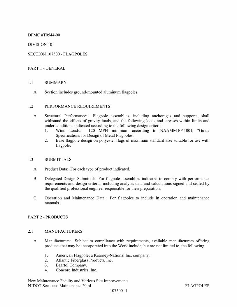
New Maintenance Facility and Various Site Improvements
NJDOT Secaucus Maintenance Yard FLAGPOLES
107500- 1
DPMC #T0544-00
DIVISION 10
SECTION 107500 - FLAGPOLES
PART 1 - GENERAL
1.1 SUMMARY
A. Section includes ground-mounted aluminum flagpoles.
1.2 PERFORMANCE REQUIREMENTS
A. Structural Performance: Flagpole assemblies, including anchorages and supports, shall
withstand the effects of gravity loads, and the following loads and stresses within limits and
under conditions indicated according to the following design criteria:
1. Wind Loads: 120 MPH minimum according to NAAMM FP 1001, "Guide
Specifications for Design of Metal Flagpoles."
2. Base flagpole design on polyester flags of maximum standard size suitable for use with
flagpole.
1.3 SUBMITTALS
A. Product Data: For each type of product indicated.
B. Delegated-Design Submittal: For flagpole assemblies indicated to comply with performance
requirements and design criteria, including analysis data and calculations signed and sealed by
the qualified professional engineer responsible for their preparation.
C. Operation and Maintenance Data: For flagpoles to include in operation and maintenance
manuals.
PART 2 - PRODUCTS
2.1 MANUFACTURERS
A. Manufacturers: Subject to compliance with requirements, available manufacturers offering
products that may be incorporated into the Work include, but are not limited to, the following:
1. American Flagpole; a Kearney-National Inc. company.
2. Atlantic Fiberglass Products, Inc.
3. Baartol Company.
4. Concord Industries, Inc.

New Maintenance Facility and Various Site Improvements
NJDOT Secaucus Maintenance Yard FLAGPOLES
107500- 2
5. Eder Flag Manufacturing Company, Inc.
6. Ewing Flagpoles.
7. Lingo Inc.; Acme Flagpole Company Division.
8. Millerbernd Manufacturing Company.
9. Morgan-Francis; Division of Original Tractor Cab Co., Inc.
10. PLP Composite Technologies, Inc.
11. Pole-Tech Company Inc.
12. U.S. Flag & Flagpole Supply, LP.
13. USS Manufacturing Inc.
14. Or Approved Equal
2.2 FLAGPOLES
A. Exposed Height: 30 feet.
B. Aluminum Flagpoles: Provide cone-tapered flagpoles fabricated from seamless extruded tubing
complying with ASTM B 241/B 241M, Alloy 6063, with a minimum wall thickness of 3/16
inch.
C. Metal Foundation Tube: Manufacturer's standard corrugated-steel foundation tube, not less than
0.064-inch- (1.6-mm-) nominal wall thickness. Provide with 3/16-inch (4.8-mm) steel bottom
plate and support plate; 3/4-inch- (19-mm-) diameter, steel ground spike; and steel centering
wedges welded together. Galvanize steel after assembly. Provide loose hardwood wedges at
top of foundation tube for plumbing pole. Provide flashing collar of same material and finish as
flagpole.
D. Finial Ball: Manufacturer's standard flush-seam ball, sized as indicated or, if not indicated, to
match flagpole-butt diameter.
E. Internal Halyard, Cam Cleat System: 5/16-inch- (8-mm-) diameter, braided polypropylene
halyard; cam cleat; and concealed revolving truck assembly with plastic-coated counterweight
and sling. Provide flush access door secured with cylinder lock. Finish truck assembly to
match flagpole.
F. Halyard Flag Snaps: Provide two swivel snap hooks per halyard.
G. Flagpole Lighting: Provide flagpole mounted lighting consisting of the following:
1. Double LED downlight, or
2. Internal revolving halyard beacon.
3. Inground uplight.
2.3 MISCELLANEOUS MATERIALS
A. Sand: ASTM C 33, fine aggregate.
B. Elastomeric Joint Sealant: Joint sealant complying with requirements in Division 07 Section
"Joint Sealants."

New Maintenance Facility and Various Site Improvements
NJDOT Secaucus Maintenance Yard FLAGPOLES
107500- 3
2.4 ALUMINUM FINISHES
A. Clear Anodic Finish: AAMA 611, AA-M12C22A31, Class II, 0.010 mm or thicker.
PART 3 - EXECUTION
3.1 FLAGPOLE INSTALLATION
A. General: Install flagpoles where shown and according to drawings and manufacturer's written
instructions.
B. Ground Set: Place foundation tube, center, and brace to prevent displacement during
concreting. Install flagpole, plumb, in foundation tube. Place tube seated on bottom plate
between steel centering wedges and install hardwood wedges to secure flagpole in place. Place
and compact sand in foundation tube and remove hardwood wedges. Seal top of foundation
tube with a 2-inch (50-mm) layer of elastomeric joint sealant and cover with flashing collar.
END OF SECTION 107500

New Maintenance Facility and Various Site Improvements
NJDOT Secaucus Maintenance Yard RESIDENTIAL APPLIANCES
113100-1
DPMC # T0544-00
DIVISION 11
SECTION 113100 - RESIDENTIAL APPLIANCES
PART 1 - GENERAL
1.1 SUMMARY
A. This Section includes the following:
1. Refrigerator.
2. Cooktop.
3. Microwave
1.2 SUBMITTALS
A. Product Data: For each type of product indicated.
B. Samples: For each exposed finish.
C. Appliance Schedule: Use same designations indicated on Drawings.
D. Maintenance data.
1.3 QUALITY ASSURANCE
A. Installer Qualifications: An employer of workers trained and approved by manufacturer for
installation and maintenance of units required for this Project.
B. Electrical Components, Devices, and Accessories: Listed and labeled as defined in NFPA 70,
Article 100, by a testing agency acceptable to authorities having jurisdiction, and marked for
intended use.
C. Residential Appliances: Comply with NAECA standards.
D. Energy Ratings: Provide appliances that qualify for the EPA/DOE ENERGY STAR product
labeling program.

New Maintenance Facility and Various Site Improvements
NJDOT Secaucus Maintenance Yard RESIDENTIAL APPLIANCES
113100-2
1.4 WARRANTY
A. Special Warranty: Manufacturer's standard form in which manufacturer of each appliance
specified agrees to repair or replace residential appliances or components that fail in materials
or workmanship within specified warranty period.
1. Refrigerator/Freezer: Five-year limited warranty for in-home service on the sealed
refrigeration system.
PART 2 - PRODUCTS
2.1 MANUFACTURERS
A. In other Part 2 articles where titles below introduce lists, the following requirements apply to
product selection:
1. Basis-of-Design Product: The design for each residential appliance is based on the
product named. Subject to compliance with requirements, provide either the named
product or a comparable product by one of the other manufacturers specified.
2.2 REFRIGERATION APPLIANCES
A. Refrigerator/Freezer:
1. Basis-of-Design Products: Whirlpool Corporation model WRT549SZDW; or a
comparable product by one of the following:
a. General Electric Company
b. Amana Appliances;
c. Electrolux Home Products;
d. Hotpoint;
e. Jenn-Air;
f. KitchenAid;
g. Maytag;
h. Sub-Zero Freezer Co., Inc.;
i. Viking Range Corporation;
j. Or approved equal
2. Type: Freestanding frost-free two-door freezer with freezer on top.
3. Storage Capacity: 19.2 cu. Ft
a. Fresh Food Compartment Volume: 14.05 cu. Ft.
b. Freezer Volume: 5.15 cu. ft.
B. Cooktop:

New Maintenance Facility and Various Site Improvements
NJDOT Secaucus Maintenance Yard RESIDENTIAL APPLIANCES
113100-3
1. Basis-of-Design Products: General Electric model JP3030DJJBB GE 30”(four burners);
or a comparable product by one of the following:
a. Amana Appliances;
b. Electrolux Home Products;
c. Hotpoint;
d. Jenn-Air;
e. KitchenAid;
f. Or approved equal
C. Microwave:
1. Microwave shall be a 2.2 Cu. Ft. countertop sensor microwave oven-1100 watts as
manufactured by General Electric; model PES7227SLSS, or Whirlpool, Amana,
Kitchenaid, or approved equal.
PART 3 - EXECUTION
3.1 INSTALLATION, GENERAL
A. Built-in Equipment: Securely anchor units to supporting cabinets or countertops with concealed
fasteners. Verify that clearances are adequate for proper functioning and rough openings are
completely concealed.
B. Freestanding Equipment: Place units in final locations after finishes have been completed in
each area. Verify that clearances are adequate to properly operate equipment.
C. Utilities: Refer to Divisions 22 and 26 for plumbing and electrical requirements.
END OF SECTION 113100

New Maintenance Facility and Various Site Improvements
NJDOT Secaucus Maintenance Yard FLOOR MATS 124840-1
DPMC #T0619-00
SECTION 124840 - FLOOR MATS
PART 1 - GENERAL
1.1 RELATED DOCUMENTS
A. Drawings and general provisions of the Contract, including General and
Supplementary Conditions and Division 1 Specification Sections, apply to this Section.
1.2 SUMMARY
A. This Section includes the following:
1. Surface-type floor mats of the following type:
a. Carpet-type mats.
1.3 SUBMITTALS
A. General: Submit the following according to the Conditions of the Contract and Division 1 Specification
Sections.
B. Product data for each type of floor mat and frame specified, including manufacturer's specifications and
installation instructions, details of construction relative to materials, dimensions of individual components,
profiles, and finishes.
C. Samples for verification purposes in form of 12-inch-square assembled section of floor mat and frame
members with selected tread surface showing each type of metal finish and color of exposed floor mat,
frames, and accessories required. Where finishes involve normal color and texture variations, include
sample sets showing the full range of variations expected.
D. Maintenance data in the form of manufacturer's printed instructions for cleaning and maintaining floor mats.
1.4 PROJECT CONDITIONS
A. Field Measurements: Check actual framed openings for mats by accurate field measurements before
fabrication; show recorded measurements on final shop drawings. Coordinate fabrication schedule with
construction progress to avoid a delay of the work.
1. Where field measurements cannot be made without delaying the work, guarantee opening
dimensions and proceed with fabrication without field measurements. Coordinate floor construction to
ensure that actual opening dimensions correspond to guarantee dimensions.
1.5 QUALITY ASSURANCE
A. Single-Source Responsibility: Obtain floor mats from one source of a single manufacturer.
PART 2 - PRODUCTS
2.1 MANUFACTURERS

New Maintenance Facility and Various Site Improvements
NJDOT Secaucus Maintenance Yard FLOOR MATS 124840-2
A. Available Manufacturers: Subject to compliance with requirements, manufacturers, offering products that
may be incorporated in the work include, but are not limited to, the following:
1. Carpet-Type Mats:
a. Matworks
b. American Floor Mat
c. Durable
d. Eagle Mat
e. Or approved equal
2.2 MATERIALS
A. General: Rubber backed carpet mat- Provide full range of colors, patterns, and profiles of materials.
2.3 FABRICATION
A. Provide single unit for each mat installation, but do not exceed manufacturer's maximum size
recommendation for units intended for removal and cleaning. Where joints in mats are necessary, space
symmetrically and away from normal traffic lanes. Where possible, verify sizes by field measurement
before shop fabrication.
PART 3 - EXECUTION
3.1 INSTALLATION
A. Install surface-type units to comply with manufacturer's instructions at locations indicated and coordinated
with entrance locations and traffic patterns. Flash patch to make up pile height difference. Direct glue
installation using manufacturer’s recommended product.
3.2 PROTECTION
A. Defer installation of floor mats until some time of Substantial Completion for Project.
END OF SECTION 124840

New Maintenance Facility and Various Site Improvements
NJDOT Secaucus Maintenance Yard
METAL BUILDING SYSTEMS
133419 - 1
DPMC #T0544-00
DIVISION 13
SECTION 133419 - METAL BUILDING SYSTEMS
PART 1 -
1.1 RELATED DOCUMENTS
A. Drawings and general provisions of the Contract, including General and Supplementary
Conditions and Division 01 Specification Sections, apply to this Section.
1.2 SUMMARY
A. Section Includes: Pre-engineered building and components as follows:
1. Structural-steel framing, secondary framing and miscellaneous framing
2. Metal roof panels.
3. Soffit panels.
4. Metal wall panels.
5. Personnel doors and frames
6. Louvers
7. Gutters and leaders
8. Accessories, panel attachments, sealants, mastics, trim and flashings
9. Custom fabrications, fascias, eaves, canopies, column enclosures
B. Related Requirements:
1. Section 033000 Cast-in-Place Concrete
2. Section 055000 Metal Fabrications
3. Section 079200 Joint Sealants
4. Section 083613 "Sectional Doors" for coiling vehicular doors in metal building systems.
5. Section 099123 Painting
6. Section 084523 Fiberglass Sandwich Panel Assemblies
7. Section 074213.19 Insulated Core Metal Wall Panels
8. Section 074116 Insulated Core Metal Roof Panel
9. Section 074113 Metal Roof Panel
10. Section 074213.13 Metal Wall Panels
1.3 DEFINITIONS
A. Terminology Standard: See MBMA's "Metal Building Systems Manual" for definitions of terms
for metal building system construction not otherwise defined in this Section or in standards
referenced by this Section.

New Maintenance Facility and Various Site Improvements
NJDOT Secaucus Maintenance Yard
METAL BUILDING SYSTEMS
133419 - 2
1.4 COORDINATION
A. Coordinate sizes and locations of concrete foundations and casting of anchor-rod inserts into
foundation walls and footings. Anchor rod installation, concrete, reinforcement, and formwork
requirements are specified in Section 033000 "Cast-in-Place Concrete."
B. Coordinate metal panel assemblies with rain drainage work, flashing, trim, and construction of
supports and other adjoining work to provide a leakproof, secure, and noncorrosive installation.
1.5 PREINSTALLATION MEETINGS
A. Preinstallation Conference: Conduct conference at project site
1. Review methods and procedures related to metal building systems including, but not
limited to, the following:
a. Condition of foundations and other preparatory work performed by other trades.
b. Structural load limitations.
c. Construction schedule. Verify availability of materials and erector's personnel,
equipment, and facilities needed to make progress and avoid delays.
d. Required tests, inspections, and certifications.
e. Unfavorable weather and forecasted weather conditions and impact on
construction schedule.
2. Review methods and procedures related to metal roof panel assemblies including, but not
limited to, the following:
a. Compliance with requirements for purlin and rafter conditions, including flatness
and attachment to structural members.
b. Structural limitations of purlins and rafters during and after roofing.
c. Flashings, special roof details, roof drainage, roof penetrations, equipment curbs,
and condition of other construction that will affect metal roof panels.
d. Temporary protection requirements for metal roof panel assembly during and after
installation.
e. Roof observation and repair after metal roof panel installation.
f. Snow guards and installation thereof.
3. Review methods and procedures related to metal wall panel assemblies including, but not
limited to, the following:
a. Compliance with requirements for support conditions, including alignment
between and attachment to structural members.
b. Structural limitations of girts and columns during and after wall panel installation.
c. Flashings, special siding details, wall penetrations, openings, and condition of
other construction that will affect metal wall panels.
d. Temporary protection requirements for metal wall panel assembly during and after
installation.
e. Wall observation and repair after metal wall panel installation.

New Maintenance Facility and Various Site Improvements
NJDOT Secaucus Maintenance Yard
METAL BUILDING SYSTEMS
133419 - 3
1.6 ACTION SUBMITTALS
A. Product Data: For each type of metal building system component.
1. Include construction details, material descriptions, dimensions of individual components
and profiles, and finishes for the following:
a. Insulated metal roof panels and trim.
b. Insulated metal wall panels and trim.
c. Metal roof panels and trim.
d. Metal wall panels and trim.
e. Personnel doors and frames.
f. Gutters and leaders.
g. Louvers.
h. Metal building accessories.
i. Insulation and insulation support system.
B. Shop Drawings: Indicate components by others. Include full building plan, elevations, sections,
details and the following:
1. Anchor-Rod Plans: Submit anchor-rod plans and templates before foundation work
begins. Include location, diameter, and minimum required projection of anchor rods
required to attach metal building to foundation. Indicate column reactions at each
location.
2. Structural-Framing Drawings: Show complete fabrication of primary and secondary
framing and miscellaneous framing; include provisions for openings. Indicate welds and
bolted connections, distinguishing between shop and field applications. Include
transverse cross-sections.
3. Bear seal and signature of Registered Professional Engineer in the state of New Jersey
responsible for metal building system design in accordance with state law.
4. Structural calculations and shop drawings for the building shall be submitted in
accordance with ICC Chapter 16, to the State of New Jersey, Office of Construction
Services, for review and approval, prior to the building erection. They shall display raised
seal and signature of an engineer licensed in the State of New Jersey. (minimum 3
copies).
5. Metal Roof and Wall Panel Layout Drawings: Show layouts of panels including methods
of support. Include details of edge conditions, joints, panel profiles, corners, anchorages,
clip spacing, trim, flashings, closures, and special details. Distinguish between factory-
and field-assembled work; show locations of exposed fasteners.
a. Show roof-mounted items including roof hatches, equipment supports, pipe
supports and penetrations, lighting fixtures, and items mounted on roof curbs.
b. Show wall-mounted items including personnel doors, vehicular doors, windows,
louvers, and lighting fixtures.
c. Show translucent panels.
6. Accessory Drawings: Include details of the following items, at a scale of not less than 1-
1/2 inches per 12 inches.

New Maintenance Facility and Various Site Improvements
NJDOT Secaucus Maintenance Yard
METAL BUILDING SYSTEMS
133419 - 4
a. Flashing and trim.
b. Gutters.
c. Downspouts.
d. Fascias and eaves.
e. Exterior entrance canopy.
f. Special details.
C. Samples for Initial Selection: For units with factory-applied finishes.
1. Selection samples for each product specified.
a. Two complete sets of color chips representing manufacturer’s full range of
available colors and patterns.
2. Verification Samples: For each finished product, minimum 6 inches square, representing
actual product, color and patterns.
D. Samples for Verification: For the following products:
1. Panels: Nominal 12 inches long by actual panel width. Include fasteners, closures, and
other exposed panel accessories.
2. Flashing and Trim: Nominal 12 inches long. Include fasteners and other exposed
accessories.
3. Accessories: Nominal 12-inch long Samples for each type of accessory.
E. Door Schedule: For doors and frames. Use same designations indicated on Drawings. Include
details of reinforcement.
1. Door Hardware Schedule: Include details of fabrication and assembly of door hardware.
Organize schedule into door hardware sets indicating complete designations of every
item required for each door or opening.
2. Keying Schedule: Detail Owner's final keying instructions for locks. Include schematic
keying diagram and index each key set to unique door designations.
F. Delegated-Design Submittal: For metal building systems.
1. Include analysis data indicating compliance with performance requirements and design
data signed and sealed by the qualified professional engineer responsible for their
preparation licensed in the state of New Jersey.
1.7 INFORMATIONAL SUBMITTALS
A. Qualification Data: For erector and manufacturer.
B. Welding certificates.
C. Letter of Design Certification: Signed and sealed by a qualified professional engineer. Include
the following:
1. Name and location of Project.
2. Order number.
3. Name of manufacturer.

New Maintenance Facility and Various Site Improvements
NJDOT Secaucus Maintenance Yard
METAL BUILDING SYSTEMS
133419 - 5
4. Name of Contractor.
5. Building dimensions including width, length, height, and roof slope.
6. Indicate compliance with AISC standards for hot-rolled steel and AISI standards for cold-
rolled steel, including edition dates of each standard.
7. Governing building code and year of edition.
8. Design Loads: Include dead load, roof live load, collateral loads, roof snow load,
deflection, wind loads/speeds and exposure, seismic design category or effective peak
velocity-related acceleration/peak acceleration, and auxiliary loads (cranes).
9. Load Combinations: Indicate that loads were applied acting simultaneously with
concentrated loads, according to governing building code.
10. Building-Use Category: Indicate category of building use and its effect on load
importance factors.
D. Erector Certificates: For qualified erector, from manufacturer.
E. Material Test Reports: For each of the following products:
1. Structural steel including chemical and physical properties.
2. Bolts, nuts, and washers including mechanical properties and chemical analysis.
3. Tension-control, high-strength, bolt-nut-washer assemblies.
4. Shop primers.
5. Nonshrink grout.
F. Source quality-control reports.
G. Field quality-control reports.
H. Surveys: Show final elevations and locations of major members. Indicate discrepancies between
actual installation and the Contract Documents. Have surveyor who performed surveys certify
their accuracy.
I. Sample Warranties: For special warranties.
J. FM Global:
1. FMRC Standard 4471 – Approval standard for class/roofs for hail damage, combustibility
and wind uplift resistance.
2. FM Class 90
1.8 CLOSEOUT SUBMITTALS
A. Maintenance Data: For metal panel finishes and door hardware to include in maintenance
manuals.
1.9 QUALITY ASSURANCE
A. Manufacturer Qualifications: A qualified manufacturer.

New Maintenance Facility and Various Site Improvements
NJDOT Secaucus Maintenance Yard
METAL BUILDING SYSTEMS
133419 - 6
1. Accreditation: Manufacturer's facility accredited according to the International
Accreditation Service's AC472, "Accreditation Criteria for Inspection Programs for
Manufacturers of Metal Building Systems."
2. Engineering Responsibility: Preparation of comprehensive engineering analysis and Shop
Drawings by a professional engineer who is legally qualified to practice in jurisdiction
where Project is located.
B. Erector Qualifications: An experienced erector who specializes in erecting and installing work
similar in material, design, and extent to that indicated for this Project and who is acceptable to
manufacturer.
C. Welding Qualifications: Qualify procedures and personnel according to the following:
1. AWS D1.1/D1.1M, "Structural Welding Code - Steel."
2. AWS D1.3, "Structural Welding Code - Sheet Steel."
D. Land Surveyor Qualifications: A professional land surveyor who practices and is licensed in
jurisdiction where Project is located and who is experienced in providing surveying services of
the kind indicated.
E. Mockups: Build mockups to verify selections made under Sample submittals, to demonstrate
aesthetic effects, and to set quality standards for materials and execution.
1. Build mockup of typical wall area as shown on Drawings.
2. Build mockups for typical wall metal panel including accessories.
a. Size: 48 inches long by 48 inches
3. Approval of mockups does not constitute approval of deviations from the Contract
Documents contained in mockups unless Architect specifically approves such deviations
in writing.
1.10 DELIVERY, STORAGE, AND HANDLING
A. Deliver components, sheets, panels, and other manufactured items so as not to be damaged or
deformed. Package metal panels for protection during transportation and handling.
B. Unload, store, and erect metal panels in a manner to prevent bending, warping, twisting, and
surface damage.
C. Stack metal panels horizontally on platforms or pallets, covered with suitable weathertight and
ventilated covering. Store metal panels to ensure dryness, with positive slope for drainage of
water. Do not store metal panels in contact with other materials that might cause staining,
denting, or other surface damage.

New Maintenance Facility and Various Site Improvements
NJDOT Secaucus Maintenance Yard
METAL BUILDING SYSTEMS
133419 - 7
1.11 FIELD CONDITIONS
A. Weather Limitations: Proceed with panel installation only when weather conditions permit
metal panels to be installed according to manufacturers' written instructions and warranty
requirements.
1.12 WARRANTY
A. Special Warranty on Metal Panel Finishes: Manufacturer agrees to repair finish or replace metal
panels that show evidence of deterioration of factory-applied finishes within specified warranty
period.
1. Exposed Panel Finish: Deterioration includes, but is not limited to, the following:
a. Color fading more than 5 Hunter units when tested according to ASTM D 2244. .
b. Chalking in excess of a No. 8 rating when tested according to ASTM D 4214. .
c. Cracking, checking, peeling, or failure of paint to adhere to bare metal. .
2. Finish Warranty Period: 30 years from date of Substantial Completion.
B. Special Weathertightness Warranty for Standing-Seam Metal Roof Panels: Manufacturer agrees
to repair or replace standing-seam metal roof panel assemblies that leak or otherwise fail to
remain weathertight within specified warranty period.
1. Warranty Period: 20 years from date of Substantial Completion.
PART 2 - PRODUCTS
2.1 MANUFACTURERS
A. Basis of Design Manufacturer: NUCOR Building Systems. Other acceptable manufacturers
include:
1. Varco Pruden Buildings
2. American Building Company
3. Butler Manufacturing Company
4. Parkline, Inc.
5. Or approved equal
B. Substitutions: Under provisions of Division 01.
C. Source Limitations: Obtain metal building system components, including primary and
secondary framing and metal panel assemblies, from single source from single manufacturer.

New Maintenance Facility and Various Site Improvements
NJDOT Secaucus Maintenance Yard
METAL BUILDING SYSTEMS
133419 - 8
2.2 SYSTEM DESCRIPTION
A. Provide a complete, integrated set of mutually dependent components and assemblies that form
a metal building system capable of withstanding structural and other loads, thermally induced
movement, and exposure to weather without failure or infiltration of water into building
interior.
B. Primary-Frame Type:
1. Rigid Clear Span: Solid-member, structural-framing system without interior columns.
Tapered columns at garage areas, straight columns at crew/office areas.
2. Finish: Factory primed, field applied finish coats.
C. End-Wall Framing: Manufacturer's standard, for buildings not required to be expandable,
consisting of primary frame, capable of supporting one-half of a bay design load, and end-wall
columns. Finish: factory primed, field applied finish coats.
D. Secondary-Frame Type: Manufacturer's standard purlins and joists and flush-framed girts.
Finish; Gray primed.
E. Eave Height: As noted on drawings.
F. Bay Spacing: As noted on drawings.
G. Roof Slope: As noted on drawings.
H. Roof System: Manufacturer's standard standing-seam, vertical-rib metal roof panels.
I. Exterior Wall System: Manufacturer's standard concealed-fastener, tapered-rib metal wall
panels.
2.3 PERFORMANCE REQUIREMENTS
A. Delegated Design: Engage a qualified professional engineer licensed in the state of New Jersey
to design metal building system.
B. Structural Performance: Metal building systems shall withstand the effects of gravity loads and
the following loads and stresses within limits and under conditions indicated according to
procedures in MBMA's "Metal Building Systems Manual."
1. Design Loads: International Building Code, New Jersey Edition with latest amendments
(IBC-NJ) and ASCE 7-10 with latest amendments as indicated on drawings.
2. Deflection and Drift Limits: Design metal building system assemblies to withstand
serviceability design loads without exceeding deflections and drift limits recommended in
AISC Steel Design Guide No. 3 "Serviceability Design Considerations for Steel
Buildings."
3. Deflection and Drift Limits: No greater than the following:

New Maintenance Facility and Various Site Improvements
NJDOT Secaucus Maintenance Yard
METAL BUILDING SYSTEMS
133419 - 9
a. Purlins and Rafters: Vertical deflection of 1/180 of the span.
b. Girts: Horizontal deflection of 1/180 of the span.
c. Metal Roof Panels: Vertical deflection of 1/160 of the span.
d. Metal Wall Panels: Horizontal deflection of 1/160 of the span.
e. Design secondary-framing system to accommodate deflection of primary framing
and construction tolerances, and to maintain clearances at openings.
f. Lateral Drift: Maximum of 1/200 of the building height.
C. Seismic Performance: Metal building system shall withstand the effects of earthquake motions
determined according to ASCE 7-10 and as indicated on the drawings
D. Thermal Movements: Allow for thermal movements from ambient and surface temperature
changes by preventing buckling, opening of joints, overstressing of components, failure of joint
sealants, failure of connections, and other detrimental effects. Base calculations on surface
temperatures of materials due to both solar heat gain and nighttime-sky heat loss.
E. Differential values in "Temperature Change" Subparagraph below (for aluminum in particular)
are suitable for most of the United States; revise to suit Project.
F. Structural Performance for Metal Roof and Wall Panels: Provide metal panel systems capable
of withstanding the effects of the following loads, based on testing according to ASTM E 1592:
1. Wind Loads: As indicated on Drawings.
G. Wind-Uplift Resistance: Provide metal roof panel assemblies that comply with UL 580 for
wind-uplift-resistance class indicated.
1. Uplift Rating: UL 90.
H. FM Global: Provide roof systems and assemblies complying with all FM Global requirements
for hail damage resistance, combustibility and uplift resistance.
2.4 MATERIALS
A. Primary Framing Steel:
1. Recycled Content: Post-consumer recycled content plus one-half of pre-consumer
recycled content not less than 75 percent.
1. Hot-rolled shapes: ASTM A 36 or ASTM A 992, minimum yield of 36 ksi (248 MPa)
or 50 ksi (345 MPa).
2. Built-up sections:
a. Webs:
1) ASTM A 1011 or ASTM A1018, SS or HSLAS, Grade 55 (380) for
webs 3/16 inch (4.76 mm) thick and thinner.
2) ASTM A 572 Grade 50 (340) or 55 (380) for webs thicker than 3/16 inch
(4.76 mm).
b. Flanges: ASTM A 529 Grade 55 (380) or ASTM A 572 Grade 50 (340) or 55
(380).

New Maintenance Facility and Various Site Improvements
NJDOT Secaucus Maintenance Yard
METAL BUILDING SYSTEMS
133419 - 10
3. Round tube: ASTM A 500, Grade B or C with minimum yield strength of 42 ksi (290
MPa).
4. Square and rectangular tube: ASTM A 500, Grade B or C, minimum yield strength of
42 ksi (290 MPa).
5. Cold-formed C sections: ASTM A 1011, Grade 55 (380), or ASTM A 653, Grade 55
(380).
6. X-bracing: ASTM A 529 or A 572 for rod bracing 36 ksi (248 MPa) or 50 ksi (345
MPa), ASTM A 36 for angle bracing or ASTM A 475 for cable bracing.
7. Finish: Grey primer. Refer to Division 099123 Painting for finish paint.
B. Secondary Framing Steel:
1. Purlins, girts, and eave struts: ASTM A 1011 Grade 55 (380), or ASTM A 653, Grade
55 (380).
2. Recycled Content: Post-consumer recycled content plus one-half of pre-consumer
recycled content not less than 25 percent.
3. Thickness:
a. 12 gauge: 0.100 inch (2.534 mm) minimum uncoated thickness.
4. Depth: To be determined by design details based on 8”.
5. Grey primer. Finish: Refer to section 099123 Painting for finish painting.
C. Panels: See specification sections 074113, 074213.13, 074213.19, and 074116
1. Fasteners:
a. Concealed-fastened panels:
b. Standing seam panels: Long life self-drilling with sealing washer.
c. Ridge: Long-life self-drilling with sealing washer.
d. Clips to purlin or bar joists: Long-life self-drilling with hex washer head and
washer.
2. Clips:
a. Low or high fixed clips: Use where moderate thermal expansion and
contraction in roof panel is expected.
b. Low or high sliding clips: Provide 2 to 4 inches of travel for panel thermal
expansion and contraction.
3. Sealants and closures:
a. Side-laps: Factory applied, hot melt, foamable mastic.
b. End-laps, eave, ridge assembly, gable flashings: Field-applied non-skinning
sealant as specified in Section 07 92 00.
c. Standing Seam Roof Closures:
1) Outside closures: 24 gauge steel sheet.
2) Inside closures: 18 gauge Galvalume or G-40 galvanized coated steel
complying with ASTM A 653/A 653M.

New Maintenance Facility and Various Site Improvements
NJDOT Secaucus Maintenance Yard
METAL BUILDING SYSTEMS
133419 - 11
d. Through-Fastened Roof Closures: Provide closed-cell polyethylene inside and
outside foam closures.
1) Bulk Density: 2 pounds per cubic foot.
2) Service Temperature: -100 to 180 degrees Fahrenheit.
3) Shore Hardness: 7 on AA scale or 51 on 00 scale when tested to ASTM
D 2240.
2.5 BOLTS
A. Rigid Frame Connections: Provide High Strength Bolts, Nuts and Washers:
1. Bolts: ASTM A 325 or ASTM A 490 Heavy Hex Structural Type I as required by
manufacturer's design.
2. Washers: ASTM F 436 Type 1 Hardened Steel.
3. Nuts: ASTM A 563 Grade C Heavy Hex.
4. Coating: Hot-Dipped Galvanized.
B. Other Connections: Provide High Strength or Machine Bolts as required by manufacturer
design:
4. High Strength Bolts and Nuts:
a. Bolts: ASTM A 325 Heavy Hex Structural Type I.
b. Nuts: ASTM A 563 Grade C Heavy Hex.
c. Coating: ASTM F 1941 Electrodeposited Yellow Zinc.
5. Machine Bolts:
a. Bolts: ASTM A 307 Grade Carbon Steel.
b. Nuts: ASTM A 563 Hex Nut Grade A.
c. Coating: ASTM F 1941 Electrodeposited Clear Zinc.
2.6 ROOF SYSTEMS
A. See specification sections 074113 and 074116
2.7 WALL AND FASCIA PANEL SYSTEMS
A. See specification Sections 074213.13 and 074213.19.
B. Accessories.
1. Base condition:
a. Formed base: self-flashing.
b. Base member: Channel.
c. Base member flashing: Masonry.
2. Framed openings: Used to frame out doors, windows, louvers and any other opening.
a. Finish: PVDF color to match wall panel.

New Maintenance Facility and Various Site Improvements
NJDOT Secaucus Maintenance Yard
METAL BUILDING SYSTEMS
133419 - 12
b. Framed opening trim: Standard trim plus full cover trim on exposed jambs and
headers, and any framing members and flashing necessary for a complete
installation.
3. Trim profiles: Profiles to match design intent of drawings.
4. Canopies.
5. Roof line trim.
6. Purlin extensions.
7. Soffit panels.
8. Facades.
9. Roof vent.
10. Pipe flashings.
2.8 PERSONNEL DOORS AND FRAMES
A. Swinging Personnel Doors and Frames: Metal building system manufacturer's standard doors
and frames; prepared and reinforced at strike and at hinges to receive factory- and field-applied
hardware according to BHMA A156 Series.
1. Steel Doors: 1-3/4 inches thick; fabricated from metallic-coated steel face sheets, 0.036-
inch nominal uncoated steel thickness, of seamless, hollow-metal construction; with
0.060-inch nominal uncoated steel thickness, inverted metallic-coated steel channels
welded to face sheets at top and bottom of door.
a. Design: Flush panel.
b. Core: Polyurethane foam with U-factor rating of at least 0.07 Btu/sq. ft. x h x
deg F.
c. Glazing Frames: Steel frames to receive field-installed glass.
2. Steel Frames: Fabricate 2-inch-wide face frames from zinc-coated (galvanized) or
aluminum-zinc alloy-coated steel sheet, 0.060-inch nominal uncoated steel thickness.
a. Type: Factory welded.
3. Fabricate concealed stiffeners, reinforcement, edge channels, and moldings from either
cold- or hot-rolled steel sheet.
4. Hardware:
a. Provide hardware for each door leaf, as follows:
1) Hinges: BHMA A156.1. Three antifriction -bearing, standard-weight, full-
mortise, stainless-steel or bronze, template-type hinges; 4-1/2 by 4-1/2
inches, with nonremovable pin.
2) Lockset: BHMA A156.2. Mortise, with lever handle type. Cylinder cores to
match owners existing system.
3) Exit Device: BHMA A156.3. Touch -bar type.
4) Threshold: BHMA A156.21. Extruded aluminum.
5) Silencers: Pneumatic rubber; three silencers on strike jambs of single door
frames and two silencers on heads of double door frames.

New Maintenance Facility and Various Site Improvements
NJDOT Secaucus Maintenance Yard
METAL BUILDING SYSTEMS
133419 - 13
6) Closer: BHMA A156.4. Surface-applied, standard-duty hydraulic type.
7) Weather Stripping: Vinyl applied to head and jambs, with vinyl sweep at
sill.
b. Provide each pair of double doors with the following hardware in addition to that
specified for each leaf:
1) Astragal: Removable type.
2) Surface Bolts: Top and bottom of inactive door.
5. Anchors and Accessories: Manufacturer's standard units, galvanized according to
ASTM A 123/A 123M.
6. Fabrication: Fabricate doors and frames to be rigid; neat in appearance; and free from
defects, warp, or buckle. Provide continuous welds on exposed joints; grind, dress, and
make welds smooth, flush, and invisible.
B. Materials:
1. Cold-Rolled Steel Sheet: ASTM A 1008/A 1008M, Commercial Steel (CS), Type B,
suitable for exposed applications.
2. Hot-Rolled Steel Sheet: ASTM A 1011/A 1011M, CS, Type B; free of scale, pitting, or
surface defects; pickled and oiled.
3. Metallic-Coated Steel Sheet: ASTM A 653/A 653M, CS, Type B; with G60 (Z180) zinc
(galvanized) or A60 (ZF180) zinc-iron-alloy (galvannealed) coating designation.
C. Finishes for Personnel Doors and Frames:
1. Prime Finish: Factory-apply manufacturer's standard primer immediately after cleaning
and pretreating.
a. Shop Primer: Manufacturer's standard, fast-curing, lead- and chromate-free primer
complying with SDI A250.10 acceptance criteria; recommended by primer
manufacturer for substrate; compatible with substrate and field-applied coatings
despite prolonged exposure.
2. Factory-Applied Paint Finish: Manufacturer's standard, complying with SDI A250.3 for
performance and acceptance criteria.
a. Color and Gloss: As selected by Architect from manufacturer's full range
2.9 ACCESSORIES
A. General: Provide accessories as standard with metal building system manufacturer and as
specified. Fabricate and finish accessories at the factory to greatest extent possible, by
manufacturer's standard procedures and processes. Comply with indicated profiles and with
dimensional and structural requirements.

New Maintenance Facility and Various Site Improvements
NJDOT Secaucus Maintenance Yard
METAL BUILDING SYSTEMS
133419 - 14
1. Form exposed sheet metal accessories that are without excessive oil-canning, buckling,
and tool marks and that are true to line and levels indicated, with exposed edges folded
back to form hems.
B. Roof Panel Accessories: Provide components required for a complete metal roof panel assembly
including copings, fasciae, corner units, ridge closures, clips, sealants, gaskets, fillers, closure
strips, and similar items. Match material and finish of metal roof panels unless otherwise
indicated.
1. Closures: Provide closures at eaves and ridges, fabricated of same material as metal roof
panels.
2. Clips: Manufacturer's standard, formed from stainless-steel sheet, designed to withstand
negative-load requirements.
3. Cleats: Manufacturer's standard, mechanically seamed cleats formed from stainless-steel
sheet or nylon-coated aluminum sheet.
4. Backing Plates: Provide metal backing plates at panel end splices, fabricated from
material recommended by manufacturer.
5. Closure Strips: Closed-cell, expanded, cellular, rubber or crosslinked, polyolefin-foam or
closed-cell laminated polyethylene; minimum 1-inch-thick, flexible closure strips; cut or
premolded to match metal roof panel profile. Provide closure strips where indicated or
necessary to ensure weathertight construction.
6. Thermal Spacer Blocks: Where metal panels attach directly to purlins, provide thermal
spacer blocks of thickness required to provide 1-inch standoff; fabricated from extruded
polystyrene.
C. Wall Panel Accessories: Provide components required for a complete metal wall panel assembly
including copings, fasciae, mullions, sills, corner units, clips, sealants, gaskets, fillers, closure
strips, and similar items. Match material and finish of metal wall panels unless otherwise
indicated.
1. Closures: Provide closures at eaves and rakes, fabricated of same material as metal wall
panels.
2. Backing Plates: Provide metal backing plates at panel end splices, fabricated from
material recommended by manufacturer.
3. Closure Strips: Closed-cell, expanded, cellular, rubber or crosslinked, polyolefin-foam or
closed-cell laminated polyethylene; minimum 1-inch-thick, flexible closure strips; cut or
premolded to match metal wall panel profile. Provide closure strips where indicated or
necessary to ensure weathertight construction.
D. Flashing and Trim: Aluminum-zinc alloy-coated steel sheet, 0.018-inch nominal uncoated steel
thickness, prepainted with coil coating; finished to match adjacent metal panels.
1. Provide flashing and trim as required to seal against weather and to provide finished
appearance. Locations include, but are not limited to, eaves, rakes, corners, bases, framed
openings, ridges, fasciae, and fillers.
2. Opening Trim: Aluminum-zinc alloy-coated steel sheet, 0.030-inch nominal uncoated
steel thickness, prepainted with coil coating. Trim head and jamb of door openings, and
head, jamb, and sill of other openings.

New Maintenance Facility and Various Site Improvements
NJDOT Secaucus Maintenance Yard
METAL BUILDING SYSTEMS
133419 - 15
E. Gutters: Aluminum-zinc alloy-coated steel sheet, 0.018-inch nominal uncoated steel thickness,
prepainted with coil coating; finished to match roof fascia and rake trim. Match profile of gable
trim, complete with end pieces, outlet tubes, and other special pieces as required. Fabricate in
minimum 96-inch-long sections, sized according to SMACNA's "Architectural Sheet Metal
Manual."
1. Gutter Supports: Fabricated from same material and finish as gutters.
2. Strainers: Aluminum wire ball type at outlets.
F. Downspouts: Aluminum-zinc alloy-coated steel sheet, 0.018-inch nominal uncoated steel
thickness, prepainted with coil coating; finished to match metal wall panels. Fabricate in
minimum 10-foot- (3-m-) long sections, complete with formed elbows and offsets.
1. Mounting Straps: Fabricated from same material and finish as gutters.
G. Roof Ventilators: Gravity type, complete with hardware, flashing, closures, and fittings.
1. Continuous or Sectional-Ridge Type: Factory-engineered and -fabricated, continuous
unit; aluminum-zinc alloy-coated steel sheet, 0.018-inch nominal uncoated steel
thickness, prepainted with coil coating; finished to match metal roof panels. Fabricated in
minimum 10-foot-long sections. Provide throat size and total length indicated, complete
with side baffles, ventilator assembly, end caps, splice plates, and reinforcing
diaphragms.
a. Bird Screening: Aluminum, 1/2-inch square mesh, 0.063-inch wire.
b. Dampers: Manually operated, spring-loaded, vertically rising type; chain and
worm gear operator; with pull chain of length required to reach within 36 inches
(914 mm) of floor.
c. Throat Size: Standard with manufacturer, and as required to comply with
ventilation requirements.
H. Louvers: Size and design indicated; self-framing and self-flashing. Fabricate welded frames
from aluminum-zinc alloy-coated steel sheet, 0.048-inch nominal uncoated steel thickness;
finished to match metal wall panels. Form blades from aluminum-zinc alloy-coated steel sheet,
0.036-inch nominal uncoated steel thickness; folded or beaded at edges, set at an angle that
excludes driving rains, and secured to frames by riveting or welding. Fabricate louvers with
equal blade spacing to produce uniform appearance.
1. Blades: Fixed.
2. Bird Screening: Galvanized steel, 1/2-inch-square mesh, 0.041-inch wire; with rewirable
frames, removable and secured with clips; fabricated of same kind and form of metal and
with same finish as louvers.
a. Mounting: Interior face of louvers.
2.10 FABRICATION
B. General:
1. Shop-fabricate framing members for field bolted assembly.

New Maintenance Facility and Various Site Improvements
NJDOT Secaucus Maintenance Yard
METAL BUILDING SYSTEMS
133419 - 16
2. Surfaces of bolted connections: Smooth and free from burrs and distortions.
3. Shop connections to conform to manufacturer's standard design practices.
4. Mark framing members with identifying mark.
5. Welding to conform to AWS D1.1 and AWS D1.3 as applicable.
B. Primary Framing:
1. Plates, stiffeners, and related members: Factory welded base plates, splice plates, cap
plates, and stiffeners into place on structural members.
2. Bolt holes and related machining: Shop fabricate base plates, splices and flanges to
include bolt connection holes. Shop-fabricate webs to include bracing holes.
3. Secondary structural connections (purlins and girts): Ordinary (not pre-tensioned)
bolted connections with welded clips.
4. Welding inspection: Per IAS AC472 Part A.
5. Non-destructive testing: NOT shall be performed and documented.
C. Long Bay Purlins:
1. Fabricate purlins from cold-formed open web long bay system assemblies with
stiffened chords.
2. Install connection bolts through purlin seats.
3. Pre-punch assemblies to allow for attachment of frame flange brace angles,
compression strut extensions, and diagonal X-bridging at centerline.
4. Furnish bridging as light-gauge cold-formed angles secured using self-drilling
fasteners.
5. Manufacture sections in IAS AC472 Part A and B Accredited facility.
6. Top and bottom chords: Nominal 4 inch width formed so that top surface is
continuous and flat to facilitate easy assembly of roof system.
7. Fabricate all elements of minimum 16 gauge steel.
8. Subject finished assemblies to periodic testing to loads equal to 110 percent of design
loads.
D. Zee Purlins:
1. Fabricate girts from cold-formed Z-shaped sections with stiffened flanges.
2. Size flange stiffeners to comply with requirements of AISI S100.
3. Purlin flanges unequal in width for easier nesting during erection.
4. Purlins pre-punched at factory to provide for field bolting to rigid frames.
E. Girts: Simple or continuous span as required by design. Connection bolts will install through
webs not flanges.
F. Bracing:
1. Diagonal Bracing:
d. Diagonal bracing in roof and sidewalls may be used to resist longitudinal loads
in structure when panel diaphragm cannot be used.
e. Furnish to length and equipped with hillside washers and nuts at each end.
f. Bracing may consist of rods threaded at each end or galvanized cable with
suitable threaded end anchors.

New Maintenance Facility and Various Site Improvements
NJDOT Secaucus Maintenance Yard
METAL BUILDING SYSTEMS
133419 - 17
g. If load requirements dictate, bracing may be of structural angle or pipe, bolted
in place.
2. Special Bracing:
a. When diagonal bracing is not permitted in sidewall use rigid frame type portal
or fixed base column.
b. Shear walls may be used where adequate to resist applied wind or seismic
forces.
3. Flange Braces: Brace compression flange of primary framing laterally with angles
connecting to purlin or girt webs so that flange compressive stress is within allowable
limits for any combination of loading.
4. Bridging:
a. Laterally brace top chord of long bay purlins with horizontal bridging if roof
system being used will not supply adequate lateral support to top chord.
5. Horizontally bridge bottom chord for lateral bracing. One row of bolted diagonal
bridging required for long span purlins 40-feet-long and longer.
G. End Laps:
1. Fabricate with 16 gauge backup plates and eight end lap joint fasteners installed in six
pre-punched holes in flat and in dimples in trapezoidal legs.
2. Apply mastic between panels and secure with self-drilling fasteners through panels
and backup plate.
3. Through roof fasteners may be used only at end laps and eaves.
PART 3 - EXECUTION
3.1 EXAMINATION
A. Verification of Conditions: Examine areas and conditions under which work is to be
performed and identify conditions detrimental to proper and or timely completion.
1. Verify foundations are properly installed, to correct dimensions and within acceptable
tolerances.
2. Verify location of covered or built-in work.
3. Do not proceed until unsatisfactory conditions have been corrected.
3.2 PREPARATION
A. Framing Erection: Erect framing in compliance with AIS Specification and the latest edition
of the MBMA metal building systems manual.
B. Provide for erection and wind loads. Provide temporary bracing to maintain structure plumb
and in alignment until completion of erection and installation of permanent bracing. Locate
braced bays as required by manufacturer.
3.3 ERECTION OF FRAME

New Maintenance Facility and Various Site Improvements
NJDOT Secaucus Maintenance Yard
METAL BUILDING SYSTEMS
133419 - 18
A. Install in accordance with manufacturer's instructions.
1. Do not erect frames without complete installation of tie beams and anchorages.
2. Set column base plates with non-shrink grout to full plate bearing.
3. Do not field cut or alter structural members without written approval.
4. After erection, prime welds, abrasions, and surfaces not primed with primer used in
shop painting.
3.4 INSTALLATION
A. Install in compliance with manufacturer's instructions and approved submittals.
1. Exercise care when cutting prefinished material to ensure cuttings do not remain on
finish surface.
2. Fasten cladding system to structural supports, aligned level and plumb.
3. Locate end laps over supports. End lap panels according to manufacturer's
recommendations. Place side laps over adjacent panel and mechanically seam or stitch
fastener per erection guidelines.
4. Provide expansion joints where indicated.
5. Use concealed fasteners.
6. Install sealant and gaskets to prevent weather penetration.
7. Install system free of rattles, noise due to thermal movement, and wind whistles.
8. Install door frames, service doors, overhead doors, window and glass, and gutter
system in compliance with manufacturer's instructions.
9. Seal wall and roof accessories watertight and weather tight with sealant in compliance
with building manufacturer's standard procedures.
10. Rigidly support and secure gutters and downspouts. Joint lengths with formed seams
sealed watertight. Flash and seal gutters to downspouts.
B. Tolerances:
1. Framing Members: 1/4 inch from level; 1/8 inch from plumb.
2. Racking: 1/8 inch from true position. Provide shoring to maintain position prior to
cladding installation.
3.5 FIELD QUALITY CONTROL
A. Testing by Contractor:
1. Roof installation inspection by roof manufacturer's representative; as required as part
of warranty provision.
B. Testing by Contractor:
1. High Strength Bolted Connections: Specification for Structural Joints Using ASTM A-
325 or A 490 Bolts, with minimum testing of bolted connections per the arbitration
inspection procedure.
2. Welded Connections: AWS. Visual inspection of 100 percent of welds. Ultrasonic
inspection of 50 percent of full and partial penetration welds. A rejection rate greater
than 5 percent will increase the inspection to 100 percent.
3. General Testing: For materials and installed tolerances.

New Maintenance Facility and Various Site Improvements
NJDOT Secaucus Maintenance Yard
METAL BUILDING SYSTEMS
133419 - 19
3.6 INSTALLATION
C. Install system in accordance with manufacturer's instructions and approved Shop Drawings.
B. Fit members square against abutting components.
C. Position members plumb, square, and level.
D. Temporarily brace members until permanently fastened.
E. Do not splice load bearing members.
F. Align and adjust various members forming parts of a complete frame or structure after
assembly but before fastening.
G. Welding to conform to AWS D1.1.
H. Fasten panels to supports.
I. Install trim to maintain visual continuity of system.
J. Install joint sealant and gaskets to prevent water penetration.
K. Flash penetrations through roofing with metal trim to match panels
L. Paint all exposed structural steel
3.7 PROTECTION
A. Protect installed products until completion of project.
3.8 ADJUSTMENT
A. Touch up, repair, or replace damaged products before Substantial Completion.
END OF SECTION 133419