project report - namrc.co.ukproject is considered in terms of progress, which has been made to raise...
TRANSCRIPT

Intelligent Fixtures for Optimised
and Radical Manufacture (InFORM)
Department for Business, Enterprise
and Industrial Strategy
NI1066-REP-01 Project report

Document Revision Page
NI1066-REP-01 03 2
© 2019 University of Sheffield NAMRC.REP Version 7.0
Nuclear AMRC
University of Sheffield
Advanced Manufacturing Park
Brunel Way
Rotherham
S60 5WG
United Kingdom
This report may only be reproduced in full, except with the express permission of the Nuclear AMRC.
The Nuclear AMRC has exercised due care in conducting this report but has not, apart from as specifically stated,
independently verified information provided by others. No other warranty, express or implied, is made in relation to
the contents of this report. Therefore, the Nuclear AMRC assumes no liability for any loss resulting from errors,
omissions, or misrepresentations made by others. Any recommendations, opinions or findings stated in this report are
based on circumstances and facts as they existed at the time the Nuclear AMRC performed the work. Any changes in
such circumstances and facts upon which this report is based may adversely affect any recommendations, opinions or
findings contained in this report. Where experiments have been carried out, these have been restricted to a level of
detail required to achieve the stated objectives of the statement of work. This work has been undertaken in accordance
with the Nuclear AMRC’s quality system.
Name Signature
Authors: Ben Cook
Ed Reeves
Technical review: Carl Hitchens
David Anson
Authorised: Prof Steve Jones
Authorised distribution: BEIS
Document revision history
Revision Date of issue Reason for revision or original issue
01 12/09/2019 Original issue
02 12/11/2019 Minor amendments following BEIS feedback
03 15/01/2020 Minor amendments following NIRO feedback
Document Revision Page
NI1066-REP-01 03 3
© 2019 University of Sheffield NAMRC.REP Version 7.0
Executive summary
The Intelligent Fixtures for Optimised and Radical Manufacture (InFORM) project has completed the first stages of
development for a range of innovative technologies that will reduce the cost and lead times associated with the
manufacture of large, complex, safety critical components required by the power generation industries. The project was
completed in two stages between May 2017 and August 2019. The Stage 1 project was a three month feasibility study
of enabling technologies and Stage 2 was a full 20 month programme to develop equipment and knowhow in each
process area.
The InFORM Stage 1 project identified several technologies in forging, machining and power beam welding which have
the potential to make large scale nuclear component manufacturing processes more productive and less costly. The
objective in Stage 2 was to realise the potential of various innovations by developing a through-life intelligent fixture
concept which can interface with and support the technologies identified in Stage 1. The fixture concept addresses the
challenges of transferring large, high value components through key stages of assembly, without the need for multiple
fixtures and repeated set-ups at each interval. A fixture system that supports the joining of large components to form
even larger assemblies, functioning more as a fully integrated manufacturing platform than as a stand-alone fixture, will
reduce the number of fixtures requiring storage and the demand on floor space, resulting in smaller, less costly, factory
footprints.
The Nuclear AMRC led a consortium of key industrial partners on a collaborative programme to deliver proof of concept
evidence for a range of innovations in:
Forging technologies (Sheffield Forgemasters RD26) – hollow ingot forging, modular tooling, materials for largenuclear pressure vessels, real-time metrology
Advanced rough machining and Super-critical CO2 coolants (Nuclear AMRC) – advanced reverse engineeringusing scan / point cloud data, and machining with cleaner, more environmentally friendly coolants
Advanced intelligent fixtures (MetLase) – upscaling of MetLase’s patented fixture system for deployment onlarge scale components
Local vacuum electron beam welding (TWI) – localised vacuum chamber for power beam applications toprovide improved productivity, faster welding time, greater weld quality and reduced factory footprint
Metrology for InFORM technologies (Nuclear AMRC) – recommendations on suitable systems and methods formeasurement and monitoring to support development of innovations in each technology group
4th Industrial Revolution technology demonstrator (AMRC with Boeing) – integration of sensors on theintelligent fixture for through-life continuous monitoring and reporting on the status of the fixture and locatedcomponent, with systems to provide location tracking, monitoring of movement and alignment of the locatedcomponent relative to the fixture
Through the course of this project the technologies have been developed to an average TRL and MRL of 3. An intelligent,
flexible and mobile assembly platform which connects digital monitoring systems with large-scale automated
manipulation hardware will lead to wider industrial adoption of innovative manufacturing processes, but the work
required to deploy and commercialise such a system will need to be the subject of future research programmes.
Document Revision Page
NI1066-REP-01 03 4
© 2019 University of Sheffield NAMRC.REP Version 7.0
Contents
A Introduction .................................................................................................................................................A-1
B Forging Optimisation.................................................................................................................................... B-1
C Machining Optimisation – Advanced Roughing ........................................................................................... C-1
D Machining Optimisation – Super-critical CO2 coolants ............................................................................... D-1
E Intelligent Fixtures ....................................................................................................................................... E-1
F Local Vacuum Electron Beam Welding ........................................................................................................ F-1
G Metrology.................................................................................................................................................... G-1
H 4IR Technology Demonstrator .................................................................................................................... H-1
I Dissemination ............................................................................................................................................... I-1
Appendices
1 TRL / MRL Assessments
2 TRL / MRL Assessment Guidance Criteria
3 Peer Review Panel
4 Forging Optimisation Report
5 Metrology Report (NI1066-REP-04)
6 Conference and Publication Abstracts
7 Stage 1 Report

Document Revision Page
NI1066-REP-01 03 A-1
© 2019 University of Sheffield NAMRC.REP Version 7.0
A. Introduction
Document Revision Page
NI1066-REP-01 03 A-2
© 2019 University of Sheffield NAMRC.REP Version 7.0
Contents
1 Introduction .......................................................................................................................................................... 3 1.1 Nuclear Innovation Programme ............................................................................................................... 3
1.1.1 History and Background ............................................................................................................... 3 1.1.2 NIRAB report to government ....................................................................................................... 3 1.1.3 Advanced Materials and Manufacturing ...................................................................................... 4
1.2 The challenge ............................................................................................................................................ 5 1.3 Intelligent fixtures for optimised manufacturing ..................................................................................... 6 1.4 Large component manufacturing ............................................................................................................. 6
2 Project scope ........................................................................................................................................................ 8 2.1 Project concept ......................................................................................................................................... 9 2.2 Future commercialisation ......................................................................................................................... 9 2.3 Commercial benefits to project developers and consumers .................................................................... 9
2.3.1 Local Vacuum Electron Beam Welding – EBFLOW system, CVE ................................................ 10 2.3.2 Through-life intelligent fixtures – MetLase ................................................................................ 10 2.3.3 Software for fixtures – AMRC (DPG) .......................................................................................... 11 2.3.4 Advanced machining strategies – Nuclear AMRC ...................................................................... 11 2.3.5 Process improvements in forging – SFIL .................................................................................... 11
2.4 Alignment with Nuclear Innovation Programme objectives .................................................................. 12 3 Project structure ................................................................................................................................................. 13
3.1 Project consortium ................................................................................................................................. 13 3.1.1 Sheffield Forgemasters RD26 ..................................................................................................... 13 3.1.2 The Nuclear AMRC ..................................................................................................................... 13 3.1.3 TWI ............................................................................................................................................. 14 3.1.4 MetLase ...................................................................................................................................... 14 3.1.5 The AMRC with Boeing – Design and Prototyping Group (DPG) ................................................ 14 3.1.6 Supporting partners ................................................................................................................... 15
3.2 Work package structure ......................................................................................................................... 17 3.3 Report and chapter structure ................................................................................................................. 17
4 Summary of project outputs .............................................................................................................................. 18 4.1 Overall impact of the project.................................................................................................................. 18 4.2 Forging technologies .............................................................................................................................. 19 4.3 Advanced rough machining .................................................................................................................... 20 4.4 Super-critical carbon dioxide machining ................................................................................................ 21 4.5 Advanced intelligent fixtures .................................................................................................................. 22 4.6 Local vacuum electron beam welding (LVEBW) ..................................................................................... 23 4.7 Metrology technologies .......................................................................................................................... 24
4.7.1 Forging metrology ...................................................................................................................... 24 4.7.2 Machining metrology ................................................................................................................. 24 4.7.3 Assembly metrology ................................................................................................................... 25 4.7.4 Welding metrology ..................................................................................................................... 25
4.8 4IR technology demonstrator ................................................................................................................. 25 4.8.1 Continuous process monitoring ................................................................................................. 25 4.8.2 Industrial impact ........................................................................................................................ 26
5 Summary of future work .................................................................................................................................... 27 References ........................................................................................................................................................................ 28

Document Revision Page
NI1066-REP-01 03 A-3
© 2019 University of Sheffield NAMRC.REP Version 7.0
1 Introduction
Intelligent Fixtures for Optimised and Radical Manufacture (InFORM) Stage 2 is a large collaborative research and
development project undertaken by the Nuclear AMRC and key industrial partners between February 2018 and August
2019. The project was funded by the Department for Business, Energy and Industrial Strategy (BEIS) in response to the
SBRI Advanced Manufacturing and Materials (AM&M) competition, which was set up to stimulate innovation in the civil
nuclear sector. The project was split into two stages, the first being a three-month feasibility study of enabling
technologies, with a fully scoped 20 month development programme in Stage 2. The outputs of the Stage 1 work are
fully documented in Appendix 7.
1.1 Nuclear Innovation Programme
1.1.1 History and Background
In 2011 the House of Lords Science and Technology Committee carried out an Inquiry into the UK’s nuclear R&D
capability and made a number of recommendations on where it viewed improvements were needed. In response, the
Government published its Nuclear Industrial Strategy in March 2013. This described a clear and ambitious vision of a
vibrant UK nuclear industry making a valuable economic contribution and providing the UK with a safe, reliable and
affordable source of low carbon electricity. It also identified a series of initial actions to realise those objectives. These
included the establishment of Nuclear Innovation and Research Advisory Board (NIRAB) and Nuclear Innovation and
Research Office (NIRO).
NIRAB was initially established as a three-year temporary advisory board in January 2014 and was charged with advising
Government on the level, approach and coordination of nuclear innovation and R&D required to keep future energy
options open to enable both domestic and international commercial opportunities to be realised. NIRAB’s initial term
ended in December 2016 (1).
NIRAB was reconvened and reconstituted in 2018 and works in partnership with NIRO to advise Ministers, Government
Departments and Agencies on issues related to nuclear research and innovation in the UK (2).
NIRO is operated by the National Nuclear Laboratory (NNL) on an independent arms-length basis and is primarily staffed
by secondees from NNL and industry (1).
1.1.2 NIRAB report to government
In March 2016 NIRAB provided a report - UK Nuclear Innovation and Research Programme Recommendations – to the
UK Government on the R&D needed to deliver its civil nuclear power objectives (3).
NIRAB developed recommendations for research, which were grouped into five key programmes. One of these areas
was advanced materials and manufacturing.
Document Revision Page
NI1066-REP-01 03 A-4
© 2019 University of Sheffield NAMRC.REP Version 7.0
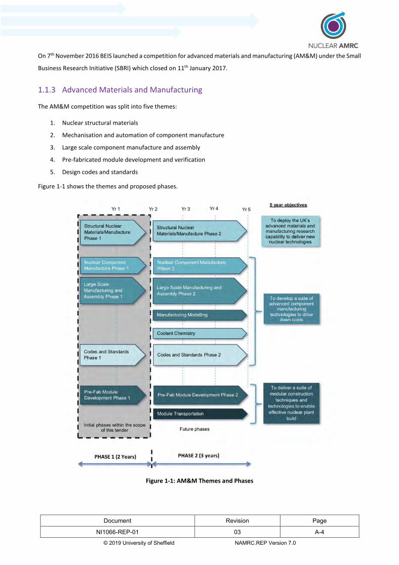
On 7th November 2016 BEIS launched a competition for advanced materials and manufacturing (AM&M) under the Small
Business Research Initiative (SBRI) which closed on 11th January 2017.
1.1.3 Advanced Materials and Manufacturing
The AM&M competition was split into five themes:
1. Nuclear structural materials
2. Mechanisation and automation of component manufacture
3. Large scale component manufacture and assembly
4. Pre-fabricated module development and verification
5. Design codes and standards
Figure 1-1 shows the themes and proposed phases.
Figure 1-1: AM&M Themes and Phases
Document Revision Page
NI1066-REP-01 03 A-5
© 2019 University of Sheffield NAMRC.REP Version 7.0
SBRI competitions are 100% funded and are open to all organisations that can demonstrate a route to market for their
solution. The BEIS Guidance for Applicants - Advanced Manufacturing and Materials Competition stated on page 7:
2. This competition covers the R&D required in the first two years of a 5 year programme. For all themes,
applicants should consider forward planning and how each theme will develop at the end of the initial 2 years.
However, this competition must have clearly defined outputs at the end of the 2 year period.
So while the competition was only for the first phase of 2 years, any submissions should be based around a 5-year
programme. Due to the size of the budgets across the various themes, the competition consisted of 2 stages for Themes
1 to 3. Successful applicants were initially awarded Stage 1 contracts (3 months) to produce a feasibility study and if
justified by the study, a Stage 2 contract (20 months) would be awarded.
Based on the 5 year timescale, Nuclear AMRC submitted an appropriate bid into Theme 3 – the InFORM project – and
was awarded a Stage 1 contract in May 2017. The Stage 1 report (see Appendix 7) was submitted in August 2017 upon
which a 20 month contract for Stage 2 was offered starting in January 2018 for completion at the end of August 2019.
Nuclear AMRC’s proposal into Theme 3 was that the 20 months of the Stage 2 contract would demonstrate proof-of-
concept evidence for potential time and cost savings, which are achievable through the development of innovative
technologies across the four themes of forging, advanced machining, intelligent fixtures and power beam welding. The
Stage 2 contract would provide the underpinnings for the 3 year Phase 2, where further development would take place
to increase the maturity of the technologies and processes, with a view to making them ready for commercialisation.
The future work would also look at other manufacturing processes that could leverage the developments of current
work and realise the concept of disparate manufacturing processes co-existing in a collaborate environment.
1.2 The challenge
A range of challenges were set for projects under Theme 3 of the AM&M competition for Large Scale Component
Manufacturing and Assembly (4). Projects were required to address the challenges associated with the manufacture
and assembly of large, complex, integrated nuclear components for SMRs and other key large-scale nuclear
components, and also identify technical solutions to these challenges (5). Broadly, applications were required to develop
and demonstrate:
Advanced techniques for the precision machining of large, complex, integrated nuclear components, such as
SMR modules and large heat exchangers.
Techniques for large-scale metrology, to measure assemblies more quickly and accurately.
Significantly better techniques to control and mitigate distortion during the machining of large nuclear
components.

Document Revision Page
NI1066-REP-01 03 A-6
© 2019 University of Sheffield NAMRC.REP Version 7.0
Non-intrusive and rapid inspection and measurement techniques, to enable faster, cheaper and more accurate
inspections when integrating large complex assemblies.
Specific outputs of Theme 3 projects were to include (5):
a) Solutions for off-site manufacture and assembly of large-scale components such as SMRs that introduce best-
practice techniques into the nuclear sector.
b) Demonstration of the development of advanced techniques for the precision machining of large, complex,
integrated nuclear components such as SMR modules and large heat exchangers.
c) Demonstration of the development of techniques for large-scale metrology to measure assemblies quickly and
accurately.
d) Demonstration of the development of techniques to control and mitigate distortion during the machining of
large nuclear components such as SMR modules.
e) Demonstration of the development of non-intrusive and rapid inspection and measurement techniques to
enable inspections during and following the integration of large complex assemblies.
f) A forward programme intended to better define the requirements of the remainder of the 5-year funding
period. This should include an outline plan to deploy and commercialise the outputs.
1.3 Intelligent fixtures for optimised manufacturing
InFORM aims to establish proof-of-concept evidence for innovative technologies that will help UK companies to
compete on a global scale and win major manufacturing contracts across all nuclear sectors, including new build, small
modular reactors (SMRs), defence, decommissioning and fusion. This will strengthen the UK’s position as a significant
partner in the global deployment of Gen III+, Gen IV and SMR technologies as envisaged in the AMM competition.
The research documented in this report will help UK companies to develop the manufacturing and design expertise
needed to become major global exporters of nuclear technology, which will be vital given that the majority of global
new-builds are likely to be built outside the UK. The successful adoption of InFORM technologies and techniques will
increase the capability of UK manufacturers in other heavy engineering sectors, such as wind energy, oil and gas and
shipbuilding, and will help to build confidence in the supply chain. The ultimate goal is to create UK-owned intellectual
property, which can be exploited across a wide range of applications, various industrial sectors and worldwide markets.
The technologies and methods developed through the InFORM research programme will generate new workforce skills
that are transferrable to other industries and will help to address the current nuclear skills gap in the UK.
1.4 Large component manufacturing
The InFORM Stage 1 feasibility report produced by the Nuclear AMRC (included in Appendix 7) noted that current
manufacturing methods for large components for the energy-generating industries often involve manually intensive,

Document Revision Page
NI1066-REP-01 03 A-7
© 2019 University of Sheffield NAMRC.REP Version 7.0
artisan operations, where the successful production of components relies largely on the skill and knowledge of shop-
floor technicians. Sub-optimal operations exist in most of the manufacturing procedures used to create large
components, from the forging stage through to machining and welding operations. Typical forging processes, for
example, generate large amounts of excess material due to poor understanding of downstream machining operations
and the use of relatively unsophisticated measures for ensuring that sufficient stock material is available to machine
components to the required size (forgings are often significantly oversized). Uncertainty regarding the exact final
dimensions of the forging lead to increased machining costs, with hours wasted moving the tool through air. This is
further exacerbated by difficulties in quickly and accurately setting components on machines because of their size and
mass. When components are joined together, thick section welds (>50mm) are carried out using traditional, manually
operated, mechanised multi-pass arc-welding techniques with inter-stage non-destructive evaluation (NDE). Bespoke
fixtures are often used at each station, which leads to long set-up times and the stacking-up of positioning errors.
The technologies developed through InFORM will help to provide solutions to these challenges and ultimately make
large-scale manufacturing processes much more efficient. InFORM sought to develop hollow ingot forging techniques
which will increase confidence in the process and enable the production of forgings, which are near net-shape (NNS),
resulting in less material waste. An intelligent fixture concept will also be developed, which, along with digital scan data
from the forging process, will allow components to be positioned quicker and more accurately at processing stations.
Advanced rough machining methods, which are already used in other sectors, will be applied to reduce the amount of
time that cutting tools spend ‘cutting’ fresh air. Additionally, carbon dioxide will be used instead of conventional
coolants, to allow cutting speeds to be increased whilst simultaneously increasing tool life.

Document Revision Page
NI1066-REP-01 03 A-8
© 2019 University of Sheffield NAMRC.REP Version 7.0
2 Project scope
Stage 1 of the InFORM project was a feasibility study that identified several technologies across forging, machining and
power beam welding, which have potential to make large-scale nuclear component manufacturing processes more
productive and less costly. The study set a goal of developing a single through-life fixture that can support and interface
with these technologies and be capable of transferring large high-value components through each stage of the
manufacturing and assembly process, rather than using multiple fixtures and set-ups at each step. The Stage 1 work
documented in Appendix 7 included market research, a technology development plan, an assessment of potential
commercialisation routes, and defined the scope for Stage 2 of the project.
InFORM Stage 2 focused on developing proof-of-concept evidence for each of the technologies and innovations
identified at Stage 1 and assessing the potential cost savings that might be achieved if they are deployed in the
manufacture of large, complex, safety critical components. The Stage 2 project also aimed to demonstrate how
expertise in these technologies could be developed and successfully transferred to industry by manufacturing a two-
thirds scale pressure vessel, showcasing each of the technology innovations. The intention was also to identify how
these technologies might, in future, be integrated into a fully commercialised system that can be procured by UK
pressure vessel manufacturers.
A core aim of Stage 2 was to produce an intelligent fixture concept that could potentially support the complete
manufacture and assembly of a full-scale pressure vessel, where individual components are transferred seamlessly
through each manufacturing stage via a single, versatile fixture system. A single intelligent fixture system has numerous
benefits over the conventional approach, which uses multiple bespoke fixtures for each step within the manufacturing
process. Bespoke fixtures can account for a large proportion of the component cost but often spend a significant amount
of time in storage when not in use. An intelligent fixture would be utilised more frequently, require less storage space,
and would lower production costs, as custom made fixtures would not be required every time a new component is
produced. The intelligent fixture would move components between ‘docking’ stations in the assembly process, where
it would provide a platform on which other manufacturing operations could be carried out. To facilitate the intelligent
fixture concept, some modification and development of existing processing technologies was considered necessary, and
the intention of InFORM Stage 2 was to investigate any such changes required of those technologies.
An intelligent fixture is likely to have greatest benefit during component assembly, where it would be required to
support joining technologies and integrate metrology and component alignment systems. Plans were made to design
an effective local vacuum end effector for electron beam welding of nuclear pressure vessels, with development trials
to establish whether the system can hold a satisfactory vacuum in order to produce an approved weld. A review of
metrology systems, which span all the InFORM technologies, and particularly those which aid component alignment,
was to be completed to support the conceptual development of the intelligent fixture. Demonstration of 4IR
technologies that are suitable for asset management and tracking of components through the manufacturing process
were included to support development of the intelligent fixture concept. A review of large scale forging technologies,
looking at various aspects from vacuum degassing techniques for steelmaking, nuclear materials for generation IV and
Document Revision Page
NI1066-REP-01 03 A-9
© 2019 University of Sheffield NAMRC.REP Version 7.0
SMR designs, to modular forging tools and concepts in real-time metrology systems, was also carried out. Advanced
rough machining techniques featuring optimised tool cutting paths, which make better use of digital scan data to
machine rough forgings, and research on advanced super-critical carbon dioxide coolants, was also to be included in the
overall machining optimisation work.
2.1 Project concept
The current best practice for the manufacture of pressure vessels and large assemblies relies on bespoke one-off fixtures
designed for individual components. The introduction of Small Modular Reactors (SMRs) has led to widespread
acceptance that serialised, mass production techniques will be required to make components of SMR designs financially
viable. The core objective of InFORM Stage 2 is to develop intelligent fixtures to optimise pressure vessel manufacture,
focusing on four primary processes: forging, machining, assembly and welding.
2.2 Future commercialisation
The scope of the InFORM project was to demonstrate proof of concept evidence for innovative technologies across
forging, machining, local vacuum electron beam welding and assembly. In principle each of the technologies could be
commercialised independently but to realise their full combined potential – and true value – on the overall
manufacturing cycle, an extensive development program is needed to incorporate them holistically into an intelligent
assembly system that would serve as a fully integrated manufacturing process rather than as a mere fixture. A fixture
system that is able to support components through critical stages of assembly, where large segments are joined
together, will mean a reduction in the number of fixtures requiring storage. A flexible, mobile manufacturing platform,
which connects digital monitoring systems with automated manipulation hardware will lead to wider industrial adoption
of innovative manufacturing processes. The work required to deploy and commercialise such a system will need to be
the subject of future research programmes.
2.3 Commercial benefits to project developers and consumers
InFORM will benefit UK manufacturing industry by reducing baseline manufacturing costs for large-scale nuclear
components, potentially generating multi-million-pound cost savings in the process. This will allow UK manufacturers
to increase their global competitiveness, win more major export contracts and drive wider economic growth. The
InFORM programme showcases several commercially exploitable manufacturing technologies (e.g. hollow ingot forging,
localised vacuum electron beam welding, supercritical carbon dioxide (scCO2) coolants, intelligent fixture design, digital
asset management and part tracking etc.) that could be used to increase manufacturing productivity for the large, high
value components seen in typical nuclear power generating plants. Knowledge gained on the application of these
technologies also has cross sector relevance, where skills and expertise can be transferred to the manufacture of other
high value components such as wind turbine masts or oil and gas well heads. This will allow manufacturers (particularly
the commercial partners of the InFORM consortium) to develop and exploit business opportunities further across a
number of different and diverse markets. The wind energy sector, for example, is a major alternative outlet for some of

Document Revision Page
NI1066-REP-01 03 A-10
© 2019 University of Sheffield NAMRC.REP Version 7.0
the technologies developed through InFORM. The InFORM Stage 1 report (see Appendix 7) highlighted that the UK is
the ‘world's largest offshore wind market and accounts for almost 36% of offshore capacity installed worldwide’. In
2017, the UK installed 53% of net capacity across Europe, according to WindEurope (6). The scale of the market which
is potentially available to UK manufacturers would be significant, as the manufacture and supply of wind turbine towers
can account for 10-25% of the cost of a typical 2 MW, £2.5-3M wind turbine.
InFORM provides substantial economic benefit to each member of the consortium with future outcomes from
commercialisation and sales being potentially transformative for each organisation; this is particularly the case for
Cambridge Vacuum Engineering (CVE) and MetLase who are both SMEs. The key exploitable results are described in the
next sections.
2.3.1 Local Vacuum Electron Beam Welding – EBFLOW system, CVE
Through InFORM, Cambridge Vacuum Engineering (CVE) has further developed the EBFLOW local vacuum system for
nuclear components. Whilst CVE compete with companies such as Sciaky, Pro-Beam, PTR Precision Technologies and
Mitsubishi Electric on conventional vacuum electron beam welding (EBW) systems, they have no known competitors in
local vacuum EBW. CVE currently hold patents for the EBFLOW system; three covering local vacuum chamber seals and
one for modifications to TWI’s (The Welding Institute’s) electron beam (EB) gun. They have total freedom to operate
through the use of their IP and sole licence of the TWI gun. The patent for the EB gun technology which underpins the
application of a local vacuum system in a ‘reduced pressure’ environment is owned by TWI, who have granted CVE a
sole licence to the technology for the purpose of machinery supply, thus allowing TWI to operate in the same
commercial space. The return on investment (ROI) for specific end-users will vary according to the application but in
offshore wind generation, for example, standard methods of producing foundations take 6200 hours of arc welding
compared to 200 hours EBW, which gives a ROI of 3-4 weeks. Whilst the EBFLOW system is already commercially
available, development of a pressure-vessel-relevant system requires further research in order to build evidence for a
comprehensive nuclear code case. Complete commercialisation of the system would have a transformative effect on
CVE's business with an estimated increase in sales of 2-4 systems per year. This would lead to a significant increase in
revenue; specifically, it could double the size of the business and create 30 new jobs. As the sole supplier in the world
for local vacuum EBW, CVE could acquire 100% of the market share.
2.3.2 Through-life intelligent fixtures – MetLase
The InFORM project has allowed MetLase to develop their approaches – and FEA methodologies – towards designing
through-life intelligent fixtures for larger, heavier components. Their patented manufacturing system, comprising jigs,
fixtures and other tooling is inherently more accurate and quicker to deploy than conventional tooling. Their
competitors use traditional technologies which are slower, less accurate and less agile. MetLase hold various patents
related to the mechanical joining of sheet metals using non-welded techniques, a method which retains the accuracy of
the laser cut edge and provides the customer with extremely accurate fixtures. Their patents allow MetLase to operate
freely in this area and, by integrating sensors and associated controlling software to add value to the fixtures, will allow

Document Revision Page
NI1066-REP-01 03 A-11
© 2019 University of Sheffield NAMRC.REP Version 7.0
them to increase their market share in high-value manufacturing sectors. By building on the design approaches
developed through InFORM, it may be feasible for MetLase to acquire more than 50% of the market share for high-
value, through-life intelligent fixtures, due to their existing advantage in the agile production of extremely accurate
fixtures. Depending on the number and type of sensors required, and the size of the fixture, their intelligent fixtures
could cost anywhere between £1K and £300K; the ROI for the customer is expected to be around one year.
Commercially, MetLase could expect to increase their turnover by around £1M per annum and employ an additional
five skilled engineers.
2.3.3 Software for fixtures – AMRC (DPG)
Software developed by The AMRC with Boeing – Design and Prototyping Group (DPG) through InFORM is protected
through confidentiality agreements. It will be used in consultancy by AMRC (DPG) and licensed to UK manufacturers
where appropriate. One commercialisation route under consideration is to license it to MetLase free of charge to be
bundled and sold with their intelligent fixtures. This resultant intelligent fixture and associated software will have a
number of applications beyond the nuclear sector, including uses in ship building, aerospace and rail.
2.3.4 Advanced machining strategies – Nuclear AMRC
The use of optimised CAM workflows and advanced coolants such as supercritical carbon dioxide (scCO2) to improve
the productivity of machining operations has been further developed by the Nuclear AMRC through InFORM. The
outcomes achieved may be used in consultancy or licensed to Nuclear AMRC members and UK manufacturers where
appropriate. The advanced machining strategy work by Nuclear AMRC has a number of applications beyond the nuclear
sector and continued development of advanced cooling techniques in machining will increase the profile of the centre
through dissemination of results in journal articles and conferences. Such research will substantially contribute to the
Nuclear AMRC’s reputation as a centre for manufacturing excellence.
2.3.5 Process improvements in forging – SFIL
Process improvements identified by Sheffield Forgemasters International (SFIL) as part of InFORM will be utilised
immediately in SFIL’s own production processes provided that there is sufficient confidence in the anticipated results.
Other commercial opportunities may be exploited by further development and testing of nuclear-scale hollow ingot
forging methods, which would also include work to characterise material and structural qualities of the component.
Similarly, further research and development of future forging tools and methods, especially modular tooling equipment,
may lead to the creation of nuclear specific tools or handling equipment which could be commercialised through
licenced use of IP or component specific design models.

Document Revision Page
NI1066-REP-01 03 A-12
© 2019 University of Sheffield NAMRC.REP Version 7.0
2.4 Alignment with Nuclear Innovation Programme objectives
Projects submitted under Theme 3 of the AM&M competition for Large Scale Component Manufacturing and Assembly,
as part of the Nuclear Innovation Programme, were required to identify and develop solutions which address the
challenges associated with the manufacture and assembly of large, high value nuclear components. The objectives
focused on developing and demonstrating innovative solutions or applications across specific technologies, which
included forging, machining, power beam welding, fixtures and assembly. If integrated successfully, these solutions will
achieve the overall objective of making large-scale nuclear component manufacturing processes more productive and
less costly to the manufacturer and consumer.
This phase of the Nuclear Innovation Programme aimed to strengthen the position of UK industry as a
significant partner in the global deployment of Gen III+, Gen IV and SMR technologies. In response, each
InFORM work package has demonstrated proof-of-concept evidence for novel technologies that will help UK
manufacturers to compete internationally and win major manufacturing contracts across all nuclear sectors,
including new build, small modular reactors (SMRs), defence, decommissioning and fusion.
Through InFORM, the project partners, SFIL, Nuclear AMRC, AMRC DPG, TWI, CVE and MetLase, have further
developed intellectual property for products and services they supply. Ultimately, with further research
funding and appropriate future commercialisation activities, they will be able to exploit this knowledge and
expertise across a wide range of applications, industrial sectors and worldwide markets.
The technologies and methods developed through InFORM research will create new workforce skills in several
areas, such as fixture design, advanced toolpath programming and non-contact metrology. Development of
training in these areas will help to capture the years of tacit knowledge which has built up among the
workforces of manufacturers so that expertise can be passed on to future generations of engineers. Many of
these skills are transferrable and will help to address the current nuclear skills gap in the UK.
InFORM has provided a framework which unifies a number of technical research areas and contributes to
ongoing research programmes in the other competition themes, such as mechanisation and automation of
nuclear component manufacture; pre-fabricated module development and verification; and nuclear design
codes and standards. InFORM has also investigated how technologies used in other industries (e.g. large
volume laser scan metrology from aerospace and fixture design from the automotive industry) could be
transferred and applied to nuclear manufacturing and identified key limitations in their suitability for meeting
the requirements of large scale nuclear manufacturing.
Significant time and cost savings have been identified across each InFORM technology group, particularly in power beam
welding, optimisation of machining strategies and application of advanced machining coolants. Although further
commercialisation work is needed to increase industrial adoption of these technologies and methods, significant
progress has been made towards developing more efficient manufacturing processes which will help to drive down
costs and in turn improve the cost effectiveness of nuclear power in the UK and potentially worldwide.
Document Revision Page
NI1066-REP-01 03 A-13
© 2019 University of Sheffield NAMRC.REP Version 7.0
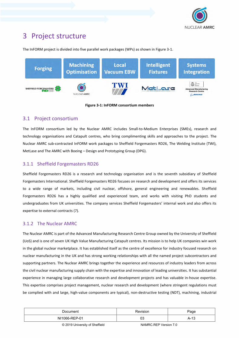
3 Project structure
The InFORM project is divided into five parallel work packages (WPs) as shown in Figure 3-1.
Figure 3-1: InFORM consortium members
3.1 Project consortium
The InFORM consortium led by the Nuclear AMRC includes Small-to-Medium Enterprises (SMEs), research and
technology organisations and Catapult centres, who bring complimenting skills and approaches to the project. The
Nuclear AMRC sub-contracted InFORM work packages to Sheffield Forgemasters RD26, The Welding Institute (TWI),
MetLase and The AMRC with Boeing – Design and Prototyping Group (DPG).
3.1.1 Sheffield Forgemasters RD26
Sheffield Forgemasters RD26 is a research and technology organisation and is the seventh subsidiary of Sheffield
Forgemasters International. Sheffield Forgemasters RD26 focuses on research and development and offers its services
to a wide range of markets, including civil nuclear, offshore, general engineering and renewables. Sheffield
Forgemasters RD26 has a highly qualified and experienced team, and works with visiting PhD students and
undergraduates from UK universities. The company services Sheffield Forgemasters’ internal work and also offers its
expertise to external contracts (7).
3.1.2 The Nuclear AMRC
The Nuclear AMRC is part of the Advanced Manufacturing Research Centre Group owned by the University of Sheffield
(UoS) and is one of seven UK High Value Manufacturing Catapult centres. Its mission is to help UK companies win work
in the global nuclear marketplace. It has established itself as the centre of excellence for industry focused research on
nuclear manufacturing in the UK and has strong working relationships with all the named project subcontractors and
supporting partners. The Nuclear AMRC brings together the experience and resources of industry leaders from across
the civil nuclear manufacturing supply chain with the expertise and innovation of leading universities. It has substantial
experience in managing large collaborative research and development projects and has valuable in-house expertise.
This expertise comprises project management, nuclear research and development (where stringent regulations must
be complied with and large, high-value components are typical), non-destructive testing (NDT), machining, industrial
Document Revision Page
NI1066-REP-01 03 A-14
© 2019 University of Sheffield NAMRC.REP Version 7.0
fixtures, large-scale metrology and the development of new and optimised welding processes for the most demanding
nuclear applications. The Nuclear AMRC can also access the experience and skills available within the University of
Sheffield and the wider AMRC Group (8).
3.1.3 TWI
The Welding Institute (TWI) is a UK research and technology organisation, which has expertise in materials joining and
industrial engineering processes. They specialise in innovation, knowledge transfer and in solving problems across all
aspects of manufacturing, fabrication and whole-life integrity management. TWI have a £150M facility in Cambridge,
which includes state-of-the-art equipment dedicated to structural integrity, robotics, welding and non-destructive
evaluation (NDE). They have extensive knowledge of electron beam welding and it is their electron beam gun that is
used under license on CVE’s EBFLOW system (see 3.1.3.1), with whom they have a long-standing relationship. TWI have
previously collaborated with all of the subcontractors and have particular expertise in weld testing / verification (8).
3.1.3.1 CVE
Cambridge Vacuum Engineering (CVE) are a SME and subcontracted to TWI to contribute to the development of the
local vacuum electron beam welding (LVEBW) technology for InFORM. CVE have more than 60 years of experience in
manufacturing electron beam systems and vacuum furnaces. They have a commercially available local vacuum welding
system named EBFLOW, own Intellectual Property related to local vacuum equipment for electron beam welding, and
design and build process solutions for electron beam systems. CVE provide valuable expertise on the sealing systems
required to enable local vacuum electron beam welding and in-factory acceptance testing (FAT). CVE will be the pilot
organisation to commercialise InFORM outputs associated with electron beam welding through marketing and sales of
an adaptable SMR-ready welding system.
3.1.4 MetLase
MetLase are a SME formed by a joint venture between Rolls-Royce and Unipart. They are a mechanical engineering
consultancy whose technology-based approach and patented tooling techniques allow them to quickly design and
manufacture bespoke, precision engineering solutions. They have expertise in laser-cutting machines and press-brake
material forming, and can design and produce both simple and complex tooling, fixtures and components for a wide
range of industries, often bringing lead times down from months to just days (9).
3.1.5 The AMRC with Boeing – Design and Prototyping Group (DPG)
The AMRC with Boeing aims to bridge the gap between industry and academia. It is a collaboration between the
University of Sheffield and Boeing, opened in 2008 with funding from the European Regional Development Fund. The
AMRC with Boeing is part of the AMRC Group, a cluster of world-class centres for industry-focused research and
development of technologies used in high-value manufacturing sectors. The group has specialist expertise in machining,
casting, welding, additive manufacturing, composites, designing for manufacturing, testing and training. It has a global

Document Revision Page
NI1066-REP-01 03 A-15
© 2019 University of Sheffield NAMRC.REP Version 7.0
reputation for helping companies overcome manufacturing problems. Its success worldwide has led it to become a
model for collaborative research involving universities, academics and industry (10).
The AMRC DPG is at the centre of active research themes across the AMRC and the wider University of Sheffield,
enabling them to combine world-class research and development with innovative and flexible design capabilities. They
utilise in-house high-precision machining processes, additive manufacturing, fabrication, advanced analytical tools and
clean room facilities to develop next generation prototypes. Their recent portfolio includes: the design and build of a
high performance, large volume additive manufacturing machine; the development of an unmanned ground support
vehicle; the successful launch of powered and free-flight unmanned aerial vehicles; the re-design of a pyro-electric fuel
shut off valve and the development of next generation orthopaedic devices.
3.1.6 Supporting partners
The InFORM project received letters of support at Stage 1 from the following supporting partners: BAE Systems,
Cavendish Nuclear, EDF Energy, Frazer Nash, GE Hitachi Nuclear Energy, Moltex Energy, NuScale, Rolls-Royce, Sellafield
and Westinghouse Electric Company (WEC). The supporting partners were available throughout the project to provide
industrial advice along with the industrial pull. The partners have confirmed how InFORM can reduce cost and time in
their core manufacturing businesses. They provided consultation during the initial proposal stage and Stage 1 to guide
the project and provided input to the Peer Review as the project reached its conclusion. The relevance of the supporting
partners’ membership is shown through their core business interests:
BAE Systems
BAE Systems (Maritime) is a world leading designer and manufacturer of the full range of naval ships, including nuclear
submarines, which necessitate welding large components.
Cavendish Nuclear
Cavendish Nuclear are the UK’s leading supplier to the nuclear industry offering both experience and specialist
knowledge across all aspects of the nuclear energy lifecycle, from design and build, through operations and
maintenance, to decommissioning, waste management and remediation.
EDF Energy
EDF Energy is an integrated energy company with operations spanning electricity generation and supply to homes and
businesses throughout the United Kingdom. Within the nuclear industry, its activities involve site planning and
construction, operations and decommissioning.

Document Revision Page
NI1066-REP-01 03 A-16
© 2019 University of Sheffield NAMRC.REP Version 7.0
Frazer-Nash
Frazer-Nash is a multi-disciplinary engineering consultancy focused on providing solutions to complex challenges in
engineering using knowledge and technical expertise gained from a diverse suite of industries – one of those being
nuclear.
GE Hitachi Energy
GE Hitachi Energy alliance combines GE’s design expertise delivering reactors, fuels and services with Hitachi’s proven
experience in advanced modular construction offering the technological leadership required to enhance reactor
performance, power output and safety.
Moltex
Moltex is a developer of nuclear power reactors specialised in molten salt reactor technology, with the potential to
make nuclear power safer and cheaper.
NuScale
NuScale Power is a leading developer of SMR technology, offering near-term deployable, cost competitive, scalable,
flexible and low carbon power supply. NuScale is advancing its plans to build a UK-US partnership, which will see its
technology built in British factories.
Rolls-Royce
Rolls-Royce are the UK’s leading manufacturer of high value components for nuclear new build and defence sectors.
They are the lead manufacturing organisation that has developed a business proposal for a UK SMR technology
programme.
Sellafield
Sellafield Ltd are responsible for the decommissioning of their site in West Cumbria, on behalf of the Nuclear
Decommissioning Authority. Sellafield is Europe’s most complex nuclear site with up to 100 years of uniquely
challenging projects remaining.
WEC
Westinghouse Electric Company (WEC) provides a wide range of nuclear power plant, products and services to utilities
throughout the world. They are continuing development of their AP100 SMR technology for UK implementation.
Document Revision Page
NI1066-REP-01 03 A-17
© 2019 University of Sheffield NAMRC.REP Version 7.0
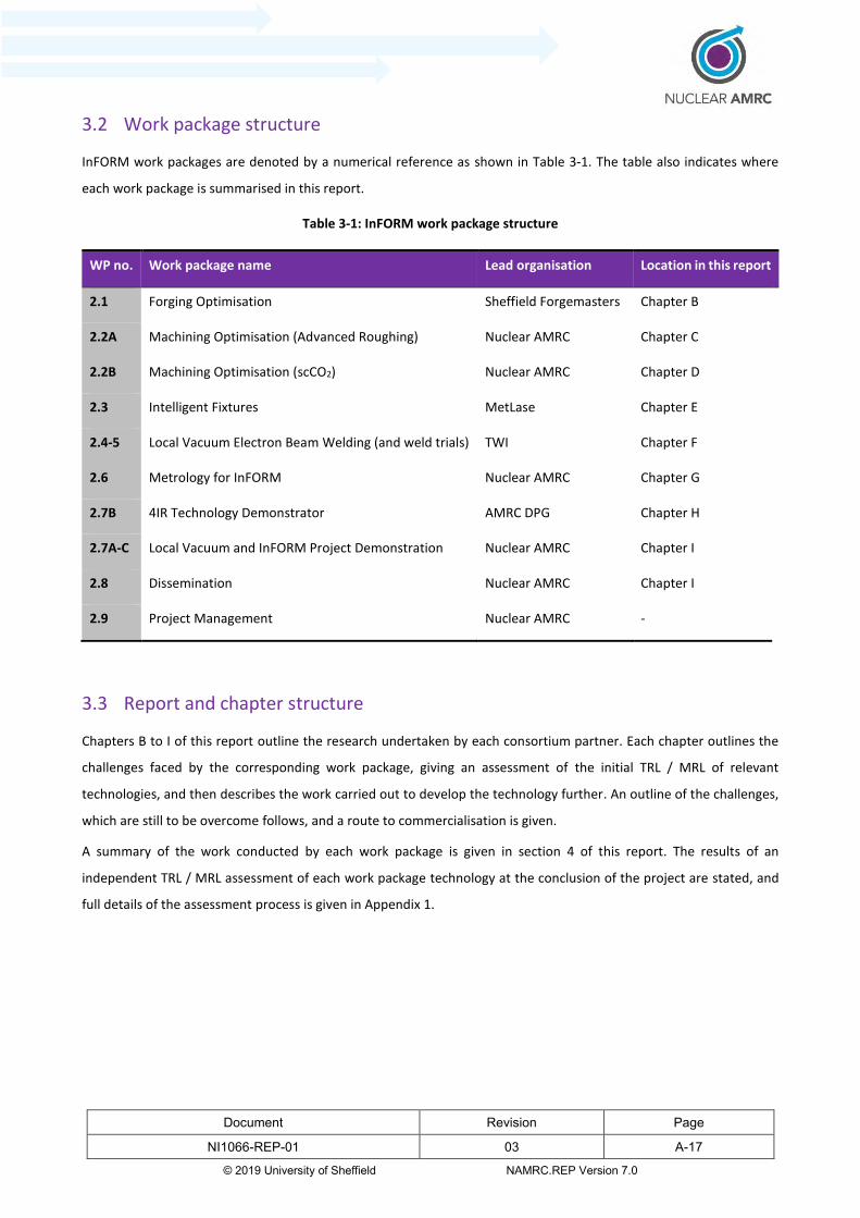
3.2 Work package structure
InFORM work packages are denoted by a numerical reference as shown in Table 3-1. The table also indicates where
each work package is summarised in this report.
Table 3-1: InFORM work package structure
WP no. Work package name Lead organisation Location in this report
2.1 Forging Optimisation Sheffield Forgemasters Chapter B
2.2A Machining Optimisation (Advanced Roughing) Nuclear AMRC Chapter C
2.2B Machining Optimisation (scCO2) Nuclear AMRC Chapter D
2.3 Intelligent Fixtures MetLase Chapter E
2.4-5 Local Vacuum Electron Beam Welding (and weld trials) TWI Chapter F
2.6 Metrology for InFORM Nuclear AMRC Chapter G
2.7B 4IR Technology Demonstrator AMRC DPG Chapter H
2.7A-C Local Vacuum and InFORM Project Demonstration Nuclear AMRC Chapter I
2.8 Dissemination Nuclear AMRC Chapter I
2.9 Project Management Nuclear AMRC -
3.3 Report and chapter structure
Chapters B to I of this report outline the research undertaken by each consortium partner. Each chapter outlines the
challenges faced by the corresponding work package, giving an assessment of the initial TRL / MRL of relevant
technologies, and then describes the work carried out to develop the technology further. An outline of the challenges,
which are still to be overcome follows, and a route to commercialisation is given.
A summary of the work conducted by each work package is given in section 4 of this report. The results of an
independent TRL / MRL assessment of each work package technology at the conclusion of the project are stated, and
full details of the assessment process is given in Appendix 1.
Document Revision Page
NI1066-REP-01 03 A-18
© 2019 University of Sheffield NAMRC.REP Version 7.0
4 Summary of project outputs
Full details of the technology developments made by each InFORM work package are documented in chapters B to I. An
overview of the key outputs and achievements from each area is given later in this section. The overall impact of the
project is considered in terms of progress, which has been made to raise the Technology and Manufacturing Readiness
Levels of each work package / technology theme.
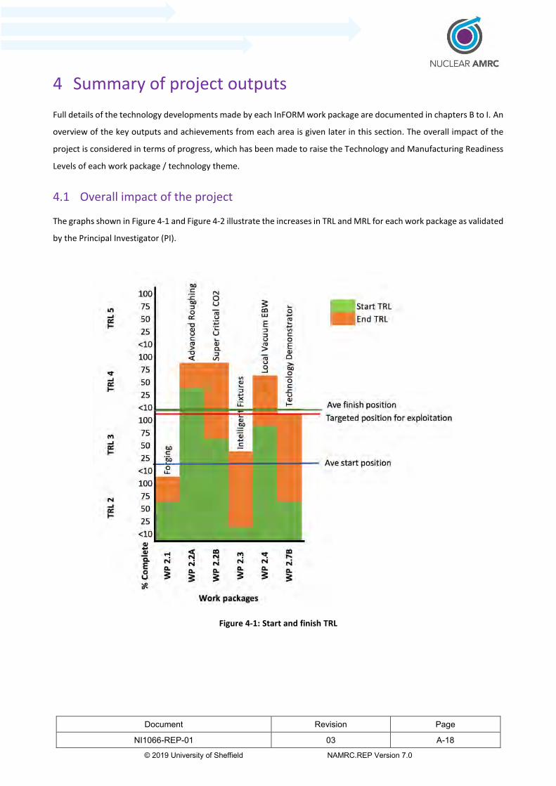
4.1 Overall impact of the project
The graphs shown in Figure 4-1 and Figure 4-2 illustrate the increases in TRL and MRL for each work package as validated
by the Principal Investigator (PI).
Figure 4-1: Start and finish TRL

Document Revision Page
NI1066-REP-01 03 A-19
© 2019 University of Sheffield NAMRC.REP Version 7.0
Figure 4-2: Start and finish MRL
A full description of the TRL / MRL assessment process and its results are given in Appendix 1.
4.2 Forging technologies
This work package provides a full review of currently available forging technologies for large scale nuclear components,
and identifies necessary developments to optimise the UK’s capability for large scale open die forging of nuclear grade
alloys for the next generation of reactors. Principal among these are the benefits of in-process advanced metrology
techniques to measure and monitor forging operations in order to improve process control and increase the geometrical
accuracy of forged components. Real time metrology will generate more reliable data, enabling nearer-net-shape
forgings and thus improve the manufacturability of key reactor components. To support further development of near
net-shape forging technology, the research:
Provides analysis of forging requirements for different designs of Advanced Modular Reactor (AMR) and Small
Modular Reactor (SMR). A number of potential manufacturing challenges and areas for further research are
identified. For example, in the very high temperature reactor (VHTR) design, intensive temperature and
irradiation conditions place demanding requirements on materials. Nickel based super alloys are required to

Document Revision Page
NI1066-REP-01 03 A-20
© 2019 University of Sheffield NAMRC.REP Version 7.0
provide corrosion and creep resistance for critical components, however, further research is required to improve
the forging and general manufacturability of such materials.
Addresses the differences between key nuclear reactor components, identifying specific features or design
characteristics that would require particular manufacturing steps or approaches to be taken. Conventional
tooling sets for Reactor Pressure Vessel (RPV) head forming have a significant cost; but a modular design
methodology and hollow fabricated tool sets are found to drastically reduce the cost of tooling manufacture.
Sheffield Forgemasters has demonstrated these methods during the manufacture of a NuScale RPV head in the
Innovate UK support programme ‘Innovate forging and fabrication solutions for the nuclear industry’.
Identifies key challenges in UK steelmaking, specifically with regards to the capabilities of existing vacuum
degassing techniques, and evaluates recent developments which could be used to address current problems.
Surveys future nuclear reactor materials, which are likely to be used in Generation IV and SMR designs,
identifying particular geometrical / forming aspects or material properties that could require alternative forging
approaches to be taken.
Highlights emerging challenges in forging and tooling. This identified improved forging routes, contrasting the
forging requirements of conventional pressure vessel designs with more advanced reactor designs; particular
attention was given to the number of individual components which need forging and welding together. Analysis
of various reactor designs, using design for manufacturing principles, highlighted the benefits of specific
technologies, such as hollow ingot forging techniques (which require fewer forging operations/steps), the use of
modular tooling, real time non-contact metrology and improved heat treatment processes.
4.3 Advanced rough machining
The advanced rough machining work package shows how large, rough forged components can be digitised with three-
dimensional scanning tools, and the captured data then used to produce more efficient computer controlled cutting
programs. Scanned data is typically captured in quality inspection procedures to verify geometrical tolerances and
specification conformity, however the highly detailed data could potentially be re-used to produce very accurate
component models for simulating optimised rough machining operations. This research developed viable methods for
preparing large point clouds and workflows for manipulating them in Computer Aided Manufacturing (CAM) software
environments. Significant improvements were made in:
Reducing the amount of time a cutting tool spends out-of-cut (not cutting material) as it moves around the
component, by using optimised tool paths based more closely on the actual stock material available.
Pre-processing and optimising scanned datasets of large file size into more usable formats for subsequent CAM
engineering.
Component location and alignment. Establishing and transferring the datum for the alignment of featureless
stock using traditional methods is time consuming and can be error prone. Software with manual and automatic

Document Revision Page
NI1066-REP-01 03 A-21
© 2019 University of Sheffield NAMRC.REP Version 7.0
tool alignment was used to align CAD/CAM test models to provide greater assurance that sufficient stock is
available to achieve the finished component.
The work package proposed an optimised advanced reverse engineering workflow – Scan-to-CAM. This removes one
step from current best practice which is to scan the component, create a CAD model from the scan data and then use
that CAD model to create a numerical control (NC) program. The key benefits of Scan-to-CAM include:
Increased machining efficiency, as the NC program will only move the cutter to where material is present and
requires removing and so minimise out-of-cut conditions.
Reduced environmental impact – components are machined quicker, reducing energy consumption and
potentially reducing material waste.
Closer tolerance forgings – increases confidence that components can be machined from the available stock.
In simulations it was found that the Scan-to-CAM approach can be up to 40% faster in rough machining
operations as compared to traditional CAM approaches which do not use scan data in toolpath programming.
4.4 Super-critical carbon dioxide machining
The advanced coolants work package investigated the effects of supercritical CO2 (scCO2) coolants on the machinability
of nuclear grade steel (SA508 Grade 3 Class 2) by evaluating tool life, tool wear mechanisms, cutting forces and surface
integrity across different combinations of cutting conditions. The performance of scCO2 was compared against
conventional soluble oil coolant. It was found that:
Machining of SA508 steel with scCO2 resulted in a significant increase in tool life compared to conventional
soluble oil flood coolant. An increase in tool life of up to 220% can be achieved when using scCO2 and minimum
quantity lubrication (MQL) compared to flood coolant (based on a maximum tool wear threshold of 300 μm).
This could lead to fewer tool changes, in turn helping to reduce component manufacturing time. Optimisation
of the flow rate of scCO2+MQL using the Design of Experiments methodology is proposed as future work to
increase metal removal rate.
No detrimental effects to the material surface condition were observed when compared to conventional soluble
oil flood coolant for the same cutting conditions. In studies with scCO2+MQL, surface roughness was influenced
more by feed rate than cutting speed. The lowest surface roughness was observed at low feed and high cutting
speed (which is consistent with published literature).
Health benefits for the workforce and reduced environmental impact have been identified with further work
required to fully quantify the significance.
The use of scCO2 results in components that are cleaner and require little or no post-machining decontamination
or removal of residue with significant downstream cost savings.

Document Revision Page
NI1066-REP-01 03 A-22
© 2019 University of Sheffield NAMRC.REP Version 7.0
4.5 Advanced intelligent fixtures
The intelligent fixtures work package developed a through-life fixture concept which is designed to transfer large
pressure vessel segments through major stages of assembly, incorporating support for welding and inspection
operations. The concept device addresses the challenges associated with large-scale component alignment, and
provides a platform for integrating sensor systems which provide feedback to actuators and manipulators in order to
automatically adjust clamping forces and minimise distortion. The radical fixture concept is based on MetLase’s
patented technology and could potentially revolutionise the process of building large pressure vessel assemblies.
MetLase use laser cut sheet metal to build bespoke fixtures and rapid prototypes for the automotive and aerospace
industries. Until now, the viability of the MetLase system for use in heavy engineering environments has not been
demonstrated extensively, however, the InFORM programme has allowed MetLase to simulate, test and experimentally
validate some of the larger structures featured in the concept design through finite element analysis (FEA). Additionally
the concept has enabled MetLase to increase their understanding of how their system can be adapted to integrate
multiple complex processes on one platform, in particular, support for heavy vessel alignment and local vacuum electron
beam welding technologies. The concept fixture addressed challenges associated with:
Scaling up MetLase technology. This included FEA of key structures to verify the non-welded fixture design.
MetLase successfully refined their FEA approaches to more accurately predict the structural response of the
concept fixture when subjected to anticipated in-use loads. This allowed MetLase technology to be developed
further for large scale applications in a safe virtual environment, enabling pre-verification of future fixture
designs with greater confidence in the results.
Location, manipulation and alignment of large, heavy pressure vessel assemblies.
Interfaces with the welding process. This included mechanisms and actuation systems to enable synchronised
manipulation of the component, and provision of x-ray shielding.
Heat treatment of the component.
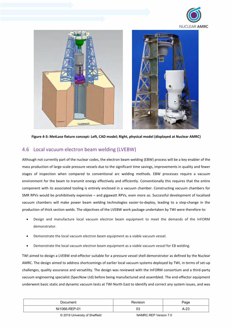
The fixture concept provides a more holistic approach to large-scale assembly, and is more than just a large work-holding
device. A scale model of the concept fixture (Figure 4-3) was produced to demonstrate the proposed process.
Document Revision Page
NI1066-REP-01 03 A-23
© 2019 University of Sheffield NAMRC.REP Version 7.0
Figure 4-3: MetLase fixture concept: Left, CAD model; Right, physical model (displayed at Nuclear AMRC)
4.6 Local vacuum electron beam welding (LVEBW)
Although not currently part of the nuclear codes, the electron beam welding (EBW) process will be a key enabler of the
mass production of large-scale pressure vessels due to the significant time savings, improvements in quality and fewer
stages of inspection when compared to conventional arc welding methods. EBW processes require a vacuum
environment for the beam to transmit energy effectively and efficiently. Conventionally this requires that the entire
component with its associated tooling is entirely enclosed in a vacuum chamber. Constructing vacuum chambers for
SMR RPVs would be prohibitively expensive – and gigawatt RPVs, even more so. Successful development of localised
vacuum chambers will make power beam welding technologies easier-to-deploy, leading to a step-change in the
production of thick section welds. The objectives of the LVEBW work package undertaken by TWI were therefore to:
Design and manufacture local vacuum electron beam equipment to meet the demands of the InFORM
demonstrator.
Demonstrate the local vacuum electron beam equipment as a viable vacuum vessel.
Demonstrate the local vacuum electron beam equipment as a viable vacuum vessel for EB welding.
TWI aimed to design a LVEBW end-effector suitable for a pressure vessel shell demonstrator as defined by the Nuclear
AMRC. The design aimed to address shortcomings of earlier local vacuum systems deployed by TWI, in terms of set-up
challenges, quality assurance and versatility. The design was reviewed with the InFORM consortium and a third-party
vacuum engineering specialist (SpecNow Ltd) before being manufactured and assembled. The end-effector equipment
underwent basic static and dynamic vacuum tests at TWI North East to identify and correct any system issues, and was

Document Revision Page
NI1066-REP-01 03 A-24
© 2019 University of Sheffield NAMRC.REP Version 7.0
then commissioned on an EBFlow electron beam welding machine at Cambridge Vacuum Engineering’s facility near
Cambridge. The trials were successful in carrying out full penetration melt runs on a steel test shell, representing a
pressure vessel of 80 mm wall thickness, 1800 mm diameter, to demonstrate the feasibility of key system features and
innovations. A one metre long melt run was completed satisfactorily, however, future work to develop the seal
arrangement and improve its resilience to heat, abrasion and x-ray emissions from the electron beam gun was identified
in order to progress from melt run to full welding capability.
4.7 Metrology technologies
A desktop review of metrology techniques, which could potentially help to streamline workflows at various stages of
the production cycle was completed. Various measurement tools and metrology techniques were investigated and the
most suitable systems for each of the InFORM technology areas (forging, machining, welding and assembly) were
identified, compared and contrasted.
4.7.1 Forging metrology
Several metrology techniques were reviewed and a Pugh matrix used to identify the most suitable for forging, with
optical tracking providing a basis for comparison. The review concluded that a laser line scanner referenced by a tracker
would be the most suitable technology to use in a forge environment. The laser line scanner allows fast data capture of
cold parts in a workshop environment, while non-contact laser tracker technology may be of interest for research into
in-process measurement of hot parts. Manually operated measurement arms would also be suitable for measuring cold
components in a workshop environment, provided the measurements can be made within the limitations on
measurement volume. These systems may also be potentially capable of making use of augmented reality projection
technology, which would put the detailed and highly accurate data collected to further use. For further details, please
refer to Appendix 5 Metrology Report.
4.7.2 Machining metrology
A similar review of metrology techniques was carried out to identify those which are most suitable for use in machining
operations, with the datum technology being photogrammetry. The review concluded that no single technology or
product provides a stand-out advantage over another, with selection depending much on the specific application
intended, and in some cases, technologies may support or complement each other. For example, a laser tracker with
laser strip scanner and appropriate software could be used to acquire scan data for part setup and tool path
optimisation. The laser tracker could also be used to verify the performance of an on-machine probing system used for
in-process verification. Sharing and using data throughout the manufacturing process is desirable to maximise
productivity and efficiency, but requires systems to be interconnected and compatible with each other. Compliance
with 4IR principles also depends more on how measurement systems are integrated and implemented than on the
systems themselves. Regardless of the measurement system(s) ultimately used, an understanding of temperature

Document Revision Page
NI1066-REP-01 03 A-25
© 2019 University of Sheffield NAMRC.REP Version 7.0
variation and its impact on part dimensions and measurement system is crucial to having accurate measurements – this
is anticipated to be an area for further investigation. For further details, please refer to Appendix 5 Metrology Report.
4.7.3 Assembly metrology
A review of assembly specific metrology identified that laser tracker based measurement systems would be most
appropriate for assembly of components in the InFORM concept fixture. Laser radar and photogrammetry have the
advantage that they support non-contact measurement but photogrammetry would still require visible reference
markers to be placed on the component. The latest laser trackers from Hexagon have the ability to take non-contact
measurements without the need for target markers. However non-contact measurement is not as crucial for assembly
as it is for forging, machining and welding. Frequency Scanning Interferometry (FSI) has been identified as a promising
technology, however, it is currently in the very early stages of development and as such considered to be out of scope
for the InFORM programme. For further details, please refer to Appendix 5 Metrology Report.
4.7.4 Welding metrology
A review of options for welding metrology concluded that laser scanning with a tracker (either a laser tracker or an
optical tracker) would be the most appropriate technology for measurement of welding operations in InFORM. This
view is taken due to the requirements for large volume, non-contact measurements, however, for smaller parts a
measurement arm with a laser scanner would achieve the same results at lower cost. The only significant limitation of
laser scanners in this context is that the quoted uncertainties of these systems are close to the limit of what is acceptable
for welding in InFORM. Measurement of artefacts with known form and comparison with other measurement systems
may help provide confidence in measurements. If the requirement for non-contact measurement is relaxed, a high
accuracy photogrammetry system may provide an alternative solution as these are robust systems which can achieve a
high data capture rate at suitable accuracy. These would be more suitable for pre-welding inspections where high
accuracy is important and the importance of non-contact measurements is reduced compared to inspections shortly
after welding processes. For further details, please refer to Appendix 5 Metrology Report.
4.8 4IR technology demonstrator
The Technology Demonstrator work package demonstrates how 4th Industrial Revolution (4IR) technology can be used
to create intelligent fixtures for the nuclear manufacturing industry. The concept of intelligent fixtures, which
continuously monitor and report the status and condition of both the fixture and its located component, has not been
adopted widely in the nuclear industry.
4.8.1 Continuous process monitoring
It was identified at the concept generation stage that a key requirement of an intelligent fixture is to provide through-
life continuous process monitoring, with systems being capable of location tracking, monitoring of movement and
alignment of the located component relative to the fixture. The proposed system demonstrates a continuous monitoring

Document Revision Page
NI1066-REP-01 03 A-26
© 2019 University of Sheffield NAMRC.REP Version 7.0
capability, enabled by the use of low power Internet of Things (IoT) sensors mounted on the InFORM fixture. The system
highlights to the nuclear industry how the application of 4IR technology to fixtures has the potential to improve
efficiency and ultimately reduce the cost of manufacturing through reduced setup time and maintenance.
4.8.2 Industrial impact
The system which InFORM has started to devise will ultimately allow manufacturers to accurately track fixtures and
components around the factory environment, in turn making it easier to identify operational improvements. The
integration of fixtures and sensors which are capable of constant monitoring also allows the acquisition of information
required to implement predictive maintenance. Clearly, the ability to predict failures or problems with fixtures before
they have a negative impact on the operation of the manufacturing process will deliver cost savings, improved safety
and accident prevention and potentially improve the quality of the product.
Fixtures used in the nuclear industry are expensive assets, requiring significant financial investment for both
maintenance and storage. Correct storage of large fixtures demands a large amount of factory floor space, and with
serialised production of reactor units a potential future scenario, there is increasing need to optimise factory layouts
and make the best use of space available.
With the ability to track fixture location and usage, and an understanding of the environmental conditions and loadings
the fixture has been subjected to, manufacturers will be better able to maintain these valuable assets in such a way that
their working life can be extended whilst minimising breakdown and failure. Data generated by the intelligent fixture
during manufacture will provide additional benefits once the reactor components are in operation, as detailed
manufacturing records combined within service data will increase the fidelity of digital twins, adding strength to safety
cases and life extensions. The InFORM 4IR technology demonstrator has shown the feasibility and potential of ‘Fit and
Forget’ sensors, which require minimal infrastructure to deploy and can provide valuable operational information to
enable opportunities such as predictive maintenance and the possibility of a digital thread associated with the life of a
fixture.

Document Revision Page
NI1066-REP-01 03 A-27
© 2019 University of Sheffield NAMRC.REP Version 7.0
5 Summary of future work
The table below summarises the main future work themes from InFORM outputs.
Work package Consortium member Future work Indicative Timescale
Short, Medium, Long
Indicative Priority
Low, Medium, High
WP2.1 Forging
Sheffield Forgemasters Further development and testing of nuclear-scale hollow ingot forging methods including characterisation of material and structural qualities. M H
Address the key challenges and gaps in UK forging capability. L M
Research and development of future forging tools and methods, especially modular tooling. S H
Establishing optimal forging parameters suitable for future reactor materials. M M
WP2.2A Advanced Roughing
Nuclear AMRC Carry out some form of cost model exercise to quantify the true cost of current machining processes against the potential benefits and savings highlighted by the Scan-to-CAM process. This will strengthen the business case and provide justification to industry for investing in commercial development and realisation of the improved process. M M
Develop standard artefacts to more accurately compare the performance of the various commercially-available Scan-to-CAM systems. As publicly-available standard items, artefacts will provide a developmental test bed for the developers of Scan-to-CAM systems as well as a comparator between alternative software solutions. S M
WP2.2B Super Critical CO2
Nuclear AMRC Further research to optimise cutting conditions with a view to increasing material removal rate is recommended, including:
Develop a research database that links tool life, material removal rate and surface integrity for effective machining process planning. M M
Apply Design of Experiments methodology to optimise MQL/scCO2 flow rate to increase metal removal rate. S H
Evaluate thermal stability of retained austenite in SA508 steel in machining with scCO2+MQL, considering the potential microstructural changes due to cyclic heating and fast cooling. M M
Determine the ductile to brittle transition temperature (DBTT) in SA508 steel after machining with scCO2+MQL to assess the surface integrity of machined workpiece. S M
Repeat machining process for optimised cutting conditions with scCO2+MQL and compare to dry machining of as-forged SA508 steel. S H
Carry out a thorough social, economic and environmental study to fully assess the impact of changing coolant strategies in industry. Study would look at full lifecycle costs of conventional coolant and scCO2 (from the manufacture of the product, through management and maintenance, to usage (pumping) and end of life disposal), component cleanliness, reduction of cleaning costs, health benefits of scCO2 for work force and carbon footprint comparison.
M H
WP2.3 Intelligent Fixtures
MetLase Further improvement and refinement of pre-existing FEA methodology, e.g. model other jointing methods; look at jointing features at different scales and in different materials; look at the modelling of dynamic loading with MetLase fixtures. M H
Physical validation / testing of large structures to validate FEA developed approaches. S M
Further refinement of large structures identified to be of benefit in fixture design. These structures have only been understood and modelled at a rudimentary level hence further work would study those structures in greater depth. M M
Create methodologies for joining core structural features. InFORM research by MetLase concentrated on the core beam and plate structures of fixtures for high-load applications. Further research is needed to scrutinise non-welded joining approaches for the beams and plates. S H
WP2.4 Local Vacuum EBW
TWI Further work to focus on building confidence in the local vacuum EB welding system, specifically:
Development of joint fit up and associated equipment for thick section welding. S H
Revisit design of seal carrier to allow easy replacement of seal. Consider a more robust silicon compound in order to improve seal life span. S H
Address issue of residual magnetism and joint fit-up/alignment before proceeding to welding a joint. M H
Continue industrial engagement to ensure that standards keep up with the development of local vacuum EB welding technology. S H
Further work needed to progress from melt run to full weld capability. M M
WP2.7B Technology Demonstrator (4IR Technology Demonstrator)
AMRC Carry out a feasibility study of energy harvesting technologies within nuclear manufacturing environments to enable the possibility of ‘fit and forget’ IoT sensor technology. S M
Create a long term industrial test bed to highlight potential challenges with applying LoRaWAN to nuclear manufacturing environments (particular consideration should be made to dealing with interference from other manufacturing equipment). L M
Research is required to understand how other location tracking systems (e.g. RFID, GPS) could be applied effectively in the nuclear sector, both inside and outside manufacturing environments, with the requirement for a low power solution. M M
Table 5-1: Summary of InFORM future work

Document Revision Page
NI1066-REP-01 03 A-28
© 2019 University of Sheffield NAMRC.REP Version 7.0
References
1. NIRAB. About us. [Online] 2019. [Cited: 22 08 2019.] http://www.nirab.org.uk/about-us/.
2. —. About Nirab. [Online] 2019. [Cited: 22 08 2019.] http://www.nirab.org.uk/about-us/about-nirab/.
3. —. UK Nuclear Innovation and Research Programme Recommendations. [Online] 2016. [Cited: 22 08 2019.]
http://www.nirab.org.uk/media/6233/uk-nuclear-innovation-and-research-programme-recommendations.pdf.
4. Innovate UK. Competition brief: advanced nuclear manufacturing and materials. [Online] 2019. [Cited: 24 07 2019.]
https://www.gov.uk/government/publications/sbri-funding-competition-advanced-nuclear-manufacturing-and-
materials/competition-brief-advanced-nuclear-manufacturing-and-materials.
5. BEIS. Competition [specification and guidance] for R&D on advanced manufaucturing and materials. [Online]
November 2016. [Cited: 24 07 2019.]
https://assets.publishing.service.gov.uk/government/uploads/system/uploads/attachment_data/file/566961/GfA_FIN
AL_1_11_16v2_.pdf.
6. WindEurope asbl/vzw. Offshore Wind in Europe – Key trends and statistics 2017. [Online] 2017. [Cited: 06 Jan
2020.] https://windeurope.org/wp-content/uploads/files/about-wind/statistics/WindEurope-Annual-Offshore-
Statistics-2017.pdf.
7. Sheffield Forgemasters International Ltd. Sheffield Forgemasters RD26 Ltd - About us. [Online] 2019. [Cited: 14 08
2019.] https://www.sheffieldforgemasters.com/rd26/about-us.
8. Nuclear AMRC. Intelligent Fixtures for Optimised and Radical Manufacture (InFORM) Stage 1 Report. 2017.
9. MetLase. About Us. [Online] [Cited: 14 08 2019.] https://www.metlase.com/.
10. AMRC. Background. [Online] 2019. [Cited: 27 08 2019.] https://www.amrc.co.uk/pages/background.
11. BEIS. Funding for nuclear innovation. www.gov.uk. [Online] 14 Jan 2019. [Cited: 9 Jul 2019.]
https://www.gov.uk/guidance/funding-for-nuclear-innovation.

Document Revision Page
NI1066-REP-01 03 B-1
© 2019 University of Sheffield NAMRC.REP Version 7.0
B. Forging Optimisation

Document Revision Page
NI1066-REP-01 01 B-2
© 2019 University of Sheffield NAMRC.REP Version 7.0
1 Forging optimisation
Sheffield Forgemasters RD26 Ltd were engaged to report on the current state of play in the forging sector and therefore
the developments that will need to be undertaken to make the sector fully ready for the manufacture of forgings for
Advanced Modular Reactors (AMR) and Small Modular Reactors (SMR). Their resulting report is in Appendix 4.
Sheffield Forgemasters’ report details potential optimisation of current UK large scale open die forging of nuclear grade
alloys for civil power generation applications. The report reviews the current reactor vendors currently involved in the
AMR feasibility and development project, as well as current SMR vendors’ designs. The different types of reactor, their
materials and operational requirements are considered to assess the potential manufacturing challenges. Additionally,
the most complex and safety critical nuclear island components are reviewed. Although only forging is within scope of
the report, upstream processing in primary / secondary steel making can have a significant influence in the forge and
thus steel making practices are reviewed and improvements are suggested. Potential future AMR material grades are
considered and additional considerations to forging practices, metrology, heat treatment and costing are made.

Document Revision Page
NI1066-REP-01 03 C-1
© 2019 University of Sheffield NAMRC.REP Version 7.0
C. Machining Optimisation – Advanced Roughing
Intelligent Fixtures for Optimised and Radical Manufacture (InFORM)
Stage 2
Department for Business, Enterprise and Industrial Strategy
NI1066-REP-02 Project report

Document Revision Page
NI1066-REP-02 01 C-2
© 2019 University of Sheffield NAMRC.REP Version 7.0
Nuclear AMRC
University of Sheffield
Advanced Manufacturing Park
Brunel Way
Rotherham
S60 5WG
United Kingdom
This report may only be reproduced in full, except with the express permission of the Nuclear AMRC.
The Nuclear AMRC has exercised due care in conducting this report but has not, apart from as specifically stated, independently verified information provided by others. No other warranty, express or implied, is made in relation to the contents of this report. Therefore, the Nuclear AMRC assumes no liability for any loss resulting from errors, omissions, or misrepresentations made by others. Any recommendations, opinions or findings stated in this report are based on circumstances and facts as they existed at the time the Nuclear AMRC performed the work. Any changes in such circumstances and facts upon which this report is based may adversely affect any recommendations, opinions or findings contained in this report. Where experiments have been carried out, these have been restricted to a level of detail required to achieve the stated objectives of the statement of work. This work has been undertaken in accordance with the Nuclear AMRC’s quality system.
Name Signature
Authors: Ben Cook
Ed Reeves
Tom Parkin
Craig Hamer
Technical review: David Anson
Authorised: Carl Hitchens 372
Authorised distribution: BEIS
Document revision history
Revision Date of issue Reason for revision or original issue
01 10/09/2019 Original issue
Document Revision Page
NI1066-REP-02 01 C-3
© 2019 University of Sheffield NAMRC.REP Version 7.0
Executive summary
This work package focuses on optimising rough machining operations for large high-value components.
The current state-of-the-art used to address the challenge is:
o Traditional reverse engineering (measure stock material mock-up with tape or laser measure, create
3D CAD model, use CAD model to generate CAM)
o Advanced reverse engineering (laser scan the stock material mock-up, create mesh from point cloud,
manually create CAD model from mesh, use CAD model to generate CAM)
An optimised advanced reverse engineering workflow (Scan-to-CAM) is proposed, which removes the CAD
model creation stage.
Scan-to-CAM is demonstrated by creating a scale model of a representative forged stock and specifying the
geometry of the required representative rough-machined component. The scale model is scanned and then
imported into industry standard CAM software to generate machine tool paths using the above advanced
reverse engineering workflow and the Scan-to-CAM workflow. The Scan-to-CAM workflow is also tested using
software products from two other leading vendors. Key results were:
o 18%-40% reduction in machining time when using industry standard software
o 13% increase in machining time to 52% reduction in machining time with two other vendors’ software.
(Note that timings are indicative as they are highly dependent on operator experience, specification of
computer hardware, the starting and ending geometries.)
Benefits of Scan-to-CAM:
Improved material removal rate
Increased machining efficiency will reduce the environmental impact of the machining process
Accommodates closer tolerance forgings, reducing the volume of material which initially needs removing
The Scan-to-CAM workflow is commonplace in other sectors (e.g. medical) but blocks to industrial adoption in the heavy
engineering sector include: access to large scale scanners and skills to process point clouds; computer hardware and
software limitations; manufacturing engineering skills with point clouds and sunk cost in legacy systems.
Key recommendations for future work are to develop:
Cost models of existing process vs. Scan-to-CAM to justify development of large scale Scan-to-CAM
Standard artefacts to enable accurate cross-vendor comparisons

Document Revision Page
NI1066-REP-02 01 C-4
© 2019 University of Sheffield NAMRC.REP Version 7.0
Contents
1 Technical challenge and first principles ...................................................................................................................... 6
Reducing inefficiencies in rough machining .................................................................................................... 6
1.1.1 Reducing non-cutting (or ‘air’ cutting) time .................................................................................... 6
1.1.2 Using 3D scan data to support machining activity ........................................................................... 7
1.1.3 Aligning featureless stock to the machine tool ............................................................................... 7
1.1.4 Ensuring a part can be made from the material available ............................................................... 7
Current state of the art used to address problem ........................................................................................... 8
1.2.1 Tape measures vs 3-dimensional scanners ...................................................................................... 8
1.2.2 Reverse engineering ........................................................................................................................ 9
2 Starting TRL/MRL level .............................................................................................................................................. 13
3 Overview of technical challenge for industry ........................................................................................................... 14
Fundamental concepts for machining of rough forgings............................................................................... 14
3.1.1 Near-net-shape manufacturing ..................................................................................................... 14
3.1.2 How nuclear components are manufactured to near-net-shape .................................................. 15
3.1.3 Machining uncertainties ................................................................................................................ 16
Work conducted and the development path ................................................................................................ 20
3.2.1 Forging test model ......................................................................................................................... 20
3.2.2 Machining workflows and reverse engineering ............................................................................. 21
3.2.3 Traditional reverse engineering ..................................................................................................... 22
3.2.4 Advanced reverse engineering ...................................................................................................... 24
3.2.5 Optimised advanced reverse engineering (Scan-to-CAM) ............................................................. 27
3.2.6 Workflow comparisons .................................................................................................................. 29
3.2.7 Processing scan data ...................................................................................................................... 32
3.2.8 Alignment of stock with the machine tool vs aligning the machine tool with the stock ............... 36
3.2.9 Existing software technology ......................................................................................................... 36
4 End TRL/MRL level .................................................................................................................................................... 39
Potential industrial impact ............................................................................................................................ 39
5 Recommendation for further research and development ....................................................................................... 40
Blocks to industrial adoption in the heavy engineering sector ..................................................................... 40

Document Revision Page
NI1066-REP-02 01 C-5
© 2019 University of Sheffield NAMRC.REP Version 7.0
5.1.1 Access to large scale scanners ....................................................................................................... 40
5.1.2 Scanning skills with point clouds ................................................................................................... 40
5.1.3 Computer hardware and software limitations .............................................................................. 40
5.1.4 Manufacturing Engineering skills with point clouds ...................................................................... 40
5.1.5 Legacy systems .............................................................................................................................. 40
Recommendations for future work ............................................................................................................... 41
5.2.1 Cost model ..................................................................................................................................... 41
5.2.2 Standard artefacts ......................................................................................................................... 41
References ........................................................................................................................................................................ 42
Glossary ............................................................................................................................................................................ 45
Document Revision Page
NI1066-REP-02 01 C-6
© 2019 University of Sheffield NAMRC.REP Version 7.0
1 Technical challenge and first principles
This report summarises research carried out by the Nuclear AMRC on technologies and approaches which can help in
optimising rough machining operations for large high value components. The research forms one of five parallel work
packages completed as part of the InFORM project which responds to the Large Scale Manufacturing and Assembly
theme of the BEIS Nuclear Innovation Programme for Advanced Manufacturing and Materials.
Reducing inefficiencies in rough machining
The Advanced Roughing work package aims to establish proof-of-concept evidence for significant time savings which
potentially can be achieved by using innovative technologies to machine components to nearer-net-shape condition.
The research focuses specifically on methods of processing 3D scan data to generate more representative condition-of-
supply (COS) models for use in toolpath programming, and methods to improve how components are located and
aligned with the machine tool to increase the overall efficiency of machining operations. The techniques investigated
are suitable for components which have been initially produced in processes such as forging, casting, additive
manufacturing (AM) and powder metallurgy hot isostatic pressing (PM-HIP).
The key technical challenges identified in current conventional machining processes used to manufacture large
components are:
1.1.1 Reducing non-cutting (or ‘air’ cutting) time
Machining time for large components such as vessels is expensive it is therefore important to ensure that cutting tools
remain ‘in cut’ (i.e. in contact with the material) for as long as possible to maximise machining efficiency and
productivity. Large nuclear components often start life as forged billets of rough and irregularly shaped material which
demand conservative cutting strategies in order to prevent tool and/or workpiece damage. Turning and milling
operations, therefore, tend to include large toolpath offsets which result in cutting tools intermittently losing contact
with the undulating surfaces as the tool traverses the workpiece. This causes tool loads to vary randomly and leads to
poor cutting efficiency, rapid tool wear and longer machining times. This intermittent cutting also increases the number
of initial engagements of the tool, which is a shock loading event that can result in tool breakage. The surface quality of
the workpiece may also be compromised and more serious damage can occur if nothing is done to alleviate the problem.
Numerically controlled toolpaths can be programmed to compensate around well-defined features on the forging
surface, for example, by varying cutting speeds and depths around specific undulations, or by introducing pauses in the
machining cycle to allow adjustments to tooling (e.g. to vary insert material grade). This approach often however relies
on the experience and manual intervention by the operator, and can be very time-consuming. Accurate surface mapping
and selection – ideally with some degree of autonomy – of only those surfaces which need machining is a necessary
advancement to enable some of the inefficiencies of the current approach to be overcome. This section of the report,
therefore, investigates how scan data from the forging process can be used to produce accurate/efficient and more-

Document Revision Page
NI1066-REP-02 01 C-7
© 2019 University of Sheffield NAMRC.REP Version 7.0
representative condition of supply (COS) models which, combined with innovative, adaptive toolpaths, can reduce the
time spent ‘air cutting’.
1.1.2 Using 3D scan data to support machining activity
Computer Aided Manufacturing (CAM) is widely used to produce computer programs that drive Numerically Controlled
(NC) machine tools. The software uses a graphical user interface (GUI) to define the machining sequence which is then
post-processed to create a numerical control (NC) program which contains the machine-specific commands for the
target machine tool. Scan data, usually in the form of 3D point clouds and polygon meshes in the standard triangle
language file format (.stl), are currently poorly supported by CAM software when seeking to define the shape of the
initial near-net shaped component. Most CAM software is not capable of processing large point cloud data and
consequently becomes unresponsive when computing large, ‘raw’ datasets delivered straight from scanning devices.
The conventional approach is to use multiple software packages which are individually optimised for specific operations
to pre-process datasets into more usable formats for subsequent CAM engineering. Tasks such as the initial scan
capture, mesh generation, mesh repair (i.e. construction of surfaces between data points and filling of holes and
overlaps) and CAD modelling are often undertaken using entirely separate software packages. This necessitates the
export/import and conversion of various file types, resulting in workflow fragmentation, inefficiency and accumulative
error due to conversion tolerances. It demands more time, effort and software knowledge from the operator; in some
cases multiple operators may be needed. The additional cost of training, purchase and maintenance of several software
packages must also be factored.
1.1.3 Aligning featureless stock to the machine tool
Aligning digital models of the forged billet, machine bed and finished workpiece is often a significant challenge in large
component machining. Similarly, ensuring the real component is aligned on the actual machine in accordance with how
it was aligned in the CAM package also presents difficulty. Models of near-net-shape objects, whether they are
generated from point cloud data or reconstructed from manual measurements into solid body CAD objects, often do
not contain fixed points of reference, and are inherently difficult to align in Cartesian space. Similarly, real forgings do
not possess defined datum and are additionally challenging to align accurately on machines due to practical handling
difficulties. To set a large, heavy and difficult to handle workpiece safely and correctly on a machine can take a significant
amount of time, and depends greatly on the skill and experience of the operator.
1.1.4 Ensuring a part can be made from the material available
Ensuring the finished component can fit into – and be formed from – the available stock material is another major
challenge in large scale manufacturing industries. If a large high value forging has to be scrapped because it is found to
contain insufficient material to produce the final component, significant time delays and severe cost implications can
occur with serious immediate and long term consequences.

Document Revision Page
NI1066-REP-02 01 C-8
© 2019 University of Sheffield NAMRC.REP Version 7.0
Current state of the art used to address problem
In Nuclear AMRC’s experience, the manufacturers of large scale nuclear components tend to use long-standing
conventional machining strategies rather than newer, more advanced techniques. Most do try to reduce cutting time,
but often do not address the non-added value aspects of the machining cycle such as those identified above.
In low-volume, high value machining operations where conventional machining strategies are used, some level of non-
cutting time tends to be accepted. In these situations, endeavours to fit the finished component within the stock
material so that it can be produced successfully often receive first priority. Checks to ensure that the stock material can
fully encapsulate the finished component, however, extend only to gathering basic dimensional information to confirm
the overall size of the supplied billet. Once it is established that the finished part can be machined from the stock
material, little consideration is given to the length of time the machine spends ‘cutting air’ or removing surplus material
from high points – a theoretical best fit of the finished component inside the stock material is usually not applied. The
question of exactly how much surplus material the supplied billet contains receives much less attention in machining
workflows than it perhaps should, possibly because the forging and machining stages are treated as two almost
unconnected activities. Forgings which contain excess surplus material might be preferable to some manufacturers and
forgers as it provides a better guarantee that the component will ‘clean up’ when machined and yield the finished item.
In some cases, removing large amounts of excess material is simply accepted because other options do not, or are not
known to, exist. In some machining operations the consequence of failing to produce the final component due to
insufficient material in the forging far outweighs the extra cost and other impacts of manufacturing in this way. It is
clear that this practice for whatever reason is inefficient and wasteful, both in materials, machine time and machining
consumables.
1.2.1 Tape measures vs 3-dimensional scanners
Conventional approaches used to align featureless billets on machine tools, and methods of establishing the location
and orientation of components within the billet, vary depending on the nature of individual components and/or specific
machine requirements. The approach currently used in industry is encapsulated in the often-used phrase of ‘setting the
component to best advantage’, usually with basic measuring tools such as tape measures and dial gauges. This
essentially means that the billet is positioned on the table in whatever way the machine operator believes will provide
the best access for machining and inspection operations to take place whilst ensuring dimensional requirements can be
achieved. Component set-up in this way requires skilled machine operators and is usually undertaken on a component-
specific basis using processes which are not easy to repeat, especially when components require transferring multiple
times between different machining stations.
In recent years, research has focused on improving alignment methods by making better use of 3D scanning technology
to create more representative COS models, with the added aim of reducing non-cutting time and developing faster
techniques for locating components on the machine table. The use of 3D scanning technology has become relatively

Document Revision Page
NI1066-REP-02 01 C-9
© 2019 University of Sheffield NAMRC.REP Version 7.0
common in the aerospace, automotive and construction industries. Designers use the technology to digitise physical
models of prototypes or existing components to create 3D parametric models which can be developed or adapted
through reverse engineering workflows. The techniques are useful for undertaking repair work and replicating
components which are no longer available, as well as modifying and upgrading existing structures and components. The
technology has become an essential tool to industrial product designers and businesses which specialise in
rapid/functional prototyping, concept modelling and 3D printing techniques. Whilst the techniques are used extensively
in vehicle body styling (1), there are numerous other applications in art, heritage, medical treatment, construction,
product development, tooling and fixture manufacture (2) (3).
1.2.2 Reverse engineering
Although reverse engineering workflows adopted by different users often have similarities, no single or common
approach appears to exist for specific applications – methods instead are often adapted to satisfy individual component
and project requirements. Quality Magazine defines reverse engineering in its simplest form as ‘a process of measuring
precise 3D dimensions of an existing object and converting that information to a 3D CAD model’ and suggests that there
is ‘a lack of consensus as to what exactly constitutes ‘reverse engineering’’ (4). This remark corroborates the perception
that approaches to, and definitions of, ‘reverse engineering’ differ amongst practitioners. This is also reflected in the
way that the software technology driving the process constantly evolves to meet new needs.
The following case studies provide insights into large-scale reverse engineering challenges which could be transferred
successfully into high value nuclear manufacturing.
1.2.2.1 Case study 1 – upgrade of Black Hawk military helicopters
BAE Systems Australia was tasked with upgrading the electronic technology for Black Hawk helicopters used by the
Australian Army (5). This required BAE to generate 3D CAD data which accurately represented the airframe and ancillary
equipment installed on each helicopter at the time of the project. A combination of 3D photogrammetry and optical
scanning techniques were used to digitise the surfaces of a designated aircraft in order to generate a 3D point cloud
from which parametric CAD surfaces and solid objects could be reconstructed. This method was selected as it was
considered the most efficient approach and would provide a more accurate representation of the helicopter structure
than other methods such as surface modelling in 3D CAD software. It also allowed large amounts of dimensional data
to be collected in a relatively short timeframe, thereby minimising disruption to flight operations.

Document Revision Page
NI1066-REP-02 01 C-10
© 2019 University of Sheffield NAMRC.REP Version 7.0
Figure 1-1: Fuselage prepared for scanning (5)
The specification of the data gathering project involved measuring the airframe and producing data to within a verifiable
accuracy of 0.1 mm. Given that the airframe is considered a large object, traditional digitising techniques such as surface
reconstruction from hand measured data were not capable of meeting the accuracy requirements. Whilst co-ordinate
measurement machine (CMM) probing would provide data of the required accuracy, it too was considered unfeasible
given the practicalities of capturing enough data points to faithfully recreate complex/compound curves. The TRITOP
Optical Photogrammetry and ATOS 3D Scanning systems supplied by GOM were able to overcome this problem. The
aircraft was prepared by placing coded and un-coded targets (Figure 1-1) onto the airframe and gathering reference
data which could be imported into CAD software and manipulated in subsequent design and planning processes. The
coded markers provide a reference coordinate framework to which captured scan data (point clouds) are aligned.
Figure 1-2: Nose – ATOS scan data (optical white light scanner data) (5)
These systems provide a time-efficient way of capturing data to accurately represent large objects which have complex
surface features. The methodologies are also likely to generate considerable time and cost savings over conventional
methods, which are substantially more labour intensive and often require some disassembly for measurements to be
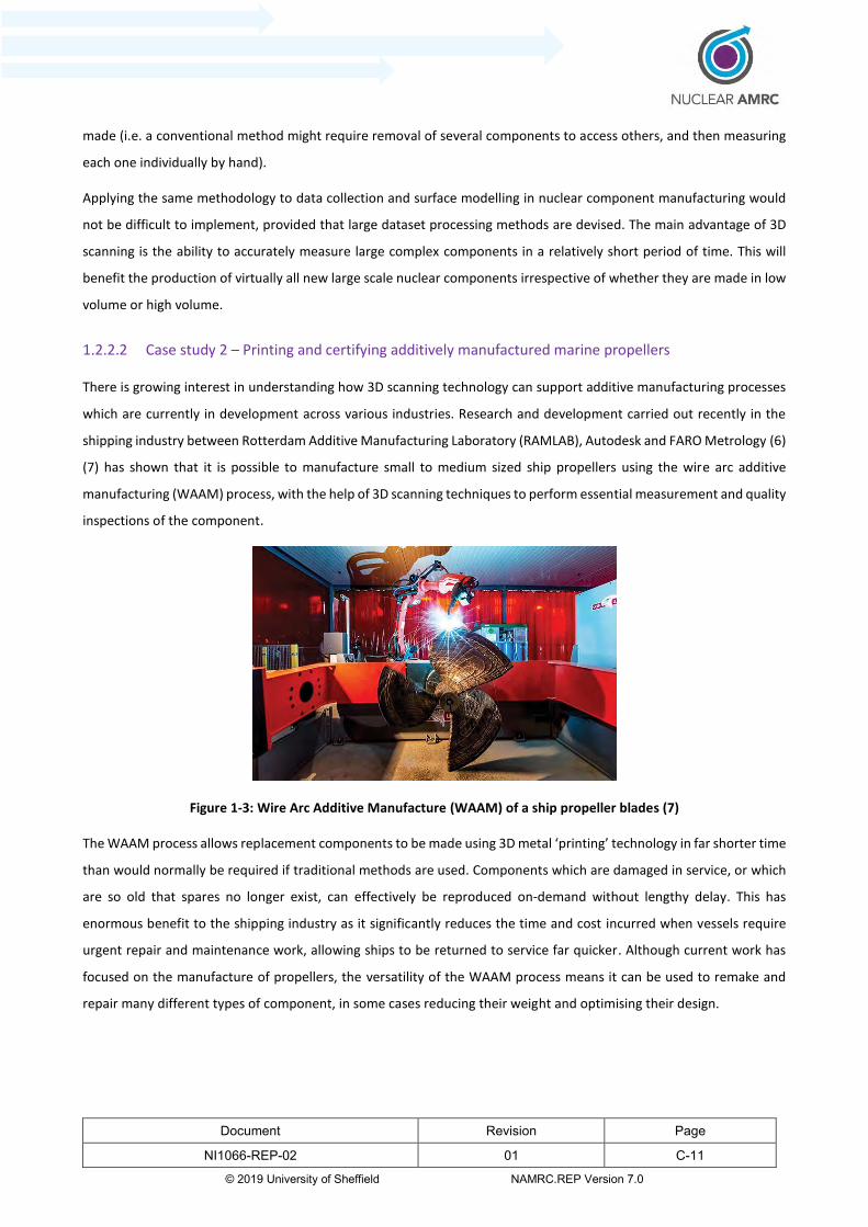
Document Revision Page
NI1066-REP-02 01 C-11
© 2019 University of Sheffield NAMRC.REP Version 7.0
made (i.e. a conventional method might require removal of several components to access others, and then measuring
each one individually by hand).
Applying the same methodology to data collection and surface modelling in nuclear component manufacturing would
not be difficult to implement, provided that large dataset processing methods are devised. The main advantage of 3D
scanning is the ability to accurately measure large complex components in a relatively short period of time. This will
benefit the production of virtually all new large scale nuclear components irrespective of whether they are made in low
volume or high volume.
1.2.2.2 Case study 2 – Printing and certifying additively manufactured marine propellers
There is growing interest in understanding how 3D scanning technology can support additive manufacturing processes
which are currently in development across various industries. Research and development carried out recently in the
shipping industry between Rotterdam Additive Manufacturing Laboratory (RAMLAB), Autodesk and FARO Metrology (6)
(7) has shown that it is possible to manufacture small to medium sized ship propellers using the wire arc additive
manufacturing (WAAM) process, with the help of 3D scanning techniques to perform essential measurement and quality
inspections of the component.
Figure 1-3: Wire Arc Additive Manufacture (WAAM) of a ship propeller blades (7)
The WAAM process allows replacement components to be made using 3D metal ‘printing’ technology in far shorter time
than would normally be required if traditional methods are used. Components which are damaged in service, or which
are so old that spares no longer exist, can effectively be reproduced on-demand without lengthy delay. This has
enormous benefit to the shipping industry as it significantly reduces the time and cost incurred when vessels require
urgent repair and maintenance work, allowing ships to be returned to service far quicker. Although current work has
focused on the manufacture of propellers, the versatility of the WAAM process means it can be used to remake and
repair many different types of component, in some cases reducing their weight and optimising their design.
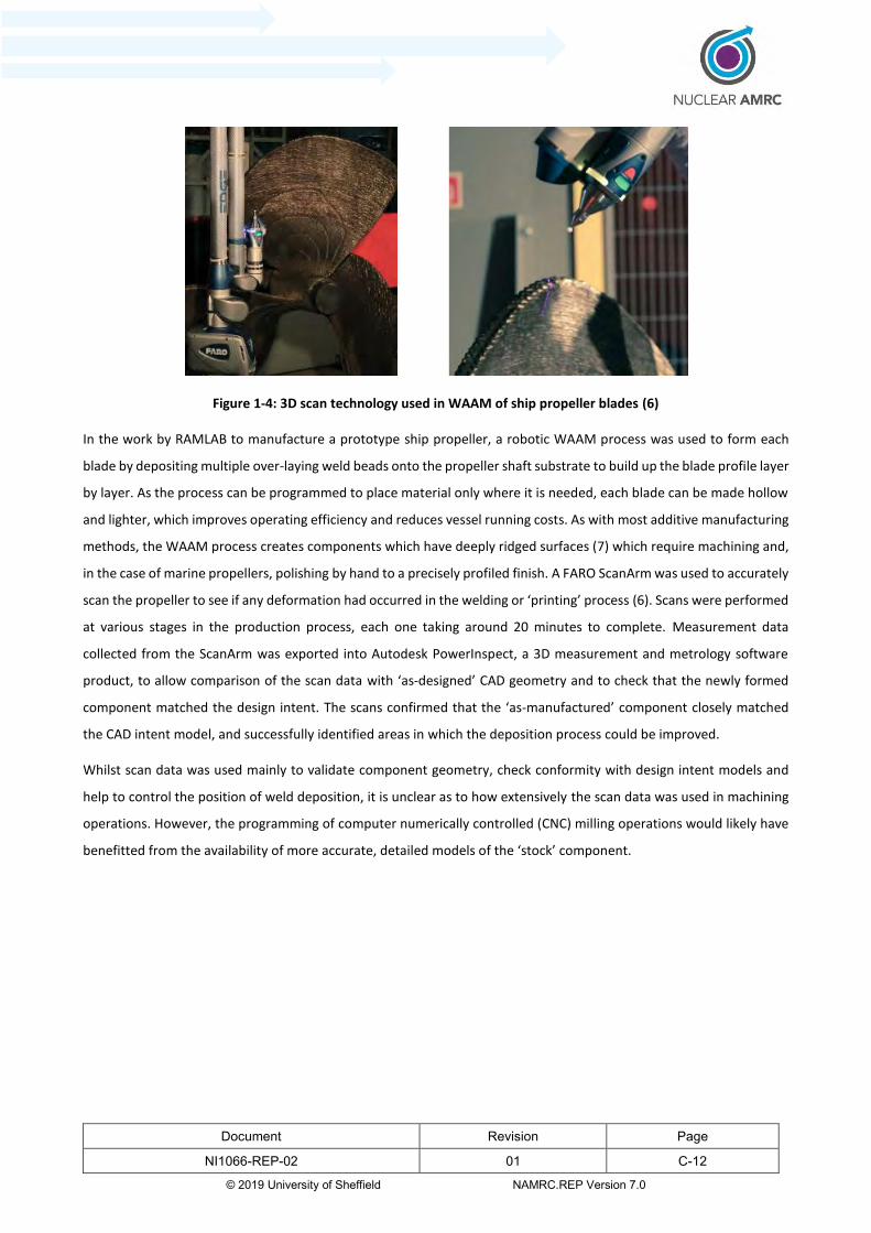
Document Revision Page
NI1066-REP-02 01 C-12
© 2019 University of Sheffield NAMRC.REP Version 7.0
Figure 1-4: 3D scan technology used in WAAM of ship propeller blades (6)
In the work by RAMLAB to manufacture a prototype ship propeller, a robotic WAAM process was used to form each
blade by depositing multiple over-laying weld beads onto the propeller shaft substrate to build up the blade profile layer
by layer. As the process can be programmed to place material only where it is needed, each blade can be made hollow
and lighter, which improves operating efficiency and reduces vessel running costs. As with most additive manufacturing
methods, the WAAM process creates components which have deeply ridged surfaces (7) which require machining and,
in the case of marine propellers, polishing by hand to a precisely profiled finish. A FARO ScanArm was used to accurately
scan the propeller to see if any deformation had occurred in the welding or ‘printing’ process (6). Scans were performed
at various stages in the production process, each one taking around 20 minutes to complete. Measurement data
collected from the ScanArm was exported into Autodesk PowerInspect, a 3D measurement and metrology software
product, to allow comparison of the scan data with ‘as-designed’ CAD geometry and to check that the newly formed
component matched the design intent. The scans confirmed that the ‘as-manufactured’ component closely matched
the CAD intent model, and successfully identified areas in which the deposition process could be improved.
Whilst scan data was used mainly to validate component geometry, check conformity with design intent models and
help to control the position of weld deposition, it is unclear as to how extensively the scan data was used in machining
operations. However, the programming of computer numerically controlled (CNC) milling operations would likely have
benefitted from the availability of more accurate, detailed models of the ‘stock’ component.

Document Revision Page
NI1066-REP-02 01 C-13
© 2019 University of Sheffield NAMRC.REP Version 7.0
2 Starting TRL/MRL level
At the start of the project the Nuclear AMRC considered that the type of technologies needed to support machining
from scanned datasets were collectively around TRL 4. In conventional applications, machine tools, CAM software and
tools for scanning and alignment are considered to be relatively mature and therefore achieve high TRL (in the range 6-
8). However, CAM software – a fundamental part of the process – was not deemed to have matured sufficiently in terms
of its ability to support machining from large scanned datasets, therefore the overall TRL is considered lower on this
occasion.
The application of scan based machining technologies in the nuclear industry was considered to be around MRL 3, as
such technologies were not thought to be widely deployed across the sector. This work package focuses on increasing
the deployment of existing technologies by aiming to improve processes and methods rather than developing the
technology itself. It does not aim to produce specific software improvements, as this would be a task for the software
vendors, but instead aims to develop and improve generic processes and raise awareness in industry to facilitate wider
adoption of these technologies in the nuclear sector.
These assessments were based largely on observations of how existing technologies are used in other industries to
complete specific tasks. A more detailed justification for the assigned TRL/MRL values is shown in Appendix 1.
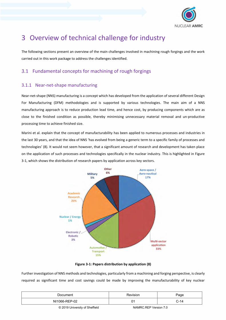
Document Revision Page
NI1066-REP-02 01 C-14
© 2019 University of Sheffield NAMRC.REP Version 7.0
3 Overview of technical challenge for industry
The following sections present an overview of the main challenges involved in machining rough forgings and the work
carried out in this work package to address the challenges identified.
Fundamental concepts for machining of rough forgings
3.1.1 Near-net-shape manufacturing
Near-net-shape (NNS) manufacturing is a concept which has developed from the application of several different Design
For Manufacturing (DFM) methodologies and is supported by various technologies. The main aim of a NNS
manufacturing approach is to reduce production lead time, and hence cost, by producing components which are as
close to the finished condition as possible, thereby minimising unnecessary material removal and un-productive
processing time to achieve finished size.
Marini et al. explain that the concept of manufacturability has been applied to numerous processes and industries in
the last 30 years, and that the idea of NNS ‘has evolved from being a generic term to a specific family of processes and
technologies’ (8). It would not seem however, that a significant amount of research and development has taken place
on the application of such processes and technologies specifically in the nuclear industry. This is highlighted in Figure
3-1, which shows the distribution of research papers by application across key sectors.
Figure 3-1: Papers distribution by application (8)
Further investigation of NNS methods and technologies, particularly from a machining and forging perspective, is clearly
required as significant time and cost savings could be made by improving the manufacturability of key nuclear

Document Revision Page
NI1066-REP-02 01 C-15
© 2019 University of Sheffield NAMRC.REP Version 7.0
components, for example by reducing the number of manufacturing steps needed to complete a component. In terms
of machining optimisation, this will focus on improving the way scan data from the forging process is acquired and
processed in order to implement more efficient cutting programs. The ultimate intention will be to move away from
cutting programs which are based on simplified CAD representations of the component, as these often do not give true
representations of the component geometry and surface condition, to using tool paths which are based on the actual
topography of the COS surface. By including all, or at least more of, the imperfections and irregularities of the COS
surface in the CAM model, toolpaths which cut only where necessary can be programmed, thereby saving a large
amount of time compared to more conventional toolpaths.
3.1.2 How nuclear components are manufactured to near-net-shape
Large nuclear forgings such as thick-walled pressure vessels create many challenges during rough machining operations.
After undergoing primary shaping, forgings can be supplied to the customer either in a completely un-machined state
or, if suitable facilities are available at the forge, in a semi-machined condition.
Where forgings are supplied in a semi-machined condition, subsequent machining operations carried out by the end
user can be relatively straightforward, as datum for measuring equipment such as flat faces, or other features and
reference points, are likely to have already been defined and the overall component geometry is generally more
uniform.
If the forging is supplied totally un-machined, however, the task of removing the rough ‘as-forged’ surface is more
complicated than for a semi-machined forging. For ease, end users might request that the stock material is supplied
semi-machined with a more uniform shape. This is mainly because foundries often provide, or have access to, first stage
machining services/capabilities and are better equipped to handle heavy components. This may cost the end user more,
but ultimately saves time in preparing the forging for further machining. The foundry, however, still has the difficult task
of preparing the ‘as-forged’ surface to the requirements of the customer. This means selecting and removing sections
of forged material which are not needed, whilst leaving enough for the end user to machine to their specific
requirements. The methods used by foundry machine shops to select regions of material for removal, whilst relatively
fast, are not always particularly sophisticated (e.g. manual measurement devices and simple, straight cuts using a band
saw may be as far as capabilities extend). This results in more material being retained on the forging to guarantee that
it will clean up to the end user’s specification.
There are other issues with as-forged surfaces. Irregular, undulating features and long shallow surface depressions
reduce tool engagement and lower cutting cycle efficiency. Localised high-points can cause increased wear, damage
and premature tool failure. Simple, conventional toolpaths may be unable to adapt to these irregular surfaces as they
tend to run at constant cutting parameters and often take slow, shallow, and hence sub-optimal, cuts to avoid excessive
tool wear and damage to the component.
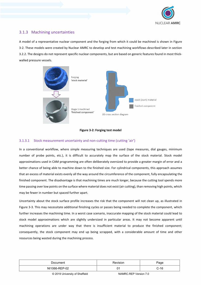
Document Revision Page
NI1066-REP-02 01 C-16
© 2019 University of Sheffield NAMRC.REP Version 7.0
3.1.3 Machining uncertainties
A model of a representative nuclear component and the forging from which it could be machined is shown in Figure
3-2. These models were created by Nuclear AMRC to develop and test machining workflows described later in section
3.2.2. The designs do not represent specific nuclear components, but are based on generic features found in most thick-
walled pressure vessels.
Figure 3-2: Forging test model
3.1.3.1 Stock measurement uncertainty and non-cutting time (cutting ‘air’)
In a conventional workflow, where simple measuring techniques are used (tape measures, dial gauges, minimum
number of probe points, etc.), it is difficult to accurately map the surface of the stock material. Stock model
approximations used in CAM programming are often deliberately oversized to provide a greater margin of error and a
better chance of being able to machine down to the finished size. For cylindrical components, this approach assumes
that an excess of material exists evenly all the way around the circumference of the component, fully encapsulating the
finished component. The disadvantage is that machining times are much longer, because the cutting tool spends more
time passing over low points on the surface where material does not exist (air cutting), than removing high points, which
may be fewer in number but spaced further apart.
Uncertainty about the stock surface profile increases the risk that the component will not clean up, as illustrated in
Figure 3-3. This may necessitate additional finishing cycles or passes being needed to complete the component, which
further increases the machining time. In a worst case scenario, inaccurate mapping of the stock material could lead to
stock model approximations which are slightly undersized in particular areas. It may not become apparent until
machining operations are under way that there is insufficient material to produce the finished component;
consequently, the stock component may end up being scrapped, with a considerable amount of time and other
resources being wasted during the machining process.
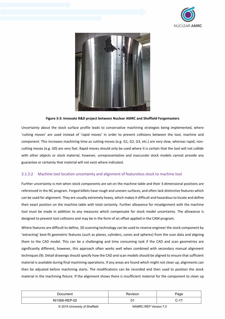
Document Revision Page
NI1066-REP-02 01 C-17
© 2019 University of Sheffield NAMRC.REP Version 7.0
Figure 3-3: Innovate R&D project between Nuclear AMRC and Sheffield Forgemasters
Uncertainty about the stock surface profile leads to conservative machining strategies being implemented, where
‘cutting moves’ are used instead of ‘rapid moves’ in order to prevent collisions between the tool, machine and
component. This increases machining time as cutting moves (e.g. G1, G2, G3, etc.) are very slow, whereas rapid, non-
cutting moves (e.g. G0) are very fast. Rapid moves should only be used where it is certain that the tool will not collide
with other objects or stock material, however, unrepresentative and inaccurate stock models cannot provide any
guarantee or certainty that material will not exist where indicated.
3.1.3.2 Machine tool location uncertainty and alignment of featureless stock to machine tool
Further uncertainty is met when stock components are set on the machine table and their 3-dimensional positions are
referenced in the NC program. Forged billets have rough and uneven surfaces, and often lack distinctive features which
can be used for alignment. They are usually extremely heavy, which makes it difficult and hazardous to locate and define
their exact position on the machine table with total certainty. Further allowance for misalignment with the machine
tool must be made in addition to any measures which compensate for stock model uncertainty. The allowance is
designed to prevent tool collisions and may be in the form of an offset applied in the CAM program.
Where features are difficult to define, 3D scanning technology can be used to reverse engineer the stock component by
‘extracting’ best-fit geometric features (such as planes, cylinders, cones and spheres) from the scan data and aligning
them to the CAD model. This can be a challenging and time consuming task if the CAD and scan geometries are
significantly different, however, this approach often works well when combined with secondary manual alignment
techniques (9). Detail drawings should specify how the CAD and scan models should be aligned to ensure that sufficient
material is available during final machining operations. If any areas are found which might not clean up, alignments can
then be adjusted before machining starts. The modifications can be recorded and then used to position the stock
material in the machining fixture. If the alignment shows there is insufficient material for the component to clean up
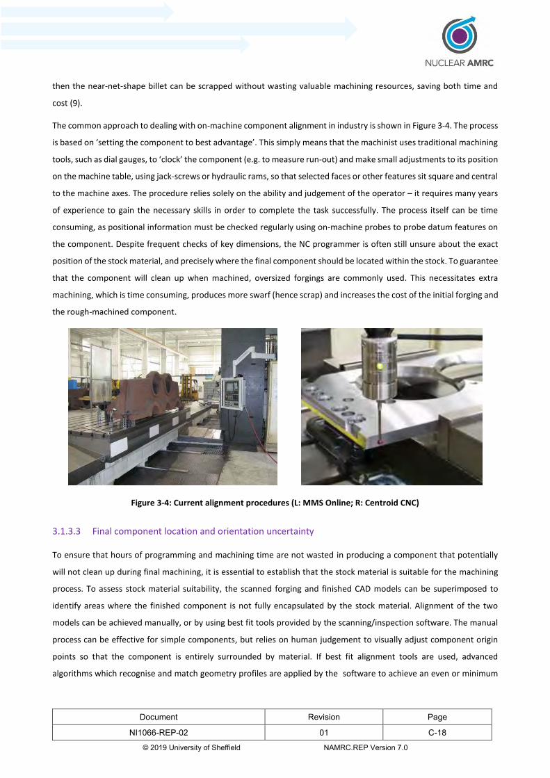
Document Revision Page
NI1066-REP-02 01 C-18
© 2019 University of Sheffield NAMRC.REP Version 7.0
then the near-net-shape billet can be scrapped without wasting valuable machining resources, saving both time and
cost (9).
The common approach to dealing with on-machine component alignment in industry is shown in Figure 3-4. The process
is based on ‘setting the component to best advantage’. This simply means that the machinist uses traditional machining
tools, such as dial gauges, to ‘clock’ the component (e.g. to measure run-out) and make small adjustments to its position
on the machine table, using jack-screws or hydraulic rams, so that selected faces or other features sit square and central
to the machine axes. The procedure relies solely on the ability and judgement of the operator – it requires many years
of experience to gain the necessary skills in order to complete the task successfully. The process itself can be time
consuming, as positional information must be checked regularly using on-machine probes to probe datum features on
the component. Despite frequent checks of key dimensions, the NC programmer is often still unsure about the exact
position of the stock material, and precisely where the final component should be located within the stock. To guarantee
that the component will clean up when machined, oversized forgings are commonly used. This necessitates extra
machining, which is time consuming, produces more swarf (hence scrap) and increases the cost of the initial forging and
the rough-machined component.
Figure 3-4: Current alignment procedures (L: MMS Online; R: Centroid CNC)
3.1.3.3 Final component location and orientation uncertainty
To ensure that hours of programming and machining time are not wasted in producing a component that potentially
will not clean up during final machining, it is essential to establish that the stock material is suitable for the machining
process. To assess stock material suitability, the scanned forging and finished CAD models can be superimposed to
identify areas where the finished component is not fully encapsulated by the stock material. Alignment of the two
models can be achieved manually, or by using best fit tools provided by the scanning/inspection software. The manual
process can be effective for simple components, but relies on human judgement to visually adjust component origin
points so that the component is entirely surrounded by material. If best fit alignment tools are used, advanced
algorithms which recognise and match geometry profiles are applied by the software to achieve an even or minimum
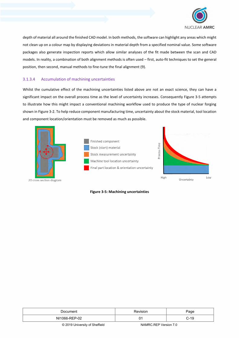
Document Revision Page
NI1066-REP-02 01 C-19
© 2019 University of Sheffield NAMRC.REP Version 7.0
depth of material all around the finished CAD model. In both methods, the software can highlight any areas which might
not clean up on a colour map by displaying deviations in material depth from a specified nominal value. Some software
packages also generate inspection reports which allow similar analyses of the fit made between the scan and CAD
models. In reality, a combination of both alignment methods is often used – first, auto-fit techniques to set the general
position, then second, manual methods to fine-tune the final alignment (9).
3.1.3.4 Accumulation of machining uncertainties
Whilst the cumulative effect of the machining uncertainties listed above are not an exact science, they can have a
significant impact on the overall process time as the level of uncertainty increases. Consequently Figure 3-5 attempts
to illustrate how this might impact a conventional machining workflow used to produce the type of nuclear forging
shown in Figure 3-2. To help reduce component manufacturing time, uncertainty about the stock material, tool location
and component location/orientation must be removed as much as possible.
Figure 3-5: Machining uncertainties
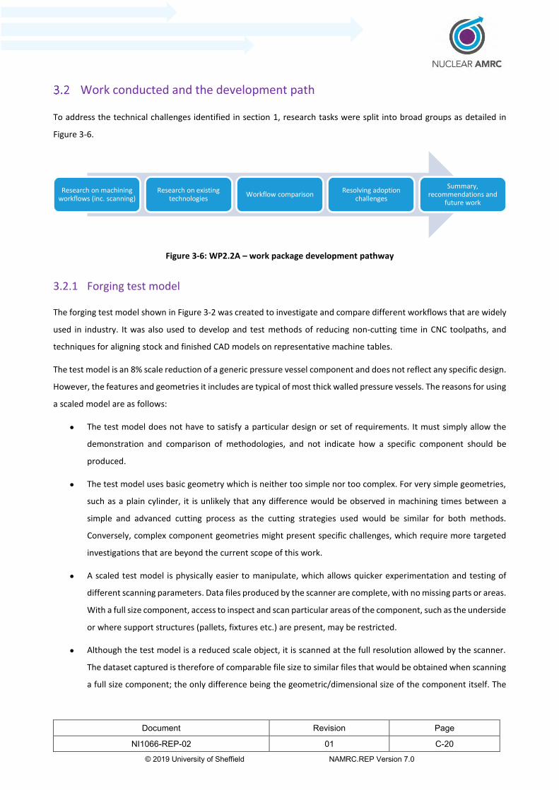
Document Revision Page
NI1066-REP-02 01 C-20
© 2019 University of Sheffield NAMRC.REP Version 7.0
Work conducted and the development path
To address the technical challenges identified in section 1, research tasks were split into broad groups as detailed in
Figure 3-6.
Figure 3-6: WP2.2A – work package development pathway
3.2.1 Forging test model
The forging test model shown in Figure 3-2 was created to investigate and compare different workflows that are widely
used in industry. It was also used to develop and test methods of reducing non-cutting time in CNC toolpaths, and
techniques for aligning stock and finished CAD models on representative machine tables.
The test model is an 8% scale reduction of a generic pressure vessel component and does not reflect any specific design.
However, the features and geometries it includes are typical of most thick walled pressure vessels. The reasons for using
a scaled model are as follows:
The test model does not have to satisfy a particular design or set of requirements. It must simply allow the
demonstration and comparison of methodologies, and not indicate how a specific component should be
produced.
The test model uses basic geometry which is neither too simple nor too complex. For very simple geometries,
such as a plain cylinder, it is unlikely that any difference would be observed in machining times between a
simple and advanced cutting process as the cutting strategies used would be similar for both methods.
Conversely, complex component geometries might present specific challenges, which require more targeted
investigations that are beyond the current scope of this work.
A scaled test model is physically easier to manipulate, which allows quicker experimentation and testing of
different scanning parameters. Data files produced by the scanner are complete, with no missing parts or areas.
With a full size component, access to inspect and scan particular areas of the component, such as the underside
or where support structures (pallets, fixtures etc.) are present, may be restricted.
Although the test model is a reduced scale object, it is scanned at the full resolution allowed by the scanner.
The dataset captured is therefore of comparable file size to similar files that would be obtained when scanning
a full size component; the only difference being the geometric/dimensional size of the component itself. The
Research on machining workflows (inc. scanning)
Research on existing technologies
Workflow comparisonResolving adoption
challenges
Summary, recommendations and
future work
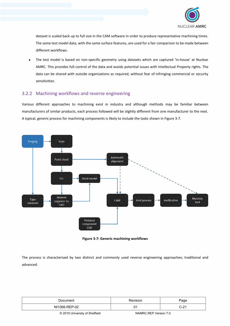
Document Revision Page
NI1066-REP-02 01 C-21
© 2019 University of Sheffield NAMRC.REP Version 7.0
dataset is scaled back up to full size in the CAM software in order to produce representative machining times.
The same test model data, with the same surface features, are used for a fair comparison to be made between
different workflows.
The test model is based on non-specific geometry using datasets which are captured ‘in-house’ at Nuclear
AMRC. This provides full control of the data and avoids potential issues with Intellectual Property rights. The
data can be shared with outside organisations as required, without fear of infringing commercial or security
sensitivities.
3.2.2 Machining workflows and reverse engineering
Various different approaches to machining exist in industry and although methods may be familiar between
manufacturers of similar products, each process followed will be slightly different from one manufacturer to the next.
A typical, generic process for machining components is likely to include the tasks shown in Figure 3-7.
Figure 3-7: Generic machining workflows
The process is characterised by two distinct and commonly used reverse engineering approaches; traditional and
advanced.
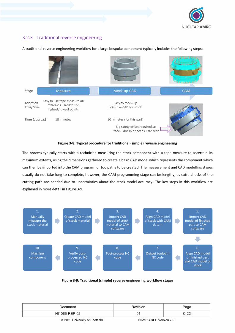
Document Revision Page
NI1066-REP-02 01 C-22
© 2019 University of Sheffield NAMRC.REP Version 7.0
3.2.3 Traditional reverse engineering
A traditional reverse engineering workflow for a large bespoke component typically includes the following steps:
Figure 3-8: Typical procedure for traditional (simple) reverse engineering
The process typically starts with a technician measuring the stock component with a tape measure to ascertain its
maximum extents, using the dimensions gathered to create a basic CAD model which represents the component which
can then be imported into the CAM program for toolpaths to be created. The measurement and CAD modelling stages
usually do not take long to complete, however, the CAM programming stage can be lengthy, as extra checks of the
cutting path are needed due to uncertainties about the stock model accuracy. The key steps in this workflow are
explained in more detail in Figure 3-9.
Figure 3-9: Traditional (simple) reverse engineering workflow stages
1.
Manually measure the
stock material
2.
Create CAD model of stock material
3.
Import CAD model of stock
material to CAM software
4.
Align CAD model of stock with CAM
datum
5.
Import CAD model of finished
part to CAM software
6.
Align CAD model of finished part
and CAD model of stock
7.
Output toolpath NC code
8.
Post-process NC code
9.
Verify post-processed NC
code
10.
Machine component

Document Revision Page
NI1066-REP-02 01 C-23
© 2019 University of Sheffield NAMRC.REP Version 7.0
Traditional reverse engineering (RE) workflows are characterised by the use of ‘contact’ metrology techniques (cf. non-
contact methods such as 3D or 2D scanning systems) to collect measurement data about the stock material. Simple
tools such as tape measures, plumb-lines, machinist-squares and straight edges offer a quick, inexpensive (but generally
less accurate) way to measure the overall geometry, position and orientation of large stock components. Large
micrometres, callipers, and height, depth and thickness gauges are also routinely used to measure dimensions between
specific points on the stock material surface. The geometry of specific features such as holes – which can be used as
reference for alignment – is usually measured with more specialised tools such as bore or thread gauges.
If appropriate handling equipment and space to manoeuvre is available, bulky, semi-machined components can be
measured using large volume CMM machines. However, it is difficult to measure large forgings in the same way because
the irregularity of surfaces on the material usually make it difficult to support, align and transfer components between
machining and measurement stations. As component complexity increases it becomes more difficult for CMM probes
to access intricate features and the confined profiles which are normally found on stock material surfaces. This often
prevents the comparatively high measurement accuracy of the CMM machine from being fully exploited. To avoid
moving and resetting the component, the most practical solution is often to use simple, manual techniques to measure
the component whilst it is still on the machine – clearly this requires the machine to be stopped, increasing downtime
and reducing productivity.
Generally, the larger and more intricate the stock component, the more difficult it is to accurately measure its geometry
and surface characteristics. This is due mainly to the ease with which the component can be manipulated to gain access
to its surfaces, but also because more data must be collected in order to fully define a larger volume/area. A significant
drawback with traditional measurement tools is that, unlike more advanced methods such as 3D scanning (in which
very large amounts of data are captured), only a limited number of data points can be measured (or ‘sampled’). A
common approach is to only measure the ‘maximum extent’ of selected primitive shapes and perhaps a few specific
dimensions (e.g. its overall height or diameter) to infer the overall geometry of the body. In practice, it is not possible
to produce high-definition models of large, irregular forgings by using traditional measurement tools alone, as every
small detail and surface undulation cannot be captured and recreated individually. The conventional solution is to create
‘oversized’ stock models, which are less detailed, less well defined, approximations of the real stock material.
Consequently, more material has to be machined away, which leads to significant increases in the amount of ‘air cutting’
required. Inevitably, machining times are longer and more material is wasted. This approach can, however, be less risky
than running a cutting program with an ‘under-sized’ representation of the stock material, since it offers more choice
over toolpath options, greater flexibility to control tool wear/damage and guarantees that enough material is available
to produce the finished component.
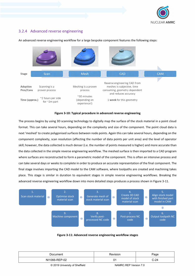
Document Revision Page
NI1066-REP-02 01 C-24
© 2019 University of Sheffield NAMRC.REP Version 7.0
3.2.4 Advanced reverse engineering
An advanced reverse engineering workflow for a large bespoke component features the following steps:
Figure 3-10: Typical procedure in advanced reverse engineering
The process begins by using 3D scanning technology to digitally map the surface of the stock material in a point cloud
format. This can take several hours, depending on the complexity and size of the component. The point cloud data is
next ‘meshed’ to create polygonised surfaces between node points. Again this can take several hours, depending on the
component complexity, scan resolution (affecting the number of data points per unit area) and the level of operator
skill; however, the data collected is much denser (i.e. the number of points measured is higher) and more accurate than
the data collected in the simple reverse engineering workflow. The meshed surface is then imported to a CAD program
where surfaces are reconstructed to form a parametric model of the component. This is often an intensive process and
can take several days or weeks to complete in order to produce an accurate representation of the final component. The
final stage involves importing the CAD model to the CAM software, where toolpaths are created and machining takes
place. This stage is similar in duration to equivalent stages in simple reverse engineering workflows. Breaking the
advanced reverse engineering workflow down into more detailed steps produces a process shown in Figure 3-11.
Figure 3-11: Advanced reverse engineering workflow stages
1.
Scan stock material
2.
Optimise stock material scan
3.
Generate mesh of stock material scan
4.Create 3D CAD model of stock material scan
5.Align stock model with finished part
model in CAM
6.Output toolpath NC
code
7.Post-process NC
code
8.Verify post-
processed NC code
9.Machine component
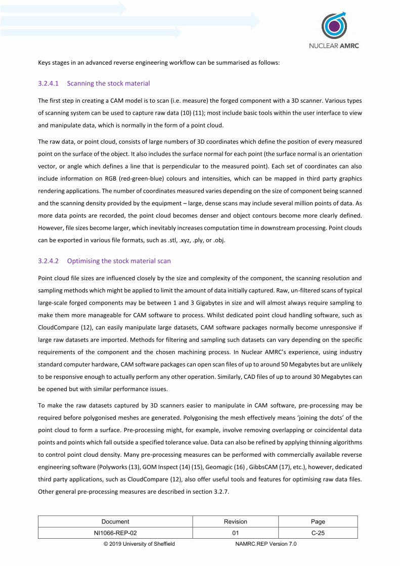
Document Revision Page
NI1066-REP-02 01 C-25
© 2019 University of Sheffield NAMRC.REP Version 7.0
Keys stages in an advanced reverse engineering workflow can be summarised as follows:
3.2.4.1 Scanning the stock material
The first step in creating a CAM model is to scan (i.e. measure) the forged component with a 3D scanner. Various types
of scanning system can be used to capture raw data (10) (11); most include basic tools within the user interface to view
and manipulate data, which is normally in the form of a point cloud.
The raw data, or point cloud, consists of large numbers of 3D coordinates which define the position of every measured
point on the surface of the object. It also includes the surface normal for each point (the surface normal is an orientation
vector, or angle which defines a line that is perpendicular to the measured point). Each set of coordinates can also
include information on RGB (red-green-blue) colours and intensities, which can be mapped in third party graphics
rendering applications. The number of coordinates measured varies depending on the size of component being scanned
and the scanning density provided by the equipment – large, dense scans may include several million points of data. As
more data points are recorded, the point cloud becomes denser and object contours become more clearly defined.
However, file sizes become larger, which inevitably increases computation time in downstream processing. Point clouds
can be exported in various file formats, such as .stl, .xyz, .ply, or .obj.
3.2.4.2 Optimising the stock material scan
Point cloud file sizes are influenced closely by the size and complexity of the component, the scanning resolution and
sampling methods which might be applied to limit the amount of data initially captured. Raw, un-filtered scans of typical
large-scale forged components may be between 1 and 3 Gigabytes in size and will almost always require sampling to
make them more manageable for CAM software to process. Whilst dedicated point cloud handling software, such as
CloudCompare (12), can easily manipulate large datasets, CAM software packages normally become unresponsive if
large raw datasets are imported. Methods for filtering and sampling such datasets can vary depending on the specific
requirements of the component and the chosen machining process. In Nuclear AMRC’s experience, using industry
standard computer hardware, CAM software packages can open scan files of up to around 50 Megabytes but are unlikely
to be responsive enough to actually perform any other operation. Similarly, CAD files of up to around 30 Megabytes can
be opened but with similar performance issues.
To make the raw datasets captured by 3D scanners easier to manipulate in CAM software, pre-processing may be
required before polygonised meshes are generated. Polygonising the mesh effectively means ‘joining the dots’ of the
point cloud to form a surface. Pre-processing might, for example, involve removing overlapping or coincidental data
points and points which fall outside a specified tolerance value. Data can also be refined by applying thinning algorithms
to control point cloud density. Many pre-processing measures can be performed with commercially available reverse
engineering software (Polyworks (13), GOM Inspect (14) (15), Geomagic (16) , GibbsCAM (17), etc.), however, dedicated
third party applications, such as CloudCompare (12), also offer useful tools and features for optimising raw data files.
Other general pre-processing measures are described in section 3.2.7.

Document Revision Page
NI1066-REP-02 01 C-26
© 2019 University of Sheffield NAMRC.REP Version 7.0
3.2.4.3 Generating the mesh from the scan of the stock material
When all scanned data has been combined into a single, optimised point cloud, surfaces can be reconstructed by
generating a polygonised mesh. Polygon meshes are formed by linking the vertices of 3D point clouds (i.e. the points)
together to define the edges and surfaces of the object. Surface reconstruction firstly allows point cloud data to be
visualised more clearly, but more importantly, provides the necessary shells (i.e. boundaries) from which 3D solid
models are formed. Reconstructed surfaces also allow easier comparison of designed and actual component geometry,
where two or more models are overlaid, aligned and checked for deviation from the design intent. Software packages
with combined meshing and inspection functions often provide tools for extracting dimensions of specific features and
methods of highlighting geometric deviations between models as colour maps (18). Meshing is often a highly iterative
process and it can therefore be time consuming to produce stock model approximations which meet accuracy
requirements which require minimal computational effort by the CAM software.
Mesh quality can significantly influence the validity of NC simulations – where quality is low, models might not represent
the actual component accurately and consequent cutting simulations might be imprecise and unrealistic. If mesh quality
is too high, models and simulations – whilst potentially being very accurate – are likely to run extremely slowly due to
increased computational demand. A balance must be found between choosing an appropriate level of accuracy which
does not require an unreasonable amount of computational time to both form and manipulate the mesh.
Various reverse engineering software packages, such as Meshmixer (19), Netfabb (20) or Tebis (21), can be used to
convert point clouds to 3D surfaces and then repair or apply patches over holes which may be present. Holes often
occur when the scanner cannot detect a surface in a particular area, possibly as a result of surface reflections, low light
contrast or other environmental conditions. Gaps and holes must be closed to make the surface continuous, otherwise
toolpaths cannot be superimposed over them. Meshes can also be refined by applying smoothing tools to flatten any
imperfections generated from the scanned data, although this method can reduce model accuracy.
3.2.4.4 Creating a 3D CAD model from the stock material scan
A common method of generating interactive parametric CAD surfaces starts by processing the mesh with ‘curvature-
based algorithms and tolerances’ (14), where mathematically defined wireframe curves are fitted between selected
mesh points. The software interpolates additional points within a specified tolerance of the original wireframe line and
creates a meshed face using the new contour as a guide. Curve fitting can also be carried out manually (i.e. visually by
the operator), however, for improved accuracy, the operation is more likely to be performed with automatic spline
fitting or feature recognition tools built into the CAM software. The process is often executed iteratively to produce
surfaces which have the required profile. Many software packages also include dynamic feature libraries, which allow
specific features identified in the mesh, such as standard hole-types (e.g. counterbore, countersunk, straight/tapered
tap etc.) to be recreated from standard templates. Although automatic curve fitting/feature recognition methods are
preferable for their accuracy and ease of use, approaches on how to apply them usually vary between different
proprietary CAM systems.

Document Revision Page
NI1066-REP-02 01 C-27
© 2019 University of Sheffield NAMRC.REP Version 7.0
Surfaces are generated using the wireframe curved lines as a guide. The curved lines represent the edges or boundaries
between adjoining panels or ‘shells’, which must be merged together to form continuous, ‘closed’ surfaces. Generally,
surfaces have to be conjoined in order to fully enclose a given volume. If surfaces are left ‘open’ or ‘non-manifold’, the
CAM software will be unable to determine the surface normal vectors of points along the line, which means it will not
be able to distinguish between internal and external spaces and generate toolpaths. The term ‘non-watertight’ is used
to describe a similar issue in 3D printing, where the component fails to print because open object surfaces prevent the
software from defining and resolving boundary interfaces. Surface models must be converted to solid bodies so that
the object can be discretised into slices and toolpaths can be generated. Solid models however are more complex and
computationally demanding than surface models, which, in turn, are more complex than wireframe models. If the
meshed surfaces generated from the scanned data have suitable resolution, it may be possible (and computationally
quicker) to define the surface of the component using primitive shapes. For example, for plain cylinders, cylinders
extruded from 2D sketches may provide satisfactory component definition and accuracy without needing to apply
surfaces based on complex compound curves.
3.2.4.5 Importing stock model CAD into CAM software and aligning with finished component model
The remaining stages in an advanced engineering workflow, which involve importing the stock material CAD model into
the CAM software and aligning it with the finished CAD model are similar to those in the traditional workflow detailed
in section 3.2.3.
3.2.4.6 Rapid surfacing
An emerging philosophy in a number of high end software packages is the concept of rapid surfacing. This removes the
need for manual CAD techniques to create surfaces and could provide a faster, less labour intensive option. However
the software (e.g. Geomagic (16), Rapidform (22), Polyworks (13)) is expensive and requires significant training to get
accurate and usable geometries with more complex components.
3.2.5 Optimised advanced reverse engineering (Scan-to-CAM)
In a typical advanced reverse engineering workflow, the process of generating surfaces from a mesh to create a CAD
model is often a time consuming task. It also introduces another source of inaccuracy, as the CAD model is an
approximation of the real component. One way to improve the process would be to eliminate the CAD stage and
program toolpaths directly onto the mesh, as illustrated in Figure 3-12.
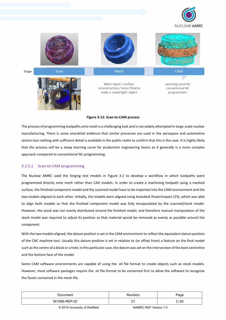
Document Revision Page
NI1066-REP-02 01 C-28
© 2019 University of Sheffield NAMRC.REP Version 7.0
Figure 3-12: Scan-to-CAM process
The process of programming toolpaths onto mesh is a challenging task and is not widely attempted in large-scale nuclear
manufacturing. There is some anecdotal evidence that similar processes are used in the aerospace and automotive
sectors but nothing with sufficient detail is available in the public realm to confirm that this is the case. It is highly likely
that the process will be a steep learning curve for production engineering teams as it generally is a more complex
approach compared to conventional NC programming.
3.2.5.1 Scan-to-CAM programming
The Nuclear AMRC used the forging test models in Figure 3-2 to develop a workflow in which toolpaths were
programmed directly onto mesh rather than CAD models. In order to create a machining toolpath using a meshed
surface, the finished component model and the scanned model have to be imported into the CAM environment and the
two models aligned to each other. Initially, the models were aligned using Autodesk PowerInspect (23), which was able
to align both models so that the finished component model was fully encapsulated by the scanned/stock model.
However, the stock was not evenly distributed around the finished model, and therefore manual manipulation of the
stock model was required to adjust its position so that material would be removed as evenly as possible around the
component.
With the two models aligned, the datum position is set in the CAM environment to reflect the equivalent datum position
of the CNC machine tool. Usually this datum position is set in relation to (or offset from) a feature on the final model
such as the centre of a block or a hole; in this particular case, the datum was set on the intersection of the bore centreline
and the bottom face of the model.
Some CAM software environments are capable of using the .stl file format to create objects such as stock models.
However, most software packages require the .stl file format to be converted first to allow the software to recognise
the facets contained in the mesh file.

Document Revision Page
NI1066-REP-02 01 C-29
© 2019 University of Sheffield NAMRC.REP Version 7.0
Once initial set-up has been completed, toolpaths can be calculated. The tooling selected comprised a 125 mm face mill
and an 84 mm shoulder mill with a flute length of 60 mm. Since all machining simulations were done virtually, with no
‘real’ machining taking place, the cutting parameters used (cutting speed, feed rate, depth of cut, etc.) were set to
nominal values which would then be used throughout all simulations to ensure realistic comparisons. In the first
operation, the top of the component was face milled and then the upper diameter was machined to where it meets the
larger diameter of the centre band. The same operation was repeated from the bottom of the component, up towards
the centre band, and then an additional toolpath for machining the central through bore was created. The final
operation involved rotary machining the centre band between the upper and lower diameters, followed by face milling
and finish machining the edges of the centre band.
The main constraining factor witnessed during these programming routines was the effect that the scan model had on
toolpath calculation times. The scan model has a relatively large file size, due to the complexity of the surfaces modelled.
As the surfaces are approximations of the real, scanned component, the toolpath calculation has to consider where all
the high and low points are, and whether the tool is actually able to cut at various points around the component. Taking
these factors into account dramatically increases calculation time. A comparison of calculation times was made to
highlight the difference between using a simple stock model approximation and a scan of the stock model. Using the
simple model with a very large safety offset, the calculation time to face mill the top of the component was estimated
to be around 2 minutes. To calculate the duration of the same operation using the scanned model, the calculation time
was estimated to be around 15 minutes. The calculations were made on a CAD / CAM specification laptop with typical
computing performance. Although calculation times for scanned data models will increase incrementally as more tool
paths are added, and offline programming time will take longer than the traditional method, the on-machine time will
be considerably less. Whilst more time may be required for programming, the overall cost of the extra programming
time will be more than offset by the reduced machining time.
3.2.6 Workflow comparisons
The Nuclear AMRC has access to various industry standard CAM software packages, which it used to generate machining
times for the two different machining strategies – traditional vs. Scan-to-CAM. In addition, the Scan-to-CAM strategy
would also be used with another CAM software package from a different vendor, referred to in this report as Vendor A.
The vendors have been anonymised as it is not the intention of this report to provide a competitive study between
suppliers. All simulations used the scanned forging test model and the finished component model as described in section
3.2.1. The simplified stock model was formed as an oversized cylindrical body, with increased diameter around the
central band, as illustrated in Figure 3-8.
A traditional helical toolpath with conventional step-overs was used with the simplified model, whereas optimised
toolpaths were used with the scanned stock model, to accommodate the uneven surface geometry. The same cutting
parameters are used on both toolpaths to allow fair comparison.

Document Revision Page
NI1066-REP-02 01 C-30
© 2019 University of Sheffield NAMRC.REP Version 7.0
The results of these exercises are detailed in Table 3-1.
Table 3-1: Comparison of machining times using different CAM software packages
Traditional machining strategy Scan-to-CAM
Software Baseline package Baseline package Vendor A
Without central
band 2 days 4 hours 32 min. 1 day 7 hours 6 min. 2 days 11 hours 17 min.
Central band
only 2 days 23 hours 55 min. 2 days 11 hours 2 min. 2 days 0 hours 55 min.
Total time 5 days 4 hours 27 min. 3 days 18 hours 8 min. 4 days 12 hours 13 min.
The key points to note are:
40% reduction in machine time without central band with baseline package, but 13% increase with Vendor A.
18% reduction in machine time central band only with baseline package and 32% reduction with Vendor A.
Due to significantly different performances with Scan-to-CAM between the baseline package and Vendor A, it was
decided to repeat the Scan-to-CAM for the ‘without central band’ component using software from another vendor,
referred to in this report as Vendor B, with the following result:
40% reduction in machine time without central band with baseline package, and 52% reduction with Vendor
B.
The simulations of toolpaths produced in the baseline package, first with the simplified stock model and secondly with
the scanned stock model, are illustrated in Figure 3-13.
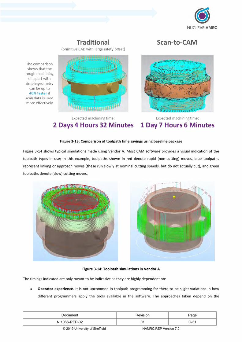
Document Revision Page
NI1066-REP-02 01 C-31
© 2019 University of Sheffield NAMRC.REP Version 7.0
Figure 3-13: Comparison of toolpath time savings using baseline package
Figure 3-14 shows typical simulations made using Vendor A. Most CAM software provides a visual indication of the
toolpath types in use; in this example, toolpaths shown in red denote rapid (non-cutting) moves, blue toolpaths
represent linking or approach moves (these run slowly at nominal cutting speeds, but do not actually cut), and green
toolpaths denote (slow) cutting moves.
Figure 3-14: Toolpath simulations in Vendor A
The timings indicated are only meant to be indicative as they are highly dependent on:
Operator experience. It is not uncommon in toolpath programming for there to be slight variations in how
different programmers apply the tools available in the software. The approaches taken depend on the

Document Revision Page
NI1066-REP-02 01 C-32
© 2019 University of Sheffield NAMRC.REP Version 7.0
experience, training and level of familiarity individual programmers have for a given software package. The
simulations made with Vendor A and the baseline package, for example, were completed by different
programmers; this might account for the difference in timings predicted.
Hardware specification. Computer speed/power etc. clearly influence how quickly simulations are processed.
Whilst the predicted machining times might not be affected, the time it takes just to run simulations –
particularly for complex operations – should be given consideration.
Application. As a general rule, when the complexity of the stock model approximation increases (i.e. the more
faceted it becomes), the longer it will take to calculate toolpaths and simulate machining operations.
Complicated models create larger digital files, which in turn take longer to compute. Splitting machining
operations into smaller tasks can help, as in the case of the forging test model. Programmers can still expect to
achieve significant time savings if optimised toolpaths and more representative stock approximations are used
when machining models with complex features, although the level of difference attained may not be as large
compared to what might be possible with simpler models – component complexity plays a significant role.
The conclusion from these results is that Scan-to-CAM would appear to provide significant advantages over the
traditional approach. However, each software solution utilises proprietary algorithms for generating toolpaths and it is
quite likely that these are affected by the actual profile being machined and the skill/experience of the programmer.
3.2.7 Processing scan data
To create stock model approximations of the forging test model for use in toolpath programming routines, a GOM ATOS
structured light scanner was used in conjunction with GOM Inspect evaluation software. The process of capturing and
processing the raw scan data into CAD readable meshed objects included the following steps:
1. Scan the test model
2. Apply sampling techniques (if necessary)
3. Generate mesh
4. Repair mesh
5. Export to CAD
3.2.7.1 Scanning the test model
A GOM ATOS structured light scanner was used as shown in Figure 3-15 to scan the forging test model. The scanner
illuminates the object with a structured fringe pattern and the geometry of the component distorts the pattern. A
camera records the fringe pattern on the surface of the component and the distortion is used to determine the
component geometry by triangulation. The operator must reposition the scanner to capture several images or scans of
the component, which must then be ‘stitched’ together by the software to construct a complete scan. Small adhesive
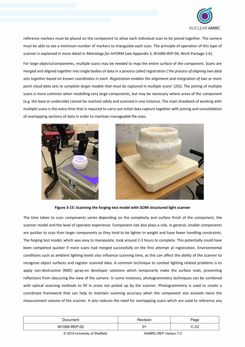
Document Revision Page
NI1066-REP-02 01 C-33
© 2019 University of Sheffield NAMRC.REP Version 7.0
reference markers must be placed on the component to allow each individual scan to be joined together. The camera
must be able to see a minimum number of markers to triangulate each scan. The principle of operation of this type of
scanner is explained in more detail in Metrology for InFORM (see Appendix 3, NI1066-REP-04, Work Package 2.6).
For large objects/components, multiple scans may be needed to map the entire surface of the component. Scans are
merged and aligned together into single bodies of data in a process called registration (‘the process of aligning two data
sets together based on known coordinates in each. Registration enables the alignment and integration of two or more
point cloud data sets to complete larger models that must be captured in multiple scans’ (25)). The joining of multiple
scans is more common when modelling very large components, but may be necessary where areas of the component
(e.g. the base or underside) cannot be reached safely and scanned in one instance. The main drawback of working with
multiple scans is the extra time that is required to carry out initial data capture together with joining and consolidation
of overlapping sections of data in order to maintain manageable file sizes.
Figure 3-15: Scanning the forging test model with GOM structured light scanner
The time taken to scan components varies depending on the complexity and surface finish of the component, the
scanner model and the level of operator experience. Component size also plays a role, in general, smaller components
are quicker to scan than larger components as they tend to be lighter in weight and have fewer handling constraints.
The forging test model, which was easy to manipulate, took around 2-3 hours to complete. This potentially could have
been completed quicker if more scans had merged successfully on the first attempt at registration. Environmental
conditions such as ambient lighting levels also influence scanning time, as this can affect the ability of the scanner to
recognise object surfaces and register scanned data. A common technique to combat lighting related problems is to
apply non-destructive (NDE) spray-on developer solutions which temporarily make the surface matt, preventing
reflections from obscuring the view of the camera. In some instances, photogrammetry techniques can be combined
with optical scanning methods to fill in areas not picked up by the scanner. Photogrammetry is used to create a
coordinate framework that can help to maintain scanning accuracy when the component size exceeds twice the
measurement volume of the scanner. It also reduces the need for overlapping scans which are used to reference any

Document Revision Page
NI1066-REP-02 01 C-34
© 2019 University of Sheffield NAMRC.REP Version 7.0
un-coded markers captured in previous scans. This helps to hasten the data capture process and reduces the amount
of duplicate data which would otherwise require registration/encoding.
3.2.7.2 Sampling the data
Data sampling in this context refers to techniques for optimising the raw scan data to make it more manageable and
responsive in CAD/CAM software. It often includes methods to strip out unnecessary or duplicate data points. Noise
reduction is one of several methods used to optimise raw data. Noise is ‘the existence of extraneous recorded data
within a point cloud. It can be caused by an object obstructing the sensor or ambient light and reflections into the sensor
during the data capture process’ (26). Highly reflective objects tend to be more difficult to scan than those with matt or
opaque surfaces, and more time is needed to orient the scanner so that it can detect and register enough features and
reference markers to fully map the surface. To make the object easier to scan, a very thin coat of non-aqueous liquid
suspension developer can be sprayed onto the surface to temporarily roughen it and reduce its reflectivity. If too much
powder is deposited, either over the whole surface or in particular areas, the true geometry of the object may be
obscured and the resulting scanned model might appear to be larger and contain more material than the real
component. The difference in volume between the scanned model and real component, however, is likely to be small
and have little influence on overall machining time, since the tool cutting depth will usually be much greater than the
depth of any deposited powder. If the surface colour of the object is dark the light from the scanner can be absorbed,
limiting or preventing data points from being collected. The spray is white in colour and therefore lightens any darker
coloured regions of the surface. Blue light scanners tend not to scan other colours, such as red, as well either. Other
potential drawbacks of using developer to reduce surface reflection include:
Contamination of the component surface. Powder residue can be undesirable for various reasons and usually
requires cleaning. A thin coat of developer is unlikely to be detrimental to the component on the basis that it
does not significantly penetrate the surface and any affected areas would be removed during normal machining
processes.
Formation of small facets. Clusters of small mosaic-like facets sometimes form in random locations during
meshing. These develop when individual powder particles or reflections of light are detected by the scanner
which interprets them as densely packed, localised high points. When polygonised, these points create multiple
surface depressions, cavities and degenerative faces. Although degenerative faces (i.e. triangles that have
negligible surface area) are small, they tend to occur in large numbers and hence require considerable
processing time. They can be hard to detect due to their small size, but it is desirable to remove as many as
possible to reduce the need for smoothing and other mesh modifications.
3.2.7.3 Generating and repairing the mesh
Mesh generation describes the formation of edges between the vertices, or points, in the point cloud data in order to
form closed surface bodies. To program toolpaths successfully, meshes must be ‘watertight’ (i.e. they do not contain
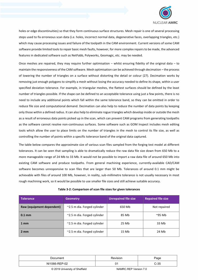
Document Revision Page
NI1066-REP-02 01 C-35
© 2019 University of Sheffield NAMRC.REP Version 7.0
holes or edge discontinuities) so that they form continuous surface structures. Mesh repair is one of several processing
steps used to fix erroneous scan data (i.e. holes, incorrect normal data, degenerative faces, overlapping triangles, etc.)
which may cause processing issues and failure of the toolpath in the CAM environment. Current versions of some CAM
software provide limited tools to repair basic mesh faults, however, for more complex repairs to be made, the advanced
features in dedicated software such as NetFabb, Polyworks, Geomagic, etc. may be needed.
Once meshes are repaired, they may require further optimisation – whilst ensuring fidelity of the original data – to
maintain the responsiveness of the CAM software. Mesh optimisation can be achieved through decimation – the process
of lowering the number of triangles on a surface without distorting the detail or colour (27). Decimation works by
removing just enough polygons to simplify a mesh without losing the accuracy needed to define its shape, within a user
specified deviation tolerance. For example, in triangular meshes, the flattest surfaces should be defined by the least
number of triangles possible. If the shape can be defined to an acceptable tolerance using just a few points, there is no
need to include any additional points which fall within the same tolerance band, so they can be omitted in order to
reduce file size and computational demand. Decimation can also help to reduce the number of data points by keeping
only those within a defined radius. It can also help to eliminate rogue triangles which develop inside or outside the mesh
as a result of erroneous data points picked up in the scan, which can prevent CAM programs from generating toolpaths
as the software cannot resolve non-continuous surfaces. Some software such as GOM Inspect includes mesh editing
tools which allow the user to place limits on the number of triangles in the mesh to control its file size, as well as
controlling the number of points within a specific tolerance band of the original data captured.
The table below compares the approximate size of various scan files sampled from the forging test model at different
tolerances. It can be seen that sampling is able to dramatically reduce the raw data file size down from 650 Mb to a
more manageable range of 24 Mb to 33 Mb. It would not be possible to import a raw data file of around 650 Mb into
existing CAM software and produce toolpaths. From general machining experience, currently-available CAD/CAM
software becomes unresponsive to scan files that are larger than 50 Mb. Tolerances of around 0.1 mm might be
achievable with files of around 100 Mb, however, in reality, sub-millimetre tolerance is not usually necessary in most
rough machining work, so it would be possible to use smaller file sizes and still achieve suitable accuracy.
Table 3-2: Comparison of scan file sizes for given tolerances
Tolerance Geometry Unrepaired file size Repaired file size
Raw (equipment dependent) ~2.5 m dia. Forged cylinder 650 Mb Not repaired
0.1 mm ~2.5 m dia. Forged cylinder 85 Mb ~95 Mb
1 mm ~2.5 m dia. Forged cylinder 25 Mb 33 Mb
2 mm ~2.5 m dia. Forged cylinder 15 Mb 24 Mb

Document Revision Page
NI1066-REP-02 01 C-36
© 2019 University of Sheffield NAMRC.REP Version 7.0
3.2.8 Alignment of stock with the machine tool vs aligning the machine tool with the stock
Workpiece alignment is traditionally achieved by aligning the workpiece to the machine tool – an operation which
requires significant operator skill. With complex components this can be quite a time-consuming exercise and unless
the machine tool has more than one pallet this can tie up an expensive resource without adding any value; commonly
referred to as ‘time in cut’. Advances in scanning technology and machine tools have the potential to change this
approach and significantly reduce setup time using the following workflow:
1. Attach metrology datum points on to the component (see section 3.2.7.1)
2. Scan the entire component off-machine
3. Load and secure the component on the machine
4. Scan the datum points with reference to the machine tool
5. Enter key offsets into the NC controller based on the scanned location of the datum points
6. Start machining
Initial investigations by Nuclear AMRC have indicated that a software agnostic approach should be feasible and it can
augment the traditional production workflow. There are a number of organisations who are starting to offer similar
(more streamlined) approaches on a commercial basis however these solutions enforce adoption of specific software
into the traditional workflow. Further work in this area is outside the scope of this report.
3.2.9 Existing software technology
A review of existing software which could support the implementation of workflows described in sections 3.2.3 to 3.2.5
was made by carrying out internet searches and enquiries with various software vendors. Trials with the forging test
model were completed using in-house software to develop and test different machining strategies. Where possible, i.e.
if relevant licences were available, software from other vendors was trialled. The list of vendors/suppliers who were
consulted included:
Innovmetric (Polyworks (13))
Autodesk (Netfabb (20), PowerMill (28), Meshmixer (19))
3D Systems (Geomagic (16))
Tebis (21)
TTL (Siemens NX (24) (29) (30))
MachineWorks (Polygonica (31) (32))
The vendors shown all supply or develop software which can support scan based machining processes. The majority of
Document Revision Page
NI1066-REP-02 01 C-37
© 2019 University of Sheffield NAMRC.REP Version 7.0
products on offer can be used on a stand-alone basis, but to increase functionality, most are designed to work alongside
other products that are usually, but not always, made by the same vendor.
The products reviewed generally provide all the tools and features necessary to perform common operations which
feature in typical machining workflows. Some products include additional toolsets which are optimised for specific
procedures and are designed to give more control over certain variables. Variations in how features and commands are
invoked exist between different products, and this can dictate how routine operations are performed. It may be
necessary to adapt workflow sub-routines in order to apply particular tools and functions, however, many products can
be modified to help optimise work procedures.
It would be difficult and potentially misleading to compare the performance of different software products due to the
number of factors which influence how each product functions. Every component dataset is different and most tasks,
such as mesh sampling, mesh repair, toolpath creation etc. can often be completed in more than one way, sometimes
without the need for specialised tools that might only be available in certain products. Businesses who are looking to
purchase new software need to decide what they want to use the software for and trial as many products as possible
to help inform their decision prior to any purchases being made. This evaluation process can be complex, time
consuming and costly and the concern for the industry is that they may not have the resource available to make an
informed selection and develop the knowledge and capability required.
3.2.9.1 User-friendliness
The notion of whether or not a piece of software is easy to use is very subjective and depends largely on the training,
experience and preference of individual operators. It is not uncommon to find machine shops which have used the same
CAD/CAM system for many years. This approach is not necessarily flawed, assuming that the software continues to meet
present day needs and is still supported by the vendor. Manufacturers may be reluctant or unable to change their
current CAD/CAM system for various reasons, but continuing to use outdated and sometimes un-popular software,
especially when more capable alternatives are known to exist, can be detrimental for productivity. Some manufacturers
retain old software simply to access historic design data and to maintain the ability to manufacture old components,
which might only occur on an ad-hoc and infrequently basis. Whilst this method may be less costly than converting
outdated CAD/CAM files into new software formats, it inevitably affects productivity as designers and programmers are
forced to reacquaint themselves with old techniques and revert to outmoded, fragmented procedures. It is therefore
important to review software capability, and any necessary training requirements, on a frequent basis to ensure that it
remains suitable for the chosen application and does not become a barrier to the production process.
3.2.9.2 Software performance
Software is normally optimised for specific tasks, and products which are designed to perform similar functions often
differ due to their fundamental coding and the algorithms used to run computations. The consequence of this can be
varied – it could mean that one software package is able to repair large data files more quickly than another, or it might

Document Revision Page
NI1066-REP-02 01 C-38
© 2019 University of Sheffield NAMRC.REP Version 7.0
mean one is able to compute simulations faster. This could be a benefit to a programmer, depending on the type and
size of components being produced (larger components generally generate larger data files). A detailed technical
assessment of software performances, however, is beyond the scope of this work as a large number of factors can affect
software performance and any comparisons made could be misleading since the performance of some algorithms is
‘highly data dependent’ (31).
3.2.9.3 Mesh handling
Machining from mesh files (.stl, .obj, .dxf, .step, .iges, .dwg, .3dm (33)) is not new, but is not yet fully supported by all
CAM packages. CAM software generally does not offer the same versatility in handling meshes as dedicated meshing
software because this is not its primary function. New technologies such as 3D printing have driven development of
alternative methods for processing scan data, and some of the techniques are now being adopted in machining
strategies. It may be the case that leading CAM software providers integrate more mesh handling functions into future
software revisions to help streamline data processing workflows.
3.2.9.4 Workflow fragmentation
Levels of product integration vary considerably between different vendors. Where some have built comprehensive
product ranges which aim to streamline workflows, others have focused on developing core products which specialise
in a narrower range of functions. Currently, separate software products are needed to support scan based machining
workflows, as tools for advanced meshing repair, surface reconstruction, toolpath creation etc. are not usually
integrated together into single software packages. This often necessitates the import, export and conversion of different
file formats, and leads to the fragmentation of workflows and accumulative error due to translation tolerances. Some
vendors however have formed partnerships to extend the capabilities of their respective products. For example
EdgeCAM Solid Machinist is a CAM program which allows solid 3D models from CAD software to be imported without
translation in order to preserve the integrity of the designed component (34). This is achieved by access to the modelling
kernel directly. However, a number of modelling kernals are available such as ACIS, Parasolid, Granite etc. The package
supports files from major CAD systems including Autodesk Inventor, SolidWorks, Solid Edge, Siemens (formerly
Unigraphics) NX, CATIA V5 and Creo (formally Pro / ENGINEER).

Document Revision Page
NI1066-REP-02 01 C-39
© 2019 University of Sheffield NAMRC.REP Version 7.0
4 End TRL/MRL level
A peer review assessment of the TRL and MRL attained by innovations in each InFORM work package was carried out
by industrial academics and consultants on 23rd May 2019. It was determined that innovations in the machining work
package which focus on methods of generating representative stock models from scan data and advanced toolpaths for
machining rough components have increased modestly in terms of readiness to deploy and are still within the bands of
TRL 4 and MRL 3. A more detailed justification for the assigned TRL/MRL values is shown in Appendix 1.
Potential industrial impact
To achieve the required metallurgical properties, large scale nuclear components have traditionally been produced from
forged nuclear grade steel. The wide dimensional tolerances of the current large scale forging process are such that a
significant percentage of the time taken to transform the component from the as-forged state to being ready for finish
machining either does not add any value (e.g. setting up the component) or reduces the efficiency of the machining
process (e.g. cutting ‘fresh air’). While another part of the InFORM project addresses possible solutions to reduce the
variation in the forging process (see Appendix 2) they will not negate the industrial impact of the advances proposed in
this report.
Scanning the component will:
Reduce component setup time
The reduced need to move the component will reduce the health and safety risks
There will be a faster learning curve for machine tool operators to become skilled in setting up the component
Reduce the potential for scrapping expensive, long lead-time components which could have significant follow-
on schedule and cost implications
Scan-to-CAM will:
Improve material removal rate (section 3.2.6 shows that this can be as high as a 40% improvement for a simple
geometry)
The increased machining efficiency will reduce the environmental impact of the machining process. The
background energy consumption of a machine tool that is cutting ‘fresh air’ can still be 25% of the energy
consumption when it is cutting metal – energy is being used but nothing is being achieved.
Allow for closer tolerance forgings which will reduce the volume of material that needs removing in the first
place
Document Revision Page
NI1066-REP-02 01 C-40
© 2019 University of Sheffield NAMRC.REP Version 7.0
5 Recommendation for further research and development
Blocks to industrial adoption in the heavy engineering sector
In some respects the workflow that has been investigated in this report already exists at very high TRLs and MRLs in
other sectors (e.g. gaming (35), heritage (36), medical (37) (38), motorsport (39)). It is by understanding the blockages
that are preventing this approach from being brought into the nuclear and wider heavy engineering sector that the
recommendations for further research and development become clear.
5.1.1 Access to large scale scanners
The installed base of appropriate scanning equipment within the sector is extremely low.
5.1.2 Scanning skills with point clouds
Scanners produce their results as point clouds which require new skills sets to be able to manipulate.
5.1.3 Computer hardware and software limitations
CAM from point cloud data readily occurs in the gaming and medical sectors where the components are the size of a
game board piece or a human bone. In these circumstances the computer hardware and software are capable of
handling the data file sizes generated during the scanning process. The data files for large forgings are several orders of
magnitude larger and outside the capabilities of current hardware and software.
5.1.4 Manufacturing Engineering skills with point clouds
Point clouds are effectively a non-conventional CAD format which will require different skills of Manufacturing Engineers
to be able to use these for producing CAM programs.
5.1.5 Legacy systems
Companies that machine large components will generally have invested heavily in CAD/CAM packages and it is quite
possible that these are without Scan-to-CAM functionality. If their chosen vendor’s system had a Scan-to-CAM module,
what evidence do they have regarding its performance? If there is no possibility of inserting a Scan-to-CAM module,
where is the justification for replacing their entire CAD/CAM system (and all the retraining that will be required)?

Document Revision Page
NI1066-REP-02 01 C-41
© 2019 University of Sheffield NAMRC.REP Version 7.0
Recommendations for future work
5.2.1 Cost model
All the respective parts for bringing this workflow into the manufacturing of large nuclear forgings are present but there
are different factors at each stage of the process. No one organisation has a view of the entire process and therefore
has no view of the end game. For this workflow to be brought into the large scale nuclear manufacturing industry there
will need to be a strong business case. This can only be produced once the true cost of the existing process is known
and the savings that can be made by incorporating this workflow. If this shows that there is a financial justification in
making the investment – either by Government sharing some of that financial burden or on purely commercial terms –
then the various investments can be made which will bring this into reality.
5.2.2 Standard artefacts
There is no way to compare the performance of the various commercially-available Scan-to-CAM systems. A series of
standard artefacts should be created – in pairs. The first artefact is the ‘as-forged’ condition and the second is in the
‘ready for finish machining’ condition. The latter artefact of each pair will contain specific features that are often used
in large scale nuclear components. As publicly-available standard items they will provide a developmental test bed for
the developers of Scan-to-CAM systems as well as a comparator between alternative software solutions.
Document Revision Page
NI1066-REP-02 01 C-42
© 2019 University of Sheffield NAMRC.REP Version 7.0
References
1. 3D Engineers. 3D SCANNING. [Online] 2019. [Cited: 31 07 2019.] https://www.3dengineers.co.uk/3d-
scanning/.
2. MSL - Measurement Solutions. Applications. [Online] 2019. [Cited: 29 07 2019.] https://measurement-
solutions.co.uk/.
3. Faro. FARO OFFERS A WIDE VARIETY OF APPLICATIONS. [Online] 2019. [Cited: 24 07 2019.]
https://www.faro.com/en-gb/metrology-3d-documentation-solutions-from-faro/faro-offers-a-wide-variety-of-
applications/.
4. Kersen, Steve. Reverse Engineering Continues to Expand its Role in Industry. Quality Magazine. [Online] 01
Oct 2016. [Cited: 19 Jun 2019.] https://www.qualitymag.com/articles/93580-reverse-engineering-continues-to-
expand-its-role-in-industry.
5. GOM. Aerospace: Upgrade of a BLACK HAWK Helicopter. Application Example: Reverse Engineering. [Online]
2008. [Cited: 22 Jul 2019.] https://www.gom.com/fileadmin/user_upload/industries/helicopter_EN.pdf.
6. Faro. Printing and certifying AM propellers signals future for large component repair and manufacture.
[Online] 25 10 2018. [Cited: 23 07 2019.] https://www.faro.com/en-gb/resources/case-studies-
en/?keyword=propeller.
7. Nathan, Stuart. Ship-shape: the world’s first 3D printed marine propeller: Dutch shipbuilders have unveiled
the world’s first 3D-printed marine propeller. The Engineer. [Online] 25 01 2018. [Cited: 22 07 2019.]
https://www.theengineer.co.uk/worlds-first-3d-printed-marine-propeller/.
8. Near net shape manufacturing of metal: A review of approaches and their evolutions. Marini, Daniele ,
Cunningham, David and Corney, Jonathan R. Glasgow : Proc IMechE Part B: J Engineering Manufacture, 2018,
Vols. 232(4) 650–669.
9. Performance Engineering Solutions Ltd. Reverse Engineering - Interview with Dan Fleetcroft.
https://www.pes-performance.com/. 2019.
10. GOM. ATOS - Industrial 3D Scanning Technology. [Online] 2019. [Cited: 24 07 2019.]
https://www.gom.com/metrology-systems/atos.html.
11. Zeiss. 3D Scanning - COMET and T-SCAN. [Online] 2019. [Cited: 24 07 2019.]
https://optotechnik.zeiss.com/en/products/3d-scanning.
12. CloudCompare. 3D point cloud and mesh processing software. [Online] 2019. [Cited: 31 07 2019.]
https://www.danielgm.net/cc/.

Document Revision Page
NI1066-REP-02 01 C-43
© 2019 University of Sheffield NAMRC.REP Version 7.0
13. Innovmetric. Polyworks - 3D METROLOGY SOFTWARE SOLUTIONS. [Online] 2019. [Cited: 31 07 2019.]
https://www.innovmetric.com/en.
14. GOM. GOM Inspect - Features. [Online] 2019. [Cited: 24 07 2019.] https://www.gom.com/3d-
software/gom-inspect/gom-inspect-features.html.
15. —. GOM Inspect - Evaluation Software for 3D Measurement Data. [Online] 2019. [Cited: 31 07 2019.]
https://www.gom.com/3d-software/gom-inspect.html.
16. 3D Systems. Geomagic - Reverse engineer physical parts into digital parametric CAD models. [Online] 2019.
[Cited: 31 07 2019.] https://uk.3dsystems.com/software/geomagic-design-x.
17. —. GibbsCAM - COMPLETE CAM SOLUTION FOR ANY CNC MACHINE. [Online] 2019. [Cited: 31 07 2019.]
https://uk.3dsystems.com/software/gibbscam.
18. Innovmetric. Polyworks Inspector - MEASURE - Extract all required dimensions. [Online] 2019. [Cited: 31 07
2019.] https://www.innovmetric.com/en/products/polyworks-inspector.
19. Autodesk. Meshmixer - Free software for making awesome stuff. [Online] 2019. [Cited: 31 07 2019.]
http://www.meshmixer.com/.
20. —. Netfabb - Connected software for additive manufacturing, design and simulation. [Online] 2019. [Cited:
31 07 2019.] https://www.autodesk.co.uk/products/netfabb/overview.
21. Tebis. TebisCAM - CAM software for fast and safe manufacturing processes. [Online] 2019. [Cited: 31 07
2019.] https://www.tebis.com/uk/en/.
22. 3D Systems. Rapidform. [Online] 2019. [Cited: 31 07 2019.] https://www.3dsystems.com/.
23. Autodesk. PowerInspect - 3D measurement software for a range of hardware. [Online] 2019. [Cited: 31 07
2019.] https://www.autodesk.co.uk/products/powerinspect/overview.
24. Siemens. Siemens NX - Products - NX. [Online] 2019. [Cited: 31 07 2019.]
https://www.plm.automation.siemens.com/global/en/products/nx/.
25. Reverse Engineering 3D. Laser Scanning Glossary - Registration. [Online] 2017. [Cited: 03 04 2019.]
http://www.reverse-engineering-3d.co.uk/laser-scanning/laser-scanning-
glossary/?doing_wp_cron=1542108216.5879130363464355468750.
26. —. Laser Scanning Glossary - Noise. [Online] 2017. [Cited: 03 04 2019.] http://www.reverse-engineering-
3d.co.uk/laser-scanning/laser-scanning-glossary/?doing_wp_cron=1542108216.5879130363464355468750.
27. —. Laser Scanning Glossary - Decimation. [Online] 2017. [Cited: 03 04 2019.] http://www.reverse-
engineering-3d.co.uk/laser-scanning/laser-scanning-
glossary/?doing_wp_cron=1542108216.5879130363464355468750.

Document Revision Page
NI1066-REP-02 01 C-44
© 2019 University of Sheffield NAMRC.REP Version 7.0
28. Autodesk. PowerMill - Expert high-speed and 5-axis machining software for manufacturing. [Online] 2019.
[Cited: 31 07 2019.] https://www.autodesk.co.uk/products/powermill/overview.
29. TTL. Adaptive Machining - Lower cycle times, increase accuracy, and minimise operating costs by utilising
Adaptive Machining in the manufacture and repair of complex components. [Online] 2019. [Cited: 31 07 2019.]
https://www.ttl-solutions.com/en-gb/our-services/adaptive-machining/.
30. —. NX CAM - Industry leading solutions that overcome barriers between design and manufacturing.
[Online] 2019. [Cited: 31 07 2019.] https://www.ttl-solutions.com/en-gb/our-services/nx-cam/.
31. MachineWorks. MachineWorks - The Software Development Toolkit for CNC Simulation and Verification.
[Online] 2019. [Cited: 31 07 2019.] https://www.machineworks.com/.
32. —. Polygonica - The solid modelling software toolkit for processing polygon meshes from the creators of
MachineWorks. [Online] 2019. [Cited: 02 08 2019.] https://www.polygonica.com/.
33. CNC with Shapr3D. Introduction to CAD vs CAM. [Online] 2019. [Cited: 30 07 2019.]
https://support.shapr3d.com/hc/en-us/articles/115001761794-CNC-with-Shapr3D?mobile_site=true.
34. Hexagon. EDGECAM Solid Machinist - Advanced CADCAM Software Solutions For The Manufacturing
Industry. [Online] 2019. [Cited: 31 07 2019.] https://www.edgecam.com/edgecam-solid-machinist/.
35. Renishaw. Renishaw precision meets the challenge of Games Workshop; Case story – Cyclone digitising, H-
3000-1142-01.
36. National Museums Liverpool. Non-contact 3D laser scanning and replication of cultural heritage at
Conservation Technologies. s.l. : Annemarie La Pensée and Martin Cooper, Conservation Technologies, National
Museums Liverpool; www.liverpoolmuseums.org.uk/conservation/technologies.
37. Bibb, Richard, Eggbeer, Dominic and Paterson, Abby. Medical Modelling: The Application of Advanced
Design and Rapid Prototyping Techniques in Medicine. s.l. : Woodhead Publishing, 2015.
38. The use of non-contact structured light scanning in burns pressure splint construction. Pilley, M. J., et al.
Burns: journal of the International Society for Burn Injuries 37(7):1168-73, s.l. : PubMed, August 2011. DOI:
10.1016/j.burns.2011.07.005.
39. Materialise. 3Matic Application - Holden Engineering wins the race against time thanks to forward
engineering - From damaged part to casting pattern in only 20 hours. s.l. : Chris Perkins, Holden Engineering;
Carl Hitchens, Materialise (3Matic).

Document Revision Page
NI1066-REP-02 01 C-45
© 2019 University of Sheffield NAMRC.REP Version 7.0
Glossary
Acronym Meaning
4IR Fourth Industrial Revolution
AI Artificial Intelligence
AR Augmented Reality
BEIS [Department for] Business, Energy and Industrial Strategy
CAD Computer Aided Design
CAM Computer Aided Manufacturing
CNC Computer Numerical Control
COS Condition of supply (i.e. the state in which material is supplied before processing)
NC Numerical Control
RE Reverse Engineering
Stock model
Stock part
Stock material
The billet or rough, block of material from which the finished part will be formed. Also
sometimes referred to as the ‘blank’ or ‘raw’ or ‘green’ material / forging / casting etc.
Swarf Small chips, filings, turnings, shavings or other material debris produced by a machining or
other cutting operation
Toolpath The route followed by the tip of a cutting tool as it moves around the stock part, removing
material to produce the finished component geometry.
Workpiece A billet of metal or other piece of material which is being worked by a machine or a person
operating a hand tool.

Document Revision Page
NI1066-REP-01 03 D-1
© 2019 University of Sheffield NAMRC.REP Version 7.0
D. Machining Optimisation – Super Critical CO2
Intelligent Fixtures for Optimised and Radical Manufacture (InFORM) - Stage 2
Machining Optimisation – Super Critical CO2
NI1066-REP-03
Project report
Document Revision Page
NI1066-REP01 02 D-1
© 2019 University of Sheffield NAMRC.REP-03 Rev 7
Nuclear AMRC
University of Sheffield
Advanced Manufacturing Park
Brunel Way
Rotherham
S60 5WG
United Kingdom
This report may only be reproduced in full, except with the express permission of the Nuclear AMRC.
The Nuclear AMRC has exercised due care in conducting this report but has not, apart from as specifically stated, independently verified information provided by others. No other warranty, express or implied, is made in relation to the contents of this report. Therefore, the Nuclear AMRC assumes no liability for any loss resulting from errors, omissions, or misrepresentations made by others. Any recommendations, opinions or findings stated in this report are based on circumstances and facts as they existed at the time the Nuclear AMRC performed the work. Any changes in such circumstances and facts upon which this report is based may adversely affect any recommendations, opinions or findings contained in this report. Where experiments have been carried out, these have been restricted to a level of detail required to achieve the stated objectives of the statement of work. This work has been undertaken in accordance with the Nuclear AMRC’s quality system.
Name Signature
Authors: Przemyslaw Litwa
Technical review: Krystian Wika
Authorised: Carl Hitchens
Authorised distribution: BEIS
Document revision history
Revision Date of issue Reason for revision or original issue
01 Original issue
02 12/11/2019 Updated references
03/09/2019

Document Revision Page
NI1066-REP01 02 D-2
© 2019 University of Sheffield NAMRC.REP-03 Rev 7
Executive summary
Tool life, tool wear mechanism, cutting forces and surface integrity were investigated to determine the effect
of supercritical CO2 cooling on machinability of SA508 Grade 3 Class 2 steel for nuclear components.
The machining trials were performed for different combinations of cutting conditions.
The results from this research were compared and contrasted with conventional soluble oil coolant.
Machining of SA508 steel with supercritical CO2 resulted in a significant increase in tool life in comparison to
the conventional cooling method.
Different tool wear mechanisms were observed depending on the coolant type being used.
No detrimental effects to the material surface condition were observed when compared to conventional
soluble oil coolant for the same cutting conditions.
The use of supercritical CO2 results in components that are clean and require little or no post-cleaning to
remove contamination and residue
Health benefits for the workforce have been identified and further work is required to fully quantify the
significance.

Document Revision Page
NI1066-REP01 02 D-3
© 2019 University of Sheffield NAMRC.REP-03 Rev 7
Contents 1 Technical challenge and first principles ................................................................................................................... 4
1.1 The challenges of machining large-scale nuclear components ......................................................................... 4
1.2 Current state of the art used to address problem ............................................................................................. 5
2 Starting MRL/TRL level ............................................................................................................................................ 5
3 Overview of technical challenge for industry .......................................................................................................... 5
3.1 Evolution from first principles ........................................................................................................................... 5
3.2 Work conducted and the development path .................................................................................................... 6
3.3 Tool Life Trials and Design of Experiments Methodology ................................................................................. 6
3.4 Tool Life and Tool Wear ................................................................................................................................... 12
3.4.1 Tool Life trials ............................................................................................................................................. 12
3.4.2 Additional Tool Life Trials ........................................................................................................................... 13
3.4.3 Tool wear .................................................................................................................................................... 15
3.5 Surface integrity ............................................................................................................................................... 18
3.5.1 Surface Roughness ..................................................................................................................................... 18
3.5.2 Cutting forces ............................................................................................................................................. 19
3.5.3 Residual stresses ........................................................................................................................................ 20
3.6 Microstructure ................................................................................................................................................. 22
4 End MRL/TRL level ................................................................................................................................................. 26
4.1 Potential industrial impact............................................................................................................................... 27
5 Recommendation for further research and development .................................................................................... 27
5.1 Future work ..................................................................................................................................................... 27
5.2 Route to industrial adoption ............................................................................................................................ 28
References ........................................................................................................................................................................ 29

Document Revision Page
NI1066-REP01 02 D-4
© 2019 University of Sheffield NAMRC.REP-03 Rev 7
1 Technical challenge and first principles
1.1 The challenges of machining large-scale nuclear components
Machining of large-scale steel components has significant impact on manufacturing cost. The most commonly used
machine coolants in cutting processes are soluble oil coolants. These coolants usually contain additives, some to provide
corrosion protection to the machined components and others to improve resistance to microbial degradation. However,
the costs of the procurement, maintenance (cleaning sumps and machinery on a regular basis) and disposal of
conventional coolants are relatively high (1). It is estimated that the total costs associated with the purchasing,
preparation, maintenance and disposal of soluble oil coolants account for approximately 16% of the total machining
costs (2). This has a negative impact on the economy of high-volume machining of large-scale nuclear components. In
addition, it is important to be aware of the health risks from exposure to these various chemicals, for example contact
with soluble oil during the handling of parts and tools can cause long-term skin rashes and dermatitis (2; 3). Oil coolant
systems can also be a source of unplanned maintenance or machine shutdown if the system leaks or the coolant
overheats.
The challenge is to find a solution which can increase material removal rate (MRR) and improve operational safety while
reducing the likelihood that the solution is a contributory factor to unplanned machine shutdowns and repairs. For
example something as simple as dispensing with coolant altogether could be a viable option, especially in interrupted
cutting where the tool undergoes cyclic thermal stress caused by non-uniform heating up and cooling down of the tool.
It could even potentially reduce the risk of thermal cracking. However, dry machining is not suitable for high speed
machining (HSM) of difficult-to-cut materials. Dry machining of materials such as titanium or nickel-based alloys causes
high heat generation during cutting due to poor thermal conductivity of these materials. Dry machining can also increase
energy consumption of the machine tool due to increased cutting forces and heat generation. This consequently can
lead to tool breakage and deterioration of the surface integrity of the machined component.
The machining of nuclear components requires cleanliness, high surface integrity, tight tolerances, and high MRR while
meeting environmental standards. However, current machining methods with oil-based coolants have the following
issues:
Non efficient cooling solution leads to
Rapid tool wear
Poor surface integrity, which can accelerate corrosion of machined component during its service life.
Coolant splashes lead to:
Soluble oil coolant contamination
Hazards and risks associated with using conventional coolants lead to:
Bacterial growth, rancidity and oil contamination.
Unsafe work environment, inhalation hazards.
Document Revision Page
NI1066-REP01 02 D-5
© 2019 University of Sheffield NAMRC.REP-03 Rev 7
1.2 Current state of the art used to address problem
In recent years, cryogenic cooling in machining processes has attracted a lot of interest (4). Currently, liquid carbon
dioxide (LCO2), supercritical carbon dioxide (scCO2) and liquid nitrogen (LN2) are three alternatives to conventional
soluble oil coolants (5). A combination of CO2 with Minimum Quantity Lubrication (MQL) has also been developed in
order to provide lubrication in the cutting zone (6). Compared to dry machining, milling of high strength stainless steel
(X12CrNiWTiB16-13) with carbon dioxide can increase MRR by 72% (7).
Following a literature review, LN2 is the most commonly researched cryogenic coolant. More recently, however, LCO2
and scCO2 are receiving growing attention due to economic and safety benefits. In general, LN2 is more difficult to
retrofit into machine tools than CO2. This is because the LN2 boiling point of about -196C (8) means that the machine
tool spindle requires insulation but this is not an issue with liquid carbon dioxide which has a boiling point of about -
79C. In addition, CO2 allows for through-spindle single-channel delivery of scCO2 and MQL due to high MQL solubility
in CO2 above its critical point (Tc = 31.2C, pc = 7.38 MPa) (9; 10). Use of cryogenic coolants in machining processes has
many environmental and economic benefits. These can potentially transform conventional manufacturing methods by
reducing the cost of energy consumption and increasing productivity (10). In industry, the performance of critical
components must be carefully controlled over their lifetime where surface integrity is important. Carbon dioxide
machining has the potential to increase tool life and maintain/improve surface integrity of those components as shown
in multiple studies which have shown an improvement of tool life in cryogenic machining of various materials (11; 12).
Tool wear improvement results from highly efficient heat removal from the cutting zone and reduced thermal softening
of the cutting edge.
2 Starting MRL/TRL level
At the start of the project the Nuclear AMRC considered supercritical CO2 machining to be at a TRL of 3. With a
corresponding MRL of 3. The justification for these values is shown in Appendix 1.
3 Overview of technical challenge for industry
3.1 Evolution from first principles
One of the challenges for the nuclear manufacturing industry is to reduce the production lead-time in the manufacturing
of components and increase production rates while maintaining surface integrity.
In most cases, increasing MRR in high speed machining processes leads to excessive tool wear/shorter tool life,
increasing burr formation on machined components and poor surface finish. Therefore, increasing MRR in the machining
of steel parts is currently limited mainly due to the cooling capability of soluble oil coolants in high speed machining and
during interrupted cutting (such as when first machining a forging) when there are temperature fluctuations.
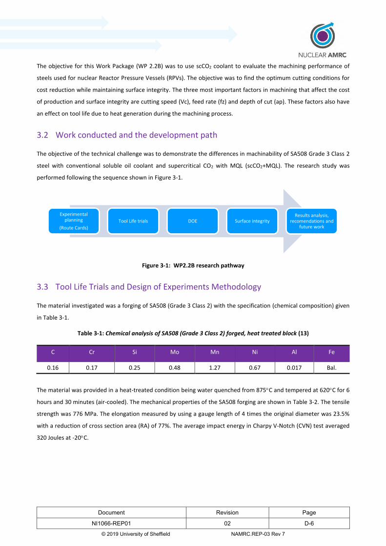
Document Revision Page
NI1066-REP01 02 D-6
© 2019 University of Sheffield NAMRC.REP-03 Rev 7
The objective for this Work Package (WP 2.2B) was to use scCO2 coolant to evaluate the machining performance of
steels used for nuclear Reactor Pressure Vessels (RPVs). The objective was to find the optimum cutting conditions for
cost reduction while maintaining surface integrity. The three most important factors in machining that affect the cost
of production and surface integrity are cutting speed (Vc), feed rate (fz) and depth of cut (ap). These factors also have
an effect on tool life due to heat generation during the machining process.
3.2 Work conducted and the development path
The objective of the technical challenge was to demonstrate the differences in machinability of SA508 Grade 3 Class 2
steel with conventional soluble oil coolant and supercritical CO2 with MQL (scCO2+MQL). The research study was
performed following the sequence shown in Figure 3-1.
Figure 3-1: WP2.2B research pathway
3.3 Tool Life Trials and Design of Experiments Methodology
The material investigated was a forging of SA508 (Grade 3 Class 2) with the specification (chemical composition) given
in Table 3-1.
Table 3-1: Chemical analysis of SA508 (Grade 3 Class 2) forged, heat treated block (13)
C Cr Si Mo Mn Ni Al Fe
0.16 0.17 0.25 0.48 1.27 0.67 0.017 Bal.
The material was provided in a heat-treated condition being water quenched from 875C and tempered at 620C for 6
hours and 30 minutes (air-cooled). The mechanical properties of the SA508 forging are shown in Table 3-2. The tensile
strength was 776 MPa. The elongation measured by using a gauge length of 4 times the original diameter was 23.5%
with a reduction of cross section area (RA) of 77%. The average impact energy in Charpy V-Notch (CVN) test averaged
320 Joules at -20C.
Experimental planning
(Route Cards)
Tool Life trials DOE Surface integrityResults analysis,
recomendations and future work
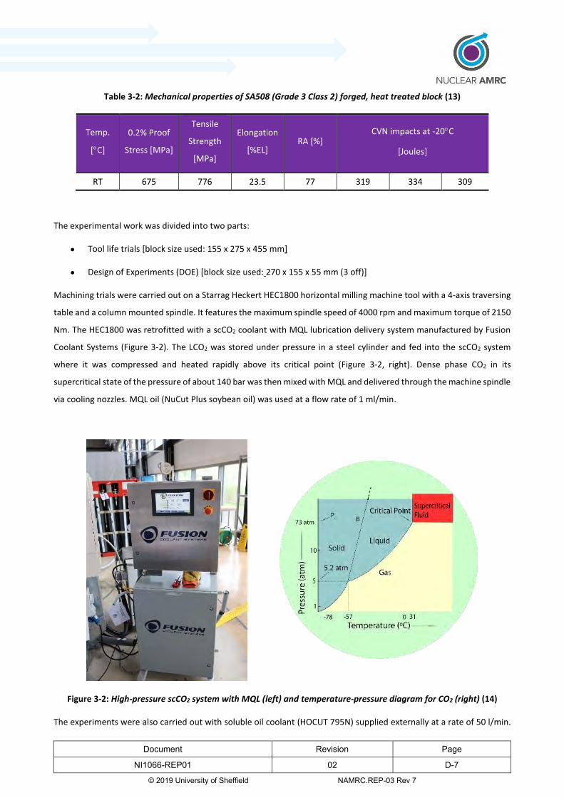
Document Revision Page
NI1066-REP01 02 D-7
© 2019 University of Sheffield NAMRC.REP-03 Rev 7
Table 3-2: Mechanical properties of SA508 (Grade 3 Class 2) forged, heat treated block (13)
Temp.
[C]
0.2% Proof
Stress [MPa]
Tensile
Strength
[MPa]
Elongation
[%EL] RA [%]
CVN impacts at -20C
[Joules]
RT 675 776 23.5 77 319 334 309
The experimental work was divided into two parts:
Tool life trials [block size used: 155 x 275 x 455 mm]
Design of Experiments (DOE) [block size used: 270 x 155 x 55 mm (3 off)]
Machining trials were carried out on a Starrag Heckert HEC1800 horizontal milling machine tool with a 4-axis traversing
table and a column mounted spindle. It features the maximum spindle speed of 4000 rpm and maximum torque of 2150
Nm. The HEC1800 was retrofitted with a scCO2 coolant with MQL lubrication delivery system manufactured by Fusion
Coolant Systems (Figure 3-2). The LCO2 was stored under pressure in a steel cylinder and fed into the scCO2 system
where it was compressed and heated rapidly above its critical point (Figure 3-2, right). Dense phase CO2 in its
supercritical state of the pressure of about 140 bar was then mixed with MQL and delivered through the machine spindle
via cooling nozzles. MQL oil (NuCut Plus soybean oil) was used at a flow rate of 1 ml/min.
Figure 3-2: High-pressure scCO2 system with MQL (left) and temperature-pressure diagram for CO2 (right) (14)
The experiments were also carried out with soluble oil coolant (HOCUT 795N) supplied externally at a rate of 50 l/min.
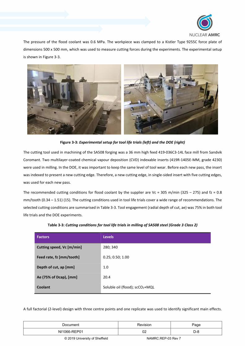
Document Revision Page
NI1066-REP01 02 D-8
© 2019 University of Sheffield NAMRC.REP-03 Rev 7
The pressure of the flood coolant was 0.6 MPa. The workpiece was clamped to a Kistler Type 9255C force plate of
dimensions 500 x 500 mm, which was used to measure cutting forces during the experiments. The experimental setup
is shown in Figure 3-3.
Figure 3-3: Experimental setup for tool life trials (left) and the DOE (right)
The cutting tool used in machining of the SA508 forging was a 36 mm high feed 419-036C3-14L face mill from Sandvik
Coromant. Two multilayer-coated chemical vapour deposition (CVD) indexable inserts (419R-1405E-MM, grade 4230)
were used in milling. In the DOE, it was important to keep the same level of tool wear. Before each new pass, the insert
was indexed to present a new cutting edge. Therefore, a new cutting edge, in single-sided insert with five cutting edges,
was used for each new pass.
The recommended cutting conditions for flood coolant by the supplier are Vc = 305 m/min (325 – 275) and fz = 0.8
mm/tooth (0.34 – 1.51) (15). The cutting conditions used in tool life trials cover a wide range of recommendations. The
selected cutting conditions are summarised in Table 3-3. Tool engagement (radial depth of cut, ae) was 75% in both tool
life trials and the DOE experiments.
Table 3-3: Cutting conditions for tool life trials in milling of SA508 steel (Grade 3 Class 2)
Factors Levels
Cutting speed, Vc [m/min] 280; 340
Feed rate, fz [mm/tooth] 0.25; 0.50; 1.00
Depth of cut, ap [mm] 1.0
Ae (75% of Dcap), [mm] 20.4
Coolant Soluble oil (flood); scCO2+MQL
A full factorial (2-level) design with three centre points and one replicate was used to identify significant main effects.

Document Revision Page
NI1066-REP01 02 D-9
© 2019 University of Sheffield NAMRC.REP-03 Rev 7
Table 3-4 presents a summary of all the data entered into investigation. The responses were: cutting forces, residual
stresses and surface roughness. The number of runs for screening design was 22. The experiments were performed in
randomised order to minimise the effect of the noise factors. (Noise factors are nuisance variables that may affect the
measured output variables. Examples of noise factors are workpiece imperfections such as material non-homogeneity,
and the machine operator when changing cutting inserts. Nuisance variables are difficult to control and therefore, the
experiments are randomised to minimise these). The tool life trials were performed according to ISO 8688-1:1989 (16).
Tool wear was measured until the maximum tool flank wear threshold was reached (VBmax = 300 μm).
The tool path in tool life trials and the DOE is shown in Figure 3-4 while Figure 3-5 shows an example of images extracted
from videos recorded during the trials. The rectangular tool path was selected to simulate continuous cutting and to
avoid placing high load on the tool upon entry. The tool path in the tool life trials consisted of straight-line segments
and circular arcs. The DOE was performed using a conventional zigzag tool path where each next pass was cut with the
different cutting conditions specified in Table 3-4.
Figure 3-4: Tool path for spiral (left) and zig-zag (right) milling (17; 18)
Tool life DOE
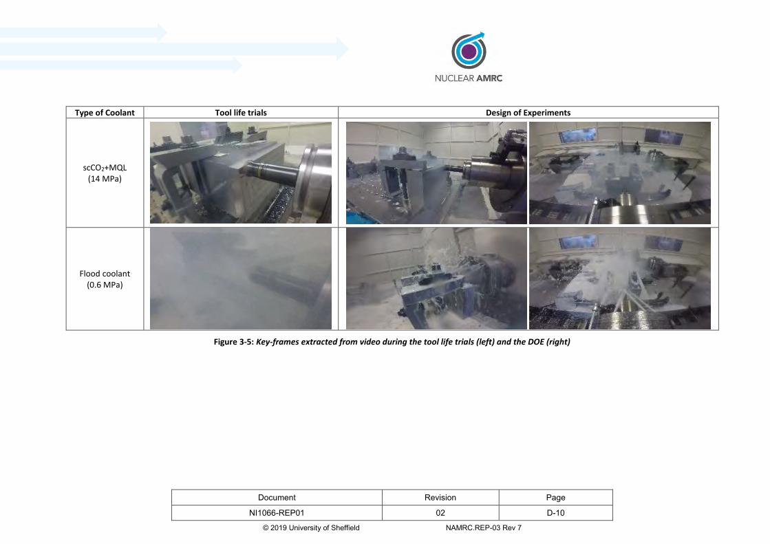
Document Revision Page
NI1066-REP01 02 D-10
© 2019 University of Sheffield NAMRC.REP-03 Rev 7
Type of Coolant Tool life trials Design of Experiments
scCO2+MQL (14 MPa)
Flood coolant (0.6 MPa)
Figure 3-5: Key-frames extracted from video during the tool life trials (left) and the DOE (right)
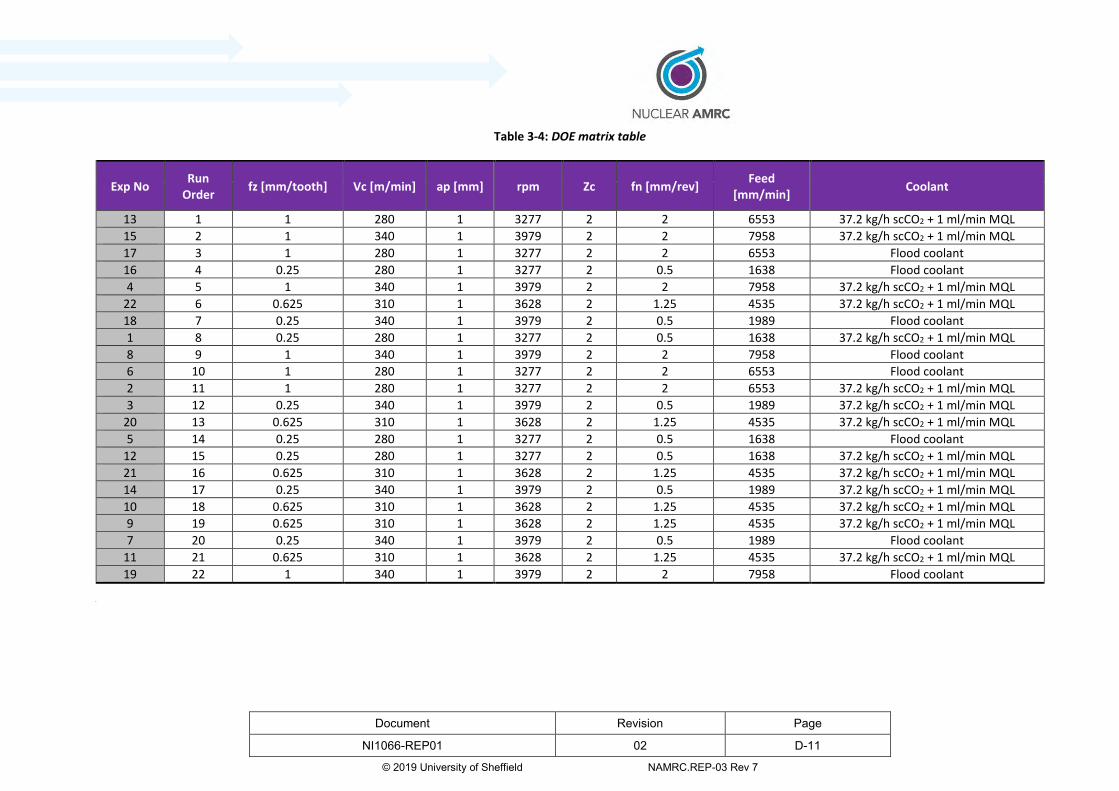
Document Revision Page
NI1066-REP01 02 D-11
© 2019 University of Sheffield NAMRC.REP-03 Rev 7
Table 3-4: DOE matrix table
Exp No Run
Order fz [mm/tooth] Vc [m/min] ap [mm] rpm Zc fn [mm/rev]
Feed [mm/min]
Coolant
13 1 1 280 1 3277 2 2 6553 37.2 kg/h scCO2 + 1 ml/min MQL
15 2 1 340 1 3979 2 2 7958 37.2 kg/h scCO2 + 1 ml/min MQL
17 3 1 280 1 3277 2 2 6553 Flood coolant
16 4 0.25 280 1 3277 2 0.5 1638 Flood coolant
4 5 1 340 1 3979 2 2 7958 37.2 kg/h scCO2 + 1 ml/min MQL
22 6 0.625 310 1 3628 2 1.25 4535 37.2 kg/h scCO2 + 1 ml/min MQL
18 7 0.25 340 1 3979 2 0.5 1989 Flood coolant
1 8 0.25 280 1 3277 2 0.5 1638 37.2 kg/h scCO2 + 1 ml/min MQL
8 9 1 340 1 3979 2 2 7958 Flood coolant
6 10 1 280 1 3277 2 2 6553 Flood coolant
2 11 1 280 1 3277 2 2 6553 37.2 kg/h scCO2 + 1 ml/min MQL
3 12 0.25 340 1 3979 2 0.5 1989 37.2 kg/h scCO2 + 1 ml/min MQL
20 13 0.625 310 1 3628 2 1.25 4535 37.2 kg/h scCO2 + 1 ml/min MQL
5 14 0.25 280 1 3277 2 0.5 1638 Flood coolant
12 15 0.25 280 1 3277 2 0.5 1638 37.2 kg/h scCO2 + 1 ml/min MQL
21 16 0.625 310 1 3628 2 1.25 4535 37.2 kg/h scCO2 + 1 ml/min MQL
14 17 0.25 340 1 3979 2 0.5 1989 37.2 kg/h scCO2 + 1 ml/min MQL
10 18 0.625 310 1 3628 2 1.25 4535 37.2 kg/h scCO2 + 1 ml/min MQL
9 19 0.625 310 1 3628 2 1.25 4535 37.2 kg/h scCO2 + 1 ml/min MQL
7 20 0.25 340 1 3979 2 0.5 1989 Flood coolant
11 21 0.625 310 1 3628 2 1.25 4535 37.2 kg/h scCO2 + 1 ml/min MQL
19 22 1 340 1 3979 2 2 7958 Flood coolant
d

Document Revision Page
NI1066-REP01 02 D-12
© 2019 University of Sheffield NAMRC.REP-03 Rev 7
3.4 Tool Life and Tool Wear
The research to investigate the potential benefits of using scCO2 included tool life trials and studies to look at the
mechanism of tool wear.
3.4.1 Tool Life trials
Figure 3-6 and Figure 3-7 show the relationship between tool wear and cutting time for different cutting conditions. A
maximum tool wear threshold was 300 μm.
0 10 20 30 40 50 600
50
100
150
200
250
300
350
VB
max
[μ
m]
Cutting time [min]
37 kg/h scCO2 + MQL - 0.25 mm/tooth, 280 m/min
37 kg/h scCO2 + MQL - 0.50 mm/tooth, 280 m/min
37 kg/h scCO2 + MQL - 1.00 mm/tooth, 280 m/min
Flood coolant - 0.25 mm/tooth, 280 m/min
Flood coolant - 0.50 mm/tooth, 280 m/min
Flood coolant - 1.00 mm/tooth, 280 m/min
Flood coolant 37 kg/h scCO2 + 1 ml/min MQL
Figure 3-6: Maximum flank wear (VBmax) as a function of cutting time at various feeds and cutting speed of 280
m/min
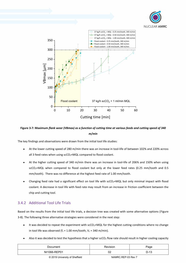
Document Revision Page
NI1066-REP01 02 D-13
© 2019 University of Sheffield NAMRC.REP-03 Rev 7
0 10 20 30 40 50 600
50
100
150
200
250
300
350V
Bm
ax [
μm
]
Cutting time [min]
37 kg/h scCO2 + MQL - 0.25 mm/tooth, 340 m/min
37 kg/h scCO2 + MQL - 0.50 mm/tooth, 340 m/min
37 kg/h scCO2 + MQL - 1.00 mm/tooth, 340 m/min
Flood coolant - 0.25 mm/tooth, 340 m/min
Flood coolant - 0.50 mm/tooth, 340 m/min
Flood coolant - 1.00 mm/tooth, 340 m/min
37 kg/h scCO2 + 1 ml/min MQLFlood coolant
Figure 3-7: Maximum flank wear (VBmax) as a function of cutting time at various feeds and cutting speed of 340
m/min
The key findings and observations were drawn from the initial tool life studies:
At the lower cutting speed of 280 m/min there was an increase in tool-life of between 102% and 220% across
all 3 feed rates when using scCO2+MQL compared to flood coolant.
At the higher cutting speed of 340 m/min there was an increase in tool-life of 206% and 150% when using
scCO2+MQL when compared to flood coolant but only at the lower feed rates (0.25 mm/tooth and 0.5
mm/tooth). There was no difference at the highest feed rate of 1.00 mm/tooth.
Changing feed rate had a significant effect on tool life with scCO2+MQL but only minimal impact with flood
coolant. A decrease in tool life with feed rate may result from an increase in friction coefficient between the
chip and cutting tool.
3.4.2 Additional Tool Life Trials
Based on the results from the initial tool life trials, a decision tree was created with some alternative options (Figure
3-8). The following three alternative strategies were considered in the next step:
It was decided to repeat the experiment with scCO2+MQL for the highest cutting conditions where no change
in tool life was observed (fz = 1.00 mm/tooth, Vc = 340 m/min).
Also it was decided to test the hypothesis that a higher scCO2 flow rate should result in higher cooling capacity
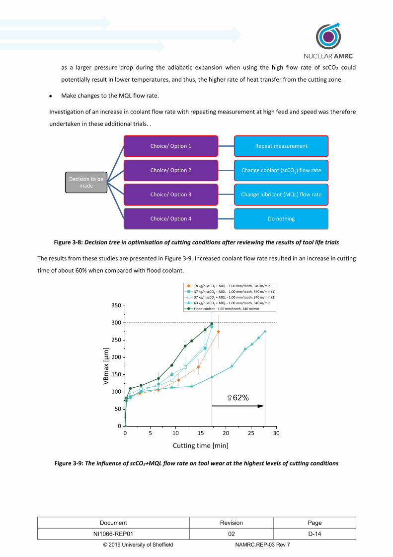
Document Revision Page
NI1066-REP01 02 D-14
© 2019 University of Sheffield NAMRC.REP-03 Rev 7
as a larger pressure drop during the adiabatic expansion when using the high flow rate of scCO2 could
potentially result in lower temperatures, and thus, the higher rate of heat transfer from the cutting zone.
Make changes to the MQL flow rate.
Investigation of an increase in coolant flow rate with repeating measurement at high feed and speed was therefore
undertaken in these additional trials. .
Figure 3-8: Decision tree in optimisation of cutting conditions after reviewing the results of tool life trials
The results from these studies are presented in Figure 3-9. Increased coolant flow rate resulted in an increase in cutting
time of about 60% when compared with flood coolant.
0 5 10 15 20 25 300
50
100
150
200
250
300
350
VB
max
[μ
m]
Cutting time [min]
18 kg/h scCO2 + MQL - 1.00 mm/tooth, 340 m/min
37 kg/h scCO2 + MQL - 1.00 mm/tooth, 340 m/min (1)
37 kg/h scCO2 + MQL - 1.00 mm/tooth, 340 m/min (2)
63 kg/h scCO2 + MQL - 1.00 mm/tooth, 340 m/min
Flood coolant - 1.00 mm/tooth, 340 m/min
X62%
Figure 3-9: The influence of scCO2+MQL flow rate on tool wear at the highest levels of cutting conditions
Decision to be made
Choice/ Option 1 Repeat measurement
Choice/ Option 2 Change coolant (scCO2) flow rate
Choice/ Option 3 Change lubricant (MQL) flow rate
Choice/ Option 4 Do nothing
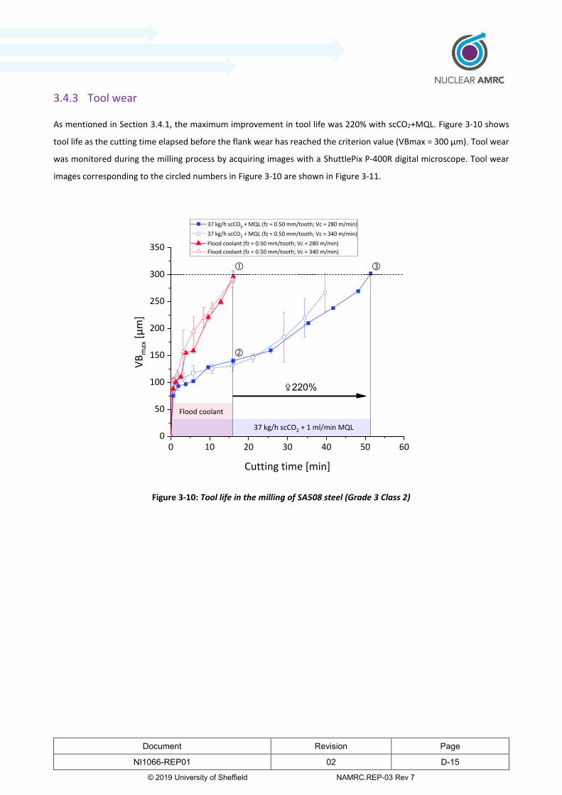
Document Revision Page
NI1066-REP01 02 D-15
© 2019 University of Sheffield NAMRC.REP-03 Rev 7
3.4.3 Tool wear
As mentioned in Section 3.4.1, the maximum improvement in tool life was 220% with scCO2+MQL. Figure 3-10 shows
tool life as the cutting time elapsed before the flank wear has reached the criterion value (VBmax = 300 μm). Tool wear
was monitored during the milling process by acquiring images with a ShuttlePix P-400R digital microscope. Tool wear
images corresponding to the circled numbers in Figure 3-10 are shown in Figure 3-11.
0 10 20 30 40 50 600
50
100
150
200
250
300
350
VB
max
[μ
m]
Cutting time [min]
37 kg/h scCO2 + MQL (fz = 0.50 mm/tooth; Vc = 280 m/min)
37 kg/h scCO2 + MQL (fz = 0.50 mm/tooth; Vc = 340 m/min)
Flood coolant (fz = 0.50 mm/tooth; Vc = 280 m/min)
Flood coolant (fz = 0.50 mm/tooth; Vc = 340 m/min)
Flood coolant
37 kg/h scCO2 + 1 ml/min MQL
X220%
Figure 3-10: Tool life in the milling of SA508 steel (Grade 3 Class 2)
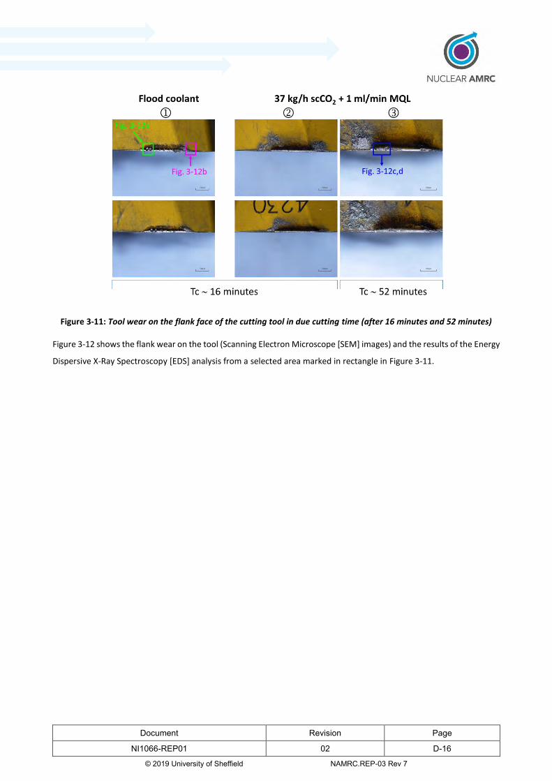
Document Revision Page
NI1066-REP01 02 D-16
© 2019 University of Sheffield NAMRC.REP-03 Rev 7
Figure 3-11: Tool wear on the flank face of the cutting tool in due cutting time (after 16 minutes and 52 minutes)
Figure 3-12 shows the flank wear on the tool (Scanning Electron Microscope [SEM] images) and the results of the Energy
Dispersive X-Ray Spectroscopy [EDS] analysis from a selected area marked in rectangle in Figure 3-11.
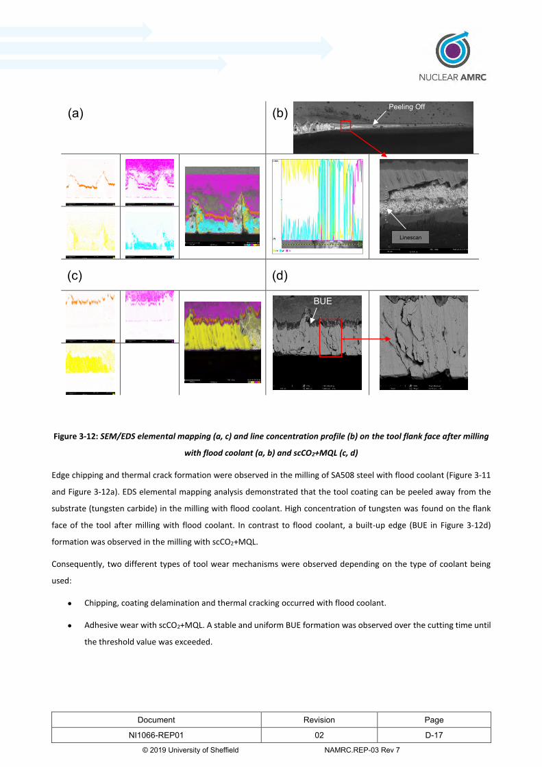
Document Revision Page
NI1066-REP01 02 D-17
© 2019 University of Sheffield NAMRC.REP-03 Rev 7
Figure 3-12: SEM/EDS elemental mapping (a, c) and line concentration profile (b) on the tool flank face after milling
with flood coolant (a, b) and scCO2+MQL (c, d)
Edge chipping and thermal crack formation were observed in the milling of SA508 steel with flood coolant (Figure 3-11
and Figure 3-12a). EDS elemental mapping analysis demonstrated that the tool coating can be peeled away from the
substrate (tungsten carbide) in the milling with flood coolant. High concentration of tungsten was found on the flank
face of the tool after milling with flood coolant. In contrast to flood coolant, a built-up edge (BUE in Figure 3-12d)
formation was observed in the milling with scCO2+MQL.
Consequently, two different types of tool wear mechanisms were observed depending on the type of coolant being
used:
Chipping, coating delamination and thermal cracking occurred with flood coolant.
Adhesive wear with scCO2+MQL. A stable and uniform BUE formation was observed over the cutting time until
the threshold value was exceeded.
(a) (b)
(c) (d)
Peeling Off
BUE
Linescan

Document Revision Page
NI1066-REP01 02 D-18
© 2019 University of Sheffield NAMRC.REP-03 Rev 7
3.5 Surface integrity
The influence of cutting conditions and cooling method on surface integrity in the milling of SA508 steel was investigated
by an experimental study of surface roughness, cutting forces and residual stresses. In addition, the microstructural
analysis in cross-section was carried out to determine the effect of milling on surface alterations and milling induced
phase changes. The DOE method was used to study the effect of cutting conditions on surface integrity in the milling of
SA508 steel. All the experiments were performed based on the full factorial design (Table 3-4).
3.5.1 Surface Roughness
The surface roughness was measured in the feed direction with a stylus-type surface roughness tester (Mutitoyo SJ
410). The arithmetic average of the roughness profile (Ra) was evaluated over a fixed length which was about 40 mm.
The Ra was calculated as the mean of three measurements with the distance between points of 3 mm. The measured
surface roughness values are presented on a grouped bar graph in Figure 3-13. As can be seen from the graph, the two
sets of data for each of the cutting conditions refer to the number of replicates that were run during the DOE phase.
The columns correspond to different cutting conditions. The results shown in the graph are from 16 runs (2x 8). In
addition, 3 centre points for a total 22 experiments were used (i.e. 6 runs at fz = 0.625 mm/tooth and Vc = 310 m/min
with scCO2+MQL). In Figure 3-13, comparison between flood coolant and scCO2+MQL at extreme cutting conditions was
made.
280 340 280 340
0.25 1 0.25 1 0.25 1 0.25 1
Flood scCO2+MQL
0.0
0.5
1.0
1.5
2.0
2.5
Ave
rage
ro
ugh
ne
ss [
μm
]
fz [mm/tooth]
Vc [m/min]
Ra =1.13 μm
Ra =0.96 μm
Ra =1.39 μm
Ra =1.16 μm
2+
Figure 3-13: Surface roughness (Ra values) for SA508 steel after milling with flood coolant and scCO2+MQL

Document Revision Page
NI1066-REP01 02 D-19
© 2019 University of Sheffield NAMRC.REP-03 Rev 7
Based on the results, it was measured in an experiment and observed that:
The feed rate had a higher influence on surface roughness than cutting speed. The lowest surface roughness
was observed at low feed and high cutting speed. The results obtained are consistent with data reported in the
literature (19).
Ra decreased with increased cutting speed for scCO2+MQL.
The results of surface roughness showed lack of model fit. This means that no theoretical model exists that
would allow to predict how cutting conditions and coolant type affect the surface roughness.
3.5.2 Cutting forces
The cutting forces were measured using a Kistler 9355C piezoelectric table dynamometer. Figure 3-14 shows the
regression coefficient plot in milling of SA508 with both flood coolant and scCO2+MQL. The R2 and Q2 values were
calculated for the Multiple Linear Regression (MLR) model at the confidence level of 95%. The size of the regression
coefficient indicates the significance of a particular factor in a model. This size corresponds to the change in response
when a factor varies from low to high level while the other factors are kept at their average values.
Figure 3-14: The scaled and centred coefficients of the fitted model for the feed force in milling SA508
In Figure 3-15, the 2D contour plot displays the predicted response values based on a specified regression model.
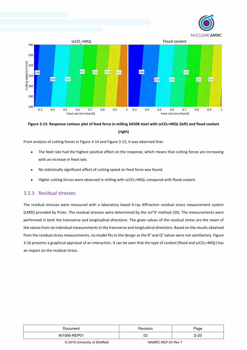
Document Revision Page
NI1066-REP01 02 D-20
© 2019 University of Sheffield NAMRC.REP-03 Rev 7
Figure 3-15: Response contour plot of feed force in milling SA508 steel with scCO2+MQL (left) and flood coolant
(right)
From analysis of cutting forces in Figure 3-14 and Figure 3-15, it was observed that:
The feed rate had the highest positive effect on the response, which means that cutting forces are increasing
with an increase in feed rate.
No statistically significant effect of cutting speed on feed force was found.
Higher cutting forces were observed in milling with scCO2+MQL compared with flood coolant.
3.5.3 Residual stresses
The residual stresses were measured with a laboratory based X-ray diffraction residual stress measurement system
(LXRD) provided by Proto. The residual stresses were determined by the sin2 method (20). The measurements were
performed in both the transverse and longitudinal directions. The given values of the residual stress are the mean of
the values from six individual measurements in the transverse and longitudinal directions. Based on the results obtained
from the residual stress measurements, no model fits to the design as the R2 and Q2 values were not satisfactory. Figure
3-16 presents a graphical appraisal of an interaction. It can be seen that the type of coolant (flood and scCO2+MQL) has
an impact on the residual stress.
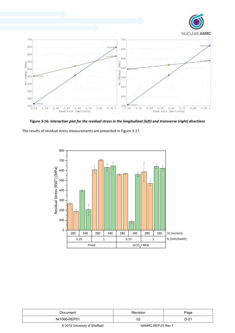
Document Revision Page
NI1066-REP01 02 D-21
© 2019 University of Sheffield NAMRC.REP-03 Rev 7
Figure 3-16: Interaction plot for the residual stress in the longitudinal (left) and transverse (right) directions
The results of residual stress measurements are presented in Figure 3-17.
0.25 1 0.25 1
280 340 280 340 280 340 280 340
Flood scCO2+MQL
0
100
200
300
400
500
600
700
800
Res
idu
al S
tres
s (R
S0°)
[M
Pa]
Vc [m/min]
fz [mm/tooth]
2+

Document Revision Page
NI1066-REP01 02 D-22
© 2019 University of Sheffield NAMRC.REP-03 Rev 7
0.25 1 0.25 1
280 340 280 340 280 340 280 340
Flood scCO2+MQL
0
100
200
300
400
500
600
700
800
Re
sid
ual
Str
ess
(R
S90°)
[M
Pa]
+2
Vc [m/min]
fz [mm/tooth]
Figure 3-17: Residual stress in the transverse (top) and longitudinal (bottom) directions after milling of SA508 steel
From the above graph, it was observed that:
Residual stress values were not significantly different at high cutting speed and feed rate in milling with flood
coolant and scCO2+MQL.
Significant differences were found on measurements of the residual stress at low feed rate. It was observed
that the residual stresses were higher in milling with scCO2+MQL at lower feed rate compared to flood coolant.
A large difference of run in the mean values of residual stress distribution in the transverse direction (fz = 0.25
mm/tooth, Vc = 340 m/min, scCO2+MQL) could be caused by noise factors.
3.6 Microstructure
Microstructural characterisation of the workpiece surface was performed for selected cutting conditions using the SEM
with backscattered electrons detector (SEM/BSE). The samples were selected based on the analysis of the data from
the tool life trials and the DOE. The effectiveness of a coolant depends on the magnitude of the temperature change
during the machining process. This can significantly affect the surface integrity. Therefore, the research was aimed at
selecting samples after machining at various cutting conditions where the cooling capability of a coolant could
potentially be different. This was important to determine if microstructural changes have occurred. The samples were
cut from the machined workpiece with the abrasive cutting machine. Small pieces were cut along the feed direction and
in the transverse direction. The yellow marked area in Figure 3-18 indicates the position of the sample. The dark shaded
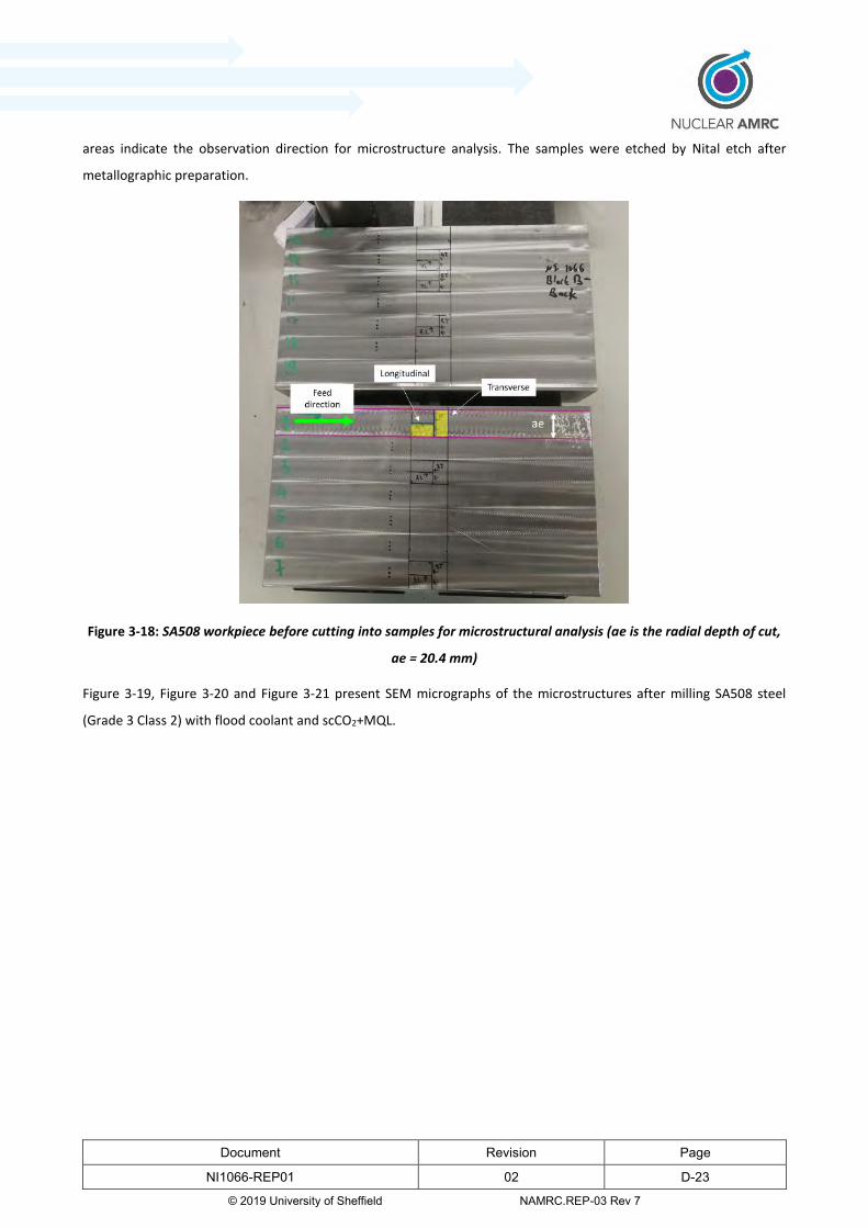
Document Revision Page
NI1066-REP01 02 D-23
© 2019 University of Sheffield NAMRC.REP-03 Rev 7
areas indicate the observation direction for microstructure analysis. The samples were etched by Nital etch after
metallographic preparation.
Figure 3-18: SA508 workpiece before cutting into samples for microstructural analysis (ae is the radial depth of cut,
ae = 20.4 mm)
Figure 3-19, Figure 3-20 and Figure 3-21 present SEM micrographs of the microstructures after milling SA508 steel
(Grade 3 Class 2) with flood coolant and scCO2+MQL.

Document Revision Page
NI1066-REP01 02 D-24
© 2019 University of Sheffield NAMRC.REP-03 Rev 7
Figure 3-19: SEM micrographs (x2000) of the microstructures along the feed direction (longitudinal)
Figure 3-20: SEM micrographs (x2000) of the microstructures in the transverse direction

Document Revision Page
NI1066-REP01 02 D-25
© 2019 University of Sheffield NAMRC.REP-03 Rev 7
Key points to note are:
SA508 Grade 3 Class 2 with a predominantly lath tempered bainite microstructure was used. The lath structures
were observed within the retained austenite (Figure 3-21).
Comparing the two types of coolants (flood and scCO2+MQL), no significant difference in microstructure could
be observed after milling at the same feeds and speeds (Figure 3-19).
Decreased volume fraction of the retained austenite was observed with increased cutting speed (Figure 3-19a,d
and Figure 3-19b,e).
The latter point suggests that the retained austenite can decompose at higher temperature to bainite. Talebi et al (21)
demonstrated that the decomposition of the retained austenite starts at 350C, which is the lowest temperature for
decomposition of retained austenite. However, the retained austenite was not fully decomposed at this temperature.
The full decomposition of the retained austenite occurs at much higher temperatures of about 600C and results in the
formation of martensite in the microstructure during cooling. It is known that the retained austenite is a metastable
phase at room temperature (22). It can be decomposed into martensite or a mixture of carbide and ferrite depending
on the stress and temperature, which can enhance the development of compressive stress in a workpiece.
No significant changes were observed in the transverse direction regarding the microstructure and phase
composition (Figure 3-20).
More surface alterations were observed in the transverse direction compared to longitudinal direction
regardless of the type of coolant used (Figure 3-20 and Figure 3-21).
Regarding the latter point, this could cause crack formation near the surface of the workpiece after milling with
scCO2+MQL (Figure 3-19f). However, there was no clear evidence that scCO2+MQL has an adverse effect on
microstructure or mechanical properties. In addition, the crack formation was observed at low cutting speed and high
feed rate. However, the effect of feed rate on the temperature rise is minimal compared to cutting speed (23).

Document Revision Page
NI1066-REP01 02 D-26
© 2019 University of Sheffield NAMRC.REP-03 Rev 7
Figure 3-21: SEM micrographs (x5000) of the microstructures in the transverse direction
4 End MRL/TRL level
A peer review assessment of the TRL and MRL attained by innovations in each InFORM work package was carried out
by industrial academics and consultants on 23rd May 2019. It was determined that innovations in the machining work
package. Specifically regarding the use of supercritical CO2 in machining operations, has increased to MRL 4 and TRL 4.

Document Revision Page
NI1066-REP01 02 D-27
© 2019 University of Sheffield NAMRC.REP-03 Rev 7
The justification for these values is shown in Appendix 1.
4.1 Potential industrial impact
Machining with scCO2 has a significant industrial impact. The current machining methods use soluble oils for lubricating
and removing heat from the cutting zone. Conventional coolants are typically limited by the heat removal capability,
which makes them not suitable for high speed machining or in machining of difficult-to-cut materials. Also machining
with conventional soluble oils generates waste products including oil-covered swarf, oil mist and increases energy
consumption. This often requires manufacturing optimisation with swarf management, coolant recycling, filtration, and
purification of oil mist (24). Machining with supercritical CO2 can bring benefits of to assist in the move towards a
cleaner, more environmentally sustainable manufacturing process.
With its demonstrated benefits of a significant improvement in material removal rates and its environmental credentials
the potential industrial impact is significant.
5 Recommendation for further research and development
5.1 Future work
The ongoing study on the machining optimisation with scCO2 has a crucial role, the development of a new cooling
method to increase productivity in manufacturing components and for sustainable development targets. In the near
future, it is expected that cryogenic coolants, which are increasingly becoming important to minimise the machining
time, increase tool life and obtain better surface finish, can be used as an alternative to conventional soluble oils. Future
research should focus on the optimisation of cutting conditions to increase metal removal rate.
From this work, it is known that machining with the assistance of scCO2+MQL results in increased tool life compared to
flood coolant without any significant unfavourable impact on surface integrity. However, more research is needed to
optimise cutting conditions towards increasing material removal rate.
Summarised below are some examples regarding future directions for research to be done in this field.
Develop a research database that links tool life, material removal rate and surface integrity for effective
machining process planning.
MQL/scCO2 flow rate optimisation using the Design of Experiments methodology for increased metal removal
rate.
Evaluate thermal stability of retained austenite in SA508 steel in machining with scCO2+MQL. Considering the
potential microstructural changes due to cyclic heating and fast cooling.
Determine the ductile to brittle transition temperature (DBTT) in SA508 steel after machining with scCO2+MQL
Document Revision Page
NI1066-REP01 02 D-28
© 2019 University of Sheffield NAMRC.REP-03 Rev 7
for assessing surface integrity of machined workpiece.
Repeat machining process for optimised cutting conditions with scCO2+MQL and compare to dry machining of
as-forged SA508 steel.
In addition to the process parameter research to optimise the cutting conditions, a full social, economic and
environmental study is required to fully assess the impact of changing coolant strategies in the industry. The output of
which should focus on the following areas:
Improved cleanliness of components and the reduction of cleaning costs.
Health benefits for the work force and there social and economic impact.
Carbon footprint comparison. This should look at the full lifecycle costs of conventional coolant and scCO2, from
the manufacture of the product, management and maintenance, usage (pumping) and end of life disposal.
By fully understand the social, economic and environmental impact will inform industry of the benefits of changing to a
new coolant method and the added value to the industry. The Nuclear AMRC has commenced this work as part of our
internal research programme called Environmental Sustainable Manufacturing (ESM).
5.2 Route to industrial adoption
Machining with the assist of scCO2 can be an alternative solution to conventional soluble oil coolants. The results from
this Work Package demonstrated the positive impact of scCO2+MQL in machining of SA508 (Grade 3 Class 2) forging for
the pressure vessels.
The use of scCO2 might potentially bring some manufacturing cost savings if the components do not require additional
cleaning to achieve the required level of cleanliness after manufacturing processes (25). Machining with scCO2 could
potentially be a cost-effective cleaning solution.
At present, the retrofit of scCO2 system requires the machine tool and CO2 unit manufacturers to work together to
ensure that the machine tool components are suitable for CO2. Once all the components are upgraded then this is a
rather straightforward modification (depending on the complexity of machine tool).
A rotary CO2 side-feed adapter can accelerate the adoption of supercritical CO2 as a coolant during machining processes.
This is an excellent solution for older machine tools, which do not have through coolant option but would like to use
the advantage of this advanced cooling method.
The clear benefit of extended tool life (up to 220% in comparison to flood coolant) can be potentially traded off for
higher productivity. This project will be continued and focused on optimising cutting conditions to maximise material
removal rates. Also, optimisation of cooling/lubrication strategy will be an important part of the project.

Document Revision Page
NI1066-REP01 02 D-29
© 2019 University of Sheffield NAMRC.REP-03 Rev 7
References
1. Processors, Carbide. [Online] [Cited: 24 June 2019.]
http://www.carbideprocessors.com/pages/machine-coolant/types-of-machine-coolant.html.
2. Environmental friendly cutting fluids and cooling techniques in machining: a review. S. Debnath, M.M. Reddy, Q.S. Yi. s.l. : Journal of Cleaner Production, 2014, Vol. 83. 33-47.
3. Rozzi, Jay C. Low-Cost Machining Without Cutting Fluids. 2002.
4. Cryogenic manufacturing processes. I.S. Jawahir, H. Attia, D. Biermann, J. Duflou, F. Klocke, D. Meyer. 2016, CIRP Annals - Manufacturing Technology, Vol. 65, pp. 713-736.
5. Investigation of cooling and lubrication strategies for machining high-temperature alloys. K. Busch, C. Hochmuth, B. Pause, A. Stoll, R. Wertheim. s.l. : Procedia CIRP, 2016, Vol. 41.
835-840.
6. Cryogenic and minimum quantity lubrication for an eco-efficiency turning of AISI 304. O. Pereira, A. Rodriguez, A.I. Fernandez-Abia, J. Barreiro, L.N. Lopez de Lacalle. s.l. :
Journal of Cleaner Production, 2016, Vol. 139. 440-449.
7. Next generation high performance cutting by use of carbon dioxide as cryogenics. S. Cordes, F. Hübner, T. Schaarschmidt. s.l. : Procedia CIRP, 2014, Vol. 14. 401-405.
8. Effect of cryogenic cooling in milling process of AISI 304 stainless steel. M. Nalbant, Y. Yildiz. s.l. : Trans. Nonferrous Met. Soc. China, 2011, Vol. 21. 72-79.
9. Performance of supercritical carbon dioxide sprays as coolants and lubricants in
representative metalworking operations. S.D. Supekar, A.F. Clarens, D.A. Stephenson, S.J. Skerlos. s.l. : Journal of Materials Processing Technology, 2012, Vol. 212. 2652-2658.
10. A review identifying the effectiveness of minimum quantity lubrication (MQL) during
conventional machining. B. Boswell, M.N. Islam, Ian J. Davies, Y. R. Ginting, Ai Keem Ong. s.l. : International Journal of Advanced Manufacturing Technology, 2017, Vol. 92. 321-340.
11. Improving tool life using cryogenic cooling. A.A. Khan, M.I. Ahmed. s.l. : Journal of
Materials Processing Technology, 2008, Vol. 196. 149-154.
12. The influence of cryogenic supercritical carbon dioxide cooling on tool wear during
machining high thermal conductivity steel. T. Mulyana, E.A. Rahim, S.N. Md Yahaya. s.l. :
Journal of Cleaner Production, 2017, Vol. 164. 950-962.
13. IIDEA. Certificate Of Conformity ZU1 / 4500833601.

Document Revision Page
NI1066-REP01 02 D-30
© 2019 University of Sheffield NAMRC.REP-03 Rev 7
14. Separations, Applied. [Online] [Cited: 23 June 2019.]
http://supercriticalfluids.blogspot.com/2015/.
15. [Online] Sandvik Coromant. [Cited: 10 July 2019.] https://www.sandvik.coromant.com/en-gb/products/Pages/productdetails.aspx?c=419R-1405E-MM%20%20%20%20%20%20%204330.
16. 8688-1:1989, ISO. Tool life testing in milling Part 1 – face milling. Geneva : International Organisation for Standarisation, 1989.
17. AMRC, Nuclear. Route Card NI1066-RC03. 2018.
18. —. Route Card NI1066-RC04. 2019.
19. Effect of machining parameters on cutting forces and surface roughness in Al-(1-2) Fe-1V-1Si alloys. B.N. Pathak, K.L. Sahoo, M. Mishra. 2013, Materials and Manufacturing Processes, Vol. 28, pp. 463–469.
20. Impact of supercritical carbon dioxide cooling with Minimum Quantity Lubrication on tool wear and surface integrity in the milling of AISI 304L stainless steel. K.K. Wika, P. Litwa, C. Hitchens. 2019, Wear, Vols. 426-427, pp. 1691–1701.
21. Retained austenite decomposition and carbide precipitation during isothermal tempering of a medium-carbon low-alloy bainitic steel. S.H. Talebi, M. Jahazi, H. Melkonyan. 1441, 2018, Materials, Vol. 11, pp. 1-12.
22. Thermal stability of retained austenite in high-carbon steels during cryogenic and tempering treatments. X. Qiao, L. Han, W. Zhang, J. Gu. 1, 2016, ISIJ International, Vol. 56, pp. 140-147.
23. Thermocouple and infrared sensor-based measurement of temperature distribution in metal cutting. A. Kus, Y. Isik, M.C. Cakir, S. Coşkun, K. Özdemir. 1, 2015, Sensors, Vol. 15, pp. 1274–1291.
24. Technical, economic and environmental review of the lubrication/cooling systems used in machining processes. E. Benedicto, D. Carou, E.M. Rubio. s.l. : Procedia Engineering, 2017, Vol. 184. 99-116.
25. Schulz, D. Component cleanliness requires effort throughout manufacturing process. [Online] 1 February 2016. [Cited: 10 July 2019.] https://www.ctemag.com/news/articles/component-cleanliness-requires-effort-throughout-manufacturing-process.
Document Revision Page
NI1066-REP01 02 D-31
© 2019 University of Sheffield NAMRC.REP-03 Rev 7
26. Bronwyn H. Hall, Beethika Khan. Adoption of new technology. NBER Working Paper No. 9730. s.l. : Academic Press, 2003.
27. Health risks from exposure to metal-working fluids in machining and grinding operations. K. Li, F. Aghazadeh, S. Hatipkarasulu, T.G. Ray. 1, 2003, International Journal of Occupational Safety and Ergonomics, Vol. 9, pp. 75-95.
28. A review of cryogenic cooling in machining processes. Y. Yildiz, M. Nalbant. 2008, International Journal of Machine Tools & Manufacture, Vol. 48, pp. 947–964.
29. Processors, Carbide. [Online] [Cited: 24 June 2019.] http://www.carbideprocessors.com/pages/machine-coolant/why-coolant-becomes-unusable.html.
30. CO2 Corrosion. [Online] TWI. [Cited: 8 July 2019.] https://www.twi-global.com/what-we-do/research-and-technology/technologies/materials-and-corrosion-management/corrosion-testing/co2-corrosion.
31. E.M. Russick, G.A. Poulter, C.L.J. Adkins, N.R. Sorensen. Corrosive effects of supercritical carbon dioxide and cosolvents on metals. s.l. : Sandia National Laboratories. DE-AC04-94AL85000.
32. Design and construction rules for mechanical components of PWR nuclear islands. s.l. : Afcen, 2012.

Document Revision Page
NI1066-REP-01 03 E-1
© 2019 University of Sheffield NAMRC.REP Version 7.0
E. Intelligent Fixtures

© University of Sheffield 2019 E-1
MetLase InFORM Report Workpackage 2.3 Intelligent Fixturing
(MetLase Project 1159)
ML-13-01A

© University of Sheffield 2019 E-2
Date of Issue: 16th July 2019 Document Reference: ML-13-01A
Document Owner
Name of person responsible for issue Stewart Lowth
Position Lead Engineer (R&D)
Contact [email protected]
Technical Content Owner
Name of person responsible for contents Cameron Nichols
Position Design Engineer
Contact [email protected]
Issue Summary Date
01A Initial issue 16th July 2019
02A Update based on feedback from consortium lead 19th Aug 2019

© University of Sheffield 2019 E-3
Table of Contents
Workpackage 2.3 Intelligent Fixturing ................................................................................................. 1
Table of Contents ......................................................................................................................... 3
1. Technical Challenges and First Principles ............................................................................ 4
2. Starting TRL .......................................................................................................................... 4
3. Overview of the Technical Challenge for Industry ............................................................... 5
4. Work conducted and the development path ...................................................................... 6
5. Present the concept as a desktop demonstrator .............................................................. 14
6. End TRL .............................................................................................................................. 16
7. Potential Industrial Impact ................................................................................................ 16
8. Future Work ....................................................................................................................... 17
9. Route to industrial adoption.............................................................................................. 17
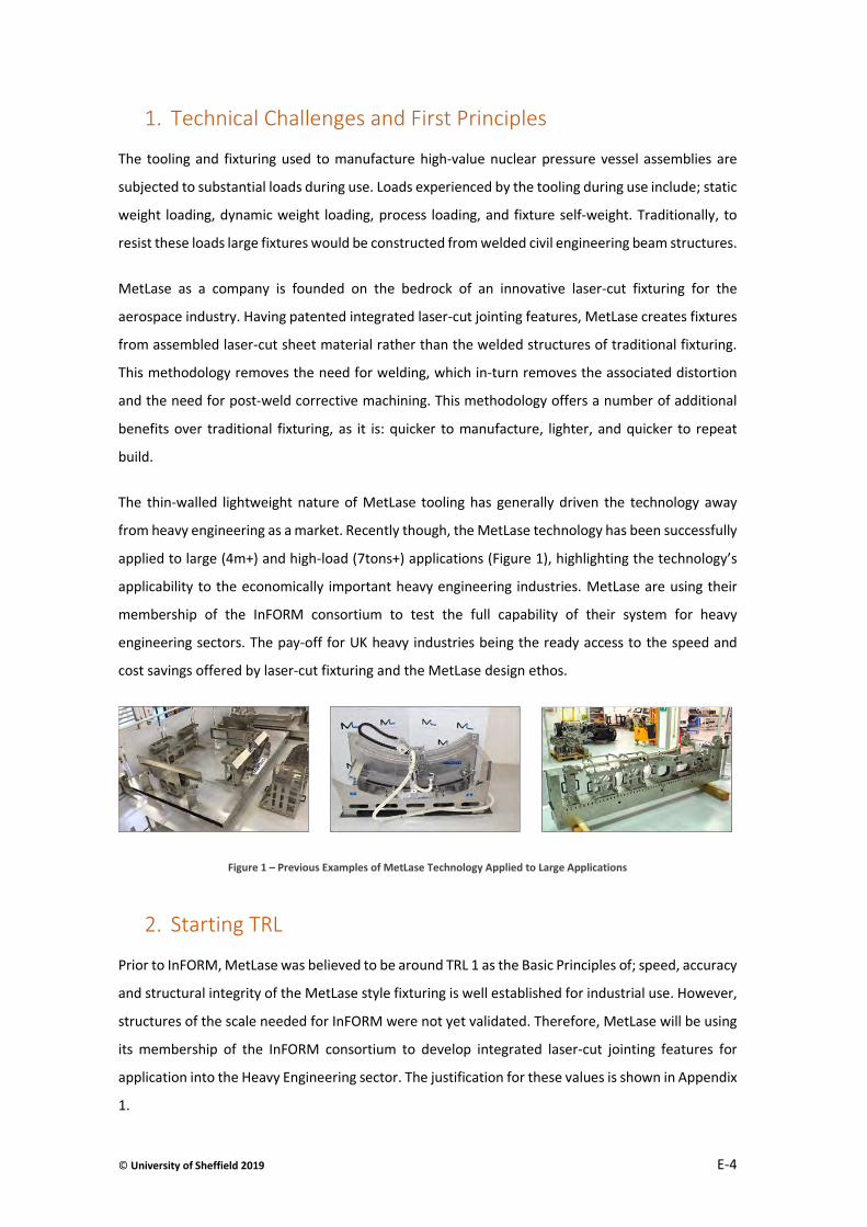
© University of Sheffield 2019 E-4
1. Technical Challenges and First Principles
The tooling and fixturing used to manufacture high-value nuclear pressure vessel assemblies are
subjected to substantial loads during use. Loads experienced by the tooling during use include; static
weight loading, dynamic weight loading, process loading, and fixture self-weight. Traditionally, to
resist these loads large fixtures would be constructed from welded civil engineering beam structures.
MetLase as a company is founded on the bedrock of an innovative laser-cut fixturing for the
aerospace industry. Having patented integrated laser-cut jointing features, MetLase creates fixtures
from assembled laser-cut sheet material rather than the welded structures of traditional fixturing.
This methodology removes the need for welding, which in-turn removes the associated distortion
and the need for post-weld corrective machining. This methodology offers a number of additional
benefits over traditional fixturing, as it is: quicker to manufacture, lighter, and quicker to repeat
build.
The thin-walled lightweight nature of MetLase tooling has generally driven the technology away
from heavy engineering as a market. Recently though, the MetLase technology has been successfully
applied to large (4m+) and high-load (7tons+) applications (Figure 1), highlighting the technology’s
applicability to the economically important heavy engineering industries. MetLase are using their
membership of the InFORM consortium to test the full capability of their system for heavy
engineering sectors. The pay-off for UK heavy industries being the ready access to the speed and
cost savings offered by laser-cut fixturing and the MetLase design ethos.
Figure 1 – Previous Examples of MetLase Technology Applied to Large Applications
2. Starting TRL
Prior to InFORM, MetLase was believed to be around TRL 1 as the Basic Principles of; speed, accuracy
and structural integrity of the MetLase style fixturing is well established for industrial use. However,
structures of the scale needed for InFORM were not yet validated. Therefore, MetLase will be using
its membership of the InFORM consortium to develop integrated laser-cut jointing features for
application into the Heavy Engineering sector. The justification for these values is shown in Appendix
1.

© University of Sheffield 2019 E-5
3. Overview of the Technical Challenge for Industry
To begin the initial verification of MetLase technologies to heavy engineering applications, there are
a number of technical challenges that will need to be addressed as part of the InFORM project
namely:
Aim 1: Generate location and alignment methods optimised for large cylindrical
components
Aim 2: Create an approach for presenting the components to the local vacuum electron
beam welding (EBW) process and interface with control systems; producing a
synchronised manipulation of the component part for local vacuum EBW
Aim 3: Develop MetLase methodology for large high-load structures
Aim 4: Present the concept as a desktop demonstrator

© University of Sheffield 2019 E-6
4. Work conducted and the development path
Aim 1 - 2 A concept generation workshop was held on 15th Aug 2018, hosted by the AMRC design and
prototyping group to:
Generate location and alignment methods optimised for large cylindrical components.
Create an approach for presenting the components to the welding process and interface
with control systems; producing a synchronised manipulation of the component part for
welding.
From the workshop the two leading ideas emerged:
The build-upwards method
The Silo-build concept
“The build-upwards method” which proposed the use of scaffold that moves upwards as the
assembly is constructed.
“The Silo-build concept” which uses a lift and trolley that is lowered into a silo (Figure 2, Figure 3).
Of the two concepts, the silo method was chosen for reasons including; better shielding for radiation,
and potential for in situ heat treatment which is outside of MetLase experience, and the higher level
of tolerance control that can be achieved through this method.
It was proposed that building the vessel in the vertical orientation optimises the process forces
involved. The location mandrel acts like a machine chuck, lifting and lowering the component into
place, while ensuring the location and alignment for the large cylindrical components. The seam line
for the two components are then presented to the local vacuum EBW via the lift and turntable
mechanisms of the fixture.

© University of Sheffield 2019 E-7
Figure 2 – The InFORM Vertical Silo-Build Concept - Diagram
The basis of the concept is to vertically build the pressure vessel from ring segments within a silo
(pit) (Figure 3). Briefly, the build process has been defined as follows:
1. A trolley loaded with a hemispherical end-cap rolls over a trapdoor that covers a vertical
pit.
2. The trolley engages with a series of vertical linear rails
3. The trapdoor opens and the trolley (with component) slide-downs the rails into the pit
4. The trolley lowers until the top face of the cap is in-line with the top of the pit.
5. The next section of the pressure vessel slides on top of the hemisphere
6. A fixed mandrel lowers down from the above the pit, while hydraulic rams activate from
the sides of the pit aligning the two parts of the assembly
7. The assembly and mandrel lower into the pit until the joint between the two parts are
aligned with the local vacuum EBW gun that is embedded in the side of the pit.
8. The mandrel contains a beam-stopper and acts as vacuum cap for the top of the assembly
9. The vessel is pumped-down to create a vacuum
10. The assembly is welded, while being rotated using a turntable built into the trolley.
11. The vacuum is vented and the mandrel withdrawn
12. The assembly is raised so the top edge of the assembly is flush with the top of the pit
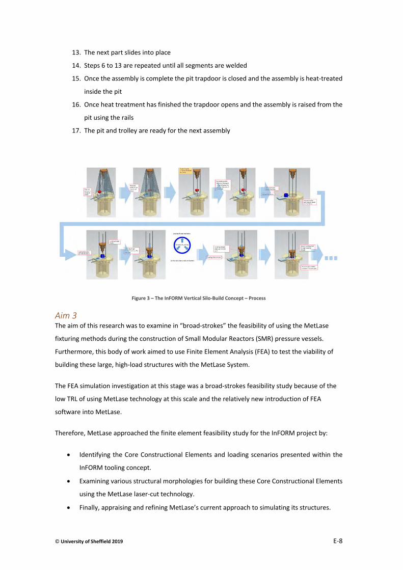
© University of Sheffield 2019 E-8
13. The next part slides into place
14. Steps 6 to 13 are repeated until all segments are welded
15. Once the assembly is complete the pit trapdoor is closed and the assembly is heat-treated
inside the pit
16. Once heat treatment has finished the trapdoor opens and the assembly is raised from the
pit using the rails
17. The pit and trolley are ready for the next assembly
Figure 3 – The InFORM Vertical Silo-Build Concept – Process
Aim 3 The aim of this research was to examine in “broad-strokes” the feasibility of using the MetLase
fixturing methods during the construction of Small Modular Reactors (SMR) pressure vessels.
Furthermore, this body of work aimed to use Finite Element Analysis (FEA) to test the viability of
building these large, high-load structures with the MetLase System.
The FEA simulation investigation at this stage was a broad-strokes feasibility study because of the
low TRL of using MetLase technology at this scale and the relatively new introduction of FEA
software into MetLase.
Therefore, MetLase approached the finite element feasibility study for the InFORM project by:
Identifying the Core Constructional Elements and loading scenarios presented within the
InFORM tooling concept.
Examining various structural morphologies for building these Core Constructional Elements
using the MetLase laser-cut technology.
Finally, appraising and refining MetLase’s current approach to simulating its structures.
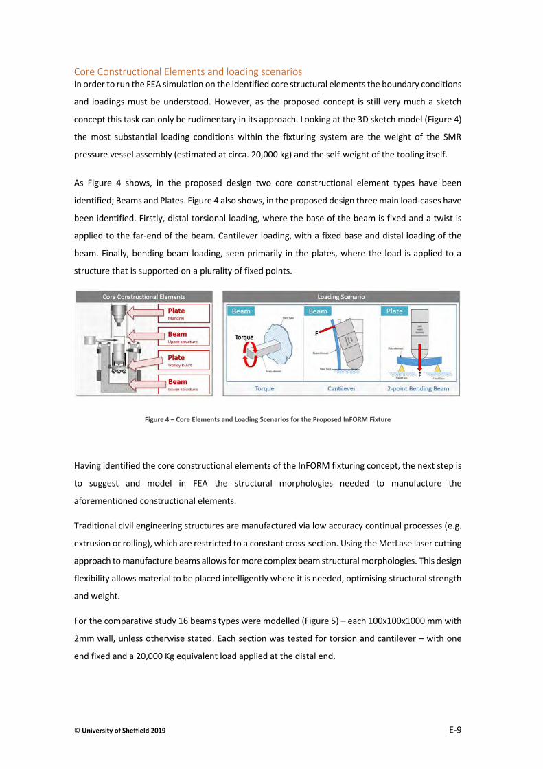
© University of Sheffield 2019 E-9
Core Constructional Elements and loading scenarios In order to run the FEA simulation on the identified core structural elements the boundary conditions
and loadings must be understood. However, as the proposed concept is still very much a sketch
concept this task can only be rudimentary in its approach. Looking at the 3D sketch model (Figure 4)
the most substantial loading conditions within the fixturing system are the weight of the SMR
pressure vessel assembly (estimated at circa. 20,000 kg) and the self-weight of the tooling itself.
As Figure 4 shows, in the proposed design two core constructional element types have been
identified; Beams and Plates. Figure 4 also shows, in the proposed design three main load-cases have
been identified. Firstly, distal torsional loading, where the base of the beam is fixed and a twist is
applied to the far-end of the beam. Cantilever loading, with a fixed base and distal loading of the
beam. Finally, bending beam loading, seen primarily in the plates, where the load is applied to a
structure that is supported on a plurality of fixed points.
Figure 4 – Core Elements and Loading Scenarios for the Proposed InFORM Fixture
Having identified the core constructional elements of the InFORM fixturing concept, the next step is
to suggest and model in FEA the structural morphologies needed to manufacture the
aforementioned constructional elements.
Traditional civil engineering structures are manufactured via low accuracy continual processes (e.g.
extrusion or rolling), which are restricted to a constant cross-section. Using the MetLase laser cutting
approach to manufacture beams allows for more complex beam structural morphologies. This design
flexibility allows material to be placed intelligently where it is needed, optimising structural strength
and weight.
For the comparative study 16 beams types were modelled (Figure 5) – each 100x100x1000 mm with
2mm wall, unless otherwise stated. Each section was tested for torsion and cantilever – with one
end fixed and a 20,000 Kg equivalent load applied at the distal end.
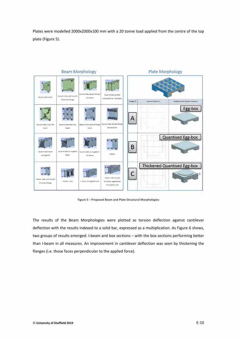
© University of Sheffield 2019 E-10
Plates were modelled 2000x2000x100 mm with a 20 tonne load applied from the centre of the top
plate (Figure 5).
Figure 5 – Proposed Beam and Plate Structural Morphologies
The results of the Beam Morphologies were plotted as torsion deflection against cantilever
deflection with the results indexed to a solid bar, expressed as a multiplication. As Figure 6 shows,
two groups of results emerged: I-beam and box sections – with the box sections performing better
than I-beam in all measures. An improvement in cantilever deflection was seen by thickening the
flanges (i.e. those faces perpendicular to the applied force).
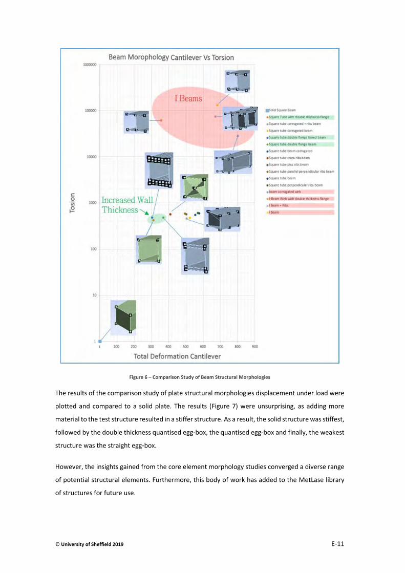
© University of Sheffield 2019 E-11
Figure 6 – Comparison Study of Beam Structural Morphologies
The results of the comparison study of plate structural morphologies displacement under load were
plotted and compared to a solid plate. The results (Figure 7) were unsurprising, as adding more
material to the test structure resulted in a stiffer structure. As a result, the solid structure was stiffest,
followed by the double thickness quantised egg-box, the quantised egg-box and finally, the weakest
structure was the straight egg-box.
However, the insights gained from the core element morphology studies converged a diverse range
of potential structural elements. Furthermore, this body of work has added to the MetLase library
of structures for future use.
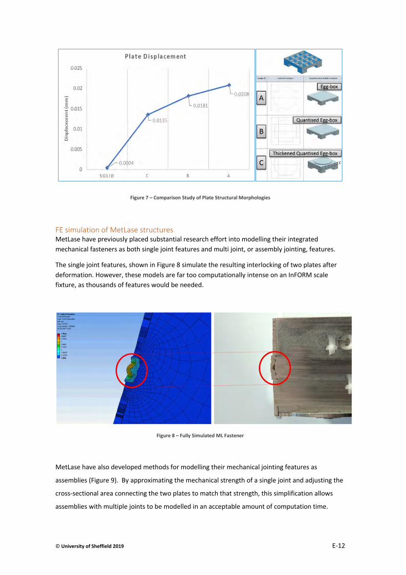
© University of Sheffield 2019 E-12
Figure 7 – Comparison Study of Plate Structural Morphologies
FE simulation of MetLase structures MetLase have previously placed substantial research effort into modelling their integrated
mechanical fasteners as both single joint features and multi joint, or assembly jointing, features.
The single joint features, shown in Figure 8 simulate the resulting interlocking of two plates after
deformation. However, these models are far too computationally intense on an InFORM scale
fixture, as thousands of features would be needed.
Figure 8 – Fully Simulated ML Fastener
MetLase have also developed methods for modelling their mechanical jointing features as
assemblies (Figure 9). By approximating the mechanical strength of a single joint and adjusting the
cross-sectional area connecting the two plates to match that strength, this simplification allows
assemblies with multiple joints to be modelled in an acceptable amount of computation time.
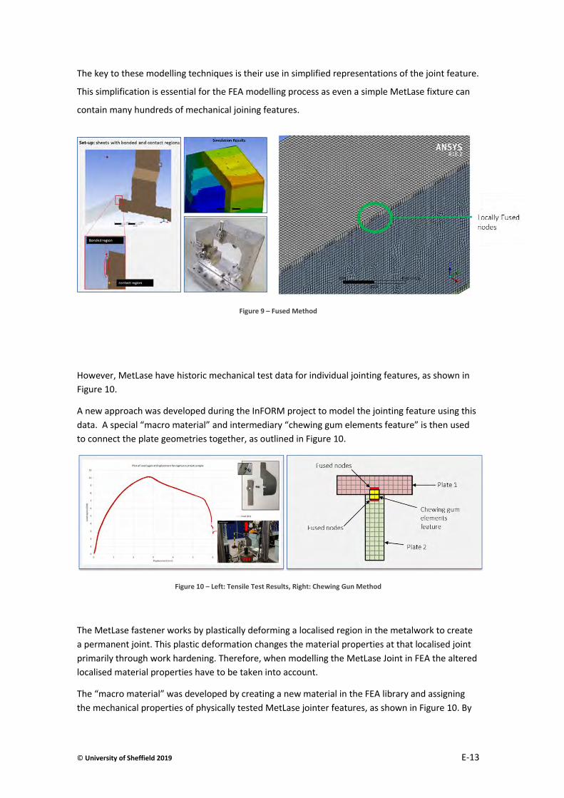
© University of Sheffield 2019 E-13
The key to these modelling techniques is their use in simplified representations of the joint feature.
This simplification is essential for the FEA modelling process as even a simple MetLase fixture can
contain many hundreds of mechanical joining features.
Figure 9 – Fused Method
However, MetLase have historic mechanical test data for individual jointing features, as shown in
Figure 10.
A new approach was developed during the InFORM project to model the jointing feature using this
data. A special “macro material” and intermediary “chewing gum elements feature” is then used
to connect the plate geometries together, as outlined in Figure 10.
Figure 10 – Left: Tensile Test Results, Right: Chewing Gun Method
The MetLase fastener works by plastically deforming a localised region in the metalwork to create
a permanent joint. This plastic deformation changes the material properties at that localised joint
primarily through work hardening. Therefore, when modelling the MetLase Joint in FEA the altered
localised material properties have to be taken into account.
The “macro material” was developed by creating a new material in the FEA library and assigning
the mechanical properties of physically tested MetLase jointer features, as shown in Figure 10. By
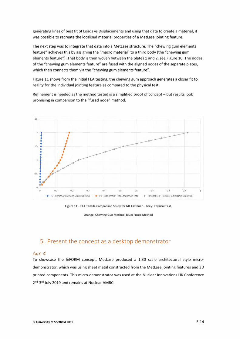
© University of Sheffield 2019 E-14
generating lines of best fit of Loads vs Displacements and using that data to create a material, it
was possible to recreate the localised material properties of a MetLase jointing feature.
The next step was to integrate that data into a MetLase structure. The “chewing gum elements
feature” achieves this by assigning the “macro material” to a third body (the “chewing gum
elements feature”). That body is then woven between the plates 1 and 2, see Figure 10. The nodes
of the “chewing gum elements feature” are fused with the aligned nodes of the separate plates,
which then connects them via the “chewing gum elements feature”.
Figure 11 shows from the initial FEA testing, the chewing gum approach generates a closer fit to
reality for the individual jointing feature as compared to the physical test.
Refinement is needed as the method tested is a simplified proof of concept – but results look
promising in comparison to the “fused node” method.
Figure 11 – FEA Tensile Comparison Study for ML Fastener – Grey: Physical Test,
Orange: Chewing Gun Method, Blue: Fused Method
5. Present the concept as a desktop demonstrator
Aim 4 To showcase the InFORM concept, MetLase produced a 1:30 scale architectural style micro-
demonstrator, which was using sheet metal constructed from the MetLase jointing features and 3D
printed components. This micro-demonstrator was used at the Nuclear Innovations UK Conference
2nd-3rd July 2019 and remains at Nuclear AMRC.

© University of Sheffield 2019 E-15
Figure 12: Desktop1:30 Scale Demonstrator Produced by MetLase
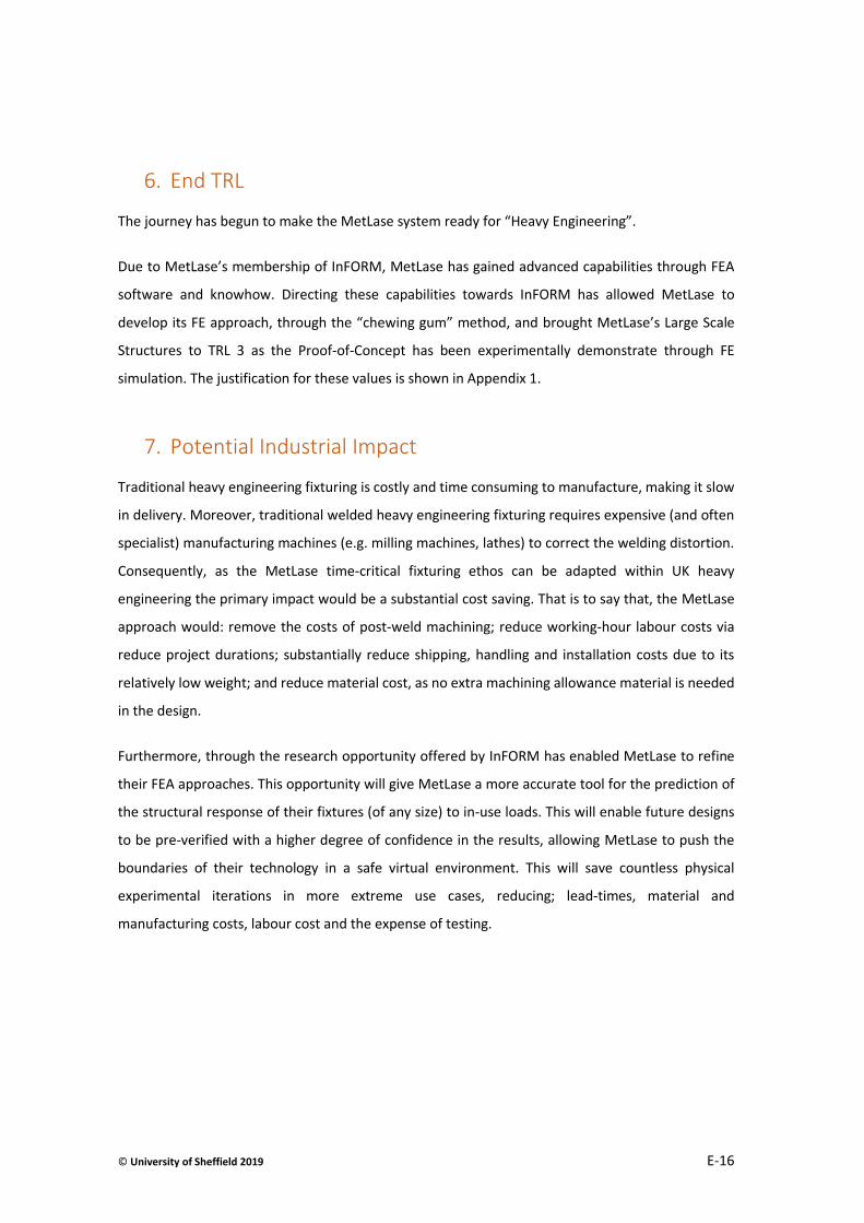
© University of Sheffield 2019 E-16
6. End TRL
The journey has begun to make the MetLase system ready for “Heavy Engineering”.
Due to MetLase’s membership of InFORM, MetLase has gained advanced capabilities through FEA
software and knowhow. Directing these capabilities towards InFORM has allowed MetLase to
develop its FE approach, through the “chewing gum” method, and brought MetLase’s Large Scale
Structures to TRL 3 as the Proof-of-Concept has been experimentally demonstrate through FE
simulation. The justification for these values is shown in Appendix 1.
7. Potential Industrial Impact
Traditional heavy engineering fixturing is costly and time consuming to manufacture, making it slow
in delivery. Moreover, traditional welded heavy engineering fixturing requires expensive (and often
specialist) manufacturing machines (e.g. milling machines, lathes) to correct the welding distortion.
Consequently, as the MetLase time-critical fixturing ethos can be adapted within UK heavy
engineering the primary impact would be a substantial cost saving. That is to say that, the MetLase
approach would: remove the costs of post-weld machining; reduce working-hour labour costs via
reduce project durations; substantially reduce shipping, handling and installation costs due to its
relatively low weight; and reduce material cost, as no extra machining allowance material is needed
in the design.
Furthermore, through the research opportunity offered by InFORM has enabled MetLase to refine
their FEA approaches. This opportunity will give MetLase a more accurate tool for the prediction of
the structural response of their fixtures (of any size) to in-use loads. This will enable future designs
to be pre-verified with a higher degree of confidence in the results, allowing MetLase to push the
boundaries of their technology in a safe virtual environment. This will save countless physical
experimental iterations in more extreme use cases, reducing; lead-times, material and
manufacturing costs, labour cost and the expense of testing.

© University of Sheffield 2019 E-17
8. Future Work
MetLase do not intend to let the research from InFORM languish and have a range of follow-on
programmes of work planned namely:
Further refinement of the FEA methods developed as part of InFORM: Although, the methods
developed are an improvement on the pre-existing FEA methodology used to simulate MetLase
fixturing, there is still room for refinement. Areas for further refinement would be: modelling other
jointing methods (the InFORM approach only examines one of the five MetLase integrated jointing
features), look at the jointing feature at different scales and in different materials; finally, look at the
modelling of dynamic loading with MetLase fixtures.
The physical testing of big structures to validate FEA developed approaches: In order to validate the
FEA modelling approaches developed as part of InFORM, a succession of physical validation tests are
needed.
Further refinement of the large structures identified: A number of structures have been identified as
part of the InFORM research. These structures have only been understood and modelled at a
rudimentary level. Further work would see more structures and in greater depth.
Create methodologies for joining core structural features: The InFORM research undertaken by
MetLase has concentrated on the core beam and plate structures of fixtures for high-load
applications. However, the research has not scrutinised non-welded joining approaches for the
beams and plates, so that fixtures can be created. This work would be conducted as part of any
future research activities.
9. Route to industrial adoption
The research would be adopted for industrial use through MetLase’s usual fixture consultancy
business. This consultancy spans a number of industries namely the: automotive, aerospace,
medical, military and construction sectors, where the MetLase technology is already applied.
The pay-off for UK heavy industries being the ready access to the speed and cost savings offered by
laser-cut fixturing and the MetLase design ethos.

Document Revision Page
NI1066-REP-01 03 F-1
© 2019 University of Sheffield NAMRC.REP Version 7.0
F. Local Vacuum Electron Beam Welding

Intelligent Fixtures for Optimised and
Radical Manufacture (InFORM) - Stage 2
Local Vacuum Electron Beam Welding
NI1066-REP-05
Project report
Document Revision Page
NI1066-REP05 01 F-3
© 2019 University of Sheffield NAMRC.REP-03 Rev 7
Nuclear AMRC
University of Sheffield
Advanced Manufacturing Park
Brunel Way
Rotherham
S60 5WG
United Kingdom
This report may only be reproduced in full, except with the express permission of the Nuclear AMRC.
The Nuclear AMRC has exercised due care in conducting this report but has not, apart from as specifically stated,
independently verified information provided by others. No other warranty, express or implied, is made in relation to
the contents of this report. Therefore, the Nuclear AMRC assumes no liability for any loss resulting from errors,
omissions, or misrepresentations made by others. Any recommendations, opinions or findings stated in this report are
based on circumstances and facts as they existed at the time the Nuclear AMRC performed the work. Any changes in
such circumstances and facts upon which this report is based may adversely affect any recommendations, opinions or
findings contained in this report. Where experiments have been carried out, these have been restricted to a level of
detail required to achieve the stated objectives of the statement of work. This work has been undertaken in accordance
with the Nuclear AMRC’s quality system.
Name Signature
Authors: Ricky Wong, TWI
Technical review: David Anson
Authorised: Carl Hitchens
Authorised distribution:
Document revision history
Revision Date of issue Reason for revision or original issue
01 9/9/19 Original issue
BEIS

Document Revision Page
NI1066-REP05 01 F-4
© 2019 University of Sheffield NAMRC.REP-03 Rev 7
Executive summary
The objectives of this work package were to:
Design and manufacture local vacuum electron beam (EB) equipment to meet the demands of the InFORM
demonstrator.
Demonstrate the local vacuum EB equipment as a viable vacuum vessel.
Demonstrate the local vacuum EB equipment as a viable vacuum vessel for EB welding.
Work Undertaken
A local vacuum EB welding end-effector was designed to meet the demands of a pressure vessel shell
demonstrator defined by Nuclear AMRC. The design took into account shortcomings of earlier local vacuum
systems deployed by TWI in terms of set-up challenges, quality assurance and versatility.
The design was reviewed with the InFORM consortium and a third-party vacuum engineering specialist
(SpecNow Ltd) before being manufactured and assembled.
Basic static and dynamic vacuum tests were undertaken at TWI North East to identify and correct any system
issues.
The local vacuum EB end effector was moved to CVE near Cambridge and commissioned on an EBFlow EB
welding machine.
Full penetration melt-runs (1m in length, plus slope-in/out length), were made in an 80mm wall thickness,
1800mm diameter C-Mn steel mock pressure vessel shell.
The key innovative features of the system were shown to be feasible, although in some cases optimisation is
required.
Novel attributes of the system were:
1. A welding station with:
Low cost interchangeable seal carrier to allow a change in vessel diameter to be welded.
Good down-beam optical viewing path to allow joint finding and weld process viewing.
Travelling cooled fronting bar, able to prevent loss of weld metal and form weld cap profile.
2. A quality assurance station with:
The ability to condition the welding gun over a cooled heat sink (or beam dump).
The ability to integrate a probe sub-system to quantify the beam power and profile.
3. The ability to translate the EB gun between the two stations while maintaining vacuum, in a short time:
The system is unique amongst travelling seals, in that it has a second sliding seal incorporated.
The motion to translate between stations was provided by the host welding machine.
4. A vacuum link to the backing vacuum (at the weld root-side) to assure a balanced vacuum level at cap and root:
Avoiding weld metal displacement by pressure differential, and resulting excess bead/underfill.

Document Revision Page
NI1066-REP05 01 F-5
© 2019 University of Sheffield NAMRC.REP-03 Rev 7
5. The local vacuum EB equipment was shown to be a viable vacuum vessel during static and dynamic vacuum
tests;
6. The local vacuum EB equipment was shown to be a viable vacuum vessel for EB melt run.
7. The novel attributes of the system were showed to function and are viable.
8. Electron beam melt runs were made in 80mm thick C-Mn steel.
9. The melt runs were shown to be of adequate integrity, noting that no development welding was undertaken.
Recommendations
It is recommended that further work is carried out to better understand and build confidence with the local vacuum EB
welding system. This will require further development on joint fit up and equipment for thick section welding.
The seals must be replaced after every use to avoid premature failure. The design of the seal carrier should be revisited
to allow easy replacement of the seals. Moreover, a more robust silicon compound could be considered to improve the
life span of the seal.
Issues such as residual magnetism and joint fit-up/alignment will need to be addressed before proceeding to weld a
joint.

Document Revision Page
NI1066-REP05 01 F-6
© 2019 University of Sheffield NAMRC.REP-03 Rev 7
Contents
1 Background ........................................................................................................................................................... 8
2 Objectives ............................................................................................................................................................. 8
3 Project Drivers and Challenges ............................................................................................................................. 8
3.1 Project drivers ........................................................................................................................................... 8
3.2 Challenges ................................................................................................................................................. 9
4 Design ................................................................................................................................................................. 10
4.1 First principles and design evolution ....................................................................................................... 10
4.2 Starting technology readiness level ........................................................................................................ 10
4.3 Design concept ........................................................................................................................................ 10
5 Manufacturing and Assembly ............................................................................................................................. 11
6 Commissioning of the End Effector .................................................................................................................... 11
6.1 Overview ................................................................................................................................................. 11
6.2 EBFlow system ......................................................................................................................................... 11
6.3 Integration ............................................................................................................................................... 12
6.4 Vacuum testing ........................................................................................................................................ 13
6.5 Weld testing ............................................................................................................................................ 16
6.6 Beam probing .......................................................................................................................................... 17
6.7 Testing of travelling drip catcher ............................................................................................................. 17
7 Results ................................................................................................................................................................ 18
7.1 Melt-run quality ...................................................................................................................................... 18
7.2 Vacuum during melt run ......................................................................................................................... 20
7.3 Welding station modifications and observations .................................................................................... 21
8 Lessons Learned ................................................................................................................................................. 27
9 Technology Readiness Level at End of Project ................................................................................................... 28
10 Route to Industrial Adoption .............................................................................................................................. 28
11 Discussions ......................................................................................................................................................... 29
12 Conclusions ......................................................................................................................................................... 29
13 Recommendations.............................................................................................................................................. 30
Appendix F-A - Introduction to local vacuum electron beam welding equipment design concepts ................................ 31

Document Revision Page
NI1066-REP05 01 F-7
© 2019 University of Sheffield NAMRC.REP-03 Rev 7
Appendix F-B - Supplementary Statement of Local Vacuum Welding Process and Equipment Factors which may affect
the Welding and/or other Processes/Tooling .................................................................................................... 35
Appendix F-C - Local Vacuum Welding Concept Design of End Effector/Backing Vacuum Sub-systems ......................... 37
Appendix F-D – Manufacture of Local Vacuum Head ....................................................................................................... 43
Appendix F-E – Schematic/Drawing of local vacuum head .............................................................................................. 48

Document Revision Page
NI1066-REP05 01 F-8
© 2019 University of Sheffield NAMRC.REP-03 Rev 7
1 Background
The Nuclear Advanced Manufacturing Research Centre (Nuclear AMRC) won Department for Business, Energy and
Industrial Strategy (BEIS) funding via the Innovate UK small business research initiative (SBRI) mechanism ‘Nuclear
Research and Development Programme – Competition for R&D on Advanced Manufacturing and Materials’. The
successful Nuclear AMRC proposal answered Theme 3 of the competition, ‘Large scale nuclear component
manufacturing and assembly’ and was entitled ‘Intelligent fixtures for optimised and radical manufacture’ with the
acronym ‘InFORM’.
TWI supported the development work on local vacuum electron beam (EB) welding in two work packages:
Local vacuum EB equipment development (InFORM WP2.4).
Welding feasibility trials (InFORM WP2.5).
This final report draws together the full scope of the work completed and presents new activities and results related to
commissioning of the end effector and welding trials at Cambridge Vacuum Engineering Limited (CVE) under TWI
direction. The report also includes comment on key topics, such as technology readiness.
2 Objectives
The objectives of the project were to:
Design and manufacture local vacuum EB equipment to meet the demands of the InFORM demonstrator.
Demonstrate the local vacuum EB equipment as a viable vacuum vessel.
Demonstrate the local vacuum EB equipment as a viable vacuum vessel for EB welding.
The objectives of the technical work specifically reported in this document were to:
Setup and test the end effector at CVE.
Demonstrate a fully penetrating melt-run of 1m, excluding slope-in/out, while testing the key features of the
end effector.
Document the results obtained, highlight outstanding challenges and any lessons learnt.
3 Project Drivers and Challenges
3.1 Project drivers
There is a large and growing market opportunity for high productivity, cost-effective welding of thick-section metallic
structures for nuclear fission power plant. Single pass EB welding provides an attractive alternative method to traditional
multi-pass arc welding.
For example, in a high integrity application, up to 120 days can be required to weld an 80mm thick, 2m diameter
pressure vessel, with narrow gap tungsten inert gas (TIG) welding. In addition to the use of welding consumables such
Document Revision Page
NI1066-REP05 01 F-9
© 2019 University of Sheffield NAMRC.REP-03 Rev 7
as wire and shielding gas, pre-heat, interpass temperature control, cleaning and interpass inspection (with statutory
laydown periods) are required throughout the welding process which adds significant time.
In contrast, the same vessel could be welded using EB in under one day. As it is an automated single-pass autogenous
welding process, only one inspection is needed. The vacuum environment and lack of filler remove the need for pre-
heat. A repeat run of the automated welding program is usually sufficient to resolve most weld defects, without the
need to remove any welded metal from the joint.
Further reduction of overall cost can be achieved using local vacuum EB welding, as it overcomes the need to apply the
EB welding process inside a large vacuum chamber; instead, a ‘local vacuum head’ (end effector) is applied to traverse
around a large structure, such as typical power plant components.
Past experience of local vacuum EB welding has shown that the initial set-up of the system can take several hours (or
even days/weeks for first use). However, once initial set up is complete, it is estimated the entire welding process,
including inspections could be completed within one to two days. It is believed that this EB welding technology could
significantly reduce both time and resources required for future nuclear programmes.
3.2 Challenges
Learning from TWI’s previous experience, a number of key technical developments and challenges need to be overcome
to enable economical and effective use of a local vacuum EB welding system; these include:
3.2.1 High tooling/equipment costs
The typical cost of a bespoke local vacuum sealing head to seal the interface between the workpiece and the welding
machine can range from £25,000 to £250,000 depending on the approach taken. As each local vacuum sealing head is
specific to the weldment diameter, a specially designed local vacuum head is often required for every component design
to be welded.
3.2.2 Quality assurance
To reduce the risk of EB gun arcing during the welding process, it is necessary to condition the cathode by emitting a
low power beam into a beam dump (under vacuum) for a period of time immediately before welding. Current set up
and joint alignment processes used for local vacuum deployment require the vacuum to be vented, and can take over
an hour to complete. More importantly, the conditioned (heated) cathode will be cooled during this time and therefore
the conditioning process is invalidated.
Similarly, to ensure repeatability and traceability of the welding process, it is beneficial to qualify the quality of the
focused beam (via beam probing) at welding power, immediately before and/or after welding. Beam probing has been
exclusively used with in-chamber EB welding until now.
Document Revision Page
NI1066-REP05 01 F-10
© 2019 University of Sheffield NAMRC.REP-03 Rev 7
3.2.3 Drip catching
Molten metal generated from unsupported joints in thick section EB welds may drip from the weld cap and damage the
local vacuum seal, or the integrity of the weld itself. A weld bead support, sometimes referred to as a fronting bar, or
dam may be used in conventional EB welding to prevent this, but it is not straightforward to implement in local vacuum
deployment.
4 Design
4.1 First principles and design evolution
The first principles and details of the evolution of the InFORM local vacuum end effector can be found in Appendices F-
A to F-C.
4.2 Starting technology readiness level
According to the ‘Nuclear AMRC de-risking strategy for delivering innovative technology and manufacturing solutions
SIMPLE and InFORM’ document (Nuclear AMRC, 2018), the pre-project technology readiness level (TRL) and
manufacturing readiness level (MRL) for local vacuum EB welding approach was TRL2 and/or MRL2. The justification for
these values is shown in Appendix 1.
4.3 Design concept
Incorporating the key technical developments highlighted in Figure 1, an end effector was designed to address the
problems listed in Section 3. These key developments included:
An exchangeable seal carrier (welding station) to act as a sealing interface to enable the welding of various
sizes of structure, using the same basic local vacuum head.
Integration of a quality assurance (QA) station, consisting of a beam probe and a beam dump/heat sink, in the
end effector. Translation between the welding and QA stations was via a secondary sliding seal system. This
enabled rapid translation between stations under operating vacuum, and significantly reduced the switch over
time from over an hour to less than one minute.
A water-cooled drip catcher to catch and form molten drips, allowing them to solidify without loss of weld
integrity or damage to the vacuum seals. This technology was mostly of interest for welding thickness above
80mm.
A vacuum link between the end effector at the weld cap-side and the vacuum seal on the inside (weld root-
side) ensuring a balanced pressure either side of the pressure vessel shell to be welded.

Document Revision Page
NI1066-REP05 01 F-11
© 2019 University of Sheffield NAMRC.REP-03 Rev 7
Figure 1 Key technical developments of the end effector.
5 Manufacturing and Assembly
The details of the manufacture and assembly of end effector, at TWI North East, can be found in Appendix F-D.
6 Commissioning of the End Effector
6.1 Overview
The commissioning of the system at CVE was carried out in a number of stages:
Assembly of the end effector and integration with CVE’s EBFlow local vacuum EB welding machine.
Vacuum testing:
o Static vacuum tests.
o Dynamic vacuum tests.
Low power melt-run on mock pressure vessel shell canister.
6.2 EBFlow system
The melt run was carried out using a 150kV accelerating potential EB welding system (EBFlow) which was built by CVE.
The system, as shown in Figure 2, has a large radiation shielding room (lead lined) and X/Y direction gantry on which the
EB gun is mounted.
Reduced pressure EB (RPEB) is the enabling technology for local vacuum EB welding. The EBFlow machine is specifically
designed to operate at coarse vacuums for RPEB welding. The electron gun column is differentially pumped and thus a
Exchangeable local dual seal assembly
(Welding station)
Integrated beam probe & beam dump assembly
(QA station)
Sliding seal Water cooled drip catcher
1m
Linked front and back vacuum
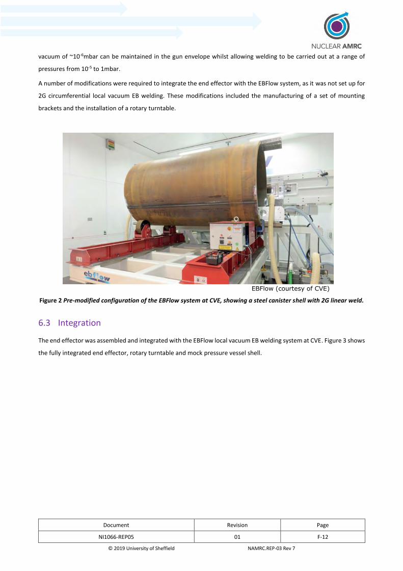
Document Revision Page
NI1066-REP05 01 F-12
© 2019 University of Sheffield NAMRC.REP-03 Rev 7
vacuum of ~10-6mbar can be maintained in the gun envelope whilst allowing welding to be carried out at a range of
pressures from 10-5 to 1mbar.
A number of modifications were required to integrate the end effector with the EBFlow system, as it was not set up for
2G circumferential local vacuum EB welding. These modifications included the manufacturing of a set of mounting
brackets and the installation of a rotary turntable.
EBFlow (courtesy of CVE)
Figure 2 Pre-modified configuration of the EBFlow system at CVE, showing a steel canister shell with 2G linear weld.
6.3 Integration
The end effector was assembled and integrated with the EBFlow local vacuum EB welding system at CVE. Figure 3 shows
the fully integrated end effector, rotary turntable and mock pressure vessel shell.
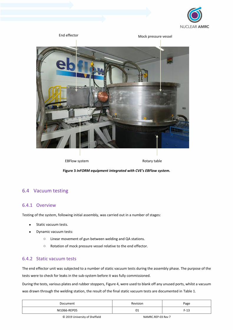
Document Revision Page
NI1066-REP05 01 F-13
© 2019 University of Sheffield NAMRC.REP-03 Rev 7
Figure 3 InFORM equipment integrated with CVE’s EBFlow system.
6.4 Vacuum testing
6.4.1 Overview
Testing of the system, following initial assembly, was carried out in a number of stages:
Static vacuum tests.
Dynamic vacuum tests:
o Linear movement of gun between welding and QA stations.
o Rotation of mock pressure vessel relative to the end effector.
6.4.2 Static vacuum tests
The end effector unit was subjected to a number of static vacuum tests during the assembly phase. The purpose of the
tests were to check for leaks in the sub-system before it was fully commissioned.
During the tests, various plates and rubber stoppers, Figure 4, were used to blank off any unused ports, whilst a vacuum
was drawn through the welding station, the result of the final static vacuum tests are documented in Table 1.
End effector Mock pressure vessel
Rotary table EBFlow system
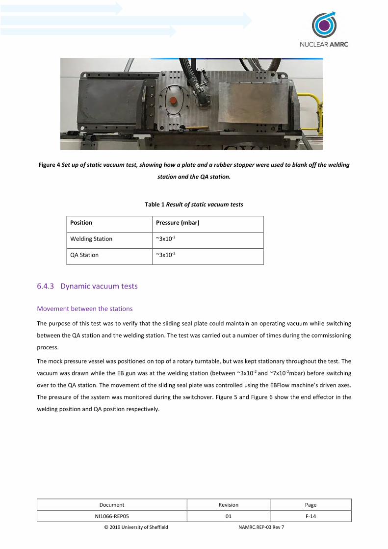
Document Revision Page
NI1066-REP05 01 F-14
© 2019 University of Sheffield NAMRC.REP-03 Rev 7
Figure 4 Set up of static vacuum test, showing how a plate and a rubber stopper were used to blank off the welding
station and the QA station.
Table 1 Result of static vacuum tests
Position Pressure (mbar)
Welding Station ~3x10⁻²
QA Station ~3x10⁻²
6.4.3 Dynamic vacuum tests
Movement between the stations
The purpose of this test was to verify that the sliding seal plate could maintain an operating vacuum while switching
between the QA station and the welding station. The test was carried out a number of times during the commissioning
process.
The mock pressure vessel was positioned on top of a rotary turntable, but was kept stationary throughout the test. The
vacuum was drawn while the EB gun was at the welding station (between ~3x10⁻² and ~7x10⁻²mbar) before switching
over to the QA station. The movement of the sliding seal plate was controlled using the EBFlow machine’s driven axes.
The pressure of the system was monitored during the switchover. Figure 5 and Figure 6 show the end effector in the
welding position and QA position respectively.
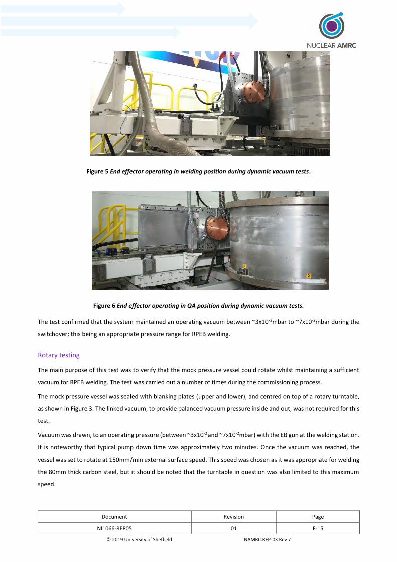
Document Revision Page
NI1066-REP05 01 F-15
© 2019 University of Sheffield NAMRC.REP-03 Rev 7
Figure 5 End effector operating in welding position during dynamic vacuum tests.
Figure 6 End effector operating in QA position during dynamic vacuum tests.
The test confirmed that the system maintained an operating vacuum between ~3x10⁻²mbar to ~7x10⁻²mbar during the
switchover; this being an appropriate pressure range for RPEB welding.
Rotary testing
The main purpose of this test was to verify that the mock pressure vessel could rotate whilst maintaining a sufficient
vacuum for RPEB welding. The test was carried out a number of times during the commissioning process.
The mock pressure vessel was sealed with blanking plates (upper and lower), and centred on top of a rotary turntable,
as shown in Figure 3. The linked vacuum, to provide balanced vacuum pressure inside and out, was not required for this
test.
Vacuum was drawn, to an operating pressure (between ~3x10⁻² and ~7x10⁻²mbar) with the EB gun at the welding station.
It is noteworthy that typical pump down time was approximately two minutes. Once the vacuum was reached, the
vessel was set to rotate at 150mm/min external surface speed. This speed was chosen as it was appropriate for welding
the 80mm thick carbon steel, but it should be noted that the turntable in question was also limited to this maximum
speed.
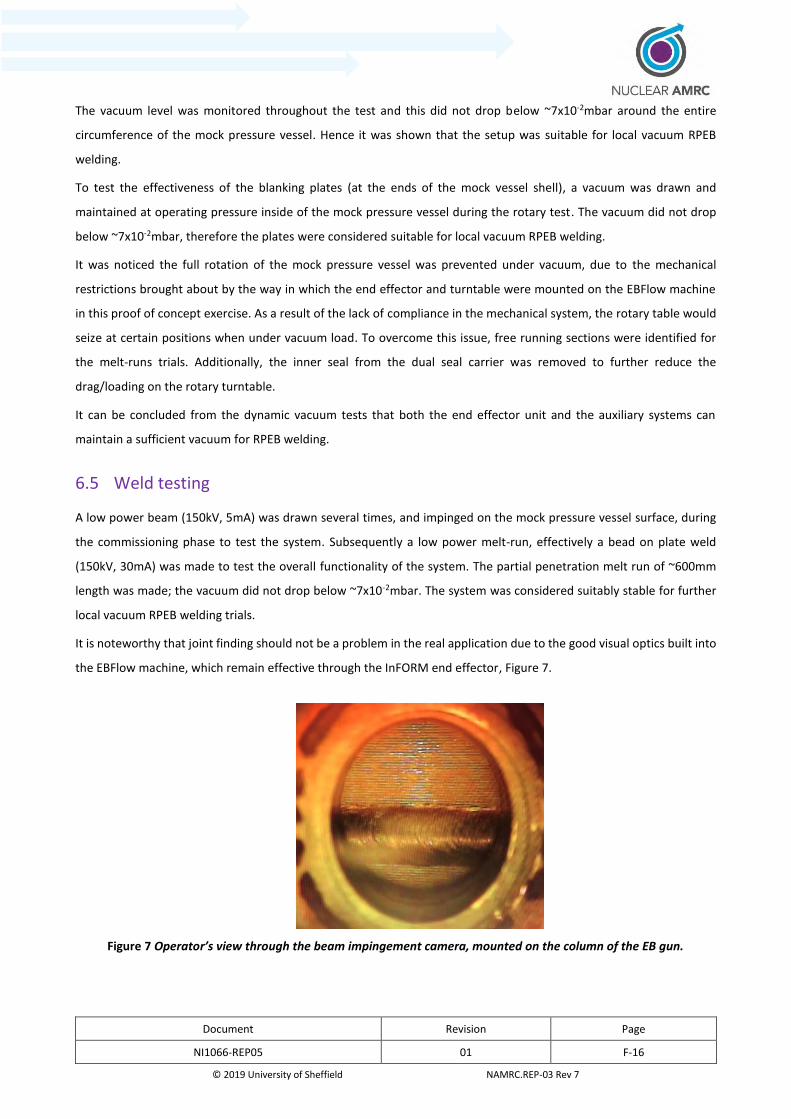
Document Revision Page
NI1066-REP05 01 F-16
© 2019 University of Sheffield NAMRC.REP-03 Rev 7
The vacuum level was monitored throughout the test and this did not drop below ~7x10⁻²mbar around the entire
circumference of the mock pressure vessel. Hence it was shown that the setup was suitable for local vacuum RPEB
welding.
To test the effectiveness of the blanking plates (at the ends of the mock vessel shell), a vacuum was drawn and
maintained at operating pressure inside of the mock pressure vessel during the rotary test. The vacuum did not drop
below ~7x10⁻²mbar, therefore the plates were considered suitable for local vacuum RPEB welding.
It was noticed the full rotation of the mock pressure vessel was prevented under vacuum, due to the mechanical
restrictions brought about by the way in which the end effector and turntable were mounted on the EBFlow machine
in this proof of concept exercise. As a result of the lack of compliance in the mechanical system, the rotary table would
seize at certain positions when under vacuum load. To overcome this issue, free running sections were identified for
the melt-runs trials. Additionally, the inner seal from the dual seal carrier was removed to further reduce the
drag/loading on the rotary turntable.
It can be concluded from the dynamic vacuum tests that both the end effector unit and the auxiliary systems can
maintain a sufficient vacuum for RPEB welding.
6.5 Weld testing
A low power beam (150kV, 5mA) was drawn several times, and impinged on the mock pressure vessel surface, during
the commissioning phase to test the system. Subsequently a low power melt-run, effectively a bead on plate weld
(150kV, 30mA) was made to test the overall functionality of the system. The partial penetration melt run of ~600mm
length was made; the vacuum did not drop below ~7x10⁻²mbar. The system was considered suitably stable for further
local vacuum RPEB welding trials.
It is noteworthy that joint finding should not be a problem in the real application due to the good visual optics built into
the EBFlow machine, which remain effective through the InFORM end effector, Figure 7.
Figure 7 Operator’s view through the beam impingement camera, mounted on the column of the EB gun.
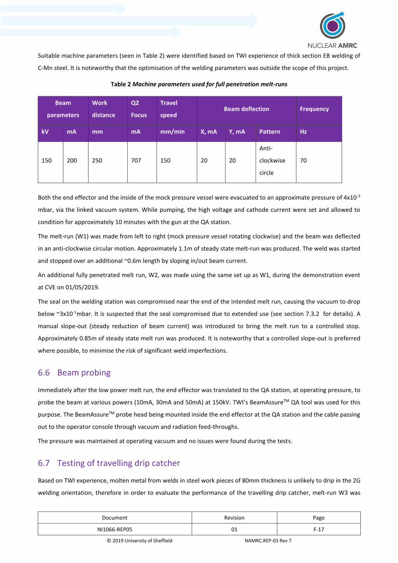
Document Revision Page
NI1066-REP05 01 F-17
© 2019 University of Sheffield NAMRC.REP-03 Rev 7
Suitable machine parameters (seen in Table 2) were identified based on TWI experience of thick section EB welding of
C-Mn steel. It is noteworthy that the optimisation of the welding parameters was outside the scope of this project.
Table 2 Machine parameters used for full penetration melt-runs
Beam
parameters
Work
distance
Q2
Focus
Travel
speed Beam deflection Frequency
kV mA mm mA mm/min X, mA Y, mA Pattern Hz
150 200 250 707 150 20 20
Anti-
clockwise
circle
70
Both the end effector and the inside of the mock pressure vessel were evacuated to an approximate pressure of 4x10⁻²
mbar, via the linked vacuum system. While pumping, the high voltage and cathode current were set and allowed to
condition for approximately 10 minutes with the gun at the QA station.
The melt-run (W1) was made from left to right (mock pressure vessel rotating clockwise) and the beam was deflected
in an anti-clockwise circular motion. Approximately 1.1m of steady state melt-run was produced. The weld was started
and stopped over an additional ~0.6m length by sloping in/out beam current.
An additional fully penetrated melt run, W2, was made using the same set up as W1, during the demonstration event
at CVE on 01/05/2019.
The seal on the welding station was compromised near the end of the intended melt run, causing the vacuum to drop
below ~3x10⁻¹mbar. It is suspected that the seal compromised due to extended use (see section 7.3.2 for details). A
manual slope-out (steady reduction of beam current) was introduced to bring the melt run to a controlled stop.
Approximately 0.85m of steady state melt run was produced. It is noteworthy that a controlled slope-out is preferred
where possible, to minimise the risk of significant weld imperfections.
6.6 Beam probing
Immediately after the low power melt run, the end effector was translated to the QA station, at operating pressure, to
probe the beam at various powers (10mA, 30mA and 50mA) at 150kV. TWI’s BeamAssureTM QA tool was used for this
purpose. The BeamAssureTM probe head being mounted inside the end effector at the QA station and the cable passing
out to the operator console through vacuum and radiation feed-throughs.
The pressure was maintained at operating vacuum and no issues were found during the tests.
6.7 Testing of travelling drip catcher
Based on TWI experience, molten metal from welds in steel work pieces of 80mm thickness is unlikely to drip in the 2G
welding orientation, therefore in order to evaluate the performance of the travelling drip catcher, melt-run W3 was
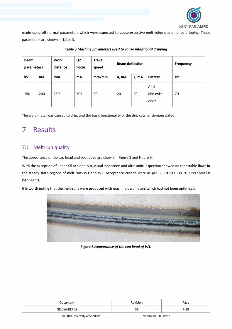
Document Revision Page
NI1066-REP05 01 F-18
© 2019 University of Sheffield NAMRC.REP-03 Rev 7
made using off-normal parameters which were expected to cause excessive melt volume and hence dripping. These
parameters are shown in Table 3.
Table 3 Machine parameters used to cause intentional dripping
Beam
parameters
Work
distance
Q2
Focus
Travel
speed Beam deflection Frequency
kV mA mm mA mm/min X, mA Y, mA Pattern Hz
150 200 250 707 90 20 20
Anti-
clockwise
circle
70
The weld metal was caused to drip, and the basic functionality of the drip catcher demonstrated.
7 Results
7.1 Melt-run quality
The appearance of the cap bead and root bead are shown in Figure 8 and Figure 9.
With the exception of under-fill at slope-out, visual inspection and ultrasonic inspection showed no reportable flaws in
the steady state regions of melt runs W1 and W2. Acceptance criteria were as per BS EN ISO 13919-1:1997 level B
(Stringent).
It is worth noting that the melt-runs were produced with machine parameters which had not been optimised.
Figure 8 Appearance of the cap bead of W1.

Document Revision Page
NI1066-REP05 01 F-19
© 2019 University of Sheffield NAMRC.REP-03 Rev 7
Figure 9 Appearance of the root bead of W1.
Vaporised metal oxide dust is a typical by-product of RPEB welding. In this case, the travelling drip catcher, mounted
over the cap bead, contained the dust; but it was not contained in the inside of the mock pressure vessel (root bead),
and therefore was freely deposited inside.
Melt run W2 was subjected to metallographic sectioning in the slope-up, steady state and slope-down regions.
Figure 10 shows the transverse cross section of the slope -up area, and Figure 11 shows the steady state area.
No volumetric weld flaws or cracks were observed in the melt run or the heat affected zone/parent material.
Figure 12 shows the slope out area, with significant under fill observed at the cap bead where the seal was
compromised, and manual intervention was required to bring the melt-run to a controlled stop.
Figure 10 Macro photograph of section taken from the slope-up area of W2.

Document Revision Page
NI1066-REP05 01 F-20
© 2019 University of Sheffield NAMRC.REP-03 Rev 7
Figure 11 Macro photograph of section taken from the steady state area of W2.
Figure 12 Macro photograph of section taken from the slope-out area of W2, with significant under-fill at the cap of
the bead highlighted in red.
7.2 Vacuum during melt run
The vacuum pressures of the end effector/mock vessel during the production of W1 and W2 are shown in Figure 13. No
significant loss of vacuum was experienced during the production of W1. At worst, the vacuum pressure deteriorated
to ~7x10⁻²mbar.
The seal compromised at around 430 seconds during the production of W2, causing a significant loss of vacuum. Manual
slope down began at 540 seconds to bring the melt run to a controlled stop. The pressure peaked at ~4.9x10⁻¹mbar
during the slope-down and resulted in the significant under-fill as shown in Figure 12.
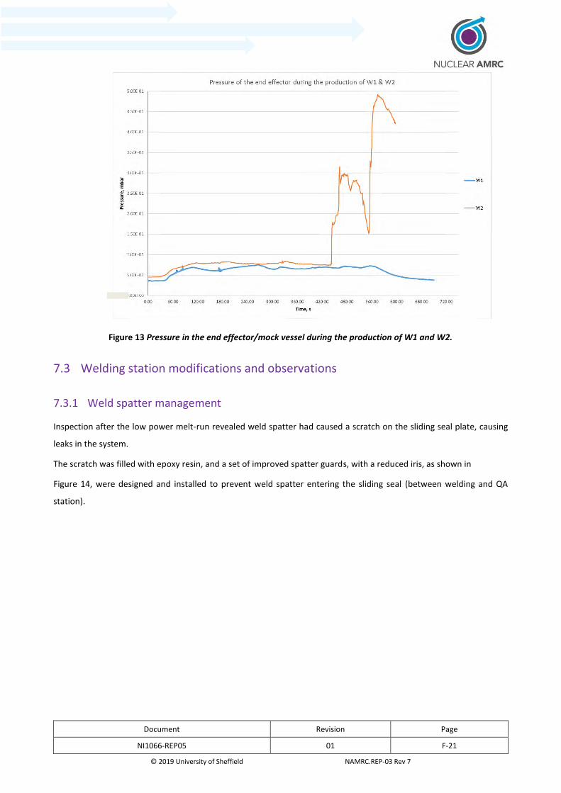
Document Revision Page
NI1066-REP05 01 F-21
© 2019 University of Sheffield NAMRC.REP-03 Rev 7
Figure 13 Pressure in the end effector/mock vessel during the production of W1 and W2.
7.3 Welding station modifications and observations
7.3.1 Weld spatter management
Inspection after the low power melt-run revealed weld spatter had caused a scratch on the sliding seal plate, causing
leaks in the system.
The scratch was filled with epoxy resin, and a set of improved spatter guards, with a reduced iris, as shown in
Figure 14, were designed and installed to prevent weld spatter entering the sliding seal (between welding and QA
station).
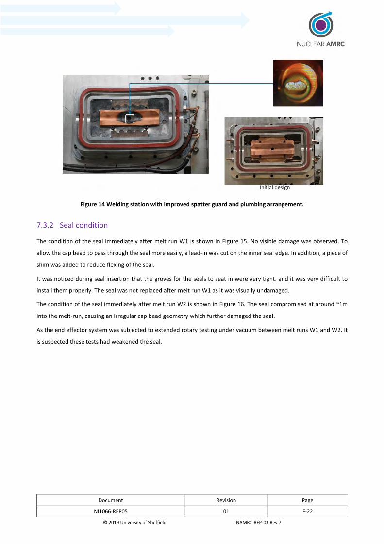
Document Revision Page
NI1066-REP05 01 F-22
© 2019 University of Sheffield NAMRC.REP-03 Rev 7
Figure 14 Welding station with improved spatter guard and plumbing arrangement.
7.3.2 Seal condition
The condition of the seal immediately after melt run W1 is shown in Figure 15. No visible damage was observed. To
allow the cap bead to pass through the seal more easily, a lead-in was cut on the inner seal edge. In addition, a piece of
shim was added to reduce flexing of the seal.
It was noticed during seal insertion that the groves for the seals to seat in were very tight, and it was very difficult to
install them properly. The seal was not replaced after melt run W1 as it was visually undamaged.
The condition of the seal immediately after melt run W2 is shown in Figure 16. The seal compromised at around ~1m
into the melt-run, causing an irregular cap bead geometry which further damaged the seal.
As the end effector system was subjected to extended rotary testing under vacuum between melt runs W1 and W2. It
is suspected these tests had weakened the seal.

Document Revision Page
NI1066-REP05 01 F-23
© 2019 University of Sheffield NAMRC.REP-03 Rev 7
Figure 15 Condition of the seal immediately after W1, showing no visual damage, with the lead in and the shim
highlighted in white.

Document Revision Page
NI1066-REP05 01 F-24
© 2019 University of Sheffield NAMRC.REP-03 Rev 7
Figure 16 Condition of the seal immediately after W2, showing significant damage on the trailing side
7.3.3 Water-cooled travelling drip catcher
It was discovered during assembling that the copper pipping used in the water-cooled travelling drip catcher was
restricting the spring action, which was to maintain contact between the end effector and mock pressure vessel.
Alternative plumbing arrangements were made to replace the copper piping with rubber hoses,
Figure 14 shows the revised plumping arrangement.
The functionality of the travelling drip catcher was evaluated with melt-run W3, using the same seal as W2. It is
noteworthy that the seal still provided a workable vacuum to sustain the beam. Figure 17 shows the bead cap of W3.
The area highlighted in white indicates that the drip catcher has caught, formed and solidified the molten drips. To
demonstrate the importance of weld cap support, Figure 18 shows the results of thick section welding without support
(earlier TWI work outside this project).
Figure 19 shows the seal was severely damaged by the ragged bead. It should be noted that the weld bead produced
was not formed in an ideal way by the drip catcher.

Document Revision Page
NI1066-REP05 01 F-25
© 2019 University of Sheffield NAMRC.REP-03 Rev 7
Figure 17 Bead cap of W3, showing the drip catcher had caught, formed and solidified the molten drips, preventing
their progression.
Figure 18 Cap of a defective weld made in 160mm thick C-Mn steel without support and with gross loss of weld
metal.
Figure 19 Condition of the seal immediately after W3, showing extensive damage caused by the ragged bead.
Document Revision Page
NI1066-REP05 01 F-26
© 2019 University of Sheffield NAMRC.REP-03 Rev 7
7.3.4 Beam characteristics
The beam was characterised using a Mk3.1 BeamAssureTM system installed in the QA station. The welding machine’s
own deflection capability was employed to pass the beam over the sensors.
Probing was not performed at welding power (200mA) due to limitations on the deflection control and the probe signal
was partly masked by the noise (backscattering) in the confined area. These issues were not related to the end effector
and could be readily resolved. Example full width half maximum (FWHM) beam caustics are shown in the X and Y axes
in Figure 20 and 21.
Figure 20 Lens current vs FWHM X.
Document Revision Page
NI1066-REP05 01 F-27
© 2019 University of Sheffield NAMRC.REP-03 Rev 7
Figure 21 Lens current vs FWHM Y.
8 Lessons Learned
Observations and recommendations made during the commissioning process can be found in Table 4.
Table 4 Observations and recommendations
No. Observations Recommendations
1 No mechanical lifting inside x-ray shield. Access for mobile lifting equipment to be
considered.
2 Minor incompatibility of auxiliary items.
Minor modification required.
Thorough compatibility check on the
design of auxiliary items.
3 Pressure vessel mock-up rotation
prevented due to 2mm eccentricity of
rotary table.
Rotary fixture design to be revisited.
4 Weld spatter caused a scratch on the
sliding seal plate, causing leak.
Better spatter guard used.

Document Revision Page
NI1066-REP05 01 F-28
© 2019 University of Sheffield NAMRC.REP-03 Rev 7
No. Observations Recommendations
5 Copper pipes behind the drip catcher were
too stiff, preventing the spring from
operating.
Use more flexible rubber hoses.
6 Seals difficult to replace as too tight. Seals with lead-in on the edges to aid
installation.
Revisit design of seal carrier.
7 Seal degraded during the demo melt run,
causing a leak and poor cap bead
geometry.
Replace the seals after every weld.
Use both seals instead of only the outer
one.
Use more robust silicone rubber
compound.
8 Insufficient seal compression onto the test
canister, causing a leak on crossing the cap
bead.
End effector should have some compliance
and be able to actively float towards the
canister.
9 Minor rotary seal leak under uneven
compression.
Rotary seal design to be revisited.
9 Technology Readiness Level at End of Project
It was considered by the InFORM peer review panel on 23/05/2019 that both the MRL and TRL of the system/approach
tested was TRL4/MRL4 at the end of the work. The justification for these values is shown in Appendix 1.
10 Route to Industrial Adoption
It would be beneficial to the wider Nuclear Innovation Programme if the design output of this project could be used in
the future stages.
As the TRL/MRL of the technology is low, it is suggested the initial route to adoption would be through the InFORM
project partners, notably Sheffield Forgemasters.
Partnering with equipment manufacturers such as CVE and Fullagar Technologies (TWI/Lloyds Register joint venture
marketing BeamAssureTM) to further develop the technology, could encourage it to be adopted by other industry
sectors, such as aerospace and defence.
It is important to ensure applicable codes & standards are kept up to date with the development of local vacuum EB
technology to ensure its acceptance by the industry.

Document Revision Page
NI1066-REP05 01 F-29
© 2019 University of Sheffield NAMRC.REP-03 Rev 7
11 Discussions
As a single pass autogenous welding process, local vacuum EB welding eliminates the need for pre-heat, wire, gas or
flux, statutory laydown periods and inter-pass inspections. The total process times and consumable costs of local
vacuum EB welding are greatly reduced, when compared with traditional arc welding processes, such as submerged arc
or narrow gap TIG welding. Also, when compared to conventional in-chamber EB welding, the capital cost (vacuum
chamber and pumps) and operational cost (vacuum pumping energy/time) benefits are very clear.
This feasibility study has demonstrated that the end effector is capable of reducing the set up and welding time by a
factor of ten or more, compared to traditional arc welding. More importantly, it has enabled quality checks on the beam
(beam diagnostics) just before and after welding, which will greatly reduce the risk of operator errors and
cathode/system failure during a weld.
The process has been shown to make high integrity melt runs, as assessed by ultrasonic inspection and metallography.
12 Conclusions
The following conclusions can be drawn:
Local vacuum EB equipment was designed and manufactured to meet the demands of the InFORM
demonstrator. The various novel attributes of the system were:
o A welding station with:
Low cost interchangeable seal carrier to allow a change in vessel diameter to be welded.
Good down-beam optical viewing path to allow joint finding and weld process viewing.
Travelling cooled fronting bar, able to prevent loss of weld metal and form weld cap profile.
A quality assurance station with:
o The ability to condition the welding gun over a cooled heat sink (or beam dump).
o The ability to integrate a probe sub-system to quantify the beam power and profile.
o The ability to translate the EB gun between the two stations while maintaining vacuum, in a short
time:
o The system is unique amongst travelling seals, in that it has a second sliding seal incorporated.
o The motion to translate between stations was provided by the host welding machine.
o A vacuum link to the backing vacuum (at the weld root-side) to assure a balanced vacuum level at cap
and root:
Avoiding weld metal displacement by pressure differential, and resulting excess
bead/underfill.
o The local vacuum EB equipment was shown to be a viable vacuum vessel during static and dynamic
vacuum tests.

Document Revision Page
NI1066-REP05 01 F-30
© 2019 University of Sheffield NAMRC.REP-03 Rev 7
The local vacuum EB equipment was shown to be a viable vacuum vessel for EB welding:
o The novel attributes of the system were showed to function and are viable.
o Electron beam melt runs were made in 80mm thick C-Mn steel.
o The melt runs were shown to be of adequate integrity, noting that no development welding was
undertaken.
13 Recommendations
It is recommended that further work is carried out to better understand and build confidence in the local vacuum EB
welding system. This will require further development on joint fit up and equipment for thick section welding.
The seals must be replaced after every use to avoid premature failure. The design of the seal carrier should be revisited
to allow easy replacement of the seals. Moreover, a more robust silicon compound could be considered to improve the
life span of the seal.
Issues such as residual magnetism and joint fit-up/alignment will need to be addressed before proceeding to welding a
joint.
It is important that the industry continues to develop suitable standards to keep up with the development of local
vacuum EB welding technology.

Document Revision Page
NI1066-REP05 01 F-31
© 2019 University of Sheffield NAMRC.REP-03 Rev 7
Appendix F-A - Introduction to local vacuum electron beam
welding equipment design concepts
Introduction
This brief deliverable report introduces the prospective approaches to equipment concept design for local vacuum
electron beam (EB) welding. The document, issued in the first two weeks of contract coverage is intended as an overview
for comment and to inspire feedback prior to down selection of a final approach and detailed design generation.
Objectives
The objective of this report is to illustrate the possible approaches to local vacuum EB welding equipment formats for
the InFORM project demonstrator.
Demonstrator detail
The proposed pressure vessel demonstrator design constraints are detailed in NAMRC presentation ‘NI1066 InFORM
Demonstrator Design DRAFT Proposal 01, 19.03.2018’ circulated by Benjamin Cook (email 19 March 2018, 15:21). Key
observations which impact EB welding include:
It is understood that ~700mm either side of the weld location will be a plain, parallel side cylinder and free
from any obstructions (nozzles, dome end curvature, etc).
Since initial proposal input was provided by TWI in summer 2017 the demonstrator vessel diameter (now
2000mm) and wall thickness (now 100mm) have grown significantly for this phase of work.
The flanges (2200mm diameter) at either end of the assembly will make it impossible to remove a near-fitting
vacuum vessel from the demonstrator after welding.
The demonstrator parts are drawn with a square-butt preparation at the weld location; as the welding
approach is developed TWI may wish to propose a change to this geometry, which may involve removal or
addition of material in or adjacent to the weld location.
Demonstrator-like parts procured/fabricated by TWI for vacuum/welding tests in work packages 2.4/2.5 will
not be fully compliant with the NAMRC design, but will be adequate for their purpose.
NAMRC should specify a favoured assembly/welding orientation and clarify what means of rotating the
demonstrator will be in place.
NAMRC should specify any instrumentation which it is envisaged will be integrated with the welding
equipment.

Document Revision Page
NI1066-REP05 01 F-32
© 2019 University of Sheffield NAMRC.REP-03 Rev 7
Approaches to local vacuum sealing
Overview
Figures 1 to 4 show example concepts (from CVE Limited literature) of the primary equipment formats for reduced
pressure EB welding. Variations of these can be considered also, specially the use of blanking plates at the end of the
vessel rather than the use of an internal box seal within the vessel.
Figure 1 Local vacuum sliding head mounted on gun column and internal box seal containing beam stopper. Shown
here welding in the 3G orientation, with the gun static and the vessel rotating.
Figure 2 Local vacuum sliding head mounted on gun column and internal box seal containing beam stopper. Shown
here welding in the 2G orientation, with the gun static and the vessel rotating.
Document Revision Page
NI1066-REP05 01 F-33
© 2019 University of Sheffield NAMRC.REP-03 Rev 7
Figure 3 Local vacuum vessel with static seal mating with pressure vessel and engineered sliding seals. Internal box
seal containing beam stopper. Shown here welding in the 3G orientation, with the gun static and the vessel
rotating.
Figure 4 Local vacuum vessel with static seals mating with pressure vessel and engineered sliding seals. Internal box
seal containing beam stopper. Shown here welding in the 2G orientation, with the gun static and the vessel
rotating.
Relative merits of different approaches
The benefits and drawbacks of using a local vacuum sliding head are:
Relatively quick and easy to install and remove.
Adjustment to find the joint line is easy.
Challenging to maintain vacuum whilst travelling across irregular surfaces.
Need to seal full weld length prior to welding to assure vacuum.
Seal is more susceptible to degradation during use and should be considered a consumable.
Changes in weldment vessel design may be accommodated by small changes in sliding head end-effector only.

Document Revision Page
NI1066-REP05 01 F-34
© 2019 University of Sheffield NAMRC.REP-03 Rev 7
The benefits and drawbacks of a local vacuum vessel are:
Good vacuum pressures may be attained and maintained more readily.
Setup can be challenging and time consuming.
Alignment with weld line is challenging.
Many components leading to complexity.
Minor changes in weldment vessel design may lead to major redesign and engineering of vacuum vessel.
Cannot be readily removed from vessel with obstructions such as flanges.
Planned approach
Concept design work will begin on a local vacuum sliding head system to meet the requirements of the demonstrator
pressure vessel. The merits of this approach outweigh those of the other approach in TWI’s view.
TWI will undertake to build on the learning from past core research and collaborative work to assure the system
designed is an improvement on past deployments. Cambridge Vacuum Engineering will be engaged in a design
consultancy role at this stage.
A further report will present the concept design prior to preparation of manufacturing drawings.
NAMRC should note and act on the bullet points given in Section 3 above.

Document Revision Page
NI1066-REP05 01 F-35
© 2019 University of Sheffield NAMRC.REP-03 Rev 7
Appendix F-B - Supplementary Statement of Local Vacuum
Welding Process and Equipment Factors which may affect
the Welding and/or other Processes/Tooling
Overview
This document has been prepared to summarise, for MetLase and NAMRC, the restrictions around the local vacuum
electron beam (EB) welding process and associated tooling which must be taken into account during related pre and
post-processing.
Points to Note
The following points (given in no particular order) must be noted to avoid detrimental impact on the welding process
and/or further processing after welding.
Magnetism; the weldment should not be magnetised. The weld tooling should not be magnetised. Residual/incidental
magnetism can be significant enough to affect EB welding.
Welding position; the 2G welding orientation (beam horizontal, vessel vertical (either beam or vessel rotating)) is
favoured. The 3G (beam horizontal, vessel horizontal rotating), 1G orientation (beam vertical-down, vessel horizontal
rotating), and 5G (beam all-positional, vessel horizontal static) orientations each respectively limit weld penetration
depth to a greater extent.
Temperature; the weldment and tooling temperature in the region of the local vacuum sealing system, ~150mm
perpendicular from the weld line may rise to ~150oC during or soon after welding. Tooling materials used must not
degrade due to thermal cycle.
Radiation; The EB welding process generates incidental x-ray radiation. The local vacuum welding head and weldment
will provide some radiation protection, although use of a high potential EB system will require additional x-ray
protection (normally in the form of lead, steel or concrete shielding). Tooling materials used must not degrade due to
radiation.
Preparation of vessel; all weldment and tooling surfaces/joints should be free from debris (swarf, etc) and fluids (cutting
fluids, oils, etc) when presented for welding. Surface finish of approximately 3.2μm Ra is generally acceptable. The wall
of the vessel should be clean and free from debris, corrosion and fluids. A reasonable mill-finish is acceptable although
a machined surface is ideal.
Joint fit-up; ideally the faying surfaces of the vessel halves should come into intimate contact, with no high-low miss
match. Gaps/miss-match may result in issues with vacuum attainment, excess post weld distortion and unexpected
welding performance.

Document Revision Page
NI1066-REP05 01 F-36
© 2019 University of Sheffield NAMRC.REP-03 Rev 7
EB weld debris; the EB process deployed in this form leads to the generation of dust, spatter and metal vapour
deposition which is contained within the equipment/weldment and may adhere to, or lay on, the components.
Beam-stopper; for full penetration welds a semi-sacrificial beam-stopper must be placed inside the vessel to absorb
excess beam energy and prevent it hitting the opposite vessel wall.
External restrictions; it must be possible to close-couple the EB gun to the vessel without undue physical restrictions
which will extend the gun-to-work distance.
Vacuum; any vacuum seals exposed during tooling changes must be protected from mechanical damage. Tooling
exposed to vacuum must have no trapped volumes which may outgas over time. Materials used must not significantly
outgas.
Vacuum load; the vessel, end blanking and local vacuum welding head may see an internal pressure down to 5x10 -3
mbar. This will cause deflections of the mechanical elements.
Weld distortion; the welding process will cause a minor change in vessel shape as a result of solidification/residual
stresses.
Rotation of weldment; rotation position and speed of the vessel or of the gun, relative to one another, must be
controllable (ideally via the welding machine CNC).
Further Sharing of Information
TWI would welcome the sharing of any information, from NAMRC or contractors in the InFORM project, which may help
to inform the EB welding equipment design, manufacture and deployment.
Document Revision Page
NI1066-REP05 01 F-37
© 2019 University of Sheffield NAMRC.REP-03 Rev 7
Appendix F-C - Local Vacuum Welding Concept Design of
End Effector/Backing Vacuum Sub-systems
Introduction
This report presents the concept design of the InFORM local vacuum welding end effector and method of achieving a
backing vacuum for the demonstrator vessel design.
Objectives
To illustrate the concept and initial detail of the design produced
To highlight the interface requirements and illustrate the novel aspects of the design.
To detail the plan for the next stage of work.
To seek comment and approval to proceed.
Concept design
The following images illustrate the concept proposed by TWI for this application and description of the detail is given
alongside.
Figure 1 Overview of concept assembly with gun positioned for pre-weld conditioning.
Figure 1 shows the assembly of the vessel demonstrator half shells, with end blanking plates (background), and the local
vacuum end effector mounted between the vessel and the electron beam (EB) gun column (foreground). The proposed

Document Revision Page
NI1066-REP05 01 F-38
© 2019 University of Sheffield NAMRC.REP-03 Rev 7
concept is relatively novel in having two sets of seals, one which act against and travel across the vessel wall and one
which allows movement of the EB gun relative to the vessel. Here the gun is shown to the left, off the joint line
positioned over a beam dump.
The design intent is that the EB gun may be aligned with the weld joint, or may be translated to the side to allow gun
conditioning and quality assurance activities while still under vacuum and assuring minimal time between these
activities and welding.
Blanking plates are shown to effect an internal vacuum, and include some centralising features. The scope of MetLase
and NAMRC design work needs to be considered with regard to responsibility for the detailed design of these
plates/associated items.
Figure 2 shows the gun reposition on the weld line in the right-hand position.
Figure 2 Alternative view of assembly with gun positioned for welding.
Figure 3 shows a wireframe diagram of the system. Notably the need for an internal beam dump or beam stopper, to
capture the excess weld energy. The proposition is that this will be suspended from the upper blanking plate. The
vacuum pumping ports are also shown, along with the need for chilled water service to support a water cooled beam
dump for beam conditioning. The conditioning beam dump will be detachable to allow servicing and easy replacement.

Document Revision Page
NI1066-REP05 01 F-39
© 2019 University of Sheffield NAMRC.REP-03 Rev 7
Figure 3 Annotated wire-frame diagram of the system indicating key elements.

Document Revision Page
NI1066-REP05 01 F-40
© 2019 University of Sheffield NAMRC.REP-03 Rev 7
Figure 4 Local vacuum end effector diagram, included to provide overview of scale (in mm) when gun seal is in the
conditioning position.
Figure 4 shows the overall dimensions of the end effector, and it should be noted that the 2,300mm plate moves relative
to the local vacuum chamber and hence the total length changes depending on its position.
Figure 5 Concept of interchangeable end effector-vessel seal section.
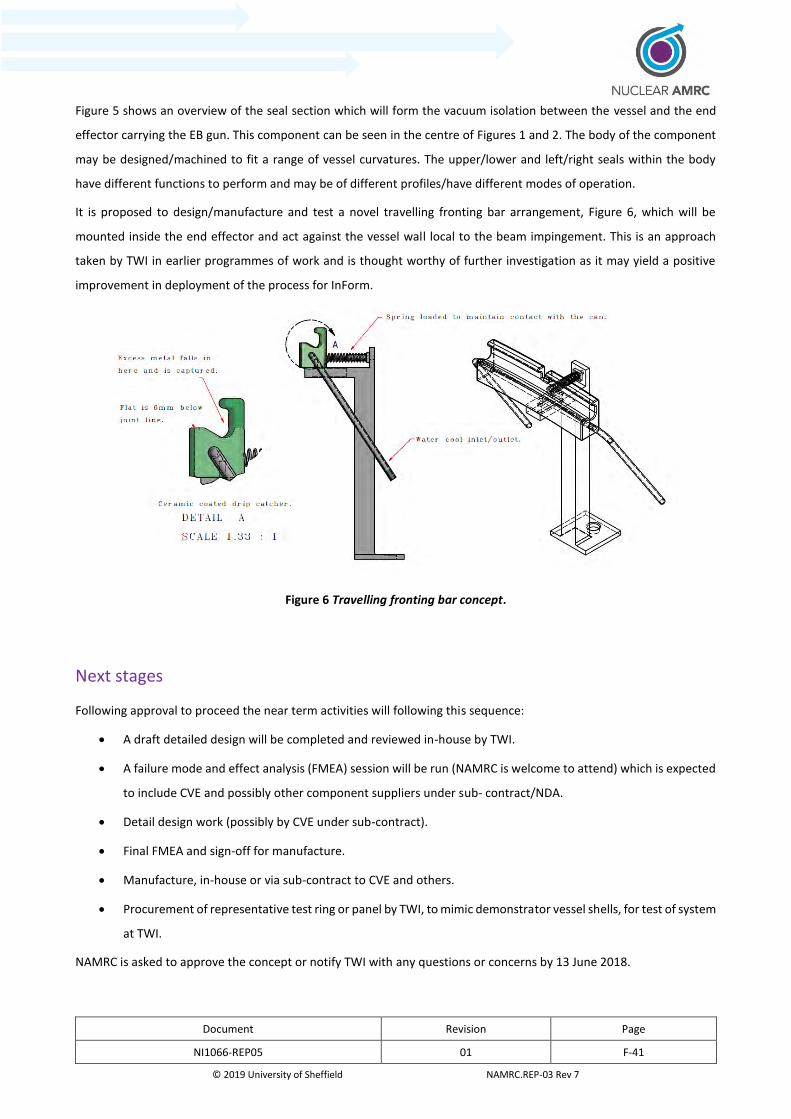
Document Revision Page
NI1066-REP05 01 F-41
© 2019 University of Sheffield NAMRC.REP-03 Rev 7
Figure 5 shows an overview of the seal section which will form the vacuum isolation between the vessel and the end
effector carrying the EB gun. This component can be seen in the centre of Figures 1 and 2. The body of the component
may be designed/machined to fit a range of vessel curvatures. The upper/lower and left/right seals within the body
have different functions to perform and may be of different profiles/have different modes of operation.
It is proposed to design/manufacture and test a novel travelling fronting bar arrangement, Figure 6, which will be
mounted inside the end effector and act against the vessel wall local to the beam impingement. This is an approach
taken by TWI in earlier programmes of work and is thought worthy of further investigation as it may yield a positive
improvement in deployment of the process for InForm.
Figure 6 Travelling fronting bar concept.
Next stages
Following approval to proceed the near term activities will following this sequence:
A draft detailed design will be completed and reviewed in-house by TWI.
A failure mode and effect analysis (FMEA) session will be run (NAMRC is welcome to attend) which is expected
to include CVE and possibly other component suppliers under sub- contract/NDA.
Detail design work (possibly by CVE under sub-contract).
Final FMEA and sign-off for manufacture.
Manufacture, in-house or via sub-contract to CVE and others.
Procurement of representative test ring or panel by TWI, to mimic demonstrator vessel shells, for test of system
at TWI.
NAMRC is asked to approve the concept or notify TWI with any questions or concerns by 13 June 2018.

Document Revision Page
NI1066-REP05 01 F-42
© 2019 University of Sheffield NAMRC.REP-03 Rev 7
NAMRC is asked to clarify whether any sensors/transducers are to be integrated with the local vacuum EB element of
the InFORM hardware and to clarify at what point the detail of these will be shared with TWI.
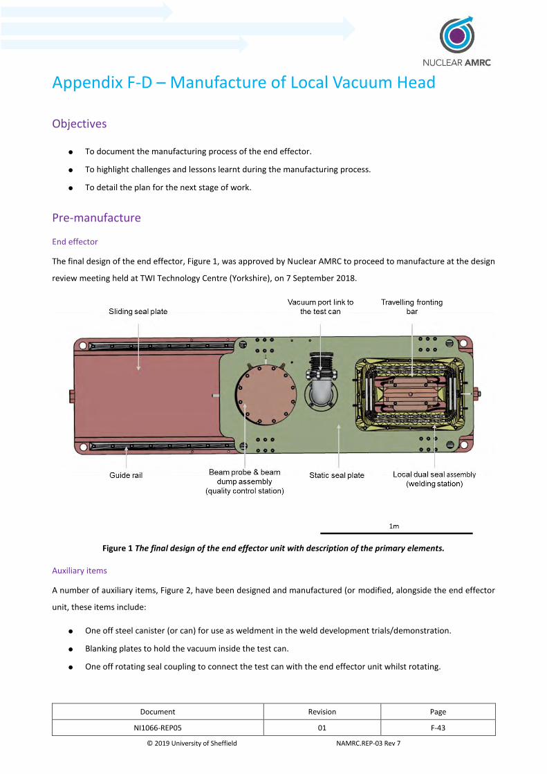
Document Revision Page
NI1066-REP05 01 F-43
© 2019 University of Sheffield NAMRC.REP-03 Rev 7
Appendix F-D – Manufacture of Local Vacuum Head
Objectives
To document the manufacturing process of the end effector.
To highlight challenges and lessons learnt during the manufacturing process.
To detail the plan for the next stage of work.
Pre-manufacture
End effector
The final design of the end effector, Figure 1, was approved by Nuclear AMRC to proceed to manufacture at the design
review meeting held at TWI Technology Centre (Yorkshire), on 7 September 2018.
Figure 1 The final design of the end effector unit with description of the primary elements.
Auxiliary items
A number of auxiliary items, Figure 2, have been designed and manufactured (or modified, alongside the end effector
unit, these items include:
One off steel canister (or can) for use as weldment in the weld development trials/demonstration.
Blanking plates to hold the vacuum inside the test can.
One off rotating seal coupling to connect the test can with the end effector unit whilst rotating.
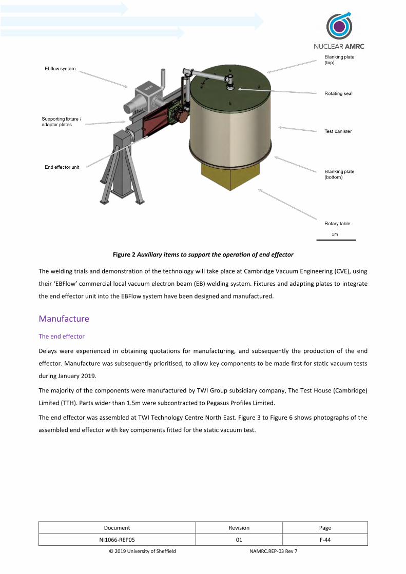
Document Revision Page
NI1066-REP05 01 F-44
© 2019 University of Sheffield NAMRC.REP-03 Rev 7
Figure 2 Auxiliary items to support the operation of end effector
The welding trials and demonstration of the technology will take place at Cambridge Vacuum Engineering (CVE), using
their ‘EBFlow’ commercial local vacuum electron beam (EB) welding system. Fixtures and adapting plates to integrate
the end effector unit into the EBFlow system have been designed and manufactured.
Manufacture
The end effector
Delays were experienced in obtaining quotations for manufacturing, and subsequently the production of the end
effector. Manufacture was subsequently prioritised, to allow key components to be made first for static vacuum tests
during January 2019.
The majority of the components were manufactured by TWI Group subsidiary company, The Test House (Cambridge)
Limited (TTH). Parts wider than 1.5m were subcontracted to Pegasus Profiles Limited.
The end effector was assembled at TWI Technology Centre North East. Figure 3 to Figure 6 shows photographs of the
assembled end effector with key components fitted for the static vacuum test.
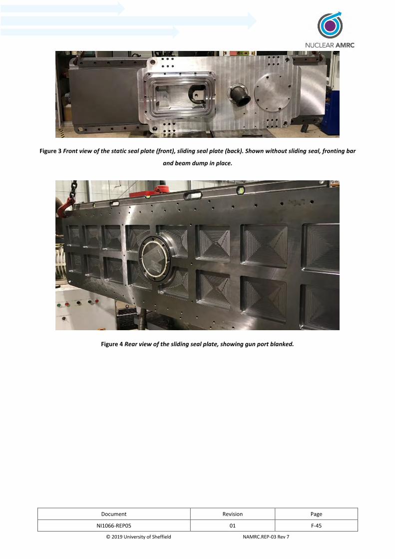
Document Revision Page
NI1066-REP05 01 F-45
© 2019 University of Sheffield NAMRC.REP-03 Rev 7
Figure 3 Front view of the static seal plate (front), sliding seal plate (back). Shown without sliding seal, fronting bar
and beam dump in place.
Figure 4 Rear view of the sliding seal plate, showing gun port blanked.
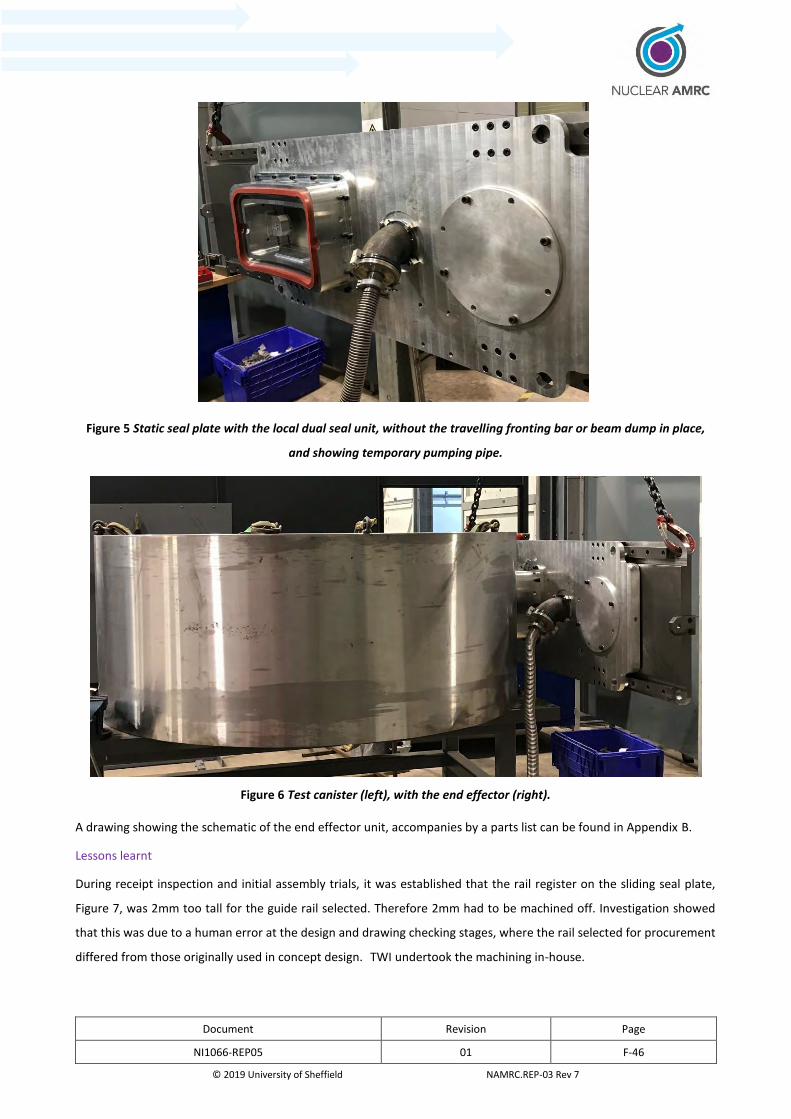
Document Revision Page
NI1066-REP05 01 F-46
© 2019 University of Sheffield NAMRC.REP-03 Rev 7
Figure 5 Static seal plate with the local dual seal unit, without the travelling fronting bar or beam dump in place,
and showing temporary pumping pipe.
Figure 6 Test canister (left), with the end effector (right).
A drawing showing the schematic of the end effector unit, accompanies by a parts list can be found in Appendix B.
Lessons learnt
During receipt inspection and initial assembly trials, it was established that the rail register on the sliding seal plate,
Figure 7, was 2mm too tall for the guide rail selected. Therefore 2mm had to be machined off. Investigation showed
that this was due to a human error at the design and drawing checking stages, where the rail selected for procurement
differed from those originally used in concept design. TWI undertook the machining in-house.
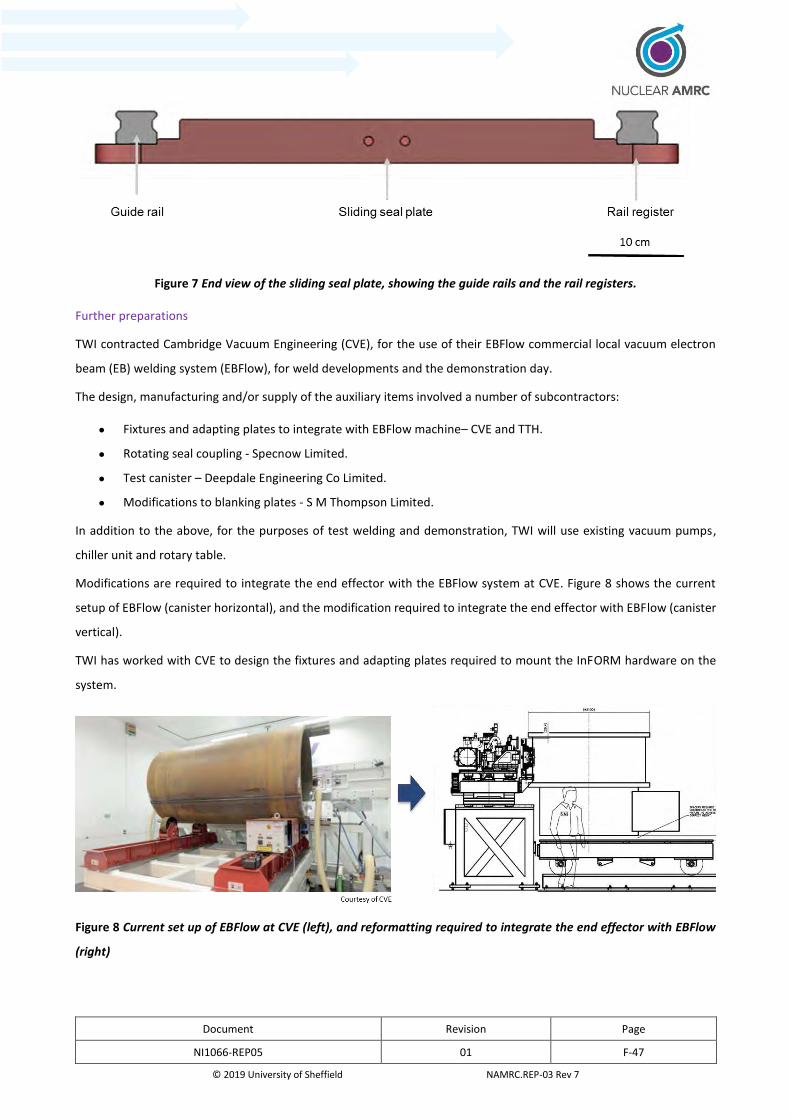
Document Revision Page
NI1066-REP05 01 F-47
© 2019 University of Sheffield NAMRC.REP-03 Rev 7
Figure 7 End view of the sliding seal plate, showing the guide rails and the rail registers.
Further preparations
TWI contracted Cambridge Vacuum Engineering (CVE), for the use of their EBFlow commercial local vacuum electron
beam (EB) welding system (EBFlow), for weld developments and the demonstration day.
The design, manufacturing and/or supply of the auxiliary items involved a number of subcontractors:
Fixtures and adapting plates to integrate with EBFlow machine– CVE and TTH.
Rotating seal coupling - Specnow Limited.
Test canister – Deepdale Engineering Co Limited.
Modifications to blanking plates - S M Thompson Limited.
In addition to the above, for the purposes of test welding and demonstration, TWI will use existing vacuum pumps,
chiller unit and rotary table.
Modifications are required to integrate the end effector with the EBFlow system at CVE. Figure 8 shows the current
setup of EBFlow (canister horizontal), and the modification required to integrate the end effector with EBFlow (canister
vertical).
TWI has worked with CVE to design the fixtures and adapting plates required to mount the InFORM hardware on the
system.
Figure 8 Current set up of EBFlow at CVE (left), and reformatting required to integrate the end effector with EBFlow
(right)

Document Revision Page
NI1066-REP05 01 F-48
© 2019 University of Sheffield NAMRC.REP-03 Rev 7
Appendix F-E – Schematic/Drawing of local vacuum head
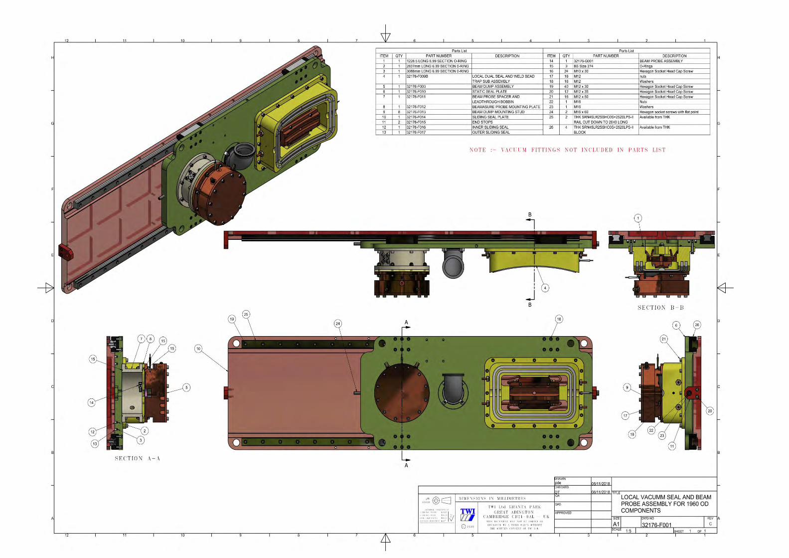

Document Revision Page
NI1066-REP-01 03 G-1
© 2019 University of Sheffield NAMRC.REP Version 7.0
G. Metrology

Document Revision Page
NI1066-REP-01 01 G-2
© 2019 University of Sheffield NAMRC.REP Version 7.0
1 Metrology
A consistent thread through the InFORM project was metrology and its impact on the various work packages.
Consequently the Nuclear AMRC Metrology Team produced a detailed report which can be found in Appendix 5.
The report reviews a range of metrology technologies to determine suitable measurement systems for various aspects
of the InFORM project, specifically forging, machining, assembly and welding.
In forging, the need for a high data capture rate, large measurement volume, automation and non-contact
measurements led to the recommendation of a laser scanner referenced by an optical or laser tracker as the most
appropriate technology. If the measurement volume is less than 4.5 m and automation is not necessary, then laser
scanning with a measurement arm is also suitable.
For machining operations, a combined system of a laser scanner referenced by a laser tracker was recommended
alongside on-machine probing. The laser scanner achieves the objective of digitising the part surface to allow
optimisation of part setup and toolpath. This also allows large measurement volumes to be achieved and is non-contact.
On-machine probing can provide in-process verification while the laser tracker can support on-machine probing by
providing additional measurements to verify machining axes.
For assembly operations, laser trackers remain the most appropriate technology, however, this represents a significant
investment in equipment if multiple trackers are used. Photogrammetry systems are also quite capable although with
less capability for automation. Both these systems normally require some degree of contact with the part for large
components; however, this may no longer be the case for the very latest developments in laser tracker technology. A
Nikon Laser Radar system would not require contact but is a less mature technology. Divergent beam frequency
scanning interferometry is a technology which shows promise but needs considerable development.
Welding operations in InFORM require a robust system suitable for the welding environment as well as non-contact
inspection and a large measurement volume. Laser scanning with a tracker, or with a measurement arm at reduced
measurement volume, meets these requirements. The high accuracy requirements for pre-welding inspections to
support electron beam welding mean this system would need careful validation to ensure it is accurate enough for the
application. If placing reference markers on the part is permitted, photogrammetry may also be an appropriate
technique to support welding.

Document Revision Page
NI1066-REP-01 03 H-1
© 2019 University of Sheffield NAMRC.REP Version 7.0
H. 4IR Technology Demonstrator

Document Revision Page
DPG047038 Final H-1
Confidential. Copyright © 2019 The University of Sheffield / Nov-19 AMRC. Template detail: AMRC.RP Revision 16 (December 2018). For information about this template contact: [email protected]
NI1066 InFORM Theme 2 Stage 2
WP2.7B 4IR Technology Demonstrator
for
Nuclear AMRC
NI1066
03/09/2019
Name Signature
Author: D King
Technical review: R Swain
Authorised: Dr G Nicholson
Authorised distribution: AMRC Staff, NAMRC Staff
AMRC proprietary information.
Document Revision Page
DPG047038 Final H-2
Confidential. Copyright © The University of Sheffield / Nov-19 AMRC. Template detail: AMRC.RP Revision 16 (December 2018). For information about this template contact: [email protected]
AMRC Advanced Manufacturing Park Wallis Way Rotherham S60 5TZ United Kingdom
The AMRC has prepared this report on behalf of NAMRC.
This report may only be reproduced in full, except with the express permission of the AMRC.
The AMRC has exercised due care in conducting this report but has not, apart from as specifically stated, independently verified information provided by others. No other warranty, express or implied, is made in relation to the contents of this report. Therefore, the AMRC assumes no liability for any loss resulting from errors, omissions, or misrepresentations made by others. Any recommendations, opinions or findings stated in this report are based on circumstances and facts as they existed at the time the AMRC performed the work. Any changes in such circumstances and facts upon which this report is based may adversely affect any recommendations, opinions or findings contained in this report. Where experiments have been carried out, these have been restricted to a level of detail required to achieve the stated objectives of the statement of work. This work has been undertaken in accordance with the AMRC’s quality system.
Revision Date of issue Reason for revision or original issue
01 03/09/2019 Original issue
Document revision history

Document Revision Page
DPG047038 Final H-3
Confidential. Copyright © The University of Sheffield / Nov-19 AMRC. Template detail: AMRC.RP Revision 16 (December 2018). For information about this template contact: [email protected]
Executive summary
The key aim of InFORM work package 2.7B was to develop a 4th Industrial Revolution (4IR) technology demonstrator of an intelligent fixture for the nuclear industry.
The concept of an intelligent fixture that is continuously monitoring and reporting the status of both the fixture and its located component is not currently adopted in the nuclear industry.
At the start of the project, concepts were developed based upon this key requirement that an intelligent fixture should provide through-life continuous process monitoring. The identified monitoring requirements of an intelligent fixture included location tracking, monitoring of movement and alignment of the located component relative to the fixture.
A system was developed that successfully demonstrated this continuous monitoring capability enabled by the use of low power Internet of Things (IoT) sensors mounted on the InFORM fixture.
The delivered demonstration system highlights to the nuclear industry how the application of 4IR technology to fixtures has the potential to improve efficiency and ultimately reduce the cost of manufacturing through reduced setup time and maintenance.
Document Revision Page
DPG047038 Final H-4
Confidential. Copyright © The University of Sheffield / Nov-19 AMRC. Template detail: AMRC.RP Revision 16 (December 2018). For information about this template contact: [email protected]
Contents
1 Technical Challenges .......................................................................................................................................................... 6
1.1 Problem ..................................................................................................................................................................... 6
1.2 Current state of the art ............................................................................................................................................ 7
2 Starting MRL / TRL .............................................................................................................................................................. 7
3 Overview of the technical challenges for industry “WHY?” ............................................................................................ 8
3.1 Technical Challenges ................................................................................................................................................ 8
3.1.1 Problem definition with Use Cases ..................................................................................................................... 8
3.2 Work conducted and development path ................................................................................................................ 9
3.2.1 Development Approach ....................................................................................................................................... 9
3.2.2 MVP Requirements ............................................................................................................................................10
3.2.3 Concept Generation ...........................................................................................................................................10
3.2.4 Technology Research .........................................................................................................................................13
3.2.5 Develop MVP ......................................................................................................................................................18
3.2.6 Testing MVP ........................................................................................................................................................25
4 End MRL/TRL level “How?” ..............................................................................................................................................29
4.1 industrial impact .....................................................................................................................................................29
5 Conclusions and recommendation ..................................................................................................................................30
5.1 Route to industrial adoption ..................................................................................................................................30
5.2 Further Research and Development .....................................................................................................................30
5.3 Conclusions .............................................................................................................................................................30
Appendix 1 .................................................................................................................................................................................32
Document Revision Page
DPG047038 Final H-5
Confidential. Copyright © The University of Sheffield / Nov-19 AMRC. Template detail: AMRC.RP Revision 16 (December 2018). For information about this template contact: [email protected]
List of Figures
Figure 1: InFORM technology demonstrator initial concept .................................................................................................11
Figure 2: InFORM component alignment concept ..................................................................................................................12
Figure 3: System Concept: Asset Tracking ...............................................................................................................................13
Figure 4: ST VL531L1X Laser ToF low power module .............................................................................................................15
Figure 5: MLX90614ESF-BCC-000-SP IR thermometer ...........................................................................................................16
Figure 6: Tiera Corp Long Cricket LoRaWAN processor module ............................................................................................17
Figure 7: MVP system concept .................................................................................................................................................19
Figure 8: InFORM Geo-fencing asset tracking system ............................................................................................................20
Figure 9: InFORM fixture demonstrator ..................................................................................................................................20
Figure 10: InFORM demonstrator system ...............................................................................................................................21
Figure 11: InFORM Sensor Module Page .................................................................................................................................22
Figure 12: InFORM Component Overview Page .....................................................................................................................22
Figure 13: InFORM Location Tracking Page .............................................................................................................................23
Figure 14: InFORM KPI Dashboard Page ..................................................................................................................................23
Figure 15: InFORM Error Log Page ...........................................................................................................................................24
Figure 16: InFORM Part Identification Page ............................................................................................................................25
Figure 17: Measured ToF distance errors with varying ambient light levels. .......................................................................26
Figure 18: Measured ToF distance errors comparing different sensor modes. ...................................................................27
Figure 19 : IR Temperature measurement variation by target surface ................................................................................28
List of Tables
Table 1: MVP Requirements .....................................................................................................................................................10
Table 2: IoT communications comparison ..............................................................................................................................14
Table 3: ToF sensor summary ...................................................................................................................................................16
Table 4: IR Thermometer summary .........................................................................................................................................17
Table 5: Low power microcontroller summary .......................................................................................................................18

Document Revision Page
DPG047038 Final H-6
Confidential. Copyright © The University of Sheffield / Nov-19 AMRC. Template detail: AMRC.RP Revision 16 (December 2018). For information about this template contact: [email protected]
1 Technical Challenges
1.1 Problem
The key aim of InFORM work package 2.7B was to develop a 4th Industrial Revolution (4IR) technology demonstrator of an intelligent fixture for the nuclear industry.
The work package focus was to highlight to the nuclear industry how the application of 4IR technology could improve efficiency and ultimately reduce the cost of manufacturing through reduced setup time and maintenance of fixtures.
The project defined that an intelligent smart fixture should have the following requirements:
Provide through-life continuous process monitoring with the use of Internet of Things (IoT) sensors mounted on the InFORM fixture.
o Asset tracking.
o Predictive maintenance.
o Monitoring of the fixture and part alignment.
Analyse IoT data to generate process Key Performance Indicators (KPI).
Present data in an intuitive and context-driven dashboard interface.
Further objectives of the project specified that the technology adopted should be:
Low cost.
Low maintenance.
Suitable for retrofitting to existing facilities.
To understand the challenges from an industrial perspective that the InFORM system should address, the team developed a number of potential industrial user questions for the system to demonstrate solutions:
How do we monitor the location of the InFORM fixtures around a potentially large and complex site?
How do we monitor the health of the fixture and identify one of the following unexpected events:
o Movement during storage.
o Unexpected part movement on the fixture.
o Temperature changes.
How do we monitor the utilisation of the fixture (i.e. active use)?
How can we query the temperature of the fixture for the past month?
Can we predict problems with the fixture and repair them without affecting production?
How do we know if the part is correctly aligned on the fixture prior to placing it into a production process?
During the problem definition phase, a constraint was identified. This constraint prevented the mounting of electronics directly to the component located in the fixture due to high temperatures experienced during the manufacturing process.
Document Revision Page
DPG047038 Final H-7
Confidential. Copyright © The University of Sheffield / Nov-19 AMRC. Template detail: AMRC.RP Revision 16 (December 2018). For information about this template contact: [email protected]
1.2 Current state of the art
Currently, fixtures used within the nuclear industry have minimal technology incorporated within them. The technology that is typically used consists of basic actuators to adjust the fixture to suit a particular operation. The concept of an intelligent fixture that is continuously monitoring both the fixture and its located component is not currently adopted in the nuclear sector.
The fast pace of technological development within the consumer mobile phone market and in recent years the significant research associated with autonomous vehicles and drone technology has delivered innovations in relation to low cost, low power sensors that could potentially be easily transferred to different applications and sectors.
The intention of this research was, therefore, to look at the potential for cross-sector horizontal innovation opportunities, enabled by looking at these other sectors.
To address the problem of low installation costs and low maintenance, it was determined that the use of energy harvesting provides a method of addressing these problems. This is enabled by the use of low power sensors, processors and communications technology that minimises the overall power requirements of the sensor system.
2 Starting MRL / TRL
The decision was taken early in the project to identify commercially available technology that while high TRL and MRL in its current sector, were not currently adopted within the nuclear industry.
This transfer of technology from one sector to another has the impact of significantly reducing the TRL and MRL levels as there are significant new challenges and testing requirements to ensure the technology is suitable for exploitation within the nuclear sector.
For these reasons the decision was that the TRL and MRL levels at the start of the project were as follows:
TRL 2 (Critical Stage-Gate)
Speculative applications have been identified.
Exploration into key principles is ongoing.
Application specific simulations or experiments have been undertaken.
Performance predictions have been refined.
MRL 1
Basic manufacturing implications have been identified.
Materials for manufacturing have been characterised and assessed.
The justification for these values is shown in Appendix 1.
Document Revision Page
DPG047038 Final H-8
Confidential. Copyright © The University of Sheffield / Nov-19 AMRC. Template detail: AMRC.RP Revision 16 (December 2018). For information about this template contact: [email protected]
3 Overview of the technical challenges for industry “WHY?”
3.1 Technical Challenges
The following technical challenges associated with applying 4IR technology to the InFORM fixture where identified:
● Low maintenance: The chosen technology should not require regular maintenance and ideally be ‘Fit and Forget’. If maintenance was required, this should be kept to an absolute minimum and typically no more frequent than on an annual basis.
● Powering IoT Devices: Meeting the low maintenance requirements necessitated consideration of methods to continuously power the IoT device during its lifetime. The challenge is to power the IoT technology with minimal installation, setup time and maintenance. Energy harvesting is a method of providing power to IoT sensors with the potential for extremely low installation, setup and maintenance costs. Solar power was identified as an option for energy harvesting; however, the use of this within workshop environments presents technical challenges due to the available energy from the light levels in these environments.
● Connectivity: Communications is the foundation of IoT technology. The challenge here was to identify a technology that was low power, provided IoT connectivity over large industrial geographical areas and required minimal investment in infrastructure.
● Non-contact low power sensors: The continuous monitoring of the component located on the fixture presents challenges with respect to the requirement for a non-contact solution due to the previously identified constraints. Identifying low power non-contact sensors capable of continuously monitoring the alignment of the component on the fixture was particularly challenging. Fixed high-cost metrology is a well established field; however, low cost, low power sensors for continuous monitoring remains a technical challenge.
● Asset tracking over large complex sites: The requirement to monitor the location of fixtures over what could potentially be large industrial areas has many challenges associated with providing tracking coverage over the entire site. Assumptions were made that the system would be used during the life of the fixture and that during its life a fixture would be transported around the site for various manufacturing operations.
3.1.1 Problem definition with Use Cases
A useful approach to further understanding of the problems and challenges that require a solution is Use Case analysis. A number of Use Cases were developed that provided context to the system from the perspective of potential end-user scenarios.
3.1.1.1 Use Case 1: Alarm/Event notification
The user notices an unexpected movement alarm on the main dashboard.
• The user clicks the alarm and the sensor is highlighted on the map/device list.
• The alarm history for the selected device is shown on the dashboard.
• The user looks at the alarm history for the device.
• The user notices that there has been unexpected movement of the fixture during storage.
• The user checks the component alignment and finds that the component has moved relative to the fixture.
• A maintenance request is generated to ensure the problem is resolved prior to the component being required for further production use.

Document Revision Page
DPG047038 Final H-9
Confidential. Copyright © The University of Sheffield / Nov-19 AMRC. Template detail: AMRC.RP Revision 16 (December 2018). For information about this template contact: [email protected]
3.1.1.2 Use Case 2: Device data query
The user wants to query the stored information for a specific device following a notification.
• The user clicks the device (Map/List).
• The device is highlighted and the device-specific information is shown on the dashboard.
• The user wants to know how the temperature has varied over the last week.
• The user creates a query to show this information in the trend graph.
3.1.1.3 Use Case 3: Device Utilisation KPI
The user wants to check that the KPI of 50% utilisation is being achieved.
• The user clicks the KPI section of the dashboard.
• The utilisation is shown as a % of storage versus active use.
• The user can then drill into this to see how specific fixtures are being utilised.
3.1.1.4 Use Case 4: Location Query
The user wants to know how many InFORM fixtures are in active use within Factory A.
• The user selects a location to perform the query e.g. Factory A.
• From the selected location the user then selects the query from a list e.g. fixtures, not in storage or active fixtures.
• The number of fixtures is shown and the locations highlighted on the map.
3.2 Work conducted and development path
3.2.1 Development Approach
Following the understanding of the problems to be addressed, the design approach adopted was to develop a specification and solution based upon a Minimum Viable Product (MVP). This approach allowed a working minimum solution to be quickly developed with subsequent iterations of the design providing opportunities for further refinement.
The adopted development approach, therefore, consisted of the following steps:
1. Requirements Elicitation: Define an MVP based upon the defined industry needs and Use Cases.
2. Concept Generation: Idea generation workshops used to develop solutions.
3. Technology Research: The project objective of building a working technology demonstrator led to a decision to focus on commercially available technology.
4. Build & Test: Build a working scaled model of technology.
5. Dissemination: Contribute to the InFORM industry dissemination package.
Document Revision Page
DPG047038 Final H-10
Confidential. Copyright © The University of Sheffield / Nov-19 AMRC. Template detail: AMRC.RP Revision 16 (December 2018). For information about this template contact: [email protected]
3.2.2 MVP Requirements
MVP Requirement Requirement Description
MVP_REQ001 Low-Cost IoT solution (<£200 per sensor module)
MVP_REQ002 Low maintenance (annually)
MVP_REQ003 Self powered – Energy harvesting
MVP_REQ004 IoT sensor measures vibration
MVP_REQ005 IoT sensor measures orientation
MVP_REQ006 IoT sensor measures temperature (ambient)
MVP_REQ007 IoT sensor measures humidity
MVP_REQ008 IoT sensor measures acceleration
MVP_REQ009 Location tracking of the InFORM fixture
MVP_REQ010 Non-contact measurement of the component’s position within the fixture
MVP_REQ011 Non-contact measurement of the component’s temperature within the fixture
MVP_REQ012 Software: Cloud data storage for offline monitoring.
MVP_REQ013 Software: Live data dashboard
MVP_REQ014 Software: Alarm and event notification
MVP_REQ015 Software: Historical data query interface Table 1: MVP Requirements
3.2.3 Concept Generation
The concept generation stage of the project was facilitated by holding creative thinking workshops. These consisted of brainstorming sessions where a problem was presented, and through a process of idea generation and evaluation, ideas were down-selected to what was considered a feasible solution.
The presented problems were derived from the previously identified requirements from the MVP. The following concepts were developed to fulfill the requirements of each aspect of the InFORM technology demonstrator.
3.2.3.1 System Concept: Fixture Monitoring
Figure 1 shows the concept that was developed to provide continuous monitoring requirements to the fixture.
The concept was to develop solar-powered sensor modules that include multiple low-cost sensors to provide the required measurement data, which continuously monitor the fixture.
Each sensor module would consist of the following:
Document Revision Page
DPG047038 Final H-11
Confidential. Copyright © The University of Sheffield / Nov-19 AMRC. Template detail: AMRC.RP Revision 16 (December 2018). For information about this template contact: [email protected]
Accelerometer used to measure vibration and acceleration.
Gyroscope and magnetometer used to determine the orientation of the fixture.
Air pressure sensor.
Ambient temperature sensor.
Humidity sensor.
Low power microcontroller.
These sensor modules would communicate wirelessly over long-range to a central gateway device with access to cloud storage and analysis system.
Figure 1: InFORM technology demonstrator initial concept
To address the challenge related to monitoring the part located in the fixture, the idea was proposed to use a non-contact measurement of both distance and temperature. Time of Flight (ToF) sensors and infra-red (IR) temperature sensors provide the sensor technology required to perform these non-contact measurements. These simple sensors provide the possibility of determining the following data related to the part:
Alignment of parts relative to the fixture.
Movement of the part relative to the fixture.
The temperature of the part.
ToF sensors are capable of accurately measuring the distance to an object by determining the time taken to emit and receive a photon of light. One example of this is the FlightSense range of ToF sensors developed by ST Microelectronics. (1) These sensor modules contain a laser emitter and Single Photon Avalanche Diode (SPAD) light receiver with accurate timing circuits to determine the distance to a target.

Document Revision Page
DPG047038 Final H-12
Confidential. Copyright © The University of Sheffield / Nov-19 AMRC. Template detail: AMRC.RP Revision 16 (December 2018). For information about this template contact: [email protected]
Figure 2 shows the use of ToF sensors to determine the relative position of the component to the fixture. By deploying multiple ToF sensors around a component it becomes possible to measure the relative position of a component to the fixed locations on the fixture. This can provide information relating to accurate component alignment.
Figure 2: InFORM component alignment concept
3.2.3.2 System Concept: Asset tracking
The next stage of concept generation considered the requirement to monitor assets, in this case, the fixture and part. The asset tracking required uniquely identified parts and fixtures, ensuring compliance with the constraint that technology could not be placed upon the component itself.
The use of laser marking to permanently create a unique identifier on a part is used extensively in both the automotive and aerospace sectors. This allows items to be tracked throughout their life and provides a mechanism to associate data to a particular asset.
The concept that was developed to demonstrate asset tracking was the combination of laser marking to place a unique 2D QR code on the asset, optical reading of the QR code and combining this with location-tracking technology to be able to identify and track assets within the nuclear manufacturing operations.
Figure 3 shows the concept that was generated including a mock-up of the assets placed on a map of a manufacturing site.
Document Revision Page
DPG047038 Final H-13
Confidential. Copyright © The University of Sheffield / Nov-19 AMRC. Template detail: AMRC.RP Revision 16 (December 2018). For information about this template contact: [email protected]
Figure 3: System Concept: Asset Tracking
3.2.4 Technology Research
The key project deliverable of building a working technology demonstrator led to a decision to focus on commercially available technology.
The key areas to identify suitable technology included:
● Investigate long-range low power IoT communications.
● Sensor research for non-contact continuous monitoring.
● Asset tracking technology.
Note that as the primary focus of the project was to develop a working demonstration of technology the decision was made to quickly identify suitable technology rather than perform a comprehensive study of all available technology. This detailed study of suitable technology would form the basis of potential further research.
3.2.4.1 Low power IoT communications
To identify suitable IoT communications technology the following selection criteria were used for comparison and down-selection:
• Low power: Suitable for implementation in systems utilising solar power for energy harvesting.
• Long-range: To ensure compliance with the need to monitor assets across potentially large sites and the need to reduce the amount of network infrastructure required to support the sensor technology it was decided that a range in excess of 1 km was desirable.
• Secure: To comply with nuclear sector security requirements relating to data security, the need for secure communications with encryption was determined as a key requirement.
• Location tracking: Utilise the communications network to provide location tracking functionality.

Document Revision Page
DPG047038 Final H-14
Confidential. Copyright © The University of Sheffield / Nov-19 AMRC. Template detail: AMRC.RP Revision 16 (December 2018). For information about this template contact: [email protected]
MVP Requirements Bluetooth LoRaWAN
Low Power
Bluetooth supports a low power mode,
with a possible battery life in excess of 1
year.
Greater than 1-year battery life in
typical use.
Long Range
>1km.
Maximum supported range 100 m. 10-15 km open space.
2-3 km urban environment.
Security Bluetooth relies upon trusted devices to
exchange data. Data encryption is not
implemented as standard but can be
applied in the devices.
AES 128bit encryption as standard.
Position Tracking Bluetooth does not directly support
location tracking. However external
Bluetooth beacons can be used to
implement some of this functionality on
a local region, for example within a
building.
LoRaWAN natively supports location
tracking over large areas through
triangulation methods from multiple
antennae. The accuracy of this system
is however limited to 20 m-200 m.
Table 2: IoT communications comparison
Table 2 highlights that LoRaWAN offers significant benefits over Bluetooth in relation to transmission range, intrinsic security features and the ability to locate LoRaWAN devices within the network.
LoRaWAN is the most deployed low power wide area network with coverage in over 100 countries worldwide. (2)
LoRaWAN has been deployed in a wide range of vertical markets including:
Asset Tracking Utilities
Smart Cities Building Automation
Agriculture Industrial IoT
Supply Chain Home & Consumer
The benefits that have been seen by adopting LoRaWAN in these markets could also be transferred to the nuclear sector, providing a low power communications network for secure sensor data.
There is a potential disadvantage of LoRaWAN associated with low data rates. LoRaWAN has a maximum packet size

Document Revision Page
DPG047038 Final H-15
Confidential. Copyright © The University of Sheffield / Nov-19 AMRC. Template detail: AMRC.RP Revision 16 (December 2018). For information about this template contact: [email protected]
of 255 bytes with a retransmission time of approximately 2 minutes. For continuous asset monitoring, these data rates do not represent a problem as it is the intention that the data from the fixture will be long term data captured throughout the life of the fixture. It is possible to acquire all the necessary data from the low power sensor modules within the data rate constraint.
3.2.4.2 Alignment ToF measurement
To perform the alignment measurements the concept chosen was to utilise ToF sensors. These sensors can be used to obtain an accurate measurement regardless of the surface characteristics.
In recent years there have been significant developments in these sensors as they have applications in sectors utilising autonomous vehicles and drones. This provides an opportunity to adopt this low cost and low power technology within manufacturing applications.
Figure 4 shows one such device that is a self-contained ToF sensor which includes the necessary processing required to convert the ToF timing algorithms into an accurate distance measurement.
Figure 4: ST VL531L1X Laser ToF low power module
Table 3 summarises the features of the ToF ST VL531L1X device (3).
Document Revision Page
DPG047038 Final H-16
Confidential. Copyright © The University of Sheffield / Nov-19 AMRC. Template detail: AMRC.RP Revision 16 (December 2018). For information about this template contact: [email protected]
MVP Requirement ToF ST VL531L1X sensor
Simple integration to a microcontroller
Supports a standard I2C serial interface supported by
most low power microcontrollers.
Accuracy minimum +-10mm +-5 mm
Target distance range
200 to 2000mm.
40 to 4000 mm
Low power mode 16mA active and 5uA in standby.
Cost <£10 ~£5.
Table 3: ToF sensor summary
3.2.4.3 Non-Contact temperature measurement
Performing non-contact temperature measurement required the identification of an IR sensor that had suitable interfaces to low power microcontrollers, was low power and had the required accuracy.
The requirements for the temperature measurement were based upon simple integration, accuracy of better than 1C with a range from 0 to 300C. These requirements were based upon assumptions regarding the intended end use of intelligent fixtures. A variety of IR sensors are available that cover a wide range of temperatures if this particular sensor was found to not be suitable for the end application. The intention was to demonstrate a possible use of an IR sensor in a typical lab environment.
The IR sensor that was identified as suitable was the MLX90614ESF-BCC-000-SP IR thermometer by Melexis (4). The device shown in Figure 5 is a dual-zone temperature measurement that provides accurate measurement of the sensor itself and also the target temperature. The sensor is an integrated device that provides a serial output for simple integration with low power microcontrollers.
Figure 5: MLX90614ESF-BCC-000-SP IR thermometer
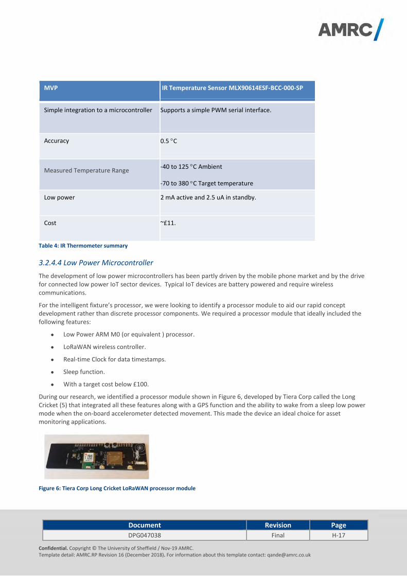
Document Revision Page
DPG047038 Final H-17
Confidential. Copyright © The University of Sheffield / Nov-19 AMRC. Template detail: AMRC.RP Revision 16 (December 2018). For information about this template contact: [email protected]
MVP IR Temperature Sensor MLX90614ESF-BCC-000-SP
Simple integration to a microcontroller
Supports a simple PWM serial interface.
Accuracy 0.5 C
Measured Temperature Range -40 to 125 C Ambient
-70 to 380 C Target temperature
Low power 2 mA active and 2.5 uA in standby.
Cost ~£11.
Table 4: IR Thermometer summary
3.2.4.4 Low Power Microcontroller
The development of low power microcontrollers has been partly driven by the mobile phone market and by the drive for connected low power IoT sector devices. Typical IoT devices are battery powered and require wireless communications.
For the intelligent fixture’s processor, we were looking to identify a processor module to aid our rapid concept development rather than discrete processor components. We required a processor module that ideally included the following features:
Low Power ARM M0 (or equivalent ) processor.
LoRaWAN wireless controller.
Real-time Clock for data timestamps.
Sleep function.
With a target cost below £100.
During our research, we identified a processor module shown in Figure 6, developed by Tiera Corp called the Long Cricket (5) that integrated all these features along with a GPS function and the ability to wake from a sleep low power mode when the on-board accelerometer detected movement. This made the device an ideal choice for asset monitoring applications.
Figure 6: Tiera Corp Long Cricket LoRaWAN processor module
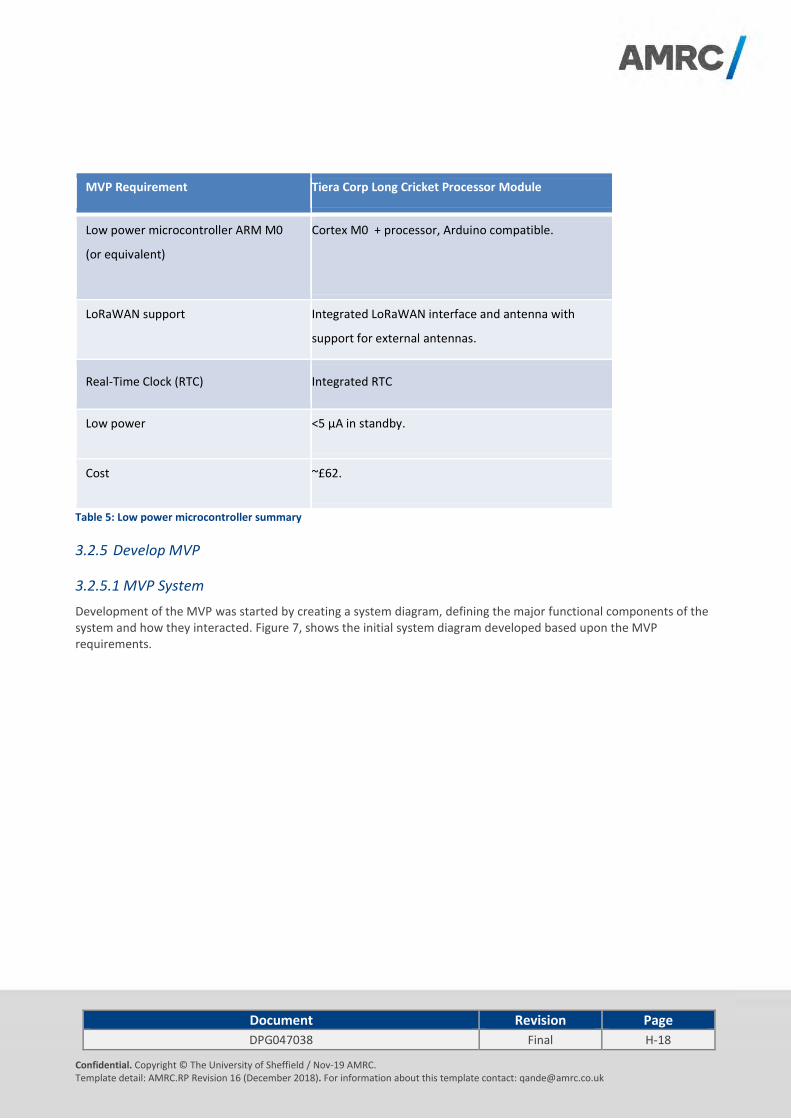
Document Revision Page
DPG047038 Final H-18
Confidential. Copyright © The University of Sheffield / Nov-19 AMRC. Template detail: AMRC.RP Revision 16 (December 2018). For information about this template contact: [email protected]
MVP Requirement Tiera Corp Long Cricket Processor Module
Low power microcontroller ARM M0
(or equivalent)
Cortex M0 + processor, Arduino compatible.
LoRaWAN support Integrated LoRaWAN interface and antenna with
support for external antennas.
Real-Time Clock (RTC) Integrated RTC
Low power <5 µA in standby.
Cost ~£62.
Table 5: Low power microcontroller summary
3.2.5 Develop MVP
3.2.5.1 MVP System
Development of the MVP was started by creating a system diagram, defining the major functional components of the system and how they interacted. Figure 7, shows the initial system diagram developed based upon the MVP requirements.
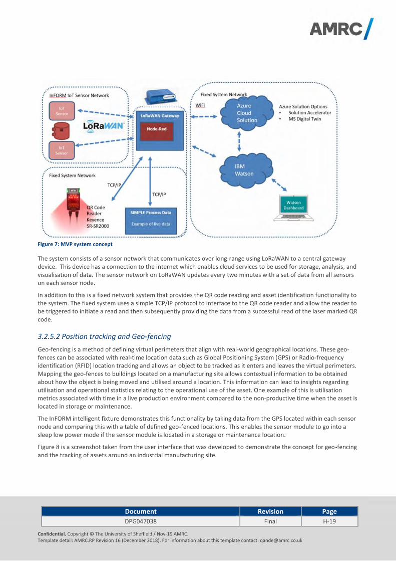
Document Revision Page
DPG047038 Final H-19
Confidential. Copyright © The University of Sheffield / Nov-19 AMRC. Template detail: AMRC.RP Revision 16 (December 2018). For information about this template contact: [email protected]
Figure 7: MVP system concept
The system consists of a sensor network that communicates over long-range using LoRaWAN to a central gateway device. This device has a connection to the internet which enables cloud services to be used for storage, analysis, and visualisation of data. The sensor network on LoRaWAN updates every two minutes with a set of data from all sensors on each sensor node.
In addition to this is a fixed network system that provides the QR code reading and asset identification functionality to the system. The fixed system uses a simple TCP/IP protocol to interface to the QR code reader and allow the reader to be triggered to initiate a read and then subsequently providing the data from a successful read of the laser marked QR code.
3.2.5.2 Position tracking and Geo-fencing
Geo-fencing is a method of defining virtual perimeters that align with real-world geographical locations. These geo-fences can be associated with real-time location data such as Global Positioning System (GPS) or Radio-frequency identification (RFID) location tracking and allows an object to be tracked as it enters and leaves the virtual perimeters. Mapping the geo-fences to buildings located on a manufacturing site allows contextual information to be obtained about how the object is being moved and utilised around a location. This information can lead to insights regarding utilisation and operational statistics relating to the operational use of the asset. One example of this is utilisation metrics associated with time in a live production environment compared to the non-productive time when the asset is located in storage or maintenance.
The InFORM intelligent fixture demonstrates this functionality by taking data from the GPS located within each sensor node and comparing this with a table of defined geo-fenced locations. This enables the sensor module to go into a sleep low power mode if the sensor module is located in a storage or maintenance location.
Figure 8 is a screenshot taken from the user interface that was developed to demonstrate the concept for geo-fencing and the tracking of assets around an industrial manufacturing site.
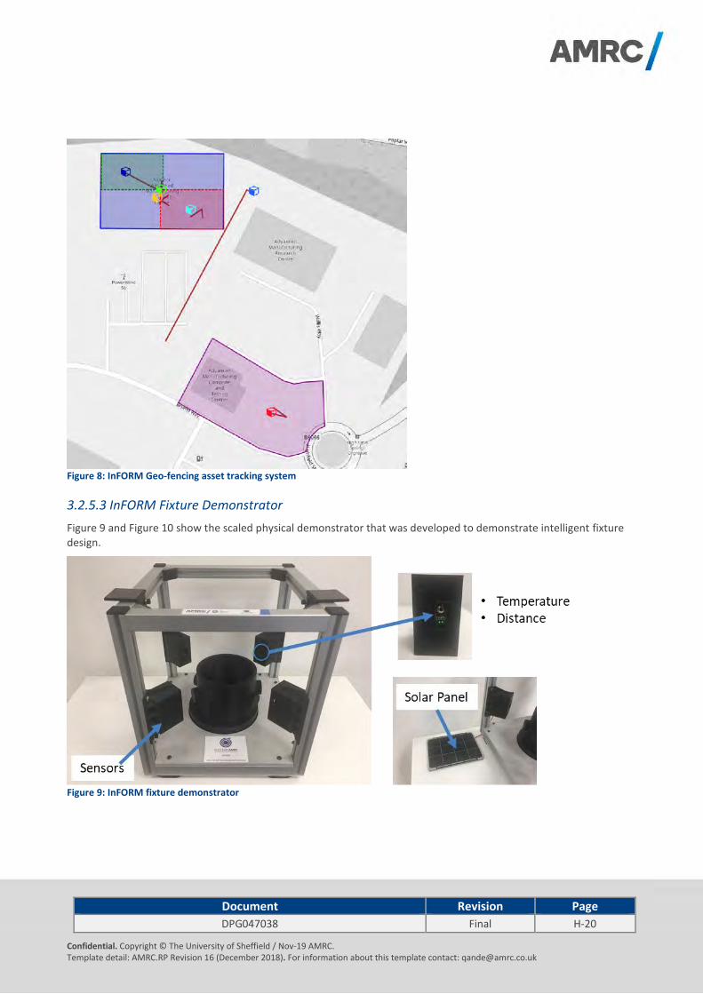
Document Revision Page
DPG047038 Final H-20
Confidential. Copyright © The University of Sheffield / Nov-19 AMRC. Template detail: AMRC.RP Revision 16 (December 2018). For information about this template contact: [email protected]
Figure 8: InFORM Geo-fencing asset tracking system
3.2.5.3 InFORM Fixture Demonstrator
Figure 9 and Figure 10 show the scaled physical demonstrator that was developed to demonstrate intelligent fixture design.
Figure 9: InFORM fixture demonstrator
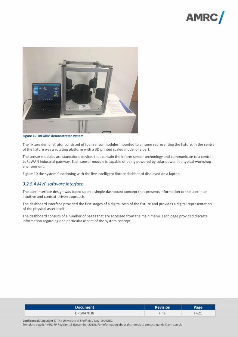
Document Revision Page
DPG047038 Final H-21
Confidential. Copyright © The University of Sheffield / Nov-19 AMRC. Template detail: AMRC.RP Revision 16 (December 2018). For information about this template contact: [email protected]
Figure 10: InFORM demonstrator system
The fixture demonstrator consisted of four sensor modules mounted to a frame representing the fixture. In the centre of the fixture was a rotating platform with a 3D printed scaled model of a part.
The sensor modules are standalone devices that contain the inform sensor technology and communicate to a central LoRaWAN industrial gateway. Each sensor module is capable of being powered by solar power in a typical workshop environment.
Figure 10 the system functioning with the live intelligent fixture dashboard displayed on a laptop.
3.2.5.4 MVP software interface
The user interface design was based upon a simple dashboard concept that presents information to the user in an intuitive and context-driven approach.
The dashboard interface provided the first stages of a digital twin of the fixture and provides a digital representation of the physical asset itself.
The dashboard consists of a number of pages that are accessed from the main menu. Each page provided discrete information regarding one particular aspect of the system concept.

Document Revision Page
DPG047038 Final H-22
Confidential. Copyright © The University of Sheffield / Nov-19 AMRC. Template detail: AMRC.RP Revision 16 (December 2018). For information about this template contact: [email protected]
Figure 11: InFORM Sensor Module Page
The sensor module page shown in Figure 11 provides the information for one device or sensor module. The user can select each device on the system with the following data from each sensor module displayed:
Sensor module temperature (ambient) data trend graph.
3 axis accelerometer data trend graph.
Current humidity.
Current sensor module battery voltage.
Current part temperature.
Distance to component/target.
The sensor module page also shows the current component identifier and information obtained from the QR code reader that is related to the sensor module fixture.
Figure 12: InFORM Component Overview Page
Four sensor modules are used in the demonstration fixture to monitor the component. The Component Overview Page shown in Figure 12 provides a simple digital twin representation of the fixture showing the component and the associated sensor modules. For each sensor module, the recorded component temperature and distance of the part is

Document Revision Page
DPG047038 Final H-23
Confidential. Copyright © The University of Sheffield / Nov-19 AMRC. Template detail: AMRC.RP Revision 16 (December 2018). For information about this template contact: [email protected]
indicated. This allows information such as temperature differences across the part to be determined and understand if there have been any changes to the alignment of the component on the fixture.
Figure 13: InFORM Location Tracking Page
The location tracking page shown in Figure 13 provides information regarding the current location of the fixtures placed
on a geographical map. Each device present in the system is represented. Geo-fencing is used to identify the specific
location of the fixture in the context of a specific site. In the example shown it can be seen that fixtures are in the
following locations:
Production.
Storage.
Transit.
The location tracking page also indicates the path taken by the fixture around a facility.
Figure 14: InFORM KPI Dashboard Page
The ability to continuously monitor the location of fixtures within a manufacturing environment provides data that can
be transformed into operationally important information such as utilisation statistics. Figure 14 shows a concept for one

Document Revision Page
DPG047038 Final H-24
Confidential. Copyright © The University of Sheffield / Nov-19 AMRC. Template detail: AMRC.RP Revision 16 (December 2018). For information about this template contact: [email protected]
such operational dashboard that indicates the proportion of time a fixture is located within each geo-fenced location
such as storage and production. These simple statistics demonstrate how it is possible to take basic location data and
convert this into useful insights into the manufacturing process.
Figure 15: InFORM Error Log Page
The InFORM demonstration system has the capability to analyse the system data and report errors and warnings based upon predefined example rules and thresholds.
The InFORM Error Log Page shown in Figure 15 provides a table displaying the current errors and warnings reported from the system:
Events that will be reported here include:
Unexpected movement.
Part out of alignment.
High component temperature.
High/Low ambient humidity/temperature.
Sensor module battery low.
Each entry in the table includes the following information:
Unique Error/Event code.
Type sensor reporting the error/warning.
Description of the error/warning.
Identifier of the device reporting the error.
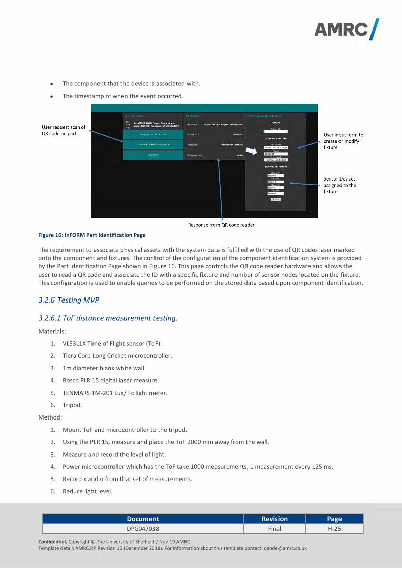
Document Revision Page
DPG047038 Final H-25
Confidential. Copyright © The University of Sheffield / Nov-19 AMRC. Template detail: AMRC.RP Revision 16 (December 2018). For information about this template contact: [email protected]
The component that the device is associated with.
The timestamp of when the event occurred.
Figure 16: InFORM Part Identification Page
The requirement to associate physical assets with the system data is fulfilled with the use of QR codes laser marked onto the component and fixtures. The control of the configuration of the component identification system is provided by the Part Identification Page shown in Figure 16. This page controls the QR code reader hardware and allows the user to read a QR code and associate the ID with a specific fixture and number of sensor nodes located on the fixture. This configuration is used to enable queries to be performed on the stored data based upon component identification.
3.2.6 Testing MVP
3.2.6.1 ToF distance measurement testing.
Materials:
1. VL53L1X Time of Flight sensor (ToF).
2. Tiera Corp Long Cricket microcontroller.
3. 1m diameter blank white wall.
4. Bosch PLR 15 digital laser measure.
5. TENMARS TM-201 Lux/ Fc light meter.
6. Tripod.
Method:
1. Mount ToF and microcontroller to the tripod.
2. Using the PLR 15, measure and place the ToF 2000 mm away from the wall.
3. Measure and record the level of light.
4. Power microcontroller which has the ToF take 1000 measurements, 1 measurement every 125 ms.
5. Record x ̄and σ from that set of measurements.
6. Reduce light level.

Document Revision Page
DPG047038 Final H-26
Confidential. Copyright © The University of Sheffield / Nov-19 AMRC. Template detail: AMRC.RP Revision 16 (December 2018). For information about this template contact: [email protected]
7. Repeat steps 3 through 5.
8. Move tripod so ToF sensor is 250 mm closer to the wall.
9. Repeat steps 3 through 8 measurements are taken at 250 mm from the wall.
10. Upload code to take measurements using short-distance mode.
11. Record data for short-distance mode with normal light levels at 250 mm to 1000 mm in 250 mm intervals.
Figure 17: Measured ToF distance errors with varying ambient light levels.
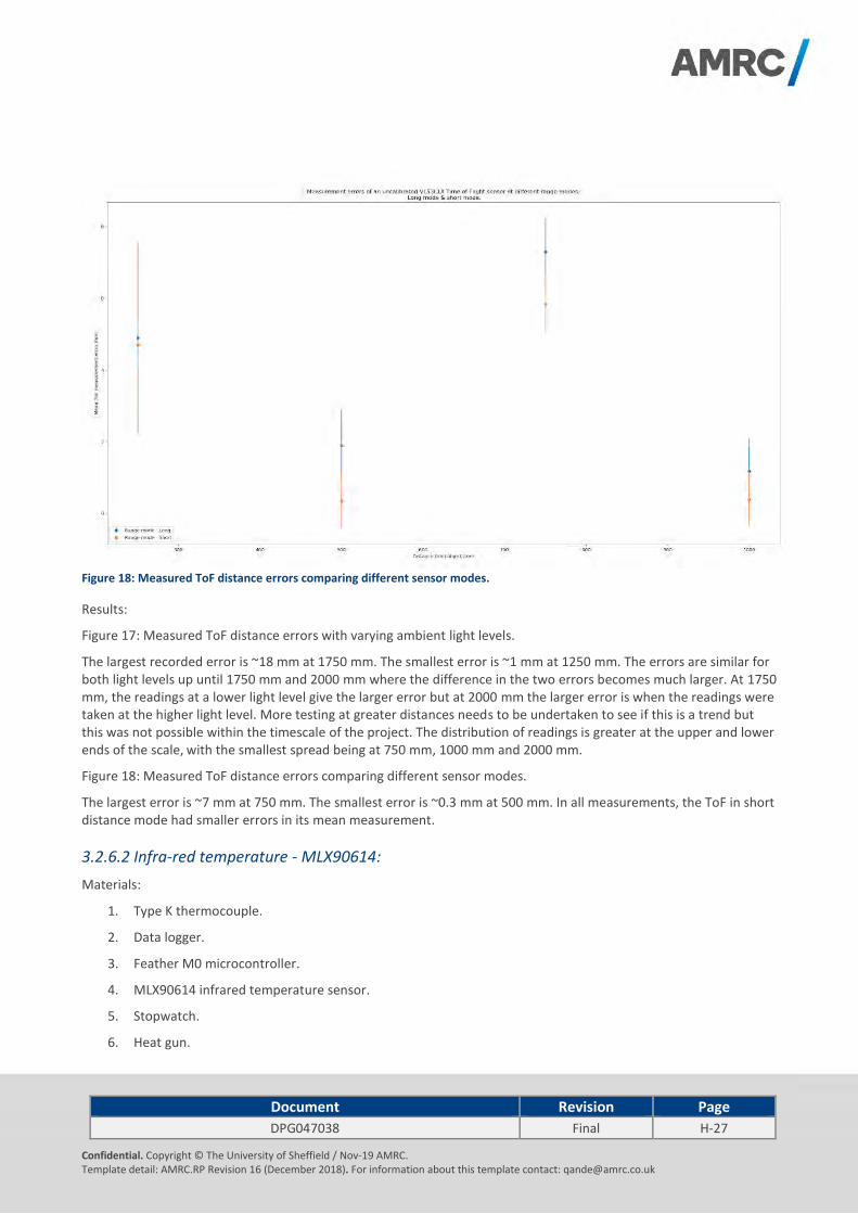
Document Revision Page
DPG047038 Final H-27
Confidential. Copyright © The University of Sheffield / Nov-19 AMRC. Template detail: AMRC.RP Revision 16 (December 2018). For information about this template contact: [email protected]
Figure 18: Measured ToF distance errors comparing different sensor modes.
Results:
Figure 17: Measured ToF distance errors with varying ambient light levels.
The largest recorded error is ~18 mm at 1750 mm. The smallest error is ~1 mm at 1250 mm. The errors are similar for both light levels up until 1750 mm and 2000 mm where the difference in the two errors becomes much larger. At 1750 mm, the readings at a lower light level give the larger error but at 2000 mm the larger error is when the readings were taken at the higher light level. More testing at greater distances needs to be undertaken to see if this is a trend but this was not possible within the timescale of the project. The distribution of readings is greater at the upper and lower ends of the scale, with the smallest spread being at 750 mm, 1000 mm and 2000 mm.
Figure 18: Measured ToF distance errors comparing different sensor modes.
The largest error is ~7 mm at 750 mm. The smallest error is ~0.3 mm at 500 mm. In all measurements, the ToF in short distance mode had smaller errors in its mean measurement.
3.2.6.2 Infra-red temperature - MLX90614:
Materials:
1. Type K thermocouple.
2. Data logger.
3. Feather M0 microcontroller.
4. MLX90614 infrared temperature sensor.
5. Stopwatch.
6. Heat gun.
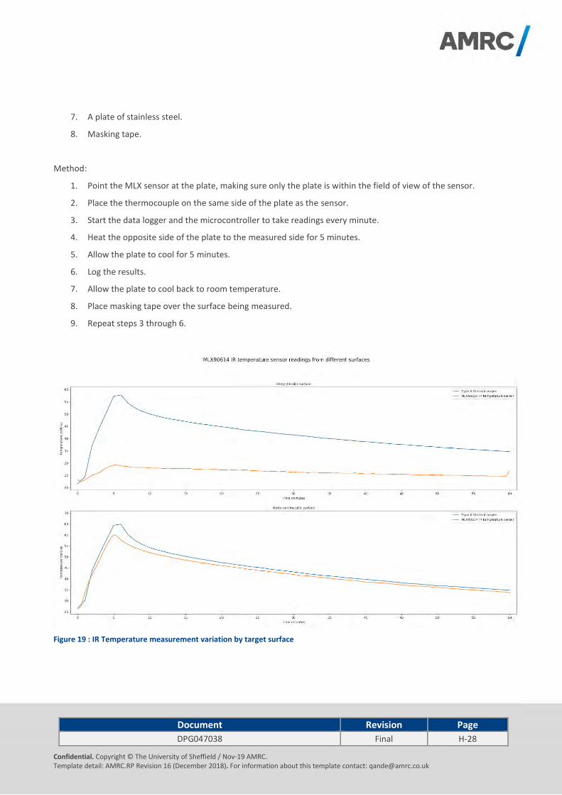
Document Revision Page
DPG047038 Final H-28
Confidential. Copyright © The University of Sheffield / Nov-19 AMRC. Template detail: AMRC.RP Revision 16 (December 2018). For information about this template contact: [email protected]
7. A plate of stainless steel.
8. Masking tape.
Method:
1. Point the MLX sensor at the plate, making sure only the plate is within the field of view of the sensor.
2. Place the thermocouple on the same side of the plate as the sensor.
3. Start the data logger and the microcontroller to take readings every minute.
4. Heat the opposite side of the plate to the measured side for 5 minutes.
5. Allow the plate to cool for 5 minutes.
6. Log the results.
7. Allow the plate to cool back to room temperature.
8. Place masking tape over the surface being measured.
9. Repeat steps 3 through 6.
Figure 19 : IR Temperature measurement variation by target surface

Document Revision Page
DPG047038 Final H-29
Confidential. Copyright © The University of Sheffield / Nov-19 AMRC. Template detail: AMRC.RP Revision 16 (December 2018). For information about this template contact: [email protected]
Results:
Figure 19 shows the effect of variations in the target surface upon the IR temperature measurement. The shiny metallic surface IR measurement is significantly different from the thermocouple contact measurement. The same measurements taken using a matte metal surface as a target are closer to the thermocouple measurements.
This variation can be explained by differences in the material radiated IR caused by different emissivity values for each material. It is possible to take this variation into account within the IR sensor to essentially calibrate the sensor for different materials.
4 End MRL/TRL level “How?”
A peer review assessment of the TRL and MRL attained by innovations in each InFORM work package was carried out by industrial academics and consultants on 23rd May 2019. It was determined that innovations in this work package have achieved MRL and TRL values of 3. The justification for these values is shown in Appendix 1.
4.1 industrial impact
The use of intelligent fixtures within the nuclear industry has the potential to reduce manufacturing costs by delivering improved efficiency. The ability to accurately track the use of fixtures within the manufacturing environment provides opportunities for operational improvements. The addition of sensors providing constant monitoring of fixtures provides the information required to implement predictive maintenance. The ability to predict failures or problems with fixtures before they have a negative impact on the operation of the manufacturing process delivers cost savings and can also improve the quality of the product.
Finally, in addition to cost and quality savings, there is also a potential improvement to safety as the prevention of failures associated with fixtures could prevent accidents occurring in critical manufacturing processes.
Document Revision Page
DPG047038 Final H-30
Confidential. Copyright © The University of Sheffield / Nov-19 AMRC. Template detail: AMRC.RP Revision 16 (December 2018). For information about this template contact: [email protected]
5 Conclusions and recommendation
5.1 Route to industrial adoption
The path to industrial adoption requires the following:
Detailed understanding of the fixture process lifecycle.
Design for industrial environments.
Testing within a relevant industrial environment throughout the fixture lifecycle.
Develop sensor platform to TRL6 – 7.
Partner with an OEM manufacturer to take the concept sensor design to market.
5.2 Further Research and Development
Understanding the challenges associated with harvesting energy in industrial environments is a key enabler for the possibility of ‘fit and forget’ IoT sensor technology. A study of the feasibility of energy harvesting technologies within the nuclear industry manufacturing environment would be beneficial.
The potential benefits of using low power LoRaWAN within industrial environments are understood. However, the creation of a long term industrial test site would highlight any potential challenges with applying LoRaWAN to manufacturing environments. In particular consideration of interference from manufacturing equipment and also any existing networks would be a recommended starting point for research.
The location tracking limitations of GPS requires a fusion of technologies to provide total tracking coverage inside and outside buildings. There are many different technologies available typically including RFID systems (6) that implement location tracking in manufacturing environments. Research is required to understand how these could be applied to the nuclear sector effectively with the requirement for a low power solution.
5.3 Conclusions
Fixtures used in the nuclear industry, typically represent a significant investment financially, but also in terms of maintenance and storage of these manufacturing assets. Correct storage of these high-value fixtures increases the size of factory space required and as moves are made towards serial production of reactors in a factory environment, optimising the factory layout becomes a priority. The ability to track the fixture location and usage provides information to ensure minimum investment is made to achieve optimal usage and factory throughput. Additional understanding of the environmental conditions and loading to which they have been subjected allows these manufacturing assets to be maintained in such a way that their working life can be extended and performance preserved while minimising breakdown and failure. Investment in intelligent fixtures will enable the industry to achieve these optimisations and minimise the capital expenditure required to start up their manufacturing processes. The data generated by the intelligent fixture during manufacture will provide additional benefits once the reactors are in operation as detailed manufacturing records combined within service data will increase the fidelity of digital twins adding strength to safety cases and life extensions.
The development of a 4IR technology demonstrator for InFORM has highlighted that there are opportunities for innovation by utilising technology from different sectors. The rapid development of 4IR technology has the potential to disrupt many of the processes within the nuclear sector and provide new insights into efficiency improvements and

Document Revision Page
DPG047038 Final H-31
Confidential. Copyright © The University of Sheffield / Nov-19 AMRC. Template detail: AMRC.RP Revision 16 (December 2018). For information about this template contact: [email protected]
ultimately cost savings.
The project has shown it is feasible to develop ‘Fit and Forget’ sensors that require minimal infrastructure to deploy and can provide valuable operational information to enable opportunities such as predictive maintenance and possibility of a digital thread associated with the life of a fixture.
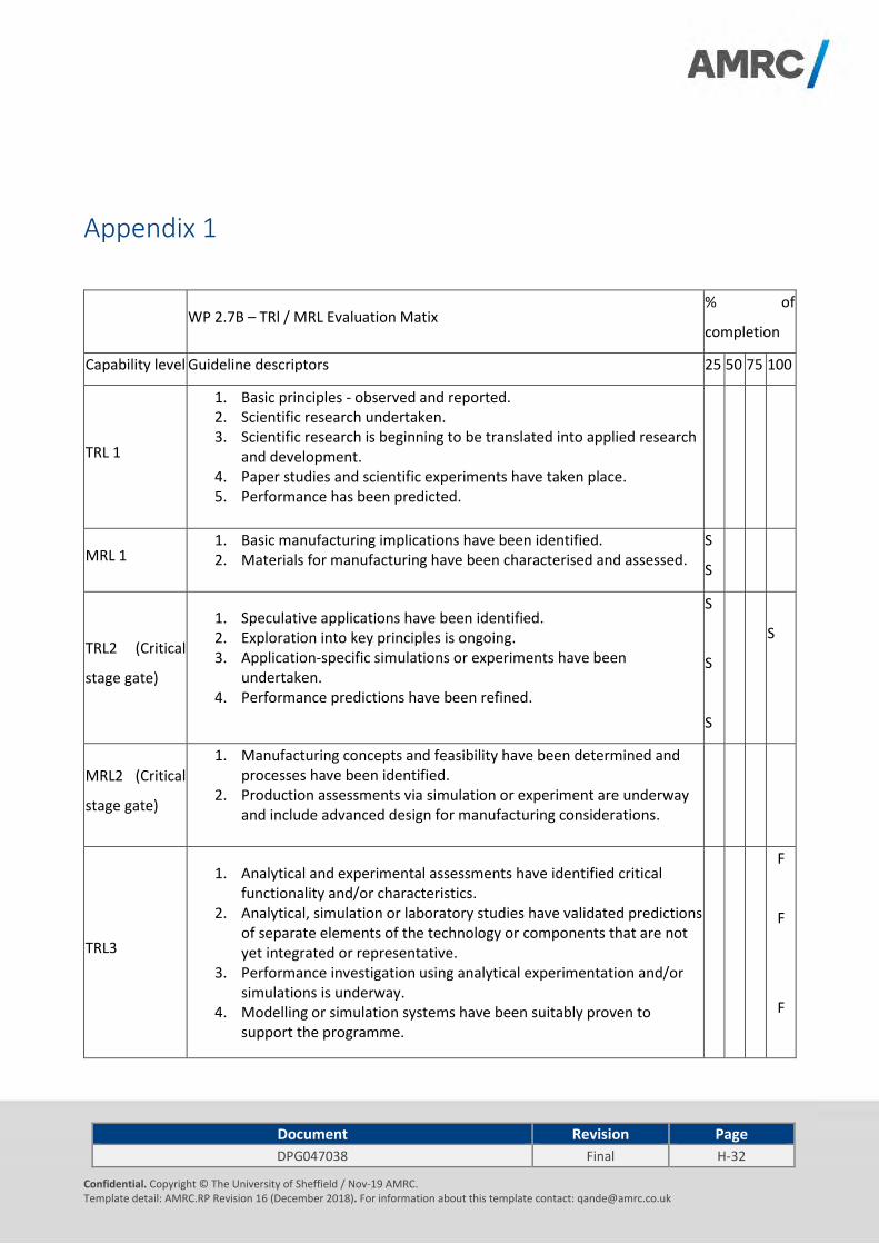
Document Revision Page
DPG047038 Final H-32
Confidential. Copyright © The University of Sheffield / Nov-19 AMRC. Template detail: AMRC.RP Revision 16 (December 2018). For information about this template contact: [email protected]
Appendix 1
WP 2.7B – TRl / MRL Evaluation Matix % of
completion
Capability level Guideline descriptors 25 50 75 100
TRL 1
1. Basic principles - observed and reported. 2. Scientific research undertaken. 3. Scientific research is beginning to be translated into applied research
and development. 4. Paper studies and scientific experiments have taken place. 5. Performance has been predicted.
MRL 1 1. Basic manufacturing implications have been identified. 2. Materials for manufacturing have been characterised and assessed.
S
S
TRL2 (Critical
stage gate)
1. Speculative applications have been identified. 2. Exploration into key principles is ongoing. 3. Application-specific simulations or experiments have been
undertaken. 4. Performance predictions have been refined.
S
S
S
S
MRL2 (Critical
stage gate)
1. Manufacturing concepts and feasibility have been determined and processes have been identified.
2. Production assessments via simulation or experiment are underway and include advanced design for manufacturing considerations.
TRL3
1. Analytical and experimental assessments have identified critical functionality and/or characteristics.
2. Analytical, simulation or laboratory studies have validated predictions of separate elements of the technology or components that are not yet integrated or representative.
3. Performance investigation using analytical experimentation and/or simulations is underway.
4. Modelling or simulation systems have been suitably proven to support the programme.
F
F
F

Document Revision Page
DPG047038 Final H-33
Confidential. Copyright © The University of Sheffield / Nov-19 AMRC. Template detail: AMRC.RP Revision 16 (December 2018). For information about this template contact: [email protected]
5. Specifications have been identified for the relevant component/sub-system.
F
F
MRL3
1. A manufacturing proof-of-concept has been developed and identified as a need within industry.
2. Analytical, simulated or laboratory experiments validate paper studies.
3. Experimental hardware or processes have been created, but are not yet integrated or representative.
4. Materials and/or processes have been characterised for manufacturability and availability.
5. Initial manufacturing cost projections have been made. 6. Supply-chain requirements have been determined. 7. Specifications have been identified and scoped within project.
F
F
F
F
F
F
F

Document Revision Page
DPG047038 Final H-34
Confidential. Copyright © The University of Sheffield / Nov-19 AMRC. Template detail: AMRC.RP Revision 16 (December 2018). For information about this template contact: [email protected]
References 1. [Online] [Cited: 3 September 2018.] https://www.st.com/en/imaging-and-photonics-solutions/proximity-
sensors.html.
2. [Online] [Cited: 01 10 2018.] https://lora-alliance.org/sites/default/files/2019-
02/LORAWAN_LIVE_MASTER_DECK_FINAL_FOR_RELEASE.pdf.
3. [Online] [Cited: 10 10 2018.] https://www.st.com/en/imaging-and-photonics-solutions/proximity-
sensors.html#products.
4. [Online] [Cited: 10 10 2018.] https://www.melexis.com/en/product/MLX90614/Digital-Plug-Play-Infrared-
Thermometer-TO-Can.
5. [Online] [Cited: 18 10 2018.] https://www.tindie.com/products/tleracorp/long-cricket-loralorawangnss-asset-
tracker/.
6. [Online] [Cited: 01 06 2019.] https://litumiot.com/category/active-rfid/.

Document Revision Page
NI1066-REP-01 03 I-1
© 2019 University of Sheffield NAMRC.REP Version 7.0
I. Dissemination

Document Revision Page
NI1066-REP-01 01 I-1
© 2019 University of Sheffield NAMRC.REP Version 7.0
Contents
1 Dissemination ............................................................................................................................................................... 2
1.1 Consortium networking ................................................................................................................................... 2
1.2 Conferences, seminars and other events ....................................................................................................... 2
1.3 BEIS Suppliers Day Event .................................................................................................................................. 4
1.4 NUMAN seminar ............................................................................................................................................... 4
1.5 ICONE27 ............................................................................................................................................................ 4
1.6 Nuclear Innovations UK Conference (NIC) ...................................................................................................... 5
1.7 PVP 2019 ........................................................................................................................................................... 6
1.8 Technical publications ...................................................................................................................................... 6
1.9 Nuclear AMRC research board ........................................................................................................................ 7
1.10 MANTRA ............................................................................................................................................................ 7
References ................................................................................................................................................................................... 8

Document Revision Page
NI1066-REP-01 01 I-2
© 2019 University of Sheffield NAMRC.REP Version 7.0
1 Dissemination
Stage two of the InFORM project ran between February 2018 and August 2019. Over this period the InFORM consortium
completed various direct and indirect dissemination activities both domestically and internationally.
1.1 Consortium networking
Five consortium meetings were held during the project, four of which were hosted by the Nuclear AMRC in Rotherham
and one by TWI in Cambridge. At these meetings, the progress of each work package was shared between the delivery
teams, the project funders the Department for Business, Energy and Industrial Strategy (BEIS) and their technical
advisors the Nuclear Innovation and Research Office (NIRO). The primary function of these meetings was to ensure
consistent and successful delivery of the programme and to provide an opportunity for each delivery partner to share
knowledge on their wider capabilities.
Table 1-1: Consortium meetings
Consortium Meeting Date Host
Kickoff meeting 06 Feb 2018 Nuclear AMRC (Rotherham)
Quarterly review meeting 1 11 Jul 2018 Nuclear AMRC (Rotherham)
Quarterly review meeting 2 25 Oct 2018 Nuclear AMRC (Rotherham)
Quarterly review meeting 3 31 Jan 2019 TWI Ltd (Cambridge)
Quarterly review meeting 4 25 Apr 2019 Nuclear AMRC (Rotherham)
Quarterly review meeting 5 23 Jul 2019 Nuclear AMRC (Rotherham)
The fifth quarterly review included a joint close out meeting with the SIMPLE team to discuss how output from the
SIMPLE and InFORM projects could be carried forward in future research projects.
1.2 Conferences, seminars and other events
The output of the research conducted has been presented and discussed at a number of industrial and academic
conferences and seminars, both domestically and internationally. A list of events attended is shown in Table 1-2.
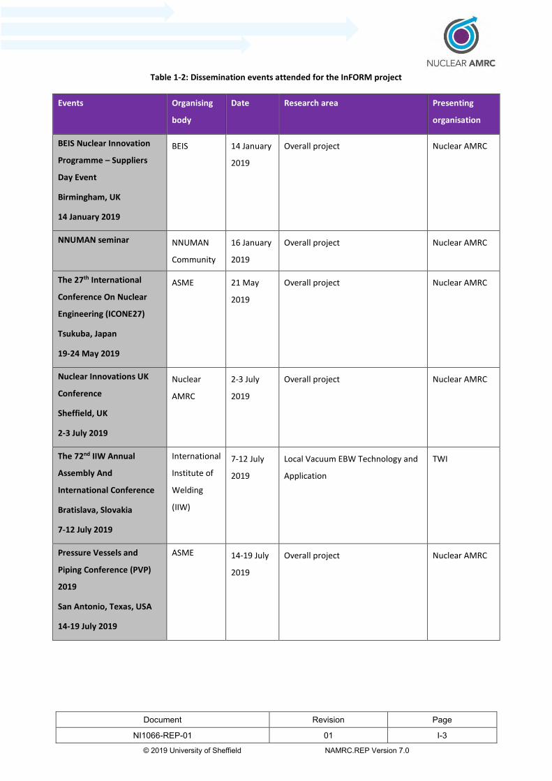
Document Revision Page
NI1066-REP-01 01 I-3
© 2019 University of Sheffield NAMRC.REP Version 7.0
Table 1-2: Dissemination events attended for the InFORM project
Events Organising
body
Date Research area Presenting
organisation
BEIS Nuclear Innovation
Programme – Suppliers
Day Event
Birmingham, UK
14 January 2019
BEIS 14 January
2019
Overall project Nuclear AMRC
NNUMAN seminar NNUMAN
Community
16 January
2019
Overall project Nuclear AMRC
The 27th International
Conference On Nuclear
Engineering (ICONE27)
Tsukuba, Japan
19-24 May 2019
ASME 21 May
2019
Overall project
Nuclear AMRC
Nuclear Innovations UK
Conference
Sheffield, UK
2-3 July 2019
Nuclear
AMRC
2-3 July
2019
Overall project Nuclear AMRC
The 72nd IIW Annual
Assembly And
International Conference
Bratislava, Slovakia
7-12 July 2019
International
Institute of
Welding
(IIW)
7-12 July
2019
Local Vacuum EBW Technology and
Application
TWI
Pressure Vessels and
Piping Conference (PVP)
2019
San Antonio, Texas, USA
14-19 July 2019
ASME 14-19 July
2019
Overall project Nuclear AMRC

Document Revision Page
NI1066-REP-01 01 I-4
© 2019 University of Sheffield NAMRC.REP Version 7.0
1.3 BEIS Suppliers Day Event
The BEIS Nuclear Innovation Programme Suppliers Day Event held in Birmingham on the 14th January 2019 aimed to
disseminate findings from the initial phases of the £180m BEIS investment through the Nuclear Innovation Programme
(NIP) and promote opportunities for the next phases of work. At the event, Phase 1 participants for the Advanced
Reactor Design – Digital and Advanced Manufacturing and Materials programmes – disseminated findings from their
work through presentations and Q&A sessions. This enabled knowledge to be shared with the wider industry, helping
to promote fairness and transparency for potential suppliers and collaborators that wish to bid into future phases of
work. Participating stakeholders were invited to engage in a brokering and networking event to stimulate discussions
about potential collaborations for the next phases of work (2). Additionally the details of the next phase of the Advanced
Manufacture and Materials funding call were given. This was to provide up to £20 million of government funding to
demonstrate how advanced manufacturing and construction can increase UK competitiveness.
1.4 NUMAN seminar
NNUMAN (New Nuclear MANufacturing) was an £8 million EPSRC (Engineering and Physical Sciences Research Council)
research programme which ran from 2012 to 2017, and covered a broad spectrum of nuclear-relevant manufacturing
research, including joining technologies, powder metallurgy, advanced machining and surface engineering. Through the
dissemination activities of the programme, a community of over 80 interested parties was formed. After the funding
period ended, the community decided to continue building up the network by meeting formally on a biannual basis to
discuss relevant research activities. NNUMAN is chaired by the Dalton Institute of the University of Manchester with
strong involvement of the Nuclear AMRC.
The NNUMAN seminar provided an academically focused event which engaged with the NNUMAN community on the
Advanced Manufacturing and Materials (AM&M) strand of the NIP. The seminar was held on the 16th January 2019 at
the AMRC’s Knowledge Transfer Centre in Rotherham, and was attended by over 75 members of the nuclear R&D
community with delegates from industry and academia. Projects from each of the AM&M themes, including InFORM
from theme 3, were presented at the event.
1.5 ICONE27
An overview of the InFORM project, including a summary of each work package, was presented at the 27th International
Conference on Nuclear Engineering (ICONE) in Tsukuba, Japan in May 2019. ICONE brings together academics and
professionals from across the nuclear industry to share knowledge and ideas on nuclear reactor technology. It includes
industry forums, technical, keynote, plenary and poster sessions, plus workshops where industry leaders, Government
and academia gather to present and explore cutting edge technical issues and solutions for the challenges in the nuclear
industry (3). It is sponsored by ASME (The American Society of Mechanical Engineers) and the Japan Society of
Mechanical Engineers s (JSME).
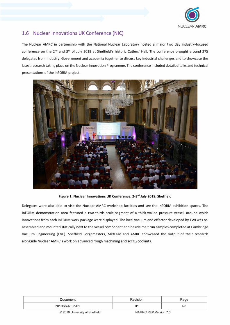
Document Revision Page
NI1066-REP-01 01 I-5
© 2019 University of Sheffield NAMRC.REP Version 7.0
1.6 Nuclear Innovations UK Conference (NIC)
The Nuclear AMRC in partnership with the National Nuclear Laboratory hosted a major two day industry-focused
conference on the 2nd and 3rd of July 2019 at Sheffield’s historic Cutlers’ Hall. The conference brought around 275
delegates from industry, Government and academia together to discuss key industrial challenges and to showcase the
latest research taking place on the Nuclear Innovation Programme. The conference included detailed talks and technical
presentations of the InFORM project.
Figure 1: Nuclear Innovations UK Conference, 2-3rd July 2019, Sheffield
Delegates were also able to visit the Nuclear AMRC workshop facilities and see the InFORM exhibition spaces. The
InFORM demonstration area featured a two-thirds scale segment of a thick-walled pressure vessel, around which
innovations from each InFORM work package were displayed. The local vacuum end effector developed by TWI was re-
assembled and mounted statically next to the vessel component and beside melt run samples completed at Cambridge
Vacuum Engineering (CVE). Sheffield Forgemasters, MetLase and AMRC showcased the output of their research
alongside Nuclear AMRC’s work on advanced rough machining and scCO2 coolants.
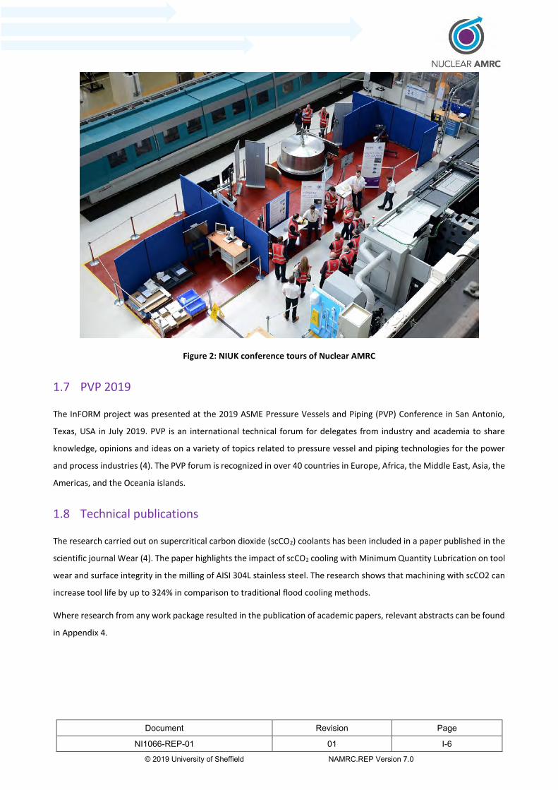
Document Revision Page
NI1066-REP-01 01 I-6
© 2019 University of Sheffield NAMRC.REP Version 7.0
Figure 2: NIUK conference tours of Nuclear AMRC
1.7 PVP 2019
The InFORM project was presented at the 2019 ASME Pressure Vessels and Piping (PVP) Conference in San Antonio,
Texas, USA in July 2019. PVP is an international technical forum for delegates from industry and academia to share
knowledge, opinions and ideas on a variety of topics related to pressure vessel and piping technologies for the power
and process industries (4). The PVP forum is recognized in over 40 countries in Europe, Africa, the Middle East, Asia, the
Americas, and the Oceania islands.
1.8 Technical publications
The research carried out on supercritical carbon dioxide (scCO2) coolants has been included in a paper published in the
scientific journal Wear (4). The paper highlights the impact of scCO2 cooling with Minimum Quantity Lubrication on tool
wear and surface integrity in the milling of AISI 304L stainless steel. The research shows that machining with scCO2 can
increase tool life by up to 324% in comparison to traditional flood cooling methods.
Where research from any work package resulted in the publication of academic papers, relevant abstracts can be found
in Appendix 4.

Document Revision Page
NI1066-REP-01 01 I-7
© 2019 University of Sheffield NAMRC.REP Version 7.0
1.9 Nuclear AMRC research board
One of the ways that the Nuclear AMRC ensures it remains industrially relevant is by way of its membership. There are
two grades of membership, Tier 1 members contribute £200K p.a. in cash or kind and have one seat on the Research
Board. Tier 2 members contribute £30K p.a. in cash or kind and all Tier 2 members nominate one person to sit on the
Research Board to represent their interests. The Research Board represents over 40 companies from across the nuclear
supply chain – including reactor vendors – and meets quarterly. The Research Board reviews the research that Nuclear
AMRC are undertaking on their behalf and also receive presentations about other publicly funded research we are
undertaking. Consequently progress updates on the InFORM project were given at each quarter’s meeting throughout
the life of the project.
1.10 MANTRA
MANTRA, the MANufacturing (technology) TRAnsporter, is a specially customised 14 metre HGV trailer which is
operated by the University of Sheffield AMRC. It is packed with the latest machinery and simulators designed to give
aspiring young engineers a hands-on experience with real cutting-edge technologies (5). The MANTRA lorry regularly
tours schools and colleges to give students a taste of modern manufacturing, advanced modelling and assembly line
technology to help inspire young people to take up careers in engineering. It also attends industrial events where it
showcases the latest developments in advanced manufacturing technology to the wider business community and
commercial audiences.
Videos highlighting the results of the InFORM project have been installed into MANTRA and will be displayed at future
exhibitions and in schools and colleges to demonstrate the impact the innovations will have on improving UK
manufacturing competitiveness.

Document Revision Page
NI1066-REP-01 01 I-8
© 2019 University of Sheffield NAMRC.REP Version 7.0
References
1. NIA. BEIS Nuclear Innovation Programme – Suppliers Day Event. [Online] 2019. [Cited: 14 08 2019.]
https://www.niauk.org/event-listing/beis-nuclear-innovation-programme-suppliers-day-event/.
2. ICONE. ASME International Conference on Nuclear Engineering & Power Conference. [Online] 2019. [Cited: 06 08
2019.] http://event.asme.org/ICONE.
3. PVP. ASME Pressure Vessels & Piping Conference. [Online] 2019. [Cited: 06 08 2019.] https://event.asme.org/PVP.
4. Impact of supercritical carbon dioxide cooling with Minimum Quantity Lubrication on tool wear and surface integrity
in the milling of AISI 304L stainless steel. Wika, Krystian K, Litwa, Przemyslaw and Hitchens, Carl. Sheffield : Elsevier,
2019, Wear, Vols. 426-427, Part B, 30 April 2019, Pages 1691-1701.
5. AMRC. Welcome to AMRC Mantra. [Online] 2019. [Cited: 14 08 2019.] https://amrcmantra.co.uk/.

Document Revision Page
NI1066-REP-01 03 Appendix 1
© 2019 University of Sheffield NAMRC.REP Version 7.0
Appendix 1. TRL / MRL Assessments

Document Revision Page
NI1066-REP-01 01 Appendix 1-1
© 2019 University of Sheffield NAMRC.REP Version 7.0
Appendix 1. TRL / MRL Assessments
This appendix summarises the Technology Readiness Level (TRL) Manufacturing Readiness Level (MRL) assessments that
were made for each Work Package at the start and finish of the project, and at the peer review assessment which took
place on the 23rd May 2019. Appendix 2 details the guidance that was given to each Work Package Technical Lead and
the members of the Peer Review panel in order that they could make their assessments.
Peer review assessment
The peer review assessment of each work package was carried out on the 23rd May 2019 at the Nuclear AMRC. The
panel members are detailed in Appendix 3.
Key to references
Each work package is deemed to have reached a particular capability level when the technologies and/or innovations it
contains are judged collectively by the assessment panel to have satisfied several criteria or ‘guideline descriptors’ that
define specific readiness levels. The extent to which each criterion has been met by a particular work package is also
assessed, and denoted in terms of ‘percentage complete’.
Each Work Package Technical Lead, in conjunction with the Nuclear ARMC CTO agreed on starting and finishing TRL/MRL
– indicated by S and F respectively in the below assessment tables. The assessments of the Peer Review panel are
indicated by X in the below assessment tables – the Peer Review having taken place some 3 months before the finish of
the project.
The column in which each letter is placed denotes the extent to which each technology/innovation is deemed to have
met the criterion. The letters assigned denote the following:
S – Readiness level assessment at the start of the project
X – Readiness level assessment at the peer review consultation with expert independent panel
F – Readiness level assessment at the finish of the project
Graphical matrices
The graphs below illustrate the increases in TRL and MRL for each work package as validated by the Principal Investigator
(PI).

Document Revision Page
NI1066-REP-01 01 Appendix 1-2
© 2019 University of Sheffield NAMRC.REP Version 7.0
Figure 1: Start and finish TRL

Document Revision Page
NI1066-REP-01 01 Appendix 1-3
© 2019 University of Sheffield NAMRC.REP Version 7.0
Figure 2: Start and finish MRL
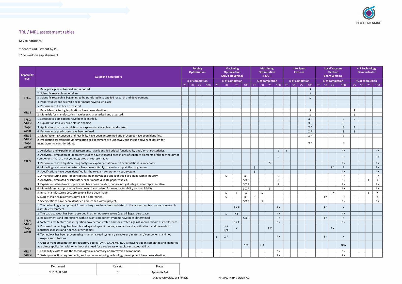
Document Revision Page
NI1066-REP-01 01 Appendix 1-4
© 2019 University of Sheffield NAMRC.REP Version 7.0
TRL / MRL assessment tables
Key to notations:
* denotes adjustment by PI.
**no work on gap alignment.
Capability level
Guideline descriptors
Forging Optimisation
Machining Optimisation
(Adv'd Roughing)
Machining Optimisation
(scCO2)
Intelligent Fixtures
Local Vacuum Electron
Beam Welding
4IR Technology Demonstrator
% of completion % of completion % of completion % of completion % of completion % of completion
25 50 75 100 25 50 75 100 25 50 75 100 25 50 75 100 25 50 75 100 25 50 75 100
TRL 1
1. Basic principles - observed and reported. S
2. Scientific research undertaken. S
3. Scientific research is beginning to be translated into applied research and development. S
4. Paper studies and scientific experiments have taken place.
5. Performance has been predicted.
MRL 1 1. Basic Manufacturing Implications have been identified. S S
2. Materials for manufacturing have been characterised and assessed. S S
TRL 2 (Critical Stage Gate)
1. Speculative applications have been identified. X F S S
2. Exploration into key principles is ongoing. X F S S
3. Application-specific simulations or experiments have been undertaken. X F S S
4. Performance predictions have been refined. X F S S
MRL 2 (Critical Stage Gate)
1. Manufacturing concepts and feasibility have been determined and processes have been identified. X F S
2. Production assessments via simulation or experiment are underway and include advanced design for manufacturing considerations. X F S
TRL 3
1. Analytical and experimental assessments have identified critical functionality and / or characteristics. S F F X F X
2. Analytical, simulation or laboratory studies have validated predictions of separate elements of the technology or components that are not yet integrated or representative. S F X F X
3. Performance investigation using analytical experimentation and / or simulations is underway. S F X F X
4. Modelling or simulation systems have been suitably proven to support the programme. S F* F F X
5. Specifications have been identified for the relevant component / sub-system. S F X F X
MRL 3
1. A manufacturing proof-of-concept has been developed and identified as a need within industry. S X F S F X F X
2. Analytical, simulated or laboratory experiments validate paper studies. S X F S F X F X
3. Experimental hardware or processes have been created, but are not yet integrated or representative. S X F S F X F X
4. Materials and / or processes have been characterised for manufacturability and availability. S X F S F X F X
5. Initial manufacturing cost projections have been made. S F X S F X F X
6. Supply-chain requirements have been determined. S X F S F* F X F X
7. Specifications have been identified and scoped within project. S X F S F X F X
TRL 4 (Critical Stage Gate)
1. The technology / component / basic sub-system have been validated in the laboratory, test house or research institute environment.
S X F F X F* X
2. The basic concept has been observed in other industry sectors (e.g. oil & gas, aerospace). S X F F X F X
3. Requirements and interactions with relevant component systems have been determined. S X F F X F* X
4. Systems architecture and integration now demonstrated and soak tested against known factors of interference. S X F F X F X
5. Proposed technology has been tested against specific codes, standards and specifications and presented to industrial sponsors and / or regulatory bodies.
S F N/A
X F X F X
6. Technology has been proven using ‘true’ or agreed systems / structures / materials / components and not surrogate substitutions.
S X F F X F* X
7. Output from presentation to regulatory bodies (ONR, EA, ASME, RCC-M etc.) has been completed and identified as a direct application with or without the need for a code-case or equivalent acceptability.
N/A F X N/A
MRL 4 (Critical
1. Capability exists to use the technology in a laboratory or prototypic environment. F X F X
2. Series production requirements, such as manufacturing technology development have been identified. F X F X
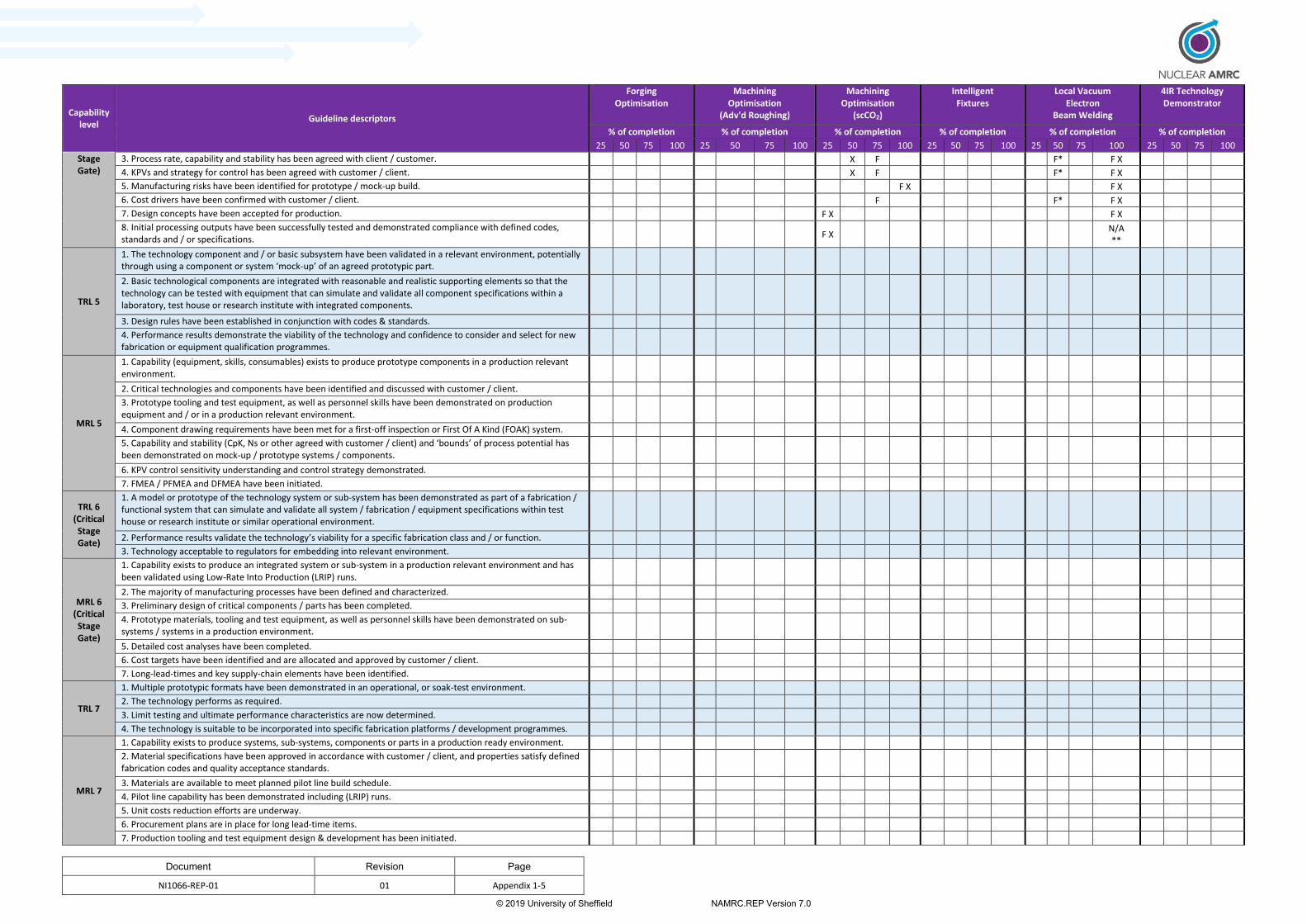
Document Revision Page
NI1066-REP-01 01 Appendix 1-5
© 2019 University of Sheffield NAMRC.REP Version 7.0
Capability level
Guideline descriptors
Forging Optimisation
Machining Optimisation
(Adv'd Roughing)
Machining Optimisation
(scCO2)
Intelligent Fixtures
Local Vacuum Electron
Beam Welding
4IR Technology Demonstrator
% of completion % of completion % of completion % of completion % of completion % of completion
25 50 75 100 25 50 75 100 25 50 75 100 25 50 75 100 25 50 75 100 25 50 75 100
Stage Gate)
3. Process rate, capability and stability has been agreed with client / customer. X F F* F X
4. KPVs and strategy for control has been agreed with customer / client. X F F* F X
5. Manufacturing risks have been identified for prototype / mock-up build. F X F X
6. Cost drivers have been confirmed with customer / client. F F* F X
7. Design concepts have been accepted for production. F X F X
8. Initial processing outputs have been successfully tested and demonstrated compliance with defined codes, standards and / or specifications. F X
N/A **
TRL 5
1. The technology component and / or basic subsystem have been validated in a relevant environment, potentially through using a component or system ‘mock-up’ of an agreed prototypic part.
2. Basic technological components are integrated with reasonable and realistic supporting elements so that the technology can be tested with equipment that can simulate and validate all component specifications within a laboratory, test house or research institute with integrated components.
3. Design rules have been established in conjunction with codes & standards.
4. Performance results demonstrate the viability of the technology and confidence to consider and select for new fabrication or equipment qualification programmes.
MRL 5
1. Capability (equipment, skills, consumables) exists to produce prototype components in a production relevant environment.
2. Critical technologies and components have been identified and discussed with customer / client.
3. Prototype tooling and test equipment, as well as personnel skills have been demonstrated on production equipment and / or in a production relevant environment.
4. Component drawing requirements have been met for a first-off inspection or First Of A Kind (FOAK) system.
5. Capability and stability (CpK, Ns or other agreed with customer / client) and ‘bounds’ of process potential has been demonstrated on mock-up / prototype systems / components.
6. KPV control sensitivity understanding and control strategy demonstrated.
7. FMEA / PFMEA and DFMEA have been initiated.
TRL 6 (Critical Stage Gate)
1. A model or prototype of the technology system or sub-system has been demonstrated as part of a fabrication / functional system that can simulate and validate all system / fabrication / equipment specifications within test house or research institute or similar operational environment.
2. Performance results validate the technology’s viability for a specific fabrication class and / or function.
3. Technology acceptable to regulators for embedding into relevant environment.
MRL 6 (Critical Stage Gate)
1. Capability exists to produce an integrated system or sub-system in a production relevant environment and has been validated using Low-Rate Into Production (LRIP) runs.
2. The majority of manufacturing processes have been defined and characterized.
3. Preliminary design of critical components / parts has been completed.
4. Prototype materials, tooling and test equipment, as well as personnel skills have been demonstrated on sub-systems / systems in a production environment.
5. Detailed cost analyses have been completed.
6. Cost targets have been identified and are allocated and approved by customer / client.
7. Long-lead-times and key supply-chain elements have been identified.
TRL 7
1. Multiple prototypic formats have been demonstrated in an operational, or soak-test environment.
2. The technology performs as required.
3. Limit testing and ultimate performance characteristics are now determined.
4. The technology is suitable to be incorporated into specific fabrication platforms / development programmes.
MRL 7
1. Capability exists to produce systems, sub-systems, components or parts in a production ready environment.
2. Material specifications have been approved in accordance with customer / client, and properties satisfy defined fabrication codes and quality acceptance standards.
3. Materials are available to meet planned pilot line build schedule.
4. Pilot line capability has been demonstrated including (LRIP) runs.
5. Unit costs reduction efforts are underway.
6. Procurement plans are in place for long lead-time items.
7. Production tooling and test equipment design & development has been initiated.

Document Revision Page
NI1066-REP-01 01 Appendix 1-6
© 2019 University of Sheffield NAMRC.REP Version 7.0
Capability level
Guideline descriptors
Forging Optimisation
Machining Optimisation
(Adv'd Roughing)
Machining Optimisation
(scCO2)
Intelligent Fixtures
Local Vacuum Electron
Beam Welding
4IR Technology Demonstrator
% of completion % of completion % of completion % of completion % of completion % of completion
25 50 75 100 25 50 75 100 25 50 75 100 25 50 75 100 25 50 75 100 25 50 75 100
8. FMEA / PFMEA and DFMEA have been completed.
TRL 8
1. Test and demonstration phases have been completed to customer’s satisfaction.
2. The technology has been proven to work in its final form and under expected conditions.
3. Performance has been validated to nuclear regulatory requirements.
MRL 8
1. Initial production is underway.
2. Manufacturing and quality processes and procedures have been proven in a production environment.
3. An early supply-chain has been established and stable.
4. Manufacturing processes have been validated.
TRL 9
1. The actual technology system has been qualified through operational experience.
2. The technology has been applied in its final form and within real environments / conditions.
3. The component or products have been launched into the market place.
MRL 9
1. Full volume rate production capability has been demonstrated.
2. Major systems design features are stable and proven in test and evaluation.
3. Materials are available to meet planned rate production schedules.
4. Manufacturing processes and procedures are established and controlled to a minimum of 3s or quality levelagreed with the client to meet design characteristic tolerances.
5. Manufacturing control processes are validated.
6. Actual cost model has been developed for full rate production.

Document Revision Page
NI1066-REP-01 03 Appendix 2
© 2019 University of Sheffield NAMRC.REP Version 7.0
Appendix 2. TRL / MRL Assessment Guidance Criteria

Document Revision Page
TRL/MRL Assessment Criteria Guidance Version V.1.0 Appendix 2-0
© 2019 University of Sheffield NAMRC.REP Version 7.0
Technology and Manufacturing Capability assessment
criteria guidance
SIMPLE and InFORM programmes
Themes 2 and 3
Of Phase-1 of the
Nuclear Innovation Programme
Version: V.1.0
Date 20th February 2019
Author: Nuclear AMRC

Document Revision Page
TRL/MRL Assessment Criteria Guidance Version V.1.0 Appendix 2-1
© 2019 University of Sheffield NAMRC.REP Version 7.0
Revision Sheet
Version Date Detail
V.1.0 20-02-19 Officially issued to all partners

Document Revision Page
TRL/MRL Assessment Criteria Guidance Version V.1.0 Appendix 2-2
© 2019 University of Sheffield NAMRC.REP Version 7.0
Table of Contents
Page
Number
Executive Summary 3
1.0 Background 4
2.0 Responsibility 4
3.0 Objectives and Evaluation criteria 5
3.1 Objectives 5
3.2 Evaluation criteria 5
3.3 Goal cascade guidance 6
Table 1 12
Table 2 13
Table 3 14
Table 4 15
Table 5 16
Table 6 17
Document Revision Page
TRL/MRL Assessment Criteria Guidance Version V.1.0 Appendix 2-3
© 2019 University of Sheffield NAMRC.REP Version 7.0
Executive summary
The Nuclear AMRC, part of the University of Sheffield’s AMRC group and one of the seven Centres
under the banner of the High-Value Manufacturing Catapult is an unbiased and technology/vendor
neutral organisation and therefore well positioned to undertake and provide honest & impartial
resource into the nuclear sector.
The mission of the Nuclear Advanced Manufacturing Research Centre is to help UK companies win
work in the nuclear and other high-value manufacturing sectors, with the purpose to support industry,
not compete with it.
The nuclear innovation programme (NIP) phase 1 stage 2 comprised of 5-themes with the aim
developing competitive technologies into the nuclear sector. These themes are:
1. Materials and modelling
2. Nuclear Component Manufacture
3. Large-scale manufacturing and Assembly
4. Modules and Modularisation
5. Codes and Standards
The Nuclear AMRC have been leading on two of these themes, themes 2 and 3, but have been
supporting all other themes as a partner too. Themes 2 and 3, known as Single Platform
Manufacturing Environment (SIMPLE) and Intelligent Fixtures for Optimised and Radical Manufacture
(InFORM) respectively, have focused on developing manufacturing concepts that increase tool-to-part
point of service to reduce movement of large parts through adopting multi-faceted technologies.
The SIMPLE concept reduces the need to move large components between work areas, and helps
ensure accuracy and quality control throughout the manufacturing process. By doing more operations
on a single platform, and automating common tasks such as machining, welding and inspection of
pressure vessels, large valve casings and decommissioning waste containers reduction in risk of
manufacturing error, costs and lead-time can be realised. Exploitation of such technology is not only
limited to nuclear manufacturing practices but also other sectors such as energy, oil and gas, marine
and aerospace. Developing a wider selection of machining, cladding and inspection heads that could
be deployed on a single large manufacturing platform, and using Industry 4.0 techniques to analyse
and act on large amounts of real-time data, could feasibly achieve cost and time savings of at least 50
per cent for a range of large complex fabrications.
The inform project aims to develop a range of advanced techniques, which could halve the cost and
lead-time of manufacturing large complex nuclear components. The proposed technology focuses at
holding large components and facilitate movement between platforms and machines to undergo a
range of manufacturing operations. With sensors linked to actuators and manipulators, fixtures will
automatically adjust its location force to minimize distortion during movement during manufacture.
For more information concerning the SIMPLE and InFORM projects, please go to the following
websites http://namrc.co.uk/services/crd/simple/
http://namrc.co.uk/services/crd/inform/

Document Revision Page
TRL/MRL Assessment Criteria Guidance Version V.1.0 Appendix 2-4
© 2019 University of Sheffield NAMRC.REP Version 7.0
1. Background Capability Acquisition (CA) is the process used by many blue-chip companies to manage development and implementation of new manufacturing competencies across domestic facilities and the supply chain. The intention of this guidance document is to identify, at the earliest possible stage, the maturity status of a project via the use of a ‘goal cascade’ and process specification. It is highly probable that mature technologies used in the Nuclear Innovation Programme (NIP) (i.e. technologies > TRL7) have been implemented and continuously matured above MRL 7 on large-scale manufacturing programmes in other industrial sectors. However, developing, integrating and maturing such technologies and procedures against new manufacturing scenarios can result in reduced levels of baseline capability being proven alongside specific business sector level governance. This document and its specified methodology aims to ensure that individual project leaders have, and provide, clarity of purpose via a mechanism for understanding and resolving any gaps within their project plans and end-user functionality. The designed supporting framework is to ensure compliance with the three underlying process principles of
1. Delivering the programme of work that addresses relevant stage-gate levels of risk for business, commercial and technical strands;
2. Developing fundamental process understanding via a systematic experimental approach; 3. Demonstrating basic capability through the definition of key process variables.
2. Responsibility
The Principal Investigator from the prime contractor, in this case the Nuclear AMRC, is responsible for
determining and agreeing the level of baseline capability with each work-package owner via the
project leader. Prior to this engagement, the individual work package owners / technical leads should
have defined their own stabilised level of capability via a ‘goal cascade’ assessment prior to defining
the output measure of success scoped within the overall theme submission. This defined goal cascade
is within section 3.2, and has been produced to establish the initial work baseline.

Document Revision Page
TRL/MRL Assessment Criteria Guidance Version V.1.0 Appendix 2-5
© 2019 University of Sheffield NAMRC.REP Version 7.0
3. Objectives and Evaluation criteria
3.1. Objectives
The focus of SIMPLE and InFORM is to address the Nuclear Sector Deal’s objectives, with its emphasis
in reducing costs of new nuclear build by 30%, through increasing modularisation and advanced
manufacturing systems. The three critical outputs that underpin the key objectives from the Nuclear
Sector Deal and initial submission concepts that these programmes are targeted to deliver against are:
1. Commercialisation by 2025 is a key output objective of all research within the SIMPLE and
InFORM programmes (Themes 2 and 3)
Question1: What approach have we as individual teams and part of the consortium taken to
realise this?
2. The Materials and Manufacturing theme. This has gained a significant profile through its
recognition within the Nuclear Sector Deal and HMG are investing in this as part of their
flagship innovation programme.
Question 2a: How have the projects raised the innovation profile within the nuclear and other
high-value manufacturing sectors, and how do we intend to demonstrate the impact from
both an individual and consortium standpoint?
Question 2b. In what areas will we need to continue to invest to accelerate capability into the
supply-chain?
3. Demonstrating a 50% cost saving?
Question 3a. Is there sufficient evidence from the project(s) to prove this can be realised?
3.2. Evaluation criteria
Supporting the evaluation of these individual work programmes and the overall theme, a suite of high-
level assessment criteria has been determined that considers the following.
Are those work-packages suitably broad enough and significantly detailed to address the range of requirements applicable to future modulated manufacturing platforms and smart tooling systems in delivering a 50% cost reduction?
Have those technologies been suitably condensed via the goal cascade to justify their initial status, and has this initial status been proven to validate the acceptance to move through the next stage gate? In addition, is there a consensus that the proposed technology and manufacturing status is suitably focused to deliver the overall coherent programme objective?
Is there evidence that this current technology could be practically applied to a wider industrial sector and does the pre-screening evidence support the present and any future investment to achieve the above three criteria?
Has the work been suitably focused and of due diligence to be measurable and discriminative among those technology alternatives?
Has the relevant technology been seen as forward-looking and flexible to meet the commercialisation of such capability within the specified timeframe? Have those precise and quantitative metrics been assigned and considered?

Document Revision Page
TRL/MRL Assessment Criteria Guidance Version V.1.0 Appendix 2-6
© 2019 University of Sheffield NAMRC.REP Version 7.0
3.3 Goal cascade guidance
Guidance for developing the goal-cascade and lowest level of capability based on at least a 75%
positive response to those questions raised.
Technology Goal cascade starts here -
Pro
cess
cri
tica
l B
usi
nes
s cr
itic
al

Document Revision Page
TRL/MRL Assessment Criteria Guidance Version V.1.0 Appendix 2-7
© 2019 University of Sheffield NAMRC.REP Version 7.0
Manufacturing Capability Goal Cascade starts here - Te
chn
olo
gy c
riti
cal
Tech
no
logy
cri
tica
l

Document Revision Page
TRL/MRL Assessment Criteria Guidance Version V.1.0 Appendix 2-8
© 2019 University of Sheffield NAMRC.REP Version 7.0
Bu
sin
ess
crit
ical
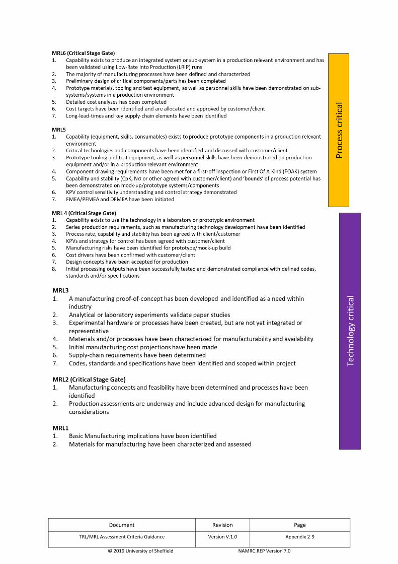
Document Revision Page
TRL/MRL Assessment Criteria Guidance Version V.1.0 Appendix 2-9
© 2019 University of Sheffield NAMRC.REP Version 7.0
Tech
no
logy
cri
tica
l P
roce
ss c
riti
cal
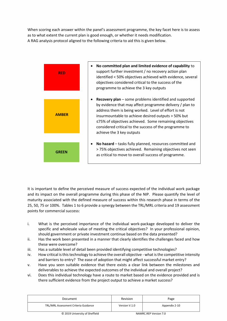
Document Revision Page
TRL/MRL Assessment Criteria Guidance Version V.1.0 Appendix 2-10
© 2019 University of Sheffield NAMRC.REP Version 7.0
When scoring each answer within the panel’s assessment programme, the key facet here is to assess
as to what extent the current plan is good enough, or whether it needs modification.
A RAG analysis protocol aligned to the following criteria to aid this is given below.
It is important to define the perceived measure of success expected of the individual work package
and its impact on the overall programme during this phase of the NIP. Please quantify the level of
maturity associated with the defined measure of success within this research phase in terms of the
25, 50, 75 or 100%. Tables 1 to 6 provide a synergy between the TRL/MRL criteria and 19 assessment
points for commercial success:
i. What is the perceived importance of the individual work-package developed to deliver the
specific and wholesale value of meeting the critical objectives? In your professional opinion, should government or private investment continue based on the data presented?
ii. Has the work been presented in a manner that clearly identifies the challenges faced and how these were overcome?
iii. Has a suitable level of detail been provided identifying competitive technologies? iv. How critical is this technology to achieve the overall objective - what is the competitive intensity
and barriers to entry? The ease of adoption that might affect successful market entry? v. Have you seen suitable evidence that there exists a clear link between the milestones and
deliverables to achieve the expected outcomes of the individual and overall project? vi. Does this individual technology have a route to market based on the evidence provided and is
there sufficient evidence from the project output to achieve a market success?
RED
AMBER
GREEN
No committed plan and limited evidence of capability to
support further investment / no recovery action plan
identified < 50% objectives achieved with evidence, several
objectives considered critical to the success of the
programme to achieve the 3 key outputs
Recovery plan – some problems identified and supported
by evidence that may affect programme delivery / plan to
address them is being worked. Level of effort is not
insurmountable to achieve desired outputs > 50% but
≤75% of objectives achieved. Some remaining objectives
considered critical to the success of the programme to
achieve the 3 key outputs
No hazard – tasks fully planned, resources committed and
> 75% objectives achieved. Remaining objectives not seen
as critical to move to overall success of programme.

Document Revision Page
TRL/MRL Assessment Criteria Guidance Version V.1.0 Appendix 2-11
© 2019 University of Sheffield NAMRC.REP Version 7.0
vii. Did the work provide enough evidence that there is a sustainable competitive advantage, such as intellectual property and higher barrier to market entry?
viii. What is the perceived knowledge gap associated with skills and competencies to deploy such technologies and manufacturing capability?
ix. Is there sufficient evidence that the route to market and ability to penetrate the existing nuclear market is in place?
x. Have other industrial sectors been identified as suitable users of this technology? If so, what is the perceived level of maturity based on this goal cascade?
xi. Based on the evidence available, what spectrum of opportunities associated with short, medium and long-term could be realised? Note short-term relates to large gigawatt reactors – 2025 to 2030 deployment, LW-SMR reactors – 2030 to 2035 and long-term Advanced Modular and Fusion Reactors – 2040+, which encompass molten salts, high-temperature gas and liquid metal cooled reactors.
xii. Has sufficient due diligence been enforced associated with managing risks (technical, commercial, and developmental) throughout the project?
xiii. Did the sensitivity of the data presented provide you with a confidence in capability, i.e. did the work contain a reputable quality metric system on which to base your judgment on making a positive decision?
xiv. What is your professional view of these activities being a technical success within the timeframes specified in item xi?
xv. The technical risk of the product/service or process being developed should be assessed. xvi. Strategic commercial partnerships are an important factor. Have these been considered
appropriately? xvii. Is there sufficient evidence that regulatory hurdles could be managed within this timeframe of
reactor activity? xviii. Was there evidence that the technology and manufacturing principles worked on required a
significant effort in meeting existing codes and standards, or whether new codes and standards will be required?
xix. What is your professional view of the project team's drive and determination and an entrepreneurial mind-set to lead these developments to an agreed level of maturity?

Document Revision Page
TRL/MRL Assessment Criteria Guidance Version V.1.0 Appendix 2-12
© 2019 University of Sheffield NAMRC.REP Version 7.0
Table 1 % of completion
Capability level Guideline descriptors 25 50 75 100
TRL 1 1. Basic principles - observed and reported. 2. Scientific research undertaken 3. Scientific research is beginning to be translated into applied research and
development
4. Paper studies and scientific experiments have taken place 5. Performance has been predicted
MRL 1 1. Basic Manufacturing Implications have been identified 2. Materials for manufacturing have been characterised and assessed
TRL2 (Critical stage gate)
1. Speculative applications have been identified 2. Exploration into key principles is ongoing 3. Application-specific simulations or experiments have been undertaken 4. Performance predictions have been refined
MRL2 (Critical stage gate)
1. Manufacturing concepts and feasibility have been determined and processes have been identified
2. Production assessments via simulation or experiment are underway and include advanced design for manufacturing considerations
TRL3 1. Analytical and experimental assessments have identified critical functionality and/or characteristics
2. Analytical, simulation or laboratory studies have validated predictions of separate elements of the technology or components that are not yet integrated or representative
3. Performance investigation using analytical experimentation and/or simulations is underway
4. Modelling or simulation systems have been suitably proven to support the programme.
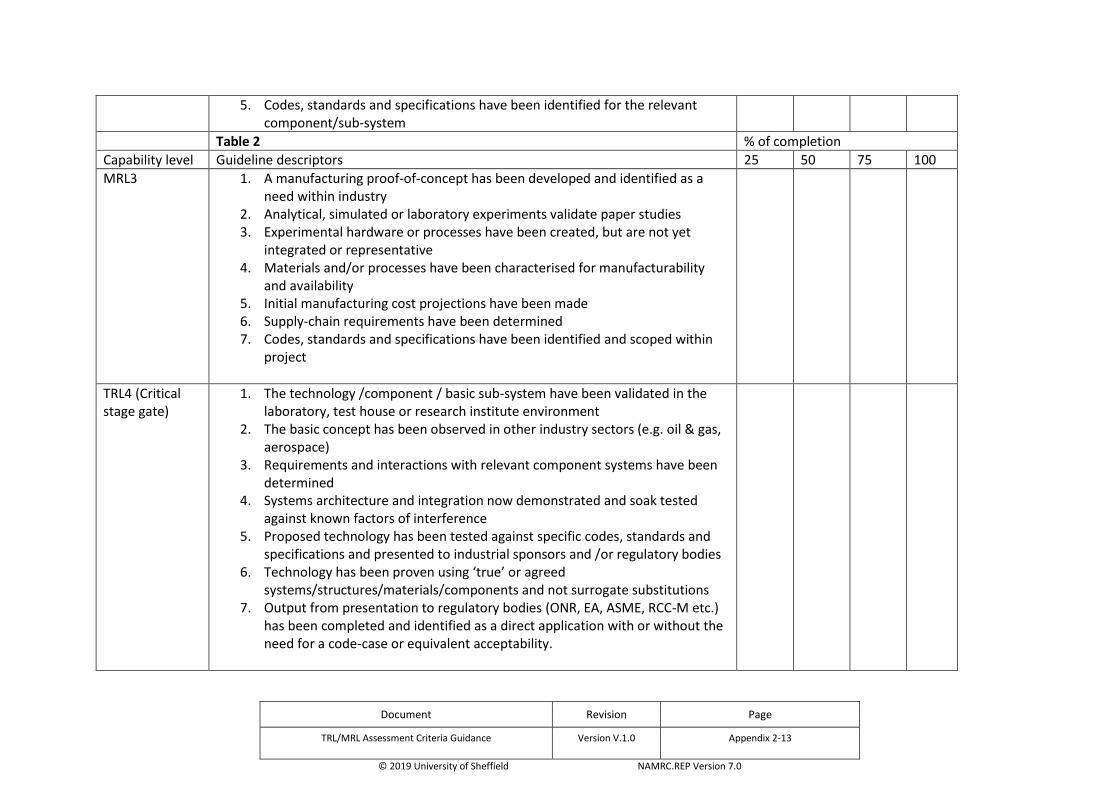
Document Revision Page
TRL/MRL Assessment Criteria Guidance Version V.1.0 Appendix 2-13
© 2019 University of Sheffield NAMRC.REP Version 7.0
5. Codes, standards and specifications have been identified for the relevant component/sub-system
Table 2 % of completion
Capability level Guideline descriptors 25 50 75 100
MRL3 1. A manufacturing proof-of-concept has been developed and identified as a need within industry
2. Analytical, simulated or laboratory experiments validate paper studies 3. Experimental hardware or processes have been created, but are not yet
integrated or representative 4. Materials and/or processes have been characterised for manufacturability
and availability 5. Initial manufacturing cost projections have been made 6. Supply-chain requirements have been determined 7. Codes, standards and specifications have been identified and scoped within
project
TRL4 (Critical stage gate)
1. The technology /component / basic sub-system have been validated in the laboratory, test house or research institute environment
2. The basic concept has been observed in other industry sectors (e.g. oil & gas, aerospace)
3. Requirements and interactions with relevant component systems have been determined
4. Systems architecture and integration now demonstrated and soak tested against known factors of interference
5. Proposed technology has been tested against specific codes, standards and specifications and presented to industrial sponsors and /or regulatory bodies
6. Technology has been proven using ‘true’ or agreed systems/structures/materials/components and not surrogate substitutions
7. Output from presentation to regulatory bodies (ONR, EA, ASME, RCC-M etc.) has been completed and identified as a direct application with or without the need for a code-case or equivalent acceptability.

Document Revision Page
TRL/MRL Assessment Criteria Guidance Version V.1.0 Appendix 2-14
© 2019 University of Sheffield NAMRC.REP Version 7.0
Table 3 % of completion
Capability level Guideline descriptors 25 50 75 100
MRL4 (Critical stage gate)
1. Capability exists to use the technology in a laboratory or prototypic environment
2. Series production requirements, such as manufacturing technology development have been identified
3. Process rate, capability and stability has been agreed with client/customer 4. KPVs and strategy for control has been agreed with customer/client 5. Manufacturing risks have been identified for prototype/mock-up build 6. Cost drivers have been confirmed with customer/client 7. Design concepts have been accepted for production 8. Initial processing outputs have been successfully tested and demonstrated
compliance with defined codes, standards and/or specifications
TRL5 1. The technology component and/or basic subsystem have been validated in a relevant environment, potentially through using a component or system ‘mock-up’ of an agreed prototypic part
2. Basic technological components are integrated with reasonable and realistic supporting elements so that the technology can be tested with equipment that can simulate and validate all component specifications within a laboratory, test house or research institute with integrated components
3. Design rules have been established in conjunction with codes & standards 4. Performance results demonstrate the viability of the technology and
confidence to consider and select for new fabrication or equipment qualification programmes
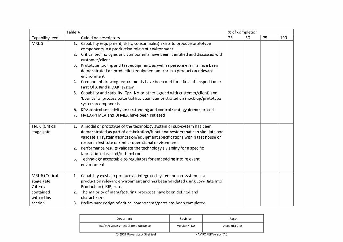
Document Revision Page
TRL/MRL Assessment Criteria Guidance Version V.1.0 Appendix 2-15
© 2019 University of Sheffield NAMRC.REP Version 7.0
Table 4 % of completion
Capability level Guideline descriptors 25 50 75 100
MRL 5 1. Capability (equipment, skills, consumables) exists to produce prototype components in a production relevant environment
2. Critical technologies and components have been identified and discussed with customer/client
3. Prototype tooling and test equipment, as well as personnel skills have been demonstrated on production equipment and/or in a production relevant environment
4. Component drawing requirements have been met for a first-off inspection or First Of A Kind (FOAK) system
5. Capability and stability (CpK, N or other agreed with customer/client) and ‘bounds’ of process potential has been demonstrated on mock-up/prototype systems/components
6. KPV control sensitivity understanding and control strategy demonstrated 7. FMEA/PFMEA and DFMEA have been initiated
TRL 6 (Critical stage gate)
1. A model or prototype of the technology system or sub-system has been demonstrated as part of a fabrication/functional system that can simulate and validate all system/fabrication/equipment specifications within test house or research institute or similar operational environment
2. Performance results validate the technology’s viability for a specific fabrication class and/or function
3. Technology acceptable to regulators for embedding into relevant environment
MRL 6 (Critical stage gate) 7 items contained within this section
1. Capability exists to produce an integrated system or sub-system in a production relevant environment and has been validated using Low-Rate Into Production (LRIP) runs
2. The majority of manufacturing processes have been defined and characterized
3. Preliminary design of critical components/parts has been completed

Document Revision Page
TRL/MRL Assessment Criteria Guidance Version V.1.0 Appendix 2-16
© 2019 University of Sheffield NAMRC.REP Version 7.0
4. Prototype materials, tooling and test equipment, as well as personnel skills have been demonstrated on sub-systems/systems in a production environment
5. Detailed cost analyses have been completed 6. Cost targets have been identified and are allocated and approved by
customer/client 7. Long-lead-times and key supply-chain elements have been identified
Table 5 % of completion
Capability level Guideline descriptors 25 50 75 100
TRL 7 1. Multiple prototypic formats have been demonstrated in an operational, or soak-test environment
2. The technology performs as required 3. Limit testing and ultimate performance characteristics are now determined 4. The technology is suitable to be incorporated into specific fabrication
platforms/development programmes
MRL 7 1. Capability exists to produce systems, sub-systems, components or parts in a production ready environment
2. Material specifications have been approved in accordance with customer/client, and properties satisfy defined fabrication codes and quality acceptance standards
3. Materials are available to meet planned pilot line build schedule 4. Pilot line capability has been demonstrated including (LRIP) runs 5. Unit costs reduction efforts are underway 6. Procurement plans are in place for long lead-time items 7. Production tooling and test equipment design & development has been
initiated 8. FMEA/PFMEA and DFMEA have been completed
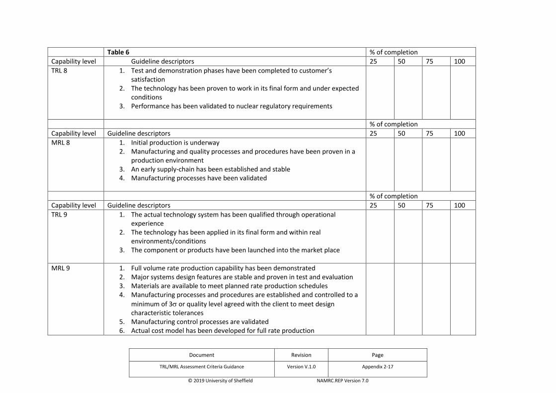
Document Revision Page
TRL/MRL Assessment Criteria Guidance Version V.1.0 Appendix 2-17
© 2019 University of Sheffield NAMRC.REP Version 7.0
Table 6 % of completion
Capability level Guideline descriptors 25 50 75 100
TRL 8 1. Test and demonstration phases have been completed to customer’s satisfaction
2. The technology has been proven to work in its final form and under expected conditions
3. Performance has been validated to nuclear regulatory requirements
% of completion
Capability level Guideline descriptors 25 50 75 100
MRL 8 1. Initial production is underway 2. Manufacturing and quality processes and procedures have been proven in a
production environment 3. An early supply-chain has been established and stable 4. Manufacturing processes have been validated
% of completion
Capability level Guideline descriptors 25 50 75 100
TRL 9 1. The actual technology system has been qualified through operational experience
2. The technology has been applied in its final form and within real environments/conditions
3. The component or products have been launched into the market place
MRL 9 1. Full volume rate production capability has been demonstrated 2. Major systems design features are stable and proven in test and evaluation 3. Materials are available to meet planned rate production schedules 4. Manufacturing processes and procedures are established and controlled to a
minimum of 3 or quality level agreed with the client to meet design characteristic tolerances
5. Manufacturing control processes are validated 6. Actual cost model has been developed for full rate production

Document Revision Page
TRL/MRL Assessment Criteria Guidance Version V.1.0 Appendix 2-18
© 2019 University of Sheffield NAMRC.REP Version 7.0
THIS PAGE IS LEFT INTENTIONALLY BLANK

Document Revision Page
NI1066-REP-01 03 Appendix 3
© 2019 University of Sheffield NAMRC.REP Version 7.0
Appendix 3. Peer Review Panel
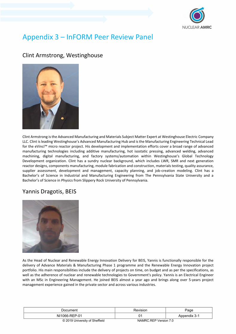
Document Revision Page
NI1066-REP-01 01 Appendix 3-1 © 2019 University of Sheffield NAMRC.REP Version 7.0
Appendix 3 – InFORM Peer Review Panel
Clint Armstrong, Westinghouse
Clint Armstrong is the Advanced Manufacturing and Materials Subject Matter Expert at Westinghouse Electric Company LLC. Clint is leading Westinghouse’s Advanced Manufacturing Hub and is the Manufacturing Engineering Technical Lead for the eVinci™ micro reactor project. His development and implementation efforts cover a broad range of advanced manufacturing technologies including additive manufacturing, hot isostatic pressing, advanced welding, advanced machining, digital manufacturing, and factory systems/automation within Westinghouse’s Global Technology Development organization. Clint has a sundry nuclear background, which includes LWR, SMR and next generation reactor designs, components manufacturing, module fabrication and construction, materials testing, quality assurance, supplier assessment, development and management, capacity planning, and job-creation modeling. Clint has a Bachelor’s of Science in Industrial and Manufacturing Engineering from The Pennsylvania State University and a Bachelor’s of Science in Physics from Slippery Rock University of Pennsylvania.
Yannis Dragotis, BEIS
As the Head of Nuclear and Renewable Energy Innovation Delivery for BEIS, Yannis is functionally responsible for the delivery of Advance Materials & Manufacturing Phase 1 programme and the Renewable Energy Innovation project portfolio. His main responsibilities include the delivery of projects on time, on budget and as per the specifications, as well as the adherence of nuclear and renewable technologies to Government's policy. Yannis is an Electrical Engineer with an MSc in Engineering Management. He joined BEIS almost a year ago and brings along over 5-years project management experience gained in the private sector and across various industries.

Document Revision Page
NI1066-REP-01 01 Appendix 3-2 © 2019 University of Sheffield NAMRC.REP Version 7.0
Dr Neil Irvine, University of Manchester (Chair)
Neil Irvine graduated in Physics at Imperial College followed by post-graduate work in ultrasonics. After early work on manufacturing carbon fibre components, he joined the nuclear industry in 1976, moving to UKAEA a year later, where he developed design codes for welds in offshore structures and high temperature reactor components, led Structural Integrity and Thermal-hydraulics research groups, set up the business development function within the Reactor Services unit and worked in the USA supplying technical services to US utilities. He worked on a number of reactor types (AGR, PWR, BWR, SFR, SGHWR) and with nuclear organisations from Europe, the Far East, and North America. This was followed by senior managerial roles with AEA Technology, ALSTOM Transport (signalling and control systems) and QinetiQ (major bid management and technical services delivery). He joined the Dalton Nuclear Institute at The University of Manchester in 2012 and managed the New Nuclear Manufacturing (NNUMAN) program until 2018, also contributing to NIRAB and DECC studies and more recently to development of work for the University within BEIS R&D programs; he continues to chair the Nuclear AMRC Research Board.
Richard March, Rolls-Royce
Richard joined Rolls-Royce Plc in 1985 after gaining a Physics degree from the University of Birmingham. He is currently leading the Welding and Joining theme for Rolls-Royce, with responsibilities in: aerospace, nuclear and energy sectors. Richard is a Chartered Engineer with the Royal Aeronautical Society. Richard’s career started in the NDT department, where he developed inspections for nuclear steam raising plant. He has subsequently undertaken a wide range of roles within the field of joining, including Rotatives’ Chief of Joining, with responsibility for joining processes applied to the critical rotating parts within gas turbines. Richard’s current role requires him to take a functional leadership role across Rolls-Royce’s joining activities. Richard has chaired and supported many internal review panels and represents Rolls-Royce on the National Joining Strategy and the Trailblazer Apprenticeship industrial panels.

Document Revision Page
NI1066-REP-01 01 Appendix 3-3 © 2019 University of Sheffield NAMRC.REP Version 7.0
Dr Neil Smart, NIRO
Neil is currently Director of Research and Innovation for the Nuclear Innovation and Research Office (NIRO). Neil has ca30 years’ experience in the nuclear industry holding senior technical roles at Sellafield Ltd, Radioactive Waste Management Ltd, Nuclear Decommissioning Authority and British Nuclear Fuels Ltd. Neil is also a visiting Professor in the Materials Engineering Department, Imperial College and a visiting researcher at the Dalton Nuclear Institute, University of Manchester. He is a physical chemist by background with BSc and PhD, supported by a MSc in Technology Management.
Prof Trevor Toman, University of Coventry
Professor Trevor Toman started working in the manufacturing industry in 1975, working extensively in the calibration and measurement disciplines within laboratories in the telecommunications industry. In 1990 Trevor commenced working in the motor manufacturing industry in Coventry. During this period, he managed various teams for the launch of new vehicles and various new measuring technologies and facilities; including large and medium sized CMM facilities and laser in-line measurement projects. Trevor’s last post held before joining Coventry University was Manager of the BIW Manufacturing Tool room, Measurement and Geometry Departments. Trevor joined Coventry University in 2006 to launch and manage the new Metrology Department on a 3 year funded project. Since joining the University Trevor has developed working relationships for delivery of training, education and research in metrology to a wide range of organisations, both nationally and internationally. Trevor has authored and delivered a Degree in Metrology at Coventry University and will soon launch the Engineering Doctorate programme in Metrology and Advanced manufacturing. Trevor currently holds the post of Professor and Head of Metrology within the Faculty of Engineering and Computing, the Institute for Future Cities and Transport, the Faculty Research Centre for Manufacturing, Materials and Engineering. Trevor is actively involved with various academic and industrial committees which focus on the aerospace and automotive industries for large volume and metrology assisted assembly. He also sits on various British Standards Institution committees including the measurement uncertainty committee and is a member of a number of professional
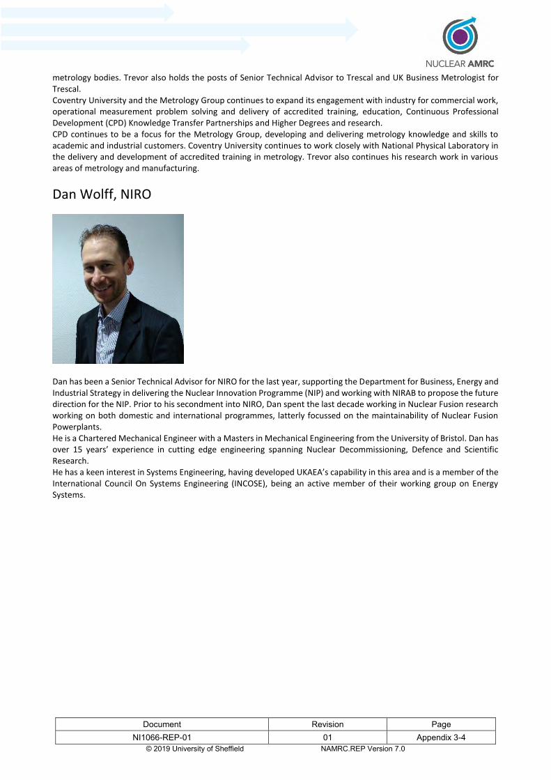
Document Revision Page NI1066-REP-01 01 Appendix 3-4
© 2019 University of Sheffield NAMRC.REP Version 7.0
metrology bodies. Trevor also holds the posts of Senior Technical Advisor to Trescal and UK Business Metrologist for Trescal. Coventry University and the Metrology Group continues to expand its engagement with industry for commercial work, operational measurement problem solving and delivery of accredited training, education, Continuous Professional Development (CPD) Knowledge Transfer Partnerships and Higher Degrees and research. CPD continues to be a focus for the Metrology Group, developing and delivering metrology knowledge and skills to academic and industrial customers. Coventry University continues to work closely with National Physical Laboratory in the delivery and development of accredited training in metrology. Trevor also continues his research work in various areas of metrology and manufacturing.
Dan Wolff, NIRO
Dan has been a Senior Technical Advisor for NIRO for the last year, supporting the Department for Business, Energy and Industrial Strategy in delivering the Nuclear Innovation Programme (NIP) and working with NIRAB to propose the future direction for the NIP. Prior to his secondment into NIRO, Dan spent the last decade working in Nuclear Fusion research working on both domestic and international programmes, latterly focussed on the maintainability of Nuclear Fusion Powerplants. He is a Chartered Mechanical Engineer with a Masters in Mechanical Engineering from the University of Bristol. Dan has over 15 years’ experience in cutting edge engineering spanning Nuclear Decommissioning, Defence and Scientific Research. He has a keen interest in Systems Engineering, having developed UKAEA’s capability in this area and is a member of the International Council On Systems Engineering (INCOSE), being an active member of their working group on Energy Systems.

Document Revision Page
NI1066-REP-01 03 Appendix 4
© 2019 University of Sheffield NAMRC.REP Version 7.0
Appendix 4. Forging Optimisation Report

1
RESEARCH AND DEVELOPMENT – Technical Report
Document Details
Report No. RDDoc0128 Issue No. 6 Date 19/08/2019 Customer NAMRC Title InForm Project Forging Optimisation Report for Work Package 2.1 File Name RDDoc0128-6.docx Authors Vasileios Pasialis, Michael Blackmore Approved Jesus Talamantes-Silva Revisions
Issue No. Date Comments
1 03/08/2017 Original Issue 2 19/06/2018 Content updated for quotation 3 14/02/2019 Interim Report 4 25/04/2019 Final Report 5 02/05/2019 Revised Final Report 6 19/08/2019 Final Version, minor corrections
Signatures
Name Date Signature
Final copy
prepared by
Vasileios Pasialis
19/08/2019
Reviewed by
Michael Blackmore
02/05/2019
Approved by
Jesus Talamantes-Silva
02/05/2019

© University of Sheffield 2019 2
InForm Project Forging Optimisation Report for Work Package 2.1

© University of Sheffield 2019 3
Contents 1 Introduction ....................................................................................................................................................................... 4 2 Advanced and Small Modular Reactor Review .................................................................................................................. 4
2.1 Lead-cooled Fast Reactor ....................................................................................................................................... 4 2.2 Sodium-cooled fast Reactor ................................................................................................................................... 5 2.3 Stable Salt Reactor ................................................................................................................................................. 6 2.4 Very High Temperature Reactor ............................................................................................................................. 7 2.5 Spherical Tokamak................................................................................................................................................ 10 2.6 Summary .............................................................................................................................................................. 11
3 Nuclear Reactor Components .......................................................................................................................................... 12 3.1 Shells .................................................................................................................................................................... 12 3.2 Top and Bottom RPV Heads ................................................................................................................................. 16 3.3 Tubesheets ........................................................................................................................................................... 17 3.4 Hot legs ................................................................................................................................................................. 18
4 Steelmaking ..................................................................................................................................................................... 19 4.1 Vacuum Stream Degassing ................................................................................................................................... 19 4.2 Vacuum pumping equipment ............................................................................................................................... 22
5 Future Reactor Materials ................................................................................................................................................. 24 5.1.1 Lead-cooled Fast Reactor ............................................................................................................................... 24 5.1.2 Sodium-cooled Fast Reactor ........................................................................................................................... 27 5.1.3 Stable Salt Reactor .......................................................................................................................................... 29 5.1.4 Very High Temperature Reactor-Small light water reactor .......................................................................... 31 5.1.5 Fusion Reactors ............................................................................................................................................... 37
6 Component Design for Manufacture ............................................................................................................................... 38 6.1 Forging Routes ...................................................................................................................................................... 39 6.2 Hollow ingot technology....................................................................................................................................... 40 6.3 On press metrology .............................................................................................................................................. 43 6.4 Heat Treatment Options ....................................................................................................................................... 46 6.5 Manufacture challenges ....................................................................................................................................... 47 6.6 Manufacturing cost optimisation ......................................................................................................................... 50
7 Summary .......................................................................................................................................................................... 53 8 References ....................................................................................................................................................................... 54
© University of Sheffield 2019 4
1 Introduction
The following report details potential optimisation of current UK large scale open die forging of nuclear grade alloys for civil power generation applications. It has been carried out under the Department for Business, Energy and Industrial Strategy (BEIS) nuclear innovation programme (NIP), within the Advanced Manufacturing and Material stream. NIP aims to reduce the cost of nuclear power generation whilst ensuring a future low carbon economy. The following report reviews the current reactor vendors currently involved in the Advanced Modular Reactor (AMR) feasibility and development project, as well as current SMR vendors designs. The different types of reactors and their materials and operational requirements are considered to assess the potential manufacturing challenges. Additionally, the most complex and safety critical nuclear island components are reviewed. Although only forging is within scope of this report, upstream processing in primary/secondary steel making can have a significant influence in the forge and thus steel making practices are reviewed and improvements suggested. Potential future AMR material grades are considered and additional considerations to forging practices, metrology, heat treatment and costing are made.
2 Advanced and Small Modular Reactor Review
The AMRs differ from conventional reactors in that they do not use pressurised or boiling water for primary cooling. Eight companies have been awarded contracts to produce feasibility studies as part of phase 1 of the AMR F&D project [1]. Seven the reactors are different Gen IV fast fission reactors and one organisation is developing a Gen III+ fusion reactor. Below are details of the five, in total, different reactor technologies, comprising the technologies types, approximate sizes, materials and operating conditions.
2.1 Lead-cooled Fast Reactor
A Lead-cooled Fast Reactor (LFR) uses molten lead as a primary coolant (Figure 1). Lead is high density, low neutron absorption, non-explosive, it can circulate by natural circulation, has a high boiling point and offers protection against gamma rays. However, it is highly corrosive to the containment vessels.
Two companies are involved in the development of LFR: Westinghouse Electric Company and LeadCold. The former is considering using uranium oxide as fuel while the latter is considering the use of uranium nitride. The Westinghouse LFR is designed to be a versatile plant, with baseload electricity production and load levelling as the primary design focus, but with the capability to fulfil a range of non-electricity applications such as process heat, desalination, and hydrogen production needs according to market demand [2]. LeadCold is aiming at producing multiple very small LFRs to power isolated regions where the cost of conventional power is too high. A single ‘SEALER-UK’ unit could produce up to 40MW of electricity in a vessel that could be transported to any location in the UK using railroad. The company has also developed alumina forming steel potentially capable of extending the reactor’s life expectancy to 30 years, including a mid-term core replacement.
As the coolant operating at atmospheric pressure, the loss of coolant accident (LOCA) can be virtually eliminated by use of an appropriately designed guard vessel. A typical thickness of the guard vessel is around 50.8 mm [3], while SEALER’s unit guard vessel dimensions are reported to be 6m in height and 2.748m in diameter [2].
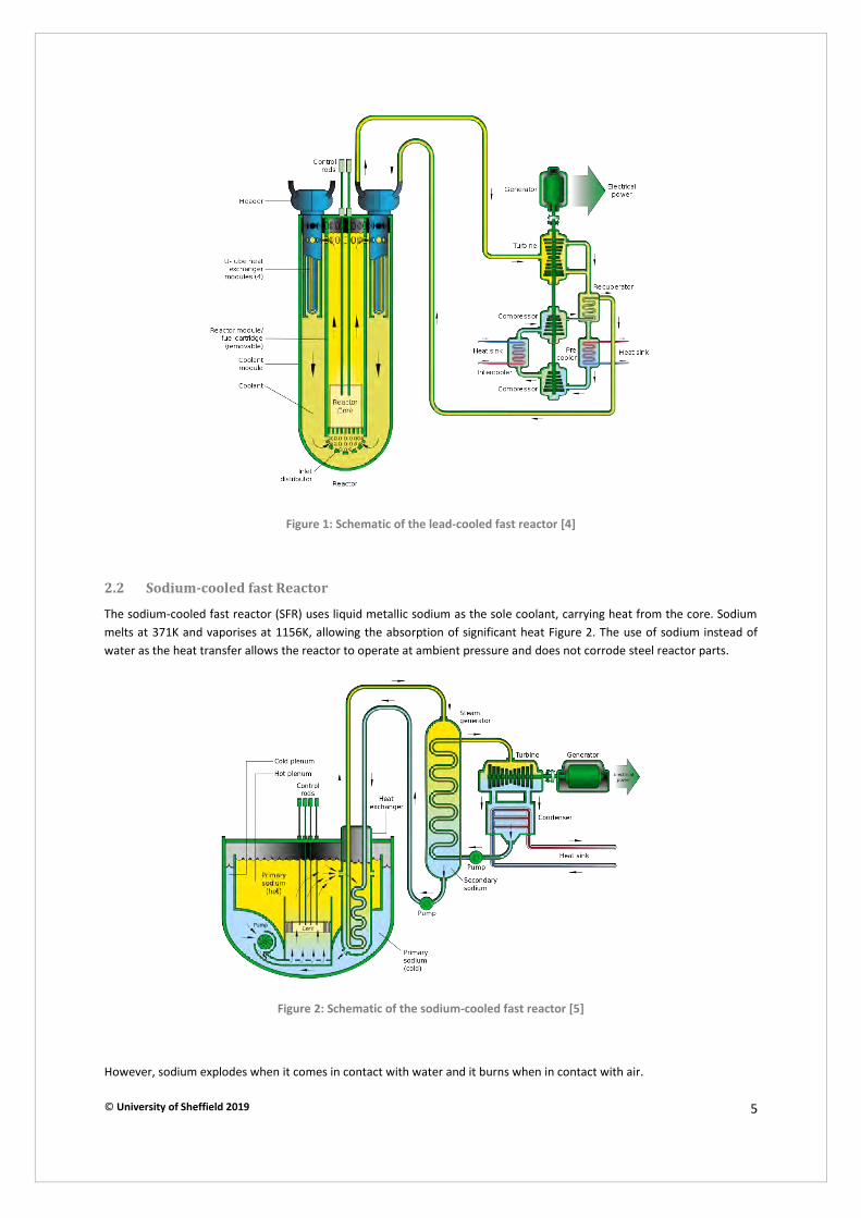
© University of Sheffield 2019 5
Figure 1: Schematic of the lead-cooled fast reactor [4]
2.2 Sodium-cooled fast Reactor
The sodium-cooled fast reactor (SFR) uses liquid metallic sodium as the sole coolant, carrying heat from the core. Sodium melts at 371K and vaporises at 1156K, allowing the absorption of significant heat Figure 2. The use of sodium instead of water as the heat transfer allows the reactor to operate at ambient pressure and does not corrode steel reactor parts.
Figure 2: Schematic of the sodium-cooled fast reactor [5]
However, sodium explodes when it comes in contact with water and it burns when in contact with air.
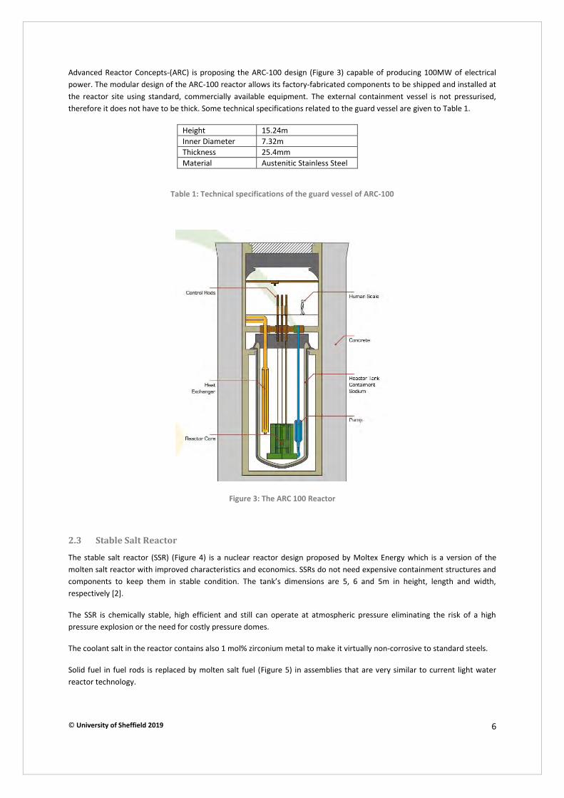
© University of Sheffield 2019 6
Advanced Reactor Concepts-(ARC) is proposing the ARC-100 design (Figure 3) capable of producing 100MW of electrical power. The modular design of the ARC-100 reactor allows its factory-fabricated components to be shipped and installed at the reactor site using standard, commercially available equipment. The external containment vessel is not pressurised, therefore it does not have to be thick. Some technical specifications related to the guard vessel are given to Table 1.
Height 15.24m Inner Diameter 7.32m Thickness 25.4mm Material Austenitic Stainless Steel
Table 1: Technical specifications of the guard vessel of ARC-100
Figure 3: The ARC 100 Reactor
2.3 Stable Salt Reactor
The stable salt reactor (SSR) (Figure 4) is a nuclear reactor design proposed by Moltex Energy which is a version of the molten salt reactor with improved characteristics and economics. SSRs do not need expensive containment structures and components to keep them in stable condition. The tank’s dimensions are 5, 6 and 5m in height, length and width, respectively [2].
The SSR is chemically stable, high efficient and still can operate at atmospheric pressure eliminating the risk of a high pressure explosion or the need for costly pressure domes.
The coolant salt in the reactor contains also 1 mol% zirconium metal to make it virtually non-corrosive to standard steels.
Solid fuel in fuel rods is replaced by molten salt fuel (Figure 5) in assemblies that are very similar to current light water reactor technology.
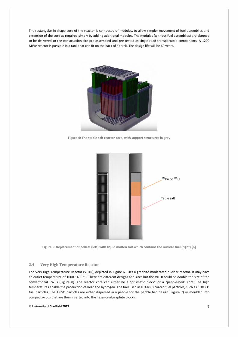
© University of Sheffield 2019 7
The rectangular in shape core of the reactor is composed of modules, to allow simpler movement of fuel assemblies and extension of the core as required simply by adding additional modules. The modules (without fuel assemblies) are planned to be delivered to the construction site pre-assembled and pre-tested as single road-transportable components. A 1200 MWe reactor is possible in a tank that can fit on the back of a truck. The design life will be 60 years.
Figure 4: The stable salt reactor core, with support structures in grey
Figure 5: Replacement of pellets (left) with liquid molten salt which contains the nuclear fuel (right) [6]
2.4 Very High Temperature Reactor
The Very High Temperature Reactor (VHTR), depicted in Figure 6, uses a graphite-moderated nuclear reactor. It may have an outlet temperature of 1000-1400 °C. There are different designs and sizes but the VHTR could be double the size of the conventional PWRs (Figure 8). The reactor core can either be a “prismatic block” or a “pebble-bed” core. The high temperatures enable the production of heat and hydrogen. The fuel used in HTGRs is coated fuel particles, such as “TRISO” fuel particles. The TRISO particles are either dispersed in a pebble for the pebble bed design (Figure 7) or moulded into compacts/rods that are then inserted into the hexagonal graphite blocks.
Table salt
239Pu or 235U

© University of Sheffield 2019 8
Helium is the coolant used in most VHTR concepts. It is an inert gas, does not react with any other material and neutron radiation does not make it radioactive.
The high temperature of the coolant exiting the reactor core enables high thermal efficiency for electricity generation, and can serve as process heat for hydrogen production. However, temperature and irradiation –intensive conditions create material challenges in terms of creep and corrosion resistance. Nickel based superalloy development may be necessary for critical components of the VHTR.
Three companies are involved in the development of the VHTR: U-Battery, Ultra Safe Nuclear Corporation (USNC) and DBD Limited.
U-battery is a micro-modular reactor (MMR) concept which has been in development since 2008. The feasibility study performed for this type of reactor has revealed that the 20MWth U-Battery can achieve a full lifetime of 10 Effective Full Power Years (EFPY).
The RPV design is such that a single main inlet/outlet is situated towards the bottom of the reactor to prevent the “chimney effect” in case of a main inlet/outlet duct failure. The RPV is provided with a removable (bolted) lid that can be removed for refuelling. The lid has feedthroughs for the control rod mechanisms. All bolted joints are to be “helium tight”.
Figure 6: The Very High Temperature Reactor (VHTR) [7]

© University of Sheffield 2019 9
Figure 7: Pebble Bed Reactor scheme [8]
Figure 8: The pressure vessel construction envisioned for the VHTR as opposed to current typical pressurised water
reactors (shown inside the VHTR vessel) [9]
The original U-Battery concept envisaged the core being replaced as a single “battery” unit which would be transported as a single module in a standard ISO freight container package, however, this is subjected to national regulations. According to the developers, the cost for the fabrication of the RPV is roughly estimated at 30€ per kilogram of SA-508 steel.

© University of Sheffield 2019 10
UNSC has developed a 15MWth VHT Micro-Modular Reactor, able to operate for 20 years without refuelling. It uses proprietary Full Ceramic Microencapsulated (FCM) fuel, which allows for the design of reactors with extremely low release of fission products during normal operations and accidents. The company seeks to identify a specific design that is best suited for application in the UK.
DBD Limited will be studying a High Temperature Gas-Cooled Reactor. DBD intend to use this project to test the feasibility of HTGRs being applied and to build on the existing China/UK ties to develop a role for the UK in the HTGR programme [1].
2.5 Spherical Tokamak
The only Gen III+ fusion reactor in the competition is being developed by Tokamak Energy. The goal is to combine two emerging technologies; the spherical tokamak (ST) and magnets made from high temperature superconductors. The reactors will be compact with modest power (100s MW range), factory fabricated and mass produced.
Tokamak reactors consist of a toroidal vacuum tube surrounded by a series of magnets. A traditional tokamak has a toroidal confinement area that gives it an overall shape similar to a donut, complete with a large hole in the middle. The spherical tokamak reduces the size of the hole as much as possible, resulting in a plasma shape that is almost spherical, often compared with a cored apple. Spherical Tokamaks have potentially higher efficiency than traditional ‘doughnut’ shape tokamaks.
The outer vacuum chamber has an internal vacuum that provides thermal insulation for the liquid nitrogen-cooled copper based field coils. It also has a vital role to play in supporting the toroidal and poloidal field coils against strong magnetic forces.
The tokamak needs to withstand huge forces and torque loads. The temperature at the very centre of the plasma will be hundreds of millions degrees C, being even hotter than the sun itself. However, the temperature will reduce moving outwards towards the vacuum wall. The walls will experience a temperature of several thousand degrees centigrade. The vessel integrity will be protection by appropriate heat shielding made of tungsten/tungsten carbide.
Figure 9: The ST40 spherical tokamak [10]
Poloidal field coils, used to control the shape and position of the hot plasma
Internal vacuum chamber
Outer vacuum chamber
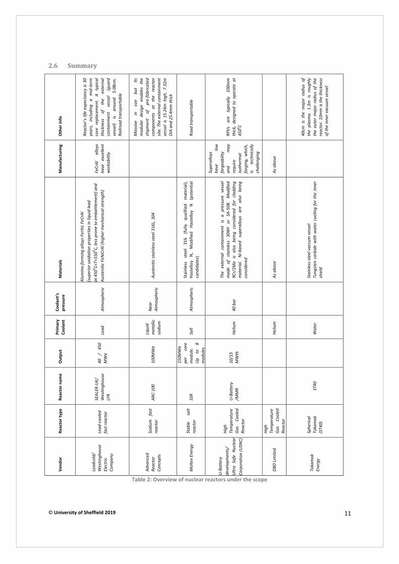
© University of Sheffield 2019 11
2.6 Summary O
the
r in
fo
Reac
tor’s
life
exp
ecta
ncy
is 30
ye
ars,
in
clud
ing
a m
id-t
erm
co
re
repl
acem
ent.
A ty
pica
l th
ickn
ess
of
the
exte
rnal
co
ntai
nmen
t ve
ssel
(g
uard
ve
ssel
) is
arou
nd
5.08
cm.
Railr
oad
tran
spor
tabl
e
Mas
sive
in
size
but
its
mod
ular
de
sign
enab
les
the
ship
men
t of
pr
e-fa
bric
ated
co
mpo
nent
s at
th
e re
acto
r sit
e. T
he e
xter
nal c
onta
inm
ent
vess
el i
s 15
.24m
hig
h, 7
.32m
DI
A an
d 25
.4m
m th
ick
Road
tran
spor
tabl
e
RPVs
ar
e ty
pica
lly
100m
m
thic
k, d
esig
ned
to o
pera
te a
t 45
00 C
40cm
is
the
maj
or r
adiu
s of
th
e pl
asm
a. 1
.3m
is
roug
hly
the
oute
r m
ajor
rad
ius
of t
he
reac
tor.
10m
m is
the
thic
knes
s of
the
inne
r vac
uum
ves
sel
Ma
nu
factu
rin
g
FeCr
Al
allo
ys
have
ex
celle
nt
wor
kabi
lity
Supe
rallo
ys
have
lo
w
forg
eabi
lity
and
may
re
quire
iso
ther
mal
fo
rgin
g, w
hich
, is
tech
nica
lly
chal
leng
ing
As a
bove
Ma
teri
als
Alum
ina-
form
ing
allo
ys F
eriti
c FeC
rAl
(sup
erio
r oxi
datio
n pr
oper
ties i
n liq
uid
lead
at
450
0 C<T<
5500 C,
less
pro
ne to
em
batt
lem
ent)
and
Au
sten
itic
FeNi
CrAl
(hig
her m
echa
nica
l str
engt
h)
Aust
eniti
c st
ainl
ess s
teel
316
L, 3
04
Stai
nles
s st
eel
316
(fully
qu
alifi
ed
mat
eria
l),
Hast
ello
y N,
M
odifi
ed
Hast
ello
y N
(pot
entia
l ca
ndid
ates
)
The
exte
rnal
con
tain
men
t is
a pr
essu
re v
esse
l m
ade
of
stai
nles
s 30
4H
or
SA-5
08.
Mod
ified
9C
r/1M
o is
also
bei
ng c
onsid
ered
for
cla
ddin
g m
ater
ial.
Ni-b
ased
su
pera
lloys
ar
e al
so
bein
g co
nsid
ered
As a
bove
Stai
nles
s ste
el v
accu
m v
esse
l Tu
ngst
en c
arbi
de w
ith w
ater
coo
ling
for
the
inne
r sh
ield
Cool
ant’s
p
ressu
re
Atm
osph
eric
Near
At
mos
pher
ic
Atm
osph
eric
40 b
ar
Pri
ma
ry
Co
ola
nt
Lead
Liqui
d m
etal
lic
sodi
um
Salt
Heliu
m
Heliu
m
Wat
er
Ou
tpu
t
40
/ 45
0 M
We
100M
We
150M
We
per
core
m
odul
e.
Up
to
8 m
odul
es
10/1
5 M
Wth
Re
acto
r n
am
e
SEAL
ER-U
K/
Wes
tingh
ouse
LF
R
ARC-
100
SSR
U-Ba
tter
y /M
MR
ST40
Re
acto
r ty
pe
Lead
-coo
led
fast
reac
tor
Sodi
um
fast
re
acto
r
Stab
le
salt
reac
tor
High
Te
mpe
ratu
re
Gas
Cool
ed
Reac
tor
High
Te
mpe
ratu
re
Gas
Cool
ed
Reac
tor
Sphe
rical
To
kam
ak
(ST4
0)
Ve
nd
or
Lead
cold
/ W
estin
ghou
se
Elec
tric
Co
mpa
ny
Adva
nced
Re
acto
r Co
ncep
ts
Mol
tex
Ener
gy
U-Ba
tter
y de
velo
pmen
ts/
Ultr
a Sa
fe N
ucle
ar
Corp
orat
ion
(USN
C)
DBD
Limite
d
Toka
mak
En
ergy
Table 2: Overview of nuclear reactors under the scope

© University of Sheffield 2019 12
3 Nuclear Reactor Components
Pressurised light water reactor vessels experience service at 250-320 °C and receive significant levels of fast neutron fluence, ranging from about 5 x 10²² to about 3 x 1024 n/m2, depending on the plant design [11]. The European Nuclear Society cites that the standard dimensions for 14 RPVs within nuclear plants are 5m in diameter, 12m in height with a weight of approximately 530 tonnes (Figure 10). The vessel itself experiences service conditions of 17.5MPa of pressure and 350 °C [12].
Figure 10: Drawing of the EPRs pressure vessel [13]
3.1 Shells
The shells are typically cylindrical shaped and are welded to other components of the reactor pressure vessels (Figure 11a). Sizes, thicknesses, shapes and specific features all depend on the type of reactor. In the case of the European Pressure Reactor (EPR) the nozzle shell includes eight penetrations for connecting to the 4 loops of reactor coolant system loop
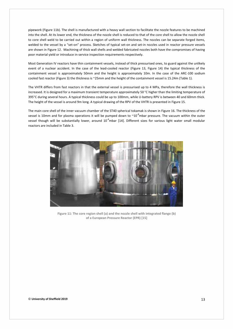
© University of Sheffield 2019 13
pipework (Figure 11b). The shell is manufactured with a heavy wall section to facilitate the nozzle features to be machined into the shell. At its lower end, the thickness of the nozzle shell is reduced to that of the core shell to allow the nozzle shell to core shell weld to be carried out within a region of uniform wall thickness. The nozzles can be separate forged items, welded to the vessel by a “set-on” process. Sketches of typical set-on and set-in nozzles used in reactor pressure vessels are shown in Figure 12. Machining of thick wall shells and welded fabricated nozzles both have the compromises of having poor material yield or introduce in-service inspection requirements respectively.
Most Generation IV reactors have thin containment vessels, instead of thick pressurised ones, to guard against the unlikely event of a nuclear accident. In the case of the lead-cooled reactor (Figure 13, Figure 14) the typical thickness of the containment vessel is approximately 50mm and the height is approximately 10m. In the case of the ARC-100 sodium cooled fast reactor (Figure 3) the thickness is ~25mm and the height of the containment vessel is 15.24m (Table 1).
The VHTR differs from fast reactors in that the external vessel is pressurised up to 4 MPa, therefore the wall thickness is increased. It is designed for a maximum transient temperature approximately 50 °C higher than the limiting temperature of 395°C during several hours. A typical thickness could be up to 100mm, while U-battery RPV is between 40 and 60mm thick. The height of the vessel is around 9m long. A typical drawing of the RPV of the VHTR is presented in Figure 15.
The main core shell of the inner vacuum chamber of the ST40 spherical tokamak is shown in Figure 16. The thickness of the vessel is 10mm and for plasma operations it will be pumped down to ~10-8mbar pressure. The vacuum within the outer vessel though will be substantially lower, around 10-4mbar [14]. Different sizes for various light water small modular reactors are included in Table 3.
Figure 11: The core region shell (a) and the nozzle shell with integrated flange (b)
of a European Pressure Reactor (EPR) [15]
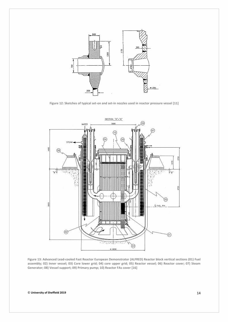
© University of Sheffield 2019 14
Figure 12: Sketches of typical set-on and set-in nozzles used in reactor pressure vessel [11]
Figure 13: Advanced Lead-cooled Fast Reactor European Demonstrator (ALFRED) Reactor block vertical sections (01) Fuel
assembly; 02) Inner vessel; 03) Core lower grid; 04) core upper grid; 05) Reactor vessel; 06) Reactor cover; 07) Steam
Generator; 08) Vessel support; 09) Primary pump; 10) Reactor FAs cover [16]
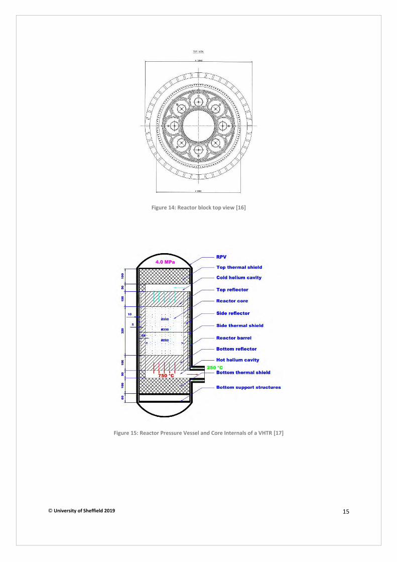
© University of Sheffield 2019 15
Figure 14: Reactor block top view [16]
Figure 15: Reactor Pressure Vessel and Core Internals of a VHTR [17]
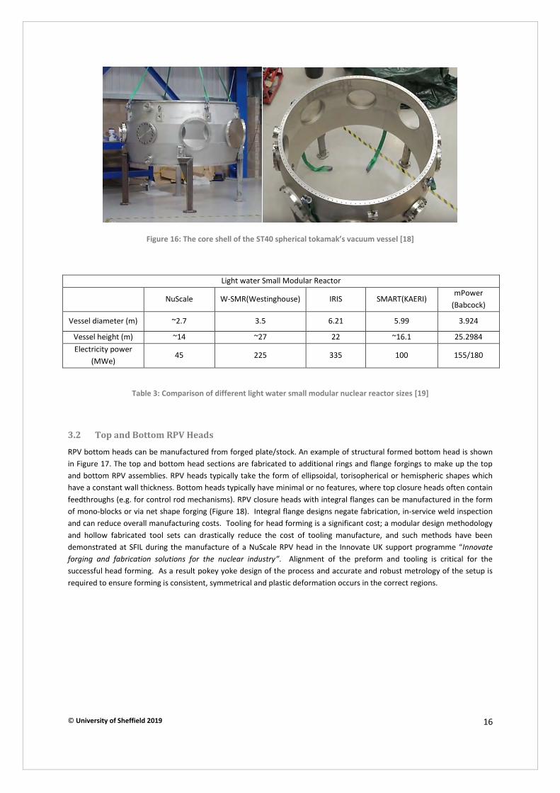
© University of Sheffield 2019 16
Figure 16: The core shell of the ST40 spherical tokamak’s vacuum vessel [18]
Light water Small Modular Reactor
NuScale W-SMR(Westinghouse) IRIS SMART(KAERI) mPower
(Babcock)
Vessel diameter (m) ~2.7 3.5 6.21 5.99 3.924
Vessel height (m) ~14 ~27 22 ~16.1 25.2984 Electricity power
(MWe) 45 225 335 100 155/180
Table 3: Comparison of different light water small modular nuclear reactor sizes [19]
3.2 Top and Bottom RPV Heads
RPV bottom heads can be manufactured from forged plate/stock. An example of structural formed bottom head is shown in Figure 17. The top and bottom head sections are fabricated to additional rings and flange forgings to make up the top and bottom RPV assemblies. RPV heads typically take the form of ellipsoidal, torisopherical or hemispheric shapes which have a constant wall thickness. Bottom heads typically have minimal or no features, where top closure heads often contain feedthroughs (e.g. for control rod mechanisms). RPV closure heads with integral flanges can be manufactured in the form of mono-blocks or via net shape forging (Figure 18). Integral flange designs negate fabrication, in-service weld inspection and can reduce overall manufacturing costs. Tooling for head forming is a significant cost; a modular design methodology and hollow fabricated tool sets can drastically reduce the cost of tooling manufacture, and such methods have been demonstrated at SFIL during the manufacture of a NuScale RPV head in the Innovate UK support programme “Innovate forging and fabrication solutions for the nuclear industry”. Alignment of the preform and tooling is critical for the successful head forming. As a result pokey yoke design of the process and accurate and robust metrology of the setup is required to ensure forming is consistent, symmetrical and plastic deformation occurs in the correct regions.

© University of Sheffield 2019 17
Figure 17: Drawing and pressed piece for the bottom of the reactor vessel [11]
Figure 18: The closure head with integrated flange of a European Pressure Reactor
3.3 Tubesheets
Tubesheets are large metallic circular components of the PWR’s steam generator. Heat exchanger tubes are welded to them to allow the movement of a given medium (gas/fluid) through the shell chamber stopping it mixing with a second fluid medium that lies outside these tubes (Figure 19). As long as there is a temperature difference between these, in effect, the two flow past one another exchanging heat without ever mixing.
Tubesheets contain many holes drilled into them, for the insertion of tubes. The number of holes can range from a few to thousands depending on reactor type. The pattern or “pitch” holes are relative to each other tubesheet within the shell. This pitch changes tube distance, angle and flow direction. These parameters have been varied to maximize the heat transfer effectiveness [20].
There is a variety of candidate materials used for the manufacturing with 2.25Cr-1Mo and modified 9Cr-1Mo being the most important [21]. Both materials are discussed further in section 3.3.
Tubesheets undergo significant upsetting and spreading during forging which results in barrelling out at the centre line. This barrelling effect adds significant excess material to the forging that increases ingot weight requirements and machining time in removing it. A combination of suitable press size, manipulator safe working loads and efficient/quick turning equipment would facilitate forging radially after spreading operations to square up the forging and remove the barrelled material thus negating the material to added to the ingot weight or have it machined off. Additionally, forging hotter and upgrading the heavy press pumping capabilities would facilitate upsetting in fewer forging operations. This would result in a reduction of approximately three forge fire heats and remove approximately the same number of days from the manufacturing schedule.
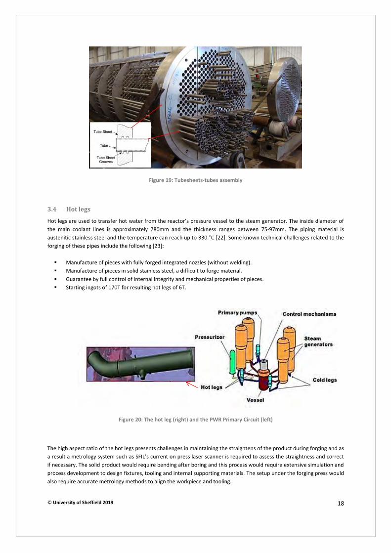
© University of Sheffield 2019 18
Figure 19: Tubesheets-tubes assembly
3.4 Hot legs
Hot legs are used to transfer hot water from the reactor’s pressure vessel to the steam generator. The inside diameter of the main coolant lines is approximately 780mm and the thickness ranges between 75-97mm. The piping material is austenitic stainless steel and the temperature can reach up to 330 °C [22]. Some known technical challenges related to the forging of these pipes include the following [23]:
� Manufacture of pieces with fully forged integrated nozzles (without welding). � Manufacture of pieces in solid stainless steel, a difficult to forge material. � Guarantee by full control of internal integrity and mechanical properties of pieces. � Starting ingots of 170T for resulting hot legs of 6T.
Figure 20: The hot leg (right) and the PWR Primary Circuit (left)
The high aspect ratio of the hot legs presents challenges in maintaining the straightens of the product during forging and as a result a metrology system such as SFIL’s current on press laser scanner is required to assess the straightness and correct if necessary. The solid product would require bending after boring and this process would require extensive simulation and process development to design fixtures, tooling and internal supporting materials. The setup under the forging press would also require accurate metrology methods to align the workpiece and tooling.
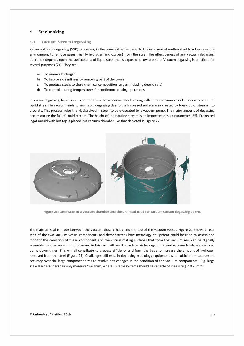
© University of Sheffield 2019 19
4 Steelmaking
4.1 Vacuum Stream Degassing
Vacuum stream degassing (VSD) processes, in the broadest sense, refer to the exposure of molten steel to a low-pressure environment to remove gases (mainly hydrogen and oxygen) from the steel. The effectiveness of any vacuum degassing operation depends upon the surface area of liquid steel that is exposed to low pressure. Vacuum degassing is practiced for several purposes [24]. They are:
a) To remove hydrogen b) To improve cleanliness by removing part of the oxygen c) To produce steels to close chemical composition ranges (including deoxidisers) d) To control pouring temperatures for continuous casting operations
In stream degassing, liquid steel is poured from the secondary steel making ladle into a vacuum vessel. Sudden exposure of liquid stream in vacuum leads to very rapid degassing due to the increased surface area created by break-up of stream into droplets. This process helps the H2 dissolved in steel, to be evacuated by a vacuum pump. The major amount of degassing occurs during the fall of liquid stream. The height of the pouring stream is an important design parameter [25]. Preheated ingot mould with hot top is placed in a vacuum chamber like that depicted in Figure 22.
Figure 21: Laser scan of a vacuum chamber and closure head used for vacuum stream degassing at SFIL
The main air seal is made between the vacuum closure head and the top of the vacuum vessel. Figure 21 shows a laser scan of the two vacuum vessel components and demonstrates how metrology equipment could be used to assess and monitor the condition of these component and the critical mating surfaces that form the vacuum seal can be digitally assembled and assessed. Improvement in this seal will result is reduce air leakage, improved vacuum levels and reduced pump down times. This will all contribute to process efficiency and form the basis to increase the amount of hydrogen removed from the steel (Figure 25). Challenges still exist in deploying metrology equipment with sufficient measurement accuracy over the large component sizes to resolve any changes in the condition of the vacuum components. E.g. large scale laser scanners can only measure ~+/-2mm, where suitable systems should be capable of measuring < 0.25mm.
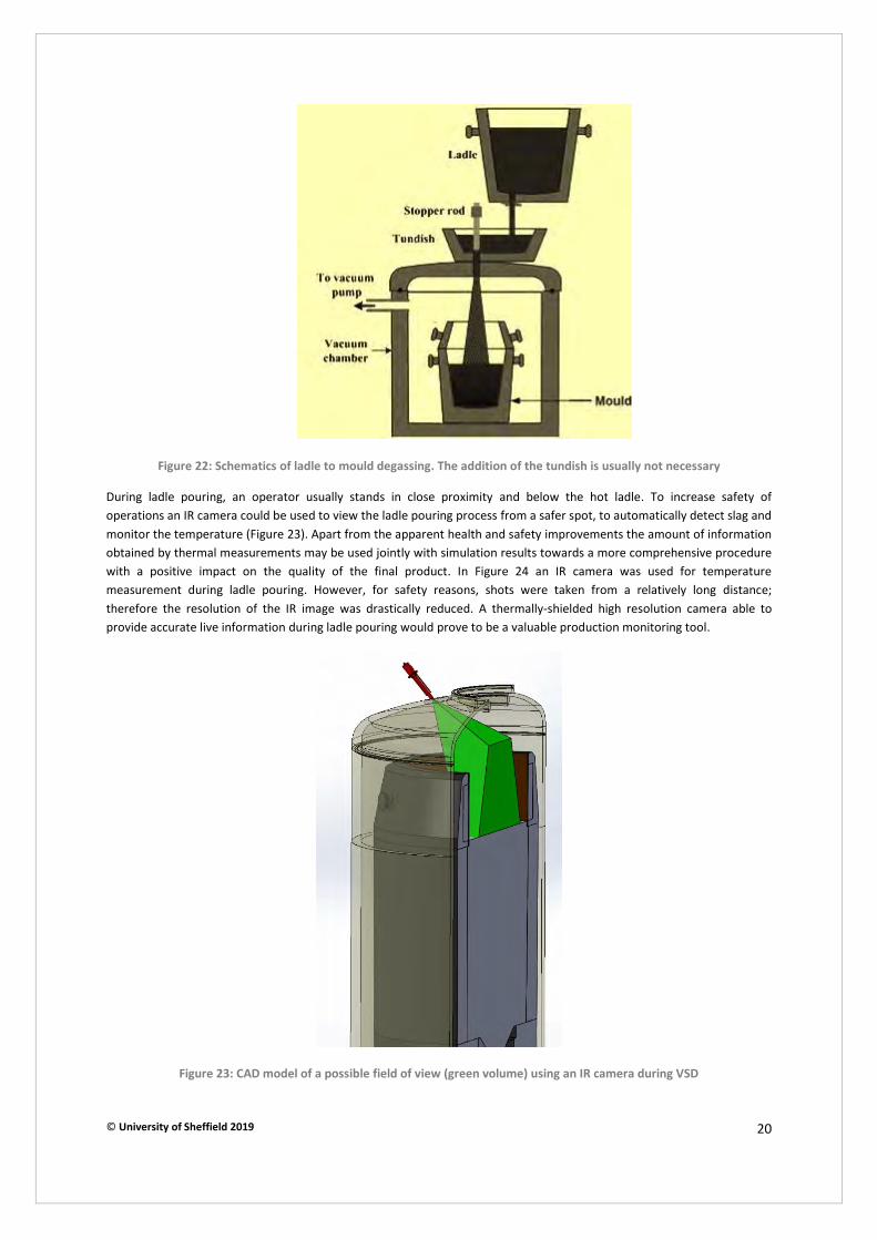
© University of Sheffield 2019 20
Figure 22: Schematics of ladle to mould degassing. The addition of the tundish is usually not necessary
During ladle pouring, an operator usually stands in close proximity and below the hot ladle. To increase safety of operations an IR camera could be used to view the ladle pouring process from a safer spot, to automatically detect slag and monitor the temperature (Figure 23). Apart from the apparent health and safety improvements the amount of information obtained by thermal measurements may be used jointly with simulation results towards a more comprehensive procedure with a positive impact on the quality of the final product. In Figure 24 an IR camera was used for temperature measurement during ladle pouring. However, for safety reasons, shots were taken from a relatively long distance; therefore the resolution of the IR image was drastically reduced. A thermally-shielded high resolution camera able to provide accurate live information during ladle pouring would prove to be a valuable production monitoring tool.
Figure 23: CAD model of a possible field of view (green volume) using an IR camera during VSD
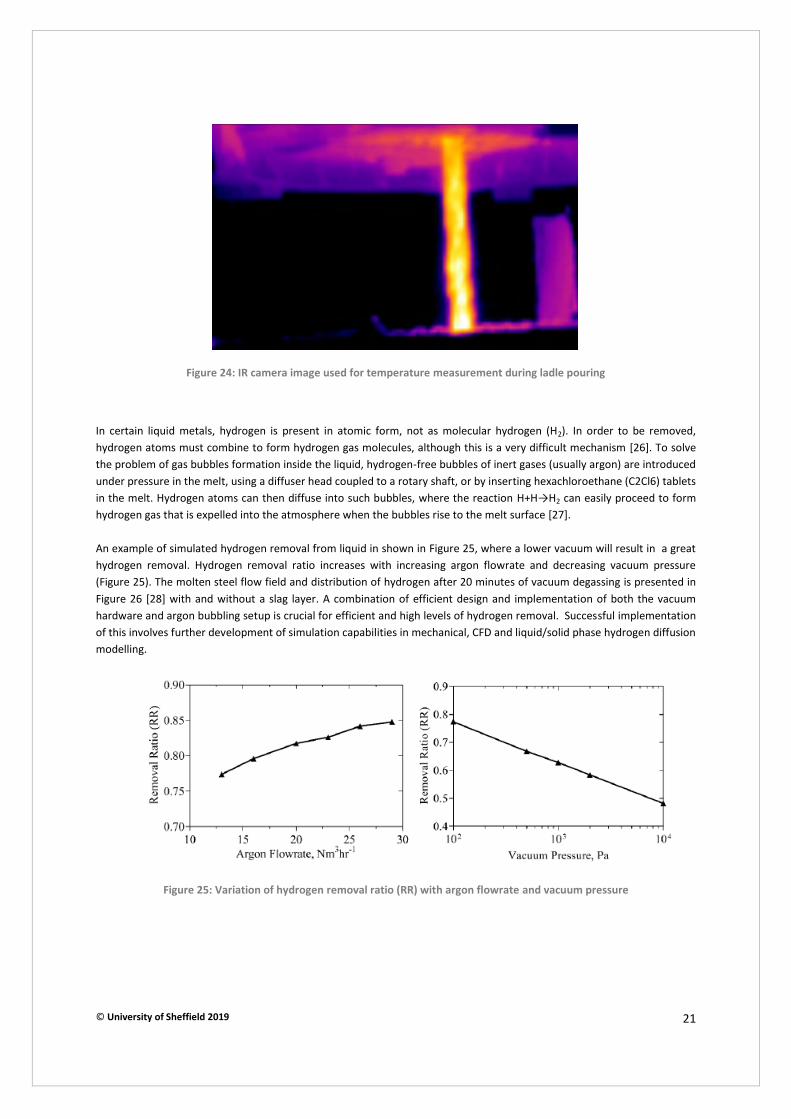
© University of Sheffield 2019 21
Figure 24: IR camera image used for temperature measurement during ladle pouring
In certain liquid metals, hydrogen is present in atomic form, not as molecular hydrogen (H2). In order to be removed, hydrogen atoms must combine to form hydrogen gas molecules, although this is a very difficult mechanism [26]. To solve the problem of gas bubbles formation inside the liquid, hydrogen-free bubbles of inert gases (usually argon) are introduced under pressure in the melt, using a diffuser head coupled to a rotary shaft, or by inserting hexachloroethane (C2Cl6) tablets in the melt. Hydrogen atoms can then diffuse into such bubbles, where the reaction H+H→H2 can easily proceed to form hydrogen gas that is expelled into the atmosphere when the bubbles rise to the melt surface [27]. An example of simulated hydrogen removal from liquid in shown in Figure 25, where a lower vacuum will result in a great hydrogen removal. Hydrogen removal ratio increases with increasing argon flowrate and decreasing vacuum pressure (Figure 25). The molten steel flow field and distribution of hydrogen after 20 minutes of vacuum degassing is presented in Figure 26 [28] with and without a slag layer. A combination of efficient design and implementation of both the vacuum hardware and argon bubbling setup is crucial for efficient and high levels of hydrogen removal. Successful implementation of this involves further development of simulation capabilities in mechanical, CFD and liquid/solid phase hydrogen diffusion modelling.
Figure 25: Variation of hydrogen removal ratio (RR) with argon flowrate and vacuum pressure

© University of Sheffield 2019 22
Figure 26: Molten steel flow field and hydrogen distribution across side profile plane after 20 minutes of vacuum
degassing for (a) slagless and (b) slag-containing melt. Volume fraction of slag eye viewed from top profile after 20s of
argon stirring for argon flowrates of (a) 170, (b) 237 and (c) 305NLmin-1
4.2 Vacuum pumping equipment
The large volumes of dissolved metallurgical gases arising from these processes, and the generation of large amounts of metallic fines and oxide dust, require high-capacity vacuum pumping equipment. Large root style mechanical vacuum booster pumps, designed for high dust tolerance, are the major component of such "dry" vacuum degassing systems, and when backed by rugged, dry, mechanical vacuum pumps form today's advanced dry pump systems. These systems are superior to previously used steam ejector systems particularly in that they enable better dust handling, increased pumping speed in the crucial processing pressure zones, and significantly reduced environmental impact [29].
The steam jet ejector (Figure 27) has been the mainstay for industrial vacuum pumping systems designed for operation at pressures above 0.67mbar / 0.5torr. The low initial cost and apparent maintenance free operation of this type of pump is well known. Compression ratios as high as 30–40 can be obtained in a single-stage ejector, but efficiency at these high compression ratios is poor; therefore single ejector stages are generally limited to a compression ratio of around 10. Typically, multiple stages of ejectors must be used for practical degassing systems, and a 4-stage system would be typical of the steel degassing installations where final vacuum levels of 0.67mbar / 0.5torr are required. In particular, the steam ejector system installed needs to have sufficient excess capacity to handle the process loads, steam pressure variations and the inevitable loss in performance due to nozzle wear and especially diffuser contamination from the large amounts of dust arising. This contamination has the unfortunate characteristic of forming a hard aggregate inside the ejector, which must be mechanically removed on a routine basis.
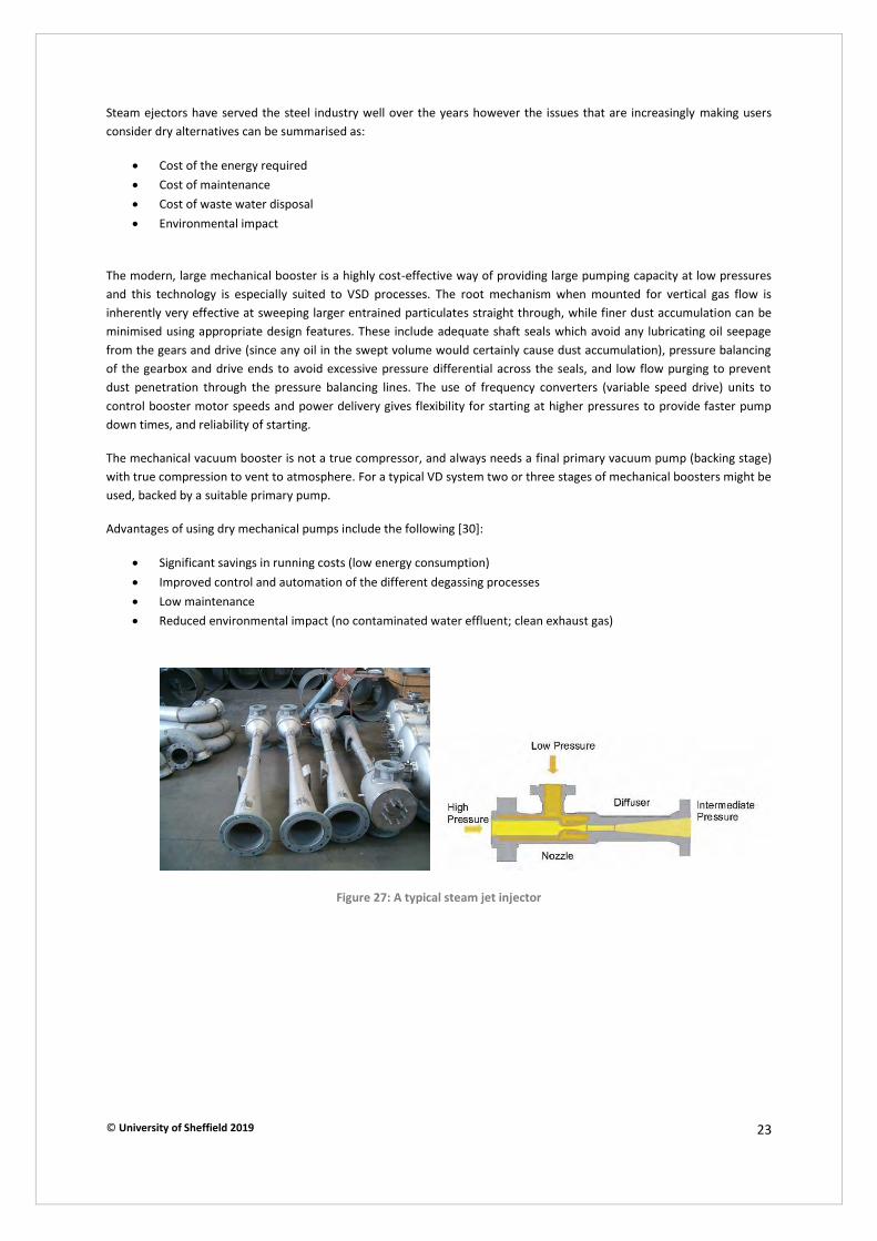
© University of Sheffield 2019 23
Steam ejectors have served the steel industry well over the years however the issues that are increasingly making users consider dry alternatives can be summarised as:
x Cost of the energy required x Cost of maintenance x Cost of waste water disposal x Environmental impact
The modern, large mechanical booster is a highly cost-effective way of providing large pumping capacity at low pressures and this technology is especially suited to VSD processes. The root mechanism when mounted for vertical gas flow is inherently very effective at sweeping larger entrained particulates straight through, while finer dust accumulation can be minimised using appropriate design features. These include adequate shaft seals which avoid any lubricating oil seepage from the gears and drive (since any oil in the swept volume would certainly cause dust accumulation), pressure balancing of the gearbox and drive ends to avoid excessive pressure differential across the seals, and low flow purging to prevent dust penetration through the pressure balancing lines. The use of frequency converters (variable speed drive) units to control booster motor speeds and power delivery gives flexibility for starting at higher pressures to provide faster pump down times, and reliability of starting.
The mechanical vacuum booster is not a true compressor, and always needs a final primary vacuum pump (backing stage) with true compression to vent to atmosphere. For a typical VD system two or three stages of mechanical boosters might be used, backed by a suitable primary pump.
Advantages of using dry mechanical pumps include the following [30]:
x Significant savings in running costs (low energy consumption) x Improved control and automation of the different degassing processes x Low maintenance x Reduced environmental impact (no contaminated water effluent; clean exhaust gas)
Figure 27: A typical steam jet injector
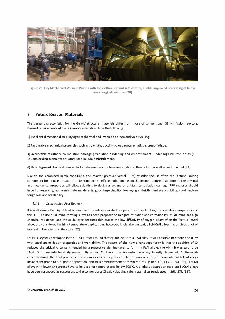
© University of Sheffield 2019 24
Figure 28: Dry Mechanical Vacuum Pumps with their efficiency and safe control, enable improved processing of heavy
metallurgical reactions [30]
5 Future Reactor Materials
The design characteristics for the Gen-IV structural materials differ from those of conventional GEN-III fission reactors. Desired requirements of these Gen-IV materials include the following:
1) Excellent dimensional stability against thermal and irradiation creep and void swelling.
2) Favourable mechanical properties such as strength, ductility, creep rupture, fatigue, creep-fatigue.
3) Acceptable resistance to radiation damage (irradiation hardening and embrittlement) under high neutron doses (10–150dpa or displacements per atom) and helium embrittlement.
4) High degree of chemical compatibility between the structural materials and the coolant as well as with the fuel [31].
Due to the combined harsh conditions, the reactor pressure vessel (RPV) cylinder shell is often the lifetime-limiting component for a nuclear reactor. Understanding the effects radiation has on the microstructure in addition to the physical and mechanical properties will allow scientists to design alloys more resistant to radiation damage. RPV material should have homogeneity, no harmful internal defects, good inspectability, low aging embrittlement susceptibility, good fracture toughness and weldability.
5.1.1 Lead-cooled Fast Reactor
It is well known that liquid lead is corrosive to steels at elevated temperatures, thus limiting the operation temperature of the LFR. The use of alumina-forming alloys has been proposed to mitigate oxidation and corrosion issues. Alumina has high chemical resistance, and the oxide layer becomes thin due to the low diffusivity of oxygen. Most often the ferritic FeCrAl alloys are considered for high-temperature applications, however, lately also austenitic FeNiCrAl alloys have gained a lot of interest in the scientific literature [32].
FeCrAl alloy was developed in the 1920’s. It was found that by adding Cr to a FeAl alloy, it was possible to produce an alloy with excellent oxidation properties and workability. The reason of the new alloy’s superiority is that the addition of Cr reduced the critical Al-content needed for a protective alumina-layer to form. In FeAl alloys, the Al-limit was said to be 16wt. % for manufacturability reasons. By adding Cr, the critical Al-content was significantly decreased. At these Al-concentrations, the final product is considerably easier to produce. The Cr-concentrations of conventional FeCrAl alloys make them prone to a-a’ phase separation, and thus embrittlement at temperatures up to 5000C ( [33], [34], [35]). FeCrAl alloys with lower Cr-content have to be used for temperatures below 5000C. A-a’ phase separation resistant FeCrAl alloys have been proposed as successors to the conventional Zircaloy cladding tube material currently used ( [36], [37], [38]).
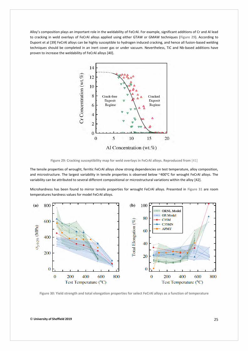
© University of Sheffield 2019 25
Alloy’s composition plays an important role in the weldability of FeCrAl. For example, significant additions of Cr and Al lead to cracking in weld overlays of FeCrAl alloys applied using either GTAW or GMAW techniques (Figure 29). According to Dupont et al [39] FeCrAl alloys can be highly susceptible to hydrogen induced cracking, and hence all fusion-based welding techniques should be completed in an inert cover gas or under vacuum. Nevertheless, TiC and Nb-based additions have proven to increase the weldability of FeCrAl alloys [40].
Figure 29: Cracking susceptibility map for weld overlays in FeCrAl alloys. Reproduced from [41]
The tensile properties of wrought, ferritic FeCrAl alloys show strong dependencies on test temperature, alloy composition, and microstructure. The largest variability in tensile properties is observed below ~400°C for wrought FeCrAl alloys. The variability can be attributed to several different compositional or microstructural variations within the alloy [42].
Microhardness has been found to mirror tensile properties for wrought FeCrAl alloys. Presented in Figure 31 are room temperatures hardness values for model FeCrAl alloys.
Figure 30: Yield strength and total elongation properties for select FeCrAl alloys as a function of temperature
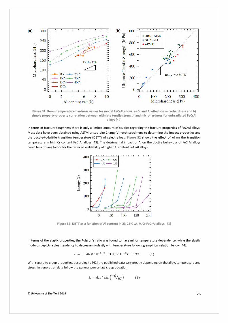
© University of Sheffield 2019 26
Figure 31: Room temperature hardness values for model FeCrAl alloys. a) Cr and Al effect on microhardness and b)
simple property-property correlation between ultimate tensile strength and microhardness for unirradiated FeCrAl
alloys [42]
In terms of fracture toughness there is only a limited amount of studies regarding the fracture properties of FeCrAl alloys. Most data have been obtained using ASTM or sub-size Charpy V-notch specimens to determine the impact properties and the ductile-to-brittle transition temperature (DBTT) of select alloys. Figure 32 shows the effect of Al on the transition temperature in high Cr content FeCrAl alloys [43]. The detrimental impact of Al on the ductile behaviour of FeCrAl alloys could be a driving factor for the reduced weldability of higher Al content FeCrAl alloys.
Figure 32: DBTT as a function of Al content in 23-25% wt. % Cr FeCrAl alloys [43]
In terms of the elastic properties, the Poisson’s ratio was found to have minor temperature dependence, while the elastic modulus depicts a clear tendency to decrease modestly with temperature following empirical relation below [44]:
𝐸 = −5.46 × 10⁻⁵𝑇2 − 3.85 × 10⁻²𝑇 + 199 (1)
With regard to creep properties, according to [42] the published data vary greatly depending on the alloy, temperature and stress. In general, all data follow the general power-law creep equation:
𝜀�̇� = 𝐴0𝜎𝑛𝑒𝑥𝑝 (−𝑄𝑅𝑇⁄ ) (2)
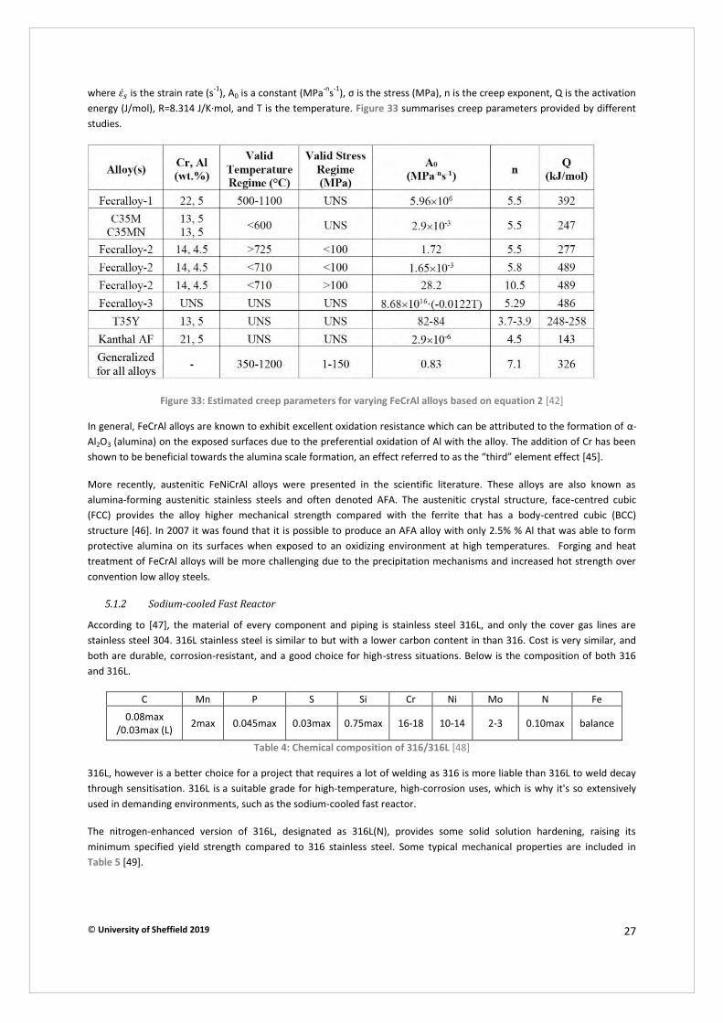
© University of Sheffield 2019 27
where 𝜀�̇� is the strain rate (s-1), A0 is a constant (MPa-ns-1), σ is the stress (MPa), n is the creep exponent, Q is the activation energy (J/mol), R=8.314 J/K∙mol, and T is the temperature. Figure 33 summarises creep parameters provided by different studies.
Figure 33: Estimated creep parameters for varying FeCrAl alloys based on equation 2 [42]
In general, FeCrAl alloys are known to exhibit excellent oxidation resistance which can be attributed to the formation of α-Al2O3 (alumina) on the exposed surfaces due to the preferential oxidation of Al with the alloy. The addition of Cr has been shown to be beneficial towards the alumina scale formation, an effect referred to as the “third” element effect [45].
More recently, austenitic FeNiCrAl alloys were presented in the scientific literature. These alloys are also known as alumina-forming austenitic stainless steels and often denoted AFA. The austenitic crystal structure, face-centred cubic (FCC) provides the alloy higher mechanical strength compared with the ferrite that has a body-centred cubic (BCC) structure [46]. In 2007 it was found that it is possible to produce an AFA alloy with only 2.5% % Al that was able to form protective alumina on its surfaces when exposed to an oxidizing environment at high temperatures. Forging and heat treatment of FeCrAl alloys will be more challenging due to the precipitation mechanisms and increased hot strength over convention low alloy steels.
5.1.2 Sodium-cooled Fast Reactor
According to [47], the material of every component and piping is stainless steel 316L, and only the cover gas lines are stainless steel 304. 316L stainless steel is similar to but with a lower carbon content in than 316. Cost is very similar, and both are durable, corrosion-resistant, and a good choice for high-stress situations. Below is the composition of both 316 and 316L.
C Mn P S Si Cr Ni Mo N Fe 0.08max
/0.03max (L) 2max 0.045max 0.03max 0.75max 16-18 10-14 2-3 0.10max balance
Table 4: Chemical composition of 316/316L [48]
316L, however is a better choice for a project that requires a lot of welding as 316 is more liable than 316L to weld decay through sensitisation. 316L is a suitable grade for high-temperature, high-corrosion uses, which is why it's so extensively used in demanding environments, such as the sodium-cooled fast reactor.
The nitrogen-enhanced version of 316L, designated as 316L(N), provides some solid solution hardening, raising its minimum specified yield strength compared to 316 stainless steel. Some typical mechanical properties are included in Table 5 [49].
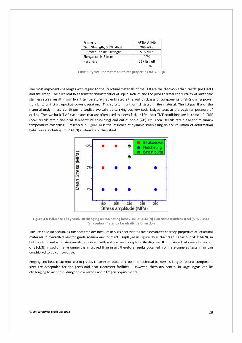
© University of Sheffield 2019 28
The most important challenges with regard to the structural materials of the SFR are the thermomechanical fatigue (TMF) and the creep. The excellent heat transfer characteristics of liquid sodium and the poor thermal conductivity of austenitic stainless steels result in significant temperature gradients across the wall thickness of components of SFRs during power transients and start up/shut down operations. This results in a thermal stress in the material. The fatigue life of the material under these conditions is studied typically by carrying out low cycle fatigue tests at the peak temperature of cycling. The two basic TMF cycle types that are often used to assess fatigue life under TMF conditions are in-phase (IP) TMF (peak tensile strain and peak temperature coinciding) and out-of-phase (OP) TMF (peak tensile strain and the minimum temperature coinciding). Presented in Figure 34 is the influence of dynamic strain aging on accumulation of deformation behaviour (ratcheting) of 316L(N) austenitic stainless steel.
Figure 34: Influence of dynamic strain aging on ratcheting behaviour of 316L(N) austenitic stainless steel [50]. Elastic
“shakedown” stands for elastic deformation
The use of liquid sodium as the heat transfer medium in SFRs necessitates the assessment of creep properties of structural materials in controlled reactor grade sodium environment. Displayed in Figure 35 is the creep behaviour of 316L(N), in both sodium and air environments, expressed with a stress versus rupture life diagram. It is obvious that creep behaviour of 316L(N) in sodium environment is improved than in air, therefore results obtained from less-complex tests in air can considered to be conservative.
Forging and heat treatment of 316 grades is common place and pose no technical barriers as long as reactor component sizes are acceptable for the press and heat treatment facilities. However, chemistry control in large ingots can be challenging to meet the stringent low carbon and nitrogen requirements.
Property ASTM A 240 Yield Strength, 0.2% offset 205 MPa Ultimate Tensile Strength 515 MPa Elongation in 51mm 40% Hardness 217 Brinell
95HRB
Table 5: typical room temperatures properties for 316L (N)

© University of Sheffield 2019 29
Figure 35: Enhanced creep rupture of 316L(N) SS in sodium environment [51]
5.1.3 Stable Salt Reactor
The material challenges for Molten Salt Reactors (MSR) generally fall into categories of irradiation effects, corrosion, and elevated temperature strength. Given that there are at least two classes of MSRs that are under consideration, liquid-fuelled and liquid-cooled, and at least two families of salt under consideration (fluoride and chloride), a single alloy is not likely to meet all of the requirements for potential designs [52]. The stable salt reactor is a special version of the MSR which uses fluoride salt cooling.
It has been shown through testing in different salt environments that alloys high in iron and chromium, such us Inconel 106 and type 316 stainless steels corrode quickly and lose significant amounts of mass within a few thousand hours [53]. Cr forms stable fluorides and is preferentially removed by circulating salts, however, some Cr is necessary for oxidation resistance [53] , [54]. Alloys with high nickel and molybdenum content tend to last much longer with only a few mils of material loss per year.
Soon as it became obvious that nickel-based alloys were corrosion-resistant a series of INOR alloys were investigated. The need for 5-7% Cr to maintain oxidation resistance in a Flibe salt environment (LiF - BeF2 - ZrF4 -
235UF4) is shown in Figure 36.
Figure 36: Oxidation rate of Ni alloys as a function of the Cr content for several temperatures [53]

© University of Sheffield 2019 30
An alloy with composition very close to INOR-8 was commercialised as Hastelloy N. The nominal composition of Hastelloy N is presented in Table 6.
Nickel: 71 Balance Chromium: 7 Molybdenum: 16 Iron: 4 max. Silicon: 1 max. Manganese: 0.8 max. Vanadium: 0.5 max. Carbon: 0.06 Cobalt: 0.2 max. Copper: 0.35 max. Tungsten: 0.5 max. Aluminium + Titanium 0.5 max
Table 6: Nominal composition of Hastelloy N, compositions in weight%
Tests within the Molten Salt Reactor Experiment (MSRE) revealed that even though the performance of INOR 8 was judged to be adequate during operation of the MSRE, upon examination of some components after decommissioning of the reactor it was found that there was significant surface cracking [55]. It was eventually determined that the cracking was associated with grain boundary embrittlement by the fission product tellurium [56]. A series of new alloy compositions based on INOR-8 with additions of niobium and titanium were examined using laboratory corrosion tests to mitigate cracking. It was found that Ti additions did not mitigate Te embrittlement and additions of Ti along with Nb would negate the beneficial effects of niobium. Based on these results there was a focus on Nb additions for mitigation of Te embrittlement. The influence of Nb content specifically is shown in Figure 37. Additionally, the embrittlement by formation of grain-boundary he bubbles, resulting from transmutation of Ni, was also recognised as a significant issue. The attributes (positive and negative) and potential limiting factors for the most important candidate materials for MSR applications are summarised in Table 7.
Figure 37: The influence of Nb content on cracking frequency in modified Hastelloy N

© University of Sheffield 2019 31
Alloy Advantages Disadvantages Limiting factor (s) Type 316 stainless
steel
Fully qualified in ASME Code Section
III, Division 5; limited He embrittlement
Restricted to temperature on order
of 700°C and only with good redox
control
Corrosion resistance at higher
temperatures. Low allowable stresses for
long time service Hastelloy N
Demonstrated in
MSRE; commercial experience with production and
fabrication. Extensive database of rupture
properties
Limited to temperature of about
700°C by strength. Susceptibility to Te
embrittlement. Poor oxidation resistance
He embrittlement; Te embrittlement if
redox chemistry is not well controlled
Modified Hastelloy N composition
Ti modification showed reduced He
embrittlement compared to N. Nb
additions reduce embrittlement from
Te
Limited experience with fabrication and
scale-up. Little rupture data.
Strength only marginally better compared to N at high temperature
He embrittlement for some variants; low high temperature
strength
Table 7: Summary of attributes (positive and negative) and potential limiting factors for most of the alloys that have
been suggested for MSR applications
While the alloy received ASTM standardization in several produced forms, it has not been qualified for nuclear construction in the ASME code, yet. The performance of Hastelloy was judged to be adequate but new nickel alloys that contain a fine, stable dispersion of intermetallic parts to trap helium should be developed. Until that happens, type 316 stainless steel may be used for relatively short-time operation of MSRs at 6500C. This alloy is fully ASME code qualified for nuclear construction [52].
Development of large open die forged components in nickel super alloys will be expensive due to the high cost of nickel and may not be successful with current large scale forge, furnace crane and manipulator equipment as these are optimised to heavy lifting and not speed. Nickel’s high temperature strength will dictate short forging times and the precipitation hardening mechanism will require short transfer times for quench. Thus, significant plant investments are likely required to successfully develop large scale nickel alloy forging capability in the UK.
5.1.4 Very High Temperature Reactor-Small light water reactor
Four are the candidate materials for the pressure vessel of these types of reactors: 304H, SA-508 (UNS K12042), 2.25Cr-1Mo-0.25V (UNS K31835) and modified 9Cr/1Mo (UNS K90901) [57]. Grade 304 is an austenitic steel with excellent welding and forming characteristics. The key elements in 304 are chromium and nickel which give it excellent resistance to corrosion, good malleability, ductility and weldability. “H” denotes higher content in carbon which gives greater strength at high temperatures as well as good corrosion resistance, but does make it more vulnerable to carbide precipitation when welding. Below in Table 8 and Table 9 are the chemical composition and mechanical properties of 304H, respectively:
C Mn Si P S Cr Ni 0.01-0.1 0-2 0-0.75 0-0.045 0-0.030 18-20 8-10.5
Table 8: Chemical composition of 304H
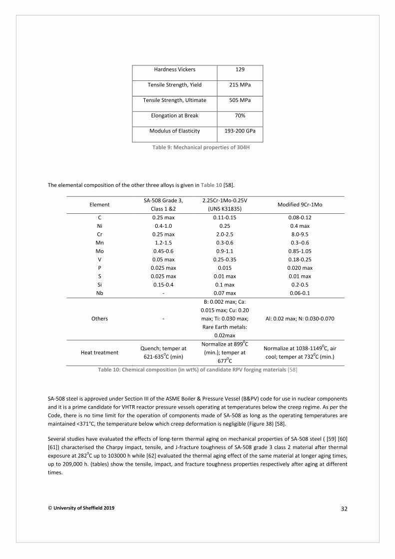
© University of Sheffield 2019 32
The elemental composition of the other three alloys is given in Table 10 [58].
Element SA-508 Grade 3,
Class 1 &2 2.25Cr-1Mo-0.25V
(UNS K31835) Modified 9Cr-1Mo
C 0.25 max 0.11-0.15 0.08-0.12 Ni 0.4-1.0 0.25 0.4 max Cr 0.25 max 2.0-2.5 8.0-9.5
Mn 1.2-1.5 0.3-0.6 0.3–0.6 Mo 0.45-0.6 0.9-1.1 0.85-1.05 V 0.05 max 0.25-0.35 0.18-0.25 P 0.025 max 0.015 0.020 max S 0.025 max 0.01 max 0.01 max Si 0.15-0.4 0.1 max 0.2-0.5
Nb - 0.07 max 0.06-0.1
Others -
B: 0.002 max; Ca: 0.015 max; Cu: 0.20 max; Ti: 0.030 max; Rare Earth metals:
0.02max
Al: 0.02 max; N: 0.030-0.070
Heat treatment Quench; temper at
621-6350C (min)
Normalize at 8990C (min.); temper at
6770C
Normalize at 1038-11490C, air cool; temper at 7320C (min.)
Table 10: Chemical composition (in wt%) of candidate RPV forging materials [58]
SA-508 steel is approved under Section III of the ASME Boiler & Pressure Vessel (B&PV) code for use in nuclear components and it is a prime candidate for VHTR reactor pressure vessels operating at temperatures below the creep regime. As per the Code, there is no time limit for the operation of components made of SA-508 as long as the operating temperatures are maintained <371°C, the temperature below which creep deformation is negligible (Figure 38) [58].
Several studies have evaluated the effects of long-term thermal aging on mechanical properties of SA-508 steel ( [59] [60] [61]) characterised the Charpy impact, tensile, and J-fracture toughness of SA-508 grade 3 class 2 material after thermal exposure at 2820C up to 103000 h while [62] evaluated the thermal aging effect of the same material at longer aging times, up to 209,000 h. (tables) show the tensile, impact, and fracture toughness properties respectively after aging at different times.
Hardness Vickers 129
Tensile Strength, Yield 215 MPa
Tensile Strength, Ultimate 505 MPa
Elongation at Break 70%
Modulus of Elasticity 193-200 GPa
Table 9: Mechanical properties of 304H

© University of Sheffield 2019 33
There is an extensive database on the mechanical properties of SA508 grade 3 steel up to about 3000C. For consideration of this material for the reactor pressure vessel, where the wall temperature could exceed 3710C depending on RPV design, creep and creep-fatigue response and thermal stability become important factors, in addition to elevated temperature tensile properties [57].
A military grade nuclear pressure vessel steel SA508 Grade 4N has been highlighted as a potential new candidate for fourth generation reactor pressure vessels since new requirements are for a tougher variant. The main difference between the Grade 3 material currently used and the new Grade 4N material is the higher Ni and Cr contents and reduced Mn content in the latter. With the increased nickel content a significant increase in yield strength of 25% is observed with the fracture toughness also being improved substantially through the optimisation of the chemical composition [63]. The range of chemical compositions of the SA508 steels is outlined in Table 11 along with the mechanical properties in Table 12 [64], [65].
However, there is a lack of experimental data in relation to Grade 4N steel in service, particularly regarding irradiation embrittlement and welding properties over long term operation. With the short time frame available until Generation IV RPVs commence construction; this creates difficulty with regard to its assessment for service. A potential concern regarding the application of Grade 4N is that it may have increased susceptibility to irradiation embrittlement. This is due to the fact that Ni has increased elemental sensitivity to irradiation with increasing. Despite this, Grade 4 is the only viable material currently available to extend the lifetime of nuclear power plants to 60+ years [12].
Table 11: Range of maximum chemical compositions of SA508 steels in wt. %
Tensile strength (MPa)
Yield strength (MPa) Elongation (%)
SA508 Grade 1 345 515 16 SA508 Grade 2 611 448 18 SA508 Grade 3 611 468 29
SA508 Grade 4N 725 585 18
Table 12: Mechanical Properties for varying alloy composition for SA508 grades
Grade 1 Grade 2 Grade 3 Grade 4N C 0.35 0.27 0.25 0.23 Mn 0.40-1.05 0.50-1.00 1.20-1.50 0.20-0.40 Ni 0.40 0.50-1.00 0.4-1.00 2.8-3.9 Cr 0.25 0.25-0.45 0.25 1.2-2.00 Mo 0.10 0.55-0.70 0.45-0.60 0.40-0.60 Si 0.15-0.35 0.15-0.35 0.15-0.35 0.15 S 0.025 0.025 0.025 0.025 P 0.025 0.025 0.025 0.025 V 0.025 0.025 0.025 0.025
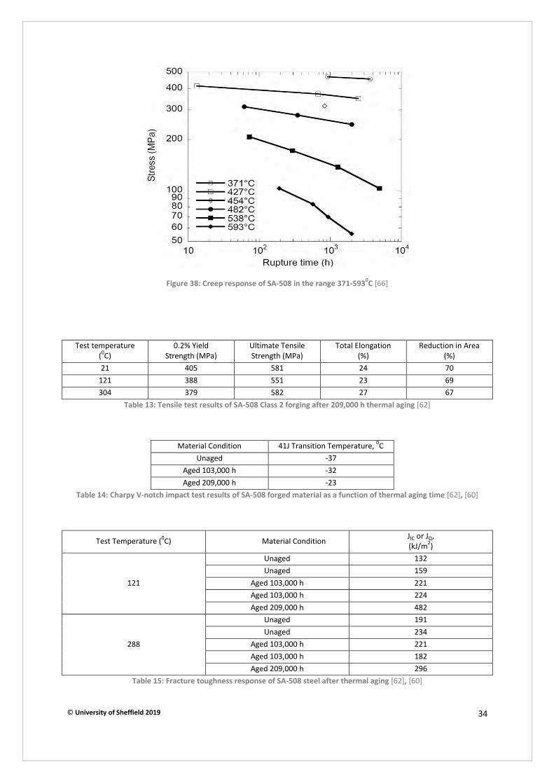
© University of Sheffield 2019 34
Figure 38: Creep response of SA-508 in the range 371-5930C [66]
Test temperature (0C)
0.2% Yield Strength (MPa)
Ultimate Tensile Strength (MPa)
Total Elongation (%)
Reduction in Area (%)
21 405 581 24 70 121 388 551 23 69 304 379 582 27 67
Table 13: Tensile test results of SA-508 Class 2 forging after 209,000 h thermal aging [62]
Material Condition 41J Transition Temperature, 0C Unaged -37
Aged 103,000 h -32 Aged 209,000 h -23
Table 14: Charpy V-notch impact test results of SA-508 forged material as a function of thermal aging time [62], [60]
Test Temperature (0C) Material Condition JIC or JQ, (kJ/m2)
121
Unaged 132 Unaged 159
Aged 103,000 h 221 Aged 103,000 h 224 Aged 209,000 h 482
288
Unaged 191 Unaged 234
Aged 103,000 h 221 Aged 103,000 h 182 Aged 209,000 h 296
Table 15: Fracture toughness response of SA-508 steel after thermal aging [62], [60]

© University of Sheffield 2019 35
UNS K31835 steel, having a nominal composition of Fe-2.25Cr-1Mo-0.25V, is permitted for structural use under ASME specification SA-336 in the ASME B&PV Code [58]. Addition of vanadium offers increased tensile and creep rupture strengths, and increases hardenability when compared to conventional 2.25Cr-1Mo steel [67]. For long life service, creep strength is offered by the presence of various fine carbides of chromium, vanadium, molybdenum, etc. The yield and tensile ratio, defined as the ratio of strength at a given temperature to those at room temperature, as a function of the temperature is given in Figure 39 [68]. In the same work, the creep rupture behaviour of Fe-2.25Cr-1Mo-0.25V steel was found at different temperatures (Figure 40).
Figure 39: Ratio trend curves of YS and UTS ratio as a function of temperature (a) YS and (b) UTS
Figure 40: Creep rupture behaviour of 2.25Cr-1Mo-0.25V steel at different temperatures [68]
UNS K90901 is ferritic steel having a nominal composition of Fe-9Cr-1Mo-V (also called modified 9Cr-1Mo steel). Forgings of this steel are allowed for use in pressure vessel components under ASME specifications SA-336 and SA-182, of which SA-336 is the standard for construction of large pressure vessels.
The 9Cr-1Mo-V steel is a modified alloy of conventional 9Cr-1Mo ferritic steel developed at Oak Ridge National Laboratory [69]. It shows a remarkable increase in stress rupture strength, achieved by addition of small amounts of vanadium, niobium, and nitrogen. This alloy is much more resistant to thermal fatigue than austenitic stainless steels because of its lower thermal expansion coefficient (at least 30% lower) and higher thermal conductivity. This alloy provides good mechanical properties at elevated temperature when produced and heat treated to form the proper microstructure.
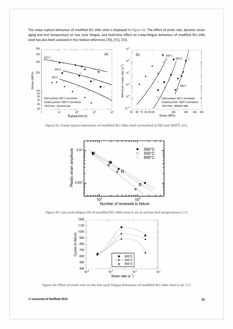
© University of Sheffield 2019 36
The creep rupture behaviour of modified 9Cr-1Mo steel is displayed in Figure 41. The effect of strain rate, dynamic strain aging and test temperature on low cycle fatigue, and hold-time effect on creep-fatigue behaviour of modified 9Cr-1Mo steel has also been assessed in the relative references [70], [71], [72].
Figure 41: Creep rupture behaviour of modified 9Cr-1Mo steel normalized at 925 and 10500C [69].
Figure 42: Low cycle fatigue life of modified 9Cr-1Mo steel in air at various test temperatures [72]
Figure 43: Effect of strain rate on the low cycle fatigue behaviour of modified 9Cr-1Mo steel in air [72]
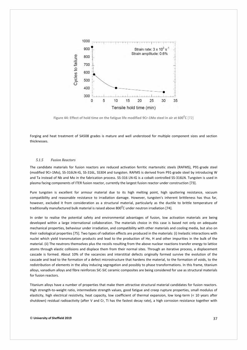
© University of Sheffield 2019 37
Figure 44: Effect of hold time on the fatigue life modified 9Cr-1Mo steel in air at 6000C [72]
Forging and heat treatment of SA508 grades is mature and well understood for multiple component sizes and section thicknesses.
5.1.5 Fusion Reactors
The candidate materials for fusion reactors are reduced activation ferritic martensitic steels (RAFMS), P91-grade steel (modified 9Cr-1Mo), SS-316LN-IG, SS-316L, SS304 and tungsten. RAFMS is derived from P91-grade steel by introducing W and Ta instead of Nb and Mo in the fabrication process. SS-316 LN-IG is a cobalt controlled SS-316LN. Tungsten is used in plasma facing components of ITER fusion reactor, currently the largest fusion reactor under construction [73].
Pure tungsten is excellent for armour material due to its high melting point, high sputtering resistance, vacuum compatibility and reasonable resistance to irradiation damage. However, tungsten's inherent brittleness has thus far, however, excluded it from consideration as a structural material, particularly as the ductile to brittle temperature of traditionally manufactured bulk material is raised above 8000C under neutron irradiation [74].
In order to realise the potential safety and environmental advantages of fusion, low activation materials are being developed within a large international collaboration. The materials choice in this case is based not only on adequate mechanical properties, behaviour under irradiation, and compatibility with other materials and cooling media, but also on their radiological properties [75]. Two types of radiation effects are produced in the materials: (i) Inelastic interactions with nuclei which yield transmutation products and lead to the production of He, H and other impurities in the bulk of the material. (ii) The neutrons themselves plus the recoils resulting from the above nuclear reactions transfer energy to lattice atoms through elastic collisions and displace them from their normal sites. Through an iterative process, a displacement cascade is formed. About 10% of the vacancies and interstitial defects originally formed survive the evolution of the cascade and lead to the formation of a defect microstructure that hardens the material, to the formation of voids, to the redistribution of elements in the alloy inducing segregation and possibly to phase transformations. In this frame, titanium alloys, vanadium alloys and fibre reinforces SiC-SiC ceramic composites are being considered for use as structural materials for fusion reactors.
Titanium alloys have a number of properties that make them attractive structural material candidates for fusion reactors. High strength-to-weight ratio, intermediate strength values, good fatigue and creep rupture properties, small modulus of elasticity, high electrical resistivity, heat capacity, low coefficient of thermal expansion, low long-term (< 10 years after shutdown) residual radioactivity (after V and Cr, Ti has the fastest decay rate), a high corrosion resistance together with
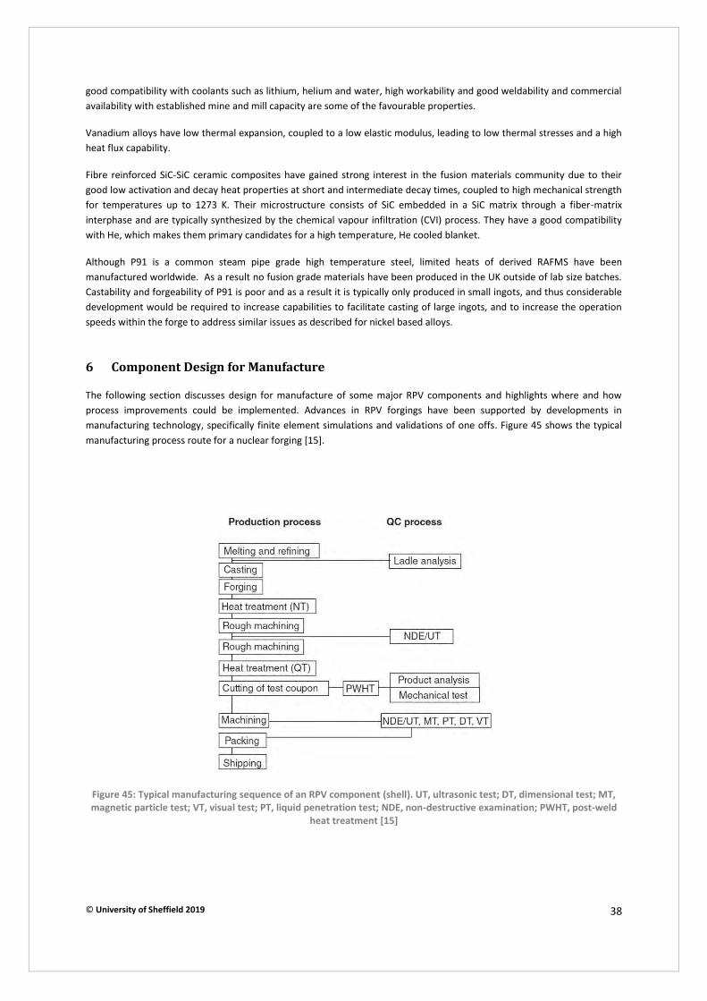
© University of Sheffield 2019 38
good compatibility with coolants such as lithium, helium and water, high workability and good weldability and commercial availability with established mine and mill capacity are some of the favourable properties.
Vanadium alloys have low thermal expansion, coupled to a low elastic modulus, leading to low thermal stresses and a high heat flux capability.
Fibre reinforced SiC-SiC ceramic composites have gained strong interest in the fusion materials community due to their good low activation and decay heat properties at short and intermediate decay times, coupled to high mechanical strength for temperatures up to 1273 K. Their microstructure consists of SiC embedded in a SiC matrix through a fiber-matrix interphase and are typically synthesized by the chemical vapour infiltration (CVI) process. They have a good compatibility with He, which makes them primary candidates for a high temperature, He cooled blanket.
Although P91 is a common steam pipe grade high temperature steel, limited heats of derived RAFMS have been manufactured worldwide. As a result no fusion grade materials have been produced in the UK outside of lab size batches. Castability and forgeability of P91 is poor and as a result it is typically only produced in small ingots, and thus considerable development would be required to increase capabilities to facilitate casting of large ingots, and to increase the operation speeds within the forge to address similar issues as described for nickel based alloys.
6 Component Design for Manufacture
The following section discusses design for manufacture of some major RPV components and highlights where and how process improvements could be implemented. Advances in RPV forgings have been supported by developments in manufacturing technology, specifically finite element simulations and validations of one offs. Figure 45 shows the typical manufacturing process route for a nuclear forging [15].
Figure 45: Typical manufacturing sequence of an RPV component (shell). UT, ultrasonic test; DT, dimensional test; MT,
magnetic particle test; VT, visual test; PT, liquid penetration test; NDE, non-destructive examination; PWHT, post-weld
heat treatment [15]

© University of Sheffield 2019 39
6.1 Forging Routes
In the early age of nuclear power generation, pressure vessels were manufactured with many welded components and rolled plates. Figure 46 shows a comparison between the layout of the plate construction type RPV and the advanced design RPV which was integrated-type forging components. Traditional manufacturing procedures involve the use of transition shells which provide the transition in thickness between the core shell and the lower head dome. They are welded to the lower shell of the core in an area of uniform cylindrical geometry, and to the lower head dome in an area of uniform thickness [76]. The advantage of this procedure consists in lower requirements to mass of forging ingots. This procedure is simpler from the viewpoint of handling the semi-product. However, the elimination of welds from both the manufacturing route and in service inspection is highly desirable. Larger, more complex forgings allow RPVs to use integrated designs with a reduced component count. This leads to a decrease in the number of weld seams which improves reliability and reduces both the construction time and the in-service inspection period. Another advantage of an integrated solution is the higher quality and better applicability on world markets. Predominant part of manufacturers of pressure vessels for nuclear reactors requires this type of products. An even more efficient approach would be to electro-beam weld early in the manufacturing process followed by quality heat treatment to restore ductility in the fusion and heat-affected zone, leading to the creation of massive, but fewer in number, integrated parts. This technique has already been demonstrated in Sheffield Forgemasters but remains a research subject and has not become an industrial practice yet. Consolidation of porosity formed in the ingot during solidification and refinement of the solidified microstructure is the major aim of the initial stage of forging. After that, the material is forged to form the shape of the desired products. Figure 47 shows an example of the forging process of a nuclear RPV component using an older design [15], while Figure 48 gives an idea of the extra allowances needed for forging. Figure 48 is an example where three components can be integrated into a single monolithic forging through the exploitation of customised tooling and extensive process simulation. Similar component integration can be realised on heat exchanger and steam plenums which contain nozzle features. Again, process simulation can be employed to develop piercing and forming operations for nozzle extrusion.
Figure 46: Layout of conventional and advanced type reactor pressure vessel [15]
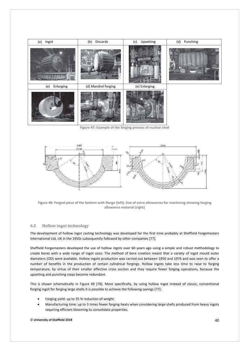
© University of Sheffield 2019 40
(a) Ingot (b) Discards (c) Upsetting (d) Punching
(e) Enlarging (d) Mandrel forging (e) Enlarging
Figure 47: Example of the forging process of nuclear shell
Figure 48: Forged piece of the bottom with flange (left); Size of extra allowances for machining showing forging
allowance material (right)
6.2 Hollow ingot technology
The development of hollow ingot casting technology was developed for the first time probably at Sheffield Forgemasters International Ltd, UK in the 1950s subsequently followed by other companies [77].
Sheffield Forgemasters developed the use of hollow ingots over 60 years ago using a simple and robust methodology to create bores with a wide range of ingot sizes. The method of bore creation meant that a variety of ingot mould outer diameters (OD) were available. Hollow ingots production was carried out between 1950 and 1976 and was seen to offer a number of benefits in the production of certain cylindrical forgings. Hollow ingots take less time to raise to forging temperature, by virtue of their smaller effective cross section and they require fewer forging operations, because the upsetting and punching steps become redundant.
This is shown schematically in Figure 49 [78]. More specifically, by using hollow ingot instead of classic, conventional forging ingot for forging large shells it is possible to achieve the following savings [77]:
x Forging yield: up to 35 % reduction of weight. x Manufacturing time: up to 3 times fewer forging heats when considering large shells produced from heavy ingots
requiring efficient blooming to consolidate properties.

© University of Sheffield 2019 41
x Environmental and energy costs: significant cut in CO2 gas emission (up to 50 %) due to the shortening of the forging program and the reduction in weight.
x Reduced lead time; important as AMR/SMR be required in volume
Whether to make the hollow ingot a standard practice depends on the favourable balance of efficiencies between the potential cost savings in the forge and the extra cost incurred at the melting stage. Energy costs have now risen to the point where hollow ingots give again a favourable balance of efficiencies. But past casting practices, such as those employed in the 1950s are not applicable anymore since new requirements imposed by the high integrity cylinder applications made the use of mechanical, microstructural and analytical procedures necessary.
In this frame, Sheffield Forgemasters International Ltd has invested in research and development of new hollow ingots and produced the first prototype in 2010 (Figure 50). New procedures involved the use of rapid but controlled cooling of the bore to displace the “metallurgical centre” towards the mid-wall position. Modern simulations of the 1950’s and today’s hollow ingot methods clearly demonstrate the difference in cooling rate between the inner and outer diameters that acted to shift the metallurgical centre of the ingot (Figure 51). Figure 52 shows the carbon content through wall in a hollow ingot, highlighting the vastly improved chemical homogeneity resulting from reduced segregation due to the higher cooling rates. These results in large improvements in fracture toughness and can enable longer service life of pressure vessel shells. New design approaches will be required to manufacture hollow ingots for the smaller new generation nuclear reactors.
Figure 49: The conventional cylindrical forging route compared to that of the hollow ingot
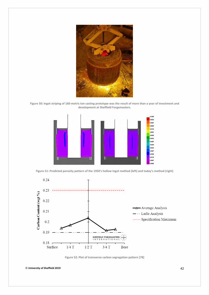
© University of Sheffield 2019 42
Figure 50: Ingot striping of 160-metric ton casting prototype was the result of more than a year of investment and
development at Sheffield Forgemasters.
Figure 51: Predicted porosity pattern of the 1950’s hollow ingot method (left) and today’s method (right)
Figure 52: Plot of transverse carbon segregation pattern [78]
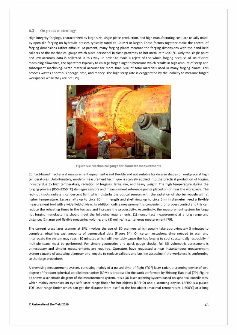
© University of Sheffield 2019 43
6.3 On press metrology
High integrity forgings, characterized by large size, single-piece production, and high manufacturing cost, are usually made by open die forging on hydraulic presses typically rated at 100MN or larger. These factors together make the control of forging dimensions rather difficult. At present, many forging plants measure the forging dimensions with the hand-held calipers or the mechanical gauge which place personnel in close proximity to hot metal at ~1200 °C. Only the single point and low accuracy data is collected in this way. In order to avoid a reject of the whole forging because of insufficient machining allowance, the operators typically to enlarge forged ingot dimensions which results in high amount of scrap and subsequent machining. Scrap material account for more than 50% of total materials used in many forging plants. This process wastes enormous energy, time, and money. The high scrap rate is exaggerated by the inability to measure forged workpieces while they are hot [79].
Figure 53: Mechanical gauge for diameter measurements
Contact-based mechanical measurement equipment is not flexible and not suitable for diverse shapes of workpiece at high temperatures. Unfortunately, modern measurement technique is scarcely applied into the practical production of forging industry due to high temperature, radiation of forgings, large size, and heavy weight. The high temperature during the forging process (850–1250 °C) damages sensors and measurement reference points placed on or near the workpiece. The red-hot ingots radiate incandescent light which disturbs the optical sensors with the radiation of shorter wavelength at higher temperature. Large shafts up to circa 20 m in length and shell rings up to circa 6 m in diameter need a flexible measurement tool with a wide field of view. In addition, online measurement is convenient for process control and this can reduce the reheating times in the furnace and increase the productivity. Accordingly, the measurement system for large hot forging manufacturing should meet the following requirements: (1) noncontact measurement at a long range and distance; (2) large and flexible measuring volume; and (3) online/instantaneous measurement [79].
The current press laser scanner at SFIL involves the use of 3D scanners which usually take approximately 5 minutes to complete, obtaining vast amounts of geometrical data (Figure 54). On certain occasions, time needed to scan and interrogate the system may reach 10 minutes which will inevitably cause the hot forging to cool substantially, especially if multiple scans must be performed. For simple geometries and quick gauge checks, full 3D volumetric assessment is unnecessary and simpler measurements are required. Operators have requested a near instantaneous measurement system capable of assessing diameter and lengths to replace calipers and lats inn assessing if the workpiece is conforming to the forge procedure.
A promising measurement system, consisting mainly of a pulsed time-of-flight (TOF) laser radar, a scanning device of two degree of freedom spherical parallel mechanism (SPM) is proposed in the work performed by Zhisong Tian et al [79]. Figure 55 shows a schematic diagram of the measurement system. It is a 3D laser scanning system based on spherical coordinates, which mainly comprises an eye-safe laser range finder for hot objects (LRFHO) and a scanning device. LRFHO is a pulsed TOF laser range finder which can get the distance from itself to the hot object (maximal temperature 1,600°C) at a long
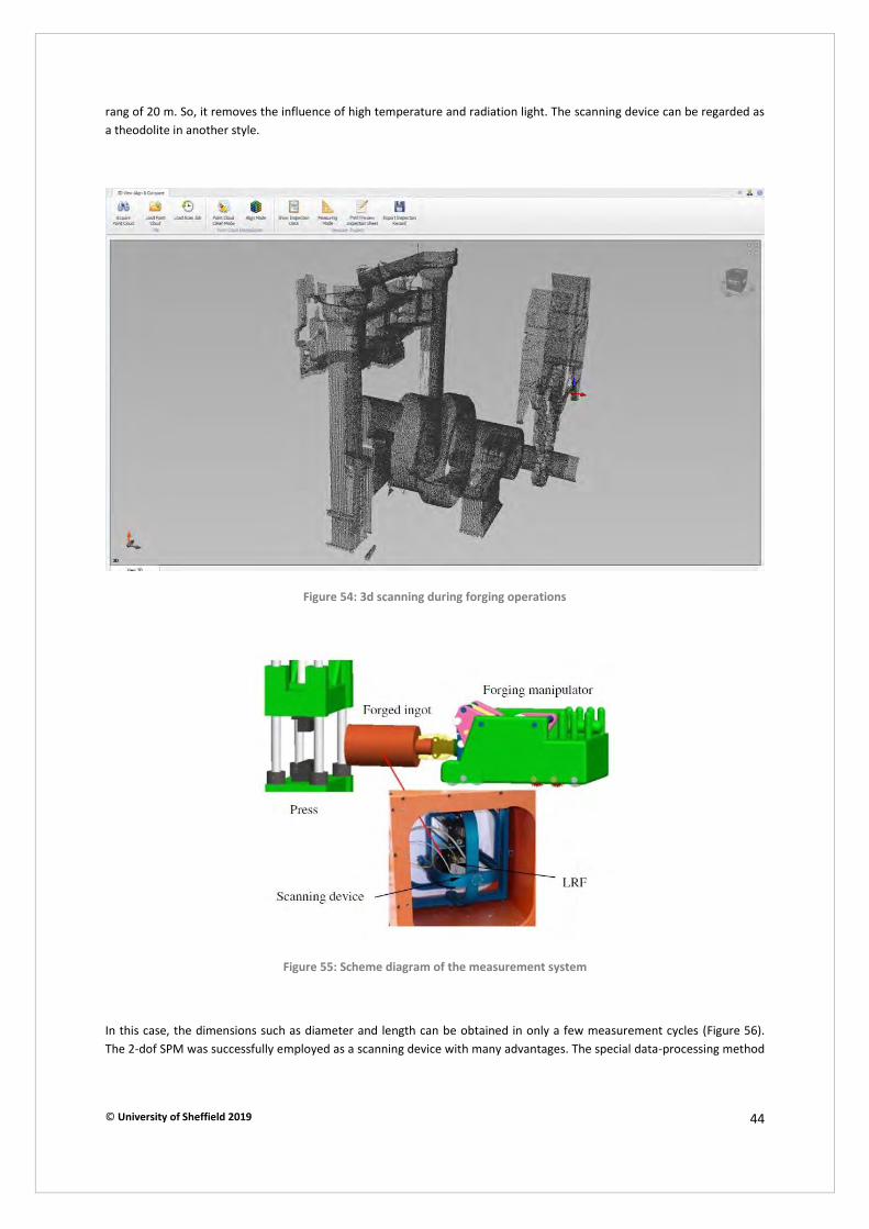
© University of Sheffield 2019 44
rang of 20 m. So, it removes the influence of high temperature and radiation light. The scanning device can be regarded as a theodolite in another style.
Figure 54: 3d scanning during forging operations
Figure 55: Scheme diagram of the measurement system
In this case, the dimensions such as diameter and length can be obtained in only a few measurement cycles (Figure 56). The 2-dof SPM was successfully employed as a scanning device with many advantages. The special data-processing method

© University of Sheffield 2019 45
showed that rapid measurement of the dimensions such as diameter and length is achievable and has the potential to reduce the amount of scrap material in the forging industry.
Figure 56: Profile of a crankshaft
Although this technique has been proven to be technically feasible, it has not been industrially implemented yet. A number of UK-based metrology agents/companies were contacted and on-site demonstrations were arranged but all attempts to find a suitable system failed mainly due to the size to the components to be measured and the high temperatures. MERMEC in Italy have been contacted as they claim to have a laser profiling method capable of taking diameter measurements on hot forging (Figure 58), however they have failed to respond to requests for information.
An additional requirement during forging processes is to be able to quickly project laser markings at desired locations to mark knifing and burning operations to split forgings and to remove excess material (Figure 57). Not being able to do this accuracy results in either large amounts of excess material being left on the forging which must then be sub sequentially heat treated and machined off, or if undercut, can scrap the forging. Only one vendor was possibly capable to assist in this specific requirement. Based on CAD data the FARO Tracer SI system is able to project green laser markings on distinctive geometrical details (edges, holes, excavations, etc.) and has sufficient standoff distance to protect the equipment from heat damage. However, the system requires “calibrating” with reference features (e.g. holes, points) to align the CAD data to the workpiece for projection. As no features like this exist and can’t be maintained on a hot plastically deformed forging the laser to unable to project onto the workpiece (Figure 59).
Figure 57: Projection of green laser on a hot forging

© University of Sheffield 2019 46
Figure 58: CAD model of a hypothetical laser profile technique
Figure 59: FARO Tracer SI is able to project green laser markings on a large component, based on the CAD
6.4 Heat Treatment Options
Heat treatment is fundamental in the manufacturing route with two principal aims, firstly to gain the desired properties of the material and secondly, to refine the microstructure. This phase is performed in two heat treatment stages: “primary” and “quality” [80], [81].
The first heat treatment stage (Figure 60) is carried out after forging in order to relax the induced strain that was caused by the hot working of the component; allowing the refining of the microstructure. Air cooling of the component with a hold at 500°C allows for completion of the austenite to ferrite phase transformation followed by a second hold at 250°C in order to avoid the probability of hydrogen cracking due to catastrophic through thickness failure. The component is held at 600°C allowing for the diffusion of hydrogen to occur the time for this to occur is dependent on the thickness of the component. Homogenisation then occurs at 900°C, allowing for the dissolution of the second phase, followed by air cooling and finally a tempering stage between 600°C - 650°C to soften the forging ready for machining. The hydrogen degassing time is dictated by the component effective diameter and hydrogen content of the steel, but thus can take several hundred hours. Thus, it is key to deliver as low a hydrogen content from the steel making process as possible.
Following primary heat treatment the forging is machined to a shape close to its final geometry for UT inspection and then undergoing a final quality heat treatment to obtain the desired mechanical properties (Figure 61). The forging is then
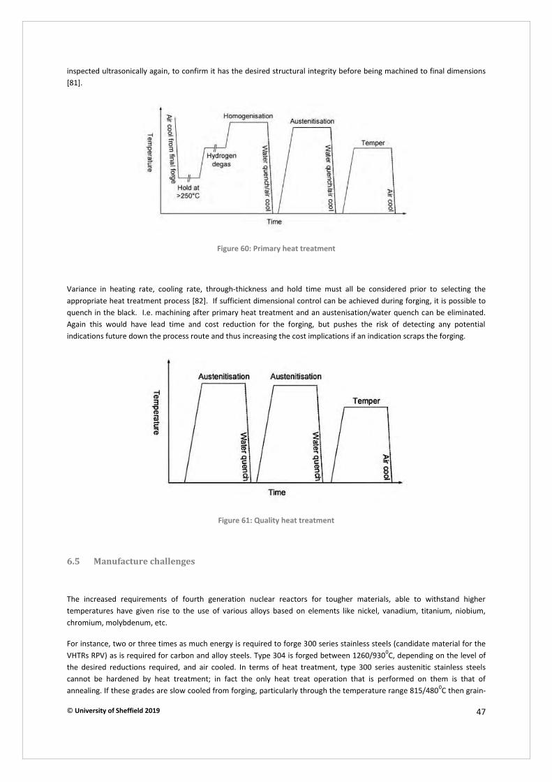
© University of Sheffield 2019 47
inspected ultrasonically again, to confirm it has the desired structural integrity before being machined to final dimensions [81].
Figure 60: Primary heat treatment
Variance in heating rate, cooling rate, through-thickness and hold time must all be considered prior to selecting the appropriate heat treatment process [82]. If sufficient dimensional control can be achieved during forging, it is possible to quench in the black. I.e. machining after primary heat treatment and an austenisation/water quench can be eliminated. Again this would have lead time and cost reduction for the forging, but pushes the risk of detecting any potential indications future down the process route and thus increasing the cost implications if an indication scraps the forging.
Figure 61: Quality heat treatment
6.5 Manufacture challenges
The increased requirements of fourth generation nuclear reactors for tougher materials, able to withstand higher temperatures have given rise to the use of various alloys based on elements like nickel, vanadium, titanium, niobium, chromium, molybdenum, etc.
For instance, two or three times as much energy is required to forge 300 series stainless steels (candidate material for the VHTRs RPV) as is required for carbon and alloy steels. Type 304 is forged between 1260/9300C, depending on the level of the desired reductions required, and air cooled. In terms of heat treatment, type 300 series austenitic stainless steels cannot be hardened by heat treatment; in fact the only heat treat operation that is performed on them is that of annealing. If these grades are slow cooled from forging, particularly through the temperature range 815/4800C then grain-

© University of Sheffield 2019 48
boundary chromium carbide precipitation will occur with a resulting very significant loss of corrosion resistance. As such annealing at around 10650C followed by a water quench is a necessary part of the production process for type 304 forgings [83].
The use of excessive pressure combined with heat may result in tool damage, therefore new specifications for more endurable tools are needed which could lead to significant increase in tooling costs. To keep tooling cost in control, modular tools could offer flexibility as they could be used for forgings with different outer diameters (Figure 62). Such a design also sets the diameters on any cylindrical forging, achieving better net shape over conventional becking tools. Improvement of tool design is also required as certain geometric features promote the initiation and propagation of cracks, leading to total tool failure (Figure 63).
Figure 62: Example of a modular tool design
As mentioned before, most of the new generation nuclear reactor vessels are not pressurised and therefore do not have thick walls. In many cases, such us the case of the manufacture of the ITER fusion reactor’s vacuum vessel, forging operations are replaced by forming of thin vessel parts which require large lightweight sandwich-type tools like those shown in Figure 64. Forging operations could also be processed by other techniques, such as ring rolling or rotary forging.
Ring rolling is a hot forming process that produces seamless rings varying in size from a few inches in diameter, and weighing less than one pound, to over 25 feet in diameter and face heights approaching 10 feet. The process and equipment are similar in principle to rolling mills used for plate. In both processes, the metal is rolled between two rolls, which move toward each other to form a continuously reducing gap (Figure 65). In ring rolling, the rolls are of different diameters. Ring results in optimum mechanical properties and predictable / efficient machinability. Tooling cost is low, set-up time is fast and rolled sections require little machining [84].
DIA 1
DIA 2
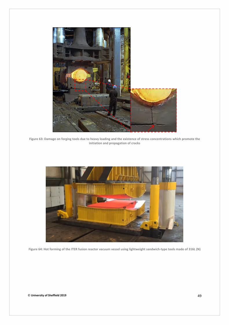
© University of Sheffield 2019 49
Figure 63: Damage on forging tools due to heavy loading and the existence of stress concentrations which promote the
initiation and propagation of cracks
Figure 64: Hot forming of the ITER fusion reactor vacuum vessel using lightweight sandwich-type tools made of 316L (N)

© University of Sheffield 2019 50
Figure 65: The process of ring rolling
Rotary forging is an incremental manufacturing process characterised by its combination of two actions, rotational and an axial compression movement, for precise component forming that can be carried out cold or hot. This technology enables greater use to be made of materials, minimizing (in some cases eliminating) machining and welding operations. Rotary forging requires less force, between 5% to 20% of conventional forming presses, due to reduction in contact and friction; resulting in smaller presses and simpler tools [85]. Development of large scale rotary forging equipment is still required to manufacture the sizes and shapes of nuclear island components for AMR/SMR applications.
Figure 66: The rotary forging process
6.6 Manufacturing cost optimisation
A high number of different processes are required to produce large forgings. Presented in Figure 67 is the percentage of cost of each manufacturing process for different forgings in Sheffield Forgemasters. In order to reduce the cost of manufacturing it is essential to isolate those factors which have the most important influence. Driven by the assumption that 20% of causes determine 80% of problems, the pareto analysis may be employed to separate important causes from trivial ones by drawing a vertical line at the intersection between the 80% line and the curve. The pareto analysis performed for each forging performed (Figure 68-Figure 70) reveals that three are the most costly factors: Material, testing and primary heat treatment.
Material costs are closely related to the weight of the starting ingot. By using a hollow ingot it may be possible to decrease the ingot’s weight by approximately 35% which could prove really cost-effective. With regard to testing, it is not easy to decrease the cost as tests are regulated by codes which dictate that every single nuclear component should be tested prior to use. The cost of primary heat treatment could be reduced mainly by reducing H2 early in the steelmaking process and quenching in the black for quality heat treatment.
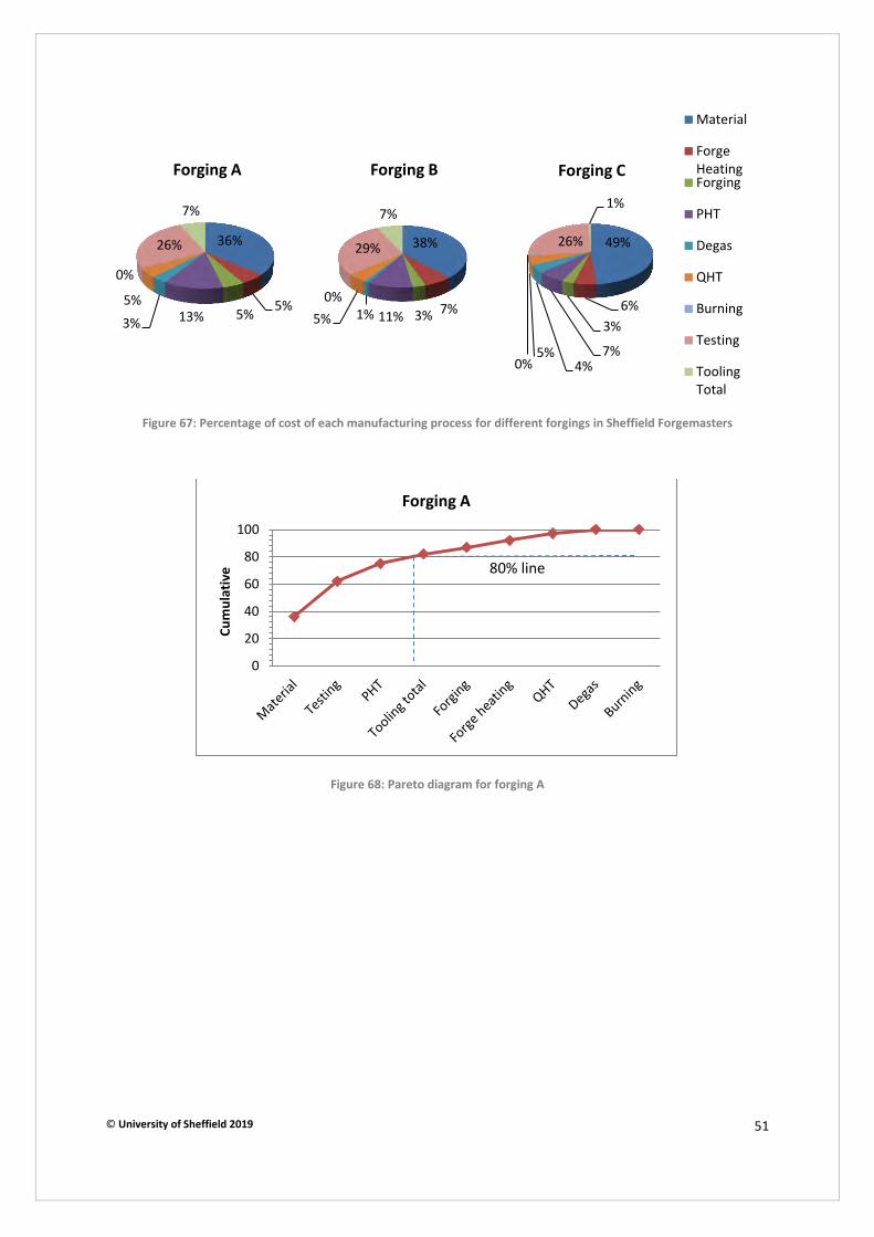
© University of Sheffield 2019 51
Figure 67: Percentage of cost of each manufacturing process for different forgings in Sheffield Forgemasters
Figure 68: Pareto diagram for forging A
36%
5% 5% 13% 3% 5%
0%
26%
7%
Forging A
38%
7% 3% 11% 1% 5% 0%
29%
7%
Forging B
49%
6% 3%
7% 4%
5% 0%
26%
1%
Forging C
Material
ForgeHeatingForging
PHT
Degas
QHT
Burning
Testing
ToolingTotal
0
20
40
60
80
100
Cu
mu
lati
ve
Forging A
80% line

© University of Sheffield 2019 52
Figure 69: Pareto diagram for forging B
Figure 70: Pareto diagram for forging C
0
20
40
60
80
100
Cu
mu
lati
ve
Forging B
0
20
40
60
80
100
Cu
mu
lati
ve
Forging C
80% line
80% line

© University of Sheffield 2019 53
7 Summary
x The current AMR/SMR designs being considered for future civil nuclear power generation many use new materials for the nuclear industry. This will result in extensive testing and qualification requirements, as well as extensive development within the supply chain to develop efficient and robust process routes for the challenging material grades.
x Qualification of specific nuclear island materials and components will be required to ensure geometries and mechanical properties can be achieved to suitable standards.
x The reactor designs are largely manufacturable within the UK, with the exception of the large thin walled vessels which do not fit open die presses. Additional manufacturing capability such as large ring/shell rolling would be needed.
x It has been shown that component integration can be successfully achieved on many RPV assemblies. In order to facilitate this, early reactor vendor engagement with the supply chain is necessary to design for manufacture.
x Steel making can have a strong effect on the quality of steel being delivered to the forge and the efficiently/time spent in heat treatment for hydrogen degas. Efficient management and control of the vacuum degassing during secondary steel making is key to delivering low hydrogen levels in forge ingots. Modern vacuum pumps systems can offer a significant cost and environmental benefit to the older generation steam injector vacuum pumps.
x The material required for many AMR will present many issues during ingot casting, forging, heat treatment and machining. The high hot strength will require high press loads and fast operations as well as more capable tools to process them. The heat treatment is made more complicated due to the precipitation of multiple phases, which has not yet been developed on heavy sections which experience significant cooling rate gradients and thus possible mechanical property variations.
x Modular and fabricated tooling conspectus can help reduce overall cost of forging and forming tools, as well can provide a method to achieve more near net shaping of forgings make in mid to high volume manufacture.
x Hollow ingots are a significantly more efficient forging route to manufacture shell components and result more homogenous chemistry and mechanical properties. They are also quicker to process over traditional solid ingots and so yield significant lead time savings when required in volume.
x On press metrology and the expansion of its uses will yield reduce quality issues, remove health and safety concerns and feed data back to production for machining stock assessment. Historic data will also inform how the forging allowances could be refined and reduce the excess material on a forging, if the metrology tool can provide live feedback to the forgemen.
x The large sizes and thin walls of the many low pressure AMR vessels will lend themselves to alternative forms of manufacture such as rotary forging, sheet forming and ring rolling. Additional challenges will be encountered during heat treatment of these components and structures as they will not possess sufficient hot strength (due to their thin wall section) to resist movement during quenching and subsequent stress relief.
x Heat treatment of forging can be optimised by ensuring hydrogen levels in the steel are as low as possible from the steel making. By achieving net shape forgings consistently the option of quenching in the black can eliminate significant furnace costs, time and machining requirements.
x Materials and testing represent the two main costs of a nuclear forging and thus targeting reductions in these should be priority to reducing the cost of nuclear island manufacturing. Material costs can be reduced by developing stable, consistent casting and forging processes that can be measured and quantified by suitable metrology methods. ASME testing requirements are not too extensive and it is often the reactor vendor who stipulates extensive and expensive mechanical testing.

© University of Sheffield 2019 54
8 References
[1] “Advanced modular reactor (AMR) feasibility and development (F&D) project,” Department for Business, Energy &Industrial Strategy, 2018.
[2] “Advances in Small Modular Reactor Technology Developments, A Supplement to IAEA Advanced ReactorsInformation System (ARIS),” IAEA, 2018.
[3] “Status Report on the Small Secure Transportable Autonomous Reactor (SSTAR) / Lead-Cooled Fast Reactor(LFR) and Supporting Research and Development,” Argonne National Laboratory, 2006.
[4] [Online]. Available: https://en.wikipedia.org/wiki/Lead-cooled_fast_reactor.
[5] [Online]. Available: https://en.wikipedia.org/wiki/Sodium-cooled_fast_reactor.
[6] [Online]. Available: https://www.moltexenergy.com/.
[7] [Online]. Available: https://en.wikipedia.org/wiki/Very-high-temperature_reactor.
[8] [Online]. Available: https://en.wikipedia.org/wiki/Pebble-bed_reactor.
[9] D. Kovan, “Nuclear fuels and structural materials: Looking to the future,” Nuclear News, pp. 129-132, 2006.
[10] A. C. C. W. O. A. G. B. A. Sykes, “Compact fusion energy based on the spherical tokamak,” Nuclear Fusion, 2018.
[11] “Assessment and management of ageing of major nuclear power plant components important to safety: PWR pressure vessels,” International Atomic Energy Agency, Vienna, Austria, 1999.
[12] A. A. Kiely, “Characterisation and interpretation of austenite grain growth kinetics in an advanced nuclear pressurevessel steel,” Cambridge University, 2016.
[13] F. Ghestemme, “PCSR – Sub-chapter 5.3 – Reactor Vessel,” 2012.
[14] O. A. M. Gryaznevich, “Overview and status of construction of ST40,” 2017.
[15] Y. TANAKA, Reactor pressure vessel (RPV) components: processing and properties, Woodhead Publishing Series in Energy, 2015.
[16] A. A. L. M. Monica Frogheri, “The Advanced Lead Fast Reactor European Demonstration: Status of the Design,” 2012.
[17] M. U. TU-Delft, “Design of a U-Battery,” 2011.
[18] [Online]. Available: https://www.tokamakenergy.co.uk/st40/.
[19] F. Aydogan, “Advanced small modular reactors,” in Handbook of Generation IV Nuclear Reactors, University of Idaho,Idaho Falls, ID, United States, Woodhead Publishing Series in Energy, 2016, pp. 661-699.
[20] Alexander Comley, [Online]. Available: http://www.alexandercomley.com/tubesheet/.
[21] P. Rodriguez, “Selection of Materials for Heat Exchangers,” Alexandria, Egypt, 1997.
© University of Sheffield 2019 55
[22] AREVA, “EPR Design Description,” AREVA, August 2005. [Online]. Available: https://www.nrc.gov/docs/ML0522/ML052280170.pdf.
[23] AREVA, “Analyst day-Equipment business unit,” Burgundy, 2009.
[24] P. Bhardwaj, Sunflag iron & steel Co. Ltd, [Online]. Available: http://www.sunflagsteel.com/Sunflag%20Iron%20and%20Steel_files/VACUUM%20DEGASSING.htm.
[25] S. K. S. I, 2016. [Online]. Available: http://ispatguru.com/vacuum-degassing-processes-for-liquid-steel/.
[26] B. C. Gruzleski J.E., “The Treatment of Liquid Alimunium-Silicon Alloys,” AFS, Des Plaines, IL, USA, 1990.
[27] J. B. E. S. S. R. M. P. H. Puga, “New Trends in Aluminium Degassing- A comparative study,” Hamburg, 2009.
[28] F. Karouni, “Numerical Simulation of Hydrogen Removal from Molten Steel in the Vacuum Arc Degasser, Phd,” Department of Materials Science and Engineering, The University of Sheffield, Sheffield, 2018.
[29] V. C. G. L. Dr. Simon Bruce, “Recent experience of mechanical vacuum pumps replacing steam ejectors in VOD and VD processes”.
[30] “Advantages of MTAG Switzerland's vacuum degassing plants”.
[31] I. C. K.L. Murty, “Structural materials for Gen-IV nuclear reactors: Challenges and opportunities,” Journal of Nuclear Materials, pp. 189-195, 2008.
[32] J. Ejenstam, “Corrosion resistant alumina-forming alloys for lead-cooled fast reactors,” Royal Institute of Technology, Stockholm, 2015.
[33] J. Bartos, “The nature of aging of Fe-Cr-Al-Y alloys at 450 C,” 1969.
[34] M. M. K. R. J. C. J. G.-C. C. Capdevila, Mat Sci Eng a-Struct, vol. 490, pp. 277-288, 2008.
[35] T. T. S. Kobayashi, Scripta Mater, pp. 1104-1107, 2010.
[36] J. K. M. B. K. T. B. P. J. T. Cheng, Nucl. Mater, vol. 427, pp. 396-400, 2012.
[37] K. T. M. B. T. C. J. K. J. B.A. Pint, Nucl. Mater., vol. 440, pp. 420-427, 2013.
[38] S. Z. L. S. K.A. Terrani, J. Nucl. Mater., p. 448, 2014.
[39] J. R. K. A. J. N. Dupont, “Improving the weldability of fecral weld overlay coatings,” in Foss. Energy Mater. Conf, 2007.
[40] K. F. Y. Y. M.N. Gussev, “Design, Properties, and Weldability of Advanced Oxidation-Resistant FeCrAl Alloys,” Mater. Des., 2017.
[41] J. N. D. A. J.R. Regina, “The effect of chromium on the weldability and microstructure of Fe-Cr-Al weld cladding,” Weld. J., 2007.
[42] K. Field, “Handbook on the Material Properties of FeCrAl Alloys for Nuclear Power Production Applications,” 2018.
[43] S. A. A. B. E. J. F. S. R. D. W. Chubb, “Costitution, metallurgy, and oxidation resistance of iron-chromium-aluminium alloys,” 1958.

© University of Sheffield 2019 56
[44] K. T. Y. Y. Z.T. Thomson, “Elastic Modulus Measrurement of ORNT ATF FeCrAl Alloys,” 2015.
[45] G. W. J. S. F.H. Stott, “The influence of alloying elements on the development and maintenance of protective scales,” Oxid. Met, 1995.
[46] Yamamoto et al, Science, pp. 433-436, 2007.
[47] Y. B. L. C. B. L. J. C. a. C. C. Yeong-il Kim, “Design Concept of Advanced Sodium-Cooled Fast Reactor and Related R&D in Korea,” Science and Technology of Nuclear Installations, 2013.
[48] “AKSteel 316/316L Stainless Steel”.
[49] A. T. I. (ATI), “ATI 316LN,” Allegheny Technologies Incorporated, Pittsburgh, USA, 2014.
[50] A. N. P. P. R. S. M. M. Aritra Sarkar, “Influence of dynamic strain ageing on the deformation behaviour during ratcheting of a 316LN stainless steel,” Mater. Sci. Engg., vol. 564, pp. 359-368, 2013.
[51] K. L. M. M. S. V. M. S. K. R. T. J. S. Ravi, “A comparison of creep deformation and rupture behaviour of 316L(N) austenitic,” Proc. Engg, vol. 55, pp. 823-829, 2013.
[52] T. -L. S. R. N. Wright, “Status of Metallic Structural Materials for Molten Salt Reactors,” Idaho National Laboratory, Argonne National Laboratory, 2018.
[53] J. Keiser, “Compatibility Studies of Potential Molten-Salt Breeder Reactor Materials in Molten Fluoride Salts,” 1977.
[54] H. E. McCoy, “The INOR-8 Story,” 1969.
[55] J. K. a. A. P. Litman, “Mass Transfer Between Hastelloy N and Haynes Hastelloy No. 25 in a Molten Sodium Fluoroborate Mixture,” 1971.
[56] J. W. Koger, “Evaluation of Hastelloy N Alloys After Nine Years Exposure to Both a Molten Fluoride Salt and Air at Temperatures from 700 to 560°C,” 1972.
[57] S. M. P. S. S. a. V. N. S. K. Natesan, “Preliminary Materials Selection Issues for the Next Generation Nuclear Plant Reactor Pressure Vessel,” 2006.
[58] “ASME Code, Section II Part D,” 2004.
[59] J. A. M. K. M. I. M. Fukakura, “Effect of Thermal Aging on Fracture Toughness of RPV Steel,” Nuclear Engineering Design, vol. 144, pp. 423-429, 1993.
[60] M. J. L. J. A. L. H. J. B. DeVan, “Fracture Toughness Test Results of Thermal Aged Reactor Vessel Materials,” in 17th International Symposium, ASTM STP 1270, 1996,.
[61] M. J. L. J. A. L. W. C. S. DeVan, “Evaluation of Thermal-Aged Plates, Forgings, and Submerged-Arc Weld Metals,” in Effects of Radiation on Materials: 16th International Symposium, ASTM STP 1175, 1993.
[62] H. P. H. J. B. R. S. T. Gunawardane, “Mechanical Property Changes in Reactor Vessel Materials Thermally Aged for 209,000 h at 282ºC,” Journal of ASTM International,, 2006.
[63] M.-C. K. M. J. H. H. B-S Lee, “Characterization of high strength and high toughness Ni-Mo-Cr low alloys steels for nuclear application,” International Journal of Pressure Vessels and Piping, vol. 87, pp. 74-80, 2010.

© University of Sheffield 2019 57
[64] H. Pous-Romero, “Quantitative basis for the structure and properties of a critically-important pressure vessel steel, Ph.D. Thesis,” Department of Materials Science and Metallurgy, University of Cambridge, Cambridge, 2014.
[65] “Standard Specification for Quenched and Tempered Vacuum Treated Carbon and Alloy Steel Forgings for Pressure Vessels A 508/A 508M,” ASTM, 2004.
[66] B. L. S. V. N. K. G. E. Harris, “Creep Rupture Failure of Three Components of the Reactor Primary Coolant System during the TMLB Accident,” 1986.
[67] “ASM Handbook, 1990, 2, p. 617”.
[68] A. G. I. S. P. M. Imgram, “A Vanadium Modified 2 1/4Cr-1Mo Steel with Superior Performance in Creep and Hydrogen Service,” New Alloys for Pressure Vessels and, 1990.
[69] V. K. W. C. T. a. T. K. C. Sikka, in Proceedings of Conference on Ferritic Steels for High Temperature Applications, Warren, PA, October 6-18, 1981.
[70] S. L. a. V. M. Mannan, “High Temperature Low Cycle Fatigue of Steels and their Welds,” Key Engineering Materials, pp. 57-64, 2004.
[71] S. L. a. V. M. Mannan, “High Temperature Low Cycle Fatigue, Creep-Fatigue and Thermomechanical Fatigue of Steels and their Welds,” International Journal of Mechanical Sciences, pp. 160-175, 2006.
[72] S. L. R. K. B. S. V. M. N. A. Mannan, “Strain Controlled Low Cycle Fatigue and Creep-Fatigue Interaction Behavior of Modified 9Cr-1Mo Ferritic Steel,” Transactions of the Indian Institute of Metals, pp. 159-168, 2005.
[73] C. D. A. K. S. H L SWAMI, “Activation characteristics of candidate structural materials for a near-term Indian fusion reactor and the impact of their impurities on design considerations,” Plasma Science and Technology, 2018.
[74] D. S. e. al, “Materials R&D for a timely DEMO: Key findings and recommendations of the EU Roadmap Materials Assessment Group,” 2014.
[75] N. B. P. S. M. Victoria, “Structural Materials for Fusion Reactors,” Fusion Technology Materials.
[76] F. Ghestemme, “PCSR-Sub-chapter 5.3-Reactor Vessel,” 2012.
[77] A. O. Z. C. M. K. M. K. V. K. P. Machovcak, “The development of hollow ingot casting technology at Vitkovice heavy machinery A.S.,” METAL 2013, 2013.
[78] J. T.-S. P. D. M. Tomlinson, “The development of hollow ingot technology at Sheffield Forgemasters International ltd,” in 18th International Forgemasters Meeting, Pittsburgh.
[79] F. G. Z. J. X. Z. Zhisong Tian, “Dimension measurement of hot large forgings with a novel time-of-flight system,” Int J Adv Manuf Technol, p. 125–132, 2009.
[80] H. Pous-Romero, “Quantitative basis for the structure and properties of a critically-important pressure vessel, Ph.D Thesis, Department of Materials Science and Metallurgy,” University of Cambridge, 2014.
[81] D. J. Cogswell, “Statistical Modelling of the Transition Toughness Properties of Low Alloy Pressure Vessel Steels Volum 1: Main Body, Ph.D. thesis,” Department of Metallurgy and Materials, School of Engineering, University of Birmingham, Birmingham, 2010.

© University of Sheffield 2019 58
[82] Y. T. a. I. Sato, “Development of high purity large forgings for nuclear power plants,” 2011.
[83] All Metals & Forge Group, 2019. [Online]. Available: https://www.steelforge.com/stainless-304-stainless-304l/.
[84] [Online]. Available: https://www.forging.org/forging/design/523-ring-rolling-process.html.
[85] [Online]. Available: https://www.globalmetalspinning.com/machinery_rotary_forging.htm.
[86] J. P. V. L. T. C. M. J. Miroslav Greger, “Development of technology for forging of bottoms of pressure vessels for nuclear power plants,” in METAL 2011, 2015.
[87] T. C. o. N. R. S. M. f. G. I. N. E. Systems, “LI Chengliang, Yang Mengjia,” Espoo, 2009.
[88] J. T. B. Steven J. Zinkle, “Structural materials for fission and fusion energy,” 2009.
[89] A. P. S. W. T. K Natesan, “Materials Behavior in HTGR Environments,” 2003 .
[90] D. H. M. P. I. T. B. W. David Hancock, “Refractory Metals as Structural Materials for Fusion High Heat FluxComponents,” Journal of Nuclear Materials, 2018.
[91] A. G. M. C. P. G. P. A. D. Á. B. Rafael Martínez-Ona, “Ultrasonic inspections in the fabrication of the ITER vacuum vesselsectors,” Fusion Engineering and Design, vol. 88, pp. 2155-2159, 2013.
[92] “Automated Ultrasonic Testing (AUT),” Corrosionpedia, [Online]. Available: https://www.corrosionpedia.com/definition/4456/automated-ultrasonic-testing-aut.
[93] M. J. R. T. S. V. A. A. H. S. W. J. Brayshaw, “Iterative mesh-based hardness mapping,” SCIENCE AND TECHNOLOGY OF WELDING AND JOINING, vol. 22, pp. 404-411, 2017.
[94] Alexander Copley, [Online]. Available: http://www.alexandercomley.com/tubesheet/.

Document Revision Page
NI1066-REP-01 03 Appendix 5
© 2019 University of Sheffield NAMRC.REP Version 7.0
Appendix 5. Metrology Report
Metrology for InFORM
(Intelligent Fixtures for Optimised and Radical
Manufacture)
Innovate UK/BEIS
Metrology Report (NI1066-REP-04)
Project report

Document Revision Page
NI1066-REP04 02 Appendix 5-1
© 2019 University of Sheffield NAMRC.REP Rev 7
Nuclear AMRC
University of Sheffield
Advanced Manufacturing Park
Brunel Way
Rotherham
S60 5WG
United Kingdom
This report may only be reproduced in full, except with the express permission of the Nuclear AMRC.
The Nuclear AMRC has exercised due care in conducting this report but has not, apart from as specifically stated, independently verified information provided by others. No other warranty, express or implied, is made in relation to the contents of this report. Therefore, the Nuclear AMRC assumes no liability for any loss resulting from errors, omissions, or misrepresentations made by others. Any recommendations, opinions or findings stated in this report are based on circumstances and facts as they existed at the time the Nuclear AMRC performed the work. Any changes in such circumstances and facts upon which this report is based may adversely affect any recommendations, opinions or findings contained in this report. Where experiments have been carried out, these have been restricted to a level of detail required to achieve the stated objectives of the statement of work. This work has been undertaken in accordance with the Nuclear AMRC’s quality system.
Name Signature
Authors:
Technical review:
Authorised:
Authorised distribution:
Document revision history
Revision Date of issue Reason for revision or original issue
02 19/08/2019 Format change.
Simon Cavill
Joseph Hiley
Shehan Lowe Callum Steventon Callum Frazer
Benjamin Pamment
BEIS

Document Revision Page
NI1066-REP04 02 Appendix 5-2
© 2019 University of Sheffield NAMRC.REP Rev 7
Executive summary
This report reviews a range of metrology technologies to determine suitable measurement systems for various aspects
of the InFORM project, specifically forging, machining, assembly and welding.
In forging, the need for a high data capture rate, large measurement volume, automation and non-contact
measurements led to the recommendation of optically or laser tracked laser scanning as the most appropriate
technology. If the measurement volume is less than 4.5 m and automation is not necessary, then laser scanning with a
measurement arm is also suitable.
For machining operations, a combined system of a laser tracker with a laser scanner was recommended alongside on-
machine probing. The laser scanner achieves the objective of digitising the part surface to allow optimisation of part
setup and toolpath. This also allows large measurement volumes to be achieved and is non-contact. On-machine
probing can provide in-process verification while the laser tracker can support on-machine probing by providing
additional measurements to verify machining axes.
For assembly operations, laser trackers remain the most appropriate technology, however, this represents a significant
investment in equipment if multiple trackers are used. Photogrammetry systems are also quite capable although with
less capability for automation. These systems both normally require some degree of contact with the part for large
components; however, this may no longer be the case for the very latest developments in laser tracker technology. A
laser radar system would not require contact but is a less mature technology. Divergent beam frequency scanning
interferometry is a technology which shows promise but needs considerable development.
Welding operations in InFORM require a robust system suitable for the welding environment as well as non-contact
inspection and a large measurement volume. Laser scanning with a tracker, or with a measurement arm at reduced
measurement volume, meets these requirements. The high accuracy requirements for pre-welding inspections to
support electron beam welding mean this system would need careful validation to ensure it is accurate enough for the
application. If placing reference markers on the part is permitted, photogrammetry may also be an appropriate
technique to support welding.

Document Revision Page
NI1066-REP04 02 Appendix 5-3
© 2019 University of Sheffield NAMRC.REP Rev 7
Contents
Executive summary ........................................................................................................................................... 2
1 Introduction ........................................................................................................................................... 6
1.1 Fundamentals of Measurement ................................................................................................... 7
2 Technology overview .......................................................................................................................... 10
2.1 Laser tracking ............................................................................................................................ 11
2.2 Laser radar ................................................................................................................................ 13
2.3 Optical tracking .......................................................................................................................... 14
2.4 Structured light scanner ............................................................................................................. 16
2.5 Laser line scanning .................................................................................................................... 17
2.6 Measurement arms .................................................................................................................... 19
2.7 Photogrammetry ........................................................................................................................ 21
2.8 On machine probing, inspection and verification....................................................................... 23
Software 23
Independence of measurement and machine error mapping 23
Temperature variation 24
Cleanliness 25
Probe and controller interaction 25
Acceptance and standards 25
Summary 26
2.9 Frequency scanning interferometry (FSI) .................................................................................. 26
2.10 Data visualisation ...................................................................................................................... 28
3 Forging ................................................................................................................................................ 29
3.1 Introduction ................................................................................................................................ 29
3.2 Establishing criteria ................................................................................................................... 29
3.3 Technology review ..................................................................................................................... 30
Photogrammetry 30
Structured light scanning 30
Laser line scanning with tracker 31
Laser Line scanning with measurement arm 32
Data visualisation 32
3.4 Review and down selection ....................................................................................................... 33

Document Revision Page
NI1066-REP04 02 Appendix 5-4
© 2019 University of Sheffield NAMRC.REP Rev 7
4 Machining ........................................................................................................................................... 34
4.1 Introduction ................................................................................................................................ 34
4.2 Establishing criteria ................................................................................................................... 34
4.3 Technology review ..................................................................................................................... 35
Structured light scanning 35
Photogrammetry 36
On-machine probing 36
Laser tracker 37
Laser line scanner with tracker 38
Data visualisation 38
4.4 Review and down selection ....................................................................................................... 39
5 Assembly ............................................................................................................................................ 40
5.1 Introduction ................................................................................................................................ 40
5.2 Establishing criteria ................................................................................................................... 40
5.3 Technology review ..................................................................................................................... 41
Laser tracker 41
Laser radar 42
Frequency scanning interferometry 43
Photogrammetry 43
5.4 Review and down selection ....................................................................................................... 45
6 Welding ............................................................................................................................................... 46
6.1 Introduction ................................................................................................................................ 46
6.2 Establishing criteria ................................................................................................................... 46
6.3 Technology review ..................................................................................................................... 47
Laser line scanner with tracker 47
Laser line scanner with measurement arm 48
Structured light scanning 48
Photogrammetry 48
6.4 Review and down selection ....................................................................................................... 49
7 Non-Destructive Evaluation (NDE) ..................................................................................................... 51
7.1 Introduction ................................................................................................................................ 51
7.2 Establishing criteria ................................................................................................................... 51
7.3 Technology Review ................................................................................................................... 52

Document Revision Page
NI1066-REP04 02 Appendix 5-5
© 2019 University of Sheffield NAMRC.REP Rev 7
7.4 Contact NDE techniques ........................................................................................................... 53
7.5 Non-contact NDE techniques .................................................................................................... 54
7.6 Laser Ultrasound ....................................................................................................................... 56
7.7 Potential solutions for InFORM.................................................................................................. 58
References ......................................................................................................................................................... 63

Document Revision Page
NI1066-REP04 02 Appendix 5-6
© 2019 University of Sheffield NAMRC.REP Rev 7
1 Introduction
Metrology is a key part of any manufacturing process and will be essential to support the manufacturing of large scale
components, for example, large reactor components or pressure vessels. The InFORM project (intelligent fixtures for
optimised and radical manufacture) is investigating the major stages of large scale manufacturing as shown in Figure
1-1. This report will present a number of advanced metrology technologies that have the potential to optimise the
manufacturing process.
Figure 1-1 – InFORM manufacturing stages
Section 1 of the report introduces the fundamentals of metrology. Section 2 introduces the metrology technologies
considered in this report. Sections 3, 4, 5 and 6 describe how these metrology technologies can be applied to the Forging,
Machining, Assembly and Welding stages of the manufacturing process respectively. Section 7 evaluates available non-
destructive evaluation techniques.
Forging MachiningIntelligent fixture & Assembly
Local vacuum electron beam
welding
Document Revision Page
NI1066-REP04 02 Appendix 5-7
© 2019 University of Sheffield NAMRC.REP Rev 7
1.1 Fundamentals of Measurement
During manufacturing operations, it is essential that we employ good measurement practice with repeatable and
controlled processes. This ensures that parts conform to dimensional and tolerance specifications and meet the design
intent. Metrology enables the manufacturer to monitor process capability and variation over time. Traditionally,
Coordinate Measuring Machines (CMM) has been considered the gold standard in metrology for many industries. While
these technologies are extremely accurate they are also labour intensive and relatively slow, especially when capturing
free form surfaces. Recent developments in measurement technologies present a wide range of possible
methodologies. In general, they will reside in one of two groups, In-process and Post-process; these can then be
subdivided further into contact and non-contact. Contact methods provide more confidence in measurement as a
physical interaction occurs during the measurement process. Contact methods are also more readily traceable to the SI
unit (metre) by means of physical artefacts often referred to as transfer standards. With non-contact scanning methods,
the traceability of measurements is complicated by the potential for surface texture or reflectivity to affect the recorded
value.
In-process inspection technologies:
Advantages:
Improved process capability
Errors detected earlier in the manufacturing process, reducing scrappage
Allows process monitoring, increasing conformance confidence
Does not require the transfer of large components to a dedicated inspection facility
Disadvantages:
Lack of control of environmental factors which can influence the result of the inspection
Inspection systems must either be portable or integrated into the manufacturing process
Depending on the system used, may not be an independent validation of the component conformity
Post-process inspection technologies
Advantages:
Inspection system does not have to be portable
Control of environmental factors is possible
Independent validation of component conformity
Disadvantages:
Cost of transfer of components to a dedicated inspection facility
Errors are detected after manufacture of the part has completed
Re-working of components requires setting and re-establishing of datum
Significant capital cost of setting up a dedicated inspection facility
Document Revision Page
NI1066-REP04 02 Appendix 5-8
© 2019 University of Sheffield NAMRC.REP Rev 7
When considering a measurement technology and its application we should first consider its accuracy. Accuracy is how
well the recorded value of an instrument agrees with the true value of the measurand. The precision of the instrument
should not be confused with accuracy; precision is the variance in the recorded values of repeated measurements.
It is possible to have an instrument with high precision and poor accuracy. This would result in repeated measurement
showing good correlation. However, the recorded value would not represent the true value. This is referred to as a
systematic error, and in many cases, the instrument can be calibrated to compensate for this.
With common engineering measurement instruments such as micrometres and callipers, accuracy can be checked
against transfer standards such as gauge blocks.
Transfer standards provide an unbroken traceable path to the SI unit held by the National Physical Laboratory which is
the UK’s National Measurement Institute. When working with large volume dimensions, establishing measurement
performance becomes difficult due to the lack of transfer standards at lengths greater than a metre as well as the
expense of such large standards.
A common error is to try to infer the accuracy of an instrument from the number of decimal places that the instrument
can display or divisions on the scale that can be read, i.e. the ‘resolution’. It is important not to confuse ‘resolution’ with
‘accuracy’. Many digital instruments will display values in millimetres down to the third decimal place (micron) however
the accuracy of many of these instruments resides at the second decimal place.
With many measurement technologies, as the length of measurement increases so does the uncertainty of
measurement. Figure 1-2 provides a depiction of key measurement technologies, their typical working range and how
measurement uncertainty increases with the increase in length.
Measurement uncertainty as defined by the GUM (Guide to the expression of Uncertainty in Measurement) is
commonly stated as a ± value or a range of values in which the true value is estimated to lie. Uncertainty is, therefore,
the doubt that exists about the measurement. Understanding measurement uncertainty is critical to the selection of
technology and methodology.
As a guide, the uncertainty should be < 10% of the dimensional tolerance required. Although in many demanding
applications 20% is often considered acceptable. (1)
Uncertainty should be kept in mind when reporting measurement values close to the tolerance limits; as an example, a
dimension of 20mm±0.1 mm is measured and the value recorded is 19.91mm. If the measurement instrument has a
stated uncertainty of ±0.1mm at a confidence level of 95%, this is 2 standard deviations often referred to as K=2
expanded coverage factor (this is how calibration certificates commonly state uncertainty, this also means that 5% of
recorded values will be distributed outside this uncertainty tolerance). Taking account of the instrument uncertainty
and combining with the displayed value, the true measurement lies in the range of 19.81mm to 20.01mm and therefore
potentially out of tolerance. Whenever the displayed value nears tolerance limits the uncertainty of the instrument
should be considered and stated on the measurement report.
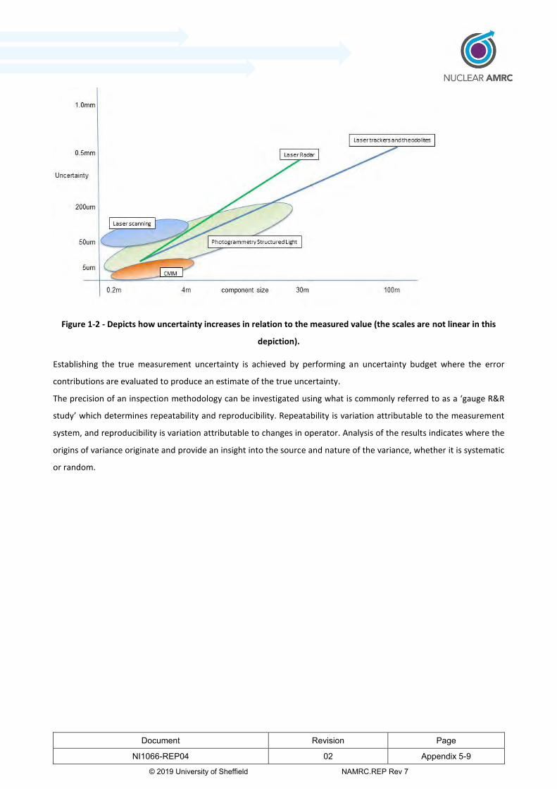
Document Revision Page
NI1066-REP04 02 Appendix 5-9
© 2019 University of Sheffield NAMRC.REP Rev 7
Figure 1-2 - Depicts how uncertainty increases in relation to the measured value (the scales are not linear in this
depiction).
Establishing the true measurement uncertainty is achieved by performing an uncertainty budget where the error
contributions are evaluated to produce an estimate of the true uncertainty.
The precision of an inspection methodology can be investigated using what is commonly referred to as a ‘gauge R&R
study’ which determines repeatability and reproducibility. Repeatability is variation attributable to the measurement
system, and reproducibility is variation attributable to changes in operator. Analysis of the results indicates where the
origins of variance originate and provide an insight into the source and nature of the variance, whether it is systematic
or random.

Document Revision Page
NI1066-REP04 02 Appendix 5-10
© 2019 University of Sheffield NAMRC.REP Rev 7
2 Technology overview
This section presents an overview of metrology technologies that could present an opportunity to optimise the
manufacturing process for large components. Table 2-1 lists these technologies and indicates to which manufacturing
challenges in the InFORM project they can be applied.
Table 2-1 Metrology technologies applicable for each InFORM work package
Test Forging Machining Assembly Welding
Laser tracker
Laser radar
Optical tracking
Structured light
Laser line scanning
Measurement arm
Photogrammetry
On machine probing
Frequency scanning interferometry
Data visualisation
Throughout this section, the following attributes are reviewed for each technology:
Large component manufacturing relevance
Technology readiness level (TRL)
Cost
Working range/volume
Typical measurement uncertainty
Environmental considerations
Access and interface with features being measured
Automation potential
Technology readiness level has been determined based on the guidelines from the nuclear AMRC guidance document:
“Technology and Manufacturing Capability assessment criteria guidance SIMPLE and InFORM programmes” (2). The
technology is assessed in the context of the measurement tasks and challenging environment associated with the
InFORM project.

Document Revision Page
NI1066-REP04 02 Appendix 5-11
© 2019 University of Sheffield NAMRC.REP Rev 7
2.1 Laser tracking
A laser tracker is a laser measurement based, portable CMM capable of static and dynamic measurements in large
volume applications. Laser trackers are typically used to determine the location of a retroreflector target in 3D
coordinates. Distance is determined by interferometry or by Absolute Distance Measurement (ADM) and angle is
determined by angular encoders.
Interferometry determines displacement by counting interference fringes between a measurement beam and a
reference beam while the target retro-reflector is moved. This method allows for very accurate, inherently traceable
measurements but is relatively slow and is sensitive to beam interruption. ADM measures distance directly rather than
by displacement and so is quicker and less sensitive to interruption. However, the traceability route of ADM is not as
direct as interferometry. ADM systems acquire traceability by calibration against an interferometer. New systems seek
to combine the practicality of ADM with the traceability of interferometry.
The distance component of a laser tracker’s measurement is the most accurate while the angular measurement is less
accurate and dependant on the tracker’s angular encoders. Laser trackers are also more accurate if used in a network
than when used alone. This means the accuracy of tracker measurements can vary significantly depending on the
measurement strategy.
A typical laser tracker has a range of up to 120 m with a typical quoted accuracy of 15 μm plus 5 μm per meter (3).
Trackers require line of sight for measurements however a laser tracker can be moved to a new vantage point by
measuring fixed reflector nests before and after it has been relocated, allowing measurement around a part.
Older laser tracker models required two operators, one to operate the tracker and another to move the retro-reflector.
However, modern trackers may be used by a single operator with a remote control. (1) It is important to specify that
while the laser tracker itself does not physically touch the part, for most models the retro-reflector does require physical
contact.
Physical contact with the measured component using a retro-reflector is not required with the latest Leica ATS600 laser
tracker from Hexagon which allows true, non-contact measurements and can digitise a surface from a range of up to 60
m (4)

Document Revision Page
NI1066-REP04 02 Appendix 5-12
© 2019 University of Sheffield NAMRC.REP Rev 7
(a) (b)
Figure 2-1 – Spherically mounted reflector (a), Laser tracker co-ordinate system (b) (5)
The capabilities of laser trackers may be augmented by other technologies. Leica have enhanced the capability of the
basic laser tracker with the addition of their T-Cam and several T-products that allow 6 degrees of freedom tracking and
additional ways to gather 3D coordinates. The T-products available are the wireless T-Probe; a ‘walk-around’ contact
probe, the T-Scan; a non-contact high-speed laser scanner, and the wireless T-Mac; a tracking device and tool interface
for a robot. The T-Cam uses videogrammetry to determine the orientation of the T-Products by monitoring a set of
embedded light-emitting diodes (LEDs) (see section 2.3 on optical tracking). This, along with the positional tracking of
the laser tracker, completes the 6 degrees of freedom system and ensures all measurements taken by any T-product
are contained within one coordinate system.
Specialist software is available to manage laser tracker measurements. For example, Spatial Analyzer by New River
Kinematics is a leading software package which is able to interface with a range of different laser trackers as well as
providing a number of features which would be valuable in the manufacturing processes outlined for this report.
Key attributes considered against the measurement requirements of InFORM:
Large component manufacturing relevance: Intelligent fixture alignment, large component assembly, weld
head tracking
Technology readiness level (TRL): 7-8. This technology is commercially available and proven in workshop and
manufacturing environments. The non-contact measurement capability of the Leica ATS 600 may need more
testing on different surface types and in different environments to verify its performance and limitations.
Cost: £150-250K
Working range/volume: Radial volume up to 160 m.
Typical measurement uncertainty: 15 µm + 6 µm/m
Environmental considerations: Generally used over large volume uncontrolled environments; however
temperature should be monitored to allow compensation to be applied.
Access and interface with features being measured: Line of sight required, most models require reflectors
applied to features being measured.

Document Revision Page
NI1066-REP04 02 Appendix 5-13
© 2019 University of Sheffield NAMRC.REP Rev 7
Automation potential: Automation common for inspection applications with wireless probe or scanner
accessories.
2.2 Laser radar
Laser radar is a non-contact portable measurement system designed for large volume metrology applications. The laser
radar works on the same principle as conventional radar, but with infrared laser light instead of radio waves being
transmitted to the surface being measured. The laser beam can be focussed to measure surface points or can scan
features requiring inspection. Nikon Metrology is currently the only supplier of a mature laser radar measurement
system. The maximum range of laser radar can be 30-50 m radially depending on the system with measurements having
an approximate accuracy of 10 µm plus 2.5 µm per meter. It has a maximum sampling rate of 4,000 points per second.
(6)
Figure 2-2 - Nikon Laser Radar, coordinate system
Frequency modulated coherent laser radar works by directing a focussed laser beam to a point on the component being
measured and recapturing a portion of the reflected light. The laser light is divided into 2 beams, one beam travels to
and from the target point, the other travels through a reference path of calibrated optical fibre in an environmentally
controlled module. The returned signal is mixed coherently with the reference signal and the difference in frequency
between the 2 signals is used to calculate the absolute range to the target point. A radial distance and two angles are
measured to determine a point on a surface in space (7).
The laser radar can be automated once a measurement plan has been defined, an operator is required for setup but the
system can then run autonomously. Unlike a laser tracker, a laser radar does not require spherically mounted
retroreflectors to be placed on the object being measured. This is particularly useful in situations where it may be
difficult for an operator to gain access to attach these to the object. The laser radar is a line of sight technology, requiring
a direct optical path to the object being measured. However, a mirror can be used to measure hidden objects as long
as a tooling ball can be viewed from the laser radar both directly and through the mirror. Tooling balls can also be used
to join separate scans if the instrument needs to be relocated during measurements. The system can work in any lighting
Document Revision Page
NI1066-REP04 02 Appendix 5-14
© 2019 University of Sheffield NAMRC.REP Rev 7
conditions including pitch black or bright sunlight. It is able to scan reflective materials as well as hot, cold, delicate or
hazardous surfaces.
Key attributes considered against the measurement requirements of InFORM:
Large component manufacturing relevance: forging scanning, intelligent fixture alignment, large component
assembly, weld inspection.
Technology readiness level (TRL): 6. The technology is yet to see widespread adoption and has not seen the
same level of verification in relevant manufacturing environments use as the other technologies covered in this
report.
Cost: £250K
Working range/volume: Radial volume up to 50 m.
Typical measurement uncertainty: 10 µm/m
Environmental considerations: Generally used over large volume uncontrolled environments; however
temperature should be monitored to allow compensation to be applied.
Access and interface with features being measured: Line of sight required, can measure surface directly (non-
contact) or for more precision, tooling balls can be measured.
Automation potential: Can be programmed to run measurement routines, either for surface or tooling ball
measurement.
2.3 Optical tracking
An optical tracker consists of twin cameras mounted a fixed distance apart which can track reference markers (either
emitters or reflectors) on a workpiece or portable devices such as a probe or scanner. The positions of the markers are
determined and so the position and orientation of the object are obtained.
Tracking cameras scan the volume and detect the light from the markers. The images captured by the cameras are
processed and the positions of the markers calculated. The positions of the markers are then used to determine the
exact location of the probe tip/ scanner. This data is used to generate six degrees of freedom position information of
the multiple markers mounted on the handheld device and thus, the probe tip or scanner location. The camera system
must have a line of sight to the markers on the probe [7].
Optically tracked probing or scanning requires no markers on the part and only a few on the scanner or probe.

Document Revision Page
NI1066-REP04 02 Appendix 5-15
© 2019 University of Sheffield NAMRC.REP Rev 7
Figure 2-3 - Illustration of an optical tracking system
An example of an optical tracking system is the Creaform C-track system. This is a twin camera system which actively
tracks a remote probe or a laser scanner. This is shown in Figure 2-4 with the Creaform HandyProbe.
Figure 2-4 - Creaform C-track and HandyProbe [8]
Creaform also provides an optically tracked laser scanner; the MetraSCAN 3D. This system has the capability to capture
images at 60 frames per second and 480,000 points per second, meaning it has a very high resolution and it is able to
capture data at a high rate. The quoted measurement uncertainty of this system is 64μm for the most accurate models.
(8) Laser scanning systems are covered in more detail in section 2.5.
Some laser tracker systems also incorporate optical tracking to determine the orientation of a probe or laser line
scanner. An example of this is Hexagon Manufacturing Intelligence’s Leica T-Probe or T-Scan products. (9)
Key attributes considered against the measurement requirements of InFORM:
Large component manufacturing relevance: Forging scanning, welded component inspection.
Technology readiness level (TRL): 6. The system is widely used in a range of applications but its measurement
performance has not seen extensive validation and testing in relevant environments.
Cost: £30-45K
Working range/volume: Range from cameras up to 10 m.
Typical measurement uncertainty: 64 µm (volumetric accuracy) (8) (10).
Environmental considerations: Generally used over small workshop environments.
Cameras
Marker
Probe tip
Probe
Camera
system
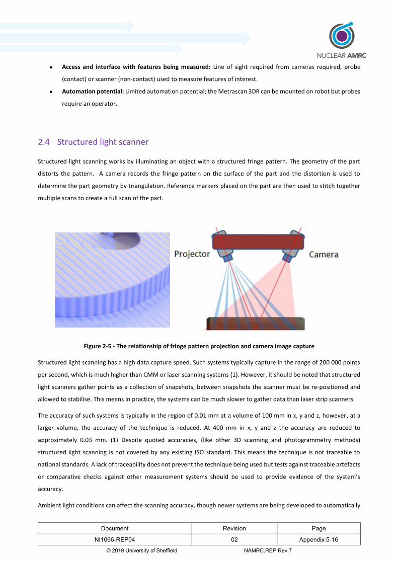
Document Revision Page
NI1066-REP04 02 Appendix 5-16
© 2019 University of Sheffield NAMRC.REP Rev 7
Access and interface with features being measured: Line of sight required from cameras required, probe
(contact) or scanner (non-contact) used to measure features of interest.
Automation potential: Limited automation potential; the Metrascan 3DR can be mounted on robot but probes
require an operator.
2.4 Structured light scanner
Structured light scanning works by illuminating an object with a structured fringe pattern. The geometry of the part
distorts the pattern. A camera records the fringe pattern on the surface of the part and the distortion is used to
determine the part geometry by triangulation. Reference markers placed on the part are then used to stitch together
multiple scans to create a full scan of the part.
Figure 2-5 - The relationship of fringe pattern projection and camera image capture
Structured light scanning has a high data capture speed. Such systems typically capture in the range of 200 000 points
per second, which is much higher than CMM or laser scanning systems (1). However, it should be noted that structured
light scanners gather points as a collection of snapshots, between snapshots the scanner must be re-positioned and
allowed to stabilise. This means in practice, the systems can be much slower to gather data than laser strip scanners.
The accuracy of such systems is typically in the region of 0.01 mm at a volume of 100 mm in x, y and z, however, at a
larger volume, the accuracy of the technique is reduced. At 400 mm in x, y and z the accuracy are reduced to
approximately 0.03 mm. (1) Despite quoted accuracies, (like other 3D scanning and photogrammetry methods)
structured light scanning is not covered by any existing ISO standard. This means the technique is not traceable to
national standards. A lack of traceability does not prevent the technique being used but tests against traceable artefacts
or comparative checks against other measurement systems should be used to provide evidence of the system’s
accuracy.
Ambient light conditions can affect the scanning accuracy, though newer systems are being developed to automatically

Document Revision Page
NI1066-REP04 02 Appendix 5-17
© 2019 University of Sheffield NAMRC.REP Rev 7
calibrate against this.
While the scanning process is non-contact, reference markers must be used in order to combine individual scans.
Applying the reference markers to the object has a further impact on overall measurement time. The process is also
sensitive to surface reflections, and it is often necessary to treat reflective components to produce a matt finish.
These scanning systems are portable and available from a number of suppliers. Examples include the Steinbichler Comet
(11) and GOM ATOS (12) scanner (Figure 2-6).
Figure 2-6 – Structured light digitisers: ATOS
Key attributes considered against the measurement requirements of InFORM:
Large component manufacturing relevance: Inspection following forging, machining or welding.
Technology readiness level (TRL): 6. The system is commonly and reliably used in controlled environments but
not in more hostile workshop environments which are the focus of this project.
Cost: £200K
Working range/volume: Range from cameras up to 1 m.
Typical measurement uncertainty: approximately 50 µm for a 1m volume
Environmental considerations: Advisable to use only within controlled laboratory environments
Access and interface with features being measured: Line of sight from cameras required, direct non-contact
measurement of surface features. Reference markers need to be applied to component or fixture.
Automation potential: Commonly robot-mounted in automotive industry application
2.5 Laser line scanning
Laser line or strip scanning works by projecting a line of laser points onto a surface; the points are reflected and detected
by a camera which allows the surface to be triangulated. Laser strip scanning typically has high data capture rates of
between 20 000 and 100 000 points per second (1).
While laser strip scanners can be mounted on a manually operated measurement arm, they are more versatile and allow
measurement of larger volumes when referenced by a laser tracker or optical tracker. The Leica T-scan system works
with the Leica AT960 laser tracker. The position of the scanner is determined using laser tracking and the orientation is
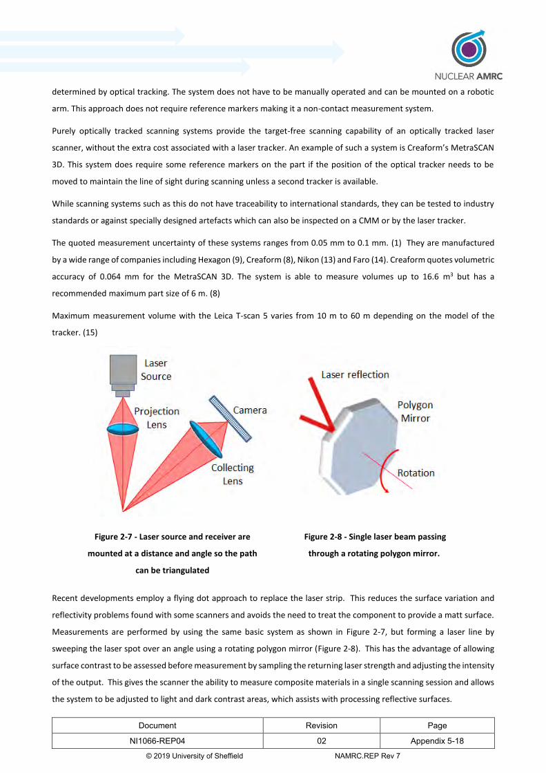
Document Revision Page
NI1066-REP04 02 Appendix 5-18
© 2019 University of Sheffield NAMRC.REP Rev 7
determined by optical tracking. The system does not have to be manually operated and can be mounted on a robotic
arm. This approach does not require reference markers making it a non-contact measurement system.
Purely optically tracked scanning systems provide the target-free scanning capability of an optically tracked laser
scanner, without the extra cost associated with a laser tracker. An example of such a system is Creaform’s MetraSCAN
3D. This system does require some reference markers on the part if the position of the optical tracker needs to be
moved to maintain the line of sight during scanning unless a second tracker is available.
While scanning systems such as this do not have traceability to international standards, they can be tested to industry
standards or against specially designed artefacts which can also be inspected on a CMM or by the laser tracker.
The quoted measurement uncertainty of these systems ranges from 0.05 mm to 0.1 mm. (1) They are manufactured
by a wide range of companies including Hexagon (9), Creaform (8), Nikon (13) and Faro (14). Creaform quotes volumetric
accuracy of 0.064 mm for the MetraSCAN 3D. The system is able to measure volumes up to 16.6 m3 but has a
recommended maximum part size of 6 m. (8)
Maximum measurement volume with the Leica T-scan 5 varies from 10 m to 60 m depending on the model of the
tracker. (15)
Figure 2-7 - Laser source and receiver are
mounted at a distance and angle so the path
can be triangulated
Figure 2-8 - Single laser beam passing
through a rotating polygon mirror.
Recent developments employ a flying dot approach to replace the laser strip. This reduces the surface variation and
reflectivity problems found with some scanners and avoids the need to treat the component to provide a matt surface.
Measurements are performed by using the same basic system as shown in Figure 2-7, but forming a laser line by
sweeping the laser spot over an angle using a rotating polygon mirror (Figure 2-8). This has the advantage of allowing
surface contrast to be assessed before measurement by sampling the returning laser strength and adjusting the intensity
of the output. This gives the scanner the ability to measure composite materials in a single scanning session and allows
the system to be adjusted to light and dark contrast areas, which assists with processing reflective surfaces.

Document Revision Page
NI1066-REP04 02 Appendix 5-19
© 2019 University of Sheffield NAMRC.REP Rev 7
Key attributes considered against the measurement requirements of InFORM:
Large component manufacturing relevance: Inspection following forging, machining or welding.
Technology readiness level (TRL): 7. The system is widely applied in manufacturing environments, under the
required conditions but measurements lack traceability.
Cost: £70K
Working range/volume: Max reach 4.5 m with an arm, max recommended part size of 6 m to 60 m with laser/
optical tracking depending on model. (15) (8)
Typical measurement uncertainty: 0.05 mm to 0.1 mm (1)
Environmental considerations: Suitable for workshop environments
Access and interface with features being measured: Requires either line of sight from a tracker or access with
an arm
Automation potential: Can be mounted on a robotic arm
2.6 Measurement arms
To reference the recorded points, laser scanners or touch probes are often attached to an articulated measurement
arm which provides a datum, as shown in Figure 2-9.
Figure 2-9 - Laser scanner measurement arm (16).
Typically the arms have five or six axes of movement. The typical quoted volumetric accuracy is around ±0.02 mm with
an arm length of 1.2 m and 0.07 mm for longer arms at 4.5 m. Measurement arms are limited to a measurement radius
of about 4.5 m due to their physical size. However they can achieve greater measurement volume if positioned on
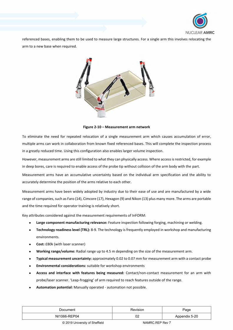
Document Revision Page
NI1066-REP04 02 Appendix 5-20
© 2019 University of Sheffield NAMRC.REP Rev 7
referenced bases, enabling them to be used to measure large structures. For a single arm this involves relocating the
arm to a new base when required.
Figure 2-10 – Measurement arm network
To eliminate the need for repeated relocation of a single measurement arm which causes accumulation of error,
multiple arms can work in collaboration from known fixed referenced bases. This will complete the inspection process
in a greatly reduced time. Using this configuration also enables larger volume inspection.
However, measurement arms are still limited to what they can physically access. Where access is restricted, for example
in deep bores, care is required to enable access of the probe tip without collision of the arm body with the part.
Measurement arms have an accumulative uncertainty based on the individual arm specification and the ability to
accurately determine the position of the arms relative to each other.
Measurement arms have been widely adopted by industry due to their ease of use and are manufactured by a wide
range of companies, such as Faro (14), Cimcore (17), Hexagon (9) and Nikon (13) plus many more. The arms are portable
and the time required for operator training is relatively short.
Key attributes considered against the measurement requirements of InFORM:
Large component manufacturing relevance: Feature inspection following forging, machining or welding.
Technology readiness level (TRL): 8-9. The technology is frequently employed in workshop and manufacturing
environments.
Cost: £80k (with laser scanner)
Working range/volume: Radial range up to 4.5 m depending on the size of the measurement arm.
Typical measurement uncertainty: approximately 0.02 to 0.07 mm for measurement arm with a contact probe
Environmental considerations: suitable for workshop environments
Access and interface with features being measured: Contact/non-contact measurement for an arm with
probe/laser scanner. ‘Leap-frogging’ of arm required to reach features outside of the range.
Automation potential: Manually operated - automation not possible.
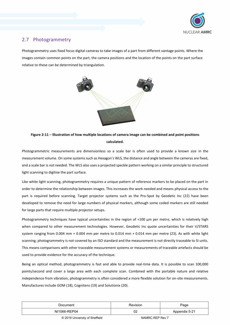
Document Revision Page
NI1066-REP04 02 Appendix 5-21
© 2019 University of Sheffield NAMRC.REP Rev 7
2.7 Photogrammetry
Photogrammetry uses fixed focus digital cameras to take images of a part from different vantage points. Where the
images contain common points on the part, the camera positions and the location of the points on the part surface
relative to these can be determined by triangulation.
Figure 2-11 – Illustration of how multiple locations of camera image can be combined and point positions
calculated.
Photogrammetric measurements are dimensionless so a scale bar is often used to provide a known size in the
measurement volume. On some systems such as Hexagon’s WLS, the distance and angle between the cameras are fixed,
and a scale bar is not needed. The WLS also uses a projected speckle pattern working on a similar principle to structured
light scanning to digitise the part surface.
Like white light scanning, photogrammetry requires a unique pattern of reference markers to be placed on the part in
order to determine the relationship between images. This increases the work needed and means physical access to the
part is required before scanning. Target projector systems such as the Pro-Spot by Geodetic Inc (22) have been
developed to remove the need for large numbers of physical markers, although some coded markers are still needed
for large parts that require multiple projector setups.
Photogrammetry techniques have typical uncertainties in the region of ≈100 μm per metre, which is relatively high
when compared to other measurement technologies. However, Geodetic Inc quote uncertainties for their V/STARS
system ranging from 0.004 mm + 0.004 mm per metre to 0.014 mm + 0.014 mm per metre (23). As with white light
scanning, photogrammetry is not covered by an ISO standard and the measurement is not directly traceable to SI units.
This means comparisons with other traceable measurement systems or measurements of traceable artefacts should be
used to provide evidence for the accuracy of the technique.
Being an optical method, photogrammetry is fast and able to provide real-time data. It is possible to scan 100,000
points/second and cover a large area with each complete scan. Combined with the portable nature and relative
independence from vibration, photogrammetry is often considered a more flexible solution for on-site measurements.
Manufactures include GOM (18), Cognitens (19) and Solutionix (20).
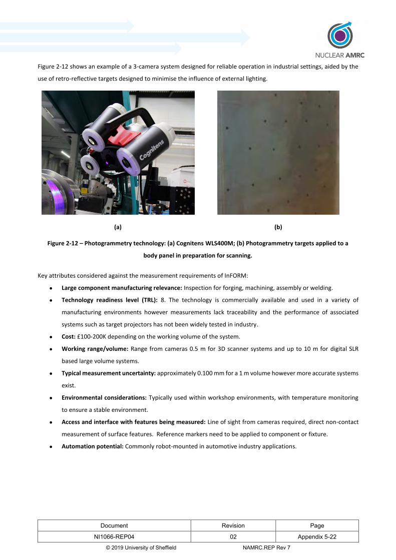
Document Revision Page
NI1066-REP04 02 Appendix 5-22
© 2019 University of Sheffield NAMRC.REP Rev 7
Figure 2-12 shows an example of a 3-camera system designed for reliable operation in industrial settings, aided by the
use of retro-reflective targets designed to minimise the influence of external lighting.
(a) (b)
Figure 2-12 – Photogrammetry technology: (a) Cognitens WLS400M; (b) Photogrammetry targets applied to a
body panel in preparation for scanning.
Key attributes considered against the measurement requirements of InFORM:
Large component manufacturing relevance: Inspection for forging, machining, assembly or welding.
Technology readiness level (TRL): 8. The technology is commercially available and used in a variety of
manufacturing environments however measurements lack traceability and the performance of associated
systems such as target projectors has not been widely tested in industry.
Cost: £100-200K depending on the working volume of the system.
Working range/volume: Range from cameras 0.5 m for 3D scanner systems and up to 10 m for digital SLR
based large volume systems.
Typical measurement uncertainty: approximately 0.100 mm for a 1 m volume however more accurate systems
exist.
Environmental considerations: Typically used within workshop environments, with temperature monitoring
to ensure a stable environment.
Access and interface with features being measured: Line of sight from cameras required, direct non-contact
measurement of surface features. Reference markers need to be applied to component or fixture.
Automation potential: Commonly robot-mounted in automotive industry applications.

Document Revision Page
NI1066-REP04 02 Appendix 5-23
© 2019 University of Sheffield NAMRC.REP Rev 7
2.8 On machine probing, inspection and verification
On-machine probing involves the use of machine tool probes to take measurements on parts within the working volume
of a Computer Numerical Controlled (CNC) machine. The probes can be touch-trigger probes or strain gauge probes
which are less susceptible to directional variation when probing. Analogue scanning probes are also available which
allow continuous scanning of a surface e.g. Renishaw’s Sprint probe. On-machine probing can be used for on-machine
verification and on-machine inspection.
On-machine verification involves using the machine tool probe to take measurements of the part during the
manufacturing stage. These measurements may be used to compensate for the cutting path, for process monitoring or
datum setting. (1) While on-machine verification may reduce scrap and rework, a separate traceable inspection may be
required to determine whether the part meets its defined tolerances.
On-machine inspection involves the use of on-machine probing to conduct the inspection of a part in-situ on a CNC
machine. This approach would reduce costs associated with transporting machined parts to a dedicated CMM room for
inspection. The capital costs of a dedicated inspection facility would also be avoided.
For very large components such as large pressure vessels or reactor components, CMM inspection might not be possible.
In this situation, an on-machine approach may be used instead of bringing large volume metrology equipment to the
part.
On-machine inspection would require some level of traceability to national standards which are not typically available
on a machine tool. The challenges and available solutions associated with on-machine inspection are outlined below.
Software
CNC machines often have limited probing capability as standard, relying on a small number of cycles to measure simple
features and update work offsets etc. The measurement strategies available often use a limited number of points and
do not take account of important considerations such as cosine error when probing. (1) The complexity of the
dimensions which can be measured is also often limited.
Dedicated metrology software for on-machine probing such as PC DMIS-NC from Hexagon or Productivity+ from
Renishaw allow the measurement of a wider range of features than standard probing cycles. PC DMIS-NC and PC DMIS-
NCi allow the use of almost all the features and measurement strategies available in PC DMIS CMM inspection software.
These dedicated software packages can be installed on a wide range of machine tools.
Independence of measurement and machine error mapping
A limitation of on-machine probing is that the machine used to inspect the part is normally the same as the machine
used for cutting. Therefore static and dynamic errors in the machine structure which influence the machining stage will
be replicated in the inspection. This can hide deviation in the part geometry. The measurement system is, therefore not
performing an independent check.

Document Revision Page
NI1066-REP04 02 Appendix 5-24
© 2019 University of Sheffield NAMRC.REP Rev 7
One solution to this problem is to quantify the static and kinematic errors of a CNC machine and test its accuracy across
the measurement volume. Traceable interferometry systems such as the Etalon Multiline (21) or the Etalon LaserTracer
(22) with trac-check software can verify the length measurement performance of a CNC machine. Additional tests such
as probing tests and measurements of shorter physical length standards can also be performed. Together, these tests
allow an independent check of the measurement performance of the machine.
The Etalon Multiline or LaserTracer can also be used with trac-cal software to develop an error map of the machine
volume. This can then be used to compensate the CNC machines positional accuracy.
InSphere (23) have developed the BASELINE system to check and update machine error maps using laser tracker
technology. Testing of the system was undertaken at the Nuclear AMRC using the Soraluce FX12000 machine tool. The
programme of testing was funded through the National Aerospace Technology Exploitation Programme. (24)
Error mapping and verification techniques apply to the machine’s static and kinematic errors in general and not just to
on-machine probing. However, they do not completely remove the need for on-machine probing to inspect or verify
features on the part. This is because part geometry may be affected by programming errors, tool wear, part setup or
dynamic errors due to cutting forces, vibration or heat generated while machining. Deviation caused by these factors
may be detected by probing routines.
Temperature variation
On-machine inspection takes place in the workshop/ factory floor and not in a dedicated, controlled inspection
environment. Significant temperature variation is therefore almost certain and this leads to changes in the part
geometry.
Linear thermal expansion is determined by the formula:
∆𝐿 = 𝐿0𝛼𝐿∆𝑇 Eq. 1
Were ∆𝐿 is the change in length in m, 𝐿0 is the initial length in m, 𝛼𝐿 is the linear coefficient of thermal expansion in
𝐾−1 and ∆𝑇 is the change in temperature in K or ˚C.
A typical linear coefficient of thermal expansion for Austenitic (304) steel is 17.3 × 10⁻⁶ 𝐾−1 (25). This means for
every ˚C change in temperature, for each meter length, the length will change by 17.3μm.
On large parts that are several metres in length and in shop floor environments that could be 3-4 ˚C away from the
standard reference temperature of 20˚C, the distortion due to temperature variation can reach significant fractions of
a millimetre.
This is complicated where different materials are used in combination and expand and contract at different rates. This
also affects fixturing and the design of the InFORM smart fixture will need to take this into account. A fixture
expanding at a different rate to the part will lead to errors between the datum features and related features as well as
distortion caused by forces exerted with the interaction of the part and fixture.

Document Revision Page
NI1066-REP04 02 Appendix 5-25
© 2019 University of Sheffield NAMRC.REP Rev 7
Many CNC machines have a temperature compensation system were internal machine temperatures are monitored and
used to correct for thermal expansion and contraction of the machine axes. Temperature sensors can also be attached
to the surface of the part being inspected and the thermal distortion can be calculated. Thermal influences on large CNC
machines can be complex and further work is ongoing at Nuclear AMRC and other centres to understand and mitigate
these effects.
Cleanliness
Another consequence of being in a less strictly controlled environment is a greater risk of contamination by dirt, swarf
or coolant, which interfere physically with probed points and can contaminate the probe tip.
Careful cleaning of parts and probes before inspection routines will reduce errors associated with contamination. If it is
impractical to achieve the same level of cleanliness or detail of visual inspection as in a dedicated metrology room, this
can be taken into account when calculating the uncertainty. This would involve increasing the error contribution due to
possible contamination in the uncertainty budget calculations. However, estimated contributions must realistically
reflect the influence of contamination and ideally should be backed up by experimentation. The work being conducted
by Nuclear AMRC to develop advanced coolants resulting in a clean machining environment will be an important enabler
for in-process inspection
Probe and controller interaction
The interaction between a machine tool controller and a probe may not always be suitable for taking accurate
measurements. There can sometimes be a refresh rate delay of a few milliseconds before a signal from a probe is
registered by the controller. There can also be a delay in the transmission time from a probe to the controller. The
combined effect of these factors can introduce a delay between the point at which the probe is triggered and the point
at which the machine records its position leading to an error due to the distance the machine has moved during this
delay. (26)
This is not a significant problem in all CNC machine types. Repeatability tests involving probing physical artefacts, such
as sphere probing tests can quantify the probing error. This includes the errors due to delays between the probe and
the controller if these exist in the machine being used. While these errors can’t be compensated for due to their random
nature, a two-point probing strategy can reduce their effects. (27)
Acceptance and standards
An internationally accepted standard for the verification and reverification of CNC machines for on-machine inspection
does not currently exist. CMM machines are verified and re-verified according to ISO10360, which provides a link to
traceable national standards but CNC machines are not covered by this standard.

Document Revision Page
NI1066-REP04 02 Appendix 5-26
© 2019 University of Sheffield NAMRC.REP Rev 7
However replicating tests found in the ISO10360 standard for CMM reverification, providing evidence of accurate
temperature compensation and conducting uncertainty budgets to factor in sources of error can build evidence of the
performance of an on-machine probing system.
Summary
Key attributes considered against the measurement requirements of InFORM:
Large component manufacturing relevance: in-process monitoring and inspection of machining
Technology readiness level (TRL): 6. Constituent parts of the technology are commercially available but there
are challenges remaining for integration and validation of on-machine inspection.
Cost: circa £50k
Working range/volume: Probe based systems can be used over the full machine tool working volume
Typical measurement uncertainty: Determined by machine tool errors and temperature management
Environmental considerations: Temperature monitoring necessary to allow compensation
Access and interface with features being measured: Tactile probing of features to be inspected within machine
tool working volume.
Automation potential: Inspection probing cycles can be pre-programmed and automated when needed.
2.9 Frequency scanning interferometry (FSI)
Frequency Scanning Interferometry (FSI) uses the principle of interferometry, where light from a laser is returned from
a reflector and superposed over a reference beam to determine the reflector’s displacement. While interferometry
normally involves counting interference fringes in order to determine displacement as the reflector is moved, FSI
employs frequency scanning to vary fringe interference and provide the more useful absolute distance measurement.
FSI can return an absolute distance with interferometric accuracy, traceable to the SI unit (28). More complex systems
can compensate for environmental vibrations using a second frequency scanning laser and real-time processing of
repeated measurement beams.
To overcome the limitation of measuring in 1D, divergent beam FSI disperses the laser into a cone, providing a larger
field of view for multiple targets to be considered. By utilising multiple sensors, divergent beam FSI can determine
coordinates for each target. This offers a more useful 3D mapping tool than conventional FSI with the aim to achieve a
coordinate uncertainty of 10 μm for a volume of 10 m × 10 m × 5 m.
The system uses a minimum of four laser emitting sensors to construct a multilateration system (Figure 2-13) and at
least three omnidirectional retro-reflecting (spherical glass) targets placed on the component. This gives a line of sight
access, ensures six degrees of freedom (3D coordinates and three rotations), and allows for tracking of moving
components in real time. (28)
Systems utilising conventional FSI for absolute distance measurement are available for machine monitoring and

Document Revision Page
NI1066-REP04 02 Appendix 5-27
© 2019 University of Sheffield NAMRC.REP Rev 7
reverification, for example, the Etalon Multiline. (21) However, these systems lack coordinate determination and the
flexibility of divergent beam FSI for component measurement. Although the FSI system for absolute distance
measurement is well researched, divergent beam FSI is relatively immature and is still being trialled outside of the
laboratory environment (TRL ~4).
Figure 2-13: A multilateration system composed of 4 sensors in (a) 3D and (b) aerial views.
Key attributes considered against the measurement requirements of InFORM:
Large component manufacturing relevance: Intelligent fixture alignment, large component assembly
Technology readiness level (TRL): 4. This technology is still undergoing development and laboratory testing.
Cost: £150-250k
Working range/volume: Distributed system scalable depending on the number of sensors. Prototype has a
range of up to 10 m.
Typical measurement uncertainty: 10 µm for working volume of 10 m × 10 m × 5 m.
Environmental considerations: Intended to be used over large volume workshop environments; however,
temperature should be monitored to allow compensation to be applied.
Access and interface with features being measured: FSI system measures glass reflectors that are applied to
features of interest. Line of sight is required to each reflector from a number of sensors.
Automation potential: Many reflectors can be measured simultaneously and continuously as long as the line
of sight maintained.
(a) (b)

Document Revision Page
NI1066-REP04 02 Appendix 5-28
© 2019 University of Sheffield NAMRC.REP Rev 7
2.10 Data visualisation
Ordinarily, analysis and visualisation of measurement data collected by the above inspection tools are carried out away
from the workpiece and the machine shop. However, there are systems available that allow the data to be more
effectively visualized for use in the machine shop environment.
Augmented reality makes use of metrology inspection software and a specialised projector to project the real-time
inspection results onto the workpiece. Colour maps and labels indicating the presence, magnitude and location of
deviation and the location of planned features can be projected onto the part. This allows clearer identification and
rework of defective areas.
Spotlight AR++ (29) from 3D Infotech makes use of this data by taking the colour-maps generated by PolyWorks
metrology software and projecting them directly onto the part. This software is able to work with a range of different
projector types.
Figure 2-14: Illustration of how colour map data is displayed on a part by projection.

Document Revision Page
NI1066-REP04 02 Appendix 5-29
© 2019 University of Sheffield NAMRC.REP Rev 7
3 Forging
3.1 Introduction
This section assesses the metrology methods involved in the measurement of parts to support the forging process in a
workshop environment. While true in-process inspection is unlikely to be practical due to the hostile and hazardous
conditions during the forging process, the inspection may still take place in a workshop environment. A further study
into the possibility of true in-process inspection in forging has been undertaken by Sheffield Forgemasters International
Ltd.
Here, technologies which may be capable of in-process inspection have been identified for possible further research.
Section 3.2 of this report establishes the requirements for metrology processes for forging in the context of InFORM.
Section 3.3 reviews of the technologies, comparing them against the criteria established in section 3.2. Finally, in section
3.4, the methods are assessed to determine which presents the most promising technology for forging metrology.
3.2 Establishing criteria
A consultation with Sheffield Forgemasters International Limited led to the following criteria for metrological equipment
used in the forging process in InFORM:
• Must be able to produce accurate measurement data for final inspection
• The metrology method must provide data at a fast rate to facilitate rapid implementation of changes
• The equipment must be suitable for non-controlled environments (no temperature control, vibrations, dust,
etc.)
• The process should have opportunities for applying ‘Industry 4.0‘ principles for better utilisation of data in
downstream applications
• Health and safety considerations (limiting human physical interaction with parts)

Document Revision Page
NI1066-REP04 02 Appendix 5-30
© 2019 University of Sheffield NAMRC.REP Rev 7
3.3 Technology review
This section presents a review of metrology technologies against the identified criteria to assess their suitability for
forging metrology. Table 2-1 identifies five technologies that are suitable for forging metrology. These are:
• Photogrammetry
• Structured light
• Laser line scanning
• Measurement arms
• Data visualisation
Photogrammetry
Most photogrammetry systems require reference markers to be attached to the part to triangulate the surface. This has
health and safety implications due to human interaction with parts and increases the measurement time. This also
makes these systems unsuitable for consideration for in-process inspection.
A target projection system, the Geodetic PRO-SPOT provides a unique pattern of simulated targets, which gives the
cameras reference points without physical contact with the part. This system may be of interest for in-process
measurement research (30) but only for small measurement volumes which can be covered by the projector. If the
projector needs to be moved, some reference markers are needed.
The high data capture rate of photogrammetry would allow large forged parts to be digitised quickly but the need to
add reference markers would result in slower measurement times.
For final inspection, like other 3D scanning techniques the data produced has no traceability to SI units. This could mean
the system is less suitable for final inspection however, comparative measurements of artefacts with other, traceable
measurement systems may provide confidence in the results. A wide range of uncertainties are quoted for
photogrammetry systems however their accuracy is likely to be suitable for forging applications where fine machining
is yet to take place.
Photogrammetry is suitable for use in a workshop environment as there is very little effect from environmental
fluctuations, although environmental temperature should be monitored and appropriately accounted for.
Data can be gathered in real time so there is potential for integrating some Industry 4.0 principles such as live data
analysis for the measurement of the part.
Structured light scanning
While the data capture process of structured light scanning is non-contact, this method requires reference markers on
the workpiece. This approach has health and safety implications, increases measurement time and is not practical for

Document Revision Page
NI1066-REP04 02 Appendix 5-31
© 2019 University of Sheffield NAMRC.REP Rev 7
in-process metrology in forging as it requires contact with the workpiece.
Due to the nature of the measurement process, the data is highly susceptible to environmental fluctuations. Therefore
it would not be suited to the measurement of parts in a forging workshop. Specifically, temperature fluctuations and
vibration may affect the quality of the image received by the scanner and lead to a distortion of the data.
Structured light scanning is suitable for final inspection in a controlled environment as the dull surface finish of forged
parts has less impact on the uncertainty of the measurement than highly reflective surfaces. Structured light scanners
also have a working volume of 10 metres and a typically quoted measurement uncertainty of 0.05 mm, which would
make the technology suitable for measurements of large, forged parts. (12)
The quoted data capture rate of structured light scanning systems is very high however in practice it can take longer to
digitise parts than with other scanning methods as the scanner has to stabilise each time it is moved. This reduces the
potential for real time modelling and analysis.
Laser line scanning with tracker
Laser line scanners have a high data capture rate, providing an accurate, three dimensional model of the scanned part
in a very short time.
A laser line scanner is suitable for large volume metrology when used with a laser or optical tracker. This allows
measurement of large, forged components.
Measurements require line of sight but where line of sight is restricted the tracker may be repositioned or multiple
trackers may be used.
The Creaform MetraSCAN has a quoted working volume of 16.6 m3 and a maximum recommended part size of 6 m (8)
which should be suitable for large forgings. The Leica T-scan 5 is capable of scanning at even greater ranges up to 60 m
in diameter from the tracker (15). However a line of sight from the tracker to the measuring instrument is required,
either a second tracker or a number of reference markers on the part may be needed to inspect a part from all sides.
Laser line scanning with a tracker is suitable for a workshop environment although adjustments should be made to allow
for temperature changes. Laser line scanning would not be suitable for in-process metrology because the environment
would be too hostile for the equipment to be brought close to the component.
Laser scanners referenced by laser or optical tracking can be mounted on a robotic arm allowing measurement without
human access to the part. The Metrascan 3D-R and Leica T-scan have this capability.
The most accurate models of the Metrascan 3D have quoted uncertainties of 64 μm which is appropriate for most
forging applications. (8) Like other 3D scanning techniques, laser scanning is not traceable to national standards.
Comparisons of measurements with traceable systems or tests to industry standards can help build evidence to support
the accuracy of the measurement system.
The technology is compatible with the principles of the Fourth Industrial Revolution (4IR). The ability to quickly digitise

Document Revision Page
NI1066-REP04 02 Appendix 5-32
© 2019 University of Sheffield NAMRC.REP Rev 7
a part allows the data to be utilised at multiple stages of manufacture over interconnected computer systems through
suitable measurement, CAD and CAM software.
The non-contact digitisation capability available on the Leica ATS600 tracker which uses the scanner to directly digitise
the surface of a component could be of interest for measurement of hot forgings. This is because the measurement
standoff distances are much larger than for traditional scanning techniques. This would have a slower data capture time
than laser scanning using a laser line scanner and would have to be tested to determine whether measurements of hot
parts can be made accurately, safely and reliably.
Laser Line scanning with measurement arm
An alternative to using a laser or optical tracker to reference a laser line scanner is to use a measurement arm. This
approach has the same high data capture rate as laser line scanning referenced by a tracker. However the measurement
range is limited by the reach of the arm rather than by line of sight from the tracker.
Laser line scanning with a measurement arm would be suitable for parts within the 4.5 m radial range limit of large
measurement arms. For larger parts, the range can be extended by repositioning the tracker by ‘leap frogging’ using
referenced bases. However, this should only be done once to twice due to the accumulation of error each time this is
done. Alternatively, additional arms and referenced bases may be used although this involves the additional cost of
purchasing extra systems.
Laser line scanners with measurement arms are a robust technology suitable for use in the workshop. The nature of
laser scanning means there is little interference from vibrations, dust or ambient light.
This technology would not be suitable for in-process inspection in forging as the equipment would need to be too close
to the hot components in order to take measurements.
Data visualisation
Within the context of forging, data visualisation using augmented reality projectors would help demonstrate where
there is too much or too little material, allowing for it to be removed by grinding. Real-time feedback can show how the
part is changing to ensure corrective work does not lead to over compensation.
An example of how this can be used to demonstrate real-time change in a physical system is the Augmented Reality
Sandbox project. This is a science education tool that has been developed to support freshwater lake and watershed
science development by the UC Davis’ W.M Keck Center for Active Visualization in the Earth Sciences (keckCAVES)
together with the UC Davis Taho Environmental Research Centre.
The project combines 3D visualization applications with a hands-on sandbox exhibit to teach earth science concepts.
The augmented reality (AR) sandbox allows users to create topography models by shaping real sand, which is then
augmented in real time by an elevation colour map, topographic contour lines, and simulated water. (31)
The way this sandbox uses an elevation colour map which responds to the topography of the sand that has been shaped,

Document Revision Page
NI1066-REP04 02 Appendix 5-33
© 2019 University of Sheffield NAMRC.REP Rev 7
mirrors the way that the contour colour map would work for a forged part, changing as the user alters the shape of the
forged part.
3.4 Review and down selection
To review and down select which metrology techniques would be most suitable for forging metrology the performance
for each technology must be compared against the criteria outlined in section 3.2.
To evaluate the effectiveness of the metrology technologies against these specifications the technologies are scored
using a datum based Pugh matrix. With optical tracking acting as the datum the other technologies are then evaluated
as: far less suitable forging metrology (--), less suitable for forging metrology (-), on a par with optical tracking for forging
metrology (0), more suitable for forging metrology (+) and far more suitable for forging metrology (++). Collecting a total
of the positive and negative scores indicates whether a method is more or less suitable for use in forging metrology.
Table 3-1: Matrix comparing metrology methodologies for use in forging
Test Final inspection
Data production
rate
Suitable for non-controlled environments
Industry 4.0
H&S Net total
Photogrammetry 0 0 0 0 0 0
Structured light + - - 0 0 -1
Laser line scanner with tracker
0 + ++
+ + 5
Laser line scanner with measurement
arm 0 +
+ + 0 3
From the matrix it can be seen that laser line scanning referenced by tracker represents the most suitable technology.
The laser line scanner would allow fast data capture of cold parts in a workshop environment while the non-contact
laser tracker technology of the Leica ATS600 may be of interest for research into in-process measurement of hot parts.
Use of a manually operated measurement arm would also be a suitable approach for measuring cold components in a
workshop environment, provided the measurements can be made within the limitations on measurement volume.
The technology has the potential to make use of the augmented reality projection technology, which would aid in the
use of the data collected.

Document Revision Page
NI1066-REP04 02 Appendix 5-34
© 2019 University of Sheffield NAMRC.REP Rev 7
4 Machining
4.1 Introduction
This section covers the metrology methods applicable to the machining process in the context of InFORM. Section 4.2
establishes the requirements. Section 4.3 reviews the technologies, comparing them against the requirements
established in section 4.2. Finally, in section 4.4 the methods are scored and the reasoning behind the scores is
explained.
4.2 Establishing criteria
The following are identified as metrology requirements and challenges for InFORM in the context of machining.
• Optimization of part setup and tool path
• In-process verification
• Final inspection of the component
• Integration with industry 4.0
Optimization of part setup utilises scan data at the start of the machining process. Autodesk’s PowerInspect is an
example of software which has capabilities supporting this. A best fit datum can be created from the scan data which
allows the part to be machined accurately from the available material. This is most useful where parts are in a rough or
forged state. Points probed on the part using a machine tool probe are used to locate the part in the machine volume
by best fitting these to the scan. (32) Optimization of part setup may also involve the use of data visualisation techniques
combined with real time measurements to adjust and optimize the orientation of components within a machine volume.
Similarly, tool path optimisation involves importing scan data into a CAM system and using this to reduce unnecessary
cuts and also make sure there is enough material present to machine the finished component.
In process verification involves checking that the features being machined are being created as expected. This aims to
reduce waste by detecting problems early in the machining process. Machining parameters and offsets can be adjusted
based on the measurements. As this is in-process validation of the manufacturing process, the requirements for
traceability are less than for final inspection but an appropriate level of confidence in the measurements is still required.
Final inspection involves checking whether the finished part meets its design specification and tolerances. Confidence
in the measurements and traceability are very important at this stage.
4IR is the concept of the ‘fourth industrial revolution’ involving the optimisation of manufacturing processes using
interconnected digital systems and widespread automation. Manufacturing, inspection and simulation systems should
be networked and data gathered from measurements and process monitoring should be shareable and utilised across
the manufacturing process.
Document Revision Page
NI1066-REP04 02 Appendix 5-35
© 2019 University of Sheffield NAMRC.REP Rev 7
4.3 Technology review
The main technologies determined to be of interest for machining metrology in InFORM in Table 2-1 are:
• Structured light scanning
• Photogrammetry
• On machine probing
• Laser Tracking
• Laser strip scanning with tracker
• Data visualisation
These technologies will be reviewed further to examine their suitability to meet the requirements identified in section
4.2. Data visualisation is not scored against the other systems because its purpose is to complement other technologies.
Structured light scanning
Structured light scanning has a high data capture rate and is able to digitise the surface of a part in the form of a polygon
mesh. This makes the technology suitable for optimisation of part setup and toolpath and lends itself to 4IR where
inspection data is shared and utilised at multiple stages of manufacture.
Structured light scanning does not involve contact with the part however reference markers must be placed on the
surface of the workpiece in order to link frames of the scan together. Consequently, physical access to the workpiece
is required. While this is not impossible in a machining environment it means this method is not ideal for in-process
inspection as it would require additional human access to the machining area. It would be reasonable to place targets
when scanning to optimise the setup of the workpiece, tool path optimisation or final inspection however, the
placement of targets is still labour intensive.
Surface reflections can interfere with the data capture process so it is advisable to coat the part to produce a matt finish.
This is problematic because machined parts tend to be highly reflective and the parts considered in this project are too
large to realistically have coatings applied.
Problems due to reflection would not affect forged parts at the start of the machining process due to their less reflective
surface. This makes structured light scanning more appropriate for data capture for tool path optimisation and
optimising workpiece setup.
As with other 3D scanning techniques, structured light scanning measurements are not traceable via national standards.
Therefore tests against industry standards or comparison measurements of artefacts using other traceable systems may
be necessary to build confidence in the measurements.

Document Revision Page
NI1066-REP04 02 Appendix 5-36
© 2019 University of Sheffield NAMRC.REP Rev 7
Photogrammetry
Photogrammetry is able to rapidly digitize the surface of a part and would, therefore, be useful for providing data
needed to optimise the part setup. This also makes it appropriate for 4IR as the data could be accessed and utilised at
different stages of manufacturing.
On-machine verification using photogrammetry has its limitations as it requires access to the machine for the placement
of markers and subsequent data capture. A projector system such as the Geodetic ProSpot (33) could partially reduce
this requirement but some markers would still be required for large workpieces which are the focus of the InFORM
project.
Photogrammetry techniques are usually less sensitive to interference from reflections than structured light scanning.
This makes the system more appropriate for measuring machined parts which are usually reflective as they do not
require the application of a coating.
When considering the final inspection of parts, the lack of traceability of photogrammetry systems limits their suitability.
However systems can be tested to specific industry standards and comparative measurements can be made with other
systems or calibrated artefacts, for example, measurements of a scale bar.
On-machine probing
Modern machine tools can be equipped with touch trigger, strain gauge or analogue scanning probes that can be used
for on-machine dimensional measurement of a component. By equipping a machine tool with a probe it effectively
allows a CNC machine to operate as a CMM. This has the advantage of utilising the existing machine infrastructure while
not requiring removal of the part from the machine or additional human access to the machining area.
However, there are limitations to on-machine probing detailed in section 2.8. The most significant of these is that the
same axis of motion used to machine a part will be used to record the measured value. Therefore any error in the axis
of motion will not be identifiable in the measurement. This means independent checks of the machine axes against
traceable measurement systems or artefacts are very important.
As with scanning and photogrammetry, on-machine probing is not covered by ISO standards and therefore does not
have traceability to national standards. This means evidence of the performance of the system should be gathered in
the form of comparative measurements of traceable artefacts. Comparisons with laser interferometry systems may be
required where the machine volume is too large to be covered by conventional artefacts such as calibrated step gauges.
Interferometry systems capable of performing an independent check of machine tool systems are available from Etalon
(LaserTracer and Multiline) (22) (21), InSphere using laser tracker systems (23) and Renishaw (XM60) (34).
The factors listed above make on-machine probing less attractive for the final inspection. For in-process verification
within a manufacturing process, traceability is less important than for final inspection but some checks against known
artefacts should be performed in order to have confidence in the system.
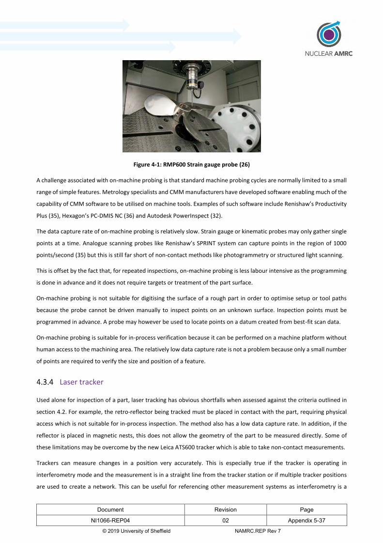
Document Revision Page
NI1066-REP04 02 Appendix 5-37
© 2019 University of Sheffield NAMRC.REP Rev 7
Figure 4-1: RMP600 Strain gauge probe (26)
A challenge associated with on-machine probing is that standard machine probing cycles are normally limited to a small
range of simple features. Metrology specialists and CMM manufacturers have developed software enabling much of the
capability of CMM software to be utilised on machine tools. Examples of such software include Renishaw’s Productivity
Plus (35), Hexagon’s PC-DMIS NC (36) and Autodesk PowerInspect (32).
The data capture rate of on-machine probing is relatively slow. Strain gauge or kinematic probes may only gather single
points at a time. Analogue scanning probes like Renishaw’s SPRINT system can capture points in the region of 1000
points/second (35) but this is still far short of non-contact methods like photogrammetry or structured light scanning.
This is offset by the fact that, for repeated inspections, on-machine probing is less labour intensive as the programming
is done in advance and it does not require targets or treatment of the part surface.
On-machine probing is not suitable for digitising the surface of a rough part in order to optimise setup or tool paths
because the probe cannot be driven manually to inspect points on an unknown surface. Inspection points must be
programmed in advance. A probe may however be used to locate points on a datum created from best-fit scan data.
On-machine probing is suitable for in-process verification because it can be performed on a machine platform without
human access to the machining area. The relatively low data capture rate is not a problem because only a small number
of points are required to verify the size and position of a feature.
Laser tracker
Used alone for inspection of a part, laser tracking has obvious shortfalls when assessed against the criteria outlined in
section 4.2. For example, the retro-reflector being tracked must be placed in contact with the part, requiring physical
access which is not suitable for in-process inspection. The method also has a low data capture rate. In addition, if the
reflector is placed in magnetic nests, this does not allow the geometry of the part to be measured directly. Some of
these limitations may be overcome by the new Leica ATS600 tracker which is able to take non-contact measurements.
Trackers can measure changes in a position very accurately. This is especially true if the tracker is operating in
interferometry mode and the measurement is in a straight line from the tracker station or if multiple tracker positions
are used to create a network. This can be useful for referencing other measurement systems as interferometry is a
Document Revision Page
NI1066-REP04 02 Appendix 5-38
© 2019 University of Sheffield NAMRC.REP Rev 7
traceable measurement technique.
For on-machine probing, a reflector could be mounted in the machine tool spindle and the tracker could be used to
provide an independent check of the machine’s measurement axes. InSphere have developed their Baseline software
to perform quick verification tests on a machine tool using a laser tracker (37). If a smaller, physical artefact is also used
to test the machine tool probe’s performance and the impact of temperature variation is monitored and understood,
this provides a good evidence base for confidence in measurements from on-machine probing.
A tracker could also be used to calibrate artefacts with reflector nests. These could then be used with matching tooling
balls to check the performance of other systems such as scanning or photogrammetry systems.
The additional technologies available as accessories to tracker systems could also be appropriate for metrology for
machining in InFORM, particularly the laser line scanner. (See section 4.3.5)
Laser line scanner with tracker
Laser scanning systems generate a point cloud so can be used for the optimisation of the part setup or tool path. This
also lends itself to 4IR as the data can be gathered quickly, shared and used at different stages of manufacture.
A laser tracked or optically tracked laser line scanner is more suitable for machining in InFORM than structured light
scanning or photogrammetry because it does not need reference targets on the part. This method is also less sensitive
to reflection and therefore does not require a coating to produce a matt finish. This is a significant advantage compared
to other scanning systems for inspecting large, reflective, machined parts.
A laser tracked or optically tracked laser line scanner could be mounted on a robotic arm within the machine volume.
This would allow the system to be used for in process inspection. However it would not be able to inspect certain internal
features such as bores very effectively due to access restrictions and the need for line of sight from the scanner to the
part.
Laser strip scanning measurements do not have traceability via national standards. However if a combined laser tracker/
laser strip scanner system is used, a laser tracker can be used as a reference against which the scanning system can be
checked. This could be achieved though inspection of an artefact which can be measured by both the tracker and the
scanner.
Data visualisation
In machining, data visualisation has the potential to support the optimization of part setup and tool path. For a five axis
machine, tool paths can be adjusted to account for misalignment of a rough component. For three axis machines the
orientation of the component must be adjusted incrementally to ensure the part is optimally aligned with the machine.
Real time data visualisation based on rapid measurements is necessary to allow this to be done efficiently and
accurately.
Nuclear AMRC will propose investigating the feasibility of a system to accomplish this as part of NIP Phase 2.
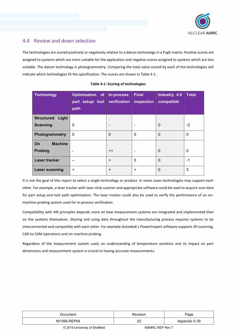
Document Revision Page
NI1066-REP04 02 Appendix 5-39
© 2019 University of Sheffield NAMRC.REP Rev 7
4.4 Review and down selection
The technologies are scored positively or negatively relative to a datum technology in a Pugh matrix. Positive scores are
assigned to systems which are more suitable for the application and negative scores assigned to systems which are less
suitable. The datum technology is photogrammetry. Comparing the total value scored by each of the technologies will
indicate which technologies fit the specification. The scores are shown in Table 4-1.
Table 4-1: Scoring of technologies
Technology Optimisation of part setup/ tool path
In-process verification
Final inspection
Industry 4.0 compatible
Total
Structured Light Scanning 0 - - 0 -2
Photogrammetry 0 0 0 0 0
On Machine Probing - ++ - 0 0
Laser tracker -- + 0 0 -1
Laser scanning + + + 0 3
It is not the goal of this report to select a single technology or product. In some cases technologies may support each
other. For example, a laser tracker with laser strip scanner and appropriate software could be used to acquire scan data
for part setup and tool path optimisation. The laser tracker could also be used to verify the performance of an on-
machine probing system used for in-process verification.
Compatibility with 4IR principles depends more on how measurement systems are integrated and implemented than
on the systems themselves. Sharing and using data throughout the manufacturing process requires systems to be
interconnected and compatible with each other. For example Autodesk’s PowerInspect software supports 3D scanning,
CAD to CAM operations and on-machine probing.
Regardless of the measurement system used, an understanding of temperature variation and its impact on part
dimensions and measurement system is crucial to having accurate measurements.

Document Revision Page
NI1066-REP04 02 Appendix 5-40
© 2019 University of Sheffield NAMRC.REP Rev 7
5 Assembly
5.1 Introduction
This section of the report will explore metrology methods that have been determined to have the potential for use
within the assembly process for InFORM. The aim of metrology in assembly is to provide in-process measurement or
“measurement assisted assembly” as well as produce accurate measurement data for final alignment validation. Section
5.2 establishes the criteria against which the technologies are evaluated. Section 5.3 reviews the technologies against
the established criteria. In section 5.4 the technologies are scored against the established criteria.
5.2 Establishing criteria
The metrology technologies are reviewed against the following criteria:
Measurement volume
Non-contact measurement
Automation
Suitability for workshop environment
Degrees of freedom (translational and rotational measurement)
Portability
Technology Readiness Level (TRL)
For the assembly process, a large measurement volume of 2-20 m with a measurement distance of 2-5 m is required.
Physical access will be restricted therefore non-contact methods will be necessary. Automation of the measurement
system is also desirable in order to increase the speed of inspections, improve safety and reduce operator induced
errors.
The measurement process must be suitable for the uncontrolled workshop environment and must be able to cope with
and compensate for some variability in ambient conditions.
Systems should be able to provide real-time measurements in 6-degrees of freedom; quickly accounting for both
translation and rotation of a part. This is to allow for fast positioning and orientation of parts in the assembly process.
The measurement system must be portable so that it can be brought to the site of the assembly.
The TRL of the system is also taken into account. The higher the score, the closer the technology is to being operationally
ready.
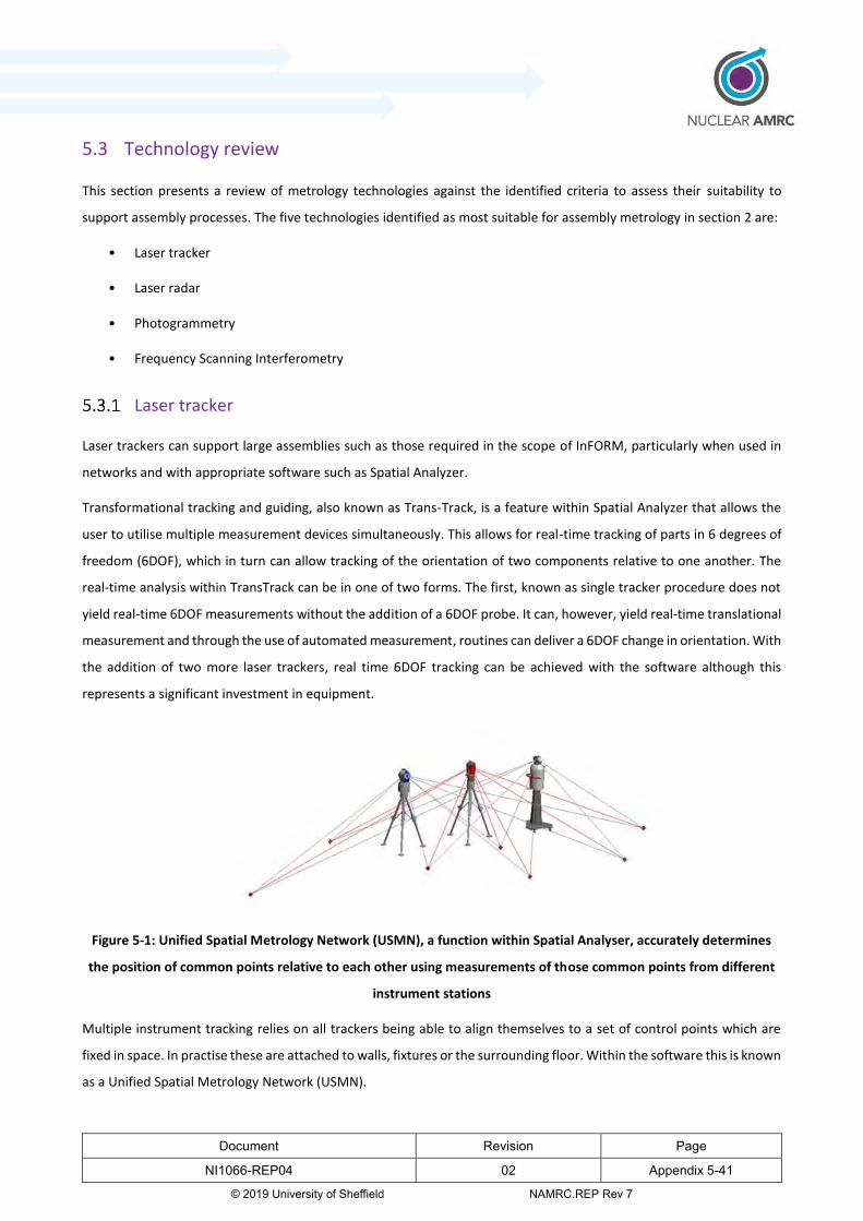
Document Revision Page
NI1066-REP04 02 Appendix 5-41
© 2019 University of Sheffield NAMRC.REP Rev 7
5.3 Technology review
This section presents a review of metrology technologies against the identified criteria to assess their suitability to
support assembly processes. The five technologies identified as most suitable for assembly metrology in section 2 are:
• Laser tracker
• Laser radar
• Photogrammetry
• Frequency Scanning Interferometry
Laser tracker
Laser trackers can support large assemblies such as those required in the scope of InFORM, particularly when used in
networks and with appropriate software such as Spatial Analyzer.
Transformational tracking and guiding, also known as Trans-Track, is a feature within Spatial Analyzer that allows the
user to utilise multiple measurement devices simultaneously. This allows for real-time tracking of parts in 6 degrees of
freedom (6DOF), which in turn can allow tracking of the orientation of two components relative to one another. The
real-time analysis within TransTrack can be in one of two forms. The first, known as single tracker procedure does not
yield real-time 6DOF measurements without the addition of a 6DOF probe. It can, however, yield real-time translational
measurement and through the use of automated measurement, routines can deliver a 6DOF change in orientation. With
the addition of two more laser trackers, real time 6DOF tracking can be achieved with the software although this
represents a significant investment in equipment.
Figure 5-1: Unified Spatial Metrology Network (USMN), a function within Spatial Analyser, accurately determines
the position of common points relative to each other using measurements of those common points from different
instrument stations
Multiple instrument tracking relies on all trackers being able to align themselves to a set of control points which are
fixed in space. In practise these are attached to walls, fixtures or the surrounding floor. Within the software this is known
as a Unified Spatial Metrology Network (USMN).
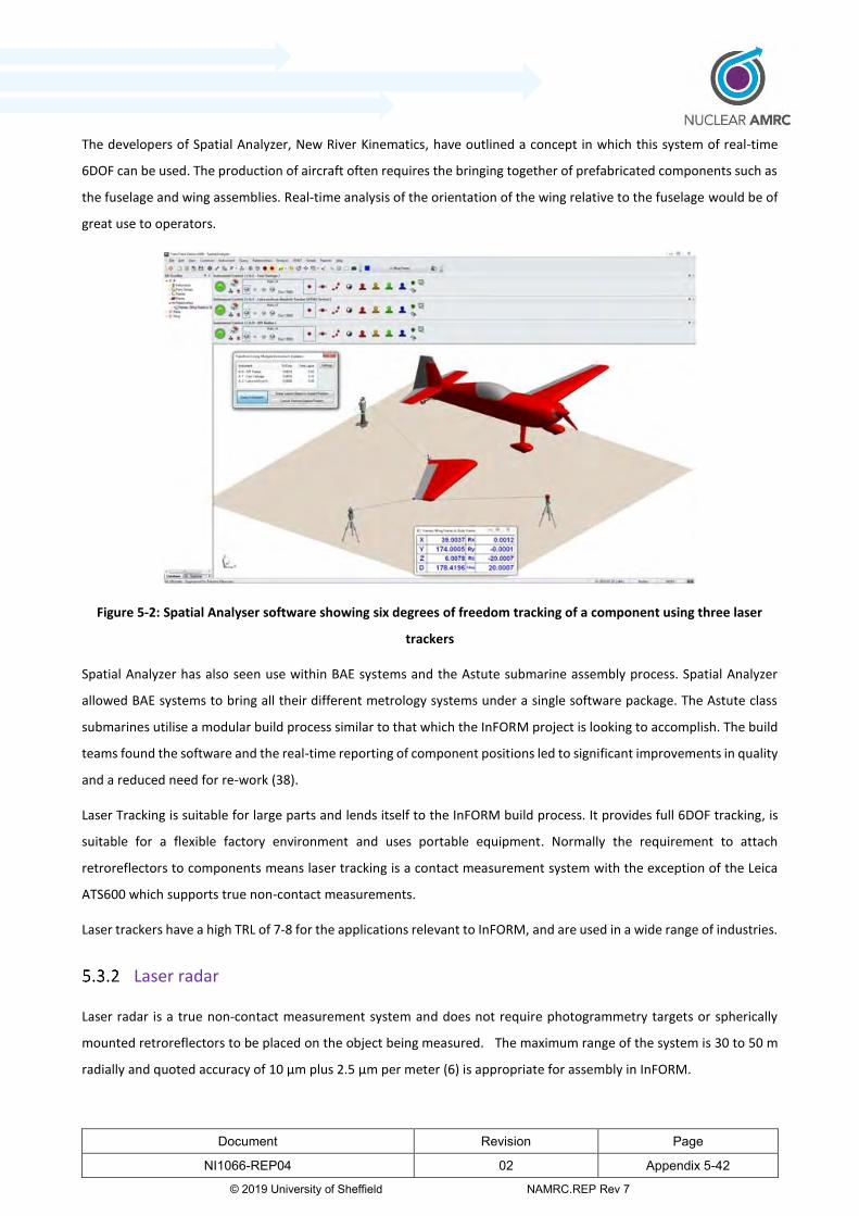
Document Revision Page
NI1066-REP04 02 Appendix 5-42
© 2019 University of Sheffield NAMRC.REP Rev 7
The developers of Spatial Analyzer, New River Kinematics, have outlined a concept in which this system of real-time
6DOF can be used. The production of aircraft often requires the bringing together of prefabricated components such as
the fuselage and wing assemblies. Real-time analysis of the orientation of the wing relative to the fuselage would be of
great use to operators.
Figure 5-2: Spatial Analyser software showing six degrees of freedom tracking of a component using three laser
trackers
Spatial Analyzer has also seen use within BAE systems and the Astute submarine assembly process. Spatial Analyzer
allowed BAE systems to bring all their different metrology systems under a single software package. The Astute class
submarines utilise a modular build process similar to that which the InFORM project is looking to accomplish. The build
teams found the software and the real-time reporting of component positions led to significant improvements in quality
and a reduced need for re-work (38).
Laser Tracking is suitable for large parts and lends itself to the InFORM build process. It provides full 6DOF tracking, is
suitable for a flexible factory environment and uses portable equipment. Normally the requirement to attach
retroreflectors to components means laser tracking is a contact measurement system with the exception of the Leica
ATS600 which supports true non-contact measurements.
Laser trackers have a high TRL of 7-8 for the applications relevant to InFORM, and are used in a wide range of industries.
Laser radar
Laser radar is a true non-contact measurement system and does not require photogrammetry targets or spherically
mounted retroreflectors to be placed on the object being measured. The maximum range of the system is 30 to 50 m
radially and quoted accuracy of 10 µm plus 2.5 µm per meter (6) is appropriate for assembly in InFORM.

Document Revision Page
NI1066-REP04 02 Appendix 5-43
© 2019 University of Sheffield NAMRC.REP Rev 7
The measurement process can be automated using a measurement plan once it has been initialised by an operator.
The ability of laser radar to work in varied lighting conditions and cope with different part temperatures suggests it
would be suitable for the workshop environment.
Individual measurements do not account for all six degrees of freedom of a part but the combination of several
measurements using an automated measurement plan can account for both translation and orientation of a part.
While the measurement system is portable, it is bulkier than a laser tracker or many photogrammetry systems.
Laser radar is a less mature technology than laser tracking or photogrammetry, with a TRL of 6. The system has not seen
widespread use in industry.
Frequency scanning interferometry
The system under consideration here is the diverging beam FSI under development by National Physical Laboratory
(NPL) for metrology-assisted machining and assembly. While FSI is already in use by Etalon AG for machine monitoring,
the Etalon Multiline system is not suitable for assembly because it relies on fixed laser lines along which measurements
are taken.
The divergent beam FSI system being investigated at NPL aims to be able to measure the absolute distance to multiple
targets within cones of illumination from multiple interferometers. This would allow measurement of the 3D positions
of the targets. (28)
This system should be able to track the translation and rotation of parts, allowing measurements to six degrees of
freedom which are useful for assembly.
The system is expected to have a range of up to 10 m (39) which would be sufficient for assembly measurements in
InFORM but significantly less than a laser tracker or laser radar. This means some care would be needed when
positioning the part and FSI systems for measurement.
The portability of the system, its ability to automate measurements and its suitability for a workshop environment are
uncertain and will emerge as the system is developed. Existing FSI systems from Etalon rely on a fixed, non-portable
base station but allow lasers to be transmitted long distances to where they are used for measurement.
Divergent beam FSI has a low TRL of 4 with significant development still required but is promising for application to
metrology for assembly in the future.
Photogrammetry
Most photogrammetry systems require some degree of contact and interaction with the surface of a part. This is
because it is necessary to attach physical reference points to the object being measured. New systems like Pro-Spot
from Geodetic Inc are coming to the market which uses digital projection to overlay a grid of points onto the surface.
This removes the need for reference markers on the part if only one projection location is needed. However the large

Document Revision Page
NI1066-REP04 02 Appendix 5-44
© 2019 University of Sheffield NAMRC.REP Rev 7
parts considered for assembly in the context of InFORM would require multiple projector locations. Some markers
would therefore still be needed, although less than would be needed without a projected pattern.
While photogrammetry systems are able to measure large parts, the range at which the cameras can measure is limited
compared to the tracker or laser radar. This means that to inspect a large volume it is necessary to transport the camera
around it.
The V-STARS photogrammetry systems are relatively compact, consisting of equipment fitting in a camera case plus a
laptop. (8) This is desirable as a more compact measurement system enables it to be used in more flexible manufacturing
environments, a key goal in the InFORM project. In addition, the live data capability of the dual camera setup is
compatible with 4IR. This is another goal of the InFORM project which hopes to encourage the fast transfer and usability
of production data.

Document Revision Page
NI1066-REP04 02 Appendix 5-45
© 2019 University of Sheffield NAMRC.REP Rev 7
5.4 Review and down selection
In order to evaluate the effectiveness and appropriateness of the metrology technologies, the technologies are
compared to a datum within a Pugh matrix. The datum technology is laser tracking, and all other technologies are
compared to the datum. Positive scores indicate the technology is better than the datum, the “0” indicates the
technology is equal to the datum, and the negative scores indicate that the technology is worse than the datum for the
selected requirement. The scores are collated and a net total is found, with the highest total indicating the most
appropriate technology.
Table 5-1 - Scoring
The review indicates that laser tracker based measurement systems would be most appropriate for assembly in InFORM.
Laser radar and photogrammetry have the advantage that they support non-contact measurement but
photogrammetry would still require some markers to be placed on the part. The latest laser tracker from Hexagon, the
Leica ATS600 also has the ability to take non-contact measurements without the need for targets. However non-contact
measurement is not as crucial for assembly as it is for forging, machining and welding.
FSI is a promising technology but is currently too immature to be a realistic consideration for InFORM.
Technology Measurement
Volume
Non-
contact
Automation Suitability for
a workshop
environment
6DOF Portability TRL Net
total
Laser trackers
(With 6DOF)
0 0 0 0 0 0 0 0
Laser RADAR 0 + 0 0 - - - -2
Frequency
Scanning
Interferometry
- 0 0 0 0 - -- -4
Photogrammetry - 0 - 0 0 + -1

Document Revision Page
NI1066-REP04 02 Appendix 5-46
© 2019 University of Sheffield NAMRC.REP Rev 7
6 Welding
6.1 Introduction
This section aims to determine the suitability of different metrology techniques to support welding operations. The
operation in focus is localised Electron Beam Welding (EBW).
True in-process metrology during the EBW process is beyond the scope of this report as the presence of the local vacuum
and the harsh environment due to welding operations would prevent this. However, inspection of parts in-situ, without
removing them from the manufacturing environment avoids the costs of building a dedicated inspection area and
logistical costs associated with transporting the part for inspection. There may also be some requirements to measure
parts shortly after welding in order to make adjustments to further welding operations.
Regardless of the measurement system used, an understanding of temperature variation and its impact on part
dimensions and the measurement system is crucial to making accurate measurements.
Section 6.2 establishes the criteria against which the technologies are evaluated. Section 6.3 reviews the technologies
against the established criteria. In section 6.4 the technologies are scored against the established criteria.
6.2 Establishing criteria
In this section, the available technologies are compared to determine their suitability to support local vacuum EBW. The
metrology requirements to consider in this process are explored below.
Requirements for measurements conducted before welding:
Accurate measurements of part form (e.g. roundness, cylindricity and flatness of mating surfaces). EBW is more
sensitive to poorly matched surfaces than arc-welding. Maximum permissible weld gap for a 60 mm thick
workpiece is as low as 0.3 mm (40). Therefore the fitting surfaces need to be measured accurately. This requires
high accuracy but also high data capture rates to be practical.
Measurement of part alignment, ensuring weld surfaces are correctly aligned e.g.no runout between mating
cylinders.
Digitisation of parts to allow smart alignment using adaptive fixturing. This requires high data capture rates.
Requirements for measurements conducted after welding:
• Measurements of weld distortion in order to provide information for the machining stage and allow adjustment
of further welding processes. This requires high accuracy of measurements.
Challenges associated with measurements for portable electron beam welding in InFORM are listed below:
• Reflective surfaces and welds can be problematic for some non-contact measurement systems.

Document Revision Page
NI1066-REP04 02 Appendix 5-47
© 2019 University of Sheffield NAMRC.REP Rev 7
• Markers or surface treatments required for data capture will not survive the welding process
• If any verification measurements are needed immediately after the welding process has finished, the part will
be hot which limits the use of contact techniques.
• Measurement of large parts is required, specifically pressure vessels several metres in diameter and length.
The requirements and challenges listed above lead to the following criteria against which the measurement
technologies will be assessed:
• Accuracy of measurements
• Data capture rate
• Measurement volume
• System robustness
• Non-contact inspection
6.3 Technology review
This section presents a review of metrology technologies against the identified criteria to assess their suitability for
welding metrology. The technologies deemed most suitable for welding metrology are:
• Laser line scanner with tracker
• Laser line scanner with measurement arm
• Structured light scanning
• Photogrammetry
• Laser displacement sensors
Laser line scanner with tracker
Laser scanners referenced by either laser tracking or optical tracking perform well against the criteria outlined in section
6.2. The systems are non-contact and the use of reference markers or surface treatments can be avoided. Compared to
other available non-contact measurement systems, modern laser line scanners are relatively robust when measuring
reflective welds or machined surfaces. The data capture rate is high allowing a surface to be digitised quickly and the
systems have the capacity to measure very large parts
Laser and optically tracked scanners can also be mounted on a robotic arm, reducing the need for human access to
potentially hazardous environments.
A disadvantage of the system is that the uncertainty is quite high compared to other technologies and may be close to

Document Revision Page
NI1066-REP04 02 Appendix 5-48
© 2019 University of Sheffield NAMRC.REP Rev 7
the limits of what is acceptable for some measurements for EBW.
The MetraSCAN 3D by Creaform3D offers optically tracked laser scanning with high data capture rate and low sensitivity
to reflection. (8) This is referenced by the C-track optical system and does not require reference markers as long as there
is a line of sight from the tracker to the scanner. If another tracker position is needed either another tracker or some
reference markers are needed.
The Leica T-scan laser scanner is referenced by the Leica absolute tracker series (15). This also requires line of sight
however the tracker can be moved to a new location by measuring and re-measuring fixed reflector nests.
Laser line scanner with measurement arm
A laser line scanner can be mounted on an articulated measurement arm in order to reference the scanner’s
measurements. The arm essentially performs the same role as the laser or optical tracker outlined in 6.3.1.
Since laser line scanning is a non-contact method, it can be considered suitable for welding metrology. However, using
measurement arms instead of optical tracking means the system is less well suited to large measurement volumes as
the range is limited by the reach of the arm to a maximum of about 4.5 m. Greater measurement volumes are possible
if a network of arms on referenced bases are used.
Measurements are also labour intensive as the arm must be used by a human operator. This means access to the part
is required even though the method is non-contact. Alongside this, the uncertainty of laser scanning measurements is
relatively high for this application.
Structured light scanning
Structured light scanning is a non-contact method which is appropriate for metrology for welding when dealing with
high-temperature surfaces. However, each scan only captures a small area and reference markers are needed to
combine multiple scans. This requires contact with the component.
The sensitivity of structured light scanning systems to reflection is a further barrier to true non-contact inspection as
reflective parts must be treated to produce a matt finish. Reflections from welds and the surrounding machined material
can make them difficult to measure with structured light scanning. These systems are also usually more sensitive to
vibrations and temperature changes than other technologies making them less robust than photogrammetry or laser
scanning systems.
The data capture rate of structured light scanning is relatively high and the quoted accuracy of structured light scanners
is usually better than other 3D digitisation technologies such as photogrammetry or laser scanning. This is beneficial for
metrology for EBW where high accuracy is required for measurements made prior to welding.
Photogrammetry
The requirement of reference markers for photogrammetry means some contact with the part is involved. While the

Document Revision Page
NI1066-REP04 02 Appendix 5-49
© 2019 University of Sheffield NAMRC.REP Rev 7
requirement for markers is reduced by projection systems like the Pro-Spot, for the large parts considered in the InFORM
project, the projector would need to be moved to multiple vantage points and some coded markers would be required.
Accuracy varies greatly between different systems. While some systems such as the Geodetic V/STARS may be accurate
enough for the application, the less accurate systems are unsuitable.
Photogrammetry systems such as the Hexagon WLS or V/STARS with Pro-Spot projector have a high data capture rate
and can be used to digitise large surfaces quickly. These systems are also normally more robust at coping with vibrations
and reflective parts than structured light scanners.
6.4 Review and down selection
To review and down-select the metrology techniques most suitable for welding metrology, the performance of each
technology must be assessed against the criteria outlined in section 6.2.
In order to evaluate the effectiveness and appropriateness of the metrology technologies for assembly in InFORM, they
are compared to a datum within a Pugh matrix. The selected datum for Welding is photogrammetry. Positive scores
indicate the technology is more suitable than the datum, a score of “0” indicates the technology is equal to the datum,
and negative scores indicate the technology is worse than the datum for the selected requirement. The scores are
collated and the highest total score indicates the most appropriate technology.

Document Revision Page
NI1066-REP04 02 Appendix 5-50
© 2019 University of Sheffield NAMRC.REP Rev 7
Table 6-1: Matrix comparing metrology methodologies for use in EBW.
This process identifies laser scanning with a tracker (either a laser tracker or an optical tracker) as the most appropriate
technology for metrology for welding in InFORM. This result is mainly due to the requirements for large volume, non-
contact measurements. For smaller parts a measurement arm with a laser scanner would achieve the same results at
lower cost.
The only significant limitation of laser scanners in this context is that the quoted uncertainties of these systems are close
to the limit of what is acceptable for welding in InFORM. With a maximum permissible weld gap of 0.3 mm, an
uncertainty of 50 μm or the 64 μm quoted for the Metrascan 3D is quite high. Measurement of artefacts with known
form and comparison with other measurement systems may help provide confidence in measurements.
If the requirement for non-contact measurement is relaxed a high accuracy photogrammetry system such as the
Geodetic V/STARS or the Hexagon WLS system may be appropriate as these are robust systems which can achieve a
high data capture rate at suitable accuracy. These would be more suitable for pre-welding inspections where high
accuracy is important and the importance of non-contact measurements is reduced compared to inspections shortly
after welding processes.
Test Measurement
accuracy
Measurement
volume
Data
capture
rate
System
robustness
Non-
contact
inspection
Net
total
Laser trackers + + - - - - 1
Optical trackers 0 + - - - -2
laser scanner with tracker
- + 0 + + +2
Laser scanning with
measurement arm
- 0 0 0 + 0
Structured light scanning
+ 0 - - 0 -1
Photogrammetry 0 0 0 0 0 0
Document Revision Page
NI1066-REP04 02 Appendix 5-51
© 2019 University of Sheffield NAMRC.REP Rev 7
7 Non-Destructive Evaluation (NDE)
7.1 Introduction
This section aims to determine the applicability of different NDE techniques to support main aspects of the InFORM
project i.e. forging, machining, assembly and welding. There are numerous NDE techniques available in the industry.
However, non-contact NDE techniques have gained interest due to the elimination of potential inconsistencies caused
by the physical interaction between transducer/sensor and the surface of the test structure. Due to the elimination of
physical interaction, non-contact NDE techniques can also expedite the data collection speed to accommodate the
requirements of in-process inspection during manufacturing.
The outline of this section is as follows: Section 7.2 establishes criteria for NDE in the context of InFORM. Section 7.3
includes a brief description and summary of NDE techniques. Section 7.4 covers contact NDE techniques. Section 7.5
covers non-contact NDE techniques. Section 7.6 focuses on laser ultrasound. Section 7.7 lists potential technology
solutions for the InFORM project.
7.2 Establishing criteria
The following NDE criteria are set for the assessment of structural integrity during forging, welding, machining and
assembly using the InFORM system. These are based on the NDE industrial direction towards automation to achieve
rapid in-process NDE.
• Must be able to provide in-process NDE measurements of components
• Rapid data acquisition and real-time data processing in order to automate the technique.
• Must be able to produce accurate measurement data for final inspection
• Non-contact technique in order to avoid using any couplants
• The method should be suitable for measuring hot parts i.e. during welding
• The process should have opportunities for applying 4IR for better utilisation of data in downstream applications
• Health and safety considerations for working near hot parts
• Material thickness > 80 mm

Document Revision Page
NI1066-REP04 02 Appendix 5-52
© 2019 University of Sheffield NAMRC.REP Rev 7
7.3 Technology Review
Non-destructive evaluation techniques are methods to evaluate material integrity for surface or internal flaws or
metallurgical condition without interfering in any way with the component by the destruction of the material or its
suitability for service. Numerous NDE methods are used in industry to evaluate materials and components to assess
their state of health. NDE techniques provide a cost-effective means of testing a sample for individual investigation and
examination or may be applied on the whole material for checking in a production quality control system. In many cases,
detection of a defect requires more than the use of a single NDE method. It may require a combination of methods and
also exploratory, invasive openings. The applications of NDE are widely spread across many industries such as the
nuclear industry, manufacturing, pipe and tube manufacturing, storage tanks, aerospace, military and defence
industries. NDE techniques have gained greater attention from the nuclear industry due to the hazardous environment
raising concerns for health & safety and environmental contamination. NDE techniques have been adopted during the
manufacture of reactor components as well as over the life-span of the nuclear facility. Damage to materials can arise
during material processing or fabrication of the component or during service. Cracks, porosity and deposition of
contaminants are the most common defects. It is therefore vital to assess the structural integrity of components at each
stage. Numerous techniques are used in the nuclear industry, including radiography, visual inspection, ultrasonic
testing, thermography, acoustic emission, shearography, optical testing, liquid penetrant testing and magnetic particle
testing. Accurate structural health assessment uses many sensors. This approach is commonly known as sensor fusion
and provides the facility operators with a better understanding of the structural integrity. Table 7-1 summaries the most
commonly used NDE techniques in the industry.
Table 7-1: Most commonly used NDE techniques in the nuclear sector.
Technique Capability Limitation
Visual Inspection
Macroscopic surface flaws Small flaws are difficult to detect, no
Subsurface flaws.
Microscopy Small surface flaws Not applicable to larger structures; no
subsurface flaws
Radiography Subsurface flaws Smallest defect detectable is 2% of the
thickness; radiation protection. No
subsurface flaws not for porous materials
Dye penetrate Surface flaws No subsurface flaws not for porous
materials
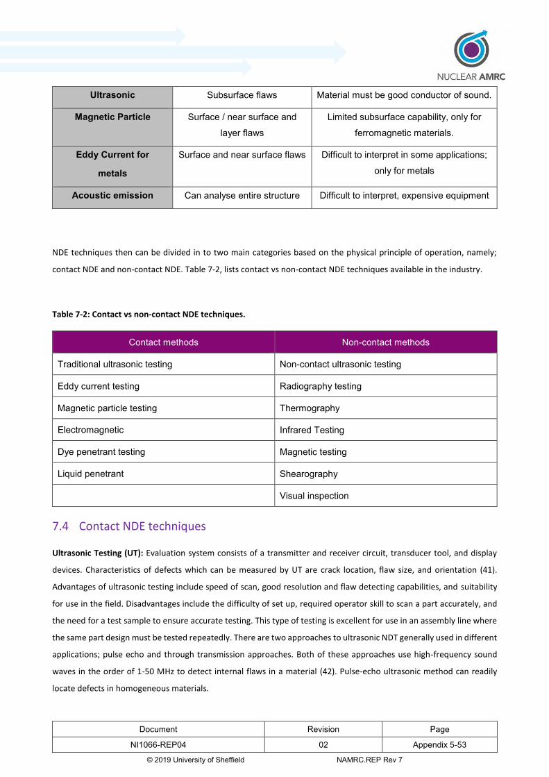
Document Revision Page
NI1066-REP04 02 Appendix 5-53
© 2019 University of Sheffield NAMRC.REP Rev 7
NDE techniques then can be divided in to two main categories based on the physical principle of operation, namely;
contact NDE and non-contact NDE. Table 7-2, lists contact vs non-contact NDE techniques available in the industry.
Table 7-2: Contact vs non-contact NDE techniques.
Contact methods Non-contact methods
Traditional ultrasonic testing Non-contact ultrasonic testing
Eddy current testing Radiography testing
Magnetic particle testing Thermography
Electromagnetic Infrared Testing
Dye penetrant testing Magnetic testing
Liquid penetrant Shearography
Visual inspection
7.4 Contact NDE techniques
Ultrasonic Testing (UT): Evaluation system consists of a transmitter and receiver circuit, transducer tool, and display
devices. Characteristics of defects which can be measured by UT are crack location, flaw size, and orientation (41).
Advantages of ultrasonic testing include speed of scan, good resolution and flaw detecting capabilities, and suitability
for use in the field. Disadvantages include the difficulty of set up, required operator skill to scan a part accurately, and
the need for a test sample to ensure accurate testing. This type of testing is excellent for use in an assembly line where
the same part design must be tested repeatedly. There are two approaches to ultrasonic NDT generally used in different
applications; pulse echo and through transmission approaches. Both of these approaches use high-frequency sound
waves in the order of 1-50 MHz to detect internal flaws in a material (42). Pulse-echo ultrasonic method can readily
locate defects in homogeneous materials.
Ultrasonic Subsurface flaws Material must be good conductor of sound.
Magnetic Particle Surface / near surface and
layer flaws
Limited subsurface capability, only for
ferromagnetic materials.
Eddy Current for
metals
Surface and near surface flaws Difficult to interpret in some applications;
only for metals
Acoustic emission Can analyse entire structure Difficult to interpret, expensive equipment
Document Revision Page
NI1066-REP04 02 Appendix 5-54
© 2019 University of Sheffield NAMRC.REP Rev 7
Eddy Current Testing (ECT): Eddy currents are created through a process called electromagnetic induction. When
alternating current is applied to a conductor, for example copper wire, a magnetic field develops in and around the
conductor. During the process this magnetic field expands as the alternating current rises to maximum and collapses as
the current is reduced to zero. If a new or secondary electrical conductor is brought into close proximity to this changing
magnetic field, current will be induced in this second conductor. These currents are influenced by the nature of the
material such as voids, cracks, changes in grain size, as well as physical distance between coil and material. These
currents form impedance on a second coil which is used to as a sensor. In practice the surface of the part is to be
inspected or examined by placing a probe above the surface, and electronic equipment monitors the eddy current in
the work piece through the same probe. ECT can be used in applications that include crack detection, material thickness
measurements, coating thickness measurements, heat damage detection, case depth determination, conductivity
measurements for material identification and heat treatment monitoring.
Magnetic Particle Inspection (MPI): The MPI method uses magnetic fields and small magnetic particles, such as iron
filings to detect component surface flaws. The only requirement from an inspectability standpoint is that the component
being inspected must be made of a ferromagnetic material such iron, nickel, cobalt, or some of their alloys, since these
materials can be magnetized to a level that will allow the inspection to be effective. In its simplest application, an
electromagnet yoke is placed on the surface of the part to be examined, a kerosene-iron filing suspension is poured on
the surface and the electromagnet is energized. If there is a discontinuity such as a crack or a flaw on the surface of the
part, magnetic flux will be broken from that place and a new south and north pole will form at each edge of the
discontinuity. Then the iron particles will be attracted at the edges of the crack which behave like poles of a magnet.
This cluster of particles is much easier to see than the actual crack. This method is suitable for the detection of surface
and near surface discontinuities in magnetic material, mainly ferrite steel and iron (43).
Dye Penetrate Testing (DPT) and Liquid Penetrate Inspection (LPI) techniques are based on the ability of a liquid to be
drawn into a "clean" surface breaking flaw by capillary action. Materials that are commonly inspected using DPT or LPI
include metals (aluminium, steel, titanium, copper, etc.), glass, many ceramic materials, rubber and plastics. The
penetrant which is used in dye penetrate testing may be applied to all non-ferrous materials and ferrous materials. For
ferrous components magnetic-particle inspection is often used instead for its subsurface detection capability. DPT is
used to detect surface defects in casting, forging and welding such as hairline cracks, surface porosity, leaks in new
products, and fatigue cracks on in-service or in operating components. LPI is based upon capillary action whereby low
surface tension fluid penetrates into clean and dry surface-breaking discontinuities. Penetrant may be applied to the
test component or specimen by dipping, spraying, or brushing. After adequate penetration time has been allowed, the
excess penetrant is removed and a developer is applied. The main advantage of using a developer in DPT is that it helps
to draw penetrant out of the flaw so that an unseen or invisible indication becomes visible to the inspector (43).
7.5 Non-contact NDE techniques
Visual Inspection (VI) should be the most basic type of NDT in many instances because it can save both time and money
by reducing the amount of other testing, or in some cases removing the need for other types of testing all together. The

Document Revision Page
NI1066-REP04 02 Appendix 5-55
© 2019 University of Sheffield NAMRC.REP Rev 7
most important advantage of visual inspection is that it is a quick process. The other advantage of visual inspection is
the relative affordability of the process. Visual inspection needs no equipment but this method has intrinsic
disadvantages in that it cannot detect microscopic or sub-surface defects. VI is particularly effective for detecting
macroscopic flaws, such as poor welds. Many welding defects are macroscopic such as crater cracking, undercutting,
slag inclusion and incomplete penetration welds. VI is also used to detect flaws in composite structures and piping of all
types. VI can detect bad welds or joints, missing fasteners or components, poor fits, wrong dimensions, improper surface
finish, large cracks, cavities, dents, inadequate size and wrong parts.
Radiography has a benefit or advantages over some of the other NDT methods in that the radiography provides a
permanent reference for the internal soundness of the object that is radiographed. The x-ray emitted from a source
penetrates metals as a function of the accelerating voltage in the x-ray emitting tube. If any defect or irregularities such
as voids are present in the object, more x-rays will pass in that area and the film under the part in turn will have more
exposure or spot light than in the non-void areas. The sensitivity of x-rays is nominally 2% of the material thickness.
Thus for a piece of steel having a thickness of 25 mm, the smallest void that could be detected from this x ray would be
0.5 mm in dimension. For this reason, parts are often radiographed in different planes. A thin crack does not show up
unless the x-rays ran parallel to the plane of the crack. This technique is appropriate for the detection of internal flaws
or defects in ferrous and non-ferrous metals and other materials. X-rays, generated electrically, and Gamma rays
emitted from radioactive isotopes, are penetrating radiation which is differentially absorbed by the material through
which it passes; the greater the thickness, the greater the absorption (43).
Thermography Testing, also called thermal imaging. The thermal conductivity of a material may be changed by the
presence of defects. Thermography inspection is used for thin parts because when defects move deeper under the
surface of a part, they tend to produce less heat fluctuation than defects seen closer to the surface of the part. As a
general rule, defects that have a diameter smaller than their depth in the part, cannot be detected. A flaw, such as a
delamination or impact damage causes a change in the thermal radiation of the area (44). There are many advantages
and disadvantages to this type of inspection. One advantage is it can inspect a large surface of a part. This allows for the
inspection of parts where only one side of the part is accessible to inspection. Disadvantages of this type of inspection
include the need for sensitive and expensive instrumentation, the need for highly skilled inspectors to run the
instruments, and the lack of clarity of defects if they fall too deeply under the surface of the part.
Shearography Testing is a laser optical method. An advantage of shearography is that it is less susceptible to noise than
many other types of non-destructive testing. This enables users to inspect and determine the condition of a part without
extensive training. A major disadvantage of shearography is that characterization of defect types other than
delamination is extremely difficult. Therefore it is sometimes paired with other types of NDE techniques that can help
to identify certain defects.
Non-contact Ultrasonic: The physics behind non-contact ultrasonic techniques is similar to conventional ultrasonic
techniques. However this method keeps the transducer and receiver off the surface and at a fixed distance away from
the sample. This is particularly advantageous when complex geometries do not allow for contact between a traditional
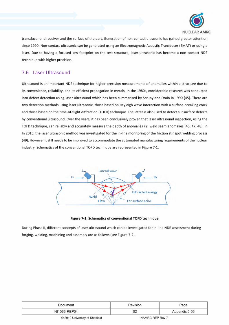
Document Revision Page
NI1066-REP04 02 Appendix 5-56
© 2019 University of Sheffield NAMRC.REP Rev 7
transducer and receiver and the surface of the part. Generation of non-contact ultrasonic has gained greater attention
since 1990. Non-contact ultrasonic can be generated using an Electromagnetic Acoustic Transducer (EMAT) or using a
laser. Due to having a focused low footprint on the test structure, laser ultrasonic has become a non-contact NDE
technique with higher precision.
7.6 Laser Ultrasound
Ultrasound is an important NDE technique for higher precision measurements of anomalies within a structure due to
its convenience, reliability, and its efficient propagation in metals. In the 1980s, considerable research was conducted
into defect detection using laser ultrasound which has been summarised by Scruby and Drain in 1990 (45). There are
two detection methods using laser ultrasonic, those based on Rayleigh wave interaction with a surface-breaking crack
and those based on the time-of-flight diffraction (TOFD) technique. The latter is also used to detect subsurface defects
by conventional ultrasound. Over the years, it has been conclusively proven that laser ultrasound inspection, using the
TOFD technique, can reliably and accurately measure the depth of anomalies i.e. weld seam anomalies (46; 47; 48). In
In 2015, the laser ultrasonic method was investigated for the in-line monitoring of the friction stir spot welding process
(49). However it still needs to be improved to accommodate the automated manufacturing requirements of the nuclear
industry. Schematics of the conventional TOFD technique are represented in Figure 7-1.
Figure 7-1: Schematics of conventional TOFD technique
During Phase II, different concepts of laser ultrasound which can be investigated for in-line NDE assessment during
forging, welding, machining and assembly are as follows (see Figure 7-2).
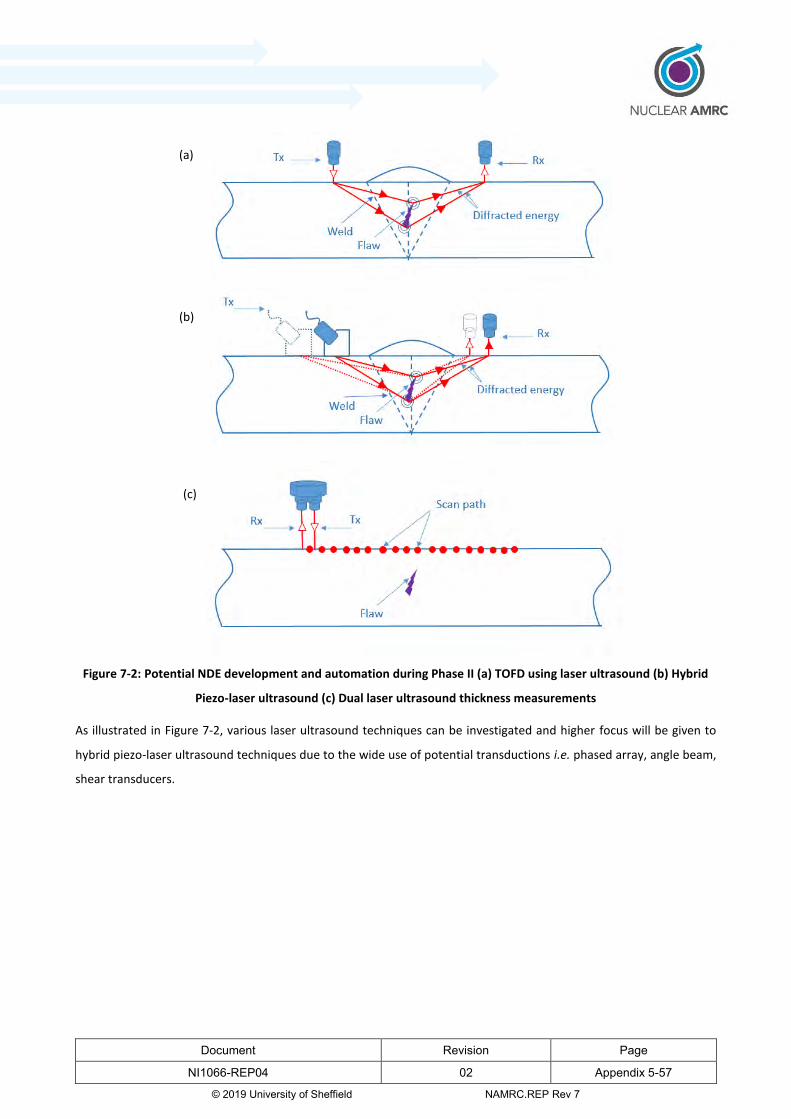
Document Revision Page
NI1066-REP04 02 Appendix 5-57
© 2019 University of Sheffield NAMRC.REP Rev 7
Figure 7-2: Potential NDE development and automation during Phase II (a) TOFD using laser ultrasound (b) Hybrid
Piezo-laser ultrasound (c) Dual laser ultrasound thickness measurements
As illustrated in Figure 7-2, various laser ultrasound techniques can be investigated and higher focus will be given to
hybrid piezo-laser ultrasound techniques due to the wide use of potential transductions i.e. phased array, angle beam,
shear transducers.
(a)
(b)
(c)
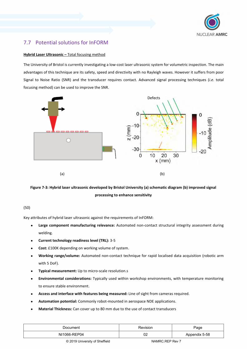
Document Revision Page
NI1066-REP04 02 Appendix 5-58
© 2019 University of Sheffield NAMRC.REP Rev 7
7.7 Potential solutions for InFORM
Hybrid Laser Ultrasonic – Total focusing method
The University of Bristol is currently investigating a low-cost laser ultrasonic system for volumetric inspection. The main
advantages of this technique are its safety, speed and directivity with no Rayleigh waves. However it suffers from poor
Signal to Noise Ratio (SNR) and the transducer requires contact. Advanced signal processing techniques (i.e. total
focusing method) can be used to improve the SNR.
(50)
Key attributes of hybrid laser ultrasonic against the requirements of InFORM:
Large component manufacturing relevance: Automated non-contact structural integrity assessment during
welding.
Current technology readiness level (TRL): 3-5
Cost: £100K depending on working volume of system.
Working range/volume: Automated non-contact technique for rapid localised data acquisition (robotic arm
with 5 DoF).
Typical measurement: Up to micro-scale resolution.s
Environmental considerations: Typically used within workshop environments, with temperature monitoring
to ensure stable environment.
Access and interface with features being measured: Line of sight from cameras required.
Automation potential: Commonly robot-mounted in aerospace NDE applications.
Material Thickness: Can cover up to 80 mm due to the use of contact transducers
(a) (b)
Defects
Figure 7-3: Hybrid laser ultrasonic developed by Bristol University (a) schematic diagram (b) improved signal
processing to enhance sensitivity
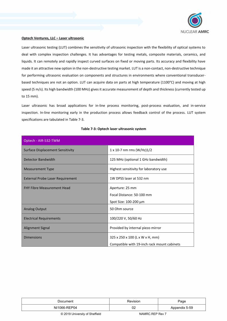
Document Revision Page
NI1066-REP04 02 Appendix 5-59
© 2019 University of Sheffield NAMRC.REP Rev 7
Optech Ventures, LLC – Laser ultrasonic
Laser ultrasonic testing (LUT) combines the sensitivity of ultrasonic inspection with the flexibility of optical systems to
deal with complex inspection challenges. It has advantages for testing metals, composite materials, ceramics, and
liquids. It can remotely and rapidly inspect curved surfaces on fixed or moving parts. Its accuracy and flexibility have
made it an attractive new option in the non-destructive testing market. LUT is a non-contact, non-destructive technique
for performing ultrasonic evaluation on components and structures in environments where conventional transducer-
based techniques are not an option. LUT can acquire data on parts at high temperature (1100°C) and moving at high
speed (5 m/s). Its high bandwidth (100 MHz) gives it accurate measurement of depth and thickness (currently tested up
to 15 mm).
Laser ultrasonic has broad applications for in-line process monitoring, post-process evaluation, and in-service
inspection. In-line monitoring early in the production process allows feedback control of the process. LUT system
specifications are tabulated in Table 7-3.
Table 7-3: Optech laser ultrasonic system
Optech - AIR-532-TWM
Surface Displacement Sensitivity 1 x 10⁻⁷ nm rms (W/Hz)1/2
Detector Bandwidth 125 MHz (optional 1 GHz bandwidth)
Measurement Type Highest sensitivity for laboratory use
External Probe Laser Requirement 1W DPSS laser at 532 nm
FHY Fibre Measurement Head Aperture: 25 mm
Focal Distance: 50-100 mm
Spot Size: 100-200 µm
Analog Output 50 Ohm source
Electrical Requirements 100/220 V, 50/60 Hz
Alignment Signal Provided by internal piezo mirror
Dimensions 325 x 250 x 100 (L x W x H, mm)
Compatible with 19-inch rack mount cabinets

Document Revision Page
NI1066-REP04 02 Appendix 5-60
© 2019 University of Sheffield NAMRC.REP Rev 7
(51)
Key attributes of Optech Ventures, LLC – Laser ultrasonic against the requirements of InFORM:
Large component manufacturing relevance: Automated non-contact structural integrity assessment during
welding.
Current technology readiness level (TRL): 6
Cost: £150K depending on working volume of system.
Working range/volume: Automated non-contact technique for rapid localised data acquisition (robotic arm
with 5 DoF).
Typical measurement: Up to micro-scale resolution.
Environmental considerations: Typically used within workshop environments, with temperature monitoring
to ensure stable environment.
Access and interface with features being measured: Line of sight from cameras required.
Automation potential: Commonly robot-mounted for composite inspection.
Material Thickness: Can’t achieve full penetration due to the available laser power.
(a)
(c) (b)
Figure 7-4: Optech laser ultrasonic system (a) AIR-1550-TWM system (b) schematic drawing
of agile measurement system (c) separation B-scan on a 6 mm steel sample
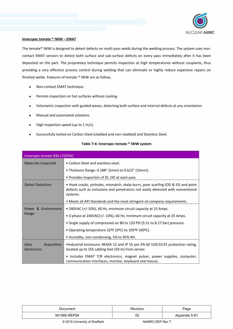
Document Revision Page
NI1066-REP04 02 Appendix 5-61
© 2019 University of Sheffield NAMRC.REP Rev 7
Innerspec temate ® IWW – EMAT
The temate® IWW is designed to detect defects on multi-pass welds during the welding process. The system uses non-
contact EMAT sensors to detect both surface and sub-surface defects on every pass immediately after it has been
deposited on the part. The proprietary technique permits inspection at high temperatures without couplants, thus
providing a very effective process control during welding that can eliminate or highly reduce expensive repairs on
finished welds. Features of temate ® IWW are as follow,
Non-contact EMAT technique.
Permits inspection on hot surfaces without cooling.
Volumetric inspection with guided waves, detecting both surface and internal defects at any orientation.
Manual and automated solutions.
High inspection speed (up to 1 m/s).
Successfully tested on Carbon Steel (cladded and non-cladded) and Stainless Steel.
Table 7-4: Innerspec temate ® IWW system
Innerspec temate BW-LT(ERW)
Materials Inspected • Carbon Steel and stainless steel.
• Thickness Range: 0.188” (5mm) to 0.623” (16mm).
• Provides inspection of ID, OD at each pass.
Defect Detection • Hook cracks, pinholes, mismatch, skelp burrs, poor scarfing (OD & ID) and point defects such as inclusions and penetrators not easily detected with conventional systems.
• Meets all API Standards and the most stringent oil company requirements.
Power & Environment Range
• 240VAC (+/-10%), 60 Hz, minimum circuit capacity at 15 Amps.
• 3-phase at 240VAC(+/- 10%), 60 Hz, minimum circuit capacity at 25 Amps.
• Single supply of compressed air 80 to 120 PSI (5.51 to 8.27 bar) pressure.
• Operating temperature 32ºF (0ºC) to 105ºF (40ºC).
• Humidity, non-condensing, 5% to 95% RH.
Data Acquisition Electronics
•Industrial enclosure; NEMA 12 and IP 55 per EN 60 529/10.91 protection rating, located up to 165 cabling feet (50 m) from sensor.
• Includes EMAT T/R electronics, magnet pulser, power supplies, computer, communication interfaces, monitor, keyboard and mouse.
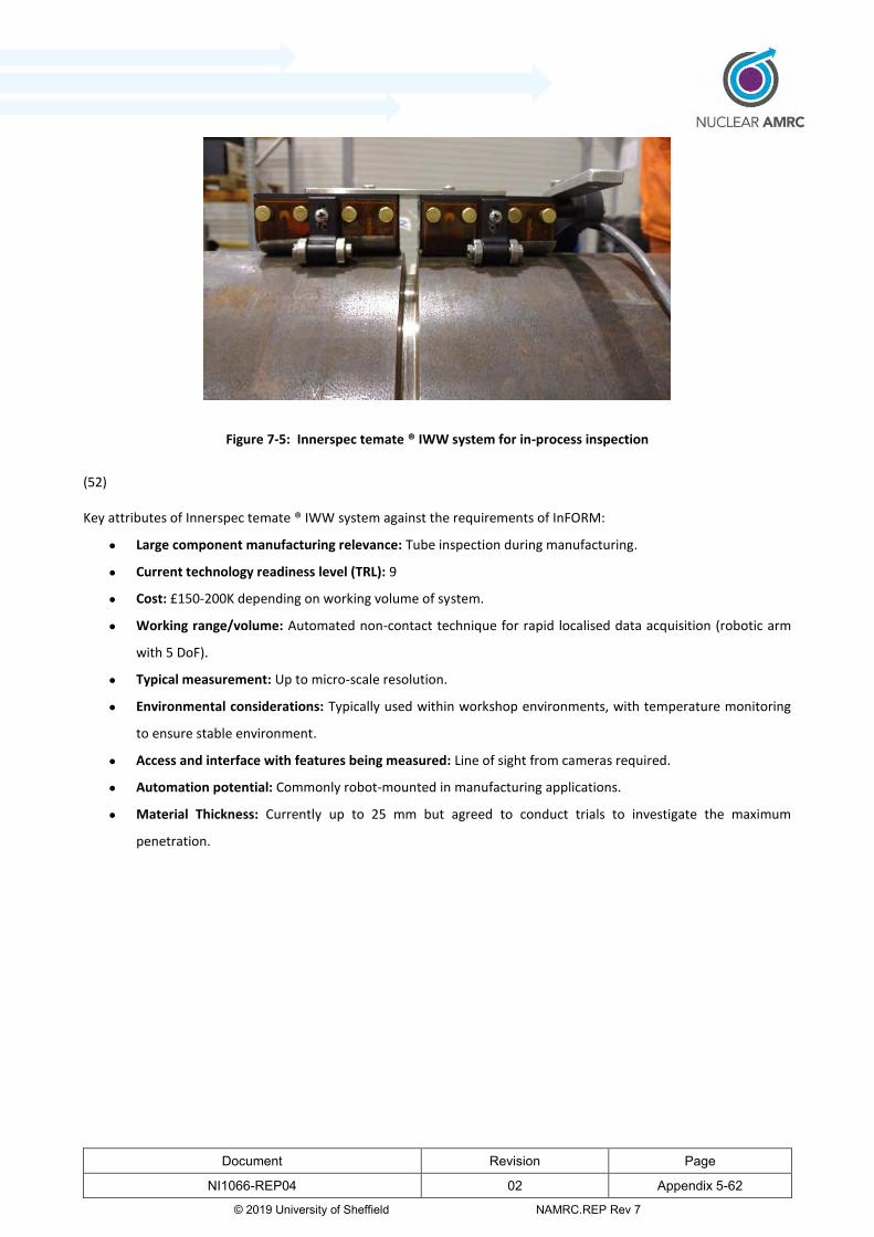
Document Revision Page
NI1066-REP04 02 Appendix 5-62
© 2019 University of Sheffield NAMRC.REP Rev 7
(52)
Key attributes of Innerspec temate ® IWW system against the requirements of InFORM:
Large component manufacturing relevance: Tube inspection during manufacturing.
Current technology readiness level (TRL): 9
Cost: £150-200K depending on working volume of system.
Working range/volume: Automated non-contact technique for rapid localised data acquisition (robotic arm
with 5 DoF).
Typical measurement: Up to micro-scale resolution.
Environmental considerations: Typically used within workshop environments, with temperature monitoring
to ensure stable environment.
Access and interface with features being measured: Line of sight from cameras required.
Automation potential: Commonly robot-mounted in manufacturing applications.
Material Thickness: Currently up to 25 mm but agreed to conduct trials to investigate the maximum
penetration.
Figure 7-5: Innerspec temate ® IWW system for in-process inspection

Document Revision Page
NI1066-REP04 02 Appendix 5-63
© 2019 University of Sheffield NAMRC.REP Rev 7
References
1. Hitchens, Carl. Guide to engineering metrology V4. s.l. : Nuclear AMRC.
2. Nuclear AMRC. Technology and Manufacturing Capability assessment criteria
guidance: Themes 2 and 3 Of Phase-1 of the Nuclear Innovation Programme. 2019.
3. FARO Technologies UK ltd. FARO SUPER 6DOF (6 DEGREES OF FREEDOM)
TRACKARM. FARO Technologies UK ltd. [Online] 2018. [Cited: 26 October 2018.]
https://www.faro.com/en-gb/products/factory-metrology/faro-laser-tracker/.
4. Hexagon AB. Leica Absolute Tracker ATS600. Hexagon Manufacturing Intelligence.
[Online] 2019. https://www.hexagonmi.com/en-GB/products/laser-tracker-
systems/leica-absolute-tracker-ats600.
5. Leica. Laser Tracker AT901 and T-Scan . [Online]
http://www.hexagonmetrology.co.uk/leica-absolute-tracker-at901_283.htm.
6. Nikon Metrology NV . Laser Radar MV331/351 . Nikon Metrology. [Online] 2017.
https://www.nikonmetrology.com/en-gb/product/laser-radar-mv331-351.
7. White, D. Coherent Laser Radar. [Online]
http://www.qualitydigest.com/aug99/html/body_radar.html.
8. Creaform. Optical CMM 3D Scanner: MetraSCAN 3D. Creaform 3D. [Online] [Cited:
24 Sept 2018.] https://www.creaform3d.com/en/metrology-solutions/optical-3d-
scanner-metrascan.
9. Hexagon Metrology. [Online] http://www.hexagonmetrology.com/.
10. Creaform. HandyPROBE Next. Creaform. [Online]
https://www.creaform3d.com/en/metrology-solutions/coordinate-measuring-
machines-handyprobe.
11. Steinbichler. 3D Digitizing. [Online] http://www.steinbichler.com/products/surface-
scanning/3d-digitizing.html.
12. GOM. ATOS - Industrial 3D Scanning Technology. [Online]
http://www.gom.com/metrology-systems/3d-scanner.html.
13. Nikon Metrology. [Online] http://www.nikonmetrology.com/.
Document Revision Page
NI1066-REP04 02 Appendix 5-64
© 2019 University of Sheffield NAMRC.REP Rev 7
14. Faro Metrology. [Online] http://www.faro.com/.
15. Hexagon. Leica T-Scan 5. Hexagon Manufacturing Intelligence. [Online] [Cited: 09
10 2018.] https://www.hexagonmi.com/en-GB/products/3d-laser-scanners/leica-tscan-
5.
16. Hexagon Metrology. Portable Measuring Arms. [Online]
http://www.hexagonmetrology.com/Portable-Measuring-Arms_234.htm.
17. Cimcore. [Online] http://www.cimcore.com/.
18. GOM. TRITOP - Optical 3D Coordinate Measuring Machine. [Online]
https://www.gom.com/metrology-systems/tritop.html.
19. Cognitens. Cognitens WLS400M Manually operated white light scanner. [Online]
http://www.cognitens.com/Cognitens-WLS400M_628.htm.
20. Solutionix. Photogrammetry. [Online] http://solutionix.com/main/bbs/3d-
measurement-photogrammetry.html.
21. Etalon AG. Absolute Multiline Technology. Etalon-AG. [Online] https://www.etalon-
ag.com/en/products/absolute-multiline-technology/.
22. —. LaserTRACER-NG. Etalon-AG. [Online] https://www.etalon-
ag.com/en/products/lasertracer/.
23. INSPHERE Ltd. BASELINE. [Online] 2019.
http://insphereltd.com/products/#baseline.
24. NATEP. insphere-basline-launch. National Aerospace Technology Programme.
[Online] 2019. http://www.natep.org.uk/insphere-basline-launch.
25. Coefficients of Linear Thermal Expansion . The Engineering ToolBox. [Online]
https://www.engineeringtoolbox.com/linear-expansion-coefficients-d_95.html.
26. Renishaw Plc. Innovations in touch-trigger probing sensor technology. [White
paper] s.l. : Renishaw Plc, 2010-20111. TE411.
27. —. One-touch versus two-touch probing. [White paper] s.l. : Renishaw Plc,
Renishaw Plc, 2010-2011. TE412.

Document Revision Page
NI1066-REP04 02 Appendix 5-65
© 2019 University of Sheffield NAMRC.REP Rev 7
28. National Physical Laboratory. Frequency Scanning Interferometry research.
National Physical Laboratory. [Online] 31 July 2017. http://www.npl.co.uk/science-
technology/dimensional/frequency-scanning-interferometry-research.
29. Metrology News. Polyworks Plug-In Provides AR Results Projection. Metrology
News. [Online] [Cited: 24 Sept 2018.] http://metrology.news/polyworks-plug-in-
provides-ar-results-projection.
30. Geodetic Systems. Why V-STARS. Geodetic Systems. [Online] [Cited: 25 Sept
2018.] https://www.geodetic.com/v-stars/.
31. Augemented reality sandbox. About Augmented Reality Sandbox. Augmented
Reality Sandbox. [Online] [Cited: 04 Oct 2018.] https://arsandbox.ucdavis.edu/about/.
32. Autodesk Inc. 3D Measurement and metrology software. Autodesk. [Online]
Autodesk Inc, 2018. https://www.autodesk.com/products/powerinspect/overview.
33. Geodetic Systems. PRO-SPORT . Geodetic Systems. [Online] [Cited: 2018 11 02.]
34. Renishaw Plc. XM-60 multi-axis calibrator. [Online] 2019.
https://www.renishaw.com/en/xm-60-multi-axis-calibrator--39258.
35. —. Brochure: Productivity+™ Scanning Suite. 2018.
36. Hexagon AB. PC-DMIS NC. Hexagon Manufacturing Intelligence. [Online] 2019.
https://www.hexagonmi.com/products/software/pc-dmis/pcdmis-nc.
37. Insphere Ltd. INSPHERE's NATEP-funded BASELINE Project. INSPHERE Ltd.
[Online] 18 October 2018. http://insphereltd.com/news/2018/10/18/inspheres-
baseline-a-natep-funded-project.
38. New River Kinematics. Building BAE Submarines: SA Spans the Globe from the
UK to Australia. New River Kinematics. [Online] 2018. [Cited: 24 October 2018.]
https://www.kinematics.com/about/newsletterarticlebaesubmarines.php.
39. National Physical Laboratory (NPL). FSI, a high accuracy coordinate measurement
system. [Online] http://www.npl.co.uk/science-technology/dimensional/frequency-
scanning-interferometry-research.
40. Schultz, H. Electron Beam Welding. 3rd revised edition. 2018. Vol. DVS English
Edition Volume 14. ISBN: 978-3-96144-020-7.
Document Revision Page
NI1066-REP04 02 Appendix 5-66
© 2019 University of Sheffield NAMRC.REP Rev 7
41. Lu, Y. Non-destructive Evaluation on Concrete Materials and Structures using
Cement-based Piezoelectric Sensor. (3457480 Ph.D.). Hong Kong : Hong Kong
University of Science and Technology, 2010.
42. Garney, G. Defects found through non-destructive testing methods of fiber
reinforced polymeric composites. (1438996 M.S.). Fullerton : California State
University, 2006.
43. Recent trends in industrial and other engineering applications of non destructive
testing: a review. Kumar S, Mahto D. G. 9, s.l. : International Journal of Scientific &
Engineering Research, 2013, Vol. 4.
44. Meyendorf, N.G.H., Nagy P.B. , and Rokhlin S. Nondestructive Materials
Characterization: With Applications to Aerospace Materials. Berlin Heidelberg. :
Springer, 2013.
45. Scruby C. B. and Drain L. E. Laser ULtrasonic:Techniques and Applications.
Bristol : CRC Press, 1990.
46. Applications of Laser Ultrasonics in the Pipeline Industry. Klein M., Ansari H.,
Tomar M. S., Fingerhut M, Portzgen N., Yu D., & Volker A. Montreal, Canada : 1st
International Symposium on Laser Ultrasonics: Science, Technology and Applications,
2008.
47. Time-of-Flight Diffraction Measurement Using Laser Ultrasound. Mihara T., Otsuka
Y., Cho H., & Yamanaka K. s.l. : Experimental Mechanics, 2006 , Vol. 46.
48. Laser Ultrasound Inspection Based on Wavelet Transform and Data Clustering for
Defect Estimation in Metallic Samples. Selim H., Prieto M. D., Trull J., Romeral L., and
Cojocaru C. s.l. : Sensors, 2019, Vol. 19.
49. Application of laser ultrasonic method for on-line monitoring of friction stir spot
welding process. Zhang K., Zhou Z., & Zhou J. s.l. : Applied optics, 2015, Vol. 54.
50. Hybrid Laser Ultrasonic Total Focussing Method (<£50k <5mins <2mins). J.
Kirkpatrick, J. Potter and P. Wilcox. Warwick : RCNDE, 2019.
51. Intelligent Optical Systems . http://www.intopsys.com/laserultrasonics/. [Online]
Intelligent Optical Systems , 2019. [Cited: 2019 06 03.]
http://www.intopsys.com/laserultrasonics/.

Document Revision Page
NI1066-REP04 02 Appendix 5-67
© 2019 University of Sheffield NAMRC.REP Rev 7
52. Innerspec Technologies, Inc. Inspection of Multi-Pass Welds. [Online] Innerspec
Technologies, Inc., 2019. [Cited: 2019 06 03.]
https://www.innerspec.com/integrated/applications/weld-inspection/inspection-of-
multi-pass-welds/.

Document Revision Page
NI1066-REP-01 03 Appendix 6
© 2019 University of Sheffield NAMRC.REP Version 7.0
Appendix 6: Conference and Publication Abstracts

Document Revision Page
NI1066-REP-01 01 Appendix 6-1
© 2019 University of Sheffield NAMRC.REP Version 7.0
Appendix 6. Conference and Publication Abstracts
Impact of supercritical carbon dioxide cooling with Minimum Quantity Lubrication on
tool wear and surface integrity in the milling of AISI 304L stainless steel
In this study, the effect of supercritical carbon dioxide cooling with Minimum Quantity Lubrication (scCO2+MQL) on tool
wear and surface integrity of AISI 304 L austenitic stainless steel in milling was investigated. A series of machining
experiments based on a Design of Experiments (DoE) was carried out at various combinations of cutting parameters to
investigate the effect of cutting speed and feed rate on tool wear, nearsurface residual stresses, surface roughness and
microhardness. The results were compared with the experimental results obtained from milling with flood coolant. A
significant improvement in tool life was observed in milling with the scCO2+MQL using multilayer coated tungsten
carbide inserts. The tool life in terms of cutting time increased by ∼324%, in comparison to a baseline flood coolant.
Further, a decrease in surface roughness value (Ra) by about 30%, from 1.09 μm for flood coolant to 0.78 μm after face
milling with scCO2+MQL was seen. Additionally, the Ra value slightly increased after machining, for both cooling
methods with the increase of cutting speed of ∼19%. The observed changes in Ra value were discussed in terms of a
built-up-edge (BUE) formation. There were no apparent differences in surface microhardness between both cooling
methods.
However, the surface microhardness increased with feed rate after milling with both scCO2+MQL and flood coolant due
to the increased strain hardening. Also, there was no significant difference in residual stresses after milling, neither with
scCO2+MQL nor the flood coolant. The surface residual stress values obtained in the transverse and longitudinal
directions were consistent with a predictive model with errors of around 3–8%. (1)
Presentation of InFORM at ICONE27
An overview (presentation only) of the InFORM project was presented to delegates at the 27th International Conference
on Nuclear Engineering (ICONE27), 19-24th May 2019, in Tsukuba, Japan (2). The abstract submitted is as follows:
InFORM (Intelligent Fixtures for Optimised and Radical Manufacture) is a £1 million collaborative research programme
between the Nuclear AMRC, the AMRC, TWI Ltd, Sheffield Forgemasters International Ltd and MetLase. The objective
of the project is to develop intelligent fixtures to reduce the cost and associated lead times of large-scale assembly and
pressure vessel component manufacture for civil nuclear, oil and gas and similar sectors.
Current best practice for the manufacture of pressure vessels and large assemblies relies on bespoke one-off fixtures
designed for individual components. With the introduction of Small Modular Reactors (SMRs) into the sector, it is widely
accepted that components will need to be mass-produced to make them financially viable. The core objective of this

Document Revision Page
NI1066-REP-01 01 Appendix 6-2
© 2019 University of Sheffield NAMRC.REP Version 7.0
stage of the InFORM project is to develop intelligent fixtures to optimise pressure vessel manufacture, focusing on four
main processes; forging, machining, assembly and welding.
Metrology techniques are being investigated to streamline the workflow between the forging and machining stages, re-
using point cloud data where appropriate. A virtual fixture is being developed using technology that is well established
in other sectors for machining near-net shape components. This minimizes fresh air cutting and guarantees whether a
part can be produced within the stock material before machining begins.
A radical fixture is being developed by MetLase to revolutionise the assembly of large-scale assemblies and pressure
vessels. MetLase are known for using laser cut sheet metal to rapid prototype bespoke fixtures for use in the automotive
and aerospace industries. This work will look at transferring this technology to large component manufacture, focusing
on vessel alignment and acting as an enabler for local vacuum electron beam technologies.
The electron beam welding process is viewed as a key enabler in the mass production of large-scale pressure vessels,
as it potentially has several advantages over conventional arc welding processes, including time-savings and improved
quality. However electron beam processes typically require a large volume enclosure to achieve a vacuum, which limits
the size of the component. An intelligent local vacuum electron beam welding fixture is being developed and tested by
TWI Ltd.
This presentation would describe each of the intelligent fixture developments described above and highlight benefits
to industry where appropriate.
Presentation of InFORM at PVP 2019
An overview (presentation only) of the InFORM project was presented to delegates at the 2019 Pressure Vessels and
Piping Conference, 14-19th July 2019, in San Antonio, Texas (3). The abstract submitted is as follows:
Intelligent fixtures to accelerate pressure vessel manufacture
InFORM (Intelligent Fixtures for Optimised and Radical Manufacture) is an industrial collaborative research programme
between the Nuclear AMRC, the AMRC, TWI Ltd, Sheffield Forgemasters International Ltd and MetLase. InFORM is
developing intelligent fixtures to optimise pressure vessel manufacture, focusing on four processes; forging, machining,
assembly and welding. The project is streamlining the workflow between the forging and machining stages, using point
cloud data to accelerate the machining process. MetLase is designing a fixture to support the assembly of pressure
vessels, focusing on vessel alignment, and enabling local vacuum (LV) electron beam technologies. E-beam welding is a
key enabler in reducing lead-times of large-scale pressure vessel manufacture with advantages over arc processes.
Conventional e-beam welding requires vacuum enclosures thus limiting component size. TWI Ltd is developing and
testing a LV e-beam welding fixture. This presentation describes the intelligent fixture developments and highlights the
benefits to industry where appropriate.

Document Revision Page
NI1066-REP-01 01 Appendix 6-3
© 2019 University of Sheffield NAMRC.REP Version 7.0
References
1. Impact of supercritical carbon dioxide cooling with Minimum Quantity Lubrication on tool wear and surface integrity
in the milling of AISI 304L stainless steel. Wika, Krystian K, Litwa, Przemyslaw and Hitchens, Carl. Sheffield : Elsevier,
2019, Wear, Vols. 426-427, Part B, 30 April 2019, Pages 1691-1701.
2. ICONE. ASME International Conference on Nuclear Engineering & Power Conference. [Online] 2019. [Cited: 06 08
2019.] http://event.asme.org/ICONE.
3. PVP. ASME Pressure Vessels & Piping Conference. [Online] 2019. [Cited: 06 08 2019.] https://event.asme.org/PVP.

Document Revision Page
NI1066-REP-01 03 Appendix 7
© 2019 University of Sheffield NAMRC.REP Version 7.0
Appendix 7: Stage 1 Report
InFORM:Stage1SBRIAdvancedManufacturingandMaterials(Area3Theme3)
1
IntelligentFixturesforOptimisedandRadicalManufacture(InFORM)
Applicationnumber:87439-545156
Maincontractordetails:
Leadcontractororganisation NuclearAMRC,UniversityofSheffieldMaincontactperson DavidAnsonMaincontactemail [email protected] +441142158047
Listofsubcontractors:
ParticipantOrganisationname Maincontactperson
CambridgeVacuumEngineering BobNicolsonMetLase DrStewartLowthSheffieldForgemastersInternational ProfessorJesusTalamantes-SilvaTWI ChrisPunshonNationalPhysicalLaboratory ProfessorBenHughes
Terminologyandabbreviations
InFORM IntelligentFixturesforOptimisedandRadicalManufacture MQL MinimumquantitylubricationRPV Reactorpressurevessel NPL NationalPhysicalLaboratoryEBW Electronbeamwelding VR VirtualrealityEB Electronbeam SAW SubmergedarcweldingFSI Frequencyscanninginterferometer FCAW FluxcorearcweldingTWI TheWeldingInstitute MRL Manufacturingreadinesslevel
CVE CambridgeVacuumEngineering NIRABNuclear Innovation andResearchAdvisoryBoard
SMR Smallmodularreactor NNUMAN NewNuclearManufactureNNS Nearnetshape F4N FitforNuclearNDE Non-destructiveevaluation SAT SiteacceptancetestingSME Smallandmediumsizedenterprise FAT FactoryacceptancetestingSFIL SheffieldForgemastersInternationalLtd LCOE Levelisedcostofelectricity
WEC WestinghouseElectricCompany AMRCAdvanced ManufacturingResearchCentre
TRL Technologyreadinesslevel WNISRWorldNuclearIndustryStatusReport
CAM Computeraidedmanufacture ROI ReturnonInvestmentCOS Conditionofsupply SSR Stablesaltreactor
InFORM:Stage1SBRIAdvancedManufacturingandMaterials(Area3Theme3)
Strictly Confidential 2
ExecutiveSummary‘Intelligent Fixtures for Optimised and Radical Manufacture’ (InFORM) will reduce the costs involved in themanufactureofthelarge,complex,safetycriticalcomponentsrequiredbythepowergenerationindustry.ItwillbecarriedoutbytheNuclearAdvancedManufacturingResearchCentre(NuclearAMRC),whichisthecentreofexcellenceintheUKfornuclearmanufacturing,withsubcontractorsTWI,CambridgeVacuumEngineering(CVE),SheffieldForgemastersInternationalLtd(SFIL),MetLase,andtheNationalPhysicalLaboratory(NPL).Thisreportsummarises the activities carriedout as part of Phase 1, Stage 1 anddetails the activities to be carriedout inStage2.AsummaryofproposedactivitiesforPhase2isalsogiven.
InFORM will develop and transfer expertise and new technologies for large, nuclear components. Thesetechnologies cover the whole manufacturing process from forging to machining, assembly, welding andinspection:
• Forging: advanced,metrology techniqueswill be used tomeasure andmonitor the forging process todeliverimprovedprocesscontrolandachieveanincreaseingeometricalaccuracy.Thiswillprovidedatatooptimisethemanufacturabilityandachievenear-netshapeforging.Adatadrivenapproachwillalsobeinvestigated intheapplicationanddesignofmanipulationandfixture interfacecustomisationachievingan improvement in process efficiency, from steel manufacture through to the machined condition ofsupply.
• Machining: near-net shape machining will be optimised by using data from the forging process, andinnovativealgorithmsandadvancedcoolingtechniqueswillbedevelopedtoreducethetimeneededtoachievethedesiredcomponentshape.
• Intelligentfixtures:athrough-lifefixturewillbedevelopedtofacilitatethetransferpartsbetweenforging,machining, welding and inspection. It will include sensors to provide feedback to actuators andmanipulatorstoautomaticallyadjustclampingforcestominimisedistortion.Thisfixturewillalsoenablelarge-scalenuclearcomponentstobeassembledandalignedmoreefficiently.
• Localvacuumwelding:localvacuumtechnologieswillbedeveloped.Easy-to-deploypowerbeamweldingwouldachieveastepchangeintheproductivityofthicksectionwelds.
ThesuccessfuldevelopmentandtransferofthesetechnologiesduringInFORMwillleadtotimeandcostsavingsofatleast50%duringthemanufactureoflarge,complex,integratednuclearcomponents.ThisprojectwillhelptheUKtocompeteonaglobalscaletowinmajormanufacturingcontractsacrossallnuclearsectors(newbuild,smallmodularreactor(SMR),defence,decommissioning,fusion).ThiswillensurethatweareasignificantpartnerintheglobaldeploymentofGenIII+,GenIVandSMRtechnologiesassetoutinthevisionforthiscompetition.However,significantbenefitoftheInFORMtechnologieswillneedtobedemonstratedinordertoachieveGenIII+designerbuy-intoenabledeploymentovercurrentmethodsofmanufacture.
InFORMwillputtheUKattheforefrontofmanufacturinginnovationandensureweremainatoptablenuclearnationandaleaderforglobalnuclearmanufacturing.ItwillallowUKmanufacturerstosignificantlyincreasetheirglobal competitiveness,winmajor export contracts thus driving economic growth. The adoption of these newtechniqueswillalsoincreasethecapabilityofUKmanufacturersinotherheavyengineeringsectorssuchaswindenergy,oilandgasandshipbuilding,buildconfidenceinthesupplychainandhelpindustryandGovernmenttotackletheongoingskillsgapinUKmanufacturingandsteelproduction.
1 Marketanalysisandopportunity1.1 GlobalMarketEstimations of global nuclear trends vary as new builds are reliant on political decisions; the World NuclearPerformanceReport1statesthat9GWecameonlinein2016,thelargestincreaseinnuclearpowergenerationforover 25 years, with the majority of increased capacity in Asia. Energy share from Nuclear increased by 1.3percentage points (12.3% to 13.6%) in those countries with reactors and by the end of 2016 therewere 448
1 "World Nuclear Performance Report 2017", World Nuclear Association

InFORM:Stage1SBRIAdvancedManufacturingandMaterials(Area3Theme3)
Strictly Confidential 3
reactors with a further 61 under construction. The World Nuclear Industry Status Report (WNISR)2 shows adecline in reactorsunderconstructionof2-3peryear,but this ispartiallyduetoproblemswithmanufacturingand partly to the completion of long-term projects. Balancing this, a number of lifetime extensions are beingapplied for and granted, giving an additional spur to thedevelopmentof nuclearmanufacturing knowledge aspowercompaniesneedtoknowhowtomonitor,repairandreplacecriticalcomponents.
TheInternationalAtomicEnergyAssociationreport3highlightsthedifficultyinestimatingfutureenergyneedsandthe generationmix, and provides low and high estimates for future nuclear power generation. Their forecastsincludeoperatingreactors,licenserenewal,populationgrowth,thelinktoincreasedenergydemand,fluctuatingprices,technicalperformanceandeconomicandenvironmentalpolicies.Theyestimatethatglobalcapacityneedsto increaseby8-112GWeand35-516GWeby2030and2050respectively.Thisequatestotheconstructionofeither25 'traditional'reactors,morethan100SMRs,oracombinationofthetwointhenext30yearsata lowestimate.Takinganaverageoftheforecastswouldrequiretentimesthatmanynewbuilds.
Most analysts agree that nuclear power is needed to meet our low-carbon electricity commitments due topopulation growth, demand for electricity in the developingworld (wheremost new reactors are being built),climatechange,air-qualityconcerns,energysecurityandpricevolatility.IfthemajorityofglobalnewbuildsareinChina,asestimated,thenit iscrucial forUKcompaniesto increasetheirmanufacturinganddesignexpertisetobecomeexportersofnucleartechnology.Theleastoptimisticreportforthenuclearindustry,WNSIR,statesthatthenuclearindustrywillbeunderincreasingeconomicstressduetocompetitionfromrenewablesanditislikelythat'unnecessary'maintenanceandmonitoringmaybecut.ThismakesitevenmoreimportantthatcomponentsareproducedtothestricteststandardsandthatmanufacturingandmaintenanceIPispresentintheUKsothatwecanmaintainournuclearfleet.
Itisworthnotingthatback-upcapacitywillalsobeneededtosmoothdemandandsupplypeaktimeenergy.ThisdemandiscurrentlymetbycoalbutcouldbemetbySMRs.ThesewillprovideanopportunityforsignificantUKgrowth throughmanufacturingand reactordesign4.Alsopertinent is the fact that currentelectricitypricesarelowbecauseofdecadesofsubsidiestocoalpowerstationswhoseinfrastructureisalreadyinplaceandwhichdonot pay for the pollution they cause5.Mike Tynan, formerly of the Nuclear AMRC points out that in order tocompareelectricitypricesbetweentechnologies,weneedtocalculatea levelisedcostofelectricity(LCOE).Thecurrent wholesale price of electricity in the UK is ~£45/MWh, while the agreed price for electricity from theplanned new plant at Hinkley Point C is £92.50/MWh. This price is driven, in large part, by the expense offinancing the project and is in linewith the estimated full cost of new gas generation by 2025; £85-95/MWh,accordingtotheUK’sindependentCommitteeonClimateChange.TheLCOEforSMRsisexpectedtobelower(intheregionof£60-75/MWh)duetoreducedcapitalcosts6,makingthemaveryattractiveoption.NuclearpoweristhereforeexpectedtoformpartoftheUK'sfutureenergymix,providingenergysecurityandlow-carbonpower.Thereareplanstodeliveraround16GWeofnewnuclearby2030,equatingtotwelvenewreactorsatfivesites7.
For a nuclear plant, the cost of pressure vessels (which includes components such as reactor pressure vessels(RPVs),heatexchangers,steamgenerators,pressurisersandliquortanks)rangesfrom£100kto£40M(foraRPV),with typical vessel costs being £400k-£750k. Of this cost, 40% is due to material and the remaining 60% ismanufacturingcost.Ittakes14-20monthstomanufacturesuchmid-rangevesselsandthereareroughly150perplant.Weestimatethatitwillbenecessarytoproduce~50-80ofsuchvesselsannuallytomeetdemandfortheforecast UK build programmes in the next 10 years. Extrapolating these figures globally, gives a conservativemarket formid-rangepressurevesselsof900perannumwitha totalvalueof£360M-£675M. InFORMhas thepotential to drastically reduce the costs of such vessels and therefore help UKmanufacturers that adopt theInFORMtechnologieswinwork.
The current manufacturing methods for large energy-generation components such as pressure vessels aremanually intensive. Typically, a large amount of excess material is produced during forging due to a lack of
2 The World Nuclear Industry Status Report 2016, Mycle Schneider Consulting 3 "Energy, Electricity and Nuclear Power Estimates for the Period up to 2050", 2016, IAEA 4 "UK Nuclear Innovation and Research Programme Recommendations", NIRAB-75-10, 2016 5 IMF Working Paper WP/15/105 'How Large are Global Energy Subsidies?' 6 http://namrc.co.uk/industry/smr-economics/, 2015, accessed 20/07/17 7 "Nuclear Industrial Strategy - The UK's Nuclear Future", HM Government, 2013, BIS/13/627
InFORM:Stage1SBRIAdvancedManufacturingandMaterials(Area3Theme3)
Strictly Confidential 4
process understanding and to ensure that there is sufficient stock for machining. Overbuild and uncertaintyregardingtheexactfinaldimensionsoftheforgingleadtoincreasedmachiningcosts,withhourswastedmovingthetoolthroughair.Thisisfurtherexacerbatedbydifficultiesinquicklyandaccuratelysettingpartsinmachinesbecause of their size and weight; they are currently positioned using jacks and cranes. Thick section welds(>50mm) are carried out using traditional multi-pass arc-welding techniques with inter-stage non-destructiveevaluation(NDE).Differentfixturesareusedateachstation,leadingtolongset-uptimesandintroducingstack-upofpositioningerrors.
The InFORMprojectwilldevelophollow ingot forging techniqueswhichwill increaseconfidence in theprocessandallowforgingstoachievenear-netshape(NNS)resultinginlessmaterialuse.Through-lifefixtureswillalsobedeveloped,whichalongwithscandataoftheforging,willallowtheparttobepositionedquicklyandaccuratelyon the machine tool. Innovative machining algorithms, already used in other sectors, can then be appliedreducing the amount of time spent cutting in fresh air. Using CO2 in place of conventional coolantswill allowcuttingspeedstobeincreased.
Through-life fixtures, as well as reducing the number of fixtures requiring storage, provide a platform for theadoptionof innovativemanufacturingprocessesduetothe integrationofsensorsandautomatedmanipulationhardware, maximising their benefits. For example, forging scan data will not reduce machining time if time-consuming but minor positional adjustments need to bemade using heavy lifting equipment rather than theautomatedpositioningsystemontheintelligentfixture.NuclearAMRCmarketdatasuggeststhattheapplicationofthesetechnologiescouldreduceforgingandroughingoperationtimeby50%.
Electronbeamwelding(EBW)istwentytimesfasterthancurrentmethodsof layingdownthickweldsanddoesnotrequireinter-stageNDE(becauseitisautogenousandsinglepass).Althoughitiswidelyacceptedascommonpracticeinsectorssuchaerospace,whereithasledtotimesavingsofupto80%,thesizeofnuclearcomponentsmakesthecostofanuclearpressurevesselsizedvacuumchamber(inexcessof£3.5M)prohibitivelyexpensive,aswellastakingupalotofspaceontheshopfloor.LocalvacuumEBWwillbeamoreviableinvestmentforUKmanufacturers, many of whom are small and medium enterprises (SMEs). In local EBW, a vacuum is onlygenerated in the immediate vicinity of welding operations, freeing up floor space, reducing capital costs, andallowing more flexible manufacture. A development system is expected to cost around £3-5M, but afterproductionramp-up,thepricewouldbenearerto£2-4M.
1.2 Businessopportunities,marketshare,commercialisationandroutetomarketThepotentialimpactofInFORMissignificant.Byreducingthebaselinecostforthemanufactureoflargenuclearcomponents, industrycanexpectmulti-million-poundcostsavings.ThiswillallowUKmanufacturerstobemoregloballycompetitiveandwinmajorexportcontracts,drivingeconomicgrowth.Thetechnologydemonstratorwillconsistoftwolargecylinders;twothirdsofthesizeofthoseseeninamid-rangenuclearpressurevessel.Withitssimple geometry, it represents the majority of large, expensive components within a nuclear power plantincluding RPVs, heat exchangers, steam generators, pressurisers and liquor tanks. Furthermore, the lessonslearnedonthisgeometrycanbeappliedtoarangeofcross-sector,highvaluecomponentssuchaswindturbinemastsoroilandgaswellheads.
The UK is the world's largest offshore wind market and accounts for almost 36% of the 14 MW of offshorecapacity installedworldwide8.Costs forwindpowerarecontinuingtodrop,making itan increasinglyattractivewaytoaddrenewablescapacity9.Atypical2MWturbinecostsintheregionof£2.5-3M,ofwhich10-25%isthecostofthetower10,whosemanufacturerequiresalargenumberofoperationswhereInFORMtechnologiescouldbeapplied.Theexploitableresultsaredescribedinthenextsections.
1.2.1 EBFLOWsystem(CVE)CVEwilldevelopthislocalvacuumsystemfornuclearcomponents.InthefieldofgeneralEBW,theircompetitorsinclude Sciaky, Pro-Beam, PTR Precision Technologies and Mitsubishi Electric, but they have no knowncompetitors in local vacuum EBW. They currently have four patents relating to EBFLOW, three of which areconcernedwiththesealsandonedescribesthemodificationsmadetotheTWIgun(seebelow).Theyhavetotal
8 "Global Wind Statistics 2016", GWEC 9 "Global Wind Power Update", REvision2017, GWEC 10 http://www.windustry.org/how_much_do_wind_turbines_cost - accessed August 2017

InFORM:Stage1SBRIAdvancedManufacturingandMaterials(Area3Theme3)
Strictly Confidential 5
freedomtooperatethroughtheuseoftheirIPandsolelicenseoftheTWIEBgun.Theexpectedcosttoendusersisintheregionof£2-4M.
The EBFLOW system is already commercially available, but to build a pressure-vessel-relevant system wouldrequire an additional nine months of research and development plus time needed to build evidence for acomprehensivenuclearcodecase.
Complete commercialisation of such a system would have a transformative effect on CVE's business with anestimated increase insalesof2-4systemsperyear. Itwould leadtoasignificant increase inrevenueand jobs;specifically,itcoulddoublethesizeofthebusinesscreating30newjobs.AsthesolesupplierintheworldforlocalvacuumEBW,CVEcouldacquire100%ofthemarketshare.
TWIown thepatent for the electronbeamgun technologywhichunderpins the applicationof a local vacuumsystem in a ‘reduced pressure’ environment. TWI have granted CVE a sole license to the technology for thepurposeofmachinerysupply,allowingTWItooperateinthesamecommercialspace.
Thereturnoninvestment(ROI)forend-userswillvaryaccordingtotheapplication.Inoffshorewindgeneration,standardmethodsofproducingfoundationstake6200hoursofarcweldingcomparedwith200hoursEBWwhichgivesaROIof3-4weeks.
1.2.2 Through-lifeintelligentfixtures(MetLase)MetLasewill develop the through-life intelligent fixtureswhichwill be used throughout InFORM. Through theinherent accuracy and speed of their patentedmanufacturing system, they can add value to jigs, fixtures andother tooling. Competitors in these fields use traditional technologieswhich are slower, less accurate and lessagilethantheMetLaseoffering.MetLasehold32patents,16ofwhichrelatetothemechanical joiningofsheetmetalwithout the use ofwelding, therefore retaining the accuracy of the laser cut edge. This allows them toprovideextremelyaccuratefixturestocustomers.Apatentsearchhasshownthattheyhavefreedomtooperatein this area, and itwill be kept up-to-date throughout the project life. The addition of sensors to the fixtures,alongwiththeassociatedcontrollingsoftwarewillprovideaddedvalueandallowthemtoincreasetheirmarketshareinhigh-valuemanufacturingsectors.Theyexpecttobeabletotakemorethan50%ofthemarketshareinhigh-value, through-life intelligent fixturesdue to their existingadvantage in theagileproductionof extremelyaccurate fixturing. Depending on the number and type of sensors required and the size of the fixture, theintelligent fixtures could cost anywhere between £1K and £300K; the ROI for the customer is expected to bearoundoneyear.Asa resultof InFORM,MetLaseexpect to increasetheir turnoverbyaround£1Mperannumandemployanadditionalfiveskilledengineers.
1.2.3 Softwareforfixtures(AMRC)Thesoftwarewillbeprotectedthroughconfidentiality.ItwillbeusedinconsultancybytheAMRCandlicensedtoUK manufacturers where appropriate. One commercialisation route under consideration is to license it toMetLasefreeofchargetobebundledandsoldwiththeirintelligentfixtures.Thisresultantintelligentfixtureandassociatedsoftwarewillhaveanumberofapplicationsbeyondthenuclearsectorincludingusesinshipbuilding,aerospaceandrail.
1.2.4 Advancedmachiningstrategies(NuclearAMRC)TheseincludemachiningalgorithmsandtheuseofadvancedcoolantssuchasCO2toimprovetheproductivityofmachiningoperations.ThesewillbedevelopedbytheNuclearAMRCandwillbeusedinconsultancyandlicensedto Nuclear AMRC members and UK manufacturers where appropriate. This result will have a number ofapplications beyond the nuclear sector. The development of innovative manufacturing processes such asadvancedcoolingtechniquesinmachiningwillincreasetheprofileofthecentrethroughdisseminationinjournalarticlesandconferences.SuchresearchwillsubstantiallycontributetotheNuclearAMRC’sreputationasacentreformanufacturingexcellence.
SomecommercialisationactivitieswillbecarriedoutduringPhase2ofInFORM,whichwill includemanufactureofatwothirdsscalenuclearpressurevessel,thegenerationofcode-casedata,andamarketsurvey.Thereareanumberofbarriers toentry into thenuclear componentmarket4 including capital equipment investment costsandextremelyhighproductionandquality assurance standards. The local EBW technologybeingdeveloped inInFORM will reduce capital costs, and the through-life fixturing will improve quality. The Nuclear AMRC's

InFORM:Stage1SBRIAdvancedManufacturingandMaterials(Area3Theme3)
Strictly Confidential 6
Fit4Nuclearprogramme11willbeusedtotransferInFORMtechnologiesintothesupplychain.SubcontractorswillworktoensurethatthenewtechnologiesofferadvantagesinbothpriceandoperatingcosttomaximisetheROIfor end-users. The adoption of these new techniques will give UK manufacturers a competitive advantage,reducingpartcostandleadtimewhileincreasingconfidenceinpartquality.Theworkforcewillbetrainedinthenewmanufacturingtechniques,generatingtheexpertiseandaddressingtheUKnuclearandmanufacturingskillsgapcausedbyanageingworkforceandtheforecasthighdemandacrossallaspectsofthenuclearsector12.Theseexpertisewillincludebothnuclearskillsandatransferralofskillsfromothersectors(suchasEBW);over80%ofthe nuclearworkforce use skillswhich are sharedwith other industries. Extending training to include skills fordifferentnucleartechnologiessuchasSMRswouldincreaseresilienceandoverallefficiencyandmakeexpertiseavailableforinternationalexport12.ThiswillbuildconfidenceintheUKsupplychain,allowingcompaniestowinordersandbringbusinessbacktotheUK.Itwillincreasetheopportunitiesforlocalsupplychainswherethelocalworkforcecanassemblecomponentson-siteratherthanimportingpre-fabricatedunitsmanufacturedelsewhere.ManyofthecomponentsforHinkleyPointCwillbemanufacturedbyEDF'sexistingsupplychain,themajorityofwhomareFrench13;UKcontractswill relatemainly to itemsoutside the reactor islandandsoare restricted tolower-value manufacturing and servicing of the site (e.g. provision of food, cleaning etc.). There is a majorchallengeforUKsupplierstowinordersforfuturenewbuildprojectsduetoalackofcompetitiveness;InFORMwillprovidecompanieswiththetechnologiesandskillstobreakintoestablishedsupplychains.
InFORMwill act as aunifying framework across anumberof technical research areas, contributing toongoingresearch programmes and driving progress in the other competition themes, such as mechanisation andautomation of nuclear component manufacture; pre-fabricated module development and verification; andnucleardesigncodesandstandards.TheNuclearAMRCwillholdmeetingseverysixmonthswithallthemeleadswhichwill act as a forum for cross theme discussions and possibly enable future collaborations. A schematicshowinghowtheseresearchprogrammescouldalignandcommunicateisshowninAppendix3.
Cost savings will be passed onto nuclear site contractors and end users, including UK consumers leading tocheaperelectricityfromthoseplantswherethewholesalepriceisstilltobeagreed.InFORMisparticularlylikelytoaffectthemanufacturingcostsofSMRsandperhapswindturbines.ThebroaderUKeconomywillbenefitfromincreasedgrowthandjobcreation.AsUKmanufacturerstakeupthenewtechnologies,theywillbeinapositiontosupplyhighqualitycomponentsataverycompetitivepriceandhencewinexportcontracts,generatingprofitsforUKorganisationsandbringingworkbacktotheUK.ThiswillhaveapositiveeffectontheUKeconomy.
2 TeamandResources2.1 SkillsandexperienceoftheprojectteamTheleadcontractoristheNuclearAMRCandthesubcontractorsareCVE,SFIL,MetLase,NPLandTWI.TherewillalsobeagroupofsupportingpartnersconsistingofBAESystems,CavendishNuclear,EDFEnergy,FrazerNash,GEHitachiNuclearEnergy,MoltexEnergy,NuScale,Rolls-Royce,SellafieldandWestinghouseElectricCompany.
2.1.1 NuclearAMRCTheNuclearAMRChasestablisheditselfasthecentreofexcellenceforUKnuclearmanufacturingandhasstrongexistingworking relationshipswith themajority of the named subcontractors and all supporting partners. TheNuclear AMRC brings together the experience and resources of industry leaders from across the civil nuclearmanufacturing supply chain with the expertise and innovation of leading universities and has substantialexperience in managing large, collaborative R&D projects. The Nuclear AMRC also brings valuable in-housetechnicalexpertiserelatedtothedevelopments inthisproject, includingEBW,advancedmachining,knowledgeof industrial fixturing and world leading metrology expertise. Personnel expertise within the Nuclear AMRCincludes three fellows, eight chartered engineers and six engineering technicians. The Nuclear AMRCwill alsohaveaccesstothewiderexperienceandskillsavailablewithintheUniversityofSheffieldandtheAMRCGroup.
11 http://namrc.co.uk/services/f4n/ 12 Nuclear Workforce Assessment 2017, a report from the Nuclear Skills Strategy Group 13 The HPC supplier booklet, "Building our industrial future" published by EDF states that there are 'relatively few companies in the UK that already have the mechanisms in place to provide [the detailed verification and quality control] about their own manufacturing supply chain.' The aim is to create a legacy of UK firms being able to compete for other nuclear contracts.

InFORM:Stage1SBRIAdvancedManufacturingandMaterials(Area3Theme3)
Strictly Confidential 7
TheNuclearAMRC,asthemainsubcontractorwillmanageInFORMandareresponsiblefordeliveringtheprojecton-timeandtocost.
DavidAnsonCommercialprogrammemanager,MSc,CEng,MIETwillmanageInFORM.HeiscurrentlyresponsibleforformingintegratedprojectteamsattheNuclearAMRCanddrivingcollaborativeprojectstowardsasuccessfulconclusion. David is a Chartered Engineer, a Member of the Institute of Engineering and Technology, and aqualifiedPRINCE2practitioner.Hehasextensiveindustrialexperience,includingproductmanagementatastart-upcompanyproducingelectronicsensors,productionengineeringinmilitaryaerospacefortheDowtyGroup,andimplementingprocesscontrolandmachinecapabilityforLeylandOaftrucks.
CarlHitchensHeadofmachiningandmetrologyMSc,CEng, FIMechEwill be the technical leadon theproject.Carl’sextensivemetrologyknowledgewillformakeypartofthisproject.CarlisaCharteredEngineerandFellowof the Institution of Mechanical Engineers. He is chair of the High Value Manufacturing Catapult MetrologyForum,BSIcommitteememberfortechnicalproductrealisation,andprimarypointofcontactwiththeNationalPhysicalLaboratory.BeforejoiningtheNuclearAMRC,Carlspent10yearsatMaterialiseasUKsoftwarebusinessmanager,andworkedfor14years invariousareasofhigh-valuemanufacturing forVeroSoftware,Doncasters,SymmetryMedicalandFirthRixsonForgings.
Dr Bernd BaufeldPower beam technology lead,MSc, Dipl Phys, PhD is responsible for leading electron beamwelding and lasermanufacturing research and development. Bernd is amember of the advisory board of theEPSRC-funded NewNuclearManufacturing (NNUMAN) project, and of a large German additivemanufacturingprogramme. He has authored over 100 peer-reviewed research papers, and reviews project proposals for theEuropeanHorizon2020programme.Aspowerbeam lead, he andhis teamhaveaccess to theK2000electronbeamwelding chamber should trials be required as part of stage 2. His knowledge will also be useful in thedevelopmentoflocalvacuumEBWandparameterselection.
2.1.2 CambridgeVacuumEngineeringCVE have more than 50 years’ experience manufacturing EB systems and vacuum furnaces. They have acommerciallyavailablelocalvacuumweldingsystemnamedEBFLOW,ownIPrelatedtolocalvacuumequipmentforEBWanddesignandbuildprocesssolutionsforEBsystems.CVEwillworkassub-contractorstoTWIonWP2.4LocalVacuumDevelopmentprovidingvaluableexpertiseonthesealingsystemsrequiredtoenablelocalvacuumEBWandcompletingfactoryacceptancetesting(FAT).TheywillalsocontributetoWP2.5(Localvacuumtrial)andWP2.8 (Dissemination activities). CVE, as one of the project’s SMEs, will be used as the pilot organisation tocommercialise InFORMoutputs associatedwith EBW throughmarketing and sales of an adaptable SMR-readyweldingsystem.
Bob Nicolson has been managing director of CVE since 2001, and has led or been involved in many UK andEuropean-fundeddevelopmentprojects.Hehasalso ledthedevelopmentofanumberofnewEBtechnologieswithsignificantdisruptivepotential.
PaulPlumb,Engineeringdirector,hasworkedforCVEsince1978,andbeenengineeringdirectorsince1990.Hehasoverseentheproductionofover800electronbeamsystemsforaerospace,automotive,energyandnuclearsites,andledtheworkpackagesforallofCVE'spreviousUKandEuropean-fundeddevelopmentprojects.
They will provide valuable knowledge and will adapt an existing EB system to ensure suitability for nuclearpressurevesselmanufacture.Thiswill includedesignandmanufactureofhardware,includingsupplyofvacuumpumps and FAT, involving demonstration of vacuum performance when in motion. CVE will design the endeffector and backing vacuum sub-systems and will provide all necessary hardware for the modified EBFLOWsystem.
2.1.3 SheffieldForgemastersInternationalLtdSFIL is a heavy engineering firm located in Sheffield and one of the world’s largest producers of forgings fornuclearpowerprojects.Thecompanyspecialisesintheproductionoflargebespokesteelcastingsandforgings,aswellasstandardrolls,ingotsandbars.SFILhasalonghistorymanufacturingcomponentsfornuclearapplicationsandspends5-10%ofitsannualprofitsonresearchanddevelopment.SFILwillbuildonexistingresearchbeingcarriedoutintheInnovateUKproject‘innovativeforgingsandfabricationsfortheenergysector’.Specifically,itwillcompleteamanufacturingprocessreviewofnuclearcomponentscoveringanoverviewofthesteelmakingprocess,andcomponentdesignformanufacture,heattreatment,materialpropertiesandcomponentinspection.Theoutputofwhichwillidentifyareasforimprovementtoincreasegeometriccontrolofthefinalforgingandto
InFORM:Stage1SBRIAdvancedManufacturingandMaterials(Area3Theme3)
Strictly Confidential 8
allow nearer net shape specifications to be applied, therefore reducingmaterial waste and reducing finishingoperations to aminimum. SFILwill leadWP2.1 (Forging optimisation) and contribute toWP2.8 (Disseminationactivities).
Prof. Jesus Talamantes-Silva,Group Design and Technology Director, is head of Sheffield Forgemasters' R&DsubsidiaryRD26Ltd,anditsoilandgassubsidiaryVulcanSFMLtd.Heisresponsiblefordeliveringmetallurgicalandengineeringsolutionsforawidevarietyofprocesses,bothwithinForgemastersandforexternalcustomers.HeisVisitingProfessorofMaterialsScienceandEngineeringattheUniversityofSheffield,andsitsontheNuclearAMRCresearchboard.HeisalsoamemberoftheBulkMetalFormingCommitteeoftheMaterialsScienceandTechnologyDivisionofTheInstituteofMaterialsMineralsandMining;andamemberoftheSheffieldCityRegionScienceandInnovationBoard.AsheadofRD26Ltdhehasaccesstoleadingresearchtechniquessuchashollowingotforging,andprovidesworldleadingexpertiseandforgingsfordemonstrationpurposes.
2.1.4 MetLaseMetLaseisajointventurebetweenRolls-RoycePLCandUnipart.Theyareamechanicalengineeringconsultancywhose technology-based approach and patented tooling techniques allow them to quickly design andmanufacturebespoke,precisionengineering solutions.Byusing laser-cuttingandpress-brakematerial forming,MetLase can design and produce simple and complex tooling, fixturing and components for a wide range ofindustries,oftenbringingleadtimesofmonthsdowntojustdays.
DrStewartLowthjoinedMetLaseinJanuary2017astheLeadEngineerforresearchanddevelopment,whereheoversees a number of internal and externally funded research projects. Dr Lowth is also a Unipart digitalchampion and oversees MetLase’s metrology capabilities. After completing his manufacturing PhD in 2016,Stewart became Assistant Professor of Tooling and Fixturing at the University of Nottingham. Here Dr Lowthoversawanumberofresearchprojectsintheareasofspecialistrobotsandfixturedesign;developingacombinedportfolioof£830K.DrLowthistheauthoroffourpeerreviewedjournalpapers(withthreemoreinreview)andthe named inventor on nine patents. Prior to his time in academia Stewart worked for 11 years as a designconsultantforautomotivefixturingandspecialpurposemachinery.
In InFORMMetLasewill leadWP2.3 (Intelligent fixture) anddevelopa through-lifeprocess integrated fixturingsystem,workingwithinacommonCartesiandatumsystemencompassingthemachining,welding,assemblyandinspection of the demonstrator manufacturing process. It will address the typical challenges involved in themanufactureoflargecomponentssuchaswork-holding;manipulation;alignment;datumsettingandtranslation;andprocessinteractions.
2.1.5 TWITWI has expertise in materials joining and engineering processes as applied in industry. They specialise ininnovation, knowledge transfer and in solving problems across all aspects of manufacturing, fabrication andwhole-life integritymanagement.TWIhavea£150Mfacility inCambridge, includingstateoftheartequipmentdedicatedtostructuralintegrity,robotics,weldingandNDE.TheyhaveextensiveknowledgeofEBWanditistheirEBgunthatisusedunderlicenseontheEBFLOWsystem,withwhomtheyhavealong-standingrelationship.TWIhave previously collaboratedwith all of the subcontractors and have particular expertise inwelding andweldtesting/verification;theywillthereforeactasasecondpartyverifier.
Chris Punshon,Power Industry SectorManager BMet. (hons) C.Eng,MIMMM, SenMWeldI, has over 30 years'experience at TWI in thick-section, high-productivitywelding process development. He has developed systemsand applications for local vacuumEBWand laserwelding for the energy sector, taking the process fromearlyresearchanddevelopmenttonear-industrialexploitation.Heoriginallytrainedasametallurgistandwasawardedan honours degree in Metallurgy BMet by the University of Sheffield and is a chartered engineer, a seniormemberoftheWeldingInstituteandamemberoftheInstituteofMiningMetalsandMaterials.He isactive incodedevelopmentandstandardsinASMEandENISOandsitsontheUKAEAtechnicaladvisorycommittee.
DrNickBagshawBEng.MSc,PhD,CEng,isTWI'stechnicalleadinlocalvacuumdeploymentofreducedpressureelectron beam welding for large structures. After spending six months in Finland, working at RautaruukkiCorporation (Steelworks), Nick joined the Finite Element Analysis (FEA) section at TWI. He spent four yearsworking onmany different types of engineering problems and became a specialist inweld processmodelling,developing modelling procedures and optimising software codes in order to predict distortion and residual
InFORM:Stage1SBRIAdvancedManufacturingandMaterials(Area3Theme3)
Strictly Confidential 9
stressesinlargeandcomplexstructures.In2005,hejoinedtheEBsectionatTWImanaginglargeEBapplicationprojectsandperformingEBWmodelling.
TWIwillleadWP2.4todevelopalocalvacuumEBWsystemusingtheirexistingEBguntechnologywithsupportfromCVE.ThistechnologyiscurrentlyhousedatSFILbutmayberelocated.TWIwill leadWP2.5(Localvacuumtrial),andwillalsosupportWP2.7(Technologydemonstrator)andWP2.8(Disseminationactivities).
2.1.6 NationalPhysicalLaboratoryNPL is theUK’sNationalMeasurement Institute and is aworld-leading centre of excellence in developing andapplying the most accurate measurement standards, science and technology available. NPL develops andmaintains the nation’s primary measurement standards which underpin an infrastructure of traceabilitythroughout theUKand theworld that ensures accuracy and consistencyofmeasurement.NPLdeliversworld-leadingmeasurementsolutionsthatarecriticaltocommercialresearchanddevelopment,andsupportbusinesssuccessacrosstheUKandtheglobe.
Currently, NPL is developing Frequency Scanning Interferometer (FSI) systems which will be used as part ofInFORM.ThesystemoperatessimilartoglobalnavigationusingGPS;anumberofsensorssurroundtheworkingvolumeandsimultaneouslydetectmultiplepointsofinterest.
Prof. BenHughes,MInstP CPhys Principal Research Scientist atNPL is an internationally recognisedmetrologyexpert with a special interest in the development of new instruments and techniques for portable and largevolumecoordinatemetrologyandmechanicaltestingofspacehardware.MostofhiscareerhasbeenspentasaresearcheratNPLwithhislatestworkincludingleadingdevelopmentofFSI.He is chair of the 3D Metrology Conference (3DMC) organising committee and is visiting professor at theUniversityofBath.Healsoworkswithseveralotheruniversities(e.g.Oxford,UCL,SouthWales,andCranfield)todelivercollaborativeresearchinthedevelopmentandapplicationofdimensionalmetrologysystemsparticularlythoseapplicableinthefieldofhigh-valuemanufacturing.
Previouslyhedevelopedanumberofstate-of-the-art instrumentsfortheEuropeanSpaceAgency’sTestCentreandtheirpartnersthathavebeenusedtotestprototypethrustersforpastmissions.
DrMichaelCampbellisaSeniorResearchScientistintheDimensionalMetrologygroupatNPL.SincejoiningNPL,Michaelhasbeenundertakingresearchinlargevolumemetrology,focusingonthedesignandimplementationofFSItomeasure3Dcoordinates.He has an MSci in Physics and Space technology and a PhD in Astrophysics and Instrumentation from theUniversityofEdinburgh.Hehasextensiveexperienceindevelopingnoveltechnologiesforcuttingedgeresearch.He is part of numerous collaborations with both industry and academia. His current role involves design andconstructionoflargevolumedimensionalmetrologysystemswiththeaimofreshoringmanufacturingintheUKandtheEU.
In this project,NPLwill supportMetLase inWP2.3 (Intelligent fixture) providing specialistmetrology expertiserelatingtoalignmentduringassembly,providetheirFSIequipmentforusewiththetechnologydemonstratoraswellasworkingwithMetLaseonameansofintegratingFSIintheintelligentfixture.Theirinputincludesfourdaysof metrology based consultancy and up to 10 days of on-site support during development of the technologydemonstratortointegratetheFSIsystemwiththeintelligentfixture.
2.1.7 SupportingpartnersThefollowingendusershavesubmitted letters insupportof the InFORMprojectandwillcomprisetheprojectsupporting partners: BAE Systems, Cavendish Nuclear, EDF Energy, Frazer Nash, GE Hitachi Nuclear Energy,Moltex Energy, NuScale, Rolls-Royce, Sellafield and Westinghouse Electric Company (WEC). The Supportingpartnerswillprovideindustrialadvicetotheprojectalongwiththeindustrialpull.ThepartnershaveconfirmedhowInFORMcanreducecostandtimeintheircoremanufacturingbusinessesandhavebeeninvolvedduringtheinitialproposalstageandStage1toguidetheproject.Themembers,termsofreferenceandgovernanceofthesupportingpartnerswillbereviewedthroughouttheprojectwiththeexpectationthatmorestakeholderswillbeidentifiedduringtheproject lifecycle.Therelevanceofthesupportingpartnermembers isshownthroughtheircorebusinessinterests:
• BAE Systems (Maritime) is aworld leading designer andmanufacturer of the full range of naval ships,includingnuclearsubmarines,whichnecessitateweldinglargecomponents.
InFORM:Stage1SBRIAdvancedManufacturingandMaterials(Area3Theme3)
Strictly Confidential 10
• Cavendish Nuclear are the UK’s leading supplier to the nuclear industry offering both experience andspecialist knowledge across all aspects of thenuclear energy life cycle, fromdesign andbuild, throughoperationsandmaintenance,todecommissioning,wastemanagementandremediation.
• EDFEnergyisanintegratedenergycompany,withoperationsspanningelectricitygenerationandsupplyto homes and businesses throughout the UK. Within the nuclear industry, its activities involve siteplanningandconstruction,operationsanddecommissioning.
• Frazer-Nash is a multi-disciplinary engineering consultancy which solves complex challenges inengineeringusingknowledgeandtechnicalexpertisegainedfromdiverseindustries;oneofthosebeingnuclear.
• GE Hitachi Energy alliance combines GE’s design expertise delivering reactors, fuels and services withHitachi’s proven experience in advanced modular construction offering the technological leadershiprequiredtoenhancereactorperformance,poweroutputandsafety.
• Moltexisadeveloperofnuclearreactorsspecialisinginmoltensaltreactortechnology,withthepotentialtomakenuclearpowersaferandcheaper.
• NuScale Power is a developer of SMR technology, offering near-term deployable, cost competitive,scalable, flexible and low carbon power supply. NuScale is advancing its plans to build a UK-USpartnership,whichwillseeitstechnologybuiltinBritishfactories.
• Rolls-Royce are the UK’s leading manufacturer of high value components for nuclear new build anddefenceandaredevelopingaSMRtechnologyfortheUKmarket.
• Sellafield Ltd are responsible for the decommissioning of their site inWest Cumbria, on behalf of theNuclearDecommissioningAuthority.SellafieldisEurope’smostcomplexnuclearsitewithupto100yearsofuniquelychallengingprojectsremaining.OneareainwhichSIMPLEwillbeabletoaddspecificvalueisthedevelopmentofgeneric3m3containersforintermediatelevelwastes.
• WECprovidesawiderangeofnuclearpowerplantproductsandservicestoutilitiesthroughouttheworldandaredevelopingtheirAP100SMRtechnologyforUKimplementation.
2.2 ChangesfromStage1Themain sub-contractor of the intelligent fixtures portion of the project was changed from the University ofNottinghamtoMetLaseduetothemovementofkeypersonnel fromUniversityofNottinghamtoMetLaseandthe improved opportunity for exploitation offered by this SME. Moltex expressed an interest in the projectoutcomes and have been added as a supporting partner.NPLwere also added as a subcontractor as their FSIequipmentwasidentifiedasimpactfulinthetechnologydown-selectionprocessasthistechnologycouldprovideastepchangeinlargescaleassembly.
2.3 RelationshipsdevelopedinStage1Stage 1 allowed existing relationships between partners to be further strengthened and led to some newrelationshipsbetweensubcontractors.Regular interactionwithCVEto formulateaclearvision for theEBFLOWdevelopmentwork in stage 2 and beyondmeant that the Nuclear AMRC and CVE developed a goodworkingrelationshipalthoughtheyhadnotpreviouslycollaborated.CollaborationwithasecondSME,MetLase,involvedregularemailandtelephonediscussionsleadingtoanotherstrongworkingrelationshipwithasharedviewofthisproject and future potential collaborations around bespoke and intelligent fixtures. MetLase also value theopportunity presented by InFORM to tailor their products to very large components, beyond the sizes theynormally consider. This will allow them to demonstrate capability for large-volume high-value manufacturingsectorssuchasshipbuilding,nuclear,rail,space,andaero-structures.Furthermore,InFORMwillprovideatest-bench for the application and integration of large volumemetrology systemswithinMetLase's fixtures. It alsooffersMetLasetheopportunitytoincreasetheirR&DeffortssinceparticipationinInFormwillallowthemtobuildrelationshipswithotherInFORMconsortiummembersandseekfundingforfurthercollaborativeresearch.ThereisalsothepotentialforInFORMtofacilitateanewrelationshipbetweenNPLandMetLasethroughcollaborationbetween the two on the intelligent fixture, with NPL providing FSI equipment and world leading metrologyexpertise. InFORMalsohelpstostrengthenexistingworkingrelationshipsbetweenNuclearAMRCandpreviouscollaboratorssuchasTWIandNPL.
2.4 ResourcesandaccessThe Nuclear AMRC have carried out capacity planning and the relevant resources are available for Stage 2.Nuclear AMRCwill assign a project team consisting of welding, metrology andmachining research engineers.
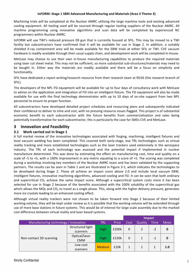
InFORM:Stage1SBRIAdvancedManufacturingandMaterials(Area3Theme3)
Strictly Confidential 11
MachiningtrialswillbecompletedattheNuclearAMRCutilisingthe largemachinetoolsandexistingadvancedcoolingequipment.All toolingusedwill be sourced through regular tooling suppliersof theNuclearAMRC.Allmachine programming using innovative algorithms and scan data will be completed by experienced NCprogrammerswithinNuclearAMRC.
InFORMwill useTWI’s reducedpressureEBgun that is currentlyhousedat SFIL. Thismaybemoved toaTWIfacility but subcontractors have confirmed that it will be available for use in Stage 2. In addition, a suitablyshielded X-ray containment areawill bemade available for the EBW trials at either SFIL or TWI. CVE vacuumhardwareisreadilyavailablethroughtheirusualsupplychain,anddevelopmentworkwillbecompletedin-house.
MetLasemay choose to use their own in-housemanufacturing capabilities to produce the requiredmaterialsusinglasercutsheetmetal.Thismaynotbesufficient,somoresubstantialsub-structures/materialsmayneedtobe bought in. Either way the materials are readily available and there will be a focus on simplicity andfunctionality.
SFILhavededicatedareportwriting/researchresourcefromtheirresearchteamatRD26(theresearchbranchofSFIL).
ThedevelopersoftheNPLFSIequipmentwillbeavailableforuptofourdaysofconsultancyworkwithMetLasetoadviseontheapplicationandintegrationofFSIintoanintelligentfixture.TheFSIequipmentwillalsobemadeavailable for usewith the final technology demonstratorwith up to 10 days of on-site support from twoNPLpersonneltoensureitsproperfunction.
All subcontractorshavedevelopeddetailedproject schedules and resourcingplans and subsequently indicatedtheirconfidencetodelivertotimeandcost,withnopressingresourceissuesflagged.Thisprojectisofsubstantialeconomic benefit to each subcontractor with the future benefits from commercialisation and sales beingpotentiallytransformativeforeachsubcontractor,thisisparticularlythecaseforSMEsCVEandMetLase.
3 InnovationandFeasibility3.1 WorkcarriedoutinStage1A fullmarket reviewof the innovative technologies associatedwith forging,machining, intelligent fixtures andlocal vacuumweldinghasbeencompleted. This coveredbothearly-stage, lowTRL technologies suchas virtualreality trackingandmoreestablished technologies suchas the laser trackersusedextensively in theaerospaceindustry. The TRL of each technology was assessed and the potential impact if implemented in nuclearmanufacturedetermined.Thiswasdonebyestimating theeffectonmanufacturingcost, timeandqualityonascaleof-5to+5,witha100%improvementinanymetricequatingtoascoreof+5.ThescoringwascompletedduringaworkshopinvolvingkeymembersoftheNuclearAMRCteamandhasbeenvalidatedbythesupportingpartners.TheresultscanbeseeninTable1andareillustratedinFigure3-1,whichindicatesthetechnologiestobe developed during Stage 2. These all achieve an impact score above 2.0 and include local vacuum EBW,intelligentfixtures,innovativemachiningalgorithms,advancedcoolingandFSI.Itcanbeseenthatbothordinaryand supercritical CO2 achieve the same impact score. Although a supercritical system costs more it has beenselected foruse in Stage2becauseof thebenefits associatedwith the100% solubility of the supercritical gaswhichallowstheMQLandCO2totravelasasinglephase.This,alongwiththehigherdeliverypressure,generatesmoreicecrystalsleadingtoanenhancedcoolingeffect.
Although virtual reality trackers were not chosen to be taken forward into Stage 2 because of their limitedworkingvolume,theywillbekeptunderreviewasitispossiblethattheworkingvolumewillbeextendedthroughuseofmorebasestationsinfuturesystems.Thiswouldbeofinterestforlargescaleassemblyduetothemarkedcostdifferencebetweenvirtualrealityandlaserbasedsystems.
ImpactManufacturingtechnology/innovation TRL Price Cost Quality Time Mean
Non-contact3Dscanning
Structuredlightscanners High £200k 0 2 -2 0
Optical/laserCMM High £150k 0 1 -1 0
Lowcostscanners Medium £10k 1 1 1 1.0
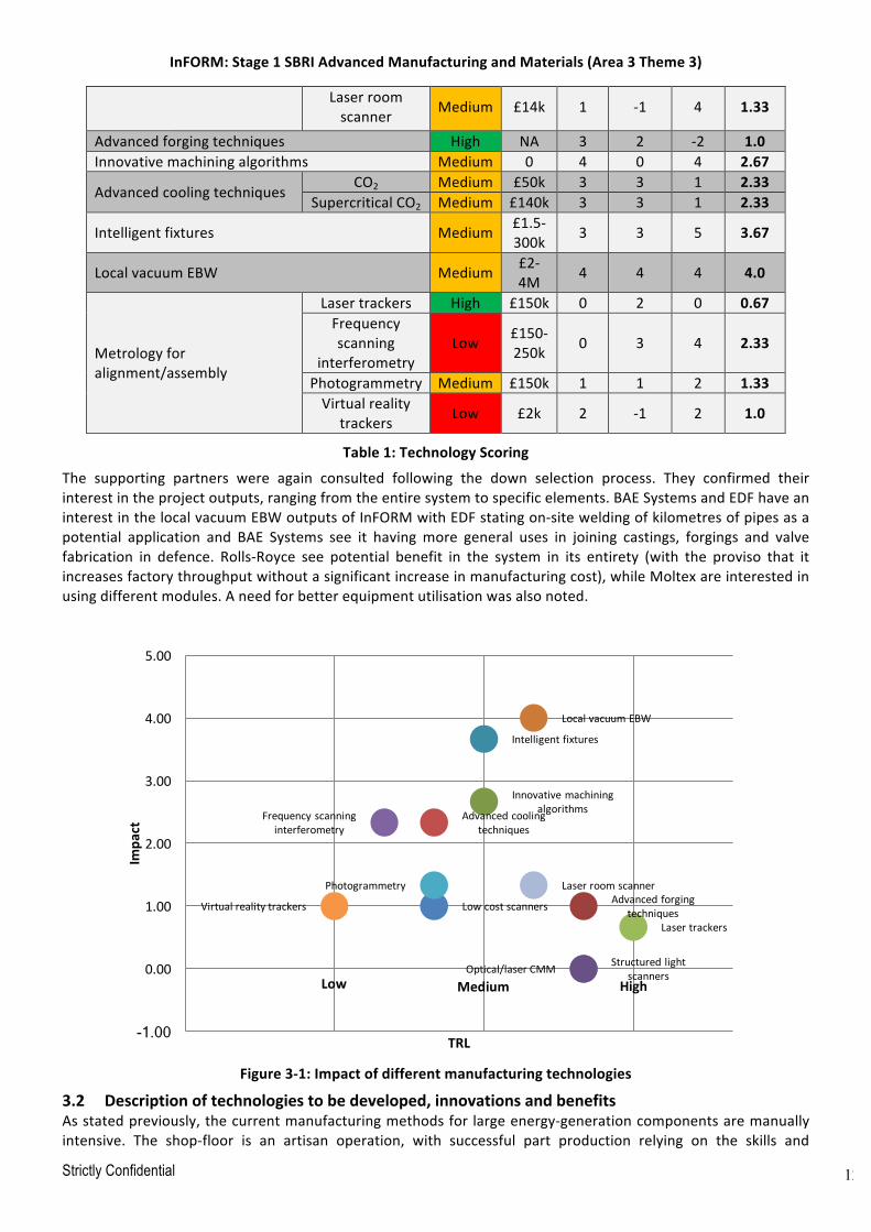
InFORM:Stage1SBRIAdvancedManufacturingandMaterials(Area3Theme3)
Strictly Confidential 12
Laserroomscanner Medium £14k 1 -1 4 1.33
Advancedforgingtechniques High NA 3 2 -2 1.0Innovativemachiningalgorithms Medium 0 4 0 4 2.67
AdvancedcoolingtechniquesCO2 Medium £50k 3 3 1 2.33
SupercriticalCO2 Medium £140k 3 3 1 2.33
Intelligentfixtures Medium £1.5-300k 3 3 5 3.67
LocalvacuumEBW Medium £2-4M 4 4 4 4.0
Metrologyforalignment/assembly
Lasertrackers High £150k 0 2 0 0.67Frequencyscanning
interferometryLow £150-
250k 0 3 4 2.33
Photogrammetry Medium £150k 1 1 2 1.33Virtualreality
trackers Low £2k 2 -1 2 1.0
Table1:TechnologyScoringThe supporting partners were again consulted following the down selection process. They confirmed theirinterestintheprojectoutputs,rangingfromtheentiresystemtospecificelements.BAESystemsandEDFhaveaninterestinthelocalvacuumEBWoutputsofInFORMwithEDFstatingon-siteweldingofkilometresofpipesasapotential application and BAE Systems see it havingmore general uses in joining castings, forgings and valvefabrication in defence. Rolls-Royce see potential benefit in the system in its entirety (with the proviso that itincreasesfactorythroughputwithoutasignificantincreaseinmanufacturingcost),whileMoltexareinterestedinusingdifferentmodules.Aneedforbetterequipmentutilisationwasalsonoted.
Figure3-1:Impactofdifferentmanufacturingtechnologies
3.2 Descriptionoftechnologiestobedeveloped,innovationsandbenefitsAsstatedpreviously,thecurrentmanufacturingmethodsfor largeenergy-generationcomponentsaremanuallyintensive. The shop-floor is an artisan operation, with successful part production relying on the skills and
Advancedforgingtechniques
Innovativemachiningalgorithms
Intelligentfixtures
LocalvacuumEBW
StructuredlightscannersOptical/laserCMM
Lowcostscanners
Advancedcoolingtechniques
Lasertrackers
Frequencyscanninginterferometry
Photogrammetry
Virtualrealitytrackers
Laserroomscanner
-1.00
0.00
1.00
2.00
3.00
4.00
5.00
Impa
ct
TRL
Low Medium High

InFORM:Stage1SBRIAdvancedManufacturingandMaterials(Area3Theme3)
Strictly Confidential 13
knowledgeof the technicians.Stage2will focusondeveloping the technologies selectedduringStage1; thesewill be showcased on a two-thirds scale technology demonstrator consisting of two large cylinders. Theinnovationsandbenefitsofeacharedescribed inthefollowingsections.Aconceptdrawingfor InFORMcanbeseen inFigure4-1andanR&Dprogrammeschematic is given inAppendix3.Theoverall innovative solution isbased on improvements in each part of the manufacturing lifecycle. The benefits of the technologies aresummarisedinTable2.
Technology Sectorbenefits
Optimisedforging Increasedconfidenceinforgingprocess
Closertonetshapeforgings
Lessmaterialtoremovefollowingforging
Reducedleadtimes
Innovativeroughingalgorithms
Reducednon-cuttingtime
Reducedmachinetimeasmoreefficienttoolpaths
Increasedmachineutilisation
Machinefromscandata Reducednon-cuttingtime
Reducedmachinetime
Increasedmachineutilisation
Advancedcoolingtechniques
Reducedcuttingtimeduetoincreasedcuttingspeeds
Noneedforcomponentcleaning(40%timesaving)
Reducedhealthrisksasnoneedforharmfulcoolants
Nocostfordisposalofspentcoolant
Keyenablerforsensorsonafixture
LocalvacuumEBW Markedlyquickerthanstandardarctechniques(hoursinsteadofweeks)
Takesuplessfloorspace(noneedforlargechamber)
Portable,single-pass,thick-sectionweldingwhichcouldbedeployedat-site
Intelligentfixtures Reducedsetuptimes
Reducedhealthandsafetyriskofmovingcomponentsaroundworkshop
Improvedpartqualitythroughfeedbackfromsensorstoclampingtoreducedistortion
ReducedassemblytimeduetoimprovedalignmentmethodsusingFSIwiththefixture
Reducedleadtimeduetoreducedsetuptimes,lessre-workrequiredduetoimprovedconfidenceinprocessthroughsensoryfeedback,quickeralignmentforfinalassembly
Table2:InFORMbenefitstothenuclearsector
3.2.1 ForgingAreviewwillbeconductedtoestablishanunderstandingof thegeometricdefinitionandtypicalgeometriesofnuclear components and theirmanufacturability. Reactor designs have limited scope for design changewhichresults in conservatism in the forging industry, where material allowances are not optimal during forging,resulting in unnecessarily high material costs and subsequent excessive machining operations to reach thespecifiedconditionofsupply.Inparticular,themorecomplexfeaturesandthemanufacturingprocessesrequiredwill be a focus of the investigation. Applying advancedmetrology techniques such as photogrammetry, whichInFORMwillcustomise/optimisefornuclearapplications,cangeneratelargequantitiesofdimensionaldata.Thedatacanbeusedtocontroltheforgingprocessandprovideadatarichenvironmentthatwillimproveforgingtooldesignand facilitate thehandlingandmanipulationof large forgings.Manipulation inparticularwillbea focusarea and a metrology driven approach will allow contact surfaces to be customised for a specific as forgedsurface,thesameapproachwillbeinvestigatedforfixturingapplicationinthesubsequentmachiningandweldingoperations.Agreatemphasisistraditionallyplacedontheforgingprocessatthepressstage,however,aholistic

InFORM:Stage1SBRIAdvancedManufacturingandMaterials(Area3Theme3)
Strictly Confidential 14
approachisrequiredthat looksatthesteelmakingprocessthroughallaspectsofmanufacturetothemachinedconditionofsupply (COS), totrulyoptimisetheproductionofnuclearcomponents. InFORMwill investigatethehollowingotforgingtechniqueinparallelwithmetrology,increasingthegeometriccontrolofthefinalforgingwillallownearernetshapepartstobeproduced.Itisthisholisticreviewofthemanufacturingprocessthatneedstobe conducted to maximise cost savings and ensure competitiveness in a global market. The scope of theinvestigationisdefinedbelow:
• Nuclearreactorcomponentdefinitiono Shells,tubesheets,othercomponentso Complexspecificfeatures
• Steelmakingo Airmeltingotso Vacuumstreamdegassingo Ingotroutecomparisono Materialchoiceso Manufacturingroute
• Componentdesignformanufactureo Forgetooling,forgingrouteso Handlingandmanipulation
• Materialpropertieso Heattreatmentoptions
• ComponentinspectionandsupplyAswellasthetechnicalinnovations,thereisanadditionalobjectiveofchangingthemindsetofUKmanufacturersfromconservatismtooneofconfidence,underpinnedbydataobtainedfromametrologydrivenapproachandapplication of intelligent fixtures. This data-driven approach is aligned to the principles of the 4th IndustrialRevolutionandessentialtomaximisetheopportunitiesofdatadrivenmanufactureandensurethefutureoftheUKforgingindustry.
3.2.2 MachiningOptimizedmachiningSpecialist CAM features targeted at improving the efficiency of machining operations such as iMachining andWaveformexistbutarenotapplicabletoturningoperationssuchasthoseusedwhenroughcuttinglargenuclearforgings.Aninnovativeapproachwouldbetousethescandatafromtheforgingprocesstoproduceanaccurateormore-representativeCOSmodel.ThiscouldthenbeimportedtotheCAMpackageandusedasstocktoreducethenumberof"freshair"cuts.ThispracticeisusedinotherindustrieswherethecomponentsaresmallerandtheCOSisnearernetshape,butnuclearcomponentsaretoolargeforthistobepossibleatpresent.
Thecurrentpracticeinnuclearistouseagenericturningcyclewithalargeoffsettoaccountforthevariationsintheoutsidegeometry.Thefollowingoptionsareavailableandwouldsignificantlyreducethemachiningtime:
1. Verticalmilling(stripmill)oftheexcessandthenturningtoachievearoundpart2. Turnmilling,whereboththecomponentandthetoolrotate3. Dividingthecomponentintoradialsectionsandcreatingabespokecycleforeach
Thefullbenefitsoftheaboveoptionsrequireascannedmodeltobeusedasstock.Thekeyenablerforusingscandataintheproductionofnuclear-sizepartsisamethodforreducingthefilesize.Atpresent,STLfilesgeneratedusingscanningtechnologiesareextremelylarge(typically100,000KBcomparedwith100-200KBforapartfileofthesamecomponent)andthisgreatlyincreasestheprogrammingtime.SFILcurrentlyuseascanaccuracyof±3mm as part of their quality check and to aid set-up, but this is not accurate enough to be used inmachiningmodels. Scannedmodels arenot used for CAMprogramming in thenuclear industry as it is seen as too time-consumingandproducesmorecomplextoolpaths.SoftwaresuchasVisi,GOMInspectandATOSProfessionalarecapable of reducing the file sizes throughmodel simplifications, or alternatively, a low-cost scanner could beused,yieldingalessaccuratemodelbutamoremanageablefilesize.Itisnecessarytostrikeabalancebetweenfile size and the requiredaccuracy.Moreefficientmachining algorithms for large forgingswould yieldmassivetimereductionswithverylittlemonetaryinvestment-atmost,newsoftwarewouldberequired.
InFORM:Stage1SBRIAdvancedManufacturingandMaterials(Area3Theme3)
Strictly Confidential 15
Touse thisapproach,accurate setup isneededso that featureson the forgingcanbe locatedon themachineotherwisethepart/tool/machinemaybedamaged.AccuratepositioningofmassiveforgingsisamajorchallengewhichwillbeaddressedbytheintelligentfixturesdevelopedinInFORM.
AdvancedcoolingformachiningAdvancedcoolingtechniquessuchasnear-cryogenicmachiningarerelativelyimmature,withtheiruselimitedtolaboratory or research centres. Literature14,15,16,17 suggests that the use of compressed CO2 in place ofconventionalcoolantsresultsin:
o Increasedproductivitythroughincreasedcuttingspeedso Improvedresistancetotoolwearo Reduceddisposalandcoolantcostso Lesssolidwaste,wasteoils,wastewaterandairpollutiono Reducedenvironmentalimpact(recycledCO2used)o Saferandcleanerworkingconditionso Noneedforcomponentcleaning
Innuclearmanufacture,40%ofmachiningcostsareduetocomponentcleaningwithanother20%duetocoolantcost.Theuseofcryogeniccoolantcouldeliminatecomponentcleaninganddrasticallyreducecoolant.Aswellasincreased cleanliness, the elimination of liquid coolant is a key enabler for the use of sensors in an intelligentfixture since their performancewould be significantly inhibited by the presence of coolant. Although very fewindustryapplicationsofthetechnologyareknown,offtheshelfcryogenicsystemsareavailableandcanberetro-fittedtoalmostanymachinetool.TheNuclearAMRChasexperienceofusingnearcryogenicmachiningona5-axis mill-turn machine as well as the recent installation of a supercritical CO2 system on a horizontal boringmachine. The effect of CO2 on the surface integrity of components is notwell investigated and appears to bematerialspecific.Researchison-goingwithintheNuclearAMRCintoitseffecton304LstainlesssteelandSA508pressurevesselsteel.Thereislimitedliteratureavailableforthesematerials;otherworkoncryogenicmachiningisnotrelevantbecauseitisgenerallycarriedoutonnickelandtitaniumalloyswhichhaveadifferentresponse.
Minimumquantitylubrication(MQL)canalsobeusedwithadvancedcoolingsystems.Thiswillnotaffectsensorsasverylittleisused;5-80ml/hourascomparedwith40,000ml/hourforfloodcoolant.ThetransportofMQLtothecuttingtoolisviatheCO2flow.TheadditionofMQLprovidestherequiredlubricityformachiningprocessesandliterature18suggeststhatitenhancesthebenefitsofCO2machining.
ThePure-Cut systemavailable fromFusionCoolantanddown-selected foruse in INFORMdelivers supercriticalCO2andMQLtothecuttingtoolasasingle-phasesystem.Thelubricant(MQL)thenseparatesfromtheCO2andpenetratesthefrictionzones,addingthemuch-neededlubricity.WorkisbeingcarriedoutbytheNuclearAMRCtoestablishsuitableparameters(coolantholesize,pressureetc)andtooling,beforescalingupthesetrialsonalargermachinewithmaterialsrelevanttothenuclearindustrywithinInFORM.
3.2.3 IntelligentFixturesAsinglefixturewillbedevelopedtofacilitatethetransferof largecomponentsthroughtheforging,machining,weldingandinspectionactivities.Thiswillreplacetheexistingapproachofusingmultiplefixturesandset-upsateach stage of the manufacturing process, and enable a through-life datum system to simplify componentalignmentateverymanufacturingstage.Apressurevesselismadebystackinglargecylindricalparts(tubulars)ontopofeachotherandweldingthemtogether,requiringaccuratealignment.Intelligentfixturesareakeyenablerforthisandforotheradvancedmanufacturingactivities;theywillallowfasterandmoreaccurateinspectionsto
14 B. Dilip Jerold and M. Pradeep Kumar, Experimental comparison of carbon-dioxide and liquid nitrogen cryogenic coolants in turning of AISI 1045 steel. Cryogenics, 2012. 52: p. 569 -574. 15 Dhananchezian, M. and M.P. Kumar, Cryogenic turning of the Ti–6Al–4V alloy with modified cutting tool inserts. Cryogenics, 2011(51): p. 34-40. 16 N R Dhar and M Kamruzzaman, Cutting temperature, tool wear, surface roughness and dimensional deviation in turning AISI-4037 steel under cryogenic condition. International Journal of Machine Tools & Manufacture, 2007. 47: p. 754-759 17 S Truesdale and Y Shin, Microstructural Analysis and Machinability Improvement of Udimet 720 Via Cryogenic Milling. Machining Science and Technology, 2009(13): p. 1-19 18 F Pusavec, et al., Surface integrity in cryogenic machining of nickel based alloy—Inconel 718, in Journal of Materials Processing Technology. 2011. p. 773 - 83.

InFORM:Stage1SBRIAdvancedManufacturingandMaterials(Area3Theme3)
Strictly Confidential 16
be carriedoutwhen integrating large complex assemblies. The fixtureswill contain sensorswhichwill providefeedback to actuators and manipulators. The sensors will be able to detect temperature and cutting forcesproviding data to inform adjustment of the clamping force so as tominimise distortion duringmachining andwelding.Asthecomponentchangesgeometryduringthemanufacturingprocess,thefixturewillknowwhereinthe process it is and adjust accordingly. Set-up procedures can also be optimised. They will be introducedfollowing forging and will allow accuratemetrology and inspection to be used throughout themanufacturinglifecycleviatheuseofafixeddatumpoint.Theywillalsoproducearobustdatasetthatcouldbeusedforotherpurposessuchastraceability,modelling,simulationanddesignimprovement.
AnumberofdifferentSMRdesignshavebeenproposedandeachofthesewillhaveuniquefixingrequirements.Thecostofdesigningandfabricatingindividualfixturescanbehighandseveralmightbeneededtomanufacturea single batch of parts. Their storage and maintenance adds further inconvenience (cost and space). Usingadaptive or reconfigurable devices designed for several component types will offer significant benefits tomanufacturers. Intelligent fixtures have been used in the automotive and aerospace sectors to help withpositioning (i.e. reference setting, datum transfer) and reduce the effect of deformation (i.e. vibrations,deflections, distortions etc.) induced by part size/geometry, process conditions or clamping itself. Sensors,includingthoseforactiveforcemonitoring,areoftenembeddedinlargeframesorcarriageswhichsupport,andtravel with, components throughout the manufacturing process. Figure 3-2 illustrates three smart fixturesequippedwithsensorsandactuatorswhichwerespecificallydesignedfordifferenttasks.
Figure3-2:(a)clampingforcecompensation;(b)residualstressescompensation;(c)toolpathcorrection19
Intelligentfixturesrequireawiderangeofsensorstomeasureandmonitorvariousparametersincluding:
o Temperatureandhumiditysensors–linkedtoheatingandcoolingsystemswhichhelptocontrolthermalexpansionoftheworkpiece,ensuringcomponentaccuracyandquality.
o Electronicstraingauges-tomeasureforcesactingontheworkpieceand/orfixture.Theyhelptoanalyseandpredicttoolcuttingforcesandtheloaddistribution,minimisingandcontrollingdistortion.
19 M., Hans-Christian, P., Wiederkehr, "Intelligent Fixtures for High Performance Machining." Procedia CIRP 46(2016):383-90.
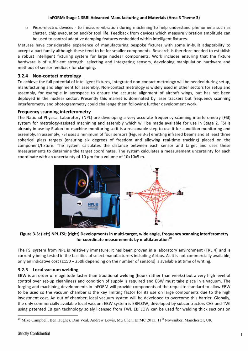
InFORM:Stage1SBRIAdvancedManufacturingandMaterials(Area3Theme3)
Strictly Confidential 17
o Piezo-electric devices - tomeasure vibrationduringmachining to helpunderstandphenomena such aschatter,chipevacuationand/ortoollife.Feedbackfromdeviceswhichmeasurevibrationamplitudecanbeusedtocontroladaptivedampingfeaturesembeddedwithinintelligentfixtures.
MetLase have considerable experience of manufacturing bespoke fixtures with some in-built adaptability toacceptapartfamilyalthoughthesetendtobeforsmallercomponents.Researchisthereforeneededtoestablisha robust intelligent fixturing system for large nuclear components. Work includes ensuring that the fixturehardware is of sufficient strength, selecting and integrating sensors, developing manipulation hardware andmethodsofsensorfeedbackforclamping.
3.2.4 Non-contactmetrologyToachievethefullpotentialofintelligentfixtures,integratednon-contactmetrologywillbeneededduringsetup,manufacturingandalignmentforassembly.Non-contactmetrologyiswidelyusedinothersectorsforsetupandassembly, for example in aerospace to ensure the accurate alignment of aircraft wings, but has not beendeployed in the nuclear sector. Presently this market is dominated by laser trackers but frequency scanninginterferometryandphotogrammetrycouldchallengethemfollowingfurtherdevelopmentwork.
FrequencyscanninginterferometryTheNational Physical Laboratory (NPL) aredeveloping a very accurate frequency scanning interferometry (FSI)system formetrology-assistedmachining and assemblywhichwill bemade available for use in Stage 2. FSI isalreadyinusebyEtalonformachinemonitoringsoitisareasonablesteptouseitforconditionmonitoringandassembly.Inassembly,FSIusesaminimumoffoursensors(Figure3-3)emittinginfraredbeamsandatleastthreespherical glass targets (ensuring six degrees of freedom and allowing real-time tracking) placed on thecomponent/fixture. The system calculates the distance between each sensor and target and uses thesemeasurementstodeterminethetargetcoordinates.Thesystemcalculatesameasurementuncertaintyforeachcoordinatewithanuncertaintyof10μmforavolumeof10x10x5m.
Figure3-3:(left)NPLFSI;(right)Developmentsinmulti-target,wideangle,frequencyscanninginterferometry
forcoordinatemeasurementsbymultilateration20
TheFSI system fromNPL is relatively immature; ithasbeenproven ina laboratoryenvironment (TRL4)and iscurrentlybeingtestedinthefacilitiesofselectmanufacturersincludingAirbus.Asitisnotcommerciallyavailable,onlyanindicativecost(£150–250kdependingonthenumberofsensors)isavailableattimeofwriting.
3.2.5 LocalvacuumweldingEBWisanorderofmagnitudefasterthantraditionalwelding(hoursratherthanweeks)butaveryhighlevelofcontrolover set-upcleanlinessandconditionof supply is requiredandEBWmust takeplace ina vacuum.TheforgingandmachiningdevelopmentsinInFORMwillprovidecomponentsoftherequisitestandardtoallowEBWto be used so the vacuum chamber is the key limiting factor for its use on large components due to the highinvestmentcost.Anoutofchamber, localvacuumsystemwillbedevelopedtoovercomethisbarrier.Globally,theonlycommerciallyavailablelocalvacuumEBWsystemisEBFLOW,developedbysubcontractorsCVEandTWIusingpatentedEBguntechnologysolely licensedfromTWI.EBFLOWcanbeusedforweldingthicksectionson 20 Mike Campbell, Ben Hughes, Dan Veal, Andrew Lewis, Mu Chen, EPMC 2015, 11th November, Manchester, UK

InFORM:Stage1SBRIAdvancedManufacturingandMaterials(Area3Theme3)
Strictly Confidential 18
largetubularcomponents.Therearetwoversions,usingeitherasystemofslidingsealsorfixedseals,toachievethe local vacuum. Although never used in manufacture it has been demonstrated on an industrial scale forcircumferentialweldsof65mmthicktubulars.Thegunandsealconfigurationusedisverymuchdependentonthe size and weight of the components to be joined. The required equipment is currently available as ademonstrator and would require modification to the sealing system to ensure a suitable vacuum for largecomponents.Additionalworkisalsoneededtoensurecompatibilitywiththefixturingsetup.Oncethesystemisfinalised,itcanberetro-fittedtoanexistingarcweldingsystem,takinguplessfloorspaceandrequiringfarfewerconsumables.Asanindication,aconventionalcircumferentialweldinaclass1nuclearpressurevessel,laiddowninamulti-passprocess,maytakearoundtwoweekstocomplete,includingcool-downandstagedvolumetricNDEbetweenpasses.Anequivalentweldcompletedusingtheelectronbeamprocesswilltakelessthantwohourstocomplete in a single pass. Tubulars for SMRwill probably bewelded in the 2G (bottom right) or 3G (top left)orientationsshowninFigure3-4.
Although beamwelding is specified in ASME IX, it is excluded by implication from themanufacture of class 1nuclear components because ASME III requires specification of a filler metal and a multi-pass procedure forwelding (beammethods are single pass and autogenous). A code case for electron beamwelding is currentlyunder development. EBW is commonly used in the aerospace sector in the manufacture of aircraft engines,sensors,gears,actuatorsandairframesaswellasfortherepairofturbineblades.OneoftheInFORMoutputsisto provide code case information for EBW. This links to a parallel AMEC project, which includes the NuclearAMRC, in theme 5 on codes and standards, andwill include information gathered from EBWpressure vesselsmanufactureinotherindustriessuchasoilandgasandoffshore.
Figure3-4:EBFLOWconfigurationsforcircumferentialweldingoftubularsections21
3.2.6 DemonstratorframeworkAtwo-thirdsscaletechnologydemonstratorwillbemadeconsistingoftwolargecylinders(around2mdiameter,atleast80mmthick)tointegratetheInFORMtechnologiesandshowcasetheresultstosupplychaincompanies. 21 Cambridge Vacuum Engineering, EBFLOW Leaflet, Cambridge, UK
InFORM:Stage1SBRIAdvancedManufacturingandMaterials(Area3Theme3)
Strictly Confidential 19
Thedemonstratorandassociatedframeworkwillincludedatastandardsandarchitecture,controlmethodology,softwaredevelopment,systemspecification,procurement,commissioning,testingandoptimisation.Stateoftheartnon-contactmetrologywillbeappliedandintegratedtosupporttheforging,machiningweldingandassemblyactivities.
3.3 TechnicalfeasibilityInFORMwill employmedium-to-highTRL technologieswhichhave seenuse inother industries. Formachining,theuseofinnovativealgorithmsisonlynewtothenuclearindustry.Theuseofmorecomplexroughingstrategiesiswidelyusedandacceptedintheaerospaceindustryforexampleandtheyarereadilyavailableincommerciallyavailable CAMpackages. The use of scan data to generate amore accurate stockmodel is also used in otherindustriesbutforsmallercomponents.Advancedcoolingtechniques,althoughnotyetwidelyusedandfairlylowontheTRLscale,arecommerciallyavailableandareunderinvestigationattheNuclearAMRC.Intelligentfixtureshave seen successful use in other industries andMetLase have an outstanding track record in this area. Therelevant sensors are also available along with structural, manipulation and actuation hardware and accuratemeasurementandtrackingsystemsarereadilyavailableforalignment.ThelocalvacuumEBFLOWsystemownedbyTWIisavailableforuseatSFIL.TherequiredmodificationstothesealingsystemwillbecompletedbyCVE.Thisiswellwithintheircapabilitygiventheirextensiveknowledgeofthefield.
3.4 Cross-sectorcollaborationInFORM will build on previous research which has delivered complementary technologies and will providevaluable leverageandskills.TheNuclearAMRCwillalsointeractwithcontractors forthemes1and5withinthiscall,andInFORMhasstronglinkswithparallelprogrammessuchasSIMPLE(whereitisalsoleadcontractor).Otherlinkedprojects,include:
o NNUMAN – £8M, fiveyear EPSRC-funded programme to provide understandingof advancedmanufacturing techniques led by The University ofManchester Dalton Nuclear Institute, with supportfromtheNuclearAMRC.
o AMOS – The Nuclear AMRC are leading this €2.6M, four-year collaboration between European andCanadian aerospace manufacturers and researchers to investigate the use of additive manufacturingtechniquesforrepairandremanufacture.
o Innovative forging and fabrication solutions for the energy sector – a £4M, 30-month project led bySheffieldForgemasters.Theprojectinvolvestheproductionoflargeprototypenuclearcomponentsusingarangeofforging,formingandfabricationmethods.
o COROMA–theNuclearAMRCareworkingalongsideitssistercentre,theAMRCwithBoeing,onthis€6million, three-year project to develop intelligent robots for a range of manufacturing tasks. FundedthroughHorizon2020,theCOROMAconsortiumincludes16internationalpartnersfromsevencountries.
4 TechnologyPlan4.1 ScopeofthecallCost-effectivenuclearpowerisanecessarypartoftheUK'slowcarbonenergymixandtosupportthis,researchisneededtodeliverGovernmentpolicy.Theaimoftheadvancedmanufacturingandmaterialscall istostimulateinnovation in the civil nuclear sector; work can include research into structural materials, manufacturingtechnologiesandmodularconstructionandprojectscandevelopnewtechnologiesortransfertechnologiesfromother sectors. InFORM will transfer technologies from aerospace and other industries, developing them tomanufacturingreadinesslevel(MRL)6inlinewithnuclearrequirements.InFORMwilldeliveraphysicaltwo-thirdsscaletechnologydemonstratortohighlightthepotentialtimeandcostsavingsthatcanbeachieved.
Projects should boost growth and reduce costs in the nuclear industry. InFORM will significantly reducemanufacturingtimeandcostforpressurevesselsandsimilarcomponents,andtransferofthesetechnologiestoUKcompanieswillthereforemakethemmorecompetitiveandabletocompeteforcontractsonGenIIIandSMRplants worldwide. InFORM will help develop the UK's manufacturing base and contracts won for new globalreactorswillallowthemtooperatewithasignificantnumberofUK-manufacturedcomponents,meetingtheaimsofthefive-yearintegratedprogrammeassetoutintheguidanceforapplicants.
The NIRAB report4 lists a number of research objectives for 2020, including developing the UK's researchcapability, developing a suite of advanced component manufacturing techniques and delivering a suite ofmodularconstructiontechnologiestoenableeffectiveplantbuilt.InFORMparticularlyaddressesthesecondgoal,

InFORM:Stage1SBRIAdvancedManufacturingandMaterials(Area3Theme3)
Strictly Confidential 20
asitwilldevelopanend-to-endmanufacturingmethodforpressurevesselsandsimilarcomponentsthroughtheforging,machining,weldingandfixturingdevelopmentsandwilldeliverimprovedqualityassurancewithreducedcostandleadtimes.Forthesub-goal'largescalenuclearcomponentmanufactureandassembly'(theme3ofthecompetition), InFORM addresses all the areas mentioned: large scale metrology, complex machining of largecomponents, integrated unit inspection and distortion and controlmitigation. Itwill develop anddemonstratetechniques for precision manufacture of large-scale nuclear components through the forging and machiningworkstreams.Itwilldemonstratetechniquesforlarge-scalemetrologyduringforgingandmethodsforcontrollingandmitigatingdistortionthroughtheuseofintelligentfixtures.Theoutputsatstage2shouldinclude22:
o Solutions for off-site manufacture of large-scale components - InFORM will develop methods tomanufacturepressurevesselsandsimilarcomponentsinUKfactories
o Demonstration of advanced techniques for precision machining of large, complex, integrated nuclearcomponentssuchasSMRmodulesandheatexchangers - InFORMwilldemonstrateadvancedprecisionmachining techniques on a two-thirds scale technology demonstrator, whose geometrical constituentsarerepresentativeofothernuclearcomponentssuchasheatexchangers
o Demonstration of techniques to control and mitigate distortion during machining - InFORM willdemonstrate the use of through-life intelligent fixtures using the two-thirds scale technologydemonstrator. These fixtures will be able to control and compensate for distortion induced duringmachining
o Demonstration of non-intrusive rapid inspection and measurement techniques - InFORM willdemonstratethesethroughthefixtures,whichwillincludesensorstoenableinspectionduringoperationsandfollowingintegrationofassemblies.ItwillalsoreducethenumberofinspectionsrequiredduringtheweldingoperationduetotheintroductionofEBW.
o A forward programme to define the requirements of the remainder of the 5-year funding period -InFORMwilldeliverthisaspartofthefinalstage2report.
TheInFORMprojectasproposedisc£100Kovertheapproximatebudgetof£1.1Mat£1.26M.Thisisduetomorerigorous specificationof theWPsand theadditionofNPLasa subcontractor followingdown-selectionof theirtechnology in Stage 1. The InFORM cost could be reduced by £70k if WP2.1 was removed. However, theinterdependencybetweentheworkpackagesmeansthatanyfurtherreductioninscopewouldhavedetrimentalconsequences on the final output. Alternatively, the approximate budget for theme 2 is £1.9M and NuclearAMRC’s proposed SIMPLE project is c£600k less than this, part of which could be used to fund the proposedoverspendinInFORM.InFORMdoesnotrequestmorethan50%ofcostsforcapitalequipmentandwillfinishinJune2019.
4.2 TechnologyplanThe focus of Stage 2 is the development of a two thirds-scale proof-of-concept technology demonstrator. Adrawing of the project outputs can be seen in Figure 4-1.WPswill be delivered by specific subcontractors asdescribedbelow.
22 "Competition specification and guidance for applicants", Nov 2016, BEIS, IUK and SBRI

InFORM:Stage1SBRIAdvancedManufacturingandMaterials(Area3Theme3)
Strictly Confidential 21
Figure4-1-DrawingofInFORMprojectoutputs
4.2.1 WP2.1.ForgingOptimisation(SFIL)SheffieldForgemasterswillleadthisWPandwillinvestigatethepotentialforprocessimprovementintheforgingof large nuclear components. This task will last six months and deliver a report including the definition of anuclear component, anoverviewof the steelmakingprocess (airmelt ingots, vacuum streamdegassing, ingotroutecomparison,materialchoice),andcomponentdesignformanufacture(forgetooling, forgingroutes,shelldiscs, other components, handling and manipulation, heat treatment, material properties and componentinspection).Thiswillcost£67K.
4.2.2 WP2.2.MachiningOptimisation(NuclearAMRC)The Nuclear AMRC will develop the advancedmachining technologies selected in Stage 1, including near netshapemachining, advanced roughing algorithms and advanced coolingmethods to increase productivitywhenmachiningtheroughforgingstofinalsize.Thiswillinvolvethefollowingtasks:
• Task1–Nearnetshapemachiningo MachiningtrialsonVTLoverthecourseof2monthsatacostof£24k
• Task2–Advancedroughingalgorithmso MachiningtrialsonVTLoverthecourseof2monthsatacostof£24k
• Task3–SupercriticalCO2machiningo MachiningtrialsonVTLoverthecourseof2monthsatacostof£31.5k,involvingmachiningtrials
onrepresentativeworkpiecestocomparetheperformanceofdifferentroughingstrategiesusingscan data in terms of cycle time and quantify the productivity benefit (if any) and effect onsurfaceintegrityofmachiningusingsupercriticalCO2.
4.2.3 WP2.3.IntelligentFixture(MetLase)MetLasewilldevelopathrough-lifefixturewhichwill interfacewiththeothertechnologies(forging,machining,weldingandmetrology).Thiswilladdressthetypicalchallengesinvolvedinthemanufactureoflargecomponentssuchaswork-holding,parttracking,manipulation,alignment,datumsetting/transferandprocessinteraction.Thishasbeenbrokendownintofivesubtasks:
• Task1–Locationstudy–Thistaskwilldevelopanunderstandingofthecomponentsandprocesseswithinthemanufacturing system thatwill interactwith the fixture. The fixed through life datumwill also bedefined.Thistaskwilltakeplaceoverthecourseof3monthsatacostof£9k.
• Task2–Concept generation– This taskwill generate a systemconcept encompassingmechanical andsensory elements based on the information gathered in task 1 relating to the fixture and processrequirements. It will include a location, clamping and sensory concept and definition of a fixturearchitectureconcept.Thedurationofthistaskwillbe2monthsatacostof£9k.
InFORM:Stage1SBRIAdvancedManufacturingandMaterials(Area3Theme3)
Strictly Confidential 22
• Task 3 – Structural design – Thiswill involve in-depth structural design and simulation building on theconcept design to ensure that the fixture will meet the structural demands of handling such largecomponents.Simulationwill involvebothstaticandmanipulationsimulations.AsoneofthemaintaskswithinthisWP,thiswilltakeplaceover4monthsatacostof£36k.
• Task 4 – Actuation and sensing design. This task will transform the fixture into an intelligent fixturethroughthedesignoftherequiredactuationandsensorsystems.Astheotherkeytask inthisWP,thiswilltakeplaceover4monthsatacostof£36k.NPLwillalsocontributetothistaskthroughconsultancysupporttoMetLaserelatingtotheuseandintegrationofFSIintheintelligentfixture.NPLwillcontributeup to fourdaysofmetrology relatedconsultancy in thisWPata costof£4K tohelpMetLasewith theintegrationofFSIintotheintelligentfixture.
• Task 5 – Producemicro-demonstrator – The output of this task will be a 3D printedmock up/micro-demonstratorthatwillbeusedtoshowcasetheconcepttoindustryandwillbeusedinSTEMactivities.Thiswillbecompletedover2monthsatacostof£3k.
ThedeliverablesassociatedwiththisWParetheresponsibilityofMetLaseandinclude:
• Processandlocationmethoddefinition(Month4)• Conceptfixturesystemproposed(Month6)• Fixturingsystemdesigned(Month10)• Micro-demonstratorproduced(Month11)
4.2.4 WP2.4.LocalVacuumDevelopment(TWI)ThisWPwill be led by TWI and relevantworkwill be sub-contracted to CVE. It will involve design, build andtesting of a local vacuumend effector sub-system (weld cap side) and backing vacuum sub-system (weld rootside) to generate andmaintain the required vacuumenvironmentof 0.1mbar or better resulting in anout ofchambervacuumsystemforusewithbothEBWandlaserweldingsystems.ItwillalsoinvolvethemodificationofanexistingTWIEBsystemcurrentlyhousedatSheffieldForgemasters(butmaymovetoTWI)toensureadequatesealing for EBWof large scale tubulars of 80mmwall thickness. CVEwill conduct FATof themodified systemincluding demonstration of vacuum performance when in motion. TWI will conduct SAT. Nuclear AMRC willsupplysuitablesub-scaledemonstrationmetalworkforthetestingofthevacuumsystem.
ThedeliverablesassociatedwiththisWPare:
• Engineering design of end effector and backing vacuum sub-systems incurring a £38.7k labour cost(month2).
• Buildendeffectorsub-systemandbackingvacuumsub-system(month4)atacostof£232kbrokendownasfollows:
o CVE–Hardwaresupply(£30k),Labour(£70k)o TWI–Labour(£132k)
• Producetechnicalreportontestingandoptimisationactivities(month8)atacostof£5.4k.
4.2.5 WP2.5.Localvacuumtrial(TWI)TWI will integrate the chamber vacuum system developed in WP2.4 with the welding process and then testweldingparametersforuseinWP2.6.Thisworkpackagewilltakeplaceoverthecourseofsixmonths.TWIwillsupport Nuclear AMRC through deployment of hardware produced inWP2.4 to demonstrate EBwelding anddetermine the early stage weld properties attainable; weld procedure and property optimisation will not beundertaken. Welding orientation will be 2G or 3G using a suitable TWI rotary table and conditions will bedevelopedwhichacknowledgetheneedforlowlevelsofdistortion.Keyprocessvariableswillbealteredtodefinea viable operating tolerance window. Metallography, radiography and limited mechanical testing will beperformed to check weld integrity. The same scale of weldment designed around inWP2.4 will be used andsuppliedbyNuclearAMRCinanappropriategradeofSA508steel.TheoutputsofthisWPwillenablethefutureupscaling to a two thirds scale pressure vessel demonstrator. TWIwill produce a report documenting allworkcompleted along with recommendations for upscaling the system for welding of a two thirds scale vesseldemonstrator.ThedeliverablesassociatedwiththisWPare:
• Producetechnicalreportonweldingandtestingprogramme(month12)atacostof£5.4k.• Deliverables include weld section, test pieces and welded residual material (month 12) at a cost of
£148.3kconsistingofmainly labourcostsbutalsoaround£10kofconsumablesand20kof travelasEB

InFORM:Stage1SBRIAdvancedManufacturingandMaterials(Area3Theme3)
Strictly Confidential 23
activity will be undertaken using TWI equipment currently located at SFIL. There will also be a £30Kfacilitychargeif itremainsatSFIL,otherwiseanequaltransportcostfortransferoftheequipmenttoaTWIfacilitywillbeincurred.
4.2.6 WP2.6.Metrology(NuclearAMRC)ThisWPwillbeledbyNuclearAMRCandwill looktoinvestigateanddevelopmetrologytechniquesrelevanttoeacharea(forging,machining,weldingandassembly).Atechnicalreportwillbeproducedforeachsubjectarea.
• Forgingmetrology-£9.8k• Machiningmetrology-£9.8k• Welding(geometric)metrology-£19.6k• Fabrication/assemblymetrology-£19.6k
4.2.7 WP2.7.Technologydemonstrator(AMRC)Aphysicaltwo-thirdsscaletechnologydemonstratorwillbemanufacturedconsistingoftwocylindersaround2mdiameterandatleast80mmthickinordertotest,validateanddemonstratethetechnologiesdevelopedduringInFORM.Thematerialsusedinthisandanyweldtrialswillbetransferredtotheme1deliverypartnersfollowingcompletionofthisWP.
Before thedemonstratorcanbebuilt thesoftware for the integrationof thevarioussensorsandmanipulationhardware must be integrated. This will be the responsibility of the AMRC with Boeing and will involve thefollowingtasks:
• Agreementandfinalisationofdatastandardswithconsortiummemberswilltakeplaceoverthecourseoftwomonths involving aworkshopwith subcontractors to establish a data standardwithwhich all aresatisfied.Cost£11.2K
• Definitionofacontrolmethodologywilltake20daystocompletecosting£11.2Kandwillinclude:o Acontrolrequirementsgatheringexercise(3days)o Developmentofthecontrolmethodologyspecification(12days)o Finaldefinitionofthecontrolmethodologyspecification(5days)
• Developmentandtestingofthedataacquisitionsoftwarewilltake34dayscosting£30Kandwillinclude:o Determining the data acquisition requirements including sources of data and data output
formats.(4days)o Definitionofdataacquisitionrequirements(1day)o Determiningdataacquisitionsoftwareandhardwarerequirements(2days)o Procurementofdataacquisitionsoftware/hardwareincludingsourcingandpurchase(1day)o Definitionofdataacquisitionsoftwarerequirements(3days)o Dataacquisitionsoftwaredesign(5days)o Dataacquisitionsoftwaredevelopment(15days)o Dataacquisitionsoftwaretesting(3days)
• Developmentandtestingofdatapresentationsoftwarewilltake26dayscosting£14.8Kandwillincludethefollowingsub-tasks:
o Definitionofdatapresentationsoftwarerequirements(3days)o Designofdatapresentationsoftware(5days)o Developmentofdatapresentationsoftware(15days)o Testingofdatapresentationsoftware(3days)
• Definition of the system specificationwill take 12 days costing £12.5K, led by AMRCwith BoeingwithinputfromNuclearAMRCtodefinethesystemstructureandspecification.
Followingsuccessfuldevelopmentandtestingofthesoftware,theNuclearAMRCwilltakeresponsibilityfortheprocurement of all necessary hardware for the technology demonstrator with a budget of £40k, followed bycommissioningandtestingofthedemonstratoratacostof£33.2kand£78.4krespectively.NPLwillprovide20person days of on-site support during commissioning and testing of the demonstrator to integrate anddemonstrateFSIworkingwiththeintelligentfixturecosting£26K.Afurthermonthwillbeallowedforoptimisingthesystematacostof£14.3k.Atechnicalreportwillalsobeproduceddetailinganyfindingsassociatedwiththedemonstrator and recommendations for further development work. At the completion of this stage, materialsampleswillbemadeavailabletoTheme1.

InFORM:Stage1SBRIAdvancedManufacturingandMaterials(Area3Theme3)
Strictly Confidential 24
4.2.8 WP2.8.Dissemination(NuclearAMRC)NuclearAMRCwilltakeresponsibilityfordissemination;thiswillincludealldisseminationactivitiesatatotalcostof£94ktobedeliveredduringanduponcompletionoftheR&DWPsandwillincludethefollowing:
• Aseminarwiththesupportingpartnerstopresentthefindingsoftheproject.• STEM interactionwill bemade usingMANTRAwith theMetLasemicro-demonstrator accompanied by
videosoftheoperatingtwothirdsscaletechnologydemonstrator.• Industry engagementwill be achieved through utilisation of relevant technical personnel to produce a
journalpaperandthreeconferencepapers.Keymembersoftheprojectteamwillengagewithindustryattrade shows and similar events along with the micro-demonstrator and videos of the large-scaletechnologydemonstrator.
4.2.9 WP2.9.Projectmanagement(NuclearAMRC)Theapproachtoprojectmanagementisdescribedindetailinsection5andcosts£105K.ThisworkpackagewillbecarriedouttheNuclearAMRCandincludesthewritingofacomprehensivefinalreport.AttheendofStage2,a fullydetailed technologyandprojectplan for thepre-commercialisationphasewillbedelivered. If Stage2 issuccessful,thiswillincluderecommendationsregardingthecontinuationoftheprojectanditsintegrationwithinInnovateUK’sfive-yearR&Dprogramme,includingthefuturedevelopmentofafull-scaledemonstrator.
4.3 WorkbeyondStage2DuringPhase2,atwothirdsscalepressurevesselwillbemanufacturedusingallthetechnologiesdemonstratedinStage2.Thesewillbefurtherdevelopedforlargescalemanufacture,resultinginafullycommercialisedsystemwhichcanbesoldtoUKpressurevesselmanufacturers.Specifically,workwillincludeextensiveweldingtrialstooptimise the local vacuumEBWsystem fornuclearpressure vessels andestablish anoperatingwindowwithinwhichapprovedweldsareconsistentlyachieved.Furtherdevelopmentoftheintelligentfixturewillbecompletedand a new fixture will be made for full scale manufacture of pressure vessels. The FSI system will also bedevelopedfurtherbyNPLtoensurerobustnessandrefinethesystemreadyforcommercialisation.Theendresultbeingacommerciallyavailable intelligentfixtureforpressurevesselmanufacture.TheassociatedsoftwaremaybetakenonbyaUKsoftwareprovidertofurtherrefineitintoacommercialsoftwarepackagereadyforsalestoUKmanufacturers.ThisworkwilllinktoparallelprogrammesattheNuclearAMRC:
• Innovativeforgingandfabricationsolutionsfortheenergysector• Reactorpressurevesseldemonstrator–EPRI
Phase 2 is expected to cost in the region of £5-6M over the course of 2-3 years. This will fund the furtherdevelopmentworktocommercialisetheInFORMsystem,produceapre-productionprototypelocalvacuumEBWsystemandthemanufactureofthelargeforgingsrequiredforatwothirdsscalevesseldemonstrator.
4.4 CommercialisationProcessimprovementsidentifiedthroughworkcompletedbySFILaspartofInFORMwillbeutilisedimmediatelyin SFIL production processes provided that there is sufficient confidence in the results. Otherwisemodelling/simulation and validationwould be required. Themodelling and simulationwould take place in theearlystagesofPhase2,describingthefinalprocesswhichwouldbeusedtomanufacturetherequiredtwothirdsscaleforgingstoproduceascalednuclearvessel.
EBFLOWisalreadycommerciallyavailableandnearmarketsaturationhasbeenachievedinthewindturbineandoilandgasindustries.FollowingthedevelopmentoftheexistingTWIsysteminStage2,Phase2wouldinvolvethesupplybyCVEofapre-productionprototypesuitable forSMRweldingoperations.Thiswouldbeeithermobile(site deployable) with a target price of £5M or factory-based with a target price of £3M. Building a nuclearpressure-vessel-readyEBFLOWsystemwouldtakearoundninemonthsfollowingthedevelopmentworkofStage2.TakeupofthetechnologyinthenuclearindustrydependsonnuclearcodecaseapprovalofEBW.TWIwouldexpecttoundertakeaconsultancycontractof£250kpersystemtoassistwithspecificcustomerimplementationissues.Thecosts for thedevelopmentwork inStage2 is£430kand£3M foranon-commercialpre-productionprototype inPhase2withananticipatedprivate investmentbyCVEof£1M.Theaimwouldbe toachieve twosystemsalesbetween2023and2025witharevenueof£10.5MgivinganROIof3:1and10salesbetween2025and2030resultinginarevenueof£52.5MandROI12:1.
ThecommercialisationplanaftertheendofPhase1,Stage2fortheintelligentfixtureisshowninFigure4-2.
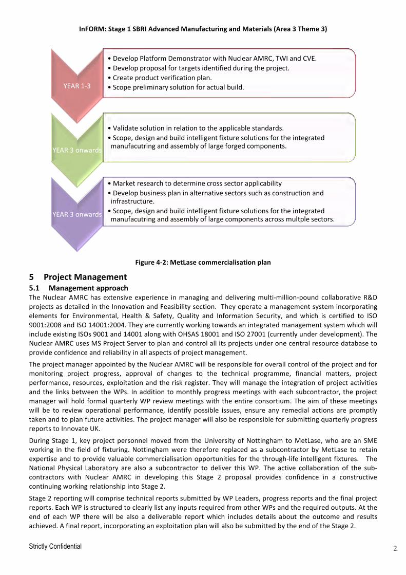
InFORM:Stage1SBRIAdvancedManufacturingandMaterials(Area3Theme3)
Strictly Confidential 25
Figure4-2:MetLasecommercialisationplan
5 ProjectManagement5.1 ManagementapproachTheNuclearAMRChasextensiveexperience inmanaginganddeliveringmulti-million-poundcollaborativeR&DprojectsasdetailedintheInnovationandFeasibilitysection.Theyoperateamanagementsystemincorporatingelements for Environmental, Health & Safety, Quality and Information Security, and which is certified to ISO9001:2008andISO14001:2004.TheyarecurrentlyworkingtowardsanintegratedmanagementsystemwhichwillincludeexistingISOs9001and14001alongwithOHSAS18001andISO27001(currentlyunderdevelopment).TheNuclearAMRCusesMSProjectServertoplanandcontrolallitsprojectsunderonecentralresourcedatabasetoprovideconfidenceandreliabilityinallaspectsofprojectmanagement.
TheprojectmanagerappointedbytheNuclearAMRCwillberesponsibleforoverallcontroloftheprojectandformonitoring project progress, approval of changes to the technical programme, financial matters, projectperformance,resources,exploitationandtheriskregister.Theywillmanagethe integrationofprojectactivitiesandthe linksbetweentheWPs. Inadditiontomonthlyprogressmeetingswitheachsubcontractor, theprojectmanagerwillholdformalquarterlyWPreviewmeetingswiththeentireconsortium.Theaimofthesemeetingswill be to review operational performance, identify possible issues, ensure any remedial actions are promptlytakenandtoplanfutureactivities.TheprojectmanagerwillalsoberesponsibleforsubmittingquarterlyprogressreportstoInnovateUK.
During Stage1, keyproject personnelmoved from theUniversityofNottingham toMetLase,whoare an SMEworking in the field of fixturing.Nottinghamwere therefore replaced as a subcontractor byMetLase to retainexpertiseandtoprovidevaluablecommercialisationopportunities forthethrough-life intelligent fixtures. TheNational Physical Laboratory are also a subcontractor to deliver thisWP. The active collaboration of the sub-contractors with Nuclear AMRC in developing this Stage 2 proposal provides confidence in a constructivecontinuingworkingrelationshipintoStage2.
Stage2reportingwillcomprisetechnicalreportssubmittedbyWPLeaders,progressreportsandthefinalprojectreports.EachWPisstructuredtoclearlylistanyinputsrequiredfromotherWPsandtherequiredoutputs.Attheend of eachWP therewill be also a deliverable report which includes details about the outcome and resultsachieved.Afinalreport,incorporatinganexploitationplanwillalsobesubmittedbytheendoftheStage2.
YEAR1-3
• DevelopPlatformDemonstratorwithNuclearAMRC,TWIandCVE.• Developproposalfortargetsidentifiedduringtheproject.• Createproductverificationplan.• Scopepreliminarysolutionforactualbuild.
YEAR3onwards
• Validatesolutioninrelationtotheapplicablestandards.• Scope,designandbuildintelligentfixturesolutionsfortheintegratedmanufacutringandassemblyoflargeforgedcomponents.
YEAR3onwards
• Marketresearchtodeterminecrosssectorapplicability• Developbusinessplaninalternativesectorssuchasconstructionandinfrastructure.• Scope,designandbuildintelligentfixturesolutionsfortheintegratedmanufacutringandassemblyoflargecomponentsacrossmultplesectors.

InFORM:Stage1SBRIAdvancedManufacturingandMaterials(Area3Theme3)
Strictly Confidential 26
Aswell as the formal project reviewmeetings referenced above, the sub-contractorswill arrangemeetings asrequiredtocarryouttheirWPsandexchangeinformation.Theprojectmanagerwillhavethefinalsayregardinganydecisionswhichaffecttheoverallprojectsuccess.TheprojectmanagerwillbethepointofcontacttoIUK/BEIS.Communicationswillprimarilybe through thequarterlyprogress reportsand final report,withadditionalmeetingsifrequired.
5.2 InteractionwithotherThemesAppendix3 indicateshowtheInFORMprojectplansto interactwiththeotherthemesintheNuclearAdvancedManufacturingandMaterialsCompetition. TheNuclearAMRCis involvedinalltheotherthemeseitherasleadcontractororsubcontractorandthereforeisanaturalhubforinteractionofthefivethemestoleveragethebestvalue from each project. For example,material samples from Themes 2 and 3 demonstrators can be used byTheme1tointegratetheprojectsandreducecost.Inordertoliaisewiththecontractorsleadingotherthemeswithin the programme, the Nuclear AMRC is offering to manage an ‘Advanced Manufacturing and MaterialsProgrammeBoard’whichwill includerepresentatives fromeachof thefivethemes.Followingan initialkick-offmeeting, the board will have quarterly meetings to deliver an integrated programme with complementaryprojectsbeforedelivering anendof project reviewacross all the themes.Communicationbetween the themeleaderswill ensure that theprogrammeavoidsduplicationbetweenprojectsandoffers innovative solutionsatthebestvaluetotheUKsupplychain.
5.3 Projectresourceplan–Seeappendix15.4 KeydeliverablesandmilestonesTable3liststhedeliverablesandmilestonesfromtheGanttchartandthemonthnumbersinwhichtheyaredue.Thesewill be demonstrated at the quarterly reviewwith Innovate UK and the table shows that therewill bedeliverablesthatwillbedemonstratedateachofthesereviewsthroughoutthe20monthproject.
Deliverable/Milestone Month QuarterlyReview
WP2.1InterimReport 3 1
WP2.1TechnicalReport 6 2
WP2.2NNSMachiningInterimReport 3 1
WP2.2AdvancedroughingalgorithmsInterimReport 5 2
WP2.2TechnicalReport 7 3
WP2.3ProcessandLocationmethoddefinition 4 2
WP2.3Conceptfixturesystemproposed 6 2
WP2.3FixturingSystemdesigned 10 4
WP2.3Micro-demonstratorproduced 11 4
WP2.4Engineeringdesigninterimreport 3 1
WP2.4Endeffectorbuild,interimreport 5 2
WP2.4TechnicalReport 9 3
WP2.5Localvacuumtrial,technicalreport 13 5
WP2.6Forgingmetrologytechnicalreport 9 3
WP2.6Machiningmetrologytechnicalreport 7 3
WP2.6Weldingmetrologytechnicalreport 7 3
WP2.6Fabricationmetrologyreport 13 5
WP2.7Finalisedatastandards 3 1
WP2.7Dataacquisitioninterimreport 5 2
WP2.7Datapresentationinterimreport 7 3
WP2.7SystemSpecification 8 3

InFORM:Stage1SBRIAdvancedManufacturingandMaterials(Area3Theme3)
Strictly Confidential 27
WP2.7Commissioning,interimreport 15 5
WP2.7Testing,interimreport 17 6
WP2.7Optimisationtechnicalreport 18 6
WP2.8Disseminationreport 19 7
WP2.9Finalreport 20 7
Table3.Keydeliverablesandmilestones
5.5 RiskregisterAriskanalysishasbeencarriedout,consideringrisksrelatedtoeachmilestoneanddeliverableaswellasproject,management and exploitation risks. Mitigation strategies and contingency plans are shown in the top-levelregisterbelow.The risk registerwillbe reviewedeverymonthduring theproject reviewmeetingandanynewrisksthatthreatenthedeliveryoftheprojectwillbecapturedandamitigationplanwillbeagreed.Theregisterwillbevisibletotheprojectsubcontractorsandsupportingpartners.Asthe leadcontractorof InFORMall risksareownedbyNuclearAMRC.
W PTitle Risk L S R Mitigation L S R2.1 Forging
optimisationR2.1Unabletoincreaseprocesscontroltoallowforatighterspecificationoftheforgingsize.
3 4 12 Forgingprocesstobemodelled tounderpinmoreaggressivetolerances.
1 4 4
2.2 Machiningoptimisation
R2.2Unabletoimproveproductivitysufficientlytojustifyprojectinvestment.
3 4 12 TheNuclearARMCwillperformdynamicanalysisofthemachines,components,fixturingandtoolingtoenablemachiningstrategiesthatwillmaximisematerialremovalratesatlowadditionalcost.TheseprocessesarewellunderstoodbytheNuclearAMRCandthereisahighlevelofconfidencethesewillbeachieved
1 4 4
2.3 Intelligentfixture R2.3.1Unabletocreateastabledatumsystemthatenablesthrough-lifefixturing.R2.3.2Unabletogainmeaningfuldatafromembeddedsensors.
33
55
15
15
Thefixturingsolutionwillbespecifiedtocreateseveralindependentdatumsystemstocreatearobustandversatilesystemsuitableforallofthemanufacturingprocesses selectedinthefeasibility study.Performrobustbenchtestingofsensorspriortointegrationwithfixture,repeat testingfortheoverallsystem.
1
1
55
5
5
2.4 Localvacuumdevelopment
R2.4Localvacuumsolutiondoesnotprovideadequate
3 5 15 Conductearlytrialstovalidatesealingsysteminadvanceofphysicalwelding
1 5 5

InFORM:Stage1SBRIAdvancedManufacturingandMaterials(Area3Theme3)
Strictly Confidential 28
vacuumlevelsforweldingprocess.
trials.Adoptlessonslearned frompreviousresearchprojectsconducted byprojectpartners.
2.5 Weldtrials R2.5.1Duetoprocesscomplexitytheweldtrialscoulddemandmoreeffortthatcanbedeliveredwiththetimeframe/budgetof theprogramme.R2.5.2residualmagnetismtoosignificanttobeovercomebyEBWprocess.
33
34
9
12
Thepurposeofthetrialsinthisstageoftheprojectaretodemonstratesuccessfulsealingofthelocalvacuumwhileachievinganappropriateweld.Weldtrialsforthisstagearethereforenotarduous–thesetrialswillbemoresignificantinPhase2Avoidmagnetichandlingdevices,keepcomponentsawayfromlargeelectricmotors.Demagnetiseifnecessary
31
34
94
2.6 Metrology R2.6existinglargevolumemetrologyequipmentunsuitable toenablethe advancedalignment andinspectionoperations.
3 5 15 AdoptlessonslearnedfrompreviousprojectsconductedattheNuclearAMRC.IfNuclearAMRCdoesnothavethemostappropriatetechnologythentheywillleveragesupportfromtheirtier1membersandconsultwithNPLtounderstandthelateststateofthearttechniques.
1 5 5
2.7 Demonstrator R2.7Unabletointegratediverserangeoftechnologiesintoasinglecoherentdemonstration.
3 5 15 AMRChaveanextensivetrackrecordincomplexintegrationprojectswithdiversetechnologiesandsuppliers.Eachtechnologywillbedevelopedinaccordancewiththesystemlevelfunctionalspec,whichwilldefineitsdatainput/outputrequirements
1 5 5
2.8 Dissemination R2.8.1MantranolongeroperatingR2.8.2Originalresearchersno
23
34
6
12
TheAMRCGrouphasamissiontopromoteSTEMsubjects.IfMantraisnotoperatingthenitwillhavebeenreplacedbyanappropriatealternative.Thereissufficientresiliencewithintheconsortiumforalternativeauthorswhowillhaveaccesstoallmaterials
12
33
36
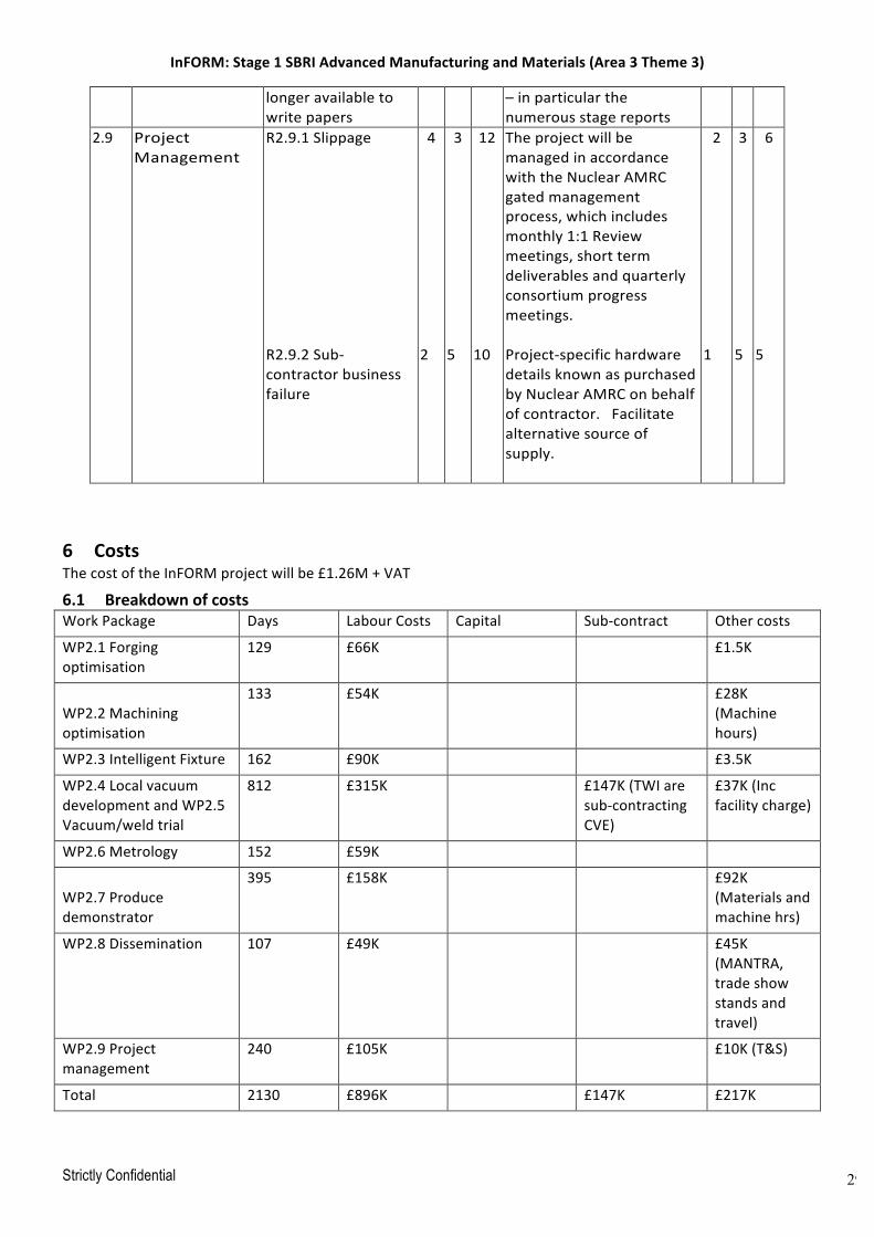
InFORM:Stage1SBRIAdvancedManufacturingandMaterials(Area3Theme3)
Strictly Confidential 29
longeravailabletowritepapers
–inparticularthenumerousstagereports
2.9 ProjectManagement
R2.9.1SlippageR2.9.2Sub-contractorbusinessfailure
4
2
3
5
12
10
TheprojectwillbemanagedinaccordancewiththeNuclearAMRCgatedmanagementprocess,whichincludesmonthly1:1Reviewmeetings,shorttermdeliverablesandquarterlyconsortiumprogressmeetings.Project-specifichardwaredetailsknownaspurchasedbyNuclearAMRConbehalfofcontractor.Facilitatealternativesourceofsupply.
2
1
35
6
5
6 CostsThecostoftheInFORMprojectwillbe£1.26M+VAT
6.1 BreakdownofcostsWorkPackage Days LabourCosts Capital Sub-contract Othercosts
WP2.1Forgingoptimisation
129 £66K £1.5K
WP2.2Machiningoptimisation
133 £54K £28K(Machinehours)
WP2.3IntelligentFixture 162 £90K £3.5K
WP2.4LocalvacuumdevelopmentandWP2.5Vacuum/weldtrial
812 £315K £147K(TWIaresub-contractingCVE)
£37K(Incfacilitycharge)
WP2.6Metrology 152 £59K
WP2.7Producedemonstrator
395 £158K £92K(Materialsandmachinehrs)
WP2.8Dissemination 107 £49K £45K(MANTRA,tradeshowstandsandtravel)
WP2.9Projectmanagement
240 £105K £10K(T&S)
Total 2130 £896K £147K £217K

InFORM:Stage1SBRIAdvancedManufacturingandMaterials(Area3Theme3)
Strictly Confidential 30
6.2 JustificationofStage2costsThe InFORM project is primarily focussed on the gaining of intellectual property. Not only does each deliverypartnerbringawealthofknowledge to the InFORMprojectbut the leverageofover£7M incapital resources.Someofthemoresignificant itemsaretheNuclearAMRC’sSoraluceFX12000horizontalboringmachine(£2M)andtheDorriesVTL(£2.5M)whichwilldemonstratetheInFORMconcept.AdditionallyTWIarecontributingtheuse of their local vacuumEBW (£2M) capability,NPL are deploying theirOptimum systemwith laser trackinghardware (£0.5M) and MetLase a laser cutter, press brake and specialist software (£0.6M). In addition thedemonstrator will be built, commissioned and tested at the Nuclear AMRC’s 8000m2 research factory inRotherham.
Consequentlythenon-staffcostsforthisprojectareprimarilylimitedtothepurchaseofmaterials,consumablesandmachiningtime.
Thisproject isnotaprofit generatingactivityand therefore thehourly ratesproposedbyNuclearAMRC -andadoptedbyallprojectsubcontractors-areonacostrecoverybasisonly.Evenwithouttheleveragebenefits,ifthisprojectwastobefundedatmarketratesthentheoverallcostswouldbesome£2.5M,especiallyaslabourissuchasignificantproportionofthecosts.
Aswellasthenecessarytechnicalexpertise,coordinationoftheworkcarriedoutbyeachofthedeliverypartnerswillbecriticaltothesuccessoftheInFORMproject.Thenumberofpartnersandtheirgeographicalspreaddoesmeanthatprojectmanagementaswellastravelandsubsistencecostswilltakeonagreatersignificancethaniftheprojectwasbeingundertakenbyasinglecontractorononesite.
6.3 AdditionalfundingThereisnoadditionalfundingotherthantheleveragedetailedabove.
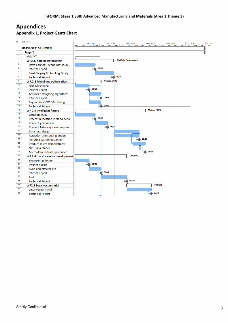
InFORM:Stage1SBRIAdvancedManufacturingandMaterials(Area3Theme3)
Strictly Confidential 31
AppendicesAppendix1.ProjectGanttChart

InFORM:Stage1SBRIAdvancedManufacturingandMaterials(Area3Theme3)
Strictly Confidential 32
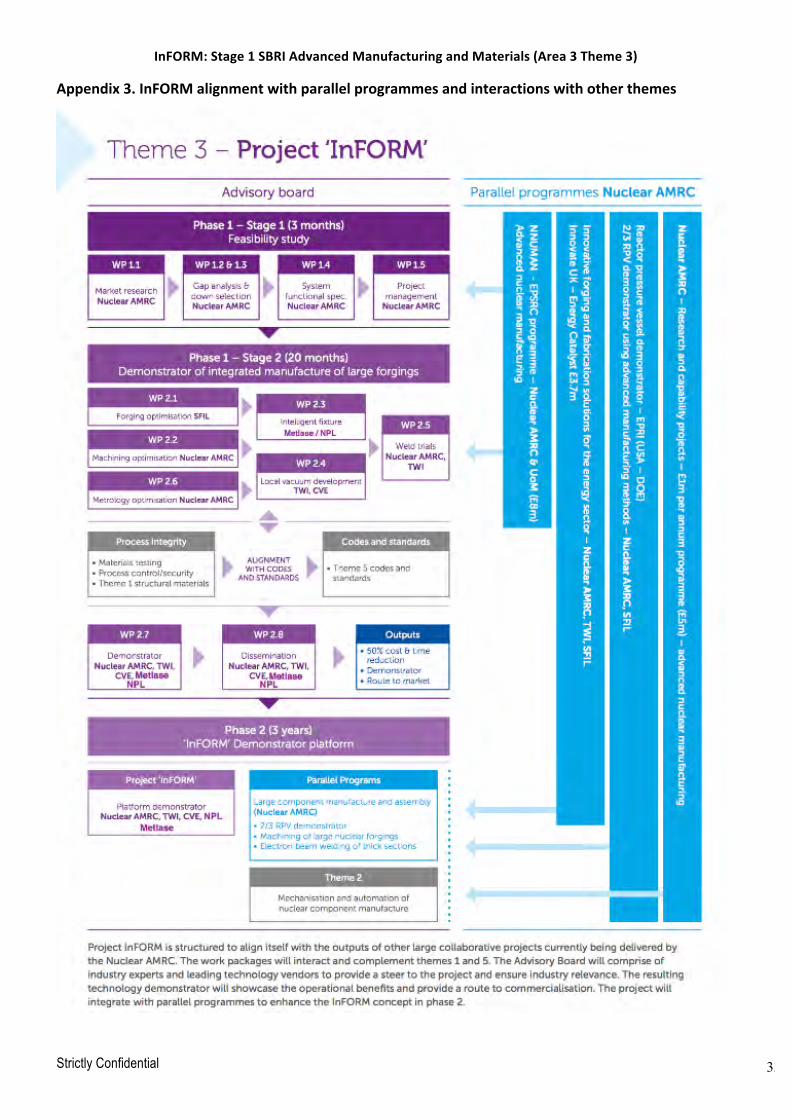
InFORM:Stage1SBRIAdvancedManufacturingandMaterials(Area3Theme3)
Strictly Confidential 33
Appendix3.InFORMalignmentwithparallelprogrammesandinteractionswithotherthemes