project outreach report - bc hydro · project outreach report ... 3.2 battery and system ... figure...
TRANSCRIPT

PROJECT OUTREACH REPORT Energy Storage and Demand Response for Improved Reliability in an Outage-prone Community Final Version – March 18th, 2015 BC Hydro Office of the Chief Technology Officer
i
TABLE OF CONTENTS 1.0 Project Background ............................................................................................................... 1
1.1 Reliability Challenge ............................................................................................................ 1
1.2 Substation Near Capacity Challenge .................................................................................... 2
1.3 Project Funding ..................................................................................................................... 3
2.0 Site Selection ........................................................................................................................ 4
2.1 First Nations and Community Engagement .......................................................................... 4
2.2 Environmental and Regulatory Permit .............................................................................. 4
2.3 Building Permit ................................................................................................................. 4
3.0 Technology Selection............................................................................................................ 5
3.1 Battery Technology ........................................................................................................... 5
3.2 Battery and System Integration ......................................................................................... 6
3.3 Telecommunications ......................................................................................................... 8
4.0 Construction ........................................................................................................................ 10
4.1 Civil Construction and Equipment Installation............................................................... 10
5.0 Testing and Commissioning ............................................................................................... 12
5.1 Component Testing and Commissioning ........................................................................ 12
5.2 Supervisory Control and Data Acquisition (SCADA) Commissioning ......................... 12
5.3 System Integration Commissioning ................................................................................ 13
5.4 Training and Transition to Operations ............................................................................ 13
6.0 Project Scope Extension ..................................................................................................... 14
6.1 Notification System ........................................................................................................ 14
6.2 Extension of the Battery System ..................................................................................... 14
7.0 Impact on the Public – Reliability Improvement ................................................................ 15
8.0 Other Issues and Resolutions .............................................................................................. 17
9.0 Next Steps ........................................................................................................................... 18
10.0 Lessons Learned................................................................................................................ 19

ii
Table of Figures TABLE 1 FIELD POWER OUTAGE STATISTICS FROM 2010 TO 2014............................................................................................... 2 TABLE 2 RESPONSIBLE PARTIES FOR COMPONENT TESTING AND COMMISSIONING......................................................................... 12 TABLE 3 BATTERY PROVIDED BACK UP POWER DURING POWER OUTAGES FROM JULY 2013 TO NOV 2014 (DATA FROM BC HYDRO PI
DATABASE) ............................................................................................................................................................ 15 TABLE 4 RELIABILITY IMPROVEMENT YEARLY TREND ................................................................................................................ 15 TABLE 5 BESS OPERATION MODES AND PERFORMANCE STATISTICS ........................................................................................... 18 TABLE 6 LESSONS LEARNED ................................................................................................................................................ 19
FIGURE 1 TERRAIN MAP OF LOCAL AREA SHOWING THE LOCATIONS OF THE PROPOSED BATTERY SITES IN GOLDEN AND FIELD.................... 2 FIGURE 2 PICTORIAL REPRESENTATION OF THE LOAD PROFILE AT GOLDEN SUBSTATION. .................................................................... 3 FIGURE 3 FIELD BATTERY SITE CONFIGURATION SHOWING THE INTELLIRUPTER AND MAIN CIRCUIT BREAKER WITHIN THE SMS AND
SATELLITE AND LOCAL RADIO COMMUNICATIONS ............................................................................................................. 7 FIGURE 4 PICTORIAL REPRESENTATION OF GOLDEN AND FIELD DISTRIBUTION NETWORK SHOWING THE TELECOMMUNICATIONS DESIGN ..... 8 FIGURE 5 CONSTRUCTION TIMELINE 2011-2013 ................................................................................................................... 10 FIGURE 6 STRUCTURE BEING ERECTED ................................................................................................................................... 11 FIGURE 7 COMPLETED BUILDING FACING NORTH .................................................................................................................... 11 FIGURE 8 SATELLITE TOWER TO BE ERECTED ........................................................................................................................... 11 FIGURE 9 SATELLITE TOWER PAD ......................................................................................................................................... 11 FIGURE 10 PROPANE TANK FOR STATION BACKUP GENERATOR ................................................................................................. 11 FIGURE 11 PROPANE GENERATOR TO PROVIDE STATION BACKUP ............................................................................................... 11 FIGURE 12 BC HYDRO GRID OPERATION MIMIC REAL-TIME DISPLAY OF THE BATTERY STORAGE SYSTEM ......................................... 13 FIGURE 13 FIELD COMMUNITY CUSTOMER INTERRUPTIONS BY MONTH ...................................................................................... 16 FIGURE 14 FIELD COMMUNITY CUSTOMER HOURS LOST BY MONTH .......................................................................................... 16 FIGURE 15 BESS NORMAL OPERATING CONFIGURATION ......................................................................................................... 17 FIGURE 16 BESS ROUND TRIP EFFICIENCY SINCE JULY 2013 .................................................................................................... 18

Page | 1
1.0 Project Background In January 2010, BC hydro initiated a project in partnership with Natural Resource Canada (NRCan) to install two 1 MW, 6 MWh battery energy storage systems (BESS) on its distribution system in Golden and Field, BC. The objectives of this project were to alleviate overloading of the Golden substation beyond capacity and to enhance customer supply reliability during sustained power outages in Field. The project scope was later reduced to installing 1 MW, 6MWh of battery storage near the community of Field when a review of the business case in January 2012 indicated that the risk of overcapacity at Golden substation was no longer present due to several other upgrades to the distribution system. On July 11th 2013, the BESS became operational. The system has since been providing benefits by delivering a clean source of back-up electricity during power outages and reducing the overall demand of Golden substation during on-peak hours. As of January 2015, the BESS in Field has provided 76 hours of back-up power to the community of Field. This is equivalent to a reduction of 11,455 customer hours lost (CHL).
1.1 Reliability Challenge The Golden substation (GDN), located at 12th Street and 11th Avenue South, Golden supplies power to the town of Golden and surrounding areas (Figure 1) serving approximately 4,000 customers. Four radial feeders from Golden substation distribute electricity to the town as well as surrounding areas, including the community of Field located 57 kilometres east of Golden, within the boundaries of Canada’s Yoho National Park. The community of Field has 155 BC Hydro residential and commercial accounts.

Page | 2
Figure 1 Terrain map of local area showing the locations of the proposed battery sites in Golden and Field.
The electricity supply for Field is provided by a single 25 kV distribution feeder GDN25F52 about 55 km long. This feeder is prone to frequent power outages of significant duration. The distribution line passes through challenging terrain subject to severe environmental conditions with natural vegetation subject to falling trees. In addition the line travels along adjacent to the Canadian Pacific Rail line, requiring coordination with train schedules for all line repairs. As an example, in 2013, the community of Field experienced a 49.5 hour power outage on June 29th as repair crews had to overcome access and repair challenges to restore service.
Fiscal Year No. of Outage Events
Customer Interruption (CI)
Customer Hours Lost (CHL)
2010 28 2,944 16,670 2011 17 1,984 6,909 2012 16 2,153 7,931 2013 17 1,907 8,294
2014 (April to July 2013) 4 576 3,436 Table 1 Field Power Outage Statistics from 2010 to 2014
1.2 Substation Near Capacity Challenge
Page | 3
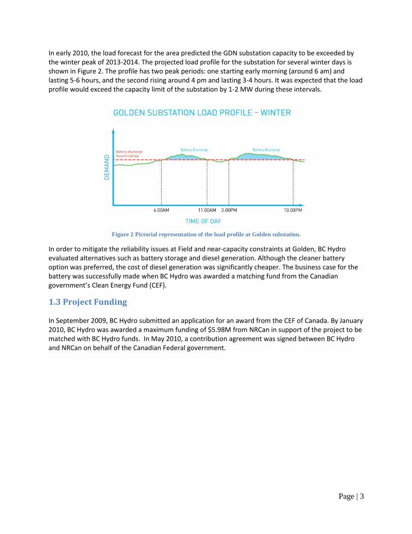
In early 2010, the load forecast for the area predicted the GDN substation capacity to be exceeded by the winter peak of 2013-2014. The projected load profile for the substation for several winter days is shown in Figure 2. The profile has two peak periods: one starting early morning (around 6 am) and lasting 5-6 hours, and the second rising around 4 pm and lasting 3-4 hours. It was expected that the load profile would exceed the capacity limit of the substation by 1-2 MW during these intervals.
Figure 2 Pictorial representation of the load profile at Golden substation.
In order to mitigate the reliability issues at Field and near-capacity constraints at Golden, BC Hydro evaluated alternatives such as battery storage and diesel generation. Although the cleaner battery option was preferred, the cost of diesel generation was significantly cheaper. The business case for the battery was successfully made when BC Hydro was awarded a matching fund from the Canadian government’s Clean Energy Fund (CEF).
1.3 Project Funding In September 2009, BC Hydro submitted an application for an award from the CEF of Canada. By January 2010, BC Hydro was awarded a maximum funding of $5.98M from NRCan in support of the project to be matched with BC Hydro funds. In May 2010, a contribution agreement was signed between BC Hydro and NRCan on behalf of the Canadian Federal government.

Page | 4
2.0 Site Selection In 2010, two sites were selected to house the battery storage systems. The Golden site is a BC Hydro-owned property previously used as a diesel generating station while the Field site is located within Yoho National Park within a Model Class Screening Report area known as Boulder Compound.
2.1 First Nations and Community Engagement Letters were sent to two First Nation bands (Shuswap Indian Band, Ktunaxa Nation Council) in October 2010 with information regarding the project and the selected site locations. During 2009-2012, BC Hydro had engaged several stakeholders to answer questions and address concerns; engaged parties included NRCan, Parks Canada, BC Ministry of Energy, Mines and Petroleum Resources, customers and the communities of Field and Golden, suppliers and local government representatives.
2.2 Environmental and Regulatory Permit Prior to NRCan releasing funds, an environmental assessment of the project was completed in accordance with the requirements of Canadian Environmental Assessment Act. BC Hydro had engaged the services of Stantec Inc. to perform an Environmental and Social Impact Assessment to identify potential effects of the project to the natural resources. A full assessment was carried out for the soils, landforms, vegetation, and wildlife Value Components and it was determined that residual effects would either be negligible or be low in magnitude, site-specific to local in geographic extent, and reversible. Stantec continued to develop an Environmental Management Plan (EMP) to reduce the extent and duration of potential effects. Contingency measures were established to address potential unplanned events that may have associated environmental or social effects. As part of the EMP, an environmental monitor on site during the construction period was responsible for ensuring that the EMP was reviewed and understood by all construction personnel involved with the project and for reporting all non–conformances to the Environmental Task Manager. The assessment report and the EMP were reviewed and accepted by Parks Canada.
2.3 Building Permit In order to meet the design criteria of extreme cold conditions (-50°C), the batteries needed to be housed within a building to operate at both Field and Golden sites. As the Field site is located within Yoho National Park, a Parks Canada building permit was obtained from Parks Canada Development Office to construct the battery storage structure within Parks Canada Land while a municipal building permit was obtained for the Golden site. In addition, a construction agreement prior to construction and a Licence of Occupation after commissioning of the BESS were signed between BC Hydro and Parks Canada. There were no other additional requirements for federal permits, licenses and authorizations or provincial or municipal permits.

Page | 5
3.0 Technology Selection In 2010, BC Hydro had formulated a conceptual design that included the battery units, power conversion system (PCS), transformer and intelligent switching devices capable of performing the functions required.
3.1 Battery Technology BC Hydro enlisted the help of Quanta Technologies to develop the Request for Proposal (RFP) for both the battery and systems integrator. Quanta suggested that both the batteries and the PCS be included in the RFP since the two are often designed to work together. However it was decided to make the PCS an optional item in the proposal so as not to restrict the responses. In addition, rather than generate a specification for a battery technology, the RFP was designed to specify functional requirements thus leaving the technology used to meet the requirements open while recognising that the objective of the project was to test the functionality of the battery energy storage system as a whole and not to test the chemistry or make-up of the battery technology. Furthermore, BC Hydro’s CEF application had used the one battery energy storage solution commercially available at the time (NGK Insulators’ Sodium-Sulphur (NaS) battery) as the model in terms of expected cost and performance. For these reasons, BC Hydro chose to continue to use NGK’s NaS battery as the baseline for the RFP requirements. Thus, all proponents were required to meet at least the same level of functionality as the NaS battery.
The technical performance requirements specified in the RFP were for: • peak shaving and; • islanding.
In addition, the battery energy storage systems were evaluated on their ability to meet conditions associated with:
• interconnection with the control systems; • environmental conditions and; • safety.
The selection criteria for the battery storage units reflected BC Hydro’s requirements for installing an asset onto the distribution system for the purposes of supplying safe, reliable power to customers. At a high-level the evaluation considered the following elements:
• technical proposal; • cost; • quality and safety record; • references, including references of subcontractors; • environmental; • Aboriginal content.
In 2010, NGK was selected as the battery vendor based on:
• Adequate performance – the performance indicated matched the expectations as developed for the business case developed for the project. Lithium-ion and Zinc Air solutions both indicated

Page | 6
stronger performance as did Vanadium Redox Battery (VRB) in all areas other than efficiency ratings and footprint1. The lead acid solution indicated a lower performance than baseline.
• Expected cost – the cost indicated matched the expectations set within the business case. Cost indicated for Lithium-ion and VRB were above baseline. Costs for Lead Acid and Zinc Air were below baseline with the cost for Zinc Air significantly lower than any other solution. This cost reflected the risk in this least commercial of solutions.
• References – NGK was the only vendor able to support the performance claims with actual installed and operating units. Prudent and Exide had installations with similar functionality but not of the same scale. Other proponents offered references for much smaller installations or none at all.
• Safety, Environmental, Aboriginal – in all of these aspects the proponents did not distinguish themselves.
3.2 Battery and System Integration BC Hydro had posted a separate request for proposal for the battery and system integrator. S&C Electric was chosen because of its previous experience with sodium sulfur BESS installations. The system integrator was responsible for:
• the design, delivery and construction of the building, PCS and associated equipment; • the integration, installation and testing of the BESS.
3.2.1 Power Conversion System The specific S&C scope of supply for the PCS is S&C’s Smart Grid Storage Management System (SMS) for the project. The SMS is made up of the following:
• One ±1.25 MVA SMS inverter and chopper complete with its own controls and ready to supply or absorb up to 1 MW of real power from the ESS batteries and capable to supply or absorb up to ±1.25 MVAR of reactive power into the step up transformer interconnecting to the 25 kV distribution system.
• One DC switchgear bay each of which has 1 DC circuit breaker for protecting the cabling and one half of the 1 MW battery.
• One set of master controls for controlling the inverter and 2 choppers via their local controllers. The master controls command the inverter and chopper to charge, or discharge the MW from the battery, as well as to independently control the voltage, reactive power or power factor at the utility supply point.
All of the S&C SMS subsystems are housed in the building in order to protect the batteries and the SMS from the extreme temperatures that are expected on site. The SMS includes controls built into the SMS enclosure for the inverter and choppers for the 1 MW NaS battery.
1 Compared to the flow battery, the footprint of the NAS battery is quite small. The final installed footprint is 25.1 m2
.

Page | 7
3.2.2 Vista System VI Switchgear The SMS consist of a single ±1.25 MVA inverter with its own 480V AC circuit breaker and 2 chopper circuits. Each chopper circuit typically connects to one half of the battery module stack, and each half of the battery is protected by its own DC breaker within the SMS for protection of the cabling and that half of the 1 MW ESS. Upstream of the 480V circuit breaker is a single 1.5 MVA 480V to 25 kV transformer. The 1.5 MVA transformer is then connected to the one 25 kV Vista interrupter that was added by S&C to provide protection and isolation of the system.
3.2.3 IntelliTeam & IntelliRupter An IntelliRupter PulseCloser is a unitized package of a fault-interrupter and control components which provides fault isolation and circuit restoration functions on an overhead distribution system. It provides the intelligence and point of isolation required for the islanding operation during power outages in Field. The islanding function is enabled by IntelliTeam software running on the IntelliRupter and SMS to isolate the load and reroute the power supply. In the event of a fault between the Golden substation and the IntelliRupter, the upstream feeder protection opens to clear the fault and the SMS anti-islanding protection trips the battery unit off-line. When the IntelliRupter detects a lack of upstream voltage, it will wait for either a detection of 3 upstream recloses or 30 seconds whichever comes first, to confirm the fault is permanent and then opens to isolate the portion of the feeder to be islanded. It then sends a signal to the SMS, and the SMS changes operating mode to supply power to the community of Field.
Figure 3 Field Battery Site Configuration showing the IntelliRupter and main circuit breaker within the SMS and
satellite and local radio communications

Page | 8
3.3 Telecommunications
Figure 4 Pictorial representation of Golden and Field distribution network showing the telecommunications design
For automated function and monitoring of the battery system, telecommunication is required between the battery site and BC Hydro Grid Operations, and between the battery site and the islanding disconnect point. Remote communication from the BESS to Golden substation and then to BC Hydro Grid Operations is provided by BC Hydro. Due to the remoteness and the terrain of the Field battery site, satellite communication was not a reliable option and there was no cellular infrastructure in 2011. After a long design process, the long-haul communication from the Field battery site to the Golden substation and back to BC Hydro Grid Operations was provided by C-band satellite, and the short-haul communications, between the islanding disconnect point and the battery site, was provided by a 900-MHz Speed Net radio. The design of the radio portion required a fiber section from the site through dense forest to the open road and then multiple radio hops on two new poles to find a reliable signal path. Since the time of the original design, cellular communication has been established in Field and this option is now used by S&C and NGK to monitor their systems remotely.

Page | 9
The telecommunication configuration between various components of the system is shown in Figure 4 above.
Page | 10
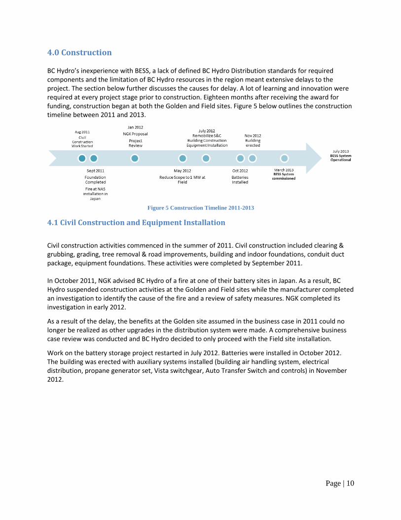
4.0 Construction BC Hydro’s inexperience with BESS, a lack of defined BC Hydro Distribution standards for required components and the limitation of BC Hydro resources in the region meant extensive delays to the project. The section below further discusses the causes for delay. A lot of learning and innovation were required at every project stage prior to construction. Eighteen months after receiving the award for funding, construction began at both the Golden and Field sites. Figure 5 below outlines the construction timeline between 2011 and 2013.
Figure 5 Construction Timeline 2011-2013
4.1 Civil Construction and Equipment Installation
Civil construction activities commenced in the summer of 2011. Civil construction included clearing & grubbing, grading, tree removal & road improvements, building and indoor foundations, conduit duct package, equipment foundations. These activities were completed by September 2011. In October 2011, NGK advised BC Hydro of a fire at one of their battery sites in Japan. As a result, BC Hydro suspended construction activities at the Golden and Field sites while the manufacturer completed an investigation to identify the cause of the fire and a review of safety measures. NGK completed its investigation in early 2012.
As a result of the delay, the benefits at the Golden site assumed in the business case in 2011 could no longer be realized as other upgrades in the distribution system were made. A comprehensive business case review was conducted and BC Hydro decided to only proceed with the Field site installation.
Work on the battery storage project restarted in July 2012. Batteries were installed in October 2012. The building was erected with auxiliary systems installed (building air handling system, electrical distribution, propane generator set, Vista switchgear, Auto Transfer Switch and controls) in November 2012.

Page | 11
Figure 6 Structure being erected
Figure 7 Completed Building facing North
Figure 8 Satellite Tower to be erected
Figure 9 Satellite Tower Pad
Figure 10 Propane Tank for Station backup Generator
Figure 11 Propane Generator to provide Station backup

Page | 12
5.0 Testing and Commissioning
5.1 Component Testing and Commissioning Component testing started in early November 2012. All tests were performed as per NETA ATS-2009 testing specifications. Table 2 below shows the list of responsible parties and the components tested.
Responsible Party Components Tested NGK Energy Storage & System Integration Testing
Magna Electric Power Transformer, MV and HV Cables, SEL Relay, Vista Switchgear Assemblies, Grounding System,
Low Power Wire and Cable S&C Electric SMS and System Integration, Relay Rack,
IntelliRupter Finning Propane Generator
SimplexGrinnell SO2 Alarm System Siemens Fire Alarm and Security Systems BC Hydro SCADA Interface Relay and Communication Rack
Table 2 Responsible Parties for Component Testing and Commissioning
5.2 Supervisory Control and Data Acquisition (SCADA) Commissioning The purpose of the SCADA setup is to provide real-time status and alarm monitoring, to regulate battery output, to control distribution automation system, and to remotely control the major equipment. The main substation SCADA interface between the battery project and BC Hydro is a Real-Time Automation Controller communication processor. Intelligent Electronic Devices and network devices involved in the substation side of the SCADA network:
• Protective relay & meter; • Ethernet switch; • Generator; • Automatic Transfer switch; • S&C Electric Company distribution automation devices (IntelliNode, IntelliRupter); • S&C Electric Company Smartgrid SMS; • Building alarms (Sulphur Dioxide, Fire Alarm, Security system).
The data points made available to BC Hydro were commissioned point by point based on a pre-approved lists of points. The SCADA commissioning was completed in March 2013.

Page | 13
Figure 12 BC Hydro Grid Operation Mimic Real-Time Display of the Battery Storage System
5.3 System Integration Commissioning The commissioning of the BESS consisted of testing the system’s response to two major events: a loss of normal utility power on the 25 kV system upstream of the IntelliRupter and a fault on the 25 kV system downstream of the IntelliRupter. BC Hydro and S&C signed off declarations that the Generator’s substation is compatible for interconnection with the BC Hydro system for the purpose of operating as a load, generator commissioning (1st synchronization) and operation in February 2013.
5.4 Training and Transition to Operations A two-day onsite training workshop was scheduled in March 2013 to provide an overview of the BESS components, operation during islanding mode, fire safety plans and hands-on training. It was attended by representations from Field Operations, Grid Operations, Occupational Safety, Communications, Protection & Control team, other BC Hydro departments and Field Fire Department. A Distribution Operating Order was created to describe the procedures that are used for operating equipment located at the BESS and its interconnection with feeder GDN25F52. An Alarm order was also created to provide description and recommended actions for the BESS alarms. The BESS is operated in a similar way as a substation.

Page | 14
6.0 Project Scope Extension The second stage of the project implemented between July 2013 and March 2015 included a notification system for customers on battery system status and an extension of the battery system to support some customers upstream of the current islanding connection point.
6.1 Notification System Currently, approximately 20% of the residents are receiving Twitter updates via SMS/email notifications when the battery is in an islanded condition. This notification encourages them to respond with conservation measures to reduce the community load during a power outage; hence maximizing the duration over which the battery can support the community.
6.2 Extension of the Battery System BC Hydro reviewed the possibility of extending the coverage of the battery system further upstream from the current islanding disconnection point. However, studies have shown that while technically possible, the potential for secondary faults impacting the function of the battery system while islanded makes the extension impractical.

Page | 15
7.0 Impact on the Public – Reliability Improvement To date, the BESS has provided 76 hours of clean back-up power to the town of Field as shown in Table 3. This is equivalent to 11,455 avoided CHL. Table 4 shows the number of outage events and the resulting customer interruptions and customer hours lost due to the outage causes related to the BESS. In addition, noise levels and greenhouse gas emission levels during BESS islanded mode are significantly less than levels during diesel power generation. The charts in Figure 13 and Figure 14 show the comparison to previous year averages and outage event months for the town of Field. The performance indices CI and CHL have noticeably improved reliability in FY2014, compared to the 4 year average (in red)2. For FY2015, there had been a few issues with IntelliTeam software that did not allow the BESS to supply the town during power outages in several occasions. Please refer to the Section 8.0 for more details.
Date of Outage Event Outage Duration (hrs)
July 15, 2013 7.5 Sept 21, 2013 9 Sept 27, 2013 6
Oct 5, 2013 2.5 Oct 11, 2013 1.5 Nov 7, 2013 4
Nov 19, 2013 6.5 March 8, 2014 23.5 June 3, 2014 3.5 July 17, 2014 7 Aug 9, 2014 2
Nov 30, 2014 3 Total 76
Table 3 Battery provided back up power during power outages from July 2013 to Nov 2014 (Data from BC Hydro PI database)
Fiscal Year 2010 2011 2012 2013 2014 2015 (up to
Nov 30th 2014)
F10-F13 Average
Outage 28 16 19 17 6 5 19.5 Customer Interruption (CI) 2,944 1,984 2,153 1,907 868 726 2,247 Customer Hours Lost (CHL) 16,670 6,909 7,931 8,294 4,713 5,832 9,951
Table 4 Reliability Improvement Yearly Trend
2 From 2009 to 2012, BC Hydro has spent approximately $630,000 with an additional $115,000 from Parks Canada, towards the removal of dead trees along the power line corridor in Yoho National Park.

Page | 16
Figure 13 Field Community Customer Interruptions by Month
Figure 14 Field Community Customer Hours Lost by Month

Page | 17
8.0 Other Issues and Resolutions On November 11th 2013, the IntelliRupter and the Vista switch tripped at the same time caused by a fallen tree. Due to some coordination issues, the BESS failed to activate and the outage lasted about 7 hours before power was restored to the town of Field. On three separate occasions (August 9th, September 8th and November 9th 2014), a fault between the BESS and the town of Field prevented the BESS from providing back-up power, causing a power outage in Field. The outages lasted for 15 hours (August 9th), 4 hours (September 8th) and a couple of minutes (November 9th) respectively. On November 28th 2014, there was another outage in Field and the BESS failed to come on. It was reported that “SMS Clear Manual Operation” was not reset after the November 9th outage event. This had disabled the SMS from initiating automatic islanding operation. BC Hydro has since initiated an investigation to streamline the operation of the BESS.
Figure 15 BESS Normal Operating Configuration

Page | 18
9.0 Next Steps BC Hydro will continue to monitor the performance of the battery system availability and efficiency over the life of the battery. Since the BESS became operational, the battery system was available 95.6% of the time to supply power to the town of Field and had supplied close to 0.5 GWh during outage and on-peak hours. The round-trip efficiency is expected to degrade over time due to the nature of battery technology. BC Hydro will monitor this performance indicator closely to better understand the battery system. As the prices of battery systems reduce, replications of the BESS may be possible for remote communities which are at the end of a feeder line to improve feeder reliability.
Operating Modes % of Time Hours
Energy Supplied by
Battery (kWh)
Grid power available, Battery Idle 79.5% 9,804 n/a Grid power available, Peak shaving 15.4% 1,898 453,000
Battery supplying town of Field during power outages 0.6% 76 21,000 Battery not available (communication down, no storage) 4.4% 546 n/a
Total 100.0% 12,327 474,000 Table 5 BESS Operation Modes and Performance Statistics
Figure 16 BESS Round Trip Efficiency since July 2013

Page | 19
10.0 Lessons Learned The BESS has been in service for a year and five months. The main objective of the project has been met: enhanced customer supply reliability during sustained power outages in Field. The community of Field has since been reaping the benefits of the improved reliability provided by this clean source of back-up power. Through the deployment of the BESS, extensive experience and knowledge had been gained for peak shaving and islanding operations. Many lessons were learned from overcoming the additional challenges associated with the difficult terrain, and the Canadian climate. The experience and knowledge can be applied towards any future battery storage projects in BC. Table 6 summarizes the lessons learned through the deployment of the BESS in Field.
Lessons Learned
BC Hydro Case in Field Considerations for Future Projects
Civil Design -50°C design temperature; Heated building required to house batteries
Location and weather condition of battery site should be considered to minimize requirements for battery storage structure
Battery Site Location
Within Yoho National Park; Approximately 4 km from the Town of Field; Location due to available land
Site location should be as close as possible to the distribution loads; currently any fault between battery site and town of Field (4 km) would disable the battery islanding function
Building Permit Within Yoho National Park; Park Canada building permit was required
Possible permitting delays due to the site location
Environmental Assessment
Environmental assessment was required as per Canadian Environmental Assessment Act
Possible delays due to environmental assessment
Stakeholder Engagement
First Nations and Community Engagement Stakeholder engagement may affect schedule
Fire Safety Fire of the NaS battery site in Japan Even the most mature technologies have not been proven over a full life-cycle
Chemical Safety Possible SO2 gas leakage from the battery systems
Chemical hazard should be considered in the safety plan
Request For Proposal Process
No standards for procurement process Possible delays due to lack of standards
Knowledge Limited in-house experience with battery energy storage systems
The balance of in-house participation and resource constraints when internal knowledge of the new technology is limited
Non-standard Equipment
No standard developed for the BESS components
Operational, maintenance procedures were developed specifically for this system
Extra time and effort were required to train personnel and develop operating order
Extra effort required to operationalise non-standard equipment
BESS Controls Integration of the controls of the different systems was not seamless
A centralized control interface would greatly improve the operation of BESS
BESS Management Systems
Human Machine Interface (HMI) was not developed for the whole system
HMI was available for the individual components (IntelliRupter, SMS)
Extra effort to train with less user-friendly management system interface. Simplified HMI for ease of use for crew and operation centre personnel is not available
Telecom Design Satellite, communication network was not available due to location and terrain of battery site
Additional infrastructure needed to provide telecommunications (new poles, fibre section)
Table 6 Lessons learned