project: n65-30188 e i &. nu - nasa · gemini survival package .....3 1-33 gemini 5 suit ......
TRANSCRIPT

I
NATIONAL AERONAUTI(5 AND SPACE ADMINISTRATION 1 W O ?-.I1 :: WASHINGTON DC 20546 ‘JVO j-/,g?r,
FOR RELEASE: THURSDA? PM August 12, 1955 P RELEASE NO: 65-262
PROJECT: GEMINI 5
ITHRU) 1
N65-30188 (ACCESSION N U B E R I I &. I AOE I
R 2
P ICATEGORY)
E (NASA CR OR TMx OR AD NUMBER)
I T
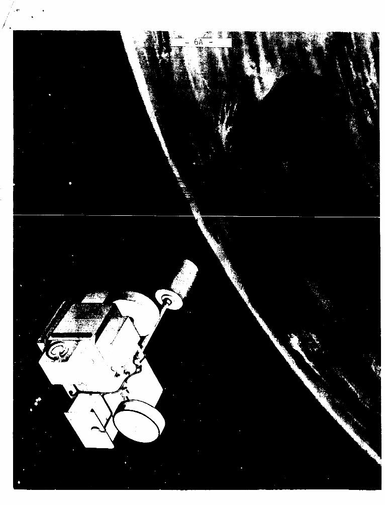
Mission Descr ipt ion ....................... 6-11 I l l u s t r a t i o n of REP. ...................... 6 A C r e w Tra in ing Background-Gemini 5.........11-14
Immediate P r e f l i g h t C r e w A c t i v i t i e s ..... 13-14 F l i g h t A c t i v i t i e s ........................ 14
Summary F l i g h t Plan ....................... 15-18 F l i g h t Data ............................... 19 Orbits - Revolutions ...................... 19-20 Weather F3quirements ....................... 20-21 Launch Countdo w n . . . . . . . . . . . . . . . . . . . . . , . . . . . 22-23 C r e w Sa fe ty ............................... 2b-31
During Launch ........................... 24-25 Abort Procedures ........................ 25 I n f l i g h t ................................ 26 Reentry, Landing and Resovery ........... 27-31 Parachute Landing Sequence, . . , . . . . . . , . , .28
Gemini Surv iva l Package . . . . . . . . . . . . . . . . . . . 3 1-33 Gemini 5 S u i t . . . . . . . . . . . . . . . . . . . . . . . . . . . . .33-3L\ Food for Gemini 5.........................35-37
Gemini 5 Menu .................,,,,,.,,,,37 Medical Checks ............................. 8 Body Waste Disposal ....................... 3 Gemini Spacecraf t ...,............,,.,,.......39- 49
Reentry Module .................,....,....39- 40 Adapter Sec t ion ......................... 40-41 RCS Function ( I l l u s t r a t i o n ) ............. 42 S p a c e c w t Responses To Orbit A l t i t u d e
Control Thrust ( I l l u s t r a t i o n ) ......... 43 Maneuvering Control ( I l l u s t r a t i o n ) . . . , , , 4 4
Launch i s scheduled no e a r l i e r than August 19.
https://ntrs.nasa.gov/search.jsp?R=19650020587 2018-07-07T21:57:44+00:00Z

Liquid Rocket Systems (Illustration) .... 1$5 Thrust Chamber Arragement (111ustration)46 Electrical Power System ................ .4 7-1\:5 Rendezvous Radar ....................... .4.? -IC9
Gemini Launch Vehicle ..................... 50-52 Gemini 5 Experiments ...................... 53-72
Inflight Exercise: Work Tolerance ...... 53754 Inflight Phonocardiogram. ............... 54 Bone Demineralization ................... 54 Cardiovascular Conditioning. ............ 55 Human Otolith Function .................. 5 5-56 Synoptic Terrain Photography ............ 5 7-61 Synoptic Weather Photography ............ 61-62 Zodiacal Light Photography. ............. 63
Visual Acuity ........................... 54 -66 Electrostatic Charge .................... 67-68 Basic Object Photography ................ 68 Nearby UbJeCt Pnotograpi iy ................ .-V;I
Celestial Radiometry .................... 69 Surface Photography ..................... 70 Space Object Radiometry ................. 70-71
Space Flight Tracking Network ...... 72-79 Goddard Computer Support ............... .7 3-74 Mission Computing Requirements .......... 74 NASA Communications Network ........... .7 5-76 Spacecraft Communications ............... 75-77 Network Responsibility . .................7 7- 78 Network. Configuration. Capability ...... 79
Crew Biographies., ....................... .8 0-84 L . Gordon Cooper, Jr .................... 30-~1 Charles Conrad. Jr ...................... .2 Neil A . Armstrong ....................... ~3 Elliot M . See. Jr ....................... .j 4
Previous Gemini Flights ................... 85-89 Gemini 1 ............................... .8 5-86 Gemini 2 ................................ 3 5-8 7 Gemini 3 ............................... .3 7 - i ~ ~ .q 3 -39 Gemini 4 ................................
Project Officials ......................... 90 U . S . Manned Space Flights(Chart) ......... 91 Conversion Table .......................... 92
Cardiovascular Effects of Space Flight .. 55-57
Cloud Top Spectrometer., ............... .6 3-64
LQ E n
Manned
C’ 0

NATIONAL AERONAUTICS AND SPACE ADMINISTRATION WO 2-41 55 WASHINGTON, D.C. 20546 TELS’ WO 3-6925
FOR RELEASE: THURSDAY PM August 12, 1965
RELEASE NO: 65-262
NASA SCHEDULES
EIGHT -DAY MANNED
SPACE FLIGHT
The National Aeronautics and Space Administration w i l l
launch the Gemini 5 eight-day manned space f l i g h t mission no
e a r l i e r than Aug. 19 a t Cape Kennedy, Fla.
A fhll dura t ion mission would achieve the longest mannea
space f l i g h t t o d a t e ,
Astronaut L. Gordon Cooper, Jr . ,will be c0mw-d P i l o t
and Astronaut Charles Conrad, Jr . ,will be p i l o t f o r the mission.
The backup crew i s Astronaut N e i l A. Armstrong, Command
p i l o t , and E l l i o t t M. See, p i l o t . The backup crew w i l l re-
p lace the primary crew should e i t h e r member of t h a t team become
i n e l i g i b l e f o r the f l i g h t .
Gemini 5 w i l l be launched by a two-stage Ti tan 11, a modi-
f i e d U. s. A i r Force In t e rcon t inen ta l B a l l i s t i c Miss i le , i n t o
an o r b i t w i t h a high poin t of 219 s t a t u t e miles and low po in t
of 100 miles. Each o r b i t w i l l take about 90 minutes and range
between 33 degrees n o r t h and south of the Equator.
- more - 8/4/55

-2 -
Fl igh t time f o r Gemini 5 will be about 191 hours and
53 minutes during which i t w i l l complete 121 r evo lu t ions of
the Earth.
revolut ion abou t 500 miles southwest of Bermuda In the West
At lan t ic Ocean.
Landing i s planned a t the beginning of the 122nd
T h i s is the t h i r d manned Qemini f l l g h t . The f i r s t two
of the previous f o u r Gemini f l i g h t s were unmanned.
Gemini 5 will be the second space f l i g h t f o r Astronaut
Cooper and w i l l g ive him more time i n space than any o t h e r
man--more than 226 hours.
20 minutes aboard Fa i th 7, May 15, 1963, the longes t f l i g h t
of t h e Pro jec t Mercury Se r i e s .
H i s f i rs t f l i g h t was 34 hours and
T h i s i s the f i r s t space f l i g h t f o r Conrad, who joined the
as t ronaut program i n September 1962.
I Primary ob jec t ives of Gemini 5 are:
(1) Demonstrate and eva lua te the performance of the Gemini
spacecraf t f o r a period of e ight days.
( 2 ) Evaluate the performance of the rendezvous guidance
and navigation system us ing the radar eva lua t ion pod.
-more-
-~ ~~~ _ _ ~ ~

i , ' -3 -
(3) Evaluate the effects of prolonged exposure to the
space environment of the two-man crew.
Seventeen experiments are scheduled to be conducted during
the flight. Five are medical, six scientific and six technolo-
gical.
of Defense.
Six of the experiments are sponsored by the Department
Six of the experiments repeat tests conducted on previous n-t 3 -.- n A m 4 - 4 P l - 1 nL.4- mL.-.. ..-A. T- @ l a . - ~ ~ - -n ___I- a ___-
U - t I I - L L A A A A L b L L V u . L L L b y G . 1 1 1 - 1 J - A ~ L L ~ OACA'ULDCA- , Iii-i L L ~ L ~ L
Phonocardiogram, Bone Demineralization, Electrostatic Charge,
Terrain and Weather Photography.
New experiments include: Cardiovascular Conditioning,
Human Otolith Function, Basic Object Photography, Nearby
Object Photography, Celestial Radiometry, Surface Photography,
Space Object Photography, Astronaut Visibility, Zodiacal Light
Photography, Cloud Top Spectrometer and Visual Acuity.
The eight-day mission is about the time required f o r an
Apollo crew to fly to the Moon, explore its surface and return
to Earth. Gemini 5 is expected to demonstrate that the pro- longed weightlessness of a manned Moon landing mission is not
a threat to the health of the crew and that well-conditioned,
well-trained astronauts can perform effectively over the dura-
tion of such a flight.
-more-

b
I
-4- -.
New equipment on Gemini 5 includes t h e rendezvous radar
and guidance system, developed f o r rendezvous and docking w i t h
an o r b i t i n g Agena rocket . A radar eva lua t ion pod w i l l be car -
r ied i n t h e adap te r s ec t ion of t h e spacecraf t and e j ec t ed i n
space t o s imula te .the Agena.
Instrumentation i n t h e pod i s similar t o Agena instrumen-
t a t i o n . It conta ins a rendezvous r ad io transponder, batteries,
antenna and f l a s h i n g l i g h t s . I ts l i f e expectancy i s about s i x
hours .
Purpose of the radar pod i n Gemini 5 i s t o t es t equipment
and provide p r a c t i c e i n rendezvous techniques. Once the pod
has been e jec ted the a s t ronau t s w i l l p u l l away. Later they
w i l l seek it out as a tes t of t h e equipment. There w i l l be
no docking.
Use of a f u e l c e l l as the e l e c t r i c a l power a l s o i s new
i n Gemini 5. It i s a device which converts e l e c t r i c a l energy
from the r eac t ion of hydrogen and oxygen.
the s torage batteries previously used and w i l l supply a l l i n -
f l i g h t e l e c t r i c a l power f o r the spacec ra f t . Batteries w i l l be
used during r een t ry .
The f u e l c e l l r ep laces
-more-
I , -5 -
The Gemini program i s t h e second phase of the United
State 's manned space f l i g h t program.
v ide experience i n o r b i t i n g maneuvers, rendezvous and docking,
space f l i g h t s l a s t i n g up t o 14 days and f o r manned s c i e n t i f i c
It i s designed t o pro-
i n v e s t i g a t i o n s i n space.
Gemini is under the d i r e c t i o n of Office of Mannec Space
F l igh t , NASA Headquarters, Washington, D.C., and i s managed
by NASA's'Manned Spacecraf t Center, Houston. Gemini i s a n a t i o n a l
space e f f o r t and i s supported by the Department of Defense l n
such areas as launch veh ic l e development, launch operat ions,
tracking and recovery.
(BACKGROUND INFORMATION FOLLOWS)
-more-
.

-6-
MISSION DESCRIPTION
A c t i v i t i e s descr ibed below and i n t h e Summary F l i g h t
P l a n w i l l be a f f e c t e d by many v a r i a b l e s such as weather, space-
c r a f t day/night p o s i t i o n and a t t i t u d e c o n t r o l f u e l remaining.
The p l a n i s f l ex ib l e and may be altered i n f l i g h t t o meet chang-
i n g condi t ions.
The Gemini 5 spacec ra f t i s scheduled t o be launched from
Cape Kennedy Complex 19 a t 9 a.m. EST onanaz imuth of 72 degrees.
Twenty seconds a f te r second stage cut -of f , a t a n i n e r t i a l velo-
c i t y of 25,807 feet per second, t h e spacec ra f t w i l l be separa-
t e d from t h e Gemini Launch Vehicle by f i r i n g the two 100-pound
a f t t h r u s t e r s . T h i s w i l l add 10 f p s t o the i n e r t i a l v e l o c i t y
and resu l t i n a n 100-219 s t a tu t e mile e l l i p t i c a l o r b i t about
600 miles from Cape Kennedy.
After i n s e r t i o n i n t o o r b i t , the crew w i l l check systems
and prepare t o a d j u s t t h e i r perigee. A t a ground elapsed
time (GET) of 56 minutes, as the spacec ra f t nea r s f i rs t apogee,
a ho r i zon ta l posigrade maneuver of 10 f p s w i l l be executed t o
ra i se t h e perigee t o approximately 106 miles.
p r i o r t o release of the Radar Evalua t ion Pod (REP) t o i n s u r e
an a p p r o p r i a t e spacec ra f t perigee a l t i t u d e when maneuvered t o
a c o - e l l i p t i c a l o r b i t i n connection w i t h the REP exe rc i se .
T h i s i s done
,-more-

-7-
The REP w i l l be e j ec t ed 13 minutes a f te r the spacecraf t
e n t e r s darkness i n t h e second r evo lu t ion a t GET of two hours
and 25 minutes. For e j e c t i o n , t h e spacec ra f t w i l l be yawed
r i g h t 90 degrees, and t h e REP will go nor th from the spacec ra f t
a t a rate of about f i v e f p s .
not a f f e c t t h e inplane motion between the two vehic les .
The out-of-plane e j e c t i o n w i l l
Because t h e spacecraf t must remain wi th in 900 f e e t of the
REP f o r f o u r minutes as part of the Celestial, Space and Ter-
r e s t r i a l Object Radiometery experiments ( D 4 and D-7) , It w i l l
be necessary t o decrease t h e range rate between t h e two ve-
h i c l e s . To accomplish t h i s , two f p s will be appl ied t o the
spacecraf t toward the REP us ing the a f t t h r u s t e r s one minute
a f t e r REP e j e c t i o n .
A t a GET of two hours and 59 minutes, t h e crew w i l l exe-
cu te a posigrade 16 f p s ho r i zon ta l maneuver us ing the a f t
t h r u s t e r s .
enough t o a l low i t t o t r a i l behind the REP.
creases the spacecraf t per iod by .l7 minutes t o 89.87 minutes.
It also r a i s e s the apogee t o approximately 229 miles.
Purpose i s t o inc rease the spacec ra f t o r b i t a l per iod
The maneuver i n -
-more-

-8-
At a GET of t h r e e hours and 39 minutes t h e crew w i l l
execute a retrograde and rad ia l ly-up burn of 14 f p s .
w i l l lower the spacecraf t perigee a l t i k u d e about seven mi les .
below the per igee a l t i t u d e o f t h e REP, which i s 106 miles,
and a d j u s t the phase angle desired a t the time of the co-
e l l i p t i c a l maneuver. The maneuver w i l l be performed i n a
pitched-up a t t i t u d e using t h e forward-f i r ing t h r u s t e r s . The
o r b i t a l parameters af ter t h r u s t w i l l be approximately loo-229
miles w i t h a per iod of 89.75 minutes .
w i l l be -073 minutes larger than the REP period, and t h e space-
c r a f t w i l l l ag behind. The spacecraf t remains i n t h i s o r b i t
f o r 52 minutes during which i t achieves a maximum range from
the REP of 52 miles.
T h i s
The spacec ra f t period
A re t rograde and radially-down maneuver of 29.8 f p s w i l l
be performed a t a GET of f o u r hours and 31 minutes. T h i s w i l l
p lace the spacecraf t i n t o an 99-212 mile o r b i t c o - e l l i p t i c a l
w i t h the REP'S o r b i t w i t h an approximate a l t i t u d e d i f f e rence
of seven miles between the two. The maneuver w i l l be executed
wi th the spacecraf t pi tched up, and the forward f i r i n g thrus-
t e r s w i l l be used. The spacecraf t per iod w i l l become 89.43
minutes, which i s .24 minutes smaller than t h e REP'S period.
The spacec ra f t w i l l s t a y i n t h e c o - e l l i p t i c a l o r b i t about 33
minutes, r e s u l t i n g i n a phase angle of .183 degrees a t terminal
phase i n i t i a t i o n .
-more-

-9-
The p i l o t w i l l switch the computer mode t o rendezvous
A t f i v e hours GET, a t a GET of f o u r h o u r s and 35 minutes.
w i t h a range of 17.5 miles and a look-angle of 22.69 degrees,
he w i l l p r e s s t h e s t a r t computer button.
minutes later, when the range i s 14.9 miles and the look-angle
i s 27.2 degrees, t h e terminal phase i n i t i a t i o n maneuver of 15
f p s i s appl ied. A t t h i s time the in-plane t h r u s t angle i s
equal t o the REP look-angle, and the r e s u l t i s a l ine-of -s ight
burn.
Approximately f o u r
A t a GET of f i v e hours, 16 minutes and 11 seconds, the
f i r s t mid-course co r rec t ion maneuver of 81.8 degrees i s d i s -
played t o t h e crew on the Incremental Veloci ty I n d i c a t o r ( I V I ) .
The vec tor components are displayed sepa ra t e ly t o maintain
l ine-of-s ight a t a del ta V cos t of t h r e e fps .
The second mid-course c o r r e c t i o n maneuver i s a p p l i e d a t
a GET o f f i v e hour s , 28 minutes , 11 seconds. T h i s 33.6 degree
maneuver c o s t s f i v e f p s . Af te r i t s completion, the closed-
loop phase i s completed and t h e crew w i l l c o n t r o l the spacecraf t
throughout t h e r e s t qf the exe rc i se v i a a semiopt ical technique.
-more-

,
-10-
The magnitude of t h e t h e o r e t i c a l braking maneuver a t a
GET of f i v e hours, 36 minutes, 32 seconds i s about 16 fps .
However, s ince the command p i l o t w i l l be c o n t r o l l i n g f i n a l
approach from about 1.7 miles by semiopt ical techniques, addi -
t i o n a l f u e l w i l l be used con t ro l l i ng the i n e r t i a l l ine-of -
s i g h t rates and the range/range r a t e .
occurs about 10 minutes p r i o r t o leaving darkness i n the fou r th
revolu t ion and about s i x minutes p r i o r t o l o s s of s i g n a l a t
Carnarvon,' Aus t ra l ia , t r ack ing s t a t i o n .
The braking maneuver
Af t e r t h e braking maneuver, t h e spacecraf t w i l l be maneu-
vered i n the near v i c i n i t y of the REP f o r the Nearby Object
Photography experiment (D-2) u n t i l time f o r the f i n a l separa-
t i o n maneuver of a GET of s ix hours, 49 minutes. A t $hat time
t h e spacecraf t w i l l be a t f i f t h apogee, and the crew w i l l per-
form a f i v e f p s posigrade maneuver t o separa te from the REP.
The o r b i t a l l i f e t i m e of t h e spacecraf t following t h i s maneuver
i s expected t o be from 10 t o 13 days. The remainder of the
mission w i l l be c a r r i e d out with spacecraf t exe rc i se s that do
not involve in -o rb i t maneuvering.
Scheduling of experiments and o the r a c t i v i t i e s i n the
f l i g h t following completion of the REP exe rc i se w i l l be on a
real- t ime basis.
-more -
-11-
Ret ro f i r e i s planned a t a GET of 191 hours, 29 minutes,
24 seconds while t h e spacecraf t i s between H a w a i i and Ca l i fo rn ia
i n the 121st revolut ion. Landing i s expected i n t h e West
A t l an t i c recovery a rea about 500 miles southwest of Bermuda
a t a GET of 191 hours, 53 minutes, 18 seconds and a Local Mean
Time of 9 a.m.
CREW T R A I N I N G BACKGROUND - G E M I N I 5
The Gemini 5 f l i g h t crew was se l ec t ed Feb. 8, 1965.
I n a d d i t i o n
Con-
cent ra ted mission t r a i n i n g began i n September.
t o the extensive general t r a i n i n g received p r i o r t o f l i g h t
assignment--such as f a m i l i a r i z a t i o n w i t h high acce le ra t ions ,
zero gravi ty , and var ious s u r v i v a l techniques--the fol lowing
preparat ions have o r w i l l be accomplished p r i o r t o launch:
a. Fami l i a r i za t ion wi th launch, launch abor t , and r e e n t r y
acce le ra t ion p r o f i l e s of the Gemini 5 mission us ing the Naval
Air Development Center, Johnsv i l l e , Pa., c en t r i fuge .
b. Egress and recovery a c t i v i t i e s using a spacecraf t
b o i l e r p l a t e model and a c t u a l recovery equipment and personnel.
c . Celestial p a t t e r n recogni t ion in the Moorehead
Planetarium, Chapel H i l l , N.C.
-more -

-12-
d. Parachute descent t r a i n i n g over land and water us ing
a towed parachute technique.
e. Zero g r a v i t y evaluat ion of e x t r a vehicu lar a c t i v i t i e s ,
food and o t h e r on-board equipment.
f . S u i t , seat, and harness f i t t i n g s .
g. Launch abor t s imulat ions at Ling-Temco-Vought i n a
s p e c i a l l y configured simulator.
h. Training sess ions t o t a l i n g over 110 hours p e r crew
member on the Gemini mission simulators.
i. Detailed systems br ie f ing ; detailed experiment brief-
ings; f l i g h t p l an and mission rules reviews.
j . P a r t i c i p a t i o n i n mock-up reviews, Serv ice Engineering
Department Report (SEDR) reviews, subsystem tests, and space-
craft acceptance review.
I n f i n a l p repara t ion f o r f l i g h t , the crew p a r t i c i p a t e s
i n network launch abor t simulations, j o i n t combined systems
test, wet mock simulated launch, and the f i n a l simulated f l i g h t
test . A t T-2 days, the major f l i g h t crew medical examinations
w i l l be administered t o determine readiness f o r f l i g h t and
ob ta in data f o r comparison wi th pos t f l i g h t medical examination
r e s u l t s . -more-
-13-
Immediate P r e f l i g h t C r e w A c t i v i t i e s
Seven hours p r i o r t o launch, the back-up f l i g h t crew
r e p o r t s t o the 100-foot l e v e l of the White Room t o monitor
the pos i t ion ing O f a l l Cockpit switches. By T-5 hours, the
p i l o t s ' ready room, the 100-foot l e v e l of the White Room and
the crew quarters are manned and made ready f o r the p r imary
crew.
T-4 hours, 30 minutes Pr imary crew awakened
T-4 hours Medical examination
T-3 hours, 40 minutes Breakfast
C r e w leaves O&C (Operations and Checkout) Building
T-2 hours, 50 minutes C r e w a r r i v e s a t ready room on Pad 16
During the next hour, the biomedical sensors are placed,
underwear and s igna l condi t ioners a r e donned, f l i g h t s u i t s
minus helmets and gloves are put on and blood pressure i s checked.
The helmets and gloves are then a t tached and communications
and o r a l temperature systems are checked.
T-2 hours Purging of s u i t begins
T-1 hour, 49 minutes C r e w l eaves ready room
T-1 hour, 44 minutes C r e w a r r i v e s a t 100-foot l eve l
T-1 hour, 40 minutes C r e w e n t e r s spacecraf t
-more-

I '
From e n t r y u n t i l i g n i t i o n , t h e crew p a r t i c i p a t e s i n o r
monitom system checks and preparat ions.
F l i g h t A c t i v i t i e s
A t i g n i t i o n the crew begins the primary launch phase task
of a s ses s ing system status and de tec t ing abor t s i t u a t i o n s .
A t 45 seconds a f te r s tag ing the command p i l o t j e t t i s o n s the
nose and horizon scanner f a i r i n g s . Twenty seconds a f t e r SECO,
the command p i l o t i n i t i a t e s forward t h r u s t i n g and the p i l o t
a c t u a t e s spacecraf t separa t ion and s e l e c t s rate command a t t i -
tude con t ro l . Ground computations of i n s e r t i o n v e l o c i t y cor-
r e c t i o n s are received and ve loc i ty adjustments are made by
forward o r a f t th rus t ing . After successfu l i n s e r t i o n and com-
p l e t i o n of the i n s e r t i o n check l is t , t h e detai led f l i g h t p lan
i s begun.
I n a d d i t i o n t o f requent housekeeping tasks such as
systems tests, biomedical readouts and ea t ing , the following
s i g n i f i c a n t events are planned:
-more-

-15-
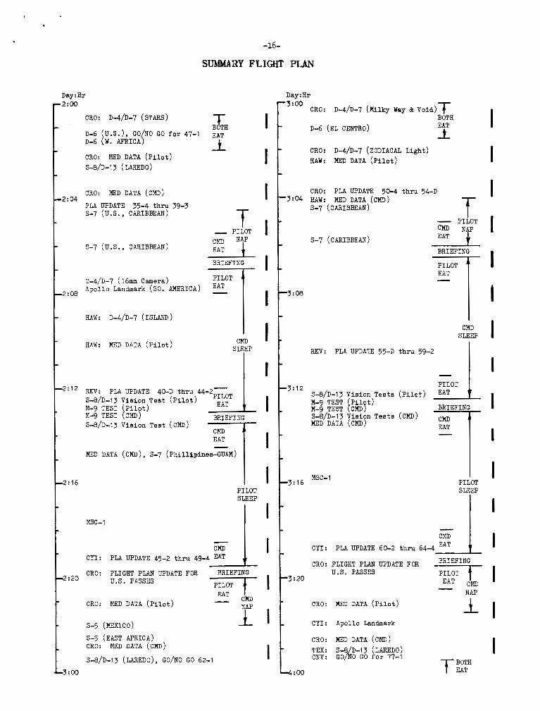
SUMMARY FLICHT PLAN
Day : H r .O:OO Lift-off
A l i g n PLAT, INSERTION Checkl i s t RAD-FLOW, CRO: GO/NO GO 6-4, GO/XO GO D-4/D-7
Align PLAT - SEF
COOLED Spectrometer Align (D-4/D-7) RADAR-ON, REP EJECT COOLED SENSOR REP Measurements (D-4/D-7) Align PLAT - SEF S/C CLOSING MANEWER, Radar Tes t No. 1 Radar Test No. 2 , No. 3
d : 0 4 Radar Test No. 2 CO-ELLIPTICAL MANEWER W T = 180° Transfer Maneuver W T = 82' Correc t ion Maneuver UT = 34' Correc t ion Maneuver
RENDEZVOUS, D-2 SEPARATION MANEXJVER POWER DOWN: COMPUTER, RADAR, PLATFORM and
SCANNER GO/NO GO 18-1
1 f
-0:W RAD & I R SPECT. Align (D-4/D-7) PWR-DOWN S/C
D-4/D-7 CRYOGENIC Gas Lifetime
PLA UPDATE 9-3 th ru 13-2 D-4/D-7 CRYOGENIC Gas Lifetime
1 SLEEP
-0:12 D-4/D-'l CRYOGENIC Cas Lifetime
MED DATA ( P i l o t )
~ - g TEST ( P i l o t )
S-8/D-l3 Vision Test (CMD)
S-8/D-13 Vision Test ( P i l o t )
M-9 TEST (CMD)
-0: 16 MED DATA (CMD)
PLA UPDATE 14-2 t h n 19-4
-0:20
PILOT - . I BRIEFING
'T PILOT
FLIGHT PLAN UPDATE FOR US PASSE
NAP - MED DATA (PILOT )
-1 :oo CNV: D-4/D-7 Miss i le MEASUAEMENT
I
I
I
I I
I
I
I
I
I I
I I
I I
I
Day : H r
' l :oo D-6 ( C Y I ) D-6 ( E . AFRICA) CRO: D-4/D-7 STAR D-6 (U.S . ) CNV: GO/NO GO f o r 33-1 D-6 W . A F R I C A D-6 [E. A F R I C A { , & E D DATA (Pi1ot)BOTH
7- 3
D-1 MOON TRACK, D-4/D-7 MOON MEASUREMENT
(::E:] D-6 (S. AFRICA) CRO: PLA UPDATE 20-4 t h n 24-3 , I :04 S-8/D-13 (LAREDO) p lus Window MEASUREMENT
T-
MED DATA (CMD) t PILOT
Eas tern Pacific.Caribbean - NAP s-7 &%ite Ca l ib ra t ion CARD 3 C M D I
. 1 : 0 8 MSC-1
EAT 1 BRIEFING
PILOT
CMD RKV: PLA UPDATE 25-D th ru 29-2 SLEEP
1
.1:12
FKV: MED DATA ( P i l o t )
S-8/D-13 Vision Tes t ( P i l o t ) ~ - 9 ' TEST ( P i l o t ) M-c) TEST CMD) MED s-6/~-13 DATA i i s i o h (CMD) Tes t (CMD)
3-7 (Phillipines-GUAM)
,I PILOT
RRIEFING
.1:16
I S-7 (Phillipines-GUAM) PILOT
SLEEP Msc-1
Apollo Landmark ( W . AFRICA) CMD - I CRO: PLA UPDATE 30-2 t h r u 34-1 5
BRIEFING -1 :20
PILOT MED DATA ( P i l o t ) EAT CMD - CRO: FLIGHT PLAN UPDATE
FOR U.S . PASSES
MED DATA (CMD)
s-8/~-13 ( LAREDO PHOTO PASS) -2 : 00
I
I I I
I I I
I 1
I
I
I I
I I
I
,
I I -
I -
I
I . I -
I .
I -
I I -
I -
I
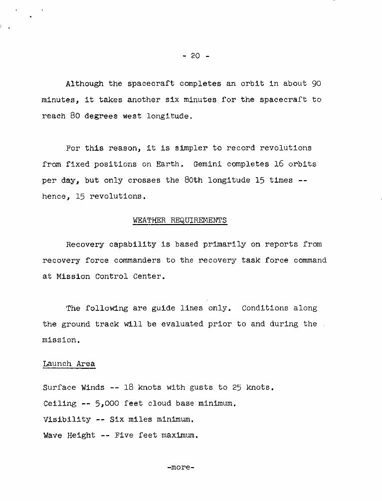
-16-
SUMMARY FLIGHT PTAN
-3:04
-
-3:08
-
-3:12
-
-3:16
-
-3:20
D a y : H r D a v : H r
I
3 : b O
I I
CRO:
D-6 ( E L CENTRO)
CRO: D-4/D-7 (ZODIACAL L i g h t ) HAW: MED DATA ( P i l o t )
D-4/D-7 (Milky Way & V o i d ) T BOTH
2:oo
T CRO: D-4/D-7 ( S T A R S )
D-6 (U.S.) , GO/NO GO f o r 4 7 - 1 D-6 (W. AFRICA)
CRO: MED DATA ( P i l o t ) S-8/D-13 ( LAREDO)
BOTH EAT
04
2:08
!:12
!:I6
' :20
CRO: MED DATA (CMD)
PLA UPDATE 35-4 thm 39-3 s-7 ( u s . , CARIBBEAN) T
EAT s-7 (u.s., CARIBBEAN)
B R I E F I N G
A p o l l o L a n d m a r k (SO. AMERICA) - D-4/D-7 ( 1 6 m m C a m e r a )
HAW: D-4/D-7 (ISLAND)
HAW: MED DATA ( P i l o t ) CMD S L E E P
RKV: PLA UPDATE 40-D t h ru 44-2-
EAT 1 S-8/D-l3 V i s i o n T e s t ( P i l o t ) M-9 T E S T P i l o t ) M-9 T E S T [CMD) B R I E F I N G S-8/D-l3 V i s i o n T e s t (CMD)
P I L O T
=7- EAT -
MED DATA (CMD) , S-7 ( P h i l l i p i n e s - G U A M )
P I L O T S L E E P
Msc-1
C Y I : PLA UPDATE 45-2 thru 49-4 EAT
CRO: F L I G H T PLAN UPDATE FOR B R I E F I N G -1 %G-r U.S. P A S S E S
CRO: MED DATA ( P i l o t ) EAT I - CMJ)
NAP I
s-5 (MEXICO) 1
I CRO: P L A UPDATE 50-4 t h n 54-D
T HAW: MED DATA (CMD) s-7 (CARIBBEAN)
s-7 (CARIBBEAN)
B R I E F I N G
P I L O T
I RKV: PLA UPDATE 55-D thm 59-2
- I ' P I L O T
S-8/D-13 V i s i o n T e s t s ( P i l c t ) EAT 1 B R I E F I N G M-9 S-8/D-l3 TEST V i s i o n [CMDY T e s t s (CMD) 7
MED DATA (CMD)
~ - 9 TEST P i 1 t )
I
MSC-1 P I L O T S L E E P
I ' C Y I : PLA UPDATE 60-2 thm 64-4 E l I CRO: F L I G H T PLAN UPDATE FOR
U . S . P A S S E S
CRO: MED DATA ( P i l o t )
C Y I : A p o l l o L a n d m a r k
P I L O T I EAT CMD
I s-5 (EAST AFRICA) CRO: MED DATA (CMD ) CRO: MED DATA (CMD)
s-s/~-l3 (LAREDO), GO/NO GO 62-1 TEX: s-8 D-13 (LAREDO) CNV: G O X O GO f o r 77-1
;:oo

-17-
SUMMARY FLIGHT PLAN
I I
I -
I -
I I -
I -
I - I -
I i - I - n
Day:& '4 : 00
- c
-5:m
-
+:12
-
-5: 16
-
3 : 2 0
-
4 : o o
CRO:
HAW :
ASC : CRO:
HAW : ~4 : 04
4:08
RKV:
4:12 m:
CSQ:
D-4/D-7 MITE SAND Missile MEASUREMENT
D 4 D - 7 Night, Water and Land
MED DATA ( P i l o t )
D-4/D-7 I s l and PIA UPDATE 65-4 t h m 70-D
MED DATA (CMD) CMD I-
MSC - 1 4:16
BRIEFING
PI LOT -1 SLEEP CMD
MED DATA ( P i l o t )
- PILOT I
EAT t BRIEFING
PLA UPDATE 71-D t h m 75-2
EAT MED DATA (Cm)
PILOT SLEEP
S-8/D-l3 Vision Teet (CMD) M-9 TEST C M D ) M-9 TEST [ P i l o t ) S-8/D-13 Viaion Tes t ( P i l o t )
MED DATA ( P i l o t ) KNO: D-4/D-7 Land Vegetation
CRO: PLA UPDATE 76-1 th ru 80-4
C Y I : MED DATA (CMD) BOTH D-6 (EAST AFRICA)
S-8/D-l3 (LAREDO), GO/NO GO 92-1
d:20 - CMD
T
5:oo
Day:& 5 :m
5:04
MED DATA ( P i l o t )
D-4/D-7 WRITE SAND Missile MEASUREMENT
D;4/D-7 ASC Ca l ib ra t ion
H A W : MED DATA (CMD) 1
T
PILOT t
EAT PILOT
CSQ: PLA UPDATE 81-3 t h r u 85-D T BRIEFING
EAT
CMD SLEEP
RKV: MED DATA ( P i l o t )
PILOT RKV: PLA UPDATE 86-D t h m 90-2 EAT -1
BRIEFING S-8/D-13 Vision Tes t ( P i l o t ) M-9 TEST ( P i l o t ) & ( C M D ) S-S/D-13 Vis ion Tes t (CMD) MED DATA (CMD )
MSC-1
CRO: S-5 (AUSTRALIA)
EAT -
PILOT SLEEP
D-4/D-7 (DESERT LAND & WATER)
MED DATA ( P i l o t )
BRIEFING
'Ga- EAT I - CMD
NAP + CRO: PLA WDATE 91-1 t h m 95-4 L
D-6 ( C Y I ) D-6 ( E . A F R I C A ) MED DATA ( C i h ) , D-1
CNV: GO/NO GO 107-1 t BOTH D-6 ( A F R I C A ) - 2 runs
D-I (CELESTIAL BODY) F"'
I
I
1
I I I i
I I I I
I I
I I I I

. -18-
SUMhdAW FLIGHT PLAN
Day:&
':0° D-6 (U.S.) MED DATA ( P i l o t ) I r L I
MED DATA (CMD) CMD T :04 CSQ: PLA UPDATE 96-3 t h r u 101-D t
L I
6:08 1 BRIEFING 't I I -
I ' CMD
SLEEP I I PILOT TT 1 BRIEFING
MED DATA ( P i l o t )
S-8/D-l3 Vision Tes t ( P i l o t ) M-9 TEST ( P i l o t )
6:12 M-9 TEST (CMD) S-S/D-13 Vision Test (CMD) MED DATA (CMD) RKV: PLA UPDATE 102-2 th ru 106-1-
t I PILOT I SLEEP
I MSC-1 I I
-
CRO: FLIGHT PLAN UPDATE FOR BRIEFING U.S. .PASSES
- 1 - C Y I : MED DATA ( P i l o t )
: 20 CRO: PLA UPDATE 107-1 th ru 1 1 1-3 I, D-6 ( C Y I ) D-6 (E. AFRICA) CRO: MED DATA (0)
GO/NO GO 122-1, Apollo Landmark I r 1 B ~ T H
T I
Day:Hr
-7:00 Apollo Landmark (FLORIDA)
MED DATA ( P i l o t ) I S-8/D-l3 (LAREDO) p lus Window MEASURPIENT
I
MED DATA (CMD)
-7:04
i I pF I
CMD T
HAW: PLA UPDATE 112-3 t h N 11 6-D
MED DATA ( P i l o t )
-7:08
MED DATA (CMD) -7:12 ruiv: PLA UPDATE 117-2
t h m 121-1
-7:16
S-S/D-13 ( P i l o t )
MED DATA ( P i l o t )
BRIEFING
-3Ff-I I -
I ' ' PILOT - 1 i
EAT t
- 1 ' I
PILOT I SLEEP
BRIEFING - NAP
CRO: PiUPDATE 122-1 t h r u 126-3
~ - 9 TEST ( P i l o t ) ~ - 9 TEST ( c m ) S-8/D-13 Vision Tes t ( C M D ) MED DATA (CMD) ,
GYM: POWER-UP Check l i s t 1 P r e r e t r o Checklist BOTH
POST-RETRO Checklist Guidance i n i t i a t e Post-Landing Checkl i s t
q : 2 0 S-S/D-l3 Vision Tes t s ( P i l o t )
D-4/D-7 (SUN)
I
EAT I T 4:oo

I
The longer time for revolutions
rotation. As the spacecraft circles
moves about 22.5 degrees in the same
-more -
i
FLIGHT DATA
Launch Azimuth -- 7 2 degrees,
Flight Duration -- Approximately 191$ hours Initial Orbital Parameters -- 100 - 219 miles. Reentry Velocity -- About 24,000 feet per second; 16,450
miles per hour.
Reentry Temperature -- About 3,000 degrees F on heat shield surface.
Landing Point -- Atlantic Ocean about 500 miles southwest of Bermuda; 70 degrees west, 29 degrees north,
Oxygen -- Cabin Enviornment, 100 p e r cent oxygen pressurized at five pounds per square inch.
Retrorockets -- Each of four retrorockets produce approximately 2,500 pounds of thrust for 5.5 seconds. Fire sequentially.
ORBITS - REVOLUTIONS
During Gemini flights the spacecraft's course is measured
in revolutions around the Earth. A revolution is completed
when the spacecraft passes over 80 degrees west longitude,
about once every 96 minutes.
Orbits are space referenced and take about 90 minutes.
is caused by the Earth's
the Earth, the Earth
direction.
- 20 -
Although t h e spacecraf t completes an o r b i t i n about 90
minutes, i t takes another s i x minutes f o r t he spacec ra f t t o
reach 80 degrees west longi tude,
For t h i s reason, it i s s i m p l e r t o record revolu t ions
from f i x e d p o s i t i o n s on E a r t h . Gemini completes 16 o r b i t s
per day, bu t only c rosses the 80th longi tude 15 times -- hence, 15 revolu t ions .
WEATHER REQUIRENENTS
Recovery c a p a b i l i t y i s based primarily on r e p o r t s from
recovery fo rce commanders t o t h e recovery task fo rce command
a t Mission Control Center.
The following a r e guide l i n e s only. Conditions along
t h e ground t r a c k wi l l be evaluated p r i o r t o and during the
mission.
Launch Area
Surface Winds -- 18 knots with g u s t s t o 25 knots.
Cei l ing -- 5,000 f e e t cloud base minimum.
V i s i b i l i t y -- S i x mi les minimum.
Wave Height -- Five f e e t maximum.
-more-

Planned Landing Areas
Surface Winds -- 30 knots maximum.
Cei l ing -- 1,500 f e e t cloud base minimum.
V i s i b i l i t y -- S i x miles minimum.
Wave Height -- Eigh t f e e t maximum.
Contingency Landing Areas
Weather and s t a t u s of contingency recovery fo rces w i l l
be cont inual ly monitored.
Mission Director who w i l l make t h e go-no-go dec i s ion based upon
condi t ions a t t h e time.
Recommendations w i l l be made t o t h e
Pararescue
The decis ion t o u s e pararescue personnel depends upon
weather conditions, su r f ace v e s s e l l oca t ions and the a b i l i t y
t o provide a i r dropped suppl ies u n t i l t he a r r i v a l of a sur face
vesse l .
master.
The f i n a l dec is ion t o jump w i l l be made by the jump-
Weather gu ide l ines f o r pararescue opera t ions a r e :
Surface Winds -- 25 knots maximum.
Ceiling -- 1,000 f e e t cloud base minimum.
V i s i b i l i t y -- Target v i s i b l e .
Waves -- Five f e e t maximum, swel l s 10 o r 11 f e e t maximum.
-more -
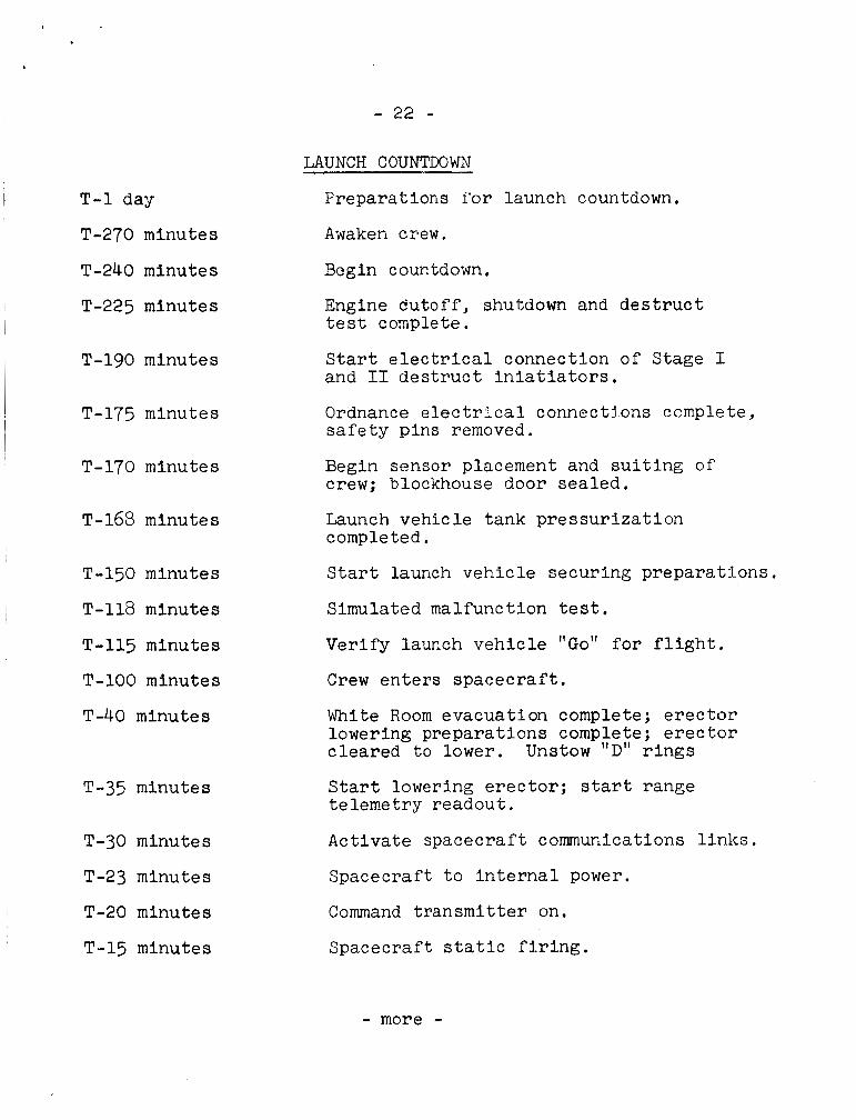
- 22 -
LAUNCH COUNTDOWN
I T - 1 day
T-270 minutes
T-240 minutes
I T-225 minutes
I T-190 minutes
~ T-175 minutes
T-170 minutes
I T-158 minutes
T-150 minutes
I T-118 minutes
T-115 minutes
T-100 minutes
T-40 minutes
T-35 minutes
T-30 minutes
T-23 minutes
T-20 minutes
T-15 minutes
Preparations f o r launch countdown.
Awaken crew.
Engine c?utoff, shutdown and d e s t r u c t t e s t complete.
S t a r t e l e c t r i c a l connection of Stage I and I1 d e s t r u c t i n i a t i a t o r s .
Ordnance e l e c t r i c a l connections complete, s a f e t y p ins removed.
Begin sensor placement and s u i t i n g o f crew; blockhouse d o o r sea led .
Launch vehicle tank p res su r i za t ion completed,
S t a r t launch vehic le securing preparat ions.
Simulated malfunction t e s t ,
Verify launch vehic le "Go" f o r f l i g h t .
Crew en te r s spacec ra f t ,
White Room evacuation complete; e r e c t o r lowering preparat ions complete; e r e c t o r c leared t o lower, Unstow "D" r i n g s
S ta r t lowering e r e c t o r ; s ta r t range te lemetry readout.
Act ivate spacecraf t communications l i n k s .
Spacecraft t o i n t e r n a l power.
Command t r ansmi t t e r on,
Spacecraft s t a t i c f i r i n g .
- more -
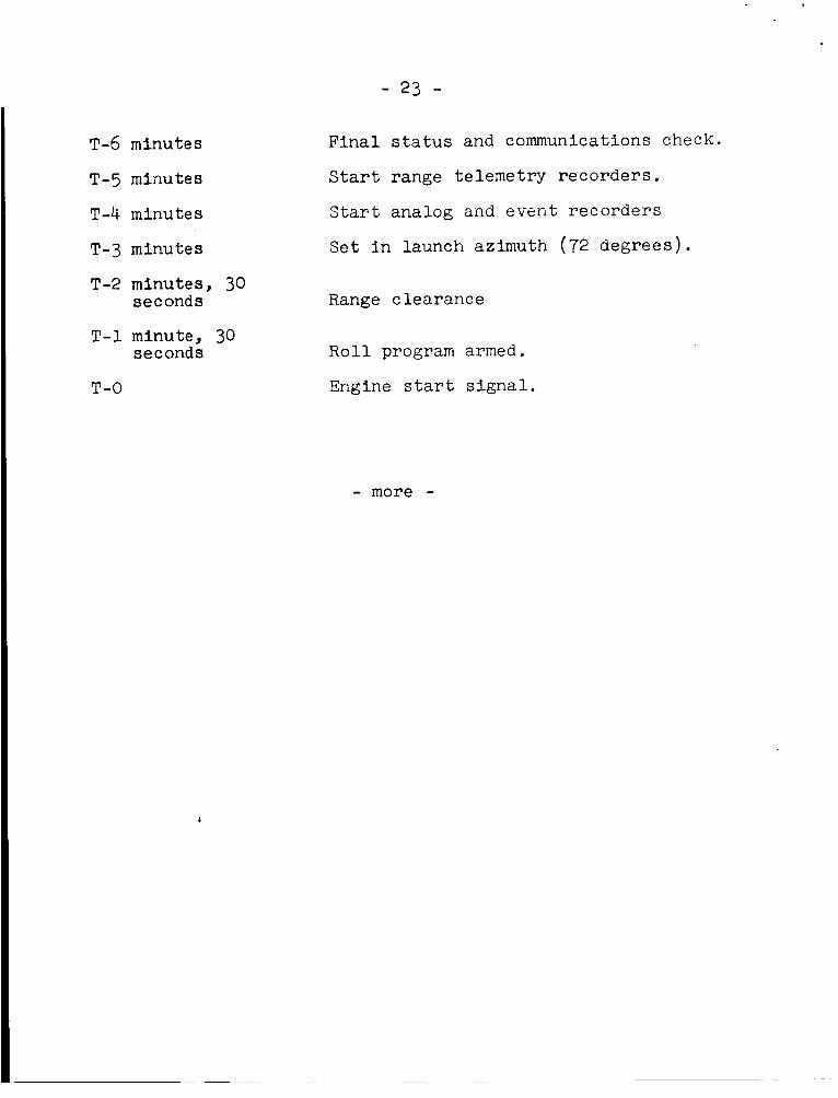
- 23 -
T-6 minutes
T-5 mi-nutes
T-4 minutes
T-3 minutes
T-2 minutes, 30 seconds
T-1 minute, 30 seconds
T-0
Fina l s t a t u s and communications check.
Star t range telemetry recorders .
S t a r t analog and event recorders
Se t i n launch azimuth (72 degrees) .
Range clearance
R o l l program armed.
Engine s t a r t s i g n a l .
- more -

- 24 -
CREW SAFETY
Every Gemini system affecting crew safety ha8 a redun-
dant (back-up) feature. The Malfunction Detection System in
the launch vehicle monitors subsystem performance in the ve-
hicle and warns the crew of a potentially catastrophic mal-
function in time for escape.
During the powered phase of flight there are three modes
for crew escape :
(1) Ejection seats.
(2) Firing the retrorockets to separate the spacecraft
from the launch vehicle, then initiating the epaoeoretft re-
covery system.
(3) Normal spacecraft separation followed by use of the
thrusters and retrorockets.
Escape procedures will be Initiated by the command pilot
following two valid cues that a malfunction has occurred.
procedures are :
Abort
(1) Lift-off to 50 seconds -- Immediate ejection for all malfunctions.
(2) Fifty seconds to 100 seconds -- Delayed retro-abort
for all malfunctions.
-more-

,
- 25 -
ABORT PROCEDURES
MODE I - EJECT AFTER SHUTDOWN
MODE II - SALVO RETROS AFTER SHUTDOWN
MODE III - SHUTDOWN, SEPARATE, TURN AROUND, RETROFIRE
t MODE-
20,700 FPS VELOCITY
78,000 FT
DELAYED V/Il \\\s \*& n MODE 50
SECON I I (WAIT 5 SECS )
SEA LEVEL -- -- - 50 SECONDS

. - 25 -
This c o n s i s t s of arming abort c i r c u i t s , waiting about
f i v e seconds af ter engine shutdown u n t i l aerodynamic pressure
has decreased, then sa lvo f i r i n g the f o u r r e t r o r o c k e t s t o
sepa ra t e from the launch vehicle .
(3) After 100 second8 of f l i g h t , aerodynamic drag will
have decreased t o the poin t where no delay is requi red for
separation.
approxiniately 20,700 f p s (14,000 rnph) o r 80 percent of that
requi red t o g e t i n t o o r b i t i s achieved.
percent of v e l o c i t ) iqcq!ii~ed f o r o r b i t has been achieved,
normal spacec ra f t sepal-ation w i l l be used for a l l malfunctions.
The crew w i l l then resume r e t r o a t t i t u d e , i n s e r t landing a r e a
parameters i r i the CW?pt.;tei-, r ? t r o f i r e , arid descend. t o a planned
recovery a rea .
Retro-abort will be used u n t i l a v e l o c i t y of
Where more than 'CJO
Inf l i g h t
There a r e no s i n g l e point f a i l u r e s which would jeopardize
crew s a f e t y during i n f l i g h t operations. All systems and sub-
systems have back-up f e a t u r e s o r t h e r e i s an a l t e r n a t e method.
The space s u i t i t se l f i s a back-up system.
pressure f a i l , the space s u i t provides l i f e support .
Should cabin

- 27 -
Reentry, Landing and Recovery
The Reentry Control System (RCS) con t ro l s t he spacecraf t
a t t i t u d e during r e t ro rocke t f i r i n g and r e e n t r y , Two complete
and Independent systems provide 100 pe r cent redundancy, The
fou r r e t ro rocke t s are wired wi th d u a l i g n i t e r s ,
The Orbi t ing At t i tude Maneuvering System i s used t o per-
form t r a n s l a t i o n maneuvers along t h r e e axes of the spacec ra f t
and provide a t t i t u d e con t ro l during o r b i t a l phases of t he
mission,
Parachutes are used for descent following spacecraf t
r een t ry , If t h e r e i s , a parachute malfunction the crew w i 1 . 1
e j e c t from the spacec ra f t and use personal chutes for landing.
Survival equipment i s c a r r i e d on the backs of t he e j e c t i o n
s e a t s and remains a t tached t o t h e a s t r o n a u t s u n t i l they land ,
Recovery fo rces will be provided by t h e mi l i t a ry se rv ices
and during mission time w i l l be under t h e opera t iona l con t ro l
of t h e Department of Defense Manager for Manned Space F l i g h t
Support Operations.
-more-

GEMINI PARACHUTE LANDING
50,000 FEET -
21,000FEET - 10,600 FEET - 9,600 FEET - 9,000 FEET -
6,700 FEET -
1,500 FEET - - SEA LEVEL
SEQUENCE
- HIGH ALTITUDE DROGUE CHUTE DEPLOYED
OPENCABIN VENT VALVE
- - PILOT PARACHUTE.
DEPLOYED
R a R SECTION - SEPARATION
- MAINCHUTE DEPLOYMENT
TWO -POINT SUS PENS I ON
-
CABIN WATER SEAL CLOSED
- - TOUCHDOWN
- JETTISON CHUTE -
- 29 -
Planned and contingency landing areas have been es tab-
l ished. Planned areas a r e those where t h e p r o b a b i l i t y of'
landing is s u f f i c i e n t l y high t o j u s t i f y pre-pos i t ion ing of
recovery fo rces f o r support and recovery of crew and space-
c r a f t within given access t imes.
Contingency areas a r e a l l o the r areas along the ground
t r a c k where t h e spacec ra f t could poss ib ly land. The proba-
b i l i t y of landing i n a contingency area i s s u f f i c i e n t l y low
that spec ia l search and rescue techniques w i l l provide ade-
quate recovery support .
There are f o u r types of planned landing areas:
(1) Primary Landing Area -- Landing will occur with
normal terminat ion of the mission a f t e r 121 revolu t ions .
T h i s area i s i n the At l an t i c Ocean, about 500 mi les south-
west of Bermuda.
( 2 ) Secondary Landing Areas -- Where a landing would
occur if it i s d e s i r a b l e t o terminate the mission e a r l y f o r
any cause. Ships and a i r c r a f t w i l l be s t a t i o n e d t o provide
support . A i rc ra f t w i l l be ab le t o drop pararescue personnel
and flo 'cation equipment within one hour a f t e r spacec ra f t
landing . -more -
~

- 30 -
(3) Launch Abort Landing Areas -- Along the launch
ground t r a c k between F l o r i d a and Afr ica where landings would
occur following abor t s above 45,000 f e e t and before o r b i t a l
i n s e r t i o n . Surface sh ips with medical personnel and r e t r i e v a l
equipment, and search and rescue a i r p l a n e s w i t h pararescue
personnel, f l o t a t i o n equipment and e l e c t r o n i c search capa-
b i l i t y w i l l be s t a t ioned i n t h i s a r e a before launch. After
the success fu l i n s e r t i o n of t h e spacec ra f t i n t o o r b i t , some
of the sh ips and planes w i l l deploy t o secondary areas t o
provide support on later revolu t ions and the remainder w i l l
r e t u r n t o home s t a t i o n s .
( 4 ) Launch S i t e Landing Area -- Landing will occur follow:i.ng
an abor t during countdown, launch and e a r l y powered f l i g h t i n
which e j e c t i o n seats a r e used. It includes an area of approxi-
mately 41 miles seaward and three mi les toward the Banana River
from Pad 19. Its major a x i s i s o r i en ted along the launch
azimuth.
A spec ia l i zed recovery force of land vehicles , amphibious
c r a f t , ships and boats , a i rp l anes and h e l i c o p t e r s w i l l be sta-
t i oned i n t h i s a r e a from t h e time t h e a s t ronau t s e n t e r t he
spacec ra f t u n t i l l i f t - o f f p l u s f i v e minutes.
-more-

- 31 -
Contingency Landing Areas:
Search and rescue a i r c r a f t equipped with e l e c t r o n i c
search equipment, pararescue men and f l o t a t i o n equipment w i l l
be staged along t h e ground and sea t r a c k s o that the space-
c r a f t w i l l be loca ted and a s s i s t a n c e given t o t h e a s t ronau t s
within 18 hours a f te r recovery fo rces are n o t i f i e d of the
probable landing pos i t i on .
GEMINI SURVIVAL PACKAGE
The Gemini s u r v i v a l package contains 14 i tems designed
t o support an a s t ronau t i f he should land outs ide normal re-
covery areas . The package weighs 23 lbs. and has two sec t ions . One
sec t ion , holding a 3&pov.nd water conta iner
mounted by t h e a s t r o n a u t f s l e f t shoulder. The main package,
containing t h e l i f e raf t , and r e l a t e d equipment, i s mounted
on t h e back of t h e e j e c t i o n seat.
t o the a s t r o n a u t f s personal parachute harness by a nylon l i n e .
After e j e c t i o n from the spacecraf t , as the seat fa l ls c l e a r
and t h e parachute deploys, the s u r v i v a l kit w i l l hang on a
l i n e , ready f o r use as soon as the a s t ronau t lands .
and machete i s
Both packages a r e a t tached
=more-

- 32 -
Inflated, the one-man life raft is five and one half
feet long and three feet wide. A C02 bottle is attached f o r
inflation. The raft is also equipped with a sea anchor, sea
dye markers, and a sun b.onnet of nylon material with an alu-
minized coating which the astronaut can place over his head.
In his survival kit, the astronaut also has a radio bea-
con, a Combination survival light, sunglasses, a medical kit,
and a desalter kit assembly.
The combination survival light is a new development f o r
the Gemini kit, combining many individual items which were
carried in the Mercury kit. About the size of a paperback
novel, it contains a strobe light f o r signaling at night, a
flashlight, and a signal mirror built in on the end of the
case. It also contains a small compass.
There are three cylindrical cartridges inside the case.
Two contain batteries for the lights. The third contains a
sewing kit, 14 feet of nylon line, cotton balls and a striker
for kindling a fire, halazone tablets f o r water purification
and a whistle.
-more -

- 33 -
The d e s a l t e r k i t includes e i g h t d e s a l t e r b r i c k e t t e s ,
Each b r i c k e t t e can d e s a l t one p i n t and a processing bag.
of seawater . The medical k i t contains a one-cubic-centimeter i n j e c t o r
for pain, and a two-cubic-centimeter i n j e c t o r f o r motion s i ck -
ness. There a l s o a r e s t imulant , pain, motion s ickness , and
a n t i b i o t i c t a b l e t s and a s p i r i n .
G E M I N I 5 SUIT
The space s u i t worn by both a s t ronau t s f o r t he Gemini 5
mission incorpora tes a l l t h e advances of t h e 4-C or ex t r a -
vehicular s u i t , without t h e bulk iness of e x t r a p r o t e c t i v e
l aye r s . The s u i t r e t a i n s the double z ipper arrangement, t h e
th i ck , e x t r a s t rong f acep la t e , and attachment po in t s for t h e
sun v i so r ,
ex t ravehicu lar a c t i v i t y .
However, t h e Gemini 5 s u i t will not be used for
The b a s i c s u i t has f i v e l a y e r s . The innermost l a y e r i s
a white constant wear undergarment made of cot ton.
nylon comfort layer provides a s t r o n a u t wearability during
long periods of time.
ment, a black neoprene coated nylon.
l ink net dacron and tef'lon used to r e s t r a i n t h e pressure l aye r .
A b l u e
The t h i r d l a y e r i s the pressure gar-
The f o u r t h l a y e r i s a
-more- ~
- 34 -
The outer layer is HT-1 nylon, a protective layer which
gives protection against wear and solar reflectance.
It is a full pressure suit which works in conjunction
with the environmental control system.
distributed through the suit ventilation system for cooling
and respiration. A 100-per cent oxygen environment at five
pounds per square inch in a pressurized cabin or 3.7 psia in an unpressurized cabin is provided.
Gaseous oxygen is
8
- 35 -
FOOD FOR G E M I N I 5
Six basic meals, comprised of 22 items, w i l l be ca r r i ed
aboard Gemin i 5. Except for juices, a l l t h e food i s b i t e -
s i z e and needs no rehydrat ion. This allows s torage of more
food f o r longer missions, a n d permits e a s i e r handling a n d
preparat ion by t h e crew.
Astronauts w i l l e a t t h r e e meals d a i l y . These meals a r e
s tored i n 24 packages i n compartments between the command
p i l o t and p i l o t .
f i r s t meal of t he f i r s t day on top . Packages a r e connected by
a t h i n nylon lanyard t o prevent them from g e t t i n g o u t of
orde r while f l o a t i n g weight less i n t h e i r compartments.
They are marked by day and meal, with t h e
Ju i ces are rehydrated w i t h water from t h e crew's
dr inking supply, employing a s p e c i a l water gun designed t o
a l low the crew t o dr ink even while su i t ed and pressur ized .
Bi te -s ize i tems need no rehydration, but a r e sur face t r e a t e d
w i t h spec ia l coa t ings t o prevent crumbling. S i x cubes a r e
wrapped together i n spec ia l p l a s t i c con ta ine r s for easy
dispensing.
-more-
- 35 -
The food formulation concept was d e v e l o p e d by the U.S.
Army Laborator ies , Natick, Mass, Overall food procurenenl.,
processing, and packaging was performed by the Whirlpool
Corp., St. Josephl, Micli. P r inc ipa l f'ood con t r ac to r s arc
Swift a n d Co,, Chicago, and Pi l l sbury Co., Minneapoli s .
-more-
l:
- 37 -
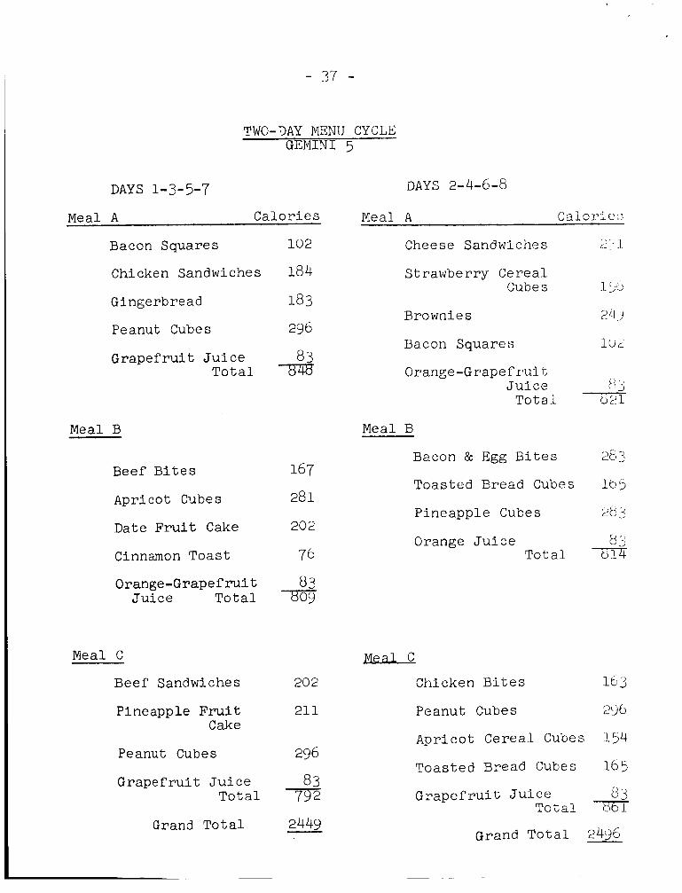
TWO-DAY MENU CYCLE G E M I N I 5
DAYS 1-3-5-7 Meal A Calor ies
Bacon Squares
Chicken Sandwiches
Gingerbread
Peanut Cubes
Grapefrui t J u i c e Tota l
Beef B i t e s
Apri cot Cubes
Date Fru i t Cake
Cinnamon Toast
Orange-Grapefruit Ju i ce Tota l
Meal C
Beef Sandwiches
Pineapple F r u i t Cake
Peanu t Cubes
Grapefrui t J u i c e Tota l
G r a n d Total
DAYS 2-4-6-8
Meal A C a 1 c 12i e :;
Cheese Sandwiches r: * 1
Strawberry Cereal Cubes I. :)I.>
Brownies 2 4 j
Bacon Squares 1UL
Orange-G rape f r u i L J u i c e pl j
Total 7 Meal B
Bacon & Egg B i t e s 2e 3
Toasted Bread Cubes lbb
Pineapple Cubes L)tj ..I 2
Orange J u i c e 8 '-' Total -8-d
s Chicken B i t e s l b 3
Peanut Cubes 2i)b
Apricot Cereal Cubes 154
Toasted Bread Cubes 165 3 13 Grapefru i t J u i c e
Total c,61
G r a n d Tota l 2496

MEDICAL CHECKS
Three medical checks a day w i l l be made by each crew rnembt.ii.
They w i l l be performed over a convenient ground s t a t i o n . A
check w i l l cons i s t o f the following opera t ions : a n oral tempera-
t u r e measure, b lood pressure measurement, an exe rc i se of 30
p u l l s (one p e r second) on t h c exe rc i se r . A second b!ood pressure
measurement a n d a food a n d water i n t a k e eva lua t ion .
BODY WASTE DISPOSAL
Two separa te systems have been devised for the c o l l e c t i o n
of body wastes.
A p l a s t i c bag wi th a n adhesive l i p t o provide secure
attachment t o the body i s used for t h e c o l l e c t i o n of feces .
It conta ins a germicide which prevents f'Jrmation of b a c t e r i a
and gas . Soi led items, t o i l e t t i s s u e s and a w e t towel, a r e
placed i n t h e bag following use , The adhesive l i p i s then
used t o form a l i q u i d s e a l a n d t h e bag i s r o l l e d a n d s t c w e d i n
the empty food conta iner spaces and brought back t o Earth f o r
a n a l y s i s ,
Urine i s co l l ec t ed i n t o a horn-shaped r ecep tac l e with a
s e l f a d j u s t i n g opening. The receptac le i s connected by a hose
t o a pump device which e i t h e r t r a n s f e r s the l i q u i d t o a conta iner
or dumps i t overboard. The s y s t e m i s much l i k e t h e r e l i e f tube
used i n m i l i t a r y f i g h t e r planes. -more-
- 39 -
G E M I N I SPACECRAFT
The Gemini spacecraf t i s conica l 18 f e e t , 5 inches long,
10 f e e t across a t the base and 39 inches across a t the top.
It has t w o major sec t ions , t he r een t ry module and the adapter
s ec t ion .
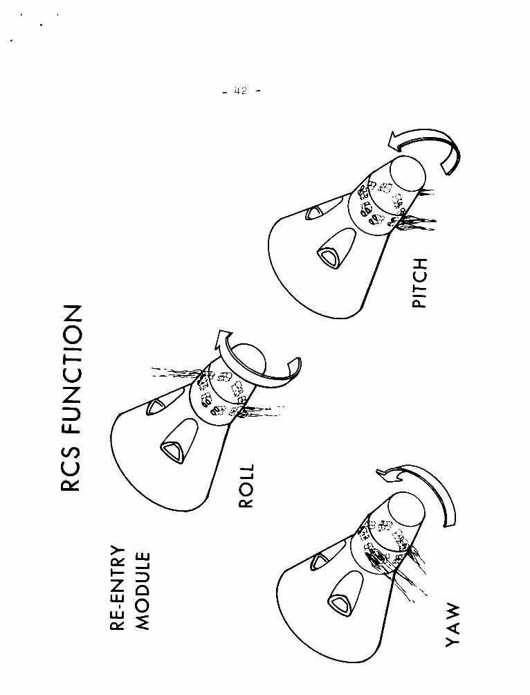
Heentrv Module
The reent ry module i s 11 fee t high and 73 f e e t i n diameter
a t i t s base. It has three primary sec t ions : (1) rendezvous
and recovery sec t ion (R&R); ( 2 ) r een t ry cont ro l s ec t ion (RCS);
(3 ) cabin sec t ion .
The rendezvous a n d recovery sec t ion i s the forward ( smal l )
po r t ion of t h e spacecraf t . Housed i n t h i s s ec t ion are t h e
drogue, p i l o t and main parachutes a n d t h e rendezvous radar.
The reent ry cont ro l system i s loca ted between the rendezvous
and recovery sec t ion and t he cabin sec t lon . It conta ins f u e l
and oxid izer t a n k s , valves, tubing a n d t h r u s t chamber assembEies
( T C A ) . A parachute adapter assembly i s o n the forward face f o r
the m a i n parachute attachment.
- 40 -
The cabin sec t ion i s located between the r een t ry cont ro l
s ec t ion and the adapter sec t ion . It houses t h e crew seated
side-by-side, e l e c t r i c a l and l i f e support equipment and expe r i -
mental devices.
and leaving t h e cabin.
and spaces containing equipment that requi re no p res su r i za t ion
o r which a r e i n t e r n a l l y pressurized are located between the
pressurized sec t ion and t h e outer s h e l l . The o u t e r shel l i s
covered wi th overlapping shingles t o provide aerodynamic and
heat pro tec t ion .
end of the cabin sec t ion and reentry module,
Above each sea t i s a ha tch opening f o r en te r ing
The crew compartment i s pressurized
A dish-shaped heat sh i e ld forms the l a r g e
Adapter Sect ion
The adapter i s 74 feet high and 10 f ee t i n diameter a t
the base ,
ment sec t ion .
It c o n s i s t s of a re t rograde sec t ion and a n equip-
The re t rograde sec t ion contains re t rograde rockets and
par t of t h e r a d i a t o r f o r the cooling system.
-more-

- 41 - The equipment s ec t ion holds b a t t e r i e s f o r e l e c t r i c a l
power, f u e l f o r t h e o r b i t a t t i t u d e and maneuver system (OAMS),
t he primary oxygen f o r the environmental cont ro l system. It
a l s o serves as a r a d i a t o r f o r the s p a c e c r a f t ' s cooling system
which i s c o n t a i n e d i n t h e sec t ion . The equipment sec t icn i s
j e t t i soned immediately before the r e t r o r o c k e t s a r e f i r e d f o r
r een t ry and t h e re t rograde sec t ion i s j e t t i s o n e d a f t e r t h e
r e t ro rocke t s a r e f i r e d .
The Gemini spacec ra f t weighs approximately 7,000 pounds
a t launch.
when i t l a n d s .
The r een t ry module weighs about 4,700 pounds
McDonnell A i rc ra f t Corp., S t . Louis, i s prime con t r ac to r
f o r the Gemini spacecraf t .
-more-
-
- 42 -


- 44 -
LIL I- Z
LL
V
I- L L <

- 45 -
w UJ a z 6 I: U
E LLI N -

- 45 -
t Lu z Z 4
4 E E
z 4 II V
N

- 47 -
ELECTRICAL POWER SYSTEM
The f u e l c e l l power subsystem inc ludes two 68-pound
pressurized f u e l c e l l sec t ions , each containing t h r e e f u e l
c e l l s t a c k s of 32 series-connected c e l l s . Operating together ,
these sec t ions produce up t o two k i l o w a t t s of DC power a t
peak load.
Four conventional s i l v e r zinc b a t t e r i e s provide backup
power t o the f u e l c e l l s during launch and primary power’ f o r
reent ry , landing and post-landing. Three add i t iona l b a t t e r i e s
a re i s o l a t e d e l e c t r i c a l l y t o a c t i v a t e pyroteehnics aboard the
spacecraf t . (The f o u r main b a t t e r i e s can a l s o be brought on
l i n e f o r t h i s purpose i f necessary.)
Besides i t s two c y l i n d r i c a l s ec t ions , t he f u e l c e l l
b a t t e r y subsystem inc ludes a r eac t an t supply of hydrogen and
oxygen, s tored a t s u p e r c r i t i c a l p re s su res and cryogenic tempera-
t u r e s .
Energy i s produced i n the f u e l c e l l by fo rc ing the r e a c t a n t s
i n t o t he s t a c k s where they a re chemically changed by a n e l e c t r o -
l y t e of polymer p l a s t i c a n d a c a t a l y s t of platinum. Resul taqt
e l e c t r o n s a n d i o n s combine w i t h oxygen t o form e l e c t r i c i t y ,
heat and water. T h i s chemical r eac t ion w i l l t h e o r e t i c a l l y
-more-

continue as lo?& as f u e l and oxidant a r e supp l i ed . E l c c -
t r i c i t ; y i s used for power, heat i s r e j ec t ed by t h e spacecraf t
coolan' i sys tem, a n d water i s diverbed l n t o ?,lie s p a c e c r n f t
dr inking supply tanks where i t i s separated from the cww's
drinking zupply by a 'c1,idder and used as prcs su ran t Go
supply drinking water.
RENDSZVOUS RADAR
The rendezvous r ada r system, being flown f o r the first t i m e
aboard Gemini 5, enables the crew t o measure t h e range, i-ange
i>a te and bear ing angle of the R a d a r Evaluation Pod i n space.
The radar supp l i e s e s s e n t i a l data t o t he I n e r t i a l Guidance
System computer so the crew can determine the maneuvers neces-
s a ry to accomplish rendezvous.
The REP s u b s t i t u t e s f o r the Agena spacec ra f t t o be used
on i 'u ture rendezvous missions, and c a r r i e s a transponder which
receives radar. impulses from t h e G e m i n i ' s r ada r and reburns
them Lo t h e spacecraf t a t a s p e c i f i c frequency and pu l sc width.
T i i i $5 i :-> L * , l l . l c ~ ( l cooperative radar . On ly those s i g n a l s processed
L,,\,- ' lie i;L,anspsnder i n t he REP are accepted by t h e s p a c e c r a f t ' s
radar sysLerri, allowir,g the Crewto recognize t h e REP by i t s
coded r e t u r n s igna l . The r ada r r ece ive r aboard G e m i n i i s con-
fSgured to accept only t h e modified r e t u r n s i g n a l from the REP
t riansporidcr,
-more-
- 49 -
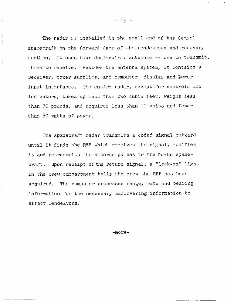
The r ada r . i d i n s t a l l e d i n t h e small end of t h e Gemini
spacecraf t on t he forward face o f t he rendezvous a n d recovery
sec t ion . It uses fou r dua l - sp i r a l antennae -- one t o t r a n s m i t ,
t h r e e t o receive. Besides the antenna system, i t contains a
rece iver , power suppl i?s , and computer, d i s2 lay and Power
input i n t e r f a c e s . The e n t i r e radar, except for con t ro l s and
ind ica to r s , t akes up l e s s than two cubic f e e t , weighs l e s s
than 70 pounds, a n d r equ i r e s l e s s than 30 v o l t s and fewer
than 80 watts of power,
The spacecraf t radar transm t s a coded s i g n a l outward
u n t i l i t f i n d s t he REP which rece ives the s igna l , m o d i f i e s
i t and r e t r a n s m i t s t h e a l t e r e d pu l ses t o the G e m h i space-
c r a f t . Upon r e c e i p t of the r e tu rn s igna l , a "lock-on" l i g h t
i n t he crew compartment tells t he crew t h e REP has been
acquired, The computer processes range, r a t e and bear ing
information f o r t he necessary maneuvering information t o
e f f e c t rendezvous.
-more-

- 50 -
G E M I N I LAUNCH VEHICLE
The Gemini Launch Vehicle i s a modified U.S. A i r Force
T i t a n I1 i n t e r c o n t i n e n t a l b a l l i s t i c m i s s i l e cons i s t ing of
two s t ages ,
The f i rs t s tage i s 63 f e e t high and the second s tage i s
27 f e e t high. Diameter of b o t h s tages i s 10 f e e t . Overall
height of the launch vehic le plus t he spacecraf t i s 109 f e e t .
Launch weight including the spacecraf t i s about 340,000 pounds.
The f i rs t s tage has two rocket engines and t he second
s t age has a s ing le engine. All engines burn a 50-50 blend
of monomethyl hydrazine a n d unsymmetrical-dimethyl hydrazine
as f u e l w i t h n i t rogen tex t roxide as oxid izer . The f u e l i s
hypergolic, t h a t i s i t i g n i t e s spontaneously when i t comes
i n contact with t h e oxid izer , and i s s t o r a b l e .
The f i r s t s tage engines produce a combined 430,000 pounds
of t h r u s t a t l i f t - o f f and the second s tage engine produces
about 100,000 pounds t h r u s t a t a l t i t u d e .
Tritan I1 was chosen f o r t h e Gemini program because of i t s
s impl i f ied operation, t h r u s t and a v a i l a b i l i t y , The following
modif icat ions were made i n the T i t a n I1 to make i t s u i t a b l e f o r
manned space f l i g h t launches:
-more -
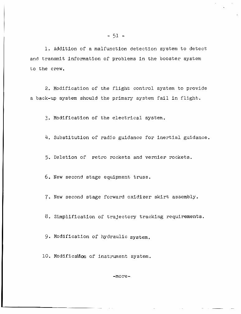
- 51 -
1. Addition of a malfunction de tec t ion system t o de t ec t
and t r a n s m i t information of problems i n t h e boos te r system
t o the crew.
2. Modification of t he f l i g h t cont ro l system t o provide
a back-up system should the primary system f a i l i n f l i g h t .
3 . Modification of t h e e l e c t r i c a l system.
4. Subs t i tu t ion of rad io guidance f o r i n e r t i a l guidance.
5. Deletion of r e t r o rockets and v e r n i e r rocke ts .
6 . New seccrnd s t age equipment t r u s s .
7. New second s tage forward o x i d i z e r s k i r t assembly.
8. S impl i f ica t ion of t r a j e c t o r y t r ack ing requirements.
9. Modification of hydraul ic system.
10. ModificatLon of instrument system.
-more -
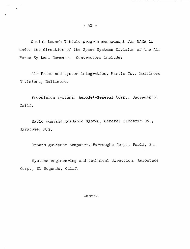
- 52 -
G e m i n i Launch Vehicle program management for NASA i s
under t h e d i r e c t i o n of t h e Space Systems Division o f the A i r
Force Systems Command. Contractors include:
A i r Frame and system in t eg ra t ion , M a r t i n Co., Baltimore
Divisions, Baltimore.
Propulsion systems, Aerojet-General Corp., Sacramento,
Ca l i f .
Radio command guidance system, General E l e c t r i c Co.,
Syracuse, N.Y.
Ground guidance computer, Burroughs Corp., Paoli, Pa.
Systems engineering and t e chni c a1 d i r e c t i on, Aerospace
Corp., E l Segundo, Calif .
-more-

- 53 - G E M I N I 5 EXPERIMENTS
Seventeen experiments a r e scheduled during the Gernlnl 5
f l i g h t . Five a r e medical experiments, s i x Department of
Defense experiments, f i v e a r e s c i e n t i f i c and one engineering.
A d e f i n i t e amount of f u e l has been a l l o t e d for supporting
those experiments which r equ i r e spacec ra f t maneuvering. The
experiment will be terminated when the f u e l for t h a t p a r t i c u l a r
experinlent has been consumed,
Medical Experiments
In-Fl ight Exercise: Work Tolerance*
The a s t ronau t s w i l l use a bungee cord t o a s s e s s t h e i r
capaci ty t o do phys ica l work under space f l i g h t condi t ions.
The bungee cord r equ i r e s a 60-pound p u l l t o s t r e t c h i t t o
i t s l i m i t of one foo t . The cord w i l l be held by loops about
the a s t r o n a u t ' s f e e t r a t h e r than being a t tached t o the floor
a s i n Project Mercury t e s t s ,
P lans c a l l f o r each of the Gemini 5 a s t ronau t s to make
the 60-pound s t r e t c h once per second for a minute a t var ious
times during t h e f l i g h t . Heart and r e s p i r a t o r y r a t e s and
- more -

- 54 - blood pressure w i l l be taken before and a f t e r the e x e r c i s e
f o r eva lua t ion . Time f o r heart ra te and blood p res su re t o
r e t u r n t o pre-work l e v e l s following the e x e r c i s e i s an index
of t he genera l condi t ion of t h e a s t r o n a u t .
In-Fl ight Phonocardiogram*
The purpose of t h i s experiment i s t o serve as a s e n s i -
t i v e i n d i c a t o r of hear t muscle d e t e r i o r a t i o n when compared
to a simultaneous electrocardiogram. Heart sounds of t h e
Gemini 5 a s t r o n a u t s w i l l be picked up by a microphone on
t h e i r ches t s and recorded on the biomedical r eco rde r , T h i s
w i l l be comparea wi th t h e e lectrocardiogram t o determine the
t i m e i n t e r v a l between h e a r t cont rac t ion .
Bone Demineralization"
X-rays us ing a s p e c i a l technique (bone denis i tomet ry)
w i l l be taken before and after t h e f l i g h t s , The hee l bone
and the end bone of the f i f t h f i n g e r on the r i g h t hand of
each a s t ronau t w i l l be s tudied t o determine whether any
deminera l iza t ion has taken place and, i f so, t o what ex ten t .
The a n t i c i p a t i o n of poss ib l e loss of calcium from the bones
du r ing weight less f l i g h t i s based on y e a r s of c l i n i c a l exper-
ience w i t h p a t i e n t s confined to bed o r i n c a s t s .
- more -

- 55 -
Cardiovascular Conditioning
The purpose of t h i s experiment i s t o determine the
e f f ec t iveness o f pneumatic c u f f s i n preventing cardiovascular
( h e a r t and blood d i s t r i b u t i o n system) d e t e r i o r a t i o n induced
by prolonged weight lessness .
This t e s t will be conducted by t h e p i l o t only, The
c u f f s will be appl ied t o the upper th ighs and be automati-
c a l l y pressur ized t o 8 0 m g f o r two minutes out of every
s i x minutes,
awake cyc le each day of f l i g h t .
continuously i f d e s i r e d ,
The system w i l l remain a c t i v a t e d during the
It may be l e f t a c t i v a t e d
Human O t o l i t h Function
A v i s u a l t e s t e r w i l l be used t o determine the a s t ronau t s
o r i e n t a t i o n c a p a b i l i t y dur-ing f l i g h t .
measure changes i n o t o l i t h ( g r a v i t y g rad ien t sensors i n the
inner e a r ) funct ions.
The experiment w i l l
The t e s t e r i s a p a i r of s p e c i a l l i g h t proof goggles,
one eye piece o f which conta ins a l i g h t source i n the form
o f a movable white l i n e . The a s t r o n a u t --!onitions the white
- more -

- 56 -
line with a calibrated knurled screw to what he judges to be
the right pitch axis of the spacecraft. The second astronaut
then reads and records the numbers.
The medical experiments are sponsored by t k N A S A Office
of Manned Space Flight's Space Medicine Division.
*Repeat Experiment
Cardiovascular Effects of Space Flight
This is a continuation of experiments to evaluate tk
effects of prolonged weightlessness on the cardiovascular
system, It is considered an operational procedure and no
longer an experiment.
Comparisons will be made of the astronaut's preflight
and postflight blood pressures, blood volumes, pulse rates,
and electrocardiograms. The data will reveal the cardiovas-
cular and blood volume changes due to heat stress, the effect
of prolonged confinement, dehydration, fatigue, and possible
effects of weightlessness, There are no inflight requirements.
- more -

e- - 31 -
Measurements w i l l be taken before, during, and a f t e r a
head-up t i l t o f 80 degrees from the ho r i zon ta l ,
I f t he a s t ronau t s remain i n the spacec ra f t while i t i s
hois ted aboard the recovery vesse l , por tab le biomedical
recorders w i l l be a t tached t o each one before he leaves the
spacecraf t , and blood pressure and electrocardiogram
measurements w i l l be taken,
t he spacecraf t and s tand on the s h i p ' s deck.
and electrocardiogram measurements w i l l be recorded auto-
mat ica l ly before , during, and f o r a s h o r t time a f t e r the
crew leaves the spacec ra f t , The a s t ronau t s w i l l then go
t o tk s h i p ' s medical f a c i l i t y f o r t he t i l t - t a b l e t e s t s ,
Each a s t ronau t then w i l l leave
Blood pressure
SCIENTIFIC EXPERIMENTS
Synoptic Terrain Photogsaphy Experiment ( S - 5 ) "
Primary ob jec t ive i s t o g e t h igh-qual i ty p i c t u r e s
of l a r g e land a reas t ha t have been previous well-mapped by
aerial photography,
f o r i n t e r p r e t a t i o n of p i c t u r e s o f unknown a r e a s on Earth,
the Moon, and o the r p l ane t s .
Such photographs can serve as a standard
- more -
- - -

A secondary ob jec t ive i s t o ob ta in high-qual i ty p i c t u r e s
of r e l a t i v e l y poorly-mapped areas of the Earth f o r s p e c i f i c
s c i e n t i f i c purposes. For example, geo log i s t s hope tha t such
photographs can he lp t o answer quest ions of con t inen ta l d r i f t ,
s t r u c t u r e o f the E a r t h ' s mantle, and o v e r a l l s t r u c t u r e of the
cont inents .
Mexico, E a s t Afr ica-and Arabian Peninsula and Aus t ra l ia
p i l l be the p r i o r i t y photographic ob jec t ives , O f p a r t i c u l a r
i n t e r e s t a r e r i f t va l l eys which a r e geologica l ly analogous
t o the r i l ls found on the Moon. These r i f t va l l eys extend
from Turkey, through Syria , Jordan, the Red Sea a rea and
and e a s t e r n Afr ica as far south as Mozambique. By photograph-
ing these rift va l leys , geologis t s f ee l that they may ga in a
b e t t e r understanding o f t h e c r u s t and upper m n t l e of the
Ear th as well as the rills on the Moon.
Photography w i l l be performed during per iods of maximum
day l ign t , from 9 A.M. t o 3 P.M. l o c a l time. I f cloud cover
i s ' o v e r 50 percent i n the p r i o r i t y a reas , the a s t ronau t s
w i l l photograph sub jec t s of opportunity -- any i n t e r e s t i n g
land areas.
- more -

- 59 -
A 70-mm modified Hasselblad (Swedish make), Model 500C
will be used. The magazine capacity of this camera is 55 frames per roll.
be tilted straight'down, Normally, the camera will be in
use from f i v e to ten minees, taking a photograph every s ix
seconds of a 100-mile-wide area, thus giving continent-wide
coverage when the individual frames are mounted as a continu-
ous photographic strip.
The nose of the Gemini 5 spacecraft will
- more -

- 60 -
Space photography, in comparison with aerial photography,
is thought to have the advantage of providing greater perspec-
tive, wider coverage, greater speed, and rapid repetition of
coverage. These factors suggest applications in many areas
of geology, weather, topography, hydrology and oceanography.
For example :
(1) Geologic reconnaissance can tell us more of our own
planet, leading to better interpretation of the geology of the
Moon and other planets.
(2) Topographic mapping of Earth can give us newer and
better maps with a scale of 1:1,000,000.
(3) Hydrology mapping could, for example, permit estimates of the amount of snowfall in particular regions and what the
amount of run-off would be in the springtime, of great interest
in flood prevention and control.
(4) Oceanographic mapping could, among other things, show the distribution and temperature of ocean currents; the l o c a -
tion of ice of danger to shipping.
Space photography also shows potential for forestry map-
ping, for exanple, noting vegetation changes.
-more -

- 61 -
It a l s o can supplement the TV-type photography of o w
weather s a t e l l i t e s s ince f i l m provides g r e a t e r r e so lu t ion .
The experiment i s being conducted by D r , P a u l D. Lowman,
Jr., a geologis t a t NASA's Goddard Space F l i g h t Center, Green-
b e l t , Md.
Synoptic Weather Photography Experiment ( s - 6 ) ~
The synopt ic Weather Photography experiment i s designed
t o make use of man's a b i l i t y t o photograph cloud systems se-
l ec t ive ly - - in co lor and i n g r e a t e r d e t a i l than can be obtained
from the cur ren t TIROS meteorological s a t e l l i t e ,
The Gemini 5 crew w i l l photograph var ious cloud systems.
They w i l l be using the same 70-mm Hasselblad camera and Ekta-
chrome f i l m as f o r the Synoptic Te r ra in Photography experiment.
A primary purpose of t he experiment i s t o augment inf'orma-
t i o n from meteorological s a t e l l i t e s .
l o g i c a l s a t e l l i t e s are con t r ibu t ing s u b s t a n t i a l l y t o knowledge
of the Ea r th ' s weather systems.
formation where few o r no o ther observat ions e x i s t .
t u r e s , however, a r e e s s e n t i a l l y t e l e v i s i o n v i e w s of l a r g e a reas
taken from an a l t i t u d e of 4.00 miles o r more.
Observations from meteoro-
I n many a reas they provide i n -
Such p ic -
-more -

Theylack t h e de ta i l which can be obtained i n photographs
taken from the Gemini he ight of about 100 miles.
One of the aims of t h e S-6 experiment i n the Gemini 5
and subsequent f l i g h t s i s t o g e t a b e t t e r look a t some of the
cloud p a t t e r n s seen on TIROS pic tures , b u t not f u l l y understood.
There are c e l l u l a r pa t t e rns , cloud bands r a d i a t i n g from a point ,
apparent shadows of ind is t inguishable high clouds on low cloud
decks, and small v o r t i c e s sometimes found i n t h e l e e of moun-
ta inous i s l ands .
Another ob jec t ive i s t o get p i c t u r e s of a v a r i e t y of storm
systems, such as weather f r o n t s , s q u a l l l i n e s , o r t r o p i c a l dis-
turbances, s o that t h e i r s t r u c t u r e can be be t te r understood.
F ina l ly , t h e experimenters hope t o get s eve ra l s e t s of
views of the same area on subsequent passes of the spacecraf t
t o see how various weather phenomena move and develop.
The experimenters are Kenneth M. Nagler and Stanley D.
Soules, both of the Weather Bureau's National Weather S a t e l l i t e
Center. Nagler has a dual r o l e in the Gemini 5 space f l igh t ,
s e rv ing both as an experimenter i n t h e weather photography e f -
f o r t and as Head of the Spacefl ight Meteorology Group which
provides NASA the f o r c a s t i n g suppor t f o r its manned space f l igh t d
programs . -more -

- 53 -
Zodiacal Light Photography (S-1)
The origin of the zodiacal light has long been a matter
of scientific speculation.
photograph the light in an attempt to determine its origin.
During Gemini 5 the astronauts will
The zodiacal light appears as a cloudy, hazy light seen in
the west after twilight and in the east before sunrise.
be visible to the astronauts for about four minutes just before
sunrise and another four minutes just after sunset. During
these periods, the astronauts will photograph the phenomenon
using a hand held 35-mm Wldelux camera loaded with high speed
color film.
It will
There w i l l also be attempts to photograph air glow, a
faint background illumination of the night sky.
Cloud Top Spectrometer (S-7)
In this experiment, several spectrograms will be taken of
various types of cloud formations.
is essentially a 35-mm camera fitted with a defraction grating
and containing infrared film.
The equipment to be used
-more -

- 64 -
R e s u l t s of the experiment w i l l be valuable i n a id ing
s c i e n t i s t s i n the design of weather s a t e l l i t e s . Present day
weather satel l i tes , TIROS, y i e l d extremely u s e f u l and d e t a i l e d
cloud photographs. However, they do not give t h e a l t i t u d e of
the clouds, an important f a c t o r i n determing the s e v e r i t y of
weather formations.
V i s u a l Acuity (sS and D l 3 )
The v i s u a l a b i l i t y of t h e a s t ronau t s i n the de t ec t ion
and recogni t ion of ob jec t s on t h e e a r t h ' s sur face w i l l be
t e s t e d i n this experiment.
The a s t ronau t w i l l view well know ground p a t t e r n s which
have been la id out near Laredo, Tex., and near Carnavon, Aus-
t ra l ia , on t h e Woodleigh Ranch.
The Texas s i t e c o n s i s t s of 12 background t e s t areas. The
markings are made out of white gypsum. I n Austral ia , the
markings are made from white shel ls obtained from depos i t s
along the coast .
-more -
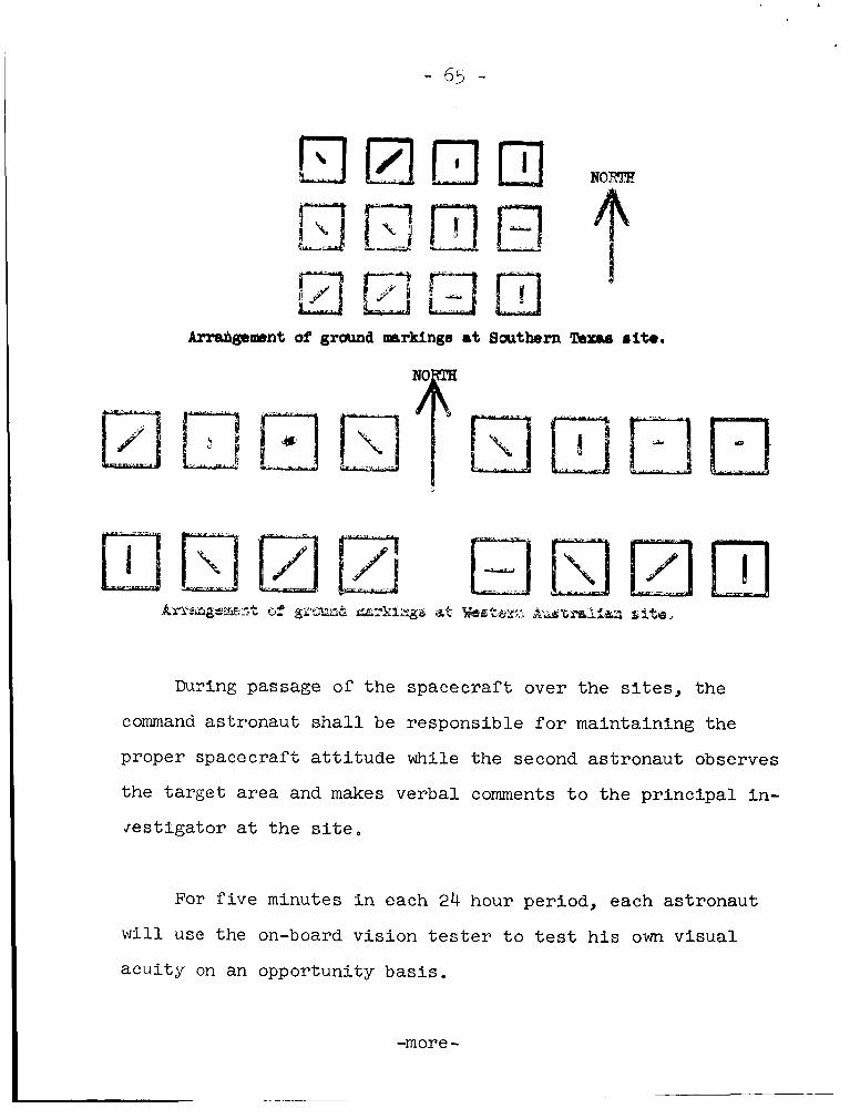
- 55 -
Arrahgemnt of ground markings at SrJuthern Bmm rite.
During passage of the spacec ra f t over the sites, the
command as t ronau t shal l be respons ib le for maintaining the
proper spacecraf t a t t i t u d e while the second a s t ronau t observes
the t a r g e t a r e a and makes ve rba l comments t o the p r i n c i p a l i n -
J e s t i g a t o r a t the s i t e .
For f i v e minutes i n each 24 hour per iod, each a s t ronau t
w i l l u se the on-board v i s i o n tes te r t o t e s t h i s own Visual
a c u i t y on an opportuni ty basis.
-more-

- 66 -
For one 10-minute period near t he end of t he P l i g h t , boLh
a s t ronau t s w i l l cooperate i n obtaining a photometer scan of'
t h e window. T h i s photometer scan serves t o determine the
grad ien t of s c a t t e r i n g across the window and must be done
while t he spacec ra f t window i s pointed a t a b l a c k p a r t of' t h e
sky and a t an angle t o the sun .
A NASA V i s i b i l i t y Laboratory instrumented t r a i l e r van
w i l l be a t t he se l ec t ed a reas during t h e mission t o record
l i g h t and atmospheric conditions. An A i r Force C-130 InstrJu-
mented by t h e V i s i b i l i t y Laboratory w i l l f l y over the a r e a a t
the time of the o r b i t s used 1'or s l sh t in ; t o document the per-
t i n e n t o p t i c a l p r o p e r t i e s of the atmosphere as a func t ion of
a l t i t u d e .
-more -

- 67 -
ENGINEERING EXPERIMENT
E l e c t r o s t a t i c Charge (MSC-11
T h i s i s a repeat of a n experiment conducted on Gemini 4 .
Objective i s t o d e t e c t and measure any accumulated e l e c t r o s t a t i c
charge on the su r face of the Gemini spacec ra f t . Natural charg-
i n g mechanisms and charged par t ic les e j e c t e d from rocket engines
can cause an e l e c t r o s t a t i c p o t e n t i a l , and t h i s must be i n v e s t i -
ga ted before rendezvous and docking missions are a t t e m p t e d .
Differences i n p o t e n t i a l between docking space v e h i c l e s
can cause an e l e c t r i c a l d i scharge which could damage the ve-
h i c l e sk in and e l e c t r o n i c equipment and i g n i t e pyrotechnics
aboard the spacec ra f t . If the spacec ra f t p o t e n t i a l and capaci-
t ance i s known, it w i l l be poss ib l e t o c a l c u l a t e t he n e t charge
on the spacecraf t and the energy a v a i l a b l e f o r an e l e c t r i c a l
discharge between t h e spacec ra f t and another space veh ic l e
of known p o t e n t i a l .
Any accumulated charge on the su r face of t h e Gemini- 5
spacecraf t w i l l be measured by a n e l e c t r o s t a t i c p o t e n t i a l
meter. The experiment w i l l be conducted during a l l per iods of'
extensive spacecraf t a t t i t u d e maneuvering and d u r i n g r e t r o f i r e .
Data obtained w i l l be telemetered t o ground s t a t i o n s .
-more-

- 5 ' ;
The e l e c t r o s t a t i c p o t e n t i a l meter c o n s i s t s of a sensor
u n i t and a n e l e c t r o n i c s u n i t .
c r a f t ' s adapter sec t ion . The sensor u n i t ' s face i s f l u s h w i t h
t h e o u t e r sur face of the spacecraf t and obta ins e l e c t r i c a l
s i g n a l s propor t iona l t o the spacec ra f t p o t e n t i a l .
Both are loca ted i n the space-
TECHNOLOGICAL EXPERIMENTS (DOD)
Basic Object Photography ( D - 1 )
The purpose of t h i s experiment i s t o determine man's
a b i l i t y t o acqui re , t r a c k and photograph ob jec t s i n space.
The a s t r o n a u t w i l l have a l i s t of o b j e c t s t o be photographed.
It inc ludes the booster , rendezvous eva lua t ion pod and n a t u r a l
c e l e s t i a l bodies such as t h e Moon.
Equipment t o be used i s a 3 5 m m Zeiss contarex camera
which w i l l be mounted on t h e p i l o t ' s side, r i g h t window. A
l27Omm l e n s w i l l be used f o r c e l e s t i a l body photcgraphs.
and a 2 0 0 m m l e n s w i l l be used f o r the pod photographs.
It
Nearby Object Photography (D-2)
This experiment w i l l be conducted a f t e r completion of
the radar rendezvous tes ts and i s designed t o t es t man's pro-
f i c i e n c y i n obta in ing high r e s o l u t i o n photographs of a n o r b i -
t i n g ob jec t while maneuvering, s t a t i o n keeping and observing
i n a manual c o n t r o l mode.
-more-
- 69 -
The same camera equipment as i n D-1 w i l l be u s e d .
In ca r ry ing out the experiment the command p i l o t w i l l
maneuver t o wi th in 40 fee t of the REP and c i r c l e i t .
graphs w i l l be taken w i t h the 2 0 0 m m l e n s a t seven p o i n t s a-
Photo-
bout the REP.
Celestial Radiometry (D-4)
For t h i s experiment t h e spacec ra f t i s equipped wi th r ad io -
metric measuring devices us ing commonndrror o p t i c s tha t can
measure r a d i a n t i n t e n s i t y from the u l t r a - v i o l e t through inf'ra-
r ed as a func t ion of wave lengch.
The r e s u l t s of t h i s experiment w i l l provide information
suppl ied by on the spectral a n a l y s i s of reg ions of i n t e r e s t ,
the s t a r f i e l d s , p r i n c i p a l p l ane t s , Ear th and Moon.
Instrumentat ion f o r t h i s (and the la te r described D-7
experiment) include a three channel spectro-radiometer, a dua l
channel Michelson Interferometer-Spectrometer and a c ryogenica l ly
cooled Michelson Interferometer-Spectrometer. These sensing
u n i t s w i l l be housed i n t h e Gemini adapter sec t ion . (See D-7)
-more-
- 70 -
Surface Photography (D-6)
The ob jec t ive of t h e surface photography experiment
i s t o i n v e s t i g a t e t e c h n i c a l problems a s soc ia t ed w i t h man's
a b i l i t y t o acqui re , t r a c k and photograph te r res t r ia l ob jec t s .
The a s t r o n a u t s w i l l have a l i s t of sub jec t areas t o be
photographed. The areas include s e l e c t e d c i t i e s , ra i1 ,h igh-
ways, harbors, r i v e r s , l akes , i l lumina ted n ight -s ide s i tes ,
ships and wakes. A l l sub jec t a r e a s are wi th in t h e United
States and Afr ica .
The camera t o be used i s a 3 5 m m Zeiss contarex s i n g l e
l e n s reflex wi th interchangeable l enses .
Space Object Radiometry ( D - 7 )
T h i s i s an extension of the D-4 experiment and u s e s the
same basic equipment. However, camera equipment w i l l a l s o be
used t o o b t a i n a v i s u a l c o r r e l a t i o n if poss ib le .
The o b j e c t i v e s f o r both t h i s and the D-4 experiment are
t o determine the threshhold of s e n s i t i v i t y va lues f o r earth
o b j e c t s and sky background r a d i a t i o n and r a d i a t i o n s igna tu res
of v a r i o u s o b j e c t s i n space and on the ground.
-more-

I n t h e D-7 experiment the a s t r o n a u t s w i l l a t t empt t o
observe t h e T i t an I1 second stage, REP, exhaust plumes of
rocket veh ic l e s launched from the Eas te rn o r Western Test
Ranges, rocket sled exhausts a t Holloman A i r Force Base, vol -
canoes and f o r e s t f i r e s a s w e l l as c o n t r a s t i n g background areas
such as deserts and w a r m ocean c u r r e n t s .
The fol lowing are a c t i v e volcanoes which l i e wi th in the
Gemini 5 f l i g h t path:
Kilauea - Hawaii
San Miguel - E l Salvador
Tel ica , Nicaragua
Irazu, Costa Rica
Langla - N e w B r i t a i n I s l a n d s
The experiment sponsors b e l i e v e tha t po in t ing accuracy,
a b i l i t y t o change s e n s i t i v i t y l e v e l s and o t h e r bas i c c o n t r o l
func t ions can best be accomplished by a human opera tor .
Visua l Acuity (D-13)
J o i n t NASA experiment, see S-8.
-more-
- 72 - MANNED SPACE FLIGHT TRACKING NETWORK
The Manned Space F l i g h t Network f o r Gemini 5 is composed
of spacec ra f t t rack ing and data acqu i s i t i on f a c i l i t i e s through-
out the world: The Mission Control Center, Cape Kennedy;
Mission Control, Houston; and real-t ime (no de lay) computing
cen te r s a t the Goddard Space F l igh t Center, Greenbelt , Md.,
and the Manned Spacecraft Center, I n add i t ion Goddard w i l l
serve as t h e mission communications cen te r .
The bas ic network f o r Gemini 5 c o n s i s t s of seven primary
land s i t e s , t h ree sh ips , ( t h e Rose Knot, Coastal Sentry and
Wheeling) ' s ix a d d i t i o n a l land s t a t i o n s , and remote voice
d a t a switching s i t e s . This network and i t s opera t ing pro-
cedures remain unchanged from the Gemini 4 mission. As i n
Gemini 4 the primary mission cont ro l and computing w i l l be the
r e s p o n s i b i l i t y of t he Mission Control Center, Manned Space-
c r a f t Center.
The Locations o f the land s t a t i o n s a r e as follows:
Primary S ta t ions Additional S t a t i o n s
Cape Kennedy, Fla . , and down- Kano, Nigeria
range A i r Force Eastern Test
Range s i t e s
Madagascar (Tananarive)
Bermuda Canton I s l and
Grand Canary Is land Point Arguello, Calif.
- more ' -

- 73 -
Carnarvon , Aust ra l ia White Sands, N.M.
Hawaii Egl in AFB, Fla .
Guaymas, Mexico
Corpus C h r i s t i , Tex.
Three Ships: The USNS Rose Knot, USNS Coastal Sentry,
and USNS Wheeling
Other t racking and data a c q u i s i t i o n f a c i l i t i e s , such as
r e l a y a i r c r a f t , ins t rumentat ion sh ips , communications, r e l a y
s t a t i o n s , e t c . , w i l l be c a l l e d up as required and in t eg ra t ed
i n t o the bas ic network. Tota l ground s t a t i o n f a c i l i t i e s
number 24.
Goddard Computer Support
Countdown phase -- The Goddard Realtime Computing Center
I w i l l provide computing support t o the Manned Spacecraf t
~
Center Realtime Computing Complex throughout the countdown
phase. During the pre-launch countdown Goddard w i l l be
responsible f o r checking the Manned Space F l igh t Network's
readiness t o support Gemini 5 through i t s CADFISS (Computer
and Data Flow In tegra ted Subsystems) Tes ts .
The GSFC Realtime Computing Center a l s o w i l l provide
prime computer support f o r a l l network t racking and data
acqu i s i t i on systems (Radars-Digital Command System-Pulse
- more -

- 74 -
Code Modulation telemetry and the Launch Monitor Subsystem)
roll call.
Data flow tests from the world-wide network to the
Manned Spacecraft Center's Realtime Computing Complex will be
conducted from MSC RTCC under the direction of Goddardls
CADFISS Test Director.
Goddardls prime computing responsibilities for Gemini 5 . does not include full-time, real-time back-up for the Houston
RTCC as in Gemini 4.
Mission Computing Requirements
Goddardls prime computing requirements in support of
Gemini 5 occur in three principal areas:
(a) Full mission network systems testing through
CADFISS Test Program.
Booster lifetime tracking data processing,
(c) REP (Radar Evaluation Pod) tracking data processing
from approximately 145 minutes after liftoff through
the rendezvous experiment (approximately seven hours)
- more -

- 75 - NASA Communications Network (NASCOM)
This Division, a Goddard r e s p o n s i b i l i t y , w i l l e s t a b l i s h
and operate the world-wide ground communications network tha t
provides t e l e type , voice, and data l i n k s between the s t a t i o n s
and cont ro l cen te r s f o r the network.
It l i n k s 89 s t a t i o n s , including 34 overseas poin ts , wi th
message, voice and data communications. I t s c i r c u i t s and
terminals span 100,000 route miles and 5OO,OOO c i r c u i t miles .
For Gemini 5 the Communications Network (NASCOM) w i l l be
used i n the same bas ic conf igura t ion as f o r Gemini 4.
During Gemini 4, voice aomunica t ion with the spacec ra f t
v i a the Syncom I11 communications sa te l l i t e and NASCOM ground
s t a t i o n s was successfu l ly achieved over the P a c i f i c Ocean.
For Gemini 5 a similar exerc ise i s planned u t i l i z i n g Syncom 111.
Also part of NASCOM is t he voice communication n e t .
A switchboard system, with mul t ip l e dual-operat ing
consoles, enables one opera tor t o concentrate on s p e c i a l
mission conferences. This system is c a l l e d SCAMA I1 ( S t a t i o n
- more -

- 76 -
Conferencing and Monitoring Arrangement).
handle 100 l i n e s and can u l t imate ly be expanded t o handle
220 l i n e s . Both point- to-point connections and conference
arrangements are poss ib l e , All l i n e s can be connected i n t o
one conference without l o s s of q u a l i t y , The SCAMA opera tor
can add conferees o r remove them, He a l s o con t ro l s which o f
t he conferees can t a l k and which can l i s t e n only,
SCAMA I1 can now
The SCAMA has 10 times the c a p a b i l i t y o f the network
used f o r Mercury.
Spacecraf t Communications
All Manned Space F l i g h t Nctwork s t a t i o n s having both
high frequency (HF) and u l t r a high frequency (UHF) spacecraf t
communications can be control led e i t h e r by the s t a t i o n o r
remotely con t ro l l ed by Goddard, Mission Control Center, Houston,
o r Mission Control Center, Cape Kennedy.
The following s i t e s have a Capsule Command Communicator
who c o n t r o l s spacec ra f t communications a t the si te: Canary
I s land; Carnarvon; Kuai, Hawaii; Corpus C h r i s t i ; Guaymas; USNS
Rose Knot; and USNS Coastal Sentry.
- more -
- 77 -
The following stations w i l l not have Capsule Communicators
and w i l l be remoted to the appropriate Mission Control Center:
Grand Bahama Island; Tananrive (Madagascar); Kano, Nigeria;
Bermuda; Grand Turk Island; Antigua Island; Ascension Island;
Canton Island; Pt, Arguello, Calif. USNS Wheeling (ship) and
the d c e relay aircraft.
Network Responsibility
Goddard Space Flight Center, NASA's Office of Tracking
and Data Acquisition has centralized the responsibility for
the planning, implementation, and technical operations of
manned space flight tracking and data acquisition at Goddard.
Technical operation includes operation, maintenance, modifica-
tion, and augmentation of tracking and data acquisition
facilities as an instrumentation network in response to mission
requirements. About 370 persons directly support the.network
at Goddard.
Manned Spacecraft Center. The MSC has the overall
management responsibility of the Gemini program.
and mission control of the network immediately preceding and
during a mission simulation o r an actual mission is the
responsibility of the MSC.
The direction
- more -
- 78 -
Weapons Research Establishment. The WRE, Department
of Supply, Commonwealth o f Austral ia , i s responsible f o r the
maintenance and operat ion of the network s t a t i o n s i n Aus t r a l i a .
Contractual arrangements and agreements def ine t h i s coopera-
t i v e e f f o r t ,
Department of Defense. DOD i s responsible f o r the
maintenance and ope ra t iona l cont ro l of t hose DOD a s s e t s and
f a c i l i t i e s required t o support Gemini. These include
network s t a t i o n s a t the Eastern T e s t Range, Western Test
Range, the A i r Proving Ground Center and the White Sands
Miss i le Test Range.
- more -
J

- 79 -

CREW BIOGRAPHIES
L. ( f o r Leroy) Gordon Cooper, Jr., Gemini 5 command pi10 t
BORN: Shawnee, Okla, Mar. 6, 1927.
HEIGHT: 5 f t . , 8 in . , WEIGHT: 155 lbs . ; Brown h a i r , blue eyes.
EDUCATION: Bachelor of Science degree i n aeronaut ica l engineering, A i r Force I n s t i t u t e of Technology, 1956,
MARITAL STATUS: Married t o the former Trudy Olson of S e a t t l e , Wash.
CHILDREN: Camala, Nov. 16, 1948; J a n i t a , Mar. 15, 1950.
EXPERIENCE: Cooper, an A i r Force l i e u t e n a n t colonel , r e - ceived an Army commission a f t e r completing th ree years of schooling a t the Universi ty of H a w a i i . He t r ans fe r r ed that commission t o the A i r Force and was placed on extended a c t i v e duty by t h a t s e rv i ce i n 1949 and given f l i g h t t r a i n i n g .
Upon completion o f f l i g h t t ra in ing , Cooper was assigned t o the 86th F ighter Bomber Group in Munich, Germany, where he flew F-84's and F - 8 6 1 ~ f o r four years . While i n Munich, he at tended the European extension of the Universi ty of Mary- land Night School.
On r e tu rn ing t o the United S ta t e s , he was assigned as a s tudent a t the Air Force I n s t i t u t e of Technology and received h i s degree i n ae ronau t i ca l engineering i n 1956 following two yea r s work the re .
Af te r graduation from AFIT, Cooper attended the A i r Force Experimental F l i g h t Test School a t Edwards A i r Force Base, Calif . He was graduated from t h i s school i n Apr i l 1957, and subsequently assigned t o duty i n the Performance Engineering Branch of the F l i g h t Test Division a t Edwards, He p a r t i c i - pated i n the f l i g h t t e s t i n g of experimental f i g h t e r a i r c r a f t , working as an ae ronau t i ca l engineer and a t e s t p i l o t ,
Cooper has logged more than 3,400 hours f l y i n g time, including more than 2,300 hours i n j e t a i r c r a f t .
- more -

- 81 - LRTRRERT ASSIGNMENT: Cooper was one of the seven P ro jec t Mercury a s t ronau t s named by NASA i n Apr i l 1959. 1963, he p i l o t e d h i s "Fa i th 7" spacecraf t on a 22-orb i t mission which completed the ope ra t iona l phase of P ro jec t Mercury, During the f l i g h t , which l a s t e d 34 hours and 20 minutes, he a t t a i n e d a maximum a l t i t u d e of 166 s t a t u t e miles, a speed of 17,546 miles per hour, and t rave led 546,167 s t a t u t e mlles, He was awarded the NASA Distinguished Service Medal f o r h i s f l i g h t . Also awarded Astronaut Wings,
On May 15-16,
Cooper i s t h e son of Mrs. Leroy G. Cooper o f Carbondale, Colo. His fa ther , a re t i red A i r Force colonel , d i ed i n March 1960.
- more -
.

.
Charles Conrad, J r . , Gemini 5 p i l o t
BORN: Phi ladelphia , Pa . , June 2, 1930
HEIGHT: 5 f t . , 6 In.,WEIGHT: 142 l b s . ; Blonde hair , blue eyes.
EDUCATION: Bachelor of Science degree i n ae ronau t i ca l engineer ing from Princeton un ive r s i ty , 1353.
MARITAL STATUS: Married t o the former Jane lXlSose o f Uvalde, Tex.
CHILDREN: Peter, Dec. 25, 1954; "l-mmas, May 3, 1957; Andrew, Apr. 30, 1959; Christopher, Nov. 26, 1960.
PROFESSIONAL ORGANIZATIONS: Member, American I n s t i t u t e of Aeronautics and Astronautics; Associate Member of Society of Experimental T e s t P i l o t s ,
EXPERIENCE: H e entered the Navy following h i s graduation from Princeton Universi ty and became a naval a v i a t o r . He is now a Navy Lieutenant Commander.
Conrad at tended the Navy Test P i l o t School a t Patuxent River, Md, 1959-1961, and f o l l o d n g completion of tha t school was a p r o j e c t t e s t p i l o t i n the armaments t e s t d i v i s i o n t h e r e . H e a l s o served a t Patuxent as a f l i g h t i n s t r u c t o r and per - formance engineer.
H e served as a F4H f l i h t i n s t r u c t o r and as Safety Off icer
S t a t i o n , f o r F ighter Squadron 9 % a t the Marimar, Ca l i f , Naval A i r
H e has logged more than 3,200 f ly ing hours, including more than 2,400 hours i n j e t a i r c r a f t .
CURRENT ASSIGNMENT: Conrad was i n the second group of a s t r o - nau t s s e l ec t ed by NASA i n September 1962. I n add i t ion t o p a r t i c i p a t i n g in the o v e r a l l as t ronaut t r a i n i n g program, h i s d u t i e s included monitoring the Apollo Command Service and Lunar Excursion Modules before h i s s e l e c t i o n t o the Gemini 5 crew.
Conrad i s the son of Charles Conrad, Sarasota , Fla., and Mrs. Frances V. Sargent, Haverford, Pa.
- more -

n
- 83 -
Neil A. ( f o r Alden) Armstrong, Gemini 5 backup crew, command p i l o t .
BORN: Wapakoneta, Ohio, Aug. 5, 1930
HEIGHT: 5 f t . , 10 1/2 in . , WEIGHT: 168 l b s , Blonde hair, blue eyes.
EDUCATTON: Bachelor of Science degree i n ae ronau t i ca l engineering from Purdue Universi ty , 1955.
MARITAL STATUS: Married t o the former J a n e t Shearon of Evanston, Ill,
CHILDREN: Er ic , June 30, 1957; Mark, Apr. 8, 1963.
PhOFESSIONAL ORGANIZATIONS: Charter member of the Society of Experimental Test P i l o t s ; a s s o c i a t e fe l low o f the American I n s t i t u t e of Aeronautics and Astronautics; and member, Soaring Society of America. He was the r e c i p i e n t of the 1962 I n s t i t u t e o f Aerospace Sciences Octave Chanute Award.
EXPERIENCE: Armstrong was a Naval a v i a t o r from 1949 t o 1952 and flew 78 combat missions during the Korean ac t ion .
H e joined NASA's L e w i s Research Center i n 1955 ( then NACA Lewis F l i g h t Propulsion Laboratory) and la ter t r ans fe r r ed t o the NASA High Speed F l i g h t S t a t i o n a t Edwards, Calif., as an aeronaut ica l research p i l o t f o r NACA and NASA.
Armstrong has p a r t i c i p a t e d i n f l i g h t t es t work on the F-100, F-104, B-47, F-102, and the X-15.
H e has logged more than 3,200 hours f l y i n g time, including 1,800 hours i n j e t a i r c r a f t ,
CURRENT ASSIGNMENT: Armstrong was se l ec t ed as an a s t ronau t by NASA i n September 1962, I n add i t ion t o p a r t i c i p a t i n g i n a l l phases of the o v e r a l l a s t ronau t t r a i n i n g program, he ha had a va r i e ty of s p e c i a l assignments. He was i n charge of Operations and Training i n the Astronaut Off ice before h i s assignment t o back-up crew f o r Gemini 5. Armstrong i s the son of M r . and Mrs. Stephen Armstrong, Wapakoneta, Ohio.
- more -
E l l i o t M . (for McKay) See, J r . , Gemini 5 backup crew, p i l o t
BORN: Dallas, Tex., July 23, 1927
HEIGHT: 5 f t . , E) i n . , WEIGHT: 150 l b s ; Brown h a i r , blue eyes.
EDUCATION: Bachelor of Science degree, U . S. Merchant Marine Academy, 1949; Master of Science degree i n engineering, Univers i ty of Ca l i fo rn ia a t Los Angeles, 1962.
MARITAL STATUS: Married t o the former Marilyn J . Denahy of Georgetown, Ohio.
CHILDREN: Sa l ly , Feb. 22, 1956; Carolyn, Nov. 16, 1957; David, Aug. 12, 1962.
SCIENTIFIC AND PROFESSIONAL ORGANIZATIONS: Member of Society of Experimental Test P i l o t s ; Associate Fellow of American I n s t i t u t e of Aeronautics and Astronaut ics .
EXPERIENCE: Naval a v i a t o r from 1953 t o 1956.
General E l e c t r i c Go. from 1949 t o 1953 and 1956 f ; ~ 1962 as a f l i g h t t e s t engineer, group leader , and experimcntal t e s t p i l o t . Served as p r o j e c t p i l o t on J79-8 engine development program i n connection with F4H a i r c r a f t . p l a n t f l i g h t t e s t s on the 5-47, J-73, J-79, C t T k 3 5 and CJ805 a f t f a n engines. This work involved f l y i n g i n F-b6, XF4D, I?-104, F11F-lF, RB-66, F4H, and T-38 a i r c r a f t .
Conducted power-
H e has logged more than 3,900 hours f l y i n g time, including more than 3,300 i n j e t a i r c r a f t ,
CURRENT ASSIGNMENT: See was se lec ted as an a s t ronau t i n the group named i n Septzmber 1962. H e p a r t i c i p a t e s i n all phases of the a s t ronau t t r a i n i n g program and had speci i ’ ic r e spons ib i l - i t y f o r monitoring t h e design and development of guidance and naviga t ion systems, and a id ing i n the coordjriatlon for mission planning, before h i s assignment t o Gemini 2 .
See i s the son o f M r . & Mrs, E l l i o t M. See, Dallas.
- more -

- 85 - PRENIOUS GEMINI FLIGHTS
Gemini 1, Apri l 8, 1964
This was an unmanned o r b i t a l f l i g h t t o tes t the Gemini
launch vehicle performance and the a b i l i t y o f t he spacecraf t
and launch vehicle t o withstand the launch environment, The
f irst production Gemini spacec ra f t w a s used, It was equipped
with Instrumentation designed t o ob ta in data on e x i t heat ing,
s t r u c t u r a l loads, temperature, v ib ra t ions and pressures . The
launch vehicle was e s s e n t i a l l y the same configurat ion as w i l l
be flown on a l l Gemini missions,
Pr imary ob jec t ives of Gemini 1, a l l successfu l ly accom-
pl ished:
1. Demonstrate and q u a l i f y Gemini launch vehic le ~ 3 . 2 -
formance.
2. Determine e x i t heat ing condi t ions on the spacecraf t
and launch vehicle .
3. Demonstrate compat ib i l i ty of the launch vehic le
and spacecraf t through o r b i t a l i n s e r t i o n .
4. Demonstrate o r b i t a l i n s e r t i o n .

. .
- 86 - The combined spacecraf t and launch vehic le second s tage
o rb i t ed f o r about four days, Recovery was no t attempted.
Gemini 2, Jan. 19, 1965
This was an unmanned b a l l i s t i c f l i g h t t o qua l i fy space-
c r a f t r e e n t r y hea t p ro t ec t ion and tes t t h e major Gemini systems
required f o r manned o r b i t a l f l i g h t s
P r imary ob jec t ives of Gemini 2, a l l successfu l ly accom-
p l i shed:
1. Demonstrate the adequacy of the spacecraf t af terbody
h e a t p ro t ec t ion during a maximum hea t ing r a t e reent ry .
2. Demonstrate spacecraf t separa t ion from the launch ve-
h i c l e and separa t ion o f the equipment and retrograde s e c t i o n s ,
3 . Qual i fy a l l spacecraf t and launch vehicle systems a s
requi red f o r manned o r b i t a l f l i g h t s ,
4 , Demonstrate combined spacec ra f t and launch vehic le
checkout and launch precedures.
5. Demonstrate spacecraf t recovery systems and recover
the spacec ra f t ,
The Gemini 2 f l i g h t was delayed th ree times b; adverse
weather -- damage t o the e l e c t r i c a l systems by l i gh tn ing i n
August 1964, by Hurricanes Cleo and Dora i n September. I n
- more -

- 87 - .
December the attempted launch was tenilinated because o f a hy-
d r a u l i c component f a i l u r e .
back-up hydraulic system but t he man-rating c a p a b i l i t y of the
The vehic le had sh i f ted t o t h e
launch vehicle p r o h i b i t s l i f t o f f when the vehic le i s opera t ing
on a back-up system.
Gemini 3, March 23, 1965.
T h i s was the f i rs t manned f l i g h t . Astronauts V i r g i l I.
Grissom and John W. Young made t h r e e o r b i t s of tk Earth i n
four hours and 53 minutes, The spacecraf t landed about 50
miles shor t o f the planned landing area i n the At l an t i c Ocean
because the spacecraf t d i d no t provide as much l i f t as expec-
t ed during the r een t ry and landing phase,
Objectives of the Gemini 3 mission:
1. Demonstrate manned o r b i t a l f l i g h t i n the Gemini space-
c r a f t and qua l i fy i t f o r long-duration missions.
2. Evaluate the Gemini design and i t s e f f e c t s on crew
performance capab i l i t l e s f o r the mission p e r h d .
3. Exercise the o r b i t a l o r i e n t a t i o n and maneuvering sys-
tem.
- more -

- 88 -
4. Evaluate controlled flight path reentry by controlling
the spacecraft roll and utilizing the force resulting from an
offset in the spacecraft center o f gravity,
5. Conduct experiments.
Gemini 4, June 3-7, 1965
This second manned Gemini flight completed 62 revolutions
and landed in the primary recovery area in the Atlantic Ocean
after 97 hours, 59 minutes of space flight. Astronaut James A.
McDivitt was command pilot, with Astronaut Edward H. White I1
as pilot. White conducted 22 minutes of Extravehicular Activity
(EVA) using a self-maneuvering unit f o r the first time in space.
The crew conducted 11 scientific experiments successfully,
but failed in an attempt to perform a near-rendezvous maneuver
with the Titan second stage because of inadequate maneuvering
fuel quantities.
Guidance System, crew made a zero lift ballistic reentry.
Because of a malfunction in the Inertial
Objectives of the Gemini 4 mission:
1. Demonstrate and evaluate performance of spacecraft
systems for a period exceeding four days.
- more -
- 89 -
2. Evaluate e f f e c t s of prolonged exposure t o space environ-
ment of the crew,
3. Evaluate EVA equipment, including Hand-Held S e l f -
Maneuvering Unit (HHSMU), and man's a b i l i t y t o perform u s e f u l
work outs ide the spacec ra f t ,
4.
up maneuver,
Demonstrate OAMS c a p a b i l i t y t o perform r e t r o f i r e back-
5. Demonstrate c a p a b i l i t y of spacec ra f t and crew t o
make in-plane and out-of-plane maneuvers.
6. Conduct experiments.

* .
- go - PROJECT OFFICIALS
George E. Mueller
W i l l i a m C . Schneider
E. E. Christensen
Charles W. Mathews
Christopher C . Kraft
L t . Gen; Leighton I. Davis
Associate Administrator, Off ice of Manned Space F l igh t , NASA Headquarters, Acting Director , Gemini Program.
Deputy Director , Gemini Program, Off ice of Manned Space F l igh t , NASA Head- q u a r t e r s ,
Di rec tor , Mission Opera- t i o n s , NASA Headquarters Mission Direc tor
Gemini Program Manager, Manned Spacecraf t Center, Houston
F l i g h t Director , Manned Spacecraf t Center, Houston
USAF, National Range Division Commander and DOD Manager o f Manned Space F l i g h t Support Opera- t i o n s ,
Maj. Gen. V. G . Huston USAF, Deputy DOD Manager
Col . Richard C . Dineen
L t . Col. John G . Albert
R. Admiral B. W. Sarver
Director , Di rec tora te Gemini Launch Vehicles, Space Systems Division, A i r Force Systems Command.
Chief, Gemini Launch Division, 6555th Aerospace Test Wing, A i r Force Missile Test Center, Cape Kennedy, Fla . USN, Commander Task Force 140.
- more -
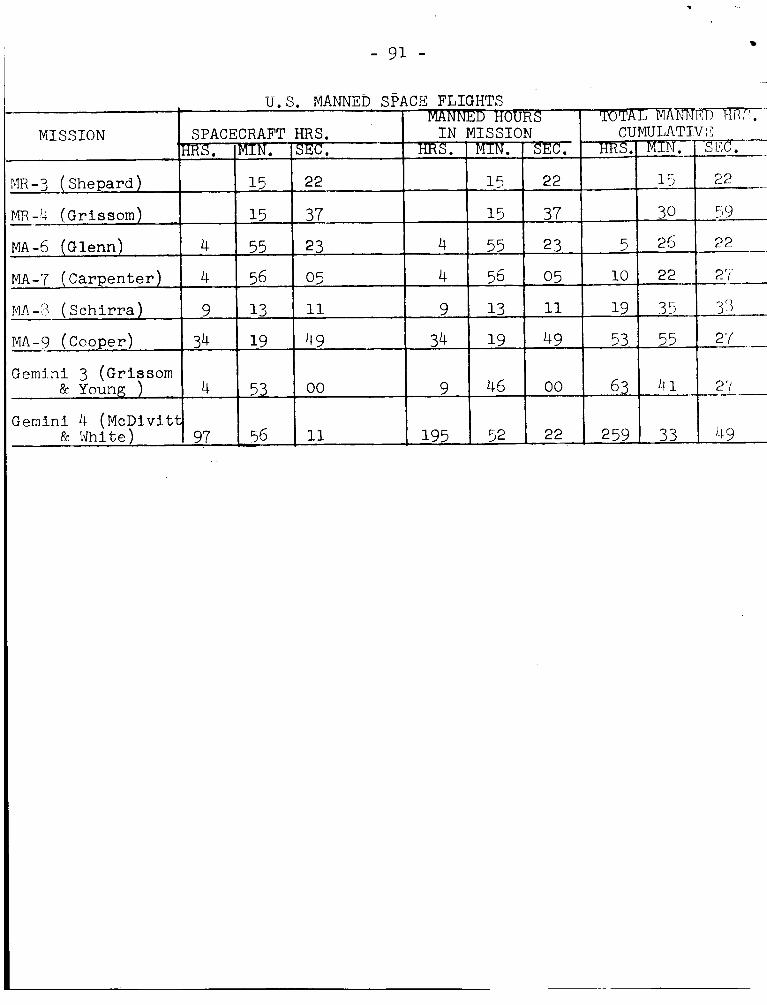
- 91 -
MISSION
" I - 3 (Shepard)
( G r i s s om )
M A - 5 (Glenn)
MA-7 (Carpenter)
1- NA-'? ( S c h i r r a )
I_ MA-9 (Cooper)
MR -'-I -
-~
Gemini 3 (Grissom & Young )
U.S. MANNED SPACl3 FLIGHTS TOTAL b'lAmJEr> TII{7.
'RRS. MIN. SXC, SPACECRAFT HRS. I N MISSION CUMULATIV 1 C ~
s. MIN. sJ5c. HRS. M I N . SKc.
15 22 15 22 15 22
15 37 15 37 30 519 -
4 55 23 4 55 23 5 25 22
4 56 05 4 55 05 lo 22
11 19 35 ,y{ 9 13 11 9 13
34 19 49 34 19 49 53 55 2'/ -
63 41 ~,-__-_ 4 53 00 9 45 00
-- -
- 2 '( ---
2 r(
97 56 11 . 195 52 22 Gemini 11 (McDivit
8~ rdhite) 259 33 ' 1 9

Feet Per Second
3
5
10
14
15
16
29.8
20,700.00
24,000.00
25,807.00
S t a t u t e Miles
1.7
6.0
14.9
17.5
99.0
100.0
106.0
212.0
219.0
229.0
CONVERSION TABLE
Miles P e r Hour Kilometers Per Hour
2.04
3.40
6.8
9.5
10.2
10.9
- 3.3
5.5
11.0
15.4
16.5
17.6
20.26 32 0 78
14,076.00 22,770.00
16,320,oo 26,400.00
17,549.00 28,254.00
Kilometers
2.77
9.56
11.27
23 99
28.18
159 59
161.00
170.66
341.32
352 6
368 . 69
500.0 805.00