project manual volume 2: specifications divisions …€¦ · section 01 33 50 - delegated design...
TRANSCRIPT

PROJECT MANUAL VOLUME 2:
Specifications Divisions 20-28
Trillium Health Partners – M Site Obs/Paeds/Rehab Renovation
Mississauga, ON
Issued for Bid & Permit (OPR)
Project No.: 11103T0200
Date: 2017-11-24 IFB&P
MANDATORY SITE VISIT DATE: at 14:30h, Thursday, November 30, 2017
BID CLOSING DATE: Thursday, December 21, 2017

Trillium Health Partners – M Site Obs/Paeds/Rehab Renovation 00 01 10 Project No.: 11103T0200 Table of Contents 2017-11-24 IFB&P Page 1 VOLUME 1 Division 0 - Procurement and Contracting Requirements Section 00 01 30 - List of Prequalified Bidders ............................................................................................ 4 Section 00 21 13 - Instructions to Bidders ................................................................................................. 11 Section 00 31 00 - Available Project Information ......................................................................................... 2 Section 00 41 13 - Bid Form – Stipulated Price (Single Prime Contract) ..................................................... 3 Section 00 43 13 - Procurement Form Submittals ....................................................................................... 8 Section 00 61 13 - Performance and Payment Security .............................................................................. 2 Section 00 63 00.01 - Consultant’s Forms ................................................................................................. 10 Section 00 63 00 - Construction Administration Forms ................................................................................ 2 Section 00 72 13 - General Conditions – Stipulated Price (Single Prime Contract) ..................................... 1 Section 00 73 00 – Supplementary Conditions .......................................................................................... 37 Division 1 - General Requirements Section 01 11 00 - Summary of Work .......................................................................................................... 6 Section 01 21 00 - Allowances .................................................................................................................... 5 Section 01 23 00 - Separate and Alternate Prices ....................................................................................... 2 Section 01 25 00 - Substitution Procedures ................................................................................................. 7 Section 01 26 13 - Requests for Information Procedures ............................................................................ 7 Section 01 31 13.20 - Mechanical and Electrical Project Coordination........................................................ 3 Section 01 31 13 - Project Coordination ...................................................................................................... 4 Section 01 31 19 - Project Meetings ............................................................................................................ 5 Section 01 32 00 - Schedules ...................................................................................................................... 4 Section 01 33 00 - Submittal Procedures .................................................................................................. 11 Section 01 33 50 - Delegated Design Submittals ........................................................................................ 4 Section 01 33 55 - Facility Start-Up Checklists ............................................................................................ 4 Section 01 35 13.19 - Special Project Procedures for Health Care Facilities .............................................. 8 Section 01 35 16 - Alteration Project Procedures ........................................................................................ 6 Section 01 35 20 - Site Safety Requirements .............................................................................................. 3 Section 01 41 00 - Regulatory Requirements .............................................................................................. 2 Section 01 41 29 - Freedom of Information and Protection of Privacy ......................................................... 4 Section 01 42 19 - Reference Standards – Ontario ..................................................................................... 3 Section 01 45 00 - Quality Control ............................................................................................................... 8 Section 01 50 00 - Temporary Facilities and Controls ................................................................................. 9 Section 01 61 00 - Common Product Requirements ................................................................................... 4 Section 01 62 00 - Product Options ............................................................................................................. 2 Section 01 65 00 - Owner Supplied Products .............................................................................................. 3 Section 01 73 00 - Execution ..................................................................................................................... 10 Section 01 73 29 - Cutting and Patching ..................................................................................................... 5 Section 01 74 23 - Final Cleaning ................................................................................................................ 2 Section 01 75 13 - Checkout Procedures .................................................................................................... 4 Section 01 75 16 - Start-up Procedures ....................................................................................................... 4 Section 01 77 00 - Closeout Procedures ..................................................................................................... 4 Section 01 78 23 - Operation and Maintenance Data .................................................................................. 4 Section 01 78 39 - Project Record Documents ............................................................................................ 3 Section 01 78 43 - Spare Parts .................................................................................................................... 2 Section 01 79 00 - Demonstration and Instruction ....................................................................................... 7 Division 2 - Existing Conditions Section 02 41 19.16 - Selective Interior Demolition ..................................................................................... 8 Section 02 81 16 - Hazardous Materials .................................................................................................... 67

Trillium Health Partners – M Site Obs/Paeds/Rehab Renovation 00 01 10 Project No.: 11103T0200 Table of Contents 2017-11-24 IFB&P Page 2 Division 3 – Concrete Also refer to Structural Specifications on Drawings Section 03 01 30 - Rehabilitation of Cast-In-Place Concrete ....................................................................... 3 Division 4 - Masonry Section 04 01 52 - Masonry Repair and Replacement ................................................................................ 6 Division 5 – Metals Also refer to Structural Specifications on Drawings Section 05 50 00 - Metal Fabrications ......................................................................................................... 8 Division 6 - Wood, Plastics and Composites Section 06 10 53 - Miscellaneous Rough Carpentry .................................................................................... 5 Section 06 40 00 - Shop Fabricated Architectural Woodwork ................................................................... 11 Section 06 61 16 - Solid Surfacing Fabrications .......................................................................................... 4 Division 7 - Thermal and Moisture Protection Section 07 01 52 - Roofing Repairs ............................................................................................................. 4 Section 07 05 53 - Fire and Smoke Assembly Design Requirements and Identification ........................... 14 Section 07 21 13 - Board Insulation ............................................................................................................. 4 Section 07 25 13 - Air and Vapour Membranes ........................................................................................... 5 Section 07 42 13 - Metal Wall Panels .......................................................................................................... 8 Section 07 62 00 - Sheet Metal Flashing and Trim ...................................................................................... 8 Section 07 71 00 - Roofing Specialties ........................................................................................................ 3 Section 07 84 00 - Fire Stopping ............................................................................................................... 13 Section 07 92 00 - Joint Sealants ................................................................................................................ 8 Division 8 - Openings Section 08 11 13 - Steel Doors and Frames .............................................................................................. 11 Section 08 14 00 - Plastic Laminate Faced Flush Wood Doors ................................................................... 6 Section 08 31 00 - Access Doors and Panels .............................................................................................. 5 Section 08 71 00 - Door Hardware ............................................................................................................ 32 Section 08 81 00 - Glass Glazing ................................................................................................................ 6 Section 08 88 13 - Fire Resistant Glazing ................................................................................................... 7 Division 9 - Finishes Section 09 06 00 - Schedules for Finishes .................................................................................................. 4 Section 09 21 16 - Gypsum Board Assemblies ......................................................................................... 23 Section 09 51 00 - Acoustical Panel Ceilings .............................................................................................. 8 Section 09 65 00 - Resilient Flooring and Accessories .............................................................................. 10 Section 09 66 13 - Portland Cement Terrazzo Flooring ............................................................................... 6 Section 09 91 00 - Painting ........................................................................................................................ 20 Section 09 96 00 - High Performance Coatings ........................................................................................... 7 Division 10 - Specialties Section 10 21 23 - Hospital Cubicle Tracks, and Curtains ........................................................................... 5 Section 10 26 23.13 - Impact Resistant Wall Protection .............................................................................. 7 Section 10 28 13 - Toilet Accessories .......................................................................................................... 7

Trillium Health Partners – M Site Obs/Paeds/Rehab Renovation 00 01 10 Project No.: 11103T0200 Table of Contents 2017-11-24 IFB&P Page 3 Division 11 - Equipment Section 11 73 13 - Patient Services Modules ............................................................................................ 11 Section 11 73 53 - Patient Transfer Systems .............................................................................................. 6 Division 12 - Furnishings Section 12 24 13 - Roller Window Shades .................................................................................................. 7 VOLUME 2 Division 20 - Mechanical General Provisions Section 20 01 00 - Mechanical Operation and Maintenance Data ............................................................... 4 Section 20 05 00 - Common Work Results for Mechanical ......................................................................... 8 Section 20 05 10 - Mechanical Systems Pipe and Pipe Fittings .................................................................. 8 Section 20 05 23 - Valves for Mechanical Systems ..................................................................................... 8 Section 20 05 29 - Hangers, Supports and Anchors for Mechanical Systems ........................................... 10 Section 20 05 40 - Mechanical Renovation Requirements .......................................................................... 1 Section 20 05 43 - Mechanical Systems Identification ................................................................................. 8 Section 20 05 93.13 - Testing of Mechanical Materials ............................................................................... 2 Section 20 05 93.16 - Testing of Mechanical Equipment ............................................................................. 4 Section 20 05 93.18 - Coordination with Balancing Agency ........................................................................ 1 Section 20 05 93.19 - Balancing of Mechanical Systems ............................................................................ 6 Section 20 07 00 - Piping and Equipment Insulation ................................................................................... 7 Section 20 41 23 - Mechanical Demolition ................................................................................................... 3 Division 21 - Fire Suppression Section 21 10 00 - Water Based Fire Suppression Systems ....................................................................... 5 Section 21 20 00 - Fire Extinguishing Systems ........................................................................................... 3 Division 22 - Plumbing Section 22 08 13 - Cleaning and Start-Up of Piping Systems ..................................................................... 2 Section 22 13 25 - Plumbing Specialties ..................................................................................................... 3 Section 22 40 00 - Plumbing Fixtures and Trim ........................................................................................... 5 Section 22 63 23 - Medical Gases System ................................................................................................ 12 Division 23 - Heating, Ventilating and Air Conditioning Section 23 01 30.52 - HVAC Duct Cleaning – Detailed ............................................................................... 4 Section 23 05 29 - Hangers and Supports for HVAC Ducting and Equipment ............................................ 7 Section 23 07 13 - Duct Insulation ............................................................................................................... 5 Section 23 31 00 - Ductwork ........................................................................................................................ 5 Section 23 33 00 - Air Duct Accessories ...................................................................................................... 5 Section 23 33 19 - Duct Silencers................................................................................................................ 4 Section 23 34 00 - HVAC Fans .................................................................................................................... 6 Section 23 36 00 - Air Terminal Units .......................................................................................................... 8 Section 23 37 13 - Diffusers, Registers and Grilles ..................................................................................... 3 Section 23 82 16 - Coils ............................................................................................................................... 2 Section 23 83 00 - Radiant Heating Units .................................................................................................... 3 Section 23 92 49 - Variable Frequency Drives ............................................................................................ 6 Division 25 - Integrated Automation Section 25 05 00 - Common Work Results for Integrated Automation ...................................................... 11

Trillium Health Partners – M Site Obs/Paeds/Rehab Renovation 00 01 10 Project No.: 11103T0200 Table of Contents 2017-11-24 IFB&P Page 4 Division 26 - Electrical Section 26 05 00 - Common Work Results for Electrical ........................................................................... 24 Section 26 05 01 - Selective Demolition for Electrical ................................................................................. 3 Section 26 05 07 - Mechanical Equipment Connections ............................................................................. 3 Section 26 05 19 - Electrical Power Conductors and Cables ...................................................................... 6 Section 26 05 19.13 - Armoured Cable ........................................................................................................ 1 Section 26 05 20 - Wire and Box Connectors 0-1000V ............................................................................... 1 Section 26 05 22 - Connectors and Terminations ........................................................................................ 1 Section 26 05 26 - Grounding and Bonding for Electrical Systems ............................................................. 2 Section 26 05 28 - Conduits, Outlet Boxes and Fittings for Electrical Systems ........................................... 8 Section 26 05 29 - Hangers and Supports for Electrical Systems ............................................................... 4 Section 26 05 31 - Cabinets, Splitters, Junction and Pull Boxes ................................................................. 3 Section 26 05 35 - Wireways and Auxiliary Gutters ..................................................................................... 2 Section 26 05 53 - Electrical Systems Identification .................................................................................... 8 Section 26 05 73 - Overcurrent Protective Device Coordination ................................................................. 6 Section 26 07 05 - Special Hospital Wiring .................................................................................................. 2 Section 26 07 13 - Wiring to Owners Equipment ......................................................................................... 1 Section 26 08 23 - Electrical Starting and Testing by Contractor ................................................................ 9 Section 26 18 00 - Building Voltage Circuit Protective Devices ................................................................... 3 Section 26 24 16 - Panelboards .................................................................................................................. 5 Section 26 27 19 - Multi Outlet Assemblies ................................................................................................. 1 Section 26 20 13 - Switches, Receptacles, Plates and other Devices ......................................................... 8 Section 26 29 03 - Control Devices ............................................................................................................. 2 Section 26 50 00 - Lighting .......................................................................................................................... 4 Division 27 - Communications Section 27 00 00 - Telecommunications General Provisions ...................................................................... 9 Section 26 05 28 - Pathways for Communications System ......................................................................... 3 Section 27 05 53 - Identification for Communications Systems ................................................................... 2 Section 27 08 01 - Testing & Recording Documentation ............................................................................. 2 Section 26 27 19 - Terminations Blocks, Patch Panels & Connectors ......................................................... 2 Section 27 15 13 - Copper Horizontal Cabling ............................................................................................. 3 Section 27 16 19 - Patch Cords, Station Cords & Cross Connect Wire ....................................................... 1 Section 27 52 23 - Nurse Call System ....................................................................................................... 17 Section 27 53 13 - Time System .................................................................................................................. 3 Division 28 - Electronic Safety and Security Section 28 08 15 - 3rd Party Fire Alarm Verification ................................................................................... 3 Section 28 20 10 - Card Access System ..................................................................................................... 8 Section 28 31 15 - Fire Detection and Alarm ............................................................................................. 12 VOLUME 3 Appendix - Information Documents Section 00 31 00 - Available Project Information ......................................................................................... 2 Contractor Safety Handbook ..................................................................................................................... 78 Asbestos Survey ...................................................................................................................................... 256 Shutdown Request Form ............................................................................................................................. 1
END OF TABLE OF CONTENTS

Trillium Health Partners – M Site Obs/Paeds/Rehab Renovation 20 01 00 Project No.: 11103T0200 Mechanical Operation and Maintenance Data 2017-11-24 IFB&P Page 1
1 General
1.1 SUMMARY
1.1.1 Work in this section includes information required to coordinate and assemble operating and maintenance manuals.
1.2 RELATED REQUIREMENTS
1.2.1 Section 01 78 23 – Operation and Maintenance Data: Coordinate with this Section for detailed assembly and submission requirements for operating and maintenance manuals required for the project.
1.3 QUALITY ASSURANCE
1.3.1 Qualifications: Provide proof of qualifications when requested by Consultant:
1.3.1.1 Engineer: Work specified in this section must be performed by a professional engineer specializing in this type of work.
2 Products
2.1 OPERATING AND MAINTENANCE MANUALS
2.1.1 Obtain and assemble all necessary literature describing the operation and maintenance of equipment provided to the project; submit and transmit documentation for review to Consultant at project milestones.
2.1.2 Binders: Provide sets of Operations and Maintenance Manuals in binders of size, colour and type listed in Section 01 78 23.
2.1.3 Tabs: Use laminated mylar plastic and coloured according to division and section divider tabs and as follows:
2.1.3.1 Plastic tabs with typewritten card inserts will not be accepted. 2.1.3.2 Include tab number and title printed on each tab. 2.1.3.3 Colouring for tabs for individual sections is as follows:
Colour System
Brown Control Systems Blue Cooling Systems Red Fire Protection
Orange Heating Systems Yellow Miscellaneous Systems Purple Plumbing Systems White Medical Gas
2.1.4 Manual Divisions: Organize each manual into the following divisions:
2.1.4.1 Operation Division 2.1.4.2 Maintenance Division 2.1.4.3 Contract Documentation Division
2.2 OPERATIONS DIVISION
2.2.1 Organize all data into sections according to the system category with individual divider tabs as follows:
2.2.1.1 CTL Control Systems 2.2.1.2 CLG Cooling Systems 2.2.1.3 FPN Fire Protection Systems 2.2.1.4 HTG Heating Systems 2.2.1.5 MIS Miscellaneous Systems 2.2.1.6 PLG Plumbing Systems

Trillium Health Partners – M Site Obs/Paeds/Rehab Renovation 20 01 00 Project No.: 11103T0200 Mechanical Operation and Maintenance Data 2017-11-24 IFB&P Page 2
2.2.2 Organize data for each system category (section) into individual sub-systems. Provide an index for each system category and a divider tab for each individual system.
2.2.3 Include the following for each individual sub-system:
2.2.3.1 System Description - Provide details of system type, composition, areas served, location in the building, design criteria and function of major components. All equipment arranged to operate together as one system must be considered part of that system description. Design criterion, at minimum, includes the following:
2.2.3.1.1 Occupied space conditions 2.2.3.1.2 Outdoor ambient conditions 2.2.3.1.3 Air circulation rate 2.2.3.1.4 Exhaust air rate 2.2.3.1.5 Minimum outside air 2.2.3.1.6 Building pressurization 2.2.3.1.7 Future load allowances 2.2.3.1.8 Standby capabilities
2.2.3.2 System Schematic - Provide a system schematic showing all components comprising the central system. Identify each component using DDC system mnemonic and generic name designation. Use this equipment designation in all references to the equipment throughout the manual.
2.2.3.3 Operating Instructions - Provide, in "operator" layman language, specific instructions for start-up, shutdown and seasonal changeover of each system component. Include exact type, and specific location of each switch and device used in the system operation. Identify safety devices and interlocks that must be satisfied in order for the equipment to start. Also, list conditions that must be fulfilled prior to attempting equipment start-up, such as correct valve positions, proper glycol mixture concentrations, piping filled with fluid, placement of filters/strainers, and similar criteria.
2.2.3.4 Equipment Identification - Provide data for each system component on equipment identification forms equal to the standard forms obtained from the design consultant.
2.3 MAINTENANCE DIVISION
2.3.1 Organize data into the following sections with divider tabs:
2.3.1.1 Maintenance Tasks and Schedules 2.3.1.2 Spare Parts 2.3.1.3 Suppliers and Contractors 2.3.1.4 Tags and Directories
2.3.2 Maintenance Tasks and Schedules: Organize data according to the system category, with further breakdown into individual systems as used in the operations division of the manual. Provide section index and divider tabs for each system category. Summarize maintenance tasks from manufacturers maintenance brochures, for each component of each system in the following format:
2.3.2.1 Daily 2.3.2.2 Weekly 2.3.2.3 Monthly 2.3.2.4 Semi-Annually 2.3.2.5 Annually 2.3.2.6 When Required
Trillium Health Partners – M Site Obs/Paeds/Rehab Renovation 20 01 00 Project No.: 11103T0200 Mechanical Operation and Maintenance Data 2017-11-24 IFB&P Page 3
2.3.3 Spare Part List: Organize data according to the system category, with further breakdown into individual systems as used in the operations division of the manual. Provide section index and divider tabs for each system category. Summarize from manufacturers maintenance brochures the recommended spare parts for each component of each system.
2.3.4 Suppliers and Contractor List: Provide summary of Suppliers and Contractors for each component of each system. List name, address and telephone number of each.
2.3.5 Tags and Directories: Provide a copy of the Mechanical Drawing List, Valve Tag List, Piping Identification Schedule and all other directories as specified in the contract documents.
2.4 CONTRACT DOCUMENTATION DIVISION
2.4.1 Organize all data required by the construction contract into sections with divider tabs as follows:
2.4.1.1 Drawings List 2.4.1.2 Shop Drawings and Product Data 2.4.1.3 Certifications 2.4.1.4 Warranties and Bonds 2.4.1.5 Maintenance Brochures 2.4.1.6 Reports
2.4.2 Shop Drawings and Product Data: Provide final copies of all shop drawings and product data required by the contract documents. Include section index and divider tabs. Maximum of twenty-five (25) sheets or one (1) system shop drawing per tab.
2.4.3 Certifications: Provide copies of Contractor Certifications for the performance of products and systems. Include copies of all pressure tests for piping and ductwork systems, equipment alignment certificates, local authority inspection reviews, backflow prevention certifications, and fire protection certifications. Include section index and divider tabs with maximum of twenty-five sheets (25) or one (1) report per tab.
2.4.4 Warranties and Bonds: Include one copy each of the Contractor's warranty, manufacturers' warranties longer than one year, the bond, and any service contract provided by the contractor. Provide section indexes.
2.4.5 Maintenance Brochures: Include copies of all manufacturers' printed maintenance brochures pertaining to each product, equipment, or system. Provide section index and divider tabs. Maximum of twenty-five (25) sheets or one (1) system brochure per tab.
2.4.6 Reports: Include copies of all reports relating to the testing, adjusting and balancing of equipment, and systems, as required by the contract specification sections. Include all Water Treatment Reports and Manufacturers Start-up Reports. Include section index and divider tabs for each report.
2.4.7 Submissions and Approvals.
3 Execution
3.1 ASSEMBLY
3.1.1 Submit documents to the Consultant for approval prior to transmitting to the Owner.
3.1.2 Upon approval by consultant provide one (1) hard copy and one (1) digital copy of all final documents to the Owner.
3.1.3 Final edition must include all outstanding project information and conform to all requirements specified.

Trillium Health Partners – M Site Obs/Paeds/Rehab Renovation 20 01 00 Project No.: 11103T0200 Mechanical Operation and Maintenance Data 2017-11-24 IFB&P Page 4
END OF SECTION

Trillium Health Partners – M Site Obs/Paeds/Rehab Renovation 20 05 00 Project No.: 11103T0200 Common Work Results for Mechanical 2017-11-24 IFB&P Page 1
1 General
1.1 SUMMARY
1.1.1 It is the responsibility of the Constructor to make requirements for affected related specification sections, and any requirements for alternates and substitutions available to Subcontractor’s:
1.1.1.1 Subcontractor’s receive a complete set of Documents for preparation of their Bids, and to provide a clear understanding of the complete scope-of-work for the Project.
1.1.1.2 Failure to provide required information to Subcontractor’s during the Bid and Construction Phases of the Work will not relieve the Constructor of their responsibility for coordination of the affected Work.
1.1.1.3 Constructor is responsible for any additional costs to the Contract arising from Subcontractor’s not receiving a complete package of Documents.
1.1.1.4 Provide complete coordination between Mechanical Divisions to attain a complete and functional building mechanical system; Mechanical Divisions include, but are not limited to, the following:
1.1.1.4.1 Division 20 – Mechanical Common Requirements 1.1.1.4.2 Division 21 – Fire Suppression 1.1.1.4.3 Division 22 – Plumbing 1.1.1.4.4 Division 23 – Heating, Ventilating and Air Conditioning 1.1.1.4.5 Division 25 – Integrated Automation
1.1.2 Provide complete, fully tested and operational mechanical systems to meet requirements described herein and in complete accord with applicable codes and ordinances:
1.1.2.1 Include costs to obtain permits and to pay for fees and charges, including inspection charges by Authorities Having Jurisdiction that issue permits; coordinate related inspections; permits, fees and inspections include, but are not limited to, the following:
1.1.2.1.1 Plumbing 1.1.2.1.2 Ventilation 1.1.2.1.3 Fire Protection 1.1.2.1.4 Water Treatment 1.1.2.1.5 Building HVAC 1.1.2.1.6 Medical Gases
1.1.3 Documents for the Project, including Specifications and Drawings, are generally diagrammatic and approximately to scale unless specifically detailed otherwise; they establish scope, material and installation quality, and are not considered as detailed installation instructions.
1.2 RELATED REQUIREMENTS
1.2.1 Section 00 43 13 – Procurement Form Submittals
1.2.2 Section 01 25 00 – Substitution Procedures: Selection of additional materials proposed by Constructor or Subcontractor during bid period or during construction for Basis-of-Design Materials listed in technical specification sections.
1.2.3 Section 01 33 00 – Submittal Procedures: Submission of shop drawings, samples and product literature.
1.2.4 Section 01 50 00 – Temporary Facilities and Controls: Temporary heating, site storage and offices, and daily clean-up requirements; protection and reconditioning of permanent equipment and systems used during construction.
1.2.5 Section 01 62 00 – Product Options: Selection of products when Acceptable Materials are indicated in technical specification sections.

Trillium Health Partners – M Site Obs/Paeds/Rehab Renovation 20 05 00 Project No.: 11103T0200 Common Work Results for Mechanical 2017-11-24 IFB&P Page 2
1.2.6 Section 01 65 00 – Owner Supplied Products: Mechanical connections to Owner supplied equipment.
1.2.7 Section 01 73 00 – Execution: Service connections and installation precedence of building systems.
1.2.8 Section 01 73 29 –Cutting and Patching: Coring and cutting requirements for mechanical services in built-up construction.
1.2.9 Section 01 74 23 – Final Cleaning: General requirements for final cleaning of installed mechanical systems.
1.2.10 Section 01 77 00 – Closeout Procedures: Requirements for declaration of Substantial and Total Performance.
1.2.11 Section 01 78 23 – Operation and Maintenance Data: Submission requirements for warranties, guaranties, and operating and maintenance information.
1.2.12 Section 01 78 39 – Project Record Documents: Submission of project record drawings and specifications.
1.2.13 Section 02 41 19-16 – Selective Interior Demolition
1.2.14 Section 08 31 00 – Access Doors and Panels: Architectural and fire rated metal access panels for access to mechanical equipment or assemblies concealed within wall or ceiling assemblies.
1.2.15 Section 20 05 40 – Mechanical Renovation Requirements
1.3 ADMINISTRATIVE REQUIREMENTS
1.3.1 Coordination: Cooperate and coordinate with other trades and verify order of installation of overlapping or interconnecting services or equipment before starting Work.
1.3.1.1 Drawings and Specifications: Drawings and specifications are complementary to each other, and what is called for by one is binding as if called for by both and as follows:
1.3.1.1.1 Examine Contract Documents including drawings and specifications, and work of other trades before starting Work and verify that Work can be satisfactorily completed without changes to building.
1.3.1.1.2 Consultant will provide a clarification to identified discrepancies between drawings and specifications that leave Constructor in doubt as to the true intent and meaning of the documents as follows:
• During Bid Period: A written Addendum will be issued to address a written request for clarification.
• During Construction: A Construction Communication will be issued to address a written request for information.
1.3.1.2 Consultant will respond to Requests for Interpretation and determine the requirements for clarification based only on variances contained in the documents as follows:
1.3.1.2.1 Clarification based on information and not contained in the documents or in manufacturers written literature will be regarded as a change to the Work.
1.3.1.2.2 Clarification will be based on the hierarchy of the complete document package, not just the documents provided to Subcontractor by Constructor.
1.3.1.2.3 Clarification will include effects or influence of other specified products, adjacent construction, adjacent finishes and methods of construction.
Trillium Health Partners – M Site Obs/Paeds/Rehab Renovation 20 05 00 Project No.: 11103T0200 Common Work Results for Mechanical 2017-11-24 IFB&P Page 3
1.3.1.2.4 Clarification issued during Construction Phase that affects the cost of the Work will be regarded as a Change to the Work.
1.3.1.3 Milestone field reviews will be conducted by the Consultant at key stages of construction. Coordinate with the consultant the type and quantity of milestone reviews required and incorporate these requirements in the construction schedule.
1.3.1.3.1 Notify the consultant in writing seven (7) calendar days in advance of work to be concealed to arrange a site review prior to the work being concealed where required by the consultant. Any noted deficiencies are to be corrected before being concealed. Failure to provide notification may result in the work being exposed for review at the Contractor’s cost.
1.3.1.4 Coordinate installation of the Work with manufacturer's recommended installation details and procedures, supplemented by requirements of Contract Documents; provide adequate access space for maintenance and service of equipment and systems.
1.3.1.5 Coordinate location of access to cleanouts, valves, equipment, and duct access doors above continuous ceilings; coordinate access panel and door requirements with Section 08 31 00.
1.3.1.6 Coordinate installation of Work with adjacent work by others as follows:
1.3.1.6.1 Install material and equipment generally in locations and routes shown, close to building structure with minimum interference with other services or free space; remove and replace improperly installed equipment as determined by Consultant.
1.3.1.6.2 Refer to electrical, mechanical, structural and architectural drawings when setting out work and coordinate with other applicable components of the Work when setting out locations for ductwork, equipment, and piping so that conflicts are avoided and symmetrical even spacing is maintained.
1.3.1.6.3 Provide coordination drawings showing the work of other trades and contractors involved in areas of potential conflict or congestion at no additional cost to the Contract.
1.3.1.6.4 Coordinate dimensional details with applicable architectural and structural drawings.
1.3.1.6.5 Full size and detailed drawings will take precedence over scale measurements from drawings when laying out the Work.
1.3.1.7 Coordinate requirements of, and connect to, equipment specified in other Sections, and to equipment supplied and installed by other contractors or by Owner; uncrate equipment, assemble, move in place, and install complete, start-up and test; refer to Section 01 65 00 for owner supplied equipment and equipment furnished by other Divisions.
1.3.2 Declarations: Coordinate declaration of Substantial Performance and Total Performance with requirements of the General Conditions and Supplementary Conditions of the Contract.

Trillium Health Partners – M Site Obs/Paeds/Rehab Renovation 20 05 00 Project No.: 11103T0200 Common Work Results for Mechanical 2017-11-24 IFB&P Page 4
1.4 SUBMITTALS
1.4.1 Provide required information in accordance with Section 01 33 00 - Submittal Procedures.
1.4.2 Construction Clarification Drawings: Coordinate construction coordination requirements as follows:
1.4.2.1 Prepare drawings in conjunction with all trades concerned, showing sleeves and openings for passage through floor structure.
1.4.2.2 Prepare a complete set of drawings showing all conduit runs and wiring using the information provided in riser diagrams, circuit numbers on floor plans, relevant details, specifications, and with reference to drawings of other trades.
1.4.2.3 Prepare composite construction drawings, fully dimensioned in metric, indicating cable, conduit, bus duct, shafts, mechanical and electrical equipment rooms, including switchgear rooms, ceiling spaces and all other critical locations to avoid a conflict of trades. Base equipment drawings upon shop drawings and include, but do not necessarily limit to, all details pertaining to clearances, access, sleeves, electrical connections, location and elevation of pipes, ducts, conduits, and similar criteria, obtained from consultation with and agreement of the trades involved.
1.4.2.4 Submit a schedule of construction drawings not later than three weeks after the award of Contract, indicating the anticipated date when the drawings will be submitted for approval.
1.4.3 Identify materials and equipment submittals by listing manufacturer, trade name, and model number, and as follows:
1.4.3.1 Include copies of applicable brochure or catalogue material. 1.4.3.2 Do not assume that applicable catalogues are available in Consultants
office. 1.4.3.3 Maintenance and operating manuals will not be considered as suitable
submittal material. 1.4.3.4 Leave space on shop drawing to accommodate Consultants review
stamp. 1.4.3.5 Clearly mark each shop drawing with identical name or number where
equipment is identified by name or number on drawings or in specifications.
1.4.3.6 Clearly identify dimensional and technical data sufficient to verify that equipment meets specified requirements.
1.4.3.7 Clearly identify wiring, piping, service connection data and motor sizes. 1.4.3.8 Clearly mark each submittal sheet using arrows, underlining, or circling
to indicate differences between specifications and options proposed for use in the Work, such as differences in sizes, types, model numbers, rating, capacities, and similar criteria.
1.4.3.9 Specifically note specified features included as a part of the submittal, such as special tank linings, pump seals, materials or painting.
1.4.3.10 Strike out non-applicable material.
1.4.4 Review shop drawings prior to submittal to Consultant certifying that:
1.4.4.1 Site measurements are verified and correct. 1.4.4.2 Site construction criteria, materials, catalogue numbers and similar
data are coordinated with shop drawings and requirements of the Work.
1.4.4.3 Certify review of each shop drawing by placing Subcontractor’s and Constructor’s review stamps, date and signatures of responsible persons.
1.4.4.4 Verify installed materials and equipment meet specified requirements where shop drawings are not provided to Consultant for review.

Trillium Health Partners – M Site Obs/Paeds/Rehab Renovation 20 05 00 Project No.: 11103T0200 Common Work Results for Mechanical 2017-11-24 IFB&P Page 5
1.4.5 Use of Metric Units and Conversions in Submittals:
1.4.5.1 Units expressed in these documents are written in Imperial (IP) or Systems International (SI) Metric Units; soft metric conversions are used throughout.
1.4.5.2 Submit shop drawings and maintenance manuals in IP or SI Units; use same IP or SI Units for submittals as stated in specification or drawings.
1.4.5.3 Equivalent Nominal Diameters of Pipes – Metric and Imperial:
1.4.5.3.1 Provide equivalent nominal Imperial sized pipe and provide adapters to allow compatible connections to SI Metric sized fittings, equipment and piping where pipes are specified with SI Metric dimensions and only Imperial sized pipes are available.
1.4.5.3.2 Provide adapters to allow compatible connections between SI Metric pipes and new and existing pipes, fittings, and equipment when CSA approved SI Metric pipes are available and are provided.
1.4.5.3.3 Record accurately on "as-built" documents the type of pipe installed.
1.4.6 Submit marked up drawing of reflected ceiling plan indicating location of access doors in ceilings prior to pipe and duct installation.
1.5 QUALITY ASSURANCE
1.5.1 Qualifications: Provide proof of qualifications when requested by Consultant:
1.5.1.1 Quality of Material and Equipment: Verify that materials and equipment installed are new, full weight and of quality specified; use same brand or manufacturer and model for each specific application:
1.5.1.1.1 Verify that the manufacturer's name, address, catalogue and serial number appear on each major component of equipment in a conspicuous place.
1.5.1.1.2 Replace materials or workmanship below specified quality and relocate work wrongly placed to satisfaction of Consultant and at no cost to Owner.
1.5.1.1.3 Install materials and equipment in a quality manner providing good workmanship by competent tradesmen.
1.5.1.1.4 Price submitted for this contract includes the use of materials and equipment as specified or as contained within the listing.
1.5.1.2 Availability of Material and Equipment: Notify Consultant in writing a minimum of ten (10) days prior to Bid Closing Date of any materials specified that are required to complete Work and that are not currently available or will not be available for use as specified in these documents as follows:
1.5.1.2.1 Bid submission denotes that specified products are available to meet specified requirements.
1.5.1.2.2 Acceptance of Bid obliges Constructor and Subcontractor’s to place orders and provide specified products in a timely manner to meet Project Schedule.
1.5.1.2.3 Failure to secure specified products will not relieve Constructor and Subcontractor’s from providing acceptable substitutions, including other associated costs to secure substitute products, at no additional cost to Owner or impact on Project Schedule.
1.5.1.2.4 Submit proposed substitutions to Consultant for acceptance in accordance with Section 01 33 00.
Trillium Health Partners – M Site Obs/Paeds/Rehab Renovation 20 05 00 Project No.: 11103T0200 Common Work Results for Mechanical 2017-11-24 IFB&P Page 6
1.5.2 Proposed Substitutions to Specified Material and Equipment:
1.5.2.1 Requests for substitutes will not be considered during Bidding Period; this does not preclude the submission of proposed substitutes by Subcontractors, manufacturers, and suppliers, provided they submit information to General Contract Bidders in accordance with Section 00 43 13 – Procurement Form Submittals and Section 01 25 00 – Substitution Procedures.
1.5.2.2 Acceptance of proposed substitutions to specified products will be based on evaluation of equal or better performance and materials to those specified in every respect, operate as intended, meet the space, capacity, and noise requirements outlined, and require no changes to the structure or configuration of adjacent assemblies or materials.
1.5.2.3 Contractor is fully responsible for costs for work or materials required by Subcontractor or other contractors to accommodate use of materials or equipment other than those specified.
1.6 WARRANTY
1.6.1 Provide a written warranty stating that Work executed in this Contract will be free from defective workmanship and materials for a period of one (1) year starting from the date of substantial performance of work in accordance with the requirements specified in Division 01.
1.6.2 Warranty makes provision for repair or replacement of any Work that fails or becomes defective during the term of the warranty, providing the operating and maintenance instructions have been complied with by the Owner.
1.6.3 Duration of the warranty specified does not, in any way, supplant any other guaranties or warranties provided under the Contract for individual pieces of equipment or systems having a longer period provided by Manufacturers or as called for in the project documents.
1.6.4 Unless specified otherwise, Owner will be responsible for routine maintenance requirements as required in the manufacturer’s instructions, and will be responsible for supplying filters, grease and belts and other consumables required for routine maintenance.
2 Products
2.1 NOT USED
3 Execution
3.1 EXAMINATION OF EXISTING CONDITIONS
3.1.1 Visit and examine the site and note characteristics and features affecting the Work before submitting Bid.
3.1.2 Report discrepancies in writing to Consultant prior to Bid closing.
3.1.3 No allowances will be made for difficulties encountered or expenses incurred arising from conditions of the site or existing items that are readily visible or known to exist at the time of Bid.
3.1.4 Failure to advise Consultant of discrepancies in writing will mean that Constructor accepts documents as presented without potential of additional costs.
3.1.5 Unforeseen conditions or discrepancies that could not be readily ascertained at the time of Bid will be administered as a change to the Contract.
3.2 CUTTING AND PATCHING
3.2.1 Coordinate requirements of the Work with Section 01 73 29 – Cutting and Patching.

Trillium Health Partners – M Site Obs/Paeds/Rehab Renovation 20 05 00 Project No.: 11103T0200 Common Work Results for Mechanical 2017-11-24 IFB&P Page 7
3.2.2 Coordinate locations of mechanical penetrations and sleeves through concrete floor structure including slabs, beams, purlins and girders.
3.2.3 Provide inserts, holes and sleeves, cutting and fitting required for mechanical work; relocate improperly located holes and sleeves.
3.2.4 Provide inserts or drill for expansion bolts, hanger rods, brackets, and supports.
3.2.5 Obtain written approval from Consultant before drilling, coring, cutting or burning structural members.
3.3 USE OF PERMANENT SYSTEMS FOR TEMPORARY HEAT
3.3.1 Coordinate requirements for use of permanent heating systems for temporary heat; do not use permanent system for temporary heating purposes without written permission from Consultant.
3.3.2 Provide a proposed temporary heat agreement for Owner to review prior to use of permanent building systems for temporary heat; agreement includes payment schedules for utilities, spare parts listings, and confirmation of warranty.
3.3.3 The terms of warranty are not modified by the use of permanent systems for temporary heat; equipment manufacturers certify that equipment is in "new" condition at start of warranty period, and as follows:
3.3.3.1 Block-off system components not required for temporary heat in accordance with manufacturer’s requirement to maintain warranty.
3.3.3.2 Thoroughly clean and overhaul permanent equipment used during construction period, replace worn or damaged parts before final inspection.
3.3.3.3 Operate heating systems under conditions that allow no temporary or permanent damage.
3.3.3.4 Operate with proper safety devices and controls installed and fully operational.
3.3.3.5 Operate systems only with treated water as specified. 3.3.3.6 Air systems may not be used for temporary heating. 3.3.3.7 Provide alarm indicating system failure; connect alarm to independent
alarm company system. 3.3.3.8 Replace mechanical seals, regardless of condition, with new
mechanical seals where pumps are used for temporary heating prior to Total Performance of the Work.
3.3.3.9 Avoid thermal shock to heating system during planning, construction and operation of temporary heating system.
3.3.4 Review temporary heating procedures with Consultant as follows:
3.3.4.1 Obtain acceptance by Consultant for thermal insulation work and automatic control equipment associated with use of permanent heating system for temporary heat.
3.3.4.2 Obtain approval from Provincial Boiler Protection Branch of Department of Labour before use of permanent heating system for temporary heat.
3.4 EQUIPMENT PROTECTION AND CLEAN-UP
3.4.1 Protect equipment and materials in storage on site during and after installation until final acceptance; leave factory covers in place; take special precautions to prevent entry of foreign material into working parts of piping and duct systems.
3.4.2 Protect equipment with polyethylene covers and crates.
3.4.3 Operate, drain and flush out bearings and refill with new change of oil, before final acceptance.
3.4.4 Clean piping, ducts and equipment of dirt, cuttings and other foreign substances.

Trillium Health Partners – M Site Obs/Paeds/Rehab Renovation 20 05 00 Project No.: 11103T0200 Common Work Results for Mechanical 2017-11-24 IFB&P Page 8
3.4.5 Protect bearings and shafts during installation: Grease shafts and sheaves to prevent corrosion. Supply and install necessary extended nipples for lubrication purposes.
3.4.6 Verify that existing equipment being turned over to Owner or reused is carefully dismantled and not damaged or lost; do not reuse existing materials and equipment unless specifically indicated.
3.5 TEMPORARY OR TRIAL USAGE OF PERMANENT SYSTEMS
3.5.1 Temporary or trial usage requested by Owner of mechanical equipment supplied under contract will not represent acceptance by Owner; operate and maintain equipment and systems during trial usage in a manner that preserves the manufacturer’s warranty/guaranty.
3.5.2 Repair or replace equipment damaged as a result of defective materials or workmanship during temporary or trial usage; coordinate with Section 01 50 00 for requirements associated with protection and reconditioning of permanent equipment and systems used during construction.
END OF SECTION
Trillium Health Partners – M Site Obs/Paeds/Rehab Renovation 20 05 10 Project No.: 11103T0200 Mechanical Systems Pipe and Pipe Fittings 2017-11-24 IFB&P Page 1
1 General
1.1 SUMMARY
1.1.1 This section includes requirements for supply and installation of pipe and pipe fittings including the following:
1.1.1.1 Hot Water Heating System Piping 1.1.1.2 Sanitary Drainage and Vent System Piping 1.1.1.3 Domestic Water Piping 1.1.1.4 Fire Protection Piping 1.1.1.5 Other components required for a complete installation
1.2 RELATED REQUIREMENTS
1.2.1 Section 07 05 53 – Fire and Smoke Assembly Design Requirements and Identification
1.2.2 Section 20 05 23 – Valves for Mechanical Systems
1.2.3 Section 20 05 29 – Pipe Hangers, Supports and Anchors for Mechanical Systems
1.2.4 Section 20 07 00 – Piping and Equipment Insulation
1.2.5 Section 21 10 00 – Water Based Fire Suppression Systems
1.2.6 Section 22 13 25 – Plumbing Specialties
1.3 REFERENCE STANDARDS
1.3.1 American Society of Mechanical Engineers (ASME):
1.3.1.1 ANSI/ASME B16.3-2011, Malleable Iron Threaded Fittings: Classes 150 and 300
1.3.1.2 ANSI/ASME B31.1-2010, Power Piping 1.3.1.3 ANSI/ASME B31.9-2011, Building Services Piping
1.3.2 American Society for Testing and Materials (ASTM):
1.3.2.1 ASTM A53/A53M-12, Standard Specification for Pipe, Steel, Black and Hot-Dipped, Zinc-Coated, Welded and Seamless
1.3.2.2 ASTM A106/A106M-11, Standard Specification for Seamless Carbon Steel Pipe for High-Temperature Service
1.3.2.3 ASTM A181/A181M-06, Standard Specification for Carbon Steel Forgings, for General-Purpose Piping
1.3.2.4 ASTM A536-84 (2009), Standard Specification for Ductile Iron Castings
1.3.2.5 ASTM A999/A999M-11, Standard Specification for General Requirements for Alloy and Stainless Steel Pipe
1.3.2.6 ASTM B88-09, Standard Specification for Seamless Copper Water Tube
1.3.2.7 ASTM B280-08, Standard Specification for Seamless Copper Tube for Air Conditioning and Refrigeration Field Service
1.3.2.8 ASTM B306-09, Standard Specification for Copper Drainage Tube (DWV)
1.3.2.9 ASTM D3034-08, Standard Specification for Type PSM Poly (Vinyl Chloride) (PVC) Sewer Pipe and Fittings
1.3.2.10 ASTM F1476-07, Standard Specification for the Performance of Gasketted Mechanical Couplings for Use in Piping Applications
1.3.3 American Water Works Association (AWWA):
1.3.3.1 ANSI/AWWA C606-11, Standard for Grooved and Shouldered Joints 1.3.3.2 ANSI/AWWA C900-07, Standard for Polyvinyl Chloride (PVC) Pressure
Pipe and Fabrication Fittings, 100 mm through 300 mm for Water Transmission and Distribution

Trillium Health Partners – M Site Obs/Paeds/Rehab Renovation 20 05 10 Project No.: 11103T0200 Mechanical Systems Pipe and Pipe Fittings 2017-11-24 IFB&P Page 2
1.3.4 Canadian Standards Association (CSA):
1.3.4.1 CSA A257 Series-09, Standards for Concrete Pipe and Manhole Sections
1.3.4.2 CSA B52-05 (R2009), Mechanical Refrigeration Code 1.3.4.3 CAN/CSA B64 Series-07, Backflow Preventers and Vacuum Breakers 1.3.4.4 CSA B70-06, Cast Iron Soil Pipe, Fittings, and Means of Joining 1.3.4.5 CSA B137 Series-09, Thermoplastic Pressure Piping Compendium 1.3.4.6 CSA B139-09, Installation Code for Oil Burning Appliances and
Equipment 1.3.4.7 CSA B149.1-10, Natural Gas and Propane Installation Code 1.3.4.8 CAN/CSA B242-05, Groove- and Shoulder-Type Mechanical Pipe
Couplings 1.3.4.9 CSA W55.3-08, Certification of companies for resistance welding of
steel and aluminum 1.3.4.10 CSA W117.2-06, Safety in Welding, Cutting and Allied Processes
1.3.5 National Fire Protection Association (NFPA):
1.3.5.1 NFPA (Fire) 14-2010, Standard for the Installation of Standpipe and Hose Systems
1.3.6 Underwriters Laboratories Canada (ULC):
1.3.6.1 CAN/ULC S102-10, Standard Method of Test for Surface Burning Characteristics of Building Materials and Assemblies
1.4 SUBMITTALS
1.4.1 Provide required information in accordance with Section 01 33 00 – Submittal Procedures.
1.4.2 Action Submittals: Provide the following submittals before starting any work of this Section:
1.4.2.1 Product Data: Indicate grooved joint couplings and fittings on drawings and product submittals; specifically identified with applicable style or series designation.
1.4.3 Informational Submittals: Provide the following submittals when requested by the Consultant:
1.4.3.1 Certificates: Submit statement describing welding procedures proposed for the review of the Consultant.
1.5 QUALITY ASSURANCE
1.5.1 Regulatory Requirements:
1.5.1.1 Welding: Weld in accordance with the requirements of the Provincial Boilers Branch on steam systems where the pressure exceeds 103 kPa and on heating water and glycol systems where the pressure exceeds 1100 kPa and the temperature exceeds 121°C, and as follows:
1.5.1.1.1 Ensure welded joints are free of defects including: elongated slag, isolated slag, porosity, incomplete penetration, lack of fusion, burn through, cracks, arc burn, internal concavity, hollow beads, internal undercuts, and external undercuts.
1.5.2 Qualifications: Provide proof of qualifications when requested by Consultant:
1.5.2.1 Materials:
1.5.2.1.1 Use highest quality piping conforming to the referenced ASTM and CSA Standards.
1.5.2.2 Installers: Use tradesmen licensed by the Authority Having Jurisdiction for the particular service or component of the work.

Trillium Health Partners – M Site Obs/Paeds/Rehab Renovation 20 05 10 Project No.: 11103T0200 Mechanical Systems Pipe and Pipe Fittings 2017-11-24 IFB&P Page 3
1.5.2.3 Manufacturer: Use a single manufacturer to supply all grooved joint couplings, fittings, valves, and specialties; the same manufacturer will supply grooving tools and grooved components.
1.5.3 Certifications: Provide the following during the course of the Work:
1.5.3.1 Welding Requirements: Provide proof of skill level and welding certificate having specific annotations for the following:
1.5.3.1.1 Use fully qualified welders licensed by the Authority Having Jurisdiction.
1.5.3.1.2 Comply with procedures of current editions of CSA W55.3, CSA W117.2 and ANSI/ASME B31.9.
1.5.3.1.3 Use pressure welders for work on systems containing pressures in excess of 103 kPa.
2 Products
2.1 MANUFACTURERS
2.1.1 Basis-of-Design Materials: Products named in this Section were used as the basis-of-design for the project; manufacturers listed as additional acceptable materials and that offer similar products may be incorporated into the work of this Section provided they meet the performance requirements established by the named products.
2.1.2 Additional Acceptable Materials Manufacturers: Subject to compliance with performance requirements specified in this Section; as established by the Basis-of-Design Materials, use any of the listed manufacturers’ products in accordance with Section 01 62 00 – Product Options; following manufacturer’s do not require submission of a request for substitutions provided required shop drawing and product data submissions are submitted before starting any work of Section:
2.1.2.1 Pipe and Fittings:
2.1.2.1.1 Crane Supply 2.1.2.1.2 Hackney Ladish, Inc. 2.1.2.1.3 Taylor Forge Engineered Systems 2.1.2.1.4 Victaulic Company for grooved mechanical fittings
2.1.2.2 Plastic Pipe and Fittings:
2.1.2.2.1 Canplas Industries Ltd. 2.1.2.2.2 EMCO Corporation 2.1.2.2.3 IPEX Inc. 2.1.2.2.4 Orion Fittings
2.1.3 Substitutions: Consultant may consider additional manufacturers having similar products to Acceptable Materials Manufacturers listed above during the construction period, provided they meet the performance requirements established by the named products and provided they submit requests for substitution in accordance with Section 01 25 00 – Substitution Procedures before starting any work of this Section:
2.1.3.1 Do not use substitute materials to establish Bid Price. 2.1.3.2 Substitutions that appear as a part of the project without review and
acceptance by the Consultant will be rejected, and replaced with one of the specified materials.
2.2 PIPE
Service Material
Sanitary drainage, and vent, inside building, above ground
DWV Copper: ASTM B306 Cast Iron: CSA B70

Trillium Health Partners – M Site Obs/Paeds/Rehab Renovation 20 05 10 Project No.: 11103T0200 Mechanical Systems Pipe and Pipe Fittings 2017-11-24 IFB&P Page 4
Service Material
Domestic hot and cold water, above ground (inside building)
Type “L” Hard Copper: ASTM B88 Schedule 40 Stainless Steel: ASTM A999/A999M
Domestic hot water recirculation, above ground (inside building)
Type “K” Hard Copper: ASTM B88 Schedule 40 Stainless Steel: ASTM A999/A999M
Hot water heating to 110°C Steel, Schedule 40: ASTM A53/A53M, Grade B Type “L” Hard Copper: ASTM B88 Type “K” Soft Copper Buried: ASTM B88
Fire protection Meeting NFPA (Fire) 13 and NFPA (Fire) 14: Minimum pipe standard; Schedule 40
2.3 FITTINGS AND JOINTS
Service Material Joint
Sanitary drainage and vent, inside building, above ground
Wrought or cast copper 50-50 Solder Cast iron (Hubless fitting)
Gasket & Clamp
Domestic water, above ground
Wrought copper, bronze
95-5 solder, brazed
Cast bronze Screwed Stainless steel Welded
Hot water to 110°C
Banded malleable iron, 1035 kPa, up to 50 mm
Screwed
Steel, same schedule as pipe, for sizes 50 mm and larger
Welded
Wrought copper, bronze
95-5 solder, brazed for pipes over 50 mm
Cast brass Screwed Cast bronze Flared Tube Steel, same schedule as pipe, for sizes 50 mm and larger, and for high pressure (over 1.4 kPa) – all sizes
Welded
Wrought copper, bronze
50-50 Solder
Cast brass Screwed
Fire protection
Malleable iron or Screwed or Flanged Ductile iron or steel Grooved Mechanical Steel, same schedule as pipe
Welded
Use factory fabricated butt welded fittings for welded steel pipes. Use long radius elbows for steel and cast iron water piping, including grooved mechanical fittings. In equipment rooms ‘standard’ radius grooved mechanical elbows are permitted.
2.4 PIPE SIZES
NOMINAL METRIC SIZE MM
STEEL PIPE O.D., MM
COPPER PIPE O.D., MM
CAST IRON O.D., MM
12 - 15 21.34 15.88 -
20 26.67 22.23 -
25 33.40 28.58 -
30 42.16 34.95 -

Trillium Health Partners – M Site Obs/Paeds/Rehab Renovation 20 05 10 Project No.: 11103T0200 Mechanical Systems Pipe and Pipe Fittings 2017-11-24 IFB&P Page 5
NOMINAL METRIC SIZE MM
STEEL PIPE O.D., MM
COPPER PIPE O.D., MM
CAST IRON O.D., MM
40 38.10 41.28 -
50 60.33 53.98 -
65 73.03 66.68 -
80 88.90 79.38 100.58
100 114.30 104.70 121.92
125 141.30 - -
150 168.28 - 175.26
200 219.09 - 229.87
300 323.85 - 304.80
2.5 UNIONS AND COUPLINGS
2.5.1 Size 50 mm and under:
2.5.1.1 1034 kPa malleable iron, bronze to iron ground joint unions for threaded ferrous piping, all bronze for copper piping, cast iron 861 kPa for heating: meeting requirements of ANSI/ASME B16.3.
2.5.2 Sizes 65 mm and over: 1034 kPa forged steel slip-on flanges for ferrous piping, 1034 kPa bronze flanges for copper piping with gaskets 1.59 mm thick preformed synthetic rubber bonded non-asbestos fibre and as follows:
2.5.2.1 Use gaskets of red rubber wire inserts in compressed non-asbestos for steam and condensate.
2.5.2.2 Flanges to ASTM A181. 2.5.2.3 In grooved piping systems, Victaulic Style 741 flange adapter may be
used instead of slip-on flanges.
2.5.3 Grooved mechanical couplings must consist of two ductile iron housing segments, elastomer pressure responsive gasket, and zinc-electroplated steel bolts and nuts:
2.5.3.1 Rigid type grooved mechanical couplings to have angled bolt pad to provide a rigid joint and permit system support and hanging in accordance with ANSI/ASME B31.1 and ANSI/ASME B31.9, and as follows:
2.5.3.1.1 Steel Piping to 300 mm, and as follows:
• Victaulic Style 107H Installation Ready • Victaulic Style 07 Rigid Coupling
2.5.3.1.2 Flexible Type: For use in locations where vibration attenuation and stress relief are required, and as follows:
• Victaulic Style 177 Installation Ready • Victaulic Style 77
2.5.3.1.3 Steel Piping 350 mm through 600 mm: Couplings as follows:
• Victaulic Advanced Groove System with wedge shaped groove, lead-in chamfer on housing keys, and wide-width FlushSeal® gasket
2.5.3.2 Rigid Type: Housing keys fill the wedge shaped AGS groove and provide rigidity and system support and hanging in accordance with ANSI/ASME B31.1 and ANSI/ASME B31.9, and as follows:
2.5.3.2.1 Victaulic Style W07 2.5.3.2.2 Victaulic Style W89 for use on stainless steel pipe

Trillium Health Partners – M Site Obs/Paeds/Rehab Renovation 20 05 10 Project No.: 11103T0200 Mechanical Systems Pipe and Pipe Fittings 2017-11-24 IFB&P Page 6
2.5.3.3 Flexible Type: Housing keys fit into the wedge shaped AGS groove and allow for linear and angular pipe movement, and as follows:
2.5.3.3.1 Basis-of-Design Materials: Victaulic Style W77
2.5.3.4 One manufacturer will supply all grooved mechanical couplings, fittings, and valves. Use grooving tools from same manufacturer as grooved components.
2.5.4 Soldering of copper tubing will not be allowed, except as noted later in this Section.
2.6 SOLDER
2.6.1 Generally, use 95-5 solder for pressure service, 50-50 solder for gravity drainage service.
3 Execution
3.1 PIPING GENERAL
3.1.1 Install piping approximately as shown, with all lines being carried parallel to building walls close to the structure as possible, or as detailed on the drawings.
3.1.2 Align and support all piping properly, under no circumstances may any piping load be transferred to the equipment. Make all equipment connections so as to allow disassembly of the piping for equipment removal and maintenance.
3.1.3 Install piping to allow for expansion and contraction without unduly stressing pipe or connected equipment.
3.1.3.1 If installation is in accordance with Victaulic recommendations, Victaulic Style 77 flexible couplings may be used for stress relief, contraction, and expansion.
3.1.4 Provide clearance for proper installation of insulation and for access to valves, air vents, drains and unions.
3.1.5 Use the following for branch connections off main:
3.1.5.1 Mains 100 mm to 200 mm inclusive: Use factory manufactured welding fittings to accommodate the take- off either welded or threaded for branches under 40 mm: Use welding saddles for branches 50 mm to 75 mm; if the Victaulic system is used, Style 920/920N Mechanical Tee may be used, use standard tee for branches 100 mm and over. Do not use welding saddles for branches greater than ½ size of main.
3.1.5.2 Mains 76 mm; use factory manufactured welding fittings to accommodate the take-off either welded or threaded for branches under 25 mm; use standard tees for branches over 25 mm.
3.1.5.3 Mains 65 mm and under: Use standard tees for all branch take-offs. 3.1.5.4 Mains 250 mm and over: Branches up to and including 2 nominal sizes
less than main, welded stub ins, tee or saddles. Use standard tees for branches nominal size smaller and above.
3.1.6 Do not use direct welded or screwed connections to valves, equipment or other apparatus. Make all connections with accessible mechanical connection of style consistent with the connecting pipe joints.
3.1.7 Sleeve all pipe passing through partitions, walls and floors.
3.1.8 Provide non-conducting type connections wherever jointing dissimilar metals. Dielectric unions or Victaulic dielectric waterway fittings are the only types acceptable.
3.1.9 Verify no contact between copper and ferrous metal.
3.1.10 Provide drain valves at main shut off valves, low points of piping and apparatus, and at the bottom of all risers.

Trillium Health Partners – M Site Obs/Paeds/Rehab Renovation 20 05 10 Project No.: 11103T0200 Mechanical Systems Pipe and Pipe Fittings 2017-11-24 IFB&P Page 7
3.1.11 Keep open ends of pipe free from scale and dirt. Whenever work is suspended during construction protect the open ends by using temporary plugs, burlap or other means approved by the Consultant.
3.1.12 Provide for isolation of systems by section.
3.1.13 Select piping location that will not subject piping to frost damage, under flow, or no flow conditions.
3.1.14 Install and support piping so that strain and weight does not bear on cast iron fittings or apparatus.
3.2 SCREWED CONNECTIONS
3.2.1 American National Taper pipe thread must be used for all screwed connections. Remove burrs and chips and ream or file the pipe ends out to size or bore. Not more than two imperfect threads exposed when joint made up.
3.2.2 Make screw joints metal to metal. Do not use lamp wick or other packing material in making up screwed joints.
3.2.3 Use teflon tape, red lead and linseed oil or other approved non- toxic joint compound applied to male threads only.
3.2.4 Thread chromium-plated piping and make up carefully. Do not expose more than one full turn of thread beyond any fitting.
3.3 GROOVED MECHANICAL COUPLINGS
3.3.1 Permitted on fire protection service in any exposed, or concealed location providing the piping can be easily accessed.
3.3.2 Prepare pipe for joining in the manner recommended by the coupling manufacturer.
3.3.3 Each Subcontractor must use the same manufacturer throughout for each service the Subcontractor is responsible for. Use the same manufacturer to provide grooving and grooved components.
3.3.4 The grooved coupling manufacturer’s factory trained representative will provide on-site training to the contractor’s site personnel in the use of grooving tools and installation of grooved joint products. The manufacturer’s representative will periodically visit the jobsite and verify the contractor is following best recommended practices in grooved product installation.
3.4 WELDED CONNECTIONS
3.4.1 Prepare mating surfaces properly; bevel at least one mating surface. Longitudinally align piping carefully, set 3.2 mm space between mating surfaces and tack, using 6010 rod. Preheat the materials to be joined to at least 21°C. Make minimum of three passes; use 6010 rod for root pass, use 7018 rod for subsequent filler passes and final cover pass. Remove slag and flux after each pass by brushing or grinding. Remove voids from each pass by cutting or grinding and make good by back welding.
3.4.2 Ensure complete penetration by the root pass. Weld a minimum of 1 mm thicker than the pipe thickness, measured at the inner diameter of the piping.
3.4.3 Do not caulk or peen welds.
3.5 SOLDER AND BRAZED CONNECTIONS
3.5.1 Remove burrs and chips and ream or file the pipe ends out to size or bore. In the case of soft copper tubing, restore reaming tubing to full diameter before joining to fitting.
3.5.2 Assemble joints without binding. Brazing material or solder must penetrate fully and fill the joint completely.
3.5.3 Braze all joints on refrigerant and medical gas piping.

Trillium Health Partners – M Site Obs/Paeds/Rehab Renovation 20 05 10 Project No.: 11103T0200 Mechanical Systems Pipe and Pipe Fittings 2017-11-24 IFB&P Page 8
3.6 SOLVENT WELDED CONNECTIONS
3.6.1 Prepare mating surfaces properly in accordance with manufacturer’s instructions. Proper primer and solvent cementing procedures must be followed at all times.
3.7 GRADING OF PIPING AND DRAINS
3.7.1 Grade water heating water piping generally up in the direction of flow, 2% for proper venting at high points.
3.7.2 In all water systems, at each low point, and at all equipment connections inside the isolating valves, install hose bibb drains in accessible locations. Use 15 mm valves unless specifically noted otherwise.
3.8 DOMESTIC WATER PIPING INSTALLATION
3.8.1 Complete water piping with service connections to all fixtures, equipment and outlets. Pipe sizes are as shown or as specified.
3.8.2 Ensure all brass and copper pipe and tubing is free from cuts, dents or other surface damage at the time of final inspection. Remove damaged pipe or tubing and replace with new pipe or tubing.
3.8.3 Take branches from water supply mains from the top, bottom or side, using crossover fittings where required by structural or operating conditions.
3.9 DRAINAGE AND VENT PIPE INSTALLATION
3.9.1 Run pipes in straight lines and have uniform grade between elevations noted. Branch drains connected to the main drain will not have lesser grade than the main drian. A 2% uniform grade will be used for pipes where elevations are not given. Where such grade on overhead pipes would reduce the headroom materially, the grade may be reduced to not less than 1%, if so directed by the Consultant. All overhead pipes must be kept as close to ceilings as possible, unless otherwise indicated or noted.
3.9.2 Do not use double hubs, straight crosses, double Ts or double TYs in any soil or waste pipe below any fixture. Do not install branch fitting other than the full Y and an eighth bend on any soil or waste pipe running in horizontal plane. Do not use quarter bends placed on their sides or inverted joints below any fixture.
3.10 VACUUM BREAKERS
3.10.1 Install vacuum breaker on water supplies to hospital equipment, flushometer valves, water heating/cooling coils, water closets, urinals, service sinks.
3.10.2 Provide air gaps on all atmospheric drains such as drains from coils.
END OF SECTION

Trillium Health Partners – M Site Obs/Paeds/Rehab Renovation 20 05 23 Project No.: 11103T0200 Valves for Mechanical Systems 2017-11-24 IFB&P Page 1
1 General
1.1 SUMMARY
1.1.1 Work in this section includes, but is not limited to, the following:
1.1.1.1 Gate Valves 1.1.1.2 Globe Valves 1.1.1.3 Check Valves 1.1.1.4 Ball Valves 1.1.1.5 Butterfly Valves 1.1.1.6 Drain Valves 1.1.1.7 Relief Valves
1.2 RELATED REQUIREMENTS
1.2.1 Section 20 05 10 – Mechanical Systems Pipe and Pipe Fittings
1.2.2 Section 21 10 00 – Water Based Fire Suppression Systems
1.2.3 Section 22 13 25 – Plumbing Specialties
1.2.4 Section 22 40 00 – Plumbing Fixtures and Trim
1.2.5 Section 25 05 00 – Common Work Results for Integrated Automation
1.3 REFERENCE STANDARDS
1.3.1 American National Standards Institute (ANSI):
1.3.1.1 ANSI/ASME B1.20.1-1983(R2006), Pipe Threads, General Purpose 1.3.1.2 ANSI/ASME B16.1-2010, Gray Iron Pipe Flanges and Flanged Fittings 1.3.1.3 ANSI/ASME B16.10-2009, Face to Face and End-to-End Dimensions
of Valves 1.3.1.4 ANSI B16.18-2001 (R2005), Cast Copper Alloy Solder Joint Pressure
Fittings
1.3.2 American Society for Testing and Materials (ASTM):
1.3.2.1 ASTM A126-04 (2009), Standard Specification for Gray Iron Castings for Valves, Flanges, and Pipe Fittings
1.3.2.2 ASTM A536-84 (2009), Standard Specification for Ductile Iron Castings 1.3.2.3 ASTM B21/B21M-06, Standard Specification for Naval Brass Rod, Bar,
and Shapes 1.3.2.4 ASTM B61-08, Standard Specification for Steam or Valve Bronze
Castings 1.3.2.5 ASTM B62-09, Standard Specification for Composition Bronze or
Ounce Metal Castings 1.3.2.6 ASTM B98/B98M-08, Standard Specification for Copper-Silicon Alloy
Rod, Bar and Shapes 1.3.2.7 ASTM B139/B139M-07, Standard Specification for Phosphor Bronze
Rod, Bar, and Shapes
1.3.3 American Water Works Association (AWWA):
1.3.3.1 ANSI/AWWA C606-06, Grooved and Shouldered Joints
1.3.4 Canadian Standards Association (CSA):
1.3.4.1 CAN/CSA B139-09, Installation Code for Oil Burning Equipment 1.3.4.2 CSA B149.1-10, Natural Gas and Propane Installation Code 1.3.4.3 CAN/CSA B242-05, Groove- and Shoulder- Type Mechanical Pipe
Couplings 1.3.4.4 CSA Z305.1-92(R2001), Non-Flammable Medical Gas Piping Systems 1.3.4.5 National Plumbing Codes Handbook 1997

Trillium Health Partners – M Site Obs/Paeds/Rehab Renovation 20 05 23 Project No.: 11103T0200 Valves for Mechanical Systems 2017-11-24 IFB&P Page 2
1.4 SUBMITTALS
1.4.1 Provide required information in accordance with Section 01 33 00 – Submittal Procedures.
1.4.2 Action Submittals: Provide the following submittals before starting any work of this Section:
1.4.2.1 Shop Drawings: Submit shop drawings of each valve type and a valve application schedule, indicate manufacturer, model, sizes, pressure rating, materials and intended uses and as follows:
1.4.2.1.1 Grooved joint valves must be shown on shop drawings and product data submittals, and be specifically identified with the applicable style or series designation.
1.5 PROJECT CLOSEOUT SUBMISSIONS
1.5.1 Operation and Maintenance Data: Submit a minimum of three (3) copies of valve directories in the form of a typed listing indicating valve tag number, service and location , include name of original installer and contact information in accordance with Section 01 78 23 – Operation and Maintenance Data and as follows:
1.5.1.1 Include valve directory in Microsoft Excel format as a part of O&M manual submissions.
1.6 QUALITY ASSURANCE
1.6.1 Comply with the codes and standards referenced in this section. Base editions of codes and standards to those currently in effect or accepted by the Authorities Having Jurisdiction.
1.6.2 Use grooved joint valves and adjoining couplings from the same manufacturer.
1.6.3 Use valves for fire service that are UL, ULC or FM approved.
2 Products
2.1 MANUFACTURERS
2.1.1 Substitutions: Consultant may consider additional manufacturers having similar products to Acceptable Materials Manufacturers listed above during the construction period, provided they meet the performance requirements established by the named products and provided they submit requests for substitution in accordance with Section 01 25 00 – Substitution Procedures before starting any work of this Section:
2.1.1.1 Do not use substitute materials to establish Bid Price. 2.1.1.2 Substitutions that appear as a part of the project without review and
acceptance by the Consultant will be rejected, and replaced with one of the specified materials.
2.1.2 All balancing valves to be provided with testing ports for measurement of flow rate, locking mechanism with memory setting, and positive shut-off function.
2.1.3 Provide extended shafts on butterfly valves when valves are insulated.
2.1.4 Offset butterfly valve stem from the disc centerline to provide full 360° circumferential seating.
2.1.5 Coil-Hook-up Connections: Victaulic Koil-Kits Series 799 or 79V may be used at terminal unit coil connections. The kit shall include a Series 786/787/78K circuit balancing valve, Series 78Y Strainer-Ball, Series 78U Union-Port fitting, with Series 78T ball valve and required coil hoses.
2.2 MATERIALS
2.2.1 Provide valves in accordance with the valve schedule that forms part of this Section.

Trillium Health Partners – M Site Obs/Paeds/Rehab Renovation 20 05 23 Project No.: 11103T0200 Valves for Mechanical Systems 2017-11-24 IFB&P Page 3
2.2.2 Use one manufacturer only for all valves of the same type.
2.2.3 Equip valves with renewable seats suitable for the service intended and to provide positive shutoff.
2.2.4 Provide composition discs on globe and check valves that are suitable for temperature and fluid or gas encountered.
2.2.5 Comply with ANSI B16.18 for solder joint ends.
2.2.6 Comply with ANSI/ASME B1.20.1 for threaded ends.
2.2.7 Comply with ANSI/AWWA C606 and CAN/CSA B242 for grooved ends.
2.2.8 Comply with ANSI/ASME B16.1 for cast iron flanges with face-to-face distance to ANSI/ASME B16.10.
2.2.9 Comply with ASTM A126 Cl.B for cast iron valves; bronze valves to ASTM B61 and ASTM B62 as noted.
2.2.10 Threaded Valve Stem Materials: Naval brass to ASTM B21/B21M; copper silicone alloys to ASTM B98/B98M; or phosphor bronze to ASTM B139/B139M.
2.3 VALVE APPLICATION SCHEDULE
HEATING SYSTEMS
STYLE 0 – 50 mm 55 – 75 mm 100 – 150 mm
150 – 200 mm
200 – 250 mm
300 – 400 mm
GATE
Connection -- Flanged Flanged Flanged Flanged Flanged Valve Item Number
-- 1.5 1.5 1.5 1.5 1.5
Function -- Isolation Isolation Isolation Isolation Isolation
BALANC-ING
Connection Screwed Flanged Flanged Flanged Flanged Flanged Valve Item Number
13.1/13.2 13.3 13.3 13.3 113.3 13.3
Function Circuit balancing
Circuit balancing
Circuit balancing
Circuit balancing
Circuit balancing
Circuit balancing
GLOBE
Connection -- Flanged -- -- -- -- Valve Item Number
-- 2.6 -- -- -- --
Function -- Isolation/ Throttling
-- -- -- --
GATE
Connection -- -- -- -- -- -- Valve Item Number
-- -- -- -- -- --
Function -- -- -- -- -- --
GLOBE
Connection -- -- -- -- -- -- Valve Item Number
-- -- -- -- -- --
Function -- -- -- -- -- --
CHECK
Connection -- Flanged Flanged Flanged Flanged Flanged Valve Item Number
-- 3.4 3.4 3.4 3.4 3.4
Function -- Check Check Check Check Check
CHECK
Connection -- -- -- -- -- -- Valve Item Number
-- -- -- -- -- --
Function -- -- -- -- -- --
BALL
Connection Screwed -- -- -- -- -- Valve Item Number
9.1 / 6.1 -- -- -- -- --
Function Drains Angle & Isolation
-- -- -- -- --

Trillium Health Partners – M Site Obs/Paeds/Rehab Renovation 20 05 23 Project No.: 11103T0200 Valves for Mechanical Systems 2017-11-24 IFB&P Page 4 PLUMBING (Cold Water, Hot Water and Hot Water Recirculation)
STYLE 0 – 50 mm 55 – 75 mm 100 – 150 mm
150 – 200 mm
200 – 250 mm
300 – 400 mm
GATE
Connection -- Screwed Flanged Flanged Flanged Flanged
Valve Item Number
-- 1.1 1.5 1.5 1.5 1.5
Function -- Isolation Isolation Isolation Isolation Isolation
GLOBE
Connection -- Screwed Flanged Flanged Flanged Flanged
Valve Item Number
-- 2.1 2.6 2.6 2.6 2.6
Function -- Isolation/ Throttling
Isolation/ Throttling
Isolation/ Throttling
Isolation/ Throttling
Isolation/ Throttling
CHECK
Connection -- Screwed Flanged Flanged Flanged Flanged
Valve Number -- 3.3 3.4 3.4 3.4 3.4
Function -- Check Check Check Check Check
SPRING
Connection -- Wafer Wafer Wafer Wafer Wafer
Valve Item Number
-- 4.2 4.2 4.2 4.2 4.2
Function -- Check, Sewage & Sump
Check, Sewage & Sump
Check, Sewage & Sump
Check, Sewage & Sump
Check, Sewage & Sump
BALL
Connection Screwed/Soldered
-- -- -- -- --
Valve Item Number
6.1/6.3 -- -- -- -- --
Function Isolation -- -- -- -- --
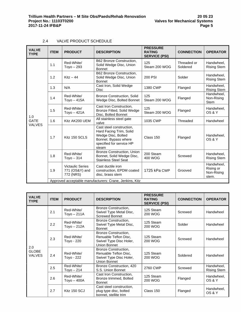
Trillium Health Partners – M Site Obs/Paeds/Rehab Renovation 20 05 23 Project No.: 11103T0200 Valves for Mechanical Systems 2017-11-24 IFB&P Page 5
2.4 VALVE PRODUCT SCHEDULE
VALVE TYPE
ITEM PRODUCT DESCRIPTION PRESSURE RATING SERVICE (PSI)
CONNECTION OPERATOR
1.0 GATE VALVES
1.1 Red-White/ Toyo – 293
B62 Bronze Construction, Solid Wedge Disc, Union Bonnet
125 Steam 200 WOG
Threaded or Soldered
Handwheel, Rising Stem
1.2 Kitz – 44 B62 Bronze Construction, Solid Wedge Disc, Union Bonnet
200 PSI Solder Handwheel, Rising Stem
1.3 N/A Cast Iron, Solid Wedge Disc
1380 CWP Flanged Handwheel, Rising Stem
1.4 Red-White/ Toyo – 415A
Bronze Construction, Solid Wedge Disc, Bolted Bonnet
125 Steam 200 WOG
Flanged Handwheel, Non-Rising Stem
1.5 Red-White/ Toyo – 421A
Cast Iron Construction, Bronze Fitted, Solid Wedge Disc, Bolted Bonnet
125 Steam 200 WOG
Flanged Handwheel, OS & Y
1.6 Kitz AK200 UEM All stainless steel gate valve
1035 CWP Threaded Handwheel
1.7 Kitz 150 SCLS
Cast steel construction, Hard Facing Trim, Solid Wedge Disc, Bolted Bonnet. Bypass where specified for service HP steam
Class 150 Flanged Handwheel, OS & Y
1.8 Red-White/ Toyo – 314
Bronze Construction, Union Bonnet, Solid Wedge Disc, Stainless Steel Seat
200 Steam 400 WOG
Screwed Handwheel, Rising Stem
1.9 Victaulic Series 771 (OS&Y) and 772 (NRS)
Cast ductile iron construction, EPDM coated disc, brass stem
1725 kPa CWP Grooved
Handwheel, Rising or Non-Rising stem.
Approved acceptable manufacturers: Crane, Jenkins, Kitz
VALVE TYPE
ITEM PRODUCT DESCRIPTION PRESSURE RATING SERVICE (PSI)
CONNECTION OPERATOR
2.0 GLOBE VALVES
2.1 Red-White/ Toyo – 211A
Bronze Construction, Swivel Type Metal Disc, Screwed Bonnet
125 Steam 200 WOG
Screwed Handwheel
2.2 Red-White/ Toyo – 212A
Bronze Construction, Swivel Type Metal Disc, Bonnet
125 Steam 200 WOG
Solder Handwheel
2.3 Red-White/ Toyo - 220
Bronze Construction, Renuable Teflon Disc, Swivel Type Disc Holer, Union Bonnet
125 Steam 200 WOG
Screwed Handwheel
2.4 Red-White/ Toyo - 222
Bronze Construction, Renuable Teflon Disc, Swivel Type Disc Holer, Union Bonnet
125 Steam 200 WOG
Soldered Handwheel
2.5 Red-White/ Toyo – 214
Bronze Construction, 420 S.S. Union Bonnet
2760 CWP Screwed Handwheel, Rising Stem
2.6 Red-White/ Toyo – 400A
Cast Iron Construction, Bronze trimmed, Bolted Bonnet
125 Steam 200 WOG
Flanged Handwheel, OS & Y
2.7 Kitz 150 SCJ Cast steel construction, plug type disc, bolted bonnet, stellite trim
Class 150 Flanged Handwheel, OS & Y

Trillium Health Partners – M Site Obs/Paeds/Rehab Renovation 20 05 23 Project No.: 11103T0200 Valves for Mechanical Systems 2017-11-24 IFB&P Page 6
2.8 Kitz AK 200 UJM All stainless steel globe valve
1035 CWP Threaded Handwheel
2.9 Red-White/ Toyo – 221
Union Bonnet, Renewable Teflon Disc, Swivel Type Disc Holder, Screwed Ends
150 Steam 300 WOG
Screwed Handwheel, Stem Rising
Approved acceptable manufacturers: Crane, Jenkins, Nibco, Kitz
VALVE TYPE
ITEM PRODUCT DESCRIPTION PRESSURE RATING SERVICE (PSI)
CONNECTION OPERATOR
3.0 CHECK VALVES
3.1 Red-White/ Toyo – 237
Bronze Construction Y-Pattern, Regrind seating, Screwed Cap, Integral Disc
125 Steam 200 WOG
Solder Swing
3.2 Red-White/ Toyo – 360
Bronze Construction, T-Pattern Regrind Seating, Screwed Cap
4140 CWP Threaded Swing
3.3 Red-White/ Toyo – 236
Bronze Construction Y-pattern, Regrind Seating, Screwed Cap, Integral Disc
125 Steam 200 WOG
Threaded Swing
3.4 Red-White/ Toyo – 435A
Cast Iron Construction, Bronze Trimmed, Regrindable Disc, Bolted Cover
125 Steam 200 WOG
Flanged Swing
3.5 Kitz 150 SCO Cast Steel Construction, Stellite Trim
Class 150 Flanged Swing
3.6 Kitz AK200UOM All stainless steel check valve
1035 CWP Screwed Swing
3.7 Victaulic Series 712
Cast ductile iron body, stainless steel trimmed, coupled cover.
2065 kPa CWP Grooved Swing
Approved acceptable manufacturers: Crane, Jenkins, Nibco, Kitz
VALVE TYPE
ITEM PRODUCT DESCRIPTION PRESSURE RATING SERVICE (PSI)
CONNECTION OPERATOR
6.0 BALL VALVES
6.1 Red-White/Toyo – 5044A
Brass Construction, 2-piece construction, Teflon seats, Seals Buna-N O-ring, Blow out Proof stem. Lead free where used for domestic water applications.
150 Steam 600 WOG
Screwed Lever
6.2 Red-White/Toyo – 5044W
Brass Construction, 2-piece construction, Teflon seats, Seals Buna-N O-ring, Blow out Proof stem
150 Steam 600 WOG
Screwed Wing Handles
6.3 Red-White/Toyo – 5049A
Brass Construction, 2-piece construction, Teflon seats, Seals Buna-N O-ring, Blow out Proof stem. Lead free where used for domestic water applications.
150 Steam 600 WOG
Soldered Lever
6.4 Red-White/Toyo – 5049W
Brass Construction, 2-piece construction, Teflon seats, Seals Buna-N O-ring, Blow out Proof stem
150 Steam 600 WOG
Soldered
Wing Handles c/w Memory Stop

Trillium Health Partners – M Site Obs/Paeds/Rehab Renovation 20 05 23 Project No.: 11103T0200 Valves for Mechanical Systems 2017-11-24 IFB&P Page 7
6.5 Kitz 150 UTBM (Full Bore)
ANSI 150 All stainless steel ball valve
1970 CWP Kitz 150 UTRM (Reduced Bore)
Flanged Worm Gear
6.6 Red-White/Toyo – 5044A
Forged Brass, 2-piece Construction, Blow Out Proof Stem, Hard chrome Plated Forged Brass Ball, Teflon seats, Buna-N O-ring, CGA Approved
600 GAS Screwed Lever
6.7 Type – 5044A
Forged Brass, 2-piece Construction, Blow Out Proof Stem, Hard chrome Plated Forged Brass Ball, Teflon seats, Buna-N O-ring, UL Approved
600 GAS Screwed Lever
Approved acceptable manufacturers: Crane, Nibco, Newman Hattersly, Kitz
VALVE TYPE
ITEM PRODUCT DESCRIPTION PRESSURE RATING SERVICE (PSI)
CONNECTION OPERATOR
9.0 DRAIN VALVES
9.1 Red-White/Toyo – 5046
Hard Chrome Plated Ball, Cap and Drain
1380 WP @ 121oC Screwed X hose
Lever
Approved acceptable manufacturers: Toyo, Kitz
VALVE TYPE ITEM PRODUCT DESCRIPTION PRESSURE RATING SERVICE (PSI)
CONNECTION OPERATOR
13.0 CIRCUIT BALANCING VALVES
13.1 Victaulic Series 786
DZR brass (Ametal) copper alloy body, globe type, with EPDM seat, and venturi taps.
2065 kPa Screwed Handwheel with memory stop
13.2 Victaulic Series 787
DZR brass (Ametal) copper alloy body, globe type, with EPDM seat, and venturi taps.
2065 kPa Soldered Handwheel with memory stop
13.3 Victaulic Series 788
Ductile iron body, globe type, with EPDM seat, and venturi taps.
2065 kPa Flanged Handwheel with memory stop
13.4 Victaulic Series 789
Ductile iron body, globe type, with EPDM seat, and venturi taps.
2065 kPa Grooved Handwheel with memory stop
3 Execution
3.1 INSTALLATION
3.1.1 Use line size valves throughout with the exception of control valve bypasses. Size control bypass valves equal to control valve.
3.1.2 Install valves with stems upright or horizontal. Under no circumstances install inverted.

Trillium Health Partners – M Site Obs/Paeds/Rehab Renovation 20 05 23 Project No.: 11103T0200 Valves for Mechanical Systems 2017-11-24 IFB&P Page 8
3.1.3 Align valves for easy access and identification when several service lines are installed together.
3.2 APPLICATION
3.2.1 Install ball, gate or butterfly valves to isolate equipment, sections of systems, at the base of each vertical pressure riser and elsewhere as indicated.
3.2.2 Install a ball, gate or butterfly valve on the inlet and outlet of each piece of heat transfer equipment, exclusive of room heat transfer units. Locate the valves on the main side of the unions or flanges of the equipment. For heat transfer equipment valving, refer to drawings.
3.2.3 Install ball, gate or butterfly valves to isolate the supply and return of each main section or loop of the heating systems. Locate a balancing valve upstream of the return isolating valve.
3.2.4 Install ball, gate or butterfly valves on all branch connections to the main.
3.2.5 Use globe valves for throttling service and control valve bypass.
3.2.6 Provide shutoffs to groups of plumbing fixtures.
3.3 DRAINS
3.3.1 Provide drain valves at main shutoff valves, low points of piping circuits including base of all risers and at apparatus other than room heat transfer units.
END OF SECTION

Trillium Health Partners – M Site Obs/Paeds/Rehab Renovation 20 05 29 Project No.: 11103T0200 Hangers, Supports and Anchors for Mechanical Systems 2017-11-24 IFB&P Page 1
1 General
1.1 SUMMARY
1.1.1 This Section includes requirements for design, supply and installation of pipe and HVAC equipment and ductwork hangers and supports, hanger rods and inserts, anchors and sleeving, formed steel channels and metal framing systems, pipe positioning systems and other fabrications required for mechanical components specified in Related Requirements.
1.2 RELATED REQUIREMENTS
1.2.1 Section 01 73 00 – Execution: General requirements relating to design, supply and installation of hangers and fastenings for the entire project.
1.2.2 Section 07 85 00 – Firestopping and Smoke Sealing: Firestopping and firestopping accessories relating to piping and equipment support systems.
1.2.1 Section 20 05 10 – Mechanical Systems Pipe and Pipe Fittings: Piping, piping and HVAC related accessory and equipment hangers, support systems and anchors.
1.2.2 Section 23 31 00 – Ductwork: HVAC ductwork, and other accessories and equipment requiring hanger, support and anchoring systems.
1.3 DEFINITIONS
1.3.1 Delegated Design Professional Engineer: The professional engineer hired or contracted to the fabricator or manufacturer to design specialty elements, produce delegated design submittals and shop drawings requiring engineering in excess to standard pre-fabricated components to meet the requirements of the Project; who is registered in the province of the Work; and who is not the Consultant.
1.4 REFERENCE STANDARDS
1.4.1 American National Standards Institute (ANSI):
1.4.1.1 ANSI/ASME B31.1-2012, Power Piping Code for Pressure Piping 1.4.1.2 ANSI/MSS SP-58-2009, Pipe Hangers and Supports – Materials,
Design, Manufacture, Selection, Application and Installation
1.4.2 National Fire Protection Association (NFPA):
1.4.2.1 NFPA (Fire) 14-2013, Standard for the Installation of Standpipe and Hose Systems
1.5 ADMINISTRATIVE REQUIREMENTS
1.5.1 Pre-Construction Meetings: Arrange a pre-construction meeting attended by Constructor, Subcontractor, Consultant, supplier/fabricator of products required by this section, and others affected by work of this Section in accordance with Section 01 31 19 – Project Meetings to discuss the following:
1.5.1.1 Confirm extent of work associated with hanger, support and anchor design, supply and installation.
1.5.1.2 Confirm follow-up and site monitoring actions by this Section to attain compliance with project requirements.
1.5.1.3 Identification of potential interferences of other building components; include potential solutions for routing of piping support systems and suspended equipment for other building systems cannot accommodate work of this Section.
1.5.1.4 Additional topics identified prior to the pre-construction meeting having potential to affect work of this Section, or coordination of work of other Sections.

Trillium Health Partners – M Site Obs/Paeds/Rehab Renovation 20 05 29 Project No.: 11103T0200 Hangers, Supports and Anchors for Mechanical Systems 2017-11-24 IFB&P Page 2
1.5.2 Coordination: Coordinate locations of any block-outs or embedded items required by this section and that are provided by other sections; provide cast-in setting blocks or anchors provided by this Section to others Sections so as not to cause delays or changes in the progress of the Work of the Project.
1.5.2.1 Coordinate requirements of this Section to maintain construction schedule and phasing requirements.
1.5.2.2 Coordinate requirements of this Section to maintain fire and smoke protection for penetrations through fire rated construction with related requirements.
1.5.3 Approval Requirements: Do not weld piping, ductwork or equipment supports to building metal decking or building structural steel supports unless prior written approval has been obtained from the Consultant and as follows:
1.5.3.1 Obtain approval prior to drilling for inserts and supports for piping system; discuss and obtain approval for hanging systems and methods with Structural Consultant.
1.5.3.2 Obtain approval prior to using percussion type fastenings.
1.6 SUBMITTALS
1.6.1 Provide required information in accordance with Section 01 33 00 – Submittal Procedures.
1.6.2 Action Submittals: Provide the following submittals before starting any work of this Section:
1.6.2.1 Product Data: Submit product data for each standard catalogued component including load capacities and manufacturer’s preparation and installation instructions; include data for mechanical fasteners indicating sizes, shear, and pull out loading capacity where applicable, and data indicating thickness and type of corrosion protection coating.
1.6.2.2 Shop Drawings: Submit shop drawings for shop fabricated components indicating the following:
1.6.2.2.1 Drawings of assemblies, including data confirming that anchors and attachments to the structure are suitable for the purposes intended, identified and coordinated with location drawings.
1.6.2.2.2 Load and movement data used to establish hanger, support and anchor locations and types.
1.6.2.2.3 Supplementary steel supports required as a part of hanger assemblies s or other fabrications required for completion of the requirements of this Section.
1.6.2.2.4 Identification of shop and site welds, including sizes and any special notations affecting quality of welds.
1.6.2.2.5 Identification of types of protective coatings required to prevent galvanic action between dissimilar materials or oxidation resulting from atmospheric conditions.
1.6.2.2.6 Location drawings indicating path of travel and any interferences, coordinated with major building components and as follows:
• Indicate critical dimensions, sizes, and pipe hanger and support locations, and details of trapeze type hangers.
• Detailed installed position; correctly oriented with respect to piping and building structure with elevations of supporting structure and pipe shown.
• Location of pipe hanger assembly with reference to building column lines and any offset locations of attachments to building structure and pipe where required to compensate for horizontal movements.

Trillium Health Partners – M Site Obs/Paeds/Rehab Renovation 20 05 29 Project No.: 11103T0200 Hangers, Supports and Anchors for Mechanical Systems 2017-11-24 IFB&P Page 3
• Setting and installation data for specialty products such as variable spring and constant support hangers, and snubbers, which may require either site adjustment or verification of installed position.
• Design load and; when applicable, special loadings such as hydrostatic test.
• Include a unique hanger mark number, including revision level and; when required, other identification information to clarify installation and maintenance requirements.
• Consultant will permit the use of typical details and approximate hanger locations instead of individual drawings where project complexity does not require the use of more detailed requirements.
1.6.2.2.7 Detailed design recommendations relative to engineered pipe hanger assembly drawings for hanger, supports and anchors required by the Delegated Design professional engineer.
1.6.2.3 Samples: Submit samples of hangers and supports with shop drawing submittal, acceptable samples will be returned for use on the project.
1.6.3 Informational Submittals: Provide the following submittals during the course of the work of this Section as a part of other required submittals:
1.6.3.1 Certificates: Submit manufacturer’s certificate verifying that products meet or exceed specified and referenced requirements.
1.6.3.2 Source Quality Control Submittals: Submit design notes and calculations signed and sealed by professional engineer only when requested by the Consultant.
1.7 PROJECT CLOSEOUT SUBMISSIONS
1.7.1 Operation and Maintenance Data: Submit manufacturer’s written instructions for repair, operations and maintenance procedures, include name of original installer and contact information in accordance with Section 01 73 00 – Maintenance Manual and Operating Instructions including the following:
1.7.1.1 Spare parts list 1.7.1.2 Exploded assembly views 1.7.1.3 Recommended maintenance intervals
1.8 QUALITY ASSURANCE
1.8.1 Regulatory Requirements: Perform welding using a firm certified by the Canadian Welding Bureau using personnel having CWB Welder Certificate indicating structural classification applicable to work being performed and as follows:
1.8.1.1 Provide hanger and support system components used in fire protection piping systems meeting requirements of the Authority Having Jurisdiction, and that are listed and labelled in accordance with NFPA 13.
1.8.2 Delegated Design Professional Engineer: Retain a professional engineer, registered in the province of the Work, to design non-catalogued fabrication and erection components of the work of this Section in accordance with applicable Building Code and Contract Documents requirements including the following:
1.8.2.1 Seal and signature to shop drawings and design submittals. 1.8.2.2 Site review and certification of installed components. 1.8.2.3 Coordination of other work affected by; or affecting, work of this
Section.

Trillium Health Partners – M Site Obs/Paeds/Rehab Renovation 20 05 29 Project No.: 11103T0200 Hangers, Supports and Anchors for Mechanical Systems 2017-11-24 IFB&P Page 4
1.9 DELIVERY, STORAGE AND HANDLING
1.9.1 Delivery and Acceptance Requirements: Deliver hangers, supports and anchors in tightly bundled packages, clearly marked using indelible ink indicating same identification marks used for preparation of shop drawings.
1.9.2 Storage and Handling Requirements: Store materials blocked off ground in a manner to prevent permanent deformation in accordance with manufacturer’s requirements.
2 Products
2.1 MANUFACTURERS
2.1.1 Basis-of-Design Materials: Products named in this Section were used as the basis-of-design for the project; manufacturers listed as additional acceptable materials and that offer similar products may be incorporated into the work of this Section provided they meet the performance requirements established by the named products.
2.1.2 Additional Acceptable Materials Manufacturers: Subject to compliance with performance requirements specified in this Section; as established by the Basis-of-Design Materials, use any of the listed manufacturers’ products in accordance with Section 01 61 00 – Product Requirements; following manufacturer’s do not require submission of a request for substitutions provided required shop drawing and product data submissions are submitted before starting any work of Section:
2.1.2.1 Atkore Unistrut Corp 2.1.2.2 Cooper/Eaton B-Line 2.1.2.3 Eaton Tolco 2.1.2.4 Erico Eristrut and Caddy Systems 2.1.2.5 HoldRite EZ-Strut 2.1.2.6 Miro Industries Inc. 2.1.2.7 Power Engineering Powerstrut 2.1.2.8 PHD Manufacturing Inc.
2.1.3 Substitutions: Consultant may consider additional manufacturers having similar products to Acceptable Materials Manufacturers listed above during the construction period, provided they meet the performance requirements established by the named products and provided they submit requests for substitution in accordance with Section 01 61 00 – Product Requirements before starting any work of this Section:
2.1.3.1 Do not use substitute materials to establish Bid Price. 2.1.3.2 Substitutions that appear as a part of the project without review and
acceptance by the Consultant will be rejected, and replaced with one of the specified materials.
2.2 DESIGN REQUIREMENTS
2.2.1 Seismic Requirement: Design hangers, supports and anchors for mechanical systems and piping for earthquake protection in accordance with seismic requirements for a post disaster building as defined by the Ontario Building Code and as applicable for health care facilities. Design of seismic bracing and supports is delegated to the contractor, and is to be carried out in accordance with authorities having jurisdiction.

Trillium Health Partners – M Site Obs/Paeds/Rehab Renovation 20 05 29 Project No.: 11103T0200 Hangers, Supports and Anchors for Mechanical Systems 2017-11-24 IFB&P Page 5
2.2.2 Performance Requirements: Provide design and engineering for project specific devices and accessories for hanging, supporting and controlling the movement of piping systems and associated accessories and equipment in accordance with MSS SP-58 and as follows:
2.2.2.1 Use Load Tables to determine design ratings for types and spacing of hanger assemblies, threaded rods, supports and anchors in accordance with referenced standards.
2.2.2.2 Design hangers, supports and anchors so that stresses generated by pressure, thermal expansion and local pipe wall stresses induced by welded attachment loading are within allowable stress range for pre-engineered and custom engineered components.
2.2.2.3 Design supports carrying piping subject to thermal expansion to freely roll axially or slide as appropriate to the installation condition.
2.2.2.4 Design hangers and supports to account for direction of travel and to control piping movement, provide lateral stability and control sway, and maintain proper piping alignment at expansion joints and loops.
2.2.2.5 Design hangers and supports to account for insulation thickness.
2.2.3 System Requirements: Provide hangers and supports to secure equipment in place, prevent vibration, maintain grade or level line, and that allow for expansion and contraction, and other lateral pipe loads and as follows:
2.2.3.1 Install supports of strength and rigidity to suit loading without unduly stressing building; locate adjacent to equipment to prevent undue stresses in piping and equipment.
2.2.3.2 Select hangers and supports appropriate for service condition and in accordance with manufacturer's recommended maximum loading; hangers must have a safety factor of 5 to 1.
2.2.3.3 Fasten hangers and supports to primary building structure or inserts in concrete construction.
2.2.4 Sleeving Requirements: Provide and set sleeves or block-outs in openings required for placing of piping and equipment and as follows:
2.2.4.1 Provide sleeves for all piping, with the exception of sprinkler piping, and duct penetrations through walls, ceilings, floors and footings.
2.2.4.2 Provide locations and dimensions for block-outs or embedded material if provided or installed by others.
2.2.5 Limitations: Use of piping or equipment for hanger supports and use of perforated band iron, wire or chain as hangers is not permitted.
2.3 MATERIALS
2.3.1 Materials Standard: Provide hangers and supports designed and manufactured in accordance with MSS SP-58 and other referenced standards acceptable to the Authority Having Jurisdiction.
2.3.2 Inserts: Provide galvanized steel shell and expander plug inserts for threaded connection with lateral adjustment, top slot for reinforcing rods, and lugs for attaching to forms; size inserts to suit threaded hanger rods.
2.3.3 Pipe Hangers and Supports: Design hangers so they cannot become disengaged by movements of supported pipe and as follows:
2.3.3.1 Provide copper plated hangers and supports for copper piping. 2.3.3.2 Provide galvanized hangers and supports for galvanized piping. 2.3.3.3 Uninsulated Pipes:
2.3.3.3.1 50 mm Ø and Smaller: Adjustable steel clevis or malleable iron hanger.
2.3.3.3.2 Larger than 50 mm Ø: Adjustable steel clevis.
2.3.3.4 Insulated Pipes – Hot Piping:

Trillium Health Partners – M Site Obs/Paeds/Rehab Renovation 20 05 29 Project No.: 11103T0200 Hangers, Supports and Anchors for Mechanical Systems 2017-11-24 IFB&P Page 6
2.3.3.4.1 50 mm Ø and Smaller: Adjustable steel clevis with galvanized sheet metal shield.
2.3.3.4.2 Larger than 50 mm Ø: Adjustable steel yoke pipe roll with covering protection saddle or Pipe roll with sockets and pipe covering protection saddle.
2.3.3.5 Insulated Pipes – Cold or Chilled Piping:
2.3.3.5.1 125 mm and Smaller: Adjustable steel clevis with galvanized sheet metal shield.
2.3.3.5.2 Larger than 125 mm: Pipe roll with sockets and pipe covering protection saddle or Steel yoke pipe roll with pipe covering protection saddle.
2.3.4 Multiple or Trapeze Hangers: Constructed from structural steel channel with welded spacers and hanger rods and as follows:
2.3.4.1 Mount pipes to trapeze with 2 piece pipe straps sized for outside diameter of pipe.
2.3.4.2 For pipes subjected to axial movement:
2.3.4.2.1 Strut mounted roller support with pipe protection shield or saddles on insulated lines.
2.3.4.2.2 Strut mounted pipe guide.
2.3.4.3 Carbon steel roll and stand for hot pipe sizes 150 mm and over. 2.3.4.4 Cup washers for hot piping below 150 mm.
2.3.5 Wall Supports:
2.3.5.1 Pipe Sizes 100 mm and Smaller: Carbon steel hook or Carbon steel J-hanger.
2.3.5.2 Pipe Sizes Larger than 100 mm: Welded steel bracket and malleable steel clamp, adjustable steel yoke and cast iron roll for hot pipe sizes 150 mm and over.
2.3.6 Floor Supports:
2.3.6.1 Hot Piping 150 mm and Smaller, and all Cold Piping: Carbon steel adjustable pipe saddle and nipple attached to steel base stand sized for pipe elevation; screw or weld to appropriate base stand.
2.3.6.2 Hot Piping Larger than 150 mm: Adjustable roller stand with base plate; adjustable roller support and steel support sized for elevation.
2.3.7 Vertical Supports: Steel riser clamp sized to fit outside diameter of pipe.
2.3.8 Copper Tubing Supports: Size hangers to fit copper tubing outside diameters and one or more of the following as applicable to specific installation:
2.3.8.1 Adjustable steel swivel ring (band type) hanger 2.3.8.2 Malleable iron ring hanger, or hinged ring hanger 2.3.8.3 Malleable iron split-ring hanger with eye socket 2.3.8.4 Adjustable steel clevis hanger 2.3.8.5 Coatings:
2.3.8.5.1 Use epoxy painted or plastic coated riser clamps for supporting vertical runs.
2.3.8.5.2 Use epoxy painted pipe straps sized for copper tubing, or plastic inserted vibration isolation clamps for supporting copper tube to strut.
2.4 ACCESSORIES
2.4.1 Fasteners Systems and Anchors.
2.4.2 Roof Mounted Pipe Stands: Premanufactured assemblies made of corrosion resistant components to support roof mounted piping and as follows:

Trillium Health Partners – M Site Obs/Paeds/Rehab Renovation 20 05 29 Project No.: 11103T0200 Hangers, Supports and Anchors for Mechanical Systems 2017-11-24 IFB&P Page 7
2.4.2.1 Compact Pipe Stand: One-piece plastic unit with integral-rod-roller, pipe clamps, or V-shaped cradle to support pipe, for roof installation without membrane penetration.
2.4.2.2 Low-Type, Single-Pipe Stand: One-piece stainless-steel base unit with plastic roller, for roof installation without membrane penetration.
2.4.2.3 High-Type, Single-Pipe Stand: Assembly of base, vertical and horizontal members, and pipe support, for roof installation without membrane penetration.
2.4.2.4 Base: Stainless steel. 2.4.2.5 Vertical Members: Two or more cadmium plated-steel or stainless
steel, continuous-thread rods. 2.4.2.6 Horizontal Member: Cadmium plated-steel or stainless steel rod with
plastic or stainless-steel, roller-type pipe support. 2.4.2.7 Curb-Mounting-Type Pipe Stands: Shop- or field-fabricated pipe
support made from structural-steel shape, continuous-thread rods, and rollers for mounting on permanent stationary roof curb.
2.4.3 Pipe Positioning Systems: Premanufactured system of metal brackets, clips, and straps for positioning piping in pipe spaces for plumbing fixtures for commercial applications.
2.4.4 Hanger Rods: Hanger rods threaded both ends, or continuous threaded rods of circular cross section; use adjusting locknuts at upper attachments and hangers; wire, chain, or perforated straps are not permitted.
2.4.5 Shields: Fabricated from 180 degree galvanized sheet metal, 300 mm minimum length, 1.2 mm minimum thickness, designed to match outside diameter of insulated pipe.
2.4.6 Pipe Protection Saddles: Pipe protection saddles formed from carbon steel, 3 mm minimum thickness, sized for insulation thickness; include centre support rib pipe sizes greater than 300 mm.
2.4.7 Sleeves: Use sleeves large enough to allow for movement due to expansion and to provide for continuous insulation and as follows:
2.4.7.1 Pipes through Floors: Form with steel pipe or approved PVC sleeves. 2.4.7.2 Pipes through Beams, Walls, Fire Proofing, Footings, and Potentially
Wet Floor: Form with steel pipe.
2.5 ROOF ACCESS/WALKWAY STAIR
2.5.1 Roof Mounted Elevated Walkway/Crossover/Stair/Access Platform: Pre-manufactured assembly where indicated on the drawings made of corrosion resistant components and designed to be installed directly on the roof without penetrating surfaces and as follows:
2.5.2 Base Supports: High density polypropylene with UV inhibitors and anti-oxidants conforming to following:
2.5.2.1 Color: Black color as molded 2.5.2.2 Moisture Content: negligible 2.5.2.3 Shrinking/Swelling due to moisture: Negligible 2.5.2.4 Resistant to oil, gasoline, antifreeze, battery acid and sulfuric acid 2.5.2.5 Base Dimensions: 18-inches wide by 18-inches long by 3-inches
tall(18x18)
2.5.3 Steel Frame: Steel, 12ga 1-5/8” or 1-7/8” strut galvanized per ASTM A123 or 14ga 13/16” strut galvanized per ASTM A653 for PP10 and SS8.
2.5.4 Walkway Surface: Interlocking Planking:
2.5.4.1 Thickness: 18 gauge 2.5.4.2 Section width: 12 inches(305 mm) standard 2.5.4.3 Planking height: 2.5 inches

Trillium Health Partners – M Site Obs/Paeds/Rehab Renovation 20 05 29 Project No.: 11103T0200 Hangers, Supports and Anchors for Mechanical Systems 2017-11-24 IFB&P Page 8
2.5.4.4 Flange options: MM/MF 2.5.4.5 Surface: Slip resistant 2.5.4.6 Finish: HDG
2.5.5 Bar Grating: Type WB-4
2.5.5.1 1" x 3/16" Bearing Bars, 1-3/16" on Center, Regular Cross Bars 4" 2.5.5.2 Width: 24 inches(standard), or 36 inches – as required 2.5.5.3 Surface: Serrated 2.5.5.4 Finish: HDG
2.5.6 Handrail: 12 gauge, 1-5/8” strut, Galvanized
2.5.7 Attaching hardware: HDG threaded rod, nuts and attaching hardware per ASTM A153.
2.6 FINISHES
2.6.1 Indoor Finishes:
2.6.1.1 Coat hangers and clamps for support of bare copper piping with copper colored epoxy paint; include additional PVC coating of epoxy painted hanger where necessary.
2.6.1.2 Hangers for other than bare copper pipe shall be wipe coated galvanized steel plated with an electro-deposited green epoxy finish.
2.6.1.3 Strut channels with wipe coated galvanized finish
2.6.2 Outdoor Area Finishes
2.6.2.1 Finish hangers and strut located outdoors shall be hot dip galvanized after fabrication; provide hot dip galvanized or stainless steel hardware and fasteners.
2.6.2.2 Zinc plated hardware is not acceptable for outdoor use
3 Execution
3.1 EXAMINATION
3.1.1 Verify openings are ready to receive sleeves and that project site is ready for work of this Section.
3.2 PREPARATION
3.2.1 Do not drill or cut structural members without obtaining permission from Consultant before starting any work of this Section.
3.3 EXECUTION
3.3.1 Inserts: Use inserts for suspending hangers from reinforced concrete slabs and sides of reinforced concrete beams wherever practicable and as follows:
3.3.1.1 Set inserts in position in advance of concrete work. 3.3.1.2 Provide reinforcement rod in concrete for inserts carrying pipe
over 100 mm Ø or ducts over 1500 mm wide. 3.3.1.3 Where concrete slabs form finished ceiling, finish inserts flush with slab
surface.
3.3.2 Pipe Hangers and Supports: Support horizontal steel and copper piping as follows:
Nominal Pipe Size Distance Between Supports Hanger Rod
Diameter Steel Copper

Trillium Health Partners – M Site Obs/Paeds/Rehab Renovation 20 05 29 Project No.: 11103T0200 Hangers, Supports and Anchors for Mechanical Systems 2017-11-24 IFB&P Page 9
Nominal Pipe Size Distance Between Supports Hanger Rod
Diameter Steel Copper
15 mm to 20 mm 1800 mm 1500 mm 10 mm
25 mm to 40 mm 2100 mm 1800 mm 10 mm
50 mm to 65 mm 3000 mm 2400 mm 10 mm
80 mm to 100 mm 3600 mm 3000 mm 16 mm
150 mm to 300 mm 4200 mm 4000 mm 22 mm
350 mm to 450 mm 6000 mm 25 mm
3.3.2.1 Install hangers to provide minimum 15 mm clear space between finished covering and adjacent work.
3.3.2.2 Use oversized hangers to accommodate pipe insulation thickness.
3.3.2.2.1 Pipes 50 mm and Smaller: Use high density rigid pipe insulation at hanger location, with an insulation protection shield.
3.3.2.2.2 Pipes Larger than 50 mm: Use insulation protection saddle.
3.3.2.3 Place a hanger within 300 mm of each horizontal elbow. 3.3.2.4 Use hangers that are vertically adjustable 40 mm minimum after piping
is erected. 3.3.2.5 Support cast iron horizontal drainage pipe near each hub and on each
side of gasket and clamp joints, with 1500 mm maximum spacing between hangers.
3.3.2.6 Support vertical piping at every other floor. Support vertical soil pipe at each floor at hub.
3.3.2.7 Where several pipes can be installed parallel and at same elevation, provide multiple or trapeze hangers.
3.3.2.8 Where practical, support riser piping independently of connected horizontal piping.
3.3.2.9 Provide templates, anchor bolts and accessories required for mounting and anchoring equipment.
3.3.2.10 Construct supports of structural steel members or steel pipe and fittings. Brace and fasten with flanges bolted to structure.
3.3.2.11 Provide rigid anchors for ducts and pipes immediately after vibration isolation connections to equipment, unless spring hangers are specified.
3.3.3 Priming: Prime coat exposed steel hangers and supports.
3.3.4 Sleeves: Set sleeves in position in advance of concrete work. Provide suitable reinforcing around sleeve and as follows:
3.3.4.1 Extend sleeves through potentially wet floors 25 mm above finished floor level. Caulk sleeves full depth and provide floor plate.
3.3.4.2 Close off space between duct and sleeve with non-combustible insulation on piping and duct work passing through floor, ceiling, or wall.
3.3.4.3 Provide tight fitting metal caps on both sides and caulk. 3.3.4.4 Close off space between pipe and sleeve with synthetic rubber
compound mechanical type seals on piping passing through mechanical room floor, roof or walls.
3.3.4.5 Sleeves provided through walls or floors where liquids could potentially pass from one side to the other, provide sleeves with a 25 mm 'flange' welded to the external face of the sleeve at the midpoint of the thickness of the structure to provide a water stop.
3.3.4.6 Install chrome plated escutcheons where piping passes through finished surfaces.

Trillium Health Partners – M Site Obs/Paeds/Rehab Renovation 20 05 29 Project No.: 11103T0200 Hangers, Supports and Anchors for Mechanical Systems 2017-11-24 IFB&P Page 10
3.3.5 Roof Mounted Access Walkway/Stair: Install roof mounted access walkway/stair where indicated on the drawings, of sufficient size, length and height to accommodate the service being crossed.
3.3.6 Roof Mounted Pipe Supports: Install roof supports for all piping in accordance with manufacturers installation instructions. Strictly follow and adhere to installation for all type of roofs, walls, and similar criteria space supports as follows:
Model No. Nominal Pipe
Size Maximum Space
Between Supports Maximum
Load
PPS-10 25 mm Ø 2400 mm 136 kg
PPS-15 40 mm Ø 3000 mm 136 kg
PPS-20 50 mm Ø 3000 mm 136 kg
PPS-30 76 mm Ø 2400 mm 136 kg
PPS-40 100 mm Ø 2400 mm 136 kg
END OF SECTION
Trillium Health Partners – M Site Obs/Paeds/Rehab Renovation 20 05 40 Project No.: 11103T0200 Mechanical Renovation Requirements 2017-11-24 IFB&P Page 1
1 General
1.1 SUMMARY
1.1.1 Renovation of existing building systems as indicated in the specifications and on the drawings.
1.1.2 Removal of redundant and obsolete mechanical components, piping, ductwork, and equipment in the renovated areas.
1.2 RELATED REQUIREMENTS
1.2.1 Section 02 41 19.16 – Selective Interior Demolition
1.2.2 Section 20 05 00 – Common Work Results for Mechanical
2 Products
2.1 NOT USED
3 Execution
3.1 GENERAL
3.1.1 Visit the site to thoroughly examine and get familiar with the existing systems and installations and every other condition which may affect the work. No claims for extras will be allowed for work or materials necessary for proper execution and completion of the contract or for the Bidder's failure, error or negligence in this regard.
3.1.1 The Hospital has policies and procedures that must be reviewed and followed when working within the areas of the Hospital. Comply with the Hospitals latest policies and procedures regarding renovations ad infection prevention and decontamination prevention measures ad as per CSA Z317.13-07 Infection Control during Construction of Healthcare Facilities.
3.1.2 Work associated with existing installation shall be carried out as follows:
3.1.2.1 All modifications and additions to the existing mechanical system shall be carried out in such a way that the interruptions to normal operations are kept to an absolute minimum. Schedule all such work to the satisfaction of the Consultant and for approval by the Owner.
3.1.2.2 All existing installations, in areas to be renovated, will be removed if they have been replaced by new installations and have not been specifically indicated (retained) for reuse.
3.1.2.3 Render the installations at locations where existing equipment has been removed safe. Remove the existing wiring and conduits unless these conduits are indicated to be reused.
3.1.2.4 Restore all services disrupted by the removal of existing equipment, or as a result of renovations.
3.1.2.5 Include for all cutting, patching, painting and restoring of existing conditions, disturbed during installation of the specified work.
3.1.2.6 Ensure prior to submission of bid that the existing wall construction and ceiling conditions are noted and allowed for in submitted price. No extra will be allowed for work or materials necessary for proper execution and completion of the contract or for the Bidder's failure, error or negligence in this regard.
END OF SECTION

Trillium Health Partners – M Site Obs/Paeds/Rehab Renovation 20 05 43 Project No.: 11103T0200 Mechanical Systems Identification 2017-11-24 IFB&P Page 1
1 General
1.1 SUMMARY
1.1.1 This Section covers the identification of various mechanical pipe and duct distribution systems using:
1.1.1.1 Pipe and Duct Markers 1.1.1.2 Stencils 1.1.1.3 Valve Tags 1.1.1.4 Valve Chart Frames
1.1.2 Paint identification of systems, pipes, ducts, and equipment will be completed as part of the work of this section.
1.1.3 Application of identification labels and stencils to systems, pipes, ducts, and equipment will be completed by trade contractor responsible for scope of work specified in this section.
1.1.4 This section will identify and label the systems, pipes, ducts, and equipment to the painting contractor that require painting in the specified colour schemes.
1.2 DEFINITIONS
1.2.1 Inherently Hazardous Materials:
1.2.1.1 Flammable or Explosive: Materials that can be easily ignited, provide fuel as primary fire producer, or create an explosive atmosphere.
1.2.1.2 Chemically Active or Toxic: Materials that are corrosive, are in themselves toxic, or produce poisonous gases.
1.2.1.3 High Temperature or Pressure: Materials that when released from piping have the potential to inflict injury or property damage by burns, impingement, or flashing to vapour state.
1.2.2 Inherently Low Hazardous Materials: Materials that are not hazardous by nature and that are near enough to ambient pressure and temperature so that personnel working on systems carrying these materials are at low risk through the release of these materials.
1.2.3 Fire Quenching Materials: Materials contained within sprinkler systems, piped fire fighting, or fire protection equipment including but not limited to fire fighting water, fire suppressant foam, CO2, and halon gas systems.
1.3 REFERENCE STANDARDS
1.3.1 American Society of Mechanical Engineers (ASME):
1.3.1.1 ASME A13.1-2007, Scheme for the Identification of Piping Systems
1.3.2 Canadian Standards Association (CSA):
1.3.2.1 CSA Z7396.1-09, Medical Gas Pipeline Systems - Part 1: Pipelines for Medical Gases and Vacuum
1.3.2.2 CAN/CSA Z7396.2-02 (R2007), Medical Gas Pipeline Systems – Part 2: Anaesthetic Gas Scavenging Disposal Systems
1.3.3 National Fire Protection Association (NFPA):
1.3.3.1 NFPA (Fire) 704-2007, Identification of the Hazards of Materials for Emergency Response
1.4 SUBMITTALS
1.4.1 Provide required information in accordance with Section 01 33 00 – Submittal Procedures.

Trillium Health Partners – M Site Obs/Paeds/Rehab Renovation 20 05 43 Project No.: 11103T0200 Mechanical Systems Identification 2017-11-24 IFB&P Page 2
1.4.2 Action Submittals: Provide the following submittals before starting any work of this Section:
1.4.2.1 Product Data: Submit manufacturer’s catalogue literature for each product specified, identifying use for interior, exterior or high temperature installations, and as follows:
1.4.2.1.1 Pipe Identification: Submit list of wording, symbols, letter size, and colour coding for piping identification.
1.4.2.1.2 Valve Identification: Submit list of wording, symbols, letter size, and colour coding for valve identification.
1.4.2.2 Schedules: Submit a complete schedule of all equipment to have identification complete with symbol and description engraved on the lamacoid plates or stamped brass tags.
1.4.2.3 Samples: Submit two labels, indicating type and quality of installed products.
1.4.3 Informational Submittals: Provide the following submittals when requested by the Consultant:
1.4.3.1 Installation Instructions: Submit manufacturer's installation instructions indicating special procedures, and installation methods.
1.5 PROJECT CLOSEOUT SUBMISSIONS
1.5.1 Operation and Maintenance Data: Submit manufacturer’s written instructions for repair and cleaning, operations and maintenance procedures, include name of original installer and contact information in accordance with Section 01 78 23 - Operation and Maintenance Data.
2 Products
2.1 MANUFACTURERS
2.1.1 Acceptable Materials Manufacturers: Subject to compliance with requirements specified in this Section; where multiple listings of manufacturers occur, use any of the following listed manufacturers’ products in accordance with the general conditions of the contract including the following:
2.1.1.1 Pre-Printed Pipe Marking Systems:
2.1.1.1.1 Brady Signmark 2.1.1.1.2 Graphic Products 2.1.1.1.3 Seton Safety and Identification
2.1.1.2 Site Printed Identification Labels: Portable label printer and tapes as follows:
2.1.1.2.1 Brady Handimark 2.1.1.2.2 Brother PT1800 2.1.1.2.3 Graphic Products, Duralabel 4TTP 2.1.1.2.4 Kroy K2500
2.1.2 Substitutions: Consultant may consider additional manufacturers having similar products to Acceptable Materials Manufacturers listed above during the construction period, provided they meet the performance requirements established by the named products and provided they submit requests for substitution in accordance with the general conditions of the contract before starting any work of this Section:
2.1.2.1 Do not use substitute materials to establish Bid Price. 2.1.2.2 Substitutions that appear as a part of the project without review and
acceptance by the Consultant will be rejected, and replaced with one of the specified materials.
Trillium Health Partners – M Site Obs/Paeds/Rehab Renovation 20 05 43 Project No.: 11103T0200 Mechanical Systems Identification 2017-11-24 IFB&P Page 3
2.2 DESIGN CRITERIA
2.2.1 Design wording for tags and labels, and submit schedule of proposed wording for review and acceptance by Consultant prior to manufacture, and as follows:
2.2.1.1 Language: Identification on labels and tags must be in English
2.2.2 Provide nameplates for terminal cabinets and junction boxes indicating system and voltage characteristics.
2.3 MATERIALS
2.3.1 Select identification materials to suit surfaces to which they are being applied including but not limited to:
2.3.1.1 Exterior Weather Exposed Surfaces 2.3.1.2 Interior Building Surfaces 2.3.1.3 Insulated or Non-Insulated Surfaces 2.3.1.4 Surfaces Exposed to High Temperature Conditions 2.3.1.5 Surfaces Exposed to High Humidity Conditions 2.3.1.6 Surfaces Subject to Wear or Abrasion
2.4 TAGS, LABELS AND BANDING
2.4.1 Valve Tags: Tags having 13 mm high lettering and #16 brass jack chain for fastening to valve fabricated from one of the following materials at Contractors choice:
2.4.1.1 Brass tags: 38 mm Ø 2.4.1.2 Fibreglass tags: 50 mm x 50 mm 2.4.1.3 Anodized aluminum tags: 38 mm Ø 2.4.1.4 Stainless steel tags: 38 mm Ø
2.4.2 BMS Identification Tags: 1 mm thick plastic laminated luggage style tags containing imprinted information label and brass jack chain or nylon cable tie for attachment to device complete with the following minimum information:
2.4.2.1 Logical Point Name 2.4.2.2 Point Hardware Address (RCU/TCU and connection terminal
identifiers) 2.4.2.3 Associated System Identification 2.4.2.4 Point Description
2.4.3 Laminated Plastic Nameplate (Lamacoid): Self-adhesive, composite laminated plastic nameplates, 3 mm thick with one smooth white surface and core of black plastic, designed to leave black lettering on a white background when engraved, fabricated as follows:
2.4.3.1 Mechanical Equipment: Engraved lettering 19 mm high. 2.4.3.2 BMS Panels and Panel Mounted Equipment: engraved lettering 19 mm
high. 2.4.3.3 BMS Equipment Cabinet Front Mounted Switches and Displays:
engraved lettering 8 mm high.
2.4.4 Colour Banding Tape: Adhesive backed plastic tape, integrally coloured, minimum 25 mm wide in accordance with ASME A13.1 pipe marking standards.
2.4.5 Duct or Pipe Mounted Identification Labels: Pre-printed, adhesive backed plasticized labels having lettering and flow arrows of sizes listed later in this section, background colour and colour of directional arrows and letters as scheduled for interior, exterior and hot temperature installations.

Trillium Health Partners – M Site Obs/Paeds/Rehab Renovation 20 05 43 Project No.: 11103T0200 Mechanical Systems Identification 2017-11-24 IFB&P Page 4
2.4.6 Site Printed Identification Labels: Site-printed, machine-printed, adhesive backed plasticized minimum 13 mm high strip labels colours as indicated later in this section.
2.4.7 Stencils: Factory-cut stencils ready for paint applied 50 mm high lettering and flow arrows, colour of letters and directional arrows as scheduled.
2.5 DIRECTORIES
2.5.1 Provide a typewritten directory for each system identified, minimum size 215 mm x 280 mm, or larger as required to accommodate information requirements.
2.5.2 Provide additional copies for inclusion in each Operating and Maintenance Data Manual.
2.5.3 Pipe and Duct Directory includes the following information:
2.5.3.1 Abbreviations used for identification 2.5.3.2 Definitions of abbreviations 2.5.3.3 Colour code identification for hazardous and non-hazardous materials
2.5.4 Valve Tag Directory includes the following information:
2.5.4.1 Valve number 2.5.4.2 Location 2.5.4.3 Service 2.5.4.4 Make/model size 2.5.4.5 With/without hand wheel 2.5.4.6 Type of control
2.5.5 BMS Directories include the following individual panel directories:
2.5.5.1 BMS Equipment Panel Directory: graphically show locations of each transducer, relay or other piece of equipment in panel. Label each device and provide a cross-reference listing between device label and function.
2.5.5.2 BMS Wiring Panel Directory: in each panel where control wiring terminates, provide a cross-reference listing between key name, descriptors, and hardware address and wiring labels.
3 Execution
3.1 PREPARATION, PROTECTION AND CLEAN-UP
3.1.1 Degrease and clean surfaces to receive identification materials.
3.1.2 Prepare surfaces for stencil painting.
3.1.3 Cover new and existing equipment and surfaces with clean tarps or heavy duty plastic.
3.1.4 Completely remove spills or spatter from finishes and equipment immediately using cleaning methods that will not harm the finish.
3.2 INSTALLATION
3.2.1 Install pipe markers in accordance with accepted shop drawings and manufacturer's instructions.
3.2.2 Install valve tags in accordance with accepted shop drawings and manufacturer's instructions.
3.2.3 Install pipe and duct identification at the following locations:
3.2.3.1 At each branch or riser take off on piping systems. 3.2.3.2 At each pipe passage through walls, floors or ceilings, on both sides.

Trillium Health Partners – M Site Obs/Paeds/Rehab Renovation 20 05 43 Project No.: 11103T0200 Mechanical Systems Identification 2017-11-24 IFB&P Page 5
3.2.3.3 On all straight pipe or duct runs evenly spaced to a maximum of 5 metres O/C.
3.2.3.4 Identify on both sides of obscuring items where pipes or ducts are partially obscured by other pipes, ducts or equipment.
3.2.3.5 Identify pipes and ducts at points of entry and leaving, and at each access opening where piping is concealed in pipe chase or other confined space.
3.2.3.6 Identify pipes and ducts at starting and end points of runs and at each piece of equipment.
3.2.3.7 Identify pipes at major manual and automatic valves immediately upstream of valves.
3.2.3.8 Identify medical gas piping in accordance with the requirements of CSA Z7396.1 or CAN/CSA Z7396.2 as appropriate.
3.2.4 Apply stencil lettering only after final finish has been applied.
3.3 MANUFACTURER'S NAME PLATES
3.3.1 Provide a factory-applied nameplate on each piece of manufactured equipment indicating size, equipment name, manufacturers name, serial number, electrical characteristics, and performance characteristics.
3.3.2 Provide registration plates such as pressure vessel, CULUS, ULC and CSA approval plates as required by respective agency or authority having jurisdiction, and as required by the specifications.
3.3.3 Nameplates of non-Canadian made equipment must include the name and address of the Canadian agent providing the product, and equivalent Canadian labelling criteria acceptable to the authorities having jurisdiction.
3.3.4 Fasten nameplates securely in a conspicuous and easily read location.
3.3.5 Do not apply insulation or paint over nameplates.
3.4 EQUIPMENT IDENTIFICATION
3.4.1 Provide each piece of equipment with a neatly stamped brass tag giving equipment name, system identification, and number.
3.4.2 Provide a separate stencilled name on each piece of equipment in letters 25 mm high where possible, in addition to identification described above.
3.4.3 Identify each piece of equipment with the symbol and number to match Owner’s existing identification system.
3.4.4 Use identical nameplates for equipment that is electrically driven and is identified at motor starter as on the starter.
3.5 DUCTWORK IDENTIFICATION
3.5.1 Identify both system number and type of air (such as AIR SYSTEM #1 - SUPPLY) where applicable using 50 mm high black, stencilled letters with arrows indicating flow.
3.6 PIPING IDENTIFICATION
3.6.1 Apply identification colour bands on all exposed or concealed piping, except drainage piping and vent piping outside mechanical rooms, in the primary colours listed in this Section.
3.6.2 Colour bands completely encircle the pipe for a length of 150 mm in primary colour. Neatly arrange all bands in straight lines across groups of pipes.
3.7 VALVE IDENTIFICATION
3.7.1 Provide brass tags with 15 mm stamped code lettering.
3.7.2 Secure tags to items with brass hooks and non-ferrous chains.
3.7.3 Affix a tag to all valves not adjacent to the equipment they serve.

Trillium Health Partners – M Site Obs/Paeds/Rehab Renovation 20 05 43 Project No.: 11103T0200 Mechanical Systems Identification 2017-11-24 IFB&P Page 6
3.8 CONTROLLER IDENTIFICATION
3.8.1 Identify each controller (such as: freezestats, humidistats, discharge temperature controllers) with embossed metal bands secured to each controller.
3.9 PRE-PAINTED EQUIPMENT
3.9.1 Repair finish on all pre-painted equipment that is damaged or faded.
3.10 MISCELLANEOUS IDENTIFICATION
3.10.1 Identify electric starting switches, thermostat controlling motors, remote push button stations, and control equipment supplies under this division with lamacoid plates having 6 mm high minimum letter size.
3.10.2 Identification must state equipment controlled and be matched to control shop drawing identification numbers.
3.10.3 Identify the purpose of duct access panels with self adhesive stick-on coloured labels with colours conforming to the following schedule:
AbbreviationField
Colour Letter Colour
Cleaning and service access C.A. Yellow Black
Controls, including heat sensors C Black White
Dampers (back draft, balance and control)
D Blue White
Fire dampers F.D. Red White
Smoke dampers and detectors S.D. Red White
3.10.4 Identify the location of the following items of equipment using site printed labels, which are concealed above a suspended unit ceiling by applying to grid adjacent to panel to be removed; or behind a wall or ceiling access door by applying to frame with colours conforming to the following schedule:
Field
Colour Letter Colour
Concealed equipment and cleaning access Yellow Black
Control equipment, including control dampers and valves, and heat sensors
Black White
Fire, smoke, and sprinkler equipment Red White
Pipe mounted equipment with the exception of fire, smoke, sprinkler and control equipment
Green White
3.11 COLOUR CODE SCHEDULE
3.11.1 Paint pipes, services, equipment and other items in areas requiring full colour coding in primary banding colour.
3.11.2 Natural gas piping must be yellow coloured in concealed, semi-concealed and exposed location, and not have any other colour applied to it, except as stated for banding identification only.

Trillium Health Partners – M Site Obs/Paeds/Rehab Renovation 20 05 43 Project No.: 11103T0200 Mechanical Systems Identification 2017-11-24 IFB&P Page 7
3.11.3 Paint colours and labels conform to the following schedule based on ASME A13.1 colour code identification system, except as modified by identification table following:
Contents
Banding Label
Primary Colour
Field Colour
Letter Colour
INHERENTLY HAZARDOUS MATERIALS
Flammable or Explosive Yellow Yellow Black
Natural Gas Yellow Yellow Black
Chemically Active or Toxic Yellow Yellow Black
Non-Potable Water Yellow White Black
Extreme Temperature or Pressure Yellow White Black
Liquid or Gaseous Freon Yellow White Black
INHERENTLY LOW HAZARDOUS MATERIALS
Liquid or Liquid Admixtures Green Black White
Gas or Gaseous Admixture Blue Black White
FIRE QUENCHING MATERIALS
Water or Foam Red Red White
MEDICAL GASES
In Accordance with CSA Z7396.1 or CAN/CSA Z7396.2
3.11.4 Ensure size of letters on labels conform to the following schedule based on ASME A13.1 identification system:
Outside Diameter of Pipe or Covering
Length of Field Colour
Size of Letters
19 mm to 32 mm 200 mm 13 mm 38 mm to 50 mm 200 mm 19 mm
65 mm to 150 mm 305 mm 32 mm 200 mm to 250 mm 610 mm 65 mm
Over 250 mm 800 mm 89 mm
3.11.5 Identification symbols and abbreviations for piping and equipment, complete with directional arrows where applicable:
Description Pipe
Colour Stripe Colour Symbol
Domestic Cold Water Light Blue None COLD WAT.
Domestic Hot Water Green Orange DHW 60°C
Domestic Hot Water Green Orange DHW 80°C
Domestic Hot Water Recirculation
Green Blue HOT WAT.R.
Fan Guards and Motor Guards
Red None None
Handles Black None None
Hangers, Brackets and Hanger Rods
Black None None

Trillium Health Partners – M Site Obs/Paeds/Rehab Renovation 20 05 43 Project No.: 11103T0200 Mechanical Systems Identification 2017-11-24 IFB&P Page 8
Description Pipe
Colour Stripe Colour Symbol
Heating Hot Water Return
Yellow Orange HHWR 90°C
Heating Hot Water Supply
Yellow Red HHWS 90°C
Medical Air White None MED. AIR
Vent AluminumRed or Orange
None
3.11.6 Mechanical Control Systems:
3.11.6.1 Conduit banding, pull boxes, terminal boxes and junction boxes; Grey Covers, Grey Bands with Black 'C'.
3.11.6.2 Main and secondary control panels, factory finish acceptable; control contractor to install company label to identify controlled equipment.
3.11.7 Duct Work:
3.11.7.1 Identify duct work as follows, complete with directional arrows:
Description Symbol
Exhaust Air EXH. AIR
Return Air R.A.
Supply Air S.A.
END OF SECTION

Trillium Health Partners – M Site Obs/Paeds/Rehab Renovation 20 05 93.13 Project No.: 11103T0200 Testing of Mechanical Materials 2017-11-24 IFB&P Page 1
1 General
1.1 SUMMARY
1.1.1 Test heating water piping
1.1.2 Test domestic water piping
1.1.3 Test sanitary sewer piping
1.1.4 Test sewer vent piping
1.1.5 Test fire protection system piping
1.1.6 Test medical gas piping
1.1.7 Test low velocity ducts
1.1.8 Test medium and high velocity ducts
1.2 RELATED REQUIREMENTS
1.2.1 Section 22 63 23 – Medical Gases System
1.3 REFERENCE STANDARDS
1.3.1 American Society of Mechanical Engineers (ASME):
1.3.1.1 ASME Section V, 2010 ASME Boiler and Pressure Vessel Code, Section V: Nondestructive Examination
1.3.1.2 ASME Code Section VIII, Div 1, 2010 ASME Boiler and Pressure Vessel Code, Section VIII, Division 1: Rules for Construction of Pressure Vessels
1.3.1.3 ANSI/ASME B31.1-2010, Power Piping
1.3.2 Compressed Gas Association (CGA):
1.3.2.1 CAN/CGA 149.1 1.3.2.2 CAN/CGA 149.2
1.3.3 Canadian Standards Association (CSA):
1.3.3.1 CSA Standard Z305.1-92 (R2001), Nonflammable Medical Gas Piping Systems
1.4 SUBMITTALS
1.4.1 Provide required information in accordance with Section 01 33 00 – Submittal Procedures.
1.4.2 Obtain certificates of approval and acceptance, complying with rules and regulations from authorities having jurisdiction. Submit copies to include in Operating and Maintenance Manuals.
1.4.3 Perform tests as specified. Include test certificates in Operating and Maintenance Manuals.
1.5 LIABILITY
1.5.1 Take charge of plant during tests, assume responsibility for damages in the event of injury to personnel, building or equipment and bear costs for liability, repairs and restoration in this connection.
1.6 QUALITY ASSURANCE
1.6.1 Test equipment and material where required by specification or authority having jurisdiction to demonstrate its proper and safe operation.
1.6.2 Test procedures in accordance with applicable portions of ASME, ASHRAE, SMACNA, NFPA and other recognized test codes.
1.6.3 Perform tests on site to the satisfaction of the Consultant.

Trillium Health Partners – M Site Obs/Paeds/Rehab Renovation 20 05 93.13 Project No.: 11103T0200 Testing of Mechanical Materials 2017-11-24 IFB&P Page 2
1.6.4 Piping, fixtures or equipment must not be concealed or covered until installation is inspected and approved by the Consultant. Provide written notice to the Consultant at least three (3) days in advance of tests or concealing of piping.
1.6.5 Coordinate with Consultant at start of the project, those tests that will require witnessing by the Consultant.
1.6.6 Submit sample test certificate forms for review two (2) weeks prior to any testing on site.
2 Products
2.1 NOT USED
3 Execution
3.1 PRESSURE TESTS
3.1.1 Provide equipment, materials and labour for tests and pay expenses. Use test instruments from approved laboratory or manufacturer and provide certificate showing degree of accuracy and date of calibration. Install permanent gauges and thermometers used for tests just prior to tests to avoid possible changes in calibration.
3.1.2 Carry out tests for an 8 hour period, or as prescribed by local building codes, and maintain pressure with no appreciable pressure drop. Where leakage occurs, repair and re-test and pay necessary costs for re-witnessing.
3.1.3 Drainage Systems: Test by filling with water to produce water pressures of 30 kPa minimum and 62 kPa maximum.
3.1.4 Water Piping: Test to 1-1/2 times maximum working pressure or 1035 kPa, whichever is greater, water pressure measured at system low point.
3.1.5 Fire Protection System: Test as required by current edition of NFPA 13, and authorities having jurisdiction.
3.1.6 Medical Gases, Compressed Air and Vacuum: Test as required by latest CSA Standard Z305.1, Non-Flammable Medical Gas Piping System. Refer to Section 22 63 23.
3.1.7 Medium Pressure Ductwork: test for tightness as specified by SMACNA manuals, with maximum leakage of not more than 0.5% of maximum design volume at 3 kPa static pressure. Verify system is free of audible leaks. Check systems during application of test pressure including visual check for leakage of water test medium, soap bubble test for air.
3.1.8 Check systems during application of test pressure including visual check for leakage of water test medium, soap bubble test for air.
3.1.9 During heating piping system tests, check linear expansion at elbows, U bends, expansion joints and offsets for proper clearance.
3.1.10 When using water as test medium for system not using water, evacuate and dehydrate the piping and certify the lines are dry. Use agency specializing in this type of work.
3.1.11 Check systems during application of test pressure including visual check for leakage of water test medium, soap bubbler test for air or nitrogen test medium and halide torch for refrigerant medium.
3.1.12 Should tests indicate defective work or variance with specified requirements, make changes immediately to correct the defects. Correct leaks by re-making joints in screwed fittings, cutting out and re-welding welded joints, re-making joints in copper lines. Do not caulk.
END OF SECTION

Trillium Health Partners – M Site Obs/Paeds/Rehab Renovation 20 05 93.16 Project No.: 11103T0200 Testing of Mechanical Equipment 2017-11-24 IFB&P Page 1
1 General
1.1 SUMMARY
1.1.1 Work in this section includes, but is not limited to, the following:
1.1.1.1 Performance testing of equipment. 1.1.1.2 Manufacturer's startup of equipment.
1.2 RELATED REQUIREMENTS
1.2.1 Section 23 31 00 – Ductwork
1.3 REFERENCE STANDARDS
1.3.1 American Society of Heating, Refrigerating and Air-Conditioning Engineers, Inc. (ASHRAE)
1.3.2 American Society of Mechanical Engineers (ASME)
1.3.3 American Society of Plumbing Engineers (ASPE)
1.3.4 American Society for Testing and Materials (ASTM)
1.3.5 National Fire Protection Association (NFPA):
1.3.5.1 NFPA (Fire) 14, Standard for the Installation of Standpipe and Hose Systems, 2010 Edition
1.3.6 Sheet Metal and Air Conditioning Contractors National Association (SMACNA)
1.4 QUALITY ASSURANCE
1.4.1 Use factory trained representatives and submit manufacturer's check sheets for starting all systems and equipment.
1.4.2 Prior to starting, testing, balancing, adjusting, and cleaning processes, verify with Consultant any tests required to be witnessed. Provide sufficient notice to Consultant prior to commencement of procedures.
1.4.3 Consultant is entitled to witness any testing, adjusting, starting, balancing, and cleaning procedures.
1.4.4 Assume all costs associated with starting and testing, including the supply of testing or cleaning medium.
1.4.5 Prior to starting equipment or systems, secure and review manufacturer's installation, operation, and starting instructions. Read in conjunction with procedures defined herein.
1.4.6 Use manufacturer's or supplier's starting personnel where required to ensure integrity of manufacturer's warranty.
1.4.7 Compare installations to published manufacturer's data and record discrepancies. Items potentially detrimental to equipment performance shall be corrected prior to equipment starting.
1.4.8 Some processes involved in starting procedures defined in this section may be duplications of authority’s verification. To facilitate expedient completion of project, arrange for authorities to assist or witness these procedures.
1.4.9 All starting, testing, and procedures must be in accordance with applicable portions of ASME, ASHRAE, AABC, CSA, NFPA, SMACNA, ASTM, ASPE and as required and outlined in these specifications.
1.4.10 Personnel involved in starting, testing, balancing and adjusting procedures shall be experienced in the design and operation of mechanical equipment and systems being checked and shall be able to interpret results of the readings and tests.
1.4.11 Assume all liabilities associated with starting, testing and balancing procedures.
Trillium Health Partners – M Site Obs/Paeds/Rehab Renovation 20 05 93.16 Project No.: 11103T0200 Testing of Mechanical Equipment 2017-11-24 IFB&P Page 2 2 Products
2.1 NOT USED
3 Execution
3.1 GENERAL
3.1.1 Conduct performance tests to demonstrate equipment and systems meet specified requirements after mechanical installations are completed and pressure tested. Conduct tests as soon as conditions permit. Make changes, repairs, and adjustments required prior to operating tests.
3.1.2 Meet with Division 26 manufacturers, suppliers, and other specialists as required to ensure all phases of work are properly coordinated prior to commencement of each particular testing procedure. Establish all necessary manpower requirements.
3.1.3 Operate and test motors and speed switches for correct wiring, sequences and direction of rotation. Check and record overload heaters in motor starters.
3.1.4 Confirm voltages and operating amperages at full load.
3.1.5 Failure to follow instructions pertaining to correct starting procedures may result in re-evaluation of equipment by an Independent Testing Agency selected by Owner at Contractor's expense. Should results reveal equipment has not been properly started; equipment may be rejected, removed from site, and replaced. Replacement equipment shall also be subject to full starting procedures, using same procedures specified on the originally installed equipment.
3.2 PROCEDURES
3.2.1 Procedure is identified in the following five (5) distinct phases:
3.2.1.1 Pre-Starting: Visual inspection. 3.2.1.2 Starting: Actual starting procedure. 3.2.1.3 Post-Starting: Operational testing, adjusting or balancing, and
equipment run-in phase. 3.2.1.4 Pre-Interim Acceptance of the Work: Final cleaning, re-testing,
balancing and adjusting, and necessary maintenance. 3.2.1.5 Post-Interim Acceptance of the Work: Repeat tests and fine-tuning
resulting from corrective action of deficiency clean-up.
3.2.2 Check specified and shop drawing data against installed data.
3.2.3 Check the installation is as defined by contract documents and as per manufacturer's recommendations including manufacturer's installation check sheets.
3.3 CONTRACTOR TESTING RESPONSIBILITIES
3.3.1 The contractor is required to provide the following tests as part of his construction contract. For each test, a test form must be filled out, witnessed, kept on site for the Consultant to verify at any time during construction and be included in the final submission of the contractor O&M manuals.
3.3.1.1 Air Systems:
3.3.1.1.1 Fans:
• Check radiated and discharge sound power levels. • Determine rpm, air flow rates, static pressure and record
on the fan curves. • Conduct fan performance test for total system volume on
main air supply and exhaust units. • Conduct smoke control test as required to meet
occupancy requirements.
3.3.1.1.2 HEPA Filters:
Trillium Health Partners – M Site Obs/Paeds/Rehab Renovation 20 05 93.16 Project No.: 11103T0200 Testing of Mechanical Equipment 2017-11-24 IFB&P Page 3
• Test per standard 209B, 209D and DOP.
3.3.1.1.3 Air Outlets:
• Take sound readings at specified air flows at outlets where directed by the consultant.
3.3.1.1.4 Fire Dampers:
• Test each damper to ensure proper blade movement and damper closure.
• Verify damper accessibility for changing of the fusible links.
3.3.1.1.5 Ductwork:
• Test low pressure supply, return and exhaust ductwork by sound and feel for leakage.
• Pressure test medium and high pressure supply, return and exhaust ductwork per requirements of Section 23 31 00.
3.3.1.2 Fire Protection System:
3.3.1.2.1 Test system as per NFPA (Fire) 13.
3.3.1.3 Hydronic Heating System:
3.3.1.3.1 Control Valves:
• Record pressure drops across each valve.
3.3.1.3.2 Piping:
• Test to 1½ times the working pressure, minimum 1035 kPa, for eight (8) hours.
3.3.1.4 Plumbing Systems:
3.3.1.4.1 Domestic Cold Water:
• Piping to be tested to 1035 kPa for eight (8) hours or as prescribed by local codes.
• Conduct pipe flushing and cleaning program with all fixtures in place.
• Conduct a water analysis after shock treatment of piping system.
3.3.1.4.2 Drainage System:
• Conduct a standing water test 30 kPa to 75 kPa over eight (8) hours or as prescribed by local codes.
3.3.1.5 Medical Gas System:
3.3.1.5.1 Source Equipment and Outlets:
• All testing to be done by a certified medical gas testing agency hired by the owner.
• Testing standard to meet CSA Z.305.4 M-1984 for pressure purity and cross connections.
3.3.1.5.2 Piping:
• Rough in piping to be tested to 1½ times the working pressure or 1030 kPa with nitrogen for 24 hours.
• Randomly sample five (5) brazed joints. Remove for inspection.
• Test all components with a 24 hour standing pressure test at 20% above the normal operating pressure.

Trillium Health Partners – M Site Obs/Paeds/Rehab Renovation 20 05 93.16 Project No.: 11103T0200 Testing of Mechanical Equipment 2017-11-24 IFB&P Page 4
3.3.1.6 DDC Control System:
3.3.1.6.1 General:
• Conduct system 7 day performance test to prove communication, loop tuning and control sequences.
END OF SECTION
Trillium Health Partners – M Site Obs/Paeds/Rehab Renovation 20 05 93.18 Project No.: 11103T0200 Coordination with Balancing Agency 2017-11-24 IFB&P Page 1
1 General
1.1 SUMMARY
1.1.1 Work in this section includes, but is not limited to, the following:
1.1.1.1 Allow for work to assist Balancing Agency in completion of the balancing process.
1.1.1.2 Prepare the Facility for Balancing.
1.2 RELATED REQUIREMENTS
1.2.1 Section 20 05 23 – Valves for Mechanical Systems
1.2.2 Section 20 05 93.19 – Balancing of Mechanical Systems
2 Products
2.1 NOT USED
3 Execution
3.1 INSTALLATION
3.1.1 Bring the work to an operating state and ready for balancing, including:
3.1.1.1 Clean equipment and ductwork. 3.1.1.2 Install air terminal devices. 3.1.1.3 Provide temporary filters in air handling equipment and carry out a
rough air balance to ensure all equipment performs required function. 3.1.1.4 Replace filters with specified filters prior to balancing. 3.1.1.5 Verify lubrication of equipment. 3.1.1.6 Install permanent instrumentation. 3.1.1.7 Complete the "start-up" of equipment. 3.1.1.8 Check rotation and alignment of rotating equipment and tension of
belted drives. 3.1.1.9 Verify ratings of overload heaters in motor starters. 3.1.1.10 Set control points of automatic apparatus, check-out sequence of
operation. 3.1.1.11 Make available control diagrams and sequence of operation. 3.1.1.12 Clean work, remove temporary tags, stickers, and coverings. 3.1.1.13 Make available one (1) copy of Maintenance Manuals especially for
use in balancing. 3.1.1.14 Provide Balancing Agency a complete set of mechanical drawings and
specifications.
3.1.2 Cooperate with the Balancing Agency as follows:
3.1.2.1 Make corrections as required by Balancing Agency. 3.1.2.2 Allow Balancing Agency free access to site during construction phase.
Inform Balancing Agency of any major changes made to systems during construction and provide a complete set of record drawings for their use.
3.1.2.3 Provide and install any additional balancing valves, dampers, and other materials requested by the balancing agency and/or necessary to properly adjust or correct the systems to design flows.
3.1.2.4 Provide and install revised pulleys and sheaves for rotating equipment and shave pump impellers, as required to properly balance the systems to design flows. Obtain requirements from balancing agency. Refer to Section 20 05 93.19.
3.1.2.5 Operate automatic control system and verify set points during Balancing.
END OF SECTION

Trillium Health Partners – M Site Obs/Paeds/Rehab Renovation 20 05 93.19 Project No.: 11103T0200 Balancing of Mechanical Systems 2017-11-24 IFB&P Page 1
1 General
1.1 SUMMARY
1.1.1 Balance, adjust, and test air and liquid systems and equipment and submit reports using identical units to those shown on contract documents.
1.2 RELATED REQUIREMENTS
1.2.1 Section 20 01 00 – Mechanical Operation and Maintenance Data
1.2.2 Section 20 05 93.18 – Coordination with Balancing Agency
1.3 REFERENCE STANDARDS
1.3.1 National Environmental Balancing Bureau (NEBB)
1.3.2 Sheet Metal and Air Conditioning Contractors National Association (SMACNA)
1.3.3 American Society of Heating, Refrigerating and Air-Conditioning Engineers, Inc. (ASHRAE)
1.4 QUALITY ASSURANCE
1.4.1 Work specified in this section shall be performed by an Independent Agency specializing in this type of work.
1.4.2 Balancing (of both air and liquid systems) and sound level readings shall be performed by the same agency.
1.4.3 During the one year warranty period, the owner may request re-check or re-setting of outlets or fans as listed in test report. Provide technicians and equipment required during visits for seasonal adjustments.
1.5 ACCEPTABLE AGENCIES
1.5.1 Work specified in this section shall be complete by one of the listed acceptable agencies specializing in this type of work, unless otherwise approved by the Consultant and Ownership:
1.5.1.1 Air & Water Precision Balancing Inc. 1.5.1.2 Flowset Balancing Inc.
1.6 SITE VISITS
1.6.1 A review of the installation and access to all valves, dampers, and equipment shall be made at one (1) specified site visit ahead of balancing of systems and any additional dampers or valves required for proper balancing shall be forwarded in writing to be reviewed by the Consultant.
1.6.2 Allow for 2 visits to site to adjust systems for seasonal changes during warranty. Coordinate time of visits with the Owner. Submit reports to Consultant.
1.6.3 Begin balancing after equipment start-up and testing and after systems have been completed and are in full working order. Place systems and equipment into full operation and continue operation during each working day of balancing.
1.7 SUBMITTALS
1.7.1 Provide required information in accordance with Section 01 33 00 - Submittal Procedures and Section 01 31 13 – Project Coordination.
1.7.2 Informational Submittals: Provide the following submittals electronically during the course of the work:
1.7.2.1 Balancing Agenda:
1.7.2.1.1 Submit balancing agenda to the Consultant and commissioning contractor for review at least sixty (60) days prior to the start of balancing work. Start balancing work only after agenda has been approved. Include descriptive data, procedure data, and sample forms in agenda.

Trillium Health Partners – M Site Obs/Paeds/Rehab Renovation 20 05 93.19 Project No.: 11103T0200 Balancing of Mechanical Systems 2017-11-24 IFB&P Page 2
1.7.2.1.2 Descriptive Data: General description of each system including associated equipment and different operation cycles, listing of flow and terminal measurements to be performed.
1.7.2.1.3 Procedure Data: Procedures for converting test measurements to establish compliance with requirements, specify type of instrument to be used, method of instrument application (by sketch) and correction factors.
1.7.2.1.4 Sample Forms: Form showing application of procedures to typical systems.
1.7.2.2 Balance Report:
1.7.2.2.1 Submit electronic copies of rough balancing reports to the Consultant for review, prior to on-site verification and acceptance of Project.
1.7.2.2.2 Provide four (4) copies of final reports to contractor for inserting in Owner's Operating and Maintenance Manuals as described in Section 20 01 00.
1.7.2.2.3 Include types, serial number, and dates of calibration of instruments in the reports.
1.8 SYSTEM DATA
1.8.1 Air Handling Equipment
Design Data:
Total air flow rate; Fan total static pressure; System static pressure; Motor kWHP, r/min, amps, Volts, Phase; Fan r/min; Fan/kWHP;
Installation Data:
Manufacturer and model; Size; Arrangement discharge and class; Motor type, kWHP, r/min, voltage, phase, cycles, and load amperage; Location and local identification data.
Recorded Data:
Exhaust Air Fan ♦ Fan Exhaust Air flow rate;
Fan total static pressure; System static pressure; Fan r/min; Motor operating amperage;
1.8.2 Duct Air Quantities - All mains supplying more than 10% of Volume, outside air and exhaust (maximum and minimum) major return air openings back to duct shafts.
Duct sizes; Number of pressure readings; Sum of velocity measurements; Average velocity; Duct recorded air flow rate;

Trillium Health Partners – M Site Obs/Paeds/Rehab Renovation 20 05 93.19 Project No.: 11103T0200 Balancing of Mechanical Systems 2017-11-24 IFB&P Page 3
Duct design air flow rate.
1.8.3 Air Inlet and Outlets:
Outlet identification location and designation; Manufacturers catalogue identification and type; *Application factors; Design and recorded velocities; Design and recorded air flow rates; Deflector vane or diffuser cone settings.
* (Refer to 3.1.3 for supporting information)
1.8.4 Heating Equipment (Radiant Heaters)
Design Data:
Heat transfer rate; Fluid flow rate; Entering and leaving fluid temperatures; Fluid pressure drop.
Installation Data:
Manufacturer, Model, Type; Entering and leaving fluid temperatures; Capacity; Pressure drops; Flow rates.
Recorded Data:
Element type and identification (location and designation); Entering and leaving fluid temperature (for varying outdoor temperatures); Fluid pressure drop; Fluid flow rate; Pressure relief valve setting.
1.8.5 Air Heating Equipment
Design Data:
Heat transfer rate; Liquid and air flow rates; Liquid pressure drop; Air static pressure drop; Entering and leaving liquid temperatures; Entering and leaving air dry and wet bulb temperatures.
Installation Data:
Manufacturer, model, type; Entering and leaving fluid flow and temperatures; Entering and leaving air flow and temperatures; Fluid and air side pressure drops.
Recorded Data:
Element type and identification (location and designation); Entering and leaving air dry and wet bulb temperatures; Entering and leaving water temperatures; Liquid pressure drop; Air static pressure drop; Air and Liquid flow rates;

Trillium Health Partners – M Site Obs/Paeds/Rehab Renovation 20 05 93.19 Project No.: 11103T0200 Balancing of Mechanical Systems 2017-11-24 IFB&P Page 4
Adjusted temperature rise or drop.
2 Products
2.1 INSTRUMENTS
2.1.1 Provide calibration histories for each instrument. Recalibration or use of other instruments may be requested when accuracy of readings is questionable.
2.2 INSTRUMENT TEST PORTS
2.2.1 Duct mounted instrument test port to be constructed of heavy duty 1.6 mm zinc-plated steel, with flat neoprene mounting gasket.
2.2.2 Test port to have cam-lever handle with chain connected to base.
2.2.3 Leakproof neoprene expansion plug to resist 275 kPa pressure when closed.
3 Execution
3.1 GENERAL PROCEDURE
3.1.1 Permanently mark, by stick-on labels and/or fluorescent paint, settings on valves, splitters, dampers, and other adjustment devices.
3.1.2 Subsequent to correctional work, take measurements to verify balance has not been disrupted or that any such disruption has been rectified.
3.1.3 Where vane anemometer is used to measure supply, return or exhaust air grilles, AK factors shall be determined as follows:
3.1.3.1 Determine and tabulate similar sized grilles being balanced for AK schedule.
3.1.3.2 Traverse all ducts serving grilles (outlined in AK schedule) to verify AK factors.
3.1.3.3 AK factor from schedule, must be approved by Consultant during initial review with balancer on site. (Balancer shall include written procedure for determination of AK factors).
3.1.3.4 No flow hoods are to be used for measurement of exhaust or return air grilles.
3.1.4 Balancing shall be performed to the following accuracies:
♦ Air - terminal outlets ±10% (outlets less than 200 l/s) ♦ Air - terminal outlets ±5% (outlets greater than 200 l/s) ♦ Air - central equipment ±5% ♦ Hydronic - terminal outlets ±10%
3.1.5 Balancing contractor shall advise mechanical contractor of required revised pulleys, sheaves and impellor shavings to allow proper balancing of systems (Refer to Section 20 05 93.18).
3.2 AIR SYSTEM PROCEDURE
3.2.1 Perform balancing, adjusting, and testing with building doors and windows in their normal operation position.
3.2.2 The following procedure shall be adopted for central systems:
3.2.2.1 Ensure dampers or volume control devices are in fully open position. 3.2.2.2 Balance central apparatus to ±5% air flow. 3.2.2.3 Balance branches and mains in accordance with 3.1.4. 3.2.2.4 Recheck central apparatus. 3.2.2.5 Balance all terminal air outlets in accordance with 3.1.4. 3.2.2.6 Re-balance central apparatus to ±5%. 3.2.2.7 Recheck all air outlets. 3.2.2.8 Perform acoustical measurements.
3.2.3 When balancing air outlets:

Trillium Health Partners – M Site Obs/Paeds/Rehab Renovation 20 05 93.19 Project No.: 11103T0200 Balancing of Mechanical Systems 2017-11-24 IFB&P Page 5
3.2.3.1 Rough balance furthest outlets and then balance sequentially back to source.
3.2.3.2 Fine balance furthest outlet back to source.
3.2.4 Install instrument test ports with cam-lever handle for all pitot tube openings.
3.2.5 Make air quantity measurements in ducts by "Pitot Tube" traverse of entire cross sectional area. Take minimum of 16 for rectangular ducts, and 10 on each vertical and horizontal axis for round ducts, traverse readings. If readings are inconsistent across duct, try to obtain straight run of six (6) diameters widths upstream and re-do traverse.
3.2.6 Use volume control devices to regulate air quantities only to extent that adjustments do not create objectionable air motion or sound levels. Effect volume control only by duct internal devices such as dampers and splitters.
3.2.7 Vary total system air quantities by adjustment of fan speeds. Vary branch air quantities by damper regulation.
3.2.8 Where modulating dampers are provided, take measurements and balance at extreme conditions.
3.2.9 The final balanced condition of each area shall include testing and adjusting of pressure conditions.
3.2.10 Complete balancing to achieve negative isolation room pressure unless otherwise instructed. A negative pressure relative to adjacent patient rooms and ante-rooms shall be 7.5 Pa minimum and 10 Pa minimum shall be achieved between the Isolation Room and adjacent Corridor.
3.3 FIRE DAMPER/FIRE STOP FLAP VERIFICATION
3.3.1 Visually inspect all fire dampers and fire stop flaps:
3.3.1.1 Installation is straight. 3.3.1.2 Wall angles properly installed. 3.3.1.3 Duct has break away connection. 3.3.1.4 Fire stopping material where used is properly installed. 3.3.1.5 Adequate access. 3.3.1.6 Clearance between sleeve and wall.
3.3.2 Inspect all fire damper blades and tracks prior to test firing. Sheet metal trade to clean all dirty dampers and tracks to satisfaction of balancer.
3.3.3 Manually remove each fusible link to ensure damper blade drops properly, then reset damper. Mark dropped fire damper with black felt marker.
3.3.4 If fire damper does not close properly, sheet metal trade to repair installation and balancing agency to retest.
3.3.5 All fire damper tests shall be witnessed by two parties, certified by Contractor and endorsed by the testing personnel.
3.4 BALANCING OF HYDRONIC SYSTEMS
3.4.1 Open all (excepting pressure bypass must be closed) valves to fully open position including balancing valves, isolation valves, and control valves.
3.4.2 Execute air balance prior to initiating hydronic balance (if coils are provided).
3.4.3 Check and adjust flows and temperatures at inlet side of coils.
3.4.4 Position and mark all automatic valves, hand valves and balancing cocks for design flow through all coils, connectors, and all items in system requiring circulation of liquid.
3.4.5 Upon completion of flow readings and coil adjustments, mark setting and record data.

Trillium Health Partners – M Site Obs/Paeds/Rehab Renovation 20 05 93.19 Project No.: 11103T0200 Balancing of Mechanical Systems 2017-11-24 IFB&P Page 6
3.5 BALANCING AND ADJUSTING OF DOMESTIC WATER SYSTEMS
3.5.1 Balance domestic hot water recirculating system piping to ensure flow from all points in the system. Ensure all hot and cold supply shut off valves are fully open.
3.6 BALANCING REPORT
3.6.1 Submit draft copies of rough balancing reports prior to final acceptance of project.
3.6.2 Include types, serial number and dates of calibration of instruments.
3.6.3 Record test data on a sepia made from the latest available revised set of mechanical drawings and submit three (3) copies upon completion of the balancing contract for inclusion in equipment and maintenance manuals.
3.6.4 Submit with report, fan curves with operating conditions plotted. Submit grille and diffuser shop drawings and diffusion factors.
3.6.5 Report shall be indexed as follows:
Air
Summary Procedure Instrumentation Drawings Equipment Summary Fan Sheets Fan Curves Fan Profile Data Static Data Traverse Data and Schedule Terminal Unit Summary Outlet Data Summary and Schematics (per system) Isolation Room Pressurization Data Weather Conditions at Time of Test
Liquid
Summary Procedure Instrumentation Drawings Coils Element Data Summary and Schematics (per system)
END OF SECTION

Trillium Health Partners – M Site Obs/Paeds/Rehab Renovation 20 07 00 Project No.: 11103T0200 Piping and Equipment Insulation 2017-11-24 IFB&P Page 1
1 General
1.1 SUMMARY
1.1.1 This Section includes requirements for supply and installation of the following:
1.1.1.1 Pipe and equipment insulation 1.1.1.2 Adhesives, tie wires, and tapes; 1.1.1.3 Recovery jackets for interior and exterior piping and equipment 1.1.1.4 and other components required for a complete installation.
1.2 RELATED REQUIREMENTS
1.2.1 Section 07 84 00 – Firestopping and Smokeseals: Coordinate insulation type with penetration classification and firestopping systems.
1.2.2 Section 07 92 00 – Joint Sealants
1.2.3 Section 20 05 10 – Mechanical Systems Pipe and Pipe Fittings
1.2.4 Section 23 07 13 – Duct Insulation
1.3 DEFINITIONS
1.3.1 Concealed: Insulated mechanical services in suspended ceilings and non-accessible chases and furred-in spaces such as duct shafts.
1.3.2 Exposed: Insulated mechanical services in all other areas visible after final construction will be considered as exposed.
1.3.3 Cold Systems: Any system operating below at or below 15˚C, including domestic cold water.
1.3.4 Hot Systems: Any system operating above 40˚C, including but not limited to hot water heating and domestic hot water.
1.4 REFERENCE STANDARDS
1.4.1 American Society for Testing and Materials (ASTM):
1.4.1.1 ASTM A666-10, Standard Specification for Annealed or Cold-Worked Austenitic Stainless Steel Sheet, Strip, Plate, and Flat Bar
1.4.1.2 ASTM B209/B209M-10, Specification for Aluminum and Aluminum Alloy Sheet and Plate
1.4.1.3 ASTM C449/C449M-07, Standard Specification for Mineral Fiber Hydraulic-Setting Thermal Insulating and Finishing Cement
1.4.1.4 ASTM C547-12, Standard Specification for Mineral Fiber Pipe Insulation
1.4.1.5 ASTM C553-11, Standard Specification for Mineral Fiber Blanket Thermal Insulation for Commercial and Industrial Applications
1.4.1.6 ASTM C612-10, Standard Specification for Mineral Fiber Block and Board Thermal Insulation
1.4.1.7 ASTM C795-08, Standard Specification for Thermal Insulation for Use in Contact with Austenitic Stainless Steel
1.4.1.8 ASTM C921-10, Standard Practice for Determining the Properties of Jacketing Materials for Thermal Insulation
1.4.1.9 ASTM C1136-10, Standard specification for Flexible, Low Permeance Vapour Retarders for Thermal Insulation
1.4.1.10 ASTM C1393-11, Specification for Perpendicularly Oriented Mineral Fiber Roll and Sheet Thermal Insulation for Pipes and Tanks
1.4.2 Canadian General Standards Board (CGSB):
1.4.2.1 CGSB 51-GP-52MA, Vapour Barrier, Jacket and Facing Material for Pipe, Duct and Equipment Thermal Insulation
1.4.2.2 CAN/CGSB 51.53-95, Poly (Vinyl Chloride) Jacketing Sheet, for Insulated Pipes, Vessels and Round Ducts

Trillium Health Partners – M Site Obs/Paeds/Rehab Renovation 20 07 00 Project No.: 11103T0200 Piping and Equipment Insulation 2017-11-24 IFB&P Page 2
1.4.3 Thermal Insulation Association of Canada (TIAC):
1.4.3.1 Mechanical Insulation Best Practices Guide
1.4.4 Underwriters Laboratories of Canada (ULC):
1.4.4.1 CAN/ULC S102-10, Method of Test for Surface Burning Characteristics of Building Materials and Assemblies
1.4.4.2 CAN/ULC S702-09, Thermal Insulation Mineral Fibre for Buildings 1.4.4.3 CAN/ULC S704-11, Standard for Thermal Insulation, Polyurethane and
Polyisocyanurate, Boards, Faced 1.4.4.4 CAN/ULC S770-09, Standard Test Method for Determination of Long
Term Thermal Resistance of Closed-Cell Thermal Insulating Foams
1.4.5 National Fire Protection Association (NFPA):
1.4.5.1 NFPA 90A, Standard for the Installation of Air-Conditioning and Ventilation Systems
1.4.5.2 NFPA 90B, Standard for the Installation of Warm Air Heating and Air-Conditioning Systems
1.5 SUBMITTALS
1.5.1 Provide required information in accordance with Section 01 33 00 – Submittal Procedures.
1.5.2 Action Submittals: Provide the following submittals before starting any work of this Section:
1.5.2.1 Shop Drawings: Submit shop drawings indicating complete material data, K value, temperature rating, density, finish, and recovery jacket of materials proposed for this project and indicate thickness of material for individual services.
1.6 QUALITY ASSURANCE
1.6.1 Regulatory Requirements: Insulation materials must meet or exceed the requirements of the building code; label packages or containers indicating compliance of packaged materials and as follows:
1.6.1.1 Environmental Requirements: Provide only insulation that is not produced with, or contain any regulated CFC compounds listed in the Montreal Protocol adopted by the United Nations Environmental Program.
1.6.1.2 Flame Spread: Use only insulation that meets or exceeds flame spread rating of 25 or less and smoke developed classification of 50 or less in accordance with applicable building codes including insulation materials, recovery jackets, vapour barrier facings, tapes and adhesives.
1.6.2 Qualifications: Provide proof of qualifications when requested by Consultant:
1.6.2.1 Installer: Use installer for work of this Section who has experience with work of similar complexity and extent as required for this project, and that has a minimum three (3) years successful experience and who is qualified to the standards of TIAC.
1.7 DELIVERY, STORAGE AND HANDLING
1.7.1 Delivery and Acceptance Procedures: Deliver material to job site in original unbroken factory packaging, labelled with manufacturer's density and thickness.
1.8 SITE CONDITIONS
1.8.1 Ambient Conditions: Perform work at ambient and equipment temperatures as recommended by the adhesive manufacturer; repair any separation of joints or cracking of insulation arising from thermal movement or poor workmanship.

Trillium Health Partners – M Site Obs/Paeds/Rehab Renovation 20 07 00 Project No.: 11103T0200 Piping and Equipment Insulation 2017-11-24 IFB&P Page 3 2 Products
2.1 MANUFACTURERS
2.1.1 Acceptable Materials Manufacturers: Subject to compliance with requirements specified in this Section; where multiple listings of manufacturers occur, use any of the following listed manufacturers’ products in accordance with Section 01 62 00 – Product Options including the following:
2.1.1.1 Insulation:
2.1.1.1.1 Isolation Manson Inc. 2.1.1.1.2 Johns Manville 2.1.1.1.3 Knauf Fiberglass 2.1.1.1.4 Owens-Corning 2.1.1.1.5 Roxul Inc.
2.1.1.2 Adhesives and Coatings:
2.1.1.2.1 Foster Products 2.1.1.2.2 Bakor 2.1.1.2.3 3M Company 2.1.1.2.4 Durodyne 2.1.1.2.5 Childers
2.1.1.3 Sealants:
2.1.1.3.1 Dow Corning 2.1.1.3.2 GE 2.1.1.3.3 Tremco
2.1.1.4 Tapes:
2.1.1.4.1 Venture 2.1.1.4.2 Mactac 2.1.1.4.3 Ideal
2.1.1.5 Canvas:
2.1.1.5.1 Fattal Thermocanvas 2.1.1.5.2 Robson Thermal
2.1.2 Substitutions: Consultant may consider additional manufacturers having similar products to Acceptable Materials Manufacturers listed above during the construction period, provided they meet the performance requirements established by the named products and provided they submit requests for substitution in accordance with Section 01 25 00 – Substitution Procedures before starting any work of this Section:
2.1.2.1 Do not use substitute materials to establish Bid Price. 2.1.2.2 Substitutions that appear as a part of the project without review and
acceptance by the Consultant will be rejected, and replaced with one of the specified materials.
2.2 PROPERTIES
2.2.1 Fire and Smoke Hazard Ratings: Provide insulation material, recovery jackets, vapour barrier facings, tapes and adhesives having composite fire and smoke hazard ratings not exceeding Flame Spread 25 and Smoke Developed 50 in accordance with ULC S102.
2.2.2 Service Temperature Rating: Provide insulating materials and accessories that are able to withstand service temperatures without smouldering, glowing, smoking or flaming.

Trillium Health Partners – M Site Obs/Paeds/Rehab Renovation 20 07 00 Project No.: 11103T0200 Piping and Equipment Insulation 2017-11-24 IFB&P Page 4
2.2.3 Material Description: Mineral fibre specified includes glass fibre, rock wool, or slag wool meeting the maximum K values listed at the choice of manufacturer.
2.3 PIPING INSULATION MATERIALS
2.3.1 Cold Piping: Formed fine fibrous glass or formed mineral fibre pipe insulation meeting requirements of ULC S702; with factory applied vapour barrier jacket, factory moulded to conform to piping and as follows:
2.3.1.1 K Value: Maximum 0.033 W/m°C at 24°C 2.3.1.2 Service Temperature: 4°C to 100°C
2.3.2 Hot Piping: Formed fine fibrous glass or mineral fibre pipe insulation meeting requirements of ULC S702; with factory applied general purpose jacket, factory moulded to conform to piping and as follows:
2.3.2.1 K Value: Maximum 0.033 W/m°C at 24°C 2.3.2.2 Service Temperature: Up to 150°C
2.4 RECOVERY JACKET MATERIALS
2.4.1 Canvas: Minimum 120 g/m² cotton, plain weave, treated with dilute fire retardant lagging adhesive in accordance with ASTM C921. Wheat or vegetable based adhesives will not be permitted.
Gauge Number MSG Nominal Steel
Core Thickness Nominal Sheet
Aluminum Thickness
8 4.2 mm --
10 3.4 mm --
12 2.7 mm 2.1 mm
14 1.9 mm 1.6 mm
16 1.5 mm 1.3 mm
18 1.2 mm 1.0 mm
20 0.9 mm 0.8 mm
22 0.8 mm 0.6 mm
24 0.6 mm 0.5 mm
26 0.5 mm --
28 0.4 mm --
29 0.35 mm --
30 0.30 mm --
2.4.2 Polyvinyl Chloride (PVC): One-piece moulded type and sheet meeting requirements of CGSB-51.53 with pre-formed shapes as required and as follows:
2.4.2.1 Colours: Match adjacent finish paint 2.4.2.2 Service Temperature Range: -20°C to 65°C 2.4.2.3 Moisture Vapour Transmission: 0.02 perm 2.4.2.4 Thickness: 0.35 mm 2.4.2.5 Fastenings:
2.4.2.5.1 Solvent weld adhesive compatible with insulation for lap and joint seals.
2.4.2.5.2 Tacks. 2.4.2.5.3 Pressure sensitive vinyl tape of matching colour. 2.4.2.5.4 Interior: UV rated materials in areas exposed to fluorescent
fixtures. 2.4.2.5.5 Exterior: UV rated material minimum 0.5 mm thick.
Trillium Health Partners – M Site Obs/Paeds/Rehab Renovation 20 07 00 Project No.: 11103T0200 Piping and Equipment Insulation 2017-11-24 IFB&P Page 5
2.5 ACCESSORIES
2.5.1 Canvas Lagging Adhesive: Compatible with insulation and compliant with requirements for ULC listed dilute fire retardant lagging adhesive, washable type.
2.5.2 Tape: Self-adhesive, aluminum, reinforced, 50 mm wide minimum.
2.5.3 Contact Adhesive: Quick setting type.
2.5.4 Tie wire: 1.5 mm diameter stainless steel.
2.5.5 Bands: Stainless steel, 19 mm wide, 0.6 mm thick.
2.5.6 Thermal Insulating and Finishing Cement: Hydraulic setting or Air drying for use on mineral wool meeting requirements of ASTM C449.
2.5.7 Vapour Retarder Lap Adhesive: Water based, fire retardant type, compatible with insulation.
2.5.8 Interior Vapour Retarder Finish: Vinyl emulsion type acrylic, compatible with insulation.
2.5.9 Exterior Vapour Retarder Finish: Vinyl emulsion type acrylic, compatible with insulation; fibrous glass reinforcing fabric; untreated 305 g/m2.
2.5.10 Sealants: Joint and weatherproofing sealants of type compatible with adjacent materials and as specified in Section 07 92 00.
3 Execution
3.1 PREPARATION
3.1.1 Install covering after piping and equipment are functioning correctly and is tested and accepted by Consultant; verify the following:
3.1.1.1 Verify that surface is clean and dry before installation 3.1.1.2 Verify that insulation is dry before and during application
3.1.2 Finish installation when systems are running at normal operating conditions, where possible.
3.2 INSTALLATION
3.2.1 Install insulation and recovery jacket in accordance with TIAC Best Practices Guide, manufacturer’s written instructions and requirements of this specification.
3.2.2 Install insulation so that it is continuous through inside walls; pack around pipes with fireproof self-supporting insulation material, properly sealed in accordance with Section 07 84 00.
3.2.3 Use two layers with staggered joints when required nominal wall thickness exceeds 75 mm.
3.2.4 Maintain uninterrupted continuity and integrity of vapour retarder jacket and finishes; hangers and supports must be outside vapour retarder jacket.
3.2.5 Apply high compressive strength insulation, suitable for service, at oversized saddles and shoes where insulation saddles have not been provided at supports and hanger locations.
3.2.6 Cold systems:
3.2.6.1 Insulate complete system including, but not limited to:
3.2.6.1.1 Piping 3.2.6.1.2 Fittings 3.2.6.1.3 Valves 3.2.6.1.4 Unions 3.2.6.1.5 Flanges

Trillium Health Partners – M Site Obs/Paeds/Rehab Renovation 20 07 00 Project No.: 11103T0200 Piping and Equipment Insulation 2017-11-24 IFB&P Page 6
3.2.6.2 Piping: Seal lap joints with 100% coverage of vapour barrier adhesive; seal butt joints with 50 mm wide strips of vapour barrier sealed with vapour barrier adhesive; apply hydraulic insulating cement for fittings and valves or apply factory fabricated insulation half shells, seal all laps and joints.
3.2.6.3 Do not insulate flexible connections and expansion joints. 3.2.6.4 For piping 25mm or smaller, insulation is not required on strainers,
control valves and balancing valves. 3.2.6.5 Terminate insulation bevelled to the pipe and sealed.
3.2.7 Hot systems:
3.2.7.1 Insulate:
3.2.7.1.1 Piping 3.2.7.1.2 Fittings 3.2.7.1.3 Valves
3.2.7.2 Do not insulate:
3.2.7.2.1 Unions 3.2.7.2.2 Flanges (except on flanged valves) 3.2.7.2.3 Strainers 3.2.7.2.4 Flexible connections 3.2.7.2.5 Expansion joints
3.2.7.3 For piping 25mm or smaller, insulation is not required on strainers, control valves and balancing valves.
3.2.7.4 Terminate insulation bevelled to the pipe and sealed. 3.2.7.5 Piping: Apply hydraulic insulating cement or apply factory fabricated
insulation half shells for fittings and valves; flare-out staples may be used to secure jacket laps on hot systems applied on 100 mm centres.
3.2.8 Radiant Panels: Install 25 mm thick aluminum foil back fibrous glass or mineral fibre insulation onto the back of all radiant panels; hold in place with wire retainers sprung in at 900 mm on centre. Install aluminum foil back facing out.
3.3 FINISHING
3.3.1 Finish insulation neatly at hangers, supports and other protrusions.
3.3.2 Provide recovering jackets on exposed insulation throughout.
3.3.3 Interior Exposed Finishing Applications, in accordance with TIAC CPF/1:
3.3.3.1 Apply factory integral service jacket to receive treated fabric jacket applied using recommended fabric adhesive.
3.3.3.2 Cover fittings, valves and strainers not finished with PVC covers with a hard coat cement and finished with treated fitting fabric applied with using recommended fabric adhesive.
3.3.3.3 Locate insulation seams in least visible locations. 3.3.3.4 Finish fabric with one (1) coat of fabric coating.
3.3.4 Interior Concealed Finishing Applications in accordance with TIAC CPF/2:
3.3.4.1 Leave insulation on concealed piping left as factory finished with no further finish required.
3.3.4.2 Apply pipe insulation with an integral all service jacket. 3.3.4.3 Secure jacket using appropriate fastenings on 100 mm centres. 3.3.4.4 Locate insulation seams on piping on side of the pipe visible to access
point of concealed space, such as: underside of pipe in concealed ceiling applications.
3.3.4.5 Cover longitudinal and circumferential joints with jacket finishing tape neatly applied or secure jacketing using integral self sealing lap and self sealing circumferential joint strips depending on system used.

Trillium Health Partners – M Site Obs/Paeds/Rehab Renovation 20 07 00 Project No.: 11103T0200 Piping and Equipment Insulation 2017-11-24 IFB&P Page 7
3.3.4.6 Cover fittings, valves and strainers not finished with PVC covers with a hard coat cement and finish with treated fitting fabric applied with fabric adhesive.
3.3.5 Interior Exposed Finishing Applications (PVC Recovery Jacket), in accordance with TIAC CPF/4:
3.3.5.1 Apply PVC Jacket over the pipe insulation using necessary fastenings on 100 mm centres.
3.3.5.2 Cover longitudinal and circumferential joints with finishing tape neatly applied.
3.3.5.3 Apply PVC jacket or preformed PVC fitting covers over insulated fittings, valve bodies, valve bonnets, strainers and flanges to provide a complete jacket system.
3.3.5.4 Locate PVC jacket seams in least visible locations. 3.3.5.5 Secure with appropriate fastenings and jacket finishing tape.
3.4 INSULATION INSTALLATION THICKNESS SCHEDULE
3.4.1 Insulation thicknesses listed below are based on based on Maximum K Value of least efficient insulation materials such as glass fibre and mineral fibre; thickness can be decreased for higher efficiency insulation materials such as polyurethane while maintaining overall K Value for the installation:
Piping or Equipment Pipe Sizes mm Insulation Thickness
mm
Recovery Jacket
Domestic Cold Water Piping 13 to 20 25 to 150
200 and over
15 25 38
Canvas PVC
Domestic Hot Water Supply and Recirculation Piping
13 to 30 40 and over
25 38
Canvas PVC
Domestic Hot Water Supply and Recirculation Piping (through unconditioned spaces)
13 to 50 65 to 100
125 and over
50 65 75
Canvas PVC
Hot Water Heating Piping; Do not insulate within Radiation Enclosures except for mains
13 to 30 40 and Over
25 50
Canvas PVC
Vents within 3 m of Roof Outlet All sizes 38 Canvas
PVC
Radiant Panels Backside 38
Note: Pipe insulation for piping installed in partitions within conditioned spaces can be reduced by 25 mm but not to thickness below 25 mm.
END OF SECTION

Trillium Health Partners – M Site Obs/Paeds/Rehab Renovation 20 41 23 Project No.: 11103T0200 Mechanical Demolition 2017-11-24 IFB&P Page 1
1 General
1.1 SUMMARY
1.1.1 Provide all labour, materials, and all incidentals required to complete mechanical work described in this Section.
1.2 RELATED REQUIREMENTS
1.2.1 Section 02 41 19.16 – Selective Interior Demolition
1.3 DEFINITIONS
1.3.1 Demolish: Detach items from existing construction and legally dispose of items off site, unless indicated as removed and salvaged, or removed and reinstalled.
1.3.2 Remove: Planned deconstruction and disassembly of electrical items from existing construction including removal of conduit, junction boxes , cabling and wiring from electrical component to panel taking care not to damage adjacent assemblies designated to remain; legally dispose of items off site, unless indicated as removed and salvaged, or removed and reinstalled.
1.3.3 Remove and Salvage: Detach items from existing construction and deliver them to Owner ready for reuse.
1.3.4 Remove and Reinstall: Detach items from existing construction, prepare them for reuse, and reinstall them where indicated.
1.3.5 Existing to Remain: Existing items of construction that are not removed and that are not otherwise indicated as being removed and salvaged, or removed and reinstalled.
1.4 REFERENCE STANDARDS
1.4.1 Applicable Provincial Safety
1.4.2 Canadian Standards Association (CSA):
1.4.2.1 CSA S350-M1980 (R2003), Code of Practice for Safety in Demolition of Structures
1.5 ADMINISTRATIVE REQUIREMENTS
1.5.1 Coordination: Coordinate Owner’s occupancy during selective demolition with Section 02 41 19.16.
1.5.2 Scheduling: Sequence of operations for demolition will proceed in stages in accordance with Contractor’s Construction Schedule.
1.6 QUALITY ASSURANCE
1.6.1 Regulatory Requirements:
1.6.1.1 Obtain necessary permits before starting work of this Section. 1.6.1.2 Provide copies of Certificate of final inspection and approval from the
Authorities Having Jurisdiction to Consultant at completion of demolition work.
2 Products
2.1 REPAIR MATERIALS
2.1.1 Use new materials required for completion or repair matching materials damaged during performance of work of this Section demolition; new will meet assembly or system characteristics and carry CSA approval labels required by the Authority Having Jurisdiction.
2.2 DEBRIS
2.2.1 Arrange for legal disposal and remove demolished materials to accredited provincial landfill site or alternative disposal site (recycle centre).
Trillium Health Partners – M Site Obs/Paeds/Rehab Renovation 20 41 23 Project No.: 11103T0200 Mechanical Demolition 2017-11-24 IFB&P Page 2
2.2.2 Demolished Materials: Demolished materials become the property of the Contractor.
2.2.3 Salvaged Materials: Carefully remove materials designated for salvage and store in a manner to prevent damage or devaluation of materials.
3 Execution
3.1 EXAMINATION
3.1.1 Visit site, thoroughly examine and become familiar with conditions that may affect the work of this Section before submitting Bid; Owner will not consider claims for extras for work or materials necessary for proper execution and completion of the contract that could have been determined by a site visit:
3.1.1.1 Examine site and local conditions to determine any difficulties in carrying out work indicated and specified prior to submitting Bid.
3.1.1.2 Examine site carefully and record exact condition of existing materials being removed or demolished.
3.2 PREPARATION
3.2.1 Protection of Existing Conditions: Protection of in-place construction and pre-conditions; does not include site conditions as a result of construction.
3.2.2 Demolition: Coordinate Section specific requirements with Demolition specifications contained in Division 02.
3.2.2.1 Disconnect and cap mechanical services in accordance with requirements of local authority having jurisdiction and with approval of the Owner.
3.2.2.2 Do not disrupt active or energized utilities without prior approval of the Owner.
3.2.2.3 Erect and maintain dust proof and weather tight partitions to prevent the spread of dust and fumes, to occupied building areas; remove partitions when complete.
3.2.2.1 The Hospital has policies and procedures that must be reviewed and followed when working within the areas of the Hospital. Comply with the Hospitals latest policies and procedures regarding renovations ad infection prevention and decontamination prevention measures ad as per CSA Z317.13-07 Infection Control during Construction of Healthcare Facilities.
3.2.2.2 At end of each day's work, leave work site in safe condition. 3.2.2.3 Perform demolition work in a neat and workmanlike manner:
3.2.2.3.1 Remove any tools or equipment after completion of work, and leave site clean and ready for subsequent renovation work.
3.2.2.3.2 Repair and restore damages caused as a result of work of this Section to match existing materials and finishes.
3.3 PROTECTION
3.3.1 Prevent movement, settlement or damage of adjacent services and parts of existing buildings to remain. Provide required bracing.
3.3.2 Take precautions to support services and, if safety of buildings being demolished or of adjacent structures or services appears to be endangered, cease operations and notify the Consultant.
3.3.3 Prevent debris from blocking drainage inlets. Protect mechanical and electrical systems that must remain in operation.
3.3.4 Arrange demolition work so that interference with the use of the buildings by the Owner and users is minimized.

Trillium Health Partners – M Site Obs/Paeds/Rehab Renovation 20 41 23 Project No.: 11103T0200 Mechanical Demolition 2017-11-24 IFB&P Page 3
3.3.5 Prevent debris from endangering the safe access to and egress from occupied buildings.
3.3.6 Conform to the requirements of the referenced regulations as minimum.
END OF SECTION

Trillium Health Partners – M Site Obs/Paeds/Rehab Renovation Project No.: 11103T0200 21 10 00 2017-11-24 IFB&P Water Based Fire Suppression Systems Page 1
1 General
1.1 SUMMARY
1.1.1 This Section includes requirements for design, supply and installation of materials for piping, fittings, valves, supports, sleeves and accessories and sprinkler system testing and certification.
1.2 RELATED REQUIREMENTS
1.2.1 Section 07 85 00 – Firestopping and Smoke Seals: Protection of penetrations required by sprinkler systems through fire rated construction.
1.2.2 Section 20 05 10 – Mechanical Systems Pipe and Pipe Fittings
1.2.3 Section 20 05 23 – Valves for Mechanical Systems
1.2.4 Section 20 05 29 – Hangers, Supports and Anchors for Mechanical Systems
1.2.5 Section 21 20 00 – Fire Extinguishing Systems
1.2.6 Section 26 05 00 – Common Work Results for Electrical: Coordination and connection of electrically operated components to building electrical system.
1.3 REFERENCE STANDARDS
1.3.1 Canadian Automatic Sprinkler Association (CASA):
1.3.1.1 CASA Member Listings of Design Professionals, Contractors, Manufacturers and Suppliers
1.3.2 National Fire Protection Association (NFPA):
1.3.2.1 NFPA 13-2010, Standard for the Installation of Sprinkler Systems 1.3.2.2 NFPA 14-2010, Standard for the Installation of Standpipe and Hose
Systems 1.3.2.3 NFPA 15-2007, Standard for Water Spray Fixed Systems for Fire
Protection 1.3.2.4 NFPA 25-2011, Standard for the Inspection, Testing, and Maintenance
of Water-Based Fire Protection Systems
1.3.3 Underwriters Laboratories of Canada (ULC):
1.3.3.1 CAN/ULC S543-09, Standard for Internal Lug Quick-Connect Couplings for Fire Hose
1.3.4 FM Global:
1.3.4.1 FM Global Property Loss Prevention Data Sheet 2-0, Installation Guidelines for Automatic Sprinklers
1.3.4.2 FM Global Property Loss Prevention Data Sheet 3-26, Fire Protection Water Demand for Nonstorage Sprinkler Properties.
1.4 ADMINISTRATIVE REQUIREMENTS
1.4.1 Coordination: Coordinate sprinkler head layout with reflected ceiling plan and ceiling mounted equipment, including diffusers, lights, security cameras, fire alarm devices, exit signs, and other devices and as follows:
1.4.1.1 Coordinate ceiling interference hierarchy in accordance with installation guidelines listed in Division 01.
1.4.1.2 Sprinkler heads are indicated on the drawings for areas where layout is critical to the architectural requirements of the space; design sprinkler system and locate sprinkler heads in accordance with applicable NFPA Standards, FM Global Standards (Data Sheet 2-0 & Data Sheet 3-26), and Authority Having Jurisdiction for the remainder of the spaces.

Trillium Health Partners – M Site Obs/Paeds/Rehab Renovation Project No.: 11103T0200 21 10 00 2017-11-24 IFB&P Water Based Fire Suppression Systems Page 2
1.4.1.3 Coordinate contact type and wiring for fire alarm sensor system with Division 28.
1.4.1.4 Select sprinkler head locations to respect the architecture of the room, and where possible, align with ceiling elements such as bulkheads, valances, light fixtures, and suspended ceiling grids.
1.4.1.5 Allow for installation of 5% additional sprinkler heads in excess to the requirements of NFPA Standards, FM Global Standards (Data Sheet 2-0), Authority Having Jurisdiction, and as shown on the drawings for the purposes of architectural coordination of sprinkler heads and ceiling elements; Consultant will coordinate sprinkler head locations after review of sprinkler head layout shop drawings.
1.5 SUBMITTALS
1.5.1 Provide required information in accordance with Section 01 33 00 – Submittal Procedures.
1.5.2 Action Submittals: Provide the following submittals before starting any work of this Section:
1.5.2.1 Product Data: Submit manufacturer’s product data indicating model, type and size of each item proposed for the project and including installation requirements the following components:
1.5.2.1.1 Sprinkler heads
1.5.2.2 Shop Drawings: Submit sprinkler and fire protection systems shop drawings and calculations in accordance with applicable standards and requirements of the Authorities Having Jurisdiction, and as follows:
1.5.2.2.1 Stamp shop drawings and calculations with seal of delegated design professional engineer.
1.5.2.3 Submit the following to FM Global Plan Review Services for review prior to the start of construction:
1.5.2.3.1 Cut sheets of all sprinkler system components such as sprinkler heads, pips, valves, etc.
1.5.2.3.2 Sprinkler system design drawings and associated hydraulic calculations. Water test data used for the hydraulic calculations should be less than 12 months old.
1.5.3 Informational Submittals: Provide the following submittals during the course of the work:
1.5.3.1 Site Quality Control Submission: Submit sprinkler system certification as required by applicable codes and standards, and Authorities Having Jurisdiction; certification sealed by delegated design engineer registered in the province of the Work.
1.6 PROJECT CLOSEOUT SUBMISSIONS
1.6.1 Operation and Maintenance Data: Submit manufacturer’s written instructions for operations and maintenance procedures, include name of original installer and contact information in accordance with Section 01 73 00 – Maintenance Manual and Operating Instructions and as follows:
1.6.2 Record Documentation: Submit as constructed information in accordance with Section 01 78 39 – Project Record Documents indicate any deviations from reviewed shop drawings and include hydraulic calculations indicating changes resulting from any deviations.
1.7 QUALITY ASSURANCE
1.7.1 Regulatory Requirements: Sprinkler equipment and installation is governed by NFPA 13, and as acceptable by local Authority Having Jurisdiction.

Trillium Health Partners – M Site Obs/Paeds/Rehab Renovation Project No.: 11103T0200 21 10 00 2017-11-24 IFB&P Water Based Fire Suppression Systems Page 3
1.7.2 Qualifications: Provide proof of qualifications when requested by Consultant:
1.7.2.1 Source of Supply: Obtain sprinkler system components from distributor or supplier listed by Canadian Automatic Sprinkler Association that maintains a stock of repair parts compatible with system components and that has sufficient experience to repair installed system during the term of the warranty period.
1.7.2.2 Installer: Install sprinkler equipment using qualified and licensed Subcontractor regularly engaged in installation of automatic fire sprinkler equipment having a minimum of three (3) years successful experience with projects of similar size and complexity.
1.7.2.3 Delegated Design Engineer: Professional engineer licensed in the province of the Work, having relevant experience in fire protection engineering, and who is responsible for design of sprinkler system required by the Contract Documents meeting requirements of NFPA 13 and Authorities Having Jurisdiction.
1.7.3 Certifications: Provide proof of the following during the course of the Work:
1.7.3.1 Compliance Certification: Provide certificates from manufacturer indicating tested performance requirements required by Authorities Having Jurisdiction.
1.7.3.2 Letters of Commitment and Compliance: Provide documents prepared by the delegated design professional engineer.
1.8 DELIVERY, STORAGE AND HANDLING
1.8.1 Delivery and Acceptance Requirements: Deliver products to project site in original, unopened packages with intact and legible manufacturers’ labels identifying product and manufacturer, date of manufacture, and shelf life if applicable.
1.8.2 Storage and Handling Requirements: Store materials inside, under cover, above ground, and kept dry and protected from physical damage until ready for use and as follows:
1.8.2.1 Remove from site and discard wet or damaged materials. 1.8.2.2 Keep automatic sprinkler components in original packaging until they
are installed; loose carrying or storage is not permitted; discard and replace loose sprinklers immediately at no expense to Owner or Consultant.
2 Products
2.1 MANUFACTURERS
2.1.1 Acceptable Materials Manufacturers: Subject to compliance with requirements specified in this Section; where multiple listings of manufacturers occur, use any of the following listed manufacturers’ products in accordance with Section 01 61 00 – Product Requirements including the following:
2.1.1.1 Any associate manufacturer listed by Canadian Automatic Sprinkler Association.
2.1.2 Delegated Design Requirements: Design sprinkler system required by the Contract Documents meeting requirements of NFPA 13, FM Global standards (Data Sheet 3-26) and Authorities Having Jurisdiction and as follows:
2.1.2.1 Hazard: Occupancy type indicated below, and as further identified on Drawings:
2.1.2.1.1 Light Hazard Occupancy

Trillium Health Partners – M Site Obs/Paeds/Rehab Renovation Project No.: 11103T0200 21 10 00 2017-11-24 IFB&P Water Based Fire Suppression Systems Page 4
2.1.2.2 Seismic Requirement: Design sprinkler systems and bracing for earthquake protection based on Zone acceleration factor and in accordance with requirements of NFPA 13 and as applicable for health care facilities.
2.1.2.3 Pipe Size and Layout: Hydraulic design or pipe schedule sizing design using sprinkler head layout meeting NFPA 13, FM Global Standards (Data Sheet 3-26) and as directed by Authority Having Jurisdiction and accounting for ceiling obstructions and coordination with other ceiling mounted equipment or accessories.
2.1.2.4 Water Distribution: Verify uniform water distribution throughout area covered by sprinkler heads; allow for variation in discharge from individual heads in hydraulically most remote area between 100% and 120% percent of specified density.
2.1.2.5 Automatic sprinkler system shall be designed to provide 0.1gpm/ft2
over 1500ft2 with a 250 gpm hose deduction. Water test data used for the hydraulic calculations shall be less than 12 months old.
2.2 MATERIALS
2.2.1 Sprinkler Pipe, Fittings and Valves: Provide system components that are FM Approved and meet requirements of NFPA 13 as described in Section 20 05 10, Section 20 05 23 and Section 20 05 29, and as follows:
2.2.1.1 Pipe: Ferrous or Copper 2.2.1.2 Fittings and Joints: Ferrous - screwed, welded, flanged or roll grooved
Copper - screwed, soldered, and brazed 2.2.1.3 Pipe hangers: ULC listed for fire protection services.
2.2.2 Pipe Sleeves and Seals: Provide sleeves and seals where conduit or piping passes through walls, floors, roofs and partitions with adequate clearance between exterior of piping and interior of sleeve in accordance with NFPA 13 and as follows:
2.2.2.1 Provide penetration firestopping in accordance with Section 07 85 00 for sleeves and seals through fire-rated assemblies.
2.2.2.2 Secure sleeves in proper position and location during construction. 2.2.2.3 Provide sleeves of sufficient length to pass through the entire thickness
of walls, floors, roofs, and partitions and as follows:
2.2.2.3.1 Sleeves in Masonry and Concrete Walls, Floors, and Roofs: Provide Schedule 40 zinc coated steel pipe sleeves; extend sleeves in floor assemblies 100 mm above finished floors to prevent seepage.
2.2.2.3.2 Sleeves in Partitions and Other than Masonry and Concrete Walls, Floors and Roofs: Provide either zinc coated Schedule 40 steel pipe or zinc coated 26 gauge steel sheet.
2.2.2.3.3 Escutcheon Plates: Provide one piece or split hinge type metal plates for piping passing through floor, walls, and ceilings in exposed and concealed areas:
• Provide chromium plated or color coordinated metal plates where pipe passes through finished ceilings.
• Securely anchor plates in proper position. • Provide sprinkler escutcheon plates to match sprinkler
head finish.
2.2.3 Sprinkler Heads: Meeting requirements of NFPA 13, ULC listed and FM Approved for fire services, and as follows:
2.2.3.1 Temperature Rating: Provide temperature rating on fusible links to suit specific hazard area with minimum margin of safety

Trillium Health Partners – M Site Obs/Paeds/Rehab Renovation Project No.: 11103T0200 21 10 00 2017-11-24 IFB&P Water Based Fire Suppression Systems Page 5
2.2.3.2 Suspended Ceilings: Semi-recessed or concealed as indicated on the drawings, Pendant type with chrome plated finish and white escutcheon or cover plate.
2.2.3.3 Exposed Areas:
2.2.3.3.1 Ceiling Mounted: standard upright type with chrome plated finish.
2.2.3.3.2 Sidewall Mounted: sidewall type with chrome plated finish and white escutcheon.
3 Execution
3.1 INSTALLATION
3.1.1 Install, inspect and test to acceptance in accordance with NFPA 13 and FM Global Standards.
3.1.2 Protect sprinkler heads against mechanical injury with standard guards when necessary.
3.1.3 Centre heads in two directions in ceiling tile, coordinate with reflected ceiling layout; maintain spacing required by Building Code.
3.1.4 Arrange sprinkler piping and provide drain valves such that it is completely drainable.
END OF SECTION
Trillium Health Partners – M Site Obs/Paeds/Rehab Renovation 21 20 00 Project No.: 11103T0200 Fire Extinguishing Systems 2017-11-24 IFB&P Page 1
1 General
1.1 SUMMARY
1.1.1 Supply and install fire protection specialties including, but is not limited to, the following:
1.1.1.1 Portable fire extinguishers.
1.2 RELATED REQUIREMENTS
1.2.1 Section 07 85 00 – Firestopping and Smoke Seals: Through penetration firestop materials for firestopping sealants at fire rated cabinets.
1.3 REFERENCE STANDARDS
1.3.1 American Society for Testing and Materials (ASTM):
1.3.1.1 ASTM E814-13a, Standard Test Method for Fire Tests of Penetration Firestop Systems
1.3.2 National Fire Protection Association (NFPA):
1.3.2.1 NFPA 10-2013, Standard for Portable Fire Extinguishers
1.3.3 Underwriters Laboratories Canada (ULC):
1.3.3.1 CAN/ULC S508-02 (R2013), Rating and Testing of Fire Extinguishers and Extinguishing Agents
1.3.3.2 CAN/ULC S522-07 (R2014), Standard for Fire Extinguishers and Booster Hose
1.4 ADMINISTRATIVE REQUIREMENTS
1.4.1 Coordination: Coordinate work of this Section with other Sections affected by installation of materials.
1.5 SUBMITTALS
1.5.1 Provide requested information in accordance with Section 01 33 00 – Submittal Procedures.
1.5.2 Submit product data including, but not limited to, construction details, material descriptions, dimensions of individual components and profiles, and finishes for fire protection specialties, and as follows:
1.5.2.1 Fire Extinguishers: Include rating and classification.
1.6 PROJECT CLOSEOUT SUBMISSIONS
1.6.1 Submit maintenance data for fire extinguishers to include in maintenance manuals in accordance with Section 01 73 00 – Maintenance Manual and Operating Instructions.
1.7 QUALITY ASSURANCE
1.7.1 Regulatory Requirements: Fabricate and label fire extinguishers in accordance with NFPA 10, ULC S522 and ULC S508, and meeting the requirements of the local Authority Having Jurisdiction and as follows:
1.7.1.1 List and label fire extinguishers for type, rating, and classification as confirmed by an independent testing agency acceptable to Authority Having Jurisdiction.
1.7.2 Qualifications: Provide proof of qualifications when requested by Consultant:
1.7.2.1 Manufacturer: Obtain fire extinguishers through one source from a single manufacturer.
Trillium Health Partners – M Site Obs/Paeds/Rehab Renovation 21 20 00 Project No.: 11103T0200 Fire Extinguishing Systems 2017-11-24 IFB&P Page 2
1.8 WARRANTY
1.8.1 Special Warranty: Manufacturer's standard form in which manufacturer agrees to repair or replace components of portable fire extinguishers that fail in materials or workmanship within specified warranty period:
1.8.1.1 Failures will be considered as one of the following:
1.8.1.1.1 Failure of hydrostatic test according to NFPA 10. 1.8.1.1.2 Faulty operation of valves or release levers. 1.8.1.1.3 Other functional defect that prevents fire extinguisher from
operating as intended.
1.8.1.2 Warranty Period: Six (6) years from date of Substantial Performance.
2 Products
2.1 MANUFACTURERS
2.1.1 Basis-of-Design Materials: Products named in this Section were used as the basis-of-design for the project; manufacturers listed as additional acceptable materials and that offer similar products may be incorporated into the work of this Section provided they meet the performance requirements established by the named products.
2.1.2 Acceptable Materials Manufacturers: Subject to compliance with requirements specified in this Section, use any of the following listed manufacturers’ products in accordance with Section 01 61 00 – Product Requirements including the following:
2.1.2.1 Ansul Incorporated 2.1.2.2 National Fire Equipment Ltd. 2.1.2.3 Pyro-Chem/Flag Fire 2.1.2.4 Simplex-Grinnell
2.1.3 Substitutions: Consultant may consider additional manufacturers having similar products to Acceptable Materials Manufacturers listed above during the construction period, provided they meet the performance requirements established by the named products and provided they submit requests for substitution in accordance with Section 01 61 00 – Product Requirements before starting any work of this Section:
2.1.3.1 Do not use substitute materials to establish Bid Price. 2.1.3.2 Substitutions that appear as a part of the project without review and
acceptance by the Consultant will be rejected, and replaced with one of the specified materials.
2.2 PORTABLE FIRE EXTINGUISHERS
2.2.1 Multi-Purpose Dry Chemical (Type 1):
2.2.1.1 Operation: Stored pressure rechargeable type with hose and shut-off nozzle.
2.2.1.2 Construction: Manufacturer’s standard tank construction; with manufacturer’s heavy duty wall bracket or installed in cabinet.
2.2.1.3 Sizes: 2.25 kg and 4.5 kg as indicated on the drawings. 2.2.1.4 ULC Label: Class A B C Protection. 2.2.1.5 ULC Classification Rating: 1-A:10-B:C, 2-A:10-B:C, 4-A:60-B:C, 20-
A:120-B:C
2.3 FIRE EXTINGUISHER BRACKETS
2.3.1 Mounting Brackets:
2.3.1.1 Manufacturer's heavy duty, galvanized steel, designed to secure fire extinguisher to wall or structure.

Trillium Health Partners – M Site Obs/Paeds/Rehab Renovation 21 20 00 Project No.: 11103T0200 Fire Extinguishing Systems 2017-11-24 IFB&P Page 3
2.3.1.2 Sizes required for types and capacities of fire extinguishers indicated, with plated or baked-enamel finish.
2.3.1.3 Colour: Red.
2.3.2 Identification:
2.3.2.1 Identify extinguishers in accordance with recommendations of ULC S508.
2.3.2.2 Attach tag or label to extinguishers, indicating month and year of installation; include space for service dates.
2.3.2.3 Location: As directed by the Consultant. 2.3.2.4 Identify bracket-mounted fire extinguishers with the words FIRE
EXTINGUISHER in red letter decals applied to mounting surface. 2.3.2.5 Orientation: Horizontal.
3 Execution
3.1 EXAMINATION
3.1.1 Examine fire extinguishers for proper charging and tagging; remove and replace damaged, defective, or undercharged units.
3.1.2 Proceed with installation only after unsatisfactory conditions have been corrected.
3.2 INSTALLATION
3.2.1 Install extinguishers in accordance with manufacturer’s written instructions and to meet specified standards and requirements of the Authorities Having Jurisdiction.
3.2.2 Install extinguishers so that the top of extinguisher is no more than 1530 mm with the bottom of the extinguisher mounted a minimum of 100 mm above floor in accordance with NFPA 10.
3.2.3 Identification: Apply at locations indicated.
3.3 ADJUSTING AND CLEANING
3.3.1 Remove temporary protective coverings and strippable films as fire protection specialties are installed, unless otherwise indicated in manufacturer's written installation instructions.
3.4 SCHEDULE
3.4.1 Provide extinguishers as indicated in the following schedule:
Fire Extinguisher Cabinet
Location Type Type Size Rating
Patient Care & Public Areas 1 1 4.50 kg 4-A:60-B:C
END OF SECTION

Trillium Health Partners – M Site Obs/Paeds/Rehab Renovation 22 08 13 Project No.: 11103T0200 Cleaning and Start-Up of Piping Systems 2017-11-24 IFB&P Page 1
1 General
1.1 SUMMARY
1.1.1 This Section includes procedures and cleaning solutions for cleaning mechanical piping systems including, but not limited to, the following:
1.1.1.1 Cleaning and degreasing of hot water heating systems. 1.1.1.2 Provide for flushing and disinfection of domestic water systems. 1.1.1.3 Isolate and bypass equipment as required to complete work of this
Section.
1.2 REFERENCE STANDARDS
1.2.1 American Society for Testing and Materials (ASTM):
1.2.1.1 ASTM E202-10, Standard Test Methods for Analysis of Ethylene Glycols and Propylene Glycols
1.2.2 Canadian Standards Association (CSA):
1.2.2.1 CSA Z318.3-95 (R2001), Commissioning of Plumbing Systems in Health Care Facilities
1.3 SUBMITTALS
1.3.1 Provide required information in accordance with Section 01 33 00 – Submittal Procedures.
1.3.2 Submit literature having complete description of proposed chemicals, quantities, calculations, procedures, test kits and equipment supplied, and copies of data sheets, procedure instructions and analysis reports proposed for use in the Work; submit within 10 workings days of the award of Contract.
1.3.3 Provide written reports containing procedure of system cleaning and degreasing, giving times, dates, conditions of water and problems and actions encountered.
1.3.4 Provide written reports to the Owner after each visit with a copy to the Consultant.
1.4 QUALITY ASSURANCE
1.4.1 Perform the cleaning and degreasing operation on site in conjunction with the mechanical contractor and submit written reports on all situations found, actions taken and final results. Provide signed reports by the contractor and chemical treatment agency. Inform the Consultant and commissioning agency 15 working days prior to commencing of work.
2 Products
2.1 MATERIALS
2.1.1 Materials which may contact finished areas shall be colorless and non-staining. Chemicals used must comply with environmental and health standards applicable to the usage on this project.
2.1.2 System Cleaner: Alkaline compound which in solution removes grease and petroleum products.
3 Execution
3.1 ACCEPTABLE AGENCIES
3.1.1 Chemical treatment agencies will be responsible for providing all equipment, chemicals and site supervision to fully comply with all requirements and their intent contained within this specification section.

Trillium Health Partners – M Site Obs/Paeds/Rehab Renovation 22 08 13 Project No.: 11103T0200 Cleaning and Start-Up of Piping Systems 2017-11-24 IFB&P Page 2
3.2 MANUFACTURER'S INSTRUCTIONS
3.2.1 Compliance: comply with manufacturer's written recommendations or specifications, including product technical bulletins, handling, storage and installation instructions, and datasheet.
3.3 SYSTEM CLEANING
3.3.1 Ensure reasonable care is exercised to prevent debris, dirt and other foreign material from entering the pipe during construction. This is to include proper protection of piping on site prior to installation, temporary caps on partial systems, and complete evacuation of moisture within systems being hydrostatically pressure tested.
3.3.2 Protect and/or remove control devices from systems during cleaning. All terminal control valves shall be in open position during cleaning. Particular attention is to be made to control valves which have a normally closed position.
3.3.3 Make systems completely operational, totally filled, thoroughly vented, and completely started.
3.3.4 Add system cleaner and degreasant to flow systems at the following concentrations:
3.3.4.1 Hot Systems: 1 kg/1000L of water contained in systems.
3.3.5 For hot water heating systems apply heat while circulating, raise temperature to 71°C slowly and maintain at 71°C for a minimum of 12 hours. Remove heat and circulate systems to 38°C or less. Drain system, entirely at one time, including all low points and coils. Intermittent start/stop of drainage is not approved. The mechanical contractor to provide additional temporary pipe, pumps as necessary and drainage location for complete drainage.
3.3.6 Inspect, clean of sludge and flush all low points with clean water after cleaning and degreasing process is completed. Include disassembly of components as required.
3.3.7 All new domestic hot, cold and domestic recirculation water systems will be required to be flushed and disinfected. Add chlorine to water in system to 50 milligrams per litre (50 ppm) and let stand for 24 hours. Check chlorine content after 24 hours and insure the content is not less than 20 milligrams per litre (20 ppm). If less than 20 milligrams per litre (20 ppm) repeat process. Flush system until the chlorine content of water being drained is equal to the chlorine content of the make-up water. Utilize plumbing fixtures (i.e. lav, sinks, flushometers, and similar criteria.) for drainage.
END OF SECTION

Trillium Health Partners – M Site Obs/Paeds/Rehab Renovation 22 13 25 Project No.: 11103T0200 Plumbing Specialties 2017-11-24 IFB&P Page 1
1 General
1.1 SUMMARY
1.1.1 Plumbing specialties in this Section includes the following:
1.1.1.1 Cleanouts 1.1.1.2 Water Hammer Arrestors
1.2 RELATED REQUIREMENTS
1.2.1 Section 20 05 10 – Mechanical Systems Pipe and Pipe Fittings
1.2.2 Section 20 05 23 – Valves for Mechanical Systems
1.3 REFERENCE STANDARDS
1.3.1 American Society of Sanitary Engineering (ASSE):
1.3.1.1 ANSI/ASSE (Plumbing) 1010-2004, Performance Requirements for Water Hammer Arresters
1.3.2 Canadian Standards Association (CSA):
1.3.2.1 CAN/CSA B64 Series-07, Backflow Preventers and Vacuum Breakers
1.3.3 The Plumbing and Drainage Institute (PDI):
1.3.3.1 PDI-WH 201 (R2010), Water Hammer Arresters
1.4 SUBMITTALS
1.4.1 Provide required information in accordance with Section 01 33 00 – Submittal Procedures.
1.4.2 Action Submittals: Provide the following submittals before starting any work of this Section:
1.4.2.1 Product Data: Submit manufacturer’s product data for devices specified in this section; indicate applicable options or modifications applicable to project requirements.
1.5 PROJECT CLOSEOUT SUBMISSIONS
1.5.1 Submit certification sheets for inclusion in the operations and maintenance manuals required information in accordance with Section 01 78 23 – Operation and Maintenance Data.
1.6 QUALITY ASSURANCE
1.6.1 Provide materials, equipment and labour to install plumbing as required by Provincial and Local Codes as specified herein.
1.6.2 Provide water and drainage connections to equipment furnished in other sections of this specification and by the Owner.
2 Products
2.1 MANUFACTURERS
2.1.1 Basis-of-Design Materials: Products named in this Section were used as the basis-of-design for the project; manufacturers listed as additional acceptable materials and that offer similar products may be incorporated into the work of this Section provided they meet the performance requirements established by the named products.

Trillium Health Partners – M Site Obs/Paeds/Rehab Renovation 22 13 25 Project No.: 11103T0200 Plumbing Specialties 2017-11-24 IFB&P Page 2
2.1.2 Additional Acceptable Materials Manufacturers: Subject to compliance with performance requirements specified in this Section; as established by the Basis-of-Design Materials, use any of the listed manufacturers’ products in accordance with Section 01 62 00 – Product Options; following manufacturer’s do not require submission of a request for substitutions provided required shop drawing and product data submissions are submitted before starting any work of Section:
2.1.2.1 Cleanouts:
2.1.2.1.1 Jay R. Smith Manufacturing Co. 2.1.2.1.2 Mifab Canada 2.1.2.1.3 Zurn Engineered Water Solutions 2.1.2.1.4 Watts
2.1.2.2 Water Hammer Arrestors:
2.1.2.2.1 Jay R. Smith Manufacturing Co. 2.1.2.2.2 Mifab Canada 2.1.2.2.3 Zurn Engineered Water Solutions 2.1.2.2.4 Watts
2.1.3 Substitutions: Consultant may consider additional manufacturers having similar products to Acceptable Materials Manufacturers listed above during the construction period, provided they meet the performance requirements established by the named products and provided they submit requests for substitution in accordance with Section 01 25 00 – Substitution Procedures before starting any work of this Section:
2.1.3.1 Do not use substitute materials to establish Bid Price. 2.1.3.2 Substitutions that appear as a part of the project without review and
acceptance by the Consultant will be rejected, and replaced with one of the specified materials.
2.2 MATERIALS
2.2.1 Cleanouts and Cleanout Access Covers: Provide caulked or threaded type extended to finished floor or wall surface; allow ample clearance at cleanout for rodding of drainage system, and as follows:
2.2.1.1 Provide round nickel bronze scoriated frames and plates for floor cleanout access covers in unfinished areas.
2.2.1.2 Provide round access covers in finished areas with depressed centre section to accommodate floor finish.
2.2.1.3 Provide chrome plated caps for wall cleanouts.
2.2.2 Water Hammer Arrestors:
2.2.2.1 Install stainless steel bellows type water hammer arrestors complete with accessible isolation valve on water lines connected to solenoid valves (including flush valves), conforming to ASSE 1010 and WH-20.
2.2.3 Shock Absorbers: Type 304 stainless steel piping shock absorbers, each complete with a nesting type bellows and a casing of sufficient displacement volume to dissipate the kinetic energy generated in the piping system, and each sized to suit the connecting potable water pipe and equipment it is provided for.
3 Execution
3.1 INSTALLATION
3.1.1 Provide cleanouts in drainage piping in locations as follows:
3.1.1.1 cleanouts serving fixtures where contamination by body fluids is likely, shall be located a minimum of 150 mm above the flood level rim of the fixture;
3.1.1.2 at or as close as practicable to the foot of each drainage stack;
Trillium Health Partners – M Site Obs/Paeds/Rehab Renovation 22 13 25 Project No.: 11103T0200 Plumbing Specialties 2017-11-24 IFB&P Page 3
3.1.1.3 at maximum 15 m intervals in horizontal pipe 100 mm dia. and smaller; 3.1.1.4 at maximum 30 m intervals in horizontal pipe larger than 100 mm dia.; 3.1.1.5 wherever else shown on the Contract Documents.
3.1.2 Cleanouts are to be the same diameter as the pipe in piping to 100 mm dia., and not less than 100 mm dia. in piping larger than 100 mm dia.
3.1.3 Where cleanouts in vertical piping are concealed behind walls or partitions, install the cleanouts near the floor and so that the cover is within 25 mm of the finished face of the wall or partition.
3.1.4 In waterproof floors, ensure that each cleanout termination is equipped with a flashing clamp device. Cleanout terminations are to suit the floor finish.
3.1.5 Where cleanout terminations occur in finished areas, confirm locations prior to rough-in and arrange piping to suit.
3.1.6 Temporarily plug and cover floor drains during construction procedures. Remove plugs and covers during final cleanup work and when requested, demonstrate free and clear operation of each floor drain. Replace any damaged grates, and refinish any areas of the drain where the cast iron finish has been damaged or removed, including rusted areas.
3.1.7 Lubricate cleanout plugs with mixture of graphite and linseed oil; remove cleanout plugs, re-lubricate and re-install using only enough force to provide permanent leak proof joint before building turnover.
3.1.8 Install trap primers on all floor drains, funnel floor drains and hub drains.
3.1.9 Install vacuum breaker assemblies on water lines where contamination of domestic water may occur.
3.1.10 Grade 2% per foot for drainage lines, unless otherwise noted on Contract Documents.
3.1.11 Provide accessible shock absorbers in domestic water piping where required.
3.1.12 Ensure that the size of each shock absorber is properly selected to suit the size of the domestic water pipe and the equipment the pipe is connected to.
3.1.13 Provide accessible water hammer arrestors in domestic water piping in locations as follows:
3.1.13.1 at ends of long horizontal runs of piping; 3.1.13.2 in piping connecting solenoid valves or equipment with integral
solenoid valves; 3.1.13.3 wherever required by Code.
3.1.14 Install each water hammer arrestor in a piping tee either horizontally or vertically in the path of potential water shock in accordance with the manufacturer’s published instructions and details.
3.1.15 Provide accessible air vents in domestic water piping where required to prevent air binding.
3.1.16 Extend copper indirect drain piping from the top drain connection of each air vent to the nearest suitable drain.
3.1.17 Locate exact air vent locations on as-built record drawings.
END OF SECTION
Trillium Health Partners – M Site Obs/Paeds/Rehab Renovation 22 40 00 Project No.: 11103T0200 Plumbing Fixtures and Trim 2017-11-24 IFB&P Page 1
1 General
1.1 SUMMARY
1.1.1 This Section includes requirements for supply and installation plumbing fixtures and related components including the following:
1.1.1.1 Plumbing fixtures and trim 1.1.1.2 Thermostatic mixing valves 1.1.1.3 Fixture carriers 1.1.1.4 Other fittings listed in this section 1.1.1.5 Accessory materials required by fittings, fixtures and trims for complete
and functioning installation.
1.2 RELATED REQUIREMENTS
1.2.1 Section 22 13 25 – Plumbing Specialties: Water hammer arrestors not forming a part of plumbing fixtures specified in this section and other specialty fixtures not specified in this Section.
1.3 ADMINISTRATIVE REQUIREMENTS
1.3.1 Coordination: Coordinate roughing-in and final plumbing fixture locations, and verify that fixtures can be installed to comply with original design and referenced standards and as follows:
1.3.1.1 Verify location and size of fixtures with millwork shop drawings for plumbing fixtures and trim being built-in to other components of the work.
1.3.1.2 Verify opening dimensions before starting any rough-in work or installation for plumbing fixtures and trim being built-in to other components of the work.
1.4 SUBMITTALS
1.4.1 Provide required information in accordance with Section 01 33 00 – Submittal Procedures.
1.4.2 Action Submittals: Provide the following submittals before starting any work of this Section:
1.4.2.1 Product Data: Submit manufacturer’s product data identifying the following for each fixture type specified:
1.4.2.1.1 Fixture and trim, fittings, accessories, appliances, appurtenances, equipment, and supports.
1.4.2.1.2 Materials and finishes, dimensions, construction details, and flow control rates.
1.4.2.2 Shop Drawings: Submit shop drawings indicating power, signal, and control wiring and differentiate between manufacturer installed and site installed wiring.
1.5 PROJECT CLOSEOUT SUBMISSIONS
1.5.1 Operation and Maintenance Data: Submit manufacturer’s written instructions for operations and maintenance procedures, include name of original installer and contact information in accordance with Section 01 78 23 – Operation and Maintenance Data.
1.6 QUALITY ASSURANCE
1.6.1 Regulatory Requirements: Provide materials that are acceptable to Authority Having Jurisdiction and as follows:
1.6.1.1 Plumbing Fixtures: Listed and labelled CSA approved materials with labels visible prior to installation.

Trillium Health Partners – M Site Obs/Paeds/Rehab Renovation 22 40 00 Project No.: 11103T0200 Plumbing Fixtures and Trim 2017-11-24 IFB&P Page 2
1.6.1.2 Accessibility Standards: Provide plumbing fixtures that meet requirements of CAN/CSA B651 and that provide barrier free access to plumbing fixtures for people with disabilities.
1.6.1.3 Electrical Components, Devices, and Accessories: Listed and labeled as defined in Canadian Electrical Code; with testing agency acceptable to Authority Having Jurisdiction, and marked for intended use.
1.6.2 Qualifications: Provide proof of qualifications when requested by Consultant:
1.6.2.1 Source Limitations: Provide new fixtures, free from flaws and blemishes with finished surfaces clear, smooth and bright; visible parts of fixture brass and accessories heavily chrome plated; with fixtures and fittings of same type from one product manufacturer and as follows:
1.6.2.1.1 Compatibility: Select combinations of fixtures and trim, faucets, fittings, and other components that are compatible.
1.6.2.1.2 Exception: Obtain similar products from other manufacturers specified for that category if fixtures, faucets, or other components are not available from a single manufacturer.
2 Products
2.1 MANUFACTURERS
2.1.1 Provide products identified on the Drawing Plumbing Fixture Schedule.
2.2 EXAMINATION
2.2.1 Examine roughing-in for water soil and for waste piping systems and supports to verify actual locations and sizes of piping connections and that locations and types of supports match those indicated, before plumbing fixture installation.
2.2.1.1 Use manufacturer's roughing-in data if roughing-in data are not indicated.
2.2.1.2 Examine walls, floors, and cabinets for suitable conditions where fixtures are being installed; proceed with installation only after unsatisfactory conditions have been corrected.
2.3 FIXTURE INSTALLATION
2.3.1 Assemble fixtures, trim, fittings, and other components according to manufacturers' written instructions and as follows:
2.3.1.1 Install each fixture with its own trap, easily removable for servicing and cleaning. At completion thoroughly clean plumbing fixtures and equipment.
2.3.1.2 Provide chrome plated rigid or flexible supplies to fixtures with screw driver stops, reducers and escutcheons.
2.3.1.3 Install wall mounted lavatories and water closets with approved wall carriers.
2.3.1.4 Caulk gap between water closet, and wall or floor with silicone sealant. 2.3.1.5 Provide pressure reducing valves on water lines to fixtures which are
not rated for the system operating pressures.
2.3.2 Wall-Hanging Fixtures: Install off-floor supports fixed to building substrates and as follows:
2.3.2.1 Use carrier supports with waste fitting and seal for back-outlet fixtures. 2.3.2.2 Use carrier supports without waste fitting for fixtures with tubular waste
piping. 2.3.2.3 Use chair-type carrier supports with rectangular steel uprights for
accessible fixtures.
2.3.3 Install back-outlet, wall-hanging fixtures onto waste fitting seals and attach to supports.

Trillium Health Partners – M Site Obs/Paeds/Rehab Renovation 22 40 00 Project No.: 11103T0200 Plumbing Fixtures and Trim 2017-11-24 IFB&P Page 3
2.3.4 Install floor-mounting fixtures on closet flanges or other attachments to piping or building substrate.
2.3.5 Install wall-hanging fixtures with tubular waste piping attached to supports.
2.3.6 Install floor-mounting, back-outlet water closets attached to building floor substrate and wall bracket and onto waste fitting seals.
2.3.7 Install fixtures level and plumb according to manufacturers' written instructions and roughing-in drawings.
2.3.8 Install water-supply piping with stop on each supply to each fixture to be connected to water distribution piping:
2.3.8.1 Attach supplies to supports or substrate within pipe spaces behind fixtures.
2.3.8.2 Install stops in locations where they can be easily reached for operation.
2.3.8.3 Exception: Use ball, gate, or globe valve if stops are not specified with fixture.
2.3.9 Install trap and tubular waste piping on drain outlet of each fixture to be directly connected to sanitary drainage system.
2.3.10 Install tubular waste piping on drain outlet of each fixture to be indirectly connected to drainage system.
2.3.11 Install flushometer valves for accessible water closets with handle mounted on wide side of compartment:
2.3.11.1 Install other actuators in locations that are easy for people with disabilities to reach.
2.3.12 Install toilet seats on water closets.
2.3.13 Install faucet-spout fittings with specified flow rates and patterns in faucet spouts if faucets are not available with required rates and patterns. Include adapters if required.
2.3.14 Install water-supply, flow-control fittings with specified flow rates in fixture supplies at stop valves.
2.3.15 Install faucet, flow-control fittings with specified flow rates and patterns in faucet spouts if faucets are not available with required rates and patterns; include adapters if required.
2.3.16 Install traps on fixture outlets:
2.3.16.1 Exception: Do not install trap on fixtures with integral traps. 2.3.16.2 Exception: Do not install trap on indirect wastes, unless otherwise
indicated.
2.3.17 Install escutcheons at piping wall ceiling penetrations in exposed, finished locations and within cabinets and millwork and as follows:
2.3.17.1 Use deep-pattern escutcheons if required to conceal protruding fittings.
2.3.18 Seal joints between fixtures and walls, floors, and counters using sanitary-type, one-part, mildew-resistant, silicone sealant and as follows:
2.3.18.1 Match sealant color to fixture color.
2.4 CONNECTIONS
2.4.1 Piping installation requirements are specified in other Division 22 Sections; drawings indicate general arrangement of piping, fittings, and specialties.
2.4.2 Connect water supplies from water distribution piping to fixtures.
2.4.3 Connect drain piping from fixtures to drainage piping.

Trillium Health Partners – M Site Obs/Paeds/Rehab Renovation 22 40 00 Project No.: 11103T0200 Plumbing Fixtures and Trim 2017-11-24 IFB&P Page 4
2.4.4 Supply and Waste Connections to Plumbing Fixtures:
2.4.4.1 Connect fixtures with water supplies, stops, risers, traps, and waste piping.
2.4.4.2 Use size fittings required to match fixtures. 2.4.4.3 Connect to plumbing piping.
2.4.5 Supply and Waste Connections to Fixtures and Equipment Specified in Other Sections:
2.4.5.1 Connect fixtures and equipment with water supplies, stops, risers, traps, and waste piping specified.
2.4.5.2 Use size fittings required to match fixtures and equipment. 2.4.5.3 Connect to plumbing piping.
2.4.6 Ground Equipment: Tighten electrical connectors and terminals according to manufacturer's published torque-tightening values.
2.5 SITE QUALITY CONTROL
2.5.1 Verify that installed fixtures are categories and types specified for locations where installed.
2.5.2 Check that fixtures are complete with trim, faucets, fittings, and other specified components.
2.5.3 Inspect installed fixtures for damage. Replace damaged fixtures and components.
2.5.4 Test installed fixtures after water systems are pressurized for proper operation. Replace malfunctioning fixtures and components, then retest. Repeat procedure until units operate properly.
2.6 PROJECT CLOSEOUT
2.6.1 Adjusting: Operate and adjust faucets and controls; replace damaged and malfunctioning fixtures, fittings, and controls and as follows:
2.6.1.1 Adjust water pressure at faucets and flushometer valves to produce proper flow and stream.
2.6.1.2 Replace washers and seals of leaking and dripping faucets and stops.
2.6.2 Cleaning: Clean fixtures, faucets, and other fittings with manufacturers' recommended cleaning methods and materials and as follows:
2.6.2.1 Remove faucet spouts and strainers, remove sediment and debris, and reinstall strainers and spouts.
2.6.2.2 Remove sediment and debris from drains.
2.6.3 Protection: Provide protective covering for installed fixtures and fittings and as follows:
2.6.3.1 Protect fixtures against use and damage during construction. 2.6.3.2 Do not allow use of fixtures for temporary facilities unless approved in
writing by Owner.
2.6.4 Mount fixtures the following heights, or as indicated on the Architectural plans. Height indicated is above finished floor:
Water Closets Standard 375 mm to top of bowl rim Barrier Free 450 mm to top of seat Lavatory Standard 775 mm to top of basin rim Barrier Free 800 mm to top of basin rim 900 mm to top of basin rim Water Closet Flush Valves

Trillium Health Partners – M Site Obs/Paeds/Rehab Renovation 22 40 00 Project No.: 11103T0200 Plumbing Fixtures and Trim 2017-11-24 IFB&P Page 5 Standard 275 mm minimum above bowl rim Recessed 254 mm minimum above bowl rim
2.7 PERFORMANCE
2.7.1 Refer to Plumbing Fixtures and Trim Schedule Drawing.
END OF SECTION
Trillium Health Partners – M Site Obs/Paeds/Rehab Renovation 22 63 23 Project No.: 11103T0200 Medical Gases System 2017-11-24 IFB&P Page 1
1 General
1.1 SUMMARY
1.1.1 This Section includes general provisions applicable to all work relating to the engineering, fabrication, erection, and commissioning of a complete medical gas system.
1.1.2 This Section includes descriptions for supply and installation of the following medical gas systems:
1.1.2.1 Medical Oxygen System 1.1.2.2 Medical Vacuum System 1.1.2.3 Medical Compressed Air System 1.1.2.4 Systems descriptions include, but are not limited to, the following
components:
1.1.2.4.1 Pipe, fittings, valves, valve boxes, alarms and sensing devices, and medical gas outlets.
1.2 RELATED REQUIREMENTS
1.2.1 Section 11 73 13 Patient Service Modules: Coordinate connection of medical gases to prefabricated headwall assemblies and patient service modules.
1.2.2 Section 20 05 10 – Mechanical Systems Pipe and Pipe Fittings
1.2.3 Section 20 05 23 – Valves for Mechanical Systems
1.2.4 Section 20 05 29 – Pipe Hangers, Supports and Anchors for Mechanical Systems
1.2.5 Section 26 05 00 – Common Work Results for Electrical: Coordination of wiring devices and equipment wiring systems associated with medical gas systems.
1.3 REFERENCE STANDARDS
1.3.1 American National Standards Institute (ANSI):
1.3.1.1 ANSI/AWS A5.8/A5.8M-2004, Specification for Filler Metals for Brazing and Braze Welding
1.3.1.2 ANSI/AWS D10.13/10.13M-2001, Recommended Practices for the Brazing of Copper Pipe and Tubing for Medical Gas Systems
1.3.2 American Society of Mechanical Engineers (ASME):
1.3.2.1 ASME Pressure Vessels And Piping Codes And Standards, 2000 1.3.2.2 ASME B16.18-2001(R2005), Cast Copper Alloy Solder Joint Pressure
Fittings 1.3.2.3 ASME B16.22-2001(R2005), Wrought Copper and Copper Alloy Solder
Joint Pressure Fittings
1.3.3 American Society for Testing and Materials (ASTM):
1.3.3.1 ASTM A167-99 (2009), Standard Specification for Stainless and Heat-Resisting Chromium - Nickel Steel Plate, Sheet, and Strip
1.3.3.2 ASTM A269-13, Standard Specification for Seamless and Welded Austenitic Stainless Steel Tubing for General Service
1.3.3.3 ASTM A403/A403M-10a, Standard Specification for Wrought Austentic Stainless Steel Piping Fittings
1.3.3.4 ASTM B32-08, Standard Specification for Solder Metal 1.3.3.5 ASTM B88-09, Standard Specification for Seamless Copper Water
Tube 1.3.3.6 ASTM B819-00(2006), Standard Specification for Seamless Copper
Tube for Medical Gas Systems 1.3.3.7 ASTM D1785-06, Standard Specification for Poly(Vinyl Chloride) (PVC)
Plastic Pipe, Schedules 40, 80, and 120 1.3.3.8 ASTM D2466-06, Standard Specification for Poly(Vinyl Chloride) (PVC)
Plastic Pipe and Fittings, Schedule 40

Trillium Health Partners – M Site Obs/Paeds/Rehab Renovation 22 63 23 Project No.: 11103T0200 Medical Gases System 2017-11-24 IFB&P Page 2
1.3.3.9 ASTM D2564-04(2009)e1, Standard Specification for Solvent Cements for Poly(Vinyl Chloride) (PVC) Plastic Pipe and Fittings
1.3.4 Canadian Standards Association (CSA):
1.3.4.1 CSA Z305.1-92 (R2001) Non-Flammable Medical Gas Piping Systems 1.3.4.2 CSA Z305.2-M88(R1997), Low-Pressure Connecting Assemblies for
Medical Gas Systems 1.3.4.3 CAN3 Z305.4-M85, Qualification Requirements for Agencies Testing
Nonflammable Medical Gas Piping Systems 1.3.4.4 CSA Z305.5-M86(R1997), Medical Gas Terminal Units 1.3.4.5 CSA Z305.6-92(R2007), Medical Oxygen Concentrator Central Supply
System: For Use with Nonflammable Medical Gas Piping Systems 1.3.4.6 CSA Z318.6-95 (R1999), Commissioning of Medical Gas Systems in
Health Care Facilities 1.3.4.7 CAN/CSA Z7396.1-09, Medical Gas Pipeline Systems – Part 1:
Pipelines for Medical Gases and Vacuum 1.3.4.8 CAN/CSA Z7396-2-02, Medical Gas Pipeline Systems - Part 2:
Anaesthetic Gas Scavenging Disposal Systems 1.3.4.9 CAN/CSA Z9170-1-00, Terminal Units for Medical Gas Pipeline
Systems - Part 1: Terminal Units for Use with Compressed Medical Gases and Vacuum
1.3.4.10 CAN/CSA Z9170-2-00, Terminal Units for Medical Gas Pipeline Systems-Part 2: Terminal Units for Anaesthetic Gas Scavenging Systems
1.3.4.11 CAN/CSA Z10524-02, Pressure Regulators and Pressure Regulators with Flow-Metering Devices for Medical Gas Systems
1.3.4.12 CAN/CSA Z15002-02, Flow-Metering Devices for Connection to Terminal Units of Medical Gas Pipeline Systems
1.3.5 Canadian General Standards Board (CGSB):
1.3.5.1 CAN/CGSB 24.2-M86, Identification of Medical Gas Containers, Pipelines and Valves
1.3.6 Compressed Gas Association (CGA):
1.3.6.1 CGA C-9-2004, Standard Color Marking of Compressed Gas Containers for Medical Use
1.3.6.2 CGA G-7-2003, Compressed Air for Human Respiration 1.3.6.3 CGA 7.1-2004, Commodity Specification for Air 1.3.6.4 CGA G8.1-1990, Standard for the Installation of Nitrous Oxide Systems
at Consumer Sites 1.3.6.5 CGA V-5-2000, Diameter Indexing Safety System (Noninterchangeable
Low Pressure Connections for Medical Gas Applications) 1.3.6.6 CGA E-7-1992, American National and CGA Standard for Medical Gas
Regulators and Flowmeters
1.3.7 National Fire Protections Association (NFPA):
1.3.7.1 NFPA 50-2001, Bulk Oxygen Systems 1.3.7.2 NFPA 99-2002, Standard for Health Care Facilities
1.4 SUBMITTALS
1.4.1 Provide required information in accordance with Section 01 33 00 – Submittal Procedures.
1.4.2 Action Submittals: Provide the following submittals before starting any work of this Section:
1.4.2.1 Submit shop drawings indicating general assembly of components, mounting and installation details, and general layout of control and alarm panels.

Trillium Health Partners – M Site Obs/Paeds/Rehab Renovation 22 63 23 Project No.: 11103T0200 Medical Gases System 2017-11-24 IFB&P Page 3
1.4.2.2 Submit product data, manufacturers literature and illustrations indicating size, dimensions and configuration of all components forming a part of the medical gas system including, but not limited to, the following:
1.4.2.2.1 Outlets 1.4.2.2.2 Valves. 1.4.2.2.3 Alarm panels. 1.4.2.2.4 Wiring diagrams
1.4.3 Information Submittals: Provide the following submittals when requested by the Consultant:
1.4.3.1 Submit certification indicating compliance to codes and standards referenced in this Section and required by the authorities having jurisdiction.
1.5 PROJECT CLOSEOUT SUBMISSIONS
1.5.1 Submit required information in accordance with Section 01 77 00 – Closeout Procedures and Section 01 78 23 – Operation and Maintenance Data including, but not limited to, the following:
1.5.1.1 Equipment list identifying components used in each system including installation instructions, lubrication instructions, and assembly views.
1.5.1.2 Equipment manufacturers names and addresses. 1.5.1.3 Equipment maintenance data including maintenance and inspection
data, replacement part numbers and availability, and service depot location and telephone numbers.
1.5.1.4 Wiring diagrams of all alarms and electrical components. 1.5.1.5 Detailed drawings of equipment and components. 1.5.1.6 Manufacturers service manuals for equipment. 1.5.1.7 Valve schedule listing valves in the system with location. 1.5.1.8 Completed test result report form from independent testing agency
verifying that systems are complete, zone valves are installed, alarm systems are functional, and pressure and cross connections tests have been performed.
1.5.2 Record actual locations of piping, valves and outlets in accordance with the general requirements of the project.
1.6 QUALITY ASSURANCE
1.6.1 Regulatory Requirements:
1.6.1.1 Conform with applicable codes for supply and installation of medical gas systems.
1.6.1.1.1 Owner will engage a certified testing agency in accordance with CSA Z305.4 to conduct quality control purity testing for medical gas purity and cross-contamination.
1.6.1.1.2 Subcontractor to include costs associated with coordination and assistance required during purity testing of medical gas systems, and for performing any adjustments required to correct non-conforming items identified by the Owners certification testing agency.
1.6.1.1.3 The Owners certified testing agency will prepare a letter of certification after all work has been completed and non-conforming items have been corrected.
1.6.1.1.4 Coordinate all testing requirements with the owners forces; Subcontractor will be responsible for paying for failed purity tests where failure is a result of installed materials or workmanship.

Trillium Health Partners – M Site Obs/Paeds/Rehab Renovation 22 63 23 Project No.: 11103T0200 Medical Gases System 2017-11-24 IFB&P Page 4
1.6.2 Perform work in accordance with NFPA 99, applicable CSA Standards, other referenced codes and standards, and requirements of this Section; maintain one copy of each document referenced in this section on site.
1.6.3 Qualifications: Provide proof of qualifications when requested by Consultant:
1.6.3.1 Verify installer is a company specializing in performing the work of this Section having a minimum of three (3) years documented experience, and as follows:
1.6.3.1.1 Installing personnel to hold current certification or license indicating that they are skilled in the installation of medical gas systems.
1.6.3.1.2 Provide evidence of certification for the Consultant prior to any work being performed on the medical gas systems.
1.6.4 Provide materials that are complete in every respect and ready to be in operation at completion of the work and as follows:
1.6.4.1 New materials and of the best grade and quality obtainable. 1.6.4.2 Materials to comply with relevant standards and codes listed in this
section and as required by the Authorities Having Jurisdiction. 1.6.4.3 Equipment must be CSA Approved and bear a CSA Label indicating
compliance with specified standards. 1.6.4.4 Ensure one manufacturer is to supply the materials used for this
section and the medical-gas system(s) equipment. 1.6.4.5 Provide medical gas system from single source and manufacturer. 1.6.4.6 Manufacturer to have a trained agent available to periodically check
with the Subcontractor during initial installation of the medical gas pipeline systems equipment, who has the authority to recommend and document changes to the installation arising from site conditions.
1.6.4.7 Equipment manufacturer's representative to train hospital personnel in the use of medical gas system and related equipment that is operated as a part of those systems.
1.6.5 Specific reference to a phrase or component within a particular Code or Standard in this specification is made to emphasize and clarify the intent of the Section; compliance with these individual points does not constitute or relieve installer or testing agency from complying with the remaining applicable sections of the reference Codes and Standards.
1.6.6 Testing Laboratory for third party quality assurance and verification from a company specializing in performing the testing of this Section with a minimum of three (3) years documented experience.
1.6.6.1 Subcontractor is required to confirm that installation of the medical gas systems specified in this Section are complete and ready for purity and cross-contamination testing specified below.
2 Products
2.1 MANUFACTURERS
2.1.1 Basis-of-Design Materials: Products named in this Section were used as the basis-of-design for the project; additional manufacturers offering similar products may be incorporated into the work of this Section provided they meet the performance and aesthetic requirements established by the named products and provided they submit requests for substitution in accordance with the general conditions of the contract.
2.1.2 Subject to compliance with requirements, manufacturers offering products that may be incorporated into the Work include, but are not limited to, the following:
2.1.2.1 Class 1 Inc. 2.1.2.2 Amico Corporation

Trillium Health Partners – M Site Obs/Paeds/Rehab Renovation 22 63 23 Project No.: 11103T0200 Medical Gases System 2017-11-24 IFB&P Page 5
2.2 SYSTEM DESCRIPTION
2.2.1 This section includes requirements for the supply, installation and testing of equipment, devices and piping required for a complete oxygen, medical air and medical vacuum delivery system meeting applicable medical gas piping systems codes and standards as listed in this Section.
2.2.2 Components forming a part of the medical gas system include, but are not limited to, the following:
2.2.2.1 Pipe and pipe fittings. 2.2.2.2 Valves and valve boxes. 2.2.2.3 Alarm panels. 2.2.2.4 Medical Gas Connectors 2.2.2.5 Connection of service piping to Patient Service Modules and required
coordination.
2.3 MEDICAL GAS PIPING, FITTINGS, AND JOINTS
2.3.1 Piping: Following applies to distribution system piping except waste anaesthetic gas evacuation system:
2.3.1.1 Tube: ASTM B819, Type K or L:
2.3.1.1.1 Use Type K for systems having an operating pressure of 1380 kPa or greater.
2.3.1.1.2 Concealed Piping: Soft Temper. 2.3.1.1.3 Exposed Piping: Hard Temper.
2.3.1.2 Service Rating: Suitable for oxygen service, permanently labelled and delivered plugged, capped or otherwise sealed to prevent contamination of internal surfaces.
2.3.1.3 Plugs, caps or other seals to remain in place until final assembly. 2.3.1.4 Copper Tubing: Type "K" seamless copper cleaned and degreased in
accordance with ASTM B819. 2.3.1.5 Protective Caps: Cap open ends of piping to prevent contamination of
system until fixtures or fittings are attached.
2.3.2 Fittings: ASME B16.22, cleaned for oxygen service:
2.3.2.1 Deliver fixtures plugged, capped, bagged or otherwise sealed to prevent contamination of internal surfaces.
2.3.2.2 Keep plugs, caps, bags or other seals in place until final assembly.
2.3.3 Joints: Brazed using an AWS A5.8 BCuP Series filler metal and flux recommended for medical gas piping systems for interior installations.
2.4 MEDICAL VACUUM PIPING, FITTINGS AND JOINTS
2.4.1 Tube:
2.4.1.1 Exposed Locations: Hard Temper ASTM B88 Type L or Type M, ASTM B280 Type ACR, or ASTM B819 Type L.
2.4.1.2 Concealed Locations: Soft Temper ASTM B 88 Type L, or ASTM B280 Type ACR, soft temper for concealed locations.
2.4.2 Fittings: ASME B16.18, ASME B16.22.
2.4.3 Joints: Brazed using an AWS A5.8 BCuP Series filler metal and flux recommended for medical gas piping systems for interior installations.
2.5 MEDICAL GAS OUTLETS
2.5.1 Diameter Index Safety System (DISS), gas specific, surface mount wall outlets to suit site standard requirements and as follows:
Trillium Health Partners – M Site Obs/Paeds/Rehab Renovation 22 63 23 Project No.: 11103T0200 Medical Gases System 2017-11-24 IFB&P Page 6
2.5.1.1 Outlets must be cULus listed, CSA approved, factory assembled, tested, cleaned for oxygen service, and supplied with temporary protective covers and packages to protect outlet during handling and installation at the job site.
2.5.1.2 CGA V-5 brass connections with automatic valve, and secondary check valves as required.
2.5.1.3 Provide each outlet connector with a positive acting metal or plastic cap secured with chain to the faceplate.
2.5.1.4 Connectors required, colour code in accordance with CGSB 24.2:
2.5.1.4.1 Vacuum
2.5.2 Surface Mounting Box: Manufacturer’s standard consisting of 6 mm inside diameter copper inlet pipe stub, silver brazed to the 32 mm single piece brass outlet body equipped with primary and secondary check valve for positive pressure gas services; rate secondary check valve for minimum 1379 kPa in the event the primary check valve is removed for maintenance.
2.6 SHUT-OFF VALVES
2.6.1 Provide lever handle valves, double seal type ball valves having a minimum pressure rating of 2070 kPa. Fabricate valve of forged bronze and designed in such a manner that it can be “swung out” during installation, so as to prevent damage, due to heat transfer during brazing operations.
2.6.2 Level handle to require a quarter of a turn from the fully open position to a fully closed position. Valve seals must be of a BUNA-N compound and seal on a chromium plated bronze ball. Valve stem to incorporate a dual "O" ring seal for blow out proof operation.
2.6.3 Type "K" washed and degreased copper tubing stubs extend from both the inlet and the outlet sides of the valve to facilitate installation.
2.6.4 Each bare valve in areas accessible only to authorized personnel to state the specific gas or vacuum being controlled by that valve; and have the lever handle removed, with the valve in the open position.
2.6.5 Provide washed and degreased valve for oxygen usage and stub end extensions capped at both ends.
2.6.6 Contractor to exercise considerable care in storing to prevent contamination of valves prior to installation. All equipment and valves to be properly protected on site.
2.6.7 Valves: sizes as shown on drawings. Acceptable material: Canadian Liquid Air Med Star Medical/Surgical Gas Shut-off Valves, Stock no. 9603-3000 Series.
2.7 AREA/ZONE SHUT-OFF VALVES (RECESSED)
2.7.1 Each recessed zone and/or shut-off valve to consist of the following components: steel valve box assembly containing one or more ball type shut-off valve with or without monitoring gauge, extruded aluminum finishing frame with pull-out window, tubing extensions and colour-coded gas identification plates.
2.7.2 Construct valve box of 1.3 mm steel with an air dried silver colour finish and two steel brackets to secure box to a structure support.
2.7.3 The ball type valves have a bronze body, blow-out proof, stem, dual "O" ring seat for positive seal, BUNA-N seat, chrome plated brass ball, and designed for a working pressure up to 2067 kPa.
2.7.4 Construct valve bodies so that they swing-out for ease of installation and service, and provide with type “K” copper tube extensions for pipeline connections, which must be securely mounted to the back of the valve box.

Trillium Health Partners – M Site Obs/Paeds/Rehab Renovation 22 63 23 Project No.: 11103T0200 Medical Gases System 2017-11-24 IFB&P Page 7
2.7.5 Only a quarter turn of the valve handle will be required to fully "OPEN" or "CLOSE" the valve. The closed position of the valve prohibit the insertion of the protective removable window.
2.7.6 Each valve to have a colour coded gas service identification plate affixed to the valve body for indicating gas service, and space for entering the location the valve is serving.
2.7.7 Provide matte finished extruded aluminum finishing plate mounted to the valve box by means of concealed mounting screws. Allow finishing plate to adjust up to 25 mm plaster thickness.
2.7.8 Provide a clear removable butyrate window incorporating a pull-ring in the centre to provide access to valves in the event of an emergency. Reinstall window without the use of tools, only after the valve handle has been returned to “OPEN” position.
2.7.9 Mark window to prevent unauthorized persons from tampering with the valves and be permanently silk screened with the following caution information: "CAUTION: CLOSE ONLY IN EMERGENCY", and "PULL RING FOR ACCESS".
2.7.10 All valves factory assembled, pressure tested, cleaned, and capped for Oxygen use.
2.8 AREA ALARM PANELS (RECESSED)
2.8.1 Area Alarm Panels be audio-visual, microprocessor controlled closed circuit self-monitoring type. A 120/208 V AC step-down 24 V AC fused transformer integrally mounted and wired to a printed circuit board located on the facia/frame assembly.
2.8.2 A GREEN power-on light to provide constant indication that the unit is energized. An AMBER fuse light to indicate in the event that the fuse is blown. Provide replaceable fuse without the use of tools and be readily accessible from the front panel. Red light to indicate an alarm condition.
2.8.3 Provide test button to assure the alarm's electrical integrity. By depressing the test button, all visual indicators become illuminated and the buzzer will sound. Releasing the button will return the alarm to a "NORMAL" operating condition.
2.8.4 Monitor signals for those actuated by an increase or decrease of 20% from optimum delivery pressure. Provide an actuated vacuum signal when the degree of vacuum decreases to 305 mm of mercury. Ensure the pre-adjusted pressure/vacuum switch(es) are readily accessible for site readjustment, if necessary.
2.8.5 Provide each specific gas and vacuum signal with its own monitoring gauge. Ensure the gauge has constant indication of the exact pressure or degree of vacuum being provided to the specific area or zone being monitored.
2.8.6 Mount a black textured facia within an anodized aluminum frame to conceal the internal components of the unit. Design facia/frame assembly in such a manner that the alarm mechanism are mounted to and firmly supported to this assembly.
2.8.7 Fabricate back box from 1.2 mm steel and is to incorporate a 20 mm wall compensation. Incorporate Type “K” washed and degreased copper inlet stem for connection of the various service to be monitored.
2.8.8 Equip alarm panel with a relay selectable NO/NC contacts for each abnormal signal to enable warning signal to be monitored at remote locations.
2.8.9 In the event of an "ABNORMALITY" in the services being monitored, the specific visual indicators will become illuminated and the sonic alarm will sound. The alarm may be silenced by depressing the alarm silence button. The visual indicator light will remain illuminated until the abnormality is corrected at which time it will automatically become reset and alarm will return to normal "OPERATION".

Trillium Health Partners – M Site Obs/Paeds/Rehab Renovation 22 63 23 Project No.: 11103T0200 Medical Gases System 2017-11-24 IFB&P Page 8
2.8.10 Provide an alarm relay interface control cabinet designed to transfer the Medical Gas Systems closed-circuit signals through a series of relays to the Building Automation System terminals and allow the central control panel to pick off the signals without interrupting the closed-circuit system.
2.8.11 Contractor to exercise considerable care in the storage of the alarm panels to prevent damage prior to installation.
2.8.12 All required electrical wiring to area alarm panel as indicated in Division 26.
2.8.13 Energize all alarm panels by both normal and emergency power supply.
3 Execution
3.1 CLEANING
3.1.1 Material Cleaning Requirements:
3.1.1.1 Fittings, tube, valves, and piping system components cleaned for oxygen service in accordance with CGA Pamphlet G-4.1. Cleaning performed by the manufacturer or a facility equipped to clean, rinse, and purge the material in accordance with CGA Pamphlet G-4.1.
3.1.1.2 Immediately before final assembly, fittings, tube, valves, and piping system components visually examined internally for contamination. Material that has become contaminated to not be installed.
3.1.1.3 On-site cleaning of the interior surfaces of fittings, tube, valves, and piping system components limited to recleaning surfaces in the immediate vicinity of the joints that have become contaminated prior to brazing. These surfaces must be cleaned by washing in a clean, hot water/alkaline solution such as sodium carbonate or trisodium phosphate (1 lb. to 3 gal. of potable water). Scrub thoroughly the interior surfaces and rinse with clean, hot, potable water.
3.2 MEDICAL GAS INSTALLATION REQUIREMENTS
3.2.1 Brazers qualified in accordance with the requirements of NFPA 99.
3.2.2 Brazing flux will not be used in joints between copper tube and ASME B16.22 fittings.
3.2.3 In applications where copper tube must be joined to brass or bronze system components brazing flux will be applied sparingly to the exterior surface of the tube. Brazing flux will not be applied to the interior surfaces of the fitting.
3.2.4 During installation care will be taken to avoid contamination of interior “cleaned for oxygen service” surfaces of piping system components. Joints brazed within one hour of being cleaned.
3.2.5 While being brazed, joints continuously purged with a positive flow of oil-free dry nitrogen to prevent the formation of copper oxide on the interior surface of the joint. Maintain the flow of purge gas until the joint is cool to the touch.
3.2.6 During and after installation, openings in the piping system kept capped, plugged or sealed to avoid unnecessary loss of purge gas while brazing and to prevent contamination of the system. During brazing, a discharge opening provided on the opposite side of the joint from where the purge gas is being introduced. After brazing, this discharge opening capped, plugged or sealed to prevent contamination of the system.
3.2.7 Brazed joints allowed to cool to the touch naturally and not be shock cooled. After cooling, all joints cleaned with water and a stainless steel wire brush to remove any residue and permit clear visual inspection of the joint. Where flux has been permitted, use hot water.
3.2.8 Site fabricated, mechanically formed tees/outlets and couplings will not be used.
Trillium Health Partners – M Site Obs/Paeds/Rehab Renovation 22 63 23 Project No.: 11103T0200 Medical Gases System 2017-11-24 IFB&P Page 9
3.3 MEDICAL VACUUM INSTALLATION REQUIREMENTS
3.3.1 If vacuum system piping is installed concurrently with medical gas piping either it be labelled or otherwise identified prior to installation in order to preclude inadvertent inclusion into a medical gas system, or ASTM B 819 tube be used.
3.3.2 The outside of all joints be cleaned by washing with hot water after assembly and cooling.
3.3.3 After installation of the piping, blow clear the line by means of oil-free, dry nitrogen or air.
3.3.4 Before erection, all pipe, tubing, valves and fittings (except those supplied expressly cleaned for oxygen and nitrous oxide services by manufacturer) be thoroughly cleansed of all grease, oil, or other combustible materials by washing in a hot solution of sodium carbonate or trisodium phosphate mixed in proportions of 2.2 kg to 11.25 L of water.
3.3.5 Scrubbing and continuous agitation of the parts employed where necessary to remove all deposits and ensure complete cleansing. After washing, all materials be rinsed thoroughly in clean, hot water and blown clean with nitrogen.
3.3.6 After cleansing, great care must be exercised in the storage and handling of all materials and in condition of tools used in cutting and reaming to prevent oil or grease being introduced into the tubing. Where such contamination is known to have occurred, the materials must be rewashed and then rinsed.
3.4 PIPING FABRICATION
3.4.1 All joints in pipe and tubing, except those at equipment requiring screwed connections, be made with brazed-joint type wrought fittings. Suitable adapters be employed for installation of equipment provided with threaded connections, all threaded connections must be tinned.
3.4.2 All brazed connections be made with type of brazing alloy as specified above in "PIPE, FITTINGS, AND JOINTS". The joining processes be those recommended by the manufacturer of pipe, tubing, and fittings. Avoid leaving excess flux inside of the pipe and fittings.
3.4.3 Screwed Connections: Telfon Tape applied to the external threads only, leaving first thread clean if possible. Acceptable material: Key Abso-Lute oxygen sealing compound.
3.4.4 Bends: All changes in direction requiring turns at offsets of radius less than five times the pipe or tubing outside diameter be made with Walseal or braze-type wrought fittings, or by pipe or tubing shaped by bending tools. All bends be free of any appreciable flattening, buckling or thinning of the tube wall at any point.
3.4.5 Piping systems for gases not be used as a grounding electrode.
3.4.6 All pipe and tubing cut accurately to measurements obtained at the site of the system and installed without springing or forcing.
Trillium Health Partners – M Site Obs/Paeds/Rehab Renovation 22 63 23 Project No.: 11103T0200 Medical Gases System 2017-11-24 IFB&P Page 10
3.4.7 Gas piping not be supported by other piping, nor medical gas piping be used to support other pipe or conduit. Provide support with pipe hangers suitable for the size of pipe and of proper strength and quality, at proper intervals, so that piping cannot be moved accidentally from the installed position as follows:
6.3 mm pipe or tubing 1200 mm 9.5 mm pipe or tubing 1200 mm 15 mm pipe or tubing 1800 mm 20 mm to 25 mm pipe or tubing 2400 mm 30 mm or larger (horizontal) 3000 mm 30 mm or larger (vertical) every floor level
3.4.8 All copper pipe, tubing, valves, and fittings be pre-cleaned and prepared for oxygen service in accordance with Section 4-4.1.4.1 of NFPA 99 except those supplied especially prepared for oxygen service by the manufacturer and received sealed on the job.
3.4.9 During the brazing of pipe connections, the interior of the pipe purged continuously with nitrogen. The outside of the tube and fittings cleaned by washing with hot water after assembly.
3.4.10 Threaded joints in piping systems be tinned or made up with polytetrafluorethylene (such as Telfon) tape or other thread sealants suitable for oxygen service. Sealants applied to the male threads only.
3.4.11 Piping exposed to physical damage adequately protected. Protect pipe or tubing in corridors or other locations where exposed to damage from moving equipment.
3.4.12 Supply and install any additional isolation valves required to obtain certification by the Testing Agency, and to meet the requirements of the codes and standards referenced.
3.5 IDENTIFICATION OF PIPING
3.5.1 Label or paint all medical gas piping to indicate its gas content. All medical gas pipelines have a permanent medical gas pipeline identifier and label applied at 6.0 m intervals, before and after barriers, and behind access doors and inlet and outlet points. Refer to CSA Standard Z305.1.
Table of Identification Labels for Pipelines and Outlets:
Gas Identification & Background Colour
Colour Form Lettering
Oxygen White 513-201 Green 503-226 Solid Medical Air Black 512-201 &
White 513-201 White 513-201 & Black 512-201
Checkered*
Medical Vacuum or Suction
Yellow 505-210 515-101 512-201
Metallic Silver or Black
Solid
* Half black background with white lettering and half white background with black lettering.
3.5.2 All labels in accordance with colours as stated above. Labels completely wrap around pipe.

Trillium Health Partners – M Site Obs/Paeds/Rehab Renovation 22 63 23 Project No.: 11103T0200 Medical Gases System 2017-11-24 IFB&P Page 11
3.6 PIPING SYSTEMS TESTING
3.6.1 After installation of the piping and valves, but before installation of the service outlets, blow the line clear by means of nitrogen.
3.6.2 After installation of the rough-in portion of service outlets and area line pressure alarms, but before closing of the walls, each section of piping system subjected to a test pressure of one and one-half (1½) times the maximum working pressure, but not less than 1030 kPa with nitrogen. This test pressure maintained until each joint has been examined for leakage by means of soapy water or other effective means of leak detection safe for use with oxygen.
3.6.3 Repair all leaks and the section retested.
3.6.4 After completing the testing of each individual piping system, all of the medical gas systems subjected to a 24-hour standing pressure test at one and one-half (1½) times the maximum working pressure, but not less than 1030 kPa. The test gas will be nitrogen. The main line shut-off valve closed during the test.
3.6.5 After completion of the above test procedures, the finishing assemblies of station outlets, alarms, and all components (e.g., pressure switches, gauges, relief valves, and similar criteria) installed and all medical gas piping systems subjected to a 24-hour standing pressure test at 20% above the normal operating line pressure. Close the main line shut-off valve during this test.
3.6.6 Leaks, if any, will be located, repaired, and the system retested.
3.6.7 Provide purging valves for this purpose.
3.6.8 Use temporary cylinders for this purpose.
3.6.9 Perform pressure test and cross connection test as per code requirements. Refer to CSA Standard Z-305.1, latest edition.
3.7 FINAL TESTING AND CERTIFICATION
3.7.1 The final testing, cross connection testing and certification of the medical gas systems done by an independent, certified, testing agency that meets the requirements of CSA Standard Z.305.4, and the testing agency employed directly by owner.
3.7.2 Medical-gas system tested in accordance with NFPA 99, latest edition. The alarm system tested per NFPA 99 and CSA Z305.1.
3.7.3 In addition to cross-connection testing, this specification requires the equipment manufacturer to test each individual pipeline-systems component for performance to design specifications and make any necessary adjustments to ensure a complete and working system is provided.
3.7.4 Agency to certify that the systems are complete in all respect, that zone valves are installed, alarm systems are functional and that all tests were conducted in accordance with CSA Standard Z305.1, latest edition.
3.7.5 The medical gas piping system will not be used until the above documentation has been certified complete and a copy has been accepted.
3.7.6 Items to be completed prior to agency's arrival on site are:
3.7.6.1 All piping and outlets identified. 3.7.6.2 Medical gas systems identified. 3.7.6.3 Items specified completed.
3.8 RECORD DRAWINGS
3.8.1 A separate set of record mechanical drawings in accordance with CSA Z305.1, latest edition, will be maintained during construction, and be brought up to date each day a variation is made.

Trillium Health Partners – M Site Obs/Paeds/Rehab Renovation 22 63 23 Project No.: 11103T0200 Medical Gases System 2017-11-24 IFB&P Page 12
3.8.2 The record drawings presented to the Owner as a set of permanent reproducible drawings marked "Record for Medical Gas Piping Systems Only" and be part of the permanent records of the health care facility of which the piping system is a part. Record drawings produced by this contractor to the same drafting standards as the contract drawings. Sepias of the original drawings may be purchased from the Consultant at cost.
3.9 MOUNTING HEIGHTS
3.9.1 Area/zone valves installed 1150 mm above floor to bottom of valve box.
3.9.2 Area alarm panels installed 1650 mm above floor to top of box.
3.9.3 Coordinate final location of all Medical Gas Outlets with Architectural plans, details and elevations.
END OF SECTION

Trillium Health Partners – M Site Obs/Paeds/Rehab Renovation 23 01 30.52 Project No.: 11103T0200 HVAC Duct Cleaning – Detailed 2017-11-24 IFB&P Page 1
1 General
1.1 SUMMARY
1.1.1 This Section includes requirements for supply and installation of the following:
1.1.1.1 Detailed cleaning of duct system to high level of quality. 1.1.1.2 Protection of equipment during cleaning operation using acceptable
filter media. 1.1.1.3 Clean all new ductwork, plenums, coils and air handling equipment
using compressed air and mechanical equipment; or compressed air and high power suction equipment when the duct systems are completed and before any fan systems are operated.
1.1.1.4 No special cleaning is required for exhaust ductwork systems that convey air directly to the outside at all times without recirculation.
1.1.1.5 Disinfect new ductwork system using a chemical directly applied to the ductwork after written acceptance of duct cleaning has been provided by the Consultant.
1.1.2 This Section is responsible for coordinating installation of access doors and ports necessary to facilitate efficient ductwork cleaning with sheet metal work specified in Section 23 31 00 and Section 23 33 00.
1.2 RELATED REQUIREMENTS
1.2.1 Section 08 31 00 – Access Doors and Panels: Access doors and panels through wall construction.
1.2.2 Section 23 31 00 – Ductwork
1.2.3 Section 23 33 00 – Air Duct Accessories: Access doors through duct construction.
1.2.4 Section 23 34 00 – HVAC Fans
1.2.5 Section 23 37 13 – Diffusers, Registers and Grilles
1.3 REFERENCE STANDARDS
1.3.1 American Society of Heating, Refrigerating and Air-Conditioning Engineers, Inc. (ASHRAE):
1.3.1.1 ASHRAE 52.1-1992, Gravimetric and Dust Spot for Testing Air-cleaning Devices Used in General Ventilation for Removing Particulate Matter.
1.3.1.2 ANSI/ASHRAE 52.2-2007-1, Method of Testing General Ventilation Air-Cleaning Devices for Removal Efficiency by Particle Size.
1.3.2 Canadian Standards Association (CSA):
1.3.2.1 CSA Z317.13-07, Infection Control during Construction or Renovation, and Maintenance of Health Care Facilities.
1.4 SUBMITTALS
1.4.1 Provide required information in accordance with Section 01 33 00 – Submittal Procedures.
1.4.2 Submit list of five (5) projects undertaken in the last two (2) years of similar size and scope as this project when requested by the Consultant.
1.4.3 Submit list of equipment, capacities, methods and sequence of cleaning to the Consultant for review prior to beginning work.
1.4.4 Submit list of filters proposed for use on the Project to protect equipment during construction and cleaning operations.
1.4.5 Submit a letter certifying that all systems have been completely cleaned, and all access doors, access ports and covers are in place.

Trillium Health Partners – M Site Obs/Paeds/Rehab Renovation 23 01 30.52 Project No.: 11103T0200 HVAC Duct Cleaning – Detailed 2017-11-24 IFB&P Page 2
1.5 QUALITY ASSURANCE
1.5.1 Only companies having a minimum of two (2) years of experience and who have experience with projects of similar size and scope will be acceptable for this Project.
1.5.2 Owner may use an independent agency to review duct cleaning procedures prior to starting work and perform spot check review of work to determine that duct cleaning is performed to the requirements of this Section.
1.5.3 Remove and clean any ductwork delivered to the site that in the Consultant's opinion is dirty; do not install any dirty or contaminated ductwork.
1.5.4 The contractor must sample and analyze the contamination in the ductwork as requested by the Consultant. The results will be verified by an independent laboratory, paid for by the Contractor, specializing in this type of work.
1.5.5 The contractor shall provide a video recording of the main existing supply air and return/exhaust air mains extending through the area of work. Video recording shall be complete following HVAC Duct Cleaning and shall be issued to the consultant for review and approval. Upon approval one (1) digital copy of the final recording shall be issued to ownership as part of the close-out document package.
1.6 PROTECTION
1.6.1 Protect furniture, equipment and flooring in close proximity to the work area with clean protective coverings.
1.6.2 Take precautions to ensure that dust and debris do not spread outside of duct system during the cleaning process.
2 Products
2.1 MATERIALS
2.1.1 Temporary Filters: 3 ply filter element to protect equipment during cleaning operation meeting the following requirements:
2.1.1.1 Dust Spot Efficiency: 35% in accordance with ASHRAE 52.1. 2.1.1.2 Particulate Efficiency: MERV-8 in accordance with ASHRAE 52.2.
2.1.2 Access Doors: Minimum 450 mm x 350 mm door, or 50 mm smaller than duct size; hinge and frame type, positive latching and locking mechanism as specified in Section 23 33 00; access panels having screws are not acceptable for this Project.
2.1.3 Access Ports Covers:
2.1.3.1 Re-useable, positive locking cover for access ports having maximum flame spread rating of 0; maximum 30 mm diameter; friction fit plastic plugs and tape are not accepted for this Project.
2.1.3.2 Provide a minimum of 5% or 50 (whichever is less) replacement access port caps to the Owner.
2.1.4 Disinfectant:
2.1.4.1 Provide disinfectant specifically intended for hard surface cleaning; neutral quaternary based formula to control cross contamination of adjacent surfaces in health care and hospital facilities.
2.1.4.2 Acceptable materials:
2.1.4.2.1 Johnson/Diversey, JWP Endbac 128. 2.1.4.2.2 Other products may be acceptable when submitted in
accordance with Section 01 62 00 – Product Options a minimum of 10 days before closing of bids.

Trillium Health Partners – M Site Obs/Paeds/Rehab Renovation 23 01 30.52 Project No.: 11103T0200 HVAC Duct Cleaning – Detailed 2017-11-24 IFB&P Page 3 3 Execution
3.1 PREPARATION
3.1.1 Shutoff and lock out HVAC System using acceptable tagging procedures; place drop cloths to protect occupied spaces.
3.1.2 Install air filters to protect HVAC equipment and adjacent spaces from cleaning activities and cross contamination; install filter media behind every supply grille or diffuser and on inlet side of duct or box reheat coils to protect finished areas from contamination that may be disturbed during cleaning.
3.1.3 Remove filter media after a settling down period of two to five days as directed by the Consultant.
3.2 APPLICATION
3.2.1 Install ductwork access ports in all applicable duct systems for ductwork cleaning and inspection at 10 metre intervals or more as required and on both sides of dampers, coils, turning vanes and similar accessories; access port system will be reusable to allow for future inspection or cleaning.
3.2.2 Install ductwork access doors for ductwork cleaning and inspection at locations as follows:
3.2.2.1 Base of all duct risers. 3.2.2.2 Both sides of turning vanes in all ducts. 3.2.2.3 Each fire damper location. 3.2.2.4 Each side of all heating coils. 3.2.2.5 All locations of internally duct mounted equipment or devices including
balancing dampers, automatic dampers, damper motors and controls.
3.2.3 Seal ductwork outlets using suitable cover after ductwork is cleaned; seal all plenums after plenums are cleaned.
3.2.4 Clean each aspect of the system regardless of size, type or configuration; remove dirt clinging to sides or top of ducting and leave as clean as the bottom; clean spiral ducting the same as for flat ducting.
3.2.5 Cleaning contractor will be responsible for removing and replacing filter media in the pre-filter; coordinate with prime mechanical contractor for access to this area.
3.2.6 Cleaning contractor will mark damper positions before cleaning and return them to their original position when cleaning is completed unless the system has not yet been balanced; coordinate with prime mechanical contractor for work relating to balancing.
3.3 DUCT SYSTEM DISINFECTION
3.3.1 Clean and disinfect duct system so that bacterial count by swab analysis is less than 30 colony forming units after cleaning and disinfecting has been completed.
3.3.2 Disinfect duct system after ducts have been satisfactorily cleaned to remove all particulates or depositions.
3.3.3 Apply chemical cleaning materials directly to the ductwork using direct wipe or compressed air and spray wand in 360o pattern.
3.3.4 Arrange for serial count test by independent lab and submit results to Consultant.
3.3.5 Repeat duct cleaning procedures on all sections found unsatisfactory by independent test agency.
3.3.6 Submit Certificate of Completion for each air system stating that duct cleaning and disinfection has been completed as specified in this section.

Trillium Health Partners – M Site Obs/Paeds/Rehab Renovation 23 01 30.52 Project No.: 11103T0200 HVAC Duct Cleaning – Detailed 2017-11-24 IFB&P Page 4
3.4 PROTECTION
3.4.1 Protect cleaned areas once cleaning has been completed to prevent any new contamination; maintaining of cleanliness is the responsibility of the Mechanical Contractor once an air system is started after final cleanliness review and acceptance, for testing purposes, balancing or fine tuning.
3.4.2 Cleanliness of all ventilation systems will be re-reviewed immediately prior to declaration of Substantial Performance; re-clean entire systems where cleanliness is not acceptable at no additional cost to the Contract.
3.4.3 Cleaning and start-up of ventilation system will not be allowed where cleanliness of ventilation systems can be jeopardized due unclean and dusty conditions.
3.5 SITE QUALITY CONTROL
3.5.1 Cleanliness of ductwork will be performed using a borescope supplied by the Contractor; make available to the Owner and Consultant at their request.
3.5.2 Any ductwork found dirty will be redone through its entire length; allow for two inspections during the warranty year complete with documentation of Owner approval.
3.5.3 All specialty ventilation systems; notwithstanding special procedure rooms and similar areas will be subject to a white glove test.
END OF SECTION
Trillium Health Partners – M Site Obs/Paeds/Rehab Renovation 23 05 29 Project No.: 11103T0200 Hangers and Supports for HVAC Ducting and Equipment 2017-11-24 IFB&P Page 1
1 General
1.1 SUMMARY
1.1.1 This Section includes requirements for supply and installation of the following:
1.1.1.1 Duct hangers and supports. 1.1.1.2 Flashing for mechanical equipment. 1.1.1.3 Sleeving required for mechanical ducting.
1.2 RELATED REQUIREMENTS
1.2.1 Section 05 50 00 – Miscellaneous and Metal Fabrications
1.2.2 Section 09 91 00 – Painting: Priming of hangers and supports ready for site finishing.
1.2.3 Section 23 31 00 – Ductwork
1.3 REFERENCE STANDARDS
1.3.1 American Society for Testing and Materials (ASTM):
1.3.1.1 ASTM A307-10, Standard Specification for Carbon Steel Bolts and Studs, 60 000 PSI Tensile Strength
1.3.1.2 ASTM A563-07a, Standard Specification for Carbons and Alloy Steel Nuts
1.3.1.3 ASTM A653/A653M-11, Standard Specification for Steel Sheet, Zinc-Coated (Galvanized) or Zinc-Iron Alloy-Coated (Galvannealed) by the Hot-Dip Process
1.3.1.4 ASTM B749-03(2009), Standard Specification for Lead and Lead Alloy Strip, Sheet, and Plate Products
1.3.2 Manufacturer's Standardization Society of the Valves and Fittings Industry (MSS):
1.3.2.1 MSS SP-58-2009, Pipe Hangers and Supports - Materials, Design, Manufacture, Selection, Application, and Installation
1.3.3 Sheet Metal and Air Conditioning Contractors' National Association (SMACNA):
1.3.3.1 SMACNA 2006, HVAC Systems - Duct Design, 4th Edition 1.3.3.2 SMACNA 2005, HVAC Duct Construction Standards - Metal and
Flexible, 3rd Edition
1.4 SUBMITTALS
1.4.1 Provide required information in accordance with Section 01 33 00 – Submittal Procedures.
1.4.2 Action Submittals: Provide the following submittals before starting any work of this Section:
1.4.2.1 Shop Drawings: Submit shop drawings and product data for each factory fabricated component including, but not limited to, the following:
1.4.2.1.1 Bases, hangers and supports. 1.4.2.1.2 Connections to equipment and structure.
2 Products
2.1 PERFORMANCE REQUIREMENTS
2.1.1 Provide hangers and supports to secure equipment in place, prevent vibration, prevent excessive heat transmission to structure, maintain grade, and allow for expansion and contraction using manufacturer's regular production components, parts and assemblies.
2.1.2 Install supports of strength and rigidity to suit loading without unduly stressing building; locate adjacent to equipment to prevent undue stresses in equipment.
Trillium Health Partners – M Site Obs/Paeds/Rehab Renovation 23 05 29 Project No.: 11103T0200 Hangers and Supports for HVAC Ducting and Equipment 2017-11-24 IFB&P Page 2
2.1.3 Seismic Requirement: Design HVAC ductwork and equipment supports and bracing for earthquake protection in accordance SMACNA standards and as applicable for health care facilities. Design of seismic bracing and supports is delegated to the contractor, and is to be carried out in accordance with authorities having jurisdiction.
2.1.4 Select hangers and supports for the service indicated in accordance with maximum load ratings on allowable stresses prescribed by MSS SP-58, and in accordance with manufacturer's recommended maximum loading to sustain without failure a load equal to a load:
2.1.4.1 Equal to six times the load imposed when installed in unit masonry. 2.1.4.2 Equal to four times the load imposed when installed in concrete. 2.1.4.3 Equal to five times the load imposed when installed in other types of
materials.
2.1.5 Fasten hangers and supports to building structure or inserts in concrete construction; discuss proposed hanging systems and methods with structural Consultant and obtain acceptance as follows:
2.1.5.1 Prior to drilling for inserts and supports for duct system. 2.1.5.2 Prior to welding ductwork and equipment supports to building metal
decking or building structural steel. 2.1.5.3 Use of piping or equipment for hanger supports and use of perforated
band iron, wire or chain as hangers will not be permitted.
2.1.6 Provide and set sleeves or block-outs required for equipment, including openings required for placing equipment; provide sleeves for duct penetrations through walls, ceilings, floors and footings; provide locations and dimensions for block-outs or embedded material if provided or installed by others.
2.2 SHEET METAL FLASHINGS
2.2.1 Zinc Galvanized Sheet Steel Flashing: Tension levelled, Commercial Steel (CS) designation, Type A, Grade 230 (33) in accordance with ASTM A653/A653M and as follows:
2.2.1.1 Thickness:
2.2.1.1.1 Flashing: Minimum 0.455 mm base metal thickness. 2.2.1.1.2 Caps: 0.759 mm base metal thickness. 2.2.1.1.3 Fire Resistant Construction 1.519 mm base metal thickness.
2.2.1.2 Galvanizing Designation: Z275 (G90) applied evenly to both sides. 2.2.1.3 Surface Texture: Smooth. 2.2.1.4 Finish: Natural finish or Mill phosphate finish ready for field painting.
2.2.2 Lead Sheet Flashing: Copper bearing lead sheet in accordance with ASTM B749, Type L51121 and as follows:
2.2.2.1 Waterproofing: 24.4 kg/m² nominal weight. 2.2.2.2 Soundproofing: 4.88 kg/m² nominal weight. 2.2.2.3 Safes: 24.4 kg/m² nominal weight or 0.5 mm thickness neoprene.
2.3 SLEEVES
2.3.1 Size sleeves large enough to allow for movement due to expansion and to provide for continuous insulation, and fabricate as follows:
2.3.1.1 Pipes through Floors: Form with steel pipe or approved PVC sleeves. 2.3.1.2 Pipes through Beams, Walls, Fire Proofing, Footings, Potentially Wet
Floor: Form using steel pipe. 2.3.1.3 Ducts: Form with galvanized steel.

Trillium Health Partners – M Site Obs/Paeds/Rehab Renovation 23 05 29 Project No.: 11103T0200 Hangers and Supports for HVAC Ducting and Equipment 2017-11-24 IFB&P Page 3
2.4 INSERTS
2.4.1 Pre-Installation Inserts:
2.4.1.1 Galvanized steel shell and expander plug, internally threaded having lateral adjustment, top slot for reinforcing rods, lugs for attaching to forms; size inserts to suit threaded hanger rods.
2.4.1.1.1 Basis of design materials:
• Steel Deck: Hilti HCI MD
2.4.2 Post-installation Inserts:
2.4.2.1 Expansion Inserts: Zinc coated carbon steel, internally threaded inserts, sized to suit supported loads and threaded rod diameter, having expansion section that adapts to the base material:
2.4.2.1.1 Basis of design materials: Hilti HDI Drop-In Anchor System.
2.4.2.2 Chemical Inserts: Carbon steel, threaded rod insert, sized to suit supported loads and threaded rod diameter, having dual chamber foil capsule containing vinyl urethane methacrylate resin:
2.4.2.2.1 Basis of design materials: Hilti HVA Chemical Anchor System.
2.5 HANGER RODS AND STRAPS
2.5.1 Provide galvanized hanger rods, threaded both ends, threaded one end, or continuous threaded as required for the equipment being supported.
2.5.2 Straps and Rod Sizes: In accordance with SMACNA HVAC Duct Construction manual and MSS SP-58 for sheet steel width and thickness and for steel rod diameters.
2.6 HANGERS AND SUPPORTS
2.6.1 Ducts: In accordance with SMACNA HVAC Duct Construction manuals and as follows:
2.6.1.1 Band Type Hangers: Same material as duct. 2.6.1.2 Rod Type Hangers:
2.6.1.2.1 Material Mild low carbon steel fully threaded or threaded each end, with two removable nuts each end for positioning and locking rod in place.
2.6.1.2.2 Finish: Galvanized.
2.6.2 Pipes: In accordance with MSS SP-58 Pipe Hangers and Support manuals.
2.7 TRAPEZE AND RISER SUPPORTS
2.7.1 Steel shapes in accordance with ASTM A36/A36M.
2.7.2 Supports for Galvanized Steel Ducts: Galvanized steel shapes and plates.
2.7.3 Supports for Stainless Steel Ducts: Stainless-steel support materials.
2.7.4 Supports for Aluminum Ducts: Aluminum support materials.
2.8 ROOFTOP SUPPORT SYSTEMS
2.8.1 Rooftop duct supports shall be goal post/enclosed type designed to support square or round ductwork at the specified height above the roof surface.
2.8.2 Steel frame: Steel, 12ga 1-5/8” or 1-7/8” strut galvanized per ASTM A123.
2.8.3 Bases: Bases shall be high density polypropylene with UV inhibitors and anti-oxidants conforming to following:
2.8.3.1 Color: Black color as molded

Trillium Health Partners – M Site Obs/Paeds/Rehab Renovation 23 05 29 Project No.: 11103T0200 Hangers and Supports for HVAC Ducting and Equipment 2017-11-24 IFB&P Page 4
2.8.3.2 Moisture Content: negligible 2.8.3.3 Shrinking/Swelling due to moisture: Negligible 2.8.3.4 Resistant to oil, gasoline, antifreeze, battery acid and sulfuric acid 2.8.3.5 12-inches wide by 12-inches long by 3-inches tall
2.9 FASTENERS AND ACCESSORIES
2.9.1 Equipment Anchor Bolts and Templates: Provide templates to ensure accurate location of anchor bolts.
2.9.2 Miscellaneous Fasteners and Upper Hanger Attachments:
2.9.2.1 Sheet Metal Screws: Same material as duct. 2.9.2.2 Machine Bolts and Nuts: Galvanized or cadmium plated steel. 2.9.2.3 C Clamps: Locking nut and retaining strap assembly. 2.9.2.4 Welding Studs: Capacitor discharge, low carbon steel, copper flashed. 2.9.2.5 Structural Steel Shapes and Plates: ASTM A36/A36M, shop primed.
2.9.3 Expansion Anchors: Anchor bolt and sleeve assembly with capability to sustain, without failure, a load equal to six times the load imposed when installed in unit masonry and equal to four times the load imposed when installed in concrete, as determined by testing in accordance with ASTM E488.
2.9.4 Bolts: In accordance with ASTM A307.
2.9.5 Nuts: In accordance with ASTM A563.
2.9.6 Adjustable Clevis: Clevis bolt with nipple spacer and vertical adjustment nuts above and below clevis in accordance with MSS SP-58 UL listed, FM approved; include "U" hole in bottom for riveting to insulation shields.
2.9.7 Yoke Style Pipe Roll: Carbon steel yoke, rod and nuts with cast iron roll in accordance with to MSS SP-58.
2.9.8 U-Bolts: Carbon steel in accordance with MSS SP-58 with 2 nuts at each end meeting ASTM A563.
2.9.9 Pipe Rollers: Cast iron roll and roll stand with carbon steel rod meeting MSS SP-58.
2.9.10 Riser Clamps:
2.9.10.1 Steel or Cast Iron Pipe: galvanized carbon steel meeting MSS SP-58, Type 42, UL listed FM approved.
2.9.10.2 Copper Pipe: Carbon steel Copper plated meeting MSS SP-58, Type 42.
2.9.11 Insulation Protection Shields:
2.9.11.1 Insulated Cold Piping: 64 kg/m³ density insulation plus insulation protection shield to: MSS SP-58, galvanized sheet carbon steel; length designed for maximum 3 m span.
2.9.11.2 Insulated Hot Piping: Curved plate 300 mm long, with edges turned up, welded-in centre plate for pipe sizes NPS 12 and over, carbon steel in accordance with MSS SP-58.
2.9.12 Variable Support Spring Hangers:
2.9.12.1 Vertical movement: 13 mm minimum, 50 mm maximum, use single spring pre-compressed variable spring hangers.
2.9.12.2 Vertical movement greater than 50 mm: use double spring pre-compressed variable spring hanger with 2 springs in series in single casing.
2.9.12.3 Variable spring hanger to be complete with factory calibrated travel stops.

Trillium Health Partners – M Site Obs/Paeds/Rehab Renovation 23 05 29 Project No.: 11103T0200 Hangers and Supports for HVAC Ducting and Equipment 2017-11-24 IFB&P Page 5
2.9.12.4 Steel alloy springs: to ASTM A125, shot peened, magnetic particle inspected, with +/-5 % spring rate tolerance, tested for free height, spring rate, loaded height and provided with CMTR.
2.9.13 Equipment Supports:
2.9.13.1 Fabricate equipment supports where indicated and not provided by equipment manufacturer from structural grade steel meeting requirements of Division 05.
2.10 FABRICATION
2.10.1 Fabricate hangers, supports and sway braces in accordance with MSS SP-58 and SMACNA HVAC Duct Construction manuals.
2.10.2 Use components for intended design purpose only; do not use for rigging or erection purposes.
3 Execution
3.1 INSERTS
3.1.1 Use inserts for suspending hangers from reinforced concrete slabs and sides of reinforced concrete beams wherever practicable.
3.1.2 Finish inserts flush with slab surface where concrete slabs form finished ceiling.
3.2 PIPE HANGERS AND SUPPORTS
3.2.1 Install in accordance with manufacturer's instructions and recommendations.
3.2.2 Clamps on riser piping:
3.2.2.1 Support independent of connected horizontal pipe work using riser clamps and riser clamp lugs welded to riser.
3.2.2.2 Bolt-tightening torques to be to industry standards. 3.2.2.3 Steel pipes: Install below coupling or shear lugs welded to pipe. 3.2.2.4 Cast iron pipes: Install below joint.
3.2.3 Clevis plates: Attach to concrete with 4 minimum concrete inserts, one at each corner.
3.2.4 Provide supplementary structural steelwork where structural bearings do not exist or where concrete inserts are not in correct locations.
3.2.5 Use variable support spring hangers where:
3.2.5.1 Transfer of load to adjacent piping or to connected equipment is not critical.
3.2.5.2 Variation in supporting effect does not exceed 25% of total load.
3.2.6 Hanger Spacing:
3.2.6.1 Plumbing Piping: Most stringent requirements of Provincial Code or authority having jurisdiction.
3.3 DUCT HANGERS AND SUPPORTS
3.3.1 Support duct work in accordance with SMACNA, and as a minimum as follows:
3.3.1.1 Low Pressure Duct Hangers and Supports:
3.3.1.1.1 Hanger Minimum Sizes:
• Less than or equal to 750 mm: 25 mm x 1.5 mm at 3 m spacing;
• 775 mm to 1220 mm: 38 mm x 1.5 mm at 3 m spacing; • Greater than or equal to 1220 mm: 38 mm x 1.5 mm
at 3.4 m spacing.
Trillium Health Partners – M Site Obs/Paeds/Rehab Renovation 23 05 29 Project No.: 11103T0200 Hangers and Supports for HVAC Ducting and Equipment 2017-11-24 IFB&P Page 6
3.3.1.1.2 Horizontal Duct on Wall Supports Minimum Sizes:
• Less than or equal to 450 mm wide: 38 mm x 1.5 mm or 25 mm x 3 mm at 2.4 m spacing;
• 475 mm to 1000 mm wide: 38 mm x 38 mm x 3 mm at 1.2 m spacing.
3.3.1.1.3 Vertical Duct on Wall Supports Minimum Sizes:
• At 3.6 mm spacing; • Less than or equal to 610 mm: 38 mm x 1.5 mm; • 625 mm to 915 mm: 25 mm x 25 mm x 3 mm; • 925 mm to 1220 mm: 30 mm x 30 mm x 3 mm.
3.3.1.1.4 Vertical Duct Floor Supports Minimum Sizes:
• Riveted or screwed to duct; • Less or equal to 1500 mm: 38 mm x 38 mm x 3 mm; • Greater than 1500 mm: 50 mm x 50 mm x 3 mm.
3.3.1.2 Medium and High Pressure Duct Hangers and Supports:
3.3.1.2.1 Rectangular Duct Hangers Minimum Sizes:
• Less than or equal to 915 mm: 2 at 25 mm x 1.5 mm at 3 m spacing;
• 925 mm to 1500 mm: 2 at 25 mm x 1.5 mm at 2.4 m spacing and 50 mm x 50 mm x 6 mm trapeze;
• 1525 mm to 3000 mm wide: 2 at 38 mm x 3 mm, at 2.4 m spacing and 50 mm x 50 mm x 6 mm trapeze;
• 3200 mm to 6000 mm: 3 at 10 mm diameter at 1.2 m spacing and 65 mm x 65 mm x 6 mm trapeze.
3.3.1.2.2 Round Duct Hangers Minimum Sizes:
• At 3 m spacing; • Less than or equal to 450 mm diameter: 25 mm
x 1.5 mm; • 475 mm to 915 mm diameter: 25 mm x 3 mm; • 925 mm to 1250 mm diameter: 38 mm x 3 mm; • 1300 mm to 2000 mm diameter: 2 at 38 mm x 3 mm
from girth reinforcing angle.
3.3.1.2.3 Vertical Duct Floor Supports Minimum Sizes:
• Rivet to duct and tie angles together with rod, angles or "band iron".
• Less than or equal to 1220 mm: 38 mm x 38 mm x 3 mm;
• Greater than 1220 mm: 50 mm x 50 mm x 5 mm. • Angle reinforcing may be used for support omitting
trapeze.
3.4 EQUIPMENT BASES AND SUPPORTS
3.4.1 Construct supports of structural steel members or steel pipe and fittings; brace and fasten with flanges bolted to structure.
3.4.2 Provide rigid anchors for ducts and pipes immediately after vibration isolation connections to equipment unless spring hangers are specified.
3.5 FLASHING
3.5.1 Flash and counterflash where mechanical equipment passes through weather or waterproofed walls and floors.

Trillium Health Partners – M Site Obs/Paeds/Rehab Renovation 23 05 29 Project No.: 11103T0200 Hangers and Supports for HVAC Ducting and Equipment 2017-11-24 IFB&P Page 7
3.5.2 Flash floor drains over finished areas with lead 250 mm clear on sides with minimum 900 mm x 900 mm sheet size; fasten flashing to drain clamp device.
3.5.3 Provide continuous lead or neoprene safes below shower stalls and shower room floors located above finished rooms; solder at joints, flash into floor drains and turn up 150 mm into walls or to top of curbs and caulk into joints.
3.5.4 Provide lead acoustic flashing around duct and pipes passing from equipment rooms, installed according to manufacturer's data for sound control.
3.6 SLEEVES
3.6.1 Ductwork passing through floor, ceiling or wall, close off space between duct and sleeve with non-combustible insulation; provide tight fitting metal caps on both sides and caulk in accordance with Section 07 92 00.
3.7 FINAL ADJUSTMENT
3.7.1 Adjust hangers and supports:
3.7.1.1 Verify that rod is vertical under operating conditions. 3.7.1.2 Equalize loads.
3.7.2 Adjustable clevis:
3.7.2.1 Tighten hanger load nut securely to ensure proper hanger performance.
3.7.2.2 Tighten upper nut after adjustment.
3.7.3 C-clamps:
3.7.3.1 Follow manufacturer's recommended written instructions and torque values when tightening C-clamps to bottom flange of beam.
3.7.4 Beam clamps:
3.7.4.1 Hammer jaw firmly against underside of beam.
END OF SECTION

Trillium Health Partners – M Site Obs/Paeds/Rehab Renovation 23 07 13 Project No.: 11103T0200 Duct Insulation 2017-11-24 IFB&P Page 1
1 General
1.1 SUMMARY
1.1.1 This Section includes requirements for supply and installation of the following:
1.1.1.1 Duct thermal insulation 1.1.1.2 Adhesives, tie wires, and tapes 1.1.1.3 Recovery jackets for interior and exterior ductwork
1.2 RELATED REQUIREMENTS
1.2.1 Section 07 84 00 – Firestopping: Coordinate insulation type with penetration classification and firestopping systems.
1.2.2 Section 07 92 00 – Joint Sealants: General provisions for installation of sealants and sealant types.
1.2.3 Section 20 07 00 – Piping and Equipment Insulation: Insulation for HVAC equipment and other accessories.
1.3 DEFINITIONS
1.3.1 Concealed: Insulated mechanical services in suspended ceilings and non-accessible chases and furred-in spaces such as crawl spaces and duct shafts.
1.3.2 Exposed: Insulated mechanical services in all other areas visible after final construction will be considered as exposed.
1.4 REFERENCE STANDARDS
1.4.1 American Society for Testing and Materials (ASTM):
1.4.1.1 ASTM C547-11e1, Standard Specification for Mineral Fiber Pipe Insulation
1.4.1.2 ASTM C553-11, Standard Specification for Mineral Fiber Blanket Thermal Insulation for Commercial and Industrial Applications
1.4.1.3 ASTM C612-10, Standard Specification for Mineral Fiber Block and Board Thermal Insulation
1.4.1.4 ASTM C795-08, Specification for Thermal Insulation for Use with Austenitic Stainless Steel
1.4.1.5 ASTM C921-10, Standard Practice for Determining the Properties of Jacketing Materials for Thermal Insulation
1.4.1.6 ASTM C1136-10, Standard specification for Flexible, Low Permeance Vapour Retarders for Thermal Insulation
1.4.2 Canadian General Standards Board (CGSB):
1.4.2.1 CGSB 51-GP-52MA, Vapour Barrier, Jacket and Facing Material for Pipe, Duct and Equipment Thermal Insulation
1.4.3 Thermal Insulation Association of Canada (TIAC):
1.4.3.1 Mechanical Insulation Best Practices Guide
1.4.4 Underwriters Laboratories of Canada (ULC):
1.4.4.1 CAN/ULC S102-10, Method of Test for Surface Burning Characteristics of Building Materials and Assemblies
1.4.4.2 CAN/ULC S702-09, Thermal Insulation Mineral Fibre for Buildings
1.5 SUBMITTALS
1.5.1 Provide required information in accordance with Section 01 33 00 – Submittals.

Trillium Health Partners – M Site Obs/Paeds/Rehab Renovation 23 07 13 Project No.: 11103T0200 Duct Insulation 2017-11-24 IFB&P Page 2
1.5.2 Action Submittals: Provide the following submittals before starting any work of this Section:
1.5.2.1 Shop Drawings: Submit shop drawings indicating complete material data, K value, temperature rating, density, finish, and recovery jacket of materials proposed for this project and indicate thickness of material for individual services.
1.6 QUALITY ASSURANCE
1.6.1 Regulatory Requirements: Insulation materials must meet or exceed the requirements of the building code; label packages or containers indicating compliance of packaged materials and as follows:
1.6.1.1 Environmental Requirements: Provide only insulation that is not produced with, or contain any regulated CFC compounds listed in the Montreal Protocol adopted by the United Nations Environmental Program.
1.6.1.2 Flame Spread: Use only insulation that meets or exceeds flame spread rating of 25 or less and smoke developed classification of 50 or less in accordance with applicable building codes including insulation materials, recovery jackets, vapour barrier facings, tapes and adhesives.
1.6.2 Qualifications: Provide proof of qualifications when requested by Consultant:
1.6.2.1 Installer: Use installer for work of this Section who has experience with work of similar complexity and extent as required for this project, and that has a minimum three (3) years successful experience, and who is qualified to the standards is a member of TIAC.
1.7 DELIVERY, STORAGE AND HANDLING
1.7.1 Delivery and Acceptance Procedures: Deliver material to job site in original unbroken factory packaging, labelled with manufacturer's density and thickness.
1.8 SITE CONDITIONS
1.8.1 Ambient Conditions: Perform work at ambient and equipment temperatures as recommended by the adhesive manufacturer; repair any separation of joints or cracking of insulation arising from thermal movement or poor workmanship.
2 Products
2.1 MANUFACTURERS
2.1.1 Acceptable Materials Manufacturers: Subject to compliance with requirements specified in this Section; where multiple listings of manufacturers occur, use any of the following listed manufacturers’ products in accordance with Section 01 62 00 – Product Options including the following:
2.1.2 Closing:
2.1.2.1 Fibrex Insulations, Inc. 2.1.2.2 Isolation Manson Inc. 2.1.2.3 Johns Manville 2.1.2.4 Knauf Fiberglass 2.1.2.5 Owens-Corning 2.1.2.6 Roxul Inc.

Trillium Health Partners – M Site Obs/Paeds/Rehab Renovation 23 07 13 Project No.: 11103T0200 Duct Insulation 2017-11-24 IFB&P Page 3
2.1.3 Substitutions: Consultant may consider additional manufacturers having similar products to Acceptable Materials Manufacturers listed above during the construction period, provided they meet the performance requirements established by the named products and provided they submit requests for substitution in accordance with Section 01 25 00 – Substitution Procedures before starting any work of this Section:
2.1.3.1 Do not use substitute materials to establish Bid Price. 2.1.3.2 Substitutions that appear as a part of the project without review and
acceptance by the Consultant will be rejected, and replaced with one of the specified materials.
2.2 PROPERTIES
2.2.1 Fire and Smoke Hazard Ratings: Provide insulation material, recovery jackets, vapour barrier facings, tapes and adhesives having composite fire and smoke hazard ratings not exceeding Flame Spread 25 and Smoke Developed 50 in accordance with ULC S102.
2.2.2 Service Temperature Rating: Provide insulating materials and accessories that are able to withstand service temperatures without smouldering, glowing, smoking or flaming.
2.2.3 Material Description: Mineral fibre specified includes glass fibre, rock wool, or slag wool meeting the maximum K values listed at the choice of manufacturer.
2.3 DUCT INSULATION MATERIALS
2.3.1 External Duct Insulation: Provide insulation to ductwork and plenums in accordance with TIAC Best Practices Guide and as follows:
2.3.1.1 Exposed Rectangular Ducts: Rigid fibrous glass or mineral fibreboard insulation meeting requirements of ULC S702 and having the following properties:
2.3.1.1.1 K Value: Maximum 0.035 W/m°C at 24°C 2.3.1.1.2 Vapour Barrier: Factory applied reinforced aluminum foil
vapour barrier for cold ducts. 2.3.1.1.3 Service Temperature:
• Hot Duct Service Temperature: 20°C to 65°C • Cold Duct Service Temperature: -40°C to 65°C
2.3.1.2 Round Ducts and Concealed Rectangular Ducts: Flexible fibrous glass or mineral fibre insulation meeting requirements of ULC S702 and having the following properties:
2.3.1.2.1 K Value: Maximum 0.035 W/m°C at 24°C 2.3.1.2.2 Vapour Barrier: Factory applied reinforced aluminum foil
vapour barrier for cold ducts. 2.3.1.2.3 Service Temperature:
• Hot Duct Service Temperature: 20°C to 65°C • Cold Duct Service Temperature: -40°C to 65°C
2.4 RECOVERY JACKET MATERIALS
2.4.1 Canvas Lagging: 220 g/m² cotton, plain weave treated with dilute fire retardant lagging adhesive in accordance with ASTM C921.
2.4.2 Aluminum: Meeting requirements of ASTM B209 with moisture barrier as follows:
2.4.2.1 Thickness:
2.4.2.1.1 Ductwork: Nominal 0.5 mm sheet
2.4.2.2 Finish: Smooth or Stucco embossed.

Trillium Health Partners – M Site Obs/Paeds/Rehab Renovation 23 07 13 Project No.: 11103T0200 Duct Insulation 2017-11-24 IFB&P Page 4
2.4.2.3 Jacket Banding and Mechanical Seals: 19 mm wide, 0.5 mm thick stainless steel.
2.5 ACCESSORIES
2.5.1 Vapour Retarder Lap Adhesive: Compatible with insulation, water based; fire retardant type.
2.5.2 Canvas Lagging Adhesive: Compatible with insulation and compliant with requirements for ULC listed dilute fire retardant lagging adhesive, washable type.
2.5.3 Indoor Vapour Retarder Finish: Vinyl emulsion type acrylic, compatible with insulation.
2.5.4 Insulating Cement: Hydraulic setting type for use on mineral wool, meeting requirements of ASTM C449.
2.5.5 Outdoor Vapour Retarder Mastic: Vinyl emulsion type acrylic, compatible with insulation with 305 g/m2 fibrous glass reinforcing fabric, untreated.
2.5.6 Tape: Self adhesive, aluminum, reinforced, minimum nominal 75 mm wide.
2.5.7 Contact Adhesive: Quick setting type.
2.5.8 Tie wire: 1.5 mm diameter stainless steel.
2.5.9 Banding: 19 mm wide, 0.5 mm thick stainless steel.
2.5.10 Facing: 25 mm galvanized steel hexagonal wire mesh stitched on both faces of insulation.
2.5.11 Fasteners: 4 mm diameter pins with 35 mm diameter or square clips, length to suit thickness of insulation.
3 Execution
3.1 PREPARATION
3.1.1 Install covering after ductwork and equipment is tested and accepted by Consultant; verify the following:
3.1.1.1 Verify that surface is clean and dry before installation. 3.1.1.2 Verify that insulation is dry before and during application.
3.1.2 Finish installation when systems are running at normal operating conditions, where possible.
3.2 INSTALLATION
3.2.1 Install insulation and recovery jacket in accordance with TIAC Best Practices Guide, manufacturer’s written instructions and requirements of this specification.
3.2.2 Install insulation so that it is continuous through inside walls; pack around ducts with fireproof self supporting insulation material, properly sealed in accordance with Section 07 84 00.
3.2.3 Finish insulation neatly at hangers, supports and other protrusions.
3.2.4 Locate insulation or cover seams in least visible locations; locate seams on ductwork in ceiling spaces on the underside of the duct.
3.2.5 Provide recovery jackets on exposed insulation throughout, including equipment rooms:
3.2.5.1 Insulation located in crawl spaces, shafts and suspended ceiling spaces is not considered exposed.
3.2.5.2 Make smooth any uneven insulated surface before recovery jacket installation.

Trillium Health Partners – M Site Obs/Paeds/Rehab Renovation 23 07 13 Project No.: 11103T0200 Duct Insulation 2017-11-24 IFB&P Page 5
3.2.6 Cover insulation exposed to outdoors with aluminum jacket secured with aluminum bands on 200 mm centres:
3.2.6.1 Longitudinal slip joints: lap circumferential joints 75 mm minimum and seal all joints with compatible waterproof lap cement.
3.2.7 Exposed Rectangular Ducts:
3.2.7.1 Secure rigid insulation with galvanized anchors, or weld pins on 400 mm centres.
3.2.7.2 Secure in place with retaining clips. 3.2.7.3 Seal all insulation joints and breaks with joint tape. 3.2.7.4 Use vapour barrier tape for insulation joints or breaks on cold ducts.
3.2.8 Round Ducts and Concealed Rectangular Ducts:
3.2.8.1 Adhere flexible insulation to ductwork with adhesive applied in 150 mm wide strips on 400 mm centres.
3.2.8.2 Provide annealed tie wire tied at 400 mm centres for securing duct insulation.
3.2.8.3 Butt insulation and seal joints and breaks with lap seal adhesive; cover joints with joint tape.
3.2.8.4 Use vapour barrier tape for cold ducts.
3.2.9 Fasten aluminum recovery jacket in place with aluminum banding on 200 mm centres or screws or rivets on 150 mm centres; longitudinal slip joints and 50 mm lap joints.
3.3 INSULATION INSTALLATION THICKNESS SCHEDULE
Insulation Description Insulation Thickness Jacket or Recovery Material
Exhaust Ducts within 3 m of Exterior Walls or Openings
38 mm Canvas
Ductwork Exposed to Outdoors 65 mm Aluminum
Supply Ducts Ventilation Systems 25 mm Canvas
Ventilation Equipment Casings 25 mm Canvas
Ventilation Equipment 65 mm Canvas
END OF SECTION

Trillium Health Partners – M Site Obs/Paeds/Rehab Renovation 23 31 00 Project No.: 11103T0200 Ductwork 2017-11-24 IFB&P Page 1
1 General
1.1 SUMMARY
1.1.1 This Section includes requirements for supply and installation of the following:
1.1.1.1 Supply, return and exhaust ductwork 1.1.1.2 Fasteners 1.1.1.3 Sealants 1.1.1.4 Duct cleanliness
1.2 RELATED REQUIREMENTS
1.2.1 Section 07 84 00 – Firestopping: Firestop and smokeseal design requirements and materials.
1.2.2 Section 23 01 30.52 – HVAC Duct Cleaning – Detailed
1.2.3 Section 23 05 29 – Hangers and Supports for HVAC Ducting and Equipment
1.2.4 Section 20 05 93.16 – Testing of Mechanical Equipment
1.2.5 Section 20 05 93.19 – Balancing of Mechanical Systems
1.2.6 Section 23 07 13 – Duct Insulation
1.2.7 Section 23 33 00 – Air Duct Accessories
1.2.8 Section 23 37 13 – Diffusers, Registers and Grilles
1.3 REFERENCE STANDARDS
1.3.1 American Society of Heating, Refrigerating and Air-Conditioning Engineers, Inc. (ASHRAE):
1.3.1.1 Duct Fitting Database, 2002 1.3.1.2 2003 ASHRAE Handbook – HVAC Applications
1.3.2 American Society for Testing and Materials (ASTM):
1.3.2.1 ASTM A36/A36M-12, Standard Specification for Carbon Structural Steel
1.3.2.2 ASTM A167-99(2009), Standard Specification for Stainless and Heat-Resisting Chromium-Nickel Steel Plate, Sheet, and Strip
1.3.2.3 ASTM A635/A635M-05, Standard Specification for Steel, Sheet and Strip, Heavy-Thickness Coils, Hot-Rolled, Carbon, Structural, High-Strength Low-Alloy, and High-Strength Low-Alloy with Improved Formability, General Requirements
1.3.2.4 ASTM A653/A653M-11, Standard Specification for Steel Sheet, Zinc-Coated (Galvanized) or Zinc-Iron Alloy-Coated (Galvannealed) by the Hot-Dip Process
1.3.2.5 ASTM B209/B209M-04, Standard Specification for Aluminum and Aluminum-Alloy Sheet and Plate (Metric)
1.3.2.6 ASTM B221-13, Standard Specification for Aluminum and Aluminum-Alloy Extruded Bars, Rods, Wire, Profiles, and Tubes
1.3.2.7 ASTM E488-96 (2003), Standard Test Methods for Strength of Anchors in Concrete and Masonry Elements
1.3.3 National Fire Protection Association (NFPA):
1.3.3.1 NFPA 90A-2002, Standard for the Installation of Air-Conditioning and Ventilating Systems
1.3.3.2 NFPA 90B-2005, Standard for the Installation of Warm Air Heating and Air Conditioning Systems
1.3.3.3 NFPA 96-2004, Standard for Ventilation Control and Fire Protection of Commercial Cooking Operations

Trillium Health Partners – M Site Obs/Paeds/Rehab Renovation 23 31 00 Project No.: 11103T0200 Ductwork 2017-11-24 IFB&P Page 2
1.3.4 Sheet Metal and Air Conditioning Contractors' National Association (SMACNA):
1.3.4.1 SMACNA HVAC Duct Construction Standards - Metal and Flexible, 1995, 2nd Edition and Addendum No. 1, 1997
1.3.4.2 SMACNA HVAC Air Duct Leakage Test Manual, 1985, 1st Edition 1.3.4.3 IAQ Guideline for Occupied Buildings Under Construction, 1995,
1st Edition
1.3.5 Underwriters Laboratories of Canada (ULC):
1.3.5.1 CAN/ULC S110-M86, Standard Methods of Test for Air Ducts
1.3.6 Underwriters Laboratories Inc. (UL):
1.3.6.1 UL 181-2005, Standard for Factory-Made Air Ducts and Air Connectors
1.4 DEFINITIONS
1.4.1 Low Pressure: Static pressure in duct less than 500 Pa and velocities less than 10 m/s.
1.4.2 Medium Pressure: Static pressure in duct less than 1500 Pa and velocities greater than 10 m/s.
1.4.3 High Pressure: Static pressure over 1500 Pa and less than 2500 Pa and velocities greater than 10 m/s.
1.4.4 Inside Clear Dimensions: Duct sizes shown on Drawings are inside clear dimensions; maintain inside duct sizes for acoustically lined or internally insulated ducts.
1.5 SUBSTITUTIONS
1.5.1 Materials other than the named products for the Project may be acceptable to the Consultant. Submit information in accordance with Section 01 62 00 – Product Options.
1.5.2 Obtain written acceptance from Consultant prior to making variations in duct configuration or sizes. Size alternatives using ASHRAE table for circular equivalents of rectangular ducts.
1.6 QUALITY ASSURANCE
1.6.1 Supply and install ductwork meeting the requirements of NFPA 90A.
1.6.2 Fabricate ductwork in accordance with SMACNA duct manuals and ASHRAE handbooks as a minimum where more stringent requirements are not identified in the contract documents.
1.6.3 Construct ductwork to meet duct leakage testing requirements specified in Section 20 05 93.16.
1.6.4 Alternatives to Indicated Duct Configurations and Sizes: Obtain written permission from Consultant prior to making and changes or variations in duct configuration or sizes; size alternatives using ASHRAE table for circular equivalents of rectangular ducts.
1.7 PROJECT CONDITIONS
1.7.1 Site Measurements: Verify dimensions by site measurements before fabrication and indicate measurements on Shop Drawings; coordinate fabrication schedule with construction progress to avoid delaying the Work.
1.7.2 Established Dimensions: Establish dimensions and proceed with fabricating work of this Section without site measurements where site measurements cannot be made without delaying the Work; coordinate construction with Constructor to ensure that actual dimensions correspond to established dimensions; allow for trimming and fitting to suit site conditions.

Trillium Health Partners – M Site Obs/Paeds/Rehab Renovation 23 31 00 Project No.: 11103T0200 Ductwork 2017-11-24 IFB&P Page 3 2 Products
2.1 MATERIALS
2.1.1 Firestopping:
2.1.1.1 Provide 50 mm x 50 mm x 3 mm retaining angles ready for and firestops and smokeseals.
2.1.1.2 Firestopping materials are specified in Section 07 84 00.
2.1.2 Galvanized Steel:
2.1.2.1 Steel Sheet: Tension levelled, Forming Steel (FS) designation, Type A, Grade 230 in accordance with ASTM A653/A653M.
2.1.2.2 Thickness: Minimum base metal thickness as noted for specific configuration or thicker as required to meet design loads.
2.1.2.3 Galvanizing Designation: Z350 applied evenly to both sides. 2.1.2.4 Thickness, Fabrication and Reinforcement: to SMACNA requirements. 2.1.2.5 Joints: to meet SMACNA requirements.
2.1.3 Stainless Steel:
2.1.3.1 Type: 304 meeting the requirements of ASTM A167. 2.1.3.2 Finish: #2D – Mill Finish, Dull. 2.1.3.3 Thickness, Fabrication and Reinforcement: to SMACNA requirements. 2.1.3.4 Joints: to meet SMACNA requirements, and continuous inert gas
2.2 FASTENERS
2.2.1 Use rivets and bolts throughout; sheet metal screws accepted on low pressure ducts; weld clean room exhaust ducts.
2.3 FABRICATION
2.3.1 Round Ducts:
2.3.1.1 Factory fabricated, spiral wound, with matching fittings and specialties meeting SMACNA requirements.
2.3.1.2 Transverse Joints up to 900 mm: Slip type with tape and sealants. 2.3.1.3 Transverse Joints over 900 mm: Vanstone type. 2.3.1.4 Fittings:
2.3.1.4.1 Elbows: Smooth radius Five (5) piece for 90° turns) Three (3) piece (for 45° turns), having minimum centreline radius of 1.5 times the diameter.
2.3.1.4.2 Branches: Conical transition with conical branch at 45° and 45° elbow.
2.3.2 Rectangular Ducts:
2.3.2.1 Fabricated ducts, fittings and specialties meeting SMACNA requirements.
2.3.2.2 Transverse Joints: Welded SMACNA Seal Class A and B. 2.3.2.3 Fittings:
2.3.2.3.1 Elbows: Smooth radius; minimum centreline radius 1.5 times the width of duct.
2.3.2.3.2 Branches: Conical branch at 45° and 45° elbow.
3 Execution
3.1 CONSTRUCTION
3.1.1 Construct ductwork from site measurements and not from plans and shop drawings exclusively; failure to do so will not constitute an extra to the Contract.
3.1.2 Complete metal ducts within themselves with no single partition between ducts; cross brace ducts for rigidity where width of duct exceeds 450 mm; open corners are not acceptable.
Trillium Health Partners – M Site Obs/Paeds/Rehab Renovation 23 31 00 Project No.: 11103T0200 Ductwork 2017-11-24 IFB&P Page 4
3.1.3 Lap metal ducts in direction of air flow; hammer down edges and slips to leave interior of duct smooth.
3.1.4 Construct ductwork using materials in thicknesses indicated; reinforced and sealed for pressure class indicated, and as follows:
3.1.4.1 Increase duct size gradually, not exceeding 15° divergence wherever possible; do not exceed 30° divergence upstream of equipment; do not exceed 45° convergence downstream of equipment.
3.1.4.2 Construct tees, bends and elbows with radius of not less than 1.5 times the width of duct on centreline; provide double wall air foil type turning vanes where turning radius is not possible and where rectangular elbows are specified; provide turning vanes of perforated metal type with fibreglass inside, where acoustical lining is provided.
3.1.5 Rigidly construct metal ducts with joints mechanically tight, substantially airtight, braced and stiffened so as not to breathe, rattle, vibrate or sag; caulk duct joints and connections using sealant as ducts are being assembled; seal seams on fresh air and exhaust ducts watertight with mastic or high velocity duct sealant.
3.1.6 Weld stainless steel ductwork and ensure a smooth finish on all interiors.
3.2 DUCT SEALING
3.2.1 Seal all supply, return and exhaust duct joints, longitudinal as well as transverse, using the following:
3.2.1.1 Low Pressure Ductwork:
3.2.1.1.1 Slip Joints: Apply heavy brush-on high pressure duct sealant. Apply second application after the first application has completely dried out. Where metal clearance exceeds 1.519 mm use heavy mastic type sealant.
3.2.1.1.2 Flanged Joints: Soft elastomer butyl or extruded form of sealant between flanges followed by an application of heavy brush-on high pressure duct sealant.
3.2.1.1.3 Other Joints: Heavy mastic type sealant.
3.2.1.2 Medium and High Pressure Ductwork: Combination of woven fabrics and sealing compound followed by an application of high pressure duct sealant.
3.2.2 Duct tapes as sealing method are not permitted.
3.2.3 Surfaces to receive sealant should be free from oil, dust, dirt, moisture, rust and other substances that inhibit or prevent bonding.
3.2.4 Prior to sealing all ductwork, demonstrate sealing of a section of each type of duct and obtain approval from the Consultant.
3.2.5 Do not insulate any section of the ductwork until it has been inspected and approved of duct sealant application.
3.3 INSTALLATION
3.3.1 Locate ducts with sufficient space around equipment to allow normal operation and maintenance activities.
3.3.2 Coordinate the location of duct access doors as specified in Section 23 33 00.
3.3.3 Provide openings in ductwork where required to accommodate thermometers and controllers.
3.3.4 Provide pitot tube openings where required for testing of systems, including metal cap with spring device or screw to prevent air leakage; install insulation material inside a metal ring where openings are provided in insulated ductwork.
3.3.5 Shield ductwork from dust and construction material during construction; clean any ductwork found to be dirty at no extra cost to the Contract.

Trillium Health Partners – M Site Obs/Paeds/Rehab Renovation 23 31 00 Project No.: 11103T0200 Ductwork 2017-11-24 IFB&P Page 5
3.3.6 Install ducts associated with fans subject to forced vibration with flexible connections immediately adjacent to equipment, refer to Section 23 33 00.
3.3.7 Prove that ductwork is substantially air tight before covering or concealing.
3.3.8 Clean and disinfect systems in accordance with Section 23 01 30.52.
END OF SECTION

Trillium Health Partners – M Site Obs/Paeds/Rehab Renovation 23 33 00 Project No.: 11103T0200 Air Duct Accessories 2017-11-24 IFB&P Page 1
1 General
1.1 SUMMARY
1.1.1 Work in this section includes requirements for supply and installation of the following:
1.1.1.1 Duct Access doors 1.1.1.2 Fire dampers 1.1.1.3 Balancing dampers 1.1.1.4 Flexible connections 1.1.1.5 Backdraft dampers 1.1.1.6 Test holes
1.2 RELATED REQUIREMENTS
1.2.1 Section 07 84 00 – Firestopping: Firestop and smokeseal design requirements and materials.
1.2.2 Section 23 01 30.52 – HVAC Duct Cleaning – Detailed
1.2.3 Section 23 05 29 – Hangers and Supports for HVAC Ducting and Equipment
1.2.4 Section 23 31 00 – Ductwork
1.3 REFERENCE STANDARDS
1.3.1 National Fire Protection Association (NFPA):
1.3.1.1 NFPA 90A-2012, Installation of Air Conditioning and Ventilating Systems
1.3.2 Sheet Metal and Air Conditioning Contractors' National Association (SMACNA):
1.3.2.1 ANSI/SMACNA 1966-006-2006, HVAC Duct Construction Standards - Metal and Flexible, 3rd Edition
1.3.3 Underwriters Laboratories Canada (ULC):
1.3.3.1 CAN/ULC S112-10, Standard Methods of Fire Test of Fire-Damper Assemblies
1.3.3.2 CAN/ULC S112.1-10, Standard for Leakage Rated Dampers for Use in Smoke Control Systems
1.3.3.3 CAN/ULC S112.2-07, Standard Method of Fire Test of Ceiling Firestop Flap Assemblies
1.3.3.4 ULC S505-1974, Fusible Links for Fire Protection Services
1.4 SUBMITTALS
1.4.1 Provide required information in accordance with Section 01 33 00 – Submittal Procedures.
1.4.2 Action Submittals: Provide the following submittals before starting any work of this Section:
1.4.2.1 Product Data: Submit product data for standard components including, but not limited to manufacturer's printed product literature, specifications and data sheet for the following items:
1.4.2.1.1 Flexible connections 1.4.2.1.2 Dampers 1.4.2.1.3 Duct access doors 1.4.2.1.4 Turning vanes 1.4.2.1.5 Instrument test ports
1.4.2.2 Shop Drawings: Submit shop drawings of factory fabricated assemblies.
1.4.2.3 Samples: Submit samples of shop fabricated assemblies as requested by the Consultant.

Trillium Health Partners – M Site Obs/Paeds/Rehab Renovation 23 33 00 Project No.: 11103T0200 Air Duct Accessories 2017-11-24 IFB&P Page 2
1.5 PROJECT CLOSEOUT SUBMISSIONS
1.5.1 Provide operations and maintenance information in accordance with Section 01 78 23 – Operation and Maintenance Data.
1.6 QUALITY ASSURANCE
1.6.1 Regulatory Requirements: Construct fire dampers and fusible links on fire dampers in accordance with referenced ULC standards; attach required labels indicating ULC listing numbers, and as follows:
1.6.1.1 Demonstrate resetting of fire dampers to Authorities Having Jurisdiction and Owner's representative.
1.6.1.2 Label fire rated access doors in accordance with ULC requirements. 1.6.1.3 Construct accessories to meet the requirements of NFPA 90A and
fabricate in accordance with ASHRAE Handbooks and SMACNA Duct Manuals.
1.6.1.4 Prove all dampers to inspector at job completion.
2 Products
2.1 MANUFACTURERS
2.1.1 Basis-of-Design Materials: Products named in this Section were used as the basis-of-design for the project; manufacturers listed as additional acceptable materials and that offer similar products may be incorporated into the work of this Section provided they meet the performance requirements established by the named products.
2.1.2 Additional Acceptable Materials Manufacturers: Subject to compliance with performance requirements specified in this Section; as established by the Basis-of-Design Materials, use any of the listed manufacturers’ products in accordance with Section 01 62 00 – Product Options; following manufacturer’s do not require submission of a request for substitutions provided required shop drawing and product data submissions are submitted before starting any work of Section:
2.1.2.1 Access Doors:
2.1.2.1.1 Ductmate Industries Inc. 2.1.2.1.2 Kees Incorporated 2.1.2.1.3 Nailor Industries Inc.
2.1.2.2 Fire Dampers:
2.1.2.2.1 Nailor Industries Inc. 2.1.2.2.2 E.H. Price 2.1.2.2.3 Ruskin Company 2.1.2.2.4 NCA 2.1.2.2.5 Ventex/Alumavent
2.1.3 Substitutions: Consultant may consider additional manufacturers having similar products to Acceptable Materials Manufacturers listed above during the construction period, provided they meet the performance requirements established by the named products and provided they submit requests for substitution in accordance with Section 01 25 00 – Substitution Procedures before starting any work of this Section:
2.1.3.1 Do not use substitute materials to establish Bid Price. 2.1.3.2 Substitutions that appear as a part of the project without review and
acceptance by the Consultant will be rejected, and replaced with one of the specified materials.
Trillium Health Partners – M Site Obs/Paeds/Rehab Renovation 23 33 00 Project No.: 11103T0200 Air Duct Accessories 2017-11-24 IFB&P Page 3
2.2 MATERIALS AND FABRICATION
2.2.1 Duct Access Doors: Fabricate rigid and close-fitting doors of galvanized steel with sealing gaskets and suitable quick fastening locking devices:
2.2.1.1 Duct access panels with screws are not acceptable. 2.2.1.2 Install minimum 25 mm thick insulation with suitable sheet metal cover
frame for insulated ductwork. 2.2.1.3 Fabricate with two butt hinges and two sash locks for sizes up
to 450 mm; two hinges and two compression latches with outside and inside handles for sizes up to 610 mm x 1220 mm and an additional hinge for larger sizes.
2.2.2 Fire Dampers: Fabricate of galvanized steel or prime coated black steel weighted to close and lock in closed position when released by fusible link:
2.2.2.1 Provide curtain type fire dampers with damper blades retained out of air stream in a recess so that free area of connecting ductwork is not reduced.
2.2.2.2 Set fusible links to activate at 73.9°C.
2.2.3 Splitter Dampers: Fabricate splitter dampers of double thickness sheet metal to streamline shape, properly stiffened to avoid vibration:
2.2.3.1 Fabricate galvanized steel, minimum nominal 1.5 mm core metal thickness, and provide with adjustable rod and locking screw.
2.2.3.2 On externally insulated ductwork, install operating mechanisms on a steel bridge type mounting base to permit continuity of insulation under the mechanism.
2.2.4 Balancing Dampers: Fabricate of galvanized steel, minimum nominal 1.5 mm core metal thickness; full blade length shafts of hollow square construction with blades rigidly fastened along entire blade length and as follows:
2.2.4.1 Lockable quadrant type operating mechanism with end bearings on accessible rectangular ducts up to 400 mm deep and on accessible round ducts.
2.2.4.2 Wide pitch screw operating mechanism with crank operator and end bearings on accessible rectangular ducts 425 mm and over in depth and on all inaccessible rectangular and round ducts.
2.2.4.3 On rectangular ducts up to 275 mm deep construct of single blade (butterfly) type.
2.2.4.4 On rectangular ducts 300 mm to 400 mm deep construct of two opposed blades mechanically interlocked with pivots at quarter points.
2.2.4.5 On rectangular ducts over 425 mm deep construct of multiple opposed blades, mechanically interlocked with blades no greater than 200 mm deep and pivots equally spaced.
2.2.4.6 On round ducts construct of single blade (butterfly) type, fabricate with full blade-length shaft.
2.2.4.7 Construct damper blades for medium and high pressure systems to block air passage 70% maximum. Provide complete with locking type handles.
2.2.4.8 Provide override limiting stops on all operating mechanisms. 2.2.4.9 Identify the air flow direction and blade rotation and open and close
positions on operating mechanism. 2.2.4.10 On round ductwork, install operating mechanism on a steel mounted
base firmly secured to the ductwork. 2.2.4.11 On externally insulated ductwork, install operating mechanisms on a
steel bridge type mounting base to permit continuity of insulation under the mechanism.

Trillium Health Partners – M Site Obs/Paeds/Rehab Renovation 23 33 00 Project No.: 11103T0200 Air Duct Accessories 2017-11-24 IFB&P Page 4
2.2.5 Flexible Connections: Fabricate of ULC approved neoprene coated flameproof glass fabric approximately 150 mm wide tightly crimped into metal edging strip and attached to ducting and equipment by screws or bolts at 150 mm intervals; flexible connection airtight at 500 Pa.
2.2.6 Backdraft Dampers: Construct of minimum 1.214 mm core metal thickness galvanized steel channel frame and as follows:
2.2.6.1 Construct of minimum 0.635 mm aluminum blades, having stiffeners along trailing edge; fabricate single blade dampers for duct sizes less than or equal to 240 mm, multi-blade dampers for ducts greater than 240 mm.
2.2.6.2 Provide full blade-length shafts complete with brass or nylon bearings. 2.2.6.3 Provide neoprene anti-clatter blade strips on pivot side of blades. 2.2.6.4 Construct blade connecting linkage of minimum 2.00 mm aluminum
rod with eyelet, pin bearings, and adjustable counter weight to assist blade opening action.
2.2.6.5 Maximum blade length of 750 mm. 2.2.6.6 Backdraft damper suitable for 10 m/s face velocity.
2.2.7 Air Turning Vanes:
2.2.7.1 For square elbows: multiple-radius turning vanes, interconnected with bars, adequately reinforced to suit the pressure and velocity of the system, constructed of the same material as the duct they are associated with, and in accordance with ANSI/SMACNA HVAC Duct Construction Standards Metal and Flexible.
2.2.7.2 For short branch ducts at grille and diffuser connections: air extractor type, each equipped with a matching bottom operated 90 degree opposed blade volume control damper, constructed of the same material as the duct it is associated with and in accordance with requirements and details in ANSI/SMACNA HVAC Duct Construction Standards Metal and Flexible.
2.2.8 Test Holes: Flat gaskets for rectangular ductwork and moulded rubber gaskets for round ductwork, having extenders for insulation thickness; cut holes with hole saw and de-burr edges; install test holes with rivets or bolts with head on the interior of the ductwork:
2.2.8.1 Basis-of-Design Materials: Duro Dyne IP Series.
3 Execution
3.1 INSTALLATION
3.1.1 Provide access door minimum 450 mm x 350 mm or 50 mm smaller than duct dimension for cleaning and inspection at positions indicated by drawings and as follows:
3.1.1.1 At 6.0 m intervals on all horizontal ducts. 3.1.1.2 At 12.0 m intervals in all vertical duct systems. 3.1.1.3 At the base of all duct risers. 3.1.1.4 Both sides of turning vanes in all ducts. 3.1.1.5 At each fire damper location. 3.1.1.6 At each side of all heating coils. 3.1.1.7 At all locations of internally duct mounted devices including automatic
dampers, damper motors, duct mounted smoke detectors and heat detectors, and control sensors and devices.
3.1.2 Provide 100 mm x 100 mm quick opening access doors within ductwork for inspection of all balancing dampers.

Trillium Health Partners – M Site Obs/Paeds/Rehab Renovation 23 33 00 Project No.: 11103T0200 Air Duct Accessories 2017-11-24 IFB&P Page 5
3.1.3 Provide fire dampers at locations shown, where ducts and outlets pass through fire rated components, and where required by authorities having jurisdiction. Fire dampers shall be complete with required perimeter mounting angles, sleeves, breakaway duct connections, corrosion resistant springs, bearings, bushings and hinges.
3.1.4 Seal opening around duct at each point where ducts pass through partitions with non-combustible material with the exception of fire dampered ductwork.
3.1.5 Provide balancing dampers at points on low pressure supply, return and exhaust systems where branches are taken from larger ducts.
3.1.6 Provide balancing dampers on medium and high pressure systems where indicated. Splitter dampers shall not be used on medium and high pressure system.
3.1.7 Install ducts associated with fans and equipment subject to forced vibration with flexible connections, immediately adjacent to equipment and/or where indicated on drawing.
3.1.8 Install 15 mm thick neoprene pad over fabric and hold in place with additional metal straps for connections to medium and high pressure fans.
3.1.9 Leave all fire dampers in the closed position for balancing contractor to fix open.
END OF SECTION

Trillium Health Partners – M Site Obs/Paeds/Rehab Renovation 23 33 19 Project No.: 11103T0200 Duct Silencers 2017-11-24 IFB&P Page 1
1 General
1.1 SUMMARY
1.1.1 This Section includes requirements for supply and installation of rectangular ductwork silencers required for sound attenuation of size, configuration, capacity and acoustic performance as scheduled in Silencer Schedule Drawing.
1.2 RELATED REQUIREMENTS
1.2.1 Section 23 31 00 – Ductwork
1.2.2 Section 23 33 00 – Air Duct Accessories
1.3 REFERENCE STANDARDS
1.3.1 American Society of Heating, Refrigeration and Air Conditioning Engineers (ASHRAE):
1.3.1.1 2011 ASHRAE Handbook – HVAC Applications
1.3.2 American Society for Testing and Materials (ASTM):
1.3.2.1 ASTM A653/A653M-11, Standard Specification for Steel Sheet, Zinc-Coated (Galvanized) or Zinc-Iron Alloy-Coated (Galvannealed) by the Hot-Dip Process
1.3.2.2 ASTM C423-02a, Test Method for Sound Absorption and Sound Absorption Coefficients by the Reverberation Room Method
1.3.2.3 ASTM E84-12c, Standard Test Method for Surface Burning Characteristics of Building Materials
1.3.2.4 ASTM E90-04, Test Method for Laboratory Measurement of Airborne Sound Transmission Loss of Building Partitions and Elements
1.3.2.5 ASTM E477-99, Standard Test Method for Measuring Acoustical and Airflow Performance of Duct Liner Materials and Prefabricated Silencers
1.3.3 Sheet Metal and Air Conditioning Contractors' National Association (SMACNA)
1.4 DESIGN REQUIREMENTS
1.4.1 Acoustic Performance:
1.4.1.1 Acoustic performance shall include dynamic insertion loss and self generated noise for forward flow (air and noise in same direction) or reverse flow (air and noise in opposite direction) in accordance with specified air distribution system requirements.
1.4.1.2 Determine silencer ratings in a duct-to-reverberant room test facility providing airflow in both directions through the test silencer in accordance with the ASTM E477, with test set-up, procedure and facility designed to eliminate effects arising from flanking, directivity, end reflection, standing waves and reverberation room absorption.
1.4.2 Aerodynamic Performance:
1.4.2.1 Pressure Drop: Not greater than pressure value than value listed in Silencer Schedule when measured in accordance with the ASTM E477; report results based on tests conducted on identical units used for the project.
1.5 SUBMITTALS
1.5.1 Provide required information in accordance with Section 01 33 00 – Submittal Procedures.
1.5.2 Submit shop drawings for each piece of attenuation equipment including dimensioned layout arrangement, connection details and methods.

Trillium Health Partners – M Site Obs/Paeds/Rehab Renovation 23 33 19 Project No.: 11103T0200 Duct Silencers 2017-11-24 IFB&P Page 2
1.5.3 Submit product data indicating information on materials, thicknesses, dimensional data, pressure losses and complete acoustic performance for airflow specified.
1.5.4 Submit acoustical system calculations for duct systems equipped with silencers to demonstrate that the resultant duct borne sound levels of specified equipment as measured in the occupied spaces meet the specified criteria; background sound level criteria will be based on guidelines contained in Chapter 48 - Table 1, Sound and Vibration Control: 2011 ASHRAE Handbook - HVAC Applications.
1.6 QUALITY ASSURANCE
1.6.1 Supply products specified in this Section fabricated and supplied by one manufacturer.
1.6.2 Only tests made at an independent testing laboratory will be considered and the test data must include acoustical performance and generated noise levels at various airflow velocities.
2 Products
2.1 MANUFACTURERS
2.1.1 Acceptable Materials Manufacturers: Subject to compliance with requirements specified in this Section; where multiple listings of manufacturers occur, use any of the following listed manufacturers’ products in accordance with the general conditions of the contract, including the following:
2.1.1.1 Sound Attenuators:
2.1.1.1.1 Enviro Noise Control Corp. 2.1.1.1.2 Kinetics Noise Control, Vibron Silencers 2.1.1.1.3 Vibro-Acoustics 2.1.1.1.4 EH Price
2.1.2 Substitutions: Consultant may consider additional manufacturers having similar products to Acceptable Materials Manufacturers listed above during the construction period, provided they meet the performance requirements established by the named products and provided they submit requests for substitution in accordance with the general conditions of the contract before starting any work of this Section:
2.1.2.1 Do not use substitute materials to establish Bid Price. 2.1.2.2 Substitutions that appear as a part of the project without review and
acceptance by the Consultant will be rejected, and replaced with one of the specified materials.
2.2 MATERIALS
2.2.1 Casing Materials:
2.2.1.1 Steel Sheet: Tension levelled, Forming Steel (FS) designation, Type A, Grade 230 in accordance with ASTM A653/A653M.
2.2.1.2 Thickness: Minimum base metal thickness as noted for specific configuration or thicker as required to meet design loads.
2.2.1.3 Galvanizing Designation: minimum Z275 applied evenly to both sides.
2.2.2 Acoustical Insulation:
2.2.2.1 Acoustical quality, shot free glass fibre insulation having long, resilient fibres bonded with thermosetting resin; crumble and break resistant, conforming to irregular surfaces; anti-microbial treated to deter growth of mould, mildew, fungi, bacteria and other deleterious pathogens.
2.2.2.2 Compress glass fibre acoustical insulation to a minimum of 15% during silencer assembly.
2.2.2.3 Acoustical insulation compatible with metal components; mineral wool will not be permitted as a substitute for glass fibre.

Trillium Health Partners – M Site Obs/Paeds/Rehab Renovation 23 33 19 Project No.: 11103T0200 Duct Silencers 2017-11-24 IFB&P Page 3
2.2.2.4 Flame spread and smoke developed ratings 15/5 in accordance with ASTM E84 as noted for specific configuration.
2.2.2.5 Erosion Protection: Glass fibre cloth or polyvinyl fluoride (PVF) sheet encapsulating material as noted for specific configuration meeting manufacturer’s requirements for specific application, and to reduce potential for shedding, erosion and impregnation of the fibres exposed to air stream.
2.2.3 Suspension Systems: Designed by manufacturer to meet specified sound level criteria.
2.3 MANUFACTURED UNITS
2.3.1 Silencers: Acoustically insulated Class I Silencers having mastic filled pressure tight seams and casing capable of withstanding 2 kPa pressure difference, and as follows:
2.3.1.1 Factory manufactured units compatible with ductwork specified in Section 23 31 00 meeting ASHRAE and SMACNA requirements.
2.3.1.2 Fabricate outer casing and inner casing from galvanized steel sheet, with inner casing having clean cut circular perforations to enclose acoustic media; provide perforated inner casing with half-splitters pods running full length of silencer where any cross sectional dimension exceeds 450 mm; stiffened to insure flatness and form; paint all spot welds.
2.3.1.3 Lock form and sealed, or stitch weld and seal casing seams and joints in accordance with manufacturer’s standard for specified silencer.
2.3.1.4 Protect acoustic insulation from erosion using glass fibre cloth or PVF between insulation and perforated metal in accordance with manufacturers standard for specified silencer.
Gauge Metric Imperial
26 0.455 mm 0.0179”
24 0.607 mm 0.0239”
22 0.759 mm 0.0299”
20 0.912 mm 0.0359”
18 1.214 mm 0.0478”
16 1.519 mm 0.0598”
2.3.2 Provide silencers in the following configurations:
2.3.2.1 Rectangular Silencers:
2.3.2.1.1 Inner Casing: Perforated galvanized steel sheet having minimum 0.455 mm core metal thickness.
2.3.2.1.2 Outer Casing: Galvanized steel sheet having minimum 0.759 mm core metal thickness.
2.3.2.1.3 Basis of Design Material: Vibro-Acoustics RFL Series.
3 Execution
3.1 INSTALLATION
3.1.1 Support duct mounted silencers using suitable hangers, independent of duct hangers in accordance with manufacturer’s requirements.
3.1.2 Install in accordance with manufacturer's written instructions to locations shown on Drawings.
3.1.3 Noise Flanking:
3.1.3.1 Install in-wall sleeve having uniform clearance around it to ensure no contact of silencer with wall sleeve.

Trillium Health Partners – M Site Obs/Paeds/Rehab Renovation 23 33 19 Project No.: 11103T0200 Duct Silencers 2017-11-24 IFB&P Page 4
3.1.3.2 Pack in-wall sleeve with flexible, non hardening sealant on both sides of sleeve.
3.1.4 Instrument Test Ports: Install at inlet and outlet to permit measurement of insertion loss and pressure loss.
3.2 SILENCER SCHEDULE
3.2.1 Refer to Silencer Schedule Drawing.
END OF SECTION

Trillium Health Partners – M Site Obs/Paeds/Rehab Renovation 23 34 00 Project No.: 11103T0200 HVAC Fans 2017-11-24 IFB&P Page 1
1 General
1.1 SUMMARY
1.1.1 This Section includes requirements for supply and installation of the following:
1.1.1.1 Exhaust HEPA Filter Containment System
1.2 RELATED REQUIREMENTS
1.2.1 Section 20 05 93.16 – Testing of Mechanical Equipment
1.2.2 Section 23 01 30.52 – HVAC Duct Cleaning – Detailed
1.2.3 Section 23 05 29 – Hangers and Supports for HVAC Piping and Equipment
1.2.4 Section 23 31 00 – Ductwork
1.2.5 Section 23 33 00 – Air Duct Accessories
1.3 REFERENCE STANDARDS
1.3.1 Air Conditioning and Mechanical Contractors (AMCA):
1.3.1.1 AMCA Publication 99-2003, Standards Handbook 1.3.1.2 AMCA 300-1996, Reverberant Room Method for Sound Testing of
Fans 1.3.1.3 AMCA 301-1990, Methods for Calculating Fan Sound Ratings from
Laboratory Test Data
1.3.2 American National Standards Institute (ANSI)/American Society of Mechanical Engineers (ASME):
1.3.2.1 ANSI/AMCA 210-1999, Laboratory Methods of Testing Fans for Aerodynamic Performance Rating
1.4 QUALITY ASSURANCE
1.4.1 Conform to AMCA Bulletins regarding construction and testing; label fans with AMCA certified rating seal for performance and sound ratings; label fans with CSA conformance tag.
1.5 SUBMITTALS
1.5.1 Provide required information in accordance with Section 01 33 00 – Submittal Procedures.
1.5.2 Submit with shop drawings acoustical data and fan curves showing fan performance with fan and system operating point plotted on curves.
1.5.3 Submit manufacturer's printed product literature, specifications and datasheet in indicating product characteristics, performance criteria, sound rating, BHP, efficiency at point of operation and limitations.
1.5.4 Submit certificates signed by manufacturer certifying that materials comply with specified performance characteristics and physical properties.
1.6 PROJECT CLOSEOUT SUBMISSIONS
1.6.1 Provide operations and maintenance information in accordance with Section 01 00 06 – General Requirements: Operation and Maintenance Data including a list of manufacturer's recommended spare parts and specific information with regards to bearings and belts, addresses of suppliers, and a list of specialized tools necessary for adjusting, repairing or replacing components.
1.7 JOB CONDITIONS
1.7.1 Do not operate fans for any purpose, temporary or permanent until ductwork is clean, filters are in place, bearings are lubricated and fan has been run under close supervision of unit manufacturer.

Trillium Health Partners – M Site Obs/Paeds/Rehab Renovation 23 34 00 Project No.: 11103T0200 HVAC Fans 2017-11-24 IFB&P Page 2 2 Products
2.1 MANUFACTURERS
2.1.1 Acceptable Materials Manufacturers: Subject to compliance with requirements specified in this Section; where multiple listings of manufacturers occur, use any of the following listed manufacturers’ products in accordance with Section 01 00 06 – General Requirements: including the following:
2.1.1.1 Exhaust HEPA Filter Containment System:
2.1.1.1.1 Contamination Technology Corp. (Industry Air Sales Ltd., Mr. Gary Curtis: 416-460-9504)
2.1.1.1.2 Camfil Farr
2.2 EXHAUST HEPA FILTER CONTAINMENT SYSTEM
2.2.1 Isolation Room Exhaust Air Fan:
2.2.1.1 Single-width single-inlet belt-driven centrifugal utility fan with backward inclined steel wheel. Fan housing to be heavy gauge, continuously welded steel. Housings are to be reinforced with rigid bracing to increase structural integrity and prevent vibration. Housing inlet cones shall be aerodynamically designed and spun providing a minimum separation of airflow. Blades are to be continuously welded to the back-plate and deep spun inlet shroud. Wheel hub to be keyed and securely attached to the fan shaft. Wheel inlet to overlap a one-piece aerodynamic aluminum inlet cone to provide maximum performance and efficiency. Wheel to be balanced in accordance with AMCA standards.
2.2.1.2 Bearings: Provide premium extended life bearings of ball-bearing type, grease lubricated, with a minimum L10 life of 80,000 hours at maximum catalogued operating speed.
2.2.1.3 Shafts: Fan shafts shall be per AISI 1040 or 1045 hot rolled steel, accurately turned, ground, polished, and ring-gauged for accuracy.
2.2.1.4 Motors: Provide e NEMA premium efficiency motor suitable for use with variable frequency drive (VFD). Size V-belt drive for 150% of motor nominal horsepower. Use adjustable drive pulleys. Use arrangement and motor location to suit fan location.
2.2.1.5 Finish: All steel fan components to be coated with an electrostatically applied, baked polyester powder coating
2.2.1.6 Accessories: The fan shall be equipped with a weather cover, bolted access door, drain/drain plug, and flanged inlet and outlet as required by the Exhaust HEPA filter containment system manufacturer.
2.2.2 Containment Filter Housing:
2.2.2.1 Housing: The housing shall be a Bag-In/Bag-Out Isolation Housing, constructed from 12 & 14 gauge, Type 304 Stainless Steel and have a minimum operating pressure rating of +/- 10” w.g. The housing shall be manufactured under a quality assurance program that meets all the requirements of ASME NQA-1. The housing shall accommodate standard gasket seal type HEPA filters utilizing a crank mechanism for a positive seal. All internal parts of the housing shall be constructed of 300 Series stainless steel, except for the brass travel nut used in the clamping mechanism. The housing will have two filter access doors per row to access the pre-filter section and the HEPA Filter section. The design of the housing must allow for pre-filter change-out without loss of containment at the HEPA filter; the pre-filter section shall be accessed independently of the HEPA filter section of the housing. The housing upstream and downstream flanges shall have a 1-1/2” minimum flange width.
Trillium Health Partners – M Site Obs/Paeds/Rehab Renovation 23 34 00 Project No.: 11103T0200 HVAC Fans 2017-11-24 IFB&P Page 3
2.2.2.2 Welding: All pressure boundaries shall be internally seam welded. All pressure retaining weld joints and seams shall be continuously welded with no pores allowed. Welds on flanges or gasket surfaces shall be ground smooth. Welders and weld procedures will meet or exceed the intent of applicable sections of ASME-Boiler and Pressure Vessel Code (BPVC), Section IX.
2.2.2.3 Filter Clamping Mechanism: Two Clamping Mechanisms shall be provided to clamp the primary (final) filters in place. The clamping mechanism shall operate outside the change-out bag. The access door shall extend over the clamping mechanism operators such that tampering with the clamping mechanism is not possible without intent of changing filters. The clamping mechanism shall exert a spring force to compensate for any long-term relaxation of the filter gasket.
2.2.2.4 Bagging Collar: A continuously seam-welded filter bagging collar shall be provided around the filter access port. This collar shall have two (2) continuous ribs to aid in holding the bag during the change-out procedure. Both filter access doors (pre-filter and HEPA filter sections) shall be fitted with bagging collars.
2.2.2.5 Change-Out Bag: One PVC change-out bag shall be furnished for each filter access port. Each amber-matted bag shall be 8-mil thick with two gloves. An elastic (shock) cord shall be hemmed into the mouth of the bag so that it fits securely when stretched around the bagging ring. To prevent the bag from sliding off the bagging ring during the change-out process, a nylon security strap shall be provided with each filter access port.
2.2.2.6 Filter Removal Rods: Filter removal rods shall be provided with all multi-wide filter housings (any housing where there are two or more filters in a single row). Removal rods are to be operated from inside the PVC bag.
2.2.2.7 Filter Access Door(s): Access doors are constructed from 14-gauge, Type 304 Stainless Steel. The access door is fitted on the interior with ½” thick PVC gasket to create an airtight seal once the doorknobs are tightened. The door will have four ¼-20 aluminum knobs, one at each corner. Doorknobs shall remain attached to the access door after removal to eliminate the possibility of loss.
2.2.2.8 Static Pressure Taps: Static pressure taps shall be ¼” IPS pipe half coupling. Standard differential pressure gage tubing shall be aluminum or copper with solid brass fittings, unless specified otherwise.
2.2.2.9 Housing Test: The Isolation Housings shall be pressure tested to meet or exceed the requirements of ASME-N510. Both the housing body and seal face will be tested using the Pressure Decay Method. Housing will be tested to a minimum of 10”w.g. (2500 pa). There will be a maximum allowable leak rate of 0.0005 CFM per cubic foot of housing volume at 10”wg over the 15-minute test duration. Test Reports are to be made available upon owner or consultant request.
2.2.2.10 Housing Inspection & Clean Up: All welds shall be chemically cleaned and be free of discoloration. Each filter housing shall be function tested using actual filter elements to verify dimensional tolerances and clamping mechanism operation. A general dimensional checklist shall be completed for all housings and kept on file to be available upon owner or consultant request.
2.2.3 Damper & Transition:
2.2.3.1 Bubble Tight Dampers:

Trillium Health Partners – M Site Obs/Paeds/Rehab Renovation 23 34 00 Project No.: 11103T0200 HVAC Fans 2017-11-24 IFB&P Page 4
2.2.3.2 The CCD style damper shall be a positive seal, isolation type damper bubble-tight at a differential pressure of 10” water gage. Damper shall be constructed with a 10-gage T-304 stainless steel body and 3/16” thick (7-gage) flanges. Flanges will be 1-1/2” wide with standard ANSI bolt pattern with bolt-holes located at maximum 4” intervals.
2.2.3.3 The damper blade shall consist of two 3/16” thick (7-gage) disks with a replaceable PVC or silicone gasket between them. The damper interior shall be continuously seam welded.
2.2.3.4 The damper blade and shaft seals shall be tested at 10” water gage and tested in accordance with ASME N509-1996 class I. The complete pressure boundary shall be leak tested by the “Pressure Decay Method” in accordance with ASME N510-1995 “reaffirmed”, “Testing of Nuclear Air Treatment Systems”, Paragraphs 6 and 7. There shall be a maximum leak rate of 0.0005 CFM per cubic foot of housing volume at 10 inches water gage.
2.2.3.4.1 Dampers shall be complete with a manual gear type operator.
2.2.3.5 Transitions for Inlet/Outlet: Constructed from 14-gauge Type 304 Stainless Steel and seam welded per ASME BPVC Section IX. Transitions are to be factory installed and have flanges (or slip collars) to mate up with existing ducting or bubble-tight dampers. If mated to bubble-tight dampers, transitions to have 10-gauge thick by 1-1/2” wide flanges with 3/8” diameter bolt holes with an ANSI bolt hole pattern. Bolt-hole pattern to have holes at maximum 4” centers per ANSI Standard. Prior to bolting to mating dampers, transition will be caulked with silicone caulking compound. Transitions are to be fitted with 1.25” diameter decontamination ball valve ports fabricated from T304SS.
2.2.4 Filters:
2.2.4.1 Pre-Filters: Pre-filters are to be 4” thick High Capacity Pleated Panel type with a minimum efficiency of MERV11. Filters are beverage-board framed with downstream pleat pack supports, with cotton or polyester blended media. Filters should be designed to operate at 500FPM face velocity with low initial pressure drop of 0.23”wg, and recommended final resistance of 1.00”wg (250Pa). Filters to be one (1) 12x24x4”.
2.2.4.2 HEPA Filters: Final filters are to be High-Capacity type with 500 FPM Rated Face Velocity. HEPA filters are to be Gasket-seal type with anodized-aluminum or galvanized-steel frame. HEPA Filters should have a minimum efficiency on 0.3 micrometer particles of 99.99% and all HEPA Filters should be provided with a factory test report. HEPA Filters must be furnished with Serial Number traceable to the factory bench test. HEPA Filters to have a maximum Initial Pressure Drop (IPD) of no more than 1.00”wg at 1,400 CFM for a 24x24x11.5” filter. Filters to have dove-tailed closed-cell neoprene or PVC face gasket. Filters to be one (1) 12x24x11.5”.
2.2.5 Differential Pressure Gauges:
2.2.5.1 Differential pressure gages are to be supplied for each filter section on the housing to allow for independent monitoring of differential pressure across the pre and main filters.
2.2.5.2 Pressure differential gauge and switch shall be similar to Dwyer Industries Series 3000 “Photohelic” differential pressure gauge and switch, with a pressure range of 0-500 Pa accurate to within 2% of full scale, a 100 mm dial face with zero point adjustment and graduates in inches W.C. The unit shall be complete with:

Trillium Health Partners – M Site Obs/Paeds/Rehab Renovation 23 34 00 Project No.: 11103T0200 HVAC Fans 2017-11-24 IFB&P Page 5
2.2.5.2.1 Single contact switch or gauge; 2.2.5.2.2 Tamper proof adjustment knob to set high limit alarm;
2.2.5.3 Gauge-transmitter shall be supplied and factory mounted using aluminum or copper tubing. Gauge-Transmitter shall be suitable in all regards for an exterior installation.
2.2.6 Double-wall Insulation:
2.2.6.1 Bag-in/Bag-out filter housing shall be provided with double-wall insulation over the filter housing section only. The double-wall insulation shall consist of 1-1/2” thick high-density foil-faced rigid fiberglass insulation with a density of 6 lbs./cu. Ft. The insulation will be covered with 22-gage T304SS with #2B finish. The 304SS skin shall be riveted at all corners through the 12-gage stainless-steel flanges of the housing.
2.2.6.2 Contractor shall provide 1.5” foil-backed insulation on the transitions and dampers after the system has been installed and mated to upstream/downstream ductwork. The contractor shall insulate and tape to create a clean job while permitting full access to damper actuators and other ports that require access on a periodic basis. Ports shall be relabeled as required after insulating the system
2.2.7 Filter & Housing Testing:
2.2.7.1 HEPA Filter Certification (Site Testing): HEPA Filters to be certified for efficiency rating at the site by accredited testing contractor. Test for “Overall Efficiency (Total Penetration)” in accordance with IEST-RP-CC-006.2 Standard. Testing contractor to provide necessary duct penetration (as required) to perform the Total Leakage test.
2.2.7.2 Isolation System Pressure Decay Testing (Site Testing): Isolation System to be tested at site for Damper-to-Damper leakage in accordance with ASME N-510, Pressure Decay Method. With bubble-tight dampers closed, system is pressurized using compressed air to minimum 10”wg (2500Pa) or Initial Pressure as prescribed by the specifications. Pressure is recorded using a digital manometer. Isolation System to maintain 95% of Initial Recorded Pressure (or 5% allowable leakage by pressure decay) for 15 minute test duration.
2.2.8 Skid Base:
2.2.8.1 Complete housing and fan assembly is to be factory mounted on 4” high C-channel or tubular steel base constructed of 304 series stainless steel. Base to be supplied with lifting lugs at four points.
2.2.8.2 Base to be of suitable length to accommodate a free-standing VFD enclosure and support frame. Refer to applicable detail drawing.
2.2.9 System Accessories:
2.2.9.1 Test ports to allow for testing of the HEPA filters. 2.2.9.2 Weather cap and insulation for outdoor installations. 2.2.9.3 Lifting lugs on housing and dampers to facilitate lifting. 2.2.9.4 Skid mounting with fan.
3 Execution
3.1 INSTALLATION
3.1.1 Install containment system in accordance with manufacturer's written recommendations or specifications, including product technical bulletins, handling, storage and installation instructions, and datasheet.
3.1.2 Provide sheaves as necessary for final exhaust fan air balancing.

Trillium Health Partners – M Site Obs/Paeds/Rehab Renovation 23 34 00 Project No.: 11103T0200 HVAC Fans 2017-11-24 IFB&P Page 6
3.2 PERFORMANCE
3.2.1 Fan performance based on sea level.
3.2.2 Refer to Fan Schedule on Drawings.
END OF SECTION

Trillium Health Partners – M Site Obs/Paeds/Rehab Renovation 23 36 00 Project No.: 11103T0200 Air Terminal Units 2017-11-24 IFB&P Page 1
1 General
1.1 SUMMARY
1.1.1 Work for this section includes, but is not limited to, the following:
1.1.1.1 Critical Room Airflow Terminals 1.1.1.2 Airflow and Pressure Control System
1.2 RELATED REQUIREMENTS
1.2.1 Section 08 31 00 – Access Doors and Panels: Ceiling access panels.
1.2.2 Section 09 21 16 – Gypsum Board Assemblies: Gypsum board ceilings.
1.2.3 Section 20 05 93.19 – Balancing of Mechanical Systems
1.2.4 Section 23 01 30.52 – HVAC Duct Cleaning – Detailed
1.2.5 Section 23 31 00 – Ductwork
1.2.6 Section 23 33 19 – Duct Silencers
1.2.7 Section 23 33 00 – Duct Accessories
1.3 PERFORMANCE REQUIREMENTS
1.3.1 For areas indicated as requiring pressure control, furnish and install an Airflow Control System (ACS) in conjunction with the central Building Automation System (BAS) to maintain room supply and exhaust airflows, room ventilation rates, room static pressurization, room ambient temperatures & humidity's and the associated exhaust system functionality as specified herein
1.3.2 The ACS shall provide the Airborne Isolation Room modes as detailed in this specification.
1.3.3 The ACS shall comply with the functional requirements of U.S. OSHA 29 CFR, (Canada Public Works MD 1580), NFPA 45, ANSI Z9.5, and all applicable Local and State (Provincial) codes
1.3.4 The ACS shall include all isolation or critical room supply and exhaust airflow terminals, air terminal actuators, sensors, associated instrumentation and the control units and associated interconnecting wiring and pneumatic tubing. Any and all associated components required to implement a fully functioning and integrated system as specified herein shall also be provided.
1.4 SUBMITTALS
1.4.1 Provide required information in accordance with Section 01 33 00 – Submittal Procedures.
1.4.2 The submittal documentation shall include:
1.4.3 Manufacturer’s product data sheets including technical specifications of all ACS components including air terminals, sensors, actuators, control units, local monitors, etc. Where applicable the specifications shall include minimum and maximum flow rates, sound ratings, measurement device accuracies, operational ranges, etc.
1.4.4 A tabulation of all air terminals including types, sizes, air capacities, sound ratings, etc.
1.4.5 A comprehensive list of all ACS input/output functions including all alarm and monitoring points.
1.4.6 Detailed descriptions of all ACS operational sequences.
1.4.7 Shop drawings showing ACS control unit configuration and wiring connection diagrams covering all ACS input/output interconnections and termination details.
1.4.8 Electrical characteristics indicating any field wiring which is to be performed by others, type of signal wiring, and installation methods including raceway type and

Trillium Health Partners – M Site Obs/Paeds/Rehab Renovation 23 36 00 Project No.: 11103T0200 Air Terminal Units 2017-11-24 IFB&P Page 2
1.5 PROJECT CLOSEOUT SUBMISSIONS
1.5.1 Operation and Maintenance Data:
1.5.1.1 Provide operations and maintenance information in accordance with Section 01 00 06 – General Requirements: Operations and Maintenance Data.
1.5.1.2 Operating and maintenance manuals shall provide descriptions of maintenance on all system components including sensors and controlled devices. These shall include Control Contractor’s completion check list, inspection requirements, periodic preventative maintenance, cleaning methods and materials, troubleshooting guide, calibration instructions and tolerances, repair parts lists, and manufacturer representative’s name, address, and phone number.
1.5.1.3 O&M Manuals shall also include interconnection wiring diagrams with identified and numbered system components and devices.
1.5.2 Record Drawings:
1.5.2.1 Submit revised shop drawings indicating all changes made during project including any changes to operating sequences or setpoints.
1.5.2.2 Update control diagrams to include all tuning parameters and setpoints applicable to systems as depicted as of date of system completion. This information shall be incorporated with sequence of operation of each system.
1.5.2.3 Record actual locations of control components including control units, temperature/humidity sensors, air terminals and any controlled devices on As-Built ductwork/piping plans provided by Mechanical Contractor
1.6 QUALITY ASSURANCE
1.6.1 ACS components shall be the standard catalogued products of the ACS supplier and shall be the most recent product design that complies with the specified requirements.
1.6.2 The manufacturer of the ACS shall provide documentation supporting compliance with ISO-9002 (Model for Quality Assurance in Production, Installation, and Servicing) and ISO-140001 (The application of well-accepted business management principles to the environment). The intent of this specification requirement is to ensure that the products from the manufacturer are delivered through a Quality System and Framework that will assure consistency in the products delivered for this project.
1.6.3 The ACS supplier shall have a fully staffed support facility within 150 miles of the project site with fully qualified, factory trained technical support personnel, spare parts and all necessary test, diagnostic and service equipment.
1.6.4 The complete installation of the ACS shall be the responsibility of the ACS supplier and the checkout, startup and verification of specified performance of the ACS shall be by factory trained employees of the ACS supplier.
2 Products
2.1 MANUFACTURERS
2.1.1 Acceptable Materials Manufacturers: Subject to compliance with requirements specified in this Section; where multiple listings of manufacturers occur, use any of the following listed manufacturers’ products in accordance with Section 01 00 06 – General Requirements: including the following:
2.1.1.1 Siemens 2.1.1.2 Pheonix Controls 2.1.1.3 TSI Incorporated
2.1.2 The ACS shall be a completely digital system, with electric actuation, manufactured and provided by a single manufacturer.

Trillium Health Partners – M Site Obs/Paeds/Rehab Renovation 23 36 00 Project No.: 11103T0200 Air Terminal Units 2017-11-24 IFB&P Page 3
2.2 GENERAL
2.2.1 The ACS shall be stand-alone for each of the Airborne Isolation Room and Ante-Room. System shall not use or rely on information from controllers serving other areas.
2.2.2 Unless indicated elsewhere herein, the ACS shall use volumetric offset to maintain room pressurization. Offset airflow requirement is indicated for each system on the Air Terminal Unit schedule.
2.2.3 Control wiring shall meet requirements of specification of the Building Automation System
2.2.4 Control panels shall be located on air terminal(s) serving space. Coordinate location of control panel with all trades to provide access to panel for maintenance. Provide one control panel for each area or suite as indicated.
2.2.5 Provide Room Pressure Monitors as specified within the Corridor Space adjacent each entry door to the Anti-Room and Isolation Room.
2.3 VENTURI AIR VALVE
2.3.1 Air terminals shall consist of venturi type air valves with adequate operational maximum to minimum airflow turndown ratios to provide the full range of minimum to maximum airflows listed in the terminal unit schedule. Terminal airflow shall be pressure independently controlled using actual airflow measurement feedback as well as a static pressure compensation spring as an integral part of the control process.
2.3.2 The venturi air valve shall be capable of achieving maximum to minimum airflow and vice-versa within 1 second. Each venturi air valve shall be factory calibrated to provide a minimum airflow sensor measurement and control accuracy of +/- 5% of actual airflow over the published range. The spring and cone assembly shall be pressure independent over a 0.3 to 3.0 inches wg drop across the terminal at rated airflows.
2.3.3 Provide a means for low air flow alarm under low flow condition and high airflow alarm under high flow conditions at each supply and exhaust valve. This may consist of two independent flow pressure switches per valve indicating high and low flow conditions, or a single independent flow station per valve. All pressure switches, flow stations, and position feedback signals shall be made available to the BAS for monitoring for safety and energy purposes. Pressure switches shall meet the same drift requirements of airflow transmitters specified herein.
2.3.4 The room supply and exhaust airflow measurement stations shall be comprised of an averaging type of airflow sensor.
2.3.5 Airflow transmitter shall be factory mounted on the venturi and shall include the necessary signal conditioning/transmitter instrumentation to provide an output proportional to the velocity pressure. Transmitter shall have an accuracy of at least +/- 0.5% of the transmitter range and a drift no greater than 0.5% full scale/year. Transmitters shall have an appropriate range and resolution for effectively measuring the required flows. High and low limits shall be fully adjustable.
2.3.6 Room supply venturi air terminals shall be constructed with an aluminum body and cone. The cone control shaft, control arm, brackets, clips, screws, nuts and all fittings within the air stream shall be of type 316 stainless steel. Room supply venturi air valve terminals shall be provided with an averaging pitot tube array type of airflow sensor located upstream from all other terminal components.

Trillium Health Partners – M Site Obs/Paeds/Rehab Renovation 23 36 00 Project No.: 11103T0200 Air Terminal Units 2017-11-24 IFB&P Page 4
2.3.7 Room general exhaust venturi air valve terminals shall be industrial grade and constructed with an aluminum body and cone. The cone control shaft, control arm, brackets, clips, screws, nuts and all fittings that are within the air stream shall be of type 316 stainless steel. Room exhaust venturi air valve terminals shall be provided with an averaging pitot tube array type of airflow sensor or orifice ring, if subject to particulate deposits, located upstream from all other air terminal components.
2.3.8 All venturi air valves shall be factory calibrated to meet the specific airflow ranges indicated in the project airflow schedules. All venturi air valves shall also be factory tested to substantiate +/- 5% airflow control accuracy at the minimum and maximum rated airflow. Each venturi air valve shall be provided with an individual certificate that includes a valve tag number, serial number, model number, factory eight point calibration data, pressure independent airflow test data and the quality control inspection number. This information shall also be included with the as-built project documentation.
2.3.9 Discharge and radiated sound power level data shall be provided for each different size and type of air terminal as part of the submittal documentation. Sound power data shall be obtained in accordance with ANSI/ASHRAE 130-1995 Standard Methods of Testing for Rating Ducted Air Terminal Units, except that air terminal inlet velocity shall accommodate the inherent lower maximum rate of a venturi air terminals as compared to traditional blade damper type air terminals. Sound Power Data shall be presented in accordance with the ARI 880-98 Standard for Air Terminals with the addition of an inlet airflow rate of 1000 fpm and a 1.5"w.c. pressure drop. All sound data shall be obtained by a qualified, accredited and ARI approved testing laboratory.
2.4 TERMINAL UNIT ELECTRIC ACTUATORS
2.4.1 All actuators shall be direct coupled type that requires no connecting linkage and shall provide a means of manual override in the absence of power.
2.4.2 All actuators shall provide stall protection throughout the full range of rotation with an easily visible position indicator
2.4.3 Standard speed electronic actuators
2.4.4 Provide Standard speed electronic actuators for all terminals. Actuators shall be fail-safe or fail in place as indicated on drawings.
2.4.5 Spring return actuators shall be capable of both clockwise and counterclockwise spring return fail-safe operation that returns the actuator to a fail-safe position in <15 seconds in response to a loss of power. Power consumption shall be no greater than 7VA
2.4.6 Actuators shall use either floating control or analog control, as needed by the control application.
2.5 ROOM PRESSURE CONTROLLERS
2.5.1 Pressurized room controllers shall provide closed loop pressure independent control of all room supply air and exhaust air functions. Temperature and Humidity control and functions shall be carried out independently through the building automation system.
2.5.2 Pressure control algorithm shall control supply and exhaust airflow devices in order to maintain a volumetric offset (either neutral or negative). The offset shall be field adjustable and represents the volume of air which will enter the room from the corridor or adjacent spaces. Offset shall be maintained regardless of any change in flow or static pressure. In particular, if the lead airflow device does not meet its setpoint, the controller shall adjust to recover room offset.

Trillium Health Partners – M Site Obs/Paeds/Rehab Renovation 23 36 00 Project No.: 11103T0200 Air Terminal Units 2017-11-24 IFB&P Page 5
2.5.3 The controller shall be configurable for supply tracks exhaust (negative spaces). In addition, the controllers shall be configurable to either track flow setpoints or actual measured airflows. In order to maximize pressure control reliability during compromised situations (ie actuator failure, insufficient duct static pressure), the controller shall automatically switch to flow tracking from setpoint tracking, if the lead device (exhaust) fails to stay within (selectable, typically 3%) flow units of its own set point for (selectable, typically 5 minutes) period of time. Controllers relying on setpoint tracking only shall provide details of proposed alternative.
2.5.4 Room ambient control (temperature, humidity etc.) and any other room control functions (lighting, IAQ etc.) shall be maintained by the building automation system or other means as indicated with the sequence of operations.
2.5.5 All room controllers shall include all inputs and control outputs necessary to perform the specified control sequences. Each room controller shall operate as a stand alone unit, performing its specified control responsibilities independently. All input point and control output point databases as well as the control programs shall be stored in non-volatile EEPROM, EPROM and PROM memory, or a minimum of 100-hour battery backup shall be provided.
2.5.6 Pressurized Room Controllers shall have available a SECURE MODE of operation, in which changes to any control parameter can only be made from designated terminals by authorized personnel, and not locally through the man-machine interface port.
2.5.7 Momentary or extended losses of power shall not change or affect any room controller setpoints or stored data. Upon resumption of power the controller shall resume full normal operation exactly as before without any need for manual intervention. Upon a power failure or operational failure within the controller, the air terminal shall automatically be positioned to the predetermined set-points.
2.5.8 Airflow tracking controllers shall be capable of having separate volumetric offset setpoints for neutral and negative pressurization modes of operation.
2.5.9 All pressurized room controllers shall provide a general alarm output that may be used for auxiliary signaling or notification.
2.6 ROOM PRESSURE SENSORS
2.6.1 Provide ultra low differential pressure transmitter with the following minimum characteristics:
2.6.1.1 Pressure Range +/- 1.0 inches w.c. 2.6.1.2 Accuracy +/- 0.25% of Full Scale Range
2.6.2 Room pressure sensor shall be Setra Model 264, or equivalent.
2.7 ROOM LEVEL MONITORS
2.7.1 Provide an integral very low differential pressure transmitter and monitor connected to passive pressure probes located in each space indicated on drawings.
2.7.2 Monitor shall be provided with a backlit LCD display to indicate pressure difference between the space and reference space, with polarity indicating positive or negative to the reference space. The display shall also have status indicators for Normal (Green) and Alarm (Red) conditions and audible alarm (with time delay feature). Monitor shall be provided with digital readout of differential pressure and bar graph indicating range.
2.7.3 Monitor shall be provided with a password protected “Quick Room Change” feature, which allows the user to disable alarms temporarily.
2.7.4 Room Pressure Monitor shall have the following minimum characteristics:
2.7.4.1 Output signal 0-5Vdc/0-10Vdc/4-20mA, field selectable 2.7.4.2 Alarm output SPDT relay

Trillium Health Partners – M Site Obs/Paeds/Rehab Renovation 23 36 00 Project No.: 11103T0200 Air Terminal Units 2017-11-24 IFB&P Page 6
2.7.4.3 Operating power 24 VAC. 60 Hz 2.7.4.4 Pressure Range +/- 1.0 inches WC 2.7.4.5 Accuracy +/- 0.25% of Full Scale Range 2.7.4.6 Resolution 0.001 inches WC 2.7.4.7 Door status SPDT or SPST NO 2.7.4.8 Pressure Fittings Barbed fittings for ¼” O.D. tubing
2.7.5 Communication to the room controller shall be via proprietary protocol or BACnet MS/TP ASC. For applications requiring pressure control, the output signal may be used in addition to digital communication.
2.7.6 If required by sequence/drawings, interlock monitor with door contacts. If door input is enabled, monitor shall indicate open door via Yellow LED on display.
2.7.7 If indicated on drawings/sequences, provide a remote annunciator where shown. Annunciator shall be provided with audible alarm and LEDs indicating Normal (Green) and Alarm (Red).
2.7.8 Room Level Monitors shall be equipped with a secure keyswitch (or similar secure control) to allow authorized user selection between containment mode (Isolation Room Mode) and Standard Operational Mode (Non-Isolation Room Function). During Standard Operational Mode, Audible Alarm(s) shall be disabled.
2.8 COMMUNICATION WITH BUILDING AUTMATION SYSTEM
2.8.1 The airflow control system shall be provided with suitable terminal’s to allow for hardwire connection of control monitoring points by the Building Automation System Contractor.
2.8.2 Required points of monitoring have been described on the control schematic drawings.
3 Execution
3.1 INSTALLATION
3.1.1 The ACS supplier shall install all control system equipment including controllers, sensors, actuators, and operator display panels. This contractor shall install and terminate all low voltage control system wiring including wiring between each controller and between each controller and all control and sensing devices. This contractor shall also provide 24 VAC power where required by the control system and associated control devices.
3.1.2 The mechanical contractor shall install all supply air terminals, exhaust air terminals and associated ductwork with the patient isolation room ventilation system
3.1.3 Mount actuators and controllers on terminal units to ensure suitable service access.
3.1.4 Transition from supply air terminal to reheat coil shall not exceed 15° per side.
3.1.5 Provide access doors for supply air terminals with reheat coils. Mount access door at inlet side of coil.
3.1.6 Control and Power Wiring:
3.1.7 ACS manufacturer shall provide control wiring from room control panel to and between other control system components as required for complete and proper functioning, including but not limited to air terminals, sensors, transducers, controllers, panels, and interface modules.
3.1.8 Pressurized Space Control Panels and Power Supplies:
3.1.9 Mount pressurized space control panels and power supplies in accessible location within anti-room or corridor.
Trillium Health Partners – M Site Obs/Paeds/Rehab Renovation 23 36 00 Project No.: 11103T0200 Air Terminal Units 2017-11-24 IFB&P Page 7
3.2 CHECKOUT AND TESTING
3.2.1 Coordinate timing of start-up with Mechanical Contractor to confirm HVAC Systems are operating as specified.
3.2.2 System startup shall be provided by factory authorized representative of system manufacturer. All testing listed in this article shall be performed by the contractor and shall make up part of the necessary verification of an operating control system. This testing shall be completed before the owner’s representative is notified of the system demonstration. Start-up shall include the following tasks:
3.2.2.1 Determine when the HVAC equipment and each room are ready for ventilation system operational testing.
3.2.2.2 Furnish all labor and test apparatus required to calibrate and prepare for service of all instruments, controls, and accessory equipment furnished under this specification.
3.2.2.3 Verify that all control wiring is properly connected and free of all shorts and ground faults. Verify that terminations are tight.
3.2.2.4 Verify that the system operation adheres to the sequences of operation. Simulate and observe all modes of operation by overriding and varying inputs and schedules.
3.2.3 Alarms and Interlocks:
3.2.3.1 Check each alarm separately by including an appropriate signal at a value that will trip the alarm.
3.2.3.2 Interlocks shall be tripped using field contacts to check the logic, as well as to ensure that the fail-safe condition for all actuators is in the proper direction.
3.2.3.3 Interlock actions shall be tested by simulating alarm conditions to check the initiating value of the variable and interlock action.
3.2.4 Set up all room controllers and verify that all controlled parameters are being maintained at the required setpoint and that all associated operational aspects including measurement accuracies, alarm criteria, high-low limits, time delays, etc. are functioning in accord with the specified performance. The Testing Adjusting and Balancing (TAB) agent shall verify that all airflows are within the specified requirements and any departure from the specified performance shall be corrected and verified by the ACS to ensure all aspects of the control system are in full conformance with these specifications. The setup and verification process shall cover as a minimum:
3.2.4.1 Room supply and exhaust airflows and the room ventilation rate control 3.2.4.2 Room static pressurization control and associated operational criteria. 3.2.4.3 Room emergency control sequences 3.2.4.4 Pressurized space centralized exhaust system static pressure, exhaust
stack velocity and associated exhaust system functionality
3.2.5 All operational aspects of the ACS performance shall be formally recorded when verified and a copy of the recorded data shall be provided to the owner as part of the as-built documentation
3.3 SYSTEM DEMONSTRATION
3.3.1 Prior to acceptance, the control system shall undergo a series of performance tests to verify operation and compliance with this specification. These tests shall occur after the Contractor has completed the installation, started up the system, and performed his/her own tests.
3.3.2 The tests described in this section are to be performed in addition to the tests that the contractor performs as a necessary part of the installation, start-up, and debugging process and as specified in the “Checkout and Testing” article of this specification.
Trillium Health Partners – M Site Obs/Paeds/Rehab Renovation 23 36 00 Project No.: 11103T0200 Air Terminal Units 2017-11-24 IFB&P Page 8
3.3.3 The ACS supplier shall provide a functional demonstration on the ACS operation to owner designated representatives as well as other interested participants. This demonstration shall include any ACS control sequences selected by the owners representatives.
3.3.4 ACS manufacturer shall demonstrate that, with specified room offset, system maintains proper room directional air flows under both static and dynamic operating conditions, and can recover to proper flow direction upon change in room/system conditions such as opening doors, revising room occupancy conditions, temporary deficit of exhaust system capacity. Verification shall be provided by temporary visual indication, such as smoke wand. Coordinate with and work in conjunction with TAB Contractor.
3.3.5 Demonstration shall also include (but not limited to) exhaust system functionality, emergency functions and associated local monitoring provisions as well as required BAS monitoring and alarm reporting.
3.3.6 The day for this demonstration shall be established by the owner’s representatives in conjunction with the other participants
3.4 SYSTEM ACCEPTANCE
3.4.1 All tests described in this specification shall have been performed to the satisfaction of the owner, or owner’s representative, prior to the acceptance of the control system as meeting the requirements of completion.
3.4.2 The system shall not be accepted until all forms and checklists completed as part of the demonstration are submitted and approved.
3.5 TRAINING
3.5.1 The ACS system contractor shall provide on-site instruction to owner designated personnel covering all aspects of the operation and use of the ACS including operator interface, control parameter setpoint adjustment, alarm limit and time delay adjustments, point trending, automatic startup, shutdown and changeover scheduling as well as the manipulation and utilization of all associated ACS monitoring and control functions. The training shall be augmented by an operational manual for each attendee and shall also include the recommended procedures to verify the proper functioning of the ACS. Instructors shall be highly qualified factory trained personnel who reside at the local branch office of the ACS supplier and who are thoroughly familiar with all aspects of the overall subject matter and this specific facility's ACS. All training shall be provided on weekdays during the normal daytime working hours of the facility operations personnel.
END OF SECTION
Trillium Health Partners – M Site Obs/Paeds/Rehab Renovation 23 37 13 Project No.: 11103T0200 Diffusers, Registers and Grilles 2017-11-24 IFB&P Page 1
1 General
1.1 SUMMARY
1.1.1 Work for this section includes, but is not limited to, the following:
1.1.1.1 Supply air diffusers, registers and grilles 1.1.1.2 Return air grilles 1.1.1.3 Exhaust air grilles
1.2 RELATED REQUIREMENTS
1.2.1 Section 07 84 00 – Firestopping: Firestop and smokeseal requirements for diffusers, registers and grilles installed in fire rated construction.
1.2.2 Section 09 21 16 – Gypsum Board Assemblies: Coordination of grilles and diffuser installed into gypsum board ceilings and bulkheads.
1.2.3 Section 09 51 00 – Acoustical Panel Ceilings: Coordination of ceiling grid sizes for grilles and diffusers used in suspended ceiling systems.
1.2.4 Section 23 01 30.52 – HVAC Duct Cleaning – Detailed
1.2.5 Section 23 31 00 – Ductwork
1.2.6 Section 23 33 00 – Air Duct Accessories
1.3 REFERENCE STANDARDS
1.3.1 Air-Conditioning, Heating and Refrigeration Institute (AHRI):
1.3.1.1 AHRI 890-2001, Air Diffusers and Air Diffuser Assemblies
1.3.2 American Society of Heating, Refrigerating and Air-Conditioning Engineers, Inc. (ASHRAE):
1.3.2.1 ANSI/ASHRAE 70-2006, Method of Testing the Performance of Air Outlets and Air Inlets
1.4 SUBMITTALS
1.4.1 Provide required information in accordance with Section 01 33 00 – Submittal Procedures.
1.4.2 Submit manufacturer's printed product literature, specifications and datasheets including, but not limited to, the following:
1.4.2.1 Product characteristics, performance criteria, and limitations. 1.4.2.2 Identify each Product with tag numbers matching Drawings and
Specifications. 1.4.2.3 Capacity. 1.4.2.4 Throw and terminal velocity. 1.4.2.5 Noise criteria. 1.4.2.6 Pressure drop. 1.4.2.7 Neck velocity.
1.4.3 Submit confirmation of performance requirements including, but not limited to, catalogued or published ratings for manufactured items: tests carried out by manufacturer or those ordered by manufacturer from independent testing agency signifying adherence to codes and standards.
1.5 PROJECT CLOSEOUT SUBMISSIONS
1.5.1 Provide keys required for volume control adjustment and airflow pattern adjustment to ownership at the close of the project.

Trillium Health Partners – M Site Obs/Paeds/Rehab Renovation 23 37 13 Project No.: 11103T0200 Diffusers, Registers and Grilles 2017-11-24 IFB&P Page 2
1.6 COORDINATION
1.6.1 Coordinate metric measure for diffusers, registers and grilles installed in suspended unit ceiling systems with Section 09 51 00; examples of coordination are as follows:
1.6.1.1 Supply imperial measure 24” x 24” units where 610 mm x 610 mm ceiling grid is indicated.
1.6.1.2 Supply true metric measure 600 mm x 600 mm units where 600 mm x 600 mm ceiling grid is indicated.
1.6.2 Coordinate actual locations of diffusers, registers and grilles to suit on site conditions; dimensions and locations indicated on Drawings are approximate only; actual locations shall align with adjacent architectural features and finishes as directed by the Consultant.
1.6.3 Coordination of blank-off panels and requirements for concealed fasteners in diffusers, registers and grilles with architectural drawings; confirm location of blank-off panels and fastener types before ordering materials.
2 Products
2.1 MANUFACTURERS
2.1.1 Acceptable Materials Manufacturers: Subject to compliance with requirements specified in this Section; where multiple listings of manufacturers occur, use any of the following listed manufacturers’ products in accordance with Section 01 62 00 – Product Options including the following:
2.1.1.1 Diffusers:
2.1.1.1.1 E. H. Price Ltd. 2.1.1.1.2 Krueger 2.1.1.1.3 Nailor Industries Inc. 2.1.1.1.4 Titus
2.1.1.2 Grilles and Registers:
2.1.1.2.1 E. H. Price Ltd. 2.1.1.2.2 Krueger 2.1.1.2.3 Nailor Industries Inc. 2.1.1.2.4 Titus
2.1.2 Substitutions: Consultant may consider additional manufacturers having similar products to Acceptable Materials Manufacturers listed above during the construction period, provided they meet the performance requirements established by the named products and provided they submit requests for substitution in accordance with the general conditions of the contract before starting any work of this Section:
2.1.2.1 Do not use substitute materials to establish Bid Price. 2.1.2.2 Substitutions that appear as a part of the project without review and
acceptance by the Consultant will be rejected, and replaced with one of the specified materials.
2.2 MATERIALS
2.2.1 Provide supply outlet units having space noise level of NC 30 maximum and with sponge rubber seal around edges.
2.2.2 Provide baffles to direct air away from walls, columns or other obstructions within the radius of diffuser operation.
2.2.3 Provide frames for diffusers to complement surfaces they are being installed into (i.e.: plaster trim for plaster surfaces); provide continuous trims for linear products where possible; notify the Consultant where continuous trims are not achievable and obtain written confirmation of where joints will be acceptable.

Trillium Health Partners – M Site Obs/Paeds/Rehab Renovation 23 37 13 Project No.: 11103T0200 Diffusers, Registers and Grilles 2017-11-24 IFB&P Page 3
2.2.4 Provide anti-smudge frames or plaques on diffusers located in rough textured surfaces (i.e.: acoustical spray applied ceiling finishes).
2.3 MANUFACTURED UNITS
2.3.1 Refer to Diffuser, Register and Grille Schedule Drawing for specifications of air outlets.
2.3.2 Provide diffusers, registers and grilles of same generic type, using products from one manufacturer; provide concealed fastenings in locations where diffusers, registers and grilles will be exposed in final construction.
3 Execution
3.1 PREPARATION
3.1.1 Locations for diffusers, registers and grilles indicated on Drawings are not intended to be used as exact; confirm location of all outlets and inlets and adjust location to conform with adjacent architectural features, symmetry, sprinkler head locations, lighting and communication devices.
3.2 INSTALLATION
3.2.1 Install diffusers, registers and grilles in accordance with manufacturers written requirements.
3.2.2 Install using flat head screws in countersunk holes where fastenings are visible.
3.3 SCHEDULE
3.3.1 Sizing: Provide size and configuration of diffusers, registers and grilles as indicated on Drawings.
3.3.2 Performance: Refer to Diffuser, Register and Grille Schedule Drawing.
END OF SECTION

Trillium Health Partners – M Site Obs/Paeds/Rehab Renovation 23 82 16 Project No.: 11103T0200 Coils 2017-11-24 IFB&P Page 1
1 General
1.1 SUMMARY
1.1.1 Work in this section includes, but is not limited to, the following:
1.1.1.1 Water coils 1.1.1.2 Coil installation 1.1.1.3 Coil piping and accessories
1.2 QUALITY ASSURANCE
1.2.1 Coils shall be the product of manufacturer regularly engaged in production of coils who issues complete catalogue data on such products.
1.2.2 Coil capacities, pressure drops, and selection procedures shall be certified in accordance with AHRI Standards and bear AHRI seal.
1.3 SUBMITTALS
1.3.1 Provide required information in accordance with Section 01 33 00 – Submittal Procedures.
1.3.2 Shop drawings shall include dimensions, materials of construction and performance data to match specifications.
1.3.3 Submit coil selection sheets or computer calculations with shop drawings.
2 Products
2.1 MANUFACTURERS
2.1.1 Acceptable Materials Manufacturers: Subject to compliance with requirements specified in this Section; where multiple listings of manufacturers occur, use any of the following listed manufacturers’ products in accordance with Section 01 62 00 – Product Options including the following:
2.1.1.1 Trane 2.1.1.2 Engineered Air 2.1.1.3 McQuay 2.1.1.4 Heatcraft 2.1.1.5 Aerofin
2.1.2 Substitutions: Consultant may consider additional manufacturers having similar products to Acceptable Materials Manufacturers listed above during the construction period, provided they meet the performance requirements established by the named products and provided they submit requests for substitution in accordance with Section 01 25 00 – Substitution Procedures before starting any work of this Section:
2.1.2.1 Do not use substitute materials to establish Bid Price. 2.1.2.2 Substitutions that appear as a part of the project without review and
acceptance by the Consultant will be rejected, and replaced with one of the specified materials.
2.2 GENERAL
2.2.1 Provide extended surface type coils with tubes of copper or brass, and plate or helical type fins of copper or aluminum.
2.2.2 Space fins 14 over 25 mm maximum. Helical fins may be crimped.
2.2.3 Mount coil section in galvanized steel casing designed for bolting to other sections of ductwork.
2.3 WATER HEATING COILS
2.3.1 Design for maximum operating limits of 1380 kPa and 104°C.
2.3.2 Coil headers shall be cast iron, copper tube or steel pipe.
2.3.3 Face length shall not exceed 3 m.

Trillium Health Partners – M Site Obs/Paeds/Rehab Renovation 23 82 16 Project No.: 11103T0200 Coils 2017-11-24 IFB&P Page 2 3 Execution
3.1 INSTALLATION
3.1.1 Support coil sections on steel channel or double angle frames and secure to casings. Level serpentine coils and install drainable tube coils with pitch within casing. Arrange galvanized steel casings for bolting to other section, ductwork or unit casings. Provide airtight seal between coils and duct or unit cabinets.
3.1.2 Make necessary connections to coils, including valves, air vents, unions and connections from drip pans. Provide isolation and control valve on supply line and isolation and balancing valve on return line to each water coil.
3.1.3 Locate water supply at bottom of supply header and return water connection at top to provide self-venting and reverse return arrangement. Provide manual air vents at high points complete with stop valve. Ensure water coils are drainable and provide drain connection at low points.
3.1.4 Protect coils so fins and flanges are not damaged. Replace loose and damaged fins. Comb out bent fins unless required to be replaced.
3.2 PERFORMANCE
3.2.1 Refer to Schedule on Drawings.
END OF SECTION

Trillium Health Partners – M Site Obs/Paeds/Rehab Renovation 23 83 00 Project No.: 11103T0200 Radiant Heating Units 2017-11-24 IFB&P Page 1
1 General
1.1 SUMMARY
1.1.1 This Section includes requirements for supply and installation of radiant heating units consisting of the following:
1.1.1.1 Radiant ceiling panels 1.1.1.2 Related accessories and specialties
1.2 RELATED REQUIREMENTS
1.2.1 Section 09 51 00 – Acoustical Panel Ceilings: Edge trims and profiles for support of radiant panels in suspended acoustic panel ceiling systems.
1.2.2 Section 20 05 10 – Mechanical Systems Pipe and Pipe Fittings
1.2.3 Section 20 05 23 – Valves for Mechanical Systems
1.2.4 Section 20 07 00 – Piping and Equipment Insulation
1.3 REFERENCE STANDARDS
1.3.1 American National Standards Institute (ANSI):
1.3.1.1 ANSI/AHRI 410-2001, Forced-Circulation Air-Cooling and Air-Heating Coils
1.4 ADMINISTRATIVE REQUIREMENTS
1.4.1 Coordination: Coordinate work of this Section with work associated with ceiling construction for compatible materials and functioning systems; coordinate with architectural reflected ceiling drawings and room finish schedules to determine location, quantity and finish of radiant panels, and placement of trims and mouldings for support of radiant panels.
1.5 SUBMITTALS
1.5.1 Provide required information in accordance with Section 01 33 00 – Submittal Procedures.
1.5.1.1 Shop Drawings:
1.5.1.1.1 Radiant Panels: Submit shop drawings indicating layouts and complete details of areas where are required including the following:
• Coordinate shop drawings with interferences arising from work of adjacent construction.
• Indicate locations of supply and return hook-ups. • Interconnection details between each zone. • Dimensions, internal and external construction details,
recommended method of installation with proposed structural steel support, sizes and location of mounting bolt holes.
• Special enclosures.
1.5.1.2 Schedules:
1.5.1.2.1 Radiant Panels: Submit schedule of radiant panels indicating location, size, and comparison of specified heat required to actual heat output provided.

Trillium Health Partners – M Site Obs/Paeds/Rehab Renovation 23 83 00 Project No.: 11103T0200 Radiant Heating Units 2017-11-24 IFB&P Page 2
1.6 QUALITY ASSURANCE
1.6.1 Qualifications: Provide proof of qualifications when requested by Consultant:
1.6.1.1 Manufacturer: Obtain products from manufacturers that are regularly engaged in manufacture of specified units and having catalogue performance data and certified test data confirming performance for installed products.
1.6.1.2 Installer: Perform installation using personnel experienced in work of similar extent and complexity as that indicated for this project.
2 Products
2.1 MANUFACTURERS
2.1.1 Acceptable Materials Manufacturers: Subject to compliance with requirements specified in this Section; where multiple listings of manufacturers occur, use any of the following listed manufacturers’ products in accordance with Section 01 62 00 – Product Options including the following:
2.1.1.1 Radiant Ceiling Panels:
2.1.1.1.1 Airtex Radiant Systems 2.1.1.1.2 Frenger Systems 2.1.1.1.3 TWA
2.1.2 Substitutions: Consultant may consider additional manufacturers having similar products to Acceptable Materials Manufacturers listed above during the construction period, provided they meet the performance requirements established by the named products and provided they submit requests for substitution in accordance with Section 01 25 00 - Substitution Procedures before starting any work of this Section:
2.1.2.1 Do not use substitute materials to establish Bid Price. 2.1.2.2 Substitutions that appear as a part of the project without review and
acceptance by the Consultant will be rejected, and replaced with one of the specified materials.
2.2 PERFORMANCE REQUIREMENTS
2.2.1 Radiant Ceiling Panels: Refer to Radiant Ceiling Panel Schedule Drawing.
2.3 RADIANT CEILING PANEL HEATING UNITS
2.3.1 Active Radiant Panels: Fabricated from nominal minimum 2.7 mm thick extruded aluminum non-perforated face plate with; having nominal 13 mm diameter copper tubing mechanically bonded to face plate using aluminum saddle clip extending greater than half way around tube diameter, with non-hardening conductive paste placed between copper tubing and aluminum face plate; use of adhesive or clips to attach copper tubing will not be acceptable and as follows:
2.3.1.1 Non-Active Panels: Matching active radiant panels in appearance, configuration and backing insulation materials.
2.3.1.2 Face Plate Profile: as indicated on Drawing Detail. 2.3.1.3 Configuration: Linear, multiple pass type, mounted within suspended
ceiling grid.
2.3.2 Backing Insulation: Foil backed to prevent fibre erosion in plenum spaces, minimum 25 mm thickness x 48 kg/m³ glass fibre semi-rigid insulation board having a nominal KSI 0.072 W/m-°C, meeting requirements of ULC S702, refer to Section 20 07 00 for additional information.
2.3.1 Finish: Manufacturer's standard white color.

Trillium Health Partners – M Site Obs/Paeds/Rehab Renovation 23 83 00 Project No.: 11103T0200 Radiant Heating Units 2017-11-24 IFB&P Page 3
2.4 ACCESSORIES
2.4.1 Provide all necessary piping and piping connections, control valves, piping connections, trims and accessories required to install radiant panels in ceilings specified for project; coordinate with architectural finishes and provide all required accessories and trim to finishing trades, coordinate with Section 20 05 10 and Section 20 05 23 for additional information.
3 Execution
3.1 INSTALLATION
3.1.1 Radiant Ceiling Panels: Install radiant ceiling panels in accordance with manufacturer’s written instructions and reflected ceiling drawings, and as follows:
3.1.1.1 Wear clean, protective cotton gloves during installation, using care not to soil, mar finishes or cause deformations visible in final installation.
3.1.1.2 Sweat solder joints between copper tube elements 95-5 solder for working pressure of 345 kPa and less, and silver brazing for higher pressures.
3.1.1.3 Grade piping to allow for air elimination. 3.1.1.4 Do not install finished ceiling surface panels and sound absorbing
element until all window glass is installed and exterior openings are closed in.
3.1.1.5 Clean, flush and drain heating system piping and refill before radiant panels are connected to the system.
3.1.1.6 Run linear radiant panels continuous from wall-to-wall; trim on site to length, cover ends of panels with architectural mouldings and trim components to ensure adequate expansion allowance; install inactive filler panels only where indicated on drawings.
3.1.1.7 Install modular radiant panels into ceiling suspension system in layout configuration indicated on drawings.
3.1.1.8 Interconnect radiant panels using nominal 13 mm outside diameter Type L soft copper tubing or other devices recommended by the manufacturer (such as 360° interconnecting loops and 180° return U-bends).
3.1.1.9 Circuit multiple panels to ensure serpentine flow over complete length of zone; individual serpentine panels coils connected in series will not be acceptable in multiple panel zones.
3.1.1.10 Provide sufficient notification to installer of architectural ceiling support mouldings required by radiant panels and confirm that ceiling openings and wall mouldings are installed as indicated on reviewed shop drawings, refer to Section 09 51 00 for additional information.
END OF SECTION

Trillium Health Partners – M Site Obs/Paeds/Rehab Renovation 23 92 49 Project No.: 11103T0200 Variable Frequency Drives 2017-11-24 IFB&P Page 1
Trillium Health Partners – M Site Obs/Paeds/Rehab Renovation
1 General
1.1 SUMMARY
1.1.1 This section includes the requirements for variable frequency drives (VFD).
1.1.2 Scope of work is to provide variable frequency drives complete with controls for equipment as identified on the schedule drawings.
1.1.3 Coordination with Contractor, delivery dates, equipment start up and technical support for the installing contractor.
1.2 REFERENCES
1.2.1 American National Standards Institute (ANSI)
1.2.2 Institute of Electrical and Electronics Engineers (IEEE):
1.2.2.1 IEEE 519-1992, IEEE Recommended Practices and Requirements for Harmonic Control in Electrical Power Systems
1.2.3 Canadian Standards Association (CSA):
1.2.3.1 CSA C22.1-09, Canadian Electrical Code, Part I (21st Edition), Safety Standard for Electrical Installations
1.2.3.2 CAN3 Z299.3-85 (R2006), Quality Assurance Program - Category 3
1.2.4 National Electrical Manufacturers Association (NEMA):
1.2.4.1 NEMA MG2-2007 Safety Standard for Construction and Guide for Selection, Installation, and Use of Electric Motors and Generators
1.2.4.2 NEMA 250-2008, Enclosures for Electrical Equipment (1000 Volts Maximum)
1.3 DESIGN REQUIREMENTS
1.3.1 Design adjustable frequency controller to operate standard squirrel cage induction motor with a 1.15 SF; with harmonic loading not exceeding a motor service factor of 1.0.
1.4 QUALITY ASSURANCE
1.4.1 Factory Testing:
1.4.1.1 VFD units are to be factory tested, including a full load heat run test, prior to shipment.
1.4.1.2 Provide certified copies of production test results required by CSA and NEMA, prior to acceptance of the equipment.
1.4.2 Field Testing:
1.4.2.1 The VFD supplier shall provide onsite start-up, fine tuning, commissioning and operator training.
1.4.3 Provide certified copies of all production test results required by CSA and NEMA.
1.5 SUBMITTALS
1.5.1 Provide required information in accordance with Section 01 00 06 – General Requirements: Submittals.

Trillium Health Partners – M Site Obs/Paeds/Rehab Renovation 23 92 49 Project No.: 11103T0200 Variable Frequency Drives 2017-11-24 IFB&P Page 2
Trillium Health Partners – M Site Obs/Paeds/Rehab Renovation
1.5.2 Full shop drawings of all equipment to be submitted for review prior to manufacture.
1.5.3 Provide as built shop drawings for each unit upon completion of installation.
2 Products
2.1 MANUFACTURERS
2.1.1 Acceptable Materials Manufacturers: Subject to compliance with requirements specified in this Section; where multiple listings of manufacturers occur, use any of the following listed manufacturers’ products in accordance with Section 01 62 00 – Product Options including the following:
2.1.1.1 Danfoss-Graham 2.1.1.2 ABB 2.1.1.3 Siemens
2.2 DESIGN REQUIREMENTS
2.2.1 Design adjustable frequency controller to operate standard squirrel cage induction motor with a 1.15 SF; with harmonic loading not exceeding a motor service factor of 1.0.
2.3 GENERAL
2.3.1 Variable speed controller shall be electronic adjustable frequency and voltage output unit. The variable frequency drive shall be PWM type. All units shall be CSA approved and manufactured to CSA Z299.3.
2.3.2 The drive shall be rated for continuous duty while operating a NEMA design induction motor of the sizes and operating voltages as shown in the schedules and indicated on the drawings. Drive output shall be sized for a 1.15 motor service factor.
2.3.2.1 The VFD shall have a current rating at least 10% in excess of the motor full load amp rating. An overload service factor of 110% for thirty minutes or 150% for one minute duty must be supplied to ensure adequate safety margins.
2.3.3 The VFD shall have a fixed bridge type converter (PWM) with a minimum of a 98% input displacement power factor over a 10 to 100% speed range. The efficiency shall be a minimum of 97% for all inverters when operated at full speed and load.
2.3.4 Input voltage shall be as indicated on motor schedules and drawings, line voltage variation 10% Line frequency variation ±5%. Vary output voltage with motor speed to nominal motor voltage. Modulate output speed through a 10:1 range. Speed stability shall be ±1%. Drive shall match torque characteristic of load.
2.3.5 Input frequency setting signal will be an isolated 4 to 20 mA DC. Output speed monitoring signal shall be galvanic isolated 4 to 20 mA DC. The VFD shall come with An integral BTL (BACnet Testing Laboratory) certified interface controller.
2.3.6 Provide drive with enclosure suitable for installation within a NEMA 4X free-standing ventilated enclosure. Forced air cooled enclosures shall have filters on all air inlet openings. Filter media is to be chemical treated.

Trillium Health Partners – M Site Obs/Paeds/Rehab Renovation 23 92 49 Project No.: 11103T0200 Variable Frequency Drives 2017-11-24 IFB&P Page 3
Trillium Health Partners – M Site Obs/Paeds/Rehab Renovation
2.3.7 Each variable speed drive shall be suitable for exterior mounting in a free-standing NEMA 4X ventilated enclosure supplied by the VFD manufacture or through an independent source. Contractor shall be responsible for coordination of all mounting and enclosure requirements.
2.3.8 Protective devices to be incorporated are:
2.3.8.1 3 pole MCB to provide overcurrent protection set at not more than 150% of drive input rating for a given motor size. Molded case breaker shall have 25 kA IC symmetrical rating to be coordinated with drive’s electronic protection circuits. Circuit Breaker to have lock-off facilities. Confirm IC symmetrical rating as noted on drawings.
2.3.8.2 Fast acting electronic circuit board protective fuses for protection of electronic components.
2.3.8.3 Line filter in the drive input to protect electronic components from transient voltage conditions.
2.3.8.4 Integral electronic motor overload protection adjustable up to 150% of motor rating for 60 seconds.
2.3.8.5 Overcurrent instantaneous trip 250%. 2.3.8.6 Short-circuit protection. 2.3.8.7 Ground fault protection. 2.3.8.8 Overvoltage DC bus monitor/protection. 2.3.8.9 Undervoltage protection. 2.3.8.10 Loss of phase and phase unbalance protection. 2.3.8.11 Inverter over-temperature protection. 2.3.8.12 Capable of running without motor. 2.3.8.13 Output filter package to limit motor voltage to 1200 volts maximum, at
motor terminals. 2.3.8.14 Long lead (motor feeder) filter package. 2.3.8.15 Thermister relay(s) as required. 2.3.8.16 BACnet Compatibility.
2.3.9 Operation Features:
2.3.9.1 Regenerative braking. 2.3.9.2 Fault shutdown. 2.3.9.3 Automatic restart following power outage. 2.3.9.4 Ability to disconnect motor load for setup or trouble. 2.3.9.5 Manual speed control potentiometer. 2.3.9.6 Adjustable maximum and minimum speed. 2.3.9.7 Acceleration and deceleration time adjustment. 2.3.9.8 Controller “stop” interlock from a NC dry contact. 2.3.9.9 Hand/Off/Auto selection switch or key pad. 2.3.9.10 Drive fault contact (Form C). 2.3.9.11 Stop/start push buttons or key pad. 2.3.9.12 Transient voltage protection. 2.3.9.13 Provide seven (7) dry “c” type contacts programmable for any
combination of the following:
2.3.9.13.1 Running (output frequency being generated). 2.3.9.13.2 Fault lockout. 2.3.9.13.3 Stopped. 2.3.9.13.4 Overspeed. 2.3.9.13.5 At speed. 2.3.9.13.6 Under speed. 2.3.9.13.7 Forward/Reverse. 2.3.9.13.8 Low reference. 2.3.9.13.9 Manual/Auto Mode.

Trillium Health Partners – M Site Obs/Paeds/Rehab Renovation 23 92 49 Project No.: 11103T0200 Variable Frequency Drives 2017-11-24 IFB&P Page 4
Trillium Health Partners – M Site Obs/Paeds/Rehab Renovation
2.3.9.13.10 Local/Remote Mode.
2.3.9.14 Soft Start sequence.
2.3.10 Environmental capabilities: The drive shall operate without mechanical or electrical damage under any combination of conditions as follows:
2.3.10.1 Ambient temperature -10°C to 40°C. 2.3.10.2 Humidity 0 to 90% (non-condensing). 2.3.10.3 Vibration up to 0.5 G. 2.3.10.4 Altitude 0 to 1000 m.
2.3.11 Diagnostic and indicating features:
2.3.11.1 Power ON indication. 2.3.11.2 Percentage speed indicator. 2.3.11.3 Overload indication. 2.3.11.4 Short circuit indication. 2.3.11.5 Ground fault indication. 2.3.11.6 Overvoltage indication. 2.3.11.7 Undervoltage indication. 2.3.11.8 High temperature (controller). 2.3.11.9 AC voltmeter (output). 2.3.11.10 AC ammeter (output). 2.3.11.11 Inverter ready. 2.3.11.12 Inverter fault. 2.3.11.13 External fault.
2.3.12 Cooling System:
2.3.12.1 VFD Supplier to provide adequate cooling devices for VFD equipment.
2.3.13 Emergency Distribution:
2.3.13.1 The VFD may be supplied from an emergency distribution system which is subjected to a short power interruptions during test of the emergency generator system. The VFD shall be designed to continuously operate through this test mode.
2.3.13.2 VFD suppliers shall verify that this condition will not cause damage to their equipment and that they will be able to ride-through this disturbance without any operational shutdowns.
2.3.14 Control wiring shall be TEW 105°C rise.
2.3.15 Terminal blocks for remote interface.
2.3.16 Provide wire markers at both ends of all control wires.
2.3.17 Note that shop drawings must clearly indicate all standard and optional features allowed for in this specification.
2.3.18 Drive components to be flush mounted in free-standing enclosure, front cover includes:
2.3.18.1 Disconnect operator. 2.3.18.2 Power ON indicator. 2.3.18.3 Percent speed indicator. 2.3.18.4 Selector switch (HOA) or key pad entry. 2.3.18.5 Manual speed adjust potentiometer or key pad entry.

Trillium Health Partners – M Site Obs/Paeds/Rehab Renovation 23 92 49 Project No.: 11103T0200 Variable Frequency Drives 2017-11-24 IFB&P Page 5
Trillium Health Partners – M Site Obs/Paeds/Rehab Renovation
2.3.18.6 Fault indicator.
2.3.19 Maintenance
2.3.19.1 VFD supplier shall provide four copies of operation and maintenance manuals.
2.3.19.2 Operation and maintenance manuals are to include a list of authorized service depots, spare parts lists and recommended spare parts.
2.3.19.3 VFD supplier is to include a preventative maintenance program (PMP) for a one year period. The PMP is to be broken down to daily, weekly, monthly and annual service periods. Each service period is to include all manufacturer recommended maintenance tasks which should be completed in each period. A maintenance check list is to be cross referenced to the maintenance period and maintenance task.
2.3.20 Warranty
2.3.20.1 The VFD supplier shall provide warranty coverage for a period of twelve (12) months upon the contractor being granted Final Acceptance and the warranty period has commenced.
2.3.20.2 VFD supplier shall be responsible for all costs during the warranty period for materials, design, labour and installation costs for installation of harmonic, EMI or RFI filters required to prevent interference to any other equipment on the project which is caused by the operation of the VFD’s.
2.3.20.3 VFD supplier shall be responsible for electric motor failures costs such as rewinding, replacement, labour and expenses for electric motors which fail after they have been terminated to a VFD during the warranty period.
3 Execution
3.1 GENERAL
3.1.1 The Contractor will provide the VFD manufacturer an as built of each motor application. Motor application data will include the following:
3.1.1.1 Motor Manufacturer. 3.1.1.2 Class. 3.1.1.3 Motor Model Number. 3.1.1.4 Motor Serial Number. 3.1.1.5 Motor Frame. 3.1.1.6 Motor H.P. (KW). 3.1.1.7 Motor F.L.A. 3.1.1.8 Motor Conductor Size. 3.1.1.9 Ground Conductor. 3.1.1.10 Length of Conductors from MCL to Motor. 3.1.1.11 MCC Manufacturer. 3.1.1.12 Motor MCP and Overload.
3.2 INSTALLATION
3.2.1 Division 26 - Electrical shall extend all load side wiring from the source to the drive; in addition, Electrical shall extend all line side wiring from the drive to the driven load.
3.2.2 Division 23 - Mechanical shall be responsible for complete commissioning of each variable speed drive. Division 23 - Mechanical shall allow for factory representative to completely calibrate all drive circuits after installation on site.

Trillium Health Partners – M Site Obs/Paeds/Rehab Renovation 23 92 49 Project No.: 11103T0200 Variable Frequency Drives 2017-11-24 IFB&P Page 6
Trillium Health Partners – M Site Obs/Paeds/Rehab Renovation
END OF SECTION

Trillium Health Partners – M Site Obs/Paeds/Rehab Renovation 25 05 00 Project No.: 11103T0200 Common Work Results for Integrated Automation 2017-11-24 IFB&P Page 1
1 General
1.1 SUMMARY
1.1.1 This Section includes common work results for design of a fully functional integrated automation system, and energy monitoring and control system including, the following:
1.1.1.1 Design of system 1.1.1.2 Equipment and sensors 1.1.1.3 Conductors and cables 1.1.1.4 Grounding and bonding 1.1.1.5 Cabling pathways 1.1.1.6 Other components required for installation of integrated automation
systems, controls, and energy management and monitoring systems
1.1.2 Energy Management and Control System (Building Management System) components supplied under this contract shall be fully compatible with and integrated into the existing Honeywell building management system residing at the facility. All graphics, programming, etc. are to be updated at the existing operator interface unit (OIU) to reflect new work completed under this contract.
1.1.3 All labor, material, equipment and software not specifically referred to herein, which is required to meet the functional intent of this specification, shall be provided without additional cost to the owner.
1.1.4 Read this Section in conjunction with work of other sections affecting installation of integrated automation systems; refer to Division 26 and 27 for electrical and communications standards required for the project.
1.2 RELATED REQUIREMENTS
1.2.1 Section 26 05 00 – Common Work Results for Electrical: Governing standards and workmanship requirements for project.
1.2.2 Section 26 05 19 – Electrical Power Conductors and Cables: Requirements for cabling and wiring for project.
1.3 REFERENCE STANDARDS
1.3.1 American Society of Heating, Refrigerating and Air-Conditioning Engineers, Inc. (ASHRAE):
1.3.1.1 ANSI/ASHRAE 135-2008, BACnet – Data Communication Protocol for Building Automation and Control Networks, including amendments
1.3.2 Consumer Electronics Association (CEA):
1.3.2.1 CEA 709.1-2002, Control Network Protocol Specification
1.3.3 Canadian Standards Association (CSA):
1.3.3.1 CSA C22.2 No. 45 1.3.3.2 CSA C22.2 No. 75 1.3.3.3 CSA C22.2 No. 83
1.4 ADMINISTRATIVE REQUIREMENTS
1.4.1 Coordinate requirements for use of electrical pathways, and common material types with Section 26 05 00; this Section will be responsible for conductors and cables, and grounding and bonding associated with installation of integrated automation systems that are consistent with project requirements and listed regulatory requirements.
1.4.2 All mechanical wiring including BAS control wiring shall be carried out by an authorized Electrical Contractor. Work shall be carried out in accordance with section 26 05 00.

Trillium Health Partners – M Site Obs/Paeds/Rehab Renovation 25 05 00 Project No.: 11103T0200 Common Work Results for Integrated Automation 2017-11-24 IFB&P Page 2
1.5 SUBMITTALS
1.5.1 Provide required information in accordance with Section 01 33 00 – Submittal Procedures.
1.5.2 Action Submittals: Provide the following submittals before starting any work of this Section:
1.5.2.1 Product Data: Submit manufacturer’s product literature for premanufactured components proposed for use on this project including, listing of equipment and systems manufacturers, listing of control devices, listing of existing devices intended for re-use, and confirmation of compliance with regulatory requirements.
1.6 PROJECT CLOSEOUT SUBMISSIONS
1.6.1 Operation and Maintenance Data: Submit manufacturer’s written instructions for operations and maintenance procedures, include name of original installer and contact information in accordance with Section 01 78 23 – Operation and Maintenance Data including the following:
1.6.1.1 Maintenance: Document maintenance procedures including inspection, periodic preventive maintenance, fault diagnosis, repair or replacement of defective components, including calibration, maintenance, repair of sensors, transmitters, transducers, controller and interface firmware's, plus diagnostics and repair/replacement of system hardware.
1.6.1.2 Include all data specified in the Submittals section of this specification in its final as-built approved form.
1.6.2 Record Documentation: Submit as constructed information in accordance with Section 20 05 00 and the following:
1.6.2.1 As-built interconnection wiring diagrams or wire list, of the complete field-installed system with proper identification and ordering number of each system component and device.
1.6.3 On completion of the work, calibrate and adjust all components to operate as required.
1.6.4 Provide point-to-point commissioning sheets with record of commissioning date and initials of technician performing the work.
1.6.5 Provide a minimum of two (2) hours (1/4 day) instruction of EMCS operation to Owner’s staff and 2 call-back sessions of 1 hour each during the first year of operation if required.
1.6.6 Instructions of EMCS operation to Owners staff shall be video recorded and one (1) digital copy of the recording shall be issued to Ownership as part of the close-out document submittal package.
1.7 QUALITY ASSURANCE
1.7.1 Regulatory Requirements: Materials used for this Project shall carry labels indicating CSA approval; equipment wiring and wiring devices shall meet the requirements of CSA C22.1, Safety Standard for Electrical Installations and other requirements as required by the Authority Having Jurisdiction.
1.7.2 Execution of work in this Division shall be by a recognized control contractor regularly employed in the design, manufacturing, and installation of EMCS and temperature control systems and equipment. The successful contractor must be a manufacture as well as supplier of all system components.
1.7.3 Emergency maintenance and service shall be provided by the successful control contractor. The contractor shall be able to respond within four hours notice given by the Board to attend to malfunctions relating to the controller and all filed equipment such as valves, wiring, etc. All service technicians shall be trained to work on the systems installed.

Trillium Health Partners – M Site Obs/Paeds/Rehab Renovation 25 05 00 Project No.: 11103T0200 Common Work Results for Integrated Automation 2017-11-24 IFB&P Page 3
1.7.4 There will be no substitutions of manufactures from those named, except where consent in writing is obtained through the Consultant.
1.8 COORDINATION
1.8.1 Controls sub-contractor is responsible for the following scope of work. This list is not exhaustive and it is the responsibility of the General and Mechanical contractors to ensure that all work defined within the Contract Documents is accounted for and coordinated. However, there are several scope items that often change hands from project to project and this list is meant to show Consultants intention at time of design.
1.8.1.1 All 24V or other low voltage wiring, conduit, final connections, junction boxes, etc. required for any mechanical device and for controls system.
1.8.1.2 All 120V wiring, conduit, final connections, junction boxes, etc. required for any mechanical controls and system. Coordinate all requirements with Division 26.
1.8.1.3 Provide and install any and all 120V to 24V step down controllers required for control of mechanical systems.
1.9 WARRANTY
1.9.1 Guarantee the control system and all components thereof to be free from defects in operating sequences, materials, and workmanship for a period of one (1) year of normal use and service from the date of certified acceptance by the Consultant and taking over by the owner.
1.9.2 Provide emergency repair service on a 24 hour basis during the warranty period and replace defective parts.
1.10 MANUFACTURERS
1.10.1 Subject to compliance with requirements, control contractors and component manufactures offering products that may be incorporated into the Work include, but are not limited to, the following:
1.10.1.1 HONEYWELL – ENTERPRISE BUILDING INTEGRATOR
Honeywell Building Solutions 185 Enterprise Blvd., Suite 100, Markham, ON L6G 0B5
• Contact: Mr. Peter Michanos • Mobile: 647-209-7196 • E-Mail: [email protected]
2 Products
2.1 SYSTEM DESCRIPTION
2.1.1 Provide a fully functioning integrated automated building monitoring and control system as required for the project including, the following:
2.1.1.1 Building controllers 2.1.1.2 Control devices 2.1.1.3 Site installed control devices 2.1.1.4 Complete operating and maintenance manuals 2.1.1.5 Training of personnel 2.1.1.6 Acceptance tests 2.1.1.7 Wiring interface coordination of equipment supplied by others
components of the Work
2.1.2 Design Requirements: Design and provide conduit and wiring linking elements for complete system including, the following:
2.1.2.1 Supply sufficient programmable controllers of types to meet project requirements; review quantity and content of controllers and points with Consultant before installation.
Trillium Health Partners – M Site Obs/Paeds/Rehab Renovation 25 05 00 Project No.: 11103T0200 Common Work Results for Integrated Automation 2017-11-24 IFB&P Page 4
2.1.2.2 Review location of controllers with Consultant before installation.
2.1.3 Operating Requirements: Provide English language operator selectable access codes and other information documents.
2.1.4 The new controls system work shall be incorporated seamlessly into the existing DDC installation without the need for upgrades or equipment replacement. All DDC points shall be included in new graphic displays with the ability to read and write to the existing controllers.
2.1.5 Controls contractor shall provide all necessary devices, hardware, wiring, and points to provide a complete and functioning system as described within the drawing sequence of operations.
2.2 TEMPERATURE SENSORS – GENERAL
2.2.1 Platinum or Nickel RTD type sensors.
2.2.2 Platinum RTD type temperature sensors shall be either 100 ohm Platinum at 0 ⁰C. (Coefficient of resistivity of 0.00385 ohms/ohm/⁰.C.) Class B. OR 1000 ohm Platinum at 0 ⁰C. (Coefficient of resistivity of 0.00385 ohms/ohm/⁰C.).
2.2.3 Nickel RTD sensors shall be 1000 ohm.
2.2.4 If the RTD is 100 ohm Pt, provide a 3 wire connection.
2.2.5 If the RTD is 1,000 ohm Pt or Nickel, provide a transmitter at the RTD: when the I/O subsystem at the UC or DCP cannot interface directly to an RTD. If the distance between the RTD and the associated UC or DCP exceeds 50m (160 feet).
2.2.6 The minimum end-to-end accuracy for all BAS monitored temperature sensors shall be ± 0.3 ⁰C.
2.3 TEMPERATURE SENSOR
2.3.1 Provide low voltage wall mounting temperature sensors in accordance with the above general temperature sensor requirements and to match existing Honeywell Controls base building sensors.
2.3.2 Verify location of exposed control sensors with drawings before installation. Locate temperature sensors 1200 mm (48”) above floor in coordination with architectural elevation drawings and details, or at the same elevation as adjacent lighting controls.
2.4 HUMIDITY SENSORS
2.4.1 Provide electronic humidity sensors and transmitters with the following minimum specifications:
2.4.1.1 sensing range - 5% to 90% RH 2.4.1.2 accuracy - 2% RH from 5% to 90% RH, including non-linearity,
hysteresis and repeatability 2.4.1.3 Complete with built in transmitter for 2- 10 Vdc 0r 4-20 mA output
proportional to RH to the BAS.
2.4.2 Space Humidity
2.4.2.1 Wall mounting humidity transmitters shall be provided to match existing Delta Controls base building sensors.
2.4.2.2 Verify location of exposed control sensors with drawings before installation. Locate humidity sensors 1200 mm (48”) above floor in coordination with architectural elevation drawings and details, or at the same elevation as adjacent lighting controls.
2.5 LATCHING TYPE CONTROL RELAYS
2.5.1 Pickup rating, time and hold rating as required for individual applications.

Trillium Health Partners – M Site Obs/Paeds/Rehab Renovation 25 05 00 Project No.: 11103T0200 Common Work Results for Integrated Automation 2017-11-24 IFB&P Page 5
2.5.2 Rated for a minimum of ten (10) million mechanical operations and a minimum of 500,000 electrical operations.
2.5.3 Provide complete isolation between the control circuit and the BAS digital output.
2.5.4 Located in the BLSC, ASC, UC or other local enclosures.
2.5.5 Malfunction of a BAS component shall cause the controlled output to fail to the positions identified in the failure procedure.
2.5.6 10 amp contact rating.
2.5.7 Pin type terminals complete with mounting bases.
2.6 MOMENTARY TYPE CONTROL RELAYS
2.6.1 Coil ratings of 120 VAC, 50 mA or 10-30 VAC/VDC, 40 mA as suitable for the application.
2.6.2 Provide complete isolation between the control circuit and the BAS digital output.
2.6.3 Located in the BLSC, ASC, UC or other local enclosures.
2.6.4 10 amp contact rating.
2.6.5 LED status indication.
2.7 CURRENT SENSING RELAY – ELECTRIC MOTOR STATUS MONITORING SERVICE
2.7.1 Rated for the applicable load.
2.7.2 SPDT Status Indication relay contacts. Status indication relay shall have an accessible trip adjustment over its complete operating range. Provide LED indication of relay status.
2.7.3 Long term drift shall not exceed 2.5% of full range per 6 months.
2.7.4 Current transformer and relay shall have over current and over voltage protection.
2.7.5 Transformer and relay may be combined into a single unit or can be separate units.
2.7.6 Transformer core shall be sized for the application.
2.7.7 Accuracy-± 2% of reading from 10% to 100% of full scale range, ± 2% full scale from 0 to 10% of full scale range.
2.7.8 Temperature range of -15 ⁰C. to 60 ⁰C. (5 ⁰F. to 140 ⁰F.).
2.7.9 Must be split core complete with LED indication and have a zero and span adjustments.
2.8 DAMPERS
2.8.1 Automatic dampers shall be extruded aluminum multiple blade mounted in extruded aluminum flanged frame. Individual blades shall not exceed 150 mm in width or 1200 mm in length. Provide interlocking edges and compressible seals. Provide oil impregnated bronze or nylon bearings with additional thrust bearings for vertical blades. Damper configuration to be as shown on drawings.
2.8.1.1 Acceptable material: Tamco Series 9000 BF Thermally insulated damper with thermally broken frames.
2.8.1.1.1 Extruded aluminum (6063T5) damper frame shall not be less than 2.03mm in thickness. Damper frame to be 100 mm deep.
2.8.1.1.2 Entire frame shall be thermally broken by means of polyurethane resin pockets, complete with thermal cuts.

Trillium Health Partners – M Site Obs/Paeds/Rehab Renovation 25 05 00 Project No.: 11103T0200 Common Work Results for Integrated Automation 2017-11-24 IFB&P Page 6
2.8.1.1.3 Blades to be extruded aluminum (6063T5) profiles, internally insulated with expanded polyurethane foam and shall be thermally broken. Complete blade shall have an insulating factor of R-2.29 and a temperature index of 55.
2.8.1.1.4 Blade and frame seals shall be of extruded silicone and be secured in an integral slot within the aluminum extrusions.
2.8.1.1.5 Bearings are to be composed of a Celcon inner bearing fixed to a 11 mm aluminum hexagon blade pin, rotating within a polycarbonate outer bearing inserted in the frame, resulting in no metal-to-metal or metal-to-plastic contact.
2.8.1.1.6 Linkage hardware shall be installed in the frame side and constructed of aluminum and corrosion-resistant, zinc-plated steel, complete with cup-point trunnion screws for a slip-proof grip.
2.8.1.1.7 Dampers are to be designed for operation in temperatures ranging between -40°C and 85°C.
2.8.1.1.8 Leakage shall not exceed 15.2 l/s/m² against 25 kPa differential static pressure.
2.8.1.1.9 Pressure drop of a fully open 1220mm x 1220mm damper shall not exceed 7 Pa at 5.08 m/s.
2.8.1.1.10 Dampers shall be available as "Flanged to Duct" mounting type.
2.9 DAMPER OPERATORS
2.9.1 Piston or gear drive type damper operators with spring return to "fail-safe" in normally open or normally closed position.
2.9.2 Provide pilot positioners on all dampers that are to be sequenced with other operators or actuators.
2.9.3 Provide sufficient damper motors to achieve unrestricted movement, with a minimum of one damper operator per damper section.
2.9.4 Provide damper operators with an operating voltage of 24VAC.
2.10 CONTROL VALVES
2.10.1 Two-way and three-way valves for liquids: Two-way valves shall have equal percentage characteristics and three-way valves shall have linear characteristics. Size two-way valve operators to close against maximum pump shut-off head.
2.10.2 Size control valves as per following criteria:
2.10.2.1 Select two-way control valves for coils, heat exchangers, terminal units, etc., with a nominal pressure drop of 30 kPa.
2.10.2.2 Select three-way control valves for coils, heat exchangers, terminal units etc., for pressure drop equal to three times the equipment pressure drop up to maximum 30 kPa.
2.10.3 Valves shall "fail-safe", spring return to normal position.
2.10.4 Valves shall be complete with 24VAC operator.
2.10.5 Provide valves complete with electronic operators for valves 38 mm and under. Valves over 38 mm shall be provided with pneumatic operators.
2.10.6 All control valve selections are to be included in shop drawing submission to the Consultant.
2.11 CONTROL CABINETS
2.11.1 Provide cubicle type lockable panels with hinged doors constructed of 16 gauge steel with enameled finish suitable for either wall mounting of leg mounting.

Trillium Health Partners – M Site Obs/Paeds/Rehab Renovation 25 05 00 Project No.: 11103T0200 Common Work Results for Integrated Automation 2017-11-24 IFB&P Page 7
2.12 MATERIALS
2.12.1 Conduit: Provide conduit and accessory materials consistent with requirements of the Electrical Specifications - Conduits, Outlet Boxes and Fittings for Electrical Systems, and as follows:
2.12.1.1 Electrical Metallic Tubing (EMT): Provide matching project requirements, except that rain tight fittings are required in areas exposed to weather, or in wet and damp areas in accordance with CSA C22.2 No. 83
2.12.1.2 Rigid Metal Conduit (RMC): Galvanized steel threaded tubing in accordance with CSA C22.2 No. 45
2.12.2 Conductors: Provide copper wiring consistent with requirements of the Electrical Specifications and as follows:
2.12.2.1 Building Wiring: 98% conductivity copper conductors, minimum 12 AWG; with 600 V insulation, cross liked thermosetting polyethylene material rated RW90; 300 V insulation allowed for conductors not entering enclosures containing line voltage in accordance with CSA C22.2 No. 75.
2.12.2.2 Control Wiring: Control wiring, minimum 14 AWG, wire types same as building wiring and meeting requirements for control circuit wiring.
2.12.2.3 Network Wiring: Network wiring, minimum 22 AWG shielded twisted cable compatible with network protocol used for project and as follows:
2.12.2.3.1 Wire Type: Stranded, except 18 AWG and larger can be solid 2.12.2.3.2 Shielding: Shielded with drain wire; multi-conductor wiring
must have individually twisted and shielded pairs with a drain wire for each pair; equip cable with overall shield; maximum 6 pairs.
2.12.2.4 Plenum Rated Cable: Provide FT4 rated cables in air return plenums and other concealed spaces.
2.12.2.5 Splicing Materials: Pressure type wire connectors as follows:
2.12.2.5.1 Acceptable Materials:
• Thomas and Betts Marrette Wire Connectors • Ideal Industries, Inc. Wire Connectors • 3M Commercial Solutions
2.12.3 Identification Materials:
2.12.3.1 Wiring Identification Materials: Provide sleeves with legibly printed, removable labels that are secure when wires are removed from termination point and shaken; size label length to suit number of characters required in identification code and matching project standards, using one of the following methods of identification:
2.12.3.1.1 Factory coded slip-on identification bead markers or sleeves 2.12.3.1.2 Snap-on or slide-on sleeves 2.12.3.1.3 Crimp-on pins with integral sleeve 2.12.3.1.4 Wrap-on adhesive strips will not be permitted 2.12.3.1.5 Basis-of-Design Materials: Grafoplast Wiremarkers Inc.
2.12.3.2 Point Identification Tags: 0.75 mm thick plastic laminated luggage style tags containing imprinted information label using minimum 14 point font size.
2.12.3.3 Engraved Plastic Nameplate: Self adhesive composite laminated plastic nameplates with one smooth white surface black core engraved as follows:
2.12.3.3.1 Remote Control Units and Equipment Cabinets: 20 mm 2.12.3.3.2 All Other Items: 8 mm
Trillium Health Partners – M Site Obs/Paeds/Rehab Renovation 25 05 00 Project No.: 11103T0200 Common Work Results for Integrated Automation 2017-11-24 IFB&P Page 8
2.12.3.4 Wiring Directories: Equip each Control Unit with laminated sheet containing a cross reference listing of logical point mnemonic, descriptor, wiring label and hardware address for each wire terminated in cabinet; arrange and place information to match wiring terminations.
2.12.3.5 Equipment Cabinet Directories: Equip each equipment cabinet with laminated sheet graphically showing location of each transducer, relay or other device in cabinet; label each device outline and indicate function of device; include logical point mnemonic, descriptor, wiring label and hardware address for network wiring terminating at transducers and relays within cabinet.
3 Execution
3.1 INSTALLATION
3.1.1 Install integrated automation systems in accordance with manufacturer’s written instruction to meet requirements of project and as described in below.
3.1.2 Conduit:
3.1.2.1 Use EMT conduit for the following:
3.1.2.1.1 High speed communications trunk wiring between RCU’s 3.1.2.1.2 Wiring that is exposed to mechanical damage 3.1.2.1.3 Wiring in inaccessible areas 3.1.2.1.4 Other areas as indicated on drawings or as required by
system designer and Canadian Electrical Code
3.1.2.2 Use rigid metal conduit for all wiring in areas designated as hazardous. 3.1.2.3 Size and install conduit sizing and installation in accordance with
Canadian Electrical Code; maximum 50% wire content within conduit. 3.1.2.4 Conceal conduit in walls, floors and ceilings wherever practical. 3.1.2.5 Install conduit parallel or at right angles to building lines; minimize
crossovers and conserve space and headroom. 3.1.2.6 Do not install conduit in or under ground floor slabs. 3.1.2.7 Do not use metallic or non-metallic sheathed cable except where
specifically indicated by Consultant as being acceptable
3.1.3 Wiring: Use neatly arranged panduit with snap on covers to restrain wiring inside cabinets larger than 300mm square and as follows:
3.1.3.1 Neatly train and cable tie wiring in cabinets smaller than 300 mm square.
3.1.3.2 Secure wiring to cabinet back with mountable cable ties fastened with #8 or larger sheet metal screws; adhesive backed twist ties or adhesive backed cable tie holders are not allowed.
3.1.3.3 Equip each device with its own signal and return wire individually terminated in panel; use of common return wire or ground for more than one control point is not allowed.
3.1.3.4 Install control cabling in its own conduit system separate from communication and computer cabling; placement of control cabling will not be permitted in cable trays without prior review and acceptance by Consultant.
3.1.3.5 Install wiring and control cabling to follow building lines, close to building structure and above ductwork or piping.
3.1.3.6 Install cabling to building structure at intervals not exceeding 2 meters with bundles wire tied every 1 meter; do not attach to ceiling support system, piping or ductwork; free-air installation in architecturally exposed open ceiling areas will not be permitted.

Trillium Health Partners – M Site Obs/Paeds/Rehab Renovation 25 05 00 Project No.: 11103T0200 Common Work Results for Integrated Automation 2017-11-24 IFB&P Page 9
3.1.3.7 Provide additional protection and grommets where wires and cables are tied against sharp edges; such as sheet metal or redi-rod, and at entry to boxes and conduit.
3.1.3.8 Provide full loop of slack at entry to boxes and conduits; radiuses less than 100 mm, kinks and sharp bends will not be permitted.
3.1.3.9 Use single continuous non-spliced cable for connecting each device; joining of cables is only permitted as follows:
3.1.3.9.1 Only one splice for every 100 meters of cable 3.1.3.9.2 Wire type, gauge, colour and number of conductors to any
device, remains the same from device through to termination connectors in the control panel
3.1.3.9.3 Splices are only allowed within equipment cabinets or junction boxes; shield drain wire for each pair must be connected; expose no more than 20 mm of unjacketed wire at splice location.
3.1.3.9.4 Use only properly sized insulated spring wire connectors with plastic insulating caps or solderless pressure connectors with insulated covers are allowed for splicing; except that screw type terminal blocks is required for splicing wiring entering a cabinet or junction box when any one of the following conditions exists:
• Panel or junction box contains more than 10 connections • Multi-conductor cables with more than 4 wires
3.1.3.9.5 Screw mount terminal blocks with #8 or larger sheet metal screws in panels or junction boxes no smaller than 150 mm square.
3.1.4 Grounding: Provide a complete ground system for all EMCS equipment, including panels, conductors, conduit, raceways, connectors and accessories and as follows:
3.1.4.1 Ground using electrical supply conductor bonding method; separate grounding conductors not permitted.
3.1.4.2 Grounding between control panels and devices in star configuration; ground shields for devices only at panel.
3.1.4.3 Shield for communications wiring must be contiguous throughout its full length and grounded at one point only.
3.1.5 Identification:
3.1.5.1 Conduit: Apply paint or colour banding tape in fluorescent orange for control wiring conduit in 35 mm wide bands all around conduit as follows:
3.1.5.1.1 At least once in each 10 m of conduit run. 3.1.5.1.2 Where conduit enters inaccessible ceiling, wall and floor
spaces 3.1.5.1.3 At least once in each room or area through which a conduit
passes. 3.1.5.1.4 Applying fluorescent orange paint to all conduit fittings prior
to installation is an acceptable practice; in addition, apply identification banding as required.
3.1.5.2 Wiring: Wiring more than 1 meter in length must be labeled at both ends; labels for all system point wiring contain the following information:
3.1.5.2.1 Panel end: panel terminal number or hardware address. 3.1.5.2.2 Device end: panel number as well as panel terminal number
or hardware address.

Trillium Health Partners – M Site Obs/Paeds/Rehab Renovation 25 05 00 Project No.: 11103T0200 Common Work Results for Integrated Automation 2017-11-24 IFB&P Page 10
3.1.5.2.3 Label panel power supply wiring with the panel connector number.
3.1.5.2.4 Label communications port wiring with panel connector number and device name (e.g. “J1-modem”, “J2-printer”).
3.1.5.2.5 Label communications trunk wiring with the panel number, router number etc. to which the other end of the cable is connected.
3.1.5.2.6 Wiring on each side of a terminal block or splice shall be labeled with the information required for the device end of the wire.
3.1.5.2.7 In retrofit situations the above labeling requirements are in addition to any existing labeling.
3.1.5.3 Point Tagging: Identify all input sensors and devices as well as all EMCS controlled output devices, motors and equipment, with Point Identification Tags. Provide multiple tags as necessary. Additional requirements as follows:
3.1.5.3.1 Tag control wiring for major mechanical equipment at equipment terminal strip.
3.1.5.3.2 Tag any input/output transducers not identified on an Equipment Cabinet Directory.
3.1.5.3.3 Tag electric motors on power cable near motor end. 3.1.5.3.4 Point Identification Tags shall be attached using two nylon
cable ties. One tie is to provide a loose loop through the tag while the other tie is to hold this loop to the wire or conduit.
3.1.5.3.5 All Point Identification Tags shall include the following minimum information:
• Logical Point Mnemonic • Point Hardware Address; Control Unit and connection
terminal identifiers • Associated System Identification • Point Description
3.1.5.4 Nameplates: Identify the following with engraved plastic nameplates:
3.1.5.4.1 Magnetic contactors and related local disconnect switches 3.1.5.4.2 Space temperature sensors and intelligent thermostats 3.1.5.4.3 Control Units, associated equipment cabinets 3.1.5.4.4 Front panel mounted switches, displays and devices; identify
function of each item 3.1.5.4.5 Nameplates shall include logical point mnemonic as
applicable 3.1.5.4.6 All nameplates to be easily visible without need to use ladder
or extraordinary body position; affix additional nameplates if necessary
3.1.5.5 Directories: Permanently mount laminated Wiring Directories on door inside surface of each Control Unit cabinet; permanently mount laminated Equipment Cabinet Directories on door inside surface of each equipment cabinet.
END OF SECTION

Trillium Health Partners – M Site Obs/Paeds/Rehab Renovation 26 05 00 Project No.: 11103T0200 Common Work Results for Electrical 2017-11-24 IFB&P Page 1
1 General
1.1 RELATED REQUIREMENTS
1.1.1 Drawings and General Conditions of the Contract, including Supplementary Conditions and Division 01 – General Requirements specification sections, affect all Work of Division 25 – Integrated Automation, Division 26 – Electrical, Division 27 – Communications and Division 28 – Electronic Safety and Security.
1.1.2 Specific requirements of the following Specification Sections apply directly to the General Electrical Provisions of this Section:
1.1.2.1 Section 01 25 00 – Substitution Procedures: Selection of additional materials proposed by Subcontractor during bid period or during construction for Basis-of-Design Materials listed in technical specification sections.
1.1.2.2 Section 01 31 13 – Project Coordination 1.1.2.3 Section 01 31 19 – Project Meetings: Constructor’s meetings required
for site safety and project coordination. 1.1.2.4 Section 01 32 00 – Schedules: Constructor’s requirements for project
schedules and progress information. 1.1.2.5 Section 01 33 00 – Submittal Procedures 1.1.2.6 Section 01 33 55 – Facility Start-Up Report Forms: Reporting
procedures for commissioning of mechanical and electrical systems. 1.1.2.7 Section 01 62 00 – Product Options: Selection of products when
Acceptable Materials are indicated in technical specification sections. 1.1.2.8 Section 01 50 00 – Temporary Facilities and Controls: Protection and
reconditioning of permanent equipment and systems used during construction.
1.1.2.9 Section 01 75 13 – Checkout Procedures: Testing, adjusting and balancing; generalized adjustments to mechanical and electrical equipment, not including building commissioning.
1.1.2.10 Section 01 75 16 – Startup Procedures: Generalized starting of mechanical and electrical equipment and systems, not including building commissioning.
1.1.2.11 Section 01 78 23 – Operations and Maintenance Data 1.1.2.12 Section 01 78 39 – Project Record Documents 1.1.2.13 Section 01 78 43 – Spare Parts 1.1.2.14 Section 01 79 00 – Demonstration and Instruction 1.1.2.15 Section 07 05 53 – Fire and Smoke Assembly Design Requirements
and Identification: Basic Product Requirements. 1.1.2.16 Section 07 84 00 – Firestopping and Smokeseals: Design and
installation of firestopping and smokeseals related to electrical work. 1.1.2.17 Section 08 31 00 – Access Doors and Panels: Rated and non-rated
access doors. 1.1.2.18 Section 08 71 00 – Door Hardware: Electronic hardware connections. 1.1.2.19 Section 09 91 00 – Painting: Site painting of electrical work. 1.1.2.20 Section 20 05 00 – Common Work Results for Mechanical:
Connections to mechanical equipment. 1.1.2.21 Section 26 18 00 – Building Voltage Circuit Protective Devices
1.2 DEFINITIONS
1.2.1 Provide: The term Provide as used in this Division means to supply, install and make operable.

Trillium Health Partners – M Site Obs/Paeds/Rehab Renovation 26 05 00 Project No.: 11103T0200 Common Work Results for Electrical 2017-11-24 IFB&P Page 2
1.2.2 Alternate: The term “Alternate” as used in this Division means an “Acceptable Material” as defined in Section 01 25 00 and Section 01 62 00, and refers to a product that fully complies with or exceeds the requirements of the specification or specified product in every aspect. For the material to be considered as acceptable, it must match the specified product with regard to function, operation, construction, performance, dimensions, visual appearance, fit and finish, and require no changes to the surrounding systems or construction.
1.3 REFERENCE STANDARDS
1.3.1 Canadian Standards Association (CSA):
1.3.1.1 Model National Energy Code of Canada for Buildings, 1997 1.3.1.2 CSA C22.1-12, Canadian Electrical Code, Part 1 (25th Edition) 1.3.1.3 CAN/CSA Z32-15, Electrical Safety and Essential Electrical Systems in
Health Care Facilities
1.3.2 Institute of Electrical and Electronic Engineers (IEEE):
1.3.2.1 IEEE C37.90-2005, Standard for Relays and Relay Systems Associated with Electric Power Apparatus
1.3.2.2 IEEE C37.90.1-2002, Standard Surge Withstand Capability (SWC) Tests for Protective Relays and Relay Systems
1.3.2.3 IEEE C37.90.2-2004, Standard for Withstand Capability of Relay Systems to Radiated Electromagnetic Interference from Transceivers
1.3.2.4 IEEE C37.90.3-2001, Standard for Electrostatic Discharge Tests for Protective Relays
1.4 ADMINISTRATIVE REQUIREMENTS
1.4.1 Coordination of Permits, Certificates and Fees: On completion of the work, submit certificate of acceptance from inspection authority to the Consultant:
1.4.1.1 Prior to commencement of work, submit the necessary drawings to the Electrical Inspection Department and the Electrical Supply Authority.
1.4.1.2 Pay all associated fees.
1.4.2 Coordination with Drawings and Specifications:
1.4.2.1 Electrical Drawings and Specifications are governed by the General Conditions of the Contract and General Requirements listed in Divisions 00 and 01, and are complementary to all other drawings and specifications forming a part of the project documentation, and shall be used as follows:
1.4.2.1.1 Drawings indicate schedules, details and floor plans that identify the general location of lights, switches, receptacles, equipment, and other electrical items.
1.4.2.1.2 Drawings shall be read in conjunction with the Specifications to determine complete scope of work required by Divisions 25, 26, 27 and 28 – Electrical; drawings and specifications are complementary to each other and what is called for by one shall be binding as if called for by both.
1.4.2.1.3 Drawings and Specifications for Work covered by Divisions 25, 26, 27 and 28 shall be coordinated between individual Sections for this work, and with other Divisions of the Work to identify potential conflicts between other systems or structural components.
1.4.2.1.4 Obtain a clarification or ruling from the Consultant should any discrepancy occur between Drawings and Specifications before submitting bid.

Trillium Health Partners – M Site Obs/Paeds/Rehab Renovation 26 05 00 Project No.: 11103T0200 Common Work Results for Electrical 2017-11-24 IFB&P Page 3
1.4.2.1.5 No additional payment will be considered where clarifications are not requested in this manner, and a subsequent conflict arises between Divisions 25, 26, 27 and 28 Sections or Work of other Divisions affected by or affecting Divisions 25, 26, 27 and 28 that could have been identified during the bid period.
1.4.2.1.6 Conflicts that arise as a result of construction activities will be considered as a Change to the Work and will be administered in accordance with the General Conditions of the Contract.
1.4.2.2 Drawings and Specifications form an integral part of the Contract Documents and will serve as the working documents for the Project, subject to the following limitations:
1.4.2.2.1 Drawings only indicate the general layout of the complete electrical system, arrangement of feeders, circuits, outlets, switches, controls, panel boards, distribution centres, fixtures and other work.
1.4.2.2.2 Drawings only indicate the general location and route followed by conduit or wiring, and cannot show all structural, mechanical and as-constructed details that may affect Divisions 25, 26, 27 and 28 Work.
1.4.2.2.3 Bring discrepancies or conflicts shown on different plans, or between plans and specifications promptly to the attention of the Consultant for a decision before proceeding with Work.
1.4.2.2.4 Systems and items indicated on Drawings and Specifications are only nominally described and may not be completely specified or noted, however, where additional components are obviously necessary to make a complete working installation, they shall be included as if specified in their entirety.
1.4.2.2.5 Drawings indicate various electrical devices, particularly wall mounted devices that take up more space on the Drawings than the device does in the actual installation:
• This allows the Drawings to provide sufficient detail and a maximum degree of clarity when indicating the intent of work using symbols.
• Drafting limitations allow only for indication of symbolic locations rather than exact physical locations of the devices.
• Devices shall be installed with prime regard for convenience of operation and the best usage of wall space for this and other purposes rather than stringing the devices out along a wall so as to coincide with the scaled locations of the symbols.
• Coordinate and confirm locations of devices and fixtures provided by other Divisions of Work, and confirm location of devices with Consultant before completing installation.
1.5 SUBMITTALS
1.5.1 Provide required shop drawings and other submittals information in accordance with Section 01 33 00 – Submittal Procedures.

Trillium Health Partners – M Site Obs/Paeds/Rehab Renovation 26 05 00 Project No.: 11103T0200 Common Work Results for Electrical 2017-11-24 IFB&P Page 4
1.5.2 Submit shop drawings and other relevant submittals for approval by electrical utilities and authorities having jurisdiction before submission to Consultant, and as follows:
1.5.2.1 Include electrical subcontractor's delegated design engineering stamp and electrical utility’s approvals where required.
1.5.2.2 Details of construction, dimensions, capacities, weights, all electrical data and performance characteristics.
1.5.2.3 Wiring diagrams, control schematics and descriptions of operation.
1.5.3 Action Submittals: Submit shop drawings for the following; but not limited to, and any additional shop drawings requested in individual technical sections:
1.5.3.1 Primary and secondary switchgear, including panel board, disconnect switches, circuit breaker and fuse details and tripping characteristics, instrument transformers and protection relays, and related equipment, complete with protection coordination study required by Section 26 18 00 – Building Voltage Circuit Protective Devices and descriptions of operation for at least primary and secondary switchgear and at least the following drawings:
1.5.3.1.1 Physical sizes, assemblies, and weights of components 1.5.3.1.2 Single line and three line drawings 1.5.3.1.3 Wiring diagrams 1.5.3.1.4 Schematic and control diagrams
1.5.3.2 Motor control centres and all motor control equipment including starters, contractors, overload heater data, control relays, time delay relays, motor circuit and control circuit fuses/breakers, as applicable pilot lights, control transformers and selector switches, etc. Include also complete motor control schematics.
1.5.3.3 Transformers with complete technical data including size, weight, noise rating, percentage impedances, taps, class of insulation, cable termination data, details of special features etc. Also all data on transformer support and/or suspension systems, fan control diagrams and descriptions, etc.
1.5.3.4 Emergency generators with complete information on rating, size, weight, all system components, schematic diagrams with description of complete system operation including safety shutdowns, transfer procedures etc; completed information on transfer switches, including control schematics and description of operation.
1.5.3.5 Uninterruptible power supplies, inverters, emergency lights with battery backup and batteries, etc., as applicable, complete with all technical data, including control schematics and description of operation.
1.5.3.6 Lighting fixtures dimensions, weights, etc. complete with photometric data, lamp information, ballast information and internal wiring diagrams, voltage and sound ratings.
1.5.3.7 All wiring devices including receptacles and switches. 1.5.3.8 All equipment and wiring data of low voltage switching system, and
exterior lighting controls, including control and interconnection schematics and descriptions of operation.
1.5.3.9 Fire alarm system including complete component information and at least the following:
1.5.3.9.1 Complete sequence of operation. 1.5.3.9.2 Fire Alarm System block schematic, showing equipment
location, interconnecting wiring and all power requirements. 1.5.3.9.3 Cabinet sizes and complete internal layouts, showing
location of all cards (alarm, monitor and auxiliary function cards), batteries, paging equipment and terminal locations, etc.

Trillium Health Partners – M Site Obs/Paeds/Rehab Renovation 26 05 00 Project No.: 11103T0200 Common Work Results for Electrical 2017-11-24 IFB&P Page 5
1.5.3.9.4 Details of customer wiring related to terminal numbers as well as specific wiring circuits, such as for fire pump, automatic detectors, generator circuits, sprinkler systems, door hold open devices, auxiliary functions, paging/signal, etc.
1.5.3.9.5 Zone schedule, complete with zone numbers and description, locations of zone cards and read out on printer/display.
1.5.3.9.6 System Programming Chart, illustrating the operation of system components, auxiliary relays, signals, etc.
1.5.3.9.7 Systems Graphic Annunciator, showing cabinet sizes, coloured graphic layouts, locations of all LED's, all switches, common controls, etc.
1.5.3.10 All component information, wiring diagrams and system operation of all communication systems such as:
1.5.3.10.1 Security System 1.5.3.10.2 Closed Circuit TV 1.5.3.10.3 Cable TV
1.5.3.11 Schedule of all nameplates.
1.5.4 Construction Clarification Drawings: Coordinate construction coordination requirements with Section 01 31 13 - Project Coordination; Provide required information in accordance with Section 01 33 00 – Submittal Procedures, and as follows:
1.5.4.1 Prepare drawings in conjunction with all trades concerned, showing sleeves and openings for passage through floor structure.
1.5.4.2 Prepare composite construction drawings, fully dimensioned in metric, indicating cable, conduit, bus duct, shafts, mechanical and electrical equipment rooms, including switchgear rooms, ceiling spaces and all other critical locations to avoid a conflict of trades. Base equipment drawings upon shop drawings and include, but do not necessarily limit to, all details pertaining to clearances, access, sleeves, electrical connections, location and elevation of pipes, ducts, conduits, etc., obtained from consultation with and agreement of the trades involved.
1.5.4.3 Prepare a complete set of drawings showing all conduit runs and wiring using the information provided in riser diagrams, circuit numbers on floor plans, relevant details, specifications and with reference to drawings of other trades.
1.5.4.4 Submit a schedule of construction drawings not later than three weeks after the award of Contract, indicating the anticipated date when the drawings will be submitted for approval.
1.6 PRICING OF CHANGE NOTICES
1.6.1 The value of a proposed change in the work shall be determined in one or more of the following methods:
1.6.1.1 By time and material; 1.6.1.2 By unit prices set out in the Contract or subsequently agreed upon; 1.6.1.3 By labour and material costs submitted in a detailed quotation.
1.6.2 In the case of changes in the Work to be paid for under the time and material or the unit price methods, the form of presentation of costs and methods of measurement shall be agreed to by the Engineer and Contractor before proceeding with the change. The Contractor shall keep accurate records, as agreed upon, of quantities or costs and present an account of the cost of the change in the Work, together with vouchers, material receipts and invoices where applicable.

Trillium Health Partners – M Site Obs/Paeds/Rehab Renovation 26 05 00 Project No.: 11103T0200 Common Work Results for Electrical 2017-11-24 IFB&P Page 6
1.6.3 In the case of changes in the Work to be paid for under the time and material or the labour and material method, the material costs are to be less trade discount. The discount to be provided from list price for items included in the Allpriser catalogue or Electrical Price Guide is 20%.
1.6.4 The detailed quotation referenced under the labour and material method is to include a summary of charges made up of three components: labour charges, material costs and fees.
1.6.4.1 Labour Charges
1.6.4.1.1 The labour hour estimates are to be based on the current NECA Column 1 manual of labour units.
1.6.4.1.2 Labour costs are to include burden on wages such as taxes, worker compensation charges, CPP, EI, project insurance, safety meetings, estimating, as-built drawings, supervision, small tools, site facilities, labour warranty and clean up.
1.6.4.1.3 The all inclusive hourly labour rate applicable for quotations submitted for changes to the work is 1.90 times the BASE RATE of the current Collective Agreement (ie current rate May 01, 2014 - April 30, 2015 for Journeyman Electrician is $42.00 x 1.9 = $79.80 per hour per hour). The hourly labour rate for specialists not governed by union agreements (technicians or engineers) is 2.25 times the base rate for Electricians.
1.6.4.1.4 The all inclusive hourly labour rate indicated above is to include:
• Collective Agreement relevant to the place of work (vacation pay, RRSP, Health & Welfare, RST of Health & Welfare, Pension, Union admin fund, ECA fund (or others), Secretariat.)
• Legislation as relevant to the place of work (Emp. Health Tax, E.I., CPP, WSIB, taxes)
• Project insurance, safety meetings, estimating, lay outs, site facilities, warranties, storage,
• clean up, office supervision and miscellaneous charges.
1.6.4.1.5 Foreman Electrician, General Foreman, Superintendent rates shall be as for the calculated Journeyman rate above plus 15% of the base rate. A maximum of 10% of the total calculated journeymen hours on a change may be charged as overhead supervision hours at the Foreman rate.
1.6.4.1.6 A maximum combined amount of 3% of the total calculated journeymen hours on a change may be charged as overhead supervision hours at the General Foreman / Supervisor rate.
1.6.4.1.7 No other overhead or supervision hours will be permitted.
1.6.4.2 Material Charges
1.6.4.2.1 Material costs are to be less trade discounts. The discount for items included in the Allpricer catalogue or Electrical Price Guide is 20%.

Trillium Health Partners – M Site Obs/Paeds/Rehab Renovation 26 05 00 Project No.: 11103T0200 Common Work Results for Electrical 2017-11-24 IFB&P Page 7
1.6.4.3 Fees
1.6.4.3.1 The overhead and profit fee is to include for the Contractor's head office and site office expenses, project manager, assistants, site office and storage facilities, utility charges, site security, telephone and facsimile transmission costs, As Builts, expendable small tools, financing costs, coffee breaks, site facilities, general clean up and disposal, security, storekeeper, and all other non-productive labour.
1.6.4.3.2 The Contractor is allowed a combined overhead and profit fee of 10%for work to be performed by his own forces.
1.6.4.3.3 The Contractor is allowed an overhead and profit fee of 5%for work performed by a Sub-Contractor.
1.6.4.3.4 A Sub-Contractor is allowed an overhead and profit fee of 5% for work performed by a Sub-Subcontractor.
1.7 COMMISSIONING
1.7.1 Equipment supplied on this project will be subject to detailed on-site testing and commissioning prior to being placed in service. The electrical contractor, their major system and equipment suppliers, and the Independent Testing Agent (ITA) will be required to participate in special commissioning meetings to review progress and status of the commissioning program.
1.7.2 Include in Bid amount for licensed electricians to participate in the commissioning program, to undertake temporary power connections, operation of equipment, opening and closing of panel boards, testing of power and control wiring, and assisting the ITA and the equipment suppliers’ field personnel in the startup and testing of the equipment.
1.7.3 The contractor and equipment suppliers to include in the Bid amount for all costs to accommodate and undertake site testing.
1.8 TRAINING
1.8.1 Include in the major equipment supply tender prices the services of a qualified technical representative to conduct "hands-on" training programs for the Owner's staff.
1.8.2 The training to include an overview of equipment function and operation, basic inspection, housekeeping and logging procedures.
1.8.3 Submit an outline of the training program for review, adjustment and approval by the Engineer. Training will occur in up to 2 separate sessions, at a time convenient to the Owner, to suit multiple shift maintenance staff schedules.
1.8.4 Sessions may be videotaped by the Owner as an aid to ongoing training of Owners staff.
1.9 PROJECT CLOSEOUT SUBMISSIONS
1.9.1 Record Drawings and Specifications (As-Builts): Submit record drawings in accordance with the requirements of Section 01 78 39 – Project Record Documents; provide the following as a minimum:
1.9.1.1 Inverts of all services entering and leaving the building and at property lines;
1.9.1.2 Dimensions of underground services in relation to building lines at key points of every run;
1.9.1.3 Elevations of underground services in relation to ground floor level of the building;
1.9.1.4 Exact dimensioned location of all services embedded in the structure; 1.9.1.5 Exact dimensioned location of all services left for future work;
Trillium Health Partners – M Site Obs/Paeds/Rehab Renovation 26 05 00 Project No.: 11103T0200 Common Work Results for Electrical 2017-11-24 IFB&P Page 8
1.9.1.6 All changes to the work during construction and ensure that corrections are made on floor plans and riser diagrams, etc, as applicable.
1.9.1.7 All conduit and wiring and all deviations from circuit numbers shown on the Contract Documents.
1.9.1.8 For the sake of clarity, produce separate lighting, power and communications drawings and show all conduit and wiring.
1.9.1.9 Revise or draw new riser and connection diagrams as necessary to indicate actual site conditions.
1.9.1.10 Revise motor control schedules, motor control centre elevations and schematic as necessary.
1.9.2 Operation and Maintenance Manuals: Submit operation and maintenance data manuals in accordance with Section 01 78 23 – Operations and Maintenance Data Manuals and as follows:
1.9.2.1 Manuals shall be in binders specified in Section 01 78 23, clearly identified and separated, and prepared as follows:
1.9.2.1.1 Manual content may all be accommodated in one binder or a series of binders depending upon the size of the project.
1.9.2.1.2 Each binder shall only be loaded so that the binder in its unexpanded state will still have approximately 10% spare capacity for future material.
1.9.2.1.3 Mark multiple binders with Volume 1, Volume 2, etcetera, if more than one binder is required.
1.9.2.2 Configure the manual similar to the following:
Index Sheet
Section 1: List of Major Electrical Materials/Manufacturer/Local Supplier.
Section 2: Low Voltage Power Distribution: Subsection 2.1: System Description Subsection 2.2: Maintenance Instructions Subsection 2.3: Distribution Equipment Shop
Drawings Subsection 2.4: SPD Shop Drawings Subsection 2.5: Disconnect Switch Shop Drawings
Section 3: Fire Alarm System Subsection 5.1: System Description Subsection 5.2: Maintenance Instructions Subsection 5.3: Fire Alarm Shop Drawings Subsection 5.4: Manufacturer’s Report Subsection 5.5: Engineer’s Verification Report
Section 4: Nurse Call System Subsection 6.1: System Description Subsection 6.2: Maintenance Instructions Subsection 6.3: Shop Drawings
Section 5: Certificates and Reports Subsection 7.1: Warranty Certificate Subsection 7.2: Power Coordination Study Subsection 7.3: Final Electrical Inspection Report Subsection 7.4: Commissioning and Testing Report

Trillium Health Partners – M Site Obs/Paeds/Rehab Renovation 26 05 00 Project No.: 11103T0200 Common Work Results for Electrical 2017-11-24 IFB&P Page 9
Prepare operation and maintenance manuals to provide complete information, so that the Owner's maintenance personnel have easy access to:
1.9.2.2.1 All pertinent data on each piece of equipment, how it fits into the building systems and how it operates
1.9.2.2.2 Complete data on recommended maintenance procedures, maintenance intervals and maintenance tools
1.9.2.2.3 Complete information on the details and the duration of the Warranty
1.9.2.2.4 Complete list of spare parts, clearly identifying those spare parts that the Owner should hold in his stores at all times
1.9.2.2.5 Names of the closest servicing agents and suppliers. Provide complete addresses, contact persons' names and phone numbers, especially for emergency service
1.9.2.2.6 All approved Shop Drawings 1.9.2.2.7 All test results 1.9.2.2.8 Provide divider tabs to separate the various index sections
• Use dividers with 45 mm coloured tabs to divide each major system section.
• Use dividers with 35 mm clear tabs to sub-divide within each major system section.
1.9.2.2.9 The final index is subject to change as defined by the final project requirements
1.9.2.2.10 The final index will be subject to approval by the Consultant
1.9.2.3 As a minimum, provide operation and maintenance information for the following identified types of equipment, containing information listed above and additional specific information as noted in following table and items:
Equipment Description
Tra
nsfo
rmer
s
Dis
trib
utio
n P
anel
s an
d B
ranc
h C
ircui
t Pan
els
Circ
uit B
reak
ers
and
Fus
es
[Uni
nter
rupt
ible
Pow
er
Sup
plie
s/In
vert
ors]
Ligh
ting
Fix
ture
s
[Lig
htin
g D
imm
ing
Con
trol
S
yste
ms]
[Low
Vol
tage
Sw
itchi
ng
Sys
tem
s]
Mot
or C
ontr
ols
[Fire
Ala
rm, C
omm
unic
atio
n an
d S
ecur
ity S
yste
ms
and
othe
r m
isce
llane
ous
syst
ems]
Reviewed and Accepted Shop Drawings
X X X X X X X X X
Complete list of materials or parts
X X X X X X X X
Complete description of operation
X X X X
Complete wiring and control diagrams, and complete description of controls.
X X X X X X X
Complete maintenance information and instructions.
X X X X X X X X
All test results and certificates. X X X X X X X X X
Warranty. X X X X X X X X X

Trillium Health Partners – M Site Obs/Paeds/Rehab Renovation 26 05 00 Project No.: 11103T0200 Common Work Results for Electrical 2017-11-24 IFB&P Page 10
Equipment Description
Tra
nsfo
rmer
s
Dis
trib
utio
n P
anel
s an
d B
ranc
h C
ircui
t Pan
els
Circ
uit B
reak
ers
and
Fus
es
[Uni
nter
rupt
ible
Pow
er
Sup
plie
s/In
vert
ors]
Ligh
ting
Fix
ture
s
[Lig
htin
g D
imm
ing
Con
trol
S
yste
ms]
[Low
Vol
tage
Sw
itchi
ng
Sys
tem
s]
Mot
or C
ontr
ols
[Fire
Ala
rm, C
omm
unic
atio
n an
d S
ecur
ity S
yste
ms
and
othe
r m
isce
llane
ous
syst
ems]
Catalogue description of all equipment used in the assembly of the switchgear, with components clearly identified and numbered on the drawings and accordingly referenced on the catalogues submitted and having any information that is not pertinent crossed out.
X X
See
1.9
.2.4
.1
X X X X
See
1.9
.2.4
.2
See
1.9
.2.4
.3
Detailed information on all components, which shall be clearly identified and referenced on drawings.
X X X
Nameplate data. X X
1.9.2.4 In addition to the above information, provide the following component specific information for the following items:
1.9.2.4.1 Circuit Breakers and Fuses:
• Pertinent information on circuit breakers and fuses will be included with the relevant items, such as switchgear, panel boards, motor control equipment, auto-transfer switches, and related equipment.
• Complete information on construction and operation. • Complete technical data on interrupting capacities, trip
curves, and similar data. • Control diagrams and description of controls, where
pertinent.
1.9.2.4.2 Motor Controls:
• Complete information on over current trips, instrument transformers and relays, etc. and the selected settings.
1.9.2.4.3 Systems: For systems such a Fire Alarm, Communication and Security Systems and other miscellaneous systems, the operation and maintenance manuals shall contain:
• Manufacturer's verification and certification reports. • For fire alarm, professional engineer's verification and
certifications report.
1.10 QUALITY ASSURANCE
1.10.1 Standards Organizations: Reference is made to the following standards organizations within the text of these specifications:
1.10.1.1 American National Standards Institute (ANSI) 1.10.1.2 Canadian Standards Association (CSA)

Trillium Health Partners – M Site Obs/Paeds/Rehab Renovation 26 05 00 Project No.: 11103T0200 Common Work Results for Electrical 2017-11-24 IFB&P Page 11
1.10.1.3 Electrical Equipment Manufacturers Advisory Council (EEMAC) of the Electro-Federation of Canada (EFC)
1.10.1.4 Institute of Electrical and Electronic Engineers (IEEE) 1.10.1.5 Insulated Cable Engineers Association (ICEA) 1.10.1.6 National Electrical Manufacturers Association (NEMA)
1.10.2 Regulatory Requirements: Materials used for this Project shall carry labels indicating CSA approval and conform to EEMAC Standards where specifically specified; equipment wiring and wiring devices shall meet the requirements of CSA C22.1, Safety Standard for Electrical Installations:
1.10.2.1 The requirements of the Canadian Electrical Code shall take precedence in any instance in this Specification or on the Drawings where material or construction methods called for are less than minimum requirements of the Code.
1.10.2.2 Supply and install materials, and perform the work as though called for to minimum Code standards.
1.10.3 Performance Requirements: Comply with the requirements of all provincial and local authorities having jurisdiction, and as follows:
1.10.3.1 Electronic Equipment: Electronics and other sensitive system and equipment must be surge protected in accordance with the requirements set forth in IEEE C37.90 Series of Standards relating to testing withstand power surges, and as follows:
1.10.3.1.1 Systems and equipment that may be adversely affected by short duration power blackouts (such as during lightning storms) shall be capable of maintaining data integrity for a disturbance of up to two seconds by means of an internal battery back up to the memory or microprocessor components, or other suitable means.
1.10.3.1.2 The above shall apply in particular, but not necessarily be limited to the following systems:
• Fire Alarm System complete with battery back-up and surge protection.
• Clock Systems complete with battery back-up and surge protection.
• Electronic Motor Controls and electronic components of conventional motor controls complete with battery back-up and surge protection.
2 Products
2.1 MATERIALS
2.1.1 Where materials or equipment are specified by the technical description only without reference to manufacturer or trade name, these shall be of the best commercial quality obtainable for the purpose.
2.1.2 Where materials are specified by reference to “Acceptable Materials” or similar words, use any one of the materials listed maintaining same source of supply and manufacture where related products are used in a system, as follows:
2.1.2.1 Where equipment or materials are specified by manufacturer or trade name, this is for the purpose of establishing a standard of quality and Subcontractors quoting on materials other than those specified or approved for substitution do so at their own risk.
2.1.2.2 Manufacturers named as acceptable materials are required to comply completely with the intent of the specifications, even if this implies custom made products or standard products modified to comply.

Trillium Health Partners – M Site Obs/Paeds/Rehab Renovation 26 05 00 Project No.: 11103T0200 Common Work Results for Electrical 2017-11-24 IFB&P Page 12
2.1.2.3 Naming an acceptable material does not imply that a standard product of the manufacturer will be accepted. If it deviates from the specifications in any way whatsoever, the standard product will not be approved for use on the project.
2.1.2.4 Substitutions to specified acceptable materials will be considered in accordance with the requirements of Section 01 25 00.
2.1.2.5 Any substitute material or equipment installed without prior approval or acceptance from the Consultant will be removed and replaced at this Contractor's expense with the acceptable material selected by the Consultant.
2.1.3 Material and equipment of any particular service shall be by one manufacturer only. Do not indiscriminately mix equipment of different manufacturers.
2.1.4 Materials installed in hazardous locations, shall be suitable for area classifications defined.
2.2 FIRESTOPPING AND SMOKESEALS
2.2.1 Fireproofing and smokeseals required for the Project shall be completed under a single scope-of-work; requirements for fireproofing and smokeseals at penetrations through fire resistance rated assemblies are specified in Section 07 05 53 and Section 07 84 00.
2.2.2 Coordinate detailed fireproofing requirements of Divisions 25, 26, 27 and 28 with scope-of-work requirements for Section 07 84 00, and provide quantities, types of openings, and penetrating materials to Section 07 84 00 so that the correct fireproofing details can be designed and detailed; laying-in of wiring and communications cabling may be affected by the requirements of Section 07 84 00.
2.2.3 Cooperate with the Contractor and Subcontractor responsible for firestopping and smokeseals; provide information required to complete report forms attached to Section 07 05 53; Divisions 25, 26, 27 and 28 is not responsible for the supply or installation of firestopping and smokeseal materials.
2.2.4 Standard of Acceptance: Hilti adjustable fire stops that can be opened and closed to suit additional cables.
2.3 SPRINKLER PROTECTION
2.3.1 Equipment in sprinklered areas, except for weatherproof equipment, must be provided with hoods or shields and gasketted doors for protection against sprinkler discharge, and to comply with the requirements of OESC.
2.3.2 Ventilation openings to be overhanging drip proof type.
2.3.3 Weatherproof equipment, where noted in the specifications and/or drawings to have EEMAC type 3 enclosures in accordance with the requirements of CSA C22.2 No. 94 Standard.
2.3.4 Surface panelboards, and other electrical equipment in sprinklered areas to be fitted with watertight hubs with insulated throat for all conduit entrances.
2.3.5 Standard of Acceptance
2.3.5.1 Thomas & Betts Ltd. - Series 401 2.3.5.2 Efcor of Canada Ltd. - Series 40-50B
2.4 FASTENINGS AND SUPPORTS
2.4.1 All equipment loads imposed on the building structure must be reviewed by the Consultant.
2.4.2 All supports and attachments to the building structure are the Contractor's responsibility and shall be designed by a professional engineer registered in the Province of the Work.
Trillium Health Partners – M Site Obs/Paeds/Rehab Renovation 26 05 00 Project No.: 11103T0200 Common Work Results for Electrical 2017-11-24 IFB&P Page 13
2.4.3 Coordinate fastening and anchorage requirements with Section 01 73 00 – Execution.
2.5 ACCESS DOORS
2.5.1 Provide access doors for electrical equipment, junction boxes, and controls as required to provide access for servicing and maintenance.
2.5.2 Supply access doors for placing by trade whose work these panels are installed in, coordinate with Section 08 31 00 – Access Doors and Panels for types of doors required in specific assemblies as follows:
2.5.2.1 Access doors shall be of a size to permit ease of maintenance or adjustment of equipment and shall be of a minimum of 305 mm x 305 mm size.
2.5.2.2 Fabricate exposed metal doors and flanges from 1.5 mm steel, suitable for painting where required.
2.5.2.3 Access doors in plastered walls and ceilings shall have integral plaster ground and 76 mm wide expanded metal lath on four sides.
2.5.2.4 Access doors in non-rated, architecturally finished gypsum board walls shall be aluminum framed with gypsum board infill, flush mounted type.
2.5.2.5 Block, brick and wood walls: 19 mm exposed flange. 2.5.2.6 Ceramic tile walls: stainless steel access door, 19 mm exposed flange. 2.5.2.7 Acoustical tile ceilings: recessed to accept a tile flush with adjacent tile,
complete with plastic grommet in tile for access to operator. 2.5.2.8 Acoustical plaster ceilings: 19 mm wide expanded metal lath on four
sides.
2.5.3 Where possible install ceiling junction boxes in services rooms and accessible false ceiling spaces to minimize the use of access doors.
2.5.4 Maintain access to all existing junction boxes.
2.6 HOUSEKEEPING PADS
2.6.1 Provide 100 mm high concrete housekeeping pads for all free-standing, floor mounted electrical equipment including the following:
2.6.1.1 Distribution Switchboards 2.6.1.2 MCC’s 2.6.1.3 Other free-standing equipment
2.7 PLYWOOD BACKBOARDS
2.7.1 Provide 19 mm plywood backboard, as specified in Section 06 10 53 – Miscellaneous Rough Carpentry, installed in electrical, communications and data rooms, and IT and telephone rooms receiving wiring and equipment, finished with intumescent coating as follows:
2.7.1.1 Paint panels with 2 coats of light coloured fire retardant paint finish as specified in Section 06 10 53; coat all sides of panels (back, front and sides) to meet the intent of fire rated panel requirements listed in CSA T530 and ANSI/TIA/EIA 569-B requirements.
2.7.1.2 Construct plywood backboards from minimum 1220 mm x 2440 mm boards on all walls over 300 mm in length, mounted 150 mm from finished floor.
2.7.1.3 Coordinate location of plywood backboards with Divisions 26, 27 and 28.
Trillium Health Partners – M Site Obs/Paeds/Rehab Renovation 26 05 00 Project No.: 11103T0200 Common Work Results for Electrical 2017-11-24 IFB&P Page 14 3 Execution
3.1 WORKMANSHIP
3.1.1 Work shall be performed in a professional and workmanlike manner in accordance with applicable building codes and professional industry standards, and comply with the minimum standards set forth in the Canadian Electrical Code, except where these specifications indicate a higher degree of workmanship in excess of the minimum requirements including, but not limited to, the following:
3.1.1.1 Exposed conduit runs including runs in ceiling spaces shall be perpendicular or parallel to the building lines.
3.1.1.2 Panels, boxes, covers, and other wall mounted items shall be installed plumb and level using spirit levels and plumb bobs.
3.1.1.3 Immediately replace bolts or nuts that have been "stripped" or "cross threaded".
3.1.1.4 Do not connect dissimilar metals together. 3.1.1.5 Do not use corrosive materials in wet or damp locations. 3.1.1.6 Conceal all electrical rough-in in public areas, unless specific request
is made in writing to the Consultant stating which adjustments are required, and approval is granted before proceeding with work.
3.2 CUTTING AND REMEDIAL WORK
3.2.1 For details of cutting and patching and Division of Work refer to Division 1.
3.2.2 Assume responsibility for prompt installation of work in advance of concrete pouring or similar work. Should any cutting or repairing of either unfinished or finished work be required because such installation was not done, employ the particular trade, whose work is involved, to do such cutting and patching. Pay for any resulting costs. Layout such work for approval before undertaking same.
3.2.3 Holes required in existing construction to accommodate cable, raceways and cable tray to be cut neatly or drilled.
3.2.4 Division 26 contractor to be responsible for arranging and paying for all cutting and patching as required. Before cutting, drilling, or sleeving structural load bearing elements, obtain the Engineer’s approval of location and methods in writing. Employ original installer or expert in the finishing of material required to perform cutting or patching for weather exposed or moisture resistant elements or sight exposed surfaces.
3.3 CORE DRILLING
3.3.1 Wherever core drilling is required, provide temporary dust proof screens as specified.
3.3.2 In areas where core drilling through existing slab is necessary, the areas to be drilled to be marked out clearly on the underside of slab. Owner's representative to be notified at least 1 week prior to core drilling operation. Tarping of equipment will be responsibility of Contractor supervised by the Owner.
3.3.3 During all core drilling operations, ensure that a minimum of one person is stationed directly below the area of drilling with a large plastic container pressed to underside of slab to hold core and water upon completion of operations.
3.3.4 A wet/dry commercial quality vacuum to be used continuously at location of drilling operation to remove all excess water from area.
3.3.5 Prior to core drilling, approval shall be obtained in writing from the Engineer. Hole locations are to be x-rayed prior to drilling. Costs for x-rays are to be carried by the Contractor. X-raying will typically be required to occur during premium time.
3.3.6 Relocate core drilling location if steel or conduit is found in the proposed location and repeat procedure. Reroute any circuits damaged by core drilling.
Trillium Health Partners – M Site Obs/Paeds/Rehab Renovation 26 05 00 Project No.: 11103T0200 Common Work Results for Electrical 2017-11-24 IFB&P Page 15
3.3.7 Core drilling of floor to be done Sunday 3am-7am or at a time identified by the Owner. Coordinate with owner.
3.4 TEMPORARY DUST PROOF SCREENS
3.4.1 Provide temporary dust proof screens where required to separate areas of new work from existing areas and to prevent dust to settle on the Owner's plant and equipment. Dust proof material to be neoprene coated nylon tarpaulin or other types of fabric as approved by the Engineer.
3.4.2 Extend dust proof screens from floor to underside of floor or roof above. Lap all sections of screen sheets 150 mm (6") minimum. Tape all lapped sheets.
3.4.3 Provide all temporary framing required. Secure all screen sheets at top, bottom and ends. Tape perimeter of screen to ensure dust proof environment.
3.4.4 Co-operate with Owners in the erection of temporary dust proof screens. Remove screens when and as directed by Engineer.
3.5 PROTECTION OF FLOORS DURING EQUIPMENT INSTALLATION
3.5.1 Provide protection of existing floor finishes during installation or removal of equipment, and at any other time when moving or installing heavy equipment.
3.5.2 Protect floors in finished rooms.
3.5.3 Install 19mm (¾") plywood over 5 mil plastic over finished floor areas when moving heavy equipment that could damage floor finish.
3.5.4 Repaint or re-tile any floors or walls damaged or scratched during construction.
3.6 PROTECTION
3.6.1 Protect all finished and unfinished work of this and other Divisions from damage due to carrying out of this work.
3.6.2 Keep equipment dry and clean at all times.
3.6.3 Cover openings in equipment and materials.
3.6.4 Be responsible for and make good any damage caused directly or indirectly to walls, floors, ceilings, woodwork, brickwork, finishes, etc.
3.6.5 Store switchgear, transformers and sensitive electrical equipment in a dry heated location.
3.6.6 Protect exposed live equipment during construction for personnel safety.
3.6.7 Shield and mark live parts “LIVE 120 VOLTS”, or with appropriate voltage.
3.6.8 Provide protection required to enable existing building and equipment to remain in continuous and normal operation, and maintain construction schedule.
3.6.9 Take the necessary precautions to protect equipment, existing building and service from damage during rearrangement. Accept responsibility for any damage which may occur and make good without cost to the Owner.
3.6.10 It is of vital importance, during work of this Contract, that all existing surfaces and items, including walls, floors, ceilings, windows, doors and frames, piping, ductwork and light fixtures, are not damaged in any way whatsoever by the work of all trades. Take all precautions required or necessary to prevent any such damage, supplying all protection, hoarding, tarpaulins and dust sleeves. Any damage caused because of lack of such protection or lack of preventative measures to be made good at no cost to the Owner. Ensure that the work in the existing building, such as floors, finishes and trim, is protected as completely as possible to hold the replacing of damaged work by each sub-contractor to a minimum.

Trillium Health Partners – M Site Obs/Paeds/Rehab Renovation 26 05 00 Project No.: 11103T0200 Common Work Results for Electrical 2017-11-24 IFB&P Page 16
3.7 SLEEVES AND CURBS
3.7.1 Provide sleeves of galvanized steel for conduit and cable runs passing through concrete walls, beams, slabs and floor. Sleeves for wireways and cable trays to be minimum 3 mm (1/8") galvanized steel.
3.7.2 Extend galvanized sleeves for conduit rising through slabs 100 mm (4") minimum above finished floors. Provide sleeves, passing through floors having a waterproof membrane, with an integral flashing clamp.
3.7.3 Where cables or conduits pass through floors and fire rated walls, pack space between wiring and sleeve full with Fireproofing, and seal with caulking compound conforming to CANZ-19.13.
3.8 CONDUIT AND CABLE INSTALLATION
3.8.1 Arrange for holes through exterior walls and roof to be flashed and made weatherproof under Division 7.
3.8.2 Install cables, conduits and fittings to be embedded or plastered over, neatly and close to building structure so furring can be kept to minimum.
3.8.3 Supply and deliver inserts to site in ample time to be built into work of other trades. Provide necessary templates and adequate instructions and assistance to locate and install inserts.
3.8.4 Secure inserts firmly to form work before concrete is poured.
3.8.5 Provide sleeve and insert drawings as required.
3.9 CLEANING
3.9.1 Provide final cleaning in accordance with Section 01 74 23.
3.9.2 At the time of final cleaning, clean lighting reflectors, lenses, and other lighting surfaces that have been exposed to construction dust and dirt, including the top surface, whether exposed or in the ceiling space.
3.9.3 Clean switch, receptacle and communications outlets, coverplates, and exposed surfaces.
3.9.4 Clean all other electrical equipment and devices installed as part of this project.
3.9.5 Electrical, security and telecommunications closets and rooms:
3.9.5.1 Thoroughly vacuum and clean interiors and buswork of all switchboards, panels, cabinets and other electrical equipment of all construction debris and dust prior to energization using a HEPA vacuum cleaner. Final clean using clean lint free cloths with a cleaning liquid as recommended by the manufacturer for the purpose.
3.9.5.2 HEPA vacuum the top of all panels, cabinets bus ducts, cable tray and conduits, and all mechanical ductwork in the spaces, followed by a thorough HEPA vacuuming of all floors. Thoroughly wash floors with a wet mop and clean water. Control access to the rooms after cleaning. Provide temporary filter media on air supply ducts to these rooms to prevent re-contamination from the other areas of construction.
3.9.5.3 Thoroughly re-clean as necessary prior to final turn over.
3.10 HOUSEKEEPING
3.10.1 Scrap and refuse to be removed from the work area daily. Whenever possible, clean up immediately following completion of work. A high level of cleanliness must be maintained. Sweep and damp mop as required.
3.10.2 Oily and waste solvent rags are a fire hazard and to be deposited in approved containers.
3.10.3 Conduit, wires or cables, tools or equipment are not to be left in such a way that they constitute a hazard.
Trillium Health Partners – M Site Obs/Paeds/Rehab Renovation 26 05 00 Project No.: 11103T0200 Common Work Results for Electrical 2017-11-24 IFB&P Page 17
3.10.4 Openings in the roof or floor to be guarded to prevent to prevent stock or scrap from dropping down.
3.10.5 Loose equipment and tools shall be cleaned off overhead areas before leaving each day.
3.10.6 Boards with protruding nails shall not be left on the floor.
3.10.7 Bolts shall be cut off at floor level to eliminate a possible tripping hazard.
3.11 OWNER’S SPECIAL REQUIREMENTS
3.11.1 Contractor must provide a written list of names for employees and sub-trades entering the building, advising which areas they need access to at least 48 hours prior to expected time of arrival. This lead time is required to prearrange security passes.
3.11.2 Security Passes must be visibly worn at all times by all employees.
3.11.3 All trades people must strictly adhere to Building Security regulations or entrance into the building will be denied.
3.11.4 All trades people are to access the entrance identified by the Owner. Vehicles are to be parked in proper designated areas delivery of materials or tools. Driveways are not to be blocked.
3.11.5 Freight elevator must be used at all times to transport tools and material. Freight elevator door must be shut immediately after exiting the cab.
3.11.6 Under no circumstances are any electrical or mechanical systems to be disabled or activated without prior knowledge and approval by the Owner's Project Manager. Prior to disabling or activation of any electrical or mechanical systems, Building Operations and Building Security must also provide approval.
3.11.7 Prior notification must be forwarded to Building Security Staff before any construction activity can start which will result in heat, smoke, dust or fumes, such as saw cutting, soldering, spray painting, which can affect the sensitive fire protection equipment.
3.11.8 Contractor responsible for scheduling and meeting the sub-trades daily on site, showing all trades people the work areas and work to be done.
3.11.9 Trades-people are to supply and use their own tools. No tools, ladders or equipment, etc. will be loaned.
3.11.10 Contractor is responsible for all associated environmental cleaning to the job site, daily during construction and upon completion. This includes both under raised floor and above ceiling. No materials or garbage will be permitted to be stored on the loading dock.
3.11.11 Special care and attention must be adhered to at all times when transporting equipment and materials to prevent accidental damage to the fire protection equipment and all furnishings and fixtures.
3.11.12 “No Smoking” - smoke free building. Violators will be denied entry. Smoking is not allowed on the roof.
3.11.13 If Building Operations deems that work on a particular system requires security escort, the Contractor should allow 48 hours to make appropriate arrangements.
3.11.14 For any fire system isolation requests, the Contractor should allow for 24 hours notification to Building Operations.
3.11.15 For any open flame work, a fire extinguisher and security fire watch is required, and will be provided and paid for by Owner. Provide 24 hour notice prior to work to allow Owner to make necessary arrangements.
3.11.16 Storage of materials on site must be cleared through the Hospital Building Manager.

Trillium Health Partners – M Site Obs/Paeds/Rehab Renovation 26 05 00 Project No.: 11103T0200 Common Work Results for Electrical 2017-11-24 IFB&P Page 18
3.11.17 Contractors must perform a daily cleanup prior to leaving the site.
3.11.18 Oxygen and acetylene cylinders are to be secured at all times and capped nightly.
3.11.19 Work performed on operating and redundant systems must be restored to their normal condition at the end of each work day.
3.11.20 At the conclusion of each work day, the Contractor's supervisor is to advise the Building Manager on the day's activities and plans for the next day's work. A security escort will be required for any work being done in secured areas, e.g. raised floor, computer room and mechanical/electrical rooms.
3.12 CONSULTANT REVIEWS
3.12.1 Notify the Consultant in writing seven (7) calendar days in advance of work to be concealed to arrange a site review prior to the Work being concealed. Any noted deficiencies are to be corrected and reviewed again by the Consultant before being concealed. Failure to provide notification can result in the Work being exposed for review at the Contractor’s cost.
3.13 FINAL INSPECTION
3.13.1 At project completion submit written request for a final inspection of electrical systems. Include with this submission written certification that:
3.13.1.1 Deficiencies noted during job inspections have been completed. 3.13.1.2 Systems have been balanced and tested and are ready for operation. 3.13.1.3 Completed maintenance and operating data have been submitted and
approved. 3.13.1.4 Tags are in place and equipment identification is completed. 3.13.1.5 The cleaning up is finished in every respect. 3.13.1.6 All electrical panels, cabinets, and equipment surfaces have been
touched up with matching paint, or re-finished as required 3.13.1.7 Spare parts and replacement parts specified have been provided and
receipt acknowledged. 3.13.1.8 As-built and Record drawings are completed and approved. 3.13.1.9 Owner's operating personnel have been instructed in operation and
maintenance of systems. 3.13.1.10 Fire alarm verification is 100% completed and Verification Certificate
has been submitted and accepted.
3.14 INSPECTION OF WORK/TESTS
3.14.1 Before energizing any portion of the electrical system, perform megger tests on all feeders and branch circuits. Results shall conform to Canadian Electrical Code, and be in accordance with the requirements of the authorized inspection authority and the Consultant.
3.14.2 Perform all necessary tests to confirm the correct operation of all systems including but not necessarily limited to the following:
3.14.2.1 Power distribution including testing and coordination of all protective devices by the relevant manufacturers.
3.14.2.2 Test all meters, control devices, breaker auxiliary contacts and operation, meter scaling and associated instrument transformer ratios including remote control devices.
3.14.2.3 Circuit breakers employing electrical trip and/or electrical close functions shall be tested to ascertain correct operation including any interlocking devices that may be part of that function.
3.14.2.4 Motor controls. 3.14.2.5 All fire alarm system components. 3.14.2.6 Grounding.
Trillium Health Partners – M Site Obs/Paeds/Rehab Renovation 26 05 00 Project No.: 11103T0200 Common Work Results for Electrical 2017-11-24 IFB&P Page 19
3.14.3 Submit letters from manufacturers of all systems indicating that they have checked, tested and verified the respective systems and are satisfied with the methods of installation, connection and operation.
3.14.4 Inform the consultant well in advance of the dates when the tests will be carried out.
3.14.5 Submit all test results in duplicate to the consultant for approval.
3.14.6 Upon completion of the building and immediately prior to final inspection and takeover, check load balance on all feeders and at distribution centres, panels, etc. Conduct tests by turning on all possible loads in the building and checking the load current balance. If load unbalance exceeds 15%, reconnect circuits to balance the load.
3.14.7 Perform voltage checks throughout the building and if directed by the Consultant, adjust the transformer tap settings.
3.14.8 In cooperation with the mechanical sub-contractor, take clip-on ammeter readings on all phases of all mechanical equipment motors with motors operating under full load conditions. Test readings shall be submitted to the Consultant.
3.15 START-UP
3.15.1 Coordinate start-up procedures with Section 01 75 16 – Startup Procedures.
3.15.2 Instruct operating personnel in operation, care and maintenance of installation, at times arranged with the Consultant and the operating personnel.
3.15.3 Where specified herein and where necessary, arrange and pay for the services of the manufacturer's factory service engineer to supervise start-up of installation, check, adjust, balance and calibrate components:
3.15.3.1 Provide these services as often as necessary to put installation in working order and to ensure that operating personnel are conversant with all aspects of operation, care and maintenance.
3.15.3.2 Provide these services for such period and for as many visits as necessary to put equipment into operation and to ensure that operating personnel are conversant with its care and operation.
3.16 WORK IN EXISTING BUILDING
3.16.1 Refer to Division 01 - General Requirements.
3.16.2 During the tender period, the Contractor shall perform a site inspection of the place of work and surroundings including the accessible ceiling spaces and other areas where access could be considered reasonable. Make a thorough investigation of As Built conditions to determine scope of renovation or demolition work required prior to submitting tender.
3.16.3 Work includes changes to existing building and changes at junction of old and new construction.
3.16.4 Route cabling, cable trays, conduits and other services to avoid interference with existing installation.
3.16.5 Relocate existing cable trays, ducts, conduits, bus ducts and any other equipment or services required for the proper installation of new work.
3.16.6 Maintain or relocate existing services which pass through the area of renovation or demolition, but which feed items located outside of these areas. Rewire devices to the original circuits.

Trillium Health Partners – M Site Obs/Paeds/Rehab Renovation 26 05 00 Project No.: 11103T0200 Common Work Results for Electrical 2017-11-24 IFB&P Page 20
3.16.7 Remove existing lighting fixtures, wiring, devices and equipment to suit new construction. Cut back and cap conduits and electrical outlets, not being used, so that finished work presents a neat and clean appearance. Disconnect obsolete wring at point of electrical supply, remove obsolete wiring and conduits, and make existing systems safe. Blank off openings in panels or boxes from removed conduits or ducts.
3.16.8 Unless noted to be reused, removed conduit, wiring and devices become the property of the Contractor and are to be taken from the site and disposed of appropriately.
3.16.9 Removed lighting fixtures and equipment shall be reviewed at site with the Owner’s representative, and if the Owner instructs they wish to keep any items, they shall be moved to a designated location on the site. Lighting fixtures and equipment that the Owner does not want shall be taken from the site and disposed of appropriately.
3.16.10 Provide junctions boxes, outlet boxes, wiring, plates, etc..., as necessary for complete relocation of devices, fixtures and equipment.
3.16.11 Revise panelboard directories accordingly if affected by work.
3.16.12 Clean and relamp relocated lighting fixtures and replace any faulty ballasts.
3.16.13 On completion of relocations, confirm relocated devices and lighting fixtures are in proper working order.
3.16.14 Co-ordinate work affecting fire alarm system, fire safety, and detection systems with Owner and fire alarm system manufacturer, and authorities having jurisdiction prior to commencing work. Retain original fire alarm system manufacturer to verify all relocated fire alarm devices and all revised wiring.
3.16.15 Provide temporary fire protection and/or a fire watch as required by authorities having jurisdiction in all areas affected by the demolition.
3.16.16 Where Owner wishes to take over renovated areas ahead of project completion date and these areas are intended to be fed from distribution systems in new building, make temporary connections to existing services in these areas. Reconnect to permanent services, at a later date, when new distribution systems are available.
3.17 CONTINUITY OF SERVICES
3.17.1 Refer to Division 01 - General Requirements.
3.17.2 Connections to existing systems to be made at approved times during premium hours. Obtain written approval recording times when connections can be made. Arrange work so that physical access to existing buildings is not unduly interrupted.
3.17.3 Be responsible for any damages caused to existing systems when making connections.
3.17.4 Keep existing occupied spaces and buildings in operation with minimum length of shutdown periods. Include overtime work to tie-in wiring at night or on weekends. Provide temporary feeders and connections as required to maintain systems in operation where shutdown periods will exceed 8 hours, or extend beyond the allowable time frame determined by the Owner.
3.18 TEMPORARY AND TRIAL USAGE
3.18.1 Temporary and trial usage by Owner of equipment or any other work or materials supplied before final completion and written acceptance is not to be construed as evidence of acceptance by Engineer.
Trillium Health Partners – M Site Obs/Paeds/Rehab Renovation 26 05 00 Project No.: 11103T0200 Common Work Results for Electrical 2017-11-24 IFB&P Page 21
3.18.2 Engineer to have the privilege of such temporary and trial usage, as soon as supplier claims that said work is completed and in accordance with specifications, for such reasonable length of time as is deemed to be sufficient for making a complete and thorough test of same.
3.18.3 Claims for damage not to be made by supplier for the damage to or breaking of any parts of such work which may be used, whether caused by weakness or inaccuracy of structural parts or by defective materials or workmanship of any kind whatsoever.
3.19 VOLTAGE RATINGS
3.19.1 Operating voltages: to CAN3-C235-83.
3.19.2 Motors, electric heating, control and distribution devices and equipment to operate satisfactorily at 60 Hz within normal operating limits established by above standard. Equipment to operate in extreme operating conditions established in above standard without damage to equipment.
3.20 FINISHES
3.20.1 Primary and final painting for Work, other than items specified as factory primed or finished, to be done under Finish Division 9.
3.20.2 Shop finish metal enclosure surfaces by application of rust resistant primer inside and outside, and at least two coats of finish enamel.
3.20.3 Clean and touch up surfaces of shop-painted equipment scratched or marred during shipment or installation, to match original paint.
3.20.4 Clean and prime exposed non-galvanized hangers, racks and fastenings to prevent rusting.
3.20.5 Store electrical materials and equipment such as, panels, transformers and luminaires in a dry, clean location and cover with polyethylene plastic to preserve factory finish.
3.20.6 Protect exposed or free standing equipment with plastic to minimize entry of dust and dirt, and marring of finished surfaces during progress of work
3.20.7 Schedule luminaires, lamps and diffusers for installation as late as possible during construction in order to minimize accumulation of dust and/or dirt on them. Clean luminaires and diffusers, not acceptable because of dust and dirt, in an approved manner as specified by manufacturer. Wrap, surface mounted and suspended luminaires in plastic to prevent dirt and paint from settling on them when installed prior to painting and other dusty construction being completed in the area.
3.21 LOCATION OF OUTLETS
3.21.1 Locate outlets in accordance with Division 01 - General Requirements.
3.21.2 Do not install outlets back-to-back in wall; allow minimum 150 mm (6") horizontal clearance between boxes.
3.21.3 Change location of outlets at no extra cost or credit, providing distance does not exceed 3000 mm (10'), and information is given before installation. Locate light switches on latch side of doors.
3.21.4 Locate disconnect devices in mechanical and elevator machine rooms on latch side of door.
3.22 RENOVATION RULES
3.22.1 Coordinate renovation work with Section 01 35 16 – Alteration Project Procedures and Section 02 41 19.19 – Selective Interior Demolition.

Trillium Health Partners – M Site Obs/Paeds/Rehab Renovation 26 05 00 Project No.: 11103T0200 Common Work Results for Electrical 2017-11-24 IFB&P Page 22
3.22.2 All work shall be complementary to the base building design and installations:
3.22.2.1 Where an exact method of installation has not been indicated, follow the methods used on the base building.
3.22.2.2 Generally, the standard of work shall be equal or better than that of the base building.
3.22.2.3 Additions or changes to existing systems shall be made using equipment identical to that already used in the base building.
3.22.3 Visit the site to thoroughly examine and familiarize with the existing systems and installations and every other condition which may affect the work:
3.22.3.1 No claims for extras will be allowed for work or materials necessary for proper execution and completion of the contract or for the Bidder's failure, error or negligence in this regard.
3.22.4 Work associated with existing installation shall be carried out as follows:
3.22.4.1 All modifications and additions to the existing electrical distribution system, as well as communication systems shall be carried out in such a way that the interruptions to normal operations are kept to an absolute minimum, if at all.
3.22.4.2 All such work shall be scheduled to the satisfaction of the Consultant and for approval by the Owners, whose convenience will be of the foremost importance.
3.22.4.3 Where existing electrical equipment is re-used, the electrical subcontractor shall be responsible for disconnecting this equipment, removing and reinstalling in the new locations and reconnecting as detailed on drawings.
3.22.4.4 All existing electrical installations in areas to be demolished or renovated will be removed, if these have been replaced by new installations, and where these have not been specifically indicated for re-use; coordinate with architectural and electrical Drawings.
3.22.4.5 Render safe the installations at locations from which existing equipment has been removed, by withdrawing the existing wiring and removing conduits unless these conduits can be re-used for new installations. Where conduits are cast in concrete or are inaccessible they will be sealed and left in place.
3.22.4.6 All existing materials that are removed and not for re-use shall be placed in the Owner's stores to the directions of the Owners. Should the Owners not wish to take over these materials, remove them from the site.
3.22.4.7 Restore any circuits that may be disrupted by the removal of existing equipment, or as a result of renovations.
3.22.5 Carry out renovations such that adjoining areas are kept fully functional, by providing temporary precautions that may be necessary to ensure uninterrupted service. NO APPLICATIONS FOR EXTRAS WILL BE ALLOWED IN THIS REGARD:
3.22.5.1 Extent of demolition and renovation indicated on Drawings is nominal, and may not show the exact extent of equipment and devices required to maintain services; Contractor will be responsible for restoring or maintaining power to all existing equipment to remain.
3.22.5.2 Where necessary due to project phasing, the electrical subcontractor shall provide temporary power and telephone services to all existing tenants and equipment that are affected by the construction until change over of services is completed.
3.23 CONSTRUCTION POWER AND TEMPORARY ELECTRICAL SERVICES
3.23.1 Provide temporary electrical power services during construction for temporary lighting and operating of power tools, cranes, and other equipment.
Trillium Health Partners – M Site Obs/Paeds/Rehab Renovation 26 05 00 Project No.: 11103T0200 Common Work Results for Electrical 2017-11-24 IFB&P Page 23
3.23.2 Arrange for connection with the Owner into existing switchboards as indicated. Pay all costs for installation, maintenance and removal.
3.23.3 Provide and maintain temporary lighting throughout project. Level of illumination on all floors and stairs to not be less than 162 Lux.
3.23.4 Temporary electrical power service 600 V, AC, 3 phase, 3 wire, are available at site in locations designated by Owner.
3.23.5 Contractor and sub-contractors to provide transformers and suitable fused disconnect switches and wiring from locations as and where required and to maintain temporary services for use of light, tools, and apparatus, in order to facilitate completion of work, in accordance with applicable local by-laws.
3.23.6 Notwithstanding the above, where a Contractor proposes to use electric welding, a portable motor generator set to be provided by Contractor to avoid undue disturbances on the building’s electrical distribution system, located to the satisfaction of Owner.
3.23.7 If, during installation phase of project, it becomes necessary to have a temporary interruption in the Owner’s utilities, Owner will inform Contractor as soon as possible before any such interruption. Contractor and sub-contractors to then take such action as is necessary to accommodate said interruption in their installation schedule.
3.24 SCHEDULE OF VALUES
3.24.1 Include the following items in the schedule of values submitted prior to first application for payment:
3.24.1.1 Distribution Equipment 3.24.1.2 Conduit and Fittings 3.24.1.3 Outlet Boxes 3.24.1.4 Branch Circuit Wiring 3.24.1.5 Wiring Devices 3.24.1.6 Motor Starters 3.24.1.7 Mechanical Equipment Connections 3.24.1.8 Lighting 3.24.1.9 Telecommunications cabling 3.24.1.10 Miscellaneous
3.24.2 This Schedule of Values may be modified to suit the scope of the project; confirm final configuration with the Consultant before first application for payment.
3.25 CORRECTION AFTER COMPLETION
3.25.1 General
3.25.1.1 At completion, submit written guarantee undertaking to remedy defects in work for a period of one year from date of substantial completion. This guarantee is not to supplant other guarantees of longer period called for on certain equipment or materials.
3.25.1.2 Guarantee to encompass replacement of defective parts, materials or equipment, and to include incidental fluids, gaskets, lubricants, supplies, and labour for removal and reinstallation work.
3.25.1.3 Submit similar guarantee for one year from date of acceptance for any part of work accepted by Owner, before completion of whole work.
3.25.2 Final Review
3.25.2.1 At project completion submit written request for final review of electrical systems.
END OF SECTION
Trillium Health Partners – M Site Obs/Paeds/Rehab Renovation 26 05 01 Project No.: 11103T0200 Selective Demolition for Electrical 2017-11-24 IFB&P Page 1
1 General
1.1 SUMMARY
1.1.1 This section includes requirements for selective demolition of electrical, communications and security components including removal of conduit, junction boxes and panels to source (home run removal) and incidentals required to complete work described in this Section.
1.2 DEFINITIONS
1.2.1 Demolish: Detach items from existing construction and legally dispose of items off site, unless indicated as removed and salvaged, or removed and reinstalled.
1.2.2 Remove: Planned deconstruction and disassembly of electrical items from existing construction including removal of conduit, junction boxes , cabling and wiring from electrical component to panel taking care not to damage adjacent assemblies designated to remain; legally dispose of items off site, unless indicated as removed and salvaged, or removed and reinstalled.
1.2.3 Remove and Salvage: Detach items from existing construction and deliver them to Owner ready for reuse.
1.2.4 Remove and Reinstall: Detach items from existing construction, prepare them for reuse, and reinstall them where indicated.
1.2.5 Existing to Remain: Existing items of construction that are not to be removed and that are not otherwise indicated to be removed, removed and salvaged, or removed and reinstalled.
1.3 RELATED REQUIREMENTS
1.3.1 Section 02 41 19.16 – Selective Interior Demolition
1.3.2 Section 02 81 16 - Hazardous Materials
1.4 ADMINISTRATIVE REQUIREMENTS
1.4.1 Coordination: Coordinate Owner’s occupancy during selective demolition with Section 01 35 16 – Alteration Project Procedures and Section 02 41 19.16.
1.4.2 Scheduling: Sequence of operations for demolition will proceed in stages in accordance with Contractor’s Construction Schedule.
1.5 QUALITY ASSURANCE
1.5.1 Regulatory Requirements:
1.5.1.1 Obtain necessary permits before starting work of this Section 1.5.1.2 Provide copies of Certificate of final inspection and approval from the
Authorities Having Jurisdiction to Consultant at completion of demolition work.
2 Products
2.1 DEBRIS
2.1.1 Arrange for legal disposal and remove demolished materials to accredited provincial landfill site or alternative disposal site (recycle centre).
2.1.2 Demolished Materials: Demolished materials become the property of the Contractor.
2.1.3 Salvaged Materials: Carefully remove materials designated for salvage and store in a manner to prevent damage or devaluation of materials.
2.1.4 Hazardous Waste Materials:
2.1.4.1 Luminaire ballasts in demolished building may contain PCB’s.

Trillium Health Partners – M Site Obs/Paeds/Rehab Renovation 26 05 01 Project No.: 11103T0200 Selective Demolition for Electrical 2017-11-24 IFB&P Page 2
2.1.4.1.1 Carefully remove ballasts and store separately from other construction waste using storage barrels and procedures in accordance with the Authorities Having Jurisdiction.
2.1.4.1.2 Store and dispose of PCB contaminated ballasts and other hazardous materials accordance with requirements of Section 02 81 16 and Authorities Having Jurisdiction.
2.1.4.2 Fluorescent lamps in demolished building may contain mercury.
2.1.4.2.1 Carefully remove lamps and store separately from other construction waste using storage procedures in accordance with the Authorities Having Jurisdiction.
2.1.4.2.2 Store and dispose of fluorescent lamps and other hazardous materials accordance with requirements of Section 02 81 16 and Authorities Having Jurisdiction.
3 Execution
3.1 EXAMINATION
3.1.1 Visit site, thoroughly examine and become familiar with conditions that may affect the work of this Section before submitting Bid; Owner will not consider claims for extras for work or materials necessary for proper execution and completion of the contract that could have been determined by a site visit:
3.1.1.1 Examine site and local conditions to determine any difficulties in carrying out work indicated and specified prior to submitting Bid.
3.1.1.2 Examine site carefully and record exact condition of existing materials being removed or demolished.
3.2 PREPARATION
3.2.1 Protection of Existing Systems to Remain: Protect systems and components indicated to remain in place during selective demolition operations:
3.2.2 Demolition: Coordinate Section specific requirements with Demolition specifications contained in Section 02 41 19.16:
3.2.2.1 Disconnect all electrical circuits and panel feeders; maintain electrical service and main distribution panel as is.
3.2.2.2 Remove all existing luminaires, electrical devices and equipment including associated conduits, boxes, wiring, and similar items unless specifically noted otherwise.
3.2.2.3 Disconnect and remove existing fire alarm system including associated conduits, boxes, wiring, and similar items unless specifically noted otherwise.
3.2.2.4 Disconnect and remove all communication systems including associated conduits, boxes, cabling, and similar items unless specifically noted otherwise.
3.2.2.5 Disconnect and remove all telephone outlets, associated conduit, cabling and sub-terminal backboards and all related accessories; maintain telephone service and main terminal backboard as is.
3.2.2.6 Perform demolition work in a neat and workmanlike manner:
3.2.2.6.1 Remove any tools or equipment after completion of work, and leave site clean and ready for subsequent renovation work.
3.2.2.6.2 Repair and restore damages caused as a result of work of this Section to match existing materials and finishes.
3.2.2.7 Coordinate work of this Section to avoid interference with work by other Sections.
3.2.2.8 Disconnect panel feeders back to the main distribution panel and re-label the respective circuit breaker as “SPARE”.
3.2.2.9 Provide weatherproof blank cover plates for all exterior outlet boxes.

Trillium Health Partners – M Site Obs/Paeds/Rehab Renovation 26 05 01 Project No.: 11103T0200 Selective Demolition for Electrical 2017-11-24 IFB&P Page 3
3.2.2.10 Remove existing conduits, boxes, cabling and wiring associated with removed luminaires, electrical devices and equipment.
3.2.2.11 Grind off conduits and make flush with surface of concrete where conduits are cast into concrete; seal open ends of conduit with silicone sealant and leave in place.
3.2.2.12 Seal open ends of conduit with silicone sealant and leave in place where they are inaccessible or cannot be removed without damaging adjacent construction.
3.3 PROTECTION
3.3.1 Prevent movement, settlement or damage of adjacent services and parts of existing buildings to remain. Provide bracing required.
3.3.2 Take precautions to support services and, if safety of buildings being demolished or of adjacent structures or services appears to be endangered, cease operations and notify the Consultant.
3.3.3 Prevent debris from blocking drainage inlets. Protect mechanical and electrical systems that must remain in operation.
3.3.4 Arrange demolition work so that interference with the use of the buildings by the Owner and users is minimized.
3.3.5 Prevent debris from endangering the safe access to and egress from occupied buildings.
3.3.6 Conform to the requirements of the referenced regulations as minimum.
3.3.7 Leave main electrical distribution panel in place.
3.3.8 Leave main telephone terminal backboard in place.
END OF SECTION

Trillium Health Partners – M Site Obs/Paeds/Rehab Renovation 26 05 07 Project No.: 11103T0200 Mechanical Equipment Connections 2017-11-24 IFB&P Page 1
1 General
1.1 SUMMARY
1.1.1 Provide complete electrical power connections for mechanical equipment.
1.2 RELATED REQUIREMENTS
1.2.1 Section 23 34 00 – HVAC Fans
1.2.2 Section 26 05 00 – Common Work Results for Electrical
1.2.3 Section 26 05 28 – Conduits, Outlet Boxes and Fittings for Electrical Systems
1.2.4 Section 26 05 19 – Electrical Power Conductors and Cables
2 Products
2.1 MATERIALS
2.1.1 Include motor starters, disconnects, conduits, wire fittings, interlocks, outlet boxes, junction boxes, and all associated equipment required to provide power wiring for mechanical equipment.
2.1.2 Variable Frequency Drive Cable: Refer to Section 26 05 19 for VFD Cable requirements.
2.2 EXTERIOR EQUIPMENT
2.2.1 All equipment mounted on the exterior of the building shall be weatherproof.
3 Execution
3.1 POWER WIRING
3.1.1 Install motor feeders, starters disconnects and associated equipment and make connections to all motors.
3.1.2 Install 120VAC branch circuit wiring for control circuits.
3.1.3 Install wiring to starters furnished with equipment and from starters to motors and equipment.
3.2 CONTROLS
3.2.1 Wire and connect 120VAC line voltage thermostats for force flows and unit heaters. Thermostats provided by Division 20.
3.2.2 Wire and connect 120VAC float switches for sump pumps. Float switches provided by Division 20.
3.3 SPRINKLER SYSTEM
3.3.1 Wire and connect flow and tamper switches to fire alarm control panel.
3.4 VARIABLE FREQUENCY DRIVES
3.4.1 Install and connect to all variable frequency drives (VFD’s) supplied with mechanical equipment, and in accordance with VFD cable manufacturer’s installation requirements.
3.4.2 Provide input power supply to VFD’s; provide VFD cable from VFD to designated motor.
3.5 VARIABLE AIR VOLUME (VAV) BOXES
3.5.1 Provide 120VAC power supply for VAV boxes.
3.5.2 Power circuits shall be dedicated to the VAV boxes. Do not share circuits with other equipment or devices.
3.5.3 Provide one (1) 15A circuit for every 6 VAV boxes.
Trillium Health Partners – M Site Obs/Paeds/Rehab Renovation 26 05 07 Project No.: 11103T0200 Mechanical Equipment Connections 2017-11-24 IFB&P Page 2
3.5.4 Refer to mechanical drawings and specifications for VAV box locations.
3.5.5 Include disconnects, conduits, wire, fittings, interlocks, outlet boxes, junction boxes, and all associated equipment required to provide 120VAC power wiring for VAV boxes.
3.5.6 Utilize the nearest suitable 120VAC panelboard designated for mechanical equipment and systems. Coordinate exact panelboard with Consultant. Provide additional breakers as required.
3.5.7 Coordinate all work with VAV installer/supplier.
3.6 BMS/BAS/DDC CONTROL PANELS
3.6.1 Provide 120VAC power supply for BMS/BAS/DDC panels.
3.6.2 Power circuits shall be dedicated to the BMS/BAS/DDC panels. Do not share circuits with other equipment or devices.
3.6.3 Provide one (1) 15A circuit for each BMS/BAS/DDC panel.
3.6.4 Refer to mechanical drawings and specifications for BMS/BAS/DDC panel locations.
3.6.5 Include disconnects, conduits, wire, fittings, interlocks, outlet boxes, junction boxes, and all associated equipment required to provide 120VAC power wiring for BMS/BAS/DDC panels.
3.6.6 Utilize the nearest suitable 120VAC panelboard designated for mechanical equipment and systems. Coordinate exact panelboard with Consultant. Provide additional breakers as required.
3.6.7 Coordinate all work with BMS/BAS/DDC installer/supplier.
3.7 MOTORIZED DAMPERS
3.7.1 Provide 120VAC power supply for mechanical motorized dampers.
3.7.2 Power circuits shall be dedicated to the mechanical motorized dampers. Do not share circuits with other equipment or devices.
3.7.3 Provide one (1) 15A circuit for every 2 motorized dampers.
3.7.4 Refer to mechanical drawings and specifications for motorized damper locations.
3.7.5 Include disconnects, conduits, wire, fittings, interlocks, outlet boxes, junction boxes, and all associated equipment required to provide 120VAC power wiring for motorized dampers.
3.7.6 Utilize the nearest suitable 120VAC panelboard designated for mechanical equipment and systems. Coordinate exact panelboard with Consultant. Provide additional breakers as required.
3.7.7 Coordinate all work with motorized damper installer/supplier.
3.8 CONTROL TRANSFORMERS
3.8.1 Provide 120VAC power supply for mechanical control transformers.
3.8.2 Power circuits shall be dedicated to the mechanical control transformers. Do not share circuits with other equipment or devices.
Trillium Health Partners – M Site Obs/Paeds/Rehab Renovation 26 05 07 Project No.: 11103T0200 Mechanical Equipment Connections 2017-11-24 IFB&P Page 3
3.8.3 Provide one (1) 15A circuit for every 1000VA of control transformers.
3.8.4 Refer to mechanical drawings and specifications control transformer locations.
3.8.5 Include circuit breakers, disconnects, conduits, wire, fittings, outlet boxes, junction boxes, and all associated equipment required to provide 120VAC power wiring for control transformers.
3.8.6 Utilize the nearest suitable 120VAC panelboard designated for mechanical equipment and systems. Coordinate exact panelboard with Consultant. Provide additional breakers as required.
3.8.7 Coordinate all work with the control transformer installer/supplier.
END OF SECTION

Trillium Health Partners – M Site Obs/Paeds/Rehab Renovation 26 05 19 Project No.: 11103T0200 Electrical Power Conductors and Cables 2017-11-24 IFB&P Page 1
1 General
1.1 RELATED REQUIREMENTS
1.1.1 Section 26 05 00 – Common Work Results for Electrical
1.1.2 Section 26 05 53 – Electrical Identification Systems
1.1.3 Section 26 05 28 – Conduits, Outlet Boxes and Fittings for Electrical Systems
1.1.4 Section 26 05 19.13 – Armoured Cable
1.1.5 Section 26 05 07 – Mechanical Equipment Connections
1.1.6 Section 28 31 15 – Fire Detection and Alarm System
1.2 REFERENCE STANDARDS
1.2.1 Canadian Standards Association (CSA):
1.2.1.1 CSA C22.2 No. 0.3-09, Test Methods for Electrical Wires and Cables 1.2.1.2 CAN/CSA C22.2 No. 38-05, Thermoset-Insulated Wires and
Cables (Tri-National standard, with UL 44 and ANCE NMX-J-451) 1.2.1.3 CAN/CSA C22.2 No. 75-08, Thermoplastic-Insulated Wires and Cables 1.2.1.4 CSA C22.2 No. 124-04 (R2009), Mineral-Insulated Cable 1.2.1.5 CAN/CSA C22.2 No. 188-04 (R2009), Splicing Wire and Cable
Connectors 1.2.1.6 CAN/CSA C22.2 No. 198.2-05, Underground Cable Splicing Kits 1.2.1.7 CSA C22.2 No. 203.1-94 (R2004), Manufactured Wiring Products 1.2.1.8 CSA C22.2 No. 208-03 (R2008), Fire Alarm and Signal Cable 1.2.1.9 CSA Z32-09, Electrical Safety and Essential Electrical Systems in
Health Care Facilities
1.2.2 Underwriters Laboratories Canada (ULC):
1.2.2.1 CAN/ULC S102.4-07 Standard Method of Test for Fire and Smoke Characteristics of Electrical Wiring and Cables.
1.3 ADMINISTRATIVE REQUIREMENTS
1.3.1 Coordination: Coordinate fire alarm system wiring requirements with Section 28 31 15, schedule and perform work so as not to create any delays to performance of work of this Section.
2 Products
2.1 PERFORMANCE REQUIREMENTS
2.1.1 Wiring Guidelines:
2.1.1.1 General loads: Provide separate neutral and separate ground wires for every circuit; 12 AWG minimum size for neutral wires or to match circuit conductor size if larger; minimum 12 AWG ground wires.
2.1.1.2 Branch Wiring: Size wire for branch circuits to limit voltage drop from the panelboard to the furthest receptacle at 3% with a test current of 80% of branch circuit breaker rating.
2.1.1.3 Use variable drive cable for wiring from variable frequency drive (VFD) connections to the motor.
2.1.1.4 Basic, Intermediate and Critical Care Patient Areas: Provide separate neutral and separate ground wires for every circuit; minimum 10 AWG for neutral and ground wires.
2.1.1.5 Standard of Acceptance
2.1.1.5.1 Aetna Insulated Wire 2.1.1.5.2 General Cable 2.1.1.5.3 Nexans Cable 2.1.1.5.4 Pirelli Cables Ltd. 2.1.1.5.5 Southwire
Trillium Health Partners – M Site Obs/Paeds/Rehab Renovation 26 05 19 Project No.: 11103T0200 Electrical Power Conductors and Cables 2017-11-24 IFB&P Page 2
2.1.1.6 Use mineral insulated (MI) 2 hour fire rated cables for life safety systems including; but not limited to, the following:
2.1.1.6.1 Between generator and automatic transfer switch 2.1.1.6.2 Between automatic transfer switch and emergency
distribution panel 2.1.1.6.3 Power cabling for following system:
• Fire alarm system • Smoke exhaust system • Fire pump • Isolation room fans
2.1.1.6.4 Wiring between fire alarm control centre, and central alarm and control facility
2.1.1.6.5 Wiring to the main fire alarm riser 2.1.1.6.6 Fire alarm and emergency voice communication riser 2.1.1.6.7 Manufacturer: Pentair
2.2 MATERIALS
2.2.1 Building Wiring: Copper conductors, size as indicated, stranded for 10 AWG and larger, with 1000 V insulation for 347/600 Volt systems, and 600 V insulation for 120/208 V systems, of chemically cross-linked thermosetting polyethylene material rated RW90 and/or RWU90 to CSA C22.2 No. 38.
2.2.2 Use RWU90 for wiring installed underground.
2.2.3 Wiring in channel back of luminaires shall be 600 volt type GTF or TEW, temperature rating as required by CSA and/or manufacturer requirements..
2.2.4 Conductors shall be colour coded. Conductors No. 10 AWG and smaller shall have colour impregnated into insulation at time of manufacture. Conductors No. 8 AWG and larger may be colour coded with adhesive colour coding tape but only black insulated conductors shall be employed in this case, except for neutrals which shall be white wherever possible.
2.2.5 Branch Circuit Wiring:
2.2.5.1 Conductors smaller than 12 AWG not permitted 2.2.5.2 Wire for 120 volt circuits, minimum wire sizes for the phase conductor
as follows:
2.2.5.2.1 12 AWG for runs up to 23 m 2.2.5.2.2 10 AWG for runs of 23 m to 37 m 2.2.5.2.3 8 AWG for runs of 37 m to 57 m 2.2.5.2.4 6 AWG for runs exceeding 57 m
2.2.5.3 Wire for 347 volt lighting circuits, minimum wire sizes for the phase
conductor as follows:
2.2.5.3.1 12 AWG for runs up to 90 m 2.2.5.3.2 10 AWG for runs of 90 m up to a distance that ensures
compliance with the requirements for Branch Wiring listed above
2.2.5.4 Wire for DC emergency lighting circuits, minimum size as follows:
2.2.5.4.1 10 AWG or larger size where required to comply with requirements for Branch Wiring listed above; coordinate with equipment manufacturer’s written recommendations

Trillium Health Partners – M Site Obs/Paeds/Rehab Renovation 26 05 19 Project No.: 11103T0200 Electrical Power Conductors and Cables 2017-11-24 IFB&P Page 3
2.2.6 Variable Frequency (Speed) Drive Cables: Provide variable frequency drive cables meeting the requirements of CSA C22.2 No. 123 and CSA C22.2 No. 174 from all VFD’s to each designated motor load, comprised as follows:
2.2.6.1 Sectored ground design consisting of 3 bare bonding conductors 2.2.6.2 1000 volt rated cross linked polyethylene insulated phase conductors 2.2.6.3 FT4 rated PVC outer jacket 2.2.6.4 Sized to suit project requirements 2.2.6.5 Basis-of-Design Materials: Nexans DriveRx
2.2.7 Fire Alarm Cables:
2.2.7.1 Solid tinned copper, annealed conductors with colour coded PVC insulation, paired or unpaired, with or without shield, with overall red PVC jacket as indicated on drawings.
2.2.7.2 Cables: CSA labelled; 300 volts, 105°C.
2.2.8 Control Circuit Wiring:
2.2.8.1 Minimum 14 AWG 2.2.8.2 Control cables shall be designed according to CSA Standard Can3-
C2.1-M86 Control Cables - 600 Volts. 2.2.8.3 Control cables shall be as follows:
2.2.8.3.1 Conductors: Quantity, arrangement and gauge shown on drawings or specified elsewhere
2.2.8.3.2 Identification: Colour coded or numbered 2.2.8.3.3 Insulation: XLPE 2.2.8.3.4 Armour: Steel (No armour required if installed in conduit or 2.2.8.3.5 approved wireway) 2.2.8.3.6 Jacket: FT4 Flame Retardant PVC FT6 Plenum rated in
open style cable trays in ceiling spaces.
2.2.8.4 Shielded cables shall provide 100% shield coverage and be complete with drain wire.
2.2.8.5 Multipair twisted shielded cables shall have individual pairs shielded, overall shield and drain wires.
2.2.8.6 Standard of Acceptance
2.2.8.6.1 BICC 2.2.8.6.2 Belden 2.2.8.6.3 Nexans Canada Inc
2.2.9 Fire Rated Cable: Use the following cable types at as required to meet specific installation requirements:
2.2.9.1 Mineral Insulated:
2.2.9.1.1 High conductivity solid copper cable 2.2.9.1.2 600 Volt rated magnesium oxide insulation 2.2.9.1.3 Cable and termination temperature rating of 90°C 2.2.9.1.4 Sheath of seamless, soft drawn copper with over jacket 2.2.9.1.5 Label system for 2 hour fire rating in accordance with
ULC S139
2.2.10 Power and Grounding System Connectors:
2.2.10.1 Pressure type connectors, fixture type splicing connectors, cable clamps as required.
2.2.10.2 Connectors for conductors 4 AWG or larger: FCI/Burndy Hylug Type YA or acceptable alternate; lugs using threaded type pressure connections will not be acceptable.

Trillium Health Partners – M Site Obs/Paeds/Rehab Renovation 26 05 19 Project No.: 11103T0200 Electrical Power Conductors and Cables 2017-11-24 IFB&P Page 4
2.2.10.3 Connectors for conductors up to and including 6 AWG: Scotchlok spring type.
2.2.11 Armoured Cables Teck
2.2.11.1 Conductors, insulated copper, size as indicated. 2.2.11.2 Type: TECK 90 2.2.11.3 Armour: interlocking steel for multiconductor cable, interlocking
aluminum for single conductor cables. 2.2.11.4 Jackets of cable shall have FT-4 rating identified. 2.2.11.5 Connectors shall be equal to T&B Star Teck type. Use non-magnetic
connectors for single conductor cables.
3 Execution
3.1 INSTALLATION
3.1.1 Conductor length for parallel feeders must be identical.
3.1.2 Lace or clip groups of feeder conductors at all distribution centres, pull boxes, wire ways, and other locations.
3.1.3 Provide permanent plastic nametag indicating load feed in accordance with Section 26 05 53.
3.1.4 Provide grounding / bonding conductor in all conduits whether metallic or non-metallic, sized as per Ontario Electrical Safety Code, and connect to grounding bus. All receptacles, lighting fixtures, panels, transformers, motors, heaters, communications conduits and other powered devices shall be grounded via ground wires.
3.1.5 Splice wire, up to and including No. 6 AWG with nylon insulated expandable spring type connectors. Connector body shall be moulded of thermoplastic and spring insert shall be an expandable square edged design. Splice larger conductors using split-bolt or compression type connections wrapped with PVC tape.
3.1.6 Where colour coding tape is utilized, it shall be applied for a minimum of 50 mm (2") at terminations, junction and pullboxes. Do not paint conductors under any conditions. Colour coding shall also apply to bussing in panels and bus duct.
3.1.7 Follow manufacturer's recommended methods of installation and ground at one end only for cables sized 1/0 or larger, for single conductor cables.
3.1.8 Do not install PVC jacketed cables in return air plenums, unless plenum cables are specially rated.
3.1.9 Lace wire and cable neatly in switchboards, panel boards, cabinets, wire ways and other similar enclosures.
3.1.10 Use BX cable only for final flexible connections from junction or outlet boxes to recessed fixtures and as follows:
3.1.10.1 Do not use BX cables to loop between fixtures except where it is not practical to provide conduit connections between boxes or where existing inaccessible ceilings prevent installation of conduit runs.
3.1.10.2 Use KX clips to fasten BX above suspended ceilings.
3.2 ARMOURED CABLE TECK
3.2.1 Terminate cable in accordance with manufacturer's recommendations.

Trillium Health Partners – M Site Obs/Paeds/Rehab Renovation 26 05 19 Project No.: 11103T0200 Electrical Power Conductors and Cables 2017-11-24 IFB&P Page 5
3.3 VARIABLE FREQUENCY DRIVES
3.3.1 Install and connect to all variable frequency drives (VFD’s) supplied with mechanical equipment, and in accordance with VFD cable manufacturers installation requirements.
3.3.2 Provide input power supply to VFD’s; provide VFD cable from VFD to designated motor.
3.4 2 HOUR FIRE RATED CABLES
3.4.1 Install fire rated cables in accordance with manufacturer’s written requirements in order to maintain integrity of the system.
3.4.2 Cable shall be installed in trays or exposed on walls, beams, purlins or ceilings, using clamps available from the manufacturer. Fire rated circuits shall be supported on centres not exceeding 1000 mm (3'). Care shall be taken when handling the cable to avoid cable kinks; it is recommended that cable be uncoiled from supply reel by rolling. Cables shall be bent using a suitable hickey with a minimum bending radius of six times the cable diameter.
3.4.3 Embedded cables shall be protected against punctures and mechanical damage.
3.4.4 Single conductor cables forming part of a circuit shall be run in contact with one another throughout their length.
3.4.5 Single conductors in parallel shall be arranged in groups and the groups shall be at least two cable diameters apart.
3.4.6 Cables shall be terminated with manufactured gland and seals. Gland and seal assembly shall be prepared with tools specifically designed for the purpose. Upon completion of termination, the insulation resistance of the cable shall be checked with an insulation tester in accordance with values to be determined by the Engineer.
3.4.7 Cables forming part of circuits rated 200 A and above shall be terminated at each end on a suitably sized minimum 6 mm thick brass plate, installed by removing the steel of the termination panel. A copper bonding conductor, sized per Table 16 of the Safety Code, shall be connected to the termination plate via a Burndy Servit type KC connector or type YA compression connector, and termination plate via a Burndy Servit type KC connector or type YA compression connector, and extended to the equipment ground bus and terminated with a Burndy YA compression connector with 12mm stainless steel bolt and hardware.
3.4.8 The entire installation shall be made in accordance with the recommendations of the manufacturer, who shall be retained by the Contractor under this Section to inspect the cable installation and termination methods.
3.5 INSTALLATION OF INSTRUMENTATION, COMMUNICATION AND CONTROL CABLING
3.5.1 Install wiring as follows:
3.5.1.1 In conduit systems in accordance with Section 26 05 33. 3.5.1.2 In wireways and auxiliary gutters in accordance with Section 26 05 37. 3.5.1.3 In open style corridor cable trays in ceiling spaces, using FT6 plenum
rated cable assemblies.
3.5.2 Neatly train circuit wiring in cabinets, panels, pullboxes and junction boxes and hold with nylon cable ties.
3.5.3 Run all instrumentation, communication and control cabling point to point and terminate on terminal strips. Do not splice communication or control cabling. Where long runs make a continuous point to point installation impractical, make splices on labeled terminal blocks installed in an accessible labeled terminal cabinet, installed at 1200 mm (48") above floor, and indicate cabinet location, terminal And wire numbers on As-built drawings.

Trillium Health Partners – M Site Obs/Paeds/Rehab Renovation 26 05 19 Project No.: 11103T0200 Electrical Power Conductors and Cables 2017-11-24 IFB&P Page 6
3.5.4 Terminate control cables in equipment with suitable connectors.
3.5.5 All control cables shall be clearly identified, at both ends, with permanent PVC wire markers, Electrovert type Z or equal, indicating Cable Number and wire numbers.
3.6 COLOUR CODING SCHEDULE
3.6.1 Colour code throughout building, same colour for same phase throughout, by insulation colour or permanently applied colour banding at all distribution centres, panels and outlet boxes.
3.6.2 Use following colour codes:
Wire Type Colour Equipment Grounding Conductor Green Neutral Conductor White Standard 120/208 V Phase Wires Red – Phase A, Black – Phase B,
Blue – Phase C Standard 277/480 V Phase Wires Red – Phase A, Black – Phase B,
Blue – Phase C Standard 347/600 V Phase Wires Red – Phase A, Black – Phase B,
Blue – Phase C Control Orange
END OF SECTION

Trillium Health Partners – M Site Obs/Paeds/Rehab Renovation 26 05 19.13 Project No.: 11103T0200 Armoured Cable 2017-11-24 IFB&P Page 1
1 General
1.1 RELATED REQUIREMENTS
1.1.1 Section 26 05 00 – Common Work Results for Electrical
1.1.2 Section 26 05 53 – Electrical Identification Systems
1.1.3 Section 26 05 28 – Conduits, Outlet Boxes and Fittings for Electrical Systems
2 Products
2.1 MATERIALS
2.1.1 Single and multi-conductor, copper, minimum size #10 phase conductors complete with #12 green insulated ground wire and bare #12 bonding wire, with RW 90 x-link insulation, armoured cables suitable for voltages indicated on drawings. Cables complete with outer PVC jacket with low acid-gas emitting fire retarding properties. Cables to be as "Canada Wire Firex II, Teck 90 Minus 40°C".
2.1.2 Type: AC90 ISO-BX 600V 90C to CSA C22.2 No. 51.
2.1.3 Armour: Interlocking type fabricated from galvanized steel or aluminum strip.
3 Execution
3.1 INSTALLATION
3.1.1 Provide connectors and terminations as recommended by cable supplier.
3.1.2 Support horizontal runs on cable tray complete with spacers and clamps. Support vertical runs on steel or aluminum channels complete with spacers and clamps.
3.1.3 Support cables in equilateral spacing on trays.
3.1.4 Cables arranged in delta formation supported on hardwood spacer block providing one cable diameter space between single conductor cables. Spacers installed at 900 mm centres around horizontal and vertical runs of cable.
3.1.5 Install non-magnetic and insulating type plates at all cable termination points. At supply points connectors shall be fitted with a grounding style bushing and a No. 6 copper conductor installed to ground supply end of cable sheath to grounding media. Note: Ground cable sheath at supply end only for single conductor cables.
3.1.6 At load end of cable install a non-metallic plate into which the single conductor cables shall terminate.
3.1.7 Non-metallic plates 12 mm fibreboard securely bolted over opening cut in enclosure.
END OF SECTION

Trillium Health Partners – M Site Obs/Paeds/Rehab Renovation 26 05 20 Project No.: 11103T0200 Wire and Box Connectors 0-1000V 2017-11-24 IFB&P Page 1
1 General
1.1 REFERENCES
1.1.1 CSA C22.2 No.65-93 (R1999) Wire Connectors.
1.1.2 .2 EEMAC 1Y-2,1961 Bushing Stud Connectors and Aluminum Adapters (1200 Ampere Maximum Rating).
2 Products
2.1 MATERIALS
2.1.1 Pressure type wire connectors: with current carrying parts of copper sized to fit copper conductors as required.
2.1.2 .2 Fixture type splicing connectors: with current carrying parts of copper sized to fit copper conductors 10 AWG or less.
2.1.3 Bushing stud connectors: to EEMAC 1Y-2 to consist of:
2.1.3.1 Connector body and stud clamp for copper conductors or bars 2.1.3.2 Clamp for copper conductors or bars. 2.1.3.3 Stud clamp bolts. 2.1.3.4 Bolts for copper conductors or bars. 2.1.3.5 Sized for conductors or bars as indicated or required.
2.1.4 Clamps or connectors for armoured cable, mineral insulated cable, and flexible conduit, as required.
3 Execution
3.1 INSTALLATION
3.1.1 Remove insulation carefully from ends of conductors and:
3.1.1.1 Install mechanical pressure type connectors and tighten screws with appropriate compression tool recommended by manufacturer. Installation shall meet secureness tests in accordance with CSA C22.2 No.65.
3.1.1.2 Install fixture type connectors and tighten. Replace insulating cap. 3.1.1.3 Install bushing stud connectors in accordance with EEMAC 1Y-2. 3.1.1.4 Install crimp type connectors.
3.1.2 Install box connectors.
END OF SECTION

Trillium Health Partners – M Site Obs/Paeds/Rehab Renovation 26 05 22 Project No.: 11103T0200 Connectors and Terminations 2017-11-24 IFB&P Page 1
1 General
1.1 SECTION INCLUDES
1.1.1 Materials and installation for connectors and terminations.
1.2 RELATED SECTIONS
1.2.1 Section 01 33 00 Submittal Procedures
1.2.2 Section 01 45 00 – Quality Control
1.2.3 Section 26 05 28 Outlet Boxes, Conduit Boxes and Fittings for Electrical Systems
1.3 REFERENCES
1.3.1 Canadian Standards Association (CSA International)
1.3.2 CSA C22.2 No.56, No. 153, No. 158
1.3.3 CSA C22.2 No.41, Grounding and Bonding Equipment
1.4 PRODUCT DATA
1.4.1 Submit product data in accordance with Section 01 33 00 Submittal Procedures.
1.5 WASTE MANAGEMENT AND DISPOSAL
1.5.1 Remove from site and dispose of all packaging materials at appropriate recycling facilities.
2 Products
2.1 CONNECTORS AND TERMINATIONS
2.1.1 Copper long barrel or short barrel compression connectors, as required by CSA and the required sized for conductors.
2.1.2 2, 3 and 4 way joint boxes, dry location type in accordance with Section 26 05 28.
3 Execution
3.1 INSTALLATION
3.1.1 Install stress cones, terminations, and splices in accordance with manufacturer's instructions.
3.1.2 Bond and ground as required to CSA C22.2No.41.
3.2 PRODUCT DATA
3.2.1 Submit product data in accordance with Section 26 05 01.
3.2.2 Indicate type of multi-outlet assemblies with similar terminology to these documents.
END OF SECTION
Trillium Health Partners – M Site Obs/Paeds/Rehab Renovation 26 05 26 Project No.: 11103T0200 Grounding and Bonding for Electrical Systems 2017-11-24 IFB&P Page 1
1 General
1.1 SUMMARY
1.1.1 This section includes requirements for supply of a complete grounding system as indicated, installed in accordance with requirements of the Canadian Electrical Code, and electrical inspection Authority Having Jurisdiction.
1.2 RELATED REQUIREMENTS
1.2.1 Section 26 05 00 – Common Work Results for Electrical
1.3 REFERENCE STANDARDS
1.3.1 Canadian Standards Association (CSA):
1.3.1.1 CSA C22.2 No.0.4-04, Bonding of Electrical Equipment, including updates
1.3.1.2 CSA C22.2 No.41-07, Grounding and Bonding Equipment 1.3.1.3 CSA T527-94(R1999), Grounding and Bonding for
Telecommunications in Commercial Buildings 1.3.1.4 CAN/CSA Z32-09, Electrical Safety and Essential Electrical Systems in
Health Care Facilities, including updates
2 Products
2.1 GROUND BUS
2.1.1 Equipment ground bus: copper, size 6 mm x 50 mm x 1.2 m long in all electrical rooms, complete with insulated supports, fastenings, and connectors.
2.1.2 Non-corroding accessories necessary for grounding system, type, size, material as indicated, including but not necessarily limited to:
2.1.2.1 Grounding and bonding bushings 2.1.2.2 Protective type clamps 2.1.2.3 Bolted type conductor connectors 2.1.2.4 Thermit welded or CSA approved compression type conductor
connectors 2.1.2.5 Bonding jumpers, straps 2.1.2.6 Pressure wire connectors
3 Execution
3.1 INSTALLATION
3.1.1 Install complete, permanent, continuous system and circuit, equipment, grounding systems including electrodes, conductors, connectors, accessories, as indicated, to conform to requirements of Consultant and local authorities having jurisdiction over installation. Install ground conductors in all raceways.
3.1.2 Install connectors to manufacturer's instructions.
3.1.3 Protect exposed grounding conductors from mechanical injury.
3.1.4 Make buried connections, and connections to electrodes using copper welding by thermit process or CSA approved compression connectors.
3.1.5 Use mechanical connectors for grounding connections to equipment provided with lugs.
3.1.6 Soldered joints not permitted.
3.1.7 Install bonding wire for flexible conduit, connected at both ends to grounding bushing, solderless lug, clamp or cup washer and screw. Bonding conductor shall be installed within the conduit.
3.1.8 Install flexible ground straps for bus duct enclosure joints, where such bonding is not inherently provided with equipment.

Trillium Health Partners – M Site Obs/Paeds/Rehab Renovation 26 05 26 Project No.: 11103T0200 Grounding and Bonding for Electrical Systems 2017-11-24 IFB&P Page 2
3.1.9 Install separate minimum #8 AWG ground conductor, to outdoor lighting standards.
3.1.10 Make grounding connections in radial configuration only, with connections terminating at single grounding point. Avoid loop connections.
3.1.11 Bond single conductor, metallic armoured cables to ground at supply end, and provide non-metallic entry plate at load end and run separate ground conductor.
3.1.12 Ground secondary service pedestals.
3.1.13 Ground all low tension conduits that terminate in telecom rooms/closets/panels and at cable trays, using grounding clamps or grounding bushings.
3.1.14 Equipment Grounding: Install grounding connections from the equipment ground bus to typical equipment included in, but not necessarily limited to the following list. Service equipment, transformers, switch gear, panels, duct systems, frame of motors, motor control centres, starters, control panels, building steel work, generators, elevators and escalators, distribution panels, outdoor lighting.
3.1.15 Communications Grounding: Ground telephone system, sound system, fire alarm system, intercommunication system as follows and as required by the relevant utilities, following as a minimum:
3.1.15.1 Telephone: #2 TWH to ground bus in telephone equipment room. 3.1.15.2 Fire Alarm: 1 #8 TWH in 15 mm conduit to fire alarm panel. 3.1.15.3 Sound: 1 #8 TWH in 15 mm conduit. 3.1.15.4 Television: 1 #8 TWH in 15 mm conduit.
3.1.16 Hospital Grounding: Grounding in hospital operating rooms shall comply with CSA Z32 requirements for safety in anaesthetizing locations, and as follows:
3.1.16.1 Connect equipment and leakage current devices to building ground system and supplementary grounding electrodes.
3.2 SITE QUALITY CONTROL
3.2.1 Measure ground continuity and grid resistance with an earth test megger and install additional ground rods and conductors as required until resistance to ground complies with Code requirements.
3.2.2 Conduct tests before energizing the system and disconnect ground fault indicators during tests; include costs for tests in contract price.
END OF SECTION
Trillium Health Partners – M Site Obs/Paeds/Rehab Renovation 26 05 28 Project No.: 11103T0200 Conduits, Outlet Boxes and Fittings for Electrical Systems 2017-11-24 IFB&P Page 1
1 General
1.1 SUMMARY
1.1.1 This Section includes requirements for supply and installation of conduit, outlet boxes and fittings for electrical systems and other low voltage systems; control, data and communications systems; and alarm and security systems coordinated by this Section.
1.2 RELATED REQUIREMENTS
1.2.1 Other sections of the specification requiring conduit refer to this section; coordinate requirements of referencing sections including, but not limited to the sections listed below.
1.2.2 Section 04 01 52 – Unit Masonry Repair and Replacement: Conduit built into masonry construction.
1.2.3 Section 05 50 00 – Metal Fabrications: Conduit built into steel framed walls.
1.2.4 Section 06 40 00 – Shop Fabricated Architectural Woodwork: Conduit built into finished carpentry cabinetry.
1.2.5 Section 07 84 00 – Firestopping
1.2.6 Section 08 71 00 – Door Hardware: Conduit and outlet boxes required by electrically operated door hardware.
1.2.7 Section 09 21 16 – Gypsum Board Assemblies: Conduit built into steel framed walls.
1.2.8 Section 26 05 00 – Common Work Results for Electrical
1.2.9 Section 26 05 19 – Electrical Power Conductors and Cables
1.2.10 Section 26 05 53 – Electrical Identification Systems
1.2.11 Section 26 05 29 – Hangers and Supports for Electrical Systems
1.2.12 Section 26 27 26 – Switches, Receptacles, Plates and other Devices
1.2.13 Section 28 20 10 – Card Access System
1.2.14 Section 28 31 15 - Fire Detection and Alarm
1.3 REFERENCE STANDARDS
1.3.1 Canadian Standards Association (CSA), Including Updates:
1.3.1.1 CAN/CSA C22.2 No.18.1-04 (R2009), Metallic Outlet Boxes (Tri-National standard, with ANCE NMX-J-023/1 and UL 514A)
1.3.1.2 CSA C22.2 No.18.2-06, Nonmetallic Outlet Boxes 1.3.1.3 CAN/CSA C22.2 No.18.3-04, Conduit, Tubing and Cable Fittings
(Tri-National standard, with ANCE NMX-J-017 and UL 514B) 1.3.1.4 CSA C22.2 No.18.4-04, Hardware for the Support of Conduit, Tubing,
and Cable (Bi-National standard, with UL 2239) 1.3.1.5 CSA C22.2 No.40-M1989 (R2004), Cutout, Junction and Pull Boxes 1.3.1.6 CAN/CSA C22.2 No.45-M1981 (R2003), Rigid Metal Conduit 1.3.1.7 CSA C22.2 No.56-04, Flexible Metal Conduit and Liquid-Tight Flexible
Metal Conduit 1.3.1.8 CSA C22.2 No.227.2.1-04, Liquid-Tight Flexible 1.3.1.9 CSA C22.2 No.83-M1985 (R2008), Electrical Metallic Tubing 1.3.1.10 CSA C22.2 No.211.2-06, Rigid PVC (Un-Plasticized) Conduit, including
updates
Trillium Health Partners – M Site Obs/Paeds/Rehab Renovation 26 05 28 Project No.: 11103T0200 Conduits, Outlet Boxes and Fittings for Electrical Systems 2017-11-24 IFB&P Page 2
1.4 ADMINISTRATIVE REQUIREMENTS
1.4.1 Pre-Construction Meeting: Schedule a meeting in accordance with Section 01 31 19 – Project Meetings, before starting installation of conduits, outlet boxes and fittings with the Constructor, Subcontractor, Consultant and Owner’s Representative, and other trades affected by work of this Section to discuss the following:
1.4.1.1 Alignment: Horizontal and vertical alignment of outlet boxes to confirm acceptable placement and modifications to standard details contained on the Drawings.
1.4.1.2 Other Trades’ Components: Discussion with other wall mounted components not installed by this Section for horizontal and vertical alignment of outlet boxes provided by this Section.
1.4.1.3 Ganged Outlets: Address ganged outlet boxes where services and communications devices can be shared within the same mounting configuration.
1.4.1.4 Other Topics: Confirm the Consultant’s design intent with respect to placement of all wall mounted components provided by this Section and with other trades affected by, or affecting work of this Section.
1.4.2 Coordination: Coordination of this Section is required since drawings are diagrammatic and include only references to known multi-service outlet configurations and do not purport to include full architectural or structural elements and possible conduit and outlet box configurations required by specific applications or equipment:
1.4.2.1 Placement of Conduits and Outlet Boxes: Coordinate work results for installation of conduit and outlet boxes concurrent with work associated in listed related requirements and others affected by work of this Section.
1.4.2.2 Low Voltage, Control and Security Systems: Coordinate requirements for cable television systems and communication systems; electronic door controls, security systems, card access systems; and sound masking and audio systems; and other low voltage systems and provide products appropriate to the systems specified.
1.4.2.3 System Installation: Include required conduit, outlet boxes, fittings and fastenings required for wired systems and that are necessary for a complete and functioning installation.
1.5 LOCATION OF CONDUIT
1.5.1 Drawings do not indicate all conduit runs. Those indicated are in diagrammatic form only.
2 Products
2.1 MANUFACTURERS
2.1.1 Basis-of-Design Materials: Products named in this Section were used as the basis-of-design for the project; manufacturers listed as additional acceptable materials and that offer similar products may be incorporated into the work of this Section provided they meet the performance requirements established by the named products.

Trillium Health Partners – M Site Obs/Paeds/Rehab Renovation 26 05 28 Project No.: 11103T0200 Conduits, Outlet Boxes and Fittings for Electrical Systems 2017-11-24 IFB&P Page 3
2.1.2 Additional Acceptable Materials Manufacturers: Subject to compliance with performance requirements specified in this Section; as established by the Basis-of-Design Materials, use any of the listed manufacturers’ products in accordance with Section 01 62 00 – Product Options; following manufacturer’s do not require submission of a request for substitutions provided required shop drawing and product data submissions are submitted before starting any work of Section:
2.1.3 Substitutions: Consultant may consider additional manufacturers having similar products to Acceptable Materials Manufacturers listed above during the construction period, provided they meet the performance requirements established by the named products and provided they submit requests for substitution in accordance with 01 25 00 – Substitution Procedures before starting any work of this Section:
2.1.3.1 Do not use substitute materials to establish Bid Price. 2.1.3.2 Substitutions that appear as a part of the project without review and
acceptance by the Consultant will be rejected, and replaced with one of the specified materials.
2.2 CONDUIT MATERIALS
2.2.1 Rigid Conduit: Steel, galvanized, with reamed ends, manufactured in accordance with CSA 22.2 No.45 including the following:
2.2.1.1 Couplings: Threaded steel 2.2.1.2 Bushings: Insulated throughout the project, ground type where
required; with threaded connections
2.2.2 Electrical Metal Tubing (EMT): Steel galvanized with reamed ends, manufactured in accordance with CSA 22.2 No.83 including the following:
2.2.2.1 Couplings:
2.2.2.1.1 Conduits 53 mm Ø and Larger: Steel set screw type 2.2.2.1.2 Conduits Less than 53 mm Ø: Zinc die cast or steel set
screw type
2.2.2.2 Connectors:
2.2.2.2.1 Conduits 53 mm Ø and Larger: Steel set screw type with nylon insulated throats
2.2.2.2.2 Conduits Less than 53 mm Ø: Zinc die cast or set screw type with nylon insulated throats
2.2.3 In sprinklered areas utilize watertight or raintight connectors for all conduit and cable entries into the top of panels, panelboards, distribution panels, switchboards, motor control centres, control panels, VFD’s, UPS systems, battery cabinets, equipment, etcetera, as per the CEC 26-008.
2.2.4 Flexible Conduit: Interlocked steel; galvanized connectors, nylon insulated throat in accordance with CSA C22.2 No.56.
2.2.5 PVC Conduit: Rigid Schedule 40, in accordance with ASTM F512 or CSA C22.2 No.211.2.
2.2.6 Liquid Tight Flexible Conduit: Flexible conduit, with overall PVC jacket and connectors having liquid tight nylon isolated with 'O' ring gasket and retainer, in accordance with CSA C22.2 No.227.2.
2.2.7 Fittings: Fittings such as condulets, conduit straps, hangers, clamps, mounting brackets and other appurtenances necessary for solid support and attachment of conduits, boxes and raceways to the building structure shall be supplied and installed to the approval of the Consultant; perforated steel strapping, tie wire or field made hangers and fittings will not be permitted.

Trillium Health Partners – M Site Obs/Paeds/Rehab Renovation 26 05 28 Project No.: 11103T0200 Conduits, Outlet Boxes and Fittings for Electrical Systems 2017-11-24 IFB&P Page 4
2.2.8 Sealant: Butyl, non-hardening, solvent release type conforming to ASTM C1311.
2.3 OUTLET BOX MATERIALS
2.3.1 Metal Outlet Boxes:
2.3.1.1 CSA labelled and certified components. 2.3.1.2 Fabricated from pressed sheet steel, galvanized to Z275 2.3.1.3 Blanked conduit openings 2.3.1.4 Sized for 16 mm or 21 mm or 27 mm conduit as required, with
attached lugs 2.3.1.5 Box Sizes:
2.3.1.5.1 100 mm octagonal or square box 2.3.1.5.2 100 mm x 54 mm wide utility box
2.3.1.6 Depth:
2.3.1.6.1 54 mm standard depth 2.3.1.6.2 64 mm for applications requiring additional volume 2.3.1.6.3 89 mm for masonry boxes 2.3.1.6.4 Other depths as required for special applications
2.3.1.7 Basis-of-Design Materials: Thomas & Betts Steel City Boxes and Covers (SC), or equivalent by Iberville, in the following configurations as required to suit project conditions:
2.3.1.7.1 Ceiling Boxes: 54171 or 72171 Series 2.3.1.7.2 Boxes for Framed Construction: 58361 or 72171 Series 2.3.1.7.3 Gang Boxes and Multi-Service Boxes: #G or H#BD Series 2.3.1.7.4 Boxes for Masonry Construction: GW Series 2.3.1.7.5 Boxes for Concrete Construction: 54541 or 54641 Series 2.3.1.7.6 Large Capacity Boxes: TD or LTD Series 2.3.1.7.7 Additional configurations as detailed or as required for a
complete installation.
2.3.2
2.3.3 Recessed Multi-Service Wall Boxes for areas indicating multi-service outlets as follows:
2.3.3.1 CSA labelled and certified components 2.3.3.2 Fabricated from 16 gauge galvanized steel 2.3.3.3 Adjustable stud mounting bracket 2.3.3.4 Conduit openings with factory knocknouts 2.3.3.5 Configured to suit number of outlets as shown on Drawings 2.3.3.6 Basis-of-Design Materials: Wiremold – WallSource Series
2.3.4 Cast Device Boxes for interior surface installation and as follows
2.3.4.1 Use for all interior installation where devices are surface mounted. 2.3.4.2 CSA labelled and certified components. 2.3.4.3 Cast fabricated from gray iron and zinc electroplated with aluminum
enamel finish. 2.3.4.4 Conduit openings with factory threaded hubs, weatherproof. 2.3.4.5 Boxes for interior surface installation: Sizes and configurations similar
to metal outlet boxes. 2.3.4.6 Basis-of-Design Materials: O-Z/Gedney - Cast Device Boxes FS and
FD Series
2.3.5 Cast Aluminum Exterior Outlet Boxes:
2.3.5.1 CSA labelled and certified components 2.3.5.2 Fabricated from corrosion resistant cast aluminum 2.3.5.3 Conduit openings with factory threaded hubs, weatherproof

Trillium Health Partners – M Site Obs/Paeds/Rehab Renovation 26 05 28 Project No.: 11103T0200 Conduits, Outlet Boxes and Fittings for Electrical Systems 2017-11-24 IFB&P Page 5
2.3.5.4 Sizes and configurations similar to metal outlet boxes: ET, TF LT, or TD Series.
2.3.6 Coverplates:
2.3.6.1 Surface Mounted Boxes: Same construction and manufacturer as outlet boxes having surface cover configured for switching or receptacle requirements indicated; include weatherproof covers to match boxes for exterior installations and for interior installations where wetting or dust penetration protection is a requirement.
2.3.7 Air/Vapour Hats: Polyethylene, minimum 0.40 mm thick, with minimum 25 mm wide flanges, designed to be installed over electrical boxes and provide an effective air/vapour retarder when sealed with flexible sealant materials specified in this Section.
2.3.8 Accessories: Box supports, channel bars, box and channel fasteners, partitions, grounding devices and cable protectors, and other items required for a complete installation.
3 Execution
3.1 CONDUIT INSTALLATION
3.1.1 Install conduit concealed in all areas where possible except mechanical and electrical rooms. Material used shall be as follows:
3.1.1.1 Rigid galvanized conduit:
3.1.1.1.1 In hazardous areas. 3.1.1.1.2 All areas exposed to the weather. 3.1.1.1.3 In areas where subject to damage.
3.1.2 Rigid PVC: As an alternate to rigid galvanized conduit up to and including 103 mm trade size (except for fire alarm system):
3.1.2.1.1 Underground work. 3.1.2.1.2 In poured concrete. 3.1.2.1.3 Under slab-on-grade concrete.
3.1.3 Electrical Metallic Tubing:
3.1.3.1.1 All indoor locations other than in those listed under 3.1.1.1 and 3.1.2 above.
3.1.3.1.2 Install in concealed false ceiling, new wall construction or exposed above 3050 mm above floor.
3.1.4 Flexible Conduit:
3.1.4.1.1 Final single drop connection to lighting fixtures.
3.1.5 Liquid Tight Flexible Conduit:
3.1.5.1.1 Final connections to motors, transformer and other equipment subject to vibration or movement.
3.1.5.1.2 If required, final connections to equipment located in damp locations.
3.1.6 Use EMT conduit for all wiring installation except where EMT conduit is:
3.1.6.1 Subject to damage 3.1.6.2 In poured concrete 3.1.6.3 Underground 3.1.6.4 Under slab-on-grade concrete 3.1.6.5 Exposed to weather 3.1.6.6 In hazardous areas 3.1.6.7 In areas with corrosive atmospheres 3.1.6.8 Not allowed by CEC

Trillium Health Partners – M Site Obs/Paeds/Rehab Renovation 26 05 28 Project No.: 11103T0200 Conduits, Outlet Boxes and Fittings for Electrical Systems 2017-11-24 IFB&P Page 6
3.1.7 Install and attach surface mounted conduit with clamps for exposed as well as in-ceiling runs, which shall be parallel or perpendicular to building lines; use rigid galvanized steel conduit for exposed installations up to 3050 mm above floor where there is a risk of mechanical damage.
3.1.8 Install rigid PVC or galvanized steel conduit in concrete slabs and underground; encase conduits below ground in minimum 76 mm concrete all around if not protected by concrete slab or asphalt pavement.
3.1.9 Make connections to mechanical motors and equipment such as transformers with PVC jacketed flexible conduit and liquid tight connectors; minimum size 21 mm for motor connections, 16 mm flexible conduit only permitted for fixture and control wiring; of sufficient length to avoid transmission of vibration.
3.1.10 Coordinate installation of conduit in masonry work; horizontal conduit runs in concrete block walls are not acceptable except for interior non-load bearing walls when written permission has been obtained from the Consultant.
3.1.11 Unless indicated otherwise on the drawings, do not install conduit larger than 19 mm in poured concrete slabs with the Consultant’s approval.
3.1.12 Install conduit free from dents and bruises; plug ends to prevent entry of dirt or moisture.
3.1.13 Clean out conduit before installation of conductors.
3.1.14 Install all wiring in conduit with number of wires per conduit and size of conduit, as indicated or required by Code where the size indicated is inadequate; do not combine homeruns without the Consultant's approval.
3.1.15 Alter routing to avoid structural obstructions keeping crossovers to a minimum.
3.1.16 Seal conduit with sealant where conduits leave heated area and enter unheated area.
3.1.17 Provide necessary flashing and pitch pockets, making watertight joints where conduits pass through roof or waterproofing membranes; coordinate required prefabricated flashings for roof penetrations with Section 07 71 00.
3.1.18 Install CSA approved expansion fitting complete with grounding jumper where conduits cross building expansion joints with bend or offset in conduit adjacent to building expansion joint where conduit is installed above suspended ceilings.
3.1.19 Install a continuous nylon cord, 180 kg test, in each conduit left empty and identify the nylon cord at both ends; cap all empty conduits and clearly identify in accordance with Section 26 05 53.
3.1.20 Run two 27 mm spare conduits up to ceiling space and two 27 mm spare conduits down to ceiling spaces below from each flush panel, cabinet, annunciator, or other device, and terminate in 150 mm x 150 mm x 100 mm junction boxes in ceiling space or in case of an exposed concrete slab, terminate each conduit in a flush concrete type box with extension ring.
3.1.21 Seal conduits with ULC approved firestopping system in accordance with Section 07 84 00 where conduits pass through fire separating floors, ceiling or walls.
3.1.22 Under no circumstances shall conduits be installed surface mounted across an open floor area.
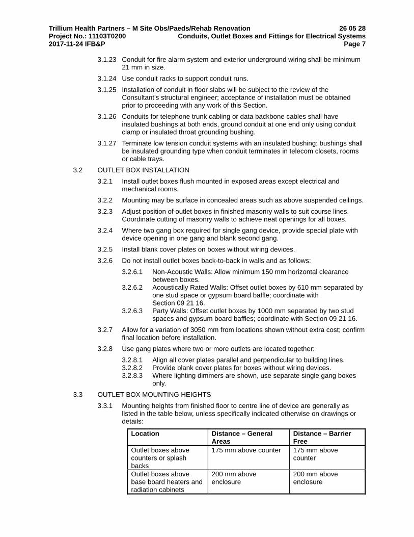
Trillium Health Partners – M Site Obs/Paeds/Rehab Renovation 26 05 28 Project No.: 11103T0200 Conduits, Outlet Boxes and Fittings for Electrical Systems 2017-11-24 IFB&P Page 7
3.1.23 Conduit for fire alarm system and exterior underground wiring shall be minimum 21 mm in size.
3.1.24 Use conduit racks to support conduit runs.
3.1.25 Installation of conduit in floor slabs will be subject to the review of the Consultant’s structural engineer; acceptance of installation must be obtained prior to proceeding with any work of this Section.
3.1.26 Conduits for telephone trunk cabling or data backbone cables shall have insulated bushings at both ends, ground conduit at one end only using conduit clamp or insulated throat grounding bushing.
3.1.27 Terminate low tension conduit systems with an insulated bushing; bushings shall be insulated grounding type when conduit terminates in telecom closets, rooms or cable trays.
3.2 OUTLET BOX INSTALLATION
3.2.1 Install outlet boxes flush mounted in exposed areas except electrical and mechanical rooms.
3.2.2 Mounting may be surface in concealed areas such as above suspended ceilings.
3.2.3 Adjust position of outlet boxes in finished masonry walls to suit course lines. Coordinate cutting of masonry walls to achieve neat openings for all boxes.
3.2.4 Where two gang box required for single gang device, provide special plate with device opening in one gang and blank second gang.
3.2.5 Install blank cover plates on boxes without wiring devices.
3.2.6 Do not install outlet boxes back-to-back in walls and as follows:
3.2.6.1 Non-Acoustic Walls: Allow minimum 150 mm horizontal clearance between boxes.
3.2.6.2 Acoustically Rated Walls: Offset outlet boxes by 610 mm separated by one stud space or gypsum board baffle; coordinate with Section 09 21 16.
3.2.6.3 Party Walls: Offset outlet boxes by 1000 mm separated by two stud spaces and gypsum board baffles; coordinate with Section 09 21 16.
3.2.7 Allow for a variation of 3050 mm from locations shown without extra cost; confirm final location before installation.
3.2.8 Use gang plates where two or more outlets are located together:
3.2.8.1 Align all cover plates parallel and perpendicular to building lines. 3.2.8.2 Provide blank cover plates for boxes without wiring devices. 3.2.8.3 Where lighting dimmers are shown, use separate single gang boxes
only.
3.3 OUTLET BOX MOUNTING HEIGHTS
3.3.1 Mounting heights from finished floor to centre line of device are generally as listed in the table below, unless specifically indicated otherwise on drawings or details:
Location Distance – General Areas
Distance – Barrier Free
Outlet boxes above counters or splash backs
175 mm above counter 175 mm above counter
Outlet boxes above base board heaters and radiation cabinets
200 mm above enclosure
200 mm above enclosure
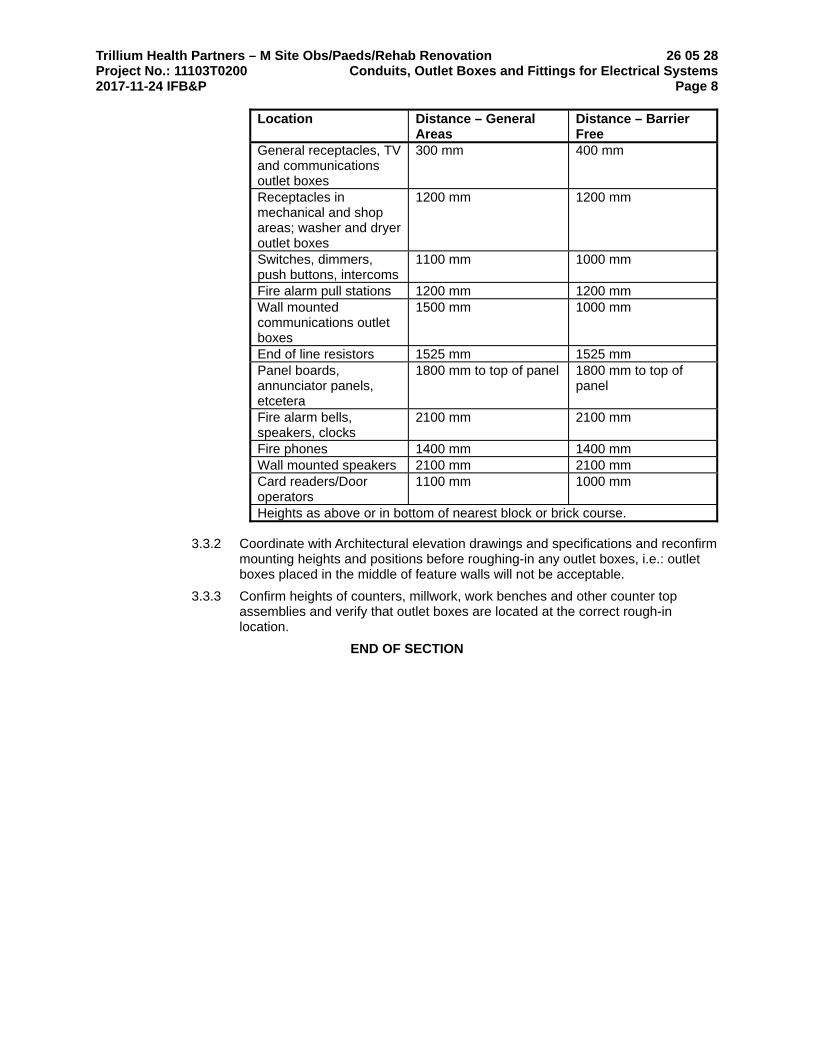
Trillium Health Partners – M Site Obs/Paeds/Rehab Renovation 26 05 28 Project No.: 11103T0200 Conduits, Outlet Boxes and Fittings for Electrical Systems 2017-11-24 IFB&P Page 8
Location Distance – General Areas
Distance – Barrier Free
General receptacles, TV and communications outlet boxes
300 mm
400 mm
Receptacles in mechanical and shop areas; washer and dryer outlet boxes
1200 mm 1200 mm
Switches, dimmers, push buttons, intercoms
1100 mm 1000 mm
Fire alarm pull stations 1200 mm 1200 mm Wall mounted communications outlet boxes
1500 mm 1000 mm
End of line resistors 1525 mm 1525 mm Panel boards, annunciator panels, etcetera
1800 mm to top of panel 1800 mm to top of panel
Fire alarm bells, speakers, clocks
2100 mm 2100 mm
Fire phones 1400 mm 1400 mm Wall mounted speakers 2100 mm 2100 mm Card readers/Door operators
1100 mm 1000 mm
Heights as above or in bottom of nearest block or brick course.
3.3.2 Coordinate with Architectural elevation drawings and specifications and reconfirm mounting heights and positions before roughing-in any outlet boxes, i.e.: outlet boxes placed in the middle of feature walls will not be acceptable.
3.3.3 Confirm heights of counters, millwork, work benches and other counter top assemblies and verify that outlet boxes are located at the correct rough-in location.
END OF SECTION

Trillium Health Partners – M Site Obs/Paeds/Rehab Renovation 26 05 29 Project No.: 11103T0200 Hangers and Supports for Electrical Systems 2017-11-24 IFB&P Page 1
1 General
1.1 RELATED REQUIREMENTS
1.1.1 Section 26 05 28 – Conduits, Outlet Boxes and Fittings for Electrical Systems
2 Products
2.1 CABLE TRAY SUPPORTS
2.1.1 Trapeze style hangers: 40 mm x 40 mm x 2.6 mm metal core thickness, length to suit with threaded rod hangers.
2.2 BUS DUCT SUPPORTS
2.2.1 Horizontal: Threaded rod hangers attached to bus duct by cantilever or icetong style hangers.
2.2.2 Vertical: Wall mounted, spring type isolators. Floor mounted, spring type isolators.
2.3 CONDUIT SUPPORTS
2.3.1 Hot dipped galvanized steel, U shape, size 41 mm x 41 mm x 2.5 mm thick, surface mounted, suspended or set in poured concrete walls and ceilings.
2.3.2 Single runs: Galvanized conduit straps or ringbolt type hangers.
2.3.3 Multiple runs: Conduit rack with 25 per cent spare capacity.
2.3.4 Vertical runs: Channel support with conduit fittings/clamps.
2.3.5 Conduit rack and channel support: Proprietary item, u-shaped, metal core thickness, length to suit, c/w conduit fittings/clamps.
2.4 INSERTS
2.4.1 Inserts for conduits and raceway hangers, for single, double and multiple runs shall be galvanized.
2.4.2 Standard of Acceptance
2.4.2.1 Unistrut Canada 2.4.2.2 Burndy (Canada) Ltd. - Flexibar 2.4.2.3 Pilgrim Technical Products Ltd. - Tufstrut
2.5 HANGERS
2.5.1 Hangers for electrical conduit shall be hot dipped galvanized after fabrication.
2.5.2 Standard of Acceptance
2.5.2.1 Burndy Canada Ltd. 2.5.2.2 Canstrut 2.5.2.3 Electrovert Ltd. 2.5.2.4 E. Myatt & Co. Ltd 2.5.2.5 Steel City Electric Ltd. 2.5.2.6 Pilgrim Technical Products Ltd.
2.6 TRAPEZE HANGERS
2.6.1 Performance:
2.6.1.1 Manufactured:
2.6.1.1.1 to product load listings.
2.6.1.2 Custom fabricated:
2.6.1.2.1 maximum deflection between supports: 1/250 (0.4%) of span 2.6.1.2.2 minimum factor of safety : 5 times load to ultimate tensile or
compressive strength.

Trillium Health Partners – M Site Obs/Paeds/Rehab Renovation 26 05 29 Project No.: 11103T0200 Hangers and Supports for Electrical Systems 2017-11-24 IFB&P Page 2
2.6.2 Construction:
2.6.2.1 Carbon steel shapes, to suit load application:
2.6.2.1.1 hollow steel section, 2.6.2.1.2 equal leg El section, or 2.6.2.1.3 double C channel “strong-back”, with welded clips.
2.6.2.2 Hanger rods:
2.6.2.2.1 as specified above, and 2.6.2.2.2 minimum two support rods, 2.6.2.2.3 rods selected for minimum factor of safety of 5 times load to
ultimate tensile or compressive strength of rod.
2.6.3 Finish:
2.6.3.1 hot dipped galvanized finish in mechanical rooms and outdoors. 2.6.3.2 black steel finish in other areas. 2.6.3.3 Standard of Acceptance
2.6.3.3.1 Anvil Fig 45, 46, 50
3 Execution
3.1 SUPPORT SPACING
3.1.1 Comply with maximum support spacing stated below.
3.1.2 Where building structure, equipment details or mass dictate, spacings shall be closer.
3.1.3 Spacings:
3.1.3.1 Cable tray: 2.4 m O/C and at bends and Tee fittings. 3.1.3.2 Bus duct horizontal 1.8 m O/C and at fittings. 3.1.3.3 Conduit runs: Vertical racks, 1.5 m O/C. 3.1.3.4 Conduit runs: Horizontal racks, 1.5 m O/C and at all changes in
direction.
3.2 INSTALLATION
3.2.1 Install to maintain head room, neat mechanical appearance, and to support equipment loads.
3.2.2 Supply and deliver inserts to site in ample time to be built into work of other trades. Provide necessary templates and adequate instructions to locate and install inserts.
3.2.3 Secure equipment to masonry, tile and plaster surfaces with lead anchors.
3.2.4 Secure equipment to poured concrete with expandable inserts.
3.2.5 Secure surface mounted equipment with T-bar support hanger fastened to inverted T bar ceilings. Ensure that T bars are adequately supported to carry weight of equipment specified before installation.
3.2.6 Standard of Acceptance
3.2.6.1 Caddy model No. 512 c/w BHC clip
3.2.7 Support equipment, conduit or cables using clips, spring loaded bolts, cable clamps designed as accessories to basic channel members.
3.2.8 Fasten exposed conduit or cables to building construction or support system using straps.
3.2.8.1 One-hole steel straps to secure surface conduits and cables 50 mm (2") and smaller.
3.2.8.2 Two-hole steel straps for conduits and cables larger than 50 mm (2"). 3.2.8.3 Beam clamps to secure conduit to exposed steel work.
Trillium Health Partners – M Site Obs/Paeds/Rehab Renovation 26 05 29 Project No.: 11103T0200 Hangers and Supports for Electrical Systems 2017-11-24 IFB&P Page 3
3.2.9 Suspended support systems.
3.2.9.1 Support individual cable or conduit runs with 6 mm (¼") diameter threaded rods and spring clips.
3.2.9.2 Support 2 or more cables or conduits on channels supported by 6 mm (¼") diameter threaded rod hangers where direct fastening to building construction is impractical.
3.2.10 For surface mounting of two or more conduits use channels.
3.2.11 Provide galvanized after fabrication metal brackets, frames, hangers, clamps and related types of support structures where indicated or as required to support conduit and cable runs.
3.2.12 Ensure adequate support for raceways and cables dropped vertically to equipment where there is no wall support.
3.2.13 Do not use wire lashing or perforated strap to support or secure raceways or cables.
3.2.14 Do not use supports or equipment installed for other trades for conduit or cable support except with permission of other trade and approval of Engineer.
3.2.15 Install fastenings and supports as required for each type of equipment cables and conduits, and in accordance with manufacturer's installation recommendations.
3.2.16 Supply and erect special structural work required for the installation of electrical equipment. Provide anchor bolts and fastenings unless noted otherwise. Mount equipment required to be suspended above floor level, where details are not shown, on a frame or platform bracketed from the wall or suspended from the ceiling. Carry supports to either the ceiling or the floor, or both as required, at locations where, because wall thickness is inadequate, it is not permitted to use such brackets.
3.2.17 Electrical panels, switches or other electrical equipment shall be complete with suitable bases or mounting brackets. Install angle or channel iron supports to bear the equipment where it is shown in or on structural tile walls, or walls that are inadequate to bear the equipment.
3.2.18 Provide channel iron or other metal supports where necessary to adequately support lighting fixtures. Do not use wood. Lighting fixtures shall be supported totally independent of ceiling and supported from structure above.
3.2.19 Support hangers, in general, from inserts in concrete construction or from building structural steel beams, using beam clamps. Provide additional angle or channel steel members required between beams for supporting conduits.
3.2.20 Do not use explosive drive pins in any section of work without obtaining prior written approval.
3.2.21 Provide re-enforced concrete pads under switchboards, and all other floor mounted electrical equipment. Pads are to be formed with chamfered edges to prevent chipping. Pads are to be sealed and painted to prevent dust from entering and interfering with electrical equipment.
3.2.22 Do not secure equipment or supports from: Bottom of precast concrete tees, bottom of cast-in-place concrete pan webs, from the edge of the chords of open web steel joist; from suspended gypsum board ceilings.
3.2.23 The Contractor is responsible for the design of all connections between structure and support systems, and must ensure that support systems are structurally sound.
3.2.24 Retain a Professional Consultant, Registered in the province of the Work, to design connections and support systems. Provide all design notes and calculations to the Consultant for his review upon request.

Trillium Health Partners – M Site Obs/Paeds/Rehab Renovation 26 05 29 Project No.: 11103T0200 Hangers and Supports for Electrical Systems 2017-11-24 IFB&P Page 4
3.2.25 Secure surface mounted equipment with twist clip fasteners to inverted T-bar ceilings. Ensure that T-bars are adequately supported to carry weight of equipment specified before installation. Provide additional support where required.
3.2.26 Fasten exposed conduit or cables to building construction or support system using straps.
3.2.26.1 One-hole malleable iron or steel straps to secure surface conduits and cables 38 mm diameter and smaller.
3.2.26.2 Two-hole steel straps for conduits and cables larger than 38 mm.
3.2.27 Suspended support systems.
3.2.27.1 Support individual cable or conduit runs with threaded rods and spring clips.
3.2.27.2 Support 2 or more cables or conduits on channels supported by threaded rod hangers where direct fastening to building construction is impractical.
3.2.28 Ensure adequate support for raceways and cables dropped vertically to equipment where there is no wall support.
3.2.29 Do not use wire lashing or perforated straps to support or secure raceways or cables.
3.2.30 Do not use supports or equipment installed for other trades for conduit or cable support except with approval of Consultant.
3.2.31 Install fastenings and supports as required for each type of equipment cables and conduits, in accordance with manufacturer's installation recommendations.
END OF SECTION

Trillium Health Partners – M Site Obs/Paeds/Rehab Renovation 26 05 31 Project No.: 11103T0200 Cabinets, Splitters, Junction and Pull Boxes 2017-11-24 IFB&P Page 1
1 General
1.1 RELATED SECTIONS
1.1.1 Section 26 05 00 – Common Work Results for Electrical
1.1.2 Section 26 05 28 - Conduits, Outlet Boxes and Fittings for Electrical Systems
1.1.3 Section 26 05 53 – Electrical Systems Identification
1.2 REFERENCE
1.2.1 CSA C22.2 No. 76 Splitters.
1.2.2 CSA C22.2 No. 40 Junction and Pull Boxes.
1.2.3 Cabinets to Section 26 27 18 Panel Trim.
1.3 LOCATION
1.3.1 Locate splitters, junction and pull boxes as indicated.
2 Products
2.1 SPLITTERS
2.1.1 Sheet metal enclosure, welded corners and formed hinged cover suitable for locking in closed position.
2.1.2 Main and branch lugs, to match required size and number of incoming and outgoing conductors as indicated.
2.1.3 Provide minimum three spare terminals on each set of lugs in splitters.
2.1.4 Distribution riser splitters shall be of special construction with hinged access door, copper bus bars predrilled to accept two hole compression connectors for all incoming and outgoing cables.
2.2 JUNCTION AND PULL BOXES
2.2.1 Welded steel construction with screw-on flat covers for surface or recessed mounting.
2.2.2 Covers with 25 mm minimum extension all around, for flush-mounted pull and junction boxes.
2.2.3 Cast type with gasketted covers where exposed to weather.
2.2.4 PVC type when embedded in concrete.
2.3 CABINETS
2.3.1 Type E: Sheet steel, hinged door and return flange overlapping sides, handle, lock and catch, for surface mounting.
2.3.2 Type T: Sheet steel cabinet, with hinged door, latch, lock, 2 keys, containing sheet steel backboard. Cabinets to be flush or surface mounted as indicated.
2.3.3 Surface mounted cabinets shall be finished in ASA 61 grey.

Trillium Health Partners – M Site Obs/Paeds/Rehab Renovation 26 05 31 Project No.: 11103T0200 Cabinets, Splitters, Junction and Pull Boxes 2017-11-24 IFB&P Page 2
2.4 INSTRUMENTATION AND CONTROL TERMINAL CABINETS
2.4.1 Surface mounted, gasketed, drip proof and dust tight, JIC enclosure, CEMA type 12 With hinged door, lock, 2 keys, white raised and removable internal mounting panel, diagram pocket, finished with ASA 61 grey.
2.4.2 Standard of Acceptance
2.4.2.1 Hammond
2.4.3 Panel wiring to be contained in PVC wiring ducts complete with cover strips, minimum 50 mm x 50 mm (2" x 2"). Wireway fill to be limited to 60%. Where there are a large number of door mounted devices, door wiring harnesses shall also be contained in wiring ducts at rear door. All door wiring devices to emanate from the control panel terminal strips. Wiring to panel face mounted devices to be bundled neatly on hinge side of panel, enclosed in flexible spiral wrap, and installed such that wiring will not be damaged when opening and closing door. Ground panel door to panel with a flexible copper bonding strap. Label all wiring with permanent PVC sleeve type markers.
2.4.4 Phoenix contact terminal blocks with mounting rails, end covers, terminal markers, partition plates and accessories: UK 2.5 termination of wiring 22 to 12 AWG; UK 5 and UK 10 series for current transformers and other leads #10 AWG and #8 AWG; UDK or UK 5 twin for connecting two or more conductors to one terminal block; DIK 1.5 for three wire sensor device wiring; MTKD for thermocouple leads.
2.4.5 Provide lamacoid nameplates for all panel mounted control and indicating devices, and all internal components such as terminal strips, control transformers, control devices, relays, etc. as per 26 05 01.
3 Execution
3.1 SPLITTER INSTALLATION
3.1.1 Install splitters as indicated and mount plumb, true and square to the building lines.
3.1.2 Extend splitters full length of equipment arrangement except where indicated otherwise.
3.2 JUNCTION, PULL BOXES AND CABINETS
3.2.1 Install pull boxes in inconspicuous but accessible locations.
3.2.2 Mount cabinets with top not higher than 1.9 m above finish floor.
3.2.3 Install terminal blocks, as indicated.
3.2.4 Only main junction and pull boxes are indicated. Provide pull boxes so as not to exceed 30 m of conduit length in any particular run.
3.2.5 Boxes and cabinets to be installed plumb and square with building lines.
3.2.6 Install junction and pull boxes clear of all mechanical duct work and piping.
3.3 IDENTIFICATION
3.3.1 Coordinate identification requirements with Section 26 05 53.

Trillium Health Partners – M Site Obs/Paeds/Rehab Renovation 26 05 31 Project No.: 11103T0200 Cabinets, Splitters, Junction and Pull Boxes 2017-11-24 IFB&P Page 3
3.3.2 Install size 2 identification labels indicating system name, voltage, phase and source of power.
3.3.3 Provide a typed directory in cabinets showing following information: Nature, actual quantities and room number of device or devices connected to each terminal, as well as signal circuit number where applicable.
END OF SECTION

Trillium Health Partners – M Site Obs/Paeds/Rehab Renovation 26 05 35 Project No.: 11103T0200 Wireways and Auxiliary Gutters 2017-11-24 IFB&P Page 1
1 General
1.1 RELATED REQUIREMENTS
1.1.1 Section 26 05 00 – Common Work Results for Electrical
1.1.2 Section 26 05 29 – Hangers and Supports for Electrical Systems
1.2 SYSTEM
1.2.1 This Section includes for wireway and auxiliary gutter systems, complete with all closure pieces, couplings, junction fittings, adaptors, elbows and hangers required for a complete installation.
1.3 SHOP DRAWINGS
1.3.1 Submit shop drawings in accordance with Section 26 05 00.
1.3.2 By large scale details, all conditions of construction, joints and accessories, dimensions, finishes and related work.
2 Products
2.1 MANUFACTURERS
2.1.1 Acceptable Materials Manufacturers: Subject to compliance with requirements specified in this Section; where multiple listings of manufacturers occur, use any of the following listed manufacturers’ products in accordance with Section 01 62 00 – Product Options including the following:
2.1.1.1 Ace Manufacturing 2.1.1.2 B-Line 2.1.1.3 A.C. Dandy
2.1.2 Substitutions: Consultant may consider additional manufacturers having similar products to Acceptable Materials Manufacturers listed above during the construction period, provided they meet the performance requirements established by the named products and provided they submit requests for substitution in accordance with Section 01 25 00 – Substitution Procedures before starting any work of this Section:
2.1.2.1 Do not use substitute materials to establish Bid Price. 2.1.2.2 Substitutions that appear as a part of the project without review and
acceptance by the Consultant will be rejected, and replaced with one of the specified materials.
2.2 WIREWAYS
2.2.1 Sheet steel, 1.5 mm nominal core thickness with hinged cover to give uninterrupted access.
2.2.2 Cross-section dimensions: 63 x 63 mm, or 101 x 101 mm or 152 x 152 mm or as indicated.
2.2.3 Finish: baked grey enamel.
2.2.4 Elbows, tees, couplings and hanger fittings manufactured as accessories to wireway supplied.

Trillium Health Partners – M Site Obs/Paeds/Rehab Renovation 26 05 35 Project No.: 11103T0200 Wireways and Auxiliary Gutters 2017-11-24 IFB&P Page 2 3 Execution
3.1 INSTALLATION
3.1.1 Install wireways and auxiliary gutters as indicated.
3.1.2 Keep number of elbows, offsets, connections to minimum.
3.1.3 Install supports, elbows, tees, connectors, fittings.
3.1.4 Install barriers where required.
3.1.5 Install gutter to full length of equipment.
END OF SECTION

Trillium Health Partners – M Site Obs/Paeds/Rehab Renovation 26 05 53 Project No.: 11103T0200 Electrical Systems Identification 2017-11-24 IFB&P Page 1
1 General
1.1 SUMMARY
1.1.1 This Section covers the identification of various electrical equipment, wire and conduit using:
1.1.1.1 Conduit and Wire Markers 1.1.1.2 Voltage Markers 1.1.1.3 Stencils 1.1.1.4 Equipment Tags and Nameplates 1.1.1.5 Chart and Directory Frames 1.1.1.6 Custom and Standard Applied Labels
1.1.2 Paint identification of systems, conduit and equipment will be completed by painting contractor responsible for work specified in Section 09 91 00.
1.1.3 Application of identification labels and stencils to systems, equipment and wires will be completed by trade contractor responsible for scope of work specified in this section.
1.1.4 This section will identify and label the systems, conduit and equipment to the painting contractor that require painting in the specified colour schemes.
1.2 RELATED REQUIREMENTS
1.2.1 Section 09 91 00 – Painting: Site painting of electrical work.
1.2.2 Section 20 05 43 – Mechanical Systems Identification
1.3 REFERENCE STANDARDS
1.3.1 Canadian Standards Association (CSA):
1.3.1.1 CSA C22.1-06, Canadian Electrical Code, Part 1 (20th Edition), Safety Standard for Electrical Installations
1.4 DESIGN CRITERIA
1.4.1 Wording on nameplates, tags and labels shall be submitted for review and accepted by the Consultant before manufacture.
1.4.2 Identification on nameplates, labels and tags shall be in English.
1.4.3 Nameplates for terminal cabinets and junction boxes to indicate system and voltage characteristics.
1.5 SUBMITTALS
1.5.1 Provide the following submittals in accordance with Section 01 33 00 – Submittal Procedures:
1.5.1.1 Submit schedule of nameplates, size of each nameplate, wording and corresponding size of letters for approval.
1.5.1.2 Submit a complete schedule of all equipment to have identification complete with symbol and description engraved on lamacoid plates.
1.5.1.3 Submit manufacturers catalogue literature for each product specified, identifying use for interior or exterior installations.
1.5.1.4 Submit two labels, indicating type and quality of installed products. 1.5.1.5 Submit manufacturer's installation instructions indicating special
procedures, and installation methods.
1.6 PROJECT CLOSEOUT SUBMISSIONS
1.6.1 Provide copies of directories and legends for inclusion in the operating and maintenance data manuals in accordance with Section 01 78 23 – Operating and Maintenance Data.
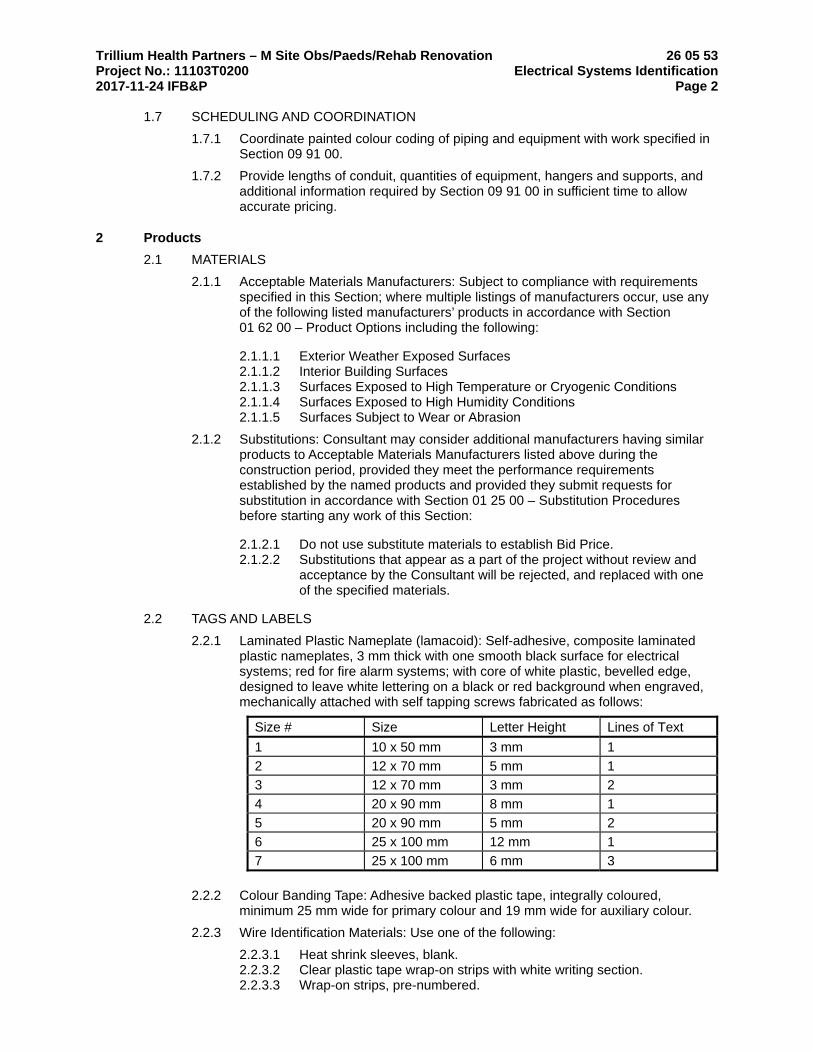
Trillium Health Partners – M Site Obs/Paeds/Rehab Renovation 26 05 53 Project No.: 11103T0200 Electrical Systems Identification 2017-11-24 IFB&P Page 2
1.7 SCHEDULING AND COORDINATION
1.7.1 Coordinate painted colour coding of piping and equipment with work specified in Section 09 91 00.
1.7.2 Provide lengths of conduit, quantities of equipment, hangers and supports, and additional information required by Section 09 91 00 in sufficient time to allow accurate pricing.
2 Products
2.1 MATERIALS
2.1.1 Acceptable Materials Manufacturers: Subject to compliance with requirements specified in this Section; where multiple listings of manufacturers occur, use any of the following listed manufacturers’ products in accordance with Section 01 62 00 – Product Options including the following:
2.1.1.1 Exterior Weather Exposed Surfaces 2.1.1.2 Interior Building Surfaces 2.1.1.3 Surfaces Exposed to High Temperature or Cryogenic Conditions 2.1.1.4 Surfaces Exposed to High Humidity Conditions 2.1.1.5 Surfaces Subject to Wear or Abrasion
2.1.2 Substitutions: Consultant may consider additional manufacturers having similar products to Acceptable Materials Manufacturers listed above during the construction period, provided they meet the performance requirements established by the named products and provided they submit requests for substitution in accordance with Section 01 25 00 – Substitution Procedures before starting any work of this Section:
2.1.2.1 Do not use substitute materials to establish Bid Price. 2.1.2.2 Substitutions that appear as a part of the project without review and
acceptance by the Consultant will be rejected, and replaced with one of the specified materials.
2.2 TAGS AND LABELS
2.2.1 Laminated Plastic Nameplate (lamacoid): Self-adhesive, composite laminated plastic nameplates, 3 mm thick with one smooth black surface for electrical systems; red for fire alarm systems; with core of white plastic, bevelled edge, designed to leave white lettering on a black or red background when engraved, mechanically attached with self tapping screws fabricated as follows:
Size # Size Letter Height Lines of Text
1 10 x 50 mm 3 mm 1
2 12 x 70 mm 5 mm 1
3 12 x 70 mm 3 mm 2
4 20 x 90 mm 8 mm 1
5 20 x 90 mm 5 mm 2
6 25 x 100 mm 12 mm 1
7 25 x 100 mm 6 mm 3
2.2.2 Colour Banding Tape: Adhesive backed plastic tape, integrally coloured, minimum 25 mm wide for primary colour and 19 mm wide for auxiliary colour.
2.2.3 Wire Identification Materials: Use one of the following:
2.2.3.1 Heat shrink sleeves, blank. 2.2.3.2 Clear plastic tape wrap-on strips with white writing section. 2.2.3.3 Wrap-on strips, pre-numbered.
Trillium Health Partners – M Site Obs/Paeds/Rehab Renovation 26 05 53 Project No.: 11103T0200 Electrical Systems Identification 2017-11-24 IFB&P Page 3
2.2.3.4 Slip-on identification bead markers or sleeves, blank or pre-numbered. 2.2.3.5 Colour Banding Tape: Adhesive backed plastic tape, integrally
coloured.
2.2.4 Conduit, Power Supply and Voltage Markers: Pre-printed, adhesive backed plasticized labels indicating line voltage, colours as listed in 3.3.3 below, as scheduled for interior installations.
2.2.5 Snap Around Cable Markers: Pre-formed snap around fibre optic or circuit cable marker, 175 mm x 6 mm Ø.
2.2.6 Site Printed Identification Labels: Site-printed, machine-printed, adhesive backed plasticized minimum 13 mm high strip labels colours as indicated in 3.3.3 below.
2.2.7 Stencils: Factory-cut stencils ready for paint applied 50 mm high lettering and flow arrows, colour of letters and directional arrows as scheduled.
2.3 DIRECTORIES
2.3.1 Provide a typewritten directory for each system identified, minimum size 216 mm x 279 mm, or larger as required to accommodate information requirements.
2.3.2 Mount each directory in an individual metal frame and protect with clear, unbreakable acrylic sheet, permanently mounted.
2.3.3 Provide additional copies for inclusion in each Operating and Maintenance Manual.
2.4 ACCEPTABLE MATERIALS
2.4.1 Subject to compliance with requirements of this section, products that may be incorporated into the Work include, but are not limited to, the following:
2.4.1.1 Pre-Printed Conduit and Wire Marking Systems:
2.4.1.1.1 Brady Signmark 2.4.1.1.2 Seton Safety and Identification
2.4.1.2 Site Printed Identification Labels: Portable label printer and tapes as manufactured by:
2.4.1.2.1 Brady Handimark 2.4.1.2.2 Brother PT1800 2.4.1.2.3 Kroy K2500
2.4.1.3 Cubicles and/or cells to include main identifier nameplate on rear of cells
2.4.1.3.1 Standard of Acceptance
• W. M. Brady Co. of Canada Limited - B350 • IDI Electric (Canada) Ltd. - Style A
3 Execution
3.1 PREPARATION, PROTECTION AND CLEAN-UP
3.1.1 Degrease and clean surfaces to receive identification materials.
3.1.2 Prepare surfaces in accordance with Section 09 91 00 for stencil painting.
3.1.3 Ensure that new and existing equipment and surfaces are carefully covered with tarping, or heavy-duty plastic.
3.1.4 Ensure that spills and splatter on finishes and equipment are cleaned up totally and promptly.

Trillium Health Partners – M Site Obs/Paeds/Rehab Renovation 26 05 53 Project No.: 11103T0200 Electrical Systems Identification 2017-11-24 IFB&P Page 4
3.2 CONDUIT AND CABLE IDENTIFICATION
3.2.1 Colour code conduit and metallic sheathed cables in accordance with colour code specified in 3.3.3 below.
3.2.2 Propose lettering and numbering for conduit and cable identification based on room number, system number, outlet type, and address labelling system and sub-system and submit for review as required by 1.4 and 1.5 above before installation.
3.2.3 Install identification markers in accordance with accepted shop drawings and manufacturer's instructions.
3.2.4 Install primary and auxiliary in colours using plastic tape or paint installed on conduit at the following locations:
3.2.4.1 At each branch or riser take off. 3.2.4.2 At each passage through walls, floors or ceilings, both sides. 3.2.4.3 On all straight runs evenly spaced to a maximum of 15 metres O/C. 3.2.4.4 Identify on both sides of obscuring items where partially obscured by
other conduits, pipes, ducts or equipment. 3.2.4.5 Identify at points of entry and leaving, and at each access opening
where conduit is concealed in pipe chase or other confined space. 3.2.4.6 Identify at starting and end points of runs and at each piece of
equipment. 3.2.4.7 Identify all junction boxes in every system, both inside and outside the
junction box.
3.3 EQUIPMENT IDENTIFICATION
3.3.1 Colour code equipment in accordance with colour code specified in 3.3.3 below.
3.3.2 Propose lettering and numbering for conduit based on room number, system number, outlet type, and address labelling system and sub-system and submit as required by 1.4 and 1.5 above including, but not limited to, the following:
3.3.2.1 Panels, pull boxes, disconnect switches, starters, motor control centres, substations, switchgear, and transformers shall be prefinished in accordance with colour code specified.
3.3.2.2 Electrical rooms, components and equipment with nameplates, sized to correspond to the size of the equipment to be identified including, but not limited to, the following:
3.3.2.2.1 Panels:
• Identify power panels, isolated power panels, distribution panels and branch circuit panels as indicated on drawings.
• Indicate main voltages and current ratings. • Provide typed panel directories.
3.3.2.2.2 Transformers: Indicate capacity, primary and secondary voltages.
3.3.2.2.3 Disconnect switches, starters, contactors, and motor control centres: Indicate equipment being controlled and voltage.
3.3.2.2.4 Terminal cabinets and pull boxes: Indicate system and voltage.
3.3.2.2.5 On/Off switches: Indicate areas being served. 3.3.2.2.6 Distribution centres: Identify distribution centres as indicated
on drawings and indicate main voltages. 3.3.2.2.7 Motor control centres and starters. 3.3.2.2.8 All miscellaneous electrical equipment. 3.3.2.2.9 Housekeeping receptacles in-patient care areas.

Trillium Health Partners – M Site Obs/Paeds/Rehab Renovation 26 05 53 Project No.: 11103T0200 Electrical Systems Identification 2017-11-24 IFB&P Page 5
3.3.2.2.10 Circuit number on each receptacle throughout, where there is only one receptacle on one circuit, identify as DED.CCT #...
3.3.2.2.11 Identify other cabinets for low voltage systems, such as signals, communications, nurse call, cardiac arrest, public address, fire alarm, as for panelboards with a directory showing circuit numbers and room locations plus a blank for "Remarks", as well as a lamacoid plate designating panel name.
3.3.2.2.12 .11 Typical Identification Standards
• Lighting, Receptacle and Power panels to each be identified with an engraved lamacoid plate secured to top interior trim as:
∗ LP-1A 12 mm (½") high lettering ∗ 120/208 volts 5 mm (¼") high lettering ∗ Fed from PP 'AA' 5 mm (¼") high lettering
3.3.3 Colour Code for Identification:
System Colour
120/208V Grey
277/480V Bronze
347/600 V Sand
Ambulance Radio Green and Purple side by side
Alarm Systems Yellow
Clocks Grey
Computer Systems Pink
DC Emergency Lighting Brown
Dictation White
Doctors' Register Purple
Door Intercom Dark Blue
Door Security Pink
Electronic Data Collection Dark Blue
Fire Alarm Red
Intercom Dark Blue
Miscellaneous Light Blue
Nurse Call System Orange
Public Address Dark Blue
Telephone Dark Green
Data Dark Green
Annunciator and Buzzer System Black
TV Systems Light Green
TV Closed Circuit Orange
3.4 NAMEPLATE IDENTIFICATION OF EQUIPMENT
3.4.1 Identify equipment with lamacoid nameplates, as indicated in Equipment Identification Schedule.
3.5 PANEL BOARD DIRECTORIES
3.5.1 Identify loads controlled by each over current protective device in each panel board, by means of a typewritten panel board directory.

Trillium Health Partners – M Site Obs/Paeds/Rehab Renovation 26 05 53 Project No.: 11103T0200 Electrical Systems Identification 2017-11-24 IFB&P Page 6
3.5.2 Directory to indicate panel name and voltage.
3.5.3 All circuit numbers shall include a description of the type of load, i.e. “lighting”, “receptacles”, “ice machine”, etc and final room # as decided by the owner.
3.5.4 Cover list with a 0.8 mm minimum thick clear plastic sheet to protect it.
3.6 COMMUNICATIONS CABLE AND EQUIPMENT LABELLING
3.6.1 Label communication outlets, panels and ports with lamacoid nameplates as specified in Equipment Identification Schedule.
3.6.2 Label each of cables with other ends address using Wire Identification Materials.
3.6.3 Label outlets with labels vertically aligned in each row.
3.6.4 Position panel labels in the same position on each panel.
3.7 IDENTIFICATION OF PULL AND JUNCTION BOXES
3.7.1 Identify pull and junction boxes over 100 mm size as follows:
3.7.1.1 Use boxes that are prefinished in coded colours, or spray paint inside and outside of boxes before installation, in coded colours designating voltage or system.
3.7.1.2 Apply lamacoid nameplate to cover of each box. 3.7.1.3 Identify system name, except where sequence identification is
required, then identify system name and number. 3.7.1.4 Identify feeder pull boxes and junction boxes with lettering stamped on
brass or aluminum tags showing feeder or system concerned, voltage involved and data for both termination points whether equipment or panel. Tag to be held to boxes under lid screws using steel wire.
3.7.2 Identify pull and junction boxes 100 mm or less in size as follows:
3.7.2.1 Spray paint inside of boxes in coded colours designating voltage or system.
3.7.2.2 Apply permanent identifying markings directly to box covers designating voltage or system using indelible black ink.
3.8 COLOUR IDENTIFICATION OF WIRING
3.8.1 Identify No. 4/0 AWG wiring and smaller by continuous insulation colour.
3.8.2 Identify wiring larger than No. 4/0 AWG by continuous insulation colour or by colour banding tape applied at each end and at splices.
3.8.3 Colour coding shall be in accordance with Canadian Electrical Code, and as follows:
Voltage Colour
Equipment Grounding Conductor Green
Neutral Conductor White
120/208 V, 3 phase In accordance with CEC
120/208 V emergency In accordance with CEC
277/480 V, 3 phase In accordance with CEC
277/480 V emergency In accordance with CEC
347/600 V, 3 phase In accordance with CEC
347/600 V emergency In accordance with CEC
3.8.4 Where multi-conductor cables are used, use same colour coding system for identification of wiring throughout each system.
3.8.5 Maintain phase sequence and colour coding throughout each system.
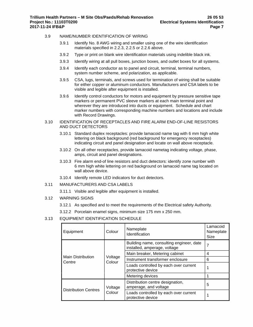
Trillium Health Partners – M Site Obs/Paeds/Rehab Renovation 26 05 53 Project No.: 11103T0200 Electrical Systems Identification 2017-11-24 IFB&P Page 7
3.9 NAME/NUMBER IDENTIFICATION OF WIRING
3.9.1 Identify No. 8 AWG wiring and smaller using one of the wire identification materials specified in 2.2.3, 2.2.5 or 2.2.6 above.
3.9.2 Type or print on blank wire identification materials using indelible black ink.
3.9.3 Identify wiring at all pull boxes, junction boxes, and outlet boxes for all systems.
3.9.4 Identify each conductor as to panel and circuit, terminal, terminal numbers, system number scheme, and polarization, as applicable.
3.9.5 CSA, lugs, terminals, and screws used for termination of wiring shall be suitable for either copper or aluminum conductors. Manufacturers and CSA labels to be visible and legible after equipment is installed.
3.9.6 Identify control conductors for motors and equipment by pressure sensitive tape markers or permanent PVC sleeve markers at each main terminal point and wherever they are introduced into ducts or equipment. Schedule and chart marker numbers with corresponding machine numbers and locations and include with Record Drawings.
3.10 IDENTIFICATION OF RECEPTACLES AND FIRE ALARM END-OF-LINE RESISTORS AND DUCT DETECTORS
3.10.1 Standard duplex receptacles: provide lamacoid name tag with 6 mm high white lettering on black background (red background for emergency receptacles) indicating circuit and panel designation and locate on wall above receptacle.
3.10.2 On all other receptacles, provide lamacoid nametag indicating voltage, phase, amps, circuit and panel designations.
3.10.3 Fire alarm end-of line resistors and duct detectors: identify zone number with 6 mm high white lettering on red background on lamacoid name tag located on wall above device.
3.10.4 Identify remote LED indicators for duct detectors.
3.11 MANUFACTURERS AND CSA LABELS
3.11.1 Visible and legible after equipment is installed.
3.12 WARNING SIGNS
3.12.1 As specified and to meet the requirements of the Electrical safety Authority.
3.12.2 Porcelain enamel signs, minimum size 175 mm x 250 mm.
3.13 EQUIPMENT IDENTIFICATION SCHEDULE
Equipment Colour Nameplate Identification
Lamacoid Nameplate Size
Main Distribution Centre
Voltage Colour
Building name, consulting engineer, date installed, amperage, voltage
7
Main breaker, Metering cabinet 4
Instrument transformer enclosure 6
Loads controlled by each over current protective device
1
Metering devices 1
Distribution Centres Voltage Colour
Distribution centre designation, amperage, and voltage
5
Loads controlled by each over current protective device
1

Trillium Health Partners – M Site Obs/Paeds/Rehab Renovation 26 05 53 Project No.: 11103T0200 Electrical Systems Identification 2017-11-24 IFB&P Page 8
Equipment Colour Nameplate Identification
Lamacoid Nameplate Size
Panelboards Voltage Colour
Panelboard designation 2
Motor Control Centres
Voltage Colour
MCC designation, amperage and voltage 3
Motors or loads controlled by each unit and mnemonics
1
Relay terminal and transformer compartments
1
Manual Motor Starters
N/A Load controlled and mnemonics 1
Ground Bus N/A System Ground 1
On/Off Switches N/A Load controlled 1
Disconnect Switches, Magnetic Motor Starters and Contactors
Voltage Colour
Voltage and equipment controlled and mnemonics
2
Transformers Voltage Colour
Transformer designation, capacity, secondary and primary voltages
2
Emergency Power Equipment
Voltage Colour
Designation and voltage 2
Wireways N/A Voltage and system designation 2
Line Voltage Cabinets and Enclosures
Voltage Colour
Designation and voltage 2
Low Voltage Cabinets and Enclosures
System Colour
System name; system name and number if more than one cabinet or enclosure
2
Major components within cabinets and enclosures
1
Communication Outlet and Outlet Assemblies
N/A Outlet Designation 1
Communication Panels
N/A Panel Designation 1
Communication Ports
N/A Port Designation 1
END OF SECTION
Trillium Health Partners – M Site Obs/Paeds/Rehab Renovation 26 05 73 Project No.: 11103T0200 Overcurrent Protective Device Coordination 2017-11-24 IFB&P and Arc Flash Hazard Studies Page 1
1 General
1.1 SUMMARY
1.1.1 This Section includes requirements for preparation and submittal of computer based, fault current and overcurrent protective device coordination studies and arc flash hazard studies:
1.1.1.1 Set protective devices based on results of protective device coordination study. 1.1.1.2 Set arc flash warnings, labels and maskings on results of arch flash hazard
study.
1.1.2 Studies listed in this section must be submitted to the Consultant before receiving any review and acceptance of distribution shop drawings or release of equipment for manufacture or both; Consultant will consider a preliminary submittal when studies contain sufficient information to ensure that selection of device ratings and characteristics can be determined where formal completion of studies could cause delay to the manufacture of equipment required for the Project.
1.2 RELATED REQUIREMENTS
1.2.1 Section 26 05 00 – Common Work Results for Electrical
1.2.2 Section 26 24 16 - Panelboards
1.3 REFERENCE STANDARDS
1.3.1 American National Standards Institute (ANSI):
1.3.1.1 ANSI/IEEE C37.5-1979, Methods for Determining the RMS Value of a Sinusoidal Current Wave and Normal-Frequency Recovery Voltage, and for Simplified Calculation of Fault Currents
1.3.1.2 ANSI/IEEE C37.010-1999, Application Guide for AC High-Voltage Circuit Breakers Rated on a Symmetrical Current Basis
1.3.1.3 ANSI/IEEE C37.41-2000, Standard Design Tests For High-Voltage Fuses, Distribution Enclosed Single-Pole Air Switches, Fuse Disconnecting Switches, and Accessories
1.3.1.4 ANSI/IEEE C57.12.00-2006, Standard for Standard General Requirements for Liquid-Immersed Distribution Power & Regulating Transformers
1.3.1.5 ANSI/IEEE C37.13.1-2006, Standard for Definite Purpose Switching Devices for Use in Metal-Enclosed Low-Voltage
1.3.2 Canadian Standards Association (CSA):
1.3.2.1 CAN/CSA C22.1-2006, Canadian Electrical Code 1.3.2.2 CAN/CSA C282-05, Emergency Electrical Power Supply for Buildings 1.3.2.3 CAN/CSA Z462-08, Workplace Electrical Safety
1.3.3 Insulated Cable Engineers Association (ICEA):
1.3.3.1 ICEA P-32-382, Short Circuit Characteristics of Insulated Cable 1.3.3.2 ICEA P-48-482, Short Circuit Performance of Metallic Shields and Sheaths on
Insulated Cables
1.3.4 Institute of Electrical and Electronics Engineers (IEEE):
1.3.4.1 IEEE 141-1993 (R1999), Recommended Practice for Electric Power Distribution for Industrial Plants
1.3.4.2 IEEE 241-1990, Recommended Practice for Electric Power Systems in Commercial Buildings
1.3.4.3 IEEE/ANSI 242-2001, Recommended Practice for Protection and Coordination of Industrial and Commercial Power Systems
1.3.4.4 IEEE/ANSI 399-1997, Recommended Practice for Power Systems Analysis 1.3.4.5 IEEE 1015, 2006, Recommended Practice for Applying Low-Voltage Circuit
Breakers Used in Industrial and Commercial Power Systems

Trillium Health Partners – M Site Obs/Paeds/Rehab Renovation 26 05 73 Project No.: 11103T0200 Overcurrent Protective Device Coordination 2017-11-24 IFB&P and Arc Flash Hazard Studies Page 2
1.3.5 National Electrical Manufacturers Association (NEMA):
1.3.5.1 ANSI/NEMA MG 1-2006, Motors and Generators, including Revision 1
1.3.6 National Fire Protection Association (NFPA):
1.3.6.1 NFPA 70E-2009, Standard for Fire Safety in the Workplace
1.4 SUBMITTALS
1.4.1 Provide required information in accordance with Section 01 33 00 – Submittal Procedures.
1.4.2 Action Submittals: Provide the following submittals before starting any work of this Section:
1.4.2.1 Product Data: Submit product data indicating computer software program being used for studies specified in this Section.
1.4.2.2 Final Reports: Submit final reports verifying equipment ratings including; but not limited to, the following before starting work related to manufacture or shipping of affected equipment (switchgear, transformers and other similar materials):
1.4.2.2.1 Overview 1.4.2.2.2 Short Circuit Study:
• Purpose • Explanation of Data • Assumptions • Fault Analysis Input Report • Analysis of Results • Recommendations
1.4.2.2.3 Protective Device Coordination Study:
• Purpose • Explanation of Data • Assumptions • Analysis of Results • Recommendations, including CEC, Section 46 and CSA C282
Requirements • Example Drawings
1.4.2.2.4 Arc Flash Study:
• Purpose • Explanation of Data • Assumptions • Arc Flash Evaluation Report • Analysis of Results • Recommendations
1.4.2.2.5 Prioritized Recommendations and Conclusions 1.4.2.2.6 Appendices:
• Software Generated Single Line Diagrams • AutoCAD Generated Single Line Diagrams • Protective Device Summaries • Reference Data • Copies of Warning Labels, including study date
1.4.3 Informational Submittals: Provide the following submittals during the course of the work:
1.4.3.1 Overcurrent Protective Device Certificates: Submit product certificates for coordination study and fault current study computer software programs, certifying compliance with IEEE 399.

Trillium Health Partners – M Site Obs/Paeds/Rehab Renovation 26 05 73 Project No.: 11103T0200 Overcurrent Protective Device Coordination 2017-11-24 IFB&P and Arc Flash Hazard Studies Page 3
1.4.3.2 Arc Flash Hazard Certificates: Submit product certificates for computer software programs certifying compliance with CAN/CSA Z462.
1.5 QUALITY ASSURANCE
1.5.1 Qualifications: Provide proof of qualifications when requested by Consultant:
1.5.1.1 Software: Use computer programs that are distributed nationally and are in wide use to produce studies; having algorithms that are coordinated and compatible with requirements of standards and guides affecting work of this Section; manual calculations are not acceptable.
2 Products
2.1 NOT USED
3 Execution
3.1 EXAMINATION
3.1.1 Verification of Conditions: Examine overcurrent protective device submittals for compliance with electrical distribution system coordination requirements and other conditions affecting performance; devices requiring coordination are indicated on Drawings:
3.1.1.1 Proceed with coordination study only after relevant equipment submittals have been assembled.
3.1.1.2 Overcurrent protective devices that have not been submitted and reviewed prior to coordination study must not be used in study.
3.2 PREPARATION
3.2.1 Power System Data: Gather and tabulate the following input data to support coordination study:
3.2.1.1 Product data for overcurrent protective devices specified in other Division 26 Sections and involved in overcurrent protective device coordination studies:
3.2.1.1.1 Use equipment designation tags that are consistent with electrical distribution system diagrams, overcurrent protective device submittals, input and output data, and recommended device settings.
3.2.1.2 Impedance of utility service entrance 3.2.1.3 Electrical Distribution System Diagram: In hard-copy and electronic-copy
formats, showing the following:
3.2.1.3.1 Circuit-breaker and fuse-current ratings and types 3.2.1.3.2 Relays and associated power and current transformer ratings and
ratios 3.2.1.3.3 Transformer kilovolt amperes, primary and secondary voltages,
connection type, impedance, and X/R ratios 3.2.1.3.4 Generator kilovolt amperes, size, voltage, and source impedance 3.2.1.3.5 Cables, indicating conduit material, sizes of conductors, conductor
material, insulation, and length 3.2.1.3.6 Bus way ampacity and impedance 3.2.1.3.7 Motor horsepower and code letter designation according to NEMA
MG 1, for motors ≥50 HP; group motors <50 HP into 50 HP blocks
3.2.1.4 Data sheets to supplement electrical distribution system diagram, cross referenced with tag numbers on diagram, showing the following:
3.2.1.4.1 Special load considerations, including starting inrush currents and frequent starting and stopping
3.2.1.4.2 Transformer characteristics, including primary protective device, magnetic inrush current, and overload capability
Trillium Health Partners – M Site Obs/Paeds/Rehab Renovation 26 05 73 Project No.: 11103T0200 Overcurrent Protective Device Coordination 2017-11-24 IFB&P and Arc Flash Hazard Studies Page 4
3.2.1.4.3 Motor full load current, locked rotor current, service factor, starting time, type of start, and thermal-damage curve
3.2.1.4.4 Generator thermal-damage curve 3.2.1.4.5 Ratings, types, and settings of utility company's overcurrent
protective devices 3.2.1.4.6 Special overcurrent protective device settings or types stipulated by
utility company 3.2.1.4.7 Time-current-characteristic curves of devices indicated to be
coordinated 3.2.1.4.8 Manufacturer, frame size, interrupting rating in amperes RMS
Symmetrical, ampere or current sensor rating, long-time adjustment range, short-time adjustment range, and instantaneous adjustment range for circuit breakers
3.2.1.4.9 Manufacturer and type, ampere-tap adjustment range, time-delay adjustment range, instantaneous attachment adjustment range, and current transformer ratio for overcurrent relays
3.2.1.4.10 Panelboards, switchboards, motor control centre ampacity, and interrupting rating in amperes RMS Symmetrical
3.3 STUDIES
3.3.1 Fault Current Study: Calculate the maximum available short-circuit current in amperes RMS Symmetrical at circuit-breaker positions of the electrical power distribution system:
3.3.1.1 Make calculation based on current immediately after initiation and for a three-phase bolted short circuit at each of the following:
3.3.1.1.1 Electrical utility’s supply termination point 3.3.1.1.2 Incoming switchgear 3.3.1.1.3 Unit substation primary and secondary terminals 3.3.1.1.4 Switchgear and switchboard bus 3.3.1.1.5 Motor control centres 3.3.1.1.6 Standby generator(s) 3.3.1.1.7 Automatic transfer switch(es) 3.3.1.1.8 Distribution panelboard 3.3.1.1.9 Branch circuit panelboard
3.3.1.2 Study electrical distribution system from normal and alternate power sources throughout electrical distribution system for Project. Include studies of system-switching configurations and alternate operations that could result in maximum fault conditions.
3.3.1.3 Calculate momentary and interrupting duties on the basis of maximum available fault current.
3.3.1.4 Study Report: Show calculated X/R ratios and equipment interrupting rating (½ cycle) fault currents on electrical distribution system diagram.
3.3.1.5 Equipment Evaluation Report:
3.3.1.5.1 Verify that interrupting ratings are equal to or higher than calculated ½ cycle symmetrical fault current for 600 V overcurrent protective devices.
3.3.1.5.2 For devices and equipment rated for asymmetrical fault current, apply multiplication factors listed in the standards to ½ cycle symmetrical fault current.
3.3.1.5.3 Verify adequacy of phase conductors at maximum three-phase bolted fault currents; verify adequacy of equipment grounding conductors and grounding electrode conductors at maximum ground-fault currents. Ensure that short-circuit withstand ratings are equal to or higher than calculated ½ cycle symmetrical fault current.

Trillium Health Partners – M Site Obs/Paeds/Rehab Renovation 26 05 73 Project No.: 11103T0200 Overcurrent Protective Device Coordination 2017-11-24 IFB&P and Arc Flash Hazard Studies Page 5
3.3.2 Coordination Study:
3.3.2.1 Perform coordination study using approved computer software program. Prepare a written report using results of fault-current study. Comply with IEEE 399; calculate the maximum and minimum ½ cycle short-circuit currents.
3.3.2.2 Comply with IEEE 141 recommendations for fault currents and time intervals. 3.3.2.3 Transformer Primary Overcurrent Protective Devices 3.3.2.4 Device shall not operate in response to the following:
3.3.2.4.1 Inrush current when first energized 3.3.2.4.2 Self-cooled, full-load current or forced-air-cooled, full-load current,
whichever is specified for that transformer 3.3.2.4.3 Permissible transformer overloads according to IEEE C57.96 if
required by unusual loading or emergency conditions
3.3.2.5 Device settings shall protect transformers according to IEEE C57.12.00, for fault currents.
3.3.2.6 Conductor Protection: Protect cables against damage from fault currents according to ICEA P-32-382, ICEA P-45-482, and conductor melting curves in IEEE 242:
3.3.2.6.1 Demonstrate that equipment withstands the maximum short-circuit current for a time equivalent to the tripping time of the primary relay protection or total clearing time of the fuse.
3.3.2.6.2 To determine temperatures that damage insulation, use curves from cable manufacturers or from listed standards indicating conductor size and short-circuit current.
3.3.2.7 Coordination Study Report: Prepare a written report indicating the following results of coordination study; Tabular Format of Settings Selected for Overcurrent Protective Devices:
3.3.2.7.1 Device tag 3.3.2.7.2 Circuit breaker sensor rating; and long-time, short-time, and
instantaneous settings 3.3.2.7.3 Fuse current rating and type 3.3.2.7.4 Ground-fault relay pickup and time delay settings
3.3.2.8 Coordination Curves: Prepared to determine settings of overcurrent protective devices to achieve selective coordination:
3.3.2.8.1 Graphically illustrate that adequate time separation exists between devices installed in series, including power utility company's upstream devices.
3.3.2.8.2 Prepare separate sets of curves for the switching schemes and for emergency periods where the power source is local generation. Show the following information:
• Device tag • Voltage and current ratio for curves • Three phase and single-phase damage points for each
transformer • No damage, melting, and clearing curves for fuses. • Cable damage curves • Transformer inrush points • Maximum fault-current cut off point
3.3.2.9 Complete data sheets for setting of overcurrent protective devices 3.3.2.10 Apply engineering stamp/seal for the project location to the final report.
3.3.3 Arc Flash Hazard Study:

Trillium Health Partners – M Site Obs/Paeds/Rehab Renovation 26 05 73 Project No.: 11103T0200 Overcurrent Protective Device Coordination 2017-11-24 IFB&P and Arc Flash Hazard Studies Page 6
3.3.3.1 Prepare arc flash hazard study including the following:
3.3.3.1.1 Determine and document all possible utility, and generator and emergency sources that are capable of being connected to each piece of electrical gear; base calculation on highest possible source connection.
3.3.3.1.2 Prepare calculations conforming to NFPA 70E and CAN/CSA Z462 calculation standards; calculate all incident energy units in calories per square centimetre.
3.3.3.1.3 Provide recommended boundary zones and personal protective equipment (PPE) based on calculated incident energy and requirements of NFPA 70E for each piece of electrical gear.
3.3.3.2 Arc Flash Cases:
3.3.3.2.1 Arc flash values for two normal cases to define the highest values (low short circuit and high short circuit).
3.3.3.2.2 Arc flash values for two maintenance cases that define the arc flash values that would be available at the equipment, if the instantaneous trip of the upstream circuit breaker is set at a minimum value; recommendation based on situation where someone has to work on live equipment.
3.3.3.3 Labelling: Provide labelling as required by the Authority Having Jurisdiction based on results of arc flash hazard study; as a minimum, provide the following information:
3.3.3.3.1 PPE Level 3.3.3.3.2 Flash Hazard Boundaries 3.3.3.3.3 Flash Protection Boundary 3.3.3.3.4 Shock Hazard Boundary, such as – Limited Approach Boundary,
Restricted Approach Boundary, Prohibited Approach Boundary 3.3.3.3.5 Study Date
3.3.3.4 Other: Recommendations to reduce arc flash incident energy in all areas that require Class 2 or higher PPE.
3.3.3.5 Apply engineering stamp/seal for the project location to the final report.
END OF SECTION
Trillium Health Partners – M Site Obs/Paeds/Rehab Renovation 26 07 05 Project No.: 11103T0200 Special Hospital Wiring 2017-11-24 IFB&P Page 1
1 General
1.1 DESCRIPTION
1.1.1 Patient care areas are grouped in three categories, as follows:
1.1.1.1 Basic care 1.1.1.2 Intermediate patient care 1.1.1.3 Critical care
1.1.2 Examples of the categories are:
1.1.2.1 Basic care areas
1.1.2.1.1 Patient care areas where body contact between a patient an medical electrical equipment is neither frequent nor usual, including examination rooms and general patient rooms
1.1.2.2 Intermediate care areas:
1.1.2.2.1 Patient bedwards 1.1.2.2.2 Treatment and examination rooms 1.1.2.2.3 Clinics and similar areas 1.1.2.2.4 Recovery Rooms 1.1.2.2.5 Patient Holding Areas 1.1.2.2.6 Patient Preparation Rooms 1.1.2.2.7 Hydrotherapy Rooms 1.1.2.2.8 Dialysis Treatment Stations
1.1.2.3 Critical Care:
1.1.2.3.1 Anaesthetizing locations 1.1.2.3.2 Intensive Care Units 1.1.2.3.3 Coronary Care Units 1.1.2.3.4 Special Care Units 1.1.2.3.5 Cardiovascular Care Units 1.1.2.3.6 Intermediate Coronary Care Units 1.1.2.3.7 Renal Dialysis Units 1.1.2.3.8 Angiographic Laboratories 1.1.2.3.9 Burn Units 1.1.2.3.10 Cardiac Cauterization Laboratories 1.1.2.3.11 Emergency Trauma Units 1.1.2.3.12 Resuscitation Rooms
2 Products
2.1 RECEPTACLES
2.1.1 Receptacles connected to the emergency power system shall be coloured red.
2.1.2 Receptacles in patient care areas shall be Hospital Grade.
2.1.3 Receptacles in patient care areas shall have a circuit identification lamacoid in accordance with CSA Z32-09 Lamacoid shall be secured to the wall above the receptacle and shall be engraved with panel name and circuit number. Lettering shall be minimum¼" (6 mm) high and shall be:
2.1.3.1 Black letter, white lamacoid for normal power 2.1.3.2 Red letter, white lamacoid for emergency power

Trillium Health Partners – M Site Obs/Paeds/Rehab Renovation 26 07 05 Project No.: 11103T0200 Special Hospital Wiring 2017-11-24 IFB&P Page 2 3 Execution
3.1 BONDING TO GROUND
3.1.1 Bonding to ground of receptacles and permanently wired electrical equipment in the patient care areas shall be carried by installing an insulated green equipment bonding conductor in the same conduit as the branch circuit conductors. The bonding conductor shall be terminated in the outlet box and the device at the load end and a ground bar in the panel supplying the equipment or outlet at the source end. A separate bonding conductor shall be provided for each circuit and the bonding conductor shall be sized equal to the branch circuit conductors.
3.1.2 Where the single phase receptacles in a patient care environment are supplied from two 2- wire branch circuits in the same conduit, a single bonding conductor may be provided for the two circuits.
3.1.3 In critical care areas a separate No. 10 ground conductor shall be provided for each circuit back to the panel.
3.1.4 Items to be grounded shall include all receptacles, wall-mounted fluorescent or incandescent fixtures and any other equipment located within 1.5 m horizontally from the nominal position of the bed and 2.3 m vertically above the floor.
3.1.5 Interconnect the ground bus in emergency and normal electrical panels which serve patient care areas with an insulated green copper conductor installed in conduit and sized as in Table 16 of the Electrical Safety Code, but not less than #6 AWG.
3.2 NEUTRAL CONDUCTORS
3.2.1 .1 In intermediate and critical care areas, a separate neutral conductor shall be provided for each branch circuit phase conductor back to the panel supplying the outlet. Since the neutral is a full current carrying conductor, it is suggested that not more than two beds have a 25 mm conduit home run to the panel to avoid conductor de-rating.
END OF SECTION

Trillium Health Partners – M Site Obs/Paeds/Rehab Renovation 26 07 13 Project No.: 11103T0200 Wiring to Owners Equipment 2017-11-24 IFB&P Page 1
1 General
1.1 RELATED WORK
1.1.1 Certain items, such as ranges and refrigerators, ice machines, etc will be supplied by Owners and put in place by another Division.
1.1.2 Surgical or examination light fixtures and articulated service arms will be supplied by another Division who will provide necessary mounting brackets and structural reinforcements for these fixtures.
1.1.3 Controls complete with box will be supplied by Owners, where surgical lights are shown with variable intensity controls.
2 Products (Not Used)
3 Execution
3.1 INSTALLATION
3.1.1 Provide electrical work required to connect up electrical parts of items, supplied by Owners and placed by another Division.
3.1.2 Disconnect any existing Owner's equipment, where such exists in building to be relocated, prior to its relocation, and install and reconnect in its new location.
3.1.3 Unpack, assemble, install and wire the surgical or exam lights. Retain services of the fixture supplier for technical advice.
3.1.4 Install and wire surgical or exam light controls and box where lights are shown with variable intensity controls.
3.1.5 Wire electrical devices in articulated arms to suit.
END OF SECTION

Trillium Health Partners – M Site Obs/Paeds/Rehab Renovation 26 08 23 Project No.: 11103T0200 Electrical Starting and Testing by Contractor 2017-11-24 IFB&P Page 1
1 General
1.1 RELATED SECTIONS
1.1.1 Section 26 05 00 – Common Work Results for Electrical
1.2 REFERENCE STANDARDS
1.2.1 Canadian Standards Association (CSA):
1.2.1.1 CSA C22.2 NO. 0.4-M1982 (R1999), Bonding and Grounding of Electrical Equipment (Protective Grounding)
1.3 DESCRIPTION
1.3.1 Test and check all portions of the electrical system for satisfactory operation. All tests and checks to be done in the presence of the Engineer, suitably logged, tabulated, signed and incorporated into the Operating and Maintenance Manuals. Testing and checking to be carried out under this Contract at no extra cost to Owner. Procedures and tests outlined below are electrical tests required in addition to normal visual and mechanical inspection which shall be carried out prior to placing equipment in service.
1.3.2 Provide certified copies of all production tests required by CEMA and CSA for all power distribution equipment.
1.3.3 All work found to be defective as a result of the testing procedures covered by this Section shall be made good at no cost to the Owner and on completion of remedial work the tests shall be repeated. The costs of such second and subsequent tests is the responsibility of the Contractor and is a prerequisite to establishing "Substantial Completion" as referred to in "Supplementary Instructions to Bidders".
1.3.4 Give timely notice to the Engineer that the work is ready for testing. The satisfactory completion of all tests is a prerequisite to establishing Substantial Completion of the project. Testing of electrical systems shall be done by only one of the following acceptable professional independent testing organizations and one complete copy of all reports, studies and test results shall be submitted directly to the Engineer:
1.3.4.1 Haronitis & Associates 1.3.4.2 Rondar 1.3.4.3 Brosz & Associates 1.3.4.4 Schneider Canada Service
1.3.5 Refer to CSA Standard Z32 for test circuits.
1.4 REPORTS
1.4.1 Prepare and submit the following reports. Submit separate reports for each area to suit construction phasing and occupancy requirements within 5 days of completion of testing in each area. Simultaneously submit one copy directly to the Engineer and a further 6 copies to the contractor to be processed as a shop drawing:
1.4.1.1 Conductor Insulation Integrity Test 1.4.1.2 Receptacle retentive force test. 1.4.1.3 Receptacle polarity test. 1.4.1.4 Branch circuit impedance.

Trillium Health Partners – M Site Obs/Paeds/Rehab Renovation 26 08 23 Project No.: 11103T0200 Electrical Starting and Testing by Contractor 2017-11-24 IFB&P Page 2
1.4.1.5 Test of ground point voltage rise under fault conditions at patient and bed locations.
1.4.1.6 Potential difference between ground points. 1.4.1.7 Impedance to ground test (single phase isolated system only).
1.4.2 One complete copy of all reports, studies and test results shall be submitted directly to the Consultant and the Owner along with a certificate, bearing a professional engineer’s seal and signature, stating that the installation meets the requirements of the CSA Z32-09 Standard, and is suitable for patient use.
1.4.3 Submit additional copies of all reports, studies and test results to the contractor for inclusion in the Maintenance Manuals as required under Section 26 05 00.
2 Products
2.1 NOT USED
3 Execution
3.1 PRELIMINARY CHECKS
3.1.1 All equipment and devices to be visually inspected and cleaned. Document that all equipment and devices have correct services, connections, settings, supply voltages, alarm circuits, heater elements, etc., and that they are operational and in accordance with the requirements of contract specifications and drawings, and the manufacturers specifications and recommendations.
3.2 ELECTRICAL TESTS
3.2.1 This Section outlines the tests to be carried out and submitted to the Engineer for approval. Be responsible at no cost to the Owner for rectifying all equipment or installations which do not meet the requirements of the various tests listed.
3.2.2 The following tests shall be carried out in accordance with the latest edition of CAN/CSA-Z32-09 "Electrical Safety and Essential Electrical Systems in Health Care Facilities":
3.2.2.1 Conductor Insulation Integrity Test 3.2.2.2 Receptacle retentive force test. 3.2.2.3 Receptacle polarity test. 3.2.2.4 Branch circuit impedance. 3.2.2.5 Test of ground point voltage rise under fault conditions at patient and
bed locations. 3.2.2.6 Potential difference between ground points. 3.2.2.7 Impedance to ground test (single phase isolated system only).
3.3 CONDUCTOR INSULATION INTEGRITY TEST
3.3.1 Using a 500V dc megohmmeter, measure the insulation resistance of each branch circuit conductor with all wiring devices connected.
3.3.2 Isolate the branch circuits under test as required to ensure that other circuits serving patients or sensitive equipment are not exposed to the test voltage.
3.3.3 Record all results on tests forms.
3.3.3.1 Submit tests forms to Engineer for approval.
Trillium Health Partners – M Site Obs/Paeds/Rehab Renovation 26 08 23 Project No.: 11103T0200 Electrical Starting and Testing by Contractor 2017-11-24 IFB&P Page 3
3.3.3.2 Where measured values are below the values listed in Z32, the Contractor shall replace the wiring and the independent testing organization shall test the replaced wiring. This process shall be repeated until satisfactory results are obtained. The cost of such work shall be the responsibility of the Contractor.
3.4 RECEPTACLE RETENTIVE TEST FORCE
3.4.1 Requirements: A force of 1.1 Newtons shall not remove a test pin from the ground slot of a receptacle. A force of 13.3 Newtons shall not remove a test attachment plug of the same configuration for a receptacle.
3.4.2 Method: Test pins and methods of test specified in CSA Standard C22.2 No. 42 shall be used. As an alternative, a commercially available "tension tester" complying with CSA Standard C22.22 No. 42, General Use Receptacles, Plugs and Similar Wiring Devices may be employed.
3.4.3 Implementation:
3.4.3.1 Using tension checker, ensure device has calibration as to tension (Newtons) for single-ground pin and tension (Newtons) for multiple pin testing.
3.4.3.2 For each outlet within a designated area, check tension of ground pin (minimum 1.1 Newtons) and tension of entire plug (minimum 13.3 Newtons).
3.4.3.3 Record go/no go tension reading for each outlet on a per room and branch circuit basis.
3.4.3.4 Replace any receptacle which does not meet the requirements listed in method.
3.5 RECEPTACLE POLARITY TEST
3.5.1.1 Requirements: Ensure all receptacles are connected in accordance with configurations listed in Canadian Electrical Code CSA C22.1, latest edition Section 26.
3.5.1.2 Method: Utilizing polarity test set, check all receptacles on a room by room basis.
3.5.1.3 Implementation: Correct connection of receptacles where polarity indication is incorrect.
3.6 BRANCH CIRCUIT IMPEDANCE TEST (VOLT DROP)
3.6.1 Requirements:
3.6.1.1 Ensure that all branch circuit wiring from panelboards to receptacles does not exceed a maximum voltage drop of 3% when 80% of the breaker current rating is applied at the receptacle. The Contractor shall test all receptacles on a room by room, circuit by circuit basis.
3.6.1.2 The equipment to be utilized by the Contractor for this test shall be approved by the Engineer. See Figure 1 in standard sheet "Test Circuit Configurations" for test circuit.
3.6.2 Method:
3.6.2.1 Ensure that all circuits other than the one under test are de-energized.
V0 – VL x 100
V0

Trillium Health Partners – M Site Obs/Paeds/Rehab Renovation 26 08 23 Project No.: 11103T0200 Electrical Starting and Testing by Contractor 2017-11-24 IFB&P Page 4
3.6.2.2 Record no load voltage at receptacle (Vo). 3.6.2.3 Apply current to 80% of the rating of the overcurrent device protecting
the circuit under test, record voltage (VL). 3.6.2.4 Remove load and reconfirm value of Vo. 3.6.2.5 Calculate voltage drop at receptacle by the formula.
3.6.3 Implementation:
3.6.3.1 Record all results on tests forms. 3.6.3.2 Submit tests forms to Engineer for approval. 3.6.3.3 Where volt drop exceeds 3% by calculation in method, the Contractor
shall take all necessary steps to reduce the voltage drop to the required value. The cost of such work shall be the responsibility of the Contractor.
3.7 GROUND POINT VOLTAGE RISE
3.7.1 Requirements: Bonding conductors shall be sized and installed so as to limit the voltage rise at the ground point of any receptacle within a patient care area to 3 V when tested. Bonding conductors for branch circuits shall be insulated.
3.7.2 Method: Using the test circuit of Figure 3 in standard sheet "Test Circuit Configurations":
3.7.2.1 Connect the test circuit to the outlet. With switch SW open, record the voltage indicated by voltmeter V1 as VN, the neutral to ground voltage without load. If it exceeds about 2 V, determine the cause and correct the defect.
3.7.2.2 Using the low voltage supply, (nominally 5 V open circuit) apply a load of 80% of the rated current of the circuit, between the neutral and the bonding conductor for a period of from 1 to 5 s. To ensure accuracy, the low voltage supply should be energized from a circuit other than the one being tested. Record the current I, the voltage indicated by voltmeter V1 as VR, and the voltage indicated by voltmeter V2 as VO.
3.7.3 Implementation
3.7.3.1 Record all results on tests forms. Submit test forms to Engineer for approval.
3.7.3.2 The return path voltage rise VO shall be not greater than 3 V where voltage rise exceeds 3 V. The Contractor shall take all steps necessary to correct the situation.
3.8 POTENTIAL DIFFERENCE BETWEEN GROUND POINTS
3.8.1 Requirements: The maximum potential difference between the grounding poles of all receptacles at a patient care location and between these poles and all other exposed conductive non-current-carrying parts at the same patient care location, shall be:
3.8.1.1 less than 20 mV in Basic Care Areas 3.8.1.2 less than 20 mV in Intermediate Care Areas; and 3.8.1.3 less than 10 mV in Critical Care Areas
3.8.2 Method:

Trillium Health Partners – M Site Obs/Paeds/Rehab Renovation 26 08 23 Project No.: 11103T0200 Electrical Starting and Testing by Contractor 2017-11-24 IFB&P Page 5
3.8.2.1 Using the standard frequency-weighted test circuit of Figure 2 in standard sheet "Test Circuit Configurations", the following test procedure shall be performed.
3.8.2.2 Confirm that all receptacles have been installed and that no utilization equipment, either permanently wired or cord-connected, is connected to the system.
3.8.2.3 Energize the system. 3.8.2.4 Select a local reference point known to be bonded to ground and
record the measured voltage between this chosen reference and each receptacle ground pole and each exposed conductive non-current-carrying metal part in turn. If the test leads are long, the readings should be corrected for pickup (zero reading) when connected together.
3.8.3 Implementation:
3.8.3.1 Using the standard frequency-weighted test circuit of Figure 2 in standard sheet "Test Circuit Configurations", the procedure shall be carried out.
3.8.3.2 The voltage measured shall meet the requirements above. 3.8.3.3 Record all results on tests forms and submit test forms to Engineer for
approval.
3.9 IMPEDANCE TO GROUND TEST (SINGLE PHASE ISOLATED SYSTEMS ONLY)
3.9.1 Requirements:
3.9.1.1 Impedance to ground on any single phase isolated power system shall not exceed 240 microamperes.
3.9.2 Method
3.9.2.1 The impedance to ground of a single phase isolated system shall be tested as follows:
3.9.2.1.1 Confirm that all receptacles have been installed and that no utilization equipment, either permanently wired or cord-connected, is connected to the system.
3.9.2.1.2 Verify that the system is ungrounded. 3.9.2.1.3 Energize the system and using the standard load and
measuring device as shown in Figure 2 in standard sheet "Test Circuit Configurations", record the measured voltage (Vm) between a reference ground and each energized conductor in sequence.
3.9.2.1.4 If a line-isolation monitor is connected to the system conduct the impedance test after opening the connection between the monitor and ground, for example by actuating the function testing switch.
3.9.2.1.5 Compute the current flow using the formula:
I = VM x 100
Where
I is in microamperes
VM is in volts
Verify that the measured current does not exceed a value:

Trillium Health Partners – M Site Obs/Paeds/Rehab Renovation 26 08 23 Project No.: 11103T0200 Electrical Starting and Testing by Contractor 2017-11-24 IFB&P Page 6
I max = 2E
Where
Imax is in microamperes
E is in the nominal voltage between the energized conductors, in volts
Trillium Health Partners – M Site Obs/Paeds/Rehab Renovation 26 08 23 Project No.: 11103T0200 Electrical Starting and Testing by Contractor 2017-11-24 IFB&P Page 7
3.9.3 Implementation
3.9.3.1 The maximum hazard index readings on the line isolation monitor shall be taken with:
3.9.3.1.1 all circuit breakers closed 3.9.3.1.2 all permanently installed equipment switched on,
(fluorescent lighting ballasts switched off) and 3.9.3.1.3 all cord-connected equipment disconnected
3.9.3.2 The readings shall be recorded and compared to previous readings. Where a reading is more than 20% greater than any previous reading, investigate the source of the increased leakage by conducting tests on individual circuits and repair or replace the faulty wiring, or equipment.
3.9.3.3 Record all results on tests forms and submit test forms to Engineer for approval.
3.9.3.4 Test each circuit individually by opening all other breakers on the system. Assist Contractor in trouble shooting system to reduce excessive leakage currents.
3.10 ENERGIZING MAIN ELECTRICAL SYSTEM: PERFORM THE FOLLOWING OPERATIONS PRIOR TO ENERGIZING MAIN ELECTRICAL SYSTEM:
3.10.1.1 Verify supply authority voltage and phase rotation. 3.10.1.3 Verify that testing as specified has been completed and deficiencies have been
corrected. 3.10.1.4 Megger all feeders and record results on approved test report forms.
3.11 TESTING AND WIRING AND WIRING DEVICES:
3.11.1 Test conductors at distribution centres and panelboards for insulation resistance to ground (megger test).
3.11.2 Test service grounding conductors for ground resistance.
3.11.3 Test all wiring devices for correct operation and circuitry.
3.12 GROUND RESISTANCE TESTING:
3.12.1 Measure ground resistance of ground grids with earth test megger to verify compliance with CSA C22.2 No. 0.4 and Canadian Electrical Code.
3.13 LOAD BALANCE TESTING:
3.13.1 Perform load tests with as many building loads activated as possible.
3.13.2 Test load balance on feeders at distribution centres, motor control centres, and panelboards.
3.13.3 Reconnect circuits to balance loads where directed by the Consultant where load unbalance exceeds 15% and revise panelboard directories and wiring identification accordingly.
3.14 VOLTAGE TESTING AND ADJUSTING:
3.14.1 Test voltage at service entry point, motor control centres, and secondary of transformers above 45 kVA.

Trillium Health Partners – M Site Obs/Paeds/Rehab Renovation 26 08 23 Project No.: 11103T0200 Electrical Starting and Testing by Contractor 2017-11-24 IFB&P Page 8
3.14.2 Adjust transformer tap settings to compensate for under-voltage or over-voltage conditions, if directed to do so by the Consultant.
3.15 STARTING MOTORS: PERFORM THE FOLLOWING OPERATIONS PRIOR TO STARTING MOTORS:
3.15.1 Confirm motor nameplate data with motor starter heater overloads, setting of MCP’s and sizing of fuses.
3.15.2 Verify rotation.
3.15.3 Verify that disconnects are installed.
3.15.4 Confirm labelling of motors, disconnects, and starters.
3.15.5 Measure and record operating load amp readings for three phase motors.
3.16 MOTOR CONTROL CENTRES
3.16.1 Ensure all starters are properly labelled.
3.16.2 Test function of control devices.
3.17 LIGHTING
3.17.1 Function test all light switches, luminaires, dimmers, and lighting control equipment such as photo-cells and time clock settings.
3.17.2 Function test low voltage lighting control system.
3.17.3 Function test light dimming systems.
3.18 FIRE SAFETY SYSTEMS
3.18.1 Prior to requesting verification of the Fire Alarm system by an Engineer, Division 26 and the system manufacturer’s technical staff shall perform the following operations:
3.18.1.1 Inspect system in conjunction with the Manufacturer and verify that fire alarm system is correctly installed, connected, and fully operational in accordance with requirements of the Contract Documents and Manufacturer’s recommendations with auxiliary equipment connected to the fire alarm system including, but not limited to, the following:
3.18.1.1.1 Elevators 3.18.1.1.2 Central station tie-in 3.18.1.1.3 Fan shut-down 3.18.1.1.4 Sprinklers 3.18.1.1.5 Door hold-open device 3.18.1.1.6 Other devices.
3.18.1.2 Verify that any subsequent work remaining to be performed on the above noted items will not invalidate examinations and tests performed during verification procedure.
3.18.1.3 Verify that operation and maintenance data has been submitted. 3.18.1.4 Verify that spare parts and maintenance materials have been
delivered.
Trillium Health Partners – M Site Obs/Paeds/Rehab Renovation 26 08 23 Project No.: 11103T0200 Electrical Starting and Testing by Contractor 2017-11-24 IFB&P Page 9
3.18.2 Notify Engineer in writing certifying that prerequisites listed in 3.18.1 above fulfilled and specifying known exceptions in the form of a list of items to be completed or corrected, prior to proceeding with the verification.
3.19 CLOSED CIRCUIT TV (CCTV)
3.19.1 Check installation of all camera units.
3.19.2 Check operation of all controls.
3.19.3 Check clarity of pictures on all monitors at minimum and normal light levels.
3.19.4 Function test system in the presence of the Consultant.
3.20 CABLE TELEVISION (CATV)
3.20.1 Arrange for cable TV company to check that all equipment has been properly installed, cable connections have been completed, and to test signal at each outlet for quality of reception.
3.21 NURSE CALL SYSTEM
3.21.1 Check installation of all components.
3.21.2 Program system as desired by the Owner.
3.21.3 Test operation of all components.
3.22 PAGING SYSTEM
3.22.1 Check installation of all speakers and headend equipment.
3.22.2 Check operation of all headend controls.
3.22.3 Adjust speaker taps to achieve proper sound levels.
3.22.4 Confirm paging control from telephone system.
3.23 DOOR SECURITY AND CARD ACCESS SYSTEM
3.23.1 Verify that equipment is properly installed and terminations are completed.
3.23.2 Verify that programming is complete and software is performing correctly before testing.
3.23.3 Verify that magnetic locks, door contacts and card readers are operational.
3.23.4 Function test system in presence of Consultant.
3.24 ELEVATOR SERVICE
3.24.1 Megger feeders and record results, confirm size of disconnects and fuses with elevator equipment suppliers prior to energizing feeders for elevator equipment.
3.24.2 Coordinate energizing of elevator feeders with elevator equipment supplier.
3.24.3 Confirm interconnections to fire alarm system before fire alarm verification.
END OF SECTION

Trillium Health Partners – M Site Obs/Paeds/Rehab Renovation 26 18 00 Project No.: 11103T0200 Building Voltage Circuit Protective Devices 2017-11-24 IFB&P Page 1
1 General
1.1 RELATED REQUIREMENTS
1.1.1 Section 26 05 00 – Common Work Results for Electrical
1.1.2 Section 26 24 16 – Panelboards
1.2 REFERENCE STANDARDS
1.2.1 American National Standards Institute (ANSI):
1.2.1.1 ANSI C37.16-2000, Recommendations for Low Voltage Power Circuit Breakers and AC Power Circuit Protectors, Preferred Ratings, Related Requirements and Application
1.2.2 Canadian Standards Association (CSA):
1.2.2.1 CAN/CSA C22.2 No. 5.1-M91 (R2000), Moulded Case Circuit Breakers 1.2.2.2 CSA C22.2 No. 59.1-M1987 (R2001), Fuses (Both Plug and
Cartridge-Enclosed Types) 1.2.2.3 CAN/CSA-C22.2 No. 106-M92, (R2001), HRC Fuses
1.3 REGULATORY REQUIREMENTS
1.3.1 Overcurrent protection devices shall meet standards of an electrical testing laboratory and bear a CSA, cUL, cULus, or cETL label and shall be sized in accordance with the Canadian Electrical Code; labels bearing only the marks UL, ULus, or ETL will not be acceptable for work of this Project.
1.4 SUBMITTALS
1.4.1 Provide requested submittals in accordance with Section 01 33 00 – Submittal Procedures; coordinated with Section 26 05 00.
1.4.2 Submit complete coordination study for overcurrent and ground fault protective devices for the complete system as follows:
1.4.2.1 Protection Coordination Study shall indicate fault levels throughout the system, and the equipment selected shall be based on the results of this study.
1.4.2.2 Selection for final breaker and fuse sizes will be determined from the coordination study.
1.4.2.3 Fuse and breaker sizes indicated on Drawings are for estimating purposes.
2 Products
2.1 COMPONENTS
2.1.1 Moulded Case Automatic Air Circuit Breakers: 250 V and 600 V bolt-in type with thermal and magnetic trip, trip free position separate from "On" or "Off" positions, and as follows:
2.1.1.1 Temperature compensation: 40°C ambient. 2.1.1.2 Common-trip breakers with single handle for multi-pole applications. 2.1.1.3 Magnetic instantaneous trip elements in circuit breakers, to operate
only when the value of current reaches setting.

Trillium Health Partners – M Site Obs/Paeds/Rehab Renovation 26 18 00 Project No.: 11103T0200 Building Voltage Circuit Protective Devices 2017-11-24 IFB&P Page 2
2.1.1.4 Trip settings on breakers with adjustable trips to range from 3 - 10 times current rating.
2.1.1.5 Circuit breakers rated 400A and larger shall be equipped with electronic trip units, interchangeable rating plugs and adjustable long-time delay and short-time functions.
2.1.1.6 Ground fault circuit breaker shall be as above with integral class A group 1 ground fault interrupter; breakers 400A and larger with ground fault protection shall be capable of zone selective interlocking so that the feeder breaker shall trip before the main breaker.
2.1.2 Industrial Air Circuit Breakers: Draw-out type solid state trip mechanism with adjustable long time 80% to 160% and short time settings, high pressure multi-finger contacts, inter-phase barriers, de-ion type arc quenchers and single phase protection, and as follows:
2.1.2.1 Where indicated, combine with high interrupting capacity current limiting fuses.
2.1.2.2 Solid state tripping system shall consist of one current sensor per pole. 2.1.2.3 One solid state trip unit and self-powered trip actuator to provide long,
short, instantaneous and ground fault protection and indication. 2.1.2.4 Operation: manual, stored energy closing mechanism to provide
quick-make operation. 2.1.2.5 Breaker with on-off indicator and spring charged/discharged indicator.
Padlocking provision in ON and OFF positions.
2.1.3 Fused switches: 250 V and 600 V, as applicable, heavy duty industrial type, quick make, quick break mechanism, dual wattage rating.
2.1.4 Fuses shall be HRC types as indicated on drawings and shall comply with CSA C22.2 No. 106.
2.1.5 Accessories:
2.1.5.1 Provide three spare fuses of each type and size installed. 2.1.5.2 Provide cabinet for storing spare fuses; mount cabinet in Main
Electrical Room.
2.1.6 Acceptable materials:
2.1.6.1 Industrial Air Circuit Breakers and Moulded Case Circuit Breakers:
2.1.6.1.1 Cutler Hammer 2.1.6.1.2 Schneider Electric 2.1.6.1.3 Siemens
2.1.6.2 Fuses:
2.1.6.2.1 Bussman 2.1.6.2.2 Gould/Ferraz Shawmut 2.1.6.2.3 Siemens
3 Execution
3.1 INSTALLATION
3.1.1 Install overcurrent protective devices as indicated, in accordance with manufacturer's written instructions.
Trillium Health Partners – M Site Obs/Paeds/Rehab Renovation 26 18 00 Project No.: 11103T0200 Building Voltage Circuit Protective Devices 2017-11-24 IFB&P Page 3
3.1.2 Fasten overcurrent protective devices without causing mechanical stresses, twisting or misalignment of equipment in final position.
3.1.3 Set field-adjustable trip settings as indicated subsequent to installation.
3.1.4 Overcurrent protective device sizes and identification as specified in respective equipment schedules.
3.1.5 Install with work of related Sections.
3.2 TESTING AND ADJUSTING
3.2.1 Coordinate testing and adjusting of installed system with Section 26 05 00.
END OF SECTION

Trillium Health Partners – M Site Obs/Paeds/Rehab Renovation 26 24 16 Project No.: 11103T0200 Panelboards 2017-11-24 IFB&P Page 1
1 General
1.1 RELATED REQUIREMENTS
1.1.1 Section 26 05 00 – Common Work Results for Electrical
1.1.2 Section 26 05 53 – Electrical Systems Identification: Lamacoid identification labels.
1.1.3 Section 26 05 28 – Conduits, Outlet Boxes and Fittings for Electrical Systems
1.2 REFERENCE STANDARDS
1.2.1 Canadian Standards Association (CSA):
1.2.1.1 CSA C22.2 No. 29-M1989 (R2004), Panelboards and Enclosed Panelboards
1.3 SUBMITTALS
1.3.1 Provide required information in accordance with Section 01 33 00 – Submittal Procedures; coordinated with Section 26 05 00.
1.3.2 Action Submittals: Provide the following submittals before starting any work of this Section:
1.3.2.1 Shop Drawings: Submit shop drawings indicating the following:
1.3.2.1.1 Outline dimensions 1.3.2.1.2 Configuration of identified compartments 1.3.2.1.3 Wall mounting method 1.3.2.1.4 Conduit knock-out locations and sizes 1.3.2.1.5 Dimensioned position and size of bus-bars and details of
provision for future breakers 1.3.2.1.6 Details on breakers, metering and surge suppression. 1.3.2.1.7 Complete nameplate schedule
1.4 QUALITY ASSURANCE
1.4.1 Regulatory Requirements: Manufacture busbar spaces, clearances, busbar mountings, breaker spaces, wiring spaces, and other components in accordance with certification and labelling requirements of CSA 22.2 No. 29, Canadian Electrical Code and electrical Authority Having Jurisdiction:
1.4.1.1 Panelboards must have CSA Approval with labels prominently placed and visible without disassembly of panel.
2 Products
2.1 MANUFACTURERS
2.1.1 Acceptable Materials Manufacturers: Subject to compliance with requirements specified in this Section; where multiple listings of manufacturers occur, use any of the following listed manufacturers’ products in accordance with Section 01 62 00: Product Options including the following:
2.1.1.1 Eaton Electrical, Cutler Hammer 2.1.1.2 Schneider Electric, Square D 2.1.1.3 Siemens Canada Ltd.

Trillium Health Partners – M Site Obs/Paeds/Rehab Renovation 26 24 16 Project No.: 11103T0200 Panelboards 2017-11-24 IFB&P Page 2
2.1.2 Substitutions: Consultant may consider additional manufacturers having similar products to Acceptable Materials Manufacturers listed above during the construction period, provided they meet the performance requirements established by the named products and provided they submit requests for substitution in accordance with Section 01 25 00 – Substitution Procedures before starting any work of this Section:
2.1.2.1 Do not use substitute materials to establish Bid Price. 2.1.2.2 Substitutions that appear as a part of the project without review and
acceptance by the Consultant will be rejected, and replaced with one of the specified materials.
2.2 DESCRIPTION
2.2.1 Factory Assembled Components: This section includes for distribution panels and branch circuit panels, their construction, and load requirements and as follows:
2.2.1.1 Construct panel boards to CSA standards and to bear CSA approval.
2.2.2 Enclosure: Fabricate as follows:
2.2.2.1 Panels: Mounting: Flush and Surface Mounted, as indicated in panelboard schedules and as follows:
2.2.2.1.1 Trim: Manufacturer’s standard panel trim having concealed hinges and trim mounting screws, hinged door-in-door construction with locking catch.
2.2.2.1.2 Sprinkler drip shields. 2.2.2.1.3 Keys: Provide two keys for each panel, interchangeable with
panels of same voltage.
2.2.3 Panels shall be dead front type in code gauge steel enclosure.
2.2.4 Each panel shall be complete with a typewritten directory which shall be mounted inside door with clear plastic cover.
2.2.5 Panels shall have mains of voltage and capacity, and main and branch breakers and contactors, as shown on the "Lighting and Receptacle Panel Schedule". Spaces shall include the necessary bus work such that Owners, at a later date, need buy only the breakers.
2.2.6 Contactors in panel mains shall be electrically operated, mechanically held and shall be rated to control incandescent, fluorescent and other loads as shown. Contactors shall be mounted within panel and shall be open type. Contactors shall be complete with fuse and fuse adaptor mounted and connected to line side of contactor and shall be connected to supply power to operating coil. Coil clearing contacts shall be included in contactor where a contactor is controlled by a time switch.
2.2.7 Where panels exceed 42 circuits, use multi-section panel with main cross-over solid bus bars. Main bus capacity of each section shall be full size to match cross-over bus. Cross-over bus shall be concealed by panel trim. Separate covers are not acceptable.
2.2.8 Breakers shall have bolted type connections.
Trillium Health Partners – M Site Obs/Paeds/Rehab Renovation 26 24 16 Project No.: 11103T0200 Panelboards 2017-11-24 IFB&P Page 3
2.2.9 120/208 V and 347/600 V Panelboards: 3 phase, 4 wire, solid neutral design with sequence style bussing and full capacity neutral of capacity indicated, composed of an assembly of bolt-in-place moulded case automatic air circuit breakers as indicated with thermal and magnetic trip and trip free position separate from either the "On" or the "Off" positions. Two and 3 pole breakers must have common simultaneous trip, and as follows:
2.2.9.1 Fabricate panelboards with hinged door-in-door construction. 2.2.9.2 Bus Material: Copper 2.2.9.3 Rate circuit breakers in 120/208 V branch circuit panels for minimum
22,000 A symmetrical interrupting capacity, unless noted otherwise or as determined by the short circuit study.
2.2.9.4 Rate circuit breakers in 347/600 V branch circuit panels for minimum 35,000 A symmetrical interrupting capacity, unless noted otherwise or as determined by the short circuit study.
2.2.9.5 Equip panelboards with normal copper ground bus. 2.2.9.6 Provide separate isolated ground bus, where indicated. 2.2.9.7 Equip panelboards with contactors in mains when indicated:
Electrically operated, mechanically held, of the size indicated, complete with 120 V holding coil with suitable control fusing and, in control section, provide one red bullseye pilot light with 220 V lamp, operating on 120 V, indicating a closed contractor and on On/Off selector switch. Construct enclosure in compliance with Bulletin No. 720 Canadian Standards Association, with hinged locking door over each section.
2.2.10 Thermal Magnetic Breakers
2.2.10.1 Moulded case circuit breaker to operate automatically by means of thermal and magnetic tripping devices to provide inverse time current tripping and instantaneous tripping for short circuit protection.
2.2.11 Trim
2.2.11.1 Front panel trim shall be overall hinged type, door within door construction. Trim assembly shall provide hinged access to the internal tub and wiring channels for access to wiring and breaker terminals without removal of the trim assembly. With overall trim assembly closed and secured, a second integral hinged door forming part of the trim assembly shall provide access to the circuit breakers only for opening and closing purposes.
2.2.11.2 Panels shall be given a rust-resistant treatment to both tub and trim. Locks shall be chrome plated.
2.2.11.3 Flush panels shall have concealed hinges and flush type combination lock latch. Doors shall open minimum 135 degrees. Trims shall have fasteners concealed and shall be prime coated to receive room finish paint in finished rooms.
2.2.11.4 Surface mounted panels shall be constructed in accordance with CSA Type 2 enclosures with overall door assembly protecting all circuit breakers. Door(s) shall be gasketted, with overhanging drip shield, with T-handle 2 point locking system complete with lock and latch
2.2.11.5 Panels in kitchen, servery and dishwashing areas shall have stainless steel trim.
2.2.11.6 Panels shall be finished with two coats of grey ASA No. 61. 2.2.11.7 UPS panels to be painted in royal blue Tempo Code #2281. Submit
colour chip for approval by Consultant. 2.2.11.8 Panel locks shall be common to one key throughout project.
2.2.12 Equipment Identification
2.2.12.1 Provide equipment identification in accordance with Section 26 05 01 - Electrical General Requirements.

Trillium Health Partners – M Site Obs/Paeds/Rehab Renovation 26 24 16 Project No.: 11103T0200 Panelboards 2017-11-24 IFB&P Page 4
2.2.12.2 Nameplate for each panelboard size 4 engraved, Submit nameplate wording.
2.2.12.3 Complete circuit directory with typewritten legend showing location and load of each circuit. Cover directory with a 0.8 mm (1/32") thick clear plastic sheet.
2.2.12.4 Nameplates for electrical panels shall indicate panel designation and mains voltage, i.e. 120/208 V, 3 φ, 4 W and panel and circuit number from which this panel is fed.
2.2.13 Transient Voltage Surge Suppression: Integral with panel where noted on single line drawings and as described in this Section and as follows:
2.2.13.1 Surge current per phase:
2.2.13.1.1 CDP’s: 160kA 2.2.13.1.2 Panelboards: 120 kA
2.2.13.2 Surge current mode (L-N, L-G, N-G, L-L)
2.2.13.2.1 CDP’s: 80kA 2.2.13.2.2 Panelboards: 60 kA
2.2.13.3 UL 1449 3rd Edition SVR – The maximum UL 1449 3rd Edition SVR for the device must not exceed the following:
Modes 208Y/120 480Y/277 600Y/347 L-N; L-G; N-G 400V 800V 1200V L-L 800V 1800V 1800V
2.2.13.4 ANSI/IEEE Category C3 Let Through Voltage – The let through voltage is based on IEEE C62.41 and IEEE C62.45 recommended procedures for Category C3 surges (20kV, 10kA) must be less than:
Modes 208Y/120 480Y/277 600Y/347 L-N 560V 960V 1840V
2.2.13.5 ANSI/IEEE Category B3 Let Through Voltage – The let through voltage is based on IEEE C62.41 and IEEE C62.45 recommended procedures for the ANSI/IEEE Category B3 ringwave (6kV, 500 amps) must be less than:
Modes 208Y/120 480Y/277 600Y/347 L-N 160V 165V 168V
2.2.13.6 Extended Range Filter – The Surge Protective Device must have a High Frequency Extended Range Tracing filter in each Line to Neutral mode with compliance to UL 1283 and NEMA LS1. The filter must have published high frequency attenuation rating in the attenuation frequencies:
Attenuation Frequency 50kHz 100kHz 500kHz 4MHz Insertion Loss (ratio) 40 316 316 89 Insertion Loss (dB) 32 50 50 39
2.2.13.7 Diagnostic features:
2.2.13.7.1 Status lights on each phase 2.2.13.7.2 Audible alarm comes with control switch 2.2.13.7.3 Form ‘C’ output contacts 2.2.13.7.4 Event counter and LCD display 2.2.13.7.5 Push-to-test button
2.2.13.8 Direct bus bar connection.

Trillium Health Partners – M Site Obs/Paeds/Rehab Renovation 26 24 16 Project No.: 11103T0200 Panelboards 2017-11-24 IFB&P Page 5
2.2.13.9 Warranty: 5 years.
3 Execution
3.1 INSTALLATION
3.1.1 Locate panel boards as indicated and mount securely, plumb, true and square, to adjoining surfaces.
3.1.2 Install surface mounted panelboards on plywood backboards. Where practical, group panelboards on common backboard.
3.1.3 Mount panelboards to height specified in Section 26 05 01 - Electrical General Requirements, or with top of trim at uniform height of 2000 mm (6' -6") or to match door heads or to suit tile layout, or as indicated.
3.1.4 Co-ordinate panel finish with Room Finish Schedule.
3.1.5 Deliver ten (10) duplicate keys for panel locks to Owner.
3.1.6 Connect loads to circuits.
3.1.7 Connect neutral conductors to common neutral bus with respective neutral identified.
3.1.8 Provide minimum #6 AWG green insulated copper bonding conductor in conduit to interconnect normal and emergency power panels serving common patient care areas. Provide all mounting brackets, busbar drillings and filler pieces for spaces.
3.1.9 Provide lock-on devices for clock outlet, fire alarm, security systems, battery chargers, door supervisory, intercom, stairway, exit and night light circuits.
3.1.10 Affix typewritten directory to the inside cover of each panelboard indicating loads controlled by each circuit.
3.1.11 Install spare conduits from recessed panels as specified under Section 26 05 28.
3.1.12 Provide lamicoid nameplate beside breakers in all distribution panels indicating the load serviced by the breaker in accordance with Section 26 05 53.
END OF SECTION

Trillium Health Partners – M Site Obs/Paeds/Rehab Renovation 26 27 19 Project No.: 11103T0200 Multi Outlet Assemblies 2017-11-24 IFB&P Page 1
1 General
1.1 PRODUCT DATA
1.1.1 Submit product data in accordance with Section 26 05 00.
1.1.2 Indicate type of multi-outlet assemblies with similar terminology to these documents.
2 Products
2.1 SURFACE RACEWAY FOR WIRING DEVICES
2.1.1 Two piece assembly manufactured for mounting wiring devices and associated wiring.
2.1.2 Cross-section dimensions: as indicated.
2.1.3 Finish: buff enamel.
2.1.4 Standard of Acceptance
2.1.4.1 Wiremold
2.2 WIRING DEVICES
2.2.1 Wiring devices: as indicated, to Section 26 27 26 - Wiring Devices.
2.3 GROUNDING
2.3.1 Ground system through raceway separate insulated conductor.
2.4 FITTINGS
2.4.1 Elbows, tees, couplings and hanger fittings manufactured as accessories to product line supplied.
3 Execution
3.1 FITTINGS
3.1.1 Install supports, elbows, tees, connectors, fittings.
3.1.2 Keep number of elbows, offsets and connections to minimum.
3.1.3 Install barriers where required, including between different systems and voltages.
3.2 WIRING
3.2.1 Install wiring as indicated.
END OF SECTION

Trillium Health Partners – M Site Obs/Paeds/Rehab Renovation 26 20 13 Project No.: 11103T0200 Switches, Receptacles, Plates and other Devices 2017-11-24 IFB&P Page 1
1 General
1.1 RELATED REQUIREMENTS
1.1.1 Section 26 05 00 – Common Work Results for Electrical
1.1.2 Section 26 05 28 – Conduits, Outlet Boxes and Fittings for Electrical Systems
1.2 REFERENCE STANDARDS
1.2.1 Canadian Standards Association (CSA):
1.2.1.1 CAN/CSA C22.2 No. 111-00 (R2005), General-Use Snap Switches (Bi-national standard, with UL 20, twelfth edition)
1.2.1.2 CSA C22.2 No. 42-M1984 Receptacles
1.2.2 National Electrical Manufacturers Association (NEMA):
1.2.2.1 NEMA WD1-1999, General Colour Requirements for Wiring Devices 1.2.2.2 NEMA WD6-2002, Wiring Devices-Dimensional Requirements
1.3 SHOP DRAWINGS AND PRODUCT DATA
1.3.1 .Submit shop drawings and product data in accordance with 26 05 01 Electrical General Requirements.
1.4 IDENTIFICATION
1.4.1 Receptacles in all patient care areas shall have a circuit identification lamacoid in accordance with CSA Z32.
1.4.1.1 Lamacoid shall be secured to the wall above the receptacle and shall be engraved with panel name and circuit number from which the receptacle is fed. Lettering shall be minimum 6 mm (¼”) high and as follows:
1.4.1.1.1 normal power: black lettering on white lamacoid. 1.4.1.1.2 emergency power: red lettering on a white lamacoid.
1.4.1.2 Provide additional lamacoid for dedicated circuit receptacles, of matching colour, indicating the words: “Dedicated Circuit”
1.4.2 All other receptacles shall be labelled with circuit identification using a lamacoid label with colour coding for normal, emergency and UPS sources complete with label attached to cover plate.
2 Products
2.1 SWITCHES
2.1.1 20 A, 120 V, silent, AC type, CSA listed, single pole, double pole, three-way, four-way switches as indicated.
2.1.2 Manually-operated general purpose ac switches with following features:
2.1.2.1 Terminal holes approved for No. 10 AWG wire. 2.1.2.2 Silver alloy contacts. 2.1.2.3 Urea or melamine moulding for parts subject to carbon tracking. 2.1.2.4 Suitable for back and side wiring. 2.1.2.5 White Decora.
2.1.3 Toggle operated fully rated for tungsten filament and fluorescent lamps, and up to 80% of rated capacity of motor loads.
2.1.4 Switches of one manufacturer throughout project.

Trillium Health Partners – M Site Obs/Paeds/Rehab Renovation 26 20 13 Project No.: 11103T0200 Switches, Receptacles, Plates and other Devices 2017-11-24 IFB&P Page 2
Type Approved Catalogue Numbers
Hubbell(120 Volt) Decora
Single Pole DS120
Double Pole DS220
Three-Way DS320
Four-Way DS420
2.1.5 Combination switches shall have neon pilot light and jewel on stainless steel plate.
2.1.6 Switches controlling lights on 120 volt emergency circuits shall be with lighted handle as follows:
Type Approved Catalogue Numbers
Hubbell Bryant P & S Cooper Leviton
Single Pole (Decora) DS120-IL 9901GL 2625 7631 5631
Three-Way (Decora) DS320-IL 9903GL 2626 7633 5633
2.1.7 Standard of Acceptance
2.1.7.1 Pass & Seymour 2.1.7.2 Harvey Hubbell of Canada Ltd. 2.1.7.3 Bryant Electric 2.1.7.4 Cooper Wiring Devices 2.1.7.5 Leviton
2.2 DIMMER SWITCHES
2.2.1 Dimmers shall be suitable for the LED drivers in the luminaires to be dimmed and shall be equal to Lutron, "DIVA Series" (thin profile), complete with chrome cover plates.
2.2.2 Where more than one dimmer is shown in the same location, mount dimmers in individual backboxes. Provide matching switches where shown adjacent to dimmers. Where remote dimmers are utilized, install associated components in accordance with the recommendations of the manufacturer.
2.3 LINE VOLTAGE OCCUPANCY SENSOR SWITCHES – WALL MOUNTED
2.3.1 Indoor, wall mounted, line voltage occupancy sensor switch, dual technology occupancy sensor, complete with manual on/off push buttons.
2.3.2 Suitable for use with 120V lighting.
2.3.3 Integral self-contained relays to allow for light switching with no minimum load requirement. Suitable for LED drivers. Maximum loading as follows
2.3.3.1 800W @ 120VAC
2.3.4 Provide 2 pole unit where required to control 2 lighting circuits or 2 different loads.
2.3.5 Occupancy sensor shall include the following features:
2.3.5.1 Manual on, with option for fully automatic. 2.3.5.2 Adjustable time out (30 sec to 20 min) and sensitivity.
Trillium Health Partners – M Site Obs/Paeds/Rehab Renovation 26 20 13 Project No.: 11103T0200 Switches, Receptacles, Plates and other Devices 2017-11-24 IFB&P Page 3
2.3.5.3 Basis-of-Design Materials (semi-circular coverage; up to 6m radius for small motion (hand), up to 10m radius for large motion (walking)):
2.3.5.3.1 Sensor Switch WSD-PDT Series or approved alternate.
2.4 LINE VOLTAGE OCCUPANCY SENSOR SWITCHES – CEILING MOUNTED
2.4.1 Indoor, ceiling mount, line voltage, occupancy sensor switch, passive dual technology occupancy sensors with 360° coverage pattern.
2.4.2 Suitable for use with 120V lighting.
2.4.3 Integral self-contained relays to allow for light switching with no minimum load requirement. Suitable for LED drivers. Maximum loading as follows
2.4.3.1 800W @ 120VAC
2.4.4 Provide 2 pole unit where required to control 2 lighting circuits or 2 different loads.
2.4.5 Provide units with photocell 0-10VDC dimming where required or shown on drawings to control lighting during daylight hours.
2.4.6 Occupancy sensor shall include the following features:
2.4.6.1 Fully automatic operation. 2.4.6.2 Minimum on timer to maximum lamp life, set 15 min. 2.4.6.3 Adjustable time out (30 sec to 20 min). 2.4.6.4 Basis-of-Design Materials (standard range for small rooms, circular
coverage up to 3.66m radius when mounted on 2.77m high ceiling):
2.4.6.4.1 Sensor Switch CMR PDT 9 Series or approved alternate.
2.4.6.5 Basis-of-Design Materials (extended range for large rooms, coverage up to 8.53m radius when mounted on 2.77m high ceiling):
2.4.6.5.1 Sensor Switch CMR PDT 10 Series or approved alternate.
2.5 RECEPTACLES
2.5.1 Receptacles to be complete with following features:
2.5.1.1 urea moulded housing. 2.5.1.2 Suitable for no. 10 AWG for back and side wiring 2.5.1.3 Break-off links for use as split receptacles. 2.5.1.4 Eight back wired entrances, four side wiring screws. 2.5.1.5 Triple wipe contacts and rivetted grounding contacts. 2.5.1.6 Heavy duty specification grade type 2.5.1.7 Receptacles in patient care areas to be heavy duty hospital grade
Decora type.
2.5.2 Receptacles of one manufacturer throughout project Decora type.
2.5.3 Receptacles shall be colour coded as follows:
2.5.3.1 Normal power: White Decora 2.5.3.2 Emergency power: red Decora.
2.5.4 Receptacles shall be as shown and as specified. For convenience, only one or two catalogue numbers of manufacturers have been shown.
2.5.4.1 Standard of Acceptance
2.5.4.1.1 Pass & Seymour 2.5.4.1.2 Harvey Hubbell of Canada Ltd. 2.5.4.1.3 Bryant Electric 2.5.4.1.4 Cooper Wiring Devices 2.5.4.1.5 Leviton
Trillium Health Partners – M Site Obs/Paeds/Rehab Renovation 26 20 13 Project No.: 11103T0200 Switches, Receptacles, Plates and other Devices 2017-11-24 IFB&P Page 4
2.5.4.1.6 H. K. Porter Canada Ltd. - NEPCO
2.5.5 The receptacles listed below represent the most common configurations available and are not necessarily used on this project. Refer to drawings for types used.
2.5.6 Duplex receptacle: 15 ampere, 120 volt, grounded CSA Configuration 5-15R:
2.5.6.1 Standard of Acceptance
2.5.6.1.1 Pass & Seymour 5262 or 8200 2.5.6.1.2 Hubbell 5262 or 8200 2.5.6.1.3 Bryant 5262C or 8200C 2.5.6.1.4 Leviton 5262 or 8200 2.5.6.1.5 Cooper 5262 or 8200
2.5.7 Weatherproof, 15 ampere, 120 volt equal to those above but complete with gasketted cast plate and hinged covers, equal to Leviton No. 4926 (vertical).
2.5.8 Isolated ground duplex receptacle: 15 ampere, 120 volt, CSA Configuration 5-15R:
2.5.8.1 Standard of Acceptance
2.5.8.1.1 Pass & Seymour IG5262 2.5.8.1.2 Hubbell IG6200 2.5.8.1.3 Bryant 5262-IGC 2.5.8.1.4 Leviton 5262-IGO 2.5.8.1.5 Cooper IG 5262
2.5.9 Transient voltage surge suppressor duplex receptacle: 15 ampere, 120 volt, grounded CSA Configuration 5-15R:
2.5.9.1 Standard of Acceptance
2.5.9.1.1 Pass & Seymour 6262-ISP 2.5.9.1.2 Hubbell 5252-S 2.5.9.1.3 Leviton 5280 2.5.9.1.4 Cooper 5262-S
2.5.10 Twistlock receptacle: 15 ampere, 120 volt, grounded CSA Configuration L5-15R
2.5.10.1 Standard of Acceptance
2.5.10.1.1 Single: Hubbell/P&S/Bryant/Leviton/Cooper 4710 2.5.10.1.2 Duplex: Hubbell/P&S/Bryant/Leviton/Cooper 4700
2.5.11 Duplex safety receptacle: 15 ampere, 120 volt, grounded CSA Configuration 5-15R:
2.5.11.1 Standard of Acceptance
2.5.11.1.1 Pass & Seymour SG-62 2.5.11.1.2 Hubbell SG-62 2.5.11.1.3 Bryant SG-62 2.5.11.1.4 Leviton 5262-SG 2.5.11.1.5 Cooper TR 8200
2.5.12 Single receptacle: 15 ampere, 208 volt, single phase, 3 wire grounded CSA Configuration 6-15R:
2.5.12.1 Standard of Acceptance
2.5.12.1.1 Pass & Seymour 5651 2.5.12.1.2 Hubbell 5661 2.5.12.1.3 Bryant 5661 2.5.12.1.4 Leviton 5661 2.5.12.1.5 Cooper 5661
Trillium Health Partners – M Site Obs/Paeds/Rehab Renovation 26 20 13 Project No.: 11103T0200 Switches, Receptacles, Plates and other Devices 2017-11-24 IFB&P Page 5
2.5.13 Duplex receptacle: 15 / 20 ampere, 120 volt, grounded CSA Configuration 5-20RA:
2.5.13.1 Standard of Acceptance
2.5.13.1.1 Pass & Seymour 5362 / 8300 2.5.13.1.2 Hubbell 5362 / 8300 2.5.13.1.3 Bryant 5352 / 8300 2.5.13.1.4 Leviton 5362 / 8300 2.5.13.1.5 Cooper 5362 / 8300
2.5.14 Receptacle: 20 ampere, 120 volt, grounded CSA Configuration 5-20R:
2.5.14.1 Standard of Acceptance
2.5.14.1.1 Single: Hubbell 6331/P&S 5391/Bryant 5351/Leviton 5361/Cooper 5361
2.5.14.1.2 Duplex: Hubbell 5392/P&S 5352/Bryant 5352/Leviton 5362/Cooper 5262
2.5.15 Twistlock receptacle: 20 ampere, 208 volt, 2 pole, 3 wire grounded CSA Configuration L6-20R:
2.5.15.1 Standard of Acceptance
2.5.15.1.1 Pass & Seymour L6-20R 2.5.15.1.2 Hubbell 2320 2.5.15.1.3 Bryant 70620 2.5.15.1.4 Leviton 2320
2.5.16 Single receptacle: 20 ampere, 208 volt, single phase, 3 wire grounded CSA Configuration 6-20R:
2.5.16.1 Standard of Acceptance
2.5.16.1.1 Pass & Seymour 5851 2.5.16.1.2 Hubbell 6391 2.5.16.1.3 Bryant 5461 2.5.16.1.4 Leviton 5461 2.5.16.1.5 Cooper CWL1520R
2.5.17 Single twistlock receptacle: 20 ampere, 208 volt, three phase, 4 wire grounded CSA Configuration L15-20R:
2.5.17.1 Standard of Acceptance
2.5.17.1.1 Pass & Seymour L15-20R 2.5.17.1.2 Hubbell 2420 2.5.17.1.3 Leviton 2420 2.5.17.1.4 Cooper CWL1520R
2.5.18 Single twistlock receptacle: 20 ampere, 120/ 208 volt, three phase, 5 wire grounded CSA Configuration L21-20R:
2.5.18.1 Standard of Acceptance
2.5.18.1.1 Pass & Seymour L21-20R 2.5.18.1.2 Hubbell 2520 2.5.18.1.3 Leviton 2520 2.5.18.1.4 Cooper CWL2120R
2.5.19 Single receptacle: 30 ampere, 120 volt, single phase, 3 wire grounded CSA Configuration 5-30R:
2.5.19.1 Standard of Acceptance
2.5.19.1.1 Pass & Seymour 5920 2.5.19.1.2 Hubbell 9308 2.5.19.1.3 Bryant 9530-FR
Trillium Health Partners – M Site Obs/Paeds/Rehab Renovation 26 20 13 Project No.: 11103T0200 Switches, Receptacles, Plates and other Devices 2017-11-24 IFB&P Page 6
2.5.19.1.4 Leviton 5371 2.5.19.1.5 Cooper 5716N
2.5.20 Single twistlock receptacle: 30 ampere, 208 volt, 2 pole, 3 wire grounded CSA Configuration L6-30R
2.5.20.1 Standard of Acceptance
2.5.20.1.1 Pass & Seymour L6-30R 2.5.20.1.2 Hubbell2620 2.5.20.1.3 Leviton 2620 2.5.20.1.4 Cooper CWL630R
2.5.21 Single twistlock receptacle: 30 ampere, 208 volt, three phase, 4 wire grounded CSA Configuration L15-30R:
2.5.21.1 Standard of Acceptance
2.5.21.1.1 Pass & Seymour L15-30R 2.5.21.1.2 Hubbell 2720 2.5.21.1.3 Leviton 2720 2.5.21.1.4 Cooper CWL1530R
2.5.22 Single receptacle: 30 ampere, 208 volt, single phase, 3 wire grounded CSA Configuration 6-30R:
2.5.22.1 Standard of Acceptance
2.5.22.1.1 Pass & Seymour 5930 2.5.22.1.2 Hubbell 9330 2.5.22.1.3 Leviton 5372 2.5.22.1.4 Cooper C5700N
2.5.23 .23 Single receptacle: 50 ampere, 208 volt, single phase, 3 wire grounded CSA Configuration 6-50R:
2.5.23.1 Standard of Acceptance
2.5.23.1.1 Pass & Seymour 5950 2.5.23.1.2 Hubbell 9367 2.5.23.1.3 Leviton 5374 2.5.23.1.4 Cooper 5709N
2.5.24 Single receptacle: 50 ampere, 208 volt, three phase, 4 wire grounded CSA Configuration 15-50R:
2.5.24.1 Standard of Acceptance
2.5.24.1.1 Pass & Seymour 5750 2.5.24.1.2 Hubbell 8450 2.5.24.1.3 Leviton 8450-A 2.5.24.1.4 Cooper 8450N
2.5.25 Single receptacle: 60 ampere, 208 volt, three phase, 4 wire grounded CSA Configuration 15-60R:
2.5.25.1 Standard of Acceptance
2.5.25.1.1 Pass & Seymour 5760 2.5.25.1.2 Hubbell 8460 2.5.25.1.3 Leviton 8460-A 2.5.25.1.4 Cooper 8460N
2.5.26 Clock receptacle: 15 ampere, 120 volt, grounded for plug-in clocks:
2.5.26.1 Standard of Acceptance
2.5.26.1.1 Pass & Seymour 2123 2.5.26.1.2 Hubbell 5235 2.5.26.1.3 Leviton 5261-CH
Trillium Health Partners – M Site Obs/Paeds/Rehab Renovation 26 20 13 Project No.: 11103T0200 Switches, Receptacles, Plates and other Devices 2017-11-24 IFB&P Page 7
2.5.27 Combination switch, receptacle, and pilot light:
2.5.27.1 Standard of Acceptance
2.5.27.1.1 Bryant Electric - 6400 Series
2.6 COVER PLATES
2.6.1 Cover plates for wiring devices.
2.6.2 Cover plates from one manufacturer throughout project.
2.6.3 Stainless steel 18-8 chrome metal alloy, Type 302, vertically brushed, 1 mm (1/32") thick cover plates for wiring devices mounted in flush-mounted outlet box.
2.6.4 Cast cover plates for wiring devices mounted in surface-mounted FS or FD type conduit boxes.
2.6.5 Weatherproof double lift spring-loaded cast aluminum cover plates, complete with gaskets for duplex receptacles as indicated.
2.6.6 Weatherproof spring-loaded cast aluminum cover plates complete with gaskets for single receptacles or switches.
2.6.7 Letters shall be 6 mm (¼”) high filled with red paint where engraving is indicated. Engraving shall be parallel to finished floor level.
2.6.7.1 Standard of Acceptance
2.6.7.1.1 Pass & Seymour #93000 Series 2.6.7.1.2 Harvey Hubbell of Canada Ltd. #93000 Series 2.6.7.1.3 Bryant Electric #S600 Series 2.6.7.1.4 Leviton #84000 Series 2.6.7.1.5 Cooper #93000 Series
2.7 GROUND FAULT CIRCUIT INTERRUPTERS
2.7.1 Units shall be CSA approved Type A.
2.7.2 .2 Ground fault circuit interrupters (GFCI) shall be complete with receptacle, test feature and reset switch.
2.7.3 Units shall include a 15A grounded duplex receptacle, a button to test operation of unit and current transformer and sensing mechanism. Unit to be complete with suitable outlet box.
2.7.4 Units in Hospitals to be hospital grade.
2.7.5 Unless noted otherwise, unit shall trip at 6 mA.
2.7.6 Where shown in outdoor locations, units shall be enclosed in weatherproof surface-mounted enclosures. In other locations units shall be furnished with stainless steel cover plate.
2.7.6.1 Standard of Acceptance
2.7.6.1.1 Pass & Seymour #2901-S 2.7.6.1.2 Harvey Hubbell of Canada Ltd. #GF8200 Series 2.7.6.1.3 Bryant Electric #GFR82 Series 2.7.6.1.4 Leviton #6598-HG 2.7.6.1.5 Cooper X4GF Series
3 Execution
3.1 INSTALLATION
3.1.1 Switches
3.1.2 Install single throw switches with handle in "UP" position when switch closed.

Trillium Health Partners – M Site Obs/Paeds/Rehab Renovation 26 20 13 Project No.: 11103T0200 Switches, Receptacles, Plates and other Devices 2017-11-24 IFB&P Page 8
3.1.3 Install switches in gang type outlet box when more than one switch is required in one location.
3.1.4 Mount toggle switches at height specified in Section 26 05 00 - Electrical General Requirements or as indicated.
3.2 RECEPTACLES
3.2.1 Install receptacles in gang type outlet box when more than one receptacle is required in one location.
3.2.2 Mount receptacles at height specified in Section 26 05 00 - Electrical General Requirements or as indicated.
3.2.3 For each type of receptacle 20 ampere or larger, supply and hand to Owner two heavy duty caps.
3.2.4 For each type of receptacle 30 ampere or larger, supply and hand to Owner two heavy duty caps.
3.2.5 Connect receptacle grounding terminal to the outlet box with an insulated green ground strap.
3.2.6 Exact position of service fittings shall be verified to suit furniture layout.
3.2.7 Do not mount receptacles directly on a column, unless column has been appropriately furred, to avoid breaking fire barrier.
3.3 .3 COVER PLATES
3.3.1 Protect stainless steel cover plate finish with paper or plastic film until painting and other work is finished.
3.3.2 Install suitable common cover plates where wiring devices are grouped.
3.3.3 Do not use cover plates meant for flush outlet boxes on surface-mounted boxes.
3.4 GROUND FAULT CIRCUIT INTERRUPTERS:
3.4.1 Mount receptacles at height indicated in Section 26 05 00 - Electrical General requirements or as indicated.
END OF SECTION

Trillium Health Partners – M Site Obs/Paeds/Rehab Renovation 26 29 03 Project No.: 11103T0200 Control Devices 2017-11-24 IFB&P Page 1
1 General
1.1 SECTION INCLUDES
1.1.1 Materials and installation for industrial control devices including pushbutton stations, control and relay panels.
1.2 RELATED SECTIONS
1.2.1 Section 01 33 00 Submittal Procedures
1.2.2 Section 01 45 00 – Quality Control: Waste Management during Construction
1.2.3 Section 26 05 00 - Common Work Results for Electrical
1.3 REFERENCES
1.3.1 Canadian Standards Association (CSA International)
1.3.2 CSA C22.2 No.14 95 (R2001), Industrial Control Equipment
1.3.3 National Electrical Manufacturers Association (NEMA)
1.3.4 NEMA ICS 1 2001, Industrial Control and Systems: General Requirements
1.4 SHOP DRAWINGS
1.4.1 Submit shop drawings in accordance with Section 01 33 00 Submittal Procedures.
1.4.2 Include schematic, wiring, interconnection diagrams.
2 Products
2.1 AC CONTROL RELAYS
2.1.1 Control Relays: to CSA C22.2 No.14 and NEMA ICS 1.
2.1.2 All contact types: electrically held with minimum 2 poles or as shown on drawings. Coil rating: 120 V. Contact rating: 120 V, amperage to suit circuit.
2.2 RELAY ACCESSORIES
2.2.1 Standard contact cartridges: normally open convertible to normally closed in field.
2.3 OILTIGHT LIMIT SWITCHES
2.3.1 Snap action type: roller rod fork lever, side push actuator. Contact rating NEMA ICS 1.
2.3.2 Manifold mounted.
2.3.3 Standard contact block.
2.3.4 Socket bases and DIN mounting rails for plug in type relays.

Trillium Health Partners – M Site Obs/Paeds/Rehab Renovation 26 29 03 Project No.: 11103T0200 Control Devices 2017-11-24 IFB&P Page 2
2.4 INSTANTANEOUS TRIP CURRENT RELAYS
2.4.1 Enclosure: CSA Type 1.
2.4.2 Contacts: NO, NC automatic reset with adjustable tripping point.
2.4.3 Control: 3 wire, with provision for shorting contacts during accelerating period of motor.
2.4.4 Contact rating: NEMA ICS 1.
2.5 OPERATOR CONTROL STATIONS
2.5.1 Enclosure: CSA Type1, surface mounting.
2.6 PUSHBUTTONS
2.6.1 Standard Operator type, as indicated. Green, with 1 NO and 1 NC contacts rated at 15 A, AC, labels as indicated. Stop pushbuttons coloured red, provision for padlocking in depressed position labelled "emergency stop".
2.7 SELECTOR SWITCHES
2.7.1 Maintained labelled as indicated standard, operators standard, contact arrangement as indicated, rated to suit circuit.
2.8 INDICATING LIGHTS
2.8.1 Standard, full voltage, type, push to test, lens colour: as indicated, supply voltage: 120 V, lamp voltage: 120 V, labels as indicated, LED.
2.9 CONTROL AND RELAY PANELS
2.9.1 CSA Type 1 sheet steel enclosure with hinged padlockable access door, accommodating relays timers, labels, as indicated, factory installed and wired to identified terminals.
3 Execution
3.1 INSTALLATION
3.1.1 Install pushbutton stations, control and relay panels, control devices and interconnect, specific to controls shown on electrical drawings. Controls shown in Division 25 deliverables are not covered by this specification section.
3.2 FIELD QUALITY CONTROL
3.2.1 Perform tests in accordance with Section 26 05 00.
3.2.2 Depending upon magnitude and complexity, divide control system into convenient sections, energize one section at time and check out operation of section.
3.2.3 Upon completion of sectional test, undertake group testing.
3.2.4 Check out complete system for operational sequencing.
END OF SECTION
Trillium Health Partners – M Site Obs/Paeds/Rehab Renovation 26 50 00 Project No.: 11103T0200 Lighting 2017-11-24 IFB&P Page 1
1 General
1.1 RELATED SECTIONS
1.1.1 Section 26 05 00 – Common Work Results for Electrical
1.2 REFERENCES
1.2.1 American National Standards Institute (ANSI):
1.2.2 ANSI C82.1-04, Lamp Ballasts-Line Frequency Fluorescent Lamp Ballast
1.2.3 ANSI C82.4-02(R2007), Ballasts for High-Intensity-Discharge and Low-Pressure Sodium Lamps Multi Supply Type
1.2.4 American National Standards Institute/Institute of Electrical and Electronics Engineers (ANSI/IEEE):
1.2.5 ANSI/IEEE C62.41-1991, Recommended Practice for Surge Voltages in Low-Voltage AC Power Circuits
1.2.6 ASTM International Inc.:
1.2.7 ASTM F1137-00(2006), Standard Specification for Phosphate/Oil and Phosphate/Organic Corrosion Protective Coatings for Fasteners
1.2.8 Canadian Standards Association (CSA International)
1.2.9 ICES-005-07, Radio Frequency Lighting Devices
1.2.10 Underwriters' Laboratories of Canada (ULC)
1.2.11 Illuminating Engineering Society (IES)
1.2.12 National Building Code 2012 (NBC)
1.2.13 Canadian Electrical Code CSA 22.1-2012 (CEC)
1.2.14 National Energy Code for Buildings 2012 (NECB)
1.3 ACTION AND INFORMATION SUBMITTALS
1.3.1 Provide submittals in accordance with Section 01 33 00 - Submittal Procedures.
1.4 PRODUCT DATA:
1.4.1 Provide manufacturer's printed product literature, specifications and datasheet and include product characteristics, performance criteria, physical size, finish and limitations.
1.4.2 Provide complete photometric data prepared by independent testing laboratory for luminaires where specified, for approval review by consultant.
1.4.3 Photometric data to include: All required IES format and other specified requirements.
1.4.4 Quality assurance submittals: provide following in accordance with Section 01 45 00 - Quality Control.

Trillium Health Partners – M Site Obs/Paeds/Rehab Renovation 26 50 00 Project No.: 11103T0200 Lighting 2017-11-24 IFB&P Page 2
1.4.5 Manufacturer's instructions: provide manufacturer's written installation instructions and special handling criteria, installation sequence and cleaning procedures.
1.5 QUALITY ASSURANCE
1.5.1 Provide mock-ups in accordance with Section 01 45 00 - Quality Control.
1.6 DELIVERY, STORAGE AND HANDLING
1.6.1 Deliver, store and handle materials in accordance with Section 01 61 00 - Common Product Requirements.
1.6.2 Deliver materials to site in original factory packaging, labeled with manufacturer's name, address.
2 Products
2.1 RECESSED FIXTURES
2.1.1 Supply recessed fixtures complete with trim type required for ceiling system installed.
2.1.2 Before ordering, confirm the ceiling construction details and architectural finish for each area.
2.1.3 Recessed potlight style fixtures: Provide prewired type with junction box forming an integral part of the assembly with satisfactory access complete with necessary plaster rings, supports, and other required accessories for complete installation.
2.1.4 Recessed fixtures: Maintain maximum 150 mm depth, including mounting yokes or bridges with distance from back face of fixture or lens to centre of lamp minimum 65 mm; design reflector and lamp positions to provide high efficiency, even brightness and lack of lamp lines.
2.1.5 All luminaires shall be ULC or CSA certified.
2.2 SUSPENDED FIXTURES
2.2.1 Coordinate supply of ceiling support for fixtures so that they are suitable for ceiling system installed.
2.3 CLEANING
2.3.1 Clean in accordance with Section 01 74 23 – Final Cleaning.
2.3.2 Remove surplus materials, excess materials, rubbish, tools and equipment.
2.3.3 Waste Management: separate waste materials for reuse and recycling in accordance with Section 01 45 16.19 – Site Quality Control Procedures: Waste Management during Construction.
3 Execution
3.1 INSTALLATION
3.1.1 Locate and install luminaires as indicated.

Trillium Health Partners – M Site Obs/Paeds/Rehab Renovation 26 50 00 Project No.: 11103T0200 Lighting 2017-11-24 IFB&P Page 3
3.1.2 Locate hangers on tiles centres or intersections. Mount recessed troffers and surface mounted luminaires in or on full tiles.
3.1.3 Verify quantity of luminaires before placing orders.
3.1.4 Verify ceiling types with the latest revised architectural drawings and order luminaires to suit the correct ceiling.
3.1.5 Check luminaires and mountings for their electrical and physical characteristics in relation to conditions due to building constriction and mechanical equipment. Make necessary adjustments to luminaires or hanging arrangement without expense to THP. Give notification at the time of shop drawings and before construction if decision on necessary changes is required.
3.1.6 Co-operate with other trades to ensure proper installation of luminaires.
3.1.7 Carefully align luminaires, shown in continuous lines or rows, so that rows appear as straight lines.
3.1.8 Mount luminaires perfectly level or plumb. Luminaires shall fit tightly to the ceiling without showing a space or light leak between frame and ceiling.
3.1.9 Take down improperly installed luminaires and re-install without expense to the owner.
3.1.10 Standard octagonal boxes may be supplied where conduits feeding luminaires in finished areas are exposed on ceiling if hanger canopies entirely cover outlet boxes and are neatly notched for conduit. Otherwise, provide cast conduit outlet boxes with a diameter larger than canopies.
3.1.11 Attach boxes or hickies directly to poured concrete with 6 mm minimum diameter bolts and lead expansion anchors where luminaires are suspended directly from concrete slabs. Use 8 mm minimum bolts through precast slabs, welded to 100 mm x 100 mm minimum, 3.5 mm (10 gauge) plate above slabs.
3.1.12 Do nort mount luminaires above pipes, ducts or equipment. In event of unavoidably tight locations, provide hangers to clear obstructions. Check layouts of other trades on job and plan co-operatively.
3.1.13 Luminaires in any room shall hang at one height. Obtain approval before any changes are made to layouts.
3.1.14 All luminaires mounted in or on ceilings shall be supported independently of ceiling by means of chains.
3.1.15 Provide continuous 12 mm x 38 mm channel above the ceiling, where luminaires are suspended or mounted on furred ceilings. Fasten luminaires to channel with two 6 mm minimum diameter studs with minimum 1220 mm on centre.
3.1.16 Luminaires installed in or on Tbar ceilings shall be equipped with safety chains anchored in an approved manner to the floor slab or roof structure above. 1’ x 4’, 2’ x 2’, 2’ x 4’ and linear luminaires shall have two chains, each supporting two corners of the luminaire. Chain shall be #10 tensile jack chain, installed as noted below.
3.1.17 Chain shall be no. 10 tensile jack chain, bright zinc coated, with a strength of 180 kg where luminaires are indicated to be chain hung. Attachments shall be made using a no. 10 “S” hook. Caddy fasteners may be used where applicable. "S" hooks must be closed after installation.
Trillium Health Partners – M Site Obs/Paeds/Rehab Renovation 26 50 00 Project No.: 11103T0200 Lighting 2017-11-24 IFB&P Page 4
3.1.18 Industrial luminaires where suspended shall be provided with 12 mm conduit and ball aligners.
3.1.19 Length and location shall clear equipment, ducts and pipes. Metal strut (Flexbar or equal) may be used for mounting of luminaires in mechanical areas and electrical rooms.
3.2 RECESSED FIXTURES:
3.2.1 Support fluorescent fixtures directly from the building structure by rod hangers and inserts or by chain hanging.
3.2.2 Provide plaster frames or plaster trim as required and turn same over to the ceiling section for installation.
3.2.3 Support fixtures equal to or larger than 610 mm in width by four hangers per fixture, minimum, independent of ceiling supports or Tbars.
3.2.4 Support fixtures smaller than 610 mm in width by two hangers per fixture, minimum, independent of ceiling supports or Tbars.
3.2.5 Install recessed fixtures to permit removal from below, to gain access to outlet or prewired fixture box.
3.2.6 Connect recessed fixtures to boxes with flexible conduit and approved fixture wire.
3.3 SUSPENDED FIXTURES:
3.3.1 Install suspended linear fluorescent fixtures with airplane cable and fittings having field adjustable length.
3.3.2 Fixtures shall be installed level unless specifically noted otherwise on Drawings, with less than 10 mm variation over 2440 mm.
3.3.3 Fixtures shall be mounted at the same height above the floor unless specifically noted otherwise on Drawings.
3.4 LUMINAIRE WIRING
3.4.1 Connect recessed luminaires to outlet boxes with modular wiring system using 90 deg. C wire.
3.5 ADJUSTMENT AND CLEANING
3.5.1 Specular reflector protection to remain in place through construction.
3.5.2 Align luminaries and clean diffusers, baskets and remove reflector protection prior to final acceptance.
3.6 LIGHTING FIXTURE SCHEDULE
3.6.1 Refer to drawing E2.01 FC.
END OF SECTION
Trillium Health Partners – M Site Obs/Paeds/Rehab Renovation 27 00 00 Project No.: 11103T0200 Telecommunications General Provisions 2017-11-24 IFB&P Page 1
1 General
1.1 RELATED DOCUMENTS
1.1.1 Drawings and general provisions of the Contract, including General and Supplementary Conditions and Division 0 & 1 Specification Sections, apply to this Section.
1.1.2 TIA/EIA-526-7 - Measurement of Optical Power Loss of Installed Single-Mode Fiber Cable Plant – OFSTP-7 (August 1998)
1.1.3 TIA/EIA-526- 14-A - Optical Power Loss Measurements of Installed Multimode Fiber Cable Plant – OFSTP-14 (August 1998)
1.1.4 TIA/EIA-5 68-B 1.1 - Commercial Building Telecommunications Cabling Standard Part 1: General Requirements (August 2001)
1.1.5 ANSI/TIA/EIA-568-B.2 - Commercial Building Telecommunications Cabling Standard, Part 2: Balanced Twisted Pair Cabling Components
1.1.6 TIA/EIA-568-B.2-4 - Commercial Building Telecommunications Cabling Standard Part 2: Balanced Twisted-Pair Cabling Components (June 2002)
1.1.7 ANSI/TIA/EIA-568-B.3 - Optical Fiber Cabling Components Standard
1.1.8 TIA/EIA-568-B.3-1 - Optical Fiber Cabling Components Standard (April 2002)
1.1.9 ANSI/TIA/EIA-569-A - Commercial Building Standard for Telecommunications Pathways and Spaces
1.1.10 TIA/EIA-569-A-7 - Commercial Building Standard for Telecommunications Pathways and Spaces (December 2001)
1.1.11 TIA/EIA-598-B - Optical Fiber Cable Color Coding (December 2001)
1.1.12 TIA/EIA-606-A - Administration Standard for Commercial Telecommunications Infrastructure (May 2002)
1.1.13 J-STD-607 - Commercial Building Grounding (Earthing) and Bonding Requirements for Telecommunications (October 2002)
1.1.14 TIA/EIA-758- 1 Customer-Owned Outside Plant Telecommunications Cabling Standard (April 1999)
1.1.15 TIA 942 Telecommunications Infrastructure Standard for Data Centers
1.1.16 ANSI/TIA/EIA-568-B.2- 10; Transmission Performance Specifications for 4-Pair 100 Ω Augmented Category 6 Cabling
1.1.17 ANSI/TIA 455-78-B-2002; Optical Fibers – Part 1-40: Measurement Methods and Test Procedures – Attenuation
1.1.18 ANSI/TIA 598-C-2005; Optical Fiber Cable Color Coding
1.1.19 ANSI/TIA 569-B-2004; Commercial Building Standard for Telecommunications Pathways and Spaces
1.1.20 TIA/TSB 140-2004; Additional Guidelines for Field-Testing Length, Loss and Polarity of Optical Fiber Cabling Systems
Trillium Health Partners – M Site Obs/Paeds/Rehab Renovation 27 00 00 Project No.: 11103T0200 Telecommunications General Provisions 2017-11-24 IFB&P Page 2
1.1.21 ISO/IEC 11801 A1: 2002 – Information Technology – Generic Cabling For Customer Premises
1.1.22 Ontario Electrical Code
1.1.23 ANSI/NECA/BICSI-568 - Standard for Installing Commercial Building Telecommunications Cabling
1.1.24 BICSI - Telecommunications Distribution Methods Manual, 11th Edition.
1.1.25 BICSI - Information Transport Systems Installation Manual, 5th Edition.
1.1.26 BICSI - Network Design Reference Manual, 6th Edition.
1.1.27 All standards related to or referenced by the standards listed herein.
1.2 TEST DOCUMENTATION
1.2.1 Provide all applicable portions of the following completed test documentation in addition to the standard requirements, within 10 days after completion of the tests for each cable channel or link:
1.2.1.1 Test reports shall be submitted in the following manner: 1.2.1.2 To the Owner: One copy on eight and one-half inch by eleven papers
providing for quality reproducible printing, and electronic copy in MS Excel format.
1.2.1.3 Submit test report documentation for review by the Engineer for specification conformance and one copy in electronic format.
1.2.1.4 Twisted-pair field test documentation.
1.3 GENERAL SCOPE
1.3.1 The Division 27 contractor (Certified Systems Installer) will be responsible for installing a telecommunications cabling network that compliments the existing Data and Voice Network Architectures.
1.3.2 The Division 27 contractor (Certified Systems Installer shall supply and install a Structured Telecommunications Cabling Systems based upon a physical star topology. This cabling infrastructure solution shall encompass, and not be limited to, all telecommunication outlets cable termination hardware.
1.3.3 The structured Telecommunications Cabling System will consist of:
1.3.3.1 Category 6 UTP 4-pair horizontal cabling.
1.3.4 Arranged for Certification by the telecommunications cabling manufacturer to attest to the following:
1.3.4.1 UTP Cabling System –Category 6 supporting 2.4 Gigabit Ethernet.
1.3.5 Preferred Vendor
1.3.5.1 Connect Canada (Mississauga Ontario – 905-277-9977) 1.3.5.2 Or equivalent vendor if approved by hospital prior to bid submission.
1.3.6 Certification
Trillium Health Partners – M Site Obs/Paeds/Rehab Renovation 27 00 00 Project No.: 11103T0200 Telecommunications General Provisions 2017-11-24 IFB&P Page 3
1.3.6.1 The Division 27 contractor (Certified Systems Installer) must currently be registered as a certified system installer for the acceptable cabling manufacturer. The Division 27 contractor (Certified Systems Installer‘s) technicians must be fully trained by the manufacturer to install the specified manufacturer’s system. The Division 27 contractor (Certified Systems Installer) must conduct a Customer Satisfaction Survey prior to the completion of an Audit Report Form.
1.3.7 All copper communication products are to be by a single manufacturer unless otherwise stated in this document.
1.3.8 The acceptable manufacturer for this installation is Belden/CDT.
1.3.9 The division 27 Contractor (Certified Systems Installer) selected for this project must provide a Belden/CDT Certification number within two (2) weeks of the awarding of the contract.
1.3.10 Removal & reinstallation of Wireless Access Points during construction shall be performed by THP preferred Communications contractor Connect Canada as part of this contract. Removed of WAP’s are to be labelled & WAP locations are to be documented for future reinstallation. WAP’s are to be handed over to THP network/Telecom team. WAP’s will be stored in THP PBX equipment room until reinstalled.
1.4 KICK-OFF MEETING
1.4.1 Conduct a kick-off meeting prior to commencement of work. Ensure the attendance of THP IT personnel as designated by the THP project manager.
1.5 WARRANTY
1.5.1 The Division 27 Contractor (Certified Systems Installer) shall be able to provide the Belden/CDT Warranty and System Performance Guarantee, from the date of substantial completion, for the entire end-to-end cabling system.
1.5.2 The Division 27 Contractor (Certified System Installer) shall be required to provide a 1 (one) year warranty on workmanship for the entire communications cabling system associated with this project.
1.5.3 Warranty documentation shall be provided to the client with 10 business days after completion of project.
1.5.4 The division 27 contractor (Certified Systems Installer) shall be required to respond to warranty claims with a minimum of 24 hours.
1.6 MATERIAL
1.6.1 Acceptable alternatives can be included only if noted in the specification. The Division 27 contractor (Certified Systems Installer) must identify alternatives products within their bid responses including alternate Manufacturer and Part Number.
1.6.2 The Division 27 contractor (Certified Systems Installer) is responsible to obtain approval to install any materials which require special inspection and approval by CSA, ULC guidelines and/or local authorities. The Division 27 contractor (Certified Systems Installer) is required to obtain such approval for the installation of the material with the cooperation & coordination of the material supplier.

Trillium Health Partners – M Site Obs/Paeds/Rehab Renovation 27 00 00 Project No.: 11103T0200 Telecommunications General Provisions 2017-11-24 IFB&P Page 4
1.7 LABOUR
1.7.1 The Division 27 contractor (Certified Systems Installer) shall only provide tradespersons, who are fully trained, qualified certified and experienced on the installation, termination and testing of the Certified Telecommunications Cabling system.
1.7.2 The Division 26 contractor (Certified system electrical Installer) shall be permitted to sub-contract the telecommunications portion of this project. The Division 27 contractor shall provide subcontractor list with bid if applicable. Sub-contractors must be fully certified by the approved manufacturer and must submit certification documents with tender bid. Sub-contractors shall not be permitted to further subcontract any portion of the telecommunications installation.
1.7.3 The Division 27 contractor (Certified Systems Installer) shall only provide trained technicians, who are familiar with the installation, during the commissioning of the telecommunications system.
1.8 CUT-OVER SUPPORT
1.8.1 The Division 27 contractor (Certified Systems Installer) shall include technician(s) to be onsite during the commissioning weekend. For pricing purposes assume one cutover weekend for this project. Overtime premiums should be included if required.
1.9 CONTRACT DRAWINGS & SPECIFICATIONS
1.9.1 The specifications and drawings may contain approximate lengths, quantities and dimensions. The Division 27 contractor (Certified Systems Installer) shall not gauge or limit the scope of work based on the approximate lengths, quantities and dimensions provided. The Division 27 contractor (Certified Systems Installer) shall verify all lengths, quantities, dimensions and part numbers by referencing field measurements and shop drawings.
1.9.2 The Division 27 contractor (Certified Systems Installer) shall accommodate any relocation of cabinets/racks and outlets to a maximum distance of 3m, 10’ (ft) prior to installation.
1.10 BID RESPONSE AND PRICING
1.10.1 The Division 27 contractor (Certified Systems Installer) shall complete and submit all supplementary bid forms pertaining to telecommunications (i.e. Bill of Material, Unit prices)
2 Products
2.1.1 This Section includes General Requirements for each section in Division 27 and shall be used in conjunction with specifications, other related Divisions and related Contract Documents to establish the total requirements for the project:
2.1.2 Refer to specific sections for Products.
2.1.3 All products must be from the same manufacturer
Trillium Health Partners – M Site Obs/Paeds/Rehab Renovation 27 00 00 Project No.: 11103T0200 Telecommunications General Provisions 2017-11-24 IFB&P Page 5 3 Execution
3.1 WORKMANSHIP
3.1.1 Manufactured products, materials, equipment, and components shall be provided, conditioned, applied, installed, connected, and tested in accordance with the manufacturer’s specifications and printed instructions.
3.1.2 The installation of all system components shall be carried out under the direction of qualified personnel. Appearance shall be considered as important as mechanical and electrical efficiency. Workmanship shall meet or exceed industry standards.
3.2 INTENT OF DRAWINGS:
3.2.1 The technology drawings show only general locations of equipment, devices, raceways, cable trays, boxes, etc., unless specifically dimensioned.
3.2.2 The contractor shall be responsible for the proper placement and routing of equipment, cable, raceways, cable runway, and related components, according to the Contract Documents and subject to prior review by the Owner and structured cabling engineer.
3.2.3 Contractor and/or Owner for resolution.
3.3 DEMOLITION
3.3.1 All demolition of existing voice & data cabling is to be removed completely back to LAN rack patch panels. This work is to be done before any net new drops are installed. The Communications contractor shall document all demolished jack numbers. THP will then remove all patch cable from network LAN closet as per this document.
3.4 FIRESTOPPING
3.4.1 Comply with requirements in the National Building Code and the National Electrical Code.
3.5 SERVICE CONTINUITY
3.5.1 Maintain continuity of communications services to all functioning portions of the process or buildings during hours of normal use.
3.5.2 Arrange temporary outages for cutover work with Grand & Toy. Keep outages to a minimum number and a minimum length of time in order to provide minimum impact.
3.6 LAYOUT AND TOLERANCES
3.6.1 Follow as closely as practicable the schematic design shown on the drawings. Make all necessary measurements in the field to verify exact locations and ensure precise location and fit of specified items in accordance with the drawings. Make no substantial alterations without prior approval of the Owner and the Engineer.
3.7 CABLE TERMINATION AND TEST PLANS
3.7.1 General:
3.7.1.1 Provide proof of testing technician(s) certification for operation of the specific units of test equipment, which are proposed for use.

Trillium Health Partners – M Site Obs/Paeds/Rehab Renovation 27 00 00 Project No.: 11103T0200 Telecommunications General Provisions 2017-11-24 IFB&P Page 6
3.7.1.2 The contractor shall obtain Grand & Toy approval for each termination and test plan prior to execution of the work.
3.7.2 This Section covers work necessary to furnish communications system testing, including the following:
3.7.2.1 Back-Bone Cabling Infrastructure 3.7.2.2 Horizontal Cabling Systems
3.7.3 Inspection Requirements:
3.7.3.1 As part of any performance test, inspect cable, material, and equipment for physical damage, continuity, and proper connection.
3.7.3.2 Verify identification and labeling at required locations for visibility, condition, legibility, and accuracy.
3.7.4 Test Report Requirements - Each test report shall include the following sections:
3.7.4.1 Scope of testing 3.7.4.2 List of equipment used in the test with a photocopy of the factory
calibration certificate. 3.7.4.3 List of technician performing the tests identified in the scope of testing 3.7.4.4 Summary of test results: Hardcopy and electronic copies of the
summary forms are to be delivered at conclusion of the project before final payment will be made.
3.7.4.5 Individual test data sheets: The individual test data sheets shall be developed and completed by the contractor. Formatted output from cable scanners is typically acceptable provided they contain all of the test parameters including graphs of the information required by this Section.
3.7.5 Cable Termination Plans:
3.7.5.1 Submit detailed termination plans for both fiber optic and twisted pair cables which describe how each system component will be installed and terminated.
3.7.6 Cable Test Plans:
3.7.6.1 Submit detailed test plans for both fiber optic and twisted-pair cable channels which include at least the following information:
3.7.6.2 Describe the tests to be performed. 3.7.6.3 Explain when and how each system component will be tested. 3.7.6.4 List the test equipment to be used. 3.7.6.5 Itemize how theoretical loss budgets and test parameters will be
calculated and listed. 3.7.6.6 Provide an example of the test reporting documentation for each type
of test, which provides a written verification of the results as required in paragraph 2 below.
3.7.7 Provide testing documentation in native format which includes:
3.7.7.1 Dates and times of test; 3.7.7.2 Personnel performing tests; 3.7.7.3 Initial test results; 3.7.7.4 Description of discrepancies found or failure, if any; 3.7.7.5 Corrective action, if any; 3.7.7.6 Date and person performing corrections; 3.7.7.7 Retest results, if required; 3.7.7.8 Include space for Owner’s sign-off;
Trillium Health Partners – M Site Obs/Paeds/Rehab Renovation 27 00 00 Project No.: 11103T0200 Telecommunications General Provisions 2017-11-24 IFB&P Page 7
3.7.7.9 Copy of test equipment calibration certificates 3.7.7.10 Intrabuilding (Vertical and Horizontal Subsystem) fiber optic segment
post-installation test plan; 3.7.7.11 Twisted-Pair Cable Tests: Testing shall be performed using a Level III,
Category-6 tester approved by the engineer. 3.7.7.12 Twisted-Pair Test Plans: Provide separate post-installation test
schemes for the following activities: 3.7.7.13 Backbone Subsystem twisted-pair segment test plan. (Copper and
Fiber) 3.7.7.14 Horizontal Subsystem twisted-pair segment test plan. (Copper and
Fiber) 3.7.7.15 Fiber-Optic Cable Tests: Testing shall be performed using a Level III
tester with approved test-heads approved by the engineer. 3.7.7.16 Fiber-Optic Test Plans: Provide separate post-installation test schemes
for the following activities: 3.7.7.17 Backbone subsystem fiber-optic segment test plan. 3.7.7.18 Horizontal subsystem fiber-optic segment test plan.
3.8 FINAL TEST AND ADJUST
3.8.1 The contractor shall be responsible for post-installation performance testing of all cabling systems specified elsewhere in this Section of the Contract Documents:
3.8.2 Testing procedures shall permit recording the length of each link, theoretical loss budget, and tested parameters for each pair and fiber, including space for sign-off by CM and Owner.
3.8.3 Any cable links or fiber strands, which fail to meet performance test criteria, shall be reterminated, reconnectorized, or replaced by the contractor free of charge.
3.8.4 Submit final field test documentation in list form, including the CM signature for Owner’s approval.
3.8.5 Unshielded Twisted-Pair Cable System Testing:
3.8.5.1 Permanent Link Test Configuration: Perform metered tests on each multi-pair twisted-pair and/or four-pair UTP cable through the wiring block, patch panel, at each end of the cable section and/or telecommunication outlet (T.O.). The permanent link test shall be undertaken as described in ANSI/TIA/EIA-568- B.2.1.
3.9 PERFORMANCE TESTING:
3.9.1 Horizontal Cable System:
3.9.2 Use Level III field test instruments capable of the following swept/stepped frequency voltage measurements in accordance with the performance parameters required by EIA/TIA 568-B.2. 1.
3.9.3 Category-6:
3.9.4 Test each horizontal link to verify/determine, wire map, length, attenuation, skew, and near-end-cross-talk (NEXT) as described in EIA/TIA 568-B.2.1.
3.9.5 Test Reports: Include field test results for each cable including cable link length
3.9.6 in accordance with EIA/TIA 568-B.2. 1. The test summary shall include:
3.9.7 Cable Identification as it appears on cable schedule.
Trillium Health Partners – M Site Obs/Paeds/Rehab Renovation 27 00 00 Project No.: 11103T0200 Telecommunications General Provisions 2017-11-24 IFB&P Page 8
3.9.8 Cable identification as it appears on the individual test reports.
3.9.9 Cable identification as it is labeled in accordance to the Specifications.
3.9.10 Pass/Fail Status.
3.9.11 All test parameters shall appear on each test document including graphics and indicating each test parameter result.
3.9.12 The individual test data sheet shall include the automated print out produced by the cable scanning equipment.
3.10 CONSTRUCTION REVIEW
3.10.1 The Engineer and Owner will review and observe installation work to ensure compliance by the contractor with requirements of the Contract Documents.
3.10.2 The contractor shall inspect and test completed communications installations to demonstrate specified performance levels including the following:
3.10.2.1 Furnish all instruments and personnel required for the inspections and tests.
3.10.2.2 Perform tests in the presence of the Engineer and Owner.
3.10.3 Demonstrate that the system components operate in accordance with the Contract Documents.
3.10.4 Review, observation, assistance, and actions by the Engineer and Owner shall not be construed as undertaking supervisory control of the work or of methods and means employed by the contractor. The Engineer and Owner review and observation activities shall not relieve the contractor from the responsibilities of these Contract Documents.
3.10.5 The fact that the Engineer and Owner does not make early discovery of faulty or omitted work shall not bar the Owner from subsequently rejecting this work and withholding payment until the contractor makes the necessary corrections.
3.10.6 Regardless of when discovery and rejection are made, and regardless of when the contractor is ordered to correct such work, the contractor shall have no claim against the Engineer or Owner for an increase in the Subcontract price, or for any payment on account of increased cost, damage, or loss.
3.11 PROJECT RECORD DOCUMENTS
3.11.1 Provide detailed project record documentation for sections listed in paragraph 1.2 above, in addition to the standard requirements, within 30 days after completion of the work.
3.11.2 Maintain separate sets of redlined record drawings for the communications work, which show the exact placement, and identification of as-built system components. These are subject to weekly review by the CM, Owner, or its representative.
3.11.3 Provide communication room record drawings which indicate exact placement for all components; e.g., conduit, wireway, cable tray, backboards, equipment cabinets, equipment racks, and cross-connect equipment, etc.

Trillium Health Partners – M Site Obs/Paeds/Rehab Renovation 27 00 00 Project No.: 11103T0200 Telecommunications General Provisions 2017-11-24 IFB&P Page 9
3.11.4 Provide communication wiring and cabling record drawings and schedules which indicate exact placement, routing, and connection details for all components, e.g., twisted-pair cables, splices, cable cross-connect termination locations, enclosures, telecommunications outlets, and cross-connect jumpers, patch cords, etc.
3.11.5 Provide network schematics when appropriate.
3.11.6 Cable Schedule: Install in a prominent location in each equipment room and wiring closet. List incoming and outgoing cables and their designations, origins, and destinations. Protect with rigid frame and clear plastic cover. Furnish an electronic copy of final comprehensive schedules for Project.
3.11.7 Cabling Administration Drawings: Show building floor plans with cabling administration-point labeling. Identify labeling convention and show labels for IDFs, backbone pathways and cables, entrance pathways and cables.
3.12 DEFINITION OF ACCEPTANCE
3.12.1 System acceptance shall be defined as that point in time when the following requirements have been fulfilled:
3.12.1.1 All submittals and documentation have been submitted, reviewed, and approved.
3.12.1.2 The complete system has successfully completed all testing requirements.
3.12.1.3 All punch list items have been corrected and accepted.
END OF SECTION

Trillium Health Partners – M Site Obs/Paeds/Rehab Renovation 26 05 28 Project No.: 11103T0200 Pathways for Communications System 2017-11-24 IFB&P Page 1
1 General
1.1 GENERAL
1.1.1 The Division 27 contractor (Certified Systems Installer) shall not use any mechanical or electrical fittings to support the telecommunications cabling. All telecommunications cabling shall be independently supported.
1.1.2 The Division 27 contractor (Certified Systems Installer) shall independently support the cables above all ceiling tiles in a manner where the cables do not interfere with the removal of the ceiling tiles. A minimum of 75 mm 3” (in) of clear vertical space above the ceiling tiles shall be maintained.
1.1.3 Engineering Consultant must approve all deviations from the contract documents and drawings in relation to cable routing, outlet and equipment locations.
2 Products
2.1 CABLE SUPPORT HANGERS
2.1.1 All Cable Support Hanger products shall be by Panduit Canada.
2.1.2 Description Panduit Part#
2.1.3 Wall Mount JP2W-L20
2.1.4 Ceiling Mount JP2CM-L20
2.1.5 Drop Wire & Threaded Rod Clip JP2DW-L20
2.1.6 Screw-On Beam Clamps JP2SBC50-L20 or JP2SBC50R-L20
2.1.7 Hammer On Beam Clamps JP2HBC25R-L20 orJP2HBC50R-L20 or
2.1.8 JP2HBC75R-L20
2.1.9 Purlin Clips JP2ZP-L20 or JP2CP-L20
2.1.10 Under Floor Pedestal Support Clamp JP2UF100-L20
2.2 FIRESTOPPING
2.2.1 The Division 27 contractor (Certified Systems Installer) shall provide all Fire Separations & Firewalls with firestop and smoke seals that form tight barriers to retard the passage of flame and smoke, These seals shall maintain the same fire resistance ratings as the adjacent floors walls or other fire separation assemblies.
2.2.2 Materials shall have a flame spread rating 25 or less (National Fire Protection Association (NFPA Class “A”)).
2.2.3 Firestop Systems shall follow the criteria set by ULC Standard CAN4-S115 for fire stopping requirements.
2.2.4 The Division 27 contractor (Certified Systems Installer) shall be responsible to restore the integrity of any established fire barrier that the cabling Division 27 contractor (Certified Systems Installer) disturbs in any way, by any means.

Trillium Health Partners – M Site Obs/Paeds/Rehab Renovation 26 05 28 Project No.: 11103T0200 Pathways for Communications System 2017-11-24 IFB&P Page 2
2.2.5 The Division 27 contractor (Certified Systems Installer shall be responsible to firestop all sleeves that cross through a fire barrier cable tray, innerduct cable bundlers, conduit including sleeves that are empty, partially empty or filled with cabling, regardless if those sleeves were or were not found firestopped. The installed seals shall provide and maintain the fire resistance rating of the adjacent, wall or other fire separation assembly. The Division 27 contractor (Certified Systems Installer) shall provide non-permanent Client approved intumescent fire stopping.
2.2.6 Firestop systems shall be UL Classified to ASTM E814 (UL 1479) and shall be approved by a qualified Professional Engineer (P.Eng.), licensed (actual or reciprocal) in the province where the work is to be performed. A drawing showing the proposed firestop system, stamped/embossed by the PE shall be provided to the Owner’s Technical Representative prior to installing the firestop system(s).
2.2.7 Product must meet or exceed the above-mentioned specifications.
3 Execution
3.1 INSTALLATION
3.1.1 The Division 27 contractor (Certified Systems Install) shall run all cable support hangers parallel or perpendicular to building lines.
3.1.2 The Division 27 contractor (Certified Systems Install) shall maintain the following minimum clearances from electrical and heat sources when routing copper cables
Minimum Separation Distances
Item (<2kVa) (2-5kVA) (>5kVA)
3.1.3 Unshielded power lines or electrical equipment in proximity to open or non- metallic pathway.
127 mm 305 mm 610 mm
3.1.4 Unshielded power lines or electrical equipment in proximity to a grounded metal conduit pathway
64 mm 152 mm 305 mm
3.1.5 Power lines enclosed in a grounded metal conduit (or equivalent shielding) in proximity to a grounded metal conduit
76 mm 152 mm
3.1.6 Motors 1.2 m 1.2 m 1.2 m
3.1.7 Transformers 1.2 m 1.2 m 1.2 m
3.1.8 Conduit and cables used for electrical distribution less than 1kV
0.3 m 0.3 m 0.3 m

Trillium Health Partners – M Site Obs/Paeds/Rehab Renovation 26 05 28 Project No.: 11103T0200 Pathways for Communications System 2017-11-24 IFB&P Page 3
3.1.9 Conduit and cables used for electrical distribution greater than 1kV
1.0 m 1.0 m 1.0 m
3.1.10 Fluorescent Luminaries 300 mm 300 mm 300 mm
3.1.11 Pipes (gas, oil, water, etc) 120 mm 120 mm 120 mm
3.1.12 HVADC (equipment, ducts, etc.)
150 mm 150 mm 150 mm
3.1.13 J-Pro cable supports (or other equal j-hook products) must not be drilled into post-tensioned beams under any circumstances.
3.1.14 The Division 26 contractor (Electrical Contractor) is responsible for coordination the best time to install the supports with the General contractor/ Project Mangers/Client. After hours work may be required for this portion of the work.
3.1.15 Supports shall be sized to accommodate the number of cables in each run. Other hardware such as hammer on clamps, screw on clamps and angled hanger brackets to support the horizontal cabling shall be included.
3.1.16 Supply and install supports, hanger supports and any other miscellaneous hardware required to support telecommunications cabling where conduit/ladder tray has not been provided. Supports are to be used every 5’ (ft) 1.5m.
3.1.17 Install fire stopping product as per manufacturer’s specifications and as per local building code requirements.
END OF SECTION

Trillium Health Partners – M Site Obs/Paeds/Rehab Renovation 27 05 53 Project No.: 11103T0200 Identification for Communications Systems 2017-11-24 IFB&P Page 1
1 General
1.1 GENERAL
1.1.1 Adhesive cable labels to meet legibility, defacement, and adhesion requirements specified in ULC 969 (Ref. D-16). In addition the labels shall meet the general exposure requirements in ULC 969 for indoor use.
1.1.2 Self-laminating vinyl construction cable labels with a white printing area and a velar rail that self laminates the printed area when wrapped around a cable. The clear area should be of sufficient length to wrap around a cable. The clear area should be of sufficient length to wrap around the cable at least one and one-half times.
1.1.3 CSA T528 (ANSI/EIA/TIA-606) for colour codes shall be followed. Labels are to be mechanically printed using a laser printer. Hand written labels are not acceptable.
1.1.4 All labels shall be printed in Times New Roman font and the font size is not to be less than 8 or greater than 10.
1.2 RELATED SECTIONS
1.2.1 Section 01 33 00 Submittal Procedures
1.2.2 Section 27 00 00 Telecommunications General Provisions
2 Products
2.1 LABELING SOLUTION
2.1.1 NORDX/Belden CDT IBDN LabelFlex Automated Labeling Solution shall be used for this project. Electronic files shall be provided to the owner.
3 Execution
3.1 INSTALLATION
3.1.1 Cable identification labels should appear at the following locations with numbers indicated on the cable schedule and drawings:
3.1.1.1 102 mm 4” (in) from each end of the cable – after termination. 3.1.1.2 Front of patch panels 3.1.1.3 Fronts of IDC termination blocks. 3.1.1.4 Front of workstation/communications outlet faceplates.
3.1.2 Provide 25% additional labels to be left in each telecommunications room on site for future growth.
3.2 HORIZONTAL CABLES
3.2.1 Labeling to match existing label structure.
3.2.2 Contractor to coordinate with the owner prior to labeling to get the standards used in the existing facility for all labeling.
END OF SECTION
Trillium Health Partners – M Site Obs/Paeds/Rehab Renovation 27 08 01 Project No.: 11103T0200 Testing & Recording Documentation 2017-11-24 IFB&P Page 1
1 General
1.1 GENERAL
1.1.1 15% of the telecommunications project value shall be withhold from the Division 27 contractor (Certified Systems Installer). All accurate close-out documentation shall be forwarded to Engineering Consultant and/or the Client. In addition, this value will be withheld until all deficiencies are resolved.
1.1.2 Upon completion of the testing, Engineering Consultant may ask the Division 27 contractor (Certified Systems Installer) to perform a random test of up to 10% of the cables.
1.1.3 All deficiencies must be corrected before Engineering Consultant. Will forward authorization to release the Holdback.
2 Product
2.1 NIL
3 Execution
3.1 INSTALLATION
3.1.1 Testing of all horizontal Category 6 4-pair UTP copper cables are to be completed in accordance with the follow minimal test criteria:
3.1.1.1 • Basic Link • grounds • NEXT • ELFEXT 3.1.1.2 • Continuity • Correct polarity • PSNEXT • PSELFEXT 3.1.1.3 • shorts • length • ACR • Return loss 3.1.1.4 • opens • attenuation • PSACR • resistance
3.1.2 Test all Category 6 cables end to end in “Channel Test Configuration”
3.1.3 Test, setup and performance shall be conducted in accordance with ANSI/TIA-568-C, ANSI/TIA/EIA-527-7 and ANSI/TIA/EIA-527-14 standards and to manufacturer’s application guidelines.
3.2 DOCUMENTATION
3.2.1 The Division 27 contractor (Certified Systems Installer) is required to submit test results in Microsoft Excel format (i.e. “.xls” extension). Paper results shall not be submitted for projects with 100 or more horizontal cable drops.
3.2.2 The Division 27 contractor (Certified Systems Installer) is required to provide the software required to view the results.
3.2.3 The report should be divided into sections by Telecommunications Room.
3.2.4 The report should indicate for each cable when it was tested successfully, the result, and the length.
3.2.5 The Division 27 contractor (Certified Systems Installer) shall sign off on the entire test report prior to submitting to Engineering Consultant.
3.2.6 The test documentation is to be submitted to Engineering Consultant. Will provide a certificate to release the Holdback on the project.
3.2.7 All deficiencies must be corrected before Engineering Consultant. Will provide a certificate to release the Holdback on the project.
Trillium Health Partners – M Site Obs/Paeds/Rehab Renovation 27 08 01 Project No.: 11103T0200 Testing & Recording Documentation 2017-11-24 IFB&P Page 2
3.2.8 The Division 27 contractor (Certified Systems Installer) must provide a manufacturer’s Letter of Certification along with one (1) copy of product & reference guide to client within two weeks following the completion of the job.
3.3 RECORD DRAWINGS
3.3.1 The Division 27 contractor (Certified Systems Installer) is required to maintain one (1) set of correct and accurate record drawings on-site at all times. These drawings are to be made available to Engineering Consultant. For review during the project.
3.3.2 The Division 27 contractor (Certified Systems Installer) is required to provide record drawings of the telecommunications cablings installation in relation to the drawings provided in this specification.
3.3.3 The record drawings shall be updated electronically and include, but are not limited to:
3.3.3.1 Horizontal cable numbers on the floor plans 3.3.3.2 Horizontal Cable Routing on the floor plans 3.3.3.3 Changes on the floor plans 3.3.3.4 Paging Speaker Locations including daisy chain cable run 3.3.3.5 Cabinet Rack Elevation drawings Backboard Elevation Drawing
3.3.4 The Division 27 contractor (Certified Systems Installer) shall provide one (1) soft copy in AutoCAD 2010 of the latest version of Microsoft Visio and one (1) plotted copy for Engineering Consultant. To review prior to complete close-out documentation submission.
3.3.5 After approval, the Division 27 contractor (Certified Systems Installer) shall submit one (1) plotted copy of the drawings for;
3.3.5.1 The Telecommunications Room 3.3.5.2 Engineering Consultant. 3.3.5.3 Client
3.3.6 All close-out documentation must be submitted to Engineering Consultant. Within ten (10) working days of the completion of the project before the documentation holdback will be released.
END OF SECTION
Trillium Health Partners – M Site Obs/Paeds/Rehab Renovation 26 27 19 Project No.: 11103T0200 Terminations Blocks, Patch Panels & Connectors 2017-11-24 IFB&P Page 1
1 General
1.1 PRODUCT DATA
1.1.1 Submit product data in accordance with Section 26 05 00.
1.2 TERMINATION EQUIPMENT
1.2.1 Any available ports shall be used on existing patch panels.
1.2.2 Patching shall be consecutive starting from the first available port in any existing patch panel with ports available.
1.2.3 If existing path panels are filled additional patch panels shall be included and installed as part of this project by the contractor.
1.2.4 All patch panels shall be fully loaded with the appropriate connectors, 20% spares shall be provided.
1.2.5 Patch panel quantities shall accommodate the number of terminated cables.
1.2.6 Material and equipment shall be new, and conform to grade, quality and standards specified.
1.2.7 All copper products such as parch panels and jacks shall conform to T568A standard pin-out termination sequence.
2 Products
2.1 IDC CONNECTOR
2.1.1 IDC termination connectors shall be QCBIX1A4 for 4-pair UTP cable terminations.
2.2 BELDON/CDT GIFAFLEX PS6+ PATCH WORK
2.2.1 482 mm (19”) rack mountable HD 2U 48-port patch panels.
2.2.2 Patch panels shall consist of 16-gauge steel with black powder paint finish.
2.3 BELDEN/CDT CATEGORY 3 PATCH PANEL
2.3.1 482 mm (19”) rack mountable HD 2U 48-port patch panels.
2.3.2 Patch panels shall consist of 16-gauge steel with black powder paint finish.
2.4 BELDEN/CDT GIGAFLEX PS6+ MODULE
2.4.1 Eight-position jacks with insulation displacement contacts for termination of all eight conductors.
2.4.2 Performance to comply with Category 6 standard.
2.4.3 The colour is white.
2.5 WALL FACEPLATES FOR MODULAR JACKS
2.5.1 Non-Decora style faceplates equipped with four (4) ports, which will accommodate RJ45 Style, RJ12, ST Compatible or SC jacks.
Trillium Health Partners – M Site Obs/Paeds/Rehab Renovation 26 27 19 Project No.: 11103T0200 Terminations Blocks, Patch Panels & Connectors 2017-11-24 IFB&P Page 2
2.5.2 Non-Decora style faceplates equipped with three (3) ports, which will accommodate RJ45 Style, RJ12, ST Compatible or SC jacks.
2.5.3 Faceplate colour shall be white. Refer to Division 27 specifications.
2.5.4 Where applicable, use recessed blanks for all unused ports. Blanks to match faceplate colour.
2.5.5 Visible mounting screws to match the finish of their faceplate.
2.5.6 Some locations on the floor plans mat indicate wall mount hacks at 47” A.F.F. These jack locations require a wall mount faceplate suitable for wall mounting a telephone set.
2.6 SYSTEM FURNITURE FACEPLATES AND SPACERS FOR MODULAR JACKS
2.6.1 Faceplate equipped with four (4) ports, which will accommodate RJ45 Style, RJ12, ST Compatible or SC jacks.
2.6.2 Face plate shall be black.
2.6.3 Where applicable, use recessed blanks for all unused ports. Blanks to match faceplate colour.
2.6.4 Faceplate size is to be coordinated with the modular furniture manufacturer.
2.6.5 Provide a ½” spacer/adapter, if required, to ensure faceplate can be properly installed on systems furniture maintaining proper bend radius.
3 Execution
3.1 INSTALLATION
3.1.1 Refer to section 27 15 13 Copper Horizontal Cabling
END OF SECTION

Trillium Health Partners – M Site Obs/Paeds/Rehab Renovation 27 15 13 Project No.: 11103T0200 Copper Horizontal Cabling 2017-11-24 IFB&P Page 1
1 General
1.1 GENERAL
1.1.1 The Division 27 contractor (Certified Systems Installer) shall ensure ANSI/EIA/TIA-568-B installation practices are followed.
1.1.2 The Division 27 contractor (Certified Systems Installer) shall terminate all pairs of cable. Terminate all spare cables at the Telecommunications Room end.
1.1.3 The Division 27 contractor (Certified Systems Installer) shall run all horizontal cables parallel or perpendicular to building grid lines with no splices.
1.1.4 Provide 3m (10’-0”) of slack at the workstation end of the cable to permit future outlet relocation. Neatly coil slack in ceiling space or on the side of the cable tray.
1.1.5 Provide 3m (10’-0”) of slack at the CCTV camera end of the cable to permit future outlet relocation. Neatly coil slack in ceiling space or on the side of the cable tray.
1.1.6 For Wireless Access Points (WAPs) provide 8m (26’-0”) of slack at the WAP end of the cable to permit future outlet relocation. Neatly coil slack in ceiling or on the side of the cable tray.
1.1.7 Provide 1m (3’-0”) of slack at the Telecommunications Room end of the cable to permit future relocation, neatly coil the cable in the cable tray or in the ceiling space.
1.1.8 Inform Engineering Consultant shall immediately of any horizontal cable runs exceeding 90 m 295’ft (including slack at both ends). Minimum cable run lengths shall be adhered to as specified by the cable manufacturer.
1.1.9 When terminating copper cables remove cable jacket only enough to perform termination and untwist pairs a maximum of 13 mm (1/2”) for Category 6.
1.1.10 Engineering Consultant. shall determine the quality of workmanship during installation. Cables that have not been properly installed will be reinstalled by the Division 27 contractor (Certified Systems Installer) at no additional expense to the Client.
1.1.11 Maintain a minimum of four (4) times cable diameter as a bend radius if no bend radius is specified.
1.1.12 A pull string shall be co-installed with al cable installed in any conduit.
1.2 SUBMITTALS
1.2.1 Provide required information in accordance with Section 01 33 00 – Submittal Procedures; coordinated with Section 26 05 00.
1.2.2 Action Submittals: Provide the following submittals before starting any work of this Section:
1.2.2.1 Shop Drawings: Submit shop drawings indicating the following:
1.2.2.1.1 Product specification sheet
Trillium Health Partners – M Site Obs/Paeds/Rehab Renovation 27 15 13 Project No.: 11103T0200 Copper Horizontal Cabling 2017-11-24 IFB&P Page 2
2 Products
2.1 GIGAFLEX 2413 SERIES CATEGORY 6 CABLES
2.1.1 4-pair UTP cable shall exceed Category 6 requirements per ANSI/TIA/EIA-568-B.2.1.
2.1.2 The Channel shall provide at least 250 MHz of bandwidth and a data rate of 2.4 GB/s.
2.1.3 Unshielded twisted pair cable consisting of solid conductors formed into individually twisted pairs enclosed in a CMP (FT6) rated thermoplastic jacket. All individual conductors to be insulated with fluorinated ethylene propylene (FEP).
2.1.4 Cable to withstand a vend radius of 25.4mm (1”) at a temperature of -20°C ±1°C without jacket or insulation cracking.
2.1.5 Jacket Colour: Blue
3 Execution
3.1 DEMOLITION
3.1.1 Division 27 contractor (Certified Systems Installer) is responsible for the complete removal of designated voice and data copper workstation cabling & associated hardware (including WAPs and CCTV cameras). Items such as equipment racks, cabinets, patch panels & patch cables are to be handed over to the client for possible reuse. Coordinate with client and/or General Division contractor prior to removal of any cabling. Refer to demolition drawings for the quantities and locations.
3.1.2 Take all necessary measures to ensure that this cabling remains undisturbed.
3.2 INSTALLATION
3.2.1 All horizontal cables shall be bundled only where exposed in Telecommunications rooms using Panduit Velcro straps. Bundles shall be tie-wrapped at a maximum of 203 mm 8” (in) separation and shall be no larger than 2” in diameter to eliminate any excessive stress on the cable jackets. DO not bundle horizontal cables where laid in cable tray outside of telecommunications rooms to minimize sources of alien cross-talk.
3.2.2 Velcro straps are to be installed so that no cable bundle exerts excess pressure on the cable at any point that may result in the compression or deformation of the cable jacket and internal pair/conductor geometry.
3.2.3 The use of water based pulling lubricants is strictly prohibited. Utilized wax based pulling lubricant if required.
3.2.4 Void scraping, denting or otherwise damaging cables before, during or after installation.
3.2.5 All Exposed cabling at the workstation between wall/floor-input point locations and system furniture is to be wrapped with black split loom tubing, size and length as required to suit.
3.2.6 Provide blank filler plates for all unused, modular jack positions on faceplates.
3.2.7 Where wall mounted phones are required provide a wall mounted phone plate.

Trillium Health Partners – M Site Obs/Paeds/Rehab Renovation 27 15 13 Project No.: 11103T0200 Copper Horizontal Cabling 2017-11-24 IFB&P Page 3
3.2.8 Provide Category 6 cables to each outlet indicated on the Division 27 drawings. The Division 27 contractor (Certified Systems Installer) shall refer to the legends on the drawing to determine the number of cables to each outlet location. Data & Voice cabling shall be terminated on same panels.
3.2.9 Cable hangers shall be used where the distance between the cable tray and the conduit is greater than 5’ (ft).
3.2.10 Terminate test and label each Category 6 cable in accordance to the parameters stated in this specification document.
3.3 PATCH CABLES
3.3.1 Provide one (1) Category 6 patch cord at the Telecommunications Room end for each data outlet location (including WAPs and CCTV cameras). On outlet locations that host more than one Category 6 cable designated for data, supply only one patch cord, not two. The client shall provide a patching schedule to the Division 27 contractor (Certified Systems Installer) prior to installation.
3.3.2 Provide one (1) Category 6 patch cord at the outlet location. In outlet locations that host more than one Category 6 cable designated for data, supply only one patch cord, not two.
3.3.3 Patch cables shall be handed over to THP at least 4 weeks before substantial completion. THP shall be allowed to determine the patch cable lengths & colour as per Belden standards (4ft , 5ft, 7ft, 10ft or 15ft ). These cables can be standard CAT6 or the new slim line CAT6 Belden patch cables.
END OF SECTION

Trillium Health Partners – M Site Obs/Paeds/Rehab Renovation 27 16 19 Project No.: 11103T0200 Patch Cords, Station Cords & Cross Connect Wire 2017-11-24 IFB&P Page 1
1 General
1.1 GENERAL
1.1.1 All copper patch conform shall conform to T568A standard pin out termination sequence.
1.1.2 Provide two (2) patch cords for every data drop.
2 Products
2.1 GIGAFLEX PS6+ MODULAR CORD
2.1.1 Category 6 UTP patch cords to have 24 AWG copper solid conductors and designed to provide a mated-connection performance that exceeds the Category 6 requirements.
2.1.2 Patch cords to be factory assembled and not site prepared.
2.1.3 Patch Cord information:
Patch Cord Designation Colour Length Location
Data Blue 7’(ft)2.1m Workstation
Data Blue 7’(ft)2.1m Telecom Room
Voice Grey 7’(ft)2.1m Telecom Room
WAPs 7’(ft) 2.1m Device
WAPs 7’(ft) 2.1m Telecom Room
CCTV 7’(ft) 2.1m Device
CCTV 7’(ft) 2.1m Telecom Room
2.2 2.2. CROSS CONNECT WIRE
2.2.1 The cross-connect wire shall be a Belden/CDT B-Plus 24 AWG1-pair, blue/white configuration
2.2.2 The cross-connect wire/shall meet or exceed the Category 3 transmission characteristics of the latest issue of ANSI/TIA/EIA-568-B, CSA T529 and ISO/IEC 11801.
2.2.3 The cross-connect wire shall be UL Listed and CSA Certified as cross-connecting wire.
3 Execution
3.1 REFERENCE
3.1.1 Refer to SECTION 27 15 13 Copper Horizontal Cabling and drawings for quantities and installation details.
END OF SECTION

Trillium Health Partners – M Site Obs/Paeds/Rehab Renovation 27 52 23 Project No.: 11103T0200 Nurse Call System 2017-11-24 IFB&P Page 1
1 General
1.1 OVERVIEW
1.1.1 Provide a complete working Nurse/Patient Communications Network based upon the specification outlined here to include all necessary devices that provide the functions listed in this specification for Trillium Health Partners Hospital. This facility will be referenced as the OWNER in this specification.
1.1.2 If an operational function is specified that requires hardware or software to complete that specific function, then consider that software or hardware part of this specification. The cost of any omissions of software or hardware necessary to complete all operational functions outlined in this specification shall be borne by the contractor providing this system.
1.1.3 All Nurse Communications Network devices shall be UL-1069 listed. This includes routers, hubs, switches, and room control devices. The nurse call network shall be an FDA Registered Class II (or higher) medical device and the system’s manufacturer shall be an FDA Registered Operator. Field wiring shall be CAT 6 cable, control wiring for power distributions and very long runs, and utilize an optional fiber backbone (when distances exceed normal Ethernet limitations). All station equipment shall use plug on connectors and all switches, routers and controllers shall utilize standard RJ-45 modular connections. All remote devices utilizing standard structured cabling shall be capable of PoE (Power over Ethernet) or power supplied within the CAT 6 cable jacket. Systems which require separate DC power to devices, remote power supplies, or heavy DC wiring to each individual room shall not be accepted. Wiring shall be capable of either being installed in conduit or cable trays, where shown on the plans. Nurse Communications cabling may be run along with other low voltage and data cables where permitted by code. Nurse Communications cabling to be separated out from any high voltage AC or DC wiring that exceeds 90 volts, or which violates any national or local electrical code.
1.1.4 The system must be UL 1069 listed as a Nurse Communications Network. Systems listed by other nationally recognized testing laboratory may not be accepted. The system shall be capable of interconnecting with the hospital’s LAN (Local Area Network). This connection shall be minimal and utilize only one Ethernet 100 Mbps (or optionally 1 Gb) connection to accomplish all ADT, hospital information, reporting software and information exchange. The HL-7 standard shall be utilized for receipt of patient information from the ADT system.
1.1.5 The OWNER will provide one VPN connection. One VPN is for the servicing contractor to diagnose any maintenance issues and to maintain the system offsite. Diagnostic software shall be web based and permit e-mail notification of high level alarms. All software applications shall be HIPAA and PIPEDA compliant and shall allow for patient name aliases and alternative display methods. Complex user names, expiring passwords, granular permission settings and role based security shall be standard. All databases shall be ODBC compliant, MS SQL 2008.

Trillium Health Partners – M Site Obs/Paeds/Rehab Renovation 27 52 23 Project No.: 11103T0200 Nurse Call System 2017-11-24 IFB&P Page 2
1.1.6 Overall Nurse Communications Network shall utilize VoIP communications between all major components: nurse consoles, staff terminals, telephones and controllers. Any nurse call console and staff terminal must be able to answer any patient call placed in the network. Systems not utilizing the VoIP standard will not be acceptable. The communication standard shall be SIP protocol when telephones are integrated. The OWNER will not be providing any analog ports to the nurse call network. As part of this contract, the OWNER will either supply or establish that there is a telephony call network which supports the SIP protocol within the OWNER’S facility. Systems requiring digital to analog conveners will not be accepted.
1.1.7 The capability to assign patients to staff shall be via a networked software infrastructure on existing OWNER workstations. There are no known software limits to the number of users or units being assigned. It shall also be possible to have multiple users logging onto system via barcode or other standard human interface devices. Log on process identifies user and the current device used that day. Systems not utilizing bar code or HID sign on and/or only single PC assignment from nurses’ station will not be accepted under this specification.
1.1.8 Ethernet ports will be provided by the OWNER for HL-7 integration to the entire network. Those nurse call systems requiring more than one interface to the live environment will not be acceptable. Additional servers will be provided by the OWNER on an as needed basis for those specific nurse call options that are selected. All servers will be installed in the facilities data center. All software must be capable of being diagnosed and supported by the distributor remotely.
1.1.9 The Network shall be expandable to any combination of over 15,000 bed, duty, or staff stations and 120,000 sub-stations connected as a contiguous interconnected system. Multiple buildings and intra- building connections may be linked together utilizing a fiber connection. Audio communications between devices shall be digital and virtually non-blocking, so as to provide fast, instantaneous communications without queuing or delay.
1.1.10 The Network shall be capable of backward compatibility to prior generation of Nurse/Patient Communications system manufactured by same vendor via a network adapter module. This module will allow calls from the prior generation system to appear and go into audio communication from the common consoles, staff terminals, duty stations, zone lights and PC displays as well as allow patient to staff assignment via a common client application.
1.1.11 Server shall be compatible to the following: VM Ware — (USE EXISTING SERVERS — EXISTING RESPONDER 5 SYSTEM)
1.1.11.1 PowerEdge R300 Quad Core Intel6 Xeon6 X3363, 2.83GHz, 2x6M Cache, 1333MHz FSB
1.1.11.2 Memory: 4GB DDR2, 667MHz, 2x2GB Dual Ranked DIMMs 1.1.11.3 Hard Drive Configuration: Hot Plug Add-in SAS6iR (SATA/SAS
Controller) supports 2 Hard Drives - RAID 1 1.1.11.4 Primary Hard Drive: SOOGB 7.2k RPM Serial ATA 3Gbps 3.5-in Hot
Plug Hard Drive 1.1.11.5 2nd Hard Drive: SOOGB 7.2k RPM Serial ATA 3Gbps 3.5-in Hot Plug
Hard Drive 1.1.11.6 Network Adapter: On-Board Dual Gigabit Network Adapter 1.1.11.7 Chassis Configuration: Chassis with Hot Plug Hard Drive and
Redundant Power Supply 1.1.11.8 Rack Rail: Rack Chassis w/Sliding Rapid/Versa Rails and Cable
Management Arm, Universal 1.1.11.9 Operating System: Windows Servers › 2003, Standard Edition,
Includes 5 CAL
Trillium Health Partners – M Site Obs/Paeds/Rehab Renovation 27 52 23 Project No.: 11103T0200 Nurse Call System 2017-11-24 IFB&P Page 3
1.1.11.10 Power Cords: NEMA 5-15P to C13 Wall Plug, 125 Volt, 15 AMP, 10 Feet (3m), Power Cord
1.1.11.11 CD/DVD Drive: 8X DVD-ROM Drive, Internal, SATA 1.1.11.12 Hardware Support Services: 3Yr Basic Hardware Warranty Repair:
5x10 HW-Only, 5x10 NBD Onsite
1.2 SCOPE
1.2.1 Provide the devices, cabling and tie-ins to the existing Rauland V Nurse Call network as shown on the drawings and described herein.
1.3 REFERENCES
1.3.1 Underwriter's Laboratories UL-1069 current release
1.3.2 Canadian Standards Association
1.3.3 National Electrical Code
1.3.4 NFPA 70 and 99
1.3.5 U.S. Dept. of Labor / Occupational Safety and Health Administration
1.3.6 State Hospital Code / Joint Commission of Hospitals - Nurse Call Requirements
1.3.7 NEMA installation standards
1.3.8 European Union's DIRECTIVE 2002/95/EC OF THE EUROPEAN PARLIAMENT AND OF THE COUNCIL of 27 January 2003, commonly known as the RoHS Directive
1.4 QUALIFICATIONS
1.4.1 Authorized Distributor for product supplied. Authorized Distributor Letter from manufacturer required upon request of specifying authority.
1.4.2 .Applicable state licenses. Copy available upon request.
1.4.3 Certificate of successful completion of manufacturer's installation/training school for installing technicians of the equipment being proposed. Letter from manufacturer stating technician qualifications on request.
1.4.4 Certificate of completion of network certifications (i.e. Cisco or Microsoft). Copy available upon request.
1.5 PREFERRED VENDOR
1.5.1 The products specified shall be new and of the standard manufacture of a single reputable manufacturer Rauland-Borg Corporation, Responder V through AATEL Communications (Contact: Tim Maxwell 905-526-2389 ext.2389 [email protected]).

Trillium Health Partners – M Site Obs/Paeds/Rehab Renovation 27 52 23 Project No.: 11103T0200 Nurse Call System 2017-11-24 IFB&P Page 4
1.6 SYSTEM DESCRIPTION
1.6.1 System hardware shall consist of a nurse call network comprised of VoIP nurse consoles, PC consoles (OWNER provided), nurse call network controllers, patient stations, power supplies, battery back-up, dome lights, entertainment cords, call cords, pull cord stations, emergency push button stations, wiring and other options such as bed side-rail interfaces, wireless bed interface, pocket page interfaces, computer interfaces, wireless/telephone network interfaces, VoIP staff terminals, RTLS (real time locating system) and network adapter module as shown on drawings. All necessary equipment required to meet the intent of these specifications, whether or not enumerated within these specifications, shall be supplied and installed to provide a complete and operating nurse/patient communications network.
1.6.2 System hardware and firmware shall be the product of a single, reputable manufacturer with a proven history of product reliability and sole control over all source code. Manufacturer shall provide, free of charge, product firmware/software upgrades for a period of one year from date of installation for any product feature enhancements. Manufacturer shall provide a 5 year warranty on all manufactured hardware. System configuration programming changes shall not require any exchange of parts and shall be capable of being executed remotely via a VPN connection. Any supplier whose equipment cannot support remote system configuration programming and diagnostics via VPN or requires the exchange of parts, chips for system configuration programming changes will not be acceptable.
1.6.3 All programming and firmware changes shall be accomplished on a working system without interruption to the normal operation of the system. Therefore, all system switches and controllers, which hold this firmware and system parameters must have DUAL storage. While updates are being made to one set of firmware, the system shall be working and fully functional on the original firmware (i.e. A and B memory blocks). It shall be possible to switch to the NEW system control software modules by a single system command. In the event of an error or failure in the update process, the system shall revert back to the previous firmware.
1.6.4 All communications shall be full duplex audio, not only on handsets, but all loud speaking devices, including patient, staff, duty, staff terminals, and pillow speakers. Systems that do not have full duplex audio or do not have separate microphone and speaker capability within the pillow speakers will not be accepted.
1.6.5 All wall mounted stations shall be flush mounted using snap tight cover plates. Sub plates shall be slotted and adjustable for trimming the mounting for "squaring" the vertical and horizontal fit. All screws shall be hidden.
1.6.6 All flush mount station buttons shall use a bio-seal cover to facilitate the use of disinfectant cleaners.
1.6.7 Entire Network shall be supervised, including all sub-stations. Reporting of station failure shall be to any designated console, PC, e-mail, or wireless device. Remote diagnostics shall be utilized to quickly locate the source of the problem.
1.6.8 Up to 99 different staff levels may be defined within the nurse call network to facilitate work flow within and outside of normal nurse call activity (i.e. environmental services, facilities, transportation, lab, pharmacy, etc.).
1.6.9 Nurse call network shall support a VLAN configuration to separate activity in the nurse call network from other hospital LAN traffic.

Trillium Health Partners – M Site Obs/Paeds/Rehab Renovation 27 52 23 Project No.: 11103T0200 Nurse Call System 2017-11-24 IFB&P Page 5
1.6.10 All specified equipment shall be manufactured using surface mount technology (SMT) and manufacturing testing shall utilize Hewlett Packard ATE (Automated Test Equipment) to assure the highest quality production. Specifying authority may request test procedures and/or results of tests on specific equipment being supplied. Manufacturer's testing procedures must be available upon request, including test equipment model number, serial numbers and date of last calibration.
1.6.11 The nurse call network shall support a GUI interface that sits on the hospital LAN. This interface consists of multiple modules such as staff assignment, PC call display, call detail recording, exception reporting, etc.
1.6.12 The nurse call network shall support at least 990 call processes to facilitate work flow and call escalations to various staff and or groups.
1.6.13 Nurse call network shall support any Real Time Locating System (RTLS) via an open architectural interface should it be required in the future.
1.6.14 Nurse call network shall support any telephone or pager device via an open architectural interface.
1.6.15 Nurse call network shall support any ADT system via an open architectural interface.
1.6.16 Nurse call network shall support any data backup system.
1.6.17 System shall provide for audio paging to individual stations, groups of stations.
1.6.17.1 Group paging by selecting any quantity of predetermined groups (single in total), to suit staff requirements and as indicated.
1.6.17.2 Master paging to all stations under the current control of the master station.
1.7 SUBMITTALS
1.7.1 Any supplying contractor proposing equipment which is not the base standard for this specification must provide full submittals at the time of bid. This option shall be exercised at the discretion of the OWNER/specifying authority.
1.7.2 Prior to submission of bid, the supplying contractor shall submit six (6) complete submittal sets. These sets are to be submitted in a three ring binder, a continuous spiral binder, or plastic binding that allows the booklet to lie flat while open. Each booklet shall consist of the following:
1.7.2.1 Page 1: Name of supplying contractor and project name. 1.7.2.2 Page 2: In the following order, a listing of: component quantities,
equipment manufacturer, model number, and description of each component being supplied. If equipment being supplied is not the specified equipment manufacturer's model, alongside the submitted model number and description, list the specification paragraph that corresponds to the equivalent specified model. Failure to provide this information will result in the rejection of submittals.
1.7.2.3 Page 3: Recently dated (within one year from submittal date) support letter from manufacturer stating that the supplying contractor is an Authorized Distributor of the product being supplied.
1.7.2.4 Page 4: Statement that warranty hardware from manufacturer for 5 years or statement of vendor extending manufacturer's original warranty to 5 years.

Trillium Health Partners – M Site Obs/Paeds/Rehab Renovation 27 52 23 Project No.: 11103T0200 Nurse Call System 2017-11-24 IFB&P Page 6
1.7.2.5 Page 5: Copy of the installing technician(s) certificate of completion from the manufacturer's training school for the equipment being proposed.
1.7.2.6 Page 6: Statement by contractor of how and when they will complete In-Service Training, including the exact number of hours being provided per system, procedures they will follow, what training aids are provided (manuals, video tapes, etc.) and how contractor will conduct training.
1.7.2.7 Page 7: Statement from contractor of exactly how they will test installed equipment and wiring, including recommendations by manufacturer, prior to commissioning of system.
1.7.2.8 Page 8: Provide a list of recommended spare parts to maintain all systems specified after the warranty period. Also provide the purchase price and turn around cost associated with each item. List separately the cost of an annual maintenance contract. Show the hourly, purchased labor rates for both regular and emergency service. State any additional charges that may accompany labor charges such as travel charges.
1.7.2.9 Pages 9+: One catalog sheet per product of equipment listed on page 2; in the exact order as listed on page 2. Each catalog sheet shall describe mechanical, electrical and functional equipment specifications. The catalog sheet must also include a photograph of the product. Photocopy duplications of the manufacturer's original equipment catalog sheets will be allowed as long as they provide adequate clarity of both the printed word and graphics/pictures. Submittals that are not of adequate clarity or content may be rejected and re-submission may not be allowed.
1.7.2.10 Last Page(s) or Separate: Provide all inter-equipment wiring diagrams and drawings necessary to install the equipment being supplied. These drawings will show all wiring types by wire gauge, conductors and wire manufacturer. These drawings must be updated prior to completion of any work to reflect changes that may have been made during actual installation.
1.7.3 In the event the specifying authority decides to reject the submittals of a supplying contractor, the specifying authority may ask the contractor to re-submit if the discrepancies are minor. Otherwise rejection of submittals means the specified product must be supplied.
1.8 PROJECT SITE VISIT
1.8.1 It is the responsibility of all prospective contractors to make an adequate inspection of the project site. A mandatory site visit is to be scheduled. Any contractor not registered as having attended the mandatory site visit tour will be disqualified and any bid proposal will automatically be rejected.
1.9 DEMONSTRATIONS
1.9.1 It will be necessary to utilize demonstration equipment to test the functional operation of the contractor's submitted equipment. Contractor will be notified of any demonstration dates and times. If such demonstrations are utilized, it will be the sole judgment of the OWNER and specifying authority to decide whether a contractor/manufacturer meets or exceeds the specification.
1.9.2 All demonstrated equipment must be of a standard single manufacturer and meet the same required testing and conditions that are applicable to the manufactured equipment. Custom or modified equipment that is not of standard, current manufacture can not be demonstrated.

Trillium Health Partners – M Site Obs/Paeds/Rehab Renovation 27 52 23 Project No.: 11103T0200 Nurse Call System 2017-11-24 IFB&P Page 7
1.9.3 If integrations are specified as part of this project, then these integrations must be demonstrated. As an example, the integration to the selected wireless vendor must be fully functional, with voice capability and call display.
1.9.4 If necessary, OWNER and/or specifying authority may visit manufacturer's facility to view functioning equipment or demonstrations and witness equipment manufacturing techniques and/or testing procedures.
1.10 SAMPLES
1.10.1 The OWNER/specifying authority reserves the right to request one each, samples of terminal (station) equipment for the purpose of coordinating colors, aesthetics, trim plate sizing, etc. These samples would be supplied at no-cost to the OWNER.
1.11 SCHEDULING
1.11.1 It is the responsibility of the contractor to coordinate all work with the other trades for scheduling, rough-in, and finishing all work specified. The OWNER will not be liable for any additional costs due to missed dates or poor coordination of the supplying contractor with other trades.
1.12 WARRANTY
1.12.1 The supplying contractor shall provide a warranty on the system which shall include all necessary labor and equipment to maintain the system(s) in full operation for a period of one year from the date of acceptance.
1.12.2 In addition, the equipment (parts) warranty for all core system components including control / switching equipment, power supplies, patient stations, sub-stations, and nurse consoles shall extend to a total of at least five (5) years. Warranty for ancillary devices such as pillow speakers and call cords shall extend to a total of at least two (2) years.
1.12.3 Manufacturer shall provide, free of charge, product firmware upgrades throughout the 1 year warranty period for any product feature fixes.
1.12.4 After the acceptance of the system(s) service shall be provided on the following basis:
1.12.4.1 Emergency Service - Provided 24 hours a day. When a total or catastrophic failure of equipment is reported to contractor, within 2 hours of notification, a service person will be on site. (An example of a catastrophic failure would be a hub failure or a nurse console failure.)
1.12.4.2 Routine Service - Provided within 4 business hours (9 a.m. to 5 p.m., Monday through Friday, excluding holidays) of notification. When a minor failure of equipment is reported to contractor, a service person will be on site within 24 hours of notification. (An example of a minor failure includes peripheral equipment such as control stations, entertainment speakers, corridor lights, pull-cord stations, etc. which normally affect only one patient or patient room.)
1.13 MAINTENANCE
1.13.1 Provide necessary spare parts, noted on Page 8 of submittal (see 1.05A), after commissioning of system(s) and prior to final payment.

Trillium Health Partners – M Site Obs/Paeds/Rehab Renovation 27 52 23 Project No.: 11103T0200 Nurse Call System 2017-11-24 IFB&P Page 8
1.13.2 Provide the cost of tuition for one person designated by the OWNER to attend a service school held by the equipment manufacturer. Transportation to this school will be borne by the OWNER. Lodging, breakfast and lunch to be borne by manufacturer or supplying contractor.
1.13.3 The OWNER may choose to have the supplying contractor maintain the system(s). The level of service provided during the maintenance contract period would be the same as the warranty period for routine and emergency service. All labor and equipment costs would be covered under this contract. Supplying contractor must state exact billing amounts, billing periods and all costs associated with this maintenance agreement and list any items that would not be covered under the service/maintenance agreement.
2 Products
2.1 MANUFACTURERS
2.1.1 The products specified shall be new and of the standard manufacture of a single reputable manufacturer. As a reference of standard and quality, functionality and operation, it is the request of the OWNER that bids be based only on equipment manufactured by Rauland-Borg Corporation, provided by AATEL.
2.2 NURSE CALL NETWORK WIRING
2.2.1 All Nurse Call Network wiring shall be only CAT 6. Plenum wire shall be used in open areas and standard CAT 6 within conduit. System shall be capable of injecting DC power into a CAT 6 run, for additional rooms, or long runs, by running a separate DC cable pair to a remote location.
2.2.2 All CAT 6 cable and the DC cable pair, shall be yellow in colour.
2.3 NURSE CALL CONTROLLER(S)
2.3.1 Furnish as needed in each nursing unit a nurse call network controller. Each controller shall provide the following:
2.3.1.1 Non-blocking, duplex communications between consoles and rooms, sub stations and duplex pillow speakers, within each 6 station loop. Provide four loops for a total of 12 dynamically allocated speech paths.
2.3.1.2 CAT 6 wiring standard utilizing PoE (Power over Ethernet) between console and nurse call controllers and local wiring to power room station equipment and dome lights.
2.3.1.3 VoIP audio to Nurse Call Network, VoIP Nurse console, VoIP staff terminal, wired or wireless phones via SIP protocol. VoIP digital audio stream out to rooms without IP overhead signaling.
2.3.1.4 Up to 96 corridor lights can be operated with a single controller.
2.3.2 Controller must be life safety grade meaning that it shall not require regular rebooting for continued basic functions of system and it shall be possible for controller to act as a stand alone controller should loss of network communication occur. Personal Computers may not be used for this purpose. PCs will only be allowed outside of the UL-listed nurse call network on the customer supported LAN.
2.3.3 Nurse call controller(s) are connected to the hospital's LAN via Ethernet switches. The nurse call servers also connected to the hospital's LAN are running specialized software for using hospital data resources and telephone communications resources.

Trillium Health Partners – M Site Obs/Paeds/Rehab Renovation 27 52 23 Project No.: 11103T0200 Nurse Call System 2017-11-24 IFB&P Page 9
2.4 VOIP NURSE CONSOLES (MASTER STATION)
2.4.1 Furnish as shown on plans, a UL-1069 listed VoIP nurse console capable of the following functions:
2.4.1.1 Full duplex audio 2.4.1.2 Color display 2.4.1.3 Full paging through system devices as specified
2.4.2 2 12 or 24 hours time display and synchronization to hospital standard network time from the nurse call gateway server including any daylight savings time changes supported by the network.
2.4.3 Display up to 3 incoming calls each with an individual elapsed timer which increments time since call was placed. Also provide the ability to scroll to see all incoming calls.
2.4.4 Power over Ethernet powered connection to UL-1069 listed Ethernet controller. No local power supplies required.
2.4.5 Choice of hands-free duplex communications through built in speaker and separate microphone or private handset conversation.
2.4.6 Ability to create up to 32 soft keys, user-configurable, with 4 buttons, 8 screens deep.
2.4.7 Console shall be interactive with an associated PC workstation (user provided) without the necessity of any interconnection to the PC. The work process relationship shall be software defined through the network connections.
2.4.8 Optional tone/mute of calls in progress.
2.4.9 Ability to block all nurse call loudspeaker paging to facilitate a low noise patient environment. Password protection can be enabled to only allow authorized access to audio paging.
2.4.10 Ability to swing an individual room or any group of rooms by touching one labeled touch point. Room(s) and consoles may be located anywhere within hospital nurse/patient communications network.
2.4.11 Console can be programmed to be the receiver of any call that is not answered by another console, or can be programmed to receive any call from a console that has failed or has been unplugged, or otherwise not receiving the call (call orphaning).
2.4.12 Ability to dial through built in key pad.
2.4.13 Self-contained unit which shall not occupy more than 88 square inches of desk space and is desk or wall-mountable.
2.4.14 Support manual Staff Follow functions. When Staff Follow is enabled, call-tones for a prescribed area will automatically be forwarded to the room station speaker where staff members are located. Staff location may be determined manually by entering the room number into the console or automatically using staff register stations or registration via RTLS (when option is available). Pressing the call button on that station shall silence the tones. When a new call is placed, the tones shall automatically be restored.
2.4.15 Responder 351200 Nurse Console

Trillium Health Partners – M Site Obs/Paeds/Rehab Renovation 27 52 23 Project No.: 11103T0200 Nurse Call System 2017-11-24 IFB&P Page 10
2.5 PC CONSOLE DISPLAY
2.5.1 Provide a PC console display on any networked OWNER provided PC that meets the system manufacturer's minimum specifications, whether it utilizes touch screen or standard mouse control. Also, OWNER provided wall mounted PC displays shall have the global option provided in this software package of a touch screen keyboard. When a PC is "associated" with a VoIP console described previously, it shall have full interoperability to provide user with easy to follow on screen functions, such as display of call priority, room and patient information. Selecting a touch point or by mouse click shall provide an automated service reminder. While in audio contact with the patient, an enriched display shall show all user defined display information, such as caregiver assigned, and pertinent patient information.
2.5.2 The following additional functions shall be provided at each one of these users' screens:
2.5.2.1 Full display of all calls, including corridor light color sequence. 2.5.2.2 Complete electronically generated census of patients showing
assigned caregiver, current patient needs as sent by service reminder process, time patient has been waiting for call answering, or need, list of caregivers on duty and staff location (when RTLS option is available).
2.5.2.3 Ability to text message to any single individual, group of users, or all users, a text message to a pager or wireless phone display.
2.5.2.4 Ability to display calls in a centralized display format (i.e. Centralized Code Blue display).
2.5.2.5 Ability to display all staff information, staff status and wireless extension.
2.6 VOIP STAFF TERMINAL
2.6.1 Furnish as shown on plans, as part of the nurse call communications network, a UL 1069 listed VoIP Staff Terminal. This dynamic device shall serve as a patient or procedure room communications tool while providing staff with "soft" touch-points to initiate an instantaneous notification of an in room need. Additionally this terminal may be used as a functional nurse call console.
2.6.2 The following functions shall be provided:
2.6.2.1 Color touchscreen display. 2.6.2.2 Ability to create up to 60 soft keys, user-configurable, up to 8 screens
per terminal. 2.6.2.3 Sends specific need for that location. Examples: Emergency, Staff
Assist, Cleaning Needed, Lifting Help, Transport, Order, Stat Order, Rounding, etc.
2.6.2.4 Speed dial to any location. 2.6.2.5 Power over Ethernet powered connection to UL-1069 listed Ethernet
switch. Local power not required. 2.6.2.6 Full duplex audio. 2.6.2.7 Hands-free duplex communications through built in speaker and
separate microphone. 2.6.2.8 Display up to 3 incoming calls each with an individual elapsed timer
which increments time since call was placed. Also provide the ability to scroll to see all incoming calls.
2.6.2.9 Ability to dial through touch key pad. 2.6.2.10 Ability to capture an individual nursing unit, selected units, or all units
in hospital by touching single custom labeled touch point.

Trillium Health Partners – M Site Obs/Paeds/Rehab Renovation 27 52 23 Project No.: 11103T0200 Nurse Call System 2017-11-24 IFB&P Page 11
2.6.2.11 See Appendix “A” for display annunciations and capabilities. Final display will be subject to final coordination with nurse manager.
2.7 CAREGIVER ASSIGNMENTS AND SIGNING ON AND OFF DUTY
2.7.1 Provide software to make caregiver to patient assignments from any OWNER provided PC workstation within the hospital by easy user sign on. Assignment process shall be intuitive and indicate to that Supervisor making the assignment, each caregiver's patient load based on number of patients and patient difficulty. These assignments shall stay in queue until each individual signs on duty. The assignment is released when the caregiver goes off duty.
2.7.2 The following additional functions shall be provided:
2.7.2.1 Unlimited assignment of caregivers to patients, patients to caregivers. 2.7.2.2 Group assignments. 2.7.2.3 Assignments may be made up to 7 days in advance. 2.7.2.4 Easy display of prior day's assignment and easy click to accept if you
want to keep assignment the same. 2.7.2.5 Display pertinent HL-7 fields for patient. 2.7.2.6 Allow for assigning advanced call escalation for un-answered calls. 2.7.2.7 Staff member shall have ability to use Bar Code for ID and wireless
devices. 2.7.2.8 User's assignment can print out to a local printer. 2.7.2.9 User shall have the ability to go ON and OFF break forwarding their
device to another caregiver and reflecting this activity in the reporting software.
2.8 PATIENT STATIONS (LAYOUT IS AS PER HEAD WALL DETAIL ON DRAWINGS)
2.8.1 Provide single patient or dual enhanced patient stations as shown on plans. Station shall include; Speaker/Microphone, Code Blue Button, Staff Assist Button, Pillow Speaker Jack and 1- Auxiliary Jack.
2.8.2 Each patient station shall be capable of the following functions:
2.8.2.1 Separate speaker and microphone for full duplex audio. Entertainment audio to be muted when intercom in use.
2.8.2.2 One pillow speaker receptacle per bed that shall have a tilt design, with automatic release of pillow speaker plug when pillow speaker cord is pulled at any angle.
2.8.2.3 Station shall support an optional module to feature bed side rail control on station to indicate bed connection. LED on station shall indicate bed connection(s).
2.8.2.4 One universal 1/4" jack for auxiliary alarm input/call cord per bed. Call priority of these receptacles shall be independent of any other button or receptacle.
2.8.2.5 No dummy plugs required. 2.8.2.6 Cancel button shall cancel any call on this station and any other station
in room that is programmed for universal room cancel. 2.8.2.7 Continuous supervision. 2.8.2.8 Ability to service exchange station "hot" without removing system
power or powering down the local controller. 2.8.2.9 Ability to program on a per patient station basis, each bed and
entertainment/call cord receptacle to custom call priorities. 2.8.2.10 Unit shall mount in a standard 3-gang electrical box Staff Station
2.8.3 Responder 353000 – Single Patient Station

Trillium Health Partners – M Site Obs/Paeds/Rehab Renovation 27 52 23 Project No.: 11103T0200 Nurse Call System 2017-11-24 IFB&P Page 12
2.8.4 Responder 353010 – Dual Patient Station
2.8.5 Responder 351300 – Staff Terminal
2.9 SUB-STATIONS
2.9.1 Provide as shown on plans, sub-stations which shall be flush mounted in a single gang box. All substation cancel buttons will follow the cancel policy as defined in the system configuration. Typically canceling a high priority call can only be accomplished by the station initiating a call, while lower priority calls may be cancelled by any associated station in the room.
2.9.2 Individual sub-stations shall be:
2.9.2.1 Pull cord station shall be water resistant with a replaceable PVC pull-cord, and easily cleaned surface. The pull-cord shall have a large, easy to pull plastic "bell" attached. This station may only be cancelable with the room and not cancelable from the nurse console.
2.9.2.2 Pull cord station with Call button shall the same characteristics as above, with the addition of one extra pushbutton for call-in. This button shall be programmable separately from the pull-cord to indicate a different call process (i.e. call caregiver to return to bed) than the pull cord which may indicate an emergency situation. Although this station trims out to a double gang faceplate, the mounting is in a single gang box.
2.9.2.3 Pull cord station with Speaker shall have all the capabilities of the pull cord station with call button, and include a built in speaker and microphone for communications with the patient. Although this station trims out to a double gang faceplate, the mounting is in a single gang box. Product shall be Responder 354000.
2.9.2.4 Single call button station and Dual button stations shall be water resistant. The buttons shall be back lit and have the ability for a user defined customized call label corresponding to the 990 call priorities available within the system. An elapsed timer may be activated by any call button to start a count up timer on any clock that accepts remote activation.
2.9.2.5 Single and Dual call button station can have an optional Clear Cover to prevent accidental initiation of the call buttons. Clear Cover is easily lifted to access buttons and does not cover the Cancel button for easy cancelation of calls.
2.9.2.6 Remote Cancel Station shall have a large "Cancel" button and will follow the room cancel policy established by the system configuration.
2.9.2.7 Staff Registration station shall have four backlit buttons that allow by default three levels of staff and one Staff Assist Button. Any button can be configured as a staff registration or call button to provide maximum flexibility. Although this station trims out to a double gang faceplate, the mounting is in a single gang box.
2.9.2.8 Bed Status station shall have four backlight buttons PROGRAMMED FOR THE FOLLOWING: CODE BLUE – Upon activation generates a code blue call- dome light to strobe blue, CODE PINK – Upon activation generates a code pink call – dome light to strobe pink, STAFF ASSIST Upon activation generates a staff assist call – dome light to flash red, AND OBSTETRICIAN NEEDED (O.B) NEEDED – Upon activation generates a code OB call – dome light to strobe yellow. The buttons will indicate the room REQUEST and alert AS REQUIRED. Canceling an event maybe accomplished by pressing a button a second time, or using the cancel button. 1. Annunciation and display of the following for the new LAU stations (including the console)

Trillium Health Partners – M Site Obs/Paeds/Rehab Renovation 27 52 23 Project No.: 11103T0200 Nurse Call System 2017-11-24 IFB&P Page 13
a. Code Blue from LAU, BSU, OBS and NICU b. Code Pink from LAU, BSU, OBS and NICU c. Code OB from LAU, BSU, OBS and NICU 2. New programming a. Activation of Code OB button at the bedside or at the staff terminal
i. Route to Nursing Consoles (BSU, OBS, NICU). Console Coverage with Non cancel upon Answer.
• you cannot cancel or silence a BSU or LAU Code OB from the OBS and NICU consoles. The only method of cancellation is at the call button location (Where its activated)
ii. Route to Philips Messaging and Phones –for integration at a later date. iii. Will not be routed to Switchboard
2.9.2.8.1 Responder 354016 – Bed Status station
2.9.2.9 A two jack auxiliary alarm station shall allow the connection of external patient monitoring devices via two (2) ¼ inch jacks. This allows individual annunciation of patient alarms to nurse call consoles and wireless devices. Each jack may be programmed for one of 990 call processes and may be configured for latching or non-latching. A call in timer may be set within system configuration to buffer a device that produces intermittent alarms.
2.9.2.10 Remote Tilt Release Pillow Speaker Station shall provide a remote connection for the standard 9 pin DIN connector associated with a patient station. This allows the remote installation of the patient station, while keeping the 9 pin receptacle close to the patient.
2.9.2.11 Provide where noted, a Remote Standard 8 pin DIN Pillow Speaker Station. This station shall function with either legacy 8 pin DIN pillow speakers.
2.9.2.12 Provide where noted a Logical Input Station which allows any dry contact closure from an external device to activate a call into the nurse communications network.
2.9.2.13 Provide where noted a Logical Output Station that allows external devices to be controlled from the nurse call network. Either dry contacts or a driver voltage output shall be available.
2.10 CORRIDOR LIGHTS AND DOMELESS CONTROLLERS
2.10.1 Provide as shown on plans, the proper type of corridor light or domeless controller. Corridor lights shall contain four sections, each lighted by a long life, RGB LED capable of producing 7 colors. Each section shall have a diffusion lens which allows for 180 degree horizontal visibility of call lights. The corridor lights shall be capable of the following:
2.10.1.1 All segments of corridor light can indicate a call in any of the following 7 colors: Blue, Red, White, Green, Orange, Yellow, or Pink.
2.10.1.2 Custom call patterns (any combination of light segments, such as all segments blue for code blue).
2.10.1.3 Flash any single color or strobe the sections of the light in any color pattern.
2.10.1.4 The dome light colored lamps and program functions must match the existing facility.

Trillium Health Partners – M Site Obs/Paeds/Rehab Renovation 27 52 23 Project No.: 11103T0200 Nurse Call System 2017-11-24 IFB&P Page 14
2.10.2 Intelligence in the corridor light and domeless controller shall support up to 16 room devices and allow for the ability of any room station to be associated with any other room in the system. This allows special functions where needed, such as associated call stations and cancelling options, (i.e. door monitoring).
2.10.3 Staff registration shall be indicated by a custom color associated with that staff level (i.e. Green = Nurse, Orange = LPN, Yellow = Aide).
2.10.4 Domeless controllers shall have all the function of the corridor light, less LED's.
2.10.5 In the unexpected event of communications loss with the nurse call controller, corridor lights and domeless controllers shall enter a local room failsafe mode showing all calls in the hallway via the LED indicators.
2.10.6 Corridor lights and domeless controllers may be hot-swapped on the room-to-room communication line without the loss of communications to other devices on the local network.
2.10.7 Supply where noted a Mini Corridor Light that contains 2 sections for use in ward rooms or above bathroom doors. The top section is a White long life LED and the bottom section is a long life RGB LED capable of producing 7 colors. Each section shall have a diffusion lens which allows for 180 degree horizontal visibility of call lights.
2.11 WIRELESS DEVICE INTERFACES (AS PER EXISTING SOFTWARE)
2.11.1 The Pocket Page Interface shall receive Ethernet messages from the nurse call network. Industry standard TAP protocol is sent to the hospitals pocket page transmitter.
2.11.2 The Telephone Interface shall receive, via an Ethernet connection, VoIP connectivity using the standard SIP protocol. This module shall support up to 60 simultaneous voice connections between wired/wireless phones and the nurse call network. There shall be four different possibilities (final strategy to be determined by the hospital):
2.11.2.1 The facility will utilize a VoIP/SIP wireless phone system and an IP/SIP PBX. The software module shall directly support an interface through the OWNER provided Telephony/SIP Call server that communicates to the nurse call network gateway server. Any nurse call system that only utilizes analog station/trunk ports to communicate with SIP wireless phones will not be acceptable.
2.11.2.2 The facility will utilize a VoIP/SIP wireless phone system with a non-SIP PBX. The software module shall directly support an interface through the OWNER provided Telephony/SIP Call Server that communicates to the nurse call network gateway server. OWNER will also provide a Telephony/SIP Gateway. Any nurse call system that only utilizes analog station/trunk ports to communicate with SIP wireless phones will not be acceptable.
2.11.2.3 The facility will utilize a wireless phone system which is not SIP compatible and a VoIP/SIP PBX. The software module shall directly support an interface through the OWNER provided Telephony/SIP Call Server that communicates to the nurse call network gateway server. The supplying contractor is to provide middleware which interfaces the non SIP wireless phone system display to the nurse call system software module. OWNER provides wireless phone system OAI. OWNER will also provide a Telephony/SIP Gateway.

Trillium Health Partners – M Site Obs/Paeds/Rehab Renovation 27 52 23 Project No.: 11103T0200 Nurse Call System 2017-11-24 IFB&P Page 15
2.11.2.4 The facility will utilize a wireless phone system which is not SIP compatible and a non SIP PBX. The software module shall directly support an interface through the OWNER provided Telephony/SIP Call Server that communicates to the nurse call network gateway server. The supplying contractor is to provide middleware which interfaces the non SIP wireless phone system display to the nurse call system software module. OWNER provides wireless phone system OAI. OWNER will also provide a Telephony/SIP Gateway.
2.12 ADT INTERFACE (AS PER EXISTING SOFTWARE)
2.12.1 Provide a HL-7 compliant interface (V2.2 - 2.5) for the purpose of receiving relevant patient information.
2.12.2 This interface shall be capable of the following:
2.12.2.1 Mapping of standard ADT segment field components and subcomponents to nurse call fields.
2.12.2.2 All updates shall be real time, but software shall buffer data for any interruption of service
2.13 DATABASE MANAGEMENT (AS PER EXISITING SOFTWARE)
2.13.1 Provide standard ODBC (MS SQL 2008) compliant databases. Databases shall be able to be backed up using facilities standard backup processes and disaster recovery methods.
2.14 REPORTING SOFTWARE (AS PER EXISTING SOFTWARE)
2.14.1 Provide software that may be accessed by any networked PC work station that gives management patient call details in clear readable format. HL-7 integration shall make all pertinent patient details available, including the ability to search by patient name and/or patient ID number for those nurse call records associated for that patient during their stay, regardless of room/bed occupied. All reports shall be fully historical.
2.14.2 In addition, the reporting software shall provide the following functions:
2.14.2.1 Standard, global reports 2.14.2.2 Summary reports 2.14.2.3 Detailed reports 2.14.2.4 Graphic reports 2.14.2.5 Productivity reports 2.14.2.6 Staff coverage reports 2.14.2.7 Reports shall be viewed in Adobe Acrobat Reader 2.14.2.8 Any trained individual may utilize standard ODBC compliant reporting
software to generate more enhanced reporting. 2.14.2.9 Not require additional off-the-shelf software for the generation of
reports. 2.14.2.10 Use SQL Reporting Services for report generation
3 Execution
3.1 SUPERVISION
3.1.1 Only factory certified installers shall install, service and maintain the specified network system.

Trillium Health Partners – M Site Obs/Paeds/Rehab Renovation 27 52 23 Project No.: 11103T0200 Nurse Call System 2017-11-24 IFB&P Page 16
3.1.2 Manufacturer shall have the equipment manufacturer's engineer or their designated agent inspects the installation and operation of this network to determine that the network complies with all standards listed in Part 1.03.
3.2 TRAINING
3.2.1 Provide training of all nursing staff assigned to those nursing units.
3.2.2 Contractor shall provide thorough training of all nursing staff assigned to those nursing units receiving new networked nurse/patient communications equipment. This training shall be developed and implemented to address two different types of staff. Floor nurses/staff shall receive training for their perspective, and likewise, unit secretaries (or any person whose specific responsibilities include answering patient calls and dispatching staff) shall receive operational training from their perspective. A separate training room will be set up that allows this type of individualized training utilizing in-service training unit, prior to cut over of the new system.
3.3 NEEDS ASSESSMENT
3.3.1 Manufacturer shall provide a one-on-one meeting with the particular nursing manager of each unit affected by the installation of the new networked nurse/patient communications equipment. This meeting shall include reviewing the floor plan drawing, educating the nursing manager with the functions of the equipment that is being provided and gathering details specific to the individual units; coverage and priorities of calls; staffing patterns; and other pertinent details that will affect the training. In-service Scheduling materials and sample of training materials will be provided. A staff member list and Pocket Page Tag Message list, if needed, be filled out for inclusion in the software. Information gathered will be provided to Contractor to program the network software.
3.4 IN-SERVICE TRAINING
3.4.1 Manufacturer shall provide thorough training of all nursing staff assigned to those nursing units receiving needs assessment of new networked nurse/patient communications equipment. This training shall be developed and implemented to address all types of staff determined at the needs assessment. Floor nurses/staff shall receive training appropriate to their needs, and likewise, unit secretaries (or any person whose specific responsibilities include answering patient calls and dispatching staff) shall receive operational training appropriate to their needs and charge nurses (or any person whose specific responsibilities include scheduling staff to patient assignments) shall receive operational training appropriate to their needs. A separate training room will be set up that allows this type of individualized training utilizing in-service training unit.
3.5 WIRING
3.5.1 Contractor shall terminate all wiring with manufacturer approved connectors. The use of wire nuts is prohibited.
3.5.2 All wiring shall be free from shorts and faults. Wiring shall be UL listed, NEC and NFPA 70, Article 25 approved.
3.5.3 Nurse patient communications network wiring shall not be run in the same conduit with other systems (i.e. Class 1 AC power distribution, fire alarm, entertainment systems, lighting controls, etc.).

Trillium Health Partners – M Site Obs/Paeds/Rehab Renovation 27 52 23 Project No.: 11103T0200 Nurse Call System 2017-11-24 IFB&P Page 17
3.6 ELECTRICAL POWER CONNECTIONS (USE EXISTING TUB R5 CONTROLLER)
3.6.1 It shall be the responsibility of the Contractor to provide a dedicated 120 VAC, 60 HZ conduit feed into the equipment cabinet. This power feed shall not have any other devices connected directly to it. A 20 AMP circuit breaker located in the electrical sub-panel labeled "nurse call" will control this circuit. This electrical circuit will be connected to the hospital's emergency power system for automatic power switch over during loss of utility power.
3.6.1.1 Large hospital systems may require multiple equipment cabinets that are separated between floors and buildings.
3.6.1.2 Care should be taken to connect power supply common mode lines when DC current can flow.
3.6.1.3 Large separation between controllers and power supplies should be connected by fiber optic cable to reduce common mode power supply issues. Provide fibre cabling if recommended by manufacturer.
3.6.2 Connect all network system power supplies and equipment cabinets to a common earth ground utilizing a 12 AWG, or larger, solid conductor which is at minimum the same conductor size as the AC feed wires.
3.7 ENVIRONMENT PROTECTION
3.7.1 Make certain that all network control equipment is accessible for service. Contractor shall notify specifying authority if designated equipment closet does not meet manufacturer's requirements for heat, radiation or static electricity.
3.8 PROTECTION OF NETWORK DEVICES
3.8.1 Contractor shall protect network devices during unpacking and installation by wearing manufacturer approved ESD wrist straps tied to chassis ground. The wrist strap shall meet OSHA requirements for prevention of electrical shock, should technician come in contact with high voltage.
3.9 DRAWINGS
3.9.1 Provide as built drawings of all installed network components and associated wiring on building plans. Final payment for work will not be authorized unless these drawings are supplied.
END OF SECTION

Trillium Health Partners – M Site Obs/Paeds/Rehab Renovation 27 53 13 Project No.: 11103T0200 Time System 2017-11-24 IFB&P Page 1
1 General
1.1 GENERAL REQUIREMENTS
1.1.1 Provide clocks that will synchronize with the existing centralized master clock system to match facility wide time.
1.1.2 Time system clocks to be located in but not limited to:
1.1.2.1 Meeting rooms 1.1.2.2 Patient care areas 1.1.2.3 Nurse Stations 1.1.2.4 Locations as shown on drawing
1.1.3 Conform to Section 26 05 01, Electrical General Requirements
1.1.4 The system shall be CSA approved
1.1.5 Transistors, capacitors, integrated circuits, and other components shall not be operated to exceed their rated values
1.1.6 System to be designed to function for 24-hours of continuous operation.
1.2 QUALITY ASSURANCE
1.2.1 Contractor shall comply with all Applicable Standards including, but not limited to:
1.2.1.1 Canadian Electrical Code 1.2.1.2 CSA Standards 1.2.1.3 IEEE Standards 1.2.1.4 EIA/TIA Standards 1.2.1.5 Facility Structured Cabling Standards 1.2.1.6 BICSI Structured Cabling Design Manual
1.2.2 References
1.2.2.1 Refer to Specification 27 00 00 – Telecommunication General Provision
1.3 SYSTEM VERIFICATION
1.3.1 Test and demonstrate the operation of the complete system to the Owner. This shall include, but not be limited to:
1.3.1.1 Detailed test and demonstration of each operable device 1.3.1.2 Detailed test and demonstration of overall system operation 1.3.1.3 Interfacing of various components
1.3.2 On completion of the installation the manufacturer/supplier shall supply, to the Consultant and the Commissioning Agent, a certificate, together with detailed inspection record sheets showing locations of each device certifying the test result per unit, confirming that the system is installed and operates in accordance with Specifications
1.4 WORK INCLUDED
1.4.1 There is an existing Primex, completely wired Master Clock System in the existing facility. The intent of this project is to expand the existing Master Clock System to the renovated Courtyard Building via the existing network and system.

Trillium Health Partners – M Site Obs/Paeds/Rehab Renovation 27 53 13 Project No.: 11103T0200 Time System 2017-11-24 IFB&P Page 2
1.4.2 Work to be done under this Section shall include furnishing of labour, materials, and equipment required for installation, testing and putting into proper operation additional clocks within the renovated area as shown and as specified.
1.5 OPERATION AND MAINTENANCE DATA
1.5.1 Provide operation and maintenance data for incorporation into manual specified in Section 26 05 00 Electrical General Requirements.
1.6 MAINTENANCE MATERIALS
1.6.1 Provide maintenance materials as required as and as specified in Section 26 05 00 Electrical General Requirements.
1.7 OPERATING AND MAINTENANCE INSTRUCTIONS
1.7.1 Provide operating and maintenance instructions as specified in Section 26 05 00 Electrical General Requirements.
2 Products
2.1 MATERIALS
2.1.1 Expanded Clock systems and components shall be:
2.1.1.1 Standard of Acceptance: Primex Clock Systems to match existing
2.2 SHOP DRAWINGS
2.2.1 Submit shop drawings and product data in accordance with section 26 05 00 – Electrical General Requirements
2.2.2 Include
2.2.2.1 Detailed assembly and internal wiring diagrams for control unit. 2.2.2.2 Step-by-step operating sequence, cross referenced to logic flow
diagram.
2.3 EQUIPMENT
2.3.1 Time clock system shall be synchronous as shown and specified herein.
2.3.2 Clocks shall be digital type, with 24-hour numbering, 2.5” high 6-digit display.
2.3.3 Clock correction signals will be available throughout the Facility.
2.3.4 Clocks shall provide automatic correction for daylight savings time and self-correct if power fails.
2.3.5 Clocks shall be powered 120v facility power.
2.3.6 Clocks shall be provided with a mounting bracket to provide 4º slope and clip that prevents accidental removal of the clock and deter theft.
2.3.7 18” cord with Pigtail.

Trillium Health Partners – M Site Obs/Paeds/Rehab Renovation 27 53 13 Project No.: 11103T0200 Time System 2017-11-24 IFB&P Page 3 3 Execution
3.1 INSTALLATION
3.1.1 Provide an expansion to the existing Primex Clock System as shown and as specified.
3.1.2 Clocks shall be located 2100 mm above finished floor (to the centre of the device) on mounting bracket, unless otherwise noted.
3.1.3 Clocks shall not be installed until painting and other finish work in each room is complete.
END OF SECTION
Trillium Health Partners – M Site Obs/Paeds/Rehab Renovation 28 08 15 Project No.: 11103T0200 3rd Party Fire Alarm Verification 2017-11-24 IFB&P Page 1
1 General
1.1 GENERAL REQUIREMENTS
1.1.1 Conform to Sections of Division 1 as applicable.
1.1.2 Conform to Section 26 05 00, Electrical General Requirements.
1.2 WORK INCLUDED
1.2.1 The Division 26 contractor shall retain and pay for the services of an Independent 3rd Party Fire Alarm Verification Specialist Firm to provide Fire Alarm and Emergency Voice and Communications System Inspection and Verification services in accordance with the details specified herein. This does not eliminate the requirement for the Fire Alarm System manufacturer to perform testing and verification as part of their scope of work as indicated in Section 28 31 19 - Addressable Fire Alarm System.
1.2.2 The Division 26 Contractor shall include in the Bid Amount the cost for the services of tradesmen to handle equipment, make temporary connections, operate equipment and make repairs and adjustments and assist the verification organization's on-site specialists during the on-site inspection, testing, and verification phase of the work.
1.2.3 The Bidders for Division 26 work shall advise all fire alarm equipment suppliers bidding for the equipment supply for this project prior to Bid close of the requirement for comprehensive 3rd party verification and ensure the services and associated costs on the part of the fire alarm equipment supplier are included in the suppliers' quotations for the project and in the Division 26 bid amount.
1.3 GENERAL SCOPE
1.3.1 Witness and provide 3rd party verification of the Fire Alarm, Emergency Voice Communication System, and submit completed typed copies of inspection record sheets as described herein. Ensure that the complete system is left fully functioning.
1.3.2 Provide adequate qualified technicians to witness the complete system verification being performed under the Division 26 contract in accordance with the Division 26 contractor’s schedule. Provide any necessary equipment, test apparatus, ladders and scaffolding as required.
1.3.3 The Fire Alarm & Emergency Voice Communication System supplier will undertake testing and verification of their system in accordance with applicable standards and the Authorities Having Jurisdiction over the project.
1.4 VERIFICATION REPORTS
1.4.1 Submit verification reports in accordance with Section 26 05 00 Electrical General Requirements.
1.5 ACCEPTABLE AGENCIES FOR INDEPENDENT 3RD PARTY WITNESS OF TESTING AND VERIFICATION
1.5.1 The firm selected for the independent 3rd party witnessing of the testing and verification of the Fire Alarm, Emergency Voice Communication System shall be suitably recognized by the Professional Engineers of Ontario. Completed copies of reports shall be submitted directly to the Engineer as well as part of the requirements for shop drawings/data books

Trillium Health Partners – M Site Obs/Paeds/Rehab Renovation 28 08 15 Project No.: 11103T0200 3rd Party Fire Alarm Verification 2017-11-24 IFB&P Page 2
1.5.2 The independent agency shall act as an independent witness on behalf of the Owner of the complete testing and verification of the fire alarm system.
1.5.2.1 Standard of Acceptance
1.5.2.1.1 Brosz & Associates (905-472-6660) 1.5.2.1.2 Larden Muniak Consulting Inc (416-762-3808) 1.5.2.1.3 Leber Rubes 416-515-9331 1.5.2.1.4 Ace Fire & Security (905 475-1606) 1.5.2.1.5 Georgian Bay Fire and Security (705 745-7207) 1.5.2.1.6 Insta Tech (416 565-6762) 1.5.2.1.7 Vipond (905-564-7060) 1.5.2.1.8 Ontario Fire and Security (905 944 9780)
2 Scope of Work
2.1 GENERAL
2.1.1 System verification shall be in accordance with the current CAN/ULC-S537" Standard for the Verification of Fire Alarm System". On completion of the verification, the witnessing agency shall submit directly to the Owner one signed certificate together with detailed inspection record sheets outlining location of each system, item, device and certification of the test results per unit. The certificate must clearly confirm that the system is installed, supervised and operates in accordance with the Project Specification and applicable Codes and Regulations.
2.2 SYSTEM VERIFICATION
2.2.1 Make a detailed inspection of all components installed for the Fire Alarm, Emergency Voice Communication System to ensure the following:
2.2.1.1 The completed installation is in accordance with:
2.2.1.1.1 Project Specification and Drawings 2.2.1.1.2 ULC requirements 2.2.1.1.3 Manufacturer's recommendations and guidelines
2.2.1.2 Wiring has been inspected at each device and that wire type, gauge and colour coding are in accordance with the Project Specification.
2.2.1.3 Each manual pullstation, thermal detector, smoke detector, sprinkler flow switch, sprinkler supervisory switch and signaling device are in compliance with the ULC Standards, and that the installation details are in accordance with CAN/ULC-S524.
2.2.1.3.1 Each and every device has been inspected for apparent damage which may interfere with its operation
2.2.1.3.2 Every device has been tested for alarm situation and trouble initiation and circuit polarity
2.2.1.3.3 The emergency firefighter's telephones have been tested and that two-way voice communication is clear and audible, and that indications at Communication Centre and applicable local control panels are correct.
2.2.1.3.4 Adjacent EVAC speakers have been connected to alternate circuits and that speakers are properly zoned.
2.2.1.3.5 Each zone has been tested for remote bypass "Activation" and "Restoration" from the fire alarm video terminal in the power plant.
Trillium Health Partners – M Site Obs/Paeds/Rehab Renovation 28 08 15 Project No.: 11103T0200 3rd Party Fire Alarm Verification 2017-11-24 IFB&P Page 3
2.2.1.4 The most remote device on each circuit receives operating power. Also confirm that replaceable over-current protection devices are inspected for proper rating. Where new devices (i.e. door holders, magnetic locks, fan shutdown relay, EVAC speakers) are added to the circuit, ammeter load readings are taken and recorded for that circuit.
2.2.1.5 Non-damaging tests shall be applied to all the new smoke detector(s) and rate of rise heat detector(s) to activate an alarm in the Communication Centre. In the event that new smoke detectors, heat detectors or pullstations are added to an existing zone, apply simulated test to one randomly-picked existing device in the same zone. Verify printout of the alarm on the Video terminal printer.
2.2.1.6 Each alarm and trouble initiating device properly activates the Fire Alarm System such that the Communication Centre and all Annunciator Panels indicate the Zone(s) and the building from which the alarm or trouble originated. The zone description shall match the assigned zoning schedule.
3 Execution
3.1 REPORTS
3.1.1 Prepare and submit the following reports. Simultaneously submit one copy directly to the engineer and a further 6 copies to the contractor to be processed as a shop drawing:
3.1.1.1 Site Verification Report for each area requiring partial occupancy within 5 working days of completion of site test.
3.1.1.2 Site verification report(s) reflecting each significant phase of system completion.
3.1.2 Complete and submit in binder form 6 copies of detailed inspection sheets including Appendix "C", Items "C1", "C2", "C3", "C4", "C5", "C6" and "C7" of the CAN/ULC-S537-97 Standard. In lieu of the ULC Appendix "C", the Verification Agent's own Standard forms, together with the completed Fire Alarm and Voice communication System Verification Report Summary will be accepted if in a comparable format. Information must be clearly defined and legible.
3.1.3 Completed reports shall also be included as part of the project maintenance manuals / data books.
END OF SECTION

Trillium Health Partners – M Site Obs/Paeds/Rehab Renovation 28 20 10 Project No.: 11103T0200 Card Access System 2017-11-24 IFB&P Page 1
1 General
1.1 GENERAL REQUIREMENTS
1.1.1 Comply with requirements of all sections of Division 1, General Requirements, as it applies to the work of this Section.
1.1.2 Conform to requirements of Section 26 05 00 - Electrical General Requirements
1.1.3 Refer to Finish Hardware for co-ordination with door hardware - specifically - Electrified Applications.
1.1.4 Design and Installation work shall be provided in accordance with the applicable international, federal, provincial, and local codes or standards current at the commencement of installation. The following list summarizes applicable standards:
1.1.4.1 UL 294, ULC 1.1.4.2 UL 1076, ULC 1.1.4.3 CE 1.1.4.4 FCC Part 15, Part 68 1.1.4.5 NFPA70, NEC 1.1.4.6 IEEE, RS170 variable standard 1.1.4.7 IEEE, NTSC (color cameras broadcast) 1.1.4.8 Canadian and Ontario Electrical Code
1.1.5 Where more than one code or regulation is applicable, the more stringent shall apply.
1.1.6 Cable installation, identification and termination shall be provided in accordance with the manufacturer's technical installation guidance, in addition to the applicable codes above.
1.1.7 In the absence of the manufacturer's recommendations on conductor application, the Contractor shall ensure that the cable selected meets all technical requirements of the equipment to be installed.
1.2 PREFERRED VENDOR
1.2.1 Johnson Controls with Connect Canada as cable/wiring provider.
1.2.2 Or equivalent vendor if approved by hospital prior to bid submission
1.3 WORK INCLUDED
1.3.1 Work to be done under this Section shall include furnishing of labour, materials, and equipment required for installation, testing and putting into proper operation complete electrical systems as shown, specified and as otherwise required. Complete systems shall be left ready for continuous and efficient operation.
1.3.2 There exists (will exist) at the Hospital a fully functioning, computer based, Security/ Card Access Control System. Provide and test for proper operation, an expansion to the existing computerized security system consisting of card access, alarm monitoring and control systems.
1.3.3 The system shall be a fully modular computer based security system. The system shall use multiplex signalling techniques between the security computers and all the remote alarm terminals and card readers and shall match existing.

Trillium Health Partners – M Site Obs/Paeds/Rehab Renovation 28 20 10 Project No.: 11103T0200 Card Access System 2017-11-24 IFB&P Page 2
1.3.4 The entire security system shall be electrically supervised and upon detection of a fault, will be reported to the security terminals as a trouble condition
1.3.5 The security system wiring classification and installation for the trunk cabling between the central equipment (RS232/RS422 converter panels), card reader controllers and remote alarm terminals shall be Class "B". End of line resistors to be located at the device or in terminal cabinets within the panels.
1.3.6 The system shall include all hardware, software, wiring connections, field devices, documentation, testing and training as described in these Specifications, and as shown on the Drawings.
1.3.7 All connections to interfacing systems such as fire alarm, door hardware etc. shall be coordinated with the appropriate contractors.
1.4 SECURITY SYSTEM OPERATION
1.4.1 General
1.4.1.1 The card access system shall be used to provide:
1.4.1.1.1 Access control to the protected areas/rooms. 1.4.1.1.2 The time must fall within the access schedule for the card
reader.
1.4.1.2 Whenever a card is read by a card reader, the reader shall check for valid entry in the following manner:
1.4.1.2.1 The card must be authorized 1.4.1.2.2 The priority/access level must match that of the card reader 1.4.1.2.3 The time must fall within the access schedule for the card
reader 1.4.1.2.4 The information from the card reader shall be transmitted to
the security computer which shall (activate or deactivate by operator's command) display related information such as card number, employee name, department, reader number, time and date on the card access LCD display terminal. Alarm messages and transactions from assignable readers shall be displayed on the card access LCD display terminal and a hard copy printout initiated on the appropriate printer.
1.4.1.3 If the card is valid, the electric locking devices (electric strike) shall be bypassed for a preset time. The preset bypass time will vary for each access controlled door which will be determined on site.
1.4.1.4 Exit through card access doors shall be by either (as specified on Drawings) depression of the exit pushbutton or free-out through mechanical interior latch.
1.4.2 If the door is held open longer than the preset time, the door monitoring switch shall initiate an alarm to the security computer, display on the card access LCD display terminal, and the local sonalert at the door shall sound until it is closed.
1.4.3 All invalid or unauthorized access attempts or alarm conditions shall be immediately displayed on the card access LCD display terminal and a hard copy printout initiated on the printer.
1.4.4 All information shall be stored in disk form with the ability to retrieve information on a day, time,

Trillium Health Partners – M Site Obs/Paeds/Rehab Renovation 28 20 10 Project No.: 11103T0200 Card Access System 2017-11-24 IFB&P Page 3
1.4.5 card number, and employee name or reader number when requested by operator's command.
2 Products
2.1 DOOR MONITORING
2.1.1 All doors as indicated on the Drawings shall be monitored by the security system.
2.1.2 Each door or set of doors shall be capable of being monitored in one of four modes:
2.1.2.1 Free access 2.1.2.2 Secure 2.1.2.3 Schedule controlled free Access 2.1.2.4 Secure with release from button at Nurse’s Station
2.1.3 The mode of each door shall be set from the security system.
2.1.4 Opening of a door which is monitored and in the secure mode shall cause an alarm to be initiated at the security system. Selected monitored doors, as indicated on the Drawings, to be provided with local alarm sonalert which shall sound for two minutes unless overridden by the security operator.
2.1.5 Selected (manual override) doors in the building to be manually controlled from the security office. Activation of associated code on the security terminal keyboard will release locking devices and by pass monitor switch. Transaction to be logged through CPU into records.
2.1.6 Activation of the fire alarm system or power failure shall cause the electro-magnetic locks on exit doors to release. Provide the necessary interconnection with the fire alarm system for system operation. The release shall be of the failsafe type ensuring unlocking of doors for any malfunction of the security system or if the fire alarm system alarms. The arrangement shall be on the approval of the local authorities having jurisdiction.
2.1.7 Activation of an alarm in a fire alarm system pull station immediately adjacent to a magnetically locked door shall release the door immediately.
2.1.8 Activation of a 2nd stage fire alarm condition shall result in all door locks being released.
2.1.9 Intelligent Proximity Readers including: LCD back-lighted with EL lamp are to be provided.
2.1.10 Each door shall be considered a separate security alarm point or zone.
2.1.11 System shall include dry contacts for remote alarms.
2.2 SECURITY SYSTEM COMPUTER SOFTWARE
2.2.1 Existing Current System is Genetec Synergis computerized software that shall be expanded and modified to monitor the new doors.
2.3 COLOUR GRAPHICS SOFTWARE
2.3.1 The security system shall facilitate the manual selection and/or automatic display of colour floor plan maps of the building (showing area in alarm) on the graphic LCD display terminal screen.

Trillium Health Partners – M Site Obs/Paeds/Rehab Renovation 28 20 10 Project No.: 11103T0200 Card Access System 2017-11-24 IFB&P Page 4
2.3.2 An alarm condition shall be displayed on the graphics by a colour code change and the flashing of the standard symbol used to highlight the location of the device which initiated an alarm and identifying the current status of the device.
2.3.3 Each time a map is displayed, the system shall determine and display the status of the monitored points represented in the map. The system shall be provided with all software and hardware required for an operator to create and maintain maps.
2.3.4 The colour graphics display shall identify input circuit conditions such as circuit secure, circuit in alarm, circuit in trouble and circuit manually shunted (ie. difference colour codes).
2.3.5 Create maps, with necessary active points including building or area outlines, symbols, stairs, elevators, corridors for areas in which security devices are shown. Mapping data base to be programmed by cursor or other approved method and have the capability of printing maps. Include all menus, charts, and symbols required for total system outline and hardware required to produce the graphics to the Consultant's approval.
2.4 TAMPER OPERATION
2.4.1 Tamper switches shall be provided on all control and equipment cabinets such as card reader controllers, remote alarm terminals, etc. Tamper switches shall be connected to security system for a polarized alarm.
2.5 SUBMITTALS AND INSTRUCTION
2.5.1 The following submittal data shall be forwarded upon award of Contract:
2.5.1.1 Trunk cable schematic showing card reader controllers, remote alarm terminals, card readers, terminal cabinet locations, sonalerts, pushbuttons, and all other devices and associated wiring and power requirements.
2.5.1.2 List of connected data points and input devices to the respective interface panels.
2.5.1.3 The security system configuration complete with all peripheral devices, batteries, power supplies, modems, etc. with interconnection diagrams.
2.5.2 Submittal data for the following shall be forwarded:
2.5.2.1 Technical specification data sheets of each system component and device.
2.5.3 Provide complete system documentation at acceptance time, as specified herein. Documentation shall be provided in six sets. Documentation shall include the following:
2.5.3.1 As-built interconnection wiring diagrams, or wire lists, of the complete field installed system with complete, properly identified, ordering number of each system component and service.
2.6 CENTRAL PROCESSING UNIT (CPU)
2.6.1 Modify existing to suit if necessary.

Trillium Health Partners – M Site Obs/Paeds/Rehab Renovation 28 20 10 Project No.: 11103T0200 Card Access System 2017-11-24 IFB&P Page 5
2.7 CARD READER CONTROLLERS
2.7.1 Controllers to be solid state microprocessor based and shall support and communicate with card readers employing a LCD display. The unit shall grant or deny access while independently reporting system activity back to the CPU for report generation or alarm initiation. Provide battery backup for unit. Provide tamper switch alarmed to security console. New controllers shall be HID VertX™ system controllers and they shall communicate via industry standard TCP/IP protocol, over 10/100 Mbps Ethernet or the Internet.
2.7.2 The controller shall be capable of operating, connecting and communicating with proximity type readers matching existing HID R40 iClass card readers.
2.7.3 In the event of a communication failure, the unit will be placed into an off-line mode and will control the readers connected to the unit with related information programmed into the controller. When communication is restored, the unit will automatically update stored information to the CPU.
2.7.4 Unit to be fed from the nearest emergency power source at 120 V.A.C.
2.8 REMOTE ALARM TERMINALS
2.8.1 Provide wall mounted remote data terminals to be microprocessor based housing circuit modules capable of monitoring and connecting to alarm inputs of zones (ie. door monitor, switches, etc.) as required, power supply unit and standby battery. The terminal shall have LED indicators for AC power, alarm and trouble. The unit shall contain automatic self-checking program for processor and memory with self-diagnostics. Unit to match existing.
2.8.2 Each remote terminal shall be loaded to 85% of its capacity with the field zone/point circuits. The remaining 15% capacity of circuit modules shall be used for future connections.
2.8.3 The remote terminal shall serve to collect data from sensors and control devices then multiplex the information to the central processor unit (CPU). It also intercepts the commands from the CPU and shall convert the data to output signals for the control of connected devices.
2.8.4 The remote terminals shall have a key locked cabinet with tamper switch alarm to the security terminal if located outside of terminal cabinets.
2.8.5 Unit to be fed from the nearest emergency power source at 120 V.A.C.
2.9 POWER SUPPLIES
2.9.1 Provide all necessary power supplies, 24 volt AC and/or DC including transformer and/or rectifiers required for operation of the system.120 volt AC power circuits will be connected from the nearest emergency power panel.
2.9.2 Provide battery back-up (UPS) for the RS232/RS422 convertor panels, modem, processors, and switcher to prevent loss of memory and loss of power. UPS system shall be retained for a power outage for a minimum of two (2) hours. Wherever there is a 120 volt supply to the security console with all information transmitted to the LCD display terminal and printer.
2.9.3 Power supplies shall be in a separate Hoffman enclosure, secured with a key lock and sized accordingly to accommodate the hardware, 2 - 12v 7a batteries per enclosure and 1 - 2 battery bracket per enclosure.

Trillium Health Partners – M Site Obs/Paeds/Rehab Renovation 28 20 10 Project No.: 11103T0200 Card Access System 2017-11-24 IFB&P Page 6
2.9.4 Power supplies for magnetic locks shall be shared with the fire alarm system such that either a signal from the security system, fire alarm panel or adjacent pullstation shall drop out the magnetic lock.
2.10 SYSTEM DEVICES
2.10.1 Card Readers
2.10.1.1 Provide flush mounted card readers. The proximity type card reader shall be base bid. Circuits within the card reader shall detect the code information on the card and shall transmit the information to the controller and CPU. Reader range to be 5" to 9". Readers to match existing.
2.10.1.2 Card reader shall include an "EL" indicator lamp. 2.10.1.3 The response time shall be within .5 seconds. The reader shall be
mounted to any non-metal surface. Power to the reader and data cables shall be connected to the associated card reader controller.
2.10.1.4 The reader shall be vandal-proof, dirt-proof, weatherproof and shock-resistant. Provide a backbox for mounting of card reader.
2.10.2 Exit Pushbutton
2.10.2.1 Provide exit pushbutton on opposite side of magnetically locked doors with card readers to be spring return type. Connect pushbutton to card reader timing circuit to bypass alarm monitor for adjustable set time and to activate the release of the electric locking device. The 25 mm diameter pushbutton shall be mounted within a PVC card type backbox complete with a stainless cover plate. Pushbuttons are not required on doors with electric strikes.
2.10.3 Connection to Electric Door Hardware
2.10.3.1 For doors with electric strikes, electric magnetic locks or electric exit devices (supplied by door hardware contractor), provide all connections to electric door hardware at a voltage to suit hardware for proper operation.
2.10.3.2 Provide transformers and rectifiers for the necessary power supplies (24 volts AC or DC) and sized as required to suit hardware equipment supplied. Coordinate with all suppliers of other equipment connected to security system.
2.10.3.3 Conduit and wiring will be provided by the Electrical Contractor as specified by the security (card access) system manufacturer.
2.10.4 Magnetic Locks
2.10.4.1 Provide the magnetic locks and all required power supplies. Magnetic locks shall be compatible with the door and frame type. Magnetic lock power supplies shall be complete with an addressable fire alarm relay, tied into the fire alarm system for maglock release upon fire alarm signal.
2.11 DOOR MONITORING SWITCHES
2.11.1 Door monitoring switches (ie. magnetic contacts, electric hinges and electric pivots) shall be supplied by the door hardware contractor. Provide the necessary points, wiring, conduits, boxes, and connections to the door monitoring switches for proper operation. Coordinate connections and installation with the door hardware contractor.

Trillium Health Partners – M Site Obs/Paeds/Rehab Renovation 28 20 10 Project No.: 11103T0200 Card Access System 2017-11-24 IFB&P Page 7
2.12 LOCAL DOOR SONALERTS
2.12.1 Provide flush mounted door sonalerts at locations shown on Drawing and as specified to sound upon activation of associated door monitoring switch. Sonalert shall be mounted in single gang box with covered stainless steel grille. Locate sonalerts at all card reader controlled doors.
2.13 INTERCOM
2.13.1 Provide AODA compliant intercom stations:
2.13.1.1 Hand-operated controls shall be operable:
2.13.1.1.1 with a closed fist; 2.13.1.1.2 without tight grasping, pinching, or twisting of the wrist; and 2.13.1.1.3 with a force of no more than than 22N (5 lb.).
2.13.1.2 Controls and operating mechanisms shall incorporate a pronounced colour contrast, to differentiate them from the surrounding environment.
2.13.1.3 Aiphone JK-DV vandal-resistant video door station 2.13.1.4 Aiphone JK-1MED master station
2.14 SYSTEM AND ITS COMPONENTS SHALL MATCH EXISTING AND BE PROVIDED BY:
2.14.1 Genetec Synergis/ Johnson Controls: Keith Porter, 905-747-3837, [email protected]
3 Execution
3.1 INSTALLATION
3.1.1 Add to the existing supervised security system as shown on Drawings and as specified.
3.1.2 Install all equipment in accordance with the manufacturer's instructions.
3.1.3 Card readers shall be installed at least 150 mm away from metal surfaces.
3.1.4 Card readers to be mounted at 1372 mm above finished floor.
3.1.5 Sonalerts to be mounted above door frames.
3.1.6 The manufacturer/supplier it to assist the Contractor in the installation and provide technical expertise required. Make final connections. Adjust system components as necessary to ensure complete system operation.
3.2 WIRING
3.2.1 All wiring to be installed in conduit. All wiring to be in accordance with manufacturer's recommendations.
3.2.2 All card access cables to be adequately shielded and are not to be run with power cables in same conduit.
3.3 SECURITY SYSTEM - WARRANTY, MAINTENANCE, TESTING AND CERTIFICATION
3.3.1 Warranty servicing shall be provided for a one (1) year period commencing at system acceptance. This service shall include:
3.3.1.1 Maintenance service as required during or after regular working hours during warranty period.

Trillium Health Partners – M Site Obs/Paeds/Rehab Renovation 28 20 10 Project No.: 11103T0200 Card Access System 2017-11-24 IFB&P Page 8
3.3.1.2 Replacing defective parts and components as required. 3.3.1.3 Servicing by factory trained and employed service representatives of
the equipment manufacturer. 3.3.1.4 Maintenance of system programming.
3.3.2 Servicing and maintenance of the security system shall be performed by qualified technicians.
3.3.3 Test all components of the security system for proper operation as indicated in Specification. Acceptance procedures shall be in accordance with General Requirements and the following:
3.3.3.1 Written certification shall be provided, on completion of a thoroughly tested installation, that the system has been pre-tested and is ready for acceptance testing. Written certification shall consist of a check list of operating features of all devices indicating that this feature has been pre-tested and is functioning satisfactorily.
3.3.3.2 Manufacturer shall submit a commissioning plan for a series of tests to demonstrate operating features, component performance and safeguards of the system. Upon approval of the testing plan, Manufacturer with the assistance of the Contractor, and in the presence of the Owner and the Consultant shall demonstrate system performance.
3.3.4 Contractor to allow for system commissioning and programming and will work in coordination with the Owner and the existing Security System vendor. The programming shall be provided to ensure uniformity with Johnson Controls' current naming, programming, access right layout, etc.
3.3.5 Provide a one (1) year Software Maintenance Agreement (SMA) for the newly installed units.
3.4 AS-BUILT DRAWINGS
3.4.1 Obtain the existing AutoCAD Card Access System files.
3.4.2 Revise the drawings to accurately reflect the work performed.
3.4.3 Submit the AutoCAD files to the owner and consultant for review.
3.4.4 Revise the AutoCAD files as required and resubmit.
END OF SECTION

Trillium Health Partners – M Site Obs/Paeds/Rehab Renovation 28 31 15 Project No.: 11103T0200 Fire Detection and Alarm 2017-11-24 IFB&P Page 1
1 General
1.1 GENERAL REQUIREMENTS
1.1.1 Conform to Sections of Division 1 as applicable.
1.1.2 Conform to Section 26 05 00, Electrical General Requirements.
1.2 ACRONYMS
1.2.1 SCP - Satellite Control Panel
1.2.2 CACF - Central Alarm and Control Facility
1.2.3 EVAC - Emergency Voice and Communication
1.2.4 CPU - Central Processing Unit
1.2.5 LED - Light Emitting Diode
1.2.6 VDT - Video Display Terminal
1.2.7 RAU - Remote Audio Unit
1.2.8 DGP- Data Gathering Panel
1.3 RELATED WORK
1.3.1 Sprinkler Systems: Section 21 10 00 Water Based Fire Suppression Systems
1.3.2 Wiring: Section 26 05 19 Electrical Power Conductors and Cables
1.3.3 Conduits: Section 26 05 28 Conduits, Outlet Boxes and Fittings for Electrical Systems
1.3.4 Door Hardware: Section 08 71 00
1.4 REFERENCES - CURRENT EDITION OF
1.4.1 CAN/ULC-S524 Installation of Fire Alarm Systems
1.4.2 ULC-S525 Audible Signal Appliances
1.4.3 CAN/ULC-S527 Control Units
1.4.4 CAN/ULC-S528 Manual Pull Stations
1.4.5 CAN/ULC-S529 Smoke Detectors
1.4.6 CAN/ULC-S530 Heat Actuated Fire Detectors
1.4.7 CAN/ULC-S536 Inspection and Testing of Fire Alarm Systems
1.4.8 CAN/ULC-S537 Verification of Fire Alarm Systems
1.4.9 CAN/ULC-S548 Alarm Initiating and Supervisory Devices for Water Type Extinguishing Systems
1.4.10 .CAN/ULC–S533 Egress Door Securing and Releasing Devices
1.4.11 CAN/ULC–S542 Speakers for Fire Alarm Systems
1.4.12 CAN/ULC-S526 Visual Signal Appliances
1.4.13 Ontario Building Code and its references.
1.5 REQUIREMENTS REGULATORY AGENCIES
1.5.1 System
1.5.1.1 Ontario Building Code 1.5.1.2 Ontario Electrical Safety Code C22.1
1.5.2 System components: listed by ULC and CSA and complying with applicable provisions of Ontario Building Code, and meeting requirements of the local authority having jurisdiction.

Trillium Health Partners – M Site Obs/Paeds/Rehab Renovation 28 31 15 Project No.: 11103T0200 Fire Detection and Alarm 2017-11-24 IFB&P Page 2
1.6 SHOP DRAWINGS
1.6.1 Submit shop drawings in accordance with Section 26 05 00- Electrical General Requirements.
1.6.2 Submit to Local Fire Department , having jurisdiction, drawings showing speakers, manual pull stations, complete wiring diagrams and annunciator details and obtain their approval.
1.6.3 Include:
1.6.3.1 Detail assembly and internal wiring diagrams for control unit. 1.6.3.2 Overall system riser wiring diagram identifying control unit, initiating
zones, signaling circuits; identifying terminations, terminal numbers, conductors and raceways.
1.6.3.3 Details for devices. 1.6.3.4 Details and performance specifications for control, annunciation and
peripherals with item by item cross reference to specification for compliance.
1.6.3.5 Step-by-step operating sequence, cross referenced to logic flow diagram.
1.6.3.6 Battery capacity calculation.
1.6.4 The Contractor in co-operation with the supplier of the system shall prepare a detailed riser diagram of the complete system showing all major components, devices and necessary interconnecting wiring.
1.6.4.1 Diagram is to indicate wiring quantities, sizes and colour code and to indicate conduit sizes.
1.6.4.2 Riser Diagram is to be produced on AutoCad and is to be submitted as a Shop Drawing.
1.6.4.3 Riser Diagram is to be revised 'As-Built' at the completion of the project and submitted with Maintenance Manuals (submit both a copy of the Drawing and an AutoCad disc).
1.7 OPERATION AND MAINTENANCE DATA
1.7.1 Provide operation and maintenance data for fire alarm system for incorporation into manual specified in Section 26 05 00 - Electrical General Requirements.
1.7.2 Include:
1.7.2.1 Instructions for complete fire alarm system to permit effective operation and maintenance.
1.7.2.2 Technical data - illustrated parts lists with parts catalogue numbers. 1.7.2.3 Copy of approved shop drawings with corrections completed and
marks removed except review stamps. 1.7.2.4 List of recommended spare parts for system. 1.7.2.5 Detailed maintenance instructions for control equipment and each
device type, maintenance schedule in accordance with CAN/ULC-S536. Trouble shooting guide for control panels and devices.
1.7.2.6 Copy of verification certificate, verification report and warranty certificates such as for fire alarm system, batteries, ancillary devices, and other similar items, including battery suppliers date coding for batteries.
1.7.2.7 Name, address and telephone number of service representative of manufacturer to be contacted during warranty period.
1.8 MAINTENANCE MATERIALS
1.8.1 Provide maintenance materials in accordance with Section 26 05 00 - Electrical General Requirements.

Trillium Health Partners – M Site Obs/Paeds/Rehab Renovation 28 31 15 Project No.: 11103T0200 Fire Detection and Alarm 2017-11-24 IFB&P Page 3
1.8.2 Provide following total components:
1.8.2.1 One multiplex type alarm indicating circuit modules including four isolator modules.
1.8.2.2 One multiplex type alarm supervisory circuit modules including two isolator modules.
1.8.2.3 Two spare fuses and incandescent bulbs of every type used in control panel and annunciator.
1.9 MAINTENANCE
1.9.1 Provide one year's free maintenance with One inspections by manufacturer during year. Inspection tests to conform to ULC-S536. Submit inspection report to Engineer.
1.10 WORK INCLUDED
1.10.1 Work to be done under this Section shall include furnishing of labour, materials, and equipment required for installation, testing and putting into proper operation complete Electrical systems as shown, as specified and as otherwise required. Complete systems shall be left ready for continuous and efficient satisfactory operation.
1.10.2 Supply and install a complete and operating two stage, zoned, addressable fully supervised microprocessor based fire detection/alarm and integrated voice communication system as shown, as specified and as otherwise required. Complete systems shall be left ready for continuous and efficient satisfactory operation.
1.11 SCOPE OF WORK
1.11.1 Modify Annunciation at Central Alarm Control Facility.
1.11.2 Modify active graphic annunciators showing floor plans complete with alarm and trouble LED’s for each zone as shown on the drawings. These annunciators shall be located: One at the Central Alarm Control facility, one in the Telephone switchboard room and one near each entrance to the building at the firemen’s response points.
1.11.3 Modify LCD displays at each graphic annunciator location. The LCD Annunciators shall be able to report all of the fire alarm system zones. Provide LCD annunciator in Nurses Station.
1.11.4 Provide Addressable smoke detectors and necessary wiring.
1.11.5 Wire up door holders release and the magnetic locks. Provide direct connection between pull station and the adjacent magnetic lock at all magnetic lock locations. Provide pull stations adjacent to the door as required by code and include the signage as required by the Ontario Building Code. Provide ½" empty conduit from each pull station to the ceiling space to be used in the future for wiring of future maglock release.
1.11.6 Wire up the fan shut down systems as required by the Ontario Building Code and local authority. Shut down fans in the same zone serving the area of the fire.
1.11.7 The smoke detectors in corridors shall be Ionization type and Photoelectric type installed in alternate position. (Unless combination ionization/ photoelectric detectors are used). All smoke detectors shall be intelligent type.
1.11.8 At the completion of the Contract, the hospital shall be left with a complete fire alarm and voice communication system accepted by the Local Authorities and meeting all applicable codes.
1.12 SYSTEM OVERVIEW
1.12.1 Tie all new and relocated devices in the the existing integrated fire detection/alarm and voice communication system.

Trillium Health Partners – M Site Obs/Paeds/Rehab Renovation 28 31 15 Project No.: 11103T0200 Fire Detection and Alarm 2017-11-24 IFB&P Page 4
1.13 SYSTEM OPERATION
1.13.1 If an alarm is initiated in any area of the building, by one of the following:
1.13.1.1 operation of a manual pull station 1.13.1.2 operation of an automatic fire detector 1.13.1.3 operation of a sprinkler switch
1.13.2 The CPU shall initiate the following alarm sequence of operations:
1.13.2.1 A trouble inhibit circuit shall be initiated to suppress any trouble signals during an alarm
1.13.2.2 Signals in the Hospital, shall sound an "alert" signal at 20 or 30 strokes per minute to match existing.
1.13.2.3 Strobe signals and the zone lights in the zone or area where the alarm originated shall activate.
1.13.2.4 The alert signal shall sound for at least one minute after which it may be silenced at the Central Alarm Control Facility (CACF)
1.13.2.5 Annunciators shall indicate exact zone where alarm originated. 1.13.2.6 Type, location, time and date of alarm condition shall be recorded on
the Fire Alarm System Printer. 1.13.2.7 All fans in zone of alarm shall be automatically turned off. 1.13.2.8 Pressurization system fan systems shall be started up as in existing. 1.13.2.9 Doors normally held open through magnetic door holders shall be
released as in existing. 1.13.2.10 Doors normally locked by magnetic devices shall be released as in
existing. 1.13.2.11 Signal the elevator control panels as in existing. 1.13.2.12 Fire Alarm System CPU shall transmit a signal to fire department or
approved central station via leased telephone lines as in existing.
1.13.3 After initial alarm has sounded and any investigation as to seriousness of fire has determined that evacuation must commence, the following shall occur:
1.13.3.1 A special key inserted into any manual station shall cause the CPU to initiate a second stage alarm sequence as follows:
1.13.3.1.1 every signal appliance in the wing and adjacent wing shall sound in "general alarm" mode at a temporal rate for 5 minutes
1.13.3.1.2 all alarm strobe signals shall flash in "alarm" mode.
1.13.4 The second stage alarm sequence may be silenced after 30 sec. at the Central Alarm Control Facility as is existing.
1.14 EMERGENCY ANNOUNCEMENTS OPERATION
1.14.1 It shall be possible to select communication with individual zones or any group of zones through the selector switches at the CACF or to select all zones through the "All Call" selector switch.
1.14.2 Operation of a zone selector switch or the "All Call" switch and the operation of the microphone "press to talk" button shall silence the audible fire alarm signals and the Doctor's paging system enabling instructions to be given to the area selected. Releasing the "press to talk button shall enable the audible fire alarm signals to sound again automatically and restore the Doctor's paging system.
1.14.3 Provide a floor by floor per zone evacuation switches. It shall be possible to use the speaker selector switches to sound the "general" alarm tone on selected floors.

Trillium Health Partners – M Site Obs/Paeds/Rehab Renovation 28 31 15 Project No.: 11103T0200 Fire Detection and Alarm 2017-11-24 IFB&P Page 5
1.15 TROUBLE SIGNAL OPERATION
1.15.1 If a trouble signal is caused by any of the following conditions:
1.15.1.1 Operation of a supervised valve of a sprinkler or standpipe system 1.15.1.2 Short, ground fault or open circuit in any fire alarm conductor, data
communication cable or field 1.15.1.3 device 1.15.1.4 Loss of 120 V AC 60 Hz power supply to the CPU, CACF or any
Satellite Control Panel 1.15.1.5 Loss of power to any special service pumps for the sprinkler system 1.15.1.6 Fault in the emergency voice and communication system hardware
1.15.2 The CPU shall initiate a trouble condition sequence of operations as follows:
1.15.2.1 Each annunciator shall identify, as a separate supervisory zone, the item causing the trouble signal
1.15.2.2 The trouble buzzer on the annunciators shall sound 1.15.2.3 The trouble condition shall be displayed on the VDT. Trouble condition
shall remain on the screen until acknowledged 1.15.2.4 The time date and the trouble condition shall be logged on the printer
1.15.3 The signals in the building shall not be sounded.
1.15.4 A subsequent trouble signal shall re-activate the trouble alarm sequence.
1.15.5 Alarms shall not be left with a short, open, ground fault or communication failure on the addressable line.
2 Products
2.1 INPUT (ALARM INITIATING) CIRCUITS
2.1.1 Provide alarm receiving circuits, addressable line cards for alarm initiating devices such as manual pull stations, smoke detectors, combination smoke detectors/ heat detectors (Intelligent type), heat detectors, and water flow switches as indicated.
2.1.2 Alarm receiving circuits shall be wired in a Class A, 2 wire configurations with the loop returning to the control panel via a separate conduit. Provide a conduit run from the Respective control panel to the first and last device on the loop.
2.1.3 All alarm receiving circuits shall be supervised for open, short or ground fault conditions.
2.2 OUTPUT ALARM CIRCUITS
2.2.1 Provide alarm output circuits for polarized audible signals such as speakers, horns and visual indicators as indicated.
2.2.2 Provide necessary amplifiers and tone generator modules for electronic audible alarm devices as required.
2.2.3 Alarm output circuits shall be wired in a class B, 2 wire configuration.
2.2.4 Alarm output circuits shall have the capability of being manually tested on a circuit by circuit basis by the CPU using a keypad or a keyboard.
2.2.5 Alarm output circuits shall have the capability of being manually disconnected on a circuit by circuit basis at the CACF for testing purposes. A trouble signal shall sound when any output circuit is manually disconnected.
2.2.6 All alarm output circuits shall be supervised for open, short or ground fault conditions by the use of an end of line resistor.

Trillium Health Partners – M Site Obs/Paeds/Rehab Renovation 28 31 15 Project No.: 11103T0200 Fire Detection and Alarm 2017-11-24 IFB&P Page 6
2.3 AUXILIARY CIRCUITS
2.3.1 Provide contacts, control modules, monitor modules, addressable double voltage relays for fan shutdown and status indication as indicated on schedules and as required to make the system operate as specified. Fan bypass feature shall be provided for each group of fans as indicated, coordinate on site.
2.3.2 Provide contacts for magnetic door locks and door holders. They shall be arranged to release the doors upon actuation of fire alarm system. By-pass feature shall be shall be provided to prevent doors from being released during test of fire alarm system.
2.3.3 Provide contacts for smoke vents, where applicable. They shall be of the normally closed type and shall release all smoke dampers upon actuation of fire alarm system. By-pass switches shall be provided.
2.3.4 Provide auxiliary contacts with 120 V AC/24 V DC, 2.5 A @ 0.5 power factor rating.
2.3.5 All auxiliary circuits shall have an override feature which can be activated by the CPU using the VDT keyboard. Activation of the override feature shall cause a warning message tobe displayed on the VDT and the warning message, time, date and circuit shall be recorded by the printer. De-activation of the override circuit shall cause the warning message to be cancelled on the VDT and the event shall be recorded on the printer.
2.4 ANNUNCIATOR PANEL (EXISTING AND MODIFY)
2.4.1 Annunciators shall contain the necessary number of LED’s to indicate ultimate number of zones, and shall have and LCD display to indicate the exact description of each addressable detection device. Annunciators in finished areas shall be flush-mounted with stainless steel trim and concealed hinges and fasteners.
2.4.2 Each annunciator shall include, under a trim common with the annunciator, a drawing consisting of a silk-screened plexiglass sheet showing each floor plan of the building with columns, column lines, stairs, elevators and building outline, drawn to a scale of approximately 1/16" = 1'-0". Each floor plan shall be subdivided to show the zone allocation per floor as shown on drawings.
2.5 ADDRESSABLE MANUAL FIRE ALARM STATIONS
2.5.1 Manual pull stations shall be metal construction, open circuit, pull lever type and finished in red enamel. They shall be mounted in a 102 mm (4 in) square recessed box with plaster ring in finished areas and surface mounted in unfinished areas.
2.5.2 Manual stations shall be suitable for insertion of an evacuation key.
2.5.3 Manual stations shall create an address on identifiable loop.
2.5.4 Each Pull station shall be provided with an additional auxiliary contact(s) to allow direct connection to future magnetic locks.
2.6 AUTOMATIC FIRE DETECTORS (HEAT DETECTORS ADDRESSABLE)
2.6.1 Automatic detectors shall be of the following types:
2.6.1.1 135ΕF, fixed temperature and 15ΕF per minute, rate of rise 2.6.1.2 .200ΕF, fixed temperature only 2.6.1.3 .as indicated on drawings
2.6.2 Detectors shall have suitable mounting plates with finish ring.

Trillium Health Partners – M Site Obs/Paeds/Rehab Renovation 28 31 15 Project No.: 11103T0200 Fire Detection and Alarm 2017-11-24 IFB&P Page 7
2.7 END OF LINE RESISTORS
2.7.1 Where Class B wiring is specified or permitted, the end of line resistors shall be located in outlet box with stainless steel cover plate.
2.8 SMOKE DETECTORS (IONIZATION TYPE, PHOTOELECTRIC SMOKE OR COMBINATION SMOKE DETECTORS ADDRESSABLE)
2.8.1 The ionization type smoke detectors shall be constructed of solid state components and operate on ionization principle to detect visible and/or invisible products of combustion.
2.8.2 It shall be possible to check and change sensitivity of detectors. Smoke detectors shall be set for approved sensitivity. Detectors shall provide environmental compensation complete with “Dirty” and “Excessively Dirty” messages.
2.8.3 The Photoelectric smoke detectors shall operate on the photoelectric (light scattering) principle of operation and be activated by visible or invisible products of combustion. Detectors shall be constructed of solid state components with the infrared light source for the photoelectric sensor emitted from a semiconductor diode.
2.8.4 Where a heat detector component is supplied as part of the detection device, the heat detector component of the detector shall be restorable and set at 135 degrees F. Fixed temperature.
2.8.5 Detectors shall be ULC listed.
2.8.6 Incorporate an LED or lamp latched circuit to indicate the signal operation of the unit.
2.8.7 Smoke detectors shall operate on 24 volts DC and be protected against electrical transients and electromagnetic interference.
2.8.8 Detectors shall be equipped with NO/NC contacts to operate ancillary devices. Where applicable.
2.8.9 Detectors shall be equipped with a fine mesh bug screen to prevent contamination of the detection chamber by insects.
2.8.10 Recessed smoke detector shall be complete with necessary shroud and flush mounting hardware.
2.8.11 Protect automatic smoke detectors during construction with a dust-bag, which shall be removed at the time of verification.
2.8.12 Smoke detectors installed in patient bedrooms shall be Photoelectric/thermal combination with contact to drive the over the door dome light.
2.8.13 The smoke detectors in corridors shall be of equal numbers of ionization and photoelectric and alternated along the corridor or be combination type detectors.
2.9 DUCT MOUNTED SMOKE DETECTORS
2.9.1 Duct-mounted smoke detectors shall consist of an ionization type smoke detector as described above, and an air tight housing assembly, mounted on the side of the duct complete with sampling tubes and supporting framework.
2.9.2 While fans are running, a continuous cross-sectional sampling of the air flows from the ventilation duct, through the detector, and then returned to the duct. Air stream velocity range from 2.5 m/sec minimum to 18 m/sec maximum be made to monitor, test and reset the detectors under actual air flow conditions. Unit shall be equipped with a test key switch and a reset key switch.
2.9.3 Remote alarm lamps or LED shall indicate the signal operation of the detector. Install Remote LED in an easily visible location to someone standing on the floor without requiring the use of ladders to see it.

Trillium Health Partners – M Site Obs/Paeds/Rehab Renovation 28 31 15 Project No.: 11103T0200 Fire Detection and Alarm 2017-11-24 IFB&P Page 8
2.9.4 Protect automatic smoke detectors during construction with a dust-bag, which will be removed at the time of verification.
2.9.5 Manufacturer shall include site visits to direct detailed locations of duct-mounted smoke detectors.
2.10 ADDRESSABLE BASES
2.10.1 Bases for all stations shall incorporate an addressable element, located in the base, to identify exact location of device. Detector heads for smoke or heat shall be interchangeable and can be removed without interrupting alarm processing of addressable initiating circuit/line.
2.11 PERIPHERAL ALARM INITIATING DEVICES
2.11.1 Local control panels, interfaced with other equipment such as pre-action systems or other Control panels, shall be a single zone capable of operating on 120 volt AC, 60 Hz and shall be complete with two isolated Form 'C' contacts and capability to initiate a fire alarm signal.
Manufacturer shall examine Drawings and Specifications prior to award of Contract to ensure that detectors, control panels and miscellaneous devices being supplied will provide a satisfactory working installation.
2.12 ALARM SIGNAL APPLIANCES
2.12.1 Remote alarm lamps shall be mounted in a single gang switch box with a brushed stainless steel cover, screw type terminals and electrically connected to heat or smoke detectors that require remote annunciation. Use only high intensity (200 med) LED lamps.
2.12.2 Alarm strobe lamps shall be ULC listed and operate on 24 V DC. The strobe shall be able to flash at a rate of one flash per second in alarm mode. The words "FIRE" shall appear on the strobe lens. Strobes shall comply with ADA requirements.
2.13 ADDITIONAL REQUIREMENTS FOR EMERGENCY VOICE COMMUNICATION SYSTEM
2.13.1 The system shall incorporate a complete arrangement of speakers, telephone handsets, amplifiers, control module and power supplies. It shall be integrated with the fire alarm system.
2.13.2 The Doctors' Paging speakers shall provide a sound pressure level of 75 dB + 3 dB at any point in the corridor covered by the system when connected to the microphone paging input from the Communications Centre. The speakers shall provide a sound pressure level of 85 dB + 3 dB when connected to the microphone input at the CACF.
2.13.3 Speakers shall provide a pre-set sound pressure level of 85 dB + 3 dB.
2.13.4 Integrated fire alarm annunciator shall be on a per floor basis, paging selector switch and visual trouble indication for speaker circuits.
2.13.5 Each selector switch shall incorporate a "call-in" light assembly.
2.14 SPEAKERS FOR VOICE PAGING SYSTEMS
2.14.1 Speakers for combined doctor's paging and firemen's paging shall be complete with acoustically treated enclosure, line matching transformer, 203 mm (8 in) diameter, ULC approved permanent magnet type speaker and complete with flat white baked enamel square baffle and shall match existing.
2.14.2 Speakers shall be flush mounted unless otherwise noted.

Trillium Health Partners – M Site Obs/Paeds/Rehab Renovation 28 31 15 Project No.: 11103T0200 Fire Detection and Alarm 2017-11-24 IFB&P Page 9
2.14.3 Speakers shall produce a minimum gap flux density of 9500 gauss, have a voice coil impedance of 8 ohms, power rating of 20 watts, RMS according to EIA Standard RS-426A, a uniform frequency range from 80 - 13,000 Hz with minimum axial sensitivity of 94 dB at 4 feet with one watt input. The speakers shall have characteristics to produce a wide dispersion bandwidth in a hemispherical pattern in both horizontal and vertical plane.
2.14.4 Speakers shall have line matching transformers with !/4 W, ½ W, 1 W and 2 W taps, initially set at 1 W. Verify suitability of sound levels in each area and adjust tap to suit.
2.14.5 Speaker baffles shall be held in place with approved fasteners.
2.14.6 Unit shall be complete with hook-up terminals with screw-type connection.
2.14.7 Speaker enclosures in stairwells shall be suitable for surface mounting. Speaker enclosures elsewhere shall be suitable for recessing in ceilings.
2.15 SPEAKER ZONING
2.15.1 Zoning for speakers shall be provided as shown on Drawings, with adjacent speakers connected to separate circuits. A minimum of two circuits per zone shall be provided.
2.16 AMPLIFIERS
2.16.1 Amplifiers shall be solid state type compatible with pre-amplifier. Amplifiers shall be adequately sized to provide volume specified for speakers add as needed.
2.16.2 Provide a separate amplifier for each paging zone.
2.16.3 Two spare amplifiers shall be provided and connected in such a manner that it automatically assumes the functions of a disabled or removed amplifier.
2.16.4 Amplifiers shall have features and facilities as follows:
2.16.4.1 Adequate RMS power rating. 2.16.4.2 Frequency response with + 1 dB from 20-20,000 Hz Noise level
minimum - 80 dB below rated output. 2.16.4.3 Maximum 300 mV input signal for rated output. 2.16.4.4 Capable of line voltages 105-130 volts, 60 Hz.
2.16.5 Automatic thermostatically controlled protective, self-restoring circuit to prevent damage due to prolonged overloads.
2.17 COMMUNICATIONS CENTRE - DOCTOR’S PAGING
2.17.1 Connect to existing system in a manner matching existing connections.
2.18 RISER DIAGRAM
2.18.1 The contractor in co-operation with the supplier shall prepare a riser diagram showing all major system components and inter-connecting wiring requirements. Riser to be submitted as a shop drawing.
2.19 WIRING
2.19.1 Wiring shall be as recommended by fire alarm system manufacturer.
2.19.2 Wiring for speaker circuits shall be twisted pair shielded sized as recommended by the manufacturer and it shall installed in conduit.
2.19.3 Wiring for annunciators shall be solid copper two hour rated, serial link communication conductor as recommended by the manufacturer.
2.19.4 Main trunk wiring from control panel to terminal cabinets on the individual floors shall be run in two hour rated fire compartment or interconnected with two hour rated MICC cables.
2.19.5 Wiring within the floor area from detection device to device shall be as recommended by manufacturer, and installed in surface mounted EMT conduit.
Trillium Health Partners – M Site Obs/Paeds/Rehab Renovation 28 31 15 Project No.: 11103T0200 Fire Detection and Alarm 2017-11-24 IFB&P Page 10
2.19.6 Providing line isolators when crossing a different fire alm zone.
2.20 MATERIALS
2.20.1 Fire alarm systems and components shall be:
2.20.1.1 Edwards of Canada (EST 3 Fire Alarm System) to match existing
3 Execution
3.1 INSTALLATION
3.1.1 Install wiring in conduit and system components in accordance with requirements of Canadian Electrical Code, Building Code and CAN/ULC S524, and the manufacturers written instructions to meet the requirements of the authority having jurisdiction.
3.1.2 Install main control panel as indicated and connect to AC emergency power supply, DC standby power.
3.1.3 Install initiating device loops and allow for 30% spare capacity on each loop for future devices.
3.1.4 Reprogram control panel as required.
3.1.5 Locate and install manual alarm stations as indicated and connect to alarm circuit wiring.
3.1.6 Locate and install detectors and connect to alarm circuit wiring. Do not mount detectors within 1 m of air outlets. Maintain at least 600 mm radius clear space on ceiling, below and around detectors. Locate duct type detectors in straight portions of ducts and to manufacturer's recommendations.
3.1.7 Connect alarm devices to main control panel.
3.1.8 Locate and install audible/visual devices as indicated and connect to signalling circuits.
3.1.9 Install signalling circuits and leave 30% spare capacity in each signalling circuits for future devices. Signalling circuits shall not serve more than one floor in a building.
3.1.10 Connect signalling and visual circuits to main control panel.
3.1.11 Install end-of-line devices at end of alarm and signalling circuits of applicable.
3.1.12 Install remote annunciator with graphic at main entrance and at nurse stations as shown on the drawings and as described herein.
3.1.13 Connect door closers with magnetic release.
3.1.14 Locate and install remote relay units for ancillary operations. Any such units to be grouped in suitable cabinet.
3.1.15 Sprinkler system: wire all alarm and supervisory switches and connect to control panel. Refer to Division 15 for exact requirements and quantities.
3.1.16 Install 19 mm empty conduit to telephone panel for remote monitoring.
3.1.17 Install transponders and provide 120 VAC power supply from nearest power panel as required:
3.1.17.1 Install all required wiring and conduit. 3.1.17.2 Use spare breakers provided.
3.1.18 Install Class A wiring for the initiating devices data communications link, and as follows:
3.1.18.1 Return trunk shall be run in a separate conduit.

Trillium Health Partners – M Site Obs/Paeds/Rehab Renovation 28 31 15 Project No.: 11103T0200 Fire Detection and Alarm 2017-11-24 IFB&P Page 11
3.1.18.2 Locate return trunk conduit a minimum of 1000 mm away from the primary trunk.
3.1.19 Run Class A data loop “in” and “out” of each initiating device; “T” taping to the data loop will not be acceptable.
3.1.20 Install interconnections to emergency generator to supervise generator "RUN" and "DISABLED" status.
3.1.21 Install interconnection to paging system such that during a fire alarm condition, the fire alarm audible signals shall be silenced for the duration of the announcement; voice message transmission will start only after the alert signal has sounded for not less than 1 minute.
3.2 TESTING VERIFICATION AND CERTIFICATION OF FIRE ALARM EQUIPMENT
3.2.1 Manufacturer shall make, inspect and test the fire alarm equipment, including those components necessary to the direct operation of the system such as manual stations, thermal detectors, smoke detectors, flow switches, bells and controls, to ensure the following:
3.2.1.1 That the type of equipment installed is that designated by the engineer's specifications.
3.2.1.2 That the wiring connections to all equipment components show that the installer observed ULC and CSA requirements, as well as all local by-laws.
3.2.1.3 That the manufacturer's equipment has been installed in accordance with the manufacturer's recommendations and that all signalling devices of whatever manufacturer have been operated or tested to verify their operations.
3.2.1.4 That the supervisory wiring of those items of equipment connected to a supervised circuit is operating and that the governmental regulations, if any, concerning such supervisory wiring, have been met to the satisfaction of inspecting officials.
3.2.2 Manufacturer shall supply technical assistance to the system installer with respect to any changes necessary to conform the work to paragraphs above system installer shall make available to the manufacturer any electricians as required by the manufacturer.
3.2.3 Inspection Certificate: On completion of the inspection and when all of the above conditions have been complied with, the manufacturer shall issue to the Engineer:
3.2.3.1 A copy of the inspecting technician's report showing location of each device and certifying the test results of each.
3.2.3.2 A certificate of verification confirming that the inspection has been completed and showing the conditions upon which such inspection and certification has been rendered.
3.2.3.3 Proof of liability insurance for the inspection. 3.2.3.4 Inspection costs: All costs involved in this inspection both from the
manufacturer and this Division shall be included with this Division's total price and it will be the responsibility of this Division to ensure that the manufacturer carries out all the work listed herein to the satisfaction of the Engineer.
3.2.3.5 The manufacturer shall provide the services of a competent alarm system technician to instruct the staff in the operation and maintenance of the system.
3.2.4 Verification by the Engineer: Contractor shall arrange and pay for the services of the Engineer to verify the fire alarm system at the completion of the project; provide the Engineer with the following before verification:
3.2.4.1 Copy of the manufacturer's verification report.

Trillium Health Partners – M Site Obs/Paeds/Rehab Renovation 28 31 15 Project No.: 11103T0200 Fire Detection and Alarm 2017-11-24 IFB&P Page 12
3.2.4.2 Arrange and coordinate with mechanical trade so that the testing and verification of the fire protection affecting the fire alarm system can be completed at the same time.
3.2.4.3 Record drawings on the installed fire alarm system. 3.2.4.4 Give minimum 3 working days written notice to the Engineer when the
system is ready to be verified. 3.2.4.5 Contractor shall have electricians and a manufacturer's technician
accompany the Engineer follow instructions provided by the Engineer. 3.2.4.6 Supply all materials necessary to perform verification including, but not
limited to: two-way radios, testing equipment, ladders, scaffolding, and other devices necessary to operations.
3.3 FIRE DEPARTMENT WALK THROUGH
3.3.1 The Chubb Edwards representative and the Electrical Contractor shall be on site for the fire department walk through and demonstration prior to occupancy. Allow for this walk through to take six (6) hours.
3.4 DEMONSTRATION
3.4.1 Arrange and pay for on-site lectures and demonstrations by fire alarm equipment manufacturer to train operational personnel in use and maintenance of fire alarm system; refer to Section 26 05 00.
End of Section