project for wireless power transmission
TRANSCRIPT

Wireless Automatic Meter Reading System
C HA PTE R 1
1.1 INTRODUCTION
An electric meter or energy meter is a device that measures the amount of electrical
energy supplied to a residence or business. The most common type is more properly known
as a (kilo)watt-hour meter or a joule meter. Utilities record the values measured by these
meters to generate an invoice for the electricity. Variations in energy meters are numerous.
From a high-level perspective, they all contain a power supply, voltage and current
transducers, a measurement engine, and a means of communicating the measurement. Some
also require a data management function depending on the mode of communication chosen.
The most common unit of measurement on the electricity meter is the kilowatt-hour which is
equal to the amount of energy used by a load of one kilowatt over a period of one hour. Some
electricity companies use the SI megajoule instead. It may help to think of reactive power
as power that is "reflected" from a load, because the load cannot immediately use all the
power provided by the distribution system. A "lagging" or "inductive" load such as a
motor will have positive reactive power. A "leading" or "capacitive" load will have negative
reactive power.
Volt-amperes measures all power passed through the distribution network, whether
reactive or actual. This is equal to the product of root-mean-square volts and amperes.
Alternatively, it is the square-root of the sum of the squares of watts and VAR . Most
electromechanical energy meters are designed on the simple assumption that their load (the
user application) is of a resistive nature (lights, heating elements and so on), but today, this is
increasingly becoming a wrong assumption. The proportion of reactive (motors can account
for up to 40% of total electricity usage) and nonlinear loads is constantly growing, posing a
burden on the electricity suppliers.
Meters which measure the amount of charge (coulombs) used, known as ampere-hour meters,
were used in the early days of electrification. These were dependent upon the supply voltage
remaining constant for accurate measurement of energy usage which is not a likely
circumstance with most supplies.
PSIT Page 1

Wireless Automatic Meter Reading System
Traditional meters cannot adequately measure the energy consumption of systems with low-
power factors. Electronic meters can easily provide indication of active/reactive power, and
power factor instantaneous values, both alerting the user and providing the basis for a tariff
system that takes power factor into consideration.
In the word of electric meters we are making the easy concept of electric meter , that has
a quality that it can be easily handled out ,it is having the trance receiver system in it .When
there is a need to check the database of customers one can easily see it on the substation of
electricity. There is no need to go to the home of customers .We are simply giving following
facility in our electric meter -------
o It shows the data on subscriber’s house at LCD.
o It stores the data of subscriber and sends it to the electricity substation.
o One can easily see it on the screen that what the reading of a particular meter is.
We are taking the help of the microcontroller to store the data and this reduces the cost of
energy meter. The power supply has the responsibility of providing power to various
electronic components in the meter. Meters usually use less than 50 milliwatts, in order to
reduce the power company's costs (it is fraud for it to charge customers for the power meters'
consumption). Normally the power supply uses a large capacitor, charged by the high voltage
through a diode, and slowly drained through a resistor network and voltage regulator. This is
far less expensive than a transformer, or the switching power supply used in a PC.
PSIT Page 2
Wireless Automatic Meter Reading System
1.2 Basic principles
Automatic meter reading, or AMR, is the technology of automatically collecting
consumption, diagnostic, and status data from water meter or energy metering devices (water,
gas & electric) and transferring that data to a central database for billing, troubleshooting, and
analyzing. This advance mainly saves utility providers the expense of periodic trips to each
physical location to read a meter. Another advantage is billing can be based on near real time
consumption rather than on estimates based on previous or predicted consumption. This
timely information coupled with analysis, can help both utility providers and customers better
control the use and production of electric energy, gas usage, or water consumption.
Now here we are designing a wireless automatic meter reading system, which is a prototypefor AMR system. We are only giving the concept of automatic meter reading system using
RF signals. We are designing an instrument, which can take the reading from 20-25 mt. away
from the consumer’s house meter. In this project if the door of consumer’s house is locked
then you can easily take the meter reading from the outside by using Radio Frequency
Signals. We can also increase the range of this Instrument. This Instrument is very useful for
both the consumer and electricity supply company. The visitor of electricity supply
company can easily calculate the reading and the bill wirelessly using this instrument. In this
way we can say that this instrument provides an efficient way of electricity meter reading and
billing.
1.3 PREVIOUS APPROCHES OF ENERGY METERS
Traditional electricity meters provide a measurement of the number of kilowatt hours that
have been consumed by a customer. To encourage more efficient use of electricity utility
companies would also like to measure the power factor of the load, and time of electricity
consumption, among other things. Mechanical meters are good at measuring linear loads;
however, many of the loads today are anything but linear. Light dimmers, refrigerators,
washing machines and dryers and HVAC, to name a few, provide a significant nonlinear load
to the meter. To build an electronic meter that can measure electricity requires a current
sensor and a voltage sensor. Determining the power factor requires a more complicated
measurement, but essentially the same two sensors. The number of sensors must match the
PSIT Page 3

Wireless Automatic Meter Reading System
number of electrical phases in the system. These sensors and supporting electronics have
been integrated into specialized ICs that take much of the effort out of building an electricity
meter and accurately measure the nonlinear component.
In the previous energy meters, they are mainly based on mechanical process. The
electromechanical induction meter operates by counting the revolutions of a metallic disc
which is made to rotate at a speed proportional to the power. The number of revolutions is
thus proportional to the energy usage. The metallic disc is acted upon by three magnetic
fields, one proportional to the voltage, another to the current and a third supplied by a
permanent magnet and constant. One of the varying fields induces currents into the metallic
disc which are then acted upon by the other varying field to produce a torque. This results in
the torque being proportional to the product of the current and voltage that is power. As the
metallic disc rotates through the permanent magnetic field, eddy currents are again produced
which dissipate energy (since the disc has some resistance) and act to slow the rotation. This
drag is proportional to the rotation speed. The equilibrium between the applied torque and the
drag results in a speed proportional to the power.
The amount of energy represented by one revolution of the disc is denoted by the symbol Kh
which is given in units of watt-hours per revolution. The value 7.2 is commonly seen. Using
the value of Kh, one can determine their power consumption at any given time by timing the
disc with a stopwatch. If the time in seconds taken by the disc to complete one revolution is t,
then the power in watts is P = 3600×Kh/t. For example, if Kh = 7.2, as above, and one
revolution took place in 14.4 seconds, the power is 1800 watts. This method can be used to
determine the power consumption of household devices by switching them on one by one.
The rotating disc in this type of meter is, in fact, an electric motor of a type called a
reluctance motor or eddy current motor. It consumes a small amount of power, typically
around 2 watts. Some meters measured only the length of time for which current flowed, with
no measurement of the magnitude of voltage or current is being made. These were only suited
for constant load applications. Neither type is likely to be found in electricity retail use today.
Meters for measuring single phase energy is also available. It also provides capabilities like
Maximum demand with date & time a kWh Backups.
PSIT Page 4

Wireless Automatic Meter Reading System
Traditionally, the electricity meters are installed on consumer’s premises and the
consumption information is collected by meter-readers on their fortnightly or monthly visits
to the premises. This method of gauging electricity consumption has the following
disadvantages:
(i) Sometimes the meters are installed inside people’s homes and, if the consumer is
not at home, the meter-reader cannot record the fortnightly or monthly consumption
and then the utilities’ company has to resort to considering the average bill-amount
of the previous months as an indicator of the likely consumption for the current
month. This results in burden for consumption for the current month. This results
in burden for both consumer and the electricity supply company. May be the
consumer has not utilized similar amount of electricity in the current month as in
the previous months for reasons such as, holidaying elsewhere or being in the
hospital, etc. during the month, and sending him a bill for a larger amount based on
h is history of electricity consumption may result in his/her financial hardship. This
method of billing is also not suitable for the electricity supply company because it
gives inaccurate account of Wireless Automatic Meter Reading System the overall
electricity consumption in the consumer’s area and may ultimately result in errors in
future planning by the company.
(ii) Hiring of a number of meter- readers by utilities’ companies and providing means
of transportation to them is an expensive burden on the transportation to them is
an expensive burden on the companies’ budgets. Moreover, these visits of the
meter- readers to consumers’ premises generate pollution in the air which has
negative impact on the environment and the greenhouse effect.
(iii) Dissatisfaction of some customers who consider meter-readers’ entrance to
their homes as some sort of invasion of their privacy. This is especially
applicable in countries, like Oman, where during the day most men are outside of
their homes earning a living and only women are at home doing the housework.
PSIT Page 5
Wireless Automatic Meter Reading System
CHAPTER-2
2.1 Wireless Automatic Meter Reading System:In order to overcome these disadvantages of the traditional meter reading system, efforts are
underway around the world to automate meter reading and to provide comprehensive
information to the consumer for efficient use of the utilities. While Italy’s ENEL SpA is
considered to be first utilities’ company which heralded in the new era of Automatic Meter
Reading (AMR) in Europe, it is by no means alone in this massive endeavor. Among other
countries, Germany, Greece, United Kingdom, Australia, and Argentina have deployed several
AMR projects with the aim of reducing the cost of meter-reading, improving the collection of
data from the meters, and then providing timely comprehensive information to consumers
about their energy usage for better load balancing and utilities’ management. By 2008, all
European Member States have to implement the Energy Services Directive, which requires
customers to be given more information about their energy usage, and receive more timely and
accurate billing.
2.2 Our Objectives:
The scope of the project includes design and development of application for accurate
collection and reliable transfer of utilities metering data. The hardware design consists of RF,
baseband controller, utilities sensors, and power supply. Key design factors include:
o Data integrity and security of the data transfer
o Long term reliability
o Low power consumption
o Low cost
o Size
Some other objectives are:
o To analyze the amount and cost of energy used for personal day-to-day
activities.
o To explore methods for and effects of conserving personal energy.
PSIT Page 6

Limiter
LOAD
POTENTIALTRANSFORMER
CURRENTTRANSFORMER
Smoother
Smoother
ADC Micro-
controller
clock
RFtransmitter
power
Limiter
Wireless Automatic Meter Reading System
o To advocate for better energy conservation among peers and the public.
o To communicate the data from customer’s home to electricity
substations.
o To cut the power of a particular subscriber in any case of disagreement.
o To keep always an eye on customer’s activity.
Customer service is improved through remote meter reading and efficient data management.
Besides having fewer questions about utility bills, consumers benefit from more efficient
power distribution. Power outages can be detected, identified and corrected more quickly for
customers whose meters are connected to a network.
2.3 BLOCK DIAGRAM:In this project basically we have only two nodes. The first one is sender and the other is
receiver. The consumer’s house meter is known as the sender because a RF transmitter is
attached with it and it continuously transmits the RF signals. The visitor of electricity Supply
Company has an instrument which is known as the receiver.
The brief description with the block diagram of Transmitter & receiver given below-
22OV
PSIT Page 7

Wireless Automatic Meter Reading System
2.4 Transmitter:
According to dia. In this part we have a load in parallel with a vtg. transformer and in
series with current transformer. The vtg, and current signal passes through the signal
conditioning unit where the signal gets smooth and a limiter is used to limit the signal power.
Then the signal passes through an ADC and converted into digital form. After then a
microcontroller is attached which is programmed to calculate the units of meter and transmit
it through a RF transmitter. A power supply is also attached to ADC, smoother, limiter,
microcontroller.
Hardware requirement –
1- Potential and current transformer
2- Smoother & limiter : these are used for signal conditioning. Smoother is used to smooth
the signal and limiter limits the signal to 230V.
3- Analog to digital converter :
PSIT Page 8

Wireless Automatic Meter Reading System
An analog-to-digital converter (abbreviated ADC, A/D or A to D) is a device which
converts continuous signals to discrete digital numbers. Typically, an ADC is
an electronic device that converts an input analog voltage (or current) to a digital number
proportional to the magnitude of the voltage or current. However, some non-electronic or
only partially electronic devices, such as rotary encoders, can also be considered ADCs. The
digital output may use different coding schemes, such as binary, Gray code or two's
complement binary.
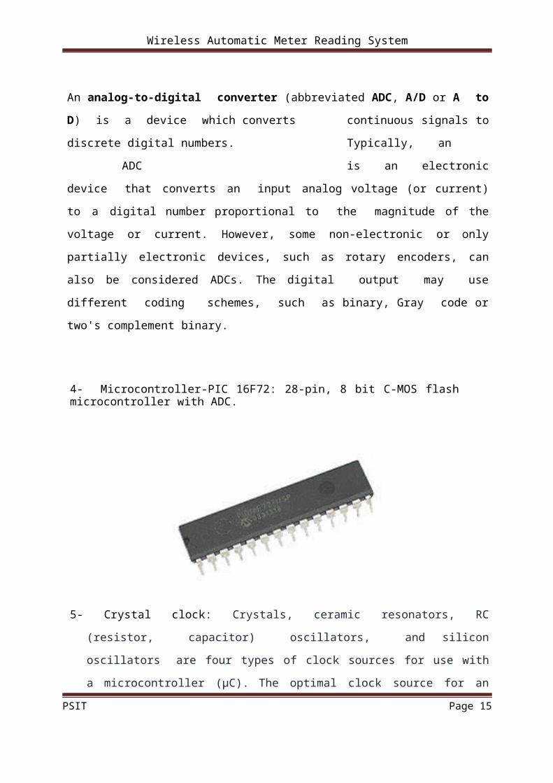
4- Microcontroller-PIC 16F72: 28-pin, 8 bit C-MOS flash microcontroller with ADC.
5- Crystal clock: Crystals, ceramic resonators, RC (resistor, capacitor) oscillators, and
silicon oscillators are four types of clock sources for use with a microcontroller (µC).
The optimal clock source for an application depends on many factors including cost,
accuracy, and environmental parameters.
PSIT Page 9
RF Receiver
Micro-controller LCD
CLOCK
Power
Wireless Automatic Meter Reading System
6- Power supply circuit
7- Radio frequency transmitter: 433 MHz RF Module-
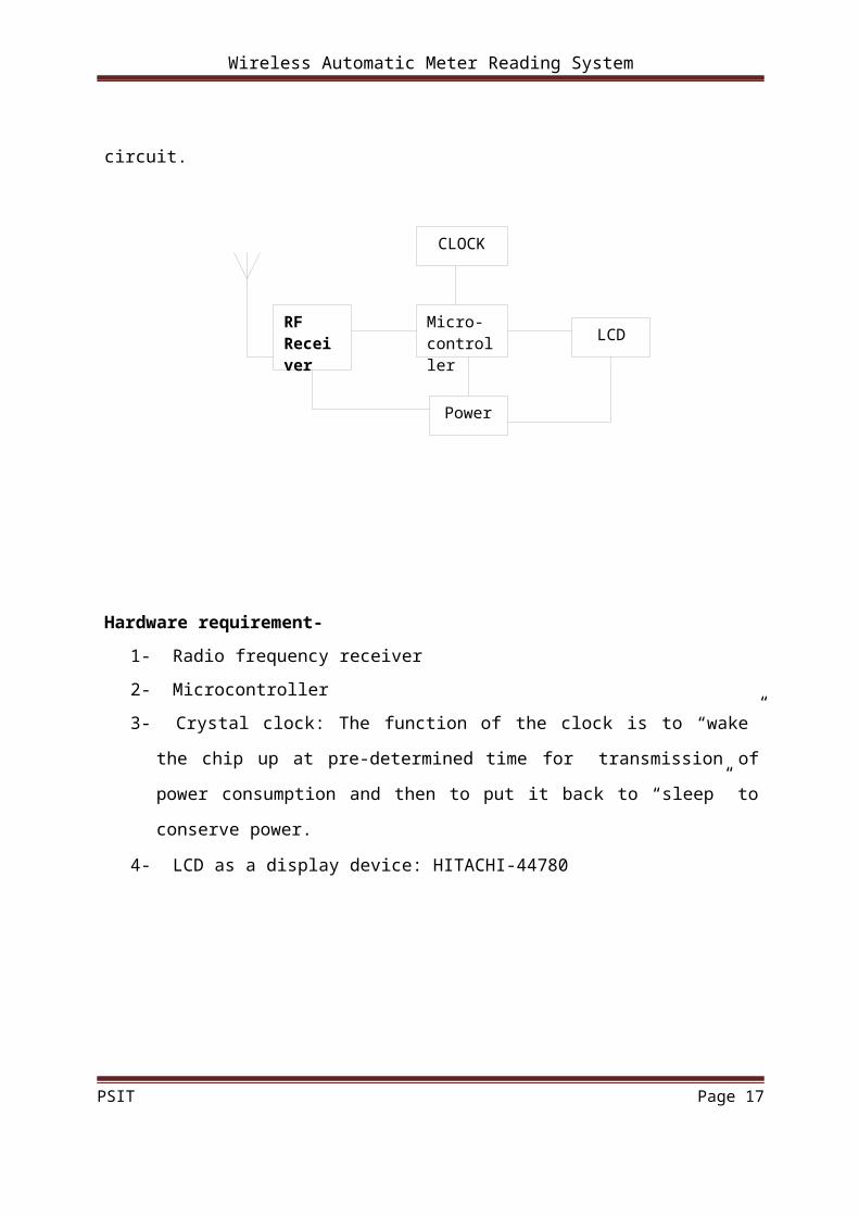
2.5 Receiver:
In this portion the employee or visitor of an electricity supply company has an
instrument that is known as receiver. According to dia. The RF receiver antenna receives the
transmitted signal and passes to microcontroller attached with the receiver .Microcontroller is
programmed to display or print the electricity meter reading and the bill of consumer. A LCD
is used as a display device and a mini digital printer is used as a printing device. The receiver,
microcontroller, LCD are connected to the power supply circuit.
PSIT Page 10

Wireless Automatic Meter Reading System
Hardware requirement-
1- Radio frequency receiver
2- Microcontroller
3- Crystal clock: The function of the clock is to “wake” the chip up at pre-determined
time for transmission of power consumption and then to put it back to “sleep” to
conserve power.
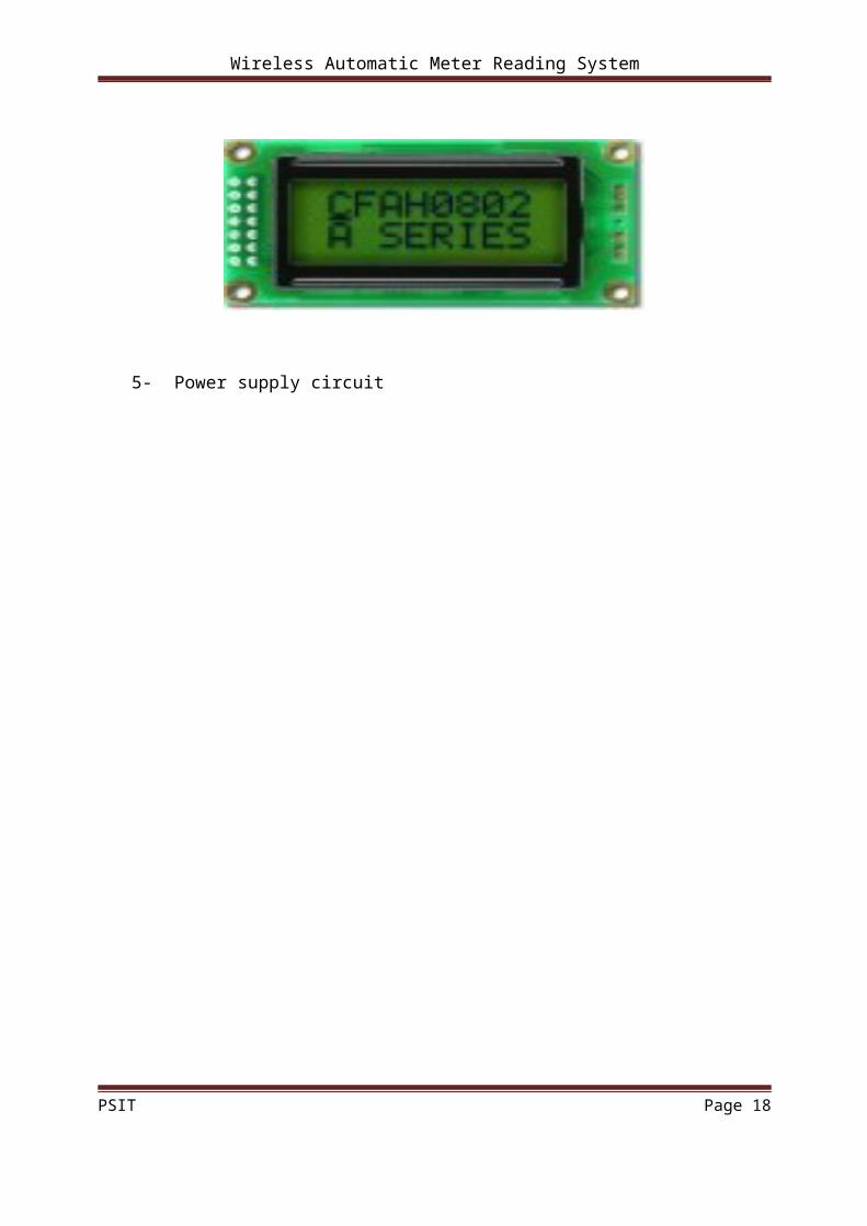
4- LCD as a display device: HITACHI-44780
5- Power supply circuit
PSIT Page 11

Wireless Automatic Meter Reading System
3.1 POWER SUPPLY
C H A P TE R 3
Power supply is the basic requirement of any electronics device. No device can work without
the energy source which is voltage in our case. So here we have used line voltage as a source
supply. We can also use battery as our source supply but it has certain limitations.
Normal power supply is of 220volts ac. But electronic IC’s can not handle such a high
voltage. So we have to convert this high ac voltage into a constant dc voltage supply. Step
down transformer is used for this purpose. In step down transformer the high-voltage winding
is the primary and the low– voltage winding is secondary. Step down transformers are used in
a broad range of applications to allow lower than line voltages to be used. Step down
transformers decrease incoming voltage from the power source. RMS manufactures a variety
of step down transformers and step up transformers (increases voltage from the incoming
power source).
It transforms 220v ac to 9v dc. The diode IN4007 is used at the output of the transformer
which rectifies the dc voltage.
This 9v supply can be used for running the relays but for driving the IC’s we want a 5v
supply so we have used a voltage regulator IC 7805 to regulate 9v into 5v.
PSIT Page 12

Wireless Automatic Meter Reading System
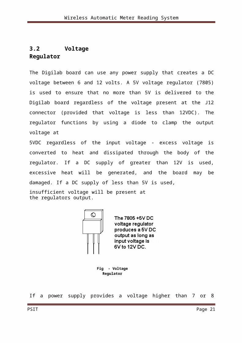
3.2 Voltage Regulator
The Digilab board can use any power supply that creates a DC voltage between 6 and 12
volts. A 5V voltage regulator (7805) is used to ensure that no more than 5V is delivered to
the Digilab board regardless of the voltage present at the J12 connector (provided that voltage
is less than 12VDC). The regulator functions by using a diode to clamp the output voltage at
5VDC regardless of the input voltage - excess voltage is converted to heat and dissipated
through the body of the regulator. If a DC supply of greater than 12V is used, excessive heat
will be generated, and the board may be damaged. If a DC supply of less than 5V is used,
insufficient voltage will be present at the regulators output.
Fig - Voltage Regulator
If a power supply provides a voltage higher than 7 or 8 volts, the regulator must dissipate
significant heat. The "fin" on the regulator body (the side that protrudes upward beyond the
main body of the part) helps to dissipate excess heat more efficiently. If the board requires
higher currents (due to the use of peripheral devices or larger breadboard circuits), then the
regulator may need to dissipate more heat. In this case, the regulator can be secured to the
circuit board by fastening it with a screw and nut (see below). By securing the regulator
tightly to the circuit board, excess heat can be passed to the board and then radiated away.
PSIT Page 13

Wireless Automatic Meter Reading System
Fig - Regulator Implemented on a PCB
We have used a L.E.D as an indicator that indicates the conversion of ac voltage into dc.
When the transformation is done the L.E.D glows and it continues to do so till there is supply
available for the ckt to work.
Fig - Power Supply Circuit
3.3 Output smoothing
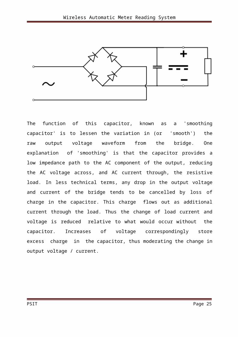
For many applications, especially with single phase AC where the full-wave bridge serves to
convert an AC input into a DC output, the addition of a capacitor may be important because
the bridge alone supplies an output voltage of fixed polarity but pulsating magnitude.
PSIT Page 14
Wireless Automatic Meter Reading System
The function of this capacitor, known as a 'smoothing capacitor' is to lessen the variation in
(or 'smooth') the raw output voltage waveform from the bridge. One explanation of
'smoothing' is that the capacitor provides a low impedance path to the AC component of the
output, reducing the AC voltage across, and AC current through, the resistive load. In less
technical terms, any drop in the output voltage and current of the bridge tends to be cancelled
by loss of charge in the capacitor. This charge flows out as additional current through the
load. Thus the change of load current and voltage is reduced relative to what would occur
without the capacitor. Increases of voltage correspondingly store excess charge in the
capacitor, thus moderating the change in output voltage / current.
PSIT Page 15

Wireless Automatic Meter Reading System
C H A P TE R 4
4.1 Transformer
A transformer is a device that transfers electrical
energy from one circuit to another through
inductively coupled wires. A changing current in
the first circuit (the primary) creates a changing
magnetic field; in turn, this magnetic field induces
a changing voltage in the second circuit (the
secondary). By adding a load to the secondary
circuit, one can make current flow in the
transformer, thus transferring energy from one
circuit to the other.
Fig- Laminated core transformer
The secondary induced voltage VS is scaled from the primary VP by a factor ideally
equal to the ratio of the number of turns of wire in their respective windings:
Wireless Automatic Meter Reading System
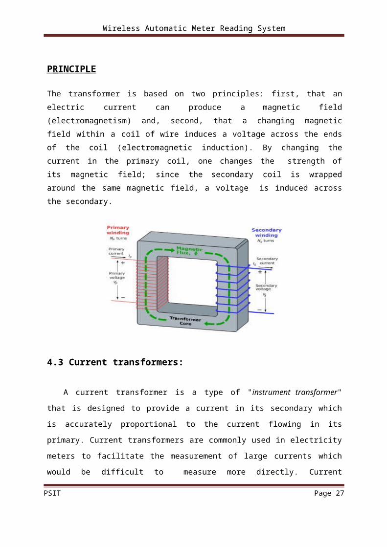
4.2 B AS I C P R I NC I P L E
The transformer is based on two principles: first, that an electric current can produce a
magnetic field (electromagnetism) and, second, that a changing magnetic field within a coil
of wire induces a voltage across the ends of the coil (electromagnetic induction). By changing
the current in the primary coil, one changes the strength of its magnetic field; since the
secondary coil is wrapped around the same magnetic field, a voltage is induced across the
secondary.
PSIT Page 16
Wireless Automatic Meter Reading System
4.3 Current transformers:
A current transformer is a type of "instrument transformer" that is designed to provide a
current in its secondary which is accurately proportional to the current flowing in its primary.
Current transformers are commonly used in electricity meters to facilitate the measurement of
large currents which would be difficult to measure more directly. Current transformers are
often constructed by passing a single primary turn (either an insulated cable or a copper bus
bar) through a well-insulated toroidal core wrapped with many turns of wire. Current
transformers are used extensively in the electrical power industry for monitoring of the power
grid. The "CT" is described by its current ratio from primary to secondary. Common
secondaries are 1 or 5 amperes. The winding often has several taps so that sensitivity to the
load may be altered in the future. Often multiple CT's will be installed as a "stack" for various
uses (for example, protection devices and revenue metering may use separate CTs). Specially
constructed "wideband current transformers" are also used (usually with an oscilloscope) to
measure waveforms of high frequency or pulsed currents. One type of specially constructed
wideband transformer provides a voltage output that is proportional to the measured current.
Another other type (called a Rogowski coil) requires an external integrator in order to provide
a voltage output that is proportional to the measured current. Care must be taken that the
secondary of a current transformer is not disconnected from its load while current is flowing
in the primary as in this circumstance a dangerously high voltage can be produced across the
open secondary.
PSIT Page 17
Wireless Automatic Meter Reading System
4.4 Voltage transformers:
Voltage transformers (also called potential transformers) are another type of "instrument
transformer". They are used by the electricity supply industry to accurately measure high
voltages for metering purposes. They are designed to have a precise turns ratio to accurately
step down dangerously high voltages so that metering equipment can be operated at a lower
(and safer) potential, typically 120 volts. They are designed to present negligible load to the
voltage being measured.
PSIT Page 18

Wireless Automatic Meter Reading System
C H A P TE R 5
LCD: HD44780U
5.1 Features:-
5 ×8 and 5 ×10 dot matrix possible Low power operation support:
2.7 to 5.5V
Wide range of liquid crystal display driver power 3.0 to 11V
Liquid crystal drive waveform Correspond to high speed MPU bus interface
2 MHz (when VCC = 5V)
4-bit or 8-bit MPU interface enabled 80 ×8-bit display RAM (80 characters max.) 9,920-bit character generator ROM for a total of 240 character fonts
208 character fonts (5 ×8 dot)
32 character fonts (5 ×10 dot)
64 ×8-bit character generator RAM8 character fonts (5 ×8 dot)
4 character fonts (5 ×10 dot)
16-common ×40-segment liquid crystal display driver Programmable duty cycles
1/8 for one line of 5 ×8 dots with cursor
1/11 for one line of 5 ×10 dots with cursor
1/16 for two lines of 5 ×8 dots with cursor
Wide range of instruction functions:Display clear, cursor home, display on/off, cursor on/off, display character blink, cursor shift, display shift
Pin function compatibility with HD44780S Automatic reset circuit that initializes the controller/driver after power on Internal oscillator with external resistors Low power consumption
PSIT Page 19
Wireless Automatic Meter Reading System
5.2 Character pattern development procedure :
The following operations correspond to the numbers listed in Figure below-
1. Determine the correspondence between character codes and character patterns.
2. Create a listing indicating the correspondence between EPROM addresses and data.
3. Program the character patterns into the EPROM.
4. Send the EPROM to Hitachi.
5. Computer processing on the EPROM is performed at Hitachi to create a character pattern
listing, which is sent to the user.
6. If there are no problems within the character pattern listing, a trial LSI is created at Hitachi
and samples are sent to the user for evaluation. When it is confirmed by the user that the
character patterns are correctly written, mass production of the LSI proceeds at Hitachi.
PSIT Page 20
Wireless Automatic Meter Reading System
PSIT Page 21

Wireless Automatic Meter Reading System
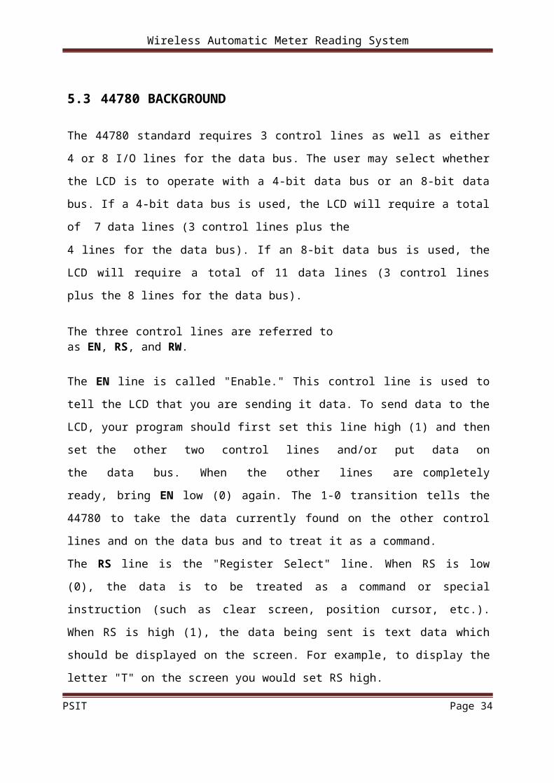
5.3 44780 BACKGROUND
The 44780 standard requires 3 control lines as well as either 4 or 8 I/O lines for the data bus.
The user may select whether the LCD is to operate with a 4-bit data bus or an 8-bit data bus.
If a 4-bit data bus is used, the LCD will require a total of 7 data lines (3 control lines plus the
4 lines for the data bus). If an 8-bit data bus is used, the LCD will require a total of 11 data
lines (3 control lines plus the 8 lines for the data bus).
The three control lines are referred to as EN, RS, and RW.
The EN line is called "Enable." This control line is used to tell the LCD that you are sending
it data. To send data to the LCD, your program should first set this line high (1) and then set
the other two control lines and/or put data on the data bus. When the other lines are
completely ready, bring EN low (0) again. The 1-0 transition tells the 44780 to take the data
currently found on the other control lines and on the data bus and to treat it as a command.
The RS line is the "Register Select" line. When RS is low (0), the data is to be treated as a
command or special instruction (such as clear screen, position cursor, etc.). When RS is high
(1), the data being sent is text data which should be displayed on the screen. For example, to
display the letter "T" on the screen you would set RS high.
The RW line is the "Read/Write" control line. When RW is low (0), the information on the
data bus is being written to the LCD. When RW is high (1), the program is effectively
querying (or reading) the LCD. Only one instruction ("Get LCD status") is a read command.
All others are write commands--so RW will almost always be low.
Finally, the data bus consists of 4 or 8 lines (depending on the mode of operation selected by
the user). In the case of an 8-bit data bus, the lines are referred to as DB0, DB1, DB2, DB3,
DB4, DB5, DB6, and DB7
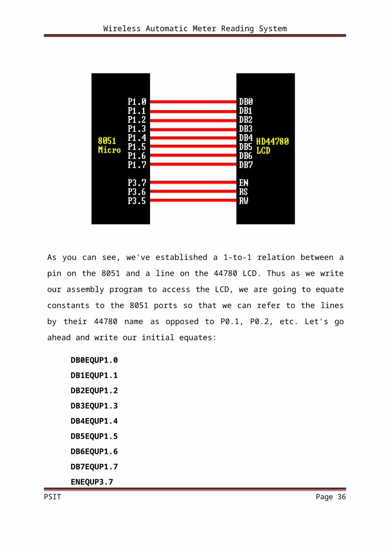
5.4 AN EXAMPLE HARDWARE CONFIGURATION
As we've mentioned, the LCD requires either 8 or 11 I/O lines to communicate with. For the
sake of this tutorial, we are going to use an 8-bit data bus--so we'll be using 11 of the 8051's
I/O pins to interface with the LCD.
PSIT Page 22

Wireless Automatic Meter Reading System
Let's draw a sample psuedo-schematic of how the LCD will be connected to the 8051.
As you can see, we've established a 1-to-1 relation between a pin on the 8051 and a line on
the 44780 LCD. Thus as we write our assembly program to access the LCD, we are going to
equate constants to the 8051 ports so that we can refer to the lines by their 44780 name as
opposed to P0.1, P0.2, etc. Let's go ahead and write our initial equates:
DB0EQUP1.0
DB1EQUP1.1
DB2EQUP1.2
DB3EQUP1.3
DB4EQUP1.4
DB5EQUP1.5
DB6EQUP1.6
DB7EQUP1.7
ENEQUP3.7
RSEQUP3.6
RWEQUP3.5
DATA EQU P1PSIT Page 23

Wireless Automatic Meter Reading System
Having established the above equates, we may now refer to our I/O lines by their 44780
name. For example, to set the RW line high (1), we can execute the following insutrction:
SETB RW
HAND LIN G THE EN C ON TR OL LIN E
As we mentioned above, the EN line is used to tell the LCD that you are ready for it to
execute an instruction that you've prepared on the data bus and on the other control lines.
Note that the EN line must be raised/lowered before/after each instruction sent to the LCD
regardless of whether that instruction is read or write, text or instruction. In short, you must
always manipulate EN when communicating with the LCD. EN is the LCD's way of knowing
that you are talking to it. If you don't raise/lower EN, the LCD doesn't know you're talking to
it on the other lines.
Thus, before we interact in any way with the LCD we will always bring the EN line high
with the following instruction:
SETB EN
And once we've finished setting up our instruction with the other control lines and data bus
lines, we'll always bring this line back low:
CLR EN
C HEC KIN G THE BU SY STA TU S OF THE LC D
As previously mentioned, it takes a certain amount of time for each instruction to be executed
by the LCD. The delay varies depending on the frequency of the crystal attached to the
oscillator input of the 44780 as well as the instruction which is being executed.
A more robust method of programming is to use the "Get LCD Status" command to
determine whether the LCD is still busy executing the last instruction received.
The "Get LCD Status" command will return to us two tidbits of information; the information
that is useful to us right now is found in DB7. In summary, when we issue the "Get LCD
PSIT Page 24
Wireless Automatic Meter Reading System
Status" command the LCD will immediately raise DB7 if it's still busy executing a command
or lower DB7 to indicate that the LCD is no longer occupied. Thus our program can query the
LCD until DB7 goes low, indicating the LCD is no longer busy. At that point we are free to
continue and send the next command.
I NI TIA LI ZIN G THE LC D
Before you may really use the LCD, you must initialize and configure it. This is
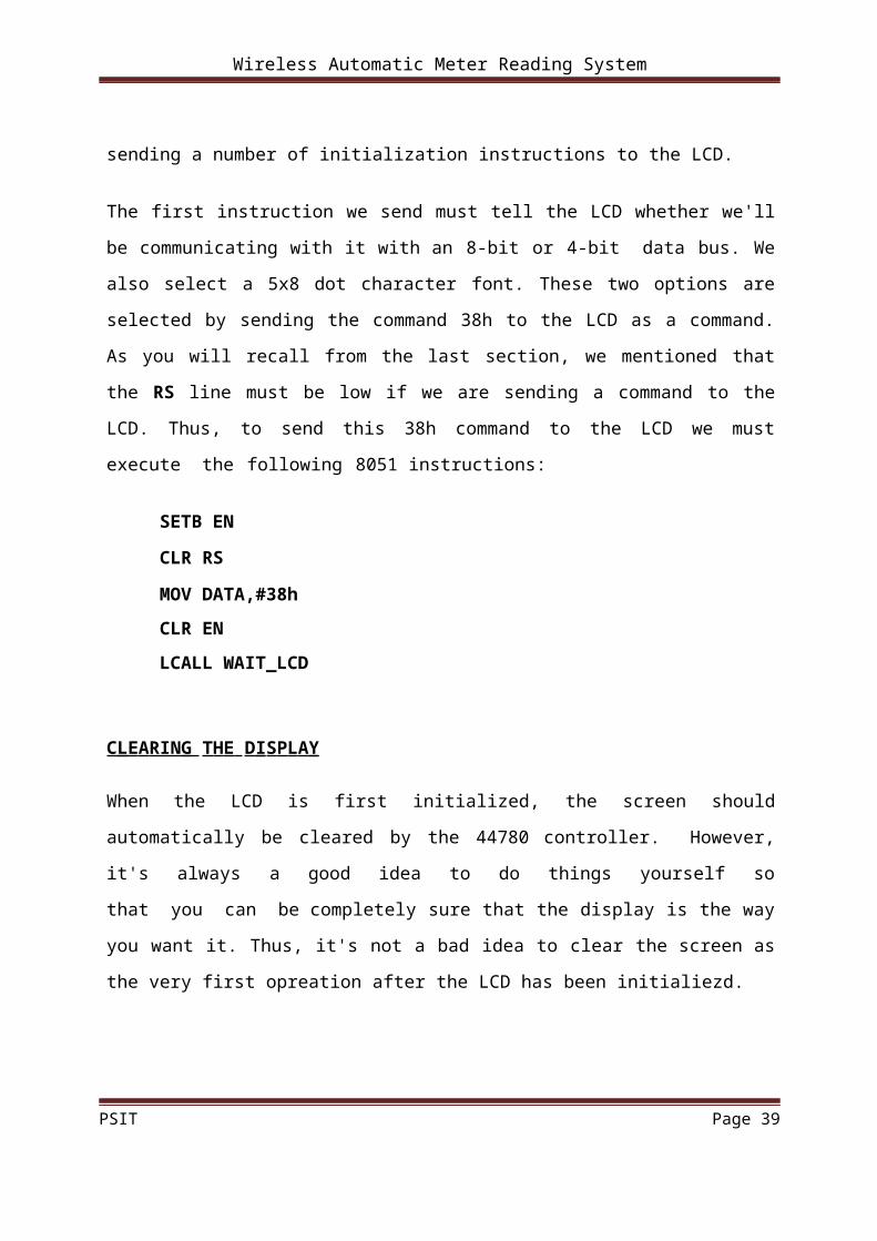
accomplished by sending a number of initialization instructions to the LCD.
The first instruction we send must tell the LCD whether we'll be communicating with it with
an 8-bit or 4-bit data bus. We also select a 5x8 dot character font. These two options are
selected by sending the command 38h to the LCD as a command. As you will recall from the
last section, we mentioned that the RS line must be low if we are sending a command to the
LCD. Thus, to send this 38h command to the LCD we must execute the following 8051
instructions:
SETB EN
CLR RS
MOV DATA,#38h
CLR EN
LCALL WAIT_LCD
C LEARIN G THE D ISPLA Y
When the LCD is first initialized, the screen should automatically be cleared by the 44780
controller. However, it's always a good idea to do things yourself so that you can be
completely sure that the display is the way you want it. Thus, it's not a bad idea to clear the
screen as the very first opreation after the LCD has been initialiezd.
PSIT Page 25

Wireless Automatic Meter Reading System
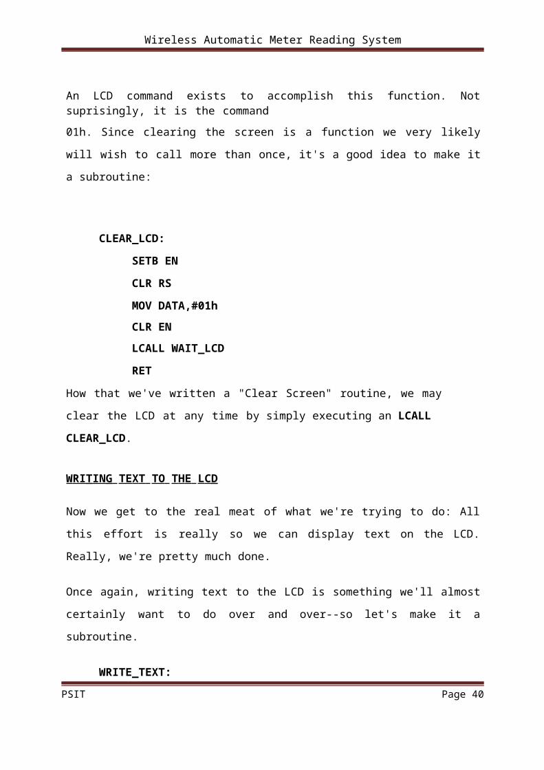
An LCD command exists to accomplish this function. Not suprisingly, it is the command
01h. Since clearing the screen is a function we very likely will wish to call more than once,
it's a good idea to make it a subroutine:
CLEAR_LCD:
SETB EN
CLR RS
MOV DATA,#01h
CLR EN
LCALL WAIT_LCD
RET
How that we've written a "Clear Screen" routine, we may clear the LCD at any time by
simply executing an LCALL CLEAR_LCD.
WRI TIN G TEXT TO THE LC D
Now we get to the real meat of what we're trying to do: All this effort is really so we can
display text on the LCD. Really, we're pretty much done.
Once again, writing text to the LCD is something we'll almost certainly want to do over and
over--so let's make it a subroutine.
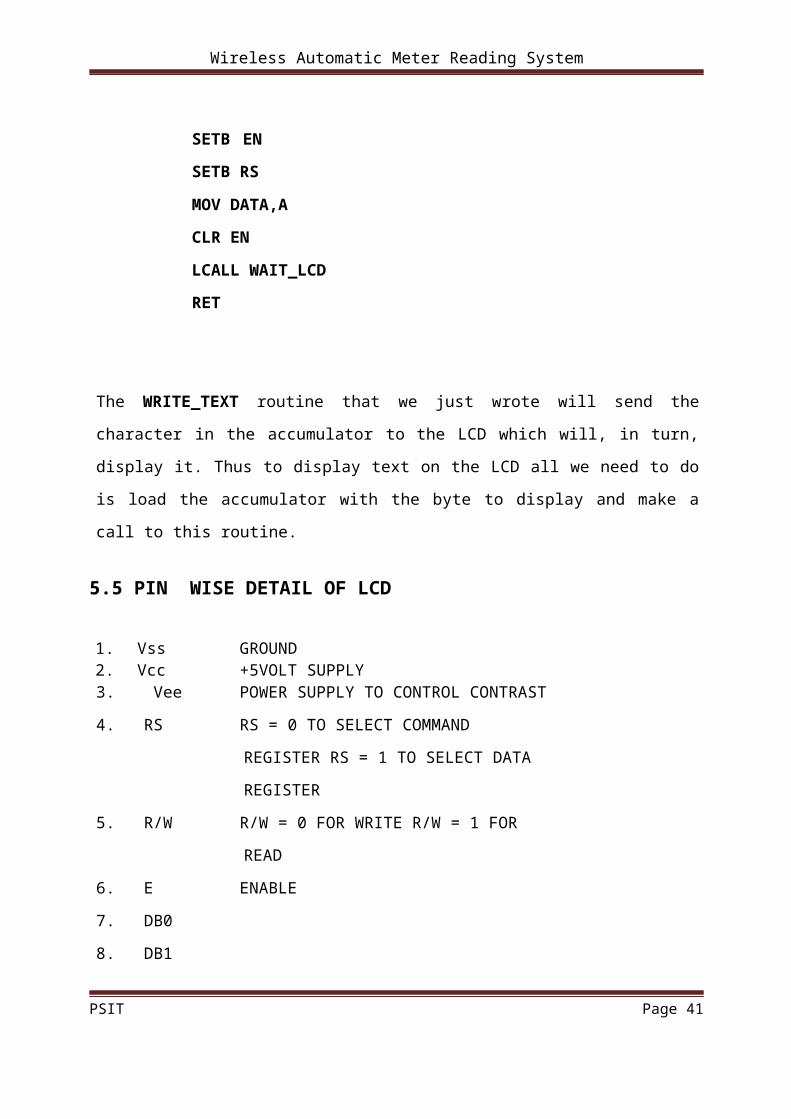
WRITE_TEXT:
SETB EN
SETB RS
MOV DATA,A
CLR EN
LCALL WAIT_LCD
RET
PSIT Page 26
Wireless Automatic Meter Reading System
The WRITE_TEXT routine that we just wrote will send the character in the accumulator to
the LCD which will, in turn, display it. Thus to display text on the LCD all we need to do is
load the accumulator with the byte to display and make a call to this routine.
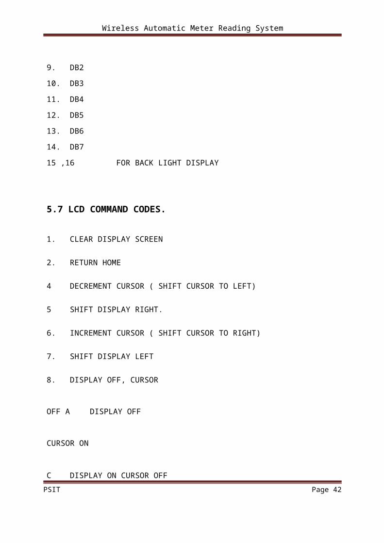
5.5 PIN WISE DETAIL OF LCD
1. Vss GROUND2. Vcc +5VOLT SUPPLY3. Vee POWER SUPPLY TO CONTROL
CONTRAST
4. RS RS = 0 TO SELECT COMMAND REGISTER
RS = 1 TO SELECT DATA REGISTER
5. R/W R/W = 0 FOR WRITE R/W = 1 FOR READ
6. E ENABLE
7. DB0
8. DB1
9. DB2
10. DB3
11. DB4
12. DB5
13. DB6
14. DB7
15 ,16 FOR BACK LIGHT DISPLAY
5.7 LCD COMMAND CODES.
1. CLEAR DISPLAY SCREEN
2. RETURN HOME
4 DECREMENT CURSOR ( SHIFT CURSOR TO LEFT)
PSIT Page 27

Wireless Automatic Meter Reading System
5 SHIFT DISPLAY RIGHT.
6. INCREMENT CURSOR ( SHIFT CURSOR TO RIGHT)
7. SHIFT DISPLAY LEFT
8. DISPLAY OFF, CURSOR OFF
A DISPLAY OFF CURSOR ON
C DISPLAY ON CURSOR OFF
E DISPLAY ON CURSOR BLINKING
F. DISPLAY ON CURSOR BLINKING.
10. SHIFT CURSOR POSITION TO LEFT
14. SHIFT CURSOR POSITION TO RIGHT
18. SHIFT THE ENTIRE DISPLAY TO THE LEFT
1C SHIFT THE ENTIRE DISPLAY TO THE RIGHT
80 FORCE CURSOR TO BEGINNING OF IST LINE
C0 FORCE CURSOR TO BEGINNING OF 2ND LINE
38 2 LINES AND 5 X 7 MATRIX
PSIT Page 28

Wireless Automatic Meter Reading System
CHAPTER-6
6.1 Micro controller:
In our day to day life the role of micro-controllers has been immense. They are used
in a variety of applications ranging from home appliances, FAX machines, Video games,
Camera, Exercise equipment, Cellular phones musical Instruments to Computers, engine
control, aeronautics, security systems and the list goes on.
MICROCONTROLLERS VERSUS MICROPROCESSORS
The microprocessors (such as 8086,80286,68000 etc.) contain no RAM, no ROM and
no I/O ports on the chip itself. For this reason they are referred as general- purpose
microprocessors. A system designer using general- purpose microprocessor must add external
RAM, ROM, I/O ports and timers to make them functional. Although the addition of external
RAM, ROM, and I/O ports make the system bulkier and much more expensive, they have the
advantage of versatility such that the designer can decide on the amount of RAM, ROM and I/o
ports needed to fit the task at hand. This is the not the case with microcontrollers. A
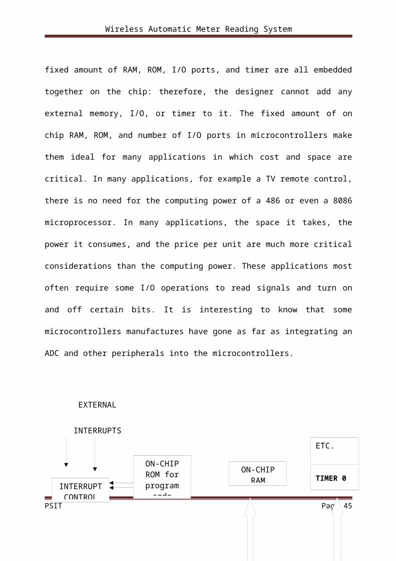
microcontroller has a CPU (a microprocessor) in addition to the fixed amount of RAM, ROM,
I/O ports, and timer are all embedded together on the chip: therefore, the designer cannot add
any external memory, I/O, or timer to it. The fixed amount of on chip RAM, ROM, and number
of I/O ports in microcontrollers make them ideal for many applications in which cost and space
are critical. In many applications, for example a TV remote control, there is no need for the
computing power of a 486 or even a 8086 microprocessor. In many applications, the space it
takes, the power it consumes, and the price per unit are much more critical considerations than
the computing power. These applications most often require some I/O operations to read signals
and turn on and off certain bits. It is interesting to know that some microcontrollers
PSIT Page 29
Wireless Automatic Meter Reading System
manufactures have gone as far as integrating an ADC and other peripherals into the
microcontrollers.
EXTERNAL
INTERRUPTS
TXD RXD
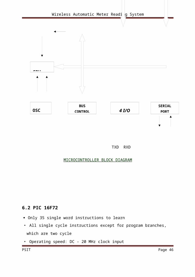
MICROCONTROLLER BLOCK DIAGRAM
PSIT Page 30
INTERRUPT CONTROL
ON-CHIP ROM for
program codeON-CHIP
RAM
ETC.
TIMER 0
SERIAL PORT4 I/O
BUS CONTROLOSC
CPU

Wireless Automatic Meter Reading System
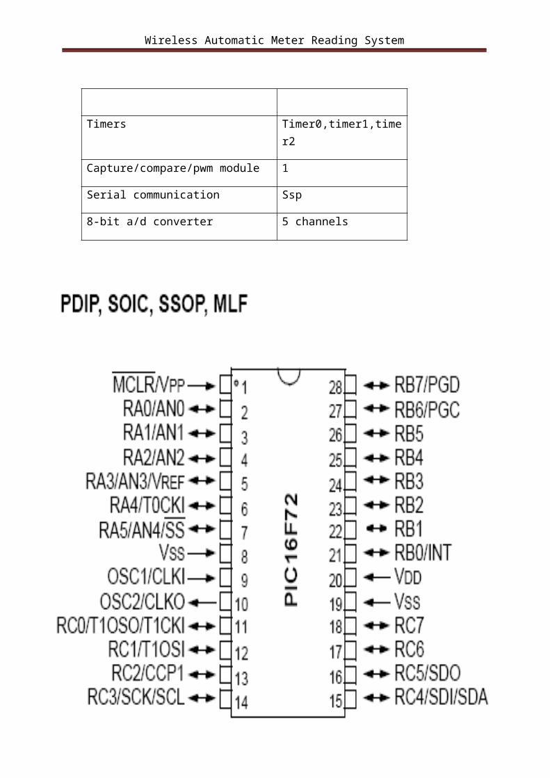
6.2 PIC 16F72
Only 35 single word instructions to learn
• All single cycle instructions except for program branches, which are two cycle
• Operating speed: DC - 20 MHz clock input
DC- 200 ns instruction cycle
• 2 K x 14 words of Program Memory,
128 x 8 bytes of Data Memory (RAM)
• Pinout compatible to PIC16C72/72A and PIC16F872
• Interrupt capability
• Eight-level deep hardware stack
• Direct, Indirect and Relative Addressing modes
Peripheral Features:1. High Sink/Source Current: 25 mA
2. Timer0: 8-bit timer/counter with 8-bit prescaler
3. Timer1: 16-bit timer/counter with prescaler, can be incremented during SLEEP via
external crystal/clock
4. Timer2: 8-bit timer/counter with 8-bit period register, prescaler and postscaler
5. Capture, Compare, PWM (CCP) module
- Capture is 16-bit, max. resolution is 12.5 ns
- Compare is 16-bit, max. resolution is 200 ns
- PWM max. resolution is 10-bit
6. 8-bit, 5-channel analog-to-digital converter
•Synchronous Serial Port (SSP)
•Brown-out detection circuitry for Brown-out Reset (BOR)
CMOS Technology
• Low power, high speed CMOS FLASH technology
• Fully static design
• Wide operating voltage range: 2.0V to 5.5V
• Industrial temperature range
• Low power consumption:
PSIT Page 31

Wireless Automatic Meter Reading System
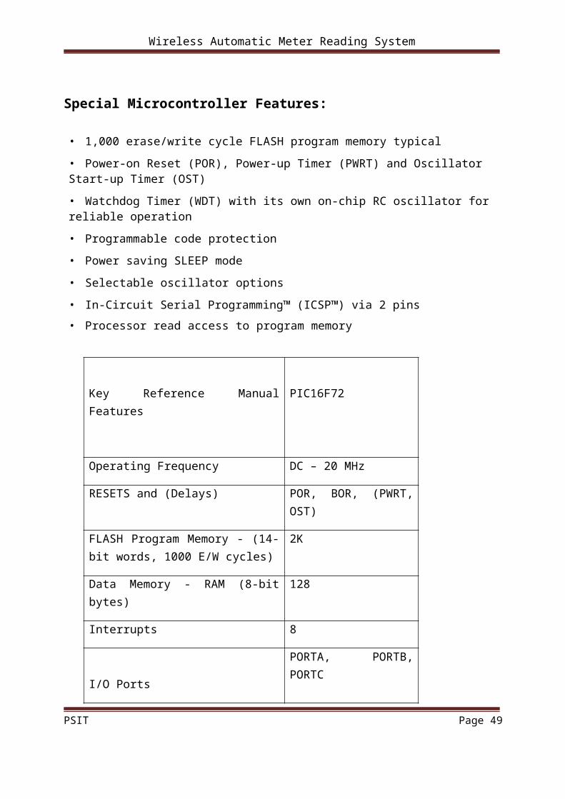
Special Microcontroller Features:
• 1,000 erase/write cycle FLASH program memory typical
• Power-on Reset (POR), Power-up Timer (PWRT) and Oscillator Start-up Timer (OST)
• Watchdog Timer (WDT) with its own on-chip RC oscillator for reliable operation
• Programmable code protection
• Power saving SLEEP mode
• Selectable oscillator options
• In-Circuit Serial Programming™ (ICSP™) via 2 pins
• Processor read access to program memory
Key Reference Manual Features PIC16F72
Operating Frequency DC – 20 MHz
RESETS and (Delays) POR, BOR, (PWRT, OST)
FLASH Program Memory - (14-bit words, 1000 E/W cycles)
2K
Data Memory - RAM (8-bit bytes) 128
Interrupts 8
I/O Ports
PORTA, PORTB, PORTC
Timers Timer0,timer1,timer2
Capture/compare/pwm module 1
Serial communication Ssp
8-bit a/d converter 5 channels
PSIT Page 32

Wireless Automatic Meter Reading System
Pin out Diagram
PSIT Page 33
Wireless Automatic Meter Reading System
PSIT Page 34

Wireless Automatic Meter Reading System
6.3 SPECIAL FUNCTION REGISTERS
The Special Function Registers are registers used by the CPU and peripheral modules
for controlling the desired operation of the device. These registers are implemented as static
RAM. A list of these registers is given in Table 2-1. The Special Function Registers can be
classified into two sets: core (CPU) and peripheral. Those registers associated with the core
functions are described in detail in this section. Those related to the operation of the
peripheral features are described in detail in the peripheral feature section.
SPECIAL FUNCTION REGISTER SUMMARY
I/O PORTS
PORTA and the TRISA Register
PORTA is a 6-bit wide, bi-directional port. The corresponding data direction register
is TRISA. Setting a TRISA bit (= 1) will make the corresponding PORTA pin an input (i.e.,
put the corresponding output driver in a Hi-Impedance mode). Clearing a TRISA bit (= 0)
will make the corresponding PORTA pin an output (i.e., put the contents of the output
latch on the selected pin). Reading the PORTA register, reads the status of the pins,
whereas writing to it will write to the port latch. All write operations are read-modify-
write operations.
Therefore, a write to a port implies that the port pins are read; this value is modified and then
written to the port data latch. Pin RA4 is multiplexed with the Timer0 module clock input to
become the RA4/T0CKI pin. The RA4/T0CKI pin is a Schmitt Trigger input and an open
drain output. All other RA port pins have TTL input levels and full CMOS output drivers.
Other PORTA pins are multiplexed with analog inputs and analog VREF input. The
operation of each pin is Selected by clearing /setting the control bits in the CON1
register (A/D Control Register1).
PSIT Page 35
Wireless Automatic Meter Reading System
6.4 BLOCK DIAGRAM OF RA3:RA0 AND RA5 PINS
Figure
6.5 BLOCK DIAGRAM OF RA4/T0CKI PIN
PSIT Page 36

Wireless Automatic Meter Reading System
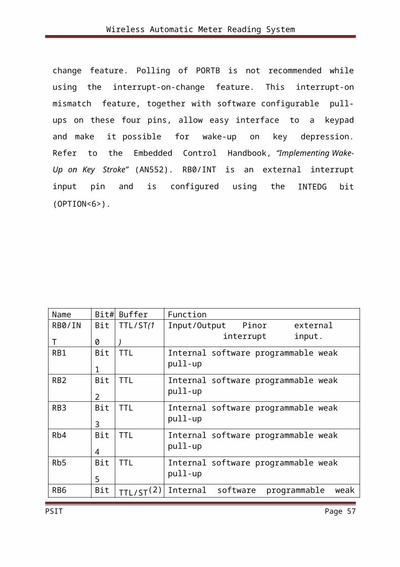
PORTB and the TRISB Register
PORTB is an 8-bit wide, bi-directional port. The corresponding data direction register
is TRISB. Setting a TRISB bit (= 1) will make the corresponding PORTB pin an input (i.e.,
put the corresponding output driver in a Hi-Impedance mode). Clearing a TRISB bit (= 0)
will make the corresponding PORTB pin an output (i.e., put the contents of the output latch
on the selected pin).Each of the PORTB pins has a weak internal pull-up. A single control bit
can turn on all the pull-ups. This is performed by clearing bit RBPU (OPTION<7>). The
Wireless Automatic Meter Reading System weak pull-up is automatically turned off when
the port pin is configured as an output. The pull-ups are disabled on a Power-on Reset. are
compared with the old value latched on the last read of PORTB. The “mismatch” outputs
of RB7:RB4 are OR’d together to generate the RB Port Change Interrupt with flag bit
RBIF (INTCON<0>).This interrupt can wake the device from SLEEP. The user, in the
Interrupt Service Routine, can clear the interrupt in the following manner:
a) Any read or write of PORTB. This will end the mismatch condition.
b) Clear flag bit RBIF.
A mismatch condition will continue to set flag bit RBIF. Reading PORTB will end
the mismatch condition and allow flag bit RBIF to be cleared. The interrupt-on-change
feature is recommended for wake-up on key depression operation and operations where
PORTB is only used for the interrupt-on-change feature. Polling of PORTB is not
recommended while using the interrupt-on-change feature. This interrupt-on mismatch
feature, together with software configurable pull-ups on these four pins, allow easy
interface to a keypad and make it possible for wake-up on key depression. Refer to
the Embedded Control Handbook, “Implementing Wake-Up on Key Stroke” (AN552).
RB0/INT is an external interrupt input pin and is configured using the INTEDG bit
(OPTION<6>).
PSIT Page 37

Wireless Automatic Meter Reading System
Name Bit# Buffer FunctionRB0/IN
T
Bit
0
TTL/ST(1
)
Input/Output Pin or external interrupt input.
Internal software programmable weak pull-upRB1 Bit
1
TTL Internal software programmable weak pull-up
RB2 Bit
2
TTL Internal software programmable weak pull-up
RB3 Bit
3
TTL Internal software programmable weak pull-up
Rb4 Bit
4
TTL Internal software programmable weak pull-up
Rb5 Bit
5
TTL Internal software programmable weak pull-up
RB6 Bit TTL/ST(2) Internal software programmable weak pull-up.
6 Serial programming clock.RB7 bit
7
TTL/ST(2) Internal software programmable weak pull-up.
Serial programming data.
6.6 BLOCK DIAGRAM OF RB3:RB0 PINS
Figure
PSIT Page 38
Wireless Automatic Meter Reading System
6.7 BLOCK DIAGRAM OF RB7:RB4 PINS
PSIT Page 39
Wireless Automatic Meter Reading System
PORTC and the TRISC Register
PORTC is an 8-bit wide, bi-directional port. The corresponding data direction register is
TRISC. Setting a TRISC bit (= 1) will make the corresponding PORTC pin an input (i.e., put
the corresponding output driver in a Hi-Impedance mode). Clearing a TRISC bit (= 0) will
make the corresponding PORTC pin an output (i.e., put the contents of the output latch on the
selected pin). PORTC is multiplexed with several peripheral functions PORTC pins have
Schmitt Trigger input buffers. When enabling peripheral functions, care should be taken
in defining TRIS bits for each PORTC pin. Some peripherals override the TRIS bit to
make a pin an out- put, while other peripherals override the TRIS bit to make a pin an input.
Since thTRIS bit override is in effect while the peripheral is enabled, read-modify- write
instructions (BSF, BCF, XORWF) with TRISC as destination should be avoided. The user
should refer to the corresponding peripheral section for the correct TRIS bit settings.
PORTC FUNCTIONS:NAME Bit# Buffer
Type
Function
RC0/T1OSO/T1CK
I
bit 0 ST Input/output port pin or Timer1 oscillator
output/Timer1 clock inputRC1/T1OSI bit 1 ST Input/output port pin or Timer1 oscillator
input.RC2/CCP1 bit 2 ST Input/output port pin or Capture1
input/Compare1 output/PWM1 output.RC3/SCK/SCL bit 3 ST RC3 can also be the synchronous serial clock
for both SPI and I2C modes.RC4/SDI/SDA bit 4 ST RC4 can also be the SPI Data In (SPI mode)
or data I/O (I2C mode).RC5/SDO bit 5 ST Input/output port pin or Synchronous Serial
Port data output.RC6 bit 6 ST Input/output port pin.RC7 bit 7 ST Input/output port pin.
PSIT Page 40
Wireless Automatic Meter Reading System
Transmission
When the R/W bit of the incoming address byte is set and an address match occurs, the
R/W bit of the SSPSTAT register is set. The received address is loaded into the SSPBUF
register. The ACK pulse will be sent on the ninth bit, and pin RC3/SCK/SCL is held low. The
transmit data must be loaded into the SSPBUF register, which also loads the SSPSR
register.Then pin RC3/SCK/SCL should be enabled by setting bit CKP (SSPCON<4>). The
master device must monitor the SCL pin prior to asserting another clock pulse. The slave
devices may be holding off the master device by stretching the clock. The eight data bits are
shifted out on the falling edge of the SCL input. This ensures that the SDA signal is valid
during the SCL high time.
An SSP interrupt is generated for each data transfer byte. Flag bit SSPIF must be cleared
in software and the SSPSTAT register is used to determine the status of the byte. Flag bit
SSPIF is set on the falling edge of the ninth clock pulse.As a slave-transmitter, the ACK
pulse from the masterreceiver is latched on the rising edge of the ninth SCL input pulse. If the
Wireless Automatic Meter Reading System
SDA line was high (not ACK), then the data transfer is complete. When the ACK is latched
by the slave device, the slave logic is reset (resets
SSPSTAT register) and the slave device then monitors for another occurrence of the START
bit. If the SDA line was low (ACK), the transmit data must be loaded into the SSPBUF
register, which also loads the SSPSR register. Then, pin RC3/SCK/SCL should be enabled by
setting bit CKP.
6.8 ANALOG-TO-DIGITAL CONVERTER (A/D) MODULE
The analog-to-digital (A/D) converter module has five inputs for the PIC16F72.
The A/D allows conversion of an analog input signal to a corresponding 8-bit digital number.
The output of the sample and hold is the input into the converter, which generates the result
via successive approximation. The analog reference voltage is software selectable to either
the device’s positive supply voltage (VDD) or the voltage level on the RA3/AN3/VREF
pin.The A/D converter has a unique feature of being able to operate while the device is in
SLEEP mode. To operate in SLEEP, the A/D conversion clock must be derived from the
PSIT Page 41
Wireless Automatic Meter Reading System
A/D’s internal RC oscillator.The A/D module has three registers:
• A/D Result Register ADRES
• A/D Control Register 0 ADCON0
• A/D Control Register 1 ADCON1
A device RESET forces all registers to their RESET state. This forces the A/D module
to be turned off and any conversion is aborted.The ADCON0 register, shown in Register 10-
1, controls the operation of the A/D module. The ADCON1 register, shown in Register 10-2,
configures the functions of the port pins. The port pins can be configured as analog inputs
(RA3 can also be a voltage reference) or a digital I/O.
The following steps should be followed for doing an A/D conversion:
1. Configure the A/D module:
• Configure analog pins/voltage reference and digital I/O (ADCON1)
• Select A/D input channel (ADCON0)
• Select A/D conversion clock (ADCON0)
• Turn on A/D module (ADCON0)
2. Configure A/D interrupt (if desired):
• Clear ADIF bit
• Set ADIE bit
• Set GIE bit
3. Wait the required acquisition time.
4. Start conversion:
• Set GO/DONE bit (ADCON0)
5. Wait for A/D conversion to complete, by either:
• Polling for the GO/DONE bit to be cleared
OR
• Waiting for the A/D interrupt
6. Read A/D Result register (ADRES), clear bit ADIF if required.
7. For next conversion, go to step 1 or step 2 as required. The A/D conversion time per bit is
defined as TAD.
PSIT Page 42

Wireless Automatic Meter Reading System
6.9 SPECIAL FEATURES OF THE CPU
These devices have a host of features intended to maximize system reliability,
minimize cost through elimination of external components, provide power saving Operating
modes and offer code protection:
• Oscillator Selection
• RESET
- Power-on Reset (POR)
- Power-up Timer (PWRT)
- Oscillator Start-up Timer (OST)
- Brown-out Reset (BOR)
• Interrupts
• Watchdog Timer (WDT)
• SLEEP
• Code Protection
• ID Locations
• In-Circuit Serial Programming
These devices have a Watchdog Timer, which can be enabled or disabled using a
configuration bit. It runs off its own RC oscillator for added reliability.There are two timers
that offer necessary delays on power-up. One is the Oscillator Start-up Timer (OST),intended PSIT Page 43

Wireless Automatic Meter Reading System
to keep the chip in RESET until the crystal oscillator is stable. The other is the Power-up
Timer (PWRT), which provides a fixed delay of 72 ms (nominal) on power-up only. It is
designed to keep the part in RESET while the power supply stabilizes, and is enabled or
disabled using a configuration bit. With these two timers on-chip, most applications need no
external RESET circuitry.SLEEP mode is designed to offer a very low current Power-down
mode. The user can wake-up from SLEEP through external RESET, Watchdog Timer Wake-
up, or through an interrupt.Several oscillator options are also made available to allow the part
to fit the application. The RC oscillator option saves system cost while the LP crystal option
saves power Configuration bits are used to select the desired oscillator mode.
Configuration Bits
The configuration bits can be programmed (read as‘0’), or left unprogrammed (read as
‘1’), to select various device configurations. These bits are mapped in program memory
location 2007h.The user will note that address 2007h is beyond the user program memory
space, which can be accessed only during programming.
6.10 Oscillator Configurations
OSCILLATOR TYPES
The PIC16F72 can be operated in four different Oscillator modes. The user can
program two configuration bits (FOSC1 and FOSC0) to select one of these four modes:
• LP Low Power Crystal
• XT Crystal/Resonator
• HS High Speed Crystal/Resonator
• RC Resistor/Capacitor
CRYSTAL OSCILLATOR/CERAMIC RESONATORS
In XT, LP or HS modes, a crystal or ceramic resonator is connected to the OSC1/CLKI
and OSC2/CLKO pins to establish. The PIC16F72 oscillator design requires the use of a
PSIT Page 44
Wireless Automatic Meter Reading System
parallel cut crystal.Use of a series cut crystal may give a frequency out of the crystal
manufacturers specifications.
Figure- CRYSTAL/CERAMIC RESONATOR OPERATION (HS, XT OR LP OSC CONFIGURATION)
Figure- EXTERNAL CLOCK INPUT OPERATION (HS OSC CONFIGURATION)
PSIT Page 45
Wireless Automatic Meter Reading System
CERAMIC RESONATORS (FOR DESIGN GUIDANCE ONLY)
MCLR
PIC16F72 device has a noise filter in the MCLR Reset path. The filter will detect and ignore
small pulses. It should be noted that a WDT Reset does not drive MCLR pin low. The
behavior of the ESD protection on the MCLR pin has been altered from previous devices of
this family. Voltages applied to the pin that exceed its specification can result in both MCLR
and excessive current beyond the device specification during the ESD event. For this reason,
Microchip recommends that the MCLR pin no longer be tied directly to VDD. The use of an
RC network, as shown in Figure, is suggested.
PSIT Page 46

Wireless Automatic Meter Reading System
Figure -Recommended MCLR Circuit
Power-on Reset (POR)A Power-on Reset pulse is generated on-chip when VDD rise is detected (in the range of
1.2V - 1.7V). To take advantage of the POR, tie the MCLR pin to VDD. A maximum rise
time for VDD is specified. When the device starts normal operation (exits the RESET
condition), device operating parameters (voltage, frequency, temperature...) must be met to
ensure operation. If these conditions are not met, the device must be held in RESET until the
operating conditions are met.
Power-up Timer (PWRT)
The Power-up Timer provides a fixed 72 ms nominal time-out on power-up only from the
POR. The Power up Timer operates on an internal RC oscillator. The chip is kept in RESET
as long as the PWRT is active. The PWRT’s time delay allows VDD to rise to an acceptable
level. A configuration bit is provided to enable/disable the PWRT. The power-up time delay
will vary from chip to chip due to VDD, temperature and process variation. See DC
parameters for details (TPWRT, parameter #33).
Oscillator Start-up Timer (OST)
The Oscillator Start-up Timer (OST) provides 1024 oscillator cycles (from OSC1 input)
delay after the PWRT delay is over (if enabled). This helps to ensure that the crystal
oscillator or resonator has started and stabilized.
PSIT Page 47

Wireless Automatic Meter Reading System
The OST time-out is invoked only for XT, LP and HS modes and only on Power-on Reset or
wake-up from SLEEP.
Brown-out Reset (BOR)
The configuration bit, BOREN, can enable or disable the Brown-out Reset circuit. If VDD
falls below VBOR (parameter D005, about 4V) for longer than TBOR (parameter #35, about
100 s), the brown-out situation will reset the device. If VDD falls below VBOR for less
than TBOR, a RESET may not occur. Once the brown-out occurs, the device will remain in
Brown-out Reset until VDD rises above VBOR. The Power-up Timer then keeps the device
in RESET for TPWRT (parameter #33, about 72 ms). If VDD should fall below VBOR
during TPWRT, the Brown-out Reset process will restart when VDD rises above VBOR,
with the Power-up Timer Reset. The Power-up Timer is always enabled when the Brown-out
Reset circuit is enabled, regardless of the state of the PWRT configuration bit
PSIT Page 48
Wireless Automatic Meter Reading System
C HA PTE R 7
7.1 Radio Frequency module:
Radio frequency, or RF, is a frequency or rate of oscillation within the range of about 3 Hz
and 30 GHz. This range corresponds to frequency of alternating current electrical signals
used to produce and detect radio waves. Since most of this range is beyond the vibration rate
that most mechanical systems can respond to, RF usually refers to oscillations in electrical
circuits.
Special Properties of RF Electrical Signals:
Electrical signals that oscillate at RF have special properties that arise out of electromagnetic
forces that do not affect direct current signals. One property arises out of electromagnetic
forces that drive the RF current to the surface of conductors, known as the skin effect.
Another property is its ability to appear to flow through paths that contain insulating material,
like the dielectric insulator of a capacitor. The degree of effect of these properties depend on
the frequency of the signals.
7.2 Radio control:Radio control is the use of radio signals to remotely control another device. The term
is used frequently to refer to the control of model cars, boats, airplanes, and helicopters from
a user-held control box (radio.) Industrial, military and scientific research all make use of
radio-controlled vehicles as well.
Today radio control is used in industry for such devices as overhead cranes and
switchyard locomotives. Radio-controlled teleoperators are used for such purposes as
inspections, and special vehicles for disarming of bombs. Some remotely-controlled devices
are loosely called robots, but are more properly categorized as teleoperators since they do not
operate autonomously, but only under control of a human operator.
Short for radio frequency, any frequency within the electromagnetic spectrum
associated with radio wave propagation. When an RF current is supplied to an antenna, an
electromagnetic field is created that then is able to propagate through space. Many wireless
PSIT Page 49
Wireless Automatic Meter Reading System
technologies are based on RF field propagation
These frequencies make up part of the electromagnetic radiation spectrum:
Ultra-low frequency (ULF) -- 0-3 Hz
Extremely low frequency (ELF) -- 3 Hz - 3 kHz
Very low frequency (VLF) -- 3kHz - 30 kHz
Low frequency (LF) -- 30 kHz - 300 kHz
Medium frequency (MF) -- 300 kHz - 3 MHz
High frequency (HF) -- 3MHz - 30 MHz
Very high frequency (VHF) -- 30 MHz - 300 MHz
Ultra-high frequency (UHF)-- 300MHz - 3 GHz
Super high frequency (SHF) -- 3GHz - 30 GHz
Extremely high frequency (EHF) -- 30GHz - 300 GHz
7.3 RF Transmitter module:
Radio transmitter design is a complex topic, which can be broken down into a series of
smaller topics. A radio communication system requires two tuned circuits each at the
transmitter and receiver, all four tuned to the same frequency. The transmitter is an electronic
device which, usually with the aid of an antenna, propagates an electromagnetic signal such
as radio, television, or other telecommunications.
The TWS-434 and RWS-434 are extremely small, and are excellent for applications
requiring short-range RF remote controls. The transmitter module is only 1/3 the size of a
standard postage stamp, and can easily be placed inside a small plastic enclosure.
TWS-434: The transmitter output is up to 8mW at 433.92MHz with a range of
approximately 400 foot (open area) outdoors. Indoors, the range is approximately 200 foot,
and will go through most walls.
PSIT Page 50

Wireless Automatic Meter Reading System
7.4 RF Receiver module:
RWS-434: The receiver also operates at 433.92MHz, and has a sensitivity of 3uV. The
RWS-434 receiver operates from 4.5 to 5.5 volts-DC, and has both linear and digital outputs.
RWS-434 Receiver
For maximum range, the recommended antenna should be approximately 35cm long. To
convert from centimeters to inches -- multiply by 0.3937. For 35cm, the length in inches will
be approximately 35cm x 0.3937 = 13.7795 inches long. We tested these modules using a
14", solid, 24 gauge hobby type wire, and reached a range of over 400 foot.
PSIT Page 51

Wireless Automatic Meter Reading System
PSIT Page 52

Wireless Automatic Meter Reading System
C HA PTE R 8
8.1 TRANSMITTER PORTION PROGRAMMING
device 16f72
xtal = 4
input porta
output portb
output portc
declare serial_baud 300
declare rsout_pin portc.7
dim a,b as byte
loop:
a=adin 0
delayms 20
b=adin 1
delayms 20
rsout "a"
rsout "b"
goto loop
PSIT Page 53
Wireless Automatic Meter Reading System
8.2 RECIEVER PORTION PROGRAMMING
device 16f72 xtal =
4 input porta
output portb
input portc
declare serial_baud 300
declare rsin_pin portc.0
dim a,p as byte
cls
loop:
a=rsin
print at 1,1,"WIR ENERGY METER"
p=a*b
print at 2,1,"P="&p
delayms 2000
print at 2,1,"V="&a
delayms 2000
print at 2,1,"I=mA"&b
delayms 2000
goto loop
PSIT Page 54

Wireless Automatic Meter Reading System
C H A P TE R 9
9.1 Advantages:
The energy monitor can be one of five different kinds of meters, depending on its
configuration. The firmware of all the five meters will reside in one energy monitor. Based
on configuration, it can be a Fan Coil Monitor or Heat Meter or Pulse Meter or Run Timer or
Energy Meter. The data that will be transmitted will be different in different cases. The
benefits of the project are given below:
• Standards based solution without the drawbacks of proprietary wireless systems that include
complexity, risk of relying on a single vendor and relatively higher system cost.
• Reliable, self healing, easy to deploy network supporting two nodes.
• Efficient power management, leading to very long battery life.
• Low cost solution
9.2 Future aspect:
In this report a wireless energy metering device is described which allows the
visualization of power consumption of electrical devices like a TV or washing machine in
real time. The current system enables residents to have an immediate overview about the
actual and short term history power consumption. Future work will include developments
towards automatic and remote control of devices. A further approach could be that once a day
accumulated data is sent from the household to the energy provider. This gives the energy
provider the opportunity to better calculate the needed. Regarding the future uses following
points are given below-
This project gives rise a new revolution in wireless meter reading technology. If we use a GPS
module between transmitter and receiver then we can check the reading of a consumer
house meter from the electricity supply office or from any where we want.
PSIT Page 55

Wireless Automatic Meter Reading System
9.3 Applications
1. In future we can also provide the facility that if the bill of the consumer is not paid
then you can also cut the power supply from the supply office wirelessly.
2. With the help of this module you can easily see the bills and readings on the
computers in electricity supply office.
3. With the help of this project we can easily measure and control the use of electrical
energy of the nation.
We have a diagram based on future applications of WAMRS-
PSIT Page 56
Wireless Automatic Meter Reading System
9.4 REFERENCES:
[1] X. Jiang, S.Dawson-Haggerty, J. Taneja, P. Dutta and D. Culler, Demo Abstract:
Creating Greener Homes with IP-Based Wireless AC Energy Monitors, Proceedings of the
6th ACM conference on Embedded network sensor systems, SENSYS 2008, Pages 355-356
[2] D. R. Muñoz, D. M. Pérez, J. S. Moreno, S. C. Berga, E. C. Montero, Design and
experimental verification of a smart sensor to measure the energy and power consumption in
a one-phase AC line, Elsevier Journal of the International Measurement Confederation
(IMEKO), Measurement 42 (2009) 412–419
[3] P. M. Jansson, J. Tisa, W. Kim, Instrument and Measurement Technology Education
—A Case Study: Inexpensive Student-Designed Power Monitoring Instrument for Campus
Submetering, IEEE TRANSACTIONS ON INSTRUMENTATION AND
MEASUREMENT, VOL. 56, NO. 5, OCTOBER 2007
[4] [1] IEEE 802.15.4.4 – Homepage, The Institute of Electrical and Electronics
Engineers, Inc., February 2007, http://www.ieee802.org/15/pub/TG4.html IEEE 802.15.2
Standard.
[5] ICradio Module 2.4G Product Homepage, In-Circuit GmbH,
http://www.ic-board.de/product_info.php?info=p4_ICradio-Module-2-4G.html, May 2009
[6] ADE 7753 Product Homepage, Analog Devices, Inc,
http://www.analog.com/en/analog-to-digital-converters/energymeasurement/
ADE7753/products/product.html, May 2009
[7] Maxim-IC. Ds2438 smart battery monitor.
http://datasheets.maxim-ic.com/en/ds/DS2438.pdf, July 2005.
[8] Microchip. Energy metering ic.
http://ww1.microchip.com/downloads/en/DeviceDoc/21948c.pdf,Aug. 2005.
[9] www.wikipedia.com
PSIT Page 57