project contract no. 036851 esonet european seas...
TRANSCRIPT

Project contract no. 036851
ESONET
European Seas Observatory Network
Instrument: Network of Excellence (NoE) Thematic Priority: 1.1.6.3 – Climate Change and Ecosystems
Sub Priority: III – Global Change and Ecosystems
Project Deliverable D27 Recommendations for marine science
observatory intervention
Due date of deliverable: Month 23 Actual submission date: February 2009
Start date of project: March 2007 Duration: 48 months Project coordinator : Roland Person Organisation name : Ifremer, France Work Package 2 Organization name of lead contractor for this deliverable : Ifremer Lead author for this deliverable: Jean-François DROGOU
Revision 1
Project co-funded by the European Commission within the Sixth Framework Programme (2002-2006) Dissemination Level
PU Public PP Restricted to other programme participants (including the Commission Services RE Restricted to a group specified by the consortium (including the Commission Services) x CO Confidential, only for members of the consortium (including the Commission Services)
ESONET NoE – Deliverable D27 / Recommendations for marine science observatory intervention
___________________________________________________________________________ Marine_Science_Observatory_Intervention_22 Feb 2009 2
CONTENTS
EXECUTIVE SUMMARY ......................................................................................................5
1. INTRODUCTION ................................................................................................................6
2. TERMINOLOGY .................................................................................................................8
3. APPLICABLE DOCUMENTS ........................................................................................8
4. GENERAL .............................................................................................................................9
5. SITE SURVEYS ................................................................................................................16
6. DEPLOYMENT & RECOVERY OPERATIONS ....................................................18
6.1 – INTRODUCTION ...........................................................................................................18
6.2 - DEPLOYMENT OF HEAVY OBU BY CABLE LIFTING AND LOWERING ..................20 6.2.1 Offshore standards and practices .................................................................................................21
6.3 – NEUTRAL (OR ALMOST NEUTRAL ) OBU DEPLOYMENT ......................................27 6.3.1 Offshore standards and practices .................................................................................................27 6.3.2 Existing scientific solutions............................................................................................................27
6.4 - BUOY DEEP MOORING DEPLOYMENT ......................................................................33
7. CABLES LAYING AND UNDERWATER CONNECTIONS .............................38
7.1 - GENERAL ......................................................................................................................38
7.2 - OFFSHORE STANDARDS AND PRACTICES ..............................................................39
7.3 - EXISTING SCIENTIFIC SOLUTIONS ............................................................................39
7.4 - RECOMMENDATIONS ..................................................................................................44
8. INSPECTION & MAINTENANCE WORK ..............................................................45
8.1 – GENERAL .....................................................................................................................45
8.2 - OFFSHORE STANDARDS AND PRACTICES ..............................................................48
8.3 - EXISTING SCIENTIFIC SOLUTIONS ............................................................................48
8.4 - RECOMMENDATIONS FOR SCIENTIFIC INTERVENTION ..........................................49 8.4.1 Compatibility for sharing platforms and ships ...............................................................................49 8.4.2 Tool sharing on ROVs, compatible user interfaces......................................................................52 8.4.3 Design process.............................................................................................................................52 8.4.4 Interfaces on observatory.............................................................................................................53 8.4.5 ROV stabilisation.........................................................................................................................56 8.4.6 ROV intervention with a tool deployment unit (TDU) ...................................................................56 8.4.7 Procedures ...................................................................................................................................57 8.4.8 Tests and training.........................................................................................................................57
9. DESIGN RECOMMENDATIONS FOR TRAINING, SIMULATION AND TESTING ..................................................................................................................................58
9.1 - GENERAL ......................................................................................................................58
9.2 - MANIPULATION TRAINING ..........................................................................................58
9.3 – VIRTUAL OPERATIONS TRAINING AND TESTING ...................................................58
9.4 – SCIENTISTS OPERATIONAL TRAINING ....................................................................59
10. CONCLUSIONS AND GENERAL RECOMMENDATIONS ...........................60

ESONET NoE – Deliverable D27 / Recommendations for marine science observatory intervention
___________________________________________________________________________ Marine_Science_Observatory_Intervention_22 Feb 2009 3
REFERENCES: 60

ESONET NoE – Deliverable D27 / Recommendations for marine science observatory intervention
___________________________________________________________________________ Marine_Science_Observatory_Intervention_22 Feb 2009 4
APPENDICES
- Appendix 1: Standards and recommended practices for underwater intervention and structures interfaces in the Offshore industry – Table of contents
- Appendix 2: Existing standards in Offshore Oil & gas industry
- Appendix 3: Examples of Ocean Bottom Unit deployment in Ifremer
- Appendix 4: ISO 13628-8 – Table of contents
- Appendix 5: Compatibility for sharing platforms and ships: specification form
- Appendix 6: Compatibility between ROVs (Tooling and payloads): specification form
- Appendix 7: Procedure demands for underwater intervention and quality assurance : procedure checklist
Note of prior importance Subject to the obligation towards all and any user to respect ISO/AFNOR copyright regarding this document and the obligation for documentary use of these standards only for internal purpose without the possibility of dissemination in whole or part and in what so ever form towards third parties

ESONET NoE – Deliverable D27 / Recommendations for marine science observatory intervention
___________________________________________________________________________ Marine_Science_Observatory_Intervention_22 Feb 2009 5
EXECUTIVE SUMMARY The series of reports “Specification report for demonstration actions - …” are meant to support the work of the operators of the ESONET demonstration missions. Together with the deliverable “Report of testing facilities survey” they are containing recommendations and guidelines in regard to implementing best practices into the preparation, deployment and operation work of the ESONET demonstration missions. It can be seen as a first step towards introducing quality management principles into ocean observatory field work. The “Specification report for demonstration actions – quality assurance” is defining the framework for the other documents explaining the high level principles underlying the other reports. All documents will undergo revisions based on the feedback of demo mission operators. It is not expected that with these documents a comprehensive quality management system can be set in place. However, it can be expected that this first step into this direction will provide valuable information about how to implement these principles into ocean observatory work. To support the European integration of regional ocean observatory it will be of importance to follow recommended procedures that are based on the experience of the involved partner institutions. To fix these procedures is the main intention of the series of the reports and by this it will enable the future definition of an ESONET label that essentially describes a certification process. To optimise intervention time and efficiency, as well as to ensure the interoperability of the various user’s equipment, ESONET NoE WP2 has identified in the 2008 Best Practices workshop various levels of interoperability, for work tasks definition [A3]:
- Precise technical conditions for enlarging/increasing the number and flexibility of welcoming vessels: such an action will guarantee that any European ROVs could be easily launched from several European ships, in order to avoid unnecessary transit times and/or transport costs.
- Facilitate exchanges of sensors, equipments, payloads on the different vehicles, by “standard” interfaces.
- Provide the scientific users and operators with standard qualified procedures or recommended practices to operate equipment in a safe and productive way.
- Provide recommendations for training (crew) and testing (procedures) The first two items will be now mainly covered by different European initiatives (Ocean Facilities Exchange Group (OFEG) – EUROFLEETS 2008). The present document proceeds on the work carried out during the Best Practice Workshop in Breme, by completing the frames concerning the existing ships and ROVs, and giving a first review of a minimum set of compatibility specifications concerning the installations onboard different vessels, and the tools/payload sharing between ROVs. The following document is mainly focusing on the two last items, and is representing the D27 deliverable. It must be considered as living document that has to be completed and adjusted according to the experience collected within demo missions.

ESONET NoE – Deliverable D27 / Recommendations for marine science observatory intervention
___________________________________________________________________________ Marine_Science_Observatory_Intervention_22 Feb 2009 6
1. INTRODUCTION In the frame of ESONET NoE WP2, the document represents the D27 deliverable. It aims to provide the scientific users and operators with standard qualified procedures or recommended practices to operate equipment in a safe and productive way. The construction and maintenance phases of an underwater observatory follows various steps, each step calling for specific competences.
- Site surveys
- Module lifting and lowering to seabed
- Cable laying and underwater connections
- Inspection and maintenance works
The document is structured by these various steps, and includes three axes of development:
• (i) Review of existing Best Practices and standards in offshore industry and the possible benefits for the scientific community.
The Offshore industry has a long and comprehensive experience in designing, installing and maintaining underwater structures, which stay on seabed for extended periods of time (20 years +), in water depths not accessible to human diving.
Various organisations and committees, such as API, ISO and DNV, have developed a certain number of standards and recommended practises for the design and the diverless installation and maintenance of these subsea infrastructures.
A complete survey of these standards and their possible benefit to the scientific community desiring to design, build, install and maintain large scale seafloor observatories in deep waters, was analysed.
The document [R2] presents the complete report of this analysis, with an overview in appendix 1 and appendix 2. The main conclusions are summarized in the core of the present document.
• (ii) Review of company or institute specifications
In working practise, the scientific institutes don’t use (or not directly) this source of recommendations and standards, and use their own specifications.
These internally prepared documents are part of “contract” documents and serve as contractual standards during execution. They specify performances and acceptance criteria, and usually refer to Institute, international or national standards.
Some of them can be very specific, some others remain pretty general. They are two levels of company specifications:
General specifications: they reflect Company philosophy and expectations on generic subjects.

ESONET NoE – Deliverable D27 / Recommendations for marine science observatory intervention
___________________________________________________________________________ Marine_Science_Observatory_Intervention_22 Feb 2009 7
Detailed specifications: they are usually project specific. They are issued by Company’s technical departments to support a specific aspect of a project, which is either new or more challenging than usual. Detailed specifications can also reflect particular conditions such as environmental conditions, special design or logistic constraints.
It is in working practise, the first reference documents for the engineers, operators and users of scientific institutes.
Although the detailed specifications represent an endless source of recommendations and good practises, they are generally not outside edited and available, and only issued as particular operations documents.
In consequence, the document presents, without detailed procedures, different existing experiences, with different marine means, company crew experience and rules.
• (iii) General recommendations for marine science observatory intervention.
It is more than obvious that the existing intervention equipment (Submarines, ROVs, AUVs) available within the scientific community will govern the early days of intervention procedures on underwater observatories.
A direct transfer of the offshore philosophy to the installation of underwater scientific modules could be detrimental to the scientific community in terms of equipment availability and installation costs. As opposed to the offshore philosophy which offers no compromise to equipment performance, a more flexible approach should be taken by the scientific community by evaluating performances of alternative methods such as smart rigging and lower cost of the support ships, versus sea state capability and global cost.
The document will present general recommendations, taking into account the elements of (i) and (ii), giving a guide for general requirements for marine operations.
ESONET NoE – Deliverable D27 / Recommendations for marine science observatory intervention
___________________________________________________________________________ Marine_Science_Observatory_Intervention_22 Feb 2009 8
2. TERMINOLOGY OBU : Ocean Bottom Unit SFO : Sea-Floor Observatory JB : Junction Box SJB : Secondary Junction Box B.U : Branching unit CTA : Cable termination assembly IMR : Inspection, Maintenance, Repair FFM : Free Fall Mode ............ 3. APPLICABLE DOCUMENTS
- [A1] ESONET NoE – Annex 1 – « Description of Work » - [A2] Guide for applicant for DEMONSTRATION MISSIONS in ESONET NoE - [A3] Proceeding of Best Practice Workshop: Sensor Interface, Quality Insurance and
specifications for demonstration Actions – C.Waldman and WP2 members, Jan 2008

ESONET NoE – Deliverable D27 / Recommendations for marine science observatory intervention
___________________________________________________________________________ Marine_Science_Observatory_Intervention_22 Feb 2009 9
4. GENERAL
At this stage of the project, different types of sub-sea observatories will be considered, according to different criteria as – need of real-time or near real-time data transmission, need of power, permanent location or not, costs, ..etc..
These types of observatories are commonly classified in three categories:
• Seafloor cabled observatory
• Tethered buoy observatory
• Autonomous relocatable observatory
And possibly a combination of these types.
It is not in the frame of the document to present in details the different concepts. They are illustrated by the following figures, with some more details concerning the cabled observatory.
General concept:

ESONET NoE – Deliverable D27 / Recommendations for marine science observatory intervention
___________________________________________________________________________ Marine_Science_Observatory_Intervention_22 Feb 2009 10
Autonomous relocatable observatory:
Figure 2. Surface buoy with acoustic link
Tethered buoy observatory:
Figure 3. Schematic of the MOOS mooring system and associated benthic network (MBARI document)
Bi-directional satellite links : Autonomous scientific packages Interface between acoustic and satellite link
Buoy with EOM cable Electric power available Bi-directional satellite links Interlinks between nodes for power and data transmission

ESONET NoE – Deliverable D27 / Recommendations for marine science observatory intervention
___________________________________________________________________________ Marine_Science_Observatory_Intervention_22 Feb 2009 11
Seafloor cabled observatory:
It is the most advanced concept for permanent real time observatory, and is more detailed as a reference for future marine operations.
Figure 4. Cabled observatory (source Neptune Canada)
Cabled observatories, connecting undersea sites of science experiments have been envisioned in the different principle configurations:
• Single line of Sensors or Nodes • Sensor Rings • Sensor Meshes
Scientific systems deployed to date have been predominantly a single cable routed from the landing point to the sea where one or several sensors are connected to the cable. Many sensor systems employ a single node, sensor or hydrophone at the end of a cable; while newer systems employ 10-20 sensors multiplexed onto a single cable. Power is applied to the cable from the shore station; the return path is either a second conductor in the cable or via a seawater return that employs a sea water ground anode at the end of the cable and a ground bed on the beach. The fundamental draw back of a single cable is its susceptibility to a fault (electrical or cable cut). Due to budgets constraints, single cable sensor systems will continue

ESONET NoE – Deliverable D27 / Recommendations for marine science observatory intervention
___________________________________________________________________________ Marine_Science_Observatory_Intervention_22 Feb 2009 12
to be an important configuration used by the science community and there are several examples of existing and planned systems based on single line architectures. Neptune Canada (University of Victoria) is planning one of the first sensor systems configured in a ring. The system is envisioned with two cables routed to the same landing point on physically diverse routes, so that if one leg is accidentally faulted, the other leg can continue to supply power around the ring and transmits data to and from the science experiments. This enhanced reliability comes at the cost of a second landing, shore end cable, and plow burial all elements that are considered in the cost, performance, reliability tradeoff on the system. A typical ring configuration is shown in following figure.
The particular key points interresting marine operations will be more illustrated in the following paragraphs.
Whatever the concept, the main components are concerning cable and nodes, junction boxes, permanent cabled instrumentation, short term scientific packages, moored buoy with EOM cable or not. More generally, construction and maintenance of the observatory shall cover :
- Site surveys
- Module lifting and lowering to seabed

ESONET NoE – Deliverable D27 / Recommendations for marine science observatory intervention
___________________________________________________________________________ Marine_Science_Observatory_Intervention_22 Feb 2009 13
- Cable laying and underwater connections
- Inspection and maintenance works
The construction and maintenance phases of an underwater observatory follow various steps, each step calling for specific competences. Recommended practises shall be issued to give guidelines on how to undertake those works. Those recommendations shall ensure that operations are conducted in safe conditions, with qualified and trained crews, and a proper follow up and reporting.
Considering the cost of marine intervention, especially when they involve DP vessels, it is of utmost importance to plan carefully the various tasks, their interactions with parallel tasks, and to define properly the necessary tooling, gears and ancillary equipment required to achieve the works.
Recommended practises for each specific construction and maintenance activity would give useful guidelines on field proven procedures, adequate construction equipment and support vessel, crew training, and methodology to conduct operations at sea.
The recommended practices for inspection and maintenance shall allow building up a comprehensive inspection and maintenance plan, throughout the duration life of the plant to optimise availability and minimize downtime and repair works.
The document is then structured by the various steps of the construction and maintenance of an underwater observatory. It will include three main axes of development:
• (i) Review of existing standards and best practices in offshore industry and the possible benefits for the scientific community.
The Offshore industry has a long and comprehensive experience in designing, installing and maintaining underwater structures, which stay on seabed for extended periods of time (20 years +), in water depths not accessible to human diving.
Various organisations and committees, such as API, ISO and DNV, have developed a certain number of standards and recommended practises for the design and the diverless installation and maintenance of these subsea infrastructures.
A complete survey of these standards and their possible benefit to the scientific community desiring to design, build, install and maintain large scale seafloor observatories in deep waters, was analysed in the frame of ESONET NoE WP2.
The document [R2] presents the complete report of this analysis, with a summary in appendix 1 and appendix 2. The main conclusions are summarized below.
• The study covered the main organisations and associations issuing norms and standards in the oil & gas business:
American Petroleum Institute (API)
International Organisation for Standardisation (ISO)
Det Norske Veritas (DNV)
NORSOK
International Marine Contractors Association (IMCA)

ESONET NoE – Deliverable D27 / Recommendations for marine science observatory intervention
___________________________________________________________________________ Marine_Science_Observatory_Intervention_22 Feb 2009 14
• If the future subsea observatory design can find many interresting guidelines in these documents, there are literally no standards or RPs covering globally the subject of ROV intervention:
DNV is more oriented towards inspection, testing and certification processes, and is of less potential for observatory designers. Two RPs can be consulted with interest: DNV-RP-A203 which gives “qualification procedures for new technology” – and DNV-RP-H101 which concerns “risk management in Marine and Subsea operations”;
NORSOK is largely refering to the ISO equivalent, with some additional constraints. There is a specific standard for ROV services, the U-102 , which has no equivalent in the international standards. It gives a ROV classification in five classes, and will give good guidelines to inexperienced custumers willing to subcontract ROV services.
IMCA deliver a “best practice”guidance, in the areas of safety, training and personnel competence.
API and ISO are more directly usable for scientific operations, and are detailed below.
• API 17H and ISO 13628 have now common documents. They are giving functional requirements and guidelines for ROV interfaces on subsea systems. It is applicable to both the selection and use of ROV interfaces on subsea equipment, and provides guidance on design as the operational requirements for maximising the potential of standard equipment and design principles.
• (ii) Review of company or institute specifications
In working practise, the scientific institutes don’t use (or not directly) this source of recommendations and standards, and use their own specifications.
These internally prepared documents are part of “contract” documents and serve as contractual standards during execution. They specify performances and acceptance criteria, and usually refer to Institute, international or national standards.
Some of them can be very specific, some others remain pretty general. They are two levels of company specifications:
General specifications: they reflect Company philosophy and expectations on generic subjects.
Detailed specifications: they are usually project specific. They are issued by Company’s technical departments to support a specific aspect of a project, which is either new or more challenging than usual. Detailed specifications can also reflect particular conditions such as environmental conditions, special design or logistic constraints.
It is in working practise, the first reference documents for the engineers, operators and users.
Although the detailed specifications represent an endless source of recommendations and good practises, they are generally not outside edited and available, and only issued as particular operations documents.
ESONET NoE – Deliverable D27 / Recommendations for marine science observatory intervention
___________________________________________________________________________ Marine_Science_Observatory_Intervention_22 Feb 2009 15
In consequence, this part of the document which presents, without detailed procedures, different existing experiences, with different means, company crew experience and rules, is not exhaustive. It can be modified and enriched by other experiences all along the project.
• (iii) General recommendations for marine science observatory intervention.
It is more than obvious that the existing intervention equipment (Submarines, ROVs, AUVs) available within the scientific community will govern the early days of intervention procedures on underwater observatories.
A direct transfer of the offshore philosophy to the installation of underwater scientific modules could be detrimental to the scientific community in terms of equipment availability and installation costs. As opposed to the offshore philosophy which offers no compromise to equipment performance, a more flexible approach should be taken by the scientific community by evaluating performances of alternative methods such as smart rigging and lower cost of the support ships, versus sea state capability and global cost.
The document will present general recommendations, taking into account the elements of (i) and (ii), giving a guide for general requirements for marine operations.

ESONET NoE – Deliverable D27 / Recommendations for marine science observatory intervention
___________________________________________________________________________ Marine_Science_Observatory_Intervention_22 Feb 2009 16
5. SITE SURVEYS Twelve permanent sites are initially identified in [A1] and [R1]and will be precised during the project.
Prior permanent cable laying, and any installation works, especially in unknown areas, a proper site survey is to be carried out, in order to acquire hydrographical and geotechnical data.
The first objective is to carry out a reconnaissance of the route to be followed by a cable. This reconnaissance will allow to acquire or to confirm water depths along the route ( to issue the route profile with kilometres points or KP), to identify and localise any obstructions (coral outcrops, exposed bedrocks, wrecks, etc. )which could lead to route modification, and to conduct a burial assessment if the cable has to be buried.
The two mains sensors used for route survey are multibeam sonars for bathymetry and imagery, and side scan sonars for obstacle identification. In addition, sub-bottom profiler can be used to characterize seabed geology, and magnetometer to detect buried obstacle such as wrecks (which could later damage the cable).
Burial assessment, if needed, is done using CPT (cone penetration testing) which gives soil mechanical characteristics in order to select the proper burying method (water jetting or mechanical trenching).
The sensors can be hull mounted in shallow to medium water depths, or mounted on a tow fish or a ROV in deeper waters. Scientific institutions (Ifremer, Geomar...) and survey companies (such as C&C technologies or Geoconsult) are now proposing AUV based survey campaigns.
The support vessel position is given by DGPS, and the tow fish or the ROV is positioned relatively to the vessel with an USBL.
The width of the route survey will vary with water depth but is typically in the range of 50 metres. The positioning of the cable during the laying operation is usually better than +/- 10 m.
A second objective may concern a detailed seabed survey, prior to installing any underwater structure or module at the selected site, to assess the geotechnical characteristics of the local soil (to design the appropriate foundation system for the structure) and to verify that no natural or artificial obstacles will present a danger for the installation and the exploitation of the system. This survey will typically be the same that the route survey, that will be generally sufficient, but may be in some particular cases completed geotechnical investigation by soil sampling and if necessary Cone Penetration Testing, using underwater seabed equipment as Ifremer/Geocean Penfeld supported by a dynamically positioned vessel in medium to deep waters.
New route planning tools and Geographical Information System (GIS) tools permit more efficient data access, route reviews, and facilitate route changes and generation of documentation.
The recovered information will be partly processed on site, to assess the quality of the samples and to give preliminary indications, and will be completed by onshore lab analysis (for advanced physical/chemical properties).
ESONET NoE – Deliverable D27 / Recommendations for marine science observatory intervention
___________________________________________________________________________ Marine_Science_Observatory_Intervention_22 Feb 2009 17
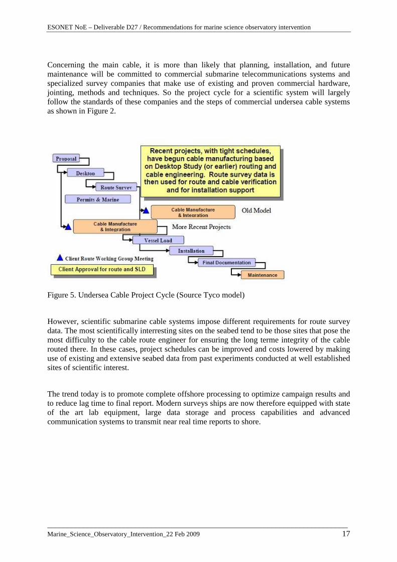
Concerning the main cable, it is more than likely that planning, installation, and future maintenance will be committed to commercial submarine telecommunications systems and specialized survey companies that make use of existing and proven commercial hardware, jointing, methods and techniques. So the project cycle for a scientific system will largely follow the standards of these companies and the steps of commercial undersea cable systems as shown in Figure 2.
Figure 5. Undersea Cable Project Cycle (Source Tyco model)
However, scientific submarine cable systems impose different requirements for route survey data. The most scientifically interresting sites on the seabed tend to be those sites that pose the most difficulty to the cable route engineer for ensuring the long terme integrity of the cable routed there. In these cases, project schedules can be improved and costs lowered by making use of existing and extensive seabed data from past experiments conducted at well established sites of scientific interest.
The trend today is to promote complete offshore processing to optimize campaign results and to reduce lag time to final report. Modern surveys ships are now therefore equipped with state of the art lab equipment, large data storage and process capabilities and advanced communication systems to transmit near real time reports to shore.

ESONET NoE – Deliverable D27 / Recommendations for marine science observatory intervention
___________________________________________________________________________ Marine_Science_Observatory_Intervention_22 Feb 2009 18
6. DEPLOYMENT & RECOVERY OPERATIONS 6.1 – Introduction We have considered in the previous paragraph that for seafloor cabled observatories, main backbone cable and cable fittings will be likely deployed by specialized cable installation and maintenance fleet.
Figure 6. Node cabling (source Alcatel design) In the Figure 3, the concerned elements are:
• the Backbone cable and the Branching Unit (BU) • the Spur cable • the Node
Like for the survey, the project cycle for a scientific system will largely follow the standards of these companies and the steps of commercial undersea cable systems as shown in Figure 5. However, after a first deployment by specialized vessel, next interventions during operational life of the observatory may be achieved by multi purpose oceanographic vessels, and follow generic operations described below. As a matter of fact, a generic concept for the node consist of a node module, a frame assembly, and a cable termination assembly (CTA). The spur cable is terminated on the node end at a CTA housing. This CTA is directly connected to the trawler resistant frame (TRF). The CTA (and associated wet mateable connectors) can be removed and recovered by ROV for repair. The node module is a removable unit that is located inside the node frame for protection.

ESONET NoE – Deliverable D27 / Recommendations for marine science observatory intervention
___________________________________________________________________________ Marine_Science_Observatory_Intervention_22 Feb 2009 19
Therefore, we are considering in this document, methods and procedures to deploy and recover other equipments or subsea integrated modules that will complete the Sea Bottom Observatory installation (for example junction box, scientific packages, permanent instrumentation...etc..), which will be classified as Ocean Bottom Unit (OBU) in the document. These operations are including more generally two general areas:
- Lifting and lowering technology - OBU control and positioning
OBU may have various functions that will be precised along the project. The document will only focus below on the main characteristics which can influence the choice of deployment methods : The OBU type : heavy or neutral in water. This feature, linked to the initial choice of
deployment concept, may become a constraint in the future. The total OBU density (payload + buoyancy) which determines the surface handling
system capabilities. The OBU displacement which defines the deployment system abilities when the OBU is
underwater. The payload density (scientific equipment, data recovery, power supply, carrying
structure) which can be deducted from the total density if the buoyancy material is subtracted.
Accuracy necessary for load control and positioning: issues related to placing the load in
the desired location, at a correct compass heading, and at a stable attitude on the seabed. The need to deploy sensors or equipment after the OBU setting (in some cases, we can
envisage automating these operations but it could generate large additional costs for host unit design. This could only be justified by technical requirements or financial interests.
The need to recover data during the OBU deployment. The requirement of OBU maintenance, underwater (equipment replacement, cleaning…)
or by regular recovery. The need to keep the bottom perfectly clear of any waste at the end of the operation. The type and performance of the vessel which will be supporting the operation (lifting
capabilities, dynamic positioning, …), which can be a constraint or a consequence. Different methods of deployment can be used according to these elements. However, these concepts can be grouped in two main categories.

ESONET NoE – Deliverable D27 / Recommendations for marine science observatory intervention
___________________________________________________________________________ Marine_Science_Observatory_Intervention_22 Feb 2009 20
- The deployment of heavy OBU by passive cable or dynamically positioned power pod
- Free Fall Mode (FFM) of neutral or almost neutral OBU, with a sub-group where the module is deployed directly by ROV
6.2 - Deployment of heavy OBU by cable lifting and lowering The two means, passive cable and dynamically positioned power pod, constitute existing and attractive responses for the deployment of observatories heavy parts with “conventional” weights (few hundred kg to less than ten tons). The technology is very used in offshore industry, and often cost effective. The use of spoolable compliant tubulars is not presented in this document because uneconomic to use, and probably reserved to OBU or modules of great weights, where existing methods and equipments will not work. However these techniques have some limitations and problems, particularly in deep water applications. There is a number of technical challenges that may be classified in the following general areas: - When using cost effective steel wire ropes, as the depth increases, the ratio of the weight of the cable to the weight of the payload becomes extreme, and at 6000 m the safe working load of the steel wire is almost entirely used by its self-weight. Synthetic fiber rope provides a potential answer to the self-weight problems. They have attractive properties such as small bend radii and ability to be repaired, but to-date there are potential problems related to stretch, creep, durability and life that, with the cost, limit their use in some applications. - They can be very significant dynamic effects due to excitation caused by the motions of the surface vessel which can be amplified with large oscillations and high dynamic tensile loads in the lifting line. Moreover the added mass of the load can be very significant to be many times it’s weight in air due to the water trapped inside, and to the shape of the load. It is shown that for lowering into deepwater there will nearly always be a depth at which a resonant response will occur. It is important that this resonant region can be passed through relatively quickly, and that it does not occur at full depth where careful control is required for placement of the payload on the seabed. Modelling methods have been developed in industry and in Ifremer in particular to predict behaviour of these dynamic responses. - Placing the load in the desired location, at the correct compass heading, and at a stable attitude on the seabed can be critical. In deep water, relatively small currents can introduce a very large offset between the ship and the load on the sea bed. The success of the final touchdown operation is susceptible to the load’s interaction with the seabed. Once the load is released, the lowering system hook must remain under control and be prevented from getting entangled with the subsea equipment. In some particular cases the assistance of a submersible or a ROV can be used to assist the operation. - The problem of module recovery has to be solved. Different solutions are possible and described below, according to the possibility or not to make the OBU buoyant. Some solutions need the use of a ROV or dynamically positioned mobile docker. Examples in appendix are illustrating these different solutions

ESONET NoE – Deliverable D27 / Recommendations for marine science observatory intervention
___________________________________________________________________________ Marine_Science_Observatory_Intervention_22 Feb 2009 21
- Position reference needs particular attention, and involves non conventional systems in great water where communication with the surface may be unreliable (long path lengths and vessel noise). - The influence of weather and sea state are important in particular when the depth increase. The required weather windows, and the speed with which tasks must be accomplished in order to fit into these practical windows are more critical.
6.2.1 Offshore standards and practices
Modules lifting, in the offshore industry, have always been a technological challenge. From the early days of the North Sea development until the recent ultra deepwater discoveries in West Africa, lifting operations have always been considered as critical and challenging tasks during the field construction phase. Therefore, a lot of engineering efforts and R&D programs have been conducted to provide the contractors with safe and efficient lifting systems.
The best examples are probably heave compensation systems, which have improved on a regular basis along the years and now provide quite efficient solutions for lifting modules even in heavy sea states. Their associated cost has comparatively drastically increased.
As far as cranes and rigging equipment are concerned, safety factors, training qualification, maintenance requirements, etc. are defined in standards such as:
- Recommended Practice for the Operation and Maintenance of Offshore Cranes, API RP 2D
- British Standard BS 7121-11 Code of Practice for safe use of cranes – Part 11 Offshore cranes
All lifting equipment, including loose gear, shall be certified by an official certifying authority (DNV, Lloyds, BV, etc.) and labelled with safe working load (SWL).
The ISO 13628-1 indicate the following safety factors for various lifting devices:
- all lifting devices (such as shackles, master links, swivels, swivel-hoist rings, eye bolts, etc.) shall be designed with a 5:1 safety factor with respect to breaking strength to a labelled safe working load (SWL)
- all slings shall be designed with a 5:1 safety factor with respect to breaking strength to labelled safe working load
- all lifting frames, structures, spreader bar arrangements, etc. shall be designed with a 2:1 safety factor with respect to material yield strength to labelled safe working load
- single-point lift pad eyes shall be designed with a 5:1 safety factor with respect to material yield strength to a labelled safe working load. The pad eye shall be either

ESONET NoE – Deliverable D27 / Recommendations for marine science observatory intervention
___________________________________________________________________________ Marine_Science_Observatory_Intervention_22 Feb 2009 22
machined as an integral part of the body being lifted, or designed with a full-penetration weld
- multipoint lift pad eyes shall be designed with a 3:1 safety factor with respect to material yield strength to a labelled safe working load. The pad eye shall be either machined as an integral part of the body being lifted, or designed with a full-penetration weld. To prevent lateral bending moments, the pad eyes should be aligned with the sling to the centre of lift. In other words, the sling load should be in the plane of the pad eye
- “N–1” philosophy for multipoint lifts: each leg of the lifting arrangement and the attached pad eye should be able to support the design load with one leg missing. For example a four-line lifting sling carrying a 10-ton load shall be designed such that three slings can safely support the 10-ton load, should the fourth line break
- lifting pad eyes should be clearly colour-coded and marked with their safe working load in accordance with ISO 13628-4. Sea-fastening or handling pad eyes are not colour-coded, but should be marked for load limits.
The consequences are that lifting operations in the offshore industry are conducted with highly specified equipment and stringent safety factors, and there is no room for uncertainty, whether it would come from rigging equipment design or meteorological conditions.
Those precautions are obviously taken for safety reasons but are also motivated by the operational costs of construction spreads (now several hundreds thousands dollars per day) which cannot afford to be kept in stand-by, even for one hour, for reasons of equipment breakdown or weather stand-by.
A direct transfer of this philosophy to the installation of underwater scientific modules could be detrimental to the scientific community in terms of equipment availability and installation costs. It is advisable to review lifting practices, in relation with the technical and economical risks, which are probably much lower, due to the smaller size of the modules and the lower cost of the support ships.
6.2.2 Existing scientific solutions and recommendations
Due to the smaller size of the modules, and the deliberate choice to do the operation by good sea conditions, with stand by acceptance, lifting operations in the scientific missions are generally conducted with no highly specialized ship, even sometimes with small oceanographic vessels.
Different experiences are existing, with different vessels, module size, depth and deposit requirements, company crew experience and rules.
Some examples of OBU deployment in Ifremer (Penfeld – ANTARES detector lines and junction box – ASSEM observatory) are briefly described in [appendix 3].
As opposed to the offshore philosophy which offers no compromise to equipment performance, this more flexible approach will be recommended for the scientific community which may use such alternative methods with smart rigging versus sea state capability and global cost.
ESONET NoE – Deliverable D27 / Recommendations for marine science observatory intervention
___________________________________________________________________________ Marine_Science_Observatory_Intervention_22 Feb 2009 23
Each deployment will be specific, but there are some rules or experience’s results that can be underlined.
• Weather conditions and dynamic loads
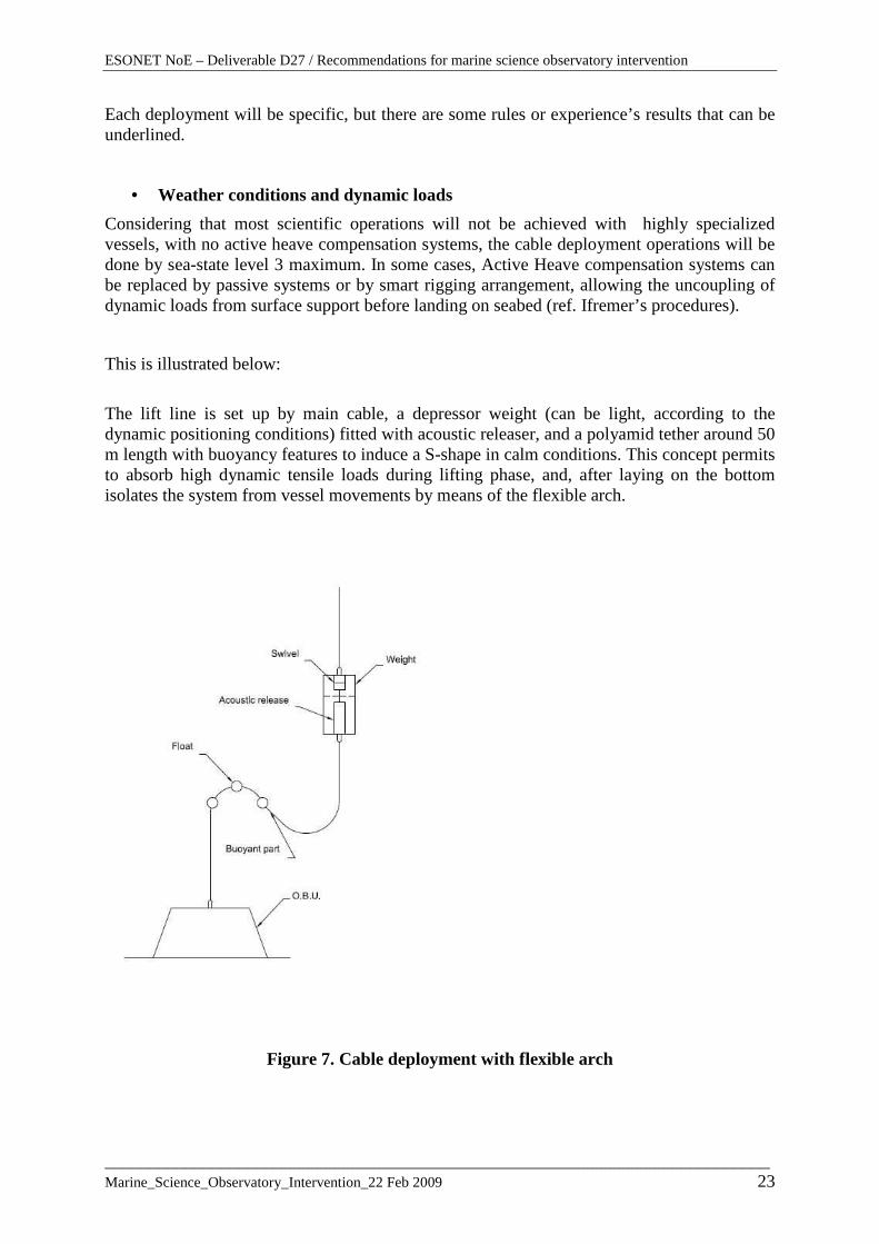
Considering that most scientific operations will not be achieved with highly specialized vessels, with no active heave compensation systems, the cable deployment operations will be done by sea-state level 3 maximum. In some cases, Active Heave compensation systems can be replaced by passive systems or by smart rigging arrangement, allowing the uncoupling of dynamic loads from surface support before landing on seabed (ref. Ifremer’s procedures).
This is illustrated below:
The lift line is set up by main cable, a depressor weight (can be light, according to the dynamic positioning conditions) fitted with acoustic releaser, and a polyamid tether around 50 m length with buoyancy features to induce a S-shape in calm conditions. This concept permits to absorb high dynamic tensile loads during lifting phase, and, after laying on the bottom isolates the system from vessel movements by means of the flexible arch.
Figure 7. Cable deployment with flexible arch

ESONET NoE – Deliverable D27 / Recommendations for marine science observatory intervention
___________________________________________________________________________ Marine_Science_Observatory_Intervention_22 Feb 2009 24
• Positioning system
For all these operations, a precise acoustic positioning system (LBL or SBL) is essential. Combined with a transpondeur on the extremity of the cable, the deposit precision can be metric.
• Dredger line and fishing tail on the bottom
A cost effective solution for module recovery by cable, is to connect to the module (can be prepared on the equipment before landing, or placed by a ROV before recovery operation) a specific “fishing tail”, that can be dredged directly from the ship by a recovery line equipped with grapnel. This technique needs a good positioning system, with a transpondeur on the line and on the grapnel. A “dredging area” have to be defined, where there will be no scientific installations, or these will be in safety position before operation. The fishing tail will not be longer than 30 m, to ease the recovery surface operation. This operation must be achieved by very good weather conditions, in very low ship displacement. It can take a few hours (experience between 2 and 8 hours).
• Precise orientation with ROV assistance
Placing the load at a correct compass heading, may be necessary. In this case the use of passive methods, like orientation panels or anchorage line, is not considered as reliable.
The operation needs the intervention of an ROV, in coordination with deposit operation. During all the operation there are two cables underwater, close from each other. This is currently operated by offshore companies. The company and the operational crew must have well tested the operation. Safety procedures will be planned, with completely separated safe energy sources for lifting devices and ROV deployment.
The RP ISO 13628 gives RPs, that could be followed [§ 4.3.3. Dual dowline intervention]. The operation will be done by DP vessels, with good weather conditions. Additional care should be taken to avoid entanglement with the ROV umbilical or tether. The two cables will have to be as similar as possible (diameter and torque properties). It is recommended that the two main lines (lift line and ROV umbilical) be deployed from separate areas of the intervention vessel. The distance between the two cables have to be as great as possible, depending on the vessel performances, and with a minimum of 15 m. The lift line should be heave compensated, especially from small heave-prone intervention vessels. Compensation includes an active heave-compensated crane or configuration of the lift line in a lazy S, located mid depth, using buoyancy cells to isolate heave motions from load movement below.
• Direct use of the ROV to deploy and orientate OBU
The deployment of small OBU, in the frame of the buoyancy and payload of a ROV, is presented and illustrated below, with “Free Fall Mode” deployment.
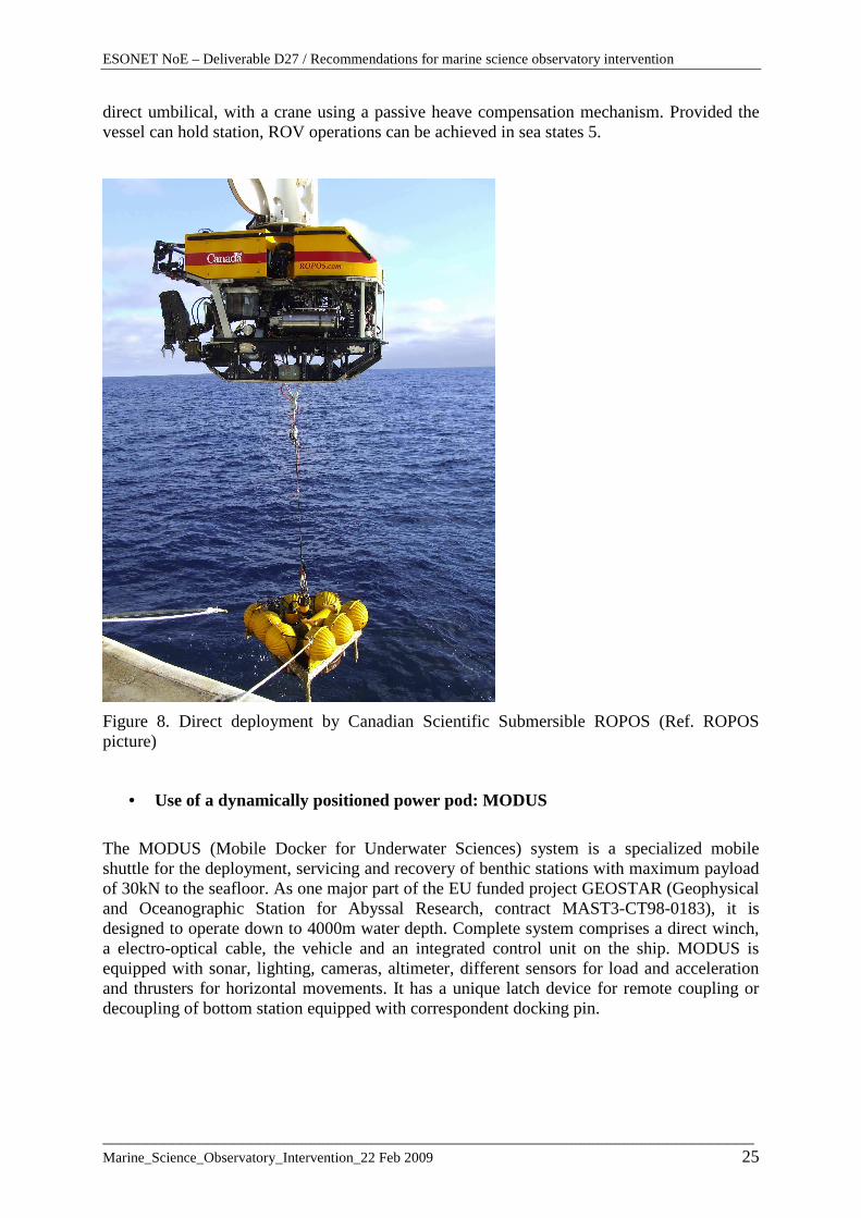
Concerning deployment of heavy OBU directly by ROV, there are some good experiences. The exemple is illustrated by the Canadian Scientific Submersible ROPOS. The system in a mid-depth configuaration (up to 2500m) has been successfully used to recover instruments weighting in excess of 2000 lbs and is a backbone of the ROCLS (Remotely Operated Cable Laying System for NEPTUNE). In that configuration it uses a 14 tons LARS and a 15 Tons
ESONET NoE – Deliverable D27 / Recommendations for marine science observatory intervention
___________________________________________________________________________ Marine_Science_Observatory_Intervention_22 Feb 2009 25
direct umbilical, with a crane using a passive heave compensation mechanism. Provided the vessel can hold station, ROV operations can be achieved in sea states 5.
Figure 8. Direct deployment by Canadian Scientific Submersible ROPOS (Ref. ROPOS picture)
• Use of a dynamically positioned power pod: MODUS
The MODUS (Mobile Docker for Underwater Sciences) system is a specialized mobile shuttle for the deployment, servicing and recovery of benthic stations with maximum payload of 30kN to the seafloor. As one major part of the EU funded project GEOSTAR (Geophysical and Oceanographic Station for Abyssal Research, contract MAST3-CT98-0183), it is designed to operate down to 4000m water depth. Complete system comprises a direct winch, a electro-optical cable, the vehicle and an integrated control unit on the ship. MODUS is equipped with sonar, lighting, cameras, altimeter, different sensors for load and acceleration and thrusters for horizontal movements. It has a unique latch device for remote coupling or decoupling of bottom station equipped with correspondent docking pin.

ESONET NoE – Deliverable D27 / Recommendations for marine science observatory intervention
___________________________________________________________________________ Marine_Science_Observatory_Intervention_22 Feb 2009 26
Figure 9. MODUS and bottom station coupled on R/V Urania The main characteristics are summarised in appendix. Mass (kg): 1090 Weight in water (N): 7350 L/B/H (m): 2,88/2,35/1,02 The system needs a support ship of medium size, with dynamic positioning, well designed A-Frame for the envisaged loads and dimensions, and available space on board to support simultaneously deployment system and benthic station. The R/V Urania has been used for the first operations. The system has been operating in various missions in the Mediterranean down to maximum water depths of 3700 m. It is a dedicated tool that needs well adapted seafloor observatories or modules. It can perform only specific “vertical operations” , and is not adapted to other operations (connection, wiring, maintenance..). One of the most critical aspects is the dynamic behaviour of the complete system including the sea-keeping characteristics of the research vessel in arbitrary sea-states and the associated hydro-elastic behaviour of the tethered mobile-docker with a bottom station.

ESONET NoE – Deliverable D27 / Recommendations for marine science observatory intervention
___________________________________________________________________________ Marine_Science_Observatory_Intervention_22 Feb 2009 27
6.3 – Neutral (or almost neutral) OBU deployment
Two generic solutions have been well experimented:
• Deployment by free falling mode (FFM) with further assistance by ROV • Direct Deployment by ROV
6.3.1 Offshore standards and practices There is no standards in offshore concerning the FFM solution, which is not a solution that permits to control anytime the position of the load, and could be risky on a subsea field in operation. Direct deployment by ROV is currently used, generally with Work class vehicles [NORSOK U-102 classification class III], for the replacement of subsea components. The ISO 13628-8 RPs gives general considerations for tool skid operation [§ 4.3.4. Tool skid intervention]. These considerations are very general, and already currently followed by scientific institutions. Therefore, this technique is more detailed under the “scientific solutions”.
6.3.2 Existing scientific solutions
6.3.2.1 Deployment by free falling mode
As general guidelines, the deployment of neutral observatory will be done in free falling mode (FFM) to be accurately positioned by submersible afterwards. This technique is well adapted when accurate load control and positioning on the bottom are required, when the weight and displacement in water are moderate, typically less than 50 daN (depending of the weight and buoyancy adjustment of the vehicle, generally lower than 150 daN). This technique have further attractive responses to some problems evocated for very deep water. The deployment of the heavy structure can be done by non dynamic positioning vessel (but necessary for the ROV intervention further), with no anti heave compensating system. The influence of metocean effects and weather window requirements are less critical.
On the other hand, there are some inherent drawbacks. This technique does not further allow the OBU to have a heavy weight on the bottom. The addition of a succion weight can be necessary if a solid anchorage is needed. This is clearly a non reversible process which does not solve easily the recovery problem if/when the subsea equipment needs to be returned to the surface for any reason. However this mode can be convenient for large assemblies that have to be installed for a long duration, in the knowledge that recovery may be performed on individual modules or components. The necessity further to recover the station independently from the assistance of a submersible by releasing acoustically an ascent weight has to be considered.
Deployment:

ESONET NoE – Deliverable D27 / Recommendations for marine science observatory intervention
___________________________________________________________________________ Marine_Science_Observatory_Intervention_22 Feb 2009 28
Generally the operation will be done by good sea conditions, but the landing point will not be precise. After locating it, the ROV will further be able to horizontally translate the load to the right position. In free fall mode, some scenariis are proposed depending on the in water weight of the equipment. In these scenariis, the equipment includes releasable ascent weight and buoyancy, and an additional descent weight suspended to a chain is added for descent. The system ensures a soft arrival on the sea floor. The structure is equipped with some weight adjustment devices, the submersible only giving control. Reliable docking devices have to be designed to ensure the transit. The principles are illustrated by the sketch below:
Figure 10. Typical free falling mode deployment
OBU Nota : It can integrate its own ascent weight
50 to 100 daN
ESONET NoE – Deliverable D27 / Recommendations for marine science observatory intervention
___________________________________________________________________________ Marine_Science_Observatory_Intervention_22 Feb 2009 29
After the ROV has put out the descent weight, the station will be placed on the seabed, under self weight, or even sucked down. This operation will be done by the submersible and its manipulating devices. In some cases the deposit of a great quantity of lost steel weight can be forbidden. A first approach will be to drop the OBU on the bottom in a dedicated area, where the descent weights are gathered, and connected up by submersible at the end of the complete operation. They are further lifted up by cable on the ship. When the module is in right position, and if its weight on the bottom must be increased, the next operation consists in releasing the buoyancy by acoustic signal from the ship. Then the ROV puts out all protections and fittings used for deployment operation., and makes checklist and tests before leaving. This operation may include sensors reading, acoustic transmission tests and auto tests. These can be triggered by the submersible using its manipulator and standard user interface, including electric and hydraulic power, data communication and payload, through local data access port. At this stage, extra sensors can be deployed from the main OBU with cable links, the necessary connections being made by manipulating capabilities. These operations are illustrated in next paragraph.
OBU retrieving with ROV assistance: The first phase consists in disconnecting cable-links between the OBU to be recovered and other equipments staying on the bottom. The plugs of disconnected cables must be probably protected and placed on a special disposal receptacle. These operations are achieved by the ROV. The second phase consists in deploying at sea a recovery line. At this stage, there are two options: (a) the recovery line is deployed directly by the handling system of the ship with the assistance of the ROV. The recovery line must be laid very closed of the OBU. (b) the recovery line is deployed with its buoyancy by FFM and OBU hooking. The operation is done by the submersible. The recovery line which can be put not very closed of the station, may be shifted by the ROV. In this case, the lifting capability is generally limited, and lower than 300 daN with the current means. Some experiments was done on Titanic wreck with fuel buoyant bags giving a 700 daN buoyancy. But further the technique is heavy and it is not a good solution. The chosen solution depends of the weight of the OBU to recover and the deployment precision of recovery line on the seabed that the ship is able to get. In the two cases, the ROV takes the hook of the recovery line, and deploys the line on the sea floor towards the OBU and fixes the hook on the structure at the right place. At the end, and in the second case, the ship recovers the ROV on board, and releases the descent weight of the recovery line. In the first case the ship prefer to retrieve the line and the OBU with the handling system, before recovering the ROV [Nota: when using a manned

ESONET NoE – Deliverable D27 / Recommendations for marine science observatory intervention
___________________________________________________________________________ Marine_Science_Observatory_Intervention_22 Feb 2009 30
submersible, the vehicle is always recovered first, to assure that the A-Frame is never engaged. The principles are illustrated by the sketch below:
Figure 11. Typical recovery scenario Typical scenario of deployment and recovery:
Deployment
a- Ship-born preparation of the station b- Deployment of the station (1m/s): following position during descent to the sea
floor. Preparation of the ROV on the ship. c- Deployment of the ROV
To connect the line to a winch

ESONET NoE – Deliverable D27 / Recommendations for marine science observatory intervention
___________________________________________________________________________ Marine_Science_Observatory_Intervention_22 Feb 2009 31
d- During descent and on the bottom, the ROV goes to the station, helped by acoustic positioning system, sonar and by end optical means.
e- ROV weights of the load, release the descent weight, and moves the station to the right place
f- At the right place, the ROV makes all preparation, checklist and tests g- Before leaving, the ROV order release of the buoyancy
Recovery: (recovery line in FFM)
a- Deployment of the recovery line by FFM: the line is positioned all the time by acoustic
b- Deployment of the ROV: during descent the ROV goes to the recovery line, helped by acoustic positioning system, sonar and optical means
c- The ROV takes the hook in the basket and hangs it on the load d- Before leaving, the ROV order the ship to release the lest e- The ship recover the ROV f- The ship recovers the OBU with the buoyancy and acoustic transpondeur.
If the cleaning of the bottom is required, the ascent weight debris are moved towards the “trash area”, and tied to other lost weights to be lifted further on the vessel by cable.
6.3.2.2 Deployment by ROV – Tool skid intervention The deployment and precise positioning and deposit of observatory, as the replacement of subsea components, can also be carried out by a ROV-mounted lifting and handling tool-skid. The load to deposit often requires a lift capacity beyond that of a free-swimming ROV. Therefore the tool skid provides added buoyancy ballast, and even trim adjustment, to that already on the ROV so that detrimental effects from load transfer do not upset the hydrodynamic characteristics of the ROV. Example of such deployment is shown in following picture. Ref. [R6]
Figure 12. MARS electronics node replacement by ROV (Ref. MBARI documentation)

ESONET NoE – Deliverable D27 / Recommendations for marine science observatory intervention
___________________________________________________________________________ Marine_Science_Observatory_Intervention_22 Feb 2009 32
The general process is illustrated by the following sketch.
Figure 13. Benthic Station / ROV Docking Process

ESONET NoE – Deliverable D27 / Recommendations for marine science observatory intervention
___________________________________________________________________________ Marine_Science_Observatory_Intervention_22 Feb 2009 33
6.4 - Buoy deep mooring deployment Scientific buoy mooring design is generally an inverse catenary design in which flotation attached to the mooring cable induces a S-shape in calm conditions. There are different techniques and architecture according to the different concepts, depending on the choice of a simple mechanical mooring or a EOM mooring. For the first case, typically, low modulus materials such as nylon and polyester are chosen for mooring lines and cables to provide a large degree of compliance to accomodate wave and tidal loading. While a challenge to overcome in the implementation of EOM mooring is related to the very low stretch tolerance of the generally high modulus materials which are needed. Final mooring design is the result of many trade-offs between requirements regarding buoy size, instrumentation payload, power-gathering or not, operational conditions and reliability concerns. Numerical modelling techniques are used to evaluate the design space and to settle on the final design and configuration. The following figures are illustrating two generic configurations of moorings.
Figure 14 . Autonomous relocatable observatory (Doc. Geomar Gi-Tews – reference [R16])

ESONET NoE – Deliverable D27 / Recommendations for marine science observatory intervention
___________________________________________________________________________ Marine_Science_Observatory_Intervention_22 Feb 2009 34
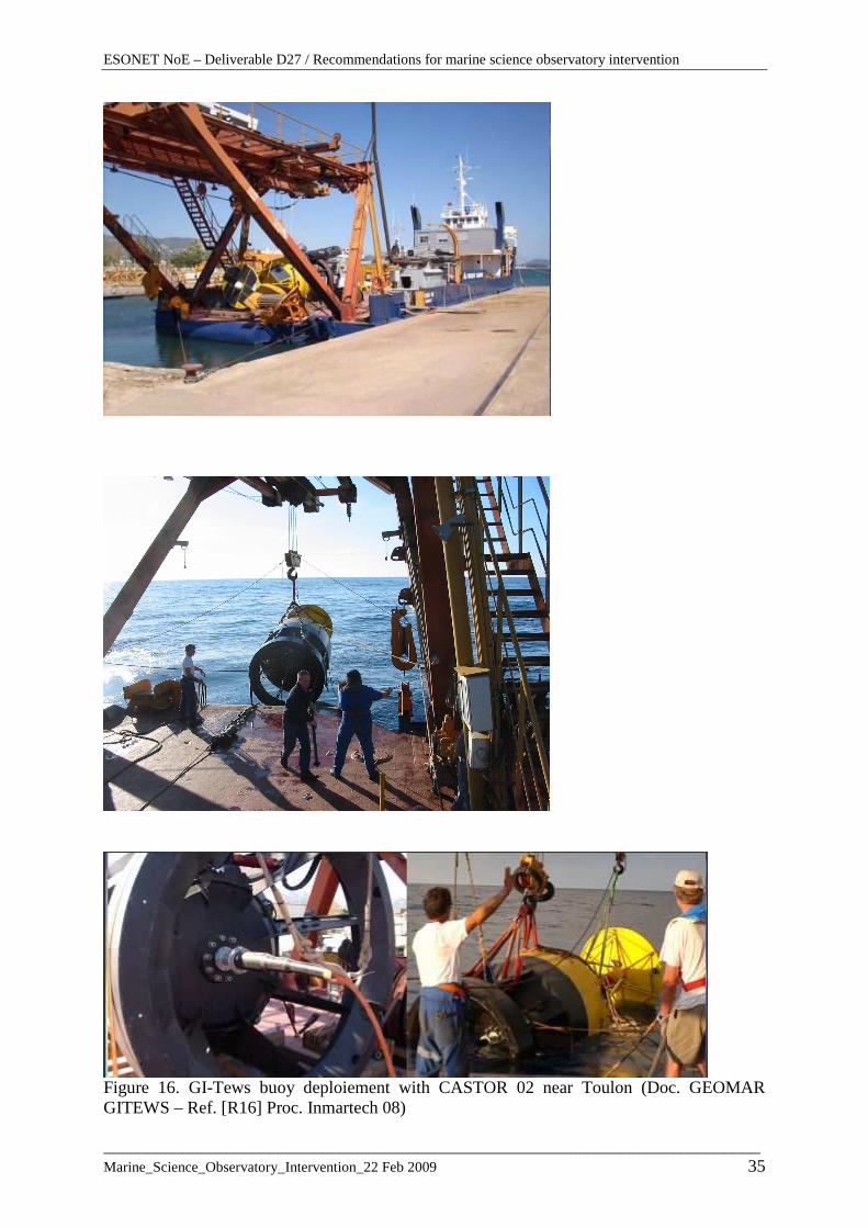
Figure 15 . Diagram of MOOS mooring system showing buoy, snubber section, EOM cable arrangement and subsea flotation (Doc. MBARI – Ref. [R17] proc.OMAE2005) Deployment and recovery of such devices can be implemented by medium size multi-purpose vessels that have enough place on deck, handling system with high clearance and lifting capabilities up to several tons for the buoy and the mooring, and dynamic positioning possibilities. There are no standards or RPs for this operation. The following slides concerning a recent operation are illustrating such a deployment.
ESONET NoE – Deliverable D27 / Recommendations for marine science observatory intervention
___________________________________________________________________________ Marine_Science_Observatory_Intervention_22 Feb 2009 35
Figure 16. GI-Tews buoy deploiement with CASTOR 02 near Toulon (Doc. GEOMAR GITEWS – Ref. [R16] Proc. Inmartech 08)

ESONET NoE – Deliverable D27 / Recommendations for marine science observatory intervention
___________________________________________________________________________ Marine_Science_Observatory_Intervention_22 Feb 2009 36
Deployment
There are two general modes for the deployment:
• Buoy first, • Mooring first
The capacities of the ship will define the adapted solution. Usually, the ship prefer to deploy the buoy first to clean the deck and easily use the different vessel handling means. In this case the general procedure is the following:
- The position for the launch of the first element is approximately far by 1.5 times the length of the complete rigging in order to plan the rigging while the vessel moves slowly to the final position.
- The buoy is launched using the aft gantry crane. As it is afloat, a small craft tows it away from the aft of the ship in order to maintain it clear from the azimuthal thrusters as well as giving a minimum of tension on the whole line.
- The line is put in the water using the cable laying capstan and the chute from the storage mobile winch. The different components are added while the line is put in the water.
- After the line is completely rigged, the vessel is approaching the final launching position. The vessel tows the buoy by the sinker. The sinker is just secured on the vessel by a rope stopper. As soon as the vessel is at launching position, the rope stopper is cut.
- After the buoy found its definitive position, the vessel comes on the buoy to control the final position.
Recovery There are also two general possibilities to recover the buoy and the mooring line. In both cases the ship have to take care for the mooring line and (more or less) for the direction of wind and the direction of the current.
• Buoy first, The main steps are the following:
- Recovering of the buoy first (rubber boat, crane), - Releasing, - Spooling and recovering of the rope, flotation modules and finally the releaser by
pulling the mooring line with moderate speed (ship & winch) to keep the mooring line streched and out of the range of the propeller
• Releaser first
The main steps are the following:
- Releasing - Waiting until the flotation modules (above the releaser) popes up, - Recovering of this modules and the releaser first (rubber boat, crane),

ESONET NoE – Deliverable D27 / Recommendations for marine science observatory intervention
___________________________________________________________________________ Marine_Science_Observatory_Intervention_22 Feb 2009 37
- Spooling and recovering of the rope, flotation modules and finally the buoy by pulling the mooring line with moderate speed (ship & winch) to keep the mooring line streched and out of the range of the propeller.
In both cases, the vessel has to stay in Dynamic Positioning and follow up the buoy and mooring line.
ESONET NoE – Deliverable D27 / Recommendations for marine science observatory intervention
___________________________________________________________________________ Marine_Science_Observatory_Intervention_22 Feb 2009 38
7. CABLES LAYING AND UNDERWATER CONNECTIONS
7.1 - General As a general rule, the operation of observatory subsea building will require a large number of power and communications cables to be laid and interconnected on the seabed. The number and kind of cables will depend on the observatory architecture.
As we have shortly underlined in the general presentation in paragraph 4, at this stage of the project, different types of sub-sea observatories will be considered, according to different criteria.
These types of observatories have been classified in three categories:
• Seafloor cabled observatory
• Tethered buoy observatory
• Autonomous relocatable observatory
And possibly a combination of these types.
Shematic figures was illustrating these concepts, and have pointed out the importance of “interlink cables”.
We have considered in the previous paragraph that for cable observatories, backbone cable, branching units and spur cable will be likely deployed by cable installation and maintenance fleet. This part of cable laying will therefore follow the standards of cable companies and the steps of commercial undersea cable systems as shown in Figure 5 . Therefore, we are considering in this section of document methods and procedures for cables laying and underwater connections needed to complete the Sea Bottom Observatory installation after the main cable deployment would be achieved, in particular to deliver power and data to remote instrument sites (for example junction box, scientific packages, permanent instrumentation...etc..). For these operations cables must be accurately placed on the seafloor and connected to each node to create the subsea network.
In most of cases, umbilicals and cables will be laid independently from the structures to which they are connected. They are terminated by specific devices called “end terminations” which will allow subsequent underwater connections to subsea modules.
This philosophy which applies well to large modules in deep water may be found too expensive for small systems, like sensors, especially in shallow to medium waters, due to the additional cost of end terminations, underwater connectors and associated underwater connections operations. In that case, the sensor can be installed with its cable already connected to the observatory. Once the observatory is landed on the seabed, the cable will be laid away from the location, towards its termination.
In the general case of underwater observatories, the cable termination can be adopted for cables linking main junction box or nodes to secondary junction boxes, while the sensors or small packages of sensors can be laid with their cables connected, the other end being abandoned on the seabed for later connection to a junction box, directly or via a flying lead.

ESONET NoE – Deliverable D27 / Recommendations for marine science observatory intervention
___________________________________________________________________________ Marine_Science_Observatory_Intervention_22 Feb 2009 39
7.2 - Offshore standards and practices In Offshore industry , underwater connections of communications and/or power cables, or more frequently integrated umbilicals, have now become standard operations in the construction phase of an oil & gas subsea field.
But they are no specific standards or recommended practises covering the installation of subsea cables, but API 17E and ISO 13628-5 (same document) have a setion concerning the design and installation of subsea umbilicals which is partly applicable to subsea cables installation.
In terms of installation, this standard address the pre and post surveys, the laying monitoring, the mechanical handling on board the vessel, the vessel positioning and the cable initiation and termination phases.
Unfortunately, no standards govern the design and construction of associated connectors, which remain specific to each manufacturer. But some oil & gas companies specifications give however guidelines for manufacturing and testing of connectors.
Those connectors (constituted by a male and female part, specific to each other), called “underwater mateable connectors”, can be anything from two electrical pins to multiple electro-optical connectors. They have been improved from the 1980s to support much higher voltages and amperages for applications such as submersible pumps and long offset power suplies [ODI Nautilus series]. In the mid 1990s, new optical connectors [ex. Rolling-Seal connector] were introduced that provided multiple channels and reliable wet-mat performance. [R18]
Efforts have been made on ROV friendly design, by adding T-type handles on top of connectors flying part, competed by grasping devices on the structure to allow ROV docking during the connection operation. Most of the time, these electrical connections are grouped on a single interface panel, which minimizes the ROV movements. This part has given rise of RPs which are presented and detailed below in parag.8 concerning intervention.
Figure 17. 4 pin wet mateable connector with ROV friendly flat handle (source: ODI)
7.3 - Existing scientific solutions The document will not develop the case where the cable is very short (some tens meters), and (or) the sensor is already equipped with a short cable. The deployment and connection is then directly using the payload and manipulating facilities of the ROV, and is not a complex operation.
ESONET NoE – Deliverable D27 / Recommendations for marine science observatory intervention
___________________________________________________________________________ Marine_Science_Observatory_Intervention_22 Feb 2009 40
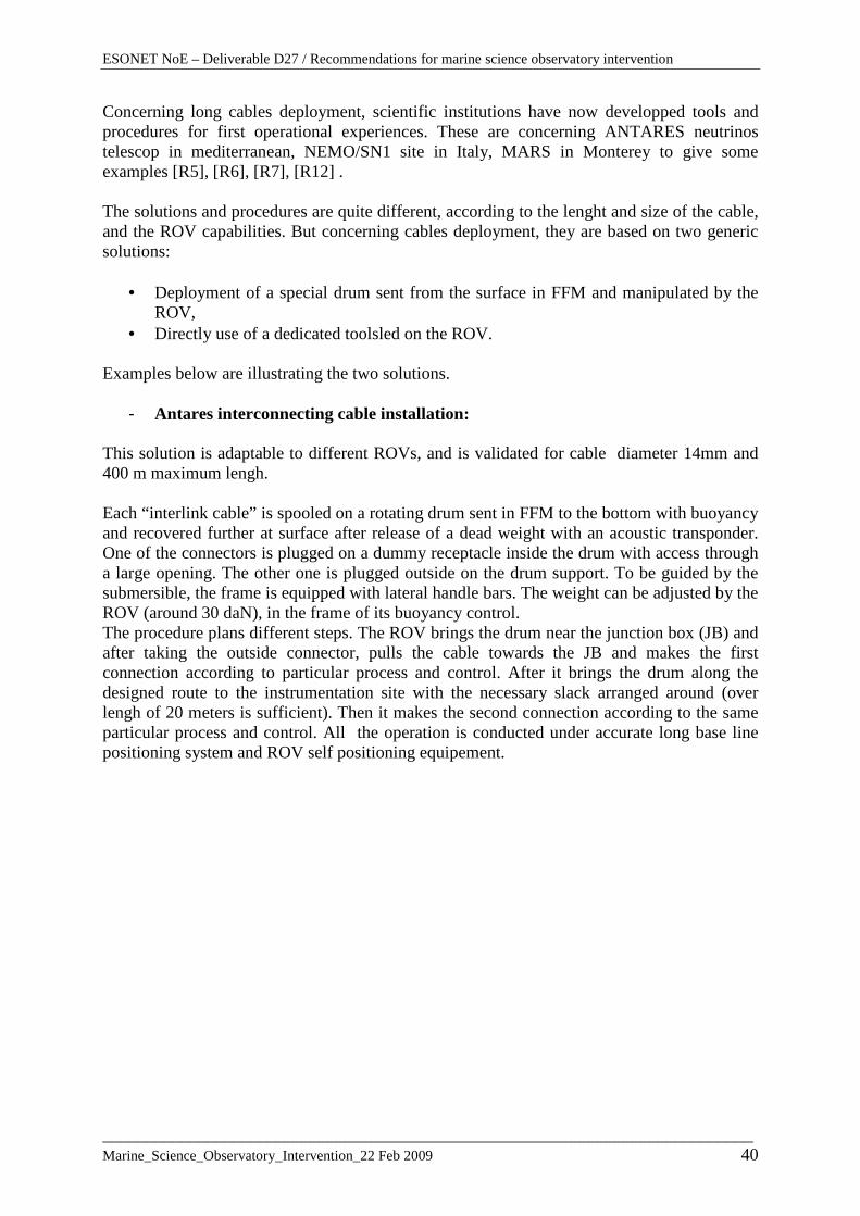
Concerning long cables deployment, scientific institutions have now developped tools and procedures for first operational experiences. These are concerning ANTARES neutrinos telescop in mediterranean, NEMO/SN1 site in Italy, MARS in Monterey to give some examples [R5], [R6], [R7], [R12] . The solutions and procedures are quite different, according to the lenght and size of the cable, and the ROV capabilities. But concerning cables deployment, they are based on two generic solutions:
• Deployment of a special drum sent from the surface in FFM and manipulated by the ROV,
• Directly use of a dedicated toolsled on the ROV. Examples below are illustrating the two solutions.
- Antares interconnecting cable installation: This solution is adaptable to different ROVs, and is validated for cable diameter 14mm and 400 m maximum lengh. Each “interlink cable” is spooled on a rotating drum sent in FFM to the bottom with buoyancy and recovered further at surface after release of a dead weight with an acoustic transponder. One of the connectors is plugged on a dummy receptacle inside the drum with access through a large opening. The other one is plugged outside on the drum support. To be guided by the submersible, the frame is equipped with lateral handle bars. The weight can be adjusted by the ROV (around 30 daN), in the frame of its buoyancy control. The procedure plans different steps. The ROV brings the drum near the junction box (JB) and after taking the outside connector, pulls the cable towards the JB and makes the first connection according to particular process and control. After it brings the drum along the designed route to the instrumentation site with the necessary slack arranged around (over lengh of 20 meters is sufficient). Then it makes the second connection according to the same particular process and control. All the operation is conducted under accurate long base line positioning system and ROV self positioning equipement.

ESONET NoE – Deliverable D27 / Recommendations for marine science observatory intervention
___________________________________________________________________________ Marine_Science_Observatory_Intervention_22 Feb 2009 41
- Monterey Bay Aquarium Research Institute (MBARI) MA RS installation To meet the requirement MBARI has developed fiber optic cable laying tool sleds for the Institute’s ROVs, Tiburon and Ventana [R5]et [R6]. These sleds currently have a weight-limited capacity of four kilometers of fiberoptic/power cable, and can lay cable to depths of 4,000 meters. The cable laying procedure is very similar. It plans to first dive at the main node mooring site and perform a connection with a wet mateable fiber optic connector to a pigtail extending from the ROV mounted cable spool. The vehicle proceeds along premapped waypoints a few meters off the sea floor maintaining visually both the bottom and the cable as it is deployed. The maximum deploy speed is 1 knot (1.85 km) per hour. Deploying approximately 10% more cable length than distance traveled avoids tensioning the cable and forming spans. This is accomplished using a custom graphic user interface that displays the amount of cable
Figure 18. ROV Victor moving cable turret for Antares connections

ESONET NoE – Deliverable D27 / Recommendations for marine science observatory intervention
___________________________________________________________________________ Marine_Science_Observatory_Intervention_22 Feb 2009 42
deployed versus the actual distance traveled across the bottom. Upon reaching the benthic instrument node (BIN) the spool containing the remaining cable is released from the cable sled, acting as an anchor and holding the excess cable in place. Using the ROV’s manipulator the connection of the cable with the instrument BIN is performed.
- ROPOS experience for NEPTUNE undersea observatory Very similar to the previous experience, the Canadian Scientific Submersible Facility has developped for its ROV ROPOS the Remotely Operated Cable Laying System (ROCLS) to support the NEPTUNE undersea observatory. ROCLS can accurately place up to 8 kms of 14 mm O.D. electro-optical cable on the sea floor. [R10] In that solution, the cable laying system can have an overall weight of 4000 lb. The ROV is towed in a heavy mode, using its direct umbilical. It can be decoupled to the package and free swim to perform the connections and other routine services.
Figure 20. ROPOS remotely operated cable laying system (Source :Canadian Scientific Submersible Facility)
Figure 19. ROV Ventana with cable laying toolsled (source MBARI [R5]

ESONET NoE – Deliverable D27 / Recommendations for marine science observatory intervention
___________________________________________________________________________ Marine_Science_Observatory_Intervention_22 Feb 2009 43
The document [R10] presents the tool and the procedures. http://www.ropos.com/documents/ROCLS%20paper.pdf Concerning connectors: The first wet mateable optical connectors are derived from those developped for offshore oil & gas. But the recent oceanographic projects, such as MARS, have placed additional demands on the available connector technology by requiring increased water depths, power capabilities (up to 10000 volts), and high bandwidth (10/100 BaseT Ethernet). The number of future connectors needed for the new projects, the need to reduce the important costs on this type of equipment, conduct to new studies and concepts, even in the oceanographic institutions themselves [R15]. No standardisation governs these studies for the moment, and it would be a real improvement in ESONET to exchange know how, experiences and ideas for future interoperabilty. Cooperation with the existing manufacturer lead to particular procedure for connectors use conditions during onland tests and subsea connections, and for connectors preparing (cleaning, jetting characteristics, ) before connection. Therefore, CNRS/CPPM and Ifremer have developped ODI connectors procedures for Antares telescop submarine connections. [R13] et [R14]. The same efforts than in Offshore industry have been made on ROV friendly design, by adding the same T-type handles. But depending of the different observatories and operators, the ROV is docked or not, and the grasping devices on the structure are for the moment different.
Figure 21. Antares subsea cable connections – source Ifremer

ESONET NoE – Deliverable D27 / Recommendations for marine science observatory intervention
___________________________________________________________________________ Marine_Science_Observatory_Intervention_22 Feb 2009 44
Other example for MARS junction box
7.4 - Recommendations - Concerning cable laying, there will be different solutions according to the lenght and the size of the cable. Three concepts have been presented. If the distance is short, less than a few hundred meters, the deployment of a neutral drum, sent from the surface or already mechanically fastenned to the ROV, instead of a heavy toolsled, will favorize interoperability between European vehicle. - The mechanical caracteristics of the special drum will be designed to be compatible with the different European vehicles - The mechanical interfaces on the drum to be guided by the vehicle have to be “standard” or easily configurable for the different manipulators. - Efforts may be combined and coordinated between the partners to study, developp, or buy “on the shelf”, qualify needed subsea connectors, in connection with existing manufacturer and new other observatory developments in the world (USA, Canada,..). - Future observatory design have to anticipate same grasping devices for the ROV, and same appropriate guides for a safe connection: this point will be detailed in the next section concerning IMR. - One or a few existing and validated procedure for connection should be selected, and be shared between partners for testing on mock-up, training and simulation.
Figure 22. Subsea connection by ROV Ventana on main MARS Junction Box - source MBARI
ESONET NoE – Deliverable D27 / Recommendations for marine science observatory intervention
___________________________________________________________________________ Marine_Science_Observatory_Intervention_22 Feb 2009 45
8. INSPECTION & MAINTENANCE WORK 8.1 – General During the Sea-floor observatory operational phase, the presence of numerous critical components at the seabed level (energy pack, modems, umbilicals, sensors, etc.) or in the water column (sensors, anchor lines) implies a comprehensive inspection and preventive maintenance program for which ROVs are again largely required.
Eventually repair operations are also carried out, from simple corrective maintenance to large disorders repairs (OFM trawling, umbilical water ingress,..).
These tasks are grouped under the acronym IMR which stands for Inspection, Maintenance and Repair, which is the dedicated terminology in offshore industry.
The typical IMR tasks can be summarized as follows:
• Global video inspection of subsea components including observatory, modules, umbilicals, moorings, deployed sensors,
• Detailed video inspection of some components,
• Leaks/corrosion/wear detection
• Cleaning operations (water jetting)
• Detection and evaluation of umbilical free spans and positions,
• Survey of general area,
• Anodes visual inspection / Cathodic protection measurement,
• Coating visual inspection,
• Wiring and connection,
• Instrument/ OFM control pod change out,
• Data retrieving & reconfiguration,
• Adding or replacing sensor,
• Replacing energy pack,
• Handling elevators,
• Handling surface-wire guided deployments/recoveries of devices,
• Etc..
In fact this list is far from being exhaustive but give an idea of the complexity of the IMR tasks to be performed and the versatility of a Work ROV equipped with the proper tools.

ESONET NoE – Deliverable D27 / Recommendations for marine science observatory intervention
___________________________________________________________________________ Marine_Science_Observatory_Intervention_22 Feb 2009 46
The first group of tasks (concerning preventive maintenance program) are planed operations while the second ones (repair operations) obviously obey to operations hazards (or faulty design and construction). Most of these operations will be made by ROV with manipulating, power and payload capabilities, and it is noted that all things to be handled by the submersible include handles, gripping points, marking, coloring.. etc…and have limited size and weight in water. All these operations can be grouped in a few categories:
• Inspection and survey video • Performing manipulating tasks, • Docking to infrastructures and devices, • Sub-systems carrying and deposit ( Ex. Handling elevators, FFM deployed modules..) • Handling surface-wire guided deployments/recoveries of devices.?
All these tasks can represent up to several weeks of ROV intervention on a typical deepwater complex observatory field.
Special care will have to be taken in the design phase to minimize these tasks and make them ROV friendly. To perform these tasks the modern Work Class ROVs, for offshore industry or scientific work, have similar equipments and capabilities concerning intervention tools, video systems, payload and buoyancy adjustment. In the NORSOK U-102 standard, they are classified as “Class III – Work class vehicles”. Scientific vehicles generally are less powerfull than the Class III A, which concerns the vehicles < 100 Hp.
The basic intervention tools used on ROVs are the manipulators. A Work ROV is normally equipped with two manipulators:
- a “grabber”, 5 functions manipulator ( 4 degrees of freedom : 2 shoulder rotations, wrist rotation and extension + gripper actuation). The grabber is mostly used in offshore industry to handle heavy loads (up to 200 kg on most powerful ROV) and to dock the vehicle on structure or purpose designed ROV panels.
- a “dexterous” manipulator, a 7 functions manipulator (6 degrees of freedom : 2 shoulder rotations, one elbow rotation, wrist continuous rotation, wrist pitch and yaw rotations + gripper actuation) is used for manipulating tools or performing highly dexterous tasks such as threading nuts.
Figure 23. 5 functions grabber and 7 functions manipulator

ESONET NoE – Deliverable D27 / Recommendations for marine science observatory intervention
___________________________________________________________________________ Marine_Science_Observatory_Intervention_22 Feb 2009 47
The gripper or “end effector” can be very different according to the manipulators. There is more or less a standard in offshore industry, as depicted below. The parallel jaws type (4” long) are well suited to grip T-bar type interfaces and are choiced for the dexterous manipulator. While the curved 3-finger jaw is the choice for “fish-tail” types and grasping handles, and fit out the grabber.
On scientific ROVs, there is no standards for the end effector. The parallel jaws type is more or less adopted for the dexterous manipulator. But the grabber is more used in scientific work to handle some “tools” for the dexterous manipulator, and more generally “help”the last one in specific tasks requiring two arms. It is few used to really dock the vehicle on structure. Therefore scientific institutions have adopted end effector adapted to their particular scientific operations and tools interfaces.
The end effector is conditionning the sensor or tool gripping device, which is not the same for all the equipment, and depends on other requirements. For this reason, the end effector can be changed before diving, to suit a maximum of tool requirements.
The following pictures illustrate different usual configurations.
Figure 24. Examples of end effector in scientific ROVs

ESONET NoE – Deliverable D27 / Recommendations for marine science observatory intervention
___________________________________________________________________________ Marine_Science_Observatory_Intervention_22 Feb 2009 48
This brings the interoperability between tools and sharing between operators more difficult.
For specific applications requiring complex tooling or equipment arrangement, offshore contractors and scientific institutions have developped a number of tool skids, which are rectangular aluminium structures, fastened underneath the ROV structure and in which are integrated various components specific to the mission. These different toolsleds are not directly operable by the different ROVs. Their equipment must be configured for each structure.
8.2 - Offshore standards and practices
In Offshore industry , the standardisation of interfaces between underwater structures and intervention equipment is of the utmost importance to optimise intervention time and efficiency, as well as to ensure the interoperability of the various users’ equipment.
Both API and ISO have issued design standards and recommendations for ROV interfaces on subsea equipment. The document [R2] gives an overview of their contents. In particular, the ISO standard N° 13628-8 give functional requirements and guidelines for ROV interfaces on typical ROV panels. They all together represent a large amount of information, recommendations and figures.
The complete table of contents of ISO 13628-8 is attached in appendix 4, for reference.
This ISO standard is not detailed there. The important points are repeated below, as recommendations for scientific intervention.
As summary, the document identifies several types of ROV configuration intervention:
- with manipulators for direct operation of the interface
- with a manipulator held tool
- with TDU’s (Tool Deployment Unit)
- dual down line method (with ROTs, Remotely Operated Tools)
- with tool skids or frames
It is applicable to both the selection and use of ROV interfaces and provides guidance on the design as well as the operational requirements for maximising the potential of standard equipment and design principles.
A special chapter in ISO 13628-1 gives guidelines on proper maintenance planning and tooling design for subsea based equipment.
8.3 - Existing scientific solutions An increase of available platforms took place during the last 4 years, from 7 to 10 dedicated heavy work-class, ultra deep diving (> 3000 m) systems being continuously operated solely for marine science today, 4 of them only in Europe. Besides, a larger number of commercially available either lightweight medium to deepwater systems or small inspection-class shallow
ESONET NoE – Deliverable D27 / Recommendations for marine science observatory intervention
___________________________________________________________________________ Marine_Science_Observatory_Intervention_22 Feb 2009 49
water systems (< 1000 m) serve the marine science community within more regional to local area applications. [R3] and [R4] give some details on these European underwater tools, and the Appendix 5 presents an overview of existing EU ships with known full ocean ROV hosting capabilities. Scientific institutes have acquired different experiences concerning intervention on observatories. They have been evocated in the previous sections, and are not more detailed there.
There are for the moment few standardisation of interfaces between underwater structures or tools and scientific ROVs, even if the performances, intervention equipment and sensors of the different vehicles are very similar. Each institute has developped its own procedures and techniques, qualified by proper experiences and training, acquired for the most part during many scientific campaigns.
8.4 - Recommendations for scientific intervention Recommendations are concerning the various levels of interoperability identified at the beginning of the document, and recalled hereafter:
- Technical conditions for enlarging/increasing the number and flexibility of
support vessels, - Exchanges of sensors, equipments, payloads on the different vehicles, - Qualified procedures or recommended practices to operate equipment in a safe and
productive way. - Training (crew) and testing (procedures)
According to these challenge, following recommendations (not exhaustive) are proposed.
8.4.1 Compatibility for sharing platforms and ships
For this first aspect, many issues have to be taken into account, as technical support, annual programming, cooperation outside Europe, insurance, transport and customs..
These issues will be more globally covered by different European initiatives, which are shortly mentioned:
- EurOcean: Gateway of the Marine Research Infrastructures in Europe
Website: http://www.eurocean.org/

ESONET NoE – Deliverable D27 / Recommendations for marine science observatory intervention
___________________________________________________________________________ Marine_Science_Observatory_Intervention_22 Feb 2009 50
Eurocean, of which a key objective is to facilitate access to marine research infrastructures in Europe through the development of information e-tools, has built up in cooperation with the Institute of Marine Research of Norway an info-base of the large exchangeable instruments available for marine research in Europe. The database is covering:
- Research Vessels: operating RVs, Planned and under construction, out of service - Underwater Vehicles Webpage: also availability
• virtual library of publications • list of the private and public research labs involved in underwater technology • directory of useful links
- Large Exchangeable Instruments
- OFEG (Ocean Facilities Exchange Group) and OFEG-Tech Created in 1996 and extended to six key players in 2006: UK, Germany,France, Netherlands,Norway,Spain The activities covers controlled Fleet ( Global and Ocean class RVds, Heavy equipments), with the particular objectives:
• use the fleet more efficiently • establish common long-term investment strategy • Joint cruises, barter and exchange
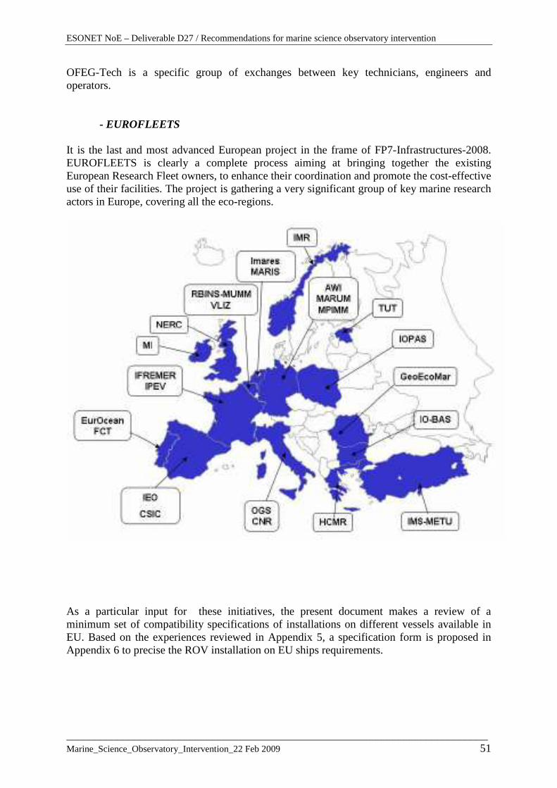
ESONET NoE – Deliverable D27 / Recommendations for marine science observatory intervention
___________________________________________________________________________ Marine_Science_Observatory_Intervention_22 Feb 2009 51
OFEG-Tech is a specific group of exchanges between key technicians, engineers and operators.
- EUROFLEETS It is the last and most advanced European project in the frame of FP7-Infrastructures-2008. EUROFLEETS is clearly a complete process aiming at bringing together the existing European Research Fleet owners, to enhance their coordination and promote the cost-effective use of their facilities. The project is gathering a very significant group of key marine research actors in Europe, covering all the eco-regions.
As a particular input for these initiatives, the present document makes a review of a minimum set of compatibility specifications of installations on different vessels available in EU. Based on the experiences reviewed in Appendix 5, a specification form is proposed in Appendix 6 to precise the ROV installation on EU ships requirements.

ESONET NoE – Deliverable D27 / Recommendations for marine science observatory intervention
___________________________________________________________________________ Marine_Science_Observatory_Intervention_22 Feb 2009 52
8.4.2 Tool sharing on ROVs, compatible user interfaces
One important aspect to be solved in the near future may be the sharing of payloads. ESONET Best Practises Workshop has identified the key parameters which will lead to a better understanding and a concise definition of a realistic level of compatibility.
The Appendix 6 proposes a specification form to collect and distribute the necessary detailed informations to identify interfaces and trend in payload development. These are mainly concerning the integration into the platform, and the manipulating capabilities and field of action:
• Dimensions of toolsleds or payload area
• Payload capacity
• Layout of toolsled and payload area
• Manipulating system description and capabilities
• End effector design
• Manipulating field of action (layout)
• Users electrical integration, and connectors
• Hydraulic interfaces
Today and in the early ages of observatory intervention, the interfaces will remain probably slightly different, and this first step concerning identification will allow to prepare the necessary adaptations to easy interoperability.
Another recommendation will concern associated training courses to test technical adaptations and procedures. That will be more generally developped in section 9.
8.4.3 Design process
ISO 13628-8 presents an intervention philosophy for the subsea observatory design that should be followed in order to reduce the number of different ROV techniques and interfaces required. Without re-writing the whole chapter [ § 6.3 Detailed design], the basic steps in the design process are as follows:
a) definition of tasks;
b) compilation of specification for interfaces, generally in association with the relevant ROV operator and observatory supplier;
c) choice of docking and tool deployment or manipulator philosophies;
d) definition of intervention interfaces
e) definition of the host subsea observatory detail design for ROV interfaces for tool operation;
f) definition of the ROV tools, interfaces, power supply and controls;
g) documentation (design, maintenance and operating philosophy;

ESONET NoE – Deliverable D27 / Recommendations for marine science observatory intervention
___________________________________________________________________________ Marine_Science_Observatory_Intervention_22 Feb 2009 53
h) final design stage with periodic reviews of the design for compliance with the recommendations and guidelines;
i) ensuring sub-system suppliers are considering ROV operation and intervention in their design and that such operation/intervention requirements and techniques are in concordance with the overall design philosophy for the subsea observatory installation and maintenance.
8.4.4 Interfaces on observatory
The ROV interfaces with many of the elements of a subsea observatory. As seen before, the subject is well covered in both API 17H and ISO 13628-8. All mechanical and dimensional aspects result from extensive track records and could be directly re-used for the design of ROV interfaces on underwater observatories. ESONET community would certainly benefit from a standardisation initiative on this subject.
The ISO 13628-8 lists the key elements that should therefore be considered during the design of the system to ensure future intervention. Adapted to scientific observatory, these elements could be:
- General:
• access for the ROV;
• selection of the correct intervention system;
• load constraints from ROV in operational mode;
• observatory design should minimize the potential for snagging;
• clear and unique identification marking;
• height of interfaces above bottom;
• ROV overrides
- For interlink connections:
• Camera access to all connectors;
• ROV cleaning tool access;
• Practibility to make connexion, guidance..;
• Protection caps setting in/out, storage..;
- Instrument/Equipment change out:
• Practibility, access for change out;
• Size and weight of the equipment and the capacity of the change-out manipulation or tooling;
• Storage for the equipment on the ROV;
These elements can be completed according to the intervention definition.
In particular:
- Interfaces shall be designed in such a way that they can resist to the loads and torque applied by the manipulator, evening case of bad manipulation; Weak points shall be

ESONET NoE – Deliverable D27 / Recommendations for marine science observatory intervention
___________________________________________________________________________ Marine_Science_Observatory_Intervention_22 Feb 2009 54
on the ROV/manipulator side. Typical docking parameters and receptacle loading are given in the ISO 13628-8, [section 12.2.5.3], and recalled in the frame below. They can be used or adapted to the ROV caracteristics and observatory design.
- For specifically designed interfaces, it is advised to perform onshore trials with a standard manipulator to verify the operability of the system, especially in terms of compliance and dexterity of the manipulator system.
- ROV will avoid to be on the seabed level for most of precise interventions requiring stabilisation. Docking and interface points should be a minimum of 1 m, and better 1,5 m above the clear local seabed.
- Guidance: This part is particularly concerning connexion/de-connexion of underwater mateable connectors, but can concern more generally ROV tooling to be deployed by manipulator. Guide cones may be sited around the point where a connector is to be inserted. Guide cones that face upwards should be open-ended, allowing debris to fall through, or equipped with a suitable debris cap. The minimum external size of the cone gives the minimum distance between two connectors.
- Access requirements: interface shall be accessible to standard 7 functions manipulators, including in terms of weight lifting, torque and accessibility. The RP ISO 13628 gives RPs concerning the three locations –externally located interfaces, external boundary penetration and internally located interfaces - where interfaces can be positioned on subsea observatory. These are general considerations on which observatory design could lean.

ESONET NoE – Deliverable D27 / Recommendations for marine science observatory intervention
___________________________________________________________________________ Marine_Science_Observatory_Intervention_22 Feb 2009 55
- Grasping handles: they are not absolutely needed, and depend on the choice adopted for the end effector of the grabber. If grasping handles are planned on structure, they should follow ISO 13628-8 RPs for dimensionning. They shall be designed to withstand a minimum force of 2,2 kN (500 lbf) applied from any direction and a gripping force of 2,2 kN applied from any direction. The method of attachment is optional.
-
- Docking probe and receptacle: they are not absolutely required. If stabilisation of the ROV on the structure requires such a technique, it would be useful to follow ISO 13628-8 design values for dimensions and typical docking parameter based upon a typical work class ROV. For any designed system the engineer should assess the specific requirements and adjust the values as necessary.

ESONET NoE – Deliverable D27 / Recommendations for marine science observatory intervention
___________________________________________________________________________ Marine_Science_Observatory_Intervention_22 Feb 2009 56
8.4.5 ROV stabilisation
Any ROV manipulator or tooling operation that requires the pilot to actively control the ROV during performance of the task should be avoided.
- ROV shall be stabilised by either
o A flat horizontal platform to “sit” the ROV, with thrusters pushing down
o Horizontal or vertical bar to allow the ROV grabber arm to take hold (see figure below)
o ROV docking/receiver points (see figures in TDU paragraph), one or two points
o Flat and smooth surfaces for attaching suction cups
It must be noted that second and third system are the most commonly used systems in offshore industry. Concerning the second point, the dimensions of the bars would be the same for every observatory, or at least compatible with all the existing manipulators.
Flat horizontal platform is giving more flexibility, and has given good results in operationnal tests for ANTARES secondary junction box.
8.4.6 ROV intervention with a tool deployment unit (TDU)
A TDU is a specifically designed work package that is attached to the front or rear of the ROV frame to accurately orient and position the tool by use of a Cartesian carriage arrangement. This is commonly adopted in offshore intervention, with single or twin-point

ESONET NoE – Deliverable D27 / Recommendations for marine science observatory intervention
___________________________________________________________________________ Marine_Science_Observatory_Intervention_22 Feb 2009 57
configuration. This is weight consuming on the ROV and needs more access space on the observatory, and so will be probably avoided. In case of absolute necessity, the configuration to be adopted will be single-point docking, which has more flexibility, generally requires lighter interface tool loading conditions and can be situated where there is a limited amount of adjacent structure. In that case, it is recommended to use the system which has been developped for offshore.
Single point docking system, with one DOF tool above
8.4.7 Procedures
A common specification form to collect and share the different operational procedures, detailed and comprehensible for the different ESONET partners, will help them in selection, tests and training.
The appendix 7 proposes a specification form for marine operations plan.
8.4.8 Tests and training Tests and training sessions during planned missions may be organized, with partners crossed participations.

ESONET NoE – Deliverable D27 / Recommendations for marine science observatory intervention
___________________________________________________________________________ Marine_Science_Observatory_Intervention_22 Feb 2009 58
9. DESIGN RECOMMENDATIONS FOR TRAINING, SIMULATION AND TESTING 9.1 - General The successful underwater installation, maintenance and recovery of observatory platforms and infrastructures require a shared operations scheme, allowing scheduled maintenance periods to be carried out independent of a single operations team and hardware platform. This will require a common understanding of both the process of dedicated intervention at a given structure as well as the underwater hardware interfacing, shared among different possible scientific ROVs and vehicle operators. To achieve such a common understanding, training will be necessary aside from seagoing cruises and expensive operations “on site”. The goal of training should be the assurance of a quality work at a comparative level between all participating operators, allowing the observatory missions and their associated science tasks to be carried out successful over long term deployment periods. A training facility would allow the dedicated setup of training courses for the following tasks: 9.2 - Manipulation training Manipulator training is essential for many kinds of operations not only regarding the topics discussed here. For intervention training, however, it is expected that the proposed standardization of specific hardware such as connectors, handles and tooling, similar manipulation tasks will emerge to maintain the periodical service at different sites and structures. This will allow the design of a repetitive training scheme, to be worked out i.e. as expert courses, and to be shared between different manipulation systems on existing and future ROVs. 9.3 – Virtual operations training and testing In addition to the manipulation task itself, underwater observatory intervention needs to be comparable on a higher level. This may implement operational procedures from underwater vehicle piloting over large-structure localization and handling, to ships positioning and wire-guided tool deployments from surface. Today’s computer technologies allow the setup of virtual environments including the above components and can be used to design, test, verify and train operational procedures of such intervention especially for ROV pilots in marine science. In addition, the specification of a certain software platform for underwater simulation could allow a virtual “accommodation and guidance” throughout the process of technical development of observatories and platforms. This in mind, observatory structure development would be able to gain experiences from virtual in-situ handling already during the CAD design phase, and thus help reduce the risks of expensive design errors and later incompatibilities.

ESONET NoE – Deliverable D27 / Recommendations for marine science observatory intervention
___________________________________________________________________________ Marine_Science_Observatory_Intervention_22 Feb 2009 59
9.4 – Scientists operational training Simulated underwater environments allow mission specific training and procedural testing, and thus also help scientists in charge of such missions to gain a higher level of understanding. Because all tasks discussed here are by definition dedicated to marine science, overall mission planning and scheduling of increasingly complex, technology loaded expeditions requires higher levels of such operational awareness than only few years ago. Examples for operational constraints are specific task durations, payload limitations or environmental dependencies such as currents and weather. With the increasing use of remotely controlled vehicle platforms, observatory installations, real-time data networks and autonomous instruments, scientists increasingly need to have access to operational training to become prepared for realistic estimations of technical capabilities, needs of enhanced cruise planning, and finally decisions and design calls of large-scale scientific deep-ocean infrastructures in future.
Existing Infrastructure Existing “dry” manipulator testing installations may be used for the design and implementation of training courses:
• IFREMER, Toulon (existing Cybernetix 7P proportional electro-hydraulic arm test setup and positioning and control software simulator). Among different objectives, the new CETSM (European Center of Marine technologies) will make functional simulations for sciences software interfaces.
• MARUM, Bremen (existing Schilling Orion 7PE proportional electro-hydraulic arm training setup with 2 proportional Pan/Tilt camera heads). Marum Bremen is currently in the process of evaluating different software solutions to setup a virtual test and training simulator environment, and intends to setup a combined hard- and software based facility with the capability of interfacing to different vehicles and proposed observatory platforms in the near future.
• Others??:

ESONET NoE – Deliverable D27 / Recommendations for marine science observatory intervention
___________________________________________________________________________ Marine_Science_Observatory_Intervention_22 Feb 2009 60
10. CONCLUSIONS AND GENERAL RECOMMENDATIONS Particular recommendations have been proposed all along the document, for the different steps of the scientific observatory building, maintenance and recovery. These recommendations must take into account that the existing underwater means will govern the early days of observatory developments, with probably different interfaces and procedures. The document has pointed out that there will be probably different “good procedures” to meet the requirements of a particular intervention. In fine, the choice will be submitted by the operator in charge and evaluated by members of network “Test and Operation Council”, and steering committee. It has been difficult to gather all the data concerning European fleets to complete the scientific intervention survey. Some of the information are still missing, and the document must be considered as a living one, and can be enriched during the project development. The first main topics for the recommendations are concerning the following points:
- The main scientific observatory equipments, except the backbone cable and branching units, may be deployed with existing scientific vessels and technical means;
- Concerning deployment of the different modules of the observatory, as opposed to the offshore philosophy, more light methods will be proposed, according to the kind of vessel and equipment, insofar as the operation can be done by good weather conditions;
- For cable laying, specific tools (including drum, toolsled..) will be designed to be compatible with the different European vehicles, or easily configurable;
- Efforts may be combined and coordinated between the partners to study, developp, or buy “on the shelf”, qualify needed subsea connectors, in connection with existing manufacturer and new other observatory developments in the world (USA, Canada,..);
- Concerning ROV interfaces with the elements of a subsea observatory, a standardisation will be initiated. It will be based largely on ISO 13628-8, adapted to the existing ROV caracteristics;
- A common specification form to collect and share the key informations to identify ROV interfaces and trend in payload development will be a first step to prepare necessary adaptations between vehicles;
- A common specification form to collect and share the different operational procedures, detailed and comprehensible for the different ESONET partners, will help them in selection, tests and training;
- Particular training during planned missions may be organized, with partners crossed participations.

ESONET NoE – Deliverable D27 / Recommendations for marine science observatory intervention
___________________________________________________________________________ Marine_Science_Observatory_Intervention_22 Feb 2009 61
References
- [R1] ESONET Website : http://www.esonet-emso.org/ - [R2] Standards and recommended practices for underwater intervention and structures
interfaces in the Offshore industry - [R3] TSM 07 Position Paper – Full Ocean ROVs and Deep Tows – Volker Ratmeyer,
V.Rigaud & Ian Rouse - [R4] Final OFWG Report: European Ocean Research Fleets. Marine Board ESF
publication – www.esf.org/marineboard - [R5] ROV Based Tool Sled For the Placement of Fiber Optic Cable Between Benthic
Instrument Nodes- Oceans MTS/IEEE Conference and Proceedings 2002. - [R6] Monterey Accelerated Research System (MARS) website and news - [R7] Marine Architecture and Installation Methods Developped for the Deep Sea
Neutrino Telescop ANTARES, Pierre Valdy, Ifremer - [R8] Monterey Ocean Observing System (MOOS) website and news - [R9] Unique Marine Route, Installation and Maintenance Considerations in planning
Scientific Cable Systems, Dr.Ronald J. Rapp, Tyco Telecommunications, Proc. - [R10] Connecting Long Term Sea Floor Observatories to the shore, Waterwoth, G.,
proc Oceans 2003 - [R11]Observatory cable laying system- Canadian Scientific Submersible Facility,
proc. - http://www.ropos.com/documents/ROCLS%20paper.pdf - [R12] ANTARES Installation – Marine means and methods- J.Roux, V.Bertin,
S.Beurthey, CNRS/IN2P3, Proc. INMARTECH 2008 - [R13] Procedure d’utilisation des connecteurs ODI – Ref 3-LSM-01-19A - Antares
property - [R14] Interlink cable connection procedure : DEE-ESM/SEH/JP.J/EP/06.146 –
Ifremer - [R15] Wet mateable optical connector advancements – VLVnT08 conference, April
08 - [R16] GI-TEWS – Deep mooring deplyment in Med.Sea – S.Roemer(GFZ), E.Flüh,
JF Drogou – Inmartech 08 - [R17] Use of electro-optical mechanical mooring cable for oceanographic
buoys:modeling and validation – A.Hamilton, M.Chaffey – OMAE2005-67561 - [R18] The evolution of ROV wet-mate connector technology in supplying high
bandwith/high power/ deep water solutions for the scientific ocean observatory market – S.Barlow, J.Flynn, W.Mudge,- Ocan Design Inc

ESONET NoE – Deliverable D27 / Recommendations for marine science observatory intervention
___________________________________________________________________________ Marine_Science_Observatory_Intervention_22 Feb 2009 62
APPENDICES
- Appendix 1: Standards and recommended practices for underwater intervention and structures interfaces in the Offshore industry – Table of contents
- Appendix 2: Existing standards in Offshore Oil & gas industry
- Appendix 3: Examples of Ocean Bottom Unit deployment in Ifremer
- Appendix 4: ISO 13628-8 – Table of contents
- Appendix 5: Compatibility for sharing platforms and ships: specification form
- Appendix 6: Compatibility between ROVs (Tooling and payloads): specification form
- Appendix 7: Procedure demands for underwater intervention and quality assurance : procedure checklist
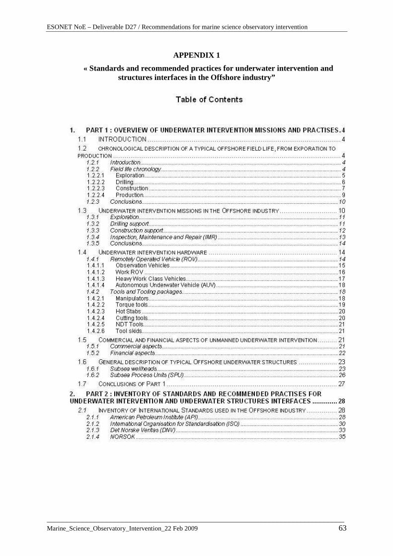
ESONET NoE – Deliverable D27 / Recommendations for marine science observatory intervention
___________________________________________________________________________ Marine_Science_Observatory_Intervention_22 Feb 2009 63
APPENDIX 1
« Standards and recommended practices for underwater intervention and structures interfaces in the Offshore industry”

ESONET NoE – Deliverable D27 / Recommendations for marine science observatory intervention
___________________________________________________________________________ Marine_Science_Observatory_Intervention_22 Feb 2009 64
« Standards and recommended practices for underwater intervention and structures interfaces in the Offshore industry”
Table of containts (following)

ESONET NoE – Deliverable D27 / Recommendations for marine science observatory intervention
___________________________________________________________________________ Marine_Science_Observatory_Intervention_22 Feb 2009 65
APPENDIX 2
Existing standards in the offshore industry
American Petroleum Institute (API)
Series 17: Subsea Production Systems
REP 17H – Remotely Operated Vehicle (ROV) Interface s on Subsea Production Systems
RP 17H gives functional requirements and guidelines for ROV interfaces on subsea production systems. It is applicable to both the selection and use of ROV interfaces on subsea production equipment, and provides guidance on design as well as the operational requirements for maximising the potential of standard equipment and design principles.
International Organization for Standardisation (ISO )
Serie 75.180 « Equipment petroleum and natural gas industries »
ISO 13628:
Part 1: General requirements and recommendations
Part 2: Flexible pipe systems for subsea and marine applications
Part 3: Through flowline (TFL) systems
Part 4: Subsea wellhead and tree equipment
Part 5: Subsea umbilicals
Part 6: Subsea production control systems
Part 8: Remotely Operated Vehicle (ROV) interfaces on subsea production systems
Part 9: Remotely Operated Tool (ROT) intervention systems
Det Norske Veritas ( DNV)
More oriented towards inspection, testing and certification processes and less potential for OFM designers
Recommended Practise N° DNV-RP-A203 “Qualification procedures for new technology”:
Recommended Practise N° DNV-RP-H101 “”Risk Manageme nt in Marine and Subsea Operations”:
DNV recommends a basic three-step process for management of risks within marine and subsea

ESONET NoE – Deliverable D27 / Recommendations for marine science observatory intervention
___________________________________________________________________________ Marine_Science_Observatory_Intervention_22 Feb 2009 66
NORSOK
Based on existing international standards with some additional constraints
U-102 Remotely Operated Vehicles Services: ROV classification and good guidelines to subcontract ROV services
International Marine Contractors Association ( IMCA )
Best practice guidance, in the areas of safety, training and personnel competence
IMCA R 002 to R 013
Field of ROV services and contracting

ESONET NoE – Deliverable D27 / Recommendations for marine science observatory intervention
___________________________________________________________________________ Marine_Science_Observatory_Intervention_22 Feb 2009 67
APPENDIX 3
Examples of OBU deployment concerning Ifremer projects 1 - PENFELD deployment : Penfeld penetrometer developped by Ifremer and Geocean is an operationnel system able to make geotechnical measures by penetrometry in deep-sea (6000 m) This heavy system (6 tons) is deployed by cable. It remains connected after it has been laid on the bottom, with the ship in station keeping during the penetrometry operation. The lift line is set up by main cable, a depressor weight (500 kg) and a polyamid tether 50 m length. This concept permits to absorb high dynamic tensile loads during lifting phase, and, after laying on the bottom isolates the system from vessel movements by means of the flexible arch.
Penfeld deployment Moreover, a specific equipment called « handling messenger »has been developped for deployment and recovery from a unique A-Frame. This device make it possible to transfer at

ESONET NoE – Deliverable D27 / Recommendations for marine science observatory intervention
___________________________________________________________________________ Marine_Science_Observatory_Intervention_22 Feb 2009 68
low depth (corresponding to synthetic tether), tension from the lift line to the main cable and vice-versa.
Instrumented trials have validated deployment procedures and system “Penfeld + cable + lest + tether”behaviour. 2 - ANTARES deployment :

ESONET NoE – Deliverable D27 / Recommendations for marine science observatory intervention
___________________________________________________________________________ Marine_Science_Observatory_Intervention_22 Feb 2009 69
The project is concerning the development of neutrino detector that will be installed in 2500 m of water in Mediterranean sea. The envisaged detector is made up by network of optical modules set up on vertical strings. The network is connected to the shore by means of electro-optical cable, main junction box and interconnecting links. Ifremer is in charge of sea operations including installation and future maintenance.
ANTARES deployment In this project, detector lines and junction box are deployed and recovered by cable from a DP vessel. For all the operations a precise long base line acoustic positioning system is essential. Junction box deployment and recovery : for deploying the ANTARES junction box, the end of the 50 km electro-optical cable is connected to a fishing tail to be dredged with a
P r o f i le r fo r S e a c u r r a n t
(A D C P )
P ro b e fo r s a l in it y an d t em p e r a t u r e (C T D )
P ro b e fo r S o u n d ve lo c it y
J u n c t io n B o x
L E D B e a c o n
L a s e r B e ac o n
S e is m o g r ap h
h yd ro p h o n e s h yd r o p h o n e
5 S to r eys o f O p t ic a l M o d u le s
A n c h o r w it h e le c t ro n ic s c o n t a in e r s L in k C ab le s
Detector geometry :
- 12 lines - 25 storeys/line

ESONET NoE – Deliverable D27 / Recommendations for marine science observatory intervention
___________________________________________________________________________ Marine_Science_Observatory_Intervention_22 Feb 2009 70
grapnel for connector recovery. With a good positioning of the cable and the fishing tail, the operation of recovery takes a few hours.
Dredger line and fishing tail on the bottom
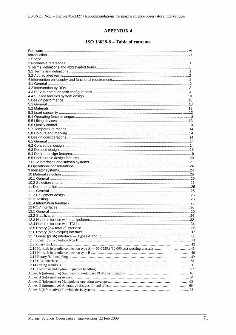
ESONET NoE – Deliverable D27 / Recommendations for marine science observatory intervention
___________________________________________________________________________ Marine_Science_Observatory_Intervention_22 Feb 2009 71
APPENDIX 4
ISO 13628-8 – Table of contents
Foreword ............................................................................................................................................... . vi Introduction........................................................................................................................................... .. vii 1 Scope............................................................................................................................................... ... .1 2 Normative references....................................................................................................................... ....1 3 Terms, definitions and abbreviated terms...................................................................................... .. ....1 3.1 Terms and definitions .................................................................................................................. .. ...1 3.2 Abbreviated terms........................................................................................................................ . ....2 4 Intervention philosophy and functional requirements....................................................................... ....2 4.1 General ....................................................................................................................................... ... ..2 4.2 Intervention by ROV...................................................................................................................... .....3 4.3 ROV intervention task configurations................................................................................................ .4 4.4 Subsea facilities system design ........................................................................................................10 5 Design performance........................................................................................................................ .....13 5.1 General ....................................................................................................................................... ......13 5.2 Materials ..................................................................................................................................... ......13 5.3 Load capability ............................................................................................................................ ......13 5.4 Operating force or torque.............................................................................................................. .....13 5.5 Lifting devices ............................................................................................................................... ....13 5.6 Quality control ....................................................................................................................................13 5.7 Temperature ratings............................................................................................................................14 5.8 Colours and marking ..........................................................................................................................14 6 Design considerations............................................................................................................................14 6.1 General ...............................................................................................................................................14 6.2 Conceptual design ..............................................................................................................................14 6.3 Detailed design ...................................................................................................................................16 6.4 Desired design features.......................................................................................................................18 6.5 Undesirable design features ...............................................................................................................20 7 ROV interfaces and subsea systems .....................................................................................................21 8 Operational considerations.....................................................................................................................24 9 Indicator systems....................................................................................................................................24 10 Material selection .................................................................................................................................25 10.1 General ..............................................................................................................................................25 10.2 Selection criteria.................................................................................................................................25 11 Documentation ......................................................................................................................................25 11.1 General ..............................................................................................................................................25 11.2 Equipment design ..............................................................................................................................26 11.3 Testing................................................................................................................................................26 11.4 Information feedback .........................................................................................................................26 12 ROV interfaces......................................................................................................................................26 12.1 General ..............................................................................................................................................26 12.2 Stabilization .......................................................................................................................................26 12.3 Handles for use with manipulators.....................................................................................................32 12.4 Handles for use with TDUs.................................................................................................................34 12.5 Rotary (low torque) interface ..............................................................................................................35 12.6 Rotary (high-torque) interface.............................................................................................................37 12.7 Linear (push) interface — Types A and C...........................................................................................38 12.8 Linear (push) interface type B ........................................................................................ ................... 41 12.9 Rotary docking ............................................................................................................................. ...... 42 12.10 Hot stab hydraulic connection type A — 69,0 MPa (10 000 psi) working pressure ........ ................. 45 12.11 Hot stab hydraulic connection type B ................................................................................. ............. 46 12.12 Rotary fluid coupling ............................................................................................................ ............ 49 12.13 CCO interface .......................................................................................................................... ........ 51 12.14 Lifting mandrels ....................................................................................................................... ........ 56 12.15 Electrical and hydraulic jumper handling................................................................................... .... .... 57 Annex A (informative) Summary of work class ROV specifications .................................................. ......... 63 Annex B (informative) Access............................................................................................................. ........ 64 Annex C (informative) Manipulator operating envelopes.................................................................... ........ 65 Annex D (informative) Alternative designs for end effectors.............................................................. ......... 66 Annex E (informative) Flowline tie-in systems .................................................................................. .......... 68

APPENDIX 5
Existing EU ships with known full ocean ROV hosting capabilities, and existing installations:
Class Country Ship
G O R
Lenght (meter)
Region Dyn. Pos.
Underwater Systems ROVs Cl II & III
Hosting capabilities ROV Cl I, II & III
Existing installation
Pourquoi pas?
G 105 Global Y ROV Cl III, HOV
Victor 6000 Nautile
L’Atalante G 85 Global Y ROV Cl III HOV
Victor 6000 Nautile Kiel 6000
France
Thalassa O 74 North Atlantic (NA)
Y
Nautile Victor 6000
ROV Cl III
Victor 6000
Polarstern G 118 Polar Y ROV Cl III
Victor 6000 Quest
Meteor G 98 Ocean Y ROV Cl III
Quest
M.S.Meriam G 95 Ocean Y ROV Cl III
Quest
Poseidon O 61 NA N ROV Cl II Cherokee
Alkor R 55 Baltic N ROV Cl II Cherokee
Heinckle R 55 North sea N ROV Cl II Cherokee
Germany
Sonne (until 2010)
G 98 Ocean Y
Quest 4000 KIEL 6000 Cherokee
ROV Cl III Quest Kiel 6000 ROPOS (Canada)
Greece Aegaeo R 62 Mediterranean Sea (M)
N Thetis (HOV)
ROV Cl II Light HOV
Thetis ROV ClI
Ireland Celtic Explorer
O 65 NA Y ROV Cl III MeBo (Remote Drill)
Urania R 61 M N ROV Cl II MODUS Italy
Universitatis R 45 M N
MODUS ROV 4000 (Cougar/Pegaso)
Netherlands Pelagia O 66 Ocean N ROV Cl III Quest DST/TOBI
G.O.Sars O 77 NA Y ROV Cl III Norway
H.Mosby R 47 NA Y ROV Cl II
Portugal Don Carlos I
R 68 NA N ROV Cl II
Hesperides G 83 Global N ROV Cl III TOBI Spain
Sarmiento de Gamboa
0 70,50 A M
Y ROV Cl III Victor 6000
Sweden Argos (until 2009?)
R 61 Baltic N ROV Cl II
J.C.Ross G 99 Polar Y ROV Cl III ISIS Autosub
Discovery G 90 Ocean N ROV Cl III Autosub
James Cook ROV Cl III ISIS
UK
C.Darwin O 69 Ocean N
ISIS 6500
Autosub
Vessel Class: Global (G), Ocean (O), Regional (R) – ROV Class: Work Class (Cl III), Medium (Cl II) – HOV : Manned sub.

APPENDIX 6
Project ESONET – NoE
Deliverable D28
Interface specifications – ROV and tool sharing
(Preliminary) Specification form for operators of ROV
CONTACT coordinates:
I – ROV Installation on ship - General description of the vehicle and the operation scenario: (General technical specifications as NORSOK STANDARD U-102) …………………………………………………………………………………………………………………………………………………………………………………………………… - TMS (General description of the TMS) ..................................................................................................................................... - Winch (Description of the winch, umbilical caracteristics, ) .................................................................................................................................... - Launch and recovery (Description of the needed handling systems and the necessary handling procedures for the vehicle - prelaunch check, necessary functional tests, typical time needed for prelaunch check and procedures etc.): - Control van (General description, installation constraints) ………………………………………………………………………………………………… - Vessel requirements and transport (Transport package, total weight, deck space for storage, energy supply, team, mobilization) ......................................................................................................................................

ESONET NoE – Deliverable D27 / Recommendations for marine science observatory intervention
___________________________________________________________________________ Marine_Science_Observatory_Intervention_22 Feb 2009 74
II) Integration into the vehicle Technical specification for users concerning installation of equipment on the véhicle: yes/no Reference: 1 - Mechanical integration - Dimensions of toolsled or payload area
Length: m
Width: m
Height: m
- Payload capacity
Max. Weight of payload in water: kg
Max. Weight payload in air ………kg
Max. Depth capability of vehicle: m
software for payload calculations - available? Yes/No
- Mounting elements (clamps, bolts etc)
……………………………………………………………………………………
- Layout of toolsled or payload area:
..................................................................................................................................................
- Manipulators
For Grabber and Working manipulator:
Number of functions
Control method
Force feedback (if exists)
Type of jaws
Size of recess for handles

ESONET NoE – Deliverable D27 / Recommendations for marine science observatory intervention
___________________________________________________________________________ Marine_Science_Observatory_Intervention_22 Feb 2009 75
Outreach
Lift capacity-Wrist torque
Layout of manipulating field of action
.......................................................................................................................................................
2 - Electrical integration - Is a power supply offered to external units? Yes/No
Supply voltage range V
Ripple voltage V
Operating currents mA
Peak currents A
Maximum current A
Isolation voltage kV
Is the power line isolated from chassis/housing? Yes/No
Is the system in compliance with CE norm Yes/No
Other safety issues (Please describe):
…………………………………………………………………………………………………
…………………………………………………………………………………………………
3 – Digital telemetry connection (If the platform has no interfaces to payload skip this section)
Number and Type of ports (RS
- Serial: ( 232 /RS 485)
-Video
Standard (PAL/SECAM/NTSC,HDTV)
Signal level (V @ 75 Ω)
Bandwidth MHz

ESONET NoE – Deliverable D27 / Recommendations for marine science observatory intervention
___________________________________________________________________________ Marine_Science_Observatory_Intervention_22 Feb 2009 76
- Ethernet: (10 / 100 Mbps)
(Indicate the type of connectors)...........................................................................
.......................................................................................................................................................
4 - Acoustic interface
Frequency kHz
Signal level dB (µPa ref 1 m)
Directivity
Bandwidth
5 - Electrical Connectors
(If platform has no interfaces to payload skip this section) Type of connection - Power, Data input/output, Command Connector 1: Type of connection:
Label:
Connector type:
Pin diagram (drawing):
Connector 2: Type of connection:
Label:
Connector type:
Pin diagram (drawing):
…………………… 6 - Hydraulic interfaces
ESONET NoE – Deliverable D27 / Recommendations for marine science observatory intervention
___________________________________________________________________________ Marine_Science_Observatory_Intervention_22 Feb 2009 77
Connectors for hydraulic actuators Number of low flow output Number of high flow hydraulic output Flow rate @ pressure 7 – Other requirements
ESONET NoE – Deliverable D27 / Recommendations for marine science observatory intervention
___________________________________________________________________________ Marine_Science_Observatory_Intervention_22 Feb 2009 78
APPENDIX 7
(PRELIMINARY) DEPLOYMENT/RECOVERY PROCEDURES DOCUME NT
1.0 SCOPE
1.1. Document overview
The document is intended to give guide lines to define observatory deployment & recovery
procedures and structure the corresponding specification. It is aimed at ESONET scientific
leaders, and organism responsible of the marine operations for demo missions propositions,
and “Test and Operation Council” (TOC) partcipants and ESONET Steering Committe for
evaluation and approval.
1.2. Applicable documents
- [1] ESONET NoE – Annex 1 – « Description of Work »
- [2] Guide for applicant for DEMONSTRATION MISSIONS in ESONET NoE
- [3] Proceeding of Best Practice Workshop: Sensor Interface, Quality Insurance and
specifications for demonstration Actions
- [4] Deliverable D28: Recommendations for marine science observatory intervention
- [5] GUASA: User Guide for Access to ANTARES
2.0. GENERAL GUIDE LINES
2.1. General requirements
To optimise intervention time and efficiency, with optimal use of the existing ressources
(ships, ROVs etc..), as well as to ensure the interoperability of the various user’s equipment,
ESONET has defined “Recommendations for marine science observatory intervention”.
The proposed marine operations will take into account the recommendations described in [4].
ESONET NoE – Deliverable D27 / Recommendations for marine science observatory intervention
___________________________________________________________________________ Marine_Science_Observatory_Intervention_22 Feb 2009 79
According to the fact that the first tests will be largely carried out on sites that have an
existing cable connection to shore, the marine operations will take into consideration the rules
emitted by the responsible of the concerned infrastructure. As an example the user guide for
installation and implementation of an experiment on ANTARES site is proposed [5].
The marine operations proposals will be evaluated by members of network “Test and
Operation Council” (TOC) and Steering Commitee, according to organization, flow chart and
criteria detailed in the ESONET NoE Guide for Applicant [2]
2.2. Description of the marine operations plan
The specification for marine operations will follow the general frame proposed below.
2.2.1. Objectives and general description of marine operations
This section provides the general requirements for marine operations, includes different items
that will be detailed further:
- the general system overlay, its fixed and mobile parts, its interfaces,
- the different objectives of the operation, without detail but with a hierarchy,
- the possible naval means, with indication of estimated crew,
- the estimated planning (and cost if possible at this stage).
2.2.2. Applicable documents
This section shall list the number, title, revision, and date of all documents referenced or used
in the preparation of the specification.
- Quality plan
- General rules for marine operations for the project
- Equipment safety form
- Management of non conformities
- Particular procedures
- ..etc

ESONET NoE – Deliverable D27 / Recommendations for marine science observatory intervention
___________________________________________________________________________ Marine_Science_Observatory_Intervention_22 Feb 2009 80
2.2.3. Intervening parties, roles and responsibilities
This section will precise the role of the different intervening parties implied in the operation:
- final user, scientific responsible
- operator in charge of the marine operations
- main contractor organism
- organism in charge of the existing marine infrastructure if needed (Antares, Nemo,
Venus….)
2.2.4. Naval and underwater means
This section will precise the planned vessels and underwater vehicles, or the possible ones,
with their main specifications and capabilities.
2.2.5. Other equipment useful for the operation
This section will detail for each operation, the necessary equipment to be used, with
utilization , storage constraints.
The disposal of other equipment than the operator ones (positioning system, handling
systems…)will be precised.
2.2.6. Operational procedures
This section will present the general operational procedures that will be used, without detail,
from the first deployment to the final recovery of the different subsystems. In case of planned
other marine interventions during the project, these will be precised.
These procedures shall be based on recognised standards, particular international
specifications or norms that will be used, and on previous tests and operational experiences.
They will refer to the D28 deliverable document [4]
2.2.7. List of tasks, during mobilization, operations, demobilization

ESONET NoE – Deliverable D27 / Recommendations for marine science observatory intervention
___________________________________________________________________________ Marine_Science_Observatory_Intervention_22 Feb 2009 81
This section will precise the responsabilities of the different intervening parties (according to
previous list) during the main phases of the operations.
2.2.8. Particular arrangements contributing to the main objectives
- Description of parrallel tasks as training, simulation and testing, already existing or
needed before the operation,
- Identification of eventual perturbations for the existing infrastructure, and propositions
for avoiding them or decreasing them to an acceptable level,
- Risk analysis, and safety dispositions for the system and the existing infrastructure,
- Human safety procedures,
- Necessary operational crew.
2.2.9. Cost of the marine operations
This section will present the cost effectiveness. This will include the use of existing
monitoring infrastructure or planned cruises.
2.2.10. Notes
This section may be used to provide information that aids in understanding the document.
2.2.11. Approval
A page shall be included in the specification for signature of the intervening parties in the
operation, as defined in 2.2.3.
Appendices
Appendices may be used to provide information published separately for convenience:
- Insurance covering, acronyms, abbrevations, detailed tasks, sketchs, figures...