project commitments a b permit... · project commitments nc 68- us 220 connector from nc 68 at sr...
TRANSCRIPT

PROJECT COMMITMENTS
NC 68- US 220 Connector
From NC 68 at SR 2133 to existing intersection of NC 68 and US 220 Guilford and Rockingham Counties
WBS Element 34429.1.1 TIP Project R-2413
COMMITMENTS FROM PROJECT DEVELOPMENT AND DESIGN
Current status, changes, or additions to the project commitments as shown in the environmental document for the project are printed in italics. All commitments, which are not pertinent to R-2413-A & B have been grayed out. Hydraulics Unit/ Roadside Environmental Unit:
• Best Management Practices will be employed. Action: Standard Commitment. Roadway Design Unit/ PDEA Unit/ Division 7:
• NCDOT will coordinate with resource agencies (USCOE, USFWS, NCWRC and
DEM) during the permitting phase of the project to develop a mutually agreeable mitigation plan.
Mitigation opportunities will be explored that will provide for wetland restoration, enhancement, and/or creation within the same drainage as the wetland loss. Action: There is ongoing coordination with the resource agencies.
Mitigation plans to be included with the permit application. The use of previously converted farmland will be explored for wetland restoration sites. Action: No suitable sites found.
The donation of orphaned plots (uneconomic remnants) of farmland and forest to the county greenway and/or parks and recreation programs will be considered
Action: This will be addressed after project construction by Division 7.
R-2413 A & B Permit Mod Greensheet May 2016 Page 1 of 6
Roadway Design/Hydraulics/ Structures/ PDEA/ Roadside Environmental:
• There will be continuing efforts for cooperation between NCDOT and theresource agencies with respect to the crossings of Reedy Fork Creek and the HawRiver.
NCDOT will construct a hazardous spill catch basin (HSCB) at the Reedy Fork Creek Crossing, which lies within the Greensboro watershed. Additional HSCBs will be considered for other locations within the Greensboro Watershed during the development of preliminary and final design plans.
NCDOT will provide a self-contained bridge drainage system for the crossing of Reedy Fork Creek. The bridge drainage will be tied in with the hazardous spill catch basin.
Action: This commitment will not be implemented. NCDOT policy does not require the construction of HSCB basin at this site. A Basin is not required if it is over 1/2 mile from the critical area of a stream classified WS-III (Reedy Fork). This project is at 1.9 miles from the critical area. BMP's on the design plans are avoiding direct discharge into the surface water and discharging as far away from the surface water as practicable. Also grassed swales and preformed scour holes are being used where practicable. No hazardous catch basin is being constructed.
NCDOT will provide bridged crossings of Reedy Fork Creek and the Haw River that allow wildlife, pedestrian, and equestrian access along both sides of the waterway. The Reedy Fork Creek crossing will provide 10 feet of natural surface on one bank, and 10 feet of natural surface as well as 10 feet of stabilized trail on the other bank for passage beneath the bridge. The Haw River crossing will provide 10 feet of natural surface on each side of the channel for passage beneath the bridge.
Action: The bridge length will accommodate wildlife, pedestrian and equestrian access per the commitment. The trail will be stabilized with vegetation.
PDEA Unit:
• NCDOT will coordinate with the USACE and the NC Department of Cultural Resources (NCDCR) regarding the possible need for archaeological survey in the vicinity of 404 permit areas to assess the nature, extent, condition and significance of archaeological resources that might be damaged or destroyed by the proposed action.
R-2413 A & B Permit Mod Greensheet May 2016 Page 2 of 6

Action: Coordination between USACE and NCDCR was completed in 2007; Concurrence in November 2007 from SHPO concluded no property is eligible for the National Register.
Contract and Proposal Unit/ Division 7:
• NCDOT will attempt to salvage merchantable timber during the clearing of right-of-way for the project. NCDOT's general contract for right-of-way c1earingprovides opportunity for contractors to market saleable trees.
Action: This commitment is standard and general in NCDOT contracts.
Roadway Design Unit/ Hydraulics Unit/ Structures Unit:
• The project will include pedestrian culverts at Brookbank Road and at theabandoned railroad. At Deboe Road, a 7.5-foot offset will be included on oneside of the bridge for the accommodation of future sidewalks.
Action: (14’X10’) pedestrian culverts are included at the Brookbank Road andthe abandoned railroad. Also, a 7.5 foot off-set is included for future sidewalks at Deboe Road, Alcorn Road and Bunch Road.
• NCDOT committed to altering their design plans for the southbound off-ramp atNC 150 to avoid direct impacts to the private recreation center for the HensonForest subdivision.
Action: The current design avoids any impacts to the recreation center.
• NCDOT agreed to include equalizer pipes in the design for water flow betweenthe wetland areas, and include sills in the culverts to prevent head cuts at acrossing of an unnamed tributary to Reedy Fork Creek.
Action: The current design includes 10’X10’ equalizer culvert, sills are includedin pipes where required and necessary.
• NCDOT will construct a single 7-foot by 8-foot culvert at a crossing of unnamedtributary to Haw River.
Action: The current design includes 10’X8’ culvert with sills.PDEA Unit:
• Based on preliminary noise studies, NCDOT will evaluate noise abatementmeasures at the following locations during final design:
-Golden Acres Subdivision south of Alcorn Road -Trailer court at US 220 and NC 65 -Trailer court across US 220 from Spotswood Road -Homes west of US 220 at Ogborn Mill Road (SR 1100) -Homes east of US 220 at Ogborn Mill Road (SR 1100)
R-2413 A & B Permit Mod Greensheet May 2016 Page 3 of 6

NOTE: Noise Barriers: For the updated traffic noise analysis prepared in April 2009, only one barrier was found to be reasonable and feasible. This barrier is located along Section C near Spotswood Road, north of the Connector/US 220 interchange from Station 34+80 to Station 39+60. This barrier is 19 feet high and 1,576 feet long and is located on the west side of US 220.
COMMITMENTS DEVELOPED FROM PERMITTING
Natural Environment Engineering Group and Onsite Mitigation Group:
404 condition 20 Mitigation:
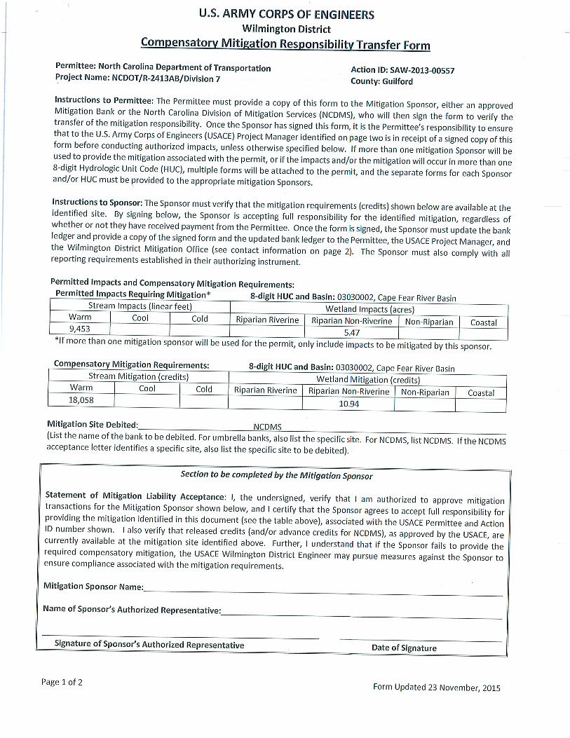
A. In Lieu Fee: In order to compensate for impacts associated with this permit, mitigation shall be provided in accordance with the provisions outlined on the most recent version of the attached Compensatory Mitigation Responsibility Transfer Form. The requirements of this form, including any special conditions listed on this form, are hereby incorporated as special conditions of this permit authorization.
B. Permittee Responsible Mitigation: 1. The Permittee shall fully implement the compensatory mitigation plan, entitled, R-2413 A & B, Plan for Onsite Mitigation, dated (revised) July 1, 2013 for the unavoidable impacts to 3,155 linear feet of streams. Activities prescribed by this plan shall be initiated prior to, or concurrently with, commencement of any construction activities within jurisdictional areas authorized by this permit. The permittee shall (re-establish, rehabilitate, enhance, establish) 3,155 linear feet of streams in accordance with the plan with the following conditions:
a) The permittee, NCDOT, is the party responsible for the implementation, performanceand long term management of the compensatory mitigation project.
b) Any changes or modifications to your mitigation plan shall be approved by the Corps.
c) The permittee shall maintain the entire mitigation site in its natural condition, asaltered by the work in the mitigation plan, in perpetuity. Prohibited activities within the mitigation site specifically include, but are not limited to: filling; grading; excavating; earth movement of any kind; construction of roads, walkways, buildings, signs, or any other structure; any activity that may alter the drainage patterns on the property; the destruction, cutting, removal, mowing, or other alteration of vegetation on the property; disposal or storage of any garbage, trash, debris or other waste material; graze or water animals, or use for any agricultural or horticultural purpose; or any other activity which would result in the property being adversely impacted or destroyed, except as specifically authorized by this permit.
R-2413 A & B Permit Mod Greensheet May 2016 Page 4 of 6

d) All mitigation areas shall be monitored for a minimum of 5 years or until deemedsuccessful by the Corps in accordance with the monitoring requirements included in the mitigation plan.
2. Remedial Mitigation Plan: If the compensatory mitigation fails to meet theperformance standards 5 years after completion of the compensatory mitigation objectives, the compensatory mitigation will be deemed unsuccessful. Within 60 days of notification by the Corps that the compensatory mitigation is unsuccessful, the Permittee shall submit to the Corps an alternate compensatory mitigation proposal to fully offset the functional loss that occurred as a result of the project. The alternate compensatory mitigation proposal may be required to include additional mitigation to compensate for the temporal loss of wetland function associated with the unsuccessful compensatory mitigation activities. The Corps reserves the right to fully evaluate, amend, and approve or reject the alternate compensatory mitigation proposal. Within 120 days of Corps approval, the Permittee will complete the alternate compensatory mitigation proposal.
3. Mitigation Release: The Permittee's responsibility to complete the requiredcompensatory mitigation, as set forth in the Compensatory Mitigation Special Condition of this permit will not be considered fulfilled until mitigation success has been demonstrated and written verification has been provided by the Corps. A mitigation area which has been released will no longer require monitoring or reporting by the Permittee; however the Permittee, Successors and subsequent Transferees remain perpetually responsible to ensure that the mitigation area(s) remain in a condition appropriate to offset the authorized impacts in accordance with the approved mitigation and monitoring plan and the general and special conditions of this permit.
401 condition 4 Compensatory mitigation for impacts to 8,171 linear feet of streams for the R-2413A project and 3,594 for the R-2413B project at a replacement ration of 1:1 is required. Compensatory mitigation for impacts to jurisdictional streams shall be provided by onsite stream relocations of 2,180 linear feet of stream for the R-2413A project and 765 linear feet for the R-2413B project. The onsite stream relocation shall be constructed in accordance with the design submitted in your application dated received July 19, 2013 and August 23, 2013. All onsite mitigation sites shall be protected in perpetuity by a conservation easement or through NCDOT fee simple acquisition and recorded in the NCDOT Natural Environment Section mitigation geodatabase. Please be reminded that as-builts for the completed streams shall be submitted to the North Carolina Division of Water Resources 401 Wetland Unit with the as-builts for the rest of the project. If the parameters of this condition are not met, then the permittee shall supply additional stream mitigation for the 2,180 linear feet of impacts. All channel relocations will be constructed in a dry work area, will be completed and stabilized, and must be approved on site by NCDWR staff, prior to diverting water into the new channel. Whenever possible, channel relocations shall be allowed to stabilize for an entire growing season. All stream relocations shall have a 50-foot wide native wooded buffer planted on both sides of the stream unless otherwise authorized by this Certification. A transitional phase
R-2413 A & B Permit Mod Greensheet May 2016 Page 5 of 6

incorporating rolled erosion control product (RECP) and appropriate temporary ground cover is allowable.
401 condition 5 The stream mitigation site shall be monitored annually for five years or until success criteria are satisfied. Monitoring protocols shall follow the Monitoring Level I outlined in the Stream Mitigation Guidelines, April 2003.
Division 7/ Roadside Environmental Unit:
401 condition 16 For the 1,149 linear feet of streams being impacted due to site dewatering activities, the site shall be graded to its preconstruction contours and revegetated with appropriated native species.
Permit Modification:
No new special conditions were added.
R-2413 A & B Permit Mod Greensheet May 2016 Page 6 of 6


LOCATIO
N
APPR
OXIMATE W
ELL
Norfolk
Airp
ort
Intern
atio
nal
Pie
dm
ont T
riad
HA
W
DEEP
RIV
ER
FUTU
RE PROPO
SED
.95
.83.79
.34
.63
LOCATIO
N
APPR
OXIMATE W
ELL
Norfolk
Airp
ort
Intern
atio
nal
Pie
dm
ont T
riad
HA
W
DEEP
RIV
ER
FUTU
RE PROPO
SED
.95
.83.79
.34
.63
STREAM IMPACTSWETLAND AND
ENGLISH
SHEET 1 OF 81PERMIT DRAWING
REVISED 9/12/2014, 3/18/2016
END FENCE
-L- +50.00END FENCE
14.39’ RT
-SER
VRD1- +
58.35
165.00’ R
T
-Y1- +
70.00
40.00’ LT
-SER
VRD1- +
90.00
ATTENUATOR
ATTENUATOR
NC 68 (LYNWOOD SMITH EXPWY.)
REGIONAL RD.
EDGEFIELD RD.
EDGEFIELD RD.
GOLDEN NUGGETS DR.
ALCORN
RD.
BUNCH RD.
BUNCH RD.
WESCOTT DR.
BROOKBANK RD.
PLEASANT RIDGE RD.
BRIGHAM RD.
LEABOURNE
RD.
RIDING T
R CT.
ALCORN RD.
ALCORN RD.
BUNCH RD.
BUNCH RD.
NW SCHOOL RD.
LAMOND DR.
BROOKBANK RD.
BROOKBANK RD.
BROOKBANK RD.
BANNING RD.
PROP. TIP I-5110
PROP. TIP I-5110
PROP. TIP I-5110
PROP. TIP I-5110
PROP. TIP I-5110
PROP. TIP R-2413B
MORGANSHIRE DR.
PROP. TIP I-5110
PROP. TIP I-5110
14.39’ RT-SERVRD1- +58.35
165.00’ RT-Y1- +70.00
40.00’ LT-SERVRD1- +90.00
TB
TB
TB
TB
TB
TB
TBTB
TB
TB
TB
TB
TB TB
TB
TB
TB
TB
TB
TB
TBTB
TB
TB
TB TB
TBTB
TB
TB
TB
TB
TB
TB
TB
TB
TB TB
TB
TB
TB TB
TB
TB TB
TB
TB
TB
TB
TBTB
TB
TB
TB
TB
TB
TB
TB
TB
TB
TB
TBTB
TB
TB
TB
TB
TBTB
TB
TB
TBTB
TB
TB
TB
TB
TB
TB
TB
TB
TB
TB
TB
TB
TBTB
TB TB
TB
TB
TB
TB
TB
TB
TB
TB
TB
TB
TB
TB
TBTB
TBTB
TB
TB
TB
TB
TB
TB
TB
TB
TB
TB
TB
TB
TB
TB
TBTB
SCRUB
13A
13B
13A
VICINITY MAPNSRS
2007
NAD 83/
6
7
89
10
11
12
13
14 15
16
17
18
19
20
21
22 2324
33
34
35
32
31
29
30
27
28
26
25
68
150
150
220
Lake Higgins
Haw River
158
International Airport
Piedmont Triad
(SR 2
127)
Bro
okbank R
d.
(SR 2131)
School Rd.
Northwest
(SR 2128)
Bunch R
d.
Summerfield
Colfax Oak Ridge
(SR 2205)
Oak Ridge Rd.
PROJECTBEGIN
PROJECTEND
(SR 2133)
Ridge Rd.
Pleasant
68
NSRS 20
07NAD
83/
Greensboro
4
36
37
5
See Sheet 1B For Conventional Symbols
See Sheet 1A for Index of Sheets
GRAPHIC SCALES
0
0
0
PROFILE (HORIZONTAL)
PLANS
PROFILE (VERTICAL)
0
00
50 50 100
50 50 100
10 10 20
NC LICENSE NO. F-0112
RALEIGH, NORTH CAROLINA 27609
900 RIDGEFIELD DRIVE, SUITE 350
RUMMEL, KLEPPER & KAHL, LLP
PROJECT LENGTH
LETTING DATE:
STATE STATE PROJECT REFERENCE NO.
F. A. PROJ. NO. DESCRIPTION
NO.TOTALSHEETS
N.C.SHEET
1
DESIGN DATA
SIGNATURE:
SIGNATURE:
P.E.
P.E.2012 STANDARD SPECIFICATIONS
PROJECT ENGINEER
PROJECT DESIGN ENGINEER
LOCATION:
TYPE OF WORK:
09/08/99
DIVISION OF HIGHWAYSSTATE OF NORTH CAROLINA
3/16/2016
R:\
Hy
draulics\
PE
RMIT
S_
Enviorn
me
ntal\
Dra
win
gs\
R-2413
A\
R2413
a_
HY
D_P
RM
_W
ET_tsh.d
gn
Fke
ys
CO
NT
RA
CT:
TIP P
ROJE
CT:
AR
TM
E
N
N
A
S
O H
DE
P
TOF TRA
SPO
RT
TIO
N
TA
TE
OF N RTC
A
RO
LIN
A
V
*T
D
DHV
ADT 2035
ADT 2014
= 70 mph
= 15%
= 65%
= 11%
= 42,200
= 24,500
APRIL 2014
Brandon J. McInnis, P.E.
J.T. Peacock, Jr., P.E.
GUILFORD COUNTY
(BROOKBANK ROAD) TO HAW RIVERFUTURE I-73 FROM EAST OF SR 2127
34429.3.S8 PENHF-0073(25)
WBS NO.
C203433
FUNC. CLASS = INTERSTATE
(*TTST 10% + DUALS 5%)
NCDOT CONTACT
PROJECT ENGINEER - DESIGN BUILD GROUP
K. Zak Hamidi, P.E.
PLANS PREPARED BY:
DEPARTMENT OF TRANSPORTATIONFOR NORTH CAROLINA
TOTAL LENGTH TIP PROJECT R-2431A.......................... 4.953 mi
LENGTH STRUCTURES TIP PROJECT R-2431A................ 0.146 mi
LENGTH ROADWAY TIP PROJECT R-2431A................... 4.807 mi
R-2413A
R-2413
A
THIS IS A CONTROLLED-ACCESS PROJECT WITH ACCESS BEING LIMITED TO INTERCHANGES.
SIGNING, LIGHTING, & ITSRESURFACING, STRUCTURES, SIGNALS,GRADING, DRAINAGE, PAVING, WIDENING,
ENGINEER
DESIGN
ROADWAY
ENGINEER HYDRAULICS
26A
DOCUMENT NOT CONSIDERED FINAL
UNLESS ALL SIGNATURES COMPLETED
END FENCE
-L- +50.00END FENCE
14.39’ RT
-SER
VRD1- +
58.35
165.00’ R
T
-Y1- +
70.00
40.00’ LT
-SER
VRD1- +
90.00
ATTENUATOR
ATTENUATOR
NC 68 (LYNWOOD SMITH EXPWY.)
REGIONAL RD.
EDGEFIELD RD.
EDGEFIELD RD.
GOLDEN NUGGETS DR.
ALCORN
RD.
BUNCH RD.
BUNCH RD.
WESCOTT DR.
BROOKBANK RD.
PLEASANT RIDGE RD.
BRIGHAM RD.
LEABOURNE
RD.
RIDING T
R CT.
ALCORN RD.
ALCORN RD.
BUNCH RD.
BUNCH RD.
NW SCHOOL RD.
LAMOND DR.
BROOKBANK RD.
BROOKBANK RD.
BROOKBANK RD.
BANNING RD.
PROP. TIP I-5110
PROP. TIP I-5110
PROP. TIP I-5110
PROP. TIP I-5110
PROP. TIP I-5110
PROP. TIP R-2413B
MORGANSHIRE DR.
PROP. TIP I-5110
PROP. TIP I-5110
14.39’ RT-SERVRD1- +58.35
165.00’ RT-Y1- +70.00
40.00’ LT-SERVRD1- +90.00
SITE 2
SITE 3
SITE 4
SITE 22SITE 5
SITE 7
SITE 6
SITE 8
SITE 9
SITE 10
SITE 12
SITE 13
SITE 20
SITE 14
SITE 15
SITE 16
SITE 17
SITE 18
SITE 19
SITE 21
SITE 11
SITE 1
SITE 23
SITE 24
POND
RETENTION
POND
RETENTION
POND
RETENTION
POND
RETENTION
BRUS
H CR
EE
K
UT OF
REED
Y FO
RK REED
Y FO
RK
UT O
F
REED
Y FO
RK
UT O
F
REED
Y FO
RK
UT OF
REED
Y FO
RK
UT O
F
REED
Y FO
RK
UT O
F
REED
Y FO
RK
UT O
F
REED
Y FO
RK
UT OF
REEDY FORK
REED
Y FO
RK
UT O
F
REEDY F
ORKUT O
F
REED
Y FO
RK
UT O
F
POND
RETENTION
POND
RETENTION
POND
RETENTION
POND
RETENTION
SC
RU
B
SC
RU
B
SC
RU
B
C&G
C&G
C&G
C&G
C&G
C&G
LT
LT
CO
NC
S
CONC
S
48" WWF/1SBW
WALL
56" CONC
65" CONC 60" CONC3SCABLE
60" CONC
70" CONC
4’ BST
NC 68 LYNWOOD SMITH EXPWY SBL 32’ BST
3’ BST
3’ BST
NC 68 LYNWOOD SMITH EXPWY NBL 30’ BST
3’ BST
48" WW/1SBW
48" W
W/1S
BW
68"CONC
96" WD
10’ HW CONC
10’x10’ CONC
SCRUB
16’ HW CONC
LT LT LT
LT
C&
G
C&
G
C&
G
PA
BST
PA
BST
15’ CONC HW
BOX
DOT
LT
SCRUB
WALL
715.3
4’
S 87°0
4’2
9" E
646.9
0’
S 66°2
2’0
1" W
1.90’ R
/W-EIP
REX W. SIMMONS
DB 2996 PG 583
MIRACLE HOLDINGS, LLC
DB 5758 PG 2650
AIRPORT CENTER ASSOCIATES
PB 73 PG 86
EIP
EXISTING R/W
EXISTING R/W
193.15’+47.00
163.5
7’
+74.4
0
;;;;;;
;;;
MIRACLE HOLDINGS, LLC
DB 5758 PG 2650
DB 5699 PG 1482
SOUTHEAST, LLC
CABLE
TIME WARNER
CO
ND
MH
MH
MH
MH
MH
MH
MH
MH
MH
MH8" VCP
8" VCP
8" D
IP
8"
DIP
8"
DIP
8" D
IP
8" D
IP
MH
MH
MH
8" VCP 8" VCP
8" V
CP (P
RIVATE)
8"
VCP (P
RIV
AT
E)
MH8" VCP
;MH
899.4’
WE
300’ TAPER
10’ FDPS
+19.0
0
.02
FD
PS
4’
FD
PS
4’
10’ FDPS
SPECIAL MEDIAN
SEE XSC’SGRADING
.02
.02
PROP. SIGN
.02
.02
-Y1- Sta. 36+50.00
BEGIN 2’-9" C&G
-Y1- Sta. 36+50.00
BEGIN 2’-9" C&G
PROP. TIP I-5110
12’
12’
12’
12’
12’
12’ PS
8:1
12’
12’
12’
12’
12’
8:1
8:1
23’
23’
23’
23’
MEDIAN
RAISED
7.7’
+74.2
5
7.7’ R=52’
R=52’
10’ FDPS
16:1
.02
12’
FDPS
4’
FDPS
4’
.04
.03.0
2
.01
.00
.01.0
2
.02.0
3.04.0
5
(TYP.)
24’
(TYP.)
24’
480’ TAP
ER
12’
8:1
8:1
FDP
S4’
FDP
S4’
16’4’
+33.2
2
+88.9
6
.02
.02
12’
12’
50 100
PLANS
0
GRAPHIC SCALE
TS TSIMPACTS IN SURFACE WATER
DENOTES TEMPORARY
S SSURFACE WATER
DENOTES IMPACTS IN
ENGLISH
SITE 24SEE INSET A
INSET A
PLANS
0
INSET GRAPHIC SCALE
25 50
SHEET 1A OF 81PERMIT DRAWING
ADDED 3/18/2016
PACKAGE
I-5110 PERMIT
IMPACT PART OF
EXISTING R-2413A ROW
FOR THE PURPOSES OF I-5110
BUFFER ZONE LINES SHOWN
FOR THE PURPOSES OF I-5110
BUFFER ZONE LINES SHOWN
EXISTING R-2413A ROW
-Y1LT-
-Y1-
-Y1RT-
REMOVE
REMOVEREMOVE
25+00 30+00 35+00
25+00 30+00 35+00
25+00 30+00 35+00
-Y1RT- POT Sta. 37+00.00 (23.00’ RT)
-Y1LT- POT Sta. 37+00.00 (23.00’ LT)
-Y1- POT Sta. 37+00.00 =PROP. TIP I-5110
CAT-1
PROP. 48" WW FENCE
CC
C
C
CC
FFF
F
C
C
C
C
F
CF
F
C
GRAU 350
CAT-1
PROP. 48" WW FENCE
GRAU 350CAT-1
HYDRAULICSROADWAY DESIGN
ENGINEER ENGINEER
R/W SHEET NO.
SHEET NO.PROJECT REFERENCE NO.
3/16/2016
R:\
Hydraulics\
PE
RMIT
S_
Enviorn
mental\
Dra
wings\
R-2413
A\
PE
RMIT
MO
DIFIC
ATIO
N\
R2413a_
HY
D_P
RM
_W
ET_psh06.d
gn
Fkeys
8/17/99
6
PLANS PREPARED BY :
900 RIDGEFIELD DRIVE SUITE 350
RALEIGH, NORTH CAROLINA 27609-3960
RUMMEL, KLEPPER & KAHL, LLP
NC LICENSE NO. F-0112 (919) 878-9560
MA
TC
HLIN
E -Y1- STA. 23+
00 SEE S
HEET 5
R-2413A
MA
TC
HLIN
E -Y1- STA. 37+
00 SEE S
HEET 7
NAD 83/ NSRS 2
007
FOR -Y1RT- PROFILE SEE SHT. 53
FOR -Y1LT- PROFILE SEE SHT. 53
FOR CONSTRUCTION DETAILS.
UNDER TIP NO. I-5110. SEE I-5110 PLANS
-FLY- AND -RP1C- TO BE CONSTRUCTED
ALN STATION STATION LOCDESCRIPTION
CURB & GUTTER LOCATIONS
23+39.50 24+45.00 RT
2’-9" 36+50.00 37+00.00
SBG -Y1-
-Y1- MED. LT&RT
DOCUMENT NOT CONSIDERED FINAL
UNLESS ALL SIGNATURES COMPLETED
-FLY-
60+00
55+0
0
65+00
GRAU 350
CAT-1
-FLY- SC Sta. 62+78.39
-FLY- TS Sta. 61+58.39
-FLY- ST Sta. 55+85.22
SKEW ANGLE FROM -Y1- = 4° 00’ 0.00"
-RP1C- POT Sta. 35+16.48 (59.00’ RT)
-Y1- POT Sta. 36+50.00 =
FC
C
F
C
C
GRAU-350
FF F
48" WWF/1SBW16’ HW CONC
S
S
S
S
S
S
DI DI
DI
72" CMP
30" R
CP 7
2"
RCP
72"
RCP
15" RCP
15"
RCP
42" C
MP
66" R
CP
DI
15"
CM
P
36" R
CP
36" R
CP
18" RCPDI
DI
DI
42"
CM
P
MH
MH
30" RCP30" R
CP
30" RCP 30" RCP
PO
ND
OV
ERFL
OW
POND OVERFLO
W
30" RCP
72" CMP
30" R
CP 7
2"
RCP
15" RCP-III 2GI-DAdj. 2GI
FS FSFS
0603 0604FS
Adj. 2GI
0605
0606
0607
2GI-A
DI
REMOVEJB w/Slab Lid
SYSTEM
RETAIN
RETAIN
RETAIN
SYSTEM
RETAIN
SYSTEM
RETAIN
RETAIN
RETAIN
RETAIN
SEE DETAIL G
SP LAT V DITCHSEE DETAIL D
SP CUT DITCH
FS
Flatter4:
1 or
D2:1
( Not to Scale)
SPECIAL CUT DITCH
-Y1- STA. 35+50 TO STA. 36+00 LT-Y1- STA. 32+00 TO STA. 34+00 RT
DETAIL D
Min. D=1.5 Ft.
Ground
Natural Slope
Ditch
Front
SEE DETAIL G
SP LAT V DITCH
( Not to Scale)
SPECIAL LATERAL ’V’ DITCH
2:1D
-Y1- STA. 34+80 TO STA. 35+50 LT-Y1- STA. 31+50 TO STA. 32+00 RT-Y1- STA. 30+50 TO STA. 32+50 LT
Min. D=1.5 Ft.
DETAIL G
Ground
Natural
Flatter4:
1 or
Slope
Fill
SEE DETAIL G
SP LAT V DITCH
SEE DETAIL D
SP CUT DITCH
RETAIN
REMOVE
RCP-III
30"
RC
P-III
2@
72"
ON BANKS ONLYW/ 150 SY GEO FAB70 TONS CL I RIPRAP
HW
SP. DET. JB 1499
1498
15"
RCP-III
15" RCP-III
15" RCP-III
15" RCP-III
HW
2GI
2GI
2GI
2GI FS
FS
FS
FS
BDO
ROD & LUG 2 ELBOWS 15" CSP
BU
RIE
D 1.0
’
60" R
CP-IV
24" RCP-III
BDO
SEE DETAIL CR
TOE PROTECTION
REM
OVE
REMOVE DI
SP. DET. JB w/MH
72" C
SP
RE
MO
VE
RETAIN
RETAIN
RETAIN
RC
P-III
2@
72"
ON BANKS ONLYW/ 150 SY GEO FAB70 TONS CL I RIPRAP
HW
SP. DET. JB

SC
RU
B
SC
RU
B
SC
RU
B
C&G
C&G
C&G
C&G
C&G
C&G
LT
LT
CO
NC
S
CONC
S
48" WWF/1SBW
WALL
56" CONC
65" CONC 60" CONC3SCABLE
60" CONC
70" CONC
4’ BST
NC 68 LYNWOOD SMITH EXPWY SBL 32’ BST
3’ BST
3’ BST
NC 68 LYNWOOD SMITH EXPWY NBL 30’ BST
3’ BST
48" WW/1SBW
48" W
W/1S
BW
68"CONC
96" WD
10’ HW CONC
10’x10’ CONC
SCRUB
16’ HW CONC
LT LT LT
LT
C&
G
C&
G
C&
G
PA
BST
PA
BST
15’ CONC HW
BOX
DOT
LT
SCRUB
WALL
715.3
4’
S 87°0
4’2
9" E
646.9
0’
S 66°2
2’0
1" W
1.90’ R
/W-EIP
REX W. SIMMONS
DB 2996 PG 583
MIRACLE HOLDINGS, LLC
DB 5758 PG 2650
AIRPORT CENTER ASSOCIATES
PB 73 PG 86
EIP
EXISTING R/W
EXISTING R/W
193.15’+47.00
163.5
7’
+74.4
0
;;;;;;
;;;
MIRACLE HOLDINGS, LLC
DB 5758 PG 2650
DB 5699 PG 1482
SOUTHEAST, LLC
CABLE
TIME WARNER
CO
ND
MH
MH
MH
MH
MH
MH
MH
MH
MH
MH8" VCP
8" VCP
8" D
IP
8"
DIP
8"
DIP
8" D
IP
8" D
IP
MH
MH
MH
8" VCP 8" VCP
8" V
CP (P
RIVATE)
8"
VCP (P
RIV
AT
E)
MH8" VCP
;MH
899.4’
WE
870
870
870
880
880
880
880
880
880
880
880
880
880
880
880
880
880
880
880
890
890
890
890890
890
890
890
890
890
890
890
890
890
890
890
890
890
890
890890
890
890
890
890
900
900
900
900
900
900
900
900
900
900
900
900
900
900
900
900
900
900
900
900
900
900
900
900
900
900
900
900
900
900
900900
900900
900
900
900
900
900
900
900900
900
900
900
900
900
900
900
900
900
900
900
900
900
900
900
900
900
900
900
910
910
910
910
910
910
910
910
910
910
910
910
910
910
910
910
910910
910
910
910
910
910
910
910
910
910
910
920
920
920
920
920
920
920
920 920
920
920
920
920
920
920
920
920
920
920
920
920
920
920
920
920
920
930
930
930
930
930930
930
930
930
930
930
930
880
880
880
890
890
890
900
900
300’ TAPER
10’ FDPS
+19.0
0
.02
FD
PS
4’
FD
PS
4’
10’ FDPS
SPECIAL MEDIAN
SEE XSC’SGRADING
.02
.02
PROP. SIGN
.02
.02
-Y1- Sta. 36+50.00
BEGIN 2’-9" C&G
-Y1- Sta. 36+50.00
BEGIN 2’-9" C&G
PROP. TIP I-5110
12’
12’
12’
12’
12’
12’ PS
8:1
12’
12’
12’
12’
12’
8:1
8:1
23’
23’
23’
23’
MEDIAN
RAISED
7.7’
+74.2
5
7.7’ R=52’
R=52’
10’ FDPS
16:1
.02
12’
FDPS
4’
FDPS
4’
.04
.03.0
2
.01
.00
.01.0
2
.02.0
3.04.0
5
(TYP.)
24’
(TYP.)
24’
480’ TAP
ER
12’
8:1
8:1
FDP
S4’
FDP
S4’
16’4’
+33.2
2
+88.9
6
.02
.02
12’
12’
50 100
PLANS
0
GRAPHIC SCALE
TS TSIMPACTS IN SURFACE WATER
DENOTES TEMPORARY
S SSURFACE WATER
DENOTES IMPACTS IN
ENGLISH
SITE 24SEE INSET A
INSET A
PLANS
0
INSET GRAPHIC SCALE
25 50
SHEET 1B OF 81PERMIT DRAWING
ADDED 3/18/2016
PACKAGE
I-5110 PERMIT
IMPACT PART OF
EXISTING R-2413A ROW
FOR THE PURPOSES OF I-5110
BUFFER ZONE LINES SHOWN
FOR THE PURPOSES OF I-5110
BUFFER ZONE LINES SHOWN
EXISTING R-2413A ROW
-Y1LT-
-Y1-
-Y1RT-
REMOVE
REMOVEREMOVE
25+00 30+00 35+00
25+00 30+00 35+00
25+00 30+00 35+00
-Y1RT- POT Sta. 37+00.00 (23.00’ RT)
-Y1LT- POT Sta. 37+00.00 (23.00’ LT)
-Y1- POT Sta. 37+00.00 =PROP. TIP I-5110
CAT-1
PROP. 48" WW FENCE
CC
C
C
CC
FFF
F
C
C
C
C
F
CF
F
C
GRAU 350
CAT-1
PROP. 48" WW FENCE
GRAU 350CAT-1
HYDRAULICSROADWAY DESIGN
ENGINEER ENGINEER
R/W SHEET NO.
SHEET NO.PROJECT REFERENCE NO.
3/16/2016
R:\
Hydraulics\
PE
RMIT
S_
Enviorn
mental\
Dra
wings\
R-2413
A\
PE
RMIT
MO
DIFIC
ATIO
N\
R2413a_
HY
D_P
RM
_W
ET_psh06_con.d
gn
Fkeys
8/17/99
6
PLANS PREPARED BY :
900 RIDGEFIELD DRIVE SUITE 350
RALEIGH, NORTH CAROLINA 27609-3960
RUMMEL, KLEPPER & KAHL, LLP
NC LICENSE NO. F-0112 (919) 878-9560
MA
TC
HLIN
E -Y1- STA. 23+
00 SEE S
HEET 5
R-2413A
MA
TC
HLIN
E -Y1- STA. 37+
00 SEE S
HEET 7
NAD 83/ NSRS 2
007
FOR -Y1RT- PROFILE SEE SHT. 53
FOR -Y1LT- PROFILE SEE SHT. 53
FOR CONSTRUCTION DETAILS.
UNDER TIP NO. I-5110. SEE I-5110 PLANS
-FLY- AND -RP1C- TO BE CONSTRUCTED
ALN STATION STATION LOCDESCRIPTION
CURB & GUTTER LOCATIONS
23+39.50 24+45.00 RT
2’-9" 36+50.00 37+00.00
SBG -Y1-
-Y1- MED. LT&RT
DOCUMENT NOT CONSIDERED FINAL
UNLESS ALL SIGNATURES COMPLETED
-FLY-
60+00
55+0
0
65+00
GRAU 350
CAT-1
-FLY- SC Sta. 62+78.39
-FLY- TS Sta. 61+58.39
-FLY- ST Sta. 55+85.22
SKEW ANGLE FROM -Y1- = 4° 00’ 0.00"
-RP1C- POT Sta. 35+16.48 (59.00’ RT)
-Y1- POT Sta. 36+50.00 =
FC
C
F
C
C
GRAU-350
FF F
48" WWF/1SBW16’ HW CONC
S
S
S
S
S
S
DI DI
DI
72" CMP
30" R
CP 7
2"
RCP
72"
RCP
15" RCP
15"
RCP
42" C
MP
66" R
CP
DI
15"
CM
P
36" R
CP
36" R
CP
18" RCPDI
DI
DI
42"
CM
P
MH
MH
30" RCP30" R
CP
30" RCP 30" RCP
PO
ND
OV
ERFL
OW
POND OVERFLO
W
30" RCP
72" CMP
30" R
CP 7
2"
RCP
15" RCP-III 2GI-DAdj. 2GI
FS FSFS
0603 0604FS
Adj. 2GI
0605
0606
0607
2GI-A
DI
REMOVEJB w/Slab Lid
SYSTEM
RETAIN
RETAIN
RETAIN
SYSTEM
RETAIN
SYSTEM
RETAIN
RETAIN
RETAIN
RETAIN
SEE DETAIL G
SP LAT V DITCHSEE DETAIL D
SP CUT DITCH
FS
Flatter4:
1 or
D2:1
( Not to Scale)
SPECIAL CUT DITCH
-Y1- STA. 35+50 TO STA. 36+00 LT-Y1- STA. 32+00 TO STA. 34+00 RT
DETAIL D
Min. D=1.5 Ft.
Ground
Natural Slope
Ditch
Front
SEE DETAIL G
SP LAT V DITCH
( Not to Scale)
SPECIAL LATERAL ’V’ DITCH
2:1D
-Y1- STA. 34+80 TO STA. 35+50 LT-Y1- STA. 31+50 TO STA. 32+00 RT-Y1- STA. 30+50 TO STA. 32+50 LT
Min. D=1.5 Ft.
DETAIL G
Ground
Natural
Flatter4:
1 or
Slope
Fill
SEE DETAIL G
SP LAT V DITCH
SEE DETAIL D
SP CUT DITCH
RETAIN
REMOVE
RCP-III
30"
RC
P-III
2@
72"
ON BANKS ONLYW/ 150 SY GEO FAB70 TONS CL I RIPRAP
HW
SP. DET. JB 1499
1498
15"
RCP-III
15" RCP-III
15" RCP-III
15" RCP-III
HW
2GI
2GI
2GI
2GI FS
FS
FS
FS
BDO
ROD & LUG 2 ELBOWS 15" CSP
BU
RIE
D 1.0
’
60" R
CP-IV
24" RCP-III
BDO
SEE DETAIL CR
TOE PROTECTION
REM
OVE
REMOVE DI
SP. DET. JB w/MH
72" C
SP
RE
MO
VE
RETAIN
RETAIN
RETAIN
RC
P-III
2@
72"
ON BANKS ONLYW/ 150 SY GEO FAB70 TONS CL I RIPRAP
HW
SP. DET. JB
PLANS PREPARED BY :
900 RIDGEFIELD DRIVE SUITE 350
RALEIGH, NORTH CAROLINA 27609-3960
RUMMEL, KLEPPER & KAHL, LLP
NC LICENSE NO. F-0112 (919) 878-9560
ENGLISH
5/14/99 SHEET NO.PROJECT REFERENCE NO.
HYDRAULICSROADWAY DESIGN
ENGINEER ENGINEER
3/16/2016
R:\
Hydraulics\
PE
RMIT
S_
Enviorn
mental\
Dra
wings\
R-2413
A\
PE
RMIT
MO
DIFIC
ATIO
N\
R2413a_
HY
D_P
RM
_W
ET_pfl1C.d
gn
Fkeys
I-5110
870
880
890
900
910
870
880
890
0 50 10050100 150 200 250
870 870
SITE 24
SHEET 1C OF 81PERMIT DRAWING
ADDED 03/18/2016
0 50 10050100 150 200200 150
-Y1- STA. 22+15.79
880
890
900
910
200 150
880
890
900
910
250250
250
10’ PROP. 72" RCP
373’ EXIST. 72" CMP,
INV = 884.6
INV = 889.1
INV = 875.9
INV = 875.5
-Y1-
-Y1-
INV = 889.9
INV = 875.8
INV = 875.5
-Y1- STA. 24+53.31
12’ PROP. 72" RCP
243’ EXIST. 72" RCP,
43’ PROP. 72" RCP,
N.W.S.:1" FLOW03/2016
N.W.S.:1" FLOW03/2016
EXIST. 72" RCP
S=3.6%
72" CSP
PROP.
S=10.5%
S=3.6%
72" RCP
PROP.
72" RCP
PROP.
S=3.8%
EXIST. 72" CMP
S=3.0%
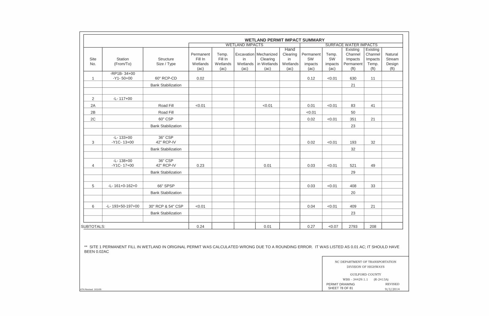
Hand Existing Existing Permanent Temp. Excavation Mechanized Clearing Permanent Temp. Channel Channel Natural
Site Station Structure Fill In Fill In in Clearing in SW SW Impacts Impacts StreamNo. (From/To) Size / Type Wetlands Wetlands Wetlands in Wetlands Wetlands impacts impacts Permanent Temp. Design
(ac) (ac) (ac) (ac) (ac) (ac) (ac) (ft) (ft) (ft)
1-RP1B- 34+00
-Y1- 50+00 60" RCP-CD 0.02 0.12 <0.01 630 11
Bank Stabilization 21
2 -L- 117+00
2A Road Fill <0.01 <0.01 0.01 <0.01 83 41
2B Road Fill <0.01 50
2C 60" CSP 0.02 <0.01 351 21
Bank Stabilization 23
3-L- 133+00
-Y1C- 13+0036" CSP
42" RCP-IV 0.02 <0.01 193 32
Bank Stabilization 32
4-L- 138+00
-Y1C- 17+0036" CSP
42" RCP-IV 0.23 0.01 0.03 <0.01 521 49
Bank Stabilization 29
5 -L- 161+0-162+0 66" SPSP 0.03 <0.01 408 33
Bank Stabilization 20
6 -L- 193+50-197+00 30" RCP & 54" CSP <0.01 0.04 <0.01 409 21
Bank Stabilization 23
SUBTOTALS: 0.24 0.01 0.2 0.07 2793 208
REVISED
ATN Revised 3/31/05 SHEET 78 OF 81 9/3/2014
WETLAND PERMIT IMPACT SUMMARYWETLAND IMPACTS SURFACE WATER IMPACTS
** SITE 1 PERMANENT FILL IN WETLAND IN ORIGINAL PERMIT WAS CALCULATED WRONG DUE TO A ROUNDING ERROR. IT WAS LISTED AS 0.01 AC; IT SHOULD HAVE BEEN 0.02AC
NC DEPARTMENT OF TRANSPORTATIONDIVISION OF HIGHWAYS
GUILFORD COUNTYWBS - 34429.1.1 (R-2413A)
PERMIT DRAWINGSHEET 78 OF 81
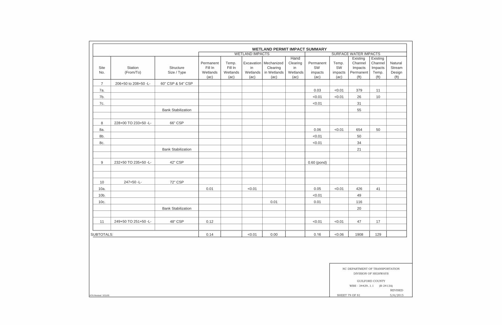
Hand Existing Existing Permanent Temp. Excavation Mechanized Clearing Permanent Temp. Channel Channel Natural
Site Station Structure Fill In Fill In in Clearing in SW SW Impacts Impacts StreamNo. (From/To) Size / Type Wetlands Wetlands Wetlands in Wetlands Wetlands impacts impacts Permanent Temp. Design
(ac) (ac) (ac) (ac) (ac) (ac) (ac) (ft) (ft) (ft)
7 206+50 to 208+50 -L- 60" CSP & 54" CSP
7a. 0.03 <0.01 379 11
7b. <0.01 <0.01 26 10
7c. <0.01 31
Bank Stabilization 55
8 228+00 TO 233+50 -L- 66" CSP
8a. 0.06 <0.01 654 50
8b. <0.01 50
8c. <0.01 34
Bank Stabilization 21
9 232+50 TO 235+50 -L- 42" CSP 0.60 (pond)
10 247+50 -L- 72" CSP
10a. 0.01 <0.01 0.05 <0.01 426 41
10b. <0.01 49
10c. 0.01 0.01 116
Bank Stabilization 20
11 249+50 TO 251+50 -L- 48" CSP 0.12 <0.01 <0.01 47 17
SUBTOTALS: 0.14 <0.01 0.00 0. <0.06 1908 129
REVISED
ATN Revised 3/31/05 SHEET 79 OF 81 5/6/2015
WETLAND PERMIT IMPACT SUMMARYWETLAND IMPACTS SURFACE WATER IMPACTS
NC DEPARTMENT OF TRANSPORTATION
DIVISION OF HIGHWAYS
GUILFORD COUNTY
WBS - 34429..1.1 (R-2413A)

Hand Existing Existing Permanent Temp. Excavation Mechanized Clearing Permanent Temp. Channel Channel Natural
Site Station Structure Fill In Fill In in Clearing in SW SW Impacts Impacts StreamNo. (From/To) Size / Type Wetlands Wetlands Wetlands in Wetlands Wetlands impacts impacts Permanent Temp. Design
(ac) (ac) (ac) (ac) (ac) (ac) (ac) (ft) (ft) (ft)12 269+50 -L- 72" CSP
12a. 0.03 299 1163*12b. 0.01 131
13 277+00 to 281+00 -L- 54" RCP13a. 0.04 <0.01 525 10 977*13b. 0.01 106
14 307+00 -L- 78" CSP14a. 0.07 551 2014b. 0.02 258 10
Bank Stabilization 25
15 322+50 to 326+00 -L- 54" CSP15a. 0.01 0.04 <0.01 513 41
Bank Stabilization 2015b. <0.01 46
16 327+50 to 329+50 -L- 72" CSP16a. 0.15 0.02 <0.01 342 29
Bank Stabilization 2016b. <0.01 33
SUBTOTALS: 0.16 0.24 0.03 2,869 110 2,140
* See Plan for On-Site Mitigation
ATN Revised 3/31/05
DIVISION OF HIGHWAYSGUILFORDCOUNTY
WBS - 34429.1.1 (R-2413A)
SHEET 80 O 81
WETLAND PERMIT IMPACT SUMMARYWETLAND IMPACTS SURFACE WATER IMPACTS
NC DEPARTMENT OF TRANSPORTATION

Hand Existing Existing Permanent Temp. Excavation Mechanized Clearing Permanent Temp. Channel Channel Natural
Site Station Structure Fill In Fill In in Clearing in SW SW Impacts Impacts StreamNo. (From/To) Size / Type Wetlands Wetlands Wetlands in Wetlands Wetlands impacts impacts Permanent Temp. Design
(ac) (ac) (ac) (ac) (ac) (ac) (ac) (ft) (ft) (ft)
17 -L- 334+00-336+50 36" CSP 0.35 0.03
18**** -L- 338+00-340+50 Bridge 0.04 0.13 0.03 172
19 -L- 348+00-353+00 60" RCP 0.03 <0.01 507 34
20 -Y4- 17+50-19+00 36" CSP 0.11 0.02 240
21 -Y5- 29+00-36+00 1@12'x12' RCBC
21A 2.11 0.13 0.06 0.09 288 262 250*
21B Road Fill 0.01 149
22 Y1C- 25+50 48" CSP 0.02 <0.01 177 40
Bank Stabilization 16
23 -Y5- 16+50 30" CSP/PDE <0.01 12
24 -Y1- 23+81 RT 2 @ 72" RCPs <0.01 <0.01 15 10
Bank Stabilization <0.01 31
SUBTOTALS: 2.57 0.04 0.16 0.13 0. 0.1 1423 530 250TOTALS: 3.11 ** 0.04 <0.01 0.19 0.13 0. 8993 977 *** 2390
REVISEDATN Revised 3/31/05 SHEET 81 OF 81 5/6/2015, 3/18/2016
* SEE PLAN FOR ON-SITE MITIGATION
GUILFORD COUNTY
WBS - 34429.1.1 (R-2413A)
NC DEPARTMENT OF TRANSPORTATION
**** PERMANENT PIER WETLAND IMPACTS= 40sqft
*** TEMP CHANNEL IMPACT IN ORIGINAL PERMIT WAS SUMMED WRONG. IT WAS LISTED AS 922'; IT SHOULD HAVE BEEN 952'
WETLAND PERMIT IMPACT SUMMARYSURFACE WATER IMPACTSWETLAND IMPACTS
** PERMANENT FILL IN WETLAND IN ORIGINAL PERMIT WAS SUMMED WRONG. IT WAS LISTED AS 3.13ac; IT SHOULD HAVE BEEN 3.14ac
DIVISION OF HIGHWAYS