“progrock” operating manual pr1.02
TRANSCRIPT

1
“ProgRock” Operating manual
_Pr1.02_
1. Introduction
This is the operating manual for the ProgRock synthesiser kit. It should be read together with the
assembly instructions for the ProgRock kit and Si5351A Synth kit.
The configuration of the ProgRock kit is stored in EEPROM so that it is persisted when the power is
switched off. The configuration is presented as a series of 32-bit “registers”.
There are two methods to edit the ProgRock configuration registers.
a) new register contents are entered one digit at a time, in Binary Coded Decimal (BCD), by
setting up the digit on the 4-way DIP switch on the ProgRock board, then pressing the button
to record the digit. Finally when the entire number has been entered, an “Enter” code is
selected, which writes the new register value into EEPROM.
b) ProgRock supports connection to a 5V logic level serial port, and configuration via a terminal
(or terminal emulator on a PC).
The configuration editing mode is chosen at start-up, by the switch configuration.
Start-up switch positions for 4-way
DIP switch and Button configuration
Start-up switch positions for serial
port configuration
If you want to change between switch/button configuration editing and serial port configuration
editing, it is necessary to set the switch positions, power down ProgRock off and power up again.

2
2. Programming using 4-way DIP switch and Button
2.1 User Interface
The ProgRock frequencies list is programed in Binary Coded Decimal, which is input on the 4-way
DIP switch, and button. Each time you press the button briefly, the 3mm red LED will flash quickly
four times. This will give you positive feedback that your button press actually occurred and the
number programmed on the DIP switch has been accepted by the microcontroller. You cannot
program another digit until the red LED flashing stops. These basic controls (DIP switch, button, and
LED) are your whole User Interface to ProgRock!
You will need to move the DIP switches with a screwdriver blade-tip – they are too small to set with
your fingers!
The rest of this document assumes holding the ProgRock PCB for programming purposes in the
orientation shown in these photographs.
When programming ProgRock please remove the 1pps connection to the GPS, if you are
using the GPS. It can interfere with the button debounce logic. The 1pps input should be
grounded during programming of ProgRock.
The DIP switches should always be set to OFF at Power-up and when you have finished
programming (except if starting in serial interface mode, see above)! ProgRock cannot test the
Si5351A (see start-up procedure below), or do GPS calibration, when the DIP switch on the left
(labelled “1” in the above photograph), is ON!
2.2 Power-up procedures
On applying power to ProgRock, the red LED flashes quickly four times.
The first operation undertaken by the ProgRock microcontroller on power up, is to check the
connection to the Si5351A chip via the I2C bus. It then checks that it can read the 27MHz reference
frequency (divided down) on the Clk2 output. If the I2C communication fails or the reference

3
frequency cannot be read, then the red LED will remain illuminated. No further actions will be taken,
and the switches, buttons, and bank select inputs are all ignored. If the microcontroller cannot operate
the Si5351A chip, then nothing else can be done. You will need to investigate the issue and resolve it,
before proceeding. The system must be reset by removing and re-applying power, to try again. The
DIP switches must be set to OFF at power-up and when using the GPS calibration option!
(except the switch that selects for serial interface mode).
You might wish to program the ProgRock frequency list without the Si5351A Synth module plugged
in. For example if you have fitted SMA connectors to the Si5351A Synth module, then the 4-way DIP
switch and button will be a bit hard to access with your fingers. When the Si5351A Synth module is
not plugged in, the above error check will fail, and ProgRock will be stuck in the “error state” with the
red LED illuminated.
To avoid this problem, and allow you to program the frequency list without the Si5351A Synth module
plugged in, you can BYPASS the error check. To bypass the error check, press the button (S2) while
powering up ProgRock. When you have done this, the microcontroller will not attempt to
communicate with the Si5351A chip again, until power is removed and re-applied.
Finally if all is well, you have programmed frequencies, and the Si5351A Synth module is all working
properly – the microcontroller will set up the Si5351A chip to output the frequencies you chose.
2.3 A crash course in Binary Coded Decimal
You can skim over this section if you already know about Binary Coded Decimal.
You have 4 switches in the 4-way DIP switch. Each switch can be either on or off. If it is on, the
weight is 8, 4, 2 or 1 as indicated by the silk screen printed legend on the
ProgRock PCB. Unfortunately the actual red switch is only labelled “1 2 3 4”
and you will have to ignore that.
To make a number, you switch the required switches to “on” that add up to the
required number.
For example, the switch configuration to (above-right) means “6”, because the “4” switch and the “2”
switch are the only switches which are “on”, and 4 + 2 = 6.
The table below shows the switch configurations for digits 0 to 9, for your reference.
Note the two special codes, which represent “Cancel” and “Enter”. (These are hexadecimal E and F
respectively, if you want to consider them this way).
If you configure the switch for the “Cancel” command and press the button, then the current number
entry is cancelled.
If you configure the switch for the “Enter” command and press the button, then the current number
entry is actioned by the microcontroller – the selected frequency register is programmed with the

4
entered number, stored in EEPROM, and programmed to the Si5351A chip if it is in the active
frequency bank.
2.4 ProgRock register configuration
ProgRock contains 29 registers, referred to as Register ID 00 to 28. Each register stores a 32-bit
number, which you can program from the switches and button. The table in section 4 below lists the
register mapping. To enter a frequency into a register, you must first specify the register, then the
required frequency register. The digits are entered into ProgRock one digit at a time.
You set up a digit on the 4-way DIP switch then press the button briefly. The LED flashes 4 times
quickly to confirm the button press. Wait for the LED to stop flashing. Then set up the next digit, press
the button, and continue until you have completely entered all the digits needed. Finally set up the
“Enter” code (all 4 switches “on”) and press the button again. This causes the entered number to be
stored at the specified register location.
For example, suppose you wish to set the Clk 0 output in bank 0 to 1.5MHz. The sequence of digits
you need to enter is:

5
0 4 1 5 0 0 0 0 0 Enter
Because “04” is the register location for Clk 0 Bank 0, and “1500000” is the desired frequency, in Hz.
The total number of digit set-ups and button presses you will need to make, is 10, in this case.
Make sure you give the button a decisive short (brief) press. Make sure that you wait for the LED
to stop flashing, before pressing the button repeatedly! Button presses are ignored while the LED is
flashing. It’s a kind of very simple switch debounce, as well as an indication of the button press. This
is particularly important to remember if you are entering a repeated sequence of digits, such as the
zeroes in this example. You don’t need to alter the 4-way DIP switch settings after each digit entry. It
is tempting to just keep hitting the button 5 times, to enter the 5 zeroes. But you MUST WAIT after
each button press for the red LED to stop flashing, first!
If you try to enter a register value into a register number higher than 28, your entry will simply be
ignored.
If you enter an invalid frequency, which is to say, the frequency is outside the possible range of the
Si5351A, then the frequency obtained at the output will not be what you want. The most likely output
will be none at all.
At the end of this document is a template which you can print and use to help program the
frequencies.
3. Programming using the serial port interface
3.1 Port requirements
The serial interface in the ProgRock microcontroller is quite minimalist. The ATtiny84 microcontroller
does not have an asynchronous serial peripheral, therefore a software-defined serial port is
implemented. The functionality of the interface is kept minimal to fit the constraints of the limited
program space and other resources available in the
ATtiny84 microcontroller.
WARNING! Don’t use RS232, it has 12V levels!
The ProgRock serial port requires 5V logic!
The serial port is a standard asynchronous port. It
has two wires, Transmit (Tx) and Receive (Rx). 5V
logic levels are required. The baud rate is fixed at
9,600 baud. The two wires must be connected to
two of the 4-way DIP switch connections, as shown
in the diagram. These are pins 13 (Tx) and 12 (Rx) of the processor. If the serial interface is going to
be the ONLY method you use to program ProgRock, then you do not need to fit the 4-way DIP switch

6
or the button, and you could solder the Rx and Tx wires directly into these holes. However, you must
then fit the jumper wire shown, in order to start the unit in serial data mode on power-up.
3.2 USB to Serial conversion using an Arduino
Modern PCs do not have serial ports, they have USB ports. Various USB to serial adapters are
available. If you have an Arduino you can use it simply as a USB to serial adapter.
Example wiring is shown in this diagram. Arduino pin 11 is configured as Tx and pin 10 as Rx. The
Arduino’s native serial port is used for serial communication with the PC via USB. The Arduino runs a
simple sketch which implements an additional software-defined serial port on these pins 10 and 11.
Everything communication received on either the real Arduino serial port or the software-defined one,
is simple echoed to the other. In this way the serial data from the PC is transmitted to ProgRock, and
vice versa.
The Arduino Tx output is connected to the ProgRock Rx input. Similarly the Arduino Rx input is
connected to the ProgRock Tx output. Standard serial communications always cross Rx/Tx signals in
this way. A ground connection is also required.

7
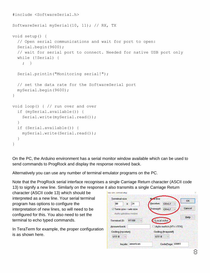
This short example sketch uses the Arduino SoftwareSerial library. Both ports are run at 9,600 baud.
Received serial data on either input is re-transmitted to the other output.
8
#include <SoftwareSerial.h>
SoftwareSerial mySerial(10, 11); // RX, TX
void setup() {
// Open serial communications and wait for port to open:
Serial.begin(9600);
// wait for serial port to connect. Needed for native USB port only
while (!Serial) {
; }
Serial.println("Monitoring serial!");
// set the data rate for the SoftwareSerial port
mySerial.begin(9600);
}
void loop() { // run over and over
if (mySerial.available()) {
Serial.write(mySerial.read());
}
if (Serial.available()) {
mySerial.write(Serial.read());
}
}
On the PC, the Arduino environment has a serial monitor window available which can be used to
send commands to ProgRock and display the response received back.
Alternatively you can use any number of terminal emulator programs on the PC.
Note that the ProgRock serial interface recognises a single Carriage Return character (ASCII code
13) to signify a new line. Similarly on the response it also transmits a single Carriage Return
character (ASCII code 13) which should be
interpreted as a new line. Your serial terminal
program has options to configure the
interpretation of new lines, so will need to be
configured for this. You also need to set the
terminal to echo typed commands.
In TeraTerm for example, the proper configuration
is as shown here.
9
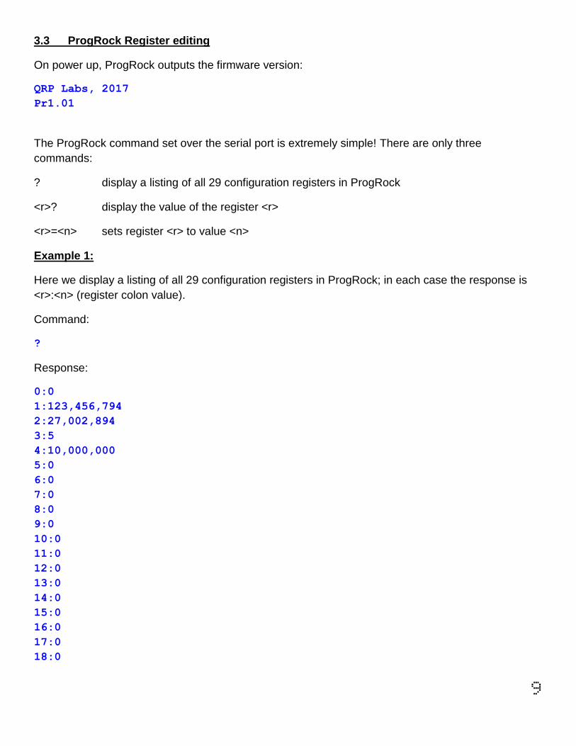
3.3 ProgRock Register editing
On power up, ProgRock outputs the firmware version:
QRP Labs, 2017
Pr1.01
The ProgRock command set over the serial port is extremely simple! There are only three
commands:
? display a listing of all 29 configuration registers in ProgRock
<r>? display the value of the register <r>
<r>=<n> sets register <r> to value <n>
Example 1:
Here we display a listing of all 29 configuration registers in ProgRock; in each case the response is
<r>:<n> (register colon value).
Command:
?
Response:
0:0
1:123,456,794
2:27,002,894
3:5
4:10,000,000
5:0
6:0
7:0
8:0
9:0
10:0
11:0
12:0
13:0
14:0
15:0
16:0
17:0
18:0

10
19:0
20:0
21:0
22:0
23:0
24:0
25:0
26:0
27:0
28:1,678,772,748
Example 2:
Here we query the contents of register 4 (the default Clk0 output frequency register)
Command:
4?
Response:
4:12,000,000
Example 3:
Here we set register 4 (the default Clk0 output frequency) to 12MHz. The response is a confirmation
of what register and value was entered.
Command:
4=12000000
Response:
4:12,000,000
Example 4:
If we try to specify an invalid register number (not in the range 0 to 28), an error is printed:
Command:
123=1000000
Response:

11
Error: Reg
Example 5:
If we enter any other invalid type of command or syntax, outside the three recognised operations
described, we get an error:
Command:
qwerty
Response:
Error: Cmd
Example 6:
It is important to note that ANY other characters, other than numbers 0 to 9, ? and = are all simply
ignored. Therefore all of these commands are equivalent, and all are valid:
4=10000000
4=10,000,000
04=10.000.000
As4f=10aeae000r.0r00
Deleting typos
The final point to make, is what to do when you accidentally type in the wrong value in your terminal
window. You can use the Backspace key to delete incorrectly typed characters. But do NOT use any
other editing key such as the cursor arrows. Only use the Backspace key, to correct mistakes. The
simple serial port editing implementation in ProgRock cannot cope with other types of editing.

12
4. ProgRock register description
4.1 Register listing
The following table shows the register mapping in ProgRock.
Register Purpose
00 Reserved, do not use this register
01 EEPROM version ID. See SECTION 4.2
02 27MHz reference clock value. See SECTION 4.3
03 GPS correction threshold. See SECTION 4.4
04 Bank 0, Clk 0 – default value 10.000MHz
05 Bank 0, Clk 1
06 Bank 0, Clk 2
07 Bank 1, Clk 0
08 Bank 1, Clk 1
09 Bank 1, Clk 2
10 Bank 2, Clk 0
11 Bank 2, Clk 1
12 Bank 2, Clk 2
13 Bank 3, Clk 0
14 Bank 3, Clk 1
15 Bank 3, Clk 2
16 Bank 4, Clk 0
17 Bank 4, Clk 1
18 Bank 4, Clk 2
19 Bank 5, Clk 0
20 Bank 5, Clk 1
21 Bank 5, Clk 2
22 Bank 6, Clk 0
23 Bank 6, Clk 1
24 Bank 6, Clk 2
25 Bank 7, Clk 0
26 Bank 7, Clk 1
27 Bank 7, Clk 2
28 Calibration configuration register. See SECTION 4.5

13
4.2 Factory Reset using EEPROM Version, register 01
Register 01 contains the EEPROM version ID. If you set this register to 0, and power down/up the
system, then the EEPROM contents will be erased and returned to the factory default. The factory
default sets all output frequency registers to 0, the Reference clock register 02 to “27,004,000”, GPS
Correction Threshold register 03 to “5”, and the Calibration configuration register 28 to its default
factory value.
If you mess everything up accidentally, you can always force this factory reset using this method, to
return your microcontroller to the default factory-installed state. Key the digit sequence
0 1 0 Enter
Then cycle the power. This will enter value 0 into register 01, and when the system is rebooted, the
factory reset will occur.
Alternatively if you are using the serial interface for configuration, the following command causes a
factory reset:
1=0
4.3 27MHz reference clock value, register 02
The 27MHz crystal used in the Si5351A Synth Module crystal does not oscillate at exactly
27.000000MHz. It varies from one crystal to the next, but in general the frequency will be 3-5 kHz too
high, e.g. 27,004,000Hz. This is why the default reference frequency in register 02 is 27,004,000.
If you are using the OCXO/Si5351A Synth module kit, the frequency of this oscillator tends to be
about 2kHz too low, e.g. 26,998,000Hz.
If you are using GPS discipline by applying a 1pps signal from a GPS receiver, the kit will self-
calibrate in less than half a minute. This will update register 02 in EEPROM. Next time ProgRock is
powered up the calibrated value will be used. Thereafter, the GPS makes corrections to the reference
oscillator value in register 02 to compensate for any measured temperature-induced drift in the crystal
frequency.
The reference oscillator value is used in the calculation of the Si5351A registers. So it is important
that it is accurate, if you need the output frequencies of ProgRock to be accurate.
If you are not using a GPS, you can manually calibrate ProgRock by entering the correct value into
register 02.
It is possible that you have an accurate means to measure the 27MHz reference oscillator frequency
itself by probing the correct point on the Si5351A module. However most kit builders will not have the
necessary equipment, and such a measurement is not easy to make without itself risking disturbing
the frequency.

14
The easiest method is to set the output frequency to something convenient such as 13.500000 MHz,
and measure it. Measurement can either be by using an accurately calibrated frequency counter, or
by setting up an accurately calibrated receiver with Argo and monitoring the output signal frequency
that way.
Once you have measured the actual output frequency, you can calculate the required correction to
the 27MHz reference frequency and enter it in the “Ref. Frq.” configuration setting. For example,
suppose you set the output frequency to 10.000000 MHz but you actually measure 10.000075. Your
output frequency is 75 Hz too high. Assuming the default reference frequency (27,004,000), you
should change this to 27,004,000 * 10.000075 / 10.000000. So enter the new value 27,004,203 in the
“Ref. Frq.” setting. If using the DIP switch configuration method (not serial port), be sure to write down
somewhere the value you enter. If you need to re-calibrate in future, you will need to know what value
you entered! Otherwise it will be necessary to do a “factory reset” (see section 4.2).
4.4 GPS correction threshold, register 03
This register has a default value of 5Hz. But you can set it to anything you like. It controls how and
when the microcontroller makes updates to the Si5351A output frequencies. For example, at the
default setting of 5Hz, the microcontroller will only correct the Si5351A output frequencies when the
27MHz reference value has changed by more than the 5Hz threshold. The threshold is always
referred to the 27MHz reference frequency, not the output frequencies.
If you set the register to have a value of 0, then the microcontroller will adjust the Si5351A output
frequencies once per second, every second, depending on whether it thinks the 27MHz frequency
has drifted upwards or downwards. This continuous change in output frequency may not be desirable.
It is more practical to have small jumps in output frequencies, less often – i.e. only when the
reference oscillator has changed by more than a threshold.
The QRP Labs website has some notes on how to obtain excellent frequency stability with the
Si5351A Synth module – please refer to the resources section below.
4.5 Calibration configuration register, register 28
The value in this register is several smaller numbers, bit-packed into the available 32-bit number.
These parameters control the way the GPS calibration and drift correction processes are done.
In the future I may describe these parameters and their effect. It may be possible to further optimise
the way the calibration and drift correction processes are carried out.
For the time being, just leave this register alone!

15
4.6 Default frequency output of ProgRock
At switch-on after factory reset, the Clk0 output is set up to default 10.000MHz. Clk1 and Clk2 are
switched off. The reference frequency is set by default to 27.004MHz which should be approximately
correct +/- 1kHz. Further calibration will be needed for your crystal as described in section 4.5 above.
16
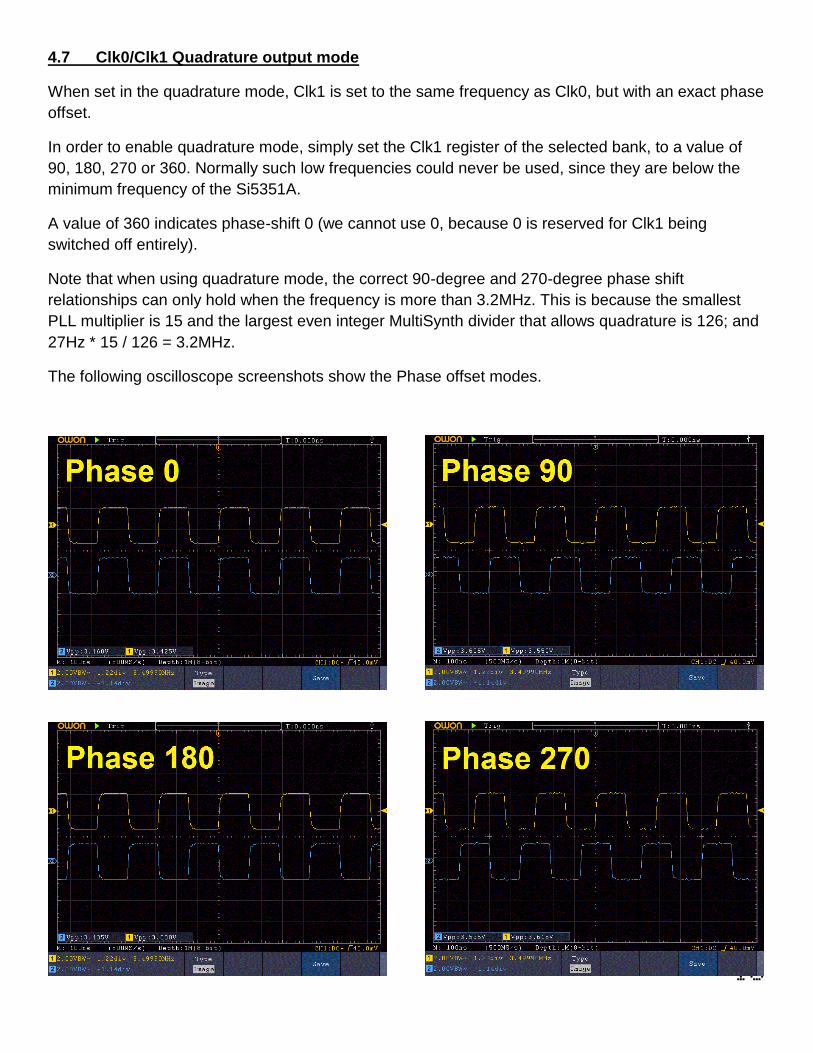
4.7 Clk0/Clk1 Quadrature output mode
When set in the quadrature mode, Clk1 is set to the same frequency as Clk0, but with an exact phase
offset.
In order to enable quadrature mode, simply set the Clk1 register of the selected bank, to a value of
90, 180, 270 or 360. Normally such low frequencies could never be used, since they are below the
minimum frequency of the Si5351A.
A value of 360 indicates phase-shift 0 (we cannot use 0, because 0 is reserved for Clk1 being
switched off entirely).
Note that when using quadrature mode, the correct 90-degree and 270-degree phase shift
relationships can only hold when the frequency is more than 3.2MHz. This is because the smallest
PLL multiplier is 15 and the largest even integer MultiSynth divider that allows quadrature is 126; and
27Hz * 15 / 126 = 3.2MHz.
The following oscilloscope screenshots show the Phase offset modes.

17
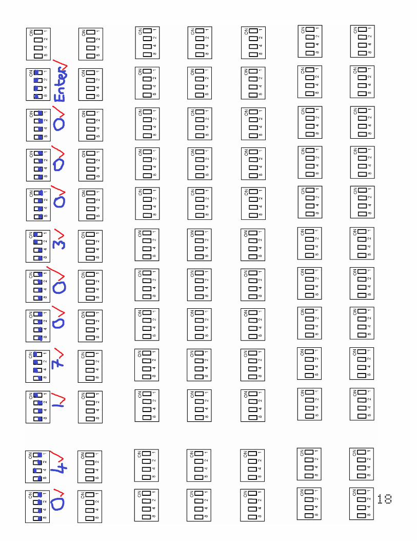
5. Template for programming ProgRock
On the following page is a template for programming registers in ProgRock using the DIP switches.
You could print it out and use it to assist with programming the registers for the frequencies you need.
On the top row is an example. Programming the Bank 0, Clk 0 output to 17.003MHz.
The first two digits are the register number. The register number for the Bank 0, Clk 0 frequency is 04
(refer to the table in section 4.1).
The next 8 digits are the frequency, specified in Hz: 17003000.
Finally, the “Enter” code is input (all 4 switches are “on”).
The ProgRock operator can write out the numbers required, as done here on the top line. Then write
the switch configurations for each digit. Refer to the Binary Coded Decimal table in section 2.3 if
necessary. For each digit, the operator should set the 4 switches of S1 as needed, then press the
button briefly (S2). It will help to write a tick next to the digits which have been input, to avoid
forgetting where you are, in the number.
18

19
6. Resources
• Please see the kit pages at http://qrp-labs.com/progrock for information on latest updates and
issues.
• Notes on getting excellent frequency stability from the Si5351A Synth kit:
http://qrp-labs.com/synth/freqstab.html
7. Version History
1 20-Apr-2016
• First version
2 27-May-2016
• Added Alan G8LCO description of the noise filter circuit
• Added clarification that capacitor Cx is neither required nor supplied, and should not be fitted
• Clarified orientation of the 4-way DIP switch; the silkscreen does not match the component
• Corrected several typos, missing words, incorrect words etc.
3 24-Jun-2016
• Added note that very short 1pps pulse widths (e.g. 10us) do not work with this kit.
4 25-Jun-2016
• Re-write of the last paragraph of section 2.6 to make the calibration procedure more clear
5 27-Jun-2016
• Section 2.6: emphasise the importance of writing down the reference clock value, in case it is
necessary to re-calibrate some time in future
6 11-Aug-2016
• Assembly manual, section 4.3.3: Add section about not installing noise filter components when
you use the OCXO
20
7 04-Oct-2016
• Added clarification that the button press should be a short one.
8 12-Jan-2017
• Corrected pin numbers of Si5351A Synth module in the circuit diagram
9 22-Feb-2017
• Separated the operating and assembly manuals
10 23-Feb-2017
• Manual for ProgRock firmware Pr1.01
• Added serial interface configuration option
• Changed Si5351A Code to all integer arithmetic - faster, smaller, more accurate
• In DIP switch configuration, LED flashes 4 times to indicate a button press is registered
11 14-Mar-2017
• Added warning about not using RS232 12V logic levels with the ProgRock serial port
12 20-Mar-2017
• Correction to the TeraTerm configuration settings
• Pr1.01a – bug fix, initialisation was missed, pr1.01 started at 27MHz output
13 12-Jun-2017
• Correction to section 3.1, to explain that if no 4-way DIP switch is fitted, in order to use
ProgRock only in serial programming mode, then a jumper wire is needed for serial mode
startup.
14 10-Oct-2018
• Pr1.02 version
• Adds quadrature LO mode where Clk0, Clk1 can be set with 0, 90, 180 or 270-degree offset