progress report on development of the …robotics.estec.esa.int/astra/astra2015/papers/session...
TRANSCRIPT

PROGRESS REPORT ON DEVELOPMENT OF THE EXOMARS 2018 SAMPLE
PROCESSING AND DISTRIBUTION SUBSYSTEM (SPDS) AND RELATED OHB
SAMPLE HANDLING STUDIES
ASTRA 2015, ESTEC, NOORDWIJK, NEDERLAND, 11-13 MAY 2015
L. Richter1, P. Carianni
2, S. Durrant
3, P. Hofmann
1, Q. Mühlbauer
1, F. Musso
2, R. Paul
1, D. Redlich
1
1: OHB System AG, Perchtinger Str. 5, D-81379 Munich, Germany
Phone: +49 89 72495 236, Fax: +49 89 72495 291 , email: [email protected]
2: Thales-Alenia Space Italia, Strada Antica di Collegno 253, I-10146 Torino, Italia
3: ESA-ESTEC, Keplerlaan 1, 2201 AZ Noordwijk, Nederland
ABSTRACT
OHB Munich, formerly Kayser-Threde GmbH, has been
assuming a leading role in a number of studies and
projects addressing space robotics with applications
ranging from vision systems, manipulation systems and
active space debris removal (e.g. the ADRS and
e.Deorbit studies) to mechanical subsystems for the
ESA- Roscosmos 2018 ExoMars rover mission . This
paper provides a progress report on the on-going
development of the Sample Processing and
Distribution Subsystem (SPDS) for the 2018 ExoMars
rover as well as highlights of related development
activities of sample acquisition and handling
mechanisms targeted to lunar polar missions through the
intended ESA-Roscomos collaboration regarding near-
term exploration of the Moon.
The SPDS is being developed by OHB under direct
subcontract to TAS-I to supply the
scientific instruments of the ExoMars rover with
granular Mars rock and soil samples of a specific
particle size distribution. This is achieved through a set
of mechanisms making up the SPDS which receive the
samples from the rover drill, crush, meter (‘dose’) and
distribute them. The sequence of operation can be
controlled from ground but pre- defined operational
sequences are embedded in the Drill and SPDS Control
Electronics and will operate the SPDS in a semi-
automated way with internal fault protection and
llimited flexibility to react to a number of off- nominal
situations. Between 2007 and 2013, ever more
sophisticated breadboards and engineering models
of the SPDS mechanisms have been developed and
tested, culminating in the successful “end-to-end”
test campaign of breadboards of the mechanisms in
correct relative positions in simulated Mars atmosphere
and temperature in early 2013.
Since the last ASTRA conference, the SPDS flight
design has been finalized, in particular related to solving
the incorporation of the static and dynamic pressure
seals (the latter with minimized parasitic torque) needed
to ensure the required contamination levels within the
ExoMars rover analytical laboratory (ALD) which
is pressurized until arrival on Mars, and with respect to
a Vibration & Shock Mechanism now having become
part of the SPDS sample crusher mechanism. Moreover,
complex questions on the SPDS mechanisms’
materials coatings driven by both tribology and the need
to sustain the ExoMars 2018 sterilisation and ultra
cleaning processes have been solved, and the
Qualification Model MRR has been fully closed. At the
time of this writing, fabrication of the SPDS QM is
under way, with integration and test activities now
starting.
Since mid 2013, OHB Munich have also been
developing the structure of the ExoMars rover analytical
laboratory (ALD) (a task delegated to OHB by TAS-I)
including the ALD pressurized Ultra Clean Zone (UCZ)
surrounding the sample path, on which this paper also
provides an update on, including the attendant
development of the UCZ pressure relief valve and of the
ALD optical windows that likewise are under
responsibility of OHB.
OHB are also involved in two different studies related
to the planned ESA-Roscomos collaboration on
landing missions targeted to lunar polar regions with the
objectives of subsurface sampling down to 2 metres
depth and analysis of volatile-enriched lunar regolith. In
this regard, the paper outlines the OHB contributions
towards the ESA-provided elements “subsurface drill”
and “analytical instrument” through the studies L-
GRASP and ProsPA, respectively.
1. EXOMARS SPDS
1.1. Overview
OHB Munich (formerly Kayser-Threde GmbH), as a

subcontractor to Thales-Alenia Space Italia (TAS-I), has
been developing the Sample Processing and Distribution
Subsystem (SPDS) for the ESA-Roscosmos 2018
ExoMars rover mission since 2007. The SPDS is a set
of mechanisms designed to crush and distribute to the
‘Pasteur’ science instruments Mars subsurface samples
acquired by the ExoMars drill. The different
mechanisms of the SPDS are distributed among the
science instruments inside the Analytical Laboratory
Drawer (ALD) contained within the rover structural
enclosure. The SPDS consists of the following
mechanisms, processing a sample in sequence:
Core Sample Handling System (CSHS) (consisting
of Core Sample Transfer Mechanism CSTM and
Blank Sample Dispenser BSD) accepts the samples
discharged from the drill and forwards them –
exploiting gravity – into the ALD and to
the subsequent SPDS mechanism, being the
Crushing Station (CS), operating as a jaw crusher
to comminute granular and massive samples to
smaller grain sizes as required by some of the
Pasteur science instruments
Powdered Sample Dosing and Distribution
System (PSDDS), being situated below the CS and
receiving the sample powder resultant from the
crushing; the powder can be dosed by the PSDDS
dosing mechanisms and thus dispensed into sample
receptacles located below the PSDDS on the
Powdered Sample Handling System (PSHS)
which essentially is a carousel wheel carrying
a number of ovens for thermal and chemical
processing of the powder samples by the ‘ Pasteur’
MOMA instrument, as well as carrying a ‘refillable
container’ (RC) to present a larger amount of
sample powder to close-up observation
optical science instruments.
The electronics unit controlling the SPDS – the Drill
and SPDS Electronics Unit (DSEU) – is shared with the
electronics controlling the ExoMars rover sample
acquisition drill and is developed by Selex Electronic
Systems (SES).
Figure 1. ExoMars rover partially exploded view,
showing position of ALD with SPDS within the rover
‘bathtub’ primary structure (credit: TAS-I)
Figure 2. SPDS mechanisms in the ALD
Fig. 1 shows the ALD / SPDS accommodation within
the ExoMars rover, and Fig. 2 provides an overview of
the SPDS mechanisms as part of the ALD system.
1.2. Concept of the Ultra Clean Zone (UCZ) and
associated AIV scenario
The ExoMars 2018 mission is pursuing a very ambitious
programme of planetary protection and contamination
control for the landed H/W. The main driver for this is
to protect the integrity of the scientific measurements to
be performed on the subsurface samples acquired by the
ExoMars rover drill in order to exclude false positive
detection of organics and, possibly, biomolecules by the
MOMA instrument.
Principal implementation measures defined by the
mission prime TAS-I to ensure the ExoMars
2018 COSPAR Category IVb classification and,
specifically, the desired cleanliness levels within the
ALD sample path, are:
A pressurized Ultra Clean Zone (UCZ)
enclosing the sample path:
o Most of the SPDS resides within the
UCZ
o The close-up optical instruments RLS
and µOMEGA reside outside the
UCZ, viewing the samples through
ALD optical windows
o The SPDS actuators are
accommodated outside the UCZ,
requiring dynamic seals around the
drive shaft
o Overpressure of the UCZ to the
relevant outside environment (Earth,
high vacuum during cruise, Mars) is
maintained until the ALD door is
first opened several days or weeks
after landing on Mars, by releasing
the CSHS Frangibolt hold-down
A set of sealed blank samples that can be

released from the CSHS mechanism to assess
sample path contamination on Mars
Sterilisation of ALD sample chain H/W by Dry
Heat Microbial Reduction (DHMR)
Ultra cleaning of the ALD sample chain
components and parts in a series of ultrasonic
baths and with CO2 snow
Final integration of the sterilized and ultra
cleaned ALD sample chain H/W in an
ISO3 AMC-9 environment at TAS-I (realised
through a series of glove boxes referred to as a
“glove box train”).
Whereas the responsibility for the planetary protection
and contamination control approach for the SPDS and
the ALD / UCZ structure rests with TAS-I, OHB
are responsible for ensuring that the designs of the
SPDS and the ALD / UCZ structure are compatible with
the sterilisation and ultra cleaning methods. In this
context, a systematic evaluation programme has been
carried out between OHB and TAS-I to confirm the
final choice of passivation treatment for Al alloy parts
which has to be compatible with the sterilisation and
cleaning approach whilst respecting the MOMA
instrument’s contamination requirements.
As a result of the overall scenario, the SPDS QM and
FM programmes both foresee a two-staged approach in
which OHB solely performs grade ISO8 integration of
the SPDS mechanisms followed by “equipment level”
testing.
Following shipment of the SPDS to TAS-I, the steps
SPDS disassembly
Sterilisation & ultra cleaning
SPDS re-integration
Integration into ALD structure
ALD-level testing
will occur, closing the SPDS qualification and
acceptance.
1.3. SPDS description
The CSHS (Core Sample Handling System) is the initial
mechanism for accepting the samples delivered by the
ExoMars drill. It is a linear boom-like extension system
that transfers the sample (granular or massive core)
from the sample discharge port of the drill to a defined
position where it is dropped into the Crushing Station.
An ALD external door is attached to the mechanism for
opening and closing the ALD for sample transfer and
which until landing on Mars maintains the UCZ
structure internal overpressure through a pre-loaded,
static pressure seal.
Figure 3. SPDS configuration
A “Blank Sample Dispenser” mechanism (BSD) is part
of the CSHS and contains six spherical blank samples of
9 mm diameter to check for contamination in the ALD
sample path. The blanks are organic-free and are kept
under ultra-clean conditions at all times. This is
achieved through encapsulation in ‘ blister packages’
consisting of a semi-spherical blister cup and a blister
foil. Six separate stamps of the BSD mechanism provide
the necessary force for opening the flat breakable blister
foil and perform the push-out process of each blister
cup. Blank samples can be dispensed by the BSD and
transferred into the Crushing Station, further processed
by the SPDS and presented to the instruments when
desired.
Projected mass of the CSHS flight design is 3.8 kg
(including maturity margin).
Figure 4. Blister cup with enclosed 9 mm blank samples
(from silica fibres)
Figure 5. Dispensing test with blank sample; metal foil
at blister package bottom has torn along engraving
pattern
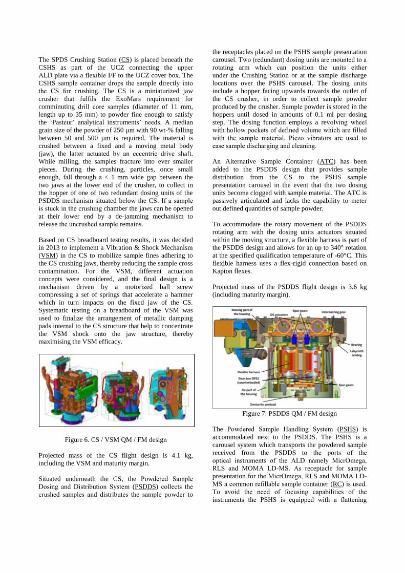
The SPDS Crushing Station (CS) is placed beneath the
CSHS as part of the UCZ connecting the upper
ALD plate via a flexible I/F to the UCZ cover box. The
CSHS sample container drops the sample directly into
the CS for crushing. The CS is a miniaturized jaw
crusher that fulfils the ExoMars requirement for
comminuting drill core samples (diameter of 11 mm,
length up to 35 mm) to powder fine enough to satisfy
the ‘Pasteur’ analytical instruments’ needs. A median
grain size of the powder of 250 µm with 90 wt-% falling
between 50 and 500 µm is required. The material is
crushed between a fixed and a moving metal body
(jaw), the latter actuated by an eccentric drive shaft.
While milling, the samples fracture into ever smaller
pieces. During the crushing, particles, once small
enough, fall through a < 1 mm wide gap between the
two jaws at the lower end of the crusher, to collect in
the hopper of one of two redundant dosing units of the
PSDDS mechanism situated below the CS. If a sample
is stuck in the crushing chamber the jaws can be opened
at their lower end by a de-jamming mechanism to
release the uncrushed sample remains.
Based on CS breadboard testing results, it was decided
in 2013 to implement a Vibration & Shock Mechanism
(VSM) in the CS to mobilize sample fines adhering to
the CS crushing jaws, thereby reducing the sample cross
contamination. For the VSM, different actuation
concepts were considered, and the final design is a
mechanism driven by a motorized ball screw
compressing a set of springs that accelerate a hammer
which in turn impacts on the fixed jaw of the CS.
Systematic testing on a breadboard of the VSM was
used to finalize the arrangement of metallic damping
pads internal to the CS structure that help to concentrate
the VSM shock onto the jaw structure, thereby
maximising the VSM efficacy.
Figure 6. CS / VSM QM / FM design
Projected mass of the CS flight design is 4.1 kg,
including the VSM and maturity margin.
Situated underneath the CS, the Powdered Sample
Dosing and Distribution System (PSDDS) collects the
crushed samples and distributes the sample powder to
the receptacles placed on the PSHS sample presentation
carousel. Two (redundant) dosing units are mounted to a
rotating arm which can position the units either
under the Crushing Station or at the sample discharge
locations over the PSHS carousel. The dosing units
include a hopper facing upwards towards the outlet of
the CS crusher, in order to collect sample powder
produced by the crusher. Sample powder is stored in the
hoppers until dosed in amounts of 0.1 ml per dosing
step. The dosing function employs a revolving wheel
with hollow pockets of defined volume which are filled
with the sample material. Piezo vibrators are used to
ease sample discharging and cleaning.
An Alternative Sample Container (ATC) has been
added to the PSDDS design that provides sample
distribution from the CS to the PSHS sample
presentation carousel in the event that the two dosing
units become clogged with sample material. The ATC is
passively articulated and lacks the capability to meter
out defined quantities of sample powder.
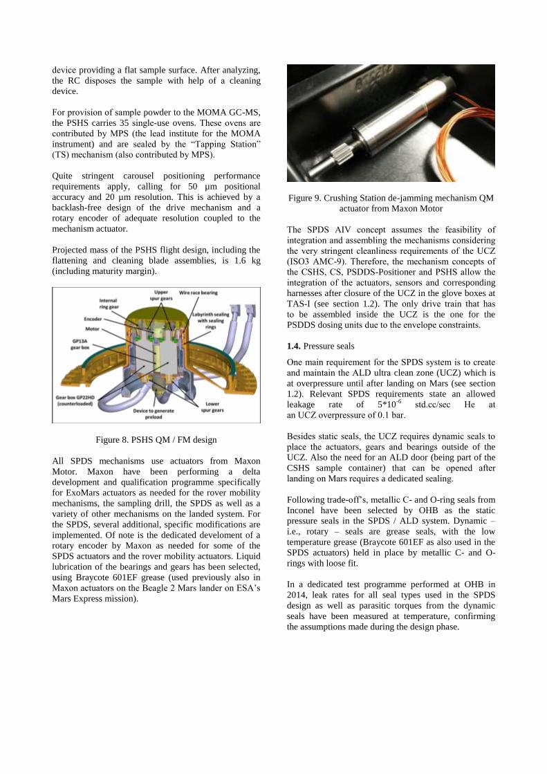
To accommodate the rotary movement of the PSDDS
rotating arm with the dosing units actuators situated
within the moving structure, a flexible harness is part of
the PSDDS design and allows for an up to 340° rotation
at the specified qualification temperature of -60°C. This
flexible harness uses a flex-rigid connection based on
Kapton flexes.
Projected mass of the PSDDS flight design is 3.6 kg
(including maturity margin).
Figure 7. PSDDS QM / FM design
The Powdered Sample Handling System (PSHS) is
accommodated next to the PSDDS. The PSHS is a
carousel system which transports the powdered sample
received from the PSDDS to the ports of the
optical instruments of the ALD namely MicrOmega,
RLS and MOMA LD-MS. As receptacle for sample
presentation for the MicrOmega, RLS and MOMA LD-
MS a common refillable sample container (RC) is used.
To avoid the need of focusing capabilities of the
instruments the PSHS is equipped with a flattening
device providing a flat sample surface. After analyzing,
the RC disposes the sample with help of a cleaning
device.
For provision of sample powder to the MOMA GC-MS,
the PSHS carries 35 single- use ovens. These ovens are
contributed by MPS (the lead institute for the MOMA
instrument) and are sealed by the “Tapping Station”
(TS) mechanism (also contributed by MPS).
Quite stringent carousel positioning performance
requirements apply, calling for 50 µm positional
accuracy and 20 µm resolution. This is achieved by a
backlash-free design of the drive mechanism and a
rotary encoder of adequate resolution coupled to the
mechanism actuator.
Projected mass of the PSHS flight design, including the
flattening and cleaning blade assemblies, is 1.6 kg
(including maturity margin).
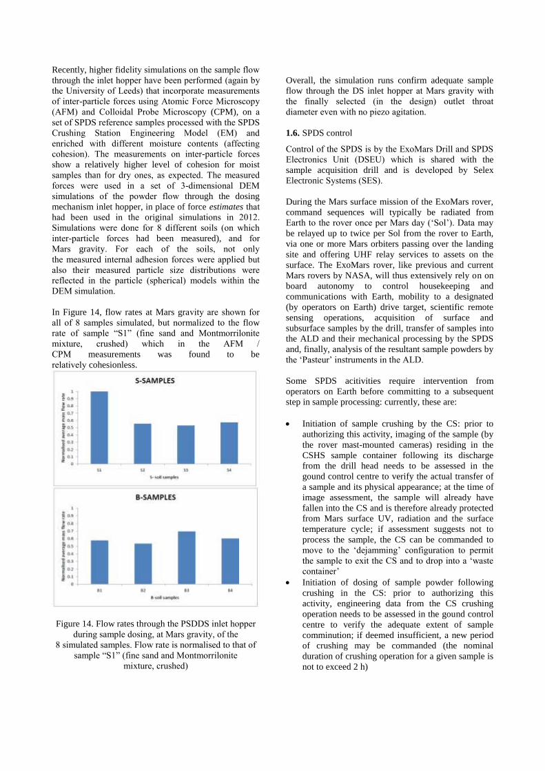
Figure 8. PSHS QM / FM design
All SPDS mechanisms use actuators from Maxon
Motor. Maxon have been performing a delta
development and qualification programme specifically
for ExoMars actuators as needed for the rover mobility
mechanisms, the sampling drill, the SPDS as well as a
variety of other mechanisms on the landed system. For
the SPDS, several additional, specific modifications are
implemented. Of note is the dedicated develoment of a
rotary encoder by Maxon as needed for some of the
SPDS actuators and the rover mobility actuators. Liquid
lubrication of the bearings and gears has been selected,
using Braycote 601EF grease (used previously also in
Maxon actuators on the Beagle 2 Mars lander on ESA’s
Mars Express mission).
Figure 9. Crushing Station de-jamming mechanism QM
actuator from Maxon Motor
The SPDS AIV concept assumes the feasibility of
integration and assembling the mechanisms considering
the very stringent cleanliness requirements of the UCZ
(ISO3 AMC-9). Therefore, the mechanism concepts of
the CSHS, CS, PSDDS- Positioner and PSHS allow the
integration of the actuators, sensors and corresponding
harnesses after closure of the UCZ in the glove boxes at
TAS-I (see section 1.2). The only drive train that has
to be assembled inside the UCZ is the one for the
PSDDS dosing units due to the envelope constraints.
1.4. Pressure seals
One main requirement for the SPDS system is to create
and maintain the ALD ultra clean zone (UCZ) which is
at overpressure until after landing on Mars (see section
1.2). Relevant SPDS requirements state an allowed
leakage rate of 5*10-6
std.cc/sec He at
an UCZ overpressure of 0.1 bar.
Besides static seals, the UCZ requires dynamic seals to
place the actuators, gears and bearings outside of the
UCZ. Also the need for an ALD door (being part of the
CSHS sample container) that can be opened after
landing on Mars requires a dedicated sealing.
Following trade-off’s, metallic C- and O-ring seals from
Inconel have been selected by OHB as the static
pressure seals in the SPDS / ALD system. Dynamic –
i.e., rotary – seals are grease seals, with the low
temperature grease (Braycote 601EF as also used in the
SPDS actuators) held in place by metallic C- and O-
rings with loose fit.
In a dedicated test programme performed at OHB in
2014, leak rates for all seal types used in the SPDS
design as well as parasitic torques from the dynamic
seals have been measured at temperature, confirming
the assumptions made during the design phase.

Figure 10. Breadboard testing of ALD door with metal
C-ring seal (May 2014)
Figure 11 : One of the Inconel C-rings used in the SPDS
as a static seal
Figure 12 : Measured leak rate of MCI lid 2 seal during
2014 test campaign, for different temperatures and a
delta pressure of 0.1 bar (nominal UCZ overpressure)
1.5. Effect of Mars gravity
The SPDS mechanisms rely on the action of gravity in
the flow of the granular samples from
one SPDS mechanism to the next. To capture and
understand the effects of reduced gravity (Mars g
vs. Earth g) on the performance of the SPDS, the
SPDS development has been relying on a combination
of testing on parabolic flights and numerical
simulations. In June 2011, under contract with ESA,
Kayser- Threde performed a parabolic flight campaign to
test the behaviour of the dosing hoppers of the PSDDS
dosing unit under Martian gravity. The aim
was to verify the performance requirements of the SPDS
Dosing Station at 1/3 Earth gravity (corresponding
to conditions on Mars), to verify the quantity of
sample dosed (throughput), to assess cross-
contamination between successive samples and to assess
the influence of vibration (the dosing station
being equipped with piezo vibrators to assist in powder
flow).
Figure 13. Side view of relative position of PSDDS
dosing station and PSHS oven (below). Inlet and out-
let funnels of dosing station are labelled. Gravity vector
points downwards
In parallel, a numerical simulation effort has been
started in late 2011 together with the University
of Leeds (UK) to model mechanism / sample interaction
effects as a function of gravity. The modelling approach
chosen was the Discrete Element Method (DEM). A
subsequent parabolic flight campaign was run in
December 2012 by the University of Munich (TUM /
LRT), flying a series of different 2D shapes of the
PSDDS Dosing Station hoppers at simulated Mars and
lunar gravity, with the sample holders and powders
exposed to Mars atmospheric pressure [3].
Simulation and testing were shown to agree in
recommending a slight design change for the
PSDDS inlet hoppers in enlarging the outlet throat
diameter to enhance mass flow at Mars gravity for
cohesive materials which was
subsequently implemented in the design.
Recently, higher fidelity simulations on the sample flow
through the inlet hopper have been performed (again by
the University of Leeds) that incorporate measurements
of inter-particle forces using Atomic Force Microscopy
(AFM) and Colloidal Probe Microscopy (CPM), on a
set of SPDS reference samples processed with the SPDS
Crushing Station Engineering Model (EM) and
enriched with different moisture contents (affecting
cohesion). The measurements on inter- particle forces
show a relatively higher level of cohesion for moist
samples than for dry ones, as expected. The measured
forces were used in a set of 3-dimensional DEM
simulations of the powder flow through the dosing
mechanism inlet hopper, in place of force estimates that
had been used in the original simulations in 2012.
Simulations were done for 8 different soils (on which
inter-particle forces had been measured), and for
Mars gravity. For each of the soils, not only
the measured internal adhesion forces were applied but
also their measured particle size distributions were
reflected in the particle (spherical) models within the
DEM simulation.
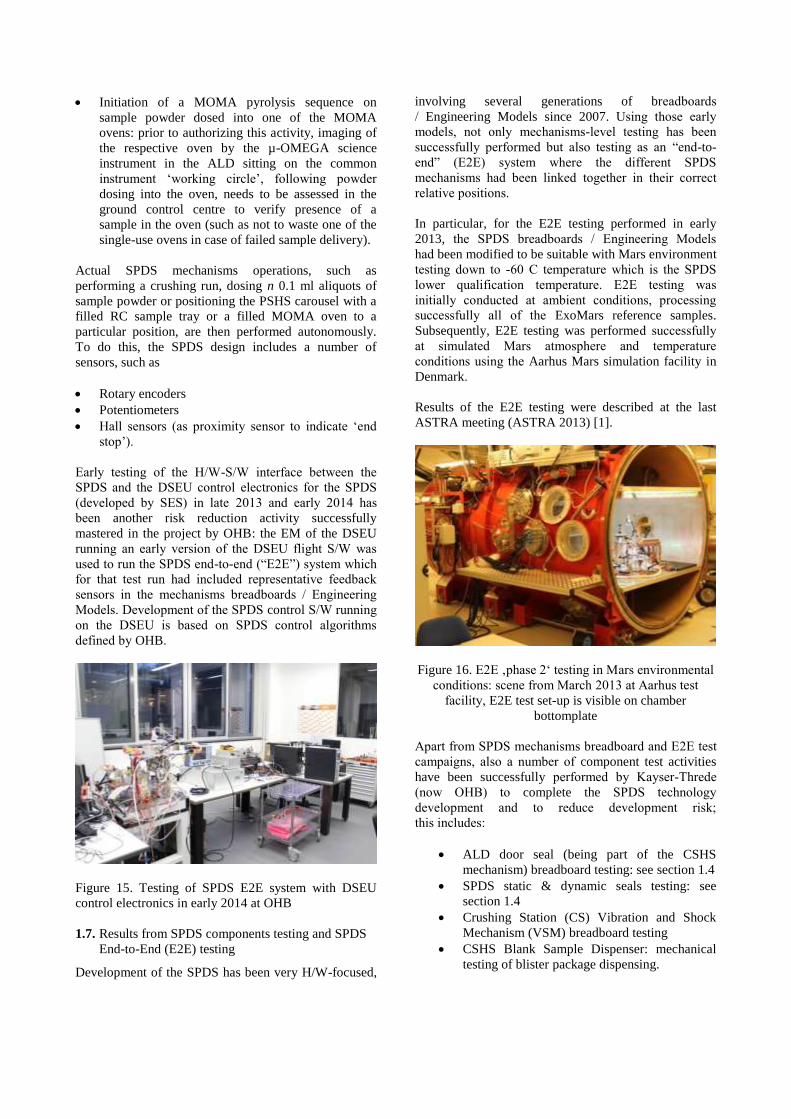
In Figure 14, flow rates at Mars gravity are shown for
all of 8 samples simulated, but normalized to the flow
rate of sample “S1” (fine sand and Montmorrilonite
mix ture, crushed) which in the AFM /
CPM measurements was found to be
relatively cohesionless.
Figure 14. Flow rates through the PSDDS inlet hopper
during sample dosing, at Mars gravity, of the
8 simulated samples. Flow rate is normalised to that of
sample “S1” (fine sand and Montmorrilonite
mixture, crushed)
Overall, the simulation runs confirm adequate sample
flow through the DS inlet hopper at Mars gravity with
the finally selected (in the design) outlet throat
diameter even with no piezo agitation.
1.6. SPDS control
Control of the SPDS is by the ExoMars Drill and SPDS
Electronics Unit (DSEU) which is shared with the
sample acquisition drill and is developed by Selex
Electronic Systems (SES).
During the Mars surface mission of the ExoMars rover,
command sequences will typically be radiated from
Earth to the rover once per Mars day (‘Sol’). Data may
be relayed up to twice per Sol from the rover to Earth,
via one or more Mars orbiters passing over the landing
site and offering UHF relay services to assets on the
surface. The ExoMars rover, like previous and current
Mars rovers by NASA, will thus extensively rely on on
board autonomy to control housekeeping and
communications with Earth, mobility to a designated
(by operators on Earth) drive target, scientific remote
sensing operations, acquisition of surface and
subsurface samples by the drill, transfer of samples into
the ALD and their mechanical processing by the SPDS
and, finally, analysis of the resultant sample powders by
the ‘Pasteur’ instruments in the ALD.
Some SPDS acitivities require intervention from
operators on Earth before committing to a subsequent
step in sample processing: currently, these are:
Initiation of sample crushing by the CS: prior to
authorizing this activity, imaging of the sample (by
the rover mast-mounted cameras) residing in the
CSHS sample container following its discharge
from the drill head needs to be assessed in the
gound control centre to verify the actual transfer of
a sample and its physical appearance; at the time of
image assessment, the sample will already have
fallen into the CS and is therefore already protected
from Mars surface UV, radiation and the surface
temperature cycle; if assessment suggests not to
process the sample, the CS can be commanded to
move to the ‘dejamming’ configuration to permit
the sample to exit the CS and to drop into a ‘waste
container’
Initiation of dosing of sample powder following
crushing in the CS: prior to authorizing this
activity, engineering data from the CS crushing
operation needs to be assessed in the gound control
centre to verify the adequate extent of sample
comminution; if deemed insufficient, a new period
of crushing may be commanded (the nominal
duration of crushing operation for a given sample is
not to exceed 2 h)
Initiation of a MOMA pyrolysis sequence on
sample powder dosed into one of the MOMA
ovens: prior to authorizing this activity, imaging of
the respective oven by the µ-OMEGA science
instrument in the ALD sitting on the common
instrument ‘working circle’, following powder
dosing into the oven, needs to be assessed in the
ground control centre to verify presence of a
sample in the oven (such as not to waste one of the
single-use ovens in case of failed sample delivery).
Actual SPDS mechanisms operations, such as
performing a crushing run, dosing n 0.1 ml aliquots of
sample powder or positioning the PSHS carousel with a
filled RC sample tray or a filled MOMA oven to a
particular position, are then performed autonomously.
To do this, the SPDS design includes a number of
sensors, such as
Rotary encoders
Potentiometers
Hall sensors (as proximity sensor to indicate ‘end
stop’).
Early testing of the H/W-S/W interface between the
SPDS and the DSEU control electronics for the SPDS
(developed by SES) in late 2013 and early 2014 has
been another risk reduction activity successfully
mastered in the project by OHB: the EM of the DSEU
running an early version of the DSEU flight S/W was
used to run the SPDS end-to-end (“E2E”) system which
for that test run had included representative feedback
sensors in the mechanisms breadboards / Engineering
Models. Development of the SPDS control S/W running
on the DSEU is based on SPDS control algorithms
defined by OHB.
Figure 15. Testing of SPDS E2E system with DSEU
control electronics in early 2014 at OHB
1.7. Results from SPDS components testing and SPDS
End-to-End (E2E) testing
Development of the SPDS has been very H/W-focused,
involving several generations of breadboards
/ Engineering Models since 2007. Using those early
models, not only mechanisms-level testing has been
successfully performed but also testing as an “end-to-
end” (E2E) system where the different SPDS
mechanisms had been linked together in their correct
relative positions.
In particular, for the E2E testing performed in early
2013, the SPDS breadboards / Engineering Models
had been modified to be suitable with Mars environment
testing down to -60 C tempera ture which is the SPDS
lower qualification temperature. E2E testing was
initially conducted at ambient conditions, processing
successfully all of the ExoMars reference samples.
Subsequently, E2E testing was performed successfully
at simulated Mars atmosphere and temperature
conditions using the Aarhus Mars simulation facility in
Denmark.
Results of the E2E testing were described at the last
ASTRA meeting (ASTRA 2013) [1].
Figure 16. E2E ‚phase 2‘ testing in Mars environmental
conditions: scene from March 2013 at Aarhus test
facility, E2E test set-up is visible on chamber
bottomplate
Apart from SPDS mechanisms breadboard and E2E test
campaigns, also a number of component test activities
have been successfully performed by Kayser-Threde
(now OHB) to complete the SPDS technology
development and to reduce development risk;
this includes:
ALD door seal (being part of the CSHS
mechanism) breadboard testing: see section 1.4
SPDS static & dynamic seals testing: see
section 1.4
Crushing Station (CS) Vibration and Shock
Mechanism (VSM) breadboard testing
CSHS Blank Sample Dispenser: mechanical
testing of blister package dispensing.

1.8. ALD / UCZ structure, pressure relief valve and
optical windows
Since mid 2013, OHB Munich have also been
developing the structure of the ExoMars rover analytical
laboratory (ALD) (a task delegated to OHB by TAS-I)
including the ALD pressurized Ultra Clean Zone (UCZ)
surrounding the sample path.
The ALD / UCZ structure conceptual design had been
developed by TAS-I and was then detailed by OHB.
Two main panels – from Al alloy – are interconnected
by composite struts, carriying not only the SPDS
mechanisms but also the “Pasteur” instruments, the
DSEU control electronics for the ALD as well as ALD
thermal control H/W. A hood interfaces with the ALD
structure lower platform (also referred to as the
“baseplate”) and forms the principal enclosure of the
UCZ. Inside it, the PSDDS and PSHS subsystems of the
SPDS are housed, and a long pressure seal – again an
Inconel C-ring – ensures pressure tightness between the
hood (the “UCZ cover”) and the baseplate, as part of the
overpressure UCZ concept.
The structure also accommodates the iso-mount
interfaces by which the ALD system – amounting to
~45 kg in mass – interfaces with the ExoMars rover
primary structure.
Figure 17. Overview of ALD / UCZ structure: top:
“upper plate”, bottom: “baseplate”, centre: “UCZ
cover”; struts interconnect upper plate and baseplate
Not only has the ALD / UCZ structure design been
driven by mass, envelope, strength and pressure
tightness constraints but also by severe shape integrity
requirements as the optical instruments MicrOmega and
RLS pose demanding sample positioning requirements,
the achievement of which also relies on the behaviour of
the structure.
Figure 18. Fit check of UCZ pressure seal (Inconel C-
ring type) on baseplate of STM of ALD structure, April
2015
A critical element of the ALD / UCZ structure is the
UCZ pressure relief valve which is mounted to the UCZ
cover. It serves to control the pressure of the filling gas
(Argon) inside the UCZ. The valve maintains a constant
overpressure of nominally 100 mbar (± 20%) in the
enclosed volume of the UCZ w.r.t.
the external environment, i.e. the environment outside
the ALD / UCZ, during ground operations and in space
until first opening of the ALD / UCZ door after landing
on Mars. This is to ensure no biological contamination
can enter the UCZ which would falsify the search for
organics in the Martian samples. The valve is operating
purely passively, simply by way of a spring- driven
orifice. Without the valve, the UCZ structurally would
have to be sized for an overpressure of 1.1 bar (instead
of 0.2 bar including margin) which would have
prohibitively driven up the structure mass.
Since the SPDS sample handling takes place inside the
ultra-clean zone (UCZ) while the optical “Pasteur”
instruments MicrOmega and RLS are located outside of
the UCZ, two sealed optical windows are integrated in
the structure – specifically in the UCZ cover – in order
to allow the analysis of the samples. These windows
are part of the ALD structure system and are also
developed by OHB. Each window consists of 2 main
parts that are soldered together: an optically trans-
missive substrate (the window ‘glass’), and a metal
carrier. The carrier provides the holding frame by means
of which the window is attached to the ALD structure.
Between carrier and ALD structure, a metallic seal ring
provides leakage tightness and electrical connection
(required for antistatic grounding). The optical
requirements on the windows and the soldering process
between substrate and carrier result in a complex stack
of coatings to be applied.

Figure 19: Development Model version of the ALD
window for MicrOmega (identical in design to QM /
FM window) , prior to successful shock testing in late
2014
1.9. Criticalities mastered in the design
The development of the SPDS and of the ALD / UCZ
structure had to go through a variety of design
challenges, in particular related to the QM / FM designs
produced over the past 2 years. This was principally
related to the following aspects:
Conflicting requirements related to surface
treatments and properties of the parts:
o Required compatibility with the
ExoMars-specific cleaning and
sterilisation processes for planetary
protection (PP) (calling for careful
selection of mechanical parts
passivation that does not degrade as a
result of the PP activities; also calling
for very stringent surface roughnesses
for parts touching samples)
o Required hardness of tribological
surfaces of the SPDS mechanisms that
may be conflicting with the PP-related
requirements
o
Manufacturability of SPDS parts – of mostly
very unusual shape – with tight tolerance
requirements to ensure mechanism
functionaility across the specified temperature
range
Choice of the type of pressure seals (both static
and dynamic).
1.10. Programmatic status
Since the last ASTRA meeting 2 years ago, the flight
design of the SPDS has been performed, and a PDR /
CDR held and closed. Subsequently, the MRR has been
held for build of the SPDS QM system which is the first
build of the flight design. At this time, manufacture of
the QM parts is fully under way and Long Lead Items
procurement for the QM is complete. The PSHS QM is
the first of the SPDS QM mechanisms to be integrated,
with integration starting this month (May 2015). Over
the subsequent 3 months, the remaining 3 SPDS
mechanisms will follow. In a staggered sequence,
qualification testing of the 4 mechanisms will be
performed at OHB, with subsequent shipment of the
SPDS QM to TAS-I.
Since mid 2013, the preliminary and then the flight
design of the ALD / UCZ structure has been performed
by OHB and a PDR / CDR held and closed. The first
model of the structure being built at this time is the
STM on which the mechanical qualification will be
performed. The STM is followed shortly thereafter by
the QM version.
At TAS-I, ALD system-level testing of the QM ALD
will be carried out after the SPDS QM has been
sterilized and ultra-cleaned and integrated into the ALD
QM structure.
FM build is to commence by August 2015.
2. LUNAR APPLICATIONS
Several space agencies are preparing a new round of
robotic landing missions to the Moon, with particular
focus on the polar regions in pursuit of volatiles now
confirmed by a variety of remote sensing techniques and
the LCROSS impactor experiment [4,5]. In particular,
Roscosmos has defined a series of lunar landing and
sample return missions – Luna-Glob / Luna-Resurs
/ Luna Sample Return – targeted to the lunar poles.
Since 2013, ESA and Roscosmos have been in a
collaboration to define possible contributions by ESA to
this new programme. Current plans envisage an ESA-
controlled development of a subsurface sampling drill
suitable for icy regolith and an analytical instrument for
analysis of the acquired samples. At a polar site, lunar
regolith accessible to a robotic lander may include
crystalline ices as a volatile component admixed in the
regolith.
If a sample handling and processing system based on
the heritage of the ExoMars SPDS developed by OHB
were to be considered for such an application, likely
design modifications are associated with manipulation
and handling of ‘icy’ samples and their protection from
premature loss of their volatile contents. To this effect,
the end-to-end (E2E) testing with the SPDS breadboards
(see section 1.8) did include several regolith analogs
that were mixed with water and subsequently frozen to
be processed by the SPDS in a simulated Mars
environment. Accordingly, samples with < 20 % water
ice content presented no issues to the system, with the
sample being ground successfully to the desired grain
sizes and dosed for observation and analysis by the
science instruments.

ESA awarded the L-GRASP TRP contract to an
industrial team led by SES, with OHB Munich as a
subcontractor. L-GRASP, ‘Lunar Generic Regolith
Acquisition / Sampling Paw’, has traded off concepts
for a lunar regolith sampling device as part of a rotary-
percussive drill compatible with a lunar polar site and
subsurface access down to 2 m of depth, reflecting the
requirements of the planned Russian LUNA 27 lander
mission. OHB has interacted with lunar scientists to
propose a suitable icy lunar regolith analogue which
was subsequently produced and characterized by
dedicated laboratory experiments. In parallel, the L-
GRASP mechanical concept was selected and the
corresponding breadboard designed by SES. Testing in
the icy lunar soil simulant is to begin in June.
Figure 20. Icy regolith sample following strength testing
by penetrometer
Another lunar-related study in which OHB Munich is
involved is ProsPA (Lunar Polar Prospecting:
Processing and Analysis), funded through the ESA
GSP. This study is led by the Open University (UK) and
investigates the analytical instrument to be part of the
prospective ESA contribution to the Russian LUNA 27
mission, i.e. the instrument that would analyse the
samples acquired by the subsurface drill. Here, OHB are
responsible for the “Sample Inlet System” (SIS) which –
similar to the ExoMars SPDS PSHS carousel – carries
ovens to be sequentially filled with samples. The SIS
also features the oven sealing mechanism, likewise
under OHB responsibility. Because of more severe oven
leak rate requirements in comparison to previous
instruments developed for Mars missions and for
Rosetta lander Philae, a knife edge seal has been
adopted for the ovens. To confirm the assumed sealing
forces to be applied by the SIS oven sealing mechanism,
a test set-up has been designed by OHB simulating the
sealing arrangement. Testing is currently on-going, in
parallel to performing the preliminary mechanical
design of the SIS.
Figure 21. Conceptual design of SIS carousel wheel
(inherited from SPDS PSHS)
Figure 21. Test set-up at OHB for measuring ProsPA
oven sealing forces and leak rates
3. Conclusions
Space Robotics is a major line of projects at OHB
Munich, comprising planetary exploration robotics and
orbital robotics. This paper describes our on-going
activities related to automated sample handling and
sample distribution for planetary landing, roving and
sample return missions. The major current project in
this area is development of the Sample Processing and
Distribution Subsystem (SPDS) for the ESA-Roscosmos

ExoMars rover mission which now is in the production
phase of the SPDS Qualification Models. Moreover,
OHB Munich are involved in the L-GRASP lunar polar
regolith sampling device study for ESA and the ProsPA
lunar icy regolith analysis instrument study.
4. Acknowledgements
The OHB SPDS activities are performed in the frame of
ESA contracts as subcontractor to TAS-I which we
gratefully acknowledge. The L-GRASP study is funded
by the ESA TRP, with OHB being subcontractor to
Selex Electronic Systems (SES). The ProsPA study is
funded by the ESA GSP, with OHB being subcontractor
to the Open University.
5. REFERENCES
1. Richter, L., Hofmann, P., Mühlbauer, Q., T. C. Ng,
Paul, R., Schulte, W. (2013), Technologies for
Automated Sample Handling and Sample
Distribution on Planetary Landing Missions,
ASTRA 2013, May 15-17
2. Mühlbauer, Q., Richter, L., Kaiser, C., Hofmann, P.
(2012), Robotics Space Systems and Subsystems for
Advanced Future Programmes, International
Symposium on Artificial Intelligence, Robotics and
Automation in Space (i-SAIRAS 2012), Torino,
Italy, Sept. 4-6
2. Schulte, W., Richter, L., Redlich, D. Hofmann, P.,
Baglioni, P., Durrant, S., Musso, F. (2012), The
ExoMars Sample Preparation and Distribution
System, 39th COSPAR Scientific Assembly,
Mysore, India, July 14-22
3. P. Reiss, P. Hager, A. Hoehn (2013), Hopper-Flow
Of Lunar Regolith Simulants In Reduced Gravity
and Vacuum, 7th Americas Con ference of
the ISTVS, Nov. 4-7
4. Spudis, P. D. and 29 co-authors (2010), Initial Results
for the North Pole of the Moon from Mini-SAR,
Chandrayaan-1 Mission, Geophysical Research
Letters, Volume 37, Issue 6,
doi:10.1029/2009GL042259
5. Colaprete, A. and 16 co-authors (2010), Detection of
Water in the LCROSS Ejecta Plume, Science,
Volume 330, Issue 6003, p. 463