programme: electronics and telecommunication engineering€¦ · government college of engineering,...
TRANSCRIPT

Government College of Engineering, Karad(An Autonomous Institute of Government of Maharashtra)
Programme: Electronics andTelecommunication Engineering
Syllabus forSecond year of B. Tech

Government College of Engineering, KaradSecond Year B. Tech
EX301: Engineering Mathematics - IIITeaching Scheme Examination SchemeLectures 3 Hrs/week CT1 15Tutorial 1 Hr/week CT2 15
TA 10ESE 60
Total Credits: 4Course Objectives:This course aims to:
1 Explain Mathematical methodologies and models, it is basic necessity for thefoundation of Engineering and Technology
2 Develop mathematical skills and enhance logical thinking power of students.3 Provide students with skills to solve differential equations and their applications
which would enable students to obtain engineering solutions for given situationsthey may encounter in their profession.
4 Learn vector calculus, probability which would enable students to findengineering solutions for given situations they may encounter in their profession.
Course ContentsHours
Unit I Linear Differential Equations (LDE) and Applications:Linear Differential Equations with constant coefficients, Cauchy’sand Legendre’s differential equation, Applications of LinearDifferential Equations with constant coefficients to Electricalsystems. 8
Unit II Fourier Series:Definition, Euler’s formulae, Conditions for a Fourier expansion,Functions having points of discontinuity, change of interval,expansions of odd and even periodic functions and half range series. 8
Unit III Fourier Transforms:Fourier transforms, Fourier sine and cosine transforms, Complexform of Fourier Integral, Finite Fourier sine and cosine Transforms. 6
Unit IV Laplace Transform and Application:Definition, properties of Laplace transforms, transforms ofderivatives, Transforms of integral. Inverse Laplace transforms,Convolution theorem. Applications to initial value boundaryproblems, Heaviside Unit step function, Dirac-delta function, andPeriodic function. 6

Unit V Vector Differential Calculus:Differentiation of vectors, Gradient of scalar point function,Directional derivative, Divergence of vector point function, Curl of avector point function. Irrotational and solenoidal vector field. 8
Unit VI Probability:Random Variable, Discrete and continuous random variable,Expected value of random variable, Variance, Moments & momentgenerating functions. Probability mass function & Probability densityfunction, Probability distribution for random variables, Binomial,Poisson and Normal distributions. 6
Note: • Tutorials for the subject shall be engaged in minimum of four batches(batch size of 20 students Maximum) per division.
• Teachers Assessment shall consist of minimum 8 tutorials from entiresyllabus.
Course Outcome (CO):Upon successful completion of this course, the student will be able to:
1 Understand the basic necessity of mathematics, for the foundation ofEngineering and Technology. Also understand Mathematical methodologies andmodels.
2 Develop mathematical skills and enhance logical thinking power of students.3 Solve problems on differential equations and their applications which would
enable students to obtain engineering solutions for given situations they mayencounter in their profession.
4 Understand vector calculus, probability which would enable students to findengineering solutions for given situations.
Text Books1 Erwin Kreyszig, “Advanced Engineering Mathematics”, 8th Edition, Wiley
Eastern Ltd. Mumbai.2 J. N. Wartikar & P. N. Wartikar, “A text book of Applied Mathematics: Vol. I, II
and III”, Vidyarthi Griha Prakashan, Pune.
Reference Books1 B. S. Grewal, “Higher Engineering Mathematics”, Khanna Publication, New
Delhi.2 S. D. Sharma, “Operations Research”.3 Kanti B. Datta, Cengage Learning, “Mathematical Methods of Science and
Engineering (Aided with MATLAB)”.
Useful Links1 http://nptel.ac.in/courses/122103012/2 www.ocw.mit.edu/courses/most-visited-courses/3 https://www.khanacademy.org/math/differential-equations4 https://www.khanacademy.org/math/probability

Mapping of CO and PO
PO PSOa B C d e F g H i j k l m n
CO1 √ √ √ √ √ √ √CO2 √ √ √ √ √ √ √ √CO3 √ √ √CO4 √ √ √ √ √ √
Assessment Pattern
Knowledge Level CT1 CT2 TA ESE
Remember 2.5 15
Understand 5 5 2.5 10
Apply 5 5 2.5 15
Analyse 10
Evaluate 5 5 2.5 10
Create
Total 15 15 10 60

Government College of Engineering, KaradSecond Year B. Tech
EX302: Electronic Devices and CircuitsTeaching Scheme Examination SchemeLectures 4 Hrs/week CT1 15
CT2 15TA 10ESE 60
Total Credits: 4Course Objectives:This course aims to:
1 Provide an introduction and basic understanding of Semiconductor Devices viz.diodes and bipolar junction transistors.
2 Understand the different types of transistor with analysis.3 Analyse effect of frequency on amplifiers.4 Design electronic circuits to meet the desired specifications.
Course ContentsHours
Unit I Semiconductors and Diode theory:Drift and diffusion mechanisms, Recombination process, Meancarrier lifetime, Conductivity, Mobility, Mass action law, Einsteinrelationship. Semiconductor p-n junction, Depletion region, Barrierpotential, V-I characteristic, Equation of diode. Forward and reversedynamic resistance, Diode Capacitances. Diode Applications –Rectifiers, Clippers & Clampers 7
Unit II Bipolar Junction Transistor:BJT biasing, concept of dc and ac load line, bias stabilization,thermal runaway, thermal stabilization, Early effect, Small signal lowfrequency h-parameter model. Introduction to amplifier, Derivationsfor CE configuration for AI, Ri, Ro, Avs, AIS in terms of h-parameters, and Detailed study of Single stage RC coupled amplifier& Emitter follower. 7
Unit III Field Effect Transistor:JFET, MOSFET (depletion and enhancement) - construction , V-Icharacteristics, transfer characteristics, voltage-current relationship,Cut-off & Pinch-off voltages, Transconductance , channel lengthmodulation, Input resistance & Capacitance and various breakdownin FET. FET small signal model, FET biasing – self and voltagedivider biasing, CMOS introduction. 7
Unit IV Frequency Response analysis:Concept of frequency response. Effect of coupling, bypass, junctionand stray capacitances on frequency response of FET amplifiers. 7

Millers Theorem. High frequency response: Hybrid π model. Gainbandwidth product
Unit V Power Amplifiers:Power transistors; Power amplifiers; Classes of amplifiers: class-Apower amplifiers, class-B power amplifiers, Class –AB push-fullcomplementary output stages. 7
Unit VI Rectifiers and Power Supplies:Different types of Rectifiers and related parameters. Inductor filter,Capacitor filter, L filter, π filter. Need of voltage regulator,Stabilization factors, Analysis & Design of Shunt regulator (usingZener diode & BJT), series voltage regulator (using BJT) Seriesvoltage regulator with Pre- regulator & Overload protection circuit. 7
Course Outcome (CO):Upon successful completion of this course, the student will be able to:
1 Apply knowledge of mathematics, science, and engineering to design, analyseand operation of electronic devices and circuits
2 Explain basic analog electronic circuit design techniques using diodes andbipolar junction transistors.
3 Explain the hybrid model of transistor and analyse the transistor amplifier (CE,CB, CC) using h-parameters.
4 Determine the frequency response of amplifiers5 Analyse and design electronic circuits such as rectifiers, voltage regulators and
transistorized amplifiers
Text Books1 J. Millman & C.Halkias, “Electronic devices & circuits”, Tata McGraw Hill
Publication.2 Allen Mottershed, “Electronic devices & circuits”, Prentice- Hall India.
Reference Books1 David A. Bell, “Electronic devices & circuits”, Oxford University.2 Robert L. Boylestad, Louis Nashelsky, “Electronic Devices and Circuit Theory”,
PHI publishers.3 Sedra/Smith, “Microelectronic Circuits” by, Oxford University Press.
Useful Links1 http://www.electronics-tutorials.ws/2 http://ocw.mit.edu/courses/electrical-engineering-and-computer-science3 http://nptel.ac.in/video.php?subjectId=1171030634 http://nptel.ac.in/courses/117107094/

Mapping of CO and PO
PO PSOa b C d e f g h i j k l m n
CO1 √ √ √ √ √ √CO2 √ √ √ √ √ √ √CO3 √ √ √ √CO4 √ √ √ √CO5 √ √ √ √ √ √
Assessment Pattern
Knowledge Level CT1 CT2 TA ESE
Remember 5 5 2 10
Understand 5 2 10
Apply 5 5 2 10
Analyse 5 2 10
Evaluate 2 10
Create 10
Total 15 15 10 60

Government College of Engineering, KaradSecond Year B. Tech
EX303: Microcontroller and InterfacingTeaching Scheme Examination SchemeLectures 4 Hrs/week CT1 15
CT2 15TA 10ESE 60
Total Credits 4Course Objectives:This course aims to:
1 Provide an overview of difference between microprocessor and micro controller.
2 Give an understanding about the concepts and basic architecture of 8051.3 Study the architecture and addressing modes of 8051.4 Impart knowledge about assembly language programs of 8051.5 Help understand the importance of different peripheral devices & their interfacing to 8051.
6 Impart knowledge of different types of external interfaces including LEDS, LCD, Keypad
Matrix, Switches & Seven segment display.
Course Contents HoursUnit I Introduction to 8085 microprocessor:
Introduction, Block diagram of 8085, machine cycle, Instruction cycle,Timing Diagram Types of Instructions and examples. Difference betweenmicroprocessor and microcontroller, memory organization in 8085,Assembly language programming. 4
Unit II Basics of 8051 Microcontrollers:Introduction to various Architectures, Concept of RISC and CISCprocessors. Microcontrollers and embedded processors, Overview of the8051 family, Architecture of 8051 , Pin description of the 8051,RAM andRom Organization in 8051 5
Unit III 8051 Assembly Language Programming:8051 Addressing Modes :Immediate and register addressing modes,Accessing memory using various addressing modes, Bit addresses for I/Oand RAM, Extra 128-byte on-chip RAM in 8052.Concept of Instructioncycle, Machine cycle. Types of Instructions ,Introduction to 8051 assemblyprogramming, Assembling and running an 8051 program, The programcounter and ROM space in the 8051, 8051 data types and directives, 8051flag bits and the PSW register, 8051 register banks and stack. Jump, Loop,And Call Instructions. I/O Port Programming. Arithmetic and LogicInstructions and Programs. 7
Unit IV 8051 Programming in C:Data types and time delay in 8051 C, I/O programming in 8051 C, Logic 3

operations in8051 C, Data conversion programs in 8051 C, Accessing codeROM space in 8051 C, Data serialization using 8051 C. 8051 HardwareConnection and Intel Hex File
Unit V 8051 Timer Programming in Assembly and C:Programming 8051 timers, counter programming, Programming timers 0and 1 in 8051 C as well as in assembly. 5
Unit VI 8051 Serial Port Programming in Assembly and C:Basics of serial communication, 8051 connection to RS232, 8051 serialport programming in Assembly, Programming the second serial port, Serialport programming in C. 5
Unit VII Interrupts Programming in Assembly and C:8051 interrupts programming, Timer interrupts, Programming externalhardware interrupts, Programming the serial communication interrupt,Interrupt priority in the 8051/52, Interrupt programming in C. 5
Unit VIII Interfacings of 8051:Details of LCD interfacing, Keyboard interfacing. Parallel and serial ADC,DAC interfacing, Sensor interfacing and signal conditioning.Semiconductor memory, Memory address decoding, 8031/51 interfacingwith external ROM, Flash RAM, 8051 data memory space, Accessingexternal data memory in8051 C.RTC Interfacing and Programming. MotorControl: Relay, PWM, DC and Stepper Motors PWM. 8
Course Outcome (CO):Upon successful completion of this course, the student will be able to:
1 Explain the difference between microprocessor and microcontroller2 Explain different addressing modes of 80513 Explain the working of various peripherals and their interfacing4 Write assembly as well as c programs for 80515 Design system based on 8051
Text Books1 Muhammad Ali Mazidi, Janice Gillispie Mazidi and Rolin McKinlay, “The 8051
Microcontroller and Embedded Systems Using Assembly and C”, Second Edition,Pearson Education.
2 K. J. Ayala, D. V. Gadre, “The 8051 Microcontroller & Embedded Systems usingAssembly and C”, Cengage Learning, India Edition.
Reference Books1 Satish Shah, “8051 Microcontrollers: MCS51 family and its variants”,
Oxford University Press.2 Subrata Ghoshal, “8051 Microcontroller: Internals, Instructions, Programming and
Interfacing”, Pearson Education.3 K Uma Rao, Andhe Pallavi, “The 8051 Microcontrollers: Architecture, Programming

and Applications”, Pearson Education.
Useful Links1 http://nptel.ac.in/courses/Webcourse-contents/IIT-KANPUR/microcontrollers/
micro/ui/TOC.htm2 http://freevideolectures.com/Course/3018/Microprocessors-and-Microcontrollers
Mapping of CO and PO
PO PSOa B c d e f g h i j k l m n
CO1CO2 √ √ √ √CO3 √ √ √CO4 √ √ √ √CO5 √ √
Assessment Pattern
Knowledge Level CT1 CT2 TA ESERemember 5 5 2 10Understand 5 5 2 20
Apply 5 5 2 10Analyse 2 10Evaluate 2 10Create - - - -Total 15 15 10 60

Government College of Engineering, KaradSecond Year B. Tech
EX304: Digital ElectronicsTeaching Scheme Examination SchemeLectures 3 Hrs/week CT1 15Tutorial 1 Hr/week CT2 15
TA 10ESE 60
Total Credits: 4Course Objectives:This course aims to:
1 Understand principles, characteristics and operations of combinational & sequential logiccircuits.
2 Design combinational circuits by using logic gates3 Explain Boolean algebra and the various methods of Boolean function reduction, K-map
reduction and Quine McCluskey method4 Design, implement and analyze, asynchronous and synchronous sequential circuits (FSM)
using flip flops.5 Explain the various 74XX series components and their applications in designing
combinational & low complexity sequential circuits.
Course ContentsHours
Unit I Logic Families:Logic Families – Significance and Types, Characteristic Parameters,Transistor Transistor Logic (TTL), Emitter Coupled Logic (ECL), NMOSand PMOS Logic, CMOS Logic Family, Comparison of Different LogicFamilies. 6
Unit II Minimization Techniques and Logic Gates:Minimization Techniques: Boolean postulates and laws – De Morgan’sTheorem Principle of Duality Boolean expression Minimization of Booleanexpressions – Minterm – Maxterm Sum of Products (SOP) – Product ofSums (POS) – Karnaugh mapMinimization – Don’t care conditions – Quine Mc Cluskey method ofminimization. Logic Gates: AND, OR, NOT, NAND, NOR, Exclusive–ORand Exclusive–NOR Implementations of Logic Functions using gates,NAND–NOR implementations – Multilevel gate implementations, TTL andCMOS Logic and their characteristics – Tristate gates 8
Unit III Combinational Circuits:Design procedure – Half adder, Full Adder, Half Subtractor, Full Subtractor,Parallel binary adder, parallel binary Subtractor, Fast Adder Carry LookAhead adder, Serial Adder/Subtractor BCD adder – Binary Multiplier –Binary Divider Multiplexer/Demultiplexer – decoder encoder – parity

checker – parity generators – code converters Magnitude Comparators. 6
Unit IV Sequential Circuits:Latches, Flip flops- SR, JK, D, T, and Master Slave – Characteristic tableand equation –Application table – Edge triggering – Level Triggering.Realization of one flip flop using other flip flops – serial adder/SubtractorAsynchronous Ripple or serial counter – Asynchronous Up/Down counterSynchronous counters – Synchronous Up/Down counters – Programmablecounters – Design of Synchronous counters: state diagram State table –Stateminimization –State assignment Excitation table and maps Circuitimplementation Modulo– n counter, Registers – shift registers Universalshift registers – Shift register counters – Ring counter – Shift countersSequence generators. 8
Unit V Memory Devices:Classification of memories – ROM, ROM organization, PROM –EPROM –EEPROM –EAPROM, RAM – RAM organization – Write operation – Readoperation.Programmable Logic Devices – Programmable Logic Array (PLA)Programmable Array Logic (PAL) – Field Programmable Gate Arrays(FPGA), ASIC, Implementation of combinational logic circuits using ROM,PLA, PAL 7
Unit VI State Machines:FSM, Moore/Mealy machines, representation techniques, state diagram, statetable, state assignment and state reduction, implementation using D flip flop,Application like sequence detector, binary adder etc., Effect of clock skewand clock jitter on synchronous designs (Meta stability), Introduction toASM 7
Note: • Tutorials for the subject shall be engaged in minimum of four batches (batch sizeof 20 students Maximum) per division.
• Teachers Assessment shall consist of minimum 8 tutorials from entire syllabus.
Course Outcome (CO):Upon successful completion of this course, the student will be able to:
1 Apply Boolean laws/K-Map/Quine McCluskey method to reduce Boolean functions anddesign combinational logic circuits using logic gates
2 Demonstrate the operation of flip-flops, counters and shift registers3 Design Synchronous sequential machine using Moore and Mealy machine4 Distinguish between various memories and implementation of digital circuits using PLA and
PAL5 Demonstrate logical skills, debugging skills in designing small digital circuits for industrial
applications
Text Books1 R.P. Jain, “Modern Digital Electronics”, 4th edition, Tata McGraw - Hill Education, 2010.

2 Primer , J. Bhasker, “A VHDL”, 3rd edition, PHI Learning, 20093 M. Morris Mano, “Digital Design”, Pearson Education (3rd Edition) (Unit 1,2,3,4)
Reference Books1 William I. Fletcher, “An Engineering Approach to Digital Design”, PHI/ Pearson.2 Anil K. Maini, “Digital Electronics principles and Integrated Circuits”, Wiley Publications.3 A. Anand Kumar, “Fundamentals of digital circuits”, 1st edition, PHI publication, 2001.
Useful Links1 https://en.wikibooks.org/wiki/Digital_Electronics2 www.asic-world.com3 www.electronics-tutorials.com4 http://nptel.ac.in/courses/117106086/5 http://10.0.0.208/NPTEL%20Videos/ELETRONICS%20&%20ELECTRICAL%20ENGG/d
igitalintegratedcircuits
Mapping of CO and PO
PO PSOa B c d E f g h i j k l m n
CO1 √ √ √ √ √ √ √ √CO2 √ √ √ √ √CO3 √ √ √ √ √ √ √ √CO4 √ √ √ √ √ √ √CO5 √ √ √ √ √ √ √ √ √ √ √
Assessment Pattern
Knowledge Level CT1 CT2 TA ESERemember 5 2 10Understand 5 5 2 10Apply 5 2 10Analyse 5 5 2 10Evaluate 2 10Create 10Total 15 15 10 60

Government College of Engineering KaradSecond Year B. Tech
EX305 : Transducers and MeasurementsTeaching Scheme Examination SchemeLectures 3 Hrs/week CT1 15
CT2 15TA 10ESE 60
Total Credits: 3Course Objectives:The course aims to:
1 Explain students the fundamental concepts of measurement.2 Make students aware of various electronic measuring instruments.3 Provide students an understanding of measurement using Bridge circuits.4 Explain students the concepts transducers and sensors.5 Make students able to understand and perform signal conditioning operations.
Course ContentsHours
Unit I Measurement fundamentals:Introduction to measurement , Performance Characteristics, StaticCharacteristics, Error in Measurement, Types of Static Error, Sourcesof Error, Dynamic Characteristics, Statistical Analysis, GraphicalRepresentation of Measurements as a Distribution 06
Unit II Measuring devices:CRO, Digital storage oscilloscope, Function generators, Digitalvoltmeters(DVM), digital multimeters, Signal Generators, Spectrumanalyzer, logic analyzer, digital frequency meter, Q-meter, LED, LCD,Graphics Display 08
Unit III AC and DC Bridges:
Need of Bridges, Measurement of Resistance, inductance, capacitance,frequency and Q of coil with Bridges, : Wheatstone’s Bridge, KelvinDouble Bridge, AC Bridges such as Haye’s Bridge, Wein Bridge,Maxwell’s-Wein Bridge, Maxwell’ L/C Bridge, Descourty’s Bridge &Schering Bridge 06
Unit IV Transducers and Sensors :Definition of transducers and study of following transducers:(i) Position and motion (ii) Strain, Force, Pressure and Flow (iii)Temperature (iv) Sound Transducer (v) Digital Transducers (vi)Proximity Devices (vii) optical Sensors (viii) Smart Sensors 10
Unit V Data acquisition and Signal Conditioning techniques :Elements of data acquisition system, AC to DC conversion, 06

amplification, OP-AMP and instrumentation amplifier, programmable
gain amplifier, theory of active filters, modulators and demodulators,
attenuators, comparators, ADC and DAC, introduction to Digital
Signal Processing and its applications
Course Outcome (CO):Upon successful completion of this course, the student will be able to:
1 Understand the basic concepts and need of measurement.2 Use various transducers and sensors for measurement purpose.3 Understand the fundamentals and design of signal conditioning circuits.4 Use and design of Bridge circuits for measurements of various parameters like
resistance, inductance, capacitance and frequency and understand its importance inmeasurement.
Text Books1 A.K.Sawhney, “A course in Electrical, Electronics measurement and
Instrumentation”, Danpat Rai Publication.2 H. S. Kalsi, “Electronic Instrumentation”, MGH, 3rd Edition.3 S. Tumanski, “Principles of electronic measurement”, Taylor and Francis
Publication.4 Rohit Khurana, “Electronic Instrumentation and Measurement”, first edition, Vikas
Publication.References
1 Welfrick Cooper, “Electronic Instrumentation and Measurement Techniques”, PHIPublication.
2 John Turner, “Instrumentation for Engineers And Scientists” , II Edition , Wiley.3 David A Bell, “Electronic Instrumentation and Measurements”, Third Edition,
Oxford.4 James W Dally, “Instrumentation for Engineering Measurements”, II Edition, Wiley.
Useful Links1 www.analogcircuits.com2 NPTEL- Mechatronics and Manufacturing automation
Mapping of CO and PO
PO PSOa B c d e f g h i j k l m n
CO1 √ √ √ √ √ √ √ √ √ √CO2 √ √ √ √ √ √ √ √ √ √CO3 √ √ √ √ √ √ √ √ √ √CO4 √ √ √ √ √ √ √ √ √ √

Assessment Pattern
Knowledge Level CT1 CT2 TA ESERemember 5 2 10Understand 5 5 2 10Apply 5 2 10Analyse 5 5 2 10Evaluate 2 10Create 10Total 15 15 10 60

Government College of Engineering, KaradSecond Year B. Tech
EX306: Electronic Devices and Circuits LabLaboratory Scheme Examination SchemePractical 2 Hrs/week CA 25
ESE 25Total Credits: 1
Course Objectives:This course aims to:
1 Understand how to use breadboard and mounting of active / passive componentson breadboard.
2 Understand the various diode application circuits with detail analysis.3 Understand the configurations of transistor with their frequency response.4 Understand the build and testing of different types of voltage regulator.
Course ContentsExperiment 1 Design and analysis of full wave rectifier using filters.
Experiment 2 Study of different types of clipper circuits.
Experiment 3 Study of different types of clamping circuits.
Experiment 4 Design and study of Low pass filter
Experiment 5 Design and study of High pass filter.
Experiment 6 Design and analysis of common emitter amplifier and FET amplifier.
Experiment 7 Design and analysis of zener shunt regulator
Experiment 8 Design and analysis of series pass voltage regulator.
Experiment 9 Design and analysis of transistorized shunt regulator.
Experiment 10 Determination of H-parameter for CE configuration using input and outputcharacteristics.
List of Submission1 Total number of Experiments: 102 Total number of sheets: NA3 Project/Dissertation Report: NA4 Seminar report: NA5 Field Visit Report: NA

Additional InformationCourse Outcome(CO):Upon successful completion of this course, the student will be able to:
1 Handle various electronic devices, instruments and circuits as well asBread board and routing on breadboard.
2 Design and test diode related circuits on breadboard and measurement of theirparameters.
3 Build and implement various type of regulators4 Design BJT and FET amplifiers.
Mapping of CO and PO
PO PSOa B c d e f g h i j k l m n
CO1 √ √ √CO2 √ √ √ √ √CO3 √ √ √ √ √ √CO4 √ √ √ √ √ √ √ √
Assessment Pattern
Skill Level Exp1
Exp2
Exp3
Exp4
Exp5
Exp6
Exp7
Exp8
Exp9
Exp10
TA ESE
Assembling
Testing √ √ √ √ √ √ √ √ √ √Observing √ √ √ √ √ √ √ √ √ √ √ √Analysing √ √ √ √ √ √Interpreting √ √ √ √Designing √ √ √ √ √ √ √ √ √ √Creating √Deducingconclusions
√ √ √ √ √ √ √ √ √ √ √ √
Total 10 10 10 10 10 10 10 10 10 10 25 25

Government College of Engineering, KaradSecond Year B. Tech
EX307: Microcontroller and Interfacing LabLaboratory Scheme Examination SchemePractical 2 Hrs/week CA 25
ESE 25Total Credits: 1
Course Objectives:This course aims to:
1 Understand the Assembly language programming for 80512 Understand the various peripheral devices and their interfacing3 Understand the programming and virtual simulation of system designed in
PROTEUS4 Understand the working of various inbuilt modules like Timers, counters,
Interrupts, etc.
Course Contents
Experiment 1 a) Write a program to add two 8-bit numbers stored in registers orinternal/External memory locations.b) Write a program to multiply two 8-bit numbers stored in registers orinternal/External memory locations.c) Write a program to multiply two 16-bit numbers.
Experiment 2 a) Write a program to add block of data stored in internal/external memorylocations.b) Write a program to transfer block of data from internal memory locations toexternal memory locations.c) Write a program to sort block of data in ascending or descending order.
Experiment 3 a) Write a program to perform the following.1. Keep monitoring P1.2 until it becomes high.2. When P1.2 becomes high write value 45H on P0.3. Sent a high to low pulse to P2.3
b) A switch is connected to P1.7. Write a program to check the status of switchand perform the following.
1. if switch = 0, send letter “N” to P22. if switch = 1, send letter “Y” to P2.
Experiment 4 a) Write a program to generate 5 KHz pulse waveform of 50% duty cycle onpin 1.0 using timer 1 in mode 2.b) Write a program to generate 1 KHz pulse waveform of 70% duty cycle onpin 1.0 using timer.
Experiment 5 a) Write a program for the 8051 to transfer letter “A” serially, continuously.

b) Write a program to transfer the message “YES” serially. Do thiscontinuously.c) Program the 8051 to receive bytes of data serially, and put them in P1.
Experiment 6 Interfacing ADC and DAC.
Experiment 7 Interfacing Matrix Keyboard.
Experiment 8 Interfacing LED and LCD Displays.
Experiment 9 Interfacing Stepper Motor.
Experiment 10 Controlling DC motor using PWM.
List of Submission1 Total number of Experiments:102 Total number of sheets: NA3 Project/Dissertation Report: NA4 Seminar report: NA5 Field Visit Report: NA
Additional InformationCourse Outcome(CO):Upon successful completion of this course, the student will be able to:
1 Write assembly as well as c programs for microcontroller2 Design delays using timers in 80513 Interface ADC,DAC, LCD, LED, Keyboard, Stepper motor, DC motor etc. with
80514 Differentiate between microprocessor and microcontroller
Mapping of CO and PO
PO PSOa B c d e f g h i j k l m n
CO1 √ √ √ √ √CO2 √ √ √ √ √CO3 √ √ √ √CO4 √

Assessment Pattern
Skill Level Exp1
Exp2
Exp3
Exp4
Exp5
Exp6
Exp7
Exp8
Exp9
Exp10
TA ESE
AssemblingTestingObserving √ √ √ √ √ √ √ √ √ √ √ √Analysing √ √ √ √ √ √ √Interpreting √ √ √ √ √ √Designing √ √ √ √ √ √ √ √ √ √ √Creating √ √Deducingconclusions
√ √ √ √ √ √ √ √ √ √ √
Total 10 10 10 10 10 10 10 10 10 10 25 25

Government College of Engineering, KaradSecond Year B. Tech
EX308: Digital Electronics LabLaboratory Scheme Examination SchemePractical 2 Hrs/week CA 25
ESE 25Total Credits: 1
Course Objectives:This course aims to:
1 Understand principles, characteristics and operations of combinational & sequentiallogic circuits.
2 Design combinational circuits by using logic gates3 Explain Boolean algebra and the various methods of Boolean function reduction, K-map
reduction and Quine McCluskey method4 Design, implement and analyse, asynchronous and synchronous sequential circuits
(FSM) using flip flops.5 Explain the various 74XX series components and their applications in designing
combinational & low complexity sequential circuits.Course Contents
Experiment 1 Realization of logic gates OR, AND, NOT, NOR, NAND gates using IC’s/discrete components and verify their truth tables using timing diagram
Experiment 2 Design code convertors (Any two)
Experiment 3 Prototyping of source to destination communication using MUX (IC 74151) andDEMUX(IC 74138)
Experiment 4 Realization of IC7483 as parallel adder and substractor
Experiment 5 Design and build 4-bit, 5-bit & 8-bit comparator using IC 7485
Experiment 6 Realization of all modes of universal shift register using IC IC 7495
Experiment 7 Design and build 4 bit comparator using IC 74181
Experiment 8 Implement and evaluate using oscilloscope Mod-N counter (IC 7490)
Experiment 9 Design, implement and test 4 bit sequence detector using IC 7474
Experiment 10 Design ring and Johnson counter using flip-flops
Experiment 11 Design 4-bit UP/DOWN synchronous counter using IC
Experiment 12 Mini project based on digital circuits on breadboard/ PCB

List of Submission1 Total number of Experiments :102 Total number of sheets:003 Project Report of mini project:01
Additional InformationCourse Outcome(CO):Upon successful completion of this course, the student will be able to:
1 Designing combinational logic circuits using logic gates2 Designing sequential logic circuits using flip-flop ICs3 Demonstrate logical skills, debugging skills in designing small digital circuits
Mapping of CO and PO
PO PSOa B c d e f g h i j k l m n
CO1 √ √ √ √ √ √ √CO2 √ √ √ √ √ √ √CO3 √ √ √ √ √ √ √ √ √ √ √ √ √
Assessment Pattern
Skill LevelExp
1Exp
2Exp
3Exp
4Exp
5Exp
6Exp
7Exp
8Exp
9Exp10
Exp11
Exp12
TA ESE
Assembling √ √ √ √ √ √ √ √ √ √ √ √ √ √
Testing √ √ √ √ √ √ √ √ √ √ √ √ √ √
Observing √ √ √ √ √ √ √ √ √ √ √ √ √ √
Analysing √ √ √ √ √ √ √ √ √ √ √ √ √ √
Interpreting √ √ √ √ √ √ √ √ √ √ √ √ √ √
Designing √ √ √ √ √ √ √ √ √
Creating √ √ √
Deducingconclusion
√ √ √ √ √ √ √ √ √ √ √ √ √ √
Total 10 10 10 10 10 10 10 10 10 10 10 10 25 25

Government College of Engineering KaradSecond Year B. Tech
EX309 : Embedded CTeaching Scheme Examination SchemeTutorial 1 Hr/week CA 50Practical 2 Hrs/week ESE --
Total Credits: 2Course Objectives:The course aims to:
1 Learn fundamentals of C, forming the programming platform.2 Provide an introduction and basic understanding of Types of Memory data
Allocations i.e. Data Structures with basic Programming Knowledge.3 Practice programs on 8051 simulator and hardware kit via Embedded C
Programming.Course Contents
HoursModule I Introduction & Overview:
Introduction to theory of C Programming.Introduction to Turbo C and Code::Blocks software. 1
Module II Arrays:Introduction, linear arrays, representation of linear array in memory,traversing linear arrays, inserting & deleting, Multidimensional arrays. 1
Module III Sorting and Searching:Sorting: bubble sort, selection sort, insertion sort.Searching: linear search, binary search. 1
Module IV Pointers:Pointers: pointer arrays. 1
Module V Records:Records: Record structures, representation of records in memory,parallel arrays, matrices, space matrices. 1
Module VI Stacks and Queues:Introduction to stacks, stack as an Abstract Data type, Operations onStacks, Applications.Queue as an abstract data type, operations, representation, circular,double ended, priority, applications. 1
Module VII Embedded ‘C’ Programming for 8051:Introduction to Embedded C Programming using Keil μVision IDE.Key words, memory models, memory types, data types, bit types,pointers. 1

Module VIII Embedded ‘C’ Programming for 8051:Functions interrupt functions, re-entrant functions. 1
Module IX Embedded ‘C’ Programming for 8051:Time delay, I/O Programming 1
Module X Embedded ‘C’ Programming for 8051:Logic operations, Data conversions 1
Module XI Embedded ‘C’ Programming for 8051:accessing code ROM space 1
Module XII Embedded ‘C’ Programming for 8051:Data serialization 1
Lab Course Contents(Note: Instructor can conduct any 5 Experiments from 1-7 and any 5 experiments from 8-14.)
Experiment 1 Introduction to C Programming: Any three basic C programs.(Two programmes should be given for practice and last problem of sessionshould be given for students for algorithm development and implementing thesame in C. The same problem should be in the lab file of students. The threeprogrammes may be different for every batch.)
Experiment 2 Array Handling - Traversing an Array, Insertion and Deletion of an element inan Array.
Experiment 3 Sorting Techniques for Arrays - Bubble sort, Selection Sort, Insertion Sort.
Experiment 4 Searching Techniques for Arrays - Linear Search, Binary Search.
Experiment 5 Multi-dimensional Array Handling – To Scan and Display a 2D Array.
Experiment 6 Implementation of Stack using Array.
Experiment 7 Implementation of Queue using Array.
Experiment 8 Arithmetic& Logical operations using 8085 using Embedded C
Experiment 9 Data transfer & Exchange using 8085 using Embedded C
Experiment 10 Data conversions using 8085 using Embedded C
Experiment 11 Timer & counter operation in 8051 using Embedded C
Experiment 12 Interface LCD to 8051 using Embedded C

Experiment 13 Serial Communication with 8051 using Embedded C
Experiment 14 Interface Stepper motor using 8051 using Embedded C
List of Submission1 Total number of Experiments = 10 (Any 5 from 1-7 and any 5 from 8-14.)2 Total number of sheets = Not Applicable3 Project/Dissertation Report = Not Applicable4 Seminar report = Not Applicable5 Field Visit Report = Not Applicable
Course Outcomes (CO):Upon successful completion of this course, the student will be able to:
1 Apply knowledge of Programming in the Fields of C Programming as well as inMicrocontrollers.
2 Understand the basic programming concepts of C.3 Develop Logic to Design an algorithm for C as well as Microcontroller
Programming.Text Books
1 V. Kanetkar, “Let us C”, BPB Publication.2 G. S. Baluja, “Data Structures using C”, Dhanpat Rai Publication.3 C51 compiler user guide By Keil software.
References1 Mark Allen Weiss, “Data structure & algorithm analysis in C”, Pearson Education.2 Muhammad Ali Mazidi & Janice Gillispie Mazidi, “The 8051 Microcontroller &
Embedded Systems”, Pearson Edition L. P .E.3 Kenneth L Short, “Microprocessors and Programmed logic”, Prentice-Hall.4 Douglas V Hall, “Microprocessors and Digital Systems”, McGraw-Hill, 1980.5 Kenneth C Ayala, “The 8051 Microcontroller”, 3rd Edition, Pearson Education.
Useful Links1 http://nptel.ac.in/courses/Webcourse-contents/IIT-
KANPUR/microcontrollers/micro/ui/Course_home2_5.htm2 http://nptel.ac.in/courses/106103069/
Mapping of CO and PO
PO PSOa b c d e f g h i j k l m n
CO1 √ √ √ √ √ √ √ √CO2 √ √ √ √ √ √ √ √CO3 √ √ √ √ √ √ √ √CO4 √ √ √ √ √ √ √ √

Assessment Pattern
Skill Level Experiments TA1 2 3 4 5 6 7 8 9 10 11 12 13 14
AssemblingTesting √ √ √ √ √ √ √ √ √ √ √ √ √ √ √Observing √ √ √ √ √ √ √ √ √ √ √ √ √ √ √AnalysingInterpreting √ √ √ √ √ √ √ √ √ √ √ √ √ √ √Designing √ √ √ √ √ √ √ √ √ √ √ √ √ √ √CreatingDeducingconclusions
√ √ √ √ √ √ √ √ √ √ √ √ √ √ √
10 10 10 10 10 10 10 10 10 10 10 10 10 10 50

Government College of Engineering KaradSecond Year B. Tech.
CC 301: Environmental StudiesTeaching Scheme Examination SchemeLectures 3Hrs/week CT1 15Laboratory - CT2 15Total Credits 0 (Audit) TA 10
ESE 60
Course Objectives:1 To learn key concepts from Economic and Social analysis as they pertain to
design and evaluation of environmental policies and institutions.2 To learn concepts and methods from ecological and physical sciences and their
applications in environmental problem solving.3 To study the ethical, cross cultural and historical context of environmental
issues and the links between human and natural systems.
Course ContentsHours
Unit I Natural Resources and Associated Problems:Nature of Environmental Studies: Definition, scope andimportance. Multidisciplinary nature of environmental studiesNeed for public awareness.a) Environment resources: Use and over-exploitation,deforestation, dams and their effects on forests and tribal people.b) Water resources: Use and over-utilization of surface and groundwater, floods, drought, conflicts over water, dams benefits andproblems.c) Mineral resources: Usage and exploitation. Environmentaleffects of extracting and using mineral resources.d) Food resources: World food problem, changes caused byagriculture effect of modern agriculture, fertilizer-pesticideproblems.e) Energy resources: Growing energy needs, renewable andnonrenewable energy resources, use of alternate energy sources.Solar energy, Biomass energy, Nuclear energy.f) Land resources: Land as a resource, land degradation, maninduced landslides, soil erosion and desertification.
8
Unit II Ecosystems:Concept of an ecosystem. Structure and function of an ecosystem.Producers, consumers and decomposers. Energy flow in theecosystem. Ecological succession. Food chains, food webs andecological pyramids. Introduction, types, characteristics features,structure and function of the following ecosystem :-a) Forest ecosystem, b) Grassland ecosystem, c) Desert ecosystem,d) Aquatic ecosystems (ponds, streams, lakes, rivers, oceans,estuaries).
6

Unit III Biodiversity and its conservation :Introduction- Definition: genetic, species and ecosystem diversity.Bio-geographical classification of India. Value of biodiversity:consumptive use, productive use, social, ethical, aesthetic andoption values. India as a mega- diversity nation. Western Ghat as abiodiversity region. Hot-spot of biodiversity. Threats tobiodiversity habitat loss, poaching of wildlife, man- wildlifeconflicts. Endangered and endemic species of India. Conservationof biodiversity: In-situ and Ex-situ conservation of biodiversity.
6
Unit IV Environmental Pollution:Definition: Causes, effects and control measures of: Air pollution,Water pollution, soil pollution, Marine pollution, Noise pollution,Thermal pollution, Nuclear hazards.Solid waste Management: Causes, effects and control measures ofurban and industrial wastes. Role of a individual in prevention ofpollution.
6
Unit V Social Issue and Environment:Disaster management: floods, earthquake, cyclone, tsunami andlandslides. Urban problems related to energy Water conservation,rain water harvesting, watershed management Resettlement andrehabilitation of people; its problems and concerns. Environmentalethics: Issue and possible solutions. Global warming, acid rain,ozone layer depletion, Social Environment, sustainability nuclearaccidents and holocaust. Wasteland exclamation.Consumerism and waste products.
8
Unit VI Environmental Protection :From Unsustainable to Sustainable development. EnvironmentalProtection Act. Air (Prevention and Control of Pollution) Act.Water (Prevention and control of Pollution) Act. WildlifeProtection Act. Forest Conservation Act. Population Growth andHuman Health, Human Rights, Environment Impact Assessment,Green Tribunals.
8
Field Work :Visit to a local area to document environmental assets-river/Forest/Grassland/Hill/Mountain.ORVisit to a local polluted site - Urban / Rural / Industrial /Agricultural.ORStudy of common plants, insects, birds.ORStudy of simple ecosystems - ponds, river, hill slopes, etc.
Course Outcome:1 Students will explain key concepts from Economic, and Social analysis
as they pertain to design and evaluation of environmental policies and

institutions.2 Student will appreciate concepts and methods from ecological and
physicalsciences and their applications in environmental problem solving.
3 Student will appreciate the ethical, cross cultural and historical contextofenvironmental issues and the links between human and natural systems.
4 Student will reflect critically about their roles and identities as citizens,consumers, environmental actors in a complex and interconnectedworld.
Text Books:1 Text Book of Environmental Studies by Dr. P.D. Raut from Shivaji
University. (Edition 2013)2 Concise Environmental Studies by Dr. Madhukar Bachulkar, B.V.
Kulkarni, Sharvil A. Shah. R.K. Publications. (Edition 2014)3 Miller T.G. Jr., Environmental Science. Wadsworth Publications Co.
(Edition 2007)4 Townsend C., Harper, J. and Michael Begon, Essentials of Ecology,
Blackwell Science. (Edition 2012)5 Trivedi R.K. and P.K. Goel, Introduction to air pollution, Techno-
Science Publications. (Edition 2010)
References:1 Agarwal, K.C.2001, Environmental Biology, Nidi Pub. Ltd., Bikaner.
(Edition 2011)2 BharuchaErach, The Biodiversity of India, Mapin Publishing Pvt. Ltd.,
Ahmedabad 380013, India, Email:[email protected] (Edition 2008)3 Cunningham, W.P. Cooper, T.H.Gorhani, E. & Hepworth, M.T.2001,
Environmental Encyclopedia, Jaico Pub. Mumbai, 1196p (Edition 2010)4 De A.K., Environmental Chemistry, Wiley Wastern Ltd. (Edition 2014)5 Down to Earth , Centre for Science and Environment , New Delhi.
(Edition 2011)6 Trivedi R.K. Handbook of Environmental Laws, Rules, Guidelines,
Compliances and Standards, vol. I and II, Environmental Media.(Edition 2014)
7 The Water (Prevention and Control of Pollution) Act, 19748 The Air (Prevention and Control of Pollution) Act, 19819 The Environment (Protection) Act, 1986
10 Hazardous Wastes (Management and Handling) Rules, 198911 The Forest (Conservation) Act, 198012 The Wildlife Protection Act, 197213 The National Environment Tribunal Act, 199514 The Noise Pollution Act, 1974
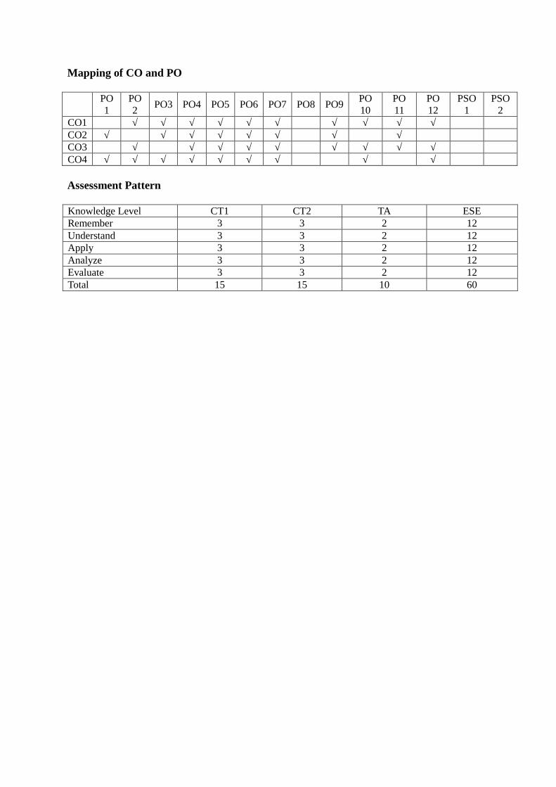
Mapping of CO and PO
PO1
PO2
PO3 PO4 PO5 PO6 PO7 PO8 PO9PO10
PO11
PO12
PSO1
PSO2
CO1 √ √ √ √ √ √ √ √ √ √CO2 √ √ √ √ √ √ √ √CO3 √ √ √ √ √ √ √ √ √CO4 √ √ √ √ √ √ √ √ √
Assessment Pattern
Knowledge Level CT1 CT2 TA ESERemember 3 3 2 12Understand 3 3 2 12Apply 3 3 2 12Analyze 3 3 2 12Evaluate 3 3 2 12Total 15 15 10 60

Government College of Engineering, KaradSecond Year B. Tech
EX401: Analog Integrated CircuitsTeaching Scheme Examination SchemeLectures 3 Hrs/week CT1 15
CT2 15TA 10ESE 60
Total Credits: 3Course Objectives:This course aims to:
1 Understand the different type of feedback amplifiers.2 Understand the multistage amplifier, configurations of differential amplifiers
(DC & AC).3 Understand the electrical parameters of Op-Amp.4 Understand the design of various applications of Op-Amp.5 Understand the signal generators and multivibrators.
Course ContentsHours
Unit I Feedback Amplifier :Classification of amplifiers, Feedback concept, Transfer gain withfeedback, General characteristics of negative feedback amplifier,Input and output resistance, Voltage - series, current - series, voltage– shunt, current shunt amplifiers. Darlington Emitter follower. 6
Unit II Multistage and Differential Amplifiers:Cascaded amplifier, cascade amplifier, multistage RC coupledamplifier. Differential Amplifier: configurations, DC analysis, ACanalysis using r parameter (Dual Input Balanced output & Dual InputUnbalanced Output), Current mirror circuits. 6
Unit III Basics Op-Amp: Definition, symbol, Block diagram of OP-AMP,Ideal parameters and practical parameters of OP-AMP and theircomparison, Virtual ground concept, Open loop configuration, closedloop configuration(Inverting and Non Inverting), unity gain amplifier.Introduction to IC 741. 6
Unit IV Applications of Op-amp: Summing, Scaling & AveragingAmplifiers using Op-amps, Instrumentation amplifier, V to I & I to VConverter, Precision Rectifiers, Log & Anti-log Amplifiers,comparator, Schmitt Trigger, Window Detector, Clippers &Clampers, V to F and F to V convertor, Peak Detectors and Sample &Hold Circuits. Introduction to PLL.
6

Unit V Active Filters and Waveform Generator:
High Pass filter, Low Pass filter (First & Second order), Band Passfilter, Band Reject filter, All Pass filter. Square wave generator,Triangular wave generator, Saw tooth wave generator (Design &Analysis using Op-Amp). 6
Unit VI Oscillators and Multivibrators: Use of positive feedback,Barkhausen criterion for oscillations, Different oscillator circuits:Hartley, Colpitts, phase shift and Wien’s bridge (Using Op-Amp).Basics of IC 555, Multi-vibrator using IC 555 (Monostable, Bistableand Astable). 6
Course Outcome (CO):Upon successful completion of this course, the student will be able to:
1 Design and explain feedback amplifiers.2 Analyse and design electronic circuits such as wave shaping circuits, multistage
amplifiers and differential amplifier.3 Explain basics of op-amp.4 Explain the working of various circuits for different applications designed using
IC 741, IC555.5 Solve problem related to op-amp.
Text Books1 Jacob Millman, “Integrated Electronics”, Mc Graw Hill second Edition.2 Ramakant A. Gayakwad, “Op-Amp and Linear Integrated Circuits”, Pearson
Education.
Reference Books1 Robert L. Boylsted, Louis Nashelsky, “Electronic devices & circuit theory”,
Pearson Education2 Sedra smith, “Microelectronics Circuits”, Oxford International student edition.3 Robert Coughlin, Fredric Driscoll, “Operational Amplifiers and Linear
Integrated”, Sixth edition, PE.4 D. Roy Choudhury, “Linear Integrated Circuits”, New Age International Ltd.
Useful Links1 http://nptel.ac.in/courses/117106030/2 www.allaboutcircuits.com3 www.electronics-tutorials.ws
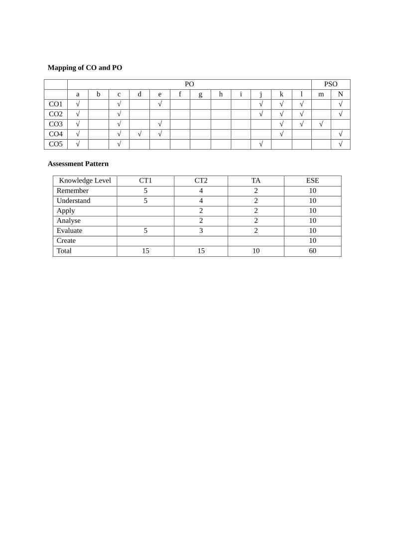
Mapping of CO and PO
PO PSOa b c d e f g h i j k l m N
CO1 √ √ √ √ √ √ √CO2 √ √ √ √ √ √CO3 √ √ √ √ √ √CO4 √ √ √ √ √ √CO5 √ √ √ √
Assessment Pattern
Knowledge Level CT1 CT2 TA ESERemember 5 4 2 10Understand 5 4 2 10Apply 2 2 10Analyse 2 2 10Evaluate 5 3 2 10Create 10
Total 15 15 10 60

Government College of Engineering, KaradSecond Year B. Tech
EX402: Network AnalysisTeaching Scheme Examination SchemeLectures 3 Hrs/week CT1 15
CT2 15TA 10ESE 60
Total Credits: 3Course Objectives:This course aims to:
1 Understand use of circuit analysis methods and theorems2 Understand basic concepts of D.C. and A.C. Circuit behaviour3 Evaluate two port network parameters4 Demonstrate series and parallel resonance and its effects5 Develop and Solve mathematical representations for linear circuits
Course ContentsHours
Unit I Network Fundamentals: Basic Definitions: Passive Network, ActiveNetwork, Linear Element, nonlinear elements, Unilateral, bilateral,lumped & distributed elements. Representation of voltage & currentsources (Ideal & practical), source transformation, series & parallelconnection of passive elements(R,L,C), Energy and Powercomputation, graph of network & its parts, loops & trees, lineargraphs & incidence matrix, cutsets, planner & non-planner graph loopmatrix. Star- Delta transformation, reduction of networks: Meshanalysis, Node analysis. Supermesh and supernode analysis. 8
Unit II Network Theorems: A. C. Analysis – Average value, R.M.S. value,Power, active power, reactive power, complex power, power factor,D.C. and A.C. network solution using dependent and independentsources: Superposition Theorem, Millman’s Theorem, Norton’sTheorem, Thevenin’s Theorem, Maximum Power Transfer Theorem,Reciprocity Theorem, Duality theorem, Tellegen’s Theorem. 8
Unit III Two port networks and network functions: Two port network:Open circuit impedance ( Z ) parameters, Short circuit admittance (Y)parameters, Hybrid (H) parameter, Transmission parameters(ABCD),Interrelation of different parameters, Interconnections of two portnetwork (Series, Parallel, Cascaded, Series- Parallel) NetworkFunctions: Network functions for one port & two port networks,Driving point impedance and admittance of one port network,Driving point impedance, admittance & different transfer function of

two port network (Z, Y, H & T parameters). Concept of complexfrequency, significance of poles & zeros. Restrictions on poles &zeros for transfer & drawing points function, stability concept inpassive circuit using Routh- Hurwitz criterion, pole zero diagram.
8
Unit IV Resonance: Types of resonance: Series & ParallelSeries resonance- resonant frequency, variation of impedance,admittance, current & voltage across L & C with respect to frequency,Effect of resistance on frequency response, Selectivity, B.W. &Quality factor.Parallel resonance – Anti resonant frequency, variation of impedance& admittance with frequency, Selectivity & B.W. 6
Unit V Transient Response: Network Solution using Laplace transforms,Initial Conditions of elements. Steady state & transient response(Voltage & Current) DC response of RL circuit, DC response of RCcircuit, DC response of RLC circuit, Sinusoidal response of RL, RC& RLC circuit 6
Course Outcome (CO):Upon successful completion of this course, the student will be able to:
1 Determine voltage, current, power and impedance at various nodes and loopsusing simplification techniques
2 Understand and analyze the basic A.C., D.C. circuits using network theorems3 Characterize, model and analyze the network in terms of network functions and
parameters4 Demonstrate knowledge of resonance in series and parallel circuits5 Explain characteristics of capacitor, inductor and compute initial conditions for
current and voltage in 1st order (RC, RL) and 2nd order (RLC) circuits
Text Books1 A. Sudhakar , Shyammohan S.Palli, “Circuit & Network – Analysis &
Synthesis”, IIIrd Edition – Tata McGraw Hill Publication2 A.Chakrabarti, “Circuit Theory (Analysis & Synthesis)”, IIIrd Edition Dhanpat
Rai & co.3 Soni Gupta, “Electrical Circuit Analysis”, Dhanpat Rai & Co.
Reference Books1 Allan Robbins, Wilhelm C. Miller, “Circuit Analysis Theory and Practice”,
Cenage Learning.2 J. David Irwin, R. Mark Nelms, “Basic Engineering Circuit Analysis”, Wiley
Publication3 William H Hayt, Jack E Kimmerly and Steven M.Durbin, “Engineering Circuit
Analysis”, Tata McGraw Hill4 M.E.Van Valkenburg, “Network Analysis”, IIIrd Edition, Pearson Education/PHI

Useful Links1 http://www.nptel.ac.in/courses/1081020422 http://www.ocw.mit.edu/courses/electrical-engineering-and-computer-science/6-
002-circuits-and-electronics-spring-2007/
Mapping of CO and PO
PO PSOa B C d E F g h i j K l M N
CO1 √ √ √ √ √ √ √CO2 √ √ √ √ √ √ √CO3 √ √ √ √ √ √ √ √CO4 √ √ √ √ √ √ √CO5 √ √ √ √ √ √ √ √
Assessment Pattern
Knowledge Level CT1 CT2 TA ESE
Remember 3 3 2 12
Understand 3 3 2 12
Apply 3 3 2 12
Analyse 3 3 2 12
Evaluate 3 3 2 12
Create 12
Total 15 15 10 60

Government College of Engineering, KaradSecond Year B. Tech
EX403: Analog CommunicationTeaching Scheme Examination SchemeLectures 3 Hrs/week CT1 15
CT2 15TA 10ESE 60
Total Credits: 3Course Objectives:This course aims to:
1 Implement & analyse the basic analog communication techniques/ circuits with the help oftheoretical and practical problem solving.
2 Make strong foundation of time domain and frequency domain analysis of modulation
techniques.3 Estimate noise in communication systems4 Analyse basics and circuits of pulse modulations
Course ContentsHours
Unit I COMMUNICATION SYSTEM AND NOISE:Communication system, need of modulation, types of analog modulation,noise-classification of noise, external noise and internal noise, noise due toseveral sources, noise due to several amplifier in cascade, noise in reactivecircuit 5
Unit II AMPLITUDE MODULATION:frequency spectrum, time and frequency domains, Review of Fourier analysis,Amplitude Modulation (AM), DSB-SC, SSB, VSB and ISB transmissions,mathematical Analysis, modulation index, frequency spectrum, powerrequirement of these systems, frequency division multiplexing 7
Unit III ANGLE MODULATION:Frequency Modulation (FM), mathematical Analysis, modulation index,frequency spectrum, power requirement of FM, narrowband & wideband FM,pre-emphasis and de-emphasis techniques, phase modulation, power contentsof the carrier & the sidebands in angle modulation, generation of FM signals,comparison between AM & FM. 6
Unit IV RADIO RECEIVERS:Basic receiver (TRF), Super heterodyne receiver, performance parameters forreceiver such as sensitivity, selectivity, fidelity, image frequency rejection etc.,AM detectors, FM discriminators, AGC technique, double-spotting effect 4

Unit V NOISE ANALYSIS:SNR for AM & FM for low noise condition, noise figure, calculation of noisefigure, noise figure from measurement, noise temperature, noise reductioncharacteristics of angle modulation 6
Unit VI PULSE MODULATION AND MULTIPLEXINGSampling theorem, Types of sampling-ideal, natural, flat top sampling,quantization, concept, generation and detection - pulse amplitude modulation(PAM), pulse width modulation (PWM), pulse position modulation (PPM),pulse code modulation (PCM), companding, A-law and µ-law companding,delta modulation(DM), adaptive delta modulation(ADM), Linear predictivecoding, multiplexing- frequency division multiplexing and time divisionmultiplexing. 8
Course Outcome (CO):Upon successful completion of this course, the student will be able to:
1 Know the communication system and be able to analyse different types of noise2 Analyse different analog modulation techniques3 Know techniques of transmission and reception of analog signal4 Know pulse modulation techniques.5 Be able to analyse multiplexing techniques
Text Books1 D. Kennedy, “Electronic Communication Systems”, 4th edition, Tata McGraw-Hill, 1999.2 Taub, Schilling and G.Saha, “Principles of Communication Systems”, 3rd edition,
McGrawHill, 1995.3 B.P. Lathi, “Communication Systems”, BS publications.
Reference Books1 A. Bruce Carlson, “Communication Systems”, 4th edition, McGraw-Hill, 2006.2 S. Haykin, “Communication Systems”, 4th edition, John wiley & Sons, 2000.3 Roddy and Coolen, “Electronic Communication”, 4th edition, Prentice Hall of India,
2003.
Useful Links1. http://nptel.ac.in/courses/117102059/2. http://ocw.mit.edu/courses/electrical-engineering-and-computer-science/6-450-principles-
of-digital-communications-i-fall-2006/video-lectures/
Mapping of CO and PO
PO PSOa b C d e f g h i j K l m N
CO1 √ √ √ √ √ √CO2 √ √ √ √ √ √ √ √CO3 √ √ √ √ √ √ √CO4 √ √ √ √ √

CO5 √ √ √
Assessment Pattern
Knowledge Level CT1 CT2 TA ESERemember 5 5 2.5 15Understand 5 5 15
Apply 2.5 10Analyse 2.5 10Evaluate 5 5 2.5 10CreateTotal 15 15 10 60

Government College of Engineering, KaradSecond Year B. Tech
EX404 : Signals and SystemsTeaching Scheme Examination SchemeLectures 3 Hrs/week CT1 15
CT2 15TA 10ESE 60
Total Credits: 3Course Objectives:This course aims to:
1 Describe basic signals mathematically and understand how to perform mathematicaloperations on signals.
2 Understand systems classification, properties & apply skills to solve problems.3 Know the Fourier series & Transforms for representation of periodic and periodic
signals.4 Analyse the systems in time & frequency domain by applying knowledge of Fourier
& Z-Transforms.Course Contents
HoursUnit I Introduction :
A) An introduction to signals and systems: Definitions of Signalsand Systems, Signals and systems as seen in everyday life, and invarious branches of engineering and science electrical,mechanical, hydraulic, thermal, biomedical signals and systemsas examples. Extracting the common essence and requirements ofsignal and system analysis from these examples. (1 L)
B) Signals and Classification of Signals: Analogy between Signalsand Vectors, Continuous time signals & discrete time, analog &digital. (1 L) Basic CT & DT signals: unit impulse, unit step, unitramp, c o m p l e x exponential & sinusoidal, sinc, rectangular,triangular and signum. (1 L) Operations on signals: AmplitudeScaling, Addition, Multiplication, Differentiation, Integration, (1L) Time Scaling and Folding, Time Shifting, Precedence rule. (1L) Classification of Signals: even & odd signals, periodic & non-periodic, deterministic & non-deterministic, energy & power.Operations on Signals (1 L).
C) System and Classification of Systems: System Representation,continuous time Systems & discrete Systems, system with andwithout memory (static and dynamic), causal and non-causalsystem, linear and non-linear system, Time invariant and timevariant system, Stable and Unstable system, Invertible Systems,properties of systems. (2 L) 8

Unit II LTI Systems and Convolution:Linear time-invariant systems: The representation of signals interm of impulses, discrete time LTI systems, continuous time-LTIsystems, properties of CT- LTI and DT-LTI systems. (2 L)Convolution: Convolution integral & its properties, convolutionsum & its properties, Systems described by differential, differenceequations, block diagram representation of LTI systems described bydifferential difference equations, Singularity functions. (4 L) 6
Unit III Fourier Series for Continuous Time & Discrete Time Signals:Continuous time Fourier series: Trigonometric and exponentialFourier series, Relation between trigonometric and exponentialFourier series. Discrete time Fourier Series, properties of Fourierseries. 4
Unit IV Fourier Transform:From Fourier series to Fourier Transform, Fourier Transform pair,Fourier Spectra, Convergence of FT.Properties of Fourier transform: linearity, time shifting, frequencyscaling, time scaling, time reversal, duality, differentiation in timedomain and frequency domain, Integral in time domain,multiplication, and convolution and Parseval’s relation. 6
Unit V Laplace Transform:Definition and its properties, ROC and pole zero concept. Applicationof Laplace transforms to the LTI system analysis. Inversion usingduality, numerical based on properties. Signal analysis using LT. 6
Unit VI Z transform:Introduction of Z-transform, Relation between DTFT and Z-transform, ROC, properties of ROC, Unilateral Z-transform,properties of Z transform: linearity, time shifting, time reversal, timescaling, convolution, differentiation, multiplication, Parseval’stheorem, initial value & final value theorem. Inverse Z-transform:long division method, PFE method, residue method. Transferfunction (Poles & Zeros), stability and causality. Representation ofsystem via difference equation and solutions. 6
Course Outcome (CO):Upon successful completion of this course, the student will be able to:
1 Define CT and DT signals mathematically & solve problems related to operationson signals.
2 Classify different systems & understand their properties.3 Understand the concept of convolution and its applications.4 Apply different tools like Fourier Series, Fourier Transform, Laplace Transform and

Z-transform to analyse the systems in time and frequency domains.
Text Books1 Hsu, “Signals & system” (Schaum’s outlines), Tata McGraw Hill2 Ramesh Babu, “Signals & system”, SciTech Publication.3 Simon Haykin, Barry Van Veen, “Signals & system”, Wiley publication
Reference Books1 Michael J. Roberts, “Fundamentals of signals & systems”, Tata McGraw Hill.2 Mandal and Asif, “Continuous and Discrete Time Signals and Systems”, Cambridge
University Press.3 Dr. D. D. Shaha and Dr. A. C. Bhagali, “Signals and Systems”, MPH.4 B. P. Lathi, “Signals Systems and Communication”, BS Publications.
Useful Links1 http://nptel.ac.in/courses/117104074/2 http://nptel.ac.in/downloads/117101055/3 http://textofvideo.nptel.iitm.ac.in/video.php?courseId=117104074
Mapping of CO and PO
PO PSOa b c d e f g h i j k l m n
CO1 √ √ √ √ √ √ √ √CO2 √ √ √ √ √ √ √ √CO3 √ √ √ √ √ √ √ √CO4 √ √ √ √ √ √ √ √
Assessment Pattern
Knowledge Level CT1 CT2 TA ESERemember 5 3 2 12Understand 3 2 12Apply 5 3 2 12Analyze 3 1 12Evaluate 5 3 3 12Create 1Total 15 15 10 60
*Note for paper setter: 30% theory and 70% numerical and Design from entire syllabus.

Government College of Engineering, KaradSecond Year B. Tech
EX405: Electromagnetic EngineeringTeaching Scheme Examination SchemeLectures 3 Hrs/week CT1 15Tutorial 1 Hr/week CT2 15
TA 10ESE 60
Total Credits: 4Course Objectives:This course aims to:
1 Provide fundamentals of Static Fields.2 Explain basics of the vector Differential, Integral operators to Electrostatic &
magneto static.3 Define and derive different laws in Electrostatic & Electromagnetic fields.4 Explain Maxwell’s equations and concepts of EM waves.5 Study various parameters in transmission line.
Course ContentsHours
Unit I Basics of electromagnetics: Review of scalars and vectors, Thecoordinate system: rectangular, cylindrical and spherical. gradient,divergence and curl. dielectric: permittivity and permeability,differential elements of length, surface and volume. 7
Unit II Electrostatics : Introduction to Coulomb’s law, electric fieldintensity, field of line charges, field of surface charges, flux density,Gauss’s law, divergence theorem, electric potential and potentialgradient.dipole and dipole moment, polarisation ,method of images,Boundary conditions for Electrostatic 7
Unit III Magnetostatics: Current and current density, continuity equation,Biot-Savart law, Ampere’s circuital law and applications, Stokestheorem, magnetic flux and flux density, vector magnetic potentials.boundary conditions for Magnetostatic 7
Unit IV Maxwell’s equations : steady field, time varying fields, Maxwell’sequations in point form and integral form 4
Unit V Electromagnetic waves : Electromagnetic wave equation, wavepropagation in free space, in a perfect dielectric, and perfectconductor, wave polarization, skin effect, Poynting theorem,reflection and refraction of uniform plane wave at normal incidenceplane, reflection at oblique incident angle. Wave propagation through 9

guided media (Rectangular waveguide) and various modes ofpropagation.
Unit VI Transmission lines : Introduction, concept of distributed elements,equations of voltage and current , standing waves and impedancetransformation, lossless and low-loss transmission lines, smith chartand impedance matching using transmission lines 8
Note: • Tutorials for the subject shall be engaged in minimum of four batches(batch size of 20 students Maximum) per division.
• Teachers Assessment shall consist of minimum 8 tutorials from entiresyllabus.
Course Outcome (CO):Upon successful completion of this course, the student will be able to:
1 Comprehend the fundamentals of Electrostatic and Electromagnetic fields.2 Demonstrate mathematical skills related with differential, integral and vector
calculus3 Apply Gauss’ law, Ampere’s Law, Biot-Savart law, Faraday’s law and laws
related with steady magnetic field while solving problems in Electrostatic andElectromagnetic fields.
4 Develop field equations from understanding of Maxwell’s Equations.5 Extend the knowledge of basic properties of transmission lines to analyse
electromagnetic wave propagation in generic transmission line geometries.
Text Books1 W.H Hayt. and J.A. Buck, “Engineering Electromagnetics”, 7th edition, Tata
McGraw Hill, 2006.2 G. S. N. Raju, “Electromagnetic Field Theory and Transmission Lines”, Pearson
Education.3 E.C. Jordan and K.C. Balamin, “Electromagnetic Waves and Radiating System”,
2nd edition, Prentice Hall of India Private Limited, 1985.
Reference Books1 Rao, Edward C. Jordan, “Elements of Engineering Electromagnetics”, 6th
edition, Pearson Education, 2006.2 J. D. Krauss, “Electromagnetics”, 3rd edition, Mc-Graw Hill, 1984.3 S. Ramo and R.Whinnery, “Fields and Waves in Communication Electronics”,
3rd edition, John Wiley and Sons, 2009.4 K. E.Lonngren and S. V. Savov, “Fundamental of Electromagnetic with
MATLAB”, 1st Prentice Hall of India, 2008.

Mapping of CO and PO
PO PSOa b c d e f g h i j K l m n
CO1 √ √ √ √ √ √CO2 √ √ √ √ √ √ √ √CO3 √ √ √ √ √ √CO4 √ √ √ √ √ √ √CO5 √ √ √ √ √ √
Assessment Pattern
Knowledge Level CT1 CT2 TA ESERemember 3 3 5 10Understand 4 4 10Apply 4 4 15Analyze 4 4 5 15Evaluate 10CreateTotal 15 15 10 60

Government College of Engineering, KaradSecond Year B. Tech
EX406: Analog Integrated Circuits LabLaboratory Scheme Examination SchemePractical 2 Hrs/week CA 25
ESE 50Total Credits: 1
Course Objectives:This course aims to:
1 Understand the characteristics of IC and Op-Amp and identify the internalstructure.
2 Understand measurement of frequency response for various amplifiers.3 Understand and verify results (levels of V & I) with hardware implementation.4 Analyse and identify linear and nonlinear applications of Op-Amp.
Course Contents
Experiment 1 Design and frequency response of two stage RC coupled amplifier
Experiment 2 Design and frequency response of voltage series feedback amplifier.
Experiment 3 Measurement Op-Amp Parameters. 1) Input Bias current 2) Input Offset current3) Input Offset voltage 4) CMRR.
Experiment 4 Design of Inverting and Non inverting amplifier using Op-Amp.
Experiment 5 Design, build and test Integrator and Differentiator.
Experiment 6 Design, build and test precision rectifier.
Experiment 7 Design, build and test comparator and Schmitt trigger.
Experiment 8 Design and implementation of Square wave and Triangular wave generatorusing Op-Amp.
Experiment 9 Design of Active filters (LPF & HPF) using Op-Amp.
Experiment 10 Design and implementation Wien bridge oscillator using Op-Amp.
Experiment 11 Design and simulate monostable and astable multivibrator using multisim.
Experiment 12 Design and simulate clipper and clamper using multisim.Note: Any 10 practical’s to be conducted from the above list.

List of Submission1 Total number of Experiments:102 Total number of sheet: NA3 Project/Dissertation Report: NA4 Seminar report: NA5 Field Visit Report: NA
Additional InformationCourse Outcome(CO):Upon successful completion of this course, the student will be able to:
1 Handle various electronic devices, instruments and circuits as well asBread board and routing on breadboard.
2 Design and test BJT amplifiers on breadboard and measurement of theirparameters.
3 Build and implement various applications of op-amp and draw output voltagewaveforms.
4 Simulate linear & non-linear circuits on software.
Mapping of CO and PO
PO PSOa b c d E f g h i j K l m n
CO1 √ √ √ √CO2 √ √ √ √ √CO3 √ √ √ √ √ √ √CO4 √ √ √ √ √ √ √ √
Assessment Pattern
Skill Level Exp1
Exp2
Exp3
Exp4
Exp5
Exp6
Exp7
Exp8
Exp9
Exp10
Exp11
Exp12
TA ESE
Assembling √ √ √ √ √ √ √ √ √ √ √ √Testing √ √ √ √ √ √ √ √ √ √ √ √Observing √ √ √ √ √ √ √ √ √ √ √ √ √ √Analyzing √ √ √ √ √ √ √ √ √Interpreting √ √ √ √ √ √Designing √ √ √ √ √ √ √ √ √ √ √ √Creating √ √ √ √Deducingconclusions
√ √ √ √ √ √ √ √ √ √ √ √ √ √
Total 10 10 10 10 10 10 10 10 10 10 10 10 25 50

Government College of Engineering, KaradSecond Year B. TechEX407 : HDL LAB
Teaching Scheme Examination SchemeTutorial 1 Hr/week CA 25Practical 2 Hrs/week ESE 50
Total Credits: 2Course Objectives:This course aims to:
1 Explain students the fundamental concepts of Hardware Description Language anddesign flow of digital system design.
2 Make students able to design combinational and sequential logic circuits using Dataflow and Behavioural modelling styles.
3 Provide students an understanding of structural description for designing of digitalcircuits.
4 Explain students the concepts of Packages, Functions and Procedures and its usagefor designing digital systems.
Course ContentsHours
Unit I Introduction to HDL:Need of HDL, A brief history of VHDL, design flow, EDA tools,structure of VHDL module, operators, data types, attributes, types ofdescriptions, simulation and synthesis. 3
Unit II Data Flow and behavioural descriptions:Highlights of data flow descriptions, structure of data flowdescriptions, highlights of behavioural descriptions, structure ofbehavioural descriptions, combinational logic design and sequentiallogic design (including FSM) using data flow and behaviouralmodelling styles. 4
Unit III Structural Descriptions :Highlights of structural descriptions, organization of structuraldescriptions, Binding, Generate, Generic and parameter statements,design of combinational and sequential logic circuits using structuralmodelling style. 3
Unit IV Packages, Functions and Procedures:Highlights of Packages, functions and Procedures, Function versusProcedures, additional examples on system design. 2
Lab Course ContentsExperiment 1 1) To design and simulate all the logic gates in VHDL and its implementation
on CPLD/ FPGA kit.2) To design and simulate Binary to Gray and Gray To Binary Code Converter

in VHDL and its implementation on CPLD/ FPGA kit.
Experiment 2 1) To design half adder and full adder using Dataflow and behaviouralmodelling and its implementation on CPLD/FPGA kit.2) To design half Subtractor and full Subtractor using Dataflow and behaviouralmodelling and its implementation on CPLD/FPGA kit.
Experiment 3 1) To design and simulate 2X1 MUX, 4X1 MUX, 8X1 MUX using Dataflowand behavioural modelling.2) To design and simulate 1X2 DEMUX, 1X4 DEMUX, 1X8 DEMUX usingDataflow and behavioural modelling
Experiment 4 1) To design and simulate 4X2 encoder, 8X3 encoder in VHDL using dataflowand behavioural modelling.2) To design and simulate 2X4 decoder and 3X8 decoder in VHDL usingdataflow and behavioural modelling.
Experiment 5 To design and simulate VHDL code for half adder and full adder usingstructural description and its implementation on CPLD/ FPGA kit.
Experiment 6 To design and simulate VHDL code for 4X1 MUX, 1X4 DEMUX, 4X2 encoderand 2X4 decoder with the help of structural description.
Experiment 7 To design and simulate all the type of flip-flops using sequential constructs.
Experiment 8 1) To design and simulate VHDL code for eight bit shift register.2) To design and simulate VHDL code for eight bit Johnsons counter.
Experiment 9 To design and simulate VHDL code for sequence detector and itsimplementation on CPLD/ FPGA kit.
Experiment 10 To design and simulate VHDL code for a full adder using two half adders withthe use of PROCEDURE.
List of Submission1 Total number of Experiments:102 Total number of sheets: NA3 Project/Dissertation Report: NA4 Seminar report: NA5 Field Visit Report: NA
Course Outcome (CO):Upon successful completion of this course, the student will be able to:
1 Implement and demonstrate the design flow of digital circuit design using VHDL.2 Design combinational circuits like adder, subtractor, multiplexer, Encoder, Decoder,
comparator etc. using various description techniques in VHDL.3 Design the sequential logic circuits like flip-flops, registers, counters, sequence
detectors etc. using various description techniques in VHDL.4 Design digital systems using VHDL elements like Packages, Functions, Procedures.
Text Books1 Nazeih M. Botros, “HDL Programming” (VHDL and Verilog), John Weily India Pvt.
Ltd. 2008.2 Stephen Brown and Zvonko Vranesic, “Fundamentals of Digital Logic with VHDL
design”, Tata–Mcgraw Hill.3 Velnoi A. Pedroni, “Circuit Design with VHDL”, MIT Press, Cambridge,
Massachusetts
Reference Books1 Douglas L. Perry, “VHDL Programming by Examples”, fourth Edition, Tata
McGraw-Hill.2 Charles S. Roth, “Principals of Digital System Design using VHDL”, Cengage
Learning, Jr. PWS publications.3 Jayram Bhaskar, “A VHDL Primer”, AWL publication.4 Enoch O. Hwang, “Digital logic and microprocessor design”, Nelson Engineering;
Har/Cdr edition.
Useful Links1 www.xilinx.com2 Xilinx synthesis tool details- xst.pdf3 www.cs.lasierra.edu/~ehwang
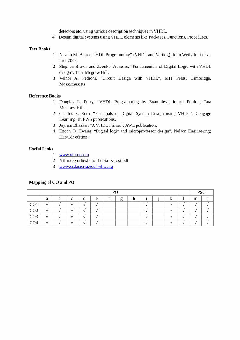
Mapping of CO and PO
PO PSOa b c d e f g h i j k l m n
CO1 √ √ √ √ √ √ √ √ √ √CO2 √ √ √ √ √ √ √ √ √ √CO3 √ √ √ √ √ √ √ √ √ √CO4 √ √ √ √ √ √ √ √ √ √

Assessment Pattern
Skill LevelExp
1Exp
2Exp
3Exp
4Exp
5Exp
6Exp
7Exp
8Exp
9Exp10
TA ESE
Assembling
Testing √ √ √ √ √ √ √ √ √ √ √ √Observing √ √ √ √ √ √ √ √ √ √ √ √Analysing √ √ √ √ √ √ √ √ √ √ √ √Interpreting √ √ √ √ √ √ √ √ √ √ √ √Designing √ √ √ √ √ √ √ √ √ √ √ √Creating .
Deducingconclusions
√ √ √ √ √ √ √ √ √ √ √ √
Total 10 10 10 10 10 10 10 10 10 10 25 50

Government College of Engineering, KaradSecond Year B. Tech
EX408: Analog Communication LabLaboratory Scheme Examination SchemePractical 2 Hrs/week CA 25
ESE 50Total Credits:1
Course Objectives:This course aims to:
1 Familiarize several modulation & demodulation techniques in communication2 Implement communication systems of given specification3 Enhance mathematical skill as well problem solving power
Course Contents
Experiment 1 Practical implementation of Amplitude modulation and demodulation.
Experiment 2 Calculation of modulation index by graphical method of DSBFC signal &measurement of power of AM wave for different modulating signal.
Experiment 3 SSB modulation using any method (filter method, Phase shift method) and itsdetection.
Experiment 4 Envelope detector- Practical diode detector.
Experiment 5 Performance and analysis of AM system using trapezoidal method
Experiment 6 Performance and analysis of frequency modulator system and also find themodulation index.
Experiment 7 Experiment on Sampling and reconstruction and also observe aliasing effect byvarying sampling frequency.
Experiment 8 Practical implementation of PAM system
Experiment 9 Practical implementation of PPM system
Experiment 10 Practical implementation of PWM system
Experiment 11 Practical implementation of PAM-TDM systems.
Experiment 12 Experiment on Pre-emphasis and De-emphasis.
Experiment 13 Visit to AIR (Compulsory)
NOTE: At least 10 experiments are compulsory out of which minimum 2 should be

performed on simulation software
List of Submission1 Total number of Experiments: 102 Total number of sheets: NA3 Project Report of Industrial visits: NA
Additional InformationCourse Outcome(CO):Upon successful completion of this course, the student will be able to:
1 Design to modulating & demodulating circuits2 Perform sampling of signals3 Analyse various pulse modulation techniques
Mapping of CO and PO
PO PSOa b c d e f g h i j K l m n
CO1 √ √ √ √ √ √ √CO2 √ √ √ √ √ √ √ √CO3 √ √ √ √ √ √ √
Assessment Pattern
Skill LevelExp
1Exp
2Exp
3Exp
4Exp
5Exp
6Exp
7Exp
8Exp
9Exp10
Exp11
Exp12
TA ESE
Assembling √ √ √ √ √ √Testing √ √ √ √ √ √Observing √ √ √ √ √ √ √ √ √ √Analysing √ √ √ √ √ √Interpreting √ √ √ √ √ √ √ √Designing √ √Creating √ √ √ √ √ √ √Deducingconclusions
√ √ √ √ √ √ √ √ √ √ √ √ √ √
Total 10 10 10 10 10 10 10 10 10 10 10 10 25 50

Government College of Engineering, KaradSecond Year B. Tech
EX409 : Signals and Systems LabLaboratory Scheme Examination SchemePractical 2 Hrs/week CA 25
ESE --Total Credits: 1
Course Objectives:This course aims to:
1 Implement different concepts and methods of handling signals and systems inMATLAB environment.
2 Understand the different MATLAB functions and tools.3 Effective MATLAB programming using different functions and commands
Course ContentsExperiment 1 Introduction to MATLAB with matrix manipulation techniques.
Experiment 2 Introduction to Graph Plotting: To plot graphs of signals like Basic Signals(both in CT and DT), Addition, Subtraction and Multiplication of given CTand DT signals in MATLAB environment.
Experiment 3 Program for signal operations on Trigonometric Signals: Time Shifting, TimeScaling, Amplitude Shifting, Combined Operations.
Experiment 4 Program using branching and looping statements.
Experiment 5 Program for Classification of Signals and Systems.
Experiment 6 Program for DT Convolution (without and with use of in-built MATLABfunction).
Experiment 7 Program for handling complex data.
Experiment 8 Program for obtaining Forward and Inverse Transforms of a given DT Signal.(Forward and Inverse Fourier Transform, Laplace Transform and Z-transform)
Experiment 9 Program using user defined function using MATLAB.
Experiment 10 Program for creating & Displaying GUI using MATLAB.
List of Submission1 Total number of Experiments: 102 Total number of sheets: NA3 Project/Dissertation Report: NA4 Seminar report: NA

5 Field Visit Report: NA
Additional InformationCourse Outcome(CO):Upon successful completion of this course, the student will be able to:
1 Implement, test and develop various signal/system handling algorithms inMATLAB.
2 Analyse and simulate the various signals and systems in MATLAB.3 Use the different commands, functions required for programming in MATLAB4 Calculate and perform various operations using MATLAB.
Mapping of CO and PO
PO PSOa b c d e f g h i j k l m N
CO1 √ √ √ √ √ √ √ √ √ √CO2 √ √ √ √ √ √ √ √ √ √CO3 √ √ √ √ √ √ √ √ √ √CO4 √ √ √ √ √ √ √ √ √ √
Assessment Pattern
Skill Level Exp1
Exp2
Exp3
Exp4
Exp5
Exp6
Exp7
Exp8
Exp9
Exp10
TA ESE
Assembling
NA
TestingObserving √ √ √ √ √ √ √ √ √ √ √Analysing √ √ √ √ √ √ √ √ √ √ √Interpreting √ √ √ √ √ √ √ √ √ √ √Designing √ √ √ √ √ √ √ √ √ √ √CreatingDeducingconclusions
√ √ √ √ √ √ √ √ √ √ √
Total 10 10 10 10 10 10 10 10 10 10 25

Government College of Engineering Karad.Second Year B. Tech
HS002: General Proficiency-IITeaching Scheme Examination SchemeLectures 2 Hrs/week CA 50Practical 2 Hrs/weekTotal Credits 3
Course Objectives:1 To introspect, develop a thorough understanding of oneself by identifying
one's strengths & weakness2 To map one's competence /employability skills & improve upon as per the
same3 To improve one's intrapersonal & interpersonal communication by mastering
the art of listening & assert oneself while communicating for developingharmonious relationships
4 To identify latent talents and sharpen them into effective tools for success incareer
5 To apply practical knowledge for self development focusing upon variousskill sets as per industry requirement
6 To live up to the popular saying "the first impression is the last impression",the focus is on building a pleasing personality leading to positive branding ofoneself
7 To keep oneself abreast with the social & professional etiquette by workingon power dressing, elegant presentation & one's brand management
8 To map one's competence /employability skills & improve upon as per thesame
Course ContentsSection I - Language Skills
Duration – 15 hrsUnit I Domain: Letter Writing
The domain letter writing is transacted based on the theme materialpossession. There are five modules under this domain. Each module has aspecific outcome. Each module is dealt with the help of a linguistic toolthat is interaction
Module 1 Duration: 3 hrsObjective: Produce & role play a conversationA trigger (picture/Image/video/ Audio/ Script) is used to initiate interactionthrough this the class arrives at a common theme. Understands the featuresof conversation & role play it.
• To read the text critically• To track one’s own reading process.• To come out with graphical organisers.

• Constructing multiple texts from the given.
Module 2 Duration: 3 hrsObjective: Reading an articleBased on the trigger (picture/Image/video/ Audio/ Script) related to thetheme to process reading. Through this learners understand how to read atext effectively & understand the sensory perceptions and emotionsinvolved. At the end of this process the learners come out with graphicalorganizers and there by construct multiple texts out of it.
Module 3 Duration: 3 hrsObjective: Write a letterTo read the different forms of letter and identify the various features of aletter. Make the learners understand the correct way of writing lettersthrough group editing.
Module 4 Duration: 3 hrsObjective: Reading a news reportBased on the trigger (picture/Image/video/ Audio/ Script) related to thetheme a text is given to process reading. The text given here is a newsreport. Through this learners understand the features of news report, learnto read a text critically & track their own reading process. At the end of thisprocess the learners come out with graphical organizers and there byconstruct multiple texts out of it.
Module 5 Duration: 3 hrsObjective: Writing a news reportBased on the trigger (picture/Image/video/ Audio/ Script) write a newsreport keeping all the features of a news report in mind. To present a newsreport orally and edit a news report.
Section II - Soft SkillsDuration – 24hrs
Unit II Self-Awareness Duration – 6 hrsThe module self awareness has three different topics that are:
• Personality Assessment• Competency Mapping• Self-Concept
This capsule focuses on the following:• To introspect & develop a thorough understanding of one’s
personality.• To Identifying the key traits in oneself comprising of attitude skill
& knowledge• To correlate the trait in oneself with the employability skill required
for success• To identify ones strength& weakness
To move from an imaginary self-concept to real self-concept

Unit III Communication Skill Duration – 6 hrsThe module communication skills has two different topics that are:
• Interpersonal Behavioral Styles• Assertive Communication
This capsule focuses on the following:• Being able to listen and use other appropriate communication
techniques including an appreciation of non-verbal communication.• To identify different behavioral styles & assert ones communication
according to style.
Unit IV Self Management Duration – 6 hrsThe module self management has two different topics that are:
• Response Able Behaviour• Beginning with End in Mind
This capsule focuses on the following:• To develop skills and techniques to cope with daily challenges• To gain practical solutions for day-to-day issues• To set career goals to improve one’s wellbeing and quality of life• To understand how to calculate percentage of any numbers• To understand how to calculate percentage of any numbers• To develop and implement an action plan
Unit V Image Management Duration – 6 hrsThe module Image Management has two different topics that are:
• Presentation Skills• Grooming and Etiquette
This capsule focuses on the following:• To make the first impression always the best impression.• To understand & follow the social norms in public.• To know the importance of personal hygiene & grooming

Section III - Aptitude SkillsDuration-21 hrs
Unit VI Basic concept 1 Duration – 3 hrsThe module basic concepts 1 has two different topics that are:
• Percentages• Profit and loss
This module focuses on the following:• To understand how to calculate percentage of any numbers• To understand how to calculate percentage of any numbers• To improve upon calculations• To understand when & how to calculate profit% & loss%
Unit VII Basic concept 2 Duration – 3 hrsThe module basic concept 2 has two different topics that are:
• Time and workThis module focuses on the following:
• To understand how to calculate efficiencies of the person’s• To understand when to take positive or negative work
UnitVIII
Basic concept 3 Duration – 3 hrsThe module basic concepts 2 has two different topics that are:
• Time and distance• Problems on trains
This module focuses on the following:• To understand how to calculate Speed or Distance or Time when
two unknown’s are given• To understand how to calculate Relative speed• To understand how to calculate length of the train or bridge or
platform
Unit IX Reasoning 1 Duration – 3 hrsThe module reasoning 1 has the following topic:
• Puzzle testThis module focuses on the following:
• To understand & analyze the given information
Unit X Reasoning 2 Duration – 3 hrsThe module reasoning 2 has two different topics that are:
• Directions sense• Blood relations
This capsule focuses on the following:• To understand how to calculate the direction and distance• To understand how to say proper relations

Unit XI Reasoning 3 Duration – 3 hrsThe module reasoning 3 has the following topic:
• Coding & decodingThis capsule focuses on the following:
• To understand how to start depending on the different types ofcoding
Unit XII Reasoning 4 Duration – 3 hrsThe module reasoning 4 has the following topic:
• Number series• Oddman out
This capsule focuses on the following:• To understand how to calculate the series depending on the
information• To understand how to pick right answer from the given information
Course Outcome (CO):1 To understanding of one’s personality.2 To Identifying the key traits in oneself comprising of attitude skill &
knowledge3 To correlate the trait in oneself with the employability skill required for
success4 To move from an imaginary self-concept to real self-concept5 To identify different behavioral styles & assert ones communication according
to style.6 To set career goals to improve one’s wellbeing and quality of life7 To be responsible for ones actions8 To make the first impression always the best impression.