programmable logic controllers - idec corporationprogrammable logic controllers sx5 network i/o usa:...
TRANSCRIPT

Programmable Logic Controllers
SX5 Network I/O
USA:
(800) 262-4332
or (408) 747-0550, Western Canada: (888) 578-9988 or Eastern Canada (888) 317-4332 J-1
J
SX5 Series Communication Terminals (General Information)
SX5 Communication Terminals
Bus I/O Type Specifications Type No.
INTERBUS
DC Input16-point source input (24V DC) SX5S-SBN16S
16-point sink input (24V DC) SX5S-SBN16K
Relay Output 8-point relay output (240V AC/24V DC, 5A) SX5S-SBR08
Transistor Output16-point transistor sink output (24V DC, 0.5A/point, 6.0A/common) SX5S-SBT16K
16-point transistor protect source output (24V DC, 0.5A/point, 6.0A/common) SX5S-SBT16P
DC inputTransistor Output
8-point source input (24V DC)8-point transistor sink output (24V DC, 0.5A/point, 4.0A/common) SX5S-SBM16K
8-point sink input (24V DC)8-point transistor protect source output (24V DC, 0.5A/point, 4.0A/common) SX5S-SBM16P
DeviceNet
DC Input16-point source input (24V DC) SX5D-SBN16S
16-point sink input (24V DC) SX5D-SBN16K
Relay Output 8-point relay output (240V AC/24V DC, 5A) SX5D-SBR08
Transistor Output16-point transistor sink output (24V DC, 0.5A/point, 6.0A/common) SX5D-SBT16K
16-point transistor protect source output (24V DC, 0.5A/point, 6.0A/common) SX5D-SBT16P
DC InputTransistor Output
8-point source input (24V DC)8-point transistor sink output (24V DC, 0.5A/point, 4.0A/common) SX5D-SBM16K
8-point sink input (24V DC)8-point transistor protect source output (24V DC, 0.5A/point, 4.0A/common) SX5D-SBM16P
L
ON
W
ORKS
DC Input16-point source input (24V DC) SX5L-SBN16S
16-point sink input (24V DC) SX5L-SBN16K
Relay Output 8-point relay output (240V AC/24V DC, 5A) SX5L-SBR08
Transistor Output16-point transistor sink output (24V DC, 0.5A/point, 6.0A/common) SX5L-SBT16K
16-point transistor protect source output (24V DC, 0.5A/point, 6.0A/common) SX5L-SBT16P
DC InputTransistor Output
8-point source input (24V DC)8-point transistor sink output (24V DC, 0.5A/point, 4.0A/common) SX5L-SBM16K
8-point sink input (24V DC)8-point transistor protect source output (24V DC, 0.5A/point, 4.0A/common) SX5L-SBM16P
Compatible with three of the world’s major net-works: INTERBUS, DeviceNet and LonWorks.
Key features:
• Detachable upper/lower terminal plugs for easy wiring and maintenance
• Finger-safe spring-up screw terminals• Compact body 75
×
132
×
48 mm• Mounting on a 35-mm-wide DIN rail or on a panel surface• Both inputs and outputs are available in sink and source types.
Relay outputs are also available.• The source output is protected against overload.
DeviceNet and L
ON
W
ORKS
are trademarks of ODVA and Echelon, USA, respectively.
Programmable Logic Controllers
SX5 Network I/O
J-2 USA:
(800) 262-4332
or (408) 747-0550, Western Canada: (888) 578-9988 or Eastern Canada (888) 317-4332
J
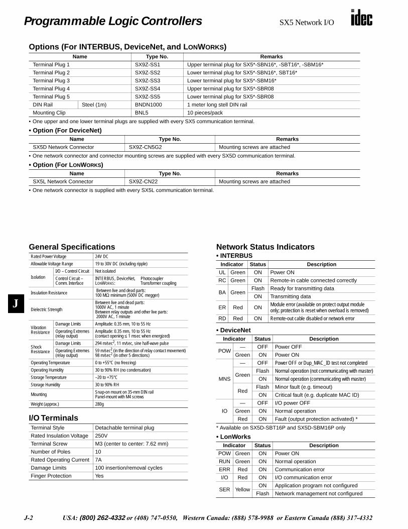
Options (For INTERBUS, DeviceNet, and L
ON
W
ORKS
)
• One upper and one lower terminal plugs are supplied with every SX5 communication terminal.
• Option (For DeviceNet)
• One network connector and connector mounting screws are supplied with every SX5D communication terminal.
• Option (For L
ON
W
ORKS
)
• One network connector is supplied with every SX5L communication terminal.
Name Type No. Remarks
Terminal Plug 1 SX9Z-SS1 Upper terminal plug for SX5*-SBN16*, -SBT16*, -SBM16*
Terminal Plug 2 SX9Z-SS2 Lower terminal plug for SX5*-SBN16*, SBT16*
Terminal Plug 3 SX9Z-SS3 Lower terminal plug for SX5*-SBM16*
Terminal Plug 4 SX9Z-SS4 Upper terminal plug for SX5*-SBR08
Terminal Plug 5 SX9Z-SS5 Lower terminal plug for SX5*-SBR08
DIN Rail Steel (1m) BNDN1000 1 meter long stell DIN rail
Mounting Clip BNL5 10 pieces/pack
Name Type No. Remarks
SX5D Network Connector SX9Z-CN5G2 Mounting screws are attached
Name Type No. Remarks
SX5L Network Connector SX9Z-CN22 Mounting screws are attached
General Specifications
I/O Terminals
Rated Power Voltage 24V DC
Allowable Voltage Range 19 to 30V DC (including ripple)
IsolationI/O – Control Circuit Not isolated
Control Circuit – Comm. Interface
INTERBUS, DeviceNet, PhotocouplerL
ON
W
ORKS
: Transformer coupling
Insulation Resistance Between live and dead parts:100 M
Ω
minimum (500V DC megger)
Dielectric Strength
Between live and dead parts:1000V AC, 1 minuteBetween relay outputs and other live parts: 2000V AC, 1 minute
Vibration Resistance
Damage Limits Amplitude: 0.35 mm, 10 to 55 Hz
Operating Extremes(relay output)
Amplitude: 0.35 mm, 10 to 55 Hz(contact opening
≤
1 msec when energized)
Shock Resistance
Damage Limits 294 m/sec
2
, 11 m/sec, sine half-wave pulse
Operating Extremes(relay output)
59 m/sec
2
(in the direction of relay contact movement)98 m/sec
2
(in other 5 directions)
Operating Temperature 0 to +55°C (no freezing)
Operating Humidity 30 to 90% RH (no condensation)
Storage Temperature –20 to +75°C
Storage Humidity 30 to 90% RH
Mounting Snap-on mount on 35-mm DIN railPanel-mount with M4 screws
Weight (approx.) 280g
Terminal Style Detachable terminal plug
Rated Insulation Voltage 250V
Terminal Screw M3 (center to center: 7.62 mm)
Number of Poles 10
Rated Operating Current 7A
Damage Limits 100 insertion/removal cycles
Finger Protection Yes
Network Status Indicators
• INTERBUS
• DeviceNet
* Available on SX5D-SBT16P and SX5D-SBM16P only
• LonWorks
Indicator Status Description
UL Green ON Power ON
RC Green ON Remote-in cable connected correctly
BA GreenFlash Ready for transmitting data
ON Transmitting data
ER Red ON
Module error (available on protect output module only; protection is reset when overload is removed)
RD Red ON
Remote-out cable disabled or network error
Indicator Status Description
POW— OFF Power OFF
Green ON Power ON
MNS
— OFF
Power OFF or Dup_MAC_ID test not completed
GreenFlash
Normal operation (not communicating with master)
ON
Normal operation (communicating with master)
RedFlash Minor fault (e.g.
timeout)
ON Critical fault (e.g. duplicate MAC ID)
IO
— OFF I/O power OFF
Green ON Normal operation
Red ON Fault (output protection activated) *
Indicator Status Description
POW Green ON Power ON
RUN Green ON Normal operation
ERR Red ON Communication error
I/O Red ON I/O communication error
SER YellowON Application program not configured
Flash Network management not configured
Programmable Logic Controllers
SX5 Network I/O
USA:
(800) 262-4332
or (408) 747-0550, Western Canada: (888) 578-9988 or Eastern Canada (888) 317-4332 J-3
J
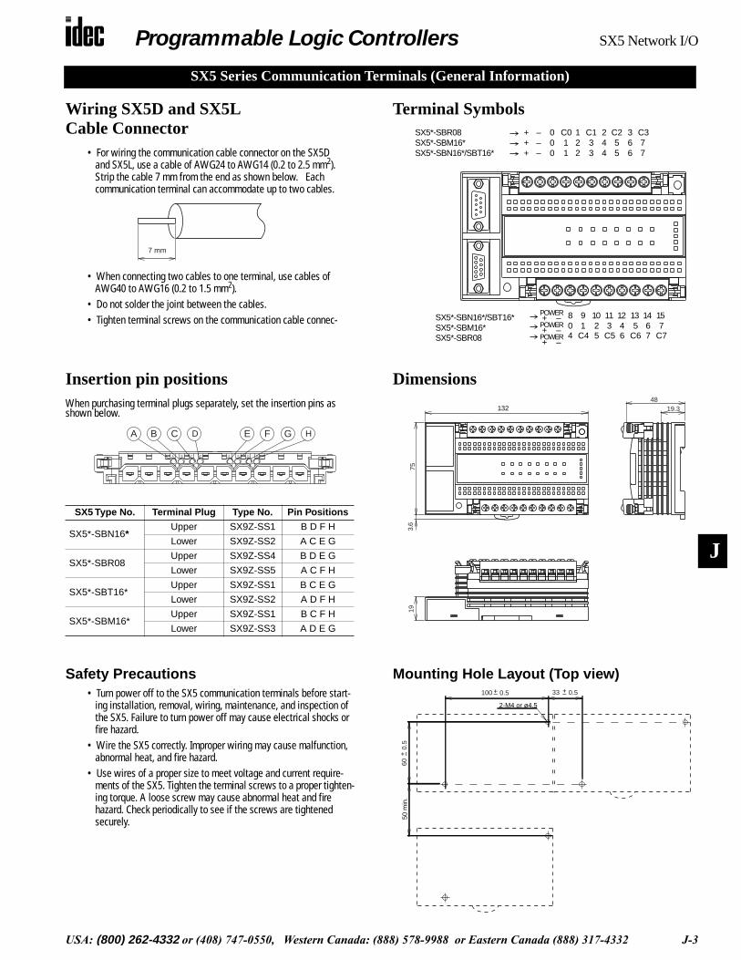
Wiring SX5D and SX5L Cable Connector
• For wiring the communication cable connector on the SX5D and SX5L, use a cable of AWG24 to AWG14 (0.2 to 2.5 mm
2
). Strip the cable 7 mm from the end as shown below. Each communication terminal can accommodate up to two cables.
• When connecting two cables to one terminal, use cables of AWG40 to AWG16 (0.2 to 1.5 mm
2
).• Do not solder the joint between the cables.• Tighten terminal screws on the communication cable connec-
7 mm
Terminal SymbolsSX5*-SBR08SX5*-SBM16*SX5*-SBN16*/SBT16* 7
7C3
+++
–––
000
11
C0
C5 C6 C7C4
221
33
C1
442
55
C2
663
157
804
91
1025
113
1246
135
1467
+ –POWER
+ –POWER
+ –POWERSX5*-SBR08
SX5*-SBM16*SX5*-SBN16*/SBT16*
Insertion pin positions
When purchasing terminal plugs separately, set the insertion pins asshown below.
SX5 Type No. Terminal Plug Type No. Pin Positions
SX5*-SBN16
*
Upper SX9Z-SS1 B D F H
Lower SX9Z-SS2 A C E G
SX5*-SBR08 Upper SX9Z-SS4 B D E G
Lower SX9Z-SS5 A C F H
SX5*-SBT16*Upper SX9Z-SS1 B C E G
Lower SX9Z-SS2 A D F H
SX5*-SBM16*Upper SX9Z-SS1 B C F H
Lower SX9Z-SS3 A D E G
HE F GA B C D
A B C D E F G H
Dimensions
193.
675
132 19.348
Safety Precautions
• Turn power off to the SX5 communication terminals before start-ing installation, removal, wiring, maintenance, and inspection of the SX5. Failure to turn power off may cause electrical shocks or fire hazard.
• Wire the SX5 correctly. Improper wiring may cause malfunction, abnormal heat, and fire hazard.
• Use wires of a proper size to meet voltage and current require-ments of the SX5. Tighten the terminal screws to a proper tighten-ing torque. A loose screw may cause abnormal heat and fire hazard. Check periodically to see if the screws are tightened securely.
Mounting Hole Layout (Top view)
2-M4 or ø4.5
33
50 m
in.
0.5+–100 0.5+–
600.
5+ –
SX5 Series Communication Terminals (General Information)
Programmable Logic Controllers
SX5 Network I/O
J-4 USA:
(800) 262-4332
or (408) 747-0550, Western Canada: (888) 578-9988 or Eastern Canada (888) 317-4332
J
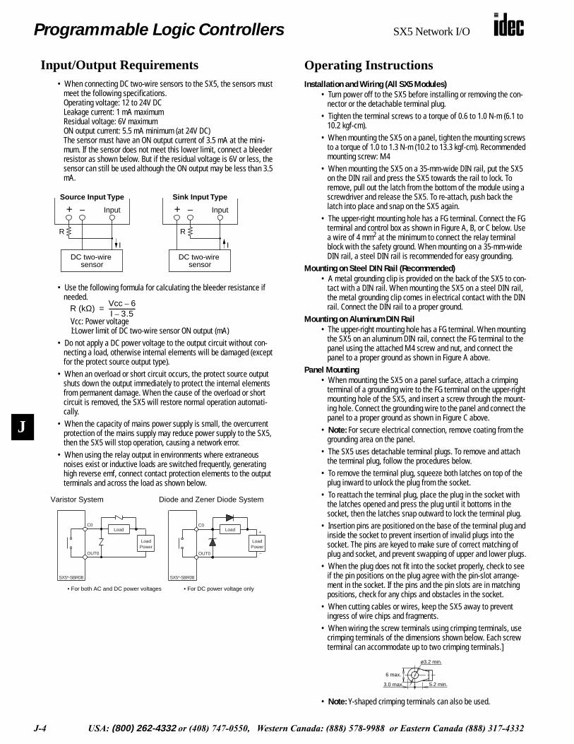
Input/Output Requirements
• When connecting DC two-wire sensors to the SX5, the sensors must meet the following specifications. Operating voltage: 12 to 24V DCLeakage current: 1 mA maximumResidual voltage: 6V maximumON output current: 5.5 mA minimum (at 24V DC)The sensor must have an ON output current of 3.5 mA at the mini-mum. If the sensor does not meet this lower limit, connect a bleeder resistor as shown below. But if the residual voltage is 6V or less, the sensor can still be used although the ON output may be less than 3.5 mA.
• Use the following formula for calculating the bleeder resistance if needed.
Vcc: Power voltage
I:Lower limit of DC two-wire sensor ON output (mA)• Do not apply a DC power voltage to the output circuit without con-
necting a load, otherwise internal elements will be damaged (except for the protect source output type).
• When an overload or short circuit occurs, the protect source output shuts down the output immediately to protect the internal elements from permanent damage. When the cause of the overload or short circuit is removed, the SX5 will restore normal operation automati-cally.
• When the capacity of mains power supply is small, the overcurrent protection of the mains supply may reduce power supply to the SX5, then the SX5 will stop operation, causing a network error.
• When using the relay output in environments where extraneous noises exist or inductive loads are switched frequently, generating high reverse emf, connect contact protection elements to the output terminals and across the load as shown below.
+ – Input
DC two-wire
Source Input Type
R
I
sensor
+ – Input
Sink Input Type
R
I
DC two-wire sensor
R (kΩ)Vcc 6–I 3.5–-------------------=
Varistor System
SX5*-SBR08 SX5*-SBR08
LoadC0
OUT0
Load
OUT0
C0
• For both AC and DC power voltages • For DC power voltage only
+
–
Diode and Zener Diode System
LoadPower
LoadPower
Operating Instructions
Installation and Wiring (All SX5 Modules)
• Turn power off to the SX5 before installing or removing the con-nector or the detachable terminal plug.
• Tighten the terminal screws to a torque of 0.6 to 1.0 N-m (6.1 to 10.2 kgf-cm).
• When mounting the SX5 on a panel, tighten the mounting screws to a torque of 1.0 to 1.3 N-m (10.2 to 13.3 kgf-cm). Recommended mounting screw: M4
• When mounting the SX5 on a 35-mm-wide DIN rail, put the SX5 on the DIN rail and press the SX5 towards the rail to lock. To remove, pull out the latch from the bottom of the module using a screwdriver and release the SX5. To re-attach, push back the latch into place and snap on the SX5 again.
• The upper-right mounting hole has a FG terminal. Connect the FG terminal and control box as shown in Figure A, B, or C below. Use a wire of 4 mm
2
at the minimum to connect the relay terminal block with the safety ground. When mounting on a 35-mm-wide DIN rail, a steel DIN rail is recommended for easy grounding.
Mounting on Steel DIN Rail (Recommended)
• A metal grounding clip is provided on the back of the SX5 to con-tact with a DIN rail. When mounting the SX5 on a steel DIN rail, the metal grounding clip comes in electrical contact with the DIN rail. Connect the DIN rail to a proper ground.
Mounting on Aluminum DIN Rail
• The upper-right mounting hole has a FG terminal. When mounting the SX5 on an aluminum DIN rail, connect the FG terminal to the panel using the attached M4 screw and nut, and connect the panel to a proper ground as shown in Figure A above.
Panel Mounting
• When mounting the SX5 on a panel surface, attach a crimping terminal of a grounding wire to the FG terminal on the upper-right mounting hole of the SX5, and insert a screw through the mount-ing hole. Connect the grounding wire to the panel and connect the panel to a proper ground as shown in Figure C above.
•
Note:
For secure electrical connection, remove coating from the grounding area on the panel.
• The SX5 uses detachable terminal plugs. To remove and attach the terminal plug, follow the procedures below.
• To remove the terminal plug, squeeze both latches on top of the plug inward to unlock the plug from the socket.
• To reattach the terminal plug, place the plug in the socket with the latches opened and press the plug until it bottoms in the socket, then the latches snap outward to lock the terminal plug.
• Insertion pins are positioned on the base of the terminal plug and inside the socket to prevent insertion of invalid plugs into the socket. The pins are keyed to make sure of correct matching of plug and socket, and prevent swapping of upper and lower plugs.
• When the plug does not fit into the socket properly, check to see if the pin positions on the plug agree with the pin-slot arrange-ment in the socket. If the pins and the pin slots are in matching positions, check for any chips and obstacles in the socket.
• When cutting cables or wires, keep the SX5 away to prevent ingress of wire chips and fragments.
• When wiring the screw terminals using crimping terminals, use crimping terminals of the dimensions shown below. Each screw terminal can accommodate up to two crimping terminals.]
•
Note:
Y-shaped crimping terminals can also be used.
ø3.2 min.
3.0 max. 5.2 min.
6 max.
Programmable Logic Controllers
SX5 Network I/O
USA:
(800) 262-4332
or (408) 747-0550, Western Canada: (888) 578-9988 or Eastern Canada (888) 317-4332 J-5
J
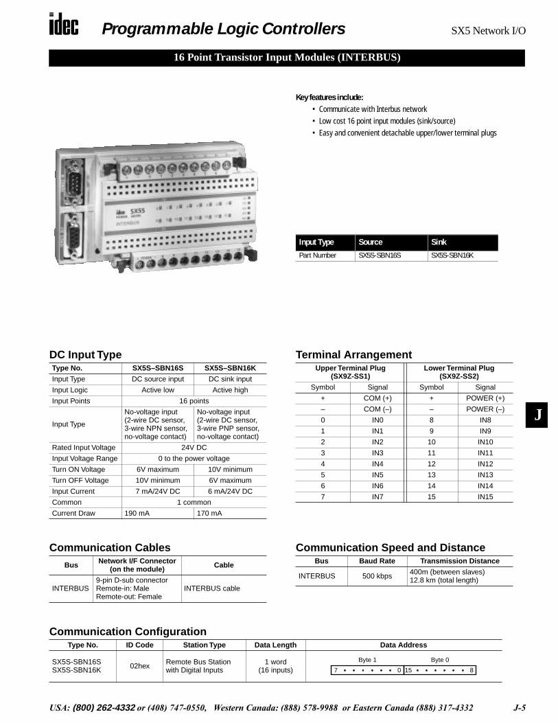
16 Point Transistor Input Modules (INTERBUS)
Input Type Source Sink
Part Number SX5S-SBN16S SX5S-SBN16K
DC Input Type
Type No. SX5S–SBN16S SX5S–SBN16K
Input Type DC source input DC sink input
Input Logic Active low Active high
Input Points 16 points
Input Type
No-voltage input (2-wire DC sensor, 3-wire NPN sensor, no-voltage contact)
No-voltage input (2-wire DC sensor, 3-wire PNP sensor, no-voltage contact)
Rated Input Voltage 24V DC
Input Voltage Range 0 to the power voltage
Turn ON Voltage 6V maximum 10V minimum
Turn OFF Voltage 10V minimum 6V maximum
Input Current 7 mA/24V DC 6 mA/24V DC
Common 1 common
Current Draw 190 mA 170 mA
Communication Speed and Distance
Bus Baud Rate Transmission Distance
INTERBUS 500 kbps 400m (between slaves)12.8 km (total length)
Communication Cables
Bus Network I/F Connector (on the module) Cable
INTERBUS9-pin D-sub connectorRemote-in: MaleRemote-out: Female
INTERBUS cable
Terminal Arrangement
Upper Terminal Plug (SX9Z-SS1)
Lower Terminal Plug (SX9Z-SS2)
Symbol Signal Symbol Signal
+ COM (+) + POWER (+)
– COM (–) – POWER (–)
0 IN0 8 IN8
1 IN1 9 IN9
2 IN2 10 IN10
3 IN3 11 IN11
4 IN4 12 IN12
5 IN5 13 IN13
6 IN6 14 IN14
7 IN7 15 IN15
Communication Configuration
Type No. ID Code Station Type Data Length Data Address
SX5S-SBN16SSX5S-SBN16K 02hex Remote Bus Station
with Digital Inputs1 word
(16 inputs)Byte 1
7 0
Byte 0
15 8
Key features include:
• Communicate with Interbus network• Low cost 16 point input modules (sink/source)• Easy and convenient detachable upper/lower terminal plugs
Programmable Logic Controllers
SX5 Network I/O
J-6 USA:
(800) 262-4332
or (408) 747-0550, Western Canada: (888) 578-9988 or Eastern Canada (888) 317-4332
J
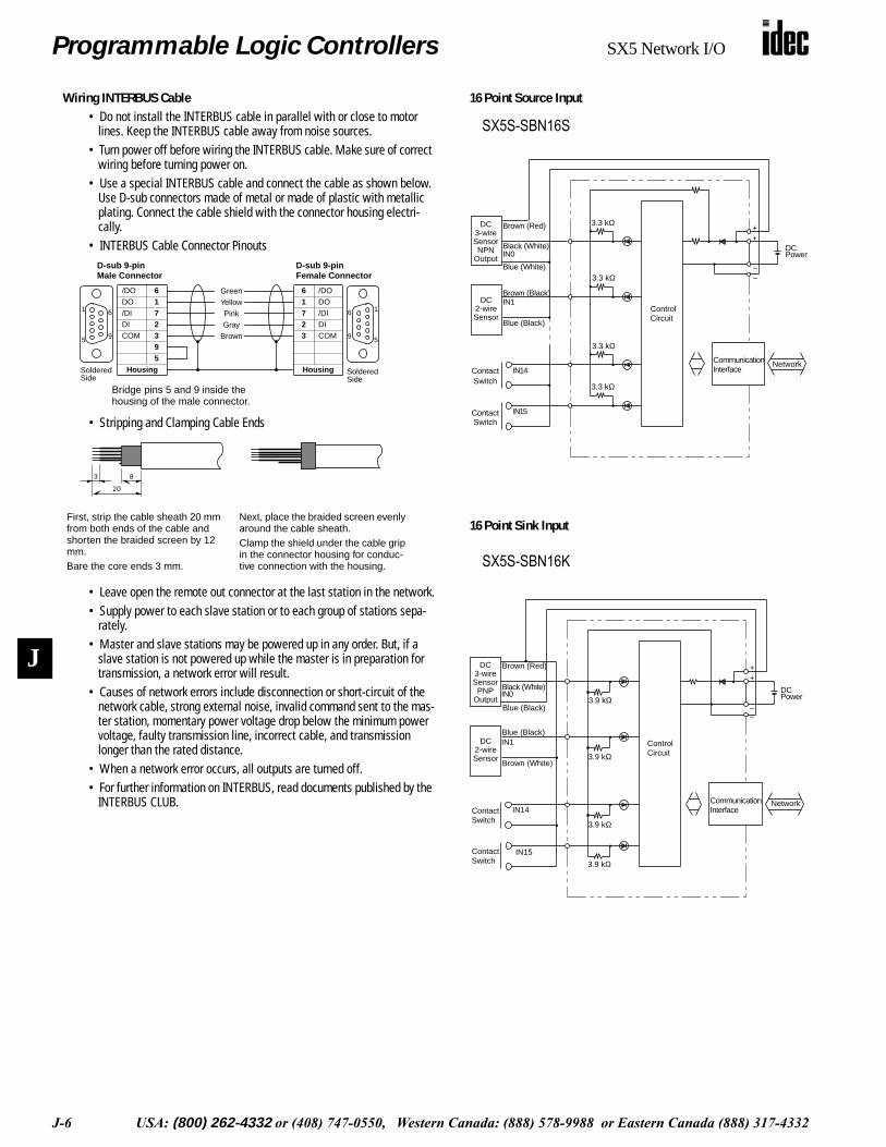
• SX5*-SBN16S
DC Power
ContactSwitch
ContactSwitch
3.3 kΩ
3.3 kΩ
3.3 kΩ
3.3 kΩ
++
–Blue (White)
IN0Black (White)
Brown (Red)
Network
Brown (Black)IN1
Blue (Black)
IN14
IN15
ControlCircuit
DC3-wireSensorNPN
Output
DC2-wireSensor
CommunicationInterface
–
• SX5*-SBN16K
3.9 kΩ
3.9 kΩ
3.9 kΩ
3.9 kΩ
ContactSwitch
ContactSwitch
++
––
Brown (Red)
Blue (Black)
IN0Black (White)
IN1
Brown (White)
Blue (Black)
IN15
IN14CommunicationInterface
ControlCircuit
DCPower
Network
DC3-wireSensorPNP
Output
DC2-wireSensor
16 Point Source Input
16 Point Sink Input
Wiring INTERBUS Cable
• Do not install the INTERBUS cable in parallel with or close to motor lines. Keep the INTERBUS cable away from noise sources.
• Turn power off before wiring the INTERBUS cable. Make sure of correct wiring before turning power on.
• Use a special INTERBUS cable and connect the cable as shown below. Use D-sub connectors made of metal or made of plastic with metallic plating. Connect the cable shield with the connector housing electri-cally.
• INTERBUS Cable Connector Pinouts
• Stripping and Clamping Cable Ends
• Leave open the remote out connector at the last station in the network.• Supply power to each slave station or to each group of stations sepa-
rately.• Master and slave stations may be powered up in any order. But, if a
slave station is not powered up while the master is in preparation for transmission, a network error will result.
• Causes of network errors include disconnection or short-circuit of the network cable, strong external noise, invalid command sent to the mas-ter station, momentary power voltage drop below the minimum power voltage, faulty transmission line, incorrect cable, and transmission longer than the rated distance.
• When a network error occurs, all outputs are turned off.• For further information on INTERBUS, read documents published by the
INTERBUS CLUB.
16
9 5
/DO 6DO 1/DI 7DI 2COM 3
95
Housing
GreenYellowPinkGray
Brown
6 /DO1 DO7 /DI2 DI3 COM
HousingSolderedSide
SolderedSide
Bridge pins 5 and 9 inside the housing of the male connector.
1 6
95
D-sub 9-pin Male Connector
D-sub 9-pin Female Connector
3 8
20
First, strip the cable sheath 20 mm from both ends of the cable and shorten the braided screen by 12 mm.Bare the core ends 3 mm.
Next, place the braided screen evenly around the cable sheath.Clamp the shield under the cable grip in the connector housing for conduc-tive connection with the housing.
SX5S-SBN16S
SX5S-SBN16K

Programmable Logic Controllers
SX5 Network I/O
USA:
(800) 262-4332
or (408) 747-0550, Western Canada: (888) 578-9988 or Eastern Canada (888) 317-4332 J-7
J
8 Point Relay Output Module (INTERBUS)
Input Type Relay Output
Part Number SX5S-SBR08
Key features include:
• Communicate with Interbus network• Low cost 8 point relay output module• Easy and convenient detachable upper/lower terminal plugs • handles current up to 5A per point
Communication Speed and Distance
Bus Baud Rate Transmission Distance
INTERBUS 500 kbps 400m (between slaves)12.8 km (total length)
Communication CablesBus Network I/F Connector
(on the module) Cable
INTERBUS9-pin D-sub connectorRemote-in: MaleRemote-out: Female
INTERBUS cable
Terminal ArrangementUpper Terminal Plug
(SX9Z-SS4)Lower Terminal Plug
(SX9Z-SS2)
Symbol Signal Symbol Signal
+ COM (+) + POWER (+)
– COM (–) – POWER (–)
0 OUT0 4 OUT4
C0 COM0 C4 COM4
1 OUT1 5 OUT5
C1 COM1 C5 COM5
2 OUT2 6 OUT6
C2 COM2 C6 COM6
3 OUT3 7 OUT7
C3 COM3 C7 COM7
Communication ConfigurationType No. ID Code Station Type Data Length Data Address
SX5S-SBR08 01hex Remote Bus Station with Digital Outputs
1 word(8 outputs)
Byte 1
7 0 None
Relay Output Type
Rated Relay Contact
Type No. SX5S–SBR08
Output Type Relay output
Output Points 8 points
Output Type 1NO relay contact
Rated Load Voltage 250V AC, 24V DC
Maximum Load Current 5A/point
Commons/Current 8 commons/5A
Current Draw 120 mA
Built-in Relay PCB mount, not replaceable
Maximum Applicable Voltage 250V AC, 125V DC
Maximum Current 5A
Rated Load (resistive load) 250V AC/5A, 24V DC/5A
Minimum Applicable Load 1V DC / 1mA
LifeMechanical 20,000,000 operations minimum
(18,000 operations/ hour)
Electrical See Electrical Life Curve on next page (1,800 operations/ hour)

Programmable Logic Controllers SX5 Network I/O
J-8 USA: (800) 262-4332 or (408) 747-0550, Western Canada: (888) 578-9988 or Eastern Canada (888) 317-4332
J
8 Point Relay Ouput Wiring INTERBUS Cable• Do not install the INTERBUS cable in parallel with or close to motor lines.
Keep the INTERBUS cable away from noise sources.• Turn power off before wiring the INTERBUS cable. Make sure of correct
wiring before turning power on.• Use a special INTERBUS cable and connect the cable as shown below.
Use D-sub connectors made of metal or made of plastic with metallic plat-ing. Connect the cable shield with the connector housing electrically.
• INTERBUS Cable Connector Pinouts
• Stripping and Clamping Cable Ends
• Leave open the remote out connector at the last station in the network.• Supply power to each slave station or to each group of stations sepa-
rately.• Master and slave stations may be powered up in any order. But, if a slave
station is not powered up while the master is in preparation for transmis-sion, a network error will result.
• Causes of network errors include disconnection or short-circuit of the net-work cable, strong external noise, invalid command sent to the master station, momentary power voltage drop below the minimum power volt-age, faulty transmission line, incorrect cable, and transmission longer than the rated distance.
• When a network error occurs, all outputs are turned off.• For further information on INTERBUS, read documents published by the
INTERBUS CLUB.
16
9 5
/DO 6DO 1/DI 7DI 2COM 3
95
Housing
GreenYellowPinkGray
Brown
6 /DO1 DO7 /DI2 DI3 COM
HousingSolderedSide
SolderedSide
Bridge pins 5 and 9 inside the housing of the male connector.
1 6
95
D-sub 9-pin Male Connector
D-sub 9-pin Female Connector
3 8
20
First, strip the cable sheath 20 mm from both ends of the cable and shorten the braided screen by 12 mm.Bare the core ends 3 mm.
Next, place the braided screen evenly around the cable sheath.Clamp the shield under the cable grip in the connector housing for conduc-tive connection with the housing.
• SX5*-SBR08
Load PowerPilotLight
Load Power
Solenoid
PilotLight
Load Power
Load Power
Solenoid
++
Network
OUT1COM1
COM7OUT7
OUT0COM0
COM6OUT6
ControlCircuit
CommunicationInterface
DCPower
––
Reference Data• Electrical Life Curve: Relay in SX5S-SBR08• Note 1: AC/DC Resistive Load• Operating frequency: 1800 operations/hour
Duty ratio: 40%• Note 2: AC Inductive Load
• Note 3: DC Inductive LoadOperating frequency: 1800 operations/hourDuty ratio: 40%Time constant: L/R =15 msec
Line Making Current Breaking Current Frequency Duty Ratio
Solid 10 I, cos θ = 0.7 I, cos θ = 0.3 to 0.4 1800 operations/h40%
Dashed 5 I, cos θ = 0.7 I, cos θ = 0.3 to 0.4 300 operations/h
100
500
50
10
0.05 0.1 1 2 3 50.2 0.3 0.5
110V ACInductive
220V ACInductive
220V AC Resistive110V AC Resistive
AC Load
Life
(x
1000
0 op
erat
ions
)
Load Current (A)
100
500
50
10
0.05 0.1 1 2 3 50.2 0.3 0.5
110V DCInductive
24V DC Resistive
48V DC Resistive
24V DC Inductive
Load Current (A)
110 DC Resistive
Life
(x
1000
0 op
erat
ions
)
48V DC Inductive
DC Load
SX5S-SBR08
Programmable Logic Controllers SX5 Network I/O
USA: (800) 262-4332 or (408) 747-0550, Western Canada: (888) 578-9988 or Eastern Canada (888) 317-4332 J-9
J
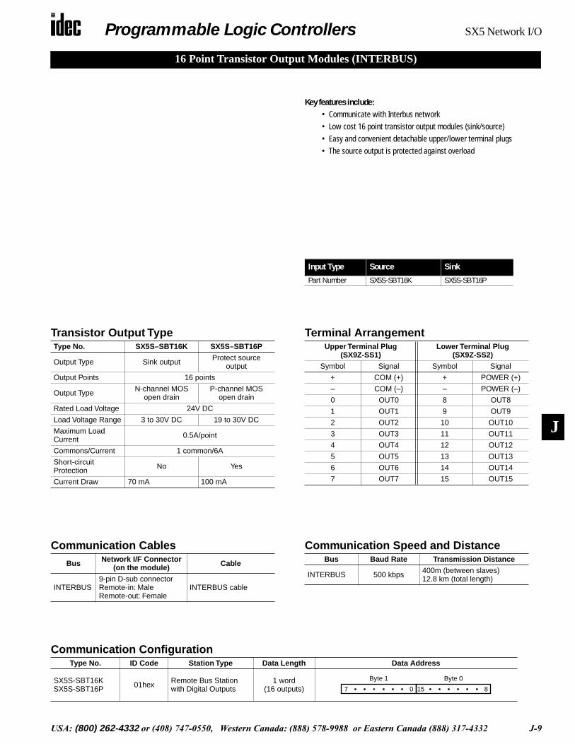
16 Point Transistor Output Modules (INTERBUS)
Key features include:• Communicate with Interbus network• Low cost 16 point transistor output modules (sink/source)• Easy and convenient detachable upper/lower terminal plugs • The source output is protected against overload
Transistor Output TypeType No. SX5S–SBT16K SX5S–SBT16P
Output Type Sink output Protect source output
Output Points 16 points
Output Type N-channel MOS open drain
P-channel MOS open drain
Rated Load Voltage 24V DC
Load Voltage Range 3 to 30V DC 19 to 30V DC
Maximum Load Current 0.5A/point
Commons/Current 1 common/6A
Short-circuit Protection No Yes
Current Draw 70 mA 100 mA
Communication Speed and DistanceBus Baud Rate Transmission Distance
INTERBUS 500 kbps 400m (between slaves)12.8 km (total length)
Communication CablesBus Network I/F Connector
(on the module) Cable
INTERBUS9-pin D-sub connectorRemote-in: MaleRemote-out: Female
INTERBUS cable
Terminal ArrangementUpper Terminal Plug
(SX9Z-SS1)Lower Terminal Plug
(SX9Z-SS2)
Symbol Signal Symbol Signal
+ COM (+) + POWER (+)
– COM (–) – POWER (–)
0 OUT0 8 OUT8
1 OUT1 9 OUT9
2 OUT2 10 OUT10
3 OUT3 11 OUT11
4 OUT4 12 OUT12
5 OUT5 13 OUT13
6 OUT6 14 OUT14
7 OUT7 15 OUT15
Communication ConfigurationType No. ID Code Station Type Data Length Data Address
SX5S-SBT16KSX5S-SBT16P 01hex Remote Bus Station
with Digital Outputs1 word
(16 outputs)Byte 1
7 0
Byte 0
15 8
Input Type Source Sink
Part Number SX5S-SBT16K SX5S-SBT16P
Programmable Logic Controllers SX5 Network I/O
J-10 USA: (800) 262-4332 or (408) 747-0550, Western Canada: (888) 578-9988 or Eastern Canada (888) 317-4332
J
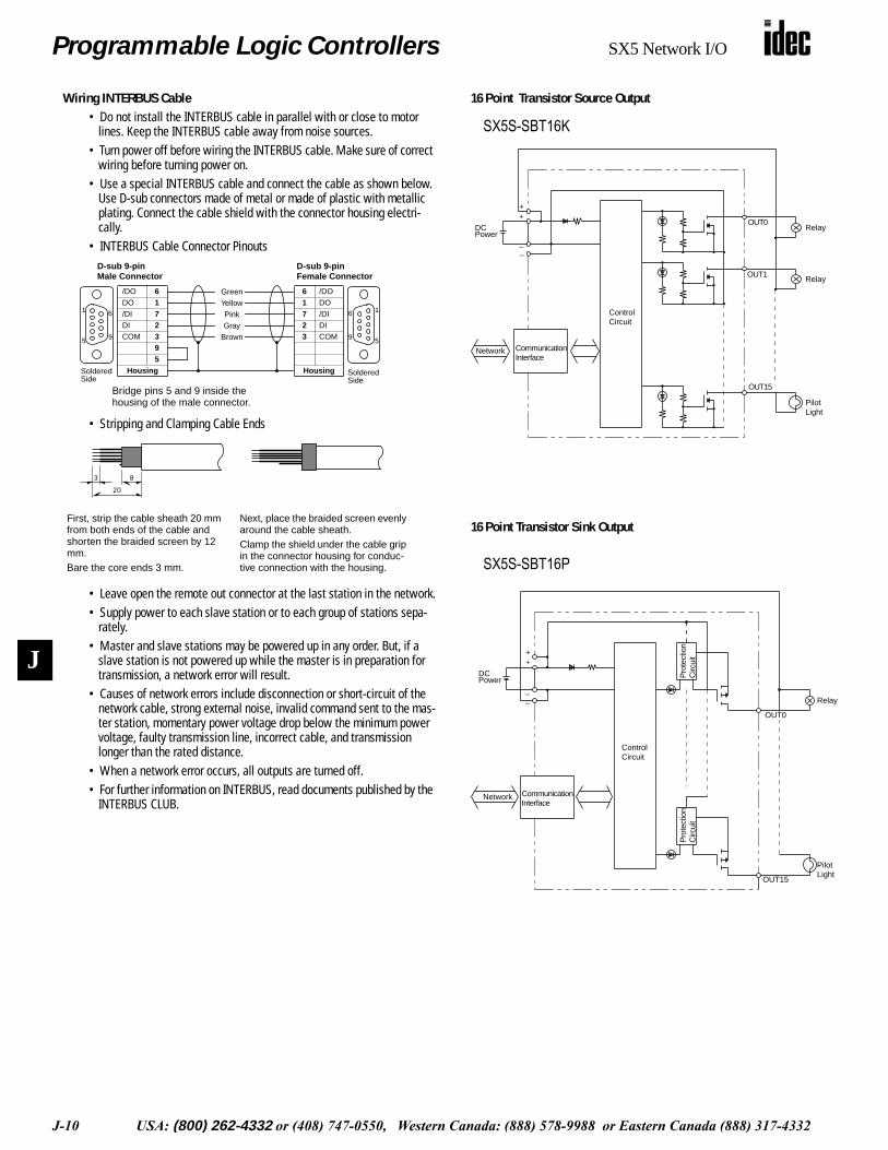
Wiring INTERBUS Cable• Do not install the INTERBUS cable in parallel with or close to motor
lines. Keep the INTERBUS cable away from noise sources.• Turn power off before wiring the INTERBUS cable. Make sure of correct
wiring before turning power on.• Use a special INTERBUS cable and connect the cable as shown below.
Use D-sub connectors made of metal or made of plastic with metallic plating. Connect the cable shield with the connector housing electri-cally.
• INTERBUS Cable Connector Pinouts
• Stripping and Clamping Cable Ends
• Leave open the remote out connector at the last station in the network.• Supply power to each slave station or to each group of stations sepa-
rately.• Master and slave stations may be powered up in any order. But, if a
slave station is not powered up while the master is in preparation for transmission, a network error will result.
• Causes of network errors include disconnection or short-circuit of the network cable, strong external noise, invalid command sent to the mas-ter station, momentary power voltage drop below the minimum power voltage, faulty transmission line, incorrect cable, and transmission longer than the rated distance.
• When a network error occurs, all outputs are turned off.• For further information on INTERBUS, read documents published by the
INTERBUS CLUB.
16
9 5
/DO 6DO 1/DI 7DI 2COM 3
95
Housing
GreenYellowPinkGray
Brown
6 /DO1 DO7 /DI2 DI3 COM
HousingSolderedSide
SolderedSide
Bridge pins 5 and 9 inside the housing of the male connector.
1 6
95
D-sub 9-pin Male Connector
D-sub 9-pin Female Connector
3 8
20
First, strip the cable sheath 20 mm from both ends of the cable and shorten the braided screen by 12 mm.Bare the core ends 3 mm.
Next, place the braided screen evenly around the cable sheath.Clamp the shield under the cable grip in the connector housing for conduc-tive connection with the housing.
16 Point Transistor Source Output
16 Point Transistor Sink Output
• SX5*-SBT16K
Relay
PilotLight
Relay
++
––
OUT0
OUT1
DCPower
ControlCircuit
CommunicationInterface
Network
OUT15
• SX5*-SBT16P
Relay
PilotLight
++
––
OUT15
ControlCircuit
Pro
tect
ion
Circ
uit
Pro
tect
ion
Circ
uit
DCPower
CommunicationInterface
Network
OUT0
SX5S-SBT16K
SX5S-SBT16P

Programmable Logic Controllers SX5 Network I/O
USA: (800) 262-4332 or (408) 747-0550, Western Canada: (888) 578-9988 or Eastern Canada (888) 317-4332 J-11
J
8 Point Source Input & 8 Point Transistor Sink Output Module (INTERBUS)
Key features include:• Communicate with Interbus network• Low cost 8 point source input and 8 point sink output module• Easy and convenient detachable upper/lower terminal plugs
Communication Speed and DistanceBus Baud Rate Transmission Distance
INTERBUS 500 kbps 400m (between slaves)12.8 km (total length)
Communication CablesBus Network I/F Connector
(on the module) Cable
INTERBUS9-pin D-sub connectorRemote-in: MaleRemote-out: Female
INTERBUS cable
Terminal ArrangementUpper Terminal Plug
(SX9Z-SS1)Lower Terminal Plug
(SX9Z-SS3)
Symbol Signal Symbol Signal
+ COM (+) + POWER (+)
– COM (–) – POWER (–)
0 IN0 0 OUT0
1 IN1 1 OUT1
2 IN2 2 OUT2
3 IN3 3 OUT3
4 IN4 4 OUT4
5 IN5 5 OUT5
6 IN6 6 OUT6
7 IN7 7 OUT7
Communication ConfigurationType No. ID Code Station Type Data Length Data Address
SX5S-SBM16K 03hex Remote Bus Station with Digital I/Os
1 byte(8 in / 8 out) Byte 0 (Output)
7 0
Byte 0 (Input)
7 0
Input Type Source Input/Sink Output
Part Number SX5S-SBM16K
DC Input / Transistor Sink Output TypeType No. SX5S–SBM16K
I/O Type Source input / sink output
Input
Input Logic Active Low
Input Points 8 points
Input TypeNo-voltage input
(2-wire DC sensor, 3-wire NPN sensor, no-voltage contact)
Rated Input Voltage 24V DC
Input Voltage Range 0 to the power voltage
ON Voltage 6V maximum
OFF Voltage 10V minimum
Input Current 7 mA/24V DC
Common 1 common
Output
Output Points 8 points
Output Type N-channel MOS open drain
Rated Load Voltage 24V DC
Load Voltage Range 3 to 30V DC
Maximum Load Current 0.5A/point
Commons/Current 1 common/4A
Short-circuit Protection No
Current Draw 140 mA
Programmable Logic Controllers SX5 Network I/O
J-12 USA: (800) 262-4332 or (408) 747-0550, Western Canada: (888) 578-9988 or Eastern Canada (888) 317-4332
J
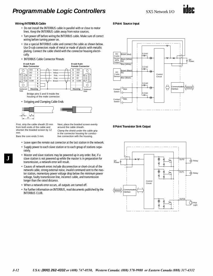
Wiring INTERBUS Cable• Do not install the INTERBUS cable in parallel with or close to motor
lines. Keep the INTERBUS cable away from noise sources.• Turn power off before wiring the INTERBUS cable. Make sure of correct
wiring before turning power on.• Use a special INTERBUS cable and connect the cable as shown below.
Use D-sub connectors made of metal or made of plastic with metallic plating. Connect the cable shield with the connector housing electri-cally.
• INTERBUS Cable Connector Pinouts
• Stripping and Clamping Cable Ends
• Leave open the remote out connector at the last station in the network.• Supply power to each slave station or to each group of stations sepa-
rately.• Master and slave stations may be powered up in any order. But, if a
slave station is not powered up while the master is in preparation for transmission, a network error will result.
• Causes of network errors include disconnection or short-circuit of the network cable, strong external noise, invalid command sent to the mas-ter station, momentary power voltage drop below the minimum power voltage, faulty transmission line, incorrect cable, and transmission longer than the rated distance.
• When a network error occurs, all outputs are turned off.• For further information on INTERBUS, read documents published by the
INTERBUS CLUB.
16
9 5
/DO 6DO 1/DI 7DI 2COM 3
95
Housing
GreenYellowPinkGray
Brown
6 /DO1 DO7 /DI2 DI3 COM
HousingSolderedSide
SolderedSide
Bridge pins 5 and 9 inside the housing of the male connector.
1 6
95
D-sub 9-pin Male Connector
D-sub 9-pin Female Connector
3 8
20
First, strip the cable sheath 20 mm from both ends of the cable and shorten the braided screen by 12 mm.Bare the core ends 3 mm.
Next, place the braided screen evenly around the cable sheath.Clamp the shield under the cable grip in the connector housing for conduc-tive connection with the housing.
8 Point Source Input
8 Point Transistor Sink Output
• SX5*-SBN16S
DC Power
ContactSwitch
ContactSwitch
3.3 kΩ
3.3 kΩ
3.3 kΩ
3.3 kΩ
++
–Blue (White)
IN0Black (White)
Brown (Red)
Network
Brown (Black)IN1
Blue (Black)
IN14
IN15
ControlCircuit
DC3-wireSensorNPN
Output
DC2-wireSensor
CommunicationInterface
–
• SX5*-SBT16K
Relay
PilotLight
Relay
++
––
OUT0
OUT1
DCPower
ControlCircuit
CommunicationInterface
Network
OUT15

Programmable Logic Controllers SX5 Network I/O
USA: (800) 262-4332 or (408) 747-0550, Western Canada: (888) 578-9988 or Eastern Canada (888) 317-4332 J-13
J
8 Point Sink Input & 8 Point Transistor Source Output Module (INTERBUS)
Key features include:• Communicate with Interbus network• Low cost 8 point sink input and 8 point source output module• Easy and convenient detachable upper/lower terminal plugs • Transistor protected source output
Communication Speed and DistanceBus Baud Rate Transmission Distance
INTERBUS 500 kbps 400m (between slaves)12.8 km (total length)
Communication CablesBus Network I/F Connector
(on the module) Cable
INTERBUS9-pin D-sub connectorRemote-in: MaleRemote-out: Female
INTERBUS cable
Terminal ArrangementUpper Terminal Plug
(SX9Z-SS1)Lower Terminal Plug
(SX9Z-SS3)
Symbol Signal Symbol Signal
+ COM (+) + POWER (+)
– COM (–) – POWER (–)
0 IN0 0 OUT0
1 IN1 1 OUT1
2 IN2 2 OUT2
3 IN3 3 OUT3
4 IN4 4 OUT4
5 IN5 5 OUT5
6 IN6 6 OUT6
7 IN7 7 OUT7
Communication ConfigurationType No. ID Code Station Type Data Length Data Address
SX5S-SBM16P 03hex Remote Bus Station with Digital I/Os
1 byte(8 in / 8 out) Byte 0 (Output)
7 0
Byte 0 (Input)
7 0
Input Type Sink Input/Source Output
Part Number SX5S-SBM16P
DC Input / Transistor Source Output TypeType No. SX5S–SBM16P
I/O Type Sink input / protect source output
Input
Input Logic Active High
Input Points 8 points
Input TypeNo-voltage input
(2-wire DC sensor, 3-wire PNP sensor, no-voltage contact)
Rated Input Voltage 24V DC
Input Voltage Range 0 to the power voltage
ON Voltage 10V minimum
OFF Voltage 6V maximum
Input Current 6 mA/24V DC
Common 1 common
Output
Output Points 8 points
Output Type P-channel MOS open drain
Rated Load Voltage 24V DC
Load Voltage Range 19 to 30V DC
Maximum Load Current 0.5A/point
Commons/Current 1 common/4A
Short-circuit Protection Yes
Current Draw 140 mA

Programmable Logic Controllers SX5 Network I/O
J-14 USA: (800) 262-4332 or (408) 747-0550, Western Canada: (888) 578-9988 or Eastern Canada (888) 317-4332
J
Wiring INTERBUS Cable• Do not install the INTERBUS cable in parallel with or close to motor
lines. Keep the INTERBUS cable away from noise sources.• Turn power off before wiring the INTERBUS cable. Make sure of cor-
rect wiring before turning power on.• Use a special INTERBUS cable and connect the cable as shown
below. Use D-sub connectors made of metal or made of plastic with metallic plating. Connect the cable shield with the connector housing electrically.
• INTERBUS Cable Connector Pinouts
• Stripping and Clamping Cable Ends
• Leave open the remote out connector at the last station in the net-work.
• Supply power to each slave station or to each group of stations sepa-rately.
• Master and slave stations may be powered up in any order. But, if a slave station is not powered up while the master is in preparation for transmission, a network error will result.
• Causes of network errors include disconnection or short-circuit of the network cable, strong external noise, invalid command sent to the master station, momentary power voltage drop below the minimum power voltage, faulty transmission line, incorrect cable, and transmis-sion longer than the rated distance.
• When a network error occurs, all outputs are turned off.• For further information on INTERBUS, read documents published by
the INTERBUS CLUB.
16
9 5
/DO 6DO 1/DI 7DI 2COM 3
95
Housing
GreenYellowPinkGray
Brown
6 /DO1 DO7 /DI2 DI3 COM
HousingSolderedSide
SolderedSide
Bridge pins 5 and 9 inside the housing of the male connector.
1 6
95
D-sub 9-pin Male Connector
D-sub 9-pin Female Connector
3 8
20
First, strip the cable sheath 20 mm from both ends of the cable and shorten the braided screen by 12 mm.Bare the core ends 3 mm.
Next, place the braided screen evenly around the cable sheath.Clamp the shield under the cable grip in the connector housing for conduc-tive connection with the housing.
8 Point Sink Input
8 Point Transistor Source Output
• SX5*-SBN16K
3.9 kΩ
3.9 kΩ
3.9 kΩ
3.9 kΩ
ContactSwitch
ContactSwitch
++
––
Brown (Red)
Blue (Black)
IN0Black (White)
IN1
Brown (White)
Blue (Black)
IN15
IN14CommunicationInterface
ControlCircuit
DCPower
Network
DC3-wireSensorPNP
Output
DC2-wireSensor
• SX5*-SBT16P
Relay
PilotLight
++
––
OUT15
ControlCircuit
Pro
tect
ion
Circ
uit
Pro
tect
ion
Circ
uit
DCPower
CommunicationInterface
Network
OUT0

Programmable Logic Controllers SX5 Network I/O
USA: (800) 262-4332 or (408) 747-0550, Western Canada: (888) 578-9988 or Eastern Canada (888) 317-4332 J-15
J
16 Point Transistor Input Modules (DeviceNet)
Input Type Source Sink
Part Number SX5D-SBN16S SX5D-SBN16K
Key features include:• Communicate with DeviceNet network• Low cost 16 point input module (sink/source)• Easy and convenient detachable upper/lower terminal plugs
DC Input TypeType No. SX5D–SBN16S SX5D–SBN16K
Input Type DC source input DC sink input
Input Logic Active low Active high
Input Points 16 points
Input Type
No-voltage input (2-wire DC sensor, 3-wire NPN sensor, no-voltage contact)
No-voltage input (2-wire DC sensor, 3-wire PNP sensor, no-voltage contact)
Rated Input Voltage 24V DC
Input Voltage Range 0 to the power voltage
Turn ON Voltage 6V maximum 10V minimum
Turn OFF Voltage 10V minimum 6V maximum
Input Current mA/24V DC 6 mA/24V DC
Common 1 common
Current Draw 190 mA 170 mA
Communication Speed and DistanceBus Baud Rate Transmission Distance
DeviceNet
125 kbps 500m [100m] *1
250 kbps 250m [100m] *1
500 kbps 100m [100m] *1
Communication CablesBus Network I/F Connector
(on the module) Cable
DeviceNetPhoenix Contact5-pin connector MSTBV2.5/5-GF-5.08AU
DeviceNet cable
Terminal Arrangeme ntUpper Terminal Plug
(SX9Z-SS1)Lower Terminal Plug
(SX9Z-SS2)
Symbol Signal Symbol Signal
+ COM (+) + POWER (+)
– COM (–) – POWER (–)
0 IN0 8 IN8
1 IN1 9 IN9
2 IN2 10 IN10
3 IN3 11 IN11
4 IN4 12 IN12
5 IN5 13 IN13
6 IN6 14 IN14
7 IN7 15 IN15
Communication Configuration[Baud Rate Selection] [Output Hold or Load Off] [System Reserve]Baud Rate DR0 DR1
125 kbps OFF OFF
250 kbps ON OFF
500 kbps OFF ON
(Selection Prohibited) ON ON
Output/Load H/L
LOAD OFF OFF
HOLD ON
System Reserve NO
Fixed to OFF
(Selection Prohibited) ON

Programmable Logic Controllers SX5 Network I/O
J-16 USA: (800) 262-4332 or (408) 747-0550, Western Canada: (888) 578-9988 or Eastern Canada (888) 317-4332
J
• SX5*-SBN16S
DC Power
ContactSwitch
ContactSwitch
3.3 kΩ
3.3 kΩ
3.3 kΩ
3.3 kΩ
++
–Blue (White)
IN0Black (White)
Brown (Red)
Network
Brown (Black)IN1
Blue (Black)
IN14
IN15
ControlCircuit
DC3-wireSensorNPN
Output
DC2-wireSensor
CommunicationInterface
–
• SX5*-SBN16K
3.9 kΩ
3.9 kΩ
3.9 kΩ
3.9 kΩ
ContactSwitch
ContactSwitch
++
––
Brown (Red)
Blue (Black)
IN0Black (White)
IN1
Brown (White)
Blue (Black)
IN15
IN14CommunicationInterface
ControlCircuit
DCPower
Network
DC3-wireSensorPNP
Output
DC2-wireSensor
16 Point Source Input 16 Point Sink Input
Wiring DeviceNet Cable• DeviceNet requires two power voltages; one for communication and the
other for internal circuit and load.• Use a special DeviceNet cable for connecting to the DeviceNet network.• Connect the core wires of the cable to terminals identified by labels of
matching colors.• DeviceNet Cable
Cable Type No. Maker
Thick Cable 1485C-P1A50Rockwell Automation
Thin Cable 1485C-P1-C150
Node Address SelectionNode Address NA0 NA1 NA2 NA3 NA4 NA5 Node Address NA0 NA1 NA2 NA3 NA4 NA5
0 OFF OFF OFF OFF OFF OFF 32 OFF OFF OFF OFF OFF ON
1 ON OFF OFF OFF OFF OFF 33 ON OFF OFF OFF OFF ON
2 OFF ON OFF OFF OFF OFF 34 OFF ON OFF OFF OFF ON
3 ON ON OFF OFF OFF OFF 35 ON ON OFF OFF OFF ON
4 OFF OFF ON OFF OFF OFF 36 OFF OFF ON OFF OFF ON
5 ON OFF ON OFF OFF OFF 37 ON OFF ON OFF OFF ON
6 OFF ON ON OFF OFF OFF 38 OFF ON ON OFF OFF ON
7 ON ON ON OFF OFF OFF 39 ON ON ON OFF OFF ON
8 OFF OFF OFF ON OFF OFF 40 OFF OFF OFF ON OFF ON
9 ON OFF OFF ON OFF OFF 41 ON OFF OFF ON OFF ON
10 OFF ON OFF ON OFF OFF 42 OFF ON OFF ON OFF ON
11 ON ON OFF ON OFF OFF 43 ON ON OFF ON OFF ON
12 OFF OFF ON ON OFF OFF 44 OFF OFF ON ON OFF ON
13 ON OFF ON ON OFF OFF 45 ON OFF ON ON OFF ON
14 OFF ON ON ON OFF OFF 46 OFF ON ON ON OFF ON
15 ON ON ON ON OFF OFF 47 ON ON ON ON OFF ON
16 OFF OFF OFF OFF ON OFF 48 OFF OFF OFF OFF ON ON
17 ON OFF OFF OFF ON OFF 49 ON OFF OFF OFF ON ON
18 OFF ON OFF OFF ON OFF 50 OFF ON OFF OFF ON ON
19 ON ON OFF OFF ON OFF 51 ON ON OFF OFF ON ON
20 OFF OFF ON OFF ON OFF 52 OFF OFF ON OFF ON ON
21 ON OFF ON OFF ON OFF 53 ON OFF ON OFF ON ON
22 OFF ON ON OFF ON OFF 54 OFF ON ON OFF ON ON
23 ON ON ON OFF ON OFF 55 ON ON ON OFF ON ON
24 OFF OFF OFF ON ON OFF 56 OFF OFF OFF ON ON ON
25 ON OFF OFF ON ON OFF 57 ON OFF OFF ON ON ON
26 OFF ON OFF ON ON OFF 58 OFF ON OFF ON ON ON
27 ON ON OFF ON ON OFF 59 ON ON OFF ON ON ON
28 OFF OFF ON ON ON OFF 60 OFF OFF ON ON ON ON
29 ON OFF ON ON ON OFF 61 ON OFF ON ON ON ON
30 OFF ON ON ON ON OFF 62 OFF ON ON ON ON ON
31 ON ON ON ON ON OFF 63 ON ON ON ON ON ON
SX5D-SBN16S SX5D-SBN16K
Programmable Logic Controllers SX5 Network I/O
USA: (800) 262-4332 or (408) 747-0550, Western Canada: (888) 578-9988 or Eastern Canada (888) 317-4332 J-17
J
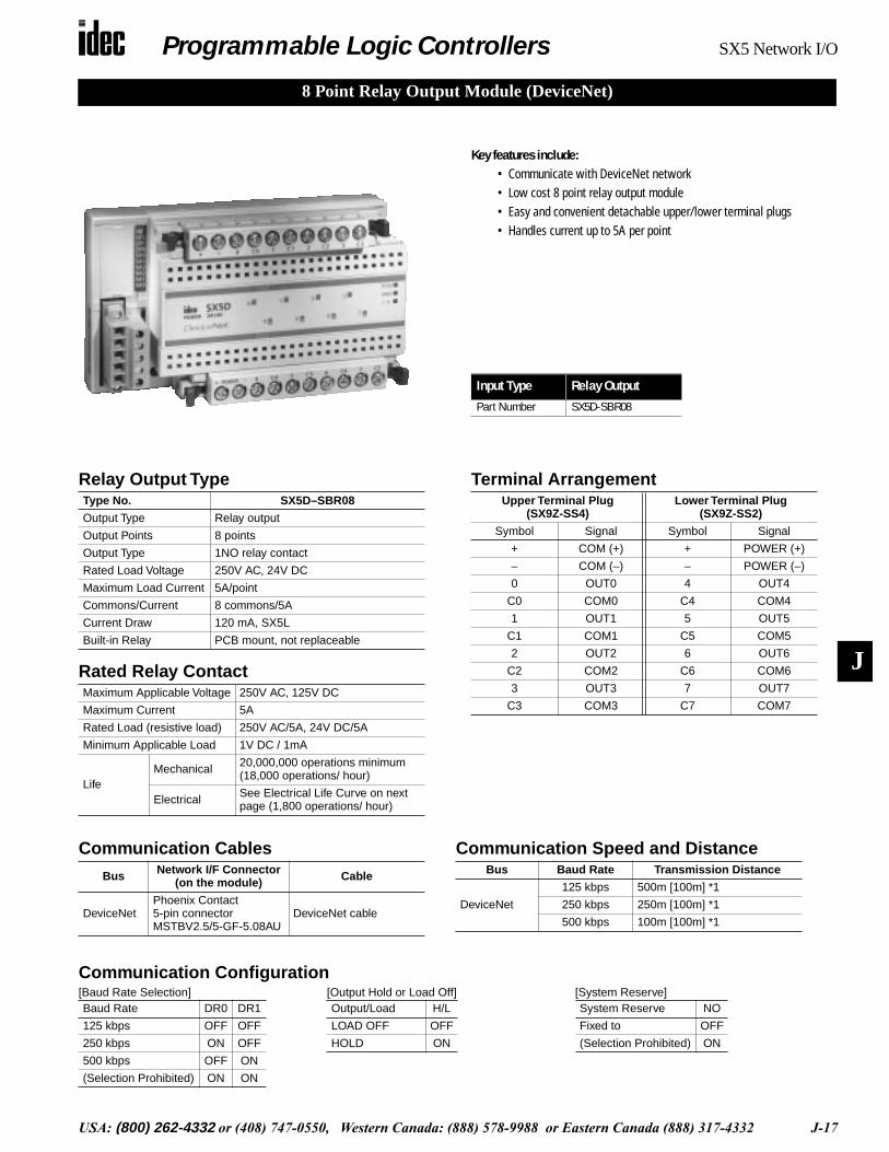
8 Point Relay Output Module (DeviceNet)
Input Type Relay Output
Part Number SX5D-SBR08
Key features include:• Communicate with DeviceNet network• Low cost 8 point relay output module• Easy and convenient detachable upper/lower terminal plugs • Handles current up to 5A per point
Terminal ArrangementUpper Terminal Plug
(SX9Z-SS4)Lower Terminal Plug
(SX9Z-SS2)
Symbol Signal Symbol Signal
+ COM (+) + POWER (+)
– COM (–) – POWER (–)
0 OUT0 4 OUT4
C0 COM0 C4 COM4
1 OUT1 5 OUT5
C1 COM1 C5 COM5
2 OUT2 6 OUT6
C2 COM2 C6 COM6
3 OUT3 7 OUT7
C3 COM3 C7 COM7
Communication Speed and DistanceBus Baud Rate Transmission Distance
DeviceNet
125 kbps 500m [100m] *1
250 kbps 250m [100m] *1
500 kbps 100m [100m] *1
Communication CablesBus Network I/F Connector
(on the module) Cable
DeviceNetPhoenix Contact5-pin connector MSTBV2.5/5-GF-5.08AU
DeviceNet cable
Communication Configuration[Baud Rate Selection] [Output Hold or Load Off] [System Reserve]Baud Rate DR0 DR1
125 kbps OFF OFF
250 kbps ON OFF
500 kbps OFF ON
(Selection Prohibited) ON ON
Output/Load H/L
LOAD OFF OFF
HOLD ON
System Reserve NO
Fixed to OFF
(Selection Prohibited) ON
Relay Output Type
Rated Relay Contact
Type No. SX5D–SBR08
Output Type Relay output
Output Points 8 points
Output Type 1NO relay contact
Rated Load Voltage 250V AC, 24V DC
Maximum Load Current 5A/point
Commons/Current 8 commons/5A
Current Draw 120 mA, SX5L
Built-in Relay PCB mount, not replaceable
Maximum Applicable Voltage 250V AC, 125V DC
Maximum Current 5A
Rated Load (resistive load) 250V AC/5A, 24V DC/5A
Minimum Applicable Load 1V DC / 1mA
LifeMechanical 20,000,000 operations minimum
(18,000 operations/ hour)
Electrical See Electrical Life Curve on next page (1,800 operations/ hour)
Programmable Logic Controllers SX5 Network I/O
J-18 USA: (800) 262-4332 or (408) 747-0550, Western Canada: (888) 578-9988 or Eastern Canada (888) 317-4332
J
Wiring DeviceNet Cable• DeviceNet requires two power voltages; one for communication and the
other for internal circuit and load.• Use a special DeviceNet cable for connecting to the DeviceNet network.• Connect the core wires of the cable to terminals identified by labels of
matching colors.• DeviceNet Cable
Cable Type No. Maker
Thick Cable 1485C-P1A50Rockwell Automation
Thin Cable 1485C-P1-C150
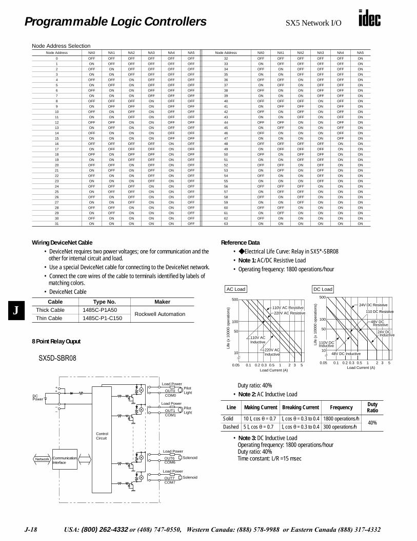
8 Point Relay Ouput
• SX5*-SBR08
Load PowerPilotLight
Load Power
Solenoid
PilotLight
Load Power
Load Power
Solenoid
++
Network
OUT1COM1
COM7OUT7
OUT0COM0
COM6OUT6
ControlCircuit
CommunicationInterface
DCPower
––
Reference Data• Electrical Life Curve: Relay in SX5*-SBR08• Note 1: AC/DC Resistive Load• Operating frequency: 1800 operations/hour
Duty ratio: 40%• Note 2: AC Inductive Load
• Note 3: DC Inductive LoadOperating frequency: 1800 operations/hourDuty ratio: 40%Time constant: L/R =15 msec
Line Making Current Breaking Current Frequency Duty Ratio
Solid 10 I, cos θ = 0.7 I, cos θ = 0.3 to 0.4 1800 operations/h40%
Dashed 5 I, cos θ = 0.7 I, cos θ = 0.3 to 0.4 300 operations/h
100
500
50
10
0.05 0.1 1 2 3 50.2 0.3 0.5
110V ACInductive
220V ACInductive
220V AC Resistive110V AC Resistive
AC Load
Life
(x
1000
0 op
erat
ions
)
Load Current (A)
100
500
50
10
0.05 0.1 1 2 3 50.2 0.3 0.5
110V DCInductive
24V DC Resistive
48V DC Resistive
24V DC Inductive
Load Current (A)
110 DC ResistiveLi
fe (
x 10
000
oper
atio
ns)
48V DC Inductive
DC Load
Node Address SelectionNode Address NA0 NA1 NA2 NA3 NA4 NA5 Node Address NA0 NA1 NA2 NA3 NA4 NA5
0 OFF OFF OFF OFF OFF OFF 32 OFF OFF OFF OFF OFF ON
1 ON OFF OFF OFF OFF OFF 33 ON OFF OFF OFF OFF ON
2 OFF ON OFF OFF OFF OFF 34 OFF ON OFF OFF OFF ON
3 ON ON OFF OFF OFF OFF 35 ON ON OFF OFF OFF ON
4 OFF OFF ON OFF OFF OFF 36 OFF OFF ON OFF OFF ON
5 ON OFF ON OFF OFF OFF 37 ON OFF ON OFF OFF ON
6 OFF ON ON OFF OFF OFF 38 OFF ON ON OFF OFF ON
7 ON ON ON OFF OFF OFF 39 ON ON ON OFF OFF ON
8 OFF OFF OFF ON OFF OFF 40 OFF OFF OFF ON OFF ON
9 ON OFF OFF ON OFF OFF 41 ON OFF OFF ON OFF ON
10 OFF ON OFF ON OFF OFF 42 OFF ON OFF ON OFF ON
11 ON ON OFF ON OFF OFF 43 ON ON OFF ON OFF ON
12 OFF OFF ON ON OFF OFF 44 OFF OFF ON ON OFF ON
13 ON OFF ON ON OFF OFF 45 ON OFF ON ON OFF ON
14 OFF ON ON ON OFF OFF 46 OFF ON ON ON OFF ON
15 ON ON ON ON OFF OFF 47 ON ON ON ON OFF ON
16 OFF OFF OFF OFF ON OFF 48 OFF OFF OFF OFF ON ON
17 ON OFF OFF OFF ON OFF 49 ON OFF OFF OFF ON ON
18 OFF ON OFF OFF ON OFF 50 OFF ON OFF OFF ON ON
19 ON ON OFF OFF ON OFF 51 ON ON OFF OFF ON ON
20 OFF OFF ON OFF ON OFF 52 OFF OFF ON OFF ON ON
21 ON OFF ON OFF ON OFF 53 ON OFF ON OFF ON ON
22 OFF ON ON OFF ON OFF 54 OFF ON ON OFF ON ON
23 ON ON ON OFF ON OFF 55 ON ON ON OFF ON ON
24 OFF OFF OFF ON ON OFF 56 OFF OFF OFF ON ON ON
25 ON OFF OFF ON ON OFF 57 ON OFF OFF ON ON ON
26 OFF ON OFF ON ON OFF 58 OFF ON OFF ON ON ON
27 ON ON OFF ON ON OFF 59 ON ON OFF ON ON ON
28 OFF OFF ON ON ON OFF 60 OFF OFF ON ON ON ON
29 ON OFF ON ON ON OFF 61 ON OFF ON ON ON ON
30 OFF ON ON ON ON OFF 62 OFF ON ON ON ON ON
31 ON ON ON ON ON OFF 63 ON ON ON ON ON ON
SX5D-SBR08
Programmable Logic Controllers SX5 Network I/O
USA: (800) 262-4332 or (408) 747-0550, Western Canada: (888) 578-9988 or Eastern Canada (888) 317-4332 J-19
J
Communication Speed and DistanceBus Baud Rate Transmission Distance
DeviceNet
125 kbps 500m [100m] *1
250 kbps 250m [100m] *1
500 kbps 100m [100m] *1
Communication CablesBus Network I/F Connector
(on the module) Cable
DeviceNetPhoenix Contact5-pin connector MSTBV2.5/5-GF-5.08AU
DeviceNet cable
Communication Configuration[Baud Rate Selection] [Output Hold or Load Off] [System Reserve]
Baud Rate DR0 DR1
125 kbps OFF OFF
250 kbps ON OFF
500 kbps OFF ON
(Selection Prohibited) ON ON
Output/Load H/L
LOAD OFF OFF
HOLD ON
System Reserve NO
Fixed to OFF
(Selection Prohibited) ON
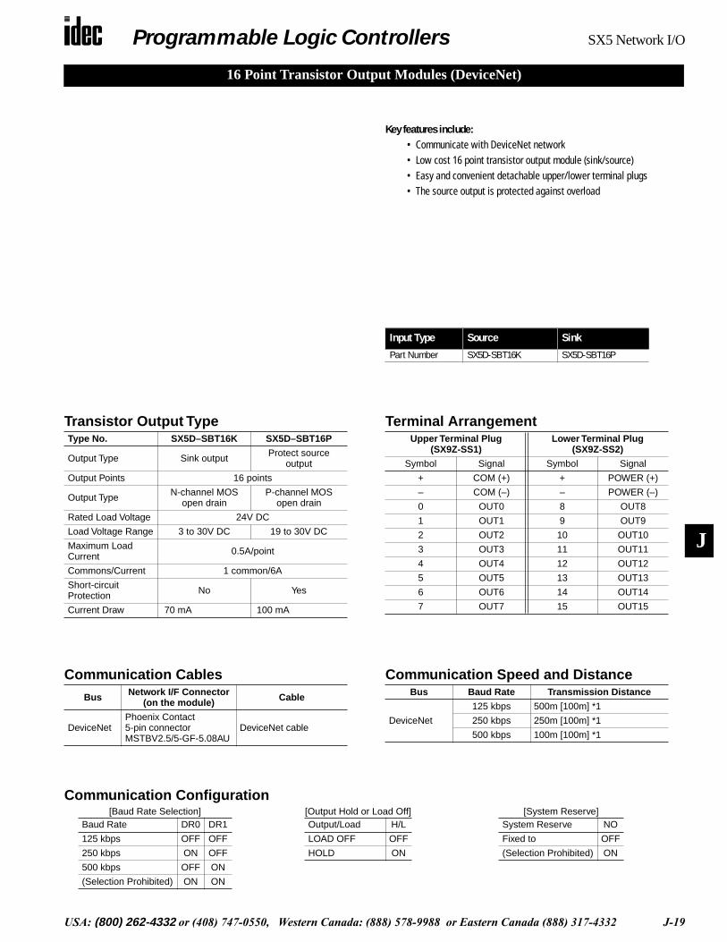
16 Point Transistor Output Modules (DeviceNet)
Key features include:• Communicate with DeviceNet network• Low cost 16 point transistor output module (sink/source)• Easy and convenient detachable upper/lower terminal plugs • The source output is protected against overload
Transistor Output TypeType No. SX5D–SBT16K SX5D–SBT16P
Output Type Sink output Protect source output
Output Points 16 points
Output Type N-channel MOS open drain
P-channel MOS open drain
Rated Load Voltage 24V DC
Load Voltage Range 3 to 30V DC 19 to 30V DC
Maximum Load Current 0.5A/point
Commons/Current 1 common/6A
Short-circuit Protection No Yes
Current Draw 70 mA 100 mA
Terminal ArrangementUpper Terminal Plug
(SX9Z-SS1)Lower Terminal Plug
(SX9Z-SS2)
Symbol Signal Symbol Signal
+ COM (+) + POWER (+)
– COM (–) – POWER (–)
0 OUT0 8 OUT8
1 OUT1 9 OUT9
2 OUT2 10 OUT10
3 OUT3 11 OUT11
4 OUT4 12 OUT12
5 OUT5 13 OUT13
6 OUT6 14 OUT14
7 OUT7 15 OUT15
Input Type Source Sink
Part Number SX5D-SBT16K SX5D-SBT16P
Programmable Logic Controllers SX5 Network I/O
J-20 USA: (800) 262-4332 or (408) 747-0550, Western Canada: (888) 578-9988 or Eastern Canada (888) 317-4332
J
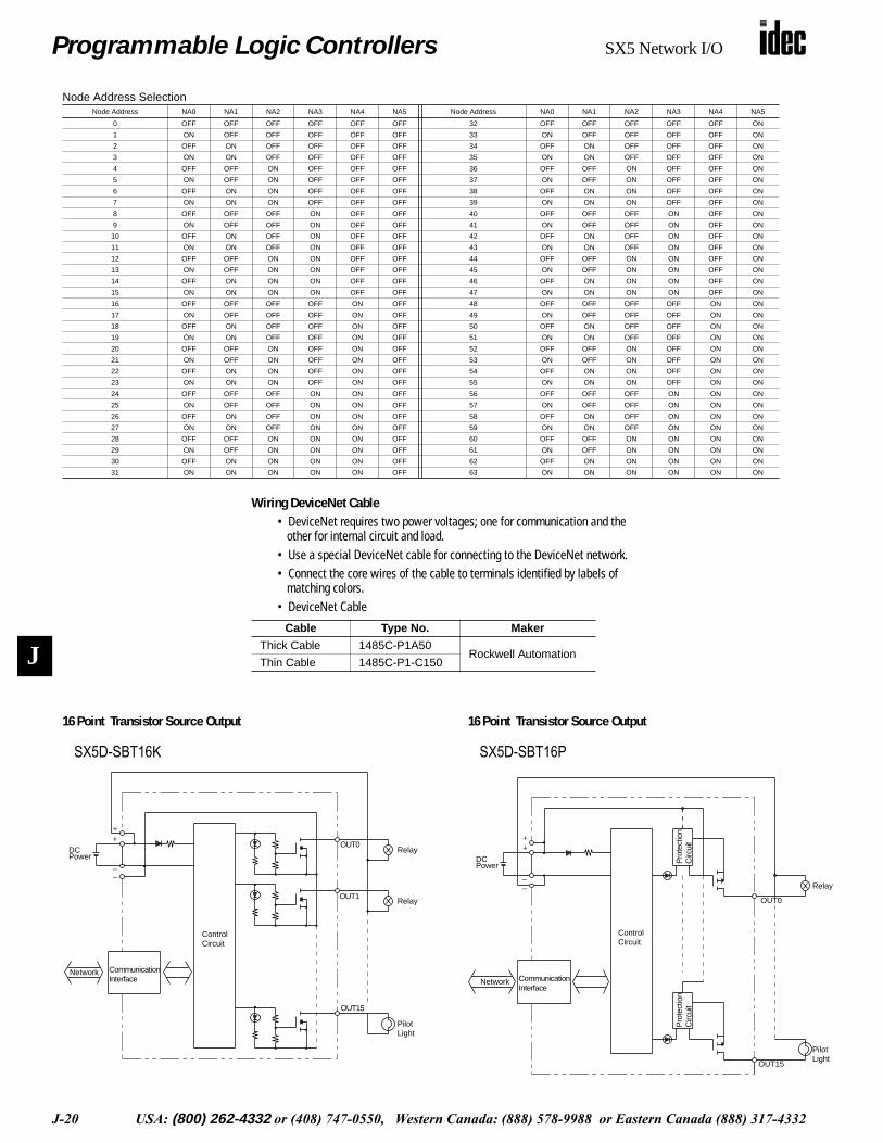
Wiring DeviceNet Cable• DeviceNet requires two power voltages; one for communication and the
other for internal circuit and load.• Use a special DeviceNet cable for connecting to the DeviceNet network.• Connect the core wires of the cable to terminals identified by labels of
matching colors.• DeviceNet Cable
Cable Type No. Maker
Thick Cable 1485C-P1A50Rockwell Automation
Thin Cable 1485C-P1-C150
16 Point Transistor Source Output
• SX5*-SBT16K
Relay
PilotLight
Relay
++
––
OUT0
OUT1
DCPower
ControlCircuit
CommunicationInterface
Network
OUT15
• SX5*-SBT16P
Relay
PilotLight
++
––
OUT15
ControlCircuit
Pro
tect
ion
Circ
uit
Pro
tect
ion
Circ
uit
DCPower
CommunicationInterface
Network
OUT0
Node Address SelectionNode Address NA0 NA1 NA2 NA3 NA4 NA5 Node Address NA0 NA1 NA2 NA3 NA4 NA5
0 OFF OFF OFF OFF OFF OFF 32 OFF OFF OFF OFF OFF ON
1 ON OFF OFF OFF OFF OFF 33 ON OFF OFF OFF OFF ON
2 OFF ON OFF OFF OFF OFF 34 OFF ON OFF OFF OFF ON
3 ON ON OFF OFF OFF OFF 35 ON ON OFF OFF OFF ON
4 OFF OFF ON OFF OFF OFF 36 OFF OFF ON OFF OFF ON
5 ON OFF ON OFF OFF OFF 37 ON OFF ON OFF OFF ON
6 OFF ON ON OFF OFF OFF 38 OFF ON ON OFF OFF ON
7 ON ON ON OFF OFF OFF 39 ON ON ON OFF OFF ON
8 OFF OFF OFF ON OFF OFF 40 OFF OFF OFF ON OFF ON
9 ON OFF OFF ON OFF OFF 41 ON OFF OFF ON OFF ON
10 OFF ON OFF ON OFF OFF 42 OFF ON OFF ON OFF ON
11 ON ON OFF ON OFF OFF 43 ON ON OFF ON OFF ON
12 OFF OFF ON ON OFF OFF 44 OFF OFF ON ON OFF ON
13 ON OFF ON ON OFF OFF 45 ON OFF ON ON OFF ON
14 OFF ON ON ON OFF OFF 46 OFF ON ON ON OFF ON
15 ON ON ON ON OFF OFF 47 ON ON ON ON OFF ON
16 OFF OFF OFF OFF ON OFF 48 OFF OFF OFF OFF ON ON
17 ON OFF OFF OFF ON OFF 49 ON OFF OFF OFF ON ON
18 OFF ON OFF OFF ON OFF 50 OFF ON OFF OFF ON ON
19 ON ON OFF OFF ON OFF 51 ON ON OFF OFF ON ON
20 OFF OFF ON OFF ON OFF 52 OFF OFF ON OFF ON ON
21 ON OFF ON OFF ON OFF 53 ON OFF ON OFF ON ON
22 OFF ON ON OFF ON OFF 54 OFF ON ON OFF ON ON
23 ON ON ON OFF ON OFF 55 ON ON ON OFF ON ON
24 OFF OFF OFF ON ON OFF 56 OFF OFF OFF ON ON ON
25 ON OFF OFF ON ON OFF 57 ON OFF OFF ON ON ON
26 OFF ON OFF ON ON OFF 58 OFF ON OFF ON ON ON
27 ON ON OFF ON ON OFF 59 ON ON OFF ON ON ON
28 OFF OFF ON ON ON OFF 60 OFF OFF ON ON ON ON
29 ON OFF ON ON ON OFF 61 ON OFF ON ON ON ON
30 OFF ON ON ON ON OFF 62 OFF ON ON ON ON ON
31 ON ON ON ON ON OFF 63 ON ON ON ON ON ON
16 Point Transistor Source Output
SX5D-SBT16K SX5D-SBT16P
Programmable Logic Controllers SX5 Network I/O
USA: (800) 262-4332 or (408) 747-0550, Western Canada: (888) 578-9988 or Eastern Canada (888) 317-4332 J-21
J
Communication Speed and DistanceBus Baud Rate Transmission Distance
DeviceNet
125 kbps 500m [100m] *1
250 kbps 250m [100m] *1
500 kbps 100m [100m] *1
Communication CablesBus Network I/F Connector
(on the module) Cable
DeviceNetPhoenix Contact5-pin connector MSTBV2.5/5-GF-5.08AU
DeviceNet cable
Communication Configuration[Baud Rate Selection] [Output Hold or Load Off] [System Reserve]
Baud Rate DR0 DR1
125 kbps OFF OFF
250 kbps ON OFF
500 kbps OFF ON
(Selection Prohibited) ON ON
Output/Load H/L
LOAD OFF OFF
HOLD ON
System Reserve NO
Fixed to OFF
(Selection Prohibited) ON
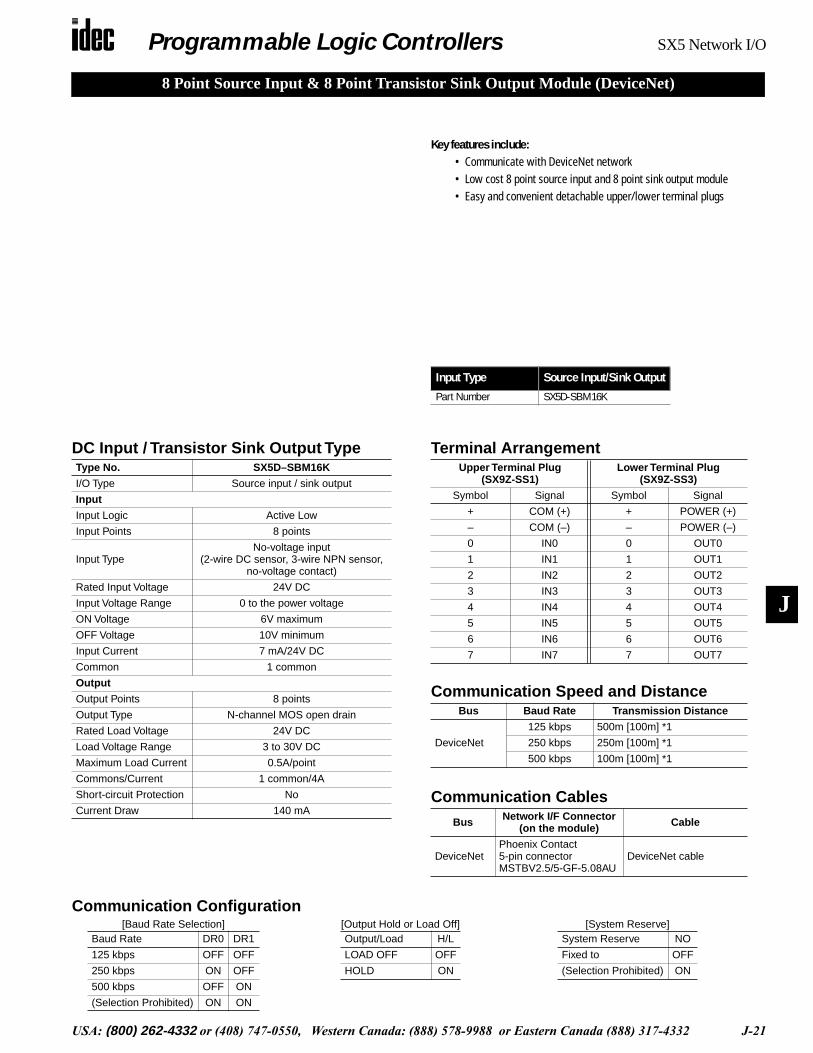
8 Point Source Input & 8 Point Transistor Sink Output Module (DeviceNet)
Key features include:• Communicate with DeviceNet network• Low cost 8 point source input and 8 point sink output module• Easy and convenient detachable upper/lower terminal plugs
Terminal ArrangementUpper Terminal Plug
(SX9Z-SS1)Lower Terminal Plug
(SX9Z-SS3)
Symbol Signal Symbol Signal
+ COM (+) + POWER (+)
– COM (–) – POWER (–)
0 IN0 0 OUT0
1 IN1 1 OUT1
2 IN2 2 OUT2
3 IN3 3 OUT3
4 IN4 4 OUT4
5 IN5 5 OUT5
6 IN6 6 OUT6
7 IN7 7 OUT7
DC Input / Transistor Sink Output TypeType No. SX5D–SBM16K
I/O Type Source input / sink output
Input
Input Logic Active Low
Input Points 8 points
Input TypeNo-voltage input
(2-wire DC sensor, 3-wire NPN sensor, no-voltage contact)
Rated Input Voltage 24V DC
Input Voltage Range 0 to the power voltage
ON Voltage 6V maximum
OFF Voltage 10V minimum
Input Current 7 mA/24V DC
Common 1 common
Output
Output Points 8 points
Output Type N-channel MOS open drain
Rated Load Voltage 24V DC
Load Voltage Range 3 to 30V DC
Maximum Load Current 0.5A/point
Commons/Current 1 common/4A
Short-circuit Protection No
Current Draw 140 mA
Input Type Source Input/Sink Output
Part Number SX5D-SBM16K

Programmable Logic Controllers SX5 Network I/O
J-22 USA: (800) 262-4332 or (408) 747-0550, Western Canada: (888) 578-9988 or Eastern Canada (888) 317-4332
J
Wiring DeviceNet Cable• DeviceNet requires two power voltages; one for communication and the
other for internal circuit and load.• Use a special DeviceNet cable for connecting to the DeviceNet network.• Connect the core wires of the cable to terminals identified by labels of
matching colors.• DeviceNet Cable
Cable Type No. Maker
Thick Cable 1485C-P1A50Rockwell Automation
Thin Cable 1485C-P1-C150
8 Point Source Input 8 Point Transistor Sink Output
• SX5*-SBN16S
DC Power
ContactSwitch
ContactSwitch
3.3 kΩ
3.3 kΩ
3.3 kΩ
3.3 kΩ
++
–Blue (White)
IN0Black (White)
Brown (Red)
Network
Brown (Black)IN1
Blue (Black)
IN14
IN15
ControlCircuit
DC3-wireSensorNPN
Output
DC2-wireSensor
CommunicationInterface
–
Node Address SelectionNode Address NA0 NA1 NA2 NA3 NA4 NA5 Node Address NA0 NA1 NA2 NA3 NA4 NA5
0 OFF OFF OFF OFF OFF OFF 32 OFF OFF OFF OFF OFF ON
1 ON OFF OFF OFF OFF OFF 33 ON OFF OFF OFF OFF ON
2 OFF ON OFF OFF OFF OFF 34 OFF ON OFF OFF OFF ON
3 ON ON OFF OFF OFF OFF 35 ON ON OFF OFF OFF ON
4 OFF OFF ON OFF OFF OFF 36 OFF OFF ON OFF OFF ON
5 ON OFF ON OFF OFF OFF 37 ON OFF ON OFF OFF ON
6 OFF ON ON OFF OFF OFF 38 OFF ON ON OFF OFF ON
7 ON ON ON OFF OFF OFF 39 ON ON ON OFF OFF ON
8 OFF OFF OFF ON OFF OFF 40 OFF OFF OFF ON OFF ON
9 ON OFF OFF ON OFF OFF 41 ON OFF OFF ON OFF ON
10 OFF ON OFF ON OFF OFF 42 OFF ON OFF ON OFF ON
11 ON ON OFF ON OFF OFF 43 ON ON OFF ON OFF ON
12 OFF OFF ON ON OFF OFF 44 OFF OFF ON ON OFF ON
13 ON OFF ON ON OFF OFF 45 ON OFF ON ON OFF ON
14 OFF ON ON ON OFF OFF 46 OFF ON ON ON OFF ON
15 ON ON ON ON OFF OFF 47 ON ON ON ON OFF ON
16 OFF OFF OFF OFF ON OFF 48 OFF OFF OFF OFF ON ON
17 ON OFF OFF OFF ON OFF 49 ON OFF OFF OFF ON ON
18 OFF ON OFF OFF ON OFF 50 OFF ON OFF OFF ON ON
19 ON ON OFF OFF ON OFF 51 ON ON OFF OFF ON ON
20 OFF OFF ON OFF ON OFF 52 OFF OFF ON OFF ON ON
21 ON OFF ON OFF ON OFF 53 ON OFF ON OFF ON ON
22 OFF ON ON OFF ON OFF 54 OFF ON ON OFF ON ON
23 ON ON ON OFF ON OFF 55 ON ON ON OFF ON ON
24 OFF OFF OFF ON ON OFF 56 OFF OFF OFF ON ON ON
25 ON OFF OFF ON ON OFF 57 ON OFF OFF ON ON ON
26 OFF ON OFF ON ON OFF 58 OFF ON OFF ON ON ON
27 ON ON OFF ON ON OFF 59 ON ON OFF ON ON ON
28 OFF OFF ON ON ON OFF 60 OFF OFF ON ON ON ON
29 ON OFF ON ON ON OFF 61 ON OFF ON ON ON ON
30 OFF ON ON ON ON OFF 62 OFF ON ON ON ON ON
31 ON ON ON ON ON OFF 63 ON ON ON ON ON ON
• SX5*-SBT16K
Relay
PilotLight
Relay
++
––
OUT0
OUT1
DCPower
ControlCircuit
CommunicationInterface
Network
OUT15
Programmable Logic Controllers SX5 Network I/O
USA: (800) 262-4332 or (408) 747-0550, Western Canada: (888) 578-9988 or Eastern Canada (888) 317-4332 J-23
J
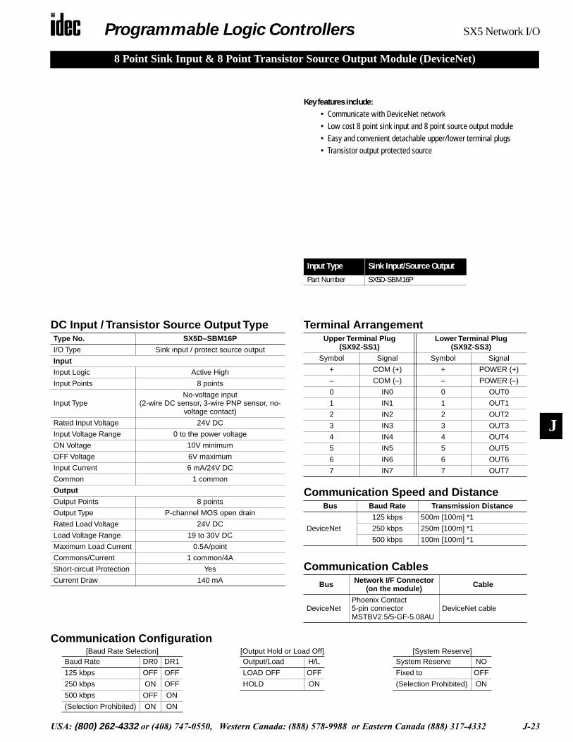
8 Point Sink Input & 8 Point Transistor Source Output Module (DeviceNet)
Key features include:• Communicate with DeviceNet network• Low cost 8 point sink input and 8 point source output module• Easy and convenient detachable upper/lower terminal plugs• Transistor output protected source
DC Input / Transistor Source Output TypeType No. SX5D–SBM16P
I/O Type Sink input / protect source output
Input
Input Logic Active High
Input Points 8 points
Input TypeNo-voltage input
(2-wire DC sensor, 3-wire PNP sensor, no-voltage contact)
Rated Input Voltage 24V DC
Input Voltage Range 0 to the power voltage
ON Voltage 10V minimum
OFF Voltage 6V maximum
Input Current 6 mA/24V DC
Common 1 common
Output
Output Points 8 points
Output Type P-channel MOS open drain
Rated Load Voltage 24V DC
Load Voltage Range 19 to 30V DC
Maximum Load Current 0.5A/point
Commons/Current 1 common/4A
Short-circuit Protection Yes
Current Draw 140 mA
Terminal ArrangementUpper Terminal Plug
(SX9Z-SS1)Lower Terminal Plug
(SX9Z-SS3)
Symbol Signal Symbol Signal
+ COM (+) + POWER (+)
– COM (–) – POWER (–)
0 IN0 0 OUT0
1 IN1 1 OUT1
2 IN2 2 OUT2
3 IN3 3 OUT3
4 IN4 4 OUT4
5 IN5 5 OUT5
6 IN6 6 OUT6
7 IN7 7 OUT7
Input Type Sink Input/Source Output
Part Number SX5D-SBM16P
Communication Speed and DistanceBus Baud Rate Transmission Distance
DeviceNet
125 kbps 500m [100m] *1
250 kbps 250m [100m] *1
500 kbps 100m [100m] *1
Communication CablesBus Network I/F Connector
(on the module) Cable
DeviceNetPhoenix Contact5-pin connector MSTBV2.5/5-GF-5.08AU
DeviceNet cable
Communication Configuration[Baud Rate Selection] [Output Hold or Load Off] [System Reserve]
Baud Rate DR0 DR1
125 kbps OFF OFF
250 kbps ON OFF
500 kbps OFF ON
(Selection Prohibited) ON ON
Output/Load H/L
LOAD OFF OFF
HOLD ON
System Reserve NO
Fixed to OFF
(Selection Prohibited) ON
Programmable Logic Controllers SX5 Network I/O
J-24 USA: (800) 262-4332 or (408) 747-0550, Western Canada: (888) 578-9988 or Eastern Canada (888) 317-4332
J
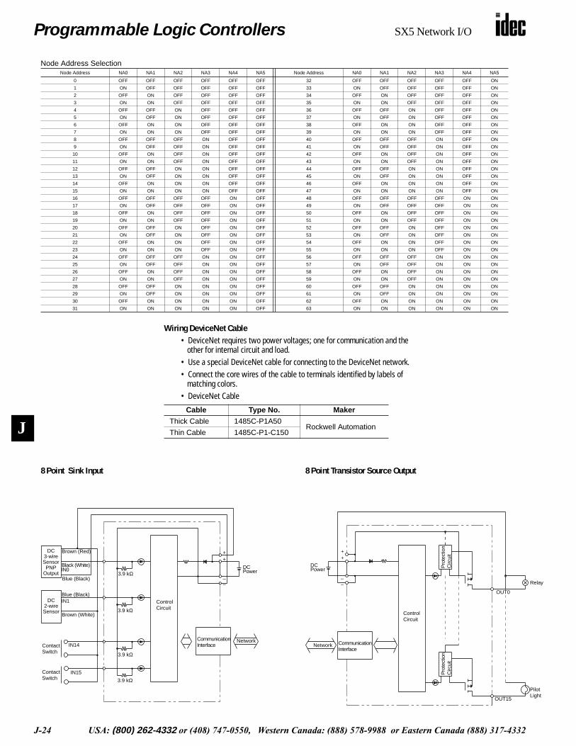
Wiring DeviceNet Cable• DeviceNet requires two power voltages; one for communication and the
other for internal circuit and load.• Use a special DeviceNet cable for connecting to the DeviceNet network.• Connect the core wires of the cable to terminals identified by labels of
matching colors.• DeviceNet Cable
Cable Type No. Maker
Thick Cable 1485C-P1A50Rockwell Automation
Thin Cable 1485C-P1-C150
Node Address SelectionNode Address NA0 NA1 NA2 NA3 NA4 NA5 Node Address NA0 NA1 NA2 NA3 NA4 NA5
0 OFF OFF OFF OFF OFF OFF 32 OFF OFF OFF OFF OFF ON
1 ON OFF OFF OFF OFF OFF 33 ON OFF OFF OFF OFF ON
2 OFF ON OFF OFF OFF OFF 34 OFF ON OFF OFF OFF ON
3 ON ON OFF OFF OFF OFF 35 ON ON OFF OFF OFF ON
4 OFF OFF ON OFF OFF OFF 36 OFF OFF ON OFF OFF ON
5 ON OFF ON OFF OFF OFF 37 ON OFF ON OFF OFF ON
6 OFF ON ON OFF OFF OFF 38 OFF ON ON OFF OFF ON
7 ON ON ON OFF OFF OFF 39 ON ON ON OFF OFF ON
8 OFF OFF OFF ON OFF OFF 40 OFF OFF OFF ON OFF ON
9 ON OFF OFF ON OFF OFF 41 ON OFF OFF ON OFF ON
10 OFF ON OFF ON OFF OFF 42 OFF ON OFF ON OFF ON
11 ON ON OFF ON OFF OFF 43 ON ON OFF ON OFF ON
12 OFF OFF ON ON OFF OFF 44 OFF OFF ON ON OFF ON
13 ON OFF ON ON OFF OFF 45 ON OFF ON ON OFF ON
14 OFF ON ON ON OFF OFF 46 OFF ON ON ON OFF ON
15 ON ON ON ON OFF OFF 47 ON ON ON ON OFF ON
16 OFF OFF OFF OFF ON OFF 48 OFF OFF OFF OFF ON ON
17 ON OFF OFF OFF ON OFF 49 ON OFF OFF OFF ON ON
18 OFF ON OFF OFF ON OFF 50 OFF ON OFF OFF ON ON
19 ON ON OFF OFF ON OFF 51 ON ON OFF OFF ON ON
20 OFF OFF ON OFF ON OFF 52 OFF OFF ON OFF ON ON
21 ON OFF ON OFF ON OFF 53 ON OFF ON OFF ON ON
22 OFF ON ON OFF ON OFF 54 OFF ON ON OFF ON ON
23 ON ON ON OFF ON OFF 55 ON ON ON OFF ON ON
24 OFF OFF OFF ON ON OFF 56 OFF OFF OFF ON ON ON
25 ON OFF OFF ON ON OFF 57 ON OFF OFF ON ON ON
26 OFF ON OFF ON ON OFF 58 OFF ON OFF ON ON ON
27 ON ON OFF ON ON OFF 59 ON ON OFF ON ON ON
28 OFF OFF ON ON ON OFF 60 OFF OFF ON ON ON ON
29 ON OFF ON ON ON OFF 61 ON OFF ON ON ON ON
30 OFF ON ON ON ON OFF 62 OFF ON ON ON ON ON
31 ON ON ON ON ON OFF 63 ON ON ON ON ON ON
8 Point Sink Input
• SX5*-SBN16K
3.9 kΩ
3.9 kΩ
3.9 kΩ
3.9 kΩ
ContactSwitch
ContactSwitch
++
––
Brown (Red)
Blue (Black)
IN0Black (White)
IN1
Brown (White)
Blue (Black)
IN15
IN14CommunicationInterface
ControlCircuit
DCPower
Network
DC3-wireSensorPNP
Output
DC2-wireSensor
8 Point Transistor Source Output
• SX5*-SBT16P
Relay
PilotLight
++
––
OUT15
ControlCircuit
Pro
tect
ion
Circ
uit
Pro
tect
ion
Circ
uit
DCPower
CommunicationInterface
Network
OUT0

Programmable Logic Controllers SX5 Network I/O
USA: (800) 262-4332 or (408) 747-0550, Western Canada: (888) 578-9988 or Eastern Canada (888) 317-4332 J-25
J
Input Type Source Sink
Part Number SX5L-SBN16S SX5L-SBN16K
Key features include:• Communicate with LonWorks network• Low cost 16 point transistor input module• Easy and convenient detachable upper/lower terminal plugs
DC Input TypeType No. SX5L–SBN16S SX5L–SBN16K
Input Type DC source input DC sink input
Input Logic Active low Active high
Input Points 16 points
Input Type
No-voltage input (2-wire DC sensor, 3-wire NPN sensor, no-voltage contact)
No-voltage input (2-wire DC sensor, 3-wire PNP sensor, no-voltage contact)
Rated Input Voltage 24V DC
Input Voltage Range 0 to the power voltage
Turn ON Voltage 6V maximum 10V minimum
Turn OFF Voltage 10V minimum 6V maximum
Input Current 7 mA/24V DC 6 mA/24V DC
Common 1 common
Current Draw 190 mA 170 mA
Communication Speed and DistanceBus Baud Rate Transmission Distance
LONWORKS 78 kbps 500m (total length) *2400m (between nodes)
Communication CablesBus Network I/F Connector
(on the module) Cable
LonWorksPhoenix Contact2-pin connectorMSTBV2.5/2-GF-5.08
Single twisted-pair cableAWG24 to 140.2 to 2.5 mm2
Terminal ArrangementUpper Terminal Plug
(SX9Z-SS1)Lower Terminal Plug
(SX9Z-SS2)
Symbol Signal Symbol Signal
+ COM (+) + POWER (+)
– COM (–) – POWER (–)
0 IN0 8 IN8
1 IN1 9 IN9
2 IN2 10 IN10
3 IN3 11 IN11
4 IN4 12 IN12
5 IN5 13 IN13
6 IN6 14 IN14
7 IN7 15 IN15
Communication ConfigurationAll SX5L Modules:
• The application program of the LonWorks is installed in the Neuron chip of the SX5L module.
• When wink is executed, the RUN LED flashes for 3 seconds in 500-msec increments.
• In the offline mode, the RUN and ERR LEDs go off and all outputs also go off.
SX5L-SBN16*:• Output network variables are updated only at the transition of the
input status.(When all inputs are off at power-up, network variables are not updated.)
• When nv_update_fails is TRUE(1) while using the data acknowl-edged service (ACKD), the ERR LED goes on.
• The ERR LED goes off when nv_update_succeeds is TRUE(1).(When an attempt to send network variables fails, resending does not occur until the input changes status.
continued
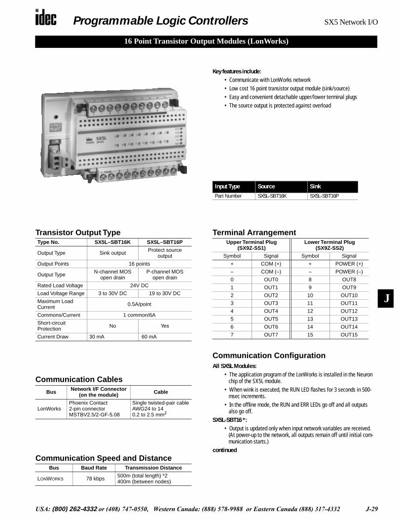
16 Point Transistor Input Modules (LonWorks)

Programmable Logic Controllers SX5 Network I/O
J-26 USA: (800) 262-4332 or (408) 747-0550, Western Canada: (888) 578-9988 or Eastern Canada (888) 317-4332
J
Communication Configuration Continued
SX5L-SBN16SSX5L-SBN16K
8
15
Input to SX5L
Output from SX5L
Input
Input0
7
Wiring L ONWORKS Cable• Turn power off before wiring the SX5L to the LonWorks network.
Make sure of correct wiring before turning power on. Supply power to each slave station or to each group of stations separately.
• The LONWORKS network uses a twisted-pair cable. The connector has no polarity and the core wires of the twisted-pair cable can be con-nected to either terminal of the connector.
• The LONWORKS network requires network management to enable communication between nodes, including the SX5L.
• The network management requires an XIF extension. For your XIF extension, find your XIF No., printed on the side of the SX5 module or on the shipping package. The network management is not completed successfully without the XIF extension.
• SX5*-SBN16S
DC Power
ContactSwitch
ContactSwitch
3.3 kΩ
3.3 kΩ
3.3 kΩ
3.3 kΩ
++
–Blue (White)
IN0Black (White)
Brown (Red)
Network
Brown (Black)IN1
Blue (Black)
IN14
IN15
ControlCircuit
DC3-wireSensorNPN
Output
DC2-wireSensor
CommunicationInterface
–
• SX5*-SBN16K
3.9 kΩ
3.9 kΩ
3.9 kΩ
3.9 kΩ
ContactSwitch
ContactSwitch
++
––
Brown (Red)
Blue (Black)
IN0Black (White)
IN1
Brown (White)
Blue (Black)
IN15
IN14CommunicationInterface
ControlCircuit
DCPower
Network
DC3-wireSensorPNP
Output
DC2-wireSensor
16 Point Source Input
16 Point Sink Input
SX5L-SBN16S
SX5L-SBN16K
Programmable Logic Controllers SX5 Network I/O
USA: (800) 262-4332 or (408) 747-0550, Western Canada: (888) 578-9988 or Eastern Canada (888) 317-4332 J-27
J
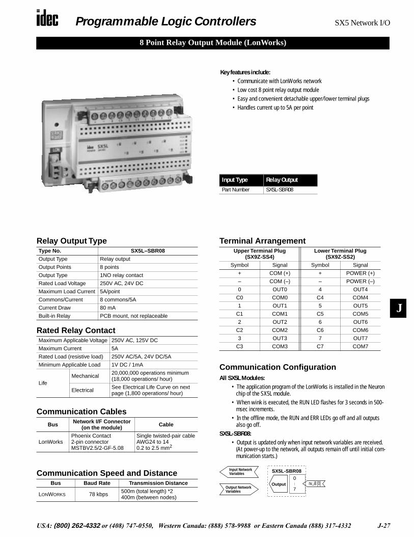
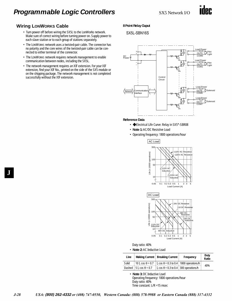
8 Point Relay Output Module (LonWorks)
Input Type Relay Output
Part Number SX5L-SBR08
Key features include:• Communicate with LonWorks network• Low cost 8 point relay output module• Easy and convenient detachable upper/lower terminal plugs• Handles current up to 5A per point
Relay Output Type
Rated Relay Contact
Type No. SX5L–SBR08
Output Type Relay output
Output Points 8 points
Output Type 1NO relay contact
Rated Load Voltage 250V AC, 24V DC
Maximum Load Current 5A/point
Commons/Current 8 commons/5A
Current Draw 80 mA
Built-in Relay PCB mount, not replaceable
Maximum Applicable Voltage 250V AC, 125V DC
Maximum Current 5A
Rated Load (resistive load) 250V AC/5A, 24V DC/5A
Minimum Applicable Load 1V DC / 1mA
LifeMechanical 20,000,000 operations minimum
(18,000 operations/ hour)
Electrical See Electrical Life Curve on next page (1,800 operations/ hour)
Terminal ArrangementUpper Terminal Plug
(SX9Z-SS4)Lower Terminal Plug
(SX9Z-SS2)
Symbol Signal Symbol Signal
+ COM (+) + POWER (+)
– COM (–) – POWER (–)
0 OUT0 4 OUT4
C0 COM0 C4 COM4
1 OUT1 5 OUT5
C1 COM1 C5 COM5
2 OUT2 6 OUT6
C2 COM2 C6 COM6
3 OUT3 7 OUT7
C3 COM3 C7 COM7
Communication Speed and DistanceBus Baud Rate Transmission Distance
LONWORKS 78 kbps 500m (total length) *2400m (between nodes)
Communication CablesBus Network I/F Connector
(on the module) Cable
LonWorksPhoenix Contact2-pin connectorMSTBV2.5/2-GF-5.08
Single twisted-pair cableAWG24 to 140.2 to 2.5 mm2
Communication ConfigurationAll SX5L Modules:
• The application program of the LonWorks is installed in the Neuron chip of the SX5L module.
• When wink is executed, the RUN LED flashes for 3 seconds in 500-msec increments.
• In the offline mode, the RUN and ERR LEDs go off and all outputs also go off.
SX5L-SBR08:• Output is updated only when input network variables are received.
(At power-up to the network, all outputs remain off until initial com-munication starts.)
SX5L-SBR08
Output nv_i8 [0]
Input Network
Output Network
0
7
Variables
Variables
Programmable Logic Controllers SX5 Network I/O
J-28 USA: (800) 262-4332 or (408) 747-0550, Western Canada: (888) 578-9988 or Eastern Canada (888) 317-4332
J
Wiring L ONWORKS Cable• Turn power off before wiring the SX5L to the LonWorks network.
Make sure of correct wiring before turning power on. Supply power to each slave station or to each group of stations separately.
• The LONWORKS network uses a twisted-pair cable. The connector has no polarity and the core wires of the twisted-pair cable can be con-nected to either terminal of the connector.
• The LONWORKS network requires network management to enable communication between nodes, including the SX5L.
• The network management requires an XIF extension. For your XIF extension, find your XIF No., printed on the side of the SX5 module or on the shipping package. The network management is not completed successfully without the XIF extension.
8 Point Relay Ouput
• SX5*-SBR08
Load PowerPilotLight
Load Power
Solenoid
PilotLight
Load Power
Load Power
Solenoid
++
Network
OUT1COM1
COM7OUT7
OUT0COM0
COM6OUT6
ControlCircuit
CommunicationInterface
DCPower
––
Reference Data• Electrical Life Curve: Relay in SX5*-SBR08• Note 1: AC/DC Resistive Load• Operating frequency: 1800 operations/hour
Duty ratio: 40%• Note 2: AC Inductive Load
• Note 3: DC Inductive LoadOperating frequency: 1800 operations/hourDuty ratio: 40%Time constant: L/R =15 msec
Line Making Current Breaking Current Frequency Duty Ratio
Solid 10 I, cos θ = 0.7 I, cos θ = 0.3 to 0.4 1800 operations/h40%
Dashed 5 I, cos θ = 0.7 I, cos θ = 0.3 to 0.4 300 operations/h
100
500
50
10
0.05 0.1 1 2 3 50.2 0.3 0.5
110V ACInductive
220V ACInductive
220V AC Resistive110V AC Resistive
AC Load
Life
(x
1000
0 op
erat
ions
)
Load Current (A)
100
500
50
10
0.05 0.1 1 2 3 50.2 0.3 0.5
110V DCInductive
24V DC Resistive
48V DC Resistive
24V DC Inductive
Load Current (A)
110 DC Resistive
Life
(x
1000
0 op
erat
ions
)
48V DC Inductive
DC Load
SX5L-SBN16S
Programmable Logic Controllers SX5 Network I/O
USA: (800) 262-4332 or (408) 747-0550, Western Canada: (888) 578-9988 or Eastern Canada (888) 317-4332 J-29
J
Key features include:• Communicate with LonWorks network• Low cost 16 point transistor output module (sink/source)• Easy and convenient detachable upper/lower terminal plugs• The source output is protected against overload
Transistor Output TypeType No. SX5L–SBT16K SX5L–SBT16P
Output Type Sink output Protect source output
Output Points 16 points
Output Type N-channel MOS open drain
P-channel MOS open drain
Rated Load Voltage 24V DC
Load Voltage Range 3 to 30V DC 19 to 30V DC
Maximum Load Current 0.5A/point
Commons/Current 1 common/6A
Short-circuit Protection No Yes
Current Draw 30 mA 60 mA
Terminal ArrangementUpper Terminal Plug
(SX9Z-SS1)Lower Terminal Plug
(SX9Z-SS2)
Symbol Signal Symbol Signal
+ COM (+) + POWER (+)
– COM (–) – POWER (–)
0 OUT0 8 OUT8
1 OUT1 9 OUT9
2 OUT2 10 OUT10
3 OUT3 11 OUT11
4 OUT4 12 OUT12
5 OUT5 13 OUT13
6 OUT6 14 OUT14
7 OUT7 15 OUT15
Input Type Source Sink
Part Number SX5L-SBT16K SX5L-SBT16P
16 Point Transistor Output Modules (LonWorks)
Communication Speed and DistanceBus Baud Rate Transmission Distance
LONWORKS 78 kbps 500m (total length) *2400m (between nodes)
Communication CablesBus Network I/F Connector
(on the module) Cable
LonWorksPhoenix Contact2-pin connectorMSTBV2.5/2-GF-5.08
Single twisted-pair cableAWG24 to 140.2 to 2.5 mm2
Communication ConfigurationAll SX5L Modules:
• The application program of the LonWorks is installed in the Neuron chip of the SX5L module.
• When wink is executed, the RUN LED flashes for 3 seconds in 500-msec increments.
• In the offline mode, the RUN and ERR LEDs go off and all outputs also go off.
SX5L-SBT16 *:• Output is updated only when input network variables are received.
(At power-up to the network, all outputs remain off until initial com-munication starts.)
continued
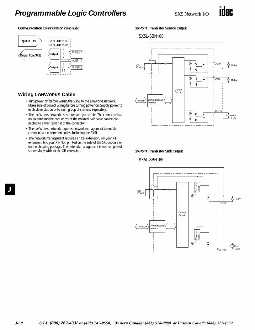
Programmable Logic Controllers SX5 Network I/O
J-30 USA: (800) 262-4332 or (408) 747-0550, Western Canada: (888) 578-9988 or Eastern Canada (888) 317-4332
J
Communication Configuration continued
Input to SX5L
Output from SX5L
SX5L-SBT16SSX5L-SBT16K
nv_i8 [0]
nv_i16
nv_i8 [1]Output
Output0
7
8
15
Wiring L ONWORKS Cable• Turn power off before wiring the SX5L to the LonWorks network.
Make sure of correct wiring before turning power on. Supply power to each slave station or to each group of stations separately.
• The LONWORKS network uses a twisted-pair cable. The connector has no polarity and the core wires of the twisted-pair cable can be con-nected to either terminal of the connector.
• The LONWORKS network requires network management to enable communication between nodes, including the SX5L.
• The network management requires an XIF extension. For your XIF extension, find your XIF No., printed on the side of the SX5 module or on the shipping package. The network management is not completed successfully without the XIF extension.
16 Point Transistor Source Output
• SX5*-SBT16K
Relay
PilotLight
Relay
++
––
OUT0
OUT1
DCPower
ControlCircuit
CommunicationInterface
Network
OUT15
• SX5*-SBT16P
Relay
PilotLight
++
––
OUT15
ControlCircuit
Pro
tect
ion
Circ
uit
Pro
tect
ion
Circ
uit
DCPower
CommunicationInterface
Network
OUT0
16 Point Transistor Sink Output
SX5L-SBN16S
SX5L-SBN16K
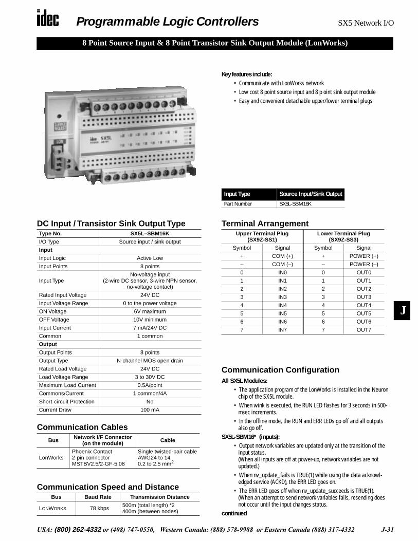
Programmable Logic Controllers SX5 Network I/O
USA: (800) 262-4332 or (408) 747-0550, Western Canada: (888) 578-9988 or Eastern Canada (888) 317-4332 J-31
J
8 Point Source Input & 8 Point Transistor Sink Output Module (LonWorks)
Key features include:• Communicate with LonWorks network• Low cost 8 point source input and 8 p oint sink output module • Easy and convenient detachable upper/lower terminal plugs
DC Input / Transistor Sink Output TypeType No. SX5L–SBM16K
I/O Type Source input / sink output
Input
Input Logic Active Low
Input Points 8 points
Input TypeNo-voltage input
(2-wire DC sensor, 3-wire NPN sensor, no-voltage contact)
Rated Input Voltage 24V DC
Input Voltage Range 0 to the power voltage
ON Voltage 6V maximum
OFF Voltage 10V minimum
Input Current 7 mA/24V DC
Common 1 common
Output
Output Points 8 points
Output Type N-channel MOS open drain
Rated Load Voltage 24V DC
Load Voltage Range 3 to 30V DC
Maximum Load Current 0.5A/point
Commons/Current 1 common/4A
Short-circuit Protection No
Current Draw 100 mA
Terminal ArrangementUpper Terminal Plug
(SX9Z-SS1)Lower Terminal Plug
(SX9Z-SS3)
Symbol Signal Symbol Signal
+ COM (+) + POWER (+)
– COM (–) – POWER (–)
0 IN0 0 OUT0
1 IN1 1 OUT1
2 IN2 2 OUT2
3 IN3 3 OUT3
4 IN4 4 OUT4
5 IN5 5 OUT5
6 IN6 6 OUT6
7 IN7 7 OUT7
Input Type Source Input/Sink Output
Part Number SX5L-SBM16K
Communication Speed and DistanceBus Baud Rate Transmission Distance
LONWORKS 78 kbps 500m (total length) *2400m (between nodes)
Communication CablesBus Network I/F Connector
(on the module) Cable
LonWorksPhoenix Contact2-pin connectorMSTBV2.5/2-GF-5.08
Single twisted-pair cableAWG24 to 140.2 to 2.5 mm2
Communication ConfigurationAll SX5L Modules:
• The application program of the LonWorks is installed in the Neuron chip of the SX5L module.
• When wink is executed, the RUN LED flashes for 3 seconds in 500-msec increments.
• In the offline mode, the RUN and ERR LEDs go off and all outputs also go off.
SX5L-SBM16* (inputs):• Output network variables are updated only at the transition of the
input status.(When all inputs are off at power-up, network variables are not updated.)
• When nv_update_fails is TRUE(1) while using the data acknowl-edged service (ACKD), the ERR LED goes on.
• The ERR LED goes off when nv_update_succeeds is TRUE(1).(When an attempt to send network variables fails, resending does not occur until the input changes status.
continued

Programmable Logic Controllers SX5 Network I/O
J-32 USA: (800) 262-4332 or (408) 747-0550, Western Canada: (888) 578-9988 or Eastern Canada (888) 317-4332
J
8 Point Source Input
• SX5*-SBN16S
DC Power
ContactSwitch
ContactSwitch
3.3 kΩ
3.3 kΩ
3.3 kΩ
3.3 kΩ
++
–Blue (White)
IN0Black (White)
Brown (Red)
Network
Brown (Black)IN1
Blue (Black)
IN14
IN15
ControlCircuit
DC3-wireSensorNPN
Output
DC2-wireSensor
CommunicationInterface
–
8 Point Transistor Sink Output
• SX5*-SBT16K
Relay
PilotLight
Relay
++
––
OUT0
OUT1
DCPower
ControlCircuit
CommunicationInterface
Network
OUT15
Communication Configuration ContinuedSX5L-SBM16* (outputs):
• Output is updated only when input network variables are received.(At power-up to the network, all outputs remain off until initial commu-nication starts.)
SX5L-SBM16KSX5L-SBM16P
Output
Input
Input Network
Output Network 0
7
0
7
nv_o8 [0]
nv_i8 [0]
Variables
Variables
Wiring L ONWORKS Cable• Turn power off before wiring the SX5L to the LonWorks network.
Make sure of correct wiring before turning power on. Supply power to each slave station or to each group of stations separately.
• The LONWORKS network uses a twisted-pair cable. The connector has no polarity and the core wires of the twisted-pair cable can be con-nected to either terminal of the connector.
• The LONWORKS network requires network management to enable communication between nodes, including the SX5L.
• The network management requires an XIF extension. For your XIF extension, find your XIF No., printed on the side of the SX5 module or on the shipping package. The network management is not completed successfully without the XIF extension.

Programmable Logic Controllers SX5 Network I/O
USA: (800) 262-4332 or (408) 747-0550, Western Canada: (888) 578-9988 or Eastern Canada (888) 317-4332 J-33
J
Communication Speed and DistanceBus Baud Rate Transmission Distance
LONWORKS 78 kbps 500m (total length) *2400m (between nodes)
Communication CablesBus Network I/F Connector
(on the module) Cable
LonWorksPhoenix Contact2-pin connectorMSTBV2.5/2-GF-5.08
Single twisted-pair cableAWG24 to 140.2 to 2.5 mm2
Communication ConfigurationAll SX5L Modules:
• The application program of the LonWorks is installed in the Neuron chip of the SX5L module.
• When wink is executed, the RUN LED flashes for 3 seconds in 500-msec increments.
• In the offline mode, the RUN and ERR LEDs go off and all outputs also go off.
SX5L-SBM16* (inputs):• Output network variables are updated only at the transition of the
input status.(When all inputs are off at power-up, network variables are not updated.)
• When nv_update_fails is TRUE(1) while using the data acknowl-edged service (ACKD), the ERR LED goes on.
• The ERR LED goes off when nv_update_succeeds is TRUE(1).(When an attempt to send network variables fails, resending does not occur until the input changes status.
continued
Key features include:• Communicate with LonWorks network• Low cost 8 point sink input and 8 p oint source output module • Easy and convenient detachable upper/lower terminal plugs
DC Input / Transistor Source Output TypeType No. SX5L–SBM16P
I/O Type Sink input / protect source output
Input
Input Logic Active High
Input Points 8 points
Input TypeNo-voltage input
(2-wire DC sensor, 3-wire PNP sensor, no-voltage contact)
Rated Input Voltage 24V DC
Input Voltage Range o to the power voltage
ON Voltage 10V minimum
OFF Voltage 6V maximum
Input Current 6 mA/24V DC
Common 1 common
Output
Output Points 8 points
Output Type P-channel MOS open drain
Rated Load Voltage 24V DC
Load Voltage Range 19 to 30V DC
Maximum Load Current 0.5A/point
Commons/Current 1 common/4A
Short-circuit Protection Yes
Current Draw 100 mA
Terminal ArrangementUpper Terminal Plug
(SX9Z-SS1)Lower Terminal Plug
(SX9Z-SS3)
Symbol Signal Symbol Signal
+ COM (+) + POWER (+)
– COM (–) – POWER (–)
0 IN0 0 OUT0
1 IN1 1 OUT1
2 IN2 2 OUT2
3 IN3 3 OUT3
4 IN4 4 OUT4
5 IN5 5 OUT5
6 IN6 6 OUT6
7 IN7 7 OUT7
Input Type Sink Input/Source Output
Part Number SX5L-SBM16P
8 Point Sink Input & 8 Point Transistor Source Output Module (LonWorks)
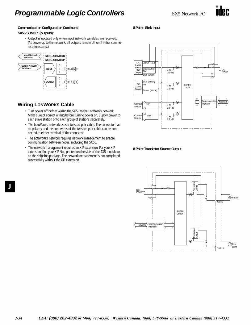
Programmable Logic Controllers SX5 Network I/O
J-34 USA: (800) 262-4332 or (408) 747-0550, Western Canada: (888) 578-9988 or Eastern Canada (888) 317-4332
J
8 Point Sink Input
8 Point Transistor Source Output
• SX5*-SBN16K
3.9 kΩ
3.9 kΩ
3.9 kΩ
3.9 kΩ
ContactSwitch
ContactSwitch
++
––
Brown (Red)
Blue (Black)
IN0Black (White)
IN1
Brown (White)
Blue (Black)
IN15
IN14CommunicationInterface
ControlCircuit
DCPower
Network
DC3-wireSensorPNP
Output
DC2-wireSensor
• SX5*-SBT16P
Relay
PilotLight
++
––
OUT15
ControlCircuit
Pro
tect
ion
Circ
uit
Pro
tect
ion
Circ
uit
DCPower
CommunicationInterface
Network
OUT0
Communication Configuration ContinuedSX5L-SBM16* (outputs):
• Output is updated only when input network variables are received.(At power-up to the network, all outputs remain off until initial commu-nication starts.)
SX5L-SBM16KSX5L-SBM16P
Output
Input
Input Network
Output Network 0
7
0
7
nv_o8 [0]
nv_i8 [0]
Variables
Variables
Wiring L ONWORKS Cable• Turn power off before wiring the SX5L to the LonWorks network.
Make sure of correct wiring before turning power on. Supply power to each slave station or to each group of stations separately.
• The LONWORKS network uses a twisted-pair cable. The connector has no polarity and the core wires of the twisted-pair cable can be con-nected to either terminal of the connector.
• The LONWORKS network requires network management to enable communication between nodes, including the SX5L.
• The network management requires an XIF extension. For your XIF extension, find your XIF No., printed on the side of the SX5 module or on the shipping package. The network management is not completed successfully without the XIF extension.