programmable logic controllers - · pdf fileto convert from binary into octal, the binary...
TRANSCRIPT

Programmable Logic ControllersUniversite Grenoble Alpes
Francesco [email protected]
PhITEM & Gipsa Lab.

Outline
1 Introduction
2 Structure of a PLC and Principle of Operation
3 Number Systems
4 Logic Functions
5 Input-output devices
Presentation of the InstructorFrancesco FerranteMaitre de Conferences at Universite Grenoble Alpes
• 2010, BSc Control Engineering and Automation, Universityof Rome
• 2012, MSc Control Systems Engineering, University ofRome
• 2015, PhD Control Theory, French National AerospaceSchool in Toulouse
• November 2015–August 2016, Research Scholar, ClemsonUniversity, South Carolina, USA
• September 2016–September 2017, Research Scholar,University of California, California, USA
website: http:www.fferrante.netResearch Interests: Hybrid systems, nonlinear systems, andobserver design
1/28

Outline
1 Introduction
2 Structure of a PLC and Principle of Operation
3 Number Systems
4 Logic Functions
5 Input-output devices

Introduction
PLCA programmable logic controller (PLC) is an industrial digital computerwhich has been ruggedised and adapted for the control of manufacturingprocesses.
They are capable of:
• storing instructions, suchas sequencing, timing,counting, arithmetic
• manipulating data
• communicating overnetworks
• controlling industrialmachines and processes.
2/28

Application Areas• Since its invention, the PLC has been successfully applied
in many industrial fields• PLCs perform a great variety of control tasks, from
repetitive ON/OFF control of simple machines tosophisticated manufacturing and process control.
1. lower the drill when the workpieceis in position
2. drill when the drill reaches theworkpiece
3. stop drilling when the drill hasproduced the required depth ofhole
4. retract the drill and then switchoff
5. repeat

Historical Background
• The Hydramatic Division of the General MotorsCorporation specified the design criteria for the firstprogrammable controller in 1968.
• Their primary goal was to eliminate costly and rigidrelay-control systems. The objective was to conceive asolid-state system with computer flexibility able to:
1. survive in an industrial environment,2. be easily programmed and maintained by plant technicians,3. be reusable
“The initial machine,which was neverdelivered, only had 125words of memory, andspeed was not a criteriaas mentioned earlier...Youcan imagine whathappened! First, weimmediately ran out ofmemory, and second, themachine was much tooslow to perform anyfunction anywhere nearthe relay response time..”
Dick Morley: the father of thePLC–
4/28

Outline
1 Introduction
2 Structure of a PLC and Principle of Operation
3 Number Systems
4 Logic Functions
5 Input-output devices
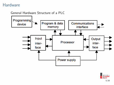
Hardware
General Hardware Structure of a PLC
5/28
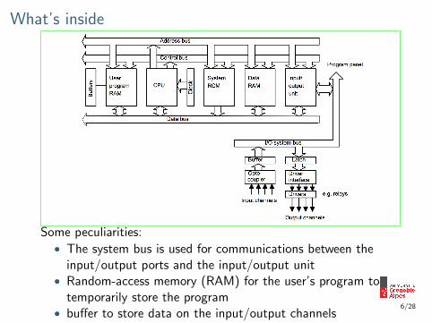
What’s inside
Some peculiarities:• The system bus is used for communications between the
input/output ports and the input/output unit• Random-access memory (RAM) for the user’s program to
temporarily store the program• buffer to store data on the input/output channels
6/28

Input/Output Unit• The input/output unit provides the interface between the
system and the outside world• It is also through the input/output unit that programs are
entered from a program panel• Every input/output point has a unique address which can
be used by the CPU.
The input/output channels provide isolation and signalconditioning functions. This allows sensors and actuators to bedirectly connected to the PLC.
Optoisolator input interface output interface
7/28

Mechanical DesignThere are two common types of mechanical design for PLCsystems: single box and modular/rack types
The single box type(brick) is supplied as acompact packagecomplete with powersupply, processor,memory, andinput/output units.
The modular typeconsists of separatemodules often mountedon rails within a metalcabinet. Thus it iscomparatively easy toexpand.
8/28

Principle of OperationThe operation of a programmable controller is relatively simple.During its operation, the CPU completes three processes:
1. it reads, or accepts, the input data from the field devicesvia the input interfaces,
2. it executes, or performs, the control program stored in thememory system
3. it writes, or updates, the output devices via the outputinterfaces.
This process of sequentially reading the inputs, executing theprogram in memory, and updating the outputs is known asscanning
9/28

Ladder Diagram• The ladder diagram is a traditional way of representing
electrical sequences of operations.• These diagrams represent the interconnection of field
devices in such a way that the activation, of one device willturn ON another device according to a predeterminedsequence of events.
10/28
Outline
1 Introduction
2 Structure of a PLC and Principle of Operation
3 Number Systems
4 Logic Functions
5 Input-output devices

Number systems• The number system used for everyday calculations is the
denary or decimal system.• This is based on the use of the 10 digits:
0, 1, 2, 3, 4, 5, 6, 7, 8, 9.• With a number represented by this system, the digit
position in the number indicates the weight attached toeach digit, the weight increasing by a factor of 10 as weproceed from right to left.
Counting can, however, be done to any base.• Computers, and hence PLC systems, are based on counting
in twos because it is convenient for their system, their twodigits being effectively just the off and on signals
• When working with PLCs, other base number systems arealso used, e.g. input and output addresses are oftenspecified using the octal system, i.e. base 8.
11/28

Binary SystemThe binary system is based on just two digits: 0 and 1. Theseare termed binary digits or bits. When a number is representedby this system, the digit position in the number indicates theweight of each digit. The weight increases by a factor of 2 as wemove from right to left.
. . . 23 22 21 20
. . . bit 3 bit 2 bit 1 bit 0binary 1000 100 10 1
The bit 0 is termed the least significant bit (LSB) and thehighest bit the most significant bit (MSB).
10102 → 1 · 23 + 0 · 22 + 1 · 21 + 0 · 20 = 1010
The conversion of a denary number to a binary number involveslooking for the appropriate powers of 2. This can be done viasuccessive divisions by 2, keeping track of the remainders ateach division.
12/28

Binary SystemThe binary system is based on just two digits: 0 and 1. Theseare termed binary digits or bits. When a number is representedby this system, the digit position in the number indicates theweight of each digit. The weight increases by a factor of 2 as wemove from right to left.
. . . 23 22 21 20
. . . bit 3 bit 2 bit 1 bit 0binary 1000 100 10 1
The bit 0 is termed the least significant bit (LSB) and thehighest bit the most significant bit (MSB).
10102 → 1 · 23 + 0 · 22 + 1 · 21 + 0 · 20 = 1010
The conversion of a denary number to a binary number involveslooking for the appropriate powers of 2. This can be done viasuccessive divisions by 2, keeping track of the remainders ateach division.
For example, with 3110:
31/2 = 15 remainder 1 This gives the LSB15/2 = 7 remainder 17/2 = 3 remainder 13/2 = 1 remainder 1 This gives the MSB
3110 → 111112 12/28

Octal SystemThe octal system is based on eight digits: 0, 1, 2, 3, 4, 5, 6, 7.When a number is represented by this system, the digit positionin the number indicates the weight of each digit, the weightincreases by a factor of 8 as we move from right to left.
. . . 83 82 81 80
binary 1000 100 10 1
• To convert denary numbers to octal, one successivelydivides by 8 and note the remainders.Thus, the denary number 15 divided by 8 gives 1 withremainder 7. Hence, the denary number 15 is 17 in theoctal system.
• To convert from binary into octal, the binary number iswritten in groups of three bits starting with the leastsignificant bit. Then, each group is replaced by thecorresponding digit 0 to 7.
13/28

Octal SystemThe octal system is based on eight digits: 0, 1, 2, 3, 4, 5, 6, 7.When a number is represented by this system, the digit positionin the number indicates the weight of each digit, the weightincreases by a factor of 8 as we move from right to left.
. . . 83 82 81 80
binary 1000 100 10 1
• To convert denary numbers to octal, one successivelydivides by 8 and note the remainders.Thus, the denary number 15 divided by 8 gives 1 withremainder 7. Hence, the denary number 15 is 17 in theoctal system.
• To convert from binary into octal, the binary number iswritten in groups of three bits starting with the leastsignificant bit. Then, each group is replaced by thecorresponding digit 0 to 7.
For example, 1001110102
binary 100 111 010octal 4 7 2
13/28

Hexadecimal systemThe hexadecimal system (hex) is based on 16 digits/symbols:0, 1, 2, 3, 4, 5, 6, 7, 8, 9,A,B,C ,D,E ,F . When a number isrepresented by this system, the digit position in the numberindicates that the weight of each digit increases by a factor of 16as we move from right to left.
. . . 163 162 161 160
hex 1000 100 10 1
• For example, 1510 → F16. To convert from denary numbersinto hex, one successively divides by 16 and keeps track ofthe remainders. Thus the denary number 156 when dividedby 16 gives 9 with remainder 12, that this 15610 → 9C16.
• To convert binary numbers into hexadecimal numbers, wegroup the binary numbers into fours starting from the leastsignificant number and associate the corresponding hexdigit at each group.
14/28

Hexadecimal systemThe hexadecimal system (hex) is based on 16 digits/symbols:0, 1, 2, 3, 4, 5, 6, 7, 8, 9,A,B,C ,D,E ,F . When a number isrepresented by this system, the digit position in the numberindicates that the weight of each digit increases by a factor of 16as we move from right to left.
. . . 163 162 161 160
hex 1000 100 10 1
• For example, 1510 → F16. To convert from denary numbersinto hex, one successively divides by 16 and keeps track ofthe remainders. Thus the denary number 156 when dividedby 16 gives 9 with remainder 12, that this 15610 → 9C16.
• To convert binary numbers into hexadecimal numbers, wegroup the binary numbers into fours starting from the leastsignificant number and associate the corresponding hexdigit at each group.
For example, 11101001102
binary 11 1010 0110hex 3 A 6
14/28

Binary Coded Decimal system BCDHumans work with the denarysystem while computer with thebinary system. However, it isnot easy to connect the positionof digits in a denary numberwith the one in a binarynumber.
An alternative method that is often used is the binary codeddecimal system (BCD). With this system, each denary digit iscoded separately in binary.
• For example, for the denary number 15: 5→ 0101 and the1→ 0001
denary 1 5bcd 0001 0101
15/28

Outline
1 Introduction
2 Structure of a PLC and Principle of Operation
3 Number Systems
4 Logic Functions
5 Input-output devices

Logic FunctionsThe binary concept refers to the idea that many things existonly in two predetermined states. For instance:• a light can be on or off,• a switch open or closed,• or a motor running or stopped...
This two-state concept can be the basis for making decisionscan be directly related to the binary number system. Hence, it isa fundamental building block for programmable controllers anddigital computers.
Positive Logic1 represents the more positivevoltage
Negative Logic0 represents the more positivevoltage
16/28

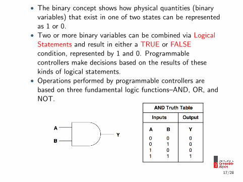
• The binary concept shows how physical quantities (binaryvariables) that exist in one of two states can be representedas 1 or 0.
• Two or more binary variables can be combined via LogicalStatements and result in either a TRUE or FALSEcondition, represented by 1 and 0. Programmablecontrollers make decisions based on the results of thesekinds of logical statements.
• Operations performed by programmable controllers arebased on three fundamental logic functions–AND, OR, andNOT.
17/28

18/28

18/28

A Cool Example
Show the logic gate, truthtable, and circuit representationfor a solenoid valve (V 1) thatwill be open (ON) if selectorswitch S1 is ON and if levelswitch L1 is NOT ON (liquidhas not reached level).
19/28

A Cool Example
Show the logic gate, truthtable, and circuit representationfor a solenoid valve (V 1) thatwill be open (ON) if selectorswitch S1 is ON and if levelswitch L1 is NOT ON (liquidhas not reached level).
Solution:
19/28

A Cool Example
Show the logic gate, truthtable, and circuit representationfor a solenoid valve (V 1) thatwill be open (ON) if selectorswitch S1 is ON and if levelswitch L1 is NOT ON (liquidhas not reached level).
Solution:
19/28

A Cool ExampleShow the logic gate, truthtable, and circuit representationfor a solenoid valve (V 1) thatwill be open (ON) if selectorswitch S1 is ON and if levelswitch L1 is NOT ON (liquidhas not reached level).
Solution:
19/28

Boolean AlgebraMastering Boolean techniques can be useful when programminga PLC
In 1849, George Booledeveloped Booleanalgebra. The purpose ofthis algebra was to aid inthe logic of reasoning, anancient form ofphilosophy.
George Boole, 1815-1864
When digital logic was developed in the 1960s, Boolean algebraproved to be a simple way to analyze and express digital logicstatements, since all digital systems use a two-valued logicconcept.
20/28

The all thing is based on the following elementary logic operators
And on the following rules
To ensure proper order of evaluation of an expression, use paren-theses as grouping signs. If additional signs are required brackets[ ], and then braces { } are used.

The all thing is based on the following elementary logic operators
And on the following rules
To ensure proper order of evaluation of an expression, use paren-theses as grouping signs. If additional signs are required brackets[ ], and then braces { } are used.

Outline
1 Introduction
2 Structure of a PLC and Principle of Operation
3 Number Systems
4 Logic Functions
5 Input-output devices

Input devices
• The term sensor is used for an input device that provides ausable output in response to a specified physical input.
• For example, a thermocouple is a sensor which converts atemperature difference into an electrical output.
• The term transducer is generally used for a device thatconverts a signal from one form to a different physical form.
22/28

Characteristics of a Sensor• accuracy: agreement of measured values with a given
reference• repeatability: capability of reproducing as output similar
measured values for different measurements of the samequantity
• stability: for a given input you always get the same output
Credit to Prof. Alessandro De Luca
• range: the limits between which the measured input canvary.
• resolution: minimal change of the input necessary toproduce a detectable change at the output
23/28

• A sensing system needs to be calibrated via a knownmeasurand.
• The relationship between the measured variable (x) and thesensor output (y) is called a calibration curve
Some important characteristics can be defined out of thecalibration curve:• sensitivity: the slope of the calibration curve• linearity: the closeness of the calibration curve to the linear
curve obtained by considering the extrema of the consideredmeasured variable
• hysteresis: the difference between output readings for thesame measurand, depending on the trajectory followed bythe sensor
24/28

Sensors are considered static but actually have their owndynamics!For example: The behavior of a thermocouple can be modeled,under suitable assumptions, by:
hA(T∞ − T (t)) = mcdT (t)
dt
where h is the convection coefficient, A is the surface area ofthe sensor, T is the temperature, m is the TC mass, and c isthe heat capacity.Therefore, it is important to define dynamical parameters tofully characterize a sensor.• The response time: the time which elapses after the input
to a system or element is abruptly increased from zero to aconstant value up to the point at which the system orelement gives an output corresponding to some specifiedpercentage, e.g. 95% of the value of the input.
• The rise time: the time taken for the output to rise to somespecified percentage of the steady-state output.
• The settling time: the time taken for the output to settle towithin some percentage of the steady-state value. 25/28

Switches• A mechanical switch generates an on-off signal as a result of
some mechanical input causing the switch to open or close.
• Proximity switches are used to detect the presence of anobject without making contact with it.
• Photoelectric sensors and switches are used to discover thedistance, absence, or presence of an object by using a light
transmitter (transmissive or reflective)
26/28

EncodersAn encoder is device that provides a digital output as a result ofangular or linear displacement.
An incremental (relative)encoder detects changes inangular or linear displacementfrom some datum position.
An absolute encoder gives theactual angular (or linear)position
27/28

Temperature Sensors• bimetal element: a bimetallic strip is used to convert a
temperature change into mechanical displacement. Thestrip bends one way if heated, and in the opposite direction
if cooled below its initial temperature.
• thermocouple: two different wires A and B forming ajunction. When the junction is heated so that it is at a
higher temperature than the other junctions in the circuit,an e.m.f. is produced. The voltage produced by a
thermocouple is small and then needs a special input device.
Homework:Carry out a little research on:
Position/displacement sensors, Strain gauges, Pressure sensors,Liquid level detector, and Fluid flow measurement
Generate a small report including, principles of operation, typeof output signal, circuitry needed to interface with a PLC, the
more detailed the better! Due in two weeks, i.e., October 9