programmable digital-7€¦ · above 3,300 rpm there is simply not enough “time” to fire the...
TRANSCRIPT

AUTOTRONIC CONTROLS CORPORATION • 1490 HENRY BRENNAN DR., EL PASO, TEXAS 79936 • (915) 857-5200 • FAX (915) 857-3344
Programmable Digital-7PN 7530T
Parts Included:1 - Ignition Control, PN 7530T1 - MSD Pro-Data+ CD4 - Vibration Mounts & Screws1 - Shielded Cam Sync Harness
Accessories (Not Supplied)Hand Held Monitor, PN 7550Inductive Cam Sync Pickup Kit, PN 7555Non-Magnetic Cam Sync Pickup Kit,
PN 2346Manual Launch RPM Control, PN 7551
LED Shift Light, PN 7552Manual Launch Control w/Shift Light,
PN 8736Single Pole/Single Throw Relay, PN 8961Double Pole/Double Throw Relay,
PN 8960
WARNING: During installation, disconnect the battery cables. When disconnecting,always remove the Negative cable first and install it last.
Note: Solid core spark plug wires cannot be used with an MSD Ignition Control.
1 - 9-Pin Computer Harness1 - Shielded Mag Pickup Harness, PN 88621 - 12-Pin Harness1 - Coil Harness1 - Power Lead Harness
OPERATION
DIGITAL OPERATIONThe MSD Programmable Digital-7 uses a high speed RISC microcontroller to control the ignition’soutput while constantly analyzing the various inputs such as supply voltage, trigger signals and rpm.The high speed controller can make extremely quick compensations to the output voltage, multiplespark series, timing and rpm limits while maintaining accurate timing signals to better than 0.1° totalaccuracy and +/- 2 rpm. The circuits and controller of the ignition have been thoroughly debouncedand suppressed to create protection against Electro Magnetic Interference (EMI).
CAPACITIVE DISCHARGEThe MSD features a capacitive discharge ignition design. The majority of stock ignition systems areinductive ignitions. In an inductive ignition, the coil must store energy and step up the suppliedvoltage to maximum strength between each firing. At higher rpm, since there is less time to chargethe coil to full capacity, the secondary voltage falls short of reaching its maximum energy level whichresults in a loss of power or top end miss.The MSD Ignition features a capacitor which is quickly charged to 520 - 535 volts and stores itsenergy until the ignition is triggered. With the CD design, the energy sent to the coil is always atmaximum power even at high rpm.
MULTIPLE SPARKSThe MSD produces full power multiple sparks for each firing of a plug. The number of multiplesparks that occur decreases as rpm increases, however the spark series always lasts for 21° ofcrankshaft rotation. Above 3,300 rpm there is simply not enough “time” to fire the spark plug morethan once, so there is only one powerful spark.
2 INSTALLATION INSTRUCTIONS
AUTOTRONIC CONTROLS CORPORATION • 1490 HENRY BRENNAN DR., EL PASO, TEXAS 79936 • (915) 857-5200 • FAX (915) 857-3344
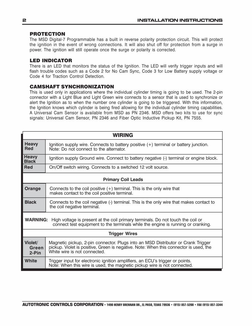
WIRING
Ignition supply wire. Connects to battery positive (+) terminal or battery junction.Note: Do not connect to the alternator.
Ignition supply Ground wire. Connect to battery negative (-) terminal or engine block.
Red On/Off switch wiring. Connects to a switched 12 volt source.
Primary Coil Leads
Orange Connects to the coil positive (+) terminal. This is the only wire thatmakes contact to the coil positive terminal.
Black Connects to the coil negative (-) terminal. This is the only wire that makes contact tothe coil negative terminal.
WARNING: High voltage is present at the coil primary terminals. Do not touch the coil orconnect test equipment to the terminals while the engine is running or cranking.
Trigger Wires
Violet/ Magnetic pickup, 2-pin connector. Plugs into an MSD Distributor or Crank Triggerpickup. Violet is positive, Green is negative. Note: When this connector is used, theWhite wire is not connected.
White Trigger input for electronic ignition amplifiers, an ECU’s trigger or points.Note: When this wire is used, the magnetic pickup wire is not connected.
Green2-Pin
HeavyRed
HeavyBlack
PROTECTIONThe MSD Digital-7 Programmable has a built in reverse polarity protection circuit. This will protectthe ignition in the event of wrong connections. It will also shut off for protection from a surge inpower. The ignition will still operate once the surge or polarity is corrected.
LED INDICATORThere is an LED that monitors the status of the Ignition. The LED will verify trigger inputs and willflash trouble codes such as a Code 2 for No Cam Sync, Code 3 for Low Battery supply voltage orCode 4 for Traction Control Detection.
CAMSHAFT SYNCHRONIZATIONThis is used only in applications where the individual cylinder timing is going to be used. The 2-pinconnector with a Light Blue and Light Green wire connects to a sensor that is used to synchronize oralert the Ignition as to when the number one cylinder is going to be triggered. With this information,the Ignition knows which cylinder is being fired allowing for the individual cylinder timing capabilities.A Universal Cam Sensor is available from MSD as PN 2346. MSD offers two kits to use for syncsignals: Universal Cam Sensor, PN 2346 and Fiber Optic Inductive Pickup Kit, PN 7555.

INSTALLATION INSTRUCTIONS 3
AUTOTRONIC CONTROLS CORPORATION • 1490 HENRY BRENNAN DR., EL PASO, TEXAS 79936 • (915) 857-5200 • FAX (915) 857-3344
Lt Green
Accessories
Dark Blue This wire activates the Launch Rev Limit and is the main reset wire for several features of theIgnition. When 12 volts are applied to this wire it will activate the Launch Rev Limit. It also resetsthe shift light and gear indicator to first gear. It also will select the Launch Retard value and Gear 1curve.
Note: When this wire is activated it will override all other Rev Limits except the TCD Limit.
Light Blue Burnout Rev Limit. When 12 volts are applied the Burnout Rev Limit is active.
Gray Tach output. This wire will provide the same 12 volt square wave tach signal as the tach terminalon the side of the unit.
Retard Stage Wires or Gear Select
These three wires can be used as Retard Stage Activation and/or as a gear select wire.
Pink Step1 retard enabled with +12 volt input and above Step1 Rpm value and Gear 2 Select.
Violet Step2 retard enabled with +12 volt input and above Step2 Rpm value and Gear 3 Select.
Tan Step3 retard enabled with +12 volt input and above Step3 Rpm value and Gear 4 Select.
Note: When activated at the same time, these retard stages are added together. They are alsoadded with any Gear Retard Curve or Boost Retard values as well. Maximum retard is 30°.
Yellow Shift Light output wire. It can handle up to 3 amps continuous to ground when enabled.
Brown/White RPM/Time switch output wire. It can switch up to 3 amps continuous to ground when enabled.
Yellow/Yellow Output for data acquisition or fuel controls. Note, only two wires are used.
Cam Synchronization
Fiber Optic This input requires the PN 7555 Inductive Sync Pickup. When this input is used, the 2-pin connectoris not. Note: If this input is not used, the plug or a cover should be installed.
2-Pin Connector
Lt Blue/ This 2-pin plug connects to Cam Sync Sensor, PN 2346, to indicated when cylinder number one isfiring. Note: When used, the fiber optic connector is not used and must be covered. Lite Blue iscam (+) and Lite Green (-).

4 INSTALLATION INSTRUCTIONS
AUTOTRONIC CONTROLS CORPORATION • 1490 HENRY BRENNAN DR., EL PASO, TEXAS 79936 • (915) 857-5200 • FAX (915) 857-3344
PRO-DATA+
INSTALLATION OF THE PRO-DATA+ SOFTWARE1. Insert the installation disk into your floppy disk drive.2. In Windows, click on Start then select Run.3. In the box type, “A:Setup” and press Enter (or whatever disk drive you are using).4. The screen will walk you through several steps.5. Once loaded, your monitor will have an MSD Graph View logo. Click on it to open the software.6. A program will open. Go to the upper left corner of the screen and click on File, then Open.7. This will open a menu of part numbers. Select “7530T”.8. This will open another menu of versions. Highlight and open the “7530Tvxx.IGN” (xx deter-
mines the versions, such as 22). This will open the Pro-Data+ software for the ProgrammableDigital-7 Ignition.
SAVES AND TRANSFERSWhenever a change is made to a program, it either must be saved to a file in your PC or it needs tobe transferred to the ignition. You will notice that whenever you make a change to a program, thebullet next to the modified value will turn red. It will remain red until you save it to a file or to the MSD.There are two ways to save your files.
Figure 1 Wiring the Programmable Digital-7 Ignition.
INSTALLATION INSTRUCTIONS 5
AUTOTRONIC CONTROLS CORPORATION • 1490 HENRY BRENNAN DR., EL PASO, TEXAS 79936 • (915) 857-5200 • FAX (915) 857-3344
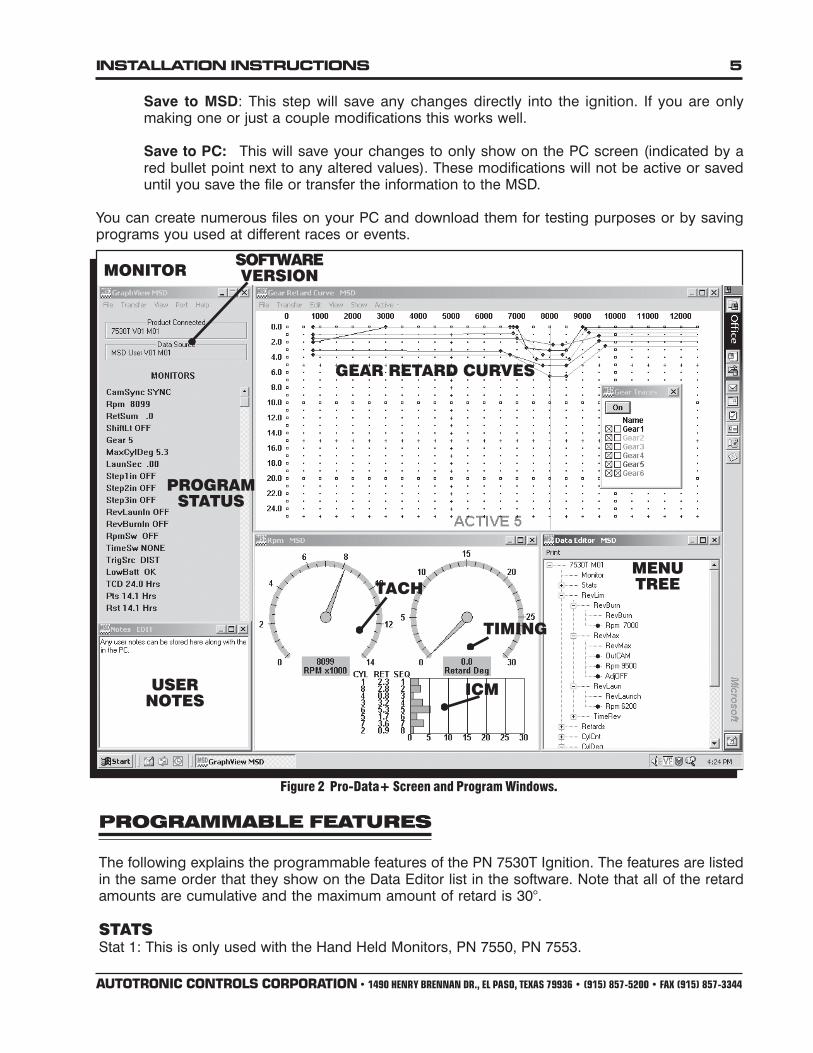
Save to MSD: This step will save any changes directly into the ignition. If you are onlymaking one or just a couple modifications this works well.
Save to PC: This will save your changes to only show on the PC screen (indicated by ared bullet point next to any altered values). These modifications will not be active or saveduntil you save the file or transfer the information to the MSD.
You can create numerous files on your PC and download them for testing purposes or by savingprograms you used at different races or events.
TACH
ICM
GEAR RETARD CURVES
TIMING
MENUTREE
SOFTWAREVERSION
Figure 2 Pro-Data+ Screen and Program Windows.
MONITOR
PROGRAMMABLE FEATURES
The following explains the programmable features of the PN 7530T Ignition. The features are listedin the same order that they show on the Data Editor list in the software. Note that all of the retardamounts are cumulative and the maximum amount of retard is 30°.
STATSStat 1: This is only used with the Hand Held Monitors, PN 7550, PN 7553.
USERNOTES
PROGRAMSTATUS

6 INSTALLATION INSTRUCTIONS
AUTOTRONIC CONTROLS CORPORATION • 1490 HENRY BRENNAN DR., EL PASO, TEXAS 79936 • (915) 857-5200 • FAX (915) 857-3344
REV LIMITSUp to three different rev limits can be programmed in 100 rpm increments.
RevBurn: Burnout Rev Limit. This limit is activated when 12 volts are applied to the LightBlue wire. It is adjustable from 2,000 to 12,500 rpm.
RevLaunch: Launch Rev Limit. This limit is activated when 12 volts are applied to the DarkBlue wire. It is adjustable from 2,000 to 12,500 rpm. This Limit has priority over all the otherrev limits.
RevMax: Max Speed Rev Limit. This is the overrev limit and is active whenever the Launchand Holeshot limits are off.
OutCam: Select either a Cam Sync output or a Rev Limiting output that can beused with MSD components that use rpm modules for the rev limit.
AdjOff: This program enables an automatic compensating rev limiter that willcorrect trigger input offsets and variables. It can be turned On or Off.
RPM: Adjustable in 100 rpm increments from 2,000 – 12,500.
TIMED SAFETY REV LIMITThis provides a time activated rpm limit ramp that is designed to work as a safe shutdown. The rampwill lower the rpm to an adjustable amount, within two seconds after it is activated. The activationpoint ranges from 1-12.5 seconds after the burnout and the shutdown rpm value can be set from1000-12,500 rpm. The time before the safety RPM Limit ramp is activated begins when the Dark Bluewire is released from 12 volts, and only if the programmed Launch Rev Limit rpm has beenacheived on the starting line.
START RETARDProgram an amount of retard that will occur while the engine is cranking. This helps reduce theload on the starter for easier cranking. It is adjustable from 0° - 25° in 1° increments. This is anautomatic feature and will enable below 500 rpm and will deactivate when the engine reachesabove 800 rpm. Default is 10°.
LAUNCH RETARDThis is the time based retard ramp. It can be programmed from 0°-15° in 0.1° increments and from0-2.5 seconds. When the Dark Blue Launch/Reset wire is connected to 12 volts, the retard value isactivated and is added to the retard sum. When 12 volts are removed from the Dark Blue wire, theretard value begins to ramp up to 0° over the programmed time. Once the time is over, the retard willnot be activated again.
TCDThe PN 7530T Ignition incorporates a unique Traction Control Detection (TCD) circuit. This soft-ware code monitors the magnetic pickup circuit for changes that would only come from an in-stalled traction control device that would modify the signal from the mag pickup. If a modification issensed in this circuit an Alert will be set and the status LED will flash a Code 4. This Alert will con-tinue to flash until the ignition is kept turned On for 24 hours in order to reset. A 4000 rpm TCD RevLimit is activated until the 24 hour TCD timer is elapsed or reset by an NHRA official.

INSTALLATION INSTRUCTIONS 7
AUTOTRONIC CONTROLS CORPORATION • 1490 HENRY BRENNAN DR., EL PASO, TEXAS 79936 • (915) 857-5200 • FAX (915) 857-3344
STEP RETARDSThere are three step retards that are controlled through three corresponding activation wires orthrough rpm. A minimum rpm can also be programmed that must be reached before a stepbecomes active. A time based ramp can now be programmed to gradually bring the retard to its fullOn amount, or to ramp the retard amount out (back to no retard) from its setting.
Step 1 - Pink Step 2 - Dark Brown Step 3 - Tan
Activation through Wiring: Each step is activated when 12 volts are applied to its correspondingwire. When the steps are enabled at the same time the retard amounts are added together.The maximum retard allowed by the Ignition is a total of 30° (including other retard amountsfrom a launch, ICM or gear retard).
Activation through RPM: Each step retard can also be activated through rpm. In order toachieve this, 12 volts must still be applied to the corresponding step retard, and an rpm valuemust be selected from the Step RPM menu. When 12 volts are applied, the retard will notactivate until the rpm value is reached. Note that the retard will remain active above this rpm,even when other stages are activated. It will deactivate when the rpm drops below the setamount.
Note: If you prefer to activate the step retards through theactivation wires and not rpm, then the rpm value in eachof the desired step menus must be set to 800 rpm.
Step Retard Off Delay: This feature will set a time baseddelay to deactivate the step retards. This is designed tokeep the timing retarded to clear the engine of anynitrous oxide prior to deactivating the retard. It isadjustable from 0 – 2.5 seconds and the default is 0.5second.
Step Retard Ramp: Each retard step can be rampedto and from its full retard amount over a time basedprogram (Figure 1). It is adjustable from 0-2.5 secondsin 0.01 second increments. Default is 0°.
RPM: The minimum engine rpm that must bereached before a step retard is activated.
On: The amount of time it takes for the step retardto reach its Retard Degree once activated. Allows agradual ramp On time to reach the Retard Degree.User adjustable from 0.00 to 2.50 sec. (0.01 secincrements)
Off: The amount of time it takes for the step to retardto reach NO retard once deactivated. Allows agradual ramp Off time to reach NO Retard. Useradjustable from 0.00 to 2.50 sec. (0.01 secincrements)
Deg: The amount of retard. Figure 3 Ramping the Step Retards.
8 INSTALLATION INSTRUCTIONS
AUTOTRONIC CONTROLS CORPORATION • 1490 HENRY BRENNAN DR., EL PASO, TEXAS 79936 • (915) 857-5200 • FAX (915) 857-3344
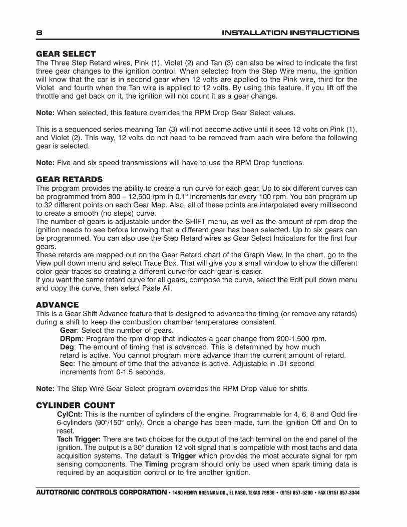
GEAR SELECTThe Three Step Retard wires, Pink (1), Violet (2) and Tan (3) can also be wired to indicate the firstthree gear changes to the ignition control. When selected from the Step Wire menu, the ignitionwill know that the car is in second gear when 12 volts are applied to the Pink wire, third for theViolet and fourth when the Tan wire is applied to 12 volts. By using this feature, if you lift off thethrottle and get back on it, the ignition will not count it as a gear change.
Note: When selected, this feature overrides the RPM Drop Gear Select values.
This is a sequenced series meaning Tan (3) will not become active until it sees 12 volts on Pink (1),and Violet (2). This way, 12 volts do not need to be removed from each wire before the followinggear is selected.
Note: Five and six speed transmissions will have to use the RPM Drop functions.
GEAR RETARDSThis program provides the ability to create a run curve for each gear. Up to six different curves canbe programmed from 800 – 12,500 rpm in 0.1° increments for every 100 rpm. You can program upto 32 different points on each Gear Map. Also, all of these points are interpolated every millisecondto create a smooth (no steps) curve.The number of gears is adjustable under the SHIFT menu, as well as the amount of rpm drop theignition needs to see before knowing that a different gear has been selected. Up to six gears canbe programmed. You can also use the Step Retard wires as Gear Select Indicators for the first fourgears.These retards are mapped out on the Gear Retard chart of the Graph View. In the chart, go to theView pull down menu and select Trace Box. That will give you a small window to show the differentcolor gear traces so creating a different curve for each gear is easier.If you want the same retard curve for all gears, compose the curve, select the Edit pull down menuand copy the curve, then select Paste All.
ADVANCEThis is a Gear Shift Advance feature that is designed to advance the timing (or remove any retards)during a shift to keep the combustion chamber temperatures consistent.
Gear: Select the number of gears.DRpm: Program the rpm drop that indicates a gear change from 200-1,500 rpm.Deg: The amount of timing that is advanced. This is determined by how muchretard is active. You cannot program more advance than the current amount of retard.Sec: The amount of time that the advance is active. Adjustable in .01 secondincrements from 0-1.5 seconds.
Note: The Step Wire Gear Select program overrides the RPM Drop value for shifts.
CYLINDER COUNTCylCnt: This is the number of cylinders of the engine. Programmable for 4, 6, 8 and Odd fire6-cylinders (90°/150° only). Once a change has been made, turn the ignition Off and On toreset.Tach Trigger: There are two choices for the output of the tach terminal on the end panel of theignition. The output is a 30° duration 12 volt signal that is compatible with most tachs and dataacquisition systems. The default is Trigger which provides the most accurate signal for rpmsensing components. The Timing program should only be used when spark timing data isrequired by an acquisition control or to fire another ignition.

INSTALLATION INSTRUCTIONS 9
AUTOTRONIC CONTROLS CORPORATION • 1490 HENRY BRENNAN DR., EL PASO, TEXAS 79936 • (915) 857-5200 • FAX (915) 857-3344
INDIVIDUAL CYLINDER TIMINGEach cylinder can be retarded up to 10° in 0.1° increments. Adjustments are made through theCylDeg menu. Default for each cylinder is 0°. A Cam Sync signal for cylinder number one must beincorporated. The MSD Fiber Optic Pickup, PN 7555, is the easiest or a pickup kit could be fabri-cated on the cam gear (MSD Kit PN 2346).The spark sequence, or firing order needs to be considered when selecting the ICT. You can gothrough the Cylinder Numbers and place them with the corresponding position, or go to the Se-quence window and select from the pre-programmed firing orders.
Spark Sequence Program the firing order of your engine.Degree Program the amount of retard of each cylinder. These retard
rates are added to any other retards that are active. Max retard is 30°.Sequence Select a firing order:
Program Order Application1843 18436572 Most GM, Chrysler and AMC V81542 15426378 Most Ford V81372 13726548 Ford 341/4001425 142536 Ford V61536 153624 Ford, Camaro, Chrysler, AMC V61654 165432 Most GM V61436 143625 Odd-fire 6-cylinder
RPM/TIME ACTIVATION SWITCHThis program lets you activate a circuit by supplying 12 volts on the Brown/White wire (up to 3Amps continuous). This can be activated in two ways; RPM or Time.
RPM Window: Program an rpm value to activate and deactivate a circuit from 800 – 12,500rpm in 100 rpm increments.
RPM On: Rpm that the circuit is activated
RPM Off: Rpm that the circuit is deactivated
RPM Hysterisis: Built in Hysterisis allows the deactivation point to be set lower than theactivation value.
Time Based: Program an activation point in 0.01 second increments after the launch. Up to 25seconds of total time. The timer begins when the Dark Blue wire is removed from 12 volts and onlyif the programmed Launch Rev Limit rpm has been acheived on the starting line.
OnDelay: The amount of time after launch (12 volts removed from the Dark Blue wire).
OnTime: The amount of time that the switch stays activated. This can be programmedfrom 0-25 seconds. It will always deactivate after 25 seconds.

10 INSTALLATION INSTRUCTIONS
AUTOTRONIC CONTROLS CORPORATION • 1490 HENRY BRENNAN DR., EL PASO, TEXAS 79936 • (915) 857-5200 • FAX (915) 857-3344
SHIFT LIGHTThis program lets you select the number of gears (Last Gear), program the shift light to come onwhen the holeshot rpm is reached, set an rpm point for each gear and the rpm drop for the ignitionto recognize as a gear shift between each gear. When the correct rpm is reached the Yellow wire isswitched to ground to turn the shift light on.
Launch Light This programs an rpm window that will illuminate the shift light when the correct rpmis reached for the holeshot. When the rpm is in this window the light will be on solid. If the rpm goeshigh, the light will flash. If the rpm goes low, the light turns off.
RpmHi: The high rpm for the launch light program.RpmLo: The low rpm for the launch light program.
ShiftLight: Program the rpm point for each gear change.(1)Rpm First gear rpm point to shift.(2)Rpm Second gear rpm point to shift.(3-5 gears)
ShiftGear: Program the rpm drop between each gear that the ignition must seeto recognize a shift. Programmable from 200-1500 rpm.
(1)DropRpm Rpm drop between first and second.(2)DropRpm Rpm drop between second and third.(3-5 gears)
Last Gear: The program lets you select the number of gears to use with the shift light from2-6 gears. Default is five gears.
ALERTSThis is only used with the Hand Held Monitor, PN 7550. You can program an alert to interrupt thescreen on the monitor. You can select which alerts to show and how often. The alerts are No CamSync, Low Battery, and Traction Control Detection (TCD).
Fault: Program the number of counts that occur for a Low Voltage alert.
BrownOut 0: This is the count of low voltage resets. This should always be set at 0.
WatchDog: The count of Watch Dog resets. This should always be set at 0.
TCD: When a traction control device is detected an alert is set and will flash a Code 4 (a 4blink sequence) on the end panel LED. This alert will continue to flash until the ignition iskept turned On for 24 hours in order to reset.
INSTALLATION INSTRUCTIONS 11
AUTOTRONIC CONTROLS CORPORATION • 1490 HENRY BRENNAN DR., EL PASO, TEXAS 79936 • (915) 857-5200 • FAX (915) 857-3344

12 INSTALLATION INSTRUCTIONS
AUTOTRONIC CONTROLS CORPORATION • 1490 HENRY BRENNAN DR., EL PASO, TEXAS 79936 • (915) 857-5200 • FAX (915) 857-3344
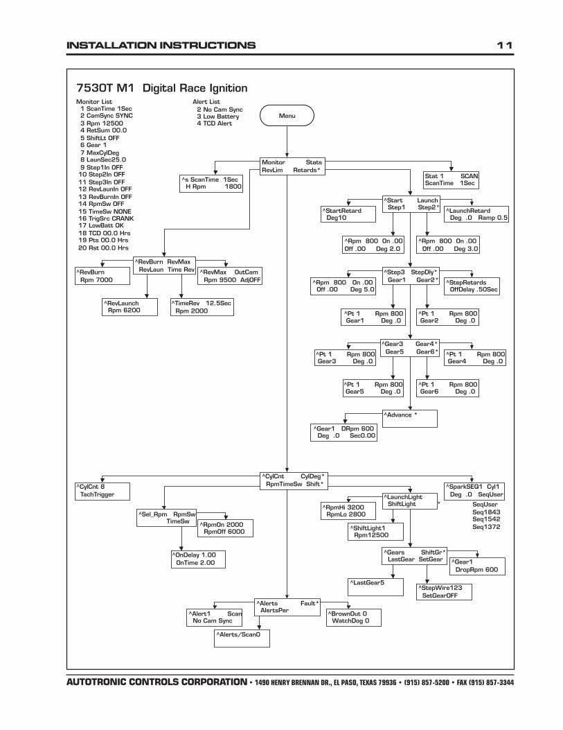
DEFAULT MENU
Notes: 7530TV1. Uses menu 7530M01MSD Digital Race Ignition.Factory default data and menu.
7530T MO1MonitorStats
Stat 1
RevLimRevBurn*Rpm 7000
RevMaxRevMax
*OutCAM*Rpm 9500*AdjOFF
RevLaunRevLaunch*Rpm 6200
TimeRevTimeRevTime 9.0Rpm 2000
RetardsStart
StartRetard* Deg10
LaunchLaunchRetard
* Deg .0* Ramp .50
Step1* Rpm 800* On .00* Off .00* Deg 2.0
Step2* Rpm 800* On .00* Off .00* Deg 3.0
Step 3* Rpm 800* On .00* Off .00* Deg 5.0
StepDlyStep Retards
* OffDelay .50Sec
Gear 1Pt 1Rpm 800Gear1Deg .0
Gear2Pt 1Rpm 800Gear2Deg .0
Gear3Pt 1Rpm 800Gear3Deg .0
Gear4Pt 1Rpm 800Gear 4Deg .0
Gear5Pt 1Rpm 800Gear5Deg .0
Gear6Pt 1Rpm 800Gear6Deg .0
AdvanceGear1* (1) dRpm 600* (2) dRpm 600* (3) dRpm 600* (4) dRpm 600* (5) dRpm 600* (1) Deg .0* (2) Deg .0* (3) Deg .0* (4) Deg .0* (5) Deg .0* (1) Sec .00* (2) Sec .00* (3) Sec .00* (4) Sec .00* (5) Sec .00
CylCnt*CylCnt 8*TachTrigger
DylDegSparkSEQ1* (1) Cyl1* (2) Cyl2* (3) Cyl3* (4) Cyl4* (5) Cyl5* (6) Cyl6* (7) Cyl7* (8) Cyl8* (1) Deg .0* (2) Deg .0* (3) Deg .0* (4) Deg .0* (5) Deg .0* (6) Deg .0* (7) Deg .0* (8) Deg .0
* SeqUser
RpmTimeSw* SwSel RPM
RpmSw*RpmOn 2000*RpmOff 6000
TimeSw*OnDelay 1.00*OnTime 2.00
ShiftLaunchLight*RpmHi 3200*RpmLo 2800
ShiftLightsShiftLight1* (1) Rpm12500* (2) Rpm12300* (3) Rpm 12100* (4) Rpm11900* (5) Rpm11700
GearsShiftGr
Gear1* (1) DropRpm 600* (2) DropRpm 600* (3) DropRpm 600* (4) DropRpm 600* (5) DropRpm 600
LastGr*LastGear5
SetGearStepWire 123*SetGearOFF
AlertsAlert 1
(1) SCAN(2) SCAN
Fault*BrownOut 0*WatchDog 0
AlertsPer*Alerts/Scan 0

INSTALLATION INSTRUCTIONS 13
AUTOTRONIC CONTROLS CORPORATION • 1490 HENRY BRENNAN DR., EL PASO, TEXAS 79936 • (915) 857-5200 • FAX (915) 857-3344
TECH NOTES________________________________________________________________________________________________________________________
________________________________________________________________________________________________________________________
________________________________________________________________________________________________________________________
________________________________________________________________________________________________________________________
________________________________________________________________________________________________________________________
________________________________________________________________________________________________________________________
________________________________________________________________________________________________________________________
________________________________________________________________________________________________________________________
________________________________________________________________________________________________________________________
________________________________________________________________________________________________________________________
________________________________________________________________________________________________________________________
________________________________________________________________________________________________________________________
________________________________________________________________________________________________________________________
________________________________________________________________________________________________________________________
________________________________________________________________________________________________________________________
________________________________________________________________________________________________________________________
________________________________________________________________________________________________________________________
________________________________________________________________________________________________________________________
________________________________________________________________________________________________________________________
________________________________________________________________________________________________________________________
________________________________________________________________________________________________________________________
________________________________________________________________________________________________________________________
________________________________________________________________________________________________________________________
________________________________________________________________________________________________________________________
________________________________________________________________________________________________________________________
________________________________________________________________________________________________________________________
________________________________________________________________________________________________________________________
________________________________________________________________________________________________________________________
________________________________________________________________________________________________________________________
________________________________________________________________________________________________________________________
________________________________________________________________________________________________________________________
________________________________________________________________________________________________________________________
________________________________________________________________________________________________________________________
________________________________________________________________________________________________________________________
________________________________________________________________________________________________________________________
________________________________________________________________________________________________________________________
________________________________________________________________________________________________________________________
________________________________________________________________________________________________________________________

14 INSTALLATION INSTRUCTIONS
AUTOTRONIC CONTROLS CORPORATION • 1490 HENRY BRENNAN DR., EL PASO, TEXAS 79936 • (915) 857-5200 • FAX (915) 857-3344
TECH NOTES________________________________________________________________________________________________________________________
________________________________________________________________________________________________________________________
________________________________________________________________________________________________________________________
________________________________________________________________________________________________________________________
________________________________________________________________________________________________________________________
________________________________________________________________________________________________________________________
________________________________________________________________________________________________________________________
________________________________________________________________________________________________________________________
________________________________________________________________________________________________________________________
________________________________________________________________________________________________________________________
________________________________________________________________________________________________________________________
________________________________________________________________________________________________________________________
________________________________________________________________________________________________________________________
________________________________________________________________________________________________________________________
________________________________________________________________________________________________________________________
________________________________________________________________________________________________________________________
________________________________________________________________________________________________________________________
________________________________________________________________________________________________________________________
________________________________________________________________________________________________________________________
________________________________________________________________________________________________________________________
________________________________________________________________________________________________________________________
________________________________________________________________________________________________________________________
________________________________________________________________________________________________________________________
________________________________________________________________________________________________________________________
________________________________________________________________________________________________________________________
________________________________________________________________________________________________________________________
________________________________________________________________________________________________________________________
________________________________________________________________________________________________________________________
________________________________________________________________________________________________________________________
________________________________________________________________________________________________________________________
________________________________________________________________________________________________________________________
________________________________________________________________________________________________________________________
________________________________________________________________________________________________________________________
________________________________________________________________________________________________________________________
________________________________________________________________________________________________________________________
________________________________________________________________________________________________________________________
________________________________________________________________________________________________________________________
________________________________________________________________________________________________________________________

INSTALLATION INSTRUCTIONS 15
AUTOTRONIC CONTROLS CORPORATION • 1490 HENRY BRENNAN DR., EL PASO, TEXAS 79936 • (915) 857-5200 • FAX (915) 857-3344
TECH NOTES________________________________________________________________________________________________________________________
________________________________________________________________________________________________________________________
________________________________________________________________________________________________________________________
________________________________________________________________________________________________________________________
________________________________________________________________________________________________________________________
________________________________________________________________________________________________________________________
________________________________________________________________________________________________________________________
________________________________________________________________________________________________________________________
________________________________________________________________________________________________________________________
________________________________________________________________________________________________________________________
________________________________________________________________________________________________________________________
________________________________________________________________________________________________________________________
________________________________________________________________________________________________________________________
________________________________________________________________________________________________________________________
________________________________________________________________________________________________________________________
________________________________________________________________________________________________________________________
________________________________________________________________________________________________________________________
________________________________________________________________________________________________________________________
________________________________________________________________________________________________________________________
________________________________________________________________________________________________________________________
________________________________________________________________________________________________________________________
________________________________________________________________________________________________________________________
________________________________________________________________________________________________________________________
________________________________________________________________________________________________________________________
________________________________________________________________________________________________________________________
________________________________________________________________________________________________________________________
________________________________________________________________________________________________________________________
________________________________________________________________________________________________________________________
________________________________________________________________________________________________________________________
________________________________________________________________________________________________________________________
________________________________________________________________________________________________________________________
________________________________________________________________________________________________________________________
________________________________________________________________________________________________________________________
________________________________________________________________________________________________________________________
________________________________________________________________________________________________________________________
________________________________________________________________________________________________________________________
________________________________________________________________________________________________________________________
________________________________________________________________________________________________________________________

16 INSTALLATION INSTRUCTIONS
AUTOTRONIC CONTROLS CORPORATION • 1490 HENRY BRENNAN DR., EL PASO, TEXAS 79936 • (915) 857-5200 • FAX (915) 857-3344
FRM25561 Revised 01/04 Printed In U.S.A.
Limited Warranty
Autotronic Controls Corporation warrants MSD Ignition products to be free from defects in material andworkmanship under normal use and if properly installed for a period of one year from date of purchase. Iffound to be defective as mentioned above, it will be replaced or repaired if returned prepaid along withproof of date of purchase. This shall constitute the sole remedy of the purchaser and the sole liability ofAutotronic Controls Corporation. To the extent permitted by law, the foregoing is exclusive and in lieu ofall other warranties or representations whether expressed or implied, including any implied warranty ofmerchantability or fitness. In no event shall Autotronic Controls Corporation be liable for special orconsequential damages.
Service
In case of malfunction, this MSD component will be repaired free of charge according to the terms of thewarranty. When returning MSD components for service, Proof of Purchase must be supplied for warrantyverification. After the warranty period has expired, repair service is charged based on a minimum andmaximum charge.Send the unit prepaid with proof of purchase to the attention of: Customer Service Department, AutotronicControls Corporation, 12120 Esther Lama, Suite 114, El Paso, Texas 79936.When returning the unit for repair, leave all wires at the length in which you have them installed. Be sure toinclude a detailed account of any problems experienced, and what components and accessories areinstalled on the vehicle.The repaired unit will be returned as soon as possible after receipt, COD for any charges. (Groundshipping is covered by warranty). All units are returned regular UPS unless otherwise noted. For moreinformation, call the MSD Customer Service Line (915) 855-7123. MSD technicians are available from 8:00a.m. to 5:00 p.m. Monday - Friday (Mountain Time).
TECH NOTES________________________________________________________________________________________________________________________
________________________________________________________________________________________________________________________
________________________________________________________________________________________________________________________
________________________________________________________________________________________________________________________
________________________________________________________________________________________________________________________
________________________________________________________________________________________________________________________
________________________________________________________________________________________________________________________
________________________________________________________________________________________________________________________
________________________________________________________________________________________________________________________
________________________________________________________________________________________________________________________
________________________________________________________________________________________________________________________
________________________________________________________________________________________________________________________
________________________________________________________________________________________________________________________
________________________________________________________________________________________________________________________
________________________________________________________________________________________________________________________
________________________________________________________________________________________________________________________