program control instructions - wordpress.com ±32k bytes from the instruction in the current code...
TRANSCRIPT

Program Control Instructions

Introduction
• This chapter explains the program control
instructions, including the jumps, calls,
returns, interrupts, and machine control
instructions.
• This chapter also presents the relational
assembly language statements (.IF, .ELSE,
.ELSEIF, .ENDIF, .WHILE, .ENDW, .REPEAT,
and .UNTIL) that are available in version 6.xx
and above of MASM or TASM, with version
5.xx set for MASM compatibility.
THE JUMP GROUP
• Allows programmer to skip program sections
and branch to any part of memory for the
next instruction.
• A conditional jump instruction allows decisions
based upon numerical tests.
– results are held in the flag bits, then tested by
conditional jump instructions
• LOOP and conditional LOOP are also forms
of the jump instruction.

Unconditional Jump (JMP)
• Three types: short jump, near jump, far jump.
• Short jump is a 2-byte instruction that allows
jumps or branches to memory locations within
+127 and –128 bytes.
– from the address following the jump
• 3-byte near jump allows a branch or jump
within ±32K bytes from the instruction in the
current code segment.

• 5-byte far jump allows a jump to any memory
location within the real memory system.
• The short and near jumps are often called
intrasegment jumps.
• Far jumps are called intersegment jumps.
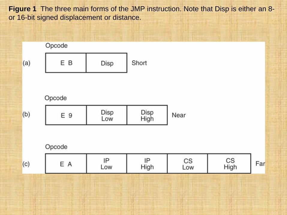
Figure 1 The three main forms of the JMP instruction. Note that Disp is either an 8-
or 16-bit signed displacement or distance.

Short Jump
• Called relative jumps because they can be
moved, with related software, to any location
in the current code segment without a change.
– jump address is not stored with the opcode
– a distance, or displacement, follows the opcode
• The short jump displacement is a distance
represented by a 1-byte signed number whose
value ranges between +127 and –128.
• Short jump instruction appears in Figure 2.

Figure 2 A short jump to four memory locations beyond the address of the next
instruction.
– when the microprocessor
executes
a short jump, the
displacement is sign-
extended and added to
the instruction pointer
(IP/EIP) to generate the
jump address
within the current code
segment
– The instruction branches to this new address for
the next instruction in the program
• When a jump references an address, a label
normally identifies the address.
• The JMP NEXT instruction is an example.
– it jumps to label NEXT for the next instruction
– very rare to use an actual hexadecimal address
with any jump instruction
• The label NEXT must be followed by a colon
(NEXT:) to allow an instruction to reference it
– if a colon does not follow, you cannot jump to it
• The only time a colon is used is when the
label is used with a jump or call instruction.

Near Jump
• A near jump passes control to an instruction in
the current code segment located within
±32K bytes from the near jump instruction.
– distance is ±2G in 80386 and above when
operated in protected mode
• Near jump is a 3-byte instruction with opcode
followed by a signed 16-bit displacement.
– 80386 - Pentium 4 displacement is 32 bits and
the near jump is 5 bytes long

• Signed displacement adds to the instruction
pointer (IP) to generate the jump address.
– because signed displacement is ±32K, a near
jump can jump to any memory location within
the current real mode code segment
• The protected mode code segment in the
80386 and above can be 4G bytes long.
– 32-bit displacement allows a near jump to any
location within ±2G bytes
• Figure 6–3 illustrates the operation of the real
mode near jump instruction.

Figure 3 A near jump that adds the displacement (0002H) to the contents of IP.

• The near jump is also relocatable because it
is also a relative jump.
• This feature, along with the relocatable data
segments, Intel microprocessors ideal for
use in a general-purpose computer system.
• Software can be written and loaded anywhere
in the memory and function without
modification because of the relative jumps
and relocatable data segments.
Far Jump
• Obtains a new segment and offset address
to accomplish the jump:
– bytes 2 and 3 of this 5-byte instruction contain
the new offset address
– bytes 4 and 5 contain the new segment address
– in protected mode, the segment address accesses
a descriptor with the base address of the far jump
segment
– offset address, either 16 or 32 bits, contains the
offset address within the new code segment

Figure 4 A far jump instruction replaces the contents of both CS and IP with 4 bytes
following the opcode.

• The far jump instruction sometimes appears
with the FAR PTR directive.
– another way to obtain a far jump is to define a
label as a far label
– a label is far only if it is external to the current
code segment or procedure
• The JMP UP instruction references a far label.
– label UP is defined as a far label by the EXTRN
UP:FAR directive
• External labels appear in programs that
contain more than one program file.

• Another way of defining a label as global is to
use a double colon (LABEL::)
– required inside procedure blocks defined as
near if the label is accessed from outside the
procedure block
• When the program files are joined, the linker
inserts the address for the UP label into the
JMP UP instruction.
• Also inserts segment address in JMP START
instruction.

Jumps with Register Operands
• Jump can also use a 16- or 32-bit register as
an operand.
– automatically sets up as an indirect jump
– address of the jump is in the register specified
by the jump instruction
• Unlike displacement associated with the near
jump, register contents are transferred directly
into the instruction pointer.
• An indirect jump does not add to the
instruction pointer.

• JMP AX, for example, copies the contents of
the AX register into the IP.
– allows a jump to any location within the current
code segment
• In 80386 and above, JMP EAX also jumps to
any location within the current code segment;
– in protected mode the code segment can be 4G
bytes long, so a 32-bit offset address is needed

Indirect Jumps Using an Index
• Jump instruction may also use the [ ] form of
addressing to directly access the jump table.
• The jump table can contain offset addresses
for near indirect jumps, or segment and offset
addresses for far indirect jumps.
– also known as a double-indirect jump if the
register jump is called an indirect jump
• The assembler assumes that the jump is near
unless the FAR PTR directive indicates a far
jump instruction.

• Mechanism used to access the jump table is
identical with a normal memory reference.
– JMP TABLE [SI] instruction points to a jump
address stored at the code segment offset
location addressed by SI
• Both the register and indirect indexed jump
instructions usually address a 16-bit offset.
– both types of jumps are near jumps
• If JMP FAR PTR [SI] or JMP TABLE [SI], with
TABLE data defined with the DD directive:
– microprocessor assumes the jump table contains
doubleword, 32-bit addresses (IP and CS)

Conditional Jumps and Conditional
Sets
• Always short jumps in 8086 - 80286.
– limits range to within +127 and –128 bytes from
the location following the conditional jump
• In 80386 and above, conditional jumps are
either short or near jumps (±32K).
– in 64-bit mode of the Pentium 4, the near jump
distance is ±2G for the conditional jumps
• Allows a conditional jump to any location
within the current code segment.
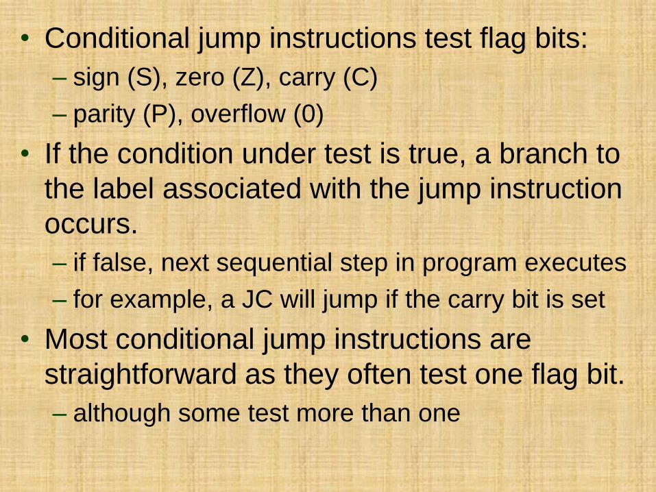
• Conditional jump instructions test flag bits:
– sign (S), zero (Z), carry (C)
– parity (P), overflow (0)
• If the condition under test is true, a branch to
the label associated with the jump instruction
occurs.
– if false, next sequential step in program executes
– for example, a JC will jump if the carry bit is set
• Most conditional jump instructions are
straightforward as they often test one flag bit.
– although some test more than one
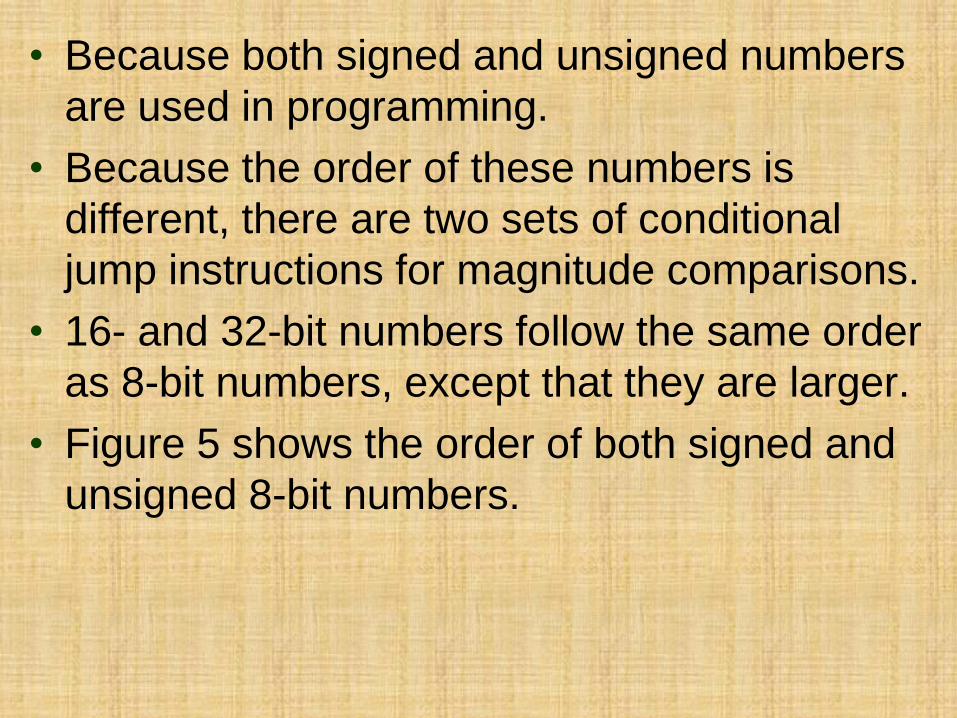
• Because both signed and unsigned numbers
are used in programming.
• Because the order of these numbers is
different, there are two sets of conditional
jump instructions for magnitude comparisons.
• 16- and 32-bit numbers follow the same order
as 8-bit numbers, except that they are larger.
• Figure 5 shows the order of both signed and
unsigned 8-bit numbers.

Figure 5 Signed and unsigned numbers follow different orders.
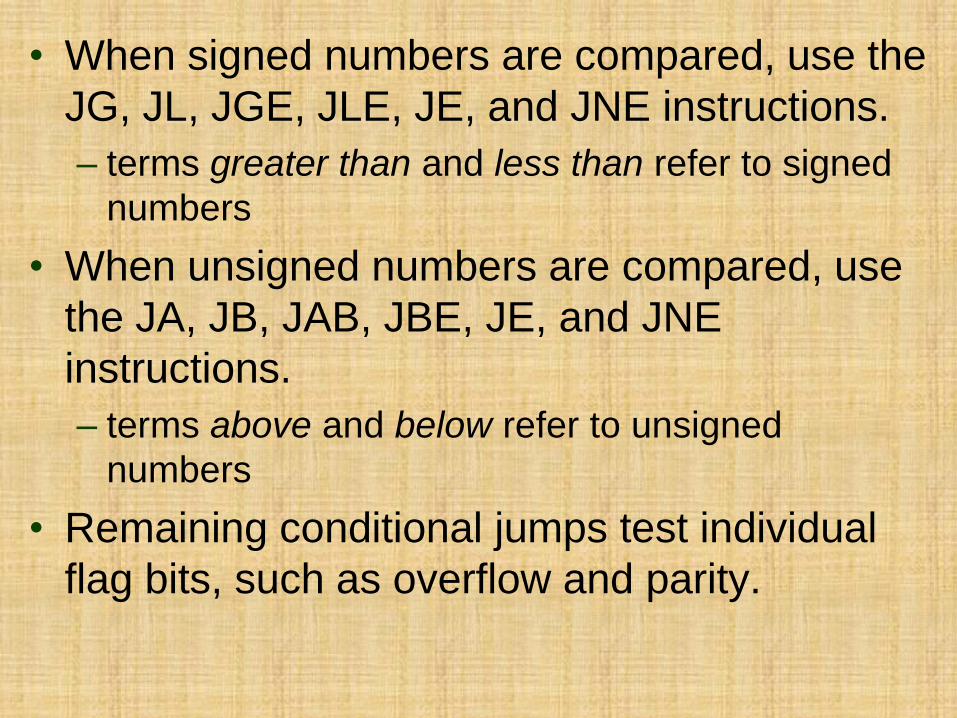
• When signed numbers are compared, use the
JG, JL, JGE, JLE, JE, and JNE instructions.
– terms greater than and less than refer to signed
numbers
• When unsigned numbers are compared, use
the JA, JB, JAB, JBE, JE, and JNE
instructions.
– terms above and below refer to unsigned
numbers
• Remaining conditional jumps test individual
flag bits, such as overflow and parity.

• Remaining conditional jumps test individual
flag bits, such as overflow and parity.
– notice that JE has an alternative opcode JZ
• All instructions have alternates, but many
aren’t used in programming because they
don’t usually fit the condition under test.

The Conditional Set Instructions
• 80386 - Core2 processors also contain
conditional set instructions.
– conditions tested by conditional jumps put
to work with the conditional set instructions
– conditional set instructions set a byte to either
01H or clear a byte to 00H, depending on the
outcome of the condition under test
• Useful where a condition must be tested
at a point much later in the program.

LOOP
• A combination of a decrement CX and the
JNZ conditional jump.
• In 8086 - 80286 LOOP decrements CX.
– if CX != 0, it jumps to the address indicated
by the label
– If CX becomes 0, the next sequential instruction
executes
• In 80386 and above, LOOP decrements either
CX or ECX, depending upon instruction mode.

• In 16-bit instruction mode, LOOP uses CX; in
the 32-bit mode, LOOP uses ECX.
– default is changed by the LOOPW (using CX) and
LOOPD (using ECX) instructions 80386 - Core2
• In 64-bit mode, the loop counter is in RCX.
– and is 64 bits wide
• There is no direct move from segment register
to segment register instruction.

Conditional LOOPs
• LOOP instruction also has conditional forms:
LOOPE and LOOPNE
• LOOPE (loop while equal) instruction jumps
if CX != 0 while an equal condition exists.
– will exit loop if the condition is not equal or the
CX register decrements to 0
• LOOPNE (loop while not equal) jumps if CX
!= 0 while a not-equal condition exists.
– will exit loop if the condition is equal or the CX
register decrements to 0

• In 80386 - Core2 processors, conditional
LOOP can use CX or ECX as the counter.
– LOOPEW/LOOPED or LOOPNEW/LOOPNED
override the instruction mode if needed
• Under 64-bit operation, the loop counter uses
RCX and is 64 bits in width
• Alternates exist for LOOPE and LOOPNE.
– LOOPE same as LOOPZ
– LOOPNE instruction is the same as LOOPNZ
• In most programs, only the LOOPE and
LOOPNE apply.
CONTROLLING THE FLOW OF THE
PROGRAM
• Easier to use assembly language statements
.IF, .ELSE, .ELSEIF, and .ENDIF to control the
flow of the program than to use the correct
conditional jump statement.
– these statements always indicate a special
assembly language command to MASM
• Control flow assembly language statements
beginning with a period available to MASM
version 6.xx, and not to earlier versions.

• Other statements developed include
.REPEAT–.UNTIL and .WHILE–.ENDW.
– the dot commands do not function using
the Visual C++ inline assembler
• Never use uppercase for assembly language
commands with the inline assembler.
– some of them are reserved by C++ and will
cause problems

WHILE Loops
• Used with a condition to begin the loop.
– the .ENDW statement ends the loop
• The .BREAK and .CONTINUE statements are
available for use with the while loop.
– .BREAK is often followed by .IF to select the break
condition as in .BREAK .IF AL == 0DH
– .CONTINUE can be used to allow a DO–.WHILE
loop to continue if a certain condition is met
• The .BREAK and .CONTINUE commands
function the same manner in C++.

REPEAT-UNTIL Loops
• A series of instructions is repeated until some
condition occurs.
• The .REPEAT statement defines the start of
the loop.
– end is defined with the .UNTIL statement, which
contains a condition
• An .UNTILCXZ instruction uses the LOOP
instruction to check CX for a repeat loop.
– .UNTILCXZ uses the CX register as a counter
to repeat a loop a fixed number of times

PROCEDURES
• A procedure is a group of instructions that
usually performs one task.
– subroutine, method, or function is an
important part of any system’s architecture
• A procedure is a reusable section of the
software stored in memory once, used as
often as necessary.
– saves memory space and makes it easier to
develop software
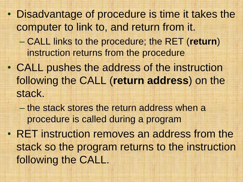
• Disadvantage of procedure is time it takes the
computer to link to, and return from it.
– CALL links to the procedure; the RET (return)
instruction returns from the procedure
• CALL pushes the address of the instruction
following the CALL (return address) on the
stack.
– the stack stores the return address when a
procedure is called during a program
• RET instruction removes an address from the
stack so the program returns to the instruction
following the CALL.

• A procedure begins with the PROC directive
and ends with the ENDP directive.
– each directive appears with the procedure name
• PROC is followed by the type of procedure:
– NEAR or FAR
• In MASM version 6.x, the NEAR or FAR type
can be followed by the USES statement.
– USES allows any number of registers to be
automatically pushed to the stack and popped
from the stack within the procedure

• Procedures that are to be used by all software
(global) should be written as far procedures.
• Procedures that are used by a given task
(local) are normally defined as near
procedures.
• Most procedures are near procedures.
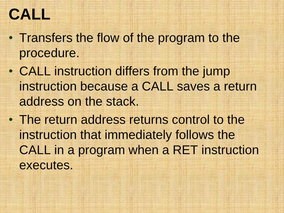
CALL
• Transfers the flow of the program to the
procedure.
• CALL instruction differs from the jump
instruction because a CALL saves a return
address on the stack.
• The return address returns control to the
instruction that immediately follows the
CALL in a program when a RET instruction
executes.
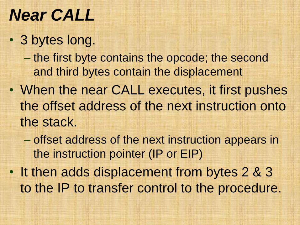
Near CALL
• 3 bytes long.
– the first byte contains the opcode; the second
and third bytes contain the displacement
• When the near CALL executes, it first pushes
the offset address of the next instruction onto
the stack.
– offset address of the next instruction appears in
the instruction pointer (IP or EIP)
• It then adds displacement from bytes 2 & 3
to the IP to transfer control to the procedure.

• Why save the IP or EIP on the stack?
– the instruction pointer always points to the
next instruction in the program
• For the CALL instruction, the contents of
IP/EIP are pushed onto the stack.
– program control passes to the instruction
following the CALL after a procedure ends
• Figure 6 shows the return address (IP) stored
on the stack and the call to the procedure.

Figure 6 The effect of a near CALL on the stack and the instruction pointer.
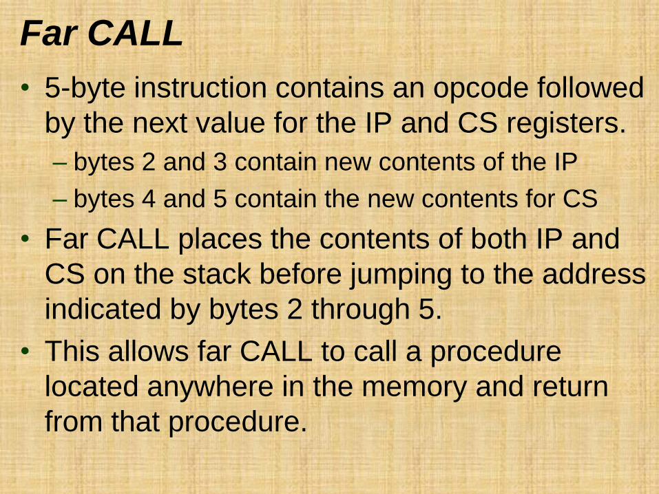
Far CALL
• 5-byte instruction contains an opcode followed
by the next value for the IP and CS registers.
– bytes 2 and 3 contain new contents of the IP
– bytes 4 and 5 contain the new contents for CS
• Far CALL places the contents of both IP and
CS on the stack before jumping to the address
indicated by bytes 2 through 5.
• This allows far CALL to call a procedure
located anywhere in the memory and return
from that procedure.

• Figure 7 shows how far CALL calls a far
procedure.
– contents of IP and CS are pushed onto the stack
• The program branches to the procedure.
– A variant of far call exists as CALLF, but should
be avoided in favor of defining the type of call
instruction with the PROC statement
• In 64-bit mode a far call is to any memory
location and information placed onto the stack
is an 8-byte number.
– the far return instruction retrieves an 8-byte return
address from the stack and places it into RIP

Figure 7 The effect of a far CALL instruction.

CALLs with Register Operands
• An example CALL BX, which pushes the
contents of IP onto the stack.
– then jumps to the offset address, located in
register BX, in the current code segment
• Always uses a 16-bit offset address, stored in
any 16-bit register except segment registers.

CALLs with Indirect Memory
Addresses
• Particularly useful when different subroutines
need to be chosen in a program.
– selection process is often keyed with a number
that addresses a CALL address in a lookup table
• Essentially the same as the indirect jump that
used a lookup table for a jump address.

RET
• Removes a 16-bit number (near return) from
the stack placing it in IP, or removes a 32-bit
number (far return) and places it in IP & CS.
– near and far return instructions in procedure’s
PROC directive
– automatically selects the proper return instruction
• Figure 8 shows how the CALL instruction links
to a procedure and how RET returns in the
8086–Core2 operating in the real mode.
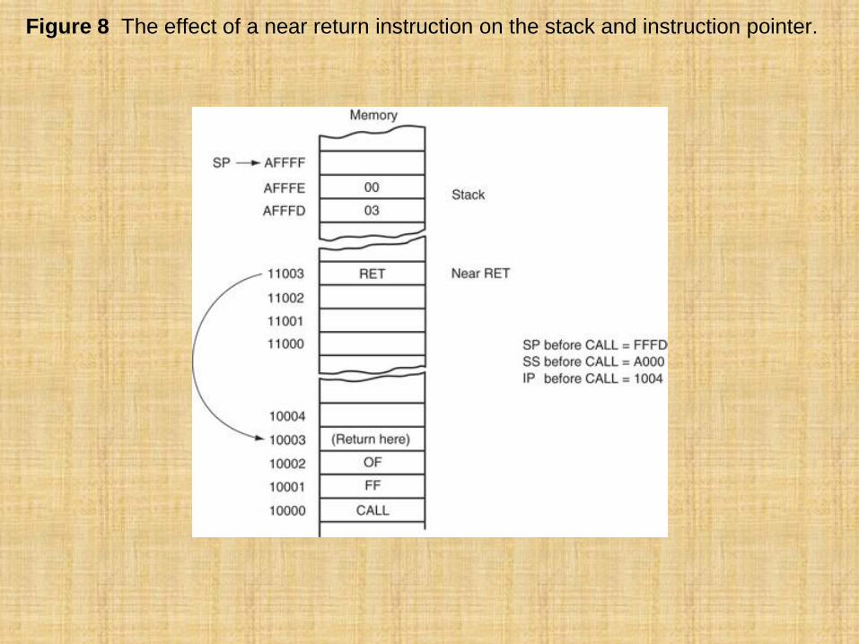
Figure 8 The effect of a near return instruction on the stack and instruction pointer.

• Another form of return adds a number to the
contents of the stack pointer (SP) after the
return address is removed from the stack.
• A return that uses an immediate operand is
ideal for use in a system that uses the C/C++
or PASCAL calling conventions.
– these conventions push parameters on the
stack before calling a procedure
• If the parameters are discarded upon return,
the return instruction contains the number of
bytes pushed to the stack as parameters.

• Parameters are addressed on the stack by
using the BP register, which by default
addresses the stack segment.
• Parameter stacking is common in procedures
written for C++ or PASCAL by using the C++
or PASCAL calling conventions.
• Variants of the return instruction:
– RETN and RETF
• Variants should also be avoided in favor of
using the PROC statement to define the type
of call and return.

INTRO TO INTERRUPTS
• An interrupt is a hardware-generated CALL
– externally derived from a hardware signal
• Or a software-generated CALL
– internally derived from the execution of an
instruction or by some other internal event
– at times an internal interrupt is called an exception
• Either type interrupts the program by calling
an interrupt service procedure (ISP) or
interrupt handler.

Interrupt Vectors
• A 4-byte number stored in the first 1024 bytes
of memory (00000H–003FFH) in real mode.
– in protected mode, the vector table is replaced by
an interrupt descriptor table that uses 8-byte
descriptors to describe each of the interrupts
• 256 different interrupt vectors.
– each vector contains the address of an interrupt
service procedure

• Each vector contains a value for IP and CS
that forms the address of the interrupt service
procedure.
– the first 2 bytes contain IP; the last 2 bytes CS
• Intel reserves the first 32 interrupt vectors for
the present and future products.
– interrupt vectors (32–255) are available to users
• Some reserved vectors are for errors that
occur during the execution of software
– such as the divide error interrupt

• Some vectors are reserved for the
coprocessor.
– others occur for normal events in the system
• In a personal computer, reserved vectors are
used for system functions
• Vectors 1–6, 7, 9, 16, and 17 function in the
real mode and protected mode.
– the remaining vectors function only in the
protected mode
Interrupt Instructions
• Three different interrupt instructions available:
– INT, INTO, and INT 3
• In real mode, each fetches a vector from the
vector table, and then calls the procedure
stored at the location addressed by the vector.
• In protected mode, each fetches an interrupt
descriptor from the interrupt descriptor table.
• Similar to a far CALL instruction because it
places the return address (IP/EIP and CS)
on the stack.

INTs
• 256 different software interrupt instructions
(INTs) available to the programmer.
– each INT instruction has a numeric operand
whose range is 0 to 255 (00H–FFH)
• For example, INT 100 uses interrupt vector
100, which appears at memory address
190H–193H.
– address of the interrupt vector is determined by
multiplying the interrupt type number by 4

• Address of the interrupt vector is determined
by multiplying the interrupt type number by 4.
– INT 10H instruction calls the interrupt service
procedure whose address is stored beginning at
memory location 40H (10H 4) in the mode
• In protected mode, the interrupt descriptor is
located by multiplying the type number by 8
– because each descriptor is 8 bytes long
• Each INT instruction is 2 bytes long.
– the first byte contains the opcode
– the second byte contains the vector type number

• When a software interrupt executes, it:
– pushes the flags onto the stack
– clears the T and I flag bits
– pushes CS onto the stack
– fetches the new value for CS from the
interrupt vector
– pushes IP/EIP onto the stack
– fetches the new value for IP/EIP from
the vector
– jumps to the new location addressed by
CS and IP/EIP

• INT performs as a far CALL
– not only pushes CS & IP onto the stack, also
pushes the flags onto the stack
• The INT instruction performs the operation of
a PUSHF, followed by a far CALL instruction.
• Software interrupts are most commonly used
to call system procedures because the
address of the function need not be known.
• The interrupts often control printers, video
displays, and disk drives.

• INT replaces a far CALL that would otherwise
be used to call a system function.
– INT instruction is 2 bytes long, whereas the far
CALL is 5 bytes long
• Each time that the INT instruction replaces a
far CALL, it saves 3 bytes of memory.
• This can amount to a sizable saving if INT
often appears in a program, as it does for
system calls.

IRET/IRETD
• Used only with software or hardware interrupt
service procedures.
• IRET instruction will
– pop stack data back into the IP
– pop stack data back into CS
– pop stack data back into the flag register
• Accomplishes the same tasks as the POPF
followed by a far RET instruction.

• When IRET executes, it restores the contents
of I and T from the stack.
– preserves the state of these flag bits
• If interrupts were enabled before an interrupt
service procedure, they are automatically re-
enabled by the IRET instruction.
– because it restores the flag register
• IRET is used in real mode and IRETD in the
protected mode.

INT 3
• A special software interrupt designed to
function as a breakpoint.
– a 1-byte instruction, while others are 2-byte
• Common to insert an INT 3 in software to
interrupt or break the flow of the software.
– function is called a breakpoint
– breakpoints help to debug faulty software
• A breakpoint occurs for any software interrupt,
but because INT 3 is 1 byte long, it is easier to
use for this function.

INTO
• Interrupt on overflow (INTO) is a conditional
software interrupt that tests overflow flag (O).
– If O = 0, INTO performs no operation
– if O = 1 and an INTO executes, an interrupt
occurs via vector type number 4
• The INTO instruction appears in software that
adds or subtracts signed binary numbers.
– eith these operations, it is possible to have an
overflow
• JO or INTO instructions detect the overflow.

An Interrupt Service Procedure
• Interrupts are usually reserved for system
events.
• Suppose a procedure is required to add the
contents of DI, SI, BP, and BX and save the
sum in AX.
– as a common task, it may be worthwhile to
develop the task as a software interrupt
• It is also important to save all registers are
changed by the procedure using USES.

Interrupt Control
• Two instructions control the INTR pin.
• The set interrupt flag instruction (STI) places
1 in the I flag bit.
– which enables the INTR pin
• The clear interrupt flag instruction (CLI)
places a 0 into the I flag bit.
– which disables the INTR pin
• The STI instruction enables INTR and the CLI
instruction disables INTR.

• In software interrupt service procedure,
hardware interrupts are enabled as one of the
first steps.
– accomplished by the STI instruction
• Interrupts are enabled early because just
about all of the I/O devices in the personal
computer are interrupt-processed.
– if interrupts are disabled too long, severe system
problems result

Interrupts in the Personal Computer
• Interrupts found in the personal computer only
contained Intel-specified interrupts 0–4.
• Access to protected mode interrupt structure
in use by Windows is accomplished through
kernel functions Microsoft provides.
– and cannot be directly addressed
• Protected mode interrupts use an interrupt
descriptor table.

Figure 9 Interrupts in a typical personal computer.

64-Bit Mode Interrupts
• The 64-bit system uses the IRETQ instruction
to return from an interrupt service procedure.
– IRETQ retrieves an 8-byte return from the stack
• IRETQ also retrieves the 32-bit EFLAG
register from the stack and places it into the
RFLAG register.
• It appears that Intel has no plans for using the
leftmost 32 bits of the RFLAG register.
– otherwise, 64-bit mode interrupts are the
same as 32-bit mode interrupts

Figure 10 The stack frame created by the ENTER 8,0 instruction. Notice that BP is
stored beginning at the top of the stack frame. This is followed by an 8-byte area
called a stack frame.

MACHINE CONTROL AND
MISCELLANEOUS INSTRUCTIONS
• These instructions provide control of the carry
bit, sample the BUSY/TEST pin, and perform
various other functions.

Controlling the Carry Flag Bit
• The carry flag (C) propagates the carry or
borrow in multiple-word/doubleword addition
and subtraction.
– can indicate errors in assembly language
procedures
• Three instructions control the contents of the
carry flag:
– STC (set carry), CLC (clear carry), and CMC
(complement carry)

WAIT
• Monitors the hardware BUSY pin on 80286
and 80386, and the TEST pin on 8086/8088.
• If the WAIT instruction executes while the
BUSY pin = 1, nothing happens and the next
instruction executes.
– pin inputs a busy condition when at a logic 0 level
– if BUSY pin = 0 the microprocessor waits for
the pin to return to a logic 1

HLT
• Stops the execution of software.
• There are three ways to exit a halt:
– by interrupt; a hardware reset, or DMA operation
• Often synchronizes external hardware
interrupts with the software system.
• DOS and Windows both use interrupts
extensively.
– so HLT will not halt the computer when
operated under these operating systems

NOP
• In early years, before software development
tools were available, a NOP, which performs
absolutely no operation, was often used to pad
software with space for future machine
language instructions.
• When the microprocessor encounters a NOP,
it takes a short time to execute.

• If you are developing machine language
programs, which are extremely rare, it is
recommended that you place 10 or so NOPS
in your program at 50-byte intervals.
– in case you need to add instructions at some
future point
• A NOP may also find application in time
delays to waste time.
• A NOP used for timing is not very accurate
because of the cache and pipelines in
modern microprocessors.

LOCK Prefix
• Appends an instruction and causes the pin to
become a logic 0.
• LOCK pin often disables external bus masters
or other system components
– causes pin to activate for duration of instruction
• If more than one sequential instruction
islocked, LOCK pin remains logic 0 for
duration of the sequence of instructions.
• The LOCK:MOV AL,[SI] instruction is an
example of a locked instruction.

ESC
• Passes instructions to the floating-point
coprocessor from the microprocessor.
• When an ESC executes, the microprocessor
provides the memory address, if required, but
otherwise performs a NOP.
• Six bits of the ESC instruction provide the
opcode to the coprocessor and begin
executing a coprocessor instruction.
• ESC is considered obsolete as an opcode.

BOUND
• A comparison instruction that may cause an
interrupt (vector type number 5).
• Compares the contents of any 16-bit or 32-bit
register against the contents of two words or
doublewords of memory
– an upper and a lower boundary
• If register value compared with memory is not
within the boundary, a type 5 interrupt ensues.
• If it is within the boundary, the next instruction
in the program executes.

ENTER and LEAVE
• Used with stack frames, mechanisms used to
pass parameters to a procedure through the
stack memory.
• Stack frame also holds local memory
variables for the procedure.
• Stack frames provide dynamic areas of
memory for procedures in multiuser
environments.

• ENTER creates a stack frame by pushing BP
onto the stack and then loading BP with the
uppermost address of the stack frame.
– allows stack frame variables to be accessed
through the BP register
• ENTER contains two operands:
– first operand specifies the number of bytes to
reserve for variables on the stack frame
– the second specifies the level of the procedure
• The ENTER and LEAVE instructions were
used to call C++ functions in Windows 3.1.

THE END