profinet io-developer’s kit dk sw v 3.0 snmpv1 and snmpv2 protocols.....25 5.4 snmp...
TRANSCRIPT

Copyright © Siemens AG 2008. All rights reserved. 1 PNIO_DKSW_Description Technical data subject to change Version 3.0.0
PROFINET IO-Developer’s Kit DK_SW V 3.0.0 for Standard-Ethernetcontroller User Description

Copyright © Siemens AG 2008. All rights reserved. 2 PNIO_DKSW_Description Technical data subject to change Version 3.0.0
issue (07/2008) Disclaimer of Liability We have checked the contents of this manual for agreement with the hardware and software described. Since deviations cannot be precluded entirely, we cannot guarantee full agreement. However, the data in this manual are reviewed regularly. Necessary corrections are included in subsequent editions. Suggestions for improvement are welcomed. Copyright © Siemens AG 2007. All rights reserved The reproduction, transmission or use of this document or its contents is not permitted without express written authority. Offenders will be liable for damages. All rights, including rights created by patent grant or registration of a utility model or design, are reserved. All product and system names are registered trademarks of their respective owner and must be treated as such. Technical data subject to change.
Preface

Copyright © Siemens AG 2008. All rights reserved. 3 PNIO_DKSW_Description Technical data subject to change Version 3.0.0
Purpose of this Manual
This user guide describes the software functionality of the PROFINET IO-developers kit.
Introduction Detailed description of the individual software functions Example for the user
Target Audience for Manual This manual is intended for software developers and for application developers who want to use the devkit for new products on any realtime platform. The developer is provided with a CD, consisting of the complete source code of the PNIO-stack, the documentation, an example application and the code for adapting to a NET+ARM50 controller based platform. Developers tools (compiler, debugger,..), operating system, TCP/IP stack and testboard are not part of the developers, they can be purchased at the toolkit provider (e.g. Digi).
Structure of this Manual This manual describes the PROFINET IO-developers kit. The manual is structured as follows:
o Section 1 Introduction
o Section 2 Commissioning the User Example with NET+ARM50 controller
o Section 3 PROFINET IO Software Creation
o Section 4 Creating a GSD File
o Section 5 SNMP
o Section 6 Important notes and limitations
o Section 7 List of Terms and References

Copyright © Siemens AG 2008. All rights reserved. 4 PNIO_DKSW_Description Technical data subject to change Version 3.0.0
This manual includes a description of the PROFINET IO-stack for the developers kit GEN_SW, that is valid at the time of publication of this manual. The current version you find on the internet at
http://www.siemens.com/comdec
Guide To help you quickly find the information you need, this manual contains the following aids: o A complete table of contents as well as a list of all figures and tables in the manual are provided at the
beginning of the manual.
o A glossary containing definitions of important terms used in the manual is located following the appendices.
o References to other documents are indicated by the document reference number enclosed in slashes (/No./). The complete title of the document can be obtained from the list of references at the end of the manual.
Additional Support If you have questions regarding the described block that are not addressed in the documentation, please contact your Siemens representative.
Please send your written questions, comments, and suggestions regarding the manual to the e-mail address.
In addition, you can receive general information, current product information, and downloads pertaining to your application on the Internet at:
http://www.siemens.com/comdec.
Technical contact person for Germany / worldwide
Siemens AG Automation & Drives ComDeC
Phone: +49 911 750 4384 Phone: +49 911 750 2080 Fax: +49 911 750 2100 E-mail: [email protected]
Street address:
Würzburgerstr.121
90766 Fürth Federal Republic of Germany
Mailing address:
P.O. Box 2355
90713 Fürth Federal Republic of Germany
Technical contact person for USA: PROFI Interface Center: One Internet Plaza PO Box 4991 Johnson City, TN 37602-4991
Fax: (423)- 262- 2103 Tel: (423)- 262- 2576 E-Mail: [email protected]

Copyright © Siemens AG 2008. All rights reserved. 5 PNIO_DKSW_Description Technical data subject to change Version 3.0.0
Contents 1 Introduction ............................................................................................................................7
1.1 Scope of Delivery ................................................................................................................................... 7 1.2 Content and Target Audience of this User Guide................................................................................... 7 1.3 Additional Information............................................................................................................................. 7
2 Commissioning the User Example with NS9360 Controller ..............................................8 2.1 Requirements......................................................................................................................................... 8 2.2 Required Knowledge .............................................................................................................................. 8 2.3 Hardware Installation.............................................................................................................................. 8 2.4 Installation of STEP 7 and the Devkit – GSD file.................................................................................... 9 2.5 Creating a PROFINET IO Configuration with STEP 7............................................................................ 11
2.5.1 Assigning the IP Address for IO Controllers ..................................................................................... 13 2.5.2 Assigning the Device Name for the Device....................................................................................... Error! Bookmark not d2.5.3 STEP 7 Example Program................................................................................................................ 14 2.5.4 Downloading the STEP 7 Program and the PROFINET IO Bus Configuration................................. 15
2.6 Compiling the Device Firmware with NET+OS Development Tools ....................................................... 15 2.6.1 Step 1: Install NET+OS Tools........................................................................................................... 15 2.6.2 Step 2: Adapt NET+OS BSP V 6.3 for PROFINET IO ..................................................................... 15 2.6.3 Step 3: Compile a Complete PROFINET IO Device Application....................................................... 17
2.7 Starting Up the User Example on the Device ......................................................................................... 18 2.7.1 Step 4: Loading and starting the PNIO Device Application............................................................... 18 2.7.2 Starting Up PROFINET IO Communication ...................................................................................... 19
2.8 Assistance in Case of Commissioning Problems ................................................................................... 20 2.8.1 …With Provided Standard Example ................................................................................................. 21 2.8.2 … With Customer Hardware/Application with ThreadX, Greenhill Tools .......................................... 21 2.8.3 Other Tips......................................................................................................................................... 22
3 PROFINET IO Software Creation ..........................................................................................23 4 Creating GSD Files.................................................................................................................24 5 SNMP (Simple Network Management Protocol)..................................................................25
5.1 Diagnostics via SNMP............................................................................................................................ 25 5.2 Management Information Base MIBs ..................................................................................................... 25 5.3 SNMPv1 and SNMPv2 Protocols ........................................................................................................... 25 5.4 SNMP Communities ............................................................................................................................... 25 5.5 Definition of Abbreviations and Source for Additional Information.......................................................... 25 5.6 Variables of the MIB II Standard ............................................................................................................ 25
6 Important Information and Limitations ................................................................................28 6.1 Resource Requirements......................................................................................................................... 28 6.2 Minimum IO cycle time ........................................................................................................................... 28 6.3 Auto-MDIX.............................................................................................................................................. 28
7 Appendix .................................................................................................................................29 7.1 Abbreviations ......................................................................................................................................... 29 7.2 List of References: ................................................................................................................................. 30

Copyright © Siemens AG 2008. All rights reserved. 6 PNIO_DKSW_Description Technical data subject to change Version 3.0.0
List of Figures Figure 1: PROFINET IO Device with Digi Test board in a Minimum Configuration.................................................. 9 Figure 2: Devkit Imported in HW Config or NCM PC Config.................................................................................... 9 Figure 3: Configuring a PROFINET Device in HW Config ..................................................................................... 11 Figure 4: Assigning the IP address in HW Config................................................................................................ 13 Figure 5: Downloading Example Program to S7 CPU ........................................................................................... 15 Figure 6: Startup Messages of the Test board on the RS232 Terminal Interface.................................................. 18 Figure 7: Messages on the hyperterminal when activating the blink function ........................................................ 19 Figure 8: Messages on the hyperterminal at connection startup ........................................................................... 19 List of Tables Table 1: Overview of PNIO Controller Blocks for Example Project........................................................................ 14 Table 2: Remedy for Commissioning Problems with Standard Example............................................................... 21 Table 3: Remedy for Commissioning Problems with Customer Hardware with ThreadX ...................................... 21

Copyright © Siemens AG 2008. All rights reserved. 7 PNIO_DKSW_Description Technical data subject to change Version 3.0.0
1 Introduction
PROFINET IO is an automation concept within PROFINET for implementation of modular, distributed applications. With PROFINET IO, you create automation solutions using the same familiar methods as with PROFIBUS. PROFINET IO is implemented with both the PROFINET standard for automation devices and the STEP 7 engineering tool. This means that you have virtually the same application view in STEP 7 – regardless of whether you are configuring PROFINET or PROFIBUS devices. Thus, programming of your user program is nearly identical for PROFINET and PROFIBUS. A software stack is offered for PROFINET IO, which enables PROFINET IO-devices to be created. As a result of the stack, the user does not have to create the complete communication software. The functionality includes:
• Cyclic data exchange with a PROFINET IO-controller • Sending and receiving of diagnostic and process alarms, and plug and pull alarms • Assignment of IP addresses and device names via Ethernet
The stack is supplied in the source code and can be ported to any hardware and operating system platform. Necessary adaptations are encapsulated in defined interfaces to the hardware and operating system, thus enabling the stack to be ported as simply and cost-effectively as possible. A good knowledge of PROFINET IO is required to implement the firmware stack.
1.1 Scope of Delivery
The supplied CD contains the following: • Software and application example for the PROFINET IO protocol stack • Information on configuring the board support package for NET+Works 6.3 • Example GSDML file for integration in STEP 7 HWCONFIG • Development Kit documentation
The software is in the form of C source code.
1.2 Content and Target Audience of this User Guide
This document is intended for developers of PROFINET IO-devices. It includes the following:
• Overview of the software stack structure • Description of the user interface for the PROFINET IO-stack • Description of the network and operating system connection of the PROFINET IO-stack • Description of the user example
This document does not include the following:
• Overview of PROFINET IO • Description of the PROFINET IO bus protocols • Detailed description of the PROFINET IO-stack structure and processes
1.3 Additional Information The application example supplied was tested on a Digi evaluation board for the 9360 controller.

Copyright © Siemens AG 2008. All rights reserved. 8 PNIO_DKSW_Description Technical data subject to change Version 3.0.0
2 Commissioning the User Example with NS9360 Controller
2.1 Requirements The Siemens PNIO Developers Kit contains a complete application example for a PROFINET IO-device. The application example was adapted to run on a NS9360 development board by Digi. It can also be easily adapted to run on other platforms. This section describes starting up a PROFINET IO system—composed of one IO-controller and one IO-device—on this platform. In addition to the Siemens PNIO Developers Kit, you will need the following components: The following components are necessary:
• NET+Works 6.3 Developers Kit or higher version for your Digi ARM controller, e.g. NS9360. This kit contains a testboard, JTAG emulator, compiler/linker by Greenhill, NetOS software by Digi obtained from http://www.digi.com
• PROFINET IO-controller, e.g., Simatic S7 CPU315 PN/DP, Simatic S7 CPU317 PN/DP, SOFTNET IO, CP1616
• Ethernet switch, e.g Siemens SCALANCE X204 • Ethernet cable • RS232 null modem cable • STEP 7 for configuring the SIMATIC CPU and CP1616 or NCM PC for configuring the CP1616, current
versions Useful additional components, e.g. for network diagnostics;
• Packet sniffer for tracing Ethernet data packages. Various products are available on the market for this purpose, some of which can be downloaded free-of-charge. E.g. the free-of-charge-tool Wireshark has already included a decoder for PROFINET telegrams.
• Ethernet TAP for passive extraction of Ethernet signals to enable tracing of message frames in a switched network
• A ready-to-go, executable PROFINET IO-device as a reference system, e.g. Siemens ET200S
2.2 Required Knowledge We recommend that programmers have knowledge of the following:
• Driver architecture of the target platform • Solid knowledge of C/C++ • Basic knowledge of realtime operating system • Operating system programming techniques (multi-threading, callback-routines, events) • Programming terms in English • Knowledge of the PROFINET IO system • General knowledge of automation engineering • Basic knowledge of the STEP 7/NCM PC configuration software
2.3 Hardware Installation The following figure shows a possible hardware constellation for the Development Kit. The minimum configuration consists of:
• development board (test board) • PROFINET IO-controller, e.g., SIEMENS S7 CPU 317-2 PN/DP • 100 Mb full duplex switch, e.g., SIEMENS SCALANCE X204-1
Optionally, another PROFINET IO-device (e.g., ET 200S with PNIO head module IM151-3PN) can be integrated. The components are connected together as follows:
Copyright © Siemens AG 2008. All rights reserved. 9 PNIO_DKSW_Description Technical data subject to change Version 3.0.0
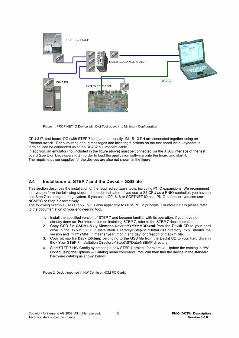
Figure 1: PROFINET IO Device with Digi Test board in a Minimum Configuration CPU 317, test board, PC (with STEP 7 tool) and, optionally, IM 151-3 PN are connected together using an Ethernet switch. For outputting debug messages and initiating functions on the test board via a keyboard, a terminal can be connected using an RS232 null modem cable. In addition, an emulator (not included in the figure above) must be connected via the JTAG interface of the test board (see Digi Developers Kit) in order to load the application software onto the board and start it. The requisite power supplies for the devices are also not shown in the figure.
2.4 Installation of STEP 7 and the Devkit – GSD file This section describes the installation of the required software tools, including PNIO expansions. We recommend that you perform the following steps in the order indicated. If you use a S7 CPU as a PNIO-controller, you have to use Step 7 as a engineering system. If you use a CP1616 or SOFTNET IO as a PNIO-controller, you can use NCM/PC or Step 7 alternatively. The following example uses Step 7, but is also applicable to NCM/PC, in principle. For more details please refer to the documentation of your engineering tool.
1. Install the specified version of STEP 7 and become familiar with its operation, if you have not already done so. For information on installing STEP 7, refer to the STEP 7 documentation.
2. Copy GSD file GSDML-Vx.y-Siemens-Devkit-YYYYMMDD.xml from the Devkit CD to your hard drive in the <Your STEP 7 Installation Directory>\Step7\S7Data\GSD directory. “x.y” means the version and “YYYYMMTT” means “year, month and day” of creation of that xml file.
3. Copy bitmap file Devkit50.bmp belonging to the GSD file from the Devkit CD to your hard drive in the <Your STEP 7 Installation Directory>\Step7\S7Data\NSBMP directory.
4. Start STEP 7 HW Config by creating a new STEP 7 project, for example. Update the catalog in HW Config using the Options → Catalog menu command. You can then find the device in the standard hardware catalog as shown below:
Figure 2: Devkit Imported in HW Config or NCM PC Config
RS232

Copyright © Siemens AG 2008. All rights reserved. 10 PNIO_DKSW_Description Technical data subject to change Version 3.0.0
When configuring a PROFINET IO network, you have the same look & feel as with PROFIBUS. You can use a drag-and-drop operation to add a device to the configuration and also to place modules. The devkit contains some example modules in the GSDML file that represent for example digital and analog input and output modules. However, these are only "virtual" modules that are not physically present. For compatibility to older PNIO controllers two different DAPs (device access points) for modular devices “Standard, PDEV” and “Standard, no PDEV” are implemented. DAP “Standard, PDEV” additionally contains the physical device (PDEV), which may be incompatible with older controller versions. The third DAP “ application example RT 1/4, 1-Port” contains a compact device with 2 fixed IO modules (64 byte input, 64 byte output), that must be used in combination with the RT source code example, included in the development kit.

Copyright © Siemens AG 2008. All rights reserved. 11 PNIO_DKSW_Description Technical data subject to change Version 3.0.0
2.5 Creating a PROFINET IO Configuration with STEP 7 The developer’s kit CD contains in the directory “Simatic_Step7” a finished STEP 7 project suitable for the device application. It includes the following:
• Bus configuration with CPU317 IO-controller and PNIO-device • Small STEP 7 program with interrupt OBs for process alarm, diagnostic interrupt (OB 82), and return of
submodule interrupt. • Variable table for online status display
We recommend that you use this example without modification for the initial startup. Import the Devkit_S7.zip project in STEP 7 SIMATIC Manager using the “File →Retrieve” menu command. Then, open HW Config in this project. The following configuration will be displayed”
Figure 3: Configuring a PROFINET Device in HW Config The screen mask shows the bus configuration, consisting of a CPU 317-2 PN/DP and a Digi ARM based DEVKIT as an IO-device. The table shows the module configuration for the selected device. In this example, there are 2 modules (one digital input module, one digital output modules) inserted in slots 1 and 2. The I-address and O-address columns indicate where the IO data are located in the process image of the CPU 317 for use in the STEP 7 program. In this example, the data for the input module in slot 1 (64 byte inputs) is located in IB 0 …63 in the process image.

Copyright © Siemens AG 2008. All rights reserved. 12 PNIO_DKSW_Description Technical data subject to change Version 3.0.0
Note: Depending on the version of the PNIO-controller one of the two different DAP’s (Device Access Points) V1.0 or V2.0 must be used. DAP V2.0 is set up on GSDML V2.0 and has additionally implemented the physical device (PDEV), which may be incompatible with older PNIO-controller versions. The physical device is represented by the following submodules, according to the PROFINET IO specification V2.1: Slot 0, Subslot 0x8000 Ethernet interface Slot 0, Subslot 0x8001 Ethernet Port 1 The modules in this example are, of course, only “virtual" modules, i.e., they do not physically exist on the test board. In addition, the indicated order numbers are defined and stored in the device description file (GSD file). The following settings were made in the example configuration:
IP address of the IO-controller: 192.168.3.176 IP address of the IO-device: 192.168.3.177
The red button can be used to download the PROFINET IO bus configuration to the IO-controller. However, the IP address specified in the configuration must be assigned to the IO-controller beforehand.

Copyright © Siemens AG 2008. All rights reserved. 13 PNIO_DKSW_Description Technical data subject to change Version 3.0.0
2.5.1 Assigning the IP Address for IO Device Before the IO controller can exchange IO data with the device, the device name must be set on the board. To do this, select the "PLC → Ethernet → Edit Ethernet node…” menu command, which starts the dialog below.
Figure 4: Assigning the device name in HW Config
(2) Then, press the “Browse node accessible online” button. HW Config scans the Ethernet bus for a few seconds and displays all online accessible IO-controllers and IO-devices with MAC address, IP address (if available), device name, and device type in another dialog. Click on the DEVKIT device and press OK. (3) Enter the device name in the dialog. In the Step7 project and the corresponding application source code example for the device name “anlage1” must be used. (4) Pressing the “Assign Name” button downloads the Name to the device. The following must also be noted when changing the device name:
• The device name must be unique from all others in the system. • The device name on the device must match the name in the configuration in HW Config. • In the application example for the NS9360 board, the device application is informed when the device
name on the device is changed, but the new name is not stored in the flash or NVRAM. After a restart,

Copyright © Siemens AG 2008. All rights reserved. 14 PNIO_DKSW_Description Technical data subject to change Version 3.0.0
the permanently assigned name (i.e., “anlage1“) in PNIO_Setup() is reentered on the device. Of course a “real” device must store the device name in a non volatile memory, it is handed back to the stack at next system startup.
2.5.2 STEP 7 Example Program The Development Kit contains a simple STEP 7 program suitable for the bus configuration. This program has the following functionality:
• When a diagnostic alarm occurs, a counter is incremented in DB 10 in the associated alarm OB82, indicating the number of diagnostic alarms that have occurred. In addition, the SFC 54 is called, which writes the alarm data supplied by the IO-device into a preassigned data block (here, DB182).
• When a process alarm occurs, a counter is incremented in DB 10 in the associated alarm OB40, indicating the number of process alarms that have occurred. In addition, the SFC 54 is called, which writes the alarm data supplied by the IO-device to a preassigned data block (here, DB140).
• When a “Return of Submodule" alarm occurs, a counter is incremented in DB 10 in the associated alarm OB83, indicating the number of “Return of Submodule” alarms that have occurred. No other data are supplied by the IO-device for this alarm, so an SFC 54 is not called in this case.
• Cyclic OB1 is empty. The I/O data of the devices are accessed directly using load and transfer commands in the process image; no additional discussion of this access will be provided here.
The sample program contains the following blocks: Block Function Remarks
OB1 Cyclic OB A counter in DB 10 is incremented cyclically in accordance with a clock memory.
OB40 Process alarm Increments a counter in DB10.Cnt_ProcAlarm for each process alarm and stores the alarm data of the device in DB 140.
OB82 Diagnostic alarm Increments a counter in DB10.Cnt_DiagAlarm for each diagnostic alarm and stores the alarm data of the device in DB 182.
OB83 Return of submodule alarm Increments a counter in continuous counter in DB 10. RetOfSubAlarm for each Return of Submodule alarm.
FC 1 Read Record Device reads a record once, if M31.7 is set. The received data are stored in DB 1.
FC 2 Write Record Device writes a record once if M 41.7 is set. The data are read from DB 2 and sent to the device.
OB 86 Loss of rack fault DB 1 Destination for Read record The data that are received with a ReadRecord via FC1
are stored here. DB 2 Source for Read/Write The data that are sent to the device with a WriteRecord
via FC2 are read here. DB 10 Counter for alarms Contains alarm counters for various alarms, which are
incremented in the corresponding alarm OBs. DB 40 Data block for OB 40 DB 52 Instance DB for SFB52 DB 53 Instance DB for SFB53 DB 82 Data block for OB 82 DB 140 Additional alarm information for
process alarm Contains the alarm data of the IO-device for a process alarm
DB 182 Additional alarm information for diagnostic alarm
Contains the alarm data of the IO-device for a diagnostic alarm
VAT_1 Variable table Display of utilized IO data areas (inputs and outputs in the process image) and alarm counters in DB10
Table 1: Overview of PNIO Controller Blocks for Example Project

Copyright © Siemens AG 2008. All rights reserved. 15 PNIO_DKSW_Description Technical data subject to change Version 3.0.0
2.5.3 Downloading the STEP 7 Program and the PROFINET IO Bus Configuration In Simatic Manager, the bus configuration can be downloaded to the CPU along with the STEP 7 program. To do so, select the CPU317 in Simatic Manager, click to open the menu PLC and download the complete data set to the CPU as shown in the figure below.
Figure 5: Downloading Example Program to S7 CPU
When it receives the bus configuration, the S7 CPU makes cyclic attempts to establish a connection to the IO-device. However, because the device is not yet active, an error status is displayed on the CPU by means of the red LEDs (SF, BF2). If the device starts up at a later time, the CPU detects this automatically, the IO data exchange is started, and the error LEDs are extinguished. However, the firmware for the IO-device must first be compiled, downloaded to the device, and started.
2.6 Compiling the Device Firmware with NET+OS Development Tools This section describes how to compile the PNIO user example when using the NET+ARM Developers Kit NET+OS 5.0 or NET+OS 6.0, the Greenhill V3.5 (for NET+OS 5.0) or V3.6.1 (for NET+OS 6.0) tools, and the ThreadX operating system.
2.6.1 Step 1: Install NET+OS Tools
1. Install the NET+OS software and the Greenhill Compiler/Linker tools included in the NET+Works Developers Kit. Refer to accompanying description for installation information.
2. Familiarize yourself with the Greenhill tools and the Net+OS software. For example, attempt to compile one of the included application examples (e.g., nahttp), download it to the NET+ARM 50 development board with the JTAG emulator, and start and debug it.
3. Attempt to recompile the standard board support package associated with the development board.
2.6.2 Step 2: Adapt NET+OS BSP V 6.3 for PROFINET IO Expanding the Board Support Package is no longer necessary in version NET+OS 6.3 or higher, because a so-called “bypass-interface“ is already integrated into the standard BSP code on which PROFINET IO can be set up. You only have to adjust the following settings in header file bsp.h of the selected platform: #define BSP_TICKS_PER_SECOND 1000 #define BSP_LOW_INTERRUPT_LATENCY TRUE #define BSP_USE_ETHERNET_RECV_QUEUE TRUE

Copyright © Siemens AG 2008. All rights reserved. 16 PNIO_DKSW_Description Technical data subject to change Version 3.0.0
#define BSP_ETHERNET_RECV_QUEUE_THREAD_PRIORITY 9 #define BSP_ENABLE_ETHERNET_BYPASS TRUE #define BSP_ETHERNET_BYPASS_SEND_BUFFERS 54 If you use a ARM7 based microcontroller (e.g. NET+50), the following bugfix-workaround also has to be set: #define BSP_WANT_2ND_ETHERNET_CHECKSUM TRUE In all other cases please set #define BSP_WANT_2ND_ETHERNET_CHECKSUM FALSE To optimize runtime behavior, set “optimize for speed“ and rebuild your BSP. If you use a different version of NET+OS, other modifications of the BSP may be necessary. In this case please contact the manufacturer.

Copyright © Siemens AG 2008. All rights reserved. 17 PNIO_DKSW_Description Technical data subject to change Version 3.0.0
2.6.3 Step 3: Compile a Complete PROFINET IO Device Application
1. After finishing the modifications in bsp.h, rebuild your BSP.
2. Now, recompile the application, including the stack. Because the PNIO software was developed on another platform, the Greenhill Compiler normally introduces various warnings.

Copyright © Siemens AG 2008. All rights reserved. 18 PNIO_DKSW_Description Technical data subject to change Version 3.0.0
2.7 Starting Up the User Example on the Device
2.7.1 Step 4: Loading and starting the PNIO Device Application 1. At the serial interface of the board (the interface that is located next to the plug connector for the supply
voltage), connect a hyperterminal and configure it as follows: 9600 Baud, 8 data bits, 1 stop bit, no parity)
2. Switch on the voltage on the board, and download the application onto the development board with the JTAG emulator.
3. Start the application. On the terminal connected via the serial interface some startup messages appear (parameters such as MAC address, etc., are different on your board)
4.
Figure 6: Startup Messages of the Test board on the RS232 Terminal Interface If problems occur during startup, set the PNIO interface logLevel in UsrlodMain.c from 1 to 3 for calling PNIO_Setup(). This provides you with additional log messages to help you locate faults.
NET+WORKS Version 6.3 Copyright (c) 2000-2004, NETsilicon, Inc. PLATFORM: ns9360_a APPLICATION: PROFINET IO developers kit ----------------------------------------------------------------------------- NETWORK INTERFACE PARAMETERS: IP address on LAN is 0.0.0.1 LAN interface's subnet mask is 255.255.255.0 IP address of default gateway to other networks is 0.0.0.1 HARDWARE PARAMETERS: Serial channels will use a baud rate of 9600 This board's serial number is N99999999 This board's MAC Address is 00:40:9D:28:D7:BC After board is reset, start-up code will wait 5 seconds Default duplex setting for Ethernet connection: phy Default ----------------------------------------------------------------------------- Press any key in 5 seconds to change these settings. ACE: Have IP address on interface eth0: 0.0.0.1 Network IP configured. scheduling rate is 1000 ticks per second Initial Performance finished, value = 185000 local IP address = 1h link port1: Status=1, Speed=2, Mode=2 change port number of MIB2 agent to 8161, State = 0... read port number of MIB2 agent:= 8161..., State = 0 ...OK, done ...OK, done read MIB2 SysDescription... value = NETOS 6.3 read MIB2 SysName... value = NETsilicon, Inc. read MIB2 SysContact... value = www.netsilicon.com read MIB2 SysLocation... value = 411 Waverly Oaks Road, Waltham MA, 02452 modify some MIB2 objects... ... and read them again read MIB2 SysName... value = anlage1 read MIB2 SysContact... value = www.siemens.de/comdec read MIB2 SysLocation... value = D90766 Fuerth Wuerzburger Str 121 start MIB2 support for PROFINET IO.... ##REMA SHADOW MEM RESTORE PNIO DEVKIT Version 2. 2. 0. 0

Copyright © Siemens AG 2008. All rights reserved. 19 PNIO_DKSW_Description Technical data subject to change Version 3.0.0
2.7.2 Starting Up PROFINET IO Communication 1. Before IO communication with a PNIO-device can be started, a device name must be assigned to the
device. To do so, go to the configuration in HW Config, click on the device, and select the PLC → Ethernet → Assign Device Name menu command. HW Config scans the Ethernet bus and searches for connected PNIO-devices. The device must be visible. “Anlage1” was the device name assigned in the device application; “DEVKIT“ was the device type assigned. In addition, MAC address and IP address (if present) are indicated.
2. The device name setting on the device (“Anlage1”) was also used in the HW Config configuration. Because the two names must match, you should not change the device name setting on the device. Blinking can be clicked as a test function. To simulate real blinking (implemented by the user), the following is displayed on the terminal:
Figure 7: Messages on the hyperterminal when activating the blink function
3. This enables the PNIO communication between HW Config and STEP 7 to function. Now, the connection between PNIO-controller and STEP 7 will be started up. To do so, click on the CPU in the configuration you created in HW Config, and select the PLC → Ethernet → Assign Ethernet Address menu command. The “Assign Ethernet Address" dialog is displayed. Click Browse… in the MAC_Address field. The controller is located after just a few seconds and its MAC address, IP address, station name, and station type is displayed (other active PNIO-devices on the bus may also be displayed). Select the controller and set a valid IP address if the controller does not have one already.
4. Now, download the configuration from HW Config to the PNIO-controller using the PLC → Download to Module menu command. Use the STEP 7 project supplied on the Devkit CD; this project is tuned to the example application.
5. Once a successful download operation to the CPU has taken place, an attempt is made to establish a connection to the PNIO-device. After a few seconds, the following messages appear on the terminal interface of the device:
Figure 8: Messages on the hyperterminal at connection startup
*** AR-CHECK_IND: RT AR *** ArNum = 1, Session = 1 ArType = 0x1, ArProp = 0x11, NumofApi = 1 Device Hndl = 5, HostIP = 192.168.20.176 StationName = pn-io, Length = 5 ********** new RT Class 1 connection ********** AR-INFO_IND new ArNum=1 Session=1, NumOfIocr = 2 IOCR 0: IocrProp = 0x1, Direction=1, SendClk = 32 RedRatio = 128, NumOfApiObj ects = 1 IOCR 1: IocrProp = 0x1, Direction=2, SendClk = 32 RedRatio = 128, NumOfApiObj ects = 1 Number of Api's = 1 Number of Modules = 7 Module plugged; Api = 0, Slot = 0, ModID = 0x300, Subslot = 1, SubId = 0x0 Module plugged; Api = 0, Slot = 0, ModID = 0x300, Subslot = 32768, SubId = 0x1 Module plugged; Api = 0, Slot = 0, ModID = 0x300, Subslot = 32769, SubId = 0x2 Module plugged; Api = 0, Slot = 1, ModID = 0x101, Subslot = 1, SubId = 0x0 Module plugged; Api = 0, Slot = 2, ModID = 0x101, Subslot = 1, SubId = 0x0 Module plugged; Api = 0, Slot = 3, ModID = 0x102, Subslot = 1, SubId = 0x0 Module plugged; Api = 0, Slot = 4, ModID = 0x201, Subslot = 1, SubId = 0x0 Module plugged; Api = 0, Slot = 5, ModID = 0x201, Subslot = 1, SubId = 0x0 Module plugged; Api = 0, Slot = 6, ModID = 0x202, Subslot = 1, SubId = 0x0 ##WRITE_REC RQ, Api=0 Slot=1 Subslot=1 Index=1, Len=4, Sequ_nr=0 ##REC_DATA = 0x 1 0x 1 0x56 0x78 …. etc…..
##LED Blink START, frequency = 2 Hz ##LED Blink STOP
Copyright © Siemens AG 2008. All rights reserved. 20 PNIO_DKSW_Description Technical data subject to change Version 3.0.0
6. After the user data exchange begins, the SF LED as well as the two BF LEDs go out on the CPU. The RX/TX lamp illuminates permanently or flickers according to the update time configured in HW Config (1 ms to 128 ms).
7. Your PROFINET IO-device now exchanges user data cyclically with the controller. You can now create a variable table with the IO data of your device in SIMATIC Manager and use it to observe the user data exchange. If you click on the device in your PROFINET IO configuration (HW Config), the modules in the corresponding slots are displayed in a table along with the I addresses and O address in the S7 CPU onto which the slots are mapped.
8. You can read the current content of the user data on the PNIO-device if you enter a “j” on the terminal interface. The current state of the data is read once each time the “j” key is pressed. The content of the displayed data must match that in the STEP 7 variable table.
9. Continue to familiarize yourself with the application example. Activating the “?” key on the terminal displays the possible commands. Refer also to the associated application source code, especially the UsrlodMain.c and PNIO_Event.c. modules.
2.8 Assistance in Case of Commissioning Problems
A variety of problems can occur when commissioning the NET+ARM50 Developers Board based on the provided user example as well as when porting the NET+ARM50 Developers Board to your own hardware, porting it to a different toolchain (GNU with ThreadX), or porting it to a different operating system with your own toolchain, etc. The causes of these problems vary but often have the same result: cyclic data communication cannot be commissioned. If other errors have also occurred at the same time, the elimination of one error does not produce a successful result. At the most, the error profile changes or a subsequent state in the system startup is correctly achieved. To simplify troubleshooting, we recommend the following procedure: The sections below illustrate commonly occurring problems and their remedies. Different application cases are assumed:
- Commissioning of the provided user example without software modifications. This is the simplest case. - Commissioning of customer hardware based on the operating system and toolchain of the provided
example, i.e., ThreadX and Greenhill tools. - Commissioning of customer hardware with a different operating system (not ThreadX) and a different
toolchain (not Greenhill). The described problems and remedies are not all-inclusive but, rather, provide some guidance. The application cases can be regarded as hierarchical. For example, if you are using a non ARM Controller and not the ThreadX operating system or any tools, the possible error causes identified in the preceding subsection should always be eliminated first.
If you don’t work with the example plattform (NS9360, NET+OS6.x), you should build a reference system on your platform first, which is most similar to the application example on CD. That means, first only adapt the OS, BSP and socket interfaces and keep the application untouched. After the reference system is running properly, integrate your customer application.

Copyright © Siemens AG 2008. All rights reserved. 21 PNIO_DKSW_Description Technical data subject to change Version 3.0.0
2.8.1 …With Provided Standard Example No. Problem Possible Causes/Remedy 1 A connection has not been
established between the controller and device
Check whether controller and device are able to communicate over Ethernet. They must be visible in the lifelist of STEP7/HWCNOFIG.If not, continue with no. 2, else no. 3.
2 PNIO-controller or device not visible on the bus in HW Config
check hardware and connection cable. Try to connect the controller and device directly using a crossover Ethernet cable.
3 A connection has not been established between the controller and device
Check whether the station name assigned during configuration matches the name assigned in the device firmware. In the software example in usriod_main.c, “anlage1” is the entered station name. Check also, that the IP addresses of controller and device join the same subnet.
4 Communication breaks down sporadically
check hardware and connection cable. Try to connect the controller and device directly using a crossover Ethernet cable.
Table 2: Remedy for Commissioning Problems with Standard Example
2.8.2 … With Customer Hardware/Application with ThreadX, Greenhill Tools No. Problem Possible Causes/Remedy 1 All indicated problems First, eliminate possible causes of error that were described in the
previous section. 2 Communication breaks down
sporadically 1. Eliminate hardware and network problems. 2. Check the priority settings for the PNIO tasks; these should
not be changed. 3. Eliminate (as much as possible) the effect of non-PNIO
code with higher priority (task, system level, interrupt) than the PNIO software.
4. For test purposes, set the EDD base clock of 1 ms to 2 ms or 4 ms. Notice: the configured bus cycle time cannot be less than the EDD base clock. The base clock is set via #define EDD_CFG_CYCLE_BASE_FACTOR in module os_cfg.h.
5. Check for adherence with the EDD base clock, i.e., whether the message loop in the Task_Edd_high () function (see sys_tsk.C module) is triggered regularly and the jitter is not too high. By setting the define #ifdef _DEBUG_LOGGING_CIRC_BUF, the runtimes of various synchronization points in the code can be written to a circular buffer. Increase the accuracy of the measurements by using a hardware timer in OsSetEntryCircBuf() (gh_os.c module).
6. Increment for a test the bus cycle time, configured in STEP7.
7. Many slow debug printf outputs (for example on a RS232 interface) can disturb the realtime properties of the system extremely. For a test reduce the debug logging in compiler.h and check, if system behavior is better afterwards.
Table 3: Remedy for Commissioning Problems with Customer Hardware with ThreadX

Copyright © Siemens AG 2008. All rights reserved. 22 PNIO_DKSW_Description Technical data subject to change Version 3.0.0
2.8.3 Other Tips In addition to the problems described in the preceding sections, other errors can occur when different microcontrollers, operating systems, tools, etc., are used. Because these problems are too numerous and varied, a tabular correlation of problem descriptions and possible causes is not feasible. Instead, a list of possible causes is provided without further details on how the associated errors are manifested. Additional problem causes:
• Alignment problems: all data structures declared between #include "xx_pck.h" and #include "xx_unpck.h" must be byte-aligned. Here, “xx” stands for the packet name, such as “acp” or “cm”. Attention must be paid that the compiler-specific alignment settings were made appropriately.
• Excessively long interrupt disables in system or application code, or displacement of the EDD through higher priority user code. These conditions adversely impact the real-time behavior of the PNIO-stack. This can result in sporadic disconnections in the case of short bus cycle times or short EDD base clock times (1 ms).
• Hardware or compiler faults • Programming errors in the BSP or user application
Work sequence when porting and commissioning on your platform:
1) Port the following interface modules: gh_os.c, gh_bspadapt.c, ossocket.c, compiler.h, os_cfg.h, iod:_cfg.h
2) Assume as much of the remaining code as possible without changes and generate a system. 3) Load and test your system until it starts up without problems, first without an Ethernet connection. 4) Connect the device to Ethernet and use a "PING" to determine whether the TCP/IP stack is running. 5) Check whether the device shows up in the life list of HW Config. This ensures that the device can always
receive PNIO frames with FrameID 0x8892 (checker functionality). 6) Download the example configuration to the controller and activate the cyclic data transmission. 7) Test whether the cyclic data transmission also functions with short bus cycle times. You now have an
executable reference system. 8) Replace the example user application step-by-step with your own user application. If you want to stop
and perform debugging in the stack, you can revert back to the reference system as a basis for comparison.

Copyright © Siemens AG 2008. All rights reserved. 23 PNIO_DKSW_Description Technical data subject to change Version 3.0.0
3 PROFINET IO Software Creation This chapter has been rolled out into the document “PNIO DK user interface description”, which is contained in the same subdirectory on the product CD. The user interface description is one document, valid for different developer kits (ERTEC, standard ethernet controller).

Copyright © Siemens AG 2008. All rights reserved. 24 PNIO_DKSW_Description Technical data subject to change Version 3.0.0
4 Creating GSD Files
The properties of a PROFINET device are stored in a Generic Station Description (GSD) file in XML format. The descriptive language is called GSDML (ML stands for markup language). The GSD file must be created by the PN IO device manufacturer and is imported by the engineering tool (STEP 7) to create the bus configuration. The detailed structure of the GSD file is described in /3/. The document, including the necessary schema files for PROFINET IO for validation, can be downloaded from the PNO at http://www.profibus.com. You need the following tools and templates to create the GSD file:
1. XML editor: with this editor, you can create XML files and check the correct format using schema files for PROFINET IO.
2. Schema files for PROFINET IO: these files can be downloaded along with the GSDML specification from the PNO server website indicated above.
3. Example template for a GSD file. These files are also included when you download the GSDML specification and the PNIO schema files. Alternatively, you can use the GSDML file from the Development Kit user example as a template.
4. You must enter a vendor ID, among other information, in the GSD file. This vendor ID must be requested from the PNO (if it is not already available) and cannot be defined by the user.
For detailed information about the GSD file structure, refer to document /3/. Note: When creating a user-defined GSDML file, note that not all parameters can be user-defined. The XML-scheme files require syntactically and structurally valid XML files. Use the supplied GSDML file as a template. Assign a unique name and to the extent possible, change only the module number and sizes within the permissible quantity framework (see above). Certain attributes in the GSDML file may not be changed. For the API“ attribute of the VirtualSubmoduleItem element, only the value range 0x0 to 0x7FFFFFFF is enabled. The document, including the necessary schema files for PROFINET IO for validation and a PROFINET XML viewer for checking the GSD file can be downloaded from the PNO at http://www.profibus.com.
Copyright © Siemens AG 2008. All rights reserved. 25 PNIO_DKSW_Description Technical data subject to change Version 3.0.0
5 SNMP (Simple Network Management Protocol)
5.1 Diagnostics via SNMP
Via SNMP (Simple Network Management Protocol), a network management station can configure and monitor stations with SNMP capability. To this end, a management agent is installed in the station. The management station exchanges data via so-called get and set requests.
5.2 Management Information Base MIBs
An MIB (Management Information Base) is a device database. SNMP clients access this database in the device. The DK ERTEC400 PNIO supports standardized MIBs: MIBII and LLDP-MIB Standardized MIBs are defined in RFC standards and contain parameters that are divided into so-called groups.
5.3 SNMPv1 and SNMPv2 Protocols
The SNMP agent integrated in the DK ERTEC400 PNIO supports the SNMPv1 and SNMPv2 protocols. All objects of the MIB-II and LLDP-MIB that are relevant for the product can be queried via the SNMPv1 and SNMPv2 protocols. The MIB-II of the DK ERTEC400 PNIO contains all groups except egp and transmission.
5.4 SNMP Communities
Access via SNMP is governed by the Communities concept. Communities are passwords used for SNMP access. In the development kit, communities are permanently set to the default values "public" and "private". Access Community Read access only public Read and write access private
5.5 Definition of Abbreviations and Source for Additional Information
Refer to the table below for a definition of abbreviations mentioned above and an indication of where you can find additional information.
Abbreviation Meaning Additional Information
SNMP Simple Network Management Protocol RFC 1157 SNMP V2 Simple Network Management Protocol Version 2
(Administration, Protocol Operations and Security) RFC 1901 and RFC 1905
SMIv1 Structure and Identification of Management Information – describes the structure of the MIB objects.
RFC 1155
MIB-II Management Information Base, Version 2 RFC 1213
5.6 Variables of the MIB II Standard
Variables in the System Directory The following table shows some SNMP variables of the MIB II standard for monitoring the device status from the System directory. The access authorizations refer to access via the SNMP protocol.

Copyright © Siemens AG 2008. All rights reserved. 26 PNIO_DKSW_Description Technical data subject to change Version 3.0.0
Variable Access
Authorizations Description
sysDescr Read access only Contains a manufacturer-specific device identification, e.g., "SIEMENS", "SIMATIC NET" “ERTEC400 Developmentkit“ A string of up to 255 characters is used. Data type: DisplayString
sysObjectID Read access only 0, as a device-specific (private) MIB is not supported
sysUpTime Read access only Time after the last reset, for example, after power up; specified as a multiple of 1/100 of a second.
sysContact Read and write access
A contact name can be entered here; factory setting: empty string. The possible value is a string with up to 255 characters.
sysName Read and write access
Name of the device; factory setting: empty string. The possible value is a string with up to 255 characters.
sysLocation Read and write access
Device location; factory setting: empty string. The possible value is a string with up to 255 characters.
sysServices Read access only Shows the functions (services) performed by the components according to ISO/OSI model. Each bit stands for one of 7 OSI layers. The default setting is as follows: Bit 2 set – Layer 2, primarily switching Bit 4 set – Layer 4, configuration via RFC 1006 Bit 7 set – Layer 7, PROFINET IO
Variables in the "Interfaces" Directory The following table shows some SNMP variables for monitoring the device status from the "Interface“ directory. SNMP Variable Access
Authorizations
Description
ifDescr Read access only
Description and any necessary additional information for a port. Port <PortNumber> is shown
ifInErrors Read access only
Number of packets received that were not relayed to higher protocol levels due to detected errors. Data type: Counter
ifLastChange Read access only
Time the selected port has been in its current mode, see "ifOperStatus“. Specified in multiples of 1/100 of a second. Data type: TimeTicks
ifNumber Read access only
Number of different interfaces available in the component. For an ERTEC400 Developmentkit, the value 5 is output (4 physical ports + 1 virtual port for the development kit itself). Data type: Integer
ifOperStatus Read access only
Current operating mode of the Ethernet port The following values are possible: 1: up 2: down Data type: Integer
ifOutErrors Read access only
Number of packets that were not sent due to an error. Data type: Counter
ifPhsAddress Read access only
MAC address of the ERTEC 400 development kit Data type: PhysAddress
ifSpeed Read access only
Data transfer rate of the Ethernet port in bits per second For the ERTEC400 development kit, either 10 Mbits/s or 100 Mbits/s is indicated. Data type: Gauge
ifType Read access only
For the ERTEC400 development kit, the value 5 (ethernet-csmacd) is entered. Data type: Integer

Copyright © Siemens AG 2008. All rights reserved. 27 PNIO_DKSW_Description Technical data subject to change Version 3.0.0
ifSpecific Read access only
Specific reference Here, a fixed value of "0.0“ is used, as no reference is available. Data type: OBJECT IDENTIFIER
Port Indices Port-specific objects can be addressed via "SNMP-Variable.Port-Number“. In the ERTEC400 development kit, the interface index corresponds to the port number. The virtual port has the number "5". Example: The “IfOperStatus.1“ variable determines the operating state (up, down) of Port 1.

Copyright © Siemens AG 2008. All rights reserved. 28 PNIO_DKSW_Description Technical data subject to change Version 3.0.0
6 Important Information and Limitations
6.1 Resource Requirements
The following resources are used in the current implementation (including operating system): • About 1,5 Mbytes of flash memory uncompressed • About 3 Mbytes SDRAM including Code (Code is executed in RAM)
6.2 Minimum IO cycle time
The minimum IO cycle time is set to 1 msec.
6.3 Auto-MDIX
Auto-MDIX provides the automatical adaptation for the send- and receive-channel of an ethernet port. Remote Uplink- and normal ports are recognized automatically and the local port is configured accordingly. Patch cable can be used as well as crossover cable. Unlike earlier versions this feature is mandatory in IEEE 802.3 – 2005, but it is not yet supported by the NS9360 development board. Digi International has developed a solution proposal, for more information to that subject please contact Digi International directly. Alternatively you can use another PHY with auto MDIX capability, e.g.
- Broadcom BCM5221A4KPTG - NSC 83849IVS NOPB

Copyright © Siemens AG 2008. All rights reserved. 29 PNIO_DKSW_Description Technical data subject to change Version 3.0.0
7 Appendix
7.1 Abbreviations ACP Acyclic Communication Protocol refers to one of the basic software packages of the PNIO-stack BSP Board Support Package CLRPC Connectionless Remote Procedure Call CM Context Management DAP Device Access Point, specified entry in the GSD file DCP Dynamic Configuration Protocol EDD Ethernet Device Driver ELOG Error Logging for debugging purposes (Level 1 = Only errors are output) GH GreenHill Abbreviation used in these document for the compiler/linker used in the NET+ARM example
implementation. GSDML Generic Station Description Markup Language GSY Generic Sync module refers to one of the basic software packages of the PNIO-stack IOD IO Device (instance) ILOG Important Logging for debugging purposes (Level 2 = output from ELOG + ILOG) IOCS IO Consumer Status IOPS IO Provider Status IRT Isochronous RealTime LOG Logging for debugging purposes (Level 3 = output from ELOG + ILOG + LOG) MIB Management Information Base. Data base for SNMP services MLOG Memory Logging for debugging purposes (Level 4 = output from ELOG + ILOG + LOG +MLOG) NRT Non Realtime is a generic term for all non-realtime frames (not type 0x8892) OS Operating System refers here to the abstraction layer for any operating system to which the PNIO-stack
is to be ported. PDEV Physical Device PNIO PROFINET IO PNO PROFIBUS Trade Organization RT Realtime is a generic term for acyclic and cyclic realtime SNMP Standard Network Management Protokoll SOCK UDP socket interface for PROFINET IO UDP User Datagram Protocol

Copyright © Siemens AG 2008. All rights reserved. 30 PNIO_DKSW_Description Technical data subject to change Version 3.0.0
7.2 List of References:
/1/ PROFINET IO Application Layer Service Definition & PROFINET IO Application Layer Protocol Specification (Downloadable from PNO Website http://profibus.com)
/2/ GSDML Specification for PROFINET IO Version 2.10 August 2006, Order No: 2.352 PROFIBUS Nutzerorganisation e.V.
(Downloadable from PNO Website http://profibus.com) /3/ a) Das PROFINET IO-BUCH Grundlagen und Tipps für Anwender
Manfred Popp Hüthig Verlag ISBN 3-7785-2966-8 (only German version available)
b) Industrial communication with PROFINET IO
Manfred Popp PROFIBUS Nutzerorganisation e.V.
Order No: 4.182
/4/ PROFINET Technology and Application System Description
(downloadable from PNO website http://profibus.com)
/5/ SIMATIC PROFINET System Description System Manual A5E00298288-02 Part of documentation packages with order numbers 6ES7398-8FA10-8BA0 and 6ES7151-1AA10-8BA0 /6/ PROFINET IO DK User_Interface_Description_V3.0.0 (is part of this product)