profibus tester bc-700-pbencon-koester.com/wp-content/uploads/2016/02/bc-700-pb... ·...
TRANSCRIPT

© Copyright 2014 Softing Industrial Automation GmbH
Getting Started with PROFIBUS Tester 5 BC-700-PB
PROFIBUS Tester 5 BC-700-PB
User Manual
Version: MMA-NN-006005-EN-1408-1.01
Insert graphic file from e.g.\\Sfiler\iap_intern\10_Marketing\02_Materials\02-11_Photos
For positioning data see..\<projectdirectory>\Images\readme_insert_graphics.txt"

The information contained in these instructions corresponds to the technical status at the time of printing of it and ispassed on with the best of our knowledge. The information in these instructions is in no event a basis for warrantyclaims or contractual agreements concerning the described products, and may especially not be deemed as warrantyconcerning the quality and durability pursuant to Sec. 443 German Civil Code. We reserve the right to make anyalterations or improvements to these instructions without prior notice. The actual design of products may deviate fromthe information contained in the instructions if technical alterations and product improvements so require.
It may not, in part or in its entirety, be reproduced, copied, or transferred into electronic media.
Disclaimer of liability
Softing Industrial Automation GmbH
Richard-Reitzner-Allee 685540 Haar / GermanyTel: + 49 89 4 56 56-0Fax: + 49 89 4 56 56-488Internet: http://industrial.softing.comEmail: [email protected]: [email protected]
The latest version of this manual is also available in the Softing download area at: http://industrial.softing.com.
Table of Contents
PROFIBUS Tester BC-700-PB - User Manual 3
Table of Contents
Chapter 1 ..................................................................................7Introduction
................................................................................................ 71.1 About PROFIBUS Tester 5 BC-700-PB
................................................................................................ 71.2 About this document
..................................................................................................................... 7Purpose 1.2.1
..................................................................................................................... 7Target group 1.2.2
..................................................................................................................... 8Conventions used 1.2.3
..................................................................................................................... 8Document history 1.2.4
................................................................................................ 81.3 Scope of delivery
................................................................................................ 91.4 Optional accessories
..................................................................................................................... 9D-sub adapter cable for testing live systems 1.4.1
..................................................................................................................... 10Adapter set for M12 connection technology 1.4.2
..................................................................................................................... 10Fieldbus shield digital leakage current clamp 1.4.3
..................................................................................................................... 10Adapter for testing PROFIBUS PA networks 1.4.4
..................................................................................................................... 11Spare rechargeable battery 1.4.5
..................................................................................................................... 12Service interfaces for PROFIBUS DP 1.4.6
....................................................................................................... 12Connection type D-sub1.4.6.1
....................................................................................................... 13Connection type M121.4.6.2
................................................................................................ 131.5 System requirements
................................................................................................ 141.6 Connectors and controls
Chapter 2 ..................................................................................15Prepare device
................................................................................................ 152.1 Insert battery
................................................................................................ 162.2 Charge battery
Chapter 3 ..................................................................................17Startup
................................................................................................ 173.1 Power-up
................................................................................................ 173.2 Power-up behaviour without USB connection
................................................................................................ 183.3 Power-up behaviour with USB connected
Chapter 4 ..................................................................................19Power-off and sleep mode
Chapter 5 ..................................................................................20Install software and connect to PC
Chapter 6 ..................................................................................21Connection to PROFIBUS
................................................................................................ 216.1 General information
..................................................................................................................... 21Possible side effects when testing a live bus 6.1.1

PROFIBUS Tester BC-700-PB - User Manual
Table of Contents
4
..................................................................................................................... 21Connection types 6.1.2
..................................................................................................................... 22Adapter cable 6.1.3
..................................................................................................................... 22Strain relief 6.1.4
..................................................................................................................... 23Using the security lock port 6.1.5
..................................................................................................................... 23Test locations 6.1.6
................................................................................................ 236.2 Simple connection for tests during system shutdown
................................................................................................ 246.3 Connection for testing a live bus (DP)
..................................................................................................................... 25Connection via D-sub connector with service socket 6.3.1
..................................................................................................................... 26Direct cable connection 6.3.2
..................................................................................................................... 27Connection via M12 connector 6.3.3
................................................................................................ 276.4 Master simulator, topology scan and cable test
................................................................................................ 296.5 Connecting to PROFIBUS-PA networks
..................................................................................................................... 29Test locations 6.5.1
..................................................................................................................... 31Requirements for analyzing a live bus 6.5.2
..................................................................................................................... 31Analyzing during system shutdown 6.5.3
..................................................................................................................... 31Bus connection 6.5.4
Chapter 7 ..................................................................................32Display and controls in stand-alone mode
................................................................................................ 327.1 Main display
................................................................................................ 327.2 User interface
................................................................................................ 347.3 Operating functions and softkeys
................................................................................................ 357.4 Device status
................................................................................................ 367.5 Menu functions
................................................................................................ 397.6 Organize and store test results
Chapter 8 ..................................................................................41Import data into the PC
Chapter 9 ..................................................................................42Licenses
Chapter 10 ..................................................................................43Firmware update
Chapter 11 ..................................................................................44Maintenance and service
Chapter 12 ..................................................................................45Troubleshooting
Chapter 13 ..................................................................................47Tips and tricks for cable testing
................................................................................................ 4713.1 Assessment criteria
................................................................................................ 4813.2 List of fault indications and remedial measures
................................................................................................ 5113.3 Metering the cable segment length correctly
Chapter 14 ..................................................................................53Notes on battery use
................................................................................................ 5314.1 Lithium backup battery

Table of Contents
PROFIBUS Tester BC-700-PB - User Manual 5
................................................................................................ 5314.2 Rechargeable battery pack
..................................................................................................................... 53Guidelines and warnings on battery use 14.2.1
..................................................................................................................... 54Charging 14.2.2
..................................................................................................................... 55Discharging 14.2.3
..................................................................................................................... 55Storage and transportation 14.2.4
..................................................................................................................... 55Battery life 14.2.5
..................................................................................................................... 55Battery warranty 14.2.6
Chapter 15 ..................................................................................56Technical data
Chapter 16 ..................................................................................58Declarations by the manufacturer
Chapter 17 ..................................................................................59Recycling

This page is intentionally left blank.
Chapter 1 - Introduction
PROFIBUS Tester BC-700-PB - User Manual 7
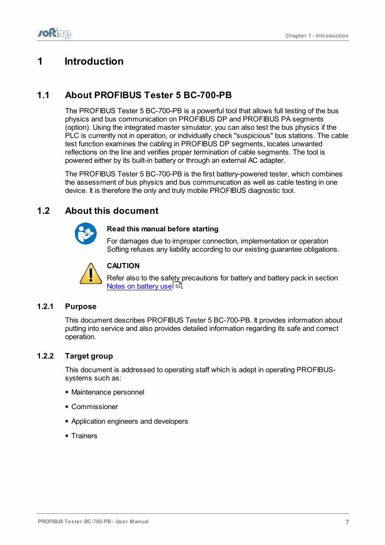
1 Introduction
1.1 About PROFIBUS Tester 5 BC-700-PB
The PROFIBUS Tester 5 BC-700-PB is a powerful tool that allows full testing of the busphysics and bus communication on PROFIBUS DP and PROFIBUS PA segments(option). Using the integrated master simulator, you can also test the bus physics if thePLC is currently not in operation, or individually check "suspicious" bus stations. The cabletest function examines the cabling in PROFIBUS DP segments, locates unwantedreflections on the line and verifies proper termination of cable segments. The tool ispowered either by its built-in battery or through an external AC adapter.
The PROFIBUS Tester 5 BC-700-PB is the first battery-powered tester, which combinesthe assessment of bus physics and bus communication as well as cable testing in onedevice. It is therefore the only and truly mobile PROFIBUS diagnostic tool.
1.2 About this document
Read this manual before starting
For damages due to improper connection, implementation or operationSofting refuses any liability according to our existing guarantee obligations.
CAUTION
Refer also to the safety precautions for battery and battery pack in section Notes on battery use .
1.2.1 Purpose
This document describes PROFIBUS Tester 5 BC-700-PB. It provides information aboutputting into service and also provides detailed information regarding its safe and correctoperation.
1.2.2 Target group
This document is addressed to operating staff which is adept in operating PROFIBUS-systems such as:
Maintenance personnel
Commissioner
Application engineers and developers
Trainers
53

Chapter 1 - Introduction
8 PROFIBUS Tester BC-700-PB - User Manual
1.2.3 Conventions used
The following conventions are used throughout Softing customer documentation:
Keys, buttons, menu items, commands andother elements involving user interaction areset in bold font and menu sequences areseparated by an arrow
Open Start Control Panel Programs
Buttons from the user interface are enclosedin brackets and set to bold typeface
Press [Start] to start the application
Coding samples, file extracts and screenoutput is set in Courier font type
MaxDlsapAddressSupported=23
Filenames and directories are written in italic Device description files are located in C:\StarterKit\delivery\software\DeviceDescription files
CAUTION
CAUTION indicates a potentially hazardous situation which, if not avoided,may result in minor or moderate injury.
Note
This symbol is used to call attention to notable information that should befollowed during installation, use, or servicing of this device.
Hint
This symbol is used when providing you with helpful user hints.
1.2.4 Document history
Document version Modifications compared to the previous version
Version 1.00 none - initial document version
Version 1.01 Editorial modifications due to internal review
Order numbers for optional accessories added
New device status symbols added
New cable test note added
1.3 Scope of delivery
The PROFIBUS Tester 5 comes in a carrying case comprising:
Test tool with RS485 interface
Rechargeable battery pack (internal battery)
Wide-range power supply with European and US mains power cables
RS485 D-sub adapter cable BC-600-PB-CB-DSUB-2 "Standard" (cable petrol blue,light connector) for PROFIBUS DP

Chapter 1 - Introduction
PROFIBUS Tester BC-700-PB - User Manual 9
USB cable, 3 m
Terminal block for trigger input/output
CD-ROM with driver software, PC software and detailed integrated help system inEnglish and German
PROFIBUS Tester 5 BC-700-PB User Manual and Quick Startup Guide for thePROFIBUS Diagnostics Suite PC software.
Figure 1: PROFIBUS Tester 5 BC-700-PB with carrying case
1.4 Optional accessories
1.4.1 D-sub adapter cable for testing live systems
This D-sub adapter cable is optimized for reduced influence on live PROFIBUS DPsegment operation. Thereby it is most suitable for testing of running plants. The risk ofcritical influences on bus operation which can cause a plant standstill is significantlyreduced.
Note
When using this cable it is not possible to use the three active functionsmaster simulator, topology scan and cable testing (see Master simulator,topology scan and cable test ).27

Chapter 1 - Introduction
10 PROFIBUS Tester BC-700-PB - User Manual
Figure 2: D-sub adapter cable with reduced influence on bus operation
Softing Order No.: BC-600-PB-CB-DSUB-1
1.4.2 Adapter set for M12 connection technology
Using the M12 adapter set, you can connect the PROFIBUS Tester 5 to field devices withM12 connectors. The set comprises an M12 adapter cable with special pin layout and anM12 terminating resistor that you can screw on, if required.
Figure 3: Special adapter set for M12
Softing Order No.: BC-600-PB-CB-M12
1.4.3 Fieldbus shield digital leakage current clamp
When routing PROFIBUS cables in high-interference environments, electromagneticinterference can affect the signal quality. By measuring the shield currents with the digitalleakage current clamp, you can locate EMC problem areas and take appropriatecountermeasures. The digital leakage current clamp is supplied in a handy case, includingmeasuring cables. There is also an empty compartment for the fieldbus shield digitalleakage current clamp in the carrying case of the PROFIBUS Tester 5 BC-700-PB.
Figure 4: Fieldbus shield digital leakage current clamp
Softing Order No.: PB-LSZ-CHB3
1.4.4 Adapter for testing PROFIBUS PA networks
The BC-700-H1 adapter and the supplied test equipment set allows to connect the

Chapter 1 - Introduction
PROFIBUS Tester BC-700-PB - User Manual 11
PROFIBUS Tester 5 to PROFIBUS PA network segments. It converts the MBP-coded(manchester bus powered) PROFIBUS-PA signal to a format which is appropriate for theRS-485 interface of PROFIBUS Tester 5. The POWER LED indicates if the BC-700-H1 iscorrectly connected to PROFIBUS-Tester 5. If the PA-STATE LED is lit, the BC-700-H1adapter is correctly connected to a PROFIBUS-PA network and detects a PROFIBUS-PADC feeding voltage greater than 9 Volts.
Figure 5: BC-700-H1 Adapter
Figure 6: Supplied test equipment set for connecting to PROFIBUS PA segments
Softing Oder No.: DDL-NL-006010 (Adapter and test equipment)
1.4.5 Spare rechargeable battery
Intensive use of PROFIBUS-Tester 5 during the work day may exhaust the rechargeablebattery faster than expected. Plus, charging and discharging will typically wear out thebattery pack over the time (refer to Notes on battery use ). PROFIBUS-Tester 5contains an energy management. If the measures for energy saving are not sufficient orare perceived as a disturbance it is recommended to operate on the device in conjunctionwith an external power supply. Alternatively the user may use a spare rechargeablebattery.
53

Chapter 1 - Introduction
12 PROFIBUS Tester BC-700-PB - User Manual
Figure 7: Rechargeable battery pack
Softing Order No.: ABA-NN-006012
1.4.6 Service interfaces for PROFIBUS DP
1.4.6.1 Connection type D-sub
The D-sub service interface provides a PROFIBUS access point for testing if the existingD-sub connectors have no service socket or if the bus stations are connected via aterminal block. The service interface can power the terminating resistor of the D-subconnector. You can thus use it as an active bus termination at the beginning or end of thebus.
If the PLC allows dropping and adding bus stations on the live bus, you will need thisexternal bus termination to be able to exchange the first and last bus stations withoutcausing problems on the bus.
The compact unit is rail mounted like a terminal block and powered by an external 24 VDCpower supply. The package includes a 90° angled PROFIBUS connector with aswitchable terminating resistor.
Figure 8: D-sub service interface for testing a live bus
Softing Order No.: BC-PBMB-PB-S
Chapter 1 - Introduction
PROFIBUS Tester BC-700-PB - User Manual 13
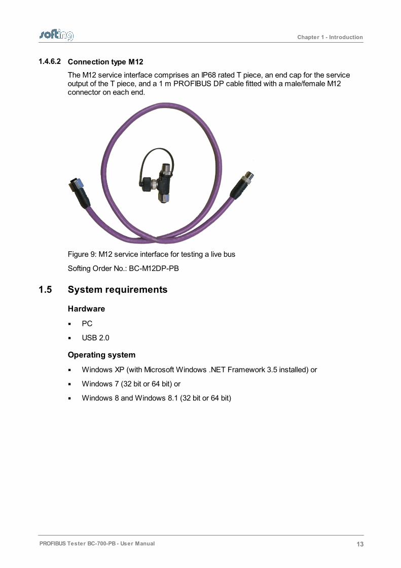
1.4.6.2 Connection type M12
The M12 service interface comprises an IP68 rated T piece, an end cap for the serviceoutput of the T piece, and a 1 m PROFIBUS DP cable fitted with a male/female M12connector on each end.
Figure 9: M12 service interface for testing a live bus
Softing Order No.: BC-M12DP-PB
1.5 System requirements
Hardware
PC
USB 2.0
Operating system
Windows XP (with Microsoft Windows .NET Framework 3.5 installed) or
Windows 7 (32 bit or 64 bit) or
Windows 8 and Windows 8.1 (32 bit or 64 bit)
Chapter 1 - Introduction
14 PROFIBUS Tester BC-700-PB - User Manual
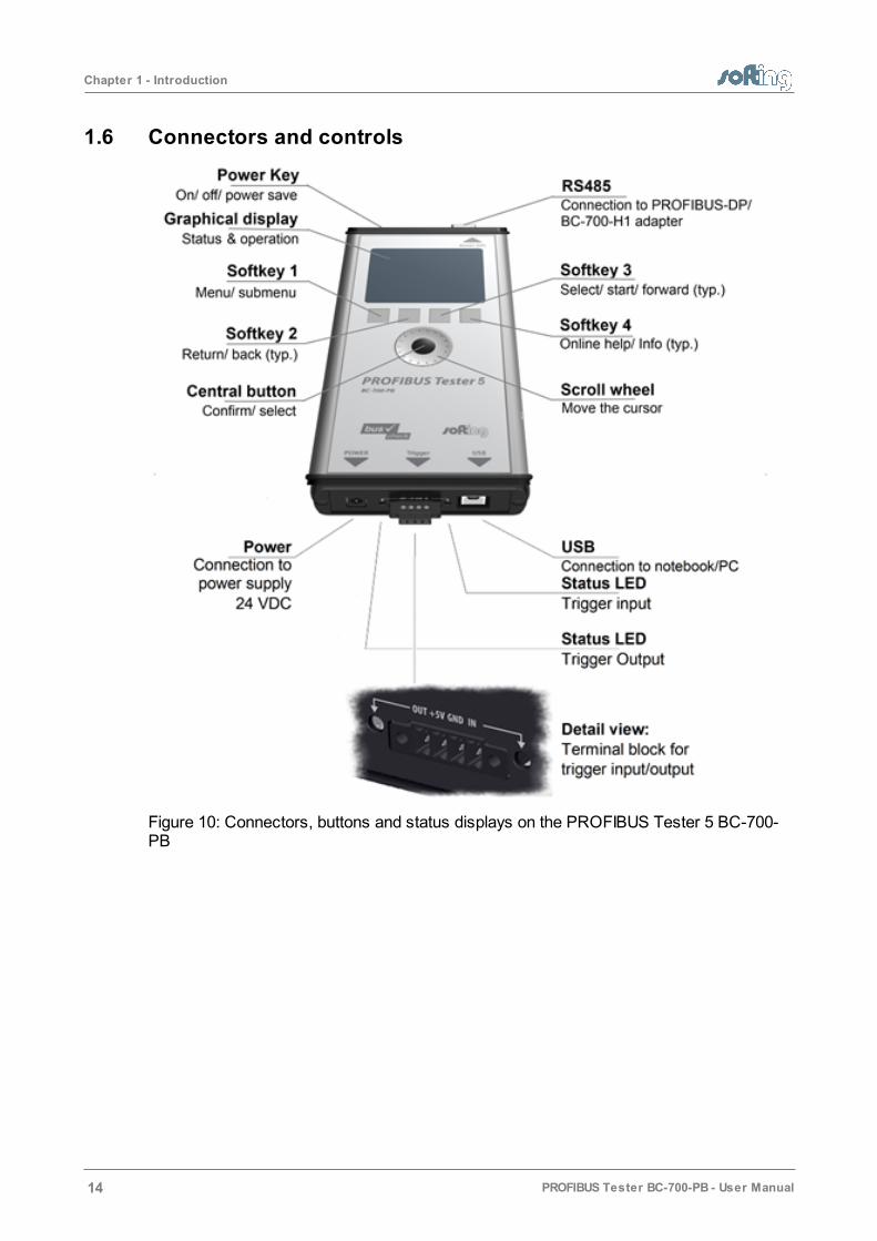
1.6 Connectors and controls
Figure 10: Connectors, buttons and status displays on the PROFIBUS Tester 5 BC-700-PB

Chapter 2 - Prepare device
PROFIBUS Tester BC-700-PB - User Manual 15
2 Prepare device
2.1 Insert battery
Switch off device and disconnect charger
Always switch off the device and disconnect the charger before removing orinstalling the battery.
1. Take a screwdriver (Philipps) and open the head screws on the back side of thedevice.
2. Remove the back cover.
Figure 11: Removing the back cover of PROFIBUS-Tester 5
3. Make sure that the provided battery is free of damage such as missing insulation ofwire leads, puncture or deformation. Insert the provided battery (standard accessory).The connecting plug is protected against polarity reversal. Check that the connectingplug is properly connected.
4. Mount the back cover and fix the screws.

Chapter 2 - Prepare device
16 PROFIBUS Tester BC-700-PB - User Manual
2.2 Charge battery
Your battery has been partially charged at the factory. If the PROFIBUS Tester 5 indicatesa low charge, do the following:
1. Connect the external AC adapter (standard accessory) to a wall outlet.
2. Connect the external AC adapter to the PROFIBUS Tester 5.
3. The PROFIBUS-Tester 5 will automatically start charging. The power key on top ofthe PROFIBUS Tester 5 is going to blink equally during the charge process. Thegraphical display remains switched off. The device is fully charged if the power keyflares up very shortly.
Alternatively you may power on the device in order to receive additional informationabout the charge process. The battery charge level indicator is located at the upperleft corner of the screen.
the battery is being charged (white flash symbol).
the PROFIBUS-Tester 5 is fully charged (without mains charger connected)
the PROFIBUS-Tester 5 is fully charged (with mains charger connected)
4. You can disconnect the AC adapter from the device, then from the wall outlet. Werecommend switching off the device in order to save energy.
Hint
You do not need to charge the battery for a specific length of time, and youcan use the device while it is charging.

Chapter 3 - Startup
PROFIBUS Tester BC-700-PB - User Manual 17
3 Startup
Hint
You can find information on the installation of PROFIBUS Diagnostics Suiteand on the corresponding drivers in section Install software and connect toPC and in the PROFIBUS Diagnostics Suite User Manual.
3.1 Power-up
1. Acclimate to room temperature
Before being connected to the AC mains power, the PROFIBUS Tester 5 and the ACadapter must be acclimated to room temperature to avoid condensation. This maytake up to 60 minutes.
2. Switch on
Switch on the tool by pressing the power key at the upper front edge. Make sure thatyou have either connected it to a power supply, or that you have inserted the battery.The display lights, performs a self-test and the splash screen is shown.
Hint
We recommend operating the device solely using the wide-range powersupply supplied or using the integrated battery to avoid equalizing currentswhich can falsify the test results.
The tool is powered by a built-in three cells lithium ion accumulator with 11.1 VDC.Alternatively the tool can be powered by 24 VDC through the external wide-range powersupply.
3.2 Power-up behaviour without USB connection
If not connected to an USB port, the PROFIBUS Tester 5 starts up in stand-alone mode(see Display and controls in stand-alone mode ) and is immediately ready for testing.During program start-up the splash screen is shown for a few seconds and displays "USBNOT CONNECTED":
Figure 12: Splash screen – starting without USB-connection
20
32

Chapter 3 - Startup
18 PROFIBUS Tester BC-700-PB - User Manual
3.3 Power-up behaviour with USB connected
Install drivers before connecting
Make sure the required USB drivers are installed before connecting the testtool to the PC or notebook. You can find them on the PROFIBUSDiagnostics Suite PC software CD.
On successful completion of the self-test, the PROFIBUS Tester 5 displays:
Figure 13: Power-up display when USB connected
When you start the PROFIBUS Diagnostics Suite control and evaluation software on yourcomputer and select the PROFIBUS Tester and a network for testing in its user interface,the test tool switches to PC mode.
At this point, you can also start a firmware update instead of using the control andevaluation software (refer also to Firmware update ).
The display shows:
Figure 14: Display at testing with PC software
43

Chapter 4 - Power-off and sleep mode
PROFIBUS Tester BC-700-PB - User Manual 19
4 Power-off and sleep mode
Power-off
Press power key for more than three seconds in order to power-off the device.There is nopower consumption during the device being powered off. The device can be stored forlong a period of time.
Activate sleep mode
If you want to change manually to sleep mode, actuate shortly the power key. During sleepmode the PROFIBUS-Tester 5 is saving energy and the power key will blink slowly.
If a measurement function is currently active, it is not possible to switch to sleep mode.Depending on the settings in energy management, the PROFIBUS-Tester 5 mayautomatically change to sleep mode after a predefined period of time.
Return to normal operation mode
You can recover normal operation very quickly by shortly actuating the power key asecond time. The lastly shown menu screen will be displayed which was active beforechanging to sleep mode.
Automatic power-off
If the PROFIBUS-Tester 5 is in sleep mode for more than 2 hours, it will automaticallypower-off.
Chapter 5 - Install software and connect to PC
20 PROFIBUS Tester BC-700-PB - User Manual
5 Install software and connect to PC
Installing
Install the software and the required drivers from your PROFIBUS Diagnostics Suite CD-ROM. For detailed installation instructions refer to the supplied Quick Startup Guide.
Connecting to a PC
Use the included USB cable to connect the tool to a PC or notebook.
Always connect directly to an USB port
We recommend connecting the unit directly to an USB port (USB 2.0) on thePC or on the notebook. When you use external USB hubs, notebook dockingstations or USB 3.0 ports for connection, problems may occur.
Chapter 6 - Connection to PROFIBUS
PROFIBUS Tester BC-700-PB - User Manual 21
6 Connection to PROFIBUS
6.1 General information
6.1.1 Possible side effects when testing a live bus
Test tool side effects
When you connect a test tool, side effects on the system under test aregenerally unavoidable. If the PROFIBUS is already disturbed to a certaindegree or if Simatic Diagnostic Repeaters are used, the operation of thePROFIBUS might nevertheless be affected occasionally. Compliance withthe connection notes is mandatory.
6.1.2 Connection types
You can connect a bus station to a PROFIBUS network either
using connectors such as
o D-sub connectors , most of which have an integrated terminating resistor and,optionally, an additional service socket
o M12 connectors for environments requiring increased IP ratings
o Special vendor-specific hybrid connectors; they are used in combination withspecial cables to supply power via the bus
or
using terminals for direct connection.
Due to the daisy-chain topology, the connection points of the bus stations are the typicalpoints for connecting the test tool.
25
13

Chapter 6 - Connection to PROFIBUS
22 PROFIBUS Tester BC-700-PB - User Manual
6.1.3 Adapter cable
The PROFIBUS Tester 5 is supplied with the D-sub adapter cable BC 600-PB-CB-DSUB-2 „Standard" (light connector). For testing on live systems the optional D-sub adaptercable BC-600-PB-CB-DSUB-2 is recommended. An M12 adapter set is optionallyavailable, see D-sub adapter cable for testing live systems .
Only use original short cables
Only use the original short cables with special pin layout to connect the unitto a PROFIBUS network.
Do not cascade more than two D-sub connectors with service sockets atthe same time!
Figure 15: Unallowed cascading of D-sub connectors
6.1.4 Strain relief
Use the strain relief supplied with the test tool. Thus you avoid the device from fallingdown.
Figure 16: Recommended use of retaining strap
9

Chapter 6 - Connection to PROFIBUS
PROFIBUS Tester BC-700-PB - User Manual 23
Avoid stress on connectors and bus stations
Avoid stress on connectors and bus stations which might be caused by thedevice's own weight. Ensure proper strain relief by using suitable supports,cable ties, etc. When this is not possible, you need to select a differentconnection point to avoid damage.
6.1.5 Using the security lock port
When using trend logging, the PROFIBUS Tester 5 is typically operated in an unattendedmanner over a prolonged period of time. You can connect a Kensington lock to thesecurity lock port to prevent your device being stolen. The Kensington lock is not part ofthe product delivery. To use this feature, you have to purchase the Kensington lockadditionally. To use the Kensington lock, refer to the product manual. Tie the Kensingtonlock cable to a fixed object and install the other end of the cable to the security lock port.
Figure 17: Using a Kensington lock
6.1.6 Test locations
The PROFIBUS Tester 5 can basically carry out tests anywhere on a physical PROFIBUSsegment. Note that the use of repeaters creates separate physical segments that eachneeds to be measured individually. For the best and most informative results, perform thetests at the beginning and at the end of each physical segment. If these test resultsindicate problems that cannot be clearly classified right away, you should carry out one ormore additional tests at the center.
6.2 Simple connection for tests during system shutdown
If all bus stations provide D-sub connectors with an additional service socket, you cansimply plug in the PROFIBUS Tester 5 at that socket (see figure below). If a D-sub
Chapter 6 - Connection to PROFIBUS
24 PROFIBUS Tester BC-700-PB - User Manual
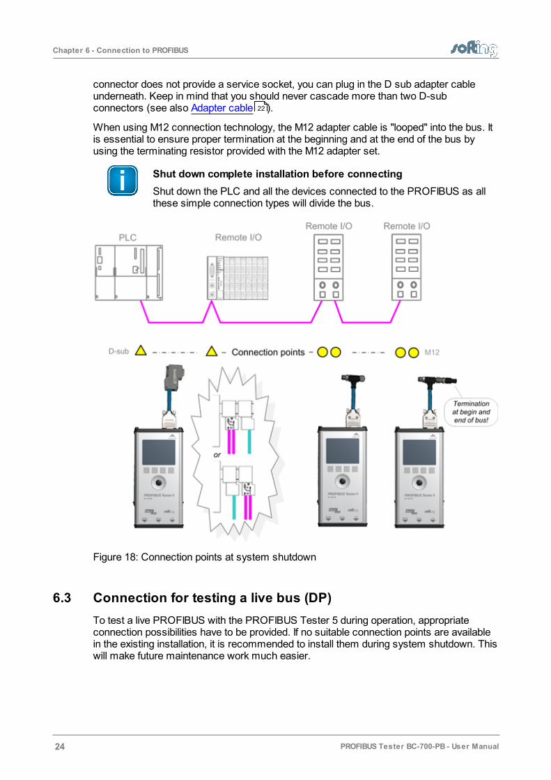
connector does not provide a service socket, you can plug in the D sub adapter cableunderneath. Keep in mind that you should never cascade more than two D-subconnectors (see also Adapter cable ).
When using M12 connection technology, the M12 adapter cable is "looped" into the bus. Itis essential to ensure proper termination at the beginning and at the end of the bus byusing the terminating resistor provided with the M12 adapter set.
Shut down complete installation before connecting
Shut down the PLC and all the devices connected to the PROFIBUS as allthese simple connection types will divide the bus.
Figure 18: Connection points at system shutdown
6.3 Connection for testing a live bus (DP)
To test a live PROFIBUS with the PROFIBUS Tester 5 during operation, appropriateconnection possibilities have to be provided. If no suitable connection points are availablein the existing installation, it is recommended to install them during system shutdown. Thiswill make future maintenance work much easier.
22
Chapter 6 - Connection to PROFIBUS
PROFIBUS Tester BC-700-PB - User Manual 25
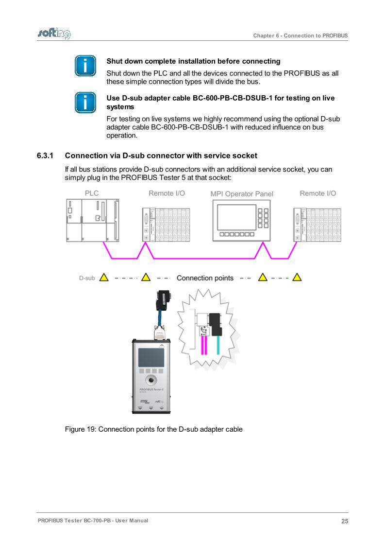
Shut down complete installation before connecting
Shut down the PLC and all the devices connected to the PROFIBUS as allthese simple connection types will divide the bus.
Use D-sub adapter cable BC-600-PB-CB-DSUB-1 for testing on livesystems
For testing on live systems we highly recommend using the optional D-subadapter cable BC-600-PB-CB-DSUB-1 with reduced influence on busoperation.
6.3.1 Connection via D-sub connector with service socket
If all bus stations provide D-sub connectors with an additional service socket, you cansimply plug in the PROFIBUS Tester 5 at that socket:
Figure 19: Connection points for the D-sub adapter cable

Chapter 6 - Connection to PROFIBUS
26 PROFIBUS Tester BC-700-PB - User Manual
6.3.2 Direct cable connection
To test a live PROFIBUS, you will need additional D-sub service interface of the type BC-PBMB-PB-S (see Service interfaces for PROFIBUS DP ).
Figure 20: Service interface provide connection points at direct cable connection
12

Chapter 6 - Connection to PROFIBUS
PROFIBUS Tester BC-700-PB - User Manual 27
6.3.3 Connection via M12 connector
To test a live PROFIBUS, you will need additional service interface of the type BC-M12DP-PB (see Adapter set for M12 connection technology ).
Tests on a live PROFIBUS are only allowed on bus segments providing D-sub connectiontechnology. Only D-sub connectors with service socket can be used as connection pointsfor the test tool. For this reason, tests can often only be performed at a bus end.
Figure 21: Connection points for the M12 adapter cable
Connect T-fitting between existing cable and 1 meter connectioncable
Always connect one end of the T-fitting to the already existing cable and theother end to the 1 meter connection cable which is supplied with the serviceinterface.
Do not screw the T-fitting of the M12 service interface directly onto a slave.
6.4 Master simulator, topology scan and cable test
Master simulator
The master simulator allows checking the bus cabling and the station addresses duringinstallation and commissioning, when the PLC (master) is not in operation yet. In addition,you can use this mode to check individual "suspicious" bus stations that have beendisconnected from the bus.
10

Chapter 6 - Connection to PROFIBUS
28 PROFIBUS Tester BC-700-PB - User Manual
Topology scan
The topology scan determines the sequence and distances of all passive bus stations(slaves). This feature requires correct bus cabling, a very good signal quality, and aconnection point located directly at the beginning or end of the bus.
Cable test
The cable test assesses the wiring and can be used to determine a faulty cable location(e.g. short circuit) by means of reflection test.
All three features can only be used during shutdown of the installation. The D-sub cableBC-600-PB-CB-DSUB-2 which is included in the standard scope of supply must be used.As long as communication is detected on the bus, i.e. at least one device is an activemaster, the functions are disabled. If necessary, disconnect every single active device(PLC, MPI and, if necessary, diagnostic repeaters) from the power supply or the bus. If anactive device is at the end of the bus you want to test, its PROFIBUS connector needs tobe unplugged and connected directly to the PROFIBUS Tester 5 BC-700-PB. The bustermination in the device connector will then be powered by the PROFIBUS Tester 5 BC-700-PB.
Figure 22: Connection points for topology scan and cable test
Bus stations must only be disconnected from the power supply or the busduring shutdown of the installation
Chapter 6 - Connection to PROFIBUS
PROFIBUS Tester BC-700-PB - User Manual 29
The three functions can be started also when the PROFIBUS Tester 5 BC-700-PB is disconnected from the bus. If you then connect the test device toa live bus, this can cause bus communication problems or a shutdown ofthe installation.
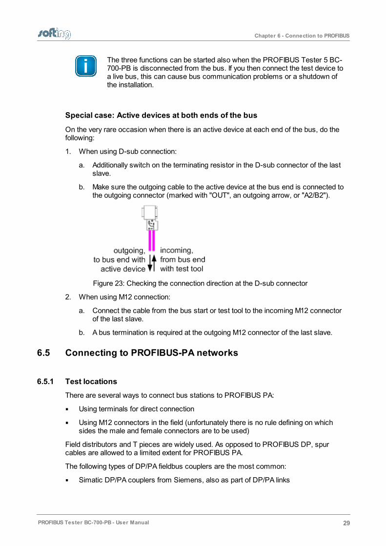
Special case: Active devices at both ends of the bus
On the very rare occasion when there is an active device at each end of the bus, do thefollowing:
1. When using D-sub connection:
a. Additionally switch on the terminating resistor in the D-sub connector of the lastslave.
b. Make sure the outgoing cable to the active device at the bus end is connected tothe outgoing connector (marked with "OUT", an outgoing arrow, or "A2/B2").
Figure 23: Checking the connection direction at the D-sub connector
2. When using M12 connection:
a. Connect the cable from the bus start or test tool to the incoming M12 connectorof the last slave.
b. A bus termination is required at the outgoing M12 connector of the last slave.
6.5 Connecting to PROFIBUS-PA networks
6.5.1 Test locations
There are several ways to connect bus stations to PROFIBUS PA:
Using terminals for direct connection
Using M12 connectors in the field (unfortunately there is no rule defining on whichsides the male and female connectors are to be used)
Field distributors and T pieces are widely used. As opposed to PROFIBUS DP, spurcables are allowed to a limited extent for PROFIBUS PA.
The following types of DP/PA fieldbus couplers are the most common:
Simatic DP/PA couplers from Siemens, also as part of DP/PA links
Chapter 6 - Connection to PROFIBUS
30 PROFIBUS Tester BC-700-PB - User Manual
SK1, SK2 and SK3 segment couplers, e.g. from Pepperl+Fuchs (or sometimes undera different label)
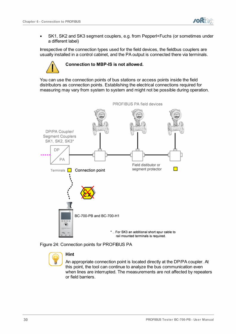
Irrespective of the connection types used for the field devices, the fieldbus couplers areusually installed in a control cabinet, and the PA output is connected there via terminals.
Connection to MBP-IS is not allowed.
You can use the connection points of bus stations or access points inside the fielddistributors as connection points. Establishing the electrical connections required formeasuring may vary from system to system and might not be possible during operation.
Figure 24: Connection points for PROFIBUS PA
Hint
An appropriate connection point is located directly at the DP/PA coupler. Atthis point, the tool can continue to analyze the bus communication evenwhen lines are interrupted. The measurements are not affected by repeatersor field barriers.

Chapter 6 - Connection to PROFIBUS
PROFIBUS Tester BC-700-PB - User Manual 31
6.5.2 Requirements for analyzing a live bus
When using the PROFIBUS Tester 5 and the BC-700-H1 adapter to carry outmeasurements on an MBP segment during operation, it is preferable to connect the toolvia free bus connection terminals of the DP/PA fieldbus coupler. If the bus begins at thecoupler, you can simply use the second terminal block at the DP/PA coupler or at the SK1or SK2 to sample the bus signal. If the couplers mentioned above are not located at thebeginning of the bus or if the bus begins with an SG3 coupler or if you are interested in thePROFIBUS PA signal at another test location, we recommend connecting a short spurcable to rail mounted terminals during system shutdown. This gives you an appropriateconnection point and makes future maintenance work much easier.
6.5.3 Analyzing during system shutdown
If there is no possibility for connection, you need to improvise in order to pick up the bussignal at an existing terminal block of the fieldbus coupler, the field distributor, segmentprotector or a field device. For example, you can try a double assignment of bus terminals.
Shut down the system before you divide the bus.
Disconnect all bus stations from the power supply.
6.5.4 Bus connection
The supplied test equipment set allows to easily connect the BC-700-H1 adapter to thePROFIBUS PA segment. Alternatively you can use a short length of PROFIBUS PAstandard cable to connect the tool to the bus.
Figure 25: PROFIBUS-PA pin assigment
Do not use in hazardous areas
The PROFIBUS Tester 5 and BC-700-H1 adapter must not be used inhazardous areas and must not be connected to an intrinsically safe MBP-ISsegment (blue terminals of fieldbus coupler; in some cases blue buscables).

Chapter 7 - Display and controls in stand-alone mode
32 PROFIBUS Tester BC-700-PB - User Manual
7 Display and controls in stand-alone mode
The PROFIBUS Tester 5 always starts in stand-alone mode unless it is USB connected toa PC or notebook. The readings are shown on the graphical display. You can control thetool with the four softkeys, the scroll wheel and the push button in center of the scrollwheel (see Connectors and controls ).
When you establish a USB connection during stand-alone mode while a test is running,the test will be aborted and the tool will be reset (restarted). The display briefly shows:"Switching to PC mode".
7.1 Main display
The start page is displayed after start-up in stand-alone mode (or when all dialogs orfunctions have been stopped and you have been returned to the main menu). The mainmenu is your starting point where you can open any of the test functions or additionaladministrative functions.
Figure 26: Start menu
7.2 User interface
The user interface of PROFIBUS Tester 5 comprises four parts:
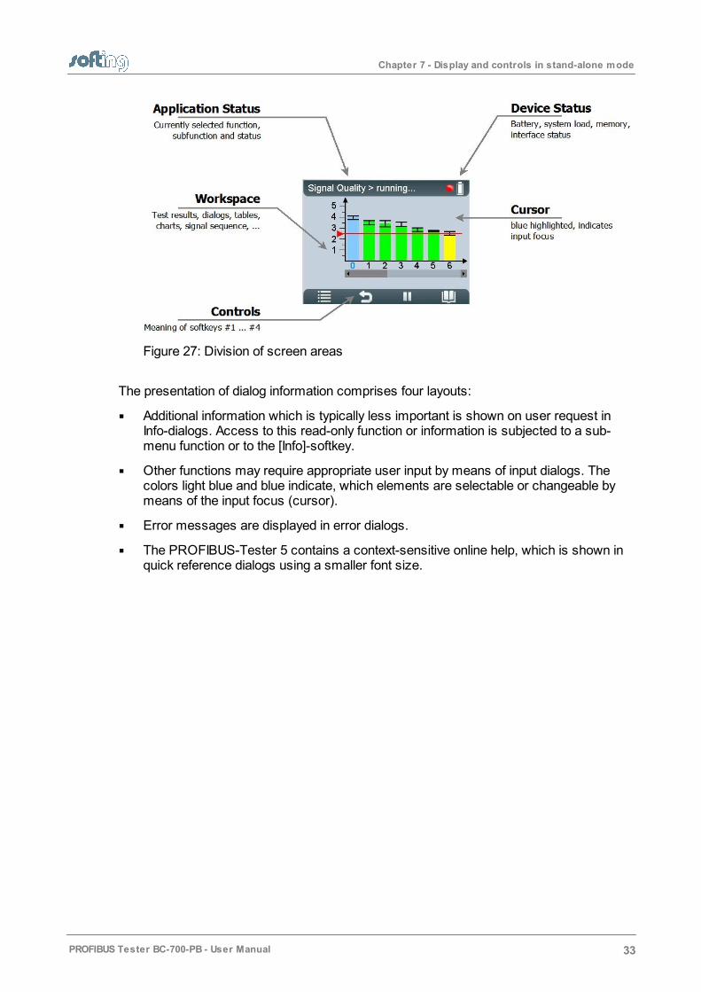
Device Status in the upper right corner, which provides information such as thebattery charge level indicator, system load status, memory information, state ofmaster simulator, connected interfaces and adapters,…
Application Status at the upper edge on the left displays which function or sub-functionis currently selected.
The Workspace in the center of the graphical user interface contains the start page,detail views for the bus analyzes and views for administrative purposes. At a glancethe user views the most important information with respect to the selected testfunction.
Control information is shown at the lower edge of the user interface. The meaning ofthe four softkeys is explained in Operating functions .
14
34
Chapter 7 - Display and controls in stand-alone mode
PROFIBUS Tester BC-700-PB - User Manual 33
Figure 27: Division of screen areas
The presentation of dialog information comprises four layouts:
Additional information which is typically less important is shown on user request inInfo-dialogs. Access to this read-only function or information is subjected to a sub-menu function or to the [Info]-softkey.
Other functions may require appropriate user input by means of input dialogs. Thecolors light blue and blue indicate, which elements are selectable or changeable bymeans of the input focus (cursor).
Error messages are displayed in error dialogs.
The PROFIBUS-Tester 5 contains a context-sensitive online help, which is shown inquick reference dialogs using a smaller font size.

Chapter 7 - Display and controls in stand-alone mode
34 PROFIBUS Tester BC-700-PB - User Manual
Figure 28: Dialogs in the user interface
7.3 Operating functions and softkeys
Use the scroll wheel, in order to move the cursor within lists, tables, dialogs andalphabetic strings. Selected elements are blue highlighted. Press the central button of thescroll wheel or press the Selection- or [Info]-softkey in order to call functions or to requestadditional information. The appearance of controls will change in a context-sensitivemanner. If a softkey is grayed out, the corresponding operating function is disabled:
Symbol Function
Open menu/ submenu
Browse backwards, leave menu function
Browse tab to the left
Browse tab to the right
Confirm/ select (central push button in scroll wheel)
Start a stopped function
Stop a running function
Request details for selected elements (press briefly) or
Open context-sensitive reference (press button approx. for 2 seconds)
Open context-sensitive reference
Chapter 7 - Display and controls in stand-alone mode
PROFIBUS Tester BC-700-PB - User Manual 35
7.4 Device status
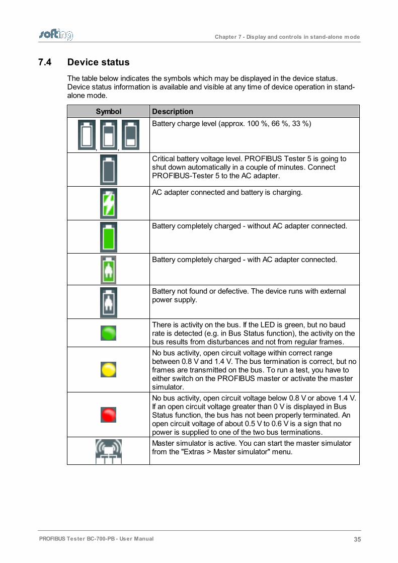
The table below indicates the symbols which may be displayed in the device status.Device status information is available and visible at any time of device operation in stand-alone mode.
Symbol Description
, ,
Battery charge level (approx. 100 %, 66 %, 33 %)
Critical battery voltage level. PROFIBUS Tester 5 is going toshut down automatically in a couple of minutes. ConnectPROFIBUS-Tester 5 to the AC adapter.
AC adapter connected and battery is charging.
Battery completely charged - without AC adapter connected.
Battery completely charged - with AC adapter connected.
Battery not found or defective. The device runs with externalpower supply.
There is activity on the bus. If the LED is green, but no baudrate is detected (e.g. in Bus Status function), the activity on thebus results from disturbances and not from regular frames.
No bus activity, open circuit voltage within correct rangebetween 0.8 V and 1.4 V. The bus termination is correct, but noframes are transmitted on the bus. To run a test, you have toeither switch on the PROFIBUS master or activate the mastersimulator.
No bus activity, open circuit voltage below 0.8 V or above 1.4 V.If an open circuit voltage greater than 0 V is displayed in BusStatus function, the bus has not been properly terminated. Anopen circuit voltage of about 0.5 V to 0.6 V is a sign that nopower is supplied to one of the two bus terminations.
Master simulator is active. You can start the master simulatorfrom the "Extras > Master simulator" menu.

Chapter 7 - Display and controls in stand-alone mode
36 PROFIBUS Tester BC-700-PB - User Manual
7.5 Menu functions
The following table gives a brief overview about the menu functions of PROFIBUS-Tester5 in stand-alone mode. The online help contains a more detailed description of operatingfunctions (use the [ ]-softkey in the corresponding context).
Menudirectory
Menufunction
(> sub menufunction)
Short description
TestFunctions
Bus Status
> Overview
Bus Status function (Overview) assesses bus physicsand bus communication and displays the test result in asimplified view.
Bus Status
> Detail view
Bus Status function (Detail view) assesses bus physicsand bus communication and displays the test result intable form.
Signal Quality The signal quality test determines the signal quality indexfor each bus station and displays the test result in a bardiagram. The test location is particularly important whenyou are testing the signal quality.
Additional information is available such as Signal/ Noiseratio, edges and numerical values with respect to signalquality testing.
Signal Quality
> Select testlocation
The test location is particularly important when you aretesting the signal quality. It is recommended to make atleast two signal quality tests per physical segment (atboth ends of the corresponding segment).
Signal Quality
> Settingsevaluation
The signal quality evaluation settings contain limit valuesfor the quality index, signal/noise ratio, rise time andtimeout.
Cable Test The cable test function examines the cabling inPROFIBUS segments. This test detects the cablesegment length, scans for unwanted reflections on theline and verifies proper termination of the cable. In caseof a fault you will get an error description and a distanceindication (if possible) for troubleshooting actions. Testsregarding cabling can only be made from one end of thePROFIBUS line. Active stations (Masters, MPI panel,...)must be disconnected during testing of the respectivecable segment.
For further information and starting points in order tocorrectly interprete the fault indication see List of faultindications and remedial measures .
Cable Test
> EditConfiguration
In the context of cable testing it is recommended toprovide additional information about the correspondingcable segment (physical segment). This is important forproper detection of line length, compliance withmaximum allowed segment length as well as for properdocumentation of test results. Please give full particularswith respect to the configuration of each cable segment.
48
Chapter 7 - Display and controls in stand-alone mode
PROFIBUS Tester BC-700-PB - User Manual 37
Menudirectory
Menufunction
(> sub menufunction)
Short description
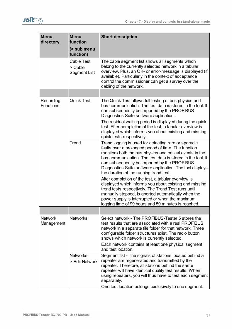
Cable Test
> CableSegment List
The cable segment list shows all segments whichbelong to the currently selected network in a tabularoverview. Plus, an OK- or error-message is displayed (ifavailable). Particularly in the context of acceptancecontrol the commissioner can get a survey over thecabling of the network.
RecordingFunctions
Quick Test The Quick Test allows full testing of bus physics andbus communication. The test data is stored in the tool. Itcan subsequently be imported by the PROFIBUSDiagnostics Suite software application.
The residual waiting period is displayed during the quicktest. After completion of the test, a tabular overview isdisplayed which informs you about existing and missingquick tests respectively.
Trend Trend logging is used for detecting rare or sporadicfaults over a prolonged period of time. The functionmonitors both the bus physics and critical events in thebus communication. The test data is stored in the tool. Itcan subsequently be imported by the PROFIBUSDiagnostics Suite software application. The tool displaysthe duration of the running trend test.
After completion of the test, a tabular overview isdisplayed which informs you about existing and missingtrend tests respectively. The Trend Test runs untilmanually stopped, is aborted automatically when thepower supply is interrupted or when the maximumlogging time of 99 hours and 59 minutes is reached.
NetworkManagement
Networks Select network - The PROFIBUS-Tester 5 stores thetest results that are associated with a real PROFIBUSnetwork in a separate file folder for that network. Threeconfigurable folder structures exist. The radio buttonshows which network is currently selected.
Each network contains at least one physical segmentand test location.
Networks
> Edit Network
Segment list - The signals of stations located behind arepeater are regenerated and transmitted by therepeater. Therefore, all stations behind the samerepeater will have identical quality test results. Whenusing repeaters, you will thus have to test each segmentseparately.
One test location belongs exclusively to one segment.
Chapter 7 - Display and controls in stand-alone mode
38 PROFIBUS Tester BC-700-PB - User Manual
Menudirectory
Menufunction
(> sub menufunction)
Short description
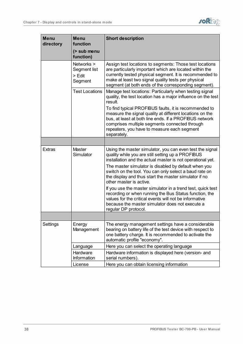
Networks >Segment list
> EditSegment
Assign test locations to segments: Those test locationsare particularly important which are located within thecurrently tested physical segment. It is recommended tomake at least two signal quality tests per physicalsegment (at both ends of the corresponding segment).
Test Locations Manage test locations: Particularly when testing signalquality, the test location has a major influence on the testresult.
To find typical PROFIBUS faults, it is recommended tomeasure the signal quality at different locations on thebus, at least at both line ends. If a PROFIBUS networkcomprises multiple segments connected throughrepeaters, you have to measure each segmentseparately.
Extras MasterSimulator
Using the master simulator, you can even test the signalquality while you are still setting up a PROFIBUSinstallation and the actual master is not operational yet.
The master simulator is disabled by default when youswitch on the tool. You can only select a baud rate onthe display and thus start the master simulator if noother master is active.
If you use the master simulator in a trend test, quick testrecording or when running the Bus Status function, thevalues for the critical events will not be informativebecause the master simulator does not execute aregular DP protocol.
Settings EnergyManagement
The energy management settings have a considerablebearing on battery life of the test device with respect toone battery charge. It is recommended to activate theautomatic profile "economy".
Language Here you can select the operating language
HardwareInformation
Hardware information is displayed here (version- andserial numbers).
License Here you can obtain licensing information

Chapter 7 - Display and controls in stand-alone mode
PROFIBUS Tester BC-700-PB - User Manual 39
7.6 Organize and store test results
PROFIBUS Tester 5 comprises three predefined network folders: a default network folderand two empty folders.
A network folder is a directory containing all the test results assigned to a network. Thename of the network folder is the same as the network name displayed during the dataimport into the PC.
The default network is provided for spontaneous tests and is a fixed component of theproject management and cannot be deleted. However, you can rename and edit thedefault network and start testing using this network. If you are deleting all networks,automatically the default network including a default segment and a default test locationwill be generated in the network folder.
A network in PROFIBUS Tester 5 comprises one or more segments, and one or moretest locations. A minimum network configuration (default network) comprises onesegment (default segment) and one test location (default test location).
The test location has a major influence on the test result, particularly when testing signalquality, using the oscilloscope function or using the cable test function. To store all testresults within a network in the PROFIBUS Tester 5, you have to set the radio button to thecorresponding network in the networks function (see also User interface ).
Figure 29: Select Network – the radio button is set to "engine production"
Test results in stand-alone mode are stored under the specified test location in thenetwork you have defined as the storage location. Thus, test results will be organized andstored in PROFIBUS Tester 5 according to their test location. Refer to the figure below tosee an example network which could be organized as follows in PROFIBUS Tester 5(recommendation):
1. Use the Networks/ select network function and select an empty network folder.Enter the network name (e.g. "engine production").
2. Use the Edit network sub-function and rename the default segment (e.g. to"heating") and add two new segments (e.g. "foundry" and "conveyor belt").
3. Use the Test locations function and generate six test locations.
32

Chapter 7 - Display and controls in stand-alone mode
40 PROFIBUS Tester BC-700-PB - User Manual
4. Assign test location to segments. You can do this in Test locations or in Networks Edit Network Edit segment-subfunction.
Figure 30: Example network comprising three segments, 13 PROFIBUS stations, 2repeaters and 6 recommended test locations (two per segment)
Chapter 8 - Import data into the PC
PROFIBUS Tester BC-700-PB - User Manual 41
8 Import data into the PC
Quick Tests, cable test results and Trend logs stored in the test tool can be imported intothe PC software.
1. To do this, start the PROFIBUS Diagnostics Suite.
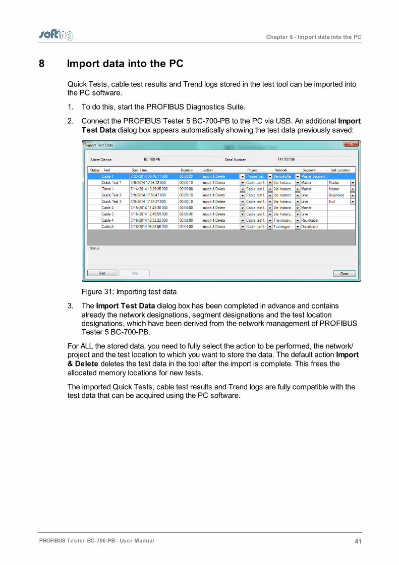
2. Connect the PROFIBUS Tester 5 BC-700-PB to the PC via USB. An additional ImportTest Data dialog box appears automatically showing the test data previously saved:
Figure 31: Importing test data
3. The Import Test Data dialog box has been completed in advance and containsalready the network designations, segment designations and the test locationdesignations, which have been derived from the network management of PROFIBUSTester 5 BC-700-PB.
For ALL the stored data, you need to fully select the action to be performed, the network/project and the test location to which you want to store the data. The default action Import& Delete deletes the test data in the tool after the import is complete. This frees theallocated memory locations for new tests.
The imported Quick Tests, cable test results and Trend logs are fully compatible with thetest data that can be acquired using the PC software.
Chapter 9 - Licenses
42 PROFIBUS Tester BC-700-PB - User Manual
9 Licenses
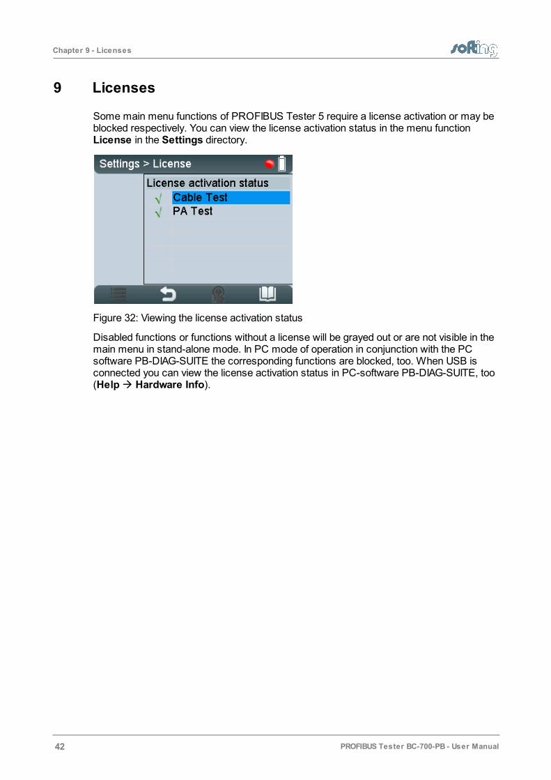
Some main menu functions of PROFIBUS Tester 5 require a license activation or may beblocked respectively. You can view the license activation status in the menu function License in the Settings directory.
Figure 32: Viewing the license activation status
Disabled functions or functions without a license will be grayed out or are not visible in themain menu in stand-alone mode. In PC mode of operation in conjunction with the PCsoftware PB-DIAG-SUITE the corresponding functions are blocked, too. When USB isconnected you can view the license activation status in PC-software PB-DIAG-SUITE, too(Help Hardware Info).

Chapter 10 - Firmware update
PROFIBUS Tester BC-700-PB - User Manual 43
10 Firmware update
Firmware updates are made available as required. They are provided with the updates tothe PC software (see Install software and connect to PC ) and allow access to new orimproved functionality. How to update the firmware is described in detail in the separatePROFIBUS Diagnostics Suite – Quick Startup Guide.
20
Chapter 11 - Maintenance and service
44 PROFIBUS Tester BC-700-PB - User Manual
11 Maintenance and service
The PROFIBUS Tester 5 is maintenance-free and does not require calibration. It isrecommended to exclude this device from control of measuring and monitoring of devices.Repairs/ service exchange (RMA) may only be carried out by the device manufacturer. Allreturns must be made without supplied carrying case and accessories (unless otherwiseagreed). Please also include a brief fault description and a phone number at which we cancontact you should we need further details. In case of returns within the warranty period,please also enclose a copy of the invoice or delivery note.
The built-in battery is subjected to normal wear and tear. The battery capacity decreasesin the course of years; this is typical for specified normal operation. Exhaustive dischargeand overcharge or exhaustive operation of the device in conjunction with very high or lowtemperatures will accelerate the battery ageing process (refer to Notes on battery use) .53

Chapter 12 - Troubleshooting
PROFIBUS Tester BC-700-PB - User Manual 45
12 Troubleshooting
Problem Causes and remedies
The display of thePROFIBUS Tester 5remains blank.
Possible cause:
The PROFIBUS Tester 5 either needs an external powersupply or you have to install the built-in battery.
Remedy:
Use the supplied external AC adapter to connect the tool tothe mains power supply.
Charge the built-in battery
Alternative cause:
The tool is defective.
The rechargeable battery is defective
Remedy:
Return the tool to the manufacturer.
Replace the rechargeable battery
The display shows thefollowing errormessage: "USBERROR - Refer tomanual or disconn. forstand-alone mode".
Possible cause:
This error message can be caused by poor physicalconnection via USB ("loose" contact).
Remedy:
Check the USB cable and connector.
Alternative cause:
The device may be connected via external USB hub,notebook docking stations or USB 3.0 port which couldevoke problems during driver installation
Remedy:
It is recommended to connect the unit directly to a USB 2.0port
The baud rate is notdetected automaticallyon a live PROFIBUS.
Possible cause:
Massive disturbances in the bus physics.
Remedy:
Manually set the baud rate and repeat the test.
A main menu functionis grayed out or is notvisible respectively
Possible cause:
Missing license
Out-dated firmware version is in use
Remedy:
Please check your bill of delivery if the license is included inyour order.
Please download the latest firmware version
Chapter 12 - Troubleshooting
46 PROFIBUS Tester BC-700-PB - User Manual
Problem Causes and remedies
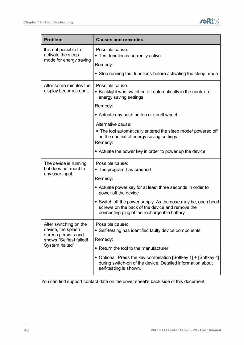
It is not possible toactivate the sleepmode for energy saving
Possible cause:
Test function is currently active
Remedy:
Stop running test functions before activating the sleep mode
After some minutes thedisplay becomes dark.
Possible cause:
Backlight was switched off automatically in the context ofenergy saving settings
Remedy:
Actuate any push button or scroll wheel
Alternative cause:
The tool automatically entered the sleep mode/ powered offin the context of energy saving settings
Remedy:
Actuate the power key in order to power up the device
The device is runningbut does not react toany user input.
Possible cause:
The program has crashed
Remedy:
Actuate power key for at least three seconds in order topower off the device
Switch off the power supply. As the case may be, open headscrews on the back of the device and remove theconnecting plug of the rechargeable battery
After switching on thedevice, the splashscreen persists andshows "Selftest failed!System halted"
Possible cause:
Self-testing has identified faulty device components
Remedy:
Return the tool to the manufacturer
Optional: Press the key combination [Softkey 1] + [Softkey 4]during switch-on of the device. Detailed information aboutself-testing is shown.
You can find support contact data on the cover sheet's back side of this document.
Chapter 13 - Tips and tricks for cable testing
PROFIBUS Tester BC-700-PB - User Manual 47
13 Tips and tricks for cable testing
Perform cable test without mains adapter
When using the cable test function we recommend removing the mainsadapter and operating on the PROFIBUS-Tester 5 by means of the built-inbattery in stand-alone operation mode.
13.1 Assessment criteria
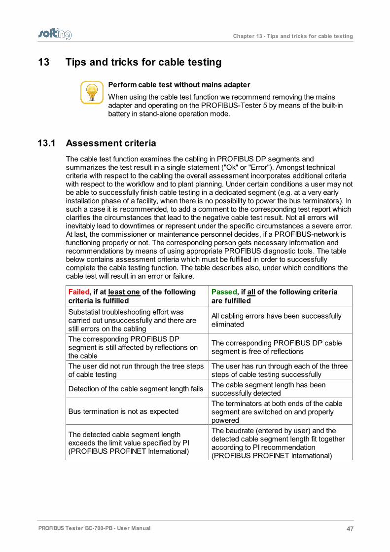
The cable test function examines the cabling in PROFIBUS DP segments andsummarizes the test result in a single statement ("Ok" or "Error"). Amongst technicalcriteria with respect to the cabling the overall assessment incorporates additional criteriawith respect to the workflow and to plant planning. Under certain conditions a user may notbe able to successfully finish cable testing in a dedicated segment (e.g. at a very earlyinstallation phase of a facility, when there is no possibility to power the bus terminators). Insuch a case it is recommended, to add a comment to the corresponding test report whichclarifies the circumstances that lead to the negative cable test result. Not all errors willinevitably lead to downtimes or represent under the specific circumstances a severe error.At last, the commissioner or maintenance personnel decides, if a PROFIBUS-network isfunctioning properly or not. The corresponding person gets necessary information andrecommendations by means of using appropriate PROFIBUS diagnostic tools. The tablebelow contains assessment criteria which must be fulfilled in order to successfullycomplete the cable testing function. The table describes also, under which conditions thecable test will result in an error or failure.
Failed, if at least one of the followingcriteria is fulfilled
Passed, if all of the following criteriaare fulfilled
Substatial troubleshooting effort wascarried out unsuccessfully and there arestill errors on the cabling
All cabling errors have been successfullyeliminated
The corresponding PROFIBUS DPsegment is still affected by reflections onthe cable
The corresponding PROFIBUS DP cablesegment is free of reflections
The user did not run through the tree stepsof cable testing
The user has run through each of the threesteps of cable testing successfully
Detection of the cable segment length failsThe cable segment length has beensuccessfully detected
Bus termination is not as expectedThe terminators at both ends of the cablesegment are switched on and properlypowered
The detected cable segment lengthexceeds the limit value specified by PI(PROFIBUS PROFINET International)
The baudrate (entered by user) and thedetected cable segment length fit togetheraccording to PI recommendation(PROFIBUS PROFINET International)
Chapter 13 - Tips and tricks for cable testing
48 PROFIBUS Tester BC-700-PB - User Manual
13.2 List of fault indications and remedial measures
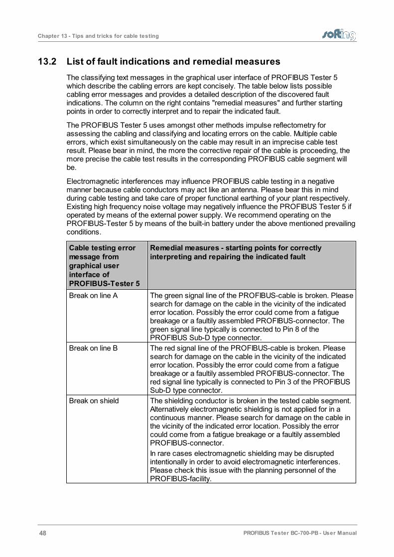
The classifying text messages in the graphical user interface of PROFIBUS Tester 5which describe the cabling errors are kept concisely. The table below lists possiblecabling error messages and provides a detailed description of the discovered faultindications. The column on the right contains "remedial measures" and further startingpoints in order to correctly interpret and to repair the indicated fault.
The PROFIBUS Tester 5 uses amongst other methods impulse reflectometry forassessing the cabling and classifying and locating errors on the cable. Multiple cableerrors, which exist simultaneously on the cable may result in an imprecise cable testresult. Please bear in mind, the more the corrective repair of the cable is proceeding, themore precise the cable test results in the corresponding PROFIBUS cable segment willbe.
Electromagnetic interferences may influence PROFIBUS cable testing in a negativemanner because cable conductors may act like an antenna. Please bear this in mindduring cable testing and take care of proper functional earthing of your plant respectively.Existing high frequency noise voltage may negatively influence the PROFIBUS Tester 5 ifoperated by means of the external power supply. We recommend operating on thePROFIBUS-Tester 5 by means of the built-in battery under the above mentioned prevailingconditions.
Cable testing errormessage fromgraphical userinterface ofPROFIBUS-Tester 5
Remedial measures - starting points for correctlyinterpreting and repairing the indicated fault
Break on line A The green signal line of the PROFIBUS-cable is broken. Pleasesearch for damage on the cable in the vicinity of the indicatederror location. Possibly the error could come from a fatiguebreakage or a faultily assembled PROFIBUS-connector. Thegreen signal line typically is connected to Pin 8 of thePROFIBUS Sub-D type connector.
Break on line B The red signal line of the PROFIBUS-cable is broken. Pleasesearch for damage on the cable in the vicinity of the indicatederror location. Possibly the error could come from a fatiguebreakage or a faultily assembled PROFIBUS-connector. Thered signal line typically is connected to Pin 3 of the PROFIBUSSub-D type connector.
Break on shield The shielding conductor is broken in the tested cable segment.Alternatively electromagnetic shielding is not applied for in acontinuous manner. Please search for damage on the cable inthe vicinity of the indicated error location. Possibly the errorcould come from a fatigue breakage or a faultily assembledPROFIBUS-connector.
In rare cases electromagnetic shielding may be disruptedintentionally in order to avoid electromagnetic interferences.Please check this issue with the planning personnel of thePROFIBUS-facility.

Chapter 13 - Tips and tricks for cable testing
PROFIBUS Tester BC-700-PB - User Manual 49
Cable testing errormessage fromgraphical userinterface ofPROFIBUS-Tester 5
Remedial measures - starting points for correctlyinterpreting and repairing the indicated fault
Short circuit between Aand B
There is an unusual low ohmic or capacitive resistancebetween signal lines A and B. Please search for damage on thecable in the vicinity of the indicated error location. Possibly theerror could come from a severe crush of the cable or multipleunpowered bus terminators.
Plus, be on the lookout for illegal spur lines and check, ifmoisture penetrated the cabling or if the cabling is heavilysoiled.
Short circuit between Aand shield
Short circuit between Band shield
Short circuit between A,B and shield
There is an unusual low ohmic or capacitive resistancebetween the mentioned signal lines and conductors. Possiblythe error could come from a severe crush of the cable or afaultily assembled PROFIBUS-connector.
Plus, be on the lookout for illegal spur lines and check, ifmoisture penetrated the cabling or if the cabling is heavilysoiled.
Capacitive Load / SpurLine
There is an unusual capacitive load between signal lines A andB and the shield conductor. Possibly the error could come froman illegal spur line or from interference-suppression capacitors.This is common usage with "over-compensated" or defectivePROFIBUS-devices.
Disconnect the devices in the vicinity of the indicated errorlocation and repeat cable testing in order to encircle the error.
Unknown error The cable is still affected by unwanted reflections. Though it isnot possible to classify the fault indication. Please search fordamage on the cable in the vicinity of the indicated errorlocation and check if the PROFIBUS-connector has beenproperly assembled.
Unwanted reflections may emerge from transitions betweenmedia and signal conductors which have different impedancevalues (e.g. two different cable types).
Sending pulse couldnot be detected. Thecable is either too shortor not connected.
Please do not fall below the minimum cable length of 3 meters.The intended use of cable testing requires a cable withadequate length.
(Near-end) terminatorswitched on
No reflections could bedetected. Pleaseremove terminators.
During the first of the three steps of cable testing thePROFIBUS Tester requires an open cable on both sides.However, the tester detected an ohmic resistance between thesignal wires and the resistance value is in the range of busterminators. Please make sure, that every bus terminator onevery PROFIBUS-connector is switched off or is deactivated.
Please take into consideration, that dip-switches for switchingon/off bus terminators may be defective.
Chapter 13 - Tips and tricks for cable testing
50 PROFIBUS Tester BC-700-PB - User Manual
Cable testing errormessage fromgraphical userinterface ofPROFIBUS-Tester 5
Remedial measures - starting points for correctlyinterpreting and repairing the indicated fault
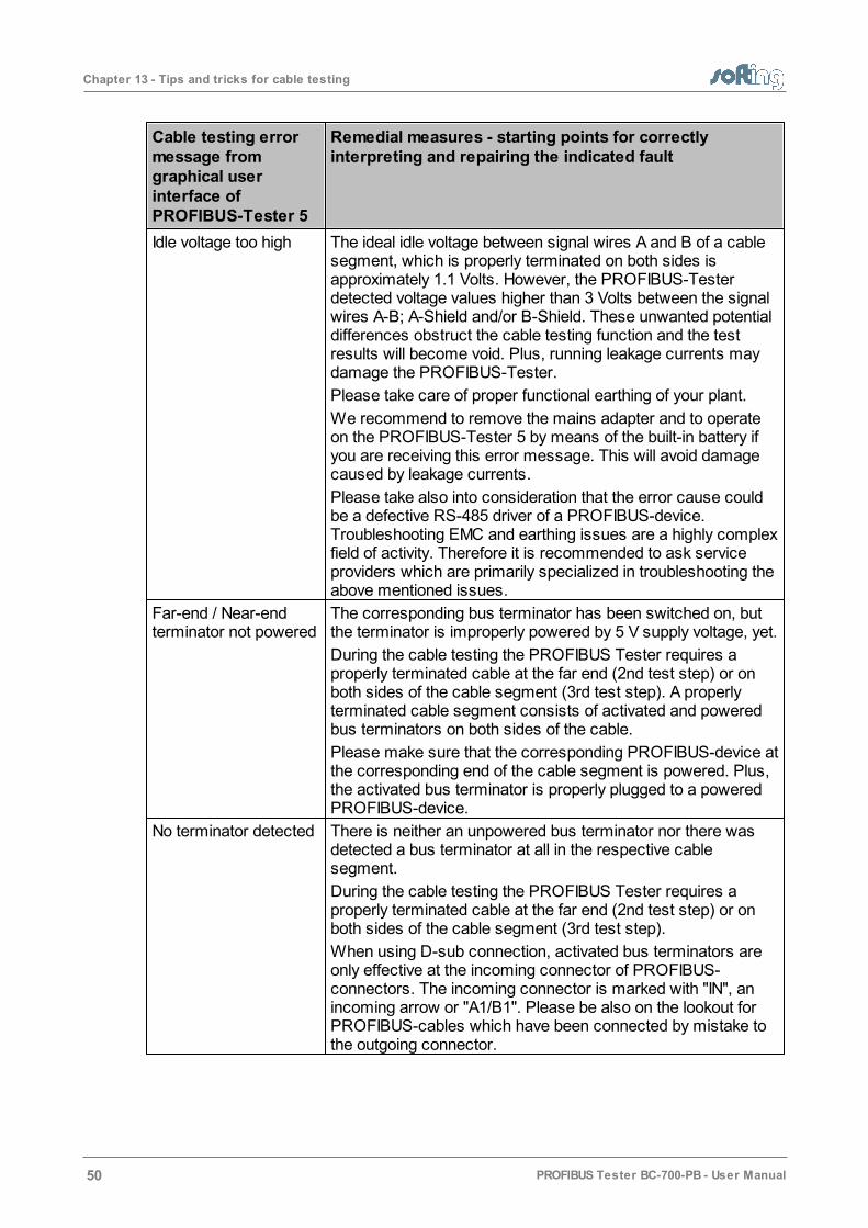
Idle voltage too high The ideal idle voltage between signal wires A and B of a cablesegment, which is properly terminated on both sides isapproximately 1.1 Volts. However, the PROFIBUS-Testerdetected voltage values higher than 3 Volts between the signalwires A-B; A-Shield and/or B-Shield. These unwanted potentialdifferences obstruct the cable testing function and the testresults will become void. Plus, running leakage currents maydamage the PROFIBUS-Tester.
Please take care of proper functional earthing of your plant.
We recommend to remove the mains adapter and to operateon the PROFIBUS-Tester 5 by means of the built-in battery ifyou are receiving this error message. This will avoid damagecaused by leakage currents.
Please take also into consideration that the error cause couldbe a defective RS-485 driver of a PROFIBUS-device.Troubleshooting EMC and earthing issues are a highly complexfield of activity. Therefore it is recommended to ask serviceproviders which are primarily specialized in troubleshooting theabove mentioned issues.
Far-end / Near-endterminator not powered
The corresponding bus terminator has been switched on, butthe terminator is improperly powered by 5 V supply voltage, yet.
During the cable testing the PROFIBUS Tester requires aproperly terminated cable at the far end (2nd test step) or onboth sides of the cable segment (3rd test step). A properlyterminated cable segment consists of activated and poweredbus terminators on both sides of the cable.
Please make sure that the corresponding PROFIBUS-device atthe corresponding end of the cable segment is powered. Plus,the activated bus terminator is properly plugged to a poweredPROFIBUS-device.
No terminator detected There is neither an unpowered bus terminator nor there wasdetected a bus terminator at all in the respective cablesegment.
During the cable testing the PROFIBUS Tester requires aproperly terminated cable at the far end (2nd test step) or onboth sides of the cable segment (3rd test step).
When using D-sub connection, activated bus terminators areonly effective at the incoming connector of PROFIBUS-connectors. The incoming connector is marked with "IN", anincoming arrow or "A1/B1". Please be also on the lookout forPROFIBUS-cables which have been connected by mistake tothe outgoing connector.

Chapter 13 - Tips and tricks for cable testing
PROFIBUS Tester BC-700-PB - User Manual 51
Cable testing errormessage fromgraphical userinterface ofPROFIBUS-Tester 5
Remedial measures - starting points for correctlyinterpreting and repairing the indicated fault
Far-end / Near-endterminator wrong or notadapted
The PROFIBUS Tester detects an ohmic resistance betweenthe signal wires A and B, but the resistance value is not asexpected in the range of a bus terminator.
Please make sure, that the bus terminator is properly poweredand the PROFIBUS-connector has been properly powered.Take into consideration that multiple bus terminators may beswitched on and that dip-switches for switching on/off busterminators may be defective (due to aging and soiling).
Line A and Binterchanged
The green and the red signal line are interchanged. Possiblecause might be a PROFIBUS connector which is assembledimproperly. Please bear in mind that after having two timesinterchanged line A and B, this error cannot be recognizedanymore. Only when interchanging both lines for a third time,you may recognize the error.
Typically, the tester will not return a measured distance. Inorder to localize the fault location we recommend shorteningthe respective cable segment step by step by switching on busterminators within the cable segment.
Repeat the cable test after each shortening procedure until theerror is no longer reported.
The last active bus terminator is the faulty one.
Near end terminatorwas powered byinternal 5 V powersupply
This message is a note and not an error message. The cabletest has been passed successfully. The bus terminatingresistor has been switched on at the test location but is notpowered via a PROFIBUS station. Possible causes: Therelated cable end is not connected to an activated PROFIBUSstation or the 5 V power supply of the related PROFIBUSstation is defective. The PROFIBUS tester was able to supplythe bus terminating resistor with its tester-internal 5 V powersupply.
13.3 Metering the cable segment length correctly
Directly after starting the cable test function you will see the actual segment configuration.In the context of cable testing it is recommended to provide the number of connectors andconnected devices in the respective cable segment. The provided number of theseelements should be as precise as possible in order to correctly detect cable segmentlength or the distance to the error. This chapter illustrates, how connectors and devicesinfluence the detection of the cable length.
Connectors: Please specify, how many 12 MBit/s PROFIBUS-connectors exist in therespective cable segment and enter the number in the segment configuration. The seriesinductance within the 12 MBit/s PROFIBUS-connectors act like a delay element on thecable with respect to impulse reflectometry. Every connector corresponds to approx. 50cm cable length.

Chapter 13 - Tips and tricks for cable testing
52 PROFIBUS Tester BC-700-PB - User Manual
Devices: Please specify, how many PROFIBUS devices are connected to the respectivecable segment (Master, Slave, repeater; typ. not more than 32). The RS485-driver unit ofeach PROFIBUS-station acts like a RC-cicuit (delay element) on the cable. In the contextof impulse reflectometry this corresponds to additional 20 cm cable length per device.
Consequently, the combination consisting of connector plus device corresponds toapprox. 70 cm cable length.
Example: A cable segment has approx. 50 m effective cable length and contains 20PROFIBUS devices, which are connected to the line by means of 12 MBit/s Sub-D typeconnectors. Without indicating the number of connectors and devices the PROFIBUSTester 5 BC-700-PB will detect a total cable segment length of 64 meters, whichcorresponds to a systematic error of measurement of approx. 28 %. The more preciseyou will enter the number of connectors and devices into the segment configuration, themore precise the length indication will be (cable segment length or distance to error).
The cable length detection is optimized for standard PROFIBUS cable type A. Thedetected cable segment length will show a methodical error in measurement, if you areusing a fieldbus cable with deviating impedance value.
Chapter 14 - Notes on battery use
PROFIBUS Tester BC-700-PB - User Manual 53
14 Notes on battery use
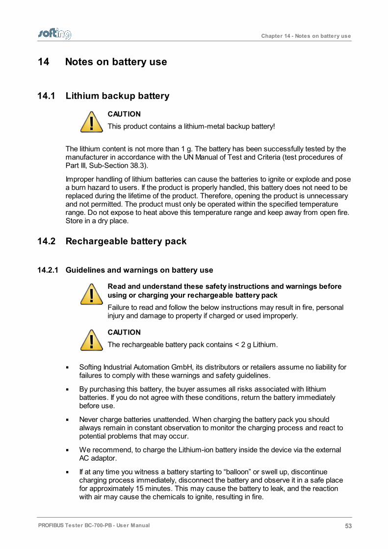
14.1 Lithium backup battery
CAUTION
This product contains a lithium-metal backup battery!
The lithium content is not more than 1 g. The battery has been successfully tested by themanufacturer in accordance with the UN Manual of Test and Criteria (test procedures ofPart III, Sub-Section 38.3).
Improper handling of lithium batteries can cause the batteries to ignite or explode and posea burn hazard to users. If the product is properly handled, this battery does not need to bereplaced during the lifetime of the product. Therefore, opening the product is unnecessaryand not permitted. The product must only be operated within the specified temperaturerange. Do not expose to heat above this temperature range and keep away from open fire.Store in a dry place.
14.2 Rechargeable battery pack
14.2.1 Guidelines and warnings on battery use
Read and understand these safety instructions and warnings beforeusing or charging your rechargeable battery pack
Failure to read and follow the below instructions may result in fire, personalinjury and damage to property if charged or used improperly.
CAUTION
The rechargeable battery pack contains < 2 g Lithium.
Softing Industrial Automation GmbH, its distributors or retailers assume no liability forfailures to comply with these warnings and safety guidelines.
By purchasing this battery, the buyer assumes all risks associated with lithiumbatteries. If you do not agree with these conditions, return the battery immediatelybefore use.
Never charge batteries unattended. When charging the battery pack you shouldalways remain in constant observation to monitor the charging process and react topotential problems that may occur.
We recommend, to charge the Lithium-ion battery inside the device via the externalAC adaptor.
If at any time you witness a battery starting to “balloon” or swell up, discontinuecharging process immediately, disconnect the battery and observe it in a safe placefor approximately 15 minutes. This may cause the battery to leak, and the reactionwith air may cause the chemicals to ignite, resulting in fire.

Chapter 14 - Notes on battery use
54 PROFIBUS Tester BC-700-PB - User Manual
Since delayed chemical reaction can occur, it is best to observe the battery as asafety precaution. Battery observation should occur in a safe area outside of anybuilding or vehicle and away from any combustible material.
You must not short circuit the wire leads! Never place the cells on a conductivesurface.
Wire lead shorts can cause fire! If you accidentally short the wires, the battery mustbe placed in a safe area for observation for approximately 15 minutes. Additionally, if ashort occurs and contact is made with metal (such as rings on your hand), severeinjuries may occur due to conductibility of electric current.
A battery can still ignite even after 10 minutes.
In the event of a crash, you must remove battery for observation and place in a safeopen area away from any combustible material for approximately 30 minutes.
Never store or charge battery pack inside your car in extreme temperatures, sinceextreme temperatures could ignite fire. Keep in mind the maximum allowed storagetemperature. Refer to Storage and Transportation for more information.
Use caution to avoid puncture of the cell. Puncture of cells may cause fire.
You must not pull the wire leads when you carry or remove the battery from thedevice.
In case of cells being damaged, do not use the battery anymore!
You must not open the cells. Oxygen and lithium will heavily react with each other!
If the electrolyte may get in contact with your skin or with our eyes, please give a washby using plenty of water and soap and call on a doctor.
Defective lithium ion batteries may evaporate substances which are harmful tohealth! You must not inhale!
Please return old battery packs to a recycling center or hand over to us for properdisposal. You must not ship battery packs which are clearly damaged. Please contactour support department.
You must not throw battery packs on the fire.
14.2.2 Charging
Use only the wide-range power supply (AC adapter) provided with the tool (seeScope of delivery ) in order to charge the battery. Set voltage and current correctly(failure to do so can cause fire).
Never charge batteries unattended.
Charge in an isolated area, away from other flammable materials.
For operating temperatures while charging refer to Specifications (operatingtemperature).
55
8
56

Chapter 14 - Notes on battery use
PROFIBUS Tester BC-700-PB - User Manual 55
14.2.3 Discharging
The energy management of the device complies with the following recommendations fordischarging lithium ion batteries:
You may not discharge the battery more than 80 % of nominal capacity.
Do not discharge battery to a level below 3.3 V per cell under load. Deep dischargebelow 3.3 V per cell can deteriorate battery performance and without load not less than3.5 V.
Operating Temperatures Discharge, refer to Specifications (operating temperature).
14.2.4 Storage and transportation
Store battery at room temperature between 12°C/53F and 18°C/65F for best results.(This corresponds to a battery charge level of 33%, refer to Device status ).
Do not expose battery pack to direct sunlight (heat) for extended periods
When transporting or temporarily storing in a vehicle, temperature range should begreater than 7°C/20F, but no more than 66°C/150F.
Storing battery at temperatures greater than 77°C/170F for extended periods of time(more than 2 hours) may cause damage to battery and possible fire.
14.2.5 Battery life
Charging and discharging will typically wear out the battery pack over the time. Due to thisaging the usable battery capacity will decrease accordingly. Higher current loads and deepdischarge processes will considerably increase the aging process.
You will have best results with respect to battery life, if you
avoid deep discharging
charge the battery properly
store the battery at recommended temperatures
avoid overloading
switch off the device when not being used for a longer period of time.
14.2.6 Battery warranty
Product warranty is limited to original defects in material and workmanship. Warrantydoes not cover collateral damage. Due to the nature and use of this product there is noterm warranty. Misuse, abuse, incorrect charging and other inappropriate use of thisproduct are not covered under warranty.
If you do not agree with these conditions, return the lithium polymer battery immediatelyand before any use.
56
35
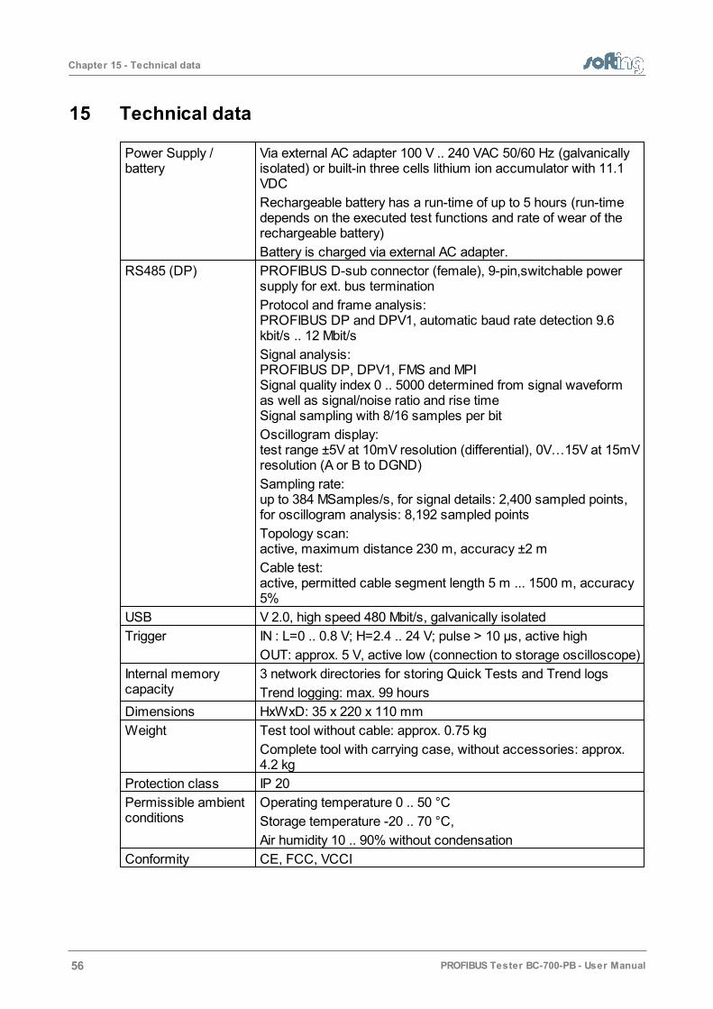
Chapter 15 - Technical data
56 PROFIBUS Tester BC-700-PB - User Manual
15 Technical data
Power Supply /battery
Via external AC adapter 100 V .. 240 VAC 50/60 Hz (galvanicallyisolated) or built-in three cells lithium ion accumulator with 11.1VDC
Rechargeable battery has a run-time of up to 5 hours (run-timedepends on the executed test functions and rate of wear of therechargeable battery)
Battery is charged via external AC adapter.
RS485 (DP) PROFIBUS D-sub connector (female), 9-pin,switchable powersupply for ext. bus termination
Protocol and frame analysis:PROFIBUS DP and DPV1, automatic baud rate detection 9.6kbit/s .. 12 Mbit/s
Signal analysis:PROFIBUS DP, DPV1, FMS and MPISignal quality index 0 .. 5000 determined from signal waveformas well as signal/noise ratio and rise timeSignal sampling with 8/16 samples per bit
Oscillogram display:test range ±5V at 10mV resolution (differential), 0V…15V at 15mVresolution (A or B to DGND)
Sampling rate:up to 384 MSamples/s, for signal details: 2,400 sampled points,for oscillogram analysis: 8,192 sampled points
Topology scan:active, maximum distance 230 m, accuracy ±2 m
Cable test:active, permitted cable segment length 5 m ... 1500 m, accuracy5%
USB V 2.0, high speed 480 Mbit/s, galvanically isolated
Trigger IN : L=0 .. 0.8 V; H=2.4 .. 24 V; pulse > 10 µs, active high
OUT: approx. 5 V, active low (connection to storage oscilloscope)
Internal memorycapacity
3 network directories for storing Quick Tests and Trend logs
Trend logging: max. 99 hours
Dimensions HxWxD: 35 x 220 x 110 mm
Weight Test tool without cable: approx. 0.75 kg
Complete tool with carrying case, without accessories: approx. 4.2 kg
Protection class IP 20
Permissible ambientconditions
Operating temperature 0 .. 50 °C
Storage temperature -20 .. 70 °C,
Air humidity 10 .. 90% without condensation
Conformity CE, FCC, VCCI

Chapter 15 - Technical data
PROFIBUS Tester BC-700-PB - User Manual 57
Operation Via graphical color display, four function keys and scroll wheelincluding central push-button or via PC/notebook.
Localization of the display texts: English and German
PC operatingsoftware
PROFIBUS Diagnostic Suite, see separate documentation

Chapter 16 - Declarations by the manufacturer
58 PROFIBUS Tester BC-700-PB - User Manual
16 Declarations by the manufacturer
This device complies to the EU product directive 2004/108/EC according to the followingdirectives:
EN 61000-6-4:2007+A1:2011 Electromagnetic compatibility (EMC) – Part 6-4: Genericstandards – Emission standard for industrial environments
EN 55022:2010 - Information technology equipment - Radio disturbancecharacteristics - Limits and methods of measurement - Class A product
EN 61000-6-2:2005 - Electromagnetic compatibility (EMC) -- Part 6-2: Genericstandards - Immunity for industrial environments
EN 61326-1:2013
A Declaration of Conformity in compliance with the above standards hasbeen made and can be requested from Softing Industrial Automation GmbH.
Note
To fulfill the EMC requirements, the other components (AC adapter,PROFIBUS stations, etc.) also have to meet the EMC requirements. Ashielded cable must be used. In addition, the cable shield must be groundedproperly.
Note
Additional tests have been performed successfully proving compatibility withthe requirements set forth by FCC and VCCI.

Chapter 17 - Recycling
PROFIBUS Tester BC-700-PB - User Manual 59
17 Recycling
This symbol is required in accordance with the Waste Electrical and Electronic Equipment(WEEE) Directive of the European Union. The presence of this marking on the productindicates:
1. The device was put on the European Market after August 13, 2005
2. The device is not to be disposed of via the municipal waste collection system of anymember state of the European Union.
**This appliance is labeled in accordance with European Directive 2002/96/EC concerningwaste electrical and electronic equipment (WEEE). The Directive determines theframework for the return and recycling of used appliances as applicable throughout theEuropean Union. This label is applied to various products to indicate that the product is notto be thrown away, but rather reclaimed upon end of life per this Directive.
**It is very important that customers understand and follow all laws regarding the properdecontamination and safe disposal of electrical equipment. For Softing products bearingthis label please contact your dealer or local Softing office for details on the take backprogram that will facilitate the proper collection, treatment, recovery, recycling and safedisposal of device.

Richard-Reitzner-Allee 685540 Haar / GermanyTel: + 49 89 4 56 56-0Fax: + 49 89 4 56 56-488Internet: http://industrial.softing.comEmail: [email protected]: [email protected]
Softing Industrial Automation GmbH
- User Manual "Getting Started"- PB-DIAG-SUITE online help
PROFIBUS Diagnostics Suite
Related Documents