profibus dp – cbf-b1/cbff-b1 burner control box vor00161floxkorea.com/img/pdf/profibus_cbf_f_...
TRANSCRIPT
P. 1 / 12
Profibus DP – CBF-B1/CBFF-B1 Burner Control Box vor00161
PROPERTIES
APPLICATION RANGE
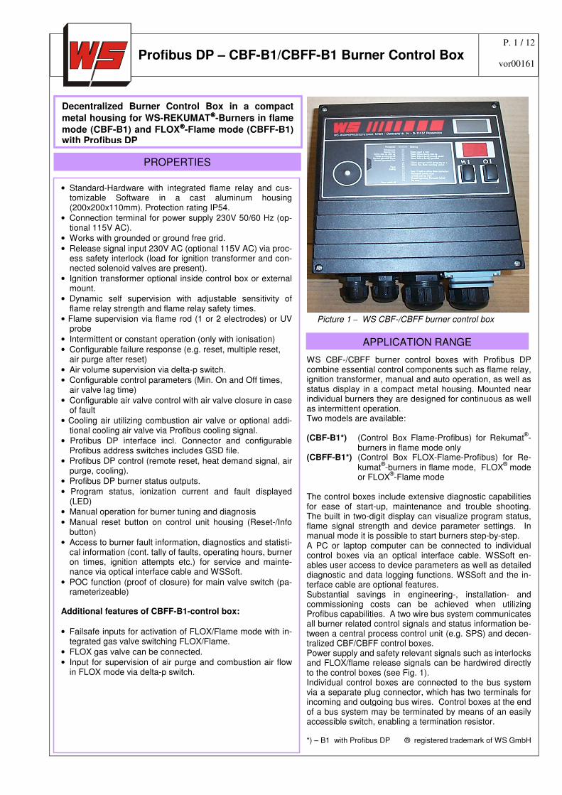
WS CBF-/CBFF burner control boxes with Profibus DP combine essential control components such as flame relay, ignition transformer, manual and auto operation, as well as status display in a compact metal housing. Mounted near individual burners they are designed for continuous as well as intermittent operation. Two models are available: (CBF-B1*) (Control Box Flame-Profibus) for Rekumat
®-
burners in flame mode only (CBFF-B1*) (Control Box FLOX-Flame-Profibus) for Re-
kumat®-burners in flame mode, FLOX
® mode
or FLOX®-Flame mode
The control boxes include extensive diagnostic capabilities for ease of start-up, maintenance and trouble shooting. The built in two-digit display can visualize program status, flame signal strength and device parameter settings. In manual mode it is possible to start burners step-by-step. A PC or laptop computer can be connected to individual control boxes via an optical interface cable. WSSoft en-ables user access to device parameters as well as detailed diagnostic and data logging functions. WSSoft and the in-terface cable are optional features. Substantial savings in engineering-, installation- and commissioning costs can be achieved when utilizing Profibus capabilities. A two wire bus system communicates all burner related control signals and status information be-tween a central process control unit (e.g. SPS) and decen-tralized CBF/CBFF control boxes. Power supply and safety relevant signals such as interlocks and FLOX/flame release signals can be hardwired directly to the control boxes (see Fig. 1). Individual control boxes are connected to the bus system via a separate plug connector, which has two terminals for incoming and outgoing bus wires. Control boxes at the end of a bus system may be terminated by means of an easily accessible switch, enabling a termination resistor. *) – B1 with Profibus DP ® registered trademark of WS GmbH
• Standard-Hardware with integrated flame relay and cus-tomizable Software in a cast aluminum housing (200x200x110mm). Protection rating IP54.
• Connection terminal for power supply 230V 50/60 Hz (op-tional 115V AC).
• Works with grounded or ground free grid.
• Release signal input 230V AC (optional 115V AC) via proc-ess safety interlock (load for ignition transformer and con-nected solenoid valves are present).
• Ignition transformer optional inside control box or external mount.
• Dynamic self supervision with adjustable sensitivity of flame relay strength and flame relay safety times.
• Flame supervision via flame rod (1 or 2 electrodes) or UV probe
• Intermittent or constant operation (only with ionisation)
• Configurable failure response (e.g. reset, multiple reset, air purge after reset)
• Air volume supervision via delta-p switch.
• Configurable control parameters (Min. On and Off times, air valve lag time)
• Configurable air valve control with air valve closure in case of fault
• Cooling air utilizing combustion air valve or optional addi-tional cooling air valve via Profibus cooling signal.
• Profibus DP interface incl. Connector and configurable Profibus address switches includes GSD file.
• Profibus DP control (remote reset, heat demand signal, air purge, cooling).
• Profibus DP burner status outputs.
• Program status, ionization current and fault displayed (LED)
• Manual operation for burner tuning and diagnosis
• Manual reset button on control unit housing (Reset-/Info button)
• Access to burner fault information, diagnostics and statisti-cal information (cont. tally of faults, operating hours, burner on times, ignition attempts etc.) for service and mainte-nance via optical interface cable and WSSoft.
• POC function (proof of closure) for main valve switch (pa-rameterizeable)
Additional features of CBFF-B1-control box:
• Failsafe inputs for activation of FLOX/Flame mode with in-tegrated gas valve switching FLOX/Flame.
• FLOX gas valve can be connected.
• Input for supervision of air purge and combustion air flow in FLOX mode via delta-p switch.
Decentralized Burner Control Box in a compact
metal housing for WS-REKUMAT-Burners in flame
mode (CBF-B1) and FLOX-Flame mode (CBFF-B1) with Profibus DP
Picture 1 – WS CBF-/CBFF burner control box
P. 2 / 12
Profibus DP – CBF-B1/CBFF-B1 Burner Control Box vor00161
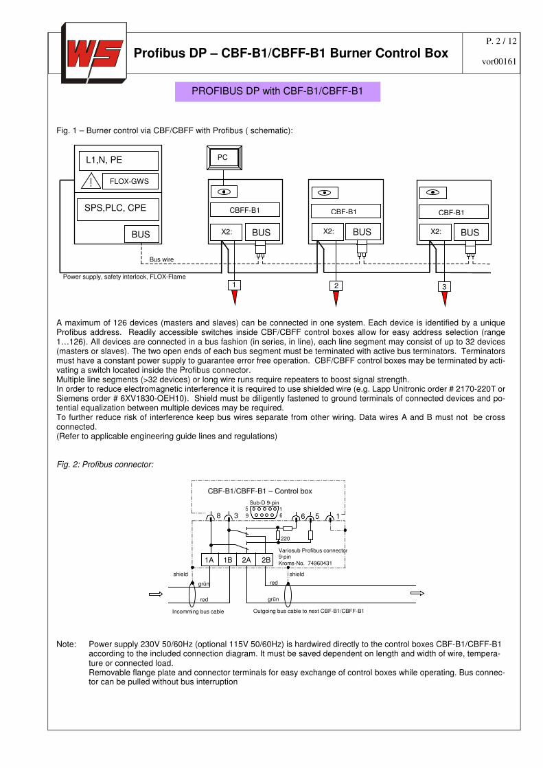
Fig. 1 – Burner control via CBF/CBFF with Profibus ( schematic):
SPS,PLC, CPE
L1,N, PE
BUS
FLOX-GWS
CBFF-B1
BUS X2:
PCC
CBF-B1
X2: BUS
CBF-B1
X2: BUS
Power supply, safety interlock, FLOX-Flame
Bus wire
1 2 3
A maximum of 126 devices (masters and slaves) can be connected in one system. Each device is identified by a unique Profibus address. Readily accessible switches inside CBF/CBFF control boxes allow for easy address selection (range 1…126). All devices are connected in a bus fashion (in series, in line), each line segment may consist of up to 32 devices (masters or slaves). The two open ends of each bus segment must be terminated with active bus terminators. Terminators must have a constant power supply to guarantee error free operation. CBF/CBFF control boxes may be terminated by acti-vating a switch located inside the Profibus connector. Multiple line segments (>32 devices) or long wire runs require repeaters to boost signal strength. In order to reduce electromagnetic interference it is required to use shielded wire (e.g. Lapp Unitronic order # 2170-220T or Siemens order # 6XV1830-OEH10). Shield must be diligently fastened to ground terminals of connected devices and po-tential equalization between multiple devices may be required. To further reduce risk of interference keep bus wires separate from other wiring. Data wires A and B must not be cross connected. (Refer to applicable engineering guide lines and regulations) Fig. 2: Profibus connector:
1B 2A 2B
8 3 6 5 1
CBF-B1/CBFF-B1 – Control box
220
grün
grün red
red
shield shield
Incomming bus cable Outgoing bus cable to next CBF-B1/CBFF-B1
1A
5 9 6
1Sub-D 9-pin
Variosub Profibus connector 9-pin Kroms-No. 74960431
Note: Power supply 230V 50/60Hz (optional 115V 50/60Hz) is hardwired directly to the control boxes CBF-B1/CBFF-B1
according to the included connection diagram. It must be saved dependent on length and width of wire, tempera-ture or connected load. Removable flange plate and connector terminals for easy exchange of control boxes while operating. Bus connec-tor can be pulled without bus interruption
PROFIBUS DP with CBF-B1/CBFF-B1
P. 3 / 12
Profibus DP – CBF-B1/CBFF-B1 Burner Control Box vor00161
Busanschluss Profibus DP:
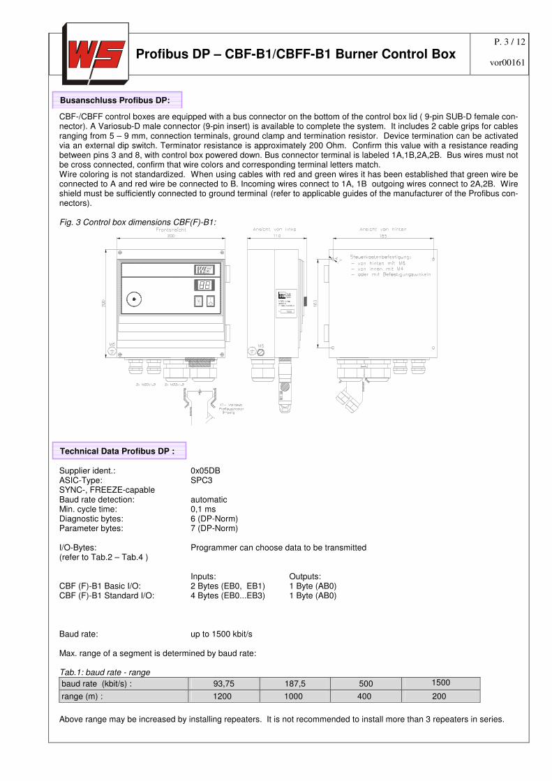
CBF-/CBFF control boxes are equipped with a bus connector on the bottom of the control box lid ( 9-pin SUB-D female con-nector). A Variosub-D male connector (9-pin insert) is available to complete the system. It includes 2 cable grips for cables ranging from 5 – 9 mm, connection terminals, ground clamp and termination resistor. Device termination can be activated via an external dip switch. Terminator resistance is approximately 200 Ohm. Confirm this value with a resistance reading between pins 3 and 8, with control box powered down. Bus connector terminal is labeled 1A,1B,2A,2B. Bus wires must not be cross connected, confirm that wire colors and corresponding terminal letters match. Wire coloring is not standardized. When using cables with red and green wires it has been established that green wire be connected to A and red wire be connected to B. Incoming wires connect to 1A, 1B outgoing wires connect to 2A,2B. Wire shield must be sufficiently connected to ground terminal (refer to applicable guides of the manufacturer of the Profibus con-nectors). Fig. 3 Control box dimensions CBF(F)-B1:
Supplier ident.: 0x05DB ASIC-Type: SPC3 SYNC-, FREEZE-capable Baud rate detection: automatic Min. cycle time: 0,1 ms Diagnostic bytes: 6 (DP-Norm) Parameter bytes: 7 (DP-Norm) I/O-Bytes: Programmer can choose data to be transmitted (refer to Tab.2 – Tab.4 ) Inputs: Outputs: CBF (F)-B1 Basic I/O: 2 Bytes (EB0, EB1) 1 Byte (AB0) CBF (F)-B1 Standard I/O: 4 Bytes (EB0...EB3) 1 Byte (AB0) Baud rate: up to 1500 kbit/s Max. range of a segment is determined by baud rate: Tab.1: baud rate - range
baud rate (kbit/s) : 93,75 187,5 500 1500
range (m) : 1200 1000 400 200
Above range may be increased by installing repeaters. It is not recommended to install more than 3 repeaters in series.
Technical Data Profibus DP :
P. 4 / 12
Profibus DP – CBF-B1/CBFF-B1 Burner Control Box vor00161
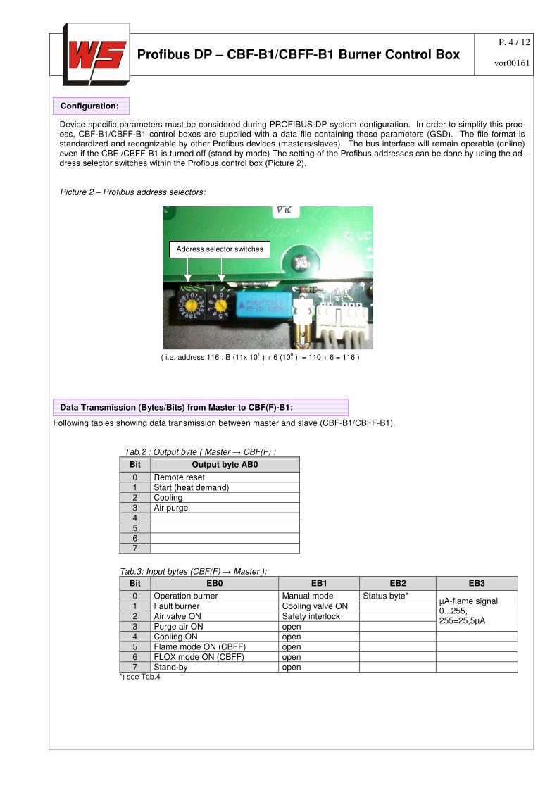
Device specific parameters must be considered during PROFIBUS-DP system configuration. In order to simplify this proc-ess, CBF-B1/CBFF-B1 control boxes are supplied with a data file containing these parameters (GSD). The file format is standardized and recognizable by other Profibus devices (masters/slaves). The bus interface will remain operable (online) even if the CBF-/CBFF-B1 is turned off (stand-by mode) The setting of the Profibus addresses can be done by using the ad-dress selector switches within the Profibus control box (Picture 2). Picture 2 – Profibus address selectors:
Following tables showing data transmission between master and slave (CBF-B1/CBFF-B1).
Tab.2 : Output byte ( Master → CBF(F) :
Bit Output byte AB0
0 Remote reset
1 Start (heat demand) 2 Cooling 3 Air purge
4 5
6 7
Tab.3: Input bytes (CBF(F) → Master ):
Bit EB0 EB1 EB2 EB3
0 Operation burner Manual mode Status byte*
1 Fault burner Cooling valve ON 2 Air valve ON Safety interlock
3 Purge air ON open
µA-flame signal 0...255, 255=25,5µA
4 Cooling ON open 5 Flame mode ON (CBFF) open
6 FLOX mode ON (CBFF) open 7 Stand-by open
*) see Tab.4
Configuration:
Address selector switches
101 10
0
+
( i.e. address 116 : B (11x 101 ) + 6 (10
0 ) = 110 + 6 = 116 )
Data Transmission (Bytes/Bits) from Master to CBF(F)-B1:
P. 5 / 12
Profibus DP – CBF-B1/CBFF-B1 Burner Control Box vor00161
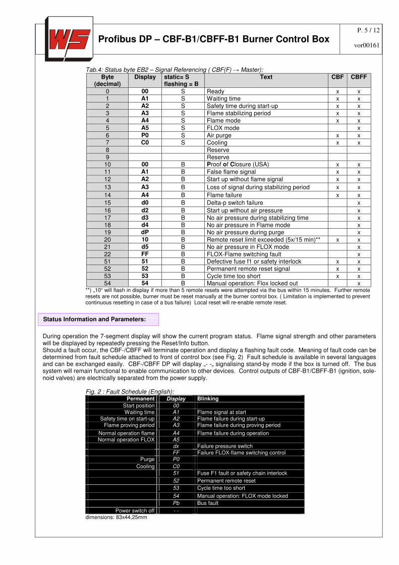
Tab.4: Status byte EB2 – Signal Referencing ( CBF(F) → Master): Byte
(decimal) Display static= S
flashing = B Text CBF CBFF
0 00 S Ready x x 1 A1 S Waiting time x x
2 A2 S Safety time during start-up x x 3 A3 S Flame stabilizing period x x
4 A4 S Flame mode x x
5 A5 S FLOX mode x
6 P0 S Air purge x x 7 C0 S Cooling x x
8 Reserve 9 Reserve
10 00 B Proof of Closure (USA) x x
11 A1 B False flame signal x x
12 A2 B Start up without flame signal x x
13 A3 B Loss of signal during stabilizing period x x
14 A4 B Flame failure x x
15 d0 B Delta-p switch failure x
16 d2 B Start up without air pressure x
17 d3 B No air pressure during stabilizing time x 18 d4 B No air pressure in Flame mode x 19 dP B No air pressure during purge x
20 10 B Remote reset limit exceeded (5x/15 min)** x x 21 d5 B No air pressure in FLOX mode x
22 FF B FLOX-Flame switching fault x 51 51 B Defective fuse f1 or safety interlock x x 52 52 B Permanent remote reset signal x x
53 53 B Cycle time too short x x 54 54 B Manual operation: Flox locked out x
**) „10“ will flash in display if more than 5 remote resets were attempted via the bus within 15 minutes. Further remote resets are not possible, burner must be reset manually at the burner control box. ( Limitation is implemented to prevent continuous resetting in case of a bus failure) Local reset will re-enable remote reset.
During operation the 7-segment display will show the current program status. Flame signal strength and other parameters will be displayed by repeatedly pressing the Reset/Info button. Should a fault occur, the CBF-/CBFF will terminate operation and display a flashing fault code. Meaning of fault code can be determined from fault schedule attached to front of control box (see Fig. 2) Fault schedule is available in several languages and can be exchanged easily. CBF-/CBFF DP will display „- -„ signalising stand-by mode if the box is turned off. The bus system will remain functional to enable communication to other devices. Control outputs of CBF-B1/CBFF-B1 (ignition, sole-noid valves) are electrically separated from the power supply.
Fig. 2 : Fault Schedule (English): Permanent Display Blinking
Start position 00
Waiting time A1 Flame signal at start
Safety time on start-up A2 Flame failure during start-up Flame proving period A3 Flame failure during proving period
Normal operation flame A4 Flame failure during operation Normal operation FLOX A5
dx Failure pressure switch
FF Failure FLOX-flame switching control
Purge P0
Cooling C0
51 Fuse F1 fault or safety chain interlock
52 Permanent remote reset
53 Cycle time too short
54 Manual operation: FLOX mode locked
Pb Bus fault
Power switch off - -
dimensions: 83x44,25mm
Status Information and Parameters:
P. 6 / 12
Profibus DP – CBF-B1/CBFF-B1 Burner Control Box vor00161
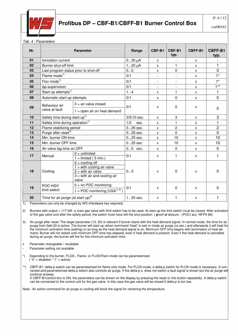
Tab. 4 : Parameters
Nr. Parameter Range CBF-B1 CBF-B1 typ.
CBFF-B1
CBFF-B1
typ.
01 Ionization current 0...30 µA x - x -
02 Burner shut-off limit 1...20 µA x 1 x 1 03 Last program status prior to shut-off 0...5 x 0 x 0 04 Flame mode
1) 0/1 - - x 1*
05 Flox mode1)
0/1 - - x 1*
06 ∆p-supervision 0/1 - - x 1**
07 Start-up attempts1)
1...4 x 1 x 1 08 Automatic start-up attempts 0/1 x 0 x 0
0 = air valve closed 09
Behaviour air valve at fault 1 = open air on heat demand
0/1
x
0
x
0
10 Safety time during start-up1)
3/5/10 sec. x 3 x 3 11 Safety time during operation
1) 1/2 sec. x 1 x 1
12 Flame stabilizing period 0...25 sec. x 2 x 2 13 Purge after reset
3) 0...25 sec. x 0 x 0
14 Min. burner ON time 0...25 sec. x 10 x 10 15 Min. burner OFF time 0...25 sec. x 10 x 10 16 Air valve lag time on OFF 0...5 sec. x 0 x 0
0 = unlimited 17 Manual
1 = limited ( 5 min.) 0/1 x 1 x 1
0 = cooling off
1 = with cooling air valve 2 = with air valve 18 Cooling
3 = with air and cooling air valve
0...3 x 0 x 0
0 = no POC monitoring 19
POC-HGV limit switch 1 = POC monitoring (USA
1) 2) )
0/1 x 0 x 0
20 Time for air purge (at start up)3)
1...25 sec. x 1 x 1
1) Parameters can only be changed by WS (Hardware key required). 2) Burners with output > 117 kW, a main gas valve with limit switch has to be used. At start-up the limit switch must be closed. After activation
of the gas valve and after the safety period, the switch must have left the shut position. [ proof of closure - (POC) acc. NFPA 86] 3) Air purge after reset: The larger parameter (13, 20) is relevant if burner starts with the heat demand signal. In normal mode, the time for air
purge from field 20 is active. The burner will start up (when command “heat” is set) in mode air purge (xx sec.) and afterwards it will heat for the minimum activation time (setting) or as long as the heat demand signal is on. Minimum OFF time begins with termination of heat de-mand. Burner will not restart until minimum OFF time has elapsed, even if heat demand is present. Even if the heat demand is cancelled during air purge, the burner will fire for the minimum activation time.
x Parameter changeable / recallable
- Parameter setting not available *) Depending to the burner, FLOX-, Flame- or FLOX/Flam-mode can be parameterized. ( “0“ = disabled / “1“ = active) **) CBFF-B1: delta-p switch can be parameterized for flame only mode. For FLOX mode, a delta-p switch for FLOX mode is necessary. A con-
nected and parameterized delta-p switch also controls air purge. If the delta-p s. does not switch a fault signal is shown but the air purge will continue anyway
If CBFF-B1control box is ON, the parameters can be shown on the display by pressing the reset or info button repeatedly. A delta-p switch can be connected to the control unit for the gas valve. In this case the gas valve will be closed if delta-p is too low.
Note.: An active command for air purge or cooling will block the signal for retrieving the temperature.

P. 7 / 12
Profibus DP – CBF-B1/CBFF-B1 Burner Control Box vor00161
Before starting the power supply 230V AC (optional 115V AC) and release signal input via process safety chain has to be connected directly to the CBF(F)-B1 control box according to supplied electrical drawings. Input of safety chain is charged by load of ignition transformer an the connected gas valves. The load for air valves and for the CBF(F)-B1 control box is charged from terminal X2.1. For burners in FLOX mode a CBFF-B1 control box has to be used. Additionally the fail save inputs for the switching signals for Flame and FLOX mode from the fail save FLOX temperature monitoring system has to be connected to the CBFF-B1 control box. To disengage FLOX mode an active signal level (230V AC L1-level optional 115V AC) at the FLOX input is necessary and the furnace temperature must be surely above 850°C. In this case the input fur Flame mode must be disabled. On the other hand when the temperature falls below 850°C the FLOX input has to be disabled and the Flame input has to be enabled. The switching must be done within 1 sec. otherwise a fault signal (FF “blinking”) will be caused. The supplied connector for Profibus (bus cables included) has to be installed according to electrical drawing (p. 3). Profibus version reduces wiring, as only power supply and safety interlocks (230V) must be run to the box in addition to the bus ca-ble. Control cables for the burner components are pre-installed and only require hook up on site. The unit is pre-wired and tested for functionality prior to delivery. An electrical schematic is located on the inside of the box lid. Each box is marked with an individual serial number, located on the side of the box. On the lid two push-buttons, ON/OFF and Reset/Info, are mounted below the 2 digit display. These buttons are also used for manual burner control. A fault schedule for failure code interpretation is inserted into a pouch on the lid as well. Activation and feed-back is according to data transmission handling (p. 4/5) from master to control boxes Before start-up of FLOX burner, the connectors and signals of FLOX mode and Flame mode have to be checked ex-actly and the settings have to be tested for correct functionality with closed gas supply – in case of wrong connec-tion:
explosion hazard
Fig. 5: Connection diagram CBF-B1 with Profibus
Hardware connection CBF(F)-B1 :
P. 8 / 12
Profibus DP – CBF-B1/CBFF-B1 Burner Control Box vor00161
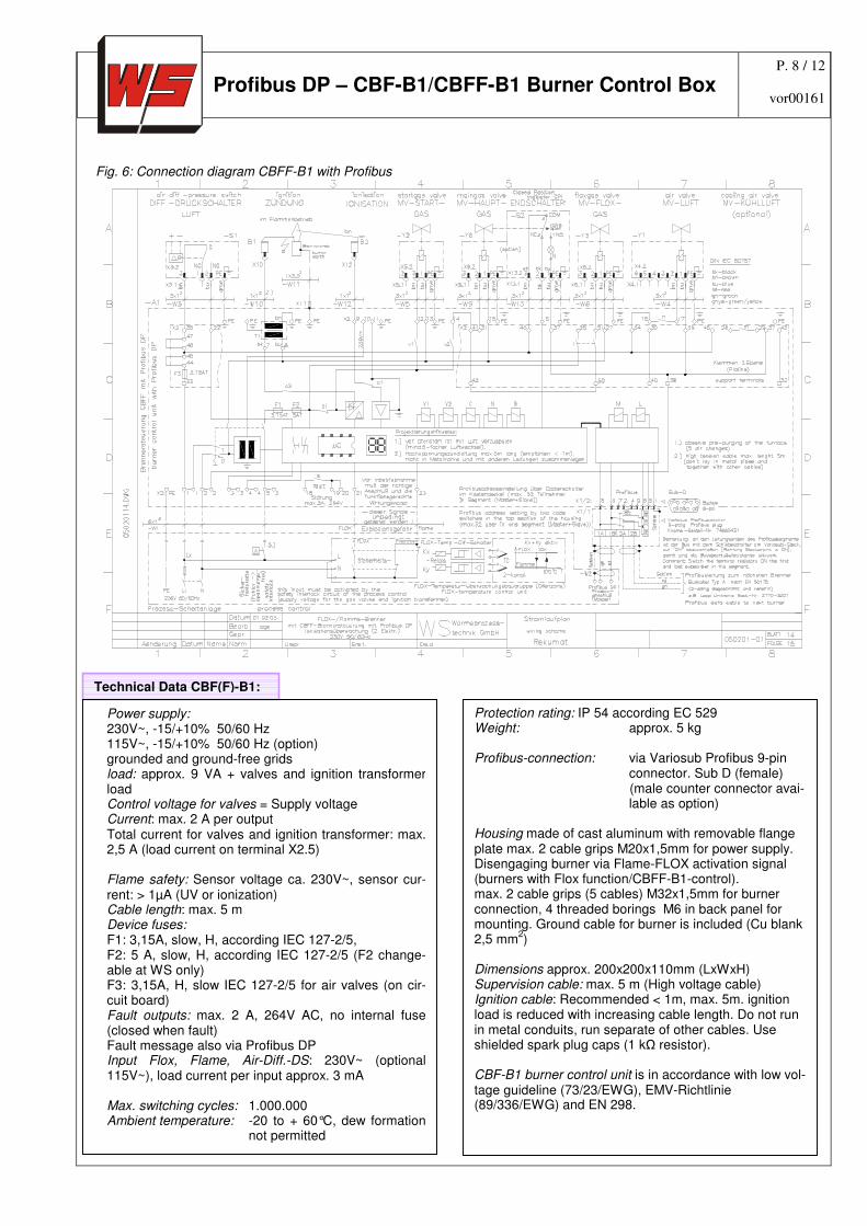
Fig. 6: Connection diagram CBFF-B1 with Profibus
Technical Data CBF(F)-B1:
Power supply: 230V~, -15/+10% 50/60 Hz 115V~, -15/+10% 50/60 Hz (option) grounded and ground-free grids load: approx. 9 VA + valves and ignition transformer load Control voltage for valves = Supply voltage Current: max. 2 A per output Total current for valves and ignition transformer: max. 2,5 A (load current on terminal X2.5) Flame safety: Sensor voltage ca. 230V~, sensor cur-rent: > 1µA (UV or ionization) Cable length: max. 5 m Device fuses: F1: 3,15A, slow, H, according IEC 127-2/5, F2: 5 A, slow, H, according IEC 127-2/5 (F2 change-able at WS only) F3: 3,15A, H, slow IEC 127-2/5 for air valves (on cir-cuit board) Fault outputs: max. 2 A, 264V AC, no internal fuse (closed when fault) Fault message also via Profibus DP Input Flox, Flame, Air-Diff.-DS: 230V~ (optional 115V~), load current per input approx. 3 mA
Max. switching cycles: 1.000.000 Ambient temperature: -20 to + 60°C, dew formation
not permitted
Protection rating: IP 54 according EC 529 Weight: approx. 5 kg Profibus-connection: via Variosub Profibus 9-pin
connector. Sub D (female) (male counter connector avai-lable as option)
Housing made of cast aluminum with removable flange plate max. 2 cable grips M20x1,5mm for power supply. Disengaging burner via Flame-FLOX activation signal (burners with Flox function/CBFF-B1-control). max. 2 cable grips (5 cables) M32x1,5mm for burner connection, 4 threaded borings M6 in back panel for mounting. Ground cable for burner is included (Cu blank 2,5 mm
2)
Dimensions approx. 200x200x110mm (LxWxH) Supervision cable: max. 5 m (High voltage cable) Ignition cable: Recommended < 1m, max. 5m. ignition load is reduced with increasing cable length. Do not run in metal conduits, run separate of other cables. Use shielded spark plug caps (1 kΩ resistor). CBF-B1 burner control unit is in accordance with low vol-tage guideline (73/23/EWG), EMV-Richtlinie (89/336/EWG) and EN 298.
P. 9 / 12
Profibus DP – CBF-B1/CBFF-B1 Burner Control Box vor00161
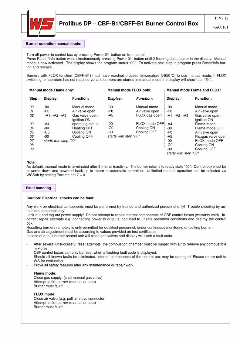
Turn off power to control box by pressing Power 0/1 button on front panel. Press Reset-/Info button while simultaneously pressing Power 0/1 button until 2 flashing dots appear in the display. Manual mode is now activated. The display shows the program status “00”. To activate next step in program press Reset/Info but-ton and release. Burners with FLOX function (CBFF-B1) must have reached process temperature (>850°C) to use manual mode. If FLOX switching temperature has not reached yet and burners are started in manual mode the display will show fault “54”.
Note: As default, manual mode is terminated after 5 min. of inactivity. The burner returns to ready state “00”. Control box must be powered down and powered back up to return to automatic operation. Unlimited manual operation can be selected via WSSoft by setting Parameter 17 = 0.
Caution: Electrical shocks can be fatal! Any work on electrical components must be performed by trained and authorized personnel only! Trouble shooting by au-thorized personnel only! Lock-out and tag-out power supply! Do not attempt to repair internal components of CBF control boxes (warranty void). In-correct repair attempts e.g. connecting power to outputs, can lead to unsafe operation conditions and destroy the control box. Resetting burners remotely is only permitted for qualified personnel, under continuous monitoring of faulting burner. Gas and air adjustment must be according to values provided on test certificates. In case of a fault burner control unit will close gas valves and display will flash a fault code. - After several unsuccessful reset attempts, the combustion chamber must be purged with air to remove any combustible
mixtures. - CBF control boxes can only be reset when a flashing fault code is displayed. - Should all known faults be eliminated, internal components of the control box may be damaged. Please return unit to
WS for evaluation. - Prove all safety features after any maintenance or repair work:
Flame mode: Close gas supply (shut manual gas valve) Attempt to fire burner (manual or auto) Burner must fault! FLOX mode: Close air valve (e.g. pull air valve connector) Attempt to fire burner (manual or auto) Burner must fault!
Burner operation manual mode:
Manual mode Flame only: Step : Display: Function: 00 -00 Manual mode 01 -P0 Air valve open
02 -A1→A2→A3 Gas valve open, ignition ON
03 -A4 operating status 04 -00 Heating OFF 05 -C0 Cooling ON 06 -00 Cooling OFF 07 starts with step “00“ 08 09
Manual mode FLOX only: Display: Function: -00 Manual mode -P0 Air valve open -A5 FLOX gas open -00 FLOX mode OFF -C0 Cooling ON -00 Cooling OFF starts with step “00“
Manual mode Flame and FLOX: Display: Function: -00 Manual mode -P0 Air valve open
-A1→A2→A3 Gas valve open, ignition ON
-A4 Flame mode -00 Flame mode OFF -P0 Air valve open -A5 Floxgas valve open -00 FLOX mode OFF -C0 Cooling ON -00 Cooling OFF starts with step “00“
Fault handling :
P. 10 / 12
Profibus DP – CBF-B1/CBFF-B1 Burner Control Box vor00161
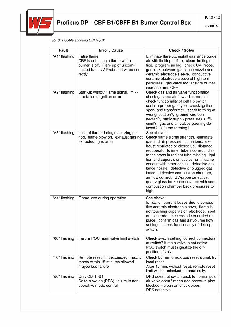
Tab. 6: Trouble shooting CBF(F)-B1
Fault Error / Cause Check / Solve
“A1“ flashing False flame CBF is detecting a flame when burner is off. Flare up of uncom-busted fuel, UV-Probe not wired cor-rectly
Eliminate flare up: install gas lance purge air with limiting orifice, clean limiting ori-fice, program air lag, check UV-Probe, gas leak between gas lance nozzle and ceramic electrode sleeve, conductive ceramic electrode sleeve at high tem-peratures, gas valve too far from burner, increase min. OFF
“A2“ flashing
Start-up without flame signal, mix-ture failure, ignition error
Check gas and air valve functionality, check gas and air flow adjustments, check functionality of delta-p switch, confirm proper gas type, check ignition spark and transformer, spark forming at wrong location?; ground wire con-nected?, static supply pressures suffi-cient?, gas and air valves opening de-layed? Is flame forming?
“A3“ flashing Loss of flame during stabilizing pe-riod, flame blow off, exhaust gas not extracted, gas or air
See above ; Check flame signal strength, eliminate gas and air pressure fluctuations, ex-haust restricted or closed up, distance recuperator to inner tube incorrect, dis-tance cross in radiant tube missing, igni-tion and supervision cables run in same conduit with other cables, defective gas lance nozzle, defective or plugged gas lance, defective combustion chamber, air flow correct, UV-probe defective, quartz glass broken or covered with soot, combustion chamber back pressures to high
“A4“ flashing Flame loss during operation
See above; Ionisation current losses due to conduc-tive ceramic electrode sleeve, flame is not touching supervision electrode, soot on electrode, electrode deteriorated re-place, confirm gas and air volume flow settings, check functionality of delta-p switch,
“00” flashing Failure POC main valve limit switch Check switch setting; correct connectors at switch? if main valve is not active POC switch must signalize the off-position of valve
“10” flashing Remote reset limit exceeded, max. 5 resets within 15 minutes allowed maybe bus failure
Check burner; check bus reset signal, try local reset. After 15 min. without reset, remote reset limit will be unlocked automatically.
“d0” flashing Only CBFF-B1 Delta-p switch (DPS) failure in non-operative mode control
DPS does not switch back to normal pos. air valve open? measured pressure pipe blocked – clean an check pipes DPS defective
P. 11 / 12
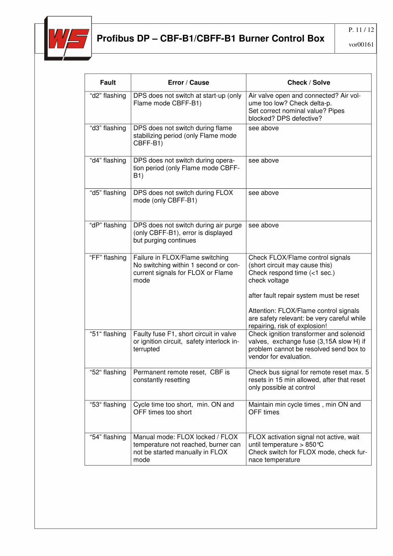
Profibus DP – CBF-B1/CBFF-B1 Burner Control Box vor00161
Fault Error / Cause Check / Solve
“d2” flashing DPS does not switch at start-up (only Flame mode CBFF-B1)
Air valve open and connected? Air vol-ume too low? Check delta-p. Set correct nominal value? Pipes blocked? DPS defective?
“d3” flashing DPS does not switch during flame stabilizing period (only Flame mode CBFF-B1)
see above
“d4” flashing DPS does not switch during opera-tion period (only Flame mode CBFF-B1)
see above
“d5” flashing DPS does not switch during FLOX mode (only CBFF-B1)
see above
“dP” flashing DPS does not switch during air purge (only CBFF-B1), error is displayed but purging continues
see above
“FF” flashing Failure in FLOX/Flame switching No switching within 1 second or con-current signals for FLOX or Flame mode
Check FLOX/Flame control signals (short circuit may cause this) Check respond time (<1 sec.) check voltage after fault repair system must be reset Attention: FLOX/Flame control signals are safety relevant: be very careful while repairing, risk of explosion!
“51“ flashing Faulty fuse F1, short circuit in valve or ignition circuit, safety interlock in-terrupted
Check ignition transformer and solenoid valves, exchange fuse (3,15A slow H) if problem cannot be resolved send box to vendor for evaluation.
“52“ flashing Permanent remote reset, CBF is constantly resetting
Check bus signal for remote reset max. 5 resets in 15 min allowed, after that reset only possible at control
“53“ flashing Cycle time too short, min. ON and OFF times too short
Maintain min cycle times , min ON and OFF times
“54” flashing Manual mode: FLOX locked / FLOX temperature not reached, burner can not be started manually in FLOX mode
FLOX activation signal not active, wait until temperature > 850°C Check switch for FLOX mode, check fur-nace temperature
P. 12 / 12
Profibus DP – CBF-B1/CBFF-B1 Burner Control Box vor00161
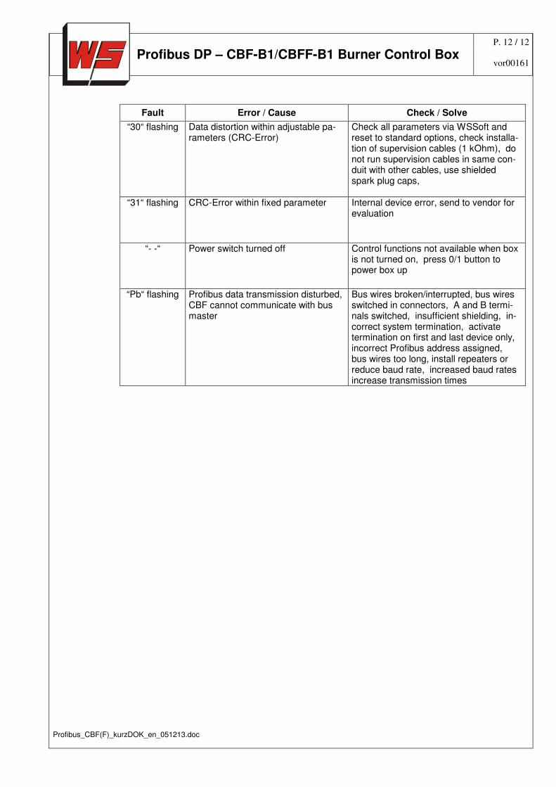
Fault Error / Cause Check / Solve
“30“ flashing Data distortion within adjustable pa-rameters (CRC-Error)
Check all parameters via WSSoft and reset to standard options, check installa-tion of supervision cables (1 kOhm), do not run supervision cables in same con-duit with other cables, use shielded spark plug caps,
“31“ flashing CRC-Error within fixed parameter Internal device error, send to vendor for evaluation
“- -“ Power switch turned off Control functions not available when box is not turned on, press 0/1 button to power box up
“Pb“ flashing Profibus data transmission disturbed, CBF cannot communicate with bus master
Bus wires broken/interrupted, bus wires switched in connectors, A and B termi-nals switched, insufficient shielding, in-correct system termination, activate termination on first and last device only, incorrect Profibus address assigned, bus wires too long, install repeaters or reduce baud rate, increased baud rates increase transmission times
Profibus_CBF(F)_kurzDOK_en_051213.doc