prof. r.k.behera - ethesisethesis.nitrkl.ac.in/2220/1/dynamic_analysis_of_a_simply_suppo… ·...
TRANSCRIPT

1
DYNAMIC ANALYSIS OF A SIMPLY SUPPORTED
BEAM WITH CRACK
A THESIS SUBMITTED IN PARTIAL FULFILLMENT OF THE
REQUIREMENT FOR THE DEGREE OF
BACHELOR OF TECHNOLOGY
IN
MECHANICAL ENGINEERING
BY
ASHISH KUMAR SAHU
UNDER THE GIDANCE OF
PROF. R.K.BEHERA
DEPARTMENT OF MECHANICAL ENGINEERING
NATIONAL INSTITUE OF TECHNOLOGY ROURKELA
ROURKELA-769008
2
National Institute of Technology
Rourkela
CERTIFICATE
This is to certify that the thesis entitled, ―Dynamic Analysis of A Simply Supported Beam
With Crack‖ submitted by Sri Ashish Kumar Sahu in partial fulfilment of the requirements
for the award of Bachelor of Technology in Mechanical Engineering at National Institute
of Technology, Rourkela (Deemed University) is an authentic work carried out by him
under my supervision and guidance.
To the best of my knowledge, the matter embodied in the thesis has not been submitted to any
other University / Institute for the award of any Degree or Diploma.
Prof.R.K.Behera Dated: Dept. of Mechanical Engg.
National Institute of Technology
Rourkela – 769008
3
ACKNOWLEDGEMENT
I wish to express my deep sense of gratitude and indebtedness to Prof. R.K. Behera
Department of Mechanical Engineering, N.I.T Rourkela for introducing the present topic and
for his inspiring guidance, constructive criticism and valuable suggestion throughout this
project work.
I would also like to sincerely thank our Head of the Department Dr. R.K.Sahoo, who with
his valuable comments and suggestions during the viva-voce helped me immensely. I would
thank him because he was the one who constantly evaluated me corrected me and had been
the guiding light for me.
I am also thankful to all staff members of Department of Mechanical Engineering NIT
Rourkela.
I feel a deep sense of gratitude for my family members who formed a part of my vision and
taught me the good things that really matter in life.
Last but not least, sincere thanks to all my friends who have patiently extended all sorts of
help for accomplishing this undertaking.
10th MAY 2011 ASHISH KUMAR SAHU
ROLL NO: 107ME026
4
CONTENTS
Title Page No
ABSTRACT 5
Chapter 1 INTRODUCTION 6
Chapter 2 LITERATURE REVIEW 9
Chapter 3 CRACK THEORY 12
Chapter 4 VIBRATIONS OF CRACKED 15
SIMPLY SUPPORTED BEAM
Chapter 5 RESULTS AND DISCUSSION 20
Chapter 6 CONCLUSIONS 24
REFERENCES 25-27
5
ABSTRACT
The crack present in the structure changes the physical nature of it as well as changes the
dynamic response towards the vibration. For the analysis the depth and location of the crack
are important parameters which change the response. So it is important to study these
changes for the structural integrity, performance and safety. In the current project titled
―Dynamic Analysis of A Simply Supported Beam with Crack‖ the response nature of both
cracked and uncracked beam is predicted. Also the responses for different crack depths are
studied. In the present study, vibration analysis is done on a simply supported beam with and
without crack. The beam is considered to be an Euler-Bernoulli beam which is the most ideal
case for simple calculation. The methods used here are both non-dimensional and parametric.
At first the problem was solved using the boundary conditions and the normal equations to
find out the natural frequency of the beam. Then the cracked beam was studied taking all the
effects of the crack into consideration and the physical property of the material. Here the
cracked beam is considered to be two beams connected by a mass less spring at the crack
point. The proposed method had been compared with the analytical calculation and then with
the help of MATLAB the frequency response had been plotted to see the deviation from the
natural response.

6
CHAPTER 1
INTRODUCTION
1.1 Introduction
The crack present in any mechanical or structural part influences its vibrational behaviour
like its frequency and resonance. The crack may be a result of cyclical load or some other
factor and it propagates with the increase of the load through the structure. The amplitude and
resonance starts to shift as the crack parameters changes. So the structure fails after some
repetitive load which is due to incapability of carrying the load. For this reason finding the
cracks in a structure is more important from an engineering point of view to eliminate such
failure and risk. In structure like beam column, bridges etc. the damages are due to long
service, impact. The crack present in beam reduces its physical properties and also its
dynamic response to the load. By monitoring this different response to the load we can detect
the presence of crack in the design and take safety measures. The dynamic response depends
on the crack types which may be open, close or breathing during vibration.
Different theories have been generated till these days for the analysis of the bending of beams
and the analysis of its behaviour under the influence of the load in different conditions.
Among the theories two of them are popular which is explained below.
Euler – Bernoulli Beam Theory
It is the most classical theory among all the analysis. According to this theory, it is
assumed that the straight lines perpendicular to the mid-plane before bending
remains straight and perpendicular to it after bending also. As a result of that,
transverse shear strain is neglected. Although this theory is useful for slender beams
and plates, it didn’t give exact solution for the thick plate and beam.
Timoshenko Theory
In this the previous assumption is slightly modified so as to consider all possible
problems. In this theory, it is assumed that the lines perpendicular to the mid plane
before bending remains straight but no longer perpendicular to the mid plane after
bending.
For a simply supported beam, the load applied in the transverse direction causes the bending
and shearing of the beam. This force gives the response to the vibration of the beam. The
frequency of the beam will differ from its natural frequency if there will be a crack in its
length. So in recent time this crack estimation is an important and essential part of any design
and for that many new technique has been developed. A crack on a structural member
7
introduces a local flexibility which is a function of the crack depth. Major characteristics of
structures, which undergo change due to presence of crack, are
• The natural frequency
• The amplitude response due to vibration
• Mode shape.
Hence it is possible to use natural frequency measurements to detect cracks
For a beam with transverse load, the effect of transverse vibration will be more than that of
the longitudinal one for ideal case which is consider in this project work.
1.2 Transverse Vibration
Let a beam of mass per unit length m and amplitude of assumed deflection curve is
∫ ̅
Where ̅ is the mean deflection of the beam mid plane from the normal position.
Strain energy of the beam is the work done on the beam which is stored as elastic energy.
∫
Usually the deflection of the beam is very small
So
From the beam theory
where R is the radius of the curvature of the beam & EI is the
flexural rigidity of the structure. Thus
∫
∫
8
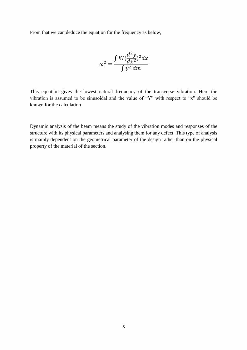
From that we can deduce the equation for the frequency as below,
∫
∫
This equation gives the lowest natural frequency of the transverse vibration. Here the
vibration is assumed to be sinusoidal and the value of ―Y‖ with respect to ―x‖ should be
known for the calculation.
Dynamic analysis of the beam means the study of the vibration modes and responses of the
structure with its physical parameters and analysing them for any defect. This type of analysis
is mainly dependent on the geometrical parameter of the design rather than on the physical
property of the material of the section.

9
CHAPTER 2
LITERATURE REVIEW
The effect of the crack or local defects in the dynamic response of the structure is known long
ago. Different researchers have found new methods for the detection of the damage or crack
in the beams. They are summarized below.
In recent years, structural analysis has gain momentum and so as on the non-destructive
damage detection methods. It is well known that damage can reduce the stiffness of a system
and the crack in it changes the dynamic response of it. That ultimately reduces the natural
frequency and the mode shape in vibration. For crack identification change in natural
frequency and modal value has been studied. In some cases crack properties are used to
obtain the dynamic behaviour as in [1-4] and sometimes inverse methods are used [5-8].
Narkis [9] used first two natural frequencies to identify the crack and later Morassi [10] used
it on simply supported beam and rods. Although it can be solved by using 2D or 3D finite
element method (FEM), Analysis of this approximate model results in algebraic equations
which relate the natural frequencies of beam and crack characteristics. These expressions are
then applied to studying the inverse problem—identification of crack location from frequency
measurements. It is found that the only information required for accurate crack identification
is the variation of the first two natural frequencies due to the crack, with no other information
needed concerning the beam geometry or material and the crack depth or shape. The
proposed method is confirmed by comparing it with results of numerical finite element
calculations the researchers still try to detect it with the help of physical parameters of the
crack i.e. crack depth, position and support condition to the beam.
Freud and Herrmann [17] modelled the problem using a torsional spring in the place of crack
whose stiffness is related. The first model is used to Euler-Bernoulli cracked beam with
different end conditions [4, 11, 19-23, 18] and recently on Timoshenko beams [24, 25].
Rubio et al [26] obtained closed-form expression for natural frequency for Euler-Bernoulli
beams with different end conditions using perturbation technique.
Some studies are directly related to the analysis of the frequency response which is called
direct problem. Some other deals with the crack properties through the knowledge of
dynamic behaviour of the beam called inverse problem.
Cracked beam is modelled as two segments of beams connected with a massless rotational
spring [10] whose stiffness is related to the crack length by the Fracture Machine Theory
[11]. So the cracked section behaves as a discontinuity in the rotation due to bending must be
considered. In using the fracture mechanics model, the local stiffness at the crack section is

10
calculated using Castigliano’s second theorem as applicable to fracture mechanics
formulations. The calculated local stiffness is then modelled by a flexural spring for the
bending vibration of a cracked beam. To establish the vibration equations, the cracked is
represented by two structures connected by flexural spring. These models are applied to the
Euler beams with varying conditions [5, 12-16].
Lele and Maiti have modelled the presence of the crack as a rotational spring in the Euler-
Bernoulli cracked beam problem. Krawczuk et al. [30] used the same method for
Timoshenko cracked beam for the development of spectral finite element. But in these above
cases the transverse deflection is neglected.
Matvev et al. [31] expressions for bending vibrations of an Euler-Bernoulli cracked beam
have been analysed. They have studied the effects of the ratio of crack location to the length
of the beam and also ratio of depth of the crack to the height of the beam. They have
investigated the variation of the natural frequency of the cracked beam.
Springer et al. [32] have examined the free longitudinal vibration of a bar with free ends and
two cracks located symmetrically at the centre of the span. The cracks have been modelled in
two ways. One is using linear springs; the other is using reductions in cross-sectional area.
The changes in natural frequencies are close to those obtained from experiments
Papadopoulos [35] has examined the torsional vibrations of rotors with transverse surface
crack. The crack has been modelled by a local flexibility matrix which was measured
experimentally. The result agreed with both theoretical and experimental values.
Both analytical and experimental study has been conducted by Wang and Qiao [39] to
develop efficient and effective damage detection techniques for beam-type structures. The
uniform load surface (ULS) was employed in this study due to its less sensitivity to ambient
noise. In combination with the ULS, two new damage detection algorithms, i.e., the
generalized fractal dimension (GFD) and simplified gapped-smoothing (SGS) methods, had
been proposed. Both methods are then applied to the ULS of cracked and delaminated beams,
from which the damage location and size were determined successfully. Based on the
experimentally measured curvature mode shapes, both the GFD and SGS methods are further
applied to detect three different types of damage in carbon/epoxy composite beams. Damage
detection in vibrating beams or beam systems had been done by Fabrizio and Danilo [40] by
discussing the amount of frequencies required locating and quantifying the damage uniquely.
Irwin [28, 29], A crack on an elastic structural element introduces considerable local
flexibility due to the strain energy concentration at the crack tip under load. This effect has
been known long ago. A local compliance has been used to quantify, in a microscopic way,
the relation between the applied load and the strain energy concentration around the tip of the
crack.
Silva and Gomez [33-35] have performed experimental dynamic analysis for the location and
the depth of cracks in straight beams. They have described the experimental techniques and
presented the results obtained for various locations and depths of crack.

11
Qian et al. [36] have used a finite element model to analyse the effect of crack closure on the
transverse vibration of a beam. The stiffness matrix of the system has been calculated from
the stress intensity factors, and it gives two values, one for the close crack (uncracked beam)
and for the other for the open crack. The sign of the stress on the crack faces has been used to
determine if the crack is open or closed.
Dimarogonas, et al. [37] have studied the influence of a circumferential crack upon the
torsional dynamic behaviour of a shaft. He found that due to the presence of crack, the
torsional natural frequencies decreases due to the added flexibility. The strain energy release
function is related to the compliance of the cracked shaft due to the introduction of a crack.
Mermertas, et al. [38] have studied the effect of mass attachment on the transverse vibration
characteristics of a cracked cantilever beam. Theoretically investigation of the cracked beam
has been carried out. The governing equation for free vibrations of the cracked beam was
constructed from the Bernoulli-Euler beam elements. To model the transverse vibration, the
crack is represented by a rotational spring. The crack was located in two different distances
from the fixed end of the beam. The results for the changes of the natural frequencies of a
cracked beam carrying a point mass are compared with the results of the beam without a
crack.
Nahvi, et al. have developed another method for crack detection in cantilever beams by
vibration analysis. To avoid non-linearity, they assumed that the crack is always open. To
identify the crack, the normalized frequency is plotted against the normalized crack depth and
location. The intersection of contours with the constant modal natural frequency planes is
used to relate the crack location and depth. The approach for identifying the cracked element
within the cantilever beam is minimized.

12
CHAPTER 3
CRACK THEORY
3.1 Classification of cracks
Based on their geometries, cracks can be broadly classified as follows:
• Cracks perpendicular to the beam axis are known as ―transverse cracks‖. These are the most
common and most serious as they reduce the cross-section and thereby weaken the beam.
They introduce a local flexibility in the stiffness of the beam due to strain energy
concentration in the vicinity of the crack tip.
• Cracks parallel to the beam axis are known as ―longitudinal cracks‖. They are not that
common but they pose danger when the tensile load is applied is at right angles to the crack
direction i.e. perpendicular to beam axis or the perpendicular to crack.
• ―Slant cracks‖ (cracks at an angle to the beam axis) are also encountered, but are not very
common. These influence the torsion behaviour of the beam. Their effect on lateral vibrations
is less than that of transverse cracks of comparable severity.
• Cracks that open when the affected part of the material is subjected to tensile stresses and
close when the stress is reversed are known as ―breathing cracks‖. The stiffness of the
component is most influenced when under tension. The breathing of the crack results in non-
linearity’s in the vibration behaviour of the beam. Cracks breathe when crack sizes are small,
running speeds are low and radial forces are large. Most theoretical research efforts are
concentrated on ―transverse breathing‖ cracks due to their direct practical relevance.
• Cracks that always remain open are known as ―gaping cracks‖. They are more correctly
called ―notches‖. Gaping cracks are easy to mimic in a laboratory environment and hence
most experimental work is focused on this particular crack type.
• Cracks that open on the surface are called ―surface cracks‖. They can normally be detected
by techniques such as dye-penetrates or visual inspection.
• Cracks that do not show on the surface are called ―subsurface cracks‖. Special techniques
such as ultrasonic, magnetic particle, radiography or shaft voltage drop are needed to detect
them. Surface cracks have a greater effect than subsurface cracks on the vibration behaviour
of shafts.

13
Physical parameters affecting Dynamic characteristics of cracked structures:
Usually the physical dimensions, boundary conditions, the material properties of the structure
play important role for the determination of its dynamic response. Their vibrations cause
changes in dynamic characteristics of structures. In addition to this presence of a crack in
structures modifies its dynamic behaviour. The following aspects of the crack greatly
influence the dynamic response of the structure.
(i) The position of crack
(ii) The depth of crack
(iii) The orientation of crack
(iv) The number of cracks
Stress Intensity Factor (SIF), K: - It is defined as a measure of the stress field intensity near
the tip of an ideal crack in a linear elastic solid when the crack surfaces are displaced in the
opening mode (Mode I). (SIFs) are used to define the magnitude of the singular stress and
displacement fields (local stresses and displacements near the crack tip). The SIF depends on
the loading, the crack size, the crack shape, and the geometric boundaries of the specimen.
The recommended units for K are MPa√m. it is customary to write the general formula in the
form K=Yσ πa where σ is the applied stress, a is crack depth, Y is dimensionless shape
factor.
Figure 3.1 Three basic modes of fracture
14
Modes of Fracture: -The three basic types of loading that a crack experiences are
• Mode I corresponds to the opening mode in which the crack faces separates in a
direction normal to the plane of the crack and the corresponding displacements of
crack walls are symmetric with respect to the crack front. Loading is normal to the
crack plane, and tends to open the crack. Mode I is generally considered the most
dangerous loading situation.
• Mode II corresponds to in-plane shear loading and tends to slide one crack face with
respect to the other (shearing mode). The stress is parallel to the crack growth
direction.
• Mode III corresponds to out-of-plane shear, or tearing. In which the crack faces are
sheared parallel to the crack front.
15
CHAPTER 4
VIBRATION OF CRACKED SIMPLY SUPPORTED BEAM
4.1 PROBLEM DEFINITION
The problem involves calculation of natural frequencies and mode shapes for simply
supported beam with a crack of different crack depths. The results calculated analytically are
validated with the results obtained by simulation analysis.
Stability of the elastic supports for different end conditions is also analysed under buckling
load.
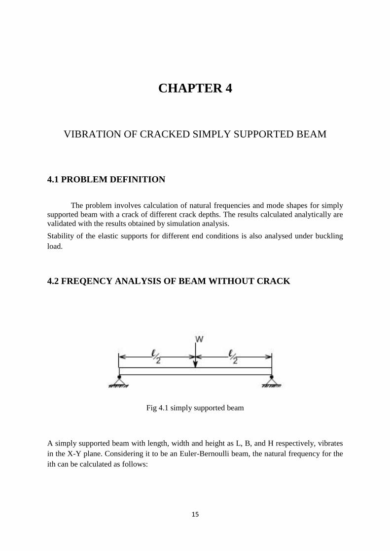
4.2 FREQENCY ANALYSIS OF BEAM WITHOUT CRACK
Fig 4.1 simply supported beam
A simply supported beam with length, width and height as L, B, and H respectively, vibrates
in the X-Y plane. Considering it to be an Euler-Bernoulli beam, the natural frequency for the
ith can be calculated as follows:
16
(
) √
(1)
Where c being the propagation speed.
√
(2)
Where I is the moment of inertia of the beam and the A belongs to the cross sectional area of
the beam. E and ρ are the Young’s modulus and the mass density of the beam respectively.
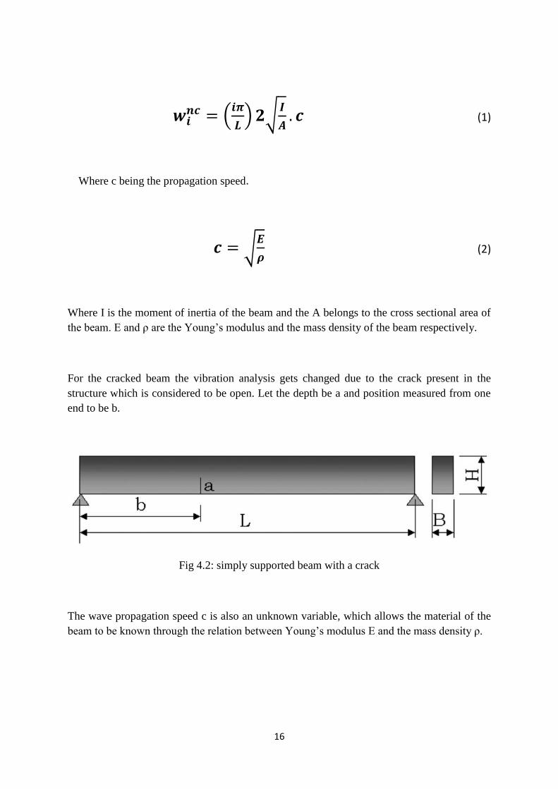
For the cracked beam the vibration analysis gets changed due to the crack present in the
structure which is considered to be open. Let the depth be a and position measured from one
end to be b.
Fig 4.2: simply supported beam with a crack
The wave propagation speed c is also an unknown variable, which allows the material of the
beam to be known through the relation between Young’s modulus E and the mass density ρ.

17
In order to take into account the presence of the crack, the cracked beam can be modelled
with two beams connected by a torsional. The model leads to a discontinuity in the slope of
the beam, which is proportional to the bending moment M as follows:
(3)
where F is the flexibility constant that can be expressed as
(4)
Where m is a function depending on the dimension of the crack depth ratio β=a/H and the
geometry of the cross section. For rectangular section the function m is as below [27]:
(
)
(5)
Each part of the cracked beam is assumed to be connected through a spring to each other
whose stiffness constant is related to crack dimensions. So the displacement of each part can
be given by the basic equation as
(j= 1, 2) (6)
Where subscript j=1 belongs to left part and 2 shows the right part of the cracked beam. The
ω* is the frequency for the cracked beam and is the transverse deflection. The solution
can be calculated from the differential equation shown below:
(j= 1, 2) (7)

18
The boundary conditions for simply supported beam are,
(8)
(9)
And for the cracked section the equations are:
Transverse deflection continuity,
(10)
Slope discontinuity,
(11)
Bending moment,
(12)
Shear force continuity,
(13)
The equation has leaded us to a pair of solutions for each part of the cracked beam:
(14)
(15)
Where the x coordinate notifies the distance of the point from the left end of the beam and
√
(16)
19
The coefficients of the solution can be calculated using the boundary equations shown above.
The natural frequency can be determined by equating the determinant to zero.
Now assuming two parameters for the easy calculation as and for the position
parameter of the crack (where δ=b/L). Taking the eight conditions to find the
eight unknown parameters the equation reduces to a non-trivial solution whose coefficient
matrix should be equal to zero and the final equation becomes
(17)
Knowing the position and depth of the crack in the beam we can calculate the frequency of
the structure.
Using all the boundary condition equations and relating the natural frequency of the cracked
beam with that to the uncracked beam the relation will be as below
∫
(18)
The displacement can take different values depending on the end conditions of the beam
support. As the case study for the present project is a simply supported beam, so the
expression will be written as
(19)
Putting the equation 19 in the equation 18 and taking into consideration the 1st equation the
following expression can be obtained:
⁄ (20)
The above equation 20 is a non-dimensional relation between the cracked and uncracked
frequency of the faulty beam. So to know the dynamic response of the beam we have to know
only the dimensions of the crack with its location from one end with the physical property of
the material.

20
CHAPTER 5
RESULTS AND DISCUSSION
5.1 RESULTS
Let us take the parameters for the beam which is simply supported.
Length (L) = 1 m
Breadth (B) = 0.5 m
Height (H) = 0.3 m
Area of the cross section = 15*1 m2
Tabulation for the following physical properties of the material of the beam
Young’s modules € = 80 GPa
Shear modules (G) = 30 GPa
Material density (ρ) = 2500 kg/m3
Considering 3 cases for the cracked beam as follows: for first two cases the lateral distance
ratio is 0.3 (ϒ= b/L) and the crack depth ratio (α=a/H) are 0.1 and 0.5 respectively. For the 3rd
case the lateral ratio is 0.5 and that for the depth ratio is 0.25.
So calculating both the natural frequency of the cracked beam and the uncracked beams for
four frequencies, the results are tabulated below:

21
Table No: 5.1
FREQUENCY(Hz) UNCRACKED CASE 1 CASE 2 CASE 3
62.8098 62.8092 62.7999 62.8068
251.2391 251.230 251.0817 251.1914
565.2880 565.2445 564.4910 565.0465
1004.9565 1004.8191 1002.4379 1004.1937
We can see all the frequencies belonging to the cracked beam are near to the natural
frequency of the uncracked beam with in the limit of 0.4% of error.
When the same cases were studied with the dimensional analysis the results were
graphically shown below. The equations expressed before were analysed for mode shape of
the beam in cracked case.
Fig 5.1: Frequency Response of the Uncracked Beam
The above graphical diagram shows the normal frequency modes of the uncracked beam for
four consecutive values. It can be seen that these are pure sinusoidal curves. They behave in
the normal way as expected from the theoretical analysis.

22
For the cracked beam, the frequency behaviour is different from that of the normal one with
dependence on the crack position and the depth ratio of it. The crack parameters are fully
influencing the dynamic response of the beam under vibration in transverse direction. The
graphs for all the three cases have been plotted and shown below with a wider range of x
value.
Fig 5.2: Frequency Response of Case 1
Fig 5.3: Frequency Response of Case 2

23
Fig 5.4: Frequency Response of Case 3
It can be clearly deduce from the above graphs that the crack influences a lot in the dynamic
response of the beam with deviation from the normal frequency response of it. All the three
cases show the influence of the crack parameters on the dynamic response.
24
CHAPTER 6
CONCLUSION
This is a simple and efficient method for the dynamic analysis of the cracked beam with
known crack parameters. This method uses only the knowledge of the crack position and not
necessarily requires the physical property of the material property such as young’s modulus,
and the mass density of it. This method can also be inversely used for the detection of the
crack position in the member of the structure with ease. This method is quite easy to be used
in case of the Euler- Bernoulli simply supported beam. The sensitivity of the method depends
on the crack depth ratio and the lateral ratio i.e. the position from one end of the beam.
The numerical results are shown in Table 5.1 and the simulation analysis results are shown in
fig 5.1-5.4.it is observed that the natural frequency of beam for a single crack decreases as
compared to the uncracked simply supported beam condition. The frequency of the cracked
simply supported beam decreases with increase in the crack depth for the all modes of
vibration.
For small crack depth, minor change in mode shapes between the cracked and uncracked
beam. For moderate crack depth (a = 3mm) the change in mode shapes are quite marginal.
For deep crack (a ≥ 5mm) the change in mode shapes can be easily recognized.
FUTURE SCOPE:
The cracked simply supported beam can be analysed under the influence of external
forces.
The dynamic response of the cracked beams can be analysed for different crack
orientations.
Effect of the longitudinal vibration can also be taken into consideration.
Stability study of the cracked beams should be done.
25
REFERENCES
1. Gudmundson, P., 1982, ―Eigenfrequency Changes of Structures Due to Cracks,
Notches or Other Geometrical Changes,‖ J. Mech. Phys. Solids, 30, pp. 339–353.
2. Dimarogonas, A. D., and Papadopoulos, C., 1983, ―Vibrations of Cracked Shafts in
Bending,‖ J. Sound Vib, 91, pp. 583–593.
3. Shen, M. H., and Pierre, C., 1990, ―Natural Modes of Bernoulli–Euler Beams With
Symmetric Cracks,‖ J. Sound Vib., 138, pp. 115–134.
4. Lee, H. P., and Ng, T. Y., 1994, ―Natural Frequencies and Modes for the Flexural
Vibration of a Cracked Beam,‖ Appl. Acoust., 42, pp. 151–163.
5. Shen, M. H., and Taylor, J. E., 1991, ―An Identification Problem for Vibrating
Cracked Beams,‖ J. Sound Vib., 150, pp. 457–484.
6. Suh, M. W., Yu, J. M., and Lee, J. H., 2000, ―Crack Identification Using Classical
Optimization Technique,‖ Key Eng. Mater. 183–187, pp. 61–66.
7. Shim, M. B., and Suh, M. W., 2002, ―A Study on Multiobjective Optimization
Technique for Inverse and Crack Identification Problems,‖ Inverse Probl. Eng., 10,
pp. 441–465.
8. Shim, M. B., and Suh, M. W., 2003, ―Crack Identification Using Evolutionary
Algorithms in Parallel Computing Environment,‖ J. Sound Vib., 262, pp. 141–160.
9. Narkis, Y., 1994, ―Identification of Crack Location in Vibrating Simply Supported
Beams,‖ J. Sound Vib., 172, pp. 549–558.
10. Morassi, A., 2001, ―Identification of a Crack in a Rod Based on Changes in a Pair of
Natural Frequencies,‖ J. Sound Vib., 242, pp. 577–596.
11. Dilena, M., and Morassi, A., 2004, ―The Use of Antiresonances for Crack etection in
Beams,‖ J. Sound Vib., 276, pp. 195–214.
12. Karthikeyan, M., Tiwari, R., and Talukdar, S., 2007, ―Development of a Technique to
Locate and Quantify a Crack in a Beam Based on Modal Parameters,‖ Trans. ASME,
J. Vib. Acoust., 129, pp. 390–395.
13. Karthikeyan, M., Tiwari, R., and Talukdar, S., 2008, ―Development of a Novel
Algorithm for Crack Detection, Localization, and Sizing in a Beam Based on Forced
Response Measurements,‖ Trans. ASME, J. Vib. Acoust., 130, p. 021002.
14. Zhong, S. and Oyaidiji, S.O., 2008, ―Identification of Cracks in Beams With
Auxiliary Mass Spatial Probing by Stationary Wavelet Transform,‖ Trans. ASME, J.
Vib. Acoust., 130, p. 041001.
15. Morassi, A., 1993, ―Crack-Induced Changes in Eigenfrequencies of Beam
Structures,‖ J. Eng. Mech., 119, pp. 1798–1803.
16. Dilena, M., and Morassi, A., 2006, ―Damage Detection in Discrete Vibrating
Systems,‖ J. Sound Vib., 289, pp. 830–850..
17. Freund, L.B. and Herrmann, G., 1976, ―Dynamic Fracture of a Beam or Plate in
Bending,‖ J. Appl. Mech., 76-APM-15, pp. 112–116.
18. Adams, R. D., Cawley, P., Pye, C. J., and Stone, B. J., 1978, ―A Vibration Technique
for Non-Destructive Assessing the Integrity of Structures,‖ J. Mech. Eng. Sci., 20, pp.
93–100.
19. Bamnios, G., and Trochides, A., 1995, ―Dynamic Behavior of a Cracked Cantilever
Beam,‖ Appl. Acoust., 45, pp. 97–112.
20. Boltezar, M., Stancar, B., and Kuhelj, A., 1998, ―Identification of Transverse Crack
Location in Exural Vibrations of Free-Free Beams,‖ J. Sound Vib., 211, pp. 729–734.
26
21. Fernández-Sáez, J., Rubio, L., and Navarro, C., 1999, ―Approximate Calculation of
the Fundamental Frequency for Bending Vibrations of Cracked Beams,‖ J. Sound
Vib., 225, pp. 345–352.
22. Fernández-Sáez, J., and Navarro, C., 2002, ―Fundamental Frequency of Cracked
Beams: An Analytical Approach,‖ J. Sound Vib., 256, pp. 17–31.
23. Aydin, K., 2008, ―Vibratory Characteristics of Euler–Bernoulli Beams With an
Arbitrary Number of Cracks Subjected to Axial Load,‖ Trans. ASME, J. Vib. Acoust.,
14_4_, pp. 485–510.
24. Loya, J. A., Rubio, L., and Fernández-Sáez, J., 2006, ―Natural Frequencies for
Bending Vibrations of Timoshenko Cracked Beams,‖ J. Sound Vib., 290, pp. 640–
653.
25. Aydin, K., 2007, ―Vibratory Characteristics of Axially-Loaded Timoshenko
BeamsWith Arbitrary Number of Cracks,‖ Trans. ASME, J. Vib. Acoust., 129, pp.
341–354.
26. Rubio, L., de Luna, S., Fernández-Sáez, J., and Navarro, C., 2000, ―Cálculo de las
Frecuencias Propias de Vigas Fisuradas,‖ Anales de Ingeniería Mecánica, 13_2_, pp.
745–754.
27. Tada, H., Paris, P., and Irwin, G., 1985, The Stress Analysis of Cracks Handbook, 2nd
ed., Paris Productions, Inc., St Louis.
28. Khiem, N. T., and Lien, T. V., 2004, ―Multi-Crack Detection for Beam by the Natural
Frequencies,‖ J. Sound Vib., 273, pp. 175–184.
29. Irwin, G.R., Relation of stresses near a crack to the crack extension force. 9th
Congress Applied Mechanics, Brussels, 1957.
30. Krawczuk, M. and Ostachowicz. W.M., Transverse natural vibrations of a cracked
beam loaded with a constant axial force. Journal of Vibration and acoustics, Trans.
ASME, 1993,115, pp.428-524.
31. Matveev, V.V. and Bovsunovsky, A.P.,Vibration based diagnostics of fatigue damage
of beam-like structures, Journal of Sound and vibration, 249(1), 2002, pp.23-40.
32. Springer, W.T., Lawrence, k.L. and Lawley, T.J., The effect of a symmetric
discontinuity on adjascent material in a longitudinally vibrating uniform beam.
Experimental Mechanics, 1987, 27, pp. 168-171.
33. Araujo Gomez, A.J.M. and Montalvaoe Silva, J.M., Experimental determination of
the influence of the cross-section size in the dynamic behaviour of cracked beams.
Proc. IMMDC2, Los Angels, U.S.A., 1990, pp.124-130.
34. Chondros T.G, Dimarogonas A.D and Yao, J., A continuos cracked beam vibration
theory. Journal of Sound and Vibration, Vol.215, 1998, pp.17-34.
35. Papadopoulos, C.A., Torsional vibrations of rotors with transverse surface cracks,.
Computers and Structures Vol.51, No.6, 1994, pp.713-718.
36. Qian, G.-L., Gu, S.-N. and Jian J.-S., The dynamic bahaviour and crack detection of a
beam with a crack. Journal of Sound and Vibration, 1990, 138(2), pp.233-243.
37. Dimarogonas, A.D., and Papadopoulos, C.A., ―Vibration of cracked shaft in
bending‖, Journal of Sound and Vibration, 1983, 91, 583-593.
38. Mermertas, V., and Erol, H., ―Effect of mass attachment on the free vibration of
cracked beams‖, The 8th
International Congress on Sound and Vibration, Hong Kong,
, 2001, 2803 – 2810.
39. Wang J and Qiao P (2007). ―Improved damage detection for beam-type structures
using a uniform load surface‖. Structural Health Monitoring, 6(2), pp. 99-110.
27
40. Fabrizio V and Danilo C (2000). ―Damage detection in beam structures based on
frequency measurements‖. J. Engrg. Mech , 126(7), pp. 761-768.
41. Nian GS, Lin ZJ, Sheng JJ, and An, HC (1989). ―A vibration diagnosis approach to
structural fault‖. A.S.M.E. Journal of Vibration and Acoustics, Stress and Reliability
in Design III, pp.88-93.
42. Behzad M, Meghdari A, and Ebrahimi A (2005). ―A new approach for vibration
analysis of a cracked beam‖. International Journal of Engineering, Transactions B:
Applications,18 (4), pp.319-330.
43. Loya JA, Rubio L, and Fernandez-Saez J (2006). ―Natural frequencies for bending
Vibrations of timoshenko cracked beams‖. Journal of Sound and Vibration, 290 (3-5),
pp. 640-653.
44. Akgun M, Ju FD, and Pacz TL (1983). ―Fracture diagnosis in beam frame structures
using circuit analogy‖. Rec. Adr. Engineering Mechanical and Impact in Ce
Practice,2, pp.767-769.
45. Chen L and Rao SS (1997). ―Fuzzy finite-element approach for the vibration analysis
of imprecisely-defined systems‖. Finite Elements n Analysis and Design,27, pp.69–
83.
46. Behera, R.K., "Vibration of a cracked cantilever beam", M.E.Thesis
47. Parhi, D.R.K., "Dynamic behavior of beam/rotor -structures with transverse crack
subjected to external force", PhD thesis.