product specifications pss 1-6h2 a en
TRANSCRIPT

Product Specifications
PSS 1-6H2 A en
Equipment should be installed, operated, serviced, and maintained only by qualified personnel.No responsibility is assumed by Schneider Electric for any consequences arising from the use of this material.
Model IMT31A Magnetic Flow Transmitter
The IMT31A magnetic flow transmitter can be used with 8400A, 8500A, 9500A, 9600A and 9700A magnetic flow tubes.
Extended accuracy optionDiagnostics of device and applicationCertified for use in hazardous areas

CONTENTS
2 www.se.com PSS 1-6H2 A en - APR 2020
IMT31A
1 Product features 3
1.1 The comprehensive solution ............................................................................................ 31.2 Options and variants......................................................................................................... 51.3 Measuring principle.......................................................................................................... 7
2 Technical data 8
2.1 Technical data................................................................................................................... 82.2 Dimensions and weight .................................................................................................. 16
2.2.1 Housing ................................................................................................................................. 162.2.2 Mounting plate of wall-mounted version, aluminium housing............................................ 202.2.3 Mounting plate of wall-mounted version, stainless steel housing...................................... 21
2.3 Flow tables ..................................................................................................................... 222.4 Measuring accuracy ....................................................................................................... 24
3 Model code 25
4 Notes 27

PRODUCT FEATURES 1
3
IMT31A
www.se.comPSS 1-6H2 A en - APR 2020
1.1 The comprehensive solution
The IMT31AIMT31AIMT31AIMT31A electromagnetic transmitter combines an attractive price with a wide range of features and benefits including an excellent measuring accuracy.The transmitter is compatible with the 8400A, 8500A, 9500A, 9600A and 9700A flow tubes.
The transmitter supplies the current required by two field coils to generate a magnetic field.It converts the flow proportional signal voltage into digital values and filters out electrical noise and interference signals. From the filtered signal, the flow velocity, the volume flow and the mass flow are calculated.
The IMT31AIMT31AIMT31AIMT31A transmitter provides a large variety of flowmeter and process diagnostic functions guaranteeing reliable measurements. Detection of deposits or coating on the electrodes, temperature and conductivity changes in the medium, gas bubbles or solids, and an empty pipe are good examples of process diagnostics functions.
The flow velocity and volume can be read from the display or in analogue form via the current output (4...20 mA) as well as by frequency, pulse and status outputs. Measuring values and diagnostic information can be transmitted via the HART® interface.
(transmitter in wall-mounted housing)
1 Large graphic display with backlit2 Push buttons (4) for operator control without opening the housing3 Intuitive navigation and quick menu setup

1 PRODUCT FEATURES
4
IMT31A
www.se.com PSS 1-6H2 A en - APR 2020
Highlights• For operation with the 8400A, 8500A, 9500A, 9600A and 9700A flow tubes• For flow tubes over a diameter range from DN2.5 up to DN1200• Housing in aluminium with a polyester topcoat or in stainless steel (option)• Tropicalized electronics to protect it from humidity (option)• Available outputs: 4...20 mA current output, pulse/frequency output and status output/limit
switch• Control input option
• HART® as standard• Power supply via 100…230 VAC (standard) or 24 VDC or 24 VAC/DC (optional)• Clearly readable values due to angle of the transmitter housing which prevents dirt and dust
on the display• Extended calibration option for higher measuring accuracy down to 0.2% of the measuring
value• Excellent price/performance ratio
Industries• Machinery• Water & Wastewater• HVAC, energy management• Chemical• Food and Beverages• Metals and Mining
Applications• Flow in electrically conductive mediums with a minimum conductivity of 5 µS/cm• Water flow measurements in a wide range of industries• Water based chemicals• Sludge and slurries• Sanitary applications (CIP, SIP) for food & beverage

PRODUCT FEATURES 1
5
IMT31A
www.se.comPSS 1-6H2 A en - APR 2020
1.2 Options and variants
Compact or remote wall-mounted housing
Variant for use in hazardous areas
(transmitter in wall-mountedaluminium housing)
For an optimal reading of the display, the compact variant comes in a 0° and a 45° version.
The transmitter can be rotated in 90° increments to suit different installation positions.
The compact 0° version is designed for flowmeters in vertical pipelines, the compact 45° version for horizontal installations.
The wall mounted transmitter can be installed remotely for locations where the flow tube is difficult to access, or ambient temperature conditions or vibrations prevent a compact variant.
(Compact version as 0° version)
The IMT31A transmitter is available in a variant suitable for hazardous areas with approvals to ATEX, IECEx, FM, CSA and NEPSI.

1 PRODUCT FEATURES
6
IMT31A
www.se.com PSS 1-6H2 A en - APR 2020
Stainless steel housing (option)
Diagnostics of device and application
(transmitter in wall-mountedstainless steel housing)
Whereas the standard housing material is aluminium with a polyester topcoat, the IMT31AIMT31AIMT31AIMT31A can optionally be ordered in a stainless steel housing.
The robust housing is suitable for many applications in the food and beverage industry.It is designed for environments where extreme chemicals or aggressive cleaning are used.
The housing is dual rated to IP67/69 protection category to resist wash down cleaning and no glass is used for the display window.
The mounting angle for the compact housing and the rounded edges in the wall-mount position prevent dirt and water from building up on the surface.
The primary focus of a user for a flowmeter is that it delivers reliable measurements. To achieve this all our electromagnetic flowmeters are calibrated before leaving the factory.
In addition, the IMT31AIMT31AIMT31AIMT31A provides a range diagnostic functions on the flow tube, transmitter and process, integrated in the transmitter.
Potential problems including gas bubbles, solids, electrode corrosion, deposits on electrodes, conductivity changes, empty pipe can be detected by the diagnostics features.

PRODUCT FEATURES 1
7
IMT31A
www.se.comPSS 1-6H2 A en - APR 2020
1.3 Measuring principle
An electrically conductive fluid flows inside an electrically insulated pipe through a magnetic field. This magnetic field is generated by a current, flowing through a pair of field coils.Inside of the fluid, a voltage U is generated:U = v * k * B * DU = v * k * B * DU = v * k * B * DU = v * k * B * D
in which:v = mean flow velocityk = factor correcting for geometryB = magnetic field strengthD = inner diameter of flowmeter
The signal voltage U is picked off by electrodes and is proportional to the mean flow velocity v and thus the flow rate Q. A signal transmitter is used to amplify the signal voltage, filter it and convert it into signals for totalizing, recording and output processing.
Figure 1-1: Measuring principle
1 Field coils2 Magnetic field3 Electrodes4 Induced voltage (proportional to flow velocity)
2 TECHNICAL DATA
8
IMT31A
www.se.com PSS 1-6H2 A en - APR 2020
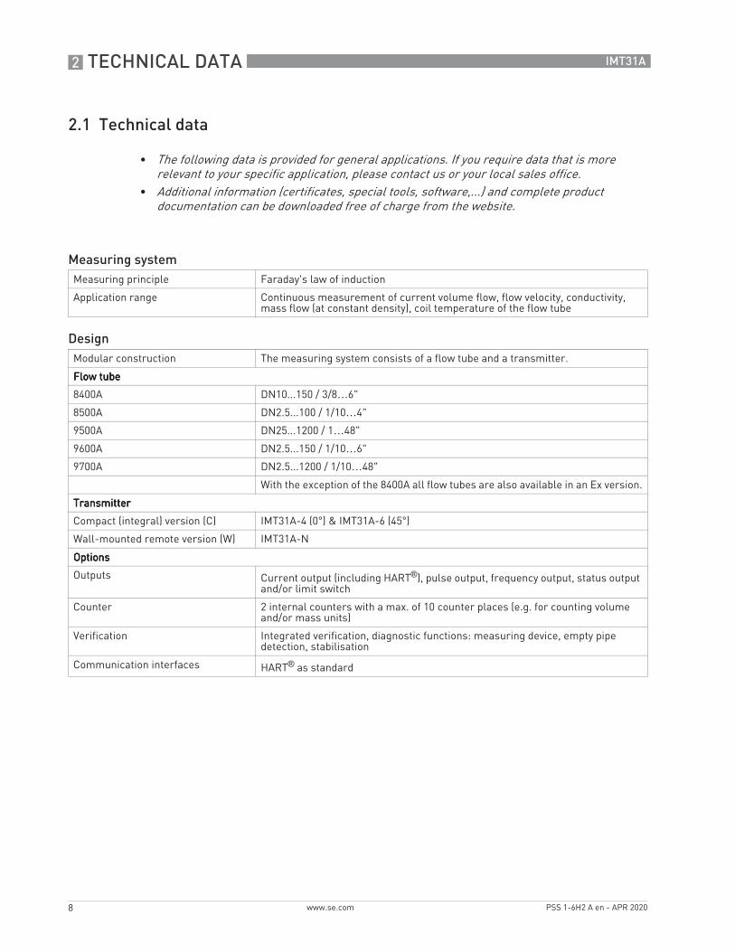
2.1 Technical data
• The following data is provided for general applications. If you require data that is more relevant to your specific application, please contact us or your local sales office.
• Additional information (certificates, special tools, software,...) and complete product documentation can be downloaded free of charge from the website.
Measuring systemMeasuring principle Faraday's law of induction
Application range Continuous measurement of current volume flow, flow velocity, conductivity, mass flow (at constant density), coil temperature of the flow tube
DesignModular construction The measuring system consists of a flow tube and a transmitter.
Flow tubeFlow tubeFlow tubeFlow tube
8400A DN10...150 / 3/8…6"
8500A DN2.5...100 / 1/10…4"
9500A DN25...1200 / 1…48"
9600A DN2.5...150 / 1/10…6"
9700A DN2.5...1200 / 1/10…48"
With the exception of the 8400A all flow tubes are also available in an Ex version.
TransmitterTransmitterTransmitterTransmitter
Compact (integral) version (C) IMT31A-4 (0°) & IMT31A-6 (45°)
Wall-mounted remote version (W) IMT31A-N
OptionsOptionsOptionsOptions
Outputs Current output (including HART®), pulse output, frequency output, status output and/or limit switch
Counter 2 internal counters with a max. of 10 counter places (e.g. for counting volume and/or mass units)
Verification Integrated verification, diagnostic functions: measuring device, empty pipe detection, stabilisation
Communication interfaces HART® as standard

TECHNICAL DATA 2
9
IMT31A
www.se.comPSS 1-6H2 A en - APR 2020
Display and user interfaceDisplay and user interfaceDisplay and user interfaceDisplay and user interface
Graphic display LC display, backlit white.
Size: 128 x 64 pixels, corresponds to 59 x 31 mm = 2.32" x 1.22"
Ambient temperatures below -25°C / -13°F may affect the readability of the display.
Operating elements 4 push buttons for operator control of the transmitter without opening the housing.
Remote control PACTwareTM (including Device Type Manager (DTM))
HART® Communicator
AMS®
All DTMs and drivers are available free of charge from the manufacturer's website.
Display functionsDisplay functionsDisplay functionsDisplay functions
Operating menu Setting the parameters using 2 measuring pages, 1 status page, 1 graphic page (measured values and graphics are freely adjustable)
Language display texts (as language package)
Standard: English, French, German, Dutch, Portuguese, Swedish, Spanish, Italian
Eastern Europe: English, Slovenian, Czech, Hungarian
Northern Europe: English, Danish, Polish, Finnish, Norwegian
China: English, German, Chinese(check www.BuyAutomation.com for availability)
Russia: English, German, Russian
Units Metric, British and US units selectable as required from lists for volume / mass flow and counting, flow velocity, electrical conductivity, temperature
Measuring accuracyMax. measuring accuracy Standard:Standard:Standard:Standard:
±0.3% of the measured value ± 1 mm/s; depending on the flow tube
Option (optimised accuracy with extended calibration):Option (optimised accuracy with extended calibration):Option (optimised accuracy with extended calibration):Option (optimised accuracy with extended calibration):±0.2% of the measured value ± 1.5 mm/s; depending on the flow tube
For detailed information and accuracy curves refer to Measuring accuracy on page 24.
Special calibrations are available on request.
Current output electronics: ±10 µA; ±100 ppm/°C (typically: ±30 ppm/°C)
Repeatability ±0.1%

2 TECHNICAL DATA
10
IMT31A
www.se.com PSS 1-6H2 A en - APR 2020
Operating conditionsTemperatureTemperatureTemperatureTemperature
Process temperature Refer to technical data for the flow tube.
Ambient temperature Depending on the version and combination of outputs.
It is a good idea to protect the transmitter from external heat sources such as direct sunlight as higher temperatures reduce the life cycle of all electronic components.
Ambient temperatures below -25°C / -13°F may affect the readability of the display.
Storage temperature -40…+70°C / -40…+158°F
PressurePressurePressurePressure
Medium Refer to technical data for the flow tube.
Ambient pressure Atmospheric
Chemical propertiesChemical propertiesChemical propertiesChemical properties
Electrical conductivity All media except for water: ≥ 5 µS/cm(also refer to the technical data for the flow tube)
Water: ≥ 20 µS/cm
State of aggregation Conductive, liquid media
Solid content (volume) ≤ 10%
Gas content (volume) ≤ 3%
Flow rate For detailed information, refer to chapter "Flow tables".
Other conditionsOther conditionsOther conditionsOther conditions
Ingress protection according to IEC 60529
Standard version with aluminium housing: IP66/67 (according to NEMA 4/4X)
Optional version with stainless steel housing: IP69
Installation conditionsInstallation For detailed information, refer to chapter "Installation".
Inlet / outlet sections Refer to technical data for the flow tube.
Dimensions and weight For detailed information refer to chapter "Dimensions and weight".
MaterialsTransmitter housing Standard: Aluminum with a polyester topcoat
Option: Stainless steel 1.4404 / AISI 316L
Flow tube For housing materials, process connections, liners, grounding electrodes and gaskets, refer to technical data for the flow tube.

TECHNICAL DATA 2
11
IMT31A
www.se.comPSS 1-6H2 A en - APR 2020
Electrical connectionGeneral Electrical connection is carried out in conformity with the VDE 0100 directive
"Regulations for electrical power installations with line voltages up to 1000 V" or equivalent national specifications.
Power supply 100…230 VAC (-15% / +10%), 50/60 Hz;240 VAC + 5% is included in the tolerance range.
24 VDC (-55% / +30%);12 VDC - 10% is included in the tolerance range.
24 VAC/DC (AC: -15% / +10%; DC: -25% / +30%);12 V is notnotnotnot included in the tolerance range.
Power consumption AC: 7 VA
DC: 4 W
Signal cable Only necessary for remote versions.
DS 300 (type A)DS 300 (type A)DS 300 (type A)DS 300 (type A)Max. length: 600 m / 1968 ft (depending on electrical conductivity and flow tube version)
Cable entries Standard: M20 x 1.5 (8...12 mm)
Option: 1/2 NPT, PF 1/2
Inputs and outputsGeneral All outputs are electrically isolated from each other and from all other circuits.
All operating data and output values can be adjusted.
Description of abbreviations Uext = external voltage; RL = load + resistance;U0 = terminal voltage; Inom = nominal current
2 TECHNICAL DATA
12
IMT31A
www.se.com PSS 1-6H2 A en - APR 2020
Current outputCurrent outputCurrent outputCurrent output
Output data Volume flow, mass flow, diagnostic value, flow velocity, coil temperature, conductivity
Settings Without HARTWithout HARTWithout HARTWithout HART®
Q = 0%: 0…20 mA; Q = 100%: 10…21.5 mA
Error identification: 20…22 mA
With HARTWith HARTWith HARTWith HART®
Q = 0%: 4…20 mA; Q = 100%: 10…21.5 mA
Error identification: 3…22 mA
Operating dataOperating dataOperating dataOperating data
Active Uint, nom = 20 VDC
I ≤ 22 mA
RL ≤ 750 Ω
HART® at terminals A
Passive Uext ≤ 32 VDC
I ≤ 22 mA
U0 ≥ 2 V at I = 22 mA
RL ≤ (Uext - U0) / Imax
HART® at terminals A
HARTHARTHARTHART®
Description HART® protocol via active and passive current output
HART® version: V5
Universal Common Practice HART® parameter: completely supported
Load ≥ 230 Ω at HART® test point;Note maximum load for current output!
Multi-drop mode Yes, current output = 4 mA
Multi-drop address adjustable in operation menu 1…15
Device drivers Available for HART® Communicator, AMS®, FDT/DTM
Registration (HART Communication Foundation)
Yes

TECHNICAL DATA 2
13
IMT31A
www.se.comPSS 1-6H2 A en - APR 2020
Pulse output / frequency outputPulse output / frequency outputPulse output / frequency outputPulse output / frequency output
Output data Pulse output: volume flow, mass flow
Frequency output: volume flow, mass flow, diagnostic value, flow velocity, coil temperature, conductivity
Function Can be set as a pulse output or frequency output
Pulse rate/frequency 0.25...10000 Hz
Settings Pulses per volume or mass unit or max. frequency for 100% flow
Pulse width: adjustable as automatic, symmetric or fixed (0.05...2000 ms)
Operating dataOperating dataOperating dataOperating data
Passive Uext ≤ 32 VDC
fmax in operating menu set to fmax ≤ 100 Hz:
I ≤ 100 mA
open:I ≤ 0.05 mA at Uext = 32 VDC
closed:U0, max = 0.2 V at I ≤ 10 mAU0, max = 2 V at I ≤ 100 mA
fmax in operating menu set to 100 Hz < fmax ≤10 kHz:
I ≤ 20 mA
open:I ≤ 0.05 mA at Uext = 32 VDC
closed:U0, max = 1.5 V at I ≤ 1 mAU0, max = 2.5 V at I ≤ 10 mAU0, max = 5.0 V at I ≤ 20 mA
Low flow cut offLow flow cut offLow flow cut offLow flow cut off
Function Switching point and hysteresis separately adjustable for each output, counter and the display
Switching point Set in increments of 0.1%.
0…20% (current output, frequency output) or 0...±9.999 m/s (pulse output)
Hysteresis Set in increments of 0.1%.
0…5% (current output, frequency output) or 0…5 m/s (pulse output)
Time constantTime constantTime constantTime constant
Function The time constant corresponds to the elapsed time until 67% of the end value has been reached according to a step function.
Settings Set in increments of 0.1 seconds.
0…100 seconds

2 TECHNICAL DATA
14
IMT31A
www.se.com PSS 1-6H2 A en - APR 2020
Status output / limit switchStatus output / limit switchStatus output / limit switchStatus output / limit switch
Function and settings Adjustable as automatic measuring range conversion, display of flow direction, counter overflow, error, switching point or empty pipe detection
Valve control with activated dosing function
Status and/or control: ON or OFF
Operating dataOperating dataOperating dataOperating data
Passive Uext ≤ 32 VDC
I ≤ 100 mA
open:I ≤ 0.05 mA at Uext = 32 VDC
closed:U0, max = 0.2 V at I ≤ 10 mAU0, max = 2 V at I ≤ 100 mA
Control inputControl inputControl inputControl input
Function Hold value of the outputs (e.g. for cleaning work), set value of the outputs to "zero", counter and error reset, range change.
Start of dosing when dosing function is activated.
Operating dataOperating dataOperating dataOperating data
Passive Uext ≤ 32 VDC
Inom = 6.5 mA at Uext = 24 VDCInom = 8.2 mA at Uext = 32 VDC
Contact open (off): U0 ≤ 2.5 V at Inom = 0.4 mA
Contact closed (on): U0 ≥ 8 V at Inom = 2.8 mA
Approvals and certificatesCE This device fulfils the statutory requirements of the relevant EU directives.
The manufacturer certifies successful testing of the product by applying the CE mark.
For full information of the EU directives & standards and the approved certifications, please refer to the EU declaration or the manufacturer website.
Non-Ex Standard
Hazardous areasHazardous areasHazardous areasHazardous areas
ATEX Option (only 9500A & 9700A)Option (only 9500A & 9700A)Option (only 9500A & 9700A)Option (only 9500A & 9700A)
II 2 G Ex e [ia] mb IIC T4 (DN10...20; DN200...300; DN350...3000)
II 2 G Ex d e [ia] mb IIC T4 (DN25...150)
II 2 G Ex e [ia] mb q T4/T3 (DN25...150; DN200...300)
II 2 D Ex tD A21 IP64 T120°C (all nominal sizes)
Option (Wall-mounted version only)Option (Wall-mounted version only)Option (Wall-mounted version only)Option (Wall-mounted version only)
II 2 G Ex e [ia] mb IIC T4
II 2 D Ex tD A21 IP64 T135°C

TECHNICAL DATA 2
15
IMT31A
www.se.comPSS 1-6H2 A en - APR 2020
IECEx Option (only 9500A & 9700A)Option (only 9500A & 9700A)Option (only 9500A & 9700A)Option (only 9500A & 9700A)
Ex e [ia] mb IIC T4 (DN10...20; DN200...300; DN350...3000)
Ex d e [ia] mb IIC T4 (DN25...150)
Ex tD A21 IP64 T120°C (all nominal sizes)
Option (Wall-mounted version only)Option (Wall-mounted version only)Option (Wall-mounted version only)Option (Wall-mounted version only)
Ex e [ia] mb IIC T4
Ex tD A21 IP64 T135°C
FM/CSA Option (only 9500A & 9700A)Option (only 9500A & 9700A)Option (only 9500A & 9700A)Option (only 9500A & 9700A)
Class I, Div 2, Group A, B, C and D
Option (Wall-mounted version only)Option (Wall-mounted version only)Option (Wall-mounted version only)Option (Wall-mounted version only)
Class I, Div 2, Group A, B, C and D
Ordinary location
Other standards and approvalsOther standards and approvalsOther standards and approvalsOther standards and approvals
Electromagnetic compatibility (EMC) 2004/108/EU in conjunction with EN 61326-1 (A1, A2)
Shock and vibration resistance IEC 68-2-27, IEC 68-2-64
NAMUR NE 21, NE 43, NE 53

2 TECHNICAL DATA
16
IMT31A
www.se.com PSS 1-6H2 A en - APR 2020
2.2 Dimensions and weight
2.2.1 Housing
Figure 2-1: Dimensions of the wall-mounted version, aluminium housing
Dimensions [mm] Weight [kg]
a b c d e f g
Wall-mounted version
241 161 95.2 257 19.3 39.7 40 1.9
Table 2-1: Dimensions and weight in mm and kg
Dimensions [inch] Weight [lb]
a b c d e f g
Wall-mounted version
9.50 6.34 3.75 10.12 0.76 1.56 1.57 4.2
Table 2-2: Dimensions and weight in inch and lb

TECHNICAL DATA 2
17
IMT31A
www.se.comPSS 1-6H2 A en - APR 2020
Figure 2-2: Dimensions of wall-mounted and compact 10° version, stainless steel housing
e f
g g g
Dimensions [mm] Weight [kg]
a b c d e f g
Wall-mounted version
268 187 110 276 29 53 40 Approx. 3.5
Table 2-3: Dimensions and weight in mm and kg
Dimensions [inch] Weight [lb]
a b c d e f g
Wall-mounted version
10.55 7.36 4.33 10.87 1.14 2.09 1.57 Approx. 7.2
Table 2-4: Dimensions and weight in inch and lb
The compact 10° version is without mounting plate.

2 TECHNICAL DATA
18
IMT31A
www.se.com PSS 1-6H2 A en - APR 2020
Figure 2-3: Dimensions of compact 0° version, aluminium housing
1 4 x M 6
Dimensions [mm] Weight [kg]
a b c d e f g h
0° version 161 40 155 81.5 257 - - Ø72 Std: 1.9Ex: 2.4
Table 2-5: Dimensions and weight in mm and kg
Dimensions [inch] Weight [lb]
a b c d e f g h
0° version 6.34 1.57 6.1 3.21 10.12 - - Ø2.83 Std: 4.2Ex: 5.3
Table 2-6: Dimensions and weight in inch and lb

TECHNICAL DATA 2
19
IMT31A
www.se.comPSS 1-6H2 A en - APR 2020
Figure 2-4: Dimensions of compact 45° version, aluminium housing
1 4 x M 6
Dimensions [mm] Weight [kg]
a b c d e f g h
45° version 161 40 155 184 27.4 45° 186 Ø72 Std: 2.1Ex: 2.6
Table 2-7: Dimensions and weight in mm and kg
Dimensions [inch] Weight [lb]
a b c d e f g h
45° version 6.34 1.57 6.10 7.24 1.08 45° 7.32 Ø2.83 Std: 4.6Ex: 5.7
Table 2-8: Dimensions and weight in inch and lb

2 TECHNICAL DATA
20
IMT31A
www.se.com PSS 1-6H2 A en - APR 2020
2.2.2 Mounting plate of wall-mounted version, aluminium housing
Figure 2-5: Dimensions of mounting plate of wall-mounted version, aluminium housing
[mm] [inch]
a Ø6.5 Ø0.26
b 87.2 3.4
c 241 9.5
Table 2-9: Dimensions in mm and inch

TECHNICAL DATA 2
21
IMT31A
www.se.comPSS 1-6H2 A en - APR 2020
2.2.3 Mounting plate of wall-mounted version, stainless steel housing
Figure 2-6: Dimensions of mounting plate of wall-mounted version, stainless steel housing
[mm] [inch]
a Ø6.5 Ø0.26
b 40 1.6
c 267.9 10.55
Table 2-10: Dimensions in mm and inch

2 TECHNICAL DATA
22
IMT31A
www.se.com PSS 1-6H2 A en - APR 2020
2.3 Flow tables
Q100 % in m3/h
v [m/s] 0.3 1 3 12
DN [mm] Minimum flow Nominal flow Maximum flow
2.5 0.005 0.02 0.05 0.21
4 0.01 0.05 0.14 0.54
6 0.03 0.10 0.31 1.22
10 0.08 0.28 0.85 3.39
15 0.19 0.64 1.91 7.63
20 0.34 1.13 3.39 13.57
25 0.53 1.77 5.30 21.21
32 0.87 2.90 8.69 34.74
40 1.36 4.52 13.57 54.29
50 2.12 7.07 21.21 84.82
65 3.58 11.95 35.84 143.35
80 5.43 18.10 54.29 217.15
100 8.48 28.27 84.82 339.29
125 13.25 44.18 132.54 530.15
150 19.09 63.62 190.85 763.40
200 33.93 113.10 339.30 1357.20
250 53.01 176.71 530.13 2120.52
300 76.34 254.47 763.41 3053.64
350 103.91 346.36 1039.08 4156.32
400 135.72 452.39 1357.17 5428.68
450 171.77 572.51 1717.65 6870.60
500 212.06 706.86 2120.58 8482.32
600 305.37 1017.90 3053.70 12214.80
700 415.62 1385.40 4156.20 16624.80
800 542.88 1809.60 5428.80 21715.20
900 687.06 2290.20 6870.60 27482.40
1000 848.22 2827.40 8482.20 33928.80
1200 1221.45 3421.20 12214.50 48858.00
Table 2-11: Flow rate in m/s and m3/h

TECHNICAL DATA 2
23
IMT31A
www.se.comPSS 1-6H2 A en - APR 2020
Q100 % in US gallons/min
v [ft/s] 1 3.3 10 40
DN [inch] Minimum flow Nominal flow Maximum flow
1/10 0.02 0.09 0.23 0.93
1/6 0.06 0.22 0.60 2.39
1/4 0.13 0.44 1.34 5.38
3/8 0.37 1.23 3.73 14.94
1/2 0.84 2.82 8.40 33.61
3/4 1.49 4.98 14.94 59.76
1 2.33 7.79 23.34 93.36
1.25 3.82 12.77 38.24 152.97
1.5 5.98 19.90 59.75 239.02
2 9.34 31.13 93.37 373.47
2.5 15.78 52.61 159.79 631.16
3 23.90 79.69 239.02 956.09
4 37.35 124.47 373.46 1493.84
5 58.35 194.48 583.24 2334.17
6 84.03 279.97 840.29 3361.17
8 149.39 497.92 1493.29 5975.57
10 233.41 777.96 2334.09 9336.37
12 336.12 1120.29 3361.19 13444.77
14 457.59 1525.15 4574.93 18299.73
16 597.54 1991.60 5975.44 23901.76
18 756.26 2520.61 7562.58 30250.34
20 933.86 3112.56 9336.63 37346.53
24 1344.50 4481.22 13445.04 53780.15
28 1829.92 6099.12 18299.20 73196.79
32 2390.23 7966.64 23902.29 95609.15
36 3025.03 10082.42 30250.34 121001.37
40 3734.50 12447.09 37346.00 149384.01
48 5377.88 17924.47 53778.83 215115.30
Table 2-12: Flow rate in ft/s and US gallons/min

2 TECHNICAL DATA
24
IMT31A
www.se.com PSS 1-6H2 A en - APR 2020
2.4 Measuring accuracy
Every electromagnetic flowmeter is calibrated by direct volume comparison. The wet calibration validates the performance of the flowmeter under reference conditions against accuracy limits.
The accuracy limits of electromagnetic flowmeters are typically the result of the combined effect of linearity, zero point stability and calibration uncertainty.
Reference conditions• Medium: water• Temperature: +5...+35°C / +41...+95°F• Operating pressure: 0.1...5 barg / 1.5...72.5 psig• Inlet section: ≥ 5 DN; outlet section: ≥ 2 DN
Figure 2-7: Measuring accuracy
X [m/s]: flow velocityY [%]: deviation from the actual measured value (mv)
DN [mm] DN [inch] Standard accuracy 1 Optimised accuracy 2
8400A 10…150 3/8…6 ±0.4% of mv ± 1 mm/s;as 1 + 0.1%
-
8500A / 9600A / 9700A 2.5…6 1/10…1/4
8500A / 9500A / 9600A / 9700A
10…1200 3/8…48 ±0.3% of mv ± 1 mm/s only 9500A / 9700A:±0.2% of mv ± 1.5 mm/s
Extended calibration at 2 points
Table 2-13: Measuring accuracy

MODEL CODE 3
25
IMT31A
www.se.comPSS 1-6H2 A en - APR 2020
Model Description
IMT31A Model IMT31A Magnetic Flow Transmitter
-4-6-N
TypeTypeTypeTypeIMT31A compact (0°)IMT31A compact (45°)IMT31A wall-mounted
14A
Power supplyPower supplyPower supplyPower supply12-24 VDC24 VDC/AC (9-31 V)100-230 VAC (85-253 VAC, 50/60 Hz)
025ACG
TUVWXY
Ex versionEx versionEx versionEx versionWithout - non ExEx zone 1 (terminal compartment "e" - compact & wall) (9500A & 9700A)cFMus Class 1 DIV 2 (US)cCSAus OLcFMus Class 1 DIV 2 (Canada)IECEx zone 1 (terminal compartment "e" - compact & wall) (9500A & 9700A tubes only)Check www.BuyAutomation.com for availability of the following items:BE-Ex EAC (Belarus "e" - compact & wall) (9500A & 9700A tubes only)RU-Ex EAC (Russia "e" - compact & wall) (9500A & 9700A tubes only)KA-Ex EAC (Kazakhstan "e" - compact & wall) (9500A & 9700A tubes only)RU EAC (Russia)KA EAC (Kazakhstan)BE EAC (Belarus)
456
Cable connectionCable connectionCable connectionCable connection1/2 NPTPF 1/2M20 x 1.5
5678ABHKLMRX
Operating manual (see "Manuals" section of the Model Code below) / operating languageOperating manual (see "Manuals" section of the Model Code below) / operating languageOperating manual (see "Manuals" section of the Model Code below) / operating languageOperating manual (see "Manuals" section of the Model Code below) / operating languageWithout / GermanWithout / English GBWithout / FrenchWithout / SpanishWithout / eastern Europe group (GB, CZ, HU, SI, SL, AL, BG & RO)Without / northern Europe group (GB, DK, FI, LT, NO, PL, EE & LV)Without / ItalianWithout / PortugueseWithout / DutchWithout / SwedishWithout / Chinese (check www.BuyAutomation.com for availability)Without / Russian
0Custody transferCustody transferCustody transferCustody transferWithout
0C
Process diagnosticsProcess diagnosticsProcess diagnosticsProcess diagnosticsStandardTropicalized electronics for non Ex (not for 12-24 VDC)
1*2
Transmitter housingTransmitter housingTransmitter housingTransmitter housingAluminum with a polyester topcoatStainless steel
1CommunicationCommunicationCommunicationCommunicationBasic IO (4-20 mA / HART + pulse / frequency + status output + control input)
01st IO module1st IO module1st IO module1st IO moduleWithout, no module possible
02nd IO module2nd IO module2nd IO module2nd IO moduleWithout, no module possible
0Reference methodReference methodReference methodReference methodStandard

3 MODEL CODE
26
IMT31A
www.se.com PSS 1-6H2 A en - APR 2020
*: Standard
023
Tag plate (field & wall only)Tag plate (field & wall only)Tag plate (field & wall only)Tag plate (field & wall only)Standard316/1.4401 tag plate (120 x 46 mm)316/1.4401 tag plate (67 x 25 mm)
13*4
ManualsManualsManualsManualsGermanEnglishFrench
Model Description

NOTES 4
27
IMT31A
www.se.comPSS 1-6H2 A en - APR 2020

PSS 1-6H2 A enPage 28
ORDERING INSTRUCTIONS
FLOWEXPERTPRO SIZING APPLICATION
ADDITIONAL PRODUCTS
1. Model Number.2. Flow Data: a. Maximum, minimum, and normal flow rate. b. Fluid composition and viscosity at operating temperatures. c. Fluid density or relative density (specific gravity). d. Maximum, minimum and normal operating temperatures. e. Maximum, minimum and normal operating pressures. f. Mating pipe schedule. g. Type and location (distance) of upstream disturbance.3. Calibration Information (analog output only); maximum flow rate 20 mA output.4. Electric Classification.5. Optional Selections and Accessories.6. Customer Tag Data.
Websitewww.FlowExpertPro.com
App Store (Apple®) Google PlayTM Store(Android®)
These product lines offer a broad range of measurement and instrument products, including solutions for pressure, flow, analytical,
temperature, positioning, controlling and recording.For a list of these offerings, visit our website at:
www.se.com
Schneider Electric Systems USA, Inc.38 Neponset AvenueFoxboro, MA 02035United States of Americahttp://www.se.com
Copyright 2020 Schneider Electric Systems USA, Inc.All rights reserved.
The Schneider Electric brand and any trademarks of Schneider Electric SE or its subsidiaries are the property of Schneider Electric SE or its subsidiaries.All other trademarks are the property of their respective owners.
APR 2020
Global Customer SupportInside U.S.: 1-866-746-6477Outside U.S.: 1-508-549-2424https://pasupport.schneider-electric.com