product specifications and installation … patio and sidewalk installation 11 ... step blocks &...
TRANSCRIPT
1
PRODUCT SPECIFICATIONS AND INSTALLATION GUIDE
2
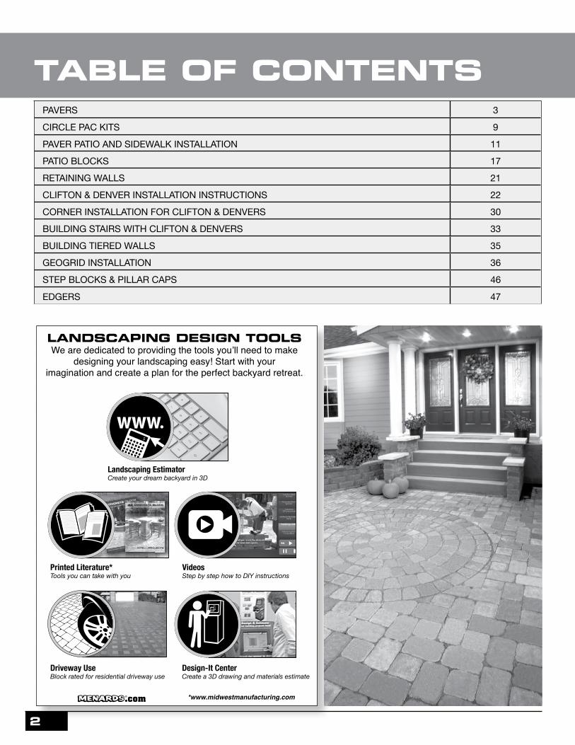
PAVERS 3
CIRCLE PAC KITS 9
PAVER PATIO AND SIDEWALK INSTALLATION 11
PATIO BLOCKS 17
RETAINING WALLS 21
CLIFTON & DENVER INSTALLATION INSTRUCTIONS 22
CORNER INSTALLATION FOR CLIFTON & DENVERS 30
BUILDING STAIRS WITH CLIFTON & DENVERS 33
BUILDING TIERED WALLS 35
GEOGRID INSTALLATION 36
STEP BLOCKS & PILLAR CAPS 46
EDGERS 47
TABLE OF CONTENTS
Driveway UseBlock rated for residential driveway use
Printed Literature*Tools you can take with you
VideosStep by step how to DIY instructions
Design-It CenterCreate a 3D drawing and materials estimate
Landscaping EstimatorCreate your dream backyard in 3D
*www.midwestmanufacturing.com
LANDSCAPING DESIGN TOOLSWe are dedicated to providing the tools you’ll need to make
designing your landscaping easy! Start with your imagination and create a plan for the perfect backyard retreat.
$

3
PRODUCT DESCRIPTIONTxWxD
WEIGHTPER BLOCK
BLOCKS PER SQUARE FT COLORS
Holland Paver 2-3/8" x 3-7/8" x 7-7/8" 6 lbs 4.72
Autumn Blend 179-3069 Charcoal 179-3058 Red/Black 179-3099
Red 179-3060 (not available at all locations) Sienna 179-3075 Tan 179-3124
ADA Holland Paver 2-3/8" x 3-7/8" x 7-7/8" 6 lbs 4.72 Red 179-3043
(Available as Special Order)
HOLLAND & PATIO PAVER PATTERN IDEAS
HOLLAND PAVER
PAVERS
Running Bond Herringbone Basketweave Casino Blend
PRODUCT DESCRIPTIONTxWxD
WEIGHTPER BLOCK
BLOCKS PER SQUARE FT COLORS
Patio Paver1-1/2" x 3-7/8" x 7-7/8" 3-1/2 lbs 4.72 Red/Black 179-3028
PATIO PAVER
Blocks may need to be cut to fit at the edges of patio.
HERRINGBONE
STACK BOND
RUNNING BOND
DOUBLE STACK BOND
BASKET WEAVE
VERTICAL RUNNING BOND
CASINO BLEND
OFFSET RUNNING BOND
Sq. Ft. Per Pattern: 0.4Blocks Per Pattern: 2
Sq. Ft. Per Pattern: 0.4Blocks Per Pattern: 2
Sq. Ft. Per Pattern: 1.7Blocks Per Pattern: 8
Sq. Ft. Per Pattern: 0.6Blocks Per Pattern: 3
Sq. Ft. Per Pattern: 0.6Blocks Per Pattern: 3
Sq. Ft. Per Pattern: 0.8Blocks Per Pattern: 4
Sq. Ft. Per Pattern: 0.4Blocks Per Pattern: 2
Sq. Ft. Per Pattern: 1.3Blocks Per Pattern: 6
PAVERS
$
$

4
RIVERFRONT PAVER PATTERN IDEAS
Running Bond Herringbone Basketweave Casino Blend
RIVERFRONT PAVER
Blocks may need to be cut to fit at the edges of patio.
HERRINGBONE
STACK BOND
RUNNING BOND
VERTICAL RUNNING BOND
CASINO BLEND
PRODUCT DESCRIPTIONTxWxD
WEIGHTPER BLOCK
BLOCKS PER SQUARE FT COLORS
(L) Riverfront Paver2-3/8" x 15-5/8" x 23-1/2" 72 lbs. 0.39 Tan/Charcoal 179-2912
(M) Riverfront Paver2-3/8" x 15-5/8" x 15-5/8" 47 lbs. 0.59 Tan/Brown 179-2913
(S) Riverfront Paver2-3/8" x 7-3/4" x 15-5/8" 23 lbs. 1.19 Gray/Charcoal 179-2914
PAVERS
Sq. Ft. Per Pattern: 5.2Blocks Per Pattern:1 L, 1 M, 1 S
Sq. Ft. Per Pattern: 10.4Blocks Per Pattern:2 L, 2 M, 2 S
Sq. Ft. Per Pattern: 5.2Blocks Per Pattern:1 L, 1 M, 1 S
Sq. Ft. Per Pattern: 5.2Blocks Per Pattern:1 L, 1 M, 1 S
Sq. Ft. Per Pattern: 10.4Blocks Per Pattern:2 L, 2 M, 2 S
$

5
HERRINGBONE
STACK BOND
RUNNING BOND
DOUBLE STACK BOND
BASKET WEAVE
VERTICAL RUNNING BOND
CASINO BLEND
OFFSET RUNNING BOND
PRODUCT DESCRIPTIONTxWxD
WEIGHTPER BLOCK
BLOCKS PER SQUARE FT COLORS
Riverfront Boardwalk Paver2-3/8" x 3-7/8" x 15-5/8" 12 lbs 2.37
Charcoal 179-3047 Gray 179-3048 Sienna 179-3045
Blocks may need to be cut to fit at the edges of patio.
PAVERS
RIVERFRONT BOARDWALK PAVER PATTERN IDEAS
RIVERFRONT BOARDWALK PAVER
Sq. Ft. Per Pattern: 0.8Blocks Per Pattern: 2
Sq. Ft. Per Pattern: 0.8Blocks Per Pattern: 2
Sq. Ft. Per Pattern: 6.4Blocks Per Pattern: 16
Sq. Ft. Per Pattern: 2.0Blocks Per Pattern: 5
Sq. Ft. Per Pattern: 2.0Blocks Per Pattern: 5
Sq. Ft. Per Pattern: 2.4Blocks Per Pattern: 6
Sq. Ft. Per Pattern: 0.8Blocks Per Pattern: 2
Sq. Ft. Per Pattern: 2.0Blocks Per Pattern: 5
$

6 PAVERS
PRODUCT DESCRIPTIONTxWxD
WEIGHTPER BLOCK
BLOCKS PER SQUARE FT COLORS
Turfstone Paver3-1/2" x 23-1/2" x 15-3/4" 67 lbs 0.39 Gray 179-1963
TURFSTONE PAVER
FLAGSTONE PAVER
PRODUCT DESCRIPTIONTxWxD
WEIGHTPER BLOCK
BLOCKS PER SQUARE FT COLORS
Flagstone Paver2-1/2" x 13-5/8" x 11" 18 lbs 1.54
Autumn Blend 179-1358 Quarry Gray 179-1354 Sienna 179-1355
$
$

7PAVERS
PRODUCT DESCRIPTIONTxWxD
WEIGHTPER BLOCK
BLOCKS PER SQUARE FT COLORS
(L) Courtland Paver2-3/8" x 5-1/2" x 11" 11 lbs. 2.38 Autumn Blend 179-3228
(M) Courtland Paver2-3/8" x 5-1/2" x 8-1/4" 9 lbs. 3.17 Autumn Blend 179-3229
(S) Courtland Paver2-3/8" x 5-1/2" x 5-1/2" 6 lbs. 4.76 Autumn Blend 179-3230
COURTLAND PAVER
Kingston Running Bond 3 to 1 Courtland Running Bond
SedonaCobalt Nashville
Blocks may need to be cut to fit at the edges of patio.
Sq. Ft. Per Pattern: 3.3Blocks Per Pattern:4 M, 2 S
Sq. Ft. Per Pattern: 1.9Blocks Per Pattern:1 L, 4 M, 1 S
Sq. Ft. Per Pattern: 1.0Blocks Per Pattern:1 L, 3 S
Sq. Ft. Per Pattern: 2.0Blocks Per Pattern:2 L, 1 M, 4 S
Sq. Ft. Per Pattern: 0.9Blocks Per Pattern:1 L, 1 M, 1 S
Sq. Ft. Per Pattern: 2.0Blocks Per Pattern:3 L,1 M, 2 S
COURTLAND PAVER PATTERN IDEAS
$

8
PRODUCT DESCRIPTIONTxWxD
WEIGHTPER BLOCK
BLOCKS PER SQUARE FT COLORS
(XL) Belgian Paver 2-1/4" x 8-7/8" x 8-7/8" 14-1/2 lbs 1.83
Autumn Blend 179-2774 Quarry Gray 179-2778 Sienna 179-2770 Tan 179-2782
(L) Belgian Paver2-1/4" x 5-7/8" x 8-7/8" 10 lbs 2.75
Autumn Blend 179-2775 Quarry Gray 179-2779 Sienna 179-2771 Tan 179-2783
(M) Belgian Paver2-1/4" x 5-7/8" x 5-7/8" 6-1/2 lbs 4.14
Autumn Blend 179-2776 Quarry Gray 179-2780 Sienna 179-2772 Tan 179-2784
(S) Belgian Paver2-1/4" x 3" x 5-7/8" 3-1/4 lbs 8.28
Autumn Blend 179-2777 Quarry Gray 179-2781 Sienna 179-2773 Tan 179-2785
TUMBLED BELGIAN PAVER
BELGIAN PAVER PATTERN IDEAS
Blocks may need to be cut to fit at the edges of patio.
RUNNING BOND 3 to 1
COBBLE RUNNING BOND
BAHAMA4 BLOCK RUNNING BOND 4 BLOCK STEP BRUSSELS
TUNGSTEN BARCELONACHARLESTON
MONTEGOMARANAKINGSTON
PAVERS
Sq. Ft. Per Pattern: 1.3Blocks Per Pattern:1 XL, 1 L, 1 M, 1 S
Sq. Ft. Per Pattern: 1.5Blocks Per Pattern:1 XL, 1 L, 1 M, 3 S
Sq. Ft. Per Pattern: 1.4Blocks Per Pattern:1 XL, 1 L, 1 M, 2 S
Sq. Ft. Per Pattern: 3.4Blocks Per Pattern:2 XL, 2 L, 3 M, 7 S
Sq. Ft. Per Pattern: 0.6Blocks Per Pattern:1 L, 1 M
Sq. Ft. Per Pattern: 3.9Blocks Per Pattern:8 L, 4 M
Sq. Ft. Per Pattern: 1.2Blocks Per Pattern:1 L, 2 M, 3 S
Sq. Ft. Per Pattern: 1.3Blocks Per Pattern:1 XL, 1 L, 3 S
Sq. Ft. Per Pattern: 1.1Blocks Per Pattern:1 L, 3 M
Sq. Ft. Per Pattern: 5.1Blocks Per Pattern:4 XL, 8 M, 8 S
Sq. Ft. Per Pattern: 1.1Blocks Per Pattern:1 XL,1 M, 3 S
Sq. Ft. Per Pattern: 3.0Blocks Per Pattern:1 XL, 4 L, 2 M, 4 S
$

9CIRCLE PAC KITS
CIRCLE PAC KITS
PRODUCT DESCRIPTION WEIGHTPER BLOCK SQUARE FT WEIGHT PER
PALLET COLORS
Tumbled Circle Kit6' 6" Diameter
6.5 lbs(varies)
Kit Covers 28 sq. ft.
1050 lbs(varies)
Autumn Blend 179-2893 Quarry Gray 179-2891 Sienna 179-2890 Tan 179-2892
Tumbled Circle Kit9' 6" Diameter
6.5 lbs(varies)
Kit Covers 70 sq. ft.
2100 lbs(varies)
Autumn Blend 179-2885 Quarry Gray 179-2889 Sienna 179-2886 Tan 179-2883
Center E = 1 qtyF = 8 qtyG = 96 qtyA = 32 qtyB = 24 qty
Center E = 1 qtyRing 1 F = 8 qtyRing 2 G = 16 qtyRing 3 G = 24 qtyRing 4 G = 15 qty A = 10 qty B = 5 qtyRing 5 G = 18 qty B = 18 qtyRing 6 G = 23 qty A = 22 qty B = 1 qty
DIAGRAM FOR 6.5' CIRCLE
Required Amounts:
BLOCK QUANTITIES PER RING:
$

10
Center E =1 qtyF = 8 qtyG = 199 qtyA = 74 qtyB = 60 qty
Center E = 1 qtyRing 1 F = 8 qtyRing 2 G = 16 qtyRing 3 G = 24 qtyRing 4 G = 15 qty A = 10 qty B = 5 qtyRing 5 G = 18 qty B = 18 qtyRing 6 G = 23 qty A = 22 qty B = 1 qtyRing 7 G = 25 qty B = 25 qtyRing 8 G = 30 qty A = 31 qtyRing 9 G = 48 qty A = 11 qty B = 11 qty
DIAGRAM FOR 9.5' CIRCLE
Required Amounts:
BLOCK QUANTITIES PER RING:
CIRCLE PAC KITS
Ring 10 61 qty.Ring 11 68 qty.Ring 12 72 qty.Ring 13 80 qty.Ring 14 86 qty.Ring 15 92 qty.Ring 16 98 qty.
FOR TUMBLED BELGIAN CIRCLES LARGER THAN 9.5' DIAMATER, USE 6" x 6" BELGIAN PAVERS (sold separately)
11
PAVER PATIO & SIDEWALK INSTALLATION
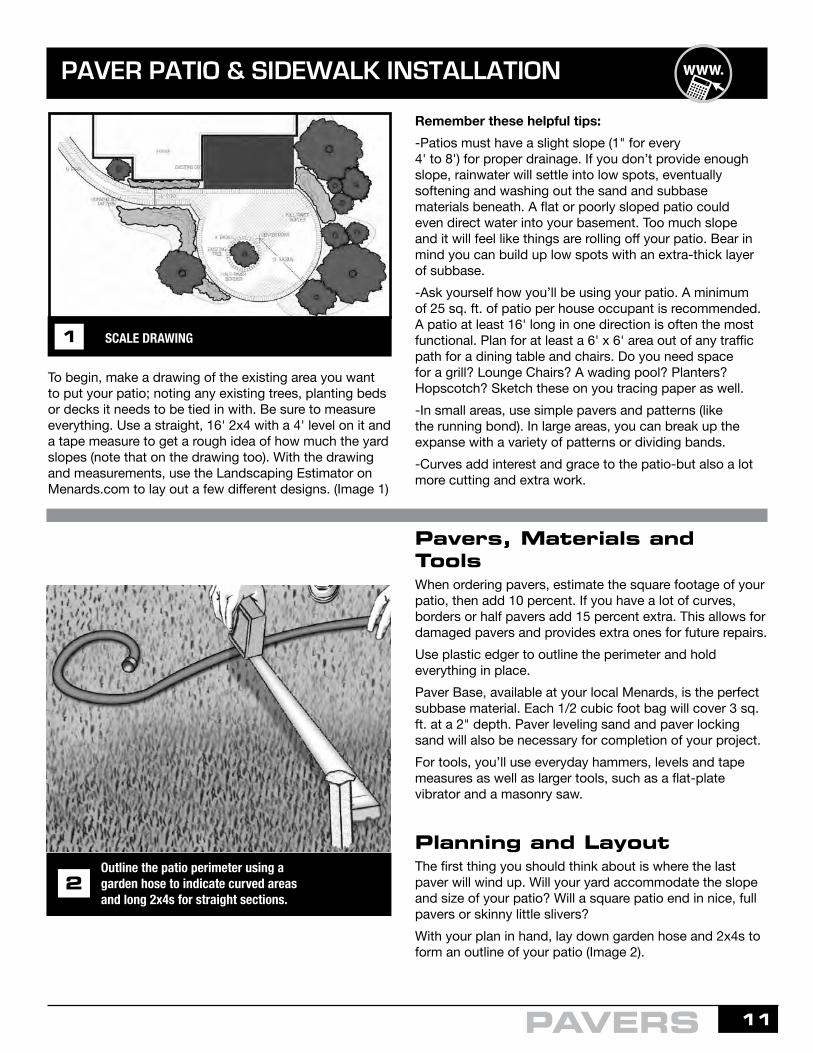
To begin, make a drawing of the existing area you want to put your patio; noting any existing trees, planting beds or decks it needs to be tied in with. Be sure to measure everything. Use a straight, 16' 2x4 with a 4' level on it and a tape measure to get a rough idea of how much the yard slopes (note that on the drawing too). With the drawing and measurements, use the Landscaping Estimator on Menards.com to lay out a few different designs. (Image 1)
Remember these helpful tips:-Patios must have a slight slope (1" for every 4' to 8') for proper drainage. If you don’t provide enough slope, rainwater will settle into low spots, eventually softening and washing out the sand and subbase materials beneath. A flat or poorly sloped patio could even direct water into your basement. Too much slope and it will feel like things are rolling off your patio. Bear in mind you can build up low spots with an extra-thick layer of subbase.-Ask yourself how you’ll be using your patio. A minimum of 25 sq. ft. of patio per house occupant is recommended. A patio at least 16' long in one direction is often the most functional. Plan for at least a 6' x 6' area out of any traffic path for a dining table and chairs. Do you need space for a grill? Lounge Chairs? A wading pool? Planters? Hopscotch? Sketch these on you tracing paper as well.-In small areas, use simple pavers and patterns (like the running bond). In large areas, you can break up the expanse with a variety of patterns or dividing bands.-Curves add interest and grace to the patio-but also a lot more cutting and extra work.
Pavers, Materials and ToolsWhen ordering pavers, estimate the square footage of your patio, then add 10 percent. If you have a lot of curves, borders or half pavers add 15 percent extra. This allows for damaged pavers and provides extra ones for future repairs. Use plastic edger to outline the perimeter and hold everything in place.Paver Base, available at your local Menards, is the perfect subbase material. Each 1/2 cubic foot bag will cover 3 sq. ft. at a 2" depth. Paver leveling sand and paver locking sand will also be necessary for completion of your project. For tools, you’ll use everyday hammers, levels and tape measures as well as larger tools, such as a flat-plate vibrator and a masonry saw.
Planning and Layout The first thing you should think about is where the last paver will wind up. Will your yard accommodate the slope and size of your patio? Will a square patio end in nice, full pavers or skinny little slivers?With your plan in hand, lay down garden hose and 2x4s to form an outline of your patio (Image 2).
SCALE DRAWING1
2
Outline the patio perimeter using a garden hose to indicate curved areas and long 2x4s for straight sections.
2
PAVERS
$

12
Use your level and a straight 2x4 to double-check the lay of the land for proper slope. Then spray-paint a line 8" outside the outline of your patio to act as a line of excavation. Be sure to call to locate and mark out your utility lines, this must be done before beginning excavation. Start by stripping away the sod at this point (Image 3), so grass doesn’t get in the way of the guide strings you’ll soon be setting up.
Excavating The Site And Building The Base This part of the project is the key to a successful (and long-lasting) patio. Use the bottom of a door or a set of stairs abutting the patio area as the starting point for establishing the final height and slope of you patio. Your entire patio should slope away from the house at a rate of 1" every 4' to 8' This slope may be one long decline or a slight dome shape so water runs off in more that one direction. Place one end of a long 2x4 at the bottom of the stairway or an inch below the door threshold, then level across to stakes driven at the perimeter of the patio and make a mark (Image 4). Make another mark the appropriate distance down the stake to indicate the slope. In our case, after making a level mark on our stake with a level and 12' 2x4, we made another mark 2" down to indicate a slope of 2" for that 12'.
Remove sod in an area extending 8" beyond the boundaries of the patio. Spray paint indicates the excavation line.
3
Use a level, a 2x4 and stakes to determine the slope of the patio. A slope of 1" per 4-8' away from the house is ideal. Run stakes and a grid of string to mark the top of the finished patio, then excavate 5" PLUS the thickness of the paver below the strings.*
4
PAVERS*When installing pavers as a residential driveway, a minimum of 8" of subbase will be required. See local code for details.
PAVER PATIO & SIDEWALK INSTALLATION

13PAVERS
Tamp the subbase using a flat-plate vibrator. Work in a circular motion compacting the area twice.
Make a grid work of stakes and guide strings to indicate the finished height and slope of your patio, then excavate 5" PLUS the thickness of your pavers, below these lines. This will provide room for a 4" subbase, the 1" leveling sand base, and the pavers themselves (Image 5). If the area is hilly, you’ll need to go back and forth between excavating, leveling and setting strings to get things right.Soil conditions vary greatly across the country. If after digging the necessary depth below your strings, you still find pockets of loose dirt or black soil, remove it or it will eventually settle, creating a wavy patio.When installing pavers as a residential driveway, a minimum of 8" of base will be required. See local code for details.
Next, bring in the subbase material. Bring the area up to a of height 1" PLUS the paver thickness below your guide strings (Image 6). It should be at least 4" deep in all places. The subbase should extend 8" beyond the actual edge of the patio to provide room for the edging. It’s possible you’ll need to build up an area to accommodate your patio. In such cases, remove the sod and loose soil, then build up the area with your subbase material. Add subbase in 2-3" lift increments, compact, and repeat until reaching the desired base level. Building a 10" to 12" subbase is common; even 20" would not be unusual.
BASE & EDGING DETAIL5
Spread subbase to a depth of 4" over the entire patio area and 8" beyond. Measure down from the guide strings to establish a uniform subbase surface.
6
7
Tamping the subbase is an important step when installing your new paver patio, walkway, or driveway (Image 7). Proper compaction provides stability to the project by spreading any load over a greater area of the ground below. If laid and compacted properly the subbase will help to recompress the surrounding soil that could have been disturbed while excavating.
PAVER PATIO & SIDEWALK INSTALLATION
14
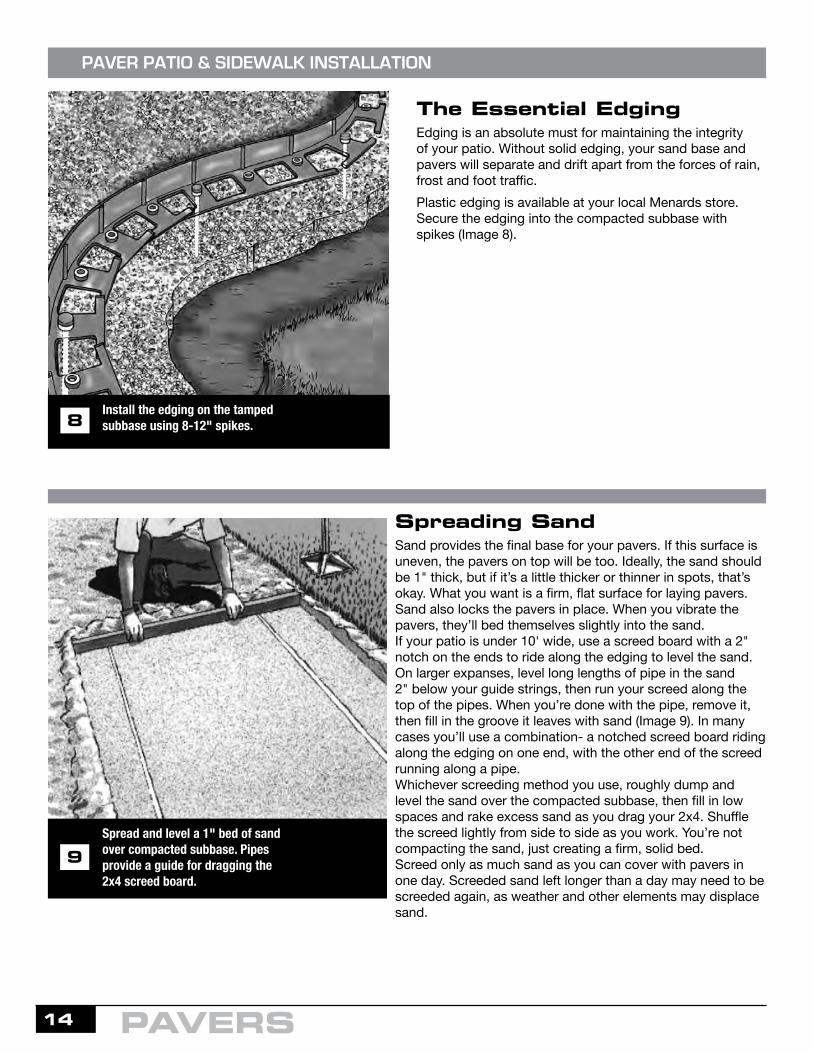
The Essential EdgingEdging is an absolute must for maintaining the integrity of your patio. Without solid edging, your sand base and pavers will separate and drift apart from the forces of rain, frost and foot traffic.Plastic edging is available at your local Menards store. Secure the edging into the compacted subbase with spikes (Image 8).
PAVER PATIO & SIDEWALK INSTALLATION
Install the edging on the tamped subbase using 8-12" spikes.8
Spread and level a 1" bed of sand over compacted subbase. Pipes provide a guide for dragging the 2x4 screed board.
9
Spreading SandSand provides the final base for your pavers. If this surface is uneven, the pavers on top will be too. Ideally, the sand should be 1" thick, but if it’s a little thicker or thinner in spots, that’s okay. What you want is a firm, flat surface for laying pavers. Sand also locks the pavers in place. When you vibrate the pavers, they’ll bed themselves slightly into the sand.If your patio is under 10' wide, use a screed board with a 2" notch on the ends to ride along the edging to level the sand. On larger expanses, level long lengths of pipe in the sand 2" below your guide strings, then run your screed along the top of the pipes. When you’re done with the pipe, remove it, then fill in the groove it leaves with sand (Image 9). In many cases you’ll use a combination- a notched screed board riding along the edging on one end, with the other end of the screed running along a pipe. Whichever screeding method you use, roughly dump and level the sand over the compacted subbase, then fill in low spaces and rake excess sand as you drag your 2x4. Shuffle the screed lightly from side to side as you work. You’re not compacting the sand, just creating a firm, solid bed.Screed only as much sand as you can cover with pavers in one day. Screeded sand left longer than a day may need to be screeded again, as weather and other elements may displace sand.
PAVERS

15
Lay paver stones in desired pattern. If the desired pattern requires cutting, the pavers can be cut with a circular saw with a masonry blade.
PAVER PATIO & SIDEWALK INSTALLATION
Pave AwayYou should now be standing before a flat, slightly sloped expanse of sand. Take down the guide strings you used to determine height and slope and put up new stakes and strings to mark the lines for the pattern of you pavers (Image 10).Start along your house or other long straight edge and lay down the border pavers. (A border isn’t essential, but adds a crisp, finished look, especially along curves.) Then lay the rest of your pavers in your selected pattern. Just lay the pavers in place- don’t stand on them or twist them. Measure over to your string every few rows to make sure you’re staying on track. Tap the pavers tighter together with a rubber mallet. Midwest Manufacturing pavers have little nubs on the side to serve as spacers. If you’ve taken the time to set things up right, laying the pavers will go quickly. Don’t walk or kneel on the edge of the patio until after you’ve vibrated it; otherwise these pavers can sink unevenly.
Let pavers run “wild” near the edges of your patio. Using a paver as a guide, (Image 11) mark the inner pavers, remove and cut them on a masonry saw, then reinstall the cut inner piece and the border piece. On tight radius circles, you can use half pavers for the border to avoid large, pie-shaped voids between them.
Always wear proper hearing and eye protection while operating a masonry saw.
10
Mark pavers that run "wild" into the border area. Then remove the paver, cut to size and place back in position along with border paver.
11Cut pavers on masonry saw. Saw has built-in sliding carriage for moving pavers past the blade. Recirculating water keeps blade cool and lubricated.12
PAVERS

16
When all your pavers are cut and in place, vibrate the entire patio, starting at the outer edge and working inward in a circular motion (Image 13). The vibrator will lock the pavers into the sand and help even up the surface. Don’t let the vibrator sit in one place too long, or pavers could settle unevenly or crack. You can put plywood down and vibrate on top of that to help distribute the weight of the machine.If a paver sinks deeper than its neighbors, use a screwdriver to pry it up, sprinkle a little extra sand in the void, then replace the paver.
PAVER PATIO & SIDEWALK INSTALLATION
Tamp the patio with a flat-plate vibrator after all the pavers are installed. Tamp entire outside edge first, then circle in.13
Sweep Paver Locking Sand into the paver joints. Once paver surfaces have been cleared, begin dampening paver joints.
14
PathwaysA pathway can be part of a larger project or a project in itself. A walkway made from pavers is an attractive way to link your driveway to your front door, existing deck to new patio, or back door to garden area.Here are a few tips:• Keep the pattern simple; a border running parallel to the path with a simple staggered pattern within is often the most attractive.• Put a slight tilt in the path for drainage. 1/2" across a 3' wide path is adequate.• Take extra care to keep the edges an equal distance apart; it will make screeding, cutting and paver laying easier.
Paver Locking SandUsing a broom sweep Paver Locking Sand to fill the paver joints. The joints should be filled to the paver chamfer (shoulder). Compact sand into joint spaces as thoroughly as possible. The use of a small plate vibrator for compaction is recommended. Carefully remove any remaining sand from paver surface prior to dampening. The best appearance is achieved by eliminating all sand from the surfaces of the pavers. It may help to use a leaf blower to remove all sand and dust from the top of the paver and dust that might have settled before watering. Then use a garden hose with a fine misting nozzle to dampen the filled joints. Do not over water the joints and avoid letting water pool on the joints; a light misting will achieve the best results. Repeat dampening process three more times every 15-20 minutes. Allow the locking sand to dry undisturbed for a minimum of 24 hours before allowing foot traffic, and wait 48 hours for vehicle traffic. Humid and wet conditions or low temperature will delay hardening.
PAVERS

17
PRODUCT DESCRIPTIONTxWxD
WEIGHTPER BLOCK
BLOCKS PER SQ FT COLORS
12" Brickface Patio Block (small)
2" x 11-5/8" x 11-5/8"22 lbs 1.07 Red 179-1321
Tan 179-1350
16" Brickface Patio Block (large)
2" x 16" x 16"40 lbs 0.56
Gray 179-1401 Red 179-1430 Tan 179-1459
Lakestone Patio Block2" x 16" x 16" 40 lbs 0.56 Quarry Gray 179-1283
Red/Black 179-1281
EZ Slate Patio Block2" x 16" x 16" 40 lbs 0.56
Autumn Blend 179-1290 Quarry Gray 179-1289 Sienna 179-1288
24" Wetcast DiamondPatio Block
1-5/8" x 23-1/4" x 23-1/4"75 lbs 0.27 Gray 179-1951
Smooth Patio Block 1-1/2" x 11-3/4" x 11-3/4" 17 lbs. 1.05 Gray: 179-1310
Red: 179-1311
PATIO BLOCKS
PATIO BLOCKS
$

18
PATIO BLOCKS
PRODUCT DESCRIPTION TxWxD
WEIGHTPER BLOCK
BLOCKS PER SQUARE FT COLORS
Wetcast FlagstonePatio Block
2" x 12" x 20"Average size
20 lbsAverage weight
.71Average square
footageTan 179-4137
Wetcast YorkstonePatio Block (round)1-5/8" x 14" round
20 lbs - Charcoal 179-1874
PATIO BLOCKS
Wetcast Yorkstone
Patio Block
(S)1-5/8" x 8" x 16" 17 lbs 1.12 Charcoal 179-1880 Sienna 179-1879
(M) 1-5/8" x 16" x 16" 32 lbs 0.56 Charcoal 179-1884 Sienna 179-1883
(L) 1-5/8" x 16" x 24" 52 lbs 0.37 Charcoal 179-1882 Sienna 179-1881
Wetcast AshlarPatio Block
1-5/8" x 16" x 16"32 lbs 0.56 Gray 179-1891
YORKSTONE PATIO BLOCK PATTERN IDEAS
Available in 4 interlocking shapes, each sold separately.
RUNNING BOND 3 to 1COBBLE RUNNING BOND MARANAKINGSTON
Blocks may need to be cut to fit at the edges of patio.
Sq. Ft. Per Pattern: 4.4Blocks Per Pattern:1 L, 1 M
Sq. Ft. Per Pattern: 28.4Blocks Per Pattern:8 L, 4 M
Sq. Ft. Per Pattern: 8.9Blocks Per Pattern:1 L, 2 M, 3 S
Sq. Ft. Per Pattern: 8Blocks Per Pattern:1 L, 3 M
19
PATIO BLOCKS
PATIO BLOCKS
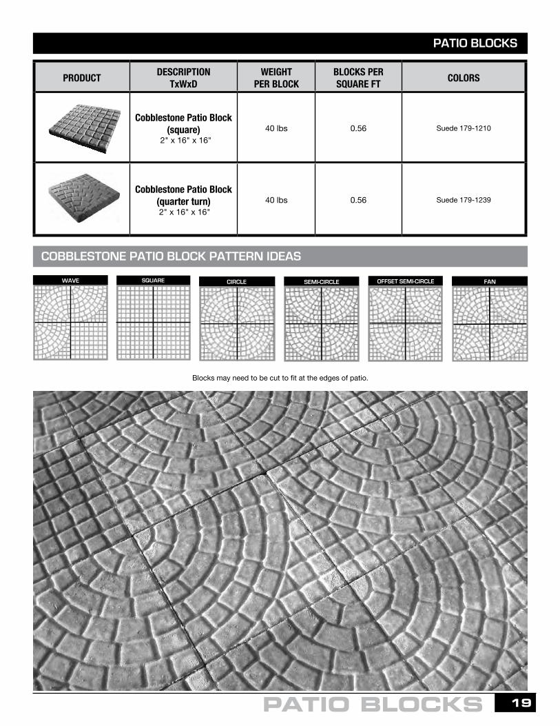
COBBLESTONE PATIO BLOCK PATTERN IDEAS
OFFSET SEMI-CIRCLESEMI-CIRCLEWAVE SQUARE CIRCLE FAN
Blocks may need to be cut to fit at the edges of patio.
PRODUCT DESCRIPTIONTxWxD
WEIGHTPER BLOCK
BLOCKS PER SQUARE FT COLORS
Cobblestone Patio Block (square)
2" x 16" x 16" 40 lbs 0.56 Suede 179-1210
Cobblestone Patio Block (quarter turn) 2" x 16" x 16"
40 lbs 0.56 Suede 179-1239

20
Running Bond Casino BlendHERRINGBONE
STACK BOND
RUNNING BOND
DOUBLE STACK BOND
BASKET WEAVE
VERTICAL RUNNING BOND
CASINO BLEND
OFFSET RUNNING BOND
PATIO BLOCKS
PRODUCT DESCRIPTIONTxWxD
WEIGHTPER BLOCK
BLOCKS PER SQUARE FT COLORS
Classic Patio Block1-5/8"T × 15-1/4" x 7-5/8"
16 lbs 1.24
Gray 179-1101 Red 179-1127 Tan 179-1103
Wetcast Wood Plank 2" x 23-3/4" x 7-3/4" 30 lbs 0.78 Cedar 179-1860
CLASSIC PATIO BLOCK PATTERN IDEAS
PATIO BLOCKS
Sq. Ft. Per Pattern: 1.6 Blocks Per Pattern: 2
Sq. Ft. Per Pattern: 1.6Blocks Per Pattern: 2
Sq. Ft. Per Pattern: 6.4Blocks Per Pattern: 8
Sq. Ft. Per Pattern: 2.4Blocks Per Pattern: 3
Sq. Ft. Per Pattern: 2.4Blocks Per Pattern: 3
Sq. Ft. Per Pattern: 3.2Blocks Per Pattern: 4
Sq. Ft. Per Pattern: 1.6Blocks Per Pattern: 2
Sq. Ft. Per Pattern: 4.8Blocks Per Pattern: 6
WETCAST WOOD PLANK PATIO BLOCK PATTERN IDEAS
VERTICAL RUNNING BOND
Sq. Ft. Per Pattern: 2.6Blocks Per Pattern: 2
Sq. Ft. Per Pattern: 2.6Blocks Per Pattern: 2
Sq. Ft. Per Pattern: 2.6Blocks Per Pattern: 2
HERRINGBONE RUNNING BOND 4 BLOCK STEP
Sq. Ft. Per Pattern: 5.2Blocks Per Pattern: 4
Sq. Ft. Per Pattern: 5.2Blocks Per Pattern: 4
SEDONA
21
RETAINING WALLS
RETAINING WALLS
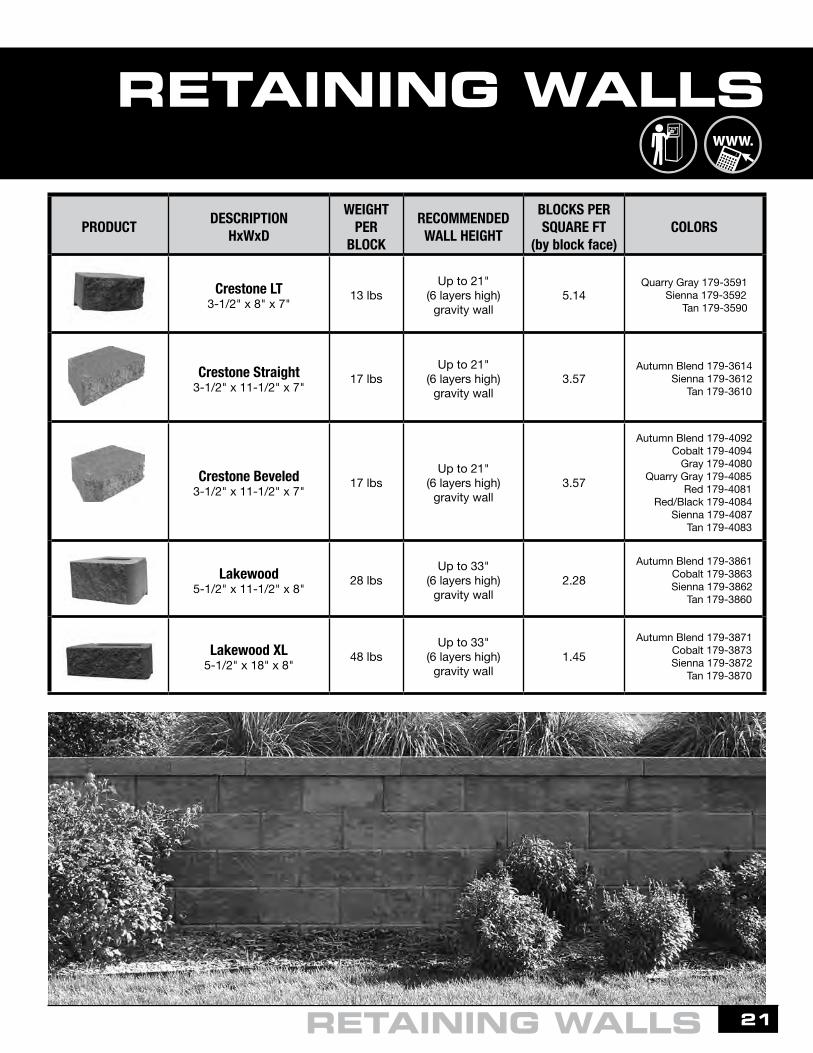
PRODUCT DESCRIPTIONHxWxD
WEIGHTPER
BLOCK
RECOMMENDEDWALL HEIGHT
BLOCKS PER SQUARE FT
(by block face)COLORS
Crestone LT3-1/2" x 8" x 7" 13 lbs
Up to 21"(6 layers high)
gravity wall5.14
Quarry Gray 179-3591 Sienna 179-3592 Tan 179-3590
Crestone Straight3-1/2" x 11-1/2" x 7" 17 lbs
Up to 21"(6 layers high)
gravity wall3.57
Autumn Blend 179-3614 Sienna 179-3612 Tan 179-3610
Crestone Beveled3-1/2" x 11-1/2" x 7" 17 lbs
Up to 21"(6 layers high)
gravity wall3.57
Autumn Blend 179-4092 Cobalt 179-4094 Gray 179-4080 Quarry Gray 179-4085 Red 179-4081 Red/Black 179-4084 Sienna 179-4087 Tan 179-4083
Lakewood5-1/2" x 11-1/2" x 8" 28 lbs
Up to 33"(6 layers high)
gravity wall2.28
Autumn Blend 179-3861 Cobalt 179-3863 Sienna 179-3862 Tan 179-3860
Lakewood XL5-1/2" x 18" x 8" 48 lbs
Up to 33"(6 layers high)
gravity wall1.45
Autumn Blend 179-3871 Cobalt 179-3873 Sienna 179-3872 Tan 179-3870
$

22
PRODUCT DESCRIPTIONHxWxD
WEIGHTPER BLOCK
RECOMMENDEDWALL HEIGHT
BLOCKS PER SQUARE FT
(by block face)COLORS
Denver Beveled6" x 17" x 12" 54 lbs
Up to 36"(6 layers high)
gravity wall1.43
Quarry Gray 179-3930 Sienna 179-3953 Tan 179-3951
Denver Straight6" x 18" x 12" 58 lbs
Up to 36"(6 layers high)
gravity wall1.33
Quarry Gray 179-3954 Sienna 179-3958 Tan 179-3956
Clifton Beveled8" x 17" x 12" 70 lbs
Up to 40"(5 layers high)
gravity wall1.07
Quarry Gray 179-3959 Sienna 179-3962 Tan 179-3961
Clifton Straight8" x 18" x 12" 77 lbs
Up to 40"(5 layers high)
gravity wall1.00
Quarry Gray 179-3966 Sienna 179-3965 Tan 179-3964
Clifton Corner8" x 18" x 9" 78 lbs
Up to 40"(5 layers high)
gravity wall0.66
Quarry Gray 179-3977 Sienna 179-3976 Tan 179-3975
CLIFTON & DENVER
CLIFTON & DENVER RETAINING WALL INSTALLATION
BEFORE INSTALLATION BEGINS
1. Confirm lot lines, wall location, wall length, set back requirements and elevations.
2. Confirm the on-site soils. For walls built in clay or poor soils, consult an engineer to confirm the wall design and the required soil reinforcement. See Midwest Manufacturing Engineering for more details.
3. Call the local utility companies to confirm the location of underground utilities.
4. Obtain all necessary building permits and verify local building code requirements. An approved plan may be needed to obtain a building permit for walls above a certain height.
5. For walls adjacent to property lines, at some time in the future a surcharge may affect the stability of the structure. Contact the Engineer of Record to ensure that additional loading has been taken into consideration.
6. Consider drainage and water management to avoid erosion or buildup of water behind the wall.
RETAINING WALLS
*42" and taller requires geogrid reinforcement and professional design is advisedEngineering available in Denver and Clifton blocks. See Midwest Manufacturing Engineering for more details.
*The back lips are not structural and are not needed to maintain the integrity of the wall.

23RETAINING WALLS
GRAVITY WALL DESIGN ASSUMPTIONS
BASIC WALL INSTALLATION - GRAVITY WALLS
The design methodology for conventional gravity walls is based upon the following:
1. There is no slope behind the wall.
2. Surcharge loads applied at the top of the wall are limited to foot traffic where the applied forces will be between 0-50 PSF.
3. There is good surface and subsurface drainage to prevent hydrostatic pressures at the back of the wall and the reinforced soil zone.
4. The site soil has adequate strength to support the wall and good draining soils will be used behind the wall. In addition, the ground water table is assumed to be well below the reinforced zone.
5. The cubic foot weight of the soil is the moist unit weight that includes the weight of water occurring naturally in the soil.
6. Seismic loading is not considered.
7. The site can support the weight of the wall.
8. The foundation soil will not settle or deform to cause failure.
9. Keep in mind, conventional segmental retaining walls are generally effective as gravity structures for most non-critical wall applications under 4 feet high, including the block below grade. For walls exposed 3 feet or more, you must terrace the wall or use geogrid to reinforce the soil. Consult a professional engineer for design assistance on taller walls. See Midwest Manufacturing Engineering for more details.
Segmental Retaining Walls that rely on their own weight, core fill, friction between units and setback are called gravity walls. Conventional segmental retaining walls are generally effective as gravity structures for most non-critical wall applications. Don’t assume shorter walls never require the services of a soils engineer. The heights listed by the manufacturer are used as a rule of thumb when ideal wall conditions are present.
Walls that exceed the heights listed by the manufacturer require additional construction techniques such as terracing or the use of geogrid reinforcement. These types of walls are known as reinforced or engineered wall structures. They are also referred to as Mechanically Stabilized Earth (MSE) walls.
The performance and construction of most retaining walls is highly dependent on the type and condition of the on-site soils and the contractor’s placement and compaction of the soils behind and under the walls. It is important to know the properties of various types of soils and understand how they might affect your estimate. To get a better understanding about soils, a brief review of soil types and properties is shown on page 24.

24
Step 1 - Base Course PreparationBeginning at a point of the wall’s lowest elevation, excavate a trench down the length of the wall that will accommodate at least 6" of compacted base material. We suggest burying 10% of your wall height below grade with a minimum of 6" even on short walls. Step the trench up or down with respect to adjacent grade. The width of the trench for both the Denver and Clifton Walls should be a minimum of 24". Based on the type of application and what is retained, the depth of the leveling pad may vary. If necessary, consult with an engineer. After excavating the native soil and prior to adding base material, remove loose material from the trench and compact.
Step 1 (Option 2)- Pouring a Concrete FootingComplete all steps described in Step 1. Then, a concrete footing should be poured on top of the granular base course. This step will require concrete forms set in place to create the size footing needed.
Step 1 (Option 1)- Using an EdgerAdd a concrete edger in front of the retaining wall to act as a bolster against grass and weeds. Retaining wall must sit a minimum of 6" below grade. Top of edger should match top of grade.
AN ALTERNATIVE TO WEED TRIMMING
Leveling Pad Trench
Native Soil
OversizeArea
24”
Approximate Limits of Excavation
6” Min.Base Fill
Thickness
anularGr -BaseLeveling Pad
24” x 6” Min. Compacted
Upper Grade
12” Min. Backfill
SRW BlockLower Grade
6” Min. BlockEmbedment
Granular-BaseLeveling Pad
24”Min. BaseFill Width
6” Min.Base Fill
Thickness24” x 6” Min. Compacted
Pouring a Concrete Footing
Using an Edger
NOTE: Size of the footing as well as steel reinforcement shall be determined at the time of engineering.NOTE: Remove the back lip of the retaining wall units prior to installing the first tier on the footing.
RETAINING WALLS

25RETAINING WALLS
Please note: If you are unsure of your soil condition, consult a soils engineer.
Soils are divided into three groups:
Step 2 - Leveling Pad InstallationPlace a minimum of 6" of compacted base material and compact to 95% Standard Proctor density. Verify that the base is level with a transit or hand level. Be aware that the base material (commonly referred to as road base or base aggregate) will vary from region to region. The base material should consist of crushed material: 3/4" crushed concrete with fines or 3/4" crushed rock or limestone with fines. Your material must be angular, nothing round. Round rock will act like ball bearings and roll when under pressure, causing the wall to bow or collapse.
Step 3 - Base Course Installation The base course will consist of one layer of block. Base units will have the rear lip removed before placing on the leveling pad. Use a string line behind the tail of the block for alignment on straight wall applications. All blocks should rest firmly on the pad and be centered to allow 6" of base material in front and 6" behind the base block. Level each block, side-to-side, front-to-back and across three full blocks with a hand level. A rubber mallet may be used to level and align the blocks.
Step 4 - Core and Drainage FillPlace 3/4" to 1" clean aggregate (crushed rock) within the cores and a minimum of 12" behind the blocks. This creates a drainage zone and the stone columns that help to unify and maximize the performance of the wall. In addition, sock wrapped perforated drainpipe can be installed at the desired level behind the wall (usually behind the first block above grade). The perforated drainpipe should have adequate slope to drain water in the right direction towards each drainpipe outlet. Drainpipe outlets are usually installed every 30 to 50 ft.
Granular - sands and gravel consisting of grains down to .002" - Best for strength and support
Clay - very fine particles, > 50% passing #200 sieve -May cause settlement
Organic - loam, peat that is made up of moss, leaves and vegetable matter, and topsoil - Should be removed

26
Step 6.1 - Stepping a WallWhen building your wall with the Clifton, a Corner Block in conjunction with a Step/Cap may be used to end a course that steps-up.
Step 6.2 - Add Step/Caps to Finish the Top of Your Walls
Step 5 - Successive Course InstallationPrior to adding successive courses, the top of each block needs to be clean and free of foreign material. Center the block and pull it forward until the rear lip abuts the two blocks below it. Place core and drainage fill as in Step 4. Place the backfill material behind the drainage rock in maximum 3" to 6" lifts based on the rating of your compaction equipment and compact to 95% Standard Proctor Density. Repeat this process for each successive course. Large compaction or construction equipment should be kept a minimum of 3' from the back of the wall. This 3' area should be compacted with a vibratory plate compactor.
RETAINING WALLS

27RETAINING WALLS
Step 6.3 - Stepping a Wall/Another OptionAnother option for walls that step-up is to cut to fit a 6" wide section of a Step/Cap for the Denver or an 8" wide section of a Step/Cap for the Clifton and lay the Step/Cap vertically to finish the end. To ensure the vertical cap maintains a straight line from the face to the back of the block, a 2" chip is installed near the back of the block (see illustration below).
Step 7 - Capping a Curved WallThe Step/Cap is rectangular in shape and is perfect for straight walls. For radius turns, an XL cap will need to be saw cut to fit. To ensure permanent placement of the caps on top of the wall, a quality exterior concrete adhesive should be used.
Place the Cap Block and measure the distance of the
gap between the caps.
Using this measurement, cut the cap so that it is parallel with the adjacent cap unit.
Slide the cap in place so that it is flush with the adjacent cap
unit. Adhere caps withconstruction adhesive.
Step 8 - Special ApplicationsWhile the installation steps presented are applicable to most basic wall designs, special consideration needs to be given to those applications in which a slope, surcharge loading and/or less than ideal soils are present. These types of applications may require geosynthetic reinforcement or other engineering design support. Such applications include but are not limited to:
Please refer to the geogrid reinforced wall sections of this guide for more information in regard to the incorporation of geosynthetic reinforcement in wall design.
• Wall Height• Water Applications• Drainage
• Fences and Guardrails• Driveways and Roads• Structures
• Tiered Walls• Bridges and Culverts
Step/Cap Blockcut to 6" or 8"

28
Additional Courses
First Course
Convex/Outside Curves and Concave/Inside Curves & Corners
Step 1 - Base Course Preparation for a Convex CurvePlace the blocks on the leveling pad so there are no gaps between them. Consider using PVC Flex Pipes to create smooth and accurate curves. When possible, start building a curve from the center and work left and right through the curve.
Step 2 - Successive Course Installation for a Convex CurveBuild each course of units by starting at the same place and the same bond as the last course. Keep in mind, for Convex Curves, the taller the wall the larger the first course needs to be. The radius of each additional course will be slightly smaller than the lower course.
SPECIAL APPLICATIONS AND WALL DETAILS
PVC Flex Pipe
Work Left Work Right
SmallerRadius
Center ofCurve
Center ofCurve
LargerRadius
RETAINING WALLS

29
Step 1 - Base Course Preparation for a Concave CurvePlace the blocks on the leveling pad so there are no gaps between them. Consider using PVC Flex Pipes to create smooth and accurate curves. When possible, start building a curve from the center and work left and right through the curve.
PVC Flex PipeM
in. Con
vex R
adius
3.0’ (0
.9m
)
Center of Curve
First Course
CONCAVE/INSIDE CURVE
RETAINING WALLS
1234
56
78
RADIUS OF CONVEX CURVES ON SUCCESSIVE COURSES
Center Stake
Top Course Radius
Base Course Radius
Convex Curve ChartBlock Rows Radius (Min.)
24-1/2"
26-3/32"
27-11/16"
29-9/32"
29-29/32"
32-1/2"
34-3/32"
35-11/16"
1
2
3
4
5
6
7
8

30
Step 2 - Successive Course Installation for a Concave CurveBuild each course of units by starting at the same place and the same bond as the last course. Keep in mind, for Concave Curves, the taller the wall the smaller the first course needs to be. The radius of each additional course will be slightly larger than the lower course.
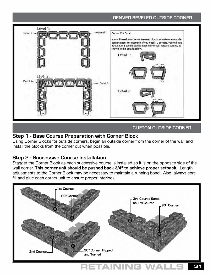
To build a Denver SRW with outside corners, two Denver Blocks are required to make one outside corner. For example, if you need 10 corners to construct a wall, you will need 20 Denver Blocks. Each corner will require four saw cuts and one split. This process allows for just about any degree of outside corner.
Center of CurveWork Left Work Right
SmallerRadius
LargerRadius
Additional Courses
DENVER STRAIGHT OUTSIDE CORNER
RETAINING WALLS
31RETAINING WALLS
90° Corner
90° Corner
90° Corner Flippedand Turned
1st Course
3rd Course Sameas 1st Course
2nd Course
Step 1 - Base Course Preparation with Corner BlockUsing Corner Blocks for outside corners, begin an outside corner from the corner of the wall and install the blocks from the corner out when possible.
Step 2 - Successive Course InstallationStagger the Corner Block as each successive course is installed so it is on the opposite side of the wall corner. This corner unit should be pushed back 3/4" to achieve proper setback. Length adjustments to the Corner Block may be necessary to maintain a running bond. Also, always core fill and glue each corner unit to ensure proper interlock.
CLIFTON OUTSIDE CORNER
DENVER BEVELED OUTSIDE CORNER

32
To build inside corners with the Denver or Clifton, corner units are not needed.
Step 1 - Base Course PreparationBegin an inside corner from the corner of the wall and install the blocks from the corner out, when possible. Place the second unit at a right angle and centered to the first base unit. Only half of a whole block installed on the corner will be exposed. Also, always core fill each unit to ensure proper interlock.
Step 2 - Successive Course InstallationPlace the second unit at a right angle and center to the 1st unit on the second course. Make sure second course units are placed at a 3/4" setback to the lower inside corner. Continue to install the units left and right of the inside corner to complete the second course of the wall. Repeat the above step-by-step installation core filling all units until the wall height is completed.
2nd Base Unit Centered
2nd Course Staggered
2nd Course Centered
1st
1st Base Unit
There are a variety of options when it comes to designing and installing steps in conjunction with the Denver or Clifton units and Step/Caps. Virtually any design can be realized. Different riser heights can be achieved by varying the depth of the Denver or Clifton units installed in the base. In this example, we will use the Clifton units. All of the step building techniques listed on the following pages also apply to the Denver units except when building steps with outside corners. The Denver outside corners are to be constructed as outlined on the previous pages.
DENVER OR CLIFTON INSIDE CORNERS
BUILDING STAIRS WITH DENVER OR CLIFTON RISERS
RETAINING WALLS

33RETAINING WALLS
Steps Built in Front of the Wall
1st Course
2nd Course
Steps Built into the WallWith a Radius Turn
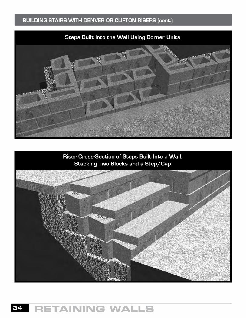
Before excavation can begin, the rise and run of the stair treads must be determined and codes must be met. Stairs can be built by stacking two Clifton units and a Step/Cap on top of each other for more stability. A more economical option is stacking one Clifton and a Step/Cap. Stairs can be built in front of the wall or into the wall with radius turns or outside 90º corners (see illustrations below).The depth of the excavation will depend on the height required for the risers and if you are stacking two Clifton units or one. Install and compact a 6" base as the footing. Break off the rear lip of each block and place them onto the base across the width of the stair opening. Level each block front to back and side to side. Fill the open cores of the units and the spaces between them with 3/4" to 1" processed gravel and sweep the units clean. Construct the next riser assembly by placing and compacting another 6" thick gravel footing behind the first course of units. Now place a row of Clifton units onto the base and position them directly behind the units in front. Install successive risers in the same manner for the number of stairs needed. The final step is to adhere the Step/Caps with construction adhesive and allow at least 24 hours to dry.
2nd Course
1st Course
BUILDING STAIRS WITH DENVER OR CLIFTON RISERS (cont.)
34
Steps Built Into the Wall Using Corner Units
Riser Cross-Section of Steps Built Into a Wall,Stacking Two Blocks and a Step/Cap
BUILDING STAIRS WITH DENVER OR CLIFTON RISERS (cont.)
RETAINING WALLS

35RETAINING WALLS
Tiered Denver and Clifton walls offer a visually pleasing and less obtrusive alternative to conventional wall construction. On sites that provide sufficient land area for this application, these walls are typically designed with green space between the tiers.
Walls perform independently and may not need engineering when the distance between gravity walls is at least two times the height of the lower wall, and the height of the upper wall is equal to or less than the height of the lower wall (known as the 2 to 1 rule). Walls that must be evaluated by an engineer are any walls needing geogrid reinforcement. These include walls closer than two times the height of the lower wall, walls with more than two terraces, and terraced walls with any structures above. Terraced walls that do not perform independently based on the 2 to 1 rule listed above must also be evaluated for global stability, and the lower wall must be designed to resist the load of the upper wall.
TIERED WALLS
Fi
Cap Block
Cap Block
Cap Block
nished Grade
Varies
Clifton Block
Clifton Block
Clifton Block
6°
6°
6°
6” 6” Minimum CompactedGranular-BaseLeveling Pad
4” ø Drain Tile (Elev. Varies)
12” of Free Draining Aggregate
1st Layer
2nd Layer
Other Layers
1
1
X
X
24”
4” ø Drain Tile (Elev. Varies)
4” ø Drain Tile (Elev. Varies)

36
All installation instructions are the same as for gravity retaining walls except for the addition of geogrid. Geosynthetic reinforcement is an engineered product that is typically comprised of polypropylene, polyester or other high tensile material. Used in conjunction with segmental retaining wall blocks, it helps stabilize the soil mass behind a wall. Depending on the wall design, the length and the number of grid layers will vary. Please remember, plasticized snow fencing is not a high tensile material and should not be used in place of geogrid.
Generally, stronger geogrids must be rolled out perpendicular to the retaining wall. As it is unrolled, it is in the same direction that it should be installed. Bidirectional grids are the same strength in both directions and can be rolled out parallel to the retaining wall or perpendicular to the retaining wall. If the geogrid depths are the same as the roll width, it may be more efficient to roll out the geogrid parallel to the retaining wall. If the geogrid depths called for are different than the roll width or if the wall curves, it is best to roll out the geogrid perpendicular to the retaining wall.
GEOGRID REINFORCED WALLS
RETAINING WALLS
Cap Block
Clifton Block
6°
Finished Grade
6” 6” Minimum CompactedGranular-BaseLeveling Pad
1st Layer
2nd Layer4”ø Drain Tile (Elev. Varies)
12” of Free Draining Aggregate
GeosyntheticReinforcementOther Layers
24”

37RETAINING WALLS
Step 1 - Preparation for GridThe area behind the wall on the grid layer needs to be level with the top of the block (after compaction) and compacted to 95% of the Standard Proctor density (ASTM D698).
BASIC GEOGRID REINFORCEMENT
Step 2 - Grid PlacementPlace the grid as close to the face of the wall without exposing it after successive placement of blocks. Ensure the grid is placed with the strength direction perpendicular to the wall. Remember, bidirectional grids (2xT) are the same strength in both directions and can be rolled out parallel on straight walls. Check grid manufacturer specifications for proper grid placement instructions. (3xT is undirectional).
Step 3 - Preparation for BackfillPlace the next course of block. Pull the grid back and stake it so it is taut and free of wrinkles.
Step 4 - Backfill and CompactPlace 3/4" to 1" clean aggregate (crushed rock) within the cores and a minimum of 12" behind the blocks. Also, place and compact backfill on the grid in lifts no greater than 3 to 6 inches at a time depending on the rating of your compaction equipment. When possible, it is recommended that the backfill be deposited directly behind the wall and pushed to the end of the grid to ensure that it remains taut and wrinkle-free.
Step 5 – Install Additional CoursesRepeat steps 2, 3 & 4 to complete wall to height required, installing additional layers of grid where needed.

38
Step 1 - Grid Placement Cut geogrid to required lengths and place the grid as close to the face of the wall without exposing it when following the contour of the curve. Place the next course of SRW block, taking care that the grid sits flat and is secured between the units. Each geogrid length should be laid perpendicular to the wall face and pulled tight to remove any slack. The geogrid should never overlap on top of the Clifton or Denver Units. Behind the Clifton or Denver Units, the geogrid will overlap because of the convex curve. In these areas place 3" of fill material to separate. Never compact directly on the geogrid.
Step 2 - Successive Grid LayersRepeat Step 1 when installing additional layers of grid. Fill cores and the drainage zone with aggregate material on every course. Place the next layer of infill soil on top of the geogrid by beginning near the wall fascia and spreading it back across the grid. Backfill in 3"-6" lifts, using only vibratory plate compactors within a 3' area from the back of the wall. Place soil in the rest of the infill area in maximum lifts of 6" based on the rating of your compaction equipment and compact to obtain a 95% Standard Proctor density.
BASIC GEOGRID REINFORCEMENT - CONVEX CURVE
RETAINING WALLS

39RETAINING WALLS
Step 1 - Grid Placement Cut geogrid to required lengths and place the grid as close to the face of the wall without exposing it when following the contour of the curve. Place the next course of SRW block, taking care that the grid sits flat and is secured between the units. Each geogrid length should be laid perpendicular to the wall face and pulled tight to remove any slack. The geogrid should never overlap on top of the Clifton or Denver Units.
Step 2 - Successive Grid LayersAfter the next course of block is placed, lay the grid to cover the area of non-reinforced soil below. This will ensure 100% coverage. Place the next layer of infill soil on top of the geogrid by beginning near the wall fascia and spreading it back across the grid. Backfill in 3"-6" lifts, using only vibratory plate compactors within a 3' area from the back of the wall. Place soil in the rest of the infill area in maximum lifts of 6" based on the rating of your compaction equipment and compact to obtain a 95% Standard Proctor density. Repeat these steps for successive specified grid layers.
BASIC GEOGRID REINFORCEMENT - CONCAVE CURVE

40
Step 1 - Grid PlacementOn an outside 90° corner, it is important that grid layers do not overlap at the corner. Place the first grid layer at the correct elevation and length. Each geogrid length should be perpendicular to the wall face. Lay the first geogrid corner section perpendicular to one side of the corner. Lay the second geogrid section perpendicular to the other side of the corner but not overlapping the first geogrid section.
Step 2 - Successive Grid LayersIn the corner and on the next course of blocks, place a layer of grid perpendicular to the previous layer of grid. Repeat these steps for successive specified grid layers.
Step 1 - Grid PlacementEach geogrid length should be laid perpendicular to the wall face. Extend the grid past one edge of the wall by a minimum of 2'. Along the other edge, place the grid perpendicular to the corner, but don’t allow the grid to overlap.
Step 2 - Successive Grid LayersAt the next designed grid layer, alternate the edge on which the grid is extended a minimum of 2' past the corner. Repeat these steps for successive specified grid layers.
2’ Min.
2’ Min.
GEOGRID - OUTSIDE 90° CORNER
GEOGRID - INSIDE 90° CORNER
RETAINING WALLS

41RETAINING WALLS
GeogridThe required type, length, vertical spacing, and strength of geosynthetic vary with each project depending on wall height, loading, slopes, and soil conditions. Poor draining soils such as clay require more geogrid than granular soils, which drain well. Typically, grid should be placed every 2 or 3 courses and should extend back a distance about equal to three-quarters the height of the wall. The number of layers of grid that will be required and how far back the grid should extend shall be determined by your engineer. See Midwest Manufacturing Engineering for more details.
These geogrid tables are for preliminary use only. They should not be used or relied upon for any application without verification of accuracy by a qualified engineer.
Drain PipeThe length of the wall will in most cases determine the amount of drainpipe needed. Check the plan for exact specifications and locations of the drainpipe.
Concrete AdhesiveUse one 10.5-ounce tube of adhesive for every 14 ft. of wall length where Step/Caps and Corners are installed. Use one 29-ounce tube of adhesive for every 39 ft. of wall length where Step/Caps and Corners are installed.
ø=34 deg. 120 pcf, No Surcharge,No Slope, Sand and Medium Gravel
5 3.33 0.5 6 4.00 0.5 7 4.67 0.5 8 5.33 0.5 9 6.00 0.5 10 6.67 0.5 11 7.33 0.5 12 8.00 0.5 13 8.67 0.5 14 9.33 0.5 15 10.00 0.5
# of Wall Embedment Units Height (ft) (ft)
# of Wall Embedment Units Height (ft) (ft)
# of Wall Embedment Units Height (ft) (ft)
# of Length Rows (ft)
# of Length Rows (ft)
# of Length Rows (ft)
1 4 1 4 2 4 2 4 2 4.28 3 4.66 3 5.04 3 5.42 4 5.81 4 6.19 4 6.57
ø=34 deg. 120 pcf, 250 psf Surcharge,No Slope, Sand and Medium Gravel
2 1.33 0.5 3 2.00 0.5 4 2.67 0.5 5 3.33 0.5 6 4.00 0.5 7 4.67 0.5 8 5.33 0.5 9 6.00 0.5 10 6.67 0.5 11 7.33 0.5 12 8.00 0.5 13 8.67 0.5 14 9.33 0.5 15 10.00 0.5
1 4 1 4.5 1 6.1 2 4.7 2 5 2 5.38 3 5.76 3 6.14 3 6.52 4 6.91 4 7.29 4 7.67 5 8.05 5 8.43
ø=34 deg. 120 pcf, No Surcharge,21.8 deg. Slope, Sand and Medium Gravel
4 2.67 0.5 5 3.33 0.5 6 4.00 0.5 7 4.67 0.5 8 5.33 0.5 9 6.00 0.5 10 6.67 0.5 11 7.33 0.5 12 8.00 0.5 13 8.67 0.5 14 9.33 0.5 15 10.00 0.5
1 4 1 4 1 4 2 4 2 4.39 2 4.87 3 5.35 3 5.83 3 6.31 4 6.79 4 7.27 4 7.74
6 3.00 0.5 7 3.50 0.5 8 4.00 0.5 9 4.50 0.5 10 5.00 0.5 11 5.50 0.5 12 6.00 0.5 13 6.50 0.5 14 7.00 0.5 15 7.50 0.5 16 8.00 0.5 17 8.50 0.5 18 9.00 0.5 19 9.50 0.5 20 10.00 0.5
1 4 1 4 1 4 2 4 2 4 2 4 2 4.22 3 4.5 3 4.78 3 5.06 3 5.33 4 5.61 4 5.89 4 6.71 4 6.45
3 1.50 0.5 4 2.00 0.5 5 2.50 0.5 6 3.00 0.5 7 3.50 0.5 8 4.00 0.5 9 4.50 0.5 10 5.00 0.5 11 5.50 0.5 12 6.00 0.5 13 6.50 0.5 14 7.00 0.5 15 7.50 0.5 16 8.00 0.5 17 8.50 0.5 18 9.00 0.5 19 9.50 0.5 20 10.00 0.5
1 4 1 4 1 4.2 1 5.1 2 4.1 2 4.4 2 4.7 2 4.92 3 5.2 3 5.48 3 5.76 3 6.04 4 6.31 4 6.59 4 6.87 4 7.15 4 7.43 4 7.7
5 2.50 0.5 6 3.00 0.5 7 3.50 0.5 8 4.00 0.5 9 4.50 0.5 10 5.00 0.5 11 5.50 0.5 12 6.00 0.5 13 6.50 0.5 14 7.00 0.5 15 7.50 0.5 16 8.00 0.5 17 8.50 0.5 18 9.00 0.5 19 9.50 0.5 20 10.00 0.5
1 4 1 4 1 4 1 4 2 4 2 4.09 2 4.44 2 4.79 3 5.14 3 5.49 3 5.84 3 6.18 4 6.53 4 6.88 4 7.23 4 7.58
Clif
ton
Den
ver
# of Wall Embedment Units Height (ft) (ft)
# of Wall Embedment Units Height (ft) (ft)
# of Wall Embedment Units Height (ft) (ft)
# of Length Rows (ft)
# of Length Rows (ft)
# of Length Rows (ft)
ø=26 deg. 110 pcf, No Surcharge, No Slope, Clay
4 2.67 0.5 5 3.33 0.5 6 4.00 0.5 7 4.67 0.5 8 5.33 0.5 9 6.00 0.5 10 6.67 0.5 11 7.33 0.5 12 8.00 0.5 13 8.67 0.5 14 9.33 0.5 15 10.00 0.5
1 4 1 4 1 4.8 2 4.2 2 4.63 2 5.19 3 5.56 3 6.12 3 6.59 4 7.05 4 7.52 4 7.98
ø=26 deg. 110 pcf, 250 psf Surcharge, No Slope, Clay
3 2.00 0.5 4 2.67 0.5 5 3.33 0.5 6 4.00 0.5 7 4.67 0.5 8 5.33 0.5 9 6.00 0.5 10 6.67 0.5 11 7.33 0.5 12 8.00 0.5 13 8.67 0.5 14 9.33 0.5 15 10.00 0.5
2 4.33 2 5.83 2 7.4 2 7.9 2 8.3 3 8.83 3 9.32 3 9.69 4 10.25 4 10.72 5 11.08 5 11.66 5 12.11
ø=26 deg. 110 pcf, No Surcharge, 21.8 deg. Slope, Clay
2 1.33 0.5 3 2.00 0.5 4 2.67 0.5 5 3.33 0.5 6 4.00 0.5 7 4.67 0.5 8 5.33 0.5 9 6.00 0.5 10 6.67 0.5 11 7.33 0.5 12 8.00 0.5 13 8.67 0.5 14 9.33 0.5 15 10.00 0.5
1 4 1 4 1 4 1 4.3 1 5.5 2 5.6 2 6.5 3 7.4 3 8.3 3 9.2 4 10.1 4 11.5 5 13 5 14.8
5 2.5 0.5 6 3.00 0.5 7 3.50 0.5 8 4.00 0.5 9 4.50 0.5 10 5.00 0.5 11 5.50 0.5 12 6.00 0.5 13 6.50 0.5 14 7.00 0.5 15 7.50 0.5 16 8.00 0.5 17 8.50 0.5 18 9.00 0.5 19 9.50 0.5 20 10.00 0.5
1 4 1 4 1 4 1 4.7 2 4 2 4.36 2 4.7 2 5.04 3 5.38 3 5.73 3 6.07 3 6.41 4 6.75 4 7.1 4 7.44 4 7.78
3 1.50 0.5 4 2.00 0.5 5 2.50 0.5 6 3.00 0.5 7 3.50 0.5 8 4.00 0.5 9 4.50 0.5 10 5.00 0.5 11 5.50 0.5 12 6.00 0.5 13 6.50 0.5 14 7.00 0.5 15 7.50 0.5 16 8.00 0.5 17 8.50 0.5 18 9.00 0.5 19 9.50 0.5 20 10.00 0.5
2 4 2 5.16 2 5.5 2 7.8 2 8.16 2 8.5 2 8.9 3 9.18 3 9.53 3 9.87 3 10.21 4 10.55 4 10.9 4 11.24 4 11.58 5 11.92 5 12.27 5 12.61
3 1.50 0.5 4 2.00 0.5 5 2.50 0.5 6 3.00 0.5 7 3.50 0.5 8 4.00 0.5 9 4.50 0.5 10 5.00 0.5 11 5.50 0.5 12 6.00 0.5 13 6.50 0.5 14 7.00 0.5 15 7.50 0.5 16 8.00 0.5 17 8.50 0.5 18 9.00 0.5 19 9.50 0.5 20 10.00 0.5
1 4 1 4 1 4 1 4 1 4.5 1 5.35 2 5.1 2 5.7 2 6.4 3 6.95 3 8.33 3 8.5 3 8.9 4 9.5 4 11.5 4 11.75 5 13.2 5 14.4
Clif
ton
Den
ver
ESTIMATES FOR DRAIN PIPE, ADHESIVE AND GEOGRID

42
Denver SRW - Ordering Blocks Based on Length and Height.
Beveled-face: Length in ft. x height in ft. multiplied by 1.43 = number of blocks.A wall 100 ft. long and 5 ft. high = 500 sq. ft. x 1.43 = 715 Beveled Denver Units for a 500 sq. ft. wall.
Straight-face: Length in ft. x height in ft. multiplied by 1.33 = number of blocks.A wall 100 ft. long and 5 ft. high = 500 sq. ft. x 1.33 = 665 Straight Denver Units for a 500 sq. ft. wall.
Beveled-face = Sq. Ft. of wall __________ x 1.43 = __________ Units Needed
Straight-face = Sq. Ft. of wall __________ x 1.33 = __________ Units Needed
Wall height needs to have the amount of buried block included. We suggest burying 10% of your wall height below grade with a minimum of 6 inches even on short walls.
Extra blocks will need to be included if your wall has step-ups and/or stairs. Ordering an extra 5% is recommended to account for any changes during construction.
When capping the top of your wall, the Step/Caps will add 3.5 inches to the height.
Clifton SRW - Ordering Blocks Based on Length and Height.
Beveled-face: Length in ft. x height in ft. multiplied by 1.07 = number of blocks.A wall 100 ft. long and 5 ft. high = 500 sq. ft. x 1.07 = 535 Beveled Clifton Units for a 500 sq. ft. wall.
Straight-face: Length in ft. x height in ft. multiplied by 1.00 = number of blocks.A wall 100 ft. long and 5 ft. high = 500 sq. ft. x 1.00 = 500 Straight Clifton Units for a 500 sq. ft. wall.
Beveled-face = Sq. Ft. of wall ___________ x 1.07 = __________ Units Needed
Straight-face = Sq. Ft. of wall ___________ x 1.00 = __________ Units Needed
Wall height needs to have the amount of buried block included. We suggest burying 10% of your wall height below grade with a minimum of 6 inches even on short walls.
Extra blocks will need to be included if walls have step-ups and/or stairs. Ordering an extra 5% is always recommended to account for any changes during construction.
When capping the top of your wall, the Step/Caps will add 3.5 inches to the height.
Steps/Caps for the top of your wall - Rectangle - 16"W x 12.5"D x 3.5"HLinear ft. of the wall x .75 = Step/Caps needed.A wall 100 ft. long = 100 x .75 = 75 Step/Caps.
Extra Step/Caps are required if your wall steps-up and/or steps-down. One extra Step/Cap should be included for each step-up or step-down.
MATERIAL ESTIMATES FOR THE DENVER, CLIFTON AND STEP/CAPS
RETAINING WALLS
43RETAINING WALLS
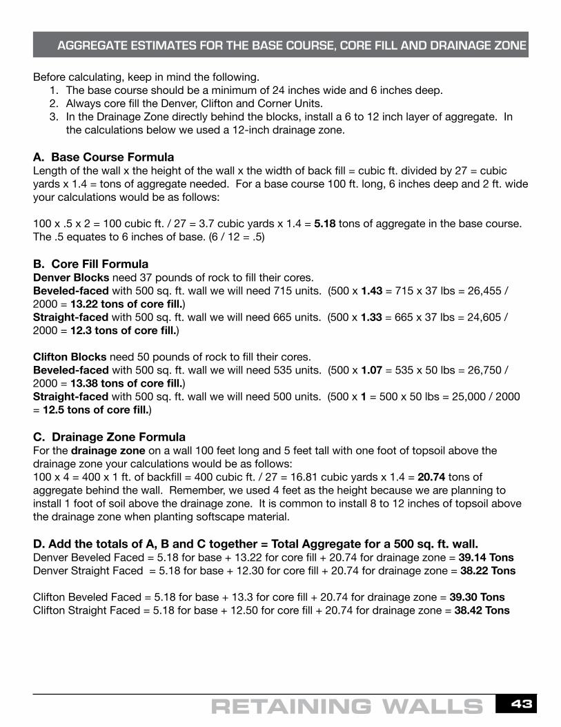
Before calculating, keep in mind the following.1. The base course should be a minimum of 24 inches wide and 6 inches deep.2. Always core fill the Denver, Clifton and Corner Units.3. In the Drainage Zone directly behind the blocks, install a 6 to 12 inch layer of aggregate. In
the calculations below we used a 12-inch drainage zone.
A. Base Course FormulaLength of the wall x the height of the wall x the width of back fill = cubic ft. divided by 27 = cubic yards x 1.4 = tons of aggregate needed. For a base course 100 ft. long, 6 inches deep and 2 ft. wide your calculations would be as follows:
100 x .5 x 2 = 100 cubic ft. / 27 = 3.7 cubic yards x 1.4 = 5.18 tons of aggregate in the base course. The .5 equates to 6 inches of base. (6 / 12 = .5)
B. Core Fill Formula Denver Blocks need 37 pounds of rock to fill their cores.Beveled-faced with 500 sq. ft. wall we will need 715 units. (500 x 1.43 = 715 x 37 lbs = 26,455 / 2000 = 13.22 tons of core fill.)Straight-faced with 500 sq. ft. wall we will need 665 units. (500 x 1.33 = 665 x 37 lbs = 24,605 / 2000 = 12.3 tons of core fill.)
Clifton Blocks need 50 pounds of rock to fill their cores. Beveled-faced with 500 sq. ft. wall we will need 535 units. (500 x 1.07 = 535 x 50 lbs = 26,750 / 2000 = 13.38 tons of core fill.)Straight-faced with 500 sq. ft. wall we will need 500 units. (500 x 1 = 500 x 50 lbs = 25,000 / 2000 = 12.5 tons of core fill.)
C. Drainage Zone FormulaFor the drainage zone on a wall 100 feet long and 5 feet tall with one foot of topsoil above the drainage zone your calculations would be as follows:100 x 4 = 400 x 1 ft. of backfill = 400 cubic ft. / 27 = 16.81 cubic yards x 1.4 = 20.74 tons of aggregate behind the wall. Remember, we used 4 feet as the height because we are planning to install 1 foot of soil above the drainage zone. It is common to install 8 to 12 inches of topsoil above the drainage zone when planting softscape material.
D. Add the totals of A, B and C together = Total Aggregate for a 500 sq. ft. wall.Denver Beveled Faced = 5.18 for base + 13.22 for core fill + 20.74 for drainage zone = 39.14 TonsDenver Straight Faced = 5.18 for base + 12.30 for core fill + 20.74 for drainage zone = 38.22 Tons
Clifton Beveled Faced = 5.18 for base + 13.3 for core fill + 20.74 for drainage zone = 39.30 Tons Clifton Straight Faced = 5.18 for base + 12.50 for core fill + 20.74 for drainage zone = 38.42 Tons
AGGREGATE ESTIMATES FOR THE BASE COURSE, CORE FILL AND DRAINAGE ZONE

44
5' 10' 15' 20' 25' 30'
PRODUCT DESCRIPTIONHxWxD
WEIGHTPER BLOCK
BLOCKS PER SQUARE FT
(by block face)COLORS
Tumbled Belgian Freestanding (large)
3-1/2" x 14" x 7"27-3/4 lbs 2.94
Autumn Blend 179-3640 Quarry Gray 179-3650 Sienna 179-3648 Tan 179-3653
Tumbled Belgian Freestanding (medium)
3-1/2" x 8-3/4" x 7"17 lbs 4.76
Autumn Blend 179-3724 Quarry Gray 179-3721 Sienna 179-3722 Tan 179-3723
Tumbled Belgian Freestanding (small) 3-1/2" x 1-3/4" x 7"
3 lbs 11.76Autumn Blend 179-3734 Quarry Gray 179-3731 Sienna 179-3732 Tan 179-3733
Tumbled Belgian Freestanding (wedge)
3-1/2" x 7" x 7"11 lbs 7.08
Autumn Blend 179-3639 Quarry Gray 179-3649 Sienna 179-3647 Tan 179-3652
Belgian Smooth 3-1/2" x 7" x 14" 27.75 lbs 2.94 Quarry Gray 179-3747
Sienna 179-3748
TUMBLED BELGIAN FREESTANDING WALL
1 3-1/2" 5 9 13 18 22 26 2 7" 9 17 27 35 43 52 3 10-1/2" 13 26 39 52 64 77 4 14 18 35 52 69 86 103 5 17-1/2" 22 43 65 82 107 129 6 21 26 52 78 99 129 155 7 24-1/2" 30 60 90 116 150 180
NO. OF COURSES WALL HEIGHT
(approximate)
SECTION LENGTH IN FT.
NUMBER OF TUMBLED BELGIAN FREESTANDING LARGE WALL BLOCKS NEEDED PER WALL SECTION
WALLS
FREESTANDING STRUCTUREThese simple shapes of Tumbled Belgian Blocks fit together to form an attractive solution for an endless array of possible combinations - all without ever cutting a single block. Let your imagination run wild, or start with one of our professionally designed projects with complete, easy to follow instructions. See store or Menards.com for more details.
PATTERN OPTIONSFor a natural look, simply follow no pattern. With random placement, make sure to minimize the number of matching joints to maintain a sturdy structure.
PROJECT CONSTRUCTIONPrepare the Foundation A solid foundation is necessary to prevent settling and tiling of each project. We recommend using a leveling pad, unless local building code requires you to pour a concrete foundation or build another type of foundation. Tips for Building a Leveling Pad • Choose the location for the completed project; place and mark the
position of the base layer of blocks. Once marked, remove the blocks and the organic top soil within the marked area.
• If applicable to the area, create a leveling pad with a non-frost susceptible, well graded, compacted angular gravel-sand mixture. The leveling pad should be a minimum of 4 to 6 inches thick. For leveling pads greater than 8” thick, then fill material shall be placed in more than once lift. Each layer or lift of fill material shall be leveled and compacted to a 95% Standard Proctor density before moving on.
• Once the top layer of fill material is compacted and level, place the base layer of blocks. The base layer should sit 1 to 2 inches below grade to help further prevent shifting. Use additional fill material to level the base.
$

45
PRODUCT DESCRIPTIONHxWxD
WEIGHTPER BLOCK
BLOCKS PER SQUARE FT
(by block face)COLORS
Tumbled Catalina Pillar5" x 17" x 8-1/2" 55 lbs 1.69
Autumn Blend 179-5064 Quarry Gray 179-5068 Sienna 179-5065
Tan 179-5062(special order)
Tumbled Catalina Retaining5" x 15" x 8-1/2" 39-1/2 lbs 1.92
Autumn Blend 179-5034 Quarry Gray 179-5030 Sienna 179-5032
Tan 179-5031 (special order)
Tumbled CatalinaFreestanding
5" x 15" x 8-1/2" 45 lbs 1.92
Autumn Blend 179-5021 Quarry Gray 179-5025 Sienna 179-5022
Tan 179-4074(special order)
TUMBLED CATALINA WALL
WALLS
PATTERN OPTIONS For a natural look, simply follow no pattern. With random placement, make sure to minimize the number of matching joints to maintain a strong wall.
FREESTANDING WALLCatalina has two split sides allowing it to be used in freestanding walls. Freestanding walls are excellent for sitting walls, patio barriers, or fencing. See the formula to calculate the material needed for your freestanding wall project. A 20" height is ideal for most sitting wall projects. Please note that freestanding walls should not exceed 3' in height.
A AB B BCBack Back Back BackFront
FrontFront
Front
Front
Front
Front
Front Front
FrontFront FrontB
BB
B
B
B
B
B B
B
BBack
A
A
A C
CC
A
A
AFront
Front
Front Front
FrontFront
Front
Front
Front
BBack
B
BBack
Back
CBack
CBack
BBack
WALL CONSTRUCTION1. Prepare Base Trench Calculate the depth of your base trench. The base trench should be 4-6 inches deep to accommodate Paver Base material with an additional inch per foot of wall height. Sample 2' wall height: 2"+ 4-6" base material = 6-8" trench depth When building on un-level areas, prepare step downs in increments of 5". Compact and level your Paver Base.2. Level Base Course Place the first layer of block on the prepared foundation. Use a carpenter's level in all directions and use a string line to verify straightness. Suggestion: To avoid un-straight lines, place gentle curves in the wall. Be certain the base course is level and the blocks lay flat. Have a rubber mallet handy for leveling blocks. Small handfuls of sand may be used for leveling too.3. Stack & Fill Backfill the wall with Multi-Purpose Gravel that will let water drain through to the drain tile behind your wall. For maximum wall strength and durability, use a landscape adhesive on each course. If desired, use a standard retaining wall cap to top the wall.
SHAPES & SIZES Each pallet of Catalina contains a variety of shapes and sizes. Mixing the different shapes, and using either of the 2 finished faces will create a unique, random looking wall with minimal cutting.
Each Catalina Block has two finished sides for more possible combinations.
NOTE: Walls over 3' in height may require geogrid and our professional design service. For projects over 3', please fill out a design service quote request.
$
15" BLOCKS
A B CFront
Back

46
PRODUCT DESCRIPTIONHxWxD
WEIGHTPER BLOCK
BLOCKS PER LINEAR FT COLORS
Step Block3-1/2" x 16" x 12-1/2"
56 lbs(Cap) 0.75
(Step) 32" Step Quarry Gray 179-3935 Sienna 179-3938 Tan 179-3939
12" Cap2-3/8" x 12" x 7-1/2"
13 lbs 1.14
Autumn Blend 179-4093 Cobalt 179-4089 Gray 179-3493 Quarry Gray 179-3503 Red 179-4082 Red/Black 179-3497 Sienna 179-4088 Tan 179-3499
XL Cap 3-1/2" x 18-1/4" x 13"
53 lbs 0.8 Quarry Gray 179-5681 Sienna 179-5680 Tan 179-5674
Smooth Pillar Cap
STEP BLOCKS, RETAINING WALL CAPS, PILLAR CAPS
CAPS
2" x 12" x 24" 40 lbs Cap Covers 1.9 sq. ft. Gray 179-5816
2" x 24" x 24" 85 lbs Cap Covers 4 sq. ft. Gray 179-5800
2" x 27" x 27" 120 lbs Cap Covers 5.06 sq. ft. Gray 179-5810
$

47
PRODUCT DESCRIPTIONHxWxL
WEIGHTPER BLOCK
BLOCKS PER LINEAR FT COLORS
Tumbled Belgian Edger3-1/2" x 12" x 4" 13-1/4 lbs 1
Autumn Blend 179-2681 Quarry Gray 179-2683 Sienna 179-2687 Tan 179-2682
Interloc Edger3-3/8" x 11-3/4" x 3-3/8" 10 lbs 1.02
Gray 179-2480 Red 179-2498Red/Black 179-2485 Tan 179-2495
Cobble Edger3-7/16" x 11-13/16" x 3-3/4" 12 lbs 1.02 Sienna 179-2696
Crescent Edger 2-3/8" x 5-3/4" x 4-3/8" 5 lbs 2.82 Red 179-2634
Tan 179-2663
Scalloped Edger (Straight)6" x 24" x 2" 22 lbs 0.50
Gray 179-2304 Red 179-2333 Tan 179-2317
Scalloped Edger (Curved)6" x 24" x 2" 23 lbs 0.50
Gray 179-2391 Red 179-2427 Tan 179-2401
EDGERS
EDGERS
$
48
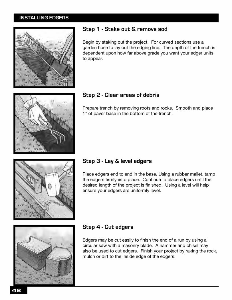
Step 1 - Stake out & remove sod
Begin by staking out the project. For curved sections use a garden hose to lay out the edging line. The depth of the trench is dependent upon how far above grade you want your edger units to appear.
Step 4 - Cut edgers
Edgers may be cut easily to finish the end of a run by using a circular saw with a masonry blade. A hammer and chisel may also be used to cut edgers. Finish your project by raking the rock, mulch or dirt to the inside edge of the edgers.
Step 3 - Lay & level edgers
Place edgers end to end in the base. Using a rubber mallet, tamp the edgers firmly iinto place. Continue to place edgers until the desired length of the project is finished. Using a level will help ensure your edgers are uniformly level.
Step 2 - Clear areas of debris
Prepare trench by removing roots and rocks. Smooth and place 1" of paver base in the bottom of the trench.
INSTALLING EDGERS

49
Installation Options
Paver Base / Step 1 Leveling Sand / Step 2 Paver Locking Sand / Step 3
Install pavers over a firm, stable base using one of the four installation diagrams shown below. If installing Paver Locking Sand on a non-drainage bed system, there must be a slope to avoid water pooling on the pavers. Paver Locking sand is the 3rd part of a 3-step standard installation system when installing pavers or patio blocks. By using Step 1 Paver Base, Step 2 Leveling Sand, and Step 3 Paver Locking Sand you will achieve the best results. Paver surface must be dry and clean prior to application of Step 3 Paver Locking Sand to prevent
materials from adhering to and hardening on top of the pavers.
Paver Installation Steps
50

51

52
MIDWEST MANUFACTURING CONCRETE BLOCK
www.midwestmanufacturing.com2018
OUR GUARANTEEMidwest Manufacturing is dedicated to offering the highest quality concrete products, to all of our guests.
All of our interlocking concrete pavers, concrete bricks, retaining walls, and masonry block, meet or exceed ASTM C-936, ASTM C1634-09/C55-09, ASTM C-1372, and ASTM C-90 specifications, respectively.
Midwest Manufacturing guarantees its concrete products against manufacturing defects for as long as you own your home. This guarantee will be honored with proof of purchase. Midwest Manufacturing takes pride
in offering our products to the “do-it-yourself-er” and contractor alike.
We do not require professional installation, however we do recommend it. Basic installation practices, available at www.midwestmanufacturing.com, must be followed. Midwest Manufacturing’s obligation is
limited to replacement of the defective product only. Midwest Manufacturing will not be responsible for lost time, replacement labor, or any other commensurate costs associated with replacement. The guarantee
does not apply to product damage caused by impact, improper installation, excessive load, or salt application. Color matching can not be guaranteed. Efflorescence is a natural and temporary occurrence –
Midwest Manufacturing cannot be held responsible.
- Not all blocks are stocked in all locations.
- All block sizes given are nominal, sizes may vary within a given tolerance.
- Some items are only available special order. Special orders may require a packaging/handling fee. Special orders ship in approximately one week.
- It is recommended that you purchase enough material to complete your entire project. Color will vary slightly from lot to lot, so materials purchased at a later date may not be a perfect color match.
- Hazy white or chalky looking surfaces are due to efflorescence. Efflorescence is a natural process which can occur as concrete cures. Efflorescence is temporary and not considered a manufacturing defect.
903-0185