product specification sfp olt 1g 20km sc - a-geara-gear.net/pdf/pon/transceivers/sfp olt 1g 20km...
TRANSCRIPT
Product SpecificationSFP OLT 1G 20km SC1.25Gbps Upstream/1.25Gbps Downstream GE-PON OLT Transceiver
1. P r o d u c t Fe a t u r e s• Bi-directional 1.25Gbps Upstream/1.25Gbps Downstream• Complies with IEEE802. 3ah 1000Base-PX20 application• SFP package with SC Receptacle• 1490nm continuous-mode 1.25Gb/s DFB transmitter, And 1310nm burst-mode 1.25Gb/s
APD receiver• Single +3.3V power supply• LVTTL Bias Control input and Rx Signal Detect output• Laser Class 1 Product which comply with the Requirements of IEC 60825-1 and
IEC 60825-2
2. A p p l i c a t i o n s• Gigabit Ethernet Passive Optical Network (GEPON) OLT
3. D e s c r i p t i o nA-GEAR’s GE-PON OLT transceiver SFP OLT 1G 20km SC is designed for Gigabit Ethernet Passive Optical Network transmission. The module is contained in a SFP package with SC/UPC receptacle connector. The module consists 1490nm DFB laser, InGaAs APD, Preamplifier and WDM filter in a high-integrated optical sub-assembly, and it receives up to 1.25Gbps of continuous data at 1310nm, and receives 1.25Gbps of burst-mode data at 1310nm. The module data link up to 20km in 9/125um single mode fiber.
a-gear.net
Раge 1 of 9
A-GEAR World Wide Manufacturing
SFP OLT 1G 20km SCdatasheet
4. A b s o l u t e M a x i m u m R a t i n g sP a r a m e t e r S y m b o l M i n . M a x . U n i t
Storage Temperature TS -40 85 °CStorage Ambient Humidity HA 5 95 %Power Supply Voltage VCC -0.3 4 VSignal Input Voltage -0.3 Vcc+0.3 VReceiver Damage Threshold +5 dBm
5. R e c o m m e n d e d O p e r a t i n g C o n d i t i o n sP a r a m e t e r S y m b o l M i n . Ty p i c a l M a x . U n i t
Ambient Operating Temperature TA 0 70 °C [1]
Ambient Humidity HA 5 95 % [2]
Power Supply Voltage VCC 3.14 3.3 3.47 VPower Supply Current ICC 400 mAPower Supply Noise Rejection 100 mVp-p [3]
Data Rate 1.25 Gbps
Notes:[1] Without air flow[2] Non-condensing[3] 100Hz to 1MHz
6. S p e c i f i c a t i o n o f Tr a n s m i t t e rP a r a m e t e r S y m b o l M i n . Ty p i c a l M a x . U n i t
Average Launched Power PO +2 +7 dBm [1]
Extinction Ratio ER 9 dBCenter Wavelength λC 1480 1500 nm [5]
Spectrum Width (RMS) σ 1.0 nmTransmitter OFF Output Power POFF -39 dBmOptical Rise/Fall Time tr/tf 260 ps [2]
Total Jitter tJ 128 ps [3]
Optical Return Loss Tolerance ORLT 15 dBOutput Eye Mask {X1,X2,Y1,Y2,Y3} Compliant with IEEE 802.3ah {0.22,0.375,0.20,0.20,0.30} [4]
Notes:[1] Launched power (avg.) is power coupled into a single mode fiber with master connector. (Before of Life)[2] These are unfiltered 20-80% values.[3] Measure at 27-1 NRZ PRBS pattern[4] Transmitter eye mask definition[5] DFB Laser
a-gear.net
Раge 2 of 9
SFP OLT 1G 20km SCdatasheet
A-GEAR World Wide Manufacturing

7. S p e c i f i c a t i o n o f R e c e i v e rP a r a m e t e r S y m b o l M i n . Ty p i c a l M a x . U n i t
Input Optical Wavelength λIN 1260 1310 1360 nm [5]
Receiver Sensitivity PIN -30 dBm [1]
Input Saturation Power (Overload) PSAT -6 dBmSignal Detect -Assert Power PA -45 dBmSignal Detect -Deassert Power PD -30 dBm [2]
Signal Detect Hysteresis PA-PD 2 dBData Output Rise/Fall time tr/tf 260 ps [3]
Receiver threshold setting time TS 400 nsReceiver Reflectance 1260 to 1360nm -12 dB [4]
Notes:[1] Measured with Light source 1490nm, ER=9dB; BER =<10-10 @PRBS=27-1 NRZ
This assurance should be met with asynchronous data flowing out of the optical transmitter of the system under test. The output data pattern from the transmitter of the system under test is a repetition of alternate 0/1 pattern as defined for this measurement.
[2] When Signal Detect deasserted, the data output is Low-level (fixed)[3] These are 20%~80% values.[4] Measured at wavelength of 1310nm.[5] APD
8. E l e c t r i c a l I n t e r f a c e C h a r a c t e r i s t i c sP a r a m e t e r S y m b o l M i n . Ty p i c a l M a x . U n i t
TransmitterDifferential line input Impedance RIN 80 100 120 OhmDifferential Data Input Swing VDT 200 1600 mVp-p [1]
TX_disable Input Voltage- High VDISH 2 Vcc V [3]
a-gear.net
Раge 3 of 9
A-GEAR World Wide Manufacturing
SFP OLT 1G 20km SCdatasheet
P a r a m e t e r S y m b o l M i n . Ty p i c a l M a x . U n i tTX_disable Input Voltage- Low VDISL 0 0.8 VTransmitter Fault Output-High VFAULTH 2 Vcc V [3]
Transmitter Fault Output-Low VFAULTL 0 0.8 VReceiver
Differential Data Output Swing VDR 400 1600 mVp-pLOS Output Voltage-High VLOSH 2.4 Vcc V [2]
LOS Output Voltage-Low VLOSL 0 0.4 V [2]
Notes:[1] Internally AC coupled, but requires a 1000hm differential termination at or internal to Serializer/ Deserializer.[2] When los output is high, RX out is no signal.[3] LVTTL
9. B u r s t M o d e D i g i t a l D i a g n o s t i c M o n i t o r I n t e r f a c e ( D D M I ) D e s c r i p t i o nA-GEAR’s GE-PON OLT transceiver support the 2-wire serial communication. The DDMI WARNING and ALARM memory positions and addresses are compliant with the SFF 8472 REV9.3 specification. The standard SFP serial ID provides access to identification information that describes the transceiver’s capabilities, standard interfaces, manufacturer, and other information.The DDMI can detect TX power, RX power, Bias current, Temperature, VCC:
M o n i t o r s c o p e M o n i t o r E r r o rTX power -3 dBm ~ 8 dBm ±3 dBmRX power -6 dBm ~ -30 dBm ±3 dBmBias 0 mA ~ 90 mA ±10%Temperature -40°C ~ 85°C ±5°CVCC 2.8V ~ 3.8V ±5%
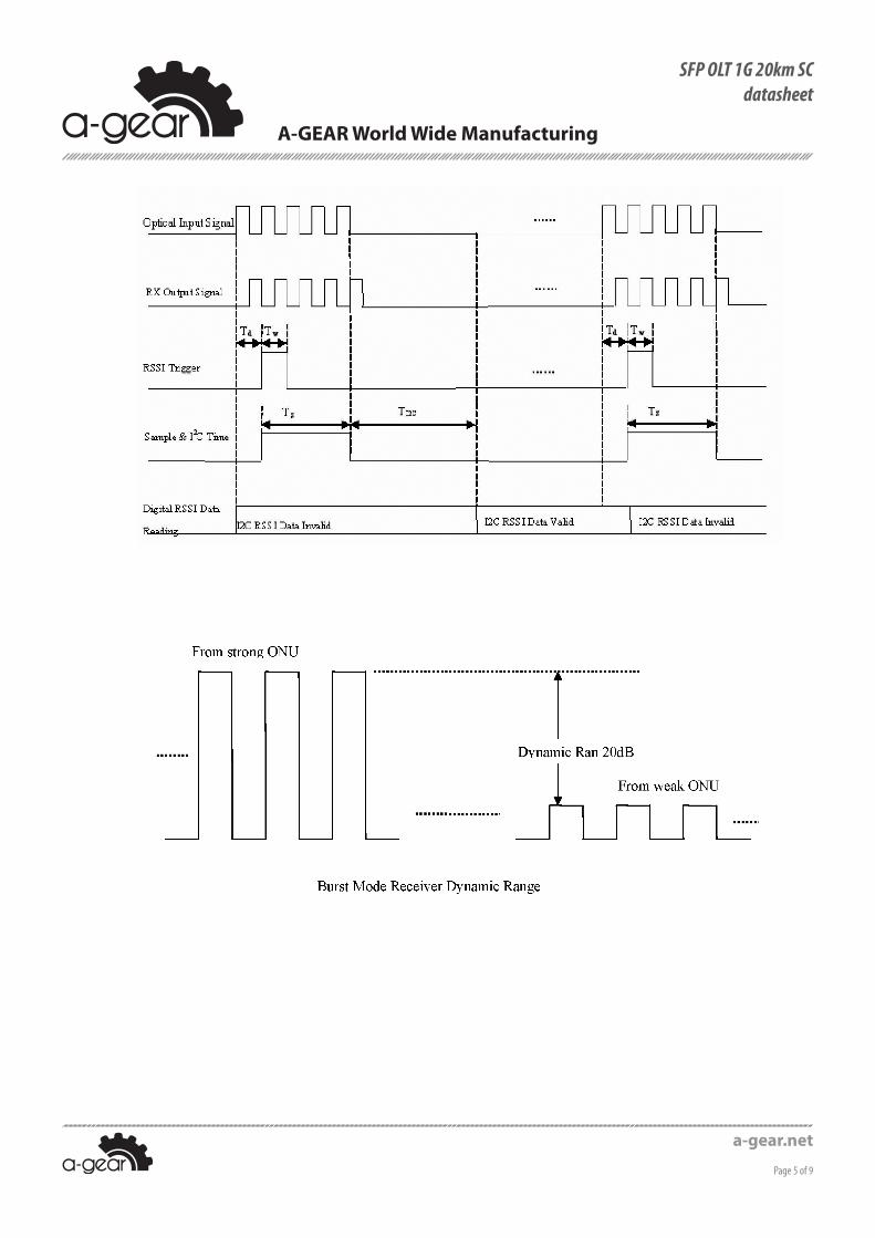
10. T i m i n g C h a r a c t e r i s t i c s f o r D i g i t a l R S S IP a r a m e t e r S y m b o l M I N T Y P E M A X U n i t s
Trigger delay TD 2 usTrigger width TW 2 4 usSample time TS 6 500 usI2C read time TI2C 150 200 us
a-gear.net
Раge 4 of 9
SFP OLT 1G 20km SCdatasheet
A-GEAR World Wide Manufacturing
a-gear.net
Раge 5 of 9
A-GEAR World Wide Manufacturing
SFP OLT 1G 20km SCdatasheet

11. P i n D e s c r i p t i o n s
P i n # N a m e F u n c t i o n N o t e s1 VeeT Transmitter Ground -2 TX Fault Transmitter Fault Indication open collector/drain output,3 TX Disable Transmitter Disable Module disables on high or open4 MOD-DEF2 Module Definition 2 2 wire serial ID interface, SDA5 MOD-DEF1 Module Definition 1 2 wire serial ID interface, SCL6 MOD-DEF0 Module Definition 0 Grounded in Module7 RSSI-Trigger8 LOS Loss of Signal9 VeeR Receiver Ground10 VeeR Receiver Ground11 VeeR Receiver Ground12 RD- Inv. Received Data Out DC-coupled13 RD+ Received Data Out DC-coupled14 VeeR Receiver Ground15 VccR Receiver Power 3.3V± 5%16 VccT Transmitter Power 3.3V± 5%17 VeeT Transmitter Ground
18 TD+ Transmit Data In AC-coupled, differential lines with 100Ω differential termination inside the module
a-gear.net
Раge 6 of 9
SFP OLT 1G 20km SCdatasheet
A-GEAR World Wide Manufacturing
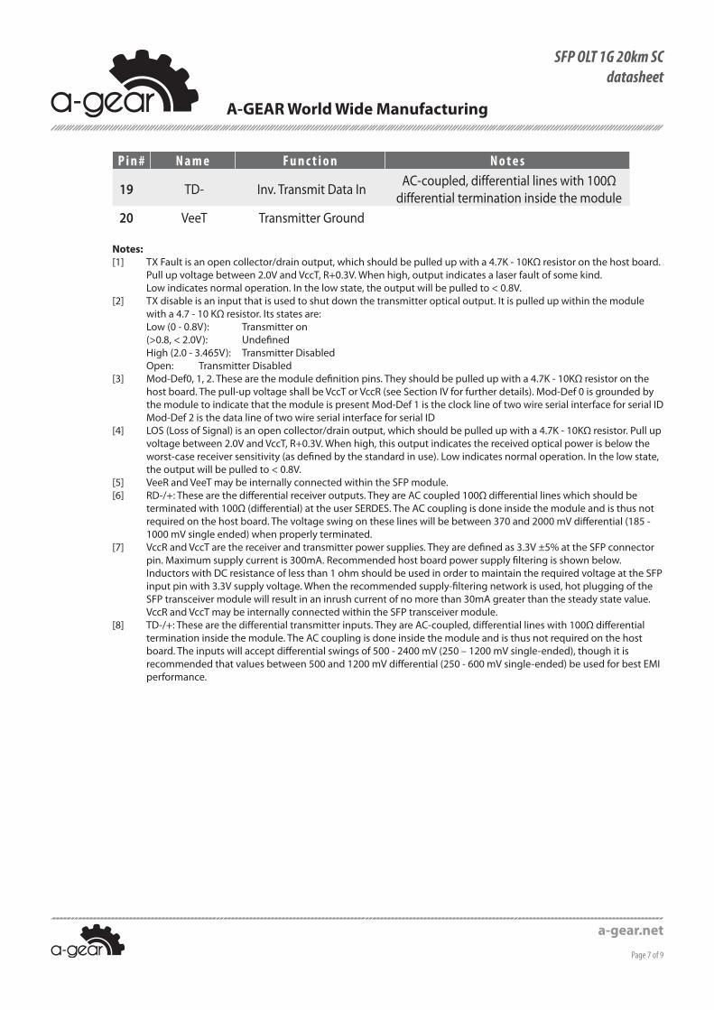
P i n # N a m e F u n c t i o n N o t e s
19 TD- Inv. Transmit Data In AC-coupled, differential lines with 100Ω differential termination inside the module
20 VeeT Transmitter Ground
Notes:[1] TX Fault is an open collector/drain output, which should be pulled up with a 4.7K - 10KΩ resistor on the host board.
Pull up voltage between 2.0V and VccT, R+0.3V. When high, output indicates a laser fault of some kind. Low indicates normal operation. In the low state, the output will be pulled to < 0.8V.
[2] TX disable is an input that is used to shut down the transmitter optical output. It is pulled up within the module with a 4.7 - 10 KΩ resistor. Its states are: Low (0 - 0.8V): Transmitter on (>0.8, < 2.0V): Undefined High (2.0 - 3.465V): Transmitter Disabled Open: Transmitter Disabled
[3] Mod-Def0, 1, 2. These are the module definition pins. They should be pulled up with a 4.7K - 10KΩ resistor on the host board. The pull-up voltage shall be VccT or VccR (see Section IV for further details). Mod-Def 0 is grounded by the module to indicate that the module is present Mod-Def 1 is the clock line of two wire serial interface for serial ID Mod-Def 2 is the data line of two wire serial interface for serial ID
[4] LOS (Loss of Signal) is an open collector/drain output, which should be pulled up with a 4.7K - 10KΩ resistor. Pull up voltage between 2.0V and VccT, R+0.3V. When high, this output indicates the received optical power is below the worst-case receiver sensitivity (as defined by the standard in use). Low indicates normal operation. In the low state, the output will be pulled to < 0.8V.
[5] VeeR and VeeT may be internally connected within the SFP module.[6] RD-/+: These are the differential receiver outputs. They are AC coupled 100Ω differential lines which should be
terminated with 100Ω (differential) at the user SERDES. The AC coupling is done inside the module and is thus not required on the host board. The voltage swing on these lines will be between 370 and 2000 mV differential (185 - 1000 mV single ended) when properly terminated.
[7] VccR and VccT are the receiver and transmitter power supplies. They are defined as 3.3V ±5% at the SFP connector pin. Maximum supply current is 300mA. Recommended host board power supply filtering is shown below. Inductors with DC resistance of less than 1 ohm should be used in order to maintain the required voltage at the SFP input pin with 3.3V supply voltage. When the recommended supply-filtering network is used, hot plugging of the SFP transceiver module will result in an inrush current of no more than 30mA greater than the steady state value. VccR and VccT may be internally connected within the SFP transceiver module.
[8] TD-/+: These are the differential transmitter inputs. They are AC-coupled, differential lines with 100Ω differential termination inside the module. The AC coupling is done inside the module and is thus not required on the host board. The inputs will accept differential swings of 500 - 2400 mV (250 – 1200 mV single-ended), though it is recommended that values between 500 and 1200 mV differential (250 - 600 mV single-ended) be used for best EMI performance.
a-gear.net
Раge 7 of 9
A-GEAR World Wide Manufacturing
SFP OLT 1G 20km SCdatasheet
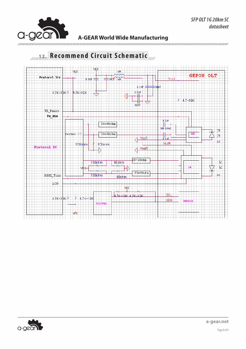
12. R e c o m m e n d C i r c u i t S c h e m a t i c
a-gear.net
Раge 8 of 9
SFP OLT 1G 20km SCdatasheet
A-GEAR World Wide Manufacturing
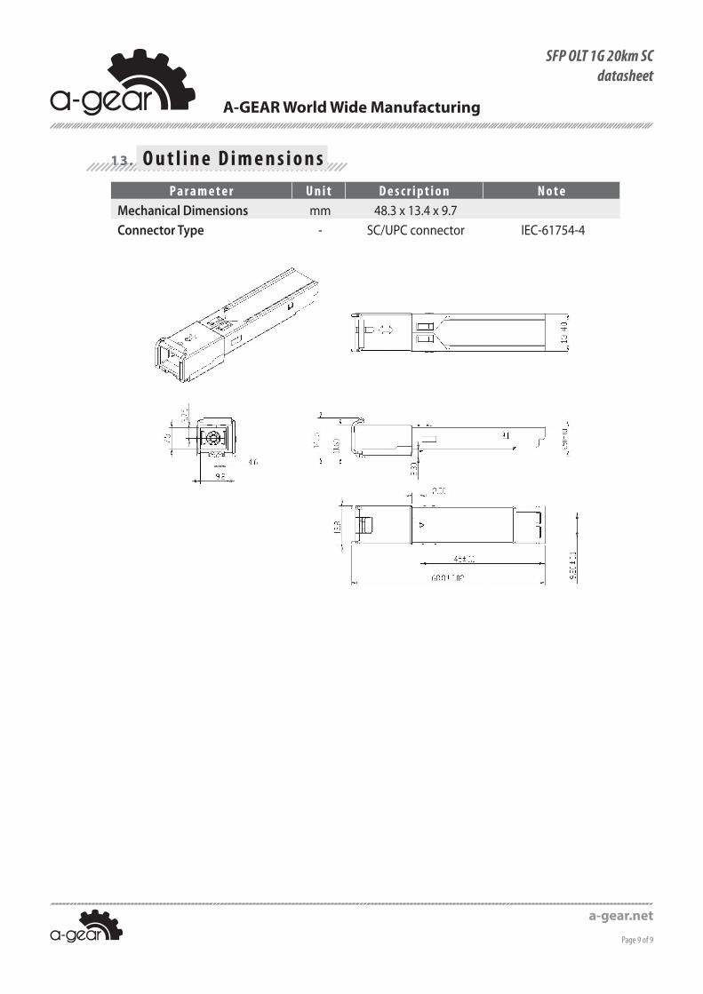
13. O u t l i n e D i m e n s i o n sP a r a m e t e r U n i t D e s c r i p t i o n N o t e
Mechanical Dimensions mm 48.3 x 13.4 x 9.7Connector Type - SC/UPC connector IEC-61754-4
a-gear.net
Раge 9 of 9
A-GEAR World Wide Manufacturing
SFP OLT 1G 20km SCdatasheet