product manual icc1-232 - contemporaryresearch.com · contemporary research 5 icc1-232 manual...
TRANSCRIPT

Product Manual
ICC1-232 RS-232 Display Controller, 1-way Control December 2018

Contemporary Research 2 ICC1-232 Manual
Table of Contents Table of Contents ................................................................................................................................ 2 Overview ............................................................................................................................................. 3 Specifications ...................................................................................................................................... 4
Physical .................................................................................................................................................... 4 Rear Panel................................................................................................................................................. 4 iCC-Net ..................................................................................................................................................... 4 Includes .................................................................................................................................................... 4 Options .................................................................................................................................................... 4
Installation ......................................................................................................................................... 5 AC Power Test ........................................................................................................................................... 5 RS-232 Control Wiring ................................................................................................................................. 5 RF Coax and iCC-Net Operation ..................................................................................................................... 5 RS-232 Control Types .................................................................................................................................. 5 Setting Device Number and Parameters .......................................................................................................... 6
ICC-Net Control Protocol .................................................................................................................... 8 Overview ................................................................................................................................................. 8 Command String Structure ........................................................................................................................... 8 Command format: ...................................................................................................................................... 8
Writing Your Own Control Code ......................................................................................................... 9 ICC-Net Commands .......................................................................................................................... 10 Safety Instructions and Warranty .................................................................................................... 12

Contemporary Research 3 ICC1-232 Manual
Overview
ICC1-232 TV Controllers deliver economical 1-way control for power, volume, channel and input commands, receiving iCC-Net network commands over the same broadband coax that carries the CATV channels. The ICC1-232 RS-232 employs a DB9 RS-232 port to control commercial-level TVs. TV Controllers receive the ICC-Net data channel and pass analog and digital channels on to the TV. The commands are generic, as make/model specific RS-232 commands and logic are stored and sent directly from the TV Controller. In addition, the power state and current channel are saved in non-volatile memory, so the controllers can restore operation after a power failure, and return the TV to a previous state after an emergency broadcast. Applications include sports and entertainment venues, commercial and civic facilities, airports, factories, schools, and houses of worship.
• Controls most brands of RS-232 controlled TVs
— Delivers discrete power commands
— Tunes analog or HDTV format channels
— Intelligent volume level and mute operation
— Enables available RS-232 control lockout commands
• Receives 1-way individual and zone commands from the ICC-HE-DXL Display Control Center
• Provides LED feedback for network and control operation
• Restores all power and channel status after loss of power from data stored in non-volatile memory
• Mounts on the back of display for simplified control and RF installation
• Operates with Display Express software, as well as custom control systems
• Includes RF loop cable, mounting Velcro, and 12VDC power supply
• Requires optional CC-COM DB9 or 3.5mm control cables

Contemporary Research 4 ICC1-232 Manual
Specifications
Physical Size: 5.5" [140mm] wide x 1.1" [28mm] height x 3.4" [86mm] deep Weight: 8 oz [226g] Enclosure: All aluminum with durable black powder coat paint Mounting: Mounts rear of TV Rear Panel RF In ‘F’, female, 75 ohm impedance, RF from CATV system, iCC-Net control RF Out: ‘F’, female, 75 ohm impedance, RF to TV, less than -1.5 dbmV loss Net LED: Green LED for iC-Net bus and DC power, flashes once per second if active RS-232: DB-9 male connector, baud rates from 1200 to 115K baud Optional CC-232 RS-232 available to match specific makes and models Tx LED: Red LED lights when RS-232 information is sent Rx LED: Yellow LED lights when RS-232 information is received Power In: 2.1mm coaxial jack (inside center conductor positive), 75 mA maximum 11.5 to 16.5 VDC, 12 VDC typical (may be unregulated) DIP Switches: Located on bottom of unit, sets RS-232 code operation and device number iCC-Net Operation: 1-way control, carried over the same RF coax connection as TV channels Data Receive: Mid-band VHF, 74.7 MHz, sent from ICC-HE -25 to +35 dBmV signal level Includes RF Loop cable, 18" 12 VDC power supply, 500 mA Mounting Velcro Options
CC-COM Null Modem cable, 6’ CC-COM 3.5 Null Modem cable with 3.5mm plug CC-COM 3.5 Null Model cable with 3.5mm plug and adapter for consumer LG TVs (Specify when ordering)

Contemporary Research 5 ICC1-232 Manual
Installation
AC Power Test 1. Insert DC power supply plug into 12 VDC jack. 2. Plug power adaptor into AC wall outlet. 3. The Net LED should turn on and stay lit. 4. When an RF feed is connected to RF with an installed ICE-HE, LED will blink once a second
RS-232 Control Wiring
1. Attach the CC-RS-232 or custom RS-232 cable to the ICC1-232 control port. 2. Connect the cable to the display’s RS-232 control input.
RF Coax and iCC-Net Operation
1. Connect the TV to CATV and observe quality of RF broadcasting. A low-quality CATV system can also affect performance of the iCC-Net commands. If needed, fix CATV problems before installing the system.
2. Connect the CATV RF Coax cable into the RF In input on the ICC1-232. 3. If the iCC-Net signal is operating, the Net LED will blink once per second. 4. Connect the RF loop cable from the RF Out jack to the TV’s RF connector (remember, you lose less than 1.5 dbmV by
going through the ICC1-232’S internal RF tap). RS-232 Control Types Presently, one control type is installed at the factory, updateable to other types through the RF or via RS-232. The list below includes current makes and models of RS-232 controllable TVs, there are more codesets available for legacy TVs.
Make Notes Accuview RS-232 TVs
LG Includes input selects for current models
NEC Older M-series with AVT tuner
New M,P,S,V,X-AVT and E-series TVs
E-series
Panasonic LRU and LRG series
Peerless Ultraview Outdoor TVs
Samsung DM,MD, ME, HD series commercial TVs
Ex-Link controlled TVs
Sharp Original Sharp TVs, P-series by Hisense
Sunbrite All models
Viewsonic Commercial TVs
RS-232 Pinouts
• Pin 5 = Ground (GND)
• Pin 2 = Receive (RX)
• Pin 3 = Transmit (TX)

Contemporary Research 6 ICC1-232 Manual
Setting Device Number and Parameters
In the next step, you’ll need to set up the device number and operation parameters for the ICC1-232. Turn the enclosure so that the DIP switches are on the bottom as shown.
1. Make sure S2 Switch 6 is OFF (unit in Device mode). 2. Set the Device number by turning on the switches that add up to the desired device number. For example, for
Device #259, turn on S1 switches 1 and 2 (3), S2 switch 1 (256)
Zone Switch Settings To define the controller’s Zone #, use the following pattern of switches ON for the S2 DIP.
Zone Value 1 2 3 4
256 512 1024 2048
1 256 X
2 512 X
3 768 X X
4 1024 X
5 1280 X X
6 1536 X X
7 1792 X X X
8 2048 X
9 2304 X X
10 2560 X X
11 2816 X X X
12 3072 X X
13 3328 X X X
14 3584 X X X
15 3840 X X X X
Installation Process and Documentation Most dealers will pre-configure the controller’s address before hanging displays. After setting the address, use a label that states the unit’s address and location. Some use this method: Room 305 - 515 - 12/2 The first identifies the location/name of the display. The second shows the specific address. The last set shows the switches in S1/S2 that are set to ON. It’s a good idea to define this first in a spreadsheet, with the columns defining the name, address, S1 and S2 ON settings. Then, one person can set up all the controllers and label them.
Once the controller is configured and labeled, it’s easier for less-trained installers to Velcro the controller on the back of the display, provide power, and hang the displays. It’s much easier to pre-configure ahead of time than perform the task once the displays are installed.

Contemporary Research 7 ICC1-232 Manual
Power-Up and Lock Logic The ICC1-232 remembers the current power and Lock state of the connected TV so that the controller can restore power and operation lock to the TV when AC power is restored. Some TVs, such as LG, will lose the locked state (no local button or IR control) when the set loses AC power. Other sets may not automatically power back on when AC power is restored. To deal with this issue, after every power-up or reset, the ICC1-232 will transmit its current (last commanded) power control string (Power On or Power Off) to the TV, as well as work to restore the Lock state. If the TV was On and Locked when power was lost, the controller will send a Power On command when power is restored, then sends a Lock command after a time delay. This assures that the TV stays locked when it is automatically powered up after a reset. If the TV was Locked and Off when power was lost, the controller will send a Power Off command every 16 seconds when power is restored. When a command is sent to turn the TV on, the controller will also send a Lock command after a time delay.
Input Selects The code sets listed a Contemporary TVs in the list on Page 5 have the ability to select inputs from a special channel command, 0-NNN. For example, a 0-211 command would send the TV to the HDMI 1 input. For some makes, such as LG, you need to send a TV/Tuner command (0-200) to restore the TV to the current channel. For other sets, sending a channel command automatically selects the tuner if it’s at a different input. The command list covers all the possibilities, not all sets have every option. Actual inputs assigned to the codes below can shift, depending on the make and model.
115=Captions 200=TV/Tuner 201=Video1 202=Video2 203=Video3 204=S-Video1 205=S-Video2
206=Component1 207=Component2 208=RGB1 209=RGB2 210=RGB3
211=HDMI1 212=HDMI2 213=HDMI3 214=HDMI4 215=HDMI5
TV Information Go to our Support Blog “Display Express TV Guide” for up-to-date information on makes and models.
LG Codes have stayed consistent in general. Newer models use different codes for inputs than previous models. A codeset is available for older models as well.
NEC There are three current codesets:
• M/P/S/V with AVT Tuners
• E-series TVs with integrated tuner
• E-Series TVs with AVT tuner
Panasonic LRU and LRG series are supported
Sharp The current codeset is for prosumer Sharp TVs that support RS-232 control.
• Send and H9,1 command via DX or control system for sets that can tune XX.1 channels (p11)
• Send an Off command to all TVs, manually turn on TVs, then send an OFF command – this turns off the Energy Star feature that turns off RS-232 when the TV is off.
• New Sharp (Hisense) commercial TV use the same control code as original Sharp TVs
Samsung • All commercial models are supported.
• Samsung TVs that support X-Link control, the commands are different than commercial TVs and can only access Major and Minor channels up to 63, cannot tune 1-part digital channels
Viewsonic

Contemporary Research 8 ICC1-232 Manual
ICC-Net Control Protocol Overview Control for over 4000 TV Controllers is provided through an ICE-HE Head-End Network Controller or ICE-HE DXL Display Control Center that inserts a micro control channel through RF coax. Both can receive ICC-Net control commands via RS-232 and TCP, and the ICE-HE-DXL adds a USB port for use with a PC with Display Express. Each TV Controller is assigned a unique device number from 257 to 4094. The devices are organized into 16 zones of 255 devices to handle large-scale TV installations. All the devices in each zone will respond to a single “virtual device number” — one device number that represents all devices in each zone. There is also a global device number, 4095, that will command all devices in the system. This feature dramatically speeds up system operation and programming, because one command can affect an entire group of devices—or all. In Display Express, we reserve the first group of devices, 1-255 (for which there is no Zone), for components in special applications. Zones 1-15 are used for CR TV Controllers. The RS-232 port can communicate from 300 to 115.2K baud. The factory default setting is 19.2K baud, 8 data bits, no parity, and 1 stop bit. ICC-Net commands can be sent via TCP to IP port 2728, when not in use by Display Express. The USB port is typically used to provide RS-232 control from a PC with Display Express software. The Telnet port (default 23) can be used by CR Toolbox and Telnet applications for HE commands and status, but not for ICC-Net commands.
Command String Structure Characters in command strings are expressed in a combination of hex and ASCII characters. For clarity, the following protocol examples use the following conventions, similar to AMX protocol, most other control systems would use Hex.
• Single-byte hex numbers are preceded by the ‘$’ symbol
• ASCII characters or strings are enclosed in single quotes
• Numbers not marked as hex or ASCII are a single decimal byte
• Parameters shown in < > brackets are single byte
• A series of multiple commands or parameters are set apart by [ ] brackets
• Commas separate the bytes, but are not part of the protocol
• Double quotes enclose the command string, but are not part of the protocol
Command format: “$A5,<dh>,<dl>,<ncb>,<cmd1>,<parameter> [<cmdN>]" $A5 Starts the command <dh> The zone or high order byte of the device* <dl> The unit or low order byte of the device (0 for global zone) <ncb> The number of command bytes to follow, the (total bytes) shown after are simply reference <cmd1> The first command byte <parameter> Command parameters (not used by all commands) [<cmdN>] Multiple commands can be concatenated, with byte count added to <ncb>
* iCC-Net devices are arranged with a zone mindset. For example, a command sent to Device 256, which triggers all the units in Zone 1, would be expressed as $A5, 1, 0 (first zone, device zero). A command sent to 257 would be $A5, 1, 1 (first zone, device 1 in the zone). See iCC-Net Zones following this section.

Contemporary Research 9 ICC1-232 Manual
Writing Your Own Control Code
While most ICC-Net systems use our Display Express software to control displays, a growing number of integrators are writing their own control applications, using AMX, Crestron, RTI, or other platforms. We encourage creative solutions, and are happy to support those who take advantage of our protocol. From our history of support activity, we are providing a few tips to help you on your way. Device Numbers iC-Net devices are arranged with a zone structure, arranged in 15 groups of 256 devices. The first address in the group represents the entire zone. For example, Zone 2’s group address is 512 (2*256). When a command is sent to 256, all controllers in that group will respond as one. An ALL command is 4095 (15,255, F FF in Hex) – all controllers will respond. All commands follow the same structure of:
• Attn = Hex A5
• Zone = 1-15 (hex 1-F)
• Unit = 1-255 (hex 1-FF)
• Bytes = Number of bytes that follow
• Command = 1 byte
• Parameters = 1 to 4 bytes String Format Every software application has a different denotation for handling hex, ASCII, and decimal formats. The examples in this manual are in AMX format, which is understood by many in the control industry:
• Hex values begin with a dollar ($) symbol
• ASCII values are enclosed in single quotes
• Decimal values are shown as normal If you plan on using a mixed-format structure for commands, convert the symbols to the types required by your software application. For example, a Tune Channel 2-3 command to device 260 could be shown several ways:
• AMX Mixed Format = “$A5,1,4,5,’TH’,2,2,3”
• AMX Hex Format “$A5 $01 $04 $05 $54 $48 $02 $02 $03”
• Standard Hex (no denotation) = A5 01 04 05 54 48 02 02 03
• Crestron Hex Format = \0xA5\0x01\0x04\0x05\0x54\0x48\0x02\0x02\0x03
• RTI = Select port, Hex mode, enter A5 01 04 05 54 48 02 02 03 - note that when you go back to normal editing mode, the app inserts an \x before each Hex character
Go to www.asciitable.com for a Decimal/ASCII/Hex conversion chart.

Contemporary Research 10 ICC1-232 Manual
ICC-Net Commands
Command Description
Power
Power Off P0 “$A5,<dh>,<dl>,2,’P0’ ” (6 bytes)
Power On P1 “$A5,<dh>,<dl>,2,’P1’ ” (6 bytes)
Power Toggle PT “$A5,<dh>,<dl>,2,’PT’ ” (6 bytes)
Volume
VL “$A5,<dh>,<dl>,3,’VL’,<vol level>” (7 bytes)
Sets TV volume level 0 = Mute 1 – 63 = Minimum level (1) to maximum volume (63)
Control Types T0 Not active as yet
Control String UX "$A5,<dh>,<dl>,2+string length>,'UX'<string>" (variable bytes) Sends an RS-232 string (‘ASCII’, decimal, or $hex) directly to the TV display. Ex: A5 01 02 06 55 58 50 4F 4E 0D Sends PON, followed by carriage return (device 258)
Save ZW “$A5,<dh>,<dl>,2,’ZW’ ” (6 bytes) Saves current channel and power status in NV RAM
Restore ZR “$A5,<dh>,<dl>,2,’ZR’ ” (6 bytes) Restores control to saved channel and power status
Tuning
Tune HD TH
$A5,<dh>,<dl>,5,’TH’,<H1>,<Major>,<Minor>” (9 bytes) <H1> 0=No change in tuning style 1=One-part digital channel, up to 5 digits Major=high byte, Minor=low byte) High byte value is x*255, low byte is between 0-255, adds to high byte number to set value 2=Two-part digital channel (Major-Minor) Ex: A5 01 02 05 54 48 01 01 69 = Device 258 to channel 361 (256+105) A5 01 02 05 54 48 02 09 01= Device 258 to channel 9.1 A5 01 02 05 54 48 02 08 00= Device 258 to analog channel 8.0 A5 01 02 05 54 48 02 00 D3=Device 258 to input HDMI1 (0-211)* * See Page 7, Input Selects for input codes.
Tuning 2 TJ= “$A5,<dh>,<dl>,6,’TJ’<Major high>,<Major low>,<Minor high>, <Minor low>” (10 bytes) Not yet implemented - accesses channel major and minor above 255. Ex: A5 01 02 06 54 4A 01 40 00 01=Device 258 to channel 320-1
Contemporary Research 11 ICC1-232 Manual
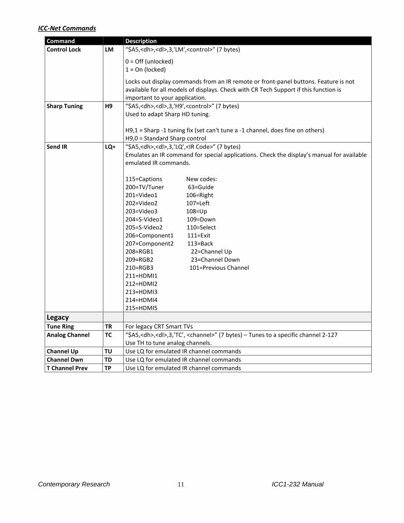
ICC-Net Commands
Command Description
Control Lock LM “$A5,<dh>,<dl>,3,'LM',<control>” (7 bytes)
0 = Off (unlocked) 1 = On (locked)
Locks out display commands from an IR remote or front-panel buttons. Feature is not available for all models of displays. Check with CR Tech Support if this function is important to your application.
Sharp Tuning H9 “$A5,<dh>,<dl>,3,'H9',<control>” (7 bytes) Used to adapt Sharp HD tuning. H9,1 = Sharp -1 tuning fix (set can't tune a -1 channel, does fine on others) H9,0 = Standard Sharp control
Send IR LQ= “$A5,<dh>,<dl>,3,’LQ’,<IR Code>” (7 bytes) Emulates an IR command for special applications. Check the display’s manual for available emulated IR commands. 115=Captions New codes: 200=TV/Tuner 63=Guide 201=Video1 106=Right 202=Video2 107=Left 203=Video3 108=Up 204=S-Video1 109=Down 205=S-Video2 110=Select 206=Component1 111=Exit 207=Component2 113=Back 208=RGB1 22=Channel Up 209=RGB2 23=Channel Down 210=RGB3 101=Previous Channel 211=HDMI1 212=HDMI2 213=HDMI3 214=HDMI4 215=HDMI5
Legacy
Tune Ring TR For legacy CRT Smart TVs
Analog Channel TC “$A5,<dh>,<dl>,3,’TC’, <channel>” (7 bytes) – Tunes to a specific channel 2-127 Use TH to tune analog channels.
Channel Up TU Use LQ for emulated IR channel commands
Channel Dwn TD Use LQ for emulated IR channel commands
T Channel Prev TP Use LQ for emulated IR channel commands

Contemporary Research 12 ICC1-232 Manual
Safety Instructions and Warranty
Read before operating equipment.
• Cleaning - Unplug this product from the wall outlet before cleaning. Do not use liquid cleaners or aerosol cleaners. Use a damp cloth for cleaning.
• Power Sources - Use supplied or equivalent UL/CSA approved low voltage DC plug-in transformer.
• Outdoor Antenna Grounding - If you connect an outside antenna or cable system to the product, be sure the antenna or cable system is grounded so as to provide some protection against voltage surges and built-up static charges. Section 810 of the National Electrical Code, ANSI/NFPA No. 70, provides information with respect to proper grounding of the mast and supporting structure, grounding of the lead-in wire to an antenna discharge unit, size of grounding conductors, location of antenna discharge unit, connection to grounding electrodes, and requirements for the grounding electrode.
• Lightning - Avoid installation or reconfiguration of wiring during lightning activity.
Power Lines - Do not locate an outside antenna system near overhead power lines or other electric light or power circuits or where it can fall into such power lines or circuits. When installing an outside antenna system, refrain from touching such power lines or circuits, as contact with them might be fatal.
• Overloading - Do not overload wall outlets and extension cords as this can result in a risk of fire or electric shock.
• Object and Liquid Entry - Never push objects of any kind into this product through openings as they may touch dangerous voltage points or short out parts, resulting in a fire or electric shock. Never spill liquid of any kind on the product. Servicing - Do not attempt to service this product yourself as opening or removing covers may expose you to dangerous voltage or other hazards. Refer all servicing to qualified service personnel.
• Damage Requiring Service - Unplug this product from the wall outlet and refer servicing to qualified service personnel under the following conditions:
• When the power supply cord or plug is damaged.
• If liquid spills or objects fall into the product.
• If the product is exposed to rain or water.
• If the product does not operate normally by following the operating instructions. Adjust only those controls that are covered by the operating instructions. An improper adjustment of other controls may result in damage and will often require extensive work by a qualified technician to restore the product to its normal operation.
• If the video product is dropped or the cabinet is damaged.
• When the video product exhibits a distinct change in performance, this indicates a need for service. * Note to CATV system installer: This reminder is provided to call CATV system installer's attention to Article 820-40 of the National Electrical Code (Section 54 of Canadian Electrical Code, Part I), that provides guidelines for proper grounding and, in particular, specifies that the cable ground shall be connected to the grounding system of the building as close to the point of cable entry as possible.

Contemporary Research 13 ICC1-232 Manual
Warranty and Return Policy Warranty: Three (3) year limited warranty on all parts and labor for Contemporary Research manufactured products. Contemporary Research warrants its
manufactured products against defects in materials and workmanship for a period of three years from the day of purchase by authorized dealer. If
Contemporary Research receives notice of such defects during the warranty period; Contemporary Research, at its option, will repair or replace products
that prove to be defective.
Exclusions: The above warranty shall not apply to defects resulting from improper or inadequate maintenance by the customer, customers applied
software or interfacing, unauthorized modifications or misuse, mishandling, operation outside the normal environmental specifications for the product,
use of the incorrect, modified or extended power supply, acts of God, weather, or improper site operation and maintenance. Please note Contemporary
Research SSV-DX Display Express PC product carries a six month limited warranty.
Product Service: Contemporary Research will test, repair, or replace the product or products without charge if the unit is under warranty. If the product is
out of warranty, Contemporary Research will test, and then repair the product or products. The parts and labor charge will be estimated by a technician
and confirmed by the customer prior to repair. All components must be returned for testing as a complete unit. Contemporary Research will not accept
responsibility for shipment after it has left the premises.
Technical Support: Contemporary Research technicians will determine and discuss with the customer the criteria for repair and/or replacement.
Contemporary Research Technical Support can be contacted through one of the following resources: e-mail support at [email protected] or phone at:
972-931-2728
Return Material Authorization (RMA) Number: Before returning a product for repair or replacement, request an RMA from Contemporary Research’s
technical support. Provide tech support with a return phone number, e-mail address, shipping address, product serial numbers and original purchase order
number. Describe the reason for repairs or returns as well as the date of purchase. See the General RMA Terms and Procedures section for more
information. RMA’s are valid for 30 days and will be issued to authorized Contemporary Research dealers only. End users must return products through
authorized Contemporary Research dealers. Include the assigned RMA number in all correspondence with Contemporary Research. Write the assigned
RMA number clearly on the shipping label of the box when returning the product. All products returned for credit are subject to a restocking charge
without exception.
Voided Warranty: The warranty does not apply if the original serial number has been removed or if the product has been disassembled or damaged
through misuse, accident, acts of God, weather, modifications, use of incorrect, modified or extended power supply, or unauthorized repair.
Shipping and Handling: Contemporary Research will not pay for inbound shipping transportation or insurance charges or accept any responsibility for laws
and ordinances from inbound transit. Contemporary Research will pay for outbound shipping, transportation, and insurance charges for all items under
warranty, but will not assume responsibility for loss and/or damage by the outbound freight carrier. If the return shipment appears damaged, retain the
original boxes and packing material for inspection by the carrier. Contact your carrier immediately.
Products not under Warranty: Payment arrangements are required before outbound shipment for all out of warranty products.
General RMA Terms and Procedures: RMA’s are valid for 30 days and will be issued only to authorized active Contemporary Research dealers only.
• End users must return products through authorized Contemporary Research dealers. End users may be eligible for a RMA at the discretion of CR Technical Support.
• Before a defective product can be authorized to send in for repair, it must first go through the troubleshooting process with a member of the Contemporary Research Technical Support team.
• Products authorized for repair must have a valid RMA (Return Material Authorization) number. • Contemporary Research Technical Support will approve the issue of an RMA number. • An RMA number is to be included in all correspondence with Contemporary Research. • The RMA number must appear clearly on the shipping label when the product is returned. • A packing slip must be included on the inside of the box with the RMA number listed and reason for RMA return. • Products received at Contemporary Research that do not have a valid RMA number clearly marked on the outside of the shipping container may be
refused and returned to sender. • Boxes showing external damage will be refused and sent back to the sender regardless of the clearly marked RMA number and will remain the
responsibility of the sender. Advanced Replacement Policies: For Contemporary Research manufactured products, advance replacement will be provided for “out-of-the-box” failures up to thirty (30) days after the initial shipment of products.
Shipments of equipment that are refused upon attempted delivery, for any reason, are subject to restocking charges.