product guide led lamps - mansunhk.com · product guide led lamps 2011-3. ... 2 * d: white (color...
TRANSCRIPT

h t t p : / / w w w . s e m i c o n . t o s h i b a . c o . j p / e n gS E M I C O N D U C T O R
PRODUCT GUIDE
LED Lamps
2011-3

High-Brightness LED Lamps
Overview of Toshiba’s Visible LED Lamp Family 31. New Product Digest 4 1. High-Luminous-Flux White LED Lamps for General Lighting (See-Through Type): TL19W01 Series ..............................................4 2. High-Brightness InGaN LED Lamps in PLCC-4 TL ✽F1108, TL ✽F1109 Series..............................................................................4 3. 3-Color LED Lamps (See-Through Type) TL0 ✽C3 Series...............................................................................................................4 4. Small High-Brightness LED Lamps for Indicator Applications (See-Through Type) TL ✽ ✽1034 Series ..........................................5 5. High-Brightness LED Lamps in Mini PLCC and PLCC-4 TL ✽M1060, TL ✽M1108 Series ..............................................................5
2. Overview 6 1. Features ............................................................................................................................................................................................6 2. Applications.......................................................................................................................................................................................6 3. Advantages of Four-Element High-Brightness LED Lamps ..............................................................................................................7 4. Colors of Four-Element High-Brightness LED Lamps.......................................................................................................................8 5. Colors and Materials .........................................................................................................................................................................8 6. Luminous Intensity and Flux Classifications .....................................................................................................................................9 7. Lens Colors.......................................................................................................................................................................................9 8. General Characteristics ....................................................................................................................................................................9
3. SMD LEDs 10 1. 1608 Package (See-Through Type) TL ✽ ✽1034(T22.....................................................................................................................10 2. 1608 Package (ESC Type) TL ✽H1032(T14, F),TL ✽H1032(T15, F).............................................................................................12 3. 1608 Package (Surface-Mount Type) TL ✽ ✽1008A(T04),TL ✽ ✽1008A(T05) ................................................................................14 4. 2125 Package TL ✽ ✽1002A(T02)..................................................................................................................................................16 5. Mini PLCC Package TL ✽M1060(T18),TL ✽F1060(T18),TL ✽D1060(T18).....................................................................................18 6. PLCC Packages TL ✽ ✽ 1108(T11),TL ✽ ✽1109(T11),TL ✽ ✽1100(T11) ........................................................................................20 7. PLCC Packages TL ✽ H1106(T11).................................................................................................................................................24 8. High-Flux White LED Lamps for General Lighting (See-Through Type): TL19W01- ✽(T32.............................................................26 9. φ3.6-mm Lens-top Package TL ✽M1050(T20), TL ✽H1050(T20), TL ✽F1050(T20), TL ✽D1050(T20)............................................28 10. 3.6 x 4.4 mm Oval Lens-top Package TL ✽M1052(T20), TL ✽H1052(T20), TL ✽F1052(T20), TL ✽D1052(T20).............................30
4. Through-Hole LEDs 33 1. Electrical and Optical Characteristics ............................................................................................................................................33 2. Package Selection Guide................................................................................................................................................................33 3. High-Brightness Red LED Lamps ...................................................................................................................................................34 4. High-Brightness Orange LED Lamps..............................................................................................................................................36 5. High-Brightness Yellow LED Lamps................................................................................................................................................38 6. High-Brightness Green LED Lamps................................................................................................................................................40 7. High-Brightness Dual-Color LED Lamps ........................................................................................................................................42 8. Package Dimensions ......................................................................................................................................................................44
5. Packing Specifications 46 1. Through-Hole LEDs ........................................................................................................................................................................46 2. SMD LEDs ......................................................................................................................................................................................48
6 . Handling Precautions 50 1. Through-hole LEDs.....................................................................................................................................................................50 1-1 Mounting on a Printed Circuit Board (PCB) ..............................................................................................................................50 1-2 Mounting Precautions ...............................................................................................................................................................50 1-3 Four-Element LEDs ..................................................................................................................................................................50 1-4 Electrostatic Discharge .............................................................................................................................................................50 1-5 Applications ..............................................................................................................................................................................50 2. SMD LEDs ....................................................................................................................................................................................51 2-1 Soldering Conditions.................................................................................................................................................................51 2-2 Mounting Precautions ...............................................................................................................................................................52 2-3 Moisture-Proof Packing.............................................................................................................................................................52 2-4 Electrostatic Discharge .............................................................................................................................................................52 2-5 Applications ..............................................................................................................................................................................52 2-6 Four-Element LEDs ..................................................................................................................................................................52
7. Design Considerations 53
8. Product Index 54
For other LED product guides such as the LED Lamps Application Guide, please visit the Toshiba Web site athttp://www.semicon.toshiba.co.jp/eng
2

* D: White (Color temp. = 6500 K)N: White (Color temp. = 5000 K)W: White (Color temp. = 4000 K)WW: White (Color temp. = 3500 K)L: White (Color temp. = 3000 K)
(F)TL✽ ✽✽
Toshiba LED
Color symbol
Two-digit package number
(T , F)TL
TL (T )
Toshiba LED
Revision code
Tape specification
Color symbol
Part number
Toshiba LED
Tape specification
Color symbol
Part number
Toshiba LED
Color symbol
Tape specification
Two-digit package number
Part number suffix
Color temperature*
(TTL
Toshiba LED
C: Multi-color LED
Tape specification
Two-digit package number
(TTL
Note
Note
C
Number of colors
Part number suffix
● Overview of Toshiba’s Visible LED Lamp Family ●Visible LED Lamp Family
Part Number Format
High-BrightnessThrough-Hole Type
▼High-Luminous-Flux LEDs
▼Multi-Color Type
▼Through-Hole Type
▼SMD Type
Example: TLRME68TG(F)- High-brightness TLRME Series- Transparent lens- Part number: 68- Can be mounted flush on a PCB.
Example: TLYK1100C(T11)- High-brightness TLYK Series- Tape and reel: T11- Part number: 1100C
Example: TLRMH1032(T14,F)- High-brightness TLRMH Series - Tape and reel: T14- Part number: 1032
Example: TL19W01-D(T32- See-through high-flux white LED Series- Subfamily: 19- Type: 01- Tape and reel: T32
Example: TL03C3-M(T28- Multi-color LED Series- Part number: 03- 3-color LED- Tape and reel: T28
● Package size : 1.6 x 0.8 mm
2.0 x 1.25 mm
2.2 x 1.4 mm
3.5 x 2.8 mm (Flat-top type)
3.5 x 2.9 mm (Flat-top type)
3.1 x 2.9 mm
3.1 x 3.8 mm
5.2 x 5.2 mm (φ 3.6-mm lens-top type)
5.2 x 5.2 mm (3.6 x 4.4-mm oval lens-top type)
■ InGaA P • TL✽K Series • TL✽H Series • TL✽E Series • TL✽U Series
SMD Type ■ InGaA P • TL✽M Series • TL✽K Series • TL✽H Series • TL✽E Series • TL✽F Series • TL✽V Series • TL✽U Series■ GaN • TL✽A1100 Series
■ InGaN • TL✽F Series • TL✽D Series • TL19W Series • TL0✽C3 Series
Note: [[G]]/RoHS COMPATIBLEPlease contact your TOSHIBA sales representative for details as to environmental matters such as the RoHS compatibility of Product.The RoHS is the Directive 2002/95/EC of the European Parliament and of the Council of 27 January 2003 on the restriction of the use of certain hazardous substances in electrical and electronic equipment.
● Four-element (InGaA P) LED lamps ranging from the TL✽K Series, which offers the brightest luminous intensity level in Toshiba LED lamps, to the TL✽U Series, which is for general-purpose applications.
● Package: φ5-mm, φ3-mm, oval and arched lenses● For φ5-mm packages, LED lamps with and without standoffs are available.
(Suffix P in the part number indicates an LED lamp without standoffs.)
Partnumber:
The part number of the through-hole type consists of the following groups of alphanumeric codes.
Partnumber:
TL✽H1032 Series
✽ Lens type T: Transparent C: Colored, transparent D: Colored, diffusing M: Milky white, diffusing✽✽ P indicates LEDs without standoffs (for φ5-mm packages only). G indicates LEDs that can be mounted flush on a PCB.
Partnumber:
The part number of the SMD type consists of the following fifth groups of alphanumeric codes.
Partnumber:
Partnumber:
3

1. New Product Digest
The specs shown above are based on the latest information available as of March 2011 and subject to change. Ask your local Toshiba sales representative for up-to-date information.
Chromaticity Ranks0.35
0.3
0.25
0.2
0.15
Cy
Cx
0.15 0.2 0.25 0.3 0.35
16
1
10 11 12
7 8 9
17 18
13 14 15
4 5 6
2 3
● 1-W type LEDs with up to 120-lm/W efficiencies (as of October 2010)● Industry's thinnest package for 1-W type white LEDs (as of October 2010)
Package dimensions: 3.1 (L) x 3.8 (W) x 0.65 (H) mm● Wide viewing angle: 130 to 140° (typ.)● Color variations: 6500 to 3000 K (as per the ANSI C78.377 standard)● LEDs with high color-rendering performance close to natural light are also offered.
High-efficiency and physically small high-flux white LEDs housed in a newly developed package
Full-color LED lamps that incorporate red, blue and green LED chips in a new package
● Small and thin Package dimensions: 3.1 (L) x 2.9 (W) x 0.6 (H) mm● Operating temperature: Topr = –40 to 85˚C,
Storage temperature: Tstg = –40 to 100˚C
Characteristic
Part Number Zener Diode Part Number Zener DiodeYes TL04C4-M(T28 No
Symbol Test Conditions Min Typ. Max Unit
IVRed: IF = 20 mA, Green: IF = 20 mA
Blue: IF = 20 mA
Red: IF = 20 mAGreen: IF = 20 mABlue: IF = 20 mA
(1000)
–––
1700
624525470
(2500)
–––
mcd
nmλdDominant Wavelength
Luminous Intensity(3 LED chips on)
TL19W01-D(T32TL19W01-N(T32TL19W01-W(T32TL19W01-WW(T32TL19W01-L(T32TL19W01-NH1(T32TL19W01-WH1(T32TL19W01-WWH1(32TL19W01-LH1(T32TL19W01-NH2(T32TL19W01-LH2(T32
65005000400035003000500040003500300050003000
110120110100100959085859080
0.313/0.3290.345/0.3550.382/0.3800.407/0.3920.434/0.4030.345/0.3550.382/0.3800.407/0.3920.434/0.4030.345/0.3550.434/0.403
6565656570858585859292
110120110100100959085859080
3003.33003.33003.33003.33003.33003.3
3003.33003.33003.33003.33003.3
Color temperature (K)Part NumberType
High efficiency
Medium colorrendering
(Ra85)
High color rendering(Ra92)
Luminous Flux (lm) Cx/Cy Forward Voltage(V)RaEfficiency (lm/W) Forward current(mA)
Typical Chromaticity CoordinatesCx Cy
TLWF1108(T11TLWNF1108(T11TLWLF1108(T11TLWF1109(T11*TLWNF1109(T11*TLWLF1109(T11*TLBF1108(T11TLEGF1108(T11
White (6500 K)White (5000 K)White (3000 K)White (6500 K)White (5000 K)White (3000 K)
BlueGreen
3200320025003200320025005602000
0.310.3450.440.310.3450.44
––
0.30.350.40.3
0.350.4––
––––––
470528
3.53.53.53.53.53.53.53.5
Part Number Color Typical LuminousIntensity Iv (mcd)
Typical Dominant Wavelength, λd (nm)
Typ. VoltageVF (V)
1 High-Luminous-Flux White LED Lamps for General Lighting (See-Through Type): TL19W01 Series
Light sources for general lighting
3 3-Color LED Lamps (See-Through Type): TL0✽C3 Series
Amusement equipment, small and thin products, etc.
▼Features ▼Applications
▼Electrical and Optical Characteristics (Ta = 25˚C)
▼Features
LED lamps in the Toshiba PLCC-4 package are now available in new colors.
● PLCC-4 package: 3.5 (L) x 2.9 (W) x 1.9 (H) mm● Color variations: Five colors — White (6500 K, 5000 K, 3000 K), blue, green● The heat-resistant casing provides support for an extended operating temperature range.
Operating temperature: Topr = –40 to 100˚C, Storage temperature: Tstg = –40 to 100˚C
2 High-Brightness InGaN LED Lamps in PLCC-4: TL✽F1108, TL✽F1109 Series
▼Features
▼Electrical and Optical Characteristics (Ta = 25˚C)
▼Optical and Electrical Characteristics (IF = 40 mA, Ta = 25˚C)
▼Product Lineup
▼Applications
Automotive interiors, general lighting,home appliances, various backlighting sources
* With Zener diode
▼Applications
TL03C3-M(T28
Under development
* All values are typical.
4

5
4
The TLxx1034 is a small high-brightness LED series housed in Toshiba's newly developed see-through package. It helps to improve the brightness and reduce the power consumption of various indicators and backlight sources.
● Package dimensions Mini PLCC: 2.2 (L) x 1.4 (W) x 1.3 (H) mm PLCC-4: 3.5 (L) x 2.9 (W) x 1.9 (H) mm● Color variations: red, orange, yellow● The heat-resistant casing provides support for an extended operating temperature range. Operating temperature: Topr = –40 to 100˚C, Storage temperature: Tstg = –40 to 100˚C
The TLxxM1060 and TLxM1108 Series incorporate a newly developed InGaAlP high-brightness LED chip. They are suitable for a wide range of consumer and automotive applications and help to reduce the size and power consumption of end products.
Small High-Brightness LED Lamps for Indicator Applications (See-Through Type): TL✽✽1034 Series
● Package● Suitable for space-saving.Package dimensions: 1.6 (L) x 0.8 (W) x 0.4 (H) mm
● Color variations12 LED colors: Three red, one orange, two yellow, four green, one blue and one white LEDsGreen LEDs are also available in the high-brightness H Series.
● Wide view angle ideal for indicator and backlight applications
▼Features
Indicator light sources for home appliances, information equipment, car audio systems, etc.
▼Applications
▼Absolute Maximum Ratings (Ta = 25˚C)
▼Features
Automotive interiors, home appliances, various backlighting sources
▼Applications
High-Brightness LED Lamps in Mini PLCC and PLCC-4: TL✽M1060, TL✽M1108 Series
▼Electrical and Optical Characteristics (Typical, Ta = 25°C)TL✽V, ✽D Series (IF = 5 mA)
Luminous IntensityIV (mcd)
Dominant Wavelength,λd (nm)Part Number
TLWD1034
Color
White 100
Forward VoltageVF (V)
TLRV1034TLRMV1034TLSV1034TLOV1034TLYV1034TLPYV1034TLGV1034TLFGV1034TLPGV1034TLEGD1034TLBD1034
152030382523148
3.57020
2.9
1.81.82.02.02.02.02.02.02.02.92.9
Chromaticity CoordinatesCx=0.31Cy=0.30
630626613605587580571565561528470
RedRedRed
OrangeYellow
Pure YellowGreenGreen
Pure greenGreenBlue
TLGH Series (IF = 20 mA)Luminous Intensity
IV (mcd)Dominant Wavelength,
λd (nm)Part Number ColorForward Voltage
VF (V)TLGH1034TLFGH1034TLPGH1034
704020
2.12.12.1
571565561
GreenGreen
Pure green
▼Electrical and Optical Characteristics(Typical, Ta = 25°C)TL✽M1060 Series (IF = 20 mA)
Luminous IntensityIV (mcd)
Dominant Wavelength,λd (nm)Part Number Color
Forward VoltageVF (V)
TLRM1060TLRMM1060TLSM1060TLOM1060TLYM1060
350450650650600
2.12.12.12.22.2
630626613605590
RedRedRed
OrangeYellow
TL✽M1108 Series (IF = 50 mA)Luminous Intensity
IV (mcd)Dominant Wavelength,
λd (nm)Part Number ColorForward Voltage
VF (V)
TLRM1108TLRMM1108TLSM1108TLOM1108TLYM1108
13001600240025002200
2.52.52.5
2.552.55
630626613605590
RedRedRed
OrangeYellow
Rating
TLGH Series
2515Forward CurrentReverse VoltageOperating TemperatureStorage Temperature
5–40 to 100–40 to 100
TL✽V,TL✽D Series
Characteristic
IFVR
Topr
Tstg
mAV˚C˚C
Symbol Unit
▼Absolute Maximum Ratings (Ta = 25˚C)Rating
TL✽M1108 Series
70203
50125
Forward CurrentAllowable Power DissipationReverse VoltageOperating TemperatureStorage Temperature
4–40 to 100–40 to 100
TL✽M1060 Series
Characteristic
IFPD
VR
Topr
Tstg
mAmWV˚C˚C
Symbol Unit
TL✽M1108 SeriesTL✽M1060 Series
TLWD1034Except TLWD1034
5

2. Overview
Message board Safety indicator
Flat-panel TVsHome and cellular phones LED billboards
AV equipment(karaoke machine, etc.)
Digital cameras Accessories on dashboard
Message board
Instrumental cluster
Traffic signal Amusement equipmentHMSL(High Mounted Stop Lamp)
● 9 colors: 3 reds, 1 orange, 2 yellows, 3 greens
● High-brightness LEDs are available for outdoor applications.
● Various packages allow customers to select the LED whose viewing angle best meets the requirements for their applications.
▼Through-Hole Type
▼Through-Hole Type
▼SMD Type
▼SMD Type● Wide range of packages for mobile and automotive applications
● Variety of colors such as white, blue and green
● Reflow-solderable
Toshiba’s LED lamps are available in a wide range of brightness, colors and package types. Please select the appropriate products for your applications.
1 Features
2 Applications
6

3 Advantages of Four-Element High-Brightness LED Lamps
▼What is a Four-Element LED?
● Excellent visibility: Usable in daylight applications. Operating status can be read even from a distance.
● Low power consumption: Power consumption can be reduced since high brightness is achieved at low current.
● Low component count: The number of LEDs used for LCD backlighting can be reduced.
Thus, component assembly cost can be also saved.
● High reliability: The service life can be prolonged due to reduced forward current.
▼Advantages of High-Brightness LEDs
▼Large Market Size of Four-Element LEDs
A four-element LED is a compound semiconductor device made from four elements: In, Ga, A , and P. The same material and crystal growth
method can be used in manufacture of high-brightness LEDs from green to red.
Four-element LED products
Lu
min
ou
s In
ten
sity
TL✽M SeriesSMD type
Market Size
■ Ultra-high brightness
■ Super-high brightness
■ Low-power/general-purpose LEDs
■ High brightness
■ Low-end
High brightness
High reliabilityLow power consumption
TL✽K SeriesSMD type/Through-hole type
TL✽F SeriesSMD type
TL✽V SeriesSMD type
TL✽E SeriesSMD typeThrough-hole type
TL✽U SeriesSMD typeThrough-hole type
TL✽H SeriesSMD type/Through-hole type
Traffic andpedestriansignals
HMSL*/ Automotiveinstrument clusters
Electronic bulletin boards
Home appliances / PCs /Audiovisual equipment
Mobile devices
*HMSL: High-Mounted Stop Lamp
Four-element LEDs
(InGaA P LEDs)
7

2. Overview
TLPGE✽ ✽
TLFGE✽ ✽
TLGE✽ ✽
TLPYE✽ ✽
TLOE✽ ✽
TLOH✽ ✽
TLYE✽ ✽
TLYH✽ ✽
TLYK✽ ✽TLOK✽ ✽
TLRMK✽ ✽
TLRK✽ ✽
TLRE✽ ✽
TLRH✽ ✽
TLRME✽ ✽
TLRMH✽ ✽
TLSE✽ ✽
TLSH
TLSK✽ ✽
558 nm 571 nm 587 nm580 nm 605 nm 613 nm565 nm 626 nm 630 nmλdOrangeGreen Yellow Red
1.0
0.8
0.6
0.4
0.2
0500400300 600 700
Wavelength, λ (nm)
TLPG ✽
TLFG ✽
TLPY ✽
TLAU
TLBATLBD
TLG ✽
TLY ✽
TLO ✽
TLRM ✽ / TLSU
TLSM / SK / SH / SE / SF / SV
TLR ✽TLEG ✽
Rel
ativ
e Lu
min
ous
Inte
nsity
➝ H
igh
Low
➝
Rel
ativ
e Lu
min
ous
Inte
nsity
Note: For details, refer to the relevant technical datasheets.
Note: For details, refer to the relevant technical datasheets.
Colors of Four-Element High-Brightness LED Lamps
▼Typical Light Emitting Spectrum
Color
Red
Orange
Amber
Yellow
Green
Blue
InGaA P
InGaA P
InGaA P
InGaA P
InGaA P
InGaA P
InGaA P
InGaA P
InGaA P
InGaA P
InGaA P
InGaA P
InGaN
InGaN
GaN
644
636
636
623
612
596
592
590
583
574
568
562
523
468
428
630
626
623
613
605
592
590
587
580
571
565
558
528
470
465
RM/RK/RH/RE/RF/RU
RMM/RMK/RMH/RME/RMF/RMV
SU
SM/SK/SH/SE/SF/SV
OM/OK/OH/OE/OF/OV/OU
AU
YM/YK
YH/YE/YF/YV/YU
PYE/PYF
GH/GE/GF/GV/GU
FGH/FGE/FGF
PGH/PGE/PGF/PGV/PGU
EGD
BD
BA
MaterialPeak Emission λp (nm)
Color SymbolDominant λd (nm)
Wavelength (typ.)@IF = 20 mA
4 Colors of Four-Element High-Brightness LED Lamps
5 Colors and Materials
Toshiba offers a wide variety of LEDs to meet your diverse needs.The following shows Toshiba’s offerings of high-brightness LEDs: K, H and E Series.
8

This example indicates the TLYH16TP binned at S and T. Generally, binned LEDs can be ordered at two adjacent bins.
TLYH16TP ( ST, F )
Part number
Note
Luminous intensity bin
0°
90˚ 90°
2θ1/2
10.50
θ
Relative luminous intensity
Viewing angle
7 Lens Colors
TL✽✽1032 / 1034 / 1060 / 1106 / 1108 / 1109 / 1100 SeriesSome of the TL✽✽1050/1052 series
TL19W Series
Through-Hole Type / SMD Type
Colored transparent and colored diffused lenses are of the same color as the emitted light.
Tolerance: ±10%
▼Part Number Format for the Through-Hole Type
ABCDEFGHJKLM
NPQRSTUVWXY
JA1JA2KA1KA2LA1LA2MA1MA2NA1NA2PA1PA2QA1QA2
4.0 to 6.35.0 to 8.06.3 to 10
8.0 to 12.510 to 16
12.5 to 2016 to 2520 to 3225 to 4032 to 5040 to 6350 to 80
63 to 10080 to 125
JA
KA
LA
MA
NA
PA
QA
RA1RA2SA1SA2TA1TA2UA1UA2VA1VA2WA1WA2
RA
SA
TA
UA
VA
WA
100 to 160125 to 200160 to 250200 to 320250 to 400320 to 500400 to 630500 to 800
630 to 1000800 to 1250
1000 to 16001250 to 2000
0.09 to 0.230.15 to 0.410.27 to 0.740.48 to 1.290.85 to 2.31.53 to 4.142.72 to 7.364.76 to 12.9
8.5 to 2315.3 to 41.427.2 to 73.647.6 to 129
85 to 230153 to 414272 to 736
476 to 1,290850 to 2,300
1,530 to 4,1402,720 to 7,3604,760 to 12,9008,500 to 23,00015,300 to 41,40027,200 to 73,600
B06B07B08B09
B10B11B12B13
Bin60 to 7070 to 8080 to 9090 to 100
100 to 110110 to 120120 to 130130 to 140
Bin BinLuminous Intensity (mcd) Luminous Intensity (mcd)
Bin BinLuminous Intensity (mcd) Luminous Intensity (mcd)
Appearance
Transparent Colorless diffused Colored transparent Colored diffusedLens Color
Bin Luminous Flux (lm)Luminous Flux (lm)
Example:
6 Luminous Intensity and Flux Classifications
8 General Characteristics
· For the available luminous intensity bins, contact your nearest Toshiba representative.Note: [[G]]/RoHS COMPATIBLE
Please contact your TOSHIBA sales representative for details as to environmental matters such as the RoHS compatibility of Product.The RoHS is the Directive 2002/95/EC of the European Parliament and of the Council of 27 January 2003 on the restriction of the use of certain hazardous substances in electrical and electronic equipment.
▼Absolute Maximum Ratings
▼Viewing Angle
▼Luminous Intensity
▼Temperature Dependence
This parameter indicates the ratio of the LED’s luminous intensity to its axial luminous intensity (= 100%) as viewed from an angle of θ with respect to the axis of the light source. The angle at which luminous intensity is exactly 50% of the axial luminous intensity is called the half-value angle, θ 1/2. The total half-value angle on both sides of the axis is expressed as 2 θ 1/2.
The absolute maximum ratings of a semiconductor device are a set of specified parameter values that must not be exceeded during operation, even for an instant. Circuit designers need to be fully aware of the importance of absolute maximum ratings.
Luminous intensity is equal to the amount of luminous flux emitted into a solid angle at a defined angular orientation from the light source. The measurement unit for luminous intensity is mcd. A narrow-viewing-angle LED provides a high luminous intensity.
The light output changes according to the ambient temperature.
9

3. SMD LEDs
1 2
0.8±
0.1
0.4±
0.1
0.6
(0.1)
1.6±0.1
0.8 0.3 0.3
1. Cathode2. AnodeTolerance: ±0.05( ): Typical value
Ta = 25˚C
Ta = 25˚C
90˚1.00.80.60.40.20
90˚
0˚
30˚40˚
50˚50˚
40˚
10˚ 20˚20˚ 10˚
60˚
70˚
80˚80˚
70˚
60˚
30˚
TL✽V, TL✽H1034
90˚1.00.80.60.40.20
90˚
0˚
30˚40˚
50˚50˚
40˚
10˚ 20˚20˚ 10˚
60˚
70˚
80˚80˚
70˚
60˚
30˚
TL✽VTL✽H
TL✽D1034 TLEGD,TLBDTLWD
TL✽V, TL✽H1034 TL✽VTL✽H
TL✽D1034 TLEGD,TLBDTLWD
Horizontal direction
Vertical direction
0.8 0.6
1.7
0.8
90˚1.00.80.60.40.20
90˚
0˚
30˚40˚
50˚50˚
40˚
10˚ 20˚20˚ 10˚
60˚
70˚
80˚80˚
70˚
60˚
30˚
90˚1.00.80.60.40.20
90˚
0˚
30˚40˚
50˚50˚
40˚
10˚ 20˚20˚ 10˚
60˚
70˚
80˚80˚
70˚
60˚
30˚
1608 Package (See-Through Type): TL✽✽1034(T221
● Suitable for space-saving● Package dimensions: 1.6 (L) x 0.8 (W) x 0.4 (H) mm
● Color variations● 12 LED colors: Three red, one orange, two yellow, four green, one blue and one white LEDs● Green LEDs are also available in the high-brightness H Series.
● Wide view angle ideal for indicator and backlight applications
▼Features
▼Tape and Reel Specifications
▼Land Pattern Dimensions for Reference Only
▼Package Dimensions ▼Radiation Patterns
Unit: mm
Unit: mm
For board design considerations, refer to the relevant technical datasheet.
Designation Units Per Reel5000 pcs/reelT22
* See pages 48 and 49 for the reel and tape dimensions.
TLWD1034Except TLWD1034
10

IF –Ta
* Allowable Forward Current vs. Ambient Temperature
30
25
20
15
10
5
00 12010080604020
Allo
wab
le F
orw
ard
Cur
rent
, IF (
mA
)
Ambient Temperature, Ta (°C)
TL✽V, TL✽DTL✽H
▼Absolute Maximum Ratings (Ta = 25˚C)
▼Electrical and Optical Characteristics
For board design considerations, refer to the relevant technical datasheet.
SeriesName Part Number
@Ta = 25˚C
✩: Dry-packed#: For the available luminous intensity bins, contact your nearest Toshiba sales representative.
TL✽V Series(InGaA P)
TL✽H Series(InGaA P)
TL✽D Series(InGaN)
TLRV1034(T22
TLRMV1034(T22
TLSV1034(T22
TLOV1034(T22
TLYV1034(T22
TLPYV1034(T22
TLGV1034(T22
TLFGV1034(T22
TLPGV1034(T22
TLGH1034(T22
TLFGH1034(T22
TLPGH1034(T22
TLEGD1034(T22
TLBD1034(T22
TLWD1034(T22
TL✽V Series(InGaA P)
630
626
613
605
587
580
571
565
561
4
4
10
10
10
10
4
2.5
1.6
15
20
30
38
25
23
14
8
3.5
Red
Red
Red
Orange
Yellow
Pure Yellow
Green
Green
Pure green
Part NumberSeriesNumber Color
Dominant Wavelength,λd(nm)
@IF = 5 mA
Typ. Typ.
50
50
80
80
80
80
50
20
12.5
MaxMin
Luminous IntensityIV (mcd)
@IF = 5 mA#
✩TLRV1034(T22
✩TLRMV1034(T22
✩TLSV1034(T22
✩TLOV1034(T22
✩TLYV1034(T22
✩TLPYV1034(T22
✩TLGV1034(T22
✩TLFGV1034(T22
✩TLPGV1034(T22
1.8
1.8
2.0
2.0
2.0
2.0
2.0
2.0
2.0
140
140
140
140
140
140
140
140
140
Typ. Typ.
Forward VoltageVF (V)
@IF = 5 mA
Viewing Angle2θ1/2 (˚)
15
15
15
15
15
15
15
15
15
25
25
25
15
15
15
–40 to 100
–40 to 100
–40 to 100
–40 to 100
–40 to 100
–40 to 100
–40 to 100
–40 to 100
–40 to 100
–40 to 100
–40 to 100
–40 to 100
–40 to 100
–40 to 100
–40 to 100
–40 to 100
–40 to 100
–40 to 100
–40 to 100
–40 to 100
–40 to 100
–40 to 100
–40 to 100
–40 to 100
–40 to 100
–40 to 100
–40 to 100
–40 to 100
–40 to 100
–40 to 100
31.5
31.5
34.5
34.5
34.5
34.5
34.5
34.5
34.5
62.5
62.5
62.5
51
51
51
5
5
5
5
5
5
5
5
5
5
5
5
5
5
5
@Ta = 25˚C
✩: Dry-packed#: For the available luminous intensity bins, contact your nearest Toshiba sales representative.
TL✽H Series(InGaA P)
571
565
561
40
25
10
70
40
20
Green
Green
Pure green
Part NumberSeriesNumber Color
Dominant Wavelength,λd(nm)
@IF = 20 mA
Typ. Typ.
200
125
50
MaxMin
Luminous IntensityIV (mcd)
@IF = 20 mA#
✩TLGH1034(T22
✩TLFGH1034(T22
✩TLPGH1034(T22
2.1
2.1
2.2
140
140
140
Typ. Typ.
Forward VoltageVF (V)
@IF = 20 mA
Viewing Angle2θ1/2 (˚)
@Ta = 25˚C
✩: Dry-packed♠ : CIE1931 (typical chromaticity coordinate)#: For the available luminous intensity bins, contact your nearest Toshiba sales representative.
TL✽D Series(InGaN)
528
470
♠0.31/0.3
32
8
40
70
20
100
Green
Blue
White
Part NumberSeriesNumber Color
Dominant Wavelength,λd(nm)
@IF = 5 mA
Typ. Typ.
160
40
200
MaxMin
Luminous IntensityIV (mcd)
@IF = 5 mA#
✩TLEGD1034(T22
✩TLBD1034(T22
✩TLWD1034(T22
2.9
2.9
2.9
150/150
150/150
130/150
Typ. Typ.
Forward VoltageVF (V)
@IF = 5 mA
Viewing Angle2θ1/2 (˚)
ForwardCurrent (DC)
IF (mA)(*)
ReverseVoltageVR (V)
PowerDissipationPD (mW)
OperatingTemperature
Topr (˚C)
StorageTemperature
Tstg (˚C)
11

3. SMD LEDs
1. Cathode2. AnodeTolerance: ±0.05( ): Typical value
LED chip
Cathode is closer to LED chip.
0.8
2
1
0.3
0.45
0.1
(0.2
)1.
2
1.6
± 0
.1
(0.2
)
0˚ 10˚20˚
30˚40˚
50˚
60˚
70˚
80˚
90˚1.00.80.60.40.20
90˚
80˚
70˚
60˚
50˚
40˚30˚
20˚ 10˚ 0˚ 10˚20˚
30˚40˚
50˚
60˚
70˚
80˚
90˚1.00.80.60.40.20
90˚
80˚
70˚
60˚
50˚
40˚30˚
20˚ 10˚
Ta = 25˚C Ta = 25˚CVertical direction Horizontal direction
2.3
0.7
0.25
0.8
0.3
0.9
▼Land Pattern Dimensions for Reference Only
▼Features
▼Package Dimensions
▼Radiation Patterns
● Package dimensions: 1.6 (L) x 0.8 (W) x 0.45 (H) mm (including lead length)
● Suitable as general-brightness LED replacements to increase brightness or reduce
power consumption.
● Ideal for backlight applications in slim products and automotive interior applications.
▼Tape and Reel Specifications
Unit: mm
For board design considerations, refer to the relevant technical datasheet.
Unit: mm
1608 Package (ESC Type): TL✽H1032(T14, F),TL✽H1032(T15, F)2
T14
T15
* See pages 48 and 49 for the reel and tape dimensions.
4000 pcs/reel
8000 pcs/reel
Units Per ReelDesignation
12

30
25
20
15
10
5
00 12010080604020
IF –Ta
Allo
wab
le F
orw
ard
Cur
rent
, IF (
mA
)
Ambient Temperature, Ta (°C)
* Allowable Forward Current vs. Ambient Temperature
▼Absolute Maximum Ratings (Ta = 25˚C)
▼Electrical and Optical Characteristics
For board design considerations, refer to the relevant technical datasheet.
@Ta = 25˚C
✩: Dry-packed#: For the available luminous intensity bins, contact your nearest Toshiba sales representative.
TL✽H Series(InGaA P)
TLRH1032(T14,F)/(T15,F)
TLRMH1032(T14,F)/(T15,F)
TLSH1032(T14,F)/(T15,F)
TLOH1032(T14,F)/(T15,F)
TLYH1032(T14,F)/(T15,F)
TLGH1032(T14,F)/(T15,F)
TLFGH1032(T14,F)/(T15,F)
TL✽H Series(InGaA P)
630
626
613
605
587
571
565
25
40
63
100
40
25
10
56
85
160
200
100
60
25
Red
Red
Red
Orange
Yellow
Green
Green
125
200
320
500
200
125
50
NA/PA/QA
PA/QA/RA
QA/RA/SA
RA/SA/TA
PA/QA/RA
NA/PA/QA
LA/MA/NA
✩TLRH1032(T14, F)/(T15, F)
✩TLRMH1032(T14, F)/(T15, F)
✩TLSH1032(T14, F)/(T15, F)
✩TLOH1032(T14, F)/(T15, F)
✩TLYH1032(T14, F)/(T15, F)
✩TLGH1032(T14, F)/(T15, F)
✩TLFGH1032(T14, F)/(T15, F)
2.0
2.0
2.0
2.0
2.0
2.1
2.2
135 to 140
135 to 140
135 to 140
135 to 140
135 to 140
135 to 140
135 to 140
25
25
25
25
25
25
25
–40 to 100
–40 to 100
–40 to 100
–40 to 100
–40 to 100
–40 to 100
–40 to 100
–40 to 100
–40 to 100
–40 to 100
–40 to 100
–40 to 100
–40 to 100
–40 to 100
60
60
60
60
60
62.5
62.5
4
4
4
4
4
4
4
SeriesName Part Number
ForwardCurrent (DC)
IF (mA)(*)
ReverseVoltageVR (V)
PowerDissipationPD (mW)
OperatingTemperature
Topr (˚C)
StorageTemperature
Tstg (˚C)
Dominant Wavelength,λd(nm)
@IF = 5 mA
Luminous IntensityIV (mcd)
@IF = 5 mA
Forward VoltageVF (V)
@IF = 5 mA
Viewing Angle2θ1/2 (˚)Part NumberSeries
Number Color
Typ. Typ. MaxMin Typ.Typ.
Available IV bins #
13

3. SMD LEDs
1. Cathode2. AnodeTolerance: ±0.1( ): Typical value
1 2Polarity
LED chip (0.2)
Cathode index
0.8
0.2
1.6
1.1
(1.0)
0.6
0.3
1 2
0.8 0.7 0.8
(0.8
)
Vertical direction Ta = 25˚CTL✽ETL✽U
Ta = 25˚CTL✽ETL✽U
90˚
80˚
70˚
60˚
50˚
40˚30˚
20˚ 10˚ 0 10˚ 20˚30˚
40˚
50˚
60˚
70˚
80˚
90˚0 0.2 0.4 0.6 0.8 1.0
Horizontal direction
90˚
80˚
70˚
60˚
50˚
40˚30˚
20˚ 10˚ 0 10˚ 20˚30˚
40˚
50˚
60˚
70˚
80˚
90˚0 0.2 0.4 0.6 0.8 1.0
▼Land Pattern Dimensions for Reference Only
▼Features
▼Package Dimensions
▼Radiation Patterns
● Package dimensions: 1.6 (L) x 0.8 (W) x 0.6 (H) mm
● Suitable as general-brightness LED replacements to increase brightness or reduce
power consumption.
● Available in T04 tape (4-mm pitch) and T05 tape (2-mm pitch).
Improves the board assembly efficiency.
● Low-profile package (t = 0.6 mm): Suitable for use as backlighting in thin equipment.
▼Tape and Reel Specifications
Unit: mmUnit: mm
1608 Package (Surface-Mount Type): TL✽✽1008A(T04),TL✽✽1008A(T05)3
For board design considerations, refer to the relevant technical datasheet.
T04
T05
* See pages 48 and 49 for the reel and tape dimensions.
4000 pcs/reel
8000 pcs/reel
Units Per ReelDesignation
14

IF –Ta
* Allowable Forward Current vs. Ambient Temperature
Allo
wab
le F
orw
ard
Cur
rent
, IF (
mA
)
Ambient Temperature, Ta (°C)
40
30
20
10
00 20 40 60 80 100
▼Absolute Maximum Ratings (Ta = 25˚C)
TLRE1008A(T04)/(T05)
TLSE1008A(T04)/(T05)
TLOE1008A(T04)/(T05)
TLYE1008A(T04)/(T05)
TLPYE1008A(T04)/(T05)
TLGE1008A(T04)/(T05)
TLFGE1008A(T04)/(T05)
TLPGE1008A(T04)/(T05)
TLSU1008A(T04)/(T05)
TLOU1008A(T04)/(T05)
TLAU1008A(T04)/(T05)
TLYU1008A(T04)/(T05)
TLGU1008A(T04)/(T05)
TLPGU1008A(T04)/(T05)
–40 to 85
–40 to 85
–40 to 85
–40 to 85
–40 to 85
–40 to 85
–40 to 85
–40 to 85
–40 to 85
–40 to 85
–40 to 85
–40 to 85
–40 to 85
–40 to 85
–40 to 100
–40 to 100
–40 to 100
–40 to 100
–40 to 100
–40 to 100
–40 to 100
–40 to 100
–40 to 100
–40 to 100
–40 to 100
–40 to 100
–40 to 100
–40 to 100
60
60
60
60
60
60
60
60
60
62.5
62.5
62.5
62.5
62.5
TL✽U Series(InGaA P)
TL✽E Series(InGaA P)
✩: Dry-packed#: For the available luminous intensity bins, contact your nearest Toshiba sales representative.
For board design considerations, refer to the relevant technical datasheet.
@Ta = 25˚C▼Electrical and Optical Characteristics
644
623
612
590
583
574
568
562
636
612
596
590
574
562
27.2
47.6
47.6
27.2
27.2
27.2
15.3
4.76
27.2
27.2
8.5
8.5
8.5
1.53
70
135
150
105
100
70
40
18
60
78
30
30
30
6
Red
Red
Orange
Yellow
Pure Yellow
Green
Green
Pure green
Red
Orange
Amber
Yellow
Green
Pure green
630
613
605
587
580
571
565
558
623
605
592
587
571
558
L/M/N/P
M/N/P/Q
M/N/P/Q
L/M/N/P
L/M/N/P
L/M/N/P
K/L/M/N
H/J/K/L
L/M/N/P
L/M/N/P
J/K/L/M
J/K/L/M
J/K/L/M
F/G/H/J
✩TLRE1008A(T04)/(T05)
✩TLSE1008A(T04)/(T05)
✩TLOE1008A(T04)/(T05)
✩TLYE1008A(T04)/(T05)
✩TLPYE1008A(T04)/(T05)
✩TLGE1008A(T04)/(T05)
✩TLFGE1008A(T04)/(T05)
✩TLPGE1008A(T04)/(T05)
✩TLSU1008A(T04)/(T05)
✩TLOU1008A(T04)/(T05)
✩TLAU1008A(T04)/(T05)
✩TLYU1008A(T04)/(T05)
✩TLGU1008A(T04)/(T05)
✩TLPGU1008A(T04)/(T05)
1.9
1.9
2.0
2.0
2.0
2.0
2.0
2.1
2.0
2.1
2.1
2.1
2.1
2.1
130 to 135
130 to 135
130 to 135
130 to 135
130 to 135
130 to 135
130 to 135
130 to 135
100 to 110
100 to 110
100 to 110
100 to 110
100 to 110
100 to 110
25
25
25
25
25
25
25
25
25
25
25
25
25
25
4
4
4
4
4
4
4
4
4
4
4
4
4
4
TL✽E Series(InGaA P)
TL✽U Series(InGaA P)
SeriesName Part Number
ForwardCurrent (DC)
IF (mA)(*)
ReverseVoltageVR (V)
PowerDissipationPD (mW)
OperatingTemperature
Topr (˚C)
StorageTemperature
Tstg (˚C)
Typical Emission Wavelength(nm)
@IF = 20 mA
λp λd
Luminous IntensityIV (mcd)
@IF = 20 mA
Forward VoltageVF (V)
@IF = 20 mA
Viewing Angle2θ1/2 (˚)Series
Name ColorPart Number
Min Typ. Typ. Typ.
Available IV bins #
15

3. SMD LEDs
Horizontal direction
0 0.2 0.4 0.6 0.8 1.090˚
80˚
70˚
60˚
50˚
40˚30˚
20˚ 10˚ 0 10˚ 20˚30˚
40˚
50˚
60˚
70˚
80˚
90˚
2
1
Ta = 25˚CTL✽ETL✽U
Ta = 25˚CTL✽ETL✽U
Vertical direction
0 0.2 0.4 0.6 0.8 1.090˚
80˚
70˚
60˚
50˚
40˚30˚
20˚ 10˚ 0 10˚ 20˚30˚
40˚
50˚
60˚
70˚
80˚
90˚
2
1
1 2Polarity
LED chip (0.25)
Cathode index
1.25
0.5
1.4
2.0
(1.28)
1.1
0.4 ± 0.2
1 21. Cathode2. AnodeTolerance: ±0.1( ): Typical value
1.2 1.0 1.2
(1.2
)
▼Land Pattern Dimensions for Reference Only
▼Features
▼Package Dimensions
▼Radiation Patterns
● Package dimensions: 2.0 (L) x 1.25 (W) x 1.1 (H) mm
● High-brightness LEDs
● Suitable as general-brightness LED replacements to increase brightness or reduce
power consumption.
● Low-profile package (t = 1.1 mm): Suitable for use as backlighting in thin equipment.
▼Tape and Reel Specifications
Unit: mmUnit: mm
2125 Package: TL✽✽1002A(T02)4
For board design considerations, refer to the relevant technical datasheet.
T02
* See pages 48 and 49 for the reel and tape dimensions.
3000 pcs/reel
Units Per ReelDesignation
16

IF –Ta
* Allowable Forward Current vs. Ambient Temperature
Allo
wab
le F
orw
ard
Cur
rent
, IF (
mA
)
Ambient Temperature, Ta (°C)
40
30
20
10
00 20 40 60 80 100
▼Absolute Maximum Ratings (Ta = 25˚C)
TLRE1002A(T02)
TLSE1002A(T02)
TLOE1002A(T02)
TLYE1002A(T02)
TLPYE1002A(T02)
TLGE1002A(T02)
TLFGE1002A(T02)
TLPGE1002A(T02)
TLRU1002A(T02)
TLSU1002A(T02)
TLOU1002A(T02)
TLAU1002A(T02)
TLYU1002A(T02)
TLGU1002A(T02)
TLPGU1002A(T02)
25
25
25
25
25
25
25
25
25
25
25
25
25
25
25
4
4
4
4
4
4
4
4
4
4
4
4
4
4
4
–40 to 85
–40 to 85
–40 to 85
–40 to 85
–40 to 85
–40 to 85
–40 to 85
–40 to 85
–40 to 85
–40 to 85
–40 to 85
–40 to 85
–40 to 85
–40 to 85
–40 to 85
–40 to 100
–40 to 100
–40 to 100
–40 to 100
–40 to 100
–40 to 100
–40 to 100
–40 to 100
–40 to 100
–40 to 100
–40 to 100
–40 to 100
–40 to 100
–40 to 100
–40 to 100
TL✽U Series(InGaA P)
TL✽E Series(InGaA P)
✩: Dry-packed#: For the available luminous intensity bins, contact your nearest Toshiba sales representative.
For board design considerations, refer to the relevant technical datasheet.
@Ta = 25˚C▼Electrical and Optical Characteristics
644
623
612
590
583
574
568
562
644
636
612
596
590
574
562
27.2
47.6
47.6
27.2
27.2
27.2
8.5
4.76
4.76
27.2
27.2
8.5
8.5
8.5
1.53
70
140
180
105
70
70
25
18
45
60
78
30
30
30
6
Red
Red
Orange
Yellow
Pure Yellow
Green
Green
Pure green
Red
Red
Orange
Amber
Yellow
Green
Pure green
630
613
605
587
580
571
565
558
630
623
605
592
587
571
558
L/M/N/P
M/N/P/G
M/N/P/G
L/M/N/P
L/M/N/P
L/M/N/P
J/K/L/M
H/J/K/L
H/J/K/L
L/M/N/P
L/M/N/P
J/K/L/M
J/K/L/M
J/K/L/M
F/G/H/J
✩TLRE1002A(T02)
✩TLSE1002A(T02)
✩TLOE1002A(T02)
✩TLYE1002A(T02)
✩TLPYE1002A(T02)
✩TLGE1002A(T02)
✩TLFGE1002A(T02)
✩TLPGE1002A(T02)
✩TLRU1002A(T02)
✩TLSU1002A(T02)
✩TLOU1002A(T02)
✩TLAU1002A(T02)
✩TLYU1002A(T02)
✩TLGU1002A(T02)
✩TLPGU1002A(T02)
1.9
1.9
2.0
2.0
2.0
2.0
2.0
2.1
2.0
2.0
2.1
2.1
2.1
2.1
2.1
130 to 140
130 to 140
130 to 140
130 to 140
130 to 140
130 to 140
130 to 140
130 to 140
120 to 130
120 to 130
120 to 130
120 to 130
120 to 130
120 to 130
120 to 130
TL✽E Series(InGaA P)
TL✽U Series(InGaA P)
60
60
60
60
60
60
60
60
60
60
62.5
62.5
62.5
62.5
62.5
SeriesName Part Number
ForwardCurrent (DC)
IF (mA)(*)
ReverseVoltageVR (V)
PowerDissipationPD (mW)
OperatingTemperature
Topr (˚C)
StorageTemperature
Tstg (˚C)
Typical Emission Wavelength(nm)
@IF = 20 mA
λp λd
Luminous IntensityIV (mcd)
@IF = 20 mA
Forward VoltageVF (V)
@IF = 20 mA
Viewing Angle2θ1/2 (˚)Series
Name ColorPart Number
Min Typ. Typ. Typ.
Available IV bins #
17

3. SMD LEDs
Ta = 25˚CTL✽F1060,TL✽D1060
1. Anode2. CathodeTolerance: ±0.2( ): Typical value
2
1 2
(2.2)
1.4
0.9
Cathode index
0.5
1.3
0.7
0.6
90˚
80˚
70˚
60˚
50˚
40˚30˚
20˚ 10˚ 0 10˚ 20˚30˚
40˚
50˚
60˚
70˚
80˚
90˚0 0.2 0.4 0.6 0.8 1.0
0.8 1.2 0.8
1.0
Ta = 25˚C
90˚1.00.80.60.40.20
90˚
0˚
30˚40˚
50˚50˚
40˚
10˚ 20˚20˚ 10˚
60˚
70˚
80˚80˚
70˚
60˚
30˚
TL✽M1060
▼Land Pattern Dimensions for Reference Only
▼Features
▼Package Dimensions
▼Radiation Pattern
● Package dimensions: 2.2 (L) x 1.4 (W) x 1.3 (H) mm
● The heat-resistant casing provides support for an extended operating temperature range.
• Operating temperature: Topr = –40 to 100˚C
▼Tape and Reel Specifications
Unit: mmUnit: mm
Mini PLCC Package: TL✽M1060(T18),TL✽F1060(T18),TL✽D1060(T18)5
For board design considerations, refer to the relevant technical datasheet.
T18
* See pages 48 and 49 for the reel and tape dimensions.
3000 pcs/reel
Units Per ReelDesignation
18

IF –Ta
* Allowable Forward Current vs. Ambient Temperature
Allo
wab
le F
orw
ard
Cur
rent
, IF (
mA
)
Ambient Temperature, Ta (°C)
0 20 40 60 80 100 120
60
50
40
30
20
10
0
TLBDTLEGDTL✽FTLCBDTLWDTL✽M
▼Absolute Maximum Ratings (Ta = 25˚C)
✩TLRM1060(T18)
✩TLRMM1060(T18)
✩TLSM1060(T18)
✩TLOM1060(T18)
✩TLYM1060(T18)
TLRF1060(T18)
TLSF1060(T18)
TLOF1060(T18)
TLYF1060(T18)
TLPYF1060(T18)
TLGF1060(T18)
TLFGF1060(T18)
TLPGF1060(T18)
TLEGD1060(T18)
TLBD1060(T18)
TLCBD1060(T18)
TLWD1060(T18)
50
50
50
50
50
30
30
30
30
30
30
30
30
30
30
20
20
4
4
4
4
4
15
15
15
15
15
15
15
15
4
4
4
4
–40 to 100
–40 to 100
–40 to 100
–40 to 100
–40 to 100
–40 to 100
–40 to 100
–40 to 100
–40 to 100
–40 to 100
–40 to 100
–40 to 100
–40 to 100
–40 to 100
–40 to 100
–40 to 100
–40 to 100
–40 to 100
–40 to 100
–40 to 100
–40 to 100
–40 to 100
–40 to 100
–40 to 100
–40 to 100
–40 to 100
–40 to 100
–40 to 100
–40 to 100
–40 to 100
–40 to 100
–40 to 100
–40 to 100
–40 to 100
125
125
125
125
125
75
75
75
75
75
75
75
75
120
120
76
76
TL✽D Series(InGaN)
TL✽F Series(InGaA P)
TL✽M Series(InGaA P)
✩: Dry-packed* : IF = 10 mA♠ : CIE1931 (typical chromaticity coordinate)#: For the available luminous intensity bins, contact your nearest Toshiba sales representative.
For board design considerations, refer to the relevant technical datasheet.
@Ta = 25˚C
▼Electrical and Optical Characteristics
TL✽F Series(InGaA P)
TL✽M Series(InGaA P)
TL✽D Series(InGaN)
644
636
623
612
592
644
623
612
590
583
574
568
562
518
468
–
–
160
160
250
250
250
40
100
100
63
40
40
25
10
63
25
40*
40*
350
450
650
650
600
100
200
220
180
100
80
50
20
150
60
90*
90*
Red
Red
Red
Orange
Yellow
Red
Red
Orange
Yellow
Pure yellow
Green
Green
Pure green
Green
Blue
Ice blue
White
630
626
613
605
590
630
613
605
587
580
571
565
558
528
470
♠0.2/0.3*
♠0.31/0.30*
800
800
1250
1250
1250
320
500
500
320
320
320
125
50
320
125
200*
200*
SA/TA/UA
SA/TA/UA
TA/UA/VA
TA/UA/VA
TA/UA/VA
PA/QA/RA/SA
RA/SA/TA
RA/SA/TA
QA/RA/SA
PA/QA/RA/SA
PA/QA/RA/SA
NA/PA/QA
LA/MA/NA
QA/RA/SA
NA/PA/QA
PA/QA/RA
PA/QA/RA
✩TLRM1060(T18)
✩TLRMM1060(T18)
✩TLSM1060(T18)
✩TLOM1060(T18)
✩TLYM1060(T18)
✩TLRF1060(T18)
✩TLSF1060(T18)
✩TLOF1060(T18)
✩TLYF1060(T18)
✩TLPYF1060(T18)
✩TLGF1060(T18)
✩TLFGF1060(T18)
✩TLPGF1060(T18)
✩TLEGD1060(T18)
✩TLBD1060(T18)
✩TLCBD1060(T18)
✩TLWD1060(T18)
2.1
2.1
2.1
2.2
2.2
2.0
2.0
2.0
2.1
2.1
2.1
2.1
2.1
3.3
3.3
3.0*
3.0*
120
120
120
120
120
100
100
100
100
100
100
100
100
110
110
110
110
SeriesName Part Number
ForwardCurrent (DC)
IF (mA)(*)
ReverseVoltageVR (V)
PowerDissipationPD (mW)
OperatingTemperature
Topr (˚C)
StorageTemperature
Tstg (˚C)
Typical Emission Wavelength(nm)
@IF = 20 mA
λp λd
Luminous IntensityIV (mcd)
@IF = 20 mA
Forward VoltageVF (V)
@IF = 20 mA
Viewing Angle2θ1/2 (˚)Series
Name ColorPart Number
Min Typ. Typ. Typ.Max
Available IV bins #
19

3. SMD LEDs
Ta = 25˚C
TL✽✽1100✽ Series
TL✽M1108 Series
TL✽✽1100✽ Series
TL✽M1108 Series
1. Anode2. CathodeTolerance: ±0.2( ): Typical value
1.65 1.15 1.65
2.41
0 0.2 0.4 0.6 0.8 1.090˚
80˚
70˚
60˚
50˚
40˚30˚
20˚ 10˚ 0 10˚ 20˚30˚
40˚
50˚
60˚
70˚
80˚
90˚
3.23.5
0.8
2.8
2.2
1.9
(0.1
)
1 2
1 2
1.1
Cathode index
Polarity
LED chipφ2.4
1. Anode2. Cathode3. Cathode4. CathodeTolerance: ±0.2( ): Typical value
Cathode mark
Anode index
2.9
1.9
(3.5)0.8
2.2
0.7
0.8
(0.1
)
3.2
(1.4)
0.7
1
2
4
3
1.1 1.5 1.1
0.8
0.8
0.7
2.3
▼Land Pattern Dimensions for Reference Only▼Package Dimensions
▼Radiation Pattern
▼Features● Package dimensions: 3.5 (L) x 2.8 (W) x 1.9 (H) mm (TL✽✽1100✽ Series)
3.5 (L) x 2.9 (W) x 1.9 (H) mm (TL✽M1108 Series)
● The heat-resistant casing provides support for extended operating temperature ranges.
• Operating temperature: Topr = –40 to 100˚C TL✽M Series, TL✽K Series, TL✽H Series (green LEDs),
TL✽E Series
• Operating temperature: Topr = –40 to 110˚C TL✽H Series (except green LEDs)
▼Tape and Reel Specifications
Unit: mmUnit: mm
▼InGaA P Series
PLCC Packages: TL✽✽1108(T11),TL✽✽1109(T11),TL✽✽1100(T11)6
For board design considerations, refer to the relevant technical datasheet.
TL✽✽1100✽ TL✽M1108
T11
* See pages 48 and 49 for the reel and tape dimensions.
2000 pcs/reel
Units Per ReelDesignation
20

IF –Ta
* Allowable Forward Current vs. Ambient Temperature
Allo
wab
le F
orw
ard
Cur
rent
, IF
(mA
)
Ambient Temperature, Ta (˚C)
80
60
40
20
00 20 40 60 10080 120
TL✽H(except green LEDs)
TL✽ETL✽H(green LEDs)
TL✽KTL✽M1108
▼Absolute Maximum Ratings (Ta = 25˚C)
TLRM1108(T11)TLRMM1108(T11)TLSM1108(T11)TLOM1108(T11)TLYM1108(T11)TLRK1100C(T11)TLRMK1100C(T11)TLSK1100C(T11)TLOK1100C(T11)TLYK1100C(T11)TLRH1100D(T11)TLRMH1100D(T11)TLSH1100D(T11)TLOH1100D(T11)TLYH1100D(T11)TLGH1100B(T11)TLFGH1100B(T11)TLPGH1100B(T11)TLRE1100D(T11)TLSE1100D(T11)TLOE1100D(T11)TLYE1100D(T11)TLGE1100D(T11)TLFGE1100D(T11)TLPGE1100D(T11)
70707070703030303030707070707040404050505050505050
4444444444444444444444444
–40 to 100–40 to 100–40 to 100–40 to 100–40 to 100–40 to 100–40 to 100–40 to 100–40 to 100–40 to 100–40 to 110–40 to 110–40 to 110–40 to 110–40 to 110–40 to 100–40 to 100–40 to 100–40 to 100–40 to 100–40 to 100–40 to 100–40 to 100–40 to 100–40 to 100
TL✽K Series(InGaA P)
PLCC-2
TL✽M Series(InGaA P)
PLCC-4
✩: Dry-packed#: For the available luminous intensity bins, contact your nearest Toshiba sales representative.
For board design considerations, refer to the relevant technical datasheet.
TL✽E Series(InGaA P)
PLCC-2
TL✽H Series(InGaA P)
PLCC-2
▼Electrical and Optical Characteristics
TL✽M Series(InGaA P)
PLCC-4
TL✽K Series(InGaA P)
PLCC-2
TL✽H Series(InGaA P)
PLCC-2
644636623612592644636623612592644636623612590574568562644623612590574568562
630630
1000100010001001602502501606363
16016010063401640636363402510
130016002400250022003004005005004001501502602702201507035
1202102101801004525
RedRedRed
OrangeYellowRedRedRed
OrangeYellowRedRedRed
OrangeYellowGreenGreen
Pure greenRedRed
OrangeYellowGreenGreen
Pure green
630626613605590630626613605590630626613605587571565558630613605587571565558
32003200500050005000500800
1250125080032050080080050032020080
32050050050032012550
VA/WA/XAVA/WA/XAWA/XA/YAWA/XA/YAWA/XA/YARA/SA/TASA/TA/UATA/UA/VATA/UA/VASA/TA/UAQA/RA/SA
QA/RA/SA/TASA/TA/UASA/TA/UARA/SA/TAQA/RA/SAPA/QA/RAMA/NA/PA
PA/QA/RA/SAQA/RA/SA/TAQA/RA/SA/TAQA/RA/SA/TAPA/QA/RA/SA
NA/PA/QALA/MA/NA
✩TLRM1108(T11)✩TLRMM1108(T11)✩TLSM1108(T11)✩TLOM1108(T11)✩TLYM1108(T11)✩TLRK1100C(T11)✩TLRMK1100C(T11)✩TLSK1100C(T11)✩TLOK1100C(T11)✩TLYK1100C(T11)✩TLRH1100D(T11)✩TLRMH1100D(T11)✩TLSH1100D(T11)✩TLOH1100D(T11)✩TLYH1100D(T11)✩TLGH1100B(T11)✩TLFGH1100B(T11)✩TLPGH1100B(T11)✩TLRE1100D(T11)✩TLSE1100D(T11)✩TLOE1100D(T11)✩TLYE1100D(T11)✩TLGE1100D(T11)✩TLFGE1100D(T11)✩TLPGE1100D(T11)
2.52.52.5
2.552.552.12.12.12.12.2
2.052.052.12.12.12.12.1
2.152.052.052.052.12.12.12.1
120120120120120120120120120120120120120120120120120120120120120120120120120
50505050502020202020202020202020202020202020202020
Typ. Typ.
Forward VoltageVF (V)
Viewing Angle
2θ1/2 (˚)
ForwardCurrent
(DC)IF (mA)
2032032032032037575757575
161161161161161100100100120120120120120120120
–40 to 100–40 to 100–40 to 100–40 to 100–40 to 100–40 to 100–40 to 100–40 to 100–40 to 100–40 to 100–40 to 110–40 to 110–40 to 110–40 to 110–40 to 110–40 to 100–40 to 100–40 to 100–40 to 100–40 to 100–40 to 100–40 to 100–40 to 100–40 to 100–40 to 100
TL✽E Series(InGaA P)
PLCC-2
@Ta = 25˚C
SeriesName Part Number
ForwardCurrent (DC)
IF (mA)(*)
ReverseVoltageVR (V)
PowerDissipationPD (mW)
OperatingTemperature
Topr (˚C)
StorageTemperature
Tstg (˚C)
Typical Emission Wavelength (nm)
@IF = 20 mA
λp λd
SeriesName ColorPart Number
Min Typ. Max
Luminous IntensityIV (mcd)
@IF = 20 mAAvailable IV bins #
21

3. SMD LEDs
3.2
3.5
0.8
2.8
2.2
1.9
(0.1
)
φ2.4
1 2
LED chip
Cathode index
1.1
2.2
(0.1
)0.
8
(1.4)
2 1
Cathode index
1.9
3.2
(3.5)0.8
2.9
1.65 1.15 1.65
2.41
0 0.2 0.4 0.6 0.8 1.090˚
80˚
70˚
60˚
50˚
40˚30˚
20˚ 10˚ 0 10˚ 20˚30˚
40˚
50˚
60˚
70˚
80˚
90˚
1. Anode2. CathodeTolerance: ±0.2( ): Typical value
1. Anode2. CathodeTolerance: ±0.2( ): Typical value
1. Cathode2. Anode3. Anode4. AnodeTolerance: ±0.2( ): Typical value
2.2
1.9
0.7
0.7
0.8
(0.1
)
2.9
3.2
(3.5)0.8
Cathode index
(1.4)
4
3
1
2
Ta = 25˚C. TL✽D. TLBA. TL✽F(Except TLEGF/BF1100C)
Ta = 25˚C. TLEGF1100C. TLBF1100C
0 0.2 0.4 0.6 0.8 1.090˚
80˚
70˚
60˚
50˚
40˚30˚
20˚ 10˚ 0 10˚ 20˚30˚
40˚
50˚
60˚
70˚
80˚
90˚
1.1 1.5 1.1
0.8
0.8
0.7
2.3
TL✽✽1100 Series
TL✽✽1108 Series/TL✽✽1109 Series
▼Land Pattern Dimensions for Reference Only
▼Package Dimensions
▼Radiation Pattern
▼Features● Package dimensions: 3.5 (L) x 2.8 (W) x 1.9 (H) mm (TL✽D Series/TLBA1100B)
3.5 (L) x 2.9 (W) x 1.9 (H) mm
(TL✽F1100C Series/TL✽F1108 Series/TL✽F1109 Series)
● The heat-resistant casing provides support for an extended operating temperature range.
• Operating temperature: Topr = –40 to 100˚C
▼Tape and Reel Specifications
Unit: mm
* See pages 48 and 49 for the reel and tape dimensions.
Units Per Reel
2000 pcs/reel
Designation
T11
Unit: mm
TL✽D1100B Series/TLBA1100B TL✽F1100C Series TL✽F1108 Series/TL✽F1109 Series
▼InGaN and GaN Series
For board design considerations, refer to the relevant technical datasheet.
TLBA1100B/TL✽D1100B
TL✽F1108/TL✽F1109
TL✽F1100C
22

IF –Ta
* Allowable Forward Current vs. Ambient Temperature
Allo
wab
le F
orw
ard
Cur
rent
, IF(m
A)
Ambient Temperature, Ta (˚C)
80
60
40
20
00 20 40 60 10080 120
TLBATL✽D/TL✽F1100CTL✽F1108/TL✽F1109
▼Absolute Maximum Ratings (Ta = 25˚C)
SeriesName Part Number
ForwardCurrent (DC)
IF (mA)(*)
ReverseVoltageVR (V)
PowerDissipationPD (mW)
OperatingTemperature
Topr (˚C)
StorageTemperature
Tstg (˚C)
–40 to 100
–40 to 100
–40 to 100
–40 to 100
–40 to 100
–40 to 100
–40 to 100
–40 to 100
–40 to 100
–40 to 100
–40 to 100
–40 to 100
114
114
120
120
120
126
114
120
200
200
200
200
TL✽F Series(InGaN)PLCC-2
TL✽D Series(InGaN)PLCC-2
TL✽A Series(GaN)
PLCC-2
TLW✽F Series(InGaN)PLCC-2
TLW✽F Series(InGaN)PLCC-4
TLW✽F Series(InGaN)PLCC-4
TLWD Series(InGaN)PLCC-2
TL✽F Series(InGaN)PLCC-2
TL✽F Series(InGaN)PLCC-4
TL✽D Series(InGaN)PLCC-2
TL✽A Series(GaN)
PLCC-2
TLEGF1100C(T11
TLBF1100C(T11
TLEGD1100B(T11
TLBD1100B(T11
TLCBD1100B(T11)
TLBA1100B(T11)
TLWF1100C(T11, etc.
TLWD1100B(T11
TLEGF1108(T11
TLBF1108(T11
TLWF1108(T11, etc.
TLWF1109(T11, etc.
30
30
30
30
30
30
30
30
50
50
50
50
4
4
4
4
4
4
4
4
4
4
4
–
–40 to 100
–40 to 100
–40 to 100
–40 to 100
–40 to 100
–40 to 100
–40 to 100
–40 to 100
–40 to 100
–40 to 100
–40 to 100
–40 to 100
For board design considerations, refer to the relevant technical datasheet.
✩: Dry-packed* : IF = 40 mA, ** :IF = 10 mA#: For the available luminous intensity bins, contact your nearest Toshiba sales representative.
▼Electrical and Optical Characteristics
518
468
518*
468*
518
468
400
200
1000*
400*
100
40
32**
4**
700
300
2000*
560*
200
70
90**
7**
Green
Blue
Green
Blue
Green
Blue
Ice blue
Blue
Part NumberSeriesName Color
Typical Emission Wavelength(nm)
@IF = 20 mAλp
528
470
528*
470*
528
470
λd Typ.
1250
500
3200*
1250*
500
200
160**
20**
MaxMin
Luminous IntensityIV (mcd)
@IF = 20 mAAvailable IV bins #
UA1/UA2/VA1/VA2
SA2/TA1/TA2
WA1/WA2/XA1/XA2
UA1/UA2/VA1/VA2
RA/SA/TA
PA/QA/RA
NA2/PA1/PA2
QA1/QA2/RA1
JA/KA/LA
✩TLEGF1100C(T11
✩TLBF1100C(T11
✩TLEGF1108(T11
✩TLBF1108(T11
✩TLEGD1100B(T11
✩TLBD1100B(T11
✩TLCBD1100B(T11
✩TLBA1100B(T11)
3.2
3.2
3.5*
3.5*
3.3*
3.3
3.0**
3.7**
120
120
120
120
120
120
120
120
Typ. Typ.
Forward VoltageVF (V)
@IF = 20 mA
Viewing Angle2θ1/2 (˚)
TLW✽F Series(InGaN)PLCC-2
TLW✽F Series(InGaN)PLCC-4
TLWD Series(InGaN)
✩: Dry-packed* : With Zener diode**: IF = 40 mA#: For the available luminous intensity bins, contact your nearest Toshiba sales representative.
@Ta = 25˚C
@Ta = 25˚C
0.31
0.345
0.44
0.31**
0.345**
0.44**
0.31**
0.345**
0.44**
0.32
1000
1000
800
2000**
2000**
1600**
2000**
2000**
1600**
63
1600
1600
1160
3200**
3200**
2500**
3200**
3200**
2500**
180
White (6500 K)
White (5000 K)
White (3000 K)
White (6500 K)
White (5000 K)
White (3000 K)
White (6500 K)
White (5000 K)
White (3000 K)
White
Part NumberSeriesName
Color(Typical color temperature)
Typical Chromaticity CoordinatesCx, Cy
@IF = 20 mACx
0.30
0.35
0.40
0.30**
0.35**
0.40**
0.30**
0.35**
0.40**
0.31
Cy Typ.2500
2000
1600
5000**
5000**
5000**
5000**
5000**
5000**
320
MaxMin
Luminous IntensityIV (mcd)
@IF = 20 mAAvailable IV bins #
WA1/WA2/XA1
WA1/WA2
VA2/WA1
XA2/YA1/YA2
XA2/YA1/YA2
XA1/XA2/YA1//YA2
XA2/YA1/YA2
XA2/YA1/YA2
XA1/XA2/YA1/YA2
QA/RA/SA
✩TLWF1100C(T11
✩TLWNF1100C(T11
✩TLWLF1100C(T11
✩TLWF1108(T11
✩TLWNF1108(T11
✩TLWLF1108(T11
✩TLWF1109(T11*
✩TLWNF1109(T11*
✩TLWLF1109(T11*
✩TLWD1100B(T11
3.2
3.2
3.2
3.5**
3.5**
3.5**
3.5**
3.5**
3.5**
3.3
120
120
120
120
120
120
120
120
120
120
Typ. Typ.
Forward VoltageVF (V)
@IF = 20 mA
Viewing Angle2θ1/2 (˚)
Cx = 0.2/Cy = 0.3**
428** 465**
23

3. SMD LEDs
Ta = 25˚C
1. Anode 2. CathodeTolerance: ±0.2( ): Typical value
90˚
80˚
70˚
60˚
50˚
40˚30˚
20˚ 10˚ 0 10˚ 20˚30˚
40˚
50˚
60˚
70˚
80˚
90˚0 0.2 0.4 0.6 0.8 1.0
1.651.151.65
2.4
1.0
(3.5)
(1.4)
3.2
0.8
2.8
2.2
φ2.4
1.9
(0.1
)0.
8
21
1 2
LED chip
Cathode index
▼Land Pattern Dimensions for Reference Only▼Package Dimensions
▼Radiation Pattern
▼Features● Package dimensions: 3.5 (L) x 2.8 (W) x 1.9 (H) mm
● High-current drive
● The heat-resistant casing provides support for an extended operating temperature range.
• Operating temperature: Topr = –40 to 100˚C
▼Tape and Reel Specifications
Unit: mm
* See pages 48 and 49 for the reel and tape dimensions.
Units Per Reel
2000 pcs/reel
Designation
T11
Unit: mm
PLCC Packages: TL✽H1106(T11)7
For board design considerations, refer to the relevant technical datasheet.
24

IF –Ta
* Allowable Forward Current vs. Ambient Temperature
Allo
wab
le F
orw
ard
Cur
rent
, IF (
mA
)
Ambient Temperature, Ta (°C)
0 20 40 60 80 100 120
100
80
60
40
20
0
▼Absolute Maximum Ratings (Ta = 25˚C)
SeriesName Part Number
ForwardCurrent (DC)
IF (mA)(*)
ReverseVoltageVR (V)
PowerDissipationPD (mW)
OperatingTemperature
Topr (˚C)
StorageTemperature
Tstg (˚C)
TLRH1106(T11)
TLRMH1106(T11)
TLSH1106(T11)
TLOH1106(T11)
TLYH1106(T11)
TLGH1106(T11)
70
70
70
70
70
70
4
4
4
4
4
4
–40 to 100
–40 to 100
–40 to 100
–40 to 100
–40 to 100
–40 to 100
–40 to 100
–40 to 100
–40 to 100
–40 to 100
–40 to 100
–40 to 100
175
175
175
175
175
175
TL✽H Series(InGaA P)
TL✽H Series(InGaA P)
✩: Dry-packed#: For the available luminous intensity bins, contact your nearest Toshiba sales representative.
▼Electrical and Optical Characteristics
644
636
623
612
590
574
160
160
250
250
250
100
380
380
500
600
450
200
Red
Red
Red
Orange
Yellow
Green
Part NumberSeriesName Color
Typical Emission Wavelength (nm)
@IF = 50 mA
λp
630
626
613
605
587
571
λd Typ.
800
800
1250
1250
1250
500
MaxMin
Luminous IntensityIV (mcd)
@IF = 50 mAAvailable IV bins #
SA/TA/UA
SA/TA/UA
TA/UA/VA
TA/UA/VA
TA/UA/VA
RA/SA/TA
✩TLRH1106(T11)
✩TLRMH1106(T11)
✩TLSH1106(T11)
✩TLOH1106(T11)
✩TLYH1106(T11)
✩TLGH1106(T11)
2.1
2.1
2.2
2.2
2.2
2.2
120
120
120
120
120
120
Typ. Typ.
Forward Voltage VF (V)
@IF = 50 mA
Viewing Angle2θ1/2 (˚)
@Ta = 25˚C
For board design considerations, refer to the relevant technical datasheet.
25

3. SMD LEDs
1. Cathode2. AnodeTolerance: ±0.1( ): Typical value
▼Radiation Patterns
▼Features
▼Package Dimensions
▼Land Pattern Dimensions for Reference Only
● Up to 120-lm/W efficiencies (1-W type LEDs)*
● Industry's thinnest package for 1-W type white LEDs*
● Wide viewing angle: 130 to 140° (typ.)
● Color variations: 6500 to 3000 K (as per the ANSI C78.377 standard)
● LEDs with high color-rendering performance close to natural light are also offered.
▼Tape and Reel Specifications
Unit: mm
* See pages 48 and 49 for the reel and tape dimensions.
Units Per Reel
1000 pcs/reel
Designation
T32
Unit: mm
Unit: mm
* As of October 2010
High-Flux White LED Lamps for General Lighting (See-Through Type): TL19W01-✽(T328
For board design considerations, refer to the relevant technical datasheet.
3.1
3.8
3.4
0.65
(0.5)
1 2
0.41.9
1.9
3.4
0.4
0.5
Ta = 25˚C
90˚1.00.80.60.40.20
90˚
0˚
30˚40˚
50˚50˚
40˚
10˚ 20˚20˚ 10˚
60˚
70˚
80˚80˚
70˚
60˚
30˚
90˚1.00.80.60.40.20
90˚
0˚
30˚40˚
50˚50˚
40˚
10˚ 20˚20˚ 10˚
60˚
70˚
80˚80˚
70˚
60˚
30˚
TL19W01-✽
✽: D, N
TL19W01-✽
✽: W, WW, L, NH1, WH1, WWH1, LH1, NH2, LH2
26

IF –Ta
*Allowable Forward Current vs. Ambient Temperature
0.45
0.43
0.41
0.39
0.37
0.35
0.33
0.31
0.29
Cy
Cx
0.28
3000K
4000K
5000K
ANSI C78.377
3500K
6500K
0.30 0.32 0.34 0.36 0.38 0.40 0.42 0.44 0.46 0.48 0.50
400
350
300
250
200
150
100
50
00 10080604020
Allo
wab
le F
orw
ard
Cur
rent
, IF(m
A)
Ambient Temperature, Ta (˚C)
The junction-to-ambient thermal resistance, Rth(j-a), should be kept below 50˚C/W so that the device is not exposed to a condition beyond the absolute maximum ratings.
▼Absolute Maximum Ratings (Ta = 25˚C)
SeriesName Part Number
ForwardCurrent
(DC)IF (mA)*1
PowerDissipation
PD (W)
OperatingTemperature
Topr (˚C)
StorageTemperature
Tstg (˚C)
JunctionTemp.(˚C)
TL19W01-D(T32
TL19W01-N(T32
TL19W01-W(T32
TL19W01-WW(T32
TL19W01-L(T32
TL19W01-NH1(T32
TL19W01-WH1(T32
TL19W01-WWH1(32
TL19W01-LH1(T32
TL19W01-NH2(T32
TL19W01-LH2(T32
–40 to 100 –40 to 100 1201.33
#: For the available luminous intensity bins, contact your nearest Toshiba sales representative.
*2: Pulse width = 10 ms, duty = 1/10
For board design considerations, refer to the relevant technical datasheet.
@Ta = 25˚C, IF = 300mA▼Electrical and Optical Characteristics
▼Chromaticity Ranks
350
ForwardCurrent(Pulsed)(mA)*2
400
–40 to 100 –40 to 100 1201.33350 400
–40 to 100 –40 to 100 1201.33350 400
–40 to 100 –40 to 100 1201.33350 400
–40 to 100 –40 to 100 1201.33350 400
–40 to 100 –40 to 100 1201.33350 400
–40 to 100 –40 to 100 1201.33350 400
–40 to 100 –40 to 100 1201.33350 400
–40 to 100 –40 to 100 1201.33350 400
–40 to 100 –40 to 100 1201.33350 400
–40 to 100 –40 to 100 1201.33350 400
TL19W01-D(T32
TL19W01-N(T32
TL19W01-W(T32
TL19W01-WW(T32
TL19W01-L(T32
TL19W01-NH1(T32
TL19W01-WH1(T32
TL19W01-WWH1(32
TL19W01-LH1(T32
TL19W01-NH2(T32
TL19W01-LH2(T32
6500
5000
4000
3500
3000
5000
4000
3500
3000
5000
3000
110
120
110
100
100
95
90
85
85
90
80
0.313/0.329
0.345/0.355
0.382/0.380
0.407/0.392
0.434/0.403
0.345/0.355
0.382/0.380
0.407/0.392
0.434/0.403
0.345/0.355
0.434/0.403
65
65
65
65
70
85
85
85
85
92
92
3003.3
3003.3
3003.3
3003.3
3003.3
3003.3
3003.3
3003.3
3003.3
3003.3
3003.3
ColorTemperature
(K)Part NumberTypeSeries
Name
Highefficiency
TL19W01Series
(InGaN)
TL19W01Series
(InGaN)
Mediumcolor
rendering(Ra85)
High colorrendering
(Ra92)
Type
Highefficiency
Mediumcolor
rendering(Ra85)
High colorrendering
(Ra92)
LuminousFlux(lm)
Cx/CyAvailable F bins #
B09/B10/B11/B12
B10/B11/B12/B13
B09/B10/B11/B12
B08/B09/B10/B11
B08/B09/B10/B11
B07/B08/B09/B10/B11
B07/B08/B09/B10
B06/B07/B08/B09/B10
B06/B07/B08/B09/B10
B07/B08/B09/B10
B06/B07/B08/B09
ForwardVoltage
(V)Ra
ForwardCurrent (DC)
(mA)
Rth(j–a) = 50˚C/W
27
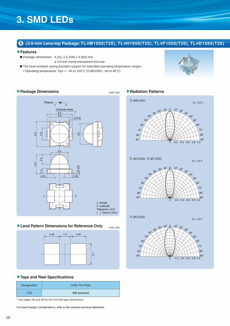
3. SMD LEDs
1. Anode2. CathodeTolerance: ±0.2( ): Typical value
(C0.8)
Cathode index
4.1
1 2
1 2
5.2
5.2
2.5
3.6
3.6
Polarity
1.1
4.0
2.0
1.55 1.55
(0.1
5)
2.45 1.3 2.45
2.7
90˚
80˚
70˚
60˚
50˚
40˚30˚
20˚ 10˚ 0 10˚ 20˚30˚
40˚
50˚
60˚
70˚
80˚
90˚0 0.2 0.4 0.6 0.8 1.0
TL✽M1050
90˚
80˚
70˚
60˚
50˚
40˚30˚
20˚ 10˚ 0 10˚ 20˚30˚
40˚
50˚
60˚
70˚
80˚
90˚0 0.2 0.4 0.6 0.8 1.0
TL✽H1050, TL✽F1050
Ta = 25˚C
Ta = 25˚C
Ta = 25˚CTL✽D1050
0 0.2 0.4 0.6 0.8 1.090˚
80˚
70˚
60˚
50˚
40˚30˚
20˚ 10˚ 0 10˚ 20˚30˚
40˚
50˚
60˚
70˚
80˚
90˚
▼Land Pattern Dimensions for Reference Only
▼Features
▼Package Dimensions ▼Radiation Patterns
● Package dimensions: 5.2(L) x 5.2(W) x 4.0(H) mm
φ 3.6-mm round transparent lens-top
● The heat-resistant casing provides support for extended operating temperature ranges.
• Operating temperature: Topr = −40 to 100˚C (TLBD1050: −40 to 85˚C)
▼Tape and Reel Specifications
Unit: mm
* See pages 48 and 49 for the reel and tape dimensions.
Units Per Reel
400 pcs/reel
Designation
T20
Unit: mm
φ3.6-mm Lens-top Package: TL✽M1050(T20), TL✽H1050(T20), TL✽F1050(T20), TL✽D1050(T20)9
For board design considerations, refer to the relevant technical datasheet.
28

IF –Ta
* Allowable Forward Current vs. Ambient Temperature
Allo
wab
le F
orw
ard
Cur
rent
, IF(m
A)
Ambient Temperature, Ta (˚C)
TLBDTLEGDTL✽H
TL✽FTL✽M
80
40
20
60
00 20 40 60 80 100 120
@Ta = 25˚C
▼Absolute Maximum Ratings (Ta = 25˚C)
SeriesName Part Number
ForwardCurrent (DC)
IF (mA)(*)
ReverseVoltageVR (V)
PowerDissipationPD (mW)
OperatingTemperature
Topr (˚C)
StorageTemperature
Tstg (˚C)
TLRM1050(T20)
TLRMM1050(T20)
TLSM1050(T20)
TLOM1050(T20)
TLYM1050(T20)
TLRMH1050(T20)
TLSH1050(T20)
TLOH1050(T20)
TLYH1050(T20)
TLGH1050(T20)
TLFGH1050(T20)
TLRMF1050(T20)
TLSF1050(T20)
TLOF1050(T20)
TLYF1050(T20)
TLGF1050(T20)
TLFGF1050(T20)
TLPGF1050(T20)
TLEGD1050(T20)
TLBD1050(T20)
4
4
4
4
4
4
4
4
4
4
4
4
4
4
4
4
4
4
4
4
–40 to 110
–40 to 110
–40 to 110
–40 to 110
–40 to 110
–40 to 110
–40 to 110
–40 to 110
–40 to 110
–40 to 110
–40 to 110
–40 to 110
–40 to 110
–40 to 110
–40 to 110
–40 to 110
–40 to 110
–40 to 110
–40 to 110
–40 to 110
TL✽H1050Series
(InGaA P)
TL✽H1050Series
(InGaA P)
TL✽M1050Series
(InGaA P)
TL✽M1050Series
(InGaA P)
TL✽F1050Series
(InGaA P)
TL✽F1050Series
(InGaA P)
TL✽D1050Series
(InGaN)
TL✽D1050Series
(InGaN)
50
50
50
50
50
50
50
50
50
50
50
50
50
50
50
50
50
50
30
30
135
135
135
135
135
120
120
120
120
120
120
120
120
120
120
120
120
120
120
120
–40 to 100
–40 to 100
–40 to 100
–40 to 100
–40 to 100
–40 to 100
–40 to 100
–40 to 100
–40 to 100
–40 to 100
–40 to 100
–40 to 100
–40 to 100
–40 to 100
–40 to 100
–40 to 100
–40 to 100
–40 to 100
–40 to 100
–40 to 85
✩: Dry-packed#: For the available luminous intensity bins, contact your nearest Toshiba sales representative.
For board design considerations, refer to the relevant technical datasheet.
▼Electrical and Optical Characteristics
644
636
623
612
592
636
623
612
590
574
568
636
623
612
590
574
568
562
518
468
630
1000
1600
1600
1600
272
476
476
476
272
85
250
630
630
630
400
160
100
476
153
1800
2000
2800
3500
3000
700
1400
1500
1000
600
250
700
1400
1500
1000
900
370
180
1300
400
Red
Red
Red
Orange
Yellow
Red
Red
Orange
Yellow
Green
Green
Red
Red
Orange
Yellow
Green
Green
Pure green
Green
Blue
Part NumberSeriesName Color
Typical Emission Wavelength(nm)
@IF = 20 mA
λp
630
626
613
605
590
626
613
605
587
571
565
626
613
605
587
571
565
558
528
470
λd Typ.Min
Luminous IntensityIv (mcd)
@IF = 20 mAAvailable IV bins #
VA/WA/XA
WA/XA/YA
XA/YA/ZA
XA/YA/ZA
XA/YA/ZA
Q/R/S
R/S/T
R/S/T
R/S
Q/R
N/P/Q
TA/UA/VA/WA
VA/WA/XA
VA/WA/XA
VA/WA/XA
UA/VA/WA
SA/TA/UA
RA/SA/TA
R/S/T
P/Q/R
✩TLRM1050(T20)
✩TLRMM1050(T20)
✩TLSM1050(T20)
✩TLOM1050(T20)
✩TLYM1050(T20)
✩TLRMH1050(T20)
✩TLSH1050(T20)
✩TLOH1050(T20)
✩TLYH1050(T20)
✩TLGH1050(T20)
✩TLFGH1050(T20)
✩TLRMF1050(T20)
✩TLSF1050(T20)
✩TLOF1050(T20)
✩TLYF1050(T20)
✩TLGF1050(T20)
✩TLFGF1050(T20)
✩TLPGF1050(T20)
✩TLEGD1050(T20)
✩TLBD1050(T20)
2.3
2.3
2.3
2.3
2.3
2.0
2.0
2.0
2.1
2.1
2.1
2.0
2.0
2.0
2.1
2.2
2.3
2.3
3.3
3.3
35
35
35
35
35
30
30
30
30
30
30
30
30
30
30
30
30
30
40
40
Typ. Typ.
Forward VoltageVF (V)
@IF = 20 mA
Viewing Angle2θ1/2 (˚)
29

3. SMD LEDs
2.45 1.3 2.45
2.7
(C0.5)
Cathode index
4.1
1 2
1 2
Polarity
5.2
5.2
2.5
4.4
3.6
1.1
4.0
2.0
1.55 1.55
(0.1
5)
90˚
80˚
70˚
60˚
50˚
40˚30˚
20˚ 10˚ 0 10˚ 20˚30˚
40˚
50˚
60˚
70˚
80˚
90˚0 0.2 0.4 0.6 0.8 1.0
90˚
80˚
70˚
60˚
50˚
40˚30˚
20˚ 10˚ 0 10˚ 20˚30˚
40˚
50˚
60˚
70˚
80˚
90˚0 0.2 0.4 0.6 0.8 1.0
1. Anode2. CathodeTolerance: ±0.2( ): Typical value
0 0.2 0.4 0.6 0.8 1.090˚
80˚
70˚
60˚
50˚
40˚30˚
20˚ 10˚ 0 10˚ 20˚30˚
40˚
50˚
60˚
70˚
80˚
90˚
▼Land Pattern Dimensions for Reference Only
▼Features
▼Package Dimensions
● Package dimensions: 5.2(L) x 5.2(W) x 4.0(H) mm
φ 3.6 × 4.4 mm oval transparent lens-top
● The heat-resistant casing provides support for extended operating temperature ranges.
• Operating temperature: Topr = −40 to 100˚C (TLBD1052: −40 to 85˚C)
▼Tape and Reel Specifications
Unit: mm
* See pages 48 and 49 for the reel and tape dimensions.
Units Per ReelDesignation
T20
Unit: mm
3.6 x 4.4 mm Oval Lens-top Package: TL✽M1052(T20), TL✽H1052(T20), TL✽F1052(T20), TL✽D1052(T20)10
For board design considerations, refer to the relevant technical datasheet.
Ta = 25˚CTL✽M1052
Ta = 25˚CTL✽H1052, TL✽F1052
Ta = 25˚CTL✽D1052
▼Radiation Patterns
400 pcs/reel
30

IF –Ta
* Allowable Forward Current vs. Ambient Temperature
Allo
wab
le F
orw
ard
Cur
rent
, IF(m
A)
Ambient Temperature, Ta (˚C)
TLBDTLEGDTL✽H
TL✽FTL✽M
80
40
20
60
00 20 40 60 80 100 120
▼Absolute Maximum Ratings (Ta = 25˚C)
SeriesName Part Number
ForwardCurrent (DC)
IF (mA)(*)
ReverseVoltageVR (V)
PowerDissipationPD (mW)
OperatingTemperature
Topr (˚C)
StorageTemperature
Tstg (˚C)
TLRM1052(T20)
TLRMM1052(T20)
TLSM1052(T20)
TLOM1052(T20)
TLYM1052(T20)
TLRMH1052(T20)
TLSH1052(T20)
TLOH1052(T20)
TLYH1052(T20)
TLGH1052(T20)
TLFGH1052(T20)
TLRMF1052(T20)
TLSF1052(T20)
TLOF1052(T20)
TLYF1052(T20)
TLGF1052(T20)
TLFGF1052(T20)
TLPGF1052(T20)
TLEGD1052(T20)
TLBD1052(T20)
50
50
50
50
50
50
50
50
50
50
50
50
50
50
50
50
50
50
30
30
4
4
4
4
4
4
4
4
4
4
4
4
4
4
4
4
4
4
4
4
–40 to 100
–40 to 100
–40 to 100
–40 to 100
–40 to 100
–40 to 100
–40 to 100
–40 to 100
–40 to 100
–40 to 100
–40 to 100
–40 to 100
–40 to 100
–40 to 100
–40 to 100
–40 to 100
–40 to 100
–40 to 100
–40 to 100
–40 to 85
135
135
135
135
135
120
120
120
120
120
120
120
120
120
120
120
120
120
120
120
TL✽H1052Series
(InGaA P)
TL✽H1052Series
(InGaA P)
TL✽M1052Series
(InGaA P)
TL✽M1052Series
(InGaA P)
TL✽F1052Series
(InGaA P)
TL✽F1052Series
(InGaA P)
TL✽D1052Series
(InGaN)
TL✽D1052Series
(InGaN)
For board design considerations, refer to the relevant technical datasheet.
✩: Dry-packed#: For the available luminous intensity bins, contact your nearest Toshiba sales representative.
▼Electrical and Optical Characteristics
644
636
623
612
592
636
623
612
590
574
568
636
623
612
590
574
568
562
518
468
630
630
1000
1000
1000
153
272
476
272
153
85
160
400
400
250
250
100
63
272
85
1200
1300
1900
2200
1900
450
900
1000
750
400
190
450
900
1000
750
600
280
140
850
300
Red
Red
Red
Orange
Yellow
Red
Red
Orange
Yellow
Green
Green
Red
Red
Orange
Yellow
Green
Green
Pure green
Green
Blue
Part NumberSeriesName Color
Typical Emission Wavelength(nm)
@IF = 20 mA
λp
630
626
613
605
590
626
613
605
587
571
565
626
613
605
587
571
565
558
528
470
λd Typ.
3200
3200
5000
5000
5000
1290
2300
2300
2300
1290
736
800
2000
2000
2000
1250
800
320
2300
736
MaxMin
Luminous IntensityIV (mcd)
@IF = 20 mAAvailable IV bins #
VA/WA/XA
VA/WA/XA
WA/XA/YA
WA/XA/YA
WA/XA/YA
P/Q/R
Q/R/S
R/S
Q/R/S
P/Q/R
N/P/Q
SA/TA/UA
UA/VA/WA
UA/VA/WA
TA/UA/VA/WA
TA/UA/VA
RA/SA/TA/UA
QA/RA/SA
Q/R/S
N/P/Q
✩TLRM1052(T20)
✩TLRMM1052(T20)
✩TLSM1052(T20)
✩TLOM1052(T20)
✩TLYM1052(T20)
✩TLRMH1052(T20)
✩TLSH1052(T20)
✩TLOH1052(T20)
✩TLYH1052(T20)
✩TLGH1052(T20)
✩TLFGH1052(T20)
✩TLRMF1052(T20)
✩TLSF1052(T20)
✩TLOF1052(T20)
✩TLYF1052(T20)
✩TLGF1052(T20)
✩TLFGF1052(T20)
✩TLPGF1052(T20)
✩TLEGD1052(T20)
✩TLBD1052(T20)
2.3
2.3
2.3
2.3
2.3
2.0
2.0
2.0
2.1
2.1
2.1
2.0
2.0
2.0
2.1
2.2
2.3
2.3
3.3
3.3
30/85
30/85
30/85
30/85
30/85
30/85
30/85
30/85
30/85
30/85
30/85
30/85
30/85
30/85
30/85
30/85
30/85
30/85
30/75
30/75
Typ. Typ.
Forward VoltageVF (V)
@IF = 20 mA
Viewing Angle2θ1/2 (˚)
–40 to 110
–40 to 110
–40 to 110
–40 to 110
–40 to 110
–40 to 110
–40 to 110
–40 to 110
–40 to 110
–40 to 110
–40 to 110
–40 to 110
–40 to 110
–40 to 110
–40 to 110
–40 to 110
–40 to 110
–40 to 110
–40 to 110
–40 to 110
@Ta = 25˚C
31

NOTE
32

4. Through-Hole LEDs
TLRH Series
TLRE Series
TLRMK Series
TLRMH Series
TLRME Series
TLSH Series
TLSE Series
TLOH Series
TLOE Series
TLYK Series
TLYH Series
TLYE Series
TLPYE Series
TLGE Series
TLGU Series
TLFGE Series
TLPGE Series
TLPGU Series
TLRMHGH Series
50
50
50
50
50
50
50
50
50
50
50
50
50
50
30
50
50
30
50 (Total)
4
4
4
4
4
4
4
4
4
4
4
4
4
4
4
4
4
4
4
120
120
130
120
120
120
120
120
120
130
120
120
120
120
72
120
120
72
120
1.9
1.9
2.15
1.9
1.9
2.0
1.9
2.0
2.0
2.25
2.0
2.0
2.0
2.0
2.1
2.0
2.1
2.1
1.95
2.05
2.4
2.4
2.5
2.4
2.4
2.4
2.4
2.4
2.4
2.5
2.4
2.4
2.4
2.4
2.4
2.4
2.4
2.4
2.4
2.4
20
20
20
20
20
20
20
20
20
20
20
20
20
20
20
20
20
20
20
20
20
20
20
20
20
20
20
20
20
20
20
20
20
20
20
20
20
20
630
630
626
626
626
613
613
605
605
590
587
587
580
571
571
565
558
558
626
571
–40 to 100
–40 to 100
–40 to 100
–40 to 100
–40 to 100
–40 to 100
–40 to 100
–40 to 100
–40 to 100
–40 to 100
–40 to 100
–40 to 100
–40 to 100
–40 to 100
–40 to 100
–40 to 100
–40 to 100
–40 to 100
–40 to 100
–40 to 120
–40 to 120
–40 to 120
–40 to 120
–40 to 120
–40 to 120
–40 to 120
–40 to 120
–40 to 120
–40 to 120
–40 to 120
–40 to 120
–40 to 120
–40 to 120
–40 to 120
–40 to 120
–40 to 120
–40 to 120
–40 to 120
DC forwardcurrentIF (mA)
DC reversevoltageVR (V)
PowerdissipationPD (mW)
Operatingtemperature
Topr (°C)
Storagetemperature
Tstg (°C)
Series Name
Absolute Maximum Ratings Electrical / Optical Characteristics
Forward voltage VF (V)Dominant Wavelength,
λd (nm)
IF (mA)typ. max IF (mA) typ.
* For board design consideration, refer to the relevant technical datasheet.
* For details, refer to the product lists on pages 34 to 43.
5˚
7˚
12˚
18˚
20˚
23˚
25˚
30˚
33˚
40˚
45˚
55˚
75˚
130˚
10˚
φ5
23TP
20TP, 20CP
38TP
19TP, 19CP
17TP, 17CP
37TP
16TP, 16CP, 17DP
18TP, 18CP, 30TP, 16TAP
30TP *TL✽H Series
30MP
13CP
13DP
25TP
11TP
33TP, 33CPArched, 5 x 2.5
Package Size Viewing Angle Part Number
27C
27T
28C
28C *TL✽H Series
50T *TL✽U Series
50T, 50C
53T, 53C *TL✽U Series
53T
53D
62T, 68TG, 68CG
68DG
60T
Package Size Viewing Angle Part Number
30˚/50˚
40˚/70˚
80˚/50˚
70˚/50˚
10˚
16˚
40˚
45˚
50˚
80˚
100˚
120˚
φ3
Oval, 4.3 x 5
Oval, 5 x 5.8
1 Electrical and Optical Characteristics
2 Package Selection Guide
Toshiba offers a number of high-brightness LED series using Four-Element (InGaA P) chips and optimum lenses. You can select an appropriate product for your application.
33

4. Through-Hole LEDs
IF,I
FP
Allo
wab
le F
orw
ard
Cur
rent
(re
lativ
e va
lue)
Ambient Temperature, Ta (°C)
1.2
1
0.8
0.6
0.4
0.2
00 20 40 60 80 100 120
1530
1530
4760
2720
2720
1530
1530
850
850
850
476
476
476
476
476
272
272
2720
850
47.6
153
4760
2720
2720
2720
850
850
476
476
476
272
272
272
153
153
272
153
47.6
8.5
φ5
φ5
φ3
23˚
30˚
7˚
12˚
20˚
25˚
33˚
40˚
16˚
80˚
40˚/ 70˚
7˚
20˚
25˚
30˚
75˚
130˚
5600
5400
11000
9000
6500
4800
4500
3200
2000
1900
1500
1500
1300
1300
950
680
600
4700
2000
180
450
12000
9000
8000
7000
3000
2400
1500
1500
1000
1200
800
800
600
500
1000
600
150
20
TLRMK37TP(F)
TLRMK16TAP(F)
TLSH20TP(F)
TLRMH20TP(F)
TLSH38TP(F)
TLRMH38TP(F)
TLSH17TP(F)
TLRMH17TP(F)
TLRH17TP(F)
TLSH16TP(F)
TLSH16CP(F)
TLRMH16TP(F)
TLRMH16CP(F)
TLSH30TP(F)
TLRMH30TP(F)
TLRH30TP(F)
TLRMH30MP(F)
TLSH50T(F)
TLRH50T(F)
TLRH62T(F)
TLRH27T(F)
TLRME20CP(F)
TLSE20TP(F)
TLRME20TP(F)
TLRE20TP(F)
TLSE17TP(F)
TLRME17TP(F)
TLRE17TP(F)
TLSE16TP(F)
TLSE16CP(F)
TLRME16TP(F)
TLRE16TP(F)
TLRME16CP(F)
TLRE16CP(F)
TLRME17DP(F)
TLSE30TP(F)
TLRE30TP(F)
TLRE25TP(F)
TLRE11TP(F)
626
626
613
626
613
626
613
626
630
613
613
626
626
613
626
630
624
613
630
630
630
626
613
626
630
613
626
630
613
613
626
630
626
630
626
613
630
630
630
636
636
623
636
623
636
623
636
644
623
623
636
636
623
636
644
634
623
644
644
644
636
623
636
644
623
636
644
623
623
636
644
636
644
636
623
644
644
644
✽1
✽1
✽1
✽1
✽1
✽1
✽1
✽1
✽1
✽1
✽1
✽1
✽1
✽1
✽1
✽1
✽1
✽1
✽1
✽1
✽1
✽1
✽1
✽1
✽1
✽1
✽1
✽1
✽1
✽1
✽1
✽1
✽1
✽1
✽1
✽1
✽1
✽1
✽1
φ5-13
φ5-3
φ5-1
φ5-1
φ5-4
φ5-4
φ5-2
φ5-2
φ5-2
φ5-3
φ5-3
φ5-3
φ5-3
φ5-14
φ5-14
φ5-14
φ5-14
φ3-3
φ3-3
φ3-2
Oval-1
φ5-1
φ5-1
φ5-1
φ5-1
φ5-2
φ5-2
φ5-2
φ5-3
φ5-3
φ5-3
φ5-3
φ5-3
φ5-3
φ5-2
φ5-14
φ5-14
φ5-6
φ5-7
φ5
Transparent
Transparent
Transparent
Transparent
Transparent
Transparent
Transparent
Transparent
Transparent
Transparent
Red transparent
Transparent
Red transparent
Transparent
Transparent
Transparent
Milky white diffused
Transparent
Transparent
Transparent
Transparent
Red transparent
Transparent
Transparent
Transparent
Transparent
Transparent
Transparent
Transparent
Red transparent
Transparent
Transparent
Red transparent
Red transparent
Red diffused
Transparent
Transparent
Transparent
Transparent
50
50
50
50
50
50
50
50
50
50
50
50
50
50
50
50
50
50
50
50
50
50
50
50
50
50
50
50
50
50
50
50
50
50
50
50
50
50
50
Oval, 5 x 5.8
@Ta = 25˚C
Characteristics
OperatingTemperature
StorageTemperature
–40 to 100˚C
–40 to 120˚C
ForwardCurrentDerating
Curve
✽1
* For board design considerations, refer to the relevant technical datasheet. #: For the available luminous intensity bins, contact your nearest Toshiba sales representative.
Pilot lamps (narrow range)
Pilot lamps (narrow range)
Pilot lamps(narrow range)
Message boards
Pilot lamps
Pilot lamps
Backlighting (wide range)
Backlighting(wide range)
Message boards,Backlighting
Message boards,Backlighting
Message boards,Backlighting
Message boards,Backlighting
Message boards, Backlighting
High-Brightness Red LED Lamps3
T/U/V
T/U/V
V/W/X
U/V/W
U/V/W
T/U/V
T/U/V
S/T/U
S/T/U
S/T/U
R/S/T
R/S/T
R/S/T
R/S/T
R/S/T
Q/R/S
Q/R/S
U/V/W
S/T/U
M/N/P
P/Q/R
V/W/X
U/V/W
U/V/W
U/V/W
S/T/U
S/T/U
R/S/T
R/S/T
R/S/T
Q/R/S
Q/R/S
Q/R/S
P/Q/R
P/Q/R
Q/R/S
P/Q/R
M/N/P
J/K/L
λd (nm) λp (nm)Available bins #Series
NameTyp.Min
Viewing Angle2θ1/2
Package Size(mm)
Luminous Intensity, IV (mcd)@IF = 20 mA Part Number Lens Color
Typical Emission Wavelength@IF = 20 mA
Absolute Maximum Ratings
Operatingtemperature
DC forward current, IF(mA)
ApplicationsPackage
ReferenceNumber
TL✽KSeries
(InGaA P)
TL✽HSeries
(InGaA P)
TL✽ESeries
(InGaA P)
34 35

4. Through-Hole LEDs
IF,I
FP
Allo
wab
le F
orw
ard
Cur
rent
(re
lativ
e va
lue)
Ambient Temperature, Ta (°C)
1.2
1
0.8
0.6
0.4
0.2
00 20 40 60 80 100 120
IF,I
FP
Allo
wab
le F
orw
ard
Cur
rent
(re
lativ
e va
lue)
Ambient Temperature, Ta (°C)
1.2
1
0.8
0.6
0.4
0.2
00 20 40 60 80 100 120
1530
1530
850
850
272
272
153
85
85
85
47.6
47.6
47.6
15.3
272
153
85
85
85
85
Oval, 5 x 5.8
φ3
16˚
45˚
80˚
100˚
120˚
30˚/ 50˚
80˚/ 50˚
3500
3500
2500
2200
800
600
400
330
260
200
180
120
140
45
750
400
300
200
200
300
T/U/V
T/U/V
S/T/U
S/T/U
Q/R/S
Q/R/S
P/Q/R
N/P/Q
N/P/Q
N/P/Q
M/N/P
M/N/P
M/N/P
K/L/M
Q/R/S
P/Q/R
N/P/Q
N/P/Q
N/P/Q
N/P/Q
TLRME50C(F)
TLSE50T(F)
TLRME50T(F)
TLRE50T(F)
TLSE53T(F)
TLRME53T(F)
TLRE53T(F)
◆ TLRME68TG(F)
◆ TLRME68CG(F)
TLSE62T(F)
TLRME62T(F)
TLRE62T(F)
◆ TLRME68DG(F)
TLRE60T(F)
TLSE27C(F)
TLRME27C(F)
TLRE27C(F)
TLRE28C(F)
TLRME28C(F)
TLSE28C(F)
626
613
626
630
613
626
630
626
626
613
626
630
626
630
613
626
630
630
626
613
636
623
636
644
623
636
644
636
636
623
636
644
636
644
623
636
644
644
636
623
✽1
✽1
✽1
✽1
✽1
✽1
✽1
✽1
✽1
✽1
✽1
✽1
✽1
✽1
✽1
✽1
✽1
✽1
✽1
✽1
φ3-3
φ3-3
φ3-3
φ3-3
φ3-4
φ3-4
φ3-4
φ3-5
φ3-5
φ3-2
φ3-2
φ3-2
φ3-5
φ3-1
Oval-1
Oval-1
Oval-1
Oval-2
Oval-2
Oval-2
Red transparent
Transparent
Transparent
Transparent
Transparent
Transparent
Transparent
Transparent
Red transparent
Transparent
Transparent
Transparent
Red diffused
Transparent
Red transparent
Red transparent
Red transparent
Red transparent
Red transparent
Red transparent
50
50
50
50
50
50
50
50
50
50
50
50
50
50
50
50
50
50
50
50
Oval, 4.3 x 5
@Ta = 25˚C
–40 to 100˚C
–40 to 120˚C
✽1Characteristics
OperatingTemperature
StorageTemperature
ForwardCurrentDerating
Curve
Pilot lamps
Message boards
Message boards
Backlighting (wide range)
◆: Designed for flush mounting.* For board design considerations, refer to the relevant technical datasheet.#: For the available luminous intensity bins, contact your nearest Toshiba sales representative.
High-Brightness Red LED Lamps (continued)3
λd (nm) λp (nm)
SeriesName
Typ.Min
Viewing Angle2θ1/2
Package Size(mm)
Luminous Intensity, IV (mcd)@IF = 20 mA Part Number Lens Color
Typical Emission Wavelength@IF = 20 mA
Absolute Maximum Ratings
Operatingtemperature
DC forward current, IF(mA)
ApplicationsPackage
ReferenceNumber
Available bins #
4760
2720
1530
850
850
476
1530
153
4760
1530
1530
850
476
476
153
27.2
2720
1530
272
153
27.2
272
153
1530
φ5
φ3
φ5
φ3
Oval, 5 x 5.8
Oval, 4.3 x 5
Arched, 5 x 2.5
7˚
12˚
20˚
25˚
33˚
16˚
80˚
7˚
20˚
25˚
30˚
75˚
130˚
16˚
45˚
80˚
120˚
30˚/ 50˚
80˚/ 50˚
10˚
15000
7500
5000
2300
2100
1600
5800
550
10000
4500
3500
2000
1600
1400
350
65
7000
4500
1000
350
100
800
500
4000
TLOH20TP(F)
TLOH38TP(F)
TLOH17TP(F)
TLOH16TP(F)
TLOH16CP(F)
TLOH30TP(F)
TLOH50T(F)
TLOH62T(F)
TLOE20TP(F)
TLOE17TP(F)
TLOE17CP(F)
TLOE16TP(F)
TLOE16CP(F)
TLOE30TP(F)
TLOE25TP(F)
TLOE11TP(F)
TLOE50C(F)
TLOE50T(F)
TLOE53T(F)
TLOE62T(F)
TLOE60T(F)
TLOE27C(F)
TLOE28C(F)
TLOE33CP(F)
605
605
605
605
605
605
605
605
605
605
605
605
605
605
605
605
605
605
605
605
605
605
605
605
V/W/X
U/V/W
T/U/V
S/T/U
S/T/U
R/S/T
T/U/V
P/Q/R
V/W/X
T/U/V
T/U/V
S/T/U
R/S/T
R/S/T
P/Q/R
L/M/N
U/V/W
T/U/V
Q/R/S
P/Q/R
L/M/N
L/M/N
P/Q/R
T/U/V
612
612
612
612
612
612
612
612
612
612
612
612
612
612
612
612
612
612
612
612
612
612
612
612
✽2
✽2
✽2
✽2
✽2
✽2
✽2
✽2
✽2
✽2
✽2
✽2
✽2
✽2
✽2
✽2
✽2
✽2
✽2
✽2
✽2
✽2
✽2
✽2
φ5-1
φ5-4
φ5-2
φ5-3
φ5-3
φ5-14
φ3-3
φ3-2
φ5-1
φ5-2
φ5-2
φ5-3
φ5-3
φ5-14
φ5-6
φ5-7
φ3-3
φ3-3
φ3-4
φ3-2
φ3-1
Oval-1
Oval-2
Arched-1
Transparent
Transparent
Transparent
Transparent
Orange transparent
Transparent
Transparent
Transparent
Transparent
Transparent
Orange transparent
Transparent
Orange transparent
Transparent
Transparent
Transparent
Orange transparent
Transparent
Transparent
Transparent
Transparent
Orange transparent
Orange transparent
Orange transparent
50
50
50
50
50
50
50
50
50
50
50
50
50
50
50
50
50
50
50
50
50
50
50
50
@Ta = 25˚C
–40 to 100˚C
–40 to 120˚C
✽2Characteristics
OperatingTemperature
StorageTemperature
ForwardCurrentDerating
Curve
* For board design considerations, refer to the relevant technical datasheet. #: For the available luminous intensity bins, contact your nearest Toshiba sales representative.
Pilot lamps(narrow range)
Pilot lamps(narrow range)
Message boards, Backlighting
Message boards
Pilot lamps
Backlighting (wide range)
Pilot lamps
Backlighting (wide range)
Backlighting (wide range)
Message boards, Backlighting
Backlighting
TL✽ESeries
(InGaA P)
TL✽HSeries
(InGaA P)
High-Brightness Orange LED Lamps4
TL✽ESeries
(InGaA P)
λd (nm) λp (nm)
SeriesName Typ.Min
Viewing Angle2θ1/2
Package Size(mm)
Luminous Intensity, IV (mcd)@IF = 20 mA Part Number Lens Color
Typical Emission Wavelength@IF = 20 mA
Absolute Maximum Ratings
Operatingtemperature
DC forward current, IF(mA)
ApplicationsPackage
ReferenceNumber
Available bins #
36 37

4. Through-Hole LEDs
IF,I
FP
Allo
wab
le F
orw
ard
Cur
rent
(re
lativ
e va
lue)
Ambient Temperature, Ta (°C)
1.2
1
0.8
0.6
0.4
0.2
00 20 40 60 80 100 120
2720
2720
4760
2720
1530
850
850
476
1530
272
153
272
272
2720
2720
476
850
850
476
476
476
272
85
15.3
1530
1530
850
272
153
85
85
85
47.6
47.6
27.2
272
153
476
1530
φ3
φ5
φ5
φ5
23˚
30˚
7˚
12˚
20˚
25˚
33˚
16˚
80˚
40˚/ 70˚
70˚/ 50˚
5˚
7˚
18˚
20˚
25˚
30˚
75˚
130˚
16˚
45˚
80˚
100˚
120˚
30˚/ 50˚
80˚/ 50˚
10˚
6800
5900
13000
7000
4800
2200
2000
1350
4400
520
400
900
750
8000
9500
2000
3000
3000
1500
1200
1300
750
300
45
3500
3500
2500
800
450
340
300
250
150
150
85
650
350
1400
3500
U/V/W
U/V/W
V/W/X
U/V/W
T/U/V
S/T/U
S/T/U
R/S/T
T/U/V
Q/R/S
P/Q/R
Q/R/S
Q/R/S
U/V/W
U/V/W
R/S/T
S/T/U
S/T/U
R/S/T
R/S/T
R/S/T
Q/R/S
N/P/Q
K/L/M
T/U/V
T/U/V
S/T/U
Q/R/S
P/Q/R
N/P/Q
N/P/Q
N/P/Q
M/N/P
M/N/P
L/M/N
L/M/N
P/Q/R
R/S/T
T/U/V
TLYK37TP(F)
TLYK16TAP(F)
TLYH20TP(F)
TLYH38TP(F)
TLYH17TP(F)
TLYH16TP(F)
TLYH16CP(F)
TLYH30TP(F)
TLYH50T(F)
◆ TLYH68TG(F)
TLYH62T(F)
TLYH27T(F)
TLYH28C(F)
TLPYE23TP(F)
TLYE20TP(F)
TLPYE19TP(F)
TLYE17CP(F)
TLYE17TP(F)
TLYE16TP(F)
TLYE16CP(F)
TLYE30TP(F)
TLPYE18TP(F)
TLYE25TP(F)
TLYE11TP(F)
TLYE50C(F)
TLYE50T(F)
TLPYE50T(F)
TLYE53T(F)
TLPYE53T(F)
◆ TLYE68TG(F)
◆ TLYE68CG(F)
TLYE62T(F)
TLPYE62T(F)
◆ TLYE68DG(F)
TLYE60T(F)
TLYE27C(F)
TLYE28C(F)
TLPYE33CP(F)
TLYE33CP(F)
590
590
587
587
587
587
587
587
587
587
587
587
587
580
587
580
587
587
587
587
587
580
587
587
587
587
580
587
580
587
587
587
580
587
587
587
587
580
587
594
594
590
590
590
590
590
590
590
590
590
590
590
583
590
583
590
590
590
590
590
583
590
590
590
590
583
590
583
590
590
590
583
590
590
590
590
583
590
✽1
✽1
✽1
✽1
✽1
✽1
✽1
✽1
✽1
✽1
✽1
✽1
✽1
✽1
✽1
✽1
✽1
✽1
✽1
✽1
✽1
✽1
✽1
✽1
✽1
✽1
✽1
✽1
✽1
✽1
✽1
✽1
✽1
✽1
✽1
✽1
✽1
✽1
✽1
φ5-13
φ5-3
φ5-1
φ5-4
φ5-2
φ5-3
φ5-3
φ5-14
φ3-3
φ3-5
φ3-2
Oval-1
Oval-2
φ5-9
φ5-1
φ5-10
φ5-2
φ5-2
φ5-3
φ5-3
φ5-14
φ5-11
φ5-6
φ5-7
φ3-3
φ3-3
φ3-3
φ3-4
φ3-4
φ3-5
φ3-5
φ3-2
φ3-2
φ3-5
φ3-1
Oval-1
Oval-2
Arched-1
Arched-1
φ3
Transparent
Transparent
Transparent
Transparent
Transparent
Transparent
Yellow transparent
Transparent
Transparent
Transparent
Transparent
Transparent
Yellow transparent
Transparent
Transparent
Transparent
Yellow transparent
Transparent
Transparent
Yellow transparent
Transparent
Transparent
Transparent
Transparent
Yellow transparent
Transparent
Transparent
Transparent
Transparent
Transparent
Yellow transparent
Transparent
Transparent
Yellow diffused
Transparent
Yellow transparent
Yellow transparent
Yellow transparent
Yellow transparent
50
50
50
50
50
50
50
50
50
50
50
50
50
50
50
50
50
50
50
50
50
50
50
50
50
50
50
50
50
50
50
50
50
50
50
50
50
50
50
Oval, 5 x 5.8
Oval, 4.3 x 5
Arched, 5 x 2.5
Oval, 5 x 5.8
Oval, 4.3 x 5
@Ta = 25˚C
–40 to 100˚C
–40 to 120˚C
✽1Characteristics
OperatingTemperature
StorageTemperature
ForwardCurrentDerating
Curve
◆: Designed for flush mounting.* For board design considerations, refer to the relevant technical datasheet. #: For the available luminous intensity bins, contact your nearest Toshiba sales representative.
Pilot lamps(narrow range)
Pilot lamps
Pilot lamps (narrow range)
Message boardsBacklighting
Message boards
Message boards, backlighting
Pilot lamps(narrow range)
Message boardsBacklighting
Backlighting (wide range)
Backlighting (wide range)
Pilot lamps
Backlighting (wide range)
Message boards
Backlighting
TL✽KSeries
(InGaA P)
TL✽HSeries
(InGaA P)
TL✽ESeries
(InGaA P)
High-Brightness Yellow LED Lamps5
λd (nm) λp (nm)
SeriesName Typ.Min
Viewing Angle2θ1/2
Package Size(mm)
Luminous Intensity, IV (mcd)@IF = 20 mA Part Number Lens Color
Typical Emission Wavelength@IF = 20 mA
Absolute Maximum Ratings Applications
PackageReferenceNumber
Available bins # Operatingtemperature
DC forward current, IF(mA)
38 39

4. Through-Hole LEDs
IF,I
FP
Allo
wab
le F
orw
ard
Cur
rent
(re
lativ
e va
lue)
Ambient Temperature, Ta (°C)
1.2
1
0.8
0.6
0.4
0.2
00 20 40 60 80 100 120
47.6
2720
1530
850
476
476
272
272
153
85
272
153
85
27.2
8.5
2.72
476
272
272
153
153
85
47.6
47.6
47.6
47.6
27.2
27.2
15.3
15.3
15.3
15.3
85
47.6
153
272
476
φ5
Oval, 4.3 x 5
φ3
70˚/ 50˚
5˚
18˚
30˚
75˚
130˚
16˚
45˚
80˚
100˚
120˚
30˚/ 50˚
80˚/ 50˚
10˚
170
7000
5000
3000
1300
1100
800
800
500
300
700
500
200
90
20
8
1500
1000
1000
600
400
200
130
155
110
110
70
70
45
45
30
50
250
150
400
800
1300
TLGH28C(F)
TLGE23TP(F)
TLFGE23TP(F)
TLPGE23TP(F)
TLGE19TP(F)
TLGE19CP(F)
TLFGE19TP(F)
TLFGE19CP(F)
TLPGE19TP(F)
TLFGE18TP(F)
TLGE18TP(F)
TLGE18CP(F)
TLPGE18TP(F)
TLGE25TP(F)
TLGE11TP(F)
TLPGE11TP(F)
TLGE50T(F)
TLFGE50T(F)
TLFGE50C(F)
TLPGE50T(F)
TLGE53T(F)
TLFGE53T(F)
TLPGE53T(F)
◆ TLGE68TG(F)
◆ TLGE68CG(F)
TLGE62T(F)
◆ TLFGE68CG(F)
TLFGE62T(F)
TLPGE62T(F)
◆ TLGE68DG(F)
◆ TLFGE68DG(F)
TLGE60T(F)
TLGE27C(F)
TLGE28C(F)
TLFGE33CP(F)
TLGE33CP(F)
TLGE33TP(F)
571
571
565
558
571
571
565
565
558
565
571
571
558
571
571
558
571
565
565
558
571
565
558
571
571
571
565
565
558
571
565
571
571
571
565
571
571
574
574
568
562
574
574
568
568
562
568
574
574
562
574
574
562
574
568
568
562
574
568
562
574
574
574
568
568
562
574
568
574
574
574
568
574
574
✽1
✽1
✽1
✽1
✽1
✽1
✽1
✽1
✽1
✽1
✽1
✽1
✽1
✽1
✽1
✽1
✽1
✽1
✽1
✽1
✽1
✽1
✽1
✽1
✽1
✽1
✽1
✽1
✽1
✽1
✽1
✽1
✽1
✽1
✽1
✽1
✽1
Oval-2
φ5-9
φ5-9
φ5-9
φ5-10
φ5-10
φ5-10
φ5-10
φ5-10
φ5-11
φ5-11
φ5-11
φ5-11
φ5-6
φ5-7
φ5-7
φ3-3
φ3-3
φ3-3
φ3-3
φ3-4
φ3-4
φ3-4
φ3-5
φ3-5
φ3-2
φ3-5
φ3-2
φ3-2
φ3-5
φ3-5
φ3-1
Oval-1
Oval-2
Arched-1
Arched-1
Arched-1
Green transparent
Transparent
Transparent
Transparent
Transparent
Green transparent
Transparent
Green transparent
Transparent
Transparent
Transparent
Green transparent
Transparent
Transparent
Transparent
Transparent
Transparent
Transparent
Green transparent
Transparent
Transparent
Transparent
Transparent
Transparent
Green transparent
Transparent
Green transparent
Transparent
Transparent
Green diffused
Green diffused
Transparent
Green transparent
Green transparent
Green transparent
Green transparent
Transparent
50
50
50
50
50
50
50
50
50
50
50
50
50
50
50
50
50
50
50
50
50
50
50
50
50
50
50
50
50
50
50
50
50
50
50
50
50
Oval, 5 x 5.8
Oval, 4.3 x 5
Arched, 5 x 2.5
@Ta = 25˚C
–40 to 100˚C
–40 to 120˚C
✽1Characteristics
OperatingTemperature
StorageTemperature
ForwardCurrentDerating
Curve
◆: Designed for flush mounting.* For board design considerations, refer to the relevant technical datasheet. #: For the available luminous intensity bins, contact your nearest Toshiba sales representative.
Backlighting
Pilot lamps(narrow range)
Message boardsBacklighting
Message boards
Pilot lamps
Backlighting (wide range)
Message boards
TL✽HSeries(InGaA P)
TL✽ESeries
(InGaA P)
M/N/P
U/V/W
T/U/V
S/T/U
R/S/T
R/S/T
Q/R/S
Q/R/S
P/Q/R
N/P/Q
Q/R/S
P/Q/R
N/P/Q
L/M/N
J/K/L
G/H/J
R/S/T
Q/R/S
Q/R/S
P/Q/R
P/Q/R
N/P/Q
M/N/P
M/N/P
M/N/P
M/N/P
L/M/N
L/M/N
K/L/M
K/L/M
K/L/M
K/L/M
N/P/Q
M/N/P
P/Q/R
Q/R/P
R/S/T
High-Brightness Green LED Lamps6
λd (nm) λp (nm)
SeriesName
Typ.Min
Viewing Angle2θ1/2
Package Size(mm)
Luminous Intensity, IV (mcd)@IF = 20 mA Part Number Lens Color
Typical Emission Wavelength@IF = 20 mA
Absolute Maximum Ratings Applications
PackageReferenceNumber
Available bins # Operatingtemperature
DC forward current, IF(mA)
40 41

4. Through-Hole LEDs
IF,I
FP
Allo
wab
le F
orw
ard
Cur
rent
(re
lativ
e va
lue)
Ambient Temperature, Ta (°C)
1.2
1
0.8
0.6
0.4
0.2
00 20 40 60 80 100 120
IF,I
FP
Allo
wab
le F
orw
ard
Cur
rent
(re
lativ
e va
lue)
Ambient Temperature, Ta (°C)
1.2
1
0.8
0.6
0.4
0.2
00 20 40 60 80 100 120
φ5
φ3
5˚
30˚
45˚
55˚
10˚
40˚
50˚
80˚
@Ta = 25˚C
–40 to 100˚C
–40 to 120˚C
✽3Characteristics
OperatingTemperature
StorageTemperature
ForwardCurrentDerating
Curve
TL✽USeries
(InGaA P)
TL✽HSeries
(InGaA P)
* For board design considerations, refer to the relevant technical datasheet. #: For the available luminous intensity bins, contact your nearest Toshiba sales representative.
φ5
φ5
30˚/35˚
40˚/50˚
TLRMHGH48T(F)
TLRMHGH48M(F)
476
272
272
153
Red
Green
Red
Green
1100
500
450
220
626
571
626
571
636
574
636
574
Transparent
White diffused
✽2
✽2
50
50
φ5-12
φ5-12
@Ta = 25˚C
Message boards
λd (nm) λp (nm)Typ.Min
SeriesName
Viewing Angle2θ1/2
Package Size(mm)
Luminous Intensity, IV (mcd)@IF = 20 mA Part Number Lens Color
Typical Emission Wavelength@IF = 20 mA
Absolute Maximum Ratings
Operatingtemperature
DC forward current, IF(mA)
ApplicationsPackage
ReferenceNumber
Color
* For board design considerations, refer to the relevant technical datasheet. When turning on two elements simultaneously, the total current should be kept below the rated value.
1530
476
85
27.2
47.6
47.6
27.2
27.2
15.3
476
153
47.6
27.2
47.6
27.2
27.2
15.3
27.2
8.5
4000
1600
200
90
180
120
80
70
35
1200
450
170
80
150
70
80
40
70
25
TLGU23TP(F)
TLPGU23TP(F)
TLGU18TP(F)
TLPGU18TP(F)
TLGU18CP(F)
TLGU13CP(F)
TLPGU13CP(F)
TLGU13DP(F)
TLPGU13DP(F)
TLGU50T(F)
TLPGU50T(F)
TLGU53T(F)
TLPGU53T(F)
TLGU53C(F)
TLPGU53C(F)
TLGU53D(F)
TLPGU53D(F)
TLGU62T(F)
TLPGU62T(F)
571
558
571
558
571
571
558
571
558
571
558
571
558
571
558
571
558
571
558
574
562
574
562
574
574
562
574
562
574
562
574
562
574
562
574
562
574
562
✽1
✽1
✽1
✽1
✽1
✽1
✽1
✽1
✽1
✽1
✽1
✽1
✽1
✽1
✽1
✽1
✽1
✽1
✽1
φ5-9
φ5-9
φ5-11
φ5-11
φ5-11
φ5-5
φ5-5
φ5-5
φ5-5
φ3-3
φ3-3
φ3-4
φ3-4
φ3-4
φ3-4
φ3-4
φ3-4
φ3-2
φ3-2
Transparent
Transparent
Transparent
Transparent
Green transparent
Green transparent
Green transparent
Green diffused
Green diffused
Transparent
Transparent
Transparent
Transparent
Green transparent
Green transparent
Green diffused
Green diffused
Transparent
Transparent
30
30
30
30
30
30
30
30
30
30
30
30
30
30
30
30
30
30
30
T/U/V
R/S/T
N/P/Q
L/M/N
M/N/P
M/N/P
L/M/N
L/M/N
K/L/M
R/S/T
P/Q/R
M/N/P
L/M/N
M/N/P
L/M/N
L/M/N
K/L/M
L/M/N
J/K/L
λd (nm) λp (nm)
SeriesName
Typ.Min
Viewing Angle2θ1/2
Package Size(mm)
Luminous Intensity, IV (mcd)@IF = 20 mA Part Number Lens Color
Typical Emission Wavelength@IF = 20 mA
Absolute Maximum Ratings Applications
PackageReferenceNumber
Available bins #
High-Brightness Green LED Lamps (continued)6
High-Brightness Dual-Color LED Lamps7
Pilot lamps(narrow range)
Message boardsBacklighting
Pilot lamps
Pilot lamps(narrow range)
–40 to 100˚C
–40 to 120˚C
✽1Characteristics
OperatingTemperature
StorageTemperature
ForwardCurrentDerating
Curve
Operatingtemperature
DC forward current, IF(mA)
42 43

4. Through-Hole LEDs
2
1
2.54
0.45
φ 3.1 ± 0.2
φ 3.8 ± 0.2
24 ±
1(2
)5.
1 ±
0.2
0.7 max
0.45
(incl
udin
g pr
otru
ded
resi
n)1.
6 m
ax
(1.3
)3.
5 ±
0.2
Cathode index2.54
21
0.5
0.5
φ 5.0 ± 0.2
21 ±
15.
65 ±
0.2
(incl
udin
g pr
otru
ded
resi
n)6.
65 ±
0.2
5
(2)
(1)
φ5.
8 ±
0.2
(1)
21
2.54
φ 3 ± 0.2
φ 2.8 ± 0.2
0.45
0.7 max
24 ±
1(2
)
(1) 4.
8 ±
0.2
3.2
± 0
.2
φ 3.8 ± 0.2
0.45
21
2.54
(incl
udin
g pr
otru
ded
resi
n)2.
1 m
ax
24 ±
1(2
)
(1.3
) 5.6
± 0
.2
3.5
± 0
.2
0.7 max
φ 3.1 ± 0.2
φ 3.8 ± 0.2
0.45
0.45
φ 3.8 ± 0.2
φ 3.1 ± 0.2
5.2
± 0.
2
(incl
udin
g pr
otru
ded
resi
n)2.
7 m
ax
24 ±
1
3.2
± 0
.2(2
)
(2)
0.7 max
0.452.54
1
20.45
φ5.
8
8.3
± 0
.2(1
)
20.0
± 1
(2)
9.3
± 0
.25
φ5.
0
2.54
0.5
12
(1)
(1)
0.5
(incl
udin
g pr
otru
ded
resi
n)1.
5 m
ax
φ5.
8 ±
0.2
(1)
(incl
udin
g pr
otru
ded
resi
n)1.
5 m
ax
φ 5 ± 0.2
20 ±
1(2
)9.
65 ±
0.2
5
2.54
12
(1.5)
(1.5)
(1)
Cathode index
0.5
0.5
φ5.
8 ±
0.2
(1)
(incl
udin
g pr
otru
ded
resi
n)1.
5 m
ax
φ 5±0.2
20 ±
1(2
)8.
75 ±
0.2
5
2.54
1
2
(1.5)
(1.5)
(1)
Cathode index
0.5
0.5
φ5.
8 ±
0.2
φ5
± 0
.2
(1)
(incl
udin
g pr
otru
ded
resi
n)1.
5 m
ax
φ 5 ± 0.2
20 ±
1(2
)9.
42 ±
0.2
5
2.54
12
(1) (1)
(1) (1)
(1)
Cathode index
0.5
0.5
φ 5.0 ± 0.2
21 ±
17.
65 ±
0.2
(1)
φ5.
8 ±
0.2
(1)
(2)
2.54Cathode index
0.5
12
(incl
udin
g pr
otru
ded
resi
n)8.
65 ±
0.2
5
0.5
2.54
21
0.5
φ 4.9 ± 0.2
21 ±
16
± 0.
2
(incl
udin
g pr
otru
ded
resi
n)7
± 0
.25
(2)
(1)
(1)
φ5.
8 ±
0.2
Cathode index
0.5
0.45
21
2.54
(incl
udin
g pr
otru
ded
resi
n)2.
1 m
ax
24 ±
1(2
)
(1.3
) 5.84
± 0
.2
3.74
± 0
.2
0.7 max
φ 3.1 ± 0.2
φ 3.8 ± 0.2
0.45
1. Anode2. Cathode
φ 3-1
1. Anode2. Cathode
φ 3-2
1. Anode2. Cathode
φ 3-3
1. Anode2. Cathode
φ 3-4
1. Anode2. Cathode
φ 3-5
1. Anode2. Cathode
Tolerance: ±0.2
Tolerance: ±0.2
Tolerance: ±0.2
Tolerance: ±0.2
Tolerance: ±0.2
Tolerance: ±0.2
Tolerance: ±0.2
Tolerance: ±0.2
Tolerance: ±0.2
Tolerance: ±0.2
* Values in parentheses are for reference only. * For board design considerations, refer to the relevant technical datasheet.
Tolerance: ±0.2
Tolerance: ±0.2
φ 5-1
1. Anode2. Cathode
φ 5-2
1. Anode2. Cathode
φ 5-3
1. Anode2. Cathode
φ 5-4
1. Anode2. Cathode
φ 5-5
1. Anode2. Cathode
φ 5-6
1. Anode2. Cathode
φ 5-7
Package Dimensions8
44

φ5
± 0
.29.
1 ±
0.2
1.64
0.5
1.640.9
Standoff
0.5 0.5
3
2.54 2.54
12
0.5
15.5
± 1
+0.
411
.6 –
0.1
(2)
(2)
(incl
udin
g pr
otru
ded
resi
n)
10.6
max
(incl
udin
g pr
otru
ded
resi
n)
5.0 ± 0.2 5.8 ± 0.2
5.8
± 0
.2
17.5
± 1
8.25
± 0
.2
(2)
+0.
410
.75
–0.1
2.54
12
0.5
9.5
max
0.5
(incl
udin
g pr
otru
ded
resi
n)
5.0 ± 0.2
2.5
± 0
.220
± 1
(2)
(9.3
5)
2.54
0.5
1 2
9.85
max
(incl
udin
g pr
otru
ded
resi
n)
1.5
max
φ 5.
8 ±
0.2
(1)
(1)
φ 5.0 ± 0.2
20±
18.
55±
0.25
(1)
2.54
0.5
Cathode index
(2)
21
0.50.5
1
+0.
49.
6 –0
.1
2.54
5.0 ± 0.2 4.3 ± 0.2
5.0 ± 0.2
5.0
±0.
2
4.3
±0.
217
.5±
1.0
(7.1
)
(2)
0.5 0.5
2
2.54
0.5
(0.8)
(0.8)
φ 5.0 ± 0.2
20 ±
19.
8 ±
0.2
5
(1)
φ5.
8 ±
0.2
(1)
2.54
0.5
Cathode index
(2)
(incl
udin
g pr
otru
ded
resi
n)
1.5
max
2
1
0.5
φ 5.0 ± 0.2
20 ±
19.
55 ±
0.2
5
(1)
(2)
φ 5.
8 ±
0.2
(1)
(0.8)
(0.8)
2.54
0.5
Cathode index
(incl
udin
g pr
otru
ded
resi
n)
1.5
max
2
1
0.5
φ 5.0 ± 0.2
20 ±
19.
0 ±
0.2
5
(1)
(2)
φ5.
8 ±
0.2
(1)
(1.5)
(1.5)
2.54
0.5
(incl
udin
g pr
otru
ded
resi
n)
1.5
max
2
1
Cathode index
0.5
(1)
φ 4.8
20±
1
8.25
9.25
±0.
25(2
)
φ5.
0
φ5.
8
(1)
2.54
1
2
(incl
udin
g pr
otru
ded
resi
n)
1.5
max
0.5 0.5
(1)
0.5
φ 5.0 ± 0.2
21±
17.
15 ±
0.2
(2)
φ5.
8 ±
0.2
(1)
2.54
1
2
Cathode index
(incl
udin
g pr
otru
ded
resi
n)8.
65 ±
0.2
5
0.5
Tolerance: ±0.2
Tolerance: ±0.2
Tolerance: ±0.2
Tolerance: ±0.2
Tolerance: ±0.2
Tolerance: ±0.2
1. Anode2. Cathode
Tolerance: ±0.2
Tolerance: ±0.2
Tolerance: ±0.2
Tolerance: ±0.2
1. Anode2. Cathode
1. Anode2. Cathode
1. Anode2. Cathode
φ 5-8 φ 5-9 φ 5-10 φ 5-11
φ 5-12
1. Anode2. Cathode
φ 5-13
1. Anode2. Cathode
φ 5-14
1. Anode2. Cathode
Oval-1
1. Anode2. Cathode
Oval-2
1. Anode2. Cathode
Arched-1
Unit: mm
1. Anode(Red)2. Common Cathode3. Anode(Green)
45

5. Packing SpecificationsH
FF
P1
F F
L
A
H0
P2
P0 D0
W2
W0
W
W1
B C D E F G
TLRE16TP ( TPK51, F )
Part number Tape specification
Note
▼Part Number Format
Tape PackingDesigned for ø3-mm round, ø5-mm round and oval through-hole LED lamps
Available in tape and reel (spaced on 2.54- or 5-mm centers) suitable for automatic pick-and-place assembly
Available in both ammo pack and tape & reel
The following table shows available taped packing options classified by packaging type, tape dimensions and lead polarity.
▼Tape and Reel Specifications
▼Tape Format
Example:
Tape Specifications
Reel pack
Anode first Cathode firstAmmo pack
Device Positioning on Tape (see the left diagram below)
H0
W
W0
W1
W2
P0
P1
P2
F
L
D0
23.35 ± 1 18.55 ± 1 17.0 ± 1 23.35 ± 1 20.5 ± 1 22.5 ± 1 23.35 ± 1
–
2.54 + 0.8 – 0.2
18.0 + 1 – 0.5
9.0 + 0.75 – 0.5
6.0 ± 0.3 or 13.0 ± 0.3
≤ 0.5
12.7
12.7 ± 1 (component pitch)
6.35 ± 1.3
11.0 max
φ4.0 ± 0.2
5.00 + 0.8 – 0.2
16.0 ± 0.5
TPK51, K51
TPK53, K53
TPK55, K55
TPJ51, J51
TPJ52, J52
TPJ53, J53
TPJ56, J56
TPKR1, KR1
TPKR3, KR3
TPKR5, KR5
TPJR1, JR1
TPJR2, JR2
TPJR3, JR3
TPJR6, JR6
TPK1, K1
TPK3, K3
TPK5, K5
TPJ1, J1
TPJ2, J2
TPJ3, J3
TPJ6, J6
H
B C D E F GA
A
B
C
D
E
F
G
Through-hole LEDs packaged into tapes may differ in lead length described in the relevant technical datasheet.
Through-Hole LEDs1
Note: [[G]]/RoHS COMPATIBLE
Please contact your TOSHIBA sales representative for details as to environmental matters such as the RoHS compatibility of Product.The RoHS is the Directive 2002/95/EC of the European Parliament and of the Council of 27 January 2003 on the restriction of the use of certain hazardous substances in electrical and electronic equipment.
46

One fold has
25 devices.
At least four devices are removed.
At least four devices are removed.
d1
Small boxd1 = 140 mmd2 = 336 mmd3 = 52 mm
Standard box✽
d1 = 268 mmd2 = 339 mmd3 = 55 mm
d2
d3
φ2
φ1
Direction of feed
t
φ1 = 360 mm t = 50 mmφ2 = 30 mm
✽: Typical quantity
▼Reel Pack
▼Ammo Pack
Reel Dimensions
1. A tape is folded alternately, with 25 devices attached per fold.2. The first and last folds have at least four devices removed.
2,000 pcs
1,000 pcs
φ3-mm series
φ5-mm and oval series
LED Type Quantity Per Reel
■ Packing Quantity
2,000 or 4,000 pcs✽
1,000 or 2,000 pcs✽
φ3-mm series
φ5-mm and oval series
LED Type Quantity Per Reel
■ Packing Quantity
47

5. Packing Specifications
8.0
± 0
.3
3.5
± 0.
05
2.3 ± 0.1
1.75
± 0
.1
0.3 ± 0.05
4.0 ± 0.1
2.0 ± 0.05
4.0 ± 0.1
Polarity
φ1.5 ± 0.1
φ1.5 + 0.1 – 0
3.7
± 0
.1
2.9 ± 0.1
A – A'
A A'
φ1.5 + 0.1 – 0
Y
Y
Y’
Y’
A A’
Polarity
A – A'
8.0
± 0
.2
3.5
± 0
.1
*1T14: 0.4 ± 0.05T15: 0.37 ± 0.05
*2 T14: 4.0 ± 0.1T15: 2.0 ± 0.1
For board design considerations, refer to the relevant technical datasheet.
0.52 ± 0.05
0.9 ± 0.05
1.3
± 0
.05
1.85
± 0
.05
1.75
± 0
.1
4.0 ± 0.1
φ0.5 ± 0.052.0 ± 0.1
*2
0.2 ± 0.05
8.0
± 0
.2
3.5
± 0.
05
1.5 ± 0.1
1.75
± 0
.1 0.2 ± 0.05
4.0 ± 0.1
2.0 ± 0.05
4.0 ± 0.1
Polarity
φ1.1 ± 0.1
φ1.5 + 0.1 – 0
2.5
± 0
.1
1.5 ± 0.1
A – A'A A’
2.25
± 0
.1
8.0
± 0
.3
3.50
± 0
.05
1.30 ± 0.05
1.75
± 0
.1 0.20 ± 0.05φ1.5 + 0.1 – 0
φ1.1 ± 0.1
4.0 ± 0.1
2.0 ± 0.05
4.0 ± 0.11.45 ± 0.1
A – A'
A A'
Polarity
1.75
± 0
.1
8.0
± 0
.1
3.50
± 0
.05
0.75 ± 0.1
1.75
± 0
.1
0.20 ± 0.05
4.0 ± 0.1
2.0 ± 0.05
*1 *1 T04: 4.0 ± 0.1T05: 2.0 ± 0.1
φ0.6 ± 0.050.9 ± 0.1Polarity
φ1.5 + 0.1 – 0
A – A'
A A'
φ60
φ13 ± 0.5φ21 ± 0.8
φ180
2 ±
0.5
+ 0– 4 + 1
– 0
11.4 ± 1.0
9
φ60
φ13 ± 0.5φ21 ± 0.8
φ180
2 ±
0.5
+ 0– 4 + 1
– 0
11.4 ± 1.0
9
φ60
φ13 ± 0.5φ21 ± 0.8
φ180
2 ±
0.5
+ 0– 4 + 1
– 0
11.4 ± 1.0
9
φ60
φ13 ± 0.5φ21 ± 0.8
φ180
2 ±
0.5
+ 0– 4 + 1
– 0
11.4 ± 1.0
9
φ60
φ13 ± 0.5φ21 ± 0.8
φ180
2 ±
0.5
+ 0– 4 + 1
– 0
11.4 ± 1.0
9
*1
22
T02
T04
T05
T11
T14
T15
T18
SMD LEDs
Tape Dimensions Reel DimensionsUnit: mm Unit: mm
48

For board design considerations, refer to the relevant technical datasheet.
4.0 ± 0.1
8.0 ± 0.15.5 ± 0.1 φ1.6 ± 0.1
12.0
±0.
2
5.5
±0.
1
5.5
±0.
051.
75±
0.1
2.0 ± 0.050.4 ± 0.05
4.4 ± 0.1
φ1.5 + 0.1 – 0
A A’A – A'
Polarity
Polarity
Polarity
φ 44
φ180
+ 0 – 4
φ60
φ13
15.4 ± 1.0
13 ± 0.3
2 ± 0.5
φ 44
φ180
+ 0 – 4
φ60
φ13
2 ± 0.5
φ 44
φ180
+ 0 – 4
φ60
φ13
2 ± 0.5
11.4 ± 1.0
+ 1– 09
+ 1– 0
11.4 ± 1.0
9
8.0 ± 0.1φ1.1 ± 0.1
4.0 ± 0.1
4.1 ± 0.1
2.0 ± 0.05
1.75
± 0
.1
3.5
± 0
.05
3.4
± 0
.1
8.0
± 0
.2
0.8 ± 0.05
0.2 ± 0.05φ1.5 + 0.1– 0
Y’
YY
Y’
X X3.5
± 0
.5
0.55 ± 0.05
1.75
± 0
.1
4.0 ± 0.1
4.0 ± 0.1
2.0 ± 0.05
φ0.5 ± 0.1
1.85
± 0
.05
8.0
± 0
.2
0.2 ± 0.05
X’X
0.95 ± 0.05
φ1.5 + 0.1– 0
T20
T22
T32
Tape Dimensions Reel DimensionsUnit: mm Unit: mm
49

6. Handling Precautions
Pliers
▼Cleaning• Ultrasonic cleaning
The resin body may be degraded if ultrasonic cleaning is conducted using a solvent after soldering to remove flux, or if non-recommended chemicals are used for brushing.Note: The amount of stress applied to a device during ultrasonic cleaning greatly varies, depending on the size of the cleaning tank, the output power of the oscillator,
the size of the PCB, and the mounting method. Perform experiments under actual conditions.Ultrasonic cleaning should normally be conducted with an ultrasonic output of 300 W or lower and should be completed within 30 seconds. These requirements may vary according to the size of the cleaning tank and the PCB.
• SolventDepending on the solvent used, the resin body may be degraded. It is therefore necessary to confirm in advance that the solvent used for cleaning will not degrade the resin body. Also, the use of solvents containing freon is restricted so as to prevent destruction of the ozone layer. Before using any alternative cleaning agent, confirm that it will not degrade the resin body.
▼Lead FormingThe lead should be bent at a point at least 5 mm away from the bottom of the body resin, with the base firmly fixed by means of radio pliers. Do not apply stress to the base.
▼Soldering Conditions
Type of Soldering Conditions Precautions
Dip solderingSolder temperature: 260°C maxDipping time: 3 seconds maxLocation: At least 2 mm away from resin body
Manual soldering (using soldering iron)
Temperature at tip of iron: 300°C maxSoldering iron capacity: 30 W max Soldering time: 3 seconds maxLocation: At least 2 mm away from resin body
1-1 Mounting on a Printed Circuit Board (PCB)
● Soldering precaution for flush-mount LEDs (with the G suffix)Toshiba developed this type of LED for flush mounting onto through-hole double-sided PCBs. Compared with Toshiba’s ø3-mm LEDs, the flush-mount LEDs are less affected by the mechanical stress that occurs during automatic mounting. However, if excessive stress is applied to the LED, the resin body may be damaged or the LED may be lose the ability to emit light. Before using the device, carefully read the precautions in the relevant technical datasheets.
1-2 Mounting Precautions
▼Mechanical Stress on LeadsIf stress is applied to leads during soldering, or if excessive stress such as tension, twisting or compression is applied to leads immediately after soldering while the temperature is still high, the device may become open-circuited. To avoid this problem, the positions and directions of leads must be corrected after the device has cooled down to room temperature.
1 Through-hole LEDs
1-3 Four-Element LEDsThis type of visible LED lamp also emits some IR light. If a photodetector is located near the LED lamp, ensure that it will not be affected by this IR light.
1-5 ApplicationsSince Toshiba’s LED lamps are intended to be used for display lighting, the measurement standard is based on the spectral sensitivity of the human eye. It is not intended to be used for any applications other than display lighting (e.g., sensors and light communications systems.)
1-4 Electrostatic DischargeThe devices with an InGaN LED chip are sensitive to electrostatic discharge. Users should follow ESD handling procedures. If excess voltage is applied, these devices may be damaged or permanently destroyed by its energy. To protect the devices from damage or degrada-tion, it is required to implement adequate measures to eliminate or reduce ESD and voltage surges.
When the temperature of the device is rising, do not apply mechanical stress to it.
During dip soldering, do not apply mechanical stress to the leads of a device; measures should also be taken to prevent any temperature rise in the device.
You are advised to dissipate heat by gripping the leads with radio pliers or tweezers.
Refer to the relevant technical datasheet when using LED lamps.
50

Time (s) Time (s)
150 to 180˚C max (✽) 230˚C
60 to 120 s max (✽) 30 to 50 s max (✽)
5 s max (✽)
260˚C max (✽)
4˚C/s max (✽)
4˚C/s max (✽)
(TL✽✽1100✽,1060,1106,1108,1109,1032,1034,1050 Series,TL19W Series)
Pac
kage
sur
face
tem
pera
ture
(°C
)
Pac
kage
sur
face
tem
pera
ture
(°C
)
Temperature profile for Pb soldering (example) Temperature profile for Lead(Pb)-free soldering (example)
10 s max (✽)
240˚C max (✽)
140 to 160˚C max (✽)
4˚C/s max (✽)
4˚C/s (✽)max
60 to 120 s max (✽)
The products are evaluated under the above reflow soldering conditions. No additional tests are performed for conditions exceeding the maximum ratings indicated. Be sure to perform reflow soldering under the above conditions.
▼Temperature Profile (reflow soldering)
< 1002A and 1008A Series >• The first reflow process should be performed under the above temperature profile within 168 hours after opening the bag. (Pb-free solder can not be used.)
• If a second reflow process is necessary, it should be performed within 168 hours from the first reflow under the above temperature profile. (Pb-free solder can not be used.)
• Storage conditions before the second reflow process: 30°C, 70% RH (max)• Do not perform wave soldering.< 1034, 1060, 1100✽ Series and TL19W Series >• The first reflow process should be performed under the above temperature profile within 168 hours after opening the bag.• If a second reflow process needs to be performed, it should be performed within 168 hours from the first reflow under the above temperature profile.• Storage conditions before the second reflow process: 30°C, 60% RH (max)• For flow soldering, contact your local Toshiba sales representative. (Flow soldering cannot be performed for the 1034, 1060, TL✽K1100C, TLW✽F1100C and TL19W Series.)
< 1032 Series >• The first reflow process should be performed under the above temperature profile within 168 hours after opening the bag.• If a second reflow process needs to be performed, it should be performed within 168 hours of the first reflow under the above temperature profile. Storage conditions before the second reflow process: 30°C, 70% RH (max)• If wave soldering needs to be performed, contact your local Toshiba sales representative.
< 1050 and 1052 Series >TL✽H1050, TL✽D1050, TL✽H1052 and TL✽D1052 Series• The first reflow process should be performed under the above temperature profile within 72 hours after opening the bag.• If a second reflow process needs to be performed, it should be performed within 72 hours of the first reflow under the above temperature profile. Storage conditions before the second reflow process: 5˚C to 30˚C, 70% RH (max)• Do not perform wave soldering. (Soldering dipping is not also allowed.)TL✽F1050, TL✽F1052, TL✽M1050 and TL✽M1052 Series• The first reflow process should be performed under the above temperature profile within 168 hours after opening the bag.• If a second reflow process needs to be performed, it should be performed within 168 hours of the first reflow under the above temperature profile. Storage conditions before the second reflow process: 5˚C to 30˚C, 70% RH (max)• Do not perform wave soldering. (Soldering dipping is not also allowed.)
▼Soldering Patterns
2-1 Soldering Conditions.
▼Manual Soldering• Manual soldering with a soldering iron should meet the following conditions:
Temperature at tip of iron: 300°C (max), 350°C (max) for the TL✽K1100C Series and the TL✽F105✽ SeriesSoldering iron capacity: 25 W Time: 3 seconds (max) (only once at each soldering point)
• For TL19W Series manual rework, use an electric hot plate. Don't use a solder iron. Only one repair can be tolerated per lead.
▼Soldering PatternsFor series-specific soldering patterns.
2 SMD LEDs
Refer to the relevant technical datasheet when using LED lamps.
51

6. Handling Precautions
PCB
Right Wrong
2-2 Mounting Precautions• Do not apply mechanical stress to the resin body at high temperature.• The resin body is easily scratched. Avoid friction against hard materials.• When installing an assembled board into equipment, ensure that the devices on the board do
not contact with other components.• LEDs should be mounted such that the direction of their electrodes is perpendicular to the long
side of the PCB. Design the PCB to minimize any stress that will be applied to the LEDs even if the PCB warps.
• When LEDs are mounted onto a flexible PCB, ensure that there is no influence on their reliability.• When cleaning is required after soldering, Toshiba recommends the following cleaning solvents.
It is confirmed that these solvents have no effect on semiconductor devices in our dipping test (under the recommended conditions). In selecting the one for your actual usage, be sure to review your washing conditions, usage conditions and so on.
2-3 Moisture-Proof PackingExposure to atmospheric moisture may affect the optical characteristics of LEDs. To avoid moisture absorption, they are packed in an aluminum envelope with a desiccant bag and a moisture indicator. Before soldering, they should be stored under the following conditions:
1. This moisture-proof bag may be stored unopened for 12 months at the following conditions:Temperature: 5°C to 30°CHumidity: 90% (max)
2. After opening the moisture-proof bag, the devices should be assembled within 168 hours in an environment of 5°C to 30°C/60% RH or below.(Refer to the relevant datasheet.)(The TL]H/]D1050 and TL]H/]D1052 Series should be assembled within 72 hours in an environment of 5°C to 30°C/70% RH or below.)
3. If, upon opening the moisture-proof bag, the moisture indicator card shows humidity above 30% (Color of indication changes to pink) or the expiration date has passed, the devices should be baked in tape-and-reel.After baking, use the baked devices within 72 hours, but perform baking only once.Baking conditions: 60 ± 5°C, for 12 to 24 hours.(for 24 to 48 hours for the TL✽F1108,1109 and the TL19W Series)Expiration date: 12 months from sealing date, which is imprinted on the same side as this label affixed.
4. Repeated baking can cause the peeling strength of the taping to change, then leads to trouble in mounting. Furthermore, prevent the devices from being destructed against static electricity for baking of it.
5. If the packing material of laminate would be broken, the hermeticity would deteriorate. Therefore, do not throw or drop the packed devices.
2-4 Electrostatic DischargeThe devices with an InGaN LED chip are sensitive to electrostatic discharge. Users should follow ESD handling procedures. If excess voltage is applied, these devices may be damaged or permanently destroyed by its energy. To protect the devices from damage or degra-dation, it is required to implement adequate measures to eliminate or reduce ESD and voltage surges.
2-5 ApplicationsSince Toshiba’s LED lamps are intended to be used for display lighting, the measurement standard is based on the spectral sensitivity of the human eye. It is not intended to be used for any applications other than display lighting (e.g., sensors and light communications systems.)
2-6 Four-Element LEDsThis type of visible LED lamp also emits some IR light. If a photodetector is located near the LED lamp, ensure that it will not be affected by this IR light.
Refer to the relevant technical datasheet when using LED lamps.
ASAHI CLEAN AK-225AES: made by Asahi GlassKAO CLEAHROUGH 750H: made by KaoPINE ALPHA ST-100S: made by Arakawa Chemical
2 SMD LEDs
Mounting example
52

7. Design Considerations
0.5 1
2θ1/2
▼Absolute Maximum Ratings
The absolute maximum ratings of a semiconductor device are a set of specified parameter values that must not be exceeded during operation, even for an instant. Even a single rating must not be exceeded at any moment. For the ratings of a specific device, refer to the relevant technical datasheet.
▼Recommended Operating Conditions The recommended operating conditions for each device are those necessary to guarantee that the device will operate as specified in the datasheets. If greater reliability is required, the device maximum ratings should be derated for voltage, current, power and temperature. For details, refer to the relevant technical datasheets.
▼Temperature and Humidity ConditionsCompared with electromechanical components, semiconductor devices are generally highly sensitive to temperature.Since the electrical characteristics of the device are subject to the operating temperature, circuit designers must be fully aware of its thermal characteristics and may need to derate the electrical ratings for temperature. Exposure to a condition beyond the guaranteed operating temperature may affect the electrical characteristics or result in device degradation.
▼Viewing Angle
Each LED has distinct viewing angle characteristics.LEDs with viewing angles that best meet your requirements should be selected.The viewing angle is based on the angle θ° between the axis on which the luminous intensity of light from the optical source is 100% and any axis on which the luminous intensity is 50%.The angle between these two axes is referred to as the LED’ s half-angle value.For the viewing angle of a specific LED, refer to the relevant technical datasheet.
▼Thermal Design
The failure rates of semiconductor devices greatly increase with operating temperatures. To achieve optimum reliability, observe the following precautions for thermal design:• Keep the rise in ambient temperature (Ta) as low as possible.• If the power dissipation of the device is relatively large, select the most appropriate circuit
board material and consider using heatsinks or forced air cooling. Such measures will help lower the thermal resistance of the package.
▼Temperature Dependency
Because the recombination rate of the minority carriers in LEDs depends on temperature, the luminous intensity decreases as the temperature rises. To prevent a rise in LED’ s junction temperature due to power dissipation, Toshiba recommends pulse lighting or a thermally enhanced package. Ensure that there is no problem with the equipment.
▼Light Output DegradationThe lifetime of the LED is affected not only by the characteristics of the device, but also by the operating and environmental conditions. Therefore, when selecting LEDs and operating conditions, it is recommended to check the lifetime characteristics.For product-specific reliability data including lifetime characteristics, contact your local Toshiba sales representative.
53

8. Product Index
TL03C3-M(T28TL04C4-M(T28TL19W01-D(T32TL19W01-L(T32TL19W01-LH1(T32TL19W01-LH2(T32TL19W01-N(T32TL19W01-NH1(T32TL19W01-NH2(T32TL19W01-W(T32TL19W01-WH1(T32TL19W01-WW(T32TL19W01-WWH1(32TLAU1002A(T02)TLAU1008A(T04)TLAU1008A(T05)TLBA1100B(T11)TLBD1034(T22TLBD1050(T20)TLBD1052(T20)TLBD1060(T18)TLBD1100B(T11TLBF1100C(T11TLBF1108(T11TLCBD1060(T18)TLCBD1100B(T11TLEGD1034(T22TLEGD1050(T20)TLEGD1052(T20)TLEGD1060(T18)TLEGD1100B(T11TLEGF1100C(T11TLEGF1108(T11TLFGE1002A(T02)TLFGE1008A(T04)TLFGE1008A(T05)TLFGE1100D(T11)TLFGE18TP(F)TLFGE19CP(F)TLFGE19TP(F)TLFGE23TP(F)TLFGE33CP(F)TLFGE50C(F)TLFGE50T(F)TLFGE53T(F)TLFGE62T(F)TLFGE68CG(F)TLFGE68DG(F)TLFGF1050(T20)TLFGF1052(T20)TLFGF1060(T18)TLFGH1032(T14,F)TLFGH1032(T15,F)TLFGH1034(T22TLFGH1050(T20)TLFGH1052(T20)
44
4,274,274,274,274,274,274,274,274,274,274,2717151523
5,112931192323
4,231923
5,112931192323
4,231715152140404040404040404040402931191313
5,112931
TLPGU1008A(T04)TLPGU1008A(T05)TLPGU13CP(F)TLPGU13DP(F)TLPGU18TP(F)TLPGU23TP(F)TLPGU50T(F)TLPGU53C(F)TLPGU53D(F)TLPGU53T(F)TLPGU62T(F)TLPGV1034(T22TLPYE1002A(T02)TLPYE1008A(T04)TLPYE1008A(T05)TLPYE18TP(F)TLPYE19TP(F)TLPYE23TP(F)TLPYE33CP(F)TLPYE50T(F)TLPYE53T(F)TLPYE62T(F)TLPYF1060(T18)TLPYV1034(T22TLRE1002A(T02)TLRE1008A(T04)TLRE1008A(T05)TLRE1100D(T11)TLRE11TP(F)TLRE16CP(F)TLRE16TP(F)TLRE17TP(F)TLRE20TP(F)TLRE25TP(F)TLRE27C(F)TLRE28C(F)TLRE30TP(F)TLRE50T(F)TLRE53T(F)TLRE60T(F)TLRE62T(F)TLRF1060(T18)TLRH1032(T14,F)TLRH1032(T15,F)TLRH1100D(T11)TLRH1106(T11)TLRH17TP(F)TLRH27T(F)TLRH30TP(F)TLRH50T(F)TLRH62T(F)TLRK1100C(T11)TLRM1050(T20)TLRM1052(T20)TLRM1060(T18)TLRM1108(T11)
1515424242424242424242
5,111715153838383838383819
5,11171515213434343434343636343636363619131321253434343434212931
5,195,21
TLFGH1100B(T11)TLFGV1034(T22TLGE1002A(T02)TLGE1008A(T04)TLGE1008A(T05)TLGE1100D(T11)TLGE11TP(F)TLGE18CP(F)TLGE18TP(F)TLGE19CP(F)TLGE19TP(F)TLGE23TP(F)TLGE25TP(F)TLGE27C(F)TLGE28C(F)TLGE33CP(F)TLGE33TP(F)TLGE50T(F)TLGE53T(F)TLGE60T(F)TLGE62T(F)TLGE68CG(F)TLGE68DG(F)TLGE68TG(F)TLGF1050(T20)TLGF1050(T20)TLGF1060(T18)TLGH1032(T14,F)TLGH1032(T15,F)TLGH1034(T22TLGH1050(T20)TLGH1052(T20)TLGH1100B(T11)TLGH1106(T11)TLGH28C(F)TLGU1002A(T02)TLGU1008A(T04)TLGU1008A(T05)TLGU13CP(F)TLGU13DP(F)TLGU18CP(F)TLGU18TP(F)TLGU23TP(F)TLGU50T(F)TLGU53C(F)TLGU53D(F)TLGU53T(F)TLGU62T(F)TLGV1034(T22TLOE1002A(T02)TLOE1008A(T04)TLOE1008A(T05)TLOE1100D(T11)TLOE11TP(F)TLOE16CP(F)TLOE16TP(F)
215,11171515214040404040404040404040404040404040402931191313
5,11293121254017151542424242424242424242
5,1117151521363636
TLOE17CP(F)TLOE17TP(F)TLOE20TP(F)TLOE25TP(F)TLOE27C(F)TLOE28C(F)TLOE30TP(F)TLOE33CP(F)TLOE50C(F)TLOE50T(F)TLOE53T(F)TLOE60T(F)TLOE62T(F)TLOF1050(T20)TLOF1052(T20)TLOF1060(T18)TLOH1032(T14,F)TLOH1032(T15,F)TLOH1050(T20)TLOH1052(T20)TLOH1100D(T11)TLOH1106(T11)TLOH16CP(F)TLOH16TP(F)TLOH17TP(F)TLOH20TP(F)TLOH30TP(F)TLOH38TP(F)TLOH50T(F)TLOH62T(F)TLOK1100C(T11)TLOM1050(T20)TLOM1052(T20)TLOM1060(T18)TLOM1108(T11)TLOU1002A(T02)TLOU1008A(T04)TLOU1008A(T05)TLOV1034(T22TLPGE1002A(T02)TLPGE1008A(T04)TLPGE1008A(T05)TLPGE1100D(T11)TLPGE11TP(F)TLPGE18TP(F)TLPGE19TP(F)TLPGE23TP(F)TLPGE50T(F)TLPGE53T(F)TLPGE62T(F)TLPGF1050(T20)TLPGF1052(T20)TLPGF1060(T18)TLPGH1034(T22TLPGH1100B(T11)TLPGU1002A(T02)
363636363636363636363636362931191313293121253636363636363636212931
5,195,21171515
5,111715152140404040404040293119
5,112117
Part Number Page Part Number PagePart Number Page Part Number Page
54

TLRME16CP(F)TLRME16TP(F)TLRME17DP(F)TLRME17TP(F)TLRME20CP(F)TLRME20TP(F)TLRME27C(F)TLRME28C(F)TLRME50C(F)TLRME50T(F)TLRME53T(F)TLRME62T(F)TLRME68CG(F)TLRME68DG(F)TLRME68TG(F)TLRMF1050(T20)TLRMF1052(T20)TLRMH1032(T14,F)TLRMH1032(T15,F)TLRMH1050(T20)TLRMH1052(T20)TLRMH1100D(T11)TLRMH1106(T11)TLRMH16CP(F)TLRMH16TP(F)TLRMH17TP(F)TLRMH20TP(F)TLRMH30MP(F)TLRMH30TP(F)TLRMH38TP(F)TLRMHGH48M(F)TLRMHGH48T(F)TLRMK1100C(T11)TLRMK16TAP(F)TLRMK37TP(F)TLRMM1050(T20)TLRMM1052(T20)TLRMM1060(T18)TLRMM1108(T11)TLRMV1034(T22TLRU1002A(T02)TLRV1034(T22TLSE1002A(T02)TLSE1008A(T04)TLSE1008A(T05)TLSE1100D(T11)TLSE16CP(F)TLSE16TP(F)TLSE17TP(F)TLSE20TP(F)TLSE27C(F)TLSE28C(F)TLSE30TP(F)TLSE50T(F)TLSE53T(F)TLSE62T(F)
34343434343436363636363636363629311313293121253434343434343442422134342931
5,195,215,1117
5,111715152134343434363634363636
TLSF1050(T20)TLSF1052(T20)TLSF1060(T18)TLSH1032(T14,F)TLSH1032(T15,F)TLSH1050(T20)TLSH1052(T20)TLSH1100D(T11)TLSH1106(T11)TLSH16CP(F)TLSH16TP(F)TLSH17TP(F)TLSH20TP(F)TLSH30TP(F)TLSH38TP(F)TLSH50T(F)TLSK1100C(T11)TLSM1050(T20)TLSM1052(T20)TLSM1060(T18)TLSM1108(T11)TLSU1002A(T02)TLSU1008A(T04)TLSU1008A(T05)TLSV1034(T22TLWD1034(T22TLWD1060(T18)TLWD1100B(T11TLWF1100C(T11TLWF1108(T11TLWF1109(T11TLWLF1100C(T11TLWLF1108(T11TLWLF1109(T11TLWNF1100C(T11TLWNF1108(T11TLWNF1109(T11TLYE1002A(T02)TLYE1008A(T04)TLYE1008A(T05)TLYE1100D(T11)TLYE11TP(F)TLYE16CP(F)TLYE16TP(F)TLYE17CP(F)TLYE17TP(F)TLYE20TP(F)TLYE25TP(F)TLYE27C(F)TLYE28C(F)TLYE30TP(F)TLYE33CP(F)TLYE50C(F)TLYE50T(F)TLYE53T(F)TLYE60T(F)
29311913132931212534343434343434212931
5,195,21171515
5,115,11192323
4,234,2323
4,234,2323
4,234,2317151521383838383838383838383838383838
TLYE62T(F)TLYE68CG(F)TLYE68DG(F)TLYE68TG(F)TLYF1050(T20)TLYF1052(T20)TLYF1060(T18)TLYH1032(T14,F)TLYH1032(T15,F)TLYH1050(T20)TLYH1052(T20)TLYH1100D(T11)TLYH1106(T11)TLYH16CP(F)TLYH16TP(F)TLYH17TP(F)TLYH20TP(F)TLYH27T(F)TLYH28C(F)TLYH30TP(F)TLYH38TP(F)TLYH50T(F)TLYH62T(F)TLYH68TG(F)TLYK1100C(T11)TLYK16TAP(F)TLYK37TP(F)TLYM1050(T20)TLYM1052(T20)TLYM1060(T18)TLYM1108(T11)TLYU1002A(T02)TLYU1008A(T04)TLYU1008A(T05)TLYV1034(T22
3838383829311913132931212538383838383838383838382138382931
5,195,21171515
5,11
Part Number Page Part Number Page Part Number Page
55

Website: http://www.semicon.toshiba.co.jp/engSemiconductor Company
BCE0006H
LED
Lamps
Previous edition: BCE0006G2011-3(3k)SO-DQ
2011
OVERSEAS SUBSIDIARIES AND AFFILIATES
Toshiba AmericaElectronic Components, Inc.• Irvine, Headquarters Tel: (949)623-2900 Fax: (949)474-1330
• Buffalo Grove (Chicago) Tel: (847)484-2400 Fax: (847)541-7287
• Duluth/Atlanta Tel: (770)931-3363 Fax: (770)931-7602
• El PasoTel: (915)771-8156
• Marlborough Tel: (508)481-0034 Fax: (508)481-8828
• Parsippany Tel: (973)541-4715 Fax: (973)541-4716
• San Jose Tel: (408)526-2400 Fax: (408)526-2410
• Wixom (Detroit) Tel: (248)347-2607 Fax: (248)347-2602
• Bloomington Tel: (952)842-2400 Fax: (952)893-8031
• San Diego Tel: (858)385-5900 Fax: (858)674-7606
Toshiba Electronics do Brasil Ltda.Tel: (011)2539-6681 Fax: (011)2539-6675
Toshiba Electronics Europe GmbH• Düsseldorf Head Office Tel: (0211)5296-0 Fax: (0211)5296-400
• France Branch Tel: (1)47282181
• Italy Branch Tel: (039)68701 Fax: (039)6870205
• Spain Branch Tel: (91)660-6798 Fax: (91)660-6799
• U.K. Branch Tel: (0870)060-2370 Fax: (01252)53-0250
• Sweden Branch Tel: (08)704-0900 Fax: (08)80-8459
Toshiba Electronics Asia (Singapore) Pte. Ltd.Tel: (6278)5252 Fax: (6271)5155
Toshiba Electronics Service (Thailand) Co., Ltd.Tel: (02)501-1635 Fax: (02)501-1638
Toshiba Electronics Trading (Malaysia) Sdn. Bhd.• Kuala Lumpur Head Office Tel: (03)5631-6311 Fax: (03)5631-6307
• Penang Office Tel: (04)226-8523 Fax: (04)226-8515
Toshiba India Private Ltd.Tel: (0124)499-6600 Fax: (0124)499-6611
Toshiba Electronics Asia, Ltd.• Hong Kong Head Office Tel: 2375-6111 Fax: 2375-0969
• Beijing Office Tel: (010)6590-8796 Fax: (010)6590-8791
• Chengdu Office Tel: (028)8675-1773 Fax: (028)8675-1065
• Qingdao Office Tel: (532)8579-3328 Fax: (532)8579-3329
Toshiba Electronics (Shenzhen) Co.,LtdTel: (0755)2399-6897 Fax: (0755)2399-5573
Toshiba Electronics (Shanghai) Co., Ltd.• Shanghai PUXI Branch Tel: (021)6139-3888 Fax: (021)6190-8288
• Hangzhou Office Tel: (0571)8717-5004 Fax: (0571)8717-5013
• Nanjing Office Tel: (025)8689-0070 Fax: (025)8689-0070
Toshiba Electronics (Dalian) Co., Ltd.Tel: (0411)8368-6882 Fax: (0411)8369-0822
Tsurong Xiamen Xiangyu Trading Co., Ltd.Tel: (0592)226-1398 Fax: (0592)226-1399
Toshiba Electronics Korea Corporation• Seoul Head Office Tel: (02)3484-4334 Fax: (02)3484-4302
• Daegu Office Tel: (053)428-7610 Fax: (053)428-7617
Toshiba Electronics Taiwan Corporation• Taipei Head Office Tel: (02)2508-9988 Fax: (02)2508-9999
2011-3(As of February 14, 2011)
Toshiba Corporation, and its subsidiaries and affiliates (collectively “TOSHIBA”), reserve the right to make changes to the information in this document, and related hardware, software and systems (collectively “Product”) without notice.
This document and any information herein may not be reproduced without prior written permission from TOSHIBA. Even with TOSHIBA’s written permission, reproduction is permissible only if reproduction is without alteration/omission.
Though TOSHIBA works continually to improve Product's quality and reliability, Product can malfunction or fail. Customers are responsible for complying with safety standards and for providing adequate designs and safeguards for their hardware, software and systems which minimize risk and avoid situations in which a malfunction or failure of Product could cause loss of human life, bodily injury or damage to property, including data loss or corruption. Before customers use the Product, create designs including the Product, or incorporate the Product into their own applications, customers must also refer to and comply with (a) the latest versions of all relevant TOSHIBA information, including without limitation, this document, the specifications, the data sheets and application notes for Product and the precautions and conditions set forth in the "TOSHIBA Semiconductor Reliability Handbook" and (b) the instructions for the application with which the Product will be used with or for. Customers are solely responsible for all aspects of their own product design or applications, including but not limited to (a) determining the appropriateness of the use of this Product in such design or applications; (b) evaluating and determining the applicability of any information contained in this document, or in charts, diagrams, programs, algorithms, sample application circuits, or any other referenced documents; and (c) validating all operating parameters for such designs and applications. TOSHIBA ASSUMES NO LIABILITY FOR CUSTOMERS' PRODUCT DESIGN OR APPLICATIONS.
Product is intended for use in general electronics applications (e.g., computers, personal equipment, office equipment, measuring equipment, industrial robots and home electronics appliances) or for specific applications as expressly stated in this document. Product is neither intended nor warranted for use in equipment or systems that require extraordinarily high levels of quality and/or reliability and/or a malfunction or failure of which may cause loss of human life, bodily injury, serious property damage or serious public impact (“Unintended Use”). Unintended Use includes, without limitation, equipment used in nuclear facilities, equipment used in the aerospace industry, medical equipment, equipment used for automobiles, trains, ships and other transportation, traffic signaling equipment, equipment used to control combustions or explosions, safety devices, elevators and escalators, devices related to electric power, and equipment used in finance-related fields. Do not use Product for Unintended Use unless specifically permitted in this document.
Do not disassemble, analyze, reverse-engineer, alter, modify, translate or copy Product, whether in whole or in part.
Product shall not be used for or incorporated into any products or systems whose manufacture, use, or sale is prohibited under any applicable laws or regulations.
The information contained herein is presented only as guidance for Product use. No responsibility is assumed by TOSHIBA for any infringement of patents or any other intellectual property rights of third parties that may result from the use of Product. No license to any intellectual property right is granted by this document, whether express or implied, by estoppel or otherwise.
ABSENT A WRITTEN SIGNED AGREEMENT, EXCEPT AS PROVIDED IN THE RELEVANT TERMS AND CONDITIONS OF SALE FOR PRODUCT, AND TO THE MAXIMUM EXTENT ALLOWABLE BY LAW, TOSHIBA (1) ASSUMES NO LIABILITY WHATSOEVER, INCLUDING WITHOUT LIMITATION, INDIRECT, CONSEQUENTIAL, SPECIAL, OR INCIDENTAL DAMAGES OR LOSS, INCLUDING WITHOUT LIMITATION, LOSS OF PROFITS, LOSS OF OPPORTUNITIES, BUSINESS INTERRUPTION AND LOSS OF DATA, AND (2) DISCLAIMS ANY AND ALL EXPRESS OR IMPLIED WARRANTIES AND CONDITIONS RELATED TO SALE, USE OF PRODUCT, OR INFORMATION, INCLUDING WARRANTIES OR CONDITIONS OF MERCHANTABILITY, FITNESS FOR A PARTICULAR PURPOSE, ACCURACY OF INFORMATION, OR NONINFRINGEMENT.
Product may include products using GaAs (Gallium Arsenide). GaAs is harmful to humans if consumed or absorbed, whether in the form of dust or vapor. Handle with care and do not break, cut, crush, grind, dissolve chemically or otherwise expose GaAs in Product.
Do not use or otherwise make available Product or related software or technology for any military purposes, including without limitation, for the design, development, use, stockpiling or manufacturing of nuclear, chemical, or biological weapons or missile technology products (mass destruction weapons). Product and related software and technology may be controlled under the Japanese Foreign Exchange and Foreign Trade Law and the U.S. Export Administration Regulations. Export and re-export of Product or related software or technology are strictly prohibited except in compliance with all applicable export laws and regulations.
Product may include products subject to foreign exchange and foreign trade control laws.
Please contact your TOSHIBA sales representative for details as to environmental matters such as the RoHS compatibility of Product. Please use Product in compliance with all applicable laws and regulations that regulate the inclusion or use of controlled substances, including without limitation, the EU RoHS Directive. TOSHIBA assumes no liability for damages or losses occurring as a result of noncompliance with applicable laws and regulations.