product design and production tooling · sheet metal working: design consideration for shearing,...
TRANSCRIPT

PRODUCT DESIGN
AND
PRODUCTION TOOLING
By
Prof.(Dr) MANOJ KUMAR PRADHAN
B.E, (University College of Engineering , Burla, Odisha)
M.Tech, (National Institute of Technology, Rourkela)
Ph.D, UCE, Sambalpur University, Odisha
Professor and Head
Department of Mechanical Engineering
Gandhi Institute for Technological Advancement (GITA) Bhubaneswar, Odisha

PRODUCT DESIGN & PRODUCTION TOOLING Module I
Product design considerations, product planning, product development, value analysis,
product specification. Role of computer in product design.
Product design for sand casting: design of gating system and risering.
Module II
Forging design: allowances, die design for drop forging, design of flash and gutter, upset
forging die design.
Sheet metal working: Design consideration for shearing, blanking piercing, deep drawing
operation, Die design for sheet metal operations, progressive and compound die, strippers ,
stops, strip layout.
Module III
Design of jigs and fixtures, principle of location and clamping, clamping methods, locating
methods, Drill Jig bushing, Indexing type drilling Jig. Design of single point cutting tool,
broach and form tool. Design of limit gauges.
Process Planning – selection of processes, machines and tools. Design of sequence of
operations, Time & cost estimation, Tooling design for turret lathe and automats.
Text Books:
1. Fundamentals of Tool Engineering design, S.K. Basu, S.N. Mukherjee, R. Mishra, Oxford & IBH Publishing co.
2. Manufacturing Technology, P.N. Rao , Tata McGraw Hill
3. A Textbook of Production Engineering, P.C. Sharma, S. Chand & Co
Reference Books:
1. Product Design & Manufacturing, A K Chitale, R C Gupta, Eastern Economy Edition, PHI.
2. Product Design & Development, Karl T Ulrich, Steven D Eppinger, Anita Goyal, Mc Graw Hill
3. Technology of Machine Tools, Krar, Gill, Smid, Tata Mc Graw Hill
4. Production Technology, HMT

MODULE-I
Introduction to Product Design
Definition of Product Design.
Product design deals with conversion of ideas into reality which aims at fulfilling
human needs.
A designer produces the prototype which issued as a sample for reproducing the
particular goods or, services as many times as required.
In the course of production, on error made by the producer in manufacturing an
item may lead to its rejection, but an error in design, which will be repeated in all
products, may lead to an economic misadventure of enormous, proportions. The
designer’s responsibility is therefore serious.
Design by Evolution – Product Designers are usually asked to develop an existing
design, rather than to design a new product from scratch. Updating successful or
even unsuccessful designs is a regular occurrence in the working life of a Product
Designer.
Take for example the humble and tried and tested pen knife. The existing design,
as seen with the Swiss Army Knife, has evolved slowly over many years. Pen
knifes and multifunction knives have been used for well over a century. Even the
Romans developed multifunctional tools. Manufacturers know from experience,
that they must continue to develop new designs in order to remain successful and
to continue to sell their products.
Design by Innovation –
Following a scientific discovery, a new body of technical knowledge develops
rapidly; the proper use of this discovery may result in an almost complete deviation
from past practice. Every skill, which the designer or, the design team can muster
in analysis and synthesis, is instrumental in a totally novel design.
e.g- Implementation of laser beam.
Product design considerations –
1. Need – A design must be in response to individual or, social need, which can be
satisfied by the technological status of the times where the design is be prepared.
2. Physical realizabilaty – A design should be convertible into material goods or,
service, is it must be physically realizable.
3. Economic worth wholeness – T he goods or services, described by a design ,
must have a utility to the consumer which equals or, exceeds the sum of the total
costs of making it available to horn .
4. Financial feasibility –The operation of designed producing and distribution the
goods must be financially supportable.

Primitive need
5. Optimality – The choice of a design concept must be optimal amongst the
available attentive the selection of the choice design concept must be optimal
among all possible design proposal.
6. Design criterion Optimality must be established relative to a design criterion
which represents the designer’s compromise among possibly conflicting value
judgments which include those of the consumer, the producer, the distributer and
his own.
7. Morphology – Design is progression from the abstract to the concrete. This
gives a chronologically horizontal structure to a design project.
Phase-I
Feasibility Study
Phase-II
Preliminary Design
Phase-III
Detailed Design
Phase-IV
Planning for Production
Phase-V
Planning for Distribution
Phase-VI
Planning for Consumption
Phase-VII
Planning for Retirement

8. Design Process – Design is an iterative problem solving process.
9. Sub problems – During the process of solution of a design problem, a sub-layer
of Sub- Problems appears; the solution of the original problem is dependent on the
solution of the Sub- problems.
10. Reduction of uncertainty – Design is derived after processing of information
that results in a transition from uncertainty, about the success or, failure of a design
towards certainty.
11. Economy worth of evidence – Information gathering and processing have a
cost that must be balanced by the worth of the evidence, which affects the success
or, failure of the design.
12. Bases for decision – A design project is terminated when it is obvious that its
failure calls for its abandonment. It is continued when confidence in an available
design solution is high enough to indicate the commitment of resources necessary
for the next phase.
13. Minimum commitment- In the solution of a design problem at any stage of the
process, commitments which will fix future design decisions must not be made
beyond what is necessary to execute the immediate solution.
14. Communication – A design is a description of an object and prescription for its
production; it will exist to the extent of is expressed in the available modes of

communication. The best way to communicate a design is through drawings, which
is the universal language of designers.
The present day impact of computer added modeling and drafting has resulted in
very effective communication between the designer and sponsor.
Product Planning-
The product planning process takes place before a product development project is
formally approved, before substantial resources are applied and before the large
development team is formed. Product planning is an activity that considers the
components (portfolio) of projects that and organization might pursue and
determines what subset of these projects will be pursued over what time period.
The product planning actuate ensures that product development projects support
the broader business strategy of the company and addresses these questions:
1. What product development projects will be undertaken?
2. What mix of fundamentally new products, platforms, and derivative products
should be pursued?
3. How do the various projects relate to each other as a portfolio?
4. What will be the timing and sequence of the projects?
The product plan identifies the portfolio of products to be developed by the
organization and the timing of their introduction to the market. The planning

process considers product development opportunities indentified by many sources,
including suggestions from marketing, research, customers, current product
development teams and benchmarking of competitors. From among these
opportunities, a portfolio of projects is chosen, timing of projects is outlined and
resources are allocated
The product plan is regularly updated to reflect changes in the competitive
environment, changes in technology, and information on the success of existing
products. Product plans are developed with the company’s goals, capabilities,
constraints, and competitive environment in mind. Product planning dews ions
generally involve the senior management of the organization and may take place
only annually or a few times each year.
Product Development –
Each of the selected projects is then completed by a product development team.
The team needs to know its mission before beginning development. The answers to
these critical questions are included in a mission statement for the team. :
What market segments should be considered in designing the product and
developing its features?
1. What new technologies (if any) should be incorporated into the new
product?

2. What are the manufacturing and service goals and constraints?
3. What are the financial targets for the project?
4. What are the budget and time frame for the project?
Four type of product Development Projects –
A. New product platforms – This type of project involves a major development
effort to create a new family of products based on a new, common platform.
The new product family would address familiar markets and product
categories.
B. Derivatives of existing product platforms – These projects extend an existing
product platform to better address familiar markets with one or , more new
products.
C. Incremental improvements to existing products – These projects may only
involve adding or modifying some features of existing products in order to
keep the product line current and competitive. Product life cycle (PLC) is
one conceptual tool which helps to analyze the requirement, growth,
maturity and decline. Many a time, the third stage of PLC that is maturity
stage of product life cycle, primarily gives clue for making incremental
improvements in existing products to remain competitive and to keep the
product in the market.

D. Fundamentally new products – These projects involve radically different
product or, production technologies and may help to address new and
infamiliar markets. Such projects inherently involve more risk; however, the
long term success of the enterprise may depend on what in learned through
these important projects.
Value Analysis –
Value analysis is defined as an organized creative approach, which has for its
purpose the efficient identification of unnecessary cost i.e, cost which provides
neither nether quality nor use, life, appearance or, customer features”.
A Product or, service is generally considered to have good value if that product
or, service has appropriate performance and cost.
1. Value is always increased by decreasing cost, (While of course, maintaining
performance)
2. Value is increased by increasing performance, if the customer has needs and
wants, and is willing to pay for more performance.
Nature and Measurement of Value –
Value can be perceived as the ratio of the sum of the positive and negative
aspects of an object.

𝑉𝑎𝑙𝑢𝑒 = ∑(+)
∑(−)
In reality, this equation, is more complex, since we are dealing with many
valuables of different magnitudes.
A more descriptive eqn is
).....(
)....(
2
21
n
n
mcmcma
mbmbmbValue
Where, m = the magnitude of a given factor or, criterion
b = a specific benefit
c = a specific cost
Maxm. Value is probably never achieved. The degree of value of any product
depends on the effectiveness with which every usable idea, process material,
and approach to the problem have been identified, studied and utilized.
In a free enterprise system, with competition at full play, success in business
over the long term hinges on continually offering the customer the best value
for the price. The best value determined by two considerations : performance
and cost.
The value Analysis Job Plan –
In the job plan, the problems are recognized and faced, with the functions to be
accomplished clearly in mind. It is a five step process.
(i) Information step –
Record of all the relevant information pertaining to the problem is done by
individuals or by groups of any number of persons.
(ii) Analysis step – In the analysis step, extensive essential “function” thinking
is developed. Functions are “evaluated” and problem setting is made precise;
functions are separated for single study and then they are grouped as needed for
best solutions.
(iii) Creativity step –
When there is a problem to be solved: “Creativity is more important than
knowledge”. Having acquired understanding and information, we have laid the
foundation for the application of various techniques, to generate every possible
solution to the overall problem involved, to the part of problem, and to the
individual problems.
To meet real life situations, the strategy of value engineering must be to
1. provide logic,
2. communicate emotionally in credible terms,
3. Identify new types of knowledge needs.
4. Provide research techniques that will find that knowledge efficiently, and
5. Cause creativity that will usefully combine the knowledge from diverse
sources.
(iv) Use preliminary judgment - Select the approaches that show so much promise
than it is believed. They should be thoroughly studied, extended and judged.
(v) Evaluation – This phase is a feasibility and cost analysis phase.
The alternative ideas suggested during the creative phase were refined and
analyzed with a view to ascertain, whether they could achieve the desired
functions.
This was carried out in two stages:
In the first stage, all suggestions were studied and those which could not be
adopted because of quality, reliability or, other basic reasons were eliminated, and
the others were shortlisted.
In the second stage, the ideas short listed after first evaluation were critically
studied and discusses with the concerned personnel , for feasibility and
practicability of production.
Value Analysis Tests – Each product or, component is subjected to the following
tests :
1. Does its use contribute value?
2. Is its cost, proportionate to its usefulness?
3. Does it need all its features?
4. Is there anything better for the intended use?
5. Can a usable part be made by a lower cost method?

6. Can a standard product be found, which will be usable?
7. Is it made on proper tooling, considering the quantities used?
8. Do material reasonable labouur, overhed and profit total its cost?
9. Will another dependable supplier provide it for less?
10. Is anyone buying it for less?
Product Specifications.
Customer needs are generally expressed in the “language of the customer”.
The term product specifications mean the precise description of what the product
has to do. A specification (singular) consists of a metric and a value. For example,
“average time to assemble” is a metric.
“Less than 75 seconds” is the value of this metric.
The value may take on several forms, including a particular number, a range or, an
in equality values are always labeled with the appropriate units. (e.g., seconds,
kilograms, joules)
Together, the metric and value form a specification. The product specifications
(plural) are simply the set of the individual specifications.
The specifications must reflect the customer needs, differentiate the product from
the competitive products and be technically and economically realizable.

Specifications are typically established at least twice. Immediately after identifying
the customer needs, the team sets target specifications. After concept selection and
testing the team develops final specifications.
Target specifications represent the hopes and aspirations of the team, but they are
established before the team knows the constraints the product technology will
place on what can be achieved. The teams Efforts may fail to meet some of these
specifications and may exceed others, depending on the details of the product
concept the team eventually selects.
The process of establishing the target specifications entails four steps.
1. Prepare the list of metrics.
2. Collect competitive benchmarking information.
3. Set ideal and marginally acceptable target values.
4. Reflect on the results and the process.
Final specifications are developed by assessing the actual technological
constraints and the expected production costs using analytical and physical
models. During this refinement phase the team must make difficult trade-offs
among various desirable characteristics of the product.
The five-step process for refining the specifications is :
1. Develop technical models of the product.
2. Develop a cost model of the product.

3. Refine the specifications, making trade – offs where necessary.
4. Flow down the specifications as appropriate.
5. Reflect on the results and the process.
Role of Computer in product Design The design related tasks which are
performaed by a modern CAD system can be grouped into four functional areas :
1. Geometric modeling. 2. Engineering analysis. 3. Design review and
evaluation. 4. Automated drafting.
1. Geometric modeling.
In CAD, geometric modeling involves computer complatible mathematical
description of the geometry of an object.
In geometric modeling, the designer constructs the image of the object on the CRT
screen of the interactive computer graphies system, by inputting three types of
command to the computer.
1. The first type of command generates basic geometric elements such as
prints, lines and corcle.
2. The second type of command is meant to accomplish translation scaling
(size change), rotation or, other transformations of the elements,
3. The third type of command joins the various elements to give the desired
object.

During the above process, the computer converts the commands into a
mathematical model, stores it in the computer data files and displays it as an image
on the CRT screen.
2. Engineering Analysis
In the formulation of any design project, some sort of analysis is required. The
analysis may be stress stralin calculations , heat transfer computations or, the use
of differential equations to described the dynamic behavior of the system being
designed. The computer can be used to assist in this work. CAD/CAM systems can
be interfaced to engineering analysis software to test a given product design.
Probably the most powerful analysis feature of a CAD system is the finite element
Method (FEM).
3. Design Review and Evaluation –
Checking the accuracy of design can be accornplished conveniently on the
graphics terminal . Semi- Automatic dimensioning and tolerancing routines which,
assign size specifications to surfaces indicated by the user help in reducing the
possibility of dimensioning errors. The designer can zoom in on any details and
closely sorutinize the magnified image. Animation helps in checking kinematic
performance of like mechanisms without resorting to pinboard experiments.
Gear simulations can be carried out and tooth contact analysis can be done.
Interference checking of shaft hole assemblies and the link can be done.

4. Automated Drafting –
This procedure results in saving a lot of time and labour. Computer aided drafting
is known as the design workstation. The CAD work station is the system interface
with the outside world. A good CAD workstation must accomplish five functions.
It must –
1. Interface with the central processing unit of the computer.
2. Generate a steady graphic image for the user;
3. Provide digital description of the graphic image.
4. Translate computer commands into operating function ; and
5. Be user friendly.

Product Design for Sand Casting
Gating systems refer t o all those elements , Which are connected with the flow of
another metal from the ladle to the mould cavity.
The various elements that are connected with a gating system are _
(i) Pouring basin ,
(ii) Sprue,
(iii) Sprue base well,
(iv) runner
(v) runner extension ,
(vi) in – gate .
(vii) riser.
Pouring Bason –
D- sprue entrance diameter The main function of a pauring basin is to reduce
the momentum of the liquid flowing into the mould by setting first in to it in
order that the natal enters into the sprue without an y turbulence, it is necessary
that the pousing basin be deep enough, and also the entrance into the sprue be a
smooth radous of at least 258mm. The pouring basin depth of 2.5 tomes the
sprue entrance diameter is enough for smooth metal flow and to prevent vortex
formation.. Also ,the pouring basin is kept full to avoid vortex formating
Constant conttains of flow through the sprue are established by using strainer
Core cevarnee from fulter

Sprue – Sprue is the channel through which the molten metal is brought in to
the parting plane where it enters the runners and gates to ultimately reach the
mould cavity.
The sprue tapering is obtained by equation of continuity. T → demites top
secton c → demotes choke section
At Vt = AcVc
t
cctV
VAAor ,
From, Bernoulli’s equation )tan2
(2
tConshv
w
p
g
ht
hcAA ct
The square root suggests that the profile of the sprue should be parabolic if
exactly done as per equation. But making a parabolic sprue as too inconvenient
in practice and therefore a straight taper is preferable. A straight – tapered sprue
is able to effectively reduce the air aspiration as well as increase the flow rate
compared to a cylindrical sprue.
The dimensions of the sprue at the top and subsequent top per depends on head
of the metal in the pouring basin . Metal at the entry of the sprue would be
moving with a velocity of gh2

Hence, h
htACAt
Where, H = Actual sprue height & ht = h + H
Theoretical ratios of
Ac
At based on pouring basin depth.
Sprue height (mm) Depth of pouring basin (mm)
50 1.414 1.225 1.155 1.118 1.095
100 .732 1.414 1.291 1.225 1.183
150 2 1.581 1.414 1.323 1.265
200 2.236 1.732 1.528 1.414 1.342
250 2.450 1.871 1.633 1-500 1.414
375 2.915 2.179 1.871 1.696 1.581
500 3.317 2.450 2.082 1.871 1.732
600 3.742 2.739 2.309 2.062 1.897
Sprue Base well -
This is a reservoir for metal the bottom of the bottom of the sprue to reduce the
momentum of the mother metal and there by mould erosion as reduced .

The sprue base area should be five times that of the sprue choke area and the
well depth shold be approximately equal to that of the runner.
For a narrow and deep runner, the well diameter should be 2.5 times the width
of the runner in a two-runner system, and twice its width in a one runner
system.
Runner
It is generally located in the horizontal plane (parting plane), which connects
the sprue to its in gates, thus allowing the metal enter the mould cavity. The
runners are normally made trapezoidal in cross section.
It is a general practice for ferrous metals to cut the runners in the cope and the
ingates in the drag, there by slag are entrapped.
For effective trapping of the slag, runners should flow full.
Figure
Runner Extension
The runner is extended a little further after it encounters the in-gate. This
extension is provided to trap the slag in the molten metal
Gates or in gates

Depending on the application, various types of gates are used in the casting
design.
Top Gate – IN this type of gating, the molten metal enters the mould cavity
from the top. This is sudtable only for simple casting shapes of famous days.
Bottom Gate – When molten metal enters the mould cavity slowly from bottom,
it would not cause any mould erosion. Bottom gate is generally used for very
deep moulds.
Parting Gate – This is the most widely used gate in sand castings. The metal
enters the mould at the parting plane when a part of the casting is in the cope
and a part in the drag.
Step Gate – Such, gates are used for heavy and large castings. The molten,
metal enters mould cavity through a number of in gates, which are arranged in
vertical steps. The size of in gates are normally increased from top to bottom
such that the metal enters the mould cavity from the bottom most gate and then
progressively moves to the higher gates.
Riser – Most of the foundry alloys shrink during solidification. Hence a
reserved of molten metal is to be maintained from which the metal can flow
readily into the casting when the need arises. These reservoirs are called risers.

Material Shrinkage (%)
Medium carbon steel
High carbon steel
No
Morel
Al
Cu
Brass
Bearing bronze
Grey cast iron
Mg
Zn
2.5% to 3.5%
4%
6.1
6.3
6.6
4.92
4.5
7.3
1.9 to negative
4.2
6.5
The metal in the riser should solidify in the end. The riser volume should be
sufficient for compensating the shrinkage in the casting.
The risers are normally of the following types top risers which are open to the
atmosphere, blind risers which are completely concealed inside the mould
cavity itself and internal risers which are enclosed on all sides by the casting.
%100xW
YieldCasting

When , W – actual casting mass
W – mass of metal poured into the mould.
Gating System Design
Pouring Time – There is an optimum pouring time for any given casting.
1. Grey cast Iron, mass less than 450 kg
.sec59.14
41.1, WT
KttimePouring
40,
inchesinironofFluidityKwhere
T = average section thickness, mm.
W = mass of the casting, Kg
2. Grey cast iron, mass than 450 kg
.sec65.16
236.1, 3 WT
KttimePouring
3. Steel castings,
.seclog3953.04335.2, WWttimePouring
4. Shell moulded ductile iron (Vertical pouring)
.sec, 1 WKttimePouring
Where, K1 = 2.080 for thinner sections

= 2.670 for sections 10 to 25mm thick .
=2.970 for heavier sections.
5. Copper alloy casting –
.sec,3
2 WKttimePouring
K2 is constant given by
Top gating = 1.3
Bottom gating = 1.8
Brass = 1.9
Tin Bronze = 2.8
6. Intricately shaped thin walled casting of mass upto 450 kg –
.sec,3 '
3 WKttimePouring
W1 = mass of the casting with gates & risers, Kg
K3 = a constant.
7. For castings above 450 kg and upto 1000 kg.
.sec,3 ''
4 TWKttimePouring
Q- Calculate the optimum pouring time for a casting whose mass is 20 kg and
having an average section thickness of 15mm. The materials of the casting are

grey cast iron and steel. Take the fluidity of iron as 28 inches. Calculate for
grey cast Iron and steel.
Solution – Grey cast Iron
.sec632.72059.14
1541.1
40
28
.sec59.14
41.1,
W
TKttimePouring
Steel,
ond
WWttimePouring
sec5825.8
20)20log3953.04335.2(
.sec)log3953.04335.2(,
Q. Calculate the optimum pouring time for a casting whose mass is 100 kg
and a thickness of 25mm . Fluidity of iron is 32 inches. Calculate both for cast
Iron Steel
Solution –
ond
ttimePouring
Steel
ond
ttimePouringIroncastGrey
sec429.16
100)100log3953.04335.2(,
,
.sec988.24
10059.14
2541.1
40
32,
Choke Area
The choke area can be calculated using Bernoulli’s equation as –

gHdtc
WA
2
Where, A = choke area, mm2
W = Casting mas, Kg.
T = pouring time, s
D = mass density of the molten metal, kg/ mm3
G = acceleration due to gravity, mm/s2
H = effective metal head (sprue height), mm
C = efficiency factor which is a function of the gating system used.
The effective sprue heads can be calculated using the following relations.
Top gate, H = h
Bottom gate, H = h - 𝑐
2
Parting gate, H = h - 𝑃2
2𝑐
Where, h = height of sprue
P = height of mould cavity in cope
c = total height of mould cavity.

Q –
Figure
For the casting sloon, which is to be made in cast iron, calculate the choke area.
Sol – Volume of the casting = 500 x 250 x 50 = 6.25 x 106 mm3
Weight of the casting = 7.86 x 10-6 x 6.25x 106 kg = 49.125 kg
Assuning a composition factor of 4.0 and a pouring temperature of 13000C and
fluidity is 22 inches.
.sec19125.4959.14
5041.1
40
22,
ttimePouring
Calculate effective sprue height , Assuring a top gating system with 100 mm cope
height, Effective sprue height = 100 mm.
Selecting effodency factor C = 0.73
Assumed the density of the liquid metal = 6.9 x 10⁻⁶ kg/mm3
2
6648.366
1009800273.019109.6
125.49, mm
xxxxxAareaChoke
In a pressurized gating system, the choke is located in gates, with four ingates, the
ingate area of each is 90 mm2 , each = (15.x6) mm
Gating Ratios –

The gating ratio refers to
Sprue ara : runner area : in gate area.
Depending on the choke area, there can be two types of gating systems :
Non – Pressurized
Pressurized.
A non – pressurized gating system having choke at the bottom of the sprue base,
having total runner area and in-gate areas higher than the sprue area. In this system
there is no pressure existing in the metal flow system and thus it helps to reduce
turbulence. E.g, sprue : runner : in-gate : : 1: 4:4
In the case of a pressurized gating system, normally the in-gate area is the smallest,
thus madntaining a back pressure throughout the gating system. Because of this
bnack pressure in the gating system, the metal is more turbulent and generally
flows full and thereby, can minimize the air aspiration.
e.g Sprue : runner : in-gate : : 1 : 2: 1
Al – 1:2:1 or 1:3:3 or 1:4:4
Al – bronze – 1:2.88:4.8
Brass – 1:1:1, OR 1:1:3 OR 1.6:1.3:1
Cu – 2:8:1 OR 3:9:1

Steels – 1:1:7 OR 1:2:1 OR 1:2:1.5
In gate Design – The in-gates are generally made wider compared to the depth,
upto a ratio of 4. Sometimes of is proffered to reduce the actual connection
between the in-gate and the casting by means of a neck down, wash burn or, dry
sand core so that the removal of the gating is simplified.
In-gate should not be located near a protruding part of the mould to avoid
the striking of vertical mould walls by the molten metal stream.
In-gates should preferably be placed along the longitudinal axis of the mould
wall.
In-gates should not be placed near a core point or a chill.
In-gate cross-sectional area should preferably be smaller than the smallest
thickness of the casting so that the in-gates solidify, forest and isolate the
castings from the gating system.
Slag Trap systems,
Runner Extension
Whirl Gate

Risering Design
Caine’s Method –
Chvorinov has shown that the solidification time of a casting is proportional to the
square of the ratio of volume – to – surface area of the casting.
The constant of proportionality called mould constant depends on the pouring
temperature, casting and mould thermal characteristics.
2
SA
VKts
Where, ts = solidification time, S
V = Volume of the casting
SA = Surface area
K = mould constant.
The ‘freezing ratio’, X, of a mould is defined as the ratio of cooling characteristics
of casting to the riser.
riserVriserSA
castingVtingSAX
/
/cos
In order to be able to feed the costing, the riser should solidify last and hence its
freezing ratio should be greater than unity. For that sphere has the lowest surface

area to volume ratio and hence should be used as a riser. But in a sphere, the
hottest metal being at the centre, it is difficult to use it for feeding the casting. The
next best is the cylindrical type which is most commonly used.
Based on the Chvorinov’s rule, Caine developed a relationship empirically for the
freezing ratio as
cbY
aX
Where , Y = Riser volume / Casting volume.
A, b & c are constants whose values are different for different materials.
Riser – Most of the foundry alloys shrink during solidification. As a result of this
volumetric shrinkage during solidification, voids are likely to form in the castings
unless additional molten metal is fed into these places which are termed as hot
spots.
Hence a reservoir of molten metal is to be maintained from which the metal can
flow reading into the casting when the need arises. These reservoirs are called
risers.
Risering requirements, vary from material to material.
Risers should be designed keeping the following in mind –
1. The metal in the riser should solidify in the end.

2. The riser volume should be sufficient for compensating the shrinkage in the
casting.
The risers are normally of the following types.
(a) Top risers open to the atmosphere.
(b) Blind, risers completely concealed inside the mould cavity.
(c) Internal risers which are enclosed on all sides by the casting.
Out of the above three, the best is the internal riser which is surrounded on all sides
by the casting such that heat Iron the casting keeps the metal in the riser hot for a
longer time. These are normally used for castings which are cylindrically shaped or
have a hollow cylindrical portion.
a b c
Steel 0.10 0.03 1.00
Al 0.10 0.06 1.08
Cost Iron brass 0.04 0.017 1.00
Grey cast Iron 0.33 0.030 1.00
Al – bronze 0.24 0.017 1.00
So - bronze 0.24 0.017 1.00

Q – Calculate the size of a cylindrical riser (height and diameter equal) necessary
to feed a steel slab costing of dimensions 25 x 25 x 5 cm with a side riser, casing
poured horizontally into the mould.
Sonn – Volume of the casting = 25x25x5 =3125 cm3
Surface area of the casting = 2x25x25 + 4x25x5 = 1750 cm2
Volume of the riser = 𝜋
4 D3
Surface area of the riser = 𝜋D2 + 𝜋
4D2 = 1.25𝜋D2
When D – Riser diameter and height
32 25.0/25.1
3125/1750,
DDXratioFreezing
= 0.112D
33
000251.03125
25.0D
D
volumecasting
volumeRiserY
Sub situating in Caine’s eqation , X= 𝑎
𝑌−𝑏+ 𝐶
103.0000251.0
10.0211.0
3
DD
On simplification , D4 – 8.9286D3 – 119.52D = 2490
By trial & error, D = 11.48 cm 12cm

Modulus Method –
If the module of the riser exceeds the modules of the casting by a factor of 1.2, the
feeding during solidification would be satisfactory.
The modulus is the inverse of the cooling characteristic (surface area/ volume) as
defined earlier.
In steel castings, it is generally preferable to choose a riser with a height to
diameter natoo of 1.
3
4DVolume
The bottom and of the riser is in contact with the casting and thus does not
contribute to the calculation of surface area.
222
45
4DxDDareaSurface
The modules of such a cylindrical riser,
MR = 0.2 D
Since MR = 1.2 Mc
= 0.2 D = 1.2 Mc = D = 6Mc
Where, Mc = Modulus of the casting

Thus in this method, the calculation of the riser size is simplified to the calculation
of the modules of the casting. Though this takes into account the cooling effect of
the riser, it does not consider exactly the amount of feeding metal required to
compensate for the shrinkage of the costing.
If allowance is made for the volume of metal to be fed to counteract the contraction
of the costing the equation would be
D3 – 5.46McD2 – 0.05093Vc = 0
Where , Vc = Volume of the casting.
Module of simple Geometric shapes.
Figure
Q – Calculate the size of a cylindrical riser (height & dia. Equal) , using Modulus
Method, necessary to feed a steel slab costing of dimensions 25x25x5 cm with a
side riser, casting poured horizontally into the mould.
Solution – Since it is a slab of dimensions 25x25x5cm, it can be considered as a
long bar with cross section of 25x5cm
cmx
ba
abMcModulus 0833.2
)525(2
525
)(2,

The riser diameter, D = 6Mc = 6x2.08333= 12.5 cm
Naval Research Laboratory Method
In NRL Method a shape factor is used in place of freezing ratio
The shape factor is defined as
Thickness
WidthLength
The corresponding riser volume to casting volume is obtained from the graph
Figure
Ex – Calculate the size of a cylindrical riser (H& Di) using NRL method necessary
to feed a steel slab casting of dimensions 25x255 cm with a side riser, casting
poured horizontally in to the mould.
Solution -
)(47.0,
105
2525
graphfromvolumeCasting
volumeRiseringCorrespond
factorShape
= Riser Volume = 0.47 x (25x25x5) = 1468.75cm3

cmx
D
cmxDD
32.1275.14684
75.14684
3
32
The same can also be directly obtained from graph
Figure
For calculation of shape faction for
1. Circular plates, the length and width are same as that of the diameter.
2. Cylinders, the width and thickness are same as the diameter.
Chills
Chjills are provided in the mould so as to increase the heat extraction capability of
the sand mould. A chill normally provides as steaper temper. Gradient so that
directional solidification as required in a casting can be obtained.
The chills are metallic objects having a higher heat absorbing capability than the
sand mould.
Depending upon the place of applications, chills can be of two types – external,
and internal .
External chills when placed in the mould should be clean and dry. The chills
should not be kept for long to avoid moisture condensation resulting in below
holes.

Internal chills are placed inside the mould cavity where an external chill can not be
provided. The material of the chill should be approximate to the composition of
the pouring metal for proper fusing.
Internal chills should be troughly cleaned before use. However, because of serious
draw backs with use of internal chills, they should be sparingly used.
Grouping of castings
Feeding Aids
To increase the efficiency of a riser, it is necessary to keep the metal in the riser in
liquied form for as long a period as required so that it would feed the casting till it
solidifies. The aids used for thos purpose are called feeding aids.
The feeding aids can be either exothermic materials or, insulators.
The exothermic materials that can be used are graphite or, charcoal powder, rice
husks and thermit mixtures.
For steel costing, an insultating shield on the top of an open riser is very effective
since it reduces heat loss by radiation. Rice husk is used as top insulation.
For non ferrous materials, plaster of pairs is generally used as insulator.

MODULE-II

FORGING DESIGN
Drawing out : Upsetting
Forging Types.- Smith Forging (Open dies)
Drop Forging (Closed impression dies)
Press Forging (closed up dies – Hydraulic Press)
Machine forging (Upsetting)
Allowance –
(i)Shrinkage Allowance – The forgings are generally made at a temperature of
11500C to 1300oC. At this temperature the material gets expanded and when it is
cooled to the atmospheric temperature its dimensions would be reduced It is very
difficult to control the temperature, at which the forging process would be
complete. A Therefore to precisely control the dimensions, a shrinkage allowance
is added on all the linear dimensions.
(ii) Die Wear Allowance – The die wear allowance is added to account for the
gradual wear of the die which takes place with the use of the die.
(iii) Finish Allowance – Machining allowance is to be provided on the various
forged surfaces, which need to be further machined. The amount of allowance to
be provided should account for besides the accuracy, the depth of the decarburized
layer. Also, the scale pits that are likely to form on the component should also be
removed during machining.
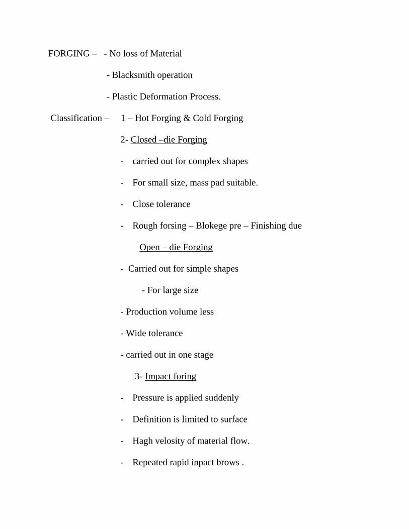
FORGING – - No loss of Material
- Blacksmith operation
- Plastic Deformation Process.
Classification – 1 – Hot Forging & Cold Forging
2- Closed –die Forging
- carried out for complex shapes
- For small size, mass pad suitable.
- Close tolerance
- Rough forsing – Blokege pre – Finishing due
Open – die Forging
- Carried out for simple shapes
- For large size
- Production volume less
- Wide tolerance
- carried out in one stage
3- Impact foring
- Pressure is applied suddenly
- Definition is limited to surface
- Hagh velosity of material flow.
- Repeated rapid inpact brows .

- Pressure is max ,at begriming &gradually bows
Press Forging
- Pressure is applied gradually.
- Law velocity of material flow.
- Single step pressure application.
- Pressure is from zero to max.
- Pressure increases as the metal is deformed & is maximum
at the moment the pressure is released
- Deeper Penetration of metal deformation.
Drop-forging Die Design –
The first step in the design of a drop –forging due is the decision regarding what
impressions (or stages) are necessary to achieve the necessary fiber flow direction
to obtain the requisite strength.
A blocking impression becomes a necessity only when the component is to be
accurately made or the component has deep pockets or thin ribs, which are difficult
to be obtained in a single finishing impression. A bending impression is required
when the part is of bent nature and the growth direction is to be along the bend
lone. In such a case, the bending impression is to be obtained before the blocking
impression or finishing impression when no blocking is used. Similarly, a
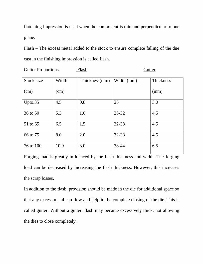
flattening impression is used when the component is thin and perpendicular to one
plane.
Flash – The excess metal added to the stock to ensure complete falling of the due
cast in the finishing impression is called flash.
Gutter Proportions. Flash Gutter
Stock size
(cm)
Width
(cm)
Thickness(mm) Width (mm) Thickness
(mm)
Upto.35 4.5 0.8 25 3.0
36 to 50 5.3 1.0 25-32 4.5
51 to 65 6.5 1.5 32-38 4.5
66 to 75 8.0 2.0 32-38 4.5
76 to 100 10.0 3.0 38-44 6.5
Forging load is greatly influenced by the flash thickness and width. The forging
load can be decreased by increasing the flash thickness. However, this increases
the scrap losses.
In addition to the flash, provision should be made in the die for additional space so
that any excess metal can flow and help in the complete closing of the die. This is
called gutter. Without a gutter, flash may became excessively thick, not allowing
the dies to close completely.
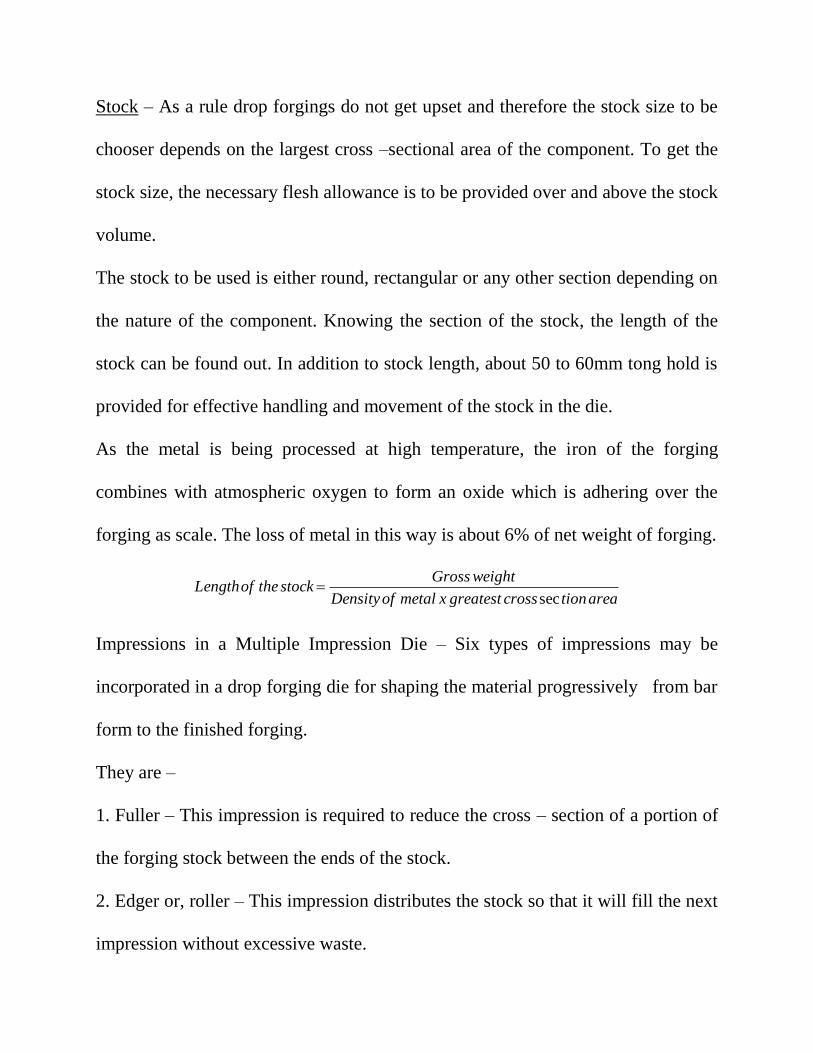
Stock – As a rule drop forgings do not get upset and therefore the stock size to be
chooser depends on the largest cross –sectional area of the component. To get the
stock size, the necessary flesh allowance is to be provided over and above the stock
volume.
The stock to be used is either round, rectangular or any other section depending on
the nature of the component. Knowing the section of the stock, the length of the
stock can be found out. In addition to stock length, about 50 to 60mm tong hold is
provided for effective handling and movement of the stock in the die.
As the metal is being processed at high temperature, the iron of the forging
combines with atmospheric oxygen to form an oxide which is adhering over the
forging as scale. The loss of metal in this way is about 6% of net weight of forging.
areationcrossgreatestxmetalofDensity
weightGrossstocktheofLength
sec
Impressions in a Multiple Impression Die – Six types of impressions may be
incorporated in a drop forging die for shaping the material progressively from bar
form to the finished forging.
They are –
1. Fuller – This impression is required to reduce the cross – section of a portion of
the forging stock between the ends of the stock.
2. Edger or, roller – This impression distributes the stock so that it will fill the next
impression without excessive waste.

3. Bender impression – Bender impression is included in the die block when curves
or, angles in the forging make it necessary to bend the stock before it will fit
properly in the finishing impression. Bending is a very important operation to keep
the flow lines continuous in a job like crane hook.
4. Block impression – Block impression gives the forging its general shape and
allows the proper gradual flow of metal necessary to prevent laps and cold shuts.
Blocking impression is of same contour as the finished parts but the radio and
fillots are lange to permit the easiest flow of metal. A block impression is without a
flash or, gutter.
5. The finishing impression – This impression bring the forging to its final size.
The finishing impression has both a gutter and flash impression cut round it to
provide space for the excess metal. Both blocker and finisher have a necking or,
running impression so that the forging is still held with tongs.
6. Cut off – It is also part of the die block. It cuts the forging from the bar by
cutting off the tong hold. The flash and gutter are however removed in separate
trimming dies, under punch, presses.
Die – block Dimensions –
The dimensions of the die-block depend upon the length of the finish forging
impression, depth of the impression and the number of impressions in the die
block.

For a single – impression die, the length of the die block may be taken as,
L = l + 3 h (minimum) B = c x b
Where, l – Total length of forging impression,
h = maximum depth of the impression,
b = Maximum width of the impression
c = Constant
= 3 for b upto 5cm
= 2.5 for b upto 25 cm
= 2 for b above 25 cm
The height of the die – block determines the maximum impression depth, since
adequate die material must be there between the bottom, of ompression and bottom
face of the die block to provide strength in the die.
From the strength point of view of the dies and the die wear, the ratio of h and b is
Material h/b
l = b l≥2b
Al, Mg 1.0 2.0
Steel, Titanium 1.0 1.5
For multi impression dies, a gap of at least 25mm should be left between two
adjacent impressions.
a1 - the inter impression distance,

a – the distance of impression from the edge of the die block
H – the height of the die block Dimension in mm
h a a1 H
6
10
40
100
12
32
56
110
10
25
40
80
100
125
200
315
h = the maximum depth of impression.
In terms of the maximum depth of impression, corresponding other values given.
Upset Forging Die Design – (Machine Forging)
In upset forgings, as a rule, no reduction in cross section occurs.
Depending on the shape of the upsetting to be done, the number of passes or blows
in the die are to be designed. The amount of upsetting to be done in a single stage
is limited. To arrive at the safe amount of upsetting in a given pass, the following
rules are to be satisfied, to achieve defect free upset forgings.
Rule 1 – The maximum length of the up supported stock that can be gathered or,
upset in a single pass is not more than three times the diameter of the bar. Beyond
this length, the material is likely to buckle under, the axial upsetting load. In
practice, it is better that the length of the unsupported stock is within 2.5 times the
bar diameter.

Rule 2 – Length of stock more than 3 times bar diameter that is within the limits of
the stroke of machine can be successfully upset made is not more than 1.5 times
bar diameter. If this is kept more than 1.5d, the buckling will be excessive and the
stock will fold in. In practices it is advisable not to exceed 1.3 time bar diameter.
Rule 3 – In an upset requiring more than 3rd in length, when the diameter of the
upset is 1.5d, the amount of unsupported stock beyond the face of the die must not
exceed one diameter of bar.
However if the diameter of the hole in the die is reduced below 1.5d, then the
length of unsupported stock beyond the face of the die can be correspondingly
increased.
Rule 4- Avoid using head diameter greater than four times the stock diameter.
The ratings of Upset forging machines as per Metals Handbook –
Rated Size,
cms
Nominal Rated
capacity kN
Average strokes per
min.
2.5
3.1
3.8
5.0
6.25
7.50
-
1250
3000
4000
5000
6000
90
75
65
60
55
45

10
12.5
15
17.5
20
22.5
8000
10000
12000
15000
18000
22000
35
30
27
25
23
-
Selection of correct size machine necessary to forge a part should be governed by
the following factors.
1. Volume of stock required in the finished forging,
2. Size of stock used.
3. Maximum dimension of the finished forging.
4. Number of blows necessary to complete the forging.
The following steps are formulated in sequences for the purpose of eliminating
guess work.
(i) Calculate the volume of metal in the part to be forged.
(ii) Determine the proper cross section of metal and shape of the metal to be used
to make the forging.
(iii) With the shape and area of the cross – section as well as the volume of the
upset, calculate the length of the metal necessary.

(iv) Calculate the number of blows necessary to complete the forging, using the
general rules that eliminate folding or, buckling.
(v) Make a die layout to determine the size of the die blocks and heading tolls
necessary to accommodate the required number of blows and cavity dimensions.
(vi) Determine the size of forging machine to be used, bearing in mind the size of
the bar to be used, size of the forging to be made, size of the die-blocks necessary
length of header slide, length of stroke, length of gather, length of die opening etc.
(vii) Use hot dimensions on all cavities.
(viii) Provide for clearance between heading tools and their mating dies when
these tolls enter the dies
(ix) Provision should be made for proper grip of the stock.
The length of this grip should not be less than 3d. Also, the cavity diameter in this
area should measure approximately 0.30 to 0.50mm smaller then the diameter of
the bar to be foged.
(x) With the dies and tools designed and the impression machined in the die
blocks, it is advisable to place the tools in the tool holders and make a preliminary
set up of the dies and tools in a face placet for final checking before placing them
in the forging machine.
(xi) Setting of the dies and tools in the forging machine requires a check of
parallelism for the die seats and also the travel of the header slide.
(xii) A small stream of coolant should be directed on the dies and tools to dissipate
the heat and keep the dies free from scale, that may gather in the cavities. The best
is solution of slable oil & water.
Upset forging gives flowing added advantages –
1. A high degree of accuracy in dimensional tolerances.
2. Die life is increased by minimusing the contact time between the dies and
the hot metal.
3. Reduction in the man power required as compard to drop forging.
4. Die setting time is less than drop forging for similar jobs.
5. Die manufacturing cost is less as insert technology is very suitable for
upsetter dies.
6. Preparation of raw material perform design ) is not needed as the bar stock is
directly used in dies.
Design suitable tooling for upset forging of the component shown. The material is
mild steel.
Solution – For the design of the die, all the dimensions will be taken on M.S.
contraction scale.
Volume to be upset.
Since 𝑙
𝑑 is less than 2.5, the forging can be upset in one blow. Applying rule 1-

Total length required for the component
= (43.8 – 5.7) + 8.188 + 0.16 = 46.45 cm
Size of the M/c = Since the bar size is 3.8 cm, so the size of M/c of nominal rated
capacity 3000 KN will be suitable.
Size of the die block = For 3.8cm size of the machine, the die block sizes.- Length
of bar to be gripped = 3d = 11.4cm.
Parting line of the job is taken aling the diameter Half the impression is in the die
block and the other half in the punch.
The length of the conical portion is within two – thirds of the maximum working
length. The unsupported stock beyond the die face is 101mm which is 2.89 times
the stock diameter and is acceptable since it is around 2.5
The average stock diameter after pass 1 is 35+45
2= 40mm
𝐿𝑒𝑛𝑔𝑡ℎ 𝑜𝑓 𝑠𝑡𝑜𝑐𝑘
𝐷𝑖𝑎𝑚𝑒𝑡𝑒𝑟=
324
40= 8.1
This is still high and therefore one more conical gathering pass is desired.
Length of conical portion = 12𝑥408898
𝜋(402+40𝑥60+602= 205.5mm
The unsupported length is 118.5mm which is 2.96 times the stock diameter and
therefore can be acceptable.
Average stock diameter after pass 2 = 40+60
2= 50mm
𝐿𝑒𝑛𝑔𝑡ℎ 𝑜𝑓 𝑠𝑡𝑜𝑐𝑘
𝐷𝑖𝑎𝑚𝑡𝑒𝑟 =
205.5
50=4.11

This is still more than 3 but not too high . Therefore, we may check for the validity
of Rule 2, since it has already violated Rule 1.
Rule 2 is violated since the diameter of 135 mm of the cavity should be
135
50=2.7x stock diameter.
Hence, one more cone gathering is desirable.
Length of conical portion= 12𝑥408898
𝜋 (502+50𝑥70+702) = 143.29 mm
After the third pass, the length to diameter ratio is now 2.388 which therefore can
be gathered in a single pass.

SHEET METAL WORKING
Shearing Action –
The metal is brought to the plastic stage by pressing the sheet between two
shearing blades so that fracture is initiated at the cutting points.
The metal under the upper shear is subjected to both compressive and tensile
stresses.
Clearances - The clearance between two shears is one of the principal factors
controlling a shearing process. This clearance depends essentially on the material
and thickness of the sheet metal. This clearance is given per side as.
C = 0.0032 x t x √𝜏
Where t = sheet thickness, mm
& = material shear stress, MPa
Shearing operations –
In die shearing operations, the shears take the form of the component to be made.
The upper shear is called the punch, and the lower shear is called the die.
Blanking – It is a process in which the punch removes a portion of material from
the stock which is a strip of sheet metal. The removed portion is called a blank.
Piercing – It is also called punching. Piercing is making holes in a sheet.
In the shearing operation, first the material is elastically deformed and then
plastically and finally removed from the stock strip. After the final breaking, the

slug will spring back due to the release of stored elastic energy. This will make
the blank cling to the die face unless the die opening is enlarged. This enlargement
is normally referred as angular clearance or draft.
The normal value is from 0.25 to 0.75 deg per side the die opening increase after
every sharpening of the die because of the provision of angular clearance. So, to
maintain the die size as per the design, the angular clearance is provided in the die
opening along with a straight portion called die land or cutting land. The length of
the cutting land is around same as the material thickness.
Stripper = Due to the release of the stored elastic energy in the stock left on the die,
the stock tends to grip the punch as the punch moves upward. This necessitates the
use of a stripper to separate the punch from the stock.
The stripping force varies from 2.5 % to 20% of the punch force. The stripping
force is given by,
Ps = KLt
Where, Ps = Stripping force, kN
L = Perimeter of cut, mm
t= Stock thickness, mm
K = Stripping constant.
= 0.0103 for low-carbon steels thinner than 1.5mm with the cut at the edge or, near
a preceding cut.
= 0.0145 for low-carbon steels thinner than 1.5mm for other cuts.
= 0.0207 for low-carbon steels thinner than 1.5mm above 1.5mm thick.
= 0.0241 for harder materials.
In blanking the die size is same as the component size whereas in piercing the
punch size is same as the actual hole size to be obtained.
Punching Force – The force required to be exerted by the punch in order to shear
out the blank from the stock can be estimated from the actual shear area and the
shear strength of the material.
It is given by =
P = Lt z
Wher, P = Punching force, N
z = shear strength , MPa
t = Stock thickness, mm
The punching force for holes which are smaller than the stock thickness is
estimated as =
Where, d = diameter of the punch, mm
S = tensile strength of the stock, MPa
Shear
The maximum shear force when shear is applied to the punch or the die, is given as
Where, p = Penetration of punch as a fraction

t1= shear on the punch or, die, mm
The provision of the shear on the punch will change the slug where as shear
provided on the die would make the stock left on the die to bend. Hence, the shear
is provided on the die for blanking and on the punch for piercing.
Q = Determine the die and punch sizes for blanking a circular disc of 20mm,
diameter from a C20 steel sheet whose thickness is 1.5mm Take shear strength of
C20 steel as 294 Mpa.
Solution = The clearance to be provide is given as
C = 0.0032 x t x √𝜏
= C = 0.0032x 1.5 x √294
=0.0823 mm≅ 0.10𝑚𝑚
Since it is a blanking operation,
Die size = blank size = 20mm.
Punch size = blank size – 2C = 20 – 2x0.10 =19.8 mm
If it were a piercing operation ,
Punch size = blank size = 20mm
Die size = blank size +2C
= 20 + 2 x 0.1 = 20.2 mm
Blanking Piercing
Punch size, mm 19.8 20.0
Die size, mm 20.0 20.2
Punching force (P) = Lt z
=𝜋𝑑 𝑥 𝑡 𝑥 𝑧
= 𝜋 𝑥 20𝑥1.5𝑥294 = 27.709𝑘𝑁.
Stripping force (Ps) = KLt
= 0.024 x (𝜋𝑥20) 𝑥 1.5
= 2.262 kN
Q = A 100mm diameter hole is to be punched in a 6mm thick steel plate. The
material is cold rolled C40 steel for which the maximum shear strength can be
taken as 550 MPa. With normal clearance on the tools, cutting is complete at 40%
penetration of the punch. Give suitable diameters for the punch and die, and shear
angle on the punch in order to bring the work within the capacity of a 200 kN
press available in the shop. Solution –
DEEP DRAWING -
Drawing is the process of making cups, shells, and similar articles from metal
blanks. Here, the setup is similar to that used in blanking except that the punch and
die are provided with the necessary rounding at the corners to allow for the smooth
flow of metal during drawing.
Shallow drawing is defined as that where the cup height is less than half the
diameter.

For drawing deeper cups it is necessary to make specific provisions to confine the
metal in order to prevent excess wrinkling of the edges. For this purpose, a blank
holder is normally provided on all deep-drawing dies.
DRAW DIE DESIGN –
Corner Radius on the Punch – The corner radius on the punch varies from four to
ten times the blank thickness. Ideally, the punch radius should be the same as the
corner radius of the required cup, because it takes its form.
Draw Radius on Die –
Drew radius = 4t normal
= (6 to 8 ) t when the blank holder is used.
= 0.8 𝜋 (D-d) t
Where, t = blank thickness
Clearances =
Ideally, the clearance between the punch and die should be same as the blank
thickness. But the blank gets thickened towards the edge because of the metal flow
and hence, the actual clearance provided is slightly higher to account for this
thickening. It varies from 7% to 20% of the blank thickness.
Blank size –
Where, r = corner radius on the punch, mm.
h = height of the shell, mm
d = outer diameter of the shell, mm.
D = blank diameter, mm.
Trim Allowance –
These are only the theoretical blank sizes, based on the surface area of the shell
and blank. Additional trimming allowance is added for trimming of uneven and
irregular rim of the deep-drawn cup. The trim allowance is 3mm for the first 25mm
cup diameter and additional 3mm for each of the additional 25mm of cup
diameters.
Drawing Force –
Where, P = drawing force N.
t = thickness of the blank material, mm
s = yield strength of the metal, Mpa.
C= constant to cover friction and bending. It varies between 0.6 to 0.7
Blank Holding Force = The maximum limit of blank holding force is generally one
third of the drawing force. However it is obtained more by trial and error
depending on the wrinkling tendency.
Ironing force = The objective of Ironing force is to reduce the wall thickness of the
cup. Neglecting the friction and shape of the die, the ironing force =
F=
Where F = Ironing force, N

d1 = mean diameter of the shell after ironing.
t1 = thickness of the shell after ironing.
to = thickness of the shell before ironing.
Sav = average of tensile strength before and after ironing.
Percent Reduction = The drawing operation relies on the ductility of the blank
material. The ductility is affected by the amount of strain a material takes. But
there is a limit to which it can be strained. The amount of straining or, the
drawability is represented by the % reduction which is expressed in terms of the
diameter of the blank and the shell
The percent reduction P is given by,
Where d= Shell diameter (OD)
D = Blank diameter
D
dP 1100
Theoretically, it is possible to get a percentage reduction upto 50, but it is
practicllay limited to 40 Because of strain hardening, the percentage reducation
gets reduced in the subsequent draws.
Reduction in drawing with cup height (% Reduction)
Ht. to dia.
ratio
No. of
draws
First draw Second
draw
Third drew Fourth drew

Up to 0.75
0.75 to 1.5
1.5 to 3.00
3 to 4.5
1
2
3
4
40
40
40
40
-
25
25
25
-
-
15
15
-
-
-
10
Air vent – An air vent is normally provided in the punch to reduce the possibility
of formation of vacuum in the cup, when it is stripped from the punch. For
cylindrical shells, one vent located centrally would be enough, but for other shapes
two vents are provided. The size of the air vent depends on the punch diameter.
Punch dia. (mm) Air- Vent dia. (mm)
Up to 50 4.5
50 to 100 6.0
100 to 200 7.5
Over 200 10
Drawing speed – The speed with which the punch moves through the blank
during drawing is termed the drawing speed. Suggested drawing speeds are =
Drawing Speeds
Material Drawing speed (m/s)
Aluminum 0.9
Brass 1
Copper 0.75

Steel 0.28
Zinc 0.75
Q. A symmetrical cup of circular cross section with a 40 mm diameter and 60mm
height having a corner radius of 2mm is to be obtained in C20 steel of 0.6mm
thickness. Make the necessary design calculations, for preparing the die for the
above cup.
Q. The symmetrical cup work piece as shown is to be made from cold rolled steel
0.8 mm thick. Make the necessary design for the drawing die of this part.
Progressive Dies – In practice, components are produced by combinations of
blanking, piercing, bending or, drawing operations in a certain order. Hence,
practically dies have to do more than one operation for making a finished
component.
The progressive dies perform two or, more operations simultaneously in a single
stroke, of a punch press, so that a complete component is obtained for each stroke.
The place where each of the operations is carried out are called stations. The stock
strip moves from station to station undergoing the particular operation.
The distance moved by the strip from station one to two so that it is properly
registered under the stations is called advance distance.
The feed distance is the amount of stock fed under the punch when the ram comes
for the next stroke. The feed distance may or, may not be the same as the advance

distance. This is because sometimes the sheet is overfed against a stop. The strip is
therefore positioned correctly under the punch by pulling it backwards with the use
of pilots.
Progressive dies contain a large number of stations. It is generally preferred to
have a piercing operation first in the sequence and a blanking or, cut off operation
in the end to get the final component. Any of the pierced holes may be used as a
pilot hole.
The choice of progressive dies is made only when the production is of large
numbers so that the handling costs are saved; stock material is not very thin, so that
movement of the strip by pilots is convenient; stock material is not too thick so as
to avoid the problems of stock straightening and the overall size of the die or, the
press capacity are large.
Compound Die- In a compound die, all the necessary operations are carried out at a
single station , in a single stroke of the ram. To do more than one set of operations,
a compound die consists of the necessary sets of punches and dies.
Compound dies are somewhat slower than the corresponding progressive dies in
operation. But higher tolerances can be achieved in them than in the progressive
dies. This is mainly because the part located in one position under goes all the
operations . Also in compound dies, small strips can be advantageously used,
whereas in progressive dies very long strips are required to cover all the stations.

MODULE-III
Design of Jigs and Fixtures
A jig may be defined as a device which holds and positions the work, locates or,
guides the cutting tool relative to the work piece and usually is not fixed to the
machine table. It is usually lighter in construction.
Jigs are used on drilling, reaming, tapping and counter boring operations.
A fixture is a work holding device which only holds and positions the work but
does not in itself guide locate or, position the cutting tool. The setting of the tool is
done by machine adjustment and a setting block or, by using slip gauges. A fixture
is bolted or, clamped to the machine table. It is usually heavy in construction.
Fixtures are used in connection with turning, milling, grinding, shapping, planning
and boring operations.
To fulfil their basic functions, both jigs and fixtures should possess the following
components or, elements:
1. A sufficiently rigid body (plate, box or frame structure) into which the
workpieces are loaded.
2. Locating elements.
3. Clemping elements.
4. Tool guiding elements (for jigs) or, tool setting elements (for fixtures).
5. Elements for positioning or, fastening the jig or, fixture on the machine on
which it is used.

Jigs and Fixtures are used –
1. To reduce the cost of production, as their use eliminates the layingout of work
and setting up of tools.
2. To increase the production.
3. To assure high accuracy of the parts.
4. To provide for interchangeability.
5. To enable heavy and complex shaped parts to be machined by being held
rigidly to a machine.
6. Reduced quality control expenses.
7. Increased versatility of machine tool.
8. Less skilled labour
9. Saving labour.
10. Their use partically automates the m/c torl.
11. Their use improves the safety at work, thereby lowering the rate of
accidents.
Locating and Clamping –
The overall accuracy is dependnt primarily on the accuracy with which the
workpiece is consistently located within the jig on fixture. There must be no
movement of the work during maching.

Locating refers to the establishment of a proper relationship between the workpiece
and the jig or fixture.
Clamping is to exert a force to press the workpiece agadust the locating surfaces
and hold it there against the action of cutting forces.
Figures
In a state of freedom, it may move in either of the two opposed directions along
three mutually perpendicular axes, xx, yy and zz. There six movements are called
“movements of translation”.
Also, the workpiece can rotate in either of two opposed directions around each
axis, clockwise and anticlockwise. These six movements are called “rotational
movements”.
The sum of these two types of movements, gives the twelve degrees of freedom of
a workpiece inspace. To confine the workpiece accurately and positively in another
fixed body (jig or, fixture). The movements, of the workpiece in any of the twelve
degrees of freedom must be restricted.
(a) The workpiece is resting on three pins A, B and C which are inserted in the
base of the fixed body.
The workpiece cannot rotate about the axes XX and YY and also it cannot move
downward. This wayt, the five degree of freedom 1,2,3,4, & 5 have been arrested.

(b) Two more pins D and E are inserted in the fixed body, ina plane perpendicular
to the plane containing the pins A,B and C. Now the workpiece cannot rotate about
the Z – axis and also it cannot move towards the left. Hence, the addition of pins D
& E restrict three more degrees of freedom, namely 6, 7 and 8.
(c) Another pin F in the second vertical face of the fixed body, arrests degree of
freedom 9.
Thus, six locating pins, three in the base of the fixed body, two in a vertical plane
and one in another vertical plane, the three planes being perpendicular to one
another, restrict nine degrees of freedom. Three degrees of freedom, namely, 10,
11, 12 are still free. To restrict these, three move pins are needed. Buyt this will
completely enclose the work piece making its loading and unloading into the jig or
fixture impossible.
Hence, these remaining three (10, 11, 12) degrees of freedom may be arrested by
means of a clamping device.
This method of locating a work piece in a jig or a fixture is called the “3-2-1”
principle or “Six point location” principle.
Locating devices –
Pins of various designs and made of hardened steel are the most common locating
devices used to locate a work piece in a jig or, fixture. The shank of the pin is press
fitted or, driven into the body of the jig or, fixture. The locating diameter of the pin
is made larger than the shank to prevent it from being forced into the jig or, fixture
body due to the weight of the work piece or, the cutting forces. Depending upon
the mutual relationship between the work piece and pin, the pins may be classified
as:
1. Locating pins 2. Support pins 3. Jack pins.
Principles for location purposes –
1. At least one datum or, reference surface should be established at the first
opportunity, from which subsequent machining will be measured.
2. For ease of cleaning, locating, surfaces should be as small as possible consistent
with adequate wearing qualities. Also, the location must be done from the
machined surface.
3. The locating surfaces should not hold swarf and thereby misalign the workpiece.
For this, proper relief should be provided where burr or, swarf will get collected.
4. Locating surfaces should be raised above surrounding surfaces of the jig or,
fixture, so that chips fall or, can be swept off readily.
5. Sharp corners in the locating surfaces must be avoided.
6. Adjustable type of locators should be used for the location on rough surfaces.
7. Locating pins should be easily accessible and visible to the operator.

Clamping –
If the work piece cannot be restrained by the locating elements, it becomes
necessary to clamp the work piece in jig or, fixture body. The purpose of clamping
is to exert a pressure to press a work piece against the locating surfaces and hold it
there in opposition to the cutting forces i.e, to secure a reliable (positive) contact of
the work with locating elements and prevent the work in the fixture from
displacement & vibration in machining.
Principles for Clamping Purposes –
Since the proper and adequate clamping of a work piece is very important, the
following design and operational factors should be taken care of
1. The clamping pressures applied against the work piece must counteract the tool
forces.
2. The clamping pressures should not be directed towards the cutting operation.
Whenever possible, it should be directed parallel to it.
3. The clamping pressure must only hold the workpiece and should never be great
enough so as to damage, deform or change any dimensions of the workpiece.
4. The clamping and cutting forces should be directed towards the locating pins;
otherwise the workpiece may get bent or forced away from the locating pins during
machining.
5. Clamping should be simple, quick and foolproof.
6. The movement of a clamp should be strictly limited.
7. Whenever possible, the lifting of the clamp by hand should be avoided if it can
be done by means of spring fitted to it.
8. Clamps should never be relied upon for holding the workpiece against the
cutting force. The cutting force should be arranged against a fixed stop or a
substantial part of the fixture body.
9. The clamps should always be arranged directly above the points supporting the
work, otherwise the distortion of the work can occur.
10. Fibre pads should be riveted to the clamp faces, oterhwise soft and fragile
workpiece can get damaged.
11. A clamp should be designed to deliver the required clamping force when
operated by the smallest force expected.
12. A clamp should be strong enough to with stand the reaction imposed upon it
when the largest expected operating force is applied.
13. Clamping pressure should be directed towards the points of support, otherwise
work will tend to rise from its support.
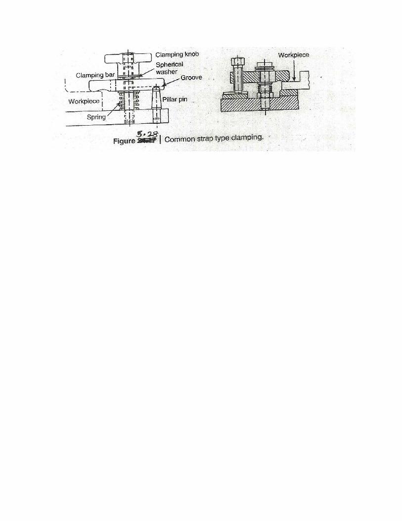
Clamping Devices – The commonly used clamping devices are –
1. Clamping screws 2. Hook blot clamp.
3. Lever type clamps 4. Quick acting clamps.


DESIGN PRINCIPLES COMMON TO JIGS & FIXTURES –
1. Since the total machining time for a work piece includes work handling time,
the methods of location and clamping should be such that the idle time is
minimum.
2. The design of jig and fixture should allow easy and quick loading and
unloading of the workpiece. This wil also help in reducing the idle tiem to
minimuse.
3. The Jig and fixture should be as open as possible to minimize chip or, burr
accumulation and tto enable the operator to remove the chips easily with a
brush or, an air jet.
4. The design features in the jig or fixture will be such that it becomes impossible
to load the work into the jig or fixture in an improper position.

5. Clearance – Clearance is provided in the jig or, fixture body for two main
reasons :
(i) To allow for any variation in component sizes, especially castings and
forgings.
(ii) To allow for hand, movements so that the workpiece can easily be placed
in the jig or, fixture and removed after maching.
6. Rigidity – Jigs and fixtures should be sufficiently stiff to secure the preset
accuracy of machining.
7. To simplify the handling of heavy jigs or, fixtures, the following means can be
adopted –
(i) Eye- bolts, lifting lugs can be provided for the lifting of the jig or, fixture.
(ii) If the workpiece is heavy, then the jig design should allow for side loading
and unloading by sliding the workpiece on the m/c table.
8. The use of ejection devices to force the workpiece out from the jig or, fixture.
9. Inserts – To avoid any damage to fragily and soft workpieces and also to the
fonishied surfaces of a workpiece clamping, inserts of some soft material such
as copper lead fibre, leather, hard rubber or plastic should be fitted to the faces
of the clamps.
10. Design for safety – Jigs/ fixtures must be safe and convenient in use. For that –
(i) Sharp corners on the body of the jig/fixture should be avoided.

(ii) Bolts and nuts should be inside the body of the jig/fixture and protrude on
the suface.
11. Sighting Surfaces – Machining on a workpiece must be clearly visible to the
worker.
12. Simplicity in Design.
13. Economical.
14. They should be easy to set in the machine tool.
DRILLING JIGS –
Drilling jigs are used to machine holes in mechanical products. To obtain
positional accuracy of the holes, hardended drill bushes or, jog bushes are used to
locate and guide drills, reamers etc. in relation to the workpiece. The portin of the
jig into which the hardened bushes are fitted is called bush plate.
Drilling jigs are either clamped to the workpiece in which holes are to be drilled or,
the workpiece is housed and clamped in the jig body. If more than one hole is to be
drilled, the drill jig is made to slide on the table of the drilling machine.
Drilling jigs make feasible the drilling of holes at higher speed, with greater
accuracy and with less skilled workers than is possible when the holes are laid out
and drilled by hand.
Design Principles –

1. A drilling jig should of light in construction consistent with adequate rigidity to
facilitate its handling because it has to be handed frequently during the operation.
2. A drilling jig which is not normally clamped to the machine table should be
provided with jour feet so that it will rock if it is not resting equeare on the
machine table and so warm the operator.
3. The stability of a drilling jig should be as good as possible since it is not usual to
clamp it to the machine table and to ensure this, the feet or, base of the jig should
extend well outside the holes to be drilled.
4. Drill bushing should be fitted in fixed portoon of the jig.
Drill Bushes –
Jig bushings eliminate the elastic spring back in machining and easily locate the
tool relative to the wor.
Drill bushings are classified as
(1) Press Fit bushings.
(ii) Renewable bushes.
(iii) Linear bushes.
(i) These bushings are used when little importance is put on accuracy or, finish.
These bushing are installed directly in the jig body and are used mainly for short
production runs out requiring bush replacement.

(ii) When the guide bushes require periodic replacement (due to the wear of the
inside dia. of the bush, in the case of continuous or, large batch production), the
replacement is simplified by using a renewable bush. These are of the flanged type
and are sloding fit into the liner bush, which is installed (press fitted in the jig
plate). The liner bush provides hardened wear resistant mating surface to the
renewable bush. The renewable bushes must be prevented from rotating or, lifting
with the drill.
(iii) Liner Bushings – also known as ‘master bushings’ are permanently fixed into
the jig body. These act as guides for renewable type bushings. These bushings can
be with or, without heads. A liner bush is always used in conjunction with a
renewable bush.
Design Principles for Drill Bushings –
1. To facilitate easy entry of drills, the entrances to drill bushes should be
extremely smooth and well chamfered or, rounded.
2. There should not be any sharp corners on the body of the bush
3. Loose or, screwed in solid bushes should not be used where accuracy is
important.
4. The effective length of the drill bushing should be sufficient to guide and
support the drill.
5. Adequate provisions must be made for the chips that are produced and for their
easy removal.
6. The hole of the drill bushing should be from 0.00025 to 0.0025cm larger than
the drill size.
Jig bushings can be used to drill from 10,000 to 15,000 holes.
Indexing jigs and Fixtures –
Indexing jigs and fixtures are used when holes or, slots are to be machined to some
specific relationship, in a workpiece.
Indexing Devices – Many indexing jigs and fixtures employ a simple indexing
plate for their operation. Suppose six holes are to be drilled in a flange. The flange
can be mounted on an index plate which has six equispaced slots. The workpiece is
revolved under the drill and each hole is drilled in turn. For this an index plunger is
used which fots by turn into each slot in the index plate. To index the workpiece,
the plunger is pulled out of the slot. The index place and thereby the workpiece is
rotated ---- the next slpt comes in line with the index plunger into which it gets
pushed due to spring action.

Design of Single Point Cutting Tools
The work of a tool, designer consists of following stops
(i) Determining the forces action on the cutting surfaces of the tool and
determining the optimum tool geometry.
(ii) Finding the most producible shapes of the cutting tool and determining the
tolerances on the dimension of the cutting and mounting elements of the tools.
(iii) Calculating the rigidily of the cutting and mounting elements of the tool.
(iv) Making a working drawing of the tool and computing the manufacturing
dimensions.

Rigidity considerations for a single point turning tool - The shank of a single point
tool may be rectangular, square, round in section. The recteangular cross – section
is the most popular.
Square shank tools are used for boring, turret and automatic lathes.
Round shank tools are used for boring & thread cutting.
The permissible size of the shank cross section is determined on the strength basis.
For this purpose the actual bending moment (Mb) acting on the tool is equated to
the moment of resistance of the tool shank (Mb1). Mb = Mb
1
From Fig, Mb = Fc x L.
The tool overhand (L) = (1 - 1.5) H.
The maximum deflection which the tool undergoes durig the maching operation
should also be limited.
The maximum deflection of the tool would occur at the cutting point and could be
found by assuming the tool shank to be a cantilever loaded at the free end. For a
tool having rectangular cross section, deflection is
BROACH DESIGN
Broaching is a process of machining a surface with a pecial multipoint tool called a
broach, whose teeth remove the while maching allowance in a single stroke.
Broaching is widely used in the manufacture of special gears, Bushings and
sleeves, compressor wheels, Rotors, Chain Sprocket teeth, turbine blades etc.

A broach is a multi point cutting tool consisting of a bar having a surface
containing a series of cutting teeth or, edges which gradually increase in size from
the starting or, entering end to the rear end. Broaches are used for machining either
internal or, external surfaces (sizing of hole, straight or, helical splines, gun riflin
and key ways).
Each tooth of the tool takes a thin slice from the surface. Broaching of inside
surface is called ‘Internal or, hole broaching’ and outside surfaces as ‘Surface
broaching’.

Tooth shape of a Broach. H.S.S. is by for the most widely used material for the
broaches. Brazed carbides are used for maching cast iron parts. Carbide tools are
also used on steel casting.
FORM TOOLS
Form tools are cutting tools which are used to machine complex shaped surfaces
with the cross section outlined by curves or, broken lines. Form tools are
commonly used in large lot and mass production. Their use ensures –
-a high output
- uniform contour of all workpieces, and
- accurate dimensions.
Classification of Form Tools –
1. According to their type as – circular, flat and end form tools.
2. According to the setting of flat tools in respect to the workpiece as : Tools with a
radial cutting edge and tangential tools.
3. According to the position of the tool axis as: tools with the axis parallel to the
workpiece axis and tools with an angular location of the axis or, mounting
surfaces.
4. According to the elements of the contoured surface on the tool, as: circular tools
with annular elements, circular tool with helieal elements, and flat tools with flat
elements.
Design features of form tools –
Most form tools are made of H.S.S. However, cemented carbides are also used.
The use of contoured cemented, carbide tips for form tills enables the productivity
to be raised by 30% to 40% as compared to H.S.S.A form tool should have the
proper rake and relief angles.
Relief angel is = 100 to 120 on circular form tools.
=120 to 150 on flat fomr tools.
Rake angles for form Tools
Material Rake angle (degrees)
Al, Cu 20 to 25
Bronze, leaded brass 0 to 5
Mild steel 25
Medium hard steel 20 to 25
Hand steel 12 to 20
Very hard steel 8 to 12
Soft cast iron 15
Hard cast Iron 12
Very hard cast iron 8

DESIGN OF LIMIT GAUGES
Gauges are inspection tools of rigid design, without a scale, which serve to check
the dimensions of manufactured parts. Gauges do not indicate the actual value of
the inspected dimensions of the component. They are only used for determining
whether the inspected part has been made within the specified limits.
Gauging is used in preference to measuring when quantities are sufficiently high,
because it is faster and easier with resulting lower costs.
The design of a limit gauge must ensure proper inspection of the part for which it
is intended. The following points and factors must be kept in mind while designing
the limit gauges:
1. Limit gauge tolerance:
(a) Manufacturing tolerance
(b) Wear allowance
2. Taylor’s principle of gauge design.
3. Fixing of gauging elements (ends) with hands.
4. Provision of Guard.
5. Provison of Pilot.
6. Correct centring
7. Materials.
8. Hardness and surface finished

9. Rigidity.
10. Alignment.
1. Limit Gauge Tolerances –
(a) Manufacturing tolerance –
Gauge maker’s tolerance or, manufacturing tolerance should be kept as small as
possible so that a large proportion of the work tolerance is still available for the
manufacturing process. However, the small the gauge tolerance, the more the
gauge will cost.
The accepted general norms are –
Limit gauges are made 10 times more accurate than the tolerancs they are going to
control that is the tolerance on each gauge whether ‘Go’ or, ‘Not Go’, is 1/10th of
the work tolerance.
There are two systems for the allocation of manufacturing tolerance, Unilateral
system and Bilateral system.
Unilateral system – In this system, the gauge tolerance zone lies entirely within the
work tolerance Zone.
e.g. the size of the hole to be tested be 25± 0.02mm
High limit of hole = 25.02 mm
Low limit of hole = 24.98
Work tolerance = 0.04
Gauge tolerance = 10% of tolerance
= 0.004 mm
Dimension of ‘Go Plug gauge = 24.98 mm + 0.004 – 0.000
+0.000
Dimension of ‘Not Go’ Plug gauge = 25.02 mm
– 0.004.
The disadvantage of this system is that certain components may be rejected as
being outside the working limits when they are not.
Bilateral system – In this system, the ‘Go’ and ‘Not Go’ gauge tolerance zones are
bisected by the high and low limits of the work tolerance zone
Dimensions of ‘Go’ Plug gauge = 24.98mm +0.002/– 0.002
Dimension s of ‘Not Go’ Plug gauge = 25.02 mm+ 0.002 /– 0.002
(b) Wear Allowance –
Mostly the measuring surfaces of ‘Go’ gauges which constantly rub against the
surfaces of the parts in inspection are sufijected to wear and loose their initial size.
To proling the senis lfie of the gauges, wear allowance is taken as 5% of work
tolerance
For above example,
Wear allowance = 5% of work tolerance = 0.002 mm
Nominal size of go plug gauge = 24.98 + 0.002=24.982 mm
Dimensions of Go plug gauge = 24.982 + 0.004 /– 0.000 mm

Dimensions of Not Go plug gauge = 25.02 + 0.000 /– 0.004mm
2. Taylor’s Principle –
This principle states that the go gauge should always be so designed that it will
cover the Maximum Metal Condition (MMC) of as many dimensions as possible in
the same limit gauge, where as a Not Go gauge to cover the minimum metal
condition of one dimension only.
According to this rule, a Go plug gauge should have a full circular section and be
of full length ofc the hole, it has to check. In addition to control the diameter at any
one point this ensures that any lack of straightness or, parallelism of the hole will
prevent the entry of full length go plug gauge.
3. Fixing of gauge elements with handle – Plug gauges can be of solid type in
which the gauging members are integral with the handle or, the gauging elements
can be separated from the handle and suitable fixed together. These are known as
“Renewable” type of gauges. Below 50mm dia., solid type gauges are mostly used.
For larger diameters, the renewable end type of plug gauges is used.
4. Provision of Guard – In case of screw gauges, in order to protect the first few
screw threads from damage, guard extension should be provided. In plug gauges
also, to protect the end, guard extension is provided. If the plug gauge is used for a
blind hole, then guard extension will not be provided.
5. Provision of Pilot – In case of very closely tolerance parts, sometimes it happens
that the plug gauge does not early enter the hole. To overcome this problem,
piloting of plug gauge used.
6. Correct centering –
Centres for high grade job should be very very perfect. Sometimes before grinding,
the centres are even honed after heat treatment.
7. Materials – Most gauges are subjected to considerable abrasion during their use
and must, therefore, be made of wear resistant materials.
High carbon and alloy steel have been used as gauge materials because of their
relatively high harden ability and abrasion resistance. For high volume production
runs, gauge wear surfaces are often chrome plated. The durability of steel gauges
coated with a layer of chrome of 5 to 8 micrometer is 10 to 12 times that of
uncoated ones.
8. Hardness and surface finish –
Recommended hardness for gauges is 62 to 64 Rockwell – C for plain gauges and
56 to 62 Rockwell – C for screw gauges. The recommended surface finish is :
0.127 to 0.254 micrometer, Ra for ground gauges & 0.05 to 2 micrometer, Ra for
lapped gauges.
9. Rigidity – Rigidity is one of the most important features of gauge design.

10. Alignment of Gauge Faces – In a normal gap gauge, the faces must be parallel
and opposite to each other and the points of contract with the work at each face
must lie on a line normal to the gauging face.

PROCESS PLANNING –
Process planning is the systematic determination of method or, process by which
the product is to be manufactured economically and competitively within the limits
of design specification laid down .It consists of devising, selecting and specifying
processes, machine tools and other equipment to convert row materials in to
finished product. Process planning is on intermediate stage between designing the
product and manufacturing it.
The process planning prepares a Plan of manufatur consigning the facto :
1 . The functional requrements of theh product .
2. Volume of output .
3. The necessary operations and their sequence.
4. Tools and equepmant necessary.
5. Estimated manufacturing cost for producing the product .
6. Requarement of tools. labour etc.
So a process planning is mainly concerned with –
(a) Detormation the manufacturing p rocess, sequence of operations,
equipments tools and lobour required for the production of na companent or
a product .
(b) Co – ordinating the effort of all factors in manufacturing the product.
(c) To finish a guide to use the existing or, the proposed facilities.
Function s of process Engineering -----

The process planning or, process engineering is the function of determinating
exactly how a product will be made.
The functions of process engineering are as
1. To determine what parts are to be manufactured and what part to be purchased
from outside.
2. To determine the most economical manufacturing process to be used . dere
3. To determine the sequence of operation to be performed on each component .
4. To determine the blank sizes of materials in process.
5. To prepare materials list for all components of product to invate the purchasing
of row materials.
6. To determine, select and initiate the order for purchasing the equipments/
machine tools needed to manufacture the product.