product data weathermaker single packaged rooftop
TRANSCRIPT

© Carrier 2021 Form 48/50FC-4-7-03PD
48/50FC**04, 05, 06, 07
48FC: Single-Package Gas Heating/Electric Cooling Rooftop Units 50FC: Electric Cooling Rooftop Units with Optional Electric Heatwith Puron® Refrigerant (R-410A)
Product DataWeatherMaker®
Single Packaged Rooftop3 to 6 Nominal Tons

2
The New Carrier WeatherMaker® rooftop units (RTU) with EcoBlue™ Technology were designed by customers for customers and integrate new technology to provide value added benefits never seen in this type of equipment before.New major design features include:• Patent pending, industry’s first effi-
cient indoor fan system using VaneAxial fan with electric commutatedvariable speed motor
• Reliable fixed speed scroll compres-sor on 3-5 ton sizes and 2 stagescroll technology on 6 ton sizes
• Upgraded unit control board withintuitive indoor fan adjustment
• Reliable copper tube/aluminum fincondenser coil with 5/16-in. tubingto help reduce refrigerant chargeversus prior designs
• New outdoor fan system with rug-ged — lightweight high impact com-posite fan blade
48/50FC WeatherMaker® units up to6 tons are specifically designed to fit onCarrier roof curbs that were installedback to 1989, which makes replace-ment easy and eliminates the need forcurb adapters or changing utilityconnections.Single-stage units deliver SEERs up to14.0. IEERs up to 15.2. All models arecapable of either vertical or horizontalairflow.The Carrier rooftop unit (RTU) wasdesigned by customers for customers.
With “no-strip” screw collars, handledaccess panels, and more, the unit iseasy to install, easy to maintain, andeasy to use. Your new 3 to 6 tonCarrier WeatherMaker rooftop unit(RTU) provides optimum comfort andcontrol from a packaged rooftop.Value-added features include:• optional Humidi-MiZer® adaptive
dehumidification system forimproved part load humidityperformance
• Puron® refrigerant (R-410A)• single point gas and electrical
connections• optional fully integrated SystemVu™
controls• RTU Open controller for BACnet1,
LonWorks2, Modbus3 and JohnsonControls N2
• 3 to 5 ton models use fixed refriger-ant metering devices and 6 tonmodels use a TXV
• Scroll compressors with internalline-break overload protection
• Units come with an easy accesstool-less filter door. Filter track tiltsout for filter removal and replace-ment. All filters are the same size ineach unit
Installation easeAll WeatherMaker units are field-con-vertible to horizontal airflow, which
makes it easy to adjust to unexpectedjob-site complications. Lighter unitsmake for easy replace. Simple, fastplug-in connections to the standardintegrated unit control board (UCB).Clearly labeled connections points toreduce installation time. Also, a largecontrol box provides room to work androom to mount Carrier accessorycontrols.Easy to maintainWith the new EcoBlue Vane Axial fansystem and direct drive ECM motor,there is no longer a need to adjust beltsor pulleys as in past designs. This freesup maintenance and installation time.Easy access handles by Carrier providequick and easy access to all normallyserviced components. Our “no-strip”screw system has superior holdingpower and guides screws into positionwhile preventing the screw from strip-ping the unit’s metal.Sloped, corrosion resistant compositedrain pan sheds water; and won’t rust.Easy to useThe newly re-designed Unit ControlBoard by Carrier puts all connectionsand troubleshooting points in one con-venient place. Most low voltage con-nections are made to the same boardand make it easy to access it. Settingup the fan is simple by an intuitiveswitch and rotary dial arrangement.Carrier rooftops have high and lowpressure switches, a filter drier, and2-in. filters standard.
1. BACnet is a registered trademark of ASHRAE (American Society of Heating, Re-frigerating and Air-Conditioning Engineers).
2. LonWorks is a registered trademark of Echelon Corporation.
3. Modbus is a registered trademark of Schneider Electric.
Features/Benefits
Table of contentsPage
Features/Benefits . . . . . . . . . . . . . . . . . . . . . . . . . . . . . . . . . . . . . . . . . . . 2Model Number Nomenclature. . . . . . . . . . . . . . . . . . . . . . . . . . . . . . . . . . . 4Capacity Ratings . . . . . . . . . . . . . . . . . . . . . . . . . . . . . . . . . . . . . . . . . . . . 6Physical Data . . . . . . . . . . . . . . . . . . . . . . . . . . . . . . . . . . . . . . . . . . . . . 10Options and Accessories . . . . . . . . . . . . . . . . . . . . . . . . . . . . . . . . . . . . . 15Base Unit Dimensions . . . . . . . . . . . . . . . . . . . . . . . . . . . . . . . . . . . . . . . 20Accessory Dimensions . . . . . . . . . . . . . . . . . . . . . . . . . . . . . . . . . . . . . . . 26Performance Data . . . . . . . . . . . . . . . . . . . . . . . . . . . . . . . . . . . . . . . . . . 27Fan Data . . . . . . . . . . . . . . . . . . . . . . . . . . . . . . . . . . . . . . . . . . . . . . . . 40Electrical Data. . . . . . . . . . . . . . . . . . . . . . . . . . . . . . . . . . . . . . . . . . . . . 97Typical Wiring Diagrams . . . . . . . . . . . . . . . . . . . . . . . . . . . . . . . . . . . . 119Sequence of Operation . . . . . . . . . . . . . . . . . . . . . . . . . . . . . . . . . . . . . 131Application Data . . . . . . . . . . . . . . . . . . . . . . . . . . . . . . . . . . . . . . . . . . 134Guide Specifications . . . . . . . . . . . . . . . . . . . . . . . . . . . . . . . . . . . . . . . 136
3
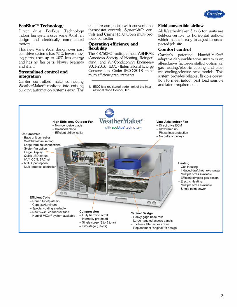
EcoBlue™ TechnologyDirect drive EcoBlue Technologyindoor fan system uses Vane Axial fandesign and electrically commutatedmotors.This new Vane Axial design over pastbelt drive systems has 75% fewer mov-ing parts, uses up to 40% less energyand has no fan belts, blower bearingsand shaft.Streamlined control and integrationCarrier controllers make connectingWeatherMaker® rooftops into existingbuilding automation systems easy. The
units are compatible with conventionalthermostat controls, SystemVu™ con-trols and Carrier RTU Open multi-pro-tocol controller.Operating efficiency and flexibilityThe 48/50FC rooftops meet ASHRAE(American Society of Heating, Refriger-ating, and Air-Conditioning Engineers)90.1-2016, IECC1 (International EnergyConservation Code) IECC-2018 mini-mum efficiency requirements.
Field convertible airflow All WeatherMaker 3 to 6 ton units arefield-convertible to horizontal airflow,which makes it easy to adjust to unex-pected job-site.Comfort controlCarrier’s patented Humidi-MiZer®
adaptive dehumidification system is anall-inclusive factory-installed option ongas heating/electric cooling and elec-tric cooling/electric heat models. Thissystem provides reliable, flexible opera-tion to meet indoor part load sensibleand latent requirements.1. IECC is a registered trademark of the Inter-
national Code Council, Inc.
High Efficiency Outdoor Fan– Non-corrosive blade– Balanced blade– Efficient airflow collar
Vane Axial Indoor Fan– Direct drive ECM– Slow ramp up– Phase loss protection– No belts or pulleys
Efficient Coils– Round tube/plate fin– Copper/Aluminum– Special coating available– New ⁵/��-in. condenser tube– Humidi-MiZer® system available
Compression– Fully hermitic scroll– Internally protected– Single stage (3 to 5 tons)– Two-stage (6 tons)
Cabinet Design– Heavy gage base rails– Large handled access panels– Tool-less filter access door– Replacement “original” fit design
Heating– Gas Heating Induced draft heat exchanger Multiple sizes available Efficient dimpled gas design– Electric Heating Multiple sizes available Single point power
Unit controls– Base unit controller Switch/dial fan setting Large terminal connections– SystemVu option Large Display Quick LED status iVu®, CCN, BACnet– RTU Open option Multi-protocol controller

4
48FC MODEL NUMBER NOMENCLATURE
Model Series - WeatherMaker®
FC – 14.0 SEER Standard Efficiency, sizes 04-06 15.0 IEER Standard Efficiency, size 07
Unit Heat Type48 – Gas Heat Packaged Rooftop
Cooling Tons04 = 3 tons05 = 4 tons06 = 5 tons07 = 6 tons
Heat SizeD = Low Gas HeatE = Medium Gas HeatF = High Gas HeatL = Low NOx – Low Gas Heat¹S = Low Heat w/ Stainless Steel ExchangerR = Medium Heat w/ Stainless Steel ExchangerT = High Heat w/ Stainless Steel Exchanger(Low NOx models include Stainless Steel HX)
Sensor OptionsA = NoneB = Return Air (RA) Smoke DetectorC = Supply Air (SA) Smoke DetectorD = RA + SA Smoke DetectorE = CO2 SensorF = RA Smoke Detector and CO2 SensorG = SA Smoke Detector and CO2 SensorH = RA + SA Smoke Detector and CO2 SensorJ = Condensate Overflow Switch K = Condensate Overflow Switch and RA Smoke DetectorL = Condensate Overflow Switch and RA and SA Smoke DetectorsM = Condensate Overflow Switch and SA Smoke Detector
Indoor Fan Options1 = Direct Drive – EcoBlue – Standard Static2 = Direct Drive – EcoBlue – Medium Static3 = Direct Drive – EcoBlue – High Static
Refrig. Systems OptionsA = Standard One Stage Cooling Models1
B = Standard One Stage Cooling Models with Humidi-MiZer® system1, 3
M = Single Circuit, Two Stage Cooling2
N = Single Circuit, Two Stage Cooling with Humidi-MiZer system2, 3
Coil Options – (Outdoor - Indoor - Hail Guard)A = Al/Cu - Al/CuB = Precoat Al/Cu - Al/CuC = E-coat Al/Cu - Al/CuD = E-coat Al/Cu - E-coat Al/CuE = Cu/Cu - Al/CuF = Cu/Cu - Cu/CuM = Al/Cu - Al/Cu — Louvered Hail GuardN = Precoat Al/Cu - Al/Cu — Louvered Hail GuardP = E-coat Al/Cu - Al/Cu — Louvered Hail GuardQ = E-coat Al/Cu - E-coat Al/Cu — Louvered Hail GuardR = Cu/Cu - Al/Cu — Louvered Hail GuardS = Cu/Cu - Cu/Cu — Louvered Hail Guard
Design Revision- = Factory Design Revision
Base Unit Controls0 = Electro-mechanical Controls – can be used with field-installed W7212 EconoMi$er® IV (Non-Fault Detection and Diagnostic)2 = RTU Open Multi-Protocol Controller3 = SystemVuTM Controls6 = Electro-mechanical Controls – can be used with W7220 EconoMi$er X (with Fault Detection and Diagnostic)
Intake / Exhaust OptionsA = NoneB = Temperature Economizer w/ Barometric ReliefF = Enthalpy Economizer w/ Barometric Relief K = Two-Position Damper1
U = Temperature Ultra Low Leak Economizer w/ Barometric ReliefW = Enthalpy Ultra Low Leak Economizer w/ Barometric Relief
Service Options0 = None1 = Unpowered Convenience Outlet2 = Powered Convenience Outlet3 = Hinged Panels4 = Hinged Panels and Unpowered Convenience Outlet5 = Hinged Panels and Powered Convenience Outlet
Packaging & Seismic Compliance0 = Standard1 = LTL
Electrical Options A = NoneC = Non-Fused DisconnectD = Thru-The-Base ConnectionsF = Non-Fused Disconnect and Thru-The-Base Connections
Example:Position:
4 8 F C D A 0 4 A 2 A 5 - 0 A 0 A 01 2 3 4 5 6 7 8 9 10 11 12 13 14 15 16 17 18
Voltage1 = 575/3/603 = 208-230/1/601
5 = 208-230/3/606 = 460/3/60
1 Size 04/05/06 models only2 Size 07 models only3 Units with Humidi-MiZer System include Low Ambient controller
Note: On single phase (-3 voltage code) models, the following are not available as a factory-installed option: - Humidi-MiZer System - Two-Position Damper - Coated Coils or Cu Fin Coils - Louvered Hail Guards - Economizer or 2-Position Damper - Powered 115 Volt Convenience Outlet
Model number nomenclature

5
50FC MODEL NUMBER NOMENCLATURE
Model Series - WeatherMaker®
FC – 14.0 SEER Standard Efficiency, sizes 04-06 15.2 IEER Standard Efficiency, size 07
Unit Heat Type50 – Electric Heat Packaged Rooftop
Cooling Tons04 = 3 tons05 = 4 tons06 = 5 tons07 = 6 tons
Heat Size- = No heat
Sensor OptionsA = NoneB = Return Air (RA) Smoke DetectorC = Supply Air (SA) Smoke DetectorD = RA + SA Smoke DetectorE = CO2 SensorF = RA Smoke Detector and CO2 SensorG = SA Smoke Detector and CO2 SensorH = RA + SA Smoke Detector and CO2 SensorJ = Condensate Overflow Switch K = Condensate Overflow Switch and RA Smoke DetectorL = Condensate Overflow Switch and RA and SA Smoke DetectorsM = Condensate Overflow Switch and SA Smoke Detector
Indoor Fan Options1 = Direct Drive – EcoBlue – Standard Static2 = Direct Drive – EcoBlue – Medium Static3 = Direct Drive – EcoBlue – High Static
Refrig. Systems OptionsA = Standard One Stage Cooling Models1
B = Standard One Stage Cooling Models with Humidi-MiZer® system1, 3
M = Single Circuit, Two Stage Cooling2
N = Single Circuit, Two Stage Cooling with Humidi-MiZer system2, 3
Coil Options – (Outdoor - Indoor - Hail Guard)A = Al/Cu - Al/CuB = Precoat Al/Cu - Al/CuC = E-coat Al/Cu - Al/CuD = E-coat Al/Cu - E-coat Al/CuE = Cu/Cu - Al/CuF = Cu/Cu - Cu/CuM = Al/Cu - Al/Cu — Louvered Hail GuardN = Precoat Al/Cu - Al/Cu — Louvered Hail GuardP = E-coat Al/Cu - Al/Cu — Louvered Hail GuardQ = E-coat Al/Cu - E-coat Al/Cu — Louvered Hail GuardR = Cu/Cu - Al/Cu — Louvered Hail GuardS = Cu/Cu - Cu/Cu — Louvered Hail Guard
Design Revision- = Factory Design Revision
Base Unit Controls0 = Electro-mechanical Controls – can be used with field-installed W7212 EconoMi$er® IV (Non-Fault Detection and Diagnostic)2 = RTU Open Multi-Protocol Controller3 = SystemVuTM Controls6 = Electro-mechanical Controls – can be used with W7220 EconoMi$er X (with Fault Detection and Diagnostic)
Intake / Exhaust OptionsA = NoneB = Temperature Economizer w/ Barometric ReliefF = Enthalpy Economizer w/ Barometric Relief K = 2-Position Damper1
U = Temperature Ultra Low Leak Economizer w/ Barometric ReliefW = Enthalpy Ultra Low Leak Economizer w/ Barometric Relief
Service Options0 = None1 = Unpowered Convenience Outlet2 = Powered Convenience Outlet3 = Hinged Panels4 = Hinged Panels and Unpowered Convenience Outlet5 = Hinged Panels and Powered Convenience Outlet
Packaging & Seismic Compliance0 = Standard1 = LTL
Electrical Options A = NoneC = Non-Fused DisconnectD = Thru-The-Base ConnectionsF = Non-Fused Disconnect and Thru-The-Base Connections
Example:Position:
5 0 F C - A 0 4 A 2 A 5 - 0 A 0 A 01 2 3 4 5 6 7 8 9 10 11 12 13 14 15 16 17 18
Voltage1 = 575/3/603 = 208-230/1/605 = 208-230/3/606 = 460/3/60
1 Size 04/05/06 models only2 Size 07 models only3 Units with Humidi-MiZer System include Low Ambient controller
Note: On single phase (-3 voltage code) models, the following are not available as a factory-installed option: - Humidi-MiZer System - Coated Coils or Cu Fin Coils - Louvered Hail Guards - Economizer or 2-Position Damper - Powered 115 Volt Convenience Outlet

6
48FC AHRI RATINGS
LEGEND
NOTES:1. Rated in accordance with AHRI Standards 210/240 (04-06 size)
and 340/360 (07 size).2. Rating are based on:
Cooling Standard: 80°F (27°C) db, 67°F (19°C) wb indoor airtemperature and 95°F (35°C) db outdoor air temperature.IEER Standard: A measure that expresses cooling part-load EERefficiency for commercial unitary air-conditioning and heat pumpequipment on the basis of weighted operation at various loadcapacities.
3. All 48FC units comply with ASHRAE 90.1-2016 (American Societyof Heating, Refrigerating, and Air-Conditioning Engineers) andDOE-2018 (Department of Energy) Energy Standard for minimumSEER and EER requirements.
4. 48FC units comply with US Energy Policy Act (2005). To evaluatecode compliance requirements, refer to state and local codes.
50FC AHRI RATINGS
LEGEND
NOTES:1. Rated in accordance with AHRI Standards 210/240 (04-06 size)
and 340/360 (07 size).2. Rating are based on:
Cooling Standard: 80°F (27°C) db, 67°F (19°C) wb indoor airtemperature and 95°F (35°C) db outdoor air temperature.IEER Standard: A measure that expresses cooling part-load EERefficiency for commercial unitary air-conditioning and heat pumpequipment on the basis of weighted operation at various loadcapacities.
3. All 50FC units comply with ASHRAE 90.1-2016 (American Societyof Heating, Refrigerating, and Air-Conditioning Engineers) andDOE-2018 (Department of Energy) Energy Standard for minimumSEER and EER requirements.
4. 50FC units comply with US Energy Policy Act (2005). To evaluatecode compliance requirements, refer to state and local codes.
48FC UNIT COOLING STAGES
NOMINALCAPACITY
(TONS)
NET COOLING CAPACITY
(MBH)
TOTAL POWER (kW) SEER EER
IEER WITH 2-SPEED
INDOOR FAN MOTOR
48FC*A04 1 3 34.5 3.0 14.0 11.5 N/A48FC*A05 1 4 47.0 4.1 14.0 11.6 N/A48FC*A06 1 5 58.5 5.3 14.0 11.0 N/A48FC*M07 2 6 70.0 6.4 N/A 11.0 15.0
AHRI — Air-Conditioning, Heating and Refrigeration InstituteEER — Energy Efficiency RatioIEER — Integrated Energy Efficiency RatioSEER — Integrated Energy Efficiency Ratio
50FC UNIT COOLING STAGES
NOMINALCAPACITY
(TONS)
NET COOLING CAPACITY
(MBH)
TOTAL POWER (kW) SEER EER
IEER WITH 2-SPEED
INDOOR FAN MOTOR
50FC*A04 1 3 34.4 2.9 14.0 11.7 N/A50FC*A05 1 4 47.0 4.0 14.0 11.8 N/A50FC*A06 1 5 58.5 5.2 14.0 11.2 N/A50FC*M07 2 6 70.0 6.3 N/A 11.2 15.2
AHRI — Air-Conditioning, Heating and Refrigeration InstituteEER — Energy Efficiency RatioIEER — Integrated Energy Efficiency RatioSEER — Integrated Energy Efficiency Ratio
Capacity ratings

7
SOUND RATINGS TABLE
LEGEND
NOTES:1. Outdoor sound data is measured in accordance with AHRI.2. Measurements are expressed in terms of sound power. Do not
compare these values to sound pressure values because soundpressure depends on specific environmental factors which nor-mally do not match individual applications. Sound power valuesare independent of the environment and therefore more accurate.
3. A-weighted sound ratings filter out very high and very low frequen-cies, to better approximate the response of “average” human ear.A-weighted measurements for Carrier units are taken in accor-dance with AHRI.
48/50FC UNIT COOLING STAGES
OUTDOOR SOUND (dB) AT 60 HzA-WEIGHTED 63 125 250 500 1000 2000 4000 8000
A04 1 79 85.6 84.7 80.5 76.0 72.4 68.0 62.8 59.3A05 1 79 85.6 84.7 80.5 76.0 72.4 68.0 62.8 59.3A06 1 79 85.6 84.7 80.5 76.0 72.4 68.0 62.8 59.3M07 2 79 85.6 84.7 80.5 76.0 72.4 68.0 62.8 59.3
dB — Decibel

8
MINIMUM - MAXIMUM AIRFLOW RATINGS (CFM) — NATURAL GAS AND PROPANE
* Heating rating values are identical for aluminum heat exchangers and stainless steel heat exchangers.
MINIMUM - MAXIMUM AIRFLOW RATINGS (CFM) — COOLING UNITS AND ACCESSORY ELECTRIC HEAT
* Electric heat modules are available as field-installed accessories for 50FC units.
UNIT HEATLEVEL VOLTAGE
COOLING HEATING*
MINIMUMAIRFLOW
CFM
MINIMUM2-SPEED
AIRFLOW(LOW SPEED)
MINIMUM2-SPEED
AIRFLOW(HIGH SPEED)
MAXIMUMAIRFLOW
CFM
MINIMUMAIRFLOW
CFM
MAXIMUMAIRFLOW
CFM
48FC**04LOW
1 PHASE 900 N/A N/A 1500890 1950
MED 800 1520HIGH N/A N/A
48FC**05LOW
1 PHASE 1200 N/A N/A 2000890 2440
MED 1050 2280HIGH 1220 2170
48FC**06LOW
1 PHASE 1500 N/A N/A 2500890 3250
MED 1050 2730HIGH 1220 2790
48FC**04LOW
3 PHASE 900 N/A N/A 1500910 2010
MED 960 1160HIGH N/A N/A
48FC**05LOW
3 PHASE 1200 N/A N/A 2000910 2010
MED 1250 2330HIGH 1390 2220
48FC**06LOW
3 PHASE 1500 N/A N/A 2500910 2510
MED 1250 2720HIGH 1390 2780
48FC**07LOW
3 PHASE 1800 1200 1800 3000910 3350
MED 1250 3260HIGH 1390 3170
UNIT
COOLING ELECTRIC HEAT*
MINIMUM AIRFLOW CFM
MINIMUM2- SPEED AIRFLOW
(LOW SPEED)
MINIMUM2- SPEED AIRFLOW
(HIGH SPEED)
MAXIMUM AIRFLOW CFM
MINIMUM AIRFLOW CFM
MAXIMUM AIRFLOW CFM
50FC**04 900 N/A N/A 1500 900 150050FC**05 1200 N/A N/A 2000 1200 200050FC**06 1500 N/A N/A 2500 1500 250050FC**07 1800 1200 1800 3000 1800 3000
Capacity ratings (cont)

9
HEAT RATING TABLE — NATURAL GAS AND PROPANE
LEGEND
48FC UNIT GAS HEATAL/SS HEAT EXCHANGER
TEMPERATURE RISE (°F)
THERMAL EFFICIENCY (%)
AFUE EFFICIENCY (%)INPUT/OUTPUT
STAGE 1 (MBH)INPUT/OUTPUT STAGE 2 (MBH)
Single Phase
04LOW –/– 65/53 25-55 81 81MED –/– 90/73 45-85 82 81HIGH –/– — — — —
05LOW –/– 65/53 20-55 81 81MED –/– 90/73 30-65 82 81HIGH –/– 130/106 45-80 81 81
06LOW –/– 65/53 15-55 81 81MED –/– 90/73 25-65 82 81HIGH –/– 130/106 35-80 81 81
Three Phase
04LOW –/– 67/54 25-55 81 N/AMED 82/65 110/93 50-85 80 N/AHIGH — — — — —
05LOW –/– 67/54 25-55 81 N/AMED –/– 110/88 35-65 80 N/AHIGH 120/96 150/120 50-80 80 N/A
06LOW –/– 67/54 20-55 81 N/AMED –/– 110/88 30-65 80 N/AHIGH 120/96 150/120 40-80 80 N/A
07LOW –/– 67/54 15-55 81 N/AMED –/– 110/88 25-65 80 N/AHIGH 120/96 150/120 30-80 80 N/A
HEAT RATING TABLE — LOW NOX
48FC UNIT GAS HEATLOW NOx HEAT EXCHANGER
TEMPERATURE RISE (°F)
THERMALEFFICIENCY (%)
AFUE EFFICIENCY (%)INPUT/OUTPUT
STAGE 1 (MBH)INPUT/OUTPUTSTAGE 2 (MBH)
Single Phase
04 LOW — 60/49 20-50 82.0 81.305 LOW — 60/49 20-50 82.0 81.306 LOW — 60/49 15-50 82.0 81.3
Three Phase
04 LOW — 60/49 20-50 82.0 81.305 LOW — 60/49 20-50 82.0 81.306 LOW — 60/49 15-50 82.0 81.3
AFUE — Annual Fuel Utilization EfficiencyMBH — Btuh in thousands

10
48/50FC 3 TO 4 TON PHYSICAL DATA
48/50FC UNIT 48/50FC*A04 48/50FC*B04 48/50FC*A05 48/50FC*B05NOMINAL TONS 3 4BASE UNIT OPERATING WT (lb) 48FC/50FC* 482/437 543/498REFRIGERATION SYSTEM
No. Circuits/No. Compressors/Type 1 / 1/ ScrollPuron® (R-410A) charge A/B (lbs-oz) 4-6 — 9-14 —Humidi-MiZer® Puron (R-410A) charge A/B (lbs-oz) — 7.6 — 14-6Metering device AcutrolHumidi-MiZer metering device — TXV-Acutrol — TXV-AcutrolHigh-Pressure Trip/Reset (psig) 630/505Low-Pressure Trip/Reset (psig) 54/117 27/44 54/117 27/44
EVAPORATOR COILMaterial (Tube/Fin) Cu/AlCoil Type 3/8-in. RTPFRows/FPI 2/15 3/15Total Face Area (ft2) 5.5Condensate Drain Connection Size 3/4-in.
CONDENSER COILMaterial Cu/AlCoil Type 5/16-in. RTPFRows/FPI 1/18 2/18Total Face Area (ft2) 11.7 15.9
HUMIDI-MIZER COILMaterial — Cu/Al — Cu/AlCoil Type — 3/8-in. RTPF — 3/8-in. RTPFRows/FPI — 1/17 — 2/17Total Face Area (ft2) — 4.1 — 4.1
EVAPORATOR FAN AND MOTORStandard Static 1 Phase
Motor Qty/Drive Type 1/Direct — 1/Direct —Max Cont BHP 0.44 — 0.72 —RPM Range 189-1890 — 190-1900 —Fan Qty/Type 1/Vane Axial — 1/Vane Axial —Fan Diameter (in.) 16.6 — 16.6 —
Medium Static 1 PhaseMotor Qty/Drive Type 1/Direct — 1/Direct —Max Cont BHP 0.71 — 1.06 —RPM Range 219-2190 — 217-2170 —Fan Qty/Type 1/Vane Axial — 1/Vane Axial —Fan Diameter (in.) 16.6 — 16.6 —
High Static 1 PhaseMotor Qty/Drive Type 1/Direct — 1/Direct —Max Cont BHP 1.07 — 1.53 —RPM Range 249-2490 — 246-2460 —Fan Qty/Type 1/Vane Axial — 1/Vane Axial —Fan Diameter (in.) 16.6 — 16.6 —
Standard Static 3 PhaseMotor Qty/Drive Type 1/DirectMax Cont BHP 0.44 0.72RPM Range 189-1890 190-1900Fan Qty/Type 1/Vane AxialFan Diameter (in.) 16.6
Medium Static 3 PhaseMotor Qty/Drive Type 1/DirectMax Cont BHP 0.71 1.06RPM Range 219-2190 217-2170Fan Qty/Type 1/Vane AxialFan Diameter (in.) 16.6
Physical data

11
* Base unit operating weight does not include weight of options.
High Static 3 PhaseMotor Qty/Drive Type 1/DirectMax Cont BHP 1.07 1.96RPM Range 249-2490 266-2660Fan Qty/Type 1/Vane AxialFan Diameter (in.) 16.6
CONDENSER FAN AND MOTORQty / Motor Drive Type 1 / DirectMotor HP/RPM 1/4 / 1100 1/4 / 1100 1/4 / 1100 1/4 / 1100Fan Diameter (in.) 23
FILTERSRA Filter Qty / Size (in.) 2 / 16x25x2OA Inlet Screen Qty / Size (in.) 1 / 20x24x1
48/50FC 3 TO 4 TON PHYSICAL DATA (cont)
48/50FC UNIT 48/50FC*A04 48/50FC*B04 48/50FC*A05 48/50FC*B05

12
48/50FC 5 TO 6 TON PHYSICAL DATA
48/50FC UNIT 48/50FC*A06 48/50FC*B06 48/50FC*M07 48/50FC* N07NOMINAL TONS 5 6BASE UNIT OPERATING WT (lb) 48FC/50FC* 556/511 607/562REFRIGERATION SYSTEM
No. Circuits/No. Compressors/Type 1 / 1 / Scroll 1 / 1 / 2-Stage ScrollPuron® (R-410A) charge A/B (lbs-oz) 8-9 — 10-3 —Humidi-MiZer® Puron (R-410A) charge A/B (lbs-oz) — 15-0 — 20-8Metering device Acutrol TXVHumidi-MiZer metering device — TXV-Acutrol — TXVHigh-Pressure Trip/Reset (psig) 630/505Low-Pressure Trip/Reset (psig) 54/117 27/44 54/117 27/44
EVAPORATOR COILMaterial (Tube/Fin) Cu/AlCoil Type 3/8-in. RTPFRows/FPI 4/15Total Face Area (ft2) 5.5 7.3Condensate Drain Connection Size 3/4-in.
CONDENSER COILMaterial Cu/AlCoil Type 5/16-in. RTPFRows/FPI 2/18Total Face Area (ft2) 15.9 15.0
HUMIDI-MIZER COILMaterial — Cu/Al — Cu/AlCoil Type — 3/8-in. RTPF — 3/8-in. RTPFRows/FPI — 2/17 — 2/17Total Face Area (ft2) — 4.1 — 5.5
EVAPORATOR FAN AND MOTORStandard Static 1 Phase
Motor Qty/Drive Type 1/Direct —Max Cont BHP 1.06 —RPM Range 215-2150 —Fan Qty/Type 1/Vane Axial —Fan Diameter (in.) 16.6 —
Medium Static 1 PhaseMotor Qty/Drive Type 1/Direct —Max Cont BHP 1.44 —RPM Range 239-2390 —Fan Qty/Type 1/Vane Axial —Fan Diameter (in.) 16.6 —
Standard Static 3 PhaseMotor Qty/Drive Type 1/DirectMax Cont BHP 1.06 1.31RPM Range 215-2150 230-2300Fan Qty/Type 1/Vane AxialFan Diameter (in.) 16.6
Medium Static 3 PhaseMotor Qty/Drive Type 1/DirectMax Cont BHP 1.44 1.76RPM Range 239-2390 253-2530Fan Qty/Type 1/Vane AxialFan Diameter (in.) 16.6
High Static 3 PhaseMotor Qty/Drive Type 1/DirectMax Cont BHP 2.43RPM Range 284-2836Fan Qty/Type 1/Vane AxialFan Diameter (in.) 16.6
CONDENSER FAN AND MOTORQty / Motor Drive Type 1 / DirectMotor HP/RPM 1/4 / 1100 1/4 / 1100 1/4 / 1100 1/4 / 1100Fan Diameter (in.) 23
FILTERSRA Filter Qty / Size (in.) 2 / 16x25x2 4 / 16x16x2OA Inlet Screen Qty / Size (in.) 1 / 20x24x1
Physical data (cont)

13
48FC 3 TO 5 TON GAS HEAT DATA — 1 PHASE UNITS
LEGEND
* Base unit operating weight does not include weight of options.
48FC UNIT 48FC**04 48FC**05 48FC**06GAS CONNECTION
No. of Gas Valves 1Natural Gas Supply Line Pressure (in. wg)/(psig) 4-13 / 0.18-0.47Liquid Propane Supply Line Pressure (in. wg)/(psig) 11-13 / 0.40-0.47
HEAT ANTICIPATOR SETTING (AMPS)First Stage 0.14Second Stage 0.14
NATURAL GAS HEATLOW
No. of Stages / No. of Burners (total) 1 / 2Connection Size 1/2-in. NPTRollout Switch Opens / Closes (°F) 195 / 115Temperature Rise (°F) 25-55 20-55 15-55
MEDIUMNo. of Stages / No. of Burners (total) 1 / 3Connection Size 1/2-in. NPTRollout Switch Opens / Closes (°F) 195 / 115Temperature Rise (°F) 45-85 30-65 25-65
HIGHNo. of Stages / No. of Burners (total) — 1 / 3Connection Size — 1/2-in. NPTRollout Switch Opens / Closes (°F) — 195 / 115Temperature Rise (°F) — 45-80 35-80
LIQUID PROPANE HEATLOW
No. of Stages / No. of Burners (total) 1 / 2Connection Size 1/2-in. NPTRollout Switch Opens / Closes (°F) 195 / 115Temperature Rise (°F) 25-55 20-55 15-55
MEDIUMNo. of Stages / No. of Burners (total) 1 / 3Connection Size 1/2-in. NPTRollout Switch Opens / Closes (°F) 195 / 115Temperature Rise (°F) 45-85 30-65 25-65
HIGHNo. of Stages / No. of Burners (total) — 1 / 3Connection Size — 1/2-in. NPTRollout Switch Opens / Closes (°F) — 195 / 115Temperature Rise (°F) — 45-80 35-80
LOW NOx GAS HEATLOW
No. of Stages / No. of Burners (total) 1 / 2Connection Size 1/2-in. NPTRollout Switch Opens / Closes (°F) 195 / 115Temperature Rise (°F) 20-50 15-50
BHP — Break HorsepowerFPI — Fins Per InchOA — Outdoor AirRA — Return Air

14
48FC 3 TO 6 TON GAS HEAT DATA — 3 PHASE UNITS
48FC UNIT 48FC**04 48FC**05 48FC**06 48FC**07GAS CONNECTION
No. of Gas Valves 1Natural Gas Supply Line Pressure (in. wg)/(psig) 4-13 / 0.18-0.47Liquid Propane Supply Line Pressure (in. wg)/(psig) 11-13 / 0.40-0.47
HEAT ANTICIPATOR SETTING (AMPS)First Stage 0.14Second Stage 0.14
NATURAL GAS HEATLOW
No. of Stages / No. of Burners (total) 1 / 2Connection Size 1/2-in. NPTRollout Switch Opens / Closes (°F) 195 / 115Temperature Rise (°F) 25-55 20-55 15-55
MEDIUMNo. of Stages / No. of Burners (total) 2 / 3 1 / 3Connection Size 1/2-in. NPTRollout Switch Opens / Closes (°F) 195 / 115Temperature Rise (°F) 50-85 35-65 30-65 25-65
HIGHNo. of Stages / No. of Burners (total) — 2/ 3Connection Size — 1/2-in. NPTRollout Switch Opens / Closes (°F) — 195 / 115Temperature Rise (°F) — 50-80 40-80 35-80
LIQUID PROPANE HEATLOW
No. of Stages / No. of Burners (total) 1 / 2Connection Size 1/2-in. NPTRollout Switch Opens / Closes (°F) 195 / 115Temperature Rise (°F) 25-55 20-55 15-55
MEDIUMNo. of Stages / No. of Burners (total) 2 / 3 1 / 3Connection Size 1/2-in. NPTRollout Switch Opens / Closes (°F) 195 / 115Temperature Rise (°F) 50-85 35-65 30-65 25-65
HIGHNo. of Stages / No. of Burners (total) — 2 / 3Connection Size — 1/2-in. NPTRollout Switch Opens / Closes (°F) — 195 / 115Temperature Rise (°F) — 50-80 40-80 35-80
LOW NOx GAS HEATLOW
No. of Stages / No. of Burners (total) 1 / 2 —Connection Size 1/2-in. NPT —Rollout Switch Opens / Closes (°F) 195 / 115 —Temperature Rise (°F) 20-50 15-50 —
Physical data (cont)

15
* Factory-installed option.
† Field-installed accessory.
NOTES:1. Not available on single phase (-3 voltage code) models. Use field-
installed accessory where available.2. Requires a field-supplied 24V transformer for each application.
See price pages for details.3. FDD (Fault Detection and Diagnostic) capability per California Title
24 section 120.2.4. Models with SystemVu and RTU Open DDC controls comply with
California Title 24 Fault Detection and Diagnostic (FDD).5. Included with economizer.6. Sensors used to optimize economizer performance.7. See application data for assistance.8. Non-fused disconnect switch cannot be used when unit electrical
rating exceeds:208-230/1/60 and 208-230/3/60 = 80 amps (FLA).480/3/60 and 575/3/60 = 80 amps (FLA).
Carrier RTUBuilder automatically selects the amp limitations.9. Available as a factory-installed option for 04-06 models only.
ITEM OPTION* ACCESSORY†
GAS HEAT (48FC units only)Low, Medium or High Gas Heat — Aluminized Heat Exchanger X
Low, Medium or High Gas Heat — Stainless Steel Heat Exchanger X
Propane Conversion Kit XHigh Altitude Conversion Kit XFlue Discharge Deflector XFlue Shield X
ELECTRIC HEAT (50FC units only)Electric Resistance Heaters XSingle Point Kits X
CABINETThru-the-Base electrical or gas-line connections X X
Hinged Access Panels XMERV-8 Filters X
COIL OPTIONSCu/Cu indoor and/or outdoor coils1 XPre-coated outdoor coils1 XPremium, E-coated outdoor coils1 X
HUMIDITY CONTROLHumidi-MiZer® Adaptive Dehumidification System1 X
CONDENSER PROTECTIONCondenser coil hail guard (louvered deign)1 X X
CONTROLSThermostats, temperature sensors, and subbases X
SystemVu™ DDC communicating controller X
RTU Open Multi-Protocol controller XSmoke detector (supply and/or return air) X
Horn Strobe Annunciator2 XTime Guard II compressor delay control circuit X
Phase Monitor X XCondensate Overflow switch X X
ITEM OPTION* ACCESSORY†
ECONOMIZERS AND OUTDOOR AIR DAMPERSEconoMi$er® IV for electro-mechanical controls - Non FDD (Standard air leak damper models)1, 3, 9
X X
EconoMi$er2 for DDC controls (Stan-dard and Ultra Low Leak air damper models)1, 4
X X
EconoMi$er X for electro-mechanical controls, complies with FDD (Stan-dard and Ultra Low Leak damper models)1, 3, 9
X X
Motorized 2-position outdoor-air damper1 X X
Manual outdoor-air damper (25% and 50%) X
Barometric relief5 X XPower exhaust - prop design X
ECONOMIZER SENSORS AND IAQ DEVICESSingle dry bulb temperature sensors6 X XDifferential dry bulb temperature sensors6 X
Single enthalpy sensors6 X XDifferential enthalpy sensors6 XCO2 sensor (wall, duct, or unit mounted)6 X X
INDOOR MOTOR AND DRIVEMultiple motor and drive packages X
LOW AMBIENT CONTROLWinter start kit7 XLow Ambient controller to -20°F (-29°C)7 X
POWER OPTIONSConvenience outlet (powered)1 XConvenience outlet (unpowered) XNon-fused disconnect8 X
ROOF CURBSRoof curb 14-in. (356 mm) XRoof curb 24-in. (610 mm) X
Options and accessories
16
Factory-installed optionsEconomizer (dry-bulb or enthalpy)Economizers save money. They bring in fresh, outside airfor ventilation; and provide cool, outside air to cool yourbuilding. This is the preferred method of low-ambient cool-ing. When coupled to CO2 sensors, economizers can pro-vide even more savings by coupling the ventilation air toonly that amount required.Economizers are available, installed and tested by the fac-tory, with either enthalpy or dry-bulb temperature inputs.Additional sensors are available as accessories to optimizethe economizers. Economizers include a powered exhaustsystem to help equalize building pressures.Economizers include gravity controlled barometric reliefthat helps equalize building pressure and ambient air pres-sures. This can be a cost effective solution to prevent build-ing pressurization. Economizers are available in Ultra LowLeak and standard low leak versions. Economizers can befactory-installed or easily field-installed.Unit mounted CO2 sensorThe CO2 sensor works with the economizer to intake onlythe correct amount of outside air for ventilation. As occu-pants fill your building, the CO2 sensor detects their pres-ence through increasing CO2 levels, and opens theeconomizer appropriately. When the occupants leave, theCO2 levels decrease, and the sensor appropriately closesthe economizer. This intelligent control of the ventilationair, called demand controlled ventilation (DCV), reducesthe overall load on the rooftop, saving money. It is alsoavailable as a field-installed accessory.Smoke detector (supply and/or return air)Trust the experts. Smoke detectors make your applicationsafer and your job easier. Carrier smoke detectors immedi-ately shut down the rooftop unit when smoke is detected.They are available, installed by the factory, for supply air,return air, or both.Optional Humidi-MiZer® adaptive dehumidificationsystemCarrier’s Humidi-MiZer adaptive dehumidification systemis an all-inclusive factory-installed option that can beordered with any WeatherMaker® 48/50FC04-07 roof-top unit, with the exception of single phase voltage (208-230/1/60) units.This system expands the envelope of operation of Carrier’sWeatherMaker rooftop products to provide unprecedentedflexibility to meet year round comfort conditions.The Humidi-MiZer adaptive dehumidification system has aunique dual operational mode setting. The Humidi-MiZersystem provides greater dehumidification of the occupiedspace by two modes of dehumidification operations inaddition to its normal design cooling mode.The WeatherMaker 48/50FC04-07 rooftop coupled withthe Humidi-MiZer system is capable of operating in normaldesign cooling mode, sub-cooling mode, and hot gasreheat mode. Normal design cooling mode is when theunit will operate under its normal sequence of operation bycycling compressors to maintain comfort conditions.
Sub-cooling mode will operate to satisfy part load typeconditions when the space requires combined sensible anda higher proportion of latent load control. Hot Gas Reheatmode will operate when outdoor temperatures diminishand the need for latent capacity is required for sole humid-ity control Hot Gas Reheat mode will provide neutral airfor maximum dehumidification operation.NOTE: Humidi-MiZer system includes Low Ambientcontroller.Thru-the-base connectionsThru-the-base connections, available as a factory option,are necessary to ensure proper connection and seal whenrouting wire and piping through the rooftop’s basepan andcurb. These couplings eliminate roof penetration andshould be considered for gas lines, main power lines, aswell as control power.Hinged access panelsAllows access to unit’s major components with specificallydesigned hinged access panels. Panels are filter, controlbox access indoor fan motor access.Cu/Cu (indoor) coilsCopper fins and copper tubes are mechanically bonded tocopper tubes and copper tube sheets. A polymer strip pre-vents coil assembly from contacting the sheet metal coilpan to minimize potential for galvanic corrosion betweencoil and pan.E-coated (outdoor and indoor) coilsA flexible epoxy polymer coating uniformly applied to allcoil surface areas without material bridging between fins.Coating process shall ensure complete coil encapsulationof tubes, fins and headers.Pre-coated outdoor coilsA durable epoxy-phenolic coating to provide protection inmildly corrosive coastal environments. The coating mini-mizes galvanic action between dissimilar metals. Coating isapplied to the aluminum fin stock prior to the fin stampingprocess to create an inert barrier between the aluminum finand copper tube.Condenser coil hail guardSleek, louvered panels protect the condenser coil from haildamage, foreign objects, and incidental contact.Single enthalpy sensorPrevents the wheel from rotating if the outside air condi-tions are acceptable for free cooling. Both exhaust andsupply blowers will remain on.Stainless steel heat exchanger (48FC units only)The stainless steel heat exchanger option provides thetubular heat exchanger be made out of a minimum20 gage type 409 stainless steel for applications where themixed air to the heat exchanger is expected to drop below45°F (7°C). Stainless steel may be specified on applicationswhere the presence of airborne contaminants require itsuse (applications such as paper mills) or in area with veryhigh outdoor humidity that may result in severe condensa-tion in the heat exchanger during cooling operation.
Options and accessories (cont)

17
Convenience outlet (powered or un-powered)Reduce service and/or installation costs by including a con-venience outlet in your specification. Carrier will install thisservice feature at our factory. Provides a convenient,15 amp, 115v GFCI receptacle with “Wet in Use” cover.The “powered” option allows the installer to power theoutlet from the line side of the disconnect or load side asrequired by code. The “unpowered” option is to be pow-ered from a separate 115/120v power source.The unpowered convenience outlet is available as a15 amp factory-installed option or a 20 amp field-installedaccessory.Non-fused disconnectThis OSHA-compliant, factory-installed, safety switchallows a service technician to locally secure power to therooftop. When selecting a factory-installed non-fused dis-connect, note they are sized for the unit as ordered fromthe factory. The sizing of these do not accommodate field-installed items such as power exhaust devices, etc. If fieldinstalling electric heat with factory-installed non-fused dis-connect switch, a single point kit may or may not berequired.SystemVu™ controllerCarrier’s SystemVu controller is an optional factory-installed and tested controller.This controller takes on a whole new approach to providean intuitive, intelligent controller that not only monitorsand controls the unit, but also provides linkage to multiplebuilding automation systems.Each SystemVu controller makes it easy to set up, service,troubleshoot, gain historical data, generate reports andprovide comfort only Carrier is noted for.Key features include:• Easy to read back lit four line text screen for superior
visibility.• Quick operational condition LEDs of: Run, Alert, and
Fault.• Simple navigation with large keypad buttons of: Naviga-
tion arrows, Test, Back, Enter and Menu.• Capable of being controlled with a conventional ther-
mostat, space sensor or build automation system.• Service capabilities include:
Auto run testManual run testComponent run hours and startsCommissioning reportsData logging
• Full range of diagnosis:Read refrigerant pressures without the need of gagesSensor faultsCompressor reverse rotationEconomizer diagnostics that meet California Title 24requirements
• Quick data transfer via USB port:Unit configuration uploading/downloadingData loggingSoftware upgrades
• Built in capacity for:i-Vu® open systemsBACnet systemsCCN systems
• Configuration and alarm point capability:Contain over 100 alarm codesContain over 260 status, troubleshooting, diagnosticand maintenance pointsContain over 270 control configuration setpoints
RTU Open, multi-protocol controllerConnect the rooftop to an existing BAS (building automa-tion system) without needing complicated translators oradapter modules using the RTU Open controller. The RTUOpen controller speaks the 4 most common building auto-mation system languages (BACnet, Modbus, Johnson Con-trols N2, and LonWorks). Use this controller when youhave an existing BAS. Besides the 4 protocols, it also com-municates with a Carrier Open system (i-Vu and VVT®).Condensate overflow switchThis sensor and related controller monitors the condensatelevel in the drain pan and shuts down compression opera-tion when overflow conditions occur. It includes:• Indicator light – solid red (more than 10 seconds on
water contact – compressors disabled), blinking red(sensor disconnected)
• 10-second delay to break – eliminates nuisance tripsfrom splashing or waves in pan (sensor needs10 seconds of constant water contact before tripping)
• Disables the compressor(s) operation when condensateplug is detected, but still allows fans to run foreconomizer.
Power exhaust with barometric reliefSuperior internal building pressure control. This field-installed accessory may eliminate the need for costly, exter-nal pressure control fans.

18
Field-installed accessoriesFilter maintenance indicatorWhen the optional factory-installed filter maintenance indi-cator is used, a factory-installed differential pressure switchmeasures pressure drop across the outside air filter andactivates a field-supplied dry contact indicator when thepressure differential exceeds the adjustable switch setpoint.Condenser coil hail guardSleek, louvered panels protect the condenser coil from haildamage, foreign objects, and incidental contact. This canbe purchased as a factory-installed option or as a field-installed accessory.Differential enthalpy sensorThe differential enthalpy sensor is comprised of an outdoorand return air enthalpy sensors to provide differentialenthalpy control. The sensor allows the unit to determine ifoutside air is suitable for free cooling.Wall or duct mounted CO2 sensorThe IAQ sensor shall be available in duct or wall mount.The sensor provides demand ventilation indoor air quality(IAQ) control.Propane conversion kit (48FC units only)Convert your gas heat rooftop from standard natural gasoperation to Propane using this field-installed kit.High altitude conversion kit (48FC units only)High altitudes have less oxygen, which affects the fuel/airmixture in heat exchangers. In order to maintain a properfuel/air mixture, heat exchangers operating in altitudesabove 2000 ft (610 m) require different orifices. To selectthe correct burner orifices or determine the heat capacityfor a high altitude application, use either the selection soft-ware, or the unit’s service manual. High altitudes have lessoxygen, which means heat exchangers need less fuel. Thenew gas orifices in this field-installed kit make the neces-sary adjustment for high altitude applications. They restorethe optimal fuel to air mixture and maintain healthy com-bustion on altitudes above 2000 ft (610 m).NOTE: Typical natural gas heating value ranges from 975to 1050 Btu/ft3 at sea level nationally. The heating valuegoes down approximately 1.7% per every thousand feetelevation. Standard factory orifices can typically be used upto 2000 ft (610 m) elevation without any operationalissues.Flue discharge deflector (48FC units only)The flue discharge deflector is a useful accessory when fluegas recirculation is a concern. By venting the flue dischargeupwards, the deflector minimizes the chance for a neigh-boring unit to intake the flue exhaust.MERV-8 return air filtersThis factory option upgrades the return air filters from stan-dard unit filters to high efficiency MERV-8 filters. Non-wovenMERV-8 filter media with high strength, moisture-resistant
frame. Filter media is securely fasted inside the filter frame onall four sides.Phase monitor protectionThe Phase Monitor Control will monitor the sequence ofthree phase electrical system to provide a phase reversalprotection; and monitor the three phase voltage inputs toprovide a phase loss protection for the three phase device.It will work on either a Delta or Wye power connection.Winter start kitThe winter start kit by Carrier extends the low ambientlimit of your rooftop to 25°F (–4°C). The kit bypasses thelow pressure switch, preventing nuisance tripping of thelow pressure switch. Other low ambient precautions maystill be prudent.Low ambient controllerThe low ambient controller is a head pressure controller kitthat is designed to maintain the unit’s condenser headpressure during periods of low ambient cooling operation.This device should be used as an alternative to economizerfree cooling when economizer usage is either not appropri-ate or desired. The low ambient controller will either cyclethe outdoor fan motors or operate them at reduced speedto maintain the unit operation, depending on the model.This controller allows cooling operation down to –20°F(–29°C) ambient conditions.Roof curb (14-in./356 mm or 24-in./610 mm)Full perimeter roof curb with exhaust capability providesseparate air streams for energy recovery from the exhaustair without supply air contamination.Filter status indicator accessoryMonitors static pressure across supply and exhaust filtersand provides indication when filters become clogged.Power exhaustSuperior internal building pressure control. This field-installed accessory may eliminate the need for costly, exter-nal pressure control fans.Manual OA DamperManual outdoor air dampers are an economical way tobring in ventilation air. The dampers are available in 25%and 50% versions.NOTE: See application tip “ROOFTOP-18-01” prior touse of this damper on 07 size models.Motorized 2-Position DamperThe Carrier 2-position, motorized outdoor air damperadmits up to 100% outside air. Using reliable, gear-driventechnology, the 2-position damper opens to allowventilation air and closes when the rooftop stops, stoppingunwanted infiltration.NOTE: See application tip “ROOFTOP-18-01” prior touse of this damper on 07 size models.
Options and accessories (cont)

19
Electric HeatersCarrier offers a full-line of field-installed accessory heaters.The heaters are very easy to use, install and are all pre-engineered and certified.
Time Guard II control circuitThis accessory protects your compressor by preventingshort-cycling in the event of some other failure, preventsthe compressor from restarting for 30 seconds after stop-ping. Not required with SystemVu™ controller, RTU Opencontroller, or authorized commercial thermostats.
OPTIONS AND ACCESSORY WEIGHTS
LEGEND— Not Available
* For Humidi-MiZer system, add Low Ambient controller weight.
NOTE: Where multiple variations are available, the heaviest combina-tion is listed.
OPTION / ACCESSORY NAME
48/50FC UNIT WEIGHT
04 05 06 07
lb kg lb kg lb kg lb kg
Humidi-MiZer® System* 15 7 15 7 15 7 24 11
Power Exhaust - vertical 51 23 51 23 51 23 51 23
Power Exhaust - horizontal 39 18 39 18 39 18 39 18
EconoMi$er® (X, IV or 2) 35 16 35 16 35 16 35 16
2-Position Damper 39 18 39 18 39 18 58 26
Manual Damper 12 5 12 5 12 5 18 8
Medium Gas Heat (48FC units only) 9 4 9 4 9 4 15 7
High Gas Heat (48FC units only) — — 63 29 63 29 63 29
Hail Guard (louvered) 13 6 13 6 13 6 17 8
Cu/Cu Condenser Coil 37 17 74 34 74 34 95 43
Cu/Cu Condenser and Evaporator Coils 75 34 112 51 112 51 165 75
Roof Curb (14-in. curb) 95 43 95 43 95 43 95 43
Roof Curb (24-in. curb) 150 68 150 68 150 68 150 68
CO2 sensor 2 1 2 1 2 1 2 1
Flue Discharge Deflector 7 3 7 3 7 3 7 3
Optional Indoor Motor/Drive 10 5 10 5 10 5 15 7
Low Ambient Controller 9 4 9 4 9 4 9 4
Winter Start Kit 5 2 5 2 5 2 5 2
Return Air Smoke Detector 7 3 7 3 7 3 7 3
Supply Air Smoke Detector 7 3 7 3 7 3 7 3
Fan Filter Switch 2 1 2 1 2 1 2 1
Non-Fused Disconnect 15 7 15 7 15 7 15 7
Powered Convenience Outlet 36 16 36 16 36 16 36 16
Unpowered Convenience Outlet 4 2 4 2 4 2 4 2
Enthalpy Sensor 2 1 2 1 2 1 2 1
Differential Enthalpy Sensor 3 1 3 1 3 1 3 1

20
48FC
**04-0
7 B
ASE U
NIT
DIM
EN
SIO
NS
Base unit dimensions

21
48FC
**04-0
7 B
ASE U
NIT
DIM
EN
SIO
NS (co
nt)

22
48FC
**04-0
7 B
ASE U
NIT
DIM
EN
SIO
NS (co
nt)
Base unit dimensions (cont)

23
50FC
**04-0
7 B
ASE U
NIT
DIM
EN
SIO
NS
24
50FC
**04-0
7 B
ASE U
NIT
DIM
EN
SIO
NS (co
nt)
Base unit dimensions (cont)

25
50FC
**04-0
7 B
ASE U
NIT
DIM
EN
SIO
NS (co
nt)

26
RO
OF
CU
RB
DIM
EN
SIO
NS —
48/5
0FC
04-0
7
EE
7/16
"[1
1]
4 9/
16"
[115
.5]
1/4"
[7.0
]
5' 7
-3/8
"[1
711.
3]
1' 4
-13/
16"
[4
27] I
NSI
DE
1-3/
4"[4
4.4]
2-3/
8"[6
1]
1-3/
4"[4
4.5]
1.00
"[2
5.4]
"A"
1-3/
4"[4
4.4]
21.7
4"[5
52.2
]5.42
"[1
37.7
]11
.96"
[303
.8]
4.96
"[1
26.0
]70
.87"
[180
0.2]
40.6
9"[1
033.
5]
21.8
4"[5
54.7
]
16.0
3"[4
07.2
]
1.75
"[4
4.5]
20.4
1"[5
18.3
]3.
00"
[76.
2]13
.78"
[350
.0]
14.0
0"[3
55.6
]
3.00
"[7
6.2]
15.1
9"[3
85.8
]
32.1
9"[8
17.6
]
3'-1
3/1
6"[9
44.6
]
"A"
1-3/
4"[4
4.5]
CR
BTM
PWR
001A
013/
4" [1
9] N
PT3/
4" [1
9] N
PT1/
2" [1
2.7]
NPT
CR
RFC
UR
B002
A01
CO
NN
ECTO
R P
KG. A
CC
.G
AS C
ON
NEC
TIO
N T
YPE
GAS
FIT
TIN
GPO
WER
WIR
ING
FI
TTIN
GC
ON
TRO
L W
IRIN
G
FITT
ING
ACC
ESSO
RY
CO
NVE
NIE
NC
E O
UTL
ET W
IRIN
G C
ON
NEC
TOR
THR
U T
HE
CU
RB
1/2"
[12.
7] N
PT1/
2" [1
2.7]
NPT
CR
BTM
PWR
003A
01TH
RU
TH
E BO
TTO
M
RO
OF
CU
RB
ACC
ESSO
RY
#A
CR
RFC
UR
B001
A01
14"
[356
]
24"
[610
]
ECN
NO
.AP
P'D
CH
K'D
BYD
ATE
REV
ISIO
N R
ECO
RD
REV
1067
898
--
MM
C04
/22/
13O
VER
ALL
DIM
. 5'-7
3/8
" WAS
5'-7
7/8
; 18G
A M
ATER
IAL
WA
16 G
A.; N
AIL
FIEL
D S
UPP
LIED
WAS
W
ITH
CU
RB
A
DR
AWIN
G R
ELEA
SE L
EVEL
:PR
OD
UC
TIO
NTH
IRD
AN
GLE
PRO
JEC
TIO
N
UN
LESS
OTH
ERW
ISE
SPEC
IFIE
DD
IMEN
SIO
NS
ARE
IN IN
CH
ESTO
LER
ANC
ES O
N:
1 D
EC2
DEC
3 D
ECAN
GM
ATER
IAL
--
--
- - -
AUTH
OR
IZAT
ION
NU
MBE
RTI
TLE
1041
738
CU
RB
ASY,
RO
OF
ENG
INEE
RIN
GM
ANU
FAC
TUR
ING
ENG
INEE
RIN
G R
EQU
IREM
ENTS
--
--
SIZE
DR
AWIN
G N
UM
BER
REV
T-00
5, Y
-002
DR
AFTE
RC
HEC
KER
D48
TC40
0427
BW
EIG
HT:
-M
MC
06/1
7/11
--
SHEE
T 5
OF
5
SUR
FAC
E FI
NIS
HM
FG/P
UR
CH
MO
DEL
(IN
TER
NAL
USE
ON
LY)
NEX
T D
RAW
ING
SCAL
ED
ISTR
IBU
TIO
N
-PU
RC
H-
N/A
MM
C
NO
TES:
1. R
OO
FCU
RB
ACC
ESSO
RY
IS S
HIP
PED
DIS
ASSE
MBL
ED.
2. IN
SULA
TED
PAN
ELS:
25.
4 [1
"] TH
K. P
OLY
UR
ETH
ANE
FOAM
, 44.
5 [1
-3/4
] # D
ENSI
TY.
3. D
IMEN
SIO
NS
IN [
] AR
E IN
MIL
LIM
ETER
S.4.
RO
OFC
UR
B: 1
8 G
AGE
STEE
L.5.
ATT
ACH
DU
CTW
OR
K TO
CU
RB.
(FLA
NG
ES O
F D
UC
T R
EST
ON
CU
RB)
.6.
SER
VIC
E C
LEAR
ANC
E 4
FEET
ON
EAC
H S
IDE.
7.
DIR
ECTI
ON
OF
AIR
FLO
W.
8. C
ON
NEC
TOR
PAC
KAG
E C
RBT
MPW
R00
1A01
IS F
OR
TH
RU
-TH
E-C
UR
B G
AS T
YPE
PA
CKA
GE
CR
BTM
PWR
003A
01 IS
FO
R T
HR
U-T
HE-
BOTT
OM
TYP
E G
AS C
ON
NEC
TIO
NS.
TYPI
CAL
(4) S
IDES
SUPP
LY A
IRR
ETU
RN
AIR
RO
OFI
NG
MAT
ERIA
L(F
IELD
SU
PPLI
ED)
CAN
T ST
RIP
(FIE
LD S
UPP
LIED
)
RO
OFI
NG
FEL
T(F
IELD
SU
PPLI
ED)
CO
UN
TER
FLA
SHIN
G(F
IELD
SU
PPLI
ED)
UN
ITG
ASKE
T(S
UPP
LIED
WIT
H C
UR
B)
RIG
ID IN
SULA
TIO
N(F
IELD
SU
PPLI
ED)
DU
CT
(FIE
LD S
UPP
LIED
)
NAI
L (F
IELD
SU
PPLI
ED)
CER
TIFI
ED D
RAW
ING
VIEW
"B"
CO
RN
ER D
ETAI
L
SEE
VIEW
"B"
RET
UR
N A
IRSU
PPLY
AIR
SUPP
LY A
IRO
PEN
ING
RET
UR
N A
IRO
PEN
ING
GAS
SER
VIC
E PL
ATE
THR
U T
HE
CU
RB
DR
ILL
HO
LE
2"
[50.
8] @
AS
SEM
BLY
(IF
REQ
UIR
ED)
(SEE
NO
TE #
8)
SEE
NO
TE #
2
11 3
/4"[2
98.5
] WID
EIN
SULA
TED
DEC
K PA
NEL
S
8 9/
16"[2
17.5
] WID
EIN
SULA
TED
DEC
K PA
NEL
1/3/
4"[4
4.5]
SCAL
E 0
.250
E-E
SEC
TIO
N
Accessory dimensions

27
LEGEND NOTE: See minimum-maximum airflow ratings on page 8.
48/50FC**04 SINGLE STAGE COOLING CAPACITIES
48/50FC**04
AMBIENT TEMPERATURE (F)85 95 105 115
EAT (db) EAT (db) EAT (db) EAT (db)75 80 85 75 80 85 75 80 85 75 80 85
900 Cfm
EAT (wb)
58TC 28.6 28.6 32.5 27.0 27.0 30.7 25.2 25.2 28.6 23.2 23.2 26.4
SHC 24.7 28.6 32.5 23.3 27.0 30.7 21.7 25.2 28.6 20.0 23.2 26.4
62TC 31.1 31.1 31.1 28.9 28.9 29.8 26.3 26.3 28.6 23.6 23.6 27.2
SHC 22.4 26.6 30.9 21.3 25.6 29.8 20.2 24.4 28.6 18.8 23.0 27.2
67TC 35.2 35.2 35.2 33.0 33.0 33.0 30.4 30.4 30.4 27.5 27.5 27.5
SHC 18.7 23.0 27.2 17.8 22.0 26.3 16.7 20.9 25.2 15.5 19.8 24.0
72TC 38.9 38.9 38.9 37.2 37.2 37.2 34.8 34.8 34.8 31.9 31.9 31.9
SHC 14.7 19.0 23.3 14.0 18.3 22.6 13.1 17.3 21.6 12.0 16.3 20.5
76TC — 41.5 41.5 — 40.0 40.0 — 38.0 38.0 — 35.4 35.4
SHC — 15.6 20.5 — 15.1 20.0 — 14.3 19.1 — 13.3 17.8
1050 Cfm
EAT (wb)
58TC 30.5 30.5 34.7 28.8 28.8 32.7 26.9 26.9 30.6 24.8 24.8 28.2
SHC 26.4 30.5 34.7 24.8 28.8 32.7 23.2 26.9 30.6 21.4 24.8 28.2
62TC 32.4 32.4 33.9 30.0 30.0 32.7 27.4 27.4 31.3 24.8 24.8 29.3
SHC 24.2 29.1 33.9 23.1 27.9 32.7 21.8 26.6 31.3 20.2 24.8 29.3
67TC 36.5 36.5 36.5 34.2 34.2 34.2 31.5 31.5 31.5 28.5 28.5 28.5
SHC 19.8 24.6 29.4 19.0 23.8 28.7 17.9 22.7 27.6 16.7 21.5 26.4
72TC 40.0 40.0 40.0 38.3 38.3 38.3 35.9 35.9 35.9 33.0 33.0 33.0
SHC 15.1 19.9 24.7 14.5 19.3 24.1 13.6 18.5 23.3 12.5 17.4 22.3
76TC — 42.5 42.5 — 40.9 40.9 — 39.0 39.0 — — —
SHC — 16.3 22.0 — 15.7 21.4 — 14.9 20.2 — — —
1200 Cfm
EAT (wb)
58TC 32.1 32.1 36.5 30.3 30.3 34.4 28.3 28.3 32.2 26.1 26.1 29.7
SHC 27.8 32.1 36.5 26.2 30.3 34.4 24.4 28.3 32.2 22.5 26.1 29.7
62TC 33.3 33.3 36.6 30.9 30.9 35.3 28.4 28.4 33.5 26.1 26.1 30.9
SHC 25.8 31.2 36.6 24.6 29.9 35.3 23.2 28.4 33.5 21.3 26.1 30.9
67TC 37.4 37.4 37.4 35.1 35.1 35.1 32.4 32.4 32.4 29.2 29.2 29.2
SHC 20.7 25.9 31.2 20.0 25.4 30.8 18.9 24.4 29.8 17.7 23.1 28.6
72TC 40.7 40.7 40.7 39.0 39.0 39.0 36.7 36.7 36.7 33.8 33.8 33.8
SHC 15.4 20.6 25.9 14.8 20.1 25.4 14.0 19.4 24.8 12.9 18.4 23.8
76TC — 43.2 43.2 — 41.5 41.5 — 39.7 39.7 — — —
SHC — 16.7 23.0 — 16.0 22.1 — 15.3 21.2 — — —
1350 Cfm
EAT (wb)
58TC 33.5 33.5 38.1 31.6 31.6 35.9 29.5 29.5 33.5 27.2 27.2 30.9
SHC 28.9 33.5 38.1 27.3 31.6 35.9 25.4 29.5 33.5 23.4 27.2 30.9
62TC 34.1 34.1 38.9 31.7 31.7 37.5 29.5 29.5 34.9 27.2 27.2 32.2
SHC 27.1 33.0 38.9 25.9 31.7 37.5 24.1 29.5 34.9 22.2 27.2 32.2
67TC 38.0 38.0 38.0 35.8 35.8 35.8 33.0 33.0 33.0 29.8 29.8 30.6
SHC 21.4 27.1 32.8 20.8 26.8 32.7 19.8 25.9 31.9 18.6 24.6 30.6
72TC 41.2 41.2 41.2 39.5 39.5 39.5 37.3 37.3 37.3 34.3 34.3 34.3
SHC 15.6 21.3 26.9 15.0 20.7 26.5 14.3 20.2 26.1 13.2 19.2 25.3
76TC — 43.7 43.7 — 41.9 41.9 — 40.0 40.0 — — —
SHC — 17.0 23.6 — 16.3 22.7 — 15.6 21.9 — — —
1500 Cfm
EAT (wb)
58TC 34.5 34.5 39.2 32.7 32.7 37.1 30.5 30.5 34.6 28.1 28.1 31.9
SHC 29.8 34.5 39.2 28.2 32.7 37.1 26.3 30.5 34.6 24.2 28.1 31.9
62TC 35.1 35.1 39.1 32.7 32.7 38.7 30.5 30.5 36.1 28.1 28.1 33.3
SHC 27.4 33.3 39.1 26.7 32.7 38.7 24.9 30.5 36.1 22.9 28.1 33.3
67TC 38.4 38.4 38.4 36.3 36.3 36.3 33.4 33.4 33.8 30.1 30.1 32.5
SHC 22.1 28.2 34.3 21.6 28.0 34.4 20.6 27.2 33.8 19.4 26.0 32.5
72TC 41.6 41.6 41.6 39.8 39.8 39.8 37.7 37.7 37.7 34.7 34.7 34.7
SHC 15.7 21.8 27.8 15.1 21.3 27.4 14.4 20.8 27.2 13.5 20.0 26.5
76TC — 44.0 44.0 — 42.2 42.2 — 40.2 40.2 — — —
SHC — 17.2 24.1 — 16.5 23.3 — 15.8 22.5 — — —
— — Do Not OperateCfm — Cubic Feet Per Minute (Supply Air)EAT (db) — Entering Air Temperature (dry bulb)EAT (wb) — Entering Air Temperature (wet bulb)SHC — Sensible Heat Capacity (1000 Btuh) GrossTC — Total Capacity (1000 Btuh) Gross
Performance data

28
LEGEND
48/50FC*B04 — UNIT WITH HUMIDI-MIZER® SYSTEM IN SUBCOOLING MODE — COOLING CAPACITIES
TEMP (F)AIR ENTERING
CONDENSER (Edb)
AIR ENTERING EVAPORATOR — SCFM/BF900 / 0.01 1200 / 0.02 1500 / 0.04
Air Entering Evaporator — Ewb (F)72 67 62 72 67 62 72 67 62
75TC 29.90 31.00 30.90 29.80 32.50 33.30 33.80 30.90 26.70
SHC 14.70 19.40 25.50 24.30 19.80 14.90 13.60 17.70 21.20kW 2.51 2.49 2.42 2.82 2.74 2.68 3.09 3.01 2.88
85TC 31.90 27.50 22.70 18.10 23.10 28.40 23.80 18.30 13.20
SHC 10.70 14.20 17.40 13.00 10.00 6.90 2.60 5.50 8.40kW 3.36 3.23 3.06 3.62 3.41 3.24 3.79 3.58 3.39
95TC 30.30 31.00 30.90 29.80 32.50 33.30 33.80 30.90 26.70
SHC 14.80 19.40 25.50 24.30 19.80 14.90 13.60 17.70 21.20kW 2.53 2.49 2.41 2.82 2.74 2.68 3.09 3.01 2.88
105TC 31.90 27.50 22.70 18.10 23.10 28.40 23.80 18.30 13.20
SHC 10.70 14.20 17.40 13.00 10.00 6.90 2.60 5.50 8.40kW 3.36 3.23 3.06 3.62 3.41 3.24 3.79 3.58 3.39
115TC 30.30 31.00 30.90 29.80 32.50 33.30 33.80 30.90 26.70
SHC 14.80 19.40 25.50 24.30 19.80 14.90 13.60 17.70 21.20kW 2.53 2.49 2.41 2.82 2.74 2.68 3.09 3.01 2.88
125TC 31.90 27.50 22.70 18.10 23.10 28.40 23.80 18.30 13.2
SHC 10.70 14.20 17.40 0.00 10.00 6.90 2.60 5.50 8.40kW 3.36 3.23 3.06 3.62 3.41 3.24 3.79 3.58 3.39
48/50FC*B04 — UNIT WITH HUMIDI-MIZER SYSTEM IN HOT GAS REHEAT MODE — COOLING CAPACITIES
TEMP (F)AIR ENTERING
CONDENSER (Edb)
AIR ENTERING EVAPORATOR — Ewb (F)75 Dry Bulb
62.5 Wet Bulb(50% Relative)
75 Dry Bulb64 Wet Bulb
(56% Relative)
75 Dry Bulb65.3 Wet Bulb(60% Relative)
Air Entering Evaporator — Cfm900 1200 1500 900 1200 1500 900 1200 1500
80TC 9.81 10.50 10.92 10.83 11.58 12.00 11.78 12.50 12.96
SHC 1.41 3.09 4.87 0.60 1.98 3.47 -0.05 1.04 2.25kW 1.92 1.93 1.94 1.96 1.98 2.00 2.00 2.01 2.02
75TC 11.71 12.51 13.04 12.67 13.38 13.86 13.44 13.91 14.32
SHC 3.10 4.87 6.70 2.30 3.67 5.03 1.62 2.51 3.51kW 1.87 1.88 1.88 1.89 1.90 1.91 1.91 1.92 1.93
70TC 13.37 14.10 14.41 13.94 14.53 14.90 14.42 14.95 15.10
SHC 4.71 6.28 7.52 3.72 4.86 5.88 2.97 4.07 4.47kW 1.78 1.80 1.82 1.81 1.83 1.84 1.82 1.82 1.86
60TC 13.95 14.80 14.62 14.47 15.22 15.53 14.66 14.63 15.46
SHC 6.20 8.05 7.61 5.67 6.67 7.68 5.03 5.55 6.30kW 1.66 1.62 1.70 1.67 1.69 1.68 1.69 1.70 1.71
50TC 14.26 14.87 15.78 14.65 15.78 16.21 15.01 16.16 16.58
SHC 5.12 6.39 8.04 3.83 5.37 6.38 2.72 4.09 4.93kW 1.98 2.03 1.94 2.01 1.94 1.97 2.03 1.96 1.99
40TC 14.16 15.50 15.88 15.28 16.24 16.28 15.62 16.60 17.01
SHC 5.04 6.99 8.14 4.43 5.81 6.44 3.31 4.51 5.34kW 2.07 1.95 1.99 1.93 1.91 2.02 1.96 1.94 1.97
Edb — Entering Dry BulbEwb — Entering Wet BulbkW — Compressor Power InputSCFM/BF— Standard Cubic Feet per Minute/Bypass FactorSHC — Sensible Heat Capacity (1000 Btuh) GrossTC — Total Capacity (1000 Btuh) Gross
Performance data (cont)

29
LEGEND NOTE: See minimum-maximum airflow ratings on page 8.
48/50FC**05 SINGLE STAGE COOLING CAPACITIES
48/50FC**05
AMBIENT TEMPERATURE (F)85 95 105 115
EAT (db) EAT (db) EAT (db) EAT (db)75 80 85 75 80 85 75 80 85 75 80 85
1200 Cfm
EAT (wb)
58TC 40.5 40.5 44.8 37.5 37.5 43.0 34.5 34.5 39.6 30.9 30.9 35.7
SHC 34.0 39.4 44.8 32.1 37.5 43.0 29.4 34.5 39.6 26.2 30.9 35.7
62TC 43.9 43.9 43.9 40.4 40.4 41.0 36.4 36.4 38.7 31.9 31.9 36.2
SHC 31.1 37.1 43.1 29.0 35.0 41.0 26.7 32.7 38.7 24.2 30.2 36.2
67TC 49.3 49.3 49.3 46.1 46.1 46.1 42.3 42.3 42.3 37.8 37.8 37.8
SHC 25.7 31.5 37.4 23.9 29.8 35.6 21.8 27.7 33.6 19.4 25.4 31.4
72TC 54.7 54.7 54.7 51.5 51.5 51.5 48.0 48.0 48.0 44.0 44.0 44.0
SHC 20.3 25.8 31.2 18.5 24.1 29.7 16.6 22.2 27.9 14.5 20.2 25.9
76TC — 58.5 58.5 — 55.7 55.7 — 52.3 52.3 — 48.4 48.4
SHC — 21.2 27.8 — 19.4 26.0 — 17.5 24.1 — 15.8 22.4
1400 Cfm
EAT (wb)
58TC 43.0 43.0 49.0 40.1 40.1 45.9 37.0 37.0 42.4 33.3 33.3 38.4
SHC 37.0 43.0 49.0 34.4 40.1 45.9 31.5 37.0 42.4 28.2 33.3 38.4
62TC 45.3 45.3 47.5 41.8 41.8 45.3 37.9 37.9 43.0 33.5 33.5 39.7
SHC 33.6 40.6 47.5 31.5 38.4 45.3 29.2 36.1 43.0 26.4 33.0 39.7
67TC 50.9 50.9 50.9 47.5 47.5 47.5 43.7 43.7 43.7 39.2 39.2 39.2
SHC 27.2 34.0 40.7 25.4 32.2 39.0 23.3 30.2 37.1 21.1 28.0 34.9
72TC 56.0 56.0 56.0 52.9 52.9 52.9 49.2 49.2 49.2 45.2 45.2 45.2
SHC 20.8 27.1 33.5 19.0 25.5 32.1 17.1 23.7 30.3 15.0 21.7 28.4
76TC — 59.8 59.8 — 56.8 56.8 — 53.3 53.3 — 49.3 49.3
SHC — 21.5 29.2 — 20.0 27.7 — 18.3 24.3 — 16.5 22.7
1600 Cfm
EAT (wb)
58TC 45.2 45.2 51.5 42.2 42.2 48.3 39.0 39.0 44.7 35.2 35.2 40.6
SHC 38.8 45.2 51.5 36.2 42.2 48.3 33.2 39.0 44.7 29.9 35.2 40.6
62TC 46.4 46.4 51.4 42.8 42.8 49.0 39.2 39.2 46.0 35.3 35.3 42.4
SHC 35.8 43.6 51.4 33.6 41.3 49.0 31.0 38.5 46.0 28.1 35.3 42.4
67TC 51.9 51.9 51.9 48.4 48.4 48.4 44.6 44.6 44.6 40.0 40.0 40.0
SHC 28.5 36.1 43.6 26.6 34.3 42.0 24.7 32.5 40.2 22.4 30.2 38.0
72TC 56.8 56.8 56.8 53.7 53.7 53.7 50.0 50.0 50.0 45.8 45.8 45.8
SHC 21.0 28.2 35.3 19.3 26.7 34.0 17.4 24.9 32.4 15.4 22.9 30.5
76TC — 60.4 60.4 — 57.4 57.4 — 53.9 53.9 — — —
SHC — 22.0 27.8 — 20.5 27.1 — 18.8 25.8 — — —
1800 Cfm
EAT (wb)
58TC 46.8 46.8 53.4 43.9 43.9 50.2 40.5 40.5 46.5 36.8 36.8 42.4
SHC 40.2 46.8 53.4 37.6 43.9 50.2 34.6 40.5 46.5 31.2 36.8 42.4
62TC 47.3 47.3 54.6 45.5 45.5 48.6 41.0 41.0 47.7 36.8 36.8 44.3
SHC 37.6 46.1 54.6 33.9 41.3 48.6 32.2 39.9 47.7 29.3 36.8 44.3
67TC 52.5 52.5 52.5 49.0 49.0 49.0 45.1 45.1 45.1 40.5 40.5 40.9
SHC 29.5 37.8 46.2 27.7 36.2 44.7 25.8 34.4 43.0 23.5 32.2 40.9
72TC 57.3 57.3 57.3 54.1 54.1 54.1 50.4 50.4 50.4 46.2 46.2 46.2
SHC 21.2 29.0 36.9 19.5 27.6 35.7 17.6 25.8 34.1 15.5 23.9 32.3
76TC — 60.7 60.7 — 57.8 57.8 — 54.2 54.2 — — —
SHC — 22.2 29.5 — 20.7 28.2 — 19.0 26.9 — — —
2000 Cfm
EAT (wb)
58TC 48.0 48.0 54.8 45.1 45.1 51.6 41.8 41.8 47.9 38.0 38.0 43.7
SHC 41.3 48.0 54.8 38.6 45.1 51.6 35.6 41.8 47.9 32.2 38.0 43.7
62TC 48.5 48.5 56.1 46.6 46.6 49.4 41.8 41.8 50.0 38.0 38.0 45.7
SHC 38.6 47.3 56.1 34.5 42.0 49.4 33.5 41.8 50.0 30.2 38.0 45.7
67TC 52.7 52.7 52.7 49.2 49.2 49.2 45.3 45.3 45.6 40.7 40.7 43.7
SHC 30.3 39.4 48.5 28.6 37.9 47.2 26.7 36.1 45.6 24.5 34.1 43.7
72TC 57.5 57.5 57.5 54.3 54.3 54.3 50.6 50.6 50.6 46.3 46.3 46.3
SHC 21.1 29.6 38.2 19.4 28.3 37.1 17.6 26.6 35.6 15.6 24.8 33.9
76TC — 60.7 60.7 — 57.8 57.8 — — — — — —
SHC — 22.3 30.4 — 20.8 29.1 — — — — — —
— — Do Not OperateCfm — Cubic Feet Per Minute (Supply Air)EAT (db) — Entering Air Temperature (dry bulb)EAT (wb) — Entering Air Temperature (wet bulb)SHC — Sensible Heat Capacity (1000 Btuh) GrossTC — Total Capacity (1000 Btuh) Gross

30
LEGEND
48/50FC*B05 — UNIT WITH HUMIDI-MIZER® SYSTEM IN SUBCOOLING MODE — COOLING CAPACITIES
TEMP (F)AIR ENTERING
CONDENSER (Edb)
AIR ENTERING EVAPORATOR — SCFM/BF1200 / 0.04 1600 / 0.07 2000 / 0.10
Air Entering Evaporator — Ewb (F)72 67 62 72 67 62 72 67 62
75TC 49.7 44.9 40.6 52.9 47.8 43.5 54.8 49.8 0.0
SHC 20.8 26.2 31.6 24.0 30.9 37.9 26.8 35.2 0.0kW 2.50 2.47 2.44 2.46 2.48 2.51 2.53 2.50 0.00
85TC 46.5 42.0 37.9 49.1 44.7 40.6 51.2 46.5 42.6
SHC 17.8 23.5 29.2 20.5 28.0 35.2 23.5 32.1 40.5kW 2.81 2.78 2.76 2.78 2.80 2.82 2.84 2.81 2.79
95TC 43.1 38.9 35.1 45.8 41.5 37.6 47.5 43.1 39.4
SHC 14.6 20.6 26.5 17.5 25.0 32.4 20.1 28.9 37.5kW 3.16 3.14 3.12 3.13 3.15 3.18 3.19 3.16 3.14
105TC 39.3 35.3 32.0 41.8 37.7 34.2 43.4 39.1 35.9
SHC 11.1 17.3 23.7 13.8 21.5 29.3 16.3 25.3 34.3kW 3.56 3.54 3.52 3.54 3.55 3.58 3.59 3.56 3.55
115TC 35.3 31.8 28.6 37.4 33.7 30.5 39.1 35.3 32.2
SHC 7.5 14.1 20.6 9.7 17.8 25.9 12.3 21.8 30.8kW 4.02 4.01 4.00 4.00 4.01 4.03 4.04 4.03 4.01
125TC 31.2 27.9 24.9 33.2 29.8 26.8 34.5 31.0 28.3
SHC 3.7 10.5 17.3 5.9 14.3 22.5 8.1 17.9 27.1kW 4.54 4.53 4.53 4.53 4.54 4.54 4.55 4.54 4.54
48/50FC*B05 — UNIT WITH HUMIDI-MIZER SYSTEM IN HOT GAS REHEAT MODE — COOLING CAPACITIES
TEMP (F)AIR ENTERING
CONDENSER (Edb)
AIR ENTERING EVAPORATOR — Ewb (F)75 Dry Bulb
62.5 Wet Bulb(50% Relative)
75 Dry Bulb64 Wet Bulb
(56% Relative)
75 Dry Bulb65.3 Wet Bulb(60% Relative)
Air Entering Evaporator — Cfm1200 1600 2000 1200 1600 2000 1200 1600 2000
80TC 10.55 10.36 10.16 11.65 11.44 11.20 12.56 12.35 12.04
SHC -1.90 -1.24 -0.52 -3.80 -3.40 -2.95 -5.39 -5.19 -4.97kW 3.15 3.16 3.16 3.19 3.20 3.20 3.22 3.23 3.23
75TC 12.91 12.76 12.57 13.89 13.76 13.47 14.64 14.56 14.25
SHC 0.35 0.98 1.63 -1.54 -1.09 -0.76 -3.12 -2.80 -2.65kW 3.04 3.05 3.06 3.07 3.08 3.09 3.10 3.12 3.12
70TC 15.12 14.94 14.82 15.98 15.88 15.60 16.69 16.50 16.13
SHC 2.51 3.04 3.60 0.68 1.11 1.36 -0.78 -0.55 -0.50kW 2.92 2.93 2.95 2.96 2.97 2.98 2.98 2.99 3.00
60TC 18.97 18.79 18.53 19.24 19.18 18.82 19.83 19.58 21.59
SHC 6.49 6.91 7.10 4.77 5.17 5.26 3.72 3.89 4.75kW 3.17 3.23 3.15 3.21 3.26 3.18 3.23 3.12 3.10
50TC 17.53 13.35 13.30 13.45 13.58 13.53 13.67 13.79 13.74
SHC 9.21 8.03 7.71 7.82 7.54 7.16 7.44 7.10 6.68kW 3.01 3.07 3.11 3.04 3.10 3.15 3.07 3.14 3.18
40TC 17.53 13.35 13.30 13.45 13.58 13.53 13.67 13.79 13.74
SHC 9.21 8.03 7.71 7.82 7.54 7.16 7.44 7.10 6.68kW 3.39 3.32 3.24 3.14 3.23 3.15 3.18 3.27 3.08
Edb — Entering Dry BulbEwb — Entering Wet BulbkW — Compressor Power InputSCFM/BF— Standard Cubic Feet per Minute/Bypass FactorSHC — Sensible Heat Capacity (1000 Btuh) GrossTC — Total Capacity (1000 Btuh) Gross
Performance data (cont)

31
LEGEND NOTE: See minimum-maximum airflow ratings on page 8.
48/50FC**06 SINGLE STAGE COOLING CAPACITIES
48/50FC**06
AMBIENT TEMPERATURE (F)85 95 105 115
EAT (db) EAT (db) EAT (db) EAT (db)75 80 85 75 80 85 75 80 85 75 80 85
1500 Cfm
EAT (wb)
58TC 52.2 52.2 58.7 49.3 49.3 55.4 46.0 46.0 51.7 42.5 42.5 47.7
SHC 45.7 52.2 58.7 43.2 49.3 55.4 40.3 46.0 51.7 37.2 42.5 47.7
62TC 55.2 55.2 56.6 51.3 51.3 54.6 47.1 47.1 52.4 42.6 42.6 49.7
SHC 41.9 49.2 56.6 40.0 47.3 54.6 37.9 45.2 52.4 35.5 42.6 49.7
67TC 61.0 61.0 61.0 57.5 57.5 57.5 53.2 53.2 53.2 48.4 48.4 48.4
SHC 34.7 41.9 49.1 33.3 40.6 48.0 31.5 38.9 46.2 29.5 36.8 44.2
72TC 64.4 64.4 64.4 62.9 62.9 62.9 59.4 59.4 59.4 55.1 55.1 55.1
SHC 26.4 33.4 40.5 25.8 33.1 40.3 24.5 31.8 39.1 22.8 30.2 37.6
76TC — 66.0 66.0 — 65.1 65.1 — 63.0 63.0 — 59.5 59.5
SHC — 26.9 35.1 — 26.5 34.8 — 25.8 34.0 — 24.4 32.4
1750 Cfm
EAT (wb)
58TC 54.8 54.8 61.7 51.6 51.6 58.1 48.2 48.2 54.3 44.5 44.5 50.1
SHC 47.9 54.8 61.7 45.1 51.6 58.1 42.1 48.2 54.3 38.9 44.5 50.1
62TC 56.5 56.5 60.9 52.7 52.7 59.0 48.4 48.4 56.5 44.6 44.6 52.1
SHC 44.3 52.6 60.9 42.4 50.7 59.0 40.2 48.4 56.5 37.0 44.6 52.1
67TC 62.0 62.0 62.0 58.7 58.7 58.7 54.4 54.4 54.4 49.4 49.4 49.4
SHC 35.7 43.7 51.7 34.6 42.9 51.2 32.9 41.3 49.7 30.9 39.3 47.8
72TC 64.6 64.6 64.6 63.4 63.4 63.4 60.3 60.3 60.3 56.1 56.1 56.1
SHC 26.2 33.8 41.5 25.8 33.8 41.8 24.6 32.9 41.1 23.1 31.4 39.8
76TC — 65.9 65.9 — 64.8 64.8 — 63.3 63.3 — 59.9 59.9
SHC — 27.2 36.8 — 26.7 36.3 — 26.0 35.1 — 24.7 33.5
2000 Cfm
EAT (wb)
58TC 56.6 56.6 63.8 53.5 53.5 60.3 49.9 49.9 56.3 46.1 46.1 52.0
SHC 49.4 56.6 63.8 46.7 53.5 60.3 43.6 49.9 56.3 40.2 46.1 52.0
62TC 57.5 57.5 64.5 53.7 53.7 62.9 50.0 50.0 58.5 46.1 46.1 54.0
SHC 46.2 55.3 64.5 44.5 53.7 62.9 41.4 50.0 58.5 38.2 46.1 54.0
67TC 62.1 62.1 62.1 59.3 59.3 59.3 55.0 55.0 55.0 50.0 50.0 51.0
SHC 36.0 44.6 53.3 35.5 44.7 53.9 34.0 43.4 52.8 32.1 41.6 51.0
72TC 64.3 64.3 64.3 63.4 63.4 63.4 60.6 60.6 60.6 56.5 56.5 56.5
SHC 25.7 34.0 42.2 25.4 34.1 42.7 24.5 33.6 42.6 23.1 32.3 41.6
76TC — 65.6 65.6 — 64.1 64.1 — 63.1 63.1 — 59.9 59.9
SHC — 27.0 37.5 — 26.4 36.5 — 25.8 35.6 — 24.6 34.3
2250 Cfm
EAT (wb)
58TC 57.7 57.7 65.2 54.7 54.7 61.8 51.2 51.2 57.8 47.2 47.2 53.3
SHC 50.2 57.7 65.2 47.6 54.7 61.8 44.5 51.2 57.8 41.0 47.2 53.3
62TC 57.9 57.9 67.9 54.8 54.8 64.3 51.2 51.2 60.1 47.2 47.2 55.4
SHC 47.9 57.9 67.9 45.3 54.8 64.3 42.3 51.2 60.1 39.0 47.2 55.4
67TC 61.7 61.7 61.7 59.5 59.5 59.5 55.2 55.2 55.5 50.2 50.2 53.9
SHC 36.0 45.1 54.3 36.1 46.2 56.2 34.8 45.1 55.5 33.0 43.5 53.9
72TC 63.9 63.9 63.9 62.9 62.9 62.9 60.5 60.5 60.5 56.5 56.5 56.5
SHC 25.1 33.8 42.5 24.9 34.0 43.2 24.2 33.9 43.6 22.8 32.9 43.0
76TC — 65.0 65.0 — 63.5 63.5 — 62.6 62.6 — 59.5 59.5
SHC — 26.5 37.3 — 25.9 36.4 — 25.4 35.8 — 24.4 34.6
2500 Cfm
EAT (wb)
58TC 58.2 58.2 65.9 55.4 55.4 62.7 51.9 51.9 58.8 47.9 47.9 54.3
SHC 50.6 58.2 65.9 48.1 55.4 62.7 45.1 51.9 58.8 41.6 47.9 54.3
62TC 58.2 58.2 68.5 56.4 56.4 59.5 51.9 51.9 61.1 47.9 47.9 56.4
SHC 48.0 58.2 68.5 42.8 51.1 59.5 42.8 51.9 61.1 39.4 47.9 56.4
67TC 61.1 61.1 61.1 59.2 59.2 59.2 55.1 55.1 57.7 50.1 50.1 56.3
SHC 35.8 45.5 55.2 36.4 47.2 57.9 35.3 46.5 57.7 33.6 44.9 56.3
72TC 63.1 63.1 63.1 62.0 62.0 62.0 60.0 60.0 60.0 56.1 56.1 56.1
SHC 24.3 33.4 42.5 24.0 33.6 43.2 23.5 33.9 44.3 22.3 33.1 43.9
76TC — 64.1 64.1 — 62.7 62.7 — 61.8 61.8 — 58.8 58.8
SHC — 25.8 36.9 — 25.2 36.1 — 24.8 35.7 — 23.8 34.7
— — Do Not OperateCfm — Cubic Feet Per Minute (Supply Air)EAT (db) — Entering Air Temperature (dry bulb)EAT (wb) — Entering Air Temperature (wet bulb)SHC — Sensible Heat Capacity (1000 Btuh) GrossTC — Total Capacity (1000 Btuh) Gross

32
LEGEND
48/50FC*B06 — UNIT WITH HUMIDI-MIZER® SYSTEM IN SUBCOOLING MODE — COOLING CAPACITIES
TEMP (F)AIR ENTERING
CONDENSER (Edb)
AIR ENTERING EVAPORATOR — SCFM/BF1500 / 0.01 2000 / 0.02 2500 / 0.03
Air Entering Evaporator — Ewb (F)72 67 62 72 67 62 72 67 62
75TC 65.6 59.0 53.7 69.6 63.1 57.4 72.0 65.6 60.4
SHC 25.3 33.5 42.2 29.9 40.9 51.6 34.3 47.6 60.0kW 3.11 3.06 3.03 3.05 3.09 3.16 3.16 3.11 3.07
85TC 61.1 55.4 50.2 65.0 58.9 53.7 66.8 61.0 56.4
SHC 21.1 30.0 38.8 25.6 36.9 48.0 29.3 43.3 56.0kW 3.47 3.43 3.39 3.42 3.46 3.51 3.52 3.48 3.44
95TC 56.7 51.2 46.4 60.1 54.5 49.6 62.2 56.5 52.1
SHC 16.9 26.1 35.2 21.0 32.7 44.2 25.0 39.1 52.1kW 3.89 3.85 3.80 3.83 3.88 3.93 3.95 3.90 3.86
105TC 51.8 46.6 42.0 54.3 49.0 44.4 56.9 51.1 46.9
SHC 12.3 21.7 31.1 15.5 27.5 39.3 20.0 34.0 46.9kW 4.36 4.31 4.26 4.29 4.33 4.38 4.42 4.36 4.32
115TC 46.5 41.9 37.8 49.1 44.3 40.2 50.8 46.2 42.5
SHC 7.3 17.3 27.2 10.7 23.2 35.4 14.4 29.4 42.5kW 4.88 4.83 4.78 4.81 4.86 4.91 4.93 4.88 4.84
125TC 40.8 36.7 33.1 43.1 38.9 35.1 44.9 40.5 37.3
SHC 2.0 12.5 22.8 5.2 18.2 30.5 8.9 24.2 37.3kW 5.44 5.39 5.35 5.37 5.42 5.47 5.49 5.44 5.40
48/50FC*B06 — UNIT WITH HUMIDI-MIZER SYSTEM IN HOT GAS REHEAT MODE — COOLING CAPACITIES
TEMP (F)AIR ENTERING
CONDENSER (Edb)
AIR ENTERING EVAPORATOR — Ewb (F)75 Dry Bulb
62.5 Wet Bulb(50% Relative)
75 Dry Bulb64 Wet Bulb
(56% Relative)
75 Dry Bulb65.3 Wet Bulb(60% Relative)
Air Entering Evaporator — Cfm1500 2000 2500 1500 2000 2500 1500 2000 2500
80TC 13.19 12.95 12.70 14.56 14.30 14.00 15.70 15.44 15.05
SHC -2.38 -1.55 -0.65 -4.75 -4.25 -3.69 -6.74 -6.49 -6.21kW 3.15 3.16 3.16 3.19 3.20 3.20 3.22 3.23 3.23
75TC 16.14 15.95 15.71 17.36 17.20 16.84 18.30 18.20 17.81
SHC 0.44 1.23 2.03 -1.92 -1.36 -0.96 -3.90 -3.50 -3.31kW 3.04 3.05 3.06 3.07 3.08 3.09 3.10 3.12 3.12
70TC 18.90 18.68 18.52 19.97 19.85 19.50 20.86 20.62 20.17
SHC 3.13 3.80 4.51 0.85 1.39 1.70 -0.97 -0.69 -0.63kW 2.92 2.93 2.95 2.96 2.97 2.98 2.98 2.99 3.00
60TC 23.71 23.48 23.16 24.05 23.98 23.52 24.79 24.47 26.99
SHC 8.11 8.63 8.88 5.97 6.46 6.58 4.65 4.87 5.94kW 3.17 3.23 3.15 3.21 3.26 3.18 3.23 3.12 3.10
50TC 21.91 16.69 16.62 16.81 16.98 16.92 17.08 17.24 17.17
SHC 11.51 10.04 9.64 9.77 9.43 8.95 9.30 8.88 8.35kW 3.01 3.07 3.11 3.04 3.10 3.15 3.07 3.14 3.18
40TC 21.91 16.69 16.62 16.81 16.98 16.92 17.08 17.24 17.17
SHC 11.51 10.04 9.64 9.77 9.43 8.95 9.30 8.88 8.35kW 3.39 3.32 3.24 3.14 3.23 3.15 3.18 3.27 3.08
Edb — Entering Dry BulbEwb — Entering Wet BulbkW — Compressor Power InputSCFM/BF— Standard Cubic Feet per Minute/Bypass FactorSHC — Sensible Heat Capacity (1000 Btuh) GrossTC — Total Capacity (1000 Btuh) Gross
Performance data (cont)

33
LEGEND NOTE: See minimum-maximum airflow ratings on page 8.
48/50FC**07 HIGH STAGE COOLING CAPACITIES
48/50FC**07
AMBIENT TEMPERATURE (F)85 95 105 115
EAT (db) EAT (db) EAT (db) EAT (db)75 80 85 75 80 85 75 80 85 75 80 85
1800 Cfm
EAT (wb)
58TC 63.8 63.8 72.2 61.1 61.1 69.1 58.1 58.1 65.8 54.9 54.9 62.3
SHC 55.5 63.8 72.2 53.0 61.1 69.1 50.4 58.1 65.8 47.6 54.9 62.3
62TC 67.2 67.2 68.3 63.7 63.7 66.4 60.0 60.0 64.4 56.2 56.2 62.3
SHC 49.9 59.1 68.3 48.1 57.3 66.4 46.1 55.3 64.4 44.1 53.2 62.3
67TC 73.2 73.2 73.2 69.5 69.5 69.5 65.5 65.5 65.5 61.4 61.4 61.4
SHC 40.8 50.0 59.2 39.0 48.2 57.4 37.1 46.3 55.6 35.2 44.4 53.6
72TC 79.7 79.7 79.7 75.7 75.7 75.7 71.5 71.5 71.5 67.1 67.1 67.1
SHC 31.4 40.7 50.0 29.7 39.0 48.3 27.9 37.2 46.4 26.1 35.3 44.5
76TC — 85.3 85.3 — 81.0 81.0 — 76.6 76.6 — 72.0 72.0
SHC — 33.3 43.1 — 31.6 41.3 — 29.8 39.5 — 28 37.6
2100 Cfm
EAT (wb)
58TC 67.1 67.1 75.9 64.1 64.1 72.5 60.9 60.9 69.0 57.6 57.6 65.2
SHC 58.3 67.1 75.9 55.7 64.1 72.5 52.8 60.9 69.0 49.9 57.6 65.2
62TC 69.0 69.0 74.7 65.4 65.4 72.6 61.6 61.6 70.4 57.7 57.7 68.0
SHC 53.6 64.1 74.7 51.7 62.2 72.6 49.6 60.0 70.4 47.4 57.7 68.0
67TC 75.0 75.0 75.0 71.2 71.2 71.2 67.0 67.0 67.0 62.7 62.7 62.7
SHC 43.2 53.8 64.4 41.4 52.0 62.6 39.5 50.1 60.7 37.6 48.2 58.7
72TC 81.6 81.6 81.6 77.5 77.5 77.5 73.1 73.1 73.1 68.5 68.5 68.5
SHC 32.5 43.2 53.8 30.7 41.4 52.0 28.9 39.5 50.1 27.1 37.6 48.2
76TC — 87.2 87.2 — 82.8 82.8 — 78.2 78.2 — 73.5 73.5
SHC — 34.6 45.7 — 32.9 43.9 — 31.1 42.0 — 29.2 40.1
2400 Cfm
EAT (wb)
58TC 69.7 69.7 78.8 66.6 66.6 75.3 63.2 63.2 71.6 59.7 59.7 67.6
SHC 60.6 69.7 78.8 57.8 66.6 75.3 54.9 63.2 71.6 51.7 59.7 67.6
62TC 70.5 70.5 80.4 66.9 66.9 78.0 63.3 63.3 74.4 59.7 59.7 70.3
SHC 57.0 68.7 80.4 54.9 66.5 78.0 52.1 63.3 74.4 49.1 59.7 70.3
67TC 76.4 76.4 76.4 72.4 72.4 72.4 68.2 68.2 68.2 63.8 63.8 63.8
SHC 45.5 57.5 69.4 43.7 55.6 67.5 41.8 53.7 65.6 39.8 51.7 63.6
72TC 83.1 83.1 83.1 78.8 78.8 78.8 74.2 74.2 74.2 69.6 69.6 69.6
SHC 33.5 45.5 57.4 31.7 43.6 55.6 29.8 41.8 53.7 28.0 39.9 51.7
76TC — 88.8 88.8 — 84.2 84.2 — 79.5 79.5 — 74.6 74.6
SHC — 35.9 48.2 — 34.1 46.4 — 32.3 44.5 — 30.4 42.5
2700 Cfm
EAT (wb)
58TC 71.9 71.9 81.3 68.7 68.7 77.7 65.1 65.1 73.7 61.5 61.5 69.7
SHC 62.5 71.9 81.3 59.6 68.7 77.7 56.5 65.1 73.7 53.3 61.5 69.7
62TC 72.0 72.0 84.5 68.7 68.7 80.7 65.2 65.2 76.6 61.5 61.5 72.4
SHC 59.5 72.0 84.5 56.7 68.7 80.7 53.7 65.2 76.6 50.6 61.5 72.4
67TC 77.5 77.5 77.5 73.4 73.4 73.4 69.0 69.0 70.3 64.5 64.5 68.3
SHC 47.7 61.0 74.2 45.9 59.1 72.3 43.9 57.1 70.3 41.9 55.1 68.3
72TC 84.2 84.2 84.2 79.8 79.8 79.8 75.2 75.2 75.2 70.4 70.4 70.4
SHC 34.4 47.6 60.9 32.6 45.8 59.0 30.7 43.9 57.1 28.8 42.0 55.1
76TC — 90.0 90.0 — 85.3 85.3 — 80.5 80.5 — 75.5 75.5
SHC — 37.0 50.6 — 35.2 48.7 — 33.4 46.8 — 31.5 44.8
3000 Cfm
EAT (wb)
58TC 73.8 73.8 83.4 70.4 70.4 79.6 66.8 66.8 75.6 63.0 63.0 71.3
SHC 64.2 73.8 83.4 61.2 70.4 79.6 58.0 66.8 75.6 54.6 63.0 71.3
62TC 73.8 73.8 86.6 70.4 70.4 82.7 66.8 66.8 78.5 63.0 63.0 74.1
SHC 61.0 73.8 86.6 58.2 70.4 82.7 55.1 66.8 78.5 51.9 63.0 74.1
67TC 78.4 78.4 78.9 74.2 74.2 76.9 69.7 69.7 74.8 65.2 65.2 72.6
SHC 49.8 64.3 78.9 47.9 62.4 76.9 46.0 60.4 74.8 43.9 58.3 72.6
72TC 85.1 85.1 85.1 80.6 80.6 80.6 75.9 75.9 75.9 71.1 71.1 71.1
SHC 35.2 49.7 64.3 33.4 47.9 62.4 31.5 46.0 60.4 29.7 44.0 58.4
76TC — 91.0 91.0 — 86.2 86.2 — 81.3 81.3 — 76.3 76.3
SHC — 38.1 52.9 — 36.3 51.0 — 34.5 49.0 — 32.5 47.0
— — Do Not OperateCfm — Cubic Feet Per Minute (Supply Air)EAT (db) — Entering Air Temperature (dry bulb)EAT (wb) — Entering Air Temperature (wet bulb)SHC — Sensible Heat Capacity (1000 Btuh) GrossTC — Total Capacity (1000 Btuh) Gross

34
LEGEND NOTE: See minimum-maximum airflow ratings on page 8.
48/50FC**07 LOW STAGE COOLING CAPACITIES
48/50FC**07
AMBIENT TEMPERATURE (F)85 95 105 115
EAT (db) EAT (db) EAT (db) EAT (db)75 80 85 75 80 85 75 80 85 75 80 85
1200 Cfm
EAT (wb)
58TC 44.2 44.2 50.4 41.6 41.6 47.5 38.8 38.8 44.4 35.7 35.7 41.0
SHC 38.0 44.2 50.4 35.7 41.6 47.5 33.1 38.8 44.4 30.3 35.7 41.0
62TC 47.6 47.6 47.6 44.3 44.3 45.1 40.8 40.8 43.0 37.0 37.0 40.7
SHC 34.0 40.5 47.0 32.0 38.5 45.1 29.9 36.5 43.0 27.7 34.2 40.7
67TC 53.1 53.1 53.1 49.7 49.7 49.7 45.9 45.9 45.9 41.9 41.9 41.9
SHC 28.1 34.7 41.2 26.2 32.7 39.2 24.1 30.6 37.2 21.9 28.5 35.0
72TC 59.0 59.0 59.0 55.4 55.4 55.4 51.5 51.5 51.5 47.2 47.2 47.2
SHC 22.1 28.6 35.2 20.2 26.7 33.3 18.1 24.7 31.2 16.0 22.6 29.1
76TC — 64.2 64.2 — 60.4 60.4 — 56.3 56.3 — 51.8 51.8
SHC — 23.7 30.3 — 21.8 28.4 — 19.8 26.4 — 17.8 24.4
1400 Cfm
EAT (wb)
58TC 47.4 47.4 53.9 44.6 44.6 50.9 41.6 41.6 47.6 38.3 38.3 43.9
SHC 40.8 47.4 53.9 38.3 44.6 50.9 35.6 41.6 47.6 32.6 38.3 43.9
62TC 49.5 49.5 52.3 46.1 46.1 50.3 42.4 42.4 48.1 38.5 38.5 45.7
SHC 37.2 44.8 52.3 35.2 42.7 50.3 33.0 40.6 48.1 30.7 38.2 45.7
67TC 55.0 55.0 55.0 51.5 51.5 51.5 47.5 47.5 47.5 43.3 43.3 43.3
SHC 30.2 37.8 45.4 28.3 35.8 43.4 26.1 33.7 41.3 23.9 31.5 39.1
72TC 61.1 61.1 61.1 57.3 57.3 57.3 53.1 53.1 53.1 48.7 48.7 48.7
SHC 23.1 30.8 38.4 21.2 28.8 36.4 19.1 26.7 34.3 16.9 24.6 32.2
76TC — 66.4 66.4 — 62.4 62.4 — 58.1 58.1 — 53.4 53.4
SHC — 25.0 32.7 — 23.1 30.8 — 21.1 28.8 — 18.9 26.6
1600 Cfm
EAT (wb)
58TC 50.0 50.0 56.8 47.1 47.1 53.6 43.9 43.9 50.1 40.4 40.4 46.3
SHC 43.1 50.0 56.8 40.5 47.1 53.6 37.6 43.9 50.1 34.5 40.4 46.3
62TC 51.0 51.0 57.3 47.5 47.5 55.2 43.9 43.9 52.3 40.5 40.5 48.4
SHC 40.2 48.8 57.3 38.1 46.6 55.2 35.6 43.9 52.3 32.6 40.5 48.4
67TC 56.5 56.5 56.5 52.8 52.8 52.8 48.7 48.7 48.7 44.3 44.3 44.3
SHC 32.2 40.9 49.5 30.2 38.8 47.5 28.1 36.7 45.3 25.8 34.5 43.1
72TC 62.6 62.6 62.6 58.7 58.7 58.7 54.4 54.4 54.4 49.8 49.8 49.8
SHC 24.1 32.7 41.4 22.1 30.7 39.4 20.0 28.6 37.3 17.8 26.5 35.1
76TC — 68.0 68.0 — 63.9 63.9 — 59.5 59.5 — 54.7 54.7
SHC — 26.2 35.0 — 24.2 33.0 — 22.2 30.9 — 20.0 28.8
1800 Cfm
EAT (wb)
58TC 52.2 52.2 59.3 49.2 49.2 56.0 45.8 45.8 52.3 42.2 42.2 48.4
SHC 45.1 52.2 59.3 42.4 49.2 56.0 39.3 45.8 52.3 36.1 42.2 48.4
62TC 52.3 52.3 61.8 49.2 49.2 58.3 45.9 45.9 54.5 42.3 42.3 50.4
SHC 42.8 52.3 61.8 40.2 49.2 58.3 37.2 45.9 54.5 34.1 42.3 50.4
67TC 57.6 57.6 57.6 53.8 53.8 53.8 49.6 49.6 49.6 45.2 45.2 47.0
SHC 34.1 43.8 53.5 32.1 41.8 51.4 29.9 39.6 49.3 27.6 37.3 47.0
72TC 63.8 63.8 63.8 59.8 59.8 59.8 55.4 55.4 55.4 50.7 50.7 50.7
SHC 24.9 34.6 44.4 22.9 32.6 42.3 20.8 30.5 40.2 18.6 28.3 38.0
76TC — 69.4 69.4 — 65.2 65.2 — 60.6 60.6 — — —
SHC — 27.3 37.1 — 25.3 35.1 — 23.2 33.0 — — —
2000 Cfm
EAT (wb)
58TC 54.1 54.1 61.5 51.0 51.0 58.0 47.5 47.5 54.2 43.8 43.8 50.1
SHC 46.8 54.1 61.5 43.9 51.0 58.0 40.8 47.5 54.2 37.4 43.8 50.1
62TC 54.2 54.2 64.0 51.0 51.0 60.4 47.6 47.6 56.5 43.8 43.8 52.2
SHC 44.4 54.2 64.0 41.7 51.0 60.4 38.6 47.6 56.5 35.4 43.8 52.2
67TC 58.6 58.6 58.6 54.7 54.7 55.3 50.4 50.4 53.0 45.9 45.9 50.7
SHC 35.9 46.6 57.3 33.8 44.6 55.3 31.7 42.3 53.0 29.4 40.0 50.7
72TC 64.8 64.8 64.8 60.7 60.7 60.7 56.1 56.1 56.1 51.4 51.4 51.4
SHC 25.7 36.5 47.2 23.7 34.4 45.2 21.5 32.3 43.0 19.3 30.0 40.8
76TC — 70.5 70.5 — 66.2 66.2 — — — — — —
SHC — 28.3 39.2 — 26.3 37.1 — — — — — —
— — Do Not OperateCfm — Cubic Feet Per Minute (Supply Air)EAT (db) — Entering Air Temperature (dry bulb)EAT (wb) — Entering Air Temperature (wet bulb)SHC — Sensible Heat Capacity (1000 Btuh) GrossTC — Total Capacity (1000 Btuh) Gross
Performance data (cont)

35
LEGEND
48/50FC*N07 — UNIT WITH HUMIDI-MIZER® SYSTEM IN SUBCOOLING MODE — COOLING CAPACITIES
TEMP (F)AIR ENTERING
CONDENSER (Edb)
AIR ENTERING EVAPORATOR — SCFM/BF1800 / 0.06 2400 / 0.08 3000 / 0.10
Air Entering Evaporator — Ewb (F)72 67 62 72 67 62 72 67 62
75TC 73.7 66.6 60.2 78.4 71.0 64.4 81.3 73.7 67.4
SHC 32.8 40.5 48.3 37.8 47.8 57.7 42.1 54.3 65.7kW 4.05 4.01 3.97 4.00 4.04 4.08 4.09 4.05 4.02
85TC 69.5 62.8 56.8 73.8 67.0 60.7 76.8 69.6 63.6
SHC 28.8 36.9 45.0 33.4 43.9 54.2 37.7 50.4 62.0kW 4.46 4.43 4.39 4.42 4.45 4.48 4.51 4.47 4.43
95TC 65.1 58.8 53.0 69.3 62.7 56.8 71.9 65.1 59.5
SHC 24.7 33.1 41.5 29.1 39.9 50.5 33.2 46.1 58.1kW 4.92 4.89 4.86 4.88 4.91 4.95 4.96 4.92 4.90
105TC 60.4 54.4 49.0 64.2 58.0 52.5 66.7 60.3 55.0
SHC 20.3 29.1 37.9 24.4 35.6 46.6 28.3 41.8 53.9kW 5.43 5.40 5.37 5.39 5.42 5.45 5.47 5.43 5.41
115TC 55.3 49.7 44.7 58.8 53.1 47.9 61.0 55.1 50.1
SHC 15.7 24.9 34.0 19.5 31.2 42.5 23.2 37.1 50.0kW 5.99 5.96 5.93 5.95 5.98 6.01 6.02 5.99 5.97
125TC 49.8 44.7 40.1 53.0 47.6 43.0 55.0 49.5 45.0
SHC 10.7 20.5 30.0 14.3 26.4 38.1 17.8 32.1 45.0kW 6.59 6.57 6.55 6.56 6.59 6.61 6.62 6.60 6.58
48/50FC*N07 — UNIT WITH HUMIDI-MIZER SYSTEM IN HOT GAS REHEAT MODE — COOLING CAPACITIES
TEMP (F)AIR ENTERING
CONDENSER (Edb)
AIR ENTERING EVAPORATOR — Ewb (F)75 Dry Bulb
62.5 Wet Bulb(50% Relative)
75 Dry Bulb64 Wet Bulb
(56% Relative)
75 Dry Bulb65.3 Wet Bulb(60% Relative)
Air Entering Evaporator — Cfm1800 2400 3000 1800 2400 3000 1800 2400 3000
80TC 14.02 15.01 15.61 14.70 15.71 16.33 15.30 16.34 16.97
SHC -0.84 1.73 4.56 -2.95 -0.90 1.45 -4.78 -3.17 -1.24kW 4.15 4.16 4.17 4.17 4.18 4.18 4.18 4.19 4.20
75TC 15.10 16.17 16.79 15.82 16.89 17.52 16.45 17.54 18.19
SHC 0.25 2.88 5.72 -1.81 0.29 2.64 -3.59 -1.95 -0.02kW 3.96 3.97 3.98 3.98 3.99 4.00 4.00 4.01 4.01
70TC 15.37 16.68 17.44 16.19 17.39 18.18 17.08 18.37 19.28
SHC 0.50 3.39 6.36 -1.44 0.78 3.30 -2.94 -1.07 1.12kW 3.97 3.93 3.91 3.96 3.95 3.93 3.92 3.89 3.87
60TC 16.00 16.95 17.50 16.64 17.59 18.16 18.27 18.17 19.09
SHC 1.11 3.63 6.39 -1.04 0.94 3.23 -1.92 -1.39 0.84kW 3.95 3.99 4.01 3.99 4.02 4.04 4.09 4.05 4.01
50TC 16.10 16.93 17.42 16.68 17.50 18.57 17.19 18.60 19.12
SHC 1.18 3.58 6.29 -1.05 0.83 3.63 -2.98 -0.98 0.84kW 4.03 4.08 4.11 4.07 4.12 4.05 4.12 4.06 4.09
40TC 16.83 17.62 18.25 17.38 18.17 18.61 17.86 19.42 19.92
SHC 1.89 4.25 5.84 -0.36 1.47 3.65 -2.32 -0.17 1.62kW 3.96 4.02 4.08 4.01 4.08 4.11 4.06 4.00 4.03
Ewb — Entering wet bulbkW — compressor Power InputSCFM/BF— Standard Cubic Feet per Minute/Bypass FactorSHC — Sensible Heat Capacity (1000 Btuh) GrossTC — Total Capacity (1000 Btuh) Gross

36
PRESSURE DROPS FOR ELECTRIC AND GAS HEATING UNITS
PRESSURE DROP FOR ELECTRIC HEAT3 TO 5 TON UNITS - 1 STAGE HEAT
PRESSURE DROP FOR ELECTRIC HEAT4 TO 6 TON UNITS - 1 AND 2 STAGE HEAT
0.00
0.01
0.02
0.03
0.04
0.05
0.06
800 900 1000 1100 1200 1300 1400 1500 1600
Sta
tic
Pre
ss
ure
Dro
p (i
n. w
g)
Unit Airflow (CFM)
Pressure Drop For Electric Heat, 3 Ton Units
1 Stage Electric Heat
0.00
0.05
0.10
0.15
0.20
0.25
0.30
1000 1500 2000 2500 3000 3500
Sta
tic
Pre
ssu
re D
rop
(in
. wg
)
Unit Airflow (CFM)
Pressure Drop For Electric Heat, 4 to 6 Ton Units
1 Stage Electric Heat 2 Stage Electric Heat
SINGLE PHASE GAS HEAT STAGES
UNIT SIZE HEAT SIZE1 Phase Low Med High
04 1 1 —05 1 1 106 1 1 1
THREE PHASE GAS HEAT STAGES
UNIT SIZE HEAT SIZE3 Phase Low Med High
04 1 2 —05 1 1 206 1 1 207 1 1 2
GAS HEAT STATIC PRESSURE DEDUCTIONS – 3 TON UNITS
CFM 900 1000 1100 1200 1300 1400 1500Low Gas Heat
Deduction 0.01 0.01 0.02 0.03 0.03 0.04 0.04
GAS HEAT STATIC PRESSURE DEDUCTIONS – 4 TO 6 TON UNITS
CFM 1200 1500 1800 2100 2400 2700 3000Medium Gas
Heat Deduction 0.01 0.05 0.08 0.12 0.15 0.18 0.20
Low Gas Heat Deduction 0.03 0.10 0.17 0.23 0.29 0.36 0.42
Performance data (cont)

37
*Check heater nameplate for model number.
†Do not use with size 05 horizontal supply duct configuration units.
**Do not use with size 05 vertical supply duct configuration units.
FIELD-INSTALLED ACCESSORY ELECTRIC HEATER DATA
50FC UNIT SIZE VOLTAGE HEATER MODEL NUMBER* NUMBER OF STAGES
04
208/230
CRHEATER323A00 1CRHEATER324A00 1CRHEATER325A00 1CRHEATER326A00 1CRHEATER327A00 2CRHEATER328A00 1
460
CRHEATER333A00 1CRHEATER334A00 1CRHEATER335A00 1CRHEATER336A00 1
575CRHEATER339A00 1CRHEATER340A00 1
05
208/230
CRHEATER323A00 1CRHEATER324A00 1CRHEATER325A00 1CRHEATER326A00 1CRHEATER327A00 2CRHEATER328A00 1CRHEATER329A00 2
CRHEATER330A00† 2 CRHEATER331A00** 2
460
CRHEATER333A00 1CRHEATER335A00 1CRHEATER336A00 1CRHEATER337A00 2
575CRHEATER339A00 1CRHEATER340A00 1
06, 07
208/230
CRHEATER324A00 1CRHEATER325A00 1CRHEATER326A00 1CRHEATER327A00 2CRHEATER328A00 1CRHEATER329A00 2CRHEATER331A00 2CRHEATER332A00 2
460
CRHEATER333A00 1CRHEATER335A00 1CRHEATER336A00 1CRHEATER337A00 2CRHEATER338A00 2
575CRHEATER340A00 1CRHEATER341A00 2
USE OF CRHEATER330A00 FOR 50FC UNITS (WITH OR WITHOUT NON-FUSED DISCONNECT)
DUCT CONFIGURATION50FC UNIT SIZE
04 05 06 07Vertical Supply Not available Available Not available Not available
Horizontal Supply Not available Not available Not available Not available
USE OF CRHEATER331A00 FOR 50FC UNITS (WITH OR WITHOUT NON-FUSED DISCONNECT)
DUCT CONFIGURATION50FC UNIT SIZE
04 05 06 07Vertical Supply Not available Not available Available Available
Horizontal Supply Not available Available Available Available
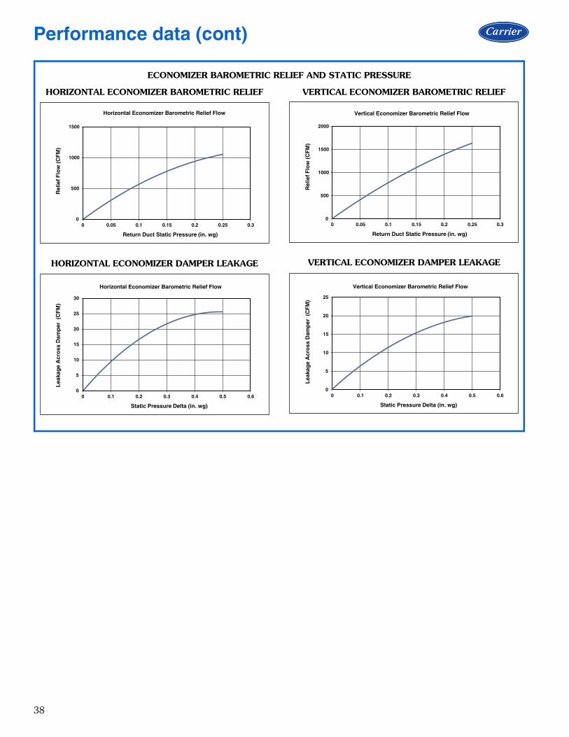
38
ECONOMIZER BAROMETRIC RELIEF AND STATIC PRESSURE
HORIZONTAL ECONOMIZER BAROMETRIC RELIEF
HORIZONTAL ECONOMIZER DAMPER LEAKAGE
VERTICAL ECONOMIZER BAROMETRIC RELIEF
VERTICAL ECONOMIZER DAMPER LEAKAGE
0
500
1000
1500
0 0.05 0.1 0.15 0.2 0.25 0.3
Rel
ief F
low
(CF
M)
Return Duct Static Pressure (in. wg)
Horizontal Economizer Barometric Relief Flow
0
5
10
15
20
25
30
0 0.1 0.2 0.3 0.4 0.5 0.6
Lea
kag
e A
cro
ss D
amp
er (
CF
M)
Static Pressure Delta (in. wg)
Horizontal Economizer Barometric Relief Flow
0
500
1000
1500
2000
0 0.05 0.1 0.15 0.2 0.25 0.3
Rel
ief F
low
(CF
M)
Return Duct Static Pressure (in. wg)
Vertical Economizer Barometric Relief Flow
0
5
10
15
20
25
0 0.1 0.2 0.3 0.4 0.5 0.6
Lea
kag
e A
cro
ss D
amp
er (
CF
M)
Static Pressure Delta (in. wg)
Vertical Economizer Barometric Relief Flow
Performance data (cont)

39
MERV-8 filters pressure dropNOTE: For factory-installed MERV-8 filters, no additionalpressure drop adjustments are necessary. The standard fantables accommodate usage.
HUMIDI-MIZER® COIL PRESSURE DROPS
0.00
0.02
0.04
0.06
0.08
800 900 1000 1100 1200 1300 1400 1500 1600
Sta
tic
Pre
ssu
re D
rop
(in
. wg
)
Unit Airflow (CFM)
Dehumidification Coil Pressure Drop, 3 Ton Units
0.00
0.05
0.10
0.15
0.20
0.25
0.30
1100 1300 1500 1700 1900 2100 2300 2500 2700
Sta
tic
Pre
ssu
re D
rop
(in
. wg
)
Unit Airflow (CFM)
Dehumidification Coil Pressure Drop, 4 and 5 Ton Units
0.00
0.05
0.10
0.15
0.20
0.25
900 1200 1500 1800 2100 2400 2700 3000 3300
Sta
tic
Pre
ssu
re D
rop
(in
. wg
)
Unit Airflow (CFM)
Dehumidification Coil Pressure Drop, 6 Ton Units

40
GENERAL FAN PERFORMANCE NOTES1. Interpolation is permissible. Do not extrapolate.2. External static pressure is the static pressure difference between the return duct and the supply duct plus the static
pressure caused by any FIOPs or accessories.3. Tabular data accounts for pressure loss due to clean filters, unit casing, wet coils, and highest gas heat exchanger
(when gas heat unit).4. Factory options and accessories may effect static pressure losses. Gas heat unit fan tables assume highest gas heat
models; for fan selections with low or medium heat models, the user must deduct low and medium heat static pres-sures. Selection software is available, through your salesperson, to help you select the best motor/drive combinationfor your application.
5. The fan performance tables offer motor/drive recommendations. In cases when two motor/drive combinations wouldwork, Carrier recommends the lower horsepower option.
6. For information on the electrical properties of Carrier motors, please see the Electrical information section of thisbook.
7. For more information on the performance limits of Carrier motors, see the application data section of this book.8. The EPACT (Energy Policy Act of 1992) regulates energy requirements for specific types of indoor fan motors.
Motors regulated by EPACT include any general purpose, T-frame (three-digit, 143 and larger), single-speed, footmounted, polyphase, squirrel cage induction motors of NEMA (National Electrical Manufacturers Association) design Aand B, manufactured for use in the United States. Ranging from 1 to 200 Hp, these continuous-duty motors operateon 230 and 460 volt, 60 Hz power. If a motor does not fit into these specifications, the motor does not have to bereplaced by an EPACT compliant energy-efficient motor. Variable-speed motors are exempt from EPACT compliancerequirements.
Fan data

41
NOTE: Fan tables include highest gas heat. Utilize static pressurededuction tables for lower gas heat capacities.
NOTE: Fan tables include highest gas heat. Utilize static pressurededuction tables for lower gas heat capacities.
48FCEA04 SINGLE PHASE — 3 TON VERTICAL SUPPLY (RPM - BHP)
CFMAVAILABLE EXTERNAL STATIC PRESSURE (in. wg)
0.2 0.4 0.6 0.8 1.0RPM BHP RPM BHP RPM BHP RPM BHP RPM BHP
900 1112 0.10 1341 0.17 1530 0.25 1696 0.34 1845 0.44 975 1162 0.11 1385 0.19 1571 0.27 1733 0.36 1881 0.461050 1213 0.12 1431 0.20 1613 0.29 1772 0.39 1917 0.491125 1265 0.14 1477 0.22 1656 0.32 1813 0.41 1956 0.521200 1319 0.16 1525 0.25 1700 0.34 1855 0.44 1996 0.551275 1374 0.18 1573 0.27 1746 0.37 1898 0.48 2037 0.591350 1430 0.20 1623 0.30 1792 0.40 1942 0.51 2079 0.631425 1487 0.23 1674 0.33 1839 0.43 1987 0.55 2122 0.671500 1545 0.26 1725 0.36 1887 0.47 2032 0.58 2165 0.71
CFMAVAILABLE EXTERNAL STATIC PRESSURE (in. wg)
1.2 1.4 1.6 1.8 2.0RPM BHP RPM BHP RPM BHP RPM BHP RPM BHP
900 1983 0.54 2111 0.66 2231 0.77 2344 0.90 2452 1.03 975 2016 0.57 2143 0.69 2262 0.81 2375 0.93 2482 1.061050 2051 0.60 2177 0.72 2294 0.84 2406 0.97 – –1125 2088 0.63 2211 0.75 2328 0.88 2438 1.01 – –1200 2126 0.67 2248 0.79 2363 0.92 2472 1.05 – –1275 2165 0.71 2285 0.83 2399 0.96 – – – –1350 2205 0.75 2324 0.87 2437 1.01 – – – –1425 2247 0.79 2364 0.92 2475 1.06 – – – –1500 2289 0.84 2405 0.97 – – – – – –
Standard Static 1112-1890 RPM, 0.44 Max BHP
Medium Static 1112-2190 RPM, 0.71 Max BHP
High Static 1112-2490 RPM, 1.07 Max BHP
48FCEA04 SINGLE PHASE – STANDARD STATIC — 3 TON VERTICAL SUPPLY (RPM - VDC)
CFMAVAILABLE EXTERNAL STATIC PRESSURE (in. wg)
0.2 0.4 0.6 0.8 1.0RPM Vdc RPM Vdc RPM Vdc RPM Vdc RPM Vdc
900 1112 5.9 1341 7.1 1530 8.1 1696 9.0 1845 9.8 975 1162 6.1 1385 7.3 1571 8.3 1733 9.2 — —1050 1213 6.4 1431 7.6 1613 8.5 1772 9.4 — —1125 1265 6.7 1477 7.8 1656 8.8 1813 9.6 — —1200 1319 7.0 1525 8.1 1700 9.0 1855 9.8 — —1275 1374 7.3 1573 8.3 1746 9.2 — — — —1350 1430 7.6 1623 8.6 1792 9.5 — — — —1425 1487 7.9 1674 8.9 1839 9.7 — — — —1500 1545 8.2 1725 9.1 — — — — — —
CFMAVAILABLE EXTERNAL STATIC PRESSURE (in. wg)
1.2 1.4 1.6 1.8 2.0RPM Vdc RPM Vdc RPM Vdc RPM Vdc RPM Vdc
900 — — — — — — — — — — 975 — — — — — — — — — —1050 — — — — — — — — — —1125 — — — — — — — — — —1200 — — — — — — — — — —1275 — — — — — — — — — —1350 — — — — — — — — — —1425 — — — — — — — — — —1500 — — — — — — — — — —
Standard Static 1112-1890 RPM

42
NOTE: Fan tables include highest gas heat. Utilize static pressurededuction tables for lower gas heat capacities.
NOTE: Fan tables include highest gas heat. Utilize static pressurededuction tables for lower gas heat capacities.
48FCEA04 SINGLE PHASE – MEDIUM STATIC — 3 TON VERTICAL SUPPLY (RPM - VDC)
CFMAVAILABLE EXTERNAL STATIC PRESSURE (in. wg)
0.2 0.4 0.6 0.8 1.0RPM Vdc RPM Vdc RPM Vdc RPM Vdc RPM Vdc
900 1112 5.1 1341 6.1 1530 7.0 1696 7.7 1845 8.4 975 1162 5.3 1385 6.3 1571 7.2 1733 7.9 1881 8.61050 1213 5.5 1431 6.5 1613 7.4 1772 8.1 1917 8.81125 1265 5.8 1477 6.7 1656 7.6 1813 8.3 1956 8.91200 1319 6.0 1525 7.0 1700 7.8 1855 8.5 1996 9.11275 1374 6.3 1573 7.2 1746 8.0 1898 8.7 2037 9.31350 1430 6.5 1623 7.4 1792 8.2 1942 8.9 2079 9.51425 1487 6.8 1674 7.6 1839 8.4 1987 9.1 2122 9.71500 1545 7.1 1725 7.9 1887 8.6 2032 9.3 2165 9.9
CFMAVAILABLE EXTERNAL STATIC PRESSURE (in. wg)
1.2 1.4 1.6 1.8 2.0RPM Vdc RPM Vdc RPM Vdc RPM Vdc RPM Vdc
900 1983 9.1 2111 9.6 — — — — — — 975 2016 9.2 2143 9.8 — — — — — —1050 2051 9.4 — — — — — — — —1125 2088 9.5 — — — — — — — —1200 2126 9.7 — — — — — — — —1275 2165 9.9 — — — — — — — —1350 — — — — — — — — — —1425 — — — — — — — — — —1500 — — — — — — — — — —
Medium Static 1112-2190 RPM
48FCEA04 SINGLE PHASE – HIGH STATIC — 3 TON VERTICAL SUPPLY (PRM - VDC)
CFMAVAILABLE EXTERNAL STATIC PRESSURE (in. wg)
0.2 0.4 0.6 0.8 1.0RPM Vdc RPM Vdc RPM Vdc RPM Vdc RPM Vdc
900 1112 4.5 1341 5.4 1530 6.1 1696 6.8 1845 7.4 975 1162 4.7 1385 5.6 1571 6.3 1733 7.0 1881 7.61050 1213 4.9 1431 5.7 1613 6.5 1772 7.1 1917 7.71125 1265 5.1 1477 5.9 1656 6.7 1813 7.3 1956 7.91200 1319 5.3 1525 6.1 1700 6.8 1855 7.4 1996 8.01275 1374 5.5 1573 6.3 1746 7.0 1898 7.6 2037 8.21350 1430 5.7 1623 6.5 1792 7.2 1942 7.8 2079 8.31425 1487 6.0 1674 6.7 1839 7.4 1987 8.0 2122 8.51500 1545 6.2 1725 6.9 1887 7.6 2032 8.2 2165 8.7
CFMAVAILABLE EXTERNAL STATIC PRESSURE (in. wg)
1.2 1.4 1.6 1.8 2.0RPM Vdc RPM Vdc RPM Vdc RPM Vdc RPM Vdc
900 1983 8.0 2111 8.5 2231 9.0 2344 9.4 2452 9.8 975 2016 8.1 2143 8.6 2262 9.1 2375 9.5 2482 10.01050 2051 8.2 2177 8.7 2294 9.2 2406 9.7 — —1125 2088 8.4 2211 8.9 2328 9.3 2438 9.8 — —1200 2126 8.5 2248 9.0 2363 9.5 2472 9.9 — —1275 2165 8.7 2285 9.2 2399 9.6 — — — —1350 2205 8.9 2324 9.3 2437 9.8 — — — —1425 2247 9.0 2364 9.5 2475 9.9 — — — —1500 2289 9.2 2405 9.7 — — — — — —
High Static 1112-2490 RPM
Fan data (cont)
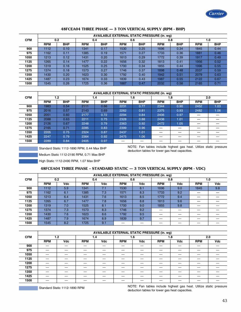
43
NOTE: Fan tables include highest gas heat. Utilize static pressurededuction tables for lower gas heat capacities.
NOTE: Fan tables include highest gas heat. Utilize static pressurededuction tables for lower gas heat capacities.
48FCEA04 THREE PHASE — 3 TON VERTICAL SUPPLY (RPM - BHP)
CFMAVAILABLE EXTERNAL STATIC PRESSURE (in. wg)
0.2 0.4 0.6 0.8 1.0RPM BHP RPM BHP RPM BHP RPM BHP RPM BHP
900 1112 0.10 1341 0.17 1530 0.25 1696 0.34 1845 0.44 975 1162 0.11 1385 0.19 1571 0.27 1733 0.36 1881 0.461050 1213 0.12 1431 0.20 1613 0.29 1772 0.39 1917 0.491125 1265 0.14 1477 0.22 1656 0.32 1813 0.41 1956 0.521200 1319 0.16 1525 0.25 1700 0.34 1855 0.44 1996 0.551275 1374 0.18 1573 0.27 1746 0.37 1898 0.48 2037 0.591350 1430 0.20 1623 0.30 1792 0.40 1942 0.51 2079 0.631425 1487 0.23 1674 0.33 1839 0.43 1987 0.55 2122 0.671500 1545 0.26 1725 0.36 1887 0.47 2032 0.58 2165 0.71
CFMAVAILABLE EXTERNAL STATIC PRESSURE (in. wg)
1.2 1.4 1.6 1.8 2.0RPM BHP RPM BHP RPM BHP RPM BHP RPM BHP
900 1983 0.54 2111 0.66 2231 0.77 2344 0.90 2452 1.03 975 2016 0.57 2143 0.69 2262 0.81 2375 0.93 2482 1.061050 2051 0.60 2177 0.72 2294 0.84 2406 0.97 — —1125 2088 0.63 2211 0.75 2328 0.88 2438 1.01 — —1200 2126 0.67 2248 0.79 2363 0.92 2472 1.05 — —1275 2165 0.71 2285 0.83 2399 0.96 — — — —1350 2205 0.75 2324 0.87 2437 1.01 — — — —1425 2247 0.79 2364 0.92 2475 1.06 — — — —1500 2289 0.84 2405 0.97 — — — — — —
Standard Static 1112-1890 RPM, 0.44 Max BHP
Medium Static 1112-2190 RPM, 0.71 Max BHP
High Static 1112-2490 RPM, 1.07 Max BHP
48FCEA04 THREE PHASE – STANDARD STATIC — 3 TON VERTICAL SUPPLY (RPM - VDC)
CFMAVAILABLE EXTERNAL STATIC PRESSURE (in. wg)
0.2 0.4 0.6 0.8 1.0RPM Vdc RPM Vdc RPM Vdc RPM Vdc RPM Vdc
900 1112 5.9 1341 7.1 1530 8.1 1696 9.0 1845 9.8 975 1162 6.1 1385 7.3 1571 8.3 1733 9.2 — —1050 1213 6.4 1431 7.6 1613 8.5 1772 9.4 — —1125 1265 6.7 1477 7.8 1656 8.8 1813 9.6 — —1200 1319 7.0 1525 8.1 1700 9.0 1855 9.8 — —1275 1374 7.3 1573 8.3 1746 9.2 — — — —1350 1430 7.6 1623 8.6 1792 9.5 — — — —1425 1487 7.9 1674 8.9 1839 9.7 — — — —1500 1545 8.2 1725 9.1 — — — — — —
CFMAVAILABLE EXTERNAL STATIC PRESSURE (in. wg)
1.2 1.4 1.6 1.8 2.0RPM Vdc RPM Vdc RPM Vdc RPM Vdc RPM Vdc
900 — — — — — — — — — — 975 — — — — — — — — — —1050 — — — — — — — — — —1125 — — — — — — — — — —1200 — — — — — — — — — —1275 — — — — — — — — — —1350 — — — — — — — — — —1425 — — — — — — — — — —1500 — — — — — — — — — —
Standard Static 1112-1890 RPM

44
NOTE: Fan tables include highest gas heat. Utilize static pressurededuction tables for lower gas heat capacities.
NOTE: Fan tables include highest gas heat. Utilize static pressurededuction tables for lower gas heat capacities.
48FCEA04 THREE PHASE – MEDIUM STATIC — 3 TON VERTICAL SUPPLY (RPM - VDC)
CFMAVAILABLE EXTERNAL STATIC PRESSURE (in. wg)
0.2 0.4 0.6 0.8 1.0RPM Vdc RPM Vdc RPM Vdc RPM Vdc RPM Vdc
900 1112 5.1 1341 6.1 1530 7.0 1696 7.7 1845 8.4 975 1162 5.3 1385 6.3 1571 7.2 1733 7.9 1881 8.61050 1213 5.5 1431 6.5 1613 7.4 1772 8.1 1917 8.81125 1265 5.8 1477 6.7 1656 7.6 1813 8.3 1956 8.91200 1319 6.0 1525 7.0 1700 7.8 1855 8.5 1996 9.11275 1374 6.3 1573 7.2 1746 8.0 1898 8.7 2037 9.31350 1430 6.5 1623 7.4 1792 8.2 1942 8.9 2079 9.51425 1487 6.8 1674 7.6 1839 8.4 1987 9.1 2122 9.71500 1545 7.1 1725 7.9 1887 8.6 2032 9.3 2165 9.9
CFMAVAILABLE EXTERNAL STATIC PRESSURE (in. wg)
1.2 1.4 1.6 1.8 2.0RPM Vdc RPM Vdc RPM Vdc RPM Vdc RPM Vdc
900 1983 9.1 2111 9.6 — — — — — — 975 2016 9.2 2143 9.8 — — — — — —1050 2051 9.4 — — — — — — — —1125 2088 9.5 — — — — — — — —1200 2126 9.7 — — — — — — — —1275 2165 9.9 — — — — — — — —1350 — — — — — — — — — —1425 — — — — — — — — — —1500 — — — — — — — — — —
Medium Static 1112-2190 RPM
48FCEA04 THREE PHASE – HIGH STATIC — 3 TON VERTICAL SUPPLY (RPM - VDC)
CFMAVAILABLE EXTERNAL STATIC PRESSURE (in. wg)
0.2 0.4 0.6 0.8 1.0RPM Vdc RPM Vdc RPM Vdc RPM Vdc RPM Vdc
900 1112 4.5 1341 5.4 1530 6.1 1696 6.8 1845 7.4 975 1162 4.7 1385 5.6 1571 6.3 1733 7.0 1881 7.61050 1213 4.9 1431 5.7 1613 6.5 1772 7.1 1917 7.71125 1265 5.1 1477 5.9 1656 6.7 1813 7.3 1956 7.91200 1319 5.3 1525 6.1 1700 6.8 1855 7.4 1996 8.01275 1374 5.5 1573 6.3 1746 7.0 1898 7.6 2037 8.21350 1430 5.7 1623 6.5 1792 7.2 1942 7.8 2079 8.31425 1487 6.0 1674 6.7 1839 7.4 1987 8.0 2122 8.51500 1545 6.2 1725 6.9 1887 7.6 2032 8.2 2165 8.7
CFMAVAILABLE EXTERNAL STATIC PRESSURE (in. wg)
1.2 1.4 1.6 1.8 2.0RPM Vdc RPM Vdc RPM Vdc RPM Vdc RPM Vdc
900 1983 8.0 2111 8.5 2231 9.0 2344 9.4 2452 9.8 975 2016 8.1 2143 8.6 2262 9.1 2375 9.5 2482 10.01050 2051 8.2 2177 8.7 2294 9.2 2406 9.7 — —1125 2088 8.4 2211 8.9 2328 9.3 2438 9.8 — —1200 2126 8.5 2248 9.0 2363 9.5 2472 9.9 — —1275 2165 8.7 2285 9.2 2399 9.6 — — — —1350 2205 8.9 2324 9.3 2437 9.8 — — — —1425 2247 9.0 2364 9.5 2475 9.9 — — — —1500 2289 9.2 2405 9.7 — — — — — —
High Static 1112-2490 RPM
Fan data (cont)

45
NOTE: Fan tables include highest gas heat. Utilize static pressurededuction tables for lower gas heat capacities.
NOTE: Fan tables include highest gas heat. Utilize static pressurededuction tables for lower gas heat capacities.
48FCFA05 SINGLE PHASE — 4 TON VERTICAL SUPPLY (RPM - BHP)
CFMAVAILABLE EXTERNAL STATIC PRESSURE (in. wg)
0.2 0.4 0.6 0.8 1.0RPM BHP RPM BHP RPM BHP RPM BHP RPM BHP
1200 1262 0.21 1452 0.33 1614 0.45 1757 0.58 1888 0.721300 1333 0.25 1516 0.37 1674 0.50 1813 0.63 1942 0.781400 1405 0.29 1583 0.42 1735 0.55 1872 0.70 1997 0.841500 1478 0.34 1650 0.48 1798 0.62 1932 0.76 2054 0.921600 1552 0.40 1718 0.54 1863 0.68 1993 0.84 2114 1.001700 1627 0.46 1787 0.60 1928 0.76 2057 0.92 2174 1.091800 1704 0.52 1857 0.68 1995 0.84 2121 1.01 2236 1.181900 1781 0.60 1929 0.76 2063 0.93 2185 1.10 2299 1.282000 1859 0.68 2001 0.85 2132 1.02 2252 1.21 2363 1.39
CFMAVAILABLE EXTERNAL STATIC PRESSURE (in. wg)
1.2 1.4 1.6 1.8 2.0RPM BHP RPM BHP RPM BHP RPM BHP RPM BHP
1200 2011 0.87 2126 1.02 2236 1.19 2341 1.37 2442 1.551300 2061 0.93 2174 1.09 2281 1.26 2384 1.44 — —1400 2114 1.00 2224 1.17 2329 1.34 2429 1.52 — —1500 2169 1.08 2277 1.25 2379 1.43 — — — —1600 2226 1.17 2331 1.34 2432 1.52 — — — —1700 2284 1.26 2388 1.44 — — — — — —1800 2344 1.36 2446 1.55 — — — — — —1900 2405 1.47 — — — — — — — —2000 — — — — — — — — — —
Standard Static 1262-1900 RPM, 0.72 Max BHP
Medium Static 1262-2170 RPM, 1.06 Max BHP
High Static 1262-2460 RPM, 1.53 Max BHP
48FCFA05 SINGLE PHASE – STANDARD STATIC — 4 TON VERTICAL SUPPLY (RPM - VDC)
CFMAVAILABLE EXTERNAL STATIC PRESSURE (in. wg)
0.2 0.4 0.6 0.8 1.0RPM Vdc RPM Vdc RPM Vdc RPM Vdc RPM Vdc
1200 1262 6.6 1452 7.6 1614 8.5 1757 9.2 1888 9.91300 1333 7.0 1516 8.0 1674 8.8 1813 9.5 — —1400 1405 7.4 1583 8.3 1735 9.1 1872 9.9 — —1500 1478 7.8 1650 8.7 1798 9.5 — — — —1600 1552 8.2 1718 9.0 1863 9.8 — — — —1700 1627 8.6 1787 9.4 — — — — — —1800 1704 9.0 1857 9.8 — — — — — —1900 1781 9.4 — — — — — — — —2000 1859 9.8 — — — — — — — —
CFMAVAILABLE EXTERNAL STATIC PRESSURE (in. wg)
1.2 1.4 1.6 1.8 2.0RPM Vdc RPM Vdc RPM Vdc RPM Vdc RPM Vdc
1200 — — — — — — — — — —1300 — — — — — — — — — —1400 — — — — — — — — — —1500 — — — — — — — — — —1600 — — — — — — — — — —1700 — — — — — — — — — —1800 — — — — — — — — — —1900 — — — — — — — — — —2000 — — — — — — — — — —
Standard Static 1262-1900 RPM

46
NOTE: Fan tables include highest gas heat. Utilize static pressurededuction tables for lower gas heat capacities.
NOTE: Fan tables include highest gas heat. Utilize static pressurededuction tables for lower gas heat capacities.
48FCFA05 SINGLE PHASE – MEDIUM STATIC — 4 TON VERTICAL SUPPLY (RPM - VDC)
CFMAVAILABLE EXTERNAL STATIC PRESSURE (in. wg)
0.2 0.4 0.6 0.8 1.0RPM Vdc RPM Vdc RPM Vdc RPM Vdc RPM Vdc
1200 1262 5.8 1452 6.7 1614 7.4 1757 8.1 1888 8.71300 1333 6.1 1516 7.0 1674 7.7 1813 8.4 1942 8.91400 1405 6.5 1583 7.3 1735 8.0 1872 8.6 1997 9.21500 1478 6.8 1650 7.6 1798 8.3 1932 8.9 2054 9.51600 1552 7.2 1718 7.9 1863 8.6 1993 9.2 2114 9.71700 1627 7.5 1787 8.2 1928 8.9 2057 9.5 — —1800 1704 7.9 1857 8.6 1995 9.2 2121 9.8 — —1900 1781 8.2 1929 8.9 2063 9.5 — — — —2000 1859 8.6 2001 9.2 2132 9.8 — — — —
CFMAVAILABLE EXTERNAL STATIC PRESSURE (in. wg)
1.2 1.4 1.6 1.8 2.0RPM Vdc RPM Vdc RPM Vdc RPM Vdc RPM Vdc
1200 2011 9.3 2126 9.8 — — — — — —1300 2061 9.5 — — — — — — — —1400 2114 9.7 — — — — — — — —1500 2169 10.0 — — — — — — — —1600 — — — — — — — — — —1700 — — — — — — — — — —1800 — — — — — — — — — —1900 — — — — — — — — — —2000 — — — — — — — — — —
Medium Static 1262-2170 RPM
48FCFA05 SINGLE PHASE – HIGH STATIC — 4 TON VERTICAL SUPPLY (RPM - VDC)
CFMAVAILABLE EXTERNAL STATIC PRESSURE (in. wg)
0.2 0.4 0.6 0.8 1.0RPM Vdc RPM Vdc RPM Vdc RPM Vdc RPM Vdc
1200 1262 5.1 1452 5.9 1614 6.6 1757 7.1 1888 7.71300 1333 5.4 1516 6.2 1674 6.8 1813 7.4 1942 7.91400 1405 5.7 1583 6.4 1735 7.1 1872 7.6 1997 8.11500 1478 6.0 1650 6.7 1798 7.3 1932 7.9 2054 8.31600 1552 6.3 1718 7.0 1863 7.6 1993 8.1 2114 8.61700 1627 6.6 1787 7.3 1928 7.8 2057 8.4 2174 8.81800 1704 6.9 1857 7.5 1995 8.1 2121 8.6 2236 9.11900 1781 7.2 1929 7.8 2063 8.4 2185 8.9 2299 9.32000 1859 7.6 2001 8.1 2132 8.7 2252 9.2 2363 9.6
CFMAVAILABLE EXTERNAL STATIC PRESSURE (in. wg)
1.2 1.4 1.6 1.8 2.0RPM Vdc RPM Vdc RPM Vdc RPM Vdc RPM Vdc
1200 2011 8.2 2126 8.6 2236 9.1 2341 9.5 2442 9.91300 2061 8.4 2174 8.8 2281 9.3 2384 9.7 — —1400 2114 8.6 2224 9.0 2329 9.5 2429 9.9 — —1500 2169 8.8 2277 9.3 2379 9.7 — — — —1600 2226 9.0 2331 9.5 2432 9.9 — — — —1700 2284 9.3 2388 9.7 — — — — — —1800 2344 9.5 2446 9.9 — — — — — —1900 2405 9.8 — — — — — — — —2000 — — — — — — — — — —
High Static 1262-2460 RPM
Fan data (cont)

47
NOTE: Fan tables include highest gas heat. Utilize static pressurededuction tables for lower gas heat capacities.
NOTE: Fan tables include highest gas heat. Utilize static pressurededuction tables for lower gas heat capacities.
48FCFA05 THREE PHASE — 4 TON VERTICAL SUPPLY (RPM - BHP)
CFMAVAILABLE EXTERNAL STATIC PRESSURE (in. wg)
0.2 0.4 0.6 0.8 1.0RPM BHP RPM BHP RPM BHP RPM BHP RPM BHP
1200 1262 0.21 1453 0.33 1614 0.45 1757 0.58 1888 0.721300 1333 0.25 1517 0.37 1674 0.50 1814 0.63 1942 0.781400 1405 0.29 1583 0.42 1736 0.56 1872 0.70 1998 0.851500 1478 0.34 1650 0.48 1799 0.62 1932 0.76 2055 0.921600 1553 0.40 1718 0.54 1863 0.68 1994 0.84 2114 1.001700 1628 0.46 1787 0.60 1929 0.76 2057 0.92 2174 1.091800 1704 0.52 1858 0.68 1995 0.84 2121 1.01 2236 1.181900 1781 0.60 1929 0.76 2063 0.93 2186 1.10 2299 1.282000 1859 0.68 2001 0.85 2132 1.02 2252 1.21 2363 1.39
CFMAVAILABLE EXTERNAL STATIC PRESSURE (in. wg)
1.2 1.4 1.6 1.8 2.0RPM BHP RPM BHP RPM BHP RPM BHP RPM BHP
1200 2011 0.87 2126 1.02 2236 1.19 2341 1.37 2442 1.551300 2061 0.93 2174 1.09 2281 1.26 2383 1.44 2482 1.621400 2114 1.00 2224 1.17 2329 1.34 2429 1.52 2526 1.711500 2169 1.08 2277 1.25 2379 1.43 2478 1.61 2572 1.801600 2226 1.17 2332 1.34 2432 1.52 2528 1.71 2621 1.911700 2284 1.26 2388 1.44 2487 1.63 2581 1.82 — —1800 2344 1.36 2446 1.55 2543 1.74 2636 1.94 — —1900 2405 1.47 2505 1.66 2600 1.86 — — — —2000 2467 1.59 2566 1.79 2659 1.99 — — — —
Standard Static 1262-1900 RPM, 0.72 Max BHP
Medium Static 1262-2170 RPM, 1.06 Max BHP
High Static 1262-2660 RPM, 1.92 Max BHP
48FCFA05 THREE PHASE – STANDARD STATIC — 4 TON VERTICAL SUPPLY (RPM - VDC)
CFMAVAILABLE EXTERNAL STATIC PRESSURE (in. wg)
0.2 0.4 0.6 0.8 1.0RPM Vdc RPM Vdc RPM Vdc RPM Vdc RPM Vdc
1200 1262 6.6 1453 7.6 1614 8.5 1757 9.2 1888 9.91300 1333 7.0 1517 8.0 1674 8.8 1814 9.5 — —1400 1405 7.4 1583 8.3 1736 9.1 1872 9.9 — —1500 1478 7.8 1650 8.7 1799 9.5 — — — —1600 1553 8.2 1718 9.0 1863 9.8 — — — —1700 1628 8.6 1787 9.4 — — — — — —1800 1704 9.0 1858 9.8 — — — — — —1900 1781 9.4 — — — — — — —2000 1859 9.8 — — — — — — — —
CFMAVAILABLE EXTERNAL STATIC PRESSURE (in. wg)
1.2 1.4 1.6 1.8 2.0RPM Vdc RPM Vdc RPM Vdc RPM Vdc RPM Vdc
1200 — — — — — — — — — —1300 — — — — — — — — — —1400 — — — — — — — — — —1500 — — — — — — — — — —1600 — — — — — — — — — —1700 — — — — — — — — — —1800 — — — — — — — — — —1900 — — — — — — — — — —2000 — — — — — — — — — —
Standard Static 1262-1900 RPM

48
NOTE: Fan tables include highest gas heat. Utilize static pressurededuction tables for lower gas heat capacities.
NOTE: Fan tables include highest gas heat. Utilize static pressurededuction tables for lower gas heat capacities.
48FCFA05 THREE PHASE – MEDIUM STATIC — 4 TON VERTICAL SUPPLY (RPM - VDC)
CFMAVAILABLE EXTERNAL STATIC PRESSURE (in. wg)
0.2 0.4 0.6 0.8 1.0RPM Vdc RPM Vdc RPM Vdc RPM Vdc RPM Vdc
1200 1262 5.8 1453 6.7 1614 7.4 1757 8.1 1888 8.71300 1333 6.1 1517 7.0 1674 7.7 1814 8.4 1942 8.91400 1405 6.5 1583 7.3 1736 8.0 1872 8.6 1998 9.21500 1478 6.8 1650 7.6 1799 8.3 1932 8.9 2055 9.51600 1553 7.2 1718 7.9 1863 8.6 1994 9.2 2114 9.71700 1628 7.5 1787 8.2 1929 8.9 2057 9.5 — —1800 1704 7.9 1858 8.6 1995 9.2 2121 9.8 — —1900 1781 8.2 1929 8.9 2063 9.5 — — — —2000 1859 8.6 2001 9.2 2132 9.8 — — — —
CFMAVAILABLE EXTERNAL STATIC PRESSURE (in. wg)
1.2 1.4 1.6 1.8 2.0RPM Vdc RPM Vdc RPM Vdc RPM Vdc RPM Vdc
1200 2011 9.3 2126 9.8 — — — — — —1300 2061 9.5 — — — — — — — —1400 2114 9.7 — — — — — — — —1500 2169 10.0 — — — — — — — —1600 — — — — — — — — — —1700 — — — — — — — — — —1800 — — — — — — — — — —1900 — — — — — — — — — —2000 — — — — — — — — — —
Medium Static 1262-2170 RPM
48FCFA05 THREE PHASE – HIGH STATIC — 4 TON VERTICAL SUPPLY (RPM - VDC)
CFMAVAILABLE EXTERNAL STATIC PRESSURE (in. wg)
0.2 0.4 0.6 0.8 1.0RPM Vdc RPM Vdc RPM Vdc RPM Vdc RPM Vdc
1200 1262 4.7 1453 5.5 1614 6.1 1757 6.6 1888 7.11300 1333 5.0 1517 5.7 1674 6.3 1814 6.8 1942 7.31400 1405 5.3 1583 6.0 1736 6.5 1872 7.0 1998 7.51500 1478 5.6 1650 6.2 1799 6.8 1932 7.3 2055 7.71600 1553 5.8 1718 6.5 1863 7.0 1994 7.5 2114 7.91700 1628 6.1 1787 6.7 1929 7.3 2057 7.7 2174 8.21800 1704 6.4 1858 7.0 1995 7.5 2121 8.0 2236 8.41900 1781 6.7 1929 7.3 2063 7.8 2186 8.2 2299 8.62000 1859 7.0 2001 7.5 2132 8.0 2252 8.5 2363 8.9
CFMAVAILABLE EXTERNAL STATIC PRESSURE (in. wg)
1.2 1.4 1.6 1.8 2.0RPM Vdc RPM Vdc RPM Vdc RPM Vdc RPM Vdc
1200 2011 7.6 2126 8.0 2236 8.4 2341 8.8 2442 9.21300 2061 7.7 2174 8.2 2281 8.6 2383 9.0 2482 9.31400 2114 7.9 2224 8.4 2329 8.8 2429 9.1 2526 9.51500 2169 8.2 2277 8.6 2379 8.9 2478 9.3 2572 9.71600 2226 8.4 2332 8.8 2432 9.1 2528 9.5 2621 9.91700 2284 8.6 2388 9.0 2487 9.3 2581 9.7 — —1800 2344 8.8 2446 9.2 2543 9.6 2636 9.9 — —1900 2405 9.0 2505 9.4 2600 9.8 — — — —2000 2467 9.3 2566 9.6 2659 10.0 — — — —
High Static 1262-2660 RPM
Fan data (cont)

49
NOTE: Fan tables include highest gas heat. Utilize static pressurededuction tables for lower gas heat capacities.
NOTE: Fan tables include highest gas heat. Utilize static pressurededuction tables for lower gas heat capacities.
48FCFA06 SINGLE PHASE — 5 TON VERTICAL SUPPLY (RPM - BHP)
CFMAVAILABLE EXTERNAL STATIC PRESSURE (in. wg)
0.2 0.4 0.6 0.8 1.0RPM BHP RPM BHP RPM BHP RPM BHP RPM BHP
1500 1478 0.34 1650 0.48 1799 0.62 1932 0.76 2055 0.921625 1571 0.41 1735 0.55 1879 0.70 2009 0.86 2129 1.021750 1666 0.49 1822 0.64 1962 0.80 2088 0.96 2205 1.131875 1761 0.58 1910 0.74 2046 0.91 2169 1.08 2283 1.262000 1859 0.68 2001 0.85 2132 1.02 2252 1.21 2363 1.392125 1957 0.79 2093 0.97 2218 1.15 2335 1.34 — —2250 2056 0.92 2185 1.10 2307 1.30 — — — —2375 2155 1.06 2279 1.25 — — — — — —2500 2256 1.21 2374 1.41 — — — — — —
CFMAVAILABLE EXTERNAL STATIC PRESSURE (in. wg)
1.2 1.4 1.6 1.8 2.0RPM BHP RPM BHP RPM BHP RPM BHP RPM BHP
1500 2169 1.08 2277 1.25 2379 1.43 — — — —1625 2240 1.19 2345 1.37 — — — — — —1750 2314 1.31 — — — — — — — —1875 2389 1.44 — — — — — — — —2000 — — — — — — — — — —2125 — — — — — — — — — —2250 — — — — — — — — — —2375 — — — — — — — — — —2500 — — — — — — — — — —
Standard Static 1478-2150 RPM, 1.06 Max BHP
Medium Static 1478-2390 RPM, 1.44 Max BHP
48FCFA06 SINGLE PHASE – STANDARD STATIC — 5 TON VERTICAL SUPPLY (RPM - VDC)
CFMAVAILABLE EXTERNAL STATIC PRESSURE (in. wg)
0.2 0.4 0.6 0.8 1.0RPM Vdc RPM Vdc RPM Vdc RPM Vdc RPM Vdc
1500 1478 6.9 1650 7.7 1799 8.4 1932 9.0 2055 9.61625 1571 7.3 1735 8.1 1879 8.7 2009 9.3 2129 9.91750 1666 7.7 1822 8.5 1962 9.1 2088 9.7 — —1875 1761 8.2 1910 8.9 2046 9.5 — — — —2000 1859 8.6 2001 9.3 2132 9.9 — — — —2125 1957 9.1 2093 9.7 — — — — — —2250 2056 9.6 — — — — — — — —2375 — — — — — — — — — —2500 — — — — — — — — — —
CFMAVAILABLE EXTERNAL STATIC PRESSURE (in. wg)
1.2 1.4 1.6 1.8 2.0RPM Vdc RPM Vdc RPM Vdc RPM Vdc RPM Vdc
1500 — — — — — — — — — —1625 — — — — — — — — — —1750 — — — — — — — — — —1875 — — — — — — — — — —2000 — — — — — — — — — —2125 — — — — — — — — — —2250 — — — — — — — — — —2375 — — — — — — — — — —2500 — — — — — — — — — —
Standard Static 1478-2150 RPM

50
NOTE: Fan tables include highest gas heat. Utilize static pressurededuction tables for lower gas heat capacities.
48FCFA06 SINGLE PHASE – MEDIUM STATIC — 5 TON VERTICAL SUPPLY (RPM - VDC)
CFMAVAILABLE EXTERNAL STATIC PRESSURE (in. wg)
0.2 0.4 0.6 0.8 1.0RPM Vdc RPM Vdc RPM Vdc RPM Vdc RPM Vdc
1500 1478 6.2 1650 6.9 1799 7.5 1932 8.1 2055 8.61625 1571 6.6 1735 7.3 1879 7.9 2009 8.4 2129 8.91750 1666 7.0 1822 7.6 1962 8.2 2088 8.7 2205 9.21875 1761 7.4 1910 8.0 2046 8.6 2169 9.1 2283 9.62000 1859 7.8 2001 8.4 2132 8.9 2252 9.4 2363 9.92125 1957 8.2 2093 8.8 2218 9.3 2335 9.8 — —2250 2056 8.6 2185 9.1 2307 9.7 — — — —2375 2155 9.0 2279 9.5 — — — — — —2500 2256 9.4 2374 9.9 — — — — — —
CFMAVAILABLE EXTERNAL STATIC PRESSURE (in. wg)
1.2 1.4 1.6 1.8 2.0RPM Vdc RPM Vdc RPM Vdc RPM Vdc RPM Vdc
1500 2169 9.1 2277 9.5 2379 10.0 — — — —1625 2240 9.4 2345 9.8 — — — — — —1750 2314 9.7 — — — — — — — —1875 2389 10.0 — — — — — — — —2000 — — — — — — — — — —2125 — — — — — — — — — —2250 — — — — — — — — — —2375 — — — — — — — — — —2500 — — — — — — — — — —
Medium Static 1478-2390 RPM
Fan data (cont)
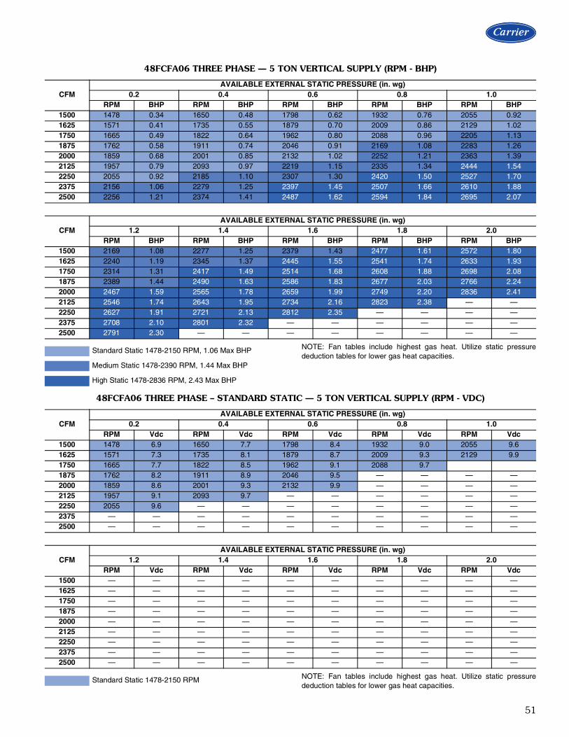
51
NOTE: Fan tables include highest gas heat. Utilize static pressurededuction tables for lower gas heat capacities.
NOTE: Fan tables include highest gas heat. Utilize static pressurededuction tables for lower gas heat capacities.
48FCFA06 THREE PHASE — 5 TON VERTICAL SUPPLY (RPM - BHP)
CFMAVAILABLE EXTERNAL STATIC PRESSURE (in. wg)
0.2 0.4 0.6 0.8 1.0RPM BHP RPM BHP RPM BHP RPM BHP RPM BHP
1500 1478 0.34 1650 0.48 1798 0.62 1932 0.76 2055 0.921625 1571 0.41 1735 0.55 1879 0.70 2009 0.86 2129 1.021750 1665 0.49 1822 0.64 1962 0.80 2088 0.96 2205 1.131875 1762 0.58 1911 0.74 2046 0.91 2169 1.08 2283 1.262000 1859 0.68 2001 0.85 2132 1.02 2252 1.21 2363 1.392125 1957 0.79 2093 0.97 2219 1.15 2335 1.34 2444 1.542250 2055 0.92 2185 1.10 2307 1.30 2420 1.50 2527 1.702375 2156 1.06 2279 1.25 2397 1.45 2507 1.66 2610 1.882500 2256 1.21 2374 1.41 2487 1.62 2594 1.84 2695 2.07
CFMAVAILABLE EXTERNAL STATIC PRESSURE (in. wg)
1.2 1.4 1.6 1.8 2.0RPM BHP RPM BHP RPM BHP RPM BHP RPM BHP
1500 2169 1.08 2277 1.25 2379 1.43 2477 1.61 2572 1.801625 2240 1.19 2345 1.37 2445 1.55 2541 1.74 2633 1.931750 2314 1.31 2417 1.49 2514 1.68 2608 1.88 2698 2.081875 2389 1.44 2490 1.63 2586 1.83 2677 2.03 2766 2.242000 2467 1.59 2565 1.78 2659 1.99 2749 2.20 2836 2.412125 2546 1.74 2643 1.95 2734 2.16 2823 2.38 — —2250 2627 1.91 2721 2.13 2812 2.35 — — — —2375 2708 2.10 2801 2.32 — — — — — —2500 2791 2.30 — — — — — — — —
Standard Static 1478-2150 RPM, 1.06 Max BHP
Medium Static 1478-2390 RPM, 1.44 Max BHP
High Static 1478-2836 RPM, 2.43 Max BHP
48FCFA06 THREE PHASE – STANDARD STATIC — 5 TON VERTICAL SUPPLY (RPM - VDC)
CFMAVAILABLE EXTERNAL STATIC PRESSURE (in. wg)
0.2 0.4 0.6 0.8 1.0RPM Vdc RPM Vdc RPM Vdc RPM Vdc RPM Vdc
1500 1478 6.9 1650 7.7 1798 8.4 1932 9.0 2055 9.61625 1571 7.3 1735 8.1 1879 8.7 2009 9.3 2129 9.91750 1665 7.7 1822 8.5 1962 9.1 2088 9.71875 1762 8.2 1911 8.9 2046 9.5 — — — —2000 1859 8.6 2001 9.3 2132 9.9 — — — —2125 1957 9.1 2093 9.7 — — — — — —2250 2055 9.6 — — — — — — — —2375 — — — — — — — — — —2500 — — — — — — — — — —
CFMAVAILABLE EXTERNAL STATIC PRESSURE (in. wg)
1.2 1.4 1.6 1.8 2.0RPM Vdc RPM Vdc RPM Vdc RPM Vdc RPM Vdc
1500 — — — — — — — — — —1625 — — — — — — — — — —1750 — — — — — — — — — —1875 — — — — — — — — — —2000 — — — — — — — — — —2125 — — — — — — — — — —2250 — — — — — — — — — —2375 — — — — — — — — — —2500 — — — — — — — — — —
Standard Static 1478-2150 RPM

52
NOTE: Fan tables include highest gas heat. Utilize static pressurededuction tables for lower gas heat capacities.
NOTE: Fan tables include highest gas heat. Utilize static pressurededuction tables for lower gas heat capacities.
48FCFA06 THREE PHASE – MEDIUM STATIC — 5 TON VERTICAL SUPPLY (RPM - VDC)
CFMAVAILABLE EXTERNAL STATIC PRESSURE (in. wg)
0.2 0.4 0.6 0.8 1.0RPM Vdc RPM Vdc RPM Vdc RPM Vdc RPM Vdc
1500 1478 6.2 1650 6.9 1798 7.5 1932 8.1 2055 8.61625 1571 6.6 1735 7.3 1879 7.9 2009 8.4 2129 8.91750 1665 7.0 1822 7.6 1962 8.2 2088 8.7 2205 9.21875 1762 7.4 1911 8.0 2046 8.6 2169 9.1 2283 9.62000 1859 7.8 2001 8.4 2132 8.9 2252 9.4 2363 9.92125 1957 8.2 2093 8.8 2219 9.3 2335 9.8 — —2250 2055 8.6 2185 9.1 2307 9.7 — — — —2375 2156 9.0 2279 9.5 — — — — — —2500 2256 9.4 2374 9.9 — — — — — —
CFMAVAILABLE EXTERNAL STATIC PRESSURE (in. wg)
1.2 1.4 1.6 1.8 2.0RPM Vdc RPM Vdc RPM Vdc RPM Vdc RPM Vdc
1500 2169 9.1 2277 9.5 2379 10.0 — — — —1625 2240 9.4 2345 9.8 — — — — — —1750 2314 9.7 — — — — — — — —1875 2389 10.0 — — — — — — — —2000 — — — — — — — — — —2125 — — — — — — — — — —2250 — — — — — — — — — —2375 — — — — — — — — — —2500 — — — — — — — — — —
Medium Static 1478-2390 RPM
48FCFA06 THREE PHASE – HIGH STATIC — 5 TON VERTICAL SUPPLY (RPM - VDC)
CFMAVAILABLE EXTERNAL STATIC PRESSURE (in. wg)
0.2 0.4 0.6 0.8 1.0RPM Vdc RPM Vdc RPM Vdc RPM Vdc RPM Vdc
1500 1478 5.2 1650 5.8 1798 6.3 1932 6.8 2055 7.21625 1571 5.5 1735 6.1 1879 6.6 2009 7.1 2129 7.51750 1665 5.9 1822 6.4 1962 6.9 2088 7.4 2205 7.81875 1762 6.2 1911 6.7 2046 7.2 2169 7.6 2283 8.12000 1859 6.6 2001 7.1 2132 7.5 2252 7.9 2363 8.32125 1957 6.9 2093 7.4 2219 7.8 2335 8.2 2444 8.62250 2055 7.2 2185 7.7 2307 8.1 2420 8.5 2527 8.92375 2156 7.6 2279 8.0 2397 8.5 2507 8.8 2610 9.22500 2256 8.0 2374 8.4 2487 8.8 2594 9.1 2695 9.5
CFMAVAILABLE EXTERNAL STATIC PRESSURE (in. wg)
1.2 1.4 1.6 1.8 2.0RPM Vdc RPM Vdc RPM Vdc RPM Vdc RPM Vdc
1500 2169 7.6 2277 8.0 2379 8.4 2477 8.7 2572 9.11625 2240 7.9 2345 8.3 2445 8.6 2541 9.0 2633 9.31750 2314 8.2 2417 8.5 2514 8.9 2608 9.2 2698 9.51875 2389 8.4 2490 8.8 2586 9.1 2677 9.4 2766 9.82000 2467 8.7 2565 9.0 2659 9.4 2749 9.7 2836 10.02125 2546 9.0 2643 9.3 2734 9.6 2823 10.0 — —2250 2627 9.3 2721 9.6 2812 9.9 — — — —2375 2708 9.5 2801 9.9 — — — — — —2500 2791 9.8 — — — — — — — —
High Static 1478-2836 RPM
Fan data (cont)

53
NOTE: Fan tables include highest gas heat. Utilize static pressurededuction tables for lower gas heat capacities.
NOTE: Fan tables include highest gas heat. Utilize static pressurededuction tables for lower gas heat capacities.
48FCFM07 THREE PHASE — 6 TON VERTICAL SUPPLY (RPM - BHP)
CFMAVAILABLE EXTERNAL STATIC PRESSURE (in. wg)
0.2 0.4 0.6 0.8 1.0RPM BHP RPM BHP RPM BHP RPM BHP RPM BHP
1800 1596 0.43 1749 0.56 1889 0.71 2015 0.86 2131 1.021950 1704 0.52 1847 0.67 1981 0.82 2104 0.98 2217 1.152100 1814 0.63 1948 0.78 2075 0.94 2194 1.12 2305 1.292250 1924 0.75 2050 0.91 2172 1.08 2286 1.26 2394 1.452400 2037 0.89 2155 1.06 2270 1.24 2381 1.43 2485 1.622550 2150 1.05 2261 1.22 2370 1.41 2476 1.61 2578 1.812700 2265 1.23 2368 1.40 2472 1.60 2574 1.80 2672 2.022850 2379 1.43 2477 1.61 2576 1.81 2674 2.02 2768 2.243000 2495 1.64 2587 1.83 2681 2.04 2775 2.26 — —
CFMAVAILABLE EXTERNAL STATIC PRESSURE (in. wg)
1.2 1.4 1.6 1.8 2.0RPM BHP RPM BHP RPM BHP RPM BHP RPM BHP
1800 2239 1.19 2340 1.35 2436 1.53 2528 1.71 2615 1.891950 2323 1.32 2422 1.50 2516 1.68 2605 1.87 2691 2.062100 2408 1.47 2505 1.66 2597 1.85 2685 2.04 2770 2.252250 2495 1.64 2590 1.84 2681 2.04 2767 2.24 — —2400 2584 1.82 2677 2.03 2766 2.24 — — — —2550 2674 2.02 2766 2.24 — — — — — —2700 2766 2.24 — — — — — — — —2850 — — — — — — — — — —3000 — — — — — — — — — —
Standard Static 1596-2300 RPM, 1.31 Max BHP
Medium Static 1596-2530 RPM, 1.76 Max BHP
High Static 1596-2836 RPM, 2.43 Max BHP
48FCFM07 THREE PHASE – STANDARD STATIC — 6 TON VERTICAL SUPPLY (RPM - VDC)
CFMAVAILABLE EXTERNAL STATIC PRESSURE (in. wg)
0.2 0.4 0.6 0.8 1.0RPM Vdc RPM Vdc RPM Vdc RPM Vdc RPM Vdc
1800 1596 6.9 1749 7.6 1889 8.2 2015 8.8 2131 9.31950 1704 7.4 1847 8.0 1981 8.6 2104 9.1 2217 9.62100 1814 7.9 1948 8.5 2075 9.0 2194 9.5 — —2250 1925 8.4 2050 8.9 2172 9.4 2286 9.9 — —2400 2037 8.9 2154 9.4 2270 9.9 — — — —2550 2150 9.3 2261 9.8 — — — — — —2700 2265 9.8 — — — — — — — —2850 — — — — — — — — — —3000 — — — — — — — — — —
CFMAVAILABLE EXTERNAL STATIC PRESSURE (in. wg)
1.2 1.4 1.6 1.8 2.0RPM Vdc RPM Vdc RPM Vdc RPM Vdc RPM Vdc
1800 2239 9.7 — — — — — — — —1950 — — — — — — — — — —2100 — — — — — — — — — —2250 — — — — — — — — — —2400 — — — — — — — — — —2550 — — — — — — — — — —2700 — — — — — — — — — —2850 — — — — — — — — — —3000 — — — — — — — — — —
Standard Static 1596-2300 RPM

54
NOTE: Fan tables include highest gas heat. Utilize static pressurededuction tables for lower gas heat capacities.
NOTE: Fan tables include highest gas heat. Utilize static pressurededuction tables for lower gas heat capacities.
48FCFM07 THREE PHASE – MEDIUM STATIC — 6 TON VERTICAL SUPPLY (RPM - VDC)
CFMAVAILABLE EXTERNAL STATIC PRESSURE (in. wg)
0.2 0.4 0.6 0.8 1.0RPM Vdc RPM Vdc RPM Vdc RPM Vdc RPM Vdc
1800 1596 6.3 1749 6.9 1889 7.5 2015 8.0 2131 8.41950 1704 6.7 1847 7.3 1981 7.8 2104 8.3 2217 8.82100 1814 7.2 1948 7.7 2075 8.2 2194 8.7 2305 9.12250 1925 7.6 2050 8.1 2172 8.6 2286 9.0 2394 9.52400 2037 8.1 2154 8.5 2270 9.0 2381 9.4 2485 9.82550 2150 8.5 2261 8.9 2370 9.4 2477 9.8 — —2700 2265 9.0 2368 9.4 2472 9.8 — — — —2850 2379 9.4 2477 9.8 — — — — — —3000 2495 9.9 — — — — — — — —
CFMAVAILABLE EXTERNAL STATIC PRESSURE (in. wg)
1.2 1.4 1.6 1.8 2.0RPM Vdc RPM Vdc RPM Vdc RPM Vdc RPM Vdc
1800 2239 8.8 2340 9.2 2436 9.6 2527 10.0 — —1950 2323 9.2 2422 9.6 2516 9.9 — — — —2100 2408 9.5 2505 9.9 — — — — — —2250 2495 9.9 — — — — — — — —2400 — — — — — — — — — —2550 — — — — — — — — — —2700 — — — — — — — — — —2850 — — — — — — — — — —3000 — — — — — — — — — —
Medium Static 1596-2530 RPM
48FCFM07 THREE PHASE – HIGH STATIC — 6 TON VERTICAL SUPPLY (RPM - VDC)
CFMAVAILABLE EXTERNAL STATIC PRESSURE (in. wg)
0.2 0.4 0.6 0.8 1.0RPM Vdc RPM Vdc RPM Vdc RPM Vdc RPM Vdc
1800 1596 5.6 1749 6.2 1889 6.7 2015 7.1 2131 7.51950 1704 6.0 1847 6.5 1981 7.0 2104 7.4 2217 7.82100 1814 6.4 1948 6.9 2075 7.3 2194 7.7 2305 8.12250 1925 6.8 2050 7.2 2172 7.7 2286 8.1 2394 8.42400 2037 7.2 2154 7.6 2270 8.0 2381 8.4 2485 8.82550 2150 7.6 2261 8.0 2370 8.4 2477 8.7 2578 9.12700 2265 8.0 2368 8.3 2472 8.7 2574 9.1 2672 9.42850 2379 8.4 2477 8.7 2576 9.1 2674 9.4 2768 9.83000 2495 8.8 2587 9.1 2681 9.5 2775 9.8 — —
CFMAVAILABLE EXTERNAL STATIC PRESSURE (in. wg)
1.2 1.4 1.6 1.8 2.0RPM Vdc RPM Vdc RPM Vdc RPM Vdc RPM Vdc
1800 2239 7.9 2340 8.3 2436 8.6 2527 8.9 2615 9.21950 2323 8.2 2422 8.5 2516 8.9 2605 9.2 2691 9.52100 2408 8.5 2505 8.8 2597 9.2 2685 9.5 2770 9.82250 2495 8.8 2590 9.1 2681 9.5 2767 9.8 — —2400 2584 9.1 2677 9.4 2766 9.8 — — — —2550 2674 9.4 2766 9.8 — — — — — —2700 2766 9.8 — — — — — — — —2850 — — — — — — — — — —3000 — — — — — — — — — —
High Static 1596-2836 RPM
Fan data (cont)

55
NOTE: Fan tables include highest gas heat. Utilize static pressurededuction tables for lower gas heat capacities.
NOTE: Fan tables include highest gas heat. Utilize static pressurededuction tables for lower gas heat capacities.
48FCEA04 SINGLE PHASE — 3 TON HORIZONTAL SUPPLY (RPM - BHP)
CFMAVAILABLE EXTERNAL STATIC PRESSURE (in. wg)
0.2 0.4 0.6 0.8 1.0RPM BHP RPM BHP RPM BHP RPM BHP RPM BHP
900 1079 0.09 1315 0.16 1510 0.24 1679 0.33 1830 0.43 975 1126 0.10 1355 0.17 1546 0.26 1713 0.35 1863 0.451050 1175 0.11 1396 0.19 1584 0.28 1749 0.37 1897 0.481125 1226 0.13 1438 0.21 1622 0.30 1785 0.40 1932 0.501200 1278 0.15 1482 0.23 1662 0.32 1822 0.42 1968 0.531275 1331 0.16 1528 0.25 1703 0.34 1861 0.45 2004 0.561350 1386 0.19 1575 0.27 1746 0.37 1900 0.48 2042 0.591425 1441 0.21 1623 0.30 1789 0.40 1941 0.51 2080 0.631500 1498 0.23 1672 0.33 1834 0.43 1982 0.54 2119 0.66
CFMAVAILABLE EXTERNAL STATIC PRESSURE (in. wg)
1.2 1.4 1.6 1.8 2.0RPM BHP RPM BHP RPM BHP RPM BHP RPM BHP
900 1968 0.53 2096 0.64 2215 0.76 2328 0.88 2434 1.00 975 2000 0.56 2127 0.67 2246 0.79 2358 0.91 2464 1.041050 2033 0.59 2159 0.70 2277 0.82 2389 0.95 — —1125 2067 0.61 2192 0.73 2309 0.86 2420 0.99 — —1200 2101 0.65 2225 0.77 2342 0.89 2452 1.03 — —1275 2136 0.68 2260 0.80 2376 0.93 2485 1.07 — —1350 2172 0.71 2295 0.84 2410 0.97 — — — —1425 2209 0.75 2330 0.88 2445 1.02 — — — —1500 2247 0.79 2367 0.92 2480 1.06 — — — —
Standard Static 1079-1890 RPM, 0.44 Max BHP
Medium Static 1079-2190 RPM, 0.71 Max BHP
High Static 1079-2490 RPM, 1.07 Max BHP
48FCEA04 SINGLE PHASE – STANDARD STATIC — 3 TON HORIZONTAL SUPPLY (RPM - VDC)
CFMAVAILABLE EXTERNAL STATIC PRESSURE (in. wg)
0.2 0.4 0.6 0.8 1.0RPM Vdc RPM Vdc RPM Vdc RPM Vdc RPM Vdc
900 1079 5.7 1315 7.0 1510 8.0 1679 8.9 1830 9.7 975 1126 6.0 1355 7.2 1546 8.2 1713 9.1 — —1050 1175 6.2 1396 7.4 1584 8.4 1749 9.3 — —1125 1226 6.5 1438 7.6 1622 8.6 1785 9.4 — —1200 1278 6.8 1482 7.8 1662 8.8 1822 9.6 — —1275 1331 7.0 1528 8.1 1703 9.0 — — — —1350 1386 7.3 1575 8.3 1746 9.2 — — — —1425 1441 7.6 1623 8.6 1789 9.5 — — — —1500 1498 7.9 1672 8.8 1834 9.7 — — — —
CFMAVAILABLE EXTERNAL STATIC PRESSURE (in. wg)
1.2 1.4 1.6 1.8 2.0RPM Vdc RPM Vdc RPM Vdc RPM Vdc RPM Vdc
900 — — — — — — — — — — 975 — — — — — — — — — —1050 — — — — — — — — — —1125 — — — — — — — — — —1200 — — — — — — — — — —1275 — — — — — — — — — —1350 — — — — — — — — — —1425 — — — — — — — — — —1500 — — — — — — — — — —
Standard Static 1079-1890 RPM

56
NOTE: Fan tables include highest gas heat. Utilize static pressurededuction tables for lower gas heat capacities.
NOTE: Fan tables include highest gas heat. Utilize static pressurededuction tables for lower gas heat capacities.
48FCEA04 SINGLE PHASE – MEDIUM STATIC — 3 TON HORIZONTAL SUPPLY (RPM - VDC)
CFMAVAILABLE EXTERNAL STATIC PRESSURE (in. wg)
0.2 0.4 0.6 0.8 1.0RPM Vdc RPM Vdc RPM Vdc RPM Vdc RPM Vdc
900 1079 4.9 1315 6.0 1510 6.9 1679 7.7 1830 8.4 975 1126 5.1 1355 6.2 1546 7.1 1713 7.8 1863 8.51050 1175 5.4 1396 6.4 1584 7.2 1749 8.0 1897 8.71125 1226 5.6 1438 6.6 1622 7.4 1785 8.2 1932 8.81200 1278 5.8 1482 6.8 1662 7.6 1822 8.3 1968 9.01275 1331 6.1 1528 7.0 1703 7.8 1861 8.5 2004 9.21350 1386 6.3 1575 7.2 1746 8.0 1900 8.7 2042 9.31425 1441 6.6 1623 7.4 1789 8.2 1941 8.9 2080 9.51500 1498 6.8 1672 7.6 1834 8.4 1982 9.1 2119 9.7
CFMAVAILABLE EXTERNAL STATIC PRESSURE (in. wg)
1.2 1.4 1.6 1.8 2.0RPM Vdc RPM Vdc RPM Vdc RPM Vdc RPM Vdc
900 1968 9.0 2096 9.6 — — — — — — 975 2000 9.1 2127 9.7 — — — — — —1050 2033 9.3 2159 9.9 — — — — — —1125 2067 9.4 — — — — — — — —1200 2101 9.6 — — — — — — — —1275 2136 9.8 — — — — — — — —1350 2172 9.9 — — — — — — — —1425 — — — — — — — — — —1500 — — — — — — — — — —
Medium Static 1079-2190 RPM
48FCEA04 SINGLE PHASE – HIGH STATIC — 3 TON HORIZONTAL SUPPLY (RPM - VDC)
CFMAVAILABLE EXTERNAL STATIC PRESSURE (in. wg)
0.2 0.4 0.6 0.8 1.0RPM Vdc RPM Vdc RPM Vdc RPM Vdc RPM Vdc
900 1079 4.3 1315 5.3 1510 6.1 1679 6.7 1830 7.3 975 1126 4.5 1355 5.4 1546 6.2 1713 6.9 1863 7.51050 1175 4.7 1396 5.6 1584 6.4 1749 7.0 1897 7.61125 1226 4.9 1438 5.8 1622 6.5 1785 7.2 1932 7.81200 1278 5.1 1482 6.0 1662 6.7 1822 7.3 1968 7.91275 1331 5.3 1528 6.1 1703 6.8 1861 7.5 2004 8.01350 1386 5.6 1575 6.3 1746 7.0 1900 7.6 2042 8.21425 1441 5.8 1623 6.5 1789 7.2 1941 7.8 2080 8.41500 1498 6.0 1672 6.7 1834 7.4 1982 8.0 2119 8.5
CFMAVAILABLE EXTERNAL STATIC PRESSURE (in. wg)
1.2 1.4 1.6 1.8 2.0RPM Vdc RPM Vdc RPM Vdc RPM Vdc RPM Vdc
900 1968 7.9 2096 8.4 2215 8.9 2328 9.3 2434 9.8 975 2000 8.0 2127 8.5 2246 9.0 2358 9.5 2464 9.91050 2033 8.2 2159 8.7 2277 9.1 2389 9.6 — —1125 2067 8.3 2192 8.8 2309 9.3 2420 9.7 — —1200 2101 8.4 2225 8.9 2342 9.4 2452 9.8 — —1275 2136 8.6 2260 9.1 2376 9.5 2485 10.0 — —1350 2172 8.7 2295 9.2 2410 9.7 — — — —1425 2209 8.9 2330 9.4 2445 9.8 — — — —1500 2247 9.0 2367 9.5 2480 10.0 — — — —
High Static 1079-2490 RPM
Fan data (cont)

57
NOTE: Fan tables include highest gas heat. Utilize static pressurededuction tables for lower gas heat capacities.
NOTE: Fan tables include highest gas heat. Utilize static pressurededuction tables for lower gas heat capacities.
48FCEA04 THREE PHASE — 3 TON HORIZONTAL SUPPLY (RPM - BHP)
CFMAVAILABLE EXTERNAL STATIC PRESSURE (in. wg)
0.2 0.4 0.6 0.8 1.0RPM BHP RPM BHP RPM BHP RPM BHP RPM BHP
900 1079 0.09 1315 0.16 1510 0.24 1679 0.33 1830 0.43 975 1126 0.10 1355 0.17 1546 0.26 1713 0.35 1863 0.451050 1175 0.11 1396 0.19 1584 0.28 1749 0.37 1897 0.481125 1226 0.13 1438 0.21 1622 0.30 1785 0.40 1932 0.501200 1278 0.15 1482 0.23 1662 0.32 1822 0.42 1968 0.531275 1331 0.16 1528 0.25 1703 0.34 1861 0.45 2004 0.561350 1386 0.19 1575 0.27 1746 0.37 1900 0.48 2042 0.591425 1441 0.21 1623 0.30 1789 0.40 1941 0.51 2080 0.631500 1498 0.23 1672 0.33 1834 0.43 1982 0.54 2119 0.66
CFMAVAILABLE EXTERNAL STATIC PRESSURE (in. wg)
1.2 1.4 1.6 1.8 2.0RPM BHP RPM BHP RPM BHP RPM BHP RPM BHP
900 1968 0.53 2096 0.64 2215 0.76 2328 0.88 2434 1.00 975 2000 0.56 2127 0.67 2246 0.79 2358 0.91 2464 1.041050 2033 0.59 2159 0.70 2277 0.82 2389 0.95 — —1125 2067 0.61 2192 0.73 2309 0.86 2420 0.99 — —1200 2101 0.65 2225 0.77 2342 0.89 2452 1.03 — —1275 2136 0.68 2260 0.80 2376 0.93 2485 1.07 — —1350 2172 0.71 2295 0.84 2410 0.97 — — — —1425 2209 0.75 2330 0.88 2445 1.02 — — — —1500 2247 0.79 2367 0.92 2480 1.06 — — — —
Standard Static 1079-1890 RPM, 0.44 Max BHP
Medium Static 1079-2190 RPM, 0.71 Max BHP
High Static 1079-2490 RPM, 1.07 Max BHP
48FCEA04 THREE PHASE – STANDARD STATIC — 3 TON HORIZONTAL SUPPLY (RPM - VDC)
CFMAVAILABLE EXTERNAL STATIC PRESSURE (in. wg)
0.2 0.4 0.6 0.8 1.0RPM Vdc RPM Vdc RPM Vdc RPM Vdc RPM Vdc
900 1079 5.7 1315 7.0 1510 8.0 1679 8.9 1830 9.7 975 1126 6.0 1355 7.2 1546 8.2 1713 9.1 — —1050 1175 6.2 1396 7.4 1584 8.4 1749 9.3 — —1125 1226 6.5 1438 7.6 1622 8.6 1785 9.4 — —1200 1278 6.8 1482 7.8 1662 8.8 1822 9.6 — —1275 1331 7.0 1528 8.1 1703 9.0 — — — —1350 1386 7.3 1575 8.3 1746 9.2 — — — —1425 1441 7.6 1623 8.6 1789 9.5 — — — —1500 1498 7.9 1672 8.8 1834 9.7 — — — —
CFMAVAILABLE EXTERNAL STATIC PRESSURE (in. wg)
1.2 1.4 1.6 1.8 2.0RPM Vdc RPM Vdc RPM Vdc RPM Vdc RPM Vdc
900 — — — — — — — — — — 975 — — — — — — — — — —1050 — — — — — — — — — —1125 — — — — — — — — — —1200 — — — — — — — — — —1275 — — — — — — — — — —1350 — — — — — — — — — —1425 — — — — — — — — — —1500 — — — — — — — — — —
Standard Static 1079-1890 RPM

58
NOTE: Fan tables include highest gas heat. Utilize static pressurededuction tables for lower gas heat capacities.
NOTE: Fan tables include highest gas heat. Utilize static pressurededuction tables for lower gas heat capacities.
48FCEA04 THREE PHASE – MEDIUM STATIC — 3 TON HORIZONTAL SUPPLY (RPM - VDC)
CFMAVAILABLE EXTERNAL STATIC PRESSURE (in. wg)
0.2 0.4 0.6 0.8 1.0RPM Vdc RPM Vdc RPM Vdc RPM Vdc RPM Vdc
900 1079 4.9 1315 6.0 1510 6.9 1679 7.7 1830 8.4 975 1126 5.1 1355 6.2 1546 7.1 1713 7.8 1863 8.51050 1175 5.4 1396 6.4 1584 7.2 1749 8.0 1897 8.71125 1226 5.6 1438 6.6 1622 7.4 1785 8.2 1932 8.81200 1278 5.8 1482 6.8 1662 7.6 1822 8.3 1968 9.01275 1331 6.1 1528 7.0 1703 7.8 1861 8.5 2004 9.21350 1386 6.3 1575 7.2 1746 8.0 1900 8.7 2042 9.31425 1441 6.6 1623 7.4 1789 8.2 1941 8.9 2080 9.51500 1498 6.8 1672 7.6 1834 8.4 1982 9.1 2119 9.7
CFMAVAILABLE EXTERNAL STATIC PRESSURE (in. wg)
1.2 1.4 1.6 1.8 2.0RPM Vdc RPM Vdc RPM Vdc RPM Vdc RPM Vdc
900 1968 9.0 2096 9.6 — — — — — — 975 2000 9.1 2127 9.7 — — — — — —1050 2033 9.3 2159 9.9 — — — — — —1125 2067 9.4 — — — — — — — —1200 2101 9.6 — — — — — — — —1275 2136 9.8 — — — — — — — —1350 2172 9.9 — — — — — — — —1425 — — — — — — — — — —1500 — — — — — — — — — —
Medium Static 1079-2190 RPM
48FCEA04 THREE PHASE – HIGH STATIC — 3 TON HORIZONTAL SUPPLY (RPM - VDC)
CFMAVAILABLE EXTERNAL STATIC PRESSURE (in. wg)
0.2 0.4 0.6 0.8 1.0RPM Vdc RPM Vdc RPM Vdc RPM Vdc RPM Vdc
900 1079 4.3 1315 5.3 1510 6.1 1679 6.7 1830 7.3 975 1126 4.5 1355 5.4 1546 6.2 1713 6.9 1863 7.51050 1175 4.7 1396 5.6 1584 6.4 1749 7.0 1897 7.61125 1226 4.9 1438 5.8 1622 6.5 1785 7.2 1932 7.81200 1278 5.1 1482 6.0 1662 6.7 1822 7.3 1968 7.91275 1331 5.3 1528 6.1 1703 6.8 1861 7.5 2004 8.01350 1386 5.6 1575 6.3 1746 7.0 1900 7.6 2042 8.21425 1441 5.8 1623 6.5 1789 7.2 1941 7.8 2080 8.41500 1498 6.0 1672 6.7 1834 7.4 1982 8.0 2119 8.5
CFMAVAILABLE EXTERNAL STATIC PRESSURE (in. wg)
1.2 1.4 1.6 1.8 2.0RPM Vdc RPM Vdc RPM Vdc RPM Vdc RPM Vdc
900 1968 7.9 2096 8.4 2215 8.9 2328 9.3 2434 9.8 975 2000 8.0 2127 8.5 2246 9.0 2358 9.5 2464 9.91050 2033 8.2 2159 8.7 2277 9.1 2389 9.6 — —1125 2067 8.3 2192 8.8 2309 9.3 2420 9.7 — —1200 2101 8.4 2225 8.9 2342 9.4 2452 9.8 — —1275 2136 8.6 2260 9.1 2376 9.5 2485 10.0 — —1350 2172 8.7 2295 9.2 2410 9.7 — — — —1425 2209 8.9 2330 9.4 2445 9.8 — — — —1500 2247 9.0 2367 9.5 2480 10.0 — — — —
High Static 1079-2490 RPM
Fan data (cont)
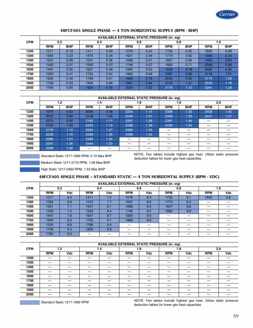
59
NOTE: Fan tables include highest gas heat. Utilize static pressurededuction tables for lower gas heat capacities.
NOTE: Fan tables include highest gas heat. Utilize static pressurededuction tables for lower gas heat capacities.
48FCFA05 SINGLE PHASE — 4 TON HORIZONTAL SUPPLY (RPM - BHP)
CFMAVAILABLE EXTERNAL STATIC PRESSURE (in. wg)
0.2 0.4 0.6 0.8 1.0RPM BHP RPM BHP RPM BHP RPM BHP RPM BHP
1200 1217 0.19 1411 0.30 1576 0.42 1722 0.55 1855 0.681300 1283 0.23 1470 0.34 1631 0.46 1774 0.60 1904 0.741400 1351 0.26 1531 0.38 1688 0.51 1827 0.65 1955 0.801500 1420 0.31 1593 0.43 1746 0.57 1883 0.71 2008 0.861600 1491 0.35 1657 0.48 1805 0.63 1939 0.78 2062 0.931700 1563 0.41 1722 0.54 1866 0.69 1997 0.85 2118 1.011800 1635 0.46 1789 0.61 1928 0.76 2056 0.92 2174 1.091900 1709 0.53 1856 0.68 1991 0.84 2116 1.01 2232 1.182000 1784 0.60 1925 0.76 2056 0.92 2178 1.10 2291 1.28
CFMAVAILABLE EXTERNAL STATIC PRESSURE (in. wg)
1.2 1.4 1.6 1.8 2.0RPM BHP RPM BHP RPM BHP RPM BHP RPM BHP
1200 1979 0.83 2094 0.98 2204 1.15 2308 1.32 2409 1.501300 2025 0.89 2138 1.05 2246 1.21 2349 1.39 2447 1.571400 2074 0.95 2185 1.11 2291 1.28 2391 1.46 — —1500 2124 1.02 2234 1.19 2338 1.36 2436 1.54 — —1600 2176 1.10 2284 1.27 2386 1.45 — — — —1700 2230 1.18 2336 1.36 2436 1.54 — — — —1800 2285 1.27 2389 1.45 — — — — — —1900 2341 1.36 2444 1.55 — — — — — —2000 2398 1.46 — — — — — — — —
Standard Static 1217-1990 RPM, 0.72 Max BHP
Medium Static 1217-2170 RPM, 1.06 Max BHP
High Static 1217-2460 RPM, 1.53 Max BHP
48FCFA05 SINGLE PHASE – STANDARD STATIC — 4 TON HORIZONTAL SUPPLY (RPM - VDC)
CFMAVAILABLE EXTERNAL STATIC PRESSURE (in. wg)
0.2 0.4 0.6 0.8 1.0RPM Vdc RPM Vdc RPM Vdc RPM Vdc RPM Vdc
1200 1217 6.4 1411 7.4 1576 8.3 1722 9.1 1855 9.81300 1283 6.8 1470 7.7 1631 8.6 1774 9.3 — —1400 1351 7.1 1531 8.1 1688 8.9 1827 9.6 — —1500 1420 7.5 1593 8.4 1746 9.2 1883 9.9 — —1600 1491 7.8 1657 8.7 1805 9.5 — — — —1700 1563 8.2 1722 9.1 1866 9.8 — — — —1800 1635 8.6 1789 9.4 — — — — — —1900 1709 9.0 1856 9.8 — — — — — —2000 1784 9.4 — — — — — — — —
CFMAVAILABLE EXTERNAL STATIC PRESSURE (in. wg)
1.2 1.4 1.6 1.8 2.0RPM Vdc RPM Vdc RPM Vdc RPM Vdc RPM Vdc
1200 — — — — — — — — — —1300 — — — — — — — — — —1400 — — — — — — — — — —1500 — — — — — — — — — —1600 — — — — — — — — — —1700 — — — — — — — — — —1800 — — — — — — — — — —1900 — — — — — — — — — —2000 — — — — — — — — — —
Standard Static 1217-1990 RPM

60
NOTE: Fan tables include highest gas heat. Utilize static pressurededuction tables for lower gas heat capacities.
NOTE: Fan tables include highest gas heat. Utilize static pressurededuction tables for lower gas heat capacities.
48FCFA05 SINGLE PHASE – MEDIUM STATIC — 4 TON HORIZONTAL SUPPLY (RPM - VDC)
CFMAVAILABLE EXTERNAL STATIC PRESSURE (in. wg)
0.2 0.4 0.6 0.8 1.0RPM Vdc RPM Vdc RPM Vdc RPM Vdc RPM Vdc
1200 1217 5.6 1411 6.5 1576 7.3 1722 7.9 1855 8.51300 1283 5.9 1470 6.8 1631 7.5 1774 8.2 1904 8.81400 1351 6.2 1531 7.1 1688 7.8 1827 8.4 1955 9.01500 1420 6.5 1593 7.3 1746 8.0 1883 8.7 2008 9.31600 1491 6.9 1657 7.6 1805 8.3 1939 8.9 2062 9.51700 1563 7.2 1722 7.9 1866 8.6 1997 9.2 2118 9.81800 1635 7.5 1789 8.2 1928 8.9 2056 9.5 — —1900 1709 7.9 1856 8.6 1991 9.2 2116 9.8 — —2000 1784 8.2 1925 8.9 2056 9.5 — — — —
CFMAVAILABLE EXTERNAL STATIC PRESSURE (in. wg)
1.2 1.4 1.6 1.8 2.0RPM Vdc RPM Vdc RPM Vdc RPM Vdc RPM Vdc
1200 1979 9.1 2094 9.6 — — — — — —1300 2025 9.3 2138 9.9 — — — — — —1400 2074 9.6 — — — — — — — —1500 2124 9.8 — — — — — — — —1600 — — — — — — — — — —1700 — — — — — — — — — —1800 — — — — — — — — — —1900 — — — — — — — — — —2000 — — — — — — — — — —
Medium Static 1217-2170 RPM
48FCFA05 SINGLE PHASE – HIGH STATIC — 4 TON HORIZONTAL SUPPLY (RPM - VDC)
CFMAVAILABLE EXTERNAL STATIC PRESSURE (in. wg)
0.2 0.4 0.6 0.8 1.0RPM Vdc RPM Vdc RPM Vdc RPM Vdc RPM Vdc
1200 1217 4.9 1411 5.7 1576 6.4 1722 7.0 1855 7.51300 1283 5.2 1470 6.0 1631 6.6 1774 7.2 1904 7.71400 1351 5.5 1531 6.2 1688 6.9 1827 7.4 1955 7.91500 1420 5.8 1593 6.5 1746 7.1 1883 7.7 2008 8.21600 1491 6.1 1657 6.7 1805 7.3 1939 7.9 2062 8.41700 1563 6.4 1722 7.0 1866 7.6 1997 8.1 2118 8.61800 1635 6.6 1789 7.3 1928 7.8 2056 8.4 2174 8.81900 1709 6.9 1856 7.5 1991 8.1 2116 8.6 2232 9.12000 1784 7.3 1925 7.8 2056 8.4 2178 8.9 2291 9.3
CFMAVAILABLE EXTERNAL STATIC PRESSURE (in. wg)
1.2 1.4 1.6 1.8 2.0RPM Vdc RPM Vdc RPM Vdc RPM Vdc RPM Vdc
1200 1979 8.0 2094 8.5 2204 9.0 2308 9.4 2409 9.81300 2025 8.2 2138 8.7 2246 9.1 2349 9.5 2447 9.91400 2074 8.4 2185 8.9 2291 9.3 2391 9.7 — —1500 2124 8.6 2234 9.1 2338 9.5 2436 9.9 — —1600 2176 8.8 2284 9.3 2386 9.7 — — — —1700 2230 9.1 2336 9.5 2436 9.9 — — — —1800 2285 9.3 2389 9.7 — — — — — —1900 2341 9.5 2444 9.9 — — — — — —2000 2398 9.7 — — — — — — — —
High Static 1217-2460 RPM
Fan data (cont)

61
NOTE: Fan tables include highest gas heat. Utilize static pressurededuction tables for lower gas heat capacities.
NOTE: Fan tables include highest gas heat. Utilize static pressurededuction tables for lower gas heat capacities.
48FCFA05 THREE PHASE — 4 TON HORIZONTAL SUPPLY (RPM - BHP)
CFMAVAILABLE EXTERNAL STATIC PRESSURE (in. wg)
0.2 0.4 0.6 0.8 1.0RPM BHP RPM BHP RPM BHP RPM BHP RPM BHP
1200 1216 0.19 1411 0.30 1576 0.42 1722 0.55 1855 0.681300 1282 0.23 1470 0.34 1631 0.46 1773 0.60 1904 0.741400 1351 0.26 1531 0.38 1688 0.51 1827 0.65 1955 0.801500 1420 0.31 1593 0.43 1746 0.57 1882 0.71 2008 0.861600 1491 0.35 1657 0.48 1806 0.63 1940 0.78 2062 0.931700 1563 0.41 1722 0.54 1866 0.69 1997 0.85 2118 1.011800 1636 0.47 1788 0.61 1928 0.76 2056 0.92 2175 1.091900 1710 0.53 1856 0.68 1991 0.84 2116 1.01 2233 1.182000 1784 0.60 1924 0.76 2055 0.92 2178 1.10 2292 1.28
CFMAVAILABLE EXTERNAL STATIC PRESSURE (in. wg)
1.2 1.4 1.6 1.8 2.0RPM BHP RPM BHP RPM BHP RPM BHP RPM BHP
1200 1978 0.83 2094 0.98 2204 1.15 2308 1.32 2409 1.501300 2025 0.89 2138 1.05 2246 1.21 2349 1.39 2447 1.571400 2073 0.95 2185 1.11 2291 1.28 2392 1.46 2488 1.641500 2124 1.02 2233 1.19 2337 1.36 2437 1.54 2532 1.731600 2176 1.10 2284 1.27 2386 1.45 2483 1.63 2577 1.821700 2230 1.18 2336 1.36 2436 1.54 2532 1.73 2624 1.921800 2285 1.27 2389 1.45 2488 1.64 2582 1.83 — —1900 2341 1.36 2443 1.55 2541 1.74 2634 1.94 — —2000 2399 1.46 2499 1.66 2595 1.85 — — — —
Standard Static 1216-1900 RPM, 0.72 Max BHP
Medium Static 1216-2170 RPM, 1.06 Max BHP
High Static 1216-2660 RPM, 1.96 Max BHP
48FCFA05 THREE PHASE – STANDARD STATIC — 4 TON HORIZONTAL SUPPLY (RPM - VDC)
CFMAVAILABLE EXTERNAL STATIC PRESSURE (in. wg)
0.2 0.4 0.6 0.8 1.0RPM Vdc RPM Vdc RPM Vdc RPM Vdc RPM Vdc
1200 1216 6.4 1411 7.4 1576 8.3 1722 9.1 1855 9.81300 1282 6.7 1470 7.7 1631 8.6 1773 9.3 — —1400 1351 7.1 1531 8.1 1688 8.9 1827 9.6 — —1500 1420 7.5 1593 8.4 1746 9.2 1882 9.9 — —1600 1491 7.8 1657 8.7 1806 9.5 — — — —1700 1563 8.2 1722 9.1 1866 9.8 — — — —1800 1636 8.6 1788 9.4 — — — — — —1900 1710 9.0 1856 9.8 — — — — — —2000 1784 9.4 — — — — — — — —
CFMAVAILABLE EXTERNAL STATIC PRESSURE (in. wg)
1.2 1.4 1.6 1.8 2.0RPM Vdc RPM Vdc RPM Vdc RPM Vdc RPM Vdc
1200 — — — — — — — — — —1300 — — — — — — — — — —1400 — — — — — — — — — —1500 — — — — — — — — — —1600 — — — — — — — — — —1700 — — — — — — — — — —1800 — — — — — — — — — —1900 — — — — — — — — — —2000 — — — — — — — — — —
Standard Static 1216-1900 RPM

62
NOTE: Fan tables include highest gas heat. Utilize static pressurededuction tables for lower gas heat capacities.
NOTE: Fan tables include highest gas heat. Utilize static pressurededuction tables for lower gas heat capacities.
48FCFA05 THREE PHASE – MEDIUM STATIC — 4 TON HORIZONTAL SUPPLY (RPM - VDC)
CFMAVAILABLE EXTERNAL STATIC PRESSURE (in. wg)
0.2 0.4 0.6 0.8 1.0RPM Vdc RPM Vdc RPM Vdc RPM Vdc RPM Vdc
1200 1216 5.6 1411 6.5 1576 7.3 1722 7.9 1855 8.51300 1282 5.9 1470 6.8 1631 7.5 1773 8.2 1904 8.81400 1351 6.2 1531 7.1 1688 7.8 1827 8.4 1955 9.01500 1420 6.5 1593 7.3 1746 8.0 1882 8.7 2008 9.31600 1491 6.9 1657 7.6 1806 8.3 1940 8.9 2062 9.51700 1563 7.2 1722 7.9 1866 8.6 1997 9.2 2118 9.81800 1636 7.5 1788 8.2 1928 8.9 2056 9.5 — —1900 1710 7.9 1856 8.6 1991 9.2 2116 9.8 — —2000 1784 8.2 1924 8.9 2055 9.5 — — — —
CFMAVAILABLE EXTERNAL STATIC PRESSURE (in. wg)
1.2 1.4 1.6 1.8 2.0RPM Vdc RPM Vdc RPM Vdc RPM Vdc RPM Vdc
1200 1978 9.1 2094 9.6 — — — — — —1300 2025 9.3 2139 9.9 — — — — — —1400 2073 9.6 — — — — — — — —1500 2124 9.8 — — — — — — — —1600 — — — — — — — — — —1700 — — — — — — — — — —1800 — — — — — — — — — —1900 — — — — — — — — — —2000 — — — — — — — — — —
Medium Static 1216-2170 RPM,
48FCFA05 THREE PHASE – HIGH STATIC — 4 TON HORIZONTAL SUPPLY (RPM - VDC)
CFMAVAILABLE EXTERNAL STATIC PRESSURE (in. wg)
0.2 0.4 0.6 0.8 1.0RPM Vdc RPM Vdc RPM Vdc RPM Vdc RPM Vdc
1200 1216 4.6 1411 5.3 1576 5.9 1722 6.5 1855 7.01300 1282 4.8 1470 5.5 1631 6.1 1773 6.7 1904 7.21400 1351 5.1 1531 5.8 1688 6.3 1827 6.9 1955 7.31500 1420 5.3 1593 6.0 1746 6.6 1882 7.1 2008 7.51600 1491 5.6 1657 6.2 1806 6.8 1940 7.3 2062 7.81700 1563 5.9 1722 6.5 1866 7.0 1997 7.5 2118 8.01800 1636 6.2 1788 6.7 1928 7.2 2056 7.7 2175 8.21900 1710 6.4 1856 7.0 1991 7.5 2116 8.0 2233 8.42000 1784 6.7 1924 7.2 2055 7.7 2178 8.2 2292 8.6
CFMAVAILABLE EXTERNAL STATIC PRESSURE (in. wg)
1.2 1.4 1.6 1.8 2.0RPM Vdc RPM Vdc RPM Vdc RPM Vdc RPM Vdc
1200 1978 7.4 2094 7.9 2204 8.3 2308 8.7 2409 9.11300 2025 7.6 2139 8.0 2246 8.4 2349 8.8 2447 9.21400 2073 7.8 2185 8.2 2291 8.6 2392 9.0 2488 9.41500 2124 8.0 2233 8.4 2337 8.8 2437 9.2 2532 9.51600 2176 8.2 2284 8.6 2386 9.0 2483 9.3 2577 9.71700 2230 8.4 2336 8.8 2436 9.2 2532 9.5 2624 9.91800 2285 8.6 2389 9.0 2488 9.4 2582 9.7 — —1900 2341 8.8 2443 9.2 2541 9.6 2634 9.9 — —2000 2399 9.0 2499 9.4 2595 9.8 — — — —
High Static 1216-2660 RPM
Fan data (cont)

63
NOTE: Fan tables include highest gas heat. Utilize static pressurededuction tables for lower gas heat capacities.
NOTE: Fan tables include highest gas heat. Utilize static pressurededuction tables for lower gas heat capacities.
48FCFA06 SINGLE PHASE — 5 TON HORIZONTAL SUPPLY (RPM - BHP)
CFMAVAILABLE EXTERNAL STATIC PRESSURE (in. wg)
0.2 0.4 0.6 0.8 1.0RPM BHP RPM BHP RPM BHP RPM BHP RPM BHP
1500 1420 0.31 1593 0.43 1746 0.57 1883 0.71 2008 0.861625 1509 0.37 1673 0.50 1820 0.64 1954 0.79 2076 0.951750 1599 0.43 1755 0.57 1897 0.73 2026 0.88 2146 1.051875 1691 0.51 1839 0.66 1975 0.82 2101 0.98 2218 1.162000 1784 0.60 1925 0.76 2056 0.92 2178 1.10 2291 1.282125 1878 0.70 2011 0.86 2138 1.04 2255 1.22 2367 1.412250 1974 0.81 2100 0.98 2221 1.16 2335 1.35 — —2375 2070 0.94 2189 1.11 2305 1.30 — — — —2500 2166 1.08 2280 1.25 — — — — — —
CFMAVAILABLE EXTERNAL STATIC PRESSURE (in. wg)
1.2 1.4 1.6 1.8 2.0RPM BHP RPM BHP RPM BHP RPM BHP RPM BHP
1500 2124 1.02 2234 1.19 2338 1.36 — — — —1625 2190 1.12 2297 1.29 — — — — — —1750 2257 1.22 2362 1.40 — — — — — —1875 2327 1.34 — — — — — — — —2000 — — — — — — — — — —2125 — — — — — — — — — —2250 — — — — — — — — — —2375 — — — — — — — — — —2500 — — — — — — — — — —
Standard Static 1420-2150 RPM, 1.06 Max BHP
Medium Static 1420-2390 RPM, 1.44 Max BHP
48FCFA06 SINGLE PHASE – STANDARD STATIC — 5 TON HORIZONTAL SUPPLY (RPM - VDC)
CFMAVAILABLE EXTERNAL STATIC PRESSURE (in. wg)
0.2 0.4 0.6 0.8 1.0RPM Vdc RPM Vdc RPM Vdc RPM Vdc RPM Vdc
1500 1420 6.6 1593 7.4 1746 8.1 1883 8.8 2008 9.31625 1509 7.0 1673 7.8 1820 8.5 1954 9.1 2076 9.71750 1599 7.4 1755 8.2 1897 8.8 2026 9.4 2146 10.01875 1691 7.9 1839 8.6 1975 9.2 2101 9.8 — —2000 1784 8.3 1925 9.0 2056 9.6 — — — —2125 1878 8.7 2011 9.4 2138 9.9 — — — —2250 1974 9.2 2100 9.8 — — — — — —2375 2070 9.6 — — — — — — — —2500 – – — — — — — — — —
CFMAVAILABLE EXTERNAL STATIC PRESSURE (in. wg)
1.2 1.4 1.6 1.8 2.0RPM Vdc RPM Vdc RPM Vdc RPM Vdc RPM Vdc
1500 2124 9.9 — — — — — — — —1625 — — — — — — — — — —1750 — — — — — — — — — —1875 — — — — — — — — — —2000 — — — — — — — — — —2125 — — — — — — — — — —2250 — — — — — — — — — —2375 — — — — — — — — — —2500 — — — — — — — — — —
Standard Static 1420-2150 RPM

64
NOTE: Fan tables include highest gas heat. Utilize static pressurededuction tables for lower gas heat capacities.
48FCFA06 SINGLE PHASE – MEDIUM STATIC — 5 TON HORIZONTAL SUPPLY (RPM - VDC)
CFMAVAILABLE EXTERNAL STATIC PRESSURE (in. wg)
0.2 0.4 0.6 0.8 1.0RPM Vdc RPM Vdc RPM Vdc RPM Vdc RPM Vdc
1500 1420 5.9 1593 6.7 1746 7.3 1883 7.9 2008 8.41625 1509 6.3 1673 7.0 1820 7.6 1954 8.2 2076 8.71750 1599 6.7 1755 7.3 1897 7.9 2026 8.5 2146 9.01875 1691 7.1 1839 7.7 1975 8.3 2101 8.8 2218 9.32000 1784 7.5 1925 8.1 2056 8.6 2178 9.1 2291 9.62125 1878 7.9 2011 8.4 2138 8.9 2255 9.4 2367 9.92250 1974 8.3 2100 8.8 2221 9.3 2335 9.8 — —2375 2070 8.7 2189 9.2 2305 9.6 — — — —2500 2166 9.1 2280 9.5 — — — — — —
CFMAVAILABLE EXTERNAL STATIC PRESSURE (in. wg)
1.2 1.4 1.6 1.8 2.0RPM Vdc RPM Vdc RPM Vdc RPM Vdc RPM Vdc
1500 2124 8.9 2234 9.3 2338 9.8 — — — —1625 2190 9.2 2297 9.6 — — — — — —1750 2257 9.4 2362 9.9 — — — — — —1875 2327 9.7 — — — — — — — —2000 — — — — — — — — — —2125 — — — — — — — — — —2250 — — — — — — — — — —2375 — — — — — — — — — —2500 — — — — — — — — — —
Medium Static 1420-2390 RPM
Fan data (cont)

65
NOTE: Fan tables include highest gas heat. Utilize static pressurededuction tables for lower gas heat capacities.
NOTE: Fan tables include highest gas heat. Utilize static pressurededuction tables for lower gas heat capacities.
48FCFA06 THREE PHASE — 5 TON HORIZONTAL SUPPLY (RPM - BHP)
CFMAVAILABLE EXTERNAL STATIC PRESSURE (in. wg)
0.2 0.4 0.6 0.8 1.0RPM BHP RPM BHP RPM BHP RPM BHP RPM BHP
1500 1420 0.31 1593 0.43 1746 0.57 1883 0.71 2008 0.861625 1509 0.37 1673 0.50 1820 0.64 1954 0.79 2076 0.951750 1599 0.43 1755 0.57 1897 0.73 2026 0.88 2146 1.051875 1691 0.51 1839 0.66 1976 0.82 2102 0.99 2218 1.162000 1784 0.60 1924 0.76 2056 0.92 2178 1.10 2291 1.282125 1879 0.70 2011 0.86 2137 1.03 2256 1.22 2367 1.412250 1974 0.81 2099 0.98 2221 1.16 2335 1.35 2444 1.552375 2070 0.94 2189 1.11 2305 1.30 2416 1.49 2522 1.702500 2166 1.08 2280 1.25 2391 1.45 2499 1.65 2601 1.86
CFMAVAILABLE EXTERNAL STATIC PRESSURE (in. wg)
1.2 1.4 1.6 1.8 2.0RPM BHP RPM BHP RPM BHP RPM BHP RPM BHP
1500 2124 1.02 2233 1.19 2337 1.36 2436 1.54 2532 1.731625 2190 1.12 2296 1.29 2398 1.47 2495 1.65 2589 1.851750 2257 1.22 2362 1.40 2462 1.59 2557 1.78 2648 1.971875 2327 1.34 2430 1.52 2528 1.72 2621 1.91 2710 2.112000 2398 1.46 2499 1.66 2595 1.85 2687 2.06 2775 2.272125 2471 1.60 2570 1.80 2665 2.01 2755 2.22 — —2250 2546 1.75 2643 1.96 2735 2.17 2824 2.39 — —2375 2622 1.91 2717 2.12 2807 2.34 — — — —2500 2699 2.08 2792 2.30 — — — — — —
Standard Static 1420-2150 RPM, 1.06 Max BHP
Medium Static 1420-2390 RPM, 1.44 Max BHP
High Static 1420-2836 RPM, 2.43 Max BHP
48FCFA06 THREE PHASE – STANDARD STATIC — 5 TON HORIZONTAL SUPPLY (RPM - VDC)
CFMAVAILABLE EXTERNAL STATIC PRESSURE (in. wg)
0.2 0.4 0.6 0.8 1.0RPM Vdc RPM Vdc RPM Vdc RPM Vdc RPM Vdc
1500 1420 6.6 1593 7.4 1746 8.1 1883 8.8 2008 9.31625 1509 7.0 1673 7.8 1820 8.5 1954 9.1 2076 9.71750 1599 7.4 1755 8.2 1897 8.8 2026 9.4 2146 10.01875 1691 7.9 1839 8.6 1976 9.2 2102 9.8 — —2000 1784 8.3 1924 8.9 2056 9.6 — — — —2125 1878 8.7 2011 9.4 2137 9.9 — — — —2250 1974 9.2 2099 9.8 — — — — — —2375 2070 9.6 — — — — — — — —2500 — — — — — — — — — —
CFMAVAILABLE EXTERNAL STATIC PRESSURE (in. wg)
1.2 1.4 1.6 1.8 2.0RPM Vdc RPM Vdc RPM Vdc RPM Vdc RPM Vdc
1500 2124 9.9 — — — — — — — —1625 — — — — — — — — — —1750 — — — — — — — — — —1875 — — — — — — — — — —2000 — — — — — — — — — —2125 — — — — — — — — — —2250 — — — — — — — — — —2375 — — — — — — — — — —2500 — — — — — — — — — —
Standard Static 1420-2150 RPM
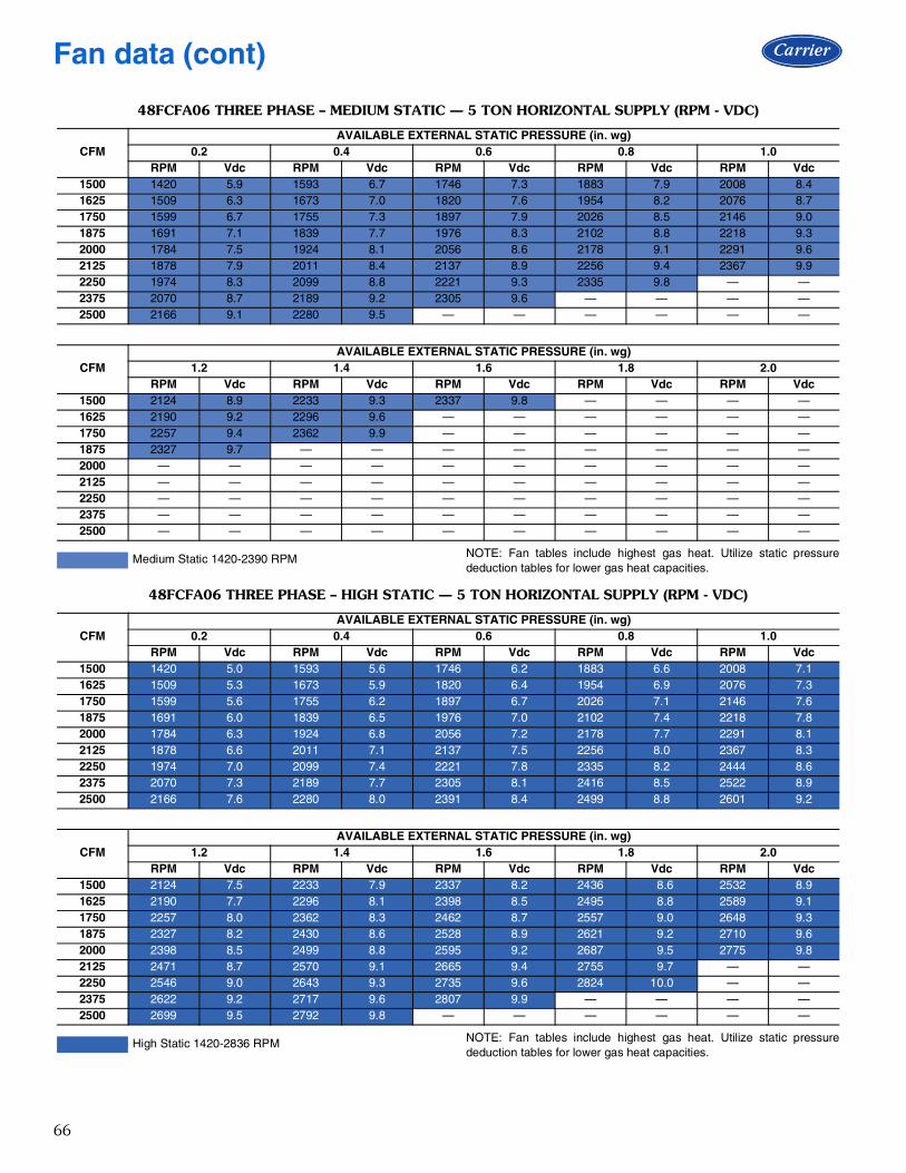
66
NOTE: Fan tables include highest gas heat. Utilize static pressurededuction tables for lower gas heat capacities.
NOTE: Fan tables include highest gas heat. Utilize static pressurededuction tables for lower gas heat capacities.
48FCFA06 THREE PHASE – MEDIUM STATIC — 5 TON HORIZONTAL SUPPLY (RPM - VDC)
CFMAVAILABLE EXTERNAL STATIC PRESSURE (in. wg)
0.2 0.4 0.6 0.8 1.0RPM Vdc RPM Vdc RPM Vdc RPM Vdc RPM Vdc
1500 1420 5.9 1593 6.7 1746 7.3 1883 7.9 2008 8.41625 1509 6.3 1673 7.0 1820 7.6 1954 8.2 2076 8.71750 1599 6.7 1755 7.3 1897 7.9 2026 8.5 2146 9.01875 1691 7.1 1839 7.7 1976 8.3 2102 8.8 2218 9.32000 1784 7.5 1924 8.1 2056 8.6 2178 9.1 2291 9.62125 1878 7.9 2011 8.4 2137 8.9 2256 9.4 2367 9.92250 1974 8.3 2099 8.8 2221 9.3 2335 9.8 — —2375 2070 8.7 2189 9.2 2305 9.6 — — — —2500 2166 9.1 2280 9.5 — — — — — —
CFMAVAILABLE EXTERNAL STATIC PRESSURE (in. wg)
1.2 1.4 1.6 1.8 2.0RPM Vdc RPM Vdc RPM Vdc RPM Vdc RPM Vdc
1500 2124 8.9 2233 9.3 2337 9.8 — — — —1625 2190 9.2 2296 9.6 — — — — — —1750 2257 9.4 2362 9.9 — — — — — —1875 2327 9.7 — — — — — — — —2000 — — — — — — — — — —2125 — — — — — — — — — —2250 — — — — — — — — — —2375 — — — — — — — — — —2500 — — — — — — — — — —
Medium Static 1420-2390 RPM
48FCFA06 THREE PHASE – HIGH STATIC — 5 TON HORIZONTAL SUPPLY (RPM - VDC)
CFMAVAILABLE EXTERNAL STATIC PRESSURE (in. wg)
0.2 0.4 0.6 0.8 1.0RPM Vdc RPM Vdc RPM Vdc RPM Vdc RPM Vdc
1500 1420 5.0 1593 5.6 1746 6.2 1883 6.6 2008 7.11625 1509 5.3 1673 5.9 1820 6.4 1954 6.9 2076 7.31750 1599 5.6 1755 6.2 1897 6.7 2026 7.1 2146 7.61875 1691 6.0 1839 6.5 1976 7.0 2102 7.4 2218 7.82000 1784 6.3 1924 6.8 2056 7.2 2178 7.7 2291 8.12125 1878 6.6 2011 7.1 2137 7.5 2256 8.0 2367 8.32250 1974 7.0 2099 7.4 2221 7.8 2335 8.2 2444 8.62375 2070 7.3 2189 7.7 2305 8.1 2416 8.5 2522 8.92500 2166 7.6 2280 8.0 2391 8.4 2499 8.8 2601 9.2
CFMAVAILABLE EXTERNAL STATIC PRESSURE (in. wg)
1.2 1.4 1.6 1.8 2.0RPM Vdc RPM Vdc RPM Vdc RPM Vdc RPM Vdc
1500 2124 7.5 2233 7.9 2337 8.2 2436 8.6 2532 8.91625 2190 7.7 2296 8.1 2398 8.5 2495 8.8 2589 9.11750 2257 8.0 2362 8.3 2462 8.7 2557 9.0 2648 9.31875 2327 8.2 2430 8.6 2528 8.9 2621 9.2 2710 9.62000 2398 8.5 2499 8.8 2595 9.2 2687 9.5 2775 9.82125 2471 8.7 2570 9.1 2665 9.4 2755 9.7 — —2250 2546 9.0 2643 9.3 2735 9.6 2824 10.0 — —2375 2622 9.2 2717 9.6 2807 9.9 — — — —2500 2699 9.5 2792 9.8 — — — — — —
High Static 1420-2836 RPM
Fan data (cont)

67
NOTE: Fan tables include highest gas heat. Utilize static pressurededuction tables for lower gas heat capacities.
NOTE: Fan tables include highest gas heat. Utilize static pressurededuction tables for lower gas heat capacities.
48FCFM07 THREE PHASE — 6 TON HORIZONTAL SUPPLY (RPM - BHP)
CFMAVAILABLE EXTERNAL STATIC PRESSURE (in. wg)
0.2 0.4 0.6 0.8 1.0RPM BHP RPM BHP RPM BHP RPM BHP RPM BHP
1800 1537 0.38 1685 0.51 1824 0.64 1953 0.79 2071 0.941950 1641 0.47 1778 0.59 1911 0.74 2035 0.89 2150 1.052100 1748 0.56 1874 0.69 2000 0.84 2119 1.00 2231 1.172250 1855 0.67 1973 0.81 2091 0.96 2206 1.13 2314 1.312400 1964 0.80 2074 0.94 2185 1.10 2294 1.27 2399 1.452550 2074 0.94 2176 1.08 2281 1.25 2385 1.43 2486 1.622700 2185 1.10 2281 1.25 2379 1.42 2478 1.60 2575 1.802850 2296 1.27 2386 1.43 2479 1.60 2573 1.79 2666 1.993000 2408 1.47 2493 1.63 2581 1.81 2670 2.00 2759 2.21
CFMAVAILABLE EXTERNAL STATIC PRESSURE (in. wg)
1.2 1.4 1.6 1.8 2.0RPM BHP RPM BHP RPM BHP RPM BHP RPM BHP
1800 2182 1.10 2285 1.26 2382 1.43 2476 1.60 2564 1.781950 2258 1.21 2359 1.39 2455 1.56 2547 1.74 2634 1.932100 2337 1.34 2436 1.52 2530 1.71 2620 1.90 2706 2.092250 2417 1.49 2514 1.67 2606 1.86 2695 2.06 2780 2.262400 2499 1.64 2594 1.84 2685 2.04 2771 2.24 — —2550 2583 1.81 2676 2.02 2765 2.22 — — — —2700 2669 2.00 2759 2.21 — — — — — —2850 2757 2.20 — — — — — — — —3000 — — — — — — — —
Standard Static 1537-2300 RPM, 1.31 Max BHP
Medium Static 1537-2530 RPM, 1.76 Max BHP
High Static 1537-2836 RPM, 2.43 Max BHP
48FCEM07 THREE PHASE – STANDARD STATIC — 6 TON HORIZONTAL SUPPLY (RPM - VDC)
CFMAVAILABLE EXTERNAL STATIC PRESSURE (in. wg)
0.2 0.4 0.6 0.8 1.0RPM Vdc RPM Vdc RPM Vdc RPM Vdc RPM Vdc
1800 1537 6.7 1685 7.3 1824 7.9 1953 8.5 2071 9.01950 1641 7.1 1778 7.7 1911 8.3 2035 8.8 2150 9.32100 1748 7.6 1874 8.1 2000 8.7 2119 9.2 2231 9.72250 1855 8.1 1973 8.6 2091 9.1 2206 9.6 — —2400 1964 8.5 2074 9.0 2185 9.5 2294 10.0 — —2550 2074 9.0 2176 9.5 2281 9.9 — — — —2700 2185 9.5 2281 9.9 — — — — — —2850 2296 10.0 — — — — — — — —3000 — — — — — — — — — —
CFMAVAILABLE EXTERNAL STATIC PRESSURE (in. wg)
1.2 1.4 1.6 1.8 2.0RPM Vdc RPM Vdc RPM Vdc RPM Vdc RPM Vdc
1800 2182 9.5 2285 9.9 — — — — — —1950 2258 9.8 — — — — — — — —2100 — — — — — — — — — —2250 — — — — — — — — — —2400 — — — — — — — — — —2550 — — — — — — — — — —2700 — — — — — — — — — —2850 — — — — — — — — — —3000 — — — — — — — — — —
Standard Static 1537-2300 RPM

68
NOTE: Fan tables include highest gas heat. Utilize static pressurededuction tables for lower gas heat capacities.
NOTE: Fan tables include highest gas heat. Utilize static pressurededuction tables for lower gas heat capacities.
48FCEM07 THREE PHASE – MEDIUM STATIC — 6 TON HORIZONTAL SUPPLY (RPM - VDC)
CFMAVAILABLE EXTERNAL STATIC PRESSURE (in. wg)
0.2 0.4 0.6 0.8 1.0RPM Vdc RPM Vdc RPM Vdc RPM Vdc RPM Vdc
1800 1537 6.1 1685 6.7 1824 7.2 1953 7.7 2071 8.21950 1641 6.5 1778 7.0 1911 7.6 2035 8.0 2150 8.52100 1748 6.9 1874 7.4 2000 7.9 2119 8.4 2231 8.82250 1855 7.3 1973 7.8 2091 8.3 2206 8.7 2314 9.12400 1964 7.8 2074 8.2 2185 8.6 2294 9.1 2399 9.52550 2074 8.2 2176 8.6 2281 9.0 2385 9.4 2486 9.82700 2185 8.6 2281 9.0 2379 9.4 2478 9.8 — —2850 2296 9.1 2386 9.4 2479 9.8 — — — —3000 2408 9.5 2493 9.9 — — — — — —
CFMAVAILABLE EXTERNAL STATIC PRESSURE (in. wg)
1.2 1.4 1.6 1.8 2.0RPM Vdc RPM Vdc RPM Vdc RPM Vdc RPM Vdc
1800 2182 8.6 2285 9.0 2382 9.4 2476 9.81950 2258 8.9 2359 9.3 2455 9.7 — — — —2100 2337 9.2 2436 9.6 2530 10.0 — — — —2250 2417 9.6 2514 9.9 — — — — — —2400 2499 9.9 — — — — — — — —2550 — — — — — — — — — —2700 — — — — — — — — — —2850 — — — — — — — — — —3000 — — — — — — — — — —
Medium Static 1537-2530 RPM
48FCEM07 THREE PHASE – HIGH STATIC — 6 TON HORIZONTAL SUPPLY (RPM - VDC)
CFMAVAILABLE EXTERNAL STATIC PRESSURE (in. wg)
0.2 0.4 0.6 0.8 1.0RPM Vdc RPM Vdc RPM Vdc RPM Vdc RPM Vdc
1800 1537 5.4 1685 5.9 1824 6.4 1953 6.9 2071 7.31950 1641 5.8 1778 6.3 1911 6.7 2035 7.2 2150 7.62100 1748 6.2 1874 6.6 2000 7.1 2119 7.5 2231 7.92250 1855 6.5 1973 7.0 2091 7.4 2206 7.8 2314 8.22400 1964 6.9 2074 7.3 2185 7.7 2294 8.1 2399 8.52550 2074 7.3 2176 7.7 2281 8.0 2385 8.4 2486 8.82700 2185 7.7 2281 8.0 2379 8.4 2478 8.7 2575 9.12850 2296 8.1 2386 8.4 2479 8.7 2573 9.1 2666 9.43000 2408 8.5 2493 8.8 2581 9.1 2670 9.4 2759 9.7
CFMAVAILABLE EXTERNAL STATIC PRESSURE (in. wg)
1.2 1.4 1.6 1.8 2.0RPM Vdc RPM Vdc RPM Vdc RPM Vdc RPM Vdc
1800 2182 7.7 2285 8.1 2382 8.4 2476 8.7 2564 9.01950 2258 8.0 2359 8.3 2455 8.7 2547 9.0 2634 9.32100 2337 8.2 2436 8.6 2530 8.9 2620 9.2 2706 9.52250 2417 8.5 2514 8.9 2606 9.2 2695 9.5 2780 9.82400 2499 8.8 2594 9.1 2685 9.5 2771 9.8 — —2550 2583 9.1 2676 9.4 2765 9.7 — — — —2700 2669 9.4 2759 9.7 — — — — — —2850 2757 9.7 — — — — — — — —3000 — — — — — — — — — —
High Static 1537-2836 RPM
Fan data (cont)

69
50FC-A04 SINGLE PHASE — 3 TON VERTICAL SUPPLY (RPM - BHP)
CFMAVAILABLE EXTERNAL STATIC PRESSURE (in. wg)
0.2 0.4 0.6 0.8 1.0RPM BHP RPM BHP RPM BHP RPM BHP RPM BHP
900 1040 0.08 1307 0.16 1526 0.25 1705 0.35 1859 0.45 975 1082 0.09 1336 0.17 1554 0.26 1736 0.36 1892 0.471050 1127 0.10 1366 0.18 1582 0.28 1766 0.38 1925 0.501125 1175 0.11 1398 0.19 1609 0.29 1795 0.40 1956 0.521200 1225 0.13 1434 0.21 1638 0.31 1822 0.42 1984 0.541275 1277 0.15 1472 0.22 1667 0.32 1849 0.44 2012 0.571350 1330 0.16 1514 0.24 1699 0.34 1878 0.46 2040 0.591425 1385 0.19 1557 0.26 1734 0.36 1906 0.48 2068 0.621500 1440 0.21 1603 0.29 1771 0.39 1937 0.51 2095 0.64
CFMAVAILABLE EXTERNAL STATIC PRESSURE (in. wg)
1.2 1.4 1.6 1.8 2.0RPM BHP RPM BHP RPM BHP RPM BHP RPM BHP
900 1995 0.55 2119 0.66 2234 0.78 2342 0.89 2444 1.02 975 2031 0.58 2156 0.70 2272 0.82 2380 0.94 2482 1.061050 2065 0.61 2192 0.73 2309 0.86 2418 0.98 — —1125 2098 0.64 2226 0.77 2345 0.90 2454 1.03 — —1200 2129 0.67 2259 0.80 2379 0.94 2490 1.07 — —1275 2159 0.70 2291 0.84 2412 0.98 — — — —1350 2187 0.73 2321 0.87 2444 1.02 — — — —1425 2215 0.76 2350 0.90 2474 1.05 — — — —1500 2242 0.78 2378 0.94 — — — — — —
Standard Static 1040-1890 RPM, 0.44 Max BHP
Medium Static 1040-2190 RPM, 0.71 Max BHP
High Static 1040-2490 RPM, 1.07 Max BHP
50FC-A04 SINGLE PHASE – STANDARD STATIC — 3 TON VERTICAL SUPPLY (RPM - VDC)
CFMAVAILABLE EXTERNAL STATIC PRESSURE (in. wg)
0.2 0.4 0.6 0.8 1.0RPM Vdc RPM Vdc RPM Vdc RPM Vdc RPM Vdc
900 1040 5.5 1307 6.9 1526 8.1 1705 9.0 — — 975 1082 5.7 1336 7.1 1554 8.2 1736 9.2 — —1050 1127 6.0 1366 7.2 1582 8.4 1766 9.3 — —1125 1175 6.2 1398 7.4 1609 8.5 1795 9.5 — —1200 1225 6.5 1434 7.6 1638 8.7 1822 9.6 — —1275 1277 6.8 1472 7.8 1667 8.8 1849 9.8 — —1350 1330 7.0 1514 8.0 1699 9.0 — — — —1425 1385 7.3 1557 8.2 1734 9.2 — — — —1500 1440 7.6 1603 8.5 1771 9.4 — — — —
CFMAVAILABLE EXTERNAL STATIC PRESSURE (in. wg)
1.2 1.4 1.6 1.8 2.0RPM Vdc RPM Vdc RPM Vdc RPM Vdc RPM Vdc
900 — — — — — — — — — — 975 — — — — — — — — — —1050 — — — — — — — — — —1125 — — — — — — — — — —1200 — — — — — — — — — —1275 — — — — — — — — — —1350 — — — — — — — — — —1425 — — — — — — — — — —1500 — — — — — — — — — —
Standard Static 1040-1890 RPM

70
50FC-A04 SINGLE PHASE – MEDIUM STATIC — 3 TON VERTICAL SUPPLY (RPM - VDC)
CFMAVAILABLE EXTERNAL STATIC PRESSURE (in. wg)
0.2 0.4 0.6 0.8 1.0RPM Vdc RPM Vdc RPM Vdc RPM Vdc RPM Vdc
900 1040 4.7 1307 6.0 1526 7.0 1705 7.8 1859 8.5 975 1082 4.9 1336 6.1 1554 7.1 1736 7.9 1892 8.61050 1127 5.1 1366 6.2 1582 7.2 1766 8.1 1925 8.81125 1175 5.4 1398 6.4 1609 7.3 1795 8.2 1956 8.91200 1225 5.6 1434 6.5 1638 7.5 1822 8.3 1984 9.11275 1277 5.8 1472 6.7 1667 7.6 1849 8.4 2012 9.21350 1330 6.1 1514 6.9 1699 7.8 1878 8.6 2040 9.31425 1385 6.3 1557 7.1 1734 7.9 1906 8.7 2068 9.41500 1440 6.6 1603 7.3 1771 8.1 1937 8.8 2095 9.6
CFMAVAILABLE EXTERNAL STATIC PRESSURE (in. wg)
1.2 1.4 1.6 1.8 2.0RPM Vdc RPM Vdc RPM Vdc RPM Vdc RPM Vdc
900 1995 9.1 2119 9.7 — — — — — — 975 2031 9.3 2156 9.8 — — — — — —1050 2065 9.4 — — — — — — — —1125 2098 9.6 — — — — — — — —1200 2129 9.7 — — — — — — — —1275 2159 9.9 — — — — — — — —1350 2187 10.0 — — — — — — — —1425 — — — — — — — — — —1500 — — — — — — — — — —
Medium Static 1040-2190 RPM
50FC-A04 SINGLE PHASE – HIGH STATIC — 3 TON VERTICAL SUPPLY (RPM - VDC)
CFMAVAILABLE EXTERNAL STATIC PRESSURE (in. wg)
0.2 0.4 0.6 0.8 1.0RPM Vdc RPM Vdc RPM Vdc RPM Vdc RPM Vdc
900 1040 4.2 1307 5.2 1526 6.1 1705 6.8 1859 7.5 975 1082 4.3 1336 5.4 1554 6.2 1736 7.0 1892 7.61050 1127 4.5 1366 5.5 1582 6.4 1766 7.1 1925 7.71125 1175 4.7 1398 5.6 1609 6.5 1795 7.2 1956 7.91200 1225 4.9 1434 5.8 1638 6.6 1822 7.3 1984 8.01275 1277 5.1 1472 5.9 1667 6.7 1849 7.4 2012 8.11350 1330 5.3 1514 6.1 1699 6.8 1878 7.5 2040 8.21425 1385 5.6 1557 6.3 1734 7.0 1906 7.7 2068 8.31500 1440 5.8 1603 6.4 1771 7.1 1937 7.8 2095 8.4
CFMAVAILABLE EXTERNAL STATIC PRESSURE (in. wg)
1.2 1.4 1.6 1.8 2.0RPM Vdc RPM Vdc RPM Vdc RPM Vdc RPM Vdc
900 1995 8.0 2119 8.5 2234 9.0 2342 9.4 2444 9.8 975 2031 8.2 2156 8.7 2272 9.1 2380 9.6 2482 10.01050 2065 8.3 2192 8.8 2309 9.3 2418 9.7 — —1125 2098 8.4 2226 8.9 2345 9.4 2454 9.9 — —1200 2129 8.6 2259 9.1 2379 9.6 2490 10.0 — —1275 2159 8.7 2291 9.2 2412 9.7 — — — —1350 2187 8.8 2321 9.3 2444 9.8 — — — —1425 2215 8.9 2350 9.4 2474 9.9 — — — —1500 2242 9.0 2378 9.6 — — — — — —
High Static 1040-2490 RPM
Fan data (cont)

71
50FC-A04 THREE PHASE — 3 TON VERTICAL SUPPLY (RPM - VDC)
CFMAVAILABLE EXTERNAL STATIC PRESSURE (in. wg)
0.2 0.4 0.6 0.8 1.0RPM BHP RPM BHP RPM BHP RPM BHP RPM BHP
900 1040 0.08 1307 0.16 1526 0.25 1705 0.35 1859 0.45 975 1082 0.09 1336 0.17 1554 0.26 1736 0.36 1892 0.471050 1127 0.10 1366 0.18 1582 0.28 1766 0.38 1925 0.501125 1175 0.11 1398 0.19 1609 0.29 1795 0.40 1956 0.521200 1225 0.13 1434 0.21 1638 0.31 1822 0.42 1984 0.541275 1277 0.15 1472 0.22 1667 0.32 1849 0.44 2012 0.571350 1330 0.16 1514 0.24 1699 0.34 1878 0.46 2040 0.591425 1385 0.19 1557 0.26 1734 0.36 1906 0.48 2068 0.621500 1440 0.21 1603 0.29 1771 0.39 1937 0.51 2095 0.64
CFMAVAILABLE EXTERNAL STATIC PRESSURE (in. wg)
1.2 1.4 1.6 1.8 2.0RPM BHP RPM BHP RPM BHP RPM BHP RPM BHP
900 1995 0.55 2119 0.66 2234 0.78 2342 0.89 2444 1.02 975 2031 0.58 2156 0.70 2272 0.82 2380 0.94 2482 1.061050 2065 0.61 2192 0.73 2309 0.86 2418 0.98 — —1125 2098 0.64 2226 0.77 2345 0.90 2454 1.03 — —1200 2129 0.67 2259 0.80 2379 0.94 2490 1.07 — —1275 2159 0.70 2291 0.84 2412 0.98 — — — —1350 2187 0.73 2321 0.87 2444 1.02 — — — —1425 2215 0.76 2350 0.90 2474 1.05 — — — —1500 2242 0.78 2378 0.94 — — — — — —
Standard Static 1040-1890 RPM, 0.44 Max BHP
Medium Static 1040-2190 RPM, 0.71 Max BHP
High Static 1040-2490 RPM, 1.07 Max BHP
50FC-A04 THREE PHASE – STANDARD STATIC — 3 TON VERTICAL SUPPLY (RPM - VDC)
CFMAVAILABLE EXTERNAL STATIC PRESSURE (in. wg)
0.2 0.4 0.6 0.8 1.0RPM Vdc RPM Vdc RPM Vdc RPM Vdc RPM Vdc
900 1040 5.5 1307 6.9 1526 8.1 1705 9.0 — — 975 1082 5.7 1336 7.1 1554 8.2 1736 9.2 — —1050 1127 6.0 1366 7.2 1582 8.4 1766 9.3 — —1125 1175 6.2 1398 7.4 1609 8.5 1795 9.5 — —1200 1225 6.5 1434 7.6 1638 8.7 1822 9.6 — —1275 1277 6.8 1472 7.8 1667 8.8 1849 9.8 — —1350 1330 7.0 1514 8.0 1699 9.0 — — — —1425 1385 7.3 1557 8.2 1734 9.2 — — — —1500 1440 7.6 1603 8.5 1771 9.4 — — — —
CFMAVAILABLE EXTERNAL STATIC PRESSURE (in. wg)
1.2 1.4 1.6 1.8 2.0RPM Vdc RPM Vdc RPM Vdc RPM Vdc RPM Vdc
900 — — — — — — — — — — 975 — — — — — — — — — —1050 — — — — — — — — — —1125 — — — — — — — — — —1200 — — — — — — — — — —1275 — — — — — — — — — —1350 — — — — — — — — — —1425 — — — — — — — — — —1500 — — — — — — — — — —
Standard Static 1040-1890 RPM

72
50FC-A04 THREE PHASE – MEDIUM STATIC — 3 TON VERTICAL SUPPLY (RPM - VDC)
CFMAVAILABLE EXTERNAL STATIC PRESSURE (in. wg)
0.2 0.4 0.6 0.8 1.0RPM Vdc RPM Vdc RPM Vdc RPM Vdc RPM Vdc
900 1040 4.7 1307 6.0 1526 7.0 1705 7.8 1859 8.5 975 1082 4.9 1336 6.1 1554 7.1 1736 7.9 1892 8.61050 1127 5.1 1366 6.2 1582 7.2 1766 8.1 1925 8.81125 1175 5.4 1398 6.4 1609 7.3 1795 8.2 1956 8.91200 1225 5.6 1434 6.5 1638 7.5 1822 8.3 1984 9.11275 1277 5.8 1472 6.7 1667 7.6 1849 8.4 2012 9.21350 1330 6.1 1514 6.9 1699 7.8 1878 8.6 2040 9.31425 1385 6.3 1557 7.1 1734 7.9 1906 8.7 2068 9.41500 1440 6.6 1603 7.3 1771 8.1 1937 8.8 2095 9.6
CFMAVAILABLE EXTERNAL STATIC PRESSURE (in. wg)
1.2 1.4 1.6 1.8 2.0RPM Vdc RPM Vdc RPM Vdc RPM Vdc RPM Vdc
900 1995 9.1 2119 9.7 — — — — — — 975 2031 9.3 2156 9.8 — — — — — —1050 2065 9.4 — — — — — — — —1125 2098 9.6 — — — — — — — —1200 2129 9.7 — — — — — — — —1275 2159 9.9 — — — — — — — —1350 2187 10.0 — — — — — — — —1425 — — — — — — — — — —1500 — — — — — — — — — —
Medium Static 1040-2190 RPM
50FC-A04 THREE PHASE – HIGH STATIC — 3 TON VERTICAL SUPPLY (RPM - VDC)
CFMAVAILABLE EXTERNAL STATIC PRESSURE (in. wg)
0.2 0.4 0.6 0.8 1.0RPM Vdc RPM Vdc RPM Vdc RPM Vdc RPM Vdc
900 1040 4.2 1307 5.2 1526 6.1 1705 6.8 1859 7.5 975 1082 4.3 1336 5.4 1554 6.2 1736 7.0 1892 7.61050 1127 4.5 1366 5.5 1582 6.4 1766 7.1 1925 7.71125 1175 4.7 1398 5.6 1609 6.5 1795 7.2 1956 7.91200 1225 4.9 1434 5.8 1638 6.6 1822 7.3 1984 8.01275 1277 5.1 1472 5.9 1667 6.7 1849 7.4 2012 8.11350 1330 5.3 1514 6.1 1699 6.8 1878 7.5 2040 8.21425 1385 5.6 1557 6.3 1734 7.0 1906 7.7 2068 8.31500 1440 5.8 1603 6.4 1771 7.1 1937 7.8 2095 8.4
CFMAVAILABLE EXTERNAL STATIC PRESSURE (in. wg)
1.2 1.4 1.6 1.8 2.0RPM Vdc RPM Vdc RPM Vdc RPM Vdc RPM Vdc
900 1995 8.0 2119 8.5 2234 9.0 2342 9.4 2444 9.8 975 2031 8.2 2156 8.7 2272 9.1 2380 9.6 2482 10.01050 2065 8.3 2192 8.8 2309 9.3 2418 9.7 — —1125 2098 8.4 2226 8.9 2345 9.4 2454 9.9 — —1200 2129 8.6 2259 9.1 2379 9.6 2490 10.0 — —1275 2159 8.7 2291 9.2 2412 9.7 — — — —1350 2187 8.8 2321 9.3 2444 9.8 — — — —1425 2215 8.9 2350 9.4 2474 9.9 — — — —1500 2242 9.0 2378 9.6 — — — — — —
High Static 1040-2490 RPM
Fan data (cont)

73
50FC-A05 SINGLE PHASE — 4 TON VERTICAL SUPPLY (RPM - BHP)
CFMAVAILABLE EXTERNAL STATIC PRESSURE (in. wg)
0.2 0.4 0.6 0.8 1.0RPM BHP RPM BHP RPM BHP RPM BHP RPM BHP
1200 1120 0.15 1327 0.25 1506 0.37 1667 0.50 1814 0.651300 1178 0.18 1375 0.28 1549 0.40 1705 0.54 1849 0.691400 1238 0.21 1424 0.31 1593 0.44 1745 0.57 1886 0.731500 1300 0.24 1476 0.35 1639 0.47 1788 0.62 1925 0.771600 1365 0.27 1530 0.39 1688 0.52 1832 0.66 1966 0.821700 1430 0.31 1586 0.43 1737 0.56 1878 0.71 2009 0.871800 1497 0.36 1644 0.48 1789 0.61 1925 0.76 2053 0.931900 1565 0.41 1703 0.53 1842 0.67 1974 0.82 2099 0.992000 1633 0.46 1764 0.59 1897 0.73 2025 0.89 2146 1.05
CFMAVAILABLE EXTERNAL STATIC PRESSURE (in. wg)
1.2 1.4 1.6 1.8 2.0RPM BHP RPM BHP RPM BHP RPM BHP RPM BHP
1200 1950 0.81 2077 0.97 2195 1.15 2307 1.33 2411 1.521300 1983 0.85 2108 1.02 2225 1.19 2336 1.38 2442 1.581400 2017 0.89 2140 1.06 2256 1.24 2367 1.43 — —1500 2053 0.93 2174 1.11 2289 1.29 2399 1.49 — —1600 2092 0.98 2210 1.16 2323 1.35 2431 1.55 — —1700 2132 1.04 2248 1.22 2359 1.41 — — — —1800 2173 1.10 2288 1.28 2397 1.47 — — — —1900 2217 1.16 2329 1.35 2436 1.54 — — — —2000 2262 1.23 2372 1.42 — — — — — —
Standard Static 1120-1900 RPM, 0.72 Max BHP
Medium Static 1120-2170 RPM, 1.06 Max BHP
High Static 1120-2460 RPM, 1.53 Max BHP
50FC-A05 SINGLE PHASE – STANDARD STATIC — 4 TON VERTICAL SUPPLY (RPM - VDC)
CFMAVAILABLE EXTERNAL STATIC PRESSURE (in. wg)
0.2 0.4 0.6 0.8 1.0RPM Vdc RPM Vdc RPM Vdc RPM Vdc RPM Vdc
1200 1120 5.9 1327 7.0 1506 7.9 1667 8.8 1814 9.51300 1178 6.2 1375 7.2 1549 8.2 1705 9.0 1849 9.71400 1238 6.5 1424 7.5 1593 8.4 1745 9.2 1886 9.91500 1300 6.8 1476 7.8 1639 8.6 1788 9.4 — —1600 1365 7.2 1530 8.1 1688 8.9 1832 9.6 — —1700 1430 7.5 1586 8.3 1737 9.1 1878 9.9 — —1800 1497 7.9 1644 8.7 1789 9.4 — — — —1900 1565 8.2 1703 9.0 1842 9.7 — — — —2000 1633 8.6 1764 9.3 1897 10.0 — — — —
CFMAVAILABLE EXTERNAL STATIC PRESSURE (in. wg)
1.2 1.4 1.6 1.8 2.0RPM Vdc RPM Vdc RPM Vdc RPM Vdc RPM Vdc
1200 — — — — — — — — — —1300 — — — — — — — — — —1400 — — — — — — — — — —1500 — — — — — — — — — —1600 — — — — — — — — — —1700 — — — — — — — — — —1800 — — — — — — — — — —1900 — — — — — — — — — —2000 — — — — — — — — — —
Standard Static 1120-1900 RPM

74
50FC-A05 SINGLE PHASE – MEDIUM STATIC — 4 TON VERTICAL SUPPLY (RPM - VDC)
CFMAVAILABLE EXTERNAL STATIC PRESSURE (in. wg)
0.2 0.4 0.6 0.8 1.0RPM Vdc RPM Vdc RPM Vdc RPM Vdc RPM Vdc
1200 1120 5.2 1327 6.1 1506 6.9 1667 7.7 1814 8.41300 1178 5.4 1375 6.3 1549 7.1 1705 7.9 1849 8.51400 1238 5.7 1424 6.6 1593 7.3 1745 8.0 1886 8.71500 1300 6.0 1476 6.8 1639 7.6 1788 8.2 1925 8.91600 1365 6.3 1530 7.1 1688 7.8 1832 8.4 1966 9.11700 1430 6.6 1586 7.3 1737 8.0 1878 8.7 2009 9.31800 1497 6.9 1644 7.6 1789 8.2 1925 8.9 2053 9.51900 1565 7.2 1703 7.8 1842 8.5 1974 9.1 2099 9.72000 1633 7.5 1764 8.1 1897 8.7 2025 9.3 2146 9.9
CFMAVAILABLE EXTERNAL STATIC PRESSURE (in. wg)
1.2 1.4 1.6 1.8 2.0RPM Vdc RPM Vdc RPM Vdc RPM Vdc RPM Vdc
1200 1950 9.0 2077 9.6 — — — — — —1300 1983 9.1 2108 9.7 — — — — — —1400 2017 9.3 2140 9.9 — — — — — —1500 2053 9.5 — — — — — — — —1600 2092 9.6 — — — — — — — —1700 2132 9.8 — — — — — — — —1800 — — — — — — — — — —1900 — — — — — — — — — —2000 — — — — — — — — — —
Medium Static 1120-2170 RPM
50FC-A05 SINGLE PHASE – HIGH STATIC — 4 TON VERTICAL SUPPLY (RPM - VDC)
CFMAVAILABLE EXTERNAL STATIC PRESSURE (in. wg)
0.2 0.4 0.6 0.8 1.0RPM Vdc RPM Vdc RPM Vdc RPM Vdc RPM Vdc
1200 1120 4.6 1327 5.4 1506 6.1 1667 6.8 1814 7.41300 1178 4.8 1375 5.6 1549 6.3 1705 6.9 1849 7.51400 1238 5.0 1424 5.8 1593 6.5 1745 7.1 1886 7.71500 1300 5.3 1476 6.0 1639 6.7 1788 7.3 1925 7.81600 1365 5.5 1530 6.2 1688 6.9 1832 7.4 1966 8.01700 1430 5.8 1586 6.4 1737 7.1 1878 7.6 2009 8.21800 1497 6.1 1644 6.7 1789 7.3 1925 7.8 2053 8.31900 1565 6.4 1703 6.9 1842 7.5 1974 8.0 2099 8.52000 1633 6.6 1764 7.2 1897 7.7 2025 8.2 2146 8.7
CFMAVAILABLE EXTERNAL STATIC PRESSURE (in. wg)
1.2 1.4 1.6 1.8 2.0RPM Vdc RPM Vdc RPM Vdc RPM Vdc RPM Vdc
1200 1950 7.9 2077 8.4 2195 8.9 2307 9.4 2411 9.81300 1983 8.1 2108 8.6 2225 9.0 2336 9.5 2442 9.91400 2017 8.2 2140 8.7 2256 9.2 2367 9.6 — —1500 2053 8.3 2174 8.8 2289 9.3 2399 9.8 — —1600 2092 8.5 2210 9.0 2323 9.4 2431 9.9 — —1700 2132 8.7 2248 9.1 2359 9.6 — — — —1800 2173 8.8 2288 9.3 2397 9.7 — — — —1900 2217 9.0 2329 9.5 2436 9.9 — — — —2000 2262 9.2 2372 9.6 — — — — — —
High Static 1120-2460 RPM
Fan data (cont)

75
50FC-A05 THREE PHASE — 4 TON VERTICAL SUPPLY (RPM - BHP)
CFMAVAILABLE EXTERNAL STATIC PRESSURE (in. wg)
0.2 0.4 0.6 0.8 1.0RPM BHP RPM BHP RPM BHP RPM BHP RPM BHP
1200 1115 0.15 1332 0.26 1513 0.37 1665 0.50 1801 0.631300 1174 0.17 1376 0.28 1557 0.41 1709 0.54 1843 0.671400 1236 0.20 1422 0.31 1601 0.44 1754 0.58 1887 0.721500 1300 0.24 1471 0.34 1644 0.48 1798 0.62 1932 0.771600 1366 0.27 1524 0.38 1688 0.51 1841 0.67 1976 0.821700 1433 0.31 1579 0.42 1734 0.56 1884 0.71 2020 0.881800 1501 0.36 1637 0.47 1783 0.60 1928 0.76 2063 0.931900 1570 0.41 1698 0.52 1834 0.66 1973 0.82 2106 0.992000 1640 0.47 1761 0.58 1888 0.71 2020 0.88 2150 1.06
CFMAVAILABLE EXTERNAL STATIC PRESSURE (in. wg)
1.2 1.4 1.6 1.8 2.0RPM BHP RPM BHP RPM BHP RPM BHP RPM BHP
1200 1931 0.78 2061 0.95 2200 1.15 2363 1.43 2617 1.941300 1967 0.82 2087 0.98 2207 1.16 2332 1.37 2471 1.621400 2009 0.87 2123 1.03 2234 1.20 2345 1.38 2460 1.601500 2052 0.93 2164 1.09 2271 1.25 2375 1.43 2478 1.631600 2097 0.99 2208 1.15 2312 1.32 2412 1.50 2510 1.691700 2141 1.05 2252 1.22 2356 1.39 2454 1.58 2548 1.761800 2185 1.11 2297 1.29 2400 1.47 2497 1.66 2590 1.851900 2229 1.18 2341 1.36 2445 1.55 2542 1.75 2634 1.942000 2272 1.25 2385 1.44 2489 1.64 2586 1.84 — —
Standard Static 1115-1900 RPM, 0.72 Max BHP
Medium Static 1115-2170 RPM, 1.06 Max BHP
High Static 1115-2660 RPM, 1.96 Max BHP
50FC-A05 THREE PHASE – STANDARD STATIC — 4 TON VERTICAL SUPPLY (RPM - VDC)
CFMAVAILABLE EXTERNAL STATIC PRESSURE (in. wg)
0.2 0.4 0.6 0.8 1.0RPM Vdc RPM Vdc RPM Vdc RPM Vdc RPM Vdc
1200 1115 5.9 1332 7.0 1513 8.0 1665 8.8 1801 9.51300 1174 6.2 1376 7.2 1557 8.2 1709 9.0 1843 9.71400 1236 6.5 1422 7.5 1601 8.4 1754 9.2 1887 9.91500 1300 6.8 1471 7.7 1644 8.7 1798 9.5 — —1600 1366 7.2 1524 8.0 1688 8.9 1841 9.7 — —1700 1433 7.5 1579 8.3 1734 9.1 1884 9.9 — —1800 1501 7.9 1637 8.6 1783 9.4 — — — —1900 1570 8.3 1698 8.9 1834 9.7 — — — —2000 1640 8.6 1761 9.3 1888 9.9 — — — —
CFMAVAILABLE EXTERNAL STATIC PRESSURE (in. wg)
1.2 1.4 1.6 1.8 2.0RPM Vdc RPM Vdc RPM Vdc RPM Vdc RPM Vdc
1200 — — — — — — — — — —1300 — — — — — — — — — —1400 — — — — — — — — — —1500 — — — — — — — — — —1600 — — — — — — — — — —1700 — — — — — — — — — —1800 — — — — — — — — — —1900 — — — — — — — — — —2000 — — — — — — — — — —
Standard Static 1115-1900 RPM
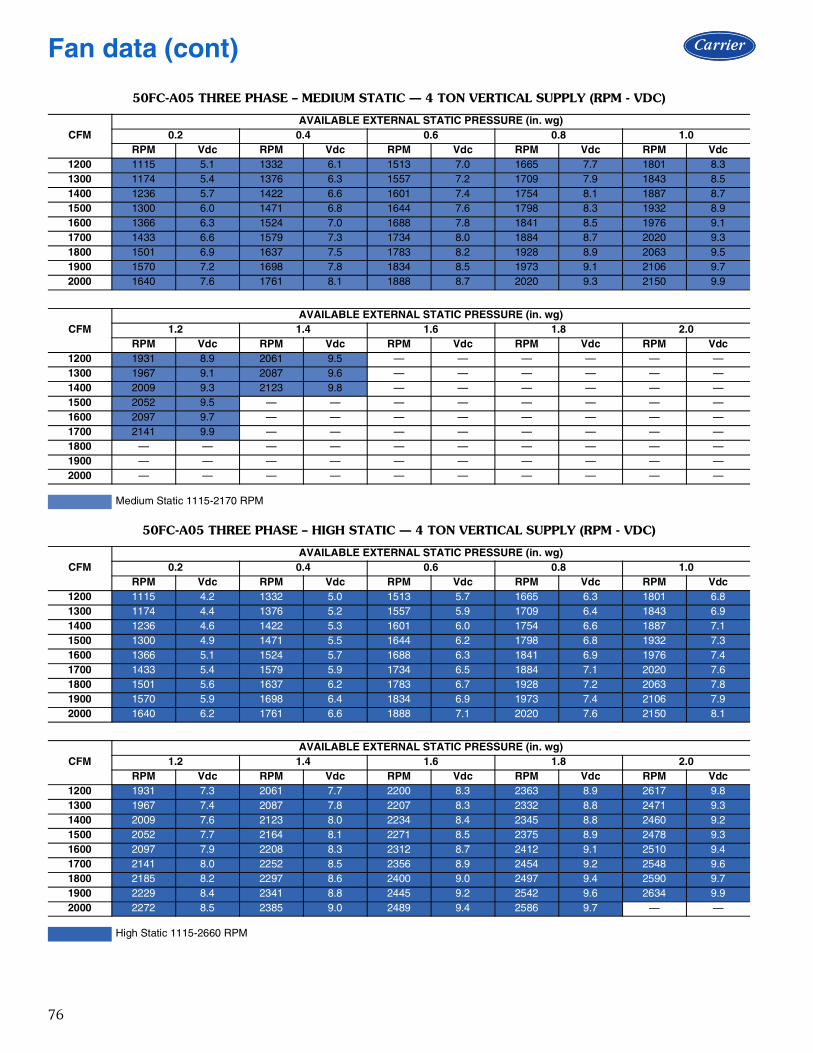
76
50FC-A05 THREE PHASE – MEDIUM STATIC — 4 TON VERTICAL SUPPLY (RPM - VDC)
CFMAVAILABLE EXTERNAL STATIC PRESSURE (in. wg)
0.2 0.4 0.6 0.8 1.0RPM Vdc RPM Vdc RPM Vdc RPM Vdc RPM Vdc
1200 1115 5.1 1332 6.1 1513 7.0 1665 7.7 1801 8.31300 1174 5.4 1376 6.3 1557 7.2 1709 7.9 1843 8.51400 1236 5.7 1422 6.6 1601 7.4 1754 8.1 1887 8.71500 1300 6.0 1471 6.8 1644 7.6 1798 8.3 1932 8.91600 1366 6.3 1524 7.0 1688 7.8 1841 8.5 1976 9.11700 1433 6.6 1579 7.3 1734 8.0 1884 8.7 2020 9.31800 1501 6.9 1637 7.5 1783 8.2 1928 8.9 2063 9.51900 1570 7.2 1698 7.8 1834 8.5 1973 9.1 2106 9.72000 1640 7.6 1761 8.1 1888 8.7 2020 9.3 2150 9.9
CFMAVAILABLE EXTERNAL STATIC PRESSURE (in. wg)
1.2 1.4 1.6 1.8 2.0RPM Vdc RPM Vdc RPM Vdc RPM Vdc RPM Vdc
1200 1931 8.9 2061 9.5 — — — — — —1300 1967 9.1 2087 9.6 — — — — — —1400 2009 9.3 2123 9.8 — — — — — —1500 2052 9.5 — — — — — — — —1600 2097 9.7 — — — — — — — —1700 2141 9.9 — — — — — — — —1800 — — — — — — — — — —1900 — — — — — — — — — —2000 — — — — — — — — — —
Medium Static 1115-2170 RPM
50FC-A05 THREE PHASE – HIGH STATIC — 4 TON VERTICAL SUPPLY (RPM - VDC)
CFMAVAILABLE EXTERNAL STATIC PRESSURE (in. wg)
0.2 0.4 0.6 0.8 1.0RPM Vdc RPM Vdc RPM Vdc RPM Vdc RPM Vdc
1200 1115 4.2 1332 5.0 1513 5.7 1665 6.3 1801 6.81300 1174 4.4 1376 5.2 1557 5.9 1709 6.4 1843 6.91400 1236 4.6 1422 5.3 1601 6.0 1754 6.6 1887 7.11500 1300 4.9 1471 5.5 1644 6.2 1798 6.8 1932 7.31600 1366 5.1 1524 5.7 1688 6.3 1841 6.9 1976 7.41700 1433 5.4 1579 5.9 1734 6.5 1884 7.1 2020 7.61800 1501 5.6 1637 6.2 1783 6.7 1928 7.2 2063 7.81900 1570 5.9 1698 6.4 1834 6.9 1973 7.4 2106 7.92000 1640 6.2 1761 6.6 1888 7.1 2020 7.6 2150 8.1
CFMAVAILABLE EXTERNAL STATIC PRESSURE (in. wg)
1.2 1.4 1.6 1.8 2.0RPM Vdc RPM Vdc RPM Vdc RPM Vdc RPM Vdc
1200 1931 7.3 2061 7.7 2200 8.3 2363 8.9 2617 9.81300 1967 7.4 2087 7.8 2207 8.3 2332 8.8 2471 9.31400 2009 7.6 2123 8.0 2234 8.4 2345 8.8 2460 9.21500 2052 7.7 2164 8.1 2271 8.5 2375 8.9 2478 9.31600 2097 7.9 2208 8.3 2312 8.7 2412 9.1 2510 9.41700 2141 8.0 2252 8.5 2356 8.9 2454 9.2 2548 9.61800 2185 8.2 2297 8.6 2400 9.0 2497 9.4 2590 9.71900 2229 8.4 2341 8.8 2445 9.2 2542 9.6 2634 9.92000 2272 8.5 2385 9.0 2489 9.4 2586 9.7 — —
High Static 1115-2660 RPM
Fan data (cont)

77
50FC-A06 SINGLE PHASE — 5 TON VERTICAL SUPPLY (RPM - BHP)
CFMAVAILABLE EXTERNAL STATIC PRESSURE (in. wg)
0.2 0.4 0.6 0.8 1.0RPM BHP RPM BHP RPM BHP RPM BHP RPM BHP
1500 1301 0.24 1476 0.35 1639 0.47 1788 0.62 1925 0.771625 1381 0.28 1545 0.40 1700 0.53 1843 0.67 1976 0.831750 1463 0.34 1615 0.45 1763 0.59 1901 0.74 2031 0.901875 1548 0.40 1688 0.51 1828 0.65 1962 0.81 2087 0.972000 1633 0.46 1764 0.59 1897 0.73 2025 0.89 2146 1.052125 1720 0.54 1842 0.67 1967 0.81 2090 0.97 2208 1.152250 1808 0.63 1922 0.75 2040 0.90 2157 1.07 2271 1.242375 1897 0.72 2003 0.85 2115 1.00 2227 1.17 2336 1.352500 1987 0.83 2086 0.96 2191 1.11 2298 1.28 — —
CFMAVAILABLE EXTERNAL STATIC PRESSURE (in. wg)
1.2 1.4 1.6 1.8 2.0RPM BHP RPM BHP RPM BHP RPM BHP RPM BHP
1500 2053 0.93 2174 1.11 2289 1.29 — — — —1625 2101 1.00 2220 1.18 2332 1.36 — — — —1750 2152 1.07 2268 1.25 2378 1.44 — — — —1875 2206 1.15 2318 1.33 — — — — — —2000 2262 1.23 2372 1.42 — — — — — —2125 2320 1.33 — — — — — — — —2250 2380 1.43 — — — — — — — —2375 — — — — — — — — — —2500 — — — — — — — — — —
Standard Static 1301-2150 RPM, 1.06 Max BHP
Medium Static 1301-2390 RPM, 1.44 Max BHP
50FC-A06 SINGLE PHASE – STANDARD STATIC — 5 TON VERTICAL SUPPLY (RPM - VDC)
CFMAVAILABLE EXTERNAL STATIC PRESSURE (in. wg)
0.2 0.4 0.6 0.8 1.0RPM Vdc RPM Vdc RPM Vdc RPM Vdc RPM Vdc
1500 1301 6.1 1476 6.9 1639 7.6 1788 8.3 1925 9.01625 1381 6.4 1545 7.2 1700 7.9 1843 8.6 1976 9.21750 1463 6.8 1615 7.5 1763 8.2 1901 8.8 2031 9.41875 1548 7.2 1688 7.9 1828 8.5 1962 9.1 2087 9.72000 1633 7.6 1764 8.2 1897 8.8 2025 9.4 2146 10.02125 1720 8.0 1842 8.6 1967 9.1 2090 9.7 — —2250 1808 8.4 1922 8.9 2040 9.5 — — — —2375 1897 8.8 2003 9.3 2115 9.8 — — — —2500 1987 9.2 2086 9.7 — — — — — —
CFMAVAILABLE EXTERNAL STATIC PRESSURE (in. wg)
1.2 1.4 1.6 1.8 2.0RPM Vdc RPM Vdc RPM Vdc RPM Vdc RPM Vdc
1500 2053 9.5 — — — — — — — —1625 2101 9.8 — — — — — — — —1750 — — — — — — — — — —1875 — — — — — — — — — —2000 — — — — — — — — — —2125 — — — — — — — — — —2250 — — — — — — — — — —2375 — — — — — — — — — —2500 — — — — — — — — — —
Standard Static 1301-2150 RPM
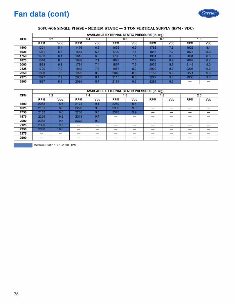
78
50FC-A06 SINGLE PHASE – MEDIUM STATIC — 3 TON VERTICAL SUPPLY (RPM - VDC)
CFMAVAILABLE EXTERNAL STATIC PRESSURE (in. wg)
0.2 0.4 0.6 0.8 1.0RPM Vdc RPM Vdc RPM Vdc RPM Vdc RPM Vdc
1500 1301 5.4 1476 6.2 1639 6.9 1788 7.5 1925 8.11625 1381 5.8 1545 6.5 1700 7.1 1843 7.7 1976 8.31750 1463 6.1 1615 6.8 1763 7.4 1901 8.0 2031 8.51875 1548 6.5 1688 7.1 1828 7.6 1962 8.2 2087 8.72000 1633 6.8 1764 7.4 1897 7.9 2025 8.5 2146 9.02125 1720 7.2 1842 7.7 1967 8.2 2090 8.7 2208 9.22250 1808 7.6 1922 8.0 2040 8.5 2157 9.0 2271 9.52375 1897 7.9 2003 8.4 2115 8.8 2227 9.3 2336 9.82500 1987 8.3 2086 8.7 2191 9.2 2298 9.6 — —
CFMAVAILABLE EXTERNAL STATIC PRESSURE (in. wg)
1.2 1.4 1.6 1.8 2.0RPM Vdc RPM Vdc RPM Vdc RPM Vdc RPM Vdc
1500 2053 8.6 2174 9.1 2289 9.6 — — — —1625 2101 8.8 2220 9.3 2332 9.8 — — — —1750 2152 9.0 2268 9.5 2378 9.9 — — — —1875 2206 9.2 2318 9.7 — — — — — —2000 2262 9.5 2372 9.9 — — — — — —2125 2320 9.7 — — — — — — — —2250 2380 10.0 — — — — — — — —2375 — — — — — — — — — —2500 — — — — — — — — — —
Medium Static 1301-2390 RPM
Fan data (cont)

79
50FC-A06 THREE PHASE — 5 TON VERTICAL SUPPLY (RPM - BHP)
CFMAVAILABLE EXTERNAL STATIC PRESSURE (in. wg)
0.2 0.4 0.6 0.8 1.0RPM BHP RPM BHP RPM BHP RPM BHP RPM BHP
1500 1301 0.24 1477 0.35 1639 0.47 1788 0.62 1925 0.771625 1381 0.28 1545 0.40 1700 0.53 1843 0.67 1977 0.831750 1463 0.34 1615 0.45 1763 0.59 1902 0.74 2031 0.901875 1548 0.40 1688 0.51 1829 0.65 1962 0.81 2088 0.972000 1633 0.46 1764 0.59 1897 0.73 2025 0.89 2147 1.062125 1720 0.54 1842 0.67 1968 0.81 2090 0.97 2208 1.152250 1809 0.63 1922 0.75 2040 0.90 2158 1.07 2271 1.242375 1897 0.72 2003 0.85 2115 1.00 2227 1.17 2336 1.352500 1987 0.83 2086 0.96 2192 1.12 2299 1.29 2403 1.47
CFMAVAILABLE EXTERNAL STATIC PRESSURE (in. wg)
1.2 1.4 1.6 1.8 2.0RPM BHP RPM BHP RPM BHP RPM BHP RPM BHP
1500 2053 0.93 2174 1.11 2289 1.29 2398 1.49 2502 1.691625 2102 1.00 2220 1.18 2332 1.36 2439 1.56 2542 1.771750 2153 1.07 2268 1.25 2378 1.44 2483 1.64 2584 1.851875 2206 1.15 2319 1.33 2426 1.53 2529 1.73 2628 1.942000 2262 1.23 2372 1.42 2477 1.62 2578 1.83 2675 2.042125 2320 1.33 2427 1.52 2530 1.72 2629 1.93 2724 2.152250 2380 1.43 2485 1.63 2585 1.83 2682 2.05 2775 2.272375 2443 1.55 2544 1.75 2642 1.96 2737 2.17 2828 2.402500 2506 1.67 2605 1.87 2701 2.09 2794 2.31 — —
Standard Static 1301-2150 RPM, 1.06 Max BHP
Medium Static 1301-2390 RPM, 1.44 Max BHP
High Static 1301-2836 RPM, 2.43 Max BHP
50FC-A06 THREE PHASE – STANDARD STATIC — 5 TON VERTICAL SUPPLY (RPM - VDC)
CFMAVAILABLE EXTERNAL STATIC PRESSURE (in. wg)
0.2 0.4 0.6 0.8 1.0RPM Vdc RPM Vdc RPM Vdc RPM Vdc RPM Vdc
1500 1301 6.1 1477 6.9 1639 7.6 1788 8.3 1925 9.01625 1381 6.4 1545 7.2 1700 7.9 1843 8.6 1977 9.21750 1463 6.8 1615 7.5 1763 8.2 1902 8.8 2031 9.41875 1548 7.2 1688 7.9 1829 8.5 1962 9.1 2088 9.72000 1633 7.6 1764 8.2 1897 8.8 2025 9.4 2147 10.02125 1720 8.0 1842 8.6 1968 9.2 2090 9.7 — —2250 1809 8.4 1922 8.9 2040 9.5 — — — —2375 1897 8.8 2003 9.3 2115 9.8 — — — —2500 1987 9.2 2086 9.7 — — — — — —
CFMAVAILABLE EXTERNAL STATIC PRESSURE (in. wg)
1.2 1.4 1.6 1.8 2.0RPM Vdc RPM Vdc RPM Vdc RPM Vdc RPM Vdc
1500 2053 9.5 — — — — — — — —1625 2102 9.8 — — — — — — — —1750 — — — — — — — — — —1875 — — — — — — — — — —2000 — — — — — — — — — —2125 — — — — — — — — — —2250 — — — — — — — — — —2375 — — — — — — — — — —2500 — — — — — — — — — —
Standard Static 1301-2150 RPM

80
50FC-A06 THREE PHASE – MEDIUM STATIC — 5 TON VERTICAL SUPPLY (RPM - VDC)
CFMAVAILABLE EXTERNAL STATIC PRESSURE (in. wg)
0.2 0.4 0.6 0.8 1.0RPM Vdc RPM Vdc RPM Vdc RPM Vdc RPM Vdc
1500 1301 5.4 1477 6.2 1639 6.9 1788 7.5 1925 8.11625 1381 5.8 1545 6.5 1700 7.1 1843 7.7 1977 8.31750 1463 6.1 1615 6.8 1763 7.4 1902 8.0 2031 8.51875 1548 6.5 1688 7.1 1829 7.7 1962 8.2 2088 8.72000 1633 6.8 1764 7.4 1897 7.9 2025 8.5 2147 9.02125 1720 7.2 1842 7.7 1968 8.2 2090 8.7 2208 9.22250 1809 7.6 1922 8.0 2040 8.5 2158 9.0 2271 9.52375 1897 7.9 2003 8.4 2115 8.8 2227 9.3 2336 9.82500 1987 8.3 2086 8.7 2192 9.2 2299 9.6 — —
CFMAVAILABLE EXTERNAL STATIC PRESSURE (in. wg)
1.2 1.4 1.6 1.8 2.0RPM Vdc RPM Vdc RPM Vdc RPM Vdc RPM Vdc
1500 2053 8.6 2174 9.1 2289 9.6 — — — —1625 2102 8.8 2220 9.3 2332 9.8 — — — —1750 2153 9.0 2268 9.5 2378 9.9 — — — —1875 2206 9.2 2319 9.7 — — — — — —2000 2262 9.5 2372 9.9 — — — — — —2125 2320 9.7 — — — — — — — —2250 2380 10.0 — — — — — — — —2375 — — — — — — — — — —2500 — — — — — — — — — —
Medium Static 1301-2390 RPM
50FC-A06 THREE PHASE – HIGH STATIC — 5 TON VERTICAL SUPPLY (RPM - VDC)
CFMAVAILABLE EXTERNAL STATIC PRESSURE (in. wg)
0.2 0.4 0.6 0.8 1.0RPM Vdc RPM Vdc RPM Vdc RPM Vdc RPM Vdc
1500 1301 4.6 1477 5.2 1639 5.8 1788 6.3 1925 6.81625 1381 4.9 1545 5.4 1700 6.0 1843 6.5 1977 7.01750 1463 5.2 1615 5.7 1763 6.2 1902 6.7 2031 7.21875 1548 5.5 1688 6.0 1829 6.4 1962 6.9 2088 7.42000 1633 5.8 1764 6.2 1897 6.7 2025 7.1 2147 7.62125 1720 6.1 1842 6.5 1968 6.9 2090 7.4 2208 7.82250 1809 6.4 1922 6.8 2040 7.2 2158 7.6 2271 8.02375 1897 6.7 2003 7.1 2115 7.5 2227 7.9 2336 8.22500 1987 7.0 2086 7.4 2192 7.7 2299 8.1 2403 8.5
CFMAVAILABLE EXTERNAL STATIC PRESSURE (in. wg)
1.2 1.4 1.6 1.8 2.0RPM Vdc RPM Vdc RPM Vdc RPM Vdc RPM Vdc
1500 2053 7.2 2174 7.7 2289 8.1 2398 8.5 2502 8.81625 2102 7.4 2220 7.8 2332 8.2 2439 8.6 2542 9.01750 2153 7.6 2268 8.0 2378 8.4 2483 8.8 2584 9.11875 2206 7.8 2319 8.2 2426 8.6 2529 8.9 2628 9.32000 2262 8.0 2372 8.4 2477 8.7 2578 9.1 2675 9.42125 2320 8.2 2427 8.6 2530 8.9 2629 9.3 2724 9.62250 2380 8.4 2485 8.8 2585 9.1 2682 9.5 2775 9.82375 2443 8.6 2544 9.0 2642 9.3 2737 9.7 2828 10.02500 2506 8.8 2605 9.2 2701 9.5 2794 9.9 — —
High Static 1301-2836 RPM
Fan data (cont)

81
50FC-M07 THREE PHASE — 6 TON VERTICAL SUPPLY (RPM - BHP)
CFMAVAILABLE EXTERNAL STATIC PRESSURE (in. wg)
0.2 0.4 0.6 0.8 1.0RPM BHP RPM BHP RPM BHP RPM BHP RPM BHP
1800 1423 0.30 1550 0.39 1682 0.50 1820 0.64 1955 0.791950 1521 0.37 1638 0.46 1758 0.57 1883 0.70 2011 0.862100 1620 0.45 1730 0.54 1839 0.65 1953 0.78 2071 0.932250 1720 0.53 1824 0.64 1924 0.75 2029 0.88 2137 1.022400 1820 0.63 1919 0.74 2013 0.85 2109 0.98 2209 1.132550 1921 0.74 2016 0.86 2105 0.98 2194 1.11 2286 1.252700 2022 0.86 2113 0.99 2198 1.11 2282 1.24 2368 1.392850 2123 1.00 2212 1.13 2293 1.26 2373 1.40 2453 1.543000 2225 1.15 2311 1.29 2389 1.42 2465 1.56 2541 1.71
CFMAVAILABLE EXTERNAL STATIC PRESSURE (in. wg)
1.2 1.4 1.6 1.8 2.0RPM BHP RPM BHP RPM BHP RPM BHP RPM BHP
1800 2079 0.95 2192 1.11 2296 1.28 2393 1.45 2485 1.621950 2133 1.02 2247 1.19 2353 1.37 2451 1.55 2543 1.732100 2189 1.10 2301 1.28 2408 1.47 2507 1.66 2601 1.852250 2248 1.19 2357 1.37 2462 1.57 2562 1.76 2656 1.972400 2312 1.30 2416 1.48 2517 1.67 2616 1.88 2711 2.092550 2381 1.41 2479 1.60 2576 1.79 2672 2.00 2765 2.212700 2456 1.55 2546 1.73 2638 1.92 2730 2.13 2821 2.352850 2535 1.70 2619 1.88 2705 2.07 2793 2.28 — —3000 2618 1.87 2696 2.05 2777 2.24 — — — —
Standard Static 1423-2300 RPM, 1.31 Max BHP
Medium Static 1423-2530 RPM, 1.76 Max BHP
High Static 1423-2836 RPM, 2.43 Max BHP
50FC-M07 THREE PHASE – STANDARD STATIC — 6 TON VERTICAL SUPPLY (RPM - VDC)
CFMAVAILABLE EXTERNAL STATIC PRESSURE (in. wg)
0.2 0.4 0.6 0.8 1.0RPM Vdc RPM Vdc RPM Vdc RPM Vdc RPM Vdc
1800 1423 6.2 1550 6.7 1682 7.3 1820 7.9 1955 8.51950 1521 6.6 1638 7.1 1758 7.6 1883 8.2 2011 8.72100 1620 7.0 1730 7.5 1839 8.0 1953 8.5 2071 9.02250 1720 7.5 1824 7.9 1924 8.4 2029 8.8 2137 9.32400 1820 7.9 1919 8.3 2013 8.8 2109 9.2 2209 9.62550 1921 8.4 2016 8.8 2105 9.2 2194 9.5 2286 9.92700 2022 8.8 2113 9.2 2198 9.6 2282 9.9 — —2850 2123 9.2 2212 9.6 2293 10.0 — — — —3000 2225 9.7 — — — — — — — —
CFMAVAILABLE EXTERNAL STATIC PRESSURE (in. wg)
1.2 1.4 1.6 1.8 2.0RPM Vdc RPM Vdc RPM Vdc RPM Vdc RPM Vdc
1800 2079 9.0 2192 9.5 2296 10.0 — — — —1950 2133 9.3 2247 9.8 — — — — — —2100 2189 9.5 — — — — — — — —2250 2248 9.8 — — — — — — — —2400 — — — — — — — — — —2550 — — — — — — — — — —2700 — — — — — — — — — —2850 — — — — — — — — — —3000 — — — — — — — — — —
Standard Static 1423-2300 RPM

82
50FC-M07 THREE PHASE – MEDIUM STATIC — 6 TON VERTICAL SUPPLY (RPM - VDC)
CFMAVAILABLE EXTERNAL STATIC PRESSURE (in. wg)
0.2 0.4 0.6 0.8 1.0RPM Vdc RPM Vdc RPM Vdc RPM Vdc RPM Vdc
1800 1423 5.6 1550 6.1 1682 6.6 1820 7.2 1955 7.71950 1521 6.0 1638 6.5 1758 6.9 1883 7.4 2011 7.92100 1620 6.4 1730 6.8 1839 7.3 1953 7.7 2071 8.22250 1720 6.8 1824 7.2 1924 7.6 2029 8.0 2137 8.42400 1820 7.2 1919 7.6 2013 8.0 2109 8.3 2209 8.72550 1921 7.6 2016 8.0 2105 8.3 2194 8.7 2286 9.02700 2022 8.0 2113 8.4 2198 8.7 2282 9.0 2368 9.42850 2123 8.4 2212 8.7 2293 9.1 2373 9.4 2453 9.73000 2225 8.8 2311 9.1 2389 9.4 2465 9.7 — —
CFMAVAILABLE EXTERNAL STATIC PRESSURE (in. wg)
1.2 1.4 1.6 1.8 2.0RPM Vdc RPM Vdc RPM Vdc RPM Vdc RPM Vdc
1800 2079 8.2 2192 8.7 2296 9.1 2393 9.5 2485 9.81950 2133 8.4 2247 8.9 2353 9.3 2451 9.7 — —2100 2189 8.7 2301 9.1 2408 9.5 2507 9.9 — —2250 2248 8.9 2357 9.3 2462 9.7 — — — —2400 2312 9.1 2416 9.5 2517 9.9 — — — —2550 2381 9.4 2479 9.8 — — — — — —2700 2456 9.7 — — — — — — — —2850 — — — — — — — — — —3000 — — — — — — — — — —
Medium Static 1423-2530 RPM
50FC-M07 THREE PHASE – HIGH STATIC — 6 TON VERTICAL SUPPLY (RPM - VDC)
CFMAVAILABLE EXTERNAL STATIC PRESSURE (in. wg)
0.2 0.4 0.6 0.8 1.0RPM Vdc RPM Vdc RPM Vdc RPM Vdc RPM Vdc
1800 1423 5.0 1550 5.5 1682 5.9 1820 6.4 1955 6.91950 1521 5.4 1638 5.8 1758 6.2 1883 6.6 2011 7.12100 1620 5.7 1730 6.1 1839 6.5 1953 6.9 2071 7.32250 1720 6.1 1824 6.4 1924 6.8 2029 7.2 2137 7.52400 1820 6.4 1919 6.8 2013 7.1 2109 7.4 2209 7.82550 1921 6.8 2016 7.1 2105 7.4 2194 7.7 2286 8.12700 2022 7.1 2113 7.5 2198 7.8 2282 8.0 2368 8.32850 2123 7.5 2212 7.8 2293 8.1 2373 8.4 2453 8.63000 2225 7.8 2311 8.1 2389 8.4 2465 8.7 2541 9.0
CFMAVAILABLE EXTERNAL STATIC PRESSURE (in. wg)
1.2 1.4 1.6 1.8 2.0RPM Vdc RPM Vdc RPM Vdc RPM Vdc RPM Vdc
1800 2079 7.3 2192 7.7 2296 8.1 2393 8.4 2485 8.81950 2133 7.5 2247 7.9 2353 8.3 2451 8.6 2543 9.02100 2189 7.7 2301 8.1 2408 8.5 2507 8.8 2601 9.22250 2248 7.9 2357 8.3 2462 8.7 2562 9.0 2656 9.42400 2312 8.2 2416 8.5 2517 8.9 2616 9.2 2711 9.62550 2381 8.4 2479 8.7 2576 9.1 2672 9.4 2765 9.72700 2456 8.7 2546 9.0 2638 9.3 2730 9.6 2821 9.92850 2535 8.9 2619 9.2 2705 9.5 2793 9.8 — —3000 2618 9.2 2696 9.5 2777 9.8 — — — —
High Static 1423-2836 RPM
Fan data (cont)
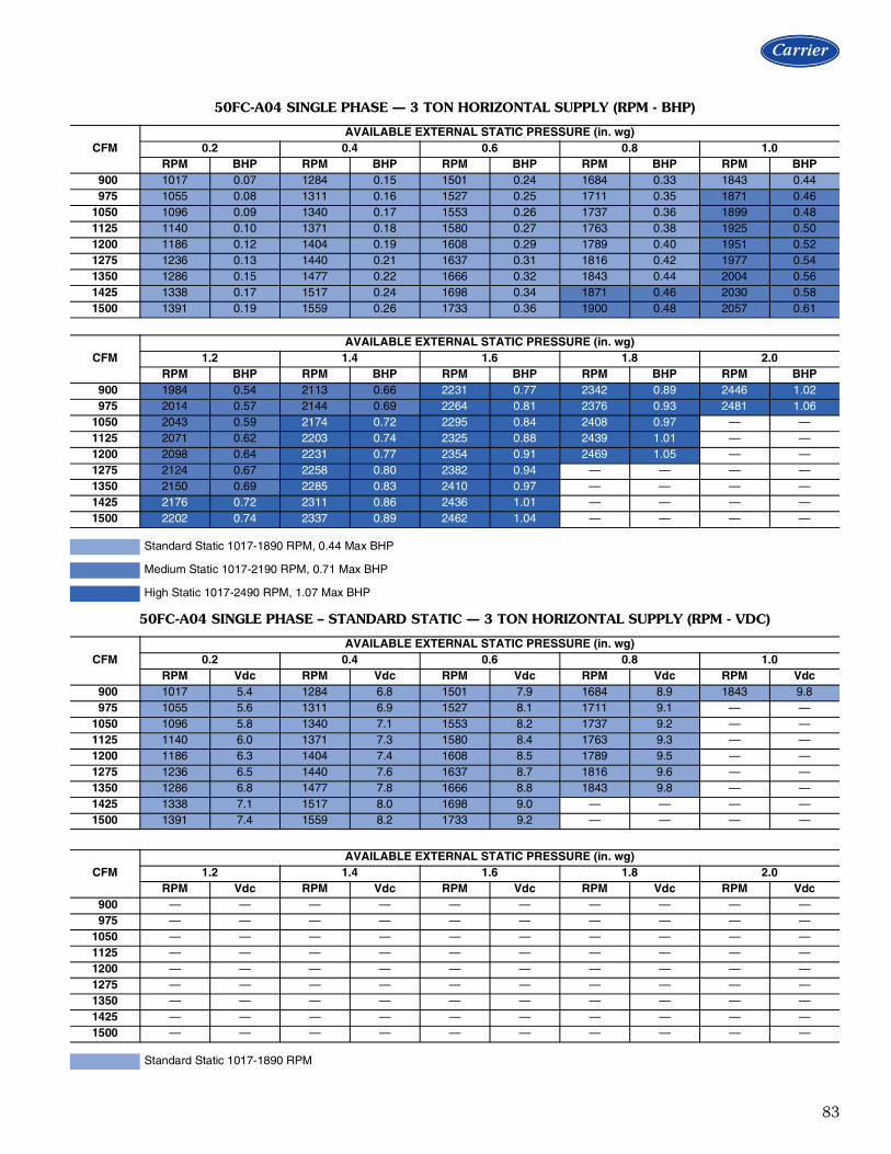
83
50FC-A04 SINGLE PHASE — 3 TON HORIZONTAL SUPPLY (RPM - BHP)
CFMAVAILABLE EXTERNAL STATIC PRESSURE (in. wg)
0.2 0.4 0.6 0.8 1.0RPM BHP RPM BHP RPM BHP RPM BHP RPM BHP
900 1017 0.07 1284 0.15 1501 0.24 1684 0.33 1843 0.44 975 1055 0.08 1311 0.16 1527 0.25 1711 0.35 1871 0.461050 1096 0.09 1340 0.17 1553 0.26 1737 0.36 1899 0.481125 1140 0.10 1371 0.18 1580 0.27 1763 0.38 1925 0.501200 1186 0.12 1404 0.19 1608 0.29 1789 0.40 1951 0.521275 1236 0.13 1440 0.21 1637 0.31 1816 0.42 1977 0.541350 1286 0.15 1477 0.22 1666 0.32 1843 0.44 2004 0.561425 1338 0.17 1517 0.24 1698 0.34 1871 0.46 2030 0.581500 1391 0.19 1559 0.26 1733 0.36 1900 0.48 2057 0.61
CFMAVAILABLE EXTERNAL STATIC PRESSURE (in. wg)
1.2 1.4 1.6 1.8 2.0RPM BHP RPM BHP RPM BHP RPM BHP RPM BHP
900 1984 0.54 2113 0.66 2231 0.77 2342 0.89 2446 1.02 975 2014 0.57 2144 0.69 2264 0.81 2376 0.93 2481 1.061050 2043 0.59 2174 0.72 2295 0.84 2408 0.97 — —1125 2071 0.62 2203 0.74 2325 0.88 2439 1.01 — —1200 2098 0.64 2231 0.77 2354 0.91 2469 1.05 — —1275 2124 0.67 2258 0.80 2382 0.94 — — — —1350 2150 0.69 2285 0.83 2410 0.97 — — — —1425 2176 0.72 2311 0.86 2436 1.01 — — — —1500 2202 0.74 2337 0.89 2462 1.04 — — — —
Standard Static 1017-1890 RPM, 0.44 Max BHP
Medium Static 1017-2190 RPM, 0.71 Max BHP
High Static 1017-2490 RPM, 1.07 Max BHP
50FC-A04 SINGLE PHASE – STANDARD STATIC — 3 TON HORIZONTAL SUPPLY (RPM - VDC)
CFMAVAILABLE EXTERNAL STATIC PRESSURE (in. wg)
0.2 0.4 0.6 0.8 1.0RPM Vdc RPM Vdc RPM Vdc RPM Vdc RPM Vdc
900 1017 5.4 1284 6.8 1501 7.9 1684 8.9 1843 9.8 975 1055 5.6 1311 6.9 1527 8.1 1711 9.1 — —1050 1096 5.8 1340 7.1 1553 8.2 1737 9.2 — —1125 1140 6.0 1371 7.3 1580 8.4 1763 9.3 — —1200 1186 6.3 1404 7.4 1608 8.5 1789 9.5 — —1275 1236 6.5 1440 7.6 1637 8.7 1816 9.6 — —1350 1286 6.8 1477 7.8 1666 8.8 1843 9.8 — —1425 1338 7.1 1517 8.0 1698 9.0 — — — —1500 1391 7.4 1559 8.2 1733 9.2 — — — —
CFMAVAILABLE EXTERNAL STATIC PRESSURE (in. wg)
1.2 1.4 1.6 1.8 2.0RPM Vdc RPM Vdc RPM Vdc RPM Vdc RPM Vdc
900 — — — — — — — — — — 975 — — — — — — — — — —1050 — — — — — — — — — —1125 — — — — — — — — — —1200 — — — — — — — — — —1275 — — — — — — — — — —1350 — — — — — — — — — —1425 — — — — — — — — — —1500 — — — — — — — — — —
Standard Static 1017-1890 RPM

84
50FC-A04 SINGLE PHASE – MEDIUM STATIC — 3 TON HORIZONTAL SUPPLY (RPM - VDC)
CFMAVAILABLE EXTERNAL STATIC PRESSURE (in. wg)
0.2 0.4 0.6 0.8 1.0RPM Vdc RPM Vdc RPM Vdc RPM Vdc RPM Vdc
900 1017 4.6 1284 5.9 1501 6.9 1684 7.7 1843 8.4 975 1055 4.8 1311 6.0 1527 7.0 1711 7.8 1871 8.51050 1096 5.0 1340 6.1 1553 7.1 1737 7.9 1899 8.71125 1140 5.2 1371 6.3 1580 7.2 1763 8.1 1925 8.81200 1186 5.4 1404 6.4 1608 7.3 1789 8.2 1951 8.91275 1236 5.6 1440 6.6 1637 7.5 1816 8.3 1977 9.01350 1286 5.9 1477 6.7 1666 7.6 1843 8.4 2004 9.21425 1338 6.1 1517 6.9 1698 7.8 1871 8.5 2030 9.31500 1391 6.4 1559 7.1 1733 7.9 1900 8.7 2057 9.4
CFMAVAILABLE EXTERNAL STATIC PRESSURE (in. wg)
1.2 1.4 1.6 1.8 2.0RPM Vdc RPM Vdc RPM Vdc RPM Vdc RPM Vdc
900 1984 9.1 2113 9.6 — — — — — — 975 2014 9.2 2144 9.8 — — — — — —1050 2043 9.3 — — — — — — — —1125 2071 9.5 — — — — — — — —1200 2098 9.6 — — — — — — — —1275 2124 9.7 — — — — — — — —1350 2150 9.8 — — — — — — — —1425 — — — — — — — — — —1500 — — — — — — — — — —
Medium Static 1017-2190 RPM
50FC-A04 SINGLE PHASE – HIGH STATIC — 3 TON HORIZONTAL SUPPLY (RPM - VDC)
CFMAVAILABLE EXTERNAL STATIC PRESSURE (in. wg)
0.2 0.4 0.6 0.8 1.0RPM Vdc RPM Vdc RPM Vdc RPM Vdc RPM Vdc
900 1017 4.1 1284 5.2 1501 6.0 1684 6.8 1843 7.4 975 1055 4.2 1311 5.3 1527 6.1 1711 6.9 1871 7.51050 1096 4.4 1340 5.4 1553 6.2 1737 7.0 1899 7.61125 1140 4.6 1371 5.5 1580 6.3 1763 7.1 1925 7.71200 1186 4.8 1404 5.6 1608 6.5 1789 7.2 1951 7.81275 1236 5.0 1440 5.8 1637 6.6 1816 7.3 1977 7.91350 1286 5.2 1477 5.9 1666 6.7 1843 7.4 2004 8.01425 1338 5.4 1517 6.1 1698 6.8 1871 7.5 2030 8.21500 1391 5.6 1559 6.3 1733 7.0 1900 7.6 2057 8.3
CFMAVAILABLE EXTERNAL STATIC PRESSURE (in. wg)
1.2 1.4 1.6 1.8 2.0RPM Vdc RPM Vdc RPM Vdc RPM Vdc RPM Vdc
900 1984 8.0 2113 8.5 2231 9.0 2342 9.4 2446 9.8 975 2014 8.1 2144 8.6 2264 9.1 2376 9.5 2481 10.01050 2043 8.2 2174 8.7 2295 9.2 2408 9.7 — —1125 2071 8.3 2203 8.8 2325 9.3 2439 9.8 — —1200 2098 8.4 2231 9.0 2354 9.5 2469 9.9 — —1275 2124 8.5 2258 9.1 2382 9.6 — — — —1350 2150 8.6 2285 9.2 2410 9.7 — — — —1425 2176 8.7 2311 9.3 2436 9.8 — — — —1500 2202 8.8 2337 9.4 2462 9.9 — — — —
High Static 1017-2490 RPM
Fan data (cont)

85
50FC-A04 THREE PHASE — 3 TON HORIZONTAL SUPPLY (RPM - BHP)
CFMAVAILABLE EXTERNAL STATIC PRESSURE (in. wg)
0.2 0.4 0.6 0.8 1.0RPM BHP RPM BHP RPM BHP RPM BHP RPM BHP
900 1017 0.07 1284 0.15 1501 0.24 1684 0.33 1843 0.44 975 1055 0.08 1311 0.16 1527 0.25 1711 0.35 1871 0.461050 1096 0.09 1340 0.17 1553 0.26 1737 0.36 1899 0.481125 1140 0.10 1371 0.18 1580 0.27 1763 0.38 1925 0.501200 1186 0.12 1404 0.19 1608 0.29 1789 0.40 1951 0.521275 1236 0.13 1440 0.21 1637 0.31 1816 0.42 1977 0.541350 1286 0.15 1477 0.22 1666 0.32 1843 0.44 2004 0.561425 1338 0.17 1517 0.24 1698 0.34 1871 0.46 2030 0.581500 1391 0.19 1559 0.26 1733 0.36 1900 0.48 2057 0.61
CFMAVAILABLE EXTERNAL STATIC PRESSURE (in. wg)
1.2 1.4 1.6 1.8 2.0RPM BHP RPM BHP RPM BHP RPM BHP RPM BHP
900 1984 0.54 2113 0.66 2231 0.77 2342 0.89 2446 1.02 975 2014 0.57 2144 0.69 2264 0.81 2376 0.93 2481 1.061050 2043 0.59 2174 0.72 2295 0.84 2408 0.97 — —1125 2071 0.62 2203 0.74 2325 0.88 2439 1.01 — —1200 2098 0.64 2231 0.77 2354 0.91 2469 1.05 — —1275 2124 0.67 2258 0.80 2382 0.94 — — — —1350 2150 0.69 2285 0.83 2410 0.97 — — — —1425 2176 0.72 2311 0.86 2436 1.01 — — — —1500 2202 0.74 2337 0.89 2462 1.04 — — — —
Standard Static 1017-1890 RPM, 0.44 Max BHP
Medium Static 1017-2190 RPM, 0.71 Max BHP
High Static 1017-2490 RPM, 1.07 Max BHP
50FC-A04 THREE PHASE – STANDARD STATIC — 3 TON HORIZONTAL SUPPLY (RPM - VDC)
CFMAVAILABLE EXTERNAL STATIC PRESSURE (in. wg)
0.2 0.4 0.6 0.8 1.0RPM Vdc RPM Vdc RPM Vdc RPM Vdc RPM Vdc
900 1017 5.4 1284 6.8 1501 7.9 1684 8.9 1843 9.8 975 1055 5.6 1311 6.9 1527 8.1 1711 9.1 — —1050 1096 5.8 1340 7.1 1553 8.2 1737 9.2 — —1125 1140 6.0 1371 7.3 1580 8.4 1763 9.3 — —1200 1186 6.3 1404 7.4 1608 8.5 1789 9.5 — —1275 1236 6.5 1440 7.6 1637 8.7 1816 9.6 — —1350 1286 6.8 1477 7.8 1666 8.8 1843 9.8 — —1425 1338 7.1 1517 8.0 1698 9.0 — — — —1500 1391 7.4 1559 8.2 1733 9.2 — — — —
CFMAVAILABLE EXTERNAL STATIC PRESSURE (in. wg)
1.2 1.4 1.6 1.8 2.0RPM Vdc RPM Vdc RPM Vdc RPM Vdc RPM Vdc
900 — — — — — — — — — — 975 — — — — — — — — — —1050 — — — — — — — — — —1125 — — — — — — — — — —1200 — — — — — — — — — —1275 — — — — — — — — — —1350 — — — — — — — — — —1425 — — — — — — — — — —1500 — — — — — — — — — —
Standard Static 1017-1890 RPM

86
50FC-A04 THREE PHASE – MEDIUM STATIC — 3 TON HORIZONTAL SUPPLY (RPM - VDC)
CFMAVAILABLE EXTERNAL STATIC PRESSURE (in. wg)
0.2 0.4 0.6 0.8 1.0RPM Vdc RPM Vdc RPM Vdc RPM Vdc RPM Vdc
900 1017 4.6 1284 5.9 1501 6.9 1684 7.7 1843 8.4 975 1055 4.8 1311 6.0 1527 7.0 1711 7.8 1871 8.51050 1096 5.0 1340 6.1 1553 7.1 1737 7.9 1899 8.71125 1140 5.2 1371 6.3 1580 7.2 1763 8.1 1925 8.81200 1186 5.4 1404 6.4 1608 7.3 1789 8.2 1951 8.91275 1236 5.6 1440 6.6 1637 7.5 1816 8.3 1977 9.01350 1286 5.9 1477 6.7 1666 7.6 1843 8.4 2004 9.21425 1338 6.1 1517 6.9 1698 7.8 1871 8.5 2030 9.31500 1391 6.4 1559 7.1 1733 7.9 1900 8.7 2057 9.4
CFMAVAILABLE EXTERNAL STATIC PRESSURE (in. wg)
1.2 1.4 1.6 1.8 2.0RPM Vdc RPM Vdc RPM Vdc RPM Vdc RPM Vdc
900 1984 9.1 2113 9.6 — — — — — — 975 2014 9.2 2144 9.8 — — — — — —1050 2043 9.3 — — — — — — — —1125 2071 9.5 — — — — — — — —1200 2098 9.6 — — — — — — — —1275 2124 9.7 — — — — — — — —1350 2150 9.8 — — — — — — — —1425 — — — — — — — — — —1500 — — — — — — — — — —
Medium Static 1017-2190 RPM
50FC-A04 THREE PHASE – HIGH STATIC — 3 TON HORIZONTAL SUPPLY (RPM - VDC)
CFMAVAILABLE EXTERNAL STATIC PRESSURE (in. wg)
0.2 0.4 0.6 0.8 1.0RPM Vdc RPM Vdc RPM Vdc RPM Vdc RPM Vdc
900 1017 4.1 1284 5.2 1501 6.0 1684 6.8 1843 7.4 975 1055 4.2 1311 5.3 1527 6.1 1711 6.9 1871 7.51050 1096 4.4 1340 5.4 1553 6.2 1737 7.0 1899 7.61125 1140 4.6 1371 5.5 1580 6.3 1763 7.1 1925 7.71200 1186 4.8 1404 5.6 1608 6.5 1789 7.2 1951 7.81275 1236 5.0 1440 5.8 1637 6.6 1816 7.3 1977 7.91350 1286 5.2 1477 5.9 1666 6.7 1843 7.4 2004 8.01425 1338 5.4 1517 6.1 1698 6.8 1871 7.5 2030 8.21500 1391 5.6 1559 6.3 1733 7.0 1900 7.6 2057 8.3
CFMAVAILABLE EXTERNAL STATIC PRESSURE (in. wg)
1.2 1.4 1.6 1.8 2.0RPM Vdc RPM Vdc RPM Vdc RPM Vdc RPM Vdc
900 1984 8.0 2113 8.5 2231 9.0 2342 9.4 2446 9.8 975 2014 8.1 2144 8.6 2264 9.1 2376 9.5 2481 10.01050 2043 8.2 2174 8.7 2295 9.2 2408 9.7 — —1125 2071 8.3 2203 8.8 2325 9.3 2439 9.8 — —1200 2098 8.4 2231 9.0 2354 9.5 2469 9.9 — —1275 2124 8.5 2258 9.1 2382 9.6 — — — —1350 2150 8.6 2285 9.2 2410 9.7 — — — —1425 2176 8.7 2311 9.3 2436 9.8 — — — —1500 2202 8.8 2337 9.4 2462 9.9 — — — —
High Static 1017-2490 RPM
Fan data (cont)
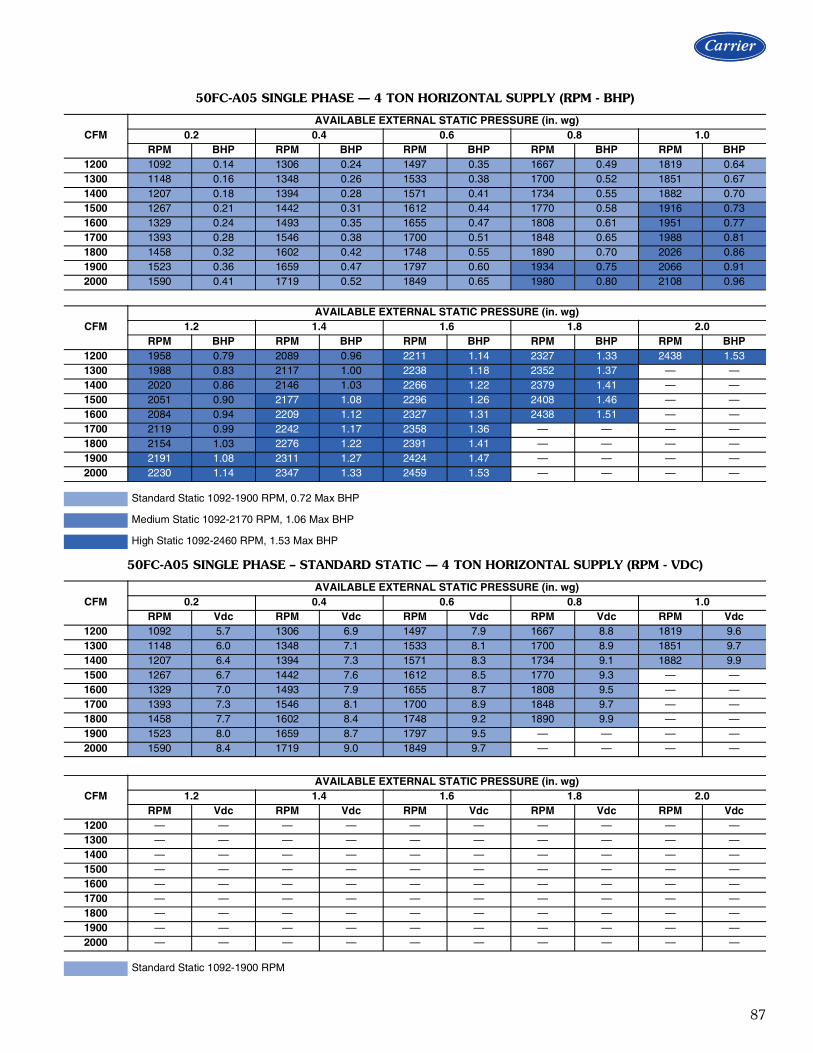
87
50FC-A05 SINGLE PHASE — 4 TON HORIZONTAL SUPPLY (RPM - BHP)
CFMAVAILABLE EXTERNAL STATIC PRESSURE (in. wg)
0.2 0.4 0.6 0.8 1.0RPM BHP RPM BHP RPM BHP RPM BHP RPM BHP
1200 1092 0.14 1306 0.24 1497 0.35 1667 0.49 1819 0.641300 1148 0.16 1348 0.26 1533 0.38 1700 0.52 1851 0.671400 1207 0.18 1394 0.28 1571 0.41 1734 0.55 1882 0.701500 1267 0.21 1442 0.31 1612 0.44 1770 0.58 1916 0.731600 1329 0.24 1493 0.35 1655 0.47 1808 0.61 1951 0.771700 1393 0.28 1546 0.38 1700 0.51 1848 0.65 1988 0.811800 1458 0.32 1602 0.42 1748 0.55 1890 0.70 2026 0.861900 1523 0.36 1659 0.47 1797 0.60 1934 0.75 2066 0.912000 1590 0.41 1719 0.52 1849 0.65 1980 0.80 2108 0.96
CFMAVAILABLE EXTERNAL STATIC PRESSURE (in. wg)
1.2 1.4 1.6 1.8 2.0RPM BHP RPM BHP RPM BHP RPM BHP RPM BHP
1200 1958 0.79 2089 0.96 2211 1.14 2327 1.33 2438 1.531300 1988 0.83 2117 1.00 2238 1.18 2352 1.37 — —1400 2020 0.86 2146 1.03 2266 1.22 2379 1.41 — —1500 2051 0.90 2177 1.08 2296 1.26 2408 1.46 — —1600 2084 0.94 2209 1.12 2327 1.31 2438 1.51 — —1700 2119 0.99 2242 1.17 2358 1.36 — — — —1800 2154 1.03 2276 1.22 2391 1.41 — — — —1900 2191 1.08 2311 1.27 2424 1.47 — — — —2000 2230 1.14 2347 1.33 2459 1.53 — — — —
Standard Static 1092-1900 RPM, 0.72 Max BHP
Medium Static 1092-2170 RPM, 1.06 Max BHP
High Static 1092-2460 RPM, 1.53 Max BHP
50FC-A05 SINGLE PHASE – STANDARD STATIC — 4 TON HORIZONTAL SUPPLY (RPM - VDC)
CFMAVAILABLE EXTERNAL STATIC PRESSURE (in. wg)
0.2 0.4 0.6 0.8 1.0RPM Vdc RPM Vdc RPM Vdc RPM Vdc RPM Vdc
1200 1092 5.7 1306 6.9 1497 7.9 1667 8.8 1819 9.61300 1148 6.0 1348 7.1 1533 8.1 1700 8.9 1851 9.71400 1207 6.4 1394 7.3 1571 8.3 1734 9.1 1882 9.91500 1267 6.7 1442 7.6 1612 8.5 1770 9.3 — —1600 1329 7.0 1493 7.9 1655 8.7 1808 9.5 — —1700 1393 7.3 1546 8.1 1700 8.9 1848 9.7 — —1800 1458 7.7 1602 8.4 1748 9.2 1890 9.9 — —1900 1523 8.0 1659 8.7 1797 9.5 — — — —2000 1590 8.4 1719 9.0 1849 9.7 — — — —
CFMAVAILABLE EXTERNAL STATIC PRESSURE (in. wg)
1.2 1.4 1.6 1.8 2.0RPM Vdc RPM Vdc RPM Vdc RPM Vdc RPM Vdc
1200 — — — — — — — — — —1300 — — — — — — — — — —1400 — — — — — — — — — —1500 — — — — — — — — — —1600 — — — — — — — — — —1700 — — — — — — — — — —1800 — — — — — — — — — —1900 — — — — — — — — — —2000 — — — — — — — — — —
Standard Static 1092-1900 RPM

88
50FC-A05 SINGLE PHASE – MEDIUM STATIC — 4 TON HORIZONTAL SUPPLY (RPM - VDC)
CFMAVAILABLE EXTERNAL STATIC PRESSURE (in. wg)
0.2 0.4 0.6 0.8 1.0RPM Vdc RPM Vdc RPM Vdc RPM Vdc RPM Vdc
1200 1092 5.0 1306 6.0 1497 6.9 1667 7.7 1819 8.41300 1148 5.3 1348 6.2 1533 7.1 1700 7.8 1851 8.51400 1207 5.6 1394 6.4 1571 7.2 1734 8.0 1882 8.71500 1267 5.8 1442 6.6 1612 7.4 1770 8.2 1916 8.81600 1329 6.1 1493 6.9 1655 7.6 1808 8.3 1951 9.01700 1393 6.4 1546 7.1 1700 7.8 1848 8.5 1988 9.21800 1458 6.7 1602 7.4 1748 8.1 1890 8.7 2026 9.31900 1523 7.0 1659 7.6 1797 8.3 1934 8.9 2066 9.52000 1590 7.3 1719 7.9 1849 8.5 1980 9.1 2108 9.7
CFMAVAILABLE EXTERNAL STATIC PRESSURE (in. wg)
1.2 1.4 1.6 1.8 2.0RPM Vdc RPM Vdc RPM Vdc RPM Vdc RPM Vdc
1200 1959 9.0 2089 9.6 — — — — — —1300 1988 9.2 2117 9.8 — — — — — —1400 2020 9.3 2146 9.9 — — — — — —1500 2051 9.5 — — — — — — — —1600 2084 9.6 — — — — — — — —1700 2119 9.8 — — — — — — — —1800 2154 9.9 — — — — — — — —1900 — — — — — — — — — —2000 — — — — — — — — — —
Medium Static 1092-2170 RPM
50FC-A05 SINGLE PHASE – HIGH STATIC — 4 TON HORIZONTAL SUPPLY (RPM - VDC)
CFMAVAILABLE EXTERNAL STATIC PRESSURE (in. wg)
0.2 0.4 0.6 0.8 1.0RPM Vdc RPM Vdc RPM Vdc RPM Vdc RPM Vdc
1200 1092 4.4 1306 5.3 1497 6.1 1667 6.8 1819 7.41300 1148 4.7 1348 5.5 1533 6.2 1700 6.9 1851 7.51400 1207 4.9 1394 5.7 1571 6.4 1734 7.0 1882 7.71500 1267 5.2 1442 5.9 1612 6.6 1770 7.2 1916 7.81600 1329 5.4 1493 6.1 1655 6.7 1808 7.3 1951 7.91700 1393 5.7 1546 6.3 1700 6.9 1848 7.5 1988 8.11800 1458 5.9 1602 6.5 1748 7.1 1890 7.7 2026 8.21900 1523 6.2 1659 6.7 1797 7.3 1934 7.9 2066 8.42000 1590 6.5 1719 7.0 1849 7.5 1980 8.0 2108 8.6
CFMAVAILABLE EXTERNAL STATIC PRESSURE (in. wg)
1.2 1.4 1.6 1.8 2.0RPM Vdc RPM Vdc RPM Vdc RPM Vdc RPM Vdc
1200 1959 8.0 2089 8.5 2211 9.0 2327 9.5 2438 9.91300 1988 8.1 2117 8.6 2238 9.1 2352 9.6 — —1400 2020 8.2 2146 8.7 2266 9.2 2379 9.7 — —1500 2051 8.3 2177 8.8 2296 9.3 2408 9.8 — —1600 2084 8.5 2209 9.0 2327 9.5 2438 9.9 — —1700 2119 8.6 2242 9.1 2358 9.6 — — — —1800 2154 8.8 2276 9.3 2391 9.7 — — — —1900 2191 8.9 2311 9.4 2424 9.9 — — — —2000 2230 9.1 2347 9.5 2459 10.0 — — — —
High Static 1092-2460 RPM
Fan data (cont)

89
50FC-A05 THREE PHASE — 4 TON HORIZONTAL SUPPLY (RPM - BHP)
CFMAVAILABLE EXTERNAL STATIC PRESSURE (in. wg)
0.2 0.4 0.6 0.8 1.0RPM BHP RPM BHP RPM BHP RPM BHP RPM BHP
1200 1093 0.14 1306 0.24 1497 0.35 1667 0.49 1819 0.641300 1148 0.16 1348 0.26 1533 0.38 1700 0.52 1850 0.671400 1206 0.18 1393 0.28 1571 0.41 1734 0.55 1883 0.701500 1266 0.21 1442 0.31 1612 0.44 1770 0.58 1916 0.731600 1329 0.24 1493 0.35 1655 0.47 1808 0.61 1951 0.771700 1393 0.28 1546 0.38 1700 0.51 1848 0.65 1988 0.811800 1458 0.32 1602 0.42 1747 0.55 1890 0.70 2026 0.861900 1523 0.36 1659 0.47 1797 0.60 1934 0.75 2066 0.912000 1590 0.41 1718 0.52 1849 0.65 1980 0.80 2108 0.96
CFMAVAILABLE EXTERNAL STATIC PRESSURE (in. wg)
1.2 1.4 1.6 1.8 2.0RPM BHP RPM BHP RPM BHP RPM BHP RPM BHP
1200 1959 0.79 2089 0.96 2211 1.14 2327 1.33 2438 1.531300 1988 0.83 2117 1.00 2238 1.18 2352 1.37 2462 1.571400 2019 0.86 2146 1.03 2266 1.22 2379 1.41 2487 1.611500 2052 0.90 2177 1.08 2296 1.26 2408 1.46 2515 1.661600 2084 0.94 2209 1.12 2327 1.31 2438 1.51 2544 1.711700 2119 0.99 2242 1.17 2358 1.36 2469 1.56 2574 1.771800 2154 1.03 2276 1.22 2391 1.41 2500 1.61 2605 1.831900 2191 1.08 2311 1.27 2424 1.47 2533 1.68 2636 1.892000 2230 1.14 2347 1.33 2459 1.53 2566 1.74 — —
Standard Static 1093-1900 RPM, 0.72 Max BHP
Medium Static 1093-2170 RPM, 1.06 Max BHP
High Static 1093-2660 RPM, 1.96 Max BHP
50FC-A05 THREE PHASE – STANDARD STATIC — 4 TON HORIZONTAL SUPPLY (RPM - VDC)
CFMAVAILABLE EXTERNAL STATIC PRESSURE (in. wg)
0.2 0.4 0.6 0.8 1.0RPM Vdc RPM Vdc RPM Vdc RPM Vdc RPM Vdc
1200 1093 5.8 1306 6.9 1497 7.9 1667 8.8 1819 9.61300 1148 6.0 1348 7.1 1533 8.1 1700 8.9 1850 9.71400 1206 6.3 1393 7.3 1571 8.3 1734 9.1 1883 9.91500 1266 6.7 1442 7.6 1612 8.5 1770 9.3 — —1600 1329 7.0 1493 7.9 1655 8.7 1808 9.5 — —1700 1393 7.3 1546 8.1 1700 8.9 1848 9.7 — —1800 1458 7.7 1602 8.4 1747 9.2 1890 9.9 — —1900 1523 8.0 1659 8.7 1797 9.5 — — — —2000 1590 8.4 1718 9.0 1849 9.7 — — — —
CFMAVAILABLE EXTERNAL STATIC PRESSURE (in. wg)
1.2 1.4 1.6 1.8 2.0RPM Vdc RPM Vdc RPM Vdc RPM Vdc RPM Vdc
1200 — — — — — — — — — —1300 — — — — — — — — — —1400 — — — — — — — — — —1500 — — — — — — — — — —1600 — — — — — — — — — —1700 — — — — — — — — — —1800 — — — — — — — — — —1900 — — — — — — — — — —2000 — — — — — — — — — —
Standard Static 1093-1900 RPM

90
50FC-M05 THREE PHASE – MEDIUM STATIC — 4 TON HORIZONTAL SUPPLY (RPM - VDC)
CFMAVAILABLE EXTERNAL STATIC PRESSURE (in. wg)
0.2 0.4 0.6 0.8 1.0RPM Vdc RPM Vdc RPM Vdc RPM Vdc RPM Vdc
1200 1093 5.0 1306 6.0 1497 6.9 1667 7.7 1819 8.41300 1148 5.3 1348 6.2 1533 7.1 1700 7.8 1850 8.51400 1206 5.6 1393 6.4 1571 7.2 1734 8.0 1883 8.71500 1266 5.8 1442 6.6 1612 7.4 1770 8.2 1916 8.81600 1329 6.1 1493 6.9 1655 7.6 1808 8.3 1951 9.01700 1393 6.4 1546 7.1 1700 7.8 1848 8.5 1988 9.21800 1458 6.7 1602 7.4 1747 8.1 1890 8.7 2026 9.31900 1523 7.0 1659 7.6 1797 8.3 1934 8.9 2066 9.52000 1590 7.3 1718 7.9 1849 8.5 1980 9.1 2108 9.7
CFMAVAILABLE EXTERNAL STATIC PRESSURE (in. wg)
1.2 1.4 1.6 1.8 2.0RPM Vdc RPM Vdc RPM Vdc RPM Vdc RPM Vdc
1200 1959 9.0 2089 9.6 — — — — — —1300 1988 9.2 2117 9.8 — — — — — —1400 2019 9.3 2146 9.9 — — — — — —1500 2052 9.5 — — — — — — — —1600 2084 9.6 — — — — — — — —1700 2119 9.8 — — — — — — — —1800 2154 9.9 — — — — — — — —1900 — — — — — — — — — —2000 — — — — — — — — — —
Medium Static 1093-2170 RPM
50FC-M05 THREE PHASE – HIGH STATIC — 4 TON HORIZONTAL SUPPLY (RPM - VDC)
CFMAVAILABLE EXTERNAL STATIC PRESSURE (in. wg)
0.2 0.4 0.6 0.8 1.0RPM Vdc RPM Vdc RPM Vdc RPM Vdc RPM Vdc
1200 1093 4.1 1306 4.9 1497 5.6 1667 6.3 1819 6.81300 1148 4.3 1348 5.1 1533 5.8 1700 6.4 1850 7.01400 1206 4.5 1393 5.2 1571 5.9 1734 6.5 1883 7.11500 1266 4.8 1442 5.4 1612 6.1 1770 6.7 1916 7.21600 1329 5.0 1493 5.6 1655 6.2 1808 6.8 1951 7.31700 1393 5.2 1546 5.8 1700 6.4 1848 6.9 1988 7.51800 1458 5.5 1602 6.0 1747 6.6 1890 7.1 2026 7.61900 1523 5.7 1659 6.2 1797 6.8 1934 7.3 2066 7.82000 1590 6.0 1718 6.5 1849 7.0 1980 7.4 2108 7.9
CFMAVAILABLE EXTERNAL STATIC PRESSURE (in. wg)
1.2 1.4 1.6 1.8 2.0RPM Vdc RPM Vdc RPM Vdc RPM Vdc RPM Vdc
1200 1959 7.4 2089 7.9 2211 8.3 2327 8.7 2438 9.21300 1988 7.5 2117 8.0 2238 8.4 2352 8.8 2462 9.31400 2019 7.6 2146 8.1 2266 8.5 2379 8.9 2487 9.31500 2052 7.7 2177 8.2 2296 8.6 2408 9.1 2515 9.51600 2084 7.8 2209 8.3 2327 8.7 2438 9.2 2544 9.61700 2119 8.0 2242 8.4 2358 8.9 2469 9.3 2574 9.71800 2154 8.1 2276 8.6 2391 9.0 2500 9.4 2605 9.81900 2191 8.2 2311 8.7 2424 9.1 2533 9.5 2636 9.92000 2230 8.4 2347 8.8 2459 9.2 2566 9.6 — —
High Static 1093-2660 RPM
Fan data (cont)
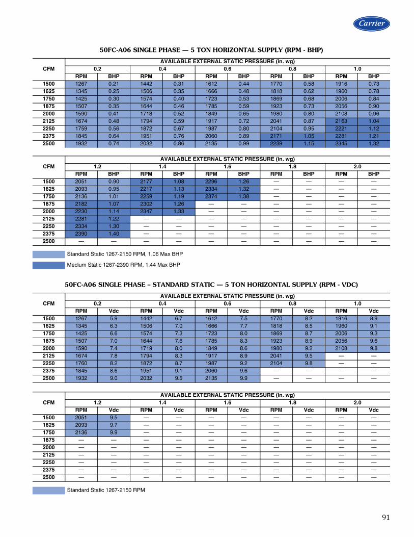
91
50FC-A06 SINGLE PHASE — 5 TON HORIZONTAL SUPPLY (RPM - BHP)
CFMAVAILABLE EXTERNAL STATIC PRESSURE (in. wg)
0.2 0.4 0.6 0.8 1.0RPM BHP RPM BHP RPM BHP RPM BHP RPM BHP
1500 1267 0.21 1442 0.31 1612 0.44 1770 0.58 1916 0.731625 1345 0.25 1506 0.35 1666 0.48 1818 0.62 1960 0.781750 1425 0.30 1574 0.40 1723 0.53 1869 0.68 2006 0.841875 1507 0.35 1644 0.46 1785 0.59 1923 0.73 2056 0.902000 1590 0.41 1718 0.52 1849 0.65 1980 0.80 2108 0.962125 1674 0.48 1794 0.59 1917 0.72 2041 0.87 2163 1.042250 1759 0.56 1872 0.67 1987 0.80 2104 0.95 2221 1.122375 1845 0.64 1951 0.76 2060 0.89 2171 1.05 2281 1.212500 1932 0.74 2032 0.86 2135 0.99 2239 1.15 2345 1.32
CFMAVAILABLE EXTERNAL STATIC PRESSURE (in. wg)
1.2 1.4 1.6 1.8 2.0RPM BHP RPM BHP RPM BHP RPM BHP RPM BHP
1500 2051 0.90 2177 1.08 2296 1.26 — — — —1625 2093 0.95 2217 1.13 2334 1.32 — — — —1750 2136 1.01 2259 1.19 2374 1.38 — — — —1875 2182 1.07 2302 1.26 — — — — — —2000 2230 1.14 2347 1.33 — — — — — —2125 2281 1.22 — — — — — — — —2250 2334 1.30 — — — — — — — —2375 2390 1.40 — — — — — — — —2500 — — — — — — — — — —
Standard Static 1267-2150 RPM, 1.06 Max BHP
Medium Static 1267-2390 RPM, 1.44 Max BHP
50FC-A06 SINGLE PHASE – STANDARD STATIC — 5 TON HORIZONTAL SUPPLY (RPM - VDC)
CFMAVAILABLE EXTERNAL STATIC PRESSURE (in. wg)
0.2 0.4 0.6 0.8 1.0RPM Vdc RPM Vdc RPM Vdc RPM Vdc RPM Vdc
1500 1267 5.9 1442 6.7 1612 7.5 1770 8.2 1916 8.91625 1345 6.3 1506 7.0 1666 7.7 1818 8.5 1960 9.11750 1425 6.6 1574 7.3 1723 8.0 1869 8.7 2006 9.31875 1507 7.0 1644 7.6 1785 8.3 1923 8.9 2056 9.62000 1590 7.4 1719 8.0 1849 8.6 1980 9.2 2108 9.82125 1674 7.8 1794 8.3 1917 8.9 2041 9.5 — —2250 1760 8.2 1872 8.7 1987 9.2 2104 9.8 — —2375 1845 8.6 1951 9.1 2060 9.6 — — — —2500 1932 9.0 2032 9.5 2135 9.9 — — — —
CFMAVAILABLE EXTERNAL STATIC PRESSURE (in. wg)
1.2 1.4 1.6 1.8 2.0RPM Vdc RPM Vdc RPM Vdc RPM Vdc RPM Vdc
1500 2051 9.5 — — — — — — — —1625 2093 9.7 — — — — — — — —1750 2136 9.9 — — — — — — — —1875 — — — — — — — — — —2000 — — — — — — — — — —2125 — — — — — — — — — —2250 — — — — — — — — — —2375 — — — — — — — — — —2500 — — — — — — — — — —
Standard Static 1267-2150 RPM

92
50FC-A06 SINGLE PHASE – MEDIUM STATIC — 5 TON HORIZONTAL SUPPLY (RPM - VDC)
CFMAVAILABLE EXTERNAL STATIC PRESSURE (in. wg)
0.2 0.4 0.6 0.8 1.0RPM Vdc RPM Vdc RPM Vdc RPM Vdc RPM Vdc
1500 1267 5.3 1442 6.0 1612 6.7 1770 7.4 1916 8.01625 1345 5.6 1506 6.3 1666 7.0 1818 7.6 1960 8.21750 1425 6.0 1574 6.6 1723 7.2 1869 7.8 2006 8.41875 1507 6.3 1644 6.9 1785 7.5 1923 8.0 2056 8.62000 1590 6.7 1719 7.2 1849 7.7 1980 8.3 2108 8.82125 1674 7.0 1794 7.5 1917 8.0 2041 8.5 2163 9.12250 1760 7.4 1872 7.8 1987 8.3 2104 8.8 2221 9.32375 1845 7.7 1951 8.2 2060 8.6 2171 9.1 2281 9.52500 1932 8.1 2032 8.5 2135 8.9 2239 9.4 2345 9.8
CFMAVAILABLE EXTERNAL STATIC PRESSURE (in. wg)
1.2 1.4 1.6 1.8 2.0RPM Vdc RPM Vdc RPM Vdc RPM Vdc RPM Vdc
1500 2051 8.6 2177 9.1 2296 9.6 — — — —1625 2093 8.8 2217 9.3 2334 9.8 — — — —1750 2136 8.9 2259 9.5 2374 9.9 — — — —1875 2182 9.1 2302 9.6 — — — — — —2000 2230 9.3 2347 9.8 — — — — — —2125 2281 9.5 — — — — — — — —2250 2334 9.8 — — — — — — — —2375 — — — — — — — — — —2500 — — — — — — — — — —
Medium Static 1267-2390 RPM
Fan data (cont)

93
50FC-A06 THREE PHASE — 5 TON HORIZONTAL SUPPLY (RPM - BHP)
CFMAVAILABLE EXTERNAL STATIC PRESSURE (in. wg)
0.2 0.4 0.6 0.8 1.0RPM BHP RPM BHP RPM BHP RPM BHP RPM BHP
1500 1267 0.21 1442 0.31 1612 0.44 1770 0.58 1916 0.731625 1345 0.25 1506 0.35 1666 0.48 1818 0.62 1960 0.781750 1425 0.30 1574 0.40 1723 0.53 1869 0.68 2006 0.841875 1507 0.35 1644 0.46 1785 0.59 1923 0.73 2056 0.902000 1590 0.41 1718 0.52 1849 0.65 1980 0.80 2108 0.962125 1674 0.48 1794 0.59 1917 0.72 2041 0.87 2163 1.042250 1759 0.56 1872 0.67 1987 0.80 2104 0.95 2221 1.122375 1845 0.64 1951 0.76 2060 0.89 2171 1.05 2281 1.212500 1932 0.74 2032 0.86 2135 0.99 2239 1.15 2345 1.32
CFMAVAILABLE EXTERNAL STATIC PRESSURE (in. wg)
1.2 1.4 1.6 1.8 2.0RPM BHP RPM BHP RPM BHP RPM BHP RPM BHP
1500 2051 0.90 2177 1.08 2296 1.26 2408 1.46 2515 1.661625 2093 0.95 2217 1.13 2334 1.32 2445 1.52 2551 1.721750 2136 1.01 2259 1.19 2374 1.38 2484 1.59 2589 1.801875 2182 1.07 2302 1.26 2416 1.45 2524 1.66 2628 1.872000 2230 1.14 2347 1.33 2459 1.53 2566 1.74 2669 1.962125 2281 1.22 2395 1.41 2505 1.61 2610 1.83 2711 2.052250 2334 1.30 2445 1.50 2552 1.70 2655 1.92 2754 2.142375 2391 1.40 2497 1.59 2601 1.80 2702 2.02 2800 2.252500 2449 1.50 2552 1.70 2653 1.91 2751 2.13 — —
Standard Static 1267-2150 RPM, 1.06 Max BHP
Medium Static 1267-2390 RPM, 1.44 Max BHP
High Static 1267-2836 RPM, 2.43 Max BHP
50FC-A06 THREE PHASE – STANDARD STATIC — 5 TON HORIZONTAL SUPPLY (RPM - VDC)
CFMAVAILABLE EXTERNAL STATIC PRESSURE (in. wg)
0.2 0.4 0.6 0.8 1.0RPM Vdc RPM Vdc RPM Vdc RPM Vdc RPM Vdc
1500 1267 5.9 1442 6.7 1612 7.5 1770 8.2 1916 8.91625 1345 6.3 1506 7.0 1666 7.7 1818 8.5 1960 9.11750 1425 6.6 1574 7.3 1723 8.0 1869 8.7 2006 9.31875 1507 7.0 1644 7.6 1785 8.3 1923 8.9 2056 9.62000 1590 7.4 1719 8.0 1849 8.6 1980 9.2 2108 9.82125 1674 7.8 1794 8.3 1917 8.9 2041 9.5 — —2250 1760 8.2 1872 8.7 1987 9.2 2104 9.8 — —2375 1845 8.6 1951 9.1 2060 9.6 — — — —2500 1932 9.0 2032 9.5 2135 9.9 — — — —
CFMAVAILABLE EXTERNAL STATIC PRESSURE (in. wg)
1.2 1.4 1.6 1.8 2.0RPM Vdc RPM Vdc RPM Vdc RPM Vdc RPM Vdc
1500 2051 9.5 — — — — — — — —1625 2093 9.7 — — — — — — — —1750 2136 9.9 — — — — — — — —1875 — — — — — — — — — —2000 — — — — — — — — — —2125 — — — — — — — — — —2250 — — — — — — — — — —2375 — — — — — — — — — —2500 — — — — — — — — — —
Standard Static 1267-2150 RPM
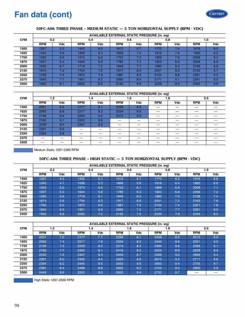
94
50FC-A06 THREE PHASE – MEDIUM STATIC — 5 TON HORIZONTAL SUPPLY (RPM - VDC)
CFMAVAILABLE EXTERNAL STATIC PRESSURE (in. wg)
0.2 0.4 0.6 0.8 1.0RPM Vdc RPM Vdc RPM Vdc RPM Vdc RPM Vdc
1500 1267 5.3 1442 6.0 1612 6.7 1770 7.4 1916 8.01625 1345 5.6 1506 6.3 1666 7.0 1818 7.6 1960 8.21750 1425 6.0 1574 6.6 1723 7.2 1869 7.8 2006 8.41875 1507 6.3 1644 6.9 1785 7.5 1923 8.0 2056 8.62000 1590 6.7 1719 7.2 1849 7.7 1980 8.3 2108 8.82125 1674 7.0 1794 7.5 1917 8.0 2041 8.5 2163 9.12250 1760 7.4 1872 7.8 1987 8.3 2104 8.8 2221 9.32375 1845 7.7 1951 8.2 2060 8.6 2171 9.1 2281 9.52500 1932 8.1 2032 8.5 2135 8.9 2239 9.4 2345 9.8
CFMAVAILABLE EXTERNAL STATIC PRESSURE (in. wg)
1.2 1.4 1.6 1.8 2.0RPM Vdc RPM Vdc RPM Vdc RPM Vdc RPM Vdc
1500 2051 8.6 2177 9.1 2296 9.6 — — — —1625 2093 8.8 2217 9.3 2334 9.8 — — — —1750 2136 8.9 2259 9.5 2374 9.9 — — — —1875 2182 9.1 2302 9.6 — — — — — —2000 2230 9.3 2347 9.8 — — — — — —2125 2281 9.5 — — — — — — — —2250 2334 9.8 — — — — — — — —2375 — — — — — — — — — —2500 — — — — — — — — — —
Medium Static 1267-2390 RPM
50FC-A06 THREE PHASE – HIGH STATIC — 5 TON HORIZONTAL SUPPLY (RPM - VDC)
CFMAVAILABLE EXTERNAL STATIC PRESSURE (in. wg)
0.2 0.4 0.6 0.8 1.0RPM Vdc RPM Vdc RPM Vdc RPM Vdc RPM Vdc
1500 1267 4.5 1442 5.1 1612 5.7 1770 6.2 1916 6.81625 1345 4.7 1506 5.3 1666 5.9 1818 6.4 1960 6.91750 1425 5.0 1574 5.6 1723 6.1 1869 6.6 2006 7.11875 1507 5.3 1644 5.8 1785 6.3 1923 6.8 2056 7.22000 1590 5.6 1719 6.1 1849 6.5 1980 7.0 2108 7.42125 1674 5.9 1794 6.3 1917 6.8 2041 7.2 2163 7.62250 1760 6.2 1872 6.6 1987 7.0 2104 7.4 2221 7.82375 1845 6.5 1951 6.9 2060 7.3 2171 7.7 2281 8.02500 1932 6.8 2032 7.2 2135 7.5 2239 7.9 2345 8.3
CFMAVAILABLE EXTERNAL STATIC PRESSURE (in. wg)
1.2 1.4 1.6 1.8 2.0RPM Vdc RPM Vdc RPM Vdc RPM Vdc RPM Vdc
1500 2051 7.2 2177 7.7 2296 8.1 2408 8.5 2515 8.91625 2093 7.4 2217 7.8 2334 8.2 2445 8.6 2551 9.01750 2136 7.5 2259 8.0 2374 8.4 2484 8.8 2589 9.11875 2182 7.7 2302 8.1 2416 8.5 2524 8.9 2628 9.32000 2230 7.9 2347 8.3 2459 8.7 2566 9.0 2669 9.42125 2281 8.0 2395 8.4 2505 8.8 2610 9.2 2711 9.62250 2334 8.2 2445 8.6 2552 9.0 2655 9.4 2755 9.72375 2391 8.4 2498 8.8 2602 9.2 2702 9.5 2800 9.92500 2449 8.6 2552 9.0 2653 9.4 2752 9.7 — —
High Static 1267-2836 RPM
Fan data (cont)

95
50FC-M07 THREE PHASE — 6 TON HORIZONTAL SUPPLY (RPM - BHP)
CFMAVAILABLE EXTERNAL STATIC PRESSURE (in. wg)
0.2 0.4 0.6 0.8 1.0RPM BHP RPM BHP RPM BHP RPM BHP RPM BHP
1800 1379 0.27 1512 0.35 1650 0.46 1786 0.58 1918 0.721950 1473 0.32 1594 0.41 1721 0.52 1848 0.64 1973 0.782100 1569 0.39 1680 0.48 1796 0.59 1915 0.71 2032 0.852250 1666 0.47 1769 0.56 1876 0.67 1986 0.79 2096 0.932400 1764 0.55 1860 0.65 1959 0.76 2061 0.88 2165 1.022550 1863 0.65 1952 0.75 2045 0.86 2140 0.99 2237 1.132700 1963 0.76 2047 0.86 2133 0.97 2222 1.10 2313 1.242850 2063 0.88 2142 0.99 2223 1.10 2307 1.23 2393 1.373000 2163 1.01 2238 1.12 2315 1.24 2394 1.37 2474 1.52
CFMAVAILABLE EXTERNAL STATIC PRESSURE (in. wg)
1.2 1.4 1.6 1.8 2.0RPM BHP RPM BHP RPM BHP RPM BHP RPM BHP
1800 2044 0.87 2163 1.03 2276 1.20 2383 1.38 2486 1.571950 2094 0.93 2210 1.10 2320 1.27 2426 1.45 2527 1.642100 2148 1.00 2260 1.17 2367 1.34 2471 1.53 2570 1.722250 2206 1.08 2313 1.25 2417 1.43 2518 1.61 2616 1.812400 2268 1.18 2371 1.34 2471 1.52 2569 1.71 2664 1.902550 2335 1.28 2432 1.45 2528 1.62 2622 1.81 2715 2.012700 2405 1.40 2497 1.56 2589 1.74 2680 1.93 2769 2.132850 2479 1.53 2566 1.69 2654 1.87 2740 2.06 2826 2.263000 2556 1.67 2639 1.84 2722 2.02 2804 2.21 — —
Standard Static 1379-2300 RPM, 1.31 Max BHP
Medium Static 1379-2530 RPM, 1.76 Max BHP
High Static 1379-2836 RPM, 2.43 Max BHP
50FC-M07 THREE PHASE – STANDARD STATIC — 6 TON HORIZONTAL SUPPLY (RPM - VDC)
CFMAVAILABLE EXTERNAL STATIC PRESSURE (in. wg)
0.2 0.4 0.6 0.8 1.0RPM Vdc RPM Vdc RPM Vdc RPM Vdc RPM Vdc
1800 1379 6.0 1512 6.6 1650 7.2 1786 7.8 1918 8.31950 1473 6.4 1594 6.9 1721 7.5 1848 8.0 1973 8.62100 1569 6.8 1680 7.3 1796 7.8 1915 8.3 2032 8.82250 1666 7.2 1769 7.7 1876 8.2 1986 8.6 2096 9.12400 1764 7.7 1860 8.1 1959 8.5 2061 9.0 2165 9.42550 1863 8.1 1952 8.5 2045 8.9 2140 9.3 2237 9.72700 1963 8.5 2047 8.9 2133 9.3 2222 9.7 — —2850 2063 9.0 2142 9.3 2223 9.7 — — — —3000 2163 9.4 2238 9.7 — — — — — —
CFMAVAILABLE EXTERNAL STATIC PRESSURE (in. wg)
1.2 1.4 1.6 1.8 2.0RPM Vdc RPM Vdc RPM Vdc RPM Vdc RPM Vdc
1800 2044 8.9 2163 9.4 2276 9.9 — — — —1950 2094 9.1 2210 9.6 — — — — — —2100 2148 9.3 2260 9.8 — — — — — —2250 2206 9.6 — — — — — — — —2400 2268 9.9 — — — — — — — —2550 — — — — — — — — — —2700 — — — — — — — — — —2850 — — — — — — — — — —3000 — — — — — — — — — —
Standard Static 1379-2300 RPM

96
50FC-M07 THREE PHASE – MEDIUM STATIC — 6 TON HORIZONTAL SUPPLY (RPM - VDC)
CFMAVAILABLE EXTERNAL STATIC PRESSURE (in. wg)
0.2 0.4 0.6 0.8 1.0RPM Vdc RPM Vdc RPM Vdc RPM Vdc RPM Vdc
1800 1379 5.5 1512 6.0 1650 6.5 1786 7.1 1918 7.61950 1473 5.8 1594 6.3 1721 6.8 1848 7.3 1973 7.82100 1569 6.2 1680 6.6 1796 7.1 1915 7.6 2032 8.02250 1666 6.6 1769 7.0 1876 7.4 1986 7.8 2096 8.32400 1764 7.0 1860 7.4 1959 7.7 2061 8.1 2165 8.62550 1863 7.4 1952 7.7 2045 8.1 2140 8.5 2237 8.82700 1963 7.8 2047 8.1 2133 8.4 2222 8.8 2313 9.12850 2063 8.2 2142 8.5 2223 8.8 2307 9.1 2393 9.53000 2163 8.5 2238 8.8 2315 9.2 2394 9.5 2474 9.8
CFMAVAILABLE EXTERNAL STATIC PRESSURE (in. wg)
1.2 1.4 1.6 1.8 2.0RPM Vdc RPM Vdc RPM Vdc RPM Vdc RPM Vdc
1800 2044 8.1 2163 8.5 2276 9.0 2383 9.4 2486 9.81950 2094 8.3 2210 8.7 2320 9.2 2426 9.6 2527 10.02100 2148 8.5 2260 8.9 2367 9.4 2471 9.8 — —2250 2206 8.7 2313 9.1 2417 9.6 2518 10.0 — —2400 2268 9.0 2371 9.4 2471 9.8 — — — —2550 2335 9.2 2432 9.6 2528 10.0 — — — —2700 2405 9.5 2497 9.9 — — — — — —2850 2479 9.8 — — — — — — — —3000 — — — — — — — — — —
Medium Static 1379-2530 RPM
50FC-M07 THREE PHASE – HIGH STATIC — 6 TON HORIZONTAL SUPPLY (RPM - VDC)
CFMAVAILABLE EXTERNAL STATIC PRESSURE (in. wg)
0.2 0.4 0.6 0.8 1.0RPM Vdc RPM Vdc RPM Vdc RPM Vdc RPM Vdc
1800 1379 4.9 1512 5.3 1650 5.8 1786 6.3 1918 6.81950 1473 5.2 1594 5.6 1721 6.1 1848 6.5 1973 7.02100 1569 5.5 1680 5.9 1796 6.3 1915 6.8 2032 7.22250 1666 5.9 1769 6.2 1876 6.6 1986 7.0 2096 7.42400 1764 6.2 1860 6.6 1959 6.9 2061 7.3 2165 7.62550 1863 6.6 1952 6.9 2045 7.2 2140 7.5 2237 7.92700 1963 6.9 2047 7.2 2133 7.5 2222 7.8 2313 8.22850 2063 7.3 2142 7.6 2223 7.8 2307 8.1 2393 8.43000 2163 7.6 2238 7.9 2315 8.2 2394 8.4 2474 8.7
CFMAVAILABLE EXTERNAL STATIC PRESSURE (in. wg)
1.2 1.4 1.6 1.8 2.0RPM Vdc RPM Vdc RPM Vdc RPM Vdc RPM Vdc
1800 2044 7.2 2163 7.6 2276 8.0 2383 8.4 2486 8.81950 2094 7.4 2210 7.8 2320 8.2 2426 8.6 2527 8.92100 2148 7.6 2260 8.0 2367 8.3 2471 8.7 2570 9.12250 2206 7.8 2313 8.2 2417 8.5 2518 8.9 2616 9.22400 2268 8.0 2371 8.4 2471 8.7 2569 9.1 2664 9.42550 2335 8.2 2432 8.6 2528 8.9 2622 9.2 2715 9.62700 2405 8.5 2497 8.8 2589 9.1 2680 9.4 2769 9.82850 2479 8.7 2566 9.0 2654 9.4 2740 9.7 2826 10.03000 2556 9.0 2639 9.3 2722 9.6 2804 9.9 — —
High Static 1379-2836 RPM
Fan data (cont)

97
Legend and NotesApplicable for Electrical Data Tables on pages 98 to118LEGEND
NOTES:1. In compliance with NEC requirements for multi-motor and combi-
nation load equipment (refer to NEC Articles 430 and 440), theovercurrent protective device for the unit shall be fuse or HACRbreaker. Canadian units may be fuse or circuit breaker.
2. For 208/230 v units, where one value is show it is the same foreither 208 or 230 volts.
3. Unbalanced 3-Phase Supply VoltageNever operate a motor where a phase imbalance in supply voltageis greater than 2%. Use the following formula to determine the per-centage of voltage imbalance.
Example: Supply voltage is 230-3-60
Determine maximum deviation from average voltage.(AB) 227-224 = 3 v(BC) 231-227 = 4 v(AC) 227-226 = 1 vMaximum deviation is 4 v.Determine percent of voltage imbalance.
This amount of phase imbalance is satisfactory as it is below themaximum allowable 2%.
BRKR — Circuit BreakerC.O. — Convenience OutletFLA — Full Load AmpsIFM — Indoor Fan MotorLRA — Locked Rotor AmpsMCA — Minimum Circuit AmpsP.E. — Power ExhaustPWRD C.O. — Powered Convenience OutletRLA — Rated Load AmpsUNPWR C.O.— Unpowered Convenience Outlet
% Voltage Imbalance = 100 x
max voltage deviation from average voltageaverage voltage
AB = 224 vBC = 231 vAC = 226 v
Average Voltage =(224 + 231 + 226)
=681
= 2273 3
% Voltage Imbalance = 100x4
= 1.78%227
IMPORTANT: If the supply voltage phase imbalance is more than 2%,contact your local electric utility company immediately.
A B C
MOTOR
Electrical data

98
48/50FC**04-07 COOLING ELECTRICAL DATA
48/50FC UNIT V-Ph-Hz
UNIT VOLTAGE COMPRESSOR OFM (EA) IFM COMBUSTION
FAN MOTORPOWER
EXHAUSTRANGE
RLA LRA WATTS FLA TYPEEFFCY
AT FULL LOAD
FLA FLA KIT QTY
FLA(EA KIT)MIN MAX
**04
208-1-60 187 253 15.4 84 275 1.5STD 84% 3.4
0.48 1 1.9MED 84% 5.1HIGH 85% 7.3
230-1-60 187 253 15.4 84 275 1.5STD 84% 3.4
0.48 1 1.9MED 84% 5.1HIGH 85% 7.3
208-3-60 187 253 10.4 73 275 1.5STD 84% 3.4
0.48 1 1.9MED 84% 5.1HIGH 85% 7.3
230-3-60 187 253 10.4 73 275 1.5STD 84% 3.4
0.48 1 1.9MED 84% 5.1HIGH 85% 7.3
460-3-60 414 506 5.8 38 275 0.8STD 85% 0.9
0.25 1 1.0MED 85% 1.2HIGH 84% 1.5
575-3-60 518 633 3.8 37 275 0.6STD 84% 0.8
0.24 1 1.9MED 84% 1.1HIGH 85% 1.5
**05
208-1-60 187 253 19.6 130 275 1.5STD 87% 5.0
0.48 1 1.9MED 86% 7.1HIGH 84% 8.8
230-1-60 187 253 19.6 130 275 1.5STD 87% 5.0
0.48 1 1.9MED 86% 7.1HIGH 84% 8.8
208-3-60 187 253 13.7 83 275 1.5STD 87% 5.0
0.48 1 1.9MED 86% 7.1HIGH 85% 5.1
230-3-60 187 253 13.7 83 275 1.5STD 87% 5.0
0.48 1 1.9MED 86% 7.1HIGH 85% 5.1
460-3-60 414 506 6.2 41 275 0.8STD 85% 1.2
0.25 1 1.0MED 86% 1.5HIGH 88% 2.4
575-3-60 518 633 4.8 33 275 0.6STD 84% 1.1
0.24 1 1.9MED 85% 1.5HIGH 88% 2.1
**06
208-1-60 187 253 24.4 144 275 1.5STD 86% 7.2
0.48 1 1.9MED 84% 8.6HIGH 87% 8.1
230-1-60 187 253 24.4 144 275 1.5STD 86% 7.2
0.48 1 1.9MED 84% 8.6HIGH 87% 8.1
208-3-60 187 253 16.0 110 275 1.5STD 86% 7.2
0.48 1 1.9MED 84% 8.6HIGH 84% 6.4
230-3-60 187 253 16.0 110 275 1.5STD 86% 7.2
0.48 1 1.9MED 84% 8.6HIGH 84% 6.4
460-3-60 414 506 7.8 52 275 0.8STD 86% 1.5
0.25 1 1.0MED 86% 1.9HIGH 88% 2.9
575-3-60 518 633 5.7 39 275 0.6STD 84% 1.5
0.24 1 1.9MED 85% 1.8HIGH 87% 2.5
Electrical data (cont)
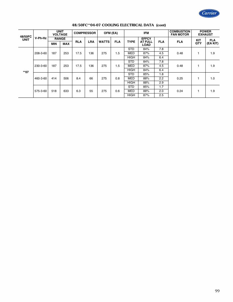
99
**07
208-3-60 187 253 17.5 136 275 1.5STD 84% 7.8
0.48 1 1.9MED 87% 4.5HIGH 84% 6.4
230-3-60 187 253 17.5 136 275 1.5STD 84% 7.8
0.48 1 1.9MED 87% 4.5HIGH 84% 6.4
460-3-60 414 506 8.4 66 275 0.8STD 85% 1.8
0.25 1 1.0MED 88% 2.2HIGH 88% 2.9
575-3-60 518 633 6.3 55 275 0.6STD 85% 1.7
0.24 1 1.9MED 88% 2.0HIGH 87% 2.5
48/50FC**04-07 COOLING ELECTRICAL DATA (cont)
48/50FC UNIT V-Ph-Hz
UNIT VOLTAGE COMPRESSOR OFM (EA) IFM COMBUSTION
FAN MOTORPOWER
EXHAUSTRANGE
RLA LRA WATTS FLA TYPEEFFCY
AT FULL LOAD
FLA FLA KIT QTY
FLA(EA KIT)MIN MAX

100
48FC**04-07 MCA MOCP ELECTRICAL DATA
48FC UNIT SIZE
NOM.V-PH-Hz IFM TYPE
NO CONVENIENCE OUTLET OR UNPOWERED CONVENIENCE OUTLETNO POWER EXHAUST w/ POWER EXHAUST (powered from unit)
MCAFUSE OR
HACR BREAKER
DISCONNECT SIZEMCA
FUSE OR HACR
BREAKER
DISCONNECT SIZE
FLA LRA FLA LRA
**04
208/230-1-60STD 25 30 23 93 27 30 26 95MED 26 30 25 95 28 40 27 97HIGH 29 40 28 98 30 45 30 100
208/230-3-60STD 18 25 18 82 20 30 20 84MED 20 30 20 84 22 30 22 86HIGH 22 30 22 87 24 30 24 89
460-3-60STD 9 15 9 41 10 15 10 42MED 10 15 9 42 11 15 10 43HIGH 10 15 9 42 11 15 10 43
575-3-60STD 7 15 6 40 9 15 8 42MED 7 15 6 41 9 15 9 43HIGH 7 15 7 41 9 15 9 43
**05
208/230-1-60STD 31 50 30 141 33 50 32 143MED 34 50 32 144 35 50 35 146HIGH 35 50 34 146 37 50 37 148
208/230-3-60STD 24 30 23 94 26 30 25 96MED 26 30 26 97 28 40 28 99HIGH 24 30 23 94 26 30 26 96
460-3-60STD 10 15 9 45 11 15 11 46MED 11 15 10 45 12 15 11 46HIGH 11 15 11 46 12 15 12 47
575-3-60STD 8 15 7 37 10 15 10 39MED 9 15 8 37 10 15 10 39HIGH 9 15 9 38 11 15 11 40
**06
208/230-1-60STD 40 60 38 158 42 60 40 160MED 41 60 40 160 43 60 42 162HIGH 41 60 39 159 42 60 41 161
208/230-3-60STD 29 40 28 124 31 45 31 126MED 31 45 30 126 32 45 32 128HIGH 28 40 27 123 30 45 30 125
460-3-60STD 13 15 12 56 14 20 13 57MED 13 20 12 57 14 20 13 58HIGH 14 20 13 58 15 20 14 59
575-3-60STD 10 15 9 43 12 15 11 45MED 10 15 9 44 12 15 12 46HIGH 11 15 10 45 13 15 12 47
**07
208/230-3-60STD 32 45 31 151 34 50 33 153MED 28 45 27 146 30 45 29 148HIGH 30 45 29 149 32 45 31 151
460-3-60STD 14 20 13 71 15 20 14 72MED 14 20 13 71 15 20 14 72HIGH 15 20 14 72 16 20 15 73
575-3-60STD 11 15 10 59 13 15 12 61MED 11 15 10 60 13 15 12 62HIGH 11 15 11 61 13 15 13 63
Electrical data (cont)

101
48FC**04-07 MCA MOCP ELECTRICAL DATA (cont)
48FC UNIT SIZE
NOM.V-PH-Hz IMF TYPE
w/ POWERED CONVENIENCE OUTLETNO POWER EXHAUST w/ POWER EXHAUST (powered from unit)
MCAFUSE OR
HACR BREAKER
DISCONNECT SIZEMCA
FUSE OR HACR
BREAKER
DISCONNECT SIZE
FLA LRA FLA LRA
**04
208/230-3-60STD 23 30 23 87 25 30 25 89MED 25 30 25 89 27 30 27 91HIGH 27 30 28 92 29 35 30 94
460-3-60STD 12 15 11 43 13 15 12 44MED 12 15 12 44 13 15 13 45HIGH 12 15 12 44 13 15 13 45
575-3-60STD 8 15 8 42 10 15 10 44MED 9 15 8 43 11 15 10 45HIGH 9 15 9 43 11 15 11 45
**05
208/230-3-60STD 29 40 29 99 31 40 31 101MED 31 40 31 102 33 45 33 104HIGH 29 40 29 99 31 40 31 101
460-3-60STD 12 15 12 47 13 15 13 48MED 13 15 12 47 14 15 13 48HIGH 14 15 13 48 15 20 14 49
575-3-60STD 10 15 9 39 12 15 12 41MED 10 15 10 39 12 15 12 41HIGH 11 15 11 40 13 15 13 42
**06
208/230-3-60STD 34 45 34 129 36 50 36 131MED 35 50 36 131 37 50 38 133HIGH 33 45 33 128 35 50 35 130
460-3-60STD 15 20 14 58 16 20 15 59MED 15 20 15 59 16 20 16 60HIGH 16 20 16 60 17 20 17 61
575-3-60STD 11 15 11 45 13 15 13 47MED 12 15 11 46 14 15 13 48HIGH 12 15 12 47 14 20 14 49
**07
208/230-3-60STD 36 50 36 156 38 50 39 158MED 33 50 33 151 35 50 35 153HIGH 35 50 35 154 37 50 37 156
460-3-60STD 16 20 15 73 17 20 16 74MED 16 20 16 73 17 25 17 74HIGH 17 20 16 74 18 25 18 75
575-3-60STD 12 15 12 61 14 20 14 63MED 13 15 12 62 15 20 14 64HIGH 13 15 13 63 15 20 15 65

102
50FC**04 MCA MOCP ELECTRICAL DATA
50FCUNITSIZE
NOM.V-Ph-Hz
IFM TYPE
ELECTRIC HEATER NO CONVENIENCE OUTLET or UNPOWERED CONVENIENCE OUTLET
CRHEATER***A00
NOM(kW) FLA
NO POWER EXHAUST w/ POWER EXHAUST (powered from unit)
MCA
FUSE OR
HACR BRKR
DISCONNECT SIZE
MCA
FUSE OR
HACR BRKR
DISCONNECT SIZE
FLA LRA FLA LRA
**04
208/230-1-60
STD
NONE — — 25 30 23 93 27 30 26 95323A 3.3/4.4 15.9/18.3 25/28 30/30 23/25 93/93 27/30 30/30 26/27 95/95324A 4.9/6.5 23.5/27.1 34/39 35/40 31/35 93/93 36/41 40/45 33/37 95/95325A 6.5/8.7 31.4/36.3 44/50 45/50 40/46 93/93 46/52 50/60 42/48 95/95326A 7.9/10.5 37.9/43.8 52/59 60/60 47/54 93/93 54/62 60/70 50/56 95/95327A 9.8/13.0 46.9/54.2 63/72 70/80 58/66 93/93 66/75 70/80 60/68 95/95
MED
NONE — — 26 30 25 95 28 40 27 97323A 3.3/4.4 15.9/18.3 27/30 30/30 25/27 95/95 29/32 40/40 27/29 97/97324A 4.9/6.5 23.5/27.1 36/41 40/45 33/37 95/95 39/43 40/45 35/39 97/97325A 6.5/8.7 31.4/36.3 46/52 50/60 42/48 95/95 48/55 50/60 44/50 97/97326A 7.9/10.5 37.9/43.8 54/62 60/70 49/56 95/95 57/64 60/70 52/58 97/97327A 9.8/13.0 46.9/54.2 65/75 70/80 60/68 95/95 68/77 70/80 62/70 97/97
HIGH
NONE — — 29 40 28 98 30 45 30 100323A 3.3/4.4 15.9/18.3 29/32 40/40 28/29 98/98 32/35 45/45 30/32 100/100324A 4.9/6.5 23.5/27.1 39/43 40/45 35/40 98/98 41/46 45/50 38/42 100/100325A 6.5/8.7 31.4/36.3 49/55 50/60 45/50 98/98 51/57 60/60 47/52 100/100326A 7.9/10.5 37.9/43.8 57/64 60/70 52/59 98/98 59/67 60/70 54/61 100/100327A 9.8/13.0 46.9/54.2 68/77 70/80 62/71 98/98 71/80 80/80 65/73 100/100
208/230-3-60
STD
NONE — — 18 25 18 82 20 30 20 84323A 3.3/4.4 9.2/10.6 18/18 25/25 18/18 82/82 20/20 30/30 20/20 84/84324A 4.9/6.5 13.6/15.6 22/24 25/25 20/22 82/82 24/27 30/30 22/24 84/84325A 6.5/8.7 18.1/20.9 27/31 30/35 25/28 82/82 30/33 30/35 27/30 84/84326A 7.9/10.5 21.9/25.3 32/36 35/40 29/33 82/82 34/39 35/40 31/35 84/84328A 12.0/16.0 33.4/38.5 46/53 50/60 42/48 82/82 49/55 50/60 45/50 84/84
MED
NONE — — 20 30 20 84 22 30 22 86323A 3.3/4.4 9.2/10.6 20/20 30/30 20/20 84/84 22/22 30/30 22/22 86/86324A 4.9/6.5 13.6/15.6 24/26 30/30 22/24 84/84 26/29 30/30 24/26 86/86325A 6.5/8.7 18.1/20.9 29/33 30/35 27/30 84/84 32/35 35/35 29/32 86/86326A 7.9/10.5 21.9/25.3 34/38 35/40 31/35 84/84 37/41 40/45 33/37 86/86328A 12.0/16.0 33.4/38.5 49/55 50/60 44/50 84/84 51/57 60/60 46/52 86/86
HIGH
NONE — — 22 30 22 87 24 30 24 89323A 3.3/4.4 9.2/10.6 22/23 30/30 22/22 87/87 24/25 30/30 24/24 89/89324A 4.9/6.5 13.6/15.6 27/29 30/30 24/26 87/87 29/31 30/35 26/29 89/89325A 6.5/8.7 18.1/20.9 32/36 35/40 29/32 87/87 35/38 35/40 31/35 89/89326A 7.9/10.5 21.9/25.3 37/41 40/45 34/37 87/87 39/44 40/45 36/40 89/89328A 12.0/16.0 33.4/38.5 51/58 60/60 47/53 87/87 54/60 60/60 49/55 89/89
460-3-60
STD
NONE — — 9 15 9 41 10 15 10 42333A 6.0 7.2 11 15 9 41 12 15 10 42334A 8.8 10.6 15 15 13 41 16 20 14 42335A 11.5 13.8 19 20 17 41 20 20 18 42336A 14.0 16.8 23 25 20 41 24 25 22 42
MED
NONE — — 10 15 9 42 11 15 10 43333A 6.0 7.2 11 15 10 42 12 15 11 43334A 8.8 10.6 15 15 14 42 16 20 15 43335A 11.5 13.8 19 20 17 42 20 25 18 43336A 14.0 16.8 23 25 21 42 24 25 22 43
HIGH
NONE — — 10 15 9 42 11 15 10 43333A 6.0 7.2 11 15 10 42 13 15 11 43334A 8.8 10.6 16 20 14 42 17 20 15 43335A 11.5 13.8 20 20 18 42 21 25 19 43336A 14.0 16.8 23 25 21 42 25 25 22 43
575-3-60
STDNONE — — 7 15 6 40 9 15 8 42339A 10.0 9.6 13 15 12 40 16 20 14 42340A 15.0 14.4 19 20 17 40 22 25 20 42
MEDNONE — — 7 15 6 41 9 15 9 43339A 10.0 9.6 14 15 12 41 16 20 14 43340A 15.0 14.4 20 20 18 41 22 25 20 43
HIGHNONE — — 7 15 7 41 9 15 9 43339A 10.0 9.6 14 15 13 41 17 20 15 43340A 15.0 14.4 20 20 18 41 23 25 20 43
Electrical data (cont)

103
50FC**04 MCA MOCP ELECTRICAL DATA (cont)
50FCUNITSIZE
NOM.V-Ph-Hz
IFM TYPE
ELECTRIC HEATER w/ POWERED CONVENIENCE OUTLET
CRHEATER***A00
NOM (kW) FLA
NO POWER EXHAUST w/ POWER EXHAUST (powered from unit)
MCA
FUSE OR
HACR BRKR
DISCONNECT SIZE
MCA
FUSE OR
HACR BRKR
DISCONNECT SIZE
FLA LRA FLA LRA
**04
208/230-3-60
STD
NONE — — 23 30 23 87 25 30 25 89323A 3.3/4.4 9.2/10.6 23/24 30/30 23/23 87/87 25/26 30/30 25/25 89/89324A 4.9/6.5 13.6/15.6 28/30 30/30 25/27 87/87 30/33 30/35 27/30 89/89325A 6.5/8.7 18.1/20.9 33/37 35/40 30/33 87/87 36/39 40/40 32/36 89/89326A 7.9/10.5 21.9/25.3 38/42 40/45 35/39 87/87 40/45 45/45 37/41 89/89328A 12.0/16.0 33.4/38.5 52/59 60/60 48/54 87/87 55/61 60/70 50/56 89/89
MED
NONE — — 25 30 25 89 27 30 27 91323A 3.3/4.4 9.2/10.6 25/26 30/30 25/25 89/89 27/28 30/30 27/27 91/91324A 4.9/6.5 13.6/15.6 30/32 30/35 27/29 89/89 32/35 35/35 29/32 91/91325A 6.5/8.7 18.1/20.9 35/39 40/40 32/35 89/89 38/41 40/45 34/38 91/91326A 7.9/10.5 21.9/25.3 40/44 40/45 37/40 89/89 43/47 45/50 39/43 91/91328A 12.0/16.0 33.4/38.5 55/61 60/70 50/56 89/89 57/63 60/70 52/58 91/91
HIGH
NONE — — 27 30 28 92 29 35 30 94323A 3.3/4.4 9.2/10.6 27/29 30/30 28/28 92/92 29/31 35/35 30/30 94/94324A 4.9/6.5 13.6/15.6 33/35 35/35 30/32 92/92 35/37 35/40 32/34 94/94325A 6.5/8.7 18.1/20.9 38/42 40/45 35/38 92/92 41/44 45/45 37/40 94/94326A 7.9/10.5 21.9/25.3 43/47 45/50 39/43 92/92 45/50 45/50 41/45 94/94328A 12.0/16.0 33.4/38.5 57/64 60/70 52/58 92/92 60/66 60/70 55/60 94/94
460-3-60
STD
NONE — — 12 15 11 43 13 15 12 44333A 6.0 7.2 13 15 12 43 15 15 13 44334A 8.8 10.6 18 20 16 43 19 20 17 44335A 11.5 13.8 22 25 19 43 23 25 21 44336A 14.0 16.8 25 25 23 43 27 30 24 44
MED
NONE — — 12 15 12 44 13 15 13 45333A 6.0 7.2 14 15 12 44 15 15 13 45334A 8.8 10.6 18 20 16 44 19 20 17 45335A 11.5 13.8 22 25 20 44 23 25 21 45336A 14.0 16.8 26 30 23 44 27 30 24 45
HIGH
NONE — — 12 15 12 44 13 15 13 45333A 6.0 7.2 14 15 13 44 15 15 14 45334A 8.8 10.6 18 20 16 44 20 20 18 45335A 11.5 13.8 22 25 20 44 24 25 21 45336A 14.0 16.8 26 30 24 44 27 30 25 45
575-3-60
STDNONE — — 8 15 8 42 10 15 10 44339A 10.0 9.6 16 20 14 42 18 20 16 44340A 15.0 14.4 22 25 19 42 24 25 22 44
MEDNONE — — 9 15 8 43 11 15 10 45339A 10.0 9.6 16 20 14 43 18 20 16 45340A 15.0 14.4 22 25 20 43 24 25 22 45
HIGHNONE — — 9 15 9 43 11 15 11 45339A 10.0 9.6 16 20 15 43 19 20 17 45340A 15.0 14.4 22 25 20 43 25 25 22 45

104
50FC**05 MCA MOCP ELECTRICAL DATA
50FCUNITSIZE
NOM.V-Ph-Hz
IFM TYPE
ELECTRIC HEATER NO CONVENIENCE OUTLET or UNPOWERED CONVENIENCE OUTLET
CRHEATER***A00
NOM (kW) FLA
NO POWER EXHAUST w/ POWER EXHAUST (powered from unit)
MCA
FUSE OR
HACR BRKR
DISCONNECT SIZE
MCA
FUSE OR
HACR BRKR
DISCONNECT SIZE
FLA LRA FLA LRA
**05
208/230-1-60
STD
NONE — — 31 50 30 141 33 50 32 143323A 3.3/4.4 15.9/18.3 31/31 50/50 30/30 141/141 33/33 50/50 32/32 143/143325A 6.5/8.7 31.4/36.3 46/52 50/60 42/47 141/141 48/54 50/60 44/50 143/143327A 9.8/13.0 46.9/54.2 65/74 70/80 60/68 141/141 68/77 70/80 62/70 143/143329A 13.1/17.4 62.8/72.5 85/97 90/100 78/89 141/141 88/100 90/100 80/91 143/143330A* 14.4/19.2 69.3/80.0 93/107 100/110 85/98 141/141 96/109 100/110 88/100 143/143331A† 15.8/21.0 75.8/87.5 101/116 110/125 93/106 141/141 104/118 110/125 95/109 143/143
MED
NONE — — 34 50 32 144 35 50 35 146323A 3.3/4.4 15.9/18.3 34/34 50/50 32/32 144/144 35/35 50/50 35/35 146/146325A 6.5/8.7 31.4/36.3 49/55 50/60 44/50 144/144 51/57 60/60 46/52 146/146327A 9.8/13.0 46.9/54.2 68/77 70/80 62/70 144/144 70/79 70/80 64/73 146/146329A 13.1/17.4 62.8/72.5 88/100 90/100 80/92 144/144 90/102 90/110 83/94 146/146330A 14.4/19.2 69.3/80.0 96/109 100/110 88/100 144/144 98/112 100/125 90/102 146/146331A† 15.8/21.0 75.8/87.5 104/119 110/125 95/109 144/144 106/121 110/125 98/111 146/146
HIGH
NONE — — 35 50 34 146 37 50 37 148323A 3.3/4.4 15.9/18.3 35/35 50/50 34/34 146/146 37/37 50/50 37/37 148/148325A 6.5/8.7 31.4/36.3 51/57 60/60 46/52 146/146 53/59 60/60 48/54 148/148327A 9.8/13.0 46.9/54.2 70/79 70/80 64/72 146/146 72/82 80/90 66/75 148/148329A 13.1/17.4 62.8/72.5 90/102 90/110 82/93 146/146 92/104 100/110 85/96 148/148330A* 14.4/19.2 69.3/80.0 98/111 100/125 90/102 146/146 100/114 110/125 92/104 148/148331A† 15.8/21.0 75.8/87.5 106/121 110/125 97/111 146/146 109/123 110/125 99/113 148/148
208/230-3-60
STD
NONE — — 24 30 23 94 26 30 25 96323A 3.3/4.4 9.2/10.6 24/24 30/30 23/23 94/94 26/26 30/30 25/25 96/96324A 4.9/6.5 13.6/15.6 24/26 30/30 23/24 94/94 26/29 30/30 25/26 96/96325A 6.5/8.7 18.1/20.9 29/33 30/35 27/30 94/94 32/35 35/35 29/32 96/96328A 12.0/16.0 33.4/38.5 48/55 50/60 44/50 94/94 51/57 60/60 46/52 96/96330A 14.4/19.2 40.0/46.2 57/64 60/70 52/59 94/94 59/67 60/70 54/61 96/96331A† 15.8/21.0 43.8/50.5 61/70 70/70 56/64 94/94 64/72 70/80 58/66 96/96
MED
NONE — — 26 30 26 97 28 40 28 99323A 3.3/4.4 9.2/10.6 26/26 30/30 26/26 97/97 28/28 40/40 28/28 99/99324A 4.9/6.5 13.6/15.6 26/29 30/30 26/26 97/97 29/31 40/40 28/28 99/99325A 6.5/8.7 18.1/20.9 32/35 35/35 29/32 97/97 34/38 40/40 31/34 99/99328A 12.0/16.0 33.4/38.5 51/57 60/60 47/52 97/97 53/60 60/60 49/55 99/99330A* 14.4/19.2 40.0/46.2 59/67 60/70 54/61 97/97 62/69 70/70 56/63 99/99331A† 15.8/21.0 43.8/50.5 64/72 70/80 59/66 97/97 66/75 70/80 61/68 99/99
HIGH
NONE — — 24 30 23 94 26 30 26 96323A 3.3/4.4 9.2/10.6 24/24 30/30 23/23 94/94 26/26 30/30 26/26 96/96324A 4.9/6.5 13.6/15.6 24/26 30/30 23/24 94/94 26/29 30/30 26/26 96/96325A 6.5/8.7 18.1/20.9 29/33 30/35 27/30 94/94 32/35 35/35 29/32 96/96328A 12.0/16.0 33.4/38.5 49/55 50/60 44/50 94/94 51/57 60/60 46/52 96/96330A* 14.4/19.2 40.0/46.2 57/65 60/70 52/59 94/94 59/67 60/70 54/61 96/96331A† 15.8/21.0 43.8/50.5 62/70 70/70 56/64 94/94 64/72 70/80 58/66 96/96
460-3-60
STD
NONE — — 10 15 9 45 11 15 11 46333A 6.0 7.2 11 15 10 45 12 15 11 46335A 11.5 13.8 19 20 17 45 20 25 18 46336A 14.0 16.8 23 25 21 45 24 25 22 46337A 21.5 25.9 34 35 31 45 36 40 32 46
MED
NONE — — 11 15 10 45 12 15 11 46333A 6.0 7.2 11 15 10 45 13 15 11 46335A 11.5 13.8 20 20 18 45 21 25 19 46336A 14.0 16.8 23 25 21 45 25 25 22 46337A 21.5 25.9 35 35 32 45 36 40 33 46
HIGH
NONE — — 11 15 11 46 12 15 12 47333A 6.0 7.2 12 15 11 46 14 15 12 47335A 11.5 13.8 21 25 19 46 22 25 20 47336A 14.0 16.8 24 25 22 46 26 30 23 47337A 21.5 25.9 36 40 33 46 37 40 34 47
Electrical data (cont)

105
*Do not use with size 05 horizontal duct configuration units.
†Do not use with size 05 vertical duct configuration units.
**05 (cont)
575-3-60
STDNONE — — 8 15 7 37 10 15 10 39339A 10.0 9.6 14 15 12 37 16 20 14 39340A 15.0 14.4 20 20 18 37 22 25 20 39
MEDNONE — — 9 15 8 37 10 15 10 39339A 10.0 9.6 14 15 13 37 17 20 15 39340A 15.0 14.4 20 20 18 37 23 25 20 39
HIGHNONE — — 9 15 9 38 11 15 11 40339A 10.0 9.6 15 15 13 38 17 20 16 40340A 15.0 14.4 21 25 19 38 23 25 21 40
50FC**05 MCA MOCP ELECTRICAL DATA (cont)
50FCUNITSIZE
NOM.V-Ph-Hz
IFM TYPE
ELECTRIC HEATER NO CONVENIENCE OUTLET or UNPOWERED CONVENIENCE OUTLET
CRHEATER***A00
NOM (kW) FLA
NO POWER EXHAUST w/ POWER EXHAUST (powered from unit)
MCA
FUSE OR
HACR BRKR
DISCONNECT SIZE
MCA
FUSE OR
HACR BRKR
DISCONNECT SIZE
FLA LRA FLA LRA

106
*Do not use with size 05 horizontal duct configuration units.
†Do not use with size 05 vertical duct configuration units.
50FC**05 MCA MOCP ELECTRICAL DATA (cont)
50FCUNITSIZE
NOM.V-Ph-Hz
IFM TYPE
ELECTRIC HEATER w/ POWERED CONVENIENCE OUTLET
CRHEATER***A00
NOM (kW) FLA
NO POWER EXHAUST w/ POWER EXHAUST (powered from unit)
MCA
FUSE OR
HACR BRKR
DISCONNECT SIZE
MCA
FUSE OR
HACR BRKR
DISCONNECT SIZE
FLA LRA FLA LRA
**05
208/230-3-60
STD
NONE — — 29 40 29 99 31 40 31 101323A 3.3/4.4 9.2/10.6 29/29 40/40 29/29 99/99 31/31 40/40 31/31 101/101324A 4.9/6.5 13.6/15.6 30/32 40/40 29/29 99/99 32/35 40/40 31/31 101/101325A 6.5/8.7 18.1/20.9 35/39 40/40 32/35 99/99 38/41 40/45 34/37 101/101328A 12.0/16.0 33.4/38.5 54/61 60/70 50/56 99/99 57/63 60/70 52/58 101/101330A* 14.4/19.2 40.0/46.2 63/70 70/80 57/64 99/99 65/73 70/80 59/67 101/101331A† 15.8/21.0 43.8/50.5 67/76 70/80 62/69 99/99 70/78 70/80 64/72 101/101
MED
NONE — — 31 40 31 102 33 45 33 104323A 3.3/4.4 9.2/10.6 31/31 40/40 31/31 102/102 33/33 45/45 33/33 104/104324A 4.9/6.5 13.6/15.6 32/35 40/40 31/32 102/102 35/37 45/45 33/34 104/104325A 6.5/8.7 18.1/20.9 38/41 40/45 35/38 102/102 40/44 45/45 37/40 104/104328A 12.0/16.0 33.4/38.5 57/63 60/70 52/58 102/102 59/66 60/70 54/60 104/104330A* 14.4/19.2 40.0/46.2 65/73 70/80 60/67 102/102 68/75 70/80 62/69 104/104331A† 15.8/21.0 43.8/50.5 70/78 70/80 64/72 102/102 72/81 80/90 66/74 104/104
HIGH
NONE — — 29 40 29 99 31 40 31 101323A 3.3/4.4 9.2/10.6 29/29 40/40 29/29 99/99 31/31 40/40 31/31 101/101324A 4.9/6.5 13.6/15.6 30/32 40/40 29/29 99/99 32/35 40/40 31/32 101/101325A 6.5/8.7 18.1/20.9 35/39 40/40 32/35 99/99 38/41 40/45 34/38 101/101328A 12.0/16.0 33.4/38.5 55/61 60/70 50/56 99/99 57/63 60/70 52/58 101/101330A* 14.4/19.2 40.0/46.2 63/71 70/80 57/65 99/99 65/73 70/80 60/67 101/101331A† 15.8/21.0 43.8/50.5 68/76 70/80 62/69 99/99 70/78 70/80 64/72 101/101
460-3-60
STD
NONE — — 12 15 12 47 13 15 13 48333A 6.0 7.2 14 15 12 47 15 15 13 48335A 11.5 13.8 22 25 20 47 23 25 21 48336A 14.0 16.8 26 30 23 47 27 30 24 48337A 21.5 25.9 37 40 34 47 38 40 35 48
MED
NONE — — 13 15 12 47 14 15 13 48333A 6.0 7.2 14 15 13 47 15 15 14 48335A 11.5 13.8 22 25 20 47 24 25 21 48336A 14.0 16.8 26 30 24 47 27 30 25 48337A 21.5 25.9 37 40 34 47 39 40 35 48
HIGH
NONE — — 14 15 13 48 15 20 14 49333A 6.0 7.2 15 15 14 48 16 20 15 49335A 11.5 13.8 23 25 21 48 25 25 22 49336A 14.0 16.8 27 30 25 48 28 30 26 49337A 21.5 25.9 39 40 35 48 40 40 36 49
575-3-60
STDNONE — — 10 15 9 39 12 15 12 41339A 10.0 9.6 16 20 14 39 18 20 16 41340A 15.0 14.4 22 25 20 39 24 25 22 41
MEDNONE — — 10 15 10 39 12 15 12 41339A 10.0 9.6 16 20 15 39 19 20 17 41340A 15.0 14.4 22 25 20 39 25 25 22 41
HIGHNONE — — 11 15 11 40 13 15 13 42339A 10.0 9.6 17 20 15 40 20 20 18 42340A 15.0 14.4 23 25 21 40 26 30 23 42
Electrical data (cont)

107
50FC**06 MCA MOCP ELECTRICAL DATA
50FCUNITSIZE
NOM.V-Ph-Hz
IFM TYPE
ELECTRIC HEATER NO CONVENIENCE OUTLET or UNPOWERED CONVENIENCE OUTLET
CRHEATER***A00
NOM (kW) FLA
NO POWER EXHAUST w/ POWER EXHAUST (powered from unit)
MCA
FUSE OR
HACR BRKR
DISCONNECT SIZE
MCA
FUSE OR
HACR BRKR
DISCONNECT SIZE
FLA LRA FLA LRA
**06
208/230-1-60
STD
NONE — — 40 60 38 158 42 60 40 160324A 4.9/6.5 23.5/27.1 40/43 60/60 38/39 158/158 42/46 60/60 40/42 160/160325A 6.5/8.7 31.4/36.3 49/55 60/60 44/50 158/158 51/57 60/60 47/52 160/160327A 9.8/13.0 46.9/54.2 68/77 70/80 62/71 158/158 70/80 80/80 64/73 160/160329A 13.1/17.4 62.8/72.5 88/100 90/100 81/92 158/158 90/102 90/110 83/94 160/160331A 15.8/21.0 75.8/87.5 104/119 110/125 95/109 158/158 107/121 110/125 98/111 160/160
MED
NONE — — 41 60 40 160 43 60 42 162324A 4.9/6.5 23.5/27.1 41/45 60/60 40/41 160/160 43/47 60/60 42/43 162/162325A 6.5/8.7 31.4/36.3 50/57 60/60 46/52 160/160 53/59 60/60 48/54 162/162327A 9.8/13.0 46.9/54.2 70/79 70/80 64/72 160/160 72/81 80/90 66/74 162/162329A 13.1/17.4 62.8/72.5 90/102 90/110 82/93 160/160 92/104 100/110 84/95 162/162331A 15.8/21.0 75.8/87.5 106/121 110/125 97/111 160/160 108/123 110/125 99/113 162/162
208/230-3-60
STD
NONE — — 29 40 28 124 31 45 31 126324A 4.9/6.5 13.6/15.6 29/29 40/40 28/28 124/124 31/31 45/45 31/31 126/126326A 7.9/10.5 21.9/25.3 37/41 40/45 33/37 124/124 39/43 45/45 36/40 126/126328A 12.0/16.0 33.4/38.5 51/58 60/60 47/53 124/124 54/60 60/60 49/55 126/126331A 15.8/21.0 43.8/50.5 64/73 70/80 59/66 124/124 67/75 70/80 61/69 126/126332A 18.4/24.5 51.1/58.9 73/83 80/90 67/76 124/124 76/85 80/90 69/78 126/126
MED
NONE — — 31 45 30 126 32 45 32 128324A 4.9/6.5 13.6/15.6 31/31 45/45 30/30 126/126 32/33 45/45 32/32 128/128326A 7.9/10.5 21.9/25.3 39/43 45/45 35/39 126/126 41/45 45/45 37/41 128/128328A 12.0/16.0 33.4/38.5 53/59 60/60 48/54 126/126 55/62 60/70 50/56 128/128331A 15.8/21.0 43.8/50.5 66/74 70/80 60/68 126/126 68/77 70/80 62/70 128/128332A 18.4/24.5 51.1/58.9 75/85 80/90 69/78 126/126 77/87 80/90 71/80 128/128
HIGH
NONE — — 28 40 27 123 30 45 30 125324A 4.9/6.5 13.6/15.6 28/28 40/40 27/27 123/123 30/30 45/45 30/30 125/125326A 7.9/10.5 21.9/25.3 36/40 40/40 33/36 123/123 38/42 45/45 35/39 125/125328A 12.0/16.0 33.4/38.5 50/57 50/60 46/52 123/123 53/59 60/60 48/54 125/125331A 15.8/21.0 43.8/50.5 63/72 70/80 58/65 123/123 66/74 70/80 60/68 125/125332A 18.4/24.5 51.1/58.9 72/82 80/90 66/75 123/123 75/84 80/90 68/77 125/125
460-3-60
STD
NONE — — 13 15 12 56 14 20 13 57333A 6.0 7.2 13 15 12 56 14 20 13 57335A 11.5 13.8 20 20 18 56 21 25 19 57336A 14.0 16.8 23 25 21 56 25 25 22 57337A 21.5 25.9 35 35 32 56 36 40 33 57338A 24.0 28.9 38 40 35 56 40 40 36 57
MED
NONE — — 13 20 12 57 14 20 13 58333A 6.0 7.2 13 20 12 57 14 20 13 58335A 11.5 13.8 20 20 18 57 21 25 19 58336A 14.0 16.8 24 25 22 57 25 25 23 58337A 21.5 25.9 35 35 32 57 36 40 33 58338A 24.0 28.9 39 40 35 57 40 40 37 58
HIGH
NONE — — 14 20 13 58 15 20 14 59333A 6.0 7.2 14 20 13 58 15 20 14 59335A 11.5 13.8 21 25 19 58 23 25 20 59336A 14.0 16.8 25 25 23 58 26 30 24 59337A 21.5 25.9 36 40 33 58 38 40 34 59338A 24.0 28.9 40 40 37 58 41 45 38 59
575-3-60
STDNONE — — 10 15 9 43 12 15 11 45340A 15.0 14.4 20 20 18 43 23 25 20 45341A 21.0 20.2 28 30 25 43 30 30 27 45
MEDNONE — — 10 15 9 44 12 15 12 46340A 15.0 14.4 21 25 19 44 23 25 21 46341A 21.0 20.2 28 30 25 44 30 30 27 46
HIGHNONE — — 11 15 10 45 13 15 12 47340A 15.0 14.4 22 25 19 45 24 25 22 47341A 21.0 20.2 29 30 26 45 31 35 28 47

108
50FC**06 MCA MOCP ELECTRICAL DATA (cont)
50FCUNITSIZE
NOM.V-Ph-Hz
IFM TYPE
ELECTRIC HEATER w/ POWERED CONVENIENCE OUTLET
CRHEATER***A00
NOM (kW) FLA
NO POWER EXHAUST w/ POWER EXHAUST (powered from unit)
MCA
FUSE OR
HACR BRKR
DISCONNECT SIZE
MCA
FUSE OR
HACR BRKR
DISCONNECT SIZE
FLA LRA FLA LRA
**06
208/230-3-60
STD
NONE - - 34 45 34 129 36 50 36 131324A 4.9/6.5 13.6/15.6 34/35 45/45 34/34 129/129 36/37 50/50 36/36 131/131326A 7.9/10.5 21.9/25.3 43/47 45/50 39/43 129/129 45/49 50/50 41/45 131/131328A 12.0/16.0 33.4/38.5 57/64 60/70 52/58 129/129 60/66 60/70 54/60 131/131331A 15.8/21.0 43.8/50.5 70/79 70/80 64/72 129/129 73/81 80/90 66/74 131/131332A 18.4/24.5 51.1/58.9 79/89 80/90 73/82 129/129 82/91 90/100 75/84 131/131
MED
NONE - - 35 50 36 131 37 50 38 133324A 4.9/6.5 13.6/15.6 35/37 50/50 36/36 131/131 37/39 50/50 38/38 133/133326A 7.9/10.5 21.9/25.3 45/49 50/50 41/45 131/131 47/51 50/60 43/47 133/133328A 12.0/16.0 33.4/38.5 59/65 60/70 54/60 131/131 61/68 70/70 56/62 133/133331A 15.8/21.0 43.8/50.5 72/80 80/80 66/73 131/131 74/83 80/90 68/76 133/133332A 18.4/24.5 51.1/58.9 81/91 90/100 74/83 131/131 83/93 90/100 76/85 133/133
HIGH
NONE - - 33 45 33 128 35 50 35 130324A 4.9/6.5 13.6/15.6 33/34 45/45 33/33 128/128 35/36 50/50 35/35 130/130326A 7.9/10.5 21.9/25.3 42/46 45/50 38/42 128/128 44/48 50/50 40/44 130/130328A 12.0/16.0 33.4/38.5 56/63 60/70 51/57 128/128 59/65 60/70 53/59 130/130331A 15.8/21.0 43.8/50.5 69/78 70/80 63/71 128/128 72/80 80/80 65/73 130/130332A 18.4/24.5 51.1/58.9 78/88 80/90 72/81 128/128 81/90 90/100 74/83 130/130
460-3-60
STD
NONE - - 15 20 14 58 16 20 15 59333A 6.0 7.2 15 20 14 58 16 20 15 59335A 11.5 13.8 22 25 20 58 24 25 21 59336A 14.0 16.8 26 30 24 58 27 30 25 59337A 21.5 25.9 37 40 34 58 39 40 35 59338A 24.0 28.9 41 45 37 58 42 45 39 59
MED
NONE - - 15 20 15 59 16 20 16 60333A 6.0 7.2 15 20 15 59 16 20 16 60335A 11.5 13.8 23 25 21 59 24 25 22 60336A 14.0 16.8 27 30 24 59 28 30 25 60337A 21.5 25.9 38 40 35 59 39 40 36 60338A 24.0 28.9 42 45 38 59 43 45 39 60
HIGH
NONE - - 16 20 16 60 17 20 17 61333A 6.0 7.2 16 20 16 60 17 20 17 61335A 11.5 13.8 24 25 22 60 25 25 23 61336A 14.0 16.8 28 30 25 60 29 30 26 61337A 21.5 25.9 39 40 36 60 40 45 37 61338A 24.0 28.9 43 45 39 60 44 45 40 61
575-3-60
STDNONE - - 11 15 11 45 13 15 13 47340A 15.0 14.4 22 25 20 45 25 25 22 47341A 21.0 20.2 30 30 27 45 32 35 29 47
MEDNONE - - 12 15 11 46 14 15 13 48340A 15.0 14.4 23 25 21 46 25 25 23 48341A 21.0 20.2 30 30 27 46 32 35 29 48
HIGHNONE - - 12 15 12 47 14 20 14 49340A 15.0 14.4 24 25 21 47 26 30 24 49341A 21.0 20.2 31 35 28 47 33 35 30 49
Electrical data (cont)

109
50FC**07 MCA MOCP ELECTRICAL DATA
50FCUNITSIZE
NOM.V-Ph-Hz
IFM TYPE
ELECTRIC HEATER NO CONVENIENCE OUTLET or UNPOWERED CONVENIENCE OUTLET
CRHEATER***A00
NOM (kW) FLA
NO POWER EXHAUST w/ POWER EXHAUST (powered from unit)
MCA
FUSE OR
HACR BRKR
DISCONNECT SIZE
MCA
FUSE OR
HACR BRKR
DISCONNECT SIZE
FLA LRA FLA LRA
**07
208/230-3-60
STD
NONE — — 32 45 31 151 34 50 33 153324A 4.9/6.5 13.6/15.6 32/32 45/45 31/31 151/151 34/34 50/50 33/33 153/153326A 7.9/10.5 21.9/25.3 38/42 45/45 34/38 151/151 40/44 50/50 36/40 153/153328A 12.0/16.0 33.4/38.5 52/58 60/60 47/53 151/151 54/61 60/70 50/55 153/153331A 15.8/21.0 43.8/50.5 65/73 70/80 59/67 151/151 67/76 70/80 62/69 153/153332A 18.4/24.5 51.1/58.9 74/84 80/90 68/77 151/151 76/86 80/90 70/79 153/153
MED
NONE — — 28 45 27 146 30 45 29 148324A 4.9/6.5 13.6/15.6 28/28 45/45 27/27 146/146 30/30 45/45 29/29 148/148326A 7.9/10.5 21.9/25.3 33/38 45/45 30/34 146/146 36/40 45/45 33/36 148/148328A 12.0/16.0 33.4/38.5 48/54 50/60 44/49 146/146 50/57 50/60 46/52 148/148331A 15.8/21.0 43.8/50.5 61/69 70/70 56/63 146/146 63/72 70/80 58/65 148/148332A 18.4/24.5 51.1/58.9 70/80 70/80 64/73 146/146 72/82 80/90 66/75 148/148
HIGH
NONE — — 30 45 29 149 32 45 31 151324A 4.9/6.5 13.6/15.6 30/30 45/45 29/29 149/149 32/32 45/45 31/31 151/151326A 7.9/10.5 21.9/25.3 36/40 45/45 33/36 149/149 38/42 45/45 35/39 151/151328A 12.0/16.0 33.4/38.5 50/57 50/60 46/52 149/149 53/59 60/60 48/54 151/151331A 15.8/21.0 43.8/50.5 63/72 70/80 58/65 149/149 66/74 70/80 60/68 151/151332A 18.4/24.5 51.1/58.9 72/82 80/90 66/75 149/149 75/84 80/90 68/77 151/151
460-3-60
STD
NONE — — 14 20 13 71 15 20 14 72333A 6.0 7.2 14 20 13 71 15 20 14 72335A 11.5 13.8 20 20 18 71 21 25 19 72336A 14.0 16.8 24 25 21 71 25 25 23 72337A 21.5 25.9 35 35 32 71 36 40 33 72338A 24.0 28.9 39 40 35 71 40 40 36 72
MED
NONE — — 14 20 13 71 15 20 14 72333A 6.0 7.2 14 20 13 71 15 20 14 72335A 11.5 13.8 20 25 18 71 22 25 20 72336A 14.0 16.8 24 25 22 71 25 30 23 72337A 21.5 25.9 36 40 32 71 37 40 33 72338A 24.0 28.9 39 40 36 71 41 45 37 72
HIGH
NONE — — 15 20 14 72 16 20 15 73333A 6.0 7.2 15 20 14 72 16 20 15 73335A 11.5 13.8 21 25 19 72 23 25 20 73336A 14.0 16.8 25 25 23 72 26 30 24 73337A 21.5 25.9 36 40 33 72 38 40 34 73338A 24.0 28.9 40 40 37 72 41 45 38 73
575-3-60
STDNONE — — 11 15 10 59 13 15 12 61340A 15.0 14.4 21 25 19 59 23 25 21 61341A 21.0 20.2 28 30 25 59 30 30 27 61
MEDNONE — — 11 15 10 60 13 15 12 62340A 15.0 14.4 21 25 19 60 23 25 21 62341A 21.0 20.2 28 30 26 60 31 35 28 62
HIGHNONE — — 11 15 11 61 13 15 13 63340A 15.0 14.4 22 25 19 61 24 25 22 63341A 21.0 20.2 29 30 26 61 31 35 28 63

110
50FC**07 MCA MOCP ELECTRICAL DATA (cont)
50FCUNITSIZE
NOM.V-Ph-Hz
IFM TYPE
ELECTRIC HEATER w/ POWERED CONVENIENCE OUTLET
CRHEATER***A00
NOM (kW) FLA
NO POWER EXHAUST w/ POWER EXHAUST (powered from unit)
MCA
FUSE OR
HACR BRKR
DISCONNECT SIZE
MCA
FUSE OR
HACR BRKR
DISCONNECT SIZE
FLA LRA FLA LRA
**07
208/230-3-60
STD
NONE — — 36 50 36 156 38 50 39 158324A 4.9/6.5 13.6/15.6 36/36 50/50 36/36 156/156 38/38 50/50 39/39 158/158326A 7.9/10.5 21.9/25.3 44/48 50/50 40/44 156/156 46/50 50/50 42/46 158/158328A 12.0/16.0 33.4/38.5 58/64 60/70 53/59 156/156 60/67 60/70 55/61 158/158331A 15.8/21.0 43.8/50.5 71/79 80/80 65/73 156/156 73/82 80/90 67/75 158/158332A 18.4/24.5 51.1/58.9 80/90 80/90 73/82 156/156 82/92 90/100 75/84 158/158
MED
NONE — — 33 50 33 151 35 50 35 153324A 4.9/6.5 13.6/15.6 33/33 50/50 33/33 151/151 35/35 50/50 35/35 153/153326A 7.9/10.5 21.9/25.3 39/44 50/50 36/40 151/151 42/46 50/50 38/42 153/153328A 12.0/16.0 33.4/38.5 54/60 60/60 49/55 151/151 56/63 60/70 51/57 153/153331A 15.8/21.0 43.8/50.5 67/75 70/80 61/69 151/151 69/78 70/80 63/71 153/153332A 18.4/24.5 51.1/58.9 76/86 80/90 69/78 151/151 78/88 80/90 72/81 153/153
HIGH
NONE — — 35 50 35 154 37 50 37 156324A 4.9/6.5 13.6/15.6 35/35 50/50 35/35 154/154 37/37 50/50 37/37 156/156326A 7.9/10.5 21.9/25.3 42/46 50/50 38/42 154/154 44/48 50/50 40/44 156/156328A 12.0/16.0 33.4/38.5 56/63 60/70 51/57 154/154 59/65 60/70 53/59 156/156331A 15.8/21.0 43.8/50.5 69/78 70/80 63/71 154/154 72/80 80/80 65/73 156/156332A 18.4/24.5 51.1/58.9 78/88 80/90 72/81 154/154 81/90 90/100 74/83 156/156
460-3-60
STD
NONE — — 16 20 15 73 17 20 16 74333A 6.0 7.2 16 20 15 73 17 20 16 74335A 11.5 13.8 23 25 20 73 24 25 22 74336A 14.0 16.8 26 30 24 73 28 30 25 74337A 21.5 25.9 38 40 34 73 39 40 36 74338A 24.0 28.9 42 45 38 73 43 45 39 74
MED
NONE — — 16 20 16 73 17 25 17 74333A 6.0 7.2 16 20 16 73 17 25 17 74335A 11.5 13.8 23 25 21 73 24 25 22 74336A 14.0 16.8 27 30 24 73 28 30 26 74337A 21.5 25.9 38 40 35 73 40 40 36 74338A 24.0 28.9 42 45 38 73 43 45 39 74
HIGH
NONE — — 17 20 16 74 18 25 18 75333A 6.0 7.2 17 20 16 74 18 25 18 75335A 11.5 13.8 24 25 22 74 25 25 23 75336A 14.0 16.8 28 30 25 74 29 30 26 75337A 21.5 25.9 39 40 36 74 40 45 37 75338A 24.0 28.9 43 45 39 74 44 45 40 75
575-3-60
STDNONE — — 12 15 12 61 14 20 14 63340A 15.0 14.4 23 25 20 61 25 25 23 63341A 21.0 20.2 30 30 27 61 32 35 29 63
MEDNONE — — 13 15 12 62 15 20 14 64340A 15.0 14.4 23 25 21 62 25 30 23 64341A 21.0 20.2 30 30 27 62 33 35 30 64
HIGHNONE — — 13 15 13 63 15 20 15 65340A 15.0 14.4 24 25 21 63 26 30 24 65341A 21.0 20.2 31 35 28 63 33 35 30 65
Electrical data (cont)

111
50FC**04 ELECTRIC HEAT DATA — WITHOUT NON-FUSED DISCONNECT
50FCUNITSIZE
NOM.V-Ph-Hz
IFM TYPE
ELECTRIC HEATER PART NUMBER
NOM (kW)
APPLICATION (kW)
APPLICATION OUTPUT (MBH)
SINGLE POINT OR JUNCTION PART NUMBERCRSINGLEXXXA00
NO C.O. OR UNPOWERED C.O. w/PWRD C.O.
NO P.E. w/P.E.(pwrd fr/unit) NO P.E w/P.E.
(pwrd fr/unit)
**04
208/230-1-60
STD
CRHEATER323A00 4.4 3.3/4.0 11.3/13.8 — — — —
CRHEATER324A00 6.5 4.9/6.0 16.7/20.4 — — — —
CRHEATER325A00 8.7 6.5/8.0 22.3/27.3 — 037 037 037
CRHEATER326A00 10.5 7.9/9.6 26.9/32.9 037 040 040 040
CRHEATER327A00 13.0 9.8/11.9 33.3/40.7 040 040 040 040
MED
CRHEATER323A00 4.4 3.3/4.0 11.3/13.8 — — — —
CRHEATER324A00 6.5 4.9/6.0 16.7/20.4 — — — —
CRHEATER325A00 8.7 6.5/8.0 22.3/27.3 037 037 037 040
CRHEATER326A00 10.5 7.9/9.6 26.9/32.9 040 040 040 040
CRHEATER327A00 13.0 9.8/11.9 33.3/40.7 040 040 040 040
HIGH
CRHEATER323A00 4.4 3.3/4.0 11.3/13.8 — — — —
CRHEATER324A00 6.5 4.9/6.0 16.7/20.4 — — — 037
CRHEATER325A00 8.7 6.5/8.0 22.3/27.3 037 037 040 040
CRHEATER326A00 10.5 7.9/9.6 26.9/32.9 040 040 040 040
CRHEATER327A00 13.0 9.8/11.9 33.3/40.7 040 040 040 040
208/230-3-60
STD
CRHEATER323A00 4.4 3.3/4.0 11.3/13.8 — — — —
CRHEATER324A00 6.5 4.9/6.0 16.7/20.4 — — — —
CRHEATER325A00 8.7 6.5/8.0 22.3/27.3 — — — —
CRHEATER326A00 10.5 7.9/9.6 26.9/32.9 — — — —
CRHEATER328A00 16.0 12.0/14.7 41.0/50.1 037 037 037 038
MED
CRHEATER323A00 4.4 3.3/4.0 11.3/13.8 — — — —
CRHEATER324A00 6.5 4.9/6.0 16.7/20.4 — — — —
CRHEATER325A00 8.7 6.5/8.0 22.3/27.3 — — — —
CRHEATER326A00 10.5 7.9/9.6 26.9/32.9 — — — —
CRHEATER328A00 16.0 12.0/14.7 41.0/50.1 037 037 038 038
HIGH
CRHEATER323A00 4.4 3.3/4.0 11.3/13.8 — — — —
CRHEATER324A00 6.5 4.9/6.0 16.7/20.4 — — — —
CRHEATER325A00 8.7 6.5/8.0 22.3/27.3 — — — —
CRHEATER326A00 10.5 7.9/9.6 26.9/32.9 — — — —
CRHEATER328A00 16.0 12.0/14.7 41.0/50.1 037 037 038 038
460-3-60
STD
CRHEATER333A00 6.0 5.5 18.8 — — — —
CRHEATER334A00 8.8 8.1 27.6 — — — —
CRHEATER335A00 11.5 10.6 36.0 — — — —
CRHEATER336A00 14.0 12.9 43.9 — — — —
MED
CRHEATER333A00 6.0 5.5 18.8 — — — —
CRHEATER334A00 8.8 8.1 27.6 — — — —
CRHEATER335A00 11.5 10.6 36.0 — — — —
CRHEATER336A00 14.0 12.9 43.9 — — — —
HIGH
CRHEATER333A00 6.0 5.5 18.8 — — — —
CRHEATER334A00 8.8 8.1 27.6 — — — —
CRHEATER335A00 11.5 10.6 36.0 — — — —
CRHEATER336A00 14.0 12.9 43.9 — — — —
575-3-60
STDCRHEATER339A00 10.0 9.2 31.3 — — — —
CRHEATER340A00 15.0 13.8 47.0 — — — —
MEDCRHEATER339A00 10.0 9.2 31.3 — — — —
CRHEATER340A00 15.0 13.8 47.0 — — — —
HIGHCRHEATER339A00 10.0 9.2 31.3 — — — —
CRHEATER340A00 15.0 13.8 47.0 — — — —

112
50FC**04 ELECTRIC HEAT DATA — WITH NON-FUSED DISCONNECT
50FCUNITSIZE
NOM.V-Ph-Hz
IFM TYPE
ELECTRIC HEATER PART NUMBER
NOM (kW)
APPLICATION (kW)
APPLICATION OUTPUT (MBH)
SINGLE POINT OR JUNCTION PART NUMBERCRSINGLEXXXA00
NO C.O. OR UNPOWERED C.O. w/PWRD C.O.
NO P.E. w/P.E.(pwrd fr/unit) NO P.E w/P.E.
(pwrd fr/unit)
**04
208/230-1-60
STD
CRHEATER323A00 4.4 3.3/4.0 11.3/13.8 037 037 — —
CRHEATER324A00 6.5 4.9/6.0 16.7/20.4 037 037 — —
CRHEATER325A00 8.7 6.5/8.0 22.3/27.3 037 037 — —
CRHEATER326A00 10.5 7.9/9.6 26.9/32.9 037 040 — —
CRHEATER327A00 13.0 9.8/11.9 33.3/40.7 040 040 — —
MED
CRHEATER323A00 4.4 3.3/4.0 11.3/13.8 037 037 — —
CRHEATER324A00 6.5 4.9/6.0 16.7/20.4 037 037 — —
CRHEATER325A00 8.7 6.5/8.0 22.3/27.3 037 037 — —
CRHEATER326A00 10.5 7.9/9.6 26.9/32.9 040 040 — —
CRHEATER327A00 13.0 9.8/11.9 33.3/40.7 040 040 — —
HIGH
CRHEATER323A00 4.4 3.3/4.0 11.3/13.8 037 037 — —
CRHEATER324A00 6.5 4.9/6.0 16.7/20.4 037 037 — —
CRHEATER325A00 8.7 6.5/8.0 22.3/27.3 037 037 — —
CRHEATER326A00 10.5 7.9/9.6 26.9/32.9 040 040 — —
CRHEATER327A00 13.0 9.8/11.9 33.3/40.7 040 040 — —
208/230-3-60
STD
CRHEATER323A00 4.4 3.3/4.0 11.3/13.8 037 037 037 037
CRHEATER324A00 6.5 4.9/6.0 16.7/20.4 037 037 037 037
CRHEATER325A00 8.7 6.5/8.0 22.3/27.3 037 037 037 037
CRHEATER326A00 10.5 7.9/9.6 26.9/32.9 037 037 037 037
CRHEATER328A00 16.0 12.0/14.7 41.0/50.1 037 037 037 038
MED
CRHEATER323A00 4.4 3.3/4.0 11.3/13.8 037 037 037 037
CRHEATER324A00 6.5 4.9/6.0 16.7/20.4 037 037 037 037
CRHEATER325A00 8.7 6.5/8.0 22.3/27.3 037 037 037 037
CRHEATER326A00 10.5 7.9/9.6 26.9/32.9 037 037 037 037
CRHEATER328A00 16.0 12.0/14.7 41.0/50.1 037 037 038 038
HIGH
CRHEATER323A00 4.4 3.3/4.0 11.3/13.8 037 037 037 037
CRHEATER324A00 6.5 4.9/6.0 16.7/20.4 037 037 037 037
CRHEATER325A00 8.7 6.5/8.0 22.3/27.3 037 037 037 037
CRHEATER326A00 10.5 7.9/9.6 26.9/32.9 037 037 037 037
CRHEATER328A00 16.0 12.0/14.7 41.0/50.1 037 037 038 038
460-3-60
STD
CRHEATER333A00 6.0 5.5 18.8 — — — —
CRHEATER334A00 8.8 8.1 27.6 — — — —
CRHEATER335A00 11.5 10.6 36.0 — — — —
CRHEATER336A00 14.0 12.9 43.9 — — — —
MED
CRHEATER333A00 6.0 5.5 18.8 — — — —
CRHEATER334A00 8.8 8.1 27.6 — — — —
CRHEATER335A00 11.5 10.6 36.0 — — — —
CRHEATER336A00 14.0 12.9 43.9 — — — —
HIGH
CRHEATER333A00 6.0 5.5 18.8 — — — —
CRHEATER334A00 8.8 8.1 27.6 — — — —
CRHEATER335A00 11.5 10.6 36.0 — — — —
CRHEATER336A00 14.0 12.9 43.9 — — — —
575-3-60
STDCRHEATER339A00 10.0 9.2 31.3 — — — —
CRHEATER340A00 15.0 13.8 47.0 — — — —
MEDCRHEATER339A00 10.0 9.2 31.3 — — — —
CRHEATER340A00 15.0 13.8 47.0 — — — —
HIGHCRHEATER339A00 10.0 9.2 31.3 — — — —
CRHEATER340A00 15.0 13.8 47.0 — — — —
Electrical data (cont)

113
50FC**05 ELECTRIC HEAT DATA — WITHOUT NON-FUSED DISCONNECT
50FCUNITSIZE
NOM.V-Ph-Hz
IFM TYPE
ELECTRIC HEATER PART NUMBER
NOM (kW)
APPLICATION (kW)
APPLICATION OUTPUT (MBH)
SINGLE POINT OR JUNCTION PART NUMBERCRSINGLEXXXA00
NO C.O. OR UNPOWERED C.O. w/PWRD C.O.
NO P.E. w/P.E.(pwrd fr/unit) NO P.E w/P.E.
(pwrd fr/unit)
**05
208/230-1-60
STD
CRHEATER323A00 4.4 3.3/4.0 11.3/13.8 — — — —
CRHEATER325A00 8.7 6.5/8.0 22.3/27.3 037 037 — —
CRHEATER327A00 13.0 9.8/11.9 33.3/40.7 040 040 — —
CRHEATER329A00 17.4 13.1/16.0 44.6/54.5 040 040 — —
CRHEATER330A00 19.2 14.4/17.6 49.2/60.2 040 040 — —
CRHEATER331A00 21.0 15.8/19.3 53.8/65.8 040 040 — —
MED
CRHEATER323A00 4.4 3.3/4.0 11.3/13.8 — — — —
CRHEATER325A00 8.7 6.5/8.0 22.3/27.3 037 037 — —
CRHEATER327A00 13.0 9.8/11.9 33.3/40.7 040 040 — —
CRHEATER329A00 17.4 13.1/16.0 44.6/54.5 040 040 — —
CRHEATER330A00 19.2 14.4/17.6 49.2/60.2 040 040 — —
CRHEATER331A00 21.0 15.8/19.3 53.8/65.8 040 040 — —
HIGH
CRHEATER323A00 4.4 3.3/4.0 11.3/13.8 — — — —
CRHEATER325A00 8.7 6.5/8.0 22.3/27.3 037 037 — —
CRHEATER327A00 13.0 9.8/11.9 33.3/40.7 040 040 — —
CRHEATER329A00 17.4 13.1/16.0 44.6/54.5 040 040 — —
CRHEATER330A00 19.2 14.4/17.6 49.2/60.2 040 040 — —
CRHEATER331A00 21.0 15.8/19.3 53.8/65.8 040 040 — —
208/230-3-60
STD
CRHEATER323A00 4.4 3.3/4.0 11.3/13.8 — — — —
CRHEATER324A00 6.5 4.9/6.0 16.7/20.4 — — — —
CRHEATER325A00 8.7 6.5/8.0 22.3/27.3 — — — —
CRHEATER328A00 16.0 12.0/14.7 41.0/50.1 037 037 038 038
CRHEATER330A00 19.2 14.4/17.6 49.2/60.2 038 038 038 038
CRHEATER331A00 21.0 15.8/19.3 53.8/65.8 038 038 038 038
MED
CRHEATER323A00 4.4 3.3/4.0 11.3/13.8 — — — —
CRHEATER324A00 6.5 4.9/6.0 16.7/20.4 — — — —
CRHEATER325A00 8.7 6.5/8.0 22.3/27.3 — — — —
CRHEATER328A00 16.0 12.0/14.7 41.0/50.1 037 037 038 038
CRHEATER330A00 19.2 14.4/17.6 49.2/60.2 038 038 038 038
CRHEATER331A00 21.0 15.8/19.3 53.8/65.8 038 038 038 038
HIGH
CRHEATER323A00 4.4 3.3/4.0 11.3/13.8 — — — —
CRHEATER324A00 6.5 4.9/6.0 16.7/20.4 — — — —
CRHEATER325A00 8.7 6.5/8.0 22.3/27.3 — — — —
CRHEATER328A00 16.0 12.0/14.7 41.0/50.1 037 037 038 038
CRHEATER330A00 19.2 14.4/17.6 49.2/60.2 038 038 038 038
CRHEATER331A00 21.0 15.8/19.3 53.8/65.8 038 038 038 038
460-3-60
STD
CRHEATER333A00 6.0 5.5 18.8 — — — —
CRHEATER335A00 11.5 10.6 36.0 — — — —
CRHEATER336A00 14.0 12.9 43.9 — — — —
CRHEATER337A00 21.5 19.7 67.4 037 037 037 037
MED
CRHEATER333A00 6.0 5.5 18.8 — — — —
CRHEATER335A00 11.5 10.6 36.0 — — — —
CRHEATER336A00 14.0 12.9 43.9 — — — —
CRHEATER337A00 21.5 19.7 67.4 037 037 037 037
HIGH
CRHEATER333A00 6.0 5.5 18.8 — — — —
CRHEATER335A00 11.5 10.6 36.0 — — — —
CRHEATER336A00 14.0 12.9 43.9 — — — —
CRHEATER337A00 21.5 19.7 67.4 037 037 037 037
575-3-60
STDCRHEATER339A00 10.0 9.2 31.3 — — — —
CRHEATER340A00 15.0 13.8 47.0 — — — —
MEDCRHEATER339A00 10.0 9.2 31.3 — — — —
CRHEATER340A00 15.0 13.8 47.0 — — — —
HIGHCRHEATER339A00 10.0 9.2 31.3 — — — —
CRHEATER340A00 15.0 13.8 47.0 — — — —

114
50FC**05 ELECTRIC HEAT DATA — WITH NON-FUSED DISCONNECT
50FCUNITSIZE
NOM.V-Ph-Hz
IFM TYPE
ELECTRIC HEATER PART NUMBER
NOM (kW)
APPLICATION (kW)
APPLICATION OUTPUT (MBH)
SINGLE POINT OR JUNCTION PART NUMBERCRSINGLEXXXA00
NO C.O. OR UNPOWERED C.O. w/PWRD C.O.
NO P.E. w/P.E.(pwrd fr/unit) NO P.E w/P.E.
(pwrd fr/unit)
**05
208/230-1-60
STD
CRHEATER323A00 4.4 3.3/4.0 11.3/13.8 037 037 — —
CRHEATER325A00 8.7 6.5/8.0 22.3/27.3 037 037 — —
CRHEATER327A00 13.0 9.8/11.9 33.3/40.7 040 040 — —
CRHEATER329A00 17.4 13.1/16.0 44.6/54.5 040 040 — —
CRHEATER330A00 19.2 14.4/17.6 49.2/60.2 040 040 — —
CRHEATER331A00 21.0 15.8/19.3 53.8/65.8 040 040 — —
MED
CRHEATER323A00 4.4 3.3/4.0 11.3/13.8 037 037 — —
CRHEATER325A00 8.7 6.5/8.0 22.3/27.3 037 037 — —
CRHEATER327A00 13.0 9.8/11.9 33.3/40.7 040 040 — —
CRHEATER329A00 17.4 13.1/16.0 44.6/54.5 040 040 — —
CRHEATER330A00 19.2 14.4/17.6 49.2/60.2 040 040 — —
CRHEATER331A00 21.0 15.8/19.3 53.8/65.8 040 040 — —
HIGH
CRHEATER323A00 4.4 3.3/4.0 11.3/13.8 037 037 — —
CRHEATER325A00 8.7 6.5/8.0 22.3/27.3 037 037 — —
CRHEATER327A00 13.0 9.8/11.9 33.3/40.7 040 040 — —
CRHEATER329A00 17.4 13.1/16.0 44.6/54.5 040 040 — —
CRHEATER330A00 19.2 14.4/17.6 49.2/60.2 040 040 — —
CRHEATER331A00 21.0 15.8/19.3 53.8/65.8 040 040 — —
208/230-3-60
STD
CRHEATER323A00 4.4 3.3/4.0 11.3/13.8 037 037 037 037
CRHEATER324A00 6.5 4.9/6.0 16.7/20.4 037 037 037 037
CRHEATER325A00 8.7 6.5/8.0 22.3/27.3 037 037 037 037
CRHEATER328A00 16.0 12.0/14.7 41.0/50.1 037 037 038 038
CRHEATER330A00 19.2 14.4/17.6 49.2/60.2 038 038 038 038
CRHEATER331A00 21.0 15.8/19.3 53.8/65.8 038 038 038 038
MED
CRHEATER323A00 4.4 3.3/4.0 11.3/13.8 037 037 037 037
CRHEATER324A00 6.5 4.9/6.0 16.7/20.4 037 037 037 037
CRHEATER325A00 8.7 6.5/8.0 22.3/27.3 037 037 037 037
CRHEATER328A00 16.0 12.0/14.7 41.0/50.1 037 037 038 038
CRHEATER330A00 19.2 14.4/17.6 49.2/60.2 038 038 038 038
CRHEATER331A00 21.0 15.8/19.3 53.8/65.8 038 038 038 038
HIGH
CRHEATER323A00 4.4 3.3/4.0 11.3/13.8 037 037 037 037
CRHEATER324A00 6.5 4.9/6.0 16.7/20.4 037 037 037 037
CRHEATER325A00 8.7 6.5/8.0 22.3/27.3 037 037 037 037
CRHEATER328A00 16.0 12.0/14.7 41.0/50.1 037 037 038 038
CRHEATER330A00 19.2 14.4/17.6 49.2/60.2 038 038 038 038
CRHEATER331A00 21.0 15.8/19.3 53.8/65.8 038 038 038 038
460-3-60
STD
CRHEATER333A00 6.0 5.5 18.8 — — — —
CRHEATER335A00 11.5 10.6 36.0 — — — —
CRHEATER336A00 14.0 12.9 43.9 — — — —
CRHEATER337A00 21.5 19.7 67.4 037 037 037 037
MED
CRHEATER333A00 6.0 5.5 18.8 — — — —
CRHEATER335A00 11.5 10.6 36.0 — — — —
CRHEATER336A00 14.0 12.9 43.9 — — — —
CRHEATER337A00 21.5 19.7 67.4 037 037 037 037
HIGH
CRHEATER333A00 6.0 5.5 18.8 — — — —
CRHEATER335A00 11.5 10.6 36.0 — — — —
CRHEATER336A00 14.0 12.9 43.9 — — — —
CRHEATER337A00 21.5 19.7 67.4 037 037 037 037
575-3-60
STDCRHEATER339A00 10.0 9.2 31.3 — — — —
CRHEATER340A00 15.0 13.8 47.0 — — — —
MEDCRHEATER339A00 10.0 9.2 31.3 — — — —
CRHEATER340A00 15.0 13.8 47.0 — — — —
HIGHCRHEATER339A00 10.0 9.2 31.3 — — — —
CRHEATER340A00 15.0 13.8 47.0 — — — —
Electrical data (cont)

115
50FC**06 ELECTRIC HEAT DATA — WITHOUT NON-FUSED DISCONNECT
50FCUNITSIZE
NOM.V-Ph-Hz
IFM TYPE
ELECTRIC HEATER PART NUMBER
NOM (kW)
APPLICATION (kW)
APPLICATION OUTPUT (MBH)
SINGLE POINT OR JUNCTION PART NUMBER CRSINGLEXXXA00
NO C.O. OR UNPOWERED C.O. w/PWRD C.O.
NO P.E. w/P.E.(pwrd fr/unit) NO P.E w/P.E.
(pwrd fr/unit)
**06
208/230-1-60
STD
CRHEATER324A00 6.5 4.9/6.0 16.7/20.4 — — — —
CRHEATER325A00 8.7 6.5/8.0 22.3/27.3 037 037 — —
CRHEATER327A00 13.0 9.8/11.9 33.3/40.7 040 040 — —
CRHEATER329A00 17.4 13.1/16.0 44.6/54.5 040 040 — —
CRHEATER331A00 21.0 15.8/19.3 53.8/65.8 040 040 — —
MED
CRHEATER324A00 6.5 4.9/6.0 16.7/20.4 — — — —
CRHEATER325A00 8.7 6.5/8.0 22.3/27.3 037 037 — —
CRHEATER327A00 13.0 9.8/11.9 33.3/40.7 040 040 — —
CRHEATER329A00 17.4 13.1/16.0 44.6/54.5 040 040 — —
CRHEATER331A00 21.0 15.8/19.3 53.8/65.8 040 040 — —
HIGH
CRHEATER324A00 6.5 4.9/6.0 16.7/20.4 — — — —
CRHEATER325A00 8.7 6.5/8.0 22.3/27.3 037 037 — —
CRHEATER327A00 13.0 9.8/11.9 33.3/40.7 040 040 — —
CRHEATER329A00 17.4 13.1/16.0 44.6/54.5 040 040 — —
CRHEATER331A00 21.0 15.8/19.3 53.8/65.8 040 040 — —
208/230-3-60
STD
CRHEATER324A00 6.5 4.9/6.0 16.7/20.4 — — — —
CRHEATER326A00 10.5 7.9/9.6 26.9/32.9 — — — —
CRHEATER328A00 16.0 12.0/14.7 41.0/50.1 037 037 038 038
CRHEATER331A00 21.0 15.8/19.3 53.8/65.8 038 038 038 038
CRHEATER332A00 24.5 18.4/22.5 62.8/76.8 038 038 038 038
MED
CRHEATER324A00 6.5 4.9/6.0 16.7/20.4 — — — —
CRHEATER326A00 10.5 7.9/9.6 26.9/32.9 — — — 037
CRHEATER328A00 16.0 12.0/14.7 41.0/50.1 037 038 038 038
CRHEATER331A00 21.0 15.8/19.3 53.8/65.8 038 038 038 038
CRHEATER332A00 24.5 18.4/22.5 62.8/76.8 038 038 038 038
HIGH
CRHEATER324A00 6.5 4.9/6.0 16.7/20.4 — — — —
CRHEATER326A00 10.5 7.9/9.6 26.9/32.9 — — — —
CRHEATER328A00 16.0 12.0/14.7 41.0/50.1 037 037 038 038
CRHEATER331A00 21.0 15.8/19.3 53.8/65.8 038 038 038 038
CRHEATER332A00 24.5 18.4/22.5 62.8/76.8 038 038 038 038
460-3-60
STD
CRHEATER333A00 6.0 5.5 18.8 — — — —
CRHEATER335A00 11.5 10.6 36.0 — — — —
CRHEATER336A00 14.0 12.9 43.9 — — — —
CRHEATER337A00 21.5 19.7 67.4 037 037 037 037
CRHEATER338A00 24.0 22.0 75.2 037 037 037 037
MED
CRHEATER333A00 6.0 5.5 18.8 — — — —
CRHEATER335A00 11.5 10.6 36.0 — — — —
CRHEATER336A00 14.0 12.9 43.9 — — — —
CRHEATER337A00 21.5 19.7 67.4 037 037 037 037
CRHEATER338A00 24.0 22.0 75.2 037 037 037 037
HIGH
CRHEATER333A00 6.0 5.5 18.8 — — — —
CRHEATER335A00 11.5 10.6 36.0 — — — —
CRHEATER336A00 14.0 12.9 43.9 — — — —
CRHEATER337A00 21.5 19.7 67.4 037 037 037 037
CRHEATER338A00 24.0 22.0 75.2 037 037 037 037
575-3-60
STDCRHEATER340A00 15.0 13.8 47.0 — — — —
CRHEATER341A00 21.0 19.3 65.8 037 037 037 037
MEDCRHEATER340A00 15.0 13.8 47.0 — — — —
CRHEATER341A00 21.0 19.3 65.8 037 037 037 037
HIGHCRHEATER340A00 15.0 13.8 47.0 — — — —
CRHEATER341A00 21.0 19.3 65.8 037 037 037 037

116
50FC**06 ELECTRIC HEAT DATA — WITH NON-FUSED DISCONNECT
50FCUNITSIZE
NOM.V-Ph-Hz
IFM TYPE
ELECTRIC HEATER PART NUMBER
NOM (kW)
APPLICATION (kW)
APPLICATION OUTPUT (MBH)
SINGLE POINT OR JUNCTION PART NUMBERCRSINGLEXXXA00
NO C.O. OR UNPOWERED C.O. w/PWRD C.O.
NO P.E. w/P.E.(pwrd fr/unit) NO P.E w/P.E.
(pwrd fr/unit)
**06
208/230-1-60
STD
CRHEATER324A00 6.5 4.9/6.0 16.7/20.4 037 037 — —
CRHEATER325A00 8.7 6.5/8.0 22.3/27.3 037 037 — —
CRHEATER327A00 13.0 9.8/11.9 33.3/40.7 040 040 — —
CRHEATER329A00 17.4 13.1/16.0 44.6/54.5 040 040 — —
CRHEATER331A00 21.0 15.8/19.3 53.8/65.8 040 040 — —
MED
CRHEATER324A00 6.5 4.9/6.0 16.7/20.4 037 037 — —
CRHEATER325A00 8.7 6.5/8.0 22.3/27.3 037 037 — —
CRHEATER327A00 13.0 9.8/11.9 33.3/40.7 040 040 — —
CRHEATER329A00 17.4 13.1/16.0 44.6/54.5 040 040 — —
CRHEATER331A00 21.0 15.8/19.3 53.8/65.8 040 040 — —
208/230-3-60
STD
CRHEATER324A00 6.5 4.9/6.0 16.7/20.4 037 037 037 037
CRHEATER326A00 10.5 7.9/9.6 26.9/32.9 037 037 037 037
CRHEATER328A00 16.0 12.0/14.7 41.0/50.1 037 037 038 038
CRHEATER331A00 21.0 15.8/19.3 53.8/65.8 038 038 038 038
CRHEATER332A00 24.5 18.4/22.5 62.8/76.8 038 038 038 038
MED
CRHEATER324A00 6.5 4.9/6.0 16.7/20.4 037 037 037 037
CRHEATER326A00 10.5 7.9/9.6 26.9/32.9 037 037 037 037
CRHEATER328A00 16.0 12.0/14.7 41.0/50.1 037 038 038 038
CRHEATER331A00 21.0 15.8/19.3 53.8/65.8 038 038 038 038
CRHEATER332A00 24.5 18.4/22.5 62.8/76.8 038 038 038 038
HIGH
CRHEATER324A00 6.5 4.9/6.0 16.7/20.4 037 037 037 037
CRHEATER326A00 10.5 7.9/9.6 26.9/32.9 037 037 037 037
CRHEATER328A00 16.0 12.0/14.7 41.0/50.1 037 037 038 038
CRHEATER331A00 21.0 15.8/19.3 53.8/65.8 038 038 038 038
CRHEATER332A00 24.5 18.4/22.5 62.8/76.8 038 038 038 038
460-3-60
STD
CRHEATER333A00 6.0 5.5 18.8 — — — —
CRHEATER335A00 11.5 10.6 36.0 — — — —
CRHEATER336A00 14.0 12.9 43.9 — — — —
CRHEATER337A00 21.5 19.7 67.4 037 037 037 037
CRHEATER338A00 24.0 22.0 75.2 037 037 037 037
MED
CRHEATER333A00 6.0 5.5 18.8 — — — —
CRHEATER335A00 11.5 10.6 36.0 — — — —
CRHEATER336A00 14.0 12.9 43.9 — — — —
CRHEATER337A00 21.5 19.7 67.4 037 037 037 037
CRHEATER338A00 24.0 22.0 75.2 037 037 037 037
HIGH
CRHEATER333A00 6.0 5.5 18.8 — — — —
CRHEATER335A00 11.5 10.6 36.0 — — — —
CRHEATER336A00 14.0 12.9 43.9 — — — —
CRHEATER337A00 21.5 19.7 67.4 037 037 037 037
CRHEATER338A00 24.0 22.0 75.2 037 037 037 037
575-3-60
STDCRHEATER340A00 15.0 13.8 47.0 — — — —
CRHEATER341A00 21.0 19.3 65.8 037 037 037 037
MEDCRHEATER340A00 15.0 13.8 47.0 — — — —
CRHEATER341A00 21.0 19.3 65.8 037 037 037 037
HIGHCRHEATER340A00 15.0 13.8 47.0 — — — —
CRHEATER341A00 21.0 19.3 65.8 037 037 037 037
Electrical data (cont)

117
50FC**07 ELECTRIC HEAT DATA — WITHOUT NON-FUSED DISCONNECT
50FCUNITSIZE
NOM.V-Ph-Hz
IFM TYPE
ELECTRIC HEATER PART NUMBER
NOM (kW)
APPLICATION (kW)
APPLICATION OUTPUT (MBH)
SINGLE POINT OR JUNCTION PART NUMBERCRSINGLEXXXA00
NO C.O. OR UNPOWERED C.O. w/PWRD C.O.
NO P.E. w/P.E.(pwrd fr/unit) NO P.E w/P.E.
(pwrd fr/unit)
**07
208/230-3-60
STD
CRHEATER324A00 6.5 4.9/6.0 16.7/20.4 — — — —
CRHEATER326A00 10.5 7.9/9.6 26.9/32.9 — — — —
CRHEATER328A00 16.0 12.0/14.7 41.0/50.1 037 038 038 038
CRHEATER331A00 21.0 15.8/19.3 53.8/65.8 038 038 038 038
CRHEATER332A00 24.5 18.4/22.5 62.8/76.8 038 038 038 038
MED
CRHEATER324A00 6.5 4.9/6.0 16.7/20.4 — — — —
CRHEATER326A00 10.5 7.9/9.6 26.9/32.9 — — — —
CRHEATER328A00 16.0 12.0/14.7 41.0/50.1 037 037 037 038
CRHEATER331A00 21.0 15.8/19.3 53.8/65.8 038 038 038 038
CRHEATER332A00 24.5 18.4/22.5 62.8/76.8 038 038 038 038
HIGH
CRHEATER324A00 6.5 4.9/6.0 16.7/20.4 — — — —
CRHEATER326A00 10.5 7.9/9.6 26.9/32.9 — — — —
CRHEATER328A00 16.0 12.0/14.7 41.0/50.1 037 037 038 038
CRHEATER331A00 21.0 15.8/19.3 53.8/65.8 038 038 038 038
CRHEATER332A00 24.5 18.4/22.5 62.8/76.8 038 038 038 038
460-3-60
STD
CRHEATER333A00 6.0 5.5 18.8 — — — —
CRHEATER335A00 11.5 10.6 36.0 — — — —
CRHEATER336A00 14.0 12.9 43.9 — — — —
CRHEATER337A00 21.5 19.7 67.4 037 037 037 037
CRHEATER338A00 24.0 22.0 75.2 037 037 037 037
MED
CRHEATER333A00 6.0 5.5 18.8 — — — —
CRHEATER335A00 11.5 10.6 36.0 — — — —
CRHEATER336A00 14.0 12.9 43.9 — — — —
CRHEATER337A00 21.5 19.7 67.4 037 037 037 037
CRHEATER338A00 24.0 22.0 75.2 037 037 037 037
HIGH
CRHEATER333A00 6.0 5.5 18.8 — — — —
CRHEATER335A00 11.5 10.6 36.0 — — — —
CRHEATER336A00 14.0 12.9 43.9 — — — —
CRHEATER337A00 21.5 19.7 67.4 037 037 037 037
CRHEATER338A00 24.0 22.0 75.2 037 037 037 037
575-3-60
STDCRHEATER340A00 15.0 13.8 47.0 — — — —
CRHEATER341A00 21.0 19.3 65.8 037 037 037 037
MEDCRHEATER340A00 15.0 13.8 47.0 — — — —
CRHEATER341A00 21.0 19.3 65.8 037 037 037 037
HIGHCRHEATER340A00 15.0 13.8 47.0 — — — —
CRHEATER341A00 21.0 19.3 65.8 037 037 037 037

118
—
50FC**07 ELECTRIC HEAT DATA — WITH NON-FUSED DISCONNECT
50FCUNITSIZE
NOM.V-Ph-Hz
IFM TYPE
ELECTRIC HEATER PART NUMBER
NOM (kW)
APPLICATION (kW)
APPLICATION OUTPUT (MBH)
SINGLE POINT OR JUNCTION PART NUMBERCRSINGLEXXXA00
NO C.O. OR UNPOWERED C.O. w/PWRD C.O.
NO P.E. w/P.E.(pwrd fr/unit) NO P.E w/P.E.
(pwrd fr/unit)
**07
208/230-3-60
STD
CRHEATER324A00 6.5 4.9/6.0 16.7/20.4 037 037 037 037
CRHEATER326A00 10.5 7.9/9.6 26.9/32.9 037 037 037 037
CRHEATER328A00 16.0 12.0/14.7 41.0/50.1 037 038 038 038
CRHEATER331A00 21.0 15.8/19.3 53.8/65.8 038 038 038 038
CRHEATER332A00 24.5 18.4/22.5 62.8/76.8 038 038 038 038
MED
CRHEATER324A00 6.5 4.9/6.0 16.7/20.4 037 037 037 037
CRHEATER326A00 10.5 7.9/9.6 26.9/32.9 037 037 037 037
CRHEATER328A00 16.0 12.0/14.7 41.0/50.1 037 037 037 038
CRHEATER331A00 21.0 15.8/19.3 53.8/65.8 038 038 038 038
CRHEATER332A00 24.5 18.4/22.5 62.8/76.8 038 038 038 038
HIGH
CRHEATER324A00 6.5 4.9/6.0 16.7/20.4 037 037 037 037
CRHEATER326A00 10.5 7.9/9.6 26.9/32.9 037 037 037 037
CRHEATER328A00 16.0 12.0/14.7 41.0/50.1 037 037 038 038
CRHEATER331A00 21.0 15.8/19.3 53.8/65.8 038 038 038 038
CRHEATER332A00 24.5 18.4/22.5 62.8/76.8 038 038 038 038
460-3-60
STD
CRHEATER333A00 6.0 5.5 18.8 — — — —
CRHEATER335A00 11.5 10.6 36.0 — — — —
CRHEATER336A00 14.0 12.9 43.9 — — — —
CRHEATER337A00 21.5 19.7 67.4 037 037 037 037
CRHEATER338A00 24.0 22.0 75.2 037 037 037 037
MED
CRHEATER333A00 6.0 5.5 18.8 — — — —
CRHEATER335A00 11.5 10.6 36.0 — — — —
CRHEATER336A00 14.0 12.9 43.9 — — — —
CRHEATER337A00 21.5 19.7 67.4 037 037 037 037
CRHEATER338A00 24.0 22.0 75.2 037 037 037 037
HIGH
CRHEATER333A00 6.0 5.5 18.8 — — — —
CRHEATER335A00 11.5 10.6 36.0 — — — —
CRHEATER336A00 14.0 12.9 43.9 — — — —
CRHEATER337A00 21.5 19.7 67.4 037 037 037 037
CRHEATER338A00 24.0 22.0 75.2 037 037 037 037
575-3-60
STDCRHEATER340A00 15.0 13.8 47.0 — — — —
CRHEATER341A00 21.0 19.3 65.8 037 037 037 037
MEDCRHEATER340A00 15.0 13.8 47.0 — — — —
CRHEATER341A00 21.0 19.3 65.8 037 037 037 037
HIGHCRHEATER340A00 15.0 13.8 47.0 — — — —
CRHEATER341A00 21.0 19.3 65.8 037 037 037 037
Electrical data (cont)

119
TY
PIC
AL
CO
NTR
OL
WIR
ING
DIA
GR
AM
— 4
8FC
04-0
6 2
08-2
30/3
/60 U
NIT
WIT
H E
LEC
TR
O-M
EC
HA
NIC
AL
CO
NTR
OL
AN
D W
7212 E
CO
NO
MIZ
ER
Typical wiring diagrams

120
TY
PIC
AL
CO
NTR
OL
WIR
ING
DIA
GR
AM
— 4
8FC
07 2
08-2
30/3
/60 U
NIT
WIT
H E
LEC
TR
O-M
EC
HA
NIC
AL
CO
NTR
OL
AN
D W
7220 E
CO
NO
MIZ
ER
Typical wiring diagrams (cont)

121
TY
PIC
AL
CO
NTR
OL
WIR
ING
DIA
GR
AM
— 4
8FC
04-0
6 4
60-5
75/3
/60 U
NIT
WIT
H E
LEC
TR
O-M
EC
HA
NIC
AL
CO
NTR
OL
AN
D W
7212 E
CO
NO
MIZ
ER

122
TY
PIC
AL
CO
NTR
OL
WIR
ING
DIA
GR
AM
— 4
8FC
07 4
60-5
75/3
/60 U
NIT
WIT
H E
LEC
TR
O-M
EC
HA
NIC
AL
CO
NTR
OL
AN
D W
7220 E
CO
NO
MIZ
ER
Typical wiring diagrams (cont)

123
TYPICAL 48FC 04-07 POWER WIRING DIAGRAM, 208-230/3/60 UNIT SHOWN

124
TYPICAL 48FC 04-07 POWER WIRING DIAGRAM, 460-575/3/60 UNIT SHOWN
Typical wiring diagrams (cont)

125
TY
PIC
AL
CO
NTR
OL
WIR
ING
DIA
GR
AM
— 5
0FC
04-0
6 2
08-2
30/3
/60 U
NIT
WIT
H E
LEC
TR
O-M
EC
HA
NIC
AL
CO
NTR
OL
AN
D W
7212 E
CO
NO
MIZ
ER

126
TY
PIC
AL
CO
NTR
OL
WIR
ING
DIA
GR
AM
— 5
0FC
07 2
08-2
30/3
/60 U
NIT
WIT
H E
LEC
TR
O-M
EC
HA
NIC
AL
CO
NTR
OL
AN
D W
7220 E
CO
NO
MIZ
ER
Typical wiring diagrams (cont)

127
TY
PIC
AL
CO
NTR
OL
WIR
ING
DIA
GR
AM
— 5
0FC
04-0
6 4
60-5
75/3
/60 U
NIT
WIT
H E
LEC
TR
O-M
EC
HA
NIC
AL
CO
NTR
OL
AN
D W
7212 E
CO
NO
MIZ
ER

128
TY
PIC
AL
CO
NTR
OL
WIR
ING
DIA
GR
AM
— 5
0FC
07 4
60-5
75/3
/60 U
NIT
WIT
H E
LEC
TR
O-M
EC
HA
NIC
AL
CO
NTR
OL
AN
D W
7220 E
CO
NO
MIZ
ER
Typical wiring diagrams (cont)

129
TYPICAL 50FC 04-07 POWER WIRING DIAGRAM, 208-230/3/60 UNIT SHOWN

130
TYPICAL 50FC 04-07 POWER WIRING DIAGRAM, 460-575/3/60 UNIT SHOWN
Typical wiring diagrams (cont)

131
GeneralThe sequence below describes the sequence of operationfor an electro-mechanical unit with and without a factory-installed EconoMi$er® IV (W7212 controller) and X(W7220 controller). For information regarding a direct dig-ital controller, see the start-up, operations, and trouble-shooting manual for the applicable controller.Electro-Mechanical Units with No EconomizerCooling (single stage units)When the thermostat calls for cooling, terminals G and Y1are energized. The indoor fan will run at the user set fanspeed and the compressor contactor (CC) is energizedcausing the compressor and outdoor fan to run.When the thermostat removes the call for Y1, the com-pressor contactor will de-energize shutting down thecompressor and the outdoor fan. When the thermostatremoves the call for G, the indoor fan will turn off after thespecific unit fan off delay. Cooling (two stage units)When the thermostat calls for cooling, terminals G and Y1are energized. The indoor fan will run at the low fan speedand the compressor contactor (CC) is energized causingthe compressor and outdoor fan to run. The low indoor fanspeed is 66% of the user set fan speed and the compressorwill run at partial capacity.If additional cooling is needed, the thermostat will add thecall for Y2. This will increase the indoor fan speed to theuser set fan speed and energize the compressor loader forfull compressor capacity. The outdoor fan is the samespeed for Y1 and Y2.When the thermostat removes the call for Y2 but leavesthe Y1, the indoor fan will reduce speed to 66% of the userset fan speed, the compressor loader will turn off, and theoutdoor fan will remain on. When the thermostat removesthe call for Y1 the compressor contactor will de-energizeshutting down the compressor and the outdoor fan. Whenthe thermostat removes the call for G, the indoor fan willturn off after the specific unit fan off delay.NOTE: Per ASHRAE 90.1-2016 and IECC-2018 stan-dards, during the first stage of cooling operation the UnitControl Board (UCB) will adjust the fan motor speed toprovide 66% of the total cfm established for the unit.Gas Heating (48FC units)NOTE: WeatherMaker® units have either 1 or 2 stages ofgas heat.When the thermostat calls for heating, power is sent to Won the Integrated Gas Controller (IGC) board. An LED (light-emitting diode) on the IGC board turns on and remains onduring normal operation. A check is made to ensure that theroll-out switch and limit switch are closed. If the check wassuccessful, the induced-draft motor is energized, and whenits speed is satisfactory, as proven by the flue gas pressureswitch, the ignition activation period begins. The burnerswill ignite within 5 seconds. If the burners do not light, thereis a 22 second delay before another 5 second attempt. Thissequence is repeated for 15 minutes or until the burnerslight. If, after the 15 minutes, the burners still have not lit,
heating is locked out. To reset the control, break 24 Vpower to the thermostat.When ignition occurs, the IGC board will continue to moni-tor the condition of the roll-out switch, the limit switches,the flue gas pressure switch, as well as the flame sensor.45 seconds after ignition occurs, assuming the unit is con-trolled through a room thermostat set for fan auto, theindoor-fan motor will energize (and the outdoor-air damp-ers will open to their minimum position). If, for some rea-son, the over-temperature limit opens prior to the start ofthe indoor fan blower, the unit will shorten the 45 seconddelay to 5 seconds less than the time from initiation of heatto when the limit tripped. Gas will not be interrupted to theburners and heating will continue. Once the fan-on delayhas been modified, it will not change back to 45 secondsuntil power is reset to the control. On units with 2 stages ofheat, when additional heat is required, W2 closes and initi-ates power to the second stage of the main gas valve.When the thermostat is satisfied, W1 and W2 open andthe gas valve closes, interrupting the flow of gas to themain burners. If the unit is controlled through a room ther-mostat set for fan auto, the indoor-fan motor will continueto operate for an additional 45 seconds then stop. A LEDindicator is provided on the IGC to monitor operation.Electric Heating (50FC units)NOTE: 50FC units are sold as cooling only. If electric heat-ers are required, use only factory-approved heaters. Theywill operate as follows.Units have either 1 or 2 stages of electric heat. When thethermostat calls for heating, power is applied to G and theW1 terminals at the unit. The unit control will energize theindoor fan contactor and the first stage of electric heat. Onunits with two-stage heating, when additional heating isrequired, the second stage of electric heat (if equipped) willbe energized when power is applied at the W2 terminal onthe unit.
Electro-mechanical Units with Factory-Installed EconoMi$erWhen free cooling is not available, the compressors will becontrolled by the zone thermostat. When free cooling isavailable, the outdoor-air damper is modulated by theEconoMi$er IV and X control to provide a 50°F (10°C) to55°F (13°C) mixed-air temperature into the zone. As themixed air temperature fluctuates above 55°F (13°C) orbelow 50°F (10°C) dampers will be modulated (open orclose) to bring the mixed-air temperature back within con-trol. If mechanical cooling is utilized with free cooling, theoutdoor-air damper will maintain its current position at thetime the compressor is started. If the increase in coolingcapacity causes the mixed-air temperature to drop below45°F (7°C), then the outdoor-air damper position will bedecreased to the minimum position. If the mixed-air tem-perature continues to fall, the outdoor-air damper willclose. Control returns to normal once the mixed-air tem-perature rises above 48°F (9°C). The power exhaust fans
IMPORTANT: The thermostat must be configured forElectric Heat so it will energize G with the W1 call.
Sequence of operation

132
will be energized and de-energized, if installed, as the out-door-air damper opens and closes.If field-installed accessory CO2 sensors are connected tothe EconoMi$er IV and X control, a demand controlledventilation strategy will begin to operate. As the CO2 levelin the zone increases above the CO2 set-point, the mini-mum position of the damper will be increased proportion-ally. As the CO2 level decreases because of the increase infresh air, the outdoor-air damper will be proportionallyclosed. For EconoMi$er IV and X operation, there must bea thermostat call for the fan (G). If the unit is occupied andthe fan is on, the damper will operate at minimum posi-tion. Otherwise, the damper will be closed. When the EconoMi$er IV and X control is in the occupiedmode and a call for cooling exists (Y1 on the thermostat),the control will first check for indoor fan operation. If thefan is not on, then cooling will not be activated. If the fan ison, then the control will open the EconoMi$er IV and Xdamper to the minimum position.On the initial power to the EconoMi$er® IV and X control,it will take the damper up to 21/2 minutes before it beginsto position itself. After the initial power-up, furtherchanges in damper position can take up to 30 seconds toinitiate. Damper movement from full closed to full open (orvice versa) will take between 11/2 and 21/2 minutes. If freecooling can be used as determined from the appropriatechangeover command (switch, dry bulb, enthalpy curve,differential dry bulb, or differential enthalpy), then the con-trol will modulate the dampers open to maintain the mixed-air temperature set-point at 50°F (10°C) to 55°F (13°C). Ifthere is a further demand for cooling (cooling second stage— Y2 is energized), then the control will bring on compres-sor stage 1 to maintain the mixed-air temperature set-point. The EconoMi$er IV and X damper will be open atmaximum position. 2-Speed Note: The EconoMi$er IV and X controller willadjust the damper position as the Indoor Fan Speedchanges, per its configured values.HeatingThe sequence of operation for the heating is the same asan electro-mechanical unit with no economizer. The onlydifference is how the economizer acts. The economizer will
stay at the Economizer Minimum Position while the evapo-rator fan is operating. The outdoor-air damper is closedwhen the indoor fan is not operating. Refer to Service andMaintenance Manual for further details.Optional Humidi-MiZer® dehumidification system Units with the factory equipped Humidi-MiZer systemoption are capable of providing multiple modes ofimproved dehumidification as a variation of the normalcooling cycle. The Humidi-MiZer system option includesadditional valves in the liquid line and discharge line ofeach refrigerant circuit, a small reheat condenser coildownstream of the evaporator, and variable-speed controlof some or all outdoor fans. Operation of the revised refrig-erant circuit for each mode is described below.The Humidi-MiZer system provides three sub-modes ofoperation: Cool, Reheat1, and Reheat2.Cool mode — Provides a normal ratio of Sensible andLatent Cooling effect from the evaporator coil.Reheat1 — Provides increased Latent Cooling whileslightly reducing the Sensible Cooling effect.Reheat2 — Provides normal Latent Cooling but with nullor minimum Sensible Cooling effect delivered to the space. The Reheat1 and Reheat2 modes are available when theunit is not in a Heating mode and when the Low AmbientLockout switch is closed.Refer to the following figures for single stage and 2 stagepiping flow diagrams.RTU Open controller (factory option)For details on operating 48/50FC units equipped with thefactory-installed RTU Open controller option, refer to Fac-tory Installed RTU Open Multi-Protocol Controller Con-trols, Start-Up, Operation and Troubleshooting manual.SystemVu™ controller (factory option)For details on operating 48/50FC units equipped with thefactory-installed SystemVu controller option, refer toFC/GC Series Single Package Rooftop Units with Sys-temVu Controller Controls, Start-Up, Operation and Trou-bleshooting manual.
Sequence of operation (cont)

133
NORMAL COOLING MODE — HUMIDI-MIZER® SYSTEM WITH SINGLE STAGE COOLING
CONDENSER COIL HUMIDI-MIZER COIL
EVAPORATOR COIL
COMPRESSOR
OUTDOOR AIR
INDOOR LEAVING AIR
INDOOR ENTERING AIR
RDVVALVE
CLVVALVE
REHEAT MODEMETERING
DEVICE (TXV)
= CLOSED VALVE
= OPEN VALVE
SUBCOOLING MODE (REHEAT 1) — HUMIDI-MIZER SYSTEM WITH SINGLE STAGE COOLING
RDVVALVE
CLVVALVE
CONDENSER COIL HUMIDI-MIZER COIL
EVAPORATOR COIL
COMPRESSOR
OUTDOOR AIR
INDOOR LEAVING AIR
INDOOR ENTERING AIR
REHEAT MODEMETERING
DEVICE (TXV)
= CLOSED VALVE
= OPEN VALVE
HOT GAS REHEAT MODE (REHEAT2) — HUMIDI-MIZER SYSTEM WITH SINGLE STAGE
COOLING
RDVVALVE
CLVVALVE
CONDENSER COIL HUMIDI-MIZER COIL
EVAPORATOR COIL
COMPRESSOR
OUTDOOR AIR
INDOOR LEAVING AIR
INDOOR ENTERING AIR
REHEAT MODEMETERING
DEVICE (TXV)
= CLOSED VALVE= OPEN VALVE
NORMAL COOLING MODE — HUMIDI-MIZER® SYSTEM WITH 2 STAGE COOLING
HUMIDI-MIZER COIL
COMPRESSOR
OUTDOOR AIR
INDOOR SUPPLYAIR
INDOOR RETURNAIR
RLVVALVE
EXPANSIONVALVE(TXV)
= CLOSED VALVE
= OPEN VALVE
RDVVALVE
EVAPORATOR COIL
CONDENSER COIL
CLVVALVE
SUBCOOLING MODE (REHEAT 1) — HUMIDI-MIZER SYSTEM WITH 2 STAGE COOLING
HUMIDI-MIZER COIL
COMPRESSOR
OUTDOOR AIR
INDOOR SUPPLYAIR
INDOOR RETURNAIR
RLVVALVE
CLVVALVE EXPANSION
VALVE(TXV)
RDVVALVE
EVAPORATOR COIL
CONDENSER COIL
= CLOSED VALVE
= OPEN VALVE
HOT GAS REHEAT MODE (REHEAT2) — HUMIDI-MIZER SYSTEM WITH 2 STAGE COOLING
HUMIDI-MIZER COIL
COMPRESSOR
OUTDOOR AIR
INDOOR SUPPLYAIR
INDOOR RETURNAIR
RLVVALVE
CLVVALVE
RDVVALVE
EVAPORATOR COIL
CONDENSER COIL
= CLOSED VALVE
= OPEN VALVE
EXPANSIONVALVE(TXV)

134
Minimum operating ambient temperature(cooling) In mechanical cooling mode, your Carrier rooftop unit cansafely operate down to an outdoor ambient temperature of40°F (4°C). It is possible to provide cooling at lower out-door ambient temperatures by using less outside air, econo-mizers, and/or accessory low ambient kits.Maximum operating ambient temperature (cooling)The maximum operating ambient temperature for coolingmode is 115°F (46°C). While cooling operation above115°F (46°C) may be possible, it could cause either areduction in performance, reliability, or a protective actionby the unit’s internal safety devices.Multiple motor and drive packagesSome applications need larger horsepower motors, someneed more airflow, and some need both. Regardless of thecase, your Carrier expert has a factory installed combinationto meet your application. A wide selection of motors areavailable, factory installed, to handle nearly any application.Stainless steel heat exchanger (48FC units only)The stainless steel heat exchanger option provides thetubular heat exchanger be made out of a minimum20 gage type 409 stainless steel for applications where themixed air to the heat exchanger is expected to drop below45°F (7°C). Stainless steel may be specified on applicationswhere the presence of airborne contaminants require itsuse (applications such as paper mills) or in area with veryhigh outdoor humidity that may result in severe condensa-tion in the heat exchanger during cooling operation.Minimum mixed air temperature (heating) (48FCunits only)Using the factory settings, the minimum temperatures forthe mixed air (the combined temperature of the warmreturn air and the cold outdoor air) entering the dimpled,gas heat exchangers are shown in the following table.
MINIMUM TEMPERATURE FOR MIXED AIR TEMPERATURE
Operating at lower mixed-air temperatures may be possi-ble, if a field-supplied, outdoor air thermostat initiates bothheat stages when the temperature is less than the mini-mum temperatures listed above. Please contact your localCarrier representative for assistance.Minimum and maximum airflow (heating andcooling)To maintain safe and reliable operation of your rooftop,operate within the heating airflow limits during heatingmode and cooling airflow limits during cooling mode. Oper-ating above the max may cause blow-off, undesired airflownoise, or airflow related problems with the rooftop unit.Operating below the min may cause problems with coilfreeze-up and unsafe heating operation. Heating and cool-ing limitations differ when evaluating operating CFM, theminimum value is the HIGHER of the cooling and heating
minimum CFM values published on page 8 and the maxi-mum value is the LOWER of the cooling and heating mini-mum values published on page 8.Heating-to-cooling changeoverYour unit will automatically change from heating to coolingmode when using a thermostat with an auto-changeoverfeature.AirflowAll units are draw-though in cooling mode and blow-through in heating mode.Outdoor air application strategiesEconomizers reduce operating expenses and compressorrun time by providing a free source of cooling and a meansof ventilation to match application changing needs. In fact,they should be considered for most applications. Also, con-sider the various economizer control methods and theirbenefits, as well as sensors required to accomplish yourapplication goals. Please contact your local Carrier repre-sentative for assistance.Motor limits, break horsepower (BHP)Due to internal design of Carrier units, the air path, andspecially designed motors, the full horsepower (maximumcontinuous BHP) band, as listed in the Fan Performancetables, can be used with the utmost confidence. There is noneed for extra safety factors, as Carrier motors aredesigned and rigorously tested to use the entire, listed BHPrange without either nuisance tripping or premature motorfailure.Propane heating (48FC units only)Propane has different physical qualities than natural gas.As a result, propane requires different fuel to air mixture.To optimize the fuel/air mixture for propane, Carrier sellsdifferent burner orifices in an easy to install accessory kit.To select the correct burner orifices or determine the heatcapacity for a propane application, use either the selectionsoftware, or the unit’s service manual.High altitude heatingHigh altitudes have less oxygen, which affects the fuel/airmixture in heat exchangers. In order to maintain a properfuel/air mixture, heat exchangers operating in altitudesabove 2000 ft (610 m) require different orifices. To selectthe correct burner orifices or determine the heat capacityfor a high altitude application, use either the selection soft-ware, or the unit’s service manual. High altitudes have less oxygen, which means heatexchangers need less fuel. The new gas orifices in this field-installed kit make the necessary adjustment for high alti-tude applications. They restore the optimal fuel to air mix-ture and maintain healthy combustion on altitudes above2000 ft (610 m).NOTE: Typical natural gas heating value ranges from 975to 1050 Btu/ft3 at sea level nationally. The heating valuegoes down approximately 1.7% per every thousand feetelevation. Standard factory orifices can typically be used upto 2000 ft (610 m) elevation without any operationalissues.
ALUMINIZED STAINLESS STEEL50°F (10°C) Continuous 40°F (4°C) Continuous45°F (7°C) Intermittent 35°F (2°C) Intermittent
Application data

135
Sizing a rooftopBigger is not necessarily better. While an air conditionerneeds to have enough capacity to meet the design loads, itdoes not need excess capacity. In fact, excess capacity typ-ically results in very poor part load performance andhumidity control. Using higher design temperatures than ASHRAE recom-mends for your location, adding “safety factors” to the cal-culated load, are all signs of oversizing air conditioners.Oversizing the air conditioner leads to poor humidity con-trol, reduced efficiency, higher utility bills, larger indoortemperature swings, excessive noise, and increased wearand tear on the air conditioner. Rather than oversizing an air conditioner, engineers should“right-size” or even slightly “under-size” air conditioners.Correctly sizing an air conditioner controls humidity better;
promotes efficiency; reduces utility bills; extends equipmentlife, and maintains even, comfortable temperatures. Pleasecontact your local Carrier representative for assistance.Low ambient applicationsThe optional Carrier economizer can adequately cool yourspace by bringing in fresh, cool outside air. In fact, when soequipped, accessory low-ambient kit may not be necessary.In low ambient conditions, unless the outdoor air is exces-sively humid or contaminated, economizer-based “freecooling” is the preferred less costly and energy consciousmethod. In low ambient applications where outside airmight not be desired (such as contaminated or excessivelyhumid outdoor environments), your Carrier rooftop canoperate to ambient temperatures down to –20°F (–29°C)using the recommended accessory low ambient controller.

136
Note about this specification:
This specification is in the “Masterformat” as published by the Construc-tion Specification Institute. Please feel free to copy this specificationdirectly into your building spec.
Gas Heat/Electric Cooling Packaged RooftopHVAC Guide SpecificationsSize Range: 3 to 6 Nominal TonsCarrier Model Number: 48FC*04-07Part 1 — (23 06 80) Schedules for Decentralized HVAC Equipment1.01 (23 06 80.13) Decentralized Unitary HVAC Equip-
ment ScheduleA. (23 06 80.13.A.) Rooftop unit (RTU) schedule:
1. Schedule is per the project specificationrequirements.
Part 2 — (23 07 16) HVAC equipment insulation2.01 (23 07 16.13) Decentralized, Rooftop Units:
A. (23 07 16.13.A.) Evaporator fan compartment:1. Interior cabinet surfaces shall be insulated with
a minimum 1/2-in. thick, minimum 11/2-lb den-sity, flexible fiberglass insulation bonded with aphenolic binder, neoprene coated on the airside.
2. Insulation and adhesive shall meet NFPA 90Arequirements for flame spread and smokegeneration.
B. (23 07 16.13.B.) Gas Heat Compartment:1. Aluminum foil-faced fiberglass insulation shall
be used.2. Insulation and adhesive shall meet NFPA 90A
requirements for flame spread and smokegeneration.
Part 3 — (23 09 13) Instrumentation and control devices for HVAC3.01 (23 09 13.23) Sensors and Transmitters
A. (23 09 13.23.A.) Thermostats1. Thermostat must
a. energize both “W” and “G” when calling forheat.
b. have capability to energize 1 or 2 stages ofcooling, and 2 different stages of heating.
c. include capability for occupancy scheduling.Part 4 — (23 09 23) Direct Digital Control system for HVAC4.01 (23 09 23.13) Decentralized, Rooftop Units:
A. (23 09 23.13.A.) SystemVu™ intelligent integratedDirect Digital Control (DDC) shall provide:
1. Integrated unit operation for comfort cooling,heating ventilation as well as all monitoring,
recording and reporting capabilities. Controllershall also provide diagnostics and alarms ofabnormal unit operation through the controller.Controller shall have an intuitive user displayand be able to be used in a standalone opera-tion or via building automation system (BAS).
2. Quick Unit Status LEDs of: Run – meaning allsystems are go, ALERT – that indicates there iscurrently a non-critical issue with the unit, likefilters need to be replaced and FAULT – thatindicates the unit has a critical issue and willpossibly shut down.
3. Six large navigation keys for easy access. Navi-gation keys shall consist of: TEST, BACK,ENTER, and MENU along with UP and DOWNarrows.
4. Full back lit user display with 4 line by 30 char-acter text capabilities. Display menu shall bedesigned to provide guided major menus andsub menus main menus provided below:a. Shutdown Unitb. Run Statusc. Settingsd. Alerts/Faultse. Servicef. Inputsg. Outputsh. USB
5. The capability for standalone operation withconventional thermostat/sensor or use withbuilding automation systems (BAS) of Carrieri-Vu®, BACnet and Carrier Comfort Network®
(CCN) systems. No special modules or boardsare required for these capabilities. Has thecapability to work with Equipment Touch™ andSystem Touch™ devices and ZS Sensors.
6. The ability to read refrigerant pressures at dis-play or via BAS network of; Discharge Pressureand Suction Pressure. The need for traditionalrefrigerant gages is not required.
7. USB Data Port for flash drive interaction. Thiswill allow the transfer of data for uploads,downloads, perform software upgrades, back-up and restore data and file transfer data suchas component number of starts and run hours.
8. Reverse Rotation Protection of compressors iffield three phase wiring is misapplied.
9. Provide Service Capabilities of:a. Auto run testb. Manual run testc. Component run hours and startsd. Commissioning reportse. Data loggingf. Alarm history
Guide specifications

137
10. Economizer control and diagnostics. Set upeconomizer operation, receive feedback fromactuator. Also meets the most recent CaliforniaTitle 24, ASHRAE 90.1 and IECC Fault Detec-tion and Diagnostic (FDD) requirements.
11. Unit cooling operation down to 40°F (4°C).12. Controller shall have easy access connections
around the controller perimeter area and con-sist of Mate-N-Lok, terminal block and RJ stylemodular jack connections.
13. 365 day real time clock, 20 holiday schedulesalong with occupied and unoccupiedscheduling.
14. Auto-Recognition for easy installation and com-missioning of devices like economizers, spacesensors etc.
15. A 5°F temperature difference between coolingand heating set points to meet the latestASHRAE 90.1 Energy Standard.
16. Contain return air sensor, supply air sensor andoutdoor air sensor to help monitor and providedata for the unit comfort operation, diagnosticand alarms.
17. Use of Carrier’s field accessory hand-held Navi-gator™ display, Equipment Touch and SystemTouch devices.
18. Units with the factory-installed Humidi-MiZer®
system option are capable of providing multiplemodes of improved dehumidification as a varia-tion of the normal cooling cycle.
19. Supply Air Tempering control operates the gasor electric heat to maintain a minimum supplyair temperature during conditions where verycold outdoor air causes the supply air tempera-ture to fall below the configured Supply AirTempering Setpoint. This occurs during periodswhere DCV is active and increasing the amountof outdoor air or in cases where the system isoperating at very low airflow and the calculatedeconomizer position has increased to maintaina constant ventilation rate.
20. Demand limiting in SystemVu™ is achievedthrough set point expansion. The systems heat-ing and cooling set points are expanded insteps or levels. The degree to which the setpoints may be expanded is defined by the6 demand level offsets and the 2 commandeddemand limit levels.
21. 3-year limited part warranty.B. (23 09 23.13.B.) RTU Open Protocol, Direct
Digital Controller:1. Shall be ASHRAE 62 compliant.2. Shall accept 18 - 30VAC, 50 - 60Hz, and con-
sumer 15VA or less power.3. Shall have an operating temperature range
from –40°F (–40°C) to 130°F (54°C), 10% to90% RH (non-condensing).
4. Shall include built-in protocol for BACnet1(MS/TP and PTP modes), Modbus2 (RTU andASCII), Johnson N2 and LonWorks3. Lon-Works Echelon processor required for all Lonapplications shall be contained in separate com-munication board.
5. Shall allow access of up to 62 network variables(SNVT). Shall be compatible with all opencontrollers.
6. Baud rate controller shall be selectable using adipswitch.
7. Shall have an LED display independently show-ing the status of serial communication, running,errors, power, all digital outputs, and all analoginputs.
8. Shall accept the following inputs: space tem-perature, setpoint adjustment, outdoor air tem-perature, indoor air quality, outdoor air quality,compressor lock-out, fire shutdown, enthalpyswitch, and fan status/filter status/humidity/remote occupancy.
9. Shall provide the following outputs: econo-mizer, fan, cooling stage 1, cooling stage 2,heat stage 1, heat stage 2, exhaust, reversingvalve/high fan speed.
10. Shall have built-in surge protection circuitrythrough solid-state polyswitches. Polyswitchesshall be used on incoming power and networkconnections. Polyswitches will return to normalwhen the “trip” condition clears.
11. Shall have a battery back-up capable of a mini-mum of 10,000 hours of data and time clockretention during power outages.
12. Shall have built-in support for Carrier techni-cian tool.
13. Shall include an RS-485 protocol communica-tion port, an access port for connection ofeither a computer or a Carrier technician tool,an RS-485 port for network communication tointelligent space sensors and displays, and aport to connect an optional LonWorks commu-nications card.
14. Software upgrades will be accomplished byeither local or remote download. No softwareupgrades through chip replacements areallowed.
Part 5 — (23 09 33) Electric and Electronic Control System for HVAC5.01 (23 09 33.13) Decentralized, Rooftop Units:
A. (23 09 33.13.A.) General:1. Shall be complete with self-contained low-volt-
age control circuit protected by a resettable
1. BACnet is a registered trademark of ASHRAE (American Society of Heating, Refrigerating and Air-Conditioning Engineers).2. Modbus is a registered trademark of Schneider Electric.3. LonWorks is a registered trademark of Echelon Corporation.

138
circuit breaker on the 24-v transformer side.Transformer shall have 75VA capability.
2. Shall utilize color-coded wiring.3. Shall include a Unit Control Board to conve-
niently and safely provide connection points forvital control functions such as: smoke detectors,phase monitor, gas controller, economizer, ther-mostat, DDC control options, and low and highpressure switches. Controller shall also providean intuitive means to adjust the indoor fanspeed through a simple switch and pot adjust-ment design.
4. The heat exchanger shall be controlled by anintegrated gas controller (IGC) microprocessor.See heat exchanger section of thisspecification.
5. Unit shall include a minimum of one 8-pinscrew terminal connection board for connec-tion of control wiring.
B. (23 09 33.13.B.) Safeties:1. Compressor over-temperature, over-current.
High internal pressure differential.2. Low pressure switch.
a. Low pressure switch shall use different colorwire than the high pressure switch. The pur-pose is to assist the installer and servicetechnician to correctly wire and or trouble-shoot the rooftop unit.
3. High pressure switch.a. High pressure switch shall use different color
wire than the low pressure switch. The pur-pose is to assist the installer and servicetechnician to correctly wire and or trouble-shoot the rooftop unit.
4. Automatic reset, motor thermal overloadprotector.
5. Heating section shall be provided with the fol-lowing minimum protections:a. High temperature limit switches.b. Induced draft motor speed sensor.c. Flame rollout switch.d. Flame proving controls.
Part 6 — (23 09 93) Sequence of Operations for HVAC Controls6.01 (23 09 93.13) Decentralized, Rooftop Units:
A. (23 09 93.13.A.) INSERT SEQUENCE OFOPERATION
Part 7 — (23 40 13) Panel Air Filters7.01 (23 40 13.13) Decentralized, Rooftop Units:
A. (23 40 13.13.A.) Standard filter section:1. Shall consist of factory installed, low velocity,
disposable 2-in. thick fiberglass filters of com-mercially available sizes.
2. Unit shall use only one filter size. Multiple sizesare not acceptable.
3. Filters shall be accessible through an accesspanel with “no-tool” removal as described inthe unit cabinet section of this specification(23 81 19.13.G).
Part 8 — (23 81 19) Self-Contained Air Conditioners8.01 (23 81 19.13) Small-Capacity Self-Contained Air
Conditioners:A. (23 81 19.13.A.) General:
1. Outdoor, rooftop mounted, electrically con-trolled, heating and cooling unit utilizing a fullyhermetic scroll compressor(s) for cooling dutyand gas combustion for heating duty.
2. Factory assembled, single-piece heating andcooling rooftop unit. Contained within the unitenclosure shall be all factory wiring, piping,controls, and special features required prior tofield start-up.
3. Unit shall use Puron® (R-410A) refrigerant.4. Unit shall be installed in accordance with the
manufacturer’s instructions.5. Unit must be selected and installed in compli-
ance with local, state, and federal codes.B. (23 81 19.13.B.) Quality Assurance:
1. Unit meets ASHRAE 90.1 minimum efficiencyrequirements.
2. Unit shall be rated in accordance with AHRIStandards 210/240 (04-06 sizes) or 340/360(07 size).
3. Unit shall be designed to conform toASHRAE 15.
4. Unit shall be UL-tested and certified in accor-dance with ANSI Z21.47 Standards and UL-listed and certified under Canadian standards asa total package for safety requirements.
5. Insulation and adhesive shall meet NFPA 90Arequirements for flame spread and smokegeneration.
6. Unit casing shall be capable of withstanding500 hour salt spray exposure per ASTM B117(scribed specimen).
7. Unit shall be designed in accordance with ISO9001, and shall be manufactured in a facilityregistered by ISO 9001:2015.
8. Roof curb shall be designed to conform toNRCA Standards.
9. Unit shall be subjected to a completely auto-mated run test on the assembly line. The datafor each unit will be stored at the factory, andmust be available upon request.
10. Unit shall be designed in accordance with ULStandard 1995, including tested to withstandrain.
11. Unit shall be constructed to prevent intrusion ofsnow and tested to prevent snow intrusion intothe control box up to 40 mph.
Guide specifications (cont)

139
12. Unit shake tested to assurance level 1, ASTMD4169 to ensure shipping reliability.
C. (23 81 19.13.C.) Delivery, Storage, and Handling:1. Unit shall be stored and handled per manufac-
turer’s recommendations.2. Lifted by crane requires either shipping top
panel or spreader bars.3. Unit shall only be stored or positioned in the
upright position.D. (23 81 19.13.D.) Project Conditions:
1. As specified in the contract.E. (23 81 19.13.E.) Operating Characteristics:
1. Unit shall be capable of starting and running at115°F (46°C) ambient outdoor temperature,meeting maximum load criteria of AHRI Stan-dard 210/240 or 340/360 at ±10% voltage.
2. Compressor with standard controls shall becapable of operation down to 40°F (4°C), ambi-ent outdoor temperatures. Accessory winterstart kit is necessary if mechanically cooling atambient temperatures down to 25°F (–4°C).
3. Unit shall discharge supply air vertically or hori-zontally as shown on contract drawings.
4. Unit shall be factory configured for vertical sup-ply and return configurations.
5. Unit shall be field convertible from vertical tohorizontal airflow on all models. No special kitrequired.
6. Unit shall be capable of mixed operation: verti-cal supply with horizontal return or horizontalsupply with vertical return.
F. (23 81 19.13.F.) Electrical Requirements:1. Main power supply voltage, phase, and
frequency must match those required by themanufacturer.
G. (23 81 19.13.G.) Unit Cabinet:1. Unit cabinet shall be constructed of galvanized
steel, and shall be bonderized and coated with aprepainted baked enamel finish on all externallyexposed surfaces.
2. Unit cabinet exterior paint shall be: film thick-ness, (dry) 0.003 inches minimum, gloss (perASTM D523, 60°F/16°C): 60, Hardness:H-2H Pencil hardness.
3. Evaporator fan compartment interior cabinetinsulation shall conform to AHRI Standards210/240 and or 340/360 minimum exteriorsweat criteria. Interior surfaces shall beinsulated with a minimum 1/2-in. thick, 1 lbdensity, flexible fiberglass insulation, neoprenecoated on the air side. Aluminum foil-facedfiberglass insulation shall be used in the gasheat compartment.
4. Base of unit shall have a minimum of fourlocations for thru-the-base gas and electrical
connections (factory-installed or field-installed),standard.
5. Base Rail:a. Unit shall have base rails on a minimum of
2 sides.b. Holes shall be provided in the base rails for
rigging shackles to facilitate maneuveringand overhead rigging.
c. Holes shall be provided in the base rail formoving the rooftop by fork truck.
d. Base rail shall be a minimum of 16 gagethickness.
6. Condensate pan and connections:a. Shall be a sloped condensate drain pan
made of a corrosion resistant material.b. Shall comply with ASHRAE Standard 62.c. Shall use a 3/4-in. 14 NPT drain connection,
possible either through the bottom or side ofthe drain pan. Connection shall be made permanufacturer’s recommendations.
7. Top panel:a. Shall be a single piece top panel on all sizes.
8. Gas Connections:a. All gas piping connecting to unit gas valve
shall enter the unit cabinet at a single loca-tion on side of unit (horizontal plane).
b. Thru-the-base capability1) Standard unit shall have a thru-the-base
gas-line location using a raised,embossed portion of the unit basepan.
2) Optional, factory approved, water-tightconnection method must be used forthru-the-base gas connections.
3) No basepan penetration, other thanthose authorized by the manufacturer, ispermitted.
9. Electrical Connections:a. All unit power wiring shall enter unit cabinet
at a single, factory prepared, knockoutlocation.
b. Thru-the-base capability.1) Standard unit shall have a thru-the-base
electrical location(s) using a raised,embossed portion of the unit basepan.
2) Optional, factory approved, water-tightconnection method must be used forthru-the-base electrical connections.
3) No basepan penetration, other thanthose authorized by the manufacturer, ispermitted.
10. Component access panels (standard):a. Cabinet panels shall be easily removable for
servicing.b. Unit shall have one factory installed, tool-
less, removable, filter access panel.

140
c. Panels covering control box, indoor fan,indoor fan motor, gas components (whereapplicable), and compressors shall havemolded composite handles.
d. Handles shall be UV modified, composite.They shall be permanently attached, andrecessed into the panel.
e. Screws on the vertical portion of all remov-able access panel shall engage into heatresistant, molded composite collars.
f. Collars shall be removable and easilyreplaceable using manufacturer recom-mended parts.
H. (23 81 19.13.H.) Gas Heat:1. General:
a. Heat exchanger shall be an induced draftdesign. Positive pressure heat exchangerdesigns shall not be allowed.
b. Shall incorporate a direct-spark ignition sys-tem and redundant main gas valve.
c. Gas supply pressure at the inlet to the roof-top unit gas valve must match that requiredby the manufacturer.
2. The heat exchanger shall be controlled by anintegrated gas controller (IGC) microprocessor.a. IGC board shall notify users of fault using an
LED (light-emitting diode).b. The LED shall be visible without removing
the control box access panel.c. IGC board shall contain algorithms that
modify evaporator fan operation to preventfuture cycling on high temperature limitswitch.
d. Unit shall be equipped with anti-cycle pro-tection with one short cycle on unit flamerollout switch or 4 continuous short cycleson the high temperature limit switch. Faultindication shall be made using an LED.
3. Standard Heat Exchanger construction:a. Heat exchanger shall be of the tubular-
section type constructed of a minimum of20-gage steel coated with a nominal 1.2 milaluminum-silicone alloy for corrosionresistance.
b. Burners shall be of the in-shot type con-structed of aluminum-coated steel.
c. Burners shall incorporate orifices for ratedheat output up to 2000 ft (610 m) elevation.Additional accessory kits may be required forapplications above 2000 ft (610 m) eleva-tion, depending on local gas supplyconditions.
d. Each heat exchanger tube shall containmultiple dimples for increased heatingeffectiveness.
4. Optional Stainless Steel Heat Exchangerconstruction:a. Use energy saving, direct-spark ignition
system.b. Use a redundant main gas valve.c. Burners shall be of the in-shot type con-
structed of aluminum-coated steel.d. All gas piping shall enter the unit cabinet at a
single location on side of unit (horizontalplane).
e. The optional stainless steel heat exchangershall be of the tubular-section type, con-structed of a minimum of 20-gage type 409stainless steel.
f. Type 409 stainless steel shall be used in heatexchanger tubes and vestibule plate.
g. Complete stainless steel heat exchangerallows for greater application flexibility.
5. Optional Low NOx Heat Exchanger construction:a. Low NOx reduction shall be provided to
reduce nitrous oxide emissions to meet Cali-fornia’s Air Quality Management District(SCAQMD) low-NOx emissions requirementof 40 nanograms per joule or less.
b. Primary tubes and vestibule plates on lowNOx units shall be 409 stainless steel. Othercomponents shall be aluminized steel.
6. Induced draft combustion motor and blowera. Shall be a direct-drive, single inlet, forward-
curved centrifugal type.b. Shall be made from steel with a corrosion
resistant finish.c. Shall have permanently lubricated sealed
bearings.d. Shall have inherent thermal overload
protection.e. Shall have an automatic reset feature.
I. (23 81 19.13.I.) Coils:1. Standard Aluminum Fin-Copper Tube Coils:
a. Standard evaporator and condenser coilsshall have aluminum lanced plate finsmechanically bonded to seamless internallygrooved copper tubes with all joints brazed.
b. Evaporator coils shall be leak tested to150 psig, pressure tested to 450 psig, andqualified to UL 1995 burst test at 1775 psig.
c. Condenser coils shall be leak tested to150 psig, pressure tested to 650 psig, andqualified to UL 1995 burst test at 1980 psig.
2. Optional Pre-coated aluminum-fin condensercoils (3 Phase Models Only):a. Shall have a durable epoxy-phenolic coating
to provide protection in mildly corrosivecoastal environments.
Guide specifications (cont)
141
b. Coating shall be applied to the aluminum finstock prior to the fin stamping process tocreate an inert barrier between the alumi-num fin and copper tube.
c. Epoxy-phenolic barrier shall minimize gal-vanic action between dissimilar metals.
d. Corrosion durability of fin stock shall be con-firmed through testing to be no less than1000 hours salt spray per ASTM B117-90.
e. Corrosion durability of fin stock shall be con-firmed through testing to have no visible cor-rosion after 48 hour immersion in a roomtemperature solution of 5% salt, 1% aceticacid.
f. Fin stock coating shall pass 2000 hours ofthe following: one week exposure in the pro-hesion chamber followed by one week ofaccelerated ultraviolet light testing. Prohe-sion chamber: the solution shall contain3.5% sodium chloride and 0.35% ammo-nium sulfate. The exposure cycle is one hourof salt fog application at ambient followed byone hour drying at 95°F (35°C).
3. Optional Copper-fin evaporator and condensercoils (3 Phase Models Only):a. Shall be constructed of copper fins mechani-
cally bonded to copper tubes and coppertube sheets.
b. Galvanized steel tube sheets shall not beacceptable.
c. A polymer strip shall prevent coil assemblyfrom contacting the sheet metal coil pan tominimize potential for galvanic corrosionbetween coil and pan.
4. Optional E-coated aluminum-fin evaporator andcondenser coils (3 Phase Models Only):a. Shall have a flexible epoxy polymer coating
uniformly applied to all coil surface areaswithout material bridging between fins.
b. Coating process shall ensure complete coilencapsulation of tubes, fins and headers.
c. Color shall be high gloss black with gloss perASTM D523-89.
d. Uniform dry film thickness from 0.8 to1.2 mil on all surface areas including finedges.
e. Superior hardness characteristics of 2H perASTM D3363-92A and cross-hatch adhe-sion of 4B-5B per ASTM D3359-93.
f. Impact resistance shall be up to 160 in. lb(ASTM D2794-93).
g. Humidity and water immersion resistanceshall be up to minimum 1000 and250 hours respectively (ASTM D2247-92and ASTM D870-92).
h. Corrosion durability shall be confirmedthrough testing to be no less than 1000hours salt spray per ASTM B117-90.
J. (23 81 19.13.J.) Refrigerant Components:1. Refrigerant circuit shall include the following
control, safety, and maintenance features:a. Fixed orifice metering system on 04-06
models and TXV on 07 size models shallinclude a multiple feed distribution systemthat optimizes coil performance.
b. Refrigerant filter drier - Solid core design.c. Service gage connections on suction and dis-
charge lines.d. Pressure gage access through a specially
designed access port in the top panel of theunit.
2. There shall be gage line access port in the skinof the rooftop, covered by a black, removableplug.a. The plug shall be easy to remove and
replace.b. When the plug is removed, the gage access
port shall enable maintenance personnel toroute their pressure gage lines.
c. This gage access port shall facilitate correctand accurate condenser pressure readings byenabling the reading with the compressoraccess panel on.
d. The plug shall be made of a leak proof,UV-resistant, composite material.
3. Compressors:a. Unit shall use fully hermetic, scroll compres-
sor for each independent refrigerationcircuit.
b. Compressor motors shall be cooled byrefrigerant gas passing through motorwindings.
c. Compressors shall be internally protectedfrom high discharge temperature conditions.
d. Compressors shall be protected from anover-temperature and over-amperage condi-tions by an internal, motor overload device.
e. Compressor shall be factory mounted onrubber grommets.
f. Compressor motors shall have internal linebreak thermal, current overload and highpressure differential protection.
g. Crankcase heaters shall not be required fornormal operating range, unless required bycompressor manufacturer due to refrigerantcharge limits.
h. Compressor on 04-06 models shall be of asingle stage cooling capacity design and 07models shall be a two stage cooling capacitydesign.

142
K. (23 81 19.13.K.) Filter Section:1. Filters access is specified in the unit cabinet sec-
tion of this specification.2. Filters shall be held in place by a pivoting filter
tray, facilitating easy removal and installation.3. Shall consist of factory installed, low velocity,
throw-away 2-in. thick fiberglass filters.4. Filters shall be standard, commercially available
sizes.5. Only one size filter per unit is allowed.
L. (23 81 19.13.L.) Evaporator Fan and Motor withEcoBlue™ Technology:1. Direct Drive Evaporator fan motor:
a. Shall be a ECM motor design.b. Shall have permanently lubricated bearings.c. Shall have inherent automatic-reset thermal
overload protection. d. Shall have slow ramp up to speed
capabilities.e. Shall require no fan/motor belts for opera-
tion, adjustments and or initial fan speed setup.
f. Fan DC voltage set up on Unit ControlBoard can eliminate the need of removalof blower access door, required on conven-tional belt drive systems.
g. Shall be internally protected from electricalphase reversal and loss.
2. Evaporator Fan:a. Shall be easily set with dedicated selection
switch and adjustment pot on unit controlboard or through SystemVu™ controller.
b. On sizes 04-06 single speed indoor fanoperation provided and on 07 size modelwith two stage cooling capacity control, theindoor fan speed is automatically controlledto meet the code-compliant 66% low fanspeed and 100% at full fan speed operation.
c. Blower fan shall be a Vane Axial fan designwith 75% less moving parts than a conven-tional belt drive system.
d. Shall be constructed of a cast aluminum sta-tor and high impact composite material onrotor and air inlet casing.
e. Shall be a patented / pending design with acorrosion resistant material and dynamicallybalanced.
f. Shall have slow ramp up to speedcapabilities to help reduce sound and com-fort issues typically associated with singlespeed belt drive systems.
g. Shall be a slide out design with two screwremoval.
3. Shall include an easily accessible unit ControlBoard to conveniently and safely provideconnection points for vital control functionssuch as: smoke detectors, phase monitor, gascontroller, economizer, thermostat, DDC con-trol options, and low and high pressureswitches. Controller shall also provide an intui-tive means to adjust the indoor fan speedthrough a simple switch and pot adjustmentdesign.
M. (23 81 19.13.M.) Condenser Fans and Motors:1. Condenser fan motors:
a. Shall be a totally enclosed motor.b. Shall use permanently lubricated bearings.c. Shall have inherent thermal overload protec-
tion with an automatic reset feature.d. Shall use a shaft-down design on all sizes.
2. Condenser Fans:a. Shall be a direct-driven propeller type fan
constructed of high impact compositematerial.
b. Shall have high impact composite bladescompletely formed into one piece withoutblade fasteners or connectors and shall bedynamically balanced.
N. (23 81 19.13.N.) Special Features Options andAccessories:
1. Integrated EconoMi$er® IV, EconoMi$er2, andEconoMi$er X low leak rate models.(EconoMi$er 2, IV and X are factory-installedon 04-06 models. EconoMi$er 2 and X are fac-tory-installed on 07 models. All are field-installed on all 3 and 1 phase models.)a. Integrated, gear driven opposing modulating
blade design type capable of simultaneouseconomizer and compressor operation.
b. Independent modules for vertical or horizon-tal return configuration shall be available.Vertical return modules shall be available asa factory installed option.
c. Damper blades shall be galvanized steel withcomposite gears. Plastic or composite bladeson intake or return shall not be acceptable.
d. Shall include all hardware and controls toprovide free cooling with outdoor air whentemperature and/or humidity are belowsetpoints.
e. Shall be equipped with gear driven dampersfor both the outdoor ventilation air and thereturn air for positive air stream control.
f. Standard leak rate shall be equipped withdampers not to exceed 2% leakage at1 in. wg pressure differential.
Guide specifications (cont)

143
g. Economizer controller on EconoMi$er IVmodels shall be Honeywell W7212 thatprovides:1) Combined minimum and DCV maxi-
mum damper position potentiometerswith compressor staging relay.
2) Functions with solid-state analogenthalpy or dry bulb changeover controlsensing.
3) LED indicators for: when free cooling isavailable, when module is in DCV mode,when exhaust fan contact is closed.
h. Economizer controller on EconoMi$er Xmodels shall be the Honeywell W7220 thatprovides:
1) 2-line LCD interface screen for setup,configuration and troubleshooting.
2) On-board Fault Detection and Diagnos-tics (FDD) that senses and alerts whenthe economizer is not operating prop-erly, per California Title 24, ASHRAE90.1 and IECC1.
3) Sensor failure loss of communicationidentification.
4) Automatic sensor detection.5) Capabilities for use with multiple-speed
or single speed indoor fan systems.6) Utilize digital sensors: Dry bulb and
Enthalpy.i. Economizer controller on EconoMi$er 2
models with RTU Open or SystemVu™controls shall be a 4 to 20mA design con-trolled directly by the controller. RTU Openand SystemVu meet California Title 24,ASHRAE 90.1 and IECC Fault Detectionand Diagnostic (FDD) requirements.
j. Shall be capable of introducing up to 100%outdoor air.
k. Shall be equipped with a barometric reliefdamper capable of relieving up to 100%return air and contain seals that meetASHRAE 90.1 requirements.
l. Shall be designed to close damper(s) duringloss-of-power situations with spring returnbuilt into motor.
m. Dry bulb outdoor air temperature sensorshall be provided as standard. Enthalpy sen-sor is also available on factory-installed econ-omizers only. Outdoor air sensor setpointshall be adjustable and shall range from 40°Fto 100°F (4°C to 38°C). Additional sensoroptions shall be available as accessories.
n. The economizer controller shall also providecontrol of an accessory power exhaust unitfunction. Factory set at 100%, with a rangeof 0% to 100%.
o. The economizer shall maintain minimum air-flow into the building during occupied periodand provide design ventilation rate for fulloccupancy.
p. Dampers shall be completely closed whenthe unit is in the unoccupied mode.
q. Economizer controller shall accept a 2 to10 Vdc CO2 sensor input for IAQ/DCVcontrol. In this mode, dampers shall modu-late the outdoor air damper to provide venti-lation based on the sensor input.
r. Compressor lockout temperature on W7220control is adjustable from –45°F to 80°F, setat a factory default of 32°F. W7212 controlopens at 35°F (2°C) and closes at 50°F(10°C).
s. Actuator shall be direct coupled to econo-mizer gear. No linkage arms or control rodsshall be acceptable.
t. Economizer controller shall provide indica-tions when in free cooling mode, in the DCVmode, or the exhaust fan contact is closed.
2. Integrated EconoMi$er®2, and EconoMi$er XUltra Low Leak rate models. (Factory-installedon 3 phase models only. Field-installed on all 3and 1 phase models.)a. Integrated, gear driven opposing modulating
blade design type capable of simultaneouseconomizer and compressor operation.
b. Independent modules for vertical or horizon-tal return configuration shall be available.Vertical return modules shall be available asa factory installed option.
c. Damper blades shall be galvanized steel withcomposite gears. Plastic or composite bladeson intake or return shall not be acceptable.
d. Shall include all hardware and controls toprovide free cooling with outdoor air whentemperature and/or humidity are below set-points.
e. Shall be equipped with gear driven dampersfor both the outdoor ventilation air and thereturn air for positive air stream control.
f. Ultra Low Leak design meets CaliforniaTitle 24 section 140.4 and ASHRAE 90.1requirements for 4 cfm per sq.ft on the out-side air dampers and 10 cfm per sq. ft onthe return dampers.
g. Economizer controller on EconoMi$er Xmodels shall be the Honeywell W7220 thatprovides:
1) 2-line LCD interface screen for setup,configuration and troubleshooting.
2) On-board Fault Detection and Diagnos-tics (FDD) that senses and alerts whenthe economizer is not operatingproperly, per California Title 24,ASHRAE 90.1 and IECC.
1. IECC is a registered trademark of the International Code Council, Inc.

144
3) Sensor failure loss of communicationidentification.
4) Automatic sensor detection.5) Capabilities for use with multiple-speed
indoor fan systems.6) Utilize digital sensors: Dry bulb and
Enthalpy.h. Economizer controller on EconoMi$er 2
models with RTU Open or SystemVu™ con-trols shall be a 4-20mA design controlleddirectly by the controller. RTU Open andSystemVu meet California Title 24,ASHRAE 90.1 and IECC Fault Detectionand Diagnostic (FDD) requirements.
i. Shall be capable of introducing up to 100%outdoor air.
j. Shall be equipped with a barometric reliefdamper capable of relieving up to 100%return air and contain seals that meetASHRAE 90.1 requirements.
k. Shall be designed to close damper(s) duringloss-of-power situations with spring returnbuilt into motor.
l. Dry bulb outdoor air temperature sensorshall be provided as standard. Enthalpy sen-sor is also available on factory-installed econ-omizers only. Outdoor air sensor setpointshall be adjustable and shall range from 40°Fto 100°F (4°C to 38°C). Additional sensoroptions shall be available as accessories.
m. The economizer controller shall also providecontrol of an accessory power exhaust unitfunction. Factory set at 100%, with a rangeof 0% to 100%.
n. The economizer shall maintain minimum air-flow into the building during occupied periodand provide design ventilation rate for fulloccupancy.
o. Dampers shall be completely closed whenthe unit is in the unoccupied mode.
p. Economizer controller shall accept a 2 to10 vdc CO2 sensor input for IAQ/DCV con-trol. In this mode, dampers shall modulatethe outdoor air damper to provide ventila-tion based on the sensor input.
q. Compressor lockout temperature on W7220control is adjustable from –45°F to 80°F, setat a factory default of 32°F. W7212 controlopens at 35°F (2°C) and closes at 50°F(10°C).
r. Actuator shall be direct coupled to econo-mizer gear. No linkage arms or control rodsshall be acceptable.
s. Economizer controller shall provide indica-tions when in free cooling mode, in the DCVmode, or the exhaust fan contact is closed.
3. Two-Position Damper (Factory-installed on3-Phase 04-06 Models Only. Field-installed onall 3 and 1 Phase Models):a. Damper shall be a Two-Position Damper.
Damper travel shall be from the full closedposition to the field adjustable %-opensetpoint.
b. Damper shall include adjustable dampertravel from 25% to 100% (full open).
c. Damper shall include single or dual blade,gear driven dampers and actuator motor.
d. Actuator shall be direct coupled to dampergear. No linkage arms or control rods shallbe acceptable.
e. Damper will admit up to 100% outdoor airfor applicable rooftop units.
f. Damper shall close upon indoor (evaporator)fan shutoff and/or loss of power.
g. The damper actuator shall plug into therooftop unit’s wiring harness plug. No hardwiring shall be required.
h. Outside air hood shall include aluminumwater entrainment filter.
4. Manual damper (Field-installed only):a. Manual damper package shall consist of
damper, air inlet screen, and rain hoodwhich can be preset to admit up to 25 or50% outdoor air for year round ventilation.
5. Humidi-MiZer® Adaptive Dehumidification Sys-tem (3 Phase Models Only):a. The Humidi-MiZer Adaptive Dehumidifica-
tion System shall be factory installed andshall provide greater dehumidification of theoccupied space by two modes of dehumidifi-cation operations in addition to its normaldesign cooling mode:
1) Subcooling mode further sub cools thehot liquid refrigerant leaving the con-denser coil when both temperature andhumidity in the space are not satisfied.
2) Hot gas reheat mode shall mix a portionof the hot gas from the discharge of thecompressor with the hot liquid refriger-ant leaving the condenser coil to createa two-phase heat transfer in the system,resulting in a neutral leaving air tem-perature when only humidity in thespace is not satisfied.
3) Includes low ambient controller.6. Low Ambient Control Package:
a. Controller shall control coil head pressure bycondenser fan speed modulation or con-denser fan cycling and wind baffles.
b. Shall consist of solid-state control and con-denser coil temperature sensor to maintaincondensing temperature between 90°F
Guide specifications (cont)

145
(32°C) and 110°F (43°C) at outdoor ambienttemperatures down to –20°F (–29°C).
7. Propane Conversion Kit:a. Package shall contain all the necessary hard-
ware and instructions to convert a standardnatural gas unit for use with liquefied pro-pane, up to 2000 ft (610m) elevation.
b. Additional accessory kits may be required forapplications above 2000 ft (610m)elevation.
8. Flue Shield:a. Flue shield shall provide protection from the
hot sides of the gas flue hood.9. Condenser Coil Hail Guard Assembly (Factory-
installed on 3 Phase Models Only. Field-installed on all 3 and 1 Phase Models.)a. Shall protect against damage from hail.b. Shall be either hood style or louvered.
10. Unit-Mounted, Non-Fused Disconnect Switch(Available on units with MOCPs of 80 amps orless):a. Switch shall be factory installed, internally
mounted.b. National Electric Code (NEC) and UL
approved non-fused switch shall provide unitpower shutoff.
c. Shall be accessible from outside the unit.d. Shall provide local shutdown and lockout
capability.e. Sized only for the unit as ordered from the
factory. Does not accommodate field-installed devices.
11. Convenience Outlet:a. Powered convenience outlet.
(3 Phase Models Only)1) Outlet shall be powered from main line
power to the rooftop unit.2) Outlet shall be powered from line side or
load side of disconnect by installing con-tractor, as required by code. If outlet ispowered from load side of disconnect,unit electrical ratings shall be UL certi-fied and rated for additional outletamperage.
3) Outlet shall be factory-installed andinternally mounted with easily accessible115-v female receptacle.
4) Outlet shall include 15 amp GFI recepta-cles with independent fuse protection.
5) Voltage required to operate convenienceoutlet shall be provided by a factoryinstalled step-down transformer.
6) Outlet shall be accessible from outsidethe unit.
7) Outlet shall include a field installed “Wetin Use” cover.
b. Factory-Installed Non-Powered convenienceoutlet.
1) Outlet shall be powered from a separate115/120v power source.
2) A transformer shall not be included.3) Outlet shall be factory-installed and
internally mounted with easily accessible115-v female receptacle.
4) Outlet shall include 15 amp GFI recepta-cles with independent fuse protection.
5) Outlet shall be accessible from outsidethe unit.
6) Outlet shall include a field installed “Wetin Use” cover.
c. Field-Installed Non-Powered convenienceoutlet.
1) Outlet shall be powered from a separate115/120v power source.
2) A transformer shall not be included.3) Outlet shall be field-installed and inter-
nally mounted with easily accessible115-v female receptacle.
4) Outlet shall include 20 amp GFI recepta-cles. This kit provides a flexible installa-tion method which allows codecompliance for height requirements ofthe GFCI outlet from the finished roofsurface as well as the capability to relo-cate the outlet to a more convenientlocation.
5) Outlet shall be accessible from outsidethe unit.
6) Outlet shall include a field installed “Wetin Use” cover.
12. Flue Discharge Deflector:a. Flue discharge deflector shall direct unit
exhaust vertically instead of horizontally.b. Deflector shall be defined as a “natural draft”
device by the National Fuel and Gas (NFG)code.
13. Thru-the-Base Connectors:a. Kits shall provide connectors to permit gas
and electrical connections to be brought tothe unit through the unit basepan.
b. Minimum of four connection locations perunit.
14. Propeller Power Exhaust:a. Power exhaust shall be used in conjunction
with an integrated economizer.b. Independent modules for vertical or horizon-
tal return configurations shall be available.c. Horizontal power exhaust is shall be
mounted in return ductwork.d. Power exhaust shall be controlled by econo-
mizer controller operation. Exhaust fansshall be energized when dampers open pastthe 0 to 100% adjustable setpoint on theeconomizer control.

146
15. Roof Curbs (Vertical):a. Full perimeter roof curb with exhaust capa-
bility providing separate air streams forenergy recovery from the exhaust air with-out supply air contamination.
b. Formed galvanized steel with wood nailerstrip and shall be capable of supportingentire unit weight.
c. Permits installation and securing of ductworkto curb prior to mounting unit on the curb.
16. High Altitude Gas Conversion Kit:a. Package shall contain all the necessary hard-
ware and instructions to convert a standardnatural gas unit to operate from 2000 to7000 ft (610 to 2134 m) elevation with nat-ural gas or from 0 to 7000 ft (0 to 2134 m)elevation with liquefied propane.
17. Outdoor Air Enthalpy Sensor:a. The outdoor air enthalpy sensor shall be
used to provide single enthalpy control.When used in conjunction with a return airenthalpy sensor, the unit will provide differ-ential enthalpy control. The sensor allowsthe unit to determine if outside air is suitablefor free cooling.
18. Return Air Enthalpy Sensor:a. The return air enthalpy sensor shall be used
in conjunction with an outdoor air enthalpysensor to provide differential enthalpycontrol.
19. Indoor Air Quality (CO2) Sensor:a. Shall be able to provide demand ventilation
indoor air quality (IAQ) control.b. The IAQ sensor shall be available in duct
mount, wall mount, or wall mount with LEDdisplay. The setpoint shall have adjustmentcapability.
20. Smoke detectors (factory-installed only):a. Shall be a Four-Wire Controller and
Detector.b. Shall be environmental compensated with
differential sensing for reliable, stable, anddrift-free sensitivity.
c. Shall use magnet-activated test/reset sensorswitches.
d. Shall have tool-less connection terminalaccess.
e. Shall have a recessed momentary switch fortesting and resetting the detector.
f. Controller shall include:1) One set of normally open alarm
initiation contacts for connection to aninitiating device circuit on a fire alarmcontrol panel.
2) Two Form-C auxiliary alarm relays forinterface with rooftop unit or otherequipment.
3) One Form-C supervision (trouble) relayto control the operation of the TroubleLED on a remote test/reset station.
4) Capable of direct connection to twoindividual detector modules.
5) Can be wired to up to 14 other ductsmoke detectors for multiple fan shut-down applications.
21. Winter Start Kit:a. Shall contain a bypass device around the low
pressure switch.b. Shall be required when mechanical cooling is
required down to 25°F (–4°C).c. Shall not be required to operate on an econ-
omizer when below an outdoor ambient of40°F (4°C).
22. Time Guard:a. Shall prevent compressor short-cycling by
providing a 5-minute delay (±2 minutes)before restarting a compressor after shut-down for any reason.
b. One device shall be required percompressor.
23. Hinged Access Panels:a. Shall provide easy access through integrated
quarter turn latches.b. Shall be on major panels of: filter, control
box, fan motor, and compressor.24. Condensate overflow switch:
a. This sensor and related controller monitorsthe condensate level in the drain pan andshuts down compression operation whenoverflow conditions occur. It includes:
1) Indicator light — solid red (more than10 seconds on water contact – compres-sors disabled), blinking red (sensordisconnected).
2) 10 second delay to break — eliminatesnuisance trips from splashing or wavesin pan (sensor needs 10 seconds of con-stant water contact before tripping).
3) Disables the compressor(s) operationwhen condensate plug is detected, butstill allows fans to run for Economizer.
25. MERV-8 Return Air filters:a. Factory option to upgrade standard unit fil-
ters to MERV-8 filters.26. Phase Monitor Control:
a. Shall monitor the sequence of three phaseelectrical system to provide a phase reversalprotection.
b. Shall monitor the three phase voltage inputsto provide a phase loss protection for thethree phase device.
Guide specifications (cont)

147
c. Will work on either a Delta or Wye powerconnection.
27. Horn/Strobe Annunciator:a. Provides an audible/visual signaling device
for use with factory-installed option or fieldinstalled accessory smoke detectors.
1) Requires installation of a field-supplied24-v transformer suitable for 4.2 VA(AC) or 3.0 VA (DC) per horn/strobeaccessory.
2) Requires field-supplied electrical box,North American 1-gang box, 2-in.(51 mm) x 4-in. (102 mm).
3) Shall have a clear colored lens.

148
Note about this specification:
This specification is in the “Masterformat” as published by the Construc-tion Specification Institute. Please feel free to copy this specificationdirectly into your building spec.
Cooling Only/Electric Heat Packaged RooftopHVAC Guide SpecificationsSize Range: 3 to 6 Nominal TonsCarrier Model Number: 50FC*04-07Part 1 — (23 06 80) Schedules for Decentralized HVAC Equipment1.01 (23 06 80.13) Decentralized Unitary HVAC Equip-
ment Schedule:A. (23 06 80.13.A.) Rooftop unit (RTU) schedule:
1. Schedule is per the project specificationrequirements.
Part 2 — (23 07 16) HVAC equipment insulation2.01 (23 07 16.13) Decentralized, Rooftop Units:
A. (23 07 16.13.A.) Evaporator fan compartment:1. Interior cabinet surfaces shall be insulated with
a minimum 1/2-in. thick, minimum 11/2-lbdensity, flexible fiberglass insulation bondedwith a phenolic binder, neoprene coated on theair side.
2. Insulation and adhesive shall meet NFPA 90Arequirements for flame spread and smokegeneration.
B. (23 07 16.13.B.) Electric Heat Compartment:1. Aluminum foil-faced fiberglass insulation shall
be used.2. Insulation and adhesive shall meet NFPA 90A
requirements for flame spread and smokegeneration.
Part 3 — (23 09 13) Instrumentation and control devices for HVAC3.01 (23 09 13.23) Sensors and Transmitters:
A. (23 09 13.23.A.) Thermostats:1. Thermostat must
a. energize both “W” and “G” when calling forheat.
b. have capability to energize 1 or 2 stages ofcooling, and 2 different stages of heating.
c. include capability for occupancy scheduling.Part 4 — (23 09 23) Direct Digital Control system for HVAC4.01 (23 09 23.13) Decentralized, Rooftop Units:
A. (23 09 23.13.A.) SystemVu™ intelligent integratedDirect Digital Control (DDC) shall provide:
1. Integrated unit operation for comfort cooling,heating ventilation as well as all monitoring,
recording and reporting capabilities. Controllershall also provide diagnostics and alarms ofabnormal unit operation through the controller.Controller shall have an intuitive user displayand be able to be used in a standalone opera-tion or via building automation system (BAS).
2. Quick Unit Status LEDs of: Run – meaning allsystems are go, ALERT – that indicates there iscurrently a non-critical issue with the unit, likefilters need to be replaced and FAULT – thatindicates the unit has a critical issue and willpossibly shut down.
3. Six large navigation keys for easy access. Navi-gation keys shall consist of: TEST, BACK,ENTER, and MENU along with UP and DOWNarrows.
4. Full back lit user display with 4 line by 30 char-acter text capabilities. Display menu shall bedesigned to provide guided major menus andsub menus main menus provided below:a. Shutdown Unitb. Run Statusc. Settingsd. Alerts/Faultse. Servicef. Inputsg. Outputsh. USB
5. The capability for standalone operation withconventional thermostat/sensor or use withbuilding automation systems (BAS) of Carrieri-Vu®, BACnet and Carrier Comfort Network®
(CCN) systems. No special modules or boardsare required for these capabilities. Has thecapability to work with Equipment Touch™ andSystem Touch™ devices and ZS Sensors.
6. The ability to read refrigerant pressures at dis-play or via BAS network of; Discharge Pressureand Suction Pressure. The need for traditionalrefrigerant gages is not required.
7. USB Data Port for flash drive interaction. Thiswill allow the transfer of data for uploads,downloads, perform software upgrades, back-up and restore data and file transfer data suchas component number of starts and run hours.
8. Reverse Rotation Protection of compressors iffield three phase wiring is misapplied.
9. Provide Service Capabilities of:a. Auto run testb. Manual run testc. Component run hours and startsd. Commissioning reportse. Data loggingf. Alarm history
Guide specifications (cont)

149
10. Economizer control and diagnostics. Set upeconomizer operation, receive feedback fromactuator. Also meets the most recent CaliforniaTitle 24, ASHRAE 90.1 and IECC Fault Detec-tion and Diagnostic (FDD) requirements.
11. Unit cooling operation down to 40°F (4°C).12. Controller shall have easy access connections
around the controller perimeter area and con-sist of Mate-N-Lok, terminal block and RJ stylemodular jack connections.
13. 365 day real time clock, 20 holiday schedulesalong with occupied and unoccupiedscheduling.
14. Auto-Recognition for easy installation and com-missioning of devices like economizers, spacesensors, etc.
15. A 5°F temperature difference between coolingand heating set points to meet the latestASHRAE 90.1 Energy Standard.
16. Contain return air sensor, supply air sensor andoutdoor air sensor to help monitor and providedata for the unit comfort operation, diagnosticand alarms.
17. Use of Carrier’s field accessory hand-held Navi-gator™ display, Equipment Touch and SystemTouch devices.
18. Units with the factory-installed Humidi-MiZer®
system option are capable of providing multiplemodes of improved dehumidification as a varia-tion of the normal cooling cycle.
19. Supply Air Tempering control operates the gasor electric heat to maintain a minimum supplyair temperature during conditions where verycold outdoor air causes the supply air tempera-ture to fall below the configured Supply AirTempering Setpoint. This occurs during periodswhere DCV is active and increasing the amountof outdoor air or in cases where the system isoperating at very low airflow and the calculatedeconomizer position has increased to maintaina constant ventilation rate.
20. Demand limiting in SystemVu™ is achievedthrough set point expansion. The systems heat-ing and cooling set points are expanded insteps or levels. The degree to which the setpoints may be expanded is defined by the 6demand level offsets and the 2 commandeddemand limit levels.
21. 3-year limited part warranty.B. (23 09 23.13.B.) RTU Open Protocol, Direct
Digital Controller:1. Shall be ASHRAE 62 compliant.2. Shall accept 18 - 30VAC, 50 - 60Hz, and con-
sumer 15VA or less power.3. Shall have an operating temperature range
from –40°F (–40°C) to 130°F (54°C), 10% to90% RH (non-condensing).
4. Shall include built-in protocol for BACnet1(MS/TP and PTP modes), Modbus2 (RTU andASCII), Johnson N2 and LonWorks3. Lon-Works Echelon processor required for all Lonapplications shall be contained in separate com-munication board.
5. Shall allow access of up to 62 network variables(SNVT). Shall be compatible with all opencontrollers.
6. Baud rate controller shall be selectable using adipswitch.
7. Shall have an LED display independently show-ing the status of serial communication, running,errors, power, all digital outputs, and all analoginputs.
8. Shall accept the following inputs: space tem-perature, setpoint adjustment, outdoor air tem-perature, indoor air quality, outdoor air quality,compressor lock-out, fire shutdown, enthalpyswitch, and fan status/filter status/humidity/remote occupancy.
9. Shall provide the following outputs: econo-mizer, fan, cooling stage 1, cooling stage 2,heat stage 1, heat stage 2, exhaust, reversingvalve/high fan speed.
10. Shall have built-in surge protection circuitrythrough solid-state polyswitches. Polyswitchesshall be used on incoming power and networkconnections. Polyswitches will return to normalwhen the “trip” condition clears.
11. Shall have a battery back-up capable of a mini-mum of 10,000 hours of data and time clockretention during power outages.
12. Shall have built-in support for Carrier techni-cian tool.
13. Shall include an RS-485 protocol communica-tion port, an access port for connection ofeither a computer or a Carrier technician tool,an RS-485 port for network communication tointelligent space sensors and displays, and aport to connect an optional LonWorks commu-nications card.
14. Software upgrades will be accomplished byeither local or remote download. No softwareupgrades through chip replacements areallowed.
Part 5 — (23 09 33) Electric and Electronic Control System for HVAC5.01 (23 09 33.13) Decentralized, Rooftop Units:
A. (23 09 33.13.A.) General:1. Shall be complete with self-contained low-volt-
age control circuit protected by a resettable
1. BACnet is a registered trademark of ASHRAE (American Society of Heating, Refrigerating and Air-Conditioning Engineers).2. Modbus is a registered trademark of Schneider Electric.3. LonWorks is a registered trademark of Echelon Corporation.

150
circuit breaker on the 24–v transformer side.Transformer shall have 75VA capability.
2. Shall utilize color-coded wiring.3. Shall include a Unit Control Board to conve-
niently and safely provide connection points forvital control functions such as: smoke detectors,phase monitor, economizer, thermostat, DDCcontrol options, and low and high pressureswitches. Controller shall also provide an intui-tive means to adjust the indoor fan speedthrough a simple switch and pot adjustmentdesign.
4. Unit shall include a minimum of one 8-pinscrew terminal connection board for connec-tion of control wiring.
B. (23 09 33.13.B.) Safeties:1. Compressor over-temperature, over-current.
High internal pressure differential.2. Low pressure switch.
a. Low pressure switch shall use different colorwire than the high pressure switch. The pur-pose is to assist the installer and servicetechnician to correctly wire and or trouble-shoot the rooftop unit.
3. High pressure switch.a. High pressure switch shall use different color
wire than the low pressure switch. The pur-pose is to assist the installer and servicetechnician to correctly wire and or trouble-shoot the rooftop unit.
4. Automatic reset, motor thermal overloadprotector.
Part 6 — (23 09 93) Sequence of Operations for HVAC Controls6.01 (23 09 93.13) Decentralized, Rooftop Units:
A. (23 09 93.13.A.) INSERT SEQUENCE OFOPERATION
Part 7 — (23 40 13) Panel Air Filters7.01 (23 40 13.13) Decentralized, Rooftop Units:
A. (23 40 13.13.A.) Standard filter section:1. Shall consist of factory installed, low velocity,
disposable 2-in. thick fiberglass filters of com-mercially available sizes.
2. Unit shall use only one filter size. Multiple sizesare not acceptable.
3. Filters shall be accessible through an accesspanel with “no-tool” removal as described inthe unit cabinet section of this specification(23 81 19.13.G).
Part 8 — (23 81 19) Self-Contained Air Conditioners8.01 (23 81 19.13) Small-Capacity Self-Contained Air
Conditioners:A. (23 81 19.13.A.) General:
1. Outdoor, rooftop mounted, electrically con-trolled, heating and cooling unit utilizing a fullyhermetic scroll compressor(s) for cooling dutyand optional electric heat for heating duty.
2. Factory assembled, single-piece heating andcooling rooftop unit. Contained within the unitenclosure shall be all factory wiring, piping,controls, and special features required prior tofield start-up.
3. Unit shall use Puron® (R-410A) refrigerant.4. Unit shall be installed in accordance with the
manufacturer’s instructions.5. Unit must be selected and installed in compli-
ance with local, state, and federal codes.B. (23 81 19.13.B.) Quality Assurance:
1. Unit meets ASHRAE 90.1 minimum efficiencyrequirements.
2. Unit shall be rated in accordance with AHRIStandards 210/240 (04-06 sizes) or 340/360(07 size).
3. Unit shall be designed to conform toASHRAE 15.
4. Unit shall be UL-tested and certified in accor-dance with ANSI Z21.47 Standards and UL-listed and certified under Canadian standards asa total package for safety requirements.
5. Insulation and adhesive shall meet NFPA 90Arequirements for flame spread and smokegeneration.
6. Unit casing shall be capable of withstanding500 hour salt spray exposure per ASTM B117(scribed specimen).
7. Unit shall be designed in accordance with ISO9001, and shall be manufactured in a facilityregistered by ISO 9001:2015.
8. Roof curb shall be designed to conform toNRCA Standards.
9. Unit shall be subjected to a completely auto-mated run test on the assembly line. The datafor each unit will be stored at the factory, andmust be available upon request.
10. Unit shall be designed in accordance with ULStandard 1995, including tested to withstandrain.
11. Unit shall be constructed to prevent intrusion ofsnow and tested to prevent snow intrusion intothe control box up to 40 mph.
12. Unit shake tested to assurance level 1, ASTMD4169 to ensure shipping reliability.
Guide specifications (cont)

151
C. (23 81 19.13.C.) Delivery, Storage, and Handling:1. Unit shall be stored and handled per manufac-
turer’s recommendations.2. Lifted by crane requires either shipping top
panel or spreader bars.3. Unit shall only be stored or positioned in the
upright position.D. (23 81 19.13.D.) Project Conditions:
1. As specified in the contract.E. (23 81 19.13.E.) Operating Characteristics:
1. Unit shall be capable of starting and running at115°F (46°C) ambient outdoor temperature,meeting maximum load criteria of AHRI Stan-dard 210/240 or 340/360 at ±10% voltage.
2. Compressor with standard controls shall becapable of operation down to 40°F (4°C), ambi-ent outdoor temperatures. Accessory winterstart kit is necessary if mechanically cooling atambient temperatures down to 25°F (–4°C).
3. Unit shall discharge supply air vertically or hori-zontally as shown on contract drawings.
4. Unit shall be factory configured for vertical sup-ply and return configurations.
5. Unit shall be field convertible from vertical tohorizontal airflow on all models. No special kitrequired.
6. Unit shall be capable of mixed operation: verti-cal supply with horizontal return or horizontalsupply with vertical return.
F. (23 81 19.13.F.) Electrical Requirements:1. Main power supply voltage, phase, and
frequency must match those required by themanufacturer.
G. (23 81 19.13.G.) Unit Cabinet:1. Unit cabinet shall be constructed of galvanized
steel, and shall be bonderized and coated with aprepainted baked enamel finish on all externallyexposed surfaces.
2. Unit cabinet exterior paint shall be: film thick-ness, (dry) 0.003-in. minimum, gloss (perASTM D523, 60°F/16°C): 60, Hardness:H-2H Pencil hardness.
3. Evaporator fan compartment interior cabinetinsulation shall conform to AHRI Standards210/240 and or 340/360 minimum exteriorsweat criteria. Interior surfaces shall be insulatedwith a minimum 1/2-in. thick, 1 lb density, flexi-ble fiberglass insulation, neoprene coated on theair side. Aluminum foil-faced fiberglass insulationshall be used in the heat compartment.
4. Base of unit shall have a minimum of fourlocations for thru-the-base gas and electricalconnections (factory-installed or field-installed),standard.
5. Base Rail:a. Unit shall have base rails on a minimum of
2 sides.b. Holes shall be provided in the base rails for
rigging shackles to facilitate maneuveringand overhead rigging.
c. Holes shall be provided in the base rail formoving the rooftop by fork truck.
d. Base rail shall be a minimum of 16 gagethickness.
6. Condensate pan and connections:a. Shall be a sloped condensate drain pan
made of a corrosion resistant material.b. Shall comply with ASHRAE Standard 62.c. Shall use a 3/4-in. 14 NPT drain connection,
possible either through the bottom or side ofthe drain pan. Connection shall be made permanufacturer’s recommendations.
7. Top panel:a. Shall be a single piece top panel on all sizes.
8. Electrical Connections:a. All unit power wiring shall enter unit cabinet
at a single, factory prepared, knockoutlocation.
b. Thru-the-base capability.1) Standard unit shall have a thru-the-base
electrical location(s) using a raised,embossed portion of the unit basepan.
2) Optional, factory approved, water-tightconnection method must be used forthru-the-base electrical connections.
3) No basepan penetration, other thanthose authorized by the manufacturer, ispermitted.
9. Component access panels (standard):a. Cabinet panels shall be easily removable for
servicing.b. Unit shall have one factory installed, tool-
less, removable, filter access panel.c. Panels covering control box, indoor fan,
indoor fan motor, gas components (whereapplicable), and compressors shall havemolded composite handles.
d. Handles shall be UV modified, composite.They shall be permanently attached, andrecessed into the panel.
e. Screws on the vertical portion of all remov-able access panel shall engage into heatresistant, molded composite collars.
f. Collars shall be removable and easilyreplaceable using manufacturer recom-mended parts.

152
H. (23 81 19.13.H.) Coils:1. Standard Aluminum Fin-Copper Tube Coils:
a. Standard evaporator and condenser coilsshall have aluminum lanced plate finsmechanically bonded to seamless internallygrooved copper tubes with all joints brazed.
b. Evaporator coils shall be leak tested to150 psig, pressure tested to 450 psig, andqualified to UL 1995 burst test at 1775 psig.
c. Condenser coils shall be leak tested to150 psig, pressure tested to 650 psig, andqualified to UL 1995 burst test at 1980 psig.
2. Optional Pre-coated aluminum-fin condensercoils (3 Phase Models Only):a. Shall have a durable epoxy-phenolic coating
to provide protection in mildly corrosivecoastal environments.
b. Coating shall be applied to the aluminum finstock prior to the fin stamping process tocreate an inert barrier between the alumi-num fin and copper tube.
c. Epoxy-phenolic barrier shall minimize gal-vanic action between dissimilar metals.
d. Corrosion durability of fin stock shall be con-firmed through testing to be no less than1000 hours salt spray per ASTM B117-90.
e. Corrosion durability of fin stock shall be con-firmed through testing to have no visible cor-rosion after 48 hour immersion in a roomtemperature solution of 5% salt, 1% aceticacid.
f. Fin stock coating shall pass 2000 hours ofthe following: one week exposure in the pro-hesion chamber followed by one week ofaccelerated ultraviolet light testing. Prohe-sion chamber: the solution shall contain3.5% sodium chloride and 0.35% ammo-nium sulfate. The exposure cycle is one hourof salt fog application at ambient followed byone hour drying at 95°F (35°C).
3. Optional Copper-fin evaporator and condensercoils (3 Phase Models Only):a. Shall be constructed of copper fins mechani-
cally bonded to copper tubes and coppertube sheets.
b. Galvanized steel tube sheets shall not beacceptable.
c. A polymer strip shall prevent coil assemblyfrom contacting the sheet metal coil pan tominimize potential for galvanic corrosionbetween coil and pan.
4. Optional E-coated aluminum-fin evaporator andcondenser coils (3 Phase Models Only):a. Shall have a flexible epoxy polymer coating
uniformly applied to all coil surface areaswithout material bridging between fins.
b. Coating process shall ensure complete coilencapsulation of tubes, fins and headers.
c. Color shall be high gloss black with gloss perASTM D523-89.
d. Uniform dry film thickness from 0.8 to1.2 mil on all surface areas including finedges.
e. Superior hardness characteristics of 2H perASTM D3363-92A and cross-hatch adhe-sion of 4B-5B per ASTM D3359-93.
f. Impact resistance shall be up to 160 in.-lb(ASTM D2794-93).
g. Humidity and water immersion resistanceshall be up to minimum 1000 and250 hours respectively (ASTM D2247-92and ASTM D870-92).
h. Corrosion durability shall be confirmedthrough testing to be no less than1000 hours salt spray per ASTM B117-90.
I. (23 81 19.13.I.) Refrigerant Components:1. Refrigerant circuit shall include the following
control, safety, and maintenance features:a. Fixed orifice metering system on 04-06
models and TXV on 07 size models shallinclude a multiple feed distribution systemthat optimizes coil performance.
b. Refrigerant filter drier - Solid core design.c. Service gage connections on suction and dis-
charge lines.d. Pressure gage access through a specially
designed access port in the top panel of theunit.
2. There shall be gage line access port in the skin ofthe rooftop, covered by a black, removable plug.a. The plug shall be easy to remove and
replace.b. When the plug is removed, the gage access
port shall enable maintenance personnel toroute their pressure gage lines.
c. This gage access port shall facilitate correctand accurate condenser pressure readings byenabling the reading with the compressoraccess panel on.
d. The plug shall be made of a leak proof,UV-resistant, composite material.
3. Compressors:a. Unit shall use fully hermetic, scroll compres-
sor for each independent refrigerationcircuit.
b. Compressor motors shall be cooled byrefrigerant gas passing through motorwindings.
c. Compressors shall be internally protectedfrom high discharge temperature conditions.
Guide specifications (cont)

153
d. Compressors shall be protected from anover-temperature and over-amperage condi-tions by an internal, motor overload device.
e. Compressor shall be factory mounted onrubber grommets.
f. Compressor motors shall have internal linebreak thermal, current overload and highpressure differential protection.
g. Crankcase heaters shall not be required fornormal operating range, unless required bycompressor manufacturer due to refrigerantcharge limits.
h. Compressor on 04-06 models shall be of asingle stage cooling capacity design and07 models shall be a two stage coolingcapacity design.
J. (23 81 19.13.J.) Filter Section:1. Filters access is specified in the unit cabinet sec-
tion of this specification.2. Filters shall be held in place by a pivoting filter
tray, facilitating easy removal and installation.3. Shall consist of factory installed, low velocity,
throw-away 2-in. thick fiberglass filters.4. Filters shall be standard, commercially available
sizes.5. Only one size filter per unit is allowed.
K. (23 81 19.13.K.) Evaporator Fan and Motor withEcoBlue™ Technology:1. Direct Drive Evaporator fan motor:
a. Shall be a ECM motor design.b. Shall have permanently lubricated bearings.c. Shall have inherent automatic-reset thermal
overload protection. d. Shall have slow ramp up to speed
capabilities.e. Shall require no fan/motor belts for opera-
tion, adjustments and or initial fan speed setup.
f. Fan DC voltage set up on Unit ControlBoard can eliminate the need of removalof blower access door, required on conven-tional belt drive systems.
g. Shall be internally protected from electricalphase reversal and loss.
2. Evaporator Fan:a. Shall be easily set with dedicated selection
switch and adjustment pot on unit controlboard or through SystemVu™ controller.
b. On sizes 04-06 single speed indoor fanoperation provided and on 07 size modelwith two stage cooling capacity control, theindoor fan speed is automatically controlledto meet the code-compliant 66% low fanspeed and 100% at full fan speed operation.
c. Blower fan shall be a Vane Axial fan designwith 75% less moving parts than a conven-tional belt drive system.
d. Shall be constructed of a cast aluminum sta-tor and high impact composite material onrotor and air inlet casing.
e. Shall be a patented / pending design with acorrosion resistant material and dynamicallybalanced.
f. Shall have slow ramp up to speedcapabilities to help reduce sound and com-fort issues typically associated with singlespeed belt drive systems.
g. Shall be a slide out design with two screwremoval.
3. Shall include an easily accessible unit ControlBoard to conveniently and safely provide con-nection points for vital control functions suchas: smoke detectors, phase monitor, gas con-troller, economizer, thermostat, DDC controloptions, and low and high pressure switches.Controller shall also provide an intuitive meansto adjust the indoor fan speed through a simpleswitch and pot adjustment design.
L. (23 81 19.13.L.) Condenser Fans and Motors:1. Condenser fan motors:
a. Shall be a totally enclosed motor.b. Shall use permanently lubricated bearings.c. Shall have inherent thermal overload protec-
tion with an automatic reset feature.d. Shall use a shaft-down design on all sizes.
2. Condenser Fans:a. Shall be a direct-driven propeller type fan
constructed of high impact compositematerial.
b. Shall have high impact composite bladescompletely formed into one piece withoutblade fasteners or connectors and shall bedynamically balanced.
M. (23 81 19.13.M.) Special Features Options andAccessories:
1. Integrated EconoMi$er® IV, EconoMi$er2, andEconoMi$er X low leak rate models.(EconoMi$er 2, IV and X are factory-installedon 04-06 models. EconoMi$er 2 and X are fac-tory-installed on 07 models. All are field-installed on all 3 and 1 phase models.)a. Integrated, gear driven opposing modulating
blade design type capable of simultaneouseconomizer and compressor operation.
b. Independent modules for vertical or horizon-tal return configuration shall be available.Vertical return modules shall be available asa factory installed option.

154
c. Damper blades shall be galvanized steel withcomposite gears. Plastic or composite bladeson intake or return shall not be acceptable.
d. Shall include all hardware and controls toprovide free cooling with outdoor air whentemperature and/or humidity are belowsetpoints.
e. Shall be equipped with gear driven dampersfor both the outdoor ventilation air and thereturn air for positive air stream control.
f. Standard leak rate shall be equipped withdampers not to exceed 2% leakage at1 in. wg pressure differential.
g. Economizer controller on EconoMi$er IVmodels shall be Honeywell W7212 thatprovides:1) Combined minimum and DCV maxi-
mum damper position potentiometerswith compressor staging relay.
2) Functions with solid-state analogenthalpy or dry bulb changeover controlsensing.
3) Contain LED indicates for: when freecooling is available, when module is inDCV mode, when exhaust fan contact isclosed.
h. Economizer controller on EconoMi$er Xmodels shall be the Honeywell W7220 thatprovides:
1) 2-line LCD interface screen for setup,configuration and troubleshooting.
2) On-board Fault Detection and Diagnos-tics (FDD) that senses and alerts whenthe economizer is not operating prop-erly, per California Title 24, ASHRAE90.1 and IECC1.
3) Sensor failure loss of communicationidentification.
4) Automatic sensor detection.5) Capabilities for use with multiple-speed
or single speed indoor fan systems.6) Utilize digital sensors: Dry bulb and
Enthalpy.i. Economizer controller on EconoMi$er 2
models with RTU Open or SystemVu™ con-trols shall be a 4 to 20mA design controlleddirectly by the controller. RTU Open andSystemVu meet California Title 24,ASHRAE 90.1 and IECC Fault Detectionand Diagnostic (FDD) requirements.
j. Shall be capable of introducing up to 100%outdoor air.
k. Shall be equipped with a barometric reliefdamper capable of relieving up to 100%return air and contain seals that meetASHRAE 90.1 requirements.
l. Shall be designed to close damper(s) duringloss-of-power situations with spring returnbuilt into motor.
m. Dry bulb outdoor air temperature sensorshall be provided as standard. Enthalpy sen-sor is also available on factory installed only.Outdoor air sensor setpoint shall be adjust-able and shall range from 40°F to 100°F(4°C to 38°C). Additional sensor optionsshall be available as accessories.
n. The economizer controller shall also providecontrol of an accessory power exhaust unitfunction. Factory set at 100%, with a rangeof 0% to 100%.
o. The economizer shall maintain minimum air-flow into the building during occupied periodand provide design ventilation rate for fulloccupancy.
p. Dampers shall be completely closed whenthe unit is in the unoccupied mode.
q. Economizer controller shall accept a 2 to10 vdc CO2 sensor input for IAQ/DCV con-trol. In this mode, dampers shall modulatethe outdoor air damper to provide ventila-tion based on the sensor input.
r. Compressor lockout temperature on W7220control is adjustable from –45°F to 80°F, setat a factory default of 32°F. W7212 controlopens at 35°F (2°C) and closes at 50°F(10°C).
s. Actuator shall be direct coupled to econo-mizer gear. No linkage arms or control rodsshall be acceptable.
t. Economizer controller shall provide indica-tions when in free cooling mode, in the DCVmode, or the exhaust fan contact is closed.
2. Integrated EconoMi$er®2, and EconoMi$er XUltra Low Leak rate models. (Factory-installedon 3 phase models only. Field-installed on all 3and 1 phase models.)a. Integrated, gear driven opposing modulating
blade design type capable of simultaneouseconomizer and compressor operation.
b. Independent modules for vertical or horizon-tal return configuration shall be available.Vertical return modules shall be available asa factory-installed option.
c. Damper blades shall be galvanized steel withcomposite gears. Plastic or composite bladeson intake or return shall not be acceptable.
d. Shall include all hardware and controls toprovide free cooling with outdoor air whentemperature and/or humidity are below set-points.
e. Shall be equipped with gear driven dampersfor both the outdoor ventilation air and thereturn air for positive air stream control.1. IECC is a registered trademark of the International Code Council,
Inc.
Guide specifications (cont)

155
f. Ultra Low Leak design meets CaliforniaTitle 24 section 140.4 and ASHRAE 90.1requirements for 4 cfm per sq.ft. on the out-side air dampers and 10 cfm per sq. ft. onthe return dampers.
g. Economizer controller on EconoMi$er Xmodels shall be the Honeywell W7220 thatprovides:
1) 2-line LCD interface screen for setup,configuration and troubleshooting.
2) On-board Fault Detection and Diagnos-tics (FDD) that senses and alerts whenthe economizer is not operating prop-erly, per California Title 24, ASHRAE90.1 and IECC.
3) Sensor failure loss of communicationidentification.
4) Automatic sensor detection.5) Capabilities for use with multiple-speed
indoor fan systems.6) Utilize digital sensors: Dry bulb and
Enthalpy.h. Economizer controller on EconoMi$er 2
models with RTU Open or SystemVu™ con-trols shall be a 4-20mA design controlleddirectly by the controller. RTU Open andSystemVu meet California Title 24,ASHRAE 90.1 and IECC Fault Detectionand Diagnostic (FDD) requirements.
i. Shall be capable of introducing up to 100%outdoor air.
j. Shall be equipped with a barometric reliefdamper capable of relieving up to 100%return air and contain seals that meetASHRAE 90.1 requirements.
k. Shall be designed to close damper(s) duringloss-of-power situations with spring returnbuilt into motor.
l. Dry bulb outdoor air temperature sensorshall be provided as standard. Enthalpy sen-sor is also available on factory installed only.Outdoor air sensor setpoint shall be adjust-able and shall range from 40°F to 100°F(4°C to 38°C). Additional sensor optionsshall be available as accessories.
m. The economizer controller shall also providecontrol of an accessory power exhaust unitfunction. Factory set at 100%, with a rangeof 0% to 100%.
n. The economizer shall maintain minimum air-flow into the building during occupied periodand provide design ventilation rate for fulloccupancy.
o. Dampers shall be completely closed whenthe unit is in the unoccupied mode.
p. Economizer controller shall accept a 2 to10 vdc CO2 sensor input for IAQ/DCV con-trol. In this mode, dampers shall modulate
the outdoor air damper to provide ventila-tion based on the sensor input.
q. Compressor lockout temperature on W7220control is adjustable from –45°F to 80°F, setat a factory default of 32°F. W7212 controlopens at 35°F (2°C) and closes at 50°F(10°C).
r. Actuator shall be direct coupled to econo-mizer gear. No linkage arms or control rodsshall be acceptable.
s. Economizer controller shall provide indica-tions when in free cooling mode, in the DCVmode, or the exhaust fan contact is closed.
3. Two-Position Damper (Factory-installed on3 Phase 04-06 Models Only. Field-installed onall 3 and 1 Phase Models)a. Damper shall be a Two-Position Damper.
Damper travel shall be from the full closedposition to the field adjustable %-opensetpoint.
b. Damper shall include adjustable dampertravel from 25% to 100% (full open).
c. Damper shall include single or dual blade,gear driven dampers and actuator motor.
d. Actuator shall be direct coupled to dampergear. No linkage arms or control rods shallbe acceptable.
e. Damper will admit up to 100% outdoor airfor applicable rooftop units.
f. Damper shall close upon indoor (evaporator)fan shutoff and/or loss of power.
g. The damper actuator shall plug into therooftop unit’s wiring harness plug. No hardwiring shall be required.
h. Outside air hood shall include aluminumwater entrainment filter.
4. Manual damper (field-installed only):a. Manual damper package shall consist of
damper, air inlet screen, and rain hoodwhich can be preset to admit up to 25% or50% outdoor air for year round ventilation.
5. Humidi-MiZer Adaptive Dehumidification Sys-tem (3 Phase Models Only):a. The Humidi-MiZer® Adaptive Dehumidifica-
tion System shall be factory installed andshall provide greater dehumidification of theoccupied space by two modes of dehumidifi-cation operations in addition to its normaldesign cooling mode:
1) Subcooling mode further sub cools thehot liquid refrigerant leaving the con-denser coil when both temperature andhumidity in the space are not satisfied.
2) Hot gas reheat mode shall mix a portionof the hot gas from the discharge of thecompressor with the hot liquid refriger-ant leaving the condenser coil to create

156
a two-phase heat transfer in the system,resulting in a neutral leaving air tem-perature when only humidity in thespace is not satisfied.
3) Includes low ambient controller.6. Low Ambient Control Package:
a. Controller shall control coil head pressure bycondenser fan speed modulation or con-denser fan cycling and wind baffles.
b. Shall consist of solid-state control and con-denser coil temperature sensor to maintaincondensing temperature between 90°F(32°C) and 110°F (43°C) at outdoor ambienttemperatures down to –20°F (–29°C).
7. Condenser Coil Hail Guard Assembly (Factory-installed on 3 Phase Models Only. Field-installed on all 3 and 1 Phase Models.)a. Shall protect against damage from hail.b. Shall be either hood style or louvered.
8. Unit-Mounted, Non-Fused Disconnect Switch(Available on units with MOCPs of 80 amps orless):a. Switch shall be factory installed, internally
mounted.b. National Electric Code (NEC) and UL
approved non-fused switch shall provide unitpower shutoff.
c. Shall be accessible from outside the unit.d. Shall provide local shutdown and lockout
capability.e. Sized only for the unit as ordered from the
factory. Does not accommodate field-installed devices.
9. Convenience Outlet:a. Powered convenience outlet.
(3 Phase Models Only)1) Outlet shall be powered from main line
power to the rooftop unit.2) Outlet shall be powered from line side or
load side of disconnect by installing con-tractor, as required by code. If outlet ispowered from load side of disconnect,unit electrical ratings shall be UL certi-fied and rated for additional outletamperage.
3) Outlet shall be factory-installed andinternally mounted with easily accessible115-v female receptacle.
4) Outlet shall include 15 amp GFI recepta-cles with independent fuse protection.
5) Voltage required to operate convenienceoutlet shall be provided by a factoryinstalled step-down transformer.
6) Outlet shall be accessible from outsidethe unit.
7) Outlet shall include a field installed “Wetin Use” cover.
b. Factory-Installed Non-Powered convenienceoutlet.
1) Outlet shall be powered from a separate115/120v power source.
2) A transformer shall not be included.3) Outlet shall be factory-installed and
internally mounted with easily accessible115-v female receptacle.
4) Outlet shall include 15 amp GFI recepta-cles with independent fuse protection.
5) Outlet shall be accessible from outsidethe unit.
6) Outlet shall include a field installed “Wetin Use” cover.
c. Field-Installed Non-Powered convenienceoutlet.
1) Outlet shall be powered from a separate115/120v power source.
2) A transformer shall not be included.3) Outlet shall be field-installed and inter-
nally mounted with easily accessible115-v female receptacle.
4) Outlet shall include 20 amp GFI recepta-cles. This kit provides a flexible installa-tion method which allows codecompliance for height requirements ofthe GFCI outlet from the finished roofsurface as well as the capability to relo-cate the outlet to a more convenientlocation.
5) Outlet shall be accessible from outsidethe unit.
6) Outlet shall include a field installed “Wetin Use” cover.
10. Thru-the-Base Connectors:a. Kits shall provide connectors to permit gas
and electrical connections to be brought tothe unit through the unit basepan.
b. Minimum of four connection locations perunit.
11. Propeller Power Exhaust:a. Power exhaust shall be used in conjunction
with an integrated economizer.b. Independent modules for vertical or horizon-
tal return configurations shall be available.c. Horizontal power exhaust is shall be
mounted in return ductwork.d. Power exhaust shall be controlled by econo-
mizer controller operation. Exhaust fansshall be energized when dampers open pastthe 0 to 100% adjustable setpoint on theeconomizer control.
12. Roof Curbs (Vertical):a. Full perimeter roof curb with exhaust capa-
bility providing separate air streams forenergy recovery from the exhaust air with-out supply air contamination.
Guide specifications (cont)

157
b. Formed galvanized steel with wood nailerstrip and shall be capable of supportingentire unit weight.
c. Permits installation and securing of ductworkto curb prior to mounting unit on the curb.
13. Outdoor Air Enthalpy Sensor:a. The outdoor air enthalpy sensor shall be
used to provide single enthalpy control.When used in conjunction with a return airenthalpy sensor, the unit will provide differ-ential enthalpy control. The sensor allowsthe unit to determine if outside air is suitablefor free cooling.
14. Return Air Enthalpy Sensor:a. The return air enthalpy sensor shall be used
in conjunction with an outdoor air enthalpysensor to provide differential enthalpycontrol.
15. Indoor Air Quality (CO2) Sensor:a. Shall be able to provide demand ventilation
indoor air quality (IAQ) control.b. The IAQ sensor shall be available in duct
mount, wall mount, or wall mount with LEDdisplay. The setpoint shall have adjustmentcapability.
16. Smoke detectors (factory-installed only):a. Shall be a four-wire controller and detector.b. Shall be environmental compensated with
differential sensing for reliable, stable, anddrift-free sensitivity.
c. Shall use magnet-activated test/reset sensorswitches.
d. Shall have tool-less connection terminalaccess.
e. Shall have a recessed momentary switch fortesting and resetting the detector.
f. Controller shall include:1) One set of normally open alarm initia-
tion contacts for connection to an initiat-ing device circuit on a fire alarm controlpanel.
2) Two Form-C auxiliary alarm relays forinterface with rooftop unit or otherequipment.
3) One Form-C supervision (trouble) relayto control the operation of the TroubleLED on a remote test/reset station.
4) Capable of direct connection to twoindividual detector modules.
5) Can be wired to up to 14 other ductsmoke detectors for multiple fan shut-down applications.
17. Winter Start Kit:a. Shall contain a bypass device around the low
pressure switch.
b. Shall be required when mechanical cooling isrequired down to 25°F (–4°C).
c. Shall not be required to operate on an econ-omizer when below an outdoor ambient of40°F (4°C).
18. Time Guard:a. Shall prevent compressor short-cycling by
providing a 5 minute delay (±2 minutes)before restarting a compressor after shut-down for any reason.
b. One device shall be required per compressor.19. Hinged Access Panels:
a. Shall provide easy access through integratedquarter turn latches.
b. Shall be on major panels of: filter, controlbox, fan motor, and compressor.
20. Condensate overflow switch:a. This sensor and related controller monitors
the condensate level in the drain pan andshuts down compression operation whenoverflow conditions occur. It includes:
1) Indicator light — solid red (more than10 seconds on water contact –compressors disabled), blinking red (sen-sor disconnected).
2) 10 second delay to break — eliminatesnuisance trips from splashing or waves inpan (sensor needs 10 seconds of con-stant water contact before tripping).
3) Disables the compressor(s) operationwhen condensate plug is detected, butstill allows fans to run for Economizer.
21. MERV-8 Return Air filters:a. Factory option to upgrade standard unit fil-
ters to MERV-8 filters.22. Phase Monitor Control:
a. Shall monitor the sequence of three phaseelectrical system to provide a phase reversalprotection.
b. Shall monitor the three phase voltage inputsto provide a phase loss protection for thethree phase device.
c. Will work on either a Delta or Wye powerconnection.
23. Horn/Strobe Annunciator:a. Provides an audible/visual signaling device
for use with factory-installed option or fieldinstalled accessory smoke detectors.
1) Requires installation of a field-supplied24-v transformer suitable for 4.2 VA(AC) or 3.0 VA (DC) per horn/strobeaccessory.
2) Requires field-supplied electrical box,North American 1-gang box, 2-in.(51 mm) x 4-in. (102 mm).
3) Shall have a clear colored lens.

Manufacturer reserves the right to discontinue, or change at any time, specifications or designs without notice and without incurring obligations.Pg 158 Catalog No. 04-52480081-01 Printed in U.S.A. Form 48/50FC-4-7-03PD
Replaces: 48/50FC-4-7-02PD
Carrier Corporation • Syracuse, New York 13221 2-21
24. Electric Heat:a. Heating Section:
1) Heater element open coil resistancewire, nickel-chrome alloy, 0.29 inchesinside diameter, strung throughceramic insulators mounted on metalframe. Coil ends are staked and weldedto terminal screw slots.
2) Heater assemblies are provided withintegral fusing for protection of inter-nal heater circuits not exceeding48 amps each. Auto reset thermo limitcontrols, magnetic heater contactors(24 v coil) and terminal block allmounted in electric heater control box(minimum 18 ga galvanized steel)attached to end of heater assembly.
Guide specifications (cont)