product catalogue 2015 for installers
TRANSCRIPT

Minimum running costs, maximum flexibility. Fast installation, top reliability, perfect comfort.
VRV Product catalogue 2015
for installers

2
CONCEALED FLOOR STANDING UNITRESTAURANT APPLICATION
CONCEALED CEILING UNITHOTEL APPLICATION
FULLY FLAT CASSETTE OFFICE APPLICATION
OUTDOOR UNIT

3
Table of contentsVRV, the solution for the commercial sector
Daikin VRV systems can be customised to meet the comfort and energy efficiency requirements of any commercial building.
VRV IV standard & technologies
Unique and patented technologies that make the difference.
Benefits
Daikin VRV IV systems are quick and simple to customise, commission and service, and they offer the end user perfect reliable comfort and control tailored to their needs.
Outdoor unit product range
Daikin outdoor units offer a solution for everyapplication or climate condition.
Indoor units
Daikin indoor units are designed to blend in with any décor, from modern to classical, and are silent and comfortable in operation.
Hot water
Efficient hot water production for underfloor heating, radiators and air handling units, or for producing hot water for sinks, baths and showers.
Biddle Air Curtains
Quick and easy to install, Biddle air curtains are extremely efficient and have a payback time of under 18 months compared to electrical air curtains.
Ventilation and Air Handling
Daikin offers the widest range of ventilation and air handling units for a healthy and comfortable environment.
Control Systems
Daikin’s control systems range from building management systems to simple remote controls which are easy to use and offer smart energy management.
Options and Accessories
We offer a full range of options and accessories which allow our systems to be customised to meet different customer requirements.
Literature overview
Discover all our commercial and technical documentation.
5
22
30
40
100
166
176
182
216
238
257

4
Why choose DaikinOur promise is to ensure that your customers can depend on Daikin for the ultimate in comfort, so that they are free to focus on their own working and home lives.
We promise to dedicate ourselves to technological excellence, a design focus and the highest quality standards so that your customers can trust and rely on the comfort we deliver.
Our promise to the planet is absolute. Our products are at the forefront of low energy consumption and we continuously innovate to reduce the environmental impact of HVACR solutions further.
We lead where others follow. We will continue our global leadership in HVACR solutions as our specialist expertise in all market sectors combined with 90 years’ experience enable us to deliver added value in long-lasting relationships based on trust, respect and credibility.

5
VRV
Intr
o
Supermarket
Sport & LeisureStore
& shop RestaurantHotel
Office Technical
Public building
VRVThe solution for the commercial sector
Daikin’s VRV technology leads the way in customisation to match individual commercial building requirements in comfort and energy efficiency. Flexible to cover all applications and climate conditions, VRV has the unique products that make the difference for you and your customers.
6
ARGUE CARDS
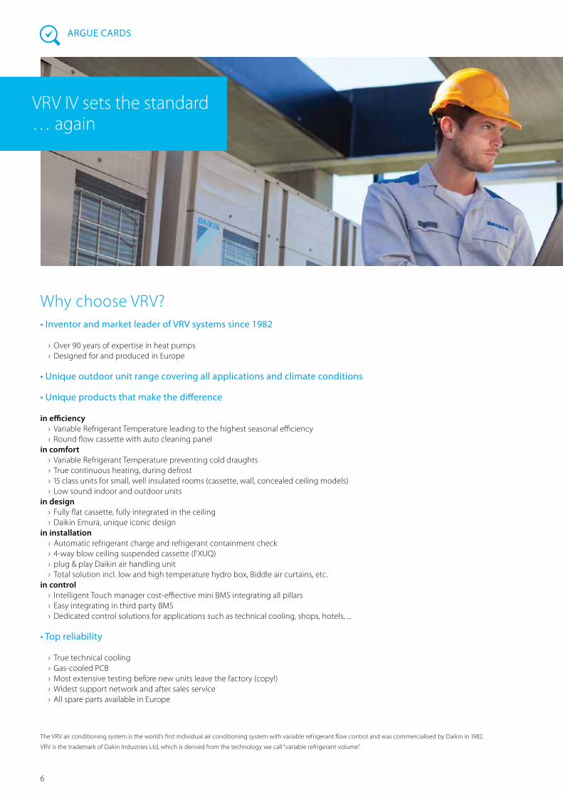
VRV IV sets the standard … again
Why choose VRV?• Inventor and market leader of VRV systems since 1982
› Over 90 years of expertise in heat pumps › Designed for and produced in Europe
• Unique outdoor unit range covering all applications and climate conditions
• Unique products that make the difference
in efficiency › Variable Refrigerant Temperature leading to the highest seasonal efficiency › Round flow cassette with auto cleaning panel
in comfort › Variable Refrigerant Temperature preventing cold draughts › True continuous heating, during defrost › 15 class units for small, well insulated rooms (cassette, wall, concealed ceiling models) › Low sound indoor and outdoor units
in design › Fully flat cassette, fully integrated in the ceiling › Daikin Emura, unique iconic design
in installation › Automatic refrigerant charge and refrigerant containment check › 4-way blow ceiling suspended cassette (FXUQ) › plug & play Daikin air handling unit › Total solution incl. low and high temperature hydro box, Biddle air curtains, etc.
in control › Intelligent Touch manager cost-effiective mini BMS integrating all pillars › Easy integrating in third party BMS › Dedicated control solutions for applications such as technical cooling, shops, hotels, ...
• Top reliability
› True technical cooling › Gas-cooled PCB › Most extensive testing before new units leave the factory (copy!) › Widest support network and after sales service › All spare parts available in Europe
The VRV air conditioning system is the world’s first individual air conditioning system with variable refrigerant flow control and was commercialised by Daikin in 1982.
VRV is the trademark of Dakin Industries Ltd, which is derived from the technology we call “variable refrigerant volume”.

7
VRV
Intr
o
VRV IV standards• Variable refrigerant temperature
› Customize your VRV for best seasonal efficiency & comfort › Up to 28% higher seasonal efficiency (ESEER) › First weather dependent VRV › No more cold draft by supply of high outblow temperatures
• Continuous comfort
› True/real continuous heating makes VRV IV the best alternative to traditional heating systems
• VRV configurator
› software for the fastest and most accurate commissioning, configuration and customisation
• Total solution
› one supplier for heating, cooling, ventilation, hot water, Biddle air curtains and control
› combine both residential and VRV indoor units
• Free combination of outdoor units to meet installation space or efficiency requirements
• Outdoor unit display for quick on-site settings
Heat pumpHeat recoveryReplacementWater cooled
Benefits for installersDaikin VRV IV sets the standard with latest technology and time saving commissioning & servicing
› Simplified and time saving commissioning with VRV configurator
› Remote refrigerant containment check › One supplier = one point of contact
Many options to meet customer requirements
Benefits for consultantsDaikin’s VRV IV technology leads the way in customisation to match individual building requirements in comfort and energy, facilitating reduced capital and running costs
› Ecological design › Ideal for reaching top BREEAM/EPDB levels › No more cold draughts with higher evaporation temperatures up to 11 or 16°C, making VRV IV an ideal alternative to water-based systems
› Unique specification for monovalent heating
Benefits for ownersVRV IV is the ultimate in customised comfort and intelligent control tailored to your individual needs and to maximise energy efficiency
› Annual cost savings up to 28% (compared with VRV III)
› No more cold draughts with variable refrigerant temperature
› Single point of contact for the design and maintenance of your climate control system
› Integrated system allows maximum energy efficiency for the end user
› Multiple systems can be managed in exactly the same way for key accounts

8
Ventilation Xpress Selection tool for ventilation devices (VAM, VKM). The selection is based on given supply/extract airflows (including fresh up), and given ESP of the supply/extract ducting:
VRV Pro, Design tool
The VRV Pro selection program is a true VRV design tool. The program enables VRV air conditioning systems to be engineered in a precise and economical way, taking into account the realtime thermal properties of any building. By calculating
annual energy consumptions, it gives the designer the possibility to make accurate selections and get competitive quotations for each project. Moreover, it ensures optimum operating cycles and maximum energy efficiency.
For more information, please contact your affiliate/distributor.
Windows95, Windows98, WindowsNT, Windows2000, WindowsXP, Windows Vista and Windows 7 are registered trademarks of Microsoft corporation.
› Determines size of electrical heaters › Visualization of psychrometric chart › Visualization of selected configuration › Required field settings mentioned in the report
Xpress, Quick Quotation toolXpress is a software tool that allows creating on the spot quotations for a Daikin VRV system. It provides a result in 6 steps to enable a professional budget quotation:
› Select indoor units › Connect outdoor units to indoor units › Automatic generation of piping diagram with joints
› Automatic generation of wiring diagram › Select possible centralised control systems › Visualise result in MS Word, MS Excel and AutoCAD
Digital tools › Visit the website: http://www.daikineurope.com/vrv-iv
› Download simulation or selection software: Go to extranet.daikineurope.com > Software downloads > sales supporting apps
ARGUE CARDS
Solutions seasonal simulatorWith this software tool you can simulate and the seasonal efficiency, the annual power consumption and CO
2 emission for a given climate,
load profile (cooling, heating, heat recovery, covalent, bivalent...) and (combination of ) system(s). With its intuitive and graphical appealing interface, a simulation can be made in a matter of minutes. The solution basket system enables you to compare
the results of several system configurations. Optionally, a return on investment calculation can be made.The outcome of the simulation can be exported to a printable report. The tool is available both for Windows PC and Tablet (iPad).

9
VRV
Intr
o
Your References
Porta Fira
"This project reinforces Daikin’s position as a leader in the air conditioning of large-scale structures, able to provide solutions that stand out not only for their accuracy and reliability, but also for their energy efficiency."
Eiffage Energie & Thermie
"The customer choose Daikin for the user comfort we offer with the VRV IV with continuous heating. Next to that the design aspect was important. Therefor the fully flat cassette in combination with Split wall mounted units were installed. Together with the ease of installation Daikin offered the best solution for the customer."
For more references check: http://www.daikineurope.com/references/index.jsp

10
Typically, many buildings today rely on several separate systems for heating, cooling, air curtain heating and hot water. As a result energy is wasted. To provide a much more efficient alternative, VRV technology has been developed into a total solution managing up to 70% of a buildings energy consumption giving large potential to cost saving.
› Heating and cooling for year round comfort › Hot water for efficient production of hot water › Underfloor heating /cooling
for efficient space heating/cooling › Ventilation for high quality environments › Air curtains for optimum air separation › Controls for maximum operating efficiency
Combine up to 70% of your building’s energy consumption
The total solution
Hot water
Air curtains
Heating
Cooling
Controls
VentilationUnderfloor heating
Average office energy consumptionAverage hotel energy consumption
Lighting
Office equipment
Integrate
third party
equipment
Space heating 25%
Space cooling 9%
Ventilation 5%
OtherHot water 9%
Other
Office
Kitchen
Lighting
Space heating 31%
Ventilation 4%
Refrigeration 3%
Space cooling 15%
Hot water 17%70% 48%
Integrate
third party
equipment

11
VRV
Intr
o
Heating and cooling Intelligent control systems
› Combine VRV indoor units with other stylish indoor units in one system
› New round flow cassette sets the standard for efficiency and comfort
› Mini BMS with connects Daikin and third-party equipment
› Integrate intelligent control solutions with energy management tools to reduce running costs
Biddle air curtainLow-temperature hydrobox
› Highly efficient space heating through: - Underfloor heating - Low temperature radiators - Heat pump convector
› Hot water from 25 °C to 45 °C
*only for connection to VRV heat recovery
› efficient hot water production for: - Showers - Sinks - Tapwater for cleaning
› Hot water from 25 °C to 80 °C
High temperature hydrobox* Ventilation
› Widest range in DX ventilation – from small heat recovery ventilation to large scale air handling units
› Provides a fresh, healthy and comfortable environment
22
› Payback time less than 1 year compared to electrical air curtain
› A highly efficient solution for doorway climate separation
One system, multiple applications for hotels, offices,
retail, home …
The total solution

12
VRV for offices and banks
VRV for hotels
Efficiency in the workplace
Efficient building and facilities management are key to minimising operational costs
Our office solution offers: › Significantly reduced costs for hot water and heating by re-using heat recovered from areas requiring cooling
› Unique fully flat cassette integrating fully flat into architectural ceilings
› Intelligent sensors - maximise efficiency by switching of the unit if there is nobody in the meeting room - maximise comfort by directing the air flow from people to avoid cold draught › Complete Daikin mini BMS for office building management with Intelligent Touch Manager
› Plug & play connection to air handling units for a healthier office atmosphere
› Hot water production for sinks and underfloor heating
› True reliable technical cooling down to -20°C, including duty/standby function
Hospitality with economy
A hotel’s reputation depends on how welcome and comfortable guests feel during their stay. Yet at the same time, hotel owners must maintain complete control of their operating costs and energy consumption.
Our hotel solution offers: › Low cost heating and hot water by recovering heat from areas requiring cooling
› The perfect personal environment for guests by simultaneously heating spaces while cooling others
› Flexible installation: the outdoor unit can be installed outdoors to maximise hospitality space or indoors to minimise external space or noise in city centres
› Concealed ceiling units developed for small, well-insulated rooms such as hotel bedrooms, offering very low sound levels ensuring a good's night rest
› Smart energy management via Intelligent Touch Manager puts the hotel owner in full control of energy costs
› Intelligent and user-friendly hotel room controllers change the set point automatically when a guest leaves the room or opens the window
› Easy integration in hotel booking software › Hot water production for bathrooms, underfloor heating and radiators up to 80°C
22
22
22
Check on
https://www.youtube.com/DaikinEurope
Check on
https://www.youtube.com/DaikinEurope

13
VRV
Intr
o
VRV for retail
VRV for residential use
Reducing retail costs
Retailers are under pressure to reduce both store development costs and running costs. That is why affordable, energy-efficient solutions are vital for minimising lifetime costs, while ensuring compliance with the latest regulations.
Our retail solutions offer: › Compact inverter heat pump technology › Flexible installation: the outdoor unit can be installed outdoors to maximise hospitality space or indoors to minimise external space or noise in city centres › Unique round flow cassettes with autocleaning panel saving up to 50% of energy use compared to standard cassette units › Easy to use remote control with lock-key function to avoid improper use › Individual control of each indoor unit or shop zone › Savings on runningcost via pre/post trade modes, limiting energy use by lights, air conditioning, ... › The most efficient open-door solution with Biddle air curtains
There is no place like home
A cost effective, low energy consumption heat pump system for home owners, offering maximum comfort
Our residential solution offers: › Lower CO2 emissions compared to traditional heating systems
› Compact outdoor unit design with a low sound level
› Whisper-quiet indoor units down to 19dBA › Daikin Emura, iconic design wall mounted unit › Unique Nexura floor standing unit offering the feel of a radiator with the efficiency of a heat pump
› Units to be concealed in the wall or ceiling to make them completely unnoticed
› User-friendly, intuitive control › Up to 9 indoor units that can be connected to one outdoor unit
Upgrade R-22 and R-407C systems quick and qualitatively with...
VRV Replacement solutions:
2222
22
Check on
https://www.youtube.com/DaikinEurope
› Keep your customers operational even during system replacement
› Less installation time › Lower installation costs › Replace non-Daikin systems › Automatic refrigerant charge and pipe cleaning

14
Which VRV outdoor system offers me the best solution?
Heat recovery or heat pump?
› Simultaneous heating AND cooling from one system
› "Free" heating and hot water production by transferring heat from areas requiring cooling
› Maximum individual comfort in all areas › Technical cooling down to -20°C
VRV Heat recovery
VRV Heat pump
Cooling HeatingHot water
Extracted heat delivers
free hot water and heating
+
› For either heating OR cooling operation from one system
Components:
Components:
Outdoor unit
Outdoor unit
Indoor unit
Indoor unit
3-pipe refrigerant
piping
2-pipe refrigerant
piping
Single and multi BS boxes:
allows the individual switching of indoor
units between heating and cooling
North
South

15
VRV
Intr
o
Air cooled or water cooled?
Air Cooled
Water Cooled
› Fast and easy to install, no need for additional components
› Low maintenance costs › Operation range from - 25°C~52°C › Can be installed both outdoors and indoors › Up to 54HP capacity for one system
› Suitable for multi-storey and large buildings because of the hardly unlimited possibilities of water piping
› Not affected by outdoor temperature/climate conditions
› Reduce CO2 emmisions thanks to the use of
geothermal energy as a renewable energy source › Allows heat recovery in the entire building thanks to the storage of energy in the water circuit
Components:
Components:
Outdoor unit
Outdoor unit
Indoor unit
Indoor unit
Refrigerant piping
Refrigerant piping (Geothermal) water loop

16
Model Product name 4 5 6 8 10 12 13 14 16 18 20 22 24 26 28 30 32 34 36 38 40 42 44 46 48 50 52 54
Air
co
ole
d - h
eat r
ecov
ery
VRV
IV h
eat r
eco
very
Best efficiency & comfort solution › Fully integrated solution with heat recovery for maximum efficiency › Covers all thermal needs of a building via a single point of contact: accurate
temperature control, ventilation, hot water, air handling units and Biddle air curtains
› “Free” heating and hot water through heat recovery › The perfect personal comfort for guests/tenants via simultaneous cooling and
heating › Incorporates VRV IV standards & technologies such as
Variable Refrigerant temperature and continuous heating › Allows technical cooling › Widest range of BS boxes on the market
REYQ-T
Products overviewOutdoor units
Air
co
ole
d - h
eat p
ump
VRV
IV h
eat p
um
p
wit
h co
nti
nu
ou
s
hea
tin
g
Daikin’s optimum solution with top comfort › Continuous heating during defrost › Covers all thermal needs of a building via a single point of contact:
accurate temperature control, ventilation, hot water, air handling units and Biddle air curtains
› Connectable to stylish indoor units (Daikin Emura, Nexura) › Incorporates VRV IV standards & technologies such as
Variable Refrigerant temperature and continuous heating
RYYQ-T
VRV
IV h
eat p
um
p
wit
ho
ut c
on
tin
uo
us
hea
tin
g
Daikin’s solution for comfort & low energy consumption › Covers all thermal needs of a building via a single point of contact:
accurate temperature control, ventilation, hot water, air handling units and Biddle air curtains
› Connectable to stylish indoor units (Daikin Emura, Nexura) › Incorporates VRV IV standards & technologies such as
Variable Refrigerant temperature
RXYQ-T(9)
VRV
III-S
Space saving solution without compromising on efficiency › For residential and light commercial applications › Space saving design › Either connect VRV of stylish indoor units (Daikin Emura, Nexura)
RXYSQ- P8V1/P8Y1
VRV
IV-S
seri
es
Space saving solution without compromising on efficiency › Space saving trunk design for flexible installation › Covers all thermal needs of a building via a single point of contact: accurate
temperature control, ventilation, air handling units and Biddle air curtains › Either connect VRV of stylish indoor units (Daikin Emura, Nexura) › Incorporates VRV IV standards & technologies such as Variable Refrigerant
temperature
launch autumn 2015
RXYSQ-TV1/TY1
VRV
IV-S
seri
es
Co
mp
act
The most compact VRV › Compact and lightweight single fan design saves space and is easy to install › Covers all thermal needs of a building via a single point of contact: accurate
temperature control, ventilation, air handling units and Biddle air curtains › Either connect VRV of stylish indoor units (Daikin Emura, Nexura) › Incorporates VRV IV standards & technologies such as Variable Refrigerant
temperature
launch autumn 2015
RXYSCQ-TV1
Compact
VRV
III h
eat
pum
p, o
pti
mis
ed
for h
eati
ng
Where heating is priority without compromising on efficiency › Suitable for single source heating › Extended operation range down to -25°C in heating › Stable heating capacity and high efficiencies at low ambient temperatures
RTSYQ-PA
VRV
Cla
ssic Classic VRV configuration
› For standard cooling & heating requirements › Connectable to VRV indoor units, controls and ventilation
RXYCQ-A
Rep
lace
men
t
heat
reco
very Quick & quality replacement for R-22 and R-407C systems
› Cost-effective and fast replacement through re-use of exisiting piping › Up to 40% more efficient than R-22 systems › No interuption of daily business while replacing your system › Replace Daikin and other manufacturers systems safely
RQCEQ-P*
hea
t pu
mp
Quick & quality replacement for R-22 and R-407C systems › Cost-effective and fast replacement through re-use of exisiting piping › Up to 80% more efficient than R-22 systems › No interuption of daily business while replacing your system › Replace Daikin and other manufacturers systems safely › Incorporates VRV IV standards & technologies such as
Variable Refrigerant temperature
RXYQQ-T*
Wat
er c
oo
led
Wat
er c
oo
led
VRV
IV
Ideal for high rise buildings, using water as heat source › Reduced CO2 emissions thanks to the use of geothermal energy as a renewable
energy source › No need for an external heating or cooling source when used in geothermal
mode › Covers all thermal needs of a building via a single point of contact:
accurate temperature control, ventilation, hot water, air handling units and Biddle air curtains
› Compact & lightweight design can be stacked for maximum space saving › Incorporates VRV IV standards & technologies such as
Variable Refrigerant temperature › Variable Water Flow control option increases flexibility and control
RWEYQ-T*
Single unit
Multi combination
NEW
NEW
* Not Eurovent certified

17
VRV
Intr
o
Model Product name 4 5 6 8 10 12 13 14 16 18 20 22 24 26 28 30 32 34 36 38 40 42 44 46 48 50 52 54
Air
co
ole
d - h
eat r
ecov
ery
VRV
IV h
eat r
eco
very
Best efficiency & comfort solution › Fully integrated solution with heat recovery for maximum efficiency › Covers all thermal needs of a building via a single point of contact: accurate
temperature control, ventilation, hot water, air handling units and Biddle air curtains
› “Free” heating and hot water through heat recovery › The perfect personal comfort for guests/tenants via simultaneous cooling and
heating › Incorporates VRV IV standards & technologies such as
Variable Refrigerant temperature and continuous heating › Allows technical cooling › Widest range of BS boxes on the market
REYQ-T
Air
co
ole
d - h
eat p
ump
VRV
IV h
eat p
um
p
wit
h co
nti
nu
ou
s
hea
tin
g
Daikin’s optimum solution with top comfort › Continuous heating during defrost › Covers all thermal needs of a building via a single point of contact:
accurate temperature control, ventilation, hot water, air handling units and Biddle air curtains
› Connectable to stylish indoor units (Daikin Emura, Nexura) › Incorporates VRV IV standards & technologies such as
Variable Refrigerant temperature and continuous heating
RYYQ-T
VRV
IV h
eat p
um
p
wit
ho
ut c
on
tin
uo
us
hea
tin
g
Daikin’s solution for comfort & low energy consumption › Covers all thermal needs of a building via a single point of contact:
accurate temperature control, ventilation, hot water, air handling units and Biddle air curtains
› Connectable to stylish indoor units (Daikin Emura, Nexura) › Incorporates VRV IV standards & technologies such as
Variable Refrigerant temperature
RXYQ-T(9)
VRV
III-S
Space saving solution without compromising on efficiency › For residential and light commercial applications › Space saving design › Either connect VRV of stylish indoor units (Daikin Emura, Nexura)
RXYSQ- P8V1/P8Y1
VRV
IV-S
seri
es
Space saving solution without compromising on efficiency › Space saving trunk design for flexible installation › Covers all thermal needs of a building via a single point of contact: accurate
temperature control, ventilation, air handling units and Biddle air curtains › Either connect VRV of stylish indoor units (Daikin Emura, Nexura) › Incorporates VRV IV standards & technologies such as Variable Refrigerant
temperature
launch autumn 2015
RXYSQ-TV1/TY1
VRV
IV-S
seri
es
Co
mp
act
The most compact VRV › Compact and lightweight single fan design saves space and is easy to install › Covers all thermal needs of a building via a single point of contact: accurate
temperature control, ventilation, air handling units and Biddle air curtains › Either connect VRV of stylish indoor units (Daikin Emura, Nexura) › Incorporates VRV IV standards & technologies such as Variable Refrigerant
temperature
launch autumn 2015
RXYSCQ-TV1
Compact
VRV
III h
eat
pum
p, o
pti
mis
ed
for h
eati
ng
Where heating is priority without compromising on efficiency › Suitable for single source heating › Extended operation range down to -25°C in heating › Stable heating capacity and high efficiencies at low ambient temperatures
RTSYQ-PA
VRV
Cla
ssic Classic VRV configuration
› For standard cooling & heating requirements › Connectable to VRV indoor units, controls and ventilation
RXYCQ-A
Rep
lace
men
t
heat
reco
very Quick & quality replacement for R-22 and R-407C systems
› Cost-effective and fast replacement through re-use of exisiting piping › Up to 40% more efficient than R-22 systems › No interuption of daily business while replacing your system › Replace Daikin and other manufacturers systems safely
RQCEQ-P*
hea
t pu
mp
Quick & quality replacement for R-22 and R-407C systems › Cost-effective and fast replacement through re-use of exisiting piping › Up to 80% more efficient than R-22 systems › No interuption of daily business while replacing your system › Replace Daikin and other manufacturers systems safely › Incorporates VRV IV standards & technologies such as
Variable Refrigerant temperature
RXYQQ-T*
Wat
er c
oo
led
Wat
er c
oo
led
VRV
IV
Ideal for high rise buildings, using water as heat source › Reduced CO2 emissions thanks to the use of geothermal energy as a renewable
energy source › No need for an external heating or cooling source when used in geothermal
mode › Covers all thermal needs of a building via a single point of contact:
accurate temperature control, ventilation, hot water, air handling units and Biddle air curtains
› Compact & lightweight design can be stacked for maximum space saving › Incorporates VRV IV standards & technologies such as
Variable Refrigerant temperature › Variable Water Flow control option increases flexibility and control
RWEYQ-T*
Capacity (HP)
Description / Combination
VR
V in
do
or u
nit
s
Ind
oo
r un
its
LT H
ydro
bo
x H
XY-
A
HT
Hyd
rob
ox
HX
HD
-A
HRV
un
its
VAM
-, V
KM
-
AH
U c
on
nec
tio
n E
KEX
V- +
EKE
QM
CB
AH
U c
on
nec
tio
n E
KEX
V- +
EK
EQFC
B
Air
cu
rtai
ns
CY
V-D
K-
Remarks
VRV IV Heat Recovery REYQ-T � O � � � � O � ū Standard total system connection ratio limit: 50 ~ 130%
with only VRV indoor units
with LT/HT Hydroboxes ū Max 32 indoor units, even on 16HP and larger systems ū Total system connection ratio up to 200% possible
HRV units VAM-, VKM- ū Dedicated systems (with only ventilation units) not allowed – a mix with standard VRV indoor units is allways neccessaryAHU connection EKEXV + EKEQMCB
Biddle air curtain CYV-DK-
VRV IV Heat Pump RYYQ-T / RXYQ-T(9) � � � O � � � � ū Standard total system connection ratio limit: 50 ~ 130%
with only VRV indoor units ū 200% total system connection ratio possible under special circumstances
with residential indoor units ū Only single-module systems (RYYQ 8~20 T / RXYQ 8~20 T) ū Max 32 indoor units, even on 16HP, 18HP and 20HP systems
with LT Hydroboxes ū Max 32 indoor units, even on 16HP and larger systems ū Contact Daikin in case of multi-module systems (>20HP)
HRV units VAM-, VKM-
AHU connection EKEXV + EKEQMCB
AHU connection EKEXV + EKEQFCB
Biddle air curtain CYV-DK-
VRV III-S Mini VRV RXYSQ-P8 � � O O � � O � ū Standard total system connection ratio limit: 50 ~ 130%
with VRV indoor units with Split indoor units
VRV IV-S Mini VRV � � O O � � O � ū Standard total system connection ratio limit: 50 ~ 130%
with VRV indoor units
with Split indoor units
VRV IV-S Mini VRV � � O O � � O � ū Standard total system connection ratio limit: 50 ~ 130%
with VRV indoor units
with Split indoor units
VRV III Cold Region RTSYQ-PA O O O O ū Standard total system connection ratio limit: 50 ~ 130%
VRV Classic RXYCQ-A O O O O O O ū Standard total system connection ratio limit: 50 ~ 120% ū In case of using at least one FXFQ20~25 indoor units on 8HP or 10HP models, the maximum connection ratio is 100%.
VRV III-Q Replacement H/R RQCEQ-P O O O O O O ū Standard total system connection
ratio limit: 50 ~ 130%
VRV IV-Q Replacement H/P RXYQQ-T O O O O ū Standard total system connection
ratio limit: 50 ~ 130%
VRV IV-W Water-cooled VRV RWEYQ-T O O O O ū Standard total system connection
ratio limit: 50 ~ 130%
� ... connection of indoor unit possible, but not neccessarily simultaneously with other allowed indoor units ... connection of indoor unit possible even simultaneously with other checked units in the same row
O ... connection of indoor not possible on this outdoor unit system

18
UNIQUE
UNIQUE
NEW
NEW
(1) Nominal cooling capacities are based on: indoor temperature: 27°CDB, 19°CWB, outdoor temperature: 35°CDB, equivalent refrigerant piping: 5m, level difference: 0m
(2) Nominal heating capacities are based on: indoor temperature: 20°CDB, outdoor temperature: 7°CDB, 6°CWB, equivalent refrigerant piping: 5m, level difference: 0m
Type Model Product name 15 20 25 32 40 50 63 71 80 100 125 140 200 250
Cei
ling
mou
nted
cas
sett
e
Round flow
cassette
360° air discharge for optimum efficiency and comfort › Auto cleaning function ensures high efficiency › Intelligent sensors save energy and maximize comfort › Flexibility to suit every room layout › Lowest installation height in the market!
FXFQ-A
Fully flat
cassette
Unique design that integrates fully flat into the ceiling › Perfect integration in standard architectural ceiling tiles › Blend of iconic design and engineering excellence › Intelligent sensors save energy and maximize comfort › Small capacity unit developed for small or well-insulated rooms › Flexibility to suit every room layout
FXZQ-A
2-way blow
ceiling
mounted
cassette
Thin, lightweight design installs easily in narrow ceiling spaces › Depth of all units is 620mm, ideal for narrow ceiling spaces › Flexibility to suit every room layout › Reduced energy consumption thanks to DC fan motor › The flaps close entirely when the unit is not operating › Optimum comfort with automatic air flow adjustment to the required load
FXCQ-A
Ceiling
mounted
corner
cassette
1-way blow unit for corner installation › Compact dimensions enable installation in narrow ceiling voids › Flexible installation thanks to different air discharge options
FXKQ-MA
Con
ceal
ed c
eilin
g
Small
concealed
ceiling unit
Designed for hotel rooms › Compact dimensions enable installation in narrow ceiling voids › Discretely concealed in the ceiling: only the grilles are visible › Flexible installation as the air suction direction can be altered from rear to
bottom suction
FXDQ-M9
Slim
concealed
ceiling unit
Slim design for flexible installation › Compact dimensions enable installation in narrow ceiling voids › Medium external static pressure up to 44Pa › Only grilles are visible › Small capacity unit developted for small of well-insulated rooms › Reduced energy consumption thanks to DC fan motor
FXDQ-A
Concealed
ceiling unit
with medium
ESP
Slimmest yet most powerfull medium static pressure unit on the market! › Slimmest unit in class, only 245mm › Low operating sound level › Medium external static pressure up to 150Pa facilitates using flexible ducts of
varying lengths › Automatic air flow adjustment function measures the air volume and static
pressure and adjusts it towards the nominal air flow, guaranteeing comfort
FXSQ-A
Concealed
ceiling unit
with high ESP
ESP up to 200, ideal for large sized spaces › Optimum comfort guaranteed no matter the length of ductwork or type of
grilles, thanks to automatic air flow adjustment › Reduced energy consumption thanks to DC fan motor › Flexible installation as the air suction direction can be altered from rear to
bottom suction
FXMQ-P7
Concealed
ceiling unit
with high ESP
ESP up to 270, ideal for extra large sized spaces › Only grilles are visible › Large capacity unit: up to 31.5 kW heating capacity
FXMQ-MA9 Concealed
ceiling unit
with high
efficiency
For the highest energy efficiency › Automatic air flow adjustment function guarantees comfort › Easy installation in narrow ceilings (245mm height) › High external static pressure up to 270Pa facilitates using flexible ducts of
varying lengths › Only the suction and discharge grilles are visible
FXTQ-A
Wal
l mou
nted Wall
mounted
unit
For rooms with no false ceilings nor free floor space › Flat, stylish front panel is more easy to clean › Small capacity unit developted for small of well-insulated rooms › Reduced energy consumption thanks to DC fan motor › The air is comfortably spread up- and downwards thanks to 5 different
discharge angles
FXAQ-P
Cei
ling
susp
end
ed
Ceiling
suspended
unit
For wide rooms with no false ceilings nor free floor space › Ideal for comfortable air flow in wide rooms thanks to Coanda effect › Rooms with ceilings up to 3.8m can be heated or cooled very easily! › Can easily be installed in both new and refurbishment projects › Can even be mounted in corners or narrow spaces without any problem › Reduced energy consumption thanks to DC fan motor
FXHQ-A
4-way blow ceiling suspended unit
Unique Daikin unit for high rooms with no false ceilings nor free floor space › Rooms with ceilings up to 3.5m can be heated up or cooled down very easily! › Can easily be installed in both new and refurbishment projects › Flexibility to suit every room layout › Reduced energy consumption thanks to DC fan motor
FXUQ-A
Flo
or s
tan
din
g
Floor
standing
unit
For perimeter zone air conditioning › Can be installed in front of glass walls or free standing as both the front and
the back are finished › Ideal for installation beneath a window › Requires very little installation space › Wall mounted installation facilitates cleaning beneath the unit
FXLQ-P
Concealed floor standing unit
Ideal for installation in offices, hotels and residential applications › Discretely concealed in the wall, leaving only the suction and discharge grilles
visible › Can even be installed underneath a window › Requires very little installation space as the depth is only 200mm › High ESP allows flexible installation
FXNQ-A
Cooling capacity (kW)1 1.7 2.2 2.8 3.6 4.5 5.6 7.1 8.0 9.0 11.2 14.0 16.0 22.4 28.0
Heating capacity (kW)2 1.9 2.5 3.2 4.0 5.0 6.3 8.0 9.0 10.0 12.5 16.0 18.0 25.0 31.5
Products overviewIndoor units
Capacity class (kW)
UNIQUE

19
VRV
Intr
o
Connectable outdoor unit
RY
YQ
-T
RX
YQ
-T(9
)
RX
YSQ
-P8V
13
RX
YSQ
-P8Y
13
Type Model Product name 15 20 25 35 42 50 60 71
Ceiling mountedcassette
Round flow cassette(incl. auto-cleaning
function1)
FCQG-F
Fully flat cassette
FFQ-C
Concealed ceiling
Small concealed ceiling unit FDBQ-B
Slim concealed ceiling unit FDXS-F(9)
Concealed ceiling unitwith inverter-driven fan
FBQ-D
Wall mounted
Daikin EmuraWall mounted unit
FTXG-LW/LS
Wall mounted unitCTXS-K FTXS-K
Wall mounted unit FTXS-G
Ceilingsuspended
Ceiling suspended unit FHQ-C
Floor standing
Nexura floor standing unit FVXG-K
Floor standing unit FVXS-F
Flexi type unit FLXS-B(9)
Stylish indoor units
overview
1 Decoration panel BYCQ140CG + BRC1E52A/B needed 2 To connect stylish indoor units a BPMKS unit is needed 3 For RXYSQ units a mix of RA indoor units and VRV indoor units is not allowed.
Capacity class (kW)
Depending on the application, Split and Sky Air indoor units can be connected to our VRV IV and VRV III-S outdoor units. Refer to the outdoor unit portfolio for combination restrictions.

20
Five components of indoor air quality
› Ventilation: ensures the provision of fresh air › Heat recovery: recovers heat and moisture from the outgoing air to maximise comfort and efficiency
› Air processing: heats or cools incoming fresh air maximising comfort and minimizing the load on the air conditioning installation
› Humidification: optimises the balance between indoor and outdoor humidity
› Filtration: removes dust, pollution and odours from the air
Ventilation
Heat recovery Humidification
Air processing
Filtration
Type Product name Model Components of
indoor air quality
Hea
t rec
laim
vent
ilati
on
VAM-FA/FB
Ventilation with heat recovery as standard › Energy saving ventilation › Maximise floor space for furniture, decoration and
fittings › Free cooling › Reduced energy consumption thanks to DC inverter
fan motor › Optional CO
2 sensor saves energy while improving
indoor air quality
› Ventilation
› Heat recovery
VKM-GB
Pre heating or cooling of fresh air for lower load on the air conditioning system › Energy saving ventilation › Creates a high quality indoor environment › Maximise floor space for furniture, decoration and
fittings › Free cooling › Reduced energy consumption thanks to DC inverter
fan motor
› Ventilation
› Heat recovery
› Air processing
VKM-GBM
Pre heating, cooling and humidification for optimum comfort › Energy saving ventilation › Creates a high quality indoor environment › Balance your indoor humidity level › Maximise floor space for furniture, decoration and
fittings › Free cooling
› Ventilation
› Heat recovery
› Air processing
› Humidification
Air
han
dlin
gun
its DX total
fresh air package
Fully customised solution for ventilation and air handling › Inverter technology › Heat pump and heat recovery › Provides virtually free heating › Room temperature via Daikin control › Large range of expansion valve kits
› Ventilation
› Heat recovery
› Air processing
› Humidification
› Filtration
0 200 400 600 800 1,000 2,000 4,000 6,000 8,000 140,000
Air flow rate (m3/h)*
* Air flow rate is a calculated indication only, based on the following values: heating capacity EKEXV-kit * 200m³/h
** Daikin AHU connected to Daikin chiller solution
**
Ventilation range

21
VRV
Intr
o
Biddle air curtain range
Air curtain size selector
Type ITC ITM DMS-IF BACNET
ScreenLayout screenTouch screen
IntegrationMini BMS for heating, air conditioning applied systems and refrigeration units (BACnet and WAGO)3rd party equipment integration (BACnet and WAGO)
Control
Basic control functions: on/off, temp, setting, air flow sttingsRefrigerant containment check
Temperature limitation
Setback
Automatic changeover
Weekly schedule and special day pattern
Timer extensionForced off
Monitoring
Basic control functions: ON/OFF status, operation mode, set point temp.Filter status
Malfunction code
History (operation, malfunction…) Visualisation
OptionsPPDWeb access and control StdHTTP option
Other
Interlock Pre-cool/heat
Sliding temperature
Free cooling
ACNSS connection Air Conditionning Network Service SystemMaximum indoor unit groups 64 2560 64 4x64
Network solutions
Hydrobox rangeType Product name Model 80 125
Leaving water temperature range
Low temperaturehydrobox
HXY-A
For high efficiency space heating and cooling › Ideal for hot or cold water in underfloor, air handling units, low temperature
radiators … › Hot/cold water from 5° to 45°C › Large operation range (down to -20°C and up to 43°C) › Fully integrated water-side components save time on system design › Space saving contemporary wall hung design
5 °C - 45 °C
High temperaturehydrobox
HXHD-A
For efficient hot water production and space heating › Ideal for hot water in bathrooms, sinks and for underfloor heating, radiators, air
handling units, … › Hot water from 25 to 80°C › "Free" heating and hot water through heat recovery › Uses heat pump technology to produce hot water efficiently, providing up to 17%
savings compared to a gas boiler › Possibility to connect thermal solar collectors
25 °C - 80 °C
Type Product name
Biddle air curtain free hanging CYV S/M/L-DK-F
Biddle air curtain cassette CYV S/M/L-DK-C
Biddle air curtain recessed CYV S/M/L-DK-R
Capacity class (kW)
Door height (m)
Favourable
Covered shopping mall or
revolving door entrance
Normal
No opposite open doors,
little direct wind, building
with ground floor only
Unfavourable
Location at a corner or
square, multiple floors and/
or open stairwell
2.32.5
3.0
S M L
2.152.4
2.75
LMS
2.32.0
2.5
LMS
Additional options › A payback time of less than 1.5 years compared to electrical air curtains
› Easy and quick installation › Maximum energy efficiency thanks to rectifier technology
› 85% air separation efficiency › Cassette model (C): mounted into a false ceiling leaving only the decoration panel visible
› Free-hanging model (F): easy wall mounted installation
› Recessed model (R) : neatly concealed in the ceiling
22
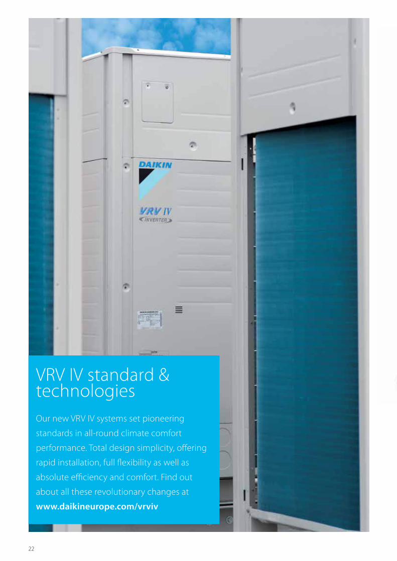
VRV IV standard & technologiesOur new VRV IV systems set pioneering
standards in all-round climate comfort
performance. Total design simplicity, offering
rapid installation, full flexibility as well as
absolute efficiency and comfort. Find out
about all these revolutionary changes at
www.daikineurope.com/vrviv

23
VRV
IV
Stan
dard
& T
echn
olog
ies
VRV IV =3 revolutionary standards
› Variable refrigerant temperature
› Continuous comfort during defrost
› VRV configurator
+ unique VRV IV core technologies
> Newly developed inverter compressor
> Refrigerant-cooled PCB
> 4-side heat exchanger
> Predictive control
> Outer rotor DC motor

24
Calculate the benefit of variable refrigerant temperature for your project in our seasonal solutions calculator:
http://extranet.daikineurope.com/en/software/downloads/solutions-seasonal-simulator/default.jsp
VRF standardCapacity is controlled only with the variance of the inverter compressor
Daikin VRV IVVariable Refrigerant Temperature control for energy saving in partial load condition.The capacity is controlled by the inverter compressor AND variation of the evaporating (Te) and condensing (Tc) temperature of the refrigerant in order to achieve the highest seasonal efficiency.
Variable refrigerant
temperature
Success story Live test: up to 46% less energy consumed
A field trial was carried out at a fashion store chain in Germany and showed that the innovative Daikin VRV IV delivers dramatically better energy efficiency compared with previous models.
The trial results showed that the new VRV IV system consumed up to 60% less energy than the VRV III system, particularly during cooling. Overall energy savings during heating averaged 20%.
How effective is the VRV IV heat pump technology?
The trial demonstrated that by using air, an infinitely renewable and free energy source, the VRV IV system provides a complete and environmentally sustainable solution for heating, cooling and ventilation in commercial applications. The trial also showed that only by monitoring climate control systems carefully and intelligently businesses can identify and control energy waste. This is a service which Daikin also offers.
Customise your VRV for best seasonal efficiency and comfortThanks to its revolutionary variable refrigerant temperatue technology (VRT), VRV IV continuously adjusts both the inverter compressor speed and the refrigerant temperature, providing the necessary capacity to meet the building load with the highest seasonal efficiency at all times!
› Seasonal efficiency increased by 28% › The first weather compensating control on the market
› Customer comfort is assured thanks to higher outblow temperatures (preventing cold draughts)
Refr
iger
ant t
empe
ratu
re
in c
oolin
g (e
vapo
ratin
g te
mpe
ratu
re)
20° 25° 30° 35°
Variable Te
Fixed Te
Outdoor temperature
Seas
onal
effi
cien
cy
20° 25° 30° 35° Outdoor temperature
Efficiency up
Cap
acity
& L
oad
in c
oolin
g m
ode
20° 25° 30° 35°
Cooling requirement
Design point
Outdoor temperature
Adjust capacity by Te control to meet the load (avoid over capacity and ON/OFF operation)
Syst
em
capa
city
A higher refrigerant temperature results in a higher seasonal efficiency and higher comfort
The lower the capacity need the higher the refrigerant temperature can be
The colder it gets, the lower the load on the building and the lower the capacity need
How does it work?

25
VRV
IV
Stan
dard
& T
echn
olog
ies
Different modes to maximise efficiency and comfortFor maximum energy efficiency and customer satisfaction, the outdoor unit needs to adapt the evaporating/condensing temperature at the optimum point for the application.
Variable refrigerant
temperature
Set up the main operation mode of the system
Define how the system reacts to changing loads
Step 1 Step 2
Automatic*Powerful
Where a quick increase of load is expected such as conference rooms. Quick reaction speed to changing load has priority, with temporarily colder outblow as a result.
Quick Same as above but slower response than the powerful mode.
Mild *This mode would be suitable for most office applications and it is the factory set mode.The perfect balance: Slower reaction speed with top efficiency
High sensible(User selection) Powerful
Gives customer choice for fixing coil temperature which avoids cold draughts. A quick reaction speed to changing load has priority, with temporarily colder outblow as a result.
Quick Same as above but slower response.
MildThe air off temperature remains fairly constant. Suitable for low ceiling rooms.
EcoCoil temperature would not change due to fluctuating load. Suitable for computer rooms. Suitable for low ceiling rooms.
BasicCurrent VRF standard
No submodesThis is how most other VRF systems work and can be used for all general type of applications. Suitable for computer rooms. Suitable for low ceiling rooms.
The perfect balance: Achieves top efficiency throughout the year,
reacts quickly on the hottest days
Quick reaction speed Top efficiency
Year round top efficiency
Quick reaction speed Top efficiency
6 patents
How to set the different modes?
* Factory setting
Check on
https://www.youtube.com/DaikinEurope
VRV III 20HP (2 modules) VRV IV 18HP (1 module)
Period March 2012 - February 2013 March 2013 - February 2014
Avg (kWh/Month) 2.797 1.502
Total (KWh) 33.562 18.023
Total (€) 6.041 3.244
Yearly (operation cost/m² (€/m²)
9,9 5,3
46% savings = € 2.797
Measured data Fashion store Unterhaching (Germany)
› Floor space: 607m² › Energy cost: 0,18 €/kWh › System taken into account for consumption:
- VRV IV heat pump with continuous heating - Round flow cassettes (without auto cleaning panel) - VAM for ventilation (2x VAM2000) - Biddle Air curtain.

26
Heat pumps are known for their high energy efficiency in heating, but they accumulate ice during heating operation and this must be melted periodically using a defrost function that reverses the refrigeration cycle. This causes a temporary temperature drop and reduced comfort levels inside the building. Defrosting can take over 10 minutes (depending on the size of the system) and occurs mostly between -7 and +7°C when there is most moisture in the air, which freezes to the coil, and this has a significant impact on the perceived indoor comfort levels and runningcosts.The VRV IV has changed the heating paradigm by providing heat even during defrost operation thus eliminating the temperature drop inside and providing comfort at all times.
VRV IV
VRF benchmark
Room temperature
Time
ΔT
For the VRV IV heat pump single models a unique heat-accumulating element is used. This element, based upon phase change materials, provides the energy to defrost the outdoor unit. The energy needed for defrosting is stored in the element during normal heating operation.
How does it work?Heat accumulating element Alternate defrost
VRV IV continues to provide heating even when in defrost mode, providing an answer to any perceived disadvantages of specifying a heat pump as a monovalent heating system.
› Indoor comfort not affected either via the unique heat accumulating element or alternate defrost
› The best alternative to traditional heating systems
The outdoor unit coil is
defrosted …
… with the energy stored
in the heat accumulating
element …
… while indoors
a comfortable temperature
is maintained. the outdoor unit coil is defrosted …
… one at the time …
… so indoors a comfortable temperature is maintained
On all our multi model combinations only 1 outdoor coil is defrosted at a time, ensuring continuous comfort during the whole process.
Continuous heating during defrost mode
Push buttonon the PCB
R410-A
Kan niet aders dan met gradient, want vloeistof warmt op en koelt af...
1 v/d 2 kiezen
naam op gas�es eventueel vervangen door echt logo
even checken in de infographics map: ik denk dat er een tekening van een VRV bestaat
even checken in de infographics map: ik denk dat er een tekening van een VRV bestaat
foto in crkeltje zou ik behouden
Check on
https://www.youtube.com/DaikinEurope

27
VRV
IV
Stan
dard
& T
echn
olog
iesConfigurator
software
Simplified commissioning
The VRV configurator is an advanced software solution that allows for easy system configuration and commissioning:
› less time is required on the roof configuring the outdoor unit
› multiple systems at different sites can be managed in exactly the same way, thus offering simplified commissioning forkey accounts
› initial settings on the outdoor unit can be easily retrieved.
Simplified
commissioning
Retrieve initial system
settingsUser friendly interface instead of
push buttons
Simplified servicing
Outdoor unit display for quick on-site settings and easy read out of errors together with the indication of service parameters for checking basic functions.
› easy-to-read error report › clear menu indicating quick and easy on-site settings
› indication of basic service parameters to quickly check basic functions: high pressure, low pressure, frequency ans operation time history of compressors, temperature of discharge/suction pipe.
3 digit 7-segment display
Software for simplified commissioning, configuration and customisation
› Graphical interface › Manage systems over multiple sites in exactly the same way
› Retrieve initial settings
Check on
https://www.youtube.com/DaikinEurope
28
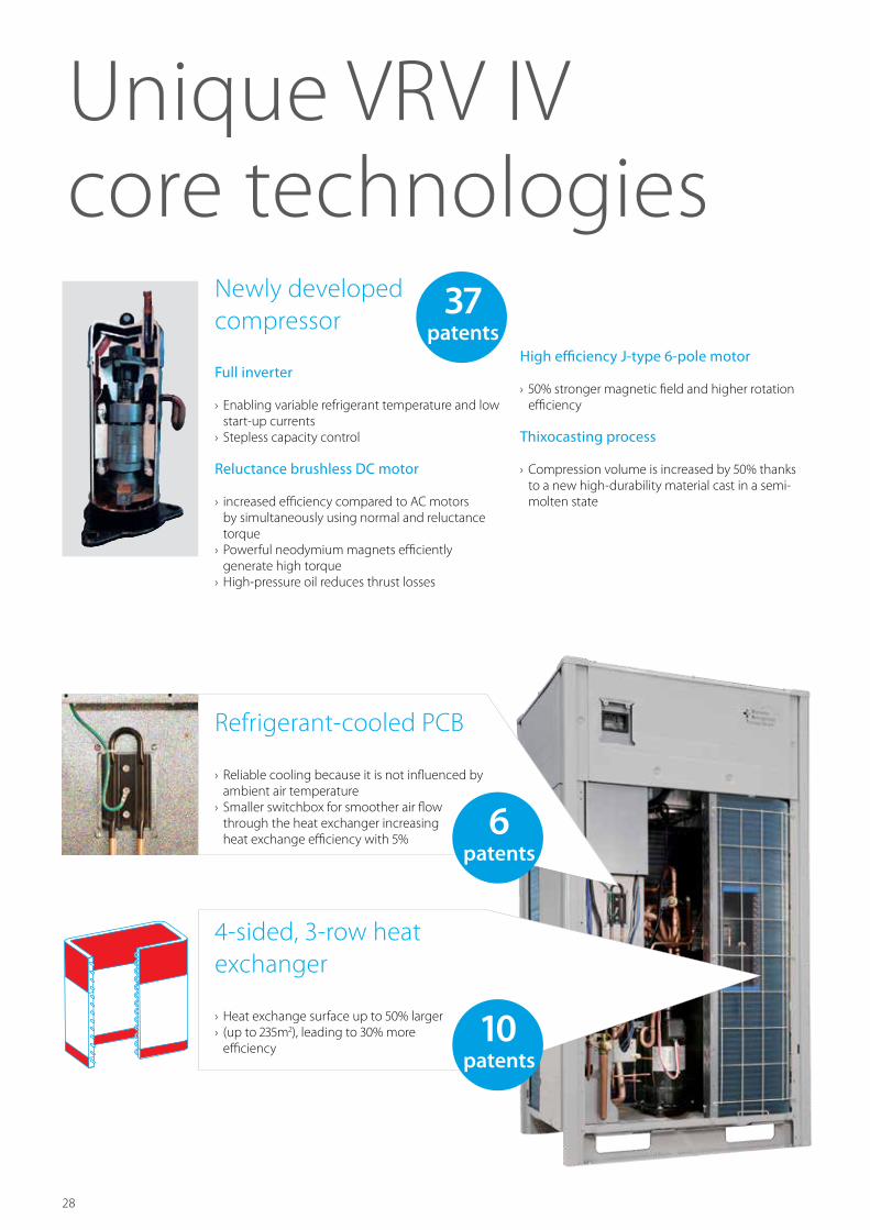
4-sided, 3-row heat exchanger
› Heat exchange surface up to 50% larger › (up to 235m2), leading to 30% more efficiency
Refrigerant-cooled PCB
› Reliable cooling because it is not influenced by ambient air temperature
› Smaller switchbox for smoother air flow through the heat exchanger increasing heat exchange efficiency with 5%
Newly developed compressor
Full inverter
› Enabling variable refrigerant temperature and low start-up currents
› Stepless capacity control
Reluctance brushless DC motor
› increased efficiency compared to AC motors by simultaneously using normal and reluctance torque
› Powerful neodymium magnets efficiently generate high torque
› High-pressure oil reduces thrust losses
High efficiency J-type 6-pole motor
› 50% stronger magnetic field and higher rotation efficiency
Thixocasting process
› Compression volume is increased by 50% thanks to a new high-durability material cast in a semi-molten state
Unique VRV IV core technologies
37patents
6patents
10patents

29
VRV
IV
Stan
dard
& T
echn
olog
ies
DC fan motor
Outer rotor DC motor for higher efficiency
› Larger rotor diameter results in greater force for the same magnetic field, leading to better efficiency
› Better control, resulting in more fan steps to match the actual capacity
Sine wave DC inverter
Optimizing the sine wave curve results in smoother motor rotation and improved motor efficiency.
DC fan motor
The use of a DC fan motor offers substantial improvements in operating efficiency compared to conventional AC motors, especially during low speed rotation.
E-Pass heat exchanger
Optimising the heat exchanger’s path layout prevents heat being transferred from the overheated gas section to the sub-cooled liquid section which is a more efficient way to use the heat exchanger.
Standard heat exchanger
In 85 °C
27 °C
Out 45 °C
55 °C
55 °C
50 °C
e-Pass heat exchanger
43 °C
In 85 °C
27 °C
Out 45 °C
60 °C
55 °C
Power consumption
Predefined limit
Time
I-demand function
Limit maximum power consumption. The newly introduced current sensor minimizes the difference between the actual power consumption and the predefined power consumption.
Predictive Control Function (PCF) › Reaches the target capacity/refrigerant temperature faster
› Reaches the target without overshooting, so there is no waste, leading to improved efficiency
› Three capacity settings give more precise control for user comfort
The large number of Daikin systems already in operation and which are monitored by our i-Net software put us in the unique position of being able to analyse this data and develop the predictive compressor control function.
Target
t
(VRV IV)
VRV IV with PCF
General VRF with PI control
Target capacity/refrigerant temperature
2t
(general VRF)
VRV IV: PCF
Compressor works with predictive data for the control
› result: quick convergence to the target temperature
and reduction of waste operation of the compressor
General VRF: Pi control
Compressor works with feedback only for the control
› result: waste operation and longer time before reaching
target set point
Conventional motor with inner rotor
Rotor RotorStator Stator
Daikin outer rotor
FF
Waste compressor operation
Half timeagainst general
VRF
General VRF:Double time against VRV IV
UNIQUE
UNIQUE

30
The VRV benefitsSee how you can profit from Daikin's highly
flexible and efficiency product range
31
Bene
fits
VRV, a total commercial solution
Drastically reducing your running costs 32Top reliability 32Up to 6 times greater resistance against corrosion 32
Comfort guaranteed at all times 37
Maximum flexibility 36
Fast installation and commissioning 38Easy servicing 38
VRVLatest technology, highest efficiency

32
OFFOFF
ON
ON
ONPrecise zone controlVRV systems have low running costs because it permits each zone to be controlled individually. That is, only those rooms that require air conditioning will be heated or cooled, while the system can be shut down completely in rooms where no air conditioning is required.
Heat exchanger
An anti-corrosion heat exchanger cutaway view
Aluminium
Hydrophilic film
Corrosion-resistantAcrylic resin
Anti Corrosion TreatmentSpecial anti corrosion treatment of the heat exchanger provides 5 to 6 times greater resistance against acid rain and salt corrosion. The provision of rust proof steel sheet on the underside of the unit gives additional protection.
Performed tests:
› VDA Wechseltest › Contents of 1 cycle (7 days): › 24 hours salt spray test SS DIN 50021 › 96 hours humidity cycle test KFW DIN 50017
› 48 hours room temperature & room humidity testing period: 5 cycles
Kesternich test (SO2)
› contents of 1 cycle (48 hours) according to DIN50018 (0.21)
› testing period : 40 cycles
8
7
6
5
4
3
2
1
01 2 3 4 5
Cycle
Cycle
Degree
of corrosion
Degree of
corrosion
DAIKIN P.E.
Bare aluminium
10
9
8
7
6
5
4
3
2
1
0 1 2 3 4 5 6 10 20 30 40 50 60 70
• Drastically reducing your running costs• Top reliability• Up to 6 times greater resistance against corrosion

33
Bene
fits
All inverter compressorsAll inverter control compressors allow to control the refrigerant volume almost stepless. In this way the capacity perfectly matches the different loads in every room avoiding unnecessary energy use.
Additionally all inverter compressors also allow precise refrigerant temperature control, automatically adapting your VRV to your building and climate requirements, reducing runnig costs with 28%.
ALL
Duty Cycling extends operation lifeThe cyclical start-up sequence of multiple outdoor units systems equalises compressor duty and extends operating life.
Sequential StartUp to 3 outdoor units can be connected to 1 power
supply and can be turned on sequentially. This allows
the number of breakers and their capacities to remain
small and simplifies wiring (for models of 10HP or less).
Only one power supply
Technical benefits VRV
Top quality Only brazed connectionsAll flange and flare connections inside the unit have been replaced by brazing connections to ensure improved refrigerant containment. Also the connection of the outdoor in the main pipe is brazed.
Flare or flange
Brazing
Push buttonon the PCB
R410-A
Kan niet aders dan met gradient, want vloeistof warmt op en koelt af...
1 v/d 2 kiezen
naam op gas�es eventueel vervangen door echt logo
even checken in de infographics map: ik denk dat er een tekening van een VRV bestaat
even checken in de infographics map: ik denk dat er een tekening van een VRV bestaat
foto in crkeltje zou ik behouden
34
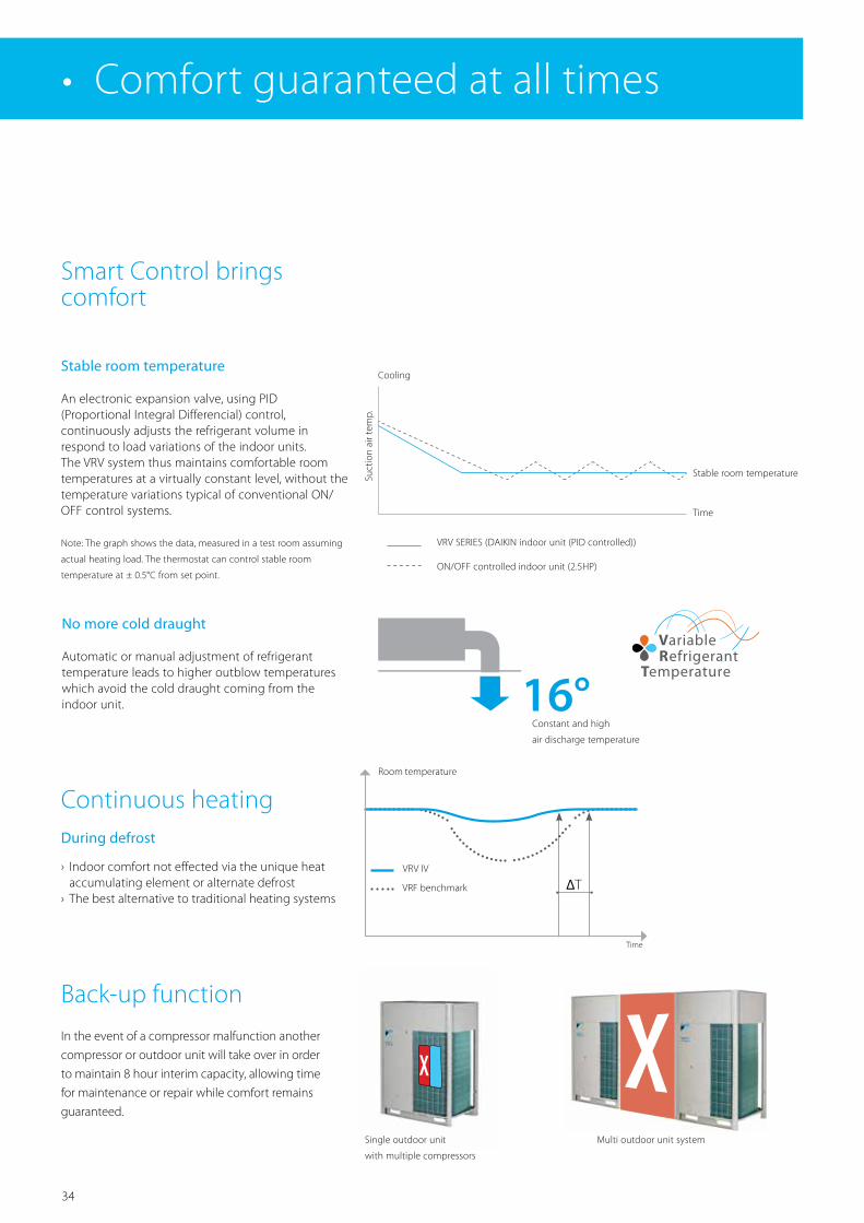
Smart Control brings comfort
No more cold draught
Automatic or manual adjustment of refrigerant temperature leads to higher outblow temperatures which avoid the cold draught coming from the indoor unit.
VRV SERIES (DAIKIN indoor unit (PID controlled))
ON/OFF controlled indoor unit (2.5HP)
Time
Stable room temperature
CoolingSu
ctio
n ai
r tem
p.
Note: The graph shows the data, measured in a test room assuming
actual heating load. The thermostat can control stable room
temperature at ± 0.5°C from set point.
16°Constant and high
air discharge temperature
Back-up function
In the event of a compressor malfunction another
compressor or outdoor unit will take over in order
to maintain 8 hour interim capacity, allowing time
for maintenance or repair while comfort remains
guaranteed.
Continuous heatingDuring defrost
› Indoor comfort not effected via the unique heat accumulating element or alternate defrost
› The best alternative to traditional heating systems
Single outdoor unit
with multiple compressors
Multi outdoor unit system
• Comfort guaranteed at all times
Stable room temperature
An electronic expansion valve, using PID (Proportional Integral Differencial) control, continuously adjusts the refrigerant volume in respond to load variations of the indoor units. The VRV system thus maintains comfortable room temperatures at a virtually constant level, without the temperature variations typical of conventional ON/OFF control systems.
VRV IV
VRF benchmark
Room temperature
Time
ΔT

35
Bene
fits
db(A) Perceived loudness Sound
0 Treshold of hearing -
20 Extremely soft Rustling leaves
40 Very soft Quiet room
60 Moderately loud Normal conversation
80 Very loud City traffic noise
100 Extremely loud Symphonic orchestra
120 Threshold of feeling Jet taking off
Low indoor unit operation sound levelDaikin indoor units have very low sound operation
levels, down to 19dB(A), making them ideal for
sound sensitive area’s as hotel bedrooms, etc…
emuraFXZQ-A
Connectable to VRV IV and VRV III-S heat pump Connectable to all VRV heat pumps
19dB(A) 25.5dB(A)
Daikin indoor units:
Technical benefits VRV
Night quiet modeFor areas where there are stringent limitations to sound levels the outdoor unit sound level can be
reduced, to meet the requirement.
Example for VRV IV heat pump, factory setting.
100%
50%
8 hrs
58 dBA
50dBA
45 dBA
10 hrs
Step 1: max. - 8dB (10HP)
Night mode STARTS Night mode ENDS
Night mode
Step 1: 50dB
Step 2: 45dBStep 2: max. - 13dB (10HP)
Capacity* %
Load %
Operation Sound dBA
Peak in the outdoor temperature
<
<
24/7
24/7
00000

36
Indoor installationThe VRV optimised fan blade shape increases output and reduces pressure loss. Together with the high ESP setting (up to 78pa), it makes VRV outdoor units ideal for indoor installation using ducts.
Indoor installation leads to less piping length, lower installation costs, increased efficiency and better visual aesthetics.
• Maximum flexibility
1 Contact your local dealer for more information and restrictions
Flexible piping designThe long piping lengths, high level differences and small refrigerant piping allows for a design with little limitations and leaving maximum space for lettable space.
VRV IV example
Total piping length 1000m
Longest length actual (Equivalent) 165m (190m)
Longest length after first branch 90m1
Level difference between indoor and outdoor units
90m1
Level difference between indoor units 30m
1 Contact your local dealer for more information and restrictions
2 In case outdoor unit is located below indoor units
Push buttonon the PCB
R410-A
Kan niet aders dan met gradient, want vloeistof warmt op en koelt af...
1 v/d 2 kiezen
naam op gas�es eventueel vervangen door echt logo
even checken in de infographics map: ik denk dat er een tekening van een VRV bestaat
even checken in de infographics map: ik denk dat er een tekening van een VRV bestaat
foto in crkeltje zou ik behouden
165m
Act
ual p
ipin
g le
ngth
40m
(90m
1 ) Lev
el d
iffer
ence
bet
wee
n in
door
and
out
door
uni
ts
30m
Lev
el d
iffer
ence
bet
wee
n in
door
uni
ts
90m
pip
ing
leng
th a
fter
firs
t bra
nch
Wide operation rangeThe VRV system can be installed practically anywhere. VRV air cooled outdoor units can cool between -20°C and +52°C outdoor ambient and can be used monovalent heating system between -25°C and +15.5°C.
Our geothermal water cooled units are not influenced by external conditions and can be operated in the most extreme climats.
52°C-20C° 15.5°C-25C°
With the technical cooling function, the operation range in cooling of the heat recovery system is
extended from -5°C to -20°C 1, making it perfect for integrating server rooms.
Cooling mode Heating mode
Push buttonon the PCB
R410-A
Kan niet aders dan met gradient, want vloeistof warmt op en koelt af...
1 v/d 2 kiezen
naam op gas�es eventueel vervangen door echt logo
even checken in de infographics map: ik denk dat er een tekening van een VRV bestaat
even checken in de infographics map: ik denk dat er een tekening van een VRV bestaat
foto in crkeltje zou ik behouden
ESP up to
78pa
37
Bene
fits
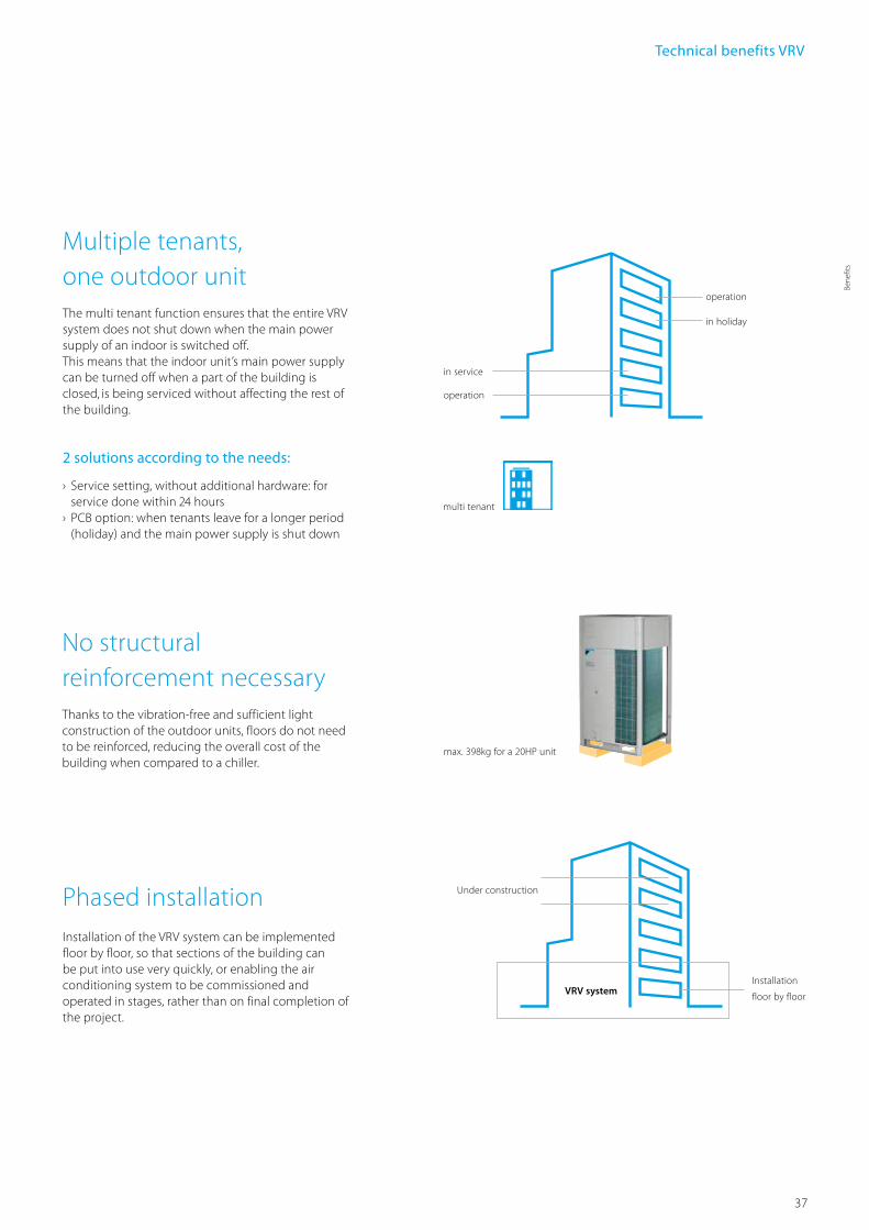
Multiple tenants, one outdoor unit The multi tenant function ensures that the entire VRV system does not shut down when the main power supply of an indoor is switched off. This means that the indoor unit’s main power supply can be turned off when a part of the building is closed, is being serviced without affecting the rest of the building.
2 solutions according to the needs:
› Service setting, without additional hardware: for service done within 24 hours
› PCB option: when tenants leave for a longer period (holiday) and the main power supply is shut down
No structural reinforcement necessaryThanks to the vibration-free and sufficient light construction of the outdoor units, floors do not need to be reinforced, reducing the overall cost of the building when compared to a chiller.
max. 398kg for a 20HP unit
in holiday
operation
operation
multi tenant
in service
Phased installationInstallation of the VRV system can be implemented floor by floor, so that sections of the building can be put into use very quickly, or enabling the air conditioning system to be commissioned and operated in stages, rather than on final completion of the project.
Installation
floor by floor
Under construction
VRV system
Technical benefits VRV
38
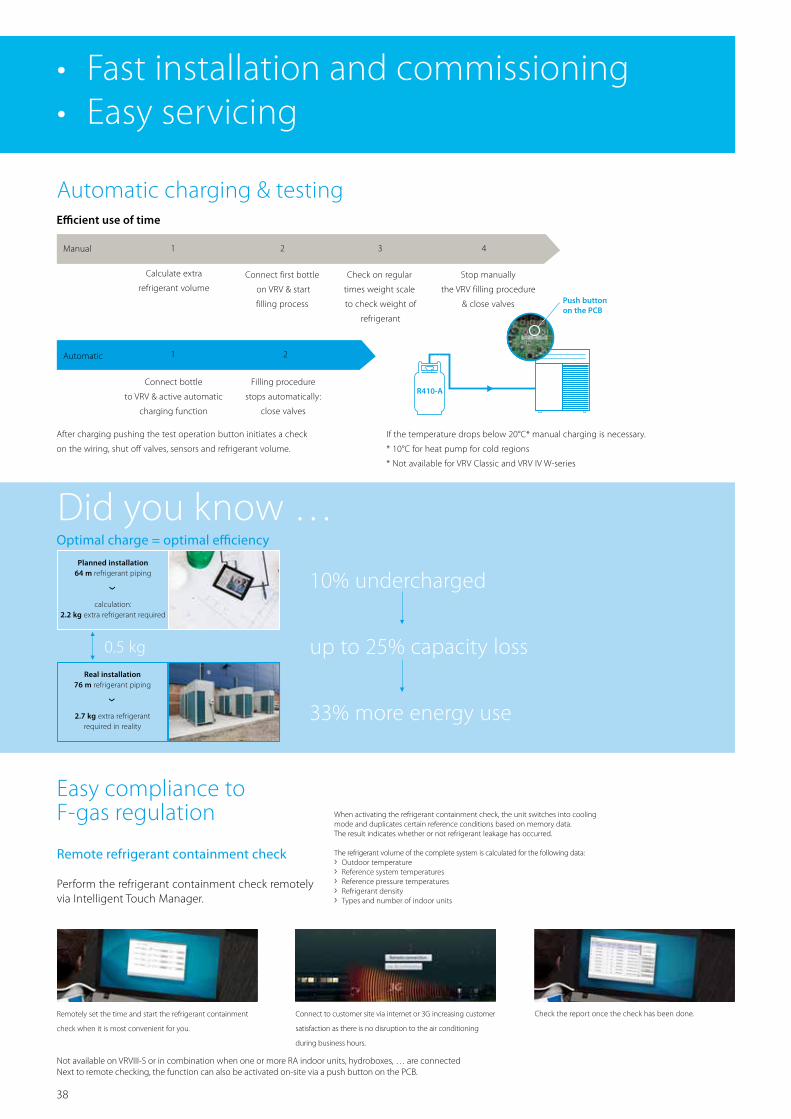
Easy compliance to F-gas regulation
Remote refrigerant containment check
Perform the refrigerant containment check remotely via Intelligent Touch Manager.
Not available on VRVIII-S or in combination when one or more RA indoor units, hydroboxes, … are connectedNext to remote checking, the function can also be activated on-site via a push button on the PCB.
Connect to customer site via internet or 3G increasing customer
satisfaction as there is no disruption to the air conditioning
during business hours.
Check the report once the check has been done.Remotely set the time and start the refrigerant containment
check when it is most convenient for you.
• Fast installation and commissioning• Easy servicing
Automatic charging & testing
Connect bottle
to VRV & active automatic
charging function
Calculate extra
refrigerant volume
Filling procedure
stops automatically:
close valves
Connect first bottle
on VRV & start
filling process
Check on regular
times weight scale
to check weight of
refrigerant
Stop manually
the VRV filling procedure
& close valves
Manual
Automatic
1 2 3 4
1 2
After charging pushing the test operation button initiates a check
on the wiring, shut off valves, sensors and refrigerant volume.
Efficient use of time
If the temperature drops below 20°C* manual charging is necessary.
* 10°C for heat pump for cold regions
* Not available for VRV Classic and VRV IV W-series
Push buttonon the PCB
R410-A
Kan niet aders dan met gradient, want vloeistof warmt op en koelt af...
1 v/d 2 kiezen
naam op gas�es eventueel vervangen door echt logo
even checken in de infographics map: ik denk dat er een tekening van een VRV bestaat
even checken in de infographics map: ik denk dat er een tekening van een VRV bestaat
foto in crkeltje zou ik behouden
Did you know …Planned installation
64 m refrigerant piping
calculation: 2.2 kg extra refrigerant required
Real installation 76 m refrigerant piping
2.7 kg extra refrigerant required in reality
0.5 kg
10% undercharged
up to 25% capacity loss
33% more energy use
Optimal charge = optimal efficiency
››
When activating the refrigerant containment check, the unit switches into cooling mode and duplicates certain reference conditions based on memory data. The result indicates whether or not refrigerant leakage has occurred.
The refrigerant volume of the complete system is calculated for the following data: › Outdoor temperature › Reference system temperatures › Reference pressure temperatures › Refrigerant density › Types and number of indoor units

39
Bene
fits
Daikin unified REFNET piping
The unified Daikin REFNET piping system is designed for simple installation.Compared to regular T-joints, where refrigerant distribution is far from optimal, the Daikin REFNET joints have specifically been designed to optimise refrigerant flow.
Daikin Europe N.V. advises only to use Daikin REFNET piping system.
REFNET
header
REFNET joint
REFNET joint T-joint
Technical benefits VRV
Push buttonon the PCB
R410-A
Kan niet aders dan met gradient, want vloeistof warmt op en koelt af...
1 v/d 2 kiezen
naam op gas�es eventueel vervangen door echt logo
even checken in de infographics map: ik denk dat er een tekening van een VRV bestaat
even checken in de infographics map: ik denk dat er een tekening van een VRV bestaat
foto in crkeltje zou ik behouden
Easy wiring - “Super Wiring” SystemSimplified wiring
Shared use of wiring between indoor units, outdoor units and centralised remote control
› Easy retrofit of centralised remote control › Impossible to make incorrect connections thanks to non polarity wiring
› Sheeted wire can be used › Unique total wiring length up to 2,000 m
Cross wiring check
The cross wiring check facility warns operatives of connection errors in inter unit wiring and piping.
Auto Address Setting Function
Allows wiring between indoor and outdoor units, as well as group control wiring of multiple indoor units, to be performed without the bothersome task of manually setting each address.
Compact designThe compact design of the outdoor units is sufficient to allow them to be taken up to the top of a building in a commercial elevator, overcoming site transportation problem, particularly when outdoor units need to be installed on each floor.
VRV configurator software
For simplified commissioning, configuration and customisation
User friendly interface instead of
push buttons
3 digit 7-segment display

40
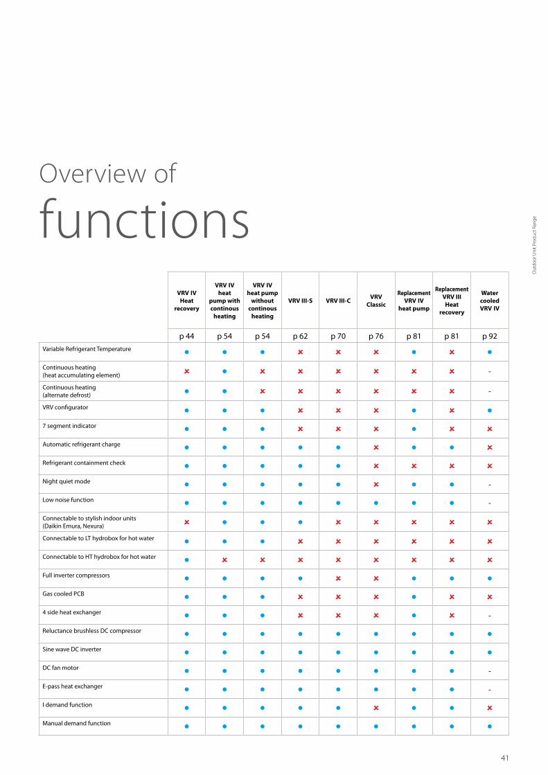
VRV Outdoor SystemsFor every application a solution
41
VRV IV Heat
recovery
VRV IV heat
pump with continous
heating
VRV IV heat pump
without continous
heating
VRV III-S VRV III-CVRV
Classic
Replacement VRV IV
heat pump
Replacement VRV III
Heat recovery
Water cooled VRV IV
p 44 p 54 p 54 p 62 p 70 p 76 p 81 p 81 p 92
Variable Refrigerant Temperature Continuous heating (heat accumulating element) -
Continuous heating (alternate defrost) -
VRV configurator 7 segment indicator Automatic refrigerant charge Refrigerant containment check Night quiet mode -
Low noise function -
Connectable to stylish indoor units (Daikin Emura, Nexura) Connectable to LT hydrobox for hot water Connectable to HT hydrobox for hot water Full inverter compressors Gas cooled PCB 4 side heat exchanger -
Reluctance brushless DC compressor Sine wave DC inverter DC fan motor -
E-pass heat exchanger -
I demand function Manual demand function
Overview of
functions
Out
door
Uni
t Pro
duct
Ran
ge

42
VRV Outdoor
EIFFAGE OFFICE, VRV IV WITH CONTINUOUS HEATING
VRV-S SERIES
PARK PHIBREEAM ® EXCELLENT OFFICE BUILDING WATERCOOLED VRV

43
VRV Outdoor
CINEMEERSE, CINEMA, 12 OUTDOOR UNITS WITH AHU
HOTEL LE PIGONNET, 8 REPLACEMENT VRV
THE RANGE SUPERSTORE, VRV IV WITH CONTINUOUS HEATING
Out
door
Uni
t Pro
duct
Ran
ge

44
Air curtain
Biddle Air curtain for VRV (CYV)
Hot water
Low temperature hydrobox
High temperature hydrobox
22
Indoor units
VRV type indoor units
Ventilation
Heat Reclaim ventilation (VAM/VKM)
AHU connection kit
Control systems
VRV IV heat recovery Best efficiency and comfort solution
VRV IV standards:
Variable refrigerant temperatureCustomize your VRV for best seasonal efficiency & comfort
Continuous heatingThe new standard in heating comfort
VRV configuratorSoftware for simplified commissioning, configuration and customisation
› 7 segment indicator
› Automatic refrigerant charge
› Refrigerant containment check
› Night quiet mode
› Low noise function
› Full inverter compressors
› Gas cooled PCB
› 4 side heat exchanger
› Reluctance brushless DC compressor
› Sine wave DC inverter
› DC fan motor
› E-pass heat exchanger
› I demand function
Widest range of BS boxes for the fastest installation
Efficient3-pipetechnology

45
-25 -20
-20-25 25 4543-15 -10 -5
-15
-25 -20 -15
0
-20-25 25 4543-15 -10 -5 0
-20-25 4543-15 -10 -5 0
-20 -15 -10 -5 150
-25 -20
-20-25 25 4543-15 -10 -5
-15
-25 -20 -15
0
-20-25 25 4543-15 -10 -5 0
-20-25 4543-15 -10 -5 0
-20 -15 -10 -5 150
“Free” heat and hot water productionUntil now, most commercial buildings have relied on separate systems for cooling, heating, hot water and so on, which results in a lot of wasted energy.
An integrated heat recovery system reuses heat from offices, server rooms, to warm other areas or create hot water.
Maximum comfortA VRV heat-recovery system allows simultaneous cooling and heating.
› For hotel owners, this means a perfect environment for guests as they can freely choose between cooling or heating.
› For offices, it means a perfect working indoor climate for both north and south-facing offices.
Cooling
Heating
Hot water
Extracted heat delivers
free hot water and heating
+
Improved efficiencyIn heat-recovery operation the VRV IV is up to 15% more efficient. In full-load operation the seasonal efficiency is even as much as 28% more efficient than the VRV III thanks to variable refrigerant temperature.
Efficient3-pipetechnology
Cooling load
Heating load
Ambient
temperature
Improved mix
mode control
Optimised Partition of Heat Exchanger for highest seasonal efficiency in heat recovery modeVertically divided heat exchanger with an optimized ratio for mix mode operation. This improves heat recovery efficiency by reducing radiation losses.
30%
70%
Additionally the bottom of the heat exchanger is continuously
hot in heating operation preventing frost accumulation
Wide heating operation rangeVRV IV heat recovery has a standard operation range down to -20°C in heating. It can also provide cooling down to -20°C for technical server rooms (field setting).
-20°CWB
-20°CWB
Technical Cooling
Heating
Cooling
-5°CWB 43°CDB-25°C
15.5°C
CWB: indoor temperature
CDB: outdoor temperature
North
South
Out
door
Uni
t Pro
duct
Ran
ge

46
Advantages of 3-pipe technology
Lower pressure drop means more efficiency
› Smooth refrigerant flow in 3-pipe system thanks to 2 smaller gas pipes results in higher energy effi-ciency
› Disturbed refrigerant flow in large gas pipe on 2-pipe system results in bigger pressure drop
More “free” heat
Daikin 3-pipe technology needs less energy to recover heat, meaning significantly higher efficiency during heat recovery mode. Our system can recover heat at a low condensing temperature because it has dedicated gas, liquid and discharge pipes.
In a 2-pipe system, gas and liquid travel as a mixture so the condensing temperature needs to be higher in order to separate the mixed gas and liquid refrigerant. The higher condensing temperature means more energy is used to recover heat resulting in lower efficiency.
3-pipe VRV H/R
2-pipe system
Pressure
Pipe length
Pressure
Enthalpy
Power input Daikin
Power input 2-pipe system
Condensing 55 °C
Condensing 45 °C
Freely combine outdoor units
Combine outdoor units flexibly to reduce your carbon footprint, optimise your system for continuous heating, and achieve the highest efficiency.
Total piping length 1000m
Longest length actual (Equivalent) 165m (190m)
Longest length after first branch 90m1
Level difference between indoor and outdoor units 90m1
Level difference between indoor units 30m
Flexible piping design
1 Outdoor unit in highest position
165m
Act
ual p
ipin
g le
ngth
90m
1 Lev
el d
iffer
ence
bet
wee
n in
door
and
out
door
uni
ts
30m
Lev
el d
iffer
ence
bet
wee
n in
door
uni
ts
90m
max
imum
Fully redesigned
BS boxes

47
Fully redesigned
BS boxes
BS1Q 10, 16, 25 A
BS 4 Q14 A BS 6, 8 Q14 A
BS 10, 12 Q14 A BS 16 Q14 A
Single port
› Unique to the market › Compact and light to install › No drain piping needed › Ideal for remote rooms › Technical cooling function › Connect up to 250 class unit (28 kW) › Allows multi-tenant applications
Multi port: 4 – 6 – 8 – 10 – 12 – 16
› Up to 55% smaller and 41% lighter than previous range
› Faster installation thanks to a reduced number of brazing points and wiring
› All indoor units connectable to one BS box › Fewer inspection ports needed › Up to 16 kW capacity available per port › Connect up to 250 class unit (28kW) by combining 2 ports
› No limit on unused ports, permitting phased installation
Maximum design flexibility and installation speed
› Quickly and flexibly design your system with a unique range of single and multi BS boxes.
› A wide variety of compact and lightweight multi BS boxes greatly reduces installation time.
› Free combination of single and multi BS boxes
Maximum comfort at all times
With the VRV BS box, any indoor unit not being used to switch between heating and cooling maintains the constant desired temperature. This is because our heat recovery system does not need to equalise pressure over the entire system after a change-over.
Off
Faster installation thanks to open connection
› No need to cut the pipe before brazing – for indoor units smaller or equal to 5.6 kW (50 class)
› Cut and braze the pipe – for indoor units bigger or equal to 7.1 kW (63 class)
Out
door
Uni
t Pro
duct
Ran
ge

48
› Incorporates VRV IV standards & technologies: Variable Refrigerant Temperature, continuous heating, VRV configurator, 7 segment display and full inverter compressors, 4-side heat exchanger, refrigerant cooled PCB, new DC fan motor
› Operation range down to -20°C for technical cooling operation such as server rooms
› Contains all standard VRV features
Best efficiency & comfort solution
› Fully integrated solution with heat recovery for maximum efficiency!
› Covers all thermal needs of a building via a single point of contact: accurate temperature control, ventilation, hot water, air handling units and Biddle air curtains
› “Free” heating and hot water through heat recovery › The perfect personal comfort for guests/tenants via simultaneous cooling and heating
VRV IV heat recovery
Outdoor system REYQ 8T 10T 12T 14T 16T 18T 20TCapacity range HP 8 10 12 14 16 18 20Cooling capacity Nom. kW 22.4 (1) (2) 28.0 (1) (2) 33.5 (1) (2) 40.0 (1) (2) 45.0 (1) (2) 50.4 56.0Heating capacity Nom. kW 22.4 (3) (4) 28.0 (3) (4) 33.5 (3) (4) 40.0 (3) (4) 45.0 (3) (4) 50.4 56.0
Max. kW 25.0 31.5 37.5 45.0 50.0 56.5 63.0Power input - 50Hz Cooling Nom. kW 5.31 (1) / 4.56 (2) 7.15 (1) / 6.19 (2) 9.23 (1) / 8.31 (2) 10.7 (1) / 9.61 (2) 12.8 (1) / 11.9 (2) 15.2 18.6
Heating Nom. kW 4.75 (3) / 4.47 (4) 6.29 (3) / 5.47 (4) 8.05 (3) / 6.83 (4) 9.60 (3) / 9.37 (4) 11.2 (3) / 9.88 (4) 12.3 14.9Max. kW 5.51 7.38 9.43 11.3 12.9 14.3 17.5
EER 4.22 (1) / 4.92 (2) 3.92 (1) / 4.52 (2) 3.63 (1) / 4.03 (2) 3.74 (1) / 4.16 (2) 3.52 (1) / 3.79 (2) 3.32 3.01COP - Max. 4.54 4.27 3.98 3.88 3.95 3.60COP - Nom. 4.72 (3) / 5.01 (4) 4.45 (3) / 5.12 (4) 4.16 (3) / 4.90 (4) 4.17 (3) / 4.27 (4) 4.02 (3) / 4.56 (4) 4.10 3.76ESEER 7.41 7.37 6.84 7.05 6.63 6.26 5.68Maximum number of connectable indoor units 64 (5)Indoor index connection
Min. 100 125 150 175 200 225 250Nom. 200 250 300 350 400 450 500Max. 260 325 390 455 520 585 650
Dimensions Unit HeightxWidthxDepth mm 1,685x930x765 1,685x1,240x765Weight Unit kg 210 218 304 305 337Fan Air flow rate Cooling Nom. m³/min 162 175 185 223 260 251 261Sound power level Cooling Nom. dBA 78 79 81 86 88Sound pressure level Cooling Nom. dBA 58 61 64 65 66
Night Quiet Mode
Level 1 dBA 56 58 58 58 58 60 60Level 2 dBA 55 54 54 52 52 52 52Level 3 dBA 53 52 52 47 47 48 48
Operation range Cooling Min.~Max. °CDB -5.0~43.0Heating Min.~Max. °CWB -20~15.5
Refrigerant Type / GWP R-410A / 2,087.5Charge kg/TCO
29.7/20.2 9.8/20.5 9.9/20.7 11.8/24.6
Piping connections Liquid OD mm 9.52 12.7 15.9Gas OD mm 19.1 22.2 28.6Discharge gas OD mm 15.9 19.1 22.2 28.6Total piping length System Actual m 1,000
Power supply Phase/Frequency/Voltage Hz/V 3N~/50/380-415Current - 50Hz Maximum fuse amps (MFA) A 20 25 32 40 50
Outdoor system REYQ 10T 13T 16T 18T 20T 22T 24T 26T 28T 30T 32TSystem Outdoor unit module 1 REMQ5T REYQ8T REYQ10T REYQ8T REYQ12T REYQ16T
Outdoor unit module 2 REMQ5T REYQ8T REYQ10T REYQ12T REYQ16T REYQ14T REYQ16T REYQ18T REYQ16TCapacity range HP 10 13 16 18 20 22 24 26 28 30 32Cooling capacity Nom. kW 28.0 36.4 44.8 50.4 55.9 61.5 67.4 73.5 78.5 83.9 90.0Heating capacity Nom. kW 28.0 36.4 44.8 50.4 55.9 61.5 67.4 73.5 78.5 83.9 90.0
Max. kW 32.0 41.0 50.0 56.5 62.5 69.0 75.0 82.5 87.5 94.0 100.0Power input - 50Hz Cooling Nom. kW 6.34 8.48 10.62 12.46 14.54 16.38 18.11 19.93 22.03 24.43 25.6
Heating Nom. kW 5.42 7.46 9.50 11.04 12.80 14.34 15.95 17.65 19.25 20.35 22.4Max. kW 6.50 8.76 11.02 12.89 14.94 16.81 18.41 20.73 22.33 23.73 25.8
EER 4.42 4.29 4.22 4.04 3.84 3.75 3.72 3.69 3.56 3.43 3.52COP - Max. 4.92 4.68 4.54 4.38 4.18 4.10 4.07 3.98 3.92 3.96 3.88COP - Nom. 5.17 4.88 4.72 4.57 4.37 4.29 4.23 4.16 4.08 4.12 4.02ESEER - Automatic 7.77 7.54 7.41 7.38 7.06 7.07 6.87 6.95 6.72 6.48 6.63ESEER - Standard 6.55 6.36 6.25 5.98 5.68 5.54 5.46 5.41 5.23 5.03 5.14Maximum number of connectable indoor units 64Indoor index connection
Min. 125 162.5 200 225 250 275 300 325 350 375 400Nom. 250 325.0 400 450 500 550 600 650 700 750 800Max. 325 422.5 520 585 650 715 780 845 910 975 1,040
Piping connections Liquid OD mm 9.52 12.7 15.9 19.1Gas OD mm 22.2 28.6 34.9Discharge gas OD mm 19.1 22.2 28.6Total piping length System Actual m 500 1,000
Current - 50Hz Maximum fuse amps (MFA) A 40 50 63 80Continuous heating v
REYQ-T

49
Outdoor system REYQ 34T 36T 38T 40T 42T 44T 46T 48T 50T 52T 54TSystem Outdoor unit module 1 REYQ16T REYQ8T REYQ10T REYQ12T REYQ14T REYQ16T REYQ18T
Outdoor unit module 2 REYQ18T REYQ20T REYQ12T REYQ16T REYQ18TOutdoor unit module 3 - REYQ18T REYQ16T REYQ18T
Capacity range HP 34 36 38 40 42 44 46 48 50 52 54Cooling capacity Nom. kW 95.4 101.0 106.3 111.9 118.0 123.5 130.0 135.0 140.4 145.8 151.2Heating capacity Nom. kW 95.4 101.0 106.3 111.9 118.0 123.5 130.0 135.0 140.4 145.8 151.2
Max. kW 106.5 113.0 119.0 125.5 131.5 137.5 145.0 150.0 156.5 163.0 169.5Power input - 50Hz Cooling Nom. kW 28.0 31.4 29.74 31.58 32.75 34.83 36.3 38.4 40.8 43.2 45.6
Heating Nom. kW 23.5 26.1 25.10 26.64 28.69 30.45 32.00 33.6 34.7 35.8 36.9Max. kW 27.2 30.4 29.24 31.11 33.18 35.23 37.1 38.7 40.1 41.5 42.9
EER 3.41 3.22 3.57 3.54 3.60 3.55 3.58 3.52 3.44 3.38 3.32COP - Max. 3.92 3.72 4.07 4.03 3.96 3.90 3.91 3.88 3.90 3.93 3.95COP - Nom. 4.06 3.87 4.24 4.20 4.11 4.06 4.02 4.05 4.07 4.10ESEER - Automatic 6.43 6.06 6.66 6.68 6.79 6.68 6.75 6.63 6.49 6.37 6.26ESEER - Standard 4.97 4.70 5.25 5.20 5.28 5.20 5.23 5.14 5.03 4.93 4.84Maximum number of connectable indoor units 64Indoor index connection
Min. 425 450 475 500 525 550 575 600 625 650 675Nom. 850 900 950 1,000 1,050 1,100 1,150 1,200 1,250 1,300 1,350Max. 1,105 1,170 1,235 1,300 1,365 1,430 1,495 1,560 1,625 1,690 1,755
Piping connections Liquid OD mm 19.1Gas OD mm 34.9 41.3Discharge gas OD mm 28.6 34.9Total piping length System Actual m 1,000
Current - 50Hz Maximum fuse amps (MFA) A 80 100 125Continuous heating v
Outdoor unit module REMQ 5TDimensions Unit HeightxWidthxDepth mm 1,685x930x765Weight Unit kg 210Fan Air flow rate Cooling Nom. m³/min 162Sound power level Cooling Nom. dBA 77Sound pressure level Cooling Nom. dBA 56Operation range Cooling Min.~Max. °CDB -5.0~43.0
Heating Min.~Max. °CWB -20~15.5Refrigerant Type / GWP R-410A / 2,087.5
Charge kg/TCO2Eq 9.7/20.2
Power supply Phase/Frequency/Voltage Hz/V 3N~/50/380-415Current - 50Hz Maximum fuse amps (MFA) A 20
(1) Nominal cooling capacities are based on: indoor temperature: 27°CDB, 19°CWB, outdoor temperature: 35°CDB, equivalent refrigerant piping: 5m, level difference: 0m. Data for standard efficiency series. (2) Nominal cooling capacities are based on: indoor
temperature: 27°CDB, 19°CWB, outdoor temperature: 35°CDB, equivalent refrigerant piping: 5m, level difference: 0m. Data for high efficiency series, Eurovent certified. (3) Nominal heating capacities are based on: indoor temperature: 20°CDB, outdoor tempera-
ture: 7°CDB, 6°CWB, equivalent refrigerant piping: 5m, level difference: 0m. Data for standard efficiency series. (4) Nominal heating capacities are based on: indoor temperature: 20°CDB, outdoor temperature: 7°CDB, 6°CWB, equivalent refrigerant piping: 5m, level
difference: 0m. Data for high efficiency series, Eurovent certified. (5) Actual number of connectable indoor units depends on the indoor unit type (VRV indoor, Hydrobox, RA indoor, etc.) and the connection ratio restriction for the system (50% <= CR <= 130%)
REYQ-T
Out
door
Uni
t Pro
duct
Ran
ge

50
Detailed technical drawings
REMQ5T / REYQ8-12T
4
67
5
9
4-15x22.5mm -
10
8
21
11
97
272
328
373
1240
107
C
13117
9259
276
122
1685
76
137
765
76
515
729
1076
134
393
107
112
125
70
106
71
192
AB
310
100
160
AA
3
ABAA
RYMQ18-20T, RXYQQ18-20TRYMQ14-16T, RXYQQ14-16T, REYQ14-20T 205240
240 210
Notes
Detail ·A· and detail ·B· indicate the dimensions after fixing the attached piping.Knockout hole.
Gas pipe
Ø ·28.6· brazing connection
Ø ·12.7· brazing connection
Ø ·22.2· brazing connection
Liquid pipe
RYYQ14-20T, RYMQ14-20T, RXYQ14-20T, RXYQQ14-20T :
Equalising pipe
High pressure/low pressure gas pipe
Items ·4 - 10:·
RYYQ14-16T, RYMQ14-16T, RXYQ14-16T, RXYQQ14-16T, REYQ14-20T :
RYMQ14-16T :RYMQ18-20T :
REYQ14-20T : Ø ·22.2· brazing connection
Ø ·25.4· brazing connectionREYQ14-20T :
1.2.3.
678910
12
3
45
Ø65Ø27Ø65Ø80Ø65
No.
11
Part name Remark
Grounding terminalPipe routing hole (bottom)Pipe routing hole (front)
Power cord routing hole (side)
Power cord routing hole (front)Power cord routing hole (front)Power cord routing hole (front)
Equalising pipe connection port
Gas pipe connection portLiquid pipe connection port
See note ·3·.
See note ·3·.See note ·3·.
Inside of the switch box (·M8·)
Power cord routing hole (bottom)
Model
Pitch of foundation bolt holes
Pitc
h of
foun
datio
n bo
lt ho
les
Foundation bolt holeOblong hole
Ø ·15.9· brazing connectionRYYQ18-20T, RYMQ18-20T, RXYQ18-20T, RXYQQ18-20T :
Ø ·28.6· brazing connection
Detail ·A· Detail ·B·
DETAIL B DETAIL A
View ·C·
High pressure/low pressure gas pipe
REYQ14-20T
2D079533B
4
515
76
765
76
67
5
9
272
328
373
930
97 107
13117
9259
276
122
766
729
4-15x22.5mm
134
353
107
112
125
70
10
8
100
160
AA
339
AB
66
106
C
AC
240208
AB
195
248AA
REMQ5T, RYMQ10-12T, REYQ8-12TRYMQ8TRYYQ10-12T, RXYQ10-12T, RXYQQ10-12TRYYQ8T, RXYQ8T, RXYQQ8T
--195248 240208
--
137
21
3
11
1685
678910
12
3
45
Ø65Ø27Ø65Ø80Ø65
No.
11
Part name Remark
Grounding terminalPipe routing hole (bottom)Pipe routing hole (front)
Power cord routing hole (side)
Power cord routing hole (front)Power cord routing hole (front)Power cord routing hole (front)
Equalising pipe connection port
Gas pipe connection portLiquid pipe connection port
See note ·3·.
See note ·3·.
See note ·3·.
Notes
Detail ·A· and detail ·B· indicate the dimensions after fixing the attached piping.Knockout hole.
Gas pipeØ ·19.1· brazing connectionØ ·22.2· brazing connection
Ø ·28.6· brazing connection
Ø ·9.5· brazing connection
Ø ·12.7· brazing connection
Ø ·19.1· brazing connectionØ ·22.2· brazing connection
Liquid pipe
Pitch of foundation bolt holes
Pitc
h of
foun
datio
n bo
lt ho
les
Foundation bolt holeOblong hole
AC
RYYQ8T, RYMQ8T, RXYQ8T, RXYQQ8T :
RYYQ12T, RYMQ12T, RXYQ12T, RXYQQ12T :
RYYQ8-10T, RYMQ8-10T, RXYQ8-10T, RXYQQ8-10T, REMQ5T, REYQ8-12T:
RYYQ10T, RYMQ10T, RXYQ10T, RXYQQ10T :
Model
Equalising pipe
High pressure/low pressure gas pipe
Items ·4 - 10:·
RYYQ12T, RYMQ12T, RXYQ12T, RXYQQ12T :
RYMQ8-10T :RYMQ12T :
REMQ5T, REYQ8-12T : Ø ·19.1· brazing connection
Ø ·25.4· brazing connectionREMQ5T, REYQ8-12T :
1.2.3.
Inside of the switch box (·M8·)
Power cord routing hole (bottom)
Detail ·A· Detail ·B·
DETAIL ADETAIL B
View ·C·
High pressure/low pressure gas pipe
REMQ5TREYQ8-12T
2D079532B
REYQ14-20T
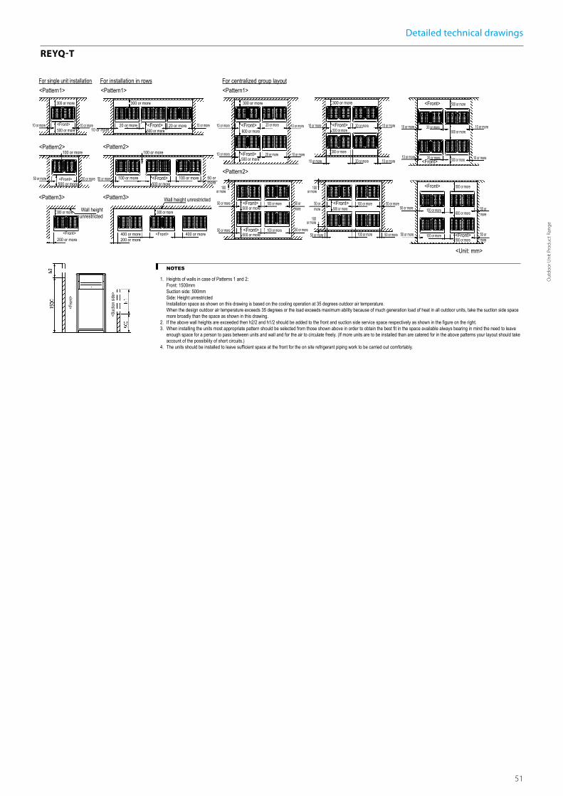
51
Detailed technical drawings
REYQ-T
3D079542
REYQ-TFor single unit installation<Pattern1>
<Pattern2>
<Pattern3>
<Pattern1>
<Pattern2>
<Pattern3>
<Pattern1>
<Unit: mm>
Wall height unrestricted
Wall height unrestricted
10 or more
300 or more
500 or more<Front>
<Front>
<Front> <Front>
<Fro
nt>
<Suc
tion s
ide>
500 or more50 or more
300 or more
300 or more300 or more
10 or more 20 or more 20 or more
200 or more200 or more
100 or more
400 or more
100 or more
100 or more
For installation in rows For centralized group layout
NOTES
1. Heights of walls in case of Patterns 1 and 2:Front: 1500mmSuction side: 500mmSide: Height unrestrictedInstallation space as shown on this drawing is based on the cooling operation at 35 degrees outdoor air temperature.When the design outdoor air temperature exceeds 35 degrees or the load exceeds maximum ability because of much generation load of heat in all outdoor units, take the suction side space more broadly than the space as shown in this drawing.
2. If the above wall heights are exceeded then h2/2 and h1/2 should be added to the front and suction side service space respectively as shown in the figure on the right.3. When installing the units most appropriate pattern should be selected from those shown above in order to obtain the best fit in the space available always bearing in mind the need to leave
enough space for a person to pass between units and wall and for the air to circulate freely. (If more units are to be installed than are catered for in the above patterns your layout should take account of the possibility of short circuits.)
4. The units should be installed to leave sufficient space at the front for the on site refrigerant piping work to be carried out comfortably.
10 or more <Front>500 or more
10 or more
50 or more 50 or more 50 or more <Front>500 or more
100 or more
10 or more
400 or more
300 or more
300 or more
10 or more
10 or more 10 or more
<Front>600 or more
20 or more
20 or more<Front>500 or more
<Pattern2>
100 or more
50 or more
50 or more
<Front>500 or more
500 or more<Front>
100 or more
100 or more
50 or more
50 or more
10 or more
10 or more 20 or more
20 or more<Front>500 or more
300 or more
10 or more
10 or more
<Front>500 or more
100 or more
50 or more
100 or more
50 or more 100 or more 50 or more
100 or more 50 or more
<Front>
<Front>
10 or more
10 or more 10 or more
10 or more
500 or more
900 or more20 or more
500 or more
50 or more
50 or more 50 or more
50 or more
20 or more<Front> 500 or more
100 or more 600 or more
<Front>500 or more
100 or more
Out
door
Uni
t Pro
duct
Ran
ge

52
Indoor unit BS 1Q10A 1Q16A 1Q25APower input Cooling Nom. kW 0.005
Heating Nom. kW 0.005Maximum number of connectable indoor units 5 8Maximum capacity index of connectable indoor units 15 < x ≤ 100 100<x≤160 160<x≤250Dimensions Unit HeightxWidthxDepth mm 207x388x326Weight Unit kg 12 15Casing Material Galvanised steel platePiping connections Outdoor unit Liquid Type/OD mm Brazing connection/9.5
Gas Type/OD mm Brazing connection/15.9 Brazing connection/22.2Discharge gas Type/OD mm Brazing connection/12.7 Brazing connection/19.1
Indoor unit Liquid Type/OD mm Brazing connection/9.5Gas Type/OD mm Brazing connection/15.9 Brazing connection/22.2
Sound absorbing thermal insulation Foamed polyurethane Flame-resistant needle feltPower supply Phase/Frequency/Voltage Hz/V 1~/50/220-240Total circuit Maximum fuse amps (MFA) A 15
Individual branch selector for VRV IV heat recovery
› Unique range of single and multi BS boxes for flexible and fast design › Compact & light to install › Ideal for remote rooms as no drain piping is needed › Allows integration of server rooms into the heat recovery solution thanks to technical cooling function
› Connect up to 250 class unit (28kW) › Faster installation thanks to open connection › Allows multi tenant applications › Connectable to REYQ-T VRV IV heat recovery units
BS1Q-A
Indoor unit BS 4Q14A 6Q14A 8Q14A 10Q14A 12Q14A 16Q14APower input Cooling Nom. kW 0.043 0.064 0.086 0.107 0.129 0.172
Heating Nom. kW 0.043 0.064 0.086 0.107 0.129 0.172Maximum number of connectable indoor units 20 30 40 50 60 64Maximum number of connectable indoor units per branch 5Number of branches 4 6 8 10 12 16Maximum capacity index of connectable indoor units 400 600 750Maximum capacity index of connectable indoor units per branch 140Dimensions Unit HeightxWidthxDepth mm 298x370x430 298x580x430 298x820x430 298x1,060x430Weight Unit kg 17 24 26 35 38 50Casing Material Galvanised steel platePiping connections Outdoor unit Liquid OD mm 9.5 12.7 12.7 / 15.9 15.9 15.9 / 19.1 19.1
Gas OD mm 22.2 / 19.1 28.6 / 22.2 28.6 28.6 / 34.9 34.9Discharge gas OD mm 19.1 / 15.9 19.1 / 22.2 19.1 / 22.2 / 28.6 28.6
Indoor unit Liquid OD mm 9.5 / 6.4Gas OD mm 15.9 / 12.7
Drain VP20 (I.D. 20/O.D. 26)Sound absorbing thermal insulation Urethane foam, polyethylene foamPower supply Phase/Frequency/Voltage Hz/V 1~/50/220-440Total circuit Maximum fuse amps (MFA) A 15
Multi branch selector for VRV IV heat recovery
› Unique range of single and multi BS boxes for flexible and fast design › Major reduction in installation time thanks to wide range, compact size and light weight multi BS boxes
› Up to 70% smaller and 66% lighter than previous series › Faster installation thanks to a reduced number of brazing points and wiring
› All indoor units connectable to one BS box › Less inspection ports needed compared to installing single BS boxes › Up to 16kW capacity available per port › Connect up to 250 class unit (28kW) by combining 2 ports › No limit on unused ports allowing phased installation › Faster installation thanks to open connection › Connectable to REYQ-T VRV IV heat recovery units
BS-Q14A
BS1Q-A
BS6,8Q14A

53
Indoor unit BSVQ 100P9B 160P9B 250P9BPower input Cooling Nom. kW 0.005
Heating Nom. kW 0.005Maximum number of connectable indoor units 6 8Maximum capacity index of connectable indoor units 15 < x ≤ 100 100<x≤160 160<x≤250Dimensions Unit HeightxWidthxDepth mm 207x388x326Weight Unit kg 12 15Casing Material Galvanised steel platePiping connections Outdoor unit Liquid Type/OD mm Brazing connection/9.5
Gas Type/OD mm Brazing connection/15.9 Brazing connection/22.2Discharge gas Type/OD mm Brazing connection/12.7 Brazing connection/12.7 Brazing connection/19.1
Indoor unit Liquid Type/OD mm Brazing connection/9.5Gas Type/OD mm Brazing connection/15.9 Brazing connection/15.9 Brazing connection/22.2
Sound absorbing thermal insulation Foamed polyurethane Flame-resistant needle feltPower supply Phase/Frequency/Voltage Hz/V 1~/50/220-240Total circuit Maximum fuse amps (MFA) A 15
Individual branch selector for VRV heat recovery
› Allows individual cool / heat switching of 1 group of indoor units › Maximum design flexibility because individual and multi boxes can be combined in one system
› Low built-in height › No drain piping needed › Allows multi tenant applications (option PCB required) › Connectable to VRV W-IV series (RWEYQ-T)
BSVQ-P9B
BSVQ-P9B
Indoor unit BSV4Q-PV/BSV6Q-PV 4Q100PV 6Q100PVPower input Cooling Nom. kW 0.020 0.030
Heating Nom. kW 0.020 0.030Maximum number of connectable indoor units 24 36Maximum number of connectable indoor units per branch 6Number of branches 4 6Maximum capacity index of connectable indoor units 400 600Maximum capacity index of connectable indoor units per branch 100Dimensions Unit HeightxWidthxDepth mm 209x1,053x635 209x1,577x635Weight Unit kg 60 89Casing Material Galvanised steel platePiping connections Outdoor unit Liquid Type/OD mm Brazing connection/12.7 Brazing connection/15.9
Gas Type/OD mm Brazing connection/28.6Discharge gas Type/OD mm Brazing connection/19.1 Brazing connection/28.6
Indoor unit Liquid Type/OD mm Brazing connection/9.5Gas Type/OD mm Brazing connection/15.9
Sound absorbing thermal insulation Foamed polyurethane Flame-resistant needle feltPower supply Phase/Frequency/Voltage Hz/V 1~/50/220-240Total circuit Maximum fuse amps (MFA) A 15
Multi branch selector for VRV heat recovery
› Faster installation thanks to a reduced number of brazing points and wiring
› Allows individual cool / heat switching for up to 4 or 6 groups of indoor units
› Maximum design flexibility because individual and multi boxes can be combined in one system
› Low built-in height › No drain piping needed › Connectable to VRV W-IV series (RWEYQ-T)
BSV4Q-PV/BSV6Q-PV
BSV4Q100PVO
utdo
or U
nit P
rodu
ct R
ange

54
VRV IV heat pumpDaikin’s optimum solution with top comfort
VRV IV standards:
Variable refrigerant temperatureCustomize your VRV for best seasonal efficiency & comfort
Continuous heatingThe new standard in heating comfort
VRV configuratorSoftware for simplified commissioning, configuration and customisation
› 7 segment indicator
› Automatic refrigerant charge
› Refrigerant containment check
› Night quiet mode
› Low noise function
› Full inverter compressors
› Gas cooled PCB
› 4 side heat exchanger
› Reluctance brushless DC compressor
› Sine wave DC inverter
› DC fan motor
› E-pass heat exchanger
› I demand function
For detailed explanation of these functions refer to vrv iv technologies tab
Air curtainBiddle Air curtain for VRV (CYV)
Hot waterLow temperature hydrobox
Indoor unitsVRV type indoor units
Residential type indoor units (such as Daikin Emura)
VentilationHeat Reclaim ventilation (VAM/VKM)
AHU connection kit
Control systems
22
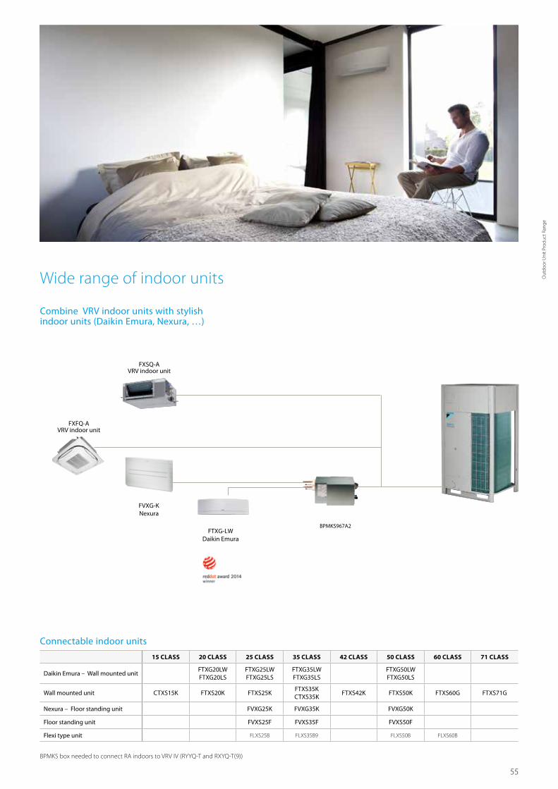
55
Combine VRV indoor units with stylish indoor units (Daikin Emura, Nexura, …)
FVXG-KNexura
FXFQ-AVRV indoor unit
FXSQ-AVRV indoor unit
Connectable indoor units
BPMKS box needed to connect RA indoors to VRV IV (RYYQ-T and RXYQ-T(9))
15 CLASS 20 CLASS 25 CLASS 35 CLASS 42 CLASS 50 CLASS 60 CLASS 71 CLASS
Daikin Emura – Wall mounted unitFTXG20LW FTXG20LS
FTXG25LWFTXG25LS
FTXG35LWFTXG35LS
FTXG50LWFTXG50LS
Wall mounted unit CTXS15K FTXS20K FTXS25KFTXS35KCTXS35K
FTXS42K FTXS50K FTXS60G FTXS71G
Nexura – Floor standing unit FVXG25K FVXG35K FVXG50K
Floor standing unit FVXS25F FVXS35F FVXS50F
Flexi type unit FLXS25B FLXS35B9 FLXS50B FLXS60B
Wide range of indoor units
FTXG-LWDaikin Emura
BPMKS967A2
Out
door
Uni
t Pro
duct
Ran
ge
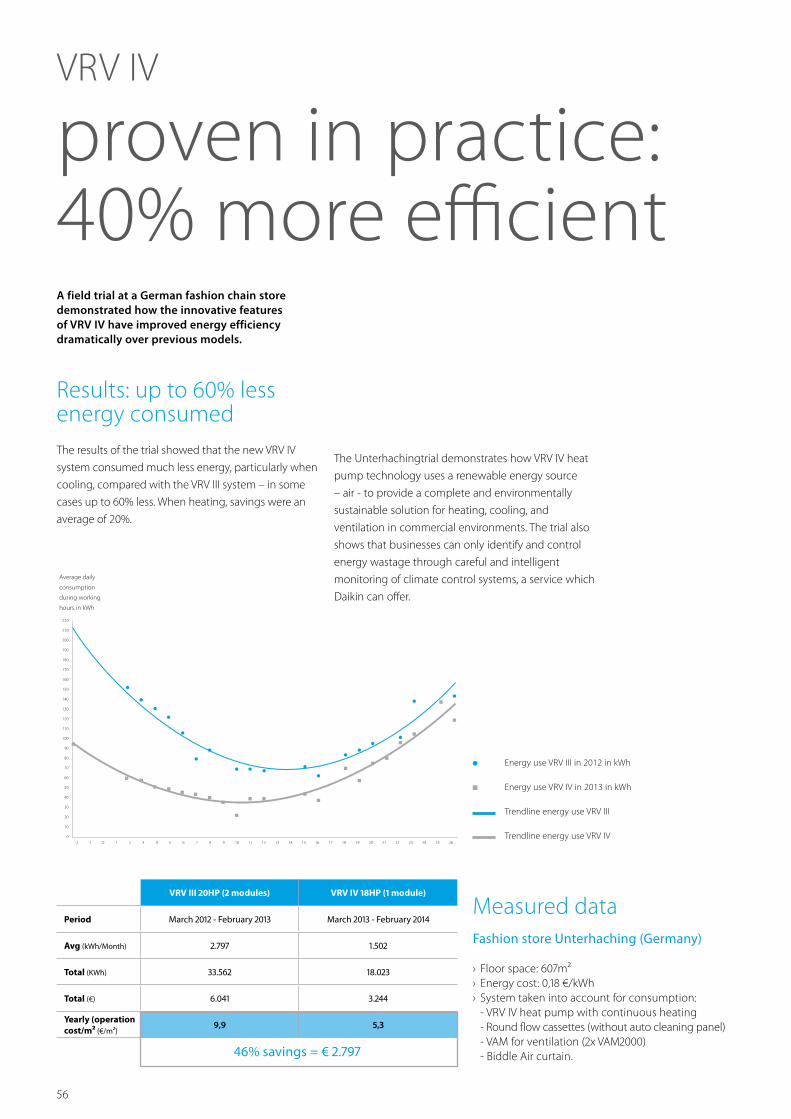
56
VRV IV
proven in practice: 40% more efficient
Results: up to 60% less energy consumed The results of the trial showed that the new VRV IV
system consumed much less energy, particularly when
cooling, compared with the VRV III system – in some
cases up to 60% less. When heating, savings were an
average of 20%.
A field trial at a German fashion chain store demonstrated how the innovative features of VRV IV have improved energy efficiency dramatically over previous models.
Energy use VRV III in 2012 in kWh
Energy use VRV IV in 2013 in kWh
Trendline energy use VRV III
Trendline energy use VRV IV
Average daily
consumption
during working
hours in kWh
220
210
200
190
180
170
160
150
140
130
120
110
100
90
80
70
60
50
40
30
20
10
0-2 -1 0 1 2 3 4 5 6 7 8 9 10 11 12 13 14 15 16 17 18 19 20 21 22 23 24 25 26
The Unterhachingtrial demonstrates how VRV IV heat
pump technology uses a renewable energy source
– air - to provide a complete and environmentally
sustainable solution for heating, cooling, and
ventilation in commercial environments. The trial also
shows that businesses can only identify and control
energy wastage through careful and intelligent
monitoring of climate control systems, a service which
Daikin can offer.
VRV III 20HP (2 modules) VRV IV 18HP (1 module)
Period March 2012 - February 2013 March 2013 - February 2014
Avg (kWh/Month) 2.797 1.502
Total (KWh) 33.562 18.023
Total (€) 6.041 3.244
Yearly (operation cost/m² (€/m²)
9,9 5,3
46% savings = € 2.797
Measured data Fashion store Unterhaching (Germany)
› Floor space: 607m² › Energy cost: 0,18 €/kWh › System taken into account for consumption:
- VRV IV heat pump with continuous heating - Round flow cassettes (without auto cleaning panel) - VAM for ventilation (2x VAM2000) - Biddle Air curtain.
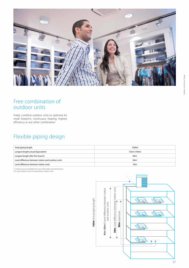
57
Total piping length 1000m
Longest length actual (Equivalent) 165m (190m)
Longest length after first branch 90m1
Level difference between indoor and outdoor units 90m1
Level difference between indoor units 30m
1 Contact your local dealer for more information and restrictions 2 in case outdoor unit is located below indoor units
Free combination of outdoor units Freely combine outdoor units to optimise for small footprint, continuous heating, highest efficiency or any other combination
Flexible piping design
165m
Act
ual p
ipin
g le
ngth
40m
(90m
1 ) Lev
el d
iffer
ence
bet
wee
n in
door
and
out
door
uni
ts
30m
Lev
el d
iffer
ence
bet
wee
n in
door
uni
ts
90m
max
imum
Out
door
Uni
t Pro
duct
Ran
ge

58
› Incorporates VRV IV standards & technologies: Variable Re-frigerant Temperature, continuous heating, VRV configurator, 7 segment display and full inverter compressors, 4-side heat exchanger, refrigerant cooled PCB, new DC fan motor
› Available as heating only by irreversible field setting › Contains all standard VRV features
Daikin‘s optimum solution with top comfort
› Covers all thermal needs of a building via a single point of contact: accurate temperature control, ventilation, hot water, air handling units and Biddle air curtains
› Wide range of indoor units: possibility to combine VRV with stylish indoor units (Daikin Emura, Nexura, ...)
VRV IV heat pump
RYYQ-T / RXYQ-T(9)
Outdoor system RYYQ/RXYQ 8T/8T9 10T 12T 14T 16T 18T 20TCapacity range HP 8 10 12 14 16 18 20Cooling capacity Nom. kW 22.4 (1) / 22.4 (2) 28.0 (1) / 28.0 (2) 33.5 (1) / 33.5 (2) 40.0 (1) / 40.0 (2) 45.0 (1) / 45.0 (2) 50.4 (1) 56.0 (1)Heating capacity Nom. kW 22.4 (3) / 22.40 (4) 28.0 (3) / 28.00 (4) 33.5 (3) / 33.50 (4) 40.0 (3) / 40.0 (4) 45.0 (3) / 45.0 (4) 50.4 (3) 56.0 (3)
Max. kW 25.0 (3) 31.5 (3) 37.5 (3) 45.0 (3) 50.0 (3) 56.5 (3) 63.0 (3)Power input - 50Hz Cooling Nom. kW 5.21 (1) / 4.47 (2) 7.29 (1) / 6.32 (2) 8.98 (1) / 8.09 (2) 11.0 (1) / 9.88 (2) 13.0 (1) / 12.10 (2) 15.0 (1) 18.5 (1)
Heating Nom. kW 4.75 (3) / 4.47 (4) 6.29 (3) / 5.47 (4) 7.77 (3) / 6.59 (4) 9.52 (3) / 9.30 (4) 11.1 (3) / 9.8 (4) 12.6 (3) 14.5 (3)Max. kW 5.51 (3) 7.38 (3) 9.10 (3) 11.2 (3) 12.8 (3) 14.6 (3) 17.0 (3)
EER 4.30 (1) / 5.01 (2) 3.84 (1) / 4.43 (2) 3.73 (1) / 4.14 (2) 3.64 (1) / 4.05 (2) 3.46 (1) / 3.73 (2) 3.36 (1) 3.03 (1)ESEER - Automatic 7.53 7.20 6.96 6.83 6.50 6.38 5.67ESEER - Standard 6.37 5.67 5.50 5.31 5.05 4.97 4.42COP - Max. 4.54 (3) 4.27 (3) 4.12 (3) 4.02 (3) 3.91 (3) 3.87 3.71COP - Nom. 4.72 (3) / 5.01 (4) 4.45 (3) / 5.12 (4) 4.31 (3) / 5.08 (4) 4.20 (3) / 4.30 (4) 4.05 (3) / 4.59 (4) 4.00 3.86Maximum number of connectable indoor units 64 (5)Indoor index connection Min./Nom./Max. 100/200/260 125/250/325 150/300/390 175/350/455 200/400/520 225/450/585 250/500/650Dimensions Unit HeightxWidthxDepth mm 1,685x930x765 1,685x1,240x765Weight Unit kg 243 252 356 391Fan Air flow rate Cooling Nom. m³/min 162 175 185 223 260 251 261Sound power level Cooling Nom. dBA 78 79 81 86 88Sound pressure level Cooling Nom. dBA 58 61 64 65 66Operation range Cooling Min.~Max. °CDB -5~43
Heating Min.~Max. °CWB -20~15.5Refrigerant Type R-410A
Charge kg 5.9 6 6.3 10.3 10.4 11.7 11.8tCO₂eq 12.3 12.5 13.2 21.5 21.7 24.4 24.6
GWP 2,087.5Piping connections Liquid OD mm 9.52 12.7 15.9
Gas OD mm 19.1 22.2 28.6Total piping length System Actual m 1,000
Power supply Phase/Frequency/Voltage Hz/V 3N~/50/380-415Current - 50Hz Maximum fuse amps (MFA) A 20 25 32 40 50
Outdoor system RYYQ/RXYQ 22T 24T/24T9 26T 28T 30T 32T 34T 36T 38T/38T9System Outdoor unit module 1 10T 8T 12T 16T 8T
Outdoor unit module 2 12T 16T 14T 16T 18T 16T 18T 20T 10TOutdoor unit module 3 - 20T
Capacity range HP 22 24 26 28 30 32 34 36 38Cooling capacity Nom. kW 61.5 67.4 73.5 78.5 83.9 90.0 95.4 101.0 106.3Heating capacity Nom. kW 61.5 67.4 73.5 78.5 83.9 90.0 95.4 101.0 106.3
Max. kW 69.0 75.0 82.5 87.5 94.0 100.0 106.5 113.0 119.0Power input - 50Hz Cooling Nom. kW 16.27 18.2 20.0 22.0 24.0 26.0 28.0 31.5 29.2
Heating Nom. kW 14.06 15.85 17.29 18.87 20.4 22.2 23.7 25.6 25.1Max. kW 16.48 18.31 20.30 21.90 23.7 25.6 27.4 29.8 29.2
EER 3.77 3.70 3.68 3.57 3.5 3.46 3.4 3.21 3.6ESEER - Automatic 7.07 6.81 6.89 6.69 6.60 6.50 6.44 6.02 6.36ESEER - Standard 5.58 5.42 5.39 5.23 5.17 5.05 5.01 4.68 5.03COP - Max. 4.19 4.10 4.06 4.00 3.91 3.9 3.79 4.1COP - Nom. 4.37 4.25 4.16 4.1 4.05 4.0 3.95 4.2Maximum number of connectable indoor units 64Indoor index connection Min./Nom./Max. 275/550/715 300/600/780 325/650/845 350/700/910 375/750/975 400/800/1,040 425/850/1,105 450/900/1,170 475/950/1,235Piping connections Liquid OD mm 15.9 19.1
Gas OD mm 28.6 34.9 41.3Total piping length System Actual m 1,000
Current - 50Hz Maximum fuse amps (MFA) A 63 80 100

59
RYYQ8-12TRXYQ8-12T(9)
Outdoor system RYYQ/RXYQ 40T 42T 44T 46T 48T 50T 52T 54TSystem Outdoor unit module 1 10T 12T 14T 16T 18T
Outdoor unit module 2 12T 16T 18TOutdoor unit module 3 18T 16T 18T
Capacity range HP 40 42 44 46 48 50 52 54Cooling capacity Nom. kW 111.9 118.0 123.5 130.0 135.0 140.0 145.8 151.2Heating capacity Nom. kW 111.9 118.0 123.5 130.0 135.0 140.0 145.8 151.2
Max. kW 125.5 131.5 137.5 145.0 150.0 156.0 163.0 169.5Power input - 50Hz Cooling Nom. kW 31.3 33.3 35.0 37.0 39.0 40.7 43.0 45.0
Heating Nom. kW 26.7 28.49 29.97 31.72 33.3 34.6 36.3 37.8Max. kW 31.1 32.98 34.70 36.8 38.4 40.0 42.0 43.8
EER 3.6 3.54 3.51 3.46 3.44 3.4 3.40ESEER - Automatic 6.74 6.65 6.62 6.60 6.50 6.46 6.42 6.38ESEER - Standard 5.29 5.19 5.17 5.13 5.05 5.02 4.99 4.97COP - Max. 4.0 3.99 3.96 3.94 3.91 3.90COP - Nom. 4.2 4.14 4.12 4.10 4.05 4.0Maximum number of connectable indoor units 64Indoor index connection Min./Nom./Max. 500/1,000/1,300 525/1,050/1,365 550/1,100/1,430 575/1,150/1,495 600/1,200/1,560 625/1,250/1,625 650/1,300/1,690 675/1,350/1,755Piping connections Liquid OD mm 19.1
Gas OD mm 41.3Total piping length System Actual m 1,000
Current - 50Hz Maximum fuse amps (MFA) A 100 125
Outdoor unit module for RYYQ combinations RYMQ 8T 10T 12T 14T 16T 18T 20TDimensions Unit Height/Width/Depth mm 1,685/930/765 1,685/1,240/765Weight Unit kg 188 195 309 319Fan Air flow rate Cooling Nom. m³/min 162 175 185 223 260 251 261Sound power level Cooling Nom. dBA 78 79 81 86 88Sound pressure level Cooling Nom. dBA 58 61 64 65 66Operation range Cooling Min.~Max. °CDB -5~43
Heating Min.~Max. °CWB -20~15.5Refrigerant Type R-410A
Charge kg 5.9 6 6.3 10.3 10.4 11.7 11.8tCO₂eq 12.3 12.5 13.2 21.5 21.7 24.4 24.6
GWP 2,087.5Power supply Phase/Frequency/Voltage Hz/V 3N~/50/380-415Current - 50Hz Maximum fuse amps (MFA) A 20 25 32 40 50
(1) Nominal cooling capacities are based on: indoor temperature: 27°CDB, 19°CWB, outdoor temperature: 35°CDB, equivalent refrigerant piping: 5m, level difference: 0m. Data for standard efficiency series (2) Nominal cooling capacities are based on: indoor
temperature: 27°CDB, 19°CWB, outdoor temperature: 35°CDB, equivalent refrigerant piping: 5m, level difference: 0m. Data for high efficiency series, Eurovent certified (3) Nominal heating capacities are based on: indoor temperature: 20°CDB, outdoor
temperature: 7°CDB, 6°CWB, equivalent refrigerant piping: 5m, level difference: 0m. Data for standard efficiency series (4) Nominal heating capacities are based on: indoor temperature: 20°CDB, outdoor temperature: 7°CDB, 6°CWB, equivalent refrigerant
piping: 5m, level difference: 0m. Data for high efficiency series, Eurovent certified (5) Actual number of connectable indoor units depends on the indoor unit type (VRV indoor, Hydrobox, RA indoor, etc.) and the connection ratio restriction for the system
(50% <= CR <= 130%) | The STANDARD ESEER value corresponds with normal VRV4 Heat Pump operation, not taking into account advanced energy saving operation functionality | The AUTOMATIC SEER value corresponds with normal VRV4 Heat Pump
operation, taking into account advanced energy saving operation functionality ( variable refrigerant temperature control operation)
Out
door
Uni
t Pro
duct
Ran
ge

60
4
515
76
765
76
67
5
9
272
328
373
930
97 107
13117
9259
276
122
766
729
4-15x22.5mm
134
353
107
112
125
70
10
8
100
160
AA
339
AB
66
106
C
AC
240208
AB
195
248AA
REMQ5T, RYMQ10-12T, REYQ8-12TRYMQ8TRYYQ10-12T, RXYQ10-12T, RXYQQ10-12TRYYQ8T, RXYQ8T, RXYQQ8T
--195248 240208
--
137
21
3
1116
85
678910
12
3
45
Ø65Ø27Ø65Ø80Ø65
No.
11
Part name Remark
Grounding terminal
Pipe routing hole (bottom)Pipe routing hole (front)
Power cord routing hole (side)
Power cord routing hole (front)Power cord routing hole (front)Power cord routing hole (front)
Equalising pipe connection port
Gas pipe connection portLiquid pipe connection port
See note 3.
See note 3.
See note 3.
Notes
Detail A and detail B indicate the dimensions after fixing the attached piping.Knockout hole.
Gas pipeØ 19.1 brazing connectionØ 22.2 brazing connection
Ø 28.6 brazing connection
Ø 9.5 brazing connection
Ø 12.7 brazing connection
Ø 19.1 brazing connectionØ 22.2 brazing connection
Liquid pipe
Pitch of foundation bolt holes
Pitc
h of
foun
datio
n bo
lt ho
les
Foundation bolt holeOblong hole
AC
RYYQ8T, RYMQ8T, RXYQ8T, RXYQQ8T :
RYYQ12T, RYMQ12T, RXYQ12T, RXYQQ12T :
RYYQ8-10T, RYMQ8-10T, RXYQ8-10T, RXYQQ8-10T, REMQ5T, REYQ8-12T:
RYYQ10T, RYMQ10T, RXYQ10T, RXYQQ10T :
Model
Equalising pipe
High pressure/low pressure gas pipe
Items 4 - 10:
RYYQ12T, RYMQ12T, RXYQ12T, RXYQQ12T :
RYMQ8-10T :RYMQ12T :
REMQ5T, REYQ8-12T : Ø 19.1 brazing connection
Ø 25.4 brazing connectionREMQ5T, REYQ8-12T :
1.2.3. Inside of the switch box (M8)
Power cord routing hole (bottom)
Detail A Detail B
DETAIL ADETAIL B
View C
High pressure/low pressure gas pipe
RYYQ8-12TRYMQ8-12TRXYQ8-12TRXYQQ8-12T
2D079532B
Detailed technical drawings
RYYQ8-12T / RYMQ8-12T / RXYQ8-12T(9)
4
67
5
9
4-15x22.5mm -
10
8
21
11
97
272
328
373
1240
107
C
13117
9259
276
122
1685
76
137
765
76
515
729
1076
134
393
107
112
125
70
106
71
192
AB
310
100
160
AA
3
ABAA
RYMQ18-20T, RXYQQ18-20TRYMQ14-16T, RXYQQ14-16T, REYQ14-20T 205240
240 210
Notes
Detail A and detail B indicate the dimensions after fixing the attached piping.Knockout hole.
Gas pipe
Ø 28.6 brazing connection
Ø 12.7 brazing connection
Ø 22.2 brazing connection
Liquid pipe
RYYQ14-20T, RYMQ14-20T, RXYQ14-20T, RXYQQ14-20T :
Equalising pipe
High pressure/low pressure gas pipe
Items 4 - 10:
RYYQ14-16T, RYMQ14-16T, RXYQ14-16T, RXYQQ14-16T, REYQ14-20T :
RYMQ14-16T :RYMQ18-20T :
REYQ14-20T : Ø 22.2 brazing connection
Ø 25.4 brazing connectionREYQ14-20T :
1.2.3.
678910
12
3
45
Ø65Ø27Ø65Ø80Ø65
No.
11
Part name Remark
Grounding terminalPipe routing hole (bottom)Pipe routing hole (front)
Power cord routing hole (side)
Power cord routing hole (front)Power cord routing hole (front)Power cord routing hole (front)
Equalising pipe connection port
Gas pipe connection portLiquid pipe connection port
See note 3.
See note 3.See note 3.
Inside of the switch box (M8)
Power cord routing hole (bottom)
Model
Pitch of foundation bolt holes
Pitc
h of
foun
datio
n bo
lt ho
les
Foundation bolt holeOblong hole
Ø 15.9 brazing connectionRYYQ18-20T, RYMQ18-20T, RXYQ18-20T, RXYQQ18-20T :
Ø 28.6 brazing connection
Detail A Detail B
DETAIL B DETAIL A
View C
High pressure/low pressure gas pipe
RYYQ14-20TRYMQ14-20TRXYQ14-20TRXYQQ14-20T
2D079533B
RYYQ14-20T / RYMQ14-20T / RXYQ14-20T

61
Detailed technical drawings
RYYQ-T / RXYQ-T(9)
RYYQ-TRYMQ-TRXYQ-TRXYQQ-T
3D079542
For single unit installation
(Pattern 1)
300 or more
100 or more
300 or more
10 or more
50 or more
300 or more
20 or more 20 or more 10 or more 10 or more
50 or more
50 or more50 or more
100 or more
10 or more
50 or more
100 or more
10 or more
50 or more
10 or more100 or more
100 or more
300 or more
100 or more
Wall height unrestricted
50 or more400 or more400 or more
200 or more
10 or more
50 or more
10 or more
50 or more
10 or more
50 or more
10 or more
50 or more
10 or more
50 or more
20 or more
100 or more
10 or more
50 or more
10 or more
50 or more
10 or more
50 or more
20 or more
100 or more
20 or more
100 or more
500 or more
500 or more
300 or more
300 or more
20 or more
100 or more
20 or more
100 or more
20 or more
100 or more
900 or more
600 or more
300 or more 300 or more
100 or more
500 or more
500 or more
10 or more
50 or more
10 or more(FRONT)
500 or more
(FRONT) 500 or more
(FRONT) 200 or more
(FRONT) 500 or more
(FRONT) 600 or more
(FRONT) 500 or more
(FRONT) 500 or more
(FRONT) 500 or more
(FRONT)
(FRONT)
(FRONT)
(FRONT)
(FRONT) 500 or more
(FRONT) 500 or more
(FRONT)(FRONT) 500 or more
(Pattern 1) (Pattern 1)
For installation in rows For centralized group layout
Wall height unrestricted
(Pattern 2) (Pattern 2)
(Pattern 2)
(Pattern 3) (Pattern 3)
<Suc
tion s
ide>
<Fro
nt>
<Unit = mm>
NOTES
1. Heights of walls in case of patterns 1 and 2: Front: 1500mm Suction side: 500mm Side: Height unrestricted Installation space as shown on this drawing is based on the cooling operation at 35 degrees outdoor air temperature. When the design outdoor air temperature exceeds 35 degrees or the load exceeds maximum ability of much generation load of heat in all outdoor unit, take the suction side space more broadly than the space as shown on this drawing.
2. If the above wall heights are exceeded then h2/2 and h1/2 should be added to the front and suction side service spaces respectively as shown in the figure on the right.3. When installing the units most appropriate pattern should be selected from those shown above in order to obtain the best fit in the
space available. Always keep in mind the need to leave enough space for a person to pass between units and wall and also for the air to circulate freely. (If more units are to be installed than are catered for in the above patterns your layout should take account of the possibility of short circuits).
4. The units should be installed to leave sufficient space at the front for the on site refrigerant piping work to be carried out comfortably.
Out
door
Uni
t Pro
duct
Ran
ge

62
VRV III-S heat pumpSpace saving solution without compromising on efficiency
› Automatic refrigerant charge
› Refrigerant containment check
› Night quiet mode
› Low noise function
› Full inverter compressors
› Reluctance brushless DC compressor
› Sine wave DC inverter
› DC fan motor
› E-pass heat exchanger
› I demand function
Air curtainBiddle Air curtain for VRV (CYV)
Control systems
22
Indoor unitsVRV type indoor units
Residential type indoor units(such as Daikin Emura, ...)
VentilationHeat Reclaim ventilation (VAM/VKM)
AHU connection kit

63
Space saving designThe VRVIII-S is slimmer and more compact, resulting in significant savings in installation space.
Footprint:Approx. 60% reduction
Volume: Approx. 70% reduction
900mm
1,68
5 m
m
1,34
5 m
m
930mm
765m
m
320mm
Wide range of indoor units
Connect VRV units…
* VRV indoor units and stylish indoor units cannot be combined.
* To connect stylish indoor units a BPMKS unit is needed
FCQG-F
FBQ-D
BPMKS967A2
FTXG-LS - Daikin Emura
FVXG-K - Nexura BPMKS967A2
… or stylish indoor units
FXAQ-P
FXFQ-A
FXSQ-A
FXZQ-A
Connectable stylish indoor units15 CLASS 20 CLASS 25 CLASS 35 CLASS 42 CLASS 50 CLASS 60 CLASS 71 CLASS
Round flow cassette FCQG35F FCQG50F FCQG60F
Fully flat cassette FFQ25C FFQ35C FFQ50C FFQ60C
Small concealed ceiling unit FDBQ25B
Slim concealed ceiling unit FDXS25F FDXS35F FDXS50F9 FDXS60F
Concealed ceiling unit with inverter driven fan FBQ35D FBQ50D FBQ60D
Daikin Emura – Wall mounted unitFTXG20LW FTXG20LS
FTXG25LWFTXG25LS
FTXG35LWFTXG35LS
FTXG50LWFTXG50LS
Wall mounted unit CTXS15K FTXS20K FTXS25KFTXS35KCTXS35K
FTXS42K FTXS50K FTXS60G FTXS71G
Ceiling suspended unit FHQ35C FHQ50C FHQ60C
Nexura – Floor standing unit FVXG25K FVXG35K FVXG50K
Floor standing unit FVXS25F FVXS35F FVXS50F
Flexi type unit FLXS25B FLXS35B9 FLXS50B FLXS60B
For more info about Daikins stylish indoor units, please check our indoor unit-portfolio
NEW
Out
door
Uni
t Pro
duct
Ran
ge

64
VRV indoors connected
Stylish indoors connected
Total piping length 300m 250m
Longest length actual (Equivalent) 150m (175m)
Minimum length between outdoor unit and first branch - 5m
Minimum piping length between BP and indoor unit - 2m
Maximum piping length between BP and indoor unit - 15m
Longest length after first branch 40m 40m
Level difference between indoor and outdoor units 50m (40m1) 30m
Level difference between indoor units 15m 15m
1 Nominal cooling capacities are based on: indoor
temperature: 27°CDB, 19°CWB, outdoor temperature: 35°C,
equivalent refrigerant piping: 5m, level difference: 0m. 2 Nominal heating capacities are based on: indoor
temperature: 20°CDB, outdoor temperature: 7°CDB, 6°CWB,
equivalent refrigerant piping: 5m, level difference: 0m
0 1 2 3 4 5
Heating
Cooling
High COP valuesA major feature of VRVIII-S is its exceptional energy efficiency. The system achieves high COPs during both cooling and heating operation by the use of refined components and functions. 3.99 1
4.55 2
Flexible piping design
1 Outdoor unit in lowest position
150m
Act
ual p
ipin
g le
ngth
50m
Lev
el d
iffer
ence
bet
wee
n in
door
and
out
door
uni
ts
15m
Lev
el d
iffer
ence
bet
wee
n in
door
uni
ts
40m
max
imum

65
1
2
3
Conventional NewEscaping edges are sucked in by the bent blade edges, reducing overall turbulence.
Aero spiral fan blade tips
1. Super aero grille
The spiral shaped ribs are aligned with the direction of discharge flow in order to minimise turbulence and reduce noise.
2. Smooth air inlet bell mouth and aero spiral fan
These features assist in significantly reducing noise. Guides are added to the bell mouth intake to reduce turbulence in the air flow generated by fan suction. The aero spiral fan features fan blades with bent blade edges, further reducing turbulence.
Advanced technologies
Evaporative capacity can be raised by taking super cooling just before the electronic expansion valve
By the SCe- bridge circuit, cooling and heating attain the improvement in COP
SCe-Bridge Circuit
Evaporative-capacity has been improved by adopting the SCe-Bridge Circuit circuit.
Current Evaporative-
capacity
3. e-Bridge circuit
Prevents accumulation of liquid refrigerant in the condenser.This results in more efficient use of the condenser surface under all conditions and leads in turn to better energy efficiency. Increased evaporative capacity stems from the newly developed refrigeration circuit, the SCe-bridge circuit, which adds super cooling prior to the expansion cycle. By adopting this circuit, the COPs in both coolingand heating have been drastically improved.
Out
door
Uni
t Pro
duct
Ran
ge
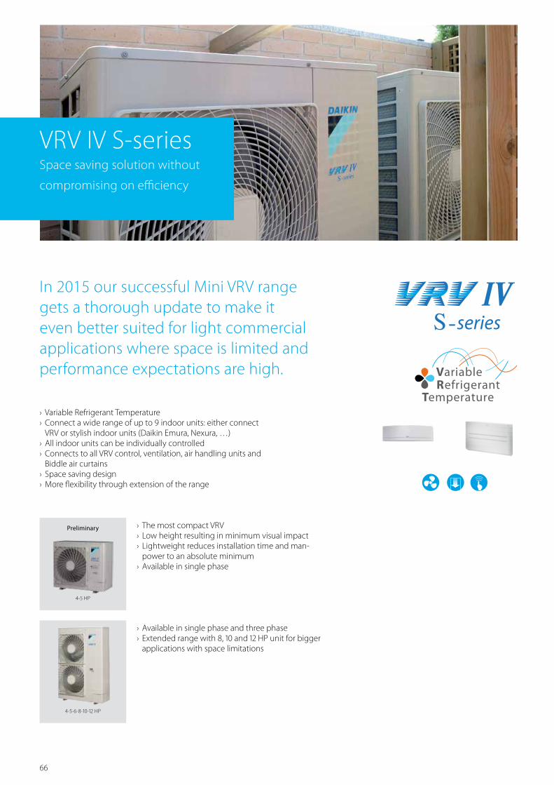
66
› Variable Refrigerant Temperature › Connect a wide range of up to 9 indoor units: either connect VRV or stylish indoor units (Daikin Emura, Nexura, …)
› All indoor units can be individually controlled › Connects to all VRV control, ventilation, air handling units and Biddle air curtains
› Space saving design › More flexibility through extension of the range
In 2015 our successful Mini VRV range gets a thorough update to make it even better suited for light commercial applications where space is limited and performance expectations are high.
VRV IV S-seriesSpace saving solution without
compromising on efficiency
› The most compact VRV › Low height resulting in minimum visual impact › Lightweight reduces installation time and man-power to an absolute minimum
› Available in single phase
› Available in single phase and three phase › Extended range with 8, 10 and 12 HP unit for bigger applications with space limitations
4-5 HP
4-5-6-8-10-12 HP
Preliminary

67
RXYSQ-P8V / RXYSQ-P8Y
VRVIII-S heat pump
Space saving solution without compromising on efficiency
› For residential and light commercial applications › Wide range of indoor units: either connect VRV or stylish indoor units such as Daikin Emura, Nexura ...
› Energy efficient heating system based on air source heat pump technology, lowering energy bills and CO
2 emmisions
› Connect up to 9 indoor units, which can all be individually controlled
› Possibility to combine different types of indoor units: wall mounted, floor standing, concealed ceiling, ceiling suspended, round flow or 4-way blow cassettes
› 3 steps in night quiet mode: step 1: 47dBA, step 2: 44 dBA, step 3: 41 dBA
› Contains all standard VRV features
RXYSQ-P8V1/RXYSQ-P8Y1
Outdoor unit RXYSQ 4P8V1 5P8V1 6P8V1 4P8Y1 5P8Y1 6P8Y1Capacity range HP 4 5 6 4 5 6Cooling capacity Nom. kW 12.6 14.0 15.5 12.6 14.0 15.5Heating capacity Nom. kW 14.2 16.0 18.0 14.2 16.0 18.0Power input - 50Hz Cooling Nom. kW 3.24 3.51 4.53 3.33 3.61 4.66
Heating Nom. kW 3.12 3.86 4.57 3.21 3.97 4.70EER 3.89 3.99 3.42 3.78 3.88 3.33COP 4.55 4.15 3.94 4.42 4.03 3.83Maximum number of connectable indoor units 8 (1) / 8 (2) 10 (1) / 9 (2) 12 (1) / 9 (2) 8 (1) / 8 (2) 10 (1) / 9 (2) 12 (1) / 9 (2)Indoor index connection
Min. 50 62.5 70 50 62.5 70Nom. -Max. 130 162.5 182 130 162.5 182
Dimensions Unit HeightxWidthxDepth mm 1,345x900x320Weight Unit kg 120Fan Air flow rate Cooling Nom. m³/min 106Sound power level Cooling Nom. dBA 66 67 69 66 67 69Sound pressure level Cooling Nom. dBA 50 51 53 50 51 53
Heating Nom. dBA 52 53 55 52 53 55Operation range Cooling Min.~Max. °CDB -5~46
Heating Min.~Max. °CWB -20~15.5Refrigerant Type / GWP R-410A / 2,087.5
Charge kg/TCO2Eq 4.0/8.4
Piping connections Liquid OD mm 9.52Gas OD mm 15.9 / 19.1 19.1 15.9 / 19.1 19.1Total piping length System Actual m 300 / 115 300 / 135 300 / 145 300 / 115 300 / 135 300 / 145
Power supply Phase/Frequency/Voltage Hz/V 1N~/50/220-240 3N~/50/380-415Current - 50Hz Maximum fuse amps (MFA) A 32.0 16.0
(1) In case VRV indoor units are connected (2) In case RA indoors are connected
Out
door
Uni
t Pro
duct
Ran
ge

68
RXYSQ-P8Y1 Hole for anchorbolt 4-M12
1 Gas pipe connection A2 Liquid connection pipe Ø9.5 are3 Service port (in the unit) (2x)4 Electronic connection and grounding terminal M5 (in switch box)5 Refrigerant piping intake6 Power supply wiring intake (knock hole Ø34)7 Control wiring intake (knock hole Ø27)8 Drain outlet
MODELA
With RA connection With VRV correctionRXYSQ4P8Y1 Ø19.1 Brazing Ø15.9 FlareRXYSQ5P8Y1 Ø19.1 Brazing Ø15.9 FlareRXYSQ6P8Y1 Ø19.1 Brazing Ø19.1 Brazing
3TW30374-1B
RXYSQ-P8V1 Hole for anchorbolt 4-M12
1 Gas pipe connection A2 Liquid connection pipe Ø9.5 are3 Service port (in the unit) (2x)4 Electronic connection and grounding terminal M5 (in switch box)5 Refrigerant piping intake6 Power supply wiring intake (knock hole Ø34)7 Control wiring intake (knock hole Ø27)8 Drain outlet
MODELA
With RA connection With VRV correctionRXYSQ4P8V1 Ø19.1 Brazing Ø15.9 FlareRXYSQ5P8V1 Ø19.1 Brazing Ø15.9 FlareRXYSQ6P8V1 Ø19.1 Brazing Ø19.1 Brazing
3TW30374-1B
Detailed technical drawings
RXYSQ-P8V1
RXYSQ-P8Y1

69
RXYSQ-P8V1
3D045696D
• Obstacle on both sides
100 or more
100 or more
100 or more
100 or more
1000 or more
200 or more 300 or more
500 or less
100 or more
1000
or m
ore
1000
or m
ore
500 or less
150 or more
150 or more150 or more
500 or less
1000 or more
200 or more300 or m
ore
1000
or m
ore
500 or more
1000 or more
1000
or m
ore500 or le
ss
500 or more
1000 or more
1000
or m
ore500 or le
ss
500or m
ore
100 or
more
300 or
more
1000
or more
500 or less
1000
or m
ore
250 or more
300 or more
1000
or m
ore
500or le
ss
500 or more
100 or more
1500
or more
500 or less
1000
or m
ore
1000
or more
500 or less
1000
or m
ore
1500
or more
A or m
ore
1000 or more
Dra
in p
ipin
g co
nstru
ctio
n di
men
sion
Dra
in p
ipin
g co
nstru
ctio
n di
men
sion
300or m
ore
1000
or more
200or m
ore
2000
or more
100or m
ore
1500
or more
600or m
ore
3000
or more
Required installation space(The unit of these values is ‘mm’)
1. Where there is an obstacle on the suction side:(a) No obstacle above
(1) Stand-alone installation• Obstacle on the suction side only
(b) Obstacle above, too(1) Stand-alone installation
The relations between H, A and L are follows:L A
L ≤ H 0 < L ≤ 1/2 H 1001/2 H < L ≤ H 200
H > L Set the stand as: L ≤ H
Close the bottom of the installation frame to prevent thedischarged air from being bypassed.
(2) Series installationThe relations between H, A and L are as follows
L AL ≤ H 0 < L ≤ 1/2 H 250
1/2 H < L ≤ H 300H < L Set the stand as: L ≤ H
Refer to the column of L ≤ H for A
Close the bottom of the installation frame to prevent thedischarged air from being bypassed.Only two units can be installed for this series.
5. Multiple rows of series installation(on the rooftop, etc.)(a) One row of stand-alone installation
(b) Rows of series installation (2 or more)The relations between H, A and L are as follows
L AL ≤ H 0 < L ≤ 1/2 H 250
1/2 H < L ≤ H 300H < L Can not be installed
(2) Series installation (2 or more)
The relations between H, A and L are as followsL A
0 < L ≤ 1/2 H 2501/2 H < L ≤ H 300
(a) Obstacle above, too(1) Stand-alone installation
(2) Series installation (2 or more)
2. Where there is an obstacle on the discharge side:(a) No obstacle above
(1) Stand-alone installation
(b) Obstacle above, too(1) Stand-alone installation
The relations between H, A and L are as followsL A
L ≤ H 0 < L ≤ 1/2 H 7501/2 H < L ≤ H 1000
H < L Set the stand as: L ≤ H
Close the bottom of the installation frame to prevent thedischarged air from being bypassed.
(2) Series installation (2 or more)The relations between H, A and L are as follows:
L AL ≤ H 0 < L ≤ 1/2 H 1000
1/2 H < L ≤ H 1250H < L Set the stand as: L ≤ H
Close the bottom of the installation frame to prevent thedischarged air from being bypassed.Only two units can be installed for this series
3. Where there are obstacles on both suction and discharge sides:
Pattern 1Where the obstacle on the discharge side is higher than the unit:
(There is no height limit for obstructions on the intake side)(a) No obstacle above
(1) Stand-alone installation
Pattern 2Where the obstacle on the discharge side is lower than the unit:
(There is no height limit for obstructions on the intake side)(a) No obstacle above
(1) Stand-alone installation
(2) Series installation (2 or more)
(2) Series installation (2 or more)
(2) Series installation (2 or more)• Obstacle on the suction side and both sides
(b) Obstacle above, too(1) Stand-alone installation
• Obstacle on the suction side, too
• Obstacle on the suction side and both sides
(2) Series installation (2 or more)• Obstacle on both sides
4. Double-decker installation(a) Obstacle on the discharge side
close the gap A (the gap between the upper and lower outdoor units) to prevent the discharged air from being bypassed.
Do not stack more than two units.
(b) Obstacle on the suction side close the gap A (the gap between the upper and lower outdoor units) to prevent the discharged air from being bypassed.
Do not stack more than two units.
L > H
L > H
L ≤ H
Detailed technical drawings
RXYSQ-P8V1 / / RXYSQ-PY1
Out
door
Uni
t Pro
duct
Ran
ge

70
VRVIII-C VRV heat pump where heating is priority without compromising on efficiency
› Automatic refrigerant charge
› Refrigerant containment check
› Night quiet mode
› Low noise function
› Reluctance brushless DC compressor
› Sine wave DC inverter
› DC fan motor
› E-pass heat exchanger
› I demand function
Air curtainBiddle Air curtain for VRV (CYV)
Indoor unitsVRV type indoor units
Control systems
VentilationHeat Reclaim ventilation (VAM/VKM)
AHU connection kit
22

71
Wide heating operation rangeVRVIII-C has a standard operation range down to -25 °CWB outdoor ambient in heating and can also provide cooling down to - 5 °CDB outdoor ambient.
heat
ing
capa
cityStable heating capacity
VRVIII-C has a stable heating capacity, even in low ambients, making it suitable for single source heating. The heating capacity is 130% in comparison with the standard VRV heating capacity under similar conditions.
-25 -20 -15 -10 -5 0 5 10
Heating capacity 10HP outdoor unit
Outdoor temp. (°CWB)
(kW) 35
30
25
20
15
10
5
0
standard heat pump
COP
4.00
3.00
2.00
1.00
0.00-25 -20 -15 -10 -5 0 5 10
Standard heat pump
Outdoor temp. (WB°)
COP for a 10HP unitHigh COP at low ambientsThe use of two stage compression technology results in improved energy saving performance at low ambients, with a COP of more than 3.0 at -10°C outdoor ambient for the entire range.
Outdoor Temp. Outdoor Temp.
VRVIII-C
-25°CWB -5°C
Standard VRV
-20°CWB 15.5°C 43°CDB
Heating mode Cooling mode
Out
door
Uni
t Pro
duct
Ran
ge
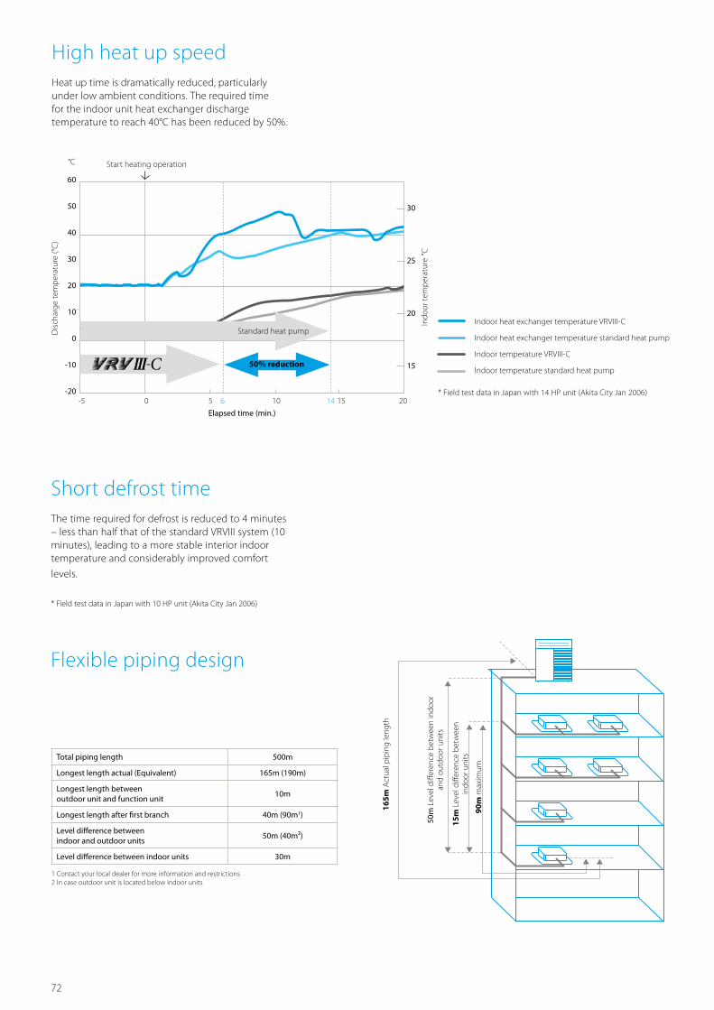
72
Total piping length 500m
Longest length actual (Equivalent) 165m (190m)
Longest length between outdoor unit and function unit
10m
Longest length after first branch 40m (90m1)
Level difference between indoor and outdoor units
50m (40m²)
Level difference between indoor units 30m
1 Contact your local dealer for more information and restrictions 2 In case outdoor unit is located below indoor units
Flexible piping design
165m
Act
ual p
ipin
g le
ngth
50m
Lev
el d
iffer
ence
bet
wee
n in
door
an
d ou
tdoo
r uni
ts
15m
Lev
el d
iffer
ence
bet
wee
n
indo
or u
nits
90m
max
imum
30
25
20
15
60
50
40
30
20
10
0
-10
-20
°C
positie blauwe lijnen:X +10
-5 0 5 6 10 14 15 20
High heat up speedHeat up time is dramatically reduced, particularly under low ambient conditions. The required time for the indoor unit heat exchanger discharge temperature to reach 40°C has been reduced by 50%.
Indoor heat exchanger temperature VRVIII-C
Indoor heat exchanger temperature standard heat pump
Indoor temperature VRVIII-C
Indoor temperature standard heat pump
Start heating operation
Elapsed time (min.)
* Field test data in Japan with 14 HP unit (Akita City Jan 2006)
Standard heat pump
50% reduction
Indo
or te
mpe
ratu
re °C
Dis
char
ge te
mpe
ratu
re (°
C)
Short defrost timeThe time required for defrost is reduced to 4 minutes – less than half that of the standard VRVIII system (10 minutes), leading to a more stable interior indoor temperature and considerably improved comfort
levels.
* Field test data in Japan with 10 HP unit (Akita City Jan 2006)

73
RTSYQ14-16PA
Outdoor system RTSYQ 10PA 14PA 16PA 20PASystem Outdoor unit module 1 RTSQ10PAY1 RTSQ14PAY1 RTSQ16PAY1 RTSQ8PAY1
Outdoor unit module 2 - RTSQ12PAY1Function unit BTSQ20PY1
Capacity range HP 10 14 16 20Cooling capacity Nom. kW 28.0 40.0 45.0 56.0Heating capacity Nom. kW 31.5 / 28.0 45.0 / 40.0 50.0 / 45.0 63.0 / 55.9Power input - 50Hz Cooling Nom. kW 7.90 12.6 14.9 15.4
Heating Nom. kW 7.78 / 8.18 11.4 / 12.8 13.0 / 15.0 15.4 / 18.7EER 3.54 3.17 3.02 3.64COP 4.05 / 3.42 3.95 / 3.13 3.85 / 3.00 4.09 / 2.99Maximum number of connectable indoor units 21 30 34 43Indoor index connection
Min. 125 175 200 250Nom. 250 350 400 500Max. 325 455 520 650
Sound pressure level Cooling Max./Nom. dBA 62/60 63/61 65/63Piping connections Liquid OD mm 9.52 12.7 15.9
Gas OD mm 22.2 28.6Oil equalizing OD mm - 19.1Total piping length System Actual m 500
Current - 50Hz Maximum fuse amps (MFA) A 25 35 40 50
Outdoor unit module BTSQ20P RTSQ8PA RTSQ10PA RTSQ12PA RTSQ14PA RTSQ16PADimensions Unit HeightxWidthxDepth mm 1,570x460x765 1,680x930x765 1,680x1,240x765Weight Unit kg 110 205 257 338 344Fan Air flow rate Cooling Nom. m³/min - 185 200 233 239Sound power level Cooling Nom. dBA -Operation range Cooling Min.~Max. °CDB -5~43
Heating Min.~Max. °CWB -25~15.5Refrigerant Type / GWP R-410A / 2,087.5
Charge kg/TCO2Eq - 9.4/19.6 10.5/21.9 10.9/22.8 11.7/24.4
Power supply Phase/Frequency/Voltage Hz/V 3~/50/380-415Current - 50Hz Maximum fuse amps (MFA) A 20 25 35 40
VRVIII heat pump, optimised for heating
Where heating is priority without compromising on efficiency
› First system in the industry developed for heating operation in low ambient conditions, making it suitable for single source heating
› Extended operation range down to -25°C in heating › Stable heating capacity and high COP values at low ambients thanks to the two stage compression technology (COP values of 3.0 and more at -10°C)
› Improved comfort thanks to shorter defrost time › Shorter heat up time compared to standard VRVIII heat pump › Contains all standard VRV features
RTSYQ-PA
Two stage compression
Two stage compression technology enables the system to create higher pressures resulting in a higher heating capacity under low ambient conditions. The second inverter compressor (located in the function unit) is specially designed to provide higher pressures.After heat is exchanged in the indoor unit, gas and liquid are separated at the gas-liquid separator. This enables the refrigerant in gas condition to be recovered and transmitted direct to the high pressure compressor.
Heating capacity
Enthalpy
Pres
sure
Evaporator capacity
Gas injection
Gas-liquidseparator
Input power
High
Middle
Low
Liquid injection
Out
door
Uni
t Pro
duct
Ran
ge

74
3D076286
RTSYQ10PA4-15 x 22.5 - mm - Oblong holes
(Foundation bolt hole)
Outdoor unit
50~100mm
Function unit
(Pitch of foundation bolt holes) (Pitch of foundation bolt holes)
(Pitch
of fo
unda
tion b
olt ho
les)
(Pitch
of fou
ndation
bolt h
oles)
NOTES
1. Heights of walls in case of Patterns 1 and 2:Front: 1500mm Suction side: 500mm Side: Height unrestricted Installation space to be shown in this drawing is based on the cooling operation at 35 degrees outdoor air temperature. When the design outdoor air temperature exceeds 35 degrees or the load exceeds maximum ability because of much generation load of heat in all outdoor unit, take the suction side space more broadly than the space to be shown in this drawing.
2. If the above wall heights are exceeded then h2/2 and h1/2 should be added to the front and suction side service spaces respectively as shown in the figure on the right.
3. When installing the units most appropriate pattern should be selected from those shown above in order to obtain the best fit in the space available always bearing in mind the need to leave enough space for a person to pass between units and wall and for the air to circulate freely. (If more units are to be installed than are catered for in the above patterns your layout should take account of the possibility of short circuits.)
4. The units should be installed to leave sufficient space at the front for the on site refrigerant piping work to be carried out comfortably.
5. In case there expected heavy snow, prepare some countermeasures recommended as follows: 1) Outdoor and Function unit must be installed on a foundation (field supply) in order to secure a distance of 200-300mm or more between the bottom frame and the snow-laid ground surface.2) Install a snowbreak hood (option) and remove its back side air inlet grill.
6. Air outlet of snowbreak hood must face at right angle or lower level than the winter wind, in case a snowbreak hood is installed at the air outlet of the unit.
7. In case there expected to freeze of exhausted water from de-frost operation due to the cold outdoor temperature in winter time, secure a sufficient space between the bottom frame and the foundation. (500-1000mm is suggested as an appropreate distance.)
10 or more 10 or more
1500
mm
<Fro
nt>
<Suc
tion s
ide>
500m
m
(Front)
300 or more
500 or more
System Outdoor unit DWG. No. Function unit DWG. No.
RTSYQ10PA RTSQ10PA 3D076289 BTSQ20P 3D060838
Detailed technical drawings
RTSYQ10PA
RTSYQ14,16PA
3D076287
RTSYQ14,16PA4-15 x 22.5 - mm - Oblong holes
(Foundation bolt hole)
Outdoor unitFunction unit
(Pitch of foundation bolt holes)
(Pitch
of fo
unda
tion b
olt ho
les)
(Pitch
of fou
ndation
bolt h
oles)
NOTES
1. Heights of walls in case of Patterns 1 and 2:Front: 1500mm Suction side: 500mm Side: Height unrestricted Installation space to be shown in this drawing is based on the cooling operation at 35 degrees outdoor air temperature. When the design outdoor air temperature exceeds 35 degrees or the load exceeds maximum ability because of much generation load of heat in all outdoor unit, take the suction side space more broadly than the space to be shown in this drawing.
2. If the above wall heights are exceeded then h2/2 and h1/2 should be added to the front and suction side service spaces respectively as shown in the figure on the right.
3. When installing the units most appropriate pattern should be selected from those shown above in order to obtain the best fit in the space available always bearing in mind the need to leave enough space for a person to pass between units and wall and for the air to circulate freely. (If more units are to be installed than are catered for in the above patterns your layout should take account of the possibility of short circuits.)
4. The units should be installed to leave sufficient space at the front for the on site refrigerant piping work to be carried out comfortably.
5. In case there expected heavy snow, prepare some countermeasures recommended as follows: 1) Outdoor and Function unit must be installed on a foundation (field supply) in order to secure a distance of 200-300mm or more between the bottom frame and the snow-laid ground surface.2) Install a snowbreak hood (option) and remove its back side air inlet grill.
6. Air outlet of snowbreak hood must face at right angle or lower level than the winter wind, in case a snowbreak hood is installed at the air outlet of the unit.
7. In case there expected to freeze of exhausted water from de-frost operation due to the cold outdoor temperature in winter time, secure a sufficient space between the bottom frame and the foundation. (500-1000mm is suggested as an appropreate distance.)
10 or more 10 or more
1500
mm
<Fro
nt>
<Suc
tion s
ide>
500m
m
(Front)
300 or more
500 or more
System Outdoor unit DWG. No. Function unit DWG. No.
RTSYQ14PA RTSQ14PA 3D076291 BTSQ20P 3D060838
RTSYQ16PA RTSQ16PA 3D076291 BTSQ20P 3D060838

75
Detailed technical drawings
RTSYQ20PA
3D076288
RTSYQ20PA
4-15 x 22.5 - mm - Oblong holes(Foundation bolt hole)
4-15 x 22.5 - mm - Oblong holes(Foundation bolt hole)
Outdoor unit 1
20mm 50~100mm
Outdoor unit 2Function unit
(Pitch of foundation bolt holes)
(Pitch of foundation bolt holes)
(Pitch of foundation bolt holes)
(Pitch
of fo
unda
tion b
olt ho
les)
(Pitch
of foun
dation
bolt h
oles)
NOTES
1. Heights of walls in case of Patterns 1 and 2:Front: 1500mm Suction side: 500mm Side: Height unrestricted Installation space to be shown in this drawing is based on the cooling operation at 35 degrees outdoor air temperature. When the design outdoor air temperature exceeds 35 degrees or the load exceeds maximum ability because of much generation load of heat in all outdoor unit, take the suction side space more broadly than the space to be shown in this drawing.
2. If the above wall heights are exceeded then h2/2 and h1/2 should be added to the front and suction side service spaces respectively as shown in the figure on the right.
3. When installing the units most appropriate pattern should be selected from those shown above in order to obtain the best fit in the space available always bearing in mind the need to leave enough space for a person to pass between units and wall and for the air to circulate freely. (If more units are to be installed than are catered for in the above patterns your layout should take account of the possibility of short circuits.)
4. The units should be installed to leave sufficient space at the front for the on site refrigerant piping work to be carried out comfortably.
5. In case there expected heavy snow, prepare some countermeasures recommended as follows: 1) Outdoor and Function unit must be installed on a foundation (field supply) in order to secure a distance of 200-300mm or more between the bottom frame and the snow-laid ground surface.2) Install a snowbreak hood (option) and remove its back side air inlet grill.
6. Air outlet of snowbreak hood must face at right angle or lower level than the winter wind, in case a snowbreak hood is installed at the air outlet of the unit.
7. In case there expected to freeze of exhausted water from de-frost operation due to the cold outdoor temperature in winter time, secure a sufficient space between the bottom frame and the foundation. (500-1000mm is suggested as an appropreate distance.)
1500
mm
<Fro
nt>
<Suc
tion s
ide>
500m
m System Outdoor unit 1 DWG. No. Outdoor unit 2 DWG. No. Function unit DWG. No.
RTSYQ20PA RTSQ12PA 3D076290 RTSQ8PA 3D076290 BTSQ20P 3D060838
10 or more
20 or more
10 or more(Front)
300 or more
500 or more
RTSYQ-PA
3D059348C
NOTES1. Heights of walls in case of Patterns 1 and 2:
Front: 1500 mm Suction side : 500 mm Side: Height unrestricted. Installation space to be shown in this drawing is based on the cooling operation at 35 degrees outdoor air temperature. When the design outdoor air temperature exceeds 35 degrees or the load exceeds maximum ability because of much generation load of heat in all outdoor unit, take the suction side space more broadly than the space to be shown in this drawing.
2. If the above wall heights are exceeded then h2/2 and h1/2 should be added to the front and suction side service spaces respectively as shown in the figure on the right.
3. When installing the units most appropriate pattern should be selected from those shown above in order to obtain the best fit in the space available always bearing in mind the need to leave enough space for a person to pass between units and wall and for the air to circulate freely. (If more units are to be installed than are catered for in the above patterns your layout should take account of the possibility of short circuits.)
4. The units should be installed to leave sufficient space at the front for the on site refrigerant piping work to be carried out comfortably.
5. Installation of snowbreak hood (field supply; ask you dealer for details) is recommended in case there expected an effect from snow and space between outdoor unit and function unit is more than 100 mm.
RTSYQ-PA
For single unit installation
< Pattern 1 >
< Pattern 2 >
< Pattern 3 >< Pattern 2 >
< Unit: mm >
1500
mm
10 or more 10 or more
50 or more
50 or more
100 or more
10 or more
50 or more
10 or more
10 or more
10 or more
100 or more
100 or more
300 or more 300 or more 300 or more
300 or more
Wall height unrestricted
100 or more
10 or more 10 or more
10 or more
10 or more
10 or more
10 or more
10 or more
10 or more
50 or more 50 or more
50 or more
50 or more
50 or more
50 or more
50 or more
10 or more
50 or more
50 or more
500 or more
500 or more
500 or more
500 or more
300 or more
600 or more
500 or more
200 or more200 or more
20 or more 20 or more
100 or more
100 or more
20 or more
20 or more
20 or more
100 or more
100 or more500 or more
100 or more
<Front> <Front> <Front>
<Front>
<Front>
<Front>
<Front>
<Front>
<Front>
<Front>
50 or more
400 or more
< Fr
ont >
< Su
ction
side
>
500m
m
< Pattern 1 >
For installation in rows
20 or more
50 or more
Out
door
Uni
t Pro
duct
Ran
ge

76
VRV Classic heat pump RXYCQ-AFor standard cooling & heating requirements
› Low noise function
› Reluctance brushless DC compressor
› Sine wave DC inverter
› DC fan motor
› E-pass heat exchanger
› Manual demand function
Indoor unitsVRV type indoor units
VentilationHeat Reclaim ventilation (VAM/VKM)
Control systems
22

77
Benefits › For projects with standard cooling & heating requirements
› Fits any building as also indoor installation is possible as a result of high external static pressure of up to 78.4 Pa. Indoor installation leads to less piping length, lower installation costs, increased efficiency and better visual aesthetics
› The ability to control each conditioned zone
Total piping length 300m
Longest length actual (Equivalent) 135m (155m)
Longest length after first branch 40m (90m1)
Level difference between indoor and outdoor units 30m
Level difference between indoor units 15m
1 Contact your local dealer for more information and restrictions
Flexible piping design
individually keeps VRV system running costs to an absolute minimum
› Spread your installation cost by phased installation › Connectable to all standard VRV indoor units, controls and ventilation
Out
door
Uni
t Pro
duct
Ran
ge

78
RXYCQ14-20A
Outdoor unit RXYCQ 8A 10A 12A 14A 16A 18A 20ACapacity range HP 8 10 12 14 16 18 20Cooling capacity Nom. kW 20.0 25.0 30.0 35.0 40.0 45.0 50.4Heating capacity Nom. kW 22.4 28.0 33.6 31.5 44.8 50.4 56.5Power input - 50Hz Cooling Nom. kW 6.60 6.74 8.77 11.4 12.9 15.0 17.9
Heating Nom. kW 5.80 7.00 8.62 8.18 11.8 13.8 16.1EER 3.03 3.71 3.42 3.07 3.10 3.00 2.81COP 3.86 4.00 3.90 3.85 3.80 3.65 3.50Maximum number of connectable indoor units 64Indoor index connection
Min. 100 125 150 175 200 225 250Nom. 200 250 300 350 400 450 500Max. 200 250 360 420 480 540 600
Dimensions Unit HeightxWidthxDepth mm 1,680x635x765 1,680x930x765 1,680x1,240x765Weight Unit kg 159 187 240 316 324Fan Air flow rate Cooling Nom. m³/min 95 171 185 196 233 239Sound power level Cooling Nom. dBA 78 81 86 88Sound pressure level Cooling Nom. dBA 58 59 61 64 65 66Operation range Cooling Min.~Max. °CDB -5~43
Heating Min.~Max. °CWB -20~15.5Refrigerant Type / GWP R-410A / 2,087.5
Charge kg 6.2 7.7 8.4 8.6 11.3 11.5 17.7Charge TCO
2Eq 12.9 16.1 17.5 18 23.6 24 24.4
Piping connections Liquid OD mm 9.52 12.7 15.9Gas OD mm 15.9 19.1 22.2 28.6Total piping length System Actual m 300
Power supply Phase/Frequency/Voltage Hz/V 3N~/50/380-415Current - 50Hz Maximum fuse amps (MFA) A 16 25 40
VRV Classic
Classic VRV configuration
› For standard cooling & heating requirements › Connectable to all standard VRV indoor units, controls and ventilation
› Contains all standard VRV features
RXYCQ-A

79
RXYCQ8A
Detail for front side
4-15 x 22.5 - mm - Oblong holes (Foundation bolt hole)
(knock-out hole)
(knock-out hole) (knock-out hole)
(knock-out hole)
(knock-out hole)
(Pitch of foundation bolt holes)
(Pitc
h of fo
unda
tion
bolt h
oles)
Detail for bottom side
No. Parts name Remarks1 Liquid pipe connection port ø 9.5 Brazing connection2 Gas pipe connection port ø 15.9 Brazing connection3 Grounding terminal Inside of switch box (M8)4 Power cord routing hole (side) ø 625 Power cord routing hole (front) ø 456 Power cord routing hole (front) ø 277 Power cord routing hole (bottom) ø 508 Wire routing hole (front) ø 279 Pipe routing hole (front)10 Pipe routing hole (bottom)
NOTES
1. Detail for front side and detail for bottom side indicate the dimensions after fixing the attached piping.
3D080764
Detailed technical drawings
RXYCQ8A
RXYCQ10-14A
Detail for front side
4-15 x 22.5 - mm - Oblong holes (Foundation bolt hole)
(knock-out hole)(knock-out hole)
(knock-out hole)
(knock-out hole)
(knock-out hole)
(Pitch of foundation bolt holes)
(Pitc
h of fo
unda
tion
bolt h
oles)
Detail for bottom side
No. Parts name Remarks1 Liquid pipe connection port See note 22 Gas pipe connection port See note 23 Grounding terminal Inside of switch box (M8)4 Power cord routing hole (side) ø 625 Power cord routing hole (front) ø 456 Power cord routing hole (front) ø 277 Power cord routing hole (bottom) ø 65.58 Wire routing hole (front) ø 279 Pipe routing hole (front)10 Pipe routing hole (bottom)
NOTES
1. Detail for front side and detail for bottom side indicate the dimensions after fixing the attached piping.
2. Gas pipe: ø 19.1 Brazing connection: RXYCQ10 ø 22.2 Brazing connection: RXYCQ12 ø 28.6 Brazing connection: RXYCQ14 Liquid pipe: ø 9.5 Brazing connection: RXYCQ10, RXYCQ12 ø 28.6 Brazing connection: RXYCQ14 3D080763
(for 10HP)
RXYCQ10-14A
Out
door
Uni
t Pro
duct
Ran
ge

80
Detail for front side
4-15 x 22.5 - mm - Oblong holes (Foundation bolt hole)
(knock-out hole)(knock-out hole)
(knock-out hole)
(knock-out hole)
(knock-out hole)
(Pitch of foundation bolt holes)
(Pitc
h of fo
unda
tion
bolt h
oles)
Detail for bottom side
No. Parts name Remarks1 Liquid pipe connection port See note 22 Gas pipe connection port See note 23 Grounding terminal Inside of switch box (M8)4 Power cord routing hole (side) ø 625 Power cord routing hole (front) ø 456 Power cord routing hole (front) ø 277 Power cord routing hole (bottom) ø 65.58 Wire routing hole (front) ø 279 Pipe routing hole (front)10 Pipe routing hole (bottom)
Model. AA ABRXYCQ16 83 179RXYCQ18 83 179RXYCQ20 63 160
NOTES
1. Detail for front side and detail for bottom side indicate the dimensions after fixing the attached piping.
2. Gas pipe: ø 28.6 Brazing connection: RXYCQ16,18,20 Liquid pipe: ø 12.7 Brazing connection: RXYCQ20 ø 9.5 Brazing connection: RXYCQ16,18
3D080767
RXYCQ16-20A
Detailed technical drawings
RXYCQ16-20A
RXYCQ-A
3D051451U
NOTES1. HeightsofwallsincaseofPatterns1and2:
Front:1500mmSuctionside:500mmSide:heightunrestricted.Installationspacetobeshowninthisdrawingisbasedonthecoolingoperationat35degreesoutdoorairtemperature.Whenthedesignoutdoorairtemperatureexceeds35degreesortheloadexceedsmaximumabilitybecauseofmuchgenerationloadofheatinalloutdoorunit,takethesuctionsidespacemorebroadlythanthespacetobeshowninthisdrawing.
2. Iftheabovewallheightsareexceededthenh2/2andh1/2shouldbeaddedtothefrontandsuctionsideservicespacesrespectivelyasshowninthefigureontheright.
3. Wheninstallingtheunitsmostappropriatepatternshouldbeselectedfromthoseshownaboveinordertoobtainthebestfitinthespaceavailablealwaysbearinginmindtheneedtoleaveenoughspaceforapersontopassbetweenunitsandwallandfortheairtocirculatefreely.(Ifmoreunitsaretobeinstalledthanarecateredforintheabovepatternsyourlayoutshouldtakeaccountofthepossibilityofshortcircuits.)
4. Theunitsshouldbeinstalledtoleavesufficientspaceatthefrontfortheonsiterefrigerantpipingworktobecarriedoutcomfortably.
Forsingleunitinstallation Forinstallationinrows Forcentralizedgrouplayout<Pattern1>
10ormore
300ormore
500ormore 500ormore
500ormore
600ormore
500ormore
500ormore
500ormore
500ormore
500ormore500ormore
200ormore 200ormore400ormore 400ormore
100ormore
50ormore 50ormore 50ormore 50ormore
50ormore 50ormore50ormore
50ormore
50ormore
1500mm
500m
m
h2
h1
50ormore50ormore 50ormore
<Unit:mm>
100ormore 100ormore
100ormore 100ormore
100ormore100ormore
100ormore
100ormore100ormore 100ormore
300ormore300ormore
300ormore 300ormore 300ormore
300ormore
10ormore 10ormore 10ormore 10ormore 20ormore20ormore20ormore 20ormore
20ormore20ormore
10ormore10ormore 10ormore
10ormore 10ormore10ormore 10ormore
<Front> <Front>
<Front><Front>
<Front> <Front> <Front>
<Front>
<Front>
<Front>
<Front>
<Front>
<Front>
<Front>
<Su
ctionside>
<Front>
<Pattern2>
<Pattern3> <Pattern3>
Wallheightunrestriced
Wallheightunrestriced
<Pattern2>
<Pattern2>
<Pattern1> <Pattern1>
RXYCQ-A
Control systems

81
Replacement VRVQuick & quality replacement for R-22 and R-407C systems
› Automatic refrigerant charge
› Night quiet mode
› Low noise function
› Full inverter compressors
› Reluctance brushless DC compressor
› Sine wave DC inverter
› DC fan motor
› E-pass heat exchanger
› I demand function
Heat pump & Heat recoveryHeat pump
For more information on these features refer to the VRV IV technologies tab
Variable refrigerant temperature Customize your VRV for best seasonal efficiency & comfort
VRV configuratorSoftware for simplified commissioning, configuration and customisation
VRV IV
VRV III
Air curtainBiddle Air curtain for VRV (CYV)
Indoor unitsVRV type indoor units
Control systems
VentilationHeat Reclaim ventilation (VAM/VKM)
AHU connection kit
22
› 7 segment indicator
› Automatic refrigerant charge
› Night quiet mode
› Low noise function
› Full inverter compressors
› Gas cooled PCB
› 4 side heat exchanger
› Reluctance brushless DC compressor
› Sine wave DC inverter
› DC fan motor
› E-pass heat exchanger
› I demand function
Out
door
Uni
t Pro
duct
Ran
ge

82
R-22 ban in Europe
Service and maintenance with R-22 will be prohibited after january 1st, 2015, meaning repairs will be impossible to R-22 systems. Avoid unexpected downtime for your customers and replace these systems now!
Replacement technologyThe quick and quality way of
upgrading R-22 and R-407C systems
These benefits willconvince your customer
Avoid loss of business
Replacing now prevents unplanned, lengthy downtime of air conditioning systems. It also avoids loss of business for shops, complaints from guests in hotels, lower working efficiency and loss of tenants in offices.
Quick and easy installation
No interruption of daily business while replacing the system thanks to phased-in, fast installation.
Smaller footprint, more performance
Thanks to a smaller footprint, Daikin outdoor units save space. Also, more indoor units can be connected to the new outdoor unit compared to the old system, allowing to increase capacity.
Lower long-term costs
EU Directives prohibit system repairs with R-22 after January 1st, 2015. Delaying the required R-22 replacement until an unplanned system breakdown is a losing game. Replacement day will come. Installing a technically advanced system lowers energy consumption and maintenance costs from day one.
Always operational
The phase-out period for R-22 is over. Act now!
The Daikin low-cost upgrade solution
! Replace indoor units and BS boxesContact your local dealer to check compatibility in case you need to keep the indoor units.
! Replace outdoor units
Up to 48% less consumption
Comparison of 10HP systems: Cooling mode Heating mode
R-410A (RXYQQ-T)R-407C (RSXYP-L7)R-22 (RSXY-KA7)

83
VRV-Q benefits to increase your profit
Optimise your businessLess installation time
Tackle more projects in less time thanks to faster installation. It is more profitable than replacing the full system with new piping.
Lower installation costs
Reducing installation costs enables you to offer customers the most cost-effective solution and improve your competitive edge.
Replace non-Daikin systems
It is a trouble-free replacement solution for Daikin systems and for systems made by other manufacturers.
Easy as one-two-three
A simple solution for replacement technology enables you to handle more projects for more customers in less time and offer them the best price! Everybody gains.
Conventional solution VRV-Q
1 Recover refrigerant 1 Recover refrigerant
2 Remove units 2 Remove units
3 Remove refrigerant pipes Re-use existing piping and wiring4 Install new piping and wiring
5 Install new units 3 Install new units
6 Leak test 4 Leak test
7 Vacuum drying 5 Vacuum drying
8 Refrigerant charging6 Auromatic refrigerant charging,
cleaning and testing9 Collect contamination
10 Test operation
âUp to 45% shorter installation time
Compare installation steps
One touch convenience: › Measure and charge refrigerant
› Automatic pipe cleaning
› Test operation
Automatic refrigerant chargeThe unique automatic refrigerant charge eliminates the need to calculate refrigerant volume and ensures that the system will operate perfectly. Not knowing the exact piping lengths because of changes or mistakes in case you didn’t do the original installation or replacing a competitor installation no longer poses a problem.
Automatic pipe cleaningThere is no need to clean inside piping as this is handled automatically by the VRV-Q unit. Finally the test operation is performed automatically to save time.
Out
door
Uni
t Pro
duct
Ran
ge

84
RQCEQ712-848P
Outdoor system RQCEQ 280P 360P 460P 500P 540P 636P 712P 744P 816P 848PSystem Outdoor unit module 1 RQEQ140P RQEQ180P RQEQ140P RQEQ180P RQEQ212P RQEQ140P RQEQ180P RQEQ212P
Outdoor unit module 2 RQEQ140P RQEQ180P RQEQ140P RQEQ180P RQEQ212P RQEQ180P RQEQ212POutdoor unit module 3 - RQEQ180P RQEQ212P RQEQ180P RQEQ212POutdoor unit module 4 - RQEQ212P
Capacity range HP 10 13 16 18 20 22 24 26 28 30Cooling capacity Nom. kW 28.0 36.0 45.0 50.0 54.0 63.6 71.2 74.4 81.6 84.8Heating capacity Nom. kW 32.0 40.0 52.0 56.0 60.0 67.2 78.4 80.8 87.2 89.6Power input - 50Hz Cooling Nom. kW 7.04 10.3 12.2 13.9 15.5 21.9 21.2 23.3 27.1 29.2
Heating Nom. kW 8.00 10.7 13.4 14.7 16.1 17.7 20.7 21.2 23.1 23.6EER 3.98 3.48 3.77 3.61 3.48 2.90 3.36 3.19 3.01 2.90COP 4.00 3.72 3.89 3.80 3.72 3.79 3.80 3.81 3.77 3.79Maximum number of connectable indoor units 21 28 34 39 43 47 52 56 60 64Indoor index connection
Min. 140 180 230 250 270 318 356 372 408 424Nom. 280 360 500 540 636 712 744 816 848Max. 364 468 598 650 702 827 926 967.0 1,061 1,102
Sound pressure level Cooling Nom. dBA 57 61 62 63 64 63 64 65 66Piping connections Liquid OD mm 9.52 12.7 15.9 19.1
Gas OD mm 22.2 25.4 28.6 34.9Discharge gas OD mm 19.1 22.2 25.4 28.6Total piping length System Actual m 300
Current - 50Hz Maximum fuse amps (MFA) A 30 40 50 60 70 80 90
Outdoor unit module RQEQ 140P 180P 212PDimensions Unit HeightxWidthxDepth mm 1,680x635x765Weight Unit kg 175 179Fan Air flow rate Cooling Nom. m³/min 95 110Sound power level Cooling Nom. dBA -Sound pressure level Cooling Nom. dBA 54 58 60Operation range Cooling Min.~Max. °CDB -5~43
Heating Min.~Max. °CWB -20~15.5Refrigerant Type / GWP R-410A / 2,087.5
Charge kg/TCO2Eq 10.3/21.5 10.6/22.1 11.2/23.4
Power supply Phase/Frequency/Voltage Hz/V 3~/50/380-415Current - 50Hz Maximum fuse amps (MFA) A 15 20 22.5
(1) Not Eurovent certified
Replacement VRV
Quick & quality replacement for R-22 and R-407C systems
› Cost-effective and fast replacement through re-use of exisiting piping
› Up to 80% more efficient than R-22 systems › No interuption of daily business while replacing your system › Replace Daikin and other manufacturers systems safely › Automatic cleaning of refrigerant pipe work ensures a quality replacement
› Possibility to increase capacity › Limited and phased investment cost › Incorporates VRV IV standards & technologies: Variable Refriger-ant Temperature, VRV configurator, 7 segment display and full inverter compressors, 4-side heat exchanger, refrigerant cooled PCB, new DC fan motor (for RXYQQ-T only)
› Contains all standard VRV features
RQCEQ-P (heat recovery)
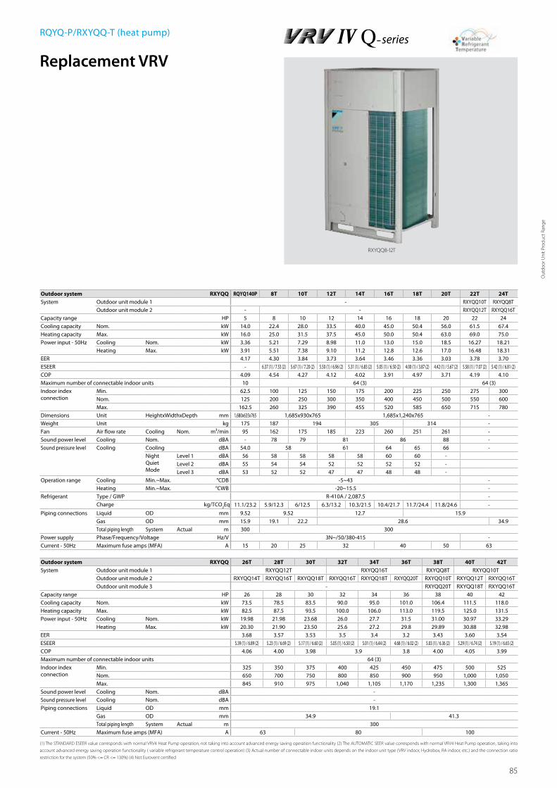
85
Replacement VRV
Outdoor system RXYQQ RQYQ140P 8T 10T 12T 14T 16T 18T 20T 22T 24TSystem Outdoor unit module 1 - RXYQQ10T RXYQQ8T
Outdoor unit module 2 - - RXYQQ12T RXYQQ16TCapacity range HP 5 8 10 12 14 16 18 20 22 24Cooling capacity Nom. kW 14.0 22.4 28.0 33.5 40.0 45.0 50.4 56.0 61.5 67.4Heating capacity Max. kW 16.0 25.0 31.5 37.5 45.0 50.0 50.4 63.0 69.0 75.0Power input - 50Hz Cooling Nom. kW 3.36 5.21 7.29 8.98 11.0 13.0 15.0 18.5 16.27 18.21
Heating Max. kW 3.91 5.51 7.38 9.10 11.2 12.8 12.6 17.0 16.48 18.31EER 4.17 4.30 3.84 3.73 3.64 3.46 3.36 3.03 3.78 3.70ESEER - 6.37 (1) / 7.53 (2) 5.67 (1) / 7.20 (2) 5.50 (1) / 6.96 (2) 5.31 (1) / 6.83 (2) 5.05 (1) / 6.50 (2) 4.00 (1) / 3.87 (2) 4.42 (1) / 5.67 (2) 5.58 (1) / 7.07 (2) 5.42 (1) / 6.81 (2)COP 4.09 4.54 4.27 4.12 4.02 3.91 4.97 3.71 4.19 4.10Maximum number of connectable indoor units 10 64 (3) 64 (3)Indoor index connection
Min. 62.5 100 125 150 175 200 225 250 275 300Nom. 125 200 250 300 350 400 450 500 550 600Max. 162.5 260 325 390 455 520 585 650 715 780
Dimensions Unit HeightxWidthxDepth mm 1,680x635x765 1,685x930x765 1,685x1,240x765 -Weight Unit kg 175 187 194 305 314 -Fan Air flow rate Cooling Nom. m³/min 95 162 175 185 223 260 251 261 -Sound power level Cooling Nom. dBA - 78 79 81 86 88 -Sound pressure level Cooling Cooling dBA 54.0 58 61 64 65 66 -
Night Quiet Mode
Level 1 dBA 56 58 58 58 58 60 60 -Level 2 dBA 55 54 54 52 52 52 52 -Level 3 dBA 53 52 52 47 47 48 48 -
Operation range Cooling Min.~Max. °CDB -5~43 -Heating Min.~Max. °CWB -20~15.5 -
Refrigerant Type / GWP R-410A / 2,087.5 -Charge kg/TCO
2Eq 11.1/23.2 5.9/12.3 6/12.5 6.3/13.2 10.3/21.5 10.4/21.7 11.7/24.4 11.8/24.6 -
Piping connections Liquid OD mm 9.52 9.52 12.7 15.9Gas OD mm 15.9 19.1 22.2 28.6 34.9Total piping length System Actual m 300 300
Power supply Phase/Frequency/Voltage Hz/V 3N~/50/380-415 -Current - 50Hz Maximum fuse amps (MFA) A 15 20 25 32 40 50 63
Outdoor system RXYQQ 26T 28T 30T 32T 34T 36T 38T 40T 42TSystem Outdoor unit module 1 RXYQQ12T RXYQQ16T RXYQQ8T RXYQQ10T
Outdoor unit module 2 RXYQQ14T RXYQQ16T RXYQQ18T RXYQQ16T RXYQQ18T RXYQQ20T RXYQQ10T RXYQQ12T RXYQQ16TOutdoor unit module 3 - RXYQQ20T RXYQQ18T RXYQQ16T
Capacity range HP 26 28 30 32 34 36 38 40 42Cooling capacity Nom. kW 73.5 78.5 83.5 90.0 95.0 101.0 106.4 111.5 118.0Heating capacity Max. kW 82.5 87.5 93.5 100.0 106.0 113.0 119.5 125.0 131.5Power input - 50Hz Cooling Nom. kW 19.98 21.98 23.68 26.0 27.7 31.5 31.00 30.97 33.29
Heating Max. kW 20.30 21.90 23.50 25.6 27.2 29.8 29.89 30.88 32.98EER 3.68 3.57 3.53 3.5 3.4 3.2 3.43 3.60 3.54ESEER 5.39 (1) / 6.89 (2) 5.23 (1) / 6.69 (2) 5.17 (1) / 6.60 (2) 5.05 (1) / 6.50 (2) 5.01 (1) / 6.44 (2) 4.68 (1) / 6.02 (2) 5.03 (1) / 6.36 (2) 5.29 (1) / 6.74 (2) 5.19 (1) / 6.65 (2)COP 4.06 4.00 3.98 3.9 3.8 4.00 4.05 3.99Maximum number of connectable indoor units 64 (3)Indoor index connection
Min. 325 350 375 400 425 450 475 500 525Nom. 650 700 750 800 850 900 950 1,000 1,050Max. 845 910 975 1,040 1,105 1,170 1,235 1,300 1,365
Sound power level Cooling Nom. dBA -Sound pressure level Cooling Nom. dBA -Piping connections Liquid OD mm 19.1
Gas OD mm 34.9 41.3Total piping length System Actual m 300
Current - 50Hz Maximum fuse amps (MFA) A 63 80 100
(1) The STANDARD ESEER value corresponds with normal VRV4 Heat Pump operation, not taking into account advanced energy saving operation functionality (2) The AUTOMATIC SEER value corresponds with normal VRV4 Heat Pump operation, taking into
account advanced energy saving operation functionality ( variable refrigerant temperature control operation) (3) Actual number of connectable indoor units depends on the indoor unit type (VRV indoor, Hydrobox, RA indoor, etc.) and the connection ratio
restriction for the system (50% <= CR <= 130%) (4) Not Eurovent certified
RQYQ-P/RXYQQ-T (heat pump)
RXYQQ8-12T
Out
door
Uni
t Pro
duct
Ran
ge

86
RQCEQ280-360P
3D066856
Model name Outdoor unit 1 Drawing N°. Outdoor Unit 2 Drawing N°.RQCEQ280P RQEQ140P 3D066441 RQEQ140P 3D066441RQCEQ360P RQEQ180P 3D066441 RQEQ180P 3D066441
Unit:mm
NOTES
1. Heights of walls Front: 1500mm Suction side: 500mm Side: Height unrestricted The installation space shown in this figure is based on the condition of cooling operation at the outdoor air temperature of 35°C. The installation space of suction side shown above must be expanded in the following case. - Design outdoor temperature becomes over 35°C. - Operating over Max. operating load (In case of causing a heavy heating load at indoor unit side)2. If the above wall heights are exceeded then h2/2 and h1/2 should be added to the front and suction side service spaces respectively as shown in the following figure.3. When installing the units the most appropriate pattern should be selected from those shown above in order to obtain the best fit in the space available always bearing in mind the need to leave
enough room for a parson to pass between nuits and wall for the air to circulate freely. (If more units are to be installed than are catered for in the above patterns your layout should take ac-count of the possibility of short circuits.)
4. The units should be installed to leave sufficient space at the front for the on site refrigerant piping work to be carried out comfortably.
SPACE EXAMPLE FOR INSTALLATION
Oblong holes Oblong holes(Pitch of foundation bolt holes) (Pitch of foundation bolt holes) (Foundation bolt holes)
(Pitc
h of fo
unda
tion b
olt ho
les)
Outdoor unit 1 Outdoor unit 2
or more
or more
or more or more
or more < Fro
nt >
< Suc
tion s
ide >
or more
(Foundation bolt holes)
(Front)
Detailed technical drawings
RQCEQ280-360P

87
Detailed technical drawings
RQCEQ460-636P
RQCEQ460-636P
3D066860
Model name Outdoor unit 1 Drawing N°. Outdoor Unit 2 Drawing N°. Outdoor unit 1 Drawing N°.RQCEQ460P RQEQ180P 3D066441 RQEQ140P 3D066441 RQEQ140P 3D066441RQCEQ500P RQEQ180P 3D066441 RQEQ180P 3D066441 RQEQ140P 3D066441RQCEQ540P RQEQ180P 3D066441 RQEQ180P 3D066441 RQEQ180P 3D066441RQCEQ636P RQEQ212P 3D066441 RQEQ212P 3D066441 RQEQ212P 3D066441
NOTES
1. Heights of walls Front: 1500mm Suction side: 500mm Side: Height unrestricted The installation space shown in this figure is based on the condition of cooling operation at the outdoor air temperature of 35°C. The installation space of suction side shown above must be expanded in the following case. - Design outdoor temperature becomes over 35°C. - Operating over Max. operating load (In case of causing a heavy heating load at indoor unit side)2. If the above wall heights are exceeded then h2/2 and h1/2 should be added to the front and suction side service spaces respectively as shown in the following figure.3. When installing the units the most appropriate pattern should be selected from those shown above in order to obtain the best fit in the space available always bearing in mind the need to leave
enough room for a parson to pass between nuits and wall for the air to circulate freely. (If more units are to be installed than are catered for in the above patterns your layout should take ac-count of the possibility of short circuits.)
4. The units should be installed to leave sufficient space at the front for the on site refrigerant piping work to be carried out comfortably.
SPACE EXAMPLE FOR INSTALLATION
Oblong holes Oblong holes
Oblong holes
(Pitch of foundation bolt holes) (Pitch of foundation bolt holes) (Pitch of foundation bolt holes)
(Foundation bolt hole)
(Foundation bolt hole)(Foundation bolt hole)
(Pitc
h of fo
unda
tion b
olt ho
les)
Outdoor Unit 1 Outdoor Unit 2 Outdoor Unit 3
or more
Unit:mm
or more
or more
or moreor more
or more
or more
or more
< Fro
nt >
< Suc
tion s
ide >
Out
door
Uni
t Pro
duct
Ran
ge
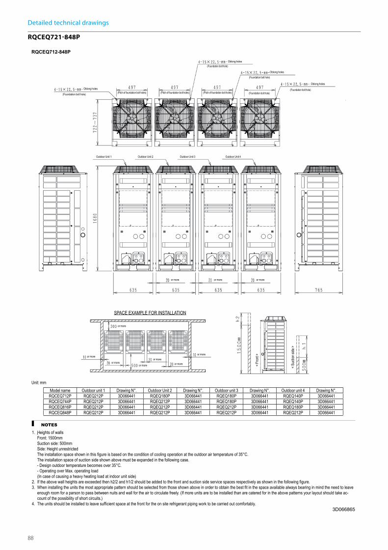
88
Detailed technical drawings
RQCEQ721-848P
RQCEQ712-848P
3D066865
Unit: mmModel name Outdoor unit 1 Drawing N°. Outdoor Unit 2 Drawing N°. Outdoor unit 3 Drawing N°. Outdoor unit 4 Drawing N°.RQCEQ712P RQEQ212P 3D066441 RQEQ180P 3D066441 RQEQ180P 3D066441 RQEQ140P 3D066441RQCEQ744P RQEQ212P 3D066441 RQEQ212P 3D066441 RQEQ180P 3D066441 RQEQ140P 3D066441RQCEQ816P RQEQ212P 3D066441 RQEQ212P 3D066441 RQEQ212P 3D066441 RQEQ180P 3D066441RQCEQ848P RQEQ212P 3D066441 RQEQ212P 3D066441 RQEQ212P 3D066441 RQEQ212P 3D066441
NOTES
1. Heights of walls Front: 1500mm Suction side: 500mm Side: Height unrestricted The installation space shown in this figure is based on the condition of cooling operation at the outdoor air temperature of 35°C. The installation space of suction side shown above must be expanded in the following case. - Design outdoor temperature becomes over 35°C. - Operating over Max. operating load (In case of causing a heavy heating load at indoor unit side)2. If the above wall heights are exceeded then h2/2 and h1/2 should be added to the front and suction side service spaces respectively as shown in the following figure.3. When installing the units the most appropriate pattern should be selected from those shown above in order to obtain the best fit in the space available always bearing in mind the need to leave
enough room for a parson to pass between nuits and wall for the air to circulate freely. (If more units are to be installed than are catered for in the above patterns your layout should take ac-count of the possibility of short circuits.)
4. The units should be installed to leave sufficient space at the front for the on site refrigerant piping work to be carried out comfortably.
SPACE EXAMPLE FOR INSTALLATION
Oblong holesOblong holes
(Pitch of foundation bolt holes) (Pitch of foundation bolt holes) (Pitch of foundation bolt holes) (Foundation bolt hole)(Foundation bolt hole)
(Pitc
h of fo
unda
tion b
olt ho
les)
Outdoor Unit 1 Outdoor Unit 2 Outdoor Unit 3 Outdoor Unit 4
or more or more or more
or more
or more or moreor more
or more
or more
< Fro
nt >
< Suc
tion s
ide >
(Foundation bolt hole)
Oblong holes
(Foundation bolt hole)
Oblong holes(Foundation bolt hole)
or more
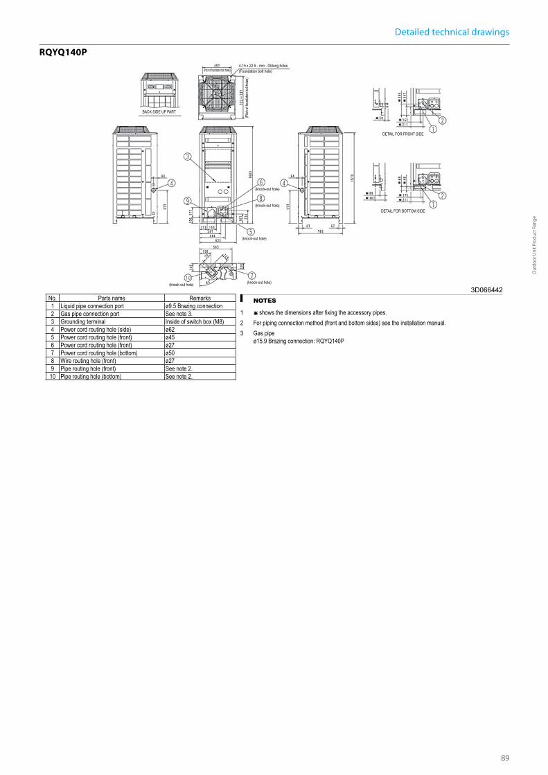
89
RQYQ140P
3D066442NOTES
1 shows the dimensions after xing the accessory pipes.2 For piping connection method (front and bottom sides) see the installation manual.3 Gas pipe
ø15.9 Brazing connection: RQYQ140P
No. Parts name Remarks1 Liquid pipe connection port ø9.5 Brazing connection2 Gas pipe connection port See note 3.3 Grounding terminal Inside of switch box (M8)4 Power cord routing hole (side) ø625 Power cord routing hole (front) ø456 Power cord routing hole (front) ø277 Power cord routing hole (bottom) ø508 Wire routing hole (front) ø279 Pipe routing hole (front) See note 2.10 Pipe routing hole (bottom) See note 2.
4-15 x 22.5 - mm - Oblong holes(Foundation bolt hole)
DETAIL FOR FRONT SIDE
DETAIL FOR BOTTOM SIDE
BACK SIDE UP PART
(Pitch of foundation bolt holes)
(Pitc
h of fo
unda
tion b
olt ho
les)
(knock-out hole)
(knock-out hole)
(knock-out hole)
(knock-out hole)(knock-out hole)
Detailed technical drawings
RQYQ140P
Out
door
Uni
t Pro
duct
Ran
ge

90
4
515
76
765
76
67
5
9
272
328
373
930
97 107
13117
9259
276
122
766
729
4-15x22.5mm
134
353
107
112
125
70
10
8
100
160
AA
339
AB
66
106
C
AC
240208
AB
195
248AA
REMQ5T, RYMQ10-12T, REYQ8-12TRYMQ8TRYYQ10-12T, RXYQ10-12T, RXYQQ10-12TRYYQ8T, RXYQ8T, RXYQQ8T
--195248 240208
--
137
21
3
1116
85
678910
12
3
45
Ø65Ø27Ø65Ø80Ø65
No.
11
Part name Remark
Grounding terminal
Pipe routing hole (bottom)Pipe routing hole (front)
Power cord routing hole (side)
Power cord routing hole (front)Power cord routing hole (front)Power cord routing hole (front)
Equalising pipe connection port
Gas pipe connection portLiquid pipe connection port
See note 3.
See note 3.
See note 3.
Notes
Detail A and detail B indicate the dimensions after fixing the attached piping.Knockout hole.
Gas pipeØ 19.1 brazing connectionØ 22.2 brazing connection
Ø 28.6 brazing connection
Ø 9.5 brazing connection
Ø 12.7 brazing connection
Ø 19.1 brazing connectionØ 22.2 brazing connection
Liquid pipe
Pitch of foundation bolt holes
Pitc
h of
foun
datio
n bo
lt ho
les
Foundation bolt holeOblong hole
AC
RYYQ8T, RYMQ8T, RXYQ8T, RXYQQ8T :
RYYQ12T, RYMQ12T, RXYQ12T, RXYQQ12T :
RYYQ8-10T, RYMQ8-10T, RXYQ8-10T, RXYQQ8-10T, REMQ5T, REYQ8-12T:
RYYQ10T, RYMQ10T, RXYQ10T, RXYQQ10T :
Model
Equalising pipe
High pressure/low pressure gas pipe
Items 4 - 10:
RYYQ12T, RYMQ12T, RXYQ12T, RXYQQ12T :
RYMQ8-10T :RYMQ12T :
REMQ5T, REYQ8-12T : Ø 19.1 brazing connection
Ø 25.4 brazing connectionREMQ5T, REYQ8-12T :
1.2.3. Inside of the switch box (M8)
Power cord routing hole (bottom)
Detail A Detail B
DETAIL ADETAIL B
View C
High pressure/low pressure gas pipe
RYYQ8-12TRYMQ8-12TRXYQ8-12TRXYQQ8-12T
2D079532B
4
67
5
9
4-15x22.5mm -
10
8
21
11
97
272
328
373
1240
107
C
13117
9259
276
122
1685
76
137
765
76
515
729
1076
134
393
107
112
125
70
106
71
192
AB
310
100
160
AA
3
ABAA
RYMQ18-20T, RXYQQ18-20TRYMQ14-16T, RXYQQ14-16T, REYQ14-20T 205240
240 210
Notes
Detail A and detail B indicate the dimensions after fixing the attached piping.Knockout hole.
Gas pipe
Ø 28.6 brazing connection
Ø 12.7 brazing connection
Ø 22.2 brazing connection
Liquid pipe
RYYQ14-20T, RYMQ14-20T, RXYQ14-20T, RXYQQ14-20T :
Equalising pipe
High pressure/low pressure gas pipe
Items 4 - 10:
RYYQ14-16T, RYMQ14-16T, RXYQ14-16T, RXYQQ14-16T, REYQ14-20T :
RYMQ14-16T :RYMQ18-20T :
REYQ14-20T : Ø 22.2 brazing connection
Ø 25.4 brazing connectionREYQ14-20T :
1.2.3.
678910
12
3
45
Ø65Ø27Ø65Ø80Ø65
No.
11
Part name Remark
Grounding terminalPipe routing hole (bottom)Pipe routing hole (front)
Power cord routing hole (side)
Power cord routing hole (front)Power cord routing hole (front)Power cord routing hole (front)
Equalising pipe connection port
Gas pipe connection portLiquid pipe connection port
See note 3.
See note 3.See note 3.
Inside of the switch box (M8)
Power cord routing hole (bottom)
Model
Pitch of foundation bolt holes
Pitc
h of
foun
datio
n bo
lt ho
les
Foundation bolt holeOblong hole
Ø 15.9 brazing connectionRYYQ18-20T, RYMQ18-20T, RXYQ18-20T, RXYQQ18-20T :
Ø 28.6 brazing connection
Detail A Detail B
DETAIL B DETAIL A
View C
High pressure/low pressure gas pipe
RYYQ14-20TRYMQ14-20TRXYQ14-20TRXYQQ14-20T
2D079533B
RXYQQ14-20T
Detailed technical drawings
RXYQQ8-12T

91
Detailed technical drawings
RQYQ140P
RQYQ140P
3D066327NOTES
1 Heights of walls in case of patterns 1 and 2: Front: 1500mm. Suction side: 500 mm. Side: Height unrestricted. Installation space to be shown in this drawing is based on the cooling operation at 35 degrees outdoor air temperature. When the design outdoor air temperatur exceeds 35 degrees or the load exceeds maximum ability because of much generation load heat in all outdoor unit, take the suction side space more broadly than the space to be shown in this drawing.
2 If the above wall heights are exceeded then h2/2 and h1/2 should be added to the front and suction side service spaces respectively as shown in the gure on the right.
3 When installing the units the most appropriate pattern should be selected from those shown above in order to obtain the best t in the space available always bearing in mind the need to leave enough room for a person to pass between units and wall and for the air to circulate freely. (If more units are to be installed than are catered for in the above patterns your layouts should take account of the possibility of short circuits.)
4 The units should be installed to leave suf cient space at the front for the on site refrigerant piping work to be carried out comfortably.
For single unit installation For installation in rows For centralized group layout
(PATTERN 1) (PATTERN 1) (PATTERN 1) (PATTERN 1) (PATTERN 1)
(PATTERN 2) (PATTERN 2)
(PATTERN 2) (PATTERN 2) (PATTERN 2)
(PATTERN 3) (PATTERN 3)
(Fro
nt)
(Suc
tion s
ide)
10 or more 10 or more 10 or more 10 or more 10 or more
10 or more
10 or more
10 or more
10 or more
10 or more10 or more10 or more
50 or more 50 or more 50 or more50 or more
50 or more 50 or more
50 or more
50 or more 50 or more
50 or more
50 or more 50 or more
10 or more
10 or more
10 or more
300 or more 300 or more 300 or more
600 or more
500 or more
100 or more 100 or more
500 or more
500 or more
500 or more
500 or more
600 or more
100 or more
200 or more400 or more 400 or more 400 or more
100 or more 100 or more500 or more
500 or more
300 or more
500 or more
900 or more
500 or more
500 or more
100 or more
500 or more20 or more20 or more
20 or more20 or more
20 or more20 or more 20 or more
20 or more
20 or more
100 or more
100 or more100 or more
100 or more
100 or more100 or more
100 or more
50 or more 50 or more 50 or more 50 or more
10 or more
300 or more
100 or more
300 or more
200 or more
Wall heightunrestricted
Wall height unrestricted
500 or more
500 or more
(Front)
(Front)
(Front) (Front)
(Front)
(Front)
(Front)(Front)
(Front) (Front)
(Front)
(Front)
(Front)
(Front)
(Front)
(Front)
(Front)
(Front)
(Unit : mm) (Unit : mm)
(Unit : mm)
RYYQ-TRYMQ-TRXYQ-TRXYQQ-T
3D079542
For single unit installation
(Pattern 1)
300 or more
100 or more
300 or more
10 or more
50 or more
300 or more
20 or more 20 or more 10 or more 10 or more
50 or more
50 or more50 or more
100 or more
10 or more
50 or more
100 or more
10 or more
50 or more
10 or more100 or more
100 or more
300 or more
100 or more
Wall height unrestricted
50 or more400 or more400 or more
200 or more
10 or more
50 or more
10 or more
50 or more
10 or more
50 or more
10 or more
50 or more
10 or more
50 or more
20 or more
100 or more
10 or more
50 or more
10 or more
50 or more
10 or more
50 or more
20 or more
100 or more
20 or more
100 or more
500 or more
500 or more
300 or more
300 or more
20 or more
100 or more
20 or more
100 or more
20 or more
100 or more
900 or more
600 or more
300 or more 300 or more
100 or more
500 or more
500 or more
10 or more
50 or more
10 or more(FRONT)
500 or more
(FRONT) 500 or more
(FRONT) 200 or more
(FRONT) 500 or more
(FRONT) 600 or more
(FRONT) 500 or more
(FRONT) 500 or more
(FRONT) 500 or more
(FRONT)
(FRONT)
(FRONT)
(FRONT)
(FRONT) 500 or more
(FRONT) 500 or more
(FRONT)(FRONT) 500 or more
(Pattern 1) (Pattern 1)
For installation in rows For centralized group layout
Wall height unrestricted
(Pattern 2) (Pattern 2)
(Pattern 2)
(Pattern 3) (Pattern 3)
<Suc
tion s
ide>
<Fro
nt>
<Unit = mm>
NOTES
1. Heights of walls in case of patterns 1 and 2: Front: 1500mm Suction side: 500mm Side: Height unrestricted Installation space as shown on this drawing is based on the cooling operation at 35 degrees outdoor air temperature. When the design outdoor air temperature exceeds 35 degrees or the load exceeds maximum ability of much generation load of heat in all outdoor unit, take the suction side space more broadly than the space as shown on this drawing.
2. If the above wall heights are exceeded then h2/2 and h1/2 should be added to the front and suction side service spaces respectively as shown in the figure on the right.3. When installing the units most appropriate pattern should be selected from those shown above in order to obtain the best fit in the
space available. Always keep in mind the need to leave enough space for a person to pass between units and wall and also for the air to circulate freely. (If more units are to be installed than are catered for in the above patterns your layout should take account of the possibility of short circuits).
4. The units should be installed to leave sufficient space at the front for the on site refrigerant piping work to be carried out comfortably.
RXYQQ-T
RYYQ-TRYMQ-TRXYQ-TRXYQQ-T
3D079542
For single unit installation
(Pattern 1)
300 or more
100 or more
300 or more
10 or more
50 or more
300 or more
20 or more 20 or more 10 or more 10 or more
50 or more
50 or more50 or more
100 or more
10 or more
50 or more
100 or more
10 or more
50 or more
10 or more100 or more
100 or more
300 or more
100 or more
Wall height unrestricted
50 or more400 or more400 or more
200 or more
10 or more
50 or more
10 or more
50 or more
10 or more
50 or more
10 or more
50 or more
10 or more
50 or more
20 or more
100 or more
10 or more
50 or more
10 or more
50 or more
10 or more
50 or more
20 or more
100 or more
20 or more
100 or more
500 or more
500 or more
300 or more
300 or more
20 or more
100 or more
20 or more
100 or more
20 or more
100 or more
900 or more
600 or more
300 or more 300 or more
100 or more
500 or more
500 or more
10 or more
50 or more
10 or more(FRONT)
500 or more
(FRONT) 500 or more
(FRONT) 200 or more
(FRONT) 500 or more
(FRONT) 600 or more
(FRONT) 500 or more
(FRONT) 500 or more
(FRONT) 500 or more
(FRONT)
(FRONT)
(FRONT)
(FRONT)
(FRONT) 500 or more
(FRONT) 500 or more
(FRONT)(FRONT) 500 or more
(Pattern 1) (Pattern 1)
For installation in rows For centralized group layout
Wall height unrestricted
(Pattern 2) (Pattern 2)
(Pattern 2)
(Pattern 3) (Pattern 3)
<Suc
tion s
ide>
<Fro
nt>
<Unit = mm>
NOTES
1. Heights of walls in case of patterns 1 and 2: Front: 1500mm Suction side: 500mm Side: Height unrestricted Installation space as shown on this drawing is based on the cooling operation at 35 degrees outdoor air temperature. When the design outdoor air temperature exceeds 35 degrees or the load exceeds maximum ability of much generation load of heat in all outdoor unit, take the suction side space more broadly than the space as shown on this drawing.
2. If the above wall heights are exceeded then h2/2 and h1/2 should be added to the front and suction side service spaces respectively as shown in the figure on the right.3. When installing the units most appropriate pattern should be selected from those shown above in order to obtain the best fit in the
space available. Always keep in mind the need to leave enough space for a person to pass between units and wall and also for the air to circulate freely. (If more units are to be installed than are catered for in the above patterns your layout should take account of the possibility of short circuits).
4. The units should be installed to leave sufficient space at the front for the on site refrigerant piping work to be carried out comfortably.
Out
door
Uni
t Pro
duct
Ran
ge

92
Water cooledVRV IV W-seriesIdeal for high rise buildings, using water as heat source
VRV IV standards:Variable refrigerant temperature Customize your VRV for best seasonal efficiency & comfort
› Full inverter compressors
› Reluctance brushless DC compressor
› Sine wave DC inverter
› Manual demand function
› Geothermal operation
For more information on these features refer to the VRV IV technologies tab
Air curtainBiddle Air curtain for VRV (CYV)
Indoor unitsVRV type indoor units
Control systems
Hot waterLow temperature hydrobox
VentilationHeat Reclaim ventilation (VAM/VKM)
AHU connection kit
22

93
Efficiency not influenced by outdoor conditionsThe water cooled VRV unit operates at a superior efficiency, even in the most extreme outdoor temperatures thanks to geothermal operation.
Because the temperature of ground water, lakes and rivers, remains relatively constant the year round, our water-cooled system maintains its superior efficiency, even in the most extreme outdoor temperatures, when the efficiency of air-cooled systems goes down.
Geothermal operation and advantagesGeothermal operation uses the more stable temperature of the ground around the building, eliminating the need for another heat source. It reduces CO
2 emissions and is an infinitely renewable
energy source.
Outside temperature Wind
Wide operation rangeStandard water cooled outdoor units have a wide operation range between 10°C & 45°C inlet water temperature, both in heating and cooling. In geothermal mode the operation range is extended even more, down to -10°C* in heating and 6°C in
cooling mode.
* Ethylene glycol should be added to the water when the water inlet
temperature is below 5°C
Heating
Cooling
-10°C
6°C 45°C
45°C
Out
door
Uni
t Pro
duct
Ran
ge

94
High energy efficiencies results from 2-stage heat recoveryStage 1: Heat recovery between indoor units in the same refrigerant circuit
Heat exhausted from indoor units in cooling mode is transferred to units in areas requiring heating, maximising energy efficiency and reducing electricity
costs.
Full Heat Recovery
All indoor units in
cooling mode
Indoor units mainly
cooling, partly heating
Indoor units
mainly heating,
partly cooling
All indoor units
in heating mode
VRV-W
VRV-W
VRV-W
VRV-W
VRV-W
stage 2stage 1
Heat recovery between indoor units Heat recovery between outdoor units (Heat recovery and heat pump)
* Above system configurations
are for illustration purposes only.
Cooling tower (Closed type), boiler
Heat rejected to loop
Heat rejected to loop
Heat absorbed from loop
Heat absorbed from loop
Stage 2: Heat recovery between the outdoor units via the water loop - also available on heat pump units!
Second stage heat recovery is achieved within the water loop between the water cooled outdoor units.

95
Variable water flow control The variable water flow control option reduces energy use by the circulation pump by reducing the water flow when possible and not using a fixed water flow all the time.
Space saving - Stacked configurationThe adoption of a new water heat exchanger and optimization of the refrigerant control circuit has resulted in the industry’s most compact and lightweight design. The unit weight of 149kg* and height of 1,000 mm makes installation easy. Stacked configuration is also possible, contributing further to
space savings.
* for 8HP unit
Ceiling height
Floor level
100-300mm
3,200mm
or higher
Stacked configuration is possible.
Variable water
Flow Control Valve
Inverter Pump
Cooling tower (Closed type), boiler
Standard water strainerA standard water strainer reduces installation time. The
new filter also has less pressure drop at higher water
flows. new filter
old filter
40
35
30
25
20
15
10
5
0
50 70 90 110 130 150
water flow (l/min)
Pres
sure
dro
p (lk
Pa)
Out
door
Uni
t Pro
duct
Ran
ge

96
Total piping length 300m
Longest length actual (Equivalent) 120m (140m)
Longest length after first branch 40m (90m1)
Level difference between indoor and outdoor units
50m (40m²)
Level difference between indoor units 15m
1 Contact your local dealer for more information and restrictions 2 In case outdoor unit is located below indoor units
Flexible piping designFlexible water piping
Water cooled VRV uses water as its heat source, so it is optimal for large buildings, including tall, multi-storey buildings, because the system can tolerate water pressure of up to 1.96 MPa.
Furthermore, if the currently installed heat source’s water temperature is between 10°C and 45°C, it may be possible to use the existing water pipe work and heat source. This alone makes it an ideal system solution for building refubishment projects.
Water piping
Refrigerant piping
Actual piping length between the VRV-W and indoor units: 120m (Equivalent piping length: 140m)
Level difference between indoor units: 15m
Level difference
between the VRV-W
and indoor units:
50m if the VRV-W is above
40m if the VRV-W is below
Unlimited water piping length
Indoor installation
For Gerard Schröder the choice for this system was an easy one: ‘As far as I’m concerned, with the VRV Heat Recovery system, Daikin has the Rolls Royce in heat pump technology. If you want to build a sustainable office building, there really is no other alternative.’
BREEAM excellent office building
Park Phi, Enschede - The Netherlands
VRV-WIII geothermal system, Daikin Altherma HT, Sky Air, aircooled chiller with heat recovery, iManager,
iTouch Manager, ACNSS
VRV-W
VRV-W
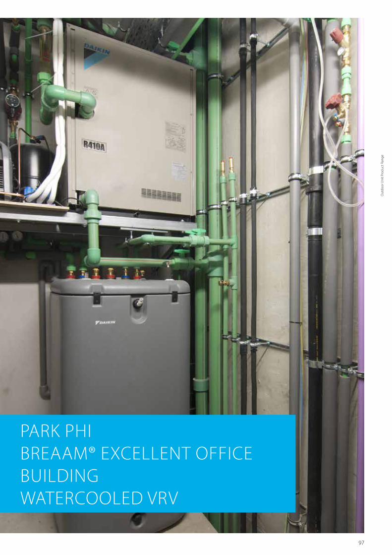
97
Total piping length 300m
Longest length actual (Equivalent) 120m (140m)
Longest length after first branch 40m (90m1)
Level difference between indoor and outdoor units
50m (40m²)
Level difference between indoor units 15m
1 Contact your local dealer for more information and restrictions 2 In case outdoor unit is located below indoor units
PARK PHIBREAAM® EXCELLENT OFFICE BUILDINGWATERCOOLED VRV
Out
door
Uni
t Pro
duct
Ran
ge

98
RWEYQ8-10T
Outdoor unit RWEYQ 8T 10T 16T 18T 20T 24T 26T 28T 30TSystem Outdoor unit module 1 RWEYQ8T RWEYQ10T RWEYQ8T RWEYQ10T RWEYQ8T RWEYQ10T
Outdoor unit module 2 - RWEYQ8T RWEYQ10T RWEYQ8T RWEYQ10TOutdoor unit module 3 - RWEYQ8T RWEYQ10T
Capacity range HP 8 10 16 18 20 24 26 28 30Cooling capacity Nom. kW 22.4 28.0 44.8 50.4 56.0 67.2 72.8 78.4 84.0Heating capacity Nom. kW 25.0 31.5 50.0 56.5 63.0 75.0 81.5 88.0 94.5Power input - 50Hz Cooling Nom. kW 4.42 6.14 8.8 10.6 12.3 13.3 15.0 16.7 18.4
Heating Nom. kW 4.21 6.00 8.4 10.2 12.0 12.6 14.4 16.2 18.0EER 5.07 4.56 5.07 4.77 4.56 5.07 4.86 4.69 4.56COP 5.94 5.25 5.94 5.53 5.25 5.94 5.65 5.43 5.25Maximum number of connectable indoor units 36Indoor index connection
Min. 100 125 200 225 250 300 325 350 375Nom. 200 250 400 450 500 600 650 700 750Max. 260 325 520 585 650 780 845 910 975
Dimensions Unit HeightxWidthxDepth mm 1,000x780x550 -Weight Unit kg 137 -
Fan Air flow rate Cooling Nom. m³/min -Sound power level Cooling Nom. dBA -Sound pressure level Cooling Nom. dBA 50 51 53 54 55 56Operation range Inlet water
temperatureCooling Min.~Max. °CDB 10~45Heating Min.~Max. °CWB -10 / 10.0~45
Refrigerant Type / GWP R-410A / 2,087.5Charge kg/TCO
2Eq 3.5/7.3 4.2/8.8 - - - - - - -
Piping connections Liquid OD mm 9.52 12.7 15.9 19.1Gas OD mm 19.10 (1) 22.2 (1) 28.6 (1) 34.9 (1)Discharge gas OD mm 15.9 (2) / 19.10 (3) 19.1 (2) / 22.10 (3) 22.2 (2) / 28.60 (3) 28.6 (2) / 34.90 (3)Water Inlet/Outlet PT1 1/4B internal thread/PT1 1/4B internal thread
Total piping length System Actual m 300Power supply Phase/Frequency/Voltage Hz/V 3N~/50/380-415Current - 50Hz Maximum fuse amps (MFA) A 20 32 50
(1) In case of heat pump system, gas pipe is not used (2) In case of heat recovery system (3) In case of heat pump system (4) Not Eurovent certified
VRV IV water cooled series
Ideal for high rise buildings, using water as heat source
› Unified range for standard and geothermal series simplifies stock. Geothermal series reduce CO
2 emmisions thanks to the
use of geothermal energy as a renewable energy source › No need for an external heating or cooling source when used in geothermal mode
› Covers all thermal needs of a building via a single point of contact: accurate temperature control, ventilation, hot water, air handling units and Biddle air curtains
› Compact & lightweight design can be stacked for maximum space saving
› Incorporates VRV IV standards & technologies: Variable Refriger-ant Temperature and full inverter compressors
› 2-stage heat recovery: first stage between indoor units, second stage between outdoor units thanks to the storage of energy in the water circuit
› Available in heat pump and heat recovery version › Variable Water Flow control option increases flexibility and control
› Easy compliance with F-gas regulation thanks to automated refrigerant containment check
› Contains all standard VRV features
RWEYQ-T
Geothermal operationStandard operation

99
3D085178
RWEYQ-T Top View
Item Part Name Remark1 Liquid Pipe See note 22 Suction Gas Pipe See note 23 HP/LP Gas Pipe See note 24 Water Inlet PT 1 1/4 B Internal Thread5 Water Outlet PT 1 1/4 B Internal Thread6 Drain Outlet PS 1/2 B Internal Thread7 Earth Terminal M58 Power Chord Though Hole Ø299 Wiring Though Hole Ø29
10 Pipe routing hole (bottom)11 Grounding terminal Inside of switch box (M8)
NOTES
1. Earth terminal is in the switch box2. Piping size is as follows
MODEL NAME RWEYQ8 RWEYQ10Operation System Heat Pump Heat Recovery Heat Pump Heat Recovery
Liquid Pipe Ø9.5 Ø9.5 Ø9.5 Ø9.5Suction Gas Pipe - Ø19.1 - Ø22.2HP/LP Gas Pipe Ø19.1 Ø15.9 Ø22.2 Ø19.1
* Connection method: Liquid Pipe: Suction Gas Pipe: } Brazing connection
HP/LP Gas Pipe: * In case of heat pump, suction gas pipe is not used.
Rear ViewRight Side View
Bottom View
Front View
8x Ø17 (Foundation Bolt Hole)
Manufacturer’s label
(After attaching accessories pipe)
Detailed technical drawings
RWEYQ-T
RWEYQ-T
3D048341F
Water piping installation space
Secure 300mm or more of service space even not using for rear side take-out
Secure 300mm or more of ventilation space above the marked part of outside unit
H: freeW: 179 mm
Water piping installation space
: Required service space
: Ventilation space
20 or more 20 or more20 or more 20 or more 20 or more
900 o
r mor
e
900 o
r mor
e
350 o
r mor
e
250 or less100 or more
500 o
r mor
e
500 o
r mor
e
350 or less
Service space (rear)
Outside unit Outside unit Outside unit
Service space (rear)
Service space (rear)
Service space (front)
Service space (front)
Service space (front)
Secure enough space for removing
front plate
Space for installation in
a row
Space for installation in
a row
Space for installation in
a row
Space for installation in
a row
Space for installation in
a row
For single unit installation
For installation in a row
Front view
Right side view
390 or more
300 o
r mor
e
RWEYQ-T
Out
door
Uni
t Pro
duct
Ran
ge
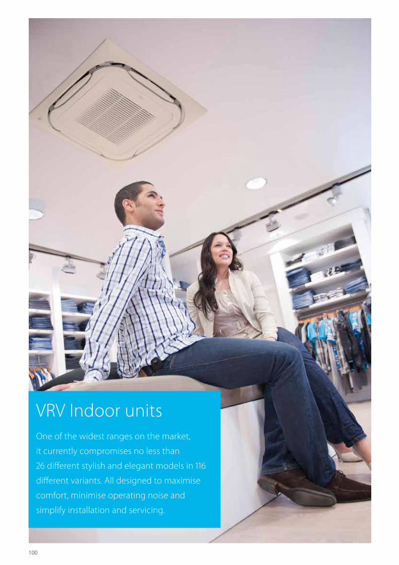
100
VRV Indoor units One of the widest ranges on the market,
it currently compromises no less than
26 different stylish and elegant models in 116
different variants. All designed to maximise
comfort, minimise operating noise and
simplify installation and servicing.

101
Indo
or U
nits
VRV Indoor units
VRV indoor units
Ceiling mounted cassette units FXFQ-A 106FXZQ-A 110FXCQ-A 113FXKQ-MA 116
Concealed ceiling units FXDQ-M9 118FXDQ-A 120FXSQ-A 126FXMQ-P7 / FXMQ-MA9 128
Wall mounted unit FXAQ-P 136
Ceiling suspended units FXHQ-A 140FXUQ-A 142
Floor standing units FXNQ-A 144FXLQ-P 145
NEW
NEW
Stylish indoor units
BPMKS Accessory to connect stylish indoor units 149
Wall mounted FTXG-LS/LW 151CTXS-K / FTXS-K 154
Floor standing FVXG-K 158FVXS-F 161
Flexi type unit FLXS-B(9) 163

102
VRV Indoor
ROUND FLOW CASSETTE
CONCEALED CEILING UNIT WITH HIGH ESP
SMALL CONCEALED CEILING UNIT
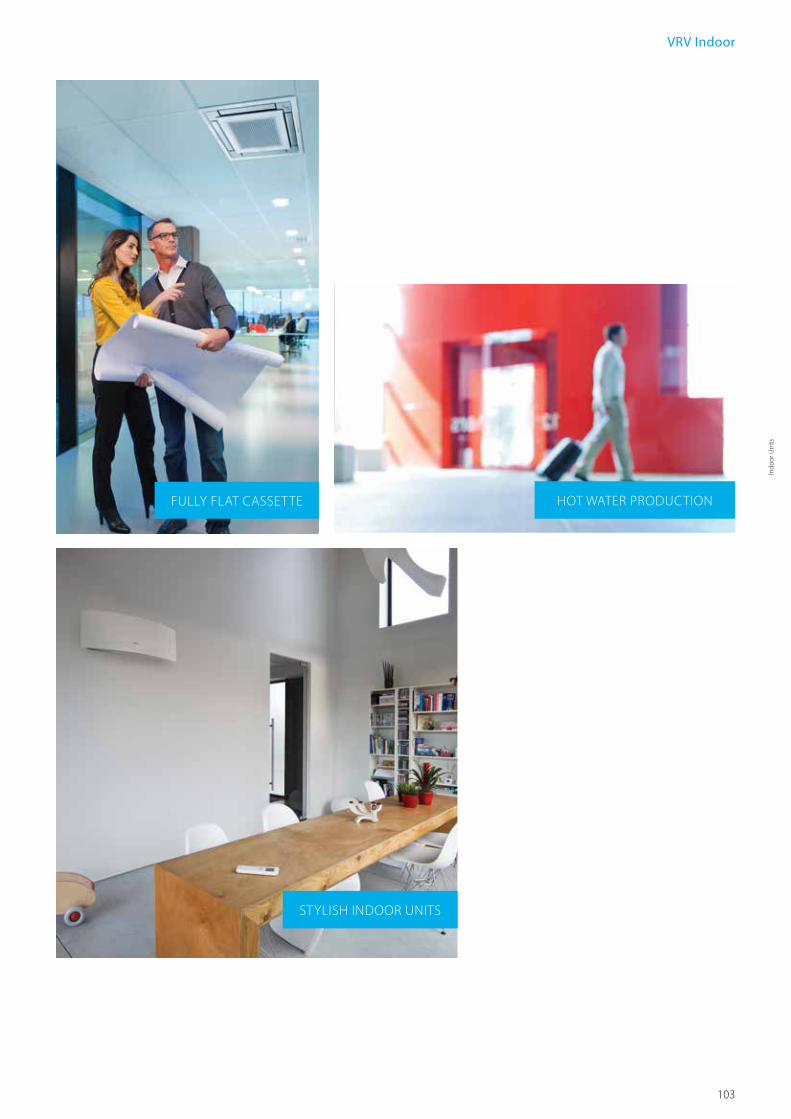
103
Indo
or U
nits
VRV Indoor
FULLY FLAT CASSETTE
STYLISH INDOOR UNITS
HOT WATER PRODUCTION

104
Benefits overview
VRV indoorW
e ca
reC
omfo
rtA
ir flo
wH
umid
ity
cont
rol
Air
trea
tmen
tRe
mot
e co
ntro
l & ti
mer
Oth
er fu
ntci
ons
Ceiling mounted cassette units Concealed ceiling unitsWall
mounted unit
Ceiling suspended units
Floor standing units
FXFQ-A FXZQ-A FXCQ-A FXKQ-MA FXDQ-M9 FXDQ-A FXSQ-A FXMQ-P7 FXMQ-MA9 FXTQ-A FXAQ-P FXHQ-A FXUQ-A FXNQ-A FXLQ-P
Inverter technology In combination with inverter controlled outdoor units Home leave operation During absence, indoor comfort levels can be maintained Fan only The air conditioner can be used as fan, blowing air without cooling or heating Auto cleaning filter
The filter automatically cleans itself once a day. Simplicity of upkeep means optimum energy efficiency and maximum comfort without the need for expensive or time-consuming maintenance
Floor and presence sensorThe presence sensor directs the air away from any person detected in the room. The floor sensor detects the average floor temperature and ensures an even temperature distribution between ceiling and floor
Draught preventionWhen starting to warm up or when the thermostat is off, the air discharge direction is set horizontally and the fan to low speed, to prevent draught. After warming up, air discharge and fan speed are set as desired
Whisper quietDaikin indoor units are whisper quiet. Also the outdoor units are guaranteed not to disturb the quiet of the neightbourhood
Auto cooling-heating changeover Automatically selects cooling or heating mode to achieve the set temperature
Air filter Removes airborne dust particles to ensure a steady supply of clean airG1
F8 (optional)G1 G1 G1
F8 (optional) G1
F8 (optional) G1 G1 G1 G1
Dry programme Allows humidity levels to be reduced without variations in room temperature
Ceiling soiling preventionThe air discharge of the indoor unit is specially designed to prevent air being blown against the ceiling to prevent ceiling stains
Vertical auto swingPossibility to select automatic vertical moving of the air discharge louvre, for uniform air flow and temperature distribution
Fan speed steps Multiple fan speeds to select,to optimize comfort levels 3 3 3 2 2 3 3 3 23 (50~63)
2 (80~100)2 3 3 2 2
Individual flap controlIndividual flap control via the wired remote controller makes it simple to fix the position of each flap individually, to suit any new room configuration. Optional closure kits are available as well
Weekly timer Timer can be set to start and stop operation anytime on a daily or weekly basis Infrared remote control Infrared remote control with LCD to remotely control your indoor unit Wired remote control Wired remote control to remotely control your indoor unit Centralised control Centralised control to to control several indoor units from one single point
Auto-restart The unit restarts automatically at the original settings after power failure Self-diagnosis Simplifies maintenance by indicating system faults or operating anomalies Drain pump kit Facilitates condensation draining from the indoor unit Standard Standard Standard Standard Standard Standard Standard Optional
Standard (50~63)Optional (80~100)
Optional Optional Standard
Multi tenant The indoor unit’s main power supply can be turned off when leaving the building or for servicing purposes () () () () ()

105
Indo
or U
nits
Ceiling mounted cassette units Concealed ceiling unitsWall
mounted unit
Ceiling suspended units
Floor standing units
FXFQ-A FXZQ-A FXCQ-A FXKQ-MA FXDQ-M9 FXDQ-A FXSQ-A FXMQ-P7 FXMQ-MA9 FXTQ-A FXAQ-P FXHQ-A FXUQ-A FXNQ-A FXLQ-P
Inverter technology In combination with inverter controlled outdoor units Home leave operation During absence, indoor comfort levels can be maintained Fan only The air conditioner can be used as fan, blowing air without cooling or heating Auto cleaning filter
The filter automatically cleans itself once a day. Simplicity of upkeep means optimum energy efficiency and maximum comfort without the need for expensive or time-consuming maintenance
Floor and presence sensorThe presence sensor directs the air away from any person detected in the room. The floor sensor detects the average floor temperature and ensures an even temperature distribution between ceiling and floor
Draught preventionWhen starting to warm up or when the thermostat is off, the air discharge direction is set horizontally and the fan to low speed, to prevent draught. After warming up, air discharge and fan speed are set as desired
Whisper quietDaikin indoor units are whisper quiet. Also the outdoor units are guaranteed not to disturb the quiet of the neightbourhood
Auto cooling-heating changeover Automatically selects cooling or heating mode to achieve the set temperature
Air filter Removes airborne dust particles to ensure a steady supply of clean airG1
F8 (optional)G1 G1 G1
F8 (optional) G1
F8 (optional) G1 G1 G1 G1
Dry programme Allows humidity levels to be reduced without variations in room temperature
Ceiling soiling preventionThe air discharge of the indoor unit is specially designed to prevent air being blown against the ceiling to prevent ceiling stains
Vertical auto swingPossibility to select automatic vertical moving of the air discharge louvre, for uniform air flow and temperature distribution
Fan speed steps Multiple fan speeds to select,to optimize comfort levels 3 3 3 2 2 3 3 3 23 (50~63)
2 (80~100)2 3 3 2 2
Individual flap controlIndividual flap control via the wired remote controller makes it simple to fix the position of each flap individually, to suit any new room configuration. Optional closure kits are available as well
Weekly timer Timer can be set to start and stop operation anytime on a daily or weekly basis Infrared remote control Infrared remote control with LCD to remotely control your indoor unit Wired remote control Wired remote control to remotely control your indoor unit Centralised control Centralised control to to control several indoor units from one single point
Auto-restart The unit restarts automatically at the original settings after power failure Self-diagnosis Simplifies maintenance by indicating system faults or operating anomalies Drain pump kit Facilitates condensation draining from the indoor unit Standard Standard Standard Standard Standard Standard Standard Optional
Standard (50~63)Optional (80~100)
Optional Optional Standard
Multi tenant The indoor unit’s main power supply can be turned off when leaving the building or for servicing purposes () () () () ()
*Note: blue cells contain preliminary data

106
FXFQ-A
Why choose a round flow cassette?• 360° air discharge for optimum efficiency and comfort in shops, offices and restaurants.
• Unique auto-cleaning panel.
Round flow cassette
Benefits for the installer › Unique functions and design enhancing comfort, efficiency and installation.
› Less time needed for onsite maintenance. › Use the controller to individually open or close any of the four flaps to easily adapt to a changing room layout.
› Easy set-up of the sensor option to improve comfort and save energy.
› Switch box and piping connections are accessible by just removing the panel, making servicing easier.
Benefits for the consultant › Product with unique functions in this market. › Designed for use in all types and sizes of commercial offices and retail environments.
› Ideal product for improving BREEAM score/EPDB.
Benefits for the end user › Designed for use in all types and sizes of commercial offices and retail environments.
› Perfect environment conditions: no more draughts or cold feet. › Save up to 50% on running costs with the auto-cleaning panel, which also facilitates maintenance.
› Your customers can save up to 27% on their energy bills thanks to the sensor option.
› Flexible use of space thanks to individual flap control.
Unique functions which help save costs
› Daikin was the first company to launch a cassette using the round flow principle with sensors* and a unique auto-cleaning panel*.
... More energy efficient than any other
› The auto-cleaning panel* means:• Running costs are reduced
by 50% compared with standard solutions thanks to automatic daily filter cleaning.
• Less time is required to clean the filter: dust can be removed easily with a vacuum cleaner without opening the unit.
› Thanks to presence sensor, the unit changes its setpoint or switches off completely, if there are no people in the room, resulting in energy savings of up to 27%.
Auto cleaning cassette
Standard round flow cassette
Cumulative energy comparison over 12 months
Energy consumption (kWh)
50% difference in electricity consumption
July Aug. Sept. Oct. Nov. Dec. Jan. Feb. March April May June July
9000
8000
7000
6000
5000
4000
3000
2000
1000
0
* available as an option
… And improved comfort
› 360° air flow discharge pattern. › The presence sensor* directs the air away from anyone it detects in the room.
› The floor sensor* detects the average floor temperature and ensures an even temperature distribution between the ceiling and the floor. Cold feet are history!
Flexible installation
› Flaps can be individually controlled or closed using the wired remote control, to suit room configuration. Optional closure kits are also available.
References Wolverhampton, UK Running costs were reduced by up to 50% compared with standard solutions thanks to daily filter cleaning.
presence sensor
floor sensor
Check on
https://www.youtube.com/DaikinEurope

107
Indo
or U
nits
Indoor unit FXFQ 20A 25A 32A 40A 50A 63A 80A 100A 125ACooling capacity Nom. kW 2.2 2.8 3.6 4.5 5.6 7.1 9.0 11.2 14.0Heating capacity Nom. kW 2.5 3.2 4.0 5.0 6.3 8.0 10.0 12.5 16.0Power input - 50Hz Cooling Nom. kW 0.038 0.053 0.061 0.092 0.115 0.186
Heating Nom. kW 0.038 0.053 0.061 0.092 0.115 0.186Dimensions Unit Height mm 204 246 288
Width mm 840Depth mm 840
Weight Unit kg 19 20 21 24 26Casing Material Galvanised steel plateDecoration panel Model BYCQ140D7W1
Colour Pure White (RAL 9010)Dimensions HeightxWidthxDepth mm 60x950x950Weight kg 5.4
Decoration panel 2 Model BYCQ140D7W1WColour Pure White (RAL 9010)Dimensions HeightxWidthxDepth mm 60x950x950Weight kg 5.4
Decoration panel 3 Model BYCQ140D7GW1Colour Pure White (RAL 9010)Dimensions HeightxWidthxDepth mm 145x950x950Weight kg 10.3
Fan-Air flow rate - 50Hz
Cooling High/Nom./Low m³/min 12.5/10.6/8.8 13.6/11.6/9.5 15.0/12.8/10.5 16.5/13.5/10.5 22.8/17.6/12.4 26.5/19.5/12.4 33.0/26.5/19.9Heating High/Nom./Low m³/min 12.5/10.6/8.8 13.6/11.6/9.5 15.0/12.8/10.5 16.5/13.5/10.5 22.8/17.6/12.4 26.5/19.5/12.4 33.0/26.5/19.9
Air filter Type Resin net with mold resistanceSound power level Cooling High/Nom. dBA 49/- 51/- 53/- 55/- 60/- 61/-Sound pressure level Cooling High/Nom./Low dBA 31/29/28 33/31/29 35/33/30 38/34/30 43/37/30 45/41/36
Heating High/Nom./Low dBA 31/29/28 33/31/29 35/33/30 38/34/30 43/37/30 45/41/36Refrigerant Type / GWP R-410A / 2.087,5Piping connections Liquid OD mm 6.35 9.52
Gas OD mm 12.7 15.9Drain VP25 (O.D. 32 / I.D. 25)
Power supply Phase/Frequency/Voltage Hz/V 1~/50/60/220-240/220Current - 50Hz Maximum fuse amps (MFA) A 16Control systems Infrared remote control BRC7FA532F
Simplified wired remote control for hotel applications -Wired remote control BRC1D52 / BRC1E52A/B
BYCQ140D7W1 = pure white panel with grey louvers , BYCQ140D7W1W = pure white standard panel with white louvers, BYCQ140D7GW1 = Pure white auto cleaning panelThe BYCQ140D7W1W has white insulations. Be informed that formations of dirt on white insulation is visibly stronger & that it is consequently not advised to install the decoration panel in environments exposed to concentrations of dirt.
Round flow cassette
360° air discharge for optimum efficiency and comfort
› Daily automatic filter cleaning results in higher efficiency & comfort and lower maintenance costs
› Two optional intelligent sensors improve energy efficiency and comfort
› Individual flap control. Flexibility to suit every room layout without changing the location of the unit!
› Lowest installation height in the market: 214mm for class 20-63
› Modern style decoration panel is available in 3 different variations: white (RAL9010) with grey louvers, full white (RAL9010) or auto cleaning panel
› Reduced energy consumption thanks to specially developed small tube heat exchanger, DC fan motor and drain pump
› Fresh air intake integrated in the same system thus reducing installation cost as no additional ventilation is required
FXFQ-A
› Branch duct discharge allows to optimize air distribution in irregular shaped rooms or to supply air to small adjecent rooms
› Standard drain pump with 850mm lift increases flexibility and installation speed
BRC1E52A/B BRC7FA532F
FXFQ20-63A
presence sensorfloor sensor
////////////////////////////////////////////
Branch discharge Main discharge
Main unit
Fresh air intake opening in casing Optional fresh air intake kit
* Brings in up to 10% of fresh air into the room * Allows larger quantities of fresh air to be brought in
* Distributes fresh air so it is most effectively pre-cooled / pre-heated

108
Detailed technical drawings
FXFQ20-63A WITH AUTO-CLEANING PANEL
FXFQ80-125A WITH AUTO-CLEANING PANEL

109
Indo
or U
nits
Detailed technical drawings
FXFQ20-63A WITH STANDARD PANEL
FXFQ80-125A WITH STANDARD PANEL

110
Benefits for the installer › Unique product in the market! › The user-friendly remote control, available in several languages, enables the easy set-up of sensor option and control of the individual flap position
› Meeting European design taste.
Benefits for the consultant › Unique product in the market! › Blends seamlessly in any modern office interior design
› Flexible usage of space thanks to individual flap control
› Ideal product to improve BREEAM score/EPDB
Benefits for the end user › Engineering excellence and unique design in one
› Most silent unit › Perfect working conditions: no more cold draughts or cold feet
› Save up to 27% on your energy bill thanks to the optional sensors
› Flexible usage of space thanks to individual flap control
› User-friendly remote control, available in several languages.
FXZQ-A
• Unique design in the market that integrates fully flat into the ceiling
Unique design
› Designed by German design office to fully meet the European taste.
› Integrated Fully Flat into the ceiling. › Fully integrated in the one ceiling tile, enabling lights, speakers and sprinklers to be installed in adjoining ceiling tiles.
› Decoration panel available in 2 colours (white and white-silver).
Comfort through unique technology
Most silent cassette in the market (25dBA)
Presence sensor (optional) › When the room is empty, it can adjust the set temperature or switch off the unit – saving energy.
› When people are detected, the direction of the airflow is adapted to avoid cold draughts being directed towards occupants.
Floor sensor (optional) › Detects the temperature difference and re-directs the airflow to ensure even temperature distribution.
Top efficiency
› When the room is empty, the sensor option can adjust the set temperature or switch off the unit – saving up to 27% energy.
› Individual flap control: easily control one or more flaps via the wired remote controller (BRC1E52) when rearranging the room. When fully closing or blocking the flaps, the option “Sealing member of air discharge outlet” is needed.
Fully Flat Cassette Design & Genius in one
Check on
https://www.youtube.com/DaikinEurope
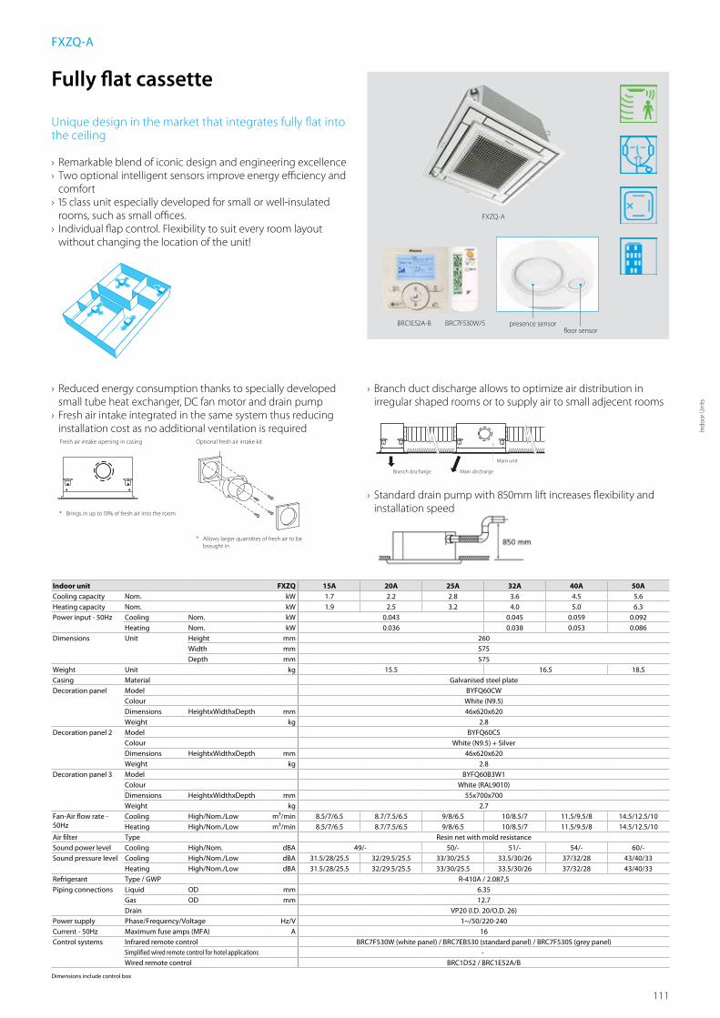
111
Indo
or U
nits
Indoor unit FXZQ 15A 20A 25A 32A 40A 50ACooling capacity Nom. kW 1.7 2.2 2.8 3.6 4.5 5.6Heating capacity Nom. kW 1.9 2.5 3.2 4.0 5.0 6.3Power input - 50Hz Cooling Nom. kW 0.043 0.045 0.059 0.092
Heating Nom. kW 0.036 0.038 0.053 0.086Dimensions Unit Height mm 260
Width mm 575Depth mm 575
Weight Unit kg 15.5 16.5 18.5Casing Material Galvanised steel plateDecoration panel Model BYFQ60CW
Colour White (N9.5)Dimensions HeightxWidthxDepth mm 46x620x620Weight kg 2.8
Decoration panel 2 Model BYFQ60CSColour White (N9.5) + SilverDimensions HeightxWidthxDepth mm 46x620x620Weight kg 2.8
Decoration panel 3 Model BYFQ60B3W1Colour White (RAL9010)Dimensions HeightxWidthxDepth mm 55x700x700Weight kg 2.7
Fan-Air flow rate - 50Hz
Cooling High/Nom./Low m³/min 8.5/7/6.5 8.7/7.5/6.5 9/8/6.5 10/8.5/7 11.5/9.5/8 14.5/12.5/10Heating High/Nom./Low m³/min 8.5/7/6.5 8.7/7.5/6.5 9/8/6.5 10/8.5/7 11.5/9.5/8 14.5/12.5/10
Air filter Type Resin net with mold resistanceSound power level Cooling High/Nom. dBA 49/- 50/- 51/- 54/- 60/-Sound pressure level Cooling High/Nom./Low dBA 31.5/28/25.5 32/29.5/25.5 33/30/25.5 33.5/30/26 37/32/28 43/40/33
Heating High/Nom./Low dBA 31.5/28/25.5 32/29.5/25.5 33/30/25.5 33.5/30/26 37/32/28 43/40/33Refrigerant Type / GWP R-410A / 2.087,5Piping connections Liquid OD mm 6.35
Gas OD mm 12.7Drain VP20 (I.D. 20/O.D. 26)
Power supply Phase/Frequency/Voltage Hz/V 1~/50/220-240Current - 50Hz Maximum fuse amps (MFA) A 16Control systems Infrared remote control BRC7F530W (white panel) / BRC7EB530 (standard panel) / BRC7F530S (grey panel)
Simplified wired remote control for hotel applications -Wired remote control BRC1D52 / BRC1E52A/B
Fully flat cassette
Unique design in the market that integrates fully flat into the ceiling
› Remarkable blend of iconic design and engineering excellence › Two optional intelligent sensors improve energy efficiency and comfort
› 15 class unit especially developed for small or well-insulated rooms, such as small offices.
› Individual flap control. Flexibility to suit every room layout without changing the location of the unit!
› Reduced energy consumption thanks to specially developed small tube heat exchanger, DC fan motor and drain pump
› Fresh air intake integrated in the same system thus reducing installation cost as no additional ventilation is required
FXZQ-A
Dimensions include control box
› Branch duct discharge allows to optimize air distribution in irregular shaped rooms or to supply air to small adjecent rooms
› Standard drain pump with 850mm lift increases flexibility and installation speed
BRC1E52A-B BRC7F530W/S
FXZQ-A
presence sensorfloor sensor
Fresh air intake opening in casing Optional fresh air intake kit
* Brings in up to 10% of fresh air into the room
* Allows larger quantities of fresh air to be brought in
////////////////////////////////////////////
Branch discharge Main discharge
Main unit

112
Detailed technical drawings
FXZQ-A NEW PANEL
FXZQ-A OLD PANEL

113
Indo
or U
nits
Indoor unit FXCQ 20A 25A 32A 40A 50A 63A 80A 125ACooling capacity Nom. kW 2.2 2.8 3.6 4.5 5.6 7.1 9.0 14.0Heating capacity Nom. kW 2.5 3.2 4.0 5.0 6.3 8.0 10.0 16.0Power input - 50Hz Cooling Nom. kW 0.031 0.039 0.041 0.059 0.063 0.090 0.149
Heating Nom. kW 0.028 0.035 0.037 0.056 0.060 0.086 0.146Dimensions Unit Height mm 305
Width mm 775 990 1,445Depth mm 620
Weight Unit kg 19 22 25 33 38Casing Material Galvanised steel plateDecoration panel Model BYBCQ40HW1 BYBCQ63HW1 BYBCQ125HW1
Colour Fresh white (6.5Y 9.5/0.5)Dimensions HeightxWidthxDepth mm 55x1,070x700 55x1,285x700 55x1,740x700Weight kg 10 11 13
Fan-Air flow rate - 50Hz Cooling High/Nom./Low m³/min 10.5/9/7.5 11.5/9.5/8 12/10.5/8.5 15/13/10.5 16/14/11.5 26/22.5/18.5 32/27.5/22.5Air filter Type Resin net with mold resistanceSound power level Cooling Nom. dBA -Sound pressure level Cooling High/Nom./Low dBA 32.0/30.0/28.0 34.0/31.0/29.0 34.0/32.0/30.0 36.0/33.0/31.0 37.0/35.0/31.0 39.0/37.0/32.0 42.0/38.0/33.0 46.0/42.0/38.0
Heating High/Nom./Low dBA 32.0/30.0/28.0 34.0/31.0/29.0 34.0/32.0/30.0 36.0/33.0/31.0 37.0/35.0/31.0 39.0/37.0/32.0 42.0/38.0/33.0 46.0/42.0/38.0Refrigerant Type / GWP R-410A / 2.087,5Piping connections Liquid OD mm 6.35 9.52
Gas OD mm 12.7 15.9Drain VP25 (O.D. 32 / I.D. 25)
Power supply Phase/Frequency/Voltage Hz/V 1~/50/220-240Current - 50Hz Maximum fuse amps (MFA) A 16Control systems Infrared remote control BRC7C52
Simplified wired remote control for hotel applications -Wired remote control BRC1D52 / BRC1E52A/B
2-way blow ceiling mounted cassette
Thin, lightweight design installs easily in narrow corridors
› Depth of all units is 620mm, ideal for narrow corridors › Refurbishing the room ? With individual flap control, one or more flaps can be easily closed via the wired remote control
› Reduced energy consumption thanks to specially developed small tube heat exchanger, DC fan motor and drain pump
› Fresh air intake integrated in the same systems thus reducing installation cost as no additional ventilation is required
› Stylish unit blends easily with any interior. The flaps close entirely when the unit is not operating and there are no air intake grilles visible
› Optimum comfort guaranteed with automatic air flow adjustment to the required load
› Maintenance operations can be performed by removing the front panel
› Branch duct discharge allows to optimize air distribution in irregular shaped rooms or to supply air to small adjecent rooms
FXCQ-A
BRC1E52A/B BRC7C52
FXCQ20-40A
› Standard drain pump with 500mm lift increases flexibility and installation speed
////////////////////////////////////////////
Branch discharge Main discharge
Main unit
Fresh air intake opening in casing
* Brings in up to 10% of fresh air into the room
500 mm

114
Detailed technical drawings
FXCQ20-40A
FXCQ50A

115
Indo
or U
nits
Detailed technical drawings
FXCQ63A
FXCQ80-125A

116
Indoor unit FXKQ 25MA 32MA 40MA 63MACooling capacity Nom. kW 2.8 3.6 4.5 7.10Heating capacity Nom. kW 3.2 4.0 5.0 8.00Power input - 50Hz Cooling Nom. kW 0.066 0.076 0.105
Heating Nom. kW 0.046 0.056 0.085Dimensions Unit Height mm 215
Width mm 1,110 1,310Depth mm 710
Weight Unit kg 31 34Casing Material Galvanised steel plateDecoration panel Model BYK45FJW1 BYK71FJW1
Colour WhiteDimensions HeightxWidthxDepth mm 70x1,240x800 70x1,440x800Weight kg 8.5 9.5
Fan-Air flow rate - 50Hz Cooling High/Low m³/min 11/9 13/10 18/15Air filter Type Resin net with mold resistanceSound power level Cooling Nom. dBA -Sound pressure level Cooling High/Low dBA 38.0/33.0 40.0/34.0 42.0/37.0Refrigerant Type / GWP R-410A / 2.087,5Piping connections Liquid OD mm 6.35 9.52
Gas OD mm 12.7 15.9Drain VP25 (O.D. 32 / I.D. 25)
Power supply Phase/Frequency/Voltage Hz/V 1~/50/60/220-240/220Current - 50Hz Maximum fuse amps (MFA) A 15Control systems Infrared remote control BRC4C61
Simplified wired remote control for hotel applications -Wired remote control BRC1D52 / BRC1E52A/B
Ceiling mounted corner cassette
1-way blow unit for corner installation
› Compact dimensions, can easily be mounted in a narrow ceiling void (only 220mm ceiling space required, 195 with panel spacer, available as accessory)
› Optimum air flow conditions are created by either downward air discharge or frontal air discharge (via optional grille) or a combination of both
› Maintenance operations can be performed by removing the
front panel › Standard drain pump with 500mm lift increases flexibility and installation speed
FXKQ-MA
BRC1E52A/B BRC4C61
FXKQ-M
500 mm

117
Indo
or U
nits
Detailed technical drawings
FXKQ25, 32, 40MA
FXKQ63MA
FXKQ25,32,40MA
3D038840
200 mm or more
20 mm or more
1,500 mm or more
200 mm or more
Required installation space
1,150 (Suspension position)1,200 (Ceiling opening)
760 (
Ceilin
g ope
ning)
4-M4 hole Suspension bolt
Front discharge duct position
Requ
ired i
nstalla
tion s
pace
1,000
or m
ore
350 (
Suspe
nsion
positi
on)
NOTES
1 Location of unit’s name plate:• For main body: Bottom part of fan housing inside of air suction grille.• For decoration panel: Service lid face inside of air suction grille.
2 When installing an optional accessory, refer to the installation drawings.
Nr. Name Description1 Liquid pipe connection ø 6.4 Flare connection2 Gas pipe connection ø 12.7 Flare connection3 Drain pipe connection VP25 (O.D. ø 32)4 Wire intake5 Interunit wiring connection6 Grounding terminal Inside switch box (M4)7 Discharge8 Air suction grille9 Long life filter10 Suspension bolt
FXKQ63MA
3D038841
20 mm or more
1,500 mm or more 200 mm or more
200 mm or more
Required installation space
1,350 (Suspension position)1,400 (Ceiling opening)
760 (
Ceilin
g ope
ning)
350 (
Suspe
nsion
positi
on)
6-M4 hole Suspension bolt
Front discharge duct position
(Requ
ired
instal
lation
space
)
1,000
or m
ore
NOTES
1 Location of unit’s name plate:• For main body: Bottom part of fan housing inside of air suction grille.• For decoration panel: Service lid face inside of air suction grille.
2 When installing an optional accessory, refer to the installation drawings.
Nr. Name Description1 Liquid pipe connection ø 9.5 Flare connection2 Gas pipe connection ø 15.9 Flare connection3 Drain pipe connection VP25 (O.D. ø 32)4 Wire intake5 Interunit wiring connection6 Grounding terminal Inside switch box (M4)7 Discharge8 Air suction grille9 Long life filter10 Suspension bolt

118
Indoor unit FXDQ 20M9 25M9Cooling capacity Nom. kW 2.2 2.8Heating capacity Nom. kW 2.5 3.2Power input - 50Hz Cooling Nom. kW 0.050
Heating Nom. kW 0.050Dimensions Unit Height mm 230
Width mm 502Depth mm 652
Required ceiling void > mm 250Weight Unit kg 17Casing Colour Unpainted
Material Galvanised steelFan-Air flow rate - 50Hz
Cooling High/Low m³/min 6.7/5.2 7.4/5.8Heating High/Low m³/min 6.7/5.2 7.4/5.8
Air filter Type Resin net with mold resistanceSound power level Cooling Nom. dBA 50Sound pressure level Cooling High/Low dBA 37/32
Heating High/Low dBA 37/32Refrigerant Type / GWP R-410A / 2.087,5Piping connections Liquid OD mm 6.35
Gas OD mm 12.7Drain I.D. 21.6, O.D. 27.2
Power supply Phase/Frequency/Voltage Hz/V 1~/50/230Current - 50Hz Maximum fuse amps (MFA) A 16Control systems Infrared remote control BRC4C62
Simplified wired remote control for hotel applications BRC2E52C (heat recovery type) / BRC3E52C (heat pump type)Wired remote control BRC1D52 / BRC1E52A/B
Small concealed ceiling unit
Designed for hotel applications
› Compact unit (230mm high & 652mm deep), can easily be mounted in narrow ceiling voids
› Discretely concealed in the ceiling: only the suction and discharge grilles are visible
› Flexible installation, as the air suction direction can be altered from rear to bottom suction
› For easy mounting, the drain pan can be located to the left or right of the unit
FXDQ-M9
BRC1E52A/B BRC4C62
FXDQ-M9

119
Indo
or U
nits
Detailed technical drawings
FXDQ-M9FXDQ-M9
3TW25774-1
(Suspension position)
250 o
r more
(Suspe
nsion p
osition
)
300 or more
Nr Part name1 Liquid pipe connection (ø 6.35)2 Gas pipe connection (ø 12.7)3 Drain hole (o.d. ø 27.2 - i.d. ø 21.6)4 Transmission wiring port5 Power supply wiring port6 Service space7 Switch box8 Nameplate
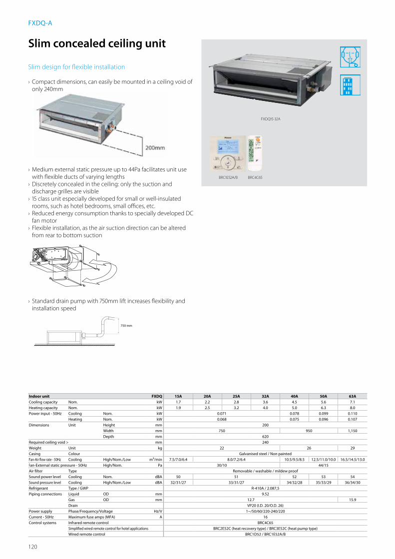
120
///////////////////////////////////////////////////////////////////////////////////////
750 mm
Indoor unit FXDQ 15A 20A 25A 32A 40A 50A 63ACooling capacity Nom. kW 1.7 2.2 2.8 3.6 4.5 5.6 7.1Heating capacity Nom. kW 1.9 2.5 3.2 4.0 5.0 6.3 8.0Power input - 50Hz Cooling Nom. kW 0.071 0.078 0.099 0.110
Heating Nom. kW 0.068 0.075 0.096 0.107Dimensions Unit Height mm 200
Width mm 750 950 1,150Depth mm 620
Required ceiling void > mm 240Weight Unit kg 22 26 29Casing Colour Galvanised steel / Non paintedFan-Air flow rate - 50Hz Cooling High/Nom./Low m³/min 7.5/7.0/6.4 8.0/7.2/6.4 10.5/9.5/8.5 12.5/11.0/10.0 16.5/14.5/13.0Fan-External static pressure - 50Hz High/Nom. Pa 30/10 44/15Air filter Type Removable / washable / mildew proofSound power level Cooling Nom. dBA 50 51 52 53 54Sound pressure level Cooling High/Nom./Low dBA 32/31/27 33/31/27 34/32/28 35/33/29 36/34/30Refrigerant Type / GWP R-410A / 2.087,5Piping connections Liquid OD mm 9.52
Gas OD mm 12.7 15.9Drain VP20 (I.D. 20/O.D. 26)
Power supply Phase/Frequency/Voltage Hz/V 1~/50/60/220-240/220Current - 50Hz Maximum fuse amps (MFA) A 16Control systems Infrared remote control BRC4C65
Simplified wired remote control for hotel applications BRC2E52C (heat recovery type) / BRC3E52C (heat pump type)Wired remote control BRC1D52 / BRC1E52A/B
Slim concealed ceiling unit
Slim design for flexible installation
› Compact dimensions, can easily be mounted in a ceiling void of only 240mm
› Medium external static pressure up to 44Pa facilitates unit use with flexible ducts of varying lengths
› Discretely concealed in the ceiling: only the suction and discharge grilles are visible
› 15 class unit especially developed for small or well-insulated rooms, such as hotel bedrooms, small offices, etc.
› Reduced energy consumption thanks to specially developed DC fan motor
› Flexible installation, as the air suction direction can be altered from rear to bottom suction
› Standard drain pump with 750mm lift increases flexibility and installation speed
FXDQ-A
BRC1E52A/B BRC4C65
FXDQ15-32A

121
Indo
or U
nits
Detailed technical drawings
FXDQ15-32A
FXDQ40-50A

122
Detailed technical drawings
FXDQ63A
FXQQ15A

123
Indo
or U
nits
Detailed technical drawings
FXDQ20-25A
FXDQ40A

124
Detailed technical drawings
FXDQ50A
FXDQ63A

125
Indo
or U
nits
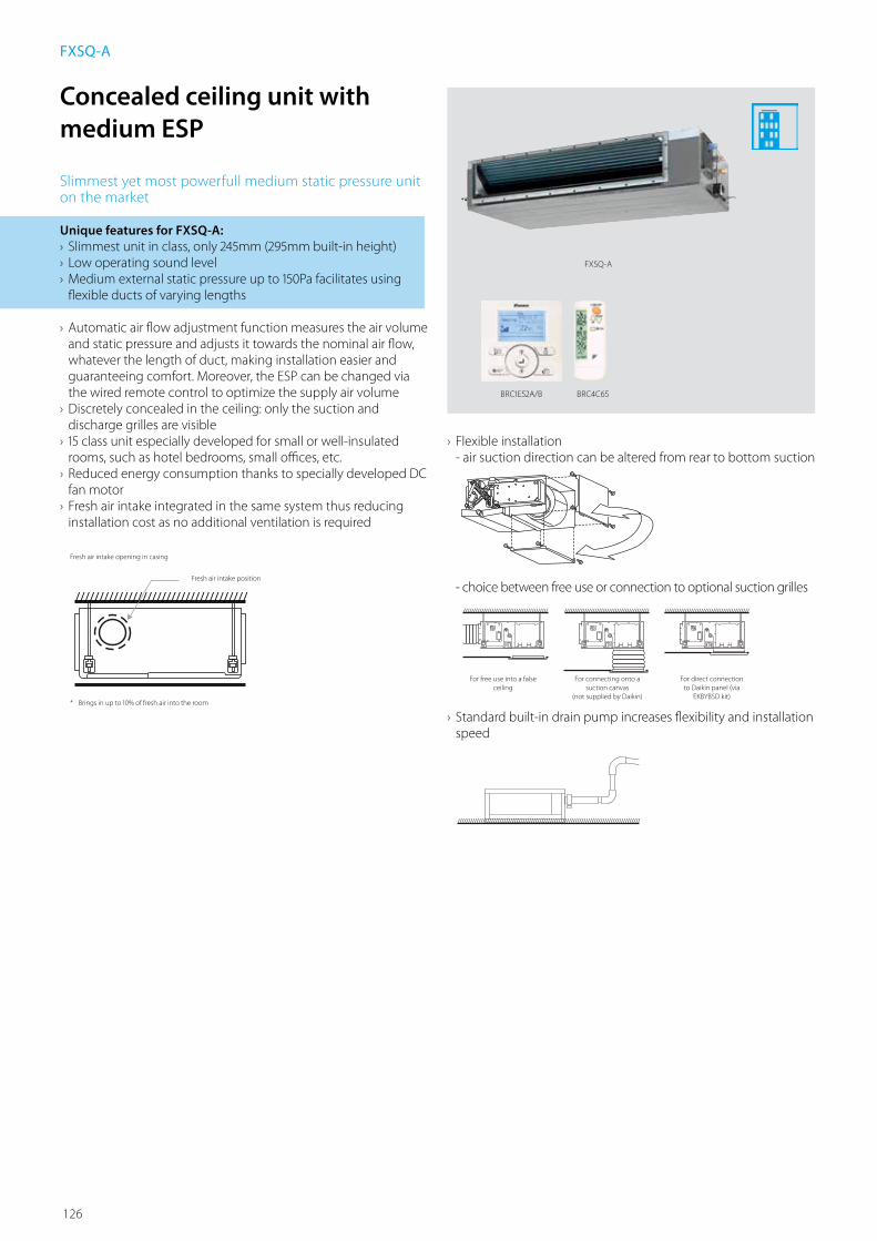
126
BRC1E52A/B
FXSQ-A
Concealed ceiling unit with medium ESP
Slimmest yet most powerfull medium static pressure unit on the market
Unique features for FXSQ-A: › Slimmest unit in class, only 245mm (295mm built-in height) › Low operating sound level › Medium external static pressure up to 150Pa facilitates using flexible ducts of varying lengths
› Automatic air flow adjustment function measures the air volume and static pressure and adjusts it towards the nominal air flow, whatever the length of duct, making installation easier and guaranteeing comfort. Moreover, the ESP can be changed via the wired remote control to optimize the supply air volume
› Discretely concealed in the ceiling: only the suction and discharge grilles are visible
› 15 class unit especially developed for small or well-insulated rooms, such as hotel bedrooms, small offices, etc.
› Reduced energy consumption thanks to specially developed DC fan motor
› Fresh air intake integrated in the same system thus reducing installation cost as no additional ventilation is required
FXSQ-A
BRC4C65
› Flexible installation - air suction direction can be altered from rear to bottom suction
- choice between free use or connection to optional suction grilles
› Standard built-in drain pump increases flexibility and installation speed
////////////////////////////////////
Fresh air intake position
////////////////////////////////////////// ////////////////////////////////////////////////////////////////////////////////////
For free use into a false ceiling
For connecting onto a suction canvas
(not supplied by Daikin)
For direct connection to Daikin panel (via
EKBYBSD kit)
Fresh air intake opening in casing
* Brings in up to 10% of fresh air into the room
///////////////////////////////////////////////////////////////////////////////////////

127
Indo
or U
nits
Automatic Airflow Adjustment function
› Automatically selects the most appropriate fan curve to achieve the units’ nominal air flow within ±10%
› Why? After installation the real ducting will frequently differ from the initially calculated air flow resistance; the real air flow may be much lower or higher than nominal , leading to a lack of capacity or uncomfortable air temperature
› The automatic Airflow Adjustment function will adapt the unit’s fan speed to any ducting automatically (10 or more fan curves are available on every model), making installation much faster
Exte
rnal
sta
tic p
ress
ure
(Pa)
Air flow (m³/min)
Rated air flow line
+/- 10%
50
200
Fan characteristic curve
Actual duct resistance curve
Duct resistance curve at the time of designing
Rated air flow
Airflow without air flow automatic adjustment
Actual airflow
Timesaving
Indoor unit FXSQ 15A 20A 25A 32A 40A 50A 63A 80A 100A 125A 140A
Cooling capacity Nom. kW 1.7 2.2 2.8 3.6 4.5 5.6 7.1 9.0 11.2 14.0 16.0
Heating capacity Nom. kW 1.9 2.5 3.2 4.0 5.0 6.3 8.0 10.0 10.0 26.0 18.0
Power input - 50Hz Cooling Nom. kW 41 45 92 95 95 121 157 214 -
Heating Nom. kW 38 42 89 92 92 118 154 211 -
Dimensions Unit Height mm 245 245 245 245 245
Width mm 550 700 1000 1400 1550
Depth mm 800 800 800 800 800
Required ceiling void > mm 295Weight Unit kg 23,5 24 28,5 29 35,5 36,5 46 47 51Casing Colour Not painted
Material Galvanised steel plateDecoration panel Model
ColourDimensions HeightxWidthxDepth mmWeight kg
Fan-Air flow rate - 50Hz
Cooling High/Nom./Low m³/min 8.7/7.5/6.5 9/7.5/6.5 9.5/8/7 15/12.5/11 15.2/12.5/11 21/18/15 23/19.5/16 32/27/23 36/31.5/26 -Heating High/Nom./Low m³/min 8.7/7.5/6.5 9/7.5/6.5 9.5/8/7 15/12.5/11 15.2/12.5/11 21/18/15 23/19.5/16 32/27/23 36/31.5/26 -
Fan-External static pressure - 50Hz High/Nom. Pa 150 -Air filter Type Resin net with mold resistanceSound power level Cooling High/Nom. dBA 54 55 60 59 61 61 64 -Sound pressure level Cooling High/Nom./Low dBA 29.5/28/25 30/28/25 31/29/26 35/32/29 33/30/27 35/32/29 36/34/31 39/36/33 -
Heating High/Nom./Low dBA 31.5/29/26 32/29/26 33/30/27 37/34/29 35/32/28 37/34/30 37/34/31 40/37/33 -Refrigerant Type / GWP R410A / 2078,5Piping connections Liquid OD mm Ø 6.35 (FLARE) Ø 9.52 (FLARE)
Gas OD mm Ø 12.7 (FLARE) Ø 15.9 (FLARE)Drain VP20 (EXTERNAL DIA. 26. INTERNAL DIA. 20), drain height 625 mm
Power supply Phase/Frequency/Voltage Hz/V 50Hz 220-240VCurrent - 50Hz Maximum fuse amps (MFA) A 16 -Control systems Infrared remote control BRC4C65
Simplified wired remote control for hotel applications BRC2E52C (heat recovery type) / BRC3E52C (heat pump type)Wired remote control BRC1D52 / BRC1E52A/B

128
Concealed ceiling unit with high ESP
Ideal for large sized spaces
FXMQ-P: ESP up to 200
› Automatic air flow adjustment function measures the air volume and static pressure and adjusts it towards the nominal air flow, whatever the length of duct, making installation easier and guaranteeing comfort. Moreover, the ESP can be changed via the wired remote control to optimize the supply air volume
› High external static pressure up to 200Pa facilitates extensive duct & grille network.
› Discretely concealed in the ceiling: only the suction and discharge grilles are visible
› Reduced energy consumption thanks to specially developed DC fan motor
› Fresh air intake integrated in the same system thus reducing installation cost as no additional ventilation is required
› Flexible installation- air suction direction can be altered from rear to bottom suction
- choice between free use or connection to optional suction grilles
› Standard built-in drain pump increases flexibility and installation speed
FXMQ-P7/FXMQ-MA9
BRC1E52A/B
FXMQ50P
BRC4C65
////////////////////////////////////////// ////////////////////////////////////////////////////////////////////////////////////
For free use into a false ceiling
For connecting onto a suction canvas
(not supplied by Daikin)
For direct connection to Daikin panel (via
EKBYBSD kit)
FXMQ-MA9: ESP up to 270
› High external static pressure up to 270Pa facilitates extensive duct & grille network
› Discretely concealed in the ceiling: only the suction and discharge grilles are visible
› Large capacity unit: up to 31.5 kW heating capacity
////////////////////////////////////Fresh air intake position
Fresh air intake opening in casing
* Brings in up to 10% of fresh air into the room
///////////////////////////////////////////////////////////////////////////////////////

129
Indo
or U
nits
Indoor unit FXMQ-P7/FXMQ-MA9 50P7 63P7 80P7 100P7 125P7 200MA9 250MA9Cooling capacity Nom. kW 5.6 7.1 9.0 11.2 14.0 22.4 28.0Heating capacity Nom. kW 6.3 8.0 10.0 12.5 16.0 25.0 31.5Power input - 50Hz Cooling Nom. kW 0.110 0.120 0.171 0.176 0.241 1.294 1.465
Heating Nom. kW 0.098 0.108 0.159 0.164 0.229 1.294 1.465Dimensions Unit Height mm 300 470
Width mm 1,000 1,400 1,380Depth mm 700 1,100
Required ceiling void > mm 350 -Weight Unit kg 35 46 137Casing Colour Unpainted -
Material Galvanised steel plateDecoration panel Model BYBS71DJW1 BYBS125DJW1 -
Colour White (10Y9/0.5) -Dimensions HeightxWidthxDepth mm 55x1,100x500 55x1,500x500 -x-x-Weight kg 4.5 6.5 -
Fan-Air flow rate - 50Hz
Cooling High/Nom./Low m³/min 18/16.5/15 19.5/17.8/16 25/22.5/20 32/27.5/23 39/33.5/28 58/-/50 72/-/62Heating High/Nom./Low m³/min 18/16.5/15 19.5/17.8/16 25/22.5/20 32/27.5/23 39/33.5/28 -/-/-
Fan-External static pressure - 50Hz High/Nom. Pa 200/100 221/132 270/191Air filter Type Resin net with mold resistance -Sound power level Cooling High/Nom. dBA 61/- 64/- 67/- 65/- 70/- -/-Sound pressure level Cooling High/Nom./Low dBA 41/39/37 42/40/38 43/41/39 44/42/40 48/-/45
Heating High/Nom./Low dBA 41/39/37 42/40/38 43/41/39 44/42/40 -/-/-Refrigerant Type / GWP R-410A / 2.087,5Piping connections Liquid OD mm 6.35 9.52
Gas OD mm 12.7 15.9 19.1 22.2Drain VP25 (I.D. 25/O.D. 32) PS1B
Power supply Phase/Frequency/Voltage Hz/V 1~/50/60/220-240/220Current - 50Hz Maximum fuse amps (MFA) A 16 15Control systems Infrared remote control BRC4C65
Simplified wired remote control for hotel applications BRC2E52C (heat recovery type) / BRC3E52C (heat pump type)Wired remote control BRC1D52 / BRC1E52A/B
Exte
rnal
sta
tic p
ress
ure
(Pa)
Air flow (m³/min)
Rated air flow line
+/- 10%
50
200
Fan characteristic curve
Actual duct resistance curve
Duct resistance curve at the time of designing
Rated air flow
Airflow without air flow automatic adjustment
Actual airflow
Automatic Airflow Adjustment function
› Automatically selects the most appropriate fan curve to achieve the units’ nominal air flow within ±10%
› Why? After installation the real ducting will frequently differ from the initially calculated air flow resistance; the real air flow may be much lower or higher than nominal , leading to a lack of capacity or uncomfortable air temperature
› The automatic Airflow Adjustment function will adapt the unit’s fan speed to any ducting automatically (10 or more fan curves are available on every model), making installation much faster
Timesaving

130
Detailed technical drawings
FXMQ50P7
FXMQ63-80P7
FXMQ50P7
3TW32694-1NOTES
1 Refer to ‘outlook drawing for installing optional accessories’ when installing optional accessories.2 The required ceiling depth varies according to the configuration of the specific system.3 For maintenance of the air filter, it is necessary to provide a service access panel.
Refer to the ‘filter installation method’ drawing.
Ø125 (Knock out hole)
Item Name Description1 Liquid pipe connection Ø6.35 Flare connection2 Gas pipe connection Ø12.70 Flare connection3 Drain pipe connection VP25 (0D Ø32, ID Ø25) 4 Remote control wiring connection -5 Power supply connection -6 Drain hole VP20 (0D Ø32, ID Ø25) 7 Air filter -8 Air suction side -9 Air discharge side -
10 Nameplate -
fresh air intake position
6 x M5 (On circumference)
VIEW A-ADETAIL B
Suspension bolt
(Service space)
350 o
r mor
e(S
ervic
e spa
ce)
DETAIL B
1038 (Suspension position)
631 (
Susp
ensio
n pos
ition)
500 or more
FXMQ63-80P7
Item Name Description1 Liquid pipe connection ø 9.52 Flare connection2 Gas pipe connection ø 15.90 Flare connection3 Drain pipe connection VP25 (OD ø 32, ID ø 25)4 Remote control wiring connection -5 Power supply connection -6 Drain hole VP25 (OD ø 32, ID ø 25)7 Air filter -8 Air suction side -9 Air discharge side -
10 Nameplate -
NOTES
1. Refer to the outlook drawing of optional accessories when installing them.2. The required ceiling depth varies according to the configuration of the specific
system.3. For maintenance of the air filter, it is necessary to provide a service access
panel.4. Optional decoration panel: BYBS71DJW1 (light ivory white 10Y9/0.5)
3TW31234-1B
(Knock out hole)
Suspension bolt
Detail B
Detail B
View A-A
500 or more(Service space)
Fresh air intake position
(On circumference)
350 o
r mor
e(S
ervic
e spa
ce)
1038 (Suspension position)
631 (
Susp
ensio
n pos
ition)
390 o
r mor
e(S
ervic
e spa
ce)
(Ceil
ing op
ening
)
(Ceiling opening)
With decoration panel
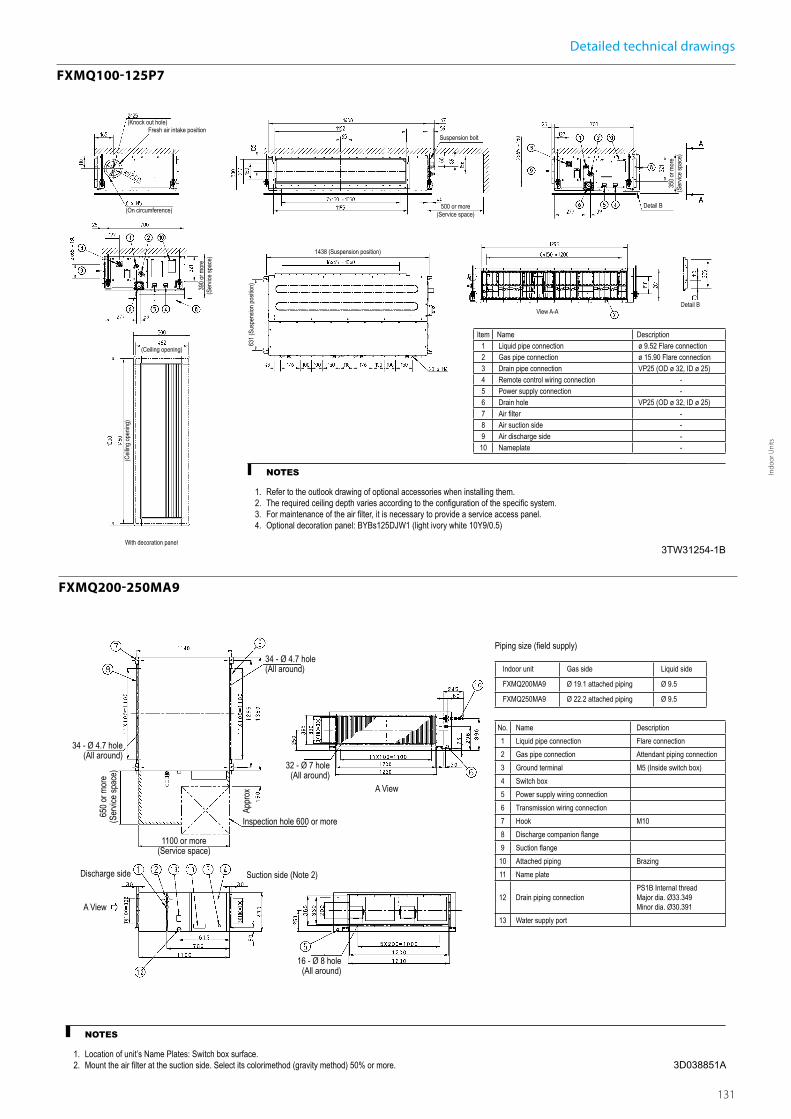
131
Indo
or U
nits
Detailed technical drawings
FXMQ100-125P7
FXMQ200-250MA9
FXMQ100-125P7
Item Name Description1 Liquid pipe connection ø 9.52 Flare connection2 Gas pipe connection ø 15.90 Flare connection3 Drain pipe connection VP25 (OD ø 32, ID ø 25)4 Remote control wiring connection -5 Power supply connection -6 Drain hole VP25 (OD ø 32, ID ø 25)7 Air filter -8 Air suction side -9 Air discharge side -
10 Nameplate -
NOTES
1. Refer to the outlook drawing of optional accessories when installing them.2. The required ceiling depth varies according to the configuration of the specific system.3. For maintenance of the air filter, it is necessary to provide a service access panel.4. Optional decoration panel: BYBs125DJW1 (light ivory white 10Y9/0.5)
3TW31254-1B
(Knock out hole)
Suspension bolt
Detail B
Detail BView A-A
500 or more(Service space)
Fresh air intake position
(On circumference)
350 o
r mor
e(S
ervic
e spa
ce)
1438 (Suspension position)63
1 (Su
spen
sion p
ositio
n)390 o
r mor
e(S
ervic
e spa
ce)
(Ceil
ing op
ening
)
(Ceiling opening)
With decoration panel
3D038851A
FXMQ-MA9
34 - Ø 4.7 hole(All around)
34 - Ø 4.7 hole(All around)
32 - Ø 7 hole(All around)
16 - Ø 8 hole(All around)
Inspection hole 600 or more
Suction side (Note 2)Discharge side
A View
1100 or more(Service space)
A View
Piping size (field supply)
Indoor unit Gas side Liquid side
FXMQ200MA9 Ø 19.1 attached piping Ø 9.5
FXMQ250MA9 Ø 22.2 attached piping Ø 9.5
No. Name Description1 Liquid pipe connection Flare connection2 Gas pipe connection Attendant piping connection3 Ground terminal M5 (Inside switch box)4 Switch box5 Power supply wiring connection6 Transmission wiring connection7 Hook M108 Discharge companion flange9 Suction flange
10 Attached piping Brazing11 Name plate
12 Drain piping connectionPS1B Internal thread Major dia. Ø33.349 Minor dia. Ø30.391
13 Water supply port
NOTES
1. Location of unit’s Name Plates: Switch box surface.2. Mount the air filter at the suction side. Select its colorimethod (gravity method) 50% or more.
650 o
r mor
e(S
ervic
e spa
ce)
Appr
ox

132
Detailed technical drawings
FXMQ50P7
FXMQ63P7
FXMQ50P7
3TW32698-1
NOTES1. Fan characteristics as shown are in “fan only” mode.2. ESP: External static pressure
Exter
nal s
tatic
pres
sure
[Pa]
Exter
nal s
tatic
pres
sure
[Pa]
Exter
nal s
tatic
pres
sure
[Pa]
Airflow [m3/min] Airflow [m3/min]
Airflow [m3/min]
Fan characteristics (1) Fan characteristics (3)(airflow auto adjustment)
Fan characteristics (2)(Field setting with remote control)
Range of available air flow rate (H)
Upper limit of ESP(max ESP) Upper limit of ESP Upper limit of ESP by
airflow auto adjustment
Lower limit of ESP
H (max ESP)
M (max ESP)
L (max ESP)
L (std ESP)Upper limit of ESP(std ESP)
Lower limit of ESP(max ESP)
Lower limit of ESP(std ESP)
H (std ESP)
M (std ESP)
Lower limit of ESP byairflow auto adjustment
L
M
H
FXMQ63P7
3TW32708-1
NOTES1. Fan characteristics as shown are in “fan only” mode.2. ESP: External static pressure
Exter
nal s
tatic
pres
sure
[Pa]
Exter
nal s
tatic
pres
sure
[Pa]
Exter
nal s
tatic
pres
sure
[Pa]
Airflow [m3/min] Airflow [m3/min]
Airflow [m3/min]
Fan characteristics (1) Fan characteristics (3)(airflow auto adjustment)
Fan characteristics (2)(Field setting with remote control)
Range of available air flow rate (H)
Upper limit of ESP(max ESP) Upper limit of ESP Upper limit of ESP by
airflow auto adjustment
Lower limit of ESP
H (max ESP)
M (max ESP)
L (max ESP)
L (std ESP)
Upper limit of ESP(std ESP)
Lower limit of ESP(max ESP)
Lower limit of ESP(std ESP)
H (std ESP)M (std ESP)
Lower limit of ESP byairflow auto adjustment
L
M
H
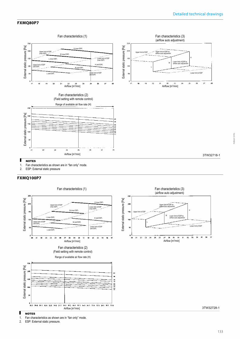
133
Indo
or U
nits
Detailed technical drawings
FXMQ80P7
FXMQ100P7
FXMQ80P7
3TW32718-1
NOTES1. Fan characteristics as shown are in “fan only” mode.2. ESP: External static pressure
Exter
nal s
tatic
pres
sure
[Pa]
Exter
nal s
tatic
pres
sure
[Pa]
Exter
nal s
tatic
pres
sure
[Pa]
Airflow [m3/min] Airflow [m3/min]
Airflow [m3/min]
Fan characteristics (1) Fan characteristics (3)(airflow auto adjustment)
Fan characteristics (2)(Field setting with remote control)
Range of available air flow rate (H)
Upper limit of ESP(max ESP) Upper limit of ESP Upper limit of ESP by
airflow auto adjustment
Lower limit of ESP
H (max ESP)
M (max ESP)
L (max ESP)
L (std ESP)
Upper limit of ESP(std ESP)
Lower limit of ESP(max ESP)
Lower limit of ESP(std ESP)
H (std ESP)M (std ESP)
Lower limit of ESP byairflow auto adjustment
L
M
H
FXMQ100P7
3TW32728-1
NOTES1. Fan characteristics as shown are in “fan only” mode.2. ESP: External static pressure.
Exter
nal s
tatic
pres
sure
[Pa]
Exter
nal s
tatic
pres
sure
[Pa]
Exter
nal s
tatic
pres
sure
[Pa]
Airflow [m3/min] Airflow [m3/min]
Airflow [m3/min]
Fan characteristics (1) Fan characteristics (3)(airflow auto adjustment)
Fan characteristics (2)(Field setting with remote control)
Range of available air flow rate (H)
Upper limit of ESP(max ESP)
Upper limit of ESP
Upper limit of ESP byairflow auto adjustment
Lower limit of ESP
H (max ESP)
M (max ESP)
L (max ESP)
L (std ESP)
Upper limit of ESP(std ESP)
Lower limit of ESP(max ESP)
Lower limit of ESP(std ESP)
H (std ESP)
M (std ESP)
Lower limit of ESP byairflow auto adjustment
L
M
H

134
Detailed technical drawings
FXMQ125P7
FXMQ200MA
FXMQ125P7
3TW32738-1
NOTES1. Fan characteristics as shown are in “fan only” mode.2. ESP: External static pressure
Exter
nal s
tatic
pres
sure
[Pa]
Exter
nal s
tatic
pres
sure
[Pa]
Exter
nal s
tatic
pres
sure
[Pa]
Airflow [m3/min] Airflow [m3/min]
Airflow [m3/min]
Fan characteristics (1) Fan characteristics (3)(airflow auto adjustment)
Fan characteristics (2)(Field setting with remote control)
Range of available air flow rate (H)
Upper limit of ESP(max ESP) Upper limit of ESP
Upper limit of ESP byairflow auto adjustment
Lower limit of ESP
H (max ESP)
M (max ESP)
L (max ESP)
L (std ESP)
Upper limit of ESP(std ESP)
Lower limit of ESP(max ESP)
Lower limit of ESP(std ESP)
H (std ESP)
M (std ESP)
Lower limit of ESP byairflow auto adjustment
L
M
H
L
FXMQ200MA
3D035172
NOTES
1. Theremotecontrolcanbeusedtoswitchbetween“high”and“low”.2. Theairflowissetto“standard”beforeleavingthefactory.Itispossibletoswitchbetween
“standardESP”and“highESP”bychangingtheswitchintheindoorunitelectricalbox.
Low(HighESP)
Airflow(m³/min)
Upperlim
itofESP
(Standar
dESP)
Externalstaticpressure
50Hz 220V(mmH2O)(PA) (mmH2O)
Low(StandardESP)
High(HighESP)
High(StandardESP)
Lowerlimi
tofESP
(HighESP
)
LowerlimitofESP
(StandardESP)
UpperlimitofES
P
(HighESP)

135
Indo
or U
nits
FXMQ250MA
3D035173A
NOTES
1. Theremotecontrolcanbeusedtoswitchbetween“high”and“low”.2. Theairflowissetto“standard”beforeleavingthefactory.Itispossibletoswitchbetween
“standardESP”and“highESP”bychangingtheswitchintheindoorunitelectricalbox.
Low(HighESP)
Airflow(m³/min)
Upperlimit
ofESP
(HighESP)
Lowerlimi
tofESP
(HighESP
)
LowerlimitofESP
(StandardESP)
Upperlimit
ofESP
(Standard
ESP)
Externalstaticpressure
60Hz 220V(mmH2O)(PA) (mmH2O)
Low(StandardESP)
High(HighESP)
High(StandardESP)
Detailed technical drawings
FXMQ250MA
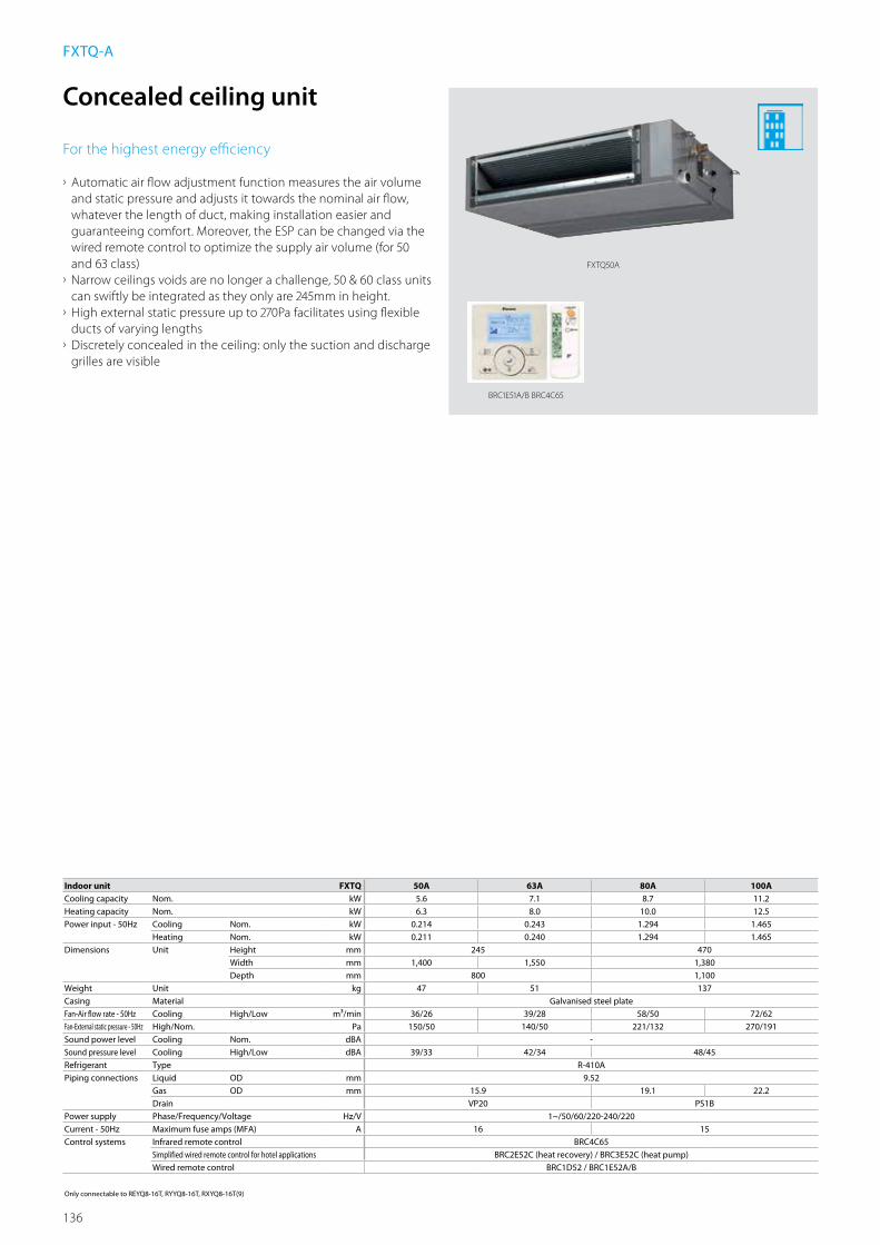
136
BRC1E51A/B BRC4C65
FXTQ50A
Indoor unit FXTQ 50A 63A 80A 100ACooling capacity Nom. kW 5.6 7.1 8.7 11.2Heating capacity Nom. kW 6.3 8.0 10.0 12.5Power input - 50Hz Cooling Nom. kW 0.214 0.243 1.294 1.465
Heating Nom. kW 0.211 0.240 1.294 1.465Dimensions Unit Height mm 245 470
Width mm 1,400 1,550 1,380Depth mm 800 1,100
Weight Unit kg 47 51 137Casing Material Galvanised steel plateFan-Air flow rate - 50Hz Cooling High/Low m³/min 36/26 39/28 58/50 72/62Fan-External static pressure - 50Hz High/Nom. Pa 150/50 140/50 221/132 270/191Sound power level Cooling Nom. dBA -Sound pressure level Cooling High/Low dBA 39/33 42/34 48/45Refrigerant Type R-410APiping connections Liquid OD mm 9.52
Gas OD mm 15.9 19.1 22.2Drain VP20 PS1B
Power supply Phase/Frequency/Voltage Hz/V 1~/50/60/220-240/220Current - 50Hz Maximum fuse amps (MFA) A 16 15Control systems Infrared remote control BRC4C65
Simplified wired remote control for hotel applications BRC2E52C (heat recovery) / BRC3E52C (heat pump)Wired remote control BRC1D52 / BRC1E52A/B
Only connectable to REYQ8-16T, RYYQ8-16T, RXYQ8-16T(9)
Concealed ceiling unit
For the highest energy efficiency
› Automatic air flow adjustment function measures the air volume and static pressure and adjusts it towards the nominal air flow, whatever the length of duct, making installation easier and guaranteeing comfort. Moreover, the ESP can be changed via the wired remote control to optimize the supply air volume (for 50 and 63 class)
› Narrow ceilings voids are no longer a challenge, 50 & 60 class units can swiftly be integrated as they only are 245mm in height.
› High external static pressure up to 270Pa facilitates using flexible ducts of varying lengths
› Discretely concealed in the ceiling: only the suction and discharge grilles are visible
FXTQ-A

137
Indo
or U
nits
Indoor unit FXAQ 15P 20P 25P 32P 40P 50P 63PCooling capacity Nom. kW 1.7 2.2 2.8 3.6 4.5 5.6 7.1Heating capacity Nom. kW 1.9 2.5 3.2 4.0 5.0 6.3 8.0Power input - 50Hz Cooling Nom. kW 0.017 0.019 0.028 0.030 0.020 0.033 0.050
Heating Nom. kW 0.025 0.029 0.034 0.035 0.020 0.039 0.060Dimensions Unit Height mm 290
Width mm 795 1,050Depth mm 238
Weight Unit kg 11 14Casing Colour White (3.0Y8.5/0.5)Fan-Air flow rate - 50Hz Cooling High/Low m³/min 7.0/4.5 7.5/4.5 8/5 8.5/5.5 12/9 15/12 19/14Air filter Type Washable resin netSound power level Cooling Nom. dBA -Sound pressure level Cooling High/Low dBA 34.0/29.0 35.0/29.0 36.0/29.0 37.5/29.0 39.0/34.0 42.0/36.0 47.0/39.0Refrigerant Type / GWP R-410A / 2.087,5Piping connections Liquid OD mm 6.35 9.52
Gas OD mm 12.7 15.9Drain VP13 (I.D. 13/O.D. 18)
Power supply Phase/Frequency/Voltage Hz/V 1~/50/220-240Current - 50Hz Maximum fuse amps (MFA) A 16Control systems Infrared remote control BRC7EB518
Simplified wired remote control for hotel applications -Wired remote control BRC1E52A/B / BRC1D52
Wall mounted unit
For rooms with no false ceilings nor free floor space
› Flat front panel blends easily within any interior décor and is more easy to clean
› Can easily be installed in both new and refurbishment projects › 15 class unit especially developed for small or well-insulated rooms, such as hotel bedrooms, small offices, etc.
› Reduced energy consumption thanks to specially developed DC fan motor
› The air is comfortably spread up and downwards thanks to 5 different discharge angles that can be programmed via the remote control
› Maintenance operations can be performed from the front of the unit
FXAQ-P
BRC1E52A/B BRC7E518
FXAQ15-32P

138
Detailed technical drawings
FXAQ15-32P
FXAQ40-50P
FXAQ15-32P
3D065064ANOTES
1 Location of unit’s of Name Plate: Right side surface of casing.
2 In case of using infrared remote control, this position will be a signal receiver. Refer to the drawing of infrared remote control in detail.
Approx 400
Nr Name Description1 Front panel2 Front grill3 Air outlet4 Gas pipe Ø12.7mm Flare connection5 Liquid pipe Ø6.4mm Flare connection6 Drain hose VP13 (External dia. Ø18)7 Grounding terminal M48 Right side pipe connection hole9 Left side pipe connection hole
Dimensions forfull open front panel
50 or more 50 or more(Required space) (Required space)
Piping direction Piping directionName plate Note 2
Piping direction
120 or less2500 or moreFor installationin high spaces
90 or
mor
e(R
equir
ed sp
ace)
30 or
mor
e(R
equir
ed sp
ace)
Approx 475Approx 460
(Filter part)
Filter part
Approx 415
Approx 290(Flexible tube part)
Ø80 holeØ80 hole
Piping andWiring intakeMounting location
Outside line
FXAQ40-50P
3D065065ANOTES
1 Location of unit’s of Name Plate: Right side surface of casing.
2 In case of using infrared remote control, this position will be a signal receiver. Refer to the drawing of infrared remote control in detail.
Approx 400
Nr Name Description1 Front panel2 Front grill3 Air outlet4 Gas pipe Ø12.7mm Flare connection5 Liquid pipe Ø6.4mm Flare connection6 Drain hose VP13 (External dia. Ø18)7 Grounding terminal M48 Right side pipe connection hole9 Left side pipe connection hole
Dimensions forfull open front panel
50 or more 50 or more(Required space) (Required space)
Piping direction Piping directionName plate Note 2
Piping direction
120 or less2500 or moreFor installationin high spaces
90 or
mor
e(R
equir
ed sp
ace)
30 or
mor
e(R
equir
ed sp
ace)
Approx 475Approx 460
(Filter part)
Filter part
Approx 415
Approx 290(Flexible tube part)
Ø80 holeØ80 hole
Piping andWiring intake
Mounting location
Outside line

139
Indo
or U
nits
Detailed technical drawings
FXAQ63P
FXAQ63P
3D065066ANOTES
1 Location of unit’s of Name Plate: Right side surface of casing.
2 In case of using infrared remote control, this position will be a signal receiver. Refer to the drawing of infrared remote control in detail.
Approx 400
Nr Name Description1 Front panel2 Front grill3 Air outlet4 Gas pipe Ø15.9mm Flare connection5 Liquid pipe Ø9.5mm Flare connection6 Drain hose VP13 (External dia. Ø18)7 Grounding terminal M48 Right side pipe connection hole9 Left side pipe connection hole
Dimensions forfull openfront panel
50 or more 50 or more(Required space) (Required space)
Piping direction Piping directionName plate Note 2
Piping direction
120 or less2500 or moreFor installationin high spaces
90 or
mor
e(R
equir
ed sp
ace)
30 or
mor
e(R
equir
ed sp
ace)
Approx 475Approx 460
Filter part
Filter partApprox 415
Ø80 holeØ80 hole
Piping andWiring intake
Mounting location
Outside line

140
Indoor unit FXHQ 32A 63A 100ACooling capacity Nom. kW 3.6 7.1 11.2Heating capacity Nom. kW 4.0 8.0 12.5Power input - 50Hz Cooling Nom. kW 0.107 0.111 0.237
Heating Nom. kW 0.107 0.111 0.237Dimensions Unit Height mm 235
Width mm 960 1,270 1,590Depth mm 690
Weight Unit kg 24 33 39Casing Colour Fresh White
Material ResinFan-Air flow rate - 50Hz
Cooling High/Nom./Low m³/min 14.0/12.0/10.0 20.0/17.0/14.0 29.5/24.0/19.0Heating High/Nom./Low m³/min 14.0/12.0/10.0 20.0/17.0/14.0 29.5/24.0/19.0
Air filter Type Resin net with mold resistanceSound power level Cooling Nom. dBA -Sound pressure level Cooling High/Nom./Low dBA 36.0/34.0/31.0 37.0/35.0/34.0 44.0/37.0/34.0
Heating High/Nom./Low dBA 36.0/34.0/31.0 37.0/35.0/34.0 44.0/37.0/34.0Refrigerant Type / GWP R-410A / 2.087,5Piping connections Liquid OD mm 6.35 9.52
Gas OD mm 12.7 15.9Drain VP20 (I.D. 20/O.D. 26)
Power supply Phase/Frequency/Voltage Hz/V 1~/50/220-240Current - 50Hz Maximum fuse amps (MFA) A 16Control systems Infrared remote control BRC7G53
Simplified wired remote control for hotel applications -Wired remote control BRC1E52A/B / BRC1D52
Ceiling suspended unit
For wide rooms with no false ceilings nor free floor space
› Ideal for comfortable air flow in wide rooms thanks to Coanda effect: up to 100° discharge angle
› Even rooms with ceilings up to 3.8m can be heated up or cooled down very easily without capacity loss
› Can easily be installed in both new and refurbishment projects › Can easily be mounted in corners and narrow spaces, as it only needs 30mm lateral service space
› Fresh air intake integrated in the same systems thus reducing installation cost as no additional ventilation is required
› Reduced energy consumption thanks to specially developed DC fan motor and drain pump
› Stylish unit blends easily with any interior. The flaps close entirely when the unit is not operating
FXHQ-A
BRC1E52A-B BRC7G53
FXHQ63A
//////////////////////
//////////////////////
////////////////////////////////////////////
////////////////////////////
////
////
////
////
////
////
////
////
////
Air outlet
Air inlet
Obstruction
≥300
30 or more(Service space)
30 or more(Service space)
Fresh air intake opening in casing
* Brings in up to 10% of fresh air into the room

141
Indo
or U
nits
Detailed technical drawings
FXHQ32A
FXHQ63A

142
Indoor unit FXUQ 71A 100ACooling capacity Nom. kW 8.0 11.2Heating capacity Nom. kW 9.0 12.5Power input - 50Hz Cooling Nom. kW 0.090 0.200
Heating Nom. kW 0.073 0.179Dimensions Unit Height mm 198
Width mm 950Depth mm 950
Weight Unit kg 26 27Casing Colour Fresh White
Material ResinFan-Air flow rate - 50Hz
Cooling High/Nom./Low m³/min 22.5/19.5/16.0 31.0/26.0/21.0Heating High/Nom./Low m³/min 22.5/19.5/16.0 31.0/26.0/21.0
Air filter Type Resin net with mold resistanceSound power level Cooling Nom. dBA -Sound pressure level Cooling High/Nom./Low dBA 40.0/38.0/36.0 47.0/44.0/40.0
Heating High/Nom./Low dBA 40.0/38.0/36.0 47.0/44.0/40.0Refrigerant Type / GWP R-410A / 2.087,5Piping connections Liquid OD mm 9.52
Gas OD mm 15.9Drain I.D. 20/O.D. 26
Power supply Phase/Frequency/Voltage Hz/V 1~/50/60/220-240/220-230Current - 50Hz Maximum fuse amps (MFA) A 16Control systems Infrared remote control BRC7C58
Simplified wired remote control for hotel applications -Wired remote control BRC1E52A/B / BRC1D52
4-way blow ceiling suspended unit
Unique Daikin unit for high rooms with no false ceilings nor free floor space
› Even rooms with ceilings up to 3.5m can be heated up or cooled down very easily without capacity loss
› Can easily be installed in both new and refurbishment projects › Refurbishing the room ? With individual flap control, one or more flaps can be easily closed via the wired remote control
› Reduced energy consumption thanks to specially developed small tube heat exchanger, DC fan motor and drain pump
› Stylish unit blends easily with any interior. The flaps close entirely when the unit is not operating
› Optimum comfort guaranteed with automatic air flow adjustment to the required load
› 5 different discharge angles between 0 and 60°can be programmed via the remote control
› Standard drain pump with 500mm lift increases flexibility and installation speed
FXUQ-A
BRC1E52A/B BRC7CB58
FXUQ-A
//////////////////////////////////////////////
≤500
VP20

143
Indo
or U
nits
Detailed technical drawings
FXUQ-A
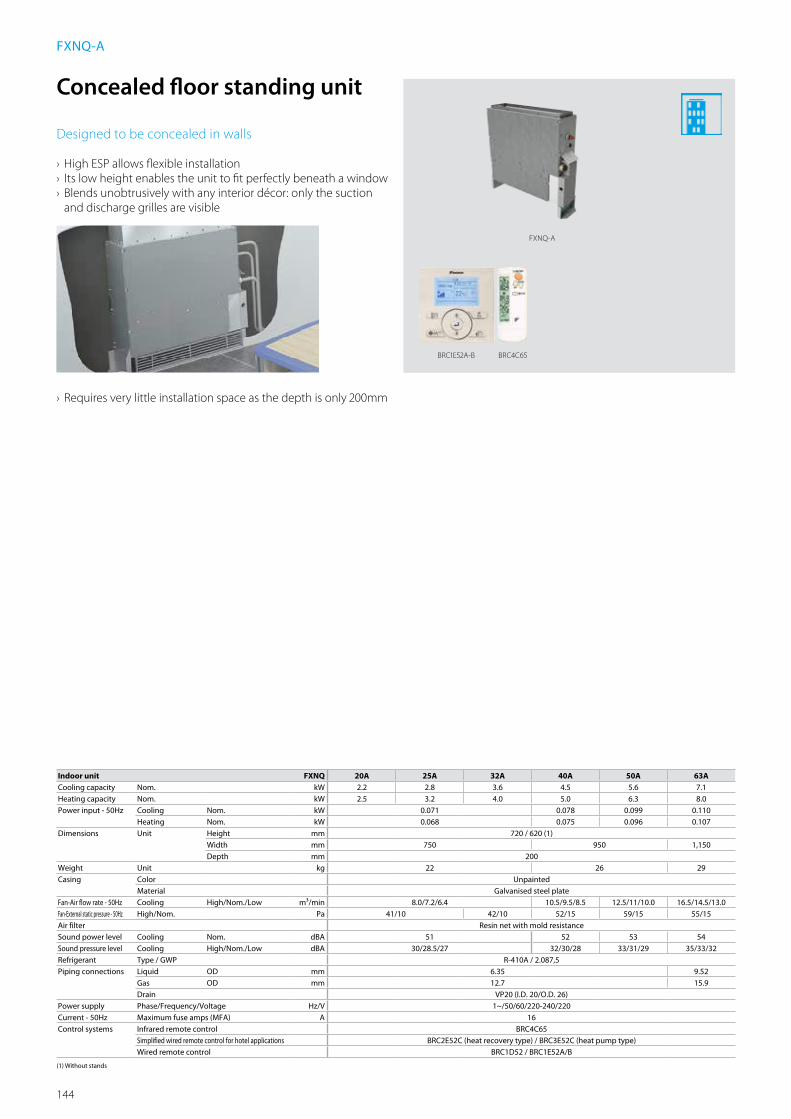
144
Indoor unit FXNQ 20A 25A 32A 40A 50A 63ACooling capacity Nom. kW 2.2 2.8 3.6 4.5 5.6 7.1Heating capacity Nom. kW 2.5 3.2 4.0 5.0 6.3 8.0Power input - 50Hz Cooling Nom. kW 0.071 0.078 0.099 0.110
Heating Nom. kW 0.068 0.075 0.096 0.107Dimensions Unit Height mm 720 / 620 (1)
Width mm 750 950 1,150Depth mm 200
Weight Unit kg 22 26 29Casing Color Unpainted
Material Galvanised steel plateFan-Air flow rate - 50Hz Cooling High/Nom./Low m³/min 8.0/7.2/6.4 10.5/9.5/8.5 12.5/11/10.0 16.5/14.5/13.0Fan-External static pressure - 50Hz High/Nom. Pa 41/10 42/10 52/15 59/15 55/15Air filter Resin net with mold resistanceSound power level Cooling Nom. dBA 51 52 53 54Sound pressure level Cooling High/Nom./Low dBA 30/28.5/27 32/30/28 33/31/29 35/33/32Refrigerant Type / GWP R-410A / 2.087,5Piping connections Liquid OD mm 6.35 9.52
Gas OD mm 12.7 15.9Drain VP20 (I.D. 20/O.D. 26)
Power supply Phase/Frequency/Voltage Hz/V 1~/50/60/220-240/220Current - 50Hz Maximum fuse amps (MFA) A 16Control systems Infrared remote control BRC4C65
Simplified wired remote control for hotel applications BRC2E52C (heat recovery type) / BRC3E52C (heat pump type)Wired remote control BRC1D52 / BRC1E52A/B
(1) Without stands
Concealed floor standing unit
Designed to be concealed in walls
› High ESP allows flexible installation › Its low height enables the unit to fit perfectly beneath a window › Blends unobtrusively with any interior décor: only the suction and discharge grilles are visible
› Requires very little installation space as the depth is only 200mm
FXNQ-A
FXNQ-A
BRC4C65BRC1E52A-B

145
Indo
or U
nits
Indoor unit FXLQ 20P 25P 32P 40P 50P 63PCooling capacity Nom. kW 2.2 2.8 3.6 4.5 5.6 7.1Heating capacity Nom. kW 2.5 3.2 4.0 5.0 6.3 8.000Power input - 50Hz Cooling Nom. kW 0.049 0.090 0.110
Heating Nom. kW 0.049 0.090 0.110Dimensions Unit Height mm 600
Width mm 1,000 1,140 1,420Depth mm 232
Weight Unit kg 27 32 38Casing Colour Fresh white (RAL9010) / Dark grey (RAL7011)Fan-Air flow rate - 50Hz Cooling High/Low m³/min 7/6 8/6 11/8.5 14/11 16/12Air filter Type Resin netSound power level Cooling Nom. dBA -Sound pressure level Cooling High/Low dBA 35/32 38/33 39/34 40/35Refrigerant Type / GWP R-410A / 2.087,5Piping connections Liquid OD mm 6.35 9.52
Gas OD mm 12.7 15.9Drain O.D. 21 (Vinyl chloride)
Power supply Phase/Frequency/Voltage Hz/V 1~/50/60/220-240/220Current - 50Hz Maximum fuse amps (MFA) A 15Control systems Infrared remote control BRC4C65
Simplified wired remote control for hotel applications BRC2E52C (heat recovery type) / BRC3E52C (heat pump type)Wired remote control BRC1D52 / BRC1E52A/B
Floor standing unit
For perimeter zone air conditioning
› Unit can be installed as free standing model by use of optional back plate
› Its low height enables the unit to fit perfectly beneath a window › Stylish modern casing finished in pure white (RAL9010) and iron grey (RAL7011) blends easily with any interior
› Requires very little installation space
› Wall mounted installation facilitates cleaning beneath the unit where dust tends to accumulate
› Wired remote control can easily be integrated in the unit
FXLQ-P
BRC1E52A/B BRC4C65
FXLQ20,25P
//////////////////
////////////////////////////////
///////////////////////////////////////////////////////////
////////////////////////////////
///////////////////////////////////////////////////////////
≥100mm
≥1750mm
Floor standing Wall mounted
>20mm
>20mm

146
3TW32294-1
20 or moreFXLQ20-25P
Item Name Description1 Liquid pipe connection Ø6.4 Flare connection2 Gas pipe connection Ø12.7 Flare connection3 Drain pipe connection O.D.Ø214 Switch box5 Air f lter
100 or more 100 or more
Front of face1000 or more
Discharge
Suction
1750 or more
Base
Required installation space
Piping hole (rear)
Level adjusting screw in standard accessory4xM6
2-12x18 Oblong holeHole for f xing to the f oor
4-12x30 Oblong holeHole for fear mounting
Wiring hole (bottom) Piping hole (bottom)
FXLQ32-40P
Detailed technical drawings
FXLQ20-25P

147
Indo
or U
nits
Detailed technical drawings
FXLQ50-63P

148
Stylish indoor units
overview
1 Decoration panel BYCQ140CG + BRC1E52A/B needed 2 To connect stylish indoor units a BPMKS unit is needed 3 For RXYSQ units a mix of RA indoor units and VRV indoor units is not allowed.
Capacity class (kW)
Connectable outdoor unit
RY
YQ
-T
RX
YQ
-T(9
)
RX
YSQ
-P8V
13
RX
YSQ
-P8Y
13
Type Model Product name 15 20 25 35 42 50 60 71
Ceiling mountedcassette
Round flow cassette(incl. auto-cleaning function1)
FCQG-F
Fully flat cassette
FFQ-C
Concealed ceiling
Small concealed ceiling unit FDBQ-B
Slim concealed ceiling unit FDXS-F(9)
Concealed ceiling unitwith inverter-driven fan
FBQ-D
Wall mounted
Daikin EmuraWall mounted unit
FTXG-LW/LS
Wall mounted unitCTXS-K FTXS-K
Wall mounted unit FTXS-G
Ceilingsuspended
Ceiling suspended unit FHQ-C
Floor standing
Nexura floor standing unit FVXG-K
Floor standing unit FVXS-F
Flexi type unit FLXS-B(9)
Depending on the application, Split and Sky Air indoor units can be connected to our VRV IV and VRV III-S outdoor units. Refer to the outdoor unit portfolio for combination restrictions.

149
Indo
or U
nits
Combine VRV indoor units with stylish indoor units
on a VRV IV heat pump
Connect only stylish indoor units to VRV III-S outdoor units on a VRV III-S heat pump
FVXG-K
Nexura
FXFQ-A
VRV indoor unit
FXSQ-A
VRV indoor unit
FTXG-LW
Daikin Emura
BPMKS967A2VRV IV heat pump
RYYQ-T
RXYQ-T(9)
FCQG-FBPMKS967A2
FTXG-LS - Daikin Emura
FVXG-K - Nexura BPMKS967A2
FBQ-D
VRV III-S heat pump
RXYSQ-P8V
RXYSQ-P8Y
VRV heatpump combined with stylish indoor units
Branch provider
To connect Split and Sky Air indoor units to VRV outdoor units
BPMKS967A
BPMKS967B2
Branch provider BPMKS967B2 BPMKS967B3
Connectable indoor units 1~2 1~3
Max. indoor unit connectable capacity 14.2 20.8Max. connectable combination 71+71 60+71+71Dimensions Height x Width x Depth mm 180x294x350Weight kg 7 8

150
ARGUE CARDS
Daikin EmuraForm. Function. Redesigned
Benefits › A remarkable blend between iconic design and engineering excellence
› Stylish design in matt crystal white and silver › Whisper quiet with sound levels down to 19 dBA › Horizontal and vertical autoswing › 2-area intelligent eye saves energy by reducing the set point if nobody is present and directs airflow away from people, thus avoiding cold draught
› Weekly timer › Online controller: Always in control no matter where you are
Why choose Daikin Emura?
• Unique design. Designed in Europe for Europe.
• High seasonal efficiency, further improved
by energy saving techniques like weekly timer
and intelligent eye.
• Optimal comfort thanks to advanced
technologies e.g. 2-area intelligent eye,
whisper quiet operation and online controller.
emura
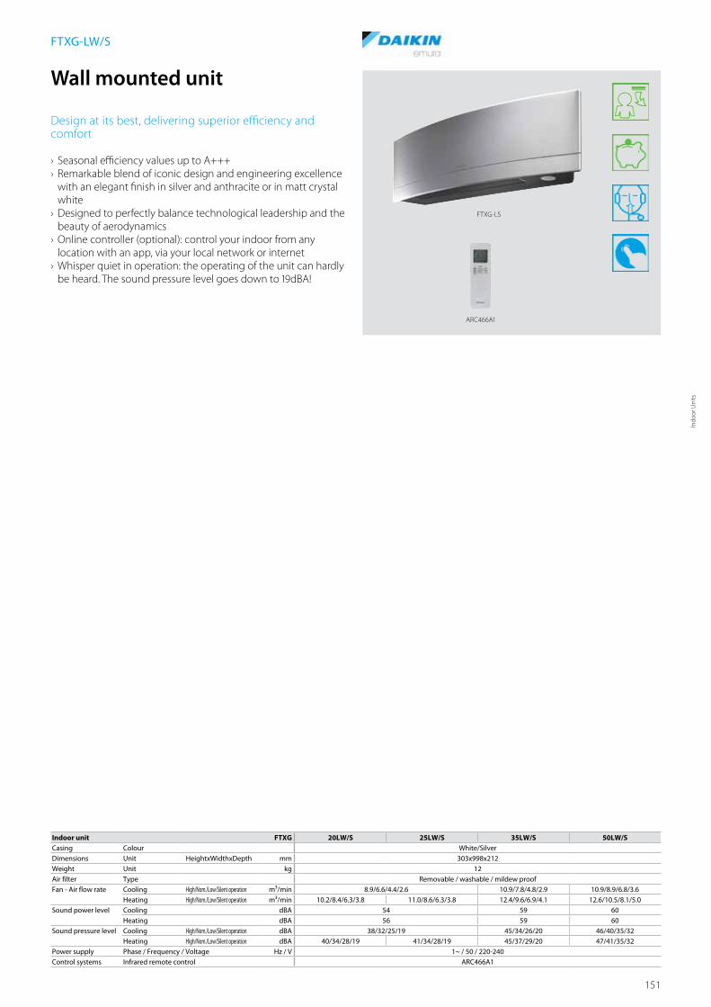
151
Indo
or U
nits
ARC466A1
Indoor unit FTXG 20LW/S 25LW/S 35LW/S 50LW/SCasing Colour White/SilverDimensions Unit HeightxWidthxDepth mm 303x998x212Weight Unit kg 12Air filter Type Removable / washable / mildew proofFan - Air flow rate Cooling High/Nom./Low/Silent operation m³/min 8.9/6.6/4.4/2.6 10.9/7.8/4.8/2.9 10.9/8.9/6.8/3.6
Heating High/Nom./Low/Silent operation m³/min 10.2/8.4/6.3/3.8 11.0/8.6/6.3/3.8 12.4/9.6/6.9/4.1 12.6/10.5/8.1/5.0Sound power level Cooling dBA 54 59 60
Heating dBA 56 59 60Sound pressure level Cooling High/Nom./Low/Silent operation dBA 38/32/25/19 45/34/26/20 46/40/35/32
Heating High/Nom./Low/Silent operation dBA 40/34/28/19 41/34/28/19 45/37/29/20 47/41/35/32Power supply Phase / Frequency / Voltage Hz / V 1~ / 50 / 220-240Control systems Infrared remote control ARC466A1
Wall mounted unit
Design at its best, delivering superior efficiency and comfort
› Seasonal efficiency values up to A+++ › Remarkable blend of iconic design and engineering excellence with an elegant finish in silver and anthracite or in matt crystal white
› Designed to perfectly balance technological leadership and the beauty of aerodynamics
› Online controller (optional): control your indoor from any location with an app, via your local network or internet
› Whisper quiet in operation: the operating of the unit can hardly be heard. The sound pressure level goes down to 19dBA!
FTXG-LW/S
FTXG-LS

152
FTXG50LW/S
Detailed technical drawings
FTXG20-35LW/S

153
Indo
or U
nits

154
ARC466A6
C/FTXS-K
Indoor unit CTXS15K CTXS35K FTXS 20K FTXS 25K FTXS 35K FTXS 42K FTXS 50K FTXS 60G FTXS 71GCasing Colour WhiteDimensions Unit HeightxWidthxDepth mm 289x780x215 289x900x215 298x900x215 290x1,050x250Weight Unit kg 8 11 12Air filter Type Removable / washable / mildew proofFan - Air flow rate Cooling High/Nom./Low/Silent operation m³/min 7.9/6.3/4.7/3.9 9.2/7.2/5.2/3.9 8.8/6.7/4.7/3.9 9.1/7.0/5.0/3.9 11.2/8.5/5.8/4.1 11.2/11.2/7.0/4.1 11.9/11.9/7.4/4.5 16.0/16.0/11.3/10.1 17.2/17.2/11.5/10.5
Heating High/Nom./Low/Silent operation m³/min 9.0/7.5/6.0/4.3 10.1/8.1/6.3/4.3 9.5/7.8/6.0/4.3 10.0/8.0/6.0/4.3 12.1/9.3/6.5/4.2 12.4/10.0/7.8/5.2 13.3/10.8/8.4/5.5 17.2/14.9/12.6/11.3 19.5/16.7/14.2/12.6Sound power level Cooling dBA 55 59 58 59 60 63
Heating dBA 56 58 59 60 59 62Sound pressure level Cooling High/Nom./Low/Silent operation dBA 37/31/25/21 42/35/28/21 40/32/24/19 41/33/25/19 45/37/29/19 45/39/33/21 46/40/34/23 45/41/36/33 46/42/37/34
Heating High/Nom./Low/Silent operation dBA 38/33/28/21 41/36/30/21 40/34/27/19 41/34/27/19 45/39/29/19 45/39/33/22 47/40/34/24 44/40/35/32 46/42/37/34Power supply Phase / Frequency / Voltage Hz / V 1~ / 50 / 220-240Control systems Infrared remote control ARC466A6 ARC452A3
Wall mounted unit
Discreet, modern design for optimal efficiency and comfort thanks to 2 area intelligent eye
› Discreet, modern design. Its smooth curve blends beautifully with the wall resulting in an unobtrusive presence that matches all interior décors.
› High quality matt crystal white finish › Whisper quiet in operation: the operating of the unit can hardly be heard. The sound pressure level goes down to 19dBA!
› Ideal for installation in bedrooms (20,25 class) and larger or irregular shaped living areas (35,42,50 class)
› 2 area intelligent eye: air flow is sent to a zone other than where the person is located at that moment; if no people are detected, the unit will automatically switch over to the energy-efficient setting (FTXS35,42,50K)
› Online controller (optional): control your indoor from any location with an app, via your local network or internet
C/FTXS-K

155
Indo
or U
nits
Detailed technical drawings
CTXS15K / FTXS20-25K
FTXS35-42K / CTXS35K
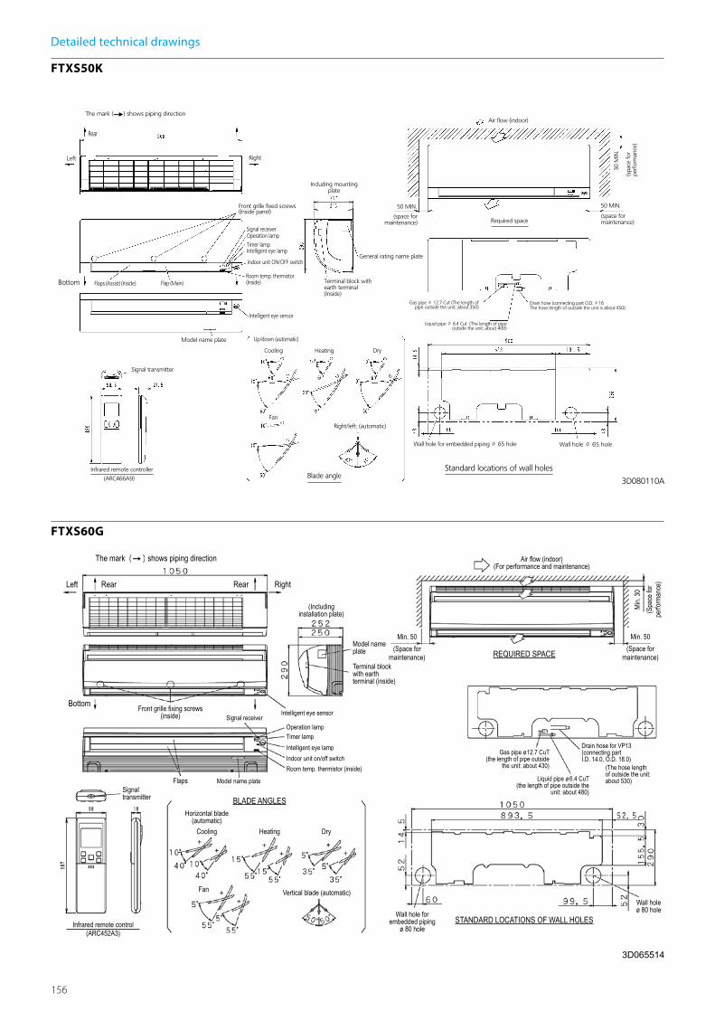
156
Detailed technical drawings
FTXS50K
FTXS60G

157
Indo
or U
nits
Detailed technical drawings
FTXS71G
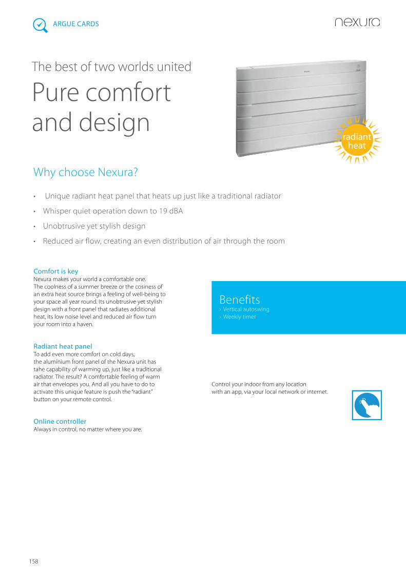
158
Logo grijs
Comfort is keyNexura makes your world a comfortable one. The coolness of a summer breeze or the cosiness of an extra heat source brings a feeling of well-being to your space all year round. Its unobtrusive yet stylish design with a front panel that radiates additional heat, its low noise level and reduced air flow turn your room into a haven.
Radiant heat panelTo add even more comfort on cold days, the aluminium front panel of the Nexura unit has tahe capability of warming up, just like a traditional radiator. The result? A comfortable feeling of warm air that envelopes you. And all you have to do to activate this unique feature is push the “radiant” button on your remote control.
Online controllerAlways in control, no matter where you are.
Why choose Nexura?
• Unique radiant heat panel that heats up just like a traditional radiator
• Whisper quiet operation down to 19 dBA
• Unobtrusive yet stylish design
• Reduced air flow, creating an even distribution of air through the room
ARGUE CARDS
The best of two worlds united
Pure comfort and design
Control your indoor from any location with an app, via your local network or internet.
radiant heat
Benefits › Vertical autoswing › Weekly timer
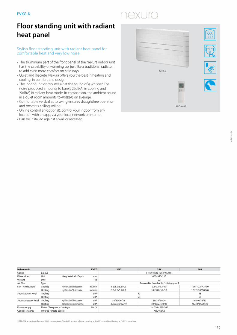
159
Indo
or U
nits
ARC466A2
FVXG-K
Indoor unit FVXG 25K 35K 50KCasing Colour Fresh white (6.5Y 9.5/0.5)Dimensions Unit HeightxWidthxDepth mm 600x950x215Weight Unit kg 22Air filter Type Removable / washable / mildew proofFan - Air flow rate Cooling High/Nom./Low/Silent operation m³/min 8.9/8.9/5.3/4.5 9.1/9.1/5.3/4.5 10.6/10.3/7.3/6.0
Heating High/Nom./Low/Silent operation m³/min 9.9/7.8/5.7/4.7 10.2/8.0/5.8/5.0 12.2/10.0/7.8/6.8Sound power level Cooling dBA 52 58
Heating dBA 53 60Sound pressure level Cooling High/Nom./Low/Silent operation dBA 38/32/26/23 39/33/27/24 44/40/36/32
Heating High/Nom./Low/Silent operation/Radiant heat dBA 39/32/26/22/19 40/33/27/23/19 46/40/34/30/26Power supply Phase / Frequency / Voltage Hz / V 1~ / 50 / 220-240Control systems Infrared remote control ARC466A2
(1) EER/COP according to Eurovent 2012, for use outside EU only (2) Nominal efficiency: cooling at 35°/27° nominal load, heating at 7°/20° nominal load
Floor standing unit with radiant heat panel
Stylish floor standing unit with radiant heat panel for comfortable heat and very low noise
› The aluminium part of the front panel of the Nexura indoor unit has the capability of warming up, just like a traditional radiator, to add even more comfort on cold days
› Quiet and discrete, Nexura offers you the best in heating and cooling, in comfort and design
› The indoor unit distributes air at the sound of a whisper. The noise produced amounts to barely 22dB(A) in cooling and 19dB(A) in radiant heat mode. In comparison, the ambient sound in a quiet room amounts to 40dB(A) on average.
› Comfortable vertical auto swing ensures draughtfree operation and prevents ceiling soiling
› Online controller (optional): control your indoor from any location with an app, via your local network or internet
› Can be installed against a wall or recessed
FVXG-K

160
Detailed technical drawings
FVXG25-35K
FVXG50K

161
Indo
or U
nits
ARC452A1
FVXS-F
Indoor unit FVXS 25F 35F 50FCasing Colour WhiteDimensions Unit HeightxWidthxDepth mm 600x700x210Weight Unit kg 14Air filter Type Removable / washable / mildew proofFan - Air flow rate Cooling High/Nom./Low/Silent operation m³/min 8.2/8.2/4.8/4.1 8.5/8.5/4.9/4.5 10.7/10.7/7.8/6.6
Heating High/Nom./Low/Silent operation m³/min 8.8/6.9/5.0/4.4 9.4/7.3/5.2/4.7 11.8/10.1/8.5/7.1Sound power level Cooling dBA 52 60
Heating dBA 52 60Sound pressure level Cooling High/Nom./Low/Silent operation dBA 38/32/26/23 39/33/27/24 44/40/36/32
Heating High/Nom./Low/Silent operation dBA 38/32/26/23 39/33/27/24 45/40/36/32Power supply Phase / Frequency / Voltage Hz / V 1~ / 50 / 220-240Control systems Infrared remote control ARC452A1
(1) EER/COP according to Eurovent 2012, for use outside EU only (2) Nominal efficiency: cooling at 35°/27° nominal load, heating at 7°/20° nominal load
Floor standing unit
Floor standing unit for optimal heating comfort thanks to dual airflow
› Its low height enables the unit to fit perfectly beneath a window › Can be installed against a wall or recessed › Vertical auto swing moves the discharge flaps up and down for efficient air and temperature distribution throughout the room
› Online controller (optional): control your indoor from any location with an app, via your local network or internet
FVXS-F

162
Detailed technical drawings
FVXS25-35F
3D056135
FVXS25-35F unit (mm)
Main unit fixing screw
Note) 1. The mark (Y) shows piping direction
Main unit fixed screws
666 (half concealed)
Operation lamp
Timer lamp
Indoor unit ON/OFF switch
Signal receiver
Air outletselectionswitch(Inside)
Name plate
Drainsocket
Front panel fixed screws
Hole for splintHole for piping
Air flow
Required space
(formaintenance)
(forperformance)
(Wall hole)
Wall hole for half concealed
Terminal block with earthterminal
Liquid pipe (J6.4 CuT)
Gas pipe (J9.5 CuT)
Room temp. thermistor
Signal transmitter
Infrared remote control
Hole for splint
Hole for piping
Drain hose
Adjusting the air flow direction
Right/left (manual)
Upper air outlet
Lower air outlet
Upward air flowlimit (OFF)
Upward air flowlimit (ON)
Up/down (automatic)Heat
(Heat pump model)
Hole for piping
Forp
erfo
rman
ce
584
(hal
fcon
ceal
ed)
(Wal
lhol
e)
Front panel fixed screws(inside)
VP20I.D. J20O.D. J26L 220
50 MIN 50 MIN
Cooling / dry
A
Model name label95 (Half concealed)
85
Cool, dry
3D056136
FVXS50F unit (mm)
Main unit fixing screw
Note) 1. The mark (Y) shows piping direction
Main unit fixed screws
666 (half concealed)
Operation lamp
Timer lamp
Indoor unit ON/OFF switch
Signal receiver
Air outletselectionswitch(Inside)
Name plate
Drainsocket
Front panel fixed screws
Hole for splintHole for piping
Air flow
Required space
(formaintenance)
(forperformance)
(Wall hole)
Wall hole for half concealed
Terminal block with earthterminal
Liquid pipe (J6.4 CuT)
Gas pipe (J12.7 CuT)
Room temp. thermistor
Signal transmitter
Infrared remote control
Hole for splint
Hole for piping
Drain hose
Adjusting the air flow direction
Right/left (manual)
Upper air outlet
Lower air outlet
Upward air flowlimit (OFF)
Upward air flowlimit (ON)
Up/down (automatic)Cooling / dry Heat
(Heat pump model)
Hole for piping
Forp
erfo
rman
ce
584
(hal
fcon
ceal
ed)
(Wal
lhol
e)
Front panel fixed screws(inside)
VP20I.D. J20O.D. J26L 220
50 MIN 50 MIN
A
Model name label95 (Half concealed)
85
Cool, dry
FVXS50F

163
Indo
or U
nits
ARC433B67
FLXS-B
Indoor unit FLXS 25B 35B9 50B 60BCasing Colour Almond white Almond whiteDimensions Unit HeightxWidthxDepth mm 490x1,050x200 490x1,050x200Weight Unit kg 16 17Air filter Type Removable / washable / mildew proofFan - Air flow rate Cooling High/Nom./Low/Silent operation m³/min 7.6/7.6/6.0/5.2 8.6/7.6/6.6/5.6 11.4/11.4/8.5/7.5 12.0/10.7/9.3/8.3
Heating High/Nom./Low/Silent operation m³/min 9.2/8.3/7.4/6.6 12.8/10.4/8.0/7.2 12.1/9.8/7.5/6.8 12.8/10.6/8.4/7.5Sound power level Cooling dBA 51 53 60
Heating dBA 51 59 - 59Sound pressure level Cooling High/Nom./Low/Silent operation dBA 37/34/31/28 38/35/32/29 47/43/39/36 48/45/41/39
Heating High/Nom./Low/Silent operation dBA 37/34/31/29 46/36/33/30 46/41/35/33 47/42/37/34Power supply Phase / Frequency / Voltage Hz / V 1~ / 50/60 / 220-240/220-230 1~ / 50 / 220-240 1~ / 50/60 / 220-240/220-230Control systems Infrared remote control ARC433B67
(1) EER/COP according to Eurovent 2012, for use outside EU only (2) Nominal efficiency: cooling at 35°/27° nominal load, heating at 7°/20° nominal load
Flexi type unit
Flexible unit, ideal for rooms without false ceiling, can fit on either ceiling or wall
› Can fit on either ceiling or lower wall; its low height enables the unit to fit beneath a window
› Vertical auto swing moves the discharge flaps up and down for efficient air and temperature distribution throughout the room
› Home leave operation maintains the indoor temperature at your specified comfort level during absence, thus saving energy
› Online controller (optional): control your indoor unit from any location via smartphone, laptop, pc, tablet or touch screen
FLXS-B(9)

164
Detailed technical drawings
FLXS25-35B(9)
FLXS50-60B

165
Indo
or U
nits
Detailed technical drawings
FLXS25-35B(9)
FLXS50-60B

166
Hot waterEfficient hot water production for underfloor
heating, radiators and air handling units, or
for producing hot water for sinks, baths and
showers. Integrating heat recovery into the
VRV system means that the production of hot
water is virtually free.

167
Hot
Wat
er
Hot water
Low temperature hydrobox HXY-A 168
High temperature hydrobox HXHD-A 170
Accessories for hot water 173

168
HXY-A
Indoor unit HXY 080A 125ACooling capacity Nom. kW 8.0 12.5Heating capacity Nom. kW 9.0 14.0Dimensions Unit HeightxWidthxDepth mm 890x480x344Weight Unit kg 44Casing Colour White
Material Precoated sheet metalSound pressure level Nom. dBA -Operation range Heating Ambient Min.~Max. °C -20~24
Water side Min.~Max. °C 25~45Refrigerant Type / GWP R-410A / 2.087,5Refrigerant circuit Gas side diameter mm 15.9
Liquid side diameter mm 9.5Water circuit Piping connections diameter inch G 1“1/4 (female)Power supply Phase/Frequency/Voltage Hz/V 1~/50/220-240Current Recommended fuses A 6~16
Low temperature hydrobox for VRV
For high efficiency space heating and cooling
› Air to water connection to VRV for applications such as underfloor, air handling units, low temperature radiators, …
› Leaving water temperature range from 5°C to 45°C without electric heater
› Super wide operating range for hot/cold water production from -20 to +43°C ambient outdoor temperature
› Saves time on system design as all water-side components are fully integrated with direct control over leaving water temperature
› Space saving contemporary wall hung design › No gas connection or oil tank needed › Connectable to VRV IV heat pump and heat recovery
HXY-A
VRV IV heat pump VRV IV heat recovery
Low temp. radiator
Air handling unit
Under floor heating
Liquid pipe
F1, F2 communicationGas pipe
Hot/cold water VRV indoor units

169
Hot
Wat
er
Detailed technical drawings
HXY-A
HXY-A
HXY-A
3D079938
Required space for service and ventilation
Holes (Ø12) for fixation to the wallWater out connection (1-1/4” F BSP)Water in connection (1-1/4” F BSP)Refrigerant liquid connection Ø9.52 (flare)Refrigerant suction connection Ø15.9 (flare)PumpUser interfaceSafety valve (pressure)Air purgeExpansion vesselPressure gaugeHeat exchanger (refrigerant / water)Shut off valve with drain / fill valve (1-1/4” F BSP) (included accessory)Water filterPower supply / Communication wire entranceService doorSwitchbox terminals
HXY-A
3D079876
ESP
(kPa)
Flow (l/m)
:unit ESP @ 4000rpm (ΔT = 5°C) :unit ESP @ 3800rpm (ΔT = 8°C)Δ: max. ESP if deltaT = 5°C (heating nominal): max. ESP if deltaT = 5°C (cooling nominal)
ESP: External Static PressureFlow: Waterflow through the unit
NOTES
1 Selecting a flow outside the curves can cause damage to or malfunctioning of the unit. See also minimum and maximum allowed flow in technical specifications.2 Water quality must be according to EN directive EC 98/83 EC.

170
EKHWP-BEKHTS-AC
HXHD-A
Indoor unit HXHD 125AHeating capacity Nom. kW 14.0Dimensions Unit HeightxWidthxDepth mm 705x600x695Weight Unit kg 92Casing Colour Metallic grey
Material Precoated sheet metalSound pressure level Nom. dBA 42 (1) / 43 (2)
Night quiet mode Level 1 dBA 38Operation range Heating Ambient Min.~Max. °C -20~20 / 24 (3)
Water side Min.~Max. °C 25~80Domestic hot water
Ambient Min.~Max. °CDB -20~43Water side Min.~Max. °C 45~75
Refrigerant Type / GWP R-134a / 1,430Charge kg 2Charge TCO
2Eq 2.9
Refrigerant circuit Gas side diameter mm 12.7Liquid side diameter mm 9.52
Water circuit Piping connections diameter inch G 1“ (female)Heating water system Water volume Min.~Max. l 20~200
Power supply Phase/Frequency/Voltage Hz/V 1~/50/220-240Current Recommended fuses A 20
(1) Sound levels are measured at: EW 55°C; LW 65°C (2) Sound levels are measured at: EW 70°C; LW 80°C (3) Field setting
High temperature hydrobox for VRV
For efficient hot water production and space heating
› Air to water connection to VRV for applications such as bathrooms, sinks, underfloor heating, radiators and air handling units
› Leaving water temperature range from 25 to 80°C without electric heater
› Free heating provided by transferring heat from areas requiring cooling to areas requiring heating or hot water
› Uses heat pump technology to produce hot water efficiently, providing up to 17% savings compared to a gas boiler
› Possibility to connect thermal solar collectors to the domestic hot water tank
› Super wide operating range for hot water production from -20 to +43°C ambient outdoor temperature
› Saves time on system design as all water-side components are fully integrated with direct control over leaving water temperature
› Various control possibilities with weather dependant set point or thermostat control
› The indoor unit and domestic hot water tank can be stacked to save space, or installed next to each other, if only limited height is available
› No gas connection or oil tank needed › Connectable to VRV IV heat recovery
HXHD-A
VRV heat recovery (REYQ8-54T)
BS-Box
BS-Box Heating only hydrobox for VRV
Domestic hot water tank
Daikin solar panel
Domestic hot water
Low temp. radiator
Air handling unit
Under floor heating
VRV indoor units
25°C - 35°C
45°C - 75°C
25°C - 75°C
45°C - 75°C
Liquid pipe
F1, F2 communication
Gas pipe
Hot water
Discharge gas pipe

171
Hot
Wat
er
Detailed technical drawings
HXHD-A
HXHD-A
HXHD-A
3TW59914-1B(1)
If required (e.g. Wall xation)Pressure gauge can be removed from water lter, maximum distance between water lter and pressure gauge ± 600 mm Left Installation
Detail A
Detail AScale 1/3 Right installation
1 Remote control (delivered as accessory)Installation location is outside the unit
2 Discharge pipe connection ø12.7 solder (R410a)3 Liquid pipe connection ø9.5 solder (R410a)4 R134a Service ports 5/16” are (2x)5 Pressure gauge6 Blow off valve7 Drain valve water circuit8 Air purge9 Shut-off valves (2x)
10 Water lter11 Water in connection G 1° (female)12 Water out connection G 1° (female)13 Control wiring intake (knock-out hole ø37)14 Power supply wiring intake (knock-out hole ø37)15 Knock-out holes for refrigerant piping and water piping16 Levelling feet17 Discharge stop valve ø12.7 solder (R410a)18 Liquid stop valve ø9.5 solder (R410a)
HXHD-A
3TW59914-1B(2)
Left Installation
Screw xation of top plate (both sides)
Min. 600(Space required for switch box removal)
Right installationUpwiring
Model A B CHXHD-A 355 270 300
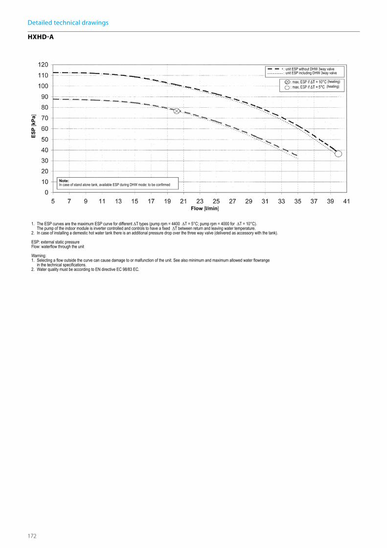
172
Detailed technical drawings
HXHD-A
HXHD-A
3TW60669-1
unit ESP without DHW 3way valveunit ESP including DHW 3way valve
Note:In case of stand alone tank, available ESP during DHW mode: to be con rmed
1. The ESP curves are the maximum ESP curve for different ∆T types (pump rpm = 4400 ∆T = 5°C; pump rpm = 4000 for ∆T = 10°C). The pump of the indoor module is inverter controlled and controls to have a xed ∆T between return and leaving water temperature.2. In case of installing a demestic hot water tank there is an additional pressure drop over the three way valve (delivered as accessory with the tank).
ESP: external static pressureFlow: water ow through the unit
Warning:1. Selecting a ow outside the curve can cause damage to or malfunction of the unit. See also minimum and maximum allowed water owrange in the technical speci cations.2. Water quality must be according to EN directive EC 98/83 EC.
ESP
[kPa
]
Flow [l/min]
(heating)(heating)

173
Hot
Wat
er
EKHTS260ACEKHTS200AC
Accessory EKHTS 200AC 260ACCasing Colour Metallic grey
Material Galvanised steel (precoated sheet metal)Dimensions Unit Height Integrated on
indoor unitmm
2,010 2,285
Width mm 600Depth mm 695
Weight Unit Empty kg 70 78Tank Water volume l 200 260
Material Stainless steel (EN 1.4521)Maximum water temperature °C 75Insulation Heat loss kWh/24h 1.2 1.5
Heat exchanger Quantity 1Tube material Duplex steel (EN 1.4162)Face area m² 1.56Internal coil volume l 7.5
Domestic hot water tank
Stackable stainless steel domestic hot water tank
› The indoor unit and domestic hot water tank can be stacked to save space, or installed next to each other, if only limited height is available
› Available in 200 and 260 liters › Heat loss is reduced to a minimum thanks to the high quality insulation
› At necessary intervals, the indoor unit can heat up the water to 60°C to prevent the risk of bacteria growth
› Efficient temperature heat-up: from 10°C to 50°C in only 60 minutes
EKHTS-AC
Accessory EKHWP 300B 500BDimensions Unit Width mm 595 790
Depth mm 615 790Weight Unit Empty kg 59 93Tank Water volume l 300 500
Maximum water temperature °C 85Insulation Heat loss kWh/24h 1.3 1.4
Heat exchanger Domestic hot water
Tube material Stainless steelFace area m² 5.8 6Internal coil volume l 27.9 29Operating pressure bar 6Average specifc thermal output W/K 2,790 2,900
Charging Tube material Stainless steelFace area m² 2.7 3.8Internal coil volume l 13.2 18.5Operating pressure bar 3Average specifc thermal output W/K 1,300 1,800
Auxiliary solar heating
Tube material Stainless steelFace area m² - 0.5Internal coil volume l - 2.3Operating pressure bar 3Average specifc thermal output W/K - 280
Domestic hot water tank
Plastic domestic hot water tank with solar support
› Available in 300 and 500 liters › Large hot water storage tank to provide domestic hot water at any time
› Heat loss is reduced to a minimum thanks to the high quality insulation
› Space heating support possible (500l tank only)
EKHWP-B
EKHWP300B

174
Pump station
› Save energy and reduce CO2 emissions with a solar system for
domestic hot water production › Pump station connectable to unpressurised solar system › Pump station and control provide the transfer of solar heat to the domestic hot water tank
EKSRPS
EKSRPS3
Accessory EKSRPS 3Mounting On side of tankDimensions Unit HeightxWidthxDepth mm 815x230x142Control Type Digital temperature difference controller with plain text display
Power consumption W 2Power supply Voltage V 230Sensor Solar panel temperature sensor Pt1000
Storage tank sensor PTCReturn flow sensor PTCFeed temperature and flow sensor Voltage signal (3.5V DC)
EKSV-P
EKSH-P
Accessory EKSV21P EKSV26P EKSH26PDimensions Unit HeightxWidthxDepth mm 2,000x1,006x85 2,000x1,300x85 1,300x2,000x85Weight Unit kg 35 42Volume l 1.3 1.7 2.1Surface Outer m² 2.01 2.6
Aperture m² 1.79 2.35Absorber m² 1.8 2.36
Coating Micro-therm (absorption max. 96%, Emission ca. 5% +/-2%)Absorber Harp-shaped copper pipe register with laser-welded highly selective coated aluminium plateGlazing Single pane safety glass, transmission +/- 92%Allowed roof angle Min.~Max. ° 15~80Operating pressure Max. bar 6Stand still temperature Max. °C 200
Solar collector
Thermal solar collector for hot water production
› Solar collectors can produce up to 70% of the energy needed for hot water production - a major cost saving
› Vertical or horizontal solar collector for domestic hot water production
› High efficiency collectors transfer all the short-wave solar radiation into heat as a result of their highly selective coating
› Easy to install on roof tiles
EKS(H/V)-P
175
Hot
Wat
er

176
Biddle air curtains
Biddle air curtains provide highly efficient
solutions for retailers and consultants to
combat the issue of climate separation across
their outlet or office doorway.

177
Bidd
le A
ir Cu
rtai
ns
Biddle air curtains connected to Daikin Heat Pumps
‘Open Door’ Trading
Although the customer friendly aspects of open door trading are widely appreciated by retail and commercial outlet managers, open doors can also give rise to massive losses in conditioned warm or cold air and hence, energy. Biddle air curtains however, not only preserve indoor temperatures and generate significant economies, they also represent an invitation for customers, to enter a pleasant trading and working environment.
High efficiency and low CO
2 emission
An efficient outdoor/indoor climate separation limits heat loss through the door opening and enhances the efficiency of the air conditioning system. Combining Biddle air curtains with Daikin heat pumps can lead to savings up to 72% compared to electric air curtains and a paypack period of less than 1.5 years!
Free-Hanging (F)
Cassette (C)
Recessed (C)
Biddle air curtain for connection to VRV (CYV) or to ERQ (CYQ)
Biddle air curtains come in 2 versions, one to connect to VRV end one for connection to ERQ. Both of them ar available in varying door widths from 1 up to
Biddle comfort air curtain range
3.8m
2.4m2.2m 2.2m
3.3m
3.0m 3.0m2.8m
2.5m 2.5m
3.5m
Installation conditionFavourableex: covered shopping mall or revolving door entrance
Normalex: little direct wind, no opposite open doors, building with ground floor only
Unfavourableex: location at a corner or square, multiple floors and / or open stairwell
S M L XL S M L XL M L XL
4
3
2
1
Door height (m)
Biddle comfort air curtian nomenclature
Which air curtain offers me the best solution?
CA V S 150 DK 80 F S CController (standard)
Color. B=White (RAL6010), S: Grey (RAL9006)
Installation type: F=Freehanging, C=Cassette, R=Recessed
Capacity class (kW)
Daikin direct expansion
Door width (cm)
Range. S=small, M=Medium, L=Large, XL= Extra Large
Connectable to VRV
Biddle comfort air curtain
2.5 meters. Below you can find an overview of the different versions and available door heights.
Biddle air curtains
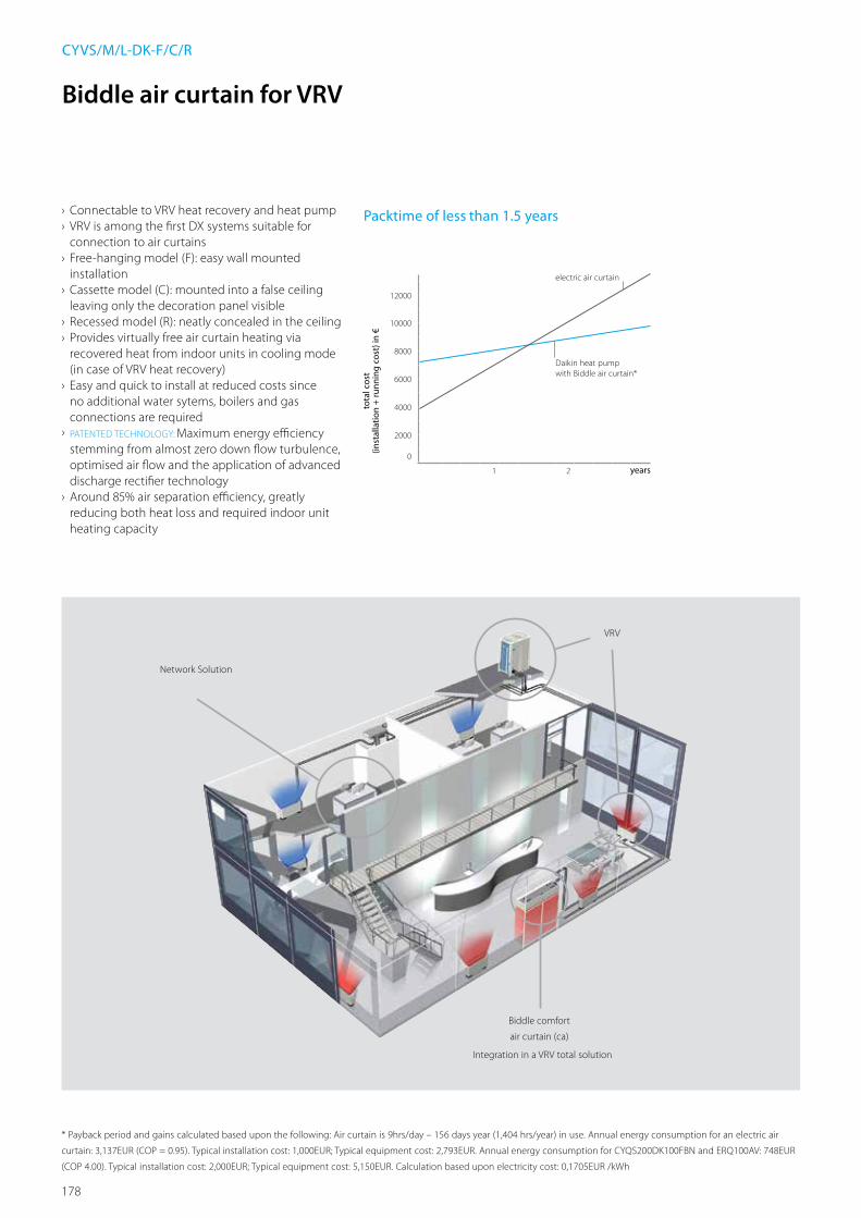
178
Biddle comfort
air curtain (ca)
VRV
Network Solution
Integration in a VRV total solution
CYVS/M/L-DK-F/C/R
› Connectable to VRV heat recovery and heat pump › VRV is among the first DX systems suitable for connection to air curtains
› Free-hanging model (F): easy wall mounted installation
› Cassette model (C): mounted into a false ceiling leaving only the decoration panel visible
› Recessed model (R): neatly concealed in the ceiling › Provides virtually free air curtain heating via recovered heat from indoor units in cooling mode (in case of VRV heat recovery)
› Easy and quick to install at reduced costs since no additional water sytems, boilers and gas connections are required
› PATENTED TECHNOLOGY: Maximum energy efficiency stemming from almost zero down flow turbulence, optimised air flow and the application of advanced discharge rectifier technology
› Around 85% air separation efficiency, greatly reducing both heat loss and required indoor unit heating capacity
Packtime of less than 1.5 years
12000
10000
8000
6000
4000
2000
0
electric air curtain
years
Daikin heat pump with Biddle air curtain*
tota
l cos
t (in
stal
latio
n +
runn
ing
cost
) in
€
21
* Payback period and gains calculated based upon the following: Air curtain is 9hrs/day – 156 days year (1,404 hrs/year) in use. Annual energy consumption for an electric air
curtain: 3,137EUR (COP = 0.95). Typical installation cost: 1,000EUR; Typical equipment cost: 2,793EUR. Annual energy consumption for CYQS200DK100FBN and ERQ100AV: 748EUR
(COP 4.00). Typical installation cost: 2,000EUR; Typical equipment cost: 5,150EUR. Calculation based upon electricity cost: 0,1705EUR /kWh
Biddle air curtain for VRV

179
Bidd
le A
ir Cu
rtai
ns
Biddle air curtain for VRV
CYVM150DK80FSC CYVM150DK80CSN CYVM150DK80RSN
Small Medium
CYVS100DK80 *BN/*SN
CYVS150DK80 *BN/*SN
CYVS200DK100 *BN/*SN
CYVS250DK140 *BN/*SN
CYVM100DK80 *BN/*SN
CYVM150DK80 *BN/*SN
CYVM200DK100 *BN/*SN
CYVM250DK140 *BN/*SN
Heating capacity Speed 3 kW 7.40 9.0 11.6 16.2 9.2 11.0 13.4 19.9Power input Fan only Nom. kW 0.23 0.35 0.46 0.58 0.37 0.56 0.75 0.94
Heating Nom. kW 0.23 0.35 0.46 0.58 0.37 0.56 0.75 0.94Delta T Speed 3 K 19 15 16 17 14 13 15Casing Colour BN: RAL9010 / SN: RAL9006Dimensions Unit Height F/C/R mm 270/270/270
Width F/C/R mm 1,000/1,000/1,048 1,500/1,500/1,548 2,000/2,000/2,048 2,500/2,500/2,548 1,000/1,000/1,048 1,500/1,500/1,548 2,000/2,000/2,048 2,500/2,500/2,548Depth F/C/R mm 590/821/561
Required ceiling void > mm 420Door height Max. m 2.3 (1) / 2.15 (2) / 2.0 (3) 2.3 (1) / 2.15 (2) / 2.0 (3) 2.3 (1) / 2.15 (2) / 2.0 (3) 2.3 (1) / 2.15 (2) / 2.0 (3) 2.5 (1) / 2.4 (2) / 2.3 (3) 2.5 (1) / 2.4 (2) / 2.3 (3) 2.5 (1) / 2.4 (2) / 2.3 (3) 2.5 (1) / 2.4 (2) / 2.3 (3)Door width Max. m 1.0 1.5 2.0 2.5 1.0 1.5 2.0 2.5Weight Unit kg 56 66 83 107 57 73 94 108Fan-Air flow rate Heating Speed 3 m³/h 1,164 1,746 2,328 2,910 1,605 2,408 3,210 4,013 Sound pressure level Heating Speed 3 dBA 47 49 50 51 50 51 53 54 Refrigerant Type / GWP R-410A / 2.087,5Piping connections Liquid/OD/Gas/OD mm 9.52/16.0 9.52/19.0 9.52/16.0 9.52/19.0Required accessories (should be ordered separately) Daikin wired remote control (BRC1E52A/B or BRC1D52)Power supply Voltage V 230
Large
CYVL100DK125*BN/*SN CYVL150DK200*BN/*SN CYVL200DK250*BN/*SN CYVL250DK250*BN/*SN
Heating capacity Speed 3 kW 15.6 23.3 29.4 31.1Power input Fan only Nom. kW 0.75 1.13 1.50 1.88
Heating Nom. kW 0.75 1.13 1.50 1.88Delta T Speed 3 K 15 14 12Casing Colour BN: RAL9010 / SN: RAL9006Dimensions Unit Height F/C/R mm 370/370/370
Width F/C/R mm 1,000/1,000/1,048 1,500/1,500/1,548 2,000/2,000/2,048 2,500/2,500/2,548Depth F/C/R mm 774/1,105/745
Required ceiling void > mm 520Door height Max. m 3.0 (1) / 2.75 (2) / 2.5 (3) 3.0 (1) / 2.75 (2) / 2.5 (3) 3.0 (1) / 2.75 (2) / 2.5 (3) 3.0 (1) / 2.75 (2) / 2.5 (3)Door width Max. m 1.0 1.5 2.0 2.5Weight Unit kg 76 100 126 157Fan-Air flow rate Heating Speed 3 m³/h 3,100 4,650 6,200 7,750 Sound pressure level Heating Speed 3 dBA 53 54 56 57 Refrigerant Type / GWP R-410A / 2,087.5Piping connections Liquid/OD/Gas/OD mm 9.52/16.0 9.52/19.0 9.52/22.0Required accessories (should be ordered separately) Daikin wired remote control (BRC1E52A/B or BRC1D52)Power supply Voltage V 230
(1) Favorable conditions: covered shopping mall or revolving door entrance (2) Normal conditions: little direct wind, no opposite open doors, building with ground floor only (3) Unfavorable conditions: location at a corner or square, multiple floors and/or
open stairway

180
L
U
A10
0
40
250 250
500
B19
7
27H
D
O9.2
98
CU0954X-000REMARKS
1 The2,500mmlargedeviceshave3suspensionbrackets,wherethethirdbracketismountedathalfthelengthofthedevice.
Suctiongridwithfilter
Type L H D U A BCYVS-DK-FBN/FSNCYVM-DK-FBN/FSN
1,000-1,5002,000-2,500 270 590 93 171 119
CYVL-DK-FBN/FSN 1,000-1,5002,000-2,500 370 774 124.5 245.5 200
CYVS_DK_FBN/FSNCYVM_DK_FBN/FSNCYVL_DK_FBN/FSN
A10
0
40
250 250
500
B19
7
H27
D
L
L
UEF
D
G
O9.2
98
CYVS_DK_CBN/CSNCYVM_DK_CBN/CSNCYVL_DK_CBN/CSN
CU0955X-000REMARKS
1 The2,500mmlargedeviceshave3suspensionbrackets,wherethethirdbracketismountedathalfthelengthofthedevice.
2 Themountingholesforfinishingprofilesinaloweredceiling(L+8)x(D+8)mm
Thefinishingprofilesaresuppliedseparately.
Suctiongridwithfilter
Screw-eyeM6
NumberofsuctiongridsperdeviceDevicelength Number Suctiongridlength1000/1500 1 1,000/1,5002000/2500 2 1,000/1,250
*1draingridperdevice
Type L H D U A B E F GCYVS-DK-CBN/CSNCYVM-DK-CBN/CSN
1,000-1,5002,000-2,500 270 821 93 171 119 250 411 260
CYVL-DK-CBN/CSN 1,000-1,5002,000-2,500 370 1,105 124.5 245.5 200 181.5 563.5 360
Detailed technical drawings
CYVS_DK_FBN/FSN / CYVM_DK_FBN/FSN / CYVL_DK_FBN/FSN
CYVS_DK_CBN/CSN / CYVM_DK_CBN/CSN / CYVL_DK_CBN/CSN

181
Bidd
le A
ir Cu
rtai
ns
A10
0
40
250 250
500
B19
7
F
M
L
E T
K
F J
G
U
SH
27
D
101.5
O9.2
98
CU0956X-000REMARKS
1 The2,500mmlargedeviceshave3suspensionbrackets,wherethethirdbracketismountedathalfthelengthofthedevice.
2 Holes(forfinishingprofiles)-drain(L+8)x(E+8)mm-suction(L+8)x(G+8)mm.
Thefinishingprofilesaresuppliedseparately.
Suctiongridwithfilter
NumberofductsperdeviceType 1000 1500 2000 2500
CYVS-DK-RBN/RSNCYVM-DK-RBN/RSN 5 7 10 12CYVL-DK-RBN/RSN 3 5 6 8
NumberofsuctiongridsperdeviceDevicelength Number Suctiongridlength1000/1500 1 1,000/1,5002000/2500 2 1,000/1,250
*1draingridperdevice
Type L H D S U A B E F G J K M TCYVS-DK-RBN/RSNCYVM-DK-RBN/RSN 1,000-1,500
2,000-2,500 270 561 80-125 90 171 119 92 139 260 308 Ø160 1044-1544
2044-25441048-15482048-2548
CYVL-DK-RBN/RSN 1,000-1,5002,000-2,500 370 745 80-
125 121.5 245.5 200 123.5 170 360 408 Ø250 1044-15442044-2544
1048-15482048-2548
Noductsaresupplied
Noductsaresupplied
CYVS_DK_RBN/RSNCYVM_DK_RBN/RSNCYVL_DK_RBN/RSN
Detailed technical drawings
CYVS_DK_RBN/RSN / CYVM_DK_RBN/RSN / CYVL_DK_RBN/RSN

182
Ventilation & air handling
Daikin offers the widest range in DX
ventilation in the market.
With a variety of ventilation solutions from
small heat recovery ventilation to large scale
air handling units we help provide a fresh,
healthy and comfortable environment in
offices, hotels, stores and other commercial
environments.

183
Vent
ilatio
n &
Air
Han
dlin
g
Ventilation & air handlingVentilation
Heat reclaim ventilation VAM-FA/FB 186VKM-GB(M) 198
Air handling applications Overview & control possibilities 209VRV 212ERQ 214Expansion valves and control boxes 215

184
Ventilation
VAM - HEAT RECLAIM VENTILATION

185
Vent
ilatio
n &
Air
Han
dlin
g
Ventilation
DAIKIN AIR HANDLING UNIT AND ERQ/VRV PLUG & PLAY CONNECTION
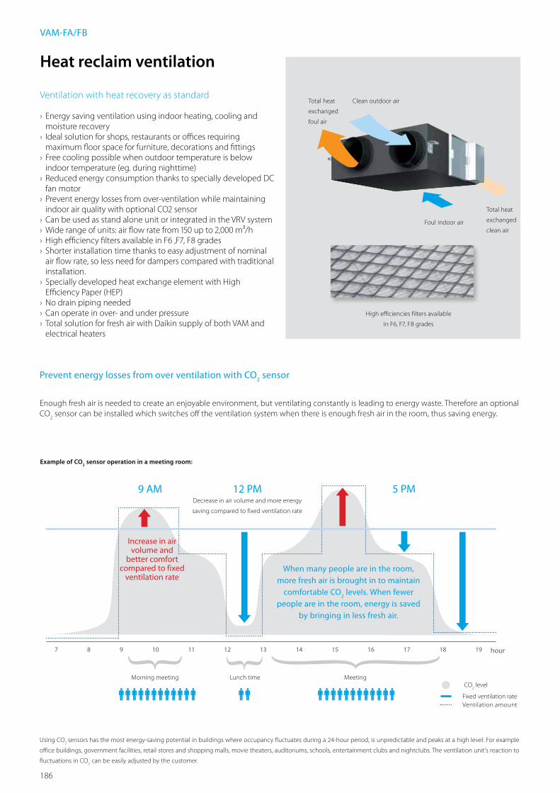
186
Heat reclaim ventilation
Ventilation with heat recovery as standard
› Energy saving ventilation using indoor heating, cooling and moisture recovery
› Ideal solution for shops, restaurants or offices requiring maximum floor space for furniture, decorations and fittings
› Free cooling possible when outdoor temperature is below indoor temperature (eg. during nighttime)
› Reduced energy consumption thanks to specially developed DC fan motor
› Prevent energy losses from over-ventilation while maintaining indoor air quality with optional CO2 sensor
› Can be used as stand alone unit or integrated in the VRV system › Wide range of units: air flow rate from 150 up to 2,000 m³/h › High efficiency filters available in F6 ,F7, F8 grades › Shorter installation time thanks to easy adjustment of nominal air flow rate, so less need for dampers compared with traditional installation.
› Specially developed heat exchange element with High Efficiency Paper (HEP)
› No drain piping needed › Can operate in over- and under pressure › Total solution for fresh air with Daikin supply of both VAM and electrical heaters
VAM-FA/FB
Prevent energy losses from over ventilation with CO2 sensor
Enough fresh air is needed to create an enjoyable environment, but ventilating constantly is leading to energy waste. Therefore an optional CO
2 sensor can be installed which switches off the ventilation system when there is enough fresh air in the room, thus saving energy.
Using CO2 sensors has the most energy-saving potential in buildings where occupancy fluctuates during a 24-hour period, is unpredictable and peaks at a high level. For example
office buildings, government facilities, retail stores and shopping malls, movie theaters, auditoriums, schools, entertainment clubs and nightclubs. The ventilation unit's reaction to
fluctuations in CO2 can be easily adjusted by the customer.
Example of CO2 sensor operation in a meeting room:
CO2 level
Ventilation amountFixed ventilation rate
Morning meeting Lunch time Meeting
7 8 9 10 11 12 13 14 15 16 17 18 19 hour
Decrease in air volume and more energy
saving compared to fixed ventilation rate
Increase in air volume and
better comfort compared to fixed
ventilation rateWhen many people are in the room,
more fresh air is brought in to maintain comfortable CO
2 levels. When fewer
people are in the room, energy is saved by bringing in less fresh air.
5 PM12 PM9 AM
Total heat
exchanged
foul air
Clean outdoor air
Total heat
exchanged
clean airFoul indoor air
High efficiencies filters available
in F6, F7, F8 grades
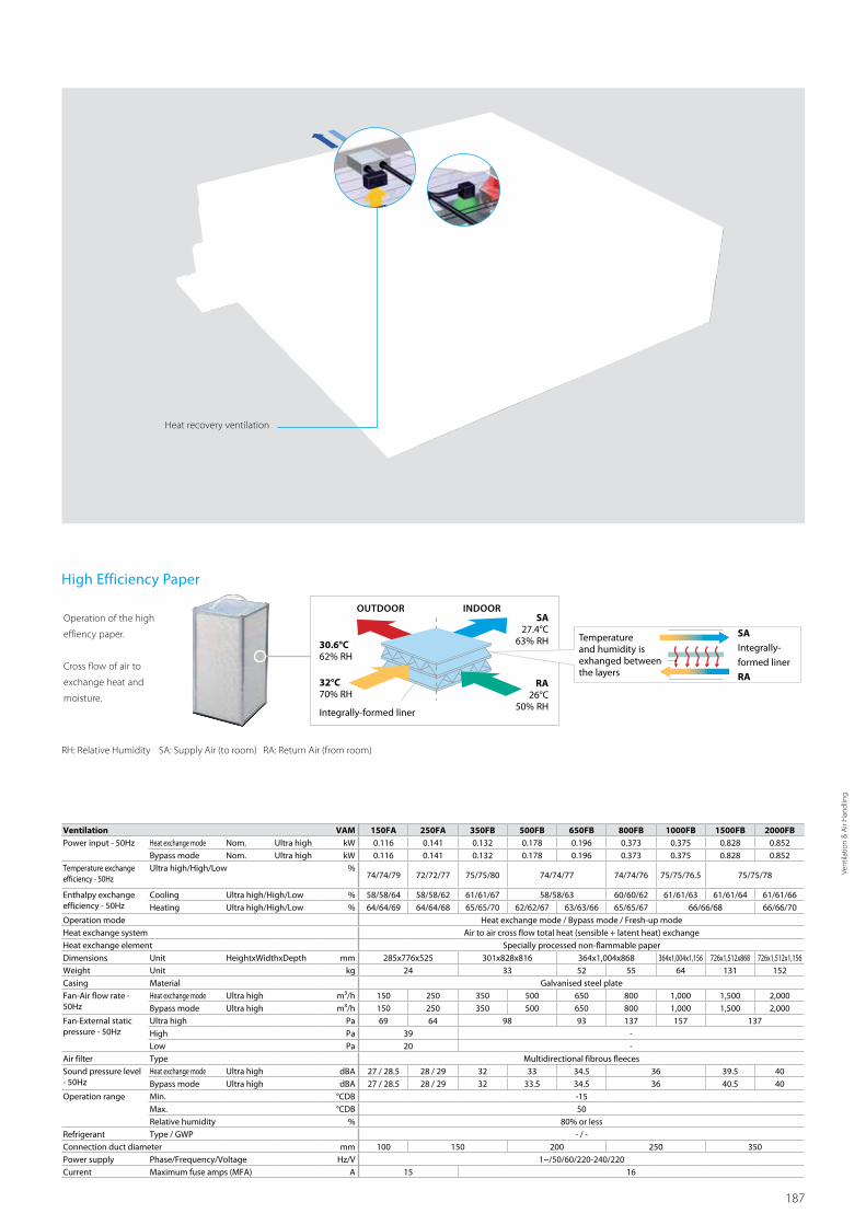
187
Vent
ilatio
n &
Air
Han
dlin
g
Ventilation VAM 150FA 250FA 350FB 500FB 650FB 800FB 1000FB 1500FB 2000FBPower input - 50Hz Heat exchange mode Nom. Ultra high kW 0.116 0.141 0.132 0.178 0.196 0.373 0.375 0.828 0.852
Bypass mode Nom. Ultra high kW 0.116 0.141 0.132 0.178 0.196 0.373 0.375 0.828 0.852Temperature exchange efficiency - 50Hz
Ultra high/High/Low %74/74/79 72/72/77 75/75/80 74/74/77 74/74/76 75/75/76.5 75/75/78
Enthalpy exchange efficiency - 50Hz
Cooling Ultra high/High/Low % 58/58/64 58/58/62 61/61/67 58/58/63 60/60/62 61/61/63 61/61/64 61/61/66Heating Ultra high/High/Low % 64/64/69 64/64/68 65/65/70 62/62/67 63/63/66 65/65/67 66/66/68 66/66/70
Operation mode Heat exchange mode / Bypass mode / Fresh-up modeHeat exchange system Air to air cross flow total heat (sensible + latent heat) exchangeHeat exchange element Specially processed non-flammable paperDimensions Unit HeightxWidthxDepth mm 285x776x525 301x828x816 364x1,004x868 364x1,004x1,156 726x1,512x868 726x1,512x1,156Weight Unit kg 24 33 52 55 64 131 152Casing Material Galvanised steel plateFan-Air flow rate - 50Hz
Heat exchange mode Ultra high m³/h 150 250 350 500 650 800 1,000 1,500 2,000Bypass mode Ultra high m³/h 150 250 350 500 650 800 1,000 1,500 2,000
Fan-External static pressure - 50Hz
Ultra high Pa 69 64 98 93 137 157 137High Pa 39 -Low Pa 20 -
Air filter Type Multidirectional fibrous fleecesSound pressure level - 50Hz
Heat exchange mode Ultra high dBA 27 / 28.5 28 / 29 32 33 34.5 36 39.5 40Bypass mode Ultra high dBA 27 / 28.5 28 / 29 32 33.5 34.5 36 40.5 40
Operation range Min. °CDB -15Max. °CDB 50Relative humidity % 80% or less
Refrigerant Type / GWP - / -Connection duct diameter mm 100 150 200 250 350Power supply Phase/Frequency/Voltage Hz/V 1~/50/60/220-240/220Current Maximum fuse amps (MFA) A 15 16
RH: Relative Humidity SA: Supply Air (to room) RA: Return Air (from room)
High Efficiency Paper
OUTDOOR INDOOR
RA26°C
50% RH
32°C70% RH
Integrally-formed liner
Temperature and humidity is exhanged between the layers
SAIntegrally-
formed liner
RA
Operation of the high
effiency paper.
Cross flow of air to
exchange heat and
moisture.
SA27.4°C
63% RH30.6°C62% RH
Heat recovery ventilation

188
Electrical heater for VAM
ELECTRICAL HEATER FOR VAM (VH)Supply voltage 220/250V ac 50/60 Hz. +/-10%Output current (maximum) 19A at 40°C (ambient)Temperature sensor 5k ohms at 25°C (table 502 1T)Temperature control range 0 to 40°C / (0-10V 0-100%)Control fuse 20 x 5mm 250mA
LED indicators Power ON - YellowHeater ON - Red (solid or flashing, indicating pulsed control)
Airflow fault - Red
Mounting holes 98mm x 181mm centres 5 mm ø holesMaximum ambient adjacent to terminal box 35°C (during operation)Auto high temp. cutout 100°C Pre-setMan. reset high temp. cutout 125°C Pre-setRun relay 1A 120V AC or 1A 24V DCBMS setpoint input 0-10VDC
VH 1B 2B 3B 4B 4/AB 5BCapacity kW 1 1 1 1.5 2.5 2.5
Duct diameter mm 100 150 200 250 250 300
Connectable VAM VAM150FA VAM250FA VAM500FB VAM800FB VAM800FB VAM1500FB- VAM350FB VAM650FB VAM1000FB VAM1000FB VAM2000FB
For the selection of the appropriate capacity, please refer to the VAM selection software.
VH
› Total solution for fresh air with Daikin supply of both VAM and electrical heaters
› Increased comfort in low outdoor temperature thanks to the heated outdoor air
› Integrated electrical heater concept (no additional accessories required)
› Standard dual flow and temperature sensor › Flexible setting with adjustable setpoint › Increased safety with 2 cut-outs: manual & automatic › BMS integration thanks to:
- Volt free relay for error indication - 0-10VDC input for setpoint control
VH

189
Vent
ilatio
n &
Air
Han
dlin
g
Detailed technical drawings
VAM150FA
VAM250FA
VAM150FA
3TW27874-1
NOTE
1 Be sure to provide the inspection hole (450x450 mm) to inspect the air filters, the exchange elements and fans.
Switch boxMaintenance space for the heat exchange elements, the air filters and fans
Inspection holeØ 450
Supply air fanMaintenance over
Ceiling hook4-14x40 oval hole
OA
EA
Fresh air from outdoors(Outdoor air)
Exhaust air to outdoors
Sealing
Exhaust air fanExhaust spacer
SA
RA
Damper plate
(Maintenance cover)
(Switch box)
Heat exchange elements Air filters
Supply air to room
Return air from roomSealing
285
269
149
120 104
67
600
120~
250
2020
560
28812
416
4
718
509
288
124
164
145 145760
104 120.3
149
Ø97
Ø97
Ø200
8 8
VAM250FA
3TW27884-1
NOTE
1 Be sure to provide the inspection hole (450x450 mm) to inspect the air filters, the exchange elements and fans.
Switch boxMaintenance space for the heat exchange elements, the air filters and fans
Inspection holeØ 450
Supply air fanMaintenance over
Ceiling hook4-14x40 oval hole
OA
EA
Fresh air from outdoors(Outdoor air)
Exhaust air to outdoorsSealing
Exhaust air fan
SA
RA
Damper plate
(Maintenance cover)
(Switch box)
Heat exchange elements Air filters
Supply air to room
Return air from roomSealing
285
269
149
120 104
67
600
120~
250
2020
560
28812
416
4
718
509
288
124
164
145 145760
104 120.3
149
Ø97
Ø200
8 8
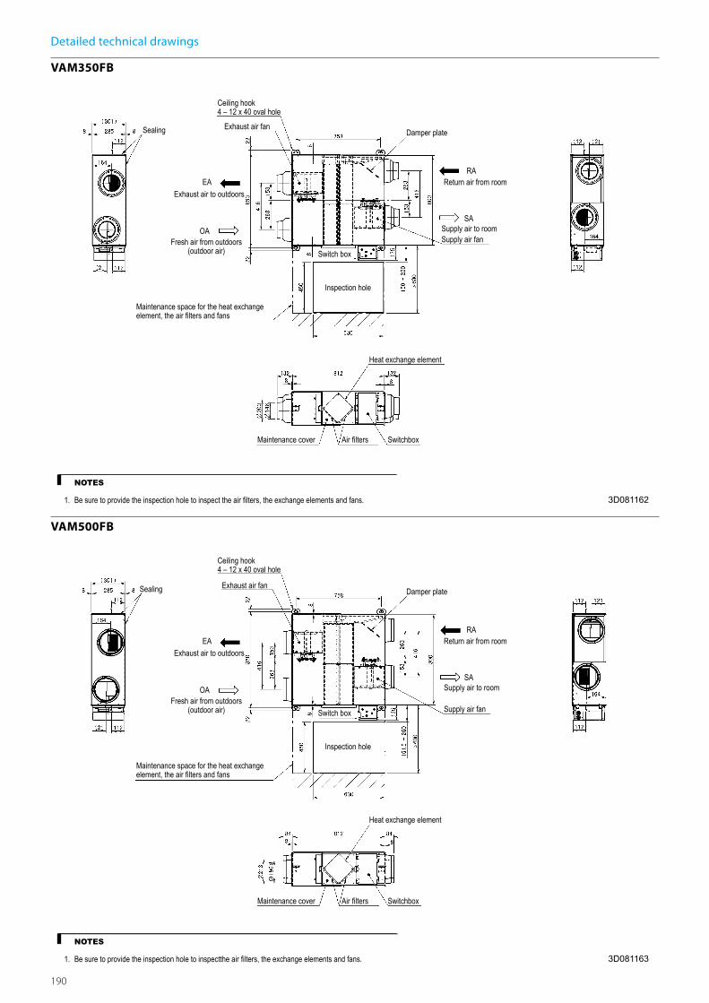
190
Detailed technical drawings
VAM350FB
VAM500FB
3D081162
VAM350FB
Maintenance cover Air lters Switchbox
Inspection hole
Switch box
Supply air to room
Return air from roomRA
SA
Damper plateExhaust air fan
Exhaust air to outdoors
Maintenance space for the heat exchange element, the air lters and fans
Fresh air from outdoors(outdoor air)
EA
OASupply air fan
Heat exchange element
Sealing
Ceiling hook4 – 12 x 40 oval hole
NOTES
1. Be sure to provide the inspection hole to inspect the air lters, the exchange elements and fans.
3D081163
VAM500FB
Maintenance cover Air lters Switchbox
Inspection hole
Switch box
Supply air to room
Return air from roomRA
SA
Damper plateExhaust air fan
Exhaust air to outdoors
Maintenance space for the heat exchange element, the air lters and fans
Fresh air from outdoors(outdoor air)
EA
OA
Supply air fan
Heat exchange element
Sealing
Ceiling hook4 – 12 x 40 oval hole
NOTES
1. Be sure to provide the inspection hole to inspectthe air lters, the exchange elements and fans.

191
Vent
ilatio
n &
Air
Han
dlin
g
Detailed technical drawings
VAM650FB
VAM800FB
3D081164
VAM650FB
Maintenance cover Air lters Switchbox
Inspection hole
Switch box
Supply air to room
Return air from roomRA
SA
Damper plate
Exhaust air fan
Exhaust air to outdoors
Maintenance space for the heat exchange element, the air lters and fans
Fresh air from outdoors(outdoor air)
EA
OASupply air fan
Heat exchange element
Sealing
Ceiling hook4 – 12 x 40 oval hole
NOTES
1. Be sure to provide the inspection hole to inspect the air lters, the exchange elements and fans.
3D081165
VAM800FB
Maintenance cover Air lters Switchbox
Inspection hole
Switch box
Supply air to room
Return air from roomRA
SA
Damper plate
Exhaust air fan
Exhaust air to outdoors
Maintenance space for the heat exchange element, the air lters and fans
Fresh air from outdoors(outdoor air)
EA
OASupply air fan
Heat exchange element
Sealing
Ceiling hook4 – 12 x 40 oval hole
NOTES
1. Be sure to provide the inspection hole to inspect the air lters, the exchange elements and fans.

192
Detailed technical drawings
VAM1000FB
VAM1500FB
3D081166
VAM1000FB
Maintenance cover Air lters Switchbox
Inspection hole
Switch box
Supply air to room
Return air from roomRA
SA
Damper plate
Exhaust air fan
Exhaust air to outdoors
Maintenance space for the heat exchange element, the air lters and fans
Fresh air from outdoors(outdoor air)
EA
OASupply air fan
Heat exchange element
Sealing
Ceiling hook4 – 12 x 40 oval hole
NOTES
1. Be sure to provide the inspection hole to inspect the air lters, the exchange elements and fans.
3D081167
VAM1500FB
Maintenance cover Air lters Switchbox
Inspection hole
Switch box
Supply air to room
Return air from roomRA
SA
Damper plateExhaust air fan (2x)
Exhaust air to outdoors
Maintenance space for the heat exchange element, the air lters and fans
Fresh air from outdoors(outdoor air)
EA
OA
Supply air fan (2x)
Heat exchange element
Sealing
Ceiling hook4 – 14 x 40 oval hole
NOTES
1. Be sure to provide the inspection hole to inspect the air lters, the exchange elements and fans.

193
Vent
ilatio
n &
Air
Han
dlin
g
Detailed technical drawings
VAM2000FB
VAM150FA
3D081168
VAM2000FB
Maintenance cover Air lters Switchbox
Inspection hole
Switch box
Supply air to room
Return air from room
RA
SA
Damper plateExhaust air fan (2x)
Exhaust air to outdoors
Maintenance space for the heat exchange element, the air lters and fans
Fresh air from outdoors(outdoor air)
EA
OA
Supply air fan (2x)
Heat exchange element
SealingCeiling hook4 – 14 x 40 oval hole
NOTES
1. Be sure to provide the inspection hole to inspect the air lters, the exchange elements and fans.
4D036773
VAM150FA
Exchange ef ciency
VAM150FA
Ultra-High
High
Temperature exchange ef ciencyEnthalpy exchange ef ciency (heating)
Enthalpy exchange ef ciency (cooling)
(Pa)
Air ow rate (m3/h)
External static pressure
ø100Pipe length
50 Hz, 220-240V60Hz, 220V

194
Detailed technical drawings
VAM250FA
VAM350FA
4D036774
VAM250FA
Exchange ef ciency
VAM250FA
Ultra-High
High
Low
Temperature exchange ef ciencyEnthalpy exchange ef ciency (heating)Enthalpy exchange ef ciency (cooling)
(Pa)
Air ow rate (m3/h)
External static pressure
50 Hz, 220-240V60Hz, 220V
3D082177
VAM350FB
Air ow (m3/h)
UH speed
upper limit UH-speedFactory set UH-speed
Factory set L-speed
Factory set H-speed
upper limit H-speed
upper limit L-speed
lower limit H-speedlower limit L-speed
lower limit UH-speed
H speed
L speed
Air ow (m3/h)
Air ow (m3/h)
Air ow (m3/h)
UH SpeedH SpeedL Speed
Exter
nal s
tatic
pres
sure
(Pa)
Exter
nal s
tatic
pres
sure
(Pa)
Exter
nal s
tatic
pres
sure
(Pa)
Exter
nal s
tatic
pres
sure
(Pa)
NOTES
1. The fan speeds are valid for 230V 50Hz power supply

195
Vent
ilatio
n &
Air
Han
dlin
g
Detailed technical drawings
VAM500FA
VAM650FA
3D082178
VAM500FB
Air ow (m3/h)
UH speed
upper limit UH-speed
Factory set UH-speed
Factory set L-speed
Factory set H-speed
upper limit H-speedupper limit L-speedlower limit H-speedlower limit L-speed
lower limit UH-speed
H speed
L speed
Air ow (m3/h)
Air ow (m3/h)
Air ow (m3/h)
UH SpeedH SpeedL Speed
Exter
nal s
tatic
pres
sure
(Pa)
Exter
nal s
tatic
pres
sure
(Pa)
Exter
nal s
tatic
pres
sure
(Pa)
Exter
nal s
tatic
pres
sure
(Pa)
NOTES
1. The fan speeds are valid for 230V 50Hz power supply
3D082179
VAM650FB
Air ow (m3/h)
UH speed
upper limit UH-speedFactory set UH-speed
Factory set L-speed
Factory set H-speed
upper limit H-speedupper limit L-speed
lower limit H-speedlower limit L-speed
lower limit UH-speed
H speed
L speed
Air ow (m3/h)
Air ow (m3/h)
Air ow (m3/h)
UH SpeedH SpeedL Speed
Exter
nal s
tatic
pres
sure
(Pa)
Exter
nal s
tatic
pres
sure
(Pa)
Exter
nal s
tatic
pres
sure
(Pa)
Exter
nal s
tatic
pres
sure
(Pa)
NOTES
1. The fan speeds are valid for 230V 50Hz power supply

196
Detailed technical drawings
VAM800FB
VAM1000FB
3D082181
VAM1000FB
Air ow (m3/h)
UH speed
upper limit UH-speed
Factory set UH-speed
Factory set L-speed
upper limit H-speed
lower limit H-speed
lower limit L-speed
lower limit UH-speed
H speed
L speed
Air ow (m3/h)
Air ow (m3/h)
Air ow (m3/h)
UH SpeedH SpeedL Speed
Exter
nal s
tatic
pres
sure
(Pa)
Exter
nal s
tatic
pres
sure
(Pa)
Exter
nal s
tatic
pres
sure
(Pa)
Exter
nal s
tatic
pres
sure
(Pa)
NOTES
1. The fan speeds are valid for 230V 50Hz power supply
upper limit L-speed
Factory set H-speed
3D082180
VAM800FB
Air ow (m3/h)
UH speed
upper limit UH-speed
Factory set UH-speed
Factory set L-speed
Factory set H-speed
upper limit H-speed
lower limit H-speedlower limit L-speed
lower limit UH-speed
H speed
L speed
Air ow (m3/h)
Air ow (m3/h)
Air ow (m3/h)
UH SpeedH SpeedL Speed
Exter
nal s
tatic
pres
sure
(Pa)
Exter
nal s
tatic
pres
sure
(Pa)
Exter
nal s
tatic
pres
sure
(Pa)
Exter
nal s
tatic
pres
sure
(Pa)
NOTES
1. The fan speeds are valid for 230V 50Hz power supply
upper limit L-speed

197
Vent
ilatio
n &
Air
Han
dlin
g
Detailed technical drawings
VAM1500FB
VAM2000FB
3D082182
VAM1500FB
Air ow (m3/h)
UH speed
upper limit UH-speed
Factory set UH-speed
Factory set L-speed
upper limit H-speed
lower limit H-speedlower limit L-speed
lower limit UH-speed
H speed
L speed
Air ow (m3/h)
Air ow (m3/h)
Air ow (m3/h)
UH SpeedH SpeedL Speed
Exter
nal s
tatic
pres
sure
(Pa)
Exter
nal s
tatic
pres
sure
(Pa)
Exter
nal s
tatic
pres
sure
(Pa)
Exter
nal s
tatic
pres
sure
(Pa)
NOTES
1. The fan speeds are valid for 230V 50Hz power supply
upper limit L-speed
Factory set H-speed
3D082183
VAM2000FB
Air ow (m3/h)
UH speed
upper limit UH-speed
Factory set UH-speed
Factory set L-speed
upper limit H-speed
lower limit H-speedlower limit L-speed
lower limit UH-speed
H speed
L speed
Air ow (m3/h)
Air ow (m3/h)
Air ow (m3/h)
UH SpeedH SpeedL Speed
Exter
nal s
tatic
pres
sure
(Pa)
Exter
nal s
tatic
pres
sure
(Pa)
Exter
nal s
tatic
pres
sure
(Pa)
Exter
nal s
tatic
pres
sure
(Pa)
NOTES
1. The fan speeds are valid for 230V 50Hz power supply
upper limit L-speed
Factory set H-speed

198
Exhaust FanHeat Exchanger
ElementsDamper Motor
DamperEA
(Exhaust air to outdours)
OA
(Fresh air from outdoors)
Air Supply Fan
Electronics Box (Control box)
SA (Supply air to room)
RA
(Return air from room)
Float switch Solenoid
valve
waterSA
Drain pan Drain
AIRFLOW
Humidifier element:Utilizing the principle of capillary action, water is permeated throughout the humidifier element. The heated air from the DX coil passes through the humidifier and absorbs the moisture.
1 VKM-GM example
Operation example: humidification & air processing (heating mode)1
DX coil (Direct expansion coil)
Heat reclaim ventilation and air processing
Pre heating or cooling of fresh air for lower load on the air conditioning system
› Energy saving ventilation using indoor heating, cooling and moisture recovery
› Creates a high quality indoor environment by pre conditioning incoming fresh air
› Humidification of the incoming air results in comfortable indoor humidity level, even during heating
› Ideal solution for shops, restaurants or offices requiring maximum floor space for furniture, decorations and fittings
› Free cooling possible when outdoor temperature is below indoor temperature (eg. during nighttime)
› Low energy consumption thanks to DC fan motor › Prevent energy losses from over-ventilation while maintaining indoor air quality with optional CO2 sensor
› Shorter installation time thanks to easy adjustment of nominal air flow rate, so less need for dampers compared with traditional installation.
› Specially developed heat exchange element with High Efficiency Paper (HEP)
› Can operate in over- and under pressure
VKM-GB/VKM-GBM

199
Vent
ilatio
n &
Air
Han
dlin
g
VKM-GM example
Heat recovery ventilation,
humidification & air processing
Heat reclaim ventilation and air processing
Heat reclaim ventilation, air processing and humidification
Ventilation VKM 50GB 80GB 100GB 50GBM 80GBM 100GBMPower input - 50Hz Heat exchange mode Nom. Ultra high kW 0.270 0.330 0.410 0.270 0.330 0.410
Bypass mode Nom. Ultra high kW 0.270 0.330 0.410 0.270 0.330 0.410Fresh air conditioning load
Cooling kW 4.71 / 1.91 / 3.5 7.46 / 2.96 / 5.6 9.12 / 3.52 / 7.0 4.71 / 1.91 / 3.5 7.46 / 2.96 / 5.6 9.12 / 3.52 / 7.0Heating kW 5.58 / 2.38 / 3.5 8.79 / 3.79 / 5.6 10.69 / 4.39 / 7.0 5.58 / 2.38 / 3.5 8.79 / 3.79 / 5.6 10.69 / 4.39 / 7.0
Temperature exchange efficiency - 50Hz
Ultra high/High/Low %76/76/77.5 78/78/79 74/74/76.5 76/76/77.5 78/78/79 74/74/76.5
Enthalpy exchange efficiency - 50Hz
Cooling Ultra high/High/Low % 64/64/67 66/66/68 62/62/66 64/64/67 66/66/68 62/62/66Heating Ultra high/High/Low % 67/67/69 71/71/73 65/65/69 67/67/69 71/71/73 65/65/69
Operation mode Heat exchange mode / Bypass mode / Fresh-up modeHeat exchange system Air to air cross flow total heat (sensible + latent heat) exchangeHeat exchange element Specially processed non-flammable paperHumidifier System - Natural evaporating typeDimensions Unit HeightxWidthxDepth mm 387x1,764x832 387x1,764x1,214 387x1,764x832 387x1,764x1,214Weight Unit kg 94 110 112 100 119 123Casing Material Galvanised steel plateFan-Air flow rate - 50Hz
Heat exchange mode Ultra high m³/h 500 750 950 500 750 950Bypass mode Ultra high m³/h 500 750 950 500 750 950
Fan-External static pressure - 50Hz
Ultra high Pa 210 150 200 205 110High Pa 170 160 100 150 155 70Low Pa 140 110 70 120 105 60
Air filter Type Multidirectional fibrous fleecesSound pressure level - 50Hz
Heat exchange mode Ultra high dBA 39 41.5 41 38 40Bypass mode Ultra high dBA 40 41.5 41 39 41
Operation range Around unit °CDB 0°C~40°CDB, 80% RH or lessSupply air °CDB -15°C~40°CDB, 80% RH or lessReturn air °CDB 0°C~40°CDB, 80% RH or lessOn coil temperature
Cooling Max. °CDB -15Heating Min. °CDB 43
Refrigerant Type / GWP R-410A / 2.087,5Connection duct diameter mm 200 250 200 250Piping connections Liquid OD mm 6.35
Gas OD mm 12.7Water supply mm - 6.4Drain PT3/4 external thread
Power supply Phase/Frequency/Voltage Hz/V 1~/50/220-240Current Maximum fuse amps (MFA) A 15

200
Detailed technical drawings
VKM50GBVKM50GB
3D083014
NOTES
1. Leavespaceforservicingtheunitandincludeinspectionhatch.(Alwaysopenaholeonthesideofthecontrolboxsothattheairfilters,heatexchangeelements,andfanscaneasilybeinspectedandserviced.)
2. Installthetwooutdoorductswithdownslope(slopeof1/30ormore)toprevententryofrainwater,also,provideinsulationforthreeducts(outdoorductsandindoorsupplyairduct)topreventdewcondensation.(Material:glasswoolof25mmthick)
3. Donotturntheunitupsidedown.4. Makesuretoinstalldrainpiping,andinsulatedrainpipingtopreventdewcondensation.5. Keepthedrainpipeshortandslopingdownwardsatagradientofatleast1/100topreventairfromforming.6. Donotuseabentcaporaroundhoodastheoutdoorhoodiftheymightgetrainedondirectly(werecommendusingadeephood)(optionalaccessory).7. Inareaswherefreezingmayoccur,alwaystakestepstopreventthepipesfromfreezing.8. Donotplacesomethingwhichshouldn’tgetwetatthebelowofthisunit.Thedewwouldfallatfollowingcase,wherehumidityis80%more,ortheexitofdrainsocketischokedup,ortheair
filterisverydirty.
Heatinsulator
Airsuctiongrille
Airdischargegrille
Heatinsulator
Refrigerantpiping(Gaspipe)
Agradientofmorethan1/30 Refrigerantpiping(Liquidpipe)
Branchduct
AirdischargegrilleFlexibleduct
360(incaseof□450inspectionhatch)140(incaseof□600inspectionhatch)
Controlbox
Maintenancespacefortheheatexchangerelementstheairfiltersandfans
Slopingdownwardsatagradientofthe1/100
Ø200Nominaldiameter
Inspectionhatch
Inspectionhatch
Morethan60
0
EA(Exhaustairtooutdoors)
OA(Freshairfromoutdoors)
Roundshapehood(Locallyprocured)
(locallyprocured)
(locallyprocured)
(locallyprocured)
(locallyprocured)
(Ø12.7flareconnection)
(Ø6.4flareconnection)
(locallyprocured)
(locallyprocured)(locallyprocured)
(locallyprocured)
(locallyprocured)(locallyprocured)InspectionhatchSuspentionbolt
EA(Exhaustairtooutdoors)
OA(Freshairfromoutdoors)
RA(Returnairfromroom)
SA(Returnairtoroom)

201
Vent
ilatio
n &
Air
Han
dlin
g
Detailed technical drawings
VKM50GBMVKM50GBM
3D083011
NOTES
1. Leavespaceforservicingtheunitandincludeinspectionhatch.(Alwaysopenaholeonthesideofthecontrolboxsothattheairfilters,heatexchangeelements,fans,andhumidifierelementscaneasilybeinspectedandserviced.)
2. Installthetwooutdoorductswithdownslope(slopeof1/30ormore)toprevententryofrainwater.Also,provideinsulationforthreeducts(outdoorductsandindoorsupplyairduct)topreventdewcondensation.(Material:glasswoolof25mmthick)
3. Donotturntheunitupsidedown.4. Usecitywaterorcleanwater.
Includewatersupplypipingwithstraner,awatersupplyshut-offvalve,andadrainvalve(bothlocallyprocured)somewherealongthewatersupplypipingthatcanbereachedfromtheinspection.
5. Itisimpossibletoconnectthewatersupplypipingdirectlytopublicpiping.Useacisterntank(oftheapprovedtype),ifyouneedtogetyourwatersupplyfrompublicpiping.6. Makesurethesupplywater0.02MPato0.49MPa(0.2kg/cm2to5kg/cm2).7. Makesurethesupplywaterisbetween5°Cand40°Cintemperature.8. Insulatethewatersupplypipingtopreventcondensationfromforming.9. Makesuretoinstalldrainpiping,andinsulatedrainpipingtopreventdewcondensation.10.Keepthedrainpipeshortandslopingdownwardsatagradientofatleast1/100topreventairfromforming.11.Installinalocationwheretheairaroundtheunitortakenintothehumidifierwillnotdropbelow0°C.12.Donotuseabentcaporaroundhoodastheoutdoorhoodiftheymightgetrainedondirectly(werecommendusingadeephood)(optionalaccessory).13.Inareaswherefreezingmayoccur,alwaystakestepstopreventthepipesfromfreezing.14.Donotplacesomethingwhichshouldn’tgetwetatthebelowofthisunit.Thedewwouldfallatfollowingcase,wherehumidityis80%more,ortheexitofdrainsocketischokedup,ortheair
filterisverydirty.15.Feedcleanwater.Ifthesupplywaterishardwater,useawatersoftenerbecauseofshortlife.
Lifeofhumidifyingelementisabout3years(4,000hours),underthesupplywaterconditionsofhardness:150mg/L.(Lifeofhumidifyingelementisabout1years(1500hours),underthesupplywaterconditionsofhardness:400mg/L.)
Heatinsulator
Airsuctiongrille
Airdischargegrille
Heatinsulator
Refrigerantpiping(Gaspipe)Agradientofmorethan1/30
Cisterntank
Refrigerantpiping(Liquidpipe)
Branchduct
Airdischargegrille
Watersupplyshut-offvalve
Drainvalve
Strainer
Flexibleduct
360(incaseof□450inspectionhatch)140(incaseof□600inspectionhatch)
Controlbox
Maintenancespacefortheheatexchangerelementstheairfilters,fansandhumidifier
Slopingdownwardsatagradientofthe1/100
Ø200Nominaldiameter
Inspectionhatch
Inspectionhatch
Morethan60
0
EA(Exhaustairtooutdoors)
OA(Freshairfromoutdoors)
Roundshapehood(Locallyprocured)
(locallyprocured)
(locallyprocured)
(locallyprocured)
(locallyprocured)
(Ø12.7flareconnection)
(Ø6.4flareconnection)
(locallyprocured)
(locallyprocured)
(locallyprocured)
(locallyprocured)
(accessory)
(locallyprocured)
(locallyprocured)
(locallyprocured)(locallyprocured)
□450•600Inspectionhatch
Suspensionbolt
EA(Exhaustairtooutdoors)
OA(Freshairfromoutdoors)
RA(Returnairfromroom)
SA(Returnairtoroom)

202
Detailed technical drawings
VKM80GBVKM80GB
3D083015
NOTES
1. Leavespaceforservicingtheunitandincludeinspectionhatch.(Alwaysopenaholeonthesideofthecontrolboxsothattheairfilters,heatexchangeelements,andfanscaneasilybeinspectedandserviced.)
2. Installthetwooutdoorductswithdownslope(slopeof1/30ormore)toprevententryofrainwater,also,provideinsulationforthreeducts(outdoorductsandindoorsupplyairduct)topreventdewcondensation.(Material:glasswoolof25mmthick)
3. Donotturntheunitupsidedown.4. Makesuretoinstalldrainpiping,andinsulatedrainpipingtopreventdewcondensation.5. Keepthedrainpipeshortandslopingdownwardsatagradientofatleast1/100topreventairfromforming.6. Donotuseabentcaporaroundhoodastheoutdoorhoodiftheymightgetrainedondirectly(werecommendusingadeephood)(optionalaccessory).7. Inareaswherefreezingmayoccur,alwaystakestepstopreventthepipesfromfreezing.8. Donotplacesomethingwhichshouldn’tgetwetatthebelowofthisunit.Thedewwouldfallatfollowingcase,wherehumidityis80%more,ortheexitofdrainsocketischokedup,ortheair
filterisverydirty.
HeatinsulatorAirsuctiongrille Airdischargegrille
Heatinsulator
Refrigerantpiping(Gaspipe)
Agradientofmorethan1/30 Refrigerantpiping(Liquidpipe)
Branchduct
Silencer
AirdischargegrilleFlexibleduct
360(incaseof□450inspectionhatch)140(incaseof□600inspectionhatch)
Controlbox
Maintenancespacefortheheatexchangerelementstheairfiltersandfans
Slopingdownwardsatagradientofthe1/100
Ø200Nominaldiameter
Inspectionhatch
Inspectionhatch
Morethan60
0
EA(Exhaustairtooutdoors)
OA(Freshairfromoutdoors)
Roundshapehood(Locallyprocured)
(locallyprocured)(locallyprocured) (locallyprocured)
(locallyprocured)
(Ø12.7flareconnection)
(Ø6.4flareconnection)
(locallyprocured)
(locallyprocured)
(locallyprocured)(locallyprocured)
(locallyprocured)
(locallyprocured)(locallyprocured)
□450•600Inspectionhatch
SuspentionboltEA
(Exhaustairtooutdoors)
OA(Freshairfromoutdoors)
RA(Returnairfromroom)
SA(Returnairtoroom)

203
Vent
ilatio
n &
Air
Han
dlin
g
Detailed technical drawings
VKM80GBMVKM80GBM
3D083012
NOTES
1. Leavespaceforservicingtheunitandincludeinspectionhatch.(Alwaysopenaholeonthesideofthecontrolboxsothattheairfilters,heatexchangeelements,fans,andhumidifierelementscaneasilybeinspectedandserviced.)
2. Installthetwooutdoorductswithdownslope(slopeof1/30ormore)toprevententryofrainwater.Also,provideinsulationforthreeducts(outdoorductsandindoorsupplyairduct)topreventdewcondensation.(Material:glasswoolof25mmthick)
3. Donotturntheunitupsidedown.4. Usecitywaterorcleanwater.
Includewatersupplypipingwithstraner,awatersupplyshut-offvalve,andadrainvalve(bothlocallyprocured)somewherealongthewatersupplypipingthatcanbereachedfromtheinspection.
5. Itisimpossibletoconnectthewatersupplypipingdirectlytopublicpiping.Useacisterntank(oftheapprovedtype),ifyouneedtogetyourwatersupplyfrompublicpiping.6. Makesurethesupplywater0.02MPato0.49MPa(0.2kg/cm2to5kg/cm2).7. Makesurethesupplywaterisbetween5°Cand40°Cintemperature.8. Insulatethewatersupplypipingtopreventcondensationfromforming.9. Makesuretoinstalldrainpiping,andinsulatedrainpipingtopreventdewcondensation.10.Keepthedrainpipeshortandslopingdownwardsatagradientofatleast1/100topreventairfromforming.11.Installinalocationwheretheairaroundtheunitortakenintothehumidifierwillnotdropbelow0°C.12.Donotuseabentcaporaroundhoodastheoutdoorhoodiftheymightgetrainedondirectly(werecommendusingadeephood)(optionalaccessory).13.Inareaswherefreezingmayoccur,alwaystakestepstopreventthepipesfromfreezing.14.Donotplacesomethingwhichshouldn’tgetwetatthebelowofthisunit.Thedewwouldfallatfollowingcase,wherehumidityis80%more,ortheexitofdrainsocketischokedup,ortheair
filterisverydirty.15.Feedcleanwater.Ifthesupplywaterishardwater,useawatersoftenerbecauseofshortlife.
Lifeofhumidifyingelementisabout3years(4,000hours),underthesupplywaterconditionsofhardness:150mg/L.(Lifeofhumidifyingelementisabout1years(1500hours),underthesupplywaterconditionsofhardness:400mg/L.)
HeatinsulatorAirsuctiongrille Airdischargegrille
Heatinsulator
Refrigerantpiping(Gaspipe)
Agradientofmorethan1/30
Cisterntank
Refrigerantpiping(Liquidpipe)
Branchduct
Airdischargegrille
Watersupplyshut-offvalve
Drainvalve
Strainer
Flexibleduct
Silencer
360(incaseof□450inspectionhatch)140(incaseof□600inspectionhatch)
Controlbox
Maintenancespacefortheheatexchangerelementstheairfilters,fansandhumidifier
Slopingdownwardsatagradientofthe1/100
Ø250Nominaldiameter
Inspectionhatch
Inspectionhatch
Morethan60
0
EA(Exhaustairtooutdoors)
OA(Freshairfromoutdoors)
Roundshapehood(Locallyprocured)
(locallyprocured)(locallyprocured) (locallyprocured)
(locallyprocured)
(Ø12.7flareconnection)
(Ø6.4flareconnection)
(locallyprocured)
(locallyprocured)
(locallyprocured)
(locallyprocured)
(accessory)
(locallyprocured)
(locallyprocured)
(locallyprocured)
(locallyprocured)
(locallyprocured)□450•600Inspectionhatch
SuspensionboltEA
(Exhaustairtooutdoors)
OA(Freshairfromoutdoors)
RA(Returnairfromroom)
SA(Returnairtoroom)

204
Detailed technical drawings
VKM100GBVKM100GB
3D083016
NOTES
1. Leavespaceforservicingtheunitandincludeinspectionhatch.(Alwaysopenaholeonthesideofthecontrolboxsothattheairfilters,heatexchangeelements,andfanscaneasilybeinspectedandserviced.)
2. Installthetwooutdoorductswithdownslope(slopeof1/30ormore)toprevententryofrainwater,also,provideinsulationforthreeducts(outdoorductsandindoorsupplyairduct)topreventdewcondensation.(Material:glasswoolof25mmthick)
3. Donotturntheunitupsidedown.4. Makesuretoinstalldrainpiping,andinsulatedrainpipingtopreventdewcondensation.5. Keepthedrainpipeshortandslopingdownwardsatagradientofatleast1/100topreventairfromforming.6. Donotuseabentcaporaroundhoodastheoutdoorhoodiftheymightgetrainedondirectly(werecommendusingadeephood)(optionalaccessory).7. Inareaswherefreezingmayoccur,alwaystakestepstopreventthepipesfromfreezing.8. Donotplacesomethingwhichshouldn’tgetwetatthebelowofthisunit.Thedewwouldfallatfollowingcase,wherehumidityis80%more,ortheexitofdrainsocketischokedup,ortheair
filterisverydirty.
HeatinsulatorAirsuctiongrille Airdischargegrille
Heatinsulator
Refrigerantpiping(Gaspipe)
Agradientofmorethan1/30 Refrigerantpiping(Liquidpipe)
Branchduct
Silencer
AirdischargegrilleFlexibleduct
360(incaseof□450inspectionhatch)140(incaseof□600inspectionhatch)
Controlbox
Maintenancespacefortheheatexchangerelementstheairfiltersandfans
Slopingdownwardsatagradientofthe1/100
Ø250Nominaldiameter
Inspectionhatch
Inspectionhatch
Morethan60
0
EA(Exhaustairtooutdoors)
OA(Freshairfromoutdoors)
Roundshapehood(Locallyprocured)
(locallyprocured)(locallyprocured) (locallyprocured)
(locallyprocured)
(Ø12.7flareconnection)
(Ø6.4flareconnection)
(locallyprocured)
(locallyprocured)
(locallyprocured)(locallyprocured)
(locallyprocured)
(locallyprocured)(locallyprocured)
□450•600Inspectionhatch
SuspentionboltEA
(Exhaustairtooutdoors)
OA(Freshairfromoutdoors)
RA(Returnairfromroom)
SA(Returnairtoroom)

205
Vent
ilatio
n &
Air
Han
dlin
g
Detailed technical drawings
VKM100GBMVKM100GBM
3D083013
NOTES
1. Leavespaceforservicingtheunitandincludeinspectionhatch.(Alwaysopenaholeonthesideofthecontrolboxsothattheairfilters,heatexchangeelements,fans,andhumidifierelementscaneasilybeinspectedandserviced.)
2. Installthetwooutdoorductswithdownslope(slopeof1/30ormore)toprevententryofrainwater.Also,provideinsulationforthreeducts(outdoorductsandindoorsupplyairduct)topreventdewcondensation.(Material:glasswoolof25mmthick)
3. Donotturntheunitupsidedown.4. Usecitywaterorcleanwater.
Includewatersupplypipingwithstraner,awatersupplyshut-offvalve,andadrainvalve(bothlocallyprocured)somewherealongthewatersupplypipingthatcanbereachedfromtheinspection.
5. Itisimpossibletoconnectthewatersupplypipingdirectlytopublicpiping.Useacisterntank(oftheapprovedtype),ifyouneedtogetyourwatersupplyfrompublicpiping.6. Makesurethesupplywater0.02MPato0.49MPa(0.2kg/cm2to5kg/cm2).7. Makesurethesupplywaterisbetween5°Cand40°Cintemperature.8. Insulatethewatersupplypipingtopreventcondensationfromforming.9. Makesuretoinstalldrainpiping,andinsulatedrainpipingtopreventdewcondensation.10.Keepthedrainpipeshortandslopingdownwardsatagradientofatleast1/100topreventairfromforming.11.Installinalocationwheretheairaroundtheunitortakenintothehumidifierwillnotdropbelow0°C.12.Donotuseabentcaporaroundhoodastheoutdoorhoodiftheymightgetrainedondirectly(werecommendusingadeephood)(optionalaccessory).13.Inareaswherefreezingmayoccur,alwaystakestepstopreventthepipesfromfreezing.14.Donotplacesomethingwhichshouldn’tgetwetatthebelowofthisunit.Thedewwouldfallatfollowingcase,wherehumidityis80%more,ortheexitofdrainsocketischokedup,ortheair
filterisverydirty.15.Feedcleanwater.Ifthesupplywaterishardwater,useawatersoftenerbecauseofshortlife.
Lifeofhumidifyingelementisabout3years(4,000hours),underthesupplywaterconditionsofhardness:150mg/L.(Lifeofhumidifyingelementisabout1years(1500hours),underthesupplywaterconditionsofhardness:400mg/L.)
HeatinsulatorAirsuctiongrille Airdischargegrille
Heatinsulator
Refrigerantpiping(Gaspipe)
Agradientofmorethan1/30
Cisterntank
Refrigerantpiping(Liquidpipe)
Branchduct
Airdischargegrille
Watersupplyshut-offvalveDrainvalve
Strainer
Flexibleduct
Silencer
360(incaseof□450inspectionhatch)140(incaseof□600inspectionhatch)
Controlbox
Maintenancespacefortheheatexchangerelementstheairfilters,fansandhumidifier
Slopingdownwardsatagradientofthe1/100
Ø250Nominaldiameter
Inspectionhatch
Inspectionhatch
Morethan60
0
EA(Exhaustairtooutdoors)
OA(Freshairfromoutdoors)
Roundshapehood(Locallyprocured)
(locallyprocured)(locallyprocured) (locallyprocured)
(locallyprocured)
(Ø12.7flareconnection)
(Ø6.4flareconnection)
(locallyprocured)
(locallyprocured)
(locallyprocured)(locallyprocured)
(accessory)
(locallyprocured)
(locallyprocured)
(locallyprocured)
(locallyprocured)
(locallyprocured)□450•600Inspectionhatch
SuspensionboltEA
(Exhaustairtooutdoors)
OA(Freshairfromoutdoors)
RA(Returnairfromroom)
SA(Returnairtoroom)

206
VKM50GB
3D082904
–––––– 50Hz, 220V-240V
Operating air flow rate range
Operating air flow rate range
Air flow rate (m3/h) Air flow rate (m3/h)Low
Air flow rate (m3/h)High
Air flow rate (m3/h)Ultra High
Operating air flow rate range Operating air flow rate range
Exchange efficiency
(%)
Exter
nal s
tatic
pres
sure
(Pa)
Exter
nal s
tatic
pres
sure
(Pa)
ø200 Pipe
length
1) For example: 19(29)- -07Mode no. : 19(29) First code: (Supply ┌ 2 ┘Exhaust ┌ 3 ┘)
Second code no. : 07
2) Rated point: ●3) The characteristic of each tap becomes a setup of the
characteristic of the same code number.
[Reading of Performance Characteristics]
Temperature exchange efficiencyEnthalpy exchange efficiency (heating)
Enthalpy exchange efficiency (cooling)
Ultra High
High
Low
VKM50GBM
3D082901
–––––– 50Hz, 220V-240V
Operating air flow rate range
Operating air flow rate range
Air flow rate (m3/h) Air flow rate (m3/h)Low
Air flow rate (m3/h)High
Air flow rate (m3/h)Ultra High
Operating air flow rate range Operating air flow rate range
Exchange efficiency(%)
Exter
nal s
tatic
pres
sure
(Pa)
Exter
nal s
tatic
pres
sure
(Pa)
ø200 Pipe
length
VKM50GBM
1) For example: 19(29)- -07 Mode no. : 19(29) First code: (Supply ┌ 2 ┘Exhaust ┌ 3 ┘)
Second code no. : 07
2) Rated point: ●3) The characteristic of each tap becomes a setup of the characteristic of the
same code number.
[Reading of Performance Characteristics]
Temperature exchange efficiencyEnthalpy exchange efficiency (heating)Enthalpy exchange efficiency (cooling)
Ultra High
High
Low
Detailed technical drawings
VKM50GB
VKM50GBM

207
Vent
ilatio
n &
Air
Han
dlin
g
VKM80GB
3D082905
–––––– 50Hz, 220V-240VOperating air flow rate range
Temperature exchange efficiencyEnthalpy exchange efficiency (heating)
Enthalpy exchange efficiency (cooling)
Operating air flow rate range
Air flow rate (m3/h) Air flow rate (m3/h)Low
Air flow rate (m3/h)High
Air flow rate (m3/h)Ultra High
Operating air flow rate range Operating air flow rate rangeExchange efficiency
(%)
Exter
nal s
tatic
pres
sure
(Pa)
Exter
nal s
tatic
pres
sure
(Pa)
ø250 Pipe
length
1) For example: 19(29)- -07Mode no. : 19(29) First code: (Supply ┌ 2 ┘Exhaust ┌ 3 ┘)
Second code no. : 07
2) Rated point: ●3) The characteristic of each tap becomes a setup of the
characteristic of the same code number.
[Reading of Performance Characteristics]
Ultra High
High
Low
VKM80GBM
3D082902
–––––– 50Hz, 220V-240V
Operating air flow rate range
Operating air flow rate range
Air flow rate (m3/h) Air flow rate (m3/h)Low
Air flow rate (m3/h)High
Air flow rate (m3/h)Ultra High
Operating air flow rate range Operating air flow rate range
Exchange efficiency(%)
Exter
nal s
tatic
pres
sure
(Pa)
Exter
nal s
tatic
pres
sure
(Pa)
ø250 Pipe
length
VKM80GBM
1) For example: 19(29)- -07 Mode no. : 19(29) First code: (Supply ┌ 2 ┘Exhaust ┌ 3 ┘)
Second code no. : 07
2) Rated point: ●3) The characteristic of each tap becomes a setup of the characteristic of the
same code number.
[Reading of Performance Characteristics]
Temperature exchange efficiencyEnthalpy exchange efficiency (heating)
Enthalpy exchange efficiency (cooling)
Ultra High
High
Low
Detailed technical drawings
VKM80GB
VKM80GBM

208
VKM100GB
3D082906
–––––– 50Hz, 220V-240V
Operating air flow rate range
Operating air flow rate range
Air flow rate (m3/h)
Air flow rate (m3/h)Low
Air flow rate (m3/h)High
Air flow rate (m3/h)Ultra High
Operating air flow rate range Operating air flow rate range
Exchange efficiency
(%)
Exter
nal s
tatic
pres
sure
(Pa)
Exter
nal s
tatic
pres
sure
(Pa)
ø250 Pipe
lengthUltra High
High
Low
1) For example: 19(29)- -07Mode no. : 19(29) First code: (Supply ┌ 2 ┘Exhaust ┌ 3 ┘)
Second code no. : 07
2) Rated point: ●3) The characteristic of each tap becomes a setup of the
characteristic of the same code number.
[Reading of Performance Characteristics]
Temperature exchange efficiency
Enthalpy exchange efficiency (heating)Enthalpy exchange efficiency (cooling)
VKM100GBM
3D082903
–––––– 50Hz, 220V-240V
Operating air flow rate range
Operating air flow rate range
Air flow rate (m3/h) Air flow rate (m3/h)Low
Air flow rate (m3/h)High
Air flow rate (m3/h)Ultra High
Operating air flow rate range Operating air flow rate range
Exchange efficiency(%)
Exter
nal s
tatic
pres
sure
(Pa)
Exter
nal s
tatic
pres
sure
(Pa)
ø250 Pipe
length
VKM100GBM
1) For example: 19(29)- -07 Mode no. : 19(29) First code: (Supply ┌ 2 ┘Exhaust ┌ 3 ┘)
Second code no. : 07
2) Rated point: ●3) The characteristic of each tap becomes a setup of the characteristic of the
same code number.
[Reading of Performance Characteristics]
Temperature exchange efficiency
Enthalpy exchange efficiency (heating)
Enthalpy exchange efficiency (cooling)
Ultra High
High
Low
Detailed technical drawings
VKM100GB
VKM100GBM

209
Vent
ilatio
n &
Air
Han
dlin
g
Air handling applications
Wide range of air flows For applications that require big volumes of treated fresh air (large atriums, banquet halls, etc) air handling units represent the ideal solution. Daikin’s wide range of air handling units treat air volumes from 500 m³/h up to 140,000 m³/h. The air handling unit can be designed to deliver
whatever air flow you require, via the specific dimensions of flow section available at the installation.
Dainkin fresh air package - plug & play
The D-AHU Professional and Energy series provide a complete solution including unit control (EKEXV, EKEQ, DDC controller) factory mounted and configured, plug & play with our ERQ and VRV condensing units.The easiest solution as you save time and only have one point of contact!
Return on investment
The air handling unit (AHU) is critical to an effective climate control system and the savings generated by our advanced designs and operating efficiencies guarantee a rapid return on the investment made. Our AHU Energy series has been designed to deliver exceptional performance thus driving down the energy consumed and so lowering energy bills. Taken over the expected 15-year life-span of the equipment, this will result in a substantial saving, especially in a time of ever increasing energy prices.
Pre-defined sizes 27 fixed sizes are available, optimized to reach the optimum combination between value for money and manufacturing standardisation. Daikin’s section by section design means that units can be sized by 1cm increments and assembled on site, without welding, to suit the space constraints of the installation.
High efficiency components
All Daikin air handling units have been designed for optimum energy efficiency. Polyurethane or Mineral wool panels guarantee excellent thermal insulation performance. And the widest range of filters are provided to meet even the most strict demands.
Air
flow
(m3 /h
x 1,
000)
0
20
40
50
60
70
80
90
100
120
140
Professional
750 m3/hup to 144,000 m3/h
Energy
750 m3/hup to 100,000 m3/h
Compact
500m3/hup to 25,000 m3/h
Professional › Pre-configured sizes › Tailored to the individual customer
› Modular construction
Energy › High-end solution for optimised energy consumption
› High efficiency components › Strong Return on Investment
Compact › Pre-configured sizes › Plug & Play concept › EC Fan Technology › High Efficiency Heat Wheel › Compact Design
NEW
Air handling applications

210
Air handling unit applications
Why use ERQ and VRV condensing units for connection to air handling units?
High Efficiency
Daikin heat pumps are renowned for their high energy efficiency. Integrating the AHU with a heat recovery system is even more effective since an office system can frequently be in cooling mode
while the outdoor air is too cold to be brought inside in an unconditioned state. In this case heat from the offices is merely transferred to heat up the cold incoming fresh air.
Outside air = 10°C
Fresh air supplied at 21°C.
The temperature difference with
the outdoor air is heated up for free
by heat recovery via A/C system
Indoor temperature 22°C,
needs cooling because of solar
radiation.
The excessive heat can be
transferred to the AHU.
Fast response to changing loads resulting in high comfort levels
Daikin ERQ and VRV units respond rapidly to fluctuations in supply air temperature, resulting in a steady indoor temperature and resultant high comfort levels for the end user. The ultimate is the VRV range which improves comfort even more by offering continuous heating, also during defrost.
Easy Design and Installation
The system is easy to design and install since no additional water systems such as boilers, tanks and gas connections etc. are required. This also reduces both the total system investment and running cost.
VRV IV or ERQ
condensing unit
Electronic interface
(EKEQ)
Expansion valve
(EKEXV)
Factory fitted and welded
fresh air package
gas
liquid
Daikin Fresh air package

211
Vent
ilatio
n &
Air
Han
dlin
g
Flexible control possibilities for air handling units
In order to maximize installation flexibility, 4 types of control systems are offered
Control w: Off the shelf control of air temperature (discharge temperature, suction temperature, room temperature) via any DDC controller using a proportional 0~10V algorithm for capacity controlControl x: Precize control of air temperature (discharge temperature, suction temperature, room temperature) requiring a preprogrammed DDC controller (for special applications) using a proportional 0~10V algorithm for capacity control
Control y: Control of refrigerant (Te/Tc) temperature via Daikin control (no DDC controller needed) with 3rd party thermostat (Daikin control for field settings and error indication)Control z: Control of air temperature (suction temperature, room temperature) via Daikin control (no DDC controller needed)
Possibility X (Td/Tr control): Precise air temperature control via DDC controllerRoom temperature is controlled as a function of the air handling unit suction or discharge air (customer selection). The DDC controller is translating the temperature difference between set point and air suction temperature (or air discharge temperature or room temperature) into a reference voltage (0-10V) which is transferred to the Daikin control box (EKEQFCBA). This reference voltage will be used as the main input value for the compressor frequency control.
Possibility W (Td/Tr control): Air temperature control via DDC controllerRoom temperature is controlled as a function of the air handling unit suction or discharge air (customer selection). The DDC controller is translating the temperature difference between set point and air suction temperature (or air discharge temperature or room temperature) into a proportional 0-10V signal which is transferred to the Daikin control box (EKEQFCBA). This voltage controls the compressor frequency.
Possibility Y (Te/Tc control): By fixed evaporating /condensing temperatureA fixed target evaporating temperature of between 3°C and 12°C can be set by the customer. In this case, room temperature is only indirectly controlled. The cooling load is determined from the actual evaporating temperature (i.e. load to the heat exchanger). A Daikin infrared remote control (BRC1D52 or BRC1E52A/B - optional) can be connected for error indication.
Ts
TrTe
AHU
RoomTd
Daikincontrol box:EKEQFCBA
BRC1D52BRC1E52A/B BRC1D52
BRC1E52A/B
Ts
Tr
TeAHU
Room
TdDaikin
control box:EKEQDCB EKEQMCB
KRP4A51
ON / OFF
Possibility Z (Ts/Tr control): Control your AHU just like a VRV indoor unit with 100% fresh air (BRC1D52 or BRC1E52A/B - optional)Set point can be fixed via standard Daikin infrared remote control. Remote ON/OFF can be achieved by an optional adapter KRP4A51.No external DDC controller should be connected. The cooling load is determined from the air suction temperature and set point on the Daikin controller.
* EKEQMCB (for ’multi’ application)
Option kit Features
Possibility w
EKEQFCBA
DDC controller is requiredtemperature control using air suction or air discharge temperature
Possibility xDDC and Microtech controller is required
Precise Temperature control using air suction or air discharge temperaturePossibility y Using fixed evaporating temperature, no set point can be set using remote control
Possibility zEKEQDCB
EKFQMCBA*Using Daikin infrared remote control BRC1D52 or BRC1E52A/B
Temperature control using air suction temperature
Ts = Air suction temperature
Td = Air discharge temperature
Tr = Room temperature
Te = Evaporating temperature
AHU = Air Handling Unit
DDC = Digital Display Controller
DDC
Ts
Tr
TeAHU
Room
TdDaikin
control box: EKEQFCBA DDC
Ts
Tr
TeAHU
Room
TdDaikin
control box: EKEQFCBA

212
Air handling application
An advanced solution for both pair and multi application
› Inverter controlled units › Heat recovery, heat pump › R-410A › Control of room temperature via Daikin control › Large range of expansion valve kits available › BRC1E52A/B is used to set the set point temperature (connected to the EKEQMCBA).
› Connectable to all VRV heat recovery and heat pump systems
- for larger capacities (from 8 to 54HP)

213
Vent
ilatio
n &
Air
Han
dlin
g
Air handling application
W, X, Y control for VRV IV heat pumpR*YQ8-20T
R*YQ12-54T
Refrigerant piping
F1-F2
other communication
Z control for all VRV outdoor units

214
An basic fresh air solution for both pair application › Inverter controlled units › Heat pump › R-410A › Wide range of expansion valve kits available
The “Daikin Fresh Air Package” provides a complete Plug & Play Solution including AHU, ERQ or VRV Condensing Unit and all unit control (EKEQ, EKEX, DDC controller) factory mounted and configured. The easiest solution with only one point of contact. F1 - F2
Refrigerant piping
Daikin air handling unit
Ventilation ERQ 100AV1 125AV1 140AV1Capacity range HP 4 5 6Cooling capacity Nom. kW 11.2 14.0 15.5Heating capacity Nom. kW 12.5 16.0 18.0Power input Cooling Nom. kW 2.81 3.51 4.53
Heating Nom. kW 2.74 3.86 4.57EER 3.99 3.42COP 4.56 4.15 3.94Dimensions Unit mm 1,345x900x320Weight Unit kg 120Fan-Air flow rate Cooling Nom. m³/min 106
Heating Nom. m³/min 102 105Sound power level Cooling Nom. dBA 66 67 69Sound pressure level
Cooling Nom. dBA 50 51 53Heating Nom. dBA 52 53 55
Operation range Cooling Min./Max. °CDB -5/46Heating Min./Max. °CWB -20/15.5On coil temperature
Heating Min. °CDB 10 (1)Cooling Max. °CDB 35
Refrigerant Type / GWP R-410A / 2.087,5Charge kg/ TCO
2Eq 4.0/8.4
Piping connections
Liquid OD mm 9.52Gas OD mm 15.9 19.1Drain OD mm 26x3
Power supply Phase/Frequency/Voltage Hz/V 1N~/50/220-240Current Maximum fuse amps (MFA) A 32.0
Ventilation ERQ 125AW1 200AW1 250AW1Capacity range HP 5 8 10Cooling capacity Nom. kW 14.0 22.4 28.0Heating capacity Nom. kW 16.0 25.0 31.5Power input Cooling Nom. kW 3.52 5.22 7.42
Heating Nom. kW 4.00 5.56 7.70EER 3.98 4.29 3.77COP 4.00 4.50 4.09Dimensions Unit mm 1,680x635x765 1,680x930x765Weight Unit kg 159 187 240Fan-Air flow rate Cooling Nom. m³/min 95 171 185
Heating Nom. m³/min 95 171 185Sound power level Nom. dBA 72 78Sound pressure level Nom. dBA 54 57 58Operation range Cooling Min./Max. °CDB -5/43
Heating Min./Max. °CWB -20/15On coil temperature
Heating Min. °CDB 10Cooling Max. °CDB 35
Refrigerant Type / GWP R-410A / 2.087,5Charge kg/ TCO2
Eq 6.2/12.9 7.7/16.1 8.4/17.5Piping connections
Liquid OD mm 9.52Gas OD mm 15.9 19.1 22.2
Power supply Phase/Frequency/Voltage Hz/V 3N~/50/400Current Maximum fuse amps (MFA) A 16 25(1) If on coil temperature is lower, use pre-treatment of the air (heat wheel, ...) to raise on coil temperature
ERQ - for smaller capacities(from 100 to 250 class)
Air handling application

215
Vent
ilatio
n &
Air
Han
dlin
g
Integration of ERQ and VRV in third party air handling unitsa wide range of expension valve kits and control boxes
Combination tableControl box Expansion valve kit
EKEQDCBV3 EKEQFCBAV3 EKEQMCBAV3 EKEXV50 EKEXV63 EKEXV80 EKEXV100 EKEXV125 EKEXV140 EKEXV200 EKEXV250 EKEXV400 EKEXV500Z control W,X,Y control Z control
System A
1-phaseERQ100 P P - P P P P - - - - -ERQ125 P P - P P P P P - - - -ERQ140 P P - - P P P P - - - -
3-phaseERQ125 P P - P P P P P - - - -ERQ200 P P - - - P P P P P - -ERQ250 P P - - - - P P P P - -
System B VRV III n1 n1 n1 n1 n1 n1 n1 n1 n1 n1 n1System B VRV IV 1 -> 3 n2 n2 n2 n2 n2 n2 n2 n2 n2 n2 n2• P (pair application): combination depends on the capacity of the air handling unit• n1 (multi application: combination of air handling units and VRV DX indoor units): to determine the quantity, refer to the engineering data book• n2 (multi application: multiple air handling units, or the combination of air handling units and VRV DX indoor units): to determine the quantity, refer to the engineering data book
• Control box EKEQFA can be connected to some types of VRV IV outdoor units (with a maximum of 3 boxes per unit). Do not combine EKEQFA control boxes with VRV DX indoor units, RA indoor units or hydroboxes
Overview of expansion valves and control boxes
EKEXV - Expansion valve kit for air handling applications
Ventilation EKEXV 50 63 80 100 125 140 200 250 400 500Dimensions Unit mm 401x215x78Weight Unit kg 2.9Sound pressure level Nom. dBA 45Operation range On coil
temperatureHeating Min. °CDB 10 (1)Cooling Max. °CDB 35 (2)
Refrigerant Type / GWP R-410A / 2.087,5Piping connections Liquid OD mm 6.35 9.52 12.7 15.9
(1) The temperature of the air entering the coil in heating mode can be reduced to -5°CDB. Contact your local dealer for more information. (2) 45% Relative humidity.
EKEQ - Control box for air handling applications
Ventilation EKEQ FCBA DCB MCBAApplication See note Pair MultiOutdoor unit ERQ / VRV ERQ VRVDimensions Unit mm 132x400x200Weight Unit kg 3.9 3.6Power supply Phase/Frequency/Voltage Hz/V 1~/50/230
The combination of EKEQFCBA and ERQ is in pair application. The EKEQFCBA can be connected to some type of VRV IV outdoor units with a maximum of 3 control boxes. The combination with DX indoor units, hydroboxes, RA outdoor units, ... is not allowed. Refer to the combination table drawing of the outdoor unit for details.
Capacity tableCooling
EKEXV ClassAllowed heat exchanger capacity (kW)
Minimum Maximum
50 5,0 6,263 6,3 7,880 7,9 9,9100 10,0 12,3125 12,4 15,4140 15,5 17,6200 17,7 24,6250 24,7 30,8400 35,4 49,5500 49,6 61,6
Saturated evaporating temperature: 6°CAir temperature: 27°C DB / 19°C WB
Heating
EKEXV ClassAllowed heat exchanger capacity (kW)
Minimum Maximum
50 5,6 7,063 7,1 8,880 8,9 11,1100 11,2 13,8125 13,9 17,3140 17,4 19,8200 19,9 27,7250 27,8 34,7400 39,8 55,0500 55,1 69,3
Saturated condensing temperature: 46°CAir temperature: 20°C DB

216
Controllers
INTELLIGENT TOUCH MANAGERDCM601A51
INFRARED REMOTE CONTROLLER
WIRED REMOTE CONTROL BRC1E52A

217
Cont
rol S
yste
ms
Control Systems
Requirements tables per application 218
Individual control systems Wired / infrared remote controls 220
Centralised control systems Centralised remote control / Unified ON/OFF control / Schedule timer 222 DTA113B51 223
223
Mini building management system 224
Standard protocol interfaces Modbus interface 226KNX Interface 229BACnet Interface 230LonWorks Interface 231
Daikin configurator software 232
Control Systems
Options & Accessories
Remote monitoring and maintenance I-Net 234Wireless room temperature sensor 236Wired room temperature sensor 236Other integration devices 237

218
Daikin offers various control solution adapted to the requirements of even the most demanding commercial application.
› Basic control solutions for those customers with few requirements and limited budget
› Integrating control solutions for those customers that would like to integrate Daikin units into their existing BMS system
› Advanced control solutions for those customers that expect Daikin to deliver a mini BMS solution, including advance energy management
Control solutions summary
Requirement tables per application
Shop Unit control Integrating control Advanced control
BRC1E52A/B RTD-20 RTD-Net KLIC-DI EKMBDXA DCS601C51 DCM601A51
1 remote controller for 1 indoor unit
(group)
1 gateway for 1 indoor unit
(group)
1 gateway for 1 indoor unit
1 gateway for 1 indoor unit
1 gateway for max. 64 indoor unit(s) (groups) & 10 outdoors
1 iTC for 64 indoor unit(s)
(groups)
1 iTM for 64 indoor unit(s) (groups) (1)
Automatic control of A/C Limited control possibilities for shop staff Create zones within the shop Interlock with eg. Alarm, PIR sensor Integrate Daikin units into existing BMS via Modbus Integrate Daikin units into existing BMS via KNX Integrate Daikin units into existing BMS via HTTP Monitor energy consumption Advanced energy management Allows free cooling Integrate Daikin products cross pillars into Daikin BMS Integrate third party products into Daikin BMS Web control standard available for control via local PC (1) : 7 iTM plus adapters (DCM601A52) can be added to have 512 indoor groups and 80 outdoor (systems)
Hotel Unit control Integrating control Advanced control
BRC2/3E52C RTD-HO RTD-Net KLIC-DI DCS601C51 DCM601A51
1 remote controller for 1 indoor unit
(group)
1 gateway for 1 indoor unit
(group)
1 gateway for 1 indoor unit
(group)
1 gateway for 1 indoor unit
1 iTC for 64 indoor unit(s)
(groups)
1 iTM for 64 indoor unit(s) (groups) (1)
Hotel guest can control & monitor basic functionalities from his room Limited control possibilities for hotel guests Interlock with window contact Interlock with key-card Integrate Daikin units into existing BMS via Modbus Integrate Daikin units into existing BMS via KNX Integrate Daikin units into existing BMS via HTTP Monitor energy consumption Advanced energy management Integrate Daikin products cross pillars into Daikin BMS Integrate third party products into Daikin BMS Web control standard available for control via local PC (1) : 7 iTM plus adapters (DCM601A52) can be added to have 512 indoor groups and 80 outdoor (systems)
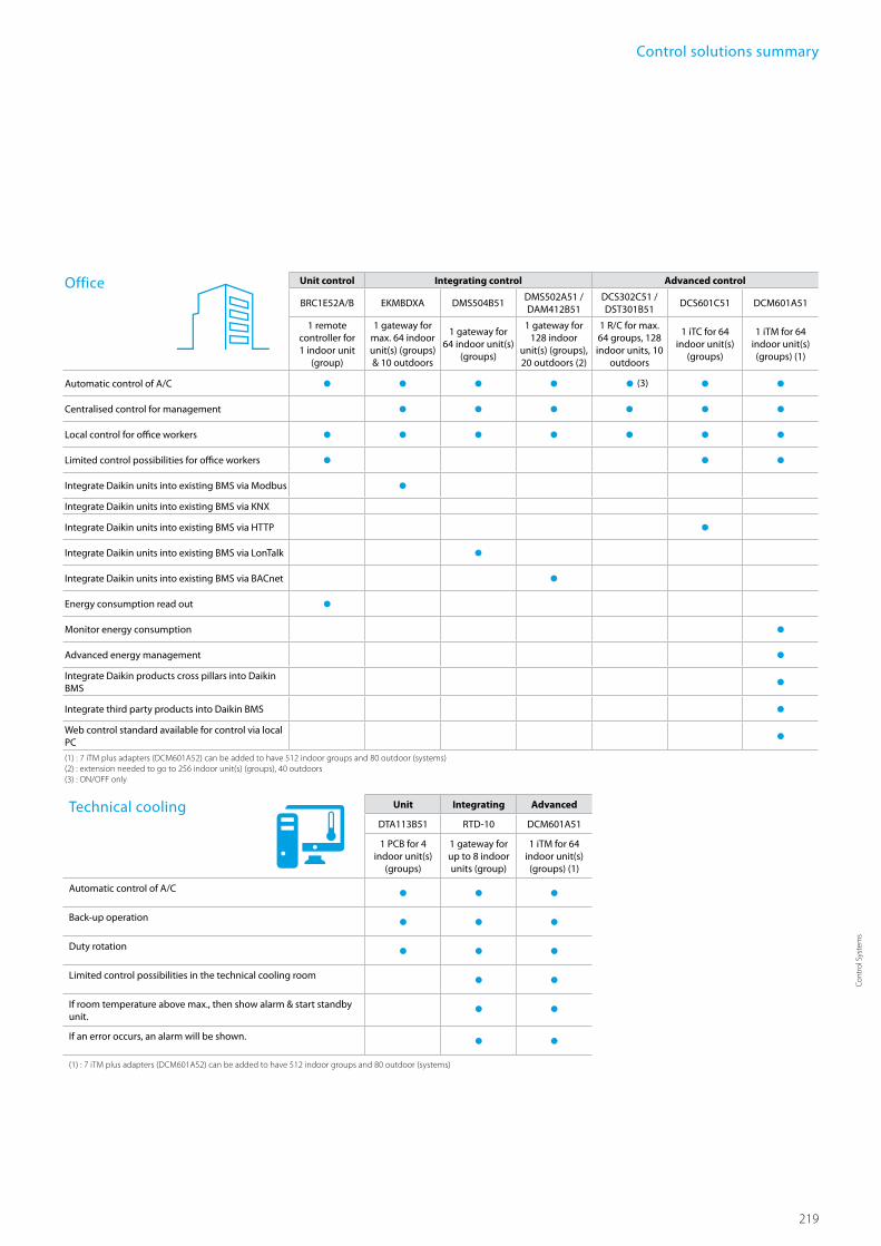
219
Cont
rol S
yste
ms
Technical cooling Unit Integrating Advanced
DTA113B51 RTD-10 DCM601A51
1 PCB for 4 indoor unit(s)
(groups)
1 gateway for up to 8 indoor units (group)
1 iTM for 64 indoor unit(s) (groups) (1)
Automatic control of A/C Back-up operation Duty rotation Limited control possibilities in the technical cooling room If room temperature above max., then show alarm & start standby unit. If an error occurs, an alarm will be shown. (1) : 7 iTM plus adapters (DCM601A52) can be added to have 512 indoor groups and 80 outdoor (systems)
Office Unit control Integrating control Advanced control
BRC1E52A/B EKMBDXA DMS504B51DMS502A51 / DAM412B51
DCS302C51 / DST301B51
DCS601C51 DCM601A51
1 remote controller for 1 indoor unit
(group)
1 gateway for max. 64 indoor unit(s) (groups) & 10 outdoors
1 gateway for 64 indoor unit(s)
(groups)
1 gateway for 128 indoor
unit(s) (groups), 20 outdoors (2)
1 R/C for max. 64 groups, 128 indoor units, 10
outdoors
1 iTC for 64 indoor unit(s)
(groups)
1 iTM for 64 indoor unit(s) (groups) (1)
Automatic control of A/C (3) Centralised control for management Local control for office workers Limited control possibilities for office workers Integrate Daikin units into existing BMS via Modbus Integrate Daikin units into existing BMS via KNX
Integrate Daikin units into existing BMS via HTTP Integrate Daikin units into existing BMS via LonTalk Integrate Daikin units into existing BMS via BACnet Energy consumption read out Monitor energy consumption Advanced energy management Integrate Daikin products cross pillars into Daikin BMS Integrate third party products into Daikin BMS Web control standard available for control via local PC (1) : 7 iTM plus adapters (DCM601A52) can be added to have 512 indoor groups and 80 outdoor (systems) (2) : extension needed to go to 256 indoor unit(s) (groups), 40 outdoors (3) : ON/OFF only
Control solutions summary

220
BRC944B2*/BRC1D52
Wired remote control Ű Schedule timer:Five day actions can be set as follows:
• set point: unit is switched ON and normal operation is maintained
• OFF: unit is switched OFF1• limits: unit is switched ON and min./max.
control (cf. limit operation for more details) Ű Home leave (frost protection): during absence, the indoor temperature can be maintained at a certain level. This function can also switch the unit ON/OFF
Ű User friendly HRV function, thanks to the introduction of a button for ventilation mode and fan speed
Ű Constantly monitoring of the system for malfunctions in a total of 80 components
Ű Immediate display of fault location and condition Ű Reduction of maintenance time and costs
ARC4*/BRC4*/BRC7*
Infrared remote controlOperation buttons: ON / OFF, timer mode start / stop, timer mode on / off, programme time, temperature setting, air flow direction (1), operating mode, fan speed control, filter sign reset (2), inspection (2)/ test indication (2)
Display: Operating mode, battery change, set temperature, air flow direction (1), programmed time, fan speed, inspection / test operation (2)
1. Not applicable for FXDQ, FXSQ, FXNQ, FBDQ, FDXS, FBQ
2. For FX** units only
3. For all features of the remote control, refer to the operation manual
Ű Symbol driven interface for intuitive control Ű Functions restricted to basic customer needs Ű Contemporary design Ű Energy saving thanks key card, window contact integration and set point limitation
Ű Flexible setback function ensures room temperature remains within comfortable limits to ensure guest comfort
Ű Flat backpanel for easy installation
Ű Easy commissioning: intuitive interface for advanced menu settings
Ű 2 versions available:• Heat pump type: temperature,
fan speed, ON/OFF• Heat recovery type: temperature,
mode, fan speed, ON/OFF Ű Replaces existing BRC2C51 & BRC3A61
Individual control systems
BRC2E52A / BRC3E52A
BRC4*/BRC7*ARC466A1
BRC1D52 BRC944B2
Simplified wired remote control developed for hotel applications
Display
Ű Operating mode1
Ű Heat Recovery Ventilation (HRV) in operation Ű Cool / heat changeover control Ű Centralised control indication Ű Group control indication Ű Set temperature1
Ű Air flow direction1
Ű Programmed time Ű Inspection test / operation Ű Fan speed1
Ű Clean air filter Ű Defrost / hot start Ű Malfunction
1 Only functions marked with ‘1’ are available on BRC944B2

221
Cont
rol S
yste
ms
Graphical display of indicative
electricity consumption
(Function available in
combination with FCQG and
FCGHQ)
User friendly remote control with contemporary designBRC1E52A/B
A series of energy saving functions that can be individually selected
› Temperature range limit › Setback function › Presence & floor sensor connection (available on new round flow cassette)
› kWh indication › Set temperature auto reset › Off timer
Temperature range limit avoids excessive heating or cooling
Save energy by constraining the lower temperature limit in cooling and upper temperature limit in heating mode.note : Also available in auto cooling/heating change over mode.
kWh indication keeps track of your consumption
The kWh indication shows an indicative electricity consumption of the last day/month/year.
Other functions
› Up to 3 independent schedules can be set, so the user can easily change the schedule himself throughout the year (e.g. Summer, winter, mid-season)
› Possibility to individually restrict menu functions Easy to use: all main functions directly accessible
› Easy setup: clear graphical user interface for advanced menu settings
› Real time clock with auto update to daylight saving time
› Built-in backup power: when a power failure occurs all settings remain stored up to 48 hours
› Supports multiple languages English, German, Dutch, Spanish, Italian, Portuguese, French, Greek, Russian, Turkish, Polish (BRC1E52A)English, German, Czech, Croatian, Hungarian, Romanian, Slovenian, Bulgarian, Slovak, Serbian, Albanian (BRC1E52B)

222
Centralised control systems
Centralised control of the Sky Air and VRV system can be achieved via 3 user friendly compact. These controls may be used independently or in combination with 1 group = several (up to 16) indoor units in combination and 1 zone = several groups in combination.A centralised remote control is ideal for use in tenanted commercial buildings subject to random occupation, enabling indoor units to be classified in groups per tenant (zoning). The schedule timer programmes the schedule and operation conditions for each tenant and the control can easily be reset according to varying requirements.
DCS302C51
Centralised remote controlProviding individual control of 64 groups (zones) of indoor units. › a maximum of 64 groups (128 indoor units, max. 10 outdoor units) can be controlled
› a maximum of 128 groups (128 indoor units, max. 10 outdoor units) can be controlled via 2 centralised remote controls in separate locations
› zone control › group control › malfunction code display › maximum wiring length of 1,000m (total: 2,000m) › air flow direction and air flow rate of HRV can be controlled › expanded timer function
DCS301B51
Unified ON/OFF controlProviding simultaneous and individual control of 16 groups of indoor units.
› a maximum of 16 groups (128 indoor units) can be controlled › 2 remote controls in separate locations can be used › operating status indication (normal operation, alarm) › centralised control indication › maximum wiring length of 1,000m (total: 2,000m)
DST301B51
Schedule timer
Enabling 64 groups to be programmed.
› a maximum of 128 indoor units can be controlled › 8 types of weekly schedule › a maximum of 48 hours back up power supply › a maximum wiring length of 1,000m (total: 2,000m)

223
Cont
rol S
yste
ms
Centralised control systems
DTA113B51
Basic solution for control of Sky Air and VRV
› Rotation function › Backup operation function.
BRC1D52
DCS601C51
Detailed & easy monitoring and operation of VRV systems (max. 64 indoor units groups).
Public line
Air conditioning
Network Service
System
third party controller (domotics, BMS, etc.)
Ethernet
DIII-NET
Forced OFF contact input
Onboard
modem
Fire alarm
Indoor units
DCS601C51
HRV
Languages › English › French › German › Italian › Spanish › Dutch › Portuguese
System layout › Up to 64 indoor units can be controlled
› Touch panel (full colour LCD via icon display)
Management › Enhanced history function
Control › Individual control (set point, start/stop, fan speed) (max. 64 groups/indoor units)
› Set back shedule › Enhanced scheduling func-tion (8 schedules, 17 patterns)
› Flexible grouping in zones › Yearly schedule › Fire emergency stop control › Interlocking control › Increased HRV monitoring and control function
› Automatic cooling / heating change-over
› Heating optimization › Temperature limit › Password security: 3 levels (general, administration & service)
› Quick selection and full control
› Simple navigation
Monitoring › Visualisation via Graphical User Interface (GUI)
› Icon colour display change function
› Indoor units operation mode › Indication filter replacement
Cost performance › Free cooling function › Labour saving › Easy installation › Compact design: limited installation space
› Overall energy saving
Open interface › Communication to any third party controller (domotics, BMS, etc.) is possible via open interface (http option)
Connectable to › VRV › HRV › Sky Air › Split (via interface adapter)
Up to 4 units / 1 adapter
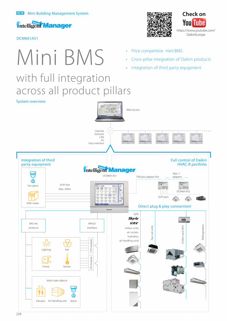
224
Mini Building Management System
Mini BMSwith full integration across all product pillarsSystem overview
NEW
• Price competitive mini BMS
• Cross-pillar integration of Daikin products
• Integration of third party equipment
Direct plug & play connection!
Lighting Fan
SensorPump
Fire alarm
kWh meter
Di/Pi line
Max. 200m
indoor units,
air curtain,
hydrobox,
air handling units
Web Access
Fan
coil
units
Chi
llers
and
AH
U
Refe
riger
atio
n
Internet Extranet
LAN3G
http interface
Split
I/O
mod
ule
I/O
mod
ule
WAGO
interface
BACnet
protocol
Integration of third party equiqment
Full control of DaikinHVAC-R portfolio
DCM601A51
Multi state objects
AlarmElevator Air handling unit
ITM plus adaptor lineMax. 7 adapters
DCM601A52
Di/Pi port
DCM601A51
Check on
https://www.youtube.com/DaikinEurope
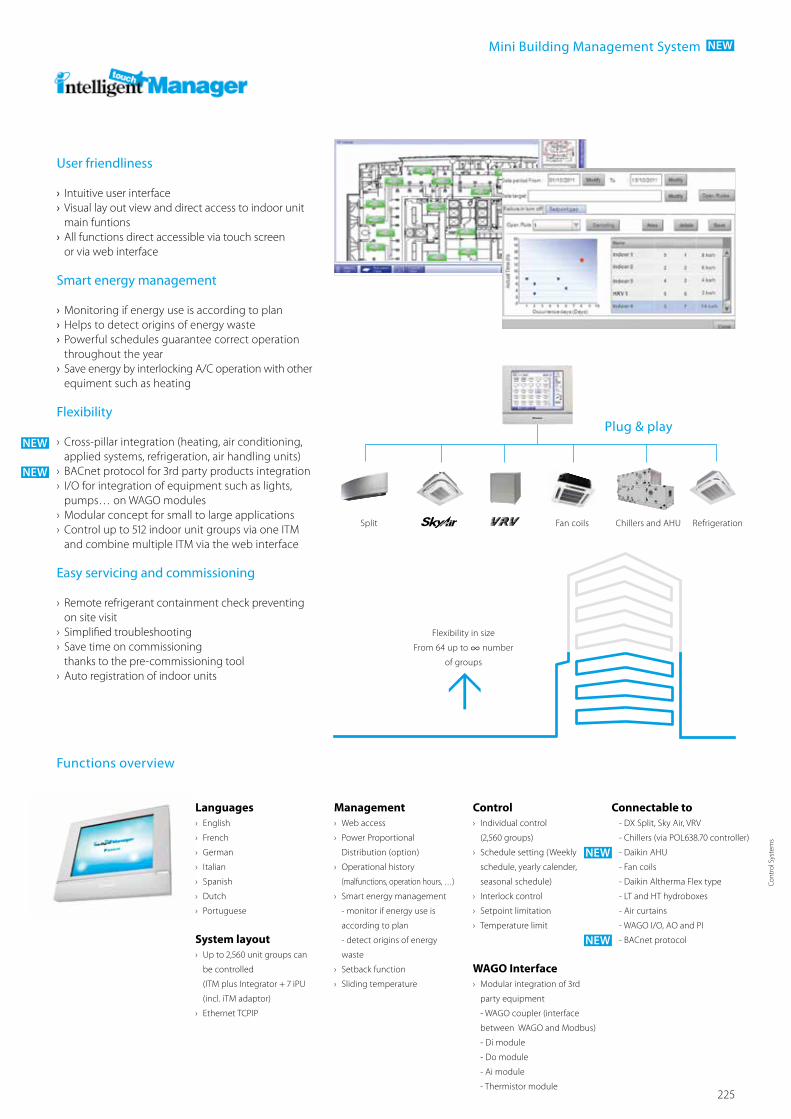
225
Cont
rol S
yste
ms
Plug & play
Mini Building Management System NEW
User friendliness › Intuitive user interface › Visual lay out view and direct access to indoor unit main funtions
› All functions direct accessible via touch screen or via web interface
Smart energy management
› Monitoring if energy use is according to plan › Helps to detect origins of energy waste › Powerful schedules guarantee correct operation throughout the year
› Save energy by interlocking A/C operation with other equiment such as heating
Flexibility
› Cross-pillar integration (heating, air conditioning, applied systems, refrigeration, air handling units)
› BACnet protocol for 3rd party products integration › I/O for integration of equipment such as lights, pumps… on WAGO modules
› Modular concept for small to large applications › Control up to 512 indoor unit groups via one ITM and combine multiple ITM via the web interface
Easy servicing and commissioning
› Remote refrigerant containment check preventing on site visit
› Simplified troubleshooting › Save time on commissioning thanks to the pre-commissioning tool
› Auto registration of indoor units
Functions overview
Languages › English
› French
› German
› Italian
› Spanish
› Dutch
› Portuguese
Management › Web access
› Power Proportional
Distribution (option)
› Operational history
(malfunctions, operation hours, …)
› Smart energy management
- monitor if energy use is
according to plan
- detect origins of energy
waste
› Setback function
› Sliding temperature
System layout › Up to 2,560 unit groups can
be controlled
(ITM plus Integrator + 7 iPU
(incl. iTM adaptor)
› Ethernet TCPIP
Control › Individual control
(2,560 groups)
› Schedule setting (Weekly
schedule, yearly calender,
seasonal schedule)
› Interlock control
› Setpoint limitation
› Temperature limit
Connectable to- DX Split, Sky Air, VRV
- Chillers (via POL638.70 controller)
- Daikin AHU
- Fan coils
- Daikin Altherma Flex type
- LT and HT hydroboxes
- Air curtains
- WAGO I/O, AO and PI
- BACnet protocol
WAGO Interface › Modular integration of 3rd
party equipment
- WAGO coupler (interface
between WAGO and Modbus)
- Di module
- Do module
- Ai module
- Thermistor module
NEW
NEW
NEW
NEW
Flexibility in size
From 64 up to ∞ number
of groups
Split Fan coils Chillers and AHU Refrigeration

226
RTD-RA › Modbus interface for monitoring and controlling residential indoor units
RTD-NET › Modbus interface for monitoring and controlling Sky Air, VRV, VAM and VKM
RTD-10 › Advanced integration into BMS of Sky Air, VRV, VAM and VKM through either:• Modbus• Voltage (0-10V)• Resistance
› Duty/standby function for server rooms
RTD-20 › Advanced control of Sky Air, VRV, VAM/VKM and air curtains
› Cloned or independent zone control › Increased comfort with integration of CO2 sensor for fresh air volume control
› Save on running costs via• pre/post and trade mode• setpoint limitation• overall shut down• PIR sensor for adaptive deadband
RTD-HO › Modbus interface for monitoring and controlling Sky Air, VRV, VAM and VKM
› Intelligent hotel room controller
RTD
Standard protocol interfaces
Modbus Interface Integration of RA, Sky Air, VRV, in BMS or home automation systems

227
Cont
rol S
yste
ms
Main functions RTD-RA RTD-NET RTD-10 RTD-20 RTD-HODimensions H x W x D mm 80 x 80 x 37,5 100 x100 x 22Key card + window contact Set back function Prohibit or restrict remote control functions (setpoint limitation, ...) ** Modbus (RS485) Group control (1) 0 - 10 V control Resistance control IT application Heating interlock Output signal (on/defrost, error) **** Retail application Partitioned room control Air curtain *** ***
(1): By combining RTD-RA devices
Overview functions
Control functions RTD-RA RTD-NET RTD-10 RTD-20 RTD-HOOn/Off M,C M M,V,R M M*Set point M M M,V,R M M*Mode M M M,V,R M M*fan M M M,V,R M M*Louver M M M,V,R M M*HRV Damper control M M,V,R MProhibit/Restrict functions M M M,V,R M M*Forced thermo off M
Monitoring functions RTD-RA RTD-NET RTD-10 RTD-20 RTD-HOOn/Off M M M M MSet point M M M M MMode M M M M Mfan M M M M MLouver M M M M MRC temperature M M M MRC mode M M M Mnbr units M M M MFault M M M M MFault code M M M M MReturn air temperature (Average /Min/Max) M M M M MFilter alarm M M M MTermo on M M M M MDefrost M M M MCoil In/Out temperature M M M M M
M : Modbus / R : Resistance / V : Voltage / C: control* : only when room is occupied / ** : setpoint limitation / (*) if available *** : no fan speed control on the CYV air curtain / **** : run & fault
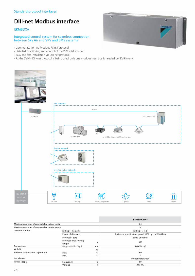
228
EKMBDXA7V1
Maximum number of connectable indoor units 64
Maximum number of connectable outdoor units 10Communication DIII-NET - Remark DIII-NET (F1F2)
Protocol - Remark 2 wire; communication speed: 9600 bps or 19200 bps
Protocol - Type RS485 (modbus)Protocol - Max. Wiring length
m 500
Dimensions HeightxWidthxDepth mm 124x379x87Weight kg 2.1Ambient temperature - operation Max. °C 60
Min. °C 0Installation Indoor installationPower supply Frequency Hz 50
Voltage V 220-240
Standard protocol interfaces
DIII-net Modbus interfaceEKMBDXA
Integrated control system for seamless connection between Sky Air and VRV and BMS systems
› Communication via Modbus RS485 protocol › Detailed monitoring and control of the VRV total solution › Easy and fast installation via DIII-net protocol › As the Daikin DIII-net protocol is being used, only one modbus interface is needed per Daikin unit
EKMBDXA
DIII- NET
VRV Outdoor unit
HRV
up to 256 units connectable per interface*via EKEQ box
VRV network
Lighting
Sky Air network
Inverter chiller network
PumpFire alarm ElevatorSecurity Power supply facility
Building control
network

229
Cont
rol S
yste
ms
KLIC-DD Size 45x45x15mm KLIC-DI Size 90x60x35mmSplit Sky Air VRV
Basic controlOn/Off • • •Mode Auto, heat, dry, fan, cool Auto, heat, dry, fan, cool Auto, heat, dry, fan, coolTemperature • • •Fan speed levels 3 or 5 + auto 2 or 3 2 or 3Swing Stop or movement Stop or movement Swing or fixed positions (5)
Advanced functionalitiesError management Communication errors, Daikin unit errorsScenes • • •Auto switch off • • •Temperature limitation • • •Initial configuration • • •Master and slave configuration • •
KNX interface
Standard protocol interfaces
KLIC-DDKLIC-DI
Integration of Split, Sky Air and VRV in HA/BMS systems
Connect split indoor units to KNX interface for Home Automation system
shutter control
house
Con
cept
Con
cept
Domotica
Controller
Connect Sky Air / VRV indoor units to KNX interface for BMS integration
KNX interface line-upThe integration of Daikin indoor units through the KNX interface allows monitoring and control of several devices, such as lights and shutters, from one central controller. One particularly important feature is the ability to programme a ‘scenario’ - such as “Home leave” - in which the end-user selects
light
light
shutter control
shop
KNX interface for
Interface Daikin protocol/ KNX
Interface Daikin protocol/ KNX
tv
tv
a range of commands to be executed simultaneously once the scenario is selected. For instance in “Home leave” , the air conditioner is off, the lights are turned off, the shutters are closed and the alarm is on.
Domotica
Controller

230
Standard protocol interfaces
Integrated control system for seamless connection between VRV, applied systems, air handling units and BMS systems
Applied systems network
› Interface for BMS system › Communication via BACnet protocol (connection via Ethernet)
› Unlimited sitesize › Easy and fast installation › PPD data is available on BMS system (only for VRV)
BAC
NET
/ E
THER
NET
Fire alarm Security
Local Control
DIII- NET
VRV Outdoor unit
Remote Control
Power supply facility
Pump Lighting Elevator
HRV
DMS502A51
up to 256 units connectable per interface
Building
control
network
BMS
EKACBACMSTP
Serial sequencing
panel
EKDSSP-S
EKCMBACIP
EKCMBACMSTP
Air handling unit network
VRV network
Serial Card
BACnet MSTP
EKCM200J EKCM200J EKCM200J
BACnet Interface
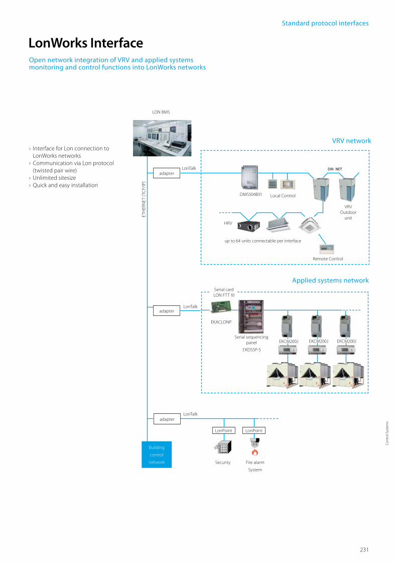
231
Cont
rol S
yste
ms
VRV network
Open network integration of VRV and applied systems monitoring and control functions into LonWorks networks
› Interface for Lon connection to LonWorks networks
› Communication via Lon protocol (twisted pair wire)
› Unlimited sitesize › Quick and easy installation
LON BMS
DMS504B51
up to 64 units connectable per interface
Local Control
DIII- NET
VRV Outdoor
unitHRV
Remote Control
Building
control
network
ETH
ERN
ET (
TCP/
IP)
adapterLonTalk
LonTalk
Fire alarm
System
Security
LonPoint LonPoint
adapter
adapterLonTalk
Applied systems network
EKACLONP
Serial sequencing panel
EKDSSP-S
Serial card LON FTT 10
EKCM200J EKCM200J EKCM200J
LonWorks Interface
Standard protocol interfaces

232
Daikin Configurator Software
Daikin Configurator Software
Simplified
commissioning
Retrieve initial
system settings
Simplified commissioning: graphical interface to configure, commission and upload system settings
Simplified commissioningThe Daikin configurator for Daikin Altherma and VRV is an advanced software solution that allows for easy system configuration and commissioning:
› Less time is required on the roof configuring the outdoor unit
› Multiple systems at different sites can be managed in exactly the same way, thus offering simplified commissioning for key accounts
› Initial settings on the outdoor unit can be easily retrieved
EKPCCAB3

233
Cont
rol S
yste
ms

234
What does I-Net offer youSafeguarding the lifelong optimum operation of your air conditioning system means getting geared up to operate the system in a energy efficient way and reduce unexpected breakdowns and costs to the absolute minimum. This is where I-Net helps to improve the effectiveness of your building management.
I-Net is about ‘being connected’ with Daikin, the Internet-based link between you, your air conditioning system and Daikin’s Remote Monitoring Centre. This allows you to monitor your energy consumption and Daikin’s expert service engineers to monitor your entire system’s status non-stop, all year round. Through predicting malfunctions and offering technical advice from data analysis, you can maximiseequipment uptime, as well as controlling energy costs with no sacrifice in comfort levels. By doing this, i-Net will prevent problems, prolong your system’s service life while reducing the energy bill.
What is I-Net?A service based on our global remote monitoring technology, keeping your system trouble-free and working with top efficiency.
I-Net Servicesi-Net consists of 2 main services: the VRV Cloud and I-Net performance monitoring and analysis.
VRV Cloud
The VRV Cloud puts you in the driving seat of your energy management. The easy-to-use energy data trending and analytic tools puts you in control and shows you CO2 footprint reduction opportunities and energy savings of up to 15%.
Saving starts by measuring. Enhance your company’s sustainability !
I-Net performance monitoring and analysis
Focus on your core business and hand the HVAC over to Daikin. Daikin I-Net connects your system continuously with Daikin. It notifies alarms and early warnings of system deviations to maximise system uptime and the comfort of the people in the building. Service providers have webbased access to operation data so that they are fully prepared when they arrive on-site. Specialists run trend analyses. All of which boosts your system’s reliability by ensuring that it is running at optimum efficiency.
24/7
CLOUD
I-Net performance monitoring
and analysis

235
Cont
rol S
yste
ms
Daikin VRV Cloud Helps you manage your energy through Daikin technology. › Intelligent energy visualization tool that helps you with your energy management
› 24/7 online monitoring by the customer from any location.
› User friendly visualization of VRV energy management (kWh)
› Analysis support of waste operation › Multiple site monitoring
Performance monitoringDaikin’s unique I-Net Service aims to prevent the equipment coming to an unexpected stop or needing emergency repair.
Fast response, better prepared
› If an alarm does occur, the service provider is immediately alerted and receives all crucial information.
› Early fault indication (predictions) : operation data are 24/7 checked by I-Net prediction algorithms to act as early as possible, averting unscheduled breakdowns.
24/7
Information to:
› customers
› service company
Monitor your energy
managment.
Performance supervision
and analysis
Data server
Internet
Prediction analysis
Data trend logging
Connection with I-Net via
ITM, PCASO, ...
CLOUD
› Performance Supervision by Daikin experts enhances a maintenance plan.
› This service aims to enhance the service level, to respond fast and accurate, to save on unexpected repair costs and assure the peace of mind. Repetitive interventions and disturbance of building tenants and maintenance teams are kept to a minimum.
Long lifetime systems
› I-Net will maximise the installation’s lifetime, by assuring the equipment runs in optimal conditions and avoid unnecessary stress on components.
AnalysisBe connected with Daikin’s experts, this gives you a clear overview of operability and use of the air conditioning system. › Daikin continuously monitors energy, operation and comfort data. Thanks to periodic analysis of the data, Daikin can suggest ways of improving performance.
› if there is a problem, Daikin specialists will analyse the operation data history to provide remote support.
Controller

236
Room sensors
Wireless room temperature sensor
Connection diagram Daikin indoor unit PCB (FXSQ-P example)
Flexible and easy installation
› Accurate temperature measurement thanks to flexible placement of the sensor
› No need for wiring › No need to drill holes › Ideal for refurbishment
Air sensor – X16A, X19
Power supply – X35, X13
RF senderRf Receiver
› Room temperature is sent to the indoor unit every 90 seconds or if the temperature difference is 0.2°C or larger.
Wireless room temperature sensor kit (K.RSS)Wireless room temperature receiver Wireless room temperature sensor
Dimensions mm 50 x 50 ø 75Weight g 40 60Power supply 16VDC, max. 20 mA N/ABattery life N/A +/- 3 yearsBattery type N/A 3 Volt Lithium batteryMaximum range m 10Operation range °C 0~50
CommunicationType RFFrequency MHz 868.3
Specifications
Wired room temperature sensor
› Accurate temperature measurement, thanks to flexible placement of the sensor
Dimensions (HxW) mm 60 x 50Weight g 300Length of branch wiring m 12
Specifications
KRCS01-1BKRCS01-4B
K.RSS

237
Cont
rol S
yste
ms
Other integration devices
Daikin’s adapter PCBs provide simple solutions for unique requirements. They are a low cost option to satisfy simple control requirements and can be used on single or multiple units.
(E)KRP1B*adapter for wiring
• Facilitates integration of auxiliary heating apparatus, humidifiers, fans, damper• Powered by and installed at the indoor unit
KRP2A*/KRP4A*Wiring adapter for
electrical appendices
• Remotely start and stop up to 16 indoor units (1 group) (KRP2A* via P1 P2)• Remotely start and stop up to 128 indoor units (64 groups) (KRP4A* via F1 F2) • Alarm indication/ fire shut down• Remote temperature setpoint adjustment
DTA104A*Outdoor Unit External
Control Adapter
• Individual or simultaneous control of VRV system operating mode• Demand control of individual or multiple systems• Low noise option for individual or multiple systems
KRP928*Interface adapter for
DIII-net • Allows integration of split units to Daikin central controls
KRP413*Wiring adapter normal open contact / normal
open pulse contact
• Switch off auto restart after power failure• Indication of operation mode / error• Remotely start /stop• Remotely change operation mode• Remotely change fan speed
KRP980*Adapter for split units
without an S21 port
• Connect a wired remote control• Connect to Daikin central controls• Allow external contact
Concept and benefits
› Low cost option to satisfy simple control requirements › Deployed on single or multiple units
ADAPTER PCBs
Simple solutions for unique requirements

238
Options & accessories
AUTO-CLEANING PANEL
INTELLIGENT SENSORS
FILTERS

239
Options & accessoriesVRV outdoor 240VRV indoor 242Stylish indoor 246Ventilation & Hot Water 248Control Systems 251
Opt
ions
& A
cces
sorie
s
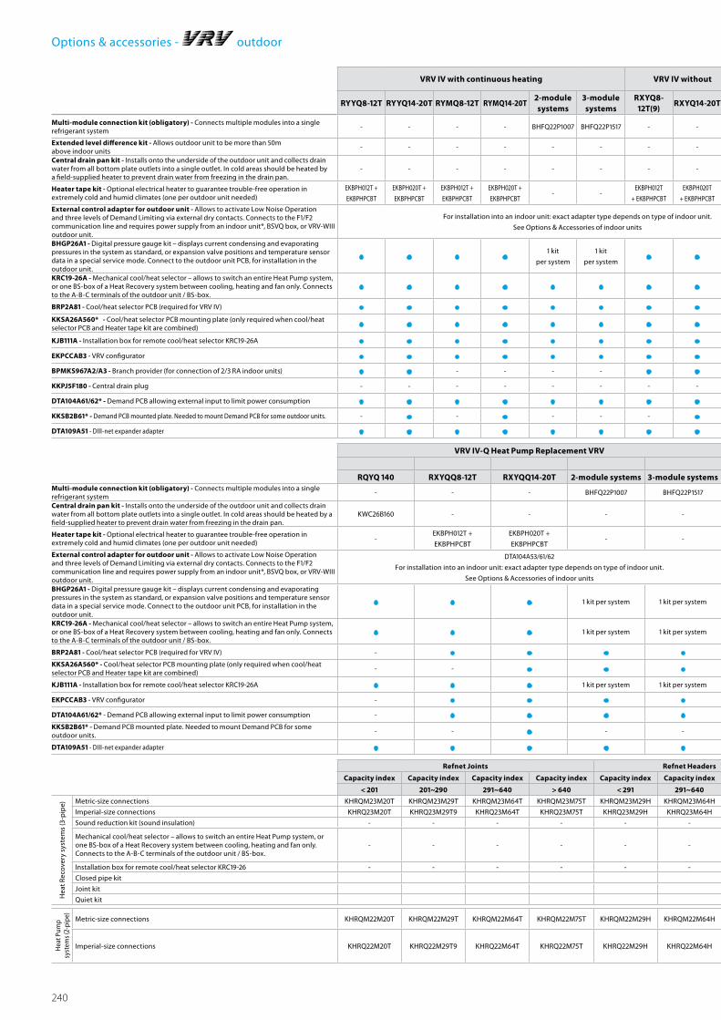
240
Options & accessories - outdoor
VRV IV with continuous heating VRV IV without continuous heatingVRV III-SMini VRV
VRV III-C Cold Region VRV VRV Classic VRV IV Heat Recovery
RYYQ8-12T RYYQ14-20T RYMQ8-12T RYMQ14-20T2-module systems
3-module systems
RXYQ8-12T(9)
RXYQ14-20T2-module systems
3-module systems
RXYSQ RTSYQ 10 RTSYQ 14~16 RTSYQ 20 RXYCQ8A RXYCQ10-14A RXYCQ16-20A REYQ 8~12 REYQ 14~20 REMQ52-module systems
3-module systems
Multi-module connection kit (obligatory) - Connects multiple modules into a single refrigerant system
- - - - BHFQ22P1007 BHFQ22P1517 - - BHFQ22P1007 BHFQ22P1517 - - - BHFQ22P1007 - - - - - - BHFQ23P907 BHFQ23P1357
Extended level difference kit - Allows outdoor unit to be more than 50m above indoor units
- - - - - - - - - - - - - - - - - Special order unit
Central drain pan kit - Installs onto the underside of the outdoor unit and collects drain water from all bottom plate outlets into a single outlet. In cold areas should be heated by a field-supplied heater to prevent drain water from freezing in the drain pan.
- - - - - - - - - - - KWC26B280 KWC26B450 2x KWC26B280 KWC26B160 KWC26B280 KWC26B450 - - - - -
Heater tape kit - Optional electrical heater to guarantee trouble-free operation in extremely cold and humid climates (one per outdoor unit needed)
EKBPH012T +
EKBPHPCBT
EKBPH020T +
EKBPHPCBT
EKBPH012T +
EKBPHPCBT
EKBPH020T +
EKBPHPCBT- -
EKBPH012T
+ EKBPHPCBT
EKBPH020T
+ EKBPHPCBT- - - BEH22A10Y1L BEH22A18Y1L 2x BEH22A10Y1L - - -
EKBPH012T +
EKBHPCBT
EKBPH020T +
EKBHPCBT
EKBPH012T +
EKBHPCBT- -
External control adapter for outdoor unit - Allows to activate Low Noise Operation and three levels of Demand Limiting via external dry contacts. Connects to the F1/F2 communication line and requires power supply from an indoor unit*, BSVQ box, or VRV-WIII outdoor unit.
For installation into an indoor unit: exact adapter type depends on type of indoor unit.
See Options & Accessories of indoor units
For installation into an indoor unit: exact adapter type depends on type of indoor unit.
See Options & Accessories of indoor units
BHGP26A1 - Digital pressure gauge kit – displays current condensing and evaporating pressures in the system as standard, or expansion valve positions and temperature sensor data in a special service mode. Connect to the outdoor unit PCB, for installation in the outdoor unit.
• • • •1 kit
per system
1 kit
per system • •1 kit
per system
1 kit
per system- • • • • • • • • •
1 kit
per system
1 kit
per system
KRC19-26A - Mechanical cool/heat selector – allows to switch an entire Heat Pump system, or one BS-box of a Heat Recovery system between cooling, heating and fan only. Connects to the A-B-C terminals of the outdoor unit / BS-box.
• • • • • • • • • • • - - - • • • - - - - -
BRP2A81 - Cool/heat selector PCB (required for VRV IV) • • • • • • • • • • - - - - - - - - - - - -
KKSA26A560* - Cool/heat selector PCB mounting plate (only required when cool/heat selector PCB and Heater tape kit are combined) • • • • • • • • • • - - - - - - - - - - - -
KJB111A - Installation box for remote cool/heat selector KRC19-26A • • • • • • • • • • • - - - • • • - - - - -
EKPCCAB3 - VRV configurator • • • • • • • • • • - - - - - - - • • • • •BPMKS967A2/A3 - Branch provider (for connection of 2/3 RA indoor units) • • - - - - • • - - • - - - - - - - - - - -
KKPJ5F180 - Central drain plug - - - - - - - - - - • - - - - - - - - - - -
DTA104A61/62* - Demand PCB allowing external input to limit power consumption • • • • • • • • • • - - - - - - - - - - - -
KKSB2B61* - Demand PCB mounted plate. Needed to mount Demand PCB for some outdoor units. - • - • - - - • - - - - - - - - - - - - - -
DTA109A51 - DIII-net expander adapter • • • • • • • • • • • • • • • • • • • • • •
VRV IV-Q Heat Pump Replacement VRVVRV III-Q Heat Recovery Replacement VRV
VRV-W IV Water-cooled VRV
Heat Pump application Heat Recovery application
RQYQ 140 RXYQQ8-12T RXYQQ14-20T 2-module systems 3-module systems RQEQ 140~212 2-module systems 3-module systems 4-module systems RWEYQ8-10T 2-module systems 3-module systems 2-module systems 3-module systemsMulti-module connection kit (obligatory) - Connects multiple modules into a single refrigerant system
- - - BHFQ22P1007 BHFQ22P1517 - BHFP26P36C BHFP26P63C BHFP26P84C - BHFQ22P1007 BHFQ22P1517 BHFQ23P907 BHFQ23P1357
Central drain pan kit - Installs onto the underside of the outdoor unit and collects drain water from all bottom plate outlets into a single outlet. In cold areas should be heated by a field-supplied heater to prevent drain water from freezing in the drain pan.
KWC26B160 - - - - KWC26B160 1 kit per module 1 kit per module 1 kit per module - - - - -
Heater tape kit - Optional electrical heater to guarantee trouble-free operation in extremely cold and humid climates (one per outdoor unit needed)
-EKBPH012T +
EKBPHPCBT
EKBPH020T +
EKBPHPCBT- - - - - - - - - - -
External control adapter for outdoor unit - Allows to activate Low Noise Operation and three levels of Demand Limiting via external dry contacts. Connects to the F1/F2 communication line and requires power supply from an indoor unit*, BSVQ box, or VRV-WIII outdoor unit.
DTA104A53/61/62
For installation into an indoor unit: exact adapter type depends on type of indoor unit.
See Options & Accessories of indoor units
DTA104A53/61/62
For installation into an indoor unit: exact adapter type depends on type of indoor unit.
See Options & Accessories of indoor units
DTA104A62
Installation in the RWEYQ outdoor unit possible. For installation in indoor units, use appropriate type (DTA104A53/61/62)
for particular indoor unit. See Options & Accessories of indoor units
BHGP26A1 - Digital pressure gauge kit – displays current condensing and evaporating pressures in the system as standard, or expansion valve positions and temperature sensor data in a special service mode. Connect to the outdoor unit PCB, for installation in the outdoor unit.
• • • 1 kit per system 1 kit per system • 1 kit per system 1 kit per system 1 kit per system - - - - -
KRC19-26A - Mechanical cool/heat selector – allows to switch an entire Heat Pump system, or one BS-box of a Heat Recovery system between cooling, heating and fan only. Connects to the A-B-C terminals of the outdoor unit / BS-box.
• • • 1 kit per system 1 kit per system - - - - • 1 kit per system 1 kit per system - -
BRP2A81 - Cool/heat selector PCB (required for VRV IV) - • • • • - - - - • 1 kit per system 1 kit per system - -
KKSA26A560* - Cool/heat selector PCB mounting plate (only required when cool/heat selector PCB and Heater tape kit are combined)
- - • • • - - - - - - - - -
KJB111A - Installation box for remote cool/heat selector KRC19-26A • • • 1 kit per system 1 kit per system - - - - • 1 kit per system 1 kit per system - -
EKPCCAB3 - VRV configurator - • • • • - - - - • • • • •DTA104A61/62* - Demand PCB allowing external input to limit power consumption - • • • • - - - - - - - - -
KKSB2B61* - Demand PCB mounted plate. Needed to mount Demand PCB for some outdoor units.
- - • - - - - - - - - - - -
DTA109A51 - DIII-net expander adapter • • • • • • • • • • • • • •
Refnet Joints Refnet Headers Heat Recovery Branch Selector Boxes (BS-Boxes)
Capacity index Capacity index Capacity index Capacity index Capacity index Capacity index Capacity index 1-port 1-port 4-port 4-port 6-port 6-port 8-port 10-port 12-port 16-port
< 201 201~290 291~640 > 640 < 291 291~640 > 640 - - - - - - - - - -
Hea
t Rec
over
y sy
stem
s (3
-pip
e) Metric-size connections KHRQM23M20T KHRQM23M29T KHRQM23M64T KHRQM23M75T KHRQM23M29H KHRQM23M64H KHRQM23M75H - - - - - - - - -Imperial-size connections KHRQ23M20T KHRQ23M29T9 KHRQ23M64T KHRQ23M75T KHRQ23M29H KHRQ23M64H KHRQ23M75H BS1Q-A BSVQ-P8B BS4Q14A BSV4Q100PV BS6Q14A BSV6Q100PV BS8Q14A BS10Q14A BS12Q14A BS16Q14A
Sound reduction kit (sound insulation) - - - - - - - EKBSVQLNP EKBSVQLNP - - - -
Mechanical cool/heat selector – allows to switch an entire Heat Pump system, or one BS-box of a Heat Recovery system between cooling, heating and fan only. Connects to the A-B-C terminals of the outdoor unit / BS-box.
- - - - - - - - KRC19-26 -
KRC19-26
1 kit per port
necessary
-
KRC19-26
1 kit per port
necessary
Installation box for remote cool/heat selector KRC19-26 - - - - - - - - KJB111A - KJB111A - KJB111A
Closed pipe kit KHFP26A100C KHFP26A100C KHFP26A100C KHFP26A100C KHFP26A100C KHFP26A100C
Joint kit KHRP26A1250C KHRP26A1250C KHRP26A1250C KHRP26A1250C KHRP26A1250C KHRP26A1250C
Quiet kit KDDN26A4 KDDN26A8 KDDN26A8 KDDN26A12 KDDN26A12 KDDN26A16
Hea
t Pum
p sy
stem
s (2-
pipe
)
Metric-size connections KHRQM22M20T KHRQM22M29T KHRQM22M64T KHRQM22M75T KHRQM22M29H KHRQM22M64H KHRQM22M75H - - - - -
Imperial-size connections KHRQ22M20T KHRQ22M29T9 KHRQ22M64T KHRQ22M75T KHRQ22M29H KHRQ22M64H KHRQ22M75H - - - - -

241
VRV IV with continuous heating VRV IV without continuous heatingVRV III-SMini VRV
VRV III-C Cold Region VRV VRV Classic VRV IV Heat Recovery
RYYQ8-12T RYYQ14-20T RYMQ8-12T RYMQ14-20T2-module systems
3-module systems
RXYQ8-12T(9)
RXYQ14-20T2-module systems
3-module systems
RXYSQ RTSYQ 10 RTSYQ 14~16 RTSYQ 20 RXYCQ8A RXYCQ10-14A RXYCQ16-20A REYQ 8~12 REYQ 14~20 REMQ52-module systems
3-module systems
Multi-module connection kit (obligatory) - Connects multiple modules into a single refrigerant system
- - - - BHFQ22P1007 BHFQ22P1517 - - BHFQ22P1007 BHFQ22P1517 - - - BHFQ22P1007 - - - - - - BHFQ23P907 BHFQ23P1357
Extended level difference kit - Allows outdoor unit to be more than 50m above indoor units
- - - - - - - - - - - - - - - - - Special order unit
Central drain pan kit - Installs onto the underside of the outdoor unit and collects drain water from all bottom plate outlets into a single outlet. In cold areas should be heated by a field-supplied heater to prevent drain water from freezing in the drain pan.
- - - - - - - - - - - KWC26B280 KWC26B450 2x KWC26B280 KWC26B160 KWC26B280 KWC26B450 - - - - -
Heater tape kit - Optional electrical heater to guarantee trouble-free operation in extremely cold and humid climates (one per outdoor unit needed)
EKBPH012T +
EKBPHPCBT
EKBPH020T +
EKBPHPCBT
EKBPH012T +
EKBPHPCBT
EKBPH020T +
EKBPHPCBT- -
EKBPH012T
+ EKBPHPCBT
EKBPH020T
+ EKBPHPCBT- - - BEH22A10Y1L BEH22A18Y1L 2x BEH22A10Y1L - - -
EKBPH012T +
EKBHPCBT
EKBPH020T +
EKBHPCBT
EKBPH012T +
EKBHPCBT- -
External control adapter for outdoor unit - Allows to activate Low Noise Operation and three levels of Demand Limiting via external dry contacts. Connects to the F1/F2 communication line and requires power supply from an indoor unit*, BSVQ box, or VRV-WIII outdoor unit.
For installation into an indoor unit: exact adapter type depends on type of indoor unit.
See Options & Accessories of indoor units
For installation into an indoor unit: exact adapter type depends on type of indoor unit.
See Options & Accessories of indoor units
BHGP26A1 - Digital pressure gauge kit – displays current condensing and evaporating pressures in the system as standard, or expansion valve positions and temperature sensor data in a special service mode. Connect to the outdoor unit PCB, for installation in the outdoor unit.
• • • •1 kit
per system
1 kit
per system • •1 kit
per system
1 kit
per system- • • • • • • • • •
1 kit
per system
1 kit
per system
KRC19-26A - Mechanical cool/heat selector – allows to switch an entire Heat Pump system, or one BS-box of a Heat Recovery system between cooling, heating and fan only. Connects to the A-B-C terminals of the outdoor unit / BS-box.
• • • • • • • • • • • - - - • • • - - - - -
BRP2A81 - Cool/heat selector PCB (required for VRV IV) • • • • • • • • • • - - - - - - - - - - - -
KKSA26A560* - Cool/heat selector PCB mounting plate (only required when cool/heat selector PCB and Heater tape kit are combined) • • • • • • • • • • - - - - - - - - - - - -
KJB111A - Installation box for remote cool/heat selector KRC19-26A • • • • • • • • • • • - - - • • • - - - - -
EKPCCAB3 - VRV configurator • • • • • • • • • • - - - - - - - • • • • •BPMKS967A2/A3 - Branch provider (for connection of 2/3 RA indoor units) • • - - - - • • - - • - - - - - - - - - - -
KKPJ5F180 - Central drain plug - - - - - - - - - - • - - - - - - - - - - -
DTA104A61/62* - Demand PCB allowing external input to limit power consumption • • • • • • • • • • - - - - - - - - - - - -
KKSB2B61* - Demand PCB mounted plate. Needed to mount Demand PCB for some outdoor units. - • - • - - - • - - - - - - - - - - - - - -
DTA109A51 - DIII-net expander adapter • • • • • • • • • • • • • • • • • • • • • •
VRV IV-Q Heat Pump Replacement VRVVRV III-Q Heat Recovery Replacement VRV
VRV-W IV Water-cooled VRV
Heat Pump application Heat Recovery application
RQYQ 140 RXYQQ8-12T RXYQQ14-20T 2-module systems 3-module systems RQEQ 140~212 2-module systems 3-module systems 4-module systems RWEYQ8-10T 2-module systems 3-module systems 2-module systems 3-module systemsMulti-module connection kit (obligatory) - Connects multiple modules into a single refrigerant system
- - - BHFQ22P1007 BHFQ22P1517 - BHFP26P36C BHFP26P63C BHFP26P84C - BHFQ22P1007 BHFQ22P1517 BHFQ23P907 BHFQ23P1357
Central drain pan kit - Installs onto the underside of the outdoor unit and collects drain water from all bottom plate outlets into a single outlet. In cold areas should be heated by a field-supplied heater to prevent drain water from freezing in the drain pan.
KWC26B160 - - - - KWC26B160 1 kit per module 1 kit per module 1 kit per module - - - - -
Heater tape kit - Optional electrical heater to guarantee trouble-free operation in extremely cold and humid climates (one per outdoor unit needed)
-EKBPH012T +
EKBPHPCBT
EKBPH020T +
EKBPHPCBT- - - - - - - - - - -
External control adapter for outdoor unit - Allows to activate Low Noise Operation and three levels of Demand Limiting via external dry contacts. Connects to the F1/F2 communication line and requires power supply from an indoor unit*, BSVQ box, or VRV-WIII outdoor unit.
DTA104A53/61/62
For installation into an indoor unit: exact adapter type depends on type of indoor unit.
See Options & Accessories of indoor units
DTA104A53/61/62
For installation into an indoor unit: exact adapter type depends on type of indoor unit.
See Options & Accessories of indoor units
DTA104A62
Installation in the RWEYQ outdoor unit possible. For installation in indoor units, use appropriate type (DTA104A53/61/62)
for particular indoor unit. See Options & Accessories of indoor units
BHGP26A1 - Digital pressure gauge kit – displays current condensing and evaporating pressures in the system as standard, or expansion valve positions and temperature sensor data in a special service mode. Connect to the outdoor unit PCB, for installation in the outdoor unit.
• • • 1 kit per system 1 kit per system • 1 kit per system 1 kit per system 1 kit per system - - - - -
KRC19-26A - Mechanical cool/heat selector – allows to switch an entire Heat Pump system, or one BS-box of a Heat Recovery system between cooling, heating and fan only. Connects to the A-B-C terminals of the outdoor unit / BS-box.
• • • 1 kit per system 1 kit per system - - - - • 1 kit per system 1 kit per system - -
BRP2A81 - Cool/heat selector PCB (required for VRV IV) - • • • • - - - - • 1 kit per system 1 kit per system - -
KKSA26A560* - Cool/heat selector PCB mounting plate (only required when cool/heat selector PCB and Heater tape kit are combined)
- - • • • - - - - - - - - -
KJB111A - Installation box for remote cool/heat selector KRC19-26A • • • 1 kit per system 1 kit per system - - - - • 1 kit per system 1 kit per system - -
EKPCCAB3 - VRV configurator - • • • • - - - - • • • • •DTA104A61/62* - Demand PCB allowing external input to limit power consumption - • • • • - - - - - - - - -
KKSB2B61* - Demand PCB mounted plate. Needed to mount Demand PCB for some outdoor units.
- - • - - - - - - - - - - -
DTA109A51 - DIII-net expander adapter • • • • • • • • • • • • • •
Refnet Joints Refnet Headers Heat Recovery Branch Selector Boxes (BS-Boxes)
Capacity index Capacity index Capacity index Capacity index Capacity index Capacity index Capacity index 1-port 1-port 4-port 4-port 6-port 6-port 8-port 10-port 12-port 16-port
< 201 201~290 291~640 > 640 < 291 291~640 > 640 - - - - - - - - - -
Hea
t Rec
over
y sy
stem
s (3
-pip
e) Metric-size connections KHRQM23M20T KHRQM23M29T KHRQM23M64T KHRQM23M75T KHRQM23M29H KHRQM23M64H KHRQM23M75H - - - - - - - - -Imperial-size connections KHRQ23M20T KHRQ23M29T9 KHRQ23M64T KHRQ23M75T KHRQ23M29H KHRQ23M64H KHRQ23M75H BS1Q-A BSVQ-P8B BS4Q14A BSV4Q100PV BS6Q14A BSV6Q100PV BS8Q14A BS10Q14A BS12Q14A BS16Q14A
Sound reduction kit (sound insulation) - - - - - - - EKBSVQLNP EKBSVQLNP - - - -
Mechanical cool/heat selector – allows to switch an entire Heat Pump system, or one BS-box of a Heat Recovery system between cooling, heating and fan only. Connects to the A-B-C terminals of the outdoor unit / BS-box.
- - - - - - - - KRC19-26 -
KRC19-26
1 kit per port
necessary
-
KRC19-26
1 kit per port
necessary
Installation box for remote cool/heat selector KRC19-26 - - - - - - - - KJB111A - KJB111A - KJB111A
Closed pipe kit KHFP26A100C KHFP26A100C KHFP26A100C KHFP26A100C KHFP26A100C KHFP26A100C
Joint kit KHRP26A1250C KHRP26A1250C KHRP26A1250C KHRP26A1250C KHRP26A1250C KHRP26A1250C
Quiet kit KDDN26A4 KDDN26A8 KDDN26A8 KDDN26A12 KDDN26A12 KDDN26A16
Hea
t Pum
p sy
stem
s (2-
pipe
)
Metric-size connections KHRQM22M20T KHRQM22M29T KHRQM22M64T KHRQM22M75T KHRQM22M29H KHRQM22M64H KHRQM22M75H - - - - -
Imperial-size connections KHRQ22M20T KHRQ22M29T9 KHRQ22M64T KHRQ22M75T KHRQ22M29H KHRQ22M64H KHRQ22M75H - - - - -
Options & accessories - outdoor
*Note: blue cells contain preliminary data
Opt
ions
& A
cces
sorie
s

242
Options & accessories - indoorO
ther
s
Decoration panel
(obligatory for cassette units, optional for others, rear panel for FXLQ)
BYCQ140D7GW1 (self
clean) *5/*6
BYCQ140D7W1W
(white) *3
BYCQ140D7W1
(standard)
BYFQ60CW (white
panel)
BYFQ60CS (grey
panel)
BYFQ60B3 (standard
panel)
BYBCQ40H BYBCQ63H BYBCQ125H BYK45F BYK71F - - - - - - -
Kit for mounting of decoration panel direct onto unit - - - - - - - - - - - - - -
Panel spacer for reducing required installation height -KDBQ44B60
(standard panel)- - - - - - - - - - - -
Sealing kit for 3-directional or 2-directional air discharge KDBHQ55B140 *7BDBHQ44C60 (white &
grey panel)- - - - - - - - - - - -
Fresh air intake kitKDDQ55B140-1 +
KDDQ55B140-2 *7*8KDDQ44XA60 - - - - - - - - - - - -
Air discharge adapter for round duct - - - - - - - - - KDAP25A36A KDAP25A56A KDAP25A71A KDAP25A140A -
Filter chamber for bottom suction - - KDDFP53B50 KDDFP53B80 KDDFP53B160 - - - - - - - - -
Replacement long life filter KAFP551K160 KAFQ441BA60 KAFP531B50 KAFP531B80 KAFP531B160 - - - - - - - - -
Drain pump kit standard standard standard standard standard Standard Standard KDAJ25K56 standard Standard Standard Standard Standard Standard
Sensor kit BRYQ140A
BRYQ60AW (white
panel)
BRYQ60AS (grey
panel)
- - - - - - - - - - - -
Noise filter (for electromagnetic use only) - - KEK26-1A KEK26-1A KEK26-1A - - - KEK26-1A - - - - -
*2 Installation box is necessary for these adapters *3 The BYCQ140D7W1W has white insulation Be informed that formation of dirt on white insulation is visibly stronger and that it is consequently not advised to install the BYCQ140D7W1W decoration panel in environments exposed to concentrations of dirt" *4 Not recommended because of the limitation of the functions *5 To be able to control the BYCQ140D7GW1 the controller BRC1E is needed *6 The BYCQ140DGW1 is not compatible with Mini VRV, Multi and Split Non-Inverter Outdoor units *7 Option not available in combination with BYCQ140D7GW1 *8 Both parts of the fresh air intake are needed for each unit *9 Sensing function not available *10 Independently controllable flaps function not available
Ceiling mounted cassette units Concealed ceiling units (duct units)
Round flow (800x800)
4-way (600x600)
2-way blow Corner (1-way blow) Small Slim Standard
FXFQ 20~125A FXZQ 15~50A FXCQ 20~40A FXCQ 50~63A FXCQ 80 ~125A FXKQ 25~40 FXKQ 63 FXDQ 20~25 M9 FXDQ 15~63A FXSQ 15~32 FXSQ 40~50 FXSQ 63~80 FXSQ 100~125 FXSQ 140
Ada
pte
rs a
nd c
ontr
ol
BRC1E52A/BPremium wired remote control with full-text interface and back-light • • • • • • • • • • • • • •BRC1D52 Standard wired remote control with weekly timer •*4 •*4 •*4 •*4 •*4 •*4 •*4 •*4 •*4 •*4 •*4 •*4 •*4 •*4
Infrared remote control including receiver BRC7FA532F
BRC7F530W *9*10
(white panel)
BRC7F530S *9*10
(grey panel)
BRC7EB530 *9*10
(standard panel)
BRC7C52 BRC7C52 BRC7C52 BRC4C61 BRC4C61 BRC4C62 BRC4C65 BRC4C65 BRC4C65 BRC4C65 BRC4C65 BRC4C65
BRC2E52ASimplified wired remote control for heat recovery system
- - - - - - - • • • • • • •BRC3E52ASimplified wired remote control for heat pump system
- - - - - - - • • • • • • •DCS302C51Central remote control • • • • • • • • • • • • • •DCS301B51Unified ON/OFF control • • • • • • • • • • • • • •DST301B51Schedule timer • • • • • • • • • • • • • •DCM601A51Intelligent Touch Manager • • • • • • • • • • • • • •External wired temperature sensor KRCS01-4 KRCS01-4 KRCS01-4 KRCS01-4 KRCS01-4 KRCS01-1 KRCS01-1 KRCS01-1 KRCS01-4B KRCS01-4B KRCS01-4B KRCS01-4B KRCS01-4B KRCS01-4B
External wireless temperature sensor K.RSS K.RSS K.RSS K.RSS K.RSS K.RSS K.RSS K.RSS K.RSS K.RSS K.RSS K.RSS K.RSS K.RSS
Adaptor for wiring (interlock for fresh air intake fan) - - - - - - - - - - - - - -
Wiring adapter for external monitoring/control via dry contacts and setpoint control via 0-140Ω KRP4A53 *2*7 KRP4A53 *2 KRP4A51 KRP4A51 KRP4A51 KRP4A51 KRP4A51 KRP4A51 KRP4A54 KRP4A52 *2 KRP4A52 *2 KRP4A52 *2 KRP4A52 *2 KRP4A52 *2
Wiring adapter for external central monitoring/control (controls 1 entire system)
- KRP2A52 KRP2A51 KRP2A51 KRP2A51 KRP2A51 KRP2A51 KRP2A51 KRP2A53 KRP2A51 *2 KRP2A51 *2 KRP2A51 *2 KRP2A51 *2 KRP2A51 *2
Wiring adapter with 4 output signals(Compressor / Error, Fan, Aux. heater, Humidifier output)
EKRP1C11 *2*7 EKRP1B2 EKRP1B2 EKRP1B2 EKRP1B2 KRP1B61 KRP1B61 EKRP1B2 KRP1B56 EKRP1B2 *2 EKRP1B2 *2 EKRP1B2 *2 EKRP1B2 *2 EKRP1B2 *2
Wiring adapter with 2 output signals(Compressor / Error, Fan output)
KRP1B57 *2*7 KRP1B57 - - - - - - - - - - - -
Adapter for multi-tenant applications (24VAC PCB power supply interface)
DTA114A61 DTA114A61 - - - - - EKMTAC DTA114A61 DTA114A61 DTA114A61 DTA114A61 DTA114A61 DTA114A61
External control adapter for outdoor unit - - DTA104A61 DTA104A61 DTA104A61 DTA104A61 DTA104A61 DTA104A61 DTA104A53 DTA104A61 DTA104A61 DTA104A61 DTA104A61 DTA104A61
Installation box / Mounting plate for adapter PCBs(For units where there is no space in the switchbox)
KRP1H98 *7 KRP1A101 KRP1C96 KRP1C96 KRP1C96 - - - KRP1B101KRP1BA101 /
KRP1B100
KRP1BA101 /
KRP1B100
KRP1BA101 /
KRP1B100
KRP1BA101 /
KRP1B100
KRP1BA101 /
KRP1B100
Connector for forced-off contact standard - standard standard standard Standard Standard Standard - Standard Standard Standard Standard Standard
Connection to centralized control standard - - - - Standard Standard Standard - Standard Standard Standard Standard Standard
Electrical box with earth terminal (2 blocks) KJB212A - KJB212A KJB212A KJB212A - - - KJB212A KJB212A KJB212A KJB212A KJB212A KJB212A
Electrical box with earth terminal (3 blocks) KJB311A - KJB311A KJB311A KJB311A - - - KJB311A KJB311A KJB311A KJB311A KJB311A KJB311A
Electrical box with earth terminal - - - - - - - - - KJB411A KJB411A KJB411A KJB411A KJB411A
Digital input adaptor - - - - - - - - - BRP7A51 BRP7A51 BRP7A51 BRP7A51 BRP7A51

243
Oth
ers
Decoration panel
(obligatory for cassette units, optional for others, rear panel for FXLQ)
BYCQ140D7GW1 (self
clean) *5/*6
BYCQ140D7W1W
(white) *3
BYCQ140D7W1
(standard)
BYFQ60CW (white
panel)
BYFQ60CS (grey
panel)
BYFQ60B3 (standard
panel)
BYBCQ40H BYBCQ63H BYBCQ125H BYK45F BYK71F - - - - - - -
Kit for mounting of decoration panel direct onto unit - - - - - - - - - - - - - -
Panel spacer for reducing required installation height -KDBQ44B60
(standard panel)- - - - - - - - - - - -
Sealing kit for 3-directional or 2-directional air discharge KDBHQ55B140 *7BDBHQ44C60 (white &
grey panel)- - - - - - - - - - - -
Fresh air intake kitKDDQ55B140-1 +
KDDQ55B140-2 *7*8KDDQ44XA60 - - - - - - - - - - - -
Air discharge adapter for round duct - - - - - - - - - KDAP25A36A KDAP25A56A KDAP25A71A KDAP25A140A -
Filter chamber for bottom suction - - KDDFP53B50 KDDFP53B80 KDDFP53B160 - - - - - - - - -
Replacement long life filter KAFP551K160 KAFQ441BA60 KAFP531B50 KAFP531B80 KAFP531B160 - - - - - - - - -
Drain pump kit standard standard standard standard standard Standard Standard KDAJ25K56 standard Standard Standard Standard Standard Standard
Sensor kit BRYQ140A
BRYQ60AW (white
panel)
BRYQ60AS (grey
panel)
- - - - - - - - - - - -
Noise filter (for electromagnetic use only) - - KEK26-1A KEK26-1A KEK26-1A - - - KEK26-1A - - - - -
Options & accessories - indoor
Ceiling mounted cassette units Concealed ceiling units (duct units)
Round flow (800x800)
4-way (600x600)
2-way blow Corner (1-way blow) Small Slim Standard
FXFQ 20~125A FXZQ 15~50A FXCQ 20~40A FXCQ 50~63A FXCQ 80 ~125A FXKQ 25~40 FXKQ 63 FXDQ 20~25 M9 FXDQ 15~63A FXSQ 15~32 FXSQ 40~50 FXSQ 63~80 FXSQ 100~125 FXSQ 140
Ada
pte
rs a
nd c
ontr
ol
BRC1E52A/BPremium wired remote control with full-text interface and back-light • • • • • • • • • • • • • •BRC1D52 Standard wired remote control with weekly timer •*4 •*4 •*4 •*4 •*4 •*4 •*4 •*4 •*4 •*4 •*4 •*4 •*4 •*4
Infrared remote control including receiver BRC7FA532F
BRC7F530W *9*10
(white panel)
BRC7F530S *9*10
(grey panel)
BRC7EB530 *9*10
(standard panel)
BRC7C52 BRC7C52 BRC7C52 BRC4C61 BRC4C61 BRC4C62 BRC4C65 BRC4C65 BRC4C65 BRC4C65 BRC4C65 BRC4C65
BRC2E52ASimplified wired remote control for heat recovery system
- - - - - - - • • • • • • •BRC3E52ASimplified wired remote control for heat pump system
- - - - - - - • • • • • • •DCS302C51Central remote control • • • • • • • • • • • • • •DCS301B51Unified ON/OFF control • • • • • • • • • • • • • •DST301B51Schedule timer • • • • • • • • • • • • • •DCM601A51Intelligent Touch Manager • • • • • • • • • • • • • •External wired temperature sensor KRCS01-4 KRCS01-4 KRCS01-4 KRCS01-4 KRCS01-4 KRCS01-1 KRCS01-1 KRCS01-1 KRCS01-4B KRCS01-4B KRCS01-4B KRCS01-4B KRCS01-4B KRCS01-4B
External wireless temperature sensor K.RSS K.RSS K.RSS K.RSS K.RSS K.RSS K.RSS K.RSS K.RSS K.RSS K.RSS K.RSS K.RSS K.RSS
Adaptor for wiring (interlock for fresh air intake fan) - - - - - - - - - - - - - -
Wiring adapter for external monitoring/control via dry contacts and setpoint control via 0-140Ω KRP4A53 *2*7 KRP4A53 *2 KRP4A51 KRP4A51 KRP4A51 KRP4A51 KRP4A51 KRP4A51 KRP4A54 KRP4A52 *2 KRP4A52 *2 KRP4A52 *2 KRP4A52 *2 KRP4A52 *2
Wiring adapter for external central monitoring/control (controls 1 entire system)
- KRP2A52 KRP2A51 KRP2A51 KRP2A51 KRP2A51 KRP2A51 KRP2A51 KRP2A53 KRP2A51 *2 KRP2A51 *2 KRP2A51 *2 KRP2A51 *2 KRP2A51 *2
Wiring adapter with 4 output signals(Compressor / Error, Fan, Aux. heater, Humidifier output)
EKRP1C11 *2*7 EKRP1B2 EKRP1B2 EKRP1B2 EKRP1B2 KRP1B61 KRP1B61 EKRP1B2 KRP1B56 EKRP1B2 *2 EKRP1B2 *2 EKRP1B2 *2 EKRP1B2 *2 EKRP1B2 *2
Wiring adapter with 2 output signals(Compressor / Error, Fan output)
KRP1B57 *2*7 KRP1B57 - - - - - - - - - - - -
Adapter for multi-tenant applications (24VAC PCB power supply interface)
DTA114A61 DTA114A61 - - - - - EKMTAC DTA114A61 DTA114A61 DTA114A61 DTA114A61 DTA114A61 DTA114A61
External control adapter for outdoor unit - - DTA104A61 DTA104A61 DTA104A61 DTA104A61 DTA104A61 DTA104A61 DTA104A53 DTA104A61 DTA104A61 DTA104A61 DTA104A61 DTA104A61
Installation box / Mounting plate for adapter PCBs(For units where there is no space in the switchbox)
KRP1H98 *7 KRP1A101 KRP1C96 KRP1C96 KRP1C96 - - - KRP1B101KRP1BA101 /
KRP1B100
KRP1BA101 /
KRP1B100
KRP1BA101 /
KRP1B100
KRP1BA101 /
KRP1B100
KRP1BA101 /
KRP1B100
Connector for forced-off contact standard - standard standard standard Standard Standard Standard - Standard Standard Standard Standard Standard
Connection to centralized control standard - - - - Standard Standard Standard - Standard Standard Standard Standard Standard
Electrical box with earth terminal (2 blocks) KJB212A - KJB212A KJB212A KJB212A - - - KJB212A KJB212A KJB212A KJB212A KJB212A KJB212A
Electrical box with earth terminal (3 blocks) KJB311A - KJB311A KJB311A KJB311A - - - KJB311A KJB311A KJB311A KJB311A KJB311A KJB311A
Electrical box with earth terminal - - - - - - - - - KJB411A KJB411A KJB411A KJB411A KJB411A
Digital input adaptor - - - - - - - - - BRP7A51 BRP7A51 BRP7A51 BRP7A51 BRP7A51
Opt
ions
& A
cces
sorie
s
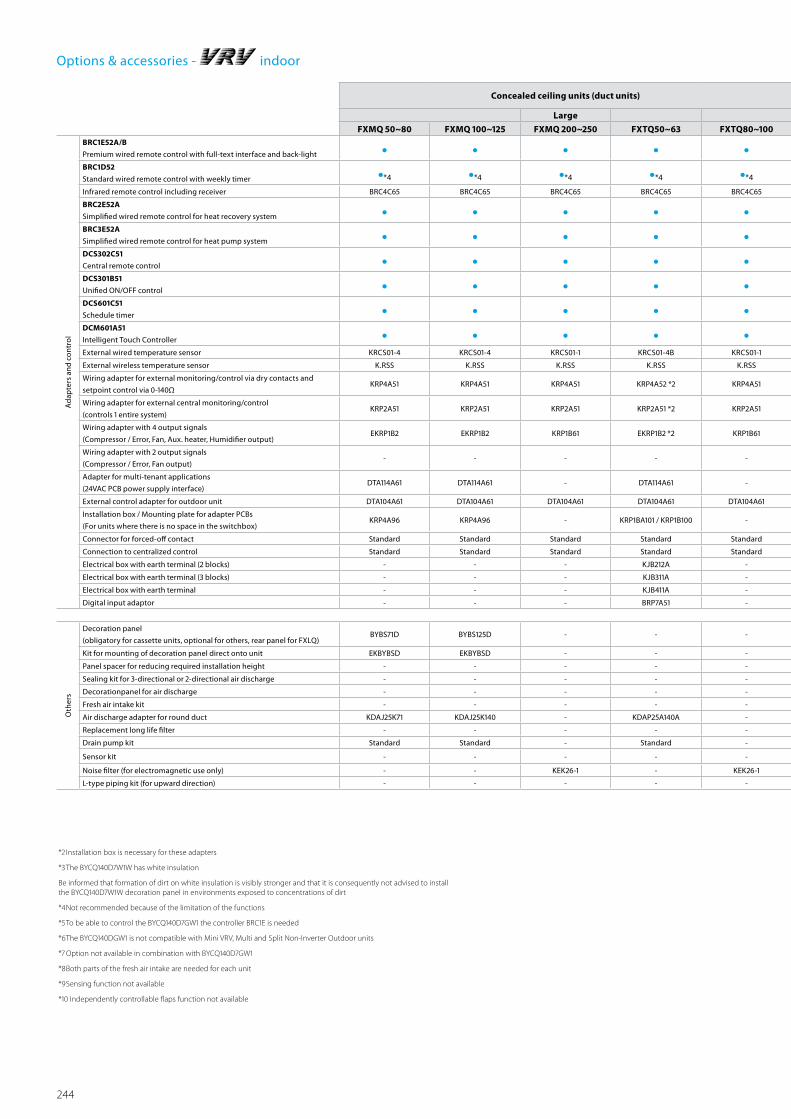
244
Options & accessories - indoor
Concealed ceiling units (duct units) Ceiling suspended unitsWall mounted
unitsFloor standing units
Large 1-way blow 4-way blow Concealed Free-standing
FXMQ 50~80 FXMQ 100~125 FXMQ 200~250 FXTQ50~63 FXTQ80~100 FXHQ 32A FXHQ 63A FXHQ 71~100A FXUQ 71~100A FXAQ 15~63 FXNQ 20~63 FXLQ 20~25 FXLQ 32~40 FXLQ 50~63
Ad
apte
rs a
nd
cont
rol
BRC1E52A/B
Premium wired remote control with full-text interface and back-light • • • • • • • • • • • • • •BRC1D52
Standard wired remote control with weekly timer •*4 •*4 •*4 •*4 •*4 •*4 •*4 •*4 •*4 •*4 •*4 •*4 •*4 •*4
Infrared remote control including receiver BRC4C65 BRC4C65 BRC4C65 BRC4C65 BRC4C65 BRC7G53 BRC7G53 BRC7G53 BRC7C58 BRC7EB518 BRC4C65 BRC4C65 BRC4C65 BRC4C65
BRC2E52A
Simplified wired remote control for heat recovery system • • • • • - - - - - • • • •BRC3E52A
Simplified wired remote control for heat pump system • • • • • - - - - - • • • •DCS302C51
Central remote control • • • • • • • • • • • • • •DCS301B51
Unified ON/OFF control • • • • • • • • • • • • • •DCS601C51
Schedule timer • • • • • • • • • • • • • •DCM601A51
Intelligent Touch Controller • • • • • • • • • • • • • •External wired temperature sensor KRCS01-4 KRCS01-4 KRCS01-1 KRCS01-4B KRCS01-1 KRCS01-4 KRCS01-4 KRCS01-4 KRCS01-4 KRCS01-1 KRCS01-1 KRCS01-1 KRCS01-1 KRCS01-1
External wireless temperature sensor K.RSS K.RSS K.RSS K.RSS K.RSS K.RSS K.RSS K.RSS K.RSS K.RSS K.RSS K.RSS K.RSS K.RSS
Wiring adapter for external monitoring/control via dry contacts and
setpoint control via 0-140ΩKRP4A51 KRP4A51 KRP4A51 KRP4A52 *2 KRP4A51 KRP4A52 KRP4A52 KRP4A52 KRP4A53 *2 KRP4A51 KRP4A51 KRP4A51 KRP4A51 KRP4A51
Wiring adapter for external central monitoring/control
(controls 1 entire system)KRP2A51 KRP2A51 KRP2A51 KRP2A51 *2 KRP2A51 KRP2A62 KRP2A62 KRP2A62 - KRP2A51 KRP2A51 KRP2A51 KRP2A51 KRP2A51
Wiring adapter with 4 output signals
(Compressor / Error, Fan, Aux. heater, Humidifier output)EKRP1B2 EKRP1B2 KRP1B61 EKRP1B2 *2 KRP1B61 - - - - - KRP1B61 KRP1B61 KRP1B61 KRP1B61
Wiring adapter with 2 output signals
(Compressor / Error, Fan output)- - - - - KRP1B54 KRP1B54 KRP1B54 - - - - - -
Adapter for multi-tenant applications
(24VAC PCB power supply interface)DTA114A61 DTA114A61 - DTA114A61 - - - - - DTA114A61 EKMTAC EKMTAC EKMTAC EKMTAC
External control adapter for outdoor unit DTA104A61 DTA104A61 DTA104A61 DTA104A61 DTA104A61 DTA104A62 DTA104A62 DTA104A62 - DTA104A61 - - - -
Installation box / Mounting plate for adapter PCBs
(For units where there is no space in the switchbox)KRP4A96 KRP4A96 - KRP1BA101 / KRP1B100 - KRP1D93A KRP1D93A KRP1D93A KRP1B97 KRP4A93 - - - -
Connector for forced-off contact Standard Standard Standard Standard Standard EKRORO4 EKRORO4 EKRORO4 EKRORO5 Standard Standard Standard Standard Standard
Connection to centralized control Standard Standard Standard Standard Standard - - - - Standard Standard Standard Standard Standard
Electrical box with earth terminal (2 blocks) - - - KJB212A - KJB212A KJB212A KJB212A KJB212A - - - - -
Electrical box with earth terminal (3 blocks) - - - KJB311A - KJB311A KJB311A KJB311A KJB311A - - - - -
Electrical box with earth terminal - - - KJB411A - - - - - - - - - -
Digital input adaptor - - - BRP7A51 - - - - - - - - - -
Oth
ers
Decoration panel
(obligatory for cassette units, optional for others, rear panel for FXLQ)BYBS71D BYBS125D - - - - - - - - - EKRDP25A EKRDP40A EKRDP63A
Kit for mounting of decoration panel direct onto unit EKBYBSD EKBYBSD - - - - - - - - - - - -
Panel spacer for reducing required installation height - - - - - - - - - - - - - -
Sealing kit for 3-directional or 2-directional air discharge - - - - - - - - KDBHP49B140 - - - - -
Decorationpanel for air discharge - - - - - - - - KDBTP49B140 - - - - -
Fresh air intake kit - - - - - KDDQ50A140 KDDQ50A140 KDDQ50A140 - - - - - -
Air discharge adapter for round duct KDAJ25K71 KDAJ25K140 - KDAP25A140A - - - - - - - - - -
Replacement long life filter - - - - - KAFP501A56 KAFP501A80 KAFP501A160 KAFP551K160 - - - - -
Drain pump kit Standard Standard - Standard - KDU50P60 KDU50P140 KDU50P140 - K-KDU572EVE - - - -
Sensor kit - - - - - - - - - - - - - -
Noise filter (for electromagnetic use only) - - KEK26-1 - KEK26-1 KEK26-1 KEK26-1 KEK26-1 - - - - - -
L-type piping kit (for upward direction) - - - - - KHFP5M35 KHFP5N63 KHFP5N160 - - - - - -
*2 Installation box is necessary for these adapters
*3 The BYCQ140D7W1W has white insulation
Be informed that formation of dirt on white insulation is visibly stronger and that it is consequently not advised to install the BYCQ140D7W1W decoration panel in environments exposed to concentrations of dirt
*4 Not recommended because of the limitation of the functions
*5 To be able to control the BYCQ140D7GW1 the controller BRC1E is needed
*6 The BYCQ140DGW1 is not compatible with Mini VRV, Multi and Split Non-Inverter Outdoor units
*7 Option not available in combination with BYCQ140D7GW1
*8 Both parts of the fresh air intake are needed for each unit
*9 Sensing function not available
*10 Independently controllable flaps function not available

245
Concealed ceiling units (duct units) Ceiling suspended unitsWall mounted
unitsFloor standing units
Large 1-way blow 4-way blow Concealed Free-standing
FXMQ 50~80 FXMQ 100~125 FXMQ 200~250 FXTQ50~63 FXTQ80~100 FXHQ 32A FXHQ 63A FXHQ 71~100A FXUQ 71~100A FXAQ 15~63 FXNQ 20~63 FXLQ 20~25 FXLQ 32~40 FXLQ 50~63
Ad
apte
rs a
nd
cont
rol
BRC1E52A/B
Premium wired remote control with full-text interface and back-light • • • • • • • • • • • • • •BRC1D52
Standard wired remote control with weekly timer •*4 •*4 •*4 •*4 •*4 •*4 •*4 •*4 •*4 •*4 •*4 •*4 •*4 •*4
Infrared remote control including receiver BRC4C65 BRC4C65 BRC4C65 BRC4C65 BRC4C65 BRC7G53 BRC7G53 BRC7G53 BRC7C58 BRC7EB518 BRC4C65 BRC4C65 BRC4C65 BRC4C65
BRC2E52A
Simplified wired remote control for heat recovery system • • • • • - - - - - • • • •BRC3E52A
Simplified wired remote control for heat pump system • • • • • - - - - - • • • •DCS302C51
Central remote control • • • • • • • • • • • • • •DCS301B51
Unified ON/OFF control • • • • • • • • • • • • • •DCS601C51
Schedule timer • • • • • • • • • • • • • •DCM601A51
Intelligent Touch Controller • • • • • • • • • • • • • •External wired temperature sensor KRCS01-4 KRCS01-4 KRCS01-1 KRCS01-4B KRCS01-1 KRCS01-4 KRCS01-4 KRCS01-4 KRCS01-4 KRCS01-1 KRCS01-1 KRCS01-1 KRCS01-1 KRCS01-1
External wireless temperature sensor K.RSS K.RSS K.RSS K.RSS K.RSS K.RSS K.RSS K.RSS K.RSS K.RSS K.RSS K.RSS K.RSS K.RSS
Wiring adapter for external monitoring/control via dry contacts and
setpoint control via 0-140ΩKRP4A51 KRP4A51 KRP4A51 KRP4A52 *2 KRP4A51 KRP4A52 KRP4A52 KRP4A52 KRP4A53 *2 KRP4A51 KRP4A51 KRP4A51 KRP4A51 KRP4A51
Wiring adapter for external central monitoring/control
(controls 1 entire system)KRP2A51 KRP2A51 KRP2A51 KRP2A51 *2 KRP2A51 KRP2A62 KRP2A62 KRP2A62 - KRP2A51 KRP2A51 KRP2A51 KRP2A51 KRP2A51
Wiring adapter with 4 output signals
(Compressor / Error, Fan, Aux. heater, Humidifier output)EKRP1B2 EKRP1B2 KRP1B61 EKRP1B2 *2 KRP1B61 - - - - - KRP1B61 KRP1B61 KRP1B61 KRP1B61
Wiring adapter with 2 output signals
(Compressor / Error, Fan output)- - - - - KRP1B54 KRP1B54 KRP1B54 - - - - - -
Adapter for multi-tenant applications
(24VAC PCB power supply interface)DTA114A61 DTA114A61 - DTA114A61 - - - - - DTA114A61 EKMTAC EKMTAC EKMTAC EKMTAC
External control adapter for outdoor unit DTA104A61 DTA104A61 DTA104A61 DTA104A61 DTA104A61 DTA104A62 DTA104A62 DTA104A62 - DTA104A61 - - - -
Installation box / Mounting plate for adapter PCBs
(For units where there is no space in the switchbox)KRP4A96 KRP4A96 - KRP1BA101 / KRP1B100 - KRP1D93A KRP1D93A KRP1D93A KRP1B97 KRP4A93 - - - -
Connector for forced-off contact Standard Standard Standard Standard Standard EKRORO4 EKRORO4 EKRORO4 EKRORO5 Standard Standard Standard Standard Standard
Connection to centralized control Standard Standard Standard Standard Standard - - - - Standard Standard Standard Standard Standard
Electrical box with earth terminal (2 blocks) - - - KJB212A - KJB212A KJB212A KJB212A KJB212A - - - - -
Electrical box with earth terminal (3 blocks) - - - KJB311A - KJB311A KJB311A KJB311A KJB311A - - - - -
Electrical box with earth terminal - - - KJB411A - - - - - - - - - -
Digital input adaptor - - - BRP7A51 - - - - - - - - - -
Oth
ers
Decoration panel
(obligatory for cassette units, optional for others, rear panel for FXLQ)BYBS71D BYBS125D - - - - - - - - - EKRDP25A EKRDP40A EKRDP63A
Kit for mounting of decoration panel direct onto unit EKBYBSD EKBYBSD - - - - - - - - - - - -
Panel spacer for reducing required installation height - - - - - - - - - - - - - -
Sealing kit for 3-directional or 2-directional air discharge - - - - - - - - KDBHP49B140 - - - - -
Decorationpanel for air discharge - - - - - - - - KDBTP49B140 - - - - -
Fresh air intake kit - - - - - KDDQ50A140 KDDQ50A140 KDDQ50A140 - - - - - -
Air discharge adapter for round duct KDAJ25K71 KDAJ25K140 - KDAP25A140A - - - - - - - - - -
Replacement long life filter - - - - - KAFP501A56 KAFP501A80 KAFP501A160 KAFP551K160 - - - - -
Drain pump kit Standard Standard - Standard - KDU50P60 KDU50P140 KDU50P140 - K-KDU572EVE - - - -
Sensor kit - - - - - - - - - - - - - -
Noise filter (for electromagnetic use only) - - KEK26-1 - KEK26-1 KEK26-1 KEK26-1 KEK26-1 - - - - - -
L-type piping kit (for upward direction) - - - - - KHFP5M35 KHFP5N63 KHFP5N160 - - - - - -
*2 Installation box is necessary for these adapters
*3 The BYCQ140D7W1W has white insulation
Be informed that formation of dirt on white insulation is visibly stronger and that it is consequently not advised to install the BYCQ140D7W1W decoration panel in environments exposed to concentrations of dirt
*4 Not recommended because of the limitation of the functions
*5 To be able to control the BYCQ140D7GW1 the controller BRC1E is needed
*6 The BYCQ140DGW1 is not compatible with Mini VRV, Multi and Split Non-Inverter Outdoor units
*7 Option not available in combination with BYCQ140D7GW1
*8 Both parts of the fresh air intake are needed for each unit
*9 Sensing function not available
*10 Independently controllable flaps function not available
Options & accessories - indoor
*Note: blue cells contain preliminary data
Opt
ions
& A
cces
sorie
s

246
INDOOR UNITS
FTXG-LW/SCTXS15-35K FTXS20-25K
FTXS35-50K FTXS-G FVXG-K FVXS-F FDXS-F(9) FLXS-B(9)
Ad
apte
rs a
nd
cont
rols
Wired remote control BRC944 (3) BRC944 (3) (5) BRC944 (3) BRC944 (3) BRC944 (3) -
BRC1D52
BRC1E52A
BRC1E52B (4)
-
Wireless remote control - - - - - - BRC4C65 -
Simplified remote control - - - - - - BRC2C51 -
Remote control for hotel use - - - - - - BRC3A61 -
Cord for wired remote control - 3m BRCW901A03 BRCW901A03 BRCW901A03 BRCW901A03 BRCW901A03 - - -
Cord for wired remote control - 8m BRCW901A08 BRCW901A08 BRCW901A08 BRCW901A08 BRCW901A08 - - -
Wiring adapter normal open contact /
normal open pulse contactKRP413A1S (1) KRP413A1S (1) (5) KRP413A1S (1) KRP413A1S (1) KRP413A1S (1) KRP413A1S (1) - KRP413A1S (1)
Centralised control board - up to 5 rooms KRC72 (2) KRC72 (2) KRC72 (2) KRC72 (2) KRC72 (2) KRC72 (2) - KRC72 (2)
Anti-theft protection for remote control KKF910A4 KKF910A4 KKF910A4 KKF910A4 KKF910A4 - - KKF917AA4
Interface adapter for wired remote control - KRP980A1 - - - - - -
Wiring adapter for electrical appendices - - - - - - KRP4A54 -
Remote sensor - - - - - - KRCS01-4 -
Installation box for adapter PCB - - - - - - KRP1BA101 -
Electric box with earth terminal 3 blocks - - - - - - KJB311A -
Electric box with earth terminal 2 blocks - - - - - - KJB212A
Interface adapter for DIII-net KRP928A2S KRP928A2S (5) KRP928A2S (5) KRP928A2S KRP928A2S KRP928A2S - KRP928A2S
Online controller BRP069A41 BRP06942 (5) BRP06942 BRP069A42 BRP069A42 BRP069A42 - BRP069A42
Modbus gateway RTD-RA RTD-RA (5) RTD-RA RTD-RA RTD-RA RTD-RA RTD-NET -
KNX gateway KLIC-DD KLIC-DD (5) KLIC-DD KLIC-DD KLIC-DD KLIC-DD KLIC-DI KLIC-DD
Oth
ers
Titanium apatite photocatalytic air-
purification filter without frame - - - - - - - -
Photocatalytic deodorising filter, with
frame - - - - - - - KAZ917B41
Photocatalytic deodorising filter, without frame - - - - - - - KAZ917B42
Air purification filter, with frame - - - - - - - KAF925B41
Installation leg - - - - BKS028 - - -
(1) Wiring adapter supplied by Daikin. Time clock and other devices : to be purchased locally; (2) Wiring adapter is also required for each indoor unit; (3) Cord for wired remote control BRCW901A03 or BRCW901A08 required; (4) Standard there is no remote control delivered with this indoor unit. Wired or wireless control to be ordered separately; (5) Interface adapter KRP980A1 required.
Options & accessories - stylish indoor

247
Options & accessories - stylish indoor
INDOOR UNITS
Description FCQG-F FFQ-C FDBQ-B FBQ-D FHQ-C
Wired remote controlBRC1D52
BRC1E52A (3) BRC1E52B (4)
BRC1D528 BRC1E52A (3)
BRC1E52B(4)(9)
BRC1D52 BRC1E52A (3) BRC1E52B (4)
BRC1D52 BRC1E52A (3) BRC1E52B (4)
BRC1D52 BRC1E52A (3) BRC1E52B (4)
Intelligent touch controller DCS601C51 DCS601C51 - DCS601C51 (2) -
Infrared remote control (heat pump) BRC7FA532F (5) BRC7EB530W BRC7F530W
BRC7F530S (8-9)- BRC4C65 BRC7G53
Simplified remote control (with operation mode selector button)
- BRC2E52C (12) - BRC2E52C (12) -
Simplified remote control (without operation mode selector button)
- BRC3E52C (12) - - -
Residential central remote control - - - - -Remote control for hotel use BRC3A61 - - BRC3E52C -Centralised remote control DCS302C51 DCS302B51 - DCS302C51 DCS302C51Unified ON/OFF control DCS301B51 DCS301B51 - DCS301B51 DCS301B51Schedule timer DST301B51 DST301B51 - DST301B51 DST301B51 Adapter for wiring (interlock for fresh air intake fan) - - - KRP1BA59 -Adapter for external ON/OFF and monitoring/for electrical appendices
KRP1B57 KRP4A53 (1)(5)
KRP1B57 KRP4A53(6)
-KRP4A52 (1) KRP2A51 (1)
KRP1B54 KRP4A52(1)
Interface adapter for Sky Air - - - DTA112B51 -
Installation box for adapter PCB KRP1H98 (5)KRP1B101
KRP1BA101- KRP1B(A)101 KRP1D93A
Remote sensor KRCS01-4 KRCS01-4 - KRCS01-4B KRCS01-4BRemote ON/OFF, forced OFF - - - - EKRORO4Electrical box with earth terminal (3 blocks) KJB311A - - - KJB311AElectrical box with earth terminal (2 blocks) KJB212A - - - KJB212AElectrical box with earth terminal - - - KJB411A -Adapter for wiring (hour meter) EKRP1C11 (1)(5) EKRP1B2 EKRP1B2 - -Digital input adaptor - BRP7A51 (1) (13) - BRP7A51 -Options PCB for external electrical heater, humidifier and/or hour meter
- - - EKRP1B2A (7) -
Option PCB for group control (NIM03) - - - - -Mounting plate for adapter PCB - - - - -
Notes: (1) Installation box for adapter PCB is necessary; (2) Interface adapter for Sky Air series (DTA112B51) is necessary; (3) Including following languages: English, German, French, Italian, Spanish, Dutch, Greek, Russian, Turkish, Portuguese, Polish; (4) Including
following languages: English, German, Czech, Croatian, Hungarian, Romanian, Slovenian, Bulgarian, Slovak, Serbian, Albanian; (5) Option not available in combination with BYCQ140*G; (6) Installation box for adapter PCB (KRP1B101) is necessary; (7) Electrical
heater, humidifier and hour meter are field supply. These parts should not be installed inside the equipment; (8) Sensing function is not available; (9) Independently controllable flaps function is not available; (10) With the infrared remote control, the individu-
al flap control and automatic air volume control cannot be controlled; (11) Including decoration panel; (12) Including following languages: English, German, French, Dutch, Spanish, Italian, Portuguese; (13) Only possible in combination with simplified remote
control BRC2/3E52C; (14) For residential use only. Cannot be used with other centralised control equipment Notes: (1) The BYCQ140DW has white insulations. Be informed that dirt is more visible on white insulation and that it is consequently not advised to install the BYCQ140DW decoration panel in environments
*Note: blue cells contain preliminary data
Opt
ions
& A
cces
sorie
s
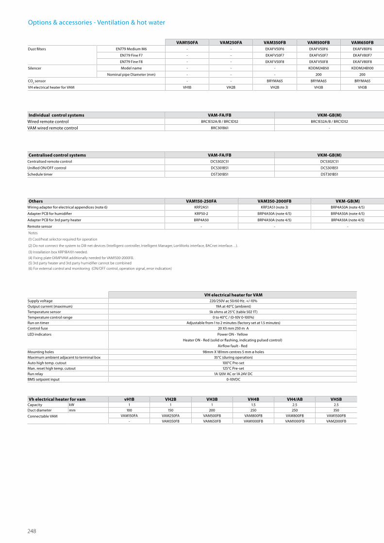
248
Options & accessories - Ventilation & hot water
VH electrical heater for VAMSupply voltage 220/250V ac 50/60 Hz. +/-10%
Output current (maximum) 19A at 40°C (ambient)
Temperature sensor 5k ohms at 25°C (table 502 1T)
Temperature control range 0 to 40°C / (0-10V 0-100%)
Run on timer Adjustable from 1 to 2 minutes (factory set at 1.5 minutes)
Control fuse 20 X5 mm 250 m A
LED indicators Power ON - Yellow
Heater ON - Red (solid or flashing, indicating pulsed control)
Airflow fault - Red
Mounting holes 98mm X 181mm centres 5 mm ø holes
Maximum ambient adjacent to terminal box 35°C (during operation)
Auto high temp. cutout 100°C Pre-set
Man. reset high temp. cutout 125°C Pre-set
Run relay 1A 120V AC or 1A 24V DC
BMS setpoint input 0-10VDC
Vh electrical heater for vam vH1B VH2B VH3B VH4B VH4/AB VH5BCapacity kW 1 1 1 1.5 2.5 2.5
Duct diameter mm 100 150 200 250 250 350
Connectable VAM VAM150FA VAM250FA VAM500FB VAM800FB VAM800FB VAM1500FB
- VAM350FB VAM650FB VAM1000FB VAM1000FB VAM2000FB
Others VAM150-250FA VAM350-2000FB VKM-GB(M) EKEQFCB 2 EKEQDCB 2 EKEQMCB 2
Wiring adapter for electrical appendices (note 6) KRP2A51 KRP2A51 (note 3) BRP4A50A (note 4/5) - - -
Adapter PCB for humidifier KRP50-2 BRP4A50A (note 4/5) BRP4A50A (note 4/5) - - -
Adapter PCB for 3rd party heater BRP4A50 BRP4A50A (note 4/5) BRP4A50A (note 4/5) - - -
Remote sensor - - - KRCS01-1
Notes
(1) Cool/heat selector required for operation
(2) Do not connect the system to DIII-net devices (Intelligent controller, Intelligent Manager, LonWorks interface, BACnet interface…).
(3) Installation box KRP1BA101 needed.
(4) Fixing plate EKMPVAM additionally needed for VAM1500-2000FB.(5) 3rd party heater and 3rd party humidifier cannot be combined(6) For external control and monitoring (ON/OFF control, operation signal, error indication)
Individual control systems VAM-FA/FB VKM-GB(M) EKEQFCB 2 EKEQDCB 2 EKEQMCB 2
Wired remote control BRC1E52A/B / BRC1D52 BRC1E52A/B / BRC1D52 BRC1E52A/B / BRC1D52 BRC1E52A/B / BRC1D52 1 BRC1E52A/B / BRC1D52 1
VAM wired remote control BRC301B61 - - - -
Centralised control systems VAM-FA/FB VKM-GB(M) EKEQFCB 2 EKEQDCB 2 EKEQMCB 2
Centralised remote control DCS302C51 DCS302C51 - - -
Unified ON/OFF control DCS301B51 DCS301B51 - - -
Schedule timer DST301B51 DST301B51 - - -
VAM150FA VAM250FA VAM350FB VAM500FB VAM650FB VAM800FB VAM1000FB VAM1500FB VAM2000FB VKM50GB(M) VKM80GB(M) VKM100GB(M)Dust filters EN779 Medium M6 - - EKAFV50F6 EKAFV50F6 EKAFV80F6 EKAFV80F6 EKAFV100F6 EKAFV100F6 x2 EKAFV100F6 x2 - - -
EN779 Fine F7 - - EKAFV50F7 EKAFV50F7 EKAFV80F7 EKAFV80F7 EKAFV100F7 EKAFV100F7 x2 EKAFV100F7 x2 - - -
EN779 Fine F8 - - EKAFV50F8 EKAFV50F8 EKAFV80F8 EKAFV80F8 EKAFV100F8 EKAFV100F8 x2 EKAFV100F8 x2 - - -
Silencer Model name - - - KDDM24B50 KDDM24B100 KDDM24B100 KDDM24B100 KDDM24B100 x2 KDDM24B100 x2 - KDDM24B100 KDDM24B100
Nominal pipe Diameter (mm) - - - 200 200 250 250 250 250 - 250 250
CO2 sensor - - BRYMA65 BRYMA65 BRYMA65 BRYMA100 BRYMA100 BRYMA200 BRYMA200 BRYMA65 BRYMA100 BRYMA200
VH electrical heater for VAM VH1B VH2B VH2B VH3B VH3B VH4B / VH4/AB VH4B / VH4/AB VH5B VH5B - - -

249
Others VAM150-250FA VAM350-2000FB VKM-GB(M) EKEQFCB 2 EKEQDCB 2 EKEQMCB 2
Wiring adapter for electrical appendices (note 6) KRP2A51 KRP2A51 (note 3) BRP4A50A (note 4/5) - - -
Adapter PCB for humidifier KRP50-2 BRP4A50A (note 4/5) BRP4A50A (note 4/5) - - -
Adapter PCB for 3rd party heater BRP4A50 BRP4A50A (note 4/5) BRP4A50A (note 4/5) - - -
Remote sensor - - - KRCS01-1
Notes
(1) Cool/heat selector required for operation
(2) Do not connect the system to DIII-net devices (Intelligent controller, Intelligent Manager, LonWorks interface, BACnet interface…).
(3) Installation box KRP1BA101 needed.
(4) Fixing plate EKMPVAM additionally needed for VAM1500-2000FB.(5) 3rd party heater and 3rd party humidifier cannot be combined(6) For external control and monitoring (ON/OFF control, operation signal, error indication)
Individual control systems VAM-FA/FB VKM-GB(M) EKEQFCB 2 EKEQDCB 2 EKEQMCB 2
Wired remote control BRC1E52A/B / BRC1D52 BRC1E52A/B / BRC1D52 BRC1E52A/B / BRC1D52 BRC1E52A/B / BRC1D52 1 BRC1E52A/B / BRC1D52 1
VAM wired remote control BRC301B61 - - - -
Centralised control systems VAM-FA/FB VKM-GB(M) EKEQFCB 2 EKEQDCB 2 EKEQMCB 2
Centralised remote control DCS302C51 DCS302C51 - - -
Unified ON/OFF control DCS301B51 DCS301B51 - - -
Schedule timer DST301B51 DST301B51 - - -
Options & accessories - Ventilation & hot water
HXY080-125A HXHD125ADrain pan EKHBDPCA2 -
Digital I/O PCB EKRP1HBAA -
Demand PCB - Required to connect room thermostat EKRP1AHTA -Remote user interface (remocon) - Same controller as supplied with cascade unit
can be mounted parallel or on other location. If 2 controllers are installed, the
installer needs to select 1 master & 1 slave
EKRUAHTB -
Back-up heater EKBUHAA6(W1/V3) -
Wired room thermostat - Requires demand PCB EKRP1AHTA EKRTWA -
Wireless room thermostat - Requires demand PCB EKRP1AHTA EKRTR1 -
Remote sensor for room thermostat - Requires demand PCB EKRP1AHTA EKRTETS -Domestic hot water tank - standward
(stacked on top of hydrobox)-
EKHTS200AC
EKHTS260ACDomestic hot water tank - with possibility for solar connection - EKHWP500B
Solar collector *1 -EKSV26P (vertical)
EKSH26P (horizontal)Pump station - EKSRPS
*1 pump station is necessary for this option
VAM150FA VAM250FA VAM350FB VAM500FB VAM650FB VAM800FB VAM1000FB VAM1500FB VAM2000FB VKM50GB(M) VKM80GB(M) VKM100GB(M)Dust filters EN779 Medium M6 - - EKAFV50F6 EKAFV50F6 EKAFV80F6 EKAFV80F6 EKAFV100F6 EKAFV100F6 x2 EKAFV100F6 x2 - - -
EN779 Fine F7 - - EKAFV50F7 EKAFV50F7 EKAFV80F7 EKAFV80F7 EKAFV100F7 EKAFV100F7 x2 EKAFV100F7 x2 - - -
EN779 Fine F8 - - EKAFV50F8 EKAFV50F8 EKAFV80F8 EKAFV80F8 EKAFV100F8 EKAFV100F8 x2 EKAFV100F8 x2 - - -
Silencer Model name - - - KDDM24B50 KDDM24B100 KDDM24B100 KDDM24B100 KDDM24B100 x2 KDDM24B100 x2 - KDDM24B100 KDDM24B100
Nominal pipe Diameter (mm) - - - 200 200 250 250 250 250 - 250 250
CO2 sensor - - BRYMA65 BRYMA65 BRYMA65 BRYMA100 BRYMA100 BRYMA200 BRYMA200 BRYMA65 BRYMA100 BRYMA200
VH electrical heater for VAM VH1B VH2B VH2B VH3B VH3B VH4B / VH4/AB VH4B / VH4/AB VH5B VH5B - - -
Opt
ions
& A
cces
sorie
s

250
Options & accessories - Ventilation (air handling units)
D-AHU Professional
Construction type SP 65 SP 45 FP 50 FP 25
Profile
Aluminium standard standard standard standard
Anodized aluminium option option option option
Aluminium with thermal break option option option option
Anodized aluminium with thermal break option option option option
Corner Glass fibre reinforced nylon standard standard standard standard
Panel insulation
Polyurethane foam density 45 kg/m3 thermal conductivity 0.020 W/m*K fire reaction class 1
standard standard standard standard
Mineral wool density 90 kg/m3 thermal conductivity 0.037 W/m*K (referred to 20°C) fire reaction class 0
option option option option
External sheet material
Grey Plastisol covered galvanized steel standard standard standard standard
Pre-coated galvanized steel option option option option
Galvanized steel option option option option
Aluminium option option option option
AISI 304 stainless steel option option option option
Internal sheet material
Galvanized steel standard standard standard standard
Pre-coated galvanized steel option option option option
Grey Plastisol covered galvanized steel option option option option
Aluminium option option option option
AISI 304 stainless steel option option option option
Base frameAluminium
standard (from size 1 to size 17)
standard (from size 1 to size 17)
standard (from size 1 to size 17)
standard (from size 1 to size 17)
Galvanized steelstandard
(from size 18 to size 27)standard
(from size 18 to size 27)standard
(from size 18 to size 27)standard
(from size 18 to size 27)Handle Glass fibre reinforced nylon standard standard standard standard
Type
Compression type standard standard standard standard
Hinge function type (possibility to remove door)
option option option option
D-AHU Easy
Construction type DS 50 DS 25
Profile Aluminium Standard Standard
Corner Glass fibre reinforced nylon Standard Standard
Panel insulation Polyurethane foam thermal conductivity 0.024 W/m*K Standard (density 45 kg/m3) standard (density 47 kg/m3)
External sheet material Pre-coated galvanized steel (RAL 9002) Standard Standard
Internal sheet material Galvanized steel Standard Standard
Base frame Aluminium Standard Standard
Handle Glass fibre reinforced nylon Standard Standard
Type Compression type Standard Standard

251
DCM601A51 DMS504B51 DMS502A51
LonWorks Interface BACnet Interface
iTM plus adapter DCM601A52iTM ppd software DCM002A51iTM energy navigator software DCM008A51iTM BACnet option DCM009A51WAGO I/O Modbus communication unit WGDCMCPLR
DC24V power supply unit: 787-712DC24V power supply unit: 750-613Connector: 750-960Terminator module: 750-600Di module: 750-400, 750-432Do module: 750-513/000-001Ai module: 750-454, 750-479Thermistor module: 750-461/020-000
Interface adapter for connection to RA units KRP928A2S KRP928A2SInterface adapter for connection to R-407C/R-22 Sky Air units DTA102A52 DTA102A52Interface adapter for connection to R-410A Sky Air units DTA112B51 DTA112B51DIII board DAM411B51Digital input/output DAM412B51
Options - Control systems
Opt
ions
& A
cces
sorie
s

252
Over 30 years of
VRV History
1987 1991 1994 1998 2003 2004 2005
Daikin introduces the VRVII,
the world’s first R-410A
operated variable refrigerant
flow system. Available in cooling
only, heat pump and heat recovery
versions. No less than 40 indoor
units in heat recovery as well as
heat pump format can be
connected to a single refrigerant
circuit.
Daikin Daikin extends
the operational scope of
its acclaimed VRVII inverter
driven dx air conditioning
system, with a new water
cooled version, VRV-WII.
Available in both heat pump
and heat recovery versions.
The original VRV air conditioning
system developed by Daikin
Industries Ltd. in 1982 is
introduced into Europe in VRV
standard format. VRV D series can
supply conditioned air from up to
6 indoor units connected to
a single outdoor unit.
A further step forward
is taken in 1991 with the
introduction of the
VRV heat recovery system,
offering simultaneous cooling
and heating from different
indoor units on the same
refrigeration circuit.
Consistent high quality and
efficiency lead to the wide-
spread acceptance of the VRV
concept and Daikin becomes the
first Japanese air conditioning
manufacturer to be awarded the
ISO9001 certification.
The introduction
of the VRVII-S series extends
the VRV operating scope
into the light commercial
sectors. Available in 4, 5 and
6HP capacities, the system is
designed for installation in
up to 9 rooms.In anticipation of phase out dates
for all CFC based equipment,
Daikin Europe launched a VRV
interter series with R-407C.
As many as 16 indoor units can be
connected to 1 single outdoor unit.
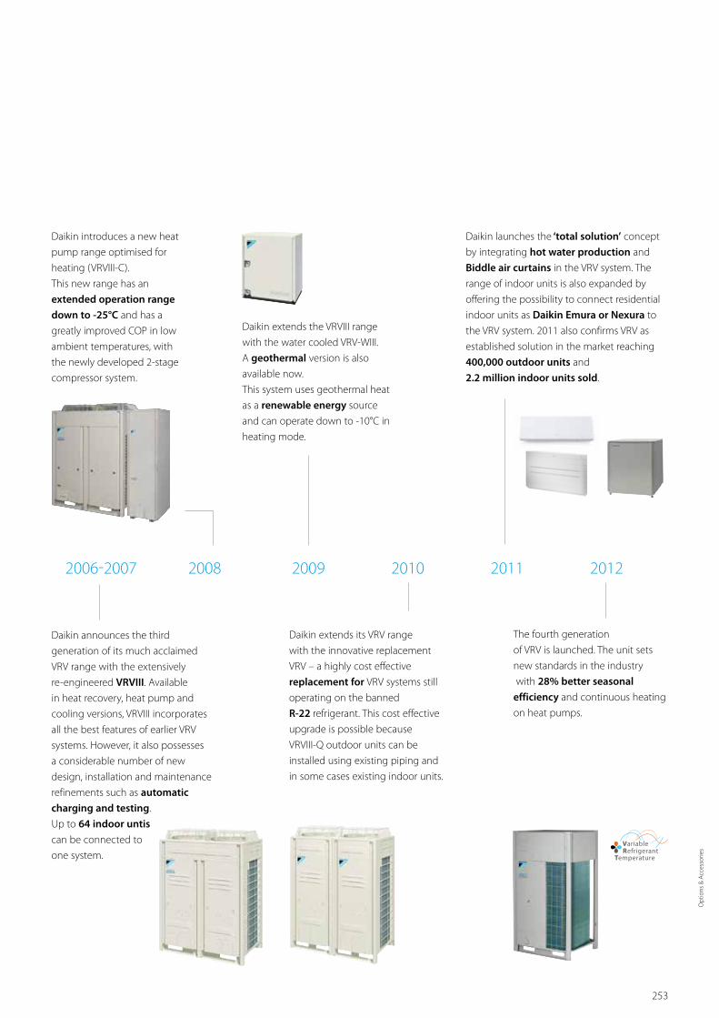
253
Over 30 years of
VRV History
Daikin extends its VRV range
with the innovative replacement
VRV – a highly cost effective
replacement for VRV systems still
operating on the banned
R-22 refrigerant. This cost effective
upgrade is possible because
VRVIII-Q outdoor units can be
installed using existing piping and
in some cases existing indoor units.
The fourth generation
of VRV is launched. The unit sets
new standards in the industry
with 28% better seasonal
efficiency and continuous heating
on heat pumps.
2006-2007 2008 2009 2010 2011 2012
Daikin announces the third
generation of its much acclaimed
VRV range with the extensively
re-engineered VRVIII. Available
in heat recovery, heat pump and
cooling versions, VRVIII incorporates
all the best features of earlier VRV
systems. However, it also possesses
a considerable number of new
design, installation and maintenance
refinements such as automatic
charging and testing.
Up to 64 indoor untis
can be connected to
one system.
Daikin introduces a new heat
pump range optimised for
heating (VRVIII-C).
This new range has an
extended operation range
down to -25°C and has a
greatly improved COP in low
ambient temperatures, with
the newly developed 2-stage
compressor system.
Daikin launches the ‘total solution’ concept
by integrating hot water production and
Biddle air curtains in the VRV system. The
range of indoor units is also expanded by
offering the possibility to connect residential
indoor units as Daikin Emura or Nexura to
the VRV system. 2011 also confirms VRV as
established solution in the market reaching
400,000 outdoor units and
2.2 million indoor units sold.
Daikin extends the VRVIII range
with the water cooled VRV-WIII.
A geothermal version is also
available now.
This system uses geothermal heat
as a renewable energy source
and can operate down to -10°C in
heating mode.
Opt
ions
& A
cces
sorie
s

254
IT and air conditioners: the obvious solution With advances in computerisation and networking, we have integrated IT into our air conditioners including communication technology and advanced software for total control. Our new control systems enable users to develop comfortable environments with superior energy savings by networking air conditioners to enable them to exchange information with each other and with our service centres.
Research & development Creating value through innovative
technologies
R&D is essential for the creation of products that enrich people's lives. As symbolised by the VRV, Daikin is at the forefront of innovative technology and the development of market leading products: the result of our advanced R&D system.
Superior products from multi-part
development approach
To create more advanced functions with added value, Daikin has set up the 'Environmental Technology Research Laboratory' and the 'Solution Product Development Center'. Working with the Product Development Group, the three divisions cooperate closely to ascertain and meet the customers' needs and to enable commercialisation of products incorporating advanced technology.
Intensive research on environmental impact
The diverse needs in different countries encountered during the accelerating globalisation of our air conditioning business have presented us with increased research challenges particularly in terms of environmental impact. To promote energy savings in and to lower the environmental impact of our air conditioners, we have developed technologies based on fundamental research into motor inverters and many other areas.
DevelopmentProduct Development Group
Solution Product Development Center
Environmental TechnologyResearch laboratory
DevelopmentIT
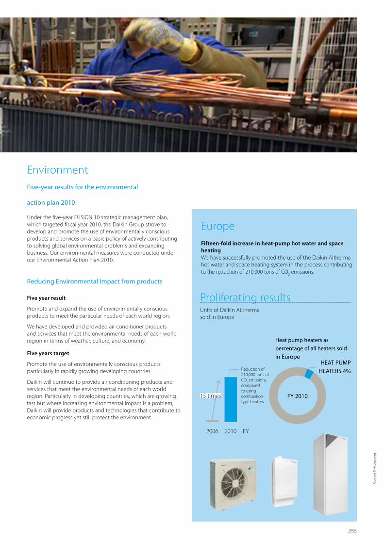
255
EnvironmentFive-year results for the environmental
action plan 2010
Under the five-year FUSION 10 strategic management plan, which targeted fiscal year 2010, the Daikin Group strove to develop and promote the use of environmentally conscious products and services on a basic policy of actively contributing to solving global environmental problems and expanding business. Our environmental measures were conducted under our Environmental Action Plan 2010.
Reducing Environmental Impact from products
Five year result
Promote and expand the use of environmentally conscious products to meet the particular needs of each world region.
We have developed and provided air conditioner products and services that meet the environmental needs of each world region in terms of weather, culture, and economy.
Five years target
Promote the use of environmentally conscious products, particularly in rapidly growing developing countries
Daikin will continue to provide air conditioning products and services that meet the environmental needs of each world region. Particularly in developing countries, which are growing fast but where increasing environmental impact is a problem, Daikin will provide products and technologies that contribute to economic progress yet still protect the environment.
EuropeFifteen-fold increase in heat-pump hot water and space heatingWe have successfully promoted the use of the Daikin Altherma hot water and space heating system in the process contributing to the reduction of 210,000 tons of CO
2 emissions.
Units of Daikin ALtherma sold in Europe
2006 2010 FY
15 times
Heat pump heaters as
percentage of all heaters sold
in EuropeHEAT PUMP
HEATERS 4%Reduction of 210,000 tons of CO
2 emissions
compared to using combustion-type heaters
Proliferating results
FY 2010
Opt
ions
& A
cces
sorie
s

256

257 Lite
ratu
re O
verv
iew
Literature overviewDaikin has a wide portfolio of commercial
catalogues in order to supply you with information
or help you to sell our products to your customers.
Literature for professional network 258Literature for your customers 259

258
15-217
Commercial catalogue 2015
Sky Air
Your business is our concern Min running costs, max flexibility.Fast installation, perfect comfort.
Commercial catalogue 2015
VRV
15-114 15-200 15-203
Product portfolio
Sky AirProduct portfolio
VRV
22
Product Portfolio
Controls
15-121 15-201 15-301
User friendly remote control with contemporary designBRC1E52A/B
› Easy to use: all main functions directly accessible
› Easy commissioning: intuitive interface for advanced menu settings
› Optimise your air conditioning system by activating a series of energy saving functions (temperature range limit, setback function, off timer, …)
› Keep track of your energy consumption with the kWh indication showing an indicative electricity consumption
› Set up to 3 independent schedules, so the user can easily change the schedule himself throughout the year (e.g. summer, winter, mid-season)
› Real time clock with auto update to daylight saving time
› Supports multiple languages
› Possibility to individually restrict menu functions
› When a power failure occurs all settings remain stored up to 48 hours thanks to the built-in backup power
Specifications / FunctionsSpecifications BRC1E52A / BRC1E52B
Dimensions (HxWxD) 3.120x120x19 mm40
LCDDisplay size (HxW) 43.2x68.85 mm
Type Full dot (160x255)
Colour Fresh white
Cover for operation part No
Max. wiring length 500m
Connectable indoor units All VRV® and Sky Air® indoor units
Functions BRC1E52A / BRC1E52B
Energy saving functions
Set sensor behavior �
Temperature range limit �
Setback function �
Set point auto reset �
Off timer �
Display
Multilingual display English, German, French, Spanish, Italian, Portuguese, Greek, Dutch, Russian, Turkish, Polishr English, German, Czech, Croation, Hungarian, Romanian, Slovenian, Bulgarian, Slovak, Serbian, Albanian
Help menu �
Room temperature display �
Clock (time display) Real time clock with auto update to daylight saving time
Backlight �
Contrast adjustment �
TimerWeekly schedule timer 3
Holiday function �
Access control
Key lock �
Restrict menus Each menu individually
Restrict buttons Each button individually (ON/OFF, operation mode selector, temperature adjustment, fan speed / air flow direction)
Memory Built-in back-up power When a power failure occurs, all settings remain stored up to 48 hours
Real time clock
Real time clock with auto update to daylight saving time
Supports multiple languages
› English, German, French, Spanish, Italian, Portuguese, Greek, Dutch, Russian, Turkish and Polishr (BRC1E52A)
› English, German, Czech, Croation, Hungarian, Romanian, Slovenian, Bulgarian, Slovak, Serbian, Albanian (BRC1E52B)
Possibility to individually restrict menu functions/buttons
› Restrict some of all functions on the remote control to void misuse in e.g. hotels, shops, offices
Other features
› Built-in back-up power. When a power failure occurs, all settings remain stored up to 48 hours
› Backlight display
The present publication is drawn up by way of information only and does not constitute an offer binding upon
Daikin Europe N.V. Daikin Europe N.V. has compiled the content of this publication to the best of its knowledge. No
express or implied warranty is given for the completeness, accuracy, reliability or fitness for particular purpose of its
content and the products and services presented therein. Specifications are subject to change without prior notice.
Daikin Europe N.V. explicitly rejects any liability for any direct or indirect damage, in the broadest sense, arising from
or related to the use and/or interpretation of this publication. All content is copyrighted by Daikin Europe N.V.
The present publication supersedes ECPEN12-306. Printed on non-chlorinated paper.
Daikin Europe N.V. Naamloze Vennootschap Zandvoordestraat 300 · 8400 Oostende · Belgium · www.daikin.eu · BE 0412 120 336 · RPR Oostende (Responsible Editor)
ECPEN15 - 306 180 · 11/14
FSC
KNX Interface KLIC-DD, KLIC-DI
› Integration of Split, Sky Air and VRV in home automation / BMS systems
› Monitoring and control of several devices from one central controller
Split
› Modbus RS485 interface for integration up to 64 indoor units groups
› BMS integration of RA, Sky Air, VRV Inverter chillers and AHU
DIII-net modbus interface
EKMBDXA
Electrical heater for VAMVH
› Total solution for fresh air with Daikin supply of both VAM and electrical heaters
› Increased comfort in low outdoor temperature thanks to the heated outdoor air
› Integrated electrical heater concept (no additional accessories required)
› Standard dual flow and temperature sensor
› Flexible setting with adjustable setpoint
› Increased safety with 2 cut-outs: manual & automatic
› BMS integration thanks to: • Volt free relay for error indication • 0-10VDC input for setpoint control
Wireless room temperature sensorK.RSS
Flexible and easy installation
› Accurate temperature measurement thanks to flexible placement of the sensor
› No need for wiring
› No need to drill holes › Ideal for refurbishment
Modbus Interface RTD
› Indoor unit control via 0~10 volt, dry contact or resistance contact
› Retail applications › Hotel applications › IT applications › Heating interlock › Alarm signal
Split, Sky Air, VRV, Chillers,
Refrigeration, Daikin Altherma
Integration of Daikin portfolio in BMS system via Modbus
15-306 15-310 15-312
15-311 15-309 15-308
15-206 15-120
The quick and quality way of upgrading R-22 and R-407C systems
Replacement technologyfor installers
VRV IV heat recovery, heat pump, replacement and water cooled
VRV IV 360° efficiency
Rooftop UATYQ-CY1
15-214 15-140
Solution guides:
Reference books:
Product profiles:
Focus topics:
Productflyers:
Product catalogues:
Product portfolios:
C O M M E R C I A L A P P L I C A T I O N SC ATA LO G U E
R E F E R E N C E
for professional network
Technical coolingClear installer benefits why to choose Daikin for technical cooling
KNX InterfaceDetailed info on KLIC-DI and KLIC-DD interfaces
DIII-net modbus gatewayDetailed info on EKMBDXA modbus interface
RTD modbus interfaceDetailed info on RTD controls and applications
Wireless temperature sensorDetailed info on wireless sensor K.RSS
VAM electrical heaterDetailed info on electrical heater for VAM
Sky Air CatalogueDetailed technical information & benefits on Sky Air/Ventilation/Biddle Air Curtain/Control systems/AHU
Sky Air product portfolioOverview of Sky air product range
VRV CatalogueDetailed technical information & benefits of the VRV total solution
VRV product portfolioOverview of VRV total solution product range
Ventilation CatalogueDetailed info on Ventilation products
Controls systems portfolioOverview of all Daikin control systems
Wired Remote ControlDetailed info on BRC1E52A/B remote control
Replacement Technology Clear installer benefits of VRV replacement technology
VRV IV rangeDetailed VRV IV standards and technologies benefits. Main features and specs of VRV IV product range
Hotel SolutionsClear installer benefits why to choose Daikin for a hotel
Rooftop UATYQ-CY1Detailed rooftop benefits incl. UAYTQ-CY1, ECONO-AY1
Commercial market - literature overview
Second half 2015
First half 2015
Heating - air conditioning - domestic hot water - cooling - ventilation - centralised control
Hotel solutions for installers

259 Lite
ratu
re O
verv
iew
Technical documentation:
Download all technical documentation such as engineering databooks, selection software, installation and operation manuals and service manuals directly from our extranet: extranet.daikineurope.com
14-213
Concealed floor standing unitFNQ-A, FXNQ-A
Powerful mode
Multi tenant
(FXNQ-A)
Home leave
operation › Ideal for installation in offices, hotels and residential applications
› Its low height enables the unit to fit perfectly beneath a window
› Discretely concealed in the wall, leaving only the suction and discharge grilles visible
› Requires very little installation space as the depth is only 200mm
› High ESP allows flexible installation
Designed to be concealed in walls
Powerful mode
Multi tenant (FXSQ)
Home leave
operation
› Top efficiency in the market › Automatic air flow adjustment function measures the air volume and static pressure and adjusts it towards the nominal air flow, whatever the length of duct, making installation easier and guaranteeing comfort. Moreover, the ESP can be changed via the wired remote control to optimize the supply air volume
› Slimmest unit in class, only 245mm › Discretely concealed in the ceiling: only the suction and discharge grilles are visible
› Low sound level
› Medium external static pressure up to 150Pa facilitates using flexible ducts of varying lengths
› Reduced energy consumption thanks to specially developed DC fan motor
› Flexible installation, as the air suction direction can be altered from rear to bottom suction
› Standard built-in drain pump increases flexibility and installation speed
› No optional adapter needed for DIII-connection, link your unit into the wider building management system
Optimum comfort guaranteed no matter the length of ductwork or type of grilles
Concealed ceiling unit with medium ESPFBQ-D, FXSQ-A
15-110 15-106 15-101
15-302
Avoid loss of business and replace your air conditioning system now!
The phase-out period for R-22 is over.
Act now!
SPLIT, SKY AIR, VRV, CHILLERS
15-215
Heating - air conditioning - hot water - ventilation - refrigeration - control
Hotel solutions for hotel owners
Sustainable design with Daikin HVAC-R systems
Green building solutions
Control systems
Intelligent Touch Manager
Mini Building Management System
15-218
15-100
15-216
for your customers
Reference catalogueDaikin commercial and industrial references
Replacement technologyClear building owner/investor benefits of replacement technology
Cassette mini catalogueGiving overview of our cassette unit product solutions (incl. Round flow cassette FCQ(H)G-F/FXFQ-A, Fully flat cassette FFQ-C/FXZQ-A, FUQ-C/FXUQ-A, ACQ-C)
Sky Air product leafletsSingle page leaflet with the main benefits and technical specifications of each individual Sky Air unit. Ideal for quotations
VRV product leafletsSingle page leaflet with the main benefits and technical specifications of each individual VRV unit. Ideal for quotations
Concealed ceiling unit mini catalogueCatalogue giving overview of our concealed ceiling unit product solutions (incl. FDXS-F(9), FBQ-D, FDQ-C, FDQ-B, FXDQ-M9, FXDQ-A, FXSQ-A, FXMQ-P7, FXMQ-MA)
Ceiling suspended, wall mounted, floor standing units mini catalogueCatalogue giving overview of our Ceiling suspended, wall mounted and floor standing product solutions. (incl. FXHQ-A,FHQ-C, FXAQ-A, FAQ-C, FXNQ-A, FNQ-A,FXLQ-P, FVQ-C)
Intelligent Touch ManagerDetailed benefits of Intelligent Touch Manager
Commercial SolutionsDaikin offers solutions for commercial applications
Hotel SolutionsClear building owner/investor benefits why to choose Daikin for a hotel
Green Buiding SolutionsClear building owner/investor benefits why to choose Daikin for a green building, with emphasis on BREEAM
First half 2015 First half 2015 First half 2015
First half 2015

The present publication is drawn up by way of information only and does not constitute an offer binding upon
Daikin Europe N.V. Daikin Europe N.V. has compiled the content of this publication to the best of its knowledge. No
express or implied warranty is given for the completeness, accuracy, reliability or fitness for particular purpose of its
content and the products and services presented therein. Specifications are subject to change without prior notice.
Daikin Europe N.V. explicitly rejects any liability for any direct or indirect damage, in the broadest sense, arising from
or related to the use and/or interpretation of this publication. All content is copyrighted by Daikin Europe N.V.
The present publication supersedes ECPEN14-115. Printed on non-chlorinated paper. Prepared by Platzer
Kommunikation, Germany.
Daikin Europe N.V. Naamloze Vennootschap Zandvoordestraat 300 · 8400 Oostende · Belgium · www.daikin.eu · BE 0412 120 336 · RPR Oostende (Responsible Editor)
Daikin Europe N.V. participates in the Eurovent Certification
programme for Liquid Chilling Packages (LCP), Air handling
units (AHU), Fan coil units (FCU) and variable refrigerant flow
systems (VRF) Check ongoing validity of certificate online:
www.eurovent-certification.com or using: www.certiflash.com
ECPEN15 -200A 500 · 03/15
Our new VRV IV heat recovery systems sets pioneer-ing standards in all-round climate comfort efficiency.
Total design simplicity, rapid installation, full flexibility with absolute efficiency and comfort. Find out about all revolutionary changes on www.daikineurope.com/vrviv
+ + + MAXcomfort
MOREfree heat
QUICKinstallation
FASTdesign
360° efficiency
installation efficiency
design efficiency
operational efficiency
Heat Recovery
FSC