product catalog - hunting-intl.com · setting tool product catalog. ... 10 - 20 t-set ® page 37...
TRANSCRIPT

Firing Heads
Adapter Kits
Inspection Kits
Power Chargers and Igniters
T-Set
® Settin
g To
ol
Product C
atalog
II© 2015 Hunting. All Rights Reserved.
Table of C
ontents
01 Compact - Single Stage T-Set® Page 011.50 in. (3.81 cm) O.D. .......................................................................................................................................................................................02
1.71 in. (4.34 cm) O.D. .......................................................................................................................................................................................05
2.50 in. (6.35 cm) O.D. .......................................................................................................................................................................................08
3.50 in. (8.89 cm) O.D. Self Bleeding ..................................................................................................................................................................11
3.63 in. (9.21 cm) O.D. .......................................................................................................................................................................................14
3.63 in. (9.21 cm) O.D. High Pressure ................................................................................................................................................................16
3.63 in. (9.21 cm) O.D. High Pressure ................................................................................................................................................................18
02 Multi-Stage T-Set® Page 211.71 in. (4.34 cm) O.D. .......................................................................................................................................................................................22
2.13 in. (5.40 cm) O.D. .......................................................................................................................................................................................26
3.25 in. (8.25 cm) O.D. .......................................................................................................................................................................................30
4.50 in. (11.43 cm) O.D. .....................................................................................................................................................................................33
T-Set® Setting Tool Catalog

III© 2015 Hunting. All Rights Reserved.
Table of C
ontents
03 Sizes 05 - 10 - 20 T-Set® Page 37SIZE 05 ............................................................................................................................................................................................................38
SIZE 10 ............................................................................................................................................................................................................42
SIZE 10 Non-ported High Pressure ....................................................................................................................................................................44
SIZE 10 Non-ported ..........................................................................................................................................................................................46
SIZE 20 ............................................................................................................................................................................................................48
SIZE 20 Non-ported High Pressure ....................................................................................................................................................................50
SIZE 20 Non-ported ...........................................................................................................................................................................................52
04 Firing Heads Page 552005-000-000 (Size 05 - 1-3/16 in.-12 “GO” Box). .............................................................................................................................................56
2010-000-000 (Size 10 - 1-3/16 in.-12 “GO” Box) ..............................................................................................................................................58
2010-000-020 (Size 10 - 3-1/8 in. O.D. “GO” Quick-Change Assembly) .............................................................................................................60
2010-000-040 (Size 10 - 2-3/4 in. O.D. “GO” Quick-Change Assembly) .............................................................................................................62
2010-000-070 (Size 10 - 3-1/8 in. O.D. SIE Quick-Change Assembly) ................................................................................................................64
2010-000-090 (Size 10 - 2010-000-090) ............................................................................................................................................................66
2020-000-000 (Size 20 - 1-3/16 in.-12 “GO” Box) ..............................................................................................................................................68
2020-000-020 (Size 20 - 3-1/8 in. O.D. GO Quick-Change Assembly) ................................................................................................................70
2020-000-070 (Size 20 - 3-1/8 in. O.D. SIE Quick-Change Assembly) ................................................................................................................72
6110-000-000 (Size 1.5 in., 1.72 in., 2.13 in., 2.5 in. - 1-3/16 in.-12 “GO” Box) ..................................................................................................74
05 Adapter Kits Page 751.71 in. (4.34 cm) O.D. .......................................................................................................................................................................................76
2.13 in. (5.40 cm) O.D. .......................................................................................................................................................................................77
3.25 in. (8.25 cm) O.D. .......................................................................................................................................................................................78
4.50 in. (11.43 cm) O.D. .....................................................................................................................................................................................79
06 Inspection Kits Page 81WST-KIT-INSP-10-20 .........................................................................................................................................................................................81
WST-KIT-INSP-UNIV...........................................................................................................................................................................................82
07 Power Charges and Igniters Page 83Power Charges and Igniters for T-Set® Tools .......................................................................................................................................................83

1
01 Com
pact - S
ingle Stage T-S
et ®
© 2015 Hunting. All Rights Reserved.
The compact, single stage T-Set is the shortest setting tool in in the T-Set family. Its low weight and short length make it ideal for stage frac jobs requiring pump down operations.
The top cylinder is filled with oil and self-bleeds with increased temperature. The trouble-free design makes it quick and easy to redress at the wellsite providing fast turnaround times.
The ignition of a slow set power charge creates gas pressure inside the setting tool. The gas migrates through the piston initiating the setting sequence. The hydraulic oil slowly bleeds out of the tool providing a cushioning effect while setting. Once the required setting force is achieved, a shear stud breaks releasing the T-Set from the plug/packer.
FEATURES■■ Short compact design
■■ Self-bleeding compensating system
■■ Options for bleeder valves
■■ Black oxide coated components
BENEFITS■■ Ideal for horizontal pump down operations
■■ Compensation oil level adjustments are not necessary
■■ Bleeder valves provide a safer option to bleed off pressure inside the tool at surface
■■ Black oxide coating improves corrosion and chemical resistance
Compact Single Stage T-SET®
2
01 Com
pact - S
ingle Stage T-S
et ®
© 2015 Hunting. All Rights Reserved.
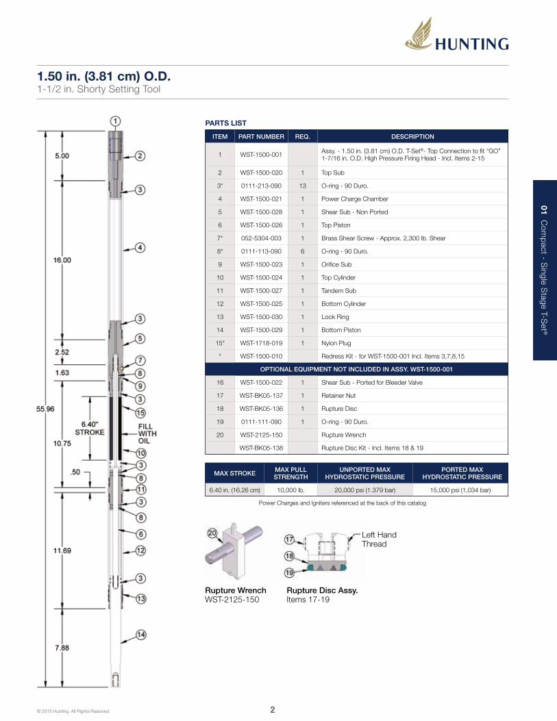
1.50 in. (3.81 cm) O.D.1-1/2 in. Shorty Setting Tool
PARTS LIST
ITEM PART NUMBER REQ. DESCRIPTION
1 WST-1500-001 Assy. - 1.50 in. (3.81 cm) O.D. T-Set®- Top Connection to fit “GO” 1-7/16 in. O.D. High Pressure Firing Head - Incl. Items 2-15
2 WST-1500-020 1 Top Sub
3* 0111-213-090 13 O-ring - 90 Duro.
4 WST-1500-021 1 Power Charge Chamber
5 WST-1500-028 1 Shear Sub - Non Ported
6 WST-1500-026 1 Top Piston
7* 052-5304-003 1 Brass Shear Screw - Approx. 2,300 lb. Shear
8* 0111-113-090 6 O-ring - 90 Duro.
9 WST-1500-023 1 Orifice Sub
10 WST-1500-024 1 Top Cylinder
11 WST-1500-027 1 Tandem Sub
12 WST-1500-025 1 Bottom Cylinder
13 WST-1500-030 1 Lock Ring
14 WST-1500-029 1 Bottom Piston
15* WST-1718-019 1 Nylon Plug
* WST-1500-010 Redress Kit - for WST-1500-001 Incl. Items 3,7,8,15
OPTIONAL EQUIPMENT NOT INCLUDED IN ASSY. WST-1500-001
16 WST-1500-022 1 Shear Sub - Ported for Bleeder Valve
17 WST-BK05-137 1 Retainer Nut
18 WST-BK05-136 1 Rupture Disc
19 0111-111-090 1 O-ring - 90 Duro.
20 WST-2125-150 Rupture Wrench
WST-BK05-138 Rupture Disc Kit - Incl. Items 18 & 19
Rupture Wrench WST-2125-150
Left Hand Thread
Rupture Disc Assy. Items 17-19
MAX STROKE MAX PULL STRENGTH
UNPORTED MAX HYDROSTATIC PRESSURE
PORTED MAX HYDROSTATIC PRESSURE
6.40 in. (16.26 cm) 10,000 lb. 20,000 psi (1.379 bar) 15,000 psi (1,034 bar)
Power Charges and Igniters referenced at the back of this catalog
3
01 Com
pact - S
ingle Stage T-S
et ®
© 2015 Hunting. All Rights Reserved.
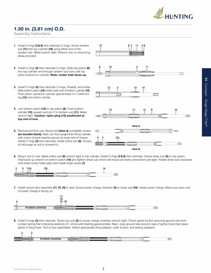
1. Install O-rings (3 & 8) then lubricate O-rings. Screw tandem sub (11) into top cylinder (10) using either end of the tandem sub. Make wrench tight. Wrench only on wrenching areas provided.
4. Join bottom piston (14) to top piston (6). Push bottom cylinder (12) upward and join it to tandem sub (11). Make wrench tight. Caution: nylon plug (15) positioned at top end of tool.
5. Remove tool from vise. Bump tool (view a) completely closed (on wooden block). Next, turn tool upright then fill top cylinder with motor oil level reaches groove at lower end of thread. Install O-rings (3) then lubricate. Install orifice sub (9). Excess oil will purge as sub is screwed in.
6. Return tool to vise. Make orifice sub (9) wrench tight to top cylinder. Install O-rings (3 & 8) then lubricate. Screw shear sub (5) to top piston. Hold back-up wrench on bottom piston (14) and tighten shear sub which will ensure all inside connections are tight. Rotate shear sub clockwise until shear screw holes align then install shear screw (7).
7. Install rupture disc assembly (17, 18, 19) If used. Screw power charge chamber (4) to shear sub (16). Install power charge. Make sure open end of power charge is facing up.
8. Install O-rings (3) then lubricate. Screw top sub (2) to power charge chamber wrench tight. Check igniter by first removing ground wire from contact spring then checking resistivity (51 ohms) with blasting galvanometer. Next, wrap ground wire around case of igniter body then place igniter in firing head. Tool is now assembled. Attach appropriate firing adapter, collar locator, and setting adapters.
2. Install O-rings (3) then lubricate O-rings. Slide top piston (6) into top cylinder and through tandem sub bore until top piston bottoms in cylinder. Note: center hole faces up.
3. Install O-rings (3) then lubricate O-rings, threads, and bores. Slide bottom piston (14) inside lower end of bottom cylinder (12). Push piston upward in cylinder approximately 5 in. Install lock ring (13) onto bottom cylinder.
1.50 in. (3.81 cm) O.D.Assembly Instructions
View A
View B
4
01 Com
pact - S
ingle Stage T-S
et ®
© 2015 Hunting. All Rights Reserved.
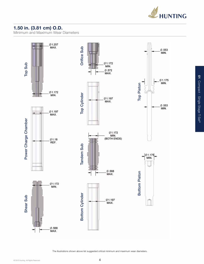
The illustrations shown above list suggested critical minimum and maximum wear diameters.
1.50 in. (3.81 cm) O.D.Minimum and Maximum Wear Diameters
Top
Sub
Po
wer
Cha
rge
Cha
mb
erS
hear
Sub
Bo
tto
m C
ylin
der
Tand
em S
ubTo
p C
ylin
der
Ori
fice
Sub
Top
Pis
ton
Bo
tto
m P
isto
n

5
01 Com
pact - S
ingle Stage T-S
et ®
© 2015 Hunting. All Rights Reserved.
PARTS LIST
ITEM PART NUMBER REQ. DESCRIPTION
1 WST-1718-001 Assy. - 1.71 in. (4.34 cm) O.D. T-Set®- Top Connection to fit “GO” 1-7/16 in. O.D. High Pressure Firing Head - Incl. Items 2-15
2 WST-1718-020 1 Top Sub
3* 0111-216-090 13 O-ring - 90 Duro.
4 WST-1718-021 1 Power Charge Chamber
5 WST-1718-028 1 Shear Sub - Non Ported
6 WST-1718-026 1 Top Piston
7* 052-5304-003 1 Brass Shear Screw - Approx. 2,300 lb. Shear
8* 0111-115-090 6 O-ring - 90 Duro.
9 WST-1718-023 1 Orifice Sub
10 WST-1718-024 1 Top Cylinder
11 WST-1718-027 1 Tandem Sub
12 WST-1718-025 1 Bottom Cylinder
13 WST-1718-030 1 Lock Ring
14 WST-1718-029 1 Bottom Piston
15* WST-1718-019 1 Nylon Plug
* WST-1718-010 Redress Kit - for WST-1718-001 - Incl. Items 3,7,8,15
OPTIONAL EQUIPMENT NOT INCLUDED IN ASSY. WST-1718-001
16 WST-1718-022 1 Shear Sub - Ported for Bleeder Valve
17 WST-BK05-137 1 Retainer Nut
18 WST-BK05-136 1 Rupture Disc
19 0111-111-090 1 O-ring - 90 Duro.
20 WST-2125-150 Rupture Wrench
WST-BK05-138 Rupture Disc Kit - Incl. Items 18 & 19
Rupture Wrench WST-2125-150
Left Hand Thread
Rupture Disc Assy. Items 17-19
1.71 in. (4.34 cm) O.D.1-11/16 in. Shorty Setting Tool
MAX STROKE MAX PULL STRENGTH
UNPORTED MAX HYDROSTATIC PRESSURE
PORTED MAX HYDROSTATIC PRESSURE
6.40 in. (16.26 cm) 13,000 lb. 20,000 psi (1.379 bar) 15,000 psi (1,034 bar)
Power Charges and Igniters referenced at the back of this catalog

6
01 Com
pact - S
ingle Stage T-S
et ®
© 2015 Hunting. All Rights Reserved.
1. Install O-rings (3 & 8) then lubricate O-rings. Screw tandem sub (11) into top cylinder (10) using either end of the tandem sub. Make wrench tight. Wrench only on wrenching areas provided.
2. Install O-rings (3) then lubricate O-rings. Slide top piston (6) into top cylinder and through tandem sub bore until top piston bottoms in cylinder. Note: center hole faces up.
4. Join bottom piston (14) to top piston (6). Push bottom cylinder (12) upward and join it to tandem sub (11). Make wrench tight. Caution: nylon plug (15) positioned at top end of tool.
6. Return tool to vise. Make orifice sub (9) wrench tight to top cylinder. Install O-rings (3 & 8) then lubricate. Screw shear sub (5) to top piston. Hold back-up wrench on bottom piston (14) and tighten shear sub which will ensure all inside connections are tight. Rotate shear sub clockwise until shear screw holes align then install shear screw (7).
7. Install rupture disc assembly (17, 18, 19) If used. Screw power charge chamber (4) to shear sub (16). Install power charge. Make sure open end of power charge is facing up.
8. Install O-rings (3) then lubricate. Screw top sub (2) to power charge chamber wrench tight. Check igniter by first removing ground wire from contact spring then checking resistivity (51 ohms) with blasting galvanometer. Next, wrap ground wire around case of igniter body then place igniter in firing head. Tool is now assembled. Attach appropriate firing adapter, collar locator, and setting adapters.
3. Install O-rings (3) then lubricate O-rings, threads, and bores. Slide bottom piston (14) inside lower end of bottom cylinder (12). Push piston upward in cylinder approximately 5 in. Install lock ring (13) onto bottom cylinder.
1.71 in. (4.34 cm) O.D.Assembly Instructions
5. Remove tool from vise. Bump tool (view a) completely closed (on wooden block). Next, turn tool upright then fill top cylinder with motor oil level reaches groove at lower end of thread. Install O-rings (3) then lubricate. Install orifice sub (9). Excess oil will purge as sub is screwed in.
View A
View B

7
01 Com
pact - S
ingle Stage T-S
et ®
© 2015 Hunting. All Rights Reserved.
Tand
em S
ub
The illustrations shown above list suggested critical minimum and maximum wear diameters.
1.71 in. (4.34 cm) O.D.Minimum and Maximum Wear Diameters
Top
Sub
Ori
fice
Sub
Po
wer
Cha
rge
Cha
mb
er
Top
Cyl
ind
er
She
ar S
ub
Top
Pis
ton
Bo
tto
m C
ylin
der
Bo
tto
m P
isto
n

8
01 Com
pact - S
ingle Stage T-S
et ®
© 2015 Hunting. All Rights Reserved.
PARTS LIST
ITEM PART NUMBER REQ. DESCRIPTION
1 WST-2500-001Assy. - 2.50 in. (6.35 cm) O.D. T-Set® Self Bleeding - Top Connection to fit “GO” 1-7/16 in. O.D. High Pressure Firing Head - Incl. Items 2-16
2 WST-2500-020 1 Top Sub
3* 0111-224-090 13 O-ring - 90 Duro.
4 WST-2500-021 1 Power Charge Chamber
5 WST-2500-028 1 Shear Sub
6* 0111-113-090 2 O-ring - 90 Duro.
7* 052-5303-003 1 Brass Shear Screw - Approx. 6,500 lb. Shear
8 WST-2500-023 1 Orifice Sub
9 WST-2500-024 1 Top Cylinder - Ported for Self Bleeding
10* 0111-212-090 2 O-ring - 90 Duro.
11 WST-2500-027 1 Connector Sub
12 WST-2500-026 1 Top Piston
13 WST-2500-025 1 Bottom Cylinder
14 WST-2500-030 1 Lock Ring
15 WST-2500-029 1 Bottom Piston
16* WST-5321-019 1 Nylon Plug
* WST-2500-010 Redress Kit - for WST-2500-001 - Incl. Items 3,6,7,10,16
2.50 in. (6.35 cm) O.D.2-1/2 in. Shorty Setting Tool
MAX STROKE MAX PULL STRENGTH MAX HYDROSTATIC PRESSURE
10.40 in. (26.42 cm) 30,000 lb. 20,000 psi (1.379 bar)
Power Charges and Igniters referenced at the back of this catalog

9
01 Com
pact - S
ingle Stage T-S
et ®
© 2015 Hunting. All Rights Reserved.
1. Install O-rings (3 ) on bottom piston (15) insert bottom piston approximately halfway inside bottom cylinder (13). Install lock ring (14).
4. Slide bottom cylinder up and thread to connector sub. Finish threading and tighten bottom piston to top piston.
5. Install nylon plug (16) in top cylinder (9). Thread top cylinder (9) to connector sub (11). Caution: nylon plug positioned at top end of tool.
6. Bump top piston fully closed. Turn tool upright and fill top cylinder with motor oil until level reaches bottom thread. Attach orifice sub (8).
7. Install O-rings (3) on shear sub (5). Screw shear sub to top piston. Tighten the shear sub, top piston and bottom piston connections by turning the shear sub while holding the bottom piston.
8. Attach power charge chamber (4) to shear sub (5). Tighten the power charge chamber, shear sub, top piston, and bottom piston connections by turning the power charge chamber while holding the bottom piston. Align the holes in orifice sub and shear sub then install brass shear screw (7).
9. Insert power charge (open end up) into power charge chamber (4). Install O-rings (3) on top sub (2). Screw top sub to power charge chamber.
2. Install O-rings (3 & 6) on top piston (12). Install O-rings (3 & 10) on connector sub (11). Slide connector sub on top piston. Caution: Internal O-rings positioned toward top of piston.
3. Install bottom cylinder and bottom piston (13 & 15) over lower end of top piston (12).
2.50 in. (6.35 cm) O.D.Assembly Instructions
10
01 Com
pact - S
ingle Stage T-S
et ®
© 2015 Hunting. All Rights Reserved.
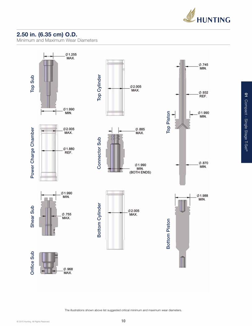
The illustrations shown above list suggested critical minimum and maximum wear diameters.
2.50 in. (6.35 cm) O.D.Minimum and Maximum Wear Diameters
Top
Sub
Po
wer
Cha
rge
Cha
mb
er
Top
Cyl
ind
er
Top
Pis
ton
She
ar S
ub
Co
nnec
tor
Sub
Ori
fice
Sub
Bo
tto
m C
ylin
der
Bo
tto
m P
isto
n
11
01 Com
pact - S
ingle Stage T-S
et ®
© 2015 Hunting. All Rights Reserved.
PARTS LIST
ITEM PART NUMBER REQ. DESCRIPTION
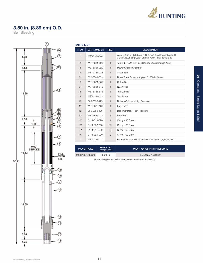
1 WST-5321-501 Assy. - 3.50 in. (8.89 cm) O.D. T-Set® Top Connection to fit 3.25 in. (8.25 cm) Quick Change Assy. - Incl. items 2-17
2 WST-5321-023 1 Top Sub - to fit 3.25 in. (8.25 cm) Quick Change Assy.
3 WST-5321-020 1 Power Charge Chamber
4 WST-5321-022 1 Shear Sub
5* 052-5303-003 1 Brass Shear Screw - Approx. 6, 500 lb. Shear
6 WST-5321-509 1 Orifice Sub
7* WST-5321-019 1 Nylon Plug
8 WST-5321-512 1 Top Cylinder
9 WST-5321-021 1 Top Piston
10 066-0350-129 1 Bottom Cylinder - High Pressure
11 WST-3625-130 1 Lock Ring
12 066-0350-136 1 Bottom Piston - High Pressure
13 WST-3625-131 1 Lock Nut
14* 0111-328-090 1 O-ring - 90 Duro.
15* 0111-332-090 12 O-ring - 90 Duro.
16* 0111-211-090 2 O-ring - 90 Duro.
17* 0111-325-090 2 O-ring - 90 Duro.
* WST-5321-110 Redress Kit - for WST-5321-101 Incl. Items 5,7,14,15,16,17
3.50 in. (8.89 cm) O.D.Self Bleeding
MAX STROKE MAX PULL STRENGTH MAX HYDROSTATIC PRESSURE
9.60 in. (24.38 cm) 55,000 lb. 15,000 psi (1,034 bar)
Power Charges and Igniters referenced at the back of this catalog

12
01 Com
pact - S
ingle Stage T-S
et ®
© 2015 Hunting. All Rights Reserved.
1. Install O-rings (15 & 17) on bottom cylinder (10). Install O-rings (15 & 16) on top piston (9). Slide lower end of top piston (9) inside upper end of top cylinder all the way. Screw lock ring (11) on bottom cylinder.
4. Bump top piston fully closed. Turn tool upright and fill top cylinder with motor oil until level reaches bottom thread. Attach orifice sub (6).
5. Install O-rings (15) on shear sub (4). Screw shear sub to top piston.
2. Slide top cylinder (8) over top piston and screw to bottom cylinder. Caution: the self bleeder port must be positioned the upper end of the tool. Insert plastic plug (7) in bleed hole of top cylinder.
6. Align holes and install brass shear screw (5). Attach power charge chamber (3).
7. Insert power charge (open end up) into power charge chamber. Install O-rings (14 & 15) to top sub (2). Screw top sub (2). Screw top sub to power charge chamber.
3. Install O-rings (15) on bottom piston (12). Screw bottom piston to top piston.
3.50 in. (8.89 cm) O.D.Assembly Instructions
13
01 Com
pact - S
ingle Stage T-S
et ®
© 2015 Hunting. All Rights Reserved.
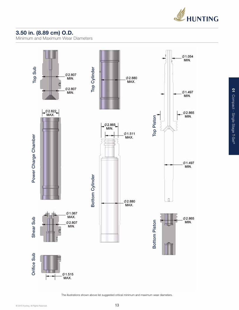
The illustrations shown above list suggested critical minimum and maximum wear diameters.
3.50 in. (8.89 cm) O.D.Minimum and Maximum Wear Diameters
Top
Sub
Po
wer
Cha
rge
Cha
mb
er
Top
Cyl
ind
er
She
ar S
ub
Bo
tto
m C
ylin
der
Ori
fice
Sub
Bo
tto
m P
isto
nTo
p P
isto
n

14
01 Com
pact - S
ingle Stage T-S
et ®
© 2015 Hunting. All Rights Reserved.
PARTS LIST
ITEM PART NUMBER REQ. DESCRIPTION
1 WST-3625-101 Assy. - 3.63 in. (9.21 cm) O.D. - Top Connection to fit 3.25 in. (8.25 cm) Quick Change Assy. - Incl. Items 3,4, & 6-22
2 WST-3625-102 Assy. - 3.63 in. (9.21 cm) O.D. Setting Tool - Top Connection to fit Baker Size #10 Firing Head - Incl. Items 5 & 7-22
3* 0111-328-090 1 O-ring - 90 Duro.
4 WST-3625-120 1 Top Sub - to fit 3.25 in. (8.25 cm) Quick Change Assy.
5 WST-3625-132 1 Top Sub - to fit Baker Size #10 Firing Head
6* 0111-332-090 6 O-ring - 90 Duro.
7 WST-3625-135 1 Assy. - Disc Type Bleeder Valve - Incl. Items 20, 21, 22
8* 0111-226-090 2 O-ring - 90 Duro.
9* 052-5303-003 1 Brass Shear Screw - Approx. 6,500 lb. Shear
10 WST-3625-121 1 Orifice Sub
11 WST-3625-125 1 Top Cylinder
12 WST-3625-122 1 Top Piston
13* 0111-322-090 2 O-ring - 90 Duro.
14 WST-3625-126 1 Connector Sub
15* 0111-335-090 1 O-ring - 90 Duro.
16 WST-3625-127 1 Bottom Cylinder
17 WST-3625-130 1 Lock Ring
18 WST-3625-128 1 Bottom Piston
19 WST-3625-131 1 Lock Nut
20 WST-3625-137 1 Retainer Nut - for Disc Type Bleeder Valve
21 WST-3625-136 1 Puncture Disc - for Disc Type Bleeder Valve
22* 0111-213-090 1 O-ring - 90 Duro. - for Disc Type Bleeder Valve
23 WST-3625-140 Rupture Wrench
* WST-3625-110 Redress Kit - for WST-3625-101 Incl. Items 3,6,8,9,13,15,22
* WST-3625-110D Redress Kit - for WST-3625-101 W/Disc Incl. Items 3,6,8,9,13,15,21,22
* WST-3625-112 Redress Kit - for WST-3625-102 Incl. Items 6,8,9,13,15,22
WST-3625-138 Rupture Disc Kit Bleed Valve - Incl. Items 21 & 22
20
21
22
77
23
Rupture Wrench WST-3625-140
Left Hand Thread
Rupture Disc Assy. WST-3625-135
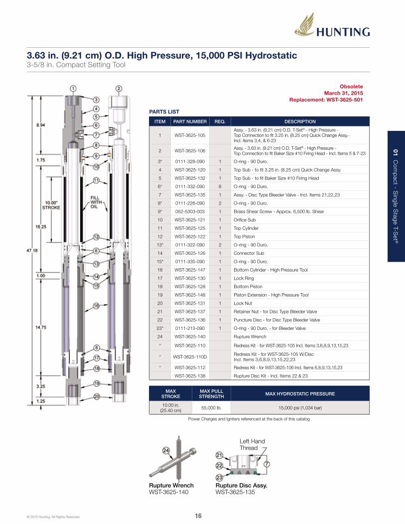
Obsolete March 31, 2015
Replacement: WST-3625-501
3.63 in. (9.21 cm) O.D.3-5/8 in. Compact Setting Tool
MAX STROKE
MAX PULL STRENGTH MAX HYDROSTATIC PRESSURE
10.00 in. (25.40 cm) 55,000 lb. 10,000 psi (689 bar)
Power Charges and Igniters referenced at the back of this catalog
15
01 Com
pact - S
ingle Stage T-S
et ®
© 2015 Hunting. All Rights Reserved.
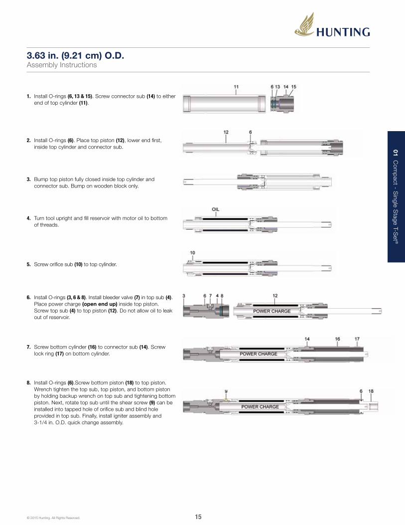
1. Install O-rings (6, 13 & 15). Screw connector sub (14) to either end of top cylinder (11).
2. Install O-rings (6). Place top piston (12), lower end first, inside top cylinder and connector sub.
4. Turn tool upright and fill reservoir with motor oil to bottom of threads.
5. Screw orifice sub (10) to top cylinder.
6. Install O-rings (3, 6 & 8). Install bleeder valve (7) in top sub (4). Place power charge (open end up) inside top piston. Screw top sub (4) to top piston (12). Do not allow oil to leak out of reservoir.
7. Screw bottom cylinder (16) to connector sub (14). Screw lock ring (17) on bottom cylinder.
8. Install O-rings (6).Screw bottom piston (18) to top piston. Wrench tighten the top sub, top piston, and bottom piston by holding backup wrench on top sub and tightening bottom piston. Next, rotate top sub until the shear screw (9) can be installed into tapped hole of orifice sub and blind hole provided in top sub. Finally, install igniter assembly and 3-1/4 in. O.D. quick change assembly.
3. Bump top piston fully closed inside top cylinder and connector sub. Bump on wooden block only.
3.63 in. (9.21 cm) O.D.Assembly Instructions
16
01 Com
pact - S
ingle Stage T-S
et ®
© 2015 Hunting. All Rights Reserved.
PARTS LIST
ITEM PART NUMBER REQ. DESCRIPTION
1 WST-3625-105Assy. - 3.63 in. (9.21 cm) O.D. T-Set® - High Pressure - Top Connection to fit 3.25 in. (8.25 cm) Quick Change Assy.- Incl. Items 3,4, & 6-23
2 WST-3625-106 Assy. - 3.63 in. (9.21 cm) O.D. T-Set® - High Pressure - Top Connection to fit Baker Size #10 Firing Head - Incl. Items 5 & 7-23
3* 0111-328-090 1 O-ring - 90 Duro.
4 WST-3625-120 1 Top Sub - to fit 3.25 in. (8.25 cm) Quick Change Assy.
5 WST-3625-132 1 Top Sub - to fit Baker Size #10 Firing Head
6* 0111-332-090 6 O-ring - 90 Duro.
7 WST-3625-135 1 Assy. - Disc Type Bleeder Valve - Incl. Items 21,22,23
8* 0111-226-090 2 O-ring - 90 Duro.
9* 052-5303-003 1 Brass Shear Screw - Approx. 6,500 lb. Shear
10 WST-3625-121 1 Orifice Sub
11 WST-3625-125 1 Top Cylinder
12 WST-3625-122 1 Top Piston
13* 0111-322-090 2 O-ring - 90 Duro.
14 WST-3625-126 1 Connector Sub
15* 0111-335-090 1 O-ring - 90 Duro.
16 WST-3625-147 1 Bottom Cylinder - High Pressure Tool
17 WST-3625-130 1 Lock Ring
18 WST-3625-128 1 Bottom Piston
19 WST-3625-148 1 Piston Extension - High Pressure Tool
20 WST-3625-131 1 Lock Nut
21 WST-3625-137 1 Retainer Nut - for Disc Type Bleeder Valve
22 WST-3625-136 1 Puncture Disc - for Disc Type Bleeder Valve
23* 0111-213-090 1 O-ring - 90 Duro. - for Bleeder Valve
24 WST-3625-140 Rupture Wrench
* WST-3625-110 Redress Kit - for WST-3625-105 Incl. Items 3,6,8,9,13,15,23
* WST-3625-110D Redress Kit - for WST-3625-105 W/Disc Incl. Items 3,6,8,9,13,15,22,23
* WST-3625-112 Redress Kit - for WST-3625-106 Incl. Items 6,8,9,13,15,23
WST-3625-138 Rupture Disc Kit - Incl. Items 22 & 23
Rupture Wrench WST-3625-140
Left Hand Thread
Rupture Disc Assy. WST-3625-135
Obsolete March 31, 2015
Replacement: WST-3625-501
3.63 in. (9.21 cm) O.D. High Pressure, 15,000 PSI Hydrostatic3-5/8 in. Compact Setting Tool
MAX STROKE
MAX PULL STRENGTH MAX HYDROSTATIC PRESSURE
10.00 in. (25.40 cm) 55,000 lb. 15,000 psi (1,034 bar)
Power Charges and Igniters referenced at the back of this catalog

17
01 Com
pact - S
ingle Stage T-S
et ®
© 2015 Hunting. All Rights Reserved.
1. Install O-rings (6, 13 & 15). Screw connector sub (14) to either end of top cylinder (11).
2. Install O-rings (6). Place top piston (12), lower end first, inside top cylinder and connector sub.
4. Turn tool upright and fill reservoir with motor oil to bottom of threads.
5. Screw orifice sub (10) to top cylinder.
6. Install O-rings (3, 6 & 8). Install bleeder valve (7) in top sub (4). Place power charge (open end up) inside top piston. Screw top sub (4) to top piston (12). Do not allow oil to leak out of reservoir.
7. Screw bottom cylinder (16) to connector sub (14). Screw lock ring (17) on bottom cylinder.
8. Install O-rings (6).Screw bottom piston (18) to top piston. Wrench tighten the top sub, top piston, and bottom piston by holding backup wrench on top sub and tightening bottom piston. Next, rotate top sub until the shear screw (9) can be installed into tapped hole of orifice sub and blind hole provided in top sub. Finally, install igniter assembly and 3-1/4 in. O.D. quick change assembly.
3. Bump top piston fully closed inside top cylinder and connector sub. Bump on wooden block only.
3.63 in. (9.21 cm) O.D. High PressureAssembly Instructions
18
01 Com
pact - S
ingle Stage T-S
et ®
© 2015 Hunting. All Rights Reserved.
PARTS LIST
ITEM PART NUMBER REQ. DESCRIPTION
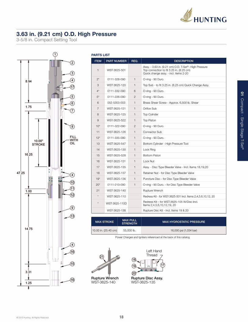
1 WST-3625-501Assy. - 3.63 in. (9.21 cm) O.D. T-Set®- High PressureTop connection to fit 3.25 in. (8.25 cm) Quick change assy. - incl. items 2-20
2* 0111-328-090 1 O-ring - 90 Duro.
3 WST-3625-120 1 Top Sub - to fit 3.25 in. (8.25 cm) Quick Change Assy.
4* 0111-332-090 6 O-ring - 90 Duro.
5* 0111-226-090 2 O-ring - 90 Duro.
6 052-5303-003 1 Brass Shear Screw - Approx. 6,500 lb. Shear
7 WST-3625-121 1 Orifice Sub
8 WST-3625-125 1 Top Cylinder
9 WST-3625-522 1 Top Piston
10* 0111-322-090 2 O-ring - 90 Duro.
11 WST-3625-126 1 Connector Sub
12* 0111-335-090 1 O-ring - 90 Duro.
13 WST-3625-547 1 Bottom Cylinder - High Pressure Tool
14 WST-3625-130 1 Lock Ring
15 WST-3625-528 1 Bottom Piston
16 WST-3625-131 1 Lock Nut
17 WST-3625-135 1 Assy. - Disc Type Bleeder Valve - Incl. Items 18,19,20
18 WST-3625-137 1 Retainer Nut - for Disc Type Bleeder Valve
19* WST-3625-136 1 Puncture Disc - for Disc Type Bleeder Valve
20* 0111-213-090 1 O-ring - 90 Duro. - for Disc Type Bleeder Valve
21 WST-3625-140 Rupture Wrench
* WST-3625-110 Redress Kit - for WST-3625-501 Incl. Items 2,4,5,6,10,12, 20
* WST-3625-110D Redress Kit - for WST-3625-105 W/Disc Incl. Items 2,4,5,6,10,12,19, 20
WST-3625-138 Rupture Disc Kit - Incl. Items 19 & 20
Rupture Wrench WST-3625-140
Left Hand Thread
Rupture Disc Assy. WST-3625-135
3.63 in. (9.21 cm) O.D. High Pressure3-5/8 in. Compact Setting Tool
MAX STROKE MAX PULL STRENGTH MAX HYDROSTATIC PRESSURE
10.00 in. (25.40 cm) 55,000 lb. 16,000 psi (1,034 bar)
Power Charges and Igniters referenced at the back of this catalog
19
01 Com
pact - S
ingle Stage T-S
et ®
© 2015 Hunting. All Rights Reserved.
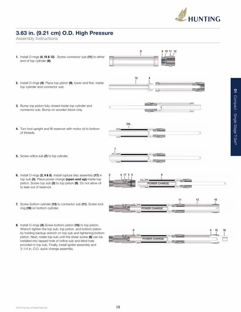
1. Install O-rings (4, 10 & 12) . Screw connector sub (11) to either end of top cylinder (8).
2. Install O-rings (4). Place top piston (9), lower end first, inside top cylinder and connector sub.
4. Turn tool upright and fill reservoir with motor oil to bottom of threads.
5. Screw orifice sub (7) to top cylinder.
6. Install O-rings (2, 4 & 5). Install rupture disc assembly (17) in top sub (3). Place power charge (open end up) inside top piston. Screw top sub (3) to top piston (9). Do not allow oil to leak out of reservoir.
7. Screw bottom cylinder (13) to connector sub (11). Screw lock ring (16) on bottom cylinder.
8. Install O-rings (4).Screw bottom piston (15) to top piston. Wrench tighten the top sub, top piston, and bottom piston by holding backup wrench on top sub and tightening bottom piston. Next, rotate top sub until the shear screw (6) can be installed into tapped hole of orifice sub and blind hole provided in top sub. Finally, install igniter assembly and 3-1/4 in. O.D. quick change assembly.
3. Bump top piston fully closed inside top cylinder and connector sub. Bump on wooden block only.
3.63 in. (9.21 cm) O.D. High PressureAssembly Instructions

20
01 Com
pact - S
ingle Stage T-S
et ®
© 2015 Hunting. All Rights Reserved.
The illustrations shown above list suggested critical minimum and maximum wear diameters.
3.63 in. (9.21 cm) O.D. High PressureMinimum and Maximum Wear Diameters
Ori
fice
Sub
Top
Sub
Top
Cyl
ind
erC
onn
ecto
r S
ub
Top
Pis
ton
Bo
tto
m C
ylin
der
Bo
tto
m P
isto
n

02 Com
pact - M
ulti-Stage T-S
et ®
21© 2015 Hunting. All Rights Reserved.
The Multi-Stage T-Set offers the capability to set plugs and packers requiring long setting strokes and higher forces necessary for tubing patches.
The design concept of the Multi-Stage T-Set is the same as the Compact Single Stage T-Set. A self-bleeding compensation system allows for quick oil filling without the need for oil level gauges.
A larger slow set power charge is used to compensate for the extra piston movement required for longer strokes. Once ignited, the generated high pressure gas migrates through the upper and lower pistons initiating the setting sequence. Like the Compact Single Stage T-Set, the hydraulic oil slowly bleeds out of the tool providing a cushioning effect. Once the required setting force is achieved, a shear stud breaks releasing the T-Set from the plug/packer.
Multi-Stage T-SET®
FEATURES■■ Long stroke
■■ Higher forces necessary for tubing patches
■■ Self-bleeding compensating system
■■ Options for bleeder valves
■■ Black oxide coated components
BENEFITS■■ Ideal for plugs and packers requiring a long stroke
■■ Compensation oil level adjustments are not necessary
■■ Bleeder valves provide a safe option to bleed off pressure inside the tool at surface
■■ Black oxide coating improves corrosion and chemical resistance

02 Com
pact - M
ulti-Stage T-S
et ®
22© 2015 Hunting. All Rights Reserved.
PARTS LIST
ITEM PART NUMBER REQ. DESCRIPTION
1 WST-1718-101 Assy. - 1.71 in. (4.34 cm) O.D. T-Set®- Top Connection to fit “GO” 1-7/16 in. O.D. High Pressure Firing Head - Incl. Items 2-16
2 WST-1718-020 1 Top Sub
3* 0111-216-090 18 O-ring - 90 Duro.
4* 0111-115-090 6 O-ring - 90 Duro.
5* 052-5304-003 1 Brass Shear Screw - Approx. 2,300 lb. Shear
6 WST-1718-121 1 Power Charge Chamber
7 WST-1718-028 1 Shear Sub - Non Ported
8 WST-1718-023 1 Orifice Sub
9 WST-1718-124 2 Top Cylinder
10 WST-1718-125 2 Top Piston
11 WST-1718-126 2 Connector Sub
12 WST-1718-127 1 Bottom Cylinder
13 WST-1718-128 1 Bottom Piston
14 WST-1718-030 1 Lock Ring
15 WST-1718-130 1 Safety Release Nut - 25,000 lb. Weak Point
16 WST-1718-131 1 Bottom Adapter
* WST-1718-110 Redress Kit - for WST-1718-101 Incl. Items 3,4,5
Optional Equipment Not Included In Assy. WST-1718-101
17 WST-1718-022 1 Shear Sub - Ported for Bleeder Valve
18 WST-Bk05-137 1 Retainer Nut
19 WST-Bk05-136 1 Rupture Disc
20 WST-111-090 1 O-ring - 90 Duro
21 WST-2125-150 Rupture Wrench
WST-BK05-138 Rupture Disc Kit - Incl. Items 19 & 20
18
19
20
21
Rupture Wrench WST-2125-150
Left Hand Thread
Rupture Disc Assy. Items 18-20
1.71 in. (4.34 cm) O.D.1-11/16 in. Multi-Stage Setting Tool
MAX STROKE MAX PULL STRENGTH
UNPORTED MAX HYDROSTATIC PRESSURE
PORTED MAX HYDROSTATIC PRESSURE
10.50 in. (26.67 cm) 20,000 lb. 20,000 psi (1,379 bar) 15,000 psi (1,034 bar)
Power Charges and Igniters referenced at the back of this catalog

02 Com
pact - M
ulti-Stage T-S
et ®
23© 2015 Hunting. All Rights Reserved.
1. Install O-rings (3). then lubricate O-rings and threads. Slide top pistons (10) in top cylinders (9). Install release nut and bottom adapter (15 & 16) to bottom piston (13). Then install this unit in bottom cylinder (12). Install lock ring (14).
8. Install O-rings (3).Screw top sub (2) to power charge chamber wrench tight. Check igniter by first removing ground wire from contact spring then checking resistance (51 ohms) with blasting galvanometer. Next, wrap ground wire around case of igniter body then place igniter in firing head. Tool is now assembled. Attach appropriate firing adapter, collar locator, and setting adapters.
2. Install O-rings (3 & 4). Screw connector subs (11) into bottom cylinder and one of top cylinders. Make wrench tight. Wrench only on wrenching areas provided. Do not wrench on pistons anywhere except in knurled areas.
6. Return tool to vise. Make orifice sub (8) wrench tight to top cylinder. Install O-rings (3 & 4). Screw shear sub (7) to top piston. Hold back-up wrench on bottom adapter (16) and tighten shear sub which will ensure all inside connections are tight. Rotate shear sub clockwise until shear screw holes align then install shear screw.
7. Install rupture disc assembly (17) if used. Screw power charge chamber (6) to shear sub (7). Install power charge. Make sure open end of power charge is facing up.
4. Join remaining top cylinder/top piston unit to connector sub/ top piston unit. Make wrench tight
5. Remove tool from vise. Bump tool (view A) completely closed (on wooden block). Next, turn tool upright then fill top cylinder with motor oil until oil level reaches groove at lower end of thread. Install O-ring (3). Install orifice sub (8). Excess oil will purge as sub is screwed in.
3. Join top cylinder/top piston unit to connector sub/top piston unit. Make wrench tight.
1.71 in. (4.34 cm) O.D.Assembly Instructions
View A
View B

02 Com
pact - M
ulti-Stage T-S
et ®
24© 2015 Hunting. All Rights Reserved.
T-Set® wireline multi-stage setting tools in O.D. sizes 1.71 in. (4.34 cm) do not contain a rupture disc bleeder assembly except when specifically ordered.
Two locations for bleeding pressure from tools less rupture disc are illustrated in drawing “A”. The preferred method of bleeding pressure is to hold wrench on “GO” 1.50 in. (8.81 cm) O.D. high pressure firing head assembly while turning the setting tool counter clockwise. Pressure will begin to bleed as soon as the lower O-ring on the firing head assembly is uncovered. Ample threads are provided on the firing adapter to prevent separation from cylinder. Should a bridge occur and pressure stops bleeding, screw the tool clockwise then begin the procedure again.
The alternate method shown in drawing “A” is accomplished by holding wrench on shear sub (see parts list) while turning the top cylinder counter clockwise. The top piston will back out of shear sub and pressure will begin to bleed. Again, if a bridge occurs screw the tool clockwise then begin the procedure again.
An indication that most of pressure has safely bled off is when the tool partially closes. This indicates that the trapped compressed atmosphere in the bottom cylinder is overcoming what little gas pressure remains of the power charge.
1.71 in. (4.34 cm) O.D.Pressure Bleeding Locations
“GO” Type 1.50” O.D. High Pressure Firing Head Assy.
Bleed Location (Preferred)
Bleed Location (Alternate)
Rupture Disc Assy. WST-BK05-136 WST-BK05-137 0111-111-090
Rupture Wrench WST-2125-150
Shear Sub
Top Piston
Top Cylinder
Bleed Location (Alternate)
A. Tools Without Manual Bleeder Valve Assy.
B. Tools With Rupture Disc Bleeder Assy.

02 Com
pact - M
ulti-Stage T-S
et ®
25© 2015 Hunting. All Rights Reserved.
The illustrations shown above list suggested critical minimum and maximum wear diameters.
1.71 in. (4.34 cm) O.D.Minimum and Maximum Wear Diameters
Top
Sub
Top
Cyl
ind
er
Po
wer
CH
arg
er C
ham
ber
Co
nnec
tor
Sub
(2
req
uire
d)
Top
Cyl
ind
er
(2 r
equi
red
)
She
ar S
ub
Bo
tto
m C
ylin
der
Bo
tto
m P
isto
n
Ori
fice
Sub

02 Com
pact - M
ulti-Stage T-S
et ®
26© 2015 Hunting. All Rights Reserved.
PARTS LIST
ITEM PART NUMBER REQ. DESCRIPTION
1 WST-2125-101 Assy. - 2.13 in. (5.40 cm) O.D. T-Set® - Top Connection to fit “GO” 1-7/16 in. O.D. High Pressure Firing Head- Incl. Items 2-19
2 WST-2125-120 1 Top Sub
3* 0111-222-090 18 O-ring - 90 Duro.
4* 0111-212-090 6 O-ring - 90 Duro.
5* 052-5304-003 1 Brass Shear Screw - Approx. 2,300 lb. Shear
6 WST-2125-121 1 Power Charge Chamber
7WST-2125-122
1Shear Sub - Ported For Bleeder Valve
WST-2125-132 Shear Sub - Unported (No Bleeder Valve)
8 WST-2125-123 1 Orifice Sub
9 WST-2125-124 2 Top Cylinder
10 WST-2125-125 2 Top Piston
11 WST-2125-126 2 Connector Sub
12 WST-2125-127 1 Bottom Cylinder
13 WST-2125-128 1 Bottom Piston
14 WST-2125-129 1 Lock Ring
15 WST-2125-130 1 Safety Release Nut- 52,000 lb. Weak Point
16 WST-2125-131 1 Bottom Adapter
17 WST-BK05-137 1 Retainer Nut
18 WST-BK05-136 1 Rupture Disc
19* 0111-111-090 1 O-ring - 90 Duro
20 WST-2125-150 1 Rupture Wrench
* WST-2125-110 Redress Kit - for WST-2125-101 Incl. Items 3,4,5,18 & 19
WST-BK05-138 Rupture Disc Kit - Incl. Items 18 & 19
Rupture Wrench WST-2125-150
Left Hand Thread
Rupture Disc Assy. Items 18-20
2.13 in. (5.40 cm) O.D.2-1/8 in. Multi-Stage Setting Tool
MAX STROKE MAX PULL STRENGTH
UNPORTED MAX HYDROSTATIC PRESSURE
PORTED MAX HYDROSTATIC PRESSURE
10.40 in. (26.42 cm) 32,000 lb. 20,000 psi (1,379 bar) 15,000 psi (1,034 bar)
Power Charges and Igniters referenced at the back of this catalog

02 Com
pact - M
ulti-Stage T-S
et ®
27© 2015 Hunting. All Rights Reserved.
1. Install O-rings (3). then lubricate O-rings and threads. Slide top pistons (10) in top cylinders (9). Install release nut and bottom adapter (15 & 16) to bottom piston (13). Then install this unit in bottom cylinder (12). Install lock ring (14).
2. Install O-rings (3 & 4). Screw connector subs (11) into bottom cylinder and one of top cylinders. Make wrench tight. Wrench only on wrenching areas provided. Do not wrench on pistons anywhere except in knurled areas.
4. Join remaining top cylinder/top piston unit to connector sub/ top piston unit. Make wrench tight
5. Remove tool from vise. Bump tool (view A) completely closed (on wooden block). Next, turn tool upright then fill top cylinder with motor oil until oil level reaches groove at lower end of thread. Install orifice sub (8).Excess oil will purge as sub is screwed in.
6. Return tool to vise. Make orifice sub (8) wrench tight to top cylinder. Install O-rings (3 & 4). Screw shear sub (7) to top piston. Hold back-up wrench on bottom adapter (16) and tighten shear sub which will ensure all inside connections are tight. Rotate shear sub clockwise until shear screw holes align then install shear screw (5).
7. Install rupture disc assembly (17) if used. Screw power charge chamber (6) to shear sub (7). Install power charge. Make sure open end of power charge is facing up.
8. Install O-rings (3).Screw top sub (2) to power charge chamber wrench tight. Check igniter by first removing ground wire from contact spring then checking resistance (51 ohms) with blasting galvanometer. Next, wrap ground wire around case of igniter body then place igniter in firing head. Tool is now assembled. Attach appropriate firing adapter, collar locator, and setting adapters.
3. Join top cylinder/top piston unit to connector sub/top piston unit. Make wrench tight.
2.13 in. (5.40 cm) O.D.Assembly Instructions
View A
View B

02 Com
pact - M
ulti-Stage T-S
et ®
28© 2015 Hunting. All Rights Reserved.
T-Set® wireline multi-stage setting tools in O.D. sizes 2.13 in. (5.40 cm) contain a rupture disc bleeder assembly except when specifically ordered with a non ported shear sub for a manual bleed application.
Two locations for bleeding pressure from tools less rupture disc are illustrated in drawing “A”. The preferred method of bleeding pressure is to hold wrench on “GO” 1.50 in. O.D. high pressure firing head assembly while turning the setting tool counter clockwise. Pressure will begin to bleed as soon as the lower O-ring on the firing head assembly is uncovered. Ample threads are provided on the firing adapter to prevent separation from cylinder. Should a bridge occur and pressure stops bleeding, screw the tool clockwise then begin the procedure again.
The alternate method shown in drawing “A” is accomplished by holding wrench on shear sub (see parts list) while turning the top cylinder counter clockwise. The top piston will back out of shear sub and pressure will begin to bleed. Again, if a bridge occurs screw the tool clockwise then begin the procedure again.
When using a ported assembly, position the tool so that the rupture port of the ported shear sub is facing “away” from the operator. (Drawing B). Take the WST-2125-150 rupture wrench, screw the “left hand” thread of the rupture stem into the “left hand” threads of the WST-BK05-137 retainer nut until the stem bottoms out on the surface of the WST-BK05-136 rupture disc. Grasp the wrench firmly and turn counter clockwise until the rupture disc is punctured and all pressure is bled from the tool. Should a bridge occur, refer to alternative bleed location and instructions .
An indication that most of pressure has safely bled off is when the tool partially closes. This indicates that the trapped compressed atmosphere in the bottom cylinder is overcoming what little gas pressure remains of the power charge.
2.13 in. (5.40 cm) O.D.Pressure Bleeding Locations
“GO” Type 1.50” O.D. High Pressure Firing Head Assy.
Bleed Location (Preferred)
Bleed Location (Alternate)
Rupture Disc Assy. WST-BK05-136 WST-BK05-137 0111-111-090
Rupture Wrench WST-2125-150
Shear Sub
Top Piston
Top Cylinder
Bleed Location (Alternate)
A. Tools Without Manual Bleeder Valve Assy.
B. Tools With Rupture Disc Bleeder Assy.

02 Com
pact - M
ulti-Stage T-S
et ®
29© 2015 Hunting. All Rights Reserved.
The illustrations shown above list suggested critical minimum and maximum wear diameters.
2.13 in. (5.40 cm) O.D.Minimum and Maximum Wear Diameters
Top
Sub
Top
Cyl
ind
er
(2 r
equi
red
)
Po
wer
Cha
rge
Cha
mb
er
Tand
em S
ub
(2 r
equi
red
)
Top
Pis
ton
(2 r
equi
red
)
She
ar S
ub
Bo
tto
m C
ylin
der
Bo
tto
m P
isto
n
Ori
fice
Sub
02 Com
pact - M
ulti-Stage T-S
et ®
30© 2015 Hunting. All Rights Reserved.
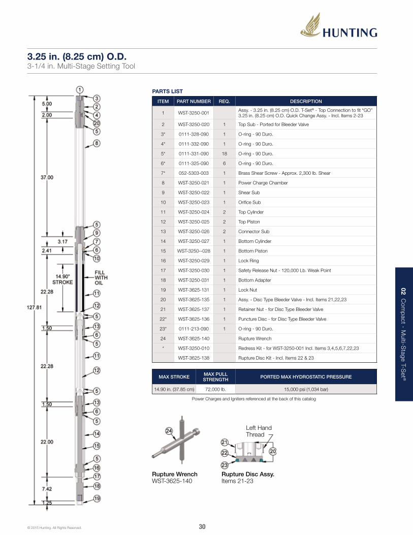
PARTS LIST
ITEM PART NUMBER REQ. DESCRIPTION
1 WST-3250-001 Assy. - 3.25 in. (8.25 cm) O.D. T-Set® - Top Connection to fit “GO” 3.25 in. (8.25 cm) O.D. Quick Change Assy. - Incl. Items 2-23
2 WST-3250-020 1 Top Sub - Ported for Bleeder Valve
3* 0111-328-090 1 O-ring - 90 Duro.
4* 0111-332-090 1 O-ring - 90 Duro.
5* 0111-331-090 18 O-ring - 90 Duro.
6* 0111-325-090 6 O-ring - 90 Duro.
7* 052-5303-003 1 Brass Shear Screw - Approx. 2,300 lb. Shear
8 WST-3250-021 1 Power Charge Chamber
9 WST-3250-022 1 Shear Sub
10 WST-3250-023 1 Orifice Sub
11 WST-3250-024 2 Top Cylinder
12 WST-3250-025 2 Top Piston
13 WST-3250-026 2 Connector Sub
14 WST-3250-027 1 Bottom Cylinder
15 WST-3250--028 1 Bottom Piston
16 WST-3250-029 1 Lock Ring
17 WST-3250-030 1 Safety Release Nut - 120,000 Lb. Weak Point
18 WST-3250-031 1 Bottom Adapter
19 WST-3625-131 1 Lock Nut
20 WST-3625-135 1 Assy. - Disc Type Bleeder Valve - Incl. Items 21,22,23
21 WST-3625-137 1 Retainer Nut - for Disc Type Bleeder Valve
22* WST-3625-136 1 Puncture Disc - for Disc Type Bleeder Valve
23* 0111-213-090 1 O-ring - 90 Duro.
24 WST-3625-140 Rupture Wrench
* WST-3250-010 Redress Kit - for WST-3250-001 Incl. Items 3,4,5,6,7,22,23
WST-3625-138 Rupture Disc Kit - Incl. Items 22 & 23
Rupture Wrench WST-3625-140
Left Hand Thread
Rupture Disc Assy. Items 21-23
3.25 in. (8.25 cm) O.D.3-1/4 in. Multi-Stage Setting Tool
MAX STROKE MAX PULL STRENGTH PORTED MAX HYDROSTATIC PRESSURE
14.90 in. (37.85 cm) 72,000 lb. 15,000 psi (1,034 bar)
Power Charges and Igniters referenced at the back of this catalog

02 Com
pact - M
ulti-Stage T-S
et ®
31© 2015 Hunting. All Rights Reserved.
1. Install O-rings (5). then lubricate O-rings and threads. Slide top pistons (12) in top cylinders (11). Install release nut and bottom adapter (17 & 18) to bottom piston (15). Then install this unit in bottom cylinder (14). Install lock ring (16).
2. Install O-rings (5 & 6). Screw connector subs (13) into bottom cylinder and one of top cylinders. Make wrench tight. Wrench only on wrenching areas provided. Do not wrench on pistons anywhere except in knurled areas.
4. Join remaining top cylinder/top piston unit to connector sub/ top piston unit. Make wrench tight
5. Remove tool from vise. Bump tool (view A) completely closed (on wooden block). Next, turn tool upright then fill top cylinder with motor oil until oil level reaches groove at lower end of thread. Install orifice sub (10).Excess oil will purge as sub is screwed in.
6. Install O-rings (5 & 6) . Return tool to vise. Make orifice sub (10) wrench tight to top cylinder screw shear sub (9) to top piston. Hold back-up wrench on bottom adapter (18) and tighten shear sub which will ensure all inside connections are tight. Rotate shear sub clockwise until shear screw holes align then install shear screw (7).
7. Install rupture disc assembly (20) . Screw power charge chamber (8) to shear sub (9). Install power charge. Make sure open end of power charge is facing up.
8. Install O-rings (5).Screw top sub (2) to power charge chamber wrench tight. Check igniter by first removing ground wire from contact spring then checking resistance (51 ohms) with blasting galvanometer. Next, wrap ground wire around case of igniter body then place igniter in firing head. Tool is now assembled. Attach appropriate firing adapter, collar locator, and setting adapters.
3. Join top cylinder/top piston unit to connector sub/top piston unit. Make wrench tight.
3.25 in. (8.25 cm) O.D.Assembly Instructions
View A
View B
02 Com
pact - M
ulti-Stage T-S
et ®
32© 2015 Hunting. All Rights Reserved.
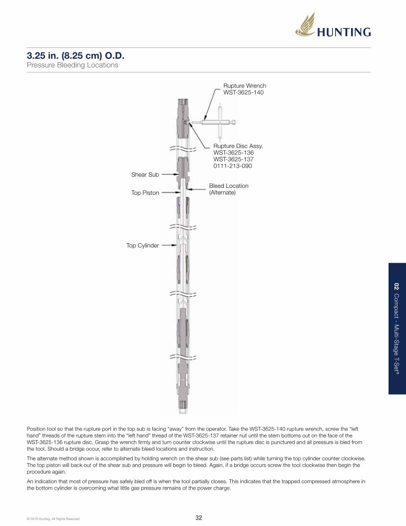
Position tool so that the rupture port in the top sub is facing “away” from the operator. Take the WST-3625-140 rupture wrench, screw the “left hand” threads of the rupture stem into the “left hand” thread of the WST-3625-137 retainer nut until the stem bottoms out on the face of the WST-3625-136 rupture disc. Grasp the wrench firmly and turn counter clockwise until the rupture disc is punctured and all pressure is bled from the tool. Should a bridge occur, refer to alternate bleed locations and instruction.
The alternate method shown is accomplished by holding wrench on the shear sub (see parts list) while turning the top cylinder counter clockwise. The top piston will back out of the shear sub and pressure will begin to bleed. Again, if a bridge occurs screw the tool clockwise then begin the procedure again.
An indication that most of pressure has safely bled off is when the tool partially closes. This indicates that the trapped compressed atmosphere in the bottom cylinder is overcoming what little gas pressure remains of the power charge.
3.25 in. (8.25 cm) O.D.Pressure Bleeding Locations
Rupture Wrench WST-3625-140
Bleed Location (Alternate)
Shear Sub
Top Piston
Top Cylinder
Rupture Disc Assy. WST-3625-136 WST-3625-137 0111-213-090

02 Com
pact - M
ulti-Stage T-S
et ®
33© 2015 Hunting. All Rights Reserved.
PARTS LIST
ITEM PART NUMBER REQ. DESCRIPTION
1 WST-4500-001 Assy. - 4.50 in. (11.43 cm) O.D. T-Set® - Top Connection to fit “GO” 3.25 in. (8.25 cm) O.D. Quick Change Assy. - Incl. Items 2-22
2 WST-4500-020 1 Top Sub - Ported for Bleeder Valve
3* 0111-328-090 7 O-ring - 90 Duro.
4* 0111-332-090 1 O-ring - 90 Duro.
5* 0111-338-090 19 O-ring - 90 Duro.
6* 052-5303-003 1 Brass Shear Screw - Approx. 2,300 lb. Shear
7 WST-4500-021 1 Power Charge Chamber
8 WST-4500-022 1 Shear Sub
9 WST-4500-023 1 Orifice Sub
10 WST-4500-024 2 Top Cylinder
11 WST-4500-025 2 Top Piston
12 WST-4500-026 2 Connector Sub
13 WST-4500-027 1 Bottom Cylinder
14 WST-4500-028 1 Bottom Piston
15 WST-4500-029 1 Lock Ring
16 WST-4500-030 1 Safety Release Nut - 194,000 lb. Weak Point
17 WST-4500-031 1 Bottom Adapter
18 WST-3625-131 1 Lock Nut
19 WST-3625-135 1 Assy. - Disc Type Bleeder Valve - Items 20,21,22
20 WST-3625-137 1 Retainer Nut - for Disc Type Bleeder Valve
21* WST-3625-136 1 Puncture Disc - for Disc Type Bleeder Valve
22* 0111-213-090 1 O-ring - 90 Duro.
23 WST-3625-140 Rupture Wrench
* WST-4500-010 Redress Kit - for WST-4500-001 Incl. Items 3,4,5,6,21,22
WST-3625-138 Rupture Disc Kit - Incl. Items 21 & 22
Rupture Wrench WST-3625-140
Left Hand Thread
Rupture Disc Assy. Items 20-22
4.50 in. (11.43 cm) O.D.4-1/2 in. Multi-Stage Setting Tool
MAX STROKE MAX PULL STRENGTH PORTED MAX HYDROSTATIC PRESSURE
20.0 in. (50.8 cm) 95,000 lb. 15,000 psi (1,034 bar)
Power Charges and Igniters referenced at the back of this catalog
02 Com
pact - M
ulti-Stage T-S
et ®
34© 2015 Hunting. All Rights Reserved.
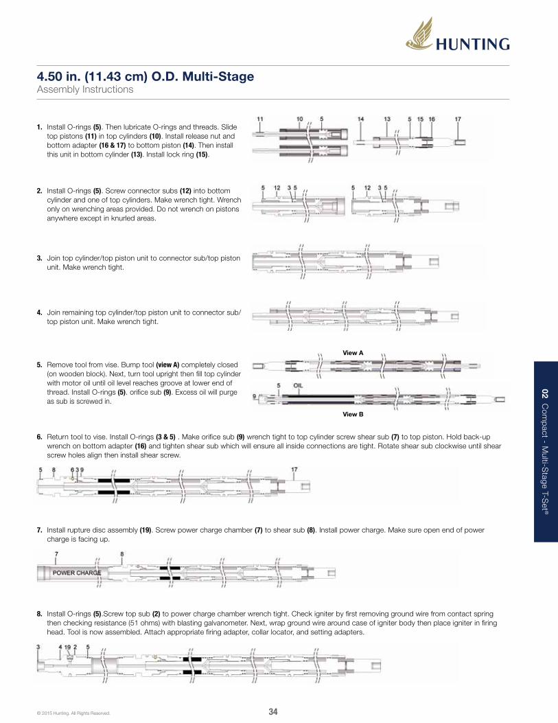
1. Install O-rings (5). Then lubricate O-rings and threads. Slide top pistons (11) in top cylinders (10). Install release nut and bottom adapter (16 & 17) to bottom piston (14). Then install this unit in bottom cylinder (13). Install lock ring (15).
2. Install O-rings (5). Screw connector subs (12) into bottom cylinder and one of top cylinders. Make wrench tight. Wrench only on wrenching areas provided. Do not wrench on pistons anywhere except in knurled areas.
4. Join remaining top cylinder/top piston unit to connector sub/ top piston unit. Make wrench tight.
5. Remove tool from vise. Bump tool (view A) completely closed (on wooden block). Next, turn tool upright then fill top cylinder with motor oil until oil level reaches groove at lower end of thread. Install O-rings (5). orifice sub (9). Excess oil will purge as sub is screwed in.
6. Return tool to vise. Install O-rings (3 & 5) . Make orifice sub (9) wrench tight to top cylinder screw shear sub (7) to top piston. Hold back-up wrench on bottom adapter (16) and tighten shear sub which will ensure all inside connections are tight. Rotate shear sub clockwise until shear screw holes align then install shear screw.
7. Install rupture disc assembly (19). Screw power charge chamber (7) to shear sub (8). Install power charge. Make sure open end of power charge is facing up.
8. Install O-rings (5).Screw top sub (2) to power charge chamber wrench tight. Check igniter by first removing ground wire from contact spring then checking resistance (51 ohms) with blasting galvanometer. Next, wrap ground wire around case of igniter body then place igniter in firing head. Tool is now assembled. Attach appropriate firing adapter, collar locator, and setting adapters.
3. Join top cylinder/top piston unit to connector sub/top piston unit. Make wrench tight.
4.50 in. (11.43 cm) O.D. Multi-StageAssembly Instructions
View A
View B

02 Com
pact - M
ulti-Stage T-S
et ®
35© 2015 Hunting. All Rights Reserved.
Position tool so that the rupture port in the top sub is facing “away” from the operator. Take the WST-3625-140 rupture wrench, screw the “left hand” threads of the rupture stem into the “left hand” thread of the WST-3625-137 retainer nut until the stem bottoms out on the face of the WST-3625-136 rupture disc. Grasp the wrench firmly and turn counter clockwise until the rupture disc is punctured and all pressure is bled from the tool. Should a bridge occur, refer to alternate bleed locations and instruction.
The alternate method shown is accomplished by holding wrench on shear sub (see parts list) while turning the top cylinder counter clockwise. The top piston will back out of shear sub and pressure will begin to bleed. Again, if a bridge occurs screw the tool clockwise then begin the procedure again.
An indication that most of pressure has safely bled off is when the tool partially closes. This indicates that the trapped compressed atmosphere in bottom cylinder is overcoming what little gas pressure remains of the power charge.
4.50 in. (11.43 cm) O.D.Pressure Bleeding Locations
Rupture Wrench WST-3625-140
Bleed Location (Alternate)
Shear Sub
Top Piston
Top Cylinder
Rupture Disc Assy. WST-3625-136 WST-3625-137 0111-213-090

02 Com
pact - M
ulti-Stage T-S
et ®
36© 2015 Hunting. All Rights Reserved.
The illustrations shown above list suggested critical minimum and maximum wear diameters.
4.50 in. (11.43 cm) O.D.Minimum and Maximum Wear Diameters
Top
Sub
Top
Cyl
ind
er
(2 r
equi
red
)
Po
wer
Cha
rge
Cha
mb
er
Co
nnec
tor
Sub
(2
req
uire
d)
Top
Pis
ton
(2 r
equi
red
)
She
ar S
ub
Bo
tto
m C
ylin
der
Bo
tto
m P
isto
n
Ori
fice
Sub
03 T-Set ® S
izes 05 - 10 - 20
37© 2015 Hunting. All Rights Reserved.
The Size 05 – 10 – 20 T-Set series features a classic design that the oilfield has been familiar with for decades. Hunting has made many improvements to the original design, making it the most rugged and reliable setting tool in the oilfield today.
The ignition of a power charge creates high gas pressure inside the setting tool. The generated high pressure gas pushes a piston, which in turn drives hydraulic oil through a small orifice, initiating the setting sequence. Once the required setting force is achieved, a shear stud breaks releasing the T-Set from the plug/packer.
Size 05 – 10 – 20 T-SET®
FEATURES■■ Case hardened pressure cylinders
■■ Black oxide coated components
■■ Options for bleeder valves
BENEFITS■■ Greater surface hardness and increased abrasive wear from case hardening
■■ Black oxide coating improves corrosion and chemical resistance
■■ Bleeder valves provide a safer option to bleed off pressure inside the tool at surface

03 T-Set ® S
izes 05 - 10 - 20
38© 2015 Hunting. All Rights Reserved.
PARTS LIST
ITEM PART NUMBER REQ. DESCRIPTION
1 WST-BK05-001 Assy. - 1.71 in. (4.34 cm) O.D. Size 05 T-Set®- Incl. Items 2-26
2 WST-BK05-036 1 Thread Protector
3 WST-BK05-020 1 Power Charge Chamber
4 WST-BK05-021 1 Upper Cylinder
5 WST-BK05-023 1 Tandem Connector
6 WST-BK05-022 1 Upper Piston
7 WST-BK05-034 1 Middle Cylinder
8 WST-BK05-025 1 Middle Connector
9 WST-BK05-024 1 Lower Piston
10 WST-BK05-035 1 Lower Cylinder
11 WST-BK05-027 1 Lower Connector
12 WST-BK05-029 1 Link Retaining Ring
13 WST-BK05-031 1 Crosslink
14 WST-BK05-026 1 Piston Rod
15 WST-BK05-030 1 Setting Mandrel
16 WST-BK05-028 1 Crosslink Sleeve
17* 0111-213-090 10 O-ring - 90 Duro.
18* 0111-214-090 7 O-ring - 90 Duro.
19* 0111-112-090 1 O-ring - 90 Duro.
20* 0111-114-090 2 O-ring - 90 Duro.
21 CPSS-0025-20-0031 1 Cup Point Set Screw - 1/4-20 X 5/16 lg.
22 CPSS-0025-20-0025 2 Cup Point Set Screw - 1/4-20 X 1/4 lg.
23 CPSS-0025-20-0019 1 Cup Point Set Screw - 1/4-20 X 3/16 lg.
24 WST-BK05-137 1 Retainer Nut
25* WST-BK05-136 1 Rupture Disc
26* 0111-111-090 1 O-ring - 90 Duro.
27 WST-2125-150 Rupture Wrench
* WST-BK05-010 Redress Kit - for WST-BK05-001 Incl. Items 17, 18, 19, 20, 25 & 26
WST-BK05-138 Rupture Disc Kit - Incl. Items 25 & 26
Rupture Wrench WST-2125-150
Left Hand Thread
Rupture Disc Assy. WST-BK05-135 Items 24, 25 & 26
T-Set® Size 05Setting tool
SIZE MAX O.D. MAX STROKE MAX PULL STRENGTH
05 1.718 in. (4.364 cm) 6.0 in. (15.2 cm) 7,000 lb.
Power Charges and Igniters referenced at the back of this catalog

03 T-Set ® S
izes 05 - 10 - 20
39© 2015 Hunting. All Rights Reserved.
1. Install O-rings (17, 18, 19) and rupture disc assembly (24, 25, 26) In power charge chamber (3)
2. Screw upper cylinder (4) to power charge chamber.
4. Screw middle cylinder (7) to tandem connector. Install O-rings (17) on upper piston (6). Install piston fully inside cylinder.
6. Install O-rings (17-18) on middle connector (8) then screw into middle cylinder with small orifice hole toward oil.
7. Install O-rings (18 & 20) to lower connector (11). Slide piston rod (14) inside lower connector. Install O-rings (18) on lower piston (9). Screw piston to piston rod.
8. Lubricate piston, lower connector threads and cylinder bore. Slide lower cylinder (10) over piston and make up to lower connector.
9. Screw setting mandrel (15) to lower connector hand tight. Install set screw (21).
10. Align slots in piston rod and setting mandrel. Slide retaining ring (12) over setting mandrel. Slide crosslink sleeve (16) over setting mandrel. Install crosslink (13) in slots. Slip retaining ring over crosslink and install set screws (22).
3. Install O-rings (17) on each end of tandem connector (5). Screw connector to upper cylinder.
T-Set® Size 05Assembly Instructions
continued on next page
5. Fill cylinder with SAE 10-40 o il to following levels: Well temp. Size 05 200°F or less 3-1/4 in. 200°F - 275°F 3-1/4 in. 275°F - 350°F 3-1/2 in. 350°F - 400°F 3-5/8 in.
See Left

03 T-Set ® S
izes 05 - 10 - 20
40© 2015 Hunting. All Rights Reserved.
T-Set® Size 05Disassembly Instructions
Hose off setting assembly to clean and cool it.
1. Point the manual bleeder valve port away from you and turn the stem slowly to the left with the manual bleeder valve wrench until it shoulders on the nut, at which time the pressure should be bled off through the pressure vent. If the pressure will not bleed off, close the manual bleeder valve; otherwise, the valve should remain open during the entire disassembly procedure.
2. Unscrew the cable head. Important, if the cable head is tight, indicating pressure has leaked into it, proceed to step 3.
3. Remove the Adapter Kit from the pressure setting assembly.
4. Hold a back-up on lower cylinder. Position the bleed hole away from you. Slowly unscrew the lower connector until compressed air escapes through the bleeder hole. Do not back-off lower connector from lower cylinder more than 1-1/4 in.
5. Hold a back-up on the upper cylinder. Position the bleed hole away from you. Slowly unscrew the connector a distance of no more than 1-1/4 in. from the upper cylinder to allow any pressure that may still be trapped in cylinder to escape. Be sure to stand away from the bleed hole.
6. Caution: all pressurized gas must be bled off before further disassembly is begun. The two halves of the tool will blow apart.
7. Unscrew and remove firing head. Unscrew and remove pressure chamber and upper cylinder. Remove burnt power charge from upper cylinder.
8. Unscrew and remove connector and middle cylinder. Discard the oil. Push floating piston out lower end of middle cylinder. Remove O-rings from floating piston, connector, and pressure chamber.
Disassemble remainder of setting assembly components. Thoroughly remove power charge debris. Apply light coat of oil to all parts to prevent rust from forming.
O-ring care and replacement:
All O-rings must be replaced after each use. The O-rings should be lubricated with an appropriate lubricant. We recommend Hydrotex. Use only the O-rings specified in the setting tools parts lists. Use only O-rings or O-ring kits supplied and/or specifically engineered for T-Set® tools.
T-Set® Size 05Assembly Instructions (continued)
11. Connect upper and lower halves of the tool together.
12. Place tool in vise and tighten all joints. Air trapped in cylinder during tightening should make crosslink sleeve stand off from cylinder head no more than 3/8 in.

03 T-Set ® S
izes 05 - 10 - 20
41© 2015 Hunting. All Rights Reserved.
The size 05 setting tool items shown below should be inspected periodically and any parts that have worn beyond the dimensions shown must be replaced.
T-Set® Size 05Minimum and Maximum Wear Diameters
Power Charge Chamber WST-BK05-020
Upper and Middle Cylinder WST-BK05-021 & WST-BK05-034
Middle Connector WST-BK05-025
Piston Rod WST-BK05-026
Lower Connector WST-BK05-027
Lower Cylinder WST-BK05-035
Lower Piston WST-BK05-024
Tandem Connector WST-BK05-023
Upper Piston WST-BK05-022

03 T-Set ® S
izes 05 - 10 - 20
42© 2015 Hunting. All Rights Reserved.
PARTS LIST
ITEM PART NUMBER REQ. DESCRIPTION
1 WST-BK10-001 Assy. - Size 10 - Incl. Items 2-26
2 WST-BK10-PIN-PRO 1 Pin Protector
3 0111-227-090 1 O-ring - 90 Duro.
4 WST-BK10-020 1 Power Charge Chamber
5* 0111-327-090 14 O-ring - 90 Duro.
6 WST-BK10-034 1 Ported Bleeder Sub
7 WST-BK10-022 1 Upper Piston
8 WST-BK10-021 1 Upper Cylinder
9 WST-BK10-023 1 Tandem Connector
10 WST-BK10-035 1 Lower Cylinder
11 WST-BK10-024 1 Lower Piston
12 CPSS-0025-20-0038 1 Cup Point Set Screw -1/4-20 x 3/8 lg.
13 WST-BK10-025 1 Retaining Pin
14 WST-BK10-026 1 Piston Rod
15* 0111-211-090 2 O-ring - 90 Duro.
16 WST-BK10-027 1 Cylinder Head
17 CPSS-0038-16-0050 1 Cup Point Set Screw - 3/8 -16 x 1/2 lg.
18 CPSS-0038-16-0025 1 Cup Point Set Screw - 3/8 -16 x 1/4 lg.
19 WST-BK10-029 1 Retaining Ring
20 WST-BK10-031 1 Crosslink
21 WST-BK10-028 1 Crosslink Sleeve
22 WST-BK10-030 1 Setting Mandrel
23 WST-3625-135 1 Assy. - Disc Type Bleeder Valve - Incl. Items 24,25,26
24 WST-3625-137 1 Retainer Nut - for Disc Type Bleeder Valve
25* WST-3625-136 1 Rupture Disc - for Disc Type Bleeder Valve
26* 0111-213-090 1 O-ring - 90 Duro. - for Bleeder Valve
27 WST-3625-140 Rupture Wrench
* WST-BK10-010 Redress Kit - for WST-BK10-001 Incl. Items 5,15,25,26
WST-3625-138 Rupture Disc Kit - Incl. Items 25 & 26
Note: high temp redress kits available upon request
Rupture Wrench WST-3625-140
Left Hand Thread
Rupture Disc Assy. WST-3625-135
T-Set® Size 10Setting Tool
SIZE MAX O.D. MAX STROKE MAX PULL STRENGTH
10 2.750 in. (6.985 cm) 5.8 in. (14.7 cm) 33,000 lb.
Power Charges and Igniters referenced at the back of this catalog
03 T-Set ® S
izes 05 - 10 - 20
43© 2015 Hunting. All Rights Reserved.
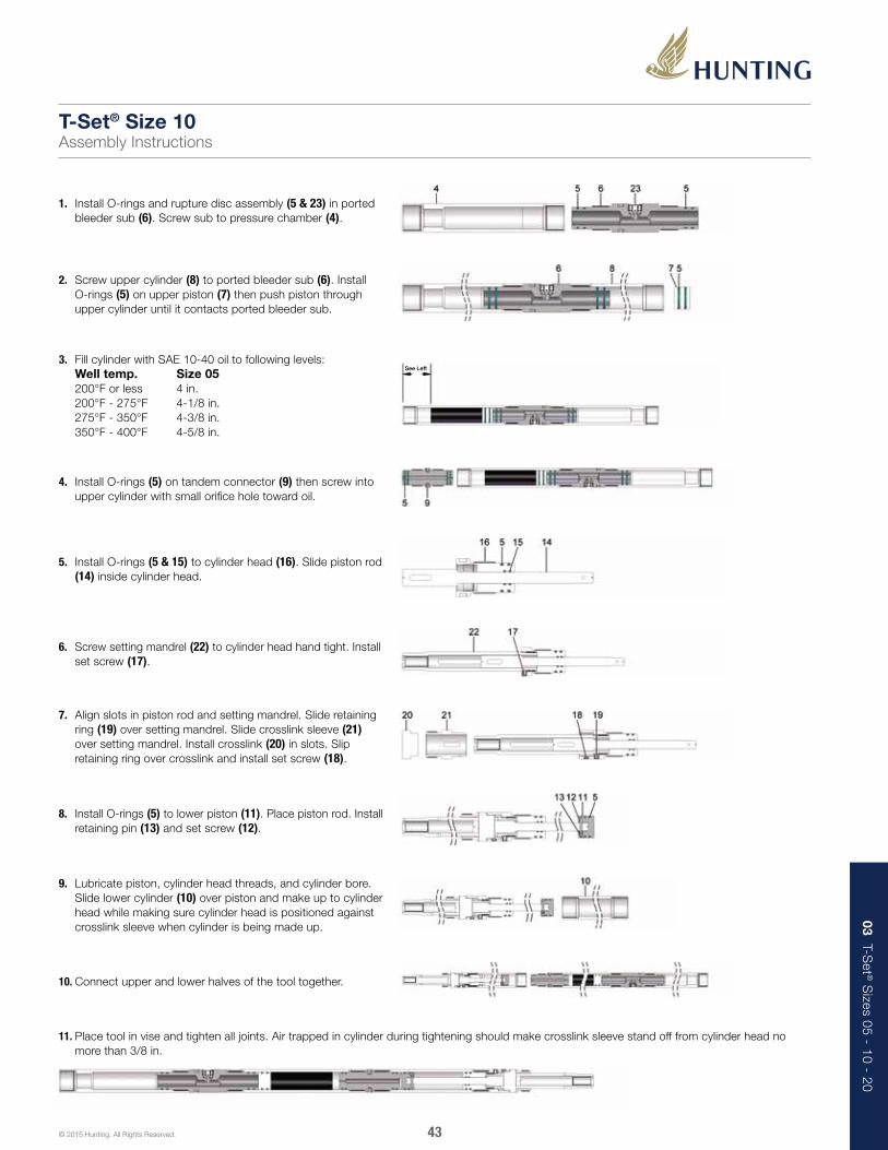
1. Install O-rings and rupture disc assembly (5 & 23) in ported bleeder sub (6). Screw sub to pressure chamber (4).
2. Screw upper cylinder (8) to ported bleeder sub (6). Install O-rings (5) on upper piston (7) then push piston through upper cylinder until it contacts ported bleeder sub.
4. Install O-rings (5) on tandem connector (9) then screw into upper cylinder with small orifice hole toward oil.
5. Install O-rings (5 & 15) to cylinder head (16). Slide piston rod (14) inside cylinder head.
6. Screw setting mandrel (22) to cylinder head hand tight. Install set screw (17).
7. Align slots in piston rod and setting mandrel. Slide retaining ring (19) over setting mandrel. Slide crosslink sleeve (21) over setting mandrel. Install crosslink (20) in slots. Slip retaining ring over crosslink and install set screw (18).
8. Install O-rings (5) to lower piston (11). Place piston rod. Install retaining pin (13) and set screw (12).
9. Lubricate piston, cylinder head threads, and cylinder bore. Slide lower cylinder (10) over piston and make up to cylinder head while making sure cylinder head is positioned against crosslink sleeve when cylinder is being made up.
10. Connect upper and lower halves of the tool together.
11. Place tool in vise and tighten all joints. Air trapped in cylinder during tightening should make crosslink sleeve stand off from cylinder head no more than 3/8 in.
T-Set® Size 10Assembly Instructions
3. Fill cylinder with SAE 10-40 oil to following levels: Well temp. Size 05 200°F or less 4 in. 200°F - 275°F 4-1/8 in. 275°F - 350°F 4-3/8 in. 350°F - 400°F 4-5/8 in.
See Left

03 T-Set ® S
izes 05 - 10 - 20
44© 2015 Hunting. All Rights Reserved.
PARTS LIST
ITEM PART NUMBER REQ. DESCRIPTION
1 WST-BK10-002 Assy. - Size 10 High Pressure T-Set® - Incl. Items 2-22
2 WST-BK10-PIN-PRO 1 Pin Protector
3 0111-227-090 1 O-ring - 90 Duro.
4 WST-BK10-050 1 Power Charge Chamber - Size #10 High Pressure
5* 0111-327-090 14 O-ring - 90 Duro.
6 WST-BK10-052 1 Non Ported Bleeder Sub - High Pressure
7 WST-BK10-022 1 Upper Piston
8 WST-BK10-051 1 Upper Cylinder - High Pressure
9 WST-BK10-023 1 Tandem Connector
10 WST-BK10-053 1 Lower Cylinder - High Pressure
11 WST-BK10-024 1 Lower Piston
12 CPSS-0025-20-0038 1 Cup Point Set Screw -1/4-20 x 3/8 lg.
13 WST-BK10-025 1 Retaining Pin
14 WST-BK10-026 1 Piston Rod
15* 0111-211-090 2 O-ring - 90 Duro.
16 WST-BK10-027 1 Cylinder Head
17 CPSS-0038-16-0050 1 Cup Point Set Screw - 3/8 -16 x 1/2 lg.
18 CPSS-0038-16-0025 1 Cup Point Set Screw - 3/8 -16 x 1/4 lg.
19 WST-BK10-029 1 Retaining Ring
20 WST-BK10-031 1 Crosslink
21 WST-BK10-028 1 Crosslink Sleeve
22 WST-BK10-030 1 Setting Mandrel
* WST-BK10-010-ND Redress Kit - for WST-BK10-002 & WST-B10-201 Incl. Items 5 & 15
T-Set® Size 10 Non-PortedHigh Pressure Setting Tool
SIZE MAX O.D. MAX STROKE MAX PULL STRENGTH
10 2.750 in. (6.985 cm) 5.8 in. (14.7 cm) 33,000 lb.
Power Charges and Igniters referenced at the back of this catalog

03 T-Set ® S
izes 05 - 10 - 20
45© 2015 Hunting. All Rights Reserved.
1. Install O-rings (5 ) in non-ported bleeder sub (6). Screw sub to pressure chamber (4).
2. Screw upper cylinder (8) to non-ported bleeder sub (6). Install O-rings (5) on upper piston (7) then push piston through upper cylinder until it contacts non-ported bleeder sub.
4. Install O-rings (5) on tandem connector (9) then screw into upper cylinder with small orifice hole toward oil.
5. Install O-rings (5 & 15) to cylinder head (16). Slide piston rod (14) inside cylinder head.
3. Fill cylinder with SAE 10-40 oil to following levels: Well temp. Size 05 200°F or less 4 in. 200°F - 275°F 4-1/8 in. 275°F - 350°F 4-3/8 in. 350°F - 400°F 4-5/8 in.
6. Screw setting mandrel (22) to cylinder head hand tight. Install set screw (17).
7. Align slots in piston rod and setting mandrel. Slide retaining ring (19) over setting mandrel. Slide crosslink sleeve (21) over setting mandrel. Install crosslink (20) in slots. Slip retaining ring over crosslink and install set screw (18).
8. Install O-rings (5) to lower piston (11). Place piston rod. Install retaining pin (13) and set screw (12).
9. Lubricate piston, cylinder head threads, and cylinder bore. Slide lower cylinder (10) over piston and make up to cylinder head while making sure cylinder head is positioned against crosslink sleeve when cylinder is being made up.
10. Connect upper and lower halves of the tool together.
11. Place tool in vise and tighten all joints. Air trapped in cylinder during tightening should make crosslink sleeve stand off from cylinder head no more than 3/8 in.
T-Set® Size 10Assembly Instructions

03 T-Set ® S
izes 05 - 10 - 20
46© 2015 Hunting. All Rights Reserved.
PARTS LIST
ITEM PART NUMBER REQ. DESCRIPTION
1 WST-BK10-201 Assy. - Size 10 Non Ported T-Set® - Incl. Items 2-22
2 WST-BK10-PIN-PRO 1 Pin Protector
3 0111-227-090 1 O-ring - 90 Duro.
4 WST-BK10-020 1 Power Charge Chamber
5* 0111-327-090 14 O-ring - 90 Duro.
6 WST-BK10-052 1 Non Ported Bleeder Sub - High Pressure
7 WST-BK10-022 1 Upper Piston
8 WST-BK10-021 1 Upper Cylinder
9 WST-BK10-023 1 Tandem Connector
10 WST-BK10-035 1 Lower Cylinder
11 WST-BK10-024 1 Lower Piston
12 CPSS-0025-20-0038 1 Cup Point Set Screw -1/4-20 x 3/8 lg.
13 WST-BK10-025 1 Retaining Pin
14 WST-BK10-026 1 Piston Rod
15* 0111-211-090 2 O-ring - 90 Duro.
16 WST-BK10-027 1 Cylinder Head
17 CPSS-0038-16-0050 1 Cup Point Set Screw - 3/8 -16 x 1/2 lg.
18 CPSS-0038-16-0025 1 Cup Point Set Screw - 3/8 -16 x 1/4 lg.
19 WST-BK10-029 1 Retaining Ring
20 WST-BK10-031 1 Crosslink
21 WST-BK10-028 1 Crosslink Sleeve
22 WST-BK10-030 1 Setting Mandrel
* WST-BK10-010-ND Redress Kit - for WST-BK10-002 & WST-B10-201 Incl. Items 5 & 15
T-Set® Size 10 Non-PortedSetting Tool
SIZE MAX O.D. MAX STROKE MAX PULL STRENGTH
10 2.75 in. (6.985 cm) 5.8 in. (14.7 cm) 33,000 lb.
Power Charges and Igniters referenced at the back of this catalog

03 T-Set ® S
izes 05 - 10 - 20
47© 2015 Hunting. All Rights Reserved.
1. Install O-rings (5 ) in non-ported bleeder sub (6). Screw sub to pressure chamber (4).
2. Screw upper cylinder (8) to non-ported bleeder sub (6). Install O-rings (5) on upper piston (7) then push piston through upper cylinder until it contacts non-ported bleeder sub.
4. Install O-rings (5) on tandem connector (9) then screw into upper cylinder with small orifice hole toward oil.
5. Install O-rings (5 & 15) to cylinder head (16). Slide piston rod (14) inside cylinder head.
6. Screw setting mandrel (22) to cylinder head hand tight. Install set screw (17).
7. Align slots in piston rod and setting mandrel. Slide retaining ring (19) over setting mandrel. Slide crosslink sleeve (21) over setting mandrel. Install crosslink (20) in slots. Slip retaining ring over crosslink and install set screw (18).
8. Install O-rings (5) to lower piston (11). Place piston rod. Install retaining pin (13) and set screw (12).
9. Lubricate piston, cylinder head threads, and cylinder bore. Slide lower cylinder (10) over piston and make up to cylinder head while making sure cylinder head is positioned against crosslink sleeve when cylinder is being made up.
10. Connect upper and lower halves of the tool together.
11. Place tool in vise and tighten all joints. Air trapped in cylinder during tightening should make crosslink sleeve stand off from cylinder head no more than 3/8 in.
T-Set® Size 10 Non-PortedAssembly Instructions
3. Fill cylinder with SAE 10-40 oil to following levels: Well temp. Size 10 200°F or less 4 in. 200°F - 275°F 4-1/8 in. 275°F - 350°F 4-3/8 in. 350°F - 400°F 4-5/8 in.
See Left

03 T-Set ® S
izes 05 - 10 - 20
48© 2015 Hunting. All Rights Reserved.
PARTS LIST
ITEM PART NUMBER REQ. DESCRIPTION
1 WST-BK20-001 Assy. - Size 20 T-Set® - Incl. Items 2-23
2 WST-BK20-PIN-PRO 1 Pin Protector
3 0111-231-090 1 O-ring - 90 Duro.
4 WST-BK20-020 1 Power Charge Chamber
5* 0111-334-090 14 O-ring - 90 Duro.
6 WST-BK20-022 1 Upper Piston
7 WST-BK20-021 2 Cylinder
8 WST-BK20-023 1 Tandem Connector
9 WST-BK20-024 1 Lower Piston
10 WST-BK20-025 1 Lock Pin
11 WST-BK20-026 1 Piston Rod
12* 0111-216-090 2 O-ring - 90 Duro.
13 WST-BK20-027 1 Cylinder Head
14 CPSS-0038-16-0050 1 Cup Point Set Screw -3/8-16 x 1/2 lg.
15 WST-BK20-029 1 Crosslink Retaining Ring
16 SHCS-0025-20-0038 1 Socket Head Cap Screw - 1/4-20 x 3/8 lg.
17 WST-BK20-031 1 Crosslink
18 WST-BK20-028 1 Crosslink Sleeve
19 WST-BK20-030 1 Setting Mandrel
20 WST-3625-135 1 Assy. - Disc Type Bleeder Valve - Incl. Items 21,22,23
21 WST-3625-137 1 Retainer Nut - for Disc Type Bleeder Valve
22 WST-3625-136 1 Rupture Disc - for Disc Type Bleeder Valve
23* 0111-213-090 1 O-ring - 90 Duro.
24 WST-3625-140 Rupture Wrench
* WST-BK20-010 Redress Kit - for WST-BK20-001 Incl. Items 5,12, 22 & 23
WST-3625-138 Rupture Disc Kit - Incl. Items 22 And 23
Note: high temp redress kit available upon request
Rupture Wrench WST-3625-140
Left Hand Thread
Rupture Disc Assy. WST-3625-135
T-Set® Size 20Setting Tool
SIZE MAX O.D. MAX STROKE MAX PULL STRENGTH
20 3.812 in. (9.682 cm) 11 in. (27.94 cm) 55,000 lb.
Power Charges and Igniters referenced at the back of this catalog

03 T-Set ® S
izes 05 - 10 - 20
49© 2015 Hunting. All Rights Reserved.
1. Install O-rings and rupture disc assembly (5 & 20) in power charge chamber (4). Screw chamber to cylinder (7).
2. Install O-rings (5) on upper piston (7) then push piston through cylinder until it contacts power charge chamber.
4. Install O-rings (5) on tandem connector (8) then screw into upper cylinder with small orifice hole toward oil.
5. Slide setting mandrel (19) inside crosslink sleeve (18). Long threaded end of mandrel positioned as shown.
6. Slide piston rod (11) into setting mandrel (19).
7. Align slots in all items and insert crosslink (17). Install retaining ring (15) and cap screw (16).
8. Install O-rings (5 & 12) to cylinder head (13). Slide head on piston rod. Make up head hand tight to setting mandrel. Install set screw (14).
9. Install O-rings (5) on lower piston (9). Place piston on piston rod. Install lock pin (10) and tighten.
10. Lubricate piston, cylinder head threads, and cylinder bore. Slide cylinder (7) over piston and make up to cylinder head while making sure cylinder head is positioned against crosslink sleeve while cylinder is being made up.
12. Place tool in vise and tighten all joints. Air trapped in cylinder during tightening should make crosslink sleeve stand off from cylinder head no more than 3/8 in.
11. Connect upper and lower halves of the tool together.
T-Set® Size 20Assembly Instructions
3. Fill cylinder with SAE 10-40 oil to following levels: Well temp. Size 20 200°F or less 4 in. 200°F - 275°F 4-1/2 in. 275°F - 350°F 5 in. 350°F - 400°F 5-1/2 in.
See Left
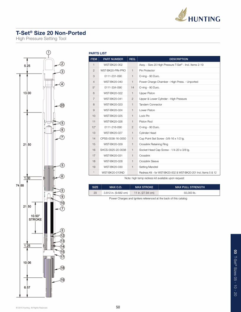
03 T-Set ® S
izes 05 - 10 - 20
50© 2015 Hunting. All Rights Reserved.
PARTS LIST
ITEM PART NUMBER REQ. DESCRIPTION
1 WST-BK20-002 Assy. - Size 20 High Pressure T-Set® - Incl. Items 2-19
2 WST-BK20-PIN-PRO 1 Pin Protector
3 0111-231-090 1 O-ring - 90 Duro.
4 WST-BK20-040 1 Power Charge Chamber - High Press. - Unported
5* 0111-334-090 14 O-ring - 90 Duro.
6 WST-BK20-022 1 Upper Piston
7 WST-BK20-041 2 Upper & Lower Cylinder - High Pressure
8 WST-BK20-023 1 Tandem Connector
9 WST-BK20-024 1 Lower Piston
10 WST-BK20-025 1 Lock Pin
11 WST-BK20-026 1 Piston Rod
12* 0111-216-090 2 O-ring - 90 Duro.
13 WST-BK20-027 1 Cylinder Head
14 CPSS-0038-16-0050 1 Cup Point Set Screw -3/8-16 x 1/2 lg.
15 WST-BK20-029 1 Crosslink Retaining Ring
16 SHCS-0025-20-0038 1 Socket Head Cap Screw - 1/4-20 x 3/8 lg.
17 WST-BK20-031 1 Crosslink
18 WST-BK20-028 1 Crosslink Sleeve
19 WST-BK20-030 1 Setting Mandrel
* WST-BK20-010ND Redress Kit - for WST-BK20-002 & WST-BK20-201 Incl. Items 5 & 12
Note: high temp redress kit available upon request
T-Set® Size 20 Non-PortedHigh Pressure Setting Tool
SIZE MAX O.D. MAX STROKE MAX PULL STRENGTH
20 3.812 in. (9.682 cm) 11 in. (27.94 cm) 55,000 lb.
Power Charges and Igniters referenced at the back of this catalog

03 T-Set ® S
izes 05 - 10 - 20
51© 2015 Hunting. All Rights Reserved.
1. Install O-rings (5) in power charge chamber (4). Screw chamber to cylinder (7).
T-Set® Size 20Assembly Instructions
2. Install O-rings (5) on upper piston (6) then push piston through cylinder until it contacts power charge chamber.
4. Install O-rings (5) on tandem connector (8) then screw into upper cylinder with small orifice hole toward oil.
5. Slide setting mandrel (19) inside crosslink sleeve (18). Long threaded end of mandrel positioned as shown.
6. Slide piston rod (11) into setting mandrel (19).
7. Align slots in all items and insert crosslink (17). Install retaining ring (15) and cap screw (16).
8. Install O-rings (5 & 12) to cylinder head (13). Slide head on piston rod. Make up head hand tight to setting mandrel. Install set screw (14).
9. Install O-rings (5) on lower piston (9). Place piston on piston rod. Install lock pin (10) and tighten.
10. Lubricate piston, cylinder head threads, and cylinder bore. Slide cylinder (7) over piston and make up to cylinder head while making sure cylinder head is positioned against crosslink sleeve while cylinder is being made up.
12. Place tool in vise and tighten all joints. Air trapped in cylinder during tightening should make crosslink sleeve stand off from cylinder head no more than 3/8 in.
11. Connect upper and lower halves of the tool together.
3. Fill cylinder with SAE 10-40 oil to following levels: Well temp. Size 20 200°F or less 4 in. 200°F - 275°F 4-1/2 in. 275°F - 350°F 5 in. 350°F - 400°F 5-1/2 in.
See Left

03 T-Set ® S
izes 05 - 10 - 20
52© 2015 Hunting. All Rights Reserved.
PARTS LIST
ITEM PART NUMBER REQ. DESCRIPTION
1 WST-BK20-201 Assy. - Size 20 Non Ported T-Set®- Incl. Items 2-19
2 WST-BK20-PIN-PRO 1 Pin Protector
3 0111-231-090 1 O-ring - 90 Duro.
4 WST-BK20-040 1 Power Charge Chamber - High Press. - Unported
5* 0111-334-090 14 O-ring - 90 Duro.
6 WST-BK20-022 1 Upper Piston
7 WST-BK20-021 2 Upper & Lower Cylinder
8 WST-BK20-023 1 Tandem Connector
9 WST-BK20-024 1 Lower Piston
10 WST-BK20-025 1 Lock Pin
11 WST-BK20-026 1 Piston Rod
12* 0111-216-090 2 O-ring - 90 Duro.
13 WST-BK20-027 1 Cylinder Head
14 CPSS-0038-16-0050 1 Cup Point Set Screw - 3/8-16 x 1/2 lg.
15 WST-BK20-029 1 Crosslink Retaining Ring
16 SHCS-0025-20-0038 1 Socket Head Cap Screw - 1/4-20 x 3/8 lg.
17 WST-BK20-031 1 Crosslink
18 WST-BK20-028 1 Crosslink Sleeve
19 WST-BK20-030 1 Setting Mandrel
* WST-BK20-010ND Redress Kit - for WST-BK20-002 & 201Incl. Items 5 & 12
Note: high temp redress kit available upon request
T-Set® Size 20 Non-PortedSetting Tool
SIZE MAX O.D. MAX STROKE MAX PULL STRENGTH
20 3.812 in. (9.682 cm) 11 in. (27.94 cm) 55,000 lb.
Power Charges and Igniters referenced at the back of this catalog

03 T-Set ® S
izes 05 - 10 - 20
53© 2015 Hunting. All Rights Reserved.
1. Install O-rings (5) in power charge chamber (4). Screw chamber to cylinder (7).
2. Install O-rings (5) on upper piston (6) then push piston through cylinder until it contacts power charge chamber.
4. Install O-rings (5) on tandem connector (8) then screw into upper cylinder with small orifice toward oil.
5. Slide setting mandrel (19) inside crosslink sleeve (18). Long threaded end of mandrel positioned as shown.
6. Slide piston rod (11) into setting mandrel (19).
7. Align slots in all items and insert crosslink (17). Install retaining ring (15) and cap screw (16).
8. Install O-rings (5 & 12) to cylinder head (13). Slide head on piston rod. Make up head hand tight to setting mandrel. Install set screw (14).
9. Install O-rings (5) on lower piston (9). Place piston on piston rod. Install lock pin (10) and tighten.
10. Lubricate piston, cylinder head threads, and cylinder bore. Slide cylinder (7) over piston and make up to cylinder head while making sure cylinder head is positioned against crosslink sleeve while cylinder is being made up.
12. Place tool in vise and tighten all joints. Air trapped in cylinder during tightening should make crosslink sleeve stand off from cylinder head no more than 3/8 in.
11. Connect upper and lower halves of the tool together.
T-Set® Size 20Assembly Instructions
3. Fill cylinder with SAE 10-40 oil to following levels: Well temp. Size 20 200°F or less 4 in. 200°F - 275°F 4-1/2 in. 275°F - 350°F 5 in. 350°F - 400°F 5-1/2 in.
See Left

03 T-Set ® S
izes 05 - 10 - 20
54© 2015 Hunting. All Rights Reserved.
Hose off setting assembly to clean and cool it. Unscrew the cable head. If the cable head is tight, pressure may have leaked into it. In this case bleed pressure from tool (steps 3 and 4)before removing cable head.
1. Remove the setting adapter kit. Hold ear of lock spring with pliers and twist against spring to relieve the bind on the threads. Unscrew the tension mandrel.
2. Place chain tongs around lower cylinder. Position bleeder holes in cylinder facing away from you and slowly unscrew cylinder head until compressed air escapes. Do not back-off cylinder head from cylinder more than 1-1/4 in.
3. Preferred gas pressure bleed-off method: position setting assembly so that side vent for manual bleeder valve is facing away from you and the bleeder stem is facing up. Using bleeder wrench, slowly turn stem to left until gas pressure escapes through the side vent. The stem will shoulder at retainer nut.
4. Alternate gas pressure bleed-off method: place chain tongs around pressure chamber. Position bleeder hole in pressure chamber facing away from you. Slowly unscrew the firing head until gas pressure bleeds off. Do not back-off firing head from pressure chamber more than 1-1/4 in.
5. Alternate gas pressure bleed-off method: should pressure not bleed off as explained in steps 4 and 5 another method is available. Place chain tongs around upper cylinder and position bleeder hole in cylinder pointing away from you. Slowly unscrew the pressure chamber until gas pressure bleeds off. Do not back-off pressure chamber from upper cylinder more than 1-1/4 in.
6. If gas pressure still does not bleed off, back off firing head exactly 1-1/4 in. From pressure chamber. Positively stand clear of bleeder hole during this procedure.
7. Caution: all pressurized gas must be bled off before further disassembly is begun. The two halves of the tool will blow apart.
8. Unscrew and remove firing head. Unscrew and remove pressure chamber and upper cylinder.
9. Push upper piston out lower end of upper cylinder. Remove O-rings from pressure chamber, upper piston, and firing head.
Disassemble remainder of setting assembly components. Thoroughly remove power charge debris. Apply light coat of oil to all parts to prevent rust from forming.
O-ring care and replacement: All O-rings must be replaced after each use. The O-rings should be lubricated with an appropriate lubricant. We recommend Hydrotex. Use only the O-rings specified in the setting tools parts lists. Use only O-rings or O-ring kits supplied and/or specifically engineered for T-Set® tools.
T-Set® Size 10 and 20Disassembly Instructions

03 T-Set ® S
izes 05 - 10 - 20
55© 2015 Hunting. All Rights Reserved.
Size 10 and 20 setting tools items shown below should be inspected periodically and any parts that have worn beyond the dimensions shown must be replaced.
SIZE 10 SIZE 20
A 2.130 in. (5.410 cm.) 3.004 in. (7.630 cm.)
B 1.755 in. (4.458 cm.) 2.255 in. (5.728 cm.)
C 2.115 in. (5.372 cm.) 2.990 in. (7.595 cm.)
D .809 in. (2.055 cm.) 1.122 in. (2.850 cm.)
E 2.115 in. (5.372 cm.) 2.990 in. (7.595 cm.)
F 2.115 in. (5.372 cm.) 2.990 in. (7.595 cm.)
G .820 in. (2.083 cm.) 1.132 in. (2.875 cm.)
T-Set® Size 10-20Minimum and Maximum Wear Diameters
Power Charge Chamber (size 20)
Power Charge Chamber (size 10)
Cylinder
Ported Bleeder Sub (size 10)
Tandem ConnectorPiston Rod
Cylinder Head
Lower Piston
Upper Piston
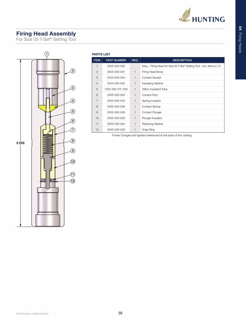
04 Firing Head
s
56© 2015 Hunting. All Rights Reserved.
PARTS LIST
ITEM PART NUMBER REQ. DESCRIPTION
1 2005-000-000 Assy. - Firing Head for Size 05 T-Set® Setting Tool - Incl. Items 2-12
2 2005-000-001 1 Firing Head Body
3 0255-000-004 1 Contact Socket
4 0255-000-003 1 Insulating Washer
5 1002-000-4TI-.625 1 Teflon Insulated Tube
6 2005-000-005 1 Contact Rod
7 2005-000-003 1 Spring Insulator
8 2005-000-008 1 Contact Spring
9 2005-000-009 1 Contact Plunger
10 2005-000-006 1 Plunger Insulator
11 2005-000-004 1 Retaining Washer
12 0256-000-009 1 Snap Ring
Power Charges and Igniters referenced at the back of this catalog
Firing Head AssemblyFor Size 05 T-Set® Setting Tool

04 Firing Head
s
57© 2015 Hunting. All Rights Reserved.
1. Place the contact rod (6) into the spring insulator (7). Then install the teflon insulated tube (5) onto the contact rod.
2. Place spring insulator (7) and contact rod (6) into lower end of the firing head body (2).
3. Place the insulating washer (4) into the upper end of the firing head body (2). Place insulating washer onto contact rod (6). Install with the tapered side facing into the firing head body.
4. Tighten the contact socket (3) onto the contact rod (6) with a screwdriver and a deep 3/8 in. socket or nutdriver.
5. Install the contact spring (8) into the spring insulator (7). Then place the plunger insulator (10) onto the contact plunger (9) with the small diameter up.
6. Place retaining washer (11) into firing head body. Then install the snap ring (12) to retain the washer.
2005-000-000Assembly Instructions

04 Firing Head
s
58© 2015 Hunting. All Rights Reserved.
PARTS LIST
ITEM PART NUMBER REQ. DESCRIPTION
1 2010-000-000 Assy. - Firing Head for Size 10 T-Set® Setting Tool - Incl. Items 2-15
2 2010-000-001 1 Firing Head Body
3 2020-000-003 1 Contact Socket
4 2020-000-004 1 Socket Insulator
5 2020-000-006 1 Contact Nut
6 2020-000-005 1 Contact Insulator
7 2020-000-007 1 Contact Spring
8 2020-000-008 1 Contact Pin
9 2010-000-005 1 Pin Insulator
10 2010-000-004 1 Retainer Nut
11 2010-000-015 1 Igniter Holder Cap
12 0111-112-V95 1 O-ring - Viton-95
13 0111-220-V95 2 O-ring - Viton-95
14 2010-000-014 1 Igniter Holder
15 0111-222-V95 2 O-ring - Viton-95
16 DB-DET-2700-075 1 BP-3 Igniter
Power Charges and Igniters referenced at the back of this catalog
Firing Head AssemblyFor Size 10 T-Set® Setting Tool

04 Firing Head
s
59© 2015 Hunting. All Rights Reserved.
1. Place this contact socket (3) into the socket insulator (4).
2. Place contact socket (3) and socket insulator (4) into upper end of the firing head body (2).
3. Place the contact nut (5) into the contact insulator (6).
4. Install the contact insulator (6) and contact nut (5) into firing head (2). Tighten the contact nut (5) onto the contact socket (3) with a screwdriver and a deep 5/16 socket or nutdriver.
10. Install the 0111-222-V95 O-rings (15). (Use grease on the 0111-222-V95 O-rings.)
5. Install the contact spring (7) into the contact insulator (6). Then place the pin insulator (9) onto the contact pin (8) with the small diameter up.
6. Lightly grease the thread on the retainer nut (10). Place the retainer nut (10) onto the pin insulator (9) with the contact pin (8) inside. Then install and tighten with a retaining wrench (2010-000-016) while depressing the contact spring (7).
7. Install the 0111-220-V95 O-rings (13) and the 0111-112-V95 O-rings (12) onto the igniter holder (14). (Lightly grease the 0111-220-V95 O-rings and thread.)
8. Install the igniter (15) into the igniter holder (10) and thread the igniter holder cap (11) over it.
9. Install the igniter holder (14) with the igniter (16) installed into the firing head body (2). Note: left hand threads.
2010-000-000Assembly Instructions
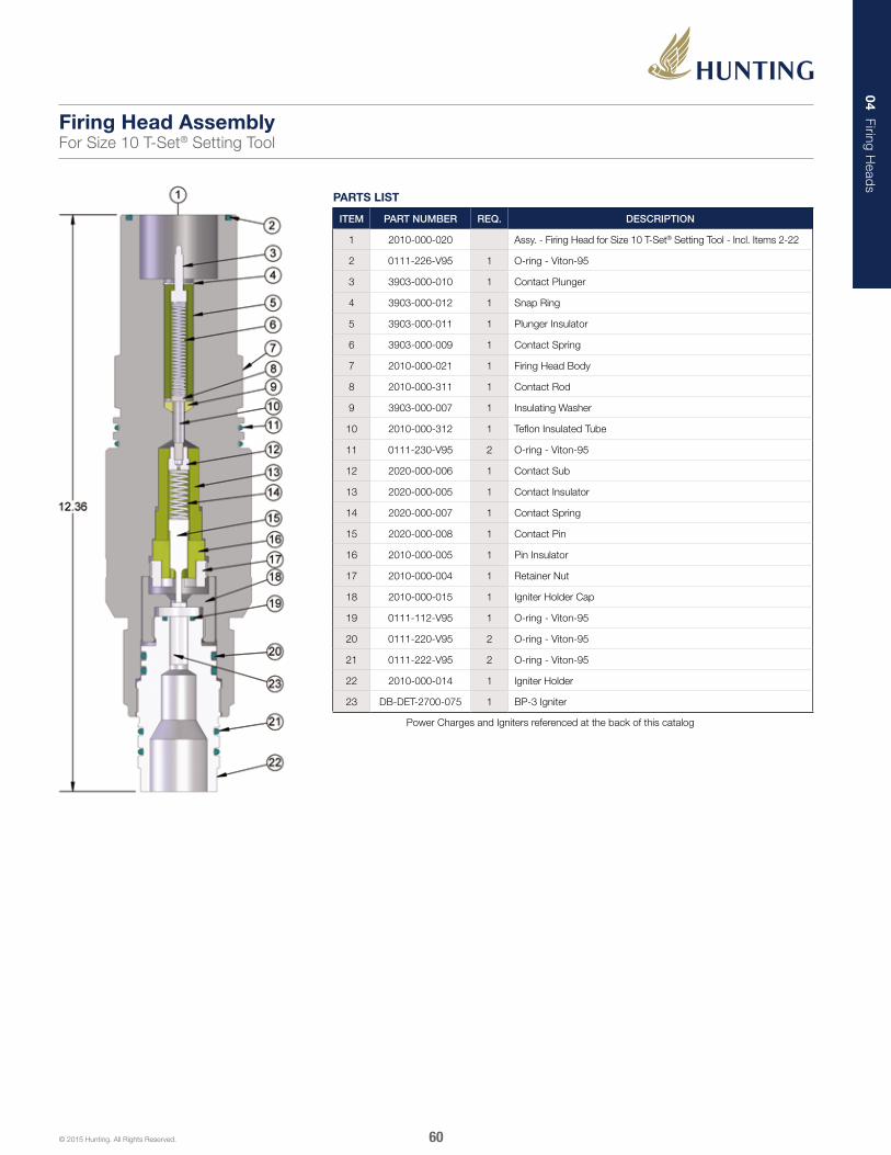
04 Firing Head
s
60© 2015 Hunting. All Rights Reserved.
PARTS LIST
ITEM PART NUMBER REQ. DESCRIPTION
1 2010-000-020 Assy. - Firing Head for Size 10 T-Set® Setting Tool - Incl. Items 2-22
2 0111-226-V95 1 O-ring - Viton-95
3 3903-000-010 1 Contact Plunger
4 3903-000-012 1 Snap Ring
5 3903-000-011 1 Plunger Insulator
6 3903-000-009 1 Contact Spring
7 2010-000-021 1 Firing Head Body
8 2010-000-311 1 Contact Rod
9 3903-000-007 1 Insulating Washer
10 2010-000-312 1 Teflon Insulated Tube
11 0111-230-V95 2 O-ring - Viton-95
12 2020-000-006 1 Contact Sub
13 2020-000-005 1 Contact Insulator
14 2020-000-007 1 Contact Spring
15 2020-000-008 1 Contact Pin
16 2010-000-005 1 Pin Insulator
17 2010-000-004 1 Retainer Nut
18 2010-000-015 1 Igniter Holder Cap
19 0111-112-V95 1 O-ring - Viton-95
20 0111-220-V95 2 O-ring - Viton-95
21 0111-222-V95 2 O-ring - Viton-95
22 2010-000-014 1 Igniter Holder
23 DB-DET-2700-075 1 BP-3 Igniter
Power Charges and Igniters referenced at the back of this catalog
Firing Head AssemblyFor Size 10 T-Set® Setting Tool
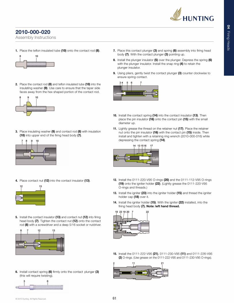
04 Firing Head
s
61© 2015 Hunting. All Rights Reserved.
1. Place the teflon insulated tube (10) onto the contact rod (8).
2. Place the contact rod (8) and teflon insulated tube (10) into the insulating washer (9). Use care to ensure that the taper side faces away from the hex shaped portion of the contact rod.
3. Place insulating washer (9) and contact rod (8) with insulation (10) into upper end of the firing head body (7).
4. Place contact nut (12) into the contact insulator (13).
10. Install the contact spring (14) into the contact insulator (13). Then place the pin insulator (16) onto the contact pin (15) with the small diameter up.
11. Lightly grease the thread on the retainer nut (17). Place the retainer nut onto the pin insulator (16) with the contact pin (15) inside. Then install and tighten with a retaining ring wrench (2010-000-016) while depressing the contact spring (14).
12. Install the 0111-220-V95 O-rings (20) and the 0111-112-V95 O-rings (19) onto the igniter holder (22). (Lightly grease the 0111-220-V95 O-rings and threads.)
13. Install the igniter (23) into the igniter holder (15) and thread the igniter holder cap (18) over it.
14. Install the igniter holder (15). With the igniter (22) installed, into the firing head body (7). Note: left hand thread.
15. Install the 0111-222-V95 (21), 0111-230-V95 (11) and 0111-226-V95 (2) O-rings. (Use grease on the 0111-222-V95 and 0111-230-V95 O-rings).
5. Install the contact insulator (13) and contact nut (12) into firing head body (7). Tighten the contact nut (12) onto the contact rod (8) with a screwdriver and a deep 5/16 socket or nutdriver.
6. Install contact spring (6) firmly onto the contact plunger (3) (this will require twisting).
7. Place this contact plunger (3) and spring (6) assembly into firing head body (7). With the contact plunger (3) pointing up.
8. Install the plunger insulator (5) over the plunger. Depress the spring (6) with the plunger insulator. Install the snap ring (4) to retain the plunger insulator.
9. Using pliers, gently twist the contact plunger (3) counter clockwise to ensure spring contact.
2010-000-020Assembly Instructions

04 Firing Head
s
62© 2015 Hunting. All Rights Reserved.
PARTS LIST
ITEM PART NUMBER REQ. DESCRIPTION
1 2010-000-040 Assy. - Firing Head for Size 10 T-Set® Setting Tool - Incl. Items 2-22
2 0111-032-V95 1 O-ring - Viton-95
3 3903-000-010 1 Contact Plunger
4 3903-000-012 1 Snap Ring
5 3903-000-011 1 Plunger Insulator
6 3903-000-009 1 Contact Spring
7 2010-000-041 1 Firing Head Body
8 2010-000-311 1 Contact Rod
9 3903-000-007 1 Insulating Washer
10 2010-000-312 1 Teflon Insulated Tube
11 0111-227-V95 2 O-ring - Viton-95
12 2020-000-006 1 Contact Sub
13 2020-000-005 1 Contact Insulator
14 2020-000-007 1 Contact Spring
15 2020-000-008 1 Contact Pin
16 2010-000-005 1 Pin Insulator
17 2010-000-004 1 Retainer Nut
18 2010-000-015 1 Igniter Holder Cap
19 0111-112-V95 1 O-ring - Viton-95
20 0111-220-V95 2 O-ring - Viton-95
21 0111-222-V95 2 O-ring - Viton-95
22 2010-000-014 1 Igniter Holder
23 DB-DET-2700-075 1 BP-3 Igniter
Power Charges and Igniters referenced at the back of this catalog
Firing Head AssemblyFor Size 10 T-Set® Setting Tool

04 Firing Head
s
63© 2015 Hunting. All Rights Reserved.
1. Place the teflon insulated tube (10) onto the contact rod (8).
2. Place the contact rod (8) and teflon insulated tube (10) into the insulating washer (9). Use care to ensure that the taper side faces away from the hex shaped portion of the contact rod.
3. Place insulating washer (9) and contact rod (8) with insulation (10) into upper end of the firing head body (7).
4. Place contact nut (12) into the contact insulator (13).
10. Install the contact spring (14) into the contact insulator (13). Then place the pin insulator (16) onto the contact pin (15) with the small diameter up.
11. Lightly grease the thread on the retainer nut (17). Place the retainer nut onto the pin insulator (16) with the contact pin (15) inside. Then install and tighten with a retaining ring wrench (2010-000-016) while depressing the contact spring (14).
12. Install the 0111-220-V95 O-rings (20) and the 0111-112-V95 O-rings (19) onto the igniter holder (22). (Lightly grease the 0111-220-V95 O-rings and threads.)
13. Install the igniter (23) into the igniter holder (15) and thread the igniter holder cap (18) over it.
14. Install the igniter holder (15). With the igniter (22) installed, into the firing head body (7). Note: left hand thread.
15. Install the 0111-222-V95 (21), 0111-227-V95 (11) and 0111-032-V95 (2) O-rings. (Use grease on the 0111-222-V95 and 0111-227-V95 O-rings).
6. Install contact spring (6) firmly onto the contact plunger (3) (this will require twisting).
7. Place this contact plunger (3) and spring (6) assembly into firing head body (7). With the contact plunger (3) pointing up.
8. Install the plunger insulator (5) over the plunger. Depress the spring (6) with the plunger insulator. Install the snap ring (4) to retain the plunger insulator.
9. Using pliers, gently twist the contact plunger (3) counter clockwise to ensure spring contact.
5. Install the contact insulator (13) and contact nut (12) into firing head body (7). Tighten the contact nut (12) onto the contact rod (8) with a screwdriver and a deep 5/16 socket or nutdriver.
2010-000-040Assembly Instructions
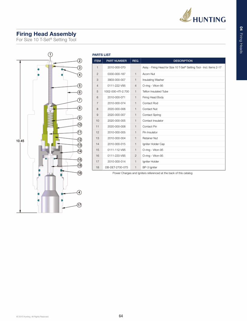
04 Firing Head
s
64© 2015 Hunting. All Rights Reserved.
PARTS LIST
ITEM PART NUMBER REQ. DESCRIPTION
1 2010-000-070 Assy. - Firing Head for Size 10 T-Set® Setting Tool - Incl. Items 2-17
2 0330-000-187 1 Acorn Nut
3 3903-000-007 1 Insulating Washer
4 0111-222-V95 4 O-ring - Viton-95
5 1002-000-4TI-2.700 1 Teflon Insulated Tube
6 2010-000-071 1 Firing Head Body
7 2010-000-074 1 Contact Rod
8 2020-000-006 1 Contact Nut
9 2020-000-007 1 Contact Spring
10 2020-000-005 1 Contact Insulator
11 2020-000-008 1 Contact Pin
12 2010-000-005 1 Pin Insulator
13 2010-000-004 1 Retainer Nut
14 2010-000-015 1 Igniter Holder Cap
15 0111-112-V95 1 O-ring - Viton-95
16 0111-220-V95 2 O-ring - Viton-95
17 2010-000-014 1 Igniter Holder
18 DB-DET-2700-075 1 BP-3 Igniter
Power Charges and Igniters referenced at the back of this catalog
Firing Head AssemblyFor Size 10 T-Set® Setting Tool
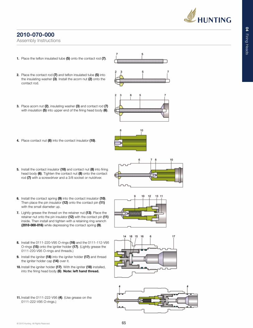
04 Firing Head
s
65© 2015 Hunting. All Rights Reserved.
1. Place the teflon insulated tube (5) onto the contact rod (7).
2. Place the contact rod (7) and teflon insulated tube (5) into the insulating washer (3). Install the acorn nut (2) onto the contact rod.
3. Place acorn nut (2), insulating washer (3) and contact rod (7) with insulation (5) into upper end of the firing head body (6).
4. Place contact nut (8) into the contact insulator (10).
5. Install the contact insulator (10) and contact nut (8) into firing head body (6). Tighten the contact nut (8) onto the contact rod (7) with a screwdriver and a 3/8 socket or nutdriver.
11. Install the 0111-222-V95 (4). (Use grease on the 0111-222-V95 O-rings.)
6. Install the contact spring (9) into the contact insulator (10). Then place the pin insulator (12) onto the contact pin (11) with the small diameter up.
7. Lightly grease the thread on the retainer nut (13). Place the retainer nut onto the pin insulator (12) with the contact pin (11) inside. Then install and tighten with a retaining ring wrench (2010-000-016) while depressing the contact spring (9).
8. Install the 0111-220-V95 O-rings (16) and the 0111-112-V95 O-rings (15) onto the igniter holder (17). (Lightly grease the 0111-220-V95 O-rings and threads.)
9. Install the igniter (18) into the igniter holder (17) and thread the igniter holder cap (14) over it.
10. Install the igniter holder (17). With the igniter (18) installed, into the firing head body (6). Note: left hand thread.
2010-070-000Assembly Instructions

04 Firing Head
s
66© 2015 Hunting. All Rights Reserved.
PARTS LIST
ITEM PART NUMBER REQ. DESCRIPTION
1 2010-000-090 Assy. - Firing Head for Size 10 T-Set® Setting Tool - Incl. Items 2-13
2 2010-000-094 1 Contact Stinger
3 0111-222-V95 4 O-ring - Viton-95
4 2010-000-093 1 Stinger Insulator
5 2010-000-091 1 Firing Head Body
6 2010-000-095 1 Contact Spring
7 2020-000-008 1 Contact Pin
8 2010-000-005 1 Pin Insulator
9 2010-000-004 1 Retainer Nut
10 2010-000-015 1 Igniter Holder Cap
11 0111-112-V95 1 O-ring - Viton-95
12 0111-222-V95 2 O-ring - Viton-95
13 2010-000-014 1 Igniter Holder
14 DB-DET-2700-075 1 BP-3 Igniter
Power Charges and Igniters referenced at the back of this catalog
Firing Head AssemblyFor Size 10 T-Set® Setting Tool
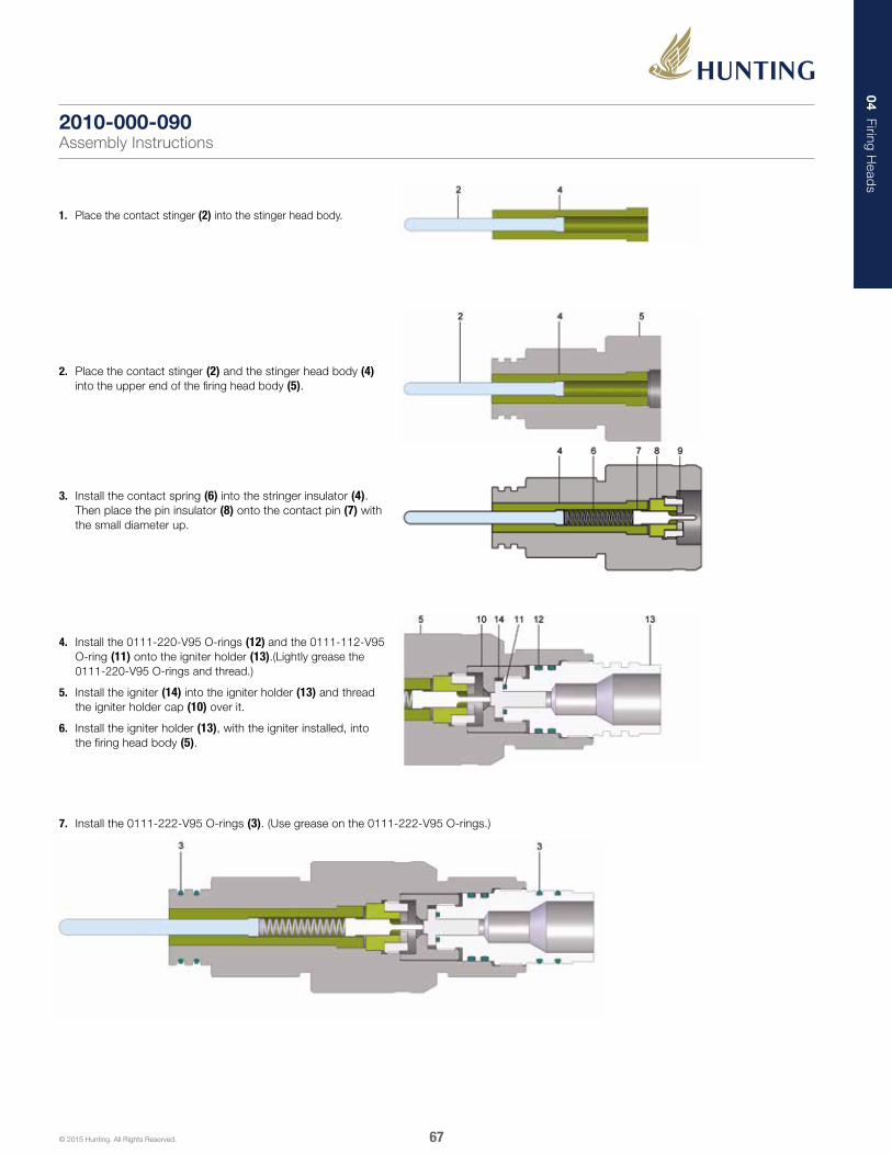
04 Firing Head
s
67© 2015 Hunting. All Rights Reserved.
1. Place the contact stinger (2) into the stinger head body.
2. Place the contact stinger (2) and the stinger head body (4) into the upper end of the firing head body (5).
3. Install the contact spring (6) into the stringer insulator (4). Then place the pin insulator (8) onto the contact pin (7) with the small diameter up.
4. Install the 0111-220-V95 O-rings (12) and the 0111-112-V95 O-ring (11) onto the igniter holder (13).(Lightly grease the 0111-220-V95 O-rings and thread.)
5. Install the igniter (14) into the igniter holder (13) and thread the igniter holder cap (10) over it.
6. Install the igniter holder (13), with the igniter installed, into the firing head body (5).
7. Install the 0111-222-V95 O-rings (3). (Use grease on the 0111-222-V95 O-rings.)
2010-000-090Assembly Instructions

04 Firing Head
s
68© 2015 Hunting. All Rights Reserved.
PARTS LIST
ITEM PART NUMBER REQ. DESCRIPTION
1 2020-000-000 Assy. - Firing Head for Size 20 T-Set® Setting Tool - Incl. Items 2-15
2 2020-000-003 1 Contact Socket
3 2020-000-004 1 Socket Insulator
4 2020-000-001 1 Firing Head Body
5 2020-000-006 1 Contact Nut
6 2020-000-005 1 Contact Insulator
7 2020-000-007 1 Contact Spring
8 2020-000-008 1 Contact Pin
9 2020-000-009 1 Pin Insulator
10 2020-000-010 1 Retainer Ring
11 2020-000-015 1 Igniter Holder Cap
12 0111-012-V95 1 O-ring - Viton-95
13 0111-325-V95 2 O-ring - Viton-95
14 0111-328-V95 2 O-ring - Viton-95
15 2010-000-014 1 Igniter Holder
16 DB-DET-2700-075 1 BP-3 Igniter
Power Charges and Igniters referenced at the back of this catalog
Firing Head AssemblyFor Size 20 T-Set® Setting Tool
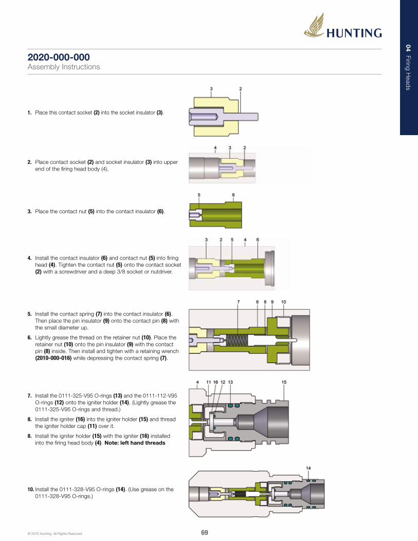
04 Firing Head
s
69© 2015 Hunting. All Rights Reserved.
1. Place this contact socket (2) into the socket insulator (3).
2. Place contact socket (2) and socket insulator (3) into upper end of the firing head body (4).
3. Place the contact nut (5) into the contact insulator (6).
4. Install the contact insulator (6) and contact nut (5) into firing head (4). Tighten the contact nut (5) onto the contact socket (2) with a screwdriver and a deep 3/8 socket or nutdriver.
5. Install the contact spring (7) into the contact insulator (6). Then place the pin insulator (9) onto the contact pin (8) with the small diameter up.
6. Lightly grease the thread on the retainer nut (10). Place the retainer nut (10) onto the pin insulator (9) with the contact pin (8) inside. Then install and tighten with a retaining wrench (2010-000-016) while depressing the contact spring (7).
10. Install the 0111-328-V95 O-rings (14). (Use grease on the 0111-328-V95 O-rings.)
7. Install the 0111-325-V95 O-rings (13) and the 0111-112-V95 O-rings (12) onto the igniter holder (14). (Lightly grease the 0111-325-V95 O-rings and thread.)
8. Install the igniter (16) into the igniter holder (15) and thread the igniter holder cap (11) over it.
8. Install the igniter holder (15) with the igniter (16) installed into the firing head body (4). Note: left hand threads
2020-000-000Assembly Instructions

04 Firing Head
s
70© 2015 Hunting. All Rights Reserved.
PARTS LIST
ITEM PART NUMBER REQ. DESCRIPTION
1 2020-000-020 Assy. - Firing Head for Size 20 T-Set® Setting Tool - Incl. Items 2-22
2 0111-226-V95 1 O-ring - Viton-95
3 3903-000-010 1 Contact Plunger
4 3903-000-012 1 Snap Ring
5 3903-000-011 1 Plunger Insulator
6 3903-000-009 1 Contact Spring
7 2020-000-021 1 Firing Head Body
8 2020-000-311 1 Contact Rod
9 3903-000-007 1 Insulating Washer
10 2020-000-312 1 Teflon Insulated Tube
11 0111-230-V95 2 O-ring - Viton-95
12 2020-000-006 1 Contact Nut
13 2020-000-005 1 Contact Insulator
14 2020-000-007 1 Contact Spring
15 2020-000-008 1 Contact Pin
16 2020-000-009 1 Pin Insulator
17 2020-000-010 1 Retainer Ring
18 2020-000-015 1 Igniter Holder Cap
19 0111-112-V95 1 O-ring - Viton-95
20 0111-325-V95 2 O-ring - Viton-95
21 0111-328-V95 2 O-ring - Viton-95
22 2020-000-014 1 Igniter Holder
23 DB-DET-2700-075 1 BP-3 Igniter
Power Charges and Igniters referenced at the back of this catalog
Firing Head AssemblyFor Size 20 T-Set® Setting Tool

04 Firing Head
s
71© 2015 Hunting. All Rights Reserved.
1. Place the teflon insulated tube (10) onto the contact rod (8).
2. Place the contact rod (8) and teflon insulated tube (10) into the insulating washer (9). Use care to ensure that the taper side faces away from the hex shaped portion of the contact rod.
3. Place insulating washer (9) and contact rod (8) with insulation (10) into upper end of the firing head body (7).
4. Place contact nut (12) into the contact insulator (13).
6. Install contact spring (6) firmly onto the contact plunger (3) this will require twisting).
7. Place this contact plunger and spring assembly into firing head body (7). With the contact plunger (3) pointing up.
8. Install the plunger insulator (5) over the plunger. Depress the spring (6) with the plunger insulator. Install the snap ring (4) to retain the plunger insulator.
9. Using pliers, gently twist the contact plunger (3) counter clockwise to ensure spring contact.
15. Install the 0111-328-V95 (21), 0111-230-V95 (11) and 0111-226-V95 (2) O-rings. (Use grease on the 0111-328-V95 and 0111-230-V95 O-rings).
10. Install the contact spring (14) into the contact insulator (13). Then place the pin insulator (16) onto the contact pin (15) with the small diameter up.
11. Lightly grease the thread on the retainer nut (17). Place the retainer nut onto the pin insulator (16) with the contact pin (15) inside. Then install and tighten with a retaining ring wrench (2010-000-016) while depressing the contact spring (14).
12. Install the 0111-325-V95 O-rings (20) and the 0111-112-V95 O-rings (19) onto the igniter holder (22). (Lightly grease the 0111-325-V95 O-rings and threads.)
13. Install the igniter (23) into the igniter holder (22) and thread the igniter holder cap (18) over it.
14. Install the igniter holder (22). With the igniter (23) installed, into the firing head body (7). Note: left hand threads.
5. Install the contact insulator (13) and contact nut (12) into firing head body (7). Tighten the contact nut (12) onto the contact rod (8) with a screwdriver and a deep 3/8 socket or nutdriver.
2020-000-020Assembly Instructions

04 Firing Head
s
72© 2015 Hunting. All Rights Reserved.
PARTS LIST
ITEM PART NUMBER REQ. DESCRIPTION
1 2020-000-070 Assy. - Firing Head for Size 20 T-Set® Setting Tool - Incl. Items 2-18
2 0330-000-184 1 Acorn Nut
3 3903-000-007 1 Insulating Washer
4 0111-222-V95 2 O-ring - Viton-95
5 1002-000-4TI-2.630 1 Teflon Insulated Tube
6 2020-000-071 1 Firing Head Body
7 2010-000-074 1 Contact Rod
8 2020-000-006 1 Contact Nut
9 2020-000-007 1 Contact Spring
10 2020-000-005 1 Contact Insulator
11 2020-000-008 1 Contact Pin
12 2020-000-009 1 Pin Insulator
13 2020-000-010 1 Retainer Ring
14 2020-000-015 1 Igniter Holder Cap
15 0111-112-V95 1 O-ring - Viton-95
16 0111-325-V95 2 O-ring - Viton-95
17 0111-328-V95 2 O-ring - Viton-95
18 2020-000-014 1 Igniter Holder
19 DB-DET-2700-075 1 BP-3 Igniter
Power Charges and Igniters referenced at the back of this catalog
Firing Head AssemblyFor Size 20 T-Set® Setting Tool
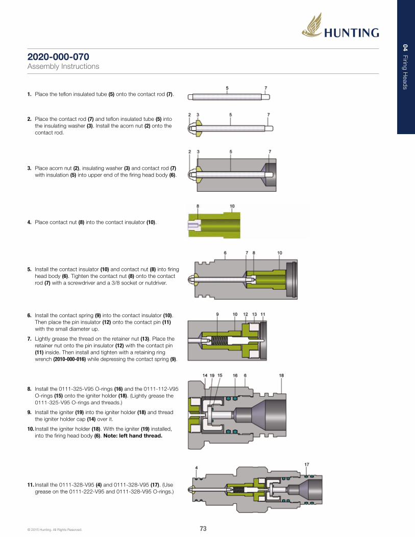
04 Firing Head
s
73© 2015 Hunting. All Rights Reserved.
1. Place the teflon insulated tube (5) onto the contact rod (7).
2. Place the contact rod (7) and teflon insulated tube (5) into the insulating washer (3). Install the acorn nut (2) onto the contact rod.
3. Place acorn nut (2), insulating washer (3) and contact rod (7) with insulation (5) into upper end of the firing head body (6).
4. Place contact nut (8) into the contact insulator (10).
5. Install the contact insulator (10) and contact nut (8) into firing head body (6). Tighten the contact nut (8) onto the contact rod (7) with a screwdriver and a 3/8 socket or nutdriver.
8. Install the 0111-325-V95 O-rings (16) and the 0111-112-V95 O-rings (15) onto the igniter holder (18). (Lightly grease the 0111-325-V95 O-rings and threads.)
9. Install the igniter (19) into the igniter holder (18) and thread the igniter holder cap (14) over it.
10. Install the igniter holder (18). With the igniter (19) installed, into the firing head body (6). Note: left hand thread.
11. Install the 0111-328-V95 (4) and 0111-328-V95 (17). (Use grease on the 0111-222-V95 and 0111-328-V95 O-rings.)
6. Install the contact spring (9) into the contact insulator (10). Then place the pin insulator (12) onto the contact pin (11) with the small diameter up.
7. Lightly grease the thread on the retainer nut (13). Place the retainer nut onto the pin insulator (12) with the contact pin (11) inside. Then install and tighten with a retaining ring wrench (2010-000-016) while depressing the contact spring (9).
2020-000-070Assembly Instructions

04 Firing Head
s
74© 2015 Hunting. All Rights Reserved.
PARTS LIST
ITEM PART NUMBER REQ. DESCRIPTION
1 6110-000-000 Assy. - Firing Head for T-Set® Setting Tool - Incl. Items 2-15
2 6110-000-001 1 Firing Head Body
3 6110-000-003 1 Contact Rod
4 1012-000-004 1 Hex Nut - 3/8-24 Unf
5 1012-000-005 2 Insulating Washer
6 0111-214-V95 2 O-ring - Viton-95
7 0256-000-4TI-2.430 1 Teflon Insulated Tube
8 0111-114-V95 1 O-ring - Viton-95
9 0111-113-V95 1 O-ring - Viton-95
Power Charges and Igniters referenced at the back of this catalog
Firing Head AssemblyFor 1-1/2 in., 1-11/16 in., 2-1/8 in. & 2-1/2 in. T-Set® Setting Tool

04 Firing Head
s
75© 2015 Hunting. All Rights Reserved.
1. Install the 0111-113-V95 (9) O-ring onto the contact rod (3). Place insulating washer (5) onto the contact rod. Then install the teflon insulated tube (7) onto the contact rod.
2. Install the 0111-114-V95 (8) O-ring onto the firing head body (2). Then place the insulating washer (5) and contact rod (3) with insulation into the lower end of the firing head body.
3. Place the insulating washer (5) into the upper end of the firing head body (2). Placing the insulating washer onto the contact rod (3).
4. Tighten the hex nut (4) onto the contact rod (3).
5. Install the 0111-214-V95 (6) O-rings onto the firing head body (2).
6110-000-000Assembly Instructions
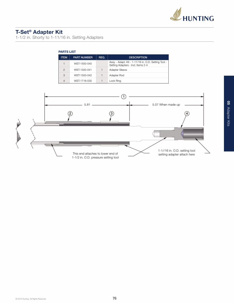
05 Ad
apter K
its
76© 2015 Hunting. All Rights Reserved.
PARTS LIST
ITEM PART NUMBER REQ. DESCRIPTION
1 WST-1500-040 Assy. - Adapt. Kit - 1-11/16 in. O.D. Setting Tool - Setting Adapters - Incl. Items 2-4
2 WST-1500-041 1 Adapter Sleeve
3 WST-1500-042 1 Adapter Rod
4 WST-1718-030 1 Lock Ring
5.81 5.07 When made up
This end attaches to lower end of 1-1/2 in. O.D. pressure setting tool
1-1//16 in. O.D. setting tool setting adapter attach here
T-Set® Adapter Kit1-1/2 in. Shorty to 1-11/16 in. Setting Adapters
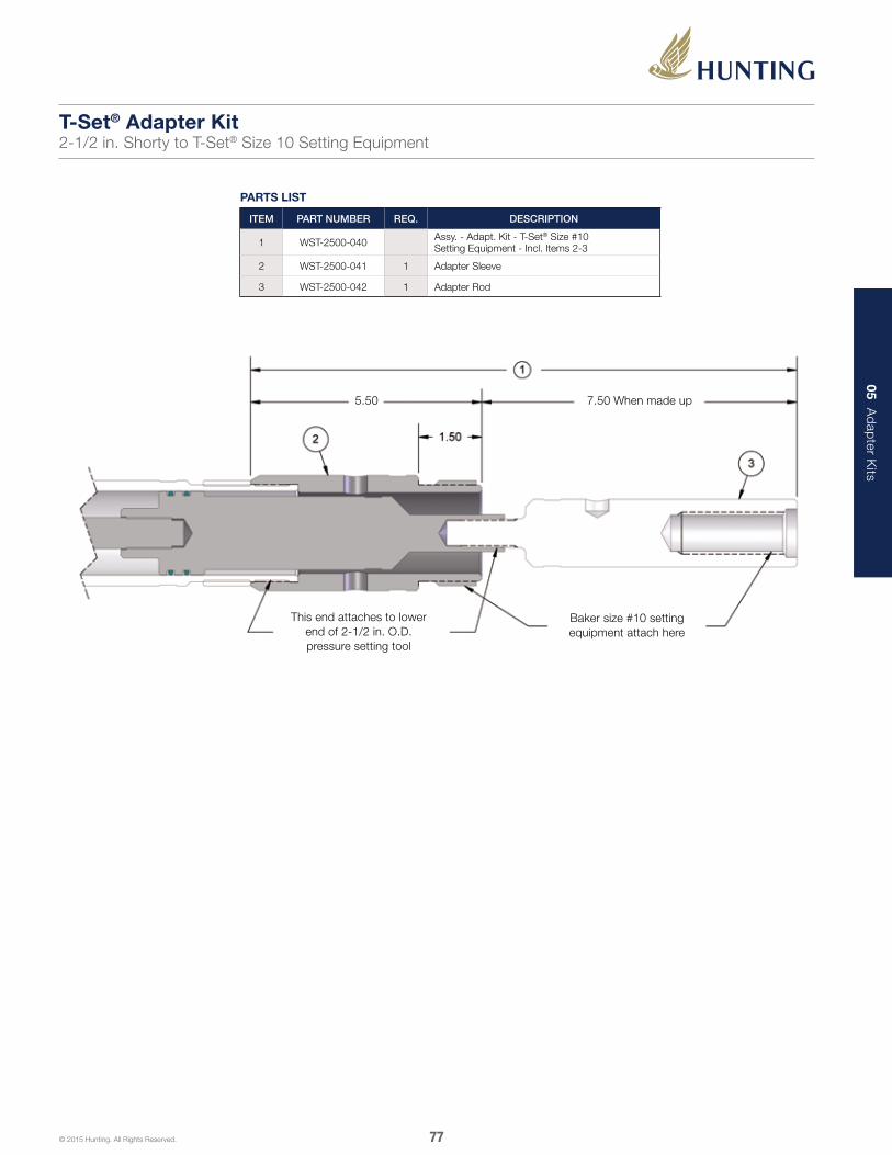
05 Ad
apter K
its
77© 2015 Hunting. All Rights Reserved.
PARTS LIST
ITEM PART NUMBER REQ. DESCRIPTION
1 WST-2500-040 Assy. - Adapt. Kit - T-Set® Size #10 Setting Equipment - Incl. Items 2-3
2 WST-2500-041 1 Adapter Sleeve
3 WST-2500-042 1 Adapter Rod
5.50 7.50 When made up
This end attaches to lower end of 2-1/2 in. O.D. pressure setting tool
Baker size #10 setting equipment attach here
T-Set® Adapter Kit2-1/2 in. Shorty to T-Set® Size 10 Setting Equipment

05 Ad
apter K
its
78© 2015 Hunting. All Rights Reserved.
PARTS LIST
ITEM PART NUMBER REQ. DESCRIPTION
1 WST-5303-117 Assy. - Adapt. Kit - T-Set® Size #10 Setting Equipment - Incl. Items 2-4
2 WST-5303-118 1 Adapter Sleeve
3 WST-3625-131 1 Lock Nut
4 WST-5303-119 1 Adapter Rod
9.25 7.50 When made up
3-1/2 in. & 3-5/8 in.
setting tools attach this end
Baker setting adapters attach this end
T-Set® Adapter Kit3-1/2 in. & 3-5/8 in. to T-Set® Size 10 Setting Equipment

05 Ad
apter K
its
79© 2015 Hunting. All Rights Reserved.
8.63 6.56 When made up
Baker setting adapters attach this end
3-1/2 in. & 3-5/8 in. setting tools attach this end
PARTS LIST
ITEM PART NUMBER REQ. DESCRIPTION
1 WST-5303-120 Assy. - Adapt. Kit - T-Set® Size #20 Setting Equipment - Incl. Items 2-4
2 WST-5303-121 1 Adapter Sleeve
3 WST-3625-131 1 Lock Nut
4 WST-5303-122 1 Adapter Mandrel
T-Set® Adapter Kit3-1/2 in. & 3-5/8 in. to T-Set® Size 20 Setting Equipment
06 Inspection K
its
80© 2015 Hunting. All Rights Reserved.
The Hunting “T-Set” Inspection System is designed to help maintain the working integrity of your “T-Set” Setting tools. This kit was developed to provide all of the necessary measuring equipment to accurately inspect the critical components of your setting tools. The WST- KIT-INSP-10-20 will cover a wide variety of tools ranging from the 2.125” MSST to the T-Set #20. The WST-KIT-INSP-UNIV covers our complete tool line beginning with 1.50” OD Shorty all the way through our T-Set #20. The kits include necessary mics, calipers, bore gauges, radius gauge, taps, aluminum oil level gauge, a fully detailed instruction manual and carrying case. On-site training to properly use the system is also available, upon request.
Inspection Kits

06 Inspection K
its
81© 2015 Hunting. All Rights Reserved.
This kit comes complete in an easy to carry Pelican™ case and includes:• Instruction manual• 1.00 in. - 2.00 in. Vernier micrometer• 2.00 in. - 3.00 in. Vernier micrometer• 1.4 in. - 6.00 in. Dial bore gauge• .75 in. - 1.75 in. Internal dial caliper gauge• Radius gage• 6.00 in. Dial caliper
• 1-1/4 - 12 Left hand tap• Oil level gauge
For inspection of: WST-2125 WST-2500 WST-3250 WST-5321
WST-3625 WST-BK10 and WST-BK20 Series
“T-Set” Wireline Setting Tools
Contents of this kit:
Instruction Manual, 1” – 2” Vernier Micrometer, 2”-3” Vernier Micrometer, 1.4”-6” Dial Bore Gage, .75”-1.75” Internal Dial Caliper Gage, Radius Gage, 6” Dial Caliper and a 1-1/4 -12 left hand tap.
These tools will allow the inspection of the inside diameter of the cylinders and the inside diameter of the bleeder port, as well as the other critical dimensions of the following series of tools: WST-2125, WST-2500, WST-3250, WST-5321, WST3625, WST-BK10 and the WST-BK20.
These tools have been tested to meet manufacturer accuracy standards. We recommend that these tools are calibrated at 6 month intervals, or if they are dropped or damaged.
Keeping the tools supplied in this kit clean and free of oil and dirt is essential to their accuracy. It is very important to thoroughly clean all parts before attempting to measure them.
WST-KIT-INSP-10-20
1.00" - 2.00" Vernier Micrometer•2.00" - 3.00" Vernier Micrometer•
2.00" - 3.00" Vernier Micrometer
1.4" - 6.00" Dial Bore Gage•
.75" - 1.75" Internal DialCaliper Gage
6.00" Dial Caliper
1-1/4 - 12 Left Hand Tap•
Oil Level Gage
Radius Gage
1.00 in. - 2.00 in. Vernier micrometer2.00 in. - 3.00 in. Vernier micrometer
1.4 in. - 6.00 in. Dial bore gage
Oil level gage
Radius gage
1.00" - 2.00" Vernier Micrometer•2.00" - 3.00" Vernier Micrometer•
2.00" - 3.00" Vernier Micrometer
1.4" - 6.00" Dial Bore Gage•
.75" - 1.75" Internal DialCaliper Gage
6.00" Dial Caliper
1-1/4 - 12 Left Hand Tap•
Oil Level Gage
Radius Gage
6.00 in. Dial caliper1.00" - 2.00" Vernier Micrometer•2.00" - 3.00" Vernier Micrometer•
2.00" - 3.00" Vernier Micrometer
1.4" - 6.00" Dial Bore Gage•
.75" - 1.75" Internal DialCaliper Gage
6.00" Dial Caliper
1-1/4 - 12 Left Hand Tap•
Oil Level Gage
Radius Gage
1-1/4 - 12 Left hand tap
.75 in. - 1.75 in. Internal dial caliper gage
1.00" - 2.00" Vernier Micrometer•2.00" - 3.00" Vernier Micrometer•
2.00" - 3.00" Vernier Micrometer
1.4" - 6.00" Dial Bore Gage•
.75" - 1.75" Internal DialCaliper Gage
6.00" Dial Caliper
1-1/4 - 12 Left Hand Tap•
Oil Level Gage
Radius Gage
1.00" - 2.00" Vernier Micrometer•2.00" - 3.00" Vernier Micrometer•
2.00" - 3.00" Vernier Micrometer
1.4" - 6.00" Dial Bore Gage•
.75" - 1.75" Internal DialCaliper Gage
6.00" Dial Caliper
1-1/4 - 12 Left Hand Tap•
Oil Level Gage
Radius Gage
WST-KIT-INSP-10-20 - Inspection KitFor WST-2125, WST-2500, WST-3250, WST-5321, WST-3625, WST-BK10 & WST-BK20 Series Setting Tools
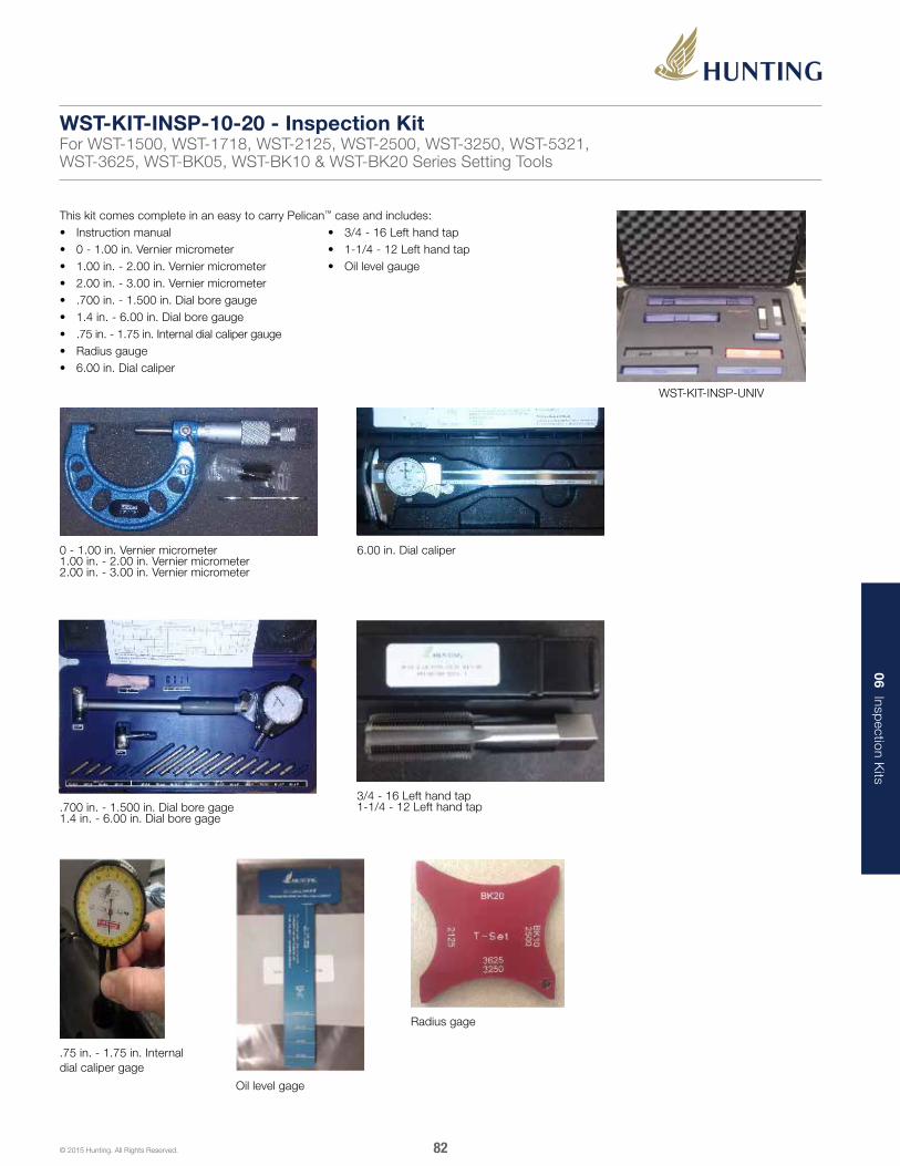
06 Inspection K
its
82© 2015 Hunting. All Rights Reserved.
This kit comes complete in an easy to carry Pelican™ case and includes:• Instruction manual• 0 - 1.00 in. Vernier micrometer• 1.00 in. - 2.00 in. Vernier micrometer• 2.00 in. - 3.00 in. Vernier micrometer• .700 in. - 1.500 in. Dial bore gauge• 1.4 in. - 6.00 in. Dial bore gauge• .75 in. - 1.75 in. Internal dial caliper gauge• Radius gauge• 6.00 in. Dial caliper
• 3/4 - 16 Left hand tap• 1-1/4 - 12 Left hand tap• Oil level gauge
WST-KIT-INSP-UNIV
1.00" - 2.00" Vernier Micrometer•2.00" - 3.00" Vernier Micrometer•
2.00" - 3.00" Vernier Micrometer
1.4" - 6.00" Dial Bore Gage•
.75" - 1.75" Internal DialCaliper Gage
6.00" Dial Caliper
1-1/4 - 12 Left Hand Tap•
Oil Level Gage
Radius Gage
0 - 1.00 in. Vernier micrometer1.00 in. - 2.00 in. Vernier micrometer2.00 in. - 3.00 in. Vernier micrometer
.700 in. - 1.500 in. Dial bore gage1.4 in. - 6.00 in. Dial bore gage
Oil level gage
Radius gage
1.00" - 2.00" Vernier Micrometer•2.00" - 3.00" Vernier Micrometer•
2.00" - 3.00" Vernier Micrometer
1.4" - 6.00" Dial Bore Gage•
.75" - 1.75" Internal DialCaliper Gage
6.00" Dial Caliper
1-1/4 - 12 Left Hand Tap•
Oil Level Gage
Radius Gage
6.00 in. Dial caliper
1.00" - 2.00" Vernier Micrometer•2.00" - 3.00" Vernier Micrometer•
2.00" - 3.00" Vernier Micrometer
1.4" - 6.00" Dial Bore Gage•
.75" - 1.75" Internal DialCaliper Gage
6.00" Dial Caliper
1-1/4 - 12 Left Hand Tap•
Oil Level Gage
Radius Gage
3/4 - 16 Left hand tap1-1/4 - 12 Left hand tap
.75 in. - 1.75 in. Internal dial caliper gage
1.00" - 2.00" Vernier Micrometer•2.00" - 3.00" Vernier Micrometer•
2.00" - 3.00" Vernier Micrometer
1.4" - 6.00" Dial Bore Gage•
.75" - 1.75" Internal DialCaliper Gage
6.00" Dial Caliper
1-1/4 - 12 Left Hand Tap•
Oil Level Gage
Radius Gage
1.00" - 2.00" Vernier Micrometer•2.00" - 3.00" Vernier Micrometer•
2.00" - 3.00" Vernier Micrometer
1.4" - 6.00" Dial Bore Gage•
.75" - 1.75" Internal DialCaliper Gage
6.00" Dial Caliper
1-1/4 - 12 Left Hand Tap•
Oil Level Gage
Radius Gage
WST-KIT-INSP-10-20 - Inspection KitFor WST-1500, WST-1718, WST-2125, WST-2500, WST-3250, WST-5321, WST-3625, WST-BK05, WST-BK10 & WST-BK20 Series Setting Tools

07 Pow
er Chargers and
Igniters
83© 2015 Hunting. All Rights Reserved.
Setting Tool Description Part Numbers for Power Chargers and Igniters
“GO” Style T-Set® Power Charges Primary Igniter
1.50 in. (3.81 cm) O.D. Single Stage DB-HDO-1500-100
DB-DET-2700-0741
1.71 in. (4.34 cm) O.D. Single Stage DB-HDO-1500-100
2.50 in. (6.35 cm) O.D. Single Stage DB-HDO-2500-200
3.50 in. (8.89 cm) O.D. Single Stage DB-HDO-3500-100
3.63 in. (9.21 cm) O.D. Single Stage DB-HDO-3625-100
3.63 in. (9.21 cm) O.D. High Pressure DB-HDO-3625-100
1.71 in. (4.34 cm) O.D. Multi-Stage DB-HDO-1687-100
2.13 in. (5.40 cm) O.D. Multi-Stage DB-HDO-3625-100
3.25 in. (8.25 cm) O.D. Multi-Stage JEC-5336-099
4.50 in. (11.43 cm) O.D. Multi-Stage Call for Availability
Diamond Back Charges and Igniters
T-Set® Setting Tool Slow Set Charges Standard Charges Primary Igniters Secondary Igniter
Size 05 N/A DB-BPC-0800-005S
DB-DET-2700-075 BP3
DB-DET-2700-075 (4) BP4DET-2700-076Size 10 DB-BPC-1300-010 DB-BPC-1300-010S
Size 20 DB-BPC-1500-020 DB-BPC-1500-020S
Baker Hughes Charges and Igniters
T-Set® Setting Tool Slow Set Charges Standard Charges Primary Igniters Secondary Igniters
Size 05 BOT-H437660550 BOT-H437641500
BP-3S: BOT-H437442200
BP-4S: BOT-H437444200
BP-5S: BOT-H437440001
BOT-H437431000Size 10 BOT-H437660010 BOT-H437642113
Size 20 BOT-H437660020 BOT-H437643223
Power Chargers and IgnitersFor T-Set® Tools