product catalog - gibson stainless stainless catalog.pdf · gibson stainless makes an effort to...
TRANSCRIPT
PRODUCT CATALOGSTAINLESS STEEL CONDUIT & FITTINGS
ALL STAINLESS STEEL • ALL IN STOCK
All Stainless Steel • All In Stock2
Introduction
When Gibson Stainless was founded in 1995, Type 316 SS electrical fittings were very hard to find. Zinc plated, galvanized, carbon steel, etc. were the norm in the industry, as they were lower in price. Reinstallation of zinc plated, galvanized, and carbon steels, however, became very expensive, and the demand began to increase for products that would withstand corrosive elements and harsh conditions, enabling the conduit system to last longer.
Gibson Stainless started with a line that consisted of just products used as support fittings. The company had nine total products, which included only two product categories. As the demand grew, a few strut accessories and other various support accessories were added. As time passed, the conduit, conduit bodies, device boxes, hubs, etc. were added to offer a conduit system entirely in Type 316 SS.
Our approach at Gibson may be a little different than most. Quality is our number one priority throughout all of the processing steps and is one thing we are never willing to sacrifice. Every product we offer is polished to achieve a bright finish. Each individual part is inspected at various stages of production and assembly and then again during packaging. All items are packaged and labeled individually. All of our conduit is shipped securely in wooden, custom-built crates.
Just as important to the quality of the product we offer, is the quality of the customer service we provide. We strive to give our customers fast and accurate responses. While all Gibson Stainless items are stock items, we do occasionally have less in stock than required by the customer. When this happens, we give our customers realistic and reliable lead times. We hope that doing business with Gibson Stainless is enjoyable and that we are perceived as offering a true quality package made up of both the product and our service.
Often referred to as the “premier” stainless steel provider, Gibson Stainless & Specialty, Inc. was the pioneer of stainless steel electrical systems, beginning its operations in 1995.
All of our products are designed to meet and exceed standard electrical industry practices. Many of our products are UL listed, and most are 100% Made in the USA. Maintain-ing a very large inventory, we are able to ship over 90% of our orders complete within 24 hours to ensure you receive the right parts quickly.
Gibson Stainless constantly works to expand its product line and strives to be the leader in developing new stainless steel products as required by the industry. We welcome requests for new products and will do the best we can to work with you.
Please refer to our website www.gibsonstainless.com for ongoing product line additions.
Gibson Stainless makes an effort to ensure the accuracy of the information contained within this catalog. Gibson reserves the right to make changes from time to time without notice. Any changes or updates to dimensions,
standards, country of origin, etc. will immediately be reflected online at www.gibsonstainless.com.
“
www.gibsonstainless.comPHONE 1-800-945-4316 • FAX 724-838-1544 3
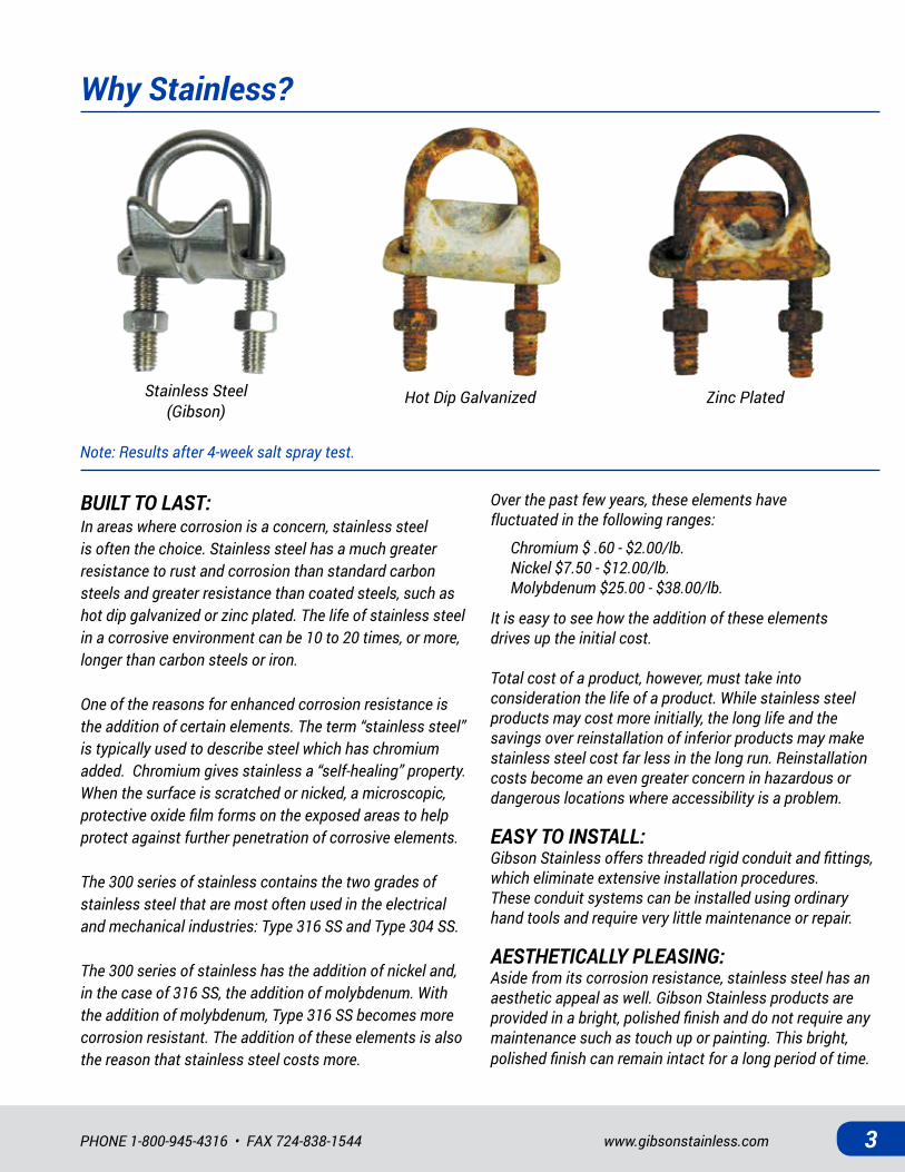
Why Stainless?
BUILT TO LAST:In areas where corrosion is a concern, stainless steel is often the choice. Stainless steel has a much greater resistance to rust and corrosion than standard carbon steels and greater resistance than coated steels, such as hot dip galvanized or zinc plated. The life of stainless steel in a corrosive environment can be 10 to 20 times, or more, longer than carbon steels or iron.
One of the reasons for enhanced corrosion resistance is the addition of certain elements. The term “stainless steel” is typically used to describe steel which has chromium added. Chromium gives stainless a “self-healing” property. When the surface is scratched or nicked, a microscopic, protective oxide film forms on the exposed areas to help protect against further penetration of corrosive elements.
The 300 series of stainless contains the two grades of stainless steel that are most often used in the electrical and mechanical industries: Type 316 SS and Type 304 SS.
The 300 series of stainless has the addition of nickel and, in the case of 316 SS, the addition of molybdenum. With the addition of molybdenum, Type 316 SS becomes more corrosion resistant. The addition of these elements is also the reason that stainless steel costs more.
Over the past few years, these elements have fluctuated in the following ranges:
Chromium $ .60 - $2.00/lb.Nickel $7.50 - $12.00/lb.Molybdenum $25.00 - $38.00/lb.
It is easy to see how the addition of these elements drives up the initial cost.
Total cost of a product, however, must take into consideration the life of a product. While stainless steel products may cost more initially, the long life and the savings over reinstallation of inferior products may make stainless steel cost far less in the long run. Reinstallation costs become an even greater concern in hazardous or dangerous locations where accessibility is a problem.
EASY TO INSTALL:Gibson Stainless offers threaded rigid conduit and fittings, which eliminate extensive installation procedures. These conduit systems can be installed using ordinary hand tools and require very little maintenance or repair.
AESTHETICALLY PLEASING:Aside from its corrosion resistance, stainless steel has an aesthetic appeal as well. Gibson Stainless products are provided in a bright, polished finish and do not require any maintenance such as touch up or painting. This bright, polished finish can remain intact for a long period of time.
Stainless Steel(Gibson)
Hot Dip Galvanized Zinc Plated
Note: Results after 4-week salt spray test.
All Stainless Steel • All In Stock4
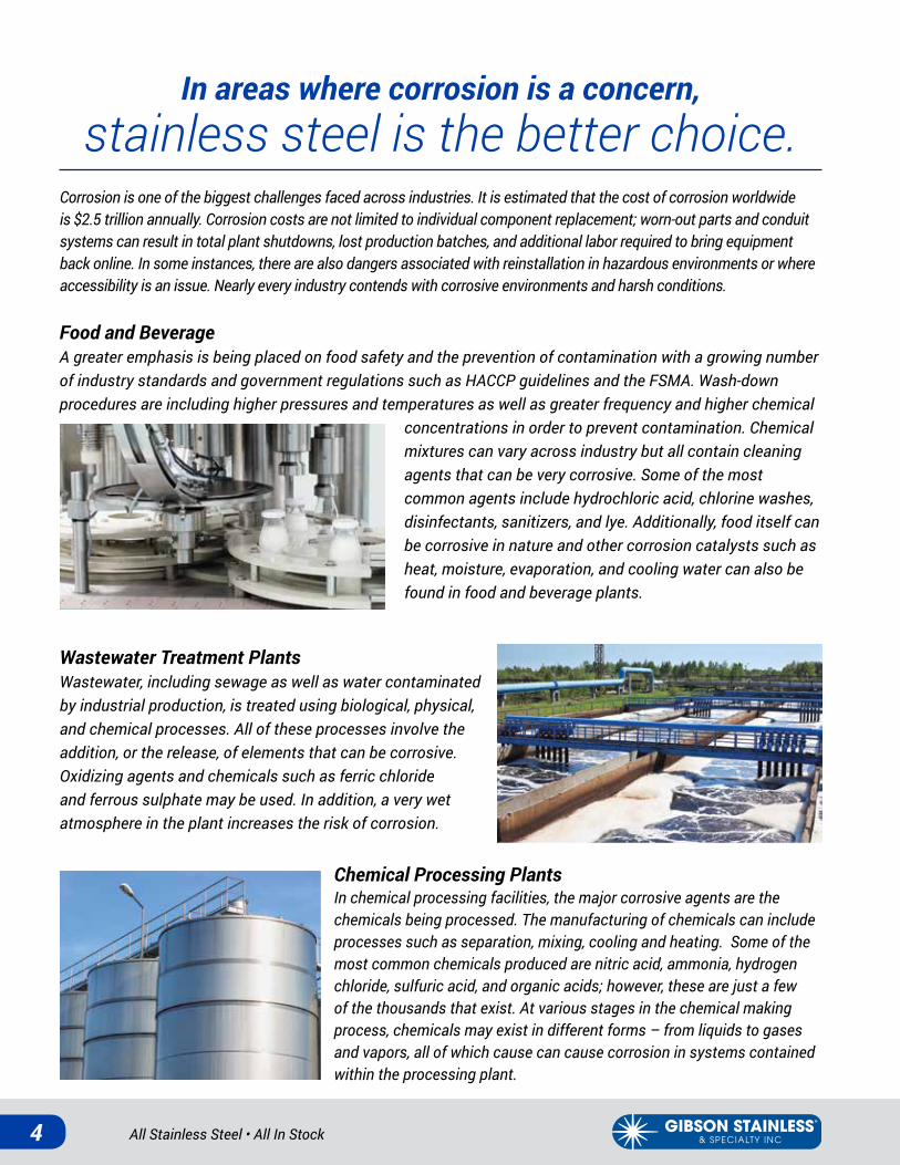
In areas where corrosion is a concern, stainless steel is the better choice.
Corrosion is one of the biggest challenges faced across industries. It is estimated that the cost of corrosion worldwide is $2.5 trillion annually. Corrosion costs are not limited to individual component replacement; worn-out parts and conduit systems can result in total plant shutdowns, lost production batches, and additional labor required to bring equipment back online. In some instances, there are also dangers associated with reinstallation in hazardous environments or where accessibility is an issue. Nearly every industry contends with corrosive environments and harsh conditions.
Food and BeverageA greater emphasis is being placed on food safety and the prevention of contamination with a growing number of industry standards and government regulations such as HACCP guidelines and the FSMA. Wash-down procedures are including higher pressures and temperatures as well as greater frequency and higher chemical
concentrations in order to prevent contamination. Chemical mixtures can vary across industry but all contain cleaning agents that can be very corrosive. Some of the most common agents include hydrochloric acid, chlorine washes, disinfectants, sanitizers, and lye. Additionally, food itself can be corrosive in nature and other corrosion catalysts such as heat, moisture, evaporation, and cooling water can also be found in food and beverage plants.
Wastewater Treatment PlantsWastewater, including sewage as well as water contaminated by industrial production, is treated using biological, physical, and chemical processes. All of these processes involve the addition, or the release, of elements that can be corrosive. Oxidizing agents and chemicals such as ferric chloride and ferrous sulphate may be used. In addition, a very wet atmosphere in the plant increases the risk of corrosion.
Chemical Processing PlantsIn chemical processing facilities, the major corrosive agents are the chemicals being processed. The manufacturing of chemicals can include processes such as separation, mixing, cooling and heating. Some of the most common chemicals produced are nitric acid, ammonia, hydrogen chloride, sulfuric acid, and organic acids; however, these are just a few of the thousands that exist. At various stages in the chemical making process, chemicals may exist in different forms – from liquids to gases and vapors, all of which cause can cause corrosion in systems contained within the processing plant.
www.gibsonstainless.comPHONE 1-800-945-4316 • FAX 724-838-1544 5
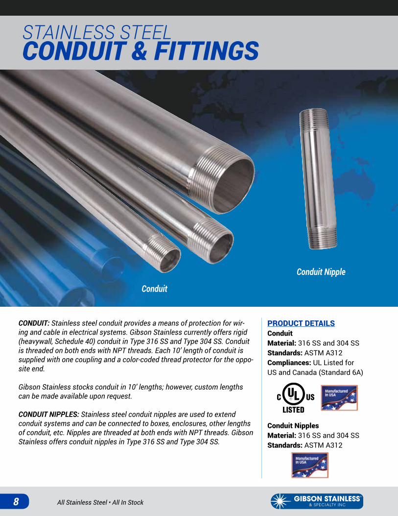
InfrastructureTunnels, bridges, and buildings are continuously exposed to weather and elements that can cause corrosion. Water takes on many forms – rain, ice, sleet, snow – and can be corrosive to metals, especially when the metals are exposed for long periods of time. An even greater corrosive element is acid rain. Structures such as tunnels and bridges are also exposed to road salts and deicing liquids. Road salts are composed of sodium and chloride ions and may contain other elements such as ferrocyanide and impurities that can greatly increase rates of corrosion.
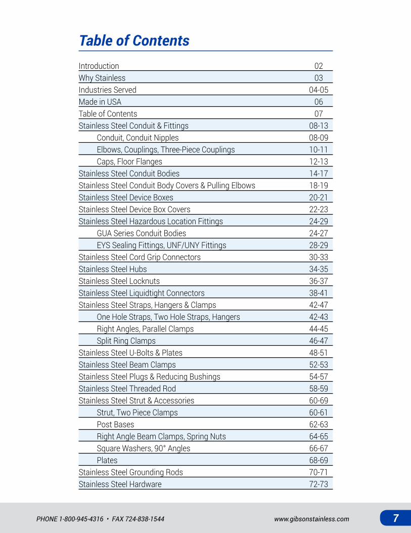
Coastal and Marine EnvironmentsThe salt ions and impurities found in seawater give it its corrosive nature. The most abundant ions found include chloride, sodium, magnesium, sulfate, calcium, and potassium. Elements such as dissolved gases, organic materials, and microscopic organisms are also present.
Metals that come in direct contact with saltwater are at risk; however, so are metals that are simply present in saltwater atmospheres. Locations within five to ten miles of saltwater are at risk for corrosion as sea salt can be carried by weather (wind, fog, and rain).
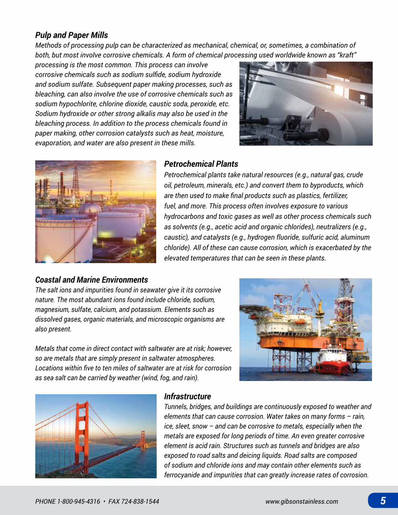
Pulp and Paper MillsMethods of processing pulp can be characterized as mechanical, chemical, or, sometimes, a combination of both, but most involve corrosive chemicals. A form of chemical processing used worldwide known as “kraft” processing is the most common. This process can involve corrosive chemicals such as sodium sulfide, sodium hydroxide and sodium sulfate. Subsequent paper making processes, such as bleaching, can also involve the use of corrosive chemicals such as sodium hypochlorite, chlorine dioxide, caustic soda, peroxide, etc. Sodium hydroxide or other strong alkalis may also be used in the bleaching process. In addition to the process chemicals found in paper making, other corrosion catalysts such as heat, moisture, evaporation, and water are also present in these mills.
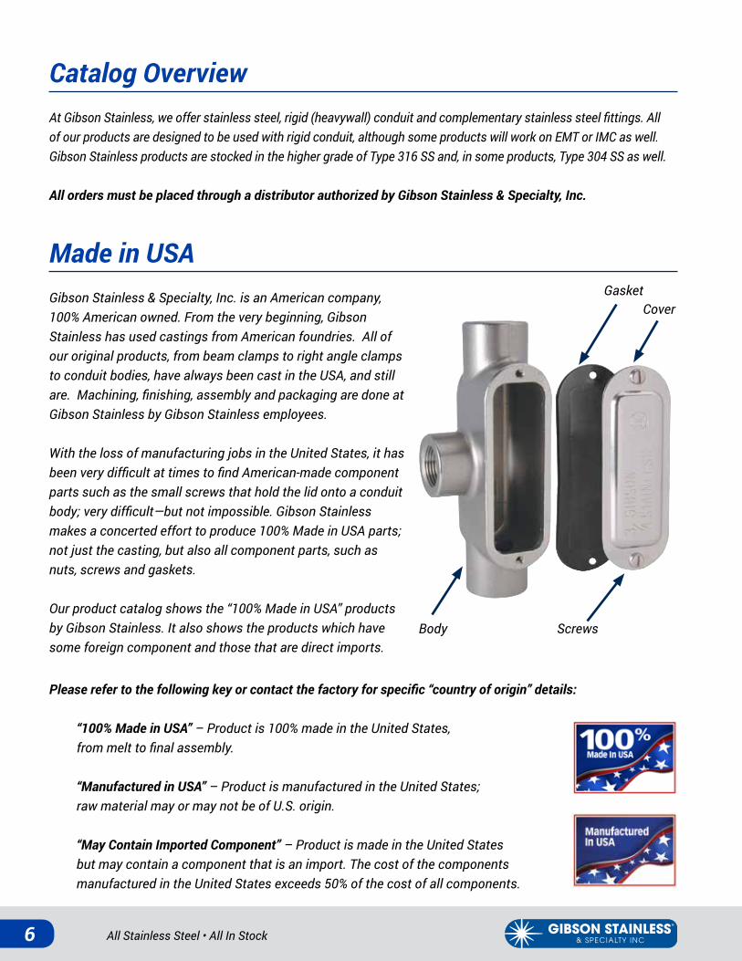
Petrochemical PlantsPetrochemical plants take natural resources (e.g., natural gas, crude oil, petroleum, minerals, etc.) and convert them to byproducts, which are then used to make final products such as plastics, fertilizer, fuel, and more. This process often involves exposure to various hydrocarbons and toxic gases as well as other process chemicals such as solvents (e.g., acetic acid and organic chlorides), neutralizers (e.g., caustic), and catalysts (e.g., hydrogen fluoride, sulfuric acid, aluminum chloride). All of these can cause corrosion, which is exacerbated by the elevated temperatures that can be seen in these plants.
All Stainless Steel • All In Stock6
Made in USAGibson Stainless & Specialty, Inc. is an American company, 100% American owned. From the very beginning, Gibson Stainless has used castings from American foundries. All of our original products, from beam clamps to right angle clamps to conduit bodies, have always been cast in the USA, and still are. Machining, finishing, assembly and packaging are done at Gibson Stainless by Gibson Stainless employees.
With the loss of manufacturing jobs in the United States, it has been very difficult at times to find American-made component parts such as the small screws that hold the lid onto a conduit body; very difficult—but not impossible. Gibson Stainless makes a concerted effort to produce 100% Made in USA parts; not just the casting, but also all component parts, such as nuts, screws and gaskets.
Our product catalog shows the “100% Made in USA” products by Gibson Stainless. It also shows the products which have some foreign component and those that are direct imports.
Please refer to the following key or contact the factory for specific “country of origin” details:
“100% Made in USA” – Product is 100% made in the United States, from melt to final assembly.
“Manufactured in USA” – Product is manufactured in the United States; raw material may or may not be of U.S. origin.
“May Contain Imported Component” – Product is made in the United States but may contain a component that is an import. The cost of the components manufactured in the United States exceeds 50% of the cost of all components.
Gasket
ScrewsBody
Cover
Catalog OverviewAt Gibson Stainless, we offer stainless steel, rigid (heavywall) conduit and complementary stainless steel fittings. All of our products are designed to be used with rigid conduit, although some products will work on EMT or IMC as well. Gibson Stainless products are stocked in the higher grade of Type 316 SS and, in some products, Type 304 SS as well.
All orders must be placed through a distributor authorized by Gibson Stainless & Specialty, Inc.
www.gibsonstainless.comPHONE 1-800-945-4316 • FAX 724-838-1544 7
Table of ContentsIntroduction 02Why Stainless 03Industries Served 04-05Made in USA 06Table of Contents 07Stainless Steel Conduit & Fittings 08-13 Conduit, Conduit Nipples 08-09 Elbows, Couplings, Three-Piece Couplings 10-11 Caps, Floor Flanges 12-13Stainless Steel Conduit Bodies 14-17Stainless Steel Conduit Body Covers & Pulling Elbows 18-19Stainless Steel Device Boxes 20-21Stainless Steel Device Box Covers 22-23Stainless Steel Hazardous Location Fittings 24-29 GUA Series Conduit Bodies 24-27 EYS Sealing Fittings, UNF/UNY Fittings 28-29Stainless Steel Cord Grip Connectors 30-33Stainless Steel Hubs 34-35Stainless Steel Locknuts 36-37Stainless Steel Liquidtight Connectors 38-41Stainless Steel Straps, Hangers & Clamps 42-47 One Hole Straps, Two Hole Straps, Hangers 42-43 Right Angles, Parallel Clamps 44-45 Split Ring Clamps 46-47Stainless Steel U-Bolts & Plates 48-51Stainless Steel Beam Clamps 52-53Stainless Steel Plugs & Reducing Bushings 54-57Stainless Steel Threaded Rod 58-59Stainless Steel Strut & Accessories 60-69 Strut, Two Piece Clamps 60-61 Post Bases 62-63 Right Angle Beam Clamps, Spring Nuts 64-65 Square Washers, 90° Angles 66-67 Plates 68-69Stainless Steel Grounding Rods 70-71Stainless Steel Hardware 72-73
All Stainless Steel • All In Stock8
STAINLESS STEEL CONDUIT & FITTINGS
CONDUIT: Stainless steel conduit provides a means of protection for wir-ing and cable in electrical systems. Gibson Stainless currently offers rigid (heavywall, Schedule 40) conduit in Type 316 SS and Type 304 SS. Conduit is threaded on both ends with NPT threads. Each 10’ length of conduit is supplied with one coupling and a color-coded thread protector for the oppo-site end.
Gibson Stainless stocks conduit in 10’ lengths; however, custom lengths can be made available upon request.
CONDUIT NIPPLES: Stainless steel conduit nipples are used to extend conduit systems and can be connected to boxes, enclosures, other lengths of conduit, etc. Nipples are threaded at both ends with NPT threads. Gibson Stainless offers conduit nipples in Type 316 SS and Type 304 SS.
PRODUCT DETAILSConduitMaterial: 316 SS and 304 SSStandards: ASTM A312Compliances: UL Listed for US and Canada (Standard 6A)
Conduit NipplesMaterial: 316 SS and 304 SSStandards: ASTM A312
Conduit Nipple
Conduit

www.gibsonstainless.comPHONE 1-800-945-4316 • FAX 724-838-1544 9
Conduit
Conduit Nipples
Part Weight/ Pitch Length w/o Outside Wall Inside Number Size Stick (lbs.) (Threads per Inch) Coupling “A” (ft.) Diameter “B” (in.) Thickness “C” (in.) Diameter “D” (in.)CND50 ½ in. 8 14 9-11-¼ 0.84 0.11 0.62CND75 ¾ in. 11 14 9-11-¼ 1.05 0.11 0.82CND100 1 in. 16 11-½ 9-11 1.32 0.13 1.05CND125 1-¼ in. 22 11-½ 9-11 1.66 0.14 1.38CND150 1-½ in. 26 11-½ 9-11 1.90 0.15 1.61CND200 2 in. 35 11-½ 9-11 2.38 0.15 2.07CND250 2-½ in. 55 8 9-10-½ 2.88 0.20 2.47CND300 3 in. 72 8 9-10-½ 3.50 0.22 3.07CND400 4 in. 100 8 9-10-¼ 4.50 0.24 4.03Type 316 SS part numbers listed above; Type 304 SS products are denoted by adding “-304SS.” For example: CND75-304SS
CA
B D
NPT Thread
*shown without coupling
Part Outside Wall Inside |-----------------------------Length “D” (in.)----------------------------| Number Size Diameter “A” (in.) Thickness “B” (in.) Diameter “C” (in.) Close NIP50 ½ in. 0.84 0.11 0.62 1.13 2” 2-½” 3” 3-½” 4” 5” 6” 8” 10” 12”NIP75 ¾ in. 1.05 0.11 0.82 1.38 2” 2-½” 3” 3-½” 4” 5” 6” 8” 10” 12”NIP100 1 in. 1.32 0.13 1.05 1.50 2” 2-½” 3” 3-½” 4” 5” 6” 8” 10” 12”NIP125 1-¼ in. 1.66 0.14 1.38 1.75 2” 2-½” 3” 3-½” 4” 5” 6” 8” 10” 12”NIP150 1-½ in. 1.90 0.15 1.61 1.75 2” 2-½” 3” 3-½” 4” 5” 6” 8” 10” 12”NIP200 2 in. 2.38 0.15 2.07 2.00 * 2-½” 3” 3-½” 4” 5” 6” 8” 10” 12”*2” x Close nipples are 2” long.Format of full part number is part number x length. For example. NIP75x2.Type 316 SS part numbers listed above; Type 304 products are denoted by adding “-304SS.” For example: NIP75x2-304SS.
BD
A
NPT Thread
C

All Stainless Steel • All In Stock10
STAINLESS STEEL CONDUIT & FITTINGS
CONDUIT ELBOWS: Stainless steel conduit elbows are bent sections of rigid conduit that help in changing the direction of conduit. Gibson Stainless offers standard radius, 90º elbows in Type 316 SS and Type 304 SS. Elbows are threaded on both ends with NPT threads and are supplied with two thread protectors.
COUPLINGS: Stainless steel conduit couplings provide a means of joining conduit, elbows, nipples, etc. Couplings are straight threaded and are designed for use with NPT threaded conduit products. Gibson Stainless offers conduit couplings in Type 316 SS and Type 304 SS.
THREE-PIECE COUPLINGS: Three-piece couplings are used to join and connect the threaded ends of rigid conduit where the conduit cannot be turned.
PRODUCT DETAILS Conduit ElbowsMaterial: 316 SS and 304 SSStandards: ASTM A312Compliances: UL Listed for US and Canada (Standard 6A)
Conduit ElbowCoupling
Three-Piece Coupling
CouplingsMaterial: 316 SS and 304 SSStandards: ASTM A479Compliances: UL Listed for US and Canada (Standard 6A)
Three-Piece CouplingsMaterial: 316 SSStandards: ASTM A479
www.gibsonstainless.comPHONE 1-800-945-4316 • FAX 724-838-1544 11
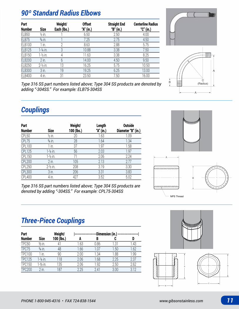
90º Standard Radius Elbows
Couplings
Three-Piece Couplings
Part Weight/ Offset Straight End Centerline Radius Number Size Each (lbs.) “A” (in.) “B” (in.) “C” (in.)ELB50 ½ in. 1 6.50 2.50 4.00ELB75 ¾ in. 1 7.25 2.75 4.50ELB100 1 in. 2 8.63 2.88 5.75ELB125 1-¼ in. 3 10.88 3.38 7.50ELB150 1-½ in. 4 11.63 3.38 8.25ELB200 2 in. 6 14.00 4.50 9.50ELB250 2-½ in. 13 16.25 5.75 10.50ELB300 3 in. 19 19.25 6.25 13.00ELB400 4 in. 31 23.50 7.50 16.00
Type 316 SS part numbers listed above; Type 304 SS products are denoted by adding “-304SS.” For example: ELB75-304SS
Type 316 SS part numbers listed above; Type 304 SS products are denoted by adding “-304SS.” For example: CPL75-304SS
Part Weight/ Length Outside Number Size 100 (lbs.) “A” (in.) Diameter “B” (in.)CPL50 ½ in. 20 1.63 1.09CPL75 ¾ in. 28 1.64 1.34CPL100 1 in. 37 1.97 1.58CPL125 1-¼ in. 56 2.03 1.97CPL150 1-½ in. 71 2.06 2.24CPL200 2 in. 105 2.13 2.77CPL250 2-½ in. 208 3.19 3.30CPL300 3 in. 206 3.31 3.83CPL400 4 in. 427 3.52 5.02
A
B
NPS Thread
C
A D
B
Part Weight/ |----------------Dimension (in.) ---------------| Number Size 100 (lbs.) A B C DTPC50 ½ in. 41 1.63 0.86 1.31 1.43TPC75 ¾ in. 48 1.66 1.07 1.50 1.62TPC100 1 in. 90 2.00 1.34 1.88 1.99TPC125 1-¼ in. 118 2.06 1.68 2.25 2.37TPC150 1-½ in. 135 2.06 1.92 2.50 2.62TPC200 2 in. 187 2.25 2.41 3.00 3.12

All Stainless Steel • All In Stock12
STAINLESS STEEL CONDUIT & FITTINGS
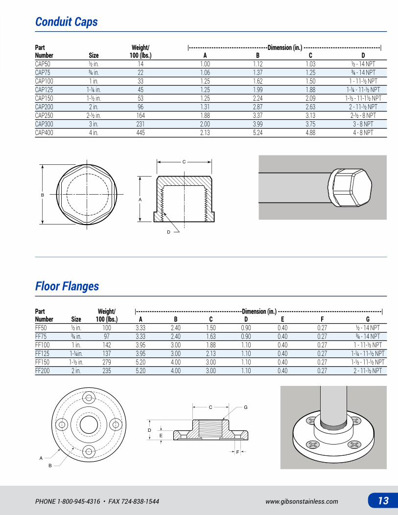
CONDUIT CAPS: Conduit caps are used to cap off or to end runs of conduit in a conduit system. These caps can allow for future system expansion or rerouting of conduit. Caps have NPT threads and are designed for use with rigid conduit. Hexagonal flats allow for easy tightening with standard hand tools.
FLOOR FLANGES: Floor flanges are designed to mount threaded conduit to floors or walls and are used predominantly where the conduit is being used as a structural member.
PRODUCT DETAILS Conduit CapsMaterial: 316 SSStandards: ASTM A479*Sizes ½" - 3" 100% Made in USA; 4" size Manufactured in USA
Floor FlangesMaterial: 316 SSStandards: ASTM A479
Conduit Cap
Floor Flange
www.gibsonstainless.comPHONE 1-800-945-4316 • FAX 724-838-1544 13
Conduit Caps
Floor Flanges
Part Weight/ |-----------------------------------Dimension (in.) ----------------------------------| Number Size 100 (lbs.) A B C DCAP50 ½ in. 14 1.00 1.12 1.03 ½ - 14 NPTCAP75 ¾ in. 22 1.06 1.37 1.25 ¾ - 14 NPTCAP100 1 in. 33 1.25 1.62 1.50 1 - 11-½ NPTCAP125 1-¼ in. 45 1.25 1.99 1.88 1-¼ - 11-½ NPTCAP150 1-½ in. 53 1.25 2.24 2.09 1-½ - 11-1½ NPTCAP200 2 in. 96 1.31 2.87 2.63 2 - 11-½ NPTCAP250 2-½ in. 164 1.88 3.37 3.13 2-½ - 8 NPTCAP300 3 in. 231 2.00 3.99 3.75 3 - 8 NPTCAP400 4 in. 445 2.13 5.24 4.88 4 - 8 NPT
Part Weight/ |-----------------------------------------------Dimension (in.) ----------------------------------------------| Number Size 100 (lbs.) A B C D E F GFF50 ½ in. 100 3.33 2.40 1.50 0.90 0.40 0.27 ½ - 14 NPTFF75 ¾ in. 97 3.33 2.40 1.63 0.90 0.40 0.27 ¾ - 14 NPTFF100 1 in. 142 3.95 3.00 1.88 1.10 0.40 0.27 1 - 11-½ NPTFF125 1-¼in. 137 3.95 3.00 2.13 1.10 0.40 0.27 1-¼ - 11-½ NPTFF150 1-½ in. 279 5.20 4.00 3.00 1.10 0.40 0.27 1-½ - 11-½ NPTFF200 2 in. 235 5.20 4.00 3.00 1.10 0.40 0.27 2 - 11-½ NPT
A
B
C
D
A
B
C
D
DE
G
AB
F
C
DE
G
AB
F
C
All Stainless Steel • All In Stock14
STAINLESS STEEL CONDUIT BODIES
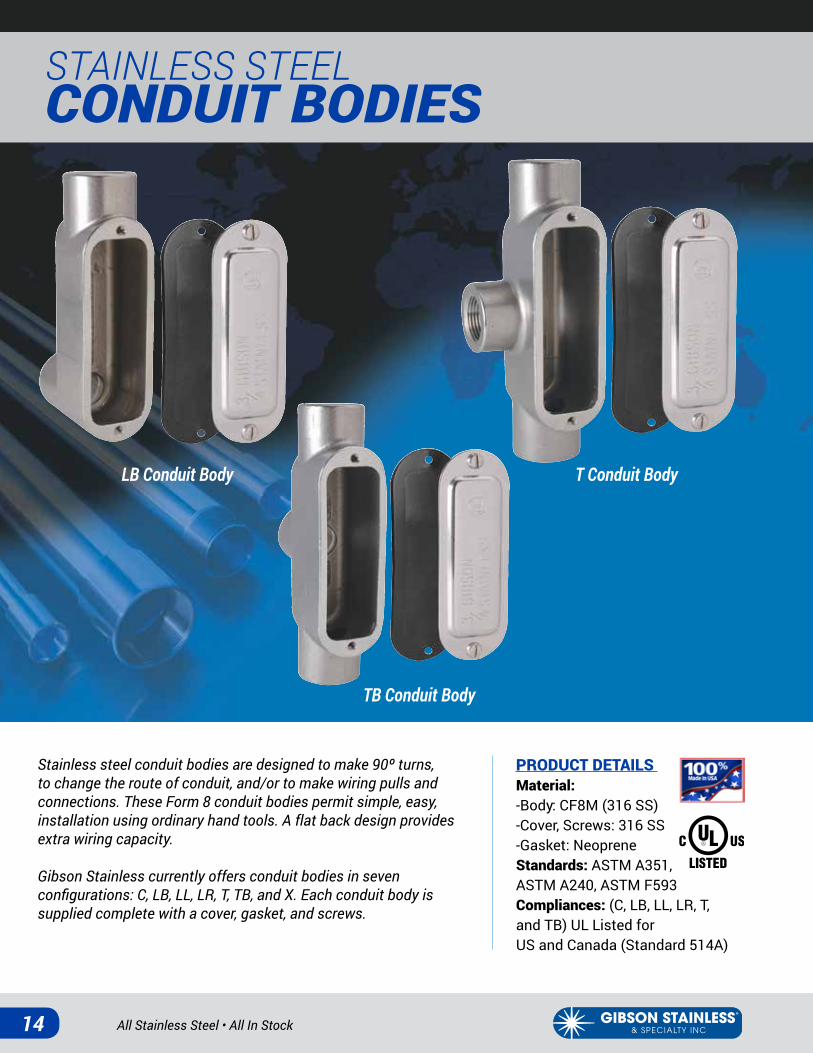
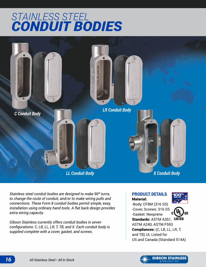
Stainless steel conduit bodies are designed to make 90º turns, to change the route of conduit, and/or to make wiring pulls and connections. These Form 8 conduit bodies permit simple, easy, installation using ordinary hand tools. A flat back design provides extra wiring capacity.
Gibson Stainless currently offers conduit bodies in seven configurations: C, LB, LL, LR, T, TB, and X. Each conduit body is supplied complete with a cover, gasket, and screws.
PRODUCT DETAILS Material: -Body: CF8M (316 SS)-Cover, Screws: 316 SS-Gasket: NeopreneStandards: ASTM A351, ASTM A240, ASTM F593 Compliances: (C, LB, LL, LR, T, and TB) UL Listed for US and Canada (Standard 514A)
LB Conduit Body T Conduit Body
TB Conduit Body
www.gibsonstainless.comPHONE 1-800-945-4316 • FAX 724-838-1544 15
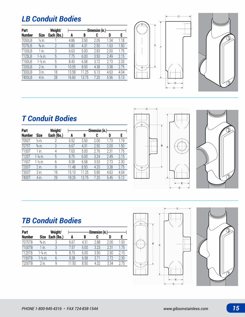
LB Conduit BodiesPart Weight/ |----------------Dimension (in.)----------------| Number Size Each (lbs.) A B C D E7050LB ½ in. 1 4.86 3.50 2.05 1.34 1.187075LB ¾ in. 2 5.80 4.31 2.50 1.63 1.507100LB 1 in. 3 6.63 5.00 2.83 2.00 1.757125LB 1-¼ in. 5 7.75 6.00 3.50 2.49 2.157150LB 1-½ in. 5 8.43 6.58 3.72 2.73 2.337200LB 2 in. 9 10.55 8.50 4.38 3.38 2.757300LB 3 in. 18 13.58 11.25 6.13 4.63 4.047400LB 4 in. 28 16.60 13.75 7.20 5.56 5.13
T Conduit BodiesPart Weight/ |-----------------Dimension (in.)----------------| Number Size Each (lbs.) A B C D E7050T ½ in. 2 5.52 3.50 2.00 1.73 1.197075T ¾ in. 3 6.67 4.31 2.50 2.00 1.507100T 1 in. 4 7.63 5.00 2.76 2.31 1.757125T 1-¼ in. 5 8.75 6.00 3.24 2.49 2.157150T 1-½ in. 6 9.38 6.58 3.53 2.73 2.307200T 2 in. 9 11.48 8.50 4.20 3.38 2.757300T 3 in. 19 15.10 11.25 5.85 4.63 4.047400T 4 in. 29 18.25 13.75 7.20 5.45 5.12
TB Conduit BodiesPart Weight/ |-----------------Dimension (in.)---------------| Number Size Each (lbs.) A B C D E7075TB ¾ in. 3 6.67 4.31 2.88 2.00 1.507100TB 1 in. 3 7.57 5.00 3.23 2.31 1.757125TB 1-¼ in. 5 8.75 6.00 3.50 2.50 2.157150TB 1-½ in. 6 9.38 6.58 3.71 2.72 2.307200TB 2 in. 9 11.50 8.50 4.32 3.34 2.75
All Stainless Steel • All In Stock16
STAINLESS STEEL CONDUIT BODIES
Stainless steel conduit bodies are designed to make 90º turns, to change the route of conduit, and/or to make wiring pulls and connections. These Form 8 conduit bodies permit simple, easy, installation using ordinary hand tools. A flat back design provides extra wiring capacity.
Gibson Stainless currently offers conduit bodies in seven configurations: C, LB, LL, LR, T, TB, and X. Each conduit body is supplied complete with a cover, gasket, and screws.
PRODUCT DETAILS Material: -Body: CF8M (316 SS)-Cover, Screws: 316 SS-Gasket: NeopreneStandards: ASTM A351, ASTM A240, ASTM F593 Compliances: (C, LB, LL, LR, T, and TB) UL Listed for US and Canada (Standard 514A)
C Conduit Body
X Conduit Body
LR Conduit Body
LL Conduit Body
www.gibsonstainless.comPHONE 1-800-945-4316 • FAX 724-838-1544 17
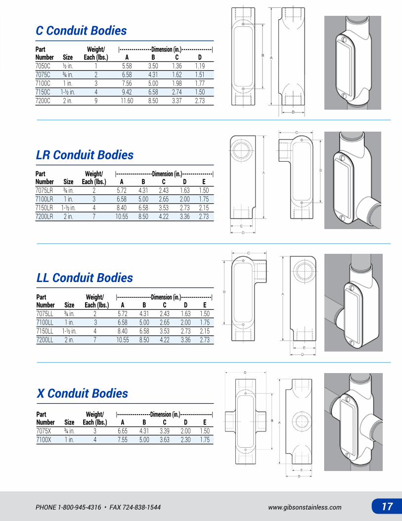
C Conduit Bodies
LL Conduit Bodies
LR Conduit Bodies
Part Weight/ |----------------Dimension (in.)---------------| Number Size Each (lbs.) A B C D7050C ½ in. 1 5.58 3.50 1.36 1.197075C ¾ in. 2 6.58 4.31 1.62 1.517100C 1 in. 3 7.56 5.00 1.98 1.777150C 1-½ in. 4 9.42 6.58 2.74 1.50 7200C 2 in. 9 11.60 8.50 3.37 2.73
Part Weight/ |------------------Dimension (in.)---------------| Number Size Each (lbs.) A B C D E7075LR ¾ in. 2 5.72 4.31 2.43 1.63 1.507100LR 1 in. 3 6.58 5.00 2.65 2.00 1.757150LR 1-½ in. 4 8.40 6.58 3.53 2.73 2.157200LR 2 in. 7 10.55 8.50 4.22 3.36 2.73
Part Weight/ |-----------------Dimension (in.)---------------| Number Size Each (lbs.) A B C D E7075LL ¾ in. 2 5.72 4.31 2.43 1.63 1.507100LL 1 in. 3 6.58 5.00 2.65 2.00 1.757150LL 1-½ in. 4 8.40 6.58 3.53 2.73 2.157200LL 2 in. 7 10.55 8.50 4.22 3.36 2.73
X Conduit BodiesPart Weight/ |-----------------Dimension (in.)----------------| Number Size Each (lbs.) A B C D E7075X ¾ in. 3 6.65 4.31 3.39 2.00 1.507100X 1 in. 4 7.55 5.00 3.63 2.30 1.75
All Stainless Steel • All In Stock18
STAINLESS STEEL CONDUIT BODY COVERS & PULLING ELBOWS
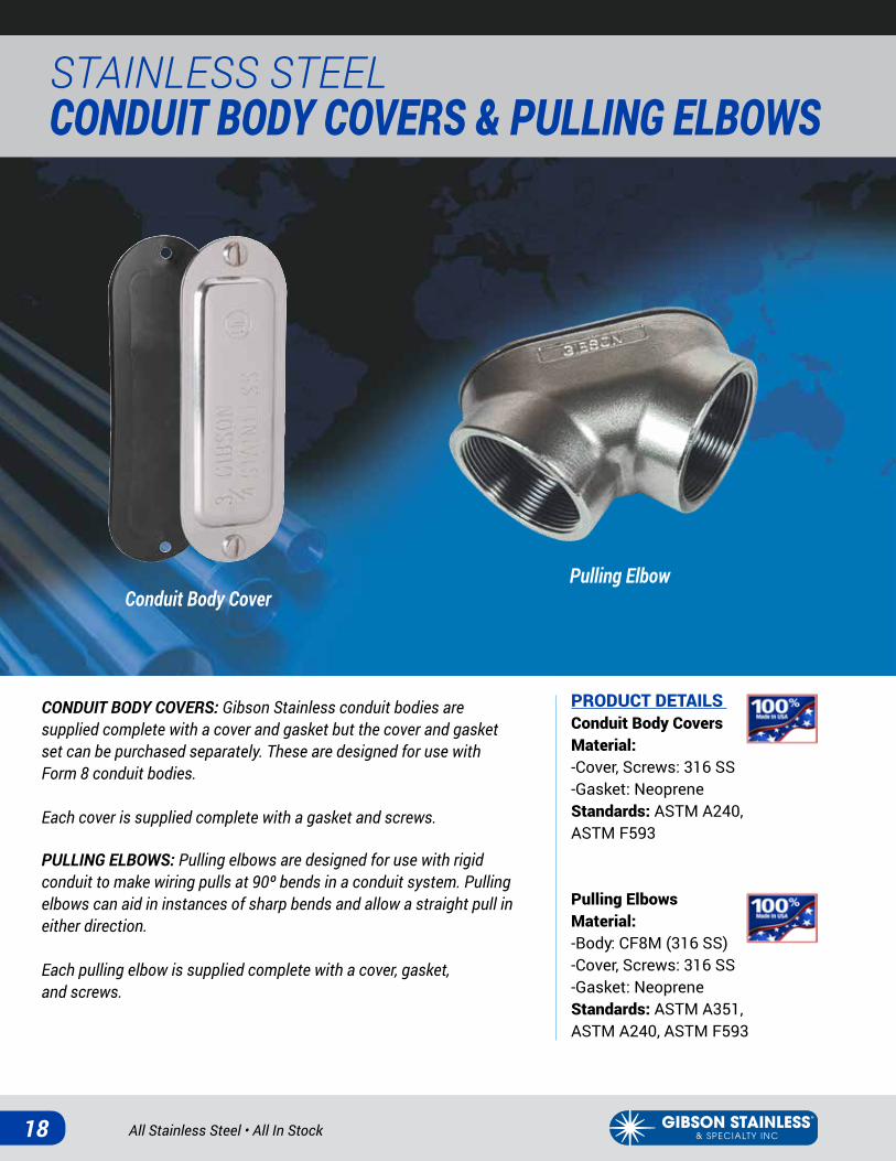
Conduit Body CoverPulling Elbow
CONDUIT BODY COVERS: Gibson Stainless conduit bodies are supplied complete with a cover and gasket but the cover and gasket set can be purchased separately. These are designed for use with Form 8 conduit bodies.
Each cover is supplied complete with a gasket and screws.
PULLING ELBOWS: Pulling elbows are designed for use with rigid conduit to make wiring pulls at 90º bends in a conduit system. Pulling elbows can aid in instances of sharp bends and allow a straight pull in either direction.
Each pulling elbow is supplied complete with a cover, gasket, and screws.
PRODUCT DETAILS Conduit Body CoversMaterial: -Cover, Screws: 316 SS-Gasket: NeopreneStandards: ASTM A240, ASTM F593
Pulling ElbowsMaterial: -Body: CF8M (316 SS)-Cover, Screws: 316 SS-Gasket: NeopreneStandards: ASTM A351, ASTM A240, ASTM F593
www.gibsonstainless.comPHONE 1-800-945-4316 • FAX 724-838-1544 19
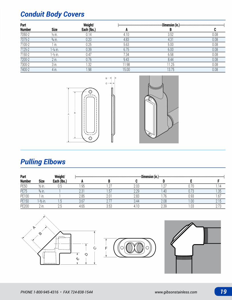
Conduit Body Covers
Pulling Elbows
Part Weight/ |--------------------------------------Dimension (in.)--------------------------------------| Number Size Each (lbs.) A B C7050-2 ½ in. 0.14 4.10 3.52 0.087075-2 ¾ in. 0.20 4.83 4.31 0.087100-2 1 in. 0.25 5.63 5.00 0.087125-2 1-¼ in. 0.39 6.75 6.00 0.087150-2 1-½ in. 0.47 7.34 6.58 0.087200-2 2 in. 0.76 9.43 8.44 0.087300-2 3 in. 1.32 11.98 11.25 0.087400-2 4 in. 1.98 15.00 13.75 0.08
Part Weight/ |---------------------------------------------------------Dimension (in.)--------------------------------------------------------| Number Size Each (lbs.) A B C D E FPE50 ½ in. 0.5 1.95 1.27 2.03 1.27 0.70 1.14PE75 ¾ in. 1 2.31 1.57 2.29 1.40 0.73 1.35PE100 1 in. 1 2.85 2.01 2.83 1.76 0.93 1.67PE150 1-½ in. 1.5 3.67 2.77 3.44 2.08 1.00 2.15PE200 2 in. 2.5 4.65 3.53 4.10 2.39 1.03 2.73
E
F
DC
AB
E
F
D C
A
B
All Stainless Steel • All In Stock20
STAINLESS STEEL DEVICE BOXES
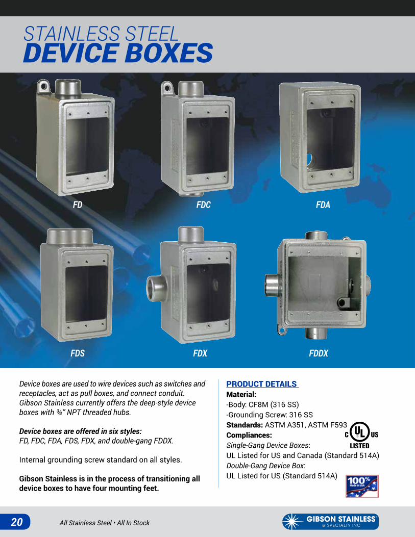
Device boxes are used to wire devices such as switches and receptacles, act as pull boxes, and connect conduit. Gibson Stainless currently offers the deep-style device boxes with ¾” NPT threaded hubs.
Device boxes are offered in six styles:FD, FDC, FDA, FDS, FDX, and double-gang FDDX.
Internal grounding screw standard on all styles.
Gibson Stainless is in the process of transitioning all device boxes to have four mounting feet.
FD
FDS FDX FDDX
FDC FDA
PRODUCT DETAILS Material: -Body: CF8M (316 SS)-Grounding Screw: 316 SS Standards: ASTM A351, ASTM F593Compliances: Single-Gang Device Boxes: UL Listed for US and Canada (Standard 514A)Double-Gang Device Box: UL Listed for US (Standard 514A)

www.gibsonstainless.comPHONE 1-800-945-4316 • FAX 724-838-1544 21
FD Device Box
FDA Device Box
FDDX Device Box
FDC Device Box
FDS Device Box
FDX Device Box
Part Weight/ |--------------Dimension (in.)-------------| Number Size Each (lbs.) A B C D EFD75 ¾ in. 3 6.14 4.67 2.96 2.94 1.31
Part Weight/ |-----------------Dimension (in.)--------------| Number Size Each (lbs.) A B C D EFDC75 ¾ in. 3 6.17 4.67 2.96 2.94 1.31
Part Weight/ |-------------Dimension (in.)--------------| Number Size Each (lbs.) A B C D EFDA75 ¾ in. 3 4.67 2.94 2.96 3.69 1.31
Part Weight/ |-----------------Dimension (in.)---------------| Number Size Each (lbs.) A B C D E FFDS75 ¾ in. 3 5.44 4.67 2.96 2.94 1.31 2.50
Part Weight/ |---------------Dimension (in.)--------------| Number Size Each (lbs.) A B C DFDDX75 ¾ in. 5 4.65 6.21 1.34 2.94
Part Weight/ |---------------Dimension (in.)----------------| Number Size Each (lbs.) A B C D E FFDX75 ¾ in. 4 6.22 4.67 2.96 2.94 1.31 4.51
All Stainless Steel • All In Stock22
STAINLESS STEEL DEVICE BOX COVERS
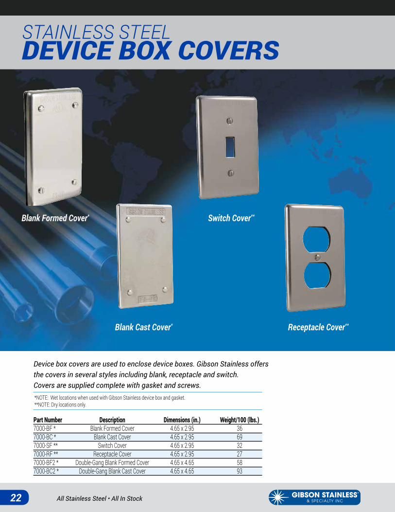
Device box covers are used to enclose device boxes. Gibson Stainless offers the covers in several styles including blank, receptacle and switch. Covers are supplied complete with gasket and screws.
Blank Formed Cover*
Blank Cast Cover*
Switch Cover**
Receptacle Cover**
*NOTE: Wet locations when used with Gibson Stainless device box and gasket. **NOTE: Dry locations only.
Part Number Description Dimensions (in.) Weight/100 (lbs.)7000-BF * Blank Formed Cover 4.65 x 2.95 36 7000-BC * Blank Cast Cover 4.65 x 2.95 697000-SF ** Switch Cover 4.65 x 2.95 327000-RF ** Receptacle Cover 4.65 x 2.95 277000-BF2 * Double-Gang Blank Formed Cover 4.65 x 4.65 587000-BC2 * Double-Gang Blank Cast Cover 4.65 x 4.65 93
www.gibsonstainless.comPHONE 1-800-945-4316 • FAX 724-838-1544 23
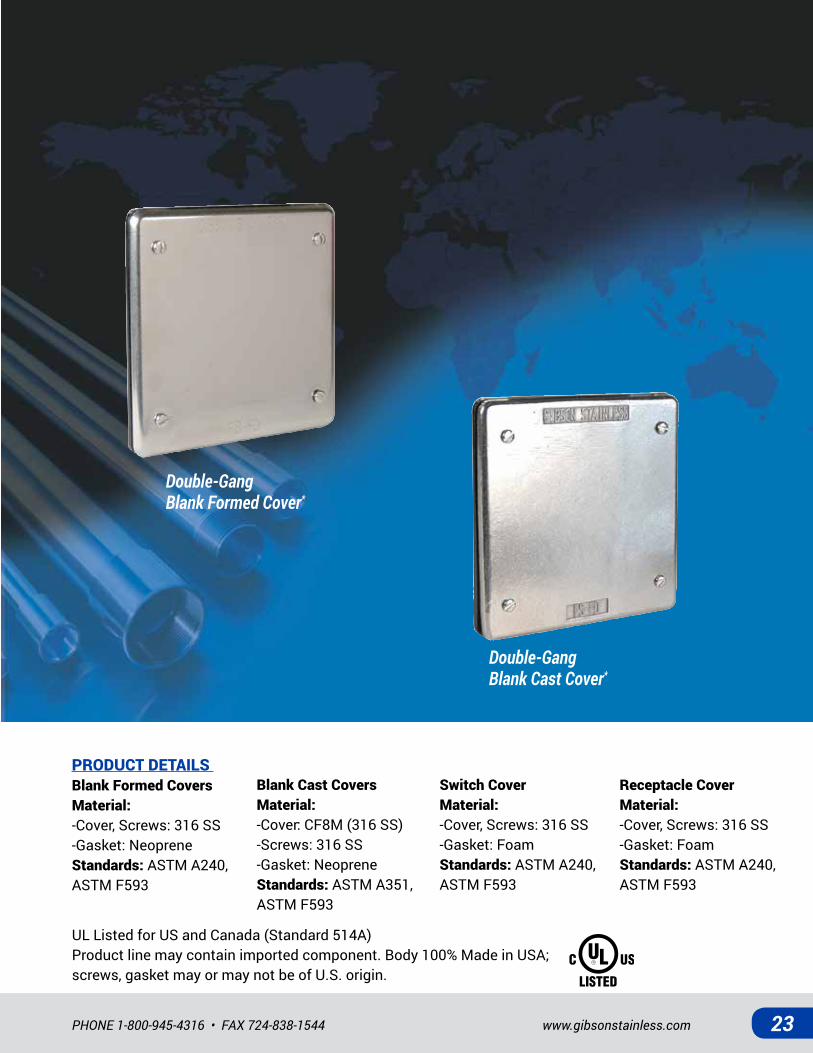
Double-GangBlank Formed Cover*
Double-GangBlank Cast Cover*
PRODUCT DETAILS Blank Formed CoversMaterial: -Cover, Screws: 316 SS-Gasket: NeopreneStandards: ASTM A240, ASTM F593
Blank Cast CoversMaterial: -Cover: CF8M (316 SS)-Screws: 316 SS-Gasket: NeopreneStandards: ASTM A351, ASTM F593
Switch CoverMaterial: -Cover, Screws: 316 SS-Gasket: FoamStandards: ASTM A240, ASTM F593
Receptacle CoverMaterial: -Cover, Screws: 316 SS-Gasket: FoamStandards: ASTM A240, ASTM F593
UL Listed for US and Canada (Standard 514A)Product line may contain imported component. Body 100% Made in USA; screws, gasket may or may not be of U.S. origin.
All Stainless Steel • All In Stock24
STAINLESS STEEL HAZARDOUS LOCATION FITTINGS
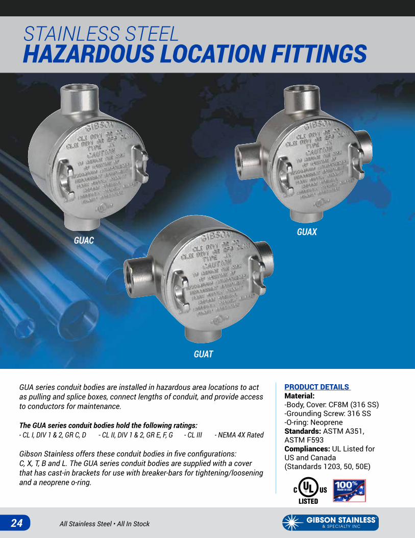
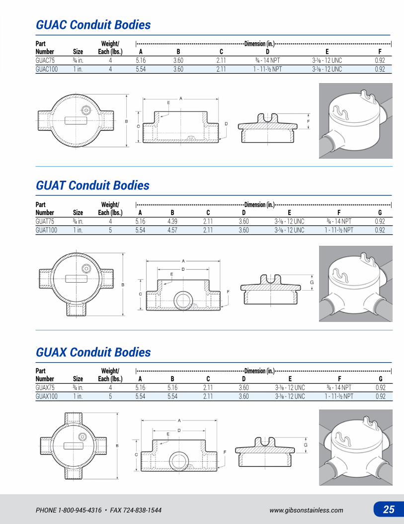
GUA series conduit bodies are installed in hazardous area locations to act as pulling and splice boxes, connect lengths of conduit, and provide access to conductors for maintenance.
The GUA series conduit bodies hold the following ratings:- CL I, DIV 1 & 2, GR C, D - CL II, DIV 1 & 2, GR E, F, G - CL III - NEMA 4X Rated
Gibson Stainless offers these conduit bodies in five configurations: C, X, T, B and L. The GUA series conduit bodies are supplied with a cover that has cast-in brackets for use with breaker-bars for tightening/loosening and a neoprene o-ring.
PRODUCT DETAILS Material: -Body, Cover: CF8M (316 SS)-Grounding Screw: 316 SS-O-ring: NeopreneStandards: ASTM A351, ASTM F593 Compliances: UL Listed for US and Canada (Standards 1203, 50, 50E)
GUAT
GUAXGUAC
www.gibsonstainless.comPHONE 1-800-945-4316 • FAX 724-838-1544 25
GUAT Conduit Bodies
GUAX Conduit Bodies
Part Weight/ |-------------------------------------------------------Dimension (in.)----------------------------------------------------------| Number Size Each (lbs.) A B C D E F GGUAT75 ¾in. 4 5.16 4.39 2.11 3.60 3-⅛-12UNC ¾-14NPT 0.92GUAT100 1in. 5 5.54 4.57 2.11 3.60 3-⅛-12UNC 1-11-½NPT 0.92
Part Weight/ |-------------------------------------------------------Dimension (in.)----------------------------------------------------------| Number Size Each (lbs.) A B C D E F GGUAX75 ¾in. 4 5.16 5.16 2.11 3.60 3-⅛-12UNC ¾-14NPT 0.92GUAX100 1in. 5 5.54 5.54 2.11 3.60 3-⅛-12UNC 1-11-½NPT 0.92
GUAC Conduit BodiesPart Weight/ |-------------------------------------------------------Dimension (in.)----------------------------------------------------------| Number Size Each (lbs.) A B C D E FGUAC75 ¾in. 4 5.16 3.60 2.11 ¾-14NPT 3-⅛-12UNC 0.92GUAC100 1in. 4 5.54 3.60 2.11 1-11-½NPT 3-⅛-12UNC 0.92
All Stainless Steel • All In Stock26
STAINLESS STEEL HAZARDOUS LOCATION FITTINGS
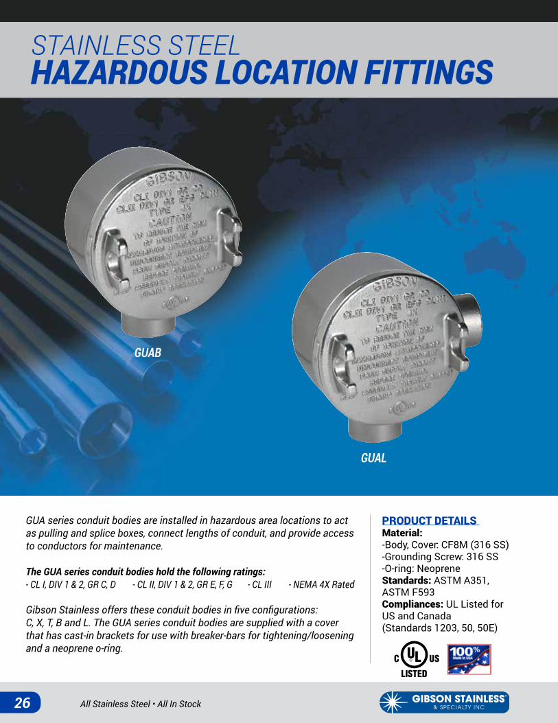
GUAB
GUAL
GUA series conduit bodies are installed in hazardous area locations to act as pulling and splice boxes, connect lengths of conduit, and provide access to conductors for maintenance.
The GUA series conduit bodies hold the following ratings:- CL I, DIV 1 & 2, GR C, D - CL II, DIV 1 & 2, GR E, F, G - CL III - NEMA 4X Rated
Gibson Stainless offers these conduit bodies in five configurations: C, X, T, B and L. The GUA series conduit bodies are supplied with a cover that has cast-in brackets for use with breaker-bars for tightening/loosening and a neoprene o-ring.
PRODUCT DETAILS Material: -Body, Cover: CF8M (316 SS)-Grounding Screw: 316 SS-O-ring: NeopreneStandards: ASTM A351, ASTM F593 Compliances: UL Listed for US and Canada (Standards 1203, 50, 50E)

www.gibsonstainless.comPHONE 1-800-945-4316 • FAX 724-838-1544 27
GUAB Conduit Bodies
GUAL Conduit Bodies
Part Weight/ |--------------------------------------------------------Dimension (in.)---------------------------------------------------------| Number Size Each (lbs.) A B C D E F GGUAB75 ¾in. 4 4.39 3.60 2.11 2.89 3-⅛-12UNC ¾-14NPT 0.92GUAB100 1in. 4 4.57 3.60 2.11 3.08 3-⅛-12UNC 1-11-½NPT 0.92
Part Weight/ |--------------------------------------------------------Dimension (in.)---------------------------------------------------------| Number Size Each (lbs.) A B C D E F GGUAL75 ¾in. 4 4.38 4.38 2.11 3.60 3-⅛-12UNC ¾-14NPT 0.92GUAL100 1in. 4 4.57 4.57 2.11 3.60 3-⅛-12UNC 1-11-½NPT 0.92
All Stainless Steel • All In Stock28
STAINLESS STEEL HAZARDOUS LOCATION FITTINGS
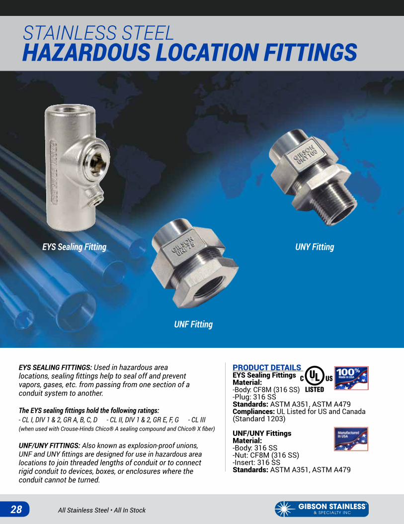
EYS Sealing Fitting
UNF Fitting
UNY Fitting
EYS SEALING FITTINGS: Used in hazardous area locations, sealing fittings help to seal off and prevent vapors, gases, etc. from passing from one section of a conduit system to another.
The EYS sealing fittings hold the following ratings:- CL I, DIV 1 & 2, GR A, B, C, D - CL II, DIV 1 & 2, GR E, F, G - CL III(when used with Crouse-Hinds Chico® A sealing compound and Chico® X fiber)
UNF/UNY FITTINGS: Also known as explosion-proof unions, UNF and UNY fittings are designed for use in hazardous area locations to join threaded lengths of conduit or to connect rigid conduit to devices, boxes, or enclosures where the conduit cannot be turned.
PRODUCT DETAILS EYS Sealing Fittings Material: -Body: CF8M (316 SS)-Plug: 316 SSStandards: ASTM A351, ASTM A479Compliances: UL Listed for US and Canada (Standard 1203)
UNF/UNY Fittings Material: -Body: 316 SS-Nut: CF8M (316 SS)-Insert: 316 SSStandards: ASTM A351, ASTM A479
www.gibsonstainless.comPHONE 1-800-945-4316 • FAX 724-838-1544 29
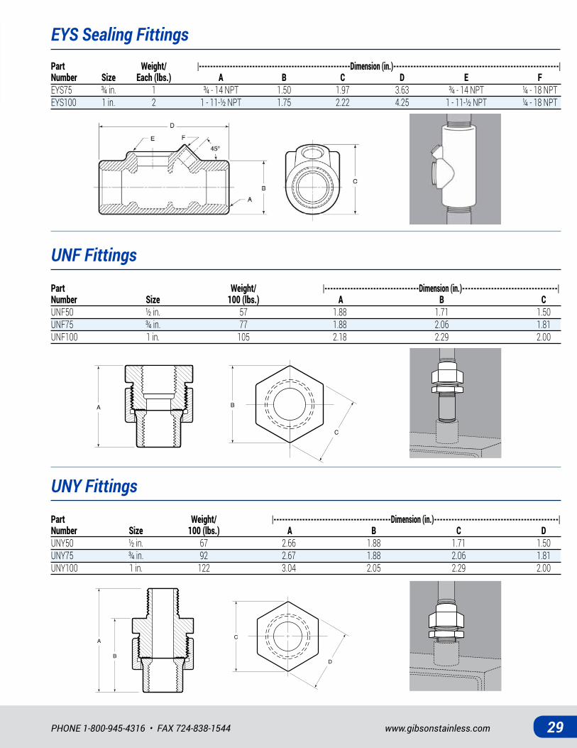
EYS Sealing Fittings
UNF Fittings
UNY Fittings
Part Weight/ |------------------------------------------------------Dimension (in.)----------------------------------------------------------| Number Size Each (lbs.) A B C D E FEYS75 ¾ in. 1 ¾ - 14 NPT 1.50 1.97 3.63 ¾ - 14 NPT ¼ - 18 NPTEYS100 1 in. 2 1 - 11-½ NPT 1.75 2.22 4.25 1 - 11-½ NPT ¼ - 18 NPT
Part Weight/ |---------------------------------Dimension (in.)---------------------------------| Number Size 100 (lbs.) A B CUNF50 ½ in. 57 1.88 1.71 1.50UNF75 ¾ in. 77 1.88 2.06 1.81UNF100 1 in. 105 2.18 2.29 2.00
A B
C
B
AC
D
Part Weight/ |-----------------------------------------Dimension (in.)-------------------------------------------| Number Size 100 (lbs.) A B C DUNY50 ½ in. 67 2.66 1.88 1.71 1.50UNY75 ¾ in. 92 2.67 1.88 2.06 1.81UNY100 1 in. 122 3.04 2.05 2.29 2.00
All Stainless Steel • All In Stock30
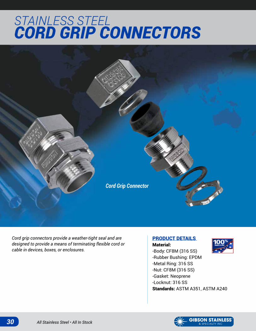
STAINLESS STEEL CORD GRIP CONNECTORS
Cord Grip Connector
Cord grip connectors provide a weather-tight seal and are designed to provide a means of terminating flexible cord or cable in devices, boxes, or enclosures.
PRODUCT DETAILS Material: -Body: CF8M (316 SS)-Rubber Bushing: EPDM-Metal Ring: 316 SS-Nut: CF8M (316 SS)-Gasket: Neoprene-Locknut: 316 SSStandards: ASTM A351, ASTM A240

www.gibsonstainless.comPHONE 1-800-945-4316 • FAX 724-838-1544 31
Cord Grip ConnectorsPart Cable Weight/ |--------------Dimension (in.)------------| Number Size Range (in.) 100 (lbs.) A B C DCG50-125-188 ½ in. .125 - .188 40 1.87 1.37 1.56 1.38CG50-188-250 ½ in. .188 - .250 40 1.87 1.37 1.56 1.38CG50-250-313 ½ in. .250 - .313 40 1.87 1.37 1.56 1.38CG50-313-375 ½ in. .313 - .375 40 1.87 1.37 1.56 1.38CG50-375-438 ½ in. .375 - .438 40 1.87 1.37 1.56 1.38CG50-438-500 ½ in. .438 - .500 40 1.87 1.37 1.56 1.38CG50-500-563 ½ in. .500 - .563 40 1.87 1.37 1.56 1.38CG50-563-610 ½ in. .563 - .610 40 1.87 1.37 1.56 1.38CG75-188-250 ¾ in. .188 - .250 50 2.13 1.51 1.71 1.50CG75-250-313 ¾ in. .250 - .313 50 2.13 1.51 1.71 1.50CG75-313-375 ¾ in. .313 - .375 50 2.13 1.51 1.71 1.50CG75-375-438 ¾ in. .375 - .438 50 2.13 1.51 1.71 1.50CG75-438-500 ¾ in. .438 - .500 50 2.13 1.51 1.71 1.50CG75-500-563 ¾ in. .500 - .563 50 2.13 1.51 1.71 1.50CG75-563-625 ¾ in. .563 - .625 50 2.13 1.51 1.71 1.50CG75-625-688 ¾ in. .625 - .688 50 2.13 1.51 1.71 1.50CG75-688-750 ¾ in. .688 - .750 50 2.13 1.51 1.71 1.50CG75-750-810 ¾ in. .750 - .810 50 2.13 1.51 1.71 1.50CG100-375-438 1 in. .375 - .438 75 2.27 1.61 2.06 1.81CG100-438-500 1 in. .438 - .500 75 2.27 1.61 2.06 1.81CG100-500-563 1 in. .500 - .563 75 2.27 1.61 2.06 1.81CG100-563-625 1 in. .563 - .625 75 2.27 1.61 2.06 1.81CG100-625-688 1 in. .625 - .688 75 2.27 1.61 2.06 1.81CG100-688-750 1 in. .688 - .750 75 2.27 1.61 2.06 1.81CG100-750-813 1 in. .750 - .813 75 2.27 1.61 2.06 1.81CG100-813-875 1 in. .813 - .875 75 2.27 1.61 2.06 1.81CG100-875-938 1 in. .875 - .938 75 2.27 1.61 2.06 1.81CG100-938-1000 1 in. .938 - 1.000 75 2.27 1.61 2.06 1.81
A
C
B
D
A
C
B
D
All Stainless Steel • All In Stock32
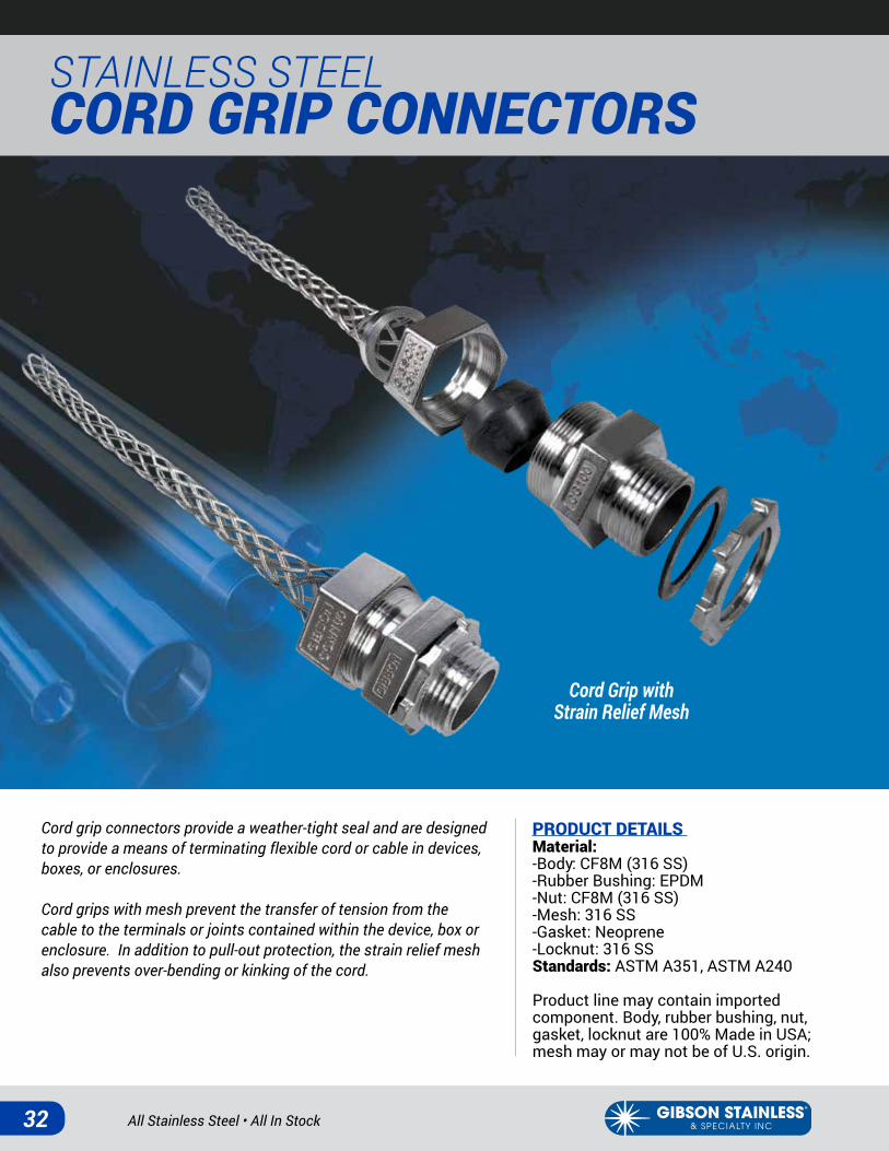
STAINLESS STEEL CORD GRIP CONNECTORS
Cord grip connectors provide a weather-tight seal and are designed to provide a means of terminating flexible cord or cable in devices, boxes, or enclosures.
Cord grips with mesh prevent the transfer of tension from the cable to the terminals or joints contained within the device, box or enclosure. In addition to pull-out protection, the strain relief mesh also prevents over-bending or kinking of the cord.
PRODUCT DETAILS Material: -Body: CF8M (316 SS)-Rubber Bushing: EPDM-Nut: CF8M (316 SS)-Mesh: 316 SS-Gasket: Neoprene-Locknut: 316 SSStandards: ASTM A351, ASTM A240
Product line may contain imported component. Body, rubber bushing, nut, gasket, locknut are 100% Made in USA; mesh may or may not be of U.S. origin.
Cord Grip withStrain Relief Mesh
www.gibsonstainless.comPHONE 1-800-945-4316 • FAX 724-838-1544 33
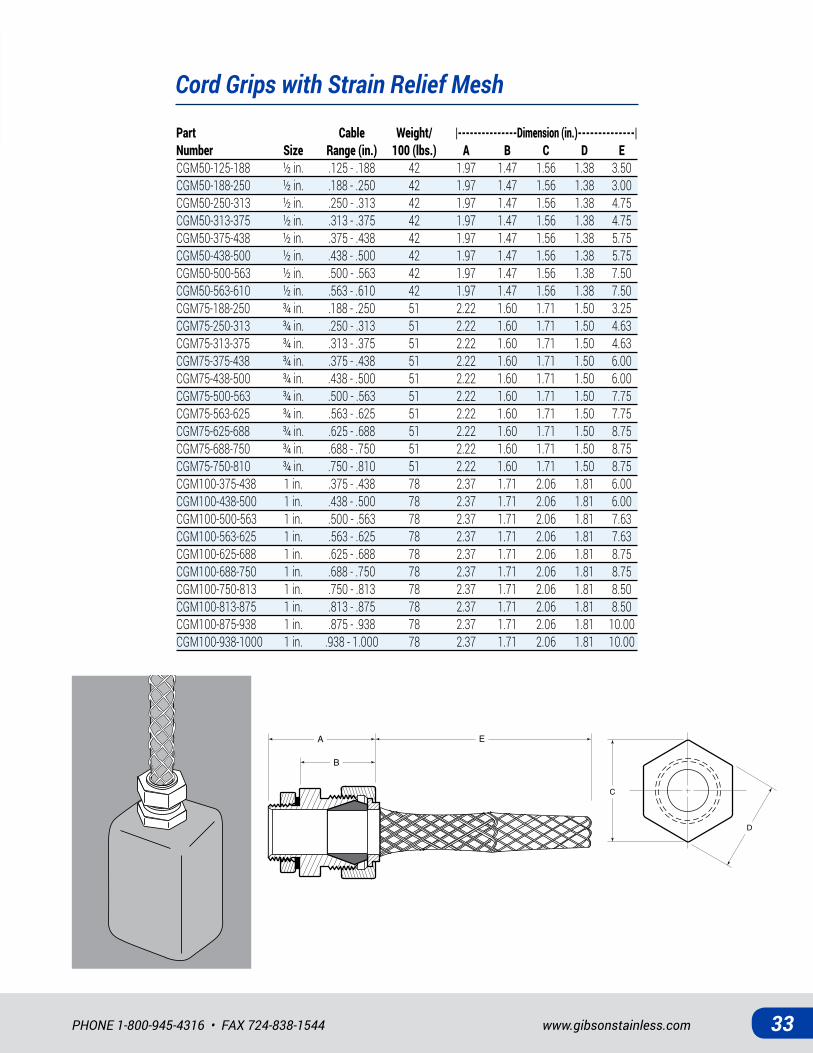
Cord Grips with Strain Relief Mesh
Part Cable Weight/ |---------------Dimension (in.)--------------| Number Size Range (in.) 100 (lbs.) A B C D ECGM50-125-188 ½ in. .125 - .188 42 1.97 1.47 1.56 1.38 3.50CGM50-188-250 ½ in. .188 - .250 42 1.97 1.47 1.56 1.38 3.00CGM50-250-313 ½ in. .250 - .313 42 1.97 1.47 1.56 1.38 4.75CGM50-313-375 ½ in. .313 - .375 42 1.97 1.47 1.56 1.38 4.75CGM50-375-438 ½ in. .375 - .438 42 1.97 1.47 1.56 1.38 5.75CGM50-438-500 ½ in. .438 - .500 42 1.97 1.47 1.56 1.38 5.75CGM50-500-563 ½ in. .500 - .563 42 1.97 1.47 1.56 1.38 7.50CGM50-563-610 ½ in. .563 - .610 42 1.97 1.47 1.56 1.38 7.50CGM75-188-250 ¾ in. .188 - .250 51 2.22 1.60 1.71 1.50 3.25CGM75-250-313 ¾ in. .250 - .313 51 2.22 1.60 1.71 1.50 4.63CGM75-313-375 ¾ in. .313 - .375 51 2.22 1.60 1.71 1.50 4.63CGM75-375-438 ¾ in. .375 - .438 51 2.22 1.60 1.71 1.50 6.00CGM75-438-500 ¾ in. .438 - .500 51 2.22 1.60 1.71 1.50 6.00CGM75-500-563 ¾ in. .500 - .563 51 2.22 1.60 1.71 1.50 7.75CGM75-563-625 ¾ in. .563 - .625 51 2.22 1.60 1.71 1.50 7.75CGM75-625-688 ¾ in. .625 - .688 51 2.22 1.60 1.71 1.50 8.75CGM75-688-750 ¾ in. .688 - .750 51 2.22 1.60 1.71 1.50 8.75CGM75-750-810 ¾ in. .750 - .810 51 2.22 1.60 1.71 1.50 8.75CGM100-375-438 1 in. .375 - .438 78 2.37 1.71 2.06 1.81 6.00CGM100-438-500 1 in. .438 - .500 78 2.37 1.71 2.06 1.81 6.00CGM100-500-563 1 in. .500 - .563 78 2.37 1.71 2.06 1.81 7.63CGM100-563-625 1 in. .563 - .625 78 2.37 1.71 2.06 1.81 7.63CGM100-625-688 1 in. .625 - .688 78 2.37 1.71 2.06 1.81 8.75CGM100-688-750 1 in. .688 - .750 78 2.37 1.71 2.06 1.81 8.75CGM100-750-813 1 in. .750 - .813 78 2.37 1.71 2.06 1.81 8.50CGM100-813-875 1 in. .813 - .875 78 2.37 1.71 2.06 1.81 8.50CGM100-875-938 1 in. .875 - .938 78 2.37 1.71 2.06 1.81 10.00CGM100-938-1000 1 in. .938 - 1.000 78 2.37 1.71 2.06 1.81 10.00
C
D
B
EA
C
D
B
EA

All Stainless Steel • All In Stock34
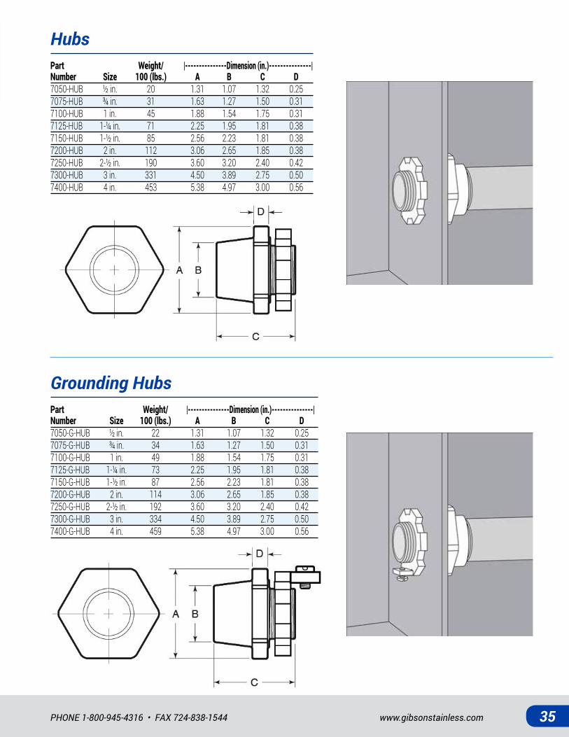
STAINLESS STEEL HUBS
HUBS: Heavy-duty, cast CF8M/316 SS conduit hubs are designed for use with threaded conduit and provide a means of connecting conduit to various enclosures and/or for terminating electric circuits. A neoprene o-ring provides a weather-proof seal and a specially designed locknut grips firmly for secure installation.
GROUNDING HUBS: Stainless steel grounding hubs, like the standard conduit hubs, are designed for use with threaded conduit and provide a means of connecting conduit to various enclosures and/or for terminating electric circuits. A grounding lug and screw provide a secure connection for ground wiring.
PRODUCT DETAILS HubsMaterial: -Body: CF8M (316 SS)-Locknut: 316 SS (½” – 1”); CF8M (1¼” – 4”)-O-Ring: NeopreneStandards: ASTM A240 (locknut sizes ½” – 1”); ASTM A351 (body, locknut sizes 1¼” – 4”)
Grounding Hubs Material: -Body: CF8M (316 SS)-Locknut: CF8M (316 SS)-Grounding Screw: 316 SS-O-Ring: NeopreneStandards: ASTM A351, ASTM F593
Hub
Grounding Hub
www.gibsonstainless.comPHONE 1-800-945-4316 • FAX 724-838-1544 35
Hubs
Grounding Hubs
Part Weight/ |---------------Dimension (in.)---------------| Number Size 100 (lbs.) A B C D7050-HUB ½ in. 20 1.31 1.07 1.32 0.257075-HUB ¾ in. 31 1.63 1.27 1.50 0.317100-HUB 1 in. 45 1.88 1.54 1.75 0.317125-HUB 1-¼ in. 71 2.25 1.95 1.81 0.387150-HUB 1-½ in. 85 2.56 2.23 1.81 0.387200-HUB 2 in. 112 3.06 2.65 1.85 0.387250-HUB 2-½ in. 190 3.60 3.20 2.40 0.427300-HUB 3 in. 331 4.50 3.89 2.75 0.507400-HUB 4 in. 453 5.38 4.97 3.00 0.56
Part Weight/ |---------------Dimension (in.)---------------| Number Size 100 (lbs.) A B C D7050-G-HUB ½ in. 22 1.31 1.07 1.32 0.257075-G-HUB ¾ in. 34 1.63 1.27 1.50 0.317100-G-HUB 1 in. 49 1.88 1.54 1.75 0.317125-G-HUB 1-¼ in. 73 2.25 1.95 1.81 0.387150-G-HUB 1-½ in. 87 2.56 2.23 1.81 0.387200-G-HUB 2 in. 114 3.06 2.65 1.85 0.387250-G-HUB 2-½ in. 192 3.60 3.20 2.40 0.427300-G-HUB 3 in. 334 4.50 3.89 2.75 0.507400-G-HUB 4 in. 459 5.38 4.97 3.00 0.56

All Stainless Steel • All In Stock36
STAINLESS STEEL LOCKNUTS
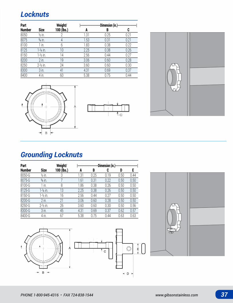
LOCKNUTS: Stainless steel locknuts are used to connect and secure threaded rigid conduit to an enclosure or outlet box.
GROUNDING LOCKNUTS: Similar to the standard locknuts, grounding locknuts also connect and secure threaded rigid conduit to boxes and enclosures. A grounding lug and screw provide a secure connection for ground wiring.
Locknut
Grounding Locknut
PRODUCT DETAILS LocknutsMaterial: -½” – 1”: 316 SS-1¼” – 4”: CF8M (316 SS)Standards: ASTM A240 (sizes ½” – 1”); ASTM A351 (sizes 1¼” – 4”)
Grounding LocknutsMaterial: -Locknut: CF8M (316 SS)-Grounding Screw: 316 SSStandards: ASTM A351, ASTM F593
www.gibsonstainless.comPHONE 1-800-945-4316 • FAX 724-838-1544 37
STAINLESS STEEL LOCKNUTS
Grounding LocknutsPart Weight/ |------------------Dimension (in.)-------------------| Number Size 100 (lbs.) A B C D E8050-G ½ in. 3 1.31 0.25 0.19 0.50 0.448075-G ¾ in. 7 1.61 0.31 0.22 0.50 0.508100-G 1 in. 8 1.86 0.38 0.26 0.50 0.508125-G 1-¼ in. 13 2.25 0.38 0.26 0.50 0.508150-G 1-½ in. 16 2.56 0.44 0.27 0.50 0.508200-G 2 in. 21 3.06 0.60 0.28 0.50 0.508250-G 2-½ in. 26 3.60 0.60 0.30 0.50 0.568300-G 3 in. 45 4.31 0.69 0.37 0.62 0.578400-G 4 in. 67 5.38 0.75 0.44 0.63 0.63
LocknutsPart Weight/ |-----------------Dimension (in.)----------------| Number Size 100 (lbs.) A B C8050 ½ in. 2 1.31 0.25 0.218075 ¾ in. 4 1.53 0.31 0.218100 1 in. 6 1.83 0.38 0.228125 1-¼ in. 10 2.25 0.38 0.268150 1-½ in. 14 2.56 0.44 0.278200 2 in. 19 3.06 0.60 0.288250 2-½ in. 24 3.60 0.60 0.308300 3 in. 41 4.31 0.69 0.378400 4 in. 60 5.38 0.75 0.44
All Stainless Steel • All In Stock38
STAINLESS STEEL LIQUIDTIGHT CONNECTORS
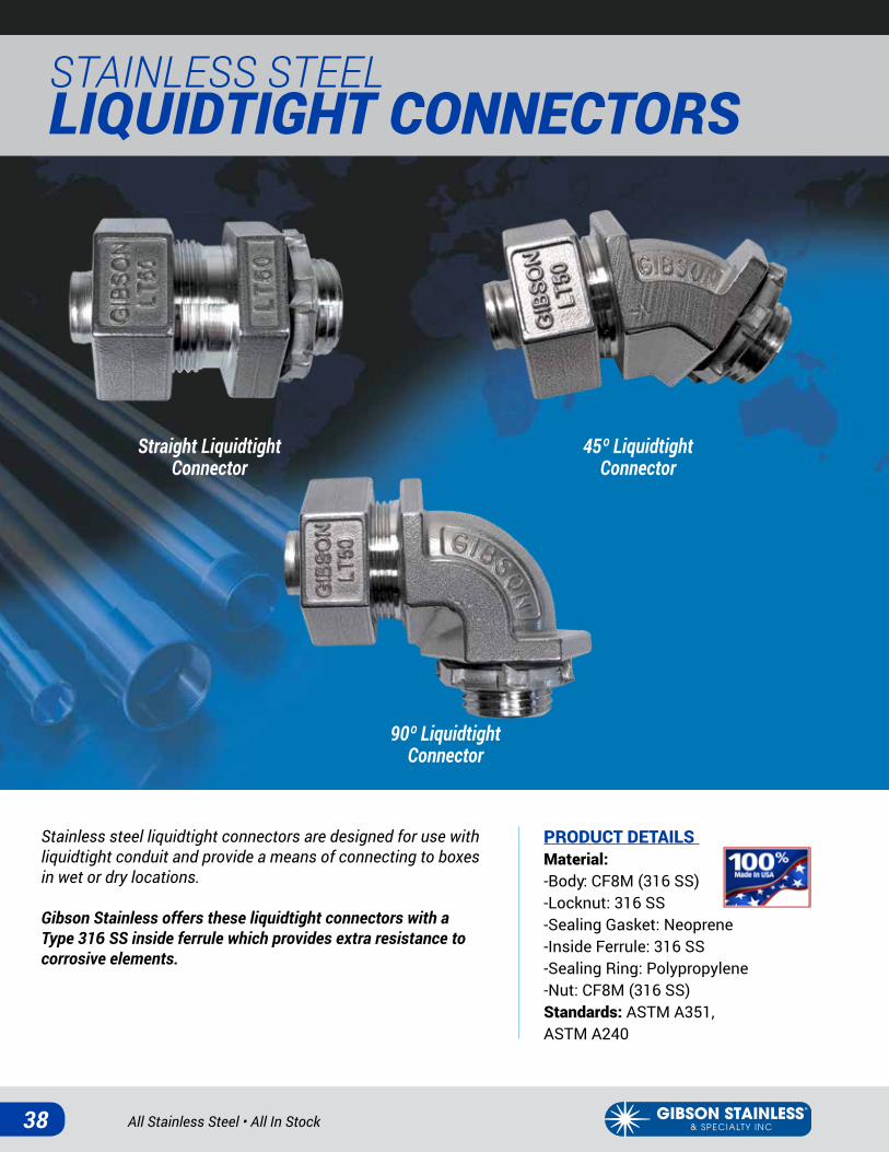
Stainless steel liquidtight connectors are designed for use with liquidtight conduit and provide a means of connecting to boxes in wet or dry locations.
Gibson Stainless offers these liquidtight connectors with a Type 316 SS inside ferrule which provides extra resistance to corrosive elements.
PRODUCT DETAILS Material: -Body: CF8M (316 SS)-Locknut: 316 SS -Sealing Gasket: Neoprene -Inside Ferrule: 316 SS -Sealing Ring: Polypropylene-Nut: CF8M (316 SS)Standards: ASTM A351, ASTM A240
Straight LiquidtightConnector
45º Liquidtight Connector
90º Liquidtight Connector
www.gibsonstainless.comPHONE 1-800-945-4316 • FAX 724-838-1544 39
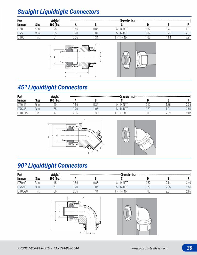
Straight Liquidtight Connectors
45º Liquidtight Connectors
90º Liquidtight Connectors
Part Weight/ |----------------------------------------------------Dimension (in.)--------------------------------------------------------| Number Size 100 (lbs.) A B C D E FLT50 ½ in. 25 1.56 0.85 ½ - 14 NPT 0.62 1.41 1.91LT75 ¾ in. 35 1.70 1.07 ¾ - 14 NPT 0.82 1.45 2.07LT100 1 in. 51 2.06 1.34 1 - 11-½ NPT 1.02 1.64 2.31
Part Weight/ |----------------------------------------------------Dimension (in.)--------------------------------------------------------| Number Size 100 (lbs.) A B C D E FLT50-45 ½ in. 40 1.56 0.85 ½ - 14 NPT 0.62 1.75 2.36LT75-45 ¾ in. 55 1.70 1.07 ¾ - 14 NPT 0.79 1.92 2.50LT100-45 1 in. 77 2.06 1.33 1 - 11-½ NPT 1.00 2.32 2.82
Part Weight/ |-----------------------------------------------------Dimension (in.)-------------------------------------------------------| Number Size 100 (lbs.) A B C D E FLT50-90 ½ in. 45 1.56 0.85 ½ - 14 NPT 0.62 2.14 2.40LT75-90 ¾ in. 61 1.70 1.07 ¾ - 14 NPT 0.79 2.35 2.56LT100-90 1 in. 86 2.06 1.34 1 - 11-½ NPT 1.00 2.67 2.95
BA
F
C
D
E
BAE
F
C
D
BA
E
F
C D
All Stainless Steel • All In Stock40
STAINLESS STEEL LIQUIDTIGHT CONNECTORS
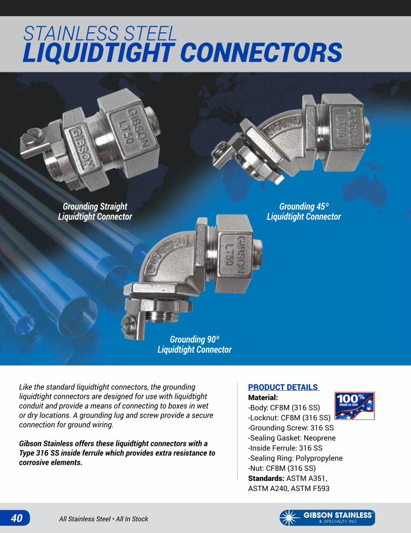
Like the standard liquidtight connectors, the grounding liquidtight connectors are designed for use with liquidtight conduit and provide a means of connecting to boxes in wet or dry locations. A grounding lug and screw provide a secure connection for ground wiring.
Gibson Stainless offers these liquidtight connectors with a Type 316 SS inside ferrule which provides extra resistance to corrosive elements.
PRODUCT DETAILS Material: -Body: CF8M (316 SS)-Locknut: CF8M (316 SS)-Grounding Screw: 316 SS -Sealing Gasket: Neoprene-Inside Ferrule: 316 SS -Sealing Ring: Polypropylene-Nut: CF8M (316 SS)Standards: ASTM A351, ASTM A240, ASTM F593
Grounding Straight Liquidtight Connector
Grounding 45ºLiquidtight Connector
Grounding 90º Liquidtight Connector
www.gibsonstainless.comPHONE 1-800-945-4316 • FAX 724-838-1544 41
BAE
F
C
D
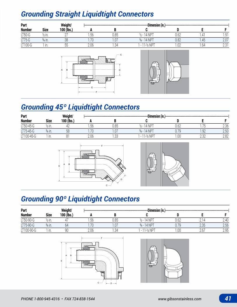
Grounding Straight Liquidtight Connectors
Grounding 45º Liquidtight Connectors
Grounding 90º Liquidtight Connectors
BA
F
C
D
E
BA
E
F
C D
Part Weight/ |-------------------------------------------------------Dimension (in.)-----------------------------------------------------| Number Size 100 (lbs.) A B C D E FLT50-G ½ in. 27 1.56 0.85 ½ - 14 NPT 0.62 1.41 1.91LT75-G ¾ in. 38 1.70 1.07 ¾ - 14 NPT 0.82 1.45 2.07LT100-G 1 in. 55 2.06 1.34 1 - 11-½ NPT 1.02 1.64 2.31
Part Weight/ |-------------------------------------------------------Dimension (in.)-----------------------------------------------------| Number Size 100 (lbs.) A B C D E FLT50-45-G ½ in. 42 1.56 0.85 ½ - 14 NPT 0.62 1.75 2.36LT75-45-G ¾ in. 58 1.70 1.07 ¾ - 14 NPT 0.79 1.92 2.50LT100-45-G 1 in. 81 2.06 1.33 1 - 11-½ NPT 1.00 2.32 2.82
Part Weight/ |-------------------------------------------------------Dimension (in.)-----------------------------------------------------| Number Size 100 (lbs.) A B C D E FLT50-90-G ½ in. 47 1.56 0.85 ½ - 14 NPT 0.62 2.14 2.40LT75-90-G ¾ in. 64 1.70 1.07 ¾ - 14 NPT 0.79 2.35 2.56LT100-90-G 1 in. 90 2.06 1.34 1 - 11-½ NPT 1.00 2.67 2.95
All Stainless Steel • All In Stock42
STAINLESS STEEL STRAPS, HANGERS & CLAMPS
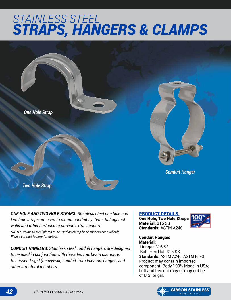
ONE HOLE AND TWO HOLE STRAPS: Stainless steel one hole and two hole straps are used to mount conduit systems flat against walls and other surfaces to provide extra support. *NOTE: Stainless steel plates to be used as clamp back spacers are available. Please contact factory for details.
CONDUIT HANGERS: Stainless steel conduit hangers are designed to be used in conjunction with threaded rod, beam clamps, etc. to suspend rigid (heavywall) conduit from I-beams, flanges, and other structural members.
PRODUCT DETAILS One Hole, Two Hole Straps Material: 316 SSStandards: ASTM A240
Conduit HangersMaterial:-Hanger: 316 SS-Bolt, Hex Nut: 316 SSStandards: ASTM A240, ASTM F593Product may contain imported component. Body 100% Made in USA; bolt and hex nut may or may not be of U.S. origin.
One Hole Strap
Two Hole Strap
Conduit Hanger
www.gibsonstainless.comPHONE 1-800-945-4316 • FAX 724-838-1544 43
C
GF
B
A
D
E
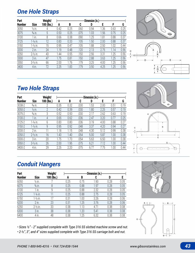
One Hole Straps
Two Hole Straps
Part Weight/ |-----------------------------Dimension (in.)---------------------------| Number Size 100 (lbs.) A B C D E F G3050 ½ in. 4 0.42 0.25 .060 0.94 1.36 0.63 0.253075 ¾ in. 5 0.53 0.25 .075 1.03 1.56 0.75 0.253100 1 in. 8 0.66 0.38 .090 1.25 1.81 0.88 0.373125 1-¼ in. 12 0.83 0.33 .105 1.50 2.00 0.88 0.373150 1-½ in. 15 0.95 0.47 .105 1.88 2.50 1.02 0.443200 2 in. 24 1.19 0.48 .120 2.13 2.75 1.14 0.563250 2-½ in. 43 1.44 0.55 .150 2.56 3.31 1.25 0.563300 3 in. 47 1.75 0.81 .150 2.88 3.63 1.25 0.563350 3-½ in. 66 2.00 1.76 .179 3.25 4.00 1.25 0.563400 4 in. 72 2.25 1.83 .179 3.50 4.25 1.25 0.56
Part Weight/ |----------------------------Dimension (in.)----------------------------| Number Size 100 (lbs.) A B C D E F G3038-2 ⅜in. 2 0.35 0.32 .030 1.53 2.00 0.51 0.193050-2 ½ in. 2 0.42 0.39 .030 1.80 2.25 0.57 0.193075-2 ¾ in. 3 0.52 0.50 .030 2.17 2.62 0.63 0.193100-2 1 in. 4 0.65 0.62 .036 2.47 3.20 0.77 0.253125-2 1-¼ in. 6 0.83 0.80 .036 3.19 4.00 0.88 0.273150-2 1-½ in. 9 0.95 0.92 .048 3.37 4.20 0.94 0.273200-2 2 in. 11 1.18 1.15 .048 4.30 5.12 0.99 0.383250-2 2-½ in. 16 1.43 1.40 .054 5.00 5.87 1.00 0.383300-2 3 in. 20 1.75 1.70 .054 5.63 6.50 1.00 0.383350-2 3-½ in. 26 2.00 1.95 .075 6.21 7.12 1.00 0.443400-2 4 in. 29 2.25 2.20 .075 6.77 7.75 1.00 0.44
Conduit HangersPart Weight/ |------------------------Dimension (in.)-------------------------| Number Size 100 (lbs.) A B C D E6050 ½ in. 7 0.25 0.75 1.90 0.28 0.056075 ¾ in. 8 0.25 0.88 1.97 0.28 0.056100 1 in. 9 0.25 0.88 2.32 0.28 0.056125 1-¼ in. 11 0.25 0.88 2.75 0.28 0.056150 1-½ in. 17 0.31 1.00 3.26 0.28 0.066200 2 in. 23 0.31 1.25 3.76 0.28 0.066250 2-½ in. 33 0.38 1.13 4.71 0.38 0.086300 3 in. 38 0.38 1.20 5.41 0.38 0.086400 4 in. 48 0.38 1.25 6.32 0.38 0.08
• Sizes ½” - 2” supplied complete with Type 316 SS slotted machine screw and nut. • 2-½”, 3”, and 4” sizes supplied complete with Type 316 SS carriage bolt and nut.
C
GF
B
A
D
E
All Stainless Steel • All In Stock44
STAINLESS STEELSTRAPS, HANGERS & CLAMPS
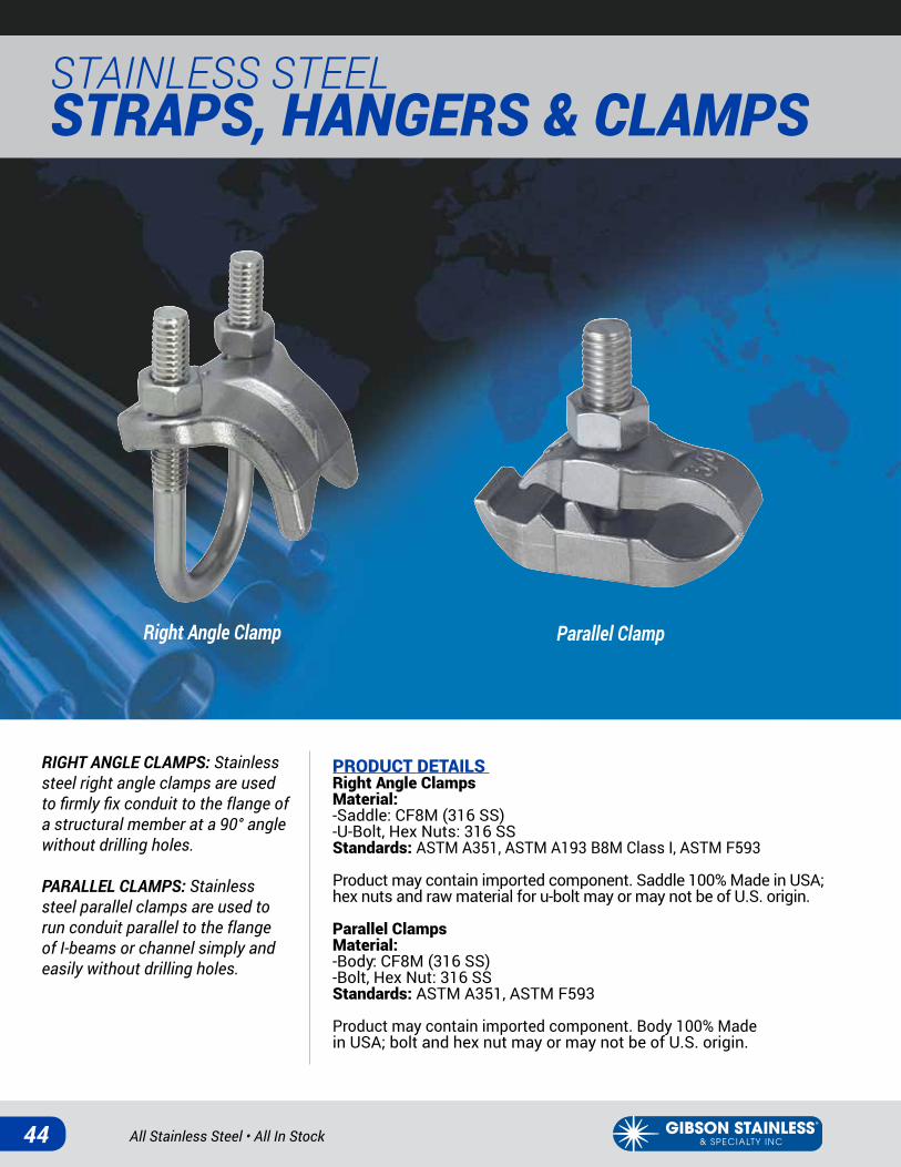
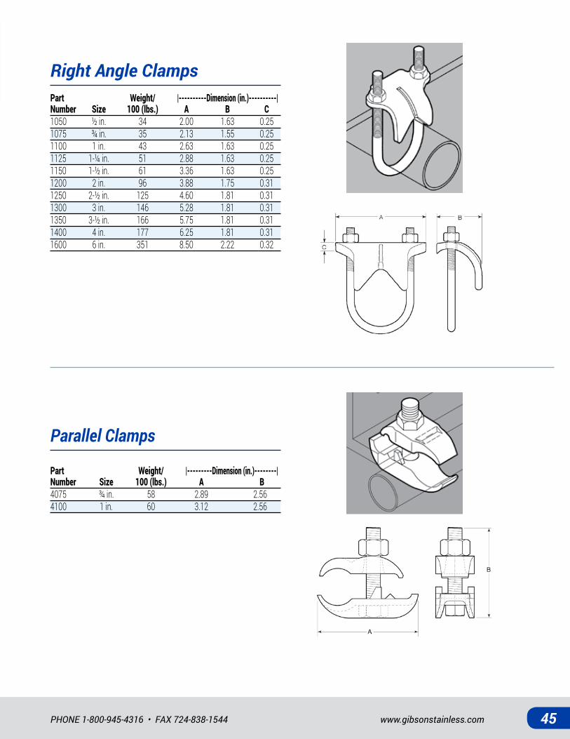
RIGHT ANGLE CLAMPS: Stainless steel right angle clamps are used to firmly fix conduit to the flange of a structural member at a 90° angle without drilling holes.
PARALLEL CLAMPS: Stainless steel parallel clamps are used to run conduit parallel to the flange of I-beams or channel simply and easily without drilling holes.
PRODUCT DETAILS Right Angle ClampsMaterial: -Saddle: CF8M (316 SS)-U-Bolt, Hex Nuts: 316 SSStandards: ASTM A351, ASTM A193 B8M Class I, ASTM F593
Product may contain imported component. Saddle 100% Made in USA; hex nuts and raw material for u-bolt may or may not be of U.S. origin.
Parallel ClampsMaterial: -Body: CF8M (316 SS)-Bolt, Hex Nut: 316 SSStandards: ASTM A351, ASTM F593
Product may contain imported component. Body 100% Made in USA; bolt and hex nut may or may not be of U.S. origin.
Right Angle Clamp Parallel Clamp
www.gibsonstainless.comPHONE 1-800-945-4316 • FAX 724-838-1544 45
Right Angle ClampsPart Weight/ |----------Dimension (in.)----------| Number Size 100 (lbs.) A B C1050 ½ in. 34 2.00 1.63 0.251075 ¾ in. 35 2.13 1.55 0.251100 1 in. 43 2.63 1.63 0.251125 1-¼ in. 51 2.88 1.63 0.251150 1-½ in. 61 3.36 1.63 0.251200 2 in. 96 3.88 1.75 0.311250 2-½ in. 125 4.60 1.81 0.311300 3 in. 146 5.28 1.81 0.311350 3-½ in. 166 5.75 1.81 0.311400 4 in. 177 6.25 1.81 0.311600 6 in. 351 8.50 2.22 0.32
Parallel Clamps
Part Weight/ |---------Dimension (in.)--------| Number Size 100 (lbs.) A B4075 ¾ in. 58 2.89 2.564100 1 in. 60 3.12 2.56
All Stainless Steel • All In Stock46
STAINLESS STEEL STRAPS, HANGERS & CLAMPS
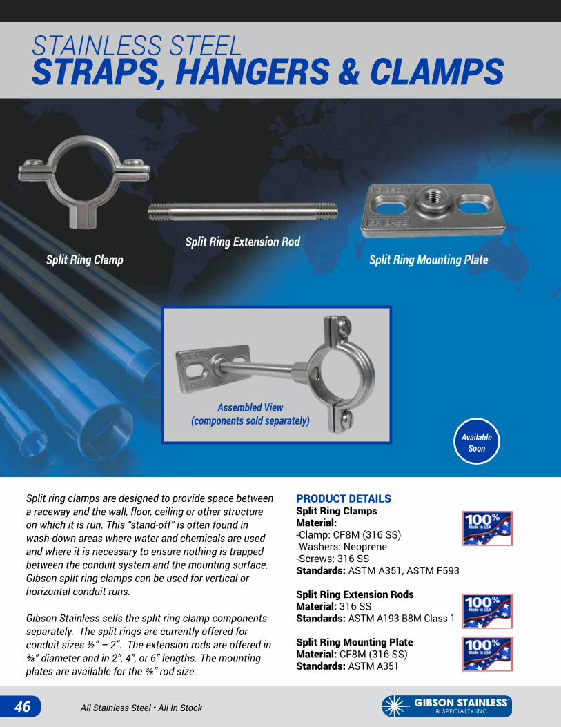
Split ring clamps are designed to provide space between a raceway and the wall, floor, ceiling or other structure on which it is run. This “stand-off” is often found in wash-down areas where water and chemicals are used and where it is necessary to ensure nothing is trapped between the conduit system and the mounting surface. Gibson split ring clamps can be used for vertical or horizontal conduit runs.
Gibson Stainless sells the split ring clamp components separately. The split rings are currently offered for conduit sizes ½” – 2”. The extension rods are offered in ⅜” diameter and in 2”, 4”, or 6” lengths. The mounting plates are available for the ⅜” rod size.
PRODUCT DETAILS Split Ring Clamps Material: -Clamp: CF8M (316 SS)-Washers: Neoprene-Screws: 316 SSStandards: ASTM A351, ASTM F593
Split Ring Extension RodsMaterial: 316 SSStandards: ASTM A193 B8M Class 1
Split Ring Mounting PlateMaterial: CF8M (316 SS)Standards: ASTM A351
Split Ring ClampSplit Ring Extension Rod
Split Ring Mounting Plate
Assembled View (components sold separately)
Available Soon

www.gibsonstainless.comPHONE 1-800-945-4316 • FAX 724-838-1544 47
B
A
Split Ring Clamps
Split Ring Extension Rods
Split Ring Mounting Plate
A
C
ØB
Part Weight/ |------------------------------------Dimension (in.)----------------------------------| Number Size 100 (lbs.) A B CSRC50 ½in. 11 ⅜-16UNC 0.88 10-32UNFSRC75 ¾in. 11 ⅜-16UNC 1.10 10-32UNFSRC100 1in. 13 ⅜-16UNC 1.36 10-32UNFSRC125 1-¼in. 16 ⅜-16UNC 1.71 10-32UNFSRC150 1-½in. 18 ⅜-16UNC 1.95 10-32UNFSRC200 2in. 21 ⅜-16UNC 2.44 10-32UNF
Part Weight/ Rod Size Length Number 100 (lbs.) "A" (in.) "B" (in.)SRE375x2 6 ⅜-16UNC 2SRE375x4 12 ⅜-16UNC 4SRE375x6 19 ⅜-16UNC 6
Part Weight/ |-----------------------------------------------Dimension (in.)-------------------------------------------| Number Rod Size 100 (lbs.) A B C D ESRM375 3/8in. 20 ⅜-16UNC 2.88 1.38 0.63 0.38
A
C
B
D
E
A
C
B
D
E

All Stainless Steel • All In Stock48
STAINLESS STEEL U-BOLTS & PLATES
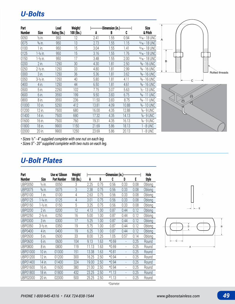
U-BOLTS: Stainless steel u-bolts are used to run and support conduit or pipe in electrical systems.
U-BOLT PLATES: U-bolt plates (sold separately) help provide a uniform surface upon which to tighten hex nuts.
PRODUCT DETAILS U-BoltsMaterial: -U-Bolt: 316 SS-Hex Nuts: 316 SSStandards: ASTM A193 B8M Class I, ASTM F593
Product may contain imported component. U-bolt manufactured in USA; hex nuts and raw material for u-bolt may or may not be of U.S. origin.
U-Bolt Plates Material: 316 SSStandards: ASTM A240
U-Bolt U-Bolt Plate
www.gibsonstainless.comPHONE 1-800-945-4316 • FAX 724-838-1544 49
U-Bolts
U-Bolt Plates
Part Load Weight/ |----------Dimension (in.)----------| Size Number Size Rating (lbs.) 100 (lbs.) A B C & Pitch0050 ½ in. 950 12 2.41 1.55 0.94 �⁄��-18UNC0075 ¾ in. 950 13 2.73 1.55 1.15 �⁄��-18UNC0100 1 in. 950 15 3.04 1.55 1.41 �⁄��-18UNC0125 1-¼ in. 950 15 3.16 1.55 1.76 �⁄��-18UNC0150 1-½ in. 950 17 3.48 1.55 2.00 �⁄��-18UNC0200 2in. 1250 30 4.30 1.81 2.50 ⅜-16UNC0250 2-½in. 1250 33 4.80 1.81 2.99 ⅜-16UNC0300 3in. 1250 36 5.36 1.81 3.62 ⅜-16UNC0350 3-½in. 1250 40 5.80 1.81 4.11 ⅜-16UNC0400 4in. 1250 44 6.50 1.81 4.61 ⅜-16UNC0500 5 in. 2250 102 7.75 3.07 5.63 ½ - 13 UNC0600 6in. 3550 199 9.50 3.83 6.75 ⅝-11UNC0800 8in. 3550 236 11.50 3.83 8.75 ⅝-11UNC01000 10 in. 5250 412 13.81 4.09 10.88 ¾ - 10 UNC01200 12in. 7500 680 16.00 4.35 12.88 ⅞-9UNC01400 14in. 7500 690 17.32 4.35 14.13 ⅞-9UNC01600 16in. 7500 760 19.31 4.35 16.13 ⅞-9UNC01800 18 in. 9900 1150 21.69 5.86 18.13 1 - 8 UNC02000 20 in. 9900 1250 23.69 5.86 20.13 1 - 8 UNC
Part Use w/ Gibson Weight/ |----------------Dimension (in.)---------------| Hole Number Size Part Number 100 (lbs.) A B C D E StyleUBP0050 ½ in. 0050 3 2.25 0.75 0.56 0.33 0.08 OblongUBP0075 ¾ in. 0075 3 2.38 0.75 0.56 0.33 0.08 OblongUBP0100 1 in. 0100 4 2.63 0.75 0.56 0.33 0.08 OblongUBP0125 1-¼ in. 0125 4 3.01 0.75 0.56 0.33 0.08 OblongUBP0150 1-½ in. 0150 5 3.25 0.75 0.56 0.33 0.08 OblongUBP0200 2 in. 0200 12 4.13 1.00 0.87 0.44 0.12 OblongUBP0250 2-½ in. 0250 16 5.00 1.00 0.87 0.44 0.12 OblongUBP0300 3 in. 0300 17 5.25 1.00 0.87 0.44 0.12 OblongUBP0350 3-½ in. 0350 19 5.75 1.00 0.87 0.44 0.12 OblongUBP0400 4 in. 0400 19 6.25 1.00 0.87 0.44 0.12 OblongUBP0500 5 in. 0500 33 8.00 1.25 1.05 0.57 0.14 OblongUBP0600 6 in. 0600 104 9.13 1.63 *0.69 - 0.25 RoundUBP0800 8 in. 0800 119 11.13 1.63 *0.69 - 0.25 RoundUBP01000 10 in. 01000 151 13.38 1.63 *0.81 - 0.25 RoundUBP01200 12 in. 01200 300 16.25 2.50 *0.94 - 0.25 RoundUBP01400 14 in. 01400 324 19.00 2.50 *0.94 - 0.25 RoundUBP01600 16 in. 01600 380 21.00 2.50 *0.94 - 0.25 RoundUBP01800 18 in. 01800 432 23.25 2.50 *1.13 - 0.25 RoundUBP02000 20 in. 02000 500 25.25 2.50 *1.13 - 0.25 Round
A
B
C
Rolled threads
A
CE
BD
A
CE
BD
*Diameter
• Sizes ½” - 4” supplied complete with one nut on each leg.• Sizes 5” - 20” supplied complete with two nuts on each leg.
All Stainless Steel • All In Stock50
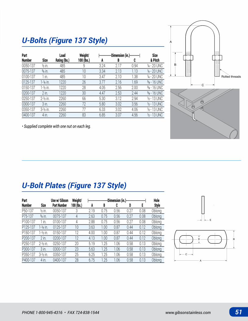
STAINLESS STEEL U-BOLTS & PLATES (FIGURE 137 STYLE)
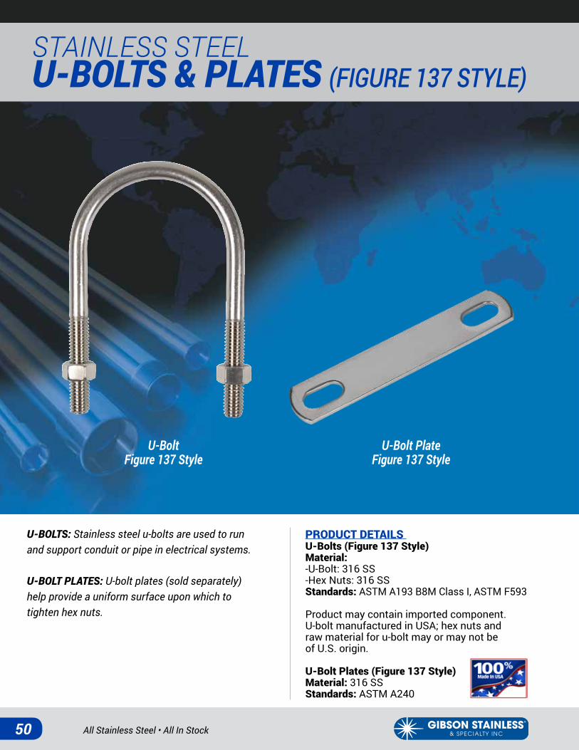
U-BOLTS: Stainless steel u-bolts are used to run and support conduit or pipe in electrical systems.
U-BOLT PLATES: U-bolt plates (sold separately) help provide a uniform surface upon which to tighten hex nuts.
PRODUCT DETAILS U-Bolts (Figure 137 Style)Material: -U-Bolt: 316 SS-Hex Nuts: 316 SSStandards: ASTM A193 B8M Class I, ASTM F593
Product may contain imported component. U-bolt manufactured in USA; hex nuts and raw material for u-bolt may or may not be of U.S. origin.
U-Bolt Plates (Figure 137 Style) Material: 316 SSStandards: ASTM A240
U-BoltFigure 137 Style
U-Bolt PlateFigure 137 Style
www.gibsonstainless.comPHONE 1-800-945-4316 • FAX 724-838-1544 51
U-Bolts (Figure 137 Style)
U-Bolt Plates (Figure 137 Style)
Part Load Weight/ |----------Dimension (in.)--------| Size Number Size Rating (lbs.) 100 (lbs.) A B C & Pitch0050-137 ½ in. 485 9 3.24 2.17 0.94 ¼ - 20 UNC0075-137 ¾ in. 485 10 3.34 2.13 1.13 ¼ - 20 UNC0100-137 1 in. 485 10 3.47 2.10 1.38 ¼ - 20 UNC0125-137 1-¼in. 1220 26 3.77 2.16 1.69 ⅜-16UNC0150-137 1-½in. 1220 28 4.05 2.56 2.00 ⅜-16UNC0200-137 2in. 1220 30 4.47 2.53 2.44 ⅜-16UNC0250-137 2-½ in. 2260 66 5.30 3.12 2.94 ½ - 13 UNC0300-137 3 in. 2260 72 5.80 3.02 3.56 ½ - 13 UNC0350-137 3-½ in. 2260 77 6.33 3.02 4.06 ½ - 13 UNC0400-137 4 in. 2260 83 6.85 3.07 4.56 ½ - 13 UNC
Part Use w/ Gibson Weight/ |----------------Dimension (in.)----------------| Hole Number Size Part Number 100 (lbs.) A B C D E StyleP50-137 ½ in. 0050-137 3 2.19 0.75 0.56 0.27 0.08 OblongP75-137 ¾ in. 0075-137 4 2.63 0.75 0.56 0.27 0.08 OblongP100-137 1 in. 0100-137 4 2.88 0.75 0.56 0.27 0.08 OblongP125-137 1-¼ in. 0125-137 10 3.63 1.00 0.87 0.44 0.12 OblongP150-137 1-½ in. 0150-137 12 4.00 1.00 0.87 0.44 0.12 OblongP200-137 2 in. 0200-137 12 4.13 1.00 0.87 0.44 0.12 OblongP250-137 2-½ in. 0250-137 20 5.19 1.25 1.06 0.58 0.13 OblongP300-137 3 in. 0300-137 23 5.63 1.25 1.06 0.58 0.13 OblongP350-137 3-½ in. 0350-137 25 6.25 1.25 1.06 0.58 0.13 OblongP400-137 4 in. 0400-137 28 6.75 1.25 1.06 0.58 0.13 Oblong
• Supplied complete with one nut on each leg.
A
CE
BD
A
CE
BD
A
B
C
Rolled threads
All Stainless Steel • All In Stock52
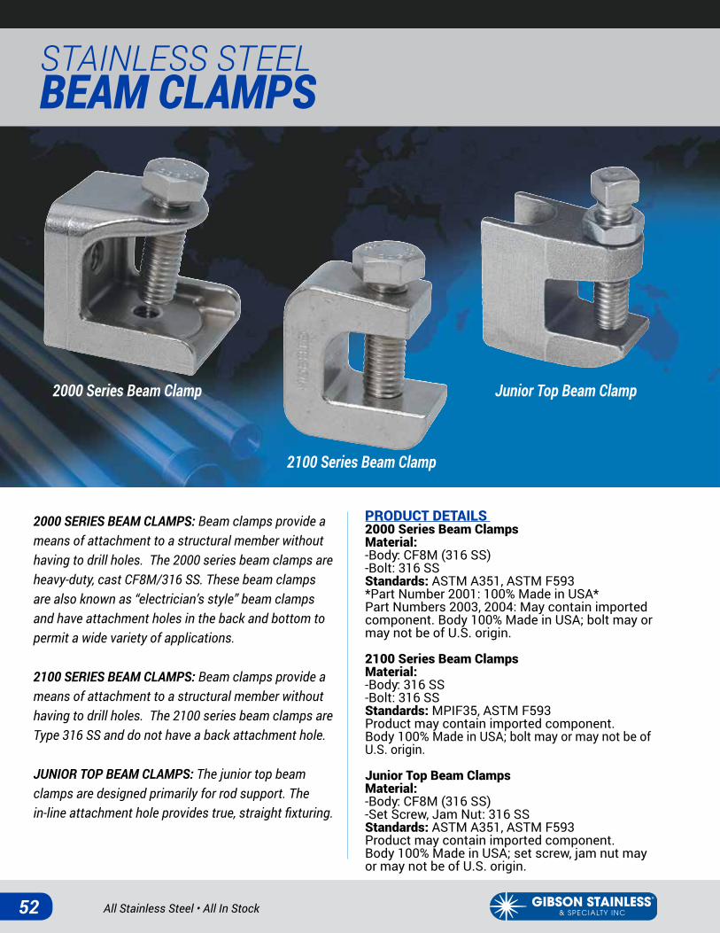
STAINLESS STEEL BEAM CLAMPS
2000 SERIES BEAM CLAMPS: Beam clamps provide a means of attachment to a structural member without having to drill holes. The 2000 series beam clamps are heavy-duty, cast CF8M/316 SS. These beam clamps are also known as “electrician’s style” beam clamps and have attachment holes in the back and bottom to permit a wide variety of applications.
2100 SERIES BEAM CLAMPS: Beam clamps provide a means of attachment to a structural member without having to drill holes. The 2100 series beam clamps are Type 316 SS and do not have a back attachment hole.
JUNIOR TOP BEAM CLAMPS: The junior top beam clamps are designed primarily for rod support. The in-line attachment hole provides true, straight fixturing.
PRODUCT DETAILS 2000 Series Beam ClampsMaterial: -Body: CF8M (316 SS)-Bolt: 316 SSStandards: ASTM A351, ASTM F593 *Part Number 2001: 100% Made in USA*Part Numbers 2003, 2004: May contain imported component. Body 100% Made in USA; bolt may or may not be of U.S. origin.
2100 Series Beam ClampsMaterial: -Body: 316 SS-Bolt: 316 SSStandards: MPIF35, ASTM F593Product may contain imported component. Body 100% Made in USA; bolt may or may not be of U.S. origin.
Junior Top Beam ClampsMaterial: -Body: CF8M (316 SS)-Set Screw, Jam Nut: 316 SSStandards: ASTM A351, ASTM F593 Product may contain imported component. Body 100% Made in USA; set screw, jam nut may or may not be of U.S. origin.
2000 Series Beam Clamp
2100 Series Beam Clamp
Junior Top Beam Clamp

www.gibsonstainless.comPHONE 1-800-945-4316 • FAX 724-838-1544 53
2000 Series Beam Clamps
Junior Top Beam Clamps
2100 Series Beam Clamps
Part Load Weight/ |-----------------------------------------------Dimension (in.)---------------------------------------------| Number Size Rating* (lbs.) 100 (lbs.) A B C D E F2001 ¼ in. 150 25 ¼ - 20 UNC �⁄��- 18 UNC 0.91 1.44 1.00 1.312003 ⅜in. 750 87 ⅜-16UNC ½-13UNC 1.16 1.90 1.88 2.002004 ½in. 1,100 148 ½-13UNC ⅝-11UNC 1.13 2.19 2.13 2.25
Part Load Weight/ |------------------------------------------------------Dimension (in.)--------------------------------------------------| Number Size Rating (lbs.) 100 (lbs.) A B C D E F G H I JJTB375 ⅜in. 750 33 1.63 1.50 0.80 0.38 0.60 0.12 0.75 ⅜-16UNC ⅜-16UNC 0.63JTB500 ½in. 750 32 1.63 1.50 0.80 0.38 0.60 0.12 0.75 ⅜-16UNC ½-13UNC 0.63
Part Load Weight/ |----------------------------------------------Dimension (in.)----------------------------------------------| Number Size Rating* (lbs.) 100 (lbs.) A B C D E F2103 ⅜in. 400 51 1.51 1.76 .89 1.90 1.00 ⅜-16UNC2104 ½ in. 600 55 1.51 1.76 .89 1.90 1.00 ½ - 13 UNC
* Based on upright installation, as shown from bottom attachment hole.
* Based on upright installation, as shown from bottom attachment hole.
All Stainless Steel • All In Stock54
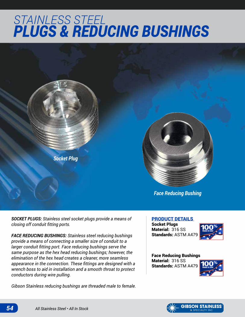
STAINLESS STEEL PLUGS & REDUCING BUSHINGS
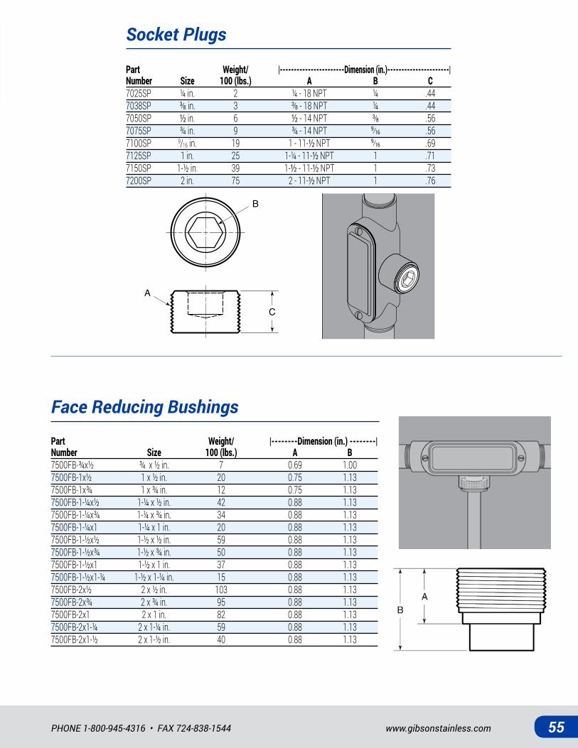
SOCKET PLUGS: Stainless steel socket plugs provide a means of closing off conduit fitting ports.
FACE REDUCING BUSHINGS: Stainless steel reducing bushings provide a means of connecting a smaller size of conduit to a larger conduit fitting port. Face reducing bushings serve the same purpose as the hex head reducing bushings; however, the elimination of the hex head creates a cleaner, more seamless appearance in the connection. These fittings are designed with a wrench boss to aid in installation and a smooth throat to protect conductors during wire pulling.
Gibson Stainless reducing bushings are threaded male to female.
PRODUCT DETAILS Socket PlugsMaterial: 316 SS Standards: ASTM A479
Face Reducing BushingsMaterial: 316 SS Standards: ASTM A479
Socket Plug
Face Reducing Bushing
www.gibsonstainless.comPHONE 1-800-945-4316 • FAX 724-838-1544 55
Face Reducing Bushings
Socket Plugs
Part Weight/ |--------Dimension (in.) --------| Number Size 100 (lbs.) A B7500FB-¾x½ ¾ x ½ in. 7 0.69 1.007500FB-1x½ 1 x ½ in. 20 0.75 1.137500FB-1x¾ 1 x ¾ in. 12 0.75 1.137500FB-1-¼x½ 1-¼ x ½ in. 42 0.88 1.137500FB-1-¼x¾ 1-¼ x ¾ in. 34 0.88 1.137500FB-1-¼x1 1-¼ x 1 in. 20 0.88 1.137500FB-1-½x½ 1-½ x ½ in. 59 0.88 1.137500FB-1-½x¾ 1-½ x ¾ in. 50 0.88 1.137500FB-1-½x1 1-½ x 1 in. 37 0.88 1.137500FB-1-½x1-¼ 1-½ x 1-¼ in. 15 0.88 1.137500FB-2x½ 2 x ½ in. 103 0.88 1.137500FB-2x¾ 2 x ¾ in. 95 0.88 1.137500FB-2x1 2 x 1 in. 82 0.88 1.137500FB-2x1-¼ 2 x 1-¼ in. 59 0.88 1.137500FB-2x1-½ 2 x 1-½ in. 40 0.88 1.13
Part Weight/ |-----------------------Dimension (in.)----------------------| Number Size 100 (lbs.) A B C7025SP ¼ in. 2 ¼ - 18 NPT ¼ .447038SP ⅜in. 3 ⅜-18NPT ¼ .447050SP ½ in. 6 ½ -14NPT ⅜ .567075SP ¾ in. 9 ¾ - 14 NPT �⁄�� .567100SP 9/16 in. 19 1 - 11-½ NPT �⁄�� .697125SP 1 in. 25 1-¼ - 11-½ NPT 1 .717150SP 1-½ in. 39 1-½ - 11-½ NPT 1 .737200SP 2 in. 75 2 - 11-½ NPT 1 .76
C
A
B

All Stainless Steel • All In Stock56
STAINLESS STEEL PLUGS & REDUCING BUSHINGS
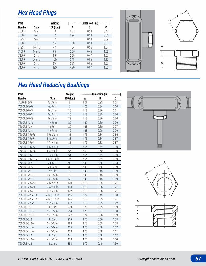
HEX HEAD PLUGS: Stainless steel hex head plugs provide a means of closing off conduit fitting ports.
HEX HEAD REDUCING BUSHINGS: Stainless steel reducing bushings provide a means of connecting a smaller size of conduit to a larger conduit fitting port.
Gibson Stainless reducing bushings are threaded male to female.
PRODUCT DETAILS Hex Head PlugsMaterial: 316 SS Standards: ASTM A182Import
Hex Head Reducing BushingsMaterial: 316 SS Standards: ASTM A182 Import
Hex Head Reducing Bushing
Hex Head Plug
www.gibsonstainless.comPHONE 1-800-945-4316 • FAX 724-838-1544 57
Hex Head Reducing Bushings
Hex Head PlugsPart Weight/ |------------Dimension (in.)------------| Number Size 100 (lbs.) A B C7038P ⅜in. 10 0.81 0.24 0.477050P ½ in. 12 0.94 0.34 0.657075P ¾ in. 17 1.17 0.34 0.697100P 1 in. 26 1.48 0.34 0.817125P 1-¼ in. 47 1.84 0.35 1.047150P 1-½ in. 65 2.05 0.46 1.037200P 2 in. 99 2.55 0.47 1.077250P 2-½ in. 155 3.18 0.56 1.197300P 3 in. 244 3.73 0.56 1.577400P 4 in. 430 4.70 0.57 1.60
Part Weight/ |------------Dimension (in.)-----------| Number Size 100 (lbs.) A B C7500RB-½x¼ ½ x ¼ in. 8 1.01 0.25 0.577500RB-½x⅜ ½x⅜ in. 7 1.02 0.24 0.607500RB-¾x¼ ¾ x ¼ in. 16 1.18 0.26 0.717500RB-¾x⅜ ¾x⅜ in. 15 1.18 0.25 0.707500RB-¾x½ ¾ x ½ in. 12 1.19 0.26 0.707500RB-1x⅜ 1x⅜ in. 22 1.39 0.30 0.797500RB-1x½ 1 x ½ in. 20 1.38 0.30 0.777500RB-1x¾ 1 x ¾ in. 16 1.38 0.29 0.797500RB-1-¼x½ 1-¼ x ½ in. 41 1.75 0.34 0.867500RB-1-¼x¾ 1-¼ x ¾ in. 38 1.75 0.34 0.877500RB-1-¼x1 1-¼ x 1 in. 31 1.77 0.33 0.877500RB-1-½x½ 1-½ x ½ in. 70 2.04 0.49 1.007500RB-1-½x¾ 1-½ x ¾ in. 67 2.03 0.50 1.007500RB-1-½x1 1-½ x 1 in. 61 2.04 0.49 1.007500RB-1-½x1-¼ 1-½ x 1-¼ in. 47 2.04 0.49 1.007500RB-2x½ 2 x ½ in. 92 2.49 0.45 0.987500RB-2x¾ 2 x ¾ in. 84 2.49 0.45 0.997500RB-2x1 2 x 1 in. 79 2.48 0.45 0.997500RB-2x1-¼ 2 x 1-¼ in. 79 2.49 0.45 0.997500RB-2x1-½ 2 x 1-½ in. 69 2.49 0.45 0.997500RB-2-½x½ 2-½ x ½ in. 170 3.18 0.55 1.217500RB-2-½x¾ 2-½ x ¾ in. 163 3.18 0.56 1.217500RB-2-½x1 2-½ x 1 in. 172 3.16 0.56 1.217500RB-2-½x1-¼ 2-½ x 1-¼ in. 155 3.24 0.49 1.187500RB-2-½x1-½ 2-½ x 1-½ in. 145 3.18 0.55 1.217500RB-2-½x2 2-½ x 2 in. 117 3.15 0.55 1.227500RB-3x1 3 x 1 in. 279 3.73 0.55 1.337500RB-3x1-¼ 3 x 1-¼ in. 264 3.70 0.57 1.307500RB-3x1-½ 3 x 1-½ in. 247 3.74 0.56 1.337500RB-3x2 3 x 2 in. 219 3.70 0.56 1.287500RB-3x2-½ 3 x 2-½ in. 183 3.73 0.55 1.287500RB-4x1-¼ 4 x 1-¼ in. 415 4.70 0.49 1.577500RB-4x1-½ 4 x 1-½ in. 423 4.70 0.49 1.617500RB-4x2 4 x 2 in. 441 4.70 0.48 1.627500RB-4x2-½ 4 x 2-½ in. 428 4.71 0.49 1.607500RB-4x3 4 x 3 in. 353 4.70 0.49 1.59
All Stainless Steel • All In Stock58
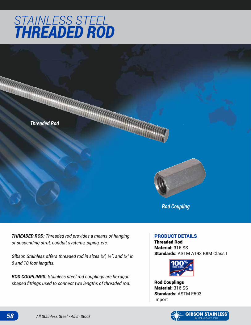
STAINLESS STEEL THREADED ROD
THREADED ROD: Threaded rod provides a means of hanging or suspending strut, conduit systems, piping, etc.
Gibson Stainless offers threaded rod in sizes ¼”, ⅜”, and ½” in 6 and 10 foot lengths.
ROD COUPLINGS: Stainless steel rod couplings are hexagon shaped fittings used to connect two lengths of threaded rod.
PRODUCT DETAILS Threaded RodMaterial: 316 SSStandards: ASTM A193 B8M Class I
Rod CouplingsMaterial: 316 SSStandards: ASTM F593 Import
Threaded Rod
Rod Coupling
www.gibsonstainless.comPHONE 1-800-945-4316 • FAX 724-838-1544 59
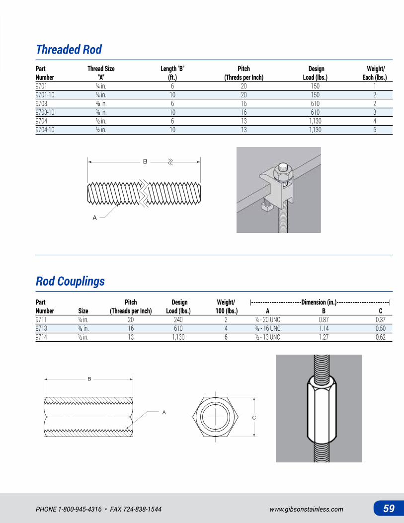
Threaded Rod
Rod Couplings
B
A
B
AC
Part Thread Size Length "B" Pitch Design Weight/ Number “A” (ft.) (Threds per Inch) Load (lbs.) Each (lbs.)9701 ¼ in. 6 20 150 19701-10 ¼ in. 10 20 150 29703 ⅜in. 6 16 610 29703-10 ⅜in. 10 16 610 39704 ½ in. 6 13 1,130 49704-10 ½ in. 10 13 1,130 6
Part Pitch Design Weight/ |----------------------Dimension (in.)-----------------------| Number Size (Threads per Inch) Load (lbs.) 100 (lbs.) A B C9711 ¼ in. 20 240 2 ¼ - 20 UNC 0.87 0.379713 ⅜in. 16 610 4 ⅜-16UNC 1.14 0.509714 ½ in. 13 1,130 6 ½ - 13 UNC 1.27 0.62
All Stainless Steel • All In Stock60
STAINLESS STEEL STRUT & ACCESSORIES
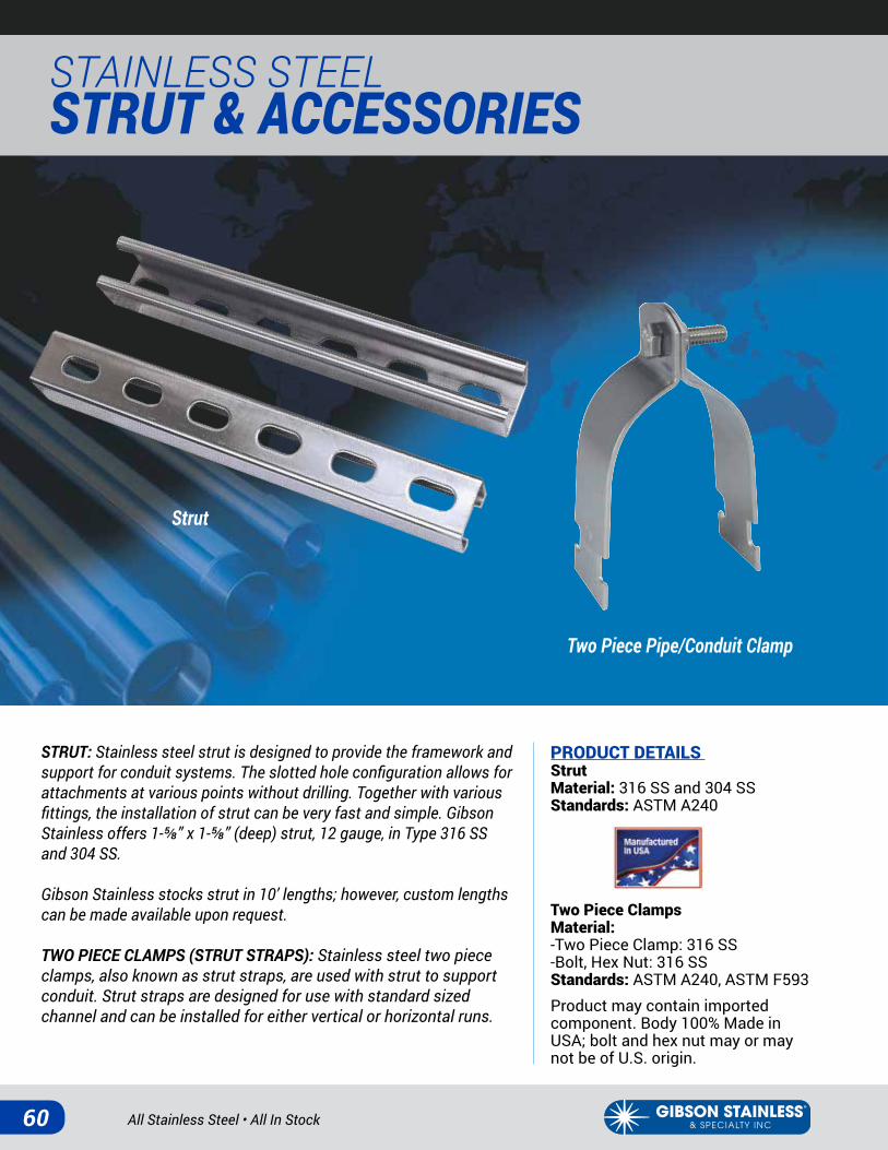
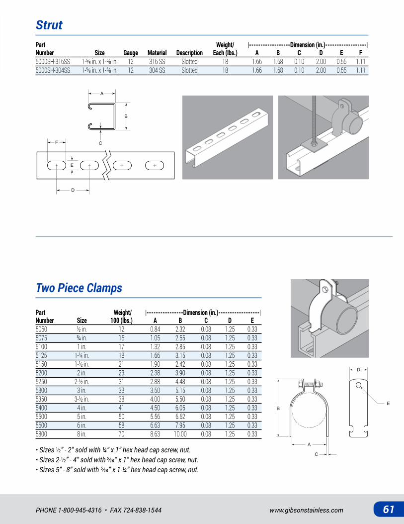
STRUT: Stainless steel strut is designed to provide the framework and support for conduit systems. The slotted hole configuration allows for attachments at various points without drilling. Together with various fittings, the installation of strut can be very fast and simple. Gibson Stainless offers 1-⅝” x 1-⅝” (deep) strut, 12 gauge, in Type 316 SS and 304 SS.
Gibson Stainless stocks strut in 10’ lengths; however, custom lengths can be made available upon request.
TWO PIECE CLAMPS (STRUT STRAPS): Stainless steel two piece clamps, also known as strut straps, are used with strut to support conduit. Strut straps are designed for use with standard sized channel and can be installed for either vertical or horizontal runs.
PRODUCT DETAILS StrutMaterial: 316 SS and 304 SSStandards: ASTM A240
Two Piece ClampsMaterial: -Two Piece Clamp: 316 SS -Bolt, Hex Nut: 316 SS Standards: ASTM A240, ASTM F593Product may contain imported component. Body 100% Made in USA; bolt and hex nut may or may not be of U.S. origin.
Strut
Two Piece Pipe/Conduit Clamp
www.gibsonstainless.comPHONE 1-800-945-4316 • FAX 724-838-1544 61
Two Piece Clamps
Strut
B
A
E
C D
F
B
A
E
C D
F
A
C
D
EB
Part Weight/ |------------------Dimension (in.)------------------| Number Size Gauge Material Description Each (lbs.) A B C D E F5000SH-316SS 1-⅝in.x1-⅝in. 12 316SS Slotted 18 1.66 1.68 0.10 2.00 0.55 1.115000SH-304SS 1-⅝in.x1-⅝in. 12 304SS Slotted 18 1.66 1.68 0.10 2.00 0.55 1.11
Part Weight/ |----------------Dimension (in.)------------------| Number Size 100 (lbs.) A B C D E5050 ½ in. 12 0.84 2.32 0.08 1.25 0.335075 ¾ in. 15 1.05 2.55 0.08 1.25 0.335100 1 in. 17 1.32 2.85 0.08 1.25 0.335125 1-¼ in. 18 1.66 3.15 0.08 1.25 0.335150 1-½ in. 21 1.90 2.42 0.08 1.25 0.335200 2 in. 23 2.38 3.90 0.08 1.25 0.335250 2-½ in. 31 2.88 4.48 0.08 1.25 0.335300 3 in. 33 3.50 5.15 0.08 1.25 0.335350 3-½ in. 38 4.00 5.50 0.08 1.25 0.335400 4 in. 41 4.50 6.05 0.08 1.25 0.335500 5 in. 50 5.56 6.62 0.08 1.25 0.335600 6 in. 58 6.63 7.95 0.08 1.25 0.335800 8 in. 70 8.63 10.00 0.08 1.25 0.33
• Sizes ½” - 2” sold with ¼” x 1” hex head cap screw, nut.• Sizes 2-½” - 4” sold with �⁄��” x 1” hex head cap screw, nut.• Sizes 5” - 8” sold with �⁄��” x 1-¼” hex head cap screw, nut.
All Stainless Steel • All In Stock62
STAINLESS STEEL STRUT & ACCESSORIES
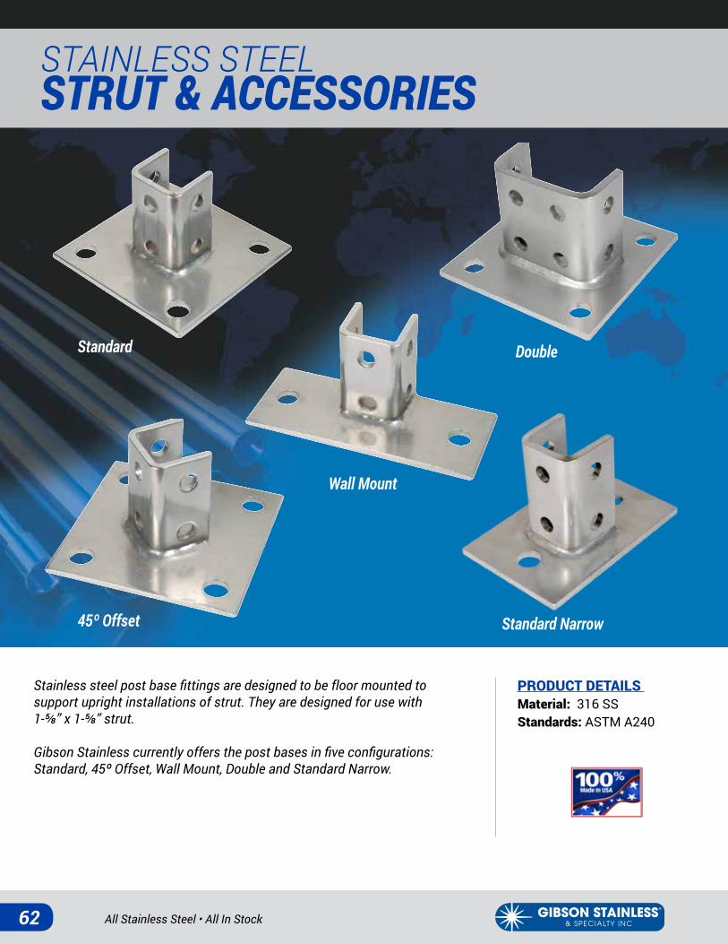
Stainless steel post base fittings are designed to be floor mounted to support upright installations of strut. They are designed for use with 1-⅝” x 1-⅝” strut.
Gibson Stainless currently offers the post bases in five configurations: Standard, 45º Offset, Wall Mount, Double and Standard Narrow.
PRODUCT DETAILS Material: 316 SSStandards: ASTM A240
Standard Double
45º Offset Standard Narrow
Wall Mount
www.gibsonstainless.comPHONE 1-800-945-4316 • FAX 724-838-1544 63
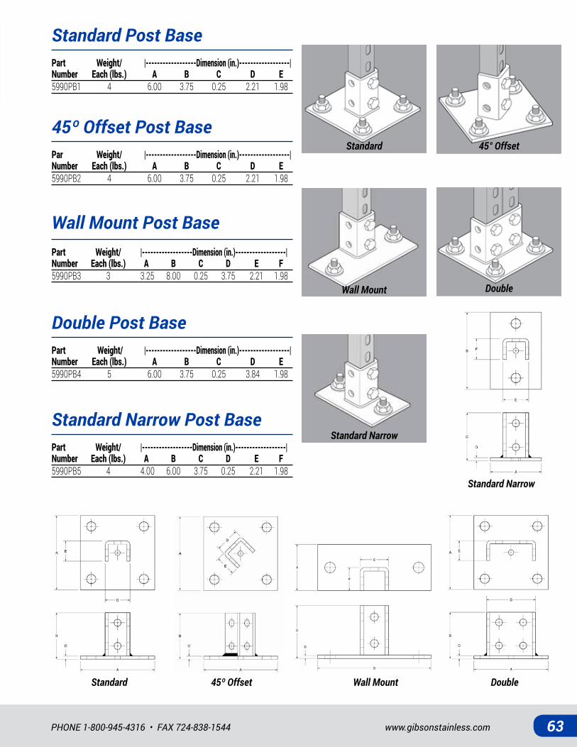
Standard Narrow Post Base
Standard Post Base
45º Offset Post Base
Double Post Base
Wall Mount Post Base
Part Weight/ |------------------Dimension (in.)------------------| Number Each (lbs.) A B C D E F5990PB5 4 4.00 6.00 3.75 0.25 2.21 1.98
Part Weight/ |------------------Dimension (in.)------------------| Number Each (lbs.) A B C D E5990PB1 4 6.00 3.75 0.25 2.21 1.98
Par Weight/ |------------------Dimension (in.)------------------| Number Each (lbs.) A B C D E5990PB2 4 6.00 3.75 0.25 2.21 1.98
Part Weight/ |------------------Dimension (in.)------------------| Number Each (lbs.) A B C D E5990PB4 5 6.00 3.75 0.25 3.84 1.98
Part Weight/ |------------------Dimension (in.)------------------| Number Each (lbs.) A B C D E F5990PB3 3 3.25 8.00 0.25 3.75 2.21 1.98
Standard Narrow
Standard Narrow
Standard
Double
45° Offset
Wall Mount
45º OffsetStandard DoubleWall Mount
All Stainless Steel • All In Stock64
STAINLESS STEEL STRUT & ACCESSORIES
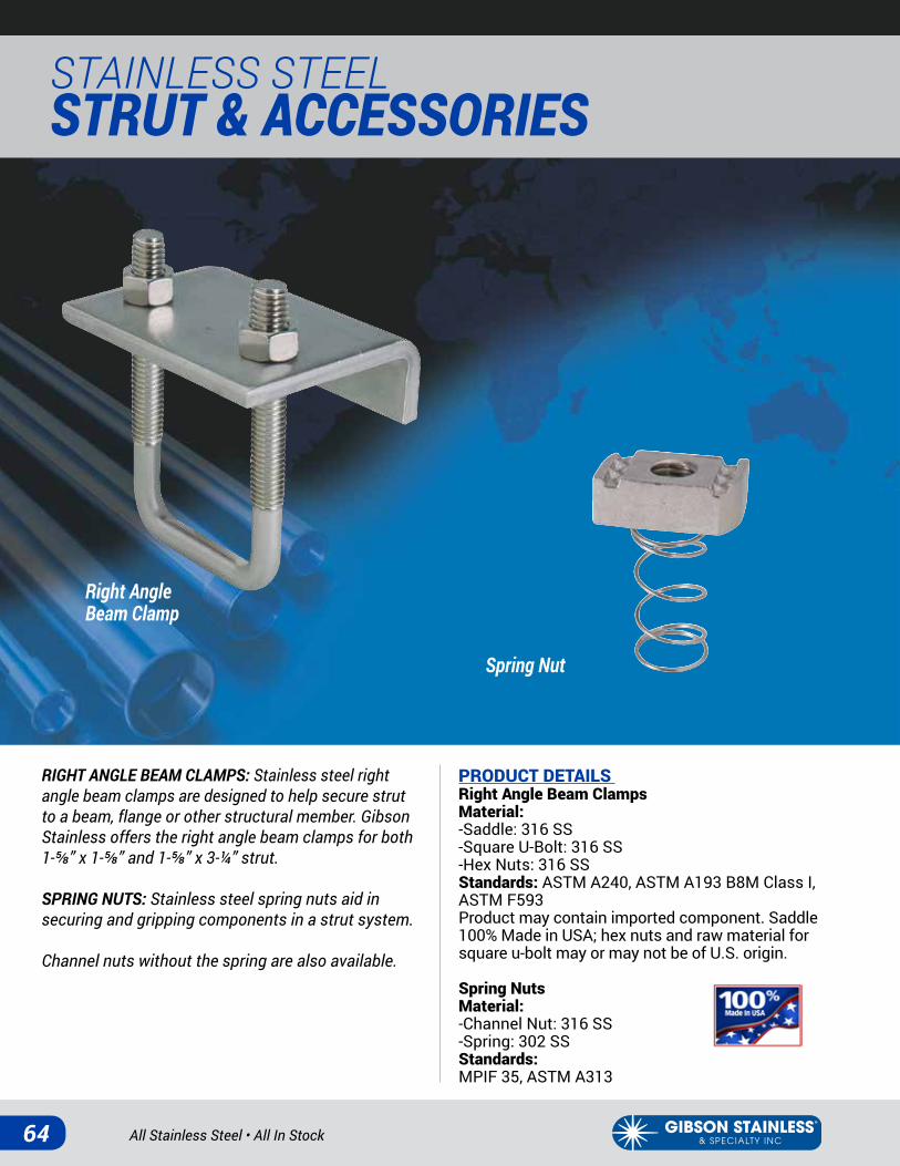
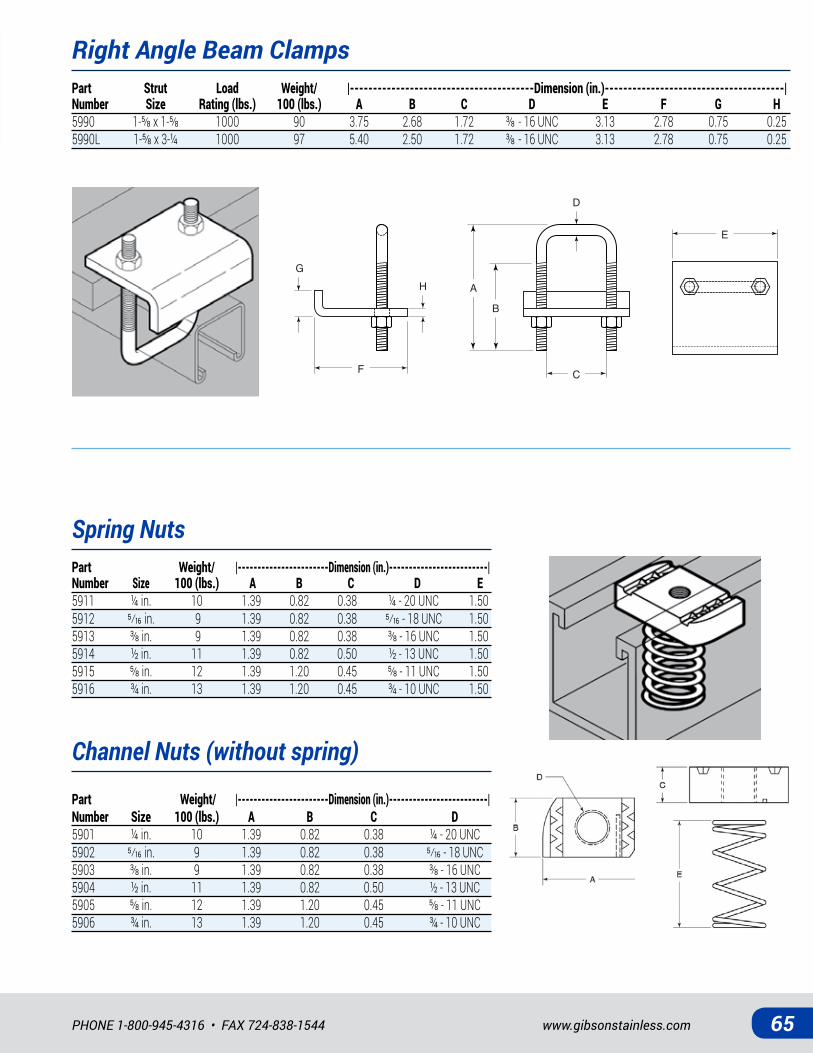
RIGHT ANGLE BEAM CLAMPS: Stainless steel right angle beam clamps are designed to help secure strut to a beam, flange or other structural member. Gibson Stainless offers the right angle beam clamps for both 1-⅝” x 1-⅝” and 1-⅝” x 3-¼” strut.
SPRING NUTS: Stainless steel spring nuts aid in securing and gripping components in a strut system.
Channel nuts without the spring are also available.
PRODUCT DETAILS Right Angle Beam ClampsMaterial: -Saddle: 316 SS-Square U-Bolt: 316 SS-Hex Nuts: 316 SSStandards: ASTM A240, ASTM A193 B8M Class I, ASTM F593Product may contain imported component. Saddle 100% Made in USA; hex nuts and raw material for square u-bolt may or may not be of U.S. origin.
Spring NutsMaterial: -Channel Nut: 316 SS-Spring: 302 SSStandards: MPIF 35, ASTM A313
Spring Nut
Right Angle Beam Clamp
www.gibsonstainless.comPHONE 1-800-945-4316 • FAX 724-838-1544 65
Spring NutsPart Weight/ |-----------------------Dimension (in.)-------------------------| Number Size 100 (lbs.) A B C D E5911 ¼ in. 10 1.39 0.82 0.38 ¼ - 20 UNC 1.505912 �⁄�� in. 9 1.39 0.82 0.38 �⁄��- 18 UNC 1.505913 ⅜in. 9 1.39 0.82 0.38 ⅜-16UNC 1.505914 ½ in. 11 1.39 0.82 0.50 ½ - 13 UNC 1.505915 ⅝in. 12 1.39 1.20 0.45 ⅝-11UNC 1.505916 ¾ in. 13 1.39 1.20 0.45 ¾ - 10 UNC 1.50 Part Weight/ |-----------------------Dimension (in.)-------------------------| Number Size 100 (lbs.) A B C D5901 ¼ in. 10 1.39 0.82 0.38 ¼ - 20 UNC5902 �⁄�� in. 9 1.39 0.82 0.38 �⁄��- 18 UNC5903 ⅜in. 9 1.39 0.82 0.38 ⅜-16UNC5904 ½ in. 11 1.39 0.82 0.50 ½ - 13 UNC5905 ⅝in. 12 1.39 1.20 0.45 ⅝-11UNC5906 ¾ in. 13 1.39 1.20 0.45 ¾ - 10 UNC
Right Angle Beam ClampsPart Strut Load Weight/ |----------------------------------------Dimension (in.)---------------------------------------| Number Size Rating (lbs.) 100 (lbs.) A B C D E F G H5990 1-⅝x1-⅝ 1000 90 3.75 2.68 1.72 ⅜-16UNC 3.13 2.78 0.75 0.255990L 1-⅝x3-¼ 1000 97 5.40 2.50 1.72 ⅜-16UNC 3.13 2.78 0.75 0.25
A
B
F
H
D
G
E
C
Channel Nuts (without spring)

All Stainless Steel • All In Stock66
STAINLESS STEEL STRUT & ACCESSORIES
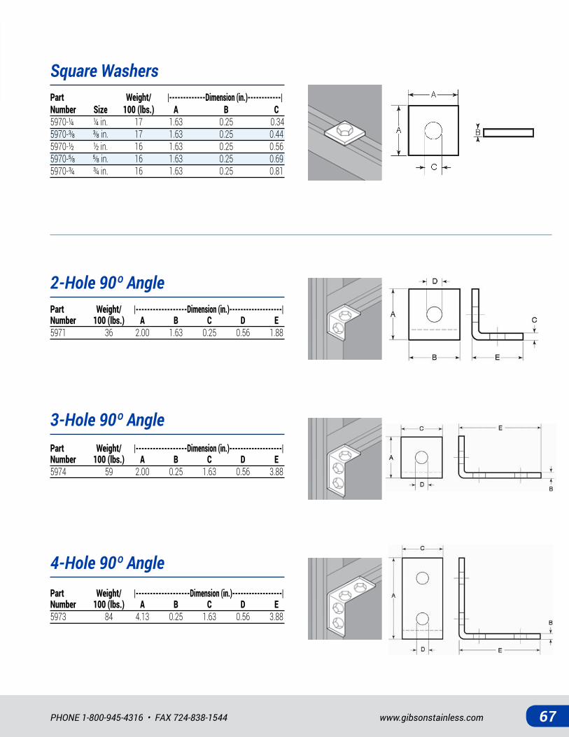
SQUARE WASHERS: Stainless steel square washers are designed for use with 1-⅝” x 1-⅝” strut to aid in making connections in strut systems.
90º ANGLES: Stainless steel 90º angles are used to support and make various connections in strut systems.
PRODUCT DETAILS Square WashersMaterial: 316 SSStandards: ASTM A240
90º AnglesMaterial: 316 SSStandards: ASTM A240
Square Washer 2-Hole 90º Angle
3-Hole 90º Angle 4-Hole 90º Angle
www.gibsonstainless.comPHONE 1-800-945-4316 • FAX 724-838-1544 67
Square Washers
2-Hole 90º Angle
3-Hole 90º Angle
4-Hole 90º Angle
Part Weight/ |-------------Dimension (in.)------------| Number Size 100 (lbs.) A B C5970-¼ ¼ in. 17 1.63 0.25 0.345970-⅜ ⅜in. 17 1.63 0.25 0.445970-½ ½ in. 16 1.63 0.25 0.565970-⅝ ⅝in. 16 1.63 0.25 0.695970-¾ ¾ in. 16 1.63 0.25 0.81
Part Weight/ |------------------Dimension (in.)-------------------| Number 100 (lbs.) A B C D E5971 36 2.00 1.63 0.25 0.56 1.88
Part Weight/ |------------------Dimension (in.)-------------------| Number 100 (lbs.) A B C D E5974 59 2.00 0.25 1.63 0.56 3.88
Part Weight/ |-------------------Dimension (in.)------------------| Number 100 (lbs.) A B C D E5973 84 4.13 0.25 1.63 0.56 3.88
All Stainless Steel • All In Stock68
STAINLESS STEEL STRUT & ACCESSORIES
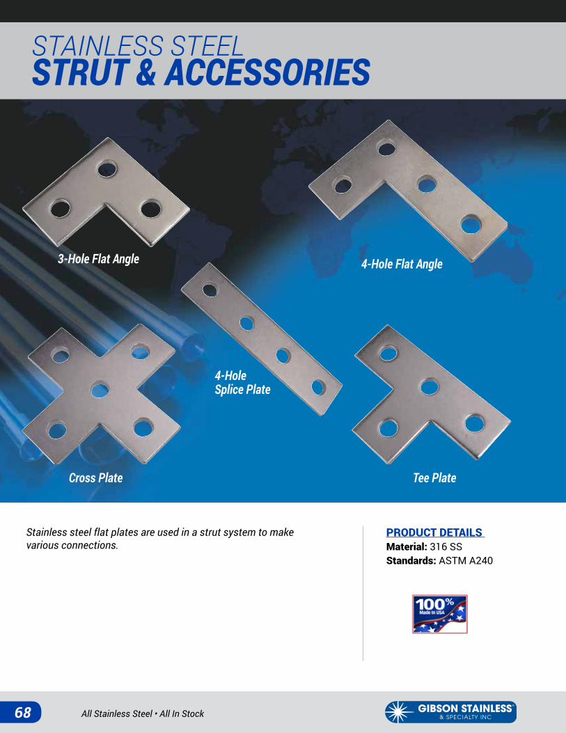
Stainless steel flat plates are used in a strut system to make various connections.
PRODUCT DETAILS Material: 316 SSStandards: ASTM A240
3-Hole Flat Angle 4-Hole Flat Angle
4-Hole Splice Plate
Cross Plate Tee Plate
www.gibsonstainless.comPHONE 1-800-945-4316 • FAX 724-838-1544 69
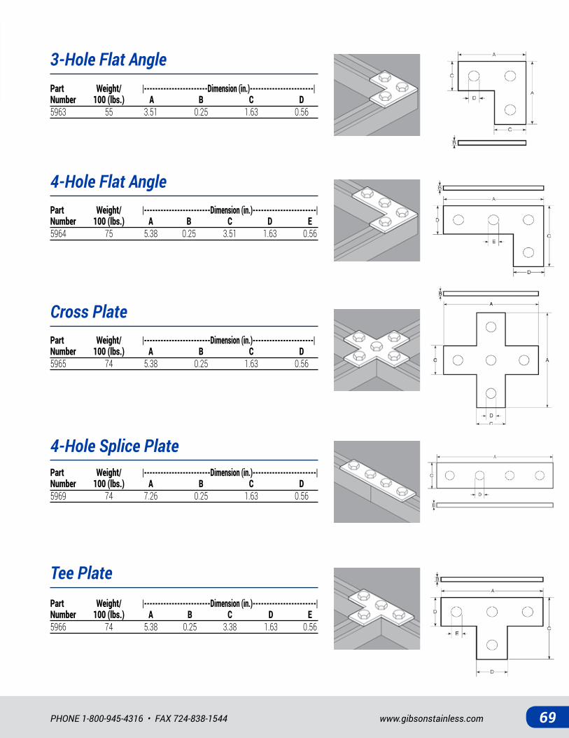
4-Hole Splice Plate
3-Hole Flat Angle
Cross Plate
4-Hole Flat Angle
Tee Plate
Part Weight/ |------------------------Dimension (in.)-----------------------| Number 100 (lbs.) A B C D5969 74 7.26 0.25 1.63 0.56
Part Weight/ |------------------------Dimension (in.)----------------------| Number 100 (lbs.) A B C D5965 74 5.38 0.25 1.63 0.56
Part Weight/ |------------------------Dimension (in.)-----------------------| Number 100 (lbs.) A B C D E5964 75 5.38 0.25 3.51 1.63 0.56
Part Weight/ |-----------------------Dimension (in.)-----------------------| Number 100 (lbs.) A B C D5963 55 3.51 0.25 1.63 0.56
Part Weight/ |------------------------Dimension (in.)-----------------------| Number 100 (lbs.) A B C D E5966 74 5.38 0.25 3.38 1.63 0.56
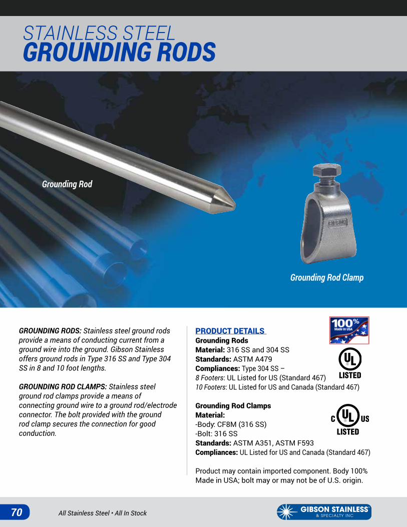
All Stainless Steel • All In Stock70
STAINLESS STEEL GROUNDING RODS
GROUNDING RODS: Stainless steel ground rods provide a means of conducting current from a ground wire into the ground. Gibson Stainless offers ground rods in Type 316 SS and Type 304 SS in 8 and 10 foot lengths.
GROUNDING ROD CLAMPS: Stainless steel ground rod clamps provide a means of connecting ground wire to a ground rod/electrode connector. The bolt provided with the ground rod clamp secures the connection for good conduction.
PRODUCT DETAILS Grounding RodsMaterial: 316 SS and 304 SSStandards: ASTM A479Compliances: Type 304 SS –8 Footers: UL Listed for US (Standard 467)10 Footers: UL Listed for US and Canada (Standard 467)
Grounding Rod ClampsMaterial:-Body: CF8M (316 SS)-Bolt: 316 SSStandards: ASTM A351, ASTM F593 Compliances: UL Listed for US and Canada (Standard 467)
Product may contain imported component. Body 100% Made in USA; bolt may or may not be of U.S. origin.
Grounding Rod
Grounding Rod Clamp
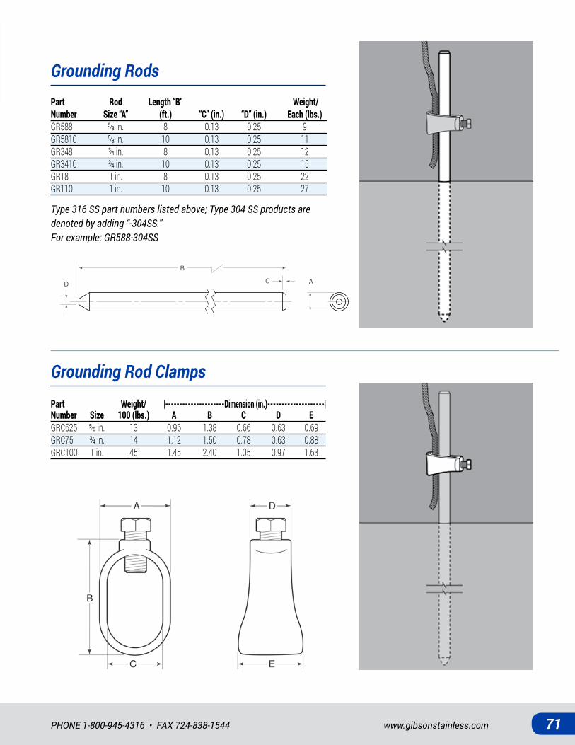
www.gibsonstainless.comPHONE 1-800-945-4316 • FAX 724-838-1544 71
Grounding Rods
Grounding Rod ClampsPart Weight/ |---------------------Dimension (in.)--------------------| Number Size 100 (lbs.) A B C D EGRC625 ⅝in. 13 0.96 1.38 0.66 0.63 0.69GRC75 ¾ in. 14 1.12 1.50 0.78 0.63 0.88GRC100 1 in. 45 1.45 2.40 1.05 0.97 1.63
Type 316 SS part numbers listed above; Type 304 SS products are denoted by adding “-304SS.”For example: GR588-304SS
CD A
B
Part Rod Length “B” Weight/ Number Size “A” (ft.) “C” (in.) “D” (in.) Each (lbs.)GR588 ⅝in. 8 0.13 0.25 9GR5810 ⅝in. 10 0.13 0.25 11GR348 ¾ in. 8 0.13 0.25 12GR3410 ¾ in. 10 0.13 0.25 15GR18 1 in. 8 0.13 0.25 22GR110 1 in. 10 0.13 0.25 27
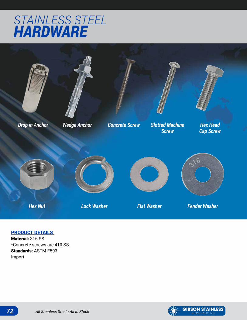
All Stainless Steel • All In Stock72
STAINLESS STEEL HARDWARE
PRODUCT DETAILS Material: 316 SS*Concrete screws are 410 SSStandards: ASTM F593 Import
Hex Head Cap Screw
Lock WasherHex Nut
Slotted Machine Screw
Concrete ScrewDrop in Anchor
Flat Washer Fender Washer
Wedge Anchor

www.gibsonstainless.comPHONE 1-800-945-4316 • FAX 724-838-1544 73
Hex Head Cap Screws
Hex Nuts
Lock Washers
Drop In Anchors
Part Number Size Pitch9901-¼ ¼ in. 209901-�⁄�� �⁄��in. 189901-⅜ ⅜in. 169901-½ ½ in. 139901-⅝ ⅝in. 119901-¾ ¾ in. 109901-⅞ ⅞in. 99901-1 1 in. 8
Part Number Size9921-¼ ¼ in.9921-�⁄�� �⁄��in.9921-⅜ ⅜in.9921-½ ½ in.9921-⅝ ⅝in.
Part Number Size9400DIA-¼ ¼ in.9400DIA-⅜ ⅜in.9400DIA-½ ½ in.
Flat Washers Fender WashersPart Number Size9920-¼ ¼ in.9920-�⁄�� �⁄��in.9920-⅜ ⅜in.9920-½ ½ in.9920-⅝ ⅝in.
Part Number Size9920F-¼ x 1 ¼ x 19920F-¼ x 1-¼ ¼ x 1-¼9920F-⅜x1 ⅜x19920F-⅜x1-¼ ⅜x1-¼9920F-½ x 1-½ ½ x 1-½
Part Number Diameter x Length (in.)9905-¼ x ¾ ¼ x ¾9905-¼ x 1 ¼ x 19905-¼ x 1-¼ ¼ x 1-¼9905-¼ x 1-½ ¼ x 1-½9905-¼ x 2 ¼ x 29905-⅜x½ ⅜x½9905-⅜x¾ ⅜x¾9905-⅜x1 ⅜x1
Part Number Diameter x Length (in.)9905-⅜x1-¼ ⅜x1-¼9905-⅜x1-½ ⅜x1-½9905-⅜x2 ⅜x29905-½ x ¾ ½ x ¾9905-½ x 1 ½ x 19905-½ x 1-¼ ½ x 1-¼9905-½ x 1-½ ½ x 1-½9905-½ x 2 ½ x 2
Wedge AnchorsPart Number Diameter x Length (in.) 9400WA-¼ x 1-¾ ¼ x 1-¾9400WA-¼ x 2-¼ ¼ x 2-¼9400WA-¼ x 3-¼ ¼ x 3-¼9400WA-⅜x2-¼ ⅜x2-¼9400WA-⅜x3-¾ ⅜x3-¾9400WA-⅜x5 ⅜x59400WA-½ x 2-¾ ½ x 2-¾9400WA-½ x 3-¾ ½ x 3-¾9400WA-½ x 5-½ ½ x 5-½
Slotted Machine Screws
Concrete Screws
Part Number Diameter x Length (in.)9905M-¼ x 1 ¼ x 19905M-¼ x 1-¼ ¼ x 1-¼9905M-¼ x 1-½ ¼ x 1-½9905M-¼ x 2 ¼ x 2
Part Number Diameter x Length (in.)9400CS-¼ x 1-¾ ¼ x 1-¾9400CS-¼ x 2-¼ ¼ x 2-¼9400CS-¼ x 3-¼ ¼ x 3-¼
All Stainless Steel • All In Stock74
NOTES
GIBSON STAINLESS & SPECIALTY, INC.Address: PO Box 847Greensburg, PA 15601
Phone: 1-800-945-4316724-838-8320Fax: 724-838-1544
Email: [email protected]: www.gibsonstainless.com
Gibson Stainless is constantly working to improve and expand its product line. New products are added periodically.
For the most up-to-date product offering, please refer to www.gibsonstainless.com where products are added immediately.
NOTES
www.gibsonstainless.comPHONE 1-800-945-4316 • FAX 724-838-1544 75
www.gibsonstainless.com
PO Box 847, Greensburg, PA 15601
PHONE: 1-800-945-4316 • 724-838-8320 • FAX: 724-838-1544
Products Made in USA
Personal Service and High Quality Products
Reliable Answers and Accurate Lead Times
We Ship Over 90% of Orders Within 24 Hours