product brochure - welcome | smartair · pdf filesmartemp.com ® product brochure hsc-fd :...
TRANSCRIPT

smartemp.com
®
PRODUCT BROCHURE
HSC-FD : 042018
HSC-FDFixed Helical Swirl Di�user

The SMARTEMP® Fixed Helical Swirl Diffuser, type
HSC-FD, produces highly inductive swirl discharge,
diffusing the supply air stream radial ly with fixed
horizontal discharge and strong mixing characteristics
into the space. The patent pending design delivers high
levels of draught-free comfort well suited to both
constant volume or VAV applications, inclusive of low
temperature or cold air supply air systems with a
minimum supply-to-room temperature differential of
-16 K including turndown to approximately 25%.
The diffuser comes standard with a square face (figure
1), or may optionally be ordered with a round face.
The cambered leading edges of the twenty off-set radial
vanes reduce the sound power level and pressure drop,
improving aural comfort and saving fan energy.
The vane tips feature helical twist (figure 2) that reduces
pressure drop, allowing the airflow rate to be increased,
thereby reducing the number of diffusers required in the
space. This unique feature also reduces the minimum
DESCRIPTION
Fixed Helical Swirl Di�user
HSC-FD : 042018
Figure 2
Cambered Leading Edge
Helical Twist
Figure 1

permissible VAV turndown to 22% at -12 K cooling or
25% at -16 K (based on 35 Pa maximum tota l
pressure) and enhances stable operation under low
supply air temperature conditions.
The HSC-FD diffuser may be flush mounted in a ceiling
or freely suspended (ie no Coanda attachment to the
ceiling required). Typical discharge height ranges from
2.0 to 4.5 m, depending on diffuser size and airflow.
The highly inductive swirl discharge benefits heating
performance by strongly diluting supply air with cooler
room, thereby diminishing supply air stream buoyancy.
The maximum recommended differential between supply
air and room air is a function of diffuser size, discharge
height and airflow rate.
The HSC-FD swirl vanes form a flush surface with the
surrounding flat diffuser face, which may be square or
round, and which may be optionally screened by a
perforated face. The diffuser is made of powder coated
steel and is available with nominal neck diameters of
250 mm, 355 mm and 500 mm. Optional reducers are
available to reduce effective neck size for decreased
airflow rates.
Reducers
Reducers can be inserted into the neck from behind,
reducing the effective neck size to suit reduced airflow
rates, especially in low air quantity VAV applications
(figure 4). Reducers allow a largely uniform diffuser
aesthetic to be achieved by enabling the use of a
common diffuser size even where airflow rates between
diffusers vary widely. The ability to simply change
reducer s ize a lso prov ides fu ture-proofing for
refurbishment and fit-out changes. Five reducer sizes
are available for size DN500 and six for size DN355.
Reducers are not available for size DN250.
1
Figure 3
CONSTRUCTION
2
3
45
6
7
1 - M6 Rivet Nut
2 - Spigot
3 - Connection Box
4 - M6 Thread Rod
5 - Reducer (Optional)
6 - HSC-FD Swirl Diffuser
7 - Perforated Face (Optional)
Fixed Helical Swirl Di�user 2
HSC-FD : 042018

Figure 5
Discharge Pattern
Segment covers that blank one half, two opposed
quarters, or one quarter of the diffuser vanes are
available to reduce the discharge pattern from 360° to
180 ° (2-way asymmetrical), or 2 x 90 ° (2-way
symmetrical), or 270° (3-way) so as to allow for diffuser
placement in corners, in corridors, or close to a wall,
respectively (figure 5). Segment covers reduce the
diffuser airflow rate. Segment covers may be used in
combination with reducers where further airflow rate
reductions are required.
Mode of Operation
The highly inductive swirl discharge of the HSC-FD
produces rapid discharge velocity decay as the total
supply air stream mass flow rate increases due to
strong entrainment of secondary air from the room into
the primary air stream. Effective air changes per hour
are increased. Consequently, at any given airflow rate,
the HSC-FD swirl diffuser is suitable both for long
throws (due to the high momentum of the supply air
stream) as well as short throws (due to the air stream's
low velocity) making it an extremely adaptable diffuser,
well suited to a broad range of applications and fit-out
changes. Strong dilution of the supply air stream with
large quantities of room air provides rapid supply air
stream temperature equalisation – and hence density
equalisation – with room air, preventing cold air
dumping in summer and min imis ing warm a i r
stratification in winter. The resultant low velocity room air
motion with uniform temperature distribution throughout
the occupancy space produces high levels of thermal
comfort (no cold and draughty or hot and stagnant
spots).
Reducer
Figure 4
3w: 3-way blow2s: 2-way symmetrical blow2a: 2-way asymmetrical blow
Fixed Helical Swirl Di�user 3
HSC-FD : 042018
1 • DN ≤ x ≤ 3 • DNCentre-line spacing to wall:
x
x
x
x x
DN
H1
E
D4
D5
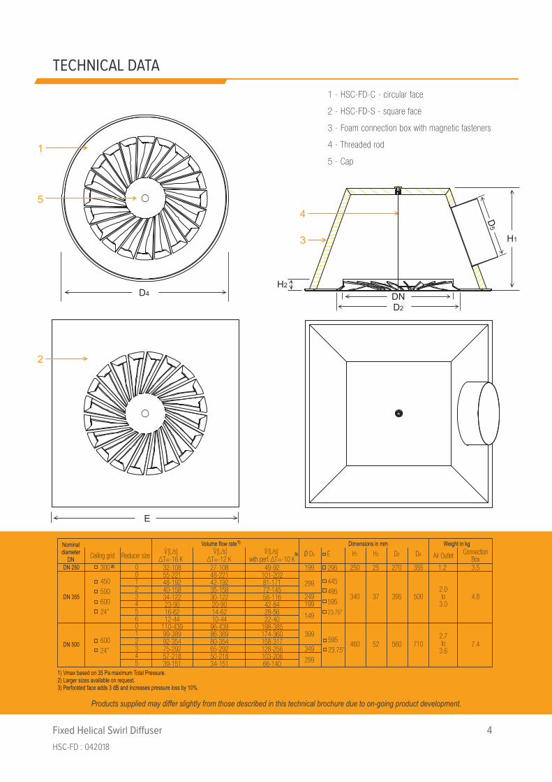
Nominaldiameter
DN Ceiling grid Reducer size ∆T=-12 K with perf. ∆T=-10 K[L/s]V
Volume flow rateØ D5 H1 H2 D4 Air Outlet
Dimensions in mm Weight in kgConnection
BoxDN 250
DN 355
DN 500
300 199
249 340
349460
5002.0to
3.0
2.7to
3.6710
37
52
4.8
7.4
250 25 355 1.2 3.5
45050060024”
60024”
00123456012345
1 - HSC-FD-C - circular face
2 - HSC-FD-S - square face
3 - Foam connection box with magnetic fasteners
4 - Threaded rod
5 - Cap1
2
4
3
5
E
295
44549559523.75”
59523.75”
H2
TECHNICAL DATA
Fixed Helical Swirl Di�user 4
HSC-FD : 042018
D2
395
560
270
D2
1) Vmax based on 35 Pa maximum Total Pressure.2) Larger sizes available on request.3) Perforated face adds 3 dB and increases pressure loss by 10%.
∆T=-16 K[L/s]V [L/s]V
299
199
149
399
299
32-10855-22148-19240-15834-12223-9016-6212-44
110-43999-38992-35475-29257-21839-151
27-10848-22142-19235-15830-12220-9014-6210-4496-43986-38980-35465-29250-21834-151
49-92101-20281-17172-14558-11642-8428-5622-40
198-385174-360158-317128-256103-20666-140
1)
2)
3)
Products supplied may differ slightly from those described in this technical brochure due to on-going product development.

Fixed Helical Swirl Di�user 5
HSC-FD : 042018
NO
TES
TO N
OM
OG
RA
MS
ON
PA
GES
5 &
7
Ther
mal
Com
fort
Gui
de:
AD
PI ≥
95%
: Pr
emiu
m c
omfo
rt s
eden
tary
act
ivity
, suc
h as
in a
udito
ria.
AD
PI ≥
90%
: H
igh
com
fort
nea
r-se
dent
ary
activ
ity, s
uch
as in
boa
rd ro
oms,
hig
h en
d of
fices
and
libr
arie
s.A
DP
I ≥ 8
0%:
Goo
d co
mfo
rt n
ear-
sede
ntar
y ac
tivity
, suc
h as
in o
pen-
plan
offi
ces
and
mee
ting
room
s.A
DP
I ≥ 7
0%:
Stan
dard
com
fort
med
ium
act
ivity
, suc
h as
in tr
ansi
ent s
pace
s, re
tail
and
lobb
ies.
Com
men
ts /
Nom
ogra
m v
alid
for:
Adju
stm
ents
:
360°
dis
char
ge p
atte
rn (4
-way
blo
w).
For 2
70°
disc
harg
e (3
-way
blo
w):
M
ultip
ly a
ctua
l airf
low
rate
by
1.33
to
de
term
ine
perfo
rman
ce fr
om n
omog
ram
.
Fo
r 180
° or
2 x
90°
dis
char
ge (2
-way
blo
w):
M
ultip
ly a
ctua
l airf
low
rate
by
2 to
dete
rmin
e pe
rform
ance
from
nom
ogra
m.
∆T
+ve
den
otes
hea
ting.
Hea
ting
valid
for 1
00%
hig
h-le
vel r
etur
n.
For l
ow-le
vel r
etur
n:
∆Tm
ax.h
eatin
g ≈ (1
+ (L
RA%
)/100
) • ∆
T max
, whe
re L
RA%
= %
low
leve
l ret
urn.
Valid
for d
isch
arge
from
clo
sed
ceilin
g.
For f
reel
y-su
spen
ded
diffu
ser:
Hea
ting
∆Tm
ax.fr
eely
sus
pend
ed ≈
∆T m
ax.h
eatin
g / 1
.2
Tota
l pre
ssur
e (P
t) is
incl
usiv
e of
sid
e-en
try c
onne
ctio
n bo
x pr
essu
re lo
ss.
For h
eigh
t ≤ 2
.7 m
sel
ect 2
.7; o
ther
wis
e se
lect
hei
ght t
wic
e (o
nce
in th
e gr
ey z
one;
onc
e in
the
whi
te z
one)
.
∆T
-ve
deno
tes
cool
ing.
Min
imum
spa
cing
bet
wee
n tw
o di
ffuse
rs (C
min) i
s to
be
halv
ed fo
r spa
cing
to w
alls
or g
lazi
ng.
∆T -v
e de
note
s co
olin
g. M
axim
um s
paci
ng b
etw
een
two
diffu
sers
(Cm
ax) i
s to
be
halv
ed fo
r spa
cing
to w
alls
or g
lazi
ng.
Det
erm
ine
Cm
ax tw
ice
(onc
e ba
sed
on c
oolin
g ∆T
; onc
e ba
sed
on d
isch
arge
hei
ght),
then
sel
ect t
he lo
wer
of t
he tw
o ou
tput
s.
Se
lect
des
ired
com
fort
leve
l to
dete
rmin
e m
inim
um a
nd m
axim
um s
paci
ng (C
min &
Cm
ax) a
nd m
inim
um d
isch
arge
hei
ght (
Hm
in).
Hm
in fo
r dis
char
ge fr
om c
lose
d ce
iling
. Fo
r fre
ely-
susp
ende
d di
ffuse
r:
Hm
in.fr
eely
sus
pend
ed ≈
Hm
in •
1.1
Soun
d pr
essu
re le
vel L
P [N
C] i
s va
lid p
er d
iffus
er in
a s
tand
ard
com
mer
cial
offi
ce o
nly
with
a 2
.7 m
to 3
m c
eilin
g. L
P sh
ould
not
be
used
for s
pace
s ot
her t
han
offic
es, b
ut s
houl
d, in
stea
d be
cal
cula
ted
by a
n ac
oust
ical
eng
inee
r.
1 2 9 5 7 6 8 3

3 m
4 m
5 m
2.7
m
DN25
0
22
H min
[m]
37
16
4.5
6
240 30
40
50
60
70
80
90
10
0
120
140
160
180
200
220
L W
L P*
L/s
3 23
20
10
-16
K
-12
K
-8 K
H =
2.5
3.5
m
3.0
2.7
4 10
20
30 28
33
20
10
C max
2.3
2.5
2.4
2.2
2
2.7
10
20
800
600
500
400
300
200
100
700 40
m3 /h
24
30
40
50
9 15
25
35
Soun
d Po
wer
, LW
[dB(
A)]
Soun
d Pr
essu
re, L
P [N
C]*
2.3
2.1
2.0
2.6
2.4
2.3
2.4
2.5
2.2
2.3
2.1
2.2
HSC-
FD-D
N25
0 &
DN
355-
R0 to
R6
20
10
2.42
17
DN25
0 0 2 3 4 5 6 1
Redu
cer
6 1 2 3 5 0
+20
K
+16
K
+12
K
+8 K
+4 K
0 K
[dB(
A)]
[NC]
[m]
[Pa]
0.6
1 1
3 0.
8
3
3.2 -8
K
-12
K
2 1
4.2 -1
6 K
4
2 3
3
C min
2
Tota
l Pre
ssur
e, P
t [Pa
]
2 4
5 1
DN25
0
2
1 0
3 4 5 6
[m]
5.2
0.7
3
3.5 3.
1
10
60
30
40 5
0
5 m
≤2.7
m
H
= 2
m
4
20
P t
∆T
[K] = 4
Cool
ing
H =
5 m
DN25
0 DN
355
1 2 5
6 7 9
3
Cool
ing ∆T
=
Cool
ing
∆T [K
] =
ADPI
≥ 9
0%; ṽ
≤ 0
.25
m/s
; DR ≈
20%
@ T
=26°
C:
ADPI
≥ 8
0%; ṽ
≤ 0
.29
m/s
:
ADPI
≥ 7
0%; ṽ
≤ 0
.33
m/s
; DR ≈
30%
@ T
=26°
C:
ADPI
≥ 9
5%; ṽ
≤ 0
.20
m/s
:
: Heati
ng
∆Tm
ax [K
] L/
s/m
2 ≤2
5 ≥1
0
+11
Not
es:
* Ba
sed
on 1
0 dB
room
abs
orpti
on.
8
170
+18
K
+14
K
+10
K
+6 K
+2 K
4
Fixed Helical Swirl Di�user 6
HSC-FD : 042018
REF
ER T
O N
OTE
S O
N P
AG
E 4

Fixed Helical Swirl Di�user 7
HSC-FD : 042018
EXAM
PLE:
HSC
-FD
-DN
355-
3w in
an
offic
e D
eter
min
e th
e pe
rform
ance
par
amet
ers
of a
n H
SC-F
D-D
N35
5 w
ith n
o re
duce
r ope
ratin
g at
128
L/s
and
inco
rpor
atin
g a
blan
king
seg
men
t to
prod
uce
a 27
0° d
isch
arge
pat
tern
(3-w
ay b
low
) fro
m a
2.7
m h
igh
clos
ed c
eilin
g, s
uppl
ying
5 L
/s/m
2 to
a pr
emiu
m o
ffice
with
100
% h
igh-
leve
l re
turn
air.
The
sup
ply-
to-r
oom
tem
pera
ture
diff
eren
tial w
hen
cool
ing
is -1
2 K.
Due
to th
e 27
0° d
isch
arge
pat
tern
, mul
tiply
the
actu
al a
irflo
w ra
te o
f 120
L/s
by
1.33
, pro
vidi
ng 1
70 L
/s fo
r inp
ut in
to th
e no
mog
ram
.
Se
lect
no
colla
r (R
educ
er 0
).
Sele
ct 2
.7 m
dis
char
ge h
eigh
t and
5 L
/s/m
2 spe
cific
airf
low
, res
ultin
g in
a m
axim
um h
eatin
g te
mpe
ratu
re d
iffer
entia
l (∆T
max
) of +
11 K
.
The
tota
l pre
ssur
e (P
t) is
20
Pa, i
nclu
sive
of s
ide-
entry
con
nect
ion
box
pres
sure
loss
.
Sele
ct 2
.7 m
dis
char
ge h
eigh
t, w
hich
is c
omm
on to
bot
h th
e gr
ey z
one
and
the
whi
te z
one.
Sele
ct -1
2 K
cool
ing.
Sele
ct -1
2 K
cool
ing
and
2.7
m d
isch
arge
hei
ght.
Fo
r a p
rem
ium
offi
ce, s
elec
t AD
PI =
90%
. Th
e m
inim
um re
com
men
ded
cent
re-li
ne d
ista
nce
(Cm
in) b
etw
een
two
adja
cent
diff
user
s is
3.
2 m
; and
hen
ce 1
.6 m
to w
alls
that
the
diffu
ser d
isch
arge
s to
war
ds.
The
min
imum
reco
mm
ende
d di
scha
rge
heig
ht (H
min) i
s 2.
42 m
. Th
e m
axim
um re
com
men
ded
cent
re-li
ne d
ista
nce
(Cm
ax) i
s 16
m (i
e th
e lo
wer
of 1
6 m
for 2
.7 m
dis
char
ge h
eigh
t and
17
m fo
r -12
K c
oolin
g);
and
henc
e 8
m to
wal
ls th
at th
e di
ffuse
r dis
char
ges
tow
ards
.
Th
e A-
wei
ghte
d so
und
pow
er le
vel (
L W) o
f the
diff
user
is 3
7 dB
(A),
prod
ucin
g a
soun
d pr
essu
re le
vel (
L P) o
f NC
22
in th
e sp
ace
(bas
ed o
n 10
dB
room
abs
orpt
ion)
.
1 2 3 5 6 7 8 9

Fixed Helical Swirl Di�user 8
HSC-FD : 042018
REF
ER T
O N
OTE
S O
N P
AG
E 4
3 m
4 m
5 m
H min
[m]
5 m
10
30
10
5 6
5.0
m
3.0
H =
2.5 38
7
L W
L P*
20
10
-16
K
-12
K
-8 K
20 30
45 55
20
C max
2.4
2.6
2.5
2.3
10
24
30
40
50
9 15
25
35
Soun
d Po
wer
, LW
[dB(
A)]
Soun
d Pr
essu
re, L
P [N
C]*
2.4
2.2
2.1
2.7
2.5
2.4
2.5
2.6
2.3
2.4
2.2
2.3
0 2 3 4 5 1
Redu
cer 1 2 3 4 5 0
+20
K
+16
K
+12
K
+8 K
+4 K
[dB(
A)]
[NC]
480 60
80
10
0 12
0 14
0 16
0 18
0 20
0
240
280
320
360
400
440
L/s
1600
1200
1000
800
600
400
200
1400
80
m3 /h
HSC-
FD-D
N50
0
40
20
4 20
33
30 30
[m
] 4.0
40
40 5
0 4.
5
5.2
4
[Pa]
0.7
1 1
3
6 -8 K
-1
2 K
2 1
6.2 -1
6 K
6
2
3
C min
2
Tota
l Pre
ssur
e, P
t [Pa
]
2 8 2
1 0
3 4 5
[m]
1.3
0.8 10
60
30
40
50
18
20
4 5
4
3 5
4
≤2.7
m
40
H =
2 m
Co
olin
g ∆T
=
Cool
ing
∆T [K
] =
P t
∆T
[K] = 4
Cool
ing
H =
5 m
1 2 5
6 7 9
3
12
7.0
25
ADPI
≥ 9
0%; ṽ
≤ 0
.25
m/s
; DR ≈
20%
@ T
=26°
C:
ADPI
≥ 8
0%; ṽ
≤ 0
.29
m/s
:
ADPI
≥ 7
0%; ṽ
≤ 0
.33
m/s
; DR ≈
30%
@ T
=26°
C:
ADPI
≥ 9
5%; ṽ
≤ 0
.20
m/s
:
: Heati
ng
∆Tm
ax [K
] L/
s/m
2 ≤2
5 ≥1
0
8
2.7
m
Not
es:
* Ba
sed
on 1
0 dB
room
abs
orpti
on.
+18
K
+14
K
+10
K
+6 K
+2 K
0
K
4

Fixed Helical Swirl Di�user 9
HSC-FD : 042018
EXAM
PLE:
HSC
-FD
-DN
500
in a
n au
dito
rium
D
eter
min
e th
e pe
rform
ance
par
amet
ers
of H
SC-F
D-D
N50
0 di
ffuse
rs w
ith n
o re
duce
r, ea
ch fr
eely
sus
pend
ed a
t 5 m
hei
ght a
nd d
isch
argi
ng
320
L/s,
sup
plyi
ng 5
L/s
/m2 to
an
audi
toriu
m w
ith 1
00%
hig
h le
vel r
etur
n ai
r. T
he s
uppl
y-to
-room
tem
pera
ture
diff
eren
tial w
hen
cool
ing
is -1
6 K.
Sele
ct 3
60 L
/s fo
r inp
ut in
to th
e no
mog
ram
.
Se
lect
no
colla
r (R
educ
er 0
).
Sele
ct 5
m d
isch
arge
hei
ght a
nd 5
L/s
/m2 s
peci
fic a
irflo
w, r
esul
ting
in a
max
imum
hea
ting
tem
pera
ture
diff
eren
tial (
∆Tm
ax) o
f +2
K. A
s th
e di
ffuse
r is
freel
y su
spen
ded,
∆T m
ax.fr
eely
sus
pend
ed ≈
∆T m
ax.h
eatin
g
air w
ill on
ly in
crea
se ∆
T max
.free
ly s
uspe
nded
to +
3.3
K, w
hich
is n
ot s
uffic
ient
for h
eatin
g. C
onsi
der u
sing
the
Smar
tem
p H
SC-A
D in
stea
d if
heat
ing
is re
quire
d.)
Th
e to
tal p
ress
ure
(Pt)
is 1
8 Pa
, inc
lusi
ve o
f sid
e-en
try c
onne
ctio
n bo
x pr
essu
re lo
ss.
Se
lect
5 m
dis
char
ge h
eigh
t tw
ice
(onc
e in
the
grey
zon
e; o
nce
in th
e w
hite
zon
e).
Se
lect
-16
K co
olin
g.
Se
lect
-16
K co
olin
g an
d 5
m d
isch
arge
hei
ght.
Fo
r an
audi
toriu
m, s
elec
t AD
PI =
95%
. Th
e m
inim
um re
com
men
ded
cent
re-li
ne d
ista
nce
(Cm
in) b
etw
een
two
adja
cent
diff
user
s is
7.0
m;
and
henc
e 3.
5 m
to w
alls
. Th
e m
inim
um re
com
men
ded
disc
harg
e he
ight
(Hm
in) i
s 2.
6 m
. Th
e m
axim
um re
com
men
ded
cent
re-li
ne
dist
ance
(Cm
ax) i
s 12
m (i
e th
e lo
wer
of 1
2 m
for -
16 K
coo
ling
and
25 m
for 5
m d
isch
arge
hei
ght);
and
hen
ce 6
m to
wal
ls.
The
A-w
eigh
ted
soun
d po
wer
leve
l (L W
) per
diff
user
is 3
8 dB
(A).
As
this
is a
larg
e vo
lum
e au
dito
rium
(and
not
an
offic
e, w
hich
typi
cally
ha
s ap
prox
imat
ely
10 d
B ro
om a
bsor
ptio
n) th
e so
und
pres
sure
leve
l (L P
) bas
ed o
n 10
dB
room
abs
orpt
ion
shou
ld n
ot b
e us
ed (i
e on
ly L
W
shou
ld b
e pr
ovid
ed fo
r aco
ustic
al c
alcu
latio
ns).
1 2 3 5 6 7 8 9
/ 1.2
≈ +1
.7 K
, bas
ed o
n 10
0% h
igh
leve
l ret
urn
air.
(Eve
n 10
0% lo
w le
vel r
etur
n

• ∆Tsupply-room ≥ -16 K (cooling); ≤ +12 K (heating), depending on application.
• Well suited to low temperature VAV systems with minimum ∆Tsupply-room = -16 K including turndown to 25%.
• Discharge height: 2.4 m to 4.5 m.
• Diffuse airflow from fixed stable horizontal swirl discharge pattern for high thermal comfort.
• 20 off-set radial vanes flush with flat diffuser face.
• Diffuser face may be square or round.
• Optional perforated screen.
• For installation substantially flush with suspended false ceiling or freely suspended.
• Vanes with cambered leading edges to reduce both noise and pressure drop.
• Helical twist vane tips for increased airflow rate range of operation.
• Available in 3 neck sizes: DN250; DN355; DN500.
• Low sound power level and pressure loss.
• Suitable for high airflow rates.
• Optional reducers for low airflow rates (DN355 and DN500 only).
• Segments covers (1/4; 2/4 opposed; 1/2) for diffuser placement near walls, in corridors or in corners.
• Diffuser made of powder coated sheet metal.
• Central optional threaded rod fastener with flush cap.
• Optional foam connection boxes, including magnetic perimeter edges and central connection nuts,
stackable for storage and transport.
Fixed Helical Swirl Di�user 10
HSC-FD : 042018
FEATURES

Note:* Standard, if no type code entered.1 Other face sizes available on request.Products supplied may differ slightly from those described inthis technical brochure due to on-going product development.
HSC-FD-DN___-___-R__-__-P__-__-__CONNECTION TYPE:- 0* = No connection box.- KF = Thermally insulated foam connection box with magnetic fastener & blanking cap.- KFR = As for KF plus threaded rod fastener and cap.
REDUCER:- 0* = No reducer- 1 – 6 = Reducers 1 to 6 for size DN355.- 1 – 5 = Reducers 1 to 5 for size DN500.
FACE FINISH:- 0* = No perforated face.- 1 = Perforated face.
SURFACE FINISH:- 9003* = Face powder coated to RAL 9003 (Signal White).- 9005* = Face powder coated to RAL 9005 (Jet Black).- _____= Face powder coated to RAL ___ .
DISCHARGE PATTERN:- 4w* = No blanking segments.- 3w = 1/4 blanking segment – for diffuser adjacent to wall.- 2s = 2/4 blanking segments – for diffuser in corridor.- 2a = 1/2 blanking segment – for diffuser in corner.
FACE SHAPE:- S*= Square face with 90° turn-up for coffered ceilings: - 295 mm1 for size DN250; - 595 mm* (445 mm to 603 mm [23.75”] available) for size DN355; - 595 mm* to 603 mm [23.75”] for size DN500.- C = Circular face with flush contact edge (4 mm / 30°) for closed false ceilings: - Ø 355 mm* for size DN250; - Ø 500 mm* for size DN355; - Ø 710 mm* for size DN500.
MODEL:- Helical Swirl Ceiling - Fixed Direction
NOMINAL DIAMETER:- DN250 = Nominal neck diameter 250 mm.- DN355 = Nominal neck diameter 355 mm.- DN500 = Nominal neck diameter 500 mm.
Fixed Helical Swirl Di�user 11
HSC-FD : 042018
ORDER DETAILS
Furnish and install SMARTEMP® Fixed Helical Swirl Diffusers, type HSC-FD, to provide diffuse airflow with fixed stable
horizontal swirl discharge pattern for the provision of high thermal comfort. Each diffuser is to be made of powder coated
steel and shall include 20 off-set radial vanes flush with the flat diffuser face. The diffuser shall be installed complete with
a flush colour matching central cap and shall be suitable for central threaded rod connection. The diffuser face is to be
square or round, as specified, and is to be fitted with the optional perforated screen where indicated. The diffuser is to be
installed substantially flush with the suspended false ceiling or freely suspended, as specified. Swirl vanes are to include
cambered leading edges for reduced noise and pressure drop, and helical swirl vane tips are each to have geometric
twist to increase the airflow rate range of operation. Diffuser neck size is to be DN250, DN355 or DN500, as
appropriate. Fit optional reducers where low airflow rates are required (DN355 and DN500 only). Install the diffusers at a
discharge height of 2.4 to 4.5 m. For VAV applications, operate each diffuser within an airflow rate band turning down to
no less than 25% at a ∆Tsupply-room ≥ -16 K. For heating applications, observe ∆Tsupply-room recommendations.
Install segments covers (1/4; 2/4 opposed; 1/2) for diffuser placement near walls, in corridors or in corners. Connect
each diffuser to SMARTEMP foam connections boxes, suitable for perimeter magnetic and/or central threaded rod
connections, as specified.
Fixed Helical Swirl Di�user 12
HSC-FD : 042018
TENDER TEXT

®