procom a/s new products - nkt-rf.ru · pdf filepcpi 70/900/1800/pcs/umts/r/h 100000394 450 -...
TRANSCRIPT

PROCOM A/S
New ProductsJanuary – March 2011
PROCOM A/S · Tel. + 45 48 27 84 84 · [email protected] · www.procom.dk

New Products January - March 2011
Base StationPCPI 800/xH
PCPI 70/900/1800/PCS/UMTS/R/...
PLPI 900/1800
GPS/Iridium-FME
CXL 4/70C/...
CXL 900/1800/1900/UMTS
Marine AntennasMA 70/GPS 4/...
Portable AntennasFSP 2/...-SMA/TAIT
FiltersBPF 3/...-200-SHT
PRO-DIPX 175/380-MAMO/WAMO
CombinersPRO-PHY450-5
MulticouplersPRO-RPS-8-N
PROCOM A/S · Tel. + 45 48 27 84 84 · [email protected] · www.procom.dk
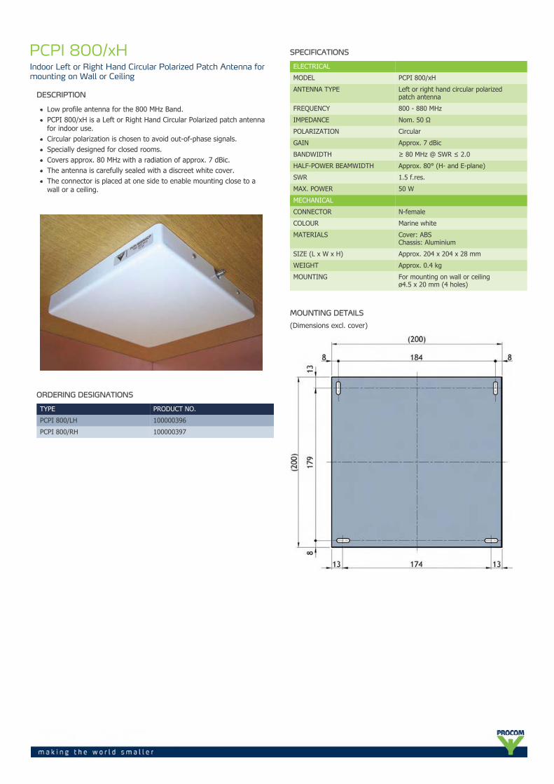
PCPI 800/xHIndoor Left or Right Hand Circular Polarized Patch Antenna formounting on Wall or Ceiling
DESCRIPTION
Low profile antenna for the 800 MHz Band.PCPI 800/xH is a Left or Right Hand Circular Polarized patch antennafor indoor use.Circular polarization is chosen to avoid out-of-phase signals.Specially designed for closed rooms.Covers approx. 80 MHz with a radiation of approx. 7 dBic.The antenna is carefully sealed with a discreet white cover.The connector is placed at one side to enable mounting close to awall or a ceiling.
ORDERING DESIGNATIONS
TYPE PRODUCT NO.
PCPI 800/LH 100000396
PCPI 800/RH 100000397
SPECIFICATIONS
ELECTRICAL
MODEL PCPI 800/xH
ANTENNA TYPE Left or right hand circular polarizedpatch antenna
FREQUENCY 800 - 880 MHz
IMPEDANCE Nom. 50 Ω
POLARIZATION Circular
GAIN Approx. 7 dBic
BANDWIDTH ≥ 80 MHz @ SWR ≤ 2.0
HALF-POWER BEAMWIDTH Approx. 80° (H- and E-plane)
SWR 1.5 f.res.
MAX. POWER 50 W
MECHANICAL
CONNECTOR N-female
COLOUR Marine white
MATERIALS Cover: ABSChassis: Aluminium
SIZE (L x W x H) Approx. 204 x 204 x 28 mm
WEIGHT Approx. 0.4 kg
MOUNTING For mounting on wall or ceilingø4.5 x 20 mm (4 holes)
MOUNTING DETAILS
(Dimensions excl. cover)
TYPICAL GAIN AND SWR CURVES
SWR¯ ¯ ¯ ¯
Gain dBic¯¯¯¯¯¯¯¯¯
f. MHz
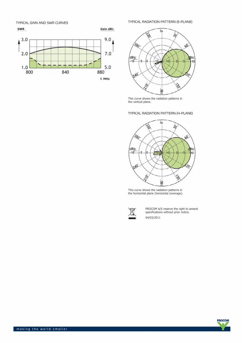
TYPICAL RADIATION PATTERN (E-PLANE)
This curve shows the radiation patterns inthe vertical plane.
TYPICAL RADIATION PATTERN (H-PLANE)
This curve shows the radiation patterns inthe horizontal plane (horizontal coverage).
PROCOM A/S reserve the right to amendspecifications without prior notice.
04/03/2011

PCPI70/900/1800/PCS/UMTS/R/...Indoor Right Hand Circular Polarized Antenna for the 450 MHz,GSM, DCS, PCS and UMTS Bands
DESCRIPTION
5-band indoor base station antenna - one antenna with five bands.Right hand circular polarized, 7 dBic antenna specially designed forclosed rooms. For use e.g. on ceilings and walls inside ships andbuildings.Circular polarization is chosen to improve link quality.Built-in diplexers with low insertion loss make it possible to have onlyone connector.
ORDERING DESIGNATIONS
TYPE PRODUCT NO. FREQUENCY
PCPI 70/900/1800/PCS/UMTS/R/s 100000391 380 - 400 MHz
PCPI 70/900/1800/PCS/UMTS/R/f 100000392 410 - 430 MHz
PCPI 70/900/1800/PCS/UMTS/R/l 100000393 430 - 450 MHz
PCPI 70/900/1800/PCS/UMTS/R/h 100000394 450 - 470 MHz
SPECIFICATIONS
ELECTRICAL
MODEL PCPI 70/900/1800/PCS/UMTS/R/...
ANTENNA TYPE Right hand circular polarized 5-band antenna
FREQUENCY 450 MHz: 380 - 470 MHzGSM: 880 - 960 MHzDCS: 1710 - 1880 MHzPCS: 1850 - 1990 MHzUMTS: 1910 - 2200 MHz
IMPEDANCE Nom. 50 Ω
POLARIZATION Circular (right hand)
GAIN Approx. 7 dBic
BANDWIDTH 450 MHz: ≥ 20 MHz @ SWR ≤ 2.0GSM: ≥ 80 MHz @ SWR ≤ 2.0DCS: ≥ 170 MHz @ SWR ≤ 3.0PCS: ≥ 140 MHz @ SWR ≤ 3.0UMTS: ≥ 290 MHz @ SWR ≤ 3.0
HALF POWER BEAMWIDTH Approx. 60º (H- and E-plane)
SWR ≤ 1.5 f.res.
MAX. POWER 25 W
MECHANICAL
CONNECTOR N-female
COLOUR Marine white
MATERIALS Cover: PS (white)Chassis: Aluminium
SIZE (L x W x H) Approx. 415 x 415 x 70 mm
WEIGHT Approx. 2 kg
MOUNTING ø 4.5 mm (4 holes)
SPECIFICATIONS DIPLEXER
ELECTRICAL FOR BUILT-IN DIPLEXER DIPX 500/800
FREQUENCY Low port : 0 - 500 MHzHigh port : 800 - 1300 MHz
MAX. INPUT POWER 35 W each port
INSERTION LOSS 0 - 500 MHz : ≤ 0.5 dB800 - 1300 MHz : ≤ 0.5 dB
ISOLATION Low to high port : ≥45 dB
ELECTRICAL FOR BUILT-IN DIPLEXER DIPX 1000/1550
FREQUENCY Low port : 0 - 1000 MHzHigh port : 1550 - 2500 MHz
MAX. INPUT POWER 35 W each port
INSERTION LOSS 0 - 1000 MHz : ≤ 0.5 dB1550 - 2500 MHz : ≤ 0.5 dB
ISOLATION Low to high port : ≥ 45 dB

TYPICAL GAIN AND SWR CURVES
SWR¯ ¯ ¯ ¯
Gain dBic¯¯¯¯¯¯¯¯¯
f. MHz
TYPICAL GAIN AND SWR CURVES
SWR¯ ¯ ¯ ¯
Gain dBic¯¯¯¯¯¯¯¯¯
f. MHz
BUILT-IN DIPLEXER
BUILT-IN DIPLEXER
MOUNTING DETAILS
TYPICAL RADIATION PATTERN (E-PLANE)
This curve shows the radiation patterns in thevertical plane.
TYPICAL RADIATION PATTERN (H-PLANE)
This curve shows the radiation patterns in thehorizontal plane (horizontal coverage).
PROCOM A/S reserve the right to amendspecifications without prior notice.
04/03/2011

PLPI 900/1800Indoor dual Patch Antenna for mounting on Wall or Ceiling
DESCRIPTION
Low profile antenna for the 900 and 1800 MHz Band.PLPI 900/1800 is a patch antenna for indoor use.Covers 80 MHz at 900 MHz and 170 MHz at 1800 MHz with aradiation of approx. 8 dBi.The antenna is carefully sealed with a discreet white cover.The two connectors are placed at one side to enable mounting closeto a wall or a ceiling.
ORDERING DESIGNATIONS
TYPE NO. PRODUCT NO.
PLPI 900/1800 100000322
SPECIFICATIONS
ELECTRICAL
MODEL PLPI 900/1800
ANTENNA TYPE Linear Polarized patch antenna
FREQUENCY 880 - 960 MHz / 1710 - 1880 MHz
IMPEDANCE Nom. 50 Ω
POLARIZATION Linear
GAIN 8 dBi
BANDWIDTH 880 - 960 ≥ 80 MHz @ SWR ≤ 21710 - 1880 ≥ 170 MHz @ SWR ≤ 2
HALF-POWER BEAMWIDTH 65° - 85° in azimuth plane60° - 80° in elevation plane
SWR ≤ 2
MAX. POWER 100 W
MECHANICAL
CONNECTOR 2 x N-female
COLOUR Marine white
MATERIALS Cover: PSChassis: Aluminium
SIZE (W x L x H) Approx. 200 x 250 x 30 mm
WEIGHT Approx. 0.4 kg
MOUNTING For mounting on wall or ceilingø4.5 x 20 mm (4 holes)
MOUNTING DETAILS
(Dimensions excl. cover)

TYPICAL GAIN AND SWR CURVE 880 - 960 MHz
SWR¯ ¯ ¯ ¯
Gain dBi¯¯¯¯¯¯¯¯
f. MHz
TYPICAL GAIN AND SWR CURVE 1710 - 1880 MHz
SWR¯ ¯ ¯ ¯
Gain dBi¯¯¯¯¯¯¯¯¯
f. MHz
TYPICAL RADIATION PATTERN (E-PLANE)
This curve shows the radiation patterns inthe vertical plane.
TYPICAL RADIATION PATTERN (H-PLANE)
This curve shows the radiation patterns in thehorizontal plane (horizontal coverage).
PROCOM A/S reserve the right to amendspecifications without prior notice.
14/01/2011
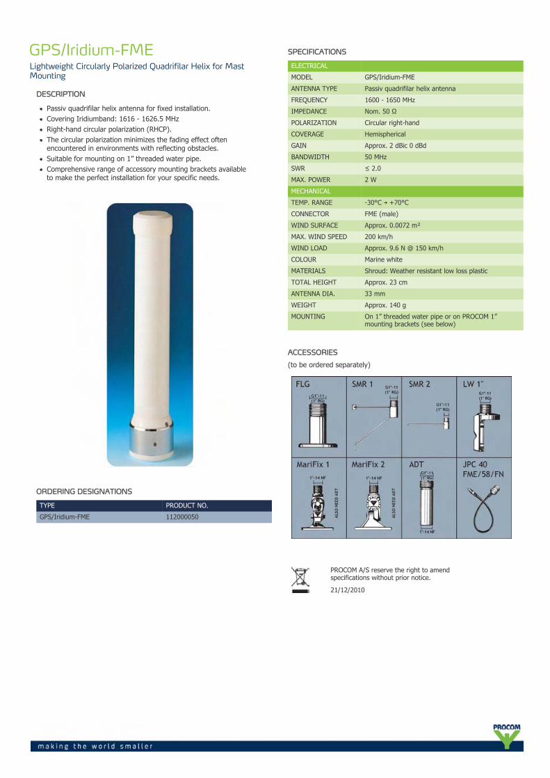
GPS/Iridium-FMELightweight Circularly Polarized Quadrifilar Helix for MastMounting
DESCRIPTION
Passiv quadrifilar helix antenna for fixed installation.Covering Iridiumband: 1616 - 1626.5 MHzRight-hand circular polarization (RHCP).The circular polarization minimizes the fading effect oftenencountered in environments with reflecting obstacles.Suitable for mounting on 1” threaded water pipe.Comprehensive range of accessory mounting brackets availableto make the perfect installation for your specific needs.
ORDERING DESIGNATIONS
TYPE PRODUCT NO.
GPS/Iridium-FME 112000050
SPECIFICATIONS
ELECTRICAL
MODEL GPS/Iridium-FME
ANTENNA TYPE Passiv quadrifilar helix antenna
FREQUENCY 1600 - 1650 MHz
IMPEDANCE Nom. 50 Ω
POLARIZATION Circular right-hand
COVERAGE Hemispherical
GAIN Approx. 2 dBic 0 dBd
BANDWIDTH 50 MHz
SWR ≤ 2.0
MAX. POWER 2 W
MECHANICAL
TEMP. RANGE -30°C → +70°C
CONNECTOR FME (male)
WIND SURFACE Approx. 0.0072 m²
MAX. WIND SPEED 200 km/h
WIND LOAD Approx. 9.6 N @ 150 km/h
COLOUR Marine white
MATERIALS Shroud: Weather resistant low loss plastic
TOTAL HEIGHT Approx. 23 cm
ANTENNA DIA. 33 mm
WEIGHT Approx. 140 g
MOUNTING On 1” threaded water pipe or on PROCOM 1”mounting brackets (see below)
ACCESSORIES
(to be ordered separately)
PROCOM A/S reserve the right to amendspecifications without prior notice.
21/12/2010

CXL 4/70C/...Dual-frequency, Base Station Antenna for the 80 MHz andTETRA Band
DESCRIPTION
CXL 4/70C/... is a dual-frequency base station antenna - two bandswith only one antenna.This antenna makes it possible to:
operate 4 m and TETRA transceivers alternately on the sameantenna.operate two transceivers (4 m and TETRA) at the same time onone antenna using a diplexer (type DIPX 225/330 - must beordered separately).
CXL 4/70C/... is designed for fixation on supporting tubes with outerdiameter between 27 mm and 65 mm.The construction of the mount makes it possible to lead the cableeither inside or along the outside of the mast tube.Atmospherical discharges are immediately led to ground as all metalparts are DC-grounded (consequently, the antenna shows a DC-shortacross the coaxial cable).
ORDERING DESIGNATIONS
TYPE PRODUCT NO. FREQUENCY
CXL 4/70C/74-87/380-400 MHz 100000376 4 m band: 74 - 87 MHzTETRA: 380 - 400 MHz
If other frequencies within the 4 m band are required, please contact usfor a quotation.
SPECIFICATIONS
ELECTRICAL
MODEL CXL 4/70C/...
ANTENNA TYPE Coaxial, dual-frequency basestation antenna
FREQUENCY 4 m : 74 - 87 MHzTETRA : 380 - 400 MHz
IMPEDANCE Nom. 50 Ω
RADIATION Omnidirectional
POLARIZATION Vertical
GAIN 4 m : 74 - 77 MHz approx. 2 dBi 0 dBd4 m : 84 - 87 MHz average -6 dBi 4 dBdTETRA : Approx. 2 dBi 0 dBd
SWR BANDWIDTH 4 m : 74 - 77 MHz ≤ SWR 2.04 m : 84 - 87 MHz ≤ SWR 6.0TETRA : 380 - 400 MHz ≤ SWR 2.0
SWR ≤ 1.5 @ f. res. in both bands
MAX. POWER 100 W (for each band)
ANTISTATIC PROTECTION All metal parts DC-grounded(Connector shows a DC-short)
MECHANICAL
CONNECTOR N-female
WIND SURFACE 0.14 m²
WIND LOAD 177 N @ 160 km/h
COLOUR Marine white
MATERIALS Radome : Polyurethane coatedglass fibreMounting bracket: Seawater resistantaluminium, epoxy-coated
TOTAL HEIGHT Approx. 2.7 m
WEIGHT Approx. 3.8 kg
MOUNTING On 27-65 mm dia. mast tube

TYPICAL GAIN AND SWR CURVES
CXL 4/70C/...
SWR Gain dBd ____
SWR Gain dBd ____
SWR Gain dBd ____
MULTI-PURPOSE MOUNTING BRACKET
TYPICAL RADIATION PATTERN (E-PLANE)
TYPICAL RADIATION PATTERN (H-PLANE)
PROCOM A/S reserve the right to amendspecifications without prior notice.
10/12/2010

CXL 900/1800/1900/UMTSQuadruple-Band Base Station and Marine Antenna for the 900MHz, 1800 MHz, 1900 MHz and 2000 MHz Bands
DESCRIPTION
Quadruple-band base station and marine antenna – four bands withonly one antenna.
Covering both GSM/NMT-900, DCS-1800/PCN (GSM 900/1800), PCS-1900 and UMTS.
Particularly suitable for use with triple-band mobile phones.
Unity gain on all bands.
Simple mounting using the 1” revolving nut system.
Wide variety of accessory mounting brackets available.
ORDERING DESIGNATIONS
TYPE PRODUCT NO.
CXL 900/1800/1900/UMTS 110000230
SPECIFICATIONS
ELECTRICAL
MODEL CXL 900/1800/1900/UMTS
ANTENNA TYPE Quadruple-band base station and marine antenna
FREQUENCY 800-960 MHz/1710-1880 MHz/1850-1990 MHz/1900-2200 MHz(GSM 900/DCS-1800/PCS-1900/UMTS)
IMPEDANCE Nom. 50 Ω
POLARIZATION Vertical
GAIN Approx. 0 dBd (all bands)
SWR GSM @ ≤ 2.0DCS-1800 @ ≤ 2.0PCS-1900 @ ≤ 3.0UMTS @ ≤ 3.0
MAX. POWER 100 W
MECHANICAL
TEMP. RANGE -30°C → +70°C
CONNECTOR N-female
WIND SURFACE Approx. 0.013 m²
WIND LOAD Approx. 17 N @ 160 km/h
COLOUR Marine white
MATERIALS MATERIALS Shroud: Polyurethane-coatedglass fibreMounting bracket: Chromed brass
TOTAL HEIGHT Approx. 450 mm
DIA. IN TOP END 21 mm
DIA. IN BOTTOM END 23 mm
WEIGHT Approx. 300 g
MOUNTING On 1” RG (G1”-11) threaded water pipe oron optional mounting brackets (see below)
ACCESSORIES
(to be ordered separately)

TYPICAL RADIATION PATTERN (E-PLANE)
TYPICAL RADIATION PATTERN (H-PLANE)
PROCOM A/S reserve the right to amendspecifications without prior notice.
01/03/2011

MA 70/GPS 4/...Dual Band Antenna for the UHF Band and GPS
DESCRIPTION
This active antenna has been designed for use on the UHF band e.g.TETRA, CDMA, ICE, and GPS.The antenna consists of a high-performance glass fibre-encapsulated antenna element and an active GPS antenna.The latter is built into the bottom part of the antenna together with adiplex filter. Only one down lead cable is therefore necessary.The antenna element is a ½ λ antenna for the UHF band frequencyrange within 380 - 467 MHz.The GPS antenna has a full hemispherical coverage and a built-inhigh-gain, low-noise amplifier.The necessary supply voltage (5 V DC) for the amplifier is deliveredthrough the down lead coaxial cable. Up to 30 m ofRG 214/U coaxial cable can be used between the antenna andthe receiver/transceiver.By careful choice of materials, the MA 70/GPS 4/... is designed towithstand the roughest of climate conditions, ensuring many years oftrouble-free service.
Standard Mounting Kit included.
ORDERING DESIGNATIONS
TYPE NO. PRODUCT NO. FREQUENCY
MA 70/GPS 4/TETRA-l 110000200 380 - 400 MHz
MA 70/GPS 4/TETRA-h 110000201 410 - 430 MHz
MA 70/GPS 4/CDMA 110000202 453 - 467 MHz
MA 70/GPS 4/ice.net 110000223 453 - 467 MHz
MA 70/GPS 4/NET 1 110000224 453 - 467 MHz
DM Mounting Kit 112000001
SM-MAS 110000196
DIPX 1000/1550-DC-H 200000749
PRO-DIPX 1000/1550-DC-H HP 200001998
SPECIFICATIONS
ELECTRICAL UHF
MODEL MA 70/GPS 4/...
ANTENNA TYPE ½ λ antenna element
FREQUENCY Models within 380 - 467 MHz
BANDWITH 5 % of freq. @ SWR ≤ 1.5
IMPEDANCE Nom. 50 Ω
POLARIZATION Vertical
GAIN Approx. 2 dBi 0 dBd
SWR Typ. < 2.0
MAX. POWER 25 W
ELECTRICAL GPS
ANTENNA TYPE Quadrifilar Helix Active antenna
FREQUENCY 1575 MHz
IMPEDANCE Nom. 50 Ω
POLARIZATION Circular right-hand
COVERAGE Hemispherical
GAIN(in axial direction)
> 32 dBi
CROSSPOLARIZATIONATT
> 10 dB (typ.)
Built-in Amplifier
GAIN > 30 dB (typ.)
NOISE FIGURE < 3 dB (typ.)
P 1 dB Approx. +10 dBm
SWR (output) ≤ 2.0
SUPPLY VOLTAGE 5 ±0.5 V DC(3 V and 12 V respectively available on request)
SELECTIVITY > 20 dB down @ ± 100 MHz
CURRENTCONSUMPTION
Approx. 44 mA
MECHANICAL (for the MA 70/GPS 4/...)
TEMP. RANGE -30° C → + 70° C
CONNECTOR N-female
WIND SURFACE Approx. 0.018 m²
WIND LOAD Approx. 23 N @ 160 km/h
COLOUR Marine white
MATERIALS Shroud : Polyurethane-coated glass fibreFlange : Chromed brass
TOTAL HEIGHT Approx. 730 mm
WEIGHT Approx. 900 g
MOUNTING Standard mounting on plane surface. Deck mounting bymeans of DM Mounting Kit (optional extra). Mountingon 30-44 mm mast tube by means of SM-MAS (optionalextra)

DM Mounting Kit for Deck Mount to be ordered separately.
SM-MAS Mounting Kit for Side Mount and Mast Mountto be ordered separately.
MOUNTING ON FLAT SURFACES
Alternatively, filter type DIPLEXERDIPX 1000/1550/DC-H can be used.Either filter to be ordered separately.
RADIATION PATTERN FOR THE UHF BAND:
TYPICAL RADIATION PATTERN (E-PLANE)
TYPICAL RADIATION PATTERN (H-PLANE)
TYPICAL GAIN AND SWR CURVE FOR THE UHF BAND
SWR¯ ¯ ¯
Gain¯¯¯¯
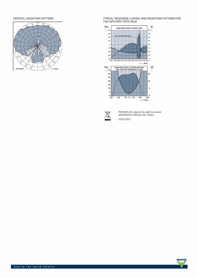
VERTICAL RADIATION PATTERN TYPICAL RESPONSE CURVES AND RADIATION PATTERN FORTHE GPS-PART (1575 MHz)
PROCOM A/S reserve the right to amendspecifications without prior notice.
25/02/2011

FSP 2/...-SMA/TAIT“StraightFlex” Antenna for TAIT Portable Equipment in the 2 mBand
DESCRIPTION
Highly flexible, polyethylene-covered StraightFlex steel wire.
Full size 1/4 λ antenna whip.
Highest quality materials in an elegant and slender design.
Delivered factory tuned and tested to ensure minimum SWR andoptimum performance.
Especially designed for TAIT portable radios (SMA-male).
ORDERING DESIGNATIONS
TYPE PRODUCT NO. FREQUENCY
FSP 2/l-SMA/TAIT 140000413 144 – 164 MHz
FSP 2/h-SMA/TAIT 140000412 155 – 175 MHz
FSP 2/166-174 MHz-SMA/TAIT 140000405 166 - 174 MHz
SPECIFICATIONS
ELECTRICAL
MODEL FSP 2/...-SMA/TAIT
ANTENNA TYPE 1/4 λ antenna for portable equipment
FREQUENCY 2 m band covered by three models
IMPEDANCE Nom. 50 Ω
POLARIZATION Vertical
GAIN 0 dB (equal to a 1/4 λ portable antenna)
BANDWIDTH ≥ 20 MHz @ SWR ≤ 2.5
SWR < 2 when mounted directly on portable equipment
MAX. POWER 100 W
MECHANICAL
MATERIALS Polyethylene-covered flexible steel wireBlack-chromed brass
COLOUR Black
TOTAL HEIGHT Approx. 560 mm (dep. on type)
WEIGHT Approx. 35 g
CONNECTOR SMA (male) special for TAIT
PROCOM A/S reserve the right to amendspecifications without prior notice.
30/11/2010

BPF 3/...-200-SHTBand-Pass Filter for the 150 MHz Band
DESCRIPTION
High power base station shortened band-pass filter for the116 - 146 MHz range.
The use of large ø200 mm cavities a high Q is achieved, resulting ina very narrow passband.
The large dimensions also mean a high power rating.
The SHT-version has only 600 mm cavity length.
Unloaded Q of a single cavity is approx. 3000.
High frequency stability on temperature and power.
19” mounting brackets are available as an option.
ORDERING DESIGNATIONS
TYPE PRODUCT NO.
BPF 3/1-200-SHT 200000983
BPF 3/2-200-SHT 200001163
BPF 3/3-200-SHT 200001890
SPECIFICATIONS
ELECTRICAL
MODEL BPF 3/1-200-SHT
BPF 3/2-200-SHT BPF 3/3-200-SHT
FREQ. RANGE 116 - 146 MHz 116 - 146 MHz 116 - 146 MHz
MAX. INPUTPOWER
350 W @0.5 dB IL150 W @2.0 dB IL
350 W @1.0 dB IL150 W @4.0 dB IL
350 W @1.5 dB IL150 W @6.0 dB IL
INSERTION LOSS Adjustable0.5-2.0 dB
Adjustable 1.0-4.0 dB
Adjustable 1.5-6.0 dB
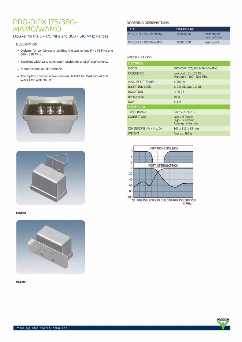
ATTENUATION See figure 1 See figure 2 See figure 3
IMPEDANCE Nom. 50 Ω Nom. 50 Ω Nom. 50 Ω
SWR(at resonance)
< 1.5 < 1.5 < 1.5
MECHANICAL
TEMP. RANGERH 0-90% non-condensing
–30° C →+60° C
–30° C →+60° C
–30° C →+60° C
FREQ. STABILITY Approx. 1.5ppm/° C
Approx. 1.5ppm/° C
Approx. 1.5ppm/° C
CONNECTORS N-female N-female N-female
DIMENSIONS ø200 x 600mm
L:200 x W:400 xH:600 mm
L:200 x W:600 xH:600 mm
WEIGHT Approx. 4.6 kg Approx. 10 kg Approx. 14.5 kg

TYPICAL RESPONSE CURVES
Figure 1
Figure 2
Figure 3
PROCOM A/S reserve the right to amendspecifications without prior notice.
01/04/2011
PRO-DIPX 175/380-MAMO/WAMODiplexer for the 0 - 175 MHz and 380 - 510 MHz Ranges
DESCRIPTION
Diplexer for combining or splitting the two ranges 0 - 175 MHz and380 - 510 MHz.
Excellent wide-band coverage – usable for a lot of applications.
N-connections on all terminals.
The diplexer comes in two versions. MAMO for Mast Mount andWAMO for Wall Mount.
MAMO
WAMO
ORDERING DESIGNATIONS
TYPE PRODUCT NO.
PRO-DIPX 175/380-MAMO 200000726 Mast mountmax. ø65 mm
PRO-DIPX 175/380-WAMO 200001768 Wall mount
SPECIFICATIONS
ELECTRICAL
MODEL PRO-DIPX 175/380-MAMO/WAMO
FREQUENCY Low port : 0 - 175 MHzHigh port : 380 - 510 MHz
MAX. INPUT POWER ≤ 200 W
INSERTION LOSS ≤ 0.5 dB, typ. 0.3 dB
ISOLATION ≥ 45 dB
IMPEDANCE 50 Ω
SWR ≤ 1.4
MECHANICAL
TEMP. RANGE –20° C → +50° C
CONNECTORS Low : N-femaleHigh : N-femaleAntenna: N-female
DIMENSIONS (W x H x D) 160 x 113 x 88 mm
WEIGHT Approx. 500 g

The PRO-DIPX 175/380-MAMO/WAMO makes it possible to use only oneantenna for the operation of two transceivers (one in each range). Seethe figure below. The antenna must be a dual-frequency antenna, thatis, it must be resonant on the actual frequencies in the two bands. Thetransceivers may be used independently and will have no degradinginfluence on each other. Typically, the diplexer is installed next to thetransceivers and only one cable is used between the diplexer and theantenna. The diplexer is suitable both for base station and mobile use.
The main tasks of the diplexer are to protect the individual receiverinput from being destroyed by the transceiver in the contrary band andto ensure a low-loss path between the transceiver and the antennawhich is not loaded by the other branch.
The diplexer can be operated together with any set of transceiversoperating within the 0 - 175 MHz and 380 - 510 MHz frequency bands.
Dual-frequency antennas are available for both mobile and base stationapplications.
MOUNTING DETAILS
PROCOM A/S reserve the right to amendspecifications without prior notice.
20/12/2010

PRO-PHY450-55-Channel Hybrid Combiner for 450 MHz Transmitters
DESCRIPTION
Combining five transmitters or receivers on the same antenna.Better utilization of good antenna position.Five antennas on the same transmitter or receiver.The only combining option with very small TX-TX frequency spacing.60 W loads included (other loads or no loads as option).
ORDERING DESIGNATIONS
TYPE PRODUCT NO. FREQ. RANGE
PRO-PHY450-5-1 210001383 380 - 400 MHz
PRO-PHY450-5-2 210001384 390 - 410 MHz
PRO-PHY450-5-3 210001385 400 - 420 MHz
PRO-PHY450-5-4 210001386 410 - 430 MHz
PRO-PHY450-5-5 210001387 420 - 440 MHz
PRO-PHY450-5-6 210001388 430 - 450 MHz
PRO-PHY450-5-7 210001389 440 - 460 MHz
PRO-PHY450-5-8 210001390 450 - 470 MHz
PRO-PHY450-5-9 210001391 460 - 480 MHz
SPECIFICATIONS
ELECTRICAL
FILTER TYPE Hybrid Junction
FREQUENCY 380 - 480 MHz (see table)
MAX. INPUT POWER 65 W per channel(max. 150 W with larger load)
INSERTION LOSS < 7.5 dB ± 0.3 dB @ 11 MHz BW< 7.8 dB ± 0.3 dB @ 22 MHz BW
ISOLATION TX 1-TX 2(*see note)
> 30 dB @ 11 MHz BW> 28 dB @ 22 MHz BW
IMPEDANCE Nom. 50 Ω
LOAD 60 W load fitted (other ratings available)
SWR < 1.5 with all other ports terminatedwith 50 Ω
MECHANICAL
TEMP. RANGE –30° C → +60° C
CONNECTORS N-female (other types as option)
DIMENSIONS (L x W x H) 510 x 89 (incl. conn.) x 42 mm (excl. load)
WEIGHT Approx. 1625 g (excl. load)
*The isolation between the TX ports is directly dependent on theterminating SWR on the antenna port. With an antenna load SWR = 1.5,the isolation between the two TX ports will be reduced to 20 dB @ 5MHz bandwidth.
**The SWR of the loads should be < 1.1! Each load should be able todissipate 4/5 of the input power.
E.g.: With 50 W input, each load should be able to dissipate 50 W x 4/5= 40 W.
PROCOM A/S reserve the right to amendspecifications without prior notice.
17/12/2010

PRO-RPS-8-N8-Channel passive RX Power Splitter
DESCRIPTION
Passive wide-band receiver power splitter.
Wide frequency range 50 MHz to 1000 MHz.
High isolation between outputs.
To be used where RF-signals are to be divided or combined:more receivers connected to the same antennamore antenna signals on the same coaxial cable.
N-female on all ports. (Other connector types on request).
DC-ground on all ports.
ORDERING DESIGNATIONS
TYPE PRODUCT NO.
PRO-RPS-8-N 210000767
SPECIFICATIONS
ELECTRICAL
MODEL PRO-RPS-8-N
FREQUENCY RANGE 50 - 1000 MHz
INSERTION LOSS [S21] 10 dB ±0.5 dB @ 50 MHz12 dB ±0.5 dB @ 960 MHz
ISOLATION OUTPUTTO OUTPUT
Min. 20 dB
INPUT SWR Max. 2.0 typ. < 1.5
OUTPUT SWR Max. 1.5 typ. < 1.3
POWER HANDLING Max. 0.5 W each port
MECHANICAL
TEMP. RANGE -30° C → +60° C
CONNECTORS N-female
DIMENSIONS(L x W x H)
138 (incl. conn.) x 255 (incl. flanges) x 35 mm
WEIGHT 550 g
MOUNTING DETAILS
PROCOM A/S reserve the right to amendspecifications without prior notice.
02/03/2011