process intensification using self-cleaning fluidized bed ... · process intensification using...
TRANSCRIPT

Process Intensification Using
Self-Cleaning Fluidized Bed Heat Exchangers
KLAREN International BV, Hanzeweg 35N, Barneveld, The Netherlands.
Email: [email protected], Website: www.klarenbv.com 1
Presented by
Dr. Ir. Dick G. Klaren M.Sc.Principal Adviser & Chief ScientistKLAREN International
November 2014
2
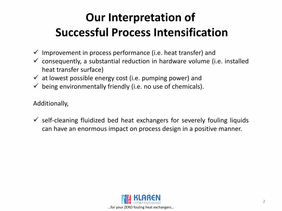
Our Interpretation of Successful Process Intensification
Improvement in process performance (i.e. heat transfer) and consequently, a substantial reduction in hardware volume (i.e. installed
heat transfer surface) at lowest possible energy cost (i.e. pumping power) and being environmentally friendly (i.e. no use of chemicals).
Additionally,
self-cleaning fluidized bed heat exchangers for severely fouling liquidscan have an enormous impact on process design in a positive manner.
…for your ZERO fouling heat exchangers…

3
A Proven Example
Table 1: Comparison conventional heat exchanger versus self-cleaning fluidized bed heat exchanger.
…for your ZERO fouling heat exchangers…

4
Consequences and Cost of Fouling
Loss of energy. Loss of production or reduced capacity operation. Over-sizing and / or redundancy of equipment. Excessive maintenance cost. Hazardous cleaning solution handling and disposal.
Annual global fouling costs are estimated at US$ 150 billion, i.e. US$ 150 x 109.
…for your ZERO fouling heat exchangers…

Principle
Figure 1: Self-cleaning heat exchanger with stationary fluidized bed of glass beads installed in vertical MSF evaporator
5
How it started in seawater desalination
…for your ZERO fouling heat exchangers…
6
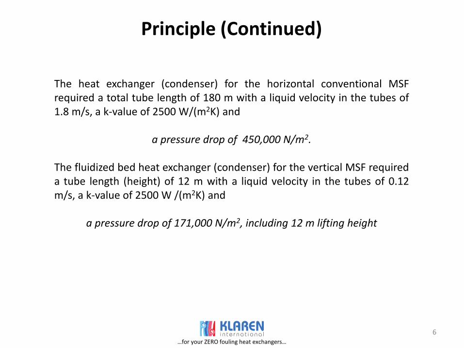
Principle (Continued)
The heat exchanger (condenser) for the horizontal conventional MSFrequired a total tube length of 180 m with a liquid velocity in the tubes of1.8 m/s, a k-value of 2500 W/(m2K) and
a pressure drop of 450,000 N/m2.
The fluidized bed heat exchanger (condenser) for the vertical MSF requireda tube length (height) of 12 m with a liquid velocity in the tubes of 0.12m/s, a k-value of 2500 W /(m2K) and
a pressure drop of 171,000 N/m2, including 12 m lifting height
…for your ZERO fouling heat exchangers…

7
Improvements of the Principle
Figure 2: Self-cleaning heat exchanger with internal circulation of cleaning
solids
Figure 3: Self-cleaning heat exchanger with external circulation of cleaning
solids
…for your ZERO fouling heat exchangers…

8
Operating Experience Example # 1
Figure 4: Self-cleaning fluidized bed heat exchanger in operation at chemical plant since 1991 eliminates reboiler fouling. Houston, Texas, USA.
…for your ZERO fouling heat exchangers…
9
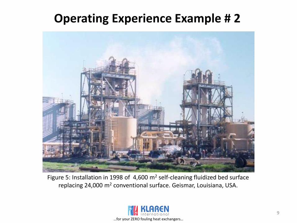
Operating Experience Example # 2
Figure 5: Installation in 1998 of 4,600 m2 self-cleaning fluidized bed surface replacing 24,000 m2 conventional surface. Geismar, Louisiana, USA.
…for your ZERO fouling heat exchangers…

10
Operating Experience Example # 2 (Continued)
Table 2: Comparison conventional heat exchanger versus self-cleaning fluidized bed heat exchangers, state-of-the-art 1998 and 2005
…for your ZERO fouling heat exchangers…

11
Revamping Conventional Fouling Exchangers into Self-Cleaning Configuration
Figure 6: Evaporator equipped with conventional heat exchanger
Figure 7: Conventional evaporator revamped into self-cleaning
configuration.
…for your ZERO fouling heat exchangers…

12
Revamping Conventional Fouling Exchangers into Self-Cleaning Configuration (Continued)
Requirements for the majority of revamps:
The same process conditions should be maintained as in the originalinstallation.
The connections to the column should be maintained. The installed pumps can be used because pumping power requirements
are generally lower for the self-cleaning fluidized bed heat exchangers than for the conventional severe fouling shell and tube exchanger.
As many components of the existing installation should be used in the revamped configuration, like bundle, channels or maybe even modified channels.
The revamp must be carried out within the available space. This often means that a revamp can only be carried out when the existing installation has already a vertical position.
The advantages of most revamps are much lower maintenance cost, an increased production and smoother operation.
…for your ZERO fouling heat exchangers…

13
Example of Revamp
Figure 8: Conventional coolingcrystallizer
Figure 9: Revamped into self-cleaning configuration
Separator
Controlchannel
Down-comer
Cooler
Discharge
Feed
4 500 m³/hdP = 0.3 bar
Cooler
Discharge
Feed
4 500 m³/hdP = 0.3 bar
…for your ZERO fouling heat exchangers…

14
Example on Offshore Platform
Figure 10: Offshore platform with air coolers on top deck indicated by arrow
…for your ZERO fouling heat exchangers…

15
Example on Offshore Platform (continued)
Table 3: Comparison gas cooling systems on offshore platforms
m2
kW
Unit Air coolers Indirect seewatercoolers
Directseawater coolers
(self-cleaning bed)
Heat duty
Gas temperature (In-, Outlet)Gas pressure
Seawater temperature
WeightPlot area
Power 80
19040
850
350530
2 000
300
90
150120 43
26 50
46⁰C
⁰C
MW
bar
tonne
…for your ZERO fouling heat exchangers…
16
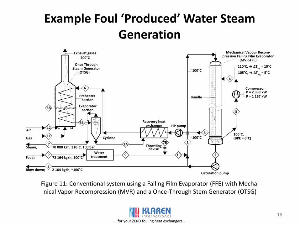
Example Foul ‘Produced’ Water SteamGeneration
Figure 11: Conventional system using a Falling Film Evaporator (FFE) with Mecha-nical Vapor Recompression (MVR) and a Once-Through Stem Generator (OTSG)
…for your ZERO fouling heat exchangers…

17
Example Foul ‘Produced’ Water Steam Generation (Continued)
Figure 12: New proposed system consisting of a Self-Cleaning Rising Film Evaporator (SC-RFSG) and a Fired Thermal Oil Heater (FTOH)
…for your ZERO fouling heat exchangers…
18
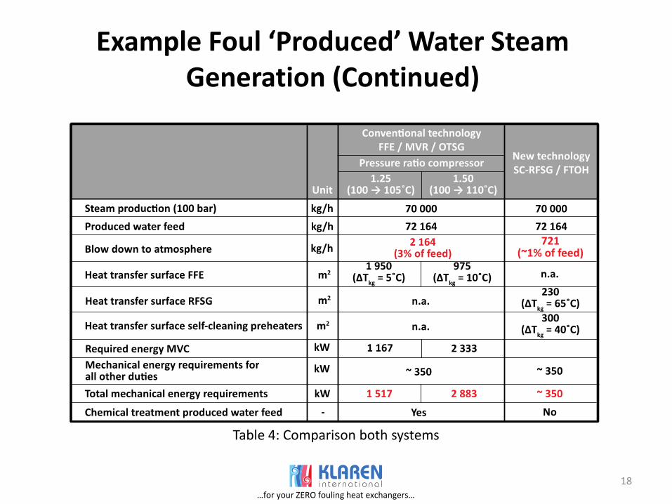
Example Foul ‘Produced’ Water Steam Generation (Continued)
Table 4: Comparison both systems
…for your ZERO fouling heat exchangers…

19
Conclusions
Thank you
We hope that you have appreciated our contribution to process intensification
Any Questions?
…for your ZERO fouling heat exchangers…