process guidance note 6/26(13) - the national...
TRANSCRIPT

www.gov.uk/defra
Process Guidance Note 6/26(13)
Statutory guidance for animal feed compounding
December 2013

© Crown copyright 2013
You may re-use this information (not including logos) free of charge in any format or medium, under the terms of the Open Government Licence. To view this licence, visit www.nationalarchives.gov.uk/doc/open-government-licence/ or write to the Information Policy Team, The National Archives, Kew, London TW9 4DU, or e-mail: [email protected]
This document/publication is also available on our website at:
http://www.defra.gov.uk/environment/quality/industrial/las-regulations/guidance/
Any enquiries regarding this document/publication should be sent to us at:
Atmosphere and Local Environment Defra Nobel House 17 Smith Square London SW1P 3JR
Email: [email protected]

Defra would like to acknowledge the work of the Environment Agency’s Local Authority Unit in the drafting of this guidance note.

PG6/26 (13) i
Revision of the guidance
The electronic version of this publication is updated from time to time with new
or amended guidance. Table 0.1 is an index to the latest changes (minor
amendments are generally not listed).
Table 0.1 - Revision of the guidance

PG6/26 (13) ii
Contents
Revision of the guidance .......................................................................................... i 1. Introduction ........................................................................................................ 1
Legal basis ........................................................................................................... 1
Who is the guidance for? ..................................................................................... 2 Updating the guidance ......................................................................................... 2 Consultation ......................................................................................................... 3 Policy and procedures ......................................................................................... 3 When to use another note rather than PG6/26 .................................................... 3
Deregulation of vegetable matter drying .............................................................. 4 2. Timetable for compliance and reviews ............................................................ 5
Existing processes or activities ............................................................................ 5 Permit reviews ..................................................................................................... 6
3. Activity description ............................................................................................ 7
Regulations .......................................................................................................... 7 Process or activity ................................................................................................ 7
4. Emission limits, monitoring and other provisions ........................................ 13
Odours - principles of BAT in this note ............................................................... 13 Emissions of odour ............................................................................................ 14 Visible emissions ............................................................................................... 15 Odorous emissions - monitoring installation performance ................................. 20
Monitoring, investigating and reporting .............................................................. 22 Information required by the regulator ................................................................. 23
Abnormal events ................................................................................................ 23 Continuous monitoring ....................................................................................... 24 Continuous monitoring - particulate abatement plant ......................................... 26
Calibration and compliance monitoring .............................................................. 27
Varying of monitoring frequency ........................................................................ 27 Monitoring of unabated releases ........................................................................ 28 Representative sampling ................................................................................... 28
5. Control techniques .......................................................................................... 29 Techniques to control emissions from contained sources .................................. 31 Techniques to control fugitive emissions ........................................................... 36 Process operations ............................................................................................ 37
Effluent and waste ............................................................................................. 38 Air quality ........................................................................................................... 39 Management techniques .................................................................................... 41
6. Summary of changes ....................................................................................... 43 7. Further information .......................................................................................... 45
Sustainable consumption and production (SCP) ............................................... 45
Health and safety ............................................................................................... 45
Further advice on responding to incidents ......................................................... 46 Appendix 1 - Application form .............................................................................. 47 Appendix 2 - Model Permit .................................................................................... 59 Appendix 3 - Method for sampling of emissions from biological (earth, peat
and heather) filters using gas detection tubes ............................. 69
Appendix 4 - Guidance on the preparation of an odour response procedure .. 70

PG6/26 (13) iii
List of Tables Table 0.1 - Revision of the guidance ........................................................................... i Table 2.1 - Compliance timetable ............................................................................... 5 Table 3.1 - Regulations listing activities ..................................................................... 7 Table 4.1 - Emission limits, monitoring and other provisions .................................... 17
Table 4.2 - Filtration plant inspection frequency ....................................................... 22 Table 5.1 - Summary of control techniques .............................................................. 30 Table 6.1 - Summary of changes ............................................................................. 43 Table 1 - Emission limits, monitoring and other provisions ....................................... 64 Table 2 - Odour abatement plant - Indicative guide provisions for monitoring .......... 67
Table A - Examples of issues to consider relating to odour release ......................... 71 List of Figures Figure 1.1: A typical animal feeding compound ........................................................ 12

PG6/26 (13) 1
1. Introduction
Legal basis
1.1 This note applies to the whole of the UK. It is issued by the Secretary of State, the
Welsh Government, the Scottish Government and the Department of the
Environment in Northern Ireland (DoE NI) to give guidance on the conditions
appropriate for the control of emissions into the air from animal feed compounding
processes and installations. It is published only in electronic form and can be found
on the Defra website. It supersedes PG6/26(05) and NIPG6/26(05).
1.2 This guidance document is compliant with the Code of Practice on Guidance on
Regulation page 6 of which contains the "golden rules of good guidance". If you feel
this guidance breaches the code or you notice any inaccuracies within the
guidance, please contact us.
1.3 This is one of a series of statutory notes giving guidance on the Best Available
Techniques (BAT). The notes are all aimed at providing a strong framework for
consistent and transparent regulation of installations regulated under the statutory
Local Air Pollution Prevention and Control (LAPPC) regime in England and Wales,
Scotland and Northern Ireland. The note will be treated as one of the material
considerations when determining any appeals against a decision made under this
legislation. Further guidance on the meaning of BAT can be found for England and
Wales, Scotland, and Northern Ireland.
1.4 In general terms, what are BAT for one installation in a sector are likely to be BAT
for a comparable installation. Consistency is important where circumstances are the
same. However, in each case it is, in practice, for regulators (subject to appeal) to
decide what are BAT for each individual installation, taking into account variable
factors such as the configuration, size and other individual characteristics of the
installation, as well as the locality (e.g. proximity to particularly sensitive receptors).
1.5 The note also, where appropriate, gives details of any mandatory requirements
affecting air emissions which are in force at the time of publication, such as those
contained in Regulations or in Directions from the Government. In the case of this
note, at the time of publication there were no such mandatory requirements.

PG6/26 (13) 2
1.6 Most of the activities covered by this note will have essentially the same
characteristics and it is expected that the application form and model permit in
Appendices 1 and 2 will normally be used in order to simplify for business the
process of applying for a permit and to simplify for regulators the process of issuing
a permit. (See also the relevant LAPPC charging scheme for reduced application
and subsistence charges for simplified permits).
If there are good reasons to consider diverging from normal use of the model
permit, the starting point for drafting any additional conditions should be the arrowed
bullets in the main body of this note.
Who is the guidance for?
1.7 This guidance is for:
Regulators
local authorities in England and Wales, who must have regard to the guidance when determining applications for permits and reviewing extant permits;
the Scottish Environment Protection Agency (SEPA) in Scotland, and district councils or the Northern Ireland Environment Agency (NIEA), in Northern Ireland;
Operators who are best advised also to have regard to it when making applications
and in the subsequent operation of their installation;
Members of the public who may be interested to know what the Government
considers, in accordance with the legislation, amounts to appropriate conditions for
controlling air emissions for the generality of installations in this particular industry
sector.
Updating the guidance
1.8 The guidance is based on the state of knowledge and understanding, at the time of
writing, of what constitute BAT for this sector. The note may be amended from time
to time to keep up with developments in BAT, including improvements in
techniques, changes to the economic parameters, and new understanding of
environmental impacts and risks. The updated version will replace the previous
version on the Defra website and will include an index to the amendments.

PG6/26 (13) 3
1.9 Reasonable steps will be taken to keep the guidance up-to-date to ensure that
those who need to know about changes to the guidance are informed of any
published revisions. However, because there can be rapid changes to matters
referred to in the guidance – for example to legislation – it should not be assumed
that the most recent version of this note reflects the very latest legal requirements;
these requirements apply.
Consultation
1.10 This note has been produced in consultation with relevant trade bodies,
representatives of regulators including members of the Industrial Pollution Liaison
Committee and other potentially-interested organisations.
Policy and procedures
1.11 General guidance explaining LAPPC and setting out the policy and procedures is
contained in separate documents for England and Wales, Scotland and Northern
Ireland.
When to use another note rather than PG6/26
1.12 This note addresses animal feed compounding processes where natural raw
materials such as grain, protein sources, vitamins, minerals, oils and fats are
formulated into nutritionally balanced animal feeding stuffs. This note also refers to
the processing of straw into pellets and micronising cereals into flakes where the
end-products are used as a raw material in the production of feeds.
1.13 There are separate guidance notes for processes involving the production of fish
meal (PG6/19), pet food manufacture (PG6/24) and for processes involving the
drying of residues and crops to produce animal feed, for example, bakery residues
and sugar beet processing (PG6/27).

PG6/26 (13) 4
Deregulation of vegetable matter drying
1.14 Amendments to the statutory Local Air Pollution Prevention and Control (LAPPC)
regime in England and Wales, Scotland and Northern Ireland came into force on 1
October 2010. One of the changes involved vegetable matter drying deregulation:
an addition has been made to the list of excluded activities in Section 6.8: “(o) the
drying of green crops”; and ‘green crops’ have been defined as meaning “alfalfa
(Lucerne), clover, grass, perennial ryegrass, tall fescue and other similar crops;”.
1.15 The British Association of Green Crop Driers (BAGCD) has agreed that their
members will comply with a Code of Practice. This in effect involves compliance
with the operational practices in PG6/27(05).

PG6/26 (13) 5
2. Timetable for compliance and reviews
Existing processes or activities
2.1 This note contains all the provisions from previous editions which have not been
removed. Some have been amended. For installations in operation at the date this
note is published, the regulator should have already issued or varied the permit
having regard to the previous editions. If they have not done so, this should now be
done.
2.2 The new provisions of this note and the dates by which compliance with these
provisions is expected are listed in Table 2.1, together with the paragraph number
where the provision is to be found. Compliance with the new provisions should
normally be achieved by the dates shown. Permits should be varied as necessary,
having regard to the changes and the timetable.
Table 2.1 - Compliance timetable
Guidance Relevant paragraph/row in this note
Compliance date
An application form and simple permit have been added in Appendix 1 and Appendix 2.
There are no new provisions in this note likely of themselves to result in a need to vary existing permit conditions. For a full list of changes made by this note, excluding very minor ones, see Table 6.1. See paragraph 2.4.
2.3 Replacement plant should normally be designed to meet the appropriate standards
specified for new installations/activities.
2.4 Where provisions in the preceding guidance note have been deleted or relaxed,
permits should be varied as necessary as soon as reasonably practicable. It is
expected that local authorities will aim to vary existing permits so as to convert them
into the model permit format in Appendix 2 within 12 months of the publication of
this note.
2.5 For new activities, the permit should have regard to the full standards of this
guidance from the first day of operation.
2.6 For substantially changed activities, the permit should normally have regard to the
full standards of this guidance with respect to the parts of the activity that have been
substantially changed and any part of the activity affected by the change, from the
first day of operation.

PG6/26 (13) 6
Permit reviews
2.7 Under LAPPC, the legislation requires permits to be reviewed periodically but does
not specify a frequency. It is considered for this sector that a frequency of once
every eight years ought normally to be sufficient for the purposes of the appropriate
Regulations. Further guidance on permit reviews is contained in the appropriate
Guidance Manual for England and Wales chapter 26, Scotland, Practical guide
section 10, Northern Ireland Part B Guidance page 9, Northern Ireland Part C
Guidance chapter 17. Regulators should use any opportunities to determine the
variations to permits necessitated by paragraph 2.2 above in conjunction with these
reviews.
2.8 Conditions should also be reviewed where complaint is attributable to the operation
of the process and is, in the opinion of the regulator, justified.

PG6/26 (13) 7
3. Activity description
Regulations
3.1 This note applies to LAPPC installations for animal feed compounding processes
and installations. The activities for regulation are listed in Table 3.1.
Table 3.1 - Regulations listing activities
LAPPC
Activity
England and Wales
Scotland Northern Ireland
EPR Schedule 1 reference
PPC Schedule 1 reference
PPC Schedule 1 reference
Part B Section 6.8 Part B Section 6.8, Part B n/a
Part C n/a n/a Section 6.8 Part C
The links are to the original version of the Regulations. A consolidated version is not available on www.legislation.gov.uk
For England and Wales, an unofficial consolidated version is available but read the first page of that document in order to understand its status and content.
3.2 This note addresses animal feed compounding processes where natural raw
materials such as grain, protein sources, vitamins, minerals, oils and fats are
formulated into nutritionally balanced animal feeding stuffs. This note also refers to
the processing of straw into pellets and micronising cereals into flakes where the
end-products are used as a raw material in the production of feeds.
Process or activity
3.3 In the context of this note, "process" or "activity" comprises the whole process from
receipt of raw materials via production of intermediates to dispatch of finished
products, including the treating, handling and storage of all materials and wastes
relating to the process.

PG6/26 (13) 8
Receipt and storage of raw materials
3.4 Compound animal feeds are based upon core formulations of cereals (such as
wheat and barley), soya, rape seed and sugar beet, liquid ingredients (such as
water, molasses and vegetable oils) and specific additives such as mineral and
medicinal supplements. The methods used for the storage and handling of the raw
materials are specific to the individual materials:
Bulk solid raw materials (e.g. cereals) are generally delivered to site in covered vehicles and tipped into reception hoppers prior to conveyance to silos or bulk bins for storage.
Other bulk powders (e.g. amino acids) are delivered by tanker and are blown directly into dedicated storage silos.
Bulk liquid raw materials (e.g. molasses, soya oil and vegetable oil) are delivered by road tankers and are pumped into designated storage tanks. (Bulk liquid raw material storage tanks should be enclosed within bunds to limit the potential for fugitive losses).
Packed solid and liquid raw materials (such as vitamins and enzymes) are normally stored internally.
Size reduction of raw materials
3.5 In order to ensure the homogeneity of the finished product and to produce the
physical attributes required, the cereal raw materials are ground and sieved prior to
inclusion in the product mixture. Typically, electrically driven grinders are used to
grind the material to a uniform particle size. Grinders operate within sealed
enclosures vented to atmosphere through a dust abatement unit. Once ground, the
cereal is conveyed to the processing plant by means of enclosed conveyors.
Processing of raw materials
Weighing and mixing
3.6 Raw materials are fed via load cells into a batch mixer. A typical site will have a
number of mixers which are dedicated to specific product types to prevent cross
contamination. At this stage of the process the low-inclusion ingredients, such as
vitamins, trace materials and medicinal additives, are added directly into the mixer.
Depending upon the recipe, liquid additives and water can also be weighed and
added into the mix via dedicated lines at this stage.
3.7 Mixing is typically performed within a horizontal enclosed continuous mixer. The
residence time for the mixing process is typically three to four minutes and when the
mixing cycle is complete the homogeneous batch is conveyed for further processing
in the press plant, or if a meal product is being produced, the batch will be
transferred directly from the mixer to a finished product bin, ready for despatch.

PG6/26 (13) 9
Steam treatment (conditioning)
3.8 Steam treatment or ‘conditioning’ is the process of adding steam directly into the
mix to raise its temperature so that any bacteria present (such as salmonella) are
eradicated. The steam also improves the physical characteristics of the mix in
preparation for the subsequent extrusion process. At this stage, further liquid
materials (such as molasses) may be added as required. The length of the
conditioning process is determined by the requirements of the feed being produced.
Extrusion
3.9 After conditioning the hot mix is conveyed to a press line; a typical installation will
have a number of press lines dedicated to the production of a specific feed material.
A screw feed is used to force the mix into a press whereupon it is extruded through
a rotating ring die to form a pellet product. Different die dimensions and press
rotation speeds facilitate the production of different pellet sizes, to meet specific
product requirements.
Cooling
3.10 After pelleting, the hot product is then passed through a counter flow air cooler to
reduce its temperature, causing it to harden and become durable. The cooling
process involves air at ambient temperature being passed directly over the pellets.
Waste air generated throughout this part of the process should be ducted into
suitable dust abatement plant (typically a cyclone) prior to being emitted to
atmosphere; the dust collected can be recycled into the production process.
3.11 Additional processing steps may be utilised after cooling to produce specific
products. The pellets may be crushed (‘crumbed’) to produce feeds for poultry, or
undergo fat coating prior to storage.
Product storage and dispatch
3.12 Once cool, finished product is conveyed to dedicated finished product silos or tote
bins, prior to dispatch. Silos should be fitted with high level alarms to prevent
overfilling.
3.13 The product is typically despatched in bulk, although some installations also operate
bagging stations to facilitate the creation of packaged products to meet small-scale
demand. Bulk product is off-loaded onto dedicated delivery lorries prior to despatch
to customers. Typically, off-loading activities are undertaken in enclosed bays to
limit the potential for the fugitive release of dust and odour.
Boiler plant
3.14 Steam is used extensively in the manufacture of compound animal feeds, primarily
in the conditioning process. Installations operate dedicated boiler plant to provide
the steam to the production process.

PG6/26 (13) 10
Cleaning activities
3.15 Cleaning and housekeeping activities are essential at compound animal feed
manufacturing installations to guarantee food hygiene and to ensure that cross-
contamination of different feeding stuffs cannot occur.
3.16 Most installations also operate a dedicated on-site vehicle washing facility to clean
the lorries used for bulk deliveries to customers.
Potential releases
3.17 Contained emissions of particulate matter are largely associated with emissions
from processing (coolers and grinding equipment). There is potential for fugitive
emissions of particulate matter which may arise from transfer of potentially dusty
materials including discharge into hoppers and onto conveyors, and delivery to
storage silos and sheds. Also material collected by bag filters may become re-
entrained if it is not securely contained and carefully handled. The dust may also be
odorous.
3.18 The potential release points for odour are as follows:
raw material reception, storage and handling;
physical process operations (grinding etc);
application of heat during extrusion and also from cooling processes;
storage, handling and transport of the product during processing;
storage and discharge of liquid waste and effluent from the odour arrestment plant;
odour arrestment plant discharge (this may be a stack or vent or may be a biofilter with an area source at ground level);
fugitive emissions of building and process air due to lack of containment.
3.19 Operators are advised that careful consideration should be given to the impact of
relatively minor process changes on odour releases from the process. It will be
necessary to review the odour response procedure (paragraph 4.6 and Appendix
4) to identify the potential effects of the proposed changes.
3.20 Where the odour arrestment plant comprises a scrubber, emissions of materials
which are added to the scrubber for improved performance (such as acids,
hypochlorite, sodium hydroxide etc.) may be released with the plume if the scrubber
and mist eliminator are not properly managed.

PG6/26 (13) 11
3.21 Where a thermal oxidiser or other combustion plant is used for the arrestment of
odours, the emissions will be characteristic of the combustion releases from the
fuel. These will include:-
sulphur dioxide from the burner, influenced by the sulphur content of the fuel;
oxides of nitrogen, influenced by nitrogen content of the fuel, the amount of excess air, flame temperature and the burner type;
carbon monoxide, which may be emitted if the combustion process is badly managed;
metals, volatile organic compounds, chlorides and fluorides may also be emitted where waste or recovered oil is used in the combustion equipment.

PG6/26 (13) 12
Figure 1.1: A typical animal feeding compound
Silo and binstorage
Grinder
Raw materialintakes
materialsBagged Liquid
tanks
Blendingbins
Grinder
Main mixer(molasses, dry products)
Blending
Store and pack meal or pellets in bulk
totes or bagged
Fat coater
Steam conditioning
Extruder
Cooler

PG6/26 (13) 13
4. Emission limits, monitoring and other provisions
4.1 Emissions of the substances listed Table 4.1 should be controlled.
4.2 The emission limit values and provisions described in this section are achievable
using the best available techniques described in Section 5. Monitoring of
emissions should be carried out according to the method specified in this section or
by an equivalent method agreed by the regulator. Where reference is made to a
British, European, or International standard (BS, CEN or ISO) in this section, the
standards referred to are correct at the date of publication. (Users of this note
should bear in mind that the standards are periodically amended, updated or
replaced.) The latest information regarding the monitoring standards applicable can
be found at the Source Testing Association website. Further information on
monitoring can be found in Environment Agency publications, M1 and M2.
4.3 All activities should comply with the emission limits and provisions with regard to
releases in Table 4.1.
The reference conditions for limits in Section 4 are: 273.1K, 101.3kPa, without
correction for water vapour content, unless stated otherwise.
Table 4.1 should be considered in conjunction with the monitoring paragraphs
found later in this section.
Odours - principles of BAT in this note
4.4 The approach promulgated in this note to reflect BAT includes:
an emission standard for odour (paragraph 4.5);
preparation of an odour response procedure (see paragraph 4.6 and Appendix 4) which will include an assessment of all emission sources, control methods, odour impacts, abnormal operations and measures to mitigate effects in the case of abnormal conditions.
Odour response procedures (sometimes know as Odour Management Plans) should be in place to minimise and control odour before the use of abatement plant is considered. Where containment measures fail, other control methods such as odour arrestment plant should be considered.
daily inspections of odour arrestment plant (where fitted);
indicative tests for odour arrestment plant (paragraph 4.12) in the case of offensive odours being detected or complaints being received;

PG6/26 (13) 14
Emissions of odour
4.5 The overall aim should be that all emissions are free from offensive odour outside
the site boundary, as perceived by the regulator. However, the location of the
installation will influence the assessment of the potential for odour impact as local
meteorological conditions may lead to poor dispersion conditions. Where the site
has a low odour impact due to its remoteness from sensitive receptors, the escape
of offensive odour beyond the installation would be unlikely to cause harm.
Where there are problems that, in the opinion of the regulator, may be attributable
to the installation, such as local complaints of odour or where odour from the
installation is being detected beyond the site boundary, the operator should
investigate in order to find out which part of their operation(s) is the cause.
Whilst problems are ongoing, a boundary check should also be made at least once
per day/shift, by the operator, when an installation is being operated. The time,
location and result of these checks, along with weather conditions such as indicative
wind direction and strength, should be recorded. Once the source of the emission
is known, corrective action should be taken without delay and where appropriate the
regulator may want to vary the permit in order to add a condition requiring the
particular measure(s) to be undertaken.
Odour response procedure
4.6 The operator should prepare an odour response procedure as outlined in Appendix
4. An odour response procedure is a summary, provided by the operator, of the
foreseeable situations which may compromise an ability to prevent and/or minimise
odorous releases from the process and the actions to be taken to minimise the
impact. It is intended to be used by operational staff on a day-to-day basis and
should detail the person responsible for initiating the action.
The procedure is intended primarily to document foreseeable events which are
outside of the control of the operator and those that are preventable by
maintenance and operational control (for example pump failure, biofilter compaction
or filter breakthrough). The procedure should include a maintenance programme for
odour containment measures (such as building structure, ventilation plant) and for
any on-site odour arrestment plant.
The odour response procedure should include a list of essential spares for any
plant/equipment identified as contributing to prevention/minimisation of odour.
The plant/equipment manufacturer should recommend which spares are
subject to wear and foreseeable failure and are critical for the correct
operation of the plant/equipment (such as pumps, nozzles etc.) and these
should be held on site. It may be acceptable for certain spares to be available
on guaranteed short delivery if the absence of a supply at the site would not
lead to complete failure of the plant/equipment or to offensive odours beyond
the site boundary.

PG6/26 (13) 15
Where odour arrestment plant is fitted, the odour response procedure should
include analysis of actions in the case of arrestment plant breakdown or
malfunction. Immediate arrangements should be made to divert odour
streams to other suitable arrestment plant. Failure to provide suitable
temporary arrestment plant may lead to the suspension of the process and
consequently emergency standby arrangements should be detailed in the
odour response procedure. This may include:
suspending process operations
reducing the scale of high odour intensity process operations, for example stopping cooking operations or reducing throughput
by-pass emissions to stand-by or alternate odour arrestment plant, for example using a boiler as an emergency odour arrestment plant.
Visible emissions
4.7 The aim should be to prevent any visible airborne emission from any part of the
process. This aim includes all sites regardless of location. Monitoring to identify the
origin of a visible emission should be undertaken and a variety of indicative
techniques are available.
where ambient monitoring is carried out it may also be appropriate for the regulator to specify recording of wind direction and strength;
where combustion units are in use for dryers then the combustion process should be controlled and equipment maintained as appropriate.
4.8 Emissions from combustion processes should in normal operation be free from
visible smoke. During start up and shut down the emissions should not exceed the
equivalent of Ringelmann Shade 1.
All other releases to air, other than condensed water vapour, should be free
from persistent visible emissions.
All emissions to air should be free from droplets.
Where there are problems that, in the opinion of the regulator, may be attributable
to the installation, such as local complaints of visual emissions or where dust from
the installation is being detected beyond the site boundary, the operator should
investigate in order to find out which part of their operation(s) is the cause.
If this inspection does not lead to correction of the problem then the operator should
inform the regulator who will determine whether ambient air monitoring is
necessary. Ambient monitoring may either be by a British Standard method or by a
method agreed with the regulator.

PG6/26 (13) 16
4.9 Whilst problems are ongoing, a visual check should also be made at least once per
day/shift, by the operator, when an installation is being operated. The time, location
and result of these checks, along with weather conditions such as indicative wind
direction and strength, should be recorded. Once the source of the emission is
known, corrective action should be taken without delay and where appropriate the
regulator may want to vary the permit in order to add a condition requiring the
particular measure(s) to be undertaken.

PG6/26 (13) 17
Table 4.1 - Emission limits, monitoring and other provisions R
ow
Substance Source Emission limits/provisions
Type of monitoring
(see also notes a & b)
Monitoring frequency
1 Odour
(see Note 1 below)
Contained process sources
Odour removal efficiency of not less than 85%
(see also note b).
Determination by manual extractive sampling and analysis by dynamic olfactometry in accordance with BS EN 13725.
On installation of new / replacement odour arrestment equipment and / or in the circumstances described in Note 2 below.
Note 1 - the overall aim should be that all emissions are free from offensive odour outside the site boundary, as perceived by the regulator – see paragraph 4.5.
Note 2 - when offensive odours are detected beyond the process boundary or complaints are received and there is no obvious cause of odour release then the operator shall check the odour abatement plant performance using guide values given in Table 2, Appendix 2 and check the process operational controls. If notified by the regulator, odour removal efficiencies shall be retested
2 Particulate matter
Whole site No visible emission Visual observations with particular attention to areas where dust may be generated
When requested by the regulator
3 Particulate matter
Silo inlets and outlets (for silos new or replacement plant since 1st August 2005)
Designed to emit less than 10mg/m3
Visual observations At time of delivery
4 Particulate matter
Wet scrubbers 20mg/m3 Extractive Annual

PG6/26 (13) 18
5 Particulate matter
Contained process sources (not silos) other than product coolers
(see also note c)
20mg/m3 EITHER
Filter leak monitor
provide visual alarms
record trend output and alarms
plus
extractive test to set up levels at which alarms will activate
Continuous
plus
every 3 years
OR
Gross filter failure device
provide audible and visual alarms
PLUS
extractive test
Continuous
PLUS
annual
6 Particulate matter
Plant serving product coolers with dry bag filtration
(see also note c)
Existing plant
50mg/m3
EITHER
Filter leak monitor
provide visual alarms
record trend output and alarms
plus
extractive test to set up levels at which alarms will activate
Continuous
plus
every 3 years
OR
Gross filter failure device
provide audible and visual alarms
plus
extractive test
Continuous
plus
annual
Plant serving product coolers using cyclones
Existing plant
50mg/m3
Cyclones only:
Monitors that:
provide visible and audible alarms which activate on cyclone malfunction; and
are interlocked to shutdown process when alarm activates
plus
extractive test
annual

PG6/26 (13) 19
7 Particulate matter
Plant serving product coolers with dry bag filtration
(see also note c)
New/replacement plant:
20mg/m3
EITHER
Filter leak monitor
provide visual alarms
record trend output and alarms
plus
extractive test to set up levels at which alarms will activate
Continuous
plus
every 3 years
OR
Gross filter failure device
provide audible and visual alarms
plus
extractive test
Continuous
plus
annual
Plant serving product coolers using cyclones
New/replacement plant:
20mg/m3
Cyclones only:
Monitors that:
provide visible and audible alarms which activate on cyclone malfunction; and
are interlocked to shutdown process when alarm activates
plus
extractive test
Annual
Notes
a) The continuous monitoring provision should be disapplied where emissions do not exceed 20mg/m3 without the use of abatement plant. This should be demonstrated by a single sampling exercise undertaken in accordance with paragraph 4.2. A further such monitoring exercise may be required in the event of a substantial change to the process.
b) Where the inlet odour concentrations are very low and the 85% destruction efficiency is difficult to demonstrate due to measurement reproducibility and equipment efficiency at low concentrations, the final discharge to air should contain less than 500 odour units/m3.
c) Where exhaust airflow is less than 100m3/min, continuous monitoring is not required.

PG6/26 (13) 20
Existing arrestment plant
4.10 For existing plant, provided the operator can satisfactorily demonstrate that the
operation of plant at lower odour removal efficiencies meets the provisions of
paragraph 4.5 then these lower odour removal efficiencies shall apply.
New/replacement arrestment plant
4.11 Where it can be demonstrated that the provisions of paragraph 4.5 are being met
new/replacement plant may be operated at odour removal efficiencies lower than
the 85% in Table 4.1. To provide such demonstration, operators should determine,
using dispersion modelling or alternative appropriate techniques, what percentage
efficiencies are required to meet the provisions of paragraph 4.5.
Odorous emissions - monitoring installation performance
4.12 The operator should monitor the performance of the installation for emissions which
may result in offensive odours beyond the boundary. This assessment should
include inspections of the process, buildings and equipment to check that emissions
are being contained and treated to meet the standards of this note.
In addition to the continuous monitoring (paragraph 4.21) the odour arrestment
plant should be inspected at least once a day to verify correct operation and to
identify any malfunctions.
This inspection should include:
identification of any leaks in air handling equipment and ductwork. Where a key component of the odour arrestment plant cannot be adequately accessed for inspection then arrangements to enable this should be made;
in the case of scrubbing equipment, thermal oxidisers and other combustion plant, verification of the operation of the continuous monitoring equipment, any blockages and also identification of any leaks of either odorous air or liquid;
in the case of biofilters, the surface should be inspected to identify any cracking of the surface or voids in the bed, leaks around the edge of the filter or air handling equipment, review of the moisture content (considering both flooding and drying out) and looking for signs of compaction or uneven flow;
in the specific case of soil biofilters, the growth of plants and weeds. Excessive flow or odour escape is often indicated by scorching of the earth or plant growth dying off.

PG6/26 (13) 21
Indicative tests for odour control equipment
4.13 If offensive odours are detected beyond the process boundary or complaints
received but there is no obvious cause of odour release it may be necessary to
check the odour arrestment plant performance.
In the case of thermal oxidisers or combustion equipment, the combustion
efficiency is a good indication of performance. Emissions tested in accordance
with the first bullet of paragraph 4.21 should normally be below 100mg/m3
(expressed as a 30-minute mean at 273K and 101.3kPa).
If emissions exceed this indicative guide value it is likely that the odour destruction
efficiency of the arrestment plant is reduced and it should be further investigated to
identify reasons for the reduced performance.
Particulate emissions from silos
4.14 Where silos are used for raw material and product storage the following measures
relating to abatement plant on silos and other silo management techniques are only
applicable where the silo vents to the external environment or where silo emissions
may escape from inside a building into the external environment.
All new or replacement silo filtration plant should be designed to operate to an
emission standard of less than 10 mg/m3 for particulate matter.
Inspection of filtration plant
4.15 Silo systems require appropriate inspections and assessments to minimise potential
for emissions during the filling process. The following measures relating to
arrestment plant on silos and other silo management techniques are only applicable
where the silo vents to the external environment or where silo emissions may
escape from inside a building into the external environment.
Operators should have a procedure in place to ensure that visual assessment
of emissions from silo inlet connections and the silo arrestment plant are
undertaken throughout the duration of all bulk deliveries. The start and finish
times of all deliveries should be recorded.
Silo arrestment plant and filtration plant serving other process operations
should be inspected at the frequency specified in Table 4.2.

PG6/26 (13) 22
Table 4.2 - Filtration plant inspection frequency
Filter cleaning method Frequency of visual inspection
Fitted with reverse jets at least once a month
Fitted with mechanical shakers at least once a week
Requiring manual shaking daily inspection or prior to any delivery being made if deliveries are not daily
The outlet should be checked for signs that emissions have occurred. The
equipment should also be checked for defects in the air flow or the cam
shakers. If emissions or defects are detected then corrective action should be
taken promptly and before another delivery takes place. Any failure of the silo
management system (e.g. high level alarms, filter, pressure relief valve)
should lead to full investigation of the operation of the plant and equipment.
Reduced inspection frequency of bag filter (or cartridge) arrestment plant may
be appropriate, as follows:
where pressure drop sensors or other continuous monitors are used to monitor the arrestment plant; such monitors should be inspected according to manufacturers’ recommendations to ensure their proper operation.
where continuous camera operation enables observation of all emission points from the arrestment plant and pressure relief valves.
for filters fitted with reverse jets or with mechanical shakers where operating experience has demonstrated satisfactory operation of the arrestment plant.
where the process operation is infrequent.
Monitoring, investigating and reporting
4.16 The operator should monitor emissions, make tests and inspections of the activity.
The need for and scope of testing, (including the frequency and time of sampling),
will depend on local circumstances.
The operator should keep records of inspections, tests and monitoring,
including all non-continuous monitoring, inspections and visual assessments.
Records should be:
kept on site;
kept by the operator for at least two years; and
made available for the regulator to examine.
If any records are kept off-site they should be made available for inspection
within one working week of any request by the regulator.
PG6/26 (13) 23
Information required by the regulator
4.17 The regulator needs to be informed of monitoring to be carried out and the results.
The results should include process conditions at the time of monitoring.
The operator should notify the regulator at least 7 days before any periodic
monitoring exercise to determine compliance with emission limit values. The
operator should state the provisional time and date of monitoring, pollutants to
be tested and the methods to be used.
The results of non-continuous emission testing should be forwarded to the
regulator within 8 weeks of completion of the sampling.
Adverse results from any monitoring activity (both continuous and non-
continuous) should be investigated by the operator as soon as the monitoring
data has been obtained. The operator should:
identify the cause and take corrective action;
clearly record as much detail as possible regarding the cause and extent of the problem, and the remedial action taken;
re-test to demonstrate compliance as soon as possible; and inform the regulator of the steps taken and the re-test results.
Abnormal events
4.18 The operator should respond to problems which may have an adverse effect on
emissions to air.
In the case of abnormal emissions, malfunction or breakdown leading to
abnormal emissions the operator should:
investigate and undertake remedial action immediately;
adjust the process or activity to minimise those emissions; and
promptly record the events and actions taken.
The regulator should be informed without delay, whether or not there is related
monitoring showing an adverse result:
if there is an emission that is likely to have an effect on the local community; or
in the event of the failure of key arrestment plant, for example, bag filtration plant or scrubber units.
The operator should provide a list of key arrestment plant and should have a
written procedure for dealing with its failure, in order to minimise any adverse
effects.

PG6/26 (13) 24
Continuous monitoring
4.19 Continuous monitoring can be either “quantitative” or “indicative”. With quantitative
monitoring the discharge of the pollutant(s) of concern is measured and recorded
numerically. For pollution control this measurement is normally expressed in
milligrams per cubic metre of air, (mg/m3). Where discharge of the pollutant
concerned is controlled by measuring an alternative parameter, (the “surrogate”
measurement), this surrogate is also expressed numerically.
4.20 Where continuous monitoring is required, it should be carried out as follows:
All continuous monitoring readings should be on display to appropriately
trained operating staff.
Instruments should be fitted with audible and visual alarms, situated
appropriately to warn the operator of arrestment plant failure or malfunction.
The activation of alarms should be automatically recorded.
All continuous monitors should be operated, maintained and calibrated (or
referenced, in the case of indicative monitors) in accordance with the
manufacturers’ instructions, which should be made available for inspection by
the regulator.
The relevant maintenance and calibration (or referencing, in the case of
indicative monitors) should be recorded.
Emission concentrations may be reported as zero when the plant is off and
there is no flow from the stack. If required a competent person should confirm
that zero is more appropriate than the measured stack concentration if there is
no flow.
Any continuous monitor used should provide reliable data >95% of the
operating time, (i.e. availability >95%). A manual or automatic procedure
should be in place to detect instrument malfunction and to monitor instrument
availability.
Continuous monitoring - odour control equipment
4.21 Where odour arrestment plant is used, continuous monitoring is required,
depending upon the type of arrestment plant used, as follows:
In the case of thermal oxidisers or combustion equipment, emissions should
be continuously monitored and continuously recorded for carbon monoxide, or
the operating temperature may be used as a surrogate measurement. The
monitor should be fitted with an audible and visual alarm to activate if the
operating temperature falls below 1123K (850◦C) or if the carbon monoxide
level exceeds the indicative guide value in paragraph 4.13.

PG6/26 (13) 25
In the case of scrubbing equipment, pH or Redox of the liquor and liquor flow
should be continuously monitored. All liquid scrubbers should be fitted with an
audible and visual alarm to activate if:
the liquor circulation fails;
the pH falls outside the operating range established during commissioning testing;
the Redox reading falls outside the correct range which will be variable and is established by regular testing of the scrubber liquor and operational experience;
If a bioscrubber is used, in addition to flow and pH or Redox monitoring, the pressure drop across the scrubber packing should be continuously monitored. The monitor should be fitted with an audible and visual alarm to activate if the pressure drop falls outside the operating range established during commissioning testing.
If a biofilter is used the pressure drop across the biofilter should be continuously monitored. This can be achieved by measuring the delivery pressure on the main fan. The monitor should be fitted with an audible and visual alarm to activate if the pressure drop falls outside the operating range established during commissioning testing. If the process has more than one fan for different process areas and these fans are not operated when the areas are not in use (for example during the winter period when production levels are low) the value used for alarming may need to be variable depending upon the volume of air being treated and process conditions. In this case, where the alarm level is varied, the set point of the alarm should be recorded.
The operating levels of the pH, Redox and pressure drop where monitored
should be recorded daily.
The cooling liquid flow of all direct or indirect condensers used for pre-
treatment of emissions (including spray tower scrubbers) should be
continuously monitored.

PG6/26 (13) 26
Continuous monitoring - particulate abatement plant
Types of continuous monitoring for particulate matter
4.22 One of the basic issues in obtaining good results from a particulate CEM is to
ensure that the instrument is fit for purpose – it must give a stable, reliable response
and be able to operate in the long term without the need for maintenance or
cleaning. There are four categories of continuous particulate monitoring
instruments used to satisfy regulatory requirements:
Quantitative instrument – a particulate CEM which may be used to monitor mg/m3 continuously and can be calibrated to a very high standard with sophisticated automatic self-checking data quality-assurance (QA) capabilities.
Qualitative instrument – quantitative CEMs may be used in qualitative mode, where data is still generated in a mg/m3 format but there is further uncertainty in the data.
Filter leak detector – this indicative instrument monitors for changes in the operation of dust arrestment plant (typically a bag filter) and measures trends of plant operation over time. Importantly, the instrument has a QA self-check capability that influences confidence in the data that can be used for simple process control. In terms of alarms, step changes can be seen from analyses for trends over time.
Gross filter failure device – a simple, indicative instrument that provides an alarm when there is a significant step-change in emissions i.e. rupture of a filter. They provide no information to improve plant performance, have no trend output or quality assurance features to provide confidence that they are working correctly.
A differential pressure gauge (a bag blinding detector) is also commonly fitted to a
bagfilter to detect excessive pressure drop across the bags caused by bag blinding.
This allows early detection of reduced filter suction and increased fan energy usage
but, when used on a primary filter, a bag blinding detector provides no particle
emission detection capability.
4.23 Emissions to atmosphere from particulate abatement plant where the exhaust
airflow exceeds 100m3/min should be continuously indicatively monitored for
particulate matter. The monitor should be fitted with a visual and audible alarm
which activates at a reference level agreed with the regulator.
The above continuous monitoring provision does not apply to wet emissions, for
example from scrubbers, and in these circumstances emissions should be tested for
particulate matter at least once a year in accordance with Table 4.1.

PG6/26 (13) 27
Calibration and compliance monitoring
4.24 For extractive testing the sampling should meet the following requirements:
For batch processes, where the production operation is complete within, say, 2
hours, then the extractive sampling should take place over a complete cycle of
the activity.
4.25 Should the activity either be continuous, or have a batch cycle that is not compatible
with the time available for sampling, then the data required should be obtained over
a minimum period of 2 hours in total.
For extractive testing, no result of monitoring should exceed the emission limit
concentrations specified.
4.26 Exhaust flow rates should be consistent with efficient capture of emissions, good
operating practice and meeting the requirements of the legislation relating to the
workplace environment.
The introduction of dilution air to achieve emission concentration limits should
not be permitted.
Varying of monitoring frequency
4.27 Where non-continuous quantitative monitoring is required, the frequency may be
varied. Where there is consistent compliance with emission limits, regulators may
consider reducing the frequency. However, any significant process changes that
might have affected the monitored emission should be taken into account in making
the decision.
4.28 When determining “consistent compliance” factors to consider include:
the number of abatement continuous indicative monitor alarms;
the number and frequency of complaints regarding offensive odour;
how the indicative surrogate performance monitoring of the odour arrestment plant reflects actual equipment performance, for example, the operating temperature and carbon monoxide emissions of a thermal oxidiser or combustion equipment are a good surrogate indicator compared to the pressure drop across a biofilter which is a less reliable surrogate indicator;
the variability of monitoring results, for example, results which range from 5-19 mg/m3, against an emission limit of 20 mg/m3 might not qualify for a reduction in monitoring;
the margin between the results and the emission limit, for example, results which range from close to 85% (e.g. 86%) destruction when the limit is 85% destruction efficiency might not qualify for a reduction in monitoring.

PG6/26 (13) 28
as the odour arrestment performance of a biofilter is dependent upon operating conditions and biomass loading, it is not appropriate that reduced monitoring be applied.
Any significant process or arrestment plant changes which might have affected
the destruction efficiency of the equipment should be taken into account.
4.29 The frequency of testing should be increased, for example, as part of the
commissioning of new or substantially changed processes, or where emission
levels are near to or approach the emission concentration limits
Consistent compliance should be demonstrated using the results from at least;
three or more consecutive annual monitoring campaigns; or
two or more consecutive annual monitoring campaigns supported by continuous monitoring.
Where a new or substantially changed process is being commissioned, or where
emission levels are near to or approach the emission concentration limits,
regulators should consider increasing the frequency of testing.
4.30 A reduction in monitoring frequency should not be permitted where continuous
quantitative or indicative monitoring is required. These types of monitoring are
needed to demonstrate at all times when the plant is operating, that either the
emission limits are being complied with or that the arrestment equipment is
functioning correctly.
Monitoring of unabated releases
4.31 Where emission limit values are consistently met without the use of abatement
equipment, the monitoring requirement for those pollutants should be dispensed
with subject to the “Varying of monitoring frequency” paragraphs 4.27 - 4.30.
Where monitoring is not in accordance with the main procedural requirements of the
relevant standard, deviations should be reported.
Representative sampling
4.32 Whether sampling on a continuous or non-continuous basis, care is needed in the
design and location of sampling systems, in order to obtain representative samples
for all release points.
Sampling points on new plant should be designed to comply with the British or
equivalent standards, (see paragraph 4.2).
The operator should ensure that relevant stacks or ducts are fitted with
facilities for sampling which allow compliance with the sampling standards.

PG6/26 (13) 29
5. Control techniques
5.1 Animal feed compounding is largely carried out in process equipment and hence
good equipment design, materials handling and spillage prevention can greatly
reduce the volumes of air necessary for odour containment by avoiding odour
release into the building. However, the containment of potentially odorous
emissions is the key to effective control. The effectiveness of containment and
treatment measures should finally be judged by the perception of odours in the
environment by the regulator. The operator should be advised of odours perceived
by the regulator as soon as possible.
The following are examples of relevant odour control techniques:
containment of odours within process buildings by good design and extract ventilation
good housekeeping and raw material handling practices
containment of odours within process equipment by maintaining material han-dling and storage facilities leakproof and spillproof as far as possible
control and minimisation of odours from residual materials, effluent and waste
containment of strong odour sources and treatment in odour control equipment.
5.2 Table 5.1 provides a summary of the best available techniques that can be used to
control the process in order to meet the emission limits and provisions in Section 4.
Provided that it is demonstrated to the satisfaction of the regulator that an
equivalent level of control will be achieved, then other techniques may be used.

PG6/26 (13) 30
Table 5.1 - Summary of control techniques
Release source Substance Control techniques
Raw material, effluent and waste storage
Odour Within enclosed silos, tanks, containers or stores under negative pressure and vented to odour arrestment plant
Spillage management including tank level management
Good housekeeping and raw material handling practices
Loading and unloading processes
Odour Enclosed vehicles and containers
Backventing of storage tanks as necessary
Spillage management
Physical process operations and application of heat (grinding, extrusion, cooking etc.)
Odour Within process equipment under negative pressure and vented to odour arrestment plant as necessary
Optimisation of the process
Appropriate construction
impervious and easy to clean surfaces
Ventilated air Odour Containment of odours within process buildings by good design and extract ventilation
Vent to suitable arrestment plant
Waste gas from odour arrestment plant
Odour Dispersion of any residual odorous releases
Waste gas from odour arrestment plant
Carbon monoxide Good combustion
Waste gas from dryer odour arrestment plant
Nitrogen oxides Good combustion
Raw material storage Particulate matter Potentially dusty materials should be stored in buildings or appropriate containers
Silos Particulate matter Process control on delivery to silos
Dust arrestment:
bag filters
cartridge filters
Dryer and cooling processes
Particulate matter Process control
In-line solid material recovery from waste gases
cyclones
scrubbers
Grinding and cooling processes
Particulate matter Process control
Spillage management
Dust arrestment
bag filters
cartridge filters
cyclones/wet arrestors

PG6/26 (13) 31
Techniques to control emissions from contained sources
5.3 Emissions from the process operations covered by this note comprise odours of
mixed chemical species. The main principles for preventing odour emissions are:
containment of the odours in the process equipment;
raw material handling operations (as detailed below); and
final treatment by arrestment of odour emissions to ensure they do not result in offensive odours beyond the process boundary.
5.4 Containment is achieved by ensuring that all operations with potential releases are
carried out within enclosed equipment under a slight negative pressure and other
fugitive odours are controlled by building extract ventilation.
5.5 Emissions from animal feed compounding are generally of lower intensity. There
may be some occasions where the process operations result in more offensive or
higher intensity odours. In this case it may be necessary to control odours with a
higher efficiency than detailed in Table 4.1, Row 1 to meet the provisions of
paragraph 4.5.
It may be possible to significantly reduce odorous releases in these circumstances
by careful process optimisation. Optimisation may not be appropriate in all cases
but steps may include control of process temperature, moisture content, raw
materials and additives.
5.6 Ventilation should be provided to maintain an adequate negative pressure within the
process equipment to contain process releases within the equipment during process
operation. The required ventilation rate will depend upon many factors (such as
environmental conditions, raw material quality, effectiveness of process
containment).
Containment of emissions within the process equipment should prevent fugitive
releases. The ventilation equipment should be vented to odour control plant as
necessary to meet the provisions of paragraph 4.5.
5.7 Suitable odour control plant should be provided and operated at all times as
necessary to meet the provisions of Table 4.1. Examples of the type of arrestment
plant which may be suitable include biofilters, high efficiency biological scrubbers,
multi-stage chemical scrubbers, thermal incinerators and other forms of combustion
plant.

PG6/26 (13) 32
In the case of drying, cooking and cooling processes, adsorption equipment is not
anticipated to offer adequate odour removal due to the types of chemical species in
the odour and the risk of odour breakthrough and re-entrainment.
The presence of water vapour in the emissions from cooling processes can
adversely affect the operation of the odour control equipment. The water
vapour will usually condense and this can lead to corrosion of materials of
construction. Also in the case of scrubbing equipment, the condensation of
significant volumes of water vapour will result in continuous liquid overflow and
dilution of the scrubbing liquor. In circumstances where odorous emissions are
saturated and wet scrubbing systems are used, the emissions from cooling
operation may need to be condensed (for example by the use of a spray tower
or quench scrubber) prior to odour treatment of the non-condensable gases.
5.8 Where odour arrestment plant is required it needs to be optimised to meet the odour
destruction efficiency provisions of Table 4.1. Depending upon the type of
arrestment plant used, this optimisation will include the following:
In the case of thermal oxidisers or combustion equipment the operating
temperature of the system will need to be maintained above 1123K (850oC). In
the case of boilers, care is needed in their use for odour arrestment as the
operating temperature and residence time may not have been designed for
odour arrestment and there is the potential for quenching in the boiler. In
addition, it may be necessary to establish a minimum firing rate for the boiler
to ensure that the boiler conditions are always optimised for odour removal.
The measurement of odour arrestment efficiency of the boiler can be used to
demonstrate the correct operating parameters of the boiler.
In the case of scrubbing equipment, it is likely that multi-stage scrubbing will
be necessary to meet the odour destruction efficiency provisions of Table 4.1.
In order to optimise the performance of the scrubber, it is important to ensure
that it is well designed (adequate gas/liquid contact), well maintained, that the
odours are sufficiently reactive with the scrubbing liquor to remove the odour
and also that the reaction products do not themselves produce a volatile
odour. In addition, additives to the liquor need to be automatically dosed with
control by pH/Redox (over-dosing can lead to secondary odours from the
scrubber associated with the chemical reagent). The scrubber will require
regular inspection to identify possible blockage by salts which are typically
formed when treating emissions from boiled green offal processes.
Mist eliminators should be fitted where droplet emissions occur and, in relation
to new or replacement scrubbing plant, where there is a potential for such
occurrence.
PG6/26 (13) 33
If a bioscrubber is used, it is important to ensure that it is well designed
(adequate gas/liquid contact), well maintained and that potential odours from
scrubbing liquor are well managed. The scrubber will require regular
inspection to identify possible blockage by biomass. In addition it is probable
that the pH of the liquor will need to be controlled as the microbial activity of
the biomass will be adversely affected by high alkalinity (which is a potential
problem with emissions from certain animal feed compounding processes).
Biofiltration can be undertaken using packaged, enclosed biofilters or open
biomass (such as peat/heather). If a peat and heather biofilter is used, it is
essential to control the pH of the biomass as the microbial activity will be
adversely affected by high alkalinity (which is a potential problem with the high
levels of ammonia). In this case it may be necessary to pre-treat the emissions
for example by water scrubbing (this will also have the beneficial effect of
humidifying the air). In order to optimise the performance of the biofilter, the
biomass must be maintained typically between 30oC and 40oC, must be kept
moist, must have a gas flow at all times and leakage through edges and
fissures must be avoided. Biofilters will require regular treatment to overcome
consolidation; this may be regular surface turning or deconsolidation by
digging-out the bed.
The required residence time for the biofilters will depend upon many design
conditions and will have to be sufficient to meet the provisions of Table 4.1.
However the recommended residence time for peat and heather filters is a
minimum of 60 seconds. It may be appropriate to provide a number of smaller
biofilters rather than one large bed to achieve more even gas flows throughout
the filter. This will also provide standby facilities in case of breakdown or
failure of one bed if the biofilter capacity is designed for this purpose.
5.9 The use of odour masking agents and counteractants should not be permitted
except in the case of counteractants where they are used at existing processes and
their use is the only practicable means of achieving an acceptable level of odour.
The use of counteractants as additives to wet scrubber liquor may also be
permitted.
Particulate matter
5.10 In the case of emissions which are both odorous and contain particulate matter, it
may be necessary to treat the releases from the particulate matter arrestment plant
to remove the odour before final dispersion.
Emissions of particulate matter from grinders, extruders and coolers should be
contained, extracted and arrested if necessary to meet the visible emission
provisions or the limits described in Table 4.1 for particulate matter.
The methods of removal of collected particulate matter from abatement plant
should be undertaken carefully to avoid re-entrainment of dust.

PG6/26 (13) 34
The discharge from particulate matter abatement plant should be to screw
auger, enclosed containers or enclosed conveyors. The potential for blockage
of the rotary valve, discharge point or hopper should be continuously
monitored (for example by the use of a rotation sensor on the rotary seal or a
level indicator in the hopper).
These indicative monitors should be fitted with an audible and/or visual alarm
to activate when blockages occur. Alternatively the operator may elect to
interlock the monitor to isolate the process equipment in case of potential
blockage.
Silos (where there is pneumatic delivery of materials)
5.11 The silo management system includes the high level alarms, arrestment plant and
pressure relief device. If best practice is being applied then any failure of the silo
management system leads to full investigation of the operation of the plant and
equipment. Continuous high level monitoring systems are currently available for
use in storage silos. They may be used telemetrically to monitor stock within the
silo. They may also be used to automatically stop delivery of material to the silo. It
is expected that such systems will become more widely used in the future.
5.12 Careful delivery by trained personnel will avoid materials being blown into silos at a
rate which is likely to result in pressurisation of the silo, especially towards the end
of the delivery when the quantity of material entering the ducting is reduced. If
deliveries are accepted from tankers without on board relief valve and filtration
systems, particular care to avoid pressurisation of silos when venting air through the
silo at the end of the delivery is needed.
5.13 The following measures relating to arrestment plant on silos and other silo
management techniques are only applicable where the silo vents to the external
environment or where silo emissions may escape from inside a building into the
external environment.
All dusty or potentially dusty materials should be stored in silos, in confined
storage areas within buildings, or in fully enclosed containers/packaging.
Where the storage is open within a building, then suitable precautions should
be taken to prevent wind whipping.
When delivery to a silo or bulk storage tank takes place, displaced air should
either be vented to suitable arrestment plant (for example cartridge/bag filters)
or back vented to the delivery tanker, in order to minimise emissions.
Arrestment plant fitted to silos should be of sufficient size (and kept clean) to
avoid pressurisation during delivery.
In order that fugitive emissions are minimised during the charging of silos,
transfer lines should be securely connected to the silo delivery inlet point and
the tanker discharge point, in that order. Tanker drivers should be informed of
the correct procedures to be followed.

PG6/26 (13) 35
Bulk storage tanks and silos containing dry materials should be equipped with
audible and/ or visual high level alarms, or volume indicators, to warn of
overfilling. The correct operation of such alarms should be checked in
accordance with manufacturers' instructions. If manufacturers’ instructions do
not specify, then the check should be weekly or before a delivery takes place,
whichever is the longer interval.
If emissions of particulate matter are visible from ducting, pipework, the
pressure relief device or dust arrestment plant during silo filling, the operation
should cease; the cause of the problem should be rectified prior to further
deliveries taking place. Tanker drivers should be informed of the correct
procedure to be followed.
Seating of pressure relief devices on silos should be checked at least once a
week, or before a delivery takes place, whichever is the longer interval.
Immediately it appears that the device has become unseated during silo filling,
no further delivery should take place until corrective action has been taken.
The pressure relief device should be examined to check for defects before
being re-set and a replacement fitted if necessary. Tanker drivers should be
informed of the correct procedure to follow.
Deliveries to silos from road vehicles should only be made using tankers with
an on-board (truck mounted) relief valve and filtration system. This means that
venting air from the tanker at the end of a delivery will not take place through
the silo. Use of alternative techniques may be acceptable provided that they
achieve an equivalent level of control with regard to potential for emissions to
air.
Care should be taken to avoid delivering materials to silos at a rate which is
likely to result in pressurisation of the silo. If compressed air is being used to
blow powder into a silo then particular care is required towards the end of the
delivery when the quantity of material entering the ducting is reduced and
hence the air flow is increased.
All new silos should be fitted with an automatic system to cut off delivery in the
event of pressurisation or overfilling. Use of alternative techniques may be
acceptable provided that they achieve an equivalent level of control with
regard to potential for emissions to air.

PG6/26 (13) 36
Techniques to control fugitive emissions
Materials handling
5.14 Adequate provision should be made for the containment of liquid and solid
spillages.
All spillages should be cleared as soon as possible and in the case of solid
materials this should be achieved by the use of vacuum cleaning, wet
methods, or other appropriate techniques.
Dry sweeping of dusty spillages should not be permitted in circumstances
where it may lead to the deposition of dust outside the site boundary:
All dusty, or potentially dusty; materials should be stored in covered
containers, sealed bags or purpose built silos.
The storage of raw materials should be permitted inside processing buildings
provided that adequate steps are taken to prevent entrainment of particulate
matter outside the building, for example by the use of plastic strip curtains on
building access points.
The bulk transfer of dry raw materials, other than delivery to site storage,
should be by suitable mechanical handling systems - for example, screw
feeder, gravity or pneumatic means.
All internal transport of dusty materials should be carried out to prevent, or
where prevention is not practicable, minimise air borne dust emissions.
Where conveyors are used they should be of sufficient capacity to handle
maximum loads. External conveyor discharges should be arranged to
minimise free fall at all times.
Where necessary, in order to minimise emissions of dust, extraction should be
provided from transfer points to abatement plant - for example, a bag filter.
Emissions from bulk storage vessels during offloading should either be vented
to suitable arrestment plant, for example a bag filter for particulate matter, or
back vented to the delivery tanker to minimise emissions of odour and dust.
Where raw materials are delivered to bulk storage by tipper lorries, the lorries
should be fully sheeted and the raw material acceptance area should be
provided with protection against wind whipping of particulate matter (i.e. a
covered, screened area) and local exhaust ventilation should be installed and
emissions should be discharged through suitable arrestment plant-for
example, a bag filter-to minimise dust emissions.

PG6/26 (13) 37
Where materials are removed from site in bulk vehicles, the loading area
should be provided with protection against wind entrainment of particulate
matter, for example carried out in a covered, screened area. The discharge of
products into the vehicles should be carried out in order to minimise the
generation of airborne dust, and fall heights from discharge pipes should be
reduced. Where necessary, these areas should be fitted with local exhaust
ventilation discharging through suitable arrestment plant, for example bag
filters, to minimise emissions of dust.
All tanks for liquid material storage should be fitted with level indicators or high
level alarms to warn of potential overfilling (it may be acceptable to rely upon
regular dipping of the tanks associated with a documented material transfer
protocol). All such tanks should be vented to odour arrestment plant where
necessary to meet the provisions of paragraph 4.5.
Process operations
5.15 Process operations should be carried out to minimise releases of odour.
Process tanks and vessels should be enclosed to minimise emissions.
Ventilation should be provided to maintain an adequate negative pressure
within the grinders, extruders and coolers to prevent fugitive emissions. The
ventilation equipment should be vented to suitable arrestment plant.
Where the processing of raw materials or the packing of dry animal feed into
bags necessitates the installation of local exhaust ventilation, suitable
arrestment plant, for example bag filters, should be installed to minimise
emissions of dust.
The on-site transfer of raw materials to the processing plant should be
undertaken in a manner to prevent spillage and minimise disturbance of
material. The material transfer method should be suitable for the raw materials
handled and the final use of the material, for example, small-scale and
infrequent material handling may be by containers or bins, and in other cases
slurries should be pumped and finely divided materials moved by gravity;
screw auger or pneumatic means.
A high standard of housekeeping should be maintained. A regular programme
of cleaning should be instigated and this should also address external
horizontal surfaces and ledges, for example, gutters and roofs, as well as
roads and internal surfaces. Cleaning operations should be carried out by
methods which minimise emissions of particulate matter to the air, for example
by vacuum cleaning, wet cleaning or other appropriate methods.

PG6/26 (13) 38
Roadways and other areas where there is regular movement of vehicles
should be hard surfaced, and kept clean, in order to minimise the emission of
airborne dust.
The spray application of materials to finished products in vehicles solely for the
purpose of providing a beneficial odour, should not be permitted in
circumstances where it may lead to offensive odour beyond the process
boundary
Effluent and waste
5.16 It is not expected that effluent will be produced from this sector. Where effluent is
produced, there is potential to generate a significant odour, therefore handling and
treatment should be carried out in a manner which will minimise the emission of
offensive odours and will render any emission inoffensive and harmless.
Effluent storage tanks should be emptied regularly and at least once every
week.
Effluent arising outside buildings that contain processing and treatment plant
should be drained via interceptor traps to the normal sewerage system or to
an effluent treatment plant or storage tank.
Effluent tanks should be fitted with level indicators or high level alarms to warn
of potential overfilling.
Effluent storage tanks should be vented to suitable odour arrestment plant
where necessary to meet the provisions of paragraph 4.5. A minimum
extracted air volume should be maintained to the tank at all times (depending
upon the tank design it may be necessary to isolate the tank from the odour
arrestment plant during emptying to avoid tank damage). Care should be
taken in emptying the effluent tanks to minimise odour release - consideration
should be given to venting the collecting tanker to the odour arrestment plant.
All tanks and effluent storage systems including cesspits and septic tanks
should be adequately covered and effluent treatment systems should be
properly maintained in accordance with the maintenance programme included
in the odour response procedure (Appendix 4).
Effluent tanks should be protected by a bund to contain spillages and the
tanker connection point should also be provided with bunding or spillage
containment kerbs. Provision should be made for effective and rapid cleaning
of any area of spillage. High pressure jetting or steam cleaning are effective
methods of cleaning and, where used, sufficient hosing points should be made
available. Spillages should be contained and cleared immediately.

PG6/26 (13) 39
Air quality
Dispersion & dilution
5.17 Pollutants that are emitted via a stack require sufficient dispersion and dilution in the
atmosphere to ensure that they ground at concentrations that are deemed
harmless. This is the basis upon which stack heights are calculated using HMIP
Technical Guidance Note (Dispersion) D1. The stack height so obtained is adjusted
to take into account local meteorological data, local topography, nearby emissions
and the influence of plant structure.
The calculation procedure of D1 is usually used to calculate the required stack
height but alternative dispersion models may be used in agreement with the
regulator. An operator may choose to meet tighter emission limits in order to reduce
the required stack height.
5.18 Where an emission consists purely of air and particulate matter, (i.e. no products of
combustion or any other gaseous pollutants are emitted) the above provisions
relating to stack height calculation for the purpose of dispersion and dilution should
not normally be applied. Revised stack height calculations should not be required as
a result of publication of this revision of the PG note, unless it is considered
necessary because of a breach or serious risk of breach of an EC Directive limit
value or because it is clear from the detailed review and assessment work that the
permitted process itself is a significant contributor to the problem.
5.19 Where offensive odour is likely outside the process site boundary the assessment of
stack or vent height should take into account the need to render harmless residual
offensive odour.
Ambient air quality management
5.20 In areas where air quality standards or objectives are being breached or are in
serious risk of breach and it is clear from the detailed review and assessment work
under Local Air Quality Management that the permitted process itself is a significant
contributor to the problem, it may be necessary to impose tighter emission limits. If
the standard that is in danger of being exceeded is not an EC Directive requirement,
then industry is not expected to go beyond BAT to meet it. Decisions should be
taken in the context of a local authority’s Local Air Quality Management action plan.
For example, where a permitted process is only responsible to a very small extent
for an air quality problem, the authority should not unduly penalise the operator of
the process by requiring disproportionate emissions reductions. Paragraph 59 of the
Air Quality Strategy 2007 [Volume 1] gives the following advice:

PG6/26 (13) 40
“...In drawing up action plans, local authority environmental health/pollution teams
are expected to engage local authority officers across different departments,
particularly, land-use and transport planners to ensure the actions are supported by
all parts of the authority. In addition, engagement with the wider panorama of
relevant stakeholders, including the public, is required to ensure action plans are fit-
for-purpose in addressing air quality issues. It is vital that all those organisations,
groups and individuals that have an impact upon local air quality, buy-in and work
towards objectives of an adopted action plan.”
Stacks, vents and process exhausts
5.21 Liquid condensation on internal surfaces of stacks and exhaust ducts might lead to
corrosion and ductwork failure or to droplet emission. Adequate insulation will
minimise the cooling of waste gases and prevent liquid condensation by keeping the
temperature of the exhaust gases above the dewpoint. A leak in a stack/vent and
the associated ductwork, or a build up of material on the internal surfaces may
affect dispersion:
Flues and ductwork should be cleaned to prevent accumulation of materials,
as part of the routine maintenance programme.
5.22 When dispersion of pollutants discharged from the stack (or vent) is necessary, the
target exit velocity should be 15m/s under normal operating conditions, however,
lower velocities than 15m/s are acceptable provided adequate dispersion and
dilution is achieved (see also the paragraph below regarding wet plumes). In order
to ensure dispersion is not impaired by either low exit velocity at the point of
discharge, or deflection of the discharge, a cap, or other restriction, should not be
used at the stack exit. However, a cone may sometimes be useful to increase the
exit velocity to achieve greater dispersion.
5.23 An exception to the previous paragraph is where wet arrestment is used as the
abatement. Unacceptable emissions of droplets could occur from such plant where
the linear velocity in the stack exceeds 9m/s.
5.24 To reduce the potential of droplet emissions a mist eliminator should be used.
Where a linear velocity of 9m/s is exceeded in existing plant consideration should
be given to reducing this velocity as far as practicable to ensure such droplet
entrainment and fall out does not happen.

PG6/26 (13) 41
Management techniques
5.25 Important elements for effective control of emissions include:
proper management, supervision and training for process operations;
proper use of equipment;
effective preventative maintenance on all plant and equipment concerned with the control of emissions to the air; and
ensuring that spares and consumables - in particular, those subject to continual wear – are held on site, or available at short notice from guaranteed local suppliers, so that plant breakdowns can be rectified rapidly. This is important with respect to arrestment plant and other necessary environmental controls. It is useful to have an audited list of essential items.
Appropriate management systems
5.26 Effective management is central to environmental performance; it is an important
component of BAT and of achieving compliance with permit conditions. It requires a
commitment to establishing objectives, setting targets, measuring progress and
revising the objectives according to results. This includes managing risks under
normal operating conditions and in accidents and emergencies.
It is therefore desirable that installations put in place some form of structured
environmental management approach, whether by adopting published standards
(ISO 14001 or the EU Eco Management and Audit Scheme [EMAS]) or by setting
up an environmental management system (EMS) tailored to the nature and size of
the particular process. Operators may also find that an EMS will help identify
business savings.
5.27 Regulators should use their discretion, in consultation with individual operators, in
agreeing the appropriate level of environmental management. Simple systems
which ensure that LAPPC considerations are taken account of in the day-to-day
running of a process may well suffice, especially for small and medium-sized
enterprises. Regulators are urged to encourage operators to have an EMS for all
their activities, but it is outside the legal scope of an LAPPC permit to require an
EMS for purposes other than LAPPC compliance. For further information/advice on
EMS refer to the appropriate chapter of the appropriate Guidance Manual for
England and Wales, Scotland and Northern Ireland.

PG6/26 (13) 42
Training
5.28 Staff at all levels need the necessary training and instruction in their duties relating
to control of the process and emissions to air. In order to minimise risk of emissions,
particular emphasis should be given to control procedures during start-up, shut
down and abnormal conditions. Training may often sensibly be addressed in the
EMS referred to above.
All staff whose functions could impact on air emissions from the activity should
receive appropriate training on those functions. This should include:
awareness of their responsibilities under the permit;
steps that are necessary to minimise emissions during start-up and shutdown;
actions to take when there are abnormal conditions, or accidents or spillages that could, if not controlled, result in emissions.
The operator should maintain a statement of training requirements for each
post with the above mentioned functions and keep a record of the training
received by each person. These documents should be made available to the
regulator on request.
Maintenance
5.29 Effective preventative maintenance plays a key part in achieving compliance with
emission limits and other provisions. All aspects of the process including all plant,
buildings and the equipment concerned with the control of emissions to air should
be properly maintained. In particular:
The operator should have the following available for inspection by the
regulator:
a written maintenance programme for all pollution control equipment; and
a record of maintenance that has been undertaken.
All external pipework used for scrubbing liquor, cleaning water, irrigation water and
process liquid transfer should be protected against frost.
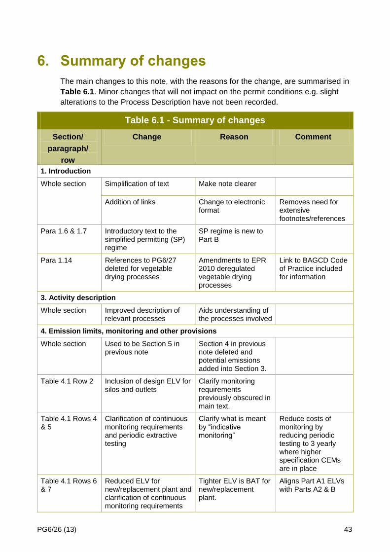
PG6/26 (13) 43
6. Summary of changes
The main changes to this note, with the reasons for the change, are summarised in
Table 6.1. Minor changes that will not impact on the permit conditions e.g. slight
alterations to the Process Description have not been recorded.
Table 6.1 - Summary of changes
Section/
paragraph/
row
Change Reason Comment
1. Introduction
Whole section Simplification of text Make note clearer
Addition of links Change to electronic format
Removes need for extensive footnotes/references
Para 1.6 & 1.7 Introductory text to the simplified permitting (SP) regime
SP regime is new to Part B
Para 1.14 References to PG6/27 deleted for vegetable drying processes
Amendments to EPR 2010 deregulated vegetable drying processes
Link to BAGCD Code of Practice included for information
3. Activity description
Whole section Improved description of relevant processes
Aids understanding of the processes involved
4. Emission limits, monitoring and other provisions
Whole section Used to be Section 5 in previous note
Section 4 in previous note deleted and potential emissions added into Section 3.
Table 4.1 Row 2 Inclusion of design ELV for silos and outlets
Clarify monitoring requirements previously obscured in main text.
Table 4.1 Rows 4 & 5
Clarification of continuous monitoring requirements and periodic extractive testing
Clarify what is meant by “indicative monitoring”
Reduce costs of monitoring by reducing periodic testing to 3 yearly where higher specification CEMs are in place
Table 4.1 Rows 6 & 7
Reduced ELV for new/replacement plant and clarification of continuous monitoring requirements
Tighter ELV is BAT for new/replacement plant.
Aligns Part A1 ELVs with Parts A2 & B

PG6/26 (13) 44
Para 4.23 Text deleted – and monitoring requirements set out in Table 4.1
Clarification of continuous monitoring requirements for cyclones
Para 4.4 - 4.7 Amended text to explain approach to take to odorous emissions
Clarification of text
Para 4.9 - 4.11
Visible Emissions
Revised text describing approach to take to visible emissions.
Allows more flexibility in managing visible emissions
5. Control techniques
Whole section Used to be Section 6 in previous note
Section 4 in previous note deleted leading to re-numbering of sections
Para 5.16 Effluent & waste
Amended text to state that effluent is not expected to be produced from this sector.
Reduce emphasis on effluent as an odour source
Air Quality Clarification of exhaust velocity requirements
Make note clearer
Appendix 1 Inclusion of a new Appendix detailing a model application form for a simplified permit
Simplification of permitting process
Appendix 2 Inclusion of a new Appendix detailing a model simplified permit

PG6/26 (13) 45
7. Further information
Sustainable consumption and production (SCP)
Both business and the environment can benefit from adopting sustainable
consumption and production practices. Estimates of potential business savings
include:
£6.4 billion a year UK business savings from resource efficiency measures that cost little or nothing;
2% of annual profit lost through inefficient management of energy, water and waste;
4% of turnover is spent on waste.
When making arrangement to comply with permit conditions, operators are strongly
advised to use the opportunity to look into what other steps they may be able to
take. Local authority regulators may be willing to provide assistance and ideas,
although cannot be expected to act as unpaid consultants.
Health and safety
Operators of installations must protect people at work as well as the environment:
requirements of a permit should not put at risk the health, safety or welfare of people at work or those who may be harmed by the work activity;
equally, the permit must not contain conditions whose only purpose is to secure the health of people at work. That is the job of the health and safety enforcing authorities.
Where emission limits quoted in this guidance conflict with health and safety limits,
the tighter limit should prevail because:
emission limits under the relevant environmental legislation relate to the concentration of pollutant released into the air from prescribed activities;
exposure limits under health and safety legislation relate to the concentration of pollutant in the air breathed by workers;
these limits may differ since they are set according to different criteria. It will normally be quite appropriate to have different standards for the same pollutant, but in some cases they may be in conflict (for example, where air discharged from a process is breathed by workers). In such cases, the tighter limit should be applied to prevent a relaxation of control.

PG6/26 (13) 46
Further advice on responding to incidents
The UK Environment Agencies have published guidance on producing an incident
response plan to deal with environmental incidents. Only those aspects relating to
air emissions can be subject to regulation via a Part B (Part C in NI) permit, but
regulators may nonetheless wish to informally draw the attention of all appropriate
operators to the guidance.
It is not envisaged that regulators will often want to include conditions, in addition to
those advised in this PG note, specifying particular incident response arrangements
aimed at minimising air emissions. Regulators should decide this on a case-by-
case basis. In accordance with BAT, any such conditions should be proportionate
to the risk, including the potential for harm from air emissions if an incident were to
occur. Account should therefore be taken of matters such as the amount and type
of materials held on site which might be affected by an incident, the likelihood of an
incident occurring, the sensitivity of the location of the installation, and the cost of
producing any plans and taking any additional measures.

PG6/26 (13) 47
Appendix 1 - Application form
Application for a permit for an animal feed compounding process
Local Authority Pollution Prevention and Control
Pollution Prevention and Control Act, 1999
Environmental Permitting (England and Wales) Regulations 2010
When to use this form
Use this form if you are applying for a permit to a Local Authority to operate a an animal feed compounding process installation as defined in Schedule 1 to the Environmental Permitting Regulations. The appropriate fee must be enclosed with the application to enable it to be processed further. When complete, send the form and the fee and any additional information to: [Insert local authority address] If you need help and advice We have made the application form as straightforward as possible, but please get in touch with us at the local authority address given above if you need any advice on how to set out the information we need. For the purposes of Section G of the form, a relevant offence is any conviction for an offence relating to the environment or environmental regulation.
For Local Authority use
Application reference
Officer reference Date received
Introduction

PG6/26 (13) 48
LAPPC application form - to be completed by the operator
A The basics
A1 Name and address of the installation
Postcode: Telephone:
A2 Details of any existing environmental permit or consent
(for waste operations, include planning permission for the site, plus established use certificates, a certificate of lawful existing use, or evidence why the General Permitted Development Order applies.)
A3 Operator details
(The ‘operator’ = the person who it is proposed will have control over the installation in accordance with the permit (if granted).)
Name:
Trading name, if different:
Registered office address:
Principal office address, if different:
Company registration number:

PG6/26 (13) 49
A4 Any holding company?
Is the operator a subsidiary of a holding company within the meaning of section 1159 of the Companies Act 2006? If “yes” please fill in details of the ultimate holding company.
Yes No
Name:
Trading name, if different:
Registered office address:
Principal office address, if different:
Company registration number:
A5 Who can we contact about your application?
It will help to have someone who we can contact directly with any questions about your application. The person you name should have the authority to act on behalf of the operator - This can be an agent or consultant.
Name and position:
Telephone:
Email:

PG6/26 (13) 50
B The installation
B1 Are you a manufacturer who produces compound animal feed?
Yes No
B2 Why is the application being made?
new installation
change to existing installation means it now needs a permit
B3 Site maps – please provide:
A location map with a red line round the boundary of the installation
Document reference:
A site plan or plans showing where all the relevant activities are on site:
a) where the processing plant will be installed
b) the areas and buildings/structures designated for materials and waste storage and the type of storage
c) the conveyors and transfer points
d) any directly associated activities or waste operations.
To save applying for permit variations, you can also show where on site you might want to use for storage etc in the future.
Document reference:
B4 Are there any sites of special scientific interest (SSSIs) or European protected sites nearer than any of the following distances to the proposed installation?
2km - for an installation which includes Part B combustion or incineration (not crematoria)
Yes No
0.5km for all other Part B activities
Yes No
If ‘yes’, is the installation likely to have a significant effect on the special scientific interest or European protected sites?
Yes No
If ‘yes’, please write on a separate sheet or enclose a relevant document explaining what the implications are for the purposes of the Conservation (Natural Habitats etc)
Regulations 1994 (see appendix 2 of Annex XVII of the general guidance manual)
Document reference:

PG6/26 (13) 51
B5 Will emissions from the activity potentially have significant environmental effects (including nuisance)?
Yes No
If ‘yes’, please list the potential significant local environmental effects (including nuisance) of the foreseeable emissions on a separate document.
Document reference:
If ‘yes’, please enclose a copy of any environmental impact assessment which has been carried out for the installation under planning legislation or for any other purpose.
Document reference:

PG6/26 (13) 52
C The details
C1 Do you extract odorous air from any part of your process and pass it through odour abatement plant? [informs conditions 1,3,4,7,11 & Table 1]
Yes No
If no, go to C5
If yes, what kind of odour abatement plant is it?
a) thermal oxidiser (tick all that apply)
b) chemical scrubber
c) bio- bed
d) bio-scrubber
e) other, please describe: ______________________________________________
C2 Is a condenser fitted before the odour treatment? [informs BAT]
Yes No
C3 If you have scrubbing equipment, is a mist eliminator fitted? [informs BAT]
Yes No
C4 Do you use any odour masking agents or counteractants at your site? [informs BAT]
Yes No
C5 Please list which of your process tanks/vessels have ventilation to maintain an adequate negative pressure, or alternatively, which have no such ventilation, whichever is the shorter list: [informs condition 5]
a) b) c) d)
e) f) g) h)
i) j) k) l)
C6 Please indicate the range of storage facilities used on site to store dusty materials: [informs condition 8, 9,10]
a) silo (tick all that apply)
b) bulk storage tank
c) in fully-enclosed containers/packaging?
d) other - please specify: ______________________________________________

PG6/26 (13) 53
C7 Do you have pneumatic loading/unloading for any dusty raw materials? [informs condition 8]
Yes No
If no, please go to C9.
If yes, will displaced air from pneumatic loading and unloading be:
a) vented to abatement plant (tick all that apply)
b) back-vented to the delivery tanker
c) other - please specify ____________________________________________
Does pneumatic transfer automatically stop for: [informs condition 8]
a) over-filling Yes No
b) over-pressurisation Yes No
If no, are any silos new since 1st August 2006? [informs condition 8]
Yes No
Do you have alarms to warn of overfilling? [informs condition 8]
Yes No
C8 Please list the identification numbers for all storage vessels with pneumatic loading/unloading for dusty materials:? [informs condition 8]
a) b) c) d)
e) f) g) h)
C9 How are dusty materials transferred/conveyed around site (external transfer)? [informs condition 9, 10]
a) fully-enclosed belt conveyors (tick all that apply)
b) fully-enclosed pneumatic transfer
c) fully-enclosed containers/packaging transported by vehicle/forklift
d) fully-enclosed bucket conveyors
e) unenclosed/uncontained transport by vehicle/forklift
f) other - please specify ___________________________________________

PG6/26 (13) 54
C10 Does your installation have particulate abatement equipment, with external discharge points, not serving silos or dryers with an airflow of:
[informs condition 11, 12, Table 1]
a) over 100m3/minute: Yes No (tick all that apply)
b) under 100m3/minute: Yes No
If yes, what kind of abatement equipment is in place?
a) wet scrubber (tick all that apply)
b) bag filtration plant (not in series with cyclones)
c) cyclones prior to bag filtration
d) cyclones without bag filtration
e) other, please describe:__________________________________________________
C11 Do you have continuous monitors to show compliance with a limit/provision in Table 1 of the simple permit? [informs 11,12, Table 1]
Yes No
If no go to C13.
If yes, do the continuous emissions monitors have alarms?
Yes No
If no go to C13
If yes, are the alarms:
a) visible (tick all that apply)
b) audible
c) interlocked to shut down the process
d) alarm activation recorded automatically
e) is a trigger level set Yes No
If so, at what percentage of the emission limit is the value set?…………………%
C12 Have you undertaken isokinetic sampling at least once to demonstrate compliance with the numerical limit in Table 1?
Yes No
C13 Will your process produce any dusty waste? [informs conditions 9, 10]
Yes No
If no, go to C19.
If yes, will any dusty materials/dusty waste be stored externally?
Yes No

PG6/26 (13) 55
C14 If yes, what facilities will be provided to store dusty waste externally?
a) silos (tick all that apply)
b) covered storage area for bagged dusty materials
c) lidded containment for loose dust
Please describe how loose dust is transferred from the source of loose dust to the storage area for loose dust:
d) other, please specify: ______________________________________________
C15 Do you have an odour response procedure (or plan)? [informs conditions 1,18,19]
Yes No
C16 Do you have environmental management procedures and policy?
[informs conditions 1,18,19]
Yes No

PG6/26 (13) 56
D Anything else?
Please tell us of anything else you would like us to take account of:
Document reference:
E Application fee
You must enclose the relevant fee with your application.
If your application is successful you will also have to pay an annual subsistence charge, so please say who you want invoices to be sent to.
Name and position:
Telephone:
Email:

PG6/26 (13) 57
F Protection of information
F1 Any confidential or national security information in your application?
If there is any information in your application you think should be kept off the public register for confidentiality or national security reasons, please say what and why. General guidance manual chapter 8 advises on what may be excluded. (Do not include any national security information in your application. Send it, plus the omitted information, to the Secretary of State or Welsh Ministers who will decide what, if anything, can be made public.)
Document reference :
F2 Please note: data protection
The information you give will be used by the Council to process your application. It will be placed on the relevant public register and used to monitor compliance with the permit conditions. We may also use and or disclose any of the information you give us in order to:
consult with the public, public bodies and other organisations;
carry out statistical analysis, research and development on environmental issues;
provide public register information to enquirers;
make sure you keep to the conditions of your permit and deal with any matters relating to your permit;
investigate possible breaches of environmental law and take any resulting action;
prevent breaches of environmental law;
offer you documents or services relating to environmental matters;
respond to requests for information under the Freedom of Information Act 2000 and the Environmental Information Regulations 2004; (if the Data Protection Act allows)
assess customer service satisfaction and improve our service.
We may pass on the information to agents/representatives who we ask to do any of these things on our behalf.
F3 Please note: it is an offence to provide false information
It is an offence under regulation 38 of the EP Regulations, for the purpose of obtaining a permit (for yourself or anyone else), to:
make a false statement which you know to be false or misleading in a material particular;
recklessly make a statement which is false or misleading in a material particular;
intentionally to make a false entry in any record required to be kept under any environmental permit condition;
with intent to deceive, to forge or use a document issued or required for any purpose under any environmental permit condition.
If you make a false statement:
we may prosecute you; and
if you are convicted, you are liable to a fine or imprisonment (or both).

PG6/26 (13) 58
G Declarations A and B for signing, please
These declarations should be signed by the person listed in answer to question A3. Where more than one person is identified as the operator, all parties should sign. Where a company or other body corporate is the operator, an authorised person should sign and provide evidence of authority from the board.
Declaration A: I/We certify
EITHER - As evidence of my/our competence to operate this installation in accordance with the EP Regulations, no offences have been committed in the previous five years relating to the environment or environmental regulation.
OR - The following offences have been committed in the previous five years which may be relevant to my/our competence to operating this installation in accordance with the regulations:
Signature: Name:
Position: Date:
Declaration B:
I/We certify that the information in this application is correct. I/We apply for a permit in respect of the particulars described in this application (including the listed supporting documentation) I/we have supplied.
(Please note that each individual operator must sign the declaration themselves, even if an agent is acting on their behalf.)
Signature: Name:
Position: Date:
Signature: Name:
Position: Date:
Signature: Name:
Position: Date:

PG6/26 (13) 59
Appendix 2 - Model Permit
This Appendix contains a model permit for animal feed compounding processing installations – see [insert relevant para from introduction] of this note and paragraph 3.6 of the General Guidance Manual on Policy and Procedures.
Notes:
text in the model permit written in italics is advice to regulators.
text in the model permit in [square brackets] offers choice to regulators or indicates where information needs to be inserted from the application;
text bracketed with asterisks (eg *Alarms shall be tested at least once a week*.) may be omitted by a regulator where the past performance of the plant gives the local authority sufficient reassurance about operator compliance – “earned recognition”;
the model permit has been drafted for local authorities in England and Wales. Regulators in Scotland and Northern Ireland will need to amend the legal heading and, where appropriate, references to ‘Council’;
references to ‘installation’ will need to be substituted with ‘mobile plant’ in relevant cases, and other amendments made accordingly;
the purpose of the activity description is to set down the main characteristics of the activity, including any directly associated activities, so it is clear to all concerned what is being authorised by the permit and therefore what changes would need further approval. Regulators are advised to include a description of any key items of abatement and monitoring equipment the operator intends to use or is using;
it should normally be sufficient for records relating to simplified permits to be kept until the next inspection or for 24 months whichever is the longer.

PG6/26 (13) 60
[ ] COUNCIL POLLUTION PREVENTION AND CONTROL ACT 1999 Environmental Permitting Regulations 2010 (as amended)
Permit ref. no:
Name and address of person (A) authorised to operate the installation (‘the operator’): Registered number and office of company: (if appropriate)
Address of permitted installation (B)
The installation boundary and key items of equipment mentioned in permit conditions are shown on the plans attached to this permit.
Activity description

PG6/26 (13) 61
Conditions
The operator (A) is authorised to operate the activity1 at the installation (B) subject to the following conditions.
1. The operator shall:
contain processing operations within a building and prevent the release of uncontrolled emissions;
extract odorous air;
have a written odour response plan
Emissions
2. No visible particulate matter shall be emitted beyond the installation boundary.
[Odour abatement plant (delete condition if no odour abatement plant serves the activity)
3. The operator shall ensure that:
collected air is discharged through odour abatement plant.]
4. Where odour abatement equipment is installed: [The odour abatement equipment shall be inspected not less than once a day for at least the following: delete non-applicable bullet points
leaks or blockages in air handling equipment, ductwork and abatement equipment;
continuous monitors for abatement equipment;
surface cracking, voids, leaks, compaction, moisture content, and plant/weed growth on biofilters.
Processing (tanks, vessels, grinders, coolers and extruders)
5. All process tanks and vessels shall be loaded to minimise spillage and disturbance to materials;
6. Choose one of the following conditions depending on the answers in the application form:
EITHER Process equipment shall be vented to maintain an adequate negative pressure and have ventilation equipment vented to odour control plant [except for list of equipment that does not have emissions captured and collected].
OR [List process equipment that is vented to maintain negative pressure and have ventilation equipment vented to odour control plant] shall be vented to maintain an adequate negative pressure and have ventilation equipment vented to odour control plant.
Good hygiene for odour control (delete bullets and conditions that do not apply)
7. To minimise emissions of odour, the operator shall ensure that:
the buildings, equipment and containers that hold raw materials and waste materials can be, and are, cleaned effectively, and are kept in good condition;
liquids drain appropriately;
vehicles and containers are cleaned appropriately;
1 listed in [ ] in Part 2 of Schedule 1 to the Environmental Permitting Regulations

PG6/26 (13) 62
Silos and bulk tanks where pneumatic transport is used
8. Materials delivered by pneumatic transport shall only be stored within [xxxxxx] silos. Silos and bulk containers of dusty materials shall not be overfilled and there shall be an overfilling alarm. When loading [xxxx] silos, ensure delivery is at a rate which does not pressurise the silo. [For silos, new or replacement plant since August 2006, deliveries must stop automatically where over-pressurisation or over-filling is identified]. Displaced air from pneumatic transfer shall pass through abatement plant prior to emission to air.
Other bulk, loose, dry material - storage and loading and transport around site
(adapt conditions 9 or 10 to the type of storage and methods of site conveyance/transport)
9. Dusty materials (including dusty wastes) shall only be stored in [specify storage locations] as detailed on the plan attached to this permit and their storage and transfer shall be subject to suppression and management techniques to minimise dust emissions. No potentially dusty materials (including wastes) or finished products shall leave the site other than by use of [specify transport type and dust control technique].
10. All dusty materials, including wastes, shall be [conveyed] [transferred] using [specify type of transport or conveyor, level of enclosure and enclosure type]. All transfer points shall be fitted with [specify dust control technique].
Monitoring provisions
11. The emission requirements and methods and frequency of monitoring set out in Table 1 and Table 2 shall be complied with. Sampling shall be representative.
12. Any monitoring display required for compliance with the permit shall be visible to operating staff at all times. Corrective action shall be taken immediately if any periodic monitoring result exceeds a limit in Table 1, or if there is a malfunction or breakdown of any equipment which might increase emissions. Monitoring shall be undertaken or repeated as soon as possible thereafter and a brief record shall be kept of the main actions taken.
13. All continuous monitors fitted to show compliance with the permit shall be fitted with a [visible] [audible] alarm warning of abatement failure or malfunction. They shall [activate when emissions reach [75%] of the relevant emission limit in Table 1 and] record automatically each activation. *Alarms shall be tested at least once a week.*
14. All plant and equipment capable of causing, or preventing, emissions and all monitoring devices shall be calibrated and maintained in accordance with the manufacturer’s instructions. *Records shall be kept of such maintenance*.
15. The operator shall, in the case of abnormal emissions, inform the regulator without delay if there is an emission likely to have an effect on the local community.
Effluent and Wastes capable of causing an odour
(It is not expected that effluent will be produced from this sector - delete bullets that do not apply)
16. Cesspits, effluent storage tanks and septic tanks shall be adequately covered.
[They and the waste storage and the collecting tanker shall be continuously vented to odour abatement plant].
[Effluent tanks should be fitted with level indicators or high level alarms to warn of potential overfilling].
17. Waste shall be removed frequently and at least once a week. When waste is moved between buildings and when it is outdoors, it shall be in sealed containers.

PG6/26 (13) 63
Records and training
18. Written or computer records of all tests and monitoring shall be kept by the operator until either the regulator’s next inspection or for [24] months, whichever is the longer. They shall be made available for examination by the Regulator. *Records shall be kept of operator inspections, including those for visible and odorous emissions.*
19. Staff at all levels shall receive the necessary training and instruction to enable them to comply with the conditions of this permit. *Records shall be kept of relevant training undertaken*.
The following two conditions are not needed for PPC permits which transferred automatically into the environmental permitting regime by virtue of regulation 69(6) of the 2007 Regulations and regulation 108(4) of the 2010 Regulations. Where permits are issued on or after 6 April 2008 the conditions will not automatically apply and need specific inclusion in the permit where required.
Best available techniques
20. The best available techniques shall be used to prevent or, where that is not practicable, reduce emissions from the installation in relation to any aspect of the operation of the installation which is not regulated by any other condition of this permit.
21. If the operator proposes to make a change in operation of the installation, he must, at least 14 days before making the change, notify the regulator in writing. The notification must contain a description of the proposed change in operation. It is not necessary to make such a notification if an application to vary this permit has been made and the application contains a description of the proposed change. In this condition ‘change in operation’ means a change in the nature or functioning, or an extension, of the installation, which may have consequences for the environment.

PG6/26 (13) 64
Permit writer to delete rows that do not apply
Table 1 - Emission limits, monitoring and other provisions
Ro
w Substance Source Emission limits/provisions
(see also a – e)
Type of monitoring Monitoring frequency
(see note g)
1 Odour
(see Note 1 below)
Contained process releases
Any odour arrestment plant installed on high intensity emissions should have an odour removal efficiency of not less than 85% (see also note f).
Determination by manual extractive sampling and analysis by dynamic olfactometry in accordance with BS EN 13725.
On installation of new / replacement odour arrestment equipment and / or in the circumstances described in Note 2, below).
Note 1 – the overall aim should be that all emissions are free from offensive odour outside the site boundary, as perceived by the regulator.
Note 2 - when offensive odours are detected beyond the process boundary or complaints are received and there is no obvious cause of odour release then the operator shall check the odour abatement plant performance using Table 2 guide values and check the process operational controls. If notified by the regulator, odour removal efficiencies shall be retested.
2 Particulate matter
Whole site No visible emission Visual observations with particular attention to areas where dust may be generated
When requested by the regulator
3 Particulate matter
Silo inlets and outlets (for silos new or replacement plant since 1st August 2005)
Designed to emit less than 10mg/m3
Visual observations At time of delivery
4 Particulate matter
Wet scrubbers 20mg/m3 Extractive Annual

PG6/26 (13) 65
5 Particulate matter
Contained process sources (not silos) other than product coolers
(see also note g)
20mg/m3 EITHER
Filter leak monitor
provide visual alarms
record trend output and alarms
plus
extractive test to set up levels at which alarms will activate
continuous
plus
every 3 years
OR
Gross filter failure device
provide audible and visual alarms
plus
extractive test
continuous
plus
annual
6 Particulate matter
Plant serving product coolers using dry bag filtration
(see also note g)
Existing plant:
50mg/m3
EITHER
Filter leak monitor
provide visual alarms
record trend output and alarms
plus
extractive test to set up levels at which alarms will activate
continuous
plus
every 3 years
OR
Gross filter failure device
provide audible and visual alarms
plus
extractive test
continuous
plus
annual
Plant serving product coolers using cyclones
Existing plant:
50mg/m3
Cyclones only:
Monitors that:
provide visible and audible alarms which activate on cyclone malfunction; and
interlocked to shutdown process when alarm activates
plus
extractive test
annual

PG6/26 (13) 66
7 Particulate matter
Plant serving product coolers using dry bag filtration
(see also note g)
New/replacement plant:
20mg/m3
EITHER
Filter leak monitor
provide visual alarms
record trend output and alarms
plus
extractive test to set up levels at which alarms will activate
continuous
plus
every 3 years
OR
Gross filter failure device
provide audible and visual alarms
plus
extractive test
continuous
plus
annual
Plant serving product coolers using cyclones
New/replacement plant:
20mg/m3
Cyclones only:
Monitors that:
provide visible and audible alarms which activate on cyclone malfunction; and
interlocked to shutdown process when alarm activates
plus
extractive test
annual
Notes
a) The reference conditions for limits in Table 1 are: 273.1K, 101.3kPa, without correction for water vapour content, unless stated otherwise.
b) All periodic monitoring shall be representative, and shall use standard methods.
c) *All periodic monitoring results shall be checked by the operator on receipt and sent to the Council within 8 weeks of the monitoring being undertaken.*
d) [The [ ] emission limits do not apply during start-up and shut down. All emissions shall be kept to a minimum during these periods].
e) The continuous monitoring provision should be disapplied where emissions do not exceed 20mg/m3 without the use of abatement plant. This should be demonstrated by a single representative sampling exercise. A further such monitoring exercise may be required in the event of a substantial change to the process.
f) Where the inlet odour concentrations are very low and the 85% destruction efficiency is difficult to demonstrate due to measurement reproducibility and equipment efficiency at low concentrations, the final discharge to air should contain less than 500 odour units/m3.
g) Where exhaust airflow is less than 100m3/min, indicative continuous monitoring is not required.

PG6/26 (13) 67
Permit writer to delete rows that do not apply
Table 2 - Odour abatement plant - Indicative guide provisions for monitoring
Type of Odour abatement plant
Indicative Guide Substance and Value Type of monitoring Monitoring frequency
Thermal oxidiser or combustion plant use as odour abatement plant
Emissions of carbon monoxide (CO) at:
100mg/m3 (expressed as a 30 minute mean at 273K and 101.3Pa); or
850oC
Carbon monoxide – recording, indicative monitor with visible and audible alarms
Temperature - Monitor and audible and visual alarms
Continuous
Scrubbing equipment Liquor flow Monitor and alarms (audible and visual) Continuous
Record daily
pH
or
Redox potentials established during commissioning
Monitor record and alarms (audible and visual) Continuous
Record daily
Bioscrubber (in addition to above)
Pressure drop across scrubber packing established during commissioning
Monitor and alarms (audible and visual) Continuous
Record daily
Biofilter Pressure drop across biofilter established during commissioning (delivery pressure of main fan is one suitable parameter)
Monitor and alarms (audible and visual)
Record trigger levels if level is varied (for example, winter/summer settings, change in number of fans in use)
Continuous
Record daily
Biobed Moisture
even flow
cracking
steam venting
Visual inspections Daily
Condensers for pre-treatment of emissions
Cooling liquid flow monitor Continuous
Notes
a) Testing of odour abatement plant should be carried out, if possible, when the process is operated at peak production (also taking ambient
temperature into account).
b) Destruction efficiency testing requires simultaneous sampling at inlet and outlet of abatement plant.
c) If emissions exceed this indicative guide value it is likely that the odour destruction efficiency of the odour abatement plant is reduced and the scrubber/biofilter should be further investigated to identify reasons for the reduced performance. This testing can be carried out using gas detection tubes. (further guidance on gas detection tubes is included in Appendix 4.

PG6/26 (13) 68
Right to Appeal
You have the right of appeal against this permit within 6 months of the date of the decision. The Council can tell you how to appeal [or supply details with the permit]. You will normally be expected to pay your own expenses during an appeal.
You will be liable for prosecution if you fail to comply with the conditions of this permit. If found guilty, the maximum penalty for each offence if prosecuted in a Magistrates Court is £50,000 and/or 6 months imprisonment. In a Crown Court it is an unlimited fine and/or 5 years imprisonment.
Our enforcement of your permit will be in accordance with the Regulators’ Compliance Code

PG6/26 (13) 69
Appendix 3 - Method for sampling of emissions from biological (earth, peat and heather) filters using gas detection tubes
Routine monitoring of emissions from biological filters can be readily undertaken
using gas detection tubes. However, it is important to ensure that a number of
representative samples are obtained and that care is taken in the interpretation of
results. The number of samples necessary will depend upon the gas distribution
within the biological filter.
It is essential that samples are taken from a representative volume of emitted gas
as near surface dispersion will significantly affect measured concentrations.
Therefore, it is necessary to reduce dispersion and obtain a volume of gas from
which to sample. This can be achieved by placing a purpose-made enclosure on top
of the filter bed and allowing the emitted gases to accumulate.
The enclosure itself should be approximately 0.5m3 - 1m3 in volume, preferably with
a 1m2 open base. The top of the enclosure should have an opening of
approximately 50mm diameter to facilitate sampling. The enclosure call be simply
fabricated using a timber frame and plywood or hardboard sides and top with mastic
or other suitable sealant applied to the side and top joints.
It will be extremely difficult to achieve a seal at the filter bed surface, however the
enclosure should be located in order to minimise leakage from the points of contact
with the filter bed. The enclosure should remain at the sample location for at least
10 minutes prior to sampling to ensure that a representative sample of emissions is
obtained (allowing the volume of the enclosure to be purged three times).
The gas detection tubes should be used in accordance with the manufacturer's
instructions. Amines and amides are a common interference with gas detection
tubes for ammonia and therefore results obtained from ammonia gas detection
tubes should be compared to a 2ppm v/v indicative guide value. It may be nec-
essary to monitor for hydrogen sulphide and mercaptans separately depending
upon the detector tube specification.
This method is only suitable for open biomass type biofilters where no final
discharge vent or stack exists.
Additional information is available in BS EN13725 - "Air Quality - Determination of
Odour Concentration by Dynamic Olfactometry" and "Odour Measurement and
Control-:\n Update "published by National Environmental Technology Centre,
Culham, Abingdon. Oxon OX14 3DB. ISBN 0-85624-8258.

PG6/26 (13) 70
Appendix 4 - Guidance on the preparation of an odour response procedure
What is an odour response procedure?
An odour response procedure is a summary, provided by the operator, of the
foreseeable situations which may compromise an ability to prevent and/or minimise
odorous releases from the process and the actions to be taken to minimise the
impact. It is intended to be used by operational staff on a day-to-day basis and
should detail the person responsible for initiating the action.
The procedure is intended primarily to document foreseeable events which are
outside of the control of the operator and those that are preventable by
maintenance and operational control (for example pump failure, biofilter compaction
or filter breakthrough). The procedure should include a maintenance programme for
any odour arrestment plant and other odour containment measures (such as
building structure, ventilation plant).
What is the format for the odour response procedure?
The odour response procedure should be a written document which is available on-
site and should be submitted to the regulator. The regulator may wish to set
conditions in the permit/authorisation which reflect the undertakings given in the
procedure (for example maximum arrestment plant by-pass times, reduced
throughput etc).
What should be included in the odour response procedure?
There are four main reasons for releases which may lead to emissions of offensive
odour which are:
1. Changes in process conditions leading to more odour generation or a change
in the odour characteristics.
2. Conditions which result in fugitive releases due to reduced odour containment.
3. Failures or reduced performance of odour abatement equipment.
4. Factors affecting the dispersion between the source and the receptor.
The occurrence of 2 and 3 above can be limited by the production of, and
compliance with, an effective plant and building maintenance programme.
Examples of other issues which should be considered in each of these categories
are given in Table A.
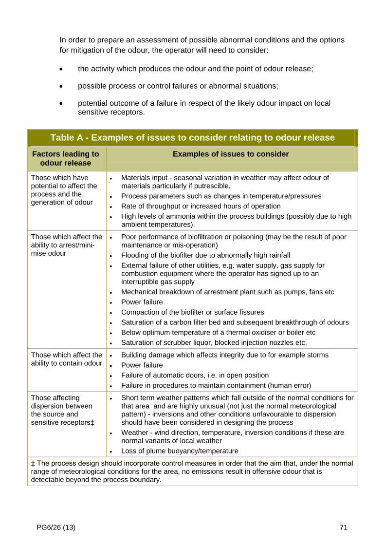
PG6/26 (13) 71
In order to prepare an assessment of possible abnormal conditions and the options
for mitigation of the odour, the operator will need to consider:
the activity which produces the odour and the point of odour release;
possible process or control failures or abnormal situations;
potential outcome of a failure in respect of the likely odour impact on local sensitive receptors.
Table A - Examples of issues to consider relating to odour release
Factors leading to odour release
Examples of issues to consider
Those which have potential to affect the process and the generation of odour
Materials input - seasonal variation in weather may affect odour of materials particularly if putrescible.
Process parameters such as changes in temperature/pressures
Rate of throughput or increased hours of operation
High levels of ammonia within the process buildings (possibly due to high ambient temperatures).
Those which affect the ability to arrest/mini-mise odour
Poor performance of biofiltration or poisoning (may be the result of poor maintenance or mis-operation)
Flooding of the biofilter due to abnormally high rainfall
External failure of other utilities, e.g. water supply, gas supply for combustion equipment where the operator has signed up to an interruptible gas supply
Mechanical breakdown of arrestment plant such as pumps, fans etc
Power failure
Compaction of the biofilter or surface fissures
Saturation of a carbon filter bed and subsequent breakthrough of odours
Below optimum temperature of a thermal oxidiser or boiler etc
Saturation of scrubber liquor, blocked injection nozzles etc.
Those which affect the ability to contain odour
Building damage which affects integrity due to for example storms
Power failure
Failure of automatic doors, i.e. in open position
Failure in procedures to maintain containment (human error)
Those affecting dispersion between the source and sensitive receptors‡
Short term weather patterns which fall outside of the normal conditions for that area and are highly unusual (not just the normal meteorological pattern) - inversions and other conditions unfavourable to dispersion should have been considered in designing the process
Weather - wind direction, temperature, inversion conditions if these are normal variants of local weather
Loss of plume buoyancy/temperature
‡ The process design should incorporate control measures in order that the aim that, under the normal range of meteorological conditions for the area, no emissions result in offensive odour that is detectable beyond the process boundary.