process gas chromatographs - debimetre, · pdf fileprocess gas chromatography is one of the...
TRANSCRIPT
Siemens PA 01 · 2009
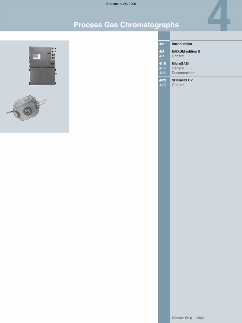
4/2 Introduction
4/3 MAXUM edition II4/3 General
4/15 MicroSAM4/15 General4/22 Documentation
4/23 SITRANS CV4/23 General
Process Gas Chromatographs
© Siemens AG 2008
Process Gas ChromatographsIntroduction
4/2 Siemens PA 01 · 2009
4
Overview
Process gas chromatography is one of the most powerful mea-suring and analysis methods for process engineering. It is a pro-cedure which is both discrete and extractive. This procedure is frequently used for online monitoring of processes since the se-quences are easy to automate and a large number of compo-nents can be measured simultaneously.
Process gas chromatography can be used to separate and quantify the components of almost all homogenous gaseous or liquid mixtures. It must be possible to vaporize the liquid compo-nents without decomposition. The individual components of a discrete sample pass through the column system at different ve-locities, and are recorded in succession by a detector.
The time between sample introduction and registering of a sub-stance at the detector (the retention time) is a characteristic of the substance and is used to identify it. The magnitude of the de-tector signal is a measure of the volume concentration of the component in the gas.
© Siemens AG 2008
Process Gas ChromatographsMAXUM edition II
General
4/3Siemens PA 01 · 2009
4
Overview
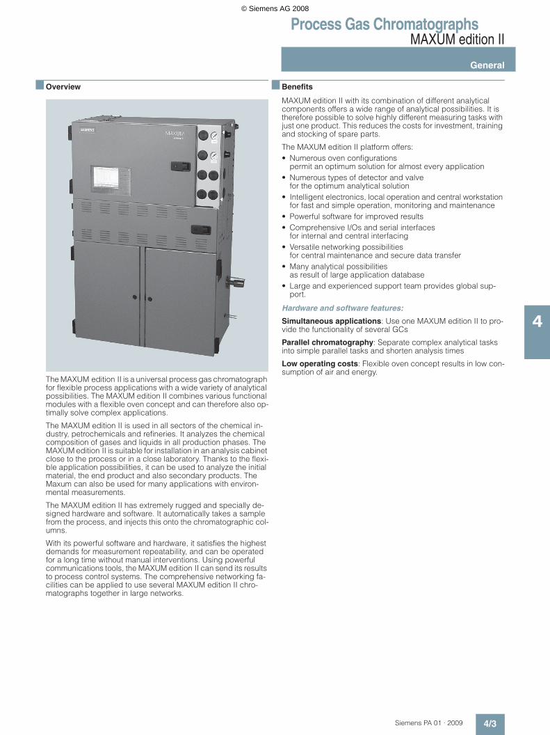
The MAXUM edition II is a universal process gas chromatograph for flexible process applications with a wide variety of analytical possibilities. The MAXUM edition II combines various functional modules with a flexible oven concept and can therefore also op-timally solve complex applications.
The MAXUM edition II is used in all sectors of the chemical in-dustry, petrochemicals and refineries. It analyzes the chemical composition of gases and liquids in all production phases. The MAXUM edition II is suitable for installation in an analysis cabinet close to the process or in a close laboratory. Thanks to the flexi-ble application possibilities, it can be used to analyze the initial material, the end product and also secondary products. The Maxum can also be used for many applications with environ-mental measurements.
The MAXUM edition II has extremely rugged and specially de-signed hardware and software. It automatically takes a sample from the process, and injects this onto the chromatographic col-umns.
With its powerful software and hardware, it satisfies the highest demands for measurement repeatability, and can be operated for a long time without manual interventions. Using powerful communications tools, the MAXUM edition II can send its results to process control systems. The comprehensive networking fa-cilities can be applied to use several MAXUM edition II chro-matographs together in large networks.
Benefits
MAXUM edition II with its combination of different analytical components offers a wide range of analytical possibilities. It is therefore possible to solve highly different measuring tasks with just one product. This reduces the costs for investment, training and stocking of spare parts.
The MAXUM edition II platform offers:• Numerous oven configurations
permit an optimum solution for almost every application • Numerous types of detector and valve
for the optimum analytical solution • Intelligent electronics, local operation and central workstation
for fast and simple operation, monitoring and maintenance• Powerful software for improved results• Comprehensive I/Os and serial interfaces
for internal and central interfacing • Versatile networking possibilities
for central maintenance and secure data transfer• Many analytical possibilities
as result of large application database• Large and experienced support team provides global sup-
port.
Hardware and software features:
Simultaneous applications: Use one MAXUM edition II to pro-vide the functionality of several GCs
Parallel chromatography: Separate complex analytical tasks into simple parallel tasks and shorten analysis times
Low operating costs: Flexible oven concept results in low con-sumption of air and energy.
© Siemens AG 2008

Process Gas ChromatographsMAXUM edition II
General
4/4 Siemens PA 01 · 2009
4
Application
Chemical industry • Monitoring of benzene in styrene in the ppb range• Traces of residual gases in ultra-pure gases• Determination of traces of hydrocarbons in air separation
plants• Fast analysis of CS2 and H2S in seconds • Fast measurement of C6 to C8 aromatic compounds including
the measurement of C9+ aromatics• Monitoring of hydrogen in chlor-alkali plants • Measurement of sulfurous components• Measurement of C9 to C18 paraffins • Determination of vinyl chloride in room air in a 60-second
cycle• Gas analysis during manufacture of vinyl chloride monomer
(VCM)
Oil & gas• Crack gas analysis • Natural gas: chromatographic determination of hydrocarbon
dew point and calorific value• Fast determination of benzene in naphtha• Determination of high boiling aromatics in a distillation fraction• Fast measurement of acetylene in ethylene• Total sulfur in petrol and diesel
Water/waste water• Determination of halogenated hydrocarbons• Simultaneous determination of chlorinated hydrocarbons,
aromatics and alcohols in water• Wastewater monitoring with PGC and stripper
Power engineering• Power generation in coal-fired power plant
Automotive industry• Fast analytical measurement of methane in car exhausts• High-speed chromatography for small molecules in propel-
lants
Design
Chromatographic measuring equipment consists of a sampling system matched to the application, sample preparation with switchover to various sample streams, and the gas chromato-graph with the analytical and electronic hardware as well as data processing, operation and communications software.
The MAXUM edition II gas chromatograph is divided into three sections: • The upper section contains the electronics with the power
supply, controllers and analog electronics. • The center section contains the pneumatics and some of the
detectors.• The bottom section contains the oven and the complete ana-
lytical components responsible for the separation.
The MAXUM edition II is available prepared for wall mounting or for free mounting on a rack.
Extension of functionality
Network Access Unit (NAU):• A MAXUM edition II without analytical section• Available with or without HMI• Has 7 slots for optional I/O plug-in cards• Offers central Modbus connection of several chromatographs
to the control system
CAN expansion unit:
For 10 additional I/O plug-in cards which can be controlled over the CAN bus.Can be connected to the NAU or directly to any MAXUM edition II or MicroSAM chromatograph.
DataNET Hub:• Converts standard Ethernet into a completely redundant
DataNET.• Uses twisted standard pairs or glass-fiber technology.• Covers large distances.
Function
Supply with carrier gas, combustion gas and auxiliary gases
A gas chromatograph must be supplied with carrier gas and, if applicable, combustion gas and other auxiliary gases. The car-rier gas is used to transport the sample through the analytical system. Auxiliary gases are used to operate valves, as combus-tion gases for flame ionization detectors, and to purge the oven.
Injection system
The injection system is the link between the continuous process stream and the discrete analytical process. It is responsible for injecting an exactly defined portion of the sample in a reproduc-ible and pulsed manner (as far as possible) into the carrier gas stream. The injection can be carried out in the conventional manner us-ing valves or by means of a live injection:• Gaseous samples (0.1 to 5 ml)• Vaporizable liquid samples (0.1 to 10 µl)
Gas injection valves
Model 50 10-port valve:• Combined gas injection and backflushing valve• Activation by pressure on the membrane without moving parts
Model 11 6-port valve:• Can be used as gas injection valve, liquid injection valve or for
column switching • Membrane controlled by tappet• One million switching cycles without maintenance
Liquid injection valve FDV
A constant quantity of a liquid sample can be automatically in-jected using the liquid injection valve, and subsequently vapor-ized rapidly and completely. The valve can also be used to inject small volumes of gas.
The liquid injection valve consists of three sections:• Thermostatically-controlled vaporization system• Sample passage section with seal• Pneumatic drive
© Siemens AG 2008

Process Gas ChromatographsMAXUM edition II
General
4/5Siemens PA 01 · 2009
4
Liquid injection valve FDV
Features:• Vaporization temperature 60 to 400 °C• Injection volume 0.3 to 9.5 µl• Ambient temperature -20 to +150 °C• Material of parts wetted by sample: Stainless steel,
mat. no. 1.4571, Hastelloy, Monel or special materials• Control pressure 400 to 600 hPa• Max. sample pressure 5 000 hPa, recommended 0.5 to
1 000 hPa• Connections for pipe: 3 mm outer diameter
Live injection• Flexible selection of the injection volume which is exactly
matched to the requirements of the columns is possible with a live injection
Live injection
Oven
A further important factor for the separating performance is the temperature This has a very high influence on the vapor pres-sure of the individual components, and thus on the diffusion between the mobile and stationary phases of the column. This influences the retention times, and thus the identification of com-ponents. Therefore very high demands are placed on the tem-perature stability of the oven and also on the injection equipment and the detectors.
Two different types of oven are available:
Airless oven for extremely stable isothermal oven temperatures (0.02 °C control accuracy) up to 280 °C.
Airbath oven for • isothermal (5 to 225 °C) or • temperature-programmed mode
Both types of oven are available as• single ovens or • dual ovens.
With the dual ovens, two separate heating circuits provide inde-pendent oven temperatures. It is then possible to carry out two different applications in one chromatograph.
In order to measure sample components with highly different vol-atilities, a temperature program is frequently used for the chro-matographic separation. In this case the column temperature is continuously increased according to a selectable heating-up rate. This method (PTGC) is available with the MAXUM edition II.
© Siemens AG 2008

Process Gas ChromatographsMAXUM edition II
General
4/6 Siemens PA 01 · 2009
4
The internal oven consists of a chamber with low thermal capac-ity located within the standard oven. It contains the capillary column used for the separation.
The ovens have separate, independent temperature control. The temperature of the internal oven is freely-programmable. The temperature changes according to the time-dependent profile assigned to the respective analysis. Up to three linear ramps and four constant periods can be configured.
It is then possible to determine components with low and high boiling points in one analysis. Laboratory applications can be opened up by PTGC for use in the process industry.
"Simulated distillation" is an important application of PTGC in re-fineries. The distillation range – a quality criterion for fuels – is chromatographically traced "online".
Columns
The columns are the central component of the chromatograph. They resolve the gas mixture into its individual components. The following distinction is made:• Packed/micropacked columns with inner diameter of 2 to
5 mm and • capillary columns with inner diameter of 0.15 to 0.53 mm.
Packed columns are mechanically stable and simple to handle. Capillary columns have a significantly higher separating perfor-mance, often with a shorter analysis period and lower analysis temperature.
Types of column
© Siemens AG 2008

Process Gas ChromatographsMAXUM edition II
General
4/7Siemens PA 01 · 2009
4
Column switching systems
Process chromatographs are almost always equipped with col-umn switching functions. Column switching is understood to be the combination of several columns in the carrier gas path which are arranged in succession or parallel. These columns usually have different separating performances, and are interconnected by valves for switching over the gas path. A distinction is made between backflushing, cut and distribution.
A wide range of techniques is available for column switching.
The techniques comprise highly stable membrane gas valves, membrane piston valves, sliding vane rotary valves and also valveless switching techniques.
Valves
Model 50 10-port valve:• Combined gas injection and backflushing valve• Activation by pressure on the membrane without moving parts• Switches gas samples at an overpressure of 0 to 5 000 hPa
Model 11 6-port valve:• Can be used as gas injection valve, liquid injection valve or for
column switching • Membrane controlled by tappet• One million switching cycles without maintenance
Valveless switching technique
The valveless live column switching is exactly controlled by elec-tronic pressure regulators, and prevents falsification of results since the sample does not come into contact with valves. A spe-cial pressure-controlled coupling element connects the capillary columns.
This technique is optimally suitable for capillary columns, and offers the best long-term stability and reliability. Live column switching is a technique where backflushing, cut or distribution is carried out on two different columns without any switching of valves or other moving components in the separation path.
This is achieved using a unique coupling unit, the live T-piece. Its function is based on a pressure difference controlled by the electronic precision pressure controllers of the MAXUM edition II. Because there is no dead volume whatsoever, it is ideally suit-able for the low flow rates used with capillary columns. Mainte-nance of the column switching configuration is then superfluous, the separating performance is improved, and complicated sep-arating procedures are simplified.
Column switching systems (examples)
© Siemens AG 2008
Process Gas ChromatographsMAXUM edition II
General
4/8 Siemens PA 01 · 2009
4
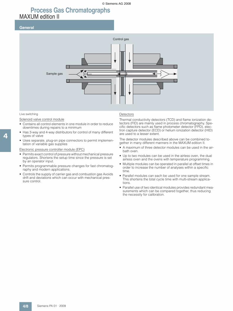
Live switching
Solenoid valve control module• Contains all control elements in one module in order to reduce
downtimes during repairs to a minimum• Has 3-way and 4-way distributors for control of many different
types of valve• Uses separate, plug-on pipe connectors to permit implemen-
tation of variable gas supplies
Electronic pressure controller module (EPC)• Permits exact control of pressure without mechanical pressure
regulators. Shortens the setup time since the pressure is set by an operator input.
• Permits programmable pressure changes for fast chromatog-raphy and modern applications.
• Controls the supply of carrier gas and combustion gas Avoids drift and deviations which can occur with mechanical pres-sure control.
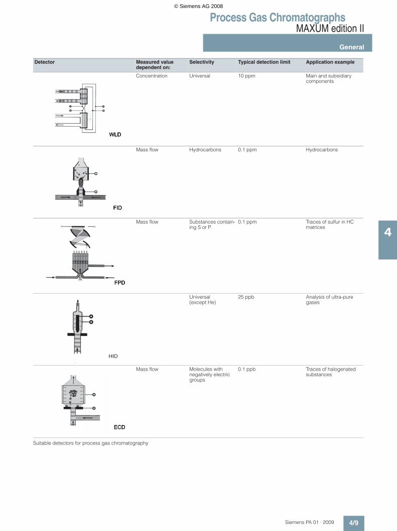
Detectors
Thermal conductivity detectors (TCD) and flame ionization de-tectors (FID) are mainly used in process chromatography. Spe-cific detectors such as flame photometer detector (FPD), elec-tron capture detector (ECD) or helium ionization detector (HID) are used to a lesser extent.
The detector modules described above can be combined to-gether in many different manners in the MAXUM edition II. • A maximum of three detector modules can be used in the air-
bath oven.• Up to two modules can be used in the airless oven, the dual
airless oven and the ovens with temperature programming.• Multiple modules can be operated in parallel at offset times in
order to increase the number of analyses within a specific time.
• Parallel modules can each be used for one sample stream. This shortens the total cycle time with multi-stream applica-tions.
• Parallel use of two identical modules provides redundant mea-surements which can be compared together, thus reducing the necessity for calibration.
© Siemens AG 2008
Process Gas ChromatographsMAXUM edition II
General
4/9Siemens PA 01 · 2009
4
Suitable detectors for process gas chromatography
Detector Measured value dependent on:
Selectivity Typical detection limit Application example
Concentration Universal 10 ppm Main and subsidiary components
Mass flow Hydrocarbons 0.1 ppm Hydrocarbons
Mass flow Substances contain-ing S or P
0.1 ppm Traces of sulfur in HC matrices
Universal (except He)
25 ppb Analysis of ultra-pure gases
Mass flow Molecules with negatively electric groups
0.1 ppb Traces of halogenated substances
HID
© Siemens AG 2008

Process Gas ChromatographsMAXUM edition II
General
4/10 Siemens PA 01 · 2009
4
Thermal conductivity detectors (TCD)
The measuring principle of the TCD is based on the difference between the thermal conductivity of a pure carrier gas stream and that of a gas mixture containing carrier gas and a compo-nent eluted from the column. Therefore all components whose thermal conductivity differs from that of the pure carrier gas can be detected by a TCD.
TCDs mainly comprise two measuring cells and two reference cells which are electrically heated and contain wire resistors connected in the circuit of a Wheatstone bridge.
The bridge resistors are balanced as long as pure carrier gas flows through the measuring and reference cells. If a mixture of carrier gas and sample component flows through the sample chamber, the change in thermal conductivity of the gas mixture also changes the temperature and thus the resistance of the heating wires.
The resulting offset in the bridge circuit is directly proportional to the current concentration of the sample component in the carrier gas stream.
Versions of TCDs:• Thermistor detector• Filament detector
Both detectors are available for universal use, except that the filament detector is more sensitive than the thermistor detector and can also be used at higher temperatures. The thermistor detector is available as a block with 6 measuring detectors and two reference detectors. The filament detector is available as a 4-fold block.
Flame ionization detector (FID)
With the flame ionization detector (FID), the gas mixture leaving the column is burnt in a hydrogen flame. If this gas mixture con-tains flammable organic compounds, ions are generated during the combustion which are collected on an electrode.
An electrode voltage is applied between the nozzle from which the flame burns and the electron collector positioned above it.
The resulting current is amplified, and is the measured signal.
In contrast to the TCD (concentration-dependent signal), the sig-nal with the FID is proportional to the mass flow of the compo-nents.
The FID features a linear range of 6 to 7 powers of ten, and per-mits detection limits of less than 0.1 ppm (referred to the concen-tration of the hydrocarbon in the sample). Non-flammable com-ponents (e.g. inert gases and water) cannot be measured with the FID.
In addition to the carrier gas, hydrogen and air are required as the flame gases to operate this detector.
Flame photometer detector (FPD)
Further detector principles are used for determination of trace concentrations of specific components. For example, the flame photometer detector is used to determine traces of compounds containing sulfur or phosphor. The emission of light of character-istic wavelengths is measured when burning the substances in a hydrogen flame.
Pulsed discharge detector (PDD)
The detector can be used in three different versions: HID (helium ionization detector), ECD (electron capture detector) and PID (photo ionization detector). Installation in the Maxum GC is pos-sible without further modification, and the detector can only be used in non-hazardous areas. The PDD uses stable, pulsed DC discharges in helium as the ionization source. The detector’s performance data is equal to or better than that of detectors which use radioactive ionization sources. Since a radioactive source is not used, the complex directives for radiation protec-tion need not be observed by the customer.• PDHID (helium ionization detector)
The PDHID works almost destruction-free with an ionization rate of 0.01 to 0.1%, and has a high sensitivity. The sensitivity for organic components is linear over five orders of magni-tude, and the detection limit is in the low ppb range. The PDHID can be used universally for organic and inorganic components, with the exception of helium and neon.
• PDECD (electron capture detector)In electron capture mode, sample components with a high electron affinity can be selectively detected, such as haloge-nated hydrocarbons. The detector’s properties and sensitivity are comparable with those of a 63Ni ECD. It is necessary to use a supplementary gas in this mode (recommended: 3% xenon in helium).
• PDPID (photo ionization detector)Addition of argon, krypton or xenon to the carrier gas results in ionization of the added gas. The detector is used in this con-figuration for selective detection of aliphatic compounds, aro-matic compounds and amines. The selectivity can be deter-mined through the choice of added gas. The sensitivity in this mode is limited to sample components whose ionization po-tential is below the emission energy of the added gas.
Accessories: Catalytic air purifier
Instrument air is usually contaminated by traces of hydrocar-bons. If this air is used as the combustion gas for a flame ioniza-tion detector (FID), the impurities are evident as disturbing back-ground noise.
The catalytic air purifier eliminates interfering impurities of hydro-carbons in the combustion air for the FID detector. The products of the catalytic oxidation (H2O, CO2) have no influence on the detector. Use of the catalytic air purifier significantly reduces the background noise. It has a flameproof enclosure and is therefore explosion-proof.
The air within the purifier is passed through a spiral lined with palladium. This metal spiral is heated up to approx. 600 °C. Palladium has a high activity at this temperature, and almost complete catalytic oxidation is achieved despite the short dwell time. The air subsequently passes through a cooling loop, and is output purified and cooled.
Parallel chromatography
This function divides a complex application into several simple sub-applications which are analyzed in parallel. This reduces the cycle times.
The hardware and software of the MAXUM edition II permit a complex chromatographic analysis to be divided into several simple analyses. Each of these simple analyses can then be si-multaneously executed in parallel. This not only simplifies the complete analysis, it can also be carried out faster and with greater reliability.
© Siemens AG 2008

Process Gas ChromatographsMAXUM edition II
General
4/11Siemens PA 01 · 2009
4
State-of-the-art communication
TCP/IP communication and standard Ethernet hardware mean that MAXUM edition II is compatible with many networks.
Software
For simple operation and maintenance, MAXUM edition II offers an online software system with local operation over an HMI and a flexible GUI accessible using a computer workstation.
The online software system is installed in every MAXUM edition II or NAU and includes:• Embedded EZChrom evaluation• Embedded MaxBasic in the runtime version• Communications software, network software, I/O driver in
order to operate the GC.
The workstation software consists of:• MAXUM edition II workstation tools:• System manager for network overview• EZChrom method builder• MMI maintenance panel emulator• Data logger• MODBUS download utility• Backup and restore utilities• Online system download utilities• Optichrom Advance APC version 8.1
(emulation of old Optichrom operation)• Online help and documentation
and optional packages for individual ordering, e.g.:• MaxBasic editor • Simulated distillation method• Air monitor reporter • OPC communications server.
Compatibility
MAXUM edition II is compatible with all older types of chromato-graph from Siemens: PGC 302, RGC 202, Advance Maxum, Op-tichrom Advance.
Application
Certain parameters must be observed during application and subsequent operation of the MAXUM edition II. It can then be determined qualitatively whether the task is fulfilled. The basic prerequisite for this is that all components can be detected clearly isolated from the interfering components. Important pa-rameters are: Analysis period, measuring ranges, detection lim-its and repeatability of the results.
© Siemens AG 2008
Process Gas ChromatographsMAXUM edition II
General
4/12 Siemens PA 01 · 2009
4
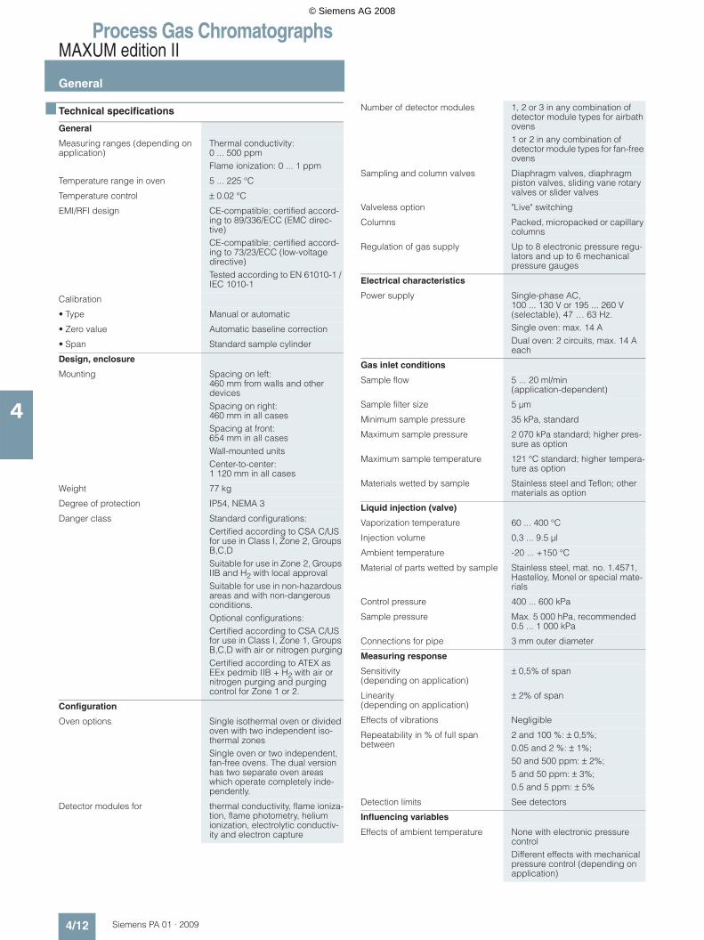
Technical specifications
General
Measuring ranges (depending on application)
Thermal conductivity: 0 ... 500 ppmFlame ionization: 0 ... 1 ppm
Temperature range in oven 5 ... 225 °C
Temperature control ± 0.02 °C
EMI/RFI design CE-compatible; certified accord-ing to 89/336/ECC (EMC direc-tive)CE-compatible; certified accord-ing to 73/23/ECC (low-voltage directive)Tested according to EN 61010-1 / IEC 1010-1
Calibration
• Type Manual or automatic
• Zero value Automatic baseline correction
• Span Standard sample cylinder
Design, enclosure
Mounting Spacing on left: 460 mm from walls and other devicesSpacing on right: 460 mm in all casesSpacing at front: 654 mm in all casesWall-mounted unitsCenter-to-center: 1 120 mm in all cases
Weight 77 kg
Degree of protection IP54, NEMA 3
Danger class Standard configurations:Certified according to CSA C/US for use in Class I, Zone 2, Groups B,C,DSuitable for use in Zone 2, Groups IIB and H2 with local approvalSuitable for use in non-hazardous areas and with non-dangerous conditions.Optional configurations:Certified according to CSA C/US for use in Class I, Zone 1, Groups B,C,D with air or nitrogen purgingCertified according to ATEX as EEx pedmib IIB + H2 with air or nitrogen purging and purging control for Zone 1 or 2.
Configuration
Oven options Single isothermal oven or divided oven with two independent iso-thermal zonesSingle oven or two independent, fan-free ovens. The dual version has two separate oven areas which operate completely inde-pendently.
Detector modules for thermal conductivity, flame ioniza-tion, flame photometry, helium ionization, electrolytic conductiv-ity and electron capture
Number of detector modules 1, 2 or 3 in any combination of detector module types for airbath ovens1 or 2 in any combination of detector module types for fan-free ovens
Sampling and column valves Diaphragm valves, diaphragm piston valves, sliding vane rotary valves or slider valves
Valveless option "Live" switching
Columns Packed, micropacked or capillary columns
Regulation of gas supply Up to 8 electronic pressure regu-lators and up to 6 mechanical pressure gauges
Electrical characteristics
Power supply Single-phase AC, 100 ... 130 V or 195 ... 260 V (selectable), 47 … 63 Hz.Single oven: max. 14 ADual oven: 2 circuits, max. 14 A each
Gas inlet conditions
Sample flow 5 ... 20 ml/min (application-dependent)
Sample filter size 5 µm
Minimum sample pressure 35 kPa, standard
Maximum sample pressure 2 070 kPa standard; higher pres-sure as option
Maximum sample temperature 121 °C standard; higher tempera-ture as option
Materials wetted by sample Stainless steel and Teflon; other materials as option
Liquid injection (valve)
Vaporization temperature 60 ... 400 °C
Injection volume 0,3 ... 9.5 µl
Ambient temperature -20 ... +150 °C
Material of parts wetted by sample Stainless steel, mat. no. 1.4571, Hastelloy, Monel or special mate-rials
Control pressure 400 ... 600 kPa
Sample pressure Max. 5 000 hPa, recommended 0.5 ... 1 000 kPa
Connections for pipe 3 mm outer diameter
Measuring response
Sensitivity (depending on application)
± 0,5% of span
Linearity (depending on application)
± 2% of span
Effects of vibrations Negligible
Repeatability in % of full span between
2 and 100 %: ± 0,5%;0.05 and 2 %: ± 1%;50 and 500 ppm: ± 2%;5 and 50 ppm: ± 3%;0.5 and 5 ppm: ± 5%
Detection limits See detectors
Influencing variables
Effects of ambient temperature None with electronic pressure controlDifferent effects with mechanical pressure control (depending on application)
© Siemens AG 2008

Process Gas ChromatographsMAXUM edition II
General
4/13Siemens PA 01 · 2009
4
Electrical inputs and outputs
Standard input and output 2 analog outputs; 4 digital outputs (1 for output of system faults, 3 are user-config-urable); 4 digital inputs; 1 serial output
Card slots for optional inputs and outputs
2
Input and output cards AO 8: 8 electrically isolated ana-log output channelsD IO: 4 digital inputs and 4 digital outputsA I/O: 2 digital inputs and 2 digital outputs, 2 analog inputs and 2 analog out-puts
Digital inputs Optocoupler with internal power supply (12 … 24 V DC); switch-able by floating contacts. Alternative: switchable by exter-nal power supply 12 … 24 V DC (only floating relay contacts), external power supply, negative connection linked to ground, for a specific digital input.
Digital outputs Floating changeover contacts, max. contact rating:1 A with 30 V DC. Diode bypass suppression should be used for inductive loads.
Analog inputs -20 ... +20 mA into 50 Ω or -10 ... +10 V Rin = 1 MΩ, alternate insulation up to 10 V
Analog outputs 0/4 ... 20 mA into max. 750 Ω, common negative pole, electri-cally isolated from ground; freely-connectable to ground
Termination Screw terminal for shielded or solid cable with a maximum area of 16 AWG or 1.5 mm2
Climatic conditions
Ambient temperature -18 ... 50 °C
Gas supply
Instrument air At least 350 kPa for units with valves Model 11 or ValcoAt least 825 kPa for units with valves Model 50At least 175 kPa for airbath ovens; 85 l/min per ovenNo instrument air for fan-free ovens
Carrier gas Nitrogen or helium in compressed gas cylinder, purity 99.998%, or hydrogen with a purity of 99.999% (depending on applica-tion).Typical consumption quantity: 5 100 l/month per detector module
Combustion gas Hydrogen with a purity of 99.999%Typical consumption quantity: 2 000 l/month per detector module
Combustion air Reference air (< 1 ppm THC, O2 concentration 20 … 21%). Supply through instrument air with catalytic purification (optional). Typical consumption quantity: 26 000 l/month
Corrosion protection Purging with dry air to protect the electronicsOven with stainless steel liningSteel lining painted on outside (epoxy powder coating)
Communication
Serial output RS232, RS485
Ethernet Standard 10BaseT Ethernet with RJ45 connectors
DataNET Special high-speed TCP/IP net-work (redundant pair of cables)
Data highway Special serial communication net-work (redundant pair of cables)
© Siemens AG 2008

Process Gas ChromatographsMAXUM edition II
General
4/14 Siemens PA 01 · 2009
4
Dimensional drawings
Notes: Only for airbath oven:Left outlet for applications with one single ovenLeft and right outlets for applications with divided oven
MAXUM edition II, dimensions in mm
© Siemens AG 2008

Process Gas ChromatographsMicroSAM
General
4/15Siemens PA 01 · 2009
4
Overview
The MicroSAM is a miniaturized process gas chromatograph (GC) in an Ex-d enclosure. Through consistent use of microsys-tem technology (silicon wafer technology), all analytical compo-nents are concentrated in the smallest possible area. The design particularly enables a distributed installation close to the pro-cess.
Benefits
• The distributed field installation reduces investment costs, and opens up new fields of application, e.g.: - Installation in plant areas where mounting within an analyzer
shed is not possible- Installation at remote locations without extended infrastruc-
ture• Reduction in laboratory analyses through online measure-
ments• Low space requirements in analysis cabinets reduce invest-
ment costs• Low maintenance effort and gas/energy consumption reduce
operating costs• High-resolution capillary columns permit fast analyses• Live injection permits representative sample injections• Maintenance-free, valveless separating column switching with
electronic pressure controllers• The use of several micro thermal conductivity detectors (mul-
tidetection) provides exact measuring results and also valida-tion possibilities
• Versatile networking possibilities for central maintenance and secure data transfer
• Remote monitoring with Windows-based software and Ether-net communication
• Simplified servicing through replacement of modules.
Application
Chemical industry• Analysis of ethylene in 1.2-dichloroethane (EDC) for process
control • Fast determination of nitrogen in acetylene for process control• Hydrocarbon analysis of starting product (LPG) of a cracker• Safety measurement of ethylene oxide during unloading of
tankers• Multicomponent analysis in ethylene oxide• Analysis of methanol, water and dimethylether in a pilot plant• Monitoring of coolant: Trace monitoring in chloromethane• Analysis of nitrogen and hydrogen in pure gas of a chloralkali
plant.
Oil & gas• Hydrogen analysis in recycled gas and other process gases• Analysis of inert gases and low-boiling paraffins/olefins in
combustion gas• Analysis of hydrogen and low-boiling hydrocarbons in re-
former/platformer plant• Trace analysis of impurities in acetylene from a cracker• Analysis of ethane in ethylene from a cracker• Measurement of calorific value in exhaust gas for quality con-
trol in a power plant• Analysis of ethylene in methane in an ethylene plant• Analysis of propadiene and propine in the C2 splitter of a
steam cracker• Analysis of low-boiling hydrocarbons in an ethylene plant/vis-
breaker• Analysis of calorific value in natural gas for power plants, in
gas transfer stations, or during turbine optimization• Analysis of exhaust gas in flares• Analysis of gas loop in a propylene oxide plant• Analysis of CO in crack gas in an LDPE plant• Analysis of refinery gas in a pilot plant• Analysis of calorific value in natural gas preparation plants
Iron & steel• Analysis of exhaust gas in blast furnaces.
Pharmaceutical industry• Analysis of O2, N2, CO2 and water in fermenting processes• Analysis of alcohols in nitrogen for vacuum drying plants.
Metals, aggregates, cement• Analysis of mine gas for inert gases and hydrocarbons
© Siemens AG 2008

Process Gas ChromatographsMicroSAM
General
4/16 Siemens PA 01 · 2009
4
Design
Enclosure• EEx-d version standard (according to ATEX II 2G)• Heating adjustable from 60 °C to 165 °C (isothermal)• Decentralized installation close to sampling point.
Analytical module
The compact analytical module contains all the functional com-ponents of a chromatograph. The MicroSAM works with: • Live injection• Valveless live switching on microchip basis• Standardized analytical modules• Multidetection through use of up to 8 micro-thermal conductiv-
ity detectors in smallest possible area (e.g. on all column/ purging outputs and injection).
Function
Live injection
The MicroSAM has a two-stage injection system. Using a micro injection valve, a defined quantity of sample is first brought up to the carrier gas pressure. This eliminates the pressure-depen-dent error in the injection quantity present with conventional sys-tems. In the second stage, the sample is transferred to the col-umn by a valveless micro injection system (live injection).The result is an "active" injection.
The injection volume can be varied time-controlled, and exactly matched to the column requirements.
Valveless live column switching
Because of the high dead volume of conventional valves, only the valveless version can be considered for a miniaturized sys-tem. In this case, the generation of differences in flow using several electronic pressure regulators at appropriate positions of the column setup causes a change in the flow directions. (The system operates according to the Wheatstone principle, but pneumatically.) The functions "Cut" and "Backflushing" can then be implemented free of dead volume.
The column system
The column system consists of two or three capillary columns connected in sequence. Micro TCDs or micro live circuits are in-stalled in sequence ("inline") upstream and downstream of the in-dividual columns. Three electronic pressure regulators supply the columns with carrier gas and carry out the switching func-tions (injection, backflushing and cut).
By using narrow-bore capillary columns, the separation at high resolution is carried out within a much shorter time, approx. fac-tor 2 to 3 compared to standard capillary columns.
Electronic pressure regulators
A high pressure stability together with rapid changing rates in the hPa range are required for precise and fast switching. This is achieved in the electronic pressure regulators by means of a pi-ezo actuator.
Detector
The principle of the micro TCDs (silicon wafer technology) is based on the continuous measurement of the different thermal conductivities of the carrier gas and the components to be mea-sured.
The measurement can be carried out without falsification by avoiding catalytic effects on the heating wires and maintaining a constant flow velocity. This permits consistent in-line detection, i.e. without qualitative or quantitative losses of substances.
Application modules
The standardized application modules all contain live injection and live switching. Modules A01 to A03 have four detectors and three columns, while A04 to A08, A10 and A11 have three detec-tors and two columns, and A09 has three detectors and three columns.
The application modules are suitable for separation of the com-ponents described below.
Application modules A01 to A03 and A09
Detector Column 1 Detector Column 2 Detector Circuit Column 3 Detector
A01
Injection TCD Sil5 C3, C4, C5, C6+
TCD PoraPLOT/Porabond QCO2, C2, H2S, H2O
TCD Live Molecular filterH2, (Ar+O2), N2, C1, CO
TCD
A02
Injection TCD Sil5 C5+
TCD SilicaPLOTC2, C3, C4 (saturated, unsaturated), C5+
TCD Live Molecular filterH2, (Ar+O2), N2, C1, C
TCD
A03
Injection TCD Sil5 C5+
TCD WaxVolatile pole compo-nents such as alcohol, ether, ketones, alde-hydes, C7+
TCD Live ALOXC1, C2, C3, C4 (saturated, unsaturated)
TCD
A09
Injection - Sil5Non-polar aromatic and aliphatic hydro-carbons
TCD Sil5Non-polar aromatic and aliphatic hydrocarbons
TCD Live Porabond QAll components except molecular filter compo-nents
TCD
© Siemens AG 2008

Process Gas ChromatographsMicroSAM
General
4/17Siemens PA 01 · 2009
4
Application modules A04 to A08, A10 and A11
Application
Various solution concepts are available:• Adjustment without method development (on request)
- Run-out ex factoryThe application modules are standardized. The functionality of the MicroSAM is proven with a specified carrier gas, exact setting of the oven temperature and the carrier gas inlet pressures, and with a standard calibration gas. The mea-sured components and switching functions (live injection, backflushing, cut) are saved.
- Commissioning on siteAll application modules are standardized, i.e. the analytical hardware is defined and cannot be changed. The specific settings are carried out on site during commissioning.
• Adjustment with method developmentNon-standardized applications require specific method development: An optimum solution is elaborated on the basis of an existing specification and a selected calibration gas or with applica-tion of a customer sample.
Detector Column 1 Detector Circuit Column 2 Detector
A04
Injection TCD WaxVolatile pole com-ponents such as alcohol, ether, ketones, alde-hydes, C7+
TCD Live SilicaPLOTC2, C3, C4, C5, C6 (saturated, unsatur-ated)
TCD
A05
Injection TCD WaxPolar aromatic and aliphatic hydrocar-bons
TCD Live WaxPolar aromatic and aliphatic hydrocar-bons
TCD
A06
Injection TCD Sil5Non-polar aromatic and aliphatic hydrocarbons
TCD Live Sil5Non-polar aromatic and aliphatic hydrocarbons
TCD
A07
Injection TCD WaxPolar aromatic and aliphatic hydrocar-bons
TCD Live Sil5Non-polar aromatic and aliphatic hydrocarbons
TCD
A08
Injection TCD Porabond QAll components except molecular filter components
TCD Live Molecular filterH2, (Ar+O2), N2, C1, CO
TCD
A10
Injection TCD Sil5Non-polar aromatic and aliphatic hydrocarbons
TCD Live WaxPolar aromatic and aliphatic hydrocar-bons
TCD
A11
Injection TCD RTX-5+RTX-200Non-polar aromatic and aliphatic hydrocarbons and medium-pole com-ponents such as chlorosilane
TCD Live SilicaPLOT C2, C3, C4, C5, C6(saturated, unsaturated)
TCD
© Siemens AG 2008
Process Gas ChromatographsMicroSAM
General
4/18 Siemens PA 01 · 2009
4
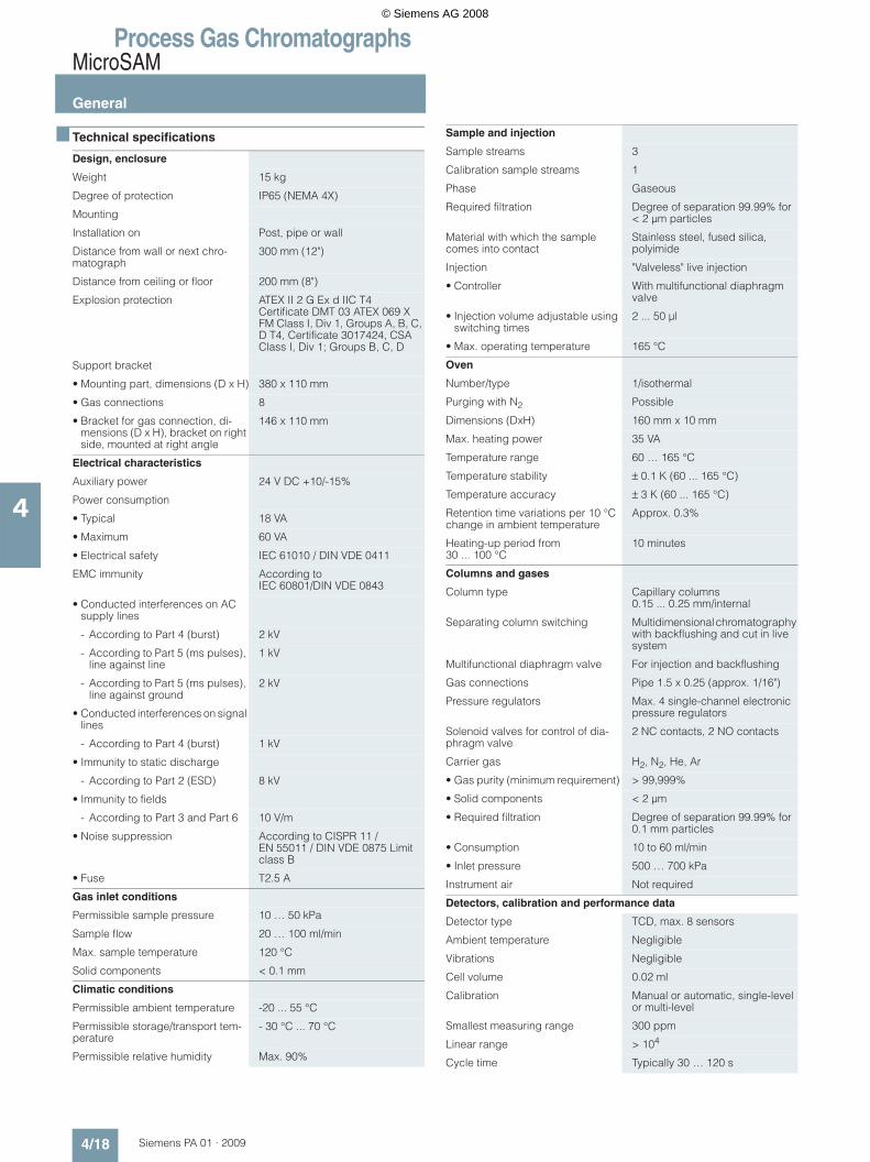
Technical specifications
Design, enclosure
Weight 15 kg
Degree of protection IP65 (NEMA 4X)
Mounting
Installation on Post, pipe or wall
Distance from wall or next chro-matograph
300 mm (12")
Distance from ceiling or floor 200 mm (8")
Explosion protection ATEX II 2 G Ex d IIC T4 Certificate DMT 03 ATEX 069 X FM Class I, Div 1, Groups A, B, C, D T4, Certificate 3017424, CSA Class I, Div 1; Groups B, C, D
Support bracket
• Mounting part, dimensions (D x H) 380 x 110 mm
• Gas connections 8
• Bracket for gas connection, di-mensions (D x H), bracket on right side, mounted at right angle
146 x 110 mm
Electrical characteristics
Auxiliary power 24 V DC +10/-15%
Power consumption
• Typical 18 VA
• Maximum 60 VA
• Electrical safety IEC 61010 / DIN VDE 0411
EMC immunity According to IEC 60801/DIN VDE 0843
• Conducted interferences on AC supply lines
- According to Part 4 (burst) 2 kV
- According to Part 5 (ms pulses), line against line
1 kV
- According to Part 5 (ms pulses), line against ground
2 kV
• Conducted interferences on signal lines
- According to Part 4 (burst) 1 kV
• Immunity to static discharge
- According to Part 2 (ESD) 8 kV
• Immunity to fields
- According to Part 3 and Part 6 10 V/m
• Noise suppression According to CISPR 11 / EN 55011 / DIN VDE 0875 Limit class B
• Fuse T2.5 A
Gas inlet conditions
Permissible sample pressure 10 … 50 kPa
Sample flow 20 … 100 ml/min
Max. sample temperature 120 °C
Solid components < 0.1 mm
Climatic conditions
Permissible ambient temperature -20 ... 55 °C
Permissible storage/transport tem-perature
- 30 °C ... 70 °C
Permissible relative humidity Max. 90%
Sample and injection
Sample streams 3
Calibration sample streams 1
Phase Gaseous
Required filtration Degree of separation 99.99% for < 2 µm particles
Material with which the sample comes into contact
Stainless steel, fused silica, polyimide
Injection "Valveless" live injection
• Controller With multifunctional diaphragm valve
• Injection volume adjustable using switching times
2 ... 50 µl
• Max. operating temperature 165 °C
Oven
Number/type 1/isothermal
Purging with N2 Possible
Dimensions (DxH) 160 mm x 10 mm
Max. heating power 35 VA
Temperature range 60 … 165 °C
Temperature stability ± 0.1 K (60 ... 165 °C)
Temperature accuracy ± 3 K (60 ... 165 °C)
Retention time variations per 10 °C change in ambient temperature
Approx. 0.3%
Heating-up period from 30 ... 100 °C
10 minutes
Columns and gases
Column type Capillary columns 0.15 ... 0.25 mm/internal
Separating column switching Multidimensional chromatography with backflushing and cut in live system
Multifunctional diaphragm valve For injection and backflushing
Gas connections Pipe 1.5 x 0.25 (approx. 1/16")
Pressure regulators Max. 4 single-channel electronic pressure regulators
Solenoid valves for control of dia-phragm valve
2 NC contacts, 2 NO contacts
Carrier gas H2, N2, He, Ar
• Gas purity (minimum requirement) > 99,999%
• Solid components < 2 µm
• Required filtration Degree of separation 99.99% for 0.1 mm particles
• Consumption 10 to 60 ml/min
• Inlet pressure 500 … 700 kPa
Instrument air Not required
Detectors, calibration and performance data
Detector type TCD, max. 8 sensors
Ambient temperature Negligible
Vibrations Negligible
Cell volume 0.02 ml
Calibration Manual or automatic, single-level or multi-level
Smallest measuring range 300 ppm
Linear range > 104
Cycle time Typically 30 … 120 s
© Siemens AG 2008

Process Gas ChromatographsMicroSAM
General
4/19Siemens PA 01 · 2009
4
Electrical inputs and outputs
Basic equipment
• Digital outputs (relay contact 0.4 A / 24 V DC)
2, freely usable (expandable by NAU, see communication)
• Digital inputs (24 V to optocoupler)
2, freely usable (expandable by NAU, see communication)
Interfaces
• Communication 1 x Ethernet 10BaseT / TCP/IP
• Control system coupling 1 x RS 485 or RS 232 / MODBUS RTU, OPC (ODPC) over Ethernet
Electronics
Communication and analytical controller (CAC)
• Microprocessor Intel 586 architecture
• Flash EPROM 128 MB
• Dynamic RAM 64 MB
• Operating system Windows CE 3.0
• Software Preinstalled. Modifications or upgrades for operation PC down-loadable via network or locally
Realtime signal processor (RSP)
• Microprocessor Motorola 68376, 20 MHz
• Flash EPROM 1 MB
• Static RAM 1 MB
• Operating system Forth
• Software Preinstalled. Modifications or upgrades downloadable via inter-nal service interface
Controller
• Sample streams 3
• Calibration sample streams 1
• Status LEDs for Supply voltage, software, heart-beat, ready, maintenance request, fault, sample flow
Recommended operator panel
• Personal computer Desktop or laptop
• Processor At least Pentium III
• Clock 800 MHz
• Interfaces 1 x Ethernet
• Operating system Windows 98, NT, 2000 or XP
• Software Advance System Tools, version 4.0 or later
© Siemens AG 2008

Process Gas ChromatographsMicroSAM
General
4/20 Siemens PA 01 · 2009
4
F) Subject to AL export regulations: N, ECCN: EAR99H
Selection and ordering data Order No. cannot be combined
ProicroSAM process gas chromatographBasic unit, mounted on holding bracketFor 3 sample streams + 1 calibration streamFor ambient temperatures from -20 °C to +55 °CExplosion-proof, for Zone 1 and Class I Div.124 V DC power supplyFor post, pipe or wall mounting
F) 7KQ3101- 777 00000
SampleFor gaseous sample 0For gaseous sample (standard UKOG) 8
Workstation operating software(1 workstation operating software required per GC network)
Without operating software AWith workstation operating software B
VersionSeparately supplied basic unit and application module. Parameter set (on CD-ROM)
A
Unit completely assembled with basic parameter settings, prepared for user-specific settings, including system test
B
Selection and ordering data
Further versions Order code cannot be combined
Add "-Z" to Order No. and specify Order code
Application modulesSee description at function of application modules
A01 bis A11
Standard applications with defined hardware
Customized settingDuring commissioning1) B01During run-out ex factory B02 B01, C0x
Method development in application (specified by application laboratory)
Very simple application C01Simple application C02
Medium application C03Special application (incl. production of a special application module) C04Special application (for natural gas analyzers for calorific value measurements) C05
Acceptance and customer information (in agreement with application laboratory)
Remote acceptance D01 B01Factory acceptance, 1 day D02 B01
Factory acceptance, 2 days D03 B01Factory acceptance, 3 days D04 B01
Repeatability test
Standard E01 B01Up to 8 hours E02 B01
Up to 24 hours E03 B01Up to 72 hours E04 B01
Data transmission by means of MODBUSModbus mapping (during commissioning) F01
Data transmission analog and control panel (MMI)
Analog values via external unit; 2 analog values (standard package); 230 V G01Analog values via external unit; 2 analog values (standard package); 115 V G02
Expansion: Ethernet 10Base FO (glass fiber) G03Expansion: MODBUS Map in the NAU G04
Expansion: Module with 8 analog outputs G05Expansion: Module with 4 digital outputs / 4 digital inputs G06
Expansion: Module with 2 DO / 2 DI / 2 AO / 2 AI G07Expansion: Operator panel (MMI) G08
Customized parameterization G091) On request.
© Siemens AG 2008
Process Gas ChromatographsMicroSAM
General
4/21Siemens PA 01 · 2009
4
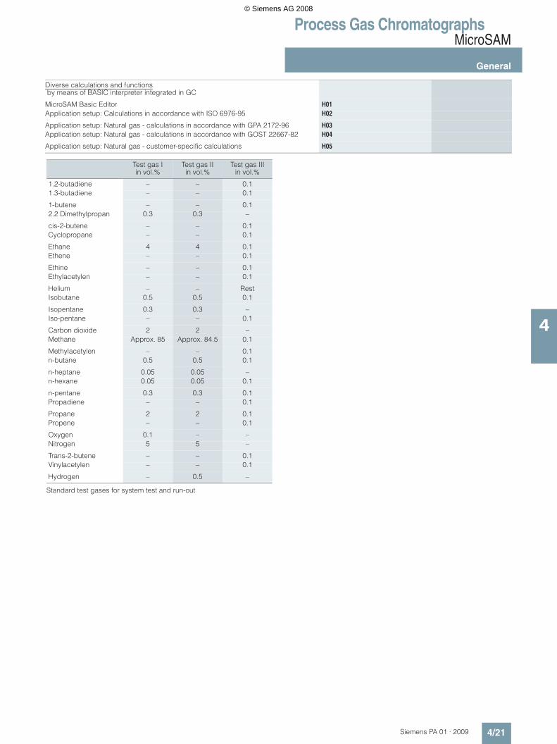
Standard test gases for system test and run-out
Diverse calculations and functions by means of BASIC interpreter integrated in GC
MicroSAM Basic Editor H01Application setup: Calculations in accordance with ISO 6976-95 H02
Application setup: Natural gas - calculations in accordance with GPA 2172-96 H03Application setup: Natural gas - calculations in accordance with GOST 22667-82 H04
Application setup: Natural gas - customer-specific calculations H05
Test gas Iin vol.%
Test gas IIin vol.%
Test gas IIIin vol.%
1.2-butadiene – – 0.11.3-butadiene – – 0.1
1-butene – – 0.12.2 Dimethylpropan 0.3 0.3 –
cis-2-butene – – 0.1Cyclopropane – – 0.1
Ethane 4 4 0.1Ethene – – 0.1
Ethine – – 0.1Ethylacetylen – – 0.1
Helium – – RestIsobutane 0.5 0.5 0.1
Isopentane 0.3 0.3 –Iso-pentane – – 0.1
Carbon dioxide 2 2 –Methane Approx. 85 Approx. 84.5 0.1
Methylacetylen – – 0.1n-butane 0.5 0.5 0.1
n-heptane 0.05 0.05 –n-hexane 0.05 0.05 0.1
n-pentane 0.3 0.3 0.1Propadiene – – 0.1
Propane 2 2 0.1Propene – – 0.1
Oxygen 0.1 – –Nitrogen 5 5 –
Trans-2-butene – – 0.1Vinylacetylen – – 0.1
Hydrogen – 0.5 –
© Siemens AG 2008

Process Gas ChromatographsMicroSAM
General
4/22 Siemens PA 01 · 2009
4
Dimensional drawings
MicroSAM, dimensions in mm
Documentation
Selection and ordering data
1 5
4 8
Order No.
Manual C79000-D5300-C564
Compact Manual
• German C79000-G5300-C568
• English C79000-G5376-C568
• French C79000-G5377-C568
• Spanish C79000-G5378-C568
• Italian C79000-G5372-C568
© Siemens AG 2008
Process Gas ChromatographsSITRANS CV
General
4/23Siemens PA 01 · 2009
4
Overview
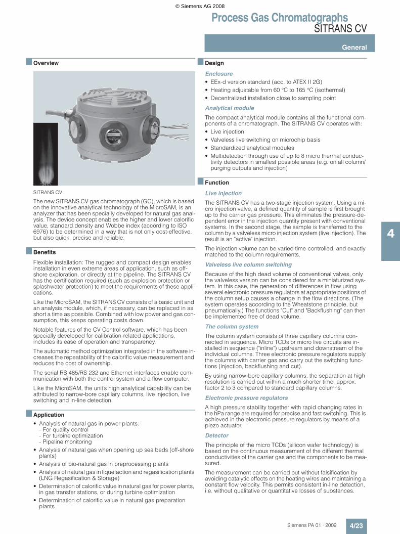
SITRANS CV
The new SITRANS CV gas chromatograph (GC), which is based on the innovative analytical technology of the MicroSAM, is an analyzer that has been specially developed for natural gas anal-ysis. The device concept enables the higher and lower calorific value, standard density and Wobbe index (according to ISO 6976) to be determined in a way that is not only cost-effective, but also quick, precise and reliable.
Benefits
Flexible installation: The rugged and compact design enables installation in even extreme areas of application, such as off-shore exploration, or directly at the pipeline. The SITRANS CV has the certification required (such as explosion protection or splashwater protection) to meet the requirements of these appli-cations.
Like the MicroSAM, the SITRANS CV consists of a basic unit and an analysis module, which, if necessary, can be replaced in as short a time as possible. Combined with low power and gas con-sumption, this keeps operating costs down.
Notable features of the CV Control software, which has been specially developed for calibration-related applications, includes its ease of operation and transparency.
The automatic method optimization integrated in the software in-creases the repeatability of the calorific value measurement and reduces the cost of ownership.
The serial RS 485/RS 232 and Ethernet interfaces enable com-munication with both the control system and a flow computer.
Like the MicroSAM, the unit’s high analytical capability can be attributed to narrow-bore capillary columns, live injection, live switching and in-line detection.
Application
• Analysis of natural gas in power plants: - For quality control - For turbine optimization - Pipeline monitoring
• Analysis of natural gas when opening up sea beds (off-shore plants)
• Analysis of bio-natural gas in preprocessing plants• Analysis of natural gas in liquefaction and regasification plants
(LNG Regasification & Storage)• Determination of calorific value in natural gas for power plants,
in gas transfer stations, or during turbine optimization• Determination of calorific value in natural gas preparation
plants
Design
Enclosure• EEx-d version standard (acc. to ATEX II 2G)• Heating adjustable from 60 °C to 165 °C (isothermal)• Decentralized installation close to sampling point
Analytical module
The compact analytical module contains all the functional com-ponents of a chromatograph. The SITRANS CV operates with: • Live injection • Valveless live switching on microchip basis• Standardized analytical modules • Multidetection through use of up to 8 micro thermal conduc-
tivity detectors in smallest possible areas (e.g. on all column/ purging outputs and injection)
Function
Live injection
The SITRANS CV has a two-stage injection system. Using a mi-cro injection valve, a defined quantity of sample is first brought up to the carrier gas pressure. This eliminates the pressure-de-pendent error in the injection quantity present with conventional systems. In the second stage, the sample is transferred to the column by a valveless micro injection system (live injection). The result is an "active" injection.
The injection volume can be varied time-controlled, and exactly matched to the column requirements.
Valveless live column switching
Because of the high dead volume of conventional valves, only the valveless version can be considered for a miniaturized sys-tem. In this case, the generation of differences in flow using several electronic pressure regulators at appropriate positions of the column setup causes a change in the flow directions. (The system operates according to the Wheatstone principle, but pneumatically.) The functions "Cut" and "Backflushing" can then be implemented free of dead volume.
The column system
The column system consists of three capillary columns con-nected in sequence. Micro TCDs or micro live circuits are in-stalled in sequence ("inline") upstream and downstream of the individual columns. Three electronic pressure regulators supply the columns with carrier gas and carry out the switching func-tions (injection, backflushing and cut).
By using narrow-bore capillary columns, the separation at high resolution is carried out within a much shorter time, approx. factor 2 to 3 compared to standard capillary columns.
Electronic pressure regulators
A high pressure stability together with rapid changing rates in the hPa range are required for precise and fast switching. This is achieved in the electronic pressure regulators by means of a piezo actuator.
Detector
The principle of the micro TCDs (silicon wafer technology) is based on the continuous measurement of the different thermal conductivities of the carrier gas and the components to be mea-sured.
The measurement can be carried out without falsification by avoiding catalytic effects on the heating wires and maintaining a constant flow velocity. This permits consistent in-line detection, i.e. without qualitative or quantitative losses of substances.
© Siemens AG 2008

Process Gas ChromatographsSITRANS CV
General
4/24 Siemens PA 01 · 2009
4
Module
The standardized application module contains live injection and live switching, and has three detectors and three columns.
Application
The SITRANS CV is a storage product. Precalibration is carried out at the factory, using helium (as the carrier gas) and a residual gas. The measured components and switching functions (live in-jection, backflushing, cut) are saved in the GC. The calibration process itself should be performed during commissioning on-site.
Measurements can be made within the following working ranges:
Table 1: Measured components and performance parameters1) Any oxygen or carbon present in the sample will be detected along with the
nitrogen and, therefore, taken into account when the nitrogen concentration is determined.
2) Hexane+ = iso/n-hexane to iso/n-nonane
Analyses within the checked working range as well as the quality parameters resulting from these (upper and lower calorific val-ues, density, relative density and Wobbe index) correspond to the requirements listed below.
Measurements outside these specifications (Table 1, right-hand column) are possible, but checking of the repeatability and cor-rectness has not been carried out.
Table 2: The repeatability of the measured components complies with ISO 6974-5 (2001) – Annex B
The repeatability of the calorific value and standard density achieve a relative standard deviation of < 0.015%.
The calibration gas is an extremely important factor for consid-eration of the maximum permissible error (MPE), and has a sig-nificant effect on the accuracy of the overall measuring system. For this reason, SITRANS CV – based on a comparative measur-ing procedure – can never be more accurate than the calibration gas used. Other parameters besides the accuracy data on the calibration gas certificate are important for the accuracy of a system. Examples of these include the optimum gas composi-tion, the ambient temperatures of the calibration gas cylinders during transportation and operation, potential condensation of, for instance, higher hydrocarbons in a calibration gas cylinder, and the functionality of the sample preparation device.Under optimum conditions, the SITRANS CV achieves an MPE of < 0,1 % for the calorific value and standard density.
SITRANS CV is designed for measuring different types of natural gas. The table below lists the typical specifications of natural gases (measured and residual components):
Table 3: Composition of Dutch, Russian and Algerian natural gas, as well as LNG
Column 1 Detector Column 2 Detector Circuit Column 3 Detector
C09 Injection
Sil5 Non-polar aromatic and aliphatic hydro-carbons
TCD Sil5 Non-polar aromatic and aliphatic hydro-carbons
TCD Live Porabond Q All components except molecular filter components
TCD
Component Certified working range (%)
Possible working range (%)
Methane 57 ... 100 50 ... 100
Nitrogen1) 0 ... 22 0 ... 25
Carbon dioxide 0 ... 12 0 ...20
Ethane 0 ... 14 0 ... 20
Propane 0 ... 5 0 ... 15
i-butane 0 ... 0.9 0 ... 10
n-butane 0 ... 1.8 0 ... 10
Neopentane 0 ... 0.1 0 ... 1
i-pentane 0 ... 0.12 0 ... 1
n-pentane 0 ... 0.12 0 ... 1
Hexane+2) 0 ... 0.08 0 ... 3
Helium Concentration can be entered as a fixed value in the components list
H2S < 500 ppm No measured component
Concentration range (mol.%) Repeatability according to ISO 6974-5 (2001); molar fraction (%), absolute
50 < xi < 100 0.1
1 < xi < 50 0.011
0.1 < xi <1 0.006
xi < 0.1
Dutch natural gas
Russian natural gas
Algerian natural gas
LNG
Helium 0.035 0.007 0.150 0.045
Nitrogen 2.072 0.873 5.493 0.948
CO2 1.131 0.102 0.210 0.000
Hydrogen 0.000 0.000 0.000 0.000
CO 0.000 0.000 0.000 0.000
Methane 90.179 98.022 83.774 89.373
Ethane 4.976 0.701 7.660 7.793
Propane 1.161 0.204 1.892 1.421
i-butane 0.144 0.035 0.256 0.178
n-butane 0.186 0.035 0.345 0.238
Neopentane 0.005 0.0005
i-pentane 0.038 0.007 0.070 0.001
n-pentane 0.031 0.005 0.079 0.001
Hexane+ 0.047 0.009 0.071 0.002
O2+Ar 0.000 0.000 0.000 0.000
H2S < 10 mg/m3 < 50 mg/m3 < 10 mg/m3 < 10 mg/m3
Mercaptan sulfur
< 20 mg/m3 < 20 mg/m3 < 20 mg/m3 < 20 mg/m3
H2O Dew point < ground temp. for line pres-sure in each case
Dew point < ground temp. for line pres-sure in each case
Dew point < ground temp. for line pres-sure in each case
Dew point < ground temp. for line pres-sure in each case
Total 100 000 100 000 100 000 100 000
Calorific value (KJ/m3)
39 061.265 37 811.062 39 604.232 40 797.089
Heating value (KJ/m3)
35 250.449 34 055.754 35 789.664 36 842.640
Density (kg/m3)
0.75617 0.69388 0.79422 0.75555
Z factor 0.99764 0.99796 0.99752 0.99750
© Siemens AG 2008

Process Gas ChromatographsSITRANS CV
General
4/25Siemens PA 01 · 2009
4
Technical specifications
Climatic conditions
Permissible ambient temperature -20 to 55 °C (depending on oven temperature)
Permissible storage/transport temperature
-30 to 70 °C
Permissible relative humidity Max. 90%
Protection against dust and moisture
• According to EN 60529/IEC 60529 IP65
• According to NEMA 250 NEMA 4X
Power supply
Auxiliary power 24 V DC +10/-15%
External fuse T 2.5 A
Power consumption, typical 18 VA
Power consumption, maximum 60 VA
Dimensions and weights
Width x depth x height 360 x 300 x 220 mm (approximately 14" x 12" x 9")
Weight 15 kg (35 lb)
Mounting
Installation on Post, pipe or wall
Distance from wall or next chro-matograph
300 mm (12")
Distance from ceiling or floor 200 mm (8")
Electromagnetic compatibility
Noise suppression According to CISPR 11/ EN 55011/DIN VDE 0875 Limit class B
EMC immunity According to IEC 60801/ DIN VDE 0843
Conducted interferences on AC supply lines
• According to Part 4 (burst) 2 kV
• According to Part 5 (ms pulses), line against line
1 kV
• According to Part 5 (ms pulses), line against ground
2 kV
Conducted interferences on signal lines
• According to Part 4 (burst) 1 kV
Immunity to static discharge
• According to Part 2 (ESD) 8 kV
Immunity to fields
• According to Part 3 and Part 6 10 V/m
Safety
Electrical safety IEC 61010/DIN VDE 0411
Explosion protection ATEX II 2 G EEx d IIC T4 FM Class I, Div 1, Groups B, C, D T4 FM Class I, Zone 1, Group IIB+H2 T4CSA Class I, Div 1, Groups B, C, D T4; Enclosure Type 4X
Oven
Number/type 1/isothermal
Purging with N2 Possible
Dimensions (D x H) 160 x 10 mm
Max. heating power 35 VA
Temperature range 60 to 165 °C
Temperature stability ±0.1 K (60 to 165 °C)
Temperature accuracy ±3 K (60 to 165 °C)
Retention time variations per 10 °C change in ambient temperature
Approx. 0.3%
Warm-up period from 30 to 100 °C 10 minutes
Columns and gases
Column type Capillary columns 0.15 to 0.25 mm ∅internal
Separating column switching Multidimensional chromatography with backflushing and cut in live system
Multifunctional diaphragm valve For injection and backflushing
Gas connections Swagelok 1/8"
Pressure regulators Max. 4 single-channel electronic pressure regulators
Solenoid valves for control of diaphragm valve
2 NC contacts, 2 NO contacts
Carrier gas He
• Gas purity (minimum requirement) ≥ 99.999% (5.0)
• Solid components < 2 µm
• Required filtration Degree of separation 99.99% for < 0.1 µm particles
• Consumption < 30 ml/min
• Inlet pressure 500 ... 700 kPa
Instrument air Not required
Sample and injection
Sample streams 3
Calibration sample streams 1
Phase Gaseous
Permissible sample pressure 10 to 500 kPa, but at least 200 kPa under carrier gas pressure. NOTICE: Sample must not con-tain acetylene!
Sample flow 20 to 100 ml/min
Max. sample temperature 120 °C
Solid components < 2 µm
Required filtration Degree of separation 99.99% for < 0.1 µm particles
Material with which the sample comes into contact
Stainless steel, fused silica, polyimide
Injection "Valveless" live injection
• Controller With multifunctional diaphragm valve
• Injection volume adjustable using switching times
From 2 to 50 µl
© Siemens AG 2008
Process Gas ChromatographsSITRANS CV
General
4/26 Siemens PA 01 · 2009
4
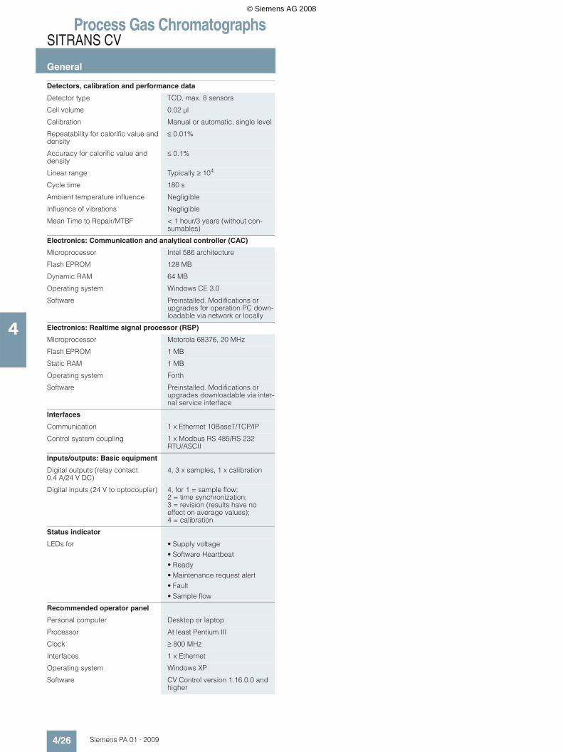
Detectors, calibration and performance data
Detector type TCD, max. 8 sensors
Cell volume 0.02 µl
Calibration Manual or automatic, single level
Repeatability for calorific value and density
≤ 0.01%
Accuracy for calorific value and density
≤ 0.1%
Linear range Typically ≥ 104
Cycle time 180 s
Ambient temperature influence Negligible
Influence of vibrations Negligible
Mean Time to Repair/MTBF < 1 hour/3 years (without con-sumables)
Electronics: Communication and analytical controller (CAC)
Microprocessor Intel 586 architecture
Flash EPROM 128 MB
Dynamic RAM 64 MB
Operating system Windows CE 3.0
Software Preinstalled. Modifications or upgrades for operation PC down-loadable via network or locally
Electronics: Realtime signal processor (RSP)
Microprocessor Motorola 68376, 20 MHz
Flash EPROM 1 MB
Static RAM 1 MB
Operating system Forth
Software Preinstalled. Modifications or upgrades downloadable via inter-nal service interface
Interfaces
Communication 1 x Ethernet 10BaseT/TCP/IP
Control system coupling 1 x Modbus RS 485/RS 232 RTU/ASCII
Inputs/outputs: Basic equipment
Digital outputs (relay contact 0.4 A/24 V DC)
4, 3 x samples, 1 x calibration
Digital inputs (24 V to optocoupler) 4, for 1 = sample flow; 2 = time synchronization; 3 = revision (results have no effect on average values); 4 = calibration
Status indicator
LEDs for • Supply voltage • Software Heartbeat • Ready • Maintenance request alert • Fault • Sample flow
Recommended operator panel
Personal computer Desktop or laptop
Processor At least Pentium III
Clock ≥ 800 MHz
Interfaces 1 x Ethernet
Operating system Windows XP
Software CV Control version 1.16.0.0 and higher
© Siemens AG 2008
Process Gas ChromatographsSITRANS CV
General
4/27Siemens PA 01 · 2009
4
B) Subject to AL export regulations: N, ECCN: 5D002ENC3
Support bracket
For easy mounting, incl. support for 8 gas connections consist-ing of:• Mounting part: Dimensions 380 x 110 mm (W x H)• Bracket for gas connection: Dimensions 146 x 110 (D x H),
bracket on right side, mounted at right angle
Sample flow switchover
The chromatograph enables automatic selection and switchover of 3 sample flows and 1 calibration flow. The DO signal from the GC requires an external relay for the solenoid valve. A sample flow selector/sample preparation device can be ordered sepa-rately.
Ambient temperatures
Particularly in warmer zones, weather protection is necessary to protect the SITRANS CV against direct solar radiation. The chro-matograph is designed as standard for temperatures from -20 to +55 °C. A version in a thermostatically-controlled casing is also available as an option for temperatures outside these limits.
Communication
SITRANS CV has two serial interfaces. One RS485/RS232 con-nection for MODBUS communication (RTU/ASCII). Modbus mapping can be flexibly used (see manual for more information). SITRANS CV is operated via the second interface Ethernet (TCP/IP).
Other serial and analog (4 to 20 mA) interfaces are available as an option; these can be ordered as a supplementary solution package.
Documentation
The documentation contains a CD-ROM version of the SITRANS CV Manual in English and German. The documentation is pro-vided on a CD.
CV Control operating software
The operating software (language: English) is included in the scope of supply. Windows XP must be installed on the computer in order to install this software.
Order No. Pos. 8_0: Applications – Standard calorific value analysis - Certified in conjunction with GWK-CHRPA-CV-CER-1
These positions contain a general system check of the basic unit and the integrated application module C09. The module and ba-sic unit are described in the manual. In addition to the original master setup as the standard method, other country or user-spe-cific method setups are available. The performance record ex works contains the analysis check, including a repeatability record (4 h test). This application comprises the standard calo-rific value analysis.
The chromatograph’s measurement method is set at the factory, using a synthetic natural gas mixture. The performance param-eters specified in Table 1 and the criteria explained in the sub-sequent text apply to the individual components in Table 2 and their physical dimensions. The calorimetric variables are calcu-lated on the basis of the GOST, AGA 8 and ISO6976-95 stan-dard, where the last standard is preset. The reference states for the combustion and for the gas volume that must be specified for calculation purposes are preset to the default state (Tb=25 °C, Tn = 0 °C) and can be easily changed to other refer-ence states during commissioning using the operating software (Tb= operating temperature, Tn= standard temperature).
The standard method (original master setup) is installed in the chromatograph, and four CD-ROMs are supplied with the follow-ing:• 2 CDs SITRANS CV Software (including manual and CV Con-
trol instructions)• 1 CD Country-specific partial setups• 1 CD Parameter backup for SITRANS CV (including documen-
tation for the individual module with TCD bridge voltages and EPC pressures, as well as module-specific hardware setups)
D01 - Acceptance and customer information - Factory accep-tance, visual check, 1 day
The scope of supply is checked and the documentation and op-eration of the unit explained as part of the factory acceptance process. The factory acceptance does not include a repeat of the unit’s repeatability test (4 h test).
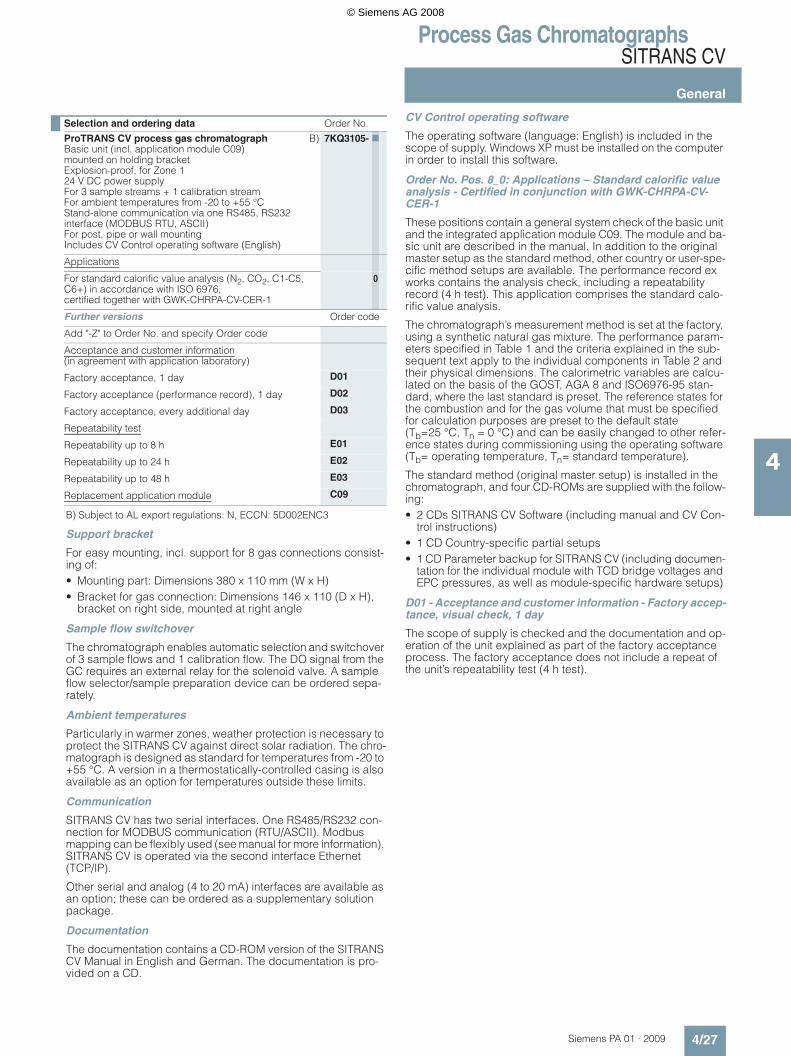
Selection and ordering data Order No.
ProTRANS CV process gas chromatographBasic unit (incl. application module C09)mounted on holding bracketExplosion-proof, for Zone 124 V DC power supply For 3 sample streams + 1 calibration streamFor ambient temperatures from -20 to +55 °CStand-alone communication via one RS485, RS232 interface (MODBUS RTU, ASCII)For post, pipe or wall mountingIncludes CV Control operating software (English)
B) 7KQ3105- 7
Applications
For standard calorific value analysis (N2, CO2, C1-C5, C6+) in accordance with ISO 6976, certified together with GWK-CHRPA-CV-CER-1
0
Further versions Order code
Add "-Z" to Order No. and specify Order code
Acceptance and customer information (in agreement with application laboratory)
Factory acceptance, 1 day D01
Factory acceptance (performance record), 1 day D02
Factory acceptance, every additional day D03
Repeatability test
Repeatability up to 8 h E01
Repeatability up to 24 h E02
Repeatability up to 48 h E03
Replacement application module C09
© Siemens AG 2008

Process Gas ChromatographsSITRANS CV
General
4/28 Siemens PA 01 · 2009
4
D02 - Acceptance and customer information - Factory accep-tance with performance record, 1 day
The scope of the tests to be carried out is described in Table 4. When ordering D02, please supplement the desired option from E0x.
Table 4: Scope of test during factory acceptance
During the factory acceptance, the customer can request setting of a method which is not preinstalled as country-specific or user-specific.
SITRANS CV is a standard product and is shipped ex stock. Only in this manner is it possible to guarantee short delivery times and attractive prices. Any performance records required in addition to the original record supplied have considerably higher demands in terms of production/application and logis-tics. When it comes to demonstrating a fully functional unit as part of the factory acceptance process, this is no exception.
D03 - Acceptance and customer information - Factory accep-tance, from 2nd day
Only in conjunction with D01 or D02
E0x - Repeatability test
A tested repeatability record for 4 h is included as standard. Longer repeatability records for the unit can be ordered by means of the supplementary item E0x.
E01 to E03 - Repeatability test, 8 h - 24 h - 48 h
Only in conjunction with D02
Replacement application module C09
The position includes the possibility for returning the used anal-ysis module for replacement by a new one. Please explicitly write in your order that this is a replacement module if this option is required.
Linearity tests can be carried out in the factory on request. The test gases required for this (Table 5) are provided free of charge. If the customer specifies other test gases with different compo-sitions or higher uncertainty requirements, they must provide these gases for acceptance purposes. As an option, Siemens can procure these special test gases (subject to a charge).
On request, proof of the complete functionality of the SITRANS CV is possible within the certified temperature and am-bient conditions.
Table 5: Recommended test gases for linearity test during acceptance
The test gases have the following uncertainties:
Record of component isolation Through final check of existing documentation and according to current chromatograms, 5 analyses
Stability test (repeatability) Acc. to order E01 to E03 Performance criteria acc. to tab.
Checking of Modbus connection Checking or simulation of Mod-bus communication can be carried out e.g. using a flow com-puter provided by the customer.
Calculation test Comparison of the values calcu-lated by CV Control with a cus-tomer comparison procedure (optional)
Auto-calibration functionAuto-optimization of method
The two functions are explained theoretically and practically dur-ing presentation of CV Control.
Alarm and event messages Simulation of alarm situations; as per customer requirement
Component Gas #1 (Mol.%) Gas #2 (Mol.%) Gas #3 (Mol.%)
Methane Residual (approx. 75)
Residual (approx. 85)
Residual (approx. 96,5)
Nitrogen 15.5 5 2.5
Carbon dioxide 0.5 2 0.1
Ethane 8 4 0.5
Propane 0.5 2 0.15
i-butane 0.15 0.5 0.03
n-butane 0.15 0.5 0.03
Neopentane 0.08 0.3 0.03
i-pentane 0.08 0.3 0.03
n-pentane 0.08 0.3 0.03
Hexane 0.05 0.1 0.015
Proportions of component materials (Mol.%)
Uncertainty (or smaller)
0.1 ... 0.25 ± 5.00%
0.25 ... 1 ± 1.00%
1 ... 10 ± 0.50%
10 ... 100 ± 0.20%
© Siemens AG 2008

Process Gas ChromatographsSITRANS CV
General
4/29Siemens PA 01 · 2009
4
Dimensional drawings
SITRANS CV, dimensions in mm
1 5
4 8
© Siemens AG 2008

Process Gas Chromatographs
Notes
4/30 Siemens PA 01 · 2009
4
© Siemens AG 2008