process control system pcs 7 v7.0 - library · pdf file · 2015-01-21s contents pcs...
TRANSCRIPT
s
Contents PCS 7 Library 1 Technological Blocks 2 Driver blocks 3 Asset Management 4 Communication Blocks 5 Glossary, Index
SIMATIC
Process Control System PCS 7 V7.0 Library Manual
11/2006 A5E00807897-01

Siemens AG Automation and Drives Postfach 4848 90437 NÜRNBERG GERMANY
A5E00807897-01 11/2006
Copyright © Siemens AG 2006 Technical data subject to change
Safety Guidelines This manual contains notices you have to observe in order to ensure your personal safety, as well as to prevent damage to property. The notices referring to your personal safety are highlighted in the manual by a safety alert symbol, notices referring to property damage only have no safety alert symbol. The notices shown below are graded according to the degree of danger.
! Danger indicates that death or severe personal injury will result if proper precautions are not taken.
! Warning indicates that death or severe personal injury may result if proper precautions are not taken.
! Caution with a safety alert symbol indicates that minor personal injury can result if proper precautions are not taken.
Caution
without a safety alert symbol indicates that property damage can result if proper precautions are not taken.
Notice
indicates that an unintended result or situation can occur if the corresponding notice is not taken into account.
If more than one degree of danger is present, the warning notice representing the highest degree of danger will be used. A notice warning of injury to persons with a safety alert symbol may also include a warning relating to property damage.
Qualified Personnel The device/system may only be set up and used in conjunction with this documentation. Commissioning and operation of a device/system may only be performed by qualified personnel. Within the context of the safety notices in this documentation qualified persons are defined as persons who are authorized to commission, ground and label devices, systems and circuits in accordance with established safety practices and standards.
Prescribed Usage Note the following:
! Warning This device and its components may only be used for the applications described in the catalog or the technical description, and only in connection with devices or components from other manufacturers which have been approved or recommended by Siemens. Correct, reliable operation of the product requires proper transport, storage, positioning and assembly as well as careful operation and maintenance.
Trademarks All names identified by ® are registered trademarks of the Siemens AG. The remaining trademarks in this publication may be trademarks whose use by third parties for their own purposes could violate the rights of the owner.
Disclaimer of Liability We have reviewed the contents of this publication to ensure consistency with the hardware and software described. Since variance cannot be precluded entirely, we cannot guarantee full consistency. However, the information in this publication is reviewed regularly and any necessary corrections are included in subsequent editions.
Process Control System PCS 7 V7.0 - Library A5E00807897-01 iii
Contents
1 PCS 7 Library 1-1 1.1 General Information About Block Description................................................... 1-1
2 Technological Blocks 2-1 2.1 Measurement and Control ................................................................................ 2-1 2.1.1 Controller Optimization Using the PID Tuner ...................................................2-1 2.1.2 CTRL_PID: PID controller block .......................................................................2-2 2.1.2.1 Description of CTRL_PID .................................................................................2-2 2.1.2.2 Signal Processing in the Setpoint and Actual-Value Branches of CTRL_PID .2-4 2.1.2.3 Generation of Manipulated Variables for CTRL_PID .......................................2-6 2.1.2.4 Manual, Auto and Following mode, and Cascading of CTRL_PID ..................2-7 2.1.2.5 CTRL_PID Mode Change.................................................................................2-9 2.1.2.6 Error Handling of CTRL_PID ..........................................................................2-11 2.1.2.7 Startup Behavior, Dynamic Response and Message response
of CTRL_PID ..................................................................................................2-12 2.1.2.8 Block Diagram of CTRL_PID..........................................................................2-12 2.1.2.9 I/Os of CTRL_PID...........................................................................................2-14 2.1.2.10 Message Texts and Associated Values of CTRL_PID ...................................2-18 2.1.2.11 VSTATUS for CTRL_PID................................................................................2-19 2.1.2.12 Operating and Monitoring of CTRL_PID.........................................................2-20 2.1.3 CTRL_S: PID controller block.........................................................................2-20 2.1.3.1 Description of CTRL_S...................................................................................2-20 2.1.3.2 Signal Processing in the Setpoint and Actual-Value Branches of CTRL_S...2-23 2.1.3.3 Generation of Control Signals for CTRL_S ....................................................2-25 2.1.3.4 Manual, Auto and Following Mode, and Cascading of CTRL_S ....................2-28 2.1.3.5 CTRL_S Mode Change ..................................................................................2-31 2.1.3.6 Error Handling of CTRL_S..............................................................................2-33 2.1.3.7 Startup Behavior, Dynamic Response and Message response of CTRL_S..2-34 2.1.3.8 Block Diagram of CTRL_S..............................................................................2-35 2.1.3.9 I/Os of CTRL_S ..............................................................................................2-38 2.1.3.10 Message Texts and Associated Values of CTRL_S.......................................2-44 2.1.3.11 VSTATUS for CTRL_S ...................................................................................2-45 2.1.3.12 Operating and Monitoring of CTRL_S ............................................................2-45 2.1.4 DEADT_P: Dead-Time Element .....................................................................2-46 2.1.4.1 Description of DEADT_P ................................................................................2-46 2.1.4.2 I/Os of DEADT_P............................................................................................2-47 2.1.5 DIF_P: Differentiation .....................................................................................2-48 2.1.5.1 Description of DIF_P.......................................................................................2-48 2.1.5.2 I/Os of DIF_P ..................................................................................................2-49 2.1.6 DIG_MON: Digital-Value Monitoring...............................................................2-50 2.1.6.1 Description of DIG_MON................................................................................2-50 2.1.6.2 I/Os of DIG_MON ...........................................................................................2-52 2.1.6.3 Message Texts and Associated Values of DIG_MON....................................2-53 2.1.6.4 VSTATUS for DIG_MON ................................................................................2-54 2.1.6.5 Operating and Monitoring of DIG_MON .........................................................2-54 2.1.7 FM_CO: Koordinierung von FMCS_PID/FMT_PID ........................................2-55 2.1.7.1 Description of FM_CO ....................................................................................2-55 2.1.7.2 I/Os of FM_CO................................................................................................2-57
Contents
Process Control System PCS 7 V7.0 - Library iv A5E00807897-01
2.1.8 FMCS_PID: Controller Block ..........................................................................2-57 2.1.8.1 Description of FMCS_PID...............................................................................2-57 2.1.8.2 Addressing......................................................................................................2-60 2.1.8.3 Function of FMCS_PID...................................................................................2-60 2.1.8.4 Acquisition and Writing of Process Values Via the Process Image ...............2-62 2.1.8.5 Generation of Setpoints, Limits, Error Signals, and Manipulated Variables...2-63 2.1.8.6 Manual, Auto and Following Mode .................................................................2-65 2.1.8.7 Mode Change .................................................................................................2-66 2.1.8.8 Safety mode....................................................................................................2-68 2.1.8.9 Download Parameters to the Module .............................................................2-68 2.1.8.10 Read Data From the Module ..........................................................................2-68 2.1.8.11 Error Handling of FMCS_PID .........................................................................2-68 2.1.8.12 Startup Behavior, Dynamic Response and Message response
of FMCS_PID..................................................................................................2-69 2.1.8.13 Backup Mode of the FM 355 ..........................................................................2-70 2.1.8.14 I/Os of FMCS_PID ..........................................................................................2-71 2.1.8.15 Message Texts and Associated Values of FMCS_PID ..................................2-77 2.1.8.16 VSTATUS for FMCS_PID...............................................................................2-78 2.1.8.17 Operating and Monitoring of FMCS_PID........................................................2-78 2.1.9 FMT_PID: Temperature controller block ........................................................2-79 2.1.9.1 Description of FMT_PID .................................................................................2-79 2.1.9.2 Addressing......................................................................................................2-81 2.1.9.3 Function of FMT_PID......................................................................................2-82 2.1.9.4 Acquisition and Writing of Process Values Via the Process Image ...............2-83 2.1.9.5 Generation of Setpoints, Limits, Error Signals, and Manipulated Variables...2-84 2.1.9.6 Manual, Auto and Following Mode .................................................................2-86 2.1.9.7 Mode Change .................................................................................................2-87 2.1.9.8 Safety mode....................................................................................................2-89 2.1.9.9 Download Parameters to the Module .............................................................2-89 2.1.9.10 Read Data From the Module/Working With the Configuration Tool ...............2-89 2.1.9.11 Optimization (Overview) .................................................................................2-90 2.1.9.12 Switching Between Different PID Parameter Sets .........................................2-91 2.1.9.13 Error handling .................................................................................................2-91 2.1.9.14 Startup Behavior, Dynamic Response and Message response of FMT_PID 2-92 2.1.9.15 Backup Mode of the FM 355-2 .......................................................................2-93 2.1.9.16 I/Os of FMT_PID.............................................................................................2-93 2.1.9.17 Message Texts and Associated Values of FMT_PID .....................................2-99 2.1.9.18 VSTATUS for FMT_PID................................................................................2-100 2.1.9.19 Operating and Monitoring of FMT_PID.........................................................2-100 2.1.10 INT_P: Integration.........................................................................................2-101 2.1.10.1 Description of INT_P.....................................................................................2-101 2.1.10.2 I/Os of INT_P ................................................................................................2-104 2.1.11 MEANTM_P: Zeitliche Mittelwertbildung ......................................................2-105 2.1.11.1 Description of MEANTM_P...........................................................................2-105 2.1.11.2 I/Os of MEANTM_P ......................................................................................2-106 2.1.12 MEAS_MON: Measured-Value Monitoring...................................................2-107 2.1.12.1 Description of MEAS_MON ..........................................................................2-107 2.1.12.2 I/Os of MEAS_MON......................................................................................2-109 2.1.12.3 Message Texts and Associated Values of MEAS_MON..............................2-110 2.1.12.4 VSTATUS for MEAS_MON ..........................................................................2-111 2.1.12.5 Operating and Monitoring of MEAS_MON ...................................................2-111 2.1.13 POLYG_P: Polygon with a maximum of 8 points .........................................2-112 2.1.13.1 Description of POLYG_P..............................................................................2-112 2.1.13.2 I/Os of POLYG_P .........................................................................................2-113 2.1.14 PT1_P: First-order lag element ....................................................................2-114 2.1.14.1 Description of PT1_P....................................................................................2-114 2.1.14.2 I/Os of PT1_P ...............................................................................................2-115
Contents
Process Control System PCS 7 V7.0 - Library A5E00807897-01 v
2.1.15 RAMP_P: Ramp structure ............................................................................2-116 2.1.15.1 Description of RAMP_P................................................................................2-116 2.1.15.2 I/Os of RAMP_P ...........................................................................................2-117 2.1.16 RATIO_P: Ratio control ................................................................................2-118 2.1.16.1 Description of RATIO_P ...............................................................................2-118 2.1.16.2 I/Os of RATIO_P...........................................................................................2-120 2.1.16.3 VSTATUS for RATIO_P................................................................................2-121 2.1.16.4 Operating and Monitoring of RATIO_P.........................................................2-121 2.1.17 READ355P: Read digital and analog inputs from FM 355 ...........................2-122 2.1.17.1 Description of READ355P ............................................................................2-122 2.1.17.2 Addressing....................................................................................................2-123 2.1.17.3 I/Os of READ355P........................................................................................2-124 2.1.18 SPLITR_P: Split Range ................................................................................2-124 2.1.18.1 Description of SPLITR_P..............................................................................2-124 2.1.18.2 I/Os of SPLITR_P .........................................................................................2-126 2.2 Motor and Valve............................................................................................ 2-127 2.2.1 MOT_REV: Reversing Motor........................................................................2-127 2.2.1.1 Description of MOT_REV .............................................................................2-127 2.2.1.2 I/Os of MOT_REV.........................................................................................2-131 2.2.1.3 Message Texts and Associated Values of MOT_REV.................................2-134 2.2.1.4 VSTATUS for MOT_REV..............................................................................2-135 2.2.1.5 Operating and Monitoring of MOT_REV.......................................................2-135 2.2.2 MOT_SPED: Two-Speed Motor ...................................................................2-136 2.2.2.1 Description of MOT_SPED...........................................................................2-136 2.2.2.2 I/Os of MOT_SPED ......................................................................................2-140 2.2.2.3 Message Texts and Associated Values of MOT_SPED...............................2-143 2.2.2.4 VSTATUS for MOT_SPED ...........................................................................2-144 2.2.2.5 Operating and Monitoring of MOT_SPED ....................................................2-144 2.2.3 MOTOR: Motor With One Control Signal .....................................................2-145 2.2.3.1 Description of MOTOR .................................................................................2-145 2.2.3.2 I/Os of MOTOR.............................................................................................2-149 2.2.3.3 Message Texts and Associated Values of MOTOR .....................................2-151 2.2.3.4 VSTATUS for MOTOR..................................................................................2-151 2.2.3.5 Operating and Monitoring of MOTOR...........................................................2-152 2.2.4 VAL_MOT: Motor Valve Control ...................................................................2-152 2.2.4.1 Description of VAL_MOT..............................................................................2-152 2.2.4.2 I/Os of VAL_MOT .........................................................................................2-157 2.2.4.3 Message Texts and Associated Values of VAL_MOT..................................2-159 2.2.4.4 VSTATUS for VAL_MOT ..............................................................................2-160 2.2.4.5 Operating and Monitoring of VAL_MOT .......................................................2-160 2.2.5 VALVE: Valve Control...................................................................................2-161 2.2.5.1 Description of VALVE ...................................................................................2-161 2.2.5.2 I/Os of VALVE...............................................................................................2-165 2.2.5.3 Message Texts and Associated Values of VALVE.......................................2-167 2.2.5.4 VSTATUS for VALVE ...................................................................................2-168 2.2.5.5 Operating and Monitoring of VALVE ............................................................2-168 2.3 Other Technological Blocks.......................................................................... 2-169 2.3.1 ADD4_P: Adder for a Maximum of 4 Values ................................................2-169 2.3.1.1 Description of ADD4_P.................................................................................2-169 2.3.1.2 I/Os of ADD4_P ............................................................................................2-169 2.3.2 ADD8_P: Adder for a Maximum of 8 Values ................................................2-170 2.3.2.1 Description of ADD8_P.................................................................................2-170 2.3.2.2 I/Os of ADD8_P ............................................................................................2-170 2.3.3 AVER_P: Time Average ...............................................................................2-171 2.3.3.1 Description of AVER_P.................................................................................2-171 2.3.3.2 I/Os of AVER_P............................................................................................2-172

Contents
Process Control System PCS 7 V7.0 - Library vi A5E00807897-01
2.3.4 COUNT_P: Counter......................................................................................2-173 2.3.4.1 Description of COUNT_P..............................................................................2-173 2.3.4.2 I/Os of COUNT_P.........................................................................................2-174 2.3.5 DOSE: Dosing Process ................................................................................2-175 2.3.5.1 Description of DOSE.....................................................................................2-175 2.3.5.2 I/Os of DOSE ................................................................................................2-179 2.3.5.3 Message Texts and Associated Values of DOSE ........................................2-182 2.3.5.4 VSTATUS for DOSE.....................................................................................2-183 2.3.5.5 Operator Control and Monitoring of DOSE...................................................2-183 2.3.6 ELAP_CNT: Operating-Hours Counter.........................................................2-183 2.3.6.1 Description of ELAP_CNT ............................................................................2-183 2.3.6.2 I/Os of ELAP_CNT........................................................................................2-185 2.3.6.3 Message Texts and Associated Values of ELAP_CNT................................2-186 2.3.6.4 VSTATUS for ELAP_CNT ............................................................................2-187 2.3.6.5 Operator Control and Monitoring of ELAP_CNT ..........................................2-187 2.3.7 INTERLOK: Status Display Lock ..................................................................2-188 2.3.7.1 Description of INTERLOK.............................................................................2-188 2.3.7.2 I/Os of INTERLOK ........................................................................................2-190 2.3.7.3 VSTATUS for INTERLOK.............................................................................2-191 2.3.7.4 Operator Control and Monitoring of INTERLOK...........................................2-192 2.3.8 LIMITS_P: Limit ............................................................................................2-192 2.3.8.1 Description of LIMITS_P...............................................................................2-192 2.3.8.2 I/Os of LIMITS_P ..........................................................................................2-194 2.3.9 MUL4_P: Multiplier for a Maximum of 4 Values ...........................................2-194 2.3.9.1 Description of MUL4_P.................................................................................2-194 2.3.9.2 I/Os of MUL4_P ............................................................................................2-195 2.3.10 MUL8_P: Multiplier for a Maximum of 4 Values ...........................................2-195 2.3.10.1 Description of MUL8_P.................................................................................2-195 2.3.10.2 I/Os of MUL8_P ............................................................................................2-196 2.3.11 OB1_TIME: Determining the Degree of CPU Utilization ..............................2-196 2.3.11.1 Description of OB1_TIME.............................................................................2-196 2.3.11.2 I/Os of OB1_TIME ........................................................................................2-198 2.3.12 SWIT_CNT: Switching-Operation Counter ...................................................2-198 2.3.12.1 Description of SWIT_CNT ............................................................................2-198 2.3.12.2 I/Os of SWIT_CNT........................................................................................2-200 2.3.12.3 Message Texts and Associated Values of SWIT_CNT................................2-201 2.3.12.4 VSTATUS for SWIT_CNT.............................................................................2-202 2.3.12.5 Operator Control and Monitoring of SWIT_CNT ..........................................2-202 2.4 Conversion Blocks ........................................................................................ 2-203 2.4.1 General Information About Conversion Blocks ............................................2-203 2.4.2 R_TO_DW: Conversion................................................................................2-203 2.4.2.1 Description of R_TO_DW .............................................................................2-203 2.4.2.2 I/Os of R_TO_DW.........................................................................................2-204 2.5 Operator-Control Blocks ............................................................................... 2-205 2.5.1 Overview of Operator-Control Blocks ...........................................................2-205 2.5.2 OP_A: Analog Value Operation....................................................................2-209 2.5.2.1 Description of OP_A .....................................................................................2-209 2.5.2.2 I/Os of OP_A.................................................................................................2-212 2.5.2.3 Operator Control and Monitoring of OP_A ...................................................2-212 2.5.3 OP_A_LIM: Analog Value Operation (limited)..............................................2-213 2.5.3.1 Description of OP_A_LIM .............................................................................2-213 2.5.3.2 I/Os OP_A_LIM.............................................................................................2-215 2.5.3.3 Operator Control and Monitoring of OP_A_LIM ...........................................2-216 2.5.4 OP_A_RJC: Analog Value Operation (exclusive) ........................................2-216 2.5.4.1 Description of OP_A_RJC ............................................................................2-216 2.5.4.2 I/Os of OP_A_RJC........................................................................................2-219 2.5.4.3 Operator Control and Monitoring of OP_A_RJC ..........................................2-219

Contents
Process Control System PCS 7 V7.0 - Library A5E00807897-01 vii
2.5.5 OP_D: Digital Value Operation (2 pushbuttons)...........................................2-220 2.5.5.1 Description of OP_D.....................................................................................2-220 2.5.5.2 I/Os of OP_D ................................................................................................2-222 2.5.5.3 Operator Control and Monitoring of OP_D ...................................................2-222 2.5.6 OP_D3: Digital Value Operation (3 pushbuttons).........................................2-223 2.5.6.1 Description of OP_D3...................................................................................2-223 2.5.6.2 I/Os of OP_D3 ..............................................................................................2-226 2.5.6.3 Operator Control and Monitoring of OP_D3 .................................................2-227 2.5.7 OP_TRIG: Digital Value Operation (1 pushbutton) ......................................2-227 2.5.7.1 Description of OP_TRIG...............................................................................2-227 2.5.7.2 I/Os of OP_TRIG ..........................................................................................2-229 2.5.7.3 Operator Control and Monitoring of OP_TRIG .............................................2-230 2.6 Message Blocks............................................................................................ 2-231 2.6.1 Overview of Message Blocks .......................................................................2-231 2.6.2 MSG_NACK: User-Specific Messages
(Which do not require acknowledgment) ......................................................2-231 2.6.2.1 Description of MSG_NACK ..........................................................................2-231 2.6.2.2 I/Os of MSG_NACK......................................................................................2-233 2.6.3 MESSAGE: Message Block (Configurable messages) ................................2-234 2.6.3.1 Description of MESSAGE.............................................................................2-234 2.6.3.2 I/Os of MESSAGE ........................................................................................2-236 2.6.3.3 Message Texts and Associated Values of MESSAGE.................................2-237 2.7 Appendix....................................................................................................... 2-238 2.7.1 Technical Data, "Technological Blocks" .......................................................2-238
3 Driver blocks 3-1 3.1 Notes on Using Driver Blocks........................................................................... 3-1 3.2 Signal Blocks and Diagnostic Drivers............................................................... 3-3 3.2.1 CH_AI: Analog Value Input...............................................................................3-3 3.2.1.1 Description of CH_AI ........................................................................................3-3 3.2.1.2 I/Os of CH_AI....................................................................................................3-8 3.2.2 CH_AO: Analog Value Output ..........................................................................3-9 3.2.2.1 Description of CH_AO ......................................................................................3-9 3.2.2.2 I/Os of CH_AO................................................................................................3-13 3.2.3 CH_CNT: Controlling and Reading FM 350 Modules ....................................3-14 3.2.3.1 Description of CH_CNT ..................................................................................3-14 3.2.3.2 I/Os of CH_CNT..............................................................................................3-18 3.2.4 CH_CNT1: Controlling and Reading an 8-DI-NAMUR-Module
of the ET 200iSP.............................................................................................3-20 3.2.4.1 Description of CH_CNT1 ................................................................................3-20 3.2.4.2 I/Os of CH_CNT1............................................................................................3-26 3.2.5 CH_DI: Digital Value Input..............................................................................3-27 3.2.5.1 Description of CH_DI ......................................................................................3-27 3.2.5.2 I/Os of CH_DI .................................................................................................3-30 3.2.6 CH_DO: Digital Value Output .........................................................................3-30 3.2.6.1 Description of CH_DO ....................................................................................3-30 3.2.6.2 I/Os of CH_DO................................................................................................3-33 3.2.7 CH_MS: Signal Processing of the ET 200S Motorstarter Module..................3-33 3.2.7.1 Description of CH_MS ....................................................................................3-33 3.2.7.2 I/Os of CH_MS................................................................................................3-38 3.2.8 CH_U_AI: Analog Value Input (Universal)......................................................3-39 3.2.8.1 Description of CH_U_AI (Universal) ...............................................................3-39 3.2.8.2 I/Os of CH_U_AI .............................................................................................3-45 3.2.9 CH_U_AO: Analog Value Output(Universal) ..................................................3-46 3.2.9.1 Description of CH_U_AO................................................................................3-46 3.2.9.2 I/Os of CH_U_AO ...........................................................................................3-51

Contents
Process Control System PCS 7 V7.0 - Library viii A5E00807897-01
3.2.10 CH_U_DI: Digital Value Input (Universal).......................................................3-52 3.2.10.1 Description of CH_U_DI (Universal)...............................................................3-52 3.2.10.2 I/Os of CH_U_DI.............................................................................................3-56 3.2.11 CH_U_DO: Digital Value Output(Universal) ...................................................3-57 3.2.11.1 Description of CH_U_DO (Universal) .............................................................3-57 3.2.11.2 I/Os of CH_U_DO...........................................................................................3-60 3.2.12 CONEC: Monitoring the Connection Status of the AS ...................................3-61 3.2.12.1 Description of CONEC....................................................................................3-61 3.2.12.2 I/Os of CONEC ...............................................................................................3-63 3.2.12.3 Message Texts and Associated Values of CONEC .......................................3-64 3.2.13 DPDIAGV0: Monitoring the Connection Status
of the ET 200S Modules as DP V0-Slave Downstream of a Y-Link...............3-65 3.2.13.1 Description of DPDIAGV0...............................................................................3-65 3.2.13.2 I/Os of DPDIAGV0..........................................................................................3-68 3.2.14 DREP: Diagnostic Repeater in the DP Master System..................................3-68 3.2.14.1 Description of DREP.......................................................................................3-68 3.2.14.2 I/Os of DREP ..................................................................................................3-74 3.2.14.3 Message Texts and Associated Values of DREP ..........................................3-75 3.2.15 DREP_L: Diagnostic Repeater Downstream of a Y-Link ...............................3-76 3.2.15.1 Description of DREP_L...................................................................................3-76 3.2.15.2 I/Os of DREP_L ..............................................................................................3-82 3.2.15.3 Message Texts and Associated Values of DREP_L ......................................3-83 3.2.16 FM_CNT: Configuring and Controlling FM 350 Modules ...............................3-84 3.2.16.1 Description of FM_CNT ..................................................................................3-84 3.2.16.2 I/Os of FM_CNT..............................................................................................3-88 3.2.16.3 Message Texts and Associated Values of FM_CNT......................................3-89 3.2.17 IM_DRV: Transferring Time-Stamped Process-Signal Changes ...................3-90 3.2.17.1 Description of IM_DRV ...................................................................................3-90 3.2.17.2 I/Os of IM_DRV...............................................................................................3-95 3.2.17.3 Message Texts and Associated Values of IM_DRV.......................................3-96 3.2.18 MOD_1: Monitoring Up to 16 Channels
of S7-300/400 SM Modules Without Diagnostic Functions ............................3-97 3.2.18.1 Description of MOD_1 ....................................................................................3-97 3.2.18.2 I/Os of MOD_1/MOD_2 ................................................................................3-101 3.2.18.3 Message Texts and Associated Values of MOD_1/MOD_2/MOD_3 ...........3-103 3.2.19 MOD_2: Monitoring 32 Channels
of S7-300/400 SM Modules Without Diagnostic Functions ..........................3-103 3.2.19.1 Description of MOD_2 ..................................................................................3-103 3.2.20 MOD_3: Monitoring Up to 16 Channels
of S7-200/300/400 SM Modules Without Diagnostic Functions ...................3-108 3.2.20.1 Description of MOD_3 ..................................................................................3-108 3.2.20.2 I/Os of MOD_3..............................................................................................3-112 3.2.21 MOD_4: Monitoring ET 200S Modules Downstream of a Y-Link .................3-113 3.2.21.1 Description of MOD_4 ..................................................................................3-113 3.2.21.2 I/Os of MOD_4..............................................................................................3-117 3.2.21.3 Message Texts and Associated Values of MOD_4 ......................................3-118 3.2.22 MOD_CP: Diagnose CP 341/441 .................................................................3-118 3.2.22.1 Description of MOD_CP ...............................................................................3-118 3.2.22.2 I/Os of MOD_CP...........................................................................................3-122 3.2.22.3 Message Texts and Associated Values of MOD_CP ...................................3-123 3.2.23 MOD_D1: Monitoring Up to 16 Channels
of S7-300/400 SM Modules With Diagnostic Functions ...............................3-124 3.2.23.1 Description of MOD_D1................................................................................3-124 3.2.23.2 I/Os of MOD_D1/MOD_D2 ...........................................................................3-130 3.2.23.3 Message Texts and Associated Values of MOD_D1 ...................................3-131
Contents
Process Control System PCS 7 V7.0 - Library A5E00807897-01 ix
3.2.24 MOD_D2: Monitoring 32 Channels of S7-300/400 SM Modules With Diagnostic Functions ............................................................................3-132
3.2.24.1 Description of MOD_D2................................................................................3-132 3.2.24.2 Message Texts and Associated Values of MOD_D2 ...................................3-138 3.2.25 MOD_HA: Monitoring Device-Specific Diagnostics
of HART Field Devices .................................................................................3-139 3.2.25.1 Description of MOD_HA ...............................................................................3-139 3.2.25.2 I/Os of MOD_HA...........................................................................................3-145 3.2.25.3 Message Texts and Associated Values of MOD_HA ...................................3-146 3.2.26 MOD_MS: Monitoring Up to 16 Channels
of ET200S/X Motor Starter Modules With Diagnostic Functions..................3-148 3.2.26.1 Description of MOD_MS...............................................................................3-148 3.2.26.2 I/Os of MOD_MS ..........................................................................................3-153 3.2.26.3 Message Texts and Associated Values of MOD_MS...................................3-154 3.2.27 OB_BEGIN: CPU Diagnostics and AS Connection Diagnostics ..................3-155 3.2.27.1 Description of OB_BEGIN ............................................................................3-155 3.2.27.2 I/Os of OB_BEGIN........................................................................................3-160 3.2.27.3 Message Texts and Associated Values of OB_BEGIN ................................3-161 3.2.28 OB_DIAG: OB Diagnostics to Avoid CPU Stop............................................3-165 3.2.28.1 Description of OB_DIAG...............................................................................3-165 3.2.28.2 I/Os of OB_DIAG ..........................................................................................3-168 3.2.29 OB_DIAG1: OB Diagnostics for Avoiding Stops
in DP V1-Master Systems.............................................................................3-169 3.2.29.1 Description of OB_DIAG1.............................................................................3-169 3.2.29.2 I/Os of OB_DIAG1 ........................................................................................3-173 3.2.29.3 Message Texts and Associated Values of OB_DIAG1 ................................3-174 3.2.30 OB_END: Reset the OB_BEGIN Stack Pointer ...........................................3-175 3.2.30.1 Description of OB_END................................................................................3-175 3.2.30.2 I/Os of OB_END ...........................................................................................3-177 3.2.31 OR_M_16: OR Value status of 2 Redundant Signal Modules,
Maximum 16 Channels, Module Granular ....................................................3-177 3.2.31.1 Description of OR_M_16 ..............................................................................3-177 3.2.31.2 I/Os of OR_M_16/OR_M_32 ........................................................................3-180 3.2.31.3 Message Texts and Associated Values of OR_M_16/OR_M_32.................3-181 3.2.32 OR_M_16C: OR Value status of 2 Redundant Signal Modules,
Maximum 16 Channels, Channel Granular ..................................................3-182 3.2.32.1 Description of OR_M_16 ..............................................................................3-182 3.2.32.2 I/Os of OR_M_8C / OR_M_16C ...................................................................3-182 3.2.32.3 Message texts and associated values of OR_M_16C..................................3-184 3.2.33 OR_M_32: OR Value status of 2 Redundant Signal Modules,
Maximum 32 Channels, Module Granular ....................................................3-186 3.2.33.1 Description of OR_M_32 ..............................................................................3-186 3.2.34 OR_M_8C: OR Value status of 2 Redundant Signal Modules,
Maximum 8 Channels, Channel Granular ....................................................3-186 3.2.34.1 Description of OR_M_8C..............................................................................3-186 3.2.34.2 Message texts and associated values of OR_M_8C....................................3-189 3.2.35 PO_UPDAT: Output Process Image ............................................................3-190 3.2.35.1 PO_UPDAT: Output Process Image ............................................................3-190 3.2.36 PS: Monitoring of Power Supply...................................................................3-191 3.2.36.1 Description of PS ..........................................................................................3-191 3.2.36.2 I/Os of PS .....................................................................................................3-194 3.2.36.3 Message Texts and Associated Values of PS..............................................3-195 3.2.37 RACK: Rack monitoring................................................................................3-195 3.2.37.1 Description of RACK.....................................................................................3-195 3.2.37.2 I/Os of RACK ................................................................................................3-199 3.2.37.3 Message Texts and Associated Values of RACK ........................................3-200
Contents
Process Control System PCS 7 V7.0 - Library x A5E00807897-01
3.2.38 RCV_341: Receiving Serial Data With CP 341 ............................................3-201 3.2.38.1 Description of RCV_341 ...............................................................................3-201 3.2.38.2 I/Os of RCV_341...........................................................................................3-205 3.2.38.3 Message Texts and Associated Values of RCV_341...................................3-206 3.2.39 SND_341: Sending Serial Data With CP 341...............................................3-207 3.2.39.1 Description of SND_341 ...............................................................................3-207 3.2.39.2 I/Os of SND_341...........................................................................................3-212 3.2.39.3 Message Texts and Associated Values of SND_341...................................3-213 3.2.40 SUBNET: DP-Master-System Monitoring.....................................................3-213 3.2.40.1 Description of SUBNET ................................................................................3-213 3.2.40.2 I/Os of SUBNET............................................................................................3-217 3.2.40.3 Message Texts and Associated Values of SUBNET....................................3-218 3.3 PROFIBUS PA Blocks .................................................................................. 3-219 3.3.1 DIAG_AB: Evaluation of the Status Word AB7000 ......................................3-219 3.3.1.1 Description of DIAG_OB...............................................................................3-219 3.3.1.2 I/Os of DIAG_AB...........................................................................................3-221 3.3.2 DPAY_V0: Monitoring DP/PA-Link and Y-Link as V0 Slave ........................3-222 3.3.2.1 Description of DPAY_V0...............................................................................3-222 3.3.2.2 I/Os of DPAY_V0 ..........................................................................................3-227 3.3.2.3 Message Texts and Associated Values of DPAY_V0 ..................................3-228 3.3.3 DPAY_V1: Enabling Blocks Downstream of a DP/PA-Link
and Y-Link as V1 Slave ................................................................................3-228 3.3.3.1 Description of DPAY_V1...............................................................................3-228 3.3.3.2 I/Os of DPAY V1 ...........................................................................................3-230 3.3.4 FF_A_AI: Editing PA Profile Transmitter ......................................................3-231 3.3.4.1 Description of FF_A_AI.................................................................................3-231 3.3.4.2 I/Os of FF_A_AI ............................................................................................3-234 3.3.5 FF_A_AO: Editing PA Profile Actuator .........................................................3-236 3.3.5.1 Description of FF_A_AI.................................................................................3-236 3.3.5.2 I/Os of FF_A_AO ..........................................................................................3-240 3.3.6 FF_A_DI: Reading Digital Values.................................................................3-243 3.3.6.1 Description of FF_A_DI ................................................................................3-243 3.3.6.2 I/Os of FF_A_DI............................................................................................3-246 3.3.7 FF_A_DO: Outputting Digital Values............................................................3-248 3.3.7.1 Description of FF_A_DO...............................................................................3-248 3.3.7.2 I/Os of FF_A_DO..........................................................................................3-251 3.3.8 MOD_PAL0: Diagnosing a DPV0 PA Slave
(Via DP/PA Coupler Downstream of a DPV1 DP/PA-Link) ..........................3-254 3.3.8.1 Description of MOD_PAL0 ...........................................................................3-254 3.3.8.2 I/Os of MOD_PAL0.......................................................................................3-256 3.3.8.3 Message Texts and Associated Values of MOD_PAL0 ...............................3-257 3.3.8.4 PA-Field-Device Status and Diagnostic Information ....................................3-259 3.3.9 MOD_PAX0: Diagnosing a DPV0 PA Slave
(Via DP/PA Coupler With Connection to a DP Master System)...................3-261 3.3.9.1 Description of MOD_PAX0 ...........................................................................3-261 3.3.9.2 I/Os of MOD_PAX0.......................................................................................3-264 3.3.9.3 Message Texts and Associated Values of MOD_PAX0...............................3-265 3.3.10 PA_AI: PROFIBUS PA Analog-Value Input..................................................3-267 3.3.10.1 Description of PA_AI.....................................................................................3-267 3.3.10.2 I/Os of PA_AI ................................................................................................3-270 3.3.11 PA_AO: PROFIBUS PA Analog-Value Output.............................................3-272 3.3.11.1 Description of PA_AO...................................................................................3-272 3.3.11.2 I/Os of PA_AO ..............................................................................................3-275 3.3.12 PA_DI: PROFIBUS PA Digital-Value Input...................................................3-278 3.3.12.1 Description of PA_DI ....................................................................................3-278 3.3.12.2 I/Os of PA_DI................................................................................................3-281

Contents
Process Control System PCS 7 V7.0 - Library A5E00807897-01 xi
3.3.13 PA_DO: PROFIBUS PA Digital-Value Output ..............................................3-283 3.3.13.1 Description of PA_DO...................................................................................3-283 3.3.13.2 I/Os of PA_DO..............................................................................................3-286 3.3.14 PA_TOT: Totalizer PROFIBUS PA...............................................................3-289 3.3.14.1 Description of PA_TOT.................................................................................3-289 3.3.14.2 I/Os of PA_TOT ............................................................................................3-292 3.3.15 PADP_L0x: Monitoring DP/PA Slaves..........................................................3-294 3.3.15.1 Description of PADP_L00.............................................................................3-294 3.3.15.2 I/Os of PADP_L0x.........................................................................................3-297 3.3.15.3 Message Texts and Associated Values of PADP_L00.................................3-298 3.3.15.4 Description of PADP_L01.............................................................................3-299 3.3.15.5 Message Texts and Associated Values of PADP_L01.................................3-303 3.3.15.6 Description of PADP_L02.............................................................................3-304 3.3.15.7 Message Texts and Associated Values of PADP_L02.................................3-308 3.3.16 PADP_L10: Monitoring PA Slaves According to DP V0 With a Maximum
of 16 Slots.....................................................................................................3-310 3.3.16.1 Description of PADP_L10.............................................................................3-310 3.3.16.2 I/Os of PADP_L10 ........................................................................................3-316 3.4 Appendix....................................................................................................... 3-317 3.4.1 Addressing....................................................................................................3-317 3.4.2 Error Information of Output Parameter MSG_STAT ....................................3-318 3.4.3 MODE Settings for SM Modules...................................................................3-318 3.4.4 OMODE Settings for SM Modules................................................................3-326 3.4.5 MODE Setting for PA Devices......................................................................3-326 3.4.6 Customizing MODE_LW for FF devices.......................................................3-328 3.4.7 Linking FF devices in ASSET .......................................................................3-329 3.4.8 Text Libraries of the Blocks ..........................................................................3-330 3.4.9 Technical Data, "Driver Blocks"....................................................................3-330
4 Asset Management 4-1 4.1 ASSETMON: Process Variable Monitoring When Limit Value Exceeded........ 4-1 4.1.1 Description of ASSETMON ..............................................................................4-1 4.1.2 I/Os of ASSETMON..........................................................................................4-6 4.1.3 Message Texts and Associated Values of ASSETMON ..................................4-7 4.1.4 Operator Control and Monitoring of ASSETMON.............................................4-8 4.2 CPU_RT: Runtime Determination of the OBs .................................................. 4-9 4.2.1 Description of CPU_RT ....................................................................................4-9 4.2.2 I/Os of CPU_RT..............................................................................................4-15 4.3 MS_MUX: Determining the Worst Single Status ............................................ 4-18 4.3.1 Description of MS_MUX .................................................................................4-18 4.3.2 I/Os of MS_MUX.............................................................................................4-19 4.4 STATEREP: Status Display of Block Groups................................................. 4-20 4.4.1 Description of STATEREP..............................................................................4-20 4.4.2 I/Os of STATEREP .........................................................................................4-21 4.5 ST_MUX: Determining the Status Value for FF_Field Devices...................... 4-22 4.5.1 Description of ST_MUX ..................................................................................4-22 4.5.2 I/Os of ST_MUX..............................................................................................4-23 4.6 Appendix......................................................................................................... 4-24 4.6.1 Technical data "Asset Blocks" ........................................................................4-24

Contents
Process Control System PCS 7 V7.0 - Library xii A5E00807897-01
5 Communication Blocks 5-1 5.1 REC_BO: 128 BOOL Values Received with BRCV ......................................... 5-1 5.1.1 Description of REC_BO....................................................................................5-1 5.1.2 I/Os of REC_BO ...............................................................................................5-3 5.2 REC_R: 32 BOOL and 32 REAL Values Received with BRCV ....................... 5-4 5.2.1 Description of REC_R.......................................................................................5-4 5.2.2 I/Os of REC_R ..................................................................................................5-6 5.3 SEND_BO: 128 BOOL Values Sent with BSEND ............................................ 5-7 5.3.1 Description of SEND_BO..................................................................................5-7 5.3.2 I/Os of SEND_BO.............................................................................................5-9 5.4 SEND_R: 32 BOOL and 32 REAL Values Driven By Changes, Sent with
BSEND............................................................................................................ 5-10 5.4.1 Description of SEND_R ..................................................................................5-10 5.4.2 I/Os of SEND_R..............................................................................................5-12 5.5 Appendix......................................................................................................... 5-14 5.5.1 Technical data "Communication blocks" ........................................................5-14
Glossary Glossary-1
Index Index-1
Process Control System PCS 7 V7.0 - Library A5E00807897-01 1-1
1 PCS 7 Library
1.1 General Information About Block Description
The setup of the block description is always uniform and contains the following sections:
Header of the Block Description Example: CTRL_PID: PID controller block
The header begins with the type name of the block (e.g., "CTRL_PID"). This symbol name is entered in the symbol name and must be unambiguous within the project. In addition to the type name, you will find a keyword for the task or function of the block (for example, "PID control block").
Object name (type + number) FB x
Syntactical components of the object name of a block type: Function block = FB, Function = FC and the Block number = x.
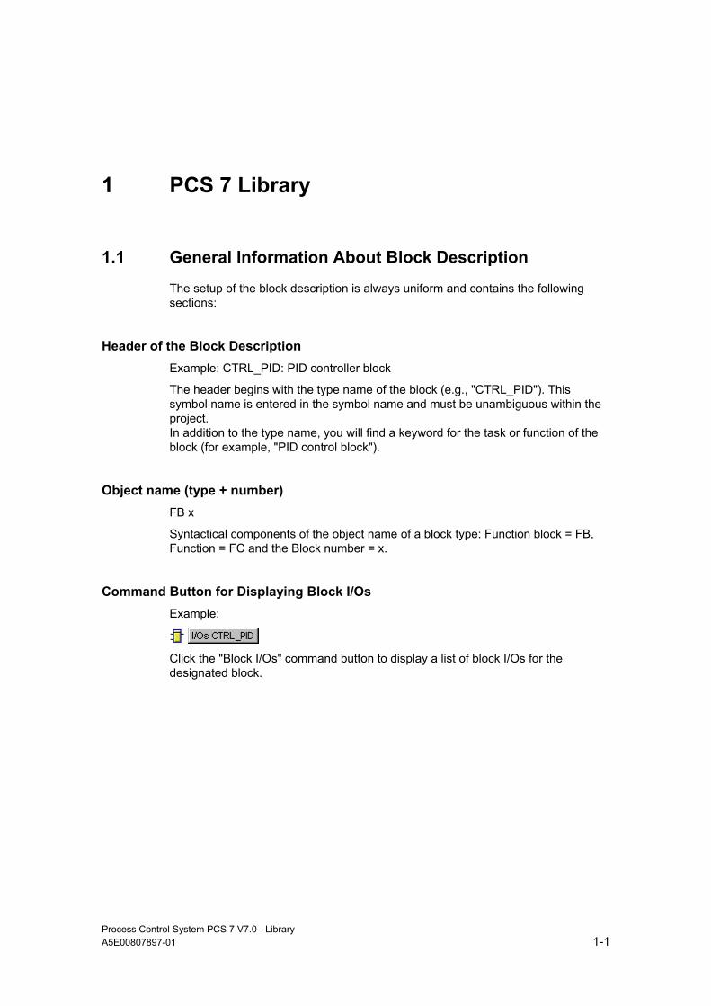
Command Button for Displaying Block I/Os Example:
Click the "Block I/Os" command button to display a list of block I/Os for the designated block.
PCS 7 Library
Process Control System PCS 7 V7.0 - Library 1-2 A5E00807897-01
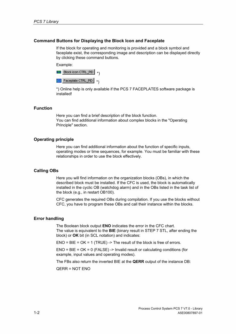
Command Buttons for Displaying the Block Icon and Faceplate If the block for operating and monitoring is provided and a block symbol and faceplate exist, the corresponding image and description can be displayed directly by clicking these command buttons.
Example:
*)
*)
*) Online help is only available if the PCS 7 FACEPLATES software package is installed!
Function Here you can find a brief description of the block function. You can find additional information about complex blocks in the "Operating Principle" section.
Operating principle Here you can find additional information about the function of specific inputs, operating modes or time sequences, for example. You must be familiar with these relationships in order to use the block effectively.
Calling OBs Here you will find information on the organization blocks (OBs), in which the described block must be installed. If the CFC is used, the block is automatically installed in the cyclic OB (watchdog alarm) and in the OBs listed in the task list of the block (e.g., in restart OB100).
CFC generates the required OBs during compilation. If you use the blocks without CFC, you have to program these OBs and call their instance within the blocks.
Error handling The Boolean block output ENO indicates the error in the CFC chart. The value is equivalent to the BIE (binary result in STEP 7 STL, after ending the block) or OK bit (in SCL notation) and indicates:
ENO = BIE = OK = 1 (TRUE) -> The result of the block is free of errors.
ENO = BIE = OK = 0 (FALSE) -> Invalid result or calculating conditions (for example, input values and operating modes).
The FBs also return the inverted BIE at the QERR output of the instance DB:
QERR = NOT ENO

PCS 7 Library
Process Control System PCS 7 V7.0 - Library A5E00807897-01 1-3
The error message is generated in two separate operations:
• The operating system detects a processing error (for example, value overflow, the called system functions return an error code with binary input bit = 0). This system service is not covered specifically in the block description.
• The block algorithm checks for functional invalidity of values and operating modes. These error events are logged in the block description.
You can evaluate the error display, for example, to generate messages or use substitute values for invalid results. You can find additional information about messages in the "Message Blocks" section.
Startup Characteristics The different startup behaviors are as follows:
• Initial startup The first call of the block in its OB. This is usually the OB that performs the standard, process-specific operations (for example, the watchdog interrupt OB). The block enters a status that conforms to its input parameters, That is, the default values (additional information in "I/Os") or values you have already configured, for example, in CFC. The initial startup response is not described separately unless the block does not conform to this rule.
• Startup The block is executed once during CPU startup. The block is called in the startup OB (where it is additionally installed either automatically in the ES or manually in STEP 7). In this case, the startup characteristics are described.
Please note that the block outputs have default values and that these can take effect during the CPU startup with other blocks, if these are processed first.
The correct startup response of the blocks is the responsibility of the project engineer.

PCS 7 Library
Process Control System PCS 7 V7.0 - Library 1-4 A5E00807897-01
Dynamic Response A block assigned this function must be installed into a watchdog alarm OB. It calculates its time constants/parameters on the basis of its sampling time (the time interval between two consecutive cyclic processes). In a CFC configuration on ES, the sampling time is also determined by the segmentation of the runtime group, which ensures that the block is not executed in every OB cycle. This sampling time is entered at the I/Os, in the SAMPLE_T parameter.
When configuring with CFC, this occurs automatically once the block has been inserted in the OB and the runtime group. For this reason, this input is set to hidden in CFC.
In STEP 7 configuration, you must set the dynamic response manually.
Dynamic response is mentioned only if the block has been assigned this feature.
Message response A block with message capability reports various events to the higher-level OS. Existing parameters required for the generation of messages are documented. Blocks not having message characteristics can be expanded with additional interrupt blocks. A cross-reference to the message response is found in the description of the message blocks.
Inputs/Outputs The I/Os of the block represent its data interface. These I/Os can be used either to enter parameter data in the block or to fetch results of the block operations.
I/O (Parameter)
Meaning
Data Type
Default
Type
Attr.
OCM
Valid Values
U1 Addend 1 REAL 0 I Q + >0 .....
The "I/O" table lists all I/O parameters of the block type. You can access these lists using the engineering tools. They are in alphabetical order. Elements accessible only via the block algorithm (internal values) are not listed. The columns have the following meanings:
• I/O Name of the parameter, derived from the English-language designation, for example, PV_IN = Process Variable INput (process variable, control variable) SIMATIC naming conventions are followed.
The state of delivery of the block display in CFC is identified as follows: I/O name in bold characters = I/O is visible, standard characters = I/O is hidden.

PCS 7 Library
Process Control System PCS 7 V7.0 - Library A5E00807897-01 1-5
• Meaning Function (short description)
• Data type S7 data type of the parameter (BOOL, REAL, etc.)
• Default Default initialization value of the block parameter (unless configured otherwise)
• Type The type of access of the block algorithm to the parameter; there are inputs, outputs and retroactive inputs:
Abbreviation Type
I Input. Initialize block with parameters (representation in CFC: left-hand block side) O Output. Output value. (representation in CFC: right-hand block side) IO Input/Output. Retroactive input, set by the OS, the block can write it back
(representation in CFC: left-hand block side)
• Attr. (Attribute) Additional features of the parameter when used under CFC Input and in/out parameters which cannot be interconnected can be configured (at online FCs, only the input/output parameters). Output parameters cannot be configured. Their values can be transferred in CFC by interconnecting them to an input of the same data type.
Additional properties of the parameter are specified as follows: Abbreviation Attribute
C Controllable (only at a faceplate) Write access to this I/O is enabled at the OS. Hidden in the CFC.
M MESSAGE ID of the message block (e.g., ALARM_8P); not configurable This ID is assigned by the message server.
Q Interconnectable. The element can be interconnected with another output of the same type.
• OCM Parameters marked with "+" can be enabled for operating and monitoring via the corresponding faceplate.
• Valid values Additional limitation within the data-type range of values
Operating and Monitoring When a corresponding faceplate exists for the AS block, links to descriptions of the corresponding blocks and faceplates are available (as with the buttons in the upper part of the topic).
Note: The jumps only lead to the online help for faceplates if the PCS7 FACEPLATES software package is installed.

PCS 7 Library
Process Control System PCS 7 V7.0 - Library 1-6 A5E00807897-01

Process Control System PCS 7 V7.0 - Library A5E00807897-01 2-1
2 Technological Blocks
2.1 Measurement and Control
2.1.1 Controller Optimization Using the PID Tuner
Using the PID tuner, you can optimize the following control blocks:
• CTRL_PID
• CTRL_S
• FMCS_PID
• FMT_PID
How it works Using the "Controller Optimization" function, you determine the optimal controller setting for a particular controlled system. A wizard guides you through the individual steps.
The measurement data of the controlled system is recorded. The optimal PID parameters are computed by means of this data and prepared for further use.
You can find additional information on the use of the PID tuner in the corresponding HELP file. Sie können diese Hilfe aufrufen, indem Sie im CFC einen Baustein auf dem Plan selektieren und den Menübefehl Bearbeiten > Regleroptimierung wählen.

Technological Blocks
Process Control System PCS 7 V7.0 - Library 2-2 A5E00807897-01
2.1.2 CTRL_PID: PID controller block
2.1.2.1 Description of CTRL_PID
Object name (type + number) FB61
*)
*)
*) Online help is only available if the "PCS 7 FACEPLATES" software package is installed!
Function Block CTRL_PID is a continuous PID controller used for setting up the following standard controller circuits:
• Fixed-setpoint control
• Cascade control (single/multiple cascades)
• Ratio Control
• Synchro control
• Proportional control
In addition to its actual controller functions, the controller block provides the following processing options:
• Modes: Manual mode, automatic or following mode
• Limit monitoring of the control variable and error signal as well as message generation via the ALARM_8P block
• Disturbance variable input
• Setpoint following mode (SP = PV_IN)
• Setpoint value and process variable range setting (physical normalization)
• Setting the range of values for manipulated variables (physical normalizing)
• Dead band (on threshold) in the error signal branch
• Proportional, integral and derivative action, which can be enabled and disabled individually
• Proportional and derivative action in the feedback path.
• Operating point setting for P or PD controller mode
Technological Blocks
Process Control System PCS 7 V7.0 - Library A5E00807897-01 2-3
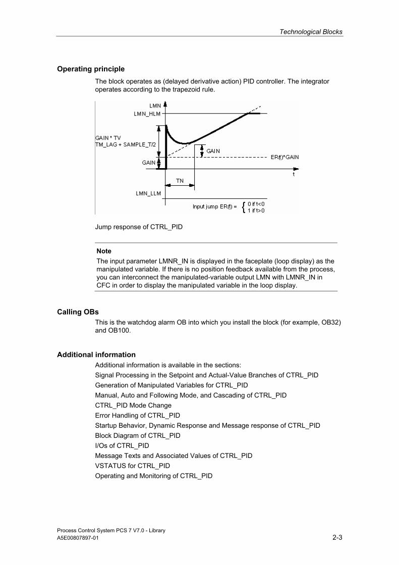
Operating principle The block operates as (delayed derivative action) PID controller. The integrator operates according to the trapezoid rule.
Jump response of CTRL_PID
Note
The input parameter LMNR_IN is displayed in the faceplate (loop display) as the manipulated variable. If there is no position feedback available from the process, you can interconnect the manipulated-variable output LMN with LMNR_IN in CFC in order to display the manipulated variable in the loop display.
Calling OBs This is the watchdog alarm OB into which you install the block (for example, OB32) and OB100.
Additional information Additional information is available in the sections: Signal Processing in the Setpoint and Actual-Value Branches of CTRL_PID Generation of Manipulated Variables for CTRL_PID Manual, Auto and Following Mode, and Cascading of CTRL_PID CTRL_PID Mode Change Error Handling of CTRL_PID Startup Behavior, Dynamic Response and Message response of CTRL_PID Block Diagram of CTRL_PID I/Os of CTRL_PID Message Texts and Associated Values of CTRL_PID VSTATUS for CTRL_PID Operating and Monitoring of CTRL_PID

Technological Blocks
Process Control System PCS 7 V7.0 - Library 2-4 A5E00807897-01
2.1.2.2 Signal Processing in the Setpoint and Actual-Value Branches of CTRL_PID
Setpoint Generation The setpoint SP can be fetched from three different sources. The table below specifies which source is used, depending on the statuses of the SP_TRK_ON and SPEXTSEL_OP inputs:
SP_TRK_ON SPEXTSEL_OP SP= State
0 0 SP_OP Internal setpoint Irrelevant 1 SP_EXT External setpoint 1 0 PV_IN ** Tracked setpoint ** in manual mode only and when SPBUMPON = 1
Internal Setpoint The internal setpoint SP_OP is operated and limited via OP_A_LIM/OP_A_RJC (range SP_LLM - SP_HLM).
External Setpoint The external setpoint SP_EXT can be interconnected and is limited to the range (SPEXTLLM, SPEXTHLM).
The change in the internal or external setpoint is limited to a maximum gradient (SPDRLM, SPURLM), if the setpoint ramp has been enabled (SPRAMPOF = 0).
Tracked Setpoint If SP_TRK_ON = 1, the process variable PV_IN is used as the setpoint. Following mode of the setpoint to the actual value is enabled only in manual mode (for internal setpoint and when SPBUMPON = 1), and is primarily used to provide an adequate setpoint when switching from manual to auto mode.
Technological Blocks
Process Control System PCS 7 V7.0 - Library A5E00807897-01 2-5
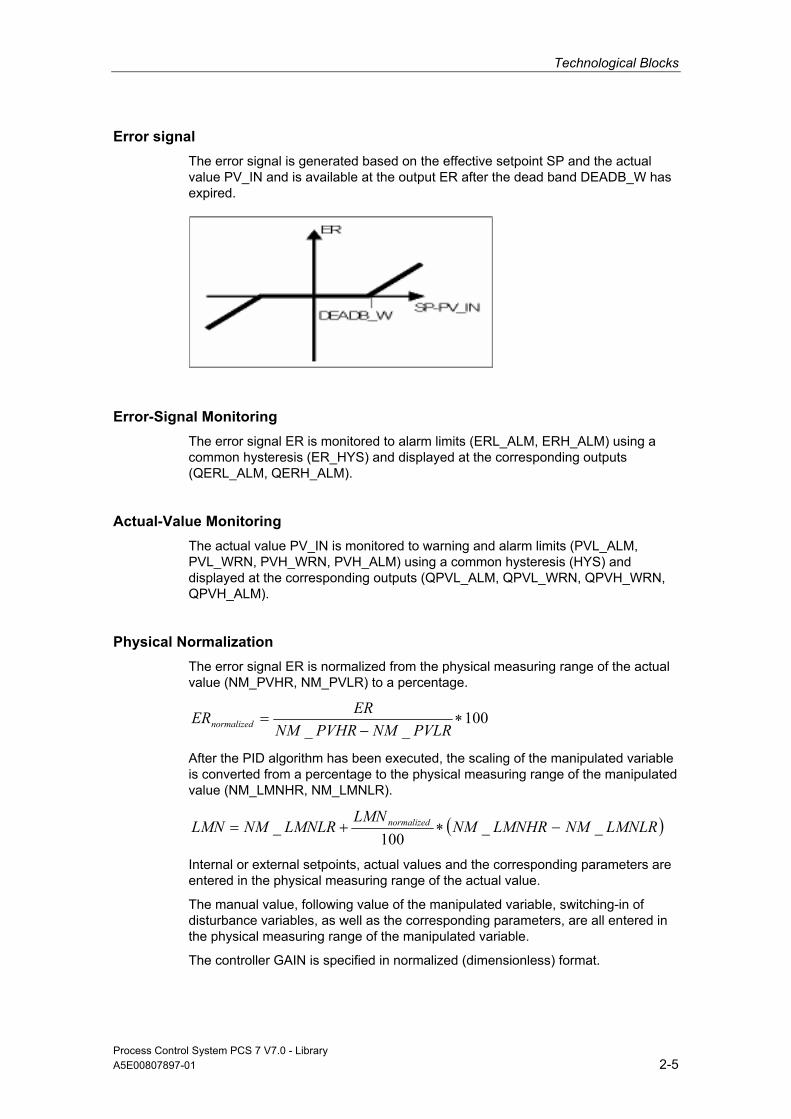
Error signal The error signal is generated based on the effective setpoint SP and the actual value PV_IN and is available at the output ER after the dead band DEADB_W has expired.
Error-Signal Monitoring The error signal ER is monitored to alarm limits (ERL_ALM, ERH_ALM) using a common hysteresis (ER_HYS) and displayed at the corresponding outputs (QERL_ALM, QERH_ALM).
Actual-Value Monitoring The actual value PV_IN is monitored to warning and alarm limits (PVL_ALM, PVL_WRN, PVH_WRN, PVH_ALM) using a common hysteresis (HYS) and displayed at the corresponding outputs (QPVL_ALM, QPVL_WRN, QPVH_WRN, QPVH_ALM).
Physical Normalization The error signal ER is normalized from the physical measuring range of the actual value (NM_PVHR, NM_PVLR) to a percentage.
100__
∗−
=PVLRNMPVHRNM
ERERnormalized
After the PID algorithm has been executed, the scaling of the manipulated variable is converted from a percentage to the physical measuring range of the manipulated value (NM_LMNHR, NM_LMNLR).
( )LMNLRNMLMNHRNMLMN
LMNLRNMLMN normalized __100
_ −∗+=
Internal or external setpoints, actual values and the corresponding parameters are entered in the physical measuring range of the actual value.
The manual value, following value of the manipulated variable, switching-in of disturbance variables, as well as the corresponding parameters, are all entered in the physical measuring range of the manipulated variable.
The controller GAIN is specified in normalized (dimensionless) format.

Technological Blocks
Process Control System PCS 7 V7.0 - Library 2-6 A5E00807897-01
2.1.2.3 Generation of Manipulated Variables for CTRL_PID
Manipulated Variable LMN The manipulated variable LMN can be fetched from three different sources. The table below specifies which source is used, depending on the statuses of the LMN_SEL, LIOP_MAN_SEL, AUT_L, and AUT_ON_P inputs:
LMN_SEL LIOP_MAN_SEL AUT_L AUT_ON_OP LMN= State
0 0 X 0 MAN_OP (is limited)
Manual mode, set via the OS
0 0 X 0 MAN_OP (is limited)
Manual mode, set via the OS
0 0 X 1 Calculated by PID algorithm
Auto mode, via the OS
0 1 0 X MAN_OP (is limited)
Manual mode, set when AUT_L = 0
0 1 0 X MAN_OP (is limited)
Manual mode, set when AUT_L = 0
0 1 1 X Calculated by PID algorithm
Auto mode, set when AUT_L = 1
1 X X X LMN_TRK Manipulated variable tracked
x = Any state
• If LIOP_MAN_SEL = 0, the AUT_ON_OP parameter is used to change over between manual and auto mode on the OS.
• If LIOP_MAN_SEL = 1, the AUT_L parameter is used to change over between manual and auto mode via an interconnection in the CFC.
• Following mode can be enabled only by means of an interconnection via the LMN_SEL parameter. Following takes priority over manual and auto mode.
In auto mode, the normalized manipulated variable is generated according to the following algorithm:
normalizednormalized ERsLAGTM
sTVsTN
GAINLMN ∗⎜⎜⎝
⎛⎟⎟⎠
⎞∗+
∗+
∗+∗=
_111
Refer to: Complex number
The manipulated variable is then denormalized.
Technological Blocks
Process Control System PCS 7 V7.0 - Library A5E00807897-01 2-7
Note This formula describes a standard case in which the proportional, integral, and derivative components are enabled, and the proportional and derivative components are not in a feedback path. (P_SEL = TRUE, TN <> 0, PFDB_SEL = FALSE und DFDB_SEL = FALSE). For example, for TN = 0, an offset calculated from the physical variable LMN_OFF (operating point) is added. You can find additional information in "Block Diagram of CTRL_PID".
Switching-In and Limitation of Disturbance Variables In automatic mode the disturbance variable DISV is added at the output of the PID algorithm. The result is limited to the range LMN_LLM to LMN_HLM.
2.1.2.4 Manual, Auto and Following mode, and Cascading of CTRL_PID
Manual operation The manipulated variable is set by the operator at OS via the input MAN_OP. The manipulated variable is operated and limited via the OP_A_LIM or OP_A_RJC block (range MAN_HLM - MAN_LLM). The QVHL and QVLL output values of the OP_A_LIM or OP_A_RJC block are passed on to the QLMN_HLM and QLMN_LLM outputs.
Auto Mode The PID algorithm calculates the manipulated variable. The control parameters GAIN, TN, TV and TM_LAG cannot be interconnected by default. If they must be interconnected for exceptional applications such as gain scheduling, the corresponding system attribute "s7_link" must be modified. Please note that parameter changes during auto mode may lead to surges of the manipulated variable.
• The controller direction of control action can be reversed (rising error signal causes a falling manipulated variable) by setting a negative proportional GAIN value. The proportional action can be disabled by setting P_SEL = 0, The integral action can be disabled by setting TN = 0. If the manipulated variable LMN is limited for auto mode, the integrator is set to hold (anti-wind-up). The direction of action of the integrator is reversed by inverting the sign at parameter TN.
• Operating point (input LMN_OFF): In automatic mode, this value replaces the integral action of the PID algorithm when the integral action is disabled. The operating point is entered in the measuring range of the manipulated variable.

Technological Blocks
Process Control System PCS 7 V7.0 - Library 2-8 A5E00807897-01
• The derivative action is a delaying component. It can be disabled by setting TV = 0. The direction of action of the differentiator is reversed by inverting the sign of the value at parameter TV. You should set a meaningful ratio between the time lag constant TM_LAG and the derivative time. This ratio is also referred to as derivative gain (maximum of the unit response of the derivative component) and normally lies in the range 5 < TV/TM_LAG < 10.
• Setting proportional action in feedback path: When PFDB_SEL = TRUE, the proportional action is set in the feedback. In this case, a control step does not affect the proportional component so that overshoot can be reduced or avoided when the setpoint value changes without changing the following mode characteristics. Changing over PFDB_SEL in auto mode leads to extreme surges of the manipulated variables. Therefore we recommend that you change over PFDB_SEL in manual mode.
• Setting derivative action in feedback path: The derivative action is set in the feedback by setting DFDB_SEL = TRUE. In this case, a control step does not affect the derivative component. The changeover of DFDB_SEL is not bumpless.
Following mode In this state (LMN_SEL = 1) the manipulated variable is fetched from the interconnected tracked value LMN_TRK and set at the output. The outputs QLMN_HLM and QLMN_LLM are set to FALSE. "Following" operating mode takes priority over all other operating modes, which means that you can use this input to configure an emergency-off circuit for the system.
Set the Proportional and Derivative Component in the Feedback The P and D component can be set in the feedback to reduce or avoid overshoot of the actual value as a result of a setpoint step. The setpoint step does not have any effect on the proportional or derivative component in this operating mode and the manipulated variable does not respond with a step. Use PFDB_SEL = 1 to set the P action and DFDB_SEL = 1 to set the D action in the feedback circuit.
Cascading Several PID Controllers The manipulated variable LMN of the master controller is connected to input SP_EXT of the slave controller. Also make sure the master controller is set to following mode when the cascade is cut. In such cases, the slave controller generates the signal QCAS_CUT, which is interconnected to the input LMN_SEL of the master controller. The cause of this cut can be found manual or following mode, setpoint changes or manipulated variable tracking of the slave controller.
QCAS_CUT = NOT( QMAN_AUT) OR LMN_SEL OR SP_TRK_ON OR NOT(QSPEXT_ON)
The tracking input LMN_TRK of the master controller is interconnected to output SP of the slave controller in order to prevent a jump when the cascade is closed again.

Technological Blocks
Process Control System PCS 7 V7.0 - Library A5E00807897-01 2-9
We also recommend that you set a directional lock of the integrator at the master controller, which takes effect when the slave controller reaches a manipulated variable limit, by interconnecting (with positive controller operating direction) the INT_HPOS and INT_HNEG inputs of the master controller with the QLMN_HLM and QLMN_LLM outputs of the slave controller.
2.1.2.5 CTRL_PID Mode Change
Mode Change This can be triggered either by operator control or via interconnected inputs.
External/Internal Setpoint Changeover is carried out between the external and internal setpoint by OS operation of the SPEXTSEL_OP input or interconnection of SPEXON_L. You must set the corresponding enable inputs SPINT_EN, SPEXT_EN or the selection input LIOP_INT_SEL to enable these changeovers.
If SPBUMPON = 1, the internal setpoint is replaced with the effective setpoint in order to allow a bumpless changeover from external or following mode to internal mode.
Enabling Changeover Between Internal and External Setpoint
QSPEXTEN = TRUE: SPEXTSEL_OP can be set from FALSE (internal setpoint) to TRUE (external setpoint).
QSPINTEN = TRUE: SPEXTSEL_OP can be set from TRUE (external setpoint) to FALSE (internal setpoint).
SPEXTSEL_OP is tracked or reset as required.
Enabling Setpoint Control Via the Operator Input
Q_SP_OP = TRUE: SP_OP operation is enabled.
SP_OP is tracked or reset as required.

Technological Blocks
Process Control System PCS 7 V7.0 - Library 2-10 A5E00807897-01
Manual/Auto Changeover is carried out between manual and auto mode by OS operation of the AUT_ON_OP input or interconnection of AUT_L. You must set the corresponding enable inputs MANOP_EN, AUTOP_EN or the selection input LIOP_MAN_SEL to enable this changeover.
Enabling the Changeover Between Manual and Auto Mode
QAUTOP = TRUE: AUT_ON_OP can be set from FALSE (manual mode) to TRUE (auto mode).
QMANOP = TRUE: AUT_ON_OP can be set from TRUE (auto mode) to FALSE (manual mode).
AUT_ON_OP is tracked or reset as required.
Enabling Manual-Value Control Via the Operator Input
QLMNOP = TRUE: MAN_OP can be set.
MAN_OP is tracked or reset as required.
Special measures are applied for the modes listed below in order to ensure a bumpless changeover:
• Setpoint external/setpoint tracking: If SPBUMPON = TRUE, the internal setpoint SP_OP is set to the effective (external or tracked) setpoint.
• Auto mode: The manual value MAN_OP is tracked to the effective manipulated variable.
• Following mode: The manual value MAN_OP is tracked to the effective manipulated variable.
• Manual or following mode: The integrator is tracked to allow a bumpless changeover to auto mode.
Integral component = manipulated variable (percentage) minus the proportional component minus the disturbance variable (percentage)

Technological Blocks
Process Control System PCS 7 V7.0 - Library A5E00807897-01 2-11
Notice: When this formula is applied, the integrator may be loaded with extremely high numeric values if at the time of changeover the field value overshoots, i.e., an extremely high proportional component has developed. Additional measures have been implemented as of V6.0 to allow flexible limiting of the integral component.
The derivative component is disabled and compensated.
2.1.2.6 Error Handling of CTRL_PID
Operator control error QOP_ERR = 1 will be set if at least one operator error occurs during the operation of one of the parameters SPEXTSEL_OP, AUT_ON_OP, SP_OP, or MAN_OP. Otherwise, QOP_ERR = 0. Operator errors are held for the duration of one cycle.
The block algorithm handles the following events:
• Parameter assignment error NM_PVHR <= NM_PVHR:
The error signal ER is set to zero and ENO = 0 or QERR = 1.
• NM_LMNHR <= NM_LMNHR:
In auto mode, the disturbance variable will be output and ENO=0 or QERR=1.
• Absolute value (TN) < SAMPLE_T/2:
For TN(TI) > 0 is calculated with TN(TI) = SAMPLE_T/2, for TN(TI) < 0 with TN(TI) = -SAMPLE_T/2. For TN(TI) = 0 the integrator is shutdown and the operating point LMN_OFF is active.
• Absolute value (TV) < SAMPLE_T:
For TV(TD) > 0 is calculated with TV(TD) = SAMPLE_T, for TV(TD) < 0 with TV(TD) = -SAMPLE_T. For TV(TD) = 0 the differentiator is shutdown.
• TM_LAG < SAMPLE_T/2:
When TM_LAG < SAMPLE_T/2, TM_LAG < SAMPLE_T/2 is used for calculation. In these cases the differential component responds as an ideal differentiator.
Technological Blocks
Process Control System PCS 7 V7.0 - Library 2-12 A5E00807897-01
2.1.2.7 Startup Behavior, Dynamic Response and Message response of CTRL_PID
Startup Characteristics During CPU startup, the internal setpoint of the CTRL_PID is set in manual mode. The block must be called in the startup OB accordingly. In CFC engineering, this is handled by the CFC. Using the basic STEP 7 tools, you must manually enter this call in the startup OB. After startup, the messages will be suppressed during the number of cycles set at RUNUPCYC.
Dynamic Response The block must be called via a watchdog interrupt OB. The sampling time of the block is set in parameter SAMPLE_T.
Assignment of the 32-Bit Status Word VSTATUS You can find additional information in "VSTATUS for CTRL_PID".
Message response The CTRL_PID block uses the ALARM_8P block for generating messages. The following message triggers exist:
• The functions for monitoring the actual value and error signal limits,
• the CSF signal, which is referenced as a control system error by interconnection
Messages regarding limit violation can be suppressed individually by setting the corresponding M_SUP_xx inputs. The process messages (not process control messages!) can be completely blocked with MSG_LOCK. QMSG_SUP is set if the RUNUPCYC cycles have not expired yet since a restart, MSG_LOCK = TRUE or MSG_STAT = 21. The table lists message texts of the CTRL_PID block and their assignment to the block parameters.
Monitoring of Process Values n.a.
2.1.2.8 Block Diagram of CTRL_PID
Note
To print out this block diagram, open the "Print" dialog box and select the "Landscape format" page setting. The diagram is then printed on two pages, which you can attach to one another if required.
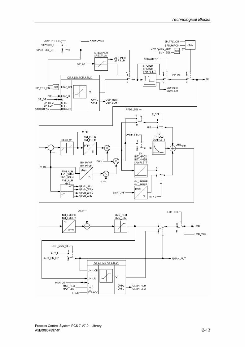
Technological Blocks
Process Control System PCS 7 V7.0 - Library A5E00807897-01 2-13

Technological Blocks
Process Control System PCS 7 V7.0 - Library 2-14 A5E00807897-01
2.1.2.9 I/Os of CTRL_PID The factory setting of the block display in CFC is identified in the "I/O" column: I/O name in bold characters = I/O is visible; I/O name in standard characters = I/O is hidden. You can find explanations of and information about the abbreviations used in "General Information About Block Description".
I/O (Parameter)
Meaning
Data Type
Default Type
Attr. OCM Valid Values
AUT_L Interconnectable input for MAN/AUTO:0: Manual, 1: Auto
BOOL 0 I Q
AUT_ON_OP Mode input (0=Manual/1=Auto)
BOOL 0 IO C +
AUTOP_EN 1 = Enable AUTO mode BOOL 1 I Q AUX_PRx Associated value x ANY 0 IO Q BA_EN Release by BATCH BOOL 0 I Q + BA_ID BATCH: Batch serial number DWORD 0 I Q + BA_NA Batch name STRING
[32] '' I Q +
CSF Control System Fault BOOL 0 I Q DEADB_W Dead band width REAL 0 I + >= 0 DFDB_SEL Set D action in feedback
(1 = enabled) BOOL 0 I Q
DISV Error variable REAL 0 I Q ER Error signal REAL 0 O + ER_HYS Hysteresis for monitoring the
error signal REAL 0.1 I + >= 0
ERH_ALM Error signal: High limit alarm
REAL 100 I + > DEADBW
ERL_ALM Error signal: Low limit alarm
REAL -100 I + < -DEADBW
GAIN Proportional gain REAL 1 I + HYS Hysteresis REAL 5 I + >= 0 INT_HNEG Freeze integral component (neg.
direction) 1 = Enabled
BOOL 0 I Q
INT_HPOS Freeze integral component (pos. direction) 1 = Enabled
BOOL 0 I Q
LIOP_INT_ SEL
1 = Interconnection active 0 = Operator control enabled
BOOL 0 I Q
LIOP_MAN _SEL
1 = Interconnection active 0 = Operator control enabled
BOOL 0 I Q
LMN Manipulated value output REAL 0 O LMN_HLM High limit: manipulated variable REAL 100 I Q + LMN_HLM >
LMN_LLM

Technological Blocks
Process Control System PCS 7 V7.0 - Library A5E00807897-01 2-15
I/O (Parameter)
Meaning
Data Type
Default Type
Attr. OCM Valid Values
LMN_LLM Low limit: manipulated variable REAL 0 I Q + LMN_LLM < LMN_HLM
LMN_OFF Linearization point REAL 0 I Q + LMN_SEL 1 = External manipulated
variable enabled BOOL 0 I Q
LMN_TRK External manipulated variable REAL 0 I Q LMNOP_ON 1 = Enable operator control of
manipulated variable MAN_OP BOOL 1 I Q
LMNR_IN Position feedback for display on OS
REAL 0 I Q
M_SUP_AH 1 = Message suppression: high limit alarm process variable
BOOL 0 I +
M_SUP_AL 1 = Message suppression: low limit alarm process variable
BOOL 0 I +
M_SUP_ER Message suppression: error signal alarm
BOOL 1 I +
M_SUP_WH 1 = Message suppression: High warning, process variable
BOOL 0 I +
M_SUP_WL 1 = Message suppression: low warning, process variable
BOOL 0 I +
MAN_HLM High limit of manual manipulated variable
REAL 100 I +
MAN_LLM Low limit of manual manipulatedvariable
REAL 0 I +
MAN_OP Operator input for manipulated value
REAL 0 IO C +
MANOP_EN 1 = Enable manual mode BOOL 1 I Q MO_PVHR High display limit (measurement
range) REAL 110 I +
MO_PVLR Low display limit (measurement range)
REAL -10 I +
MSG_ACK Acknowledge message WORD 0 O MSG_EVID Message number DWORD 0 I M MSG_LOCK 1 = Message suppression at
specific process state BOOL 0 I Q +
MSG_STAT Error message status WORD 0 O NM_LMNHR High limit: normalization of
manipulated variable (measuring range)
REAL 100 I
NM_LMNLR Low limit: normalization of manipulated variable (measuring range)
REAL 0 I
NM_PVHR High limit: normalization of actual value (measuring range)
REAL 100 I
NM_PVLR Low limit: normalization of actual value (measuring range)
REAL 0 I
OCCUPIED ID for occupied by BATCH BOOL 0 I Q + OOS Reserve BOOL 0 I +
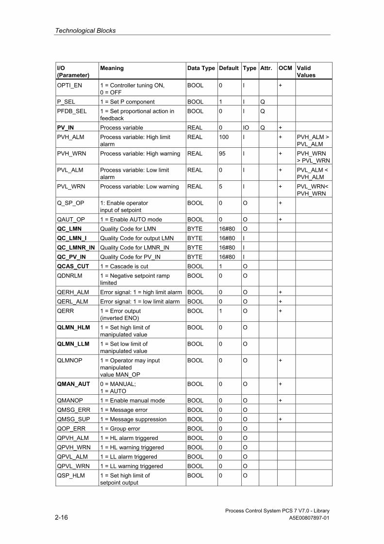
Technological Blocks
Process Control System PCS 7 V7.0 - Library 2-16 A5E00807897-01
I/O (Parameter)
Meaning
Data Type
Default Type
Attr. OCM Valid Values
OPTI_EN 1 = Controller tuning ON, 0 = OFF
BOOL 0 I +
P_SEL 1 = Set P component BOOL 1 I Q PFDB_SEL 1 = Set proportional action in
feedback BOOL 0 I Q
PV_IN Process variable REAL 0 IO Q + PVH_ALM Process variable: High limit
alarm REAL 100 I + PVH_ALM >
PVL_ALM PVH_WRN Process variable: High warning REAL 95 I + PVH_WRN
> PVL_WRNPVL_ALM Process variable: Low limit
alarm REAL 0 I + PVL_ALM <
PVH_ALM PVL_WRN Process variable: Low warning REAL 5 I + PVL_WRN<
PVH_WRN Q_SP_OP 1: Enable operator
input of setpoint BOOL 0 O +
QAUT_OP 1 = Enable AUTO mode BOOL 0 O + QC_LMN Quality Code for LMN BYTE 16#80 O QC_LMN_I Quality Code for output LMN BYTE 16#80 I QC_LMNR_IN Quality Code for LMNR_IN BYTE 16#80 I QC_PV_IN Quality Code for PV_IN BYTE 16#80 I QCAS_CUT 1 = Cascade is cut BOOL 1 O QDNRLM 1 = Negative setpoint ramp
limited BOOL 0 O
QERH_ALM Error signal: 1 = high limit alarm BOOL 0 O + QERL_ALM Error signal: 1 = low limit alarm BOOL 0 O + QERR 1 = Error output
(inverted ENO) BOOL 1 O +
QLMN_HLM 1 = Set high limit of manipulated value
BOOL 0 O
QLMN_LLM 1 = Set low limit of manipulated value
BOOL 0 O
QLMNOP 1 = Operator may input manipulated value MAN_OP
BOOL 0 O +
QMAN_AUT 0 = MANUAL; 1 = AUTO
BOOL 0 O +
QMANOP 1 = Enable manual mode BOOL 0 O + QMSG_ERR 1 = Message error BOOL 0 O QMSG_SUP 1 = Message suppression BOOL 0 O + QOP_ERR 1 = Group error BOOL 0 O QPVH_ALM 1 = HL alarm triggered BOOL 0 O QPVH_WRN 1 = HL warning triggered BOOL 0 O QPVL_ALM 1 = LL alarm triggered BOOL 0 O QPVL_WRN 1 = LL warning triggered BOOL 0 O QSP_HLM 1 = Set high limit of
setpoint output BOOL 0 O

Technological Blocks
Process Control System PCS 7 V7.0 - Library A5E00807897-01 2-17
I/O (Parameter)
Meaning
Data Type
Default Type
Attr. OCM Valid Values
QSP_LLM 1 = Set low limit of setpoint output
BOOL 0 O
QSPEXTEN 1 = Enable external operator control mode
BOOL 0 O +
QSPEXTON 0 = Internal; 1 = External
BOOL 0 O +
QSPINTEN 1 = Enable internal operation BOOL 0 O + QUPRLM 1 = Limit positive setpoint ramp BOOL 0 O RUNUPCYC Number of run-up cycles INT 3 I SAMPLE_T Sampling time in seconds REAL 1 I >= 0.001 SP Active setpoint REAL 0 O + SP_EXT External setpoint REAL 0 I Q SP_HLM Setpoint high limit REAL 100 I + SP_HLM >
SP_LLM SP_LLM Setpoint low limit REAL 0 I + SP_LLM <
SP_HLM SP_OP Operator input: Setpoint REAL 0 IO C + SP_OP_ON Enable: 1 = Operator may input
SP_OP BOOL 1 I Q
SP_TRK_ON 1 = Track setpoint SP_OP BOOL 0 I + SPBUMPON 1 = Bumpless setpoint BOOL 1 I + SPDRLM Max. negative setpoint
ramp rate [1/s] REAL 100 I +
SPEXON_L Interconnectable input internal/external 0 = Internal 1 = External
BOOL 0 I Q
SPEXT_EN 1 = Enable operator to select external setpoint
BOOL 1 I Q
SPEXTHLM High limit of external setpoint REAL 100 I Q SPEXTHLM > SPEXTLLM
SPEXTLLM Low limit of external setpoint REAL 0 I Q SPEXTHLM > SPEXTLLM
SPEXTSEL_ OP
Operator input: 0 = Internal, 1 = External
BOOL 0 IO C +
SPINT_EN 1 = Enable internal operation BOOL 1 I Q SPRAMPOF 1 = Setpoint ramp
limiting = OFF BOOL 1 I +
SPURLM Max. positive setpoint ramp rate [1/s]
REAL 100 I +
STEP_NO Batch step number DWORD 0 I Q + TM_LAG Time lag of derivative
component in seconds REAL 1 I + ≥±SAMPLE_
T/2 TN Following time in seconds REAL 10 I + TN=0,
≥±SAMPLE_T/2
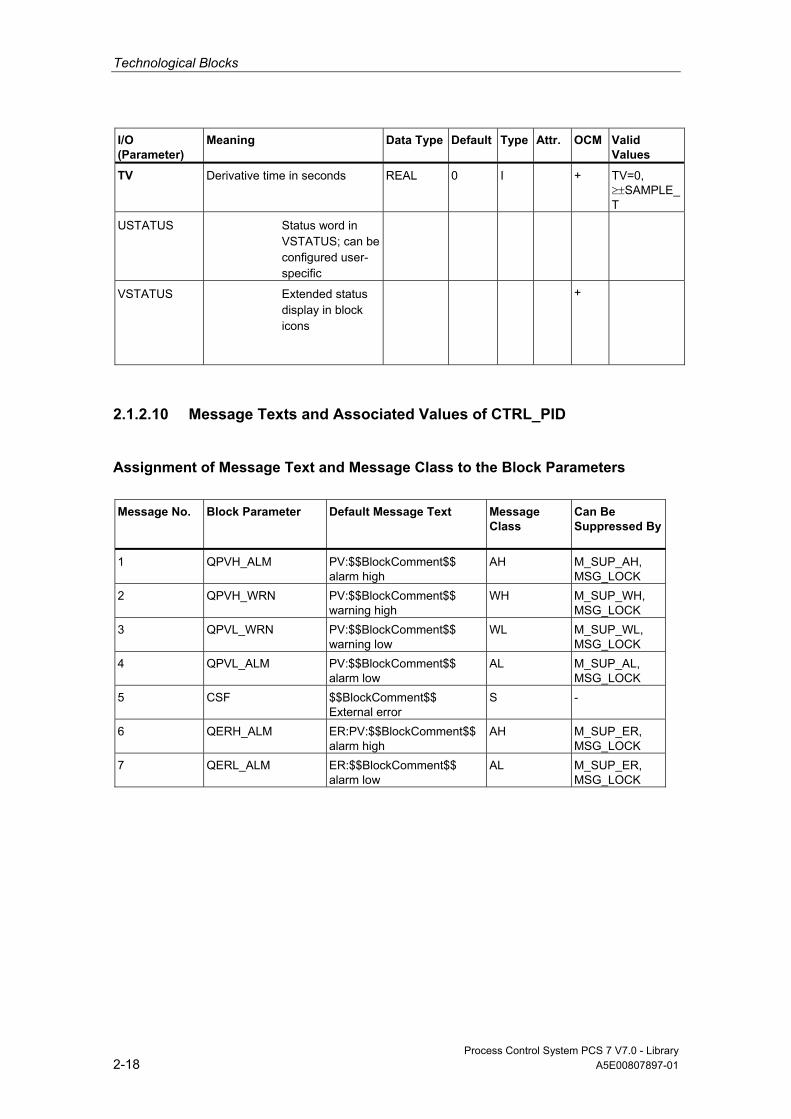
Technological Blocks
Process Control System PCS 7 V7.0 - Library 2-18 A5E00807897-01
I/O (Parameter)
Meaning
Data Type
Default Type
Attr. OCM Valid Values
TV Derivative time in seconds REAL 0 I + TV=0, ≥±SAMPLE_T
USTATUS Status word in VSTATUS; can be configured user-specific
VSTATUS Extended status display in block icons
+
2.1.2.10 Message Texts and Associated Values of CTRL_PID
Assignment of Message Text and Message Class to the Block Parameters
Message No.
Block Parameter
Default Message Text Message Class
Can Be Suppressed By
1 QPVH_ALM PV:$$BlockComment$$ alarm high
AH M_SUP_AH, MSG_LOCK
2 QPVH_WRN PV:$$BlockComment$$ warning high
WH M_SUP_WH, MSG_LOCK
3 QPVL_WRN PV:$$BlockComment$$ warning low
WL M_SUP_WL, MSG_LOCK
4 QPVL_ALM PV:$$BlockComment$$ alarm low
AL M_SUP_AL, MSG_LOCK
5 CSF $$BlockComment$$ External error
S -
6 QERH_ALM ER:PV:$$BlockComment$$ alarm high
AH M_SUP_ER, MSG_LOCK
7 QERL_ALM ER:$$BlockComment$$ alarm low
AL M_SUP_ER, MSG_LOCK

Technological Blocks
Process Control System PCS 7 V7.0 - Library A5E00807897-01 2-19
Assignment of Associated Values to the Block Parameters The first three of the associated values of the message block are assigned SIMATIC BATCH data, the fourth is reserved for PV_IN and the remaining ones (AUX_PRx) can be freely assigned by the user.
Associated Value
Block Parameter
1 BA_NA 2 STEP_NO 3 BA_ID 4 PV_IN 5 AUX_PR05 6 AUX_PR06 7 AUX_PR07 8 AUX_PR08 9 AUX_PR09 10 AUX_PR010
2.1.2.11 VSTATUS for CTRL_PID
The 32-bit status word extends the status display in the block icons and faceplates. The 16 low bits (bits 0 - 15) are used by the block as follows:
Bit no.: 7 6 5 4 3 2 1 0 Parameters - - - QSPEXTON QMAN_AUT MSG_LOCK BA_EN OCCUPIED
Bit no.: 5 14 13 12 11 10 9 8 Parameters OOS QMSG_SUP LMN_SEL - - - - -
The 16-bit input USTATUS (data type WORD) uses the high bits (bits 16 - 31). You can use these bits as you wish.

Technological Blocks
Process Control System PCS 7 V7.0 - Library 2-20 A5E00807897-01
2.1.2.12 Operating and Monitoring of CTRL_PID
Additional information You can find additional information in the following sections:
• Block Icon CTRL_PID
• Faceplate CTRL_PID
Note: Online help and the "PCS 7 FACEPLATES" Manual are only available if the "PCS 7 FACEPLATES" software package is installed!
2.1.3 CTRL_S: PID controller block
2.1.3.1 Description of CTRL_S
Object name (type + number) FB76
*)
*)
*) Online help is only available if the "PCS 7 FACEPLATES" software package is installed!
Function The CTRL_S controller block is a step controller for process-control systems in which integral-action actuating elements (for example, motor-driven valves) are used. The valves are controlled by means of two binary control signals.
The operating principle of the step controller is based on a combination of the PID algorithm of a sampling controller and a downstream position controller. In the process, the continuous control signal is converted into a sequence of control pulses.
The configuration can be used to activate or deactivate the following sub-functions of the PID algorithm and thus adapt these to the process:
• Modes: Manual mode, automatic or tracking
• Monitoring limits of the control variable and error signal as well as message generation via the ALARM_8P block
• Disturbance variable input

Technological Blocks
Process Control System PCS 7 V7.0 - Library A5E00807897-01 2-21
• Setpoint tracking (SP = PV_IN)
• Setpoint value and process variable range setting (physical normalization)
• Proportional, integral and derivative component, which can be enabled and disabled individually
• A proportional and derivative action can be set in the feedback path (P action only in step controllers with position feedback).
• Operating-point setting for P or PD controller mode
• The downstream positioning controller takes the following applications into account:
- Controlling with position feedback signal
- Controlling without position feedback signal
- Direct signal adjustment by means of manual operation or interconnected signals
• Suppression of the control signals based on corresponding feedback signals from the motor (motor protection) or valve (limit stop signals)
• Reduction of the number of control pulses by means of adaptive response threshold
Operating principle PI step controllers are commonly used applications. In this mode, the step response of the controller is as follows:
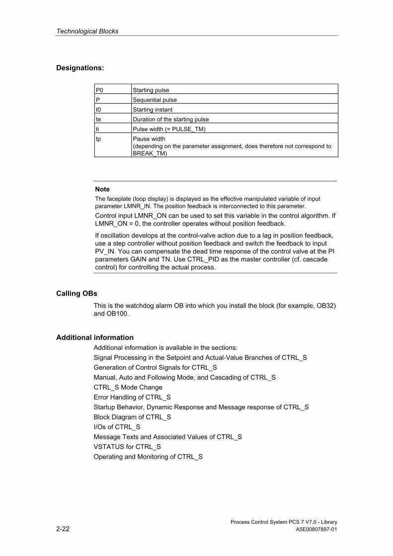
Technological Blocks
Process Control System PCS 7 V7.0 - Library 2-22 A5E00807897-01
Designations: P0 Starting pulse P Sequential pulse t0 Starting instant te Duration of the starting pulse ti Pulse width (= PULSE_TM) tp Pause width
(depending on the parameter assignment, does therefore not correspond to BREAK_TM)
Note
The faceplate (loop display) is displayed as the effective manipulated variable of input parameter LMNR_IN. The position feedback is interconnected to this parameter. Control input LMNR_ON can be used to set this variable in the control algorithm. If LMNR_ON = 0, the controller operates without position feedback.
If oscillation develops at the control-valve action due to a lag in position feedback, use a step controller without position feedback and switch the feedback to input PV_IN. You can compensate the dead time response of the control valve at the PI parameters GAIN and TN. Use CTRL_PID as the master controller (cf. cascade control) for controlling the actual process.
Calling OBs This is the watchdog alarm OB into which you install the block (for example, OB32) and OB100.
Additional information Additional information is available in the sections: Signal Processing in the Setpoint and Actual-Value Branches of CTRL_S Generation of Control Signals for CTRL_S Manual, Auto and Following Mode, and Cascading of CTRL_S CTRL_S Mode Change Error Handling of CTRL_S Startup Behavior, Dynamic Response and Message response of CTRL_S Block Diagram of CTRL_S I/Os of CTRL_S Message Texts and Associated Values of CTRL_S VSTATUS for CTRL_S Operating and Monitoring of CTRL_S
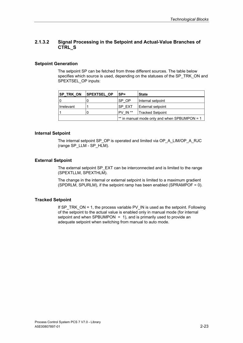
Technological Blocks
Process Control System PCS 7 V7.0 - Library A5E00807897-01 2-23
2.1.3.2 Signal Processing in the Setpoint and Actual-Value Branches of CTRL_S
Setpoint Generation The setpoint SP can be fetched from three different sources. The table below specifies which source is used, depending on the statuses of the SP_TRK_ON and SPEXTSEL_OP inputs:
SP_TRK_ON SPEXTSEL_OP SP= State
0 0 SP_OP Internal setpoint Irrelevant 1 SP_EXT External setpoint 1 0 PV_IN ** Tracked Setpoint ** in manual mode only and when SPBUMPON = 1
Internal Setpoint The internal setpoint SP_OP is operated and limited via OP_A_LIM/OP_A_RJC (range SP_LLM - SP_HLM).
External Setpoint The external setpoint SP_EXT can be interconnected and is limited to the range (SPEXTLLM, SPEXTHLM).
The change in the internal or external setpoint is limited to a maximum gradient (SPDRLM, SPURLM), if the setpoint ramp has been enabled (SPRAMPOF = 0).
Tracked Setpoint If SP_TRK_ON = 1, the process variable PV_IN is used as the setpoint. Following of the setpoint to the actual value is enabled only in manual mode (for internal setpoint and when SPBUMPON = 1), and is primarily used to provide an adequate setpoint when switching from manual to auto mode.

Technological Blocks
Process Control System PCS 7 V7.0 - Library 2-24 A5E00807897-01
Error signal The error signal is generated based on the effective setpoint SP and the actual value PV_IN and is available at the output ER after the dead band DEADB_W has expired.
Error-Signal Monitoring The error signal ER is monitored to alarm limits (ERL_ALM, ERH_ALM) using a common hysteresis (ER_HYS) and displayed at the corresponding outputs (QERL_ALM, QERH_ALM).
Actual-Value Monitoring The actual value PV_IN is monitored to warning and alarm limits (PVL_ALM, PVL_WRN, PVH_WRN, PVH_ALM) using a common hysteresis (HYS) and displayed at the corresponding outputs (QPVL_ALM, QPVL_WRN, QPVH_WRN, QPVH_ALM).
Physical Normalization The error signal ER is normalized from the physical measuring range of the actual value (NM_PVHR, NM_PVLR) to a percentage.
100__
∗−
=PVLRNMPVHRNM
ERERnormalized
Internal or external setpoints, actual values and the corresponding parameters are entered in the physical measuring range of the actual value.
The operating range of the valve is normalized to 0 to 100. Manual values, tracking values of the manipulated variable and disturbance variables are entered as percentage.
The controller GAIN is specified in normalized (dimensionless) format.

Technological Blocks
Process Control System PCS 7 V7.0 - Library A5E00807897-01 2-25
2.1.3.3 Generation of Control Signals for CTRL_S
Control Signals Control signals can be generated from various sources. The tables below specify which source is used, depending on the statuses of the control inputs:
No.
Operating Principle
Set-point Internal/External
Position Feedback
Effective Source Generally: Depending on the setting, LMN_OFF and DISV can also be effective in auto mode.
Tracked Signals Generally: SP_OP is only tracked if SPBUMPON=1.
Remark
2 Startup/ restart
- - Startup values Startup values
4 Manual/ Following
- yes MAN_OP SP_OP=SP_EXT/ PV_IN
Manipulated variable operation
8 yes LMN_TRK SP_OP=SP_EXT/ PV_IN MAN_OP=LMNR_ IN
Following to external manipulated variable
5 - LMNUP_OP/ LMNDN_OP
SP_OP=SP_EXT/ PV_IN MAN_OP= LMNR_IN
Manipulated variable operation at the OS
6 - LMNUP/LMNDN SP_OP=SP_EXT/ PV_IN MAN_OP= LMNR_IN
Direct control signal adjustment via interconnection
9 Automatic Internal - SP_OP, control signal from PID algorithm
MAN_OP= LMNR_IN
Setpoint from OS
12 SP_EXT, control signal from PID algorithm
SP_OP=SP_EXT MAN_OP= LMNR_IN
Interconnected setpoint

Technological Blocks
Process Control System PCS 7 V7.0 - Library 2-26 A5E00807897-01
Operating principle
Following Manual Automatic
Source LMN_ TRK
LMNUP/ LMNDN
MAN_OP LMNUP_OP/ LMNDN_OP
SP_EXT SP_OP PV_IN
Internal/external External
External Ext. Int. Ext. Int. Ext. Int. Ext. Int. Ext. Int.
Control inputs
AUT_L - - 0 - 0 - 1 - 1 - 1 -
AUT_ON_OP - - - 0 - 0 - 1 - 1 - 1
AUTOP_EN - - - - - - - (1) - (1) - -
MANOP_EN - - - (1) - (1) - - - - - -
LIOP_MAN_SEL - - 1 0 1 0 1 0 1 0 1 0
SPEXON_L - - - - - - 1 - 0 - - -
SPEXTSEL_OP - - - - - - - 1 - 0 - -
SPINT_EN - - - - - - - - - (1) - -
SPEXT_EN - - - - - - - (1) - - - -
LIOP_INT_SEL - - - - - - 1 0 1 0 - -
LMN_SEL 1 - 0 0 0 0 0 0 0 0 0 0
LMNS_ON 0 1 0 0 0 0 0 0 0 0 0 0
SP_OP_ON - - - - - - - - 1 1 - -
LMNOP_ON - - 1 1 - - - - - - - -
LMNSOPON - - (2) (2) 1 1 - - - - - -
LMNR_ON 1 - 1 1 - - - - - - - -
SP_TRK_ON - - - - - - 0 0 0 0 1 1
Explanations:
External: The setpoint is program-controlled and is set via interconnected inputs or by configuration.
Internal: The setpoint is set via operator control on the OS.
"-": Random status
(1): The setting is only checked when there is a changeover at the OS.
(2): Control signal operation may not be enabled. ( = not (LMNSOPON and (LMNUP_OP xor LMNDN_OP)) ). Signal operation via LMNUP_OP or LMNDN_OP takes priority over manipulated-variable operation via MAN_OP.
The analog manipulated variable of the PID algorithm is generated as follows:
normalizeditedun ERsLAGTM
sTVsTN
GAINLMN ∗⎜⎜⎝
⎛⎟⎟⎠
⎞∗+
∗+
∗+∗=
_111lim
Refer to: Complex number

Technological Blocks
Process Control System PCS 7 V7.0 - Library A5E00807897-01 2-27
Switching-In and Limitation of Disturbance Variables In automatic mode the disturbance variable DISV is added at the output of the PID algorithm. The result is limited to the range LMN_LLM to LMN_HLM.
The Three-Step Element With Threshold Adaptation The three-point element has an on and off threshold, which can be adapted by the block to a value between.
Note
This formula describes a standard case in which the proportional, integral, and derivative actions are enabled, and the proportional and derivative actions are not in a feedback path. (P_SEL = TRUE, TN <> 0, PFDB_SEL = FALSE und DFDB_SEL = FALSE). For example, for TN = 0, an offset calculated from the physical variable LMN_OFF (operating point) is added. For additional information, refer to the section "Block diagram of the CTRL_PID".
Off threshold: 55.0 / MTR_TM * SAMPLE_T
Minimum response threshold: 100.0 / MTR_TM * Maximum (PULSE_TM, SAMPLE_T)
Maximum response threshold: 10.0
Technological Blocks
Process Control System PCS 7 V7.0 - Library 2-28 A5E00807897-01
Adaptation of the response threshold can be switched off by setting THRADA_ON = FALSE. This sets the response threshold to the minimum value.
The currently effective response threshold can be viewed at output THRESON.
Note
The response threshold is set to minimum in the following cases (also if THRADA = TRUE): • Manual or following mode of step controllers without position feedback
• Controllers without integral component (TN = 0 s)
2.1.3.4 Manual, Auto and Following Mode, and Cascading of CTRL_S
Manual operation Manual mode offers you three options for operating control signals:
• Manipulated variable preset via MAN_OP
• Stepping mode of MAN_OP
• Direct operation of control signals via actuating commands
Operation of MAN_OP via manipulated-variable preset or direct operation is only possible in control systems with position feedback (LMNR_ON = 1). It is operated and limited via OP_A_LIM or OP_A_RJC (range MAN_HLM - MAN_LLM). The QVHL and QVLL output values of OP_A_LIM or OP_A_RJC are passed on to the QLMN_HLM and QLMN_LLM outputs. The value of MAN_OP is then passed to output LMN and the motor is traveled via the control signals until the value of the position feedback LMNR_IN reaches the value of MAN_OP.
Direct operation of control signals via actuating commands is, however also possible in control systems operating with and without position feedback. Signal operation is enabled with LMNSOPON and the control signals are set with LMNUP_OP or LMNDN_OP. The valve is then driven until the operation is disabled or the end position is achieved.
Control signal operation takes priority over manipulated variable operation. If MAN_OP is not the effective input signal, the value is tracked to LMNR_IN.
Technological Blocks
Process Control System PCS 7 V7.0 - Library A5E00807897-01 2-29
Auto Mode The PID algorithm calculates the manipulated variable LMN. The control parameters GAIN, TN, TV and TM_LAG cannot be interconnected by default. If they must be interconnected for exceptional applications such as gain scheduling, the corresponding s7_link system attribute must be modified. Please note that parameter changes during auto mode may lead to surges of the manipulated variable:
• The controller direction of control action can be reversed (rising error signal causes a falling manipulated variable) by setting a negative proportional GAIN value. The proportional action can be disabled by setting P_SEL = 0, the integral action can be disabled by setting TN = 0. In the case of control systems with position feedback, the integral action can be locked for a particular direction by interconnecting input INTH_POS or INTH_NEG.
• Within the scope of the anti-windup measures, the integrator is automatically stopped when the limit switch is tripped LMNR_HS or LMNR_LS or if the position feedback LMNR_IN is active and exits the LMN_HLM, LMN_LLM section.
• Operating point (input LMN_OFF): In automatic mode, this value replaces the integral action of the PID algorithm when the integral action is disabled. The operating point is entered in the measuring range of the manipulated variable.
• The derivative action is a delaying component. It can be disabled by setting TV = 0. You should set a meaningful ratio between the time lag constant TM_LAG and the derivative time. This ratio is also referred to as derivative gain (maximum of the unit response of the derivative component) and normally lies in the range 5 < TV/TM_LAG < 10.
• Setting a proportional action in the feedback branch of the controller. When PFDB_SEL = TRUE, the proportional action is set in the feedback of the controller. In this case, a control step does not affect the proportional component so that overshoot can be reduced or avoided when the setpoint value changes without changing the tracking characteristics. Changing over PFDB_SEL in auto mode leads to extreme surges of the manipulated variables. Therefore we recommend that you change over PFDB_SEL in manual mode.
• Setting a derivative action in the feedback branch of the controller. When DFDB_SEL = TRUE, the derivative action is set in the feedback of the controller. In this case, a control step does not affect the derivative component. The changeover of DFDB_SEL is not bumpless.
The calculated manipulated variable is then converted into a sequence of actuating pulses. The algorithm for generating the actuating pulse is influenced by the following parameters:
• MTR_TM: Motor actuating time = Time required to cover the maximum travel distance of the valve.
• PULSE_TM: Minimum pulse width. The smallest step a valve travels. Amounts to 100%*PULSE_TM/MTR_TM.
• BREAK_TM: Minimum break time: After an actuating pulse has terminated, this period must expire before a new pulse can be output.

Technological Blocks
Process Control System PCS 7 V7.0 - Library 2-30 A5E00807897-01
• LMNR_HS, LMNR_LS: Limit switch. If one of the limit switches is set, the corresponding output signal QLMNUP or QLMNDN is locked.
• At the negative edge of the motor-protection signal MSS, the motor protection error is held and passed to output QMSS_ST. The parameter MSS_SIG is used to specify whether only to display an error message (MSS_SIG = 0), or whether the motor is to be limited irrespective of all other inputs and system states (MSS_SIG = 1). The motor protection error (QMSS_ST = 1) is reported to the OS. The operator can reset QMSS_ST via the ERROR input, or it is reset automatically by setting an interconnection with L_RESET = 1.
• LMNR_ON: If LMNR_ON is used controlling is performed with position feedback. The control input may not be changed over while an operation is busy.
• DEADB_W: The dead band in the error signal is necessary in order to reduce switching frequency of the controller as a result of minor error signal fluctuations around zero. At the operating point of the loop, the error signal changes around the value: (100% *PULSE_TM/MTR_TM) * Process gain. Hence, the dead band should be greater than 50% of this value. If DEADB_W is negative, the dead band is ignored.
Following mode There are two options of handling control signals in following mode:
• Following via the external manipulated variable LMN_TRK
• Direct control of the control signals via the interconnected inputs LMNS_ON, LMNUP and LMNDN
Following via an external manipulated variable LMN_TRK is only possible in control systems with position feedback. The setting LMN_SEL = 1 is used the pass the manipulated variable from the interconnected tracked value LMN_TRK to output LMN. The valve is traveled via the control signals until the value of the position feedback LMNR_IN has reached the value of LMN_TRK.
The following mode using LMNS_ON with direct connection of the control signals over the LMNUP and LMNDN interconnected inputs has the highest priority of all operating modes. If LMNS_ON is set, the control signals can only be set via the inputs LMNUP or LMNDN. As long as LMNS_ON is set, all other influences on the control signals are suppressed.
Setting the Proportional and Derivative Component at the Feedback Channel The P and D component can be set in the feedback to reduce or avoid overshoot of the actual value as a result of a setpoint step. The setpoint step does not have any effect on the proportional or derivative component in this operating mode and the manipulated variable does not respond with a step.
Use PFDB_SEL = 1 to set the P action PFDB_SEL does not affect step controllers with feedback. In this operating mode, the P action cannot be set in the feedback.
and DFDB_SEL = 1 to set the D action in the feedback circuit.

Technological Blocks
Process Control System PCS 7 V7.0 - Library A5E00807897-01 2-31
Cascading PID Controllers The manipulated variable LMN of the master controller is connected to input SP_EXT of the slave controller (please note: only the slave controller is a step controller, not the master controller). Also make sure the master controller is set to following mode when the cascade is cut. In such cases, the slave controller generates the signal QCAS_CUT, which is interconnected to the input LMN_SEL of the master controller. The cause of this cut can be found manual or following mode, setpoint changes or manipulated variable tracking of the slave controller.
QCAS_CUT = LMNS_ON or LMN_SEL or (not QMAN_AUT) or (QMAN_AUT and SP_TRK_ON)
The tracking input LMN_TRK of the master controller is interconnected to output SP of the slave controller in order to prevent a jump when the cascade is closed again.
We also recommend that you set a directional lock of the integrator at the master controller, which takes effect when the slave controller reaches a manipulated variable limit, by interconnecting (with positive controller operating direction) the INT_HPOS and INT_HNEG inputs of the master controller with the QLMN_HLM and QLMN_LLM outputs of the slave controller.
2.1.3.5 CTRL_S Mode Change
Mode Change This can be triggered either by operator control or via interconnected inputs.
External/Internal Setpoint Depending on the setting of the LIOP_INT_SEL selection input, changeover is carried out between the external and internal setpoint by OS operation of the SPEXTSEL_OP input or interconnection of SPEXON_L. You must set the corresponding enable inputs SPINT_EN, SPEXT_EN to enable this changeover.
If SPBUMPON = 1, the internal setpoint is replaced with the effective setpoint in order to allow a bumpless changeover from external or following mode to internal mode.

Technological Blocks
Process Control System PCS 7 V7.0 - Library 2-32 A5E00807897-01
Enabling Changeover Between Internal and External Setpoint
QSPEXTEN = TRUE: SPEXTSEL_OP can be set from FALSE (internal setpoint) to TRUE (external setpoint).
QSPINTEN = TRUE: SPEXTSEL_OP can be set from TRUE (external setpoint) to FALSE (internal setpoint).
SPEXTSEL_OP is tracked or reset as required.
Enabling Setpoint Control Via the Operator Input
Q_SP_OP = TRUE: SP_OP operation is enabled.
SP_OP is tracked or reset as required.
Manual/Auto Depending on the setting of the LIOP_MAN_SEL selection input, changeover is carried out between manual and auto mode by OS operation of the AUT_ON_OP input or interconnection of AUT_L. You must set the corresponding enable inputs MANOP_EN, AUTOP_EN to enable this changeover.
Enabling the Changeover Between Manual and Auto Mode
QAUTOP = TRUE: AUT_ON_OP can be set from FALSE (manual mode) to TRUE (auto mode).
QMANOP = TRUE: AUT_ON_OP can be set from TRUE (auto mode) to FALSE (manual mode).
AUT_ON_OP is tracked or reset as required.

Technological Blocks
Process Control System PCS 7 V7.0 - Library A5E00807897-01 2-33
Enabling Manual Mode Manipulated variable operation is enabled at the faceplate via MAN_OP by setting QLMNVOP, the control signal is controlled via QLMNSOP instructions:
QLMNVOP QLMNSOP
LMNOP_ON 1 - LMNSOPON - 1 LMNR_ON 1 - LMNSOPON and (LMNUP_OP xor LMNDN_OP)
0 -
LMN_SEL 0 0 LMNS_ON 0 0 QMAN_AUT 0 0
Special measures are applied for the modes listed below in order to ensure a bumpless changeover:
• Setpoint external/setpoint tracking: If SPBUMPON = TRUE, the internal setpoint SP_OP is set to the effective (external or tracked) setpoint.
• Auto mode: The manual value MAN_OP is tracked to the value of the effective manipulated variable LMNR_IN.
• Following mode: When LMN_SEL is set, the manually input value MAN_OP is tracked to the value of LMN_TRK. You can thus see up to which value the valve is traveled. When LMN_SEL is canceled, MAN_OP will be reset to the value of LMNR_IN, in order to ensure a bumpless changeover when MAN_OP is set.
• Manual mode: In control systems with position feedback the integrator is tracked to allow a bumpless changeover to auto mode.
Integrated component = manipulated variable ( in [%] ) minus the proportional component minus the disturbance variable ( in [%] )
2.1.3.6 Error Handling of CTRL_S
Operator control error QOP_ERR = 1 will be set if at least one operator error occurs during the operation of one of the parameters SPEXTSEL_OP, AUT_ON_OP, SP_OP, or MAN_OP. Otherwise, QOP_ERR = 0. Operator errors are held for the duration of one cycle.
The block algorithm handles the following events:
• Configuration error: NM_PVHR <= NM_PVLR: The error signal ER is set to zero. ENO = 0 or QERR = 1 is set.
Technological Blocks
Process Control System PCS 7 V7.0 - Library 2-34 A5E00807897-01
• Configuration error: SAMPLE_T<0.001: The sampling time SAMPLE_T is set to 0.001. ENO = 0 or QERR = 1 is set.
• Configuration error: GAIN = 0: The error signal ER is set to zero. ENO = 0 or QERR = 1 is set.
• TN < SAMPLE_T/2: If TN > 0, TN = SAMPLE_T/2 is used for calculation. If TN = 0, the integrator is disabled and the operating point LMN_OFF is active.
• TV < SAMPLE_T: If TV > 0, TV = SAMPLE_T is used for calculation. If TV = 0, the differentiator is disabled.
• TM_LAG < SAMPLE_T/2: When TM_LAG < SAMPLE_T/2, TM_LAG < SAMPLE_T/2 is used for calculation. In these cases the differential component responds as an ideal differentiator.
The low limits of MTR_TM, PULSE_TM and BREAK_TM are set to the value of SAMPLE_T.
If the enable inputs *_EN are reset during active operation, this is indicated via the outputs QMAN_ERR or QAUT_ERR.
QMAN_ERR will also be set if the control input for the position feedback LMNR_ON is canceled while the controller is being tracked to LMN_TRK. In this case the valve is stopped.
2.1.3.7 Startup Behavior, Dynamic Response and Message response of CTRL_S
Startup Characteristics During CPU startup, the internal setpoint of the CTRL_S is set in manual mode. The block must be called in the startup OB accordingly. In CFC engineering, this is handled by the CFC. Using the basic STEP 7 tools, you must manually enter this call in the startup OB. After startup, the messages will be suppressed during the number of cycles set at RUNUPCYC.
MAN_OP and LMN with LMNR_IN are initialized during the startup. The integral action is set to zero.
Dynamic Response The block must be called via a watchdog interrupt OB. The sampling time of the block is set in parameter SAMPLE_T.
Assignment of the 32-Bit Status Word VSTATUS You can find additional information in "VSTATUS for CTRL_S".

Technological Blocks
Process Control System PCS 7 V7.0 - Library A5E00807897-01 2-35
Message response The CTRL_S block uses the ALARM_8P block for generating messages.
The following message triggers exist:
• the functions for monitoring the actual value and system deviation limits
• the CSF signal QMSS_ST, which is referenced as a control system error by means of interconnection
Messages regarding limit violation can be suppressed individually by setting the corresponding M_SUP_xx inputs. The process messages (not process control messages!) can be completely blocked with MSG_LOCK.
QMSG_SUP is set if the RUNUPCYC cycles have not expired yet since a restart, MSG_LOCK = TRUE or MSG_STAT = 21.
The table lists message texts of the CTRL_S block and their assignment to the block parameters.
Monitoring of Process Values n.a.
2.1.3.8 Block Diagram of CTRL_S
Note To print out this block diagram, open the "Print" dialog box and select the "Landscape format" page setting. The diagram is then printed on two pages, which you can attach to one another if required.
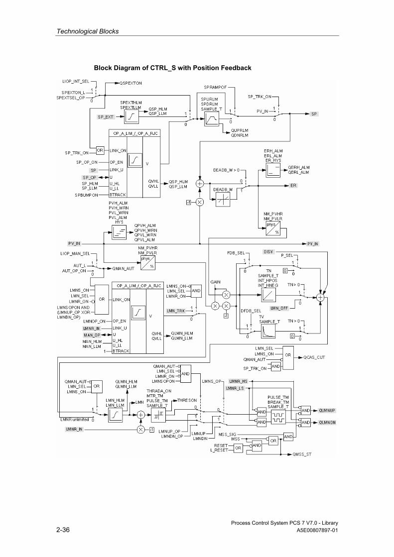
Technological Blocks
Process Control System PCS 7 V7.0 - Library 2-36 A5E00807897-01
Block Diagram of CTRL_S with Position Feedback
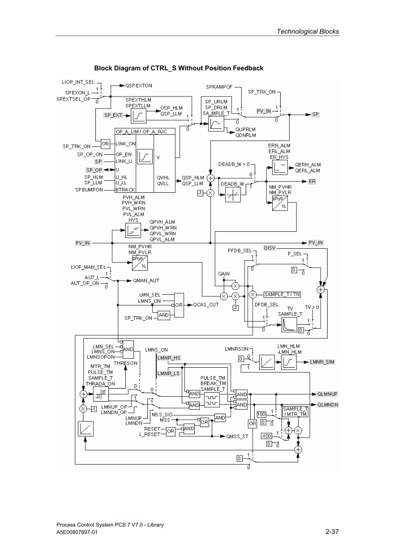
Technological Blocks
Process Control System PCS 7 V7.0 - Library A5E00807897-01 2-37
Block Diagram of CTRL_S Without Position Feedback

Technological Blocks
Process Control System PCS 7 V7.0 - Library 2-38 A5E00807897-01
2.1.3.9 I/Os of CTRL_S
The factory setting of the block display in CFC is identified in the "I/O" column: I/O name in bold characters = I/O is visible; I/O name in standard characters = I/O is hidden.
You can find explanations of and information about the abbreviations used in "General Information About Block Description".
I/O (Parameter)
Meaning
Data Type
Default Type
Attr.
OCM Valid Values
AUT_L Interconnectable input for MANUAL/AUTO (0=Manual/1=Auto)
BOOL 0 I Q
AUT_ON_OP Mode input (0=Manual/1=Auto)
BOOL 0 IO C +
AUTOP_EN 1 = Enable AUTO mode BOOL 1 I Q AUX_PRx Associated value x ANY 0 IO Q BA_EN Release by BATCH BOOL 0 I Q + BA_ID BATCH: Batch serial
number DWORD 0 I Q +
BA_NA Batch name STRING [32]
'' I Q +
BREAK_TM Minimum break time in seconds
REAL 1 I +
CSF Control System Fault BOOL 0 I Q DEADB_W Dead band width REAL 0 I + ≥ 0 DFDB_SEL Derivative action in
feedback path, 1 = enabled
BOOL 0 I Q
DISV Error variable REAL 0 I Q ER Error signal REAL 0 O + ER_HYS Hysteresis for monitoring
the error signal
REAL 0.1 I + ≥ 0
ERH_ALM Error signal: High limit alarm
REAL 100 I + > 0
ERL_ALM Error signal: Low limit alarm REAL -100 I + < 0 GAIN Proportional gain REAL 1 I + HYS Hysteresis REAL 5 I + ≥ 0 INT_HNEG Lock negative integral
action BOOL 0 I
INT_HPOS Lock positive integral action BOOL 0 I L_RESET Interconnectable input
RESET: Motor-protection error (QMSS_ST=0)
BOOL 0 I Q
LIOP_INT_ SEL
1 = Interconnection active 0 = Operator control enabled
BOOL 0 I Q
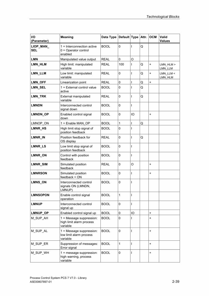
Technological Blocks
Process Control System PCS 7 V7.0 - Library A5E00807897-01 2-39
I/O (Parameter)
Meaning
Data Type
Default Type
Attr.
OCM Valid Values
LIOP_MAN_ SEL
1 = Interconnection active 0 = Operator control enabled
BOOL 0 I Q
LMN Manipulated value output REAL 0 O LMN_HLM High limit: manipulated
variable REAL 100 I Q + LMN_HLM >
LMN_LLM LMN_LLM Low limit: manipulated
variable REAL 0 I Q + LMN_LLM <
LMN_HLM LMN_OFF Linearization point REAL 0 I Q + LMN_SEL 1 = External control value
active BOOL 0 I Q
LMN_TRK External manipulated variable
REAL 0 I Q
LMNDN Interconnected control signal down
BOOL 0 I
LMNDN_OP Enabled control signal down
BOOL 0 IO +
LMNOP_ON 1 = Enable MAN_OP BOOL 1 I Q LMNR_HS High limit stop signal of
position feedback BOOL 0 I
LMNR_IN Position feedback for OS display
REAL 0 I Q
LMNR_LS Low limit stop signal of position feedback
BOOL 0 I
LMNR_ON Control with position feedback
BOOL 0 I
LMNR_SIM Simulated position feedback
REAL 0 O +
LMNRSON Simulated position feedback = ON
BOOL 0 I +
LMNS_ON Interconnected control signals ON (LMNDN, LMNUP)
BOOL 0 I
LMNSOPON Enable control signal operation
BOOL 1 I
LMNUP Interconnected control signal up
BOOL 0 I
LMNUP_OP Enabled control signal up BOOL 0 IO + M_SUP_AH 1 = Message suppression:
high limit alarm process variable
BOOL 0 I +
M_SUP_AL 1 = Message suppression:low limit alarm process variable
BOOL 0 I +
M_SUP_ER Suppression of messages: Error signal
BOOL 1 I +
M_SUP_WH 1 = message suppression: high warning, process variable
BOOL 0 I +
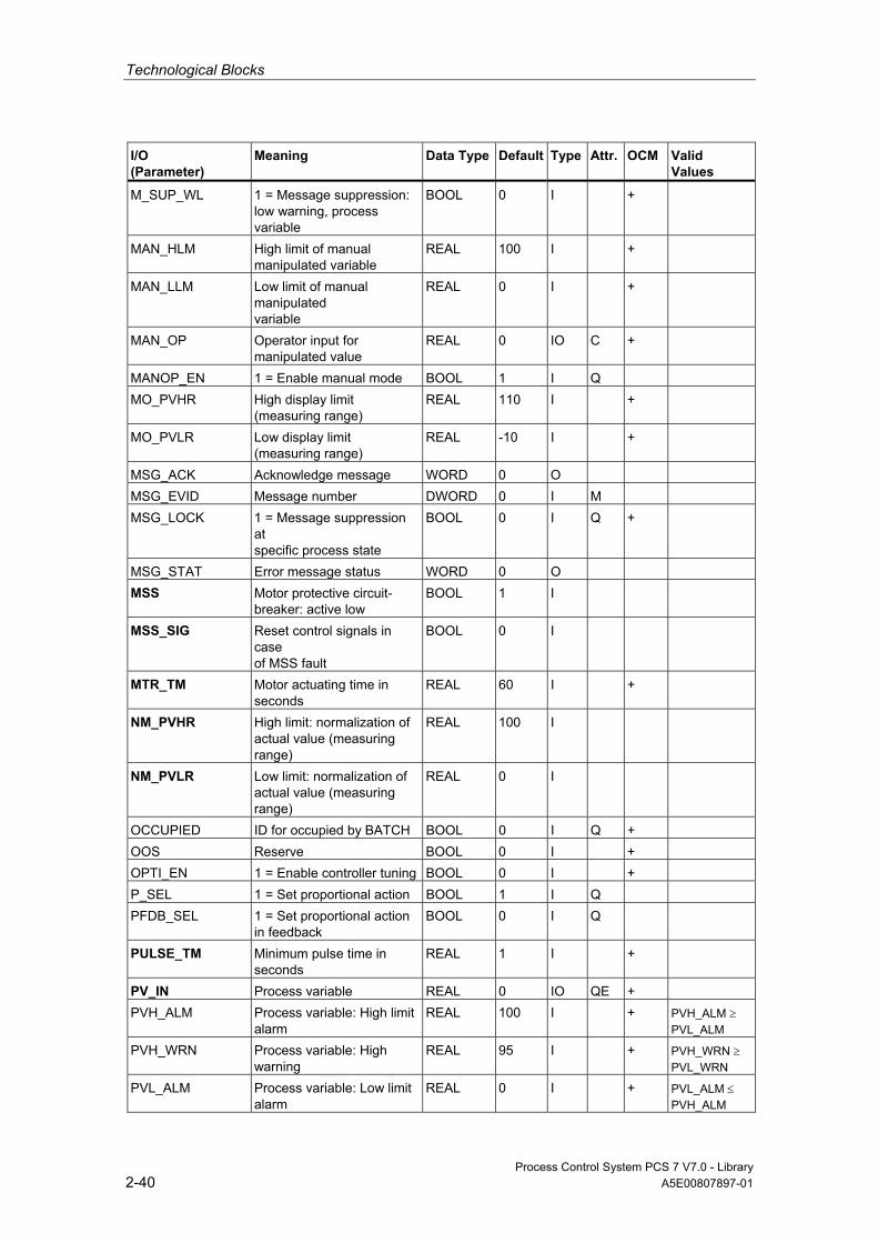
Technological Blocks
Process Control System PCS 7 V7.0 - Library 2-40 A5E00807897-01
I/O (Parameter)
Meaning
Data Type
Default Type
Attr.
OCM Valid Values
M_SUP_WL 1 = Message suppression:low warning, process variable
BOOL 0 I +
MAN_HLM High limit of manual manipulated variable
REAL 100 I +
MAN_LLM Low limit of manual manipulated variable
REAL 0 I +
MAN_OP Operator input for manipulated value
REAL 0 IO C +
MANOP_EN 1 = Enable manual mode BOOL 1 I Q MO_PVHR High display limit
(measuring range) REAL 110 I +
MO_PVLR Low display limit (measuring range)
REAL -10 I +
MSG_ACK Acknowledge message WORD 0 O MSG_EVID Message number DWORD 0 I M MSG_LOCK 1 = Message suppression
at specific process state
BOOL 0 I Q +
MSG_STAT Error message status WORD 0 O MSS Motor protective circuit-
breaker: active low BOOL 1 I
MSS_SIG Reset control signals in case of MSS fault
BOOL 0 I
MTR_TM Motor actuating time in seconds
REAL 60 I +
NM_PVHR High limit: normalization of actual value (measuring range)
REAL 100 I
NM_PVLR Low limit: normalization of actual value (measuring range)
REAL 0 I
OCCUPIED ID for occupied by BATCH BOOL 0 I Q + OOS Reserve BOOL 0 I + OPTI_EN 1 = Enable controller tuning BOOL 0 I + P_SEL 1 = Set proportional action BOOL 1 I Q PFDB_SEL 1 = Set proportional action
in feedback BOOL 0 I Q
PULSE_TM Minimum pulse time in seconds
REAL 1 I +
PV_IN Process variable REAL 0 IO QE + PVH_ALM Process variable: High limit
alarm REAL 100 I + PVH_ALM ≥
PVL_ALM PVH_WRN Process variable: High
warning REAL 95 I + PVH_WRN ≥
PVL_WRN PVL_ALM Process variable: Low limit
alarm REAL 0 I + PVL_ALM ≤
PVH_ALM
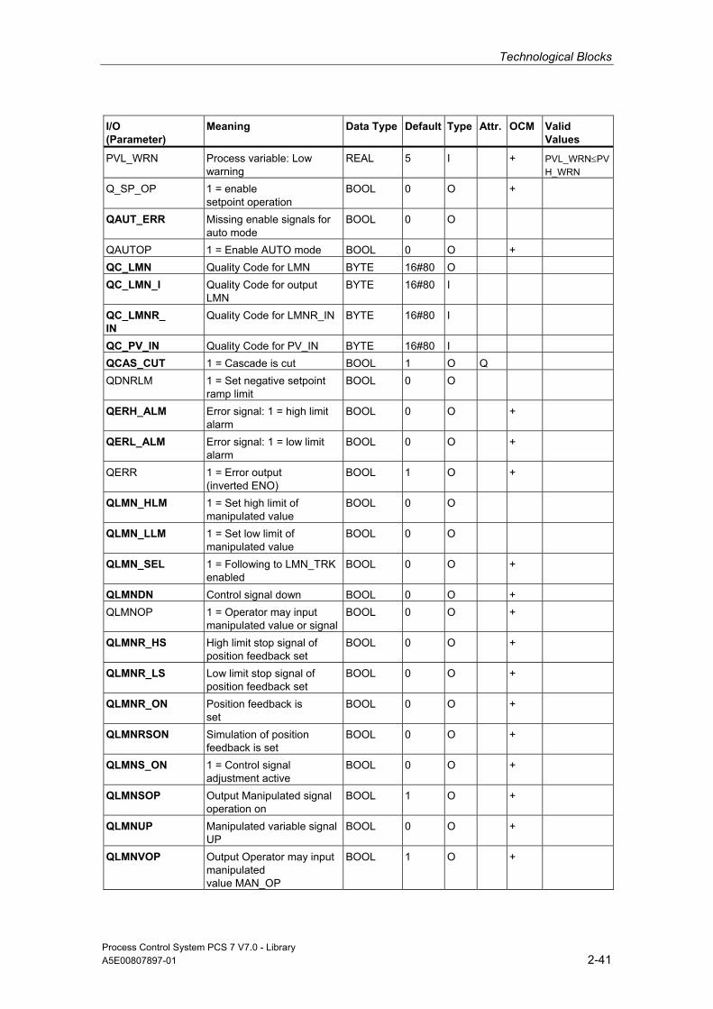
Technological Blocks
Process Control System PCS 7 V7.0 - Library A5E00807897-01 2-41
I/O (Parameter)
Meaning
Data Type
Default Type
Attr.
OCM Valid Values
PVL_WRN Process variable: Low warning
REAL 5 I + PVL_WRN≤PVH_WRN
Q_SP_OP 1 = enable setpoint operation
BOOL 0 O +
QAUT_ERR Missing enable signals for auto mode
BOOL 0 O
QAUTOP 1 = Enable AUTO mode BOOL 0 O + QC_LMN Quality Code for LMN BYTE 16#80 O QC_LMN_I Quality Code for output
LMN BYTE 16#80 I
QC_LMNR_ IN
Quality Code for LMNR_IN BYTE 16#80 I
QC_PV_IN Quality Code for PV_IN BYTE 16#80 I QCAS_CUT 1 = Cascade is cut BOOL 1 O Q QDNRLM 1 = Set negative setpoint
ramp limit BOOL 0 O
QERH_ALM Error signal: 1 = high limit alarm
BOOL 0 O +
QERL_ALM Error signal: 1 = low limit alarm
BOOL 0 O +
QERR 1 = Error output (inverted ENO)
BOOL 1 O +
QLMN_HLM 1 = Set high limit of manipulated value
BOOL 0 O
QLMN_LLM 1 = Set low limit of manipulated value
BOOL 0 O
QLMN_SEL 1 = Following to LMN_TRK enabled
BOOL 0 O +
QLMNDN Control signal down BOOL 0 O + QLMNOP 1 = Operator may input
manipulated value or signalBOOL 0 O +
QLMNR_HS High limit stop signal of position feedback set
BOOL 0 O +
QLMNR_LS Low limit stop signal of position feedback set
BOOL 0 O +
QLMNR_ON Position feedback is set
BOOL 0 O +
QLMNRSON Simulation of position feedback is set
BOOL 0 O +
QLMNS_ON 1 = Control signal adjustment active
BOOL 0 O +
QLMNSOP Output Manipulated signal operation on
BOOL 1 O +
QLMNUP Manipulated variable signal UP
BOOL 0 O +
QLMNVOP Output Operator may input manipulated value MAN_OP
BOOL 1 O +

Technological Blocks
Process Control System PCS 7 V7.0 - Library 2-42 A5E00807897-01
I/O (Parameter)
Meaning
Data Type
Default Type
Attr.
OCM Valid Values
QMAN_AUT 0 = MANUAL 1 = AUTO
BOOL 0 O +
QMAN_ERR Missing enable signals for manual mode
BOOL 0 O
QMANOP 1 = Enable manual mode BOOL 0 O + QMAN_ERR Error output of ALARM_8P BOOL 0 O QMSG_SUP 1 = Set message
suppression BOOL 0 O +
QMSS_ST Motor protection triggered (0 = reset with RESET)
BOOL 0 O +
QOP_ERR 1 = Group error BOOL 0 O QPVH_ALM 1 = HL alarm triggered BOOL 0 O QPVH_WRN 1 = HL warning triggered BOOL 0 O QPVL_ALM 1 = LL alarm triggered BOOL 0 O QPVL_WRN 1 = LL warning triggered BOOL 0 O QSP_HLM 1 = Set high limit of
setpoint output BOOL 0 O
QSP_LLM 1 = Set low limit of setpoint output
BOOL 0 O
QSPEXTEN 1 = Operator-control enable, external
BOOL 0 O +
QSPEXTON 0 = Internal 1 = External
BOOL 0 O +
QSPINTEN 1 = Enable internal operation
BOOL 0 O +
QUPRLM 1 = Limit positive setpoint ramp
BOOL 0 O
RESET Enabled reset input for motor-protection error (QMSS_ST=0)
BOOL 0 IO C +
RUNUPCYC Number of run-up cycles INT 3 I SAMPLE_T Sampling time in seconds REAL 1 I ≥ 0.001 SP Active setpoint REAL 0 O E + SP_EXT External setpoint REAL 0 I Q SP_HLM Setpoint high limit REAL 100 I + SP_HLM >
SP_LLM SP_LLM Setpoint low limit REAL 0 I + SP_LLM <
SP_HLM SP_OP Operator input: Setpoint REAL 0 IO C + SP_OP_ON Enable: 1 = Operator may
input SP_OP BOOL 1 I Q
SP_TRK_ON 1 = Track setpoint SP_OP BOOL 0 I + SPBUMPON 1 = Bumpless setpoint BOOL 1 I + SPDRLM Max. negative setpoint
ramp rate [1/s] REAL 100 I +
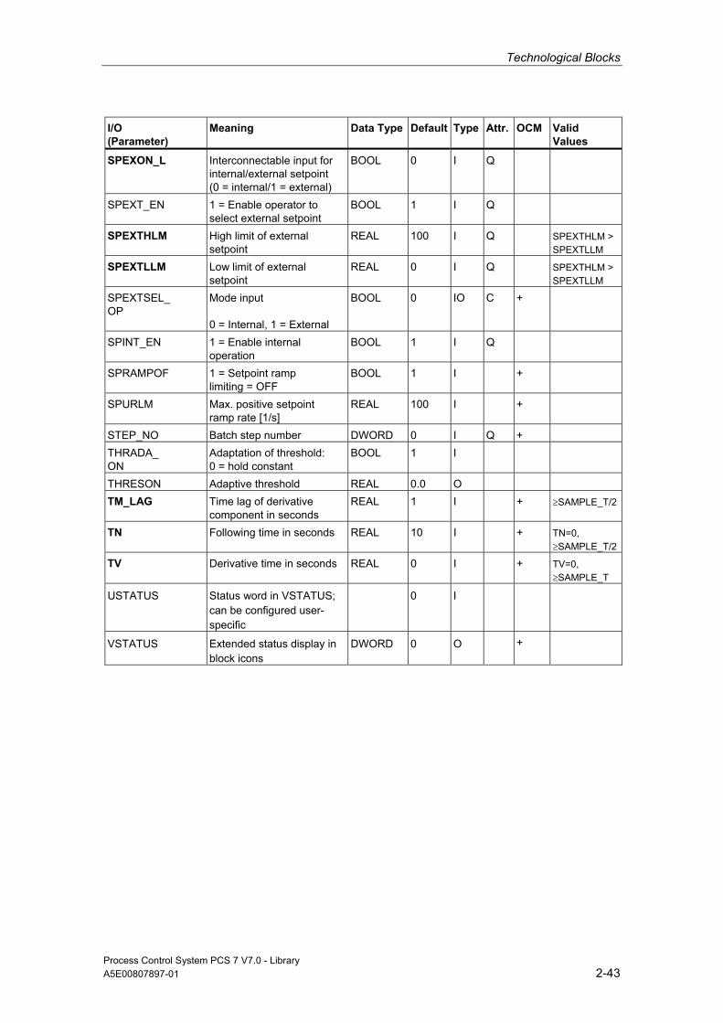
Technological Blocks
Process Control System PCS 7 V7.0 - Library A5E00807897-01 2-43
I/O (Parameter)
Meaning
Data Type
Default Type
Attr.
OCM Valid Values
SPEXON_L Interconnectable input for internal/external setpoint (0 = internal/1 = external)
BOOL 0 I Q
SPEXT_EN 1 = Enable operator to select external setpoint
BOOL 1 I Q
SPEXTHLM High limit of external setpoint
REAL 100 I Q SPEXTHLM > SPEXTLLM
SPEXTLLM Low limit of external setpoint
REAL 0 I Q SPEXTHLM > SPEXTLLM
SPEXTSEL_ OP
Mode input 0 = Internal, 1 = External
BOOL 0 IO C +
SPINT_EN 1 = Enable internal operation
BOOL 1 I Q
SPRAMPOF 1 = Setpoint ramp limiting = OFF
BOOL 1 I +
SPURLM Max. positive setpoint ramp rate [1/s]
REAL 100 I +
STEP_NO Batch step number DWORD 0 I Q + THRADA_ ON
Adaptation of threshold: 0 = hold constant
BOOL 1 I
THRESON Adaptive threshold REAL 0.0 O TM_LAG Time lag of derivative
component in seconds REAL 1 I + ≥SAMPLE_T/2
TN Following time in seconds REAL 10 I + TN=0, ≥SAMPLE_T/2
TV Derivative time in seconds REAL 0 I + TV=0, ≥SAMPLE_T
USTATUS Status word in VSTATUS; can be configured user-specific
0 I
VSTATUS Extended status display in block icons
DWORD 0 O +

Technological Blocks
Process Control System PCS 7 V7.0 - Library 2-44 A5E00807897-01
2.1.3.10 Message Texts and Associated Values of CTRL_S
Assignment of Message Text and Message Class to the Block Parameters
Message No. Block Parameter
Default Message Text
Message Class
Can be Suppressed By
1 QPVH_ALM (for PV_IN ≥ PVH_ALM)
PV:$$BlockComment$$ alarm high
AH M_SUP_AH, MSG_LOCK
2 QPVH_WRN (for PV_IN ≥ PVH_WRN)
PV:$$BlockComment$$ warning high
WH M_SUP_WH, MSG_LOCK
3 QPVL_WRN (for PV_IN ≤ PVL_WRN)
PV:$$BlockComment$$ warning low
WL M_SUP_WL, MSG_LOCK
4 QPVL_ALM (for PV_IN ≤ PVL_ALM)
PV:$$BlockComment$$ alarm low
AL M_SUP_AL, MSG_LOCK
5 CSF $$BlockComment$$ External error
S -
6 QERH_ALM (at ER ≥ ERH_ALM)
ER:PV:$$BlockComment$$ alarm high
AH M_SUP_ER, MSG_LOCK
7 QERL_ALM (at ER ≤ ERL_ALM)
ER:$$BlockComment$$ alarm low
AL M_SUP_ER, MSG_LOCK
8 QMSS_ST $$BlockComment$$ Motor protection
S -
Assignment of Associated Values to the Block Parameters The first three of the associated values of the message block are assigned SIMATIC BATCH data, the fourth is reserved for PV_IN and the remaining ones (AUX_PRx) can be freely assigned by the user.
Associated Value Block Parameter
1 BA_NA 2 STEP_NO 3 BA_ID 4 PV_IN 5 AUX_PR05 6 AUX_PR06 7 AUX_PR07 8 AUX_PR08 9 AUX_PR09 10 AUX_PR10
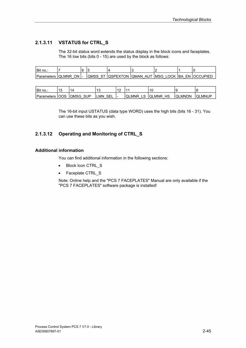
Technological Blocks
Process Control System PCS 7 V7.0 - Library A5E00807897-01 2-45
2.1.3.11 VSTATUS for CTRL_S
The 32-bit status word extends the status display in the block icons and faceplates. The 16 low bits (bits 0 - 15) are used by the block as follows:
Bit no.: 7 6 5 4 3 2 1 0 Parameters QLMNR_ON - QMSS_ST QSPEXTON QMAN_AUT MSG_LOCK BA_EN OCCUPIED
Bit no.: 15 14 13 12 11 10 9 8 Parameters OOS QMSG_SUP LMN_SEL - QLMNR_LS QLMNR_HS QLMNDN QLMNUP
The 16-bit input USTATUS (data type WORD) uses the high bits (bits 16 - 31). You can use these bits as you wish.
2.1.3.12 Operating and Monitoring of CTRL_S
Additional information You can find additional information in the following sections:
• Block Icon CTRL_S
• Faceplate CTRL_S
Note: Online help and the "PCS 7 FACEPLATES" Manual are only available if the "PCS 7 FACEPLATES" software package is installed!
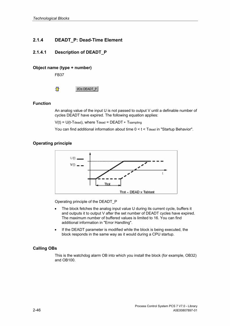
Technological Blocks
Process Control System PCS 7 V7.0 - Library 2-46 A5E00807897-01
2.1.4 DEADT_P: Dead-Time Element
2.1.4.1 Description of DEADT_P
Object name (type + number) FB37
Function An analog value of the input U is not passed to output V until a definable number of cycles DEADT have expired. The following equation applies:
V(t) = U(t-Tdead), where Tdead = DEADT ∗ Tsampling
You can find additional information about time 0 < t < Tdead in "Startup Behavior".
Operating principle
Operating principle of the DEADT_P
• The block fetches the analog input value U during its current cycle, buffers it and outputs it to output V after the set number of DEADT cycles have expired. The maximum number of buffered values is limited to 16. You can find additional information in "Error Handling".
• If the DEADT parameter is modified while the block is being executed, the block responds in the same way as it would during a CPU startup.
Calling OBs This is the watchdog alarm OB into which you install the block (for example, OB32) and OB100.
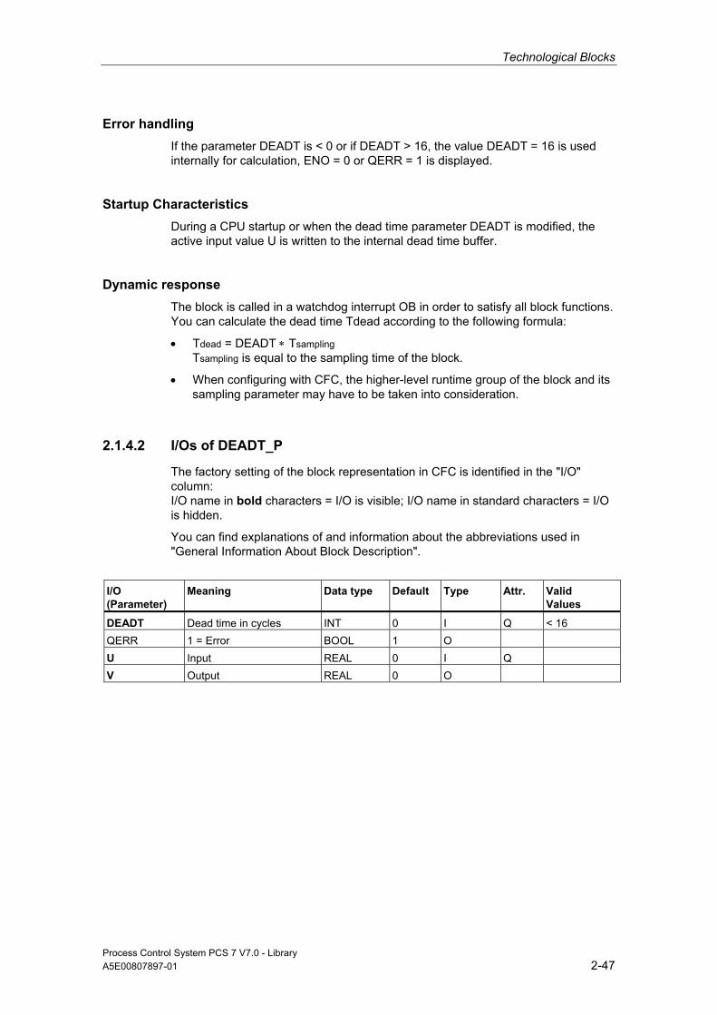
Technological Blocks
Process Control System PCS 7 V7.0 - Library A5E00807897-01 2-47
Error handling If the parameter DEADT is < 0 or if DEADT > 16, the value DEADT = 16 is used internally for calculation, ENO = 0 or QERR = 1 is displayed.
Startup Characteristics During a CPU startup or when the dead time parameter DEADT is modified, the active input value U is written to the internal dead time buffer.
Dynamic response The block is called in a watchdog interrupt OB in order to satisfy all block functions. You can calculate the dead time Tdead according to the following formula:
• Tdead = DEADT ∗ Tsampling Tsampling is equal to the sampling time of the block.
• When configuring with CFC, the higher-level runtime group of the block and its sampling parameter may have to be taken into consideration.
2.1.4.2 I/Os of DEADT_P
The factory setting of the block representation in CFC is identified in the "I/O" column: I/O name in bold characters = I/O is visible; I/O name in standard characters = I/O is hidden.
You can find explanations of and information about the abbreviations used in "General Information About Block Description".
I/O (Parameter)
Meaning
Data type Default Type
Attr.
Valid Values
DEADT Dead time in cycles INT 0 I Q < 16 QERR 1 = Error BOOL 1 O U Input REAL 0 I Q V Output REAL 0 O

Technological Blocks
Process Control System PCS 7 V7.0 - Library 2-48 A5E00807897-01
2.1.5 DIF_P: Differentiation
2.1.5.1 Description of DIF_P
Object name (type + number) FB38
Function Block DIF_P approximates a DT1 action and operates according to the trapezoid rule:
v(s) = TD ∗ s / (TM_LAG ∗ s + 1) ∗ u(s)
Operating principle The algorithm operates according to the trapezoid rule. The following steps are carried out in addition:
• The high limit of output V is set to V_HL, the low limit to V_LL. Internal calculation is not affected by the limiting function.
• The assigned output Q_HL or Q_LL is set when limiting is active.
• The parameter setting TD = 0 is allowed and results in V = 0 = const. Negative values for TD are also allowed and have the effect of inverting the sign of the results.
Jump response of the DIF_P

Technological Blocks
Process Control System PCS 7 V7.0 - Library A5E00807897-01 2-49
Calling OBs This is the watchdog alarm OB into which you install the block (for example, OB32) and OB100.
Error handling In case of an overflow/underflow, the REAL value of the high/low limit is set in the result V and ENO is set high. The following configuration errors will also lead to ENO = 0 (QERR = TRUE) and V=0:
• V_LL > 0
• V_HL < 0
Startup Characteristics After a CPU startup, the internal flag for the old value of input U is tracked to this input. This ensures that the output value V is "0" during the first cyclic operation.
Dynamic Response The block is called in a watchdog interrupt OB.
2.1.5.2 I/Os of DIF_P
The factory setting of the block display in CFC is identified in the "I/O" column: I/O name in bold characters = I/O is visible; I/O name in standard characters = I/O is hidden.
You can find explanations of and information about the abbreviations used in "General Information About Block Description".
I/O (Parameter)
Meaning
Data Type
Default Type
Attr.
OCM
Valid Values
QERR 1 = Error BOOL 1 O QVHL Initial value high limit BOOL 0 O QVLL Initial value low limit BOOL 0 O SAMPLE_T Sampling time in seconds REAL 1 I > 0 TD Differential time in seconds REAL 1 I Q TM_LAG Time lag in seconds REAL 10 I Q ≥ 0 U Input REAL 0 I Q V Output value REAL 0 O V_HL High limit of V REAL 100 I Q V_HL ≥ V_LL
V_LL Low limit of V REAL -100 I Q V_LL ≥ V_HL

Technological Blocks
Process Control System PCS 7 V7.0 - Library 2-50 A5E00807897-01
2.1.6 DIG_MON: Digital-Value Monitoring
2.1.6.1 Description of DIG_MON
Object name (type + number) FB62
*)
*)
*) Online help is only available if the "PCS 7 FACEPLATES" software package is installed!
Function Block DIG_MON is used to monitor a digital process tag with chatter suppression. Both the signal status and the state of the control system (external control system faults, channel faults) belong to the measuring point. The parameter MSG_CLAS can be used to determine the message class of the measuring point.
Operating principle The block monitors changes of the digital value at input Ix. The timer is retriggered at each edge of the input signal. After the waiting time set in SUPPTIME has expired, the value of input Ix is passed to output Q. This ensures that only the signals held at least until the period set in SUPPTIME has expired will be passed to the output. Signals changing at a faster rate will not be passed on. When SUPPTIME < SAMPLE_T, the input value Ix will be passed to output Q.
Calling OBs This is the watchdog alarm OB into which you install the block (for example, OB32) and OB100.
Error handling QERR=1 if the message-class configuration is invalid. An error message is not output in this case. You can find additional information in "Message response".
Technological Blocks
Process Control System PCS 7 V7.0 - Library A5E00807897-01 2-51
Startup Characteristics During CPU startup the old initial value Q is retained. Monitoring of changes is re-enabled after the restart. The block must be called in the startup OB accordingly. In CFC engineering, this is handled by the CFC. Using the basic STEP 7 tools, you must manually enter this call in the startup OB. After startup, the messages will be suppressed during the number of cycles set at RUNUPCYC.
Assignment of the 32-Bit Status Word VSTATUS You can find additional information in "VSTATUS for DIG_MON".
Dynamic response The block must be called via a watchdog interrupt OB. The sampling time of the block is set in parameter SAMPLE_T.
Message response The DIG_MON block uses the ALARM_8P block (MSG_EVID) for generating messages (1 to 6 and 8). Message 7 does not require acknowledgement and is generated via NOTIFY (MSG_EVID1). The following message triggers exist:
• A change of the output signal Q
• The CSF signal received as a control system error via interconnection. Process messages (not the control system messages!) can be locked by setting MSG_LOCK. QMSG_SUP is set if the RUNUPCYC cycles have not expired yet since a restart, MSG_LOCK = TRUE or MSG_STAT = 21.
Message Classes A change at output Q can be signaled to the OS with a selectable message class by configuring the MSG_CLAS input.
Monitoring of Process Values n.a.
Additional information Additional information is available in the sections: I/Os of DIG_MON Message Texts and Associated Values of DIG_MON VSTATUS for DIG_MON Operating and Monitoring of DIG_MON
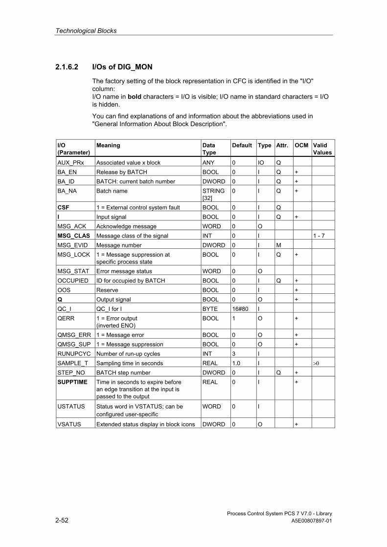
Technological Blocks
Process Control System PCS 7 V7.0 - Library 2-52 A5E00807897-01
2.1.6.2 I/Os of DIG_MON
The factory setting of the block representation in CFC is identified in the "I/O" column: I/O name in bold characters = I/O is visible; I/O name in standard characters = I/O is hidden.
You can find explanations of and information about the abbreviations used in "General Information About Block Description".
I/O (Parameter)
Meaning Data Type
Default Type
Attr.
OCM Valid Values
AUX_PRx Associated value x block ANY 0 IO Q BA_EN Release by BATCH BOOL 0 I Q + BA_ID BATCH: current batch number DWORD 0 I Q + BA_NA Batch name STRING
[32] 0 I Q +
CSF 1 = External control system fault BOOL 0 I Q I Input signal BOOL 0 I Q + MSG_ACK Acknowledge message WORD 0 O MSG_CLAS Message class of the signal INT 0 I 1 - 7 MSG_EVID Message number DWORD 0 I M MSG_LOCK 1 = Message suppression at
specific process state BOOL 0 I Q +
MSG_STAT Error message status WORD 0 O OCCUPIED ID for occupied by BATCH BOOL 0 I Q + OOS Reserve BOOL 0 I + Q Output signal BOOL 0 O + QC_I QC_I for I BYTE 16#80 I QERR 1 = Error output
(inverted ENO) BOOL 1 O +
QMSG_ERR 1 = Message error BOOL 0 O + QMSG_SUP 1 = Message suppression BOOL 0 O + RUNUPCYC Number of run-up cycles INT 3 I SAMPLE_T Sampling time in seconds REAL 1.0 I >0 STEP_NO BATCH step number DWORD 0 I Q + SUPPTIME Time in seconds to expire before
an edge transition at the input is passed to the output
REAL 0 I +
USTATUS Status word in VSTATUS; can be configured user-specific
WORD 0 I
VSATUS Extended status display in block icons DWORD 0 O +

Technological Blocks
Process Control System PCS 7 V7.0 - Library A5E00807897-01 2-53
2.1.6.3 Message Texts and Associated Values of DIG_MON
Assignment of Message Text and Message Class to the Block Parameters
Message No. MSG_EVID
Block Parameter
Default Message Text Message Class
Can be Suppressed By
1 Q & MSG_CLAS = 1 $$BlockComment$$ alarm high
AH MSG_LOCK
2 Q & MSG_CLAS = 2 $$BlockComment$$ warning high
WH MSG_LOCK
3 Q & MSG_CLAS = 3 $$BlockComment$$ tolerance high
TH MSG_LOCK
4 Q & MSG_CLAS = 4 $$BlockComment$$ tolerance low
TL MSG_LOCK
5 Q & MSG_CLAS = 5 $$BlockComment$$ warning low
WL MSG_LOCK
6 Q & MSG_CLAS = 6 $$BlockComment$$ alarm low
AL MSG_LOCK
7 no message
8 CSF $$BlockComment$$ External error
S -
Message no. MSG_EVID1
Q & MSG_CLAS = 7 $$BlockComment$$ Operator request
OR MSG_LOCK

Technological Blocks
Process Control System PCS 7 V7.0 - Library 2-54 A5E00807897-01
Assignment of Associated Values to the Block Parameters The first three of the associated values of the message block are assigned SIMATIC BATCH data and the remaining ones (AUX_PRx) can be freely assigned by the user.
Associated Value
Block Parameter
1 BA_NA 2 STEP_NO 3 BA_ID 4 AUX_PR04 5 AUX_PR05 6 AUX_PR06 7 AUX_PR07 8 AUX_PR08 9 AUX_PR09 10 AUX_PR10
2.1.6.4 VSTATUS for DIG_MON
The 32-bit status word extends the status display in the block icons and faceplates. The 16 low bits (bits 0 - 15) are used by the block as follows:
Bit no.: 7 6 5 4 3 2 1 0 Parameters I - - - - MSG_LOCK BA_EN OCCUPIED
Bit no.: 15 14 13 12 11 10 9 8 Parameters OOS QMSG_SUP - - - - - Q
The 16-bit input USTATUS (data type WORD) uses the high bits (bits 16 - 31). You can use these bits as you wish.
2.1.6.5 Operating and Monitoring of DIG_MON
Additional information Additional information is available in the sections:
• Block Icon DIG_MON
• Faceplate DIG_MON
Note: Online help and the "PCS 7 FACEPLATES" Manual are only available if the "PCS 7 FACEPLATES" software package is installed!
Technological Blocks
Process Control System PCS 7 V7.0 - Library A5E00807897-01 2-55
2.1.7 FM_CO: Koordinierung von FMCS_PID/FMT_PID
2.1.7.1 Description of FM_CO
Object name (type + number) FB79
Function The block coordinates the reading of the data set of blocks FM_CNT, FMCS_PID, FMT_PID or READ355P. The block is installed and the parameters interconnected by the driver generator.
It is possible to include data set reading blocks from other modules in the coordination.
Operating principle The FM_CO block can start a maximum of 8 block chains.
The blocks connected to the output structure EN_COx check whether the current coordination number (EN_COx.CO_ACT) corresponds to their own coordination number. If this is the case, they read their data sets from the module and reduce the coordination number EN_COx.CO_ACT by 1, so that the next block can read out its data sets.
If the current coordination number of a sequence (EN_COx.CO_ACT) has a value less than 1, the FM_CO block determines the highest number assigned in sequence x based on its inputs ENCOx_yy. The inputs ENCOx_yy (yy = coordination number) are provided by the data set reading blocks by connecting to their respective coordination number. The highest coordination number is the number for which ENCOx_yy = yy still applies. The FM_CO module restarts the sequence in which it sets EN_COx.CO_ACT to this value.
This algorithm ensures that no more than one read data record operation ever takes place at a given moment.
Calling OBs The fastest watchdog alarm OB of all OBs, in which you have installed blocks FM_CNT, FMCS_PID, FMT_PID or READ355P and also the OB100.

Technological Blocks
Process Control System PCS 7 V7.0 - Library 2-56 A5E00807897-01
Use in CFC When using the CFC function "Generate Module Drivers," the block is automatically installed and the connections, such as those described under "Installation regulation" are made.
If you install, delete or move blocks of an existing block chain in other OBs or runtime groups, the driver generator must be called.
Should the sequence not start up as expected (after CPU restart) or not continue to run (after downloading changes), you must set ACC_ID to 1.
Installation rules An FM_CO is responsible for a DP master system (chain). On this DP master system, a maximum of 8 DP slaves (only ET 200M) can be operated with at least one FM 350, FM 355 or FM355-2 module. A station (19" frame) can include up to 4 FM 355 modules. An FM 355 can be configured for 1 to 4 controller channels, in other words, a maximum of 16 control channels can be operated with one DP slave.
In the following, only the FMCS_PID block , which also represents FM_CNT, FMT_PID or READ355P is taken into consideration. The FM_CO must always be installed before the first FMCS_PID block in the fastest watchdog alarm OB. The output structure EN_COx for the rack x is connected to the input structures EN_COx of all FMCS_PID blocks, which communicate to controller modules of rack x. The output ENCO of each FMCS_PID block is connected to an input ENCOx_yy (yy corresponds to the coordination number CO_NO assigned to each FMCS_PID block) of the FM_CO block.
As described above, 8 DP slaves can be operated with one FM_CO block 8 on a DP master system.
The selection of the watchdog alarm OB depends on the utilization of the CPU. Please note that, when using 8 DP slaves, the CPU has no reserves for other "Read data record" jobs because only up to 8 jobs can be buffered per DP master system. As soon as a module is inserted this causes an overflow. It is recommended that you operate a maximum of 6 DP slaves on one DP master system. The remaining DP slaves must be distributed on other DP master systems with further FM_CO blocks.
To achieve a constant time cycle for the read data of the FM 355, it is advisable to install the blocks in an OB36 (50 ms). Make sure that with the number of blocks you install means a maximum execution time for OB36 of approximately 25 ms. If the FMCS_PID blocks to be processed exceed the runtime limit, group the DP slaves with the FM 355 modules in fast and slow control loops.
Startup Characteristics During the startup (restart), all outputs EN_CO_x.CO_ACT = 1 are set.
Technological Blocks
Process Control System PCS 7 V7.0 - Library A5E00807897-01 2-57
Dynamic response n.a.
Message response n.a.
2.1.7.2 I/Os of FM_CO
The factory setting of the block representation in CFC is identified in the "I/O" column: I/O name in bold characters = I/O is visible; I/O name in standard characters = I/O is hidden.
You can find explanations of and information about the abbreviations used in "General Information About Block Description".
I/O (Parameter)
Meaning
Data Type
Default
Type
ACC_ID Restart all sequences BOOL 1 IO ENCOx_yy The coordination number yy is assigned in the rack x if
the input has the value yy (x = 0 - 7, yy = 1 - 64) BYTE 0 I
EN_CO_x Coordination number of the block that can read data sets STRUCT 0 O
2.1.8 FMCS_PID: Controller Block
2.1.8.1 Description of FMCS_PID
Object name (type + number) FB114
*)
*)
*) Online help is only available if the "PCS 7 FACEPLATES" software package is installed!

Technological Blocks
Process Control System PCS 7 V7.0 - Library 2-58 A5E00807897-01
Fields of application Block FMCS_PID is used to interface the FM 355 controller block.
It can be used for the C (continuous controllers) and S (step and pulse controllers) module types. It does not in itself contain any control algorithms, since the control functions are carried out exclusively on the module. You can use the FMCS_PID block to monitor all relevant process variables and to change all relevant controller parameters.
Application examples of the FM 355 and detailed descriptions of the input and output parameters can be found in the manual of the controller module FM 355.
Use in CFC When the CFC function "Generate module drivers" is used, the following occurs automatically:
• The parameter CO_NO is parameterized
• The input EN_CO is connected to the output EN_CO_x of the FM_CO block (x = number of the rack)
• Output ENCO is interconnected with input ENCOx_yy of the FM_CO block (x = number of the rack, yy = coordination number).
Dependencies You can find additional information about dependencies in "FM_CO".
Implementing the FM 355C Controller Module as Continuous Control The block provides the following displays and setting options:
• Display of the result of the limit monitoring carried out on the module for two limit pairs for the process variable PV or the error signal ER (QH_ALM, QH_WRN, QL_WRN, QL_ALM outputs). MONERSEL is used to specify whether PV or ER is monitored.
• Disabling of the generation of individual messages when limits are exceeded
• Split-range function
• Dead band (DEADB_W, on threshold) in the error-signal branch
• Specification of the control algorithm: PID algorithm (QFUZZY = 0) or FUZZY algorithm (QFUZZY = 1)
• Manipulated variable tracking
• Disabling of the integral action
• Setpoint tracking (SP = PV)
Technological Blocks
Process Control System PCS 7 V7.0 - Library A5E00807897-01 2-59
Implementing the FM 355S Controller Module as Pulse Control Using the controller module as a pulse controller rather than a continuous controller means that split-range control is not possible. You can use the pulse controller to generate pulse width modulated control signals. The control signal is converted into a binary output signal so that the ratio between the pulse width and the configured period at the assigned digital output corresponds with the manipulated value LNM.
Implementing the FM 355S Controller Module as Step Control Using the controller module as a step controller rather than a continuous controller results in the following differences: • Output QLMNR_ON indicates whether a feedback signal is available
(1 = exists, 0 = does not exist). • Split-range operation is not possible. When used as a step-action controller without a position feedback (QLMNR_ON = 0), manual adjustment of the manipulated variable is only possible at the final positions. In this case the safety position or value of the external manipulated variable value is interpreted by the controller module as follows: LMN_SAFE < 40 %: Close actuating element completely LMN_SAFE > 60 %: Open actuating element completely 40 % ≤ LMN_SAFE ≤ 60 %: Hold current setting
Calling OBs Watchdog OB: e.g., OB32 The block is be installed with the same instance in the startup block OB100
Additional information Additional information is available in the sections: Addressing Function Acquisition of Process Values Via the Process Image Generation of Setpoints, Limits, Error Signals and Manipulated Variables Manual, Auto and Following Mode Mode Change Safety Mode Download Parameters to the Module Read Data From the Module Error Handling Startup Behavior, Dynamic Response and Message response Backup Mode of the FM 355 I/Os of FMCS_PID Message Texts and Associated Values of FMCS_PID VSTATUS for FMCS_PID Operating and Monitoring of FMCS_PID

Technological Blocks
Process Control System PCS 7 V7.0 - Library 2-60 A5E00807897-01
2.1.8.2 Addressing
The controller channel of an FM 355 belonging to the instance is addressed via its logical base address (set in HW Config) (LADDR input) and the controller channel number (CHANNEL input, valid values = 1 to 4). 1 to 4 are the allowed values for the CHANNEL input. ACC_MODE must be set to TRUE after a change is made to CHANNEL.
The FM 355 module is monitored with the blocks of the PCS 7 Library. INput MODE is interconnected with the OMODE output of the MOD_D1 block. The block communicates only via the FM 355 control channel. Hence, the measurement range coding in the low word of the output OMODE is irrelevant and assigned zero.
2.1.8.3 Function of FMCS_PID
Function The FMCS_PID block forms the interface between the control module (FM 355) and the blocks of the SIMATIC PCS 7 Library and can also be interconnected with other SIMATIC S7 blocks.
The block and the controller module operate asynchronously to each other.
All the relevant process and disturbance variables are provided by the module and can only be read by the block. The block can furthermore transfer various operating modes and settings to the controller module.
The process values are read cyclically. (Exceptions: SP (setpoint from the FM), ER (error), DISV (disturbance), LMN_A and LMN_B ). They are, however, only updated after every 4th cycle. Additional information is available in "Acquisition of Process Values Via the Process Image".
The parameters SP (setpoint from the FM), ER (error signal), DISV (disturbance variable), LMN_A, and LMN_B can only be read from the FM 355 using "Read data record" (SFC59). You can find additional information in "Read Via Data Record".
A quality code that can assume the following statuses is generated for process values PV and LMN:
State Quality Code
Valid value 16#80 Invalid value 16#00
Technological Blocks
Process Control System PCS 7 V7.0 - Library A5E00807897-01 2-61
OP_SEL Input As a rule, the FM 355 obtains its parameters via the block. Each change to a parameter in the block is passed to the module. If, however, you want to change a parameter directly at the FM 355 via the operator panel (OP), you first have to enable this function at OP_SEL (OP_SEL = 1). OP_SEL must be reset if you want to restrict operator control and configuration via the block again after the OP has been used.
When configuration via the OP is enabled, the controller module does not accept any parameters from the block. However, the blocks continues to update the process variables SP_OP_ON, LMNOP_ON, SP_OP and LMN, thus allowing a bumpless changeover to the mode in which configuration is carried out by the block. The remaining parameters (for example, GAIN) are overwritten with the data of the block instance when you set OP_SEL = 0. The entries made with the OP are lost, if you have not entered the data in the block instance before reversing OP_SEL.
SDB_SEL Input Some of the parameters can be specified via the FMCS_PID block in addition to the configuration tool. These two parameter sets may deviate. The SDB_SEL input at the block is available to avoid such a conflict. SDB_SEL = 1 is used to specify that the module only reads these parameters from the block and not from the configuration tool. SDB_SEL = 0 is used to specify that the module should accept these parameters from the configuration tool and from the block. Please note that the parameters from the configuration tool are sent to the module after every STOP-RUN transition of the CPU. The parameters of the block, on the other hand, are sent to the module each time there is a change at the block input.
When configuration via the OP is permitted, the operator inputs are disabled with the following exception: The operation OP_SEL = 0 (operation disable via OP) is possible.

Technological Blocks
Process Control System PCS 7 V7.0 - Library 2-62 A5E00807897-01
2.1.8.4 Acquisition and Writing of Process Values Via the Process Image
Reading Process Values The process values (except SP (setpoint from the FM), ER (error), DISV (disturbance), LMN_A and LMN_B ) are read cyclically from the process image. They are, however, only updated after every 4th cycle. In a normal situation, this takes place in the cyclic interrupt OB in which the FMCS_PID is installed. To achieve higher accuracy, it is possible to install the FMCS_PID additionally in a second cyclic interrupt OB with a higher clock rate.
After a restart or when ACC_MODE is set to 1, the block determines the watchdog alarms used (up to 2 are permitted; you can find additional information in "Startup Behavior").
The following must be considered when selecting cyclic interrupts:
• The watchdog alarm OB in which the block is installed must not run slower than 30 s or faster than 25 ms.
Note: OB1 must not be used!
• The process image partition (TPA) in HW Config must be set for the faster OB.
• The read via process image for a block is complete after 4 block cycles (after 4 s in the example with OB32 [1,000 ms]) if the block cycle is longer than the cycle time of the module, otherwise after 4 module cycles.
• Example: With 4 processed analog inputs on the module, the cycle time of the module is 400 ms (see "Module parameters" command button on the configuration interface of the FM 355). If the block, is installed in OB32 (1000 ms), for example, you can accelerate reading of the process image by means of an additional installation in OB33 (500 ms).
Writing Process Values The following process values are written to the process image in every second cycle:
• Setpoint (automatic mode only)
• Manipulated value (manual mode only)
• SP_OP_ON, SAFE_ON, QMAN_AUT, LMNTRKON, LMN_REON, LMNRHSRE, LMNRLSRE
• LMNSOPON
• LMNUP or LMNUP_OP
• LMNDN or LMNDN_OP
• FUZID_ON
• LMNRS_ON
Technological Blocks
Process Control System PCS 7 V7.0 - Library A5E00807897-01 2-63
In the following cases, a restart must be performed or ACC_MODE must be set to 1 following a compile and download:
• if you have moved blocks to a different cycle
• if you have also installed blocks in a fast cycle
• if you have also deleted installed blocks.
2.1.8.5 Generation of Setpoints, Limits, Error Signals, and Manipulated Variables
Setpoint Generation by the FMCS_PID Block The setpoint SP can be fetched from four different sources:
• From one of the controller modules (you have configured it via OP, or the module is in back-up mode). In this case setpoint operation is disabled and the applied value is written to the operating input SP_OP of the block.
• The three other sources depend on the inputs SP_TRK_ON, SPEXTSEL_OP and SP_OP_ON. You can find additional information about the external/internal setpoint in "Mode Change".
SP_TRK_ON SPEXTSEL_OP SP_OP_ON SP= State
Irrelevant 0 0 SP_INT Internal setpoint 0 0 1 SP_OP Internal (operator controlled) setpoint Irrelevant 1 Irrelevant SP_EXT External setpoint 1 0 1 PV ** Tracked setpoint ** in manual mode only and when SPBUMPON = 1
The effective setpoint is limited to the range (SP_LLM, SP_HLM).
If SP_TRK_ON is set, in the manual mode (when SP_OP_ON = 1, SPEXTSEL_OP = 0 and SPBUMPON = 1) the setpoint SP_OP is tracked. This enables bumpless changeover from manual to auto mode.
Bumpless changeover to manual operation is ensured by writing back the active setpoint and manipulated variables.
Limit Generation Depending on the input MONERSEL, the controller module monitors either the process variable PV (MONERSEL = 0) or the error signal ER (MONERSEL = 1) for warning and alarm limits (L_WRN, H_WRN, L_ALM, H_ALM). Monitoring is carried out with the common hysteresis HYS.
The block makes the monitoring result available at the QL_WRN, QH_WRN, QL_ALM and QH_ALM outputs. While monitoring the actual value PV, the block signals any violation of the high and low limits, unless message suppression has been enabled.
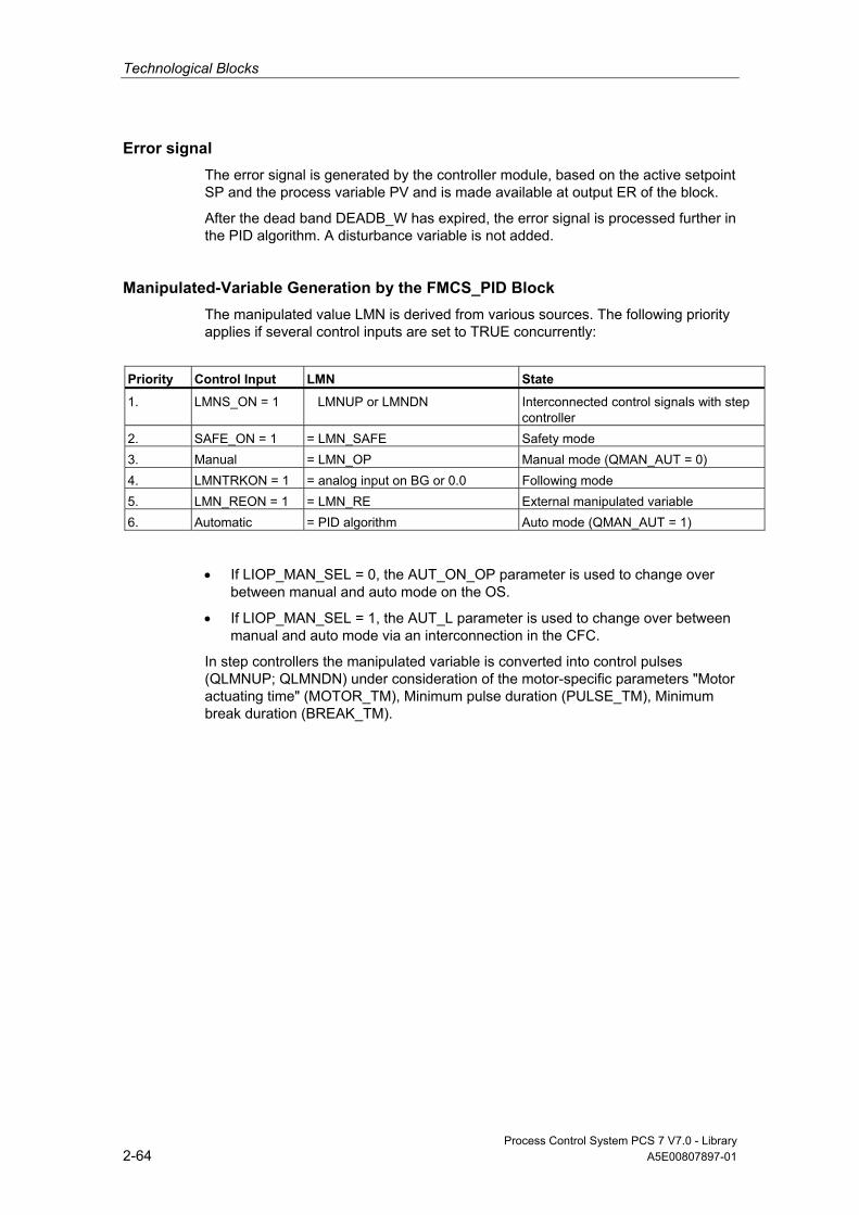
Technological Blocks
Process Control System PCS 7 V7.0 - Library 2-64 A5E00807897-01
Error signal The error signal is generated by the controller module, based on the active setpoint SP and the process variable PV and is made available at output ER of the block.
After the dead band DEADB_W has expired, the error signal is processed further in the PID algorithm. A disturbance variable is not added.
Manipulated-Variable Generation by the FMCS_PID Block The manipulated value LMN is derived from various sources. The following priority applies if several control inputs are set to TRUE concurrently:
Priority Control Input LMN State
1. LMNS_ON = 1 LMNUP or LMNDN Interconnected control signals with step controller
2. SAFE_ON = 1 = LMN_SAFE Safety mode 3. Manual = LMN_OP Manual mode (QMAN_AUT = 0) 4. LMNTRKON = 1 = analog input on BG or 0.0 Following mode 5. LMN_REON = 1 = LMN_RE External manipulated variable 6. Automatic = PID algorithm Auto mode (QMAN_AUT = 1)
• If LIOP_MAN_SEL = 0, the AUT_ON_OP parameter is used to change over between manual and auto mode on the OS.
• If LIOP_MAN_SEL = 1, the AUT_L parameter is used to change over between manual and auto mode via an interconnection in the CFC.
In step controllers the manipulated variable is converted into control pulses (QLMNUP; QLMNDN) under consideration of the motor-specific parameters "Motor actuating time" (MOTOR_TM), Minimum pulse duration (PULSE_TM), Minimum break duration (BREAK_TM).

Technological Blocks
Process Control System PCS 7 V7.0 - Library A5E00807897-01 2-65
2.1.8.6 Manual, Auto and Following Mode
Manual mode The manipulated variable is determined by operator control at input LMN_OP (stepping mode is also possible here). When changing over to automatic mode, the module takes over the manipulated variable set "manually" as the operating point.
"Manual mode" takes priority over "Following mode".
Manual mode for step controller:
Actuating commands can be used for direct control of the control signal for step controllers. Signal operation is enabled with LMNSOPON and the control signals are set with LMNUP_OP or LMNDN_OP. The valve is then driven until the operation is disabled or the end position is achieved.
The control signal operation has priority over the manipulated value operation via LMN_OP.
The LMN_OP input cannot be controlled when step controllers without position feedback are used.
Auto Mode The manipulated variable is calculated by the PID or fuzzy algorithm of the module. The control parameters GAIN, TI, TD and TM_LAG can be interconnected.
The controller's direction of control can be reversed (rising error signal causes a falling manipulated variable) by setting a negative proportional GAIN.
The integral action can be disabled by setting TI = 0.
The operator-controllable manipulated-variable input LMN_OP is tracked to the LMN output so that bumpless changeover from automatic to manual mode is ensured.
External Setpoint (LMN_RE) The block transfers the value LMN_RE to the FM 355. The FM 355 accepts the external manipulated variable LMN_RE manipulated variable as LMN, if LNM_REON = 1.
"External manipulated variable" mode takes priority over "Auto mode".
Following the Manipulated Variable In manipulated variable following mode (LMNTRKON = 1), the manipulated variable is tracked to an analog input of the module or to the value 0.0. "Following" mode takes priority over the "External manipulated variable" mode.

Technological Blocks
Process Control System PCS 7 V7.0 - Library 2-66 A5E00807897-01
Safety Mode (LMN_SAFE) The block transfers the value LMN_SAFE to the FM 355. The FM 355 accepts the safety manipulated variable LMN_SAFE as manipulated variable LMN, if SAFE_ON = 1. "Safety mode" takes priority over all other operating modes.
Disabling the Operator Input of Control Signals and Manual Values You must set LMNOP_ON and LMNSOPON to 0.
Interconnectable Control Signal Setting for the Step Controller The following mode using LMNS_ON with direct connection of the control signals over the LMNUP and LMNDN interconnected inputs has the highest priority of all operating modes. If LMNS_ON is set, the control signals can only be set via the inputs LMNUP or LMNDN. As long as LMNS_ON is set, all other influences on the control signals are suppressed.
2.1.8.7 Mode Change This can be triggered either by operator control or via interconnected inputs. The operating mode is changed over by means of the operator-control blocks assigned to the operating modes.
External/Internal Setpoint Changeover is carried out between the external and internal setpoint by OS operation of the SPEXTSEL_OP input or interconnection of SPEXON_L. You must set the corresponding enable inputs SPINT_EN, SPEXT_EN or the selection input LIOP_INT_SEL to enable these changeovers. SP_OP_ON must be set TRUE to enable operator control of the setpoint.
Enabling Changeover Between Internal and External Setpoint
QSPEXTEN = TRUE: SPEXTSEL_OP can be set from FALSE (internal setpoint) to TRUE (external setpoint). QSPINTEN = TRUE: SPEXTSEL_OP can be set from TRUE (external setpoint) to FALSE (internal setpoint). SPEXTSEL_OP is tracked or reset as required.

Technological Blocks
Process Control System PCS 7 V7.0 - Library A5E00807897-01 2-67
Manual/Auto The operating mode is changed over by OS operation of the AUT_ON_OP input or interconnection of AUT_L. You must set the corresponding enable inputs MANOP_EN, AUTOP_EN or the selection input LIOP_MAN_SEL to enable this changeover.
LMNOP_ON must be set TRUE to enable manual control of the variable.
Enabling the Changeover Between Manual and Auto Mode
QAUTOP = TRUE: AUT_ON_OP can be set from FALSE (manual mode) to TRUE (auto mode).
QMANOP = TRUE: AUT_ON_OP can be set from TRUE (auto mode) to FALSE (manual mode).
AUT_ON_OP is tracked or reset as required.
Measures for Bumpless Changeover Special measures are applied for the modes listed below in order to ensure a bumpless changeover:
• Setpoint external/setpoint tracking: If SPBUMPON = TRUE, the internal setpoint SP_OP is set to the effective (external or tracked) setpoint.
• Automatic mode, safety mode, following mode or external manipulated variable LMN_RE: The manipulated value LMN_OP is tracked to the effective manipulated variable.
• Manual mode, safety mode, following mode or external manipulated variable LMN_RE: The integrator is tracked so that a bumpless changeover to auto mode is possible (not with a step controller). Using the configuration tool, you can disable the default bumpless changeover function, in order to allow a faster correction of the error signal.
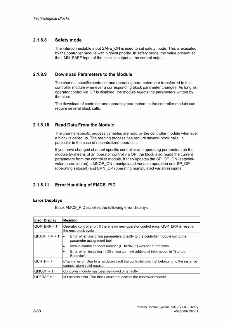
Technological Blocks
Process Control System PCS 7 V7.0 - Library 2-68 A5E00807897-01
2.1.8.8 Safety mode
The interconnectable input SAFE_ON is used to set safety mode. This is executed by the controller module with highest priority. In safety mode, the value present at the LMN_SAFE input of the block is output at the control output.
2.1.8.9 Download Parameters to the Module
The channel-specific controller and operating parameters are transferred to the controller module whenever a corresponding block parameter changes. As long as operator control via OP is disabled, the module rejects the parameters written by the block.
The download of controller and operating parameters to the controller module can require several block calls.
2.1.8.10 Read Data From the Module
The channel-specific process variables are read by the controller module whenever a block is called up. The reading process can require several block calls, in particular in the case of decentralized operation.
If you have changed channel-specific controller and operating parameters on the module by means of an operator control via OP, the block also reads the current parameters from the controller module. It then updates the SP_OP_ON (setpoint-value operation on), LMNOP_ON (manipulated-variable operation on), SP_OP (operating setpoint) and LMN_OP (operating manipulated variable) inputs.
2.1.8.11 Error Handling of FMCS_PID
Error Displays Block FMCS_PID supplies the following error displays:
Error Display Meaning
QOP_ERR = 1 Operator control error: If there is no new operator control error, QOP_ERR is reset in the next block cycle.
QPARF_FM = 1 • Error when assigning parameters directly to the controller module using the parameter assignment tool
• Invalid control channel number (CHANNEL) was set at the block. • Error when installing in OBs; you can find additional information in "Startup
Behavior". QCH_F = 1 Channel error. Due to a hardware fault the controller channel belonging to the instance
cannot return valid results. QMODF = 1 Controller module has been removed or is faulty. QPERAF = 1 I/O access error. The block could not access the controller module.
Technological Blocks
Process Control System PCS 7 V7.0 - Library A5E00807897-01 2-69
2.1.8.12 Startup Behavior, Dynamic Response and Message response of FMCS_PID
Startup Characteristics During CPU startup or initial run of block FMCS_PID, the operating modes MANUAL and INTERNAL are set.
In OB100, QDONE is set to 0.
After a CPU restart or when ACC_MODE is set to 1, the block is not operable for up to approximately 30 seconds.
The block uses the first 30 seconds after a restart (OB100) or after ACC_MODE is set to 1 to detect whether the block instance is installed in more than one OB. If you then move the blocks to another OB, a restart must be performed or ACC_MODE must be set to 1 after compiling and downloading (otherwise you will receive the error message QPARF_FM = 1, and the block will not provide any more data).
Note
The configuration tool can be configured in HW Config with Save/Compile and Download and written to the SDB (system data). These SDB parameters can deviate from the block parameters. When SDB_SEL = 0, the SDB parameters are sent to the module at every STOP-RUN transition of the CPU. The block parameters are written to the module, however, a few cycles later. With SDB_SEL = 1, the module does not load the SDB parameters at a STOP-RUN transition of the CPU. This avoids a jump in the manipulated variable when the SDB parameters deviate from the block parameters.
The following cases are differentiated:
• The FM 335 has failed and it was not being operated via OP before its failure. The block transfers the current controller and operating parameters to the FM 355.
• The FM 335 has failed and it was being operated via OP before its failure. The block reads the current values from the FM 355 and updates its outputs SP, LMN, Q_SP_OP and QLMNOP.
• The FM 335 has not failed and it was being operated via OP. The block reads the current values from the FM 355 and updates its outputs SP, LMN, Q_SP_OP and QLMNOP.
• The FM 335 has not failed and it was not being operated via OP. The controller and operating parameters of the FM and the block are identical. The block does nothing.
The block transfers the controller and operating parameters to the FM 355 during the startup (however not during the initial run).
Dynamic Response n.a.

Technological Blocks
Process Control System PCS 7 V7.0 - Library 2-70 A5E00807897-01
Assignment of the 32-Bit Status Word VSTATUS You can find additional information in "VSTATUS for FMCS_PID".
Message response The FMCS_PID block uses the ALARM_8P block for generating messages.
The following message triggers exist:
• the functions for monitoring the actual value/system deviation limits
• the function for monitoring the module hardware (executed primarily by the MOD_D1 block)
Messages regarding limit violation can be suppressed individually by setting the corresponding M_SUP_xx inputs. The process messages (not process control messages!) can be completely blocked with MSG_LOCK.
QMSG_SUP is set if the RUNUPCYC cycles have not expired yet since a restart, MSG_LOCK = TRUE or MSG_STAT = 21.
Monitoring of Process Values n.a.
2.1.8.13 Backup Mode of the FM 355
If the CPU changes over to STOP or fails, the FM 355 changes over to backup mode. In this case it automatically enables operator control via the OP (acts as if OP_SEL = 1).
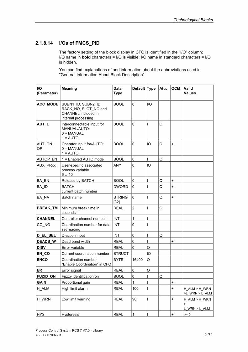
Technological Blocks
Process Control System PCS 7 V7.0 - Library A5E00807897-01 2-71
2.1.8.14 I/Os of FMCS_PID
The factory setting of the block display in CFC is identified in the "I/O" column: I/O name in bold characters = I/O is visible; I/O name in standard characters = I/O is hidden.
You can find explanations of and information about the abbreviations used in "General Information About Block Description".
I/O (Parameter)
Meaning
Data Type
Default Type
Attr. OCM Valid Values
ACC_MODE SUBN1_ID, SUBN2_ID, RACK_NO, SLOT_NO and CHANNEL included in internal processing
BOOL 0 I/O
AUT_L Interconnectable input for MANUAL/AUTO: 0 = MANUAL 1 = AUTO
BOOL 0 I Q
AUT_ON_ OP
Operator input for/AUTO: 0 = MANUAL 1 = AUTO
BOOL 0 IO C +
AUTOP_EN 1 = Enabled AUTO mode BOOL 0 I Q AUX_PRxx User-specific associated
process variable 6 …10
ANY 0 IO
BA_EN Release by BATCH BOOL 0 I Q + BA_ID BATCH:
current batch number DWORD 0 I Q +
BA_NA Batch name STRING[32]
0 I Q +
BREAK_TM Minimum break time in seconds
REAL 2 I Q
CHANNEL Controller channel number INT 1 I CO_NO Coordination number for data
set reading INT 0 I
D_EL_SEL D-action input INT 0 I Q DEADB_W Dead band width REAL 0 I + DISV Error variable REAL 0 O EN_CO Current coordination number STRUCT IO ENCO Coordination number
"Enable Coordination" in CFCBYTE 16#00 O
ER Error signal REAL 0 O FUZID_ON Fuzzy identification on BOOL 0 I Q GAIN Proportional gain REAL 1 I + H_ALM High limit alarm REAL 100 I + H_ALM > H_WRN
>L_WRN > L_ALM
H_WRN Low limit warning REAL 90 I + H_ALM > H_WRN > L_WRN > L_ALM
HYS Hysteresis REAL 1 I + >= 0

Technological Blocks
Process Control System PCS 7 V7.0 - Library 2-72 A5E00807897-01
I/O (Parameter)
Meaning
Data Type
Default Type
Attr. OCM Valid Values
L_ALM Low limit alarm REAL 0 I + H_ALM > H_WRN > L_WRN > L_ALM
L_WRN Low limit warning REAL 10 I + H_ALM > H_WRN > L_WRN > L_ALM
LADDR Logical address FM 355 INT 0 I
LIOP_INT_ SEL
1 = Interconnection active 0 = Operator control enabled
BOOL 0 I Q
LIOP_MAN_ SEL
1 = Interconnection active 0 = Operator control enabled
BOOL 0 I Q
LMN Manipulated value REAL 0 O + LMN_A Manipulated value A of the
split-range function/position feedback
REAL 0 O
LMN_B Manipulated value B: Split-range function
REAL 0 O
LMN_HLM Manipulated value high limit REAL 100 I + LMN_LLM Manipulated value low limit REAL 0 I + LMN_OP Operator input for
manipulated value REAL 0 IO C +
LMN_RE External manipulated variable REAL 0 I Q LMN_REON Enable external setpoint BOOL 0 I Q LMN_SAFE Safety manipulated value REAL 0 I + LMNDN Interconnected control signal
down BOOL 0
LMNDN_OP Enabled control signal down BOOL 0 IO Q LMNOP_ON 1 = Operator input of
LMN_OP enabled
BOOL 0 IO
LMNRHSRE High limit stop signal of position feedback
BOOL 0 I Q
LMNRLSRE Low limit stop signal of position feedback
BOOL 0 I Q
LMNRS_ON Simulation of position feedback is set
BOOL 0 I Q
LMNRSVAL Start value of simulated position feedback
REAL 0 I Q
LMNS_ON Interconnected control signals ON (LMNDN, LMNUP)
BOOL 0 I
LMNSOPON Activate operator enable for control signal
BOOL 0 I Q
LMNTRKON Following (manipulated value via analog input)
BOOL 0 I Q
LMNUP Interconnected control signal up
BOOL 0 I
LMNUP_OP Enabled control signal up BOOL 0 IO Q

Technological Blocks
Process Control System PCS 7 V7.0 - Library A5E00807897-01 2-73
I/O (Parameter)
Meaning
Data Type
Default Type
Attr. OCM Valid Values
M_SUP_AH 1 = Suppress high limit alarm
BOOL 0 I Q +
M_SUP_AL 1 = Suppress low limit alarm
BOOL 0 I Q +
M_SUP_WH 1 = Suppress high warning
BOOL 0 I Q +
M_SUP_WL 1 = Suppress low warning
BOOL 0 I Q +
MANOP_EN 1 = Enable MANUAL operation
BOOL 0 I Q
MO_PVHR High display limit (measuring range)
REAL 110 I +
MO_PVLR Low display limit (measuring range)
REAL -10 I +
MODE Operating Mode
MODE_CS Operating mode: 0 = C controller, 1 = S controller
BOOL 0 I QB +
MONERSEL Monitoring: 0 = process variable, 1 = error signal
BOOL 0 I Q
MSG_ACK Acknowledge message WORD 0 O MSG_EVID Message number DWORD 0 I M MSG_LOCK 1 = Message suppression at
specific process state BOOL 0 I Q +
MSG_STAT Error message status WORD 0 O MTR_TM Motor actuating time in
seconds REAL 60 I Q
OCCUPIED ID for occupied by BATCH BOOL 0 I Q + OOS Reserve BOOL 0 I + OP_SEL Operation via P-Bus
0 = off, 1 = on BOOL 0 I Q +
OPTI_EN 1 = Controller tuning ON, 0 = OFF
BOOL 0 I +
P_SEL Enable P action BOOL 1 I Q PFDB_SEL P action in feedback path BOOL 0 I Q PULSE_TM Minimum pulse time in
seconds REAL 2 I Q
PV Process variable REAL 0 O E + Q_SP_OP 1 = Enable setpoint operation BOOL 0 O + QAUTOP 1 = AUTO mode
enabled BOOL 0 O +
QC_LMN Quality Code for LMN BYTE 16#80 O

Technological Blocks
Process Control System PCS 7 V7.0 - Library 2-74 A5E00807897-01
I/O (Parameter)
Meaning
Data Type
Default Type
Attr. OCM Valid Values
QC_PV Quality Code for PV BYTE 16#80 I QCH_F Channel error BOOL 0 O QDNRLM Limit of negative setpoint
ramp reached BOOL 0 O
QDONE 1 = Parameter read BOOL 0 O QERR Inverted ENO BOOL 1 O QFUZZY 0 = PID algorithm
1 = Fuzzy BOOL 0 O
QID 1 = Fuzzy identification in process
BOOL 0 O
QH_ALM High limit alarm triggered BOOL 0 O QH_WRN High limit warning triggered BOOL 0 O QL_ALM Low limit alarm
triggered BOOL 0 O
QL_WRN Low limit warning triggered BOOL 0 O QLMN_HLM Manipulated value: High limit
triggered BOOL 0 O
QLMN_LLM Manipulated value: Low limit triggered
BOOL 0 O
QLMN_RE 0 = MANUAL 1 = AUTO
BOOL 0 O
QLMNDN Manipulated value low BOOL 0 O QLMNOP 1 = Manipulated value
operation enabled BOOL 0 O +
QLMNOPON Manipulated value operationon
BOOL 0 O
QLMNR_HS High limit stop signal of position feedback
BOOL 0 O
QLMNR_LS Low limit stop signal of position feedback
BOOL 0 O
QLMNR_ON Position feedback ON
BOOL 0 O
QLMNS_ON 1 = LMNS_ON active BOOL 0 O QLMNSAFE Safety mode BOOL 0 O QLMNSOP Operator enable for control
signal activated
BOOL 1 O +
QLMNTRK Following mode BOOL 0 O QLMNUP Manipulated variable signal
UP BOOL 0 O
QLMNVOP Operator enable for control signal LMN_OP activated
BOOL 1 O +
QMAN_AUT 0 = MANUAL 1 = AUTO
BOOL 0 O +
QMAN_FC 1 = Following mode or Anti-Reset-Windup at slave controller
BOOL 0 O

Technological Blocks
Process Control System PCS 7 V7.0 - Library A5E00807897-01 2-75
I/O (Parameter)
Meaning
Data Type
Default Type
Attr. OCM Valid Values
QMANOP 1 = Manual mode enabled BOOL 0 O + QMODF 1 = Module fault BOOL 0 O QMSG_ERR 1 = Message error BOOL 0 O + QMSG_SUP 1 = Set message suppression BOOL 0 O + QOP_ERR 1 = Group error BOOL 0 O QOP_SEL Operation via P-Bus
0 = OFF 1= ON
BOOL 0 O
QPARF_FM 1 = FM parameter assignment error or CHANNEL is false
BOOL 0 O
QPERAF 1 = I/O access error BOOL 0 O QSP_HLM 1 = Setpoint: High limit
triggered BOOL 0 O
QSP_LLM 1 = Setpoint: Low limit triggered
BOOL 0 O
QSPEXTEN 1 = External operator-control enable ON
BOOL 0 O +
QSPINTEN 1 = Internal operator-control enable ON
BOOL 0 O +
QSPINTON Internal setpoint ON BOOL 0 O + QSPLEPV Fuzzy controller display:
Setpoint < process variable BOOL 0 O
QSPOPON Setpoint operation on
BOOL 0 O
QSPR Split-range mode BOOL 0 O QUPRLM Limit of positive setpoint ramp BOOL 0 O RACK_NO Rack number BYTE 255 I RET_VALU Return value of RD_REC WORD 0 O RUNUPCYC Number of run-up cycles INT 3 I SAFE_ON Safety position ON BOOL 0 I Q SDB_SEL 1 = The SDB
parameters are not taken over by the module after a STOP to RUN transition of the CPU
BOOL 1 I Q +
SLOT_NO Slot number BYTE 255 I SP Setpoint REAL 0 O + SP_EXT External setpoint REAL 0 I Q SP_HLM Setpoint high limit REAL 100 I + SP_INT Internal setpoint REAL 0 I Q SP_LLM Setpoint low limit REAL 0 I + SP_OP Operator input setpoint REAL 0 IO C + SP_OP_ON Enable manual input of
setpoint SP_ON
BOOL 1 IO Q
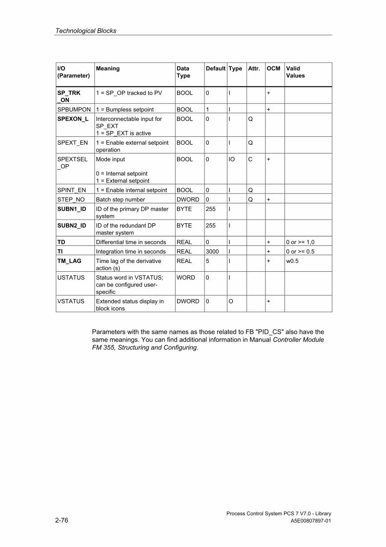
Technological Blocks
Process Control System PCS 7 V7.0 - Library 2-76 A5E00807897-01
I/O (Parameter)
Meaning
Data Type
Default Type
Attr. OCM Valid Values
SP_TRK _ON
1 = SP_OP tracked to PV BOOL 0 I +
SPBUMPON 1 = Bumpless setpoint BOOL 1 I + SPEXON_L Interconnectable input for
SP_EXT 1 = SP_EXT is active
BOOL 0 I Q
SPEXT_EN 1 = Enable external setpoint operation
BOOL 0 I Q
SPEXTSEL _OP
Mode input 0 = Internal setpoint 1 = External setpoint
BOOL 0 IO C +
SPINT_EN 1 = Enable internal setpoint BOOL 0 I Q STEP_NO Batch step number DWORD 0 I Q + SUBN1_ID ID of the primary DP master
system BYTE 255 I
SUBN2_ID ID of the redundant DP master system
BYTE 255 I
TD Differential time in seconds REAL 0 I + 0 or >= 1,0 TI Integration time in seconds REAL 3000 I + 0 or >= 0.5 TM_LAG Time lag of the derivative
action (s) REAL 5 I + w0.5
USTATUS Status word in VSTATUS; can be configured user-specific
WORD 0 I
VSTATUS Extended status display in block icons
DWORD 0 O +
Parameters with the same names as those related to FB "PID_CS" also have the same meanings. You can find additional information in Manual Controller Module FM 355, Structuring and Configuring.

Technological Blocks
Process Control System PCS 7 V7.0 - Library A5E00807897-01 2-77
2.1.8.15 Message Texts and Associated Values of FMCS_PID
Assignment of Message Text and Message Class to the Block Parameters
Message No. Block Parameter Default Message Text Message Class Can be Suppressed By
1 QPERAF/QMODF @6%d@/@7%d@/@8%d@ controller channel error @5%d@
S -
2 QPARF_FM @6%d@/@7%d@/@8%d@ controller channel configuration error @5%d@
S -
3 no message - 4 no message - 5 QH_ALM $$BlockComment$$
alarm high AH M_SUP_AL,
MSG_LOCK 6 QH_WRN $$BlockComment$$
warning high WH M_SUP_ER,
MSG_LOCK 7 QL_WRN $$BlockComment$$
warning low WL M_SUP_ER,
MSG_LOCK 8 QL_ALM $$BlockComment$$
alarm low AL M_SUP_AL,
MSG_LOCK
Assignment of Associated Values to the Block Parameters The first three of the associated values of the message block are assigned SIMATIC BATCH data, the fourth is reserved for the actual value and the fifth for the controller channel ID. The re maining associated values can be freely assigned by the user.
Associated Value Block Parameter
1 BA_NA 2 STEP_NO 3 BA_ID 4 PV 5 CHANNEL 6 SUBNET_ID 7 RACK_NO 8 SLOT_NO 9 AUX_PR09 10 AUX_PR10
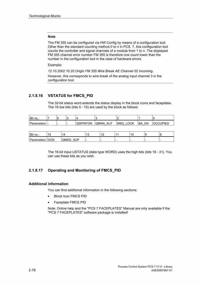
Technological Blocks
Process Control System PCS 7 V7.0 - Library 2-78 A5E00807897-01
Note
The FM 355 can be configured via HW Config by means of a configuration tool. Other than the standard counting method 0 to n in PCS 7, this configuration tool counts the controller and signal channels of a module from 1 to n. The displayed FM 355 channel error number FM 355 is therefore one count lower than the number in the configuration tool in the case of hardware errors.
Example:
12.10.2002 10.20 Origin FM 355 Wire Break AE Channel 02 Incoming. However, this corresponds to wire break of the analog input channel 3 in the configuration tool.
2.1.8.16 VSTATUS for FMCS_PID
The 32-bit status word extends the status display in the block icons and faceplates. The 16 low bits (bits 0 - 15) are used by the block as follows:
Bit no.: 7 6 5 4 3 2 1 0
Parameters - - - QSPINTON QMAN_AUT MSG_LOCK BA_EN OCCUPIED
Bit no.: 15 14 13 12 11 10 9 8
Parameters OOS QMSG_SUP - - - - - -
The 16-bit input USTATUS (data type WORD) uses the high bits (bits 16 - 31). You can use these bits as you wish.
2.1.8.17 Operating and Monitoring of FMCS_PID
Additional information You can find additional information in the following sections:
• Block Icon FMCS PID
• Faceplate FMCS PID
Note: Online help and the "PCS 7 FACEPLATES" Manual are only available if the "PCS 7 FACEPLATES" software package is installed!

Technological Blocks
Process Control System PCS 7 V7.0 - Library A5E00807897-01 2-79
2.1.9 FMT_PID: Temperature controller block
2.1.9.1 Description of FMT_PID
Object name (type + number) FB77
*)
*)
*) Online help is only available if the "PCS 7 FACEPLATES" software package is installed!
Fields of application The FMT_PID block is used to integrate the FM 355-2 temperature control modules.
It can be used for the module types FM 355-2 C (C controller) and FM 355-2 S (S and P controller). It does not itself contain a control algorithm, since the PID control function is performed only on the module. You can use it to monitor all relevant process variables and to change all relevant controller parameters. You can find sample applications of the FM 355-2 and detailed descriptions on I/O parameters in the Temperature-Controller Module FM 355-2 Manual.
The controller parameters can be set via the "Auto-tuning" function on the module (TUN_ON = TRUE).
Use in CFC When the CFC function "Generate module drivers" is used, the following occurs automatically:
• The parameter CO_NO is parameterized
• The input EN_CO is connected to the output EN_CO_x of the FM_CO block (x = number of the rack)
The output ENCO is connected to the input ENCOx_yy of the FM_CO block (x = number of the rack, yy = coordination number).
Dependencies You can find information about dependencies in the description of FM_CO.
Technological Blocks
Process Control System PCS 7 V7.0 - Library 2-80 A5E00807897-01
Using the FM 355-2 C Controller Module as a Continuous Controller (C controller) The block provides the following displays and setting options:
• Display of the result of the limit monitoring carried out on the module for two limit pairs for the process variable PV or the error signal ER (QH_ALM, QH_WRN, QL_WRN, QL_ALM outputs). MONERSEL is used to specify whether PV or ER is monitored.
• Disabling of the generation of individual messages when limits are exceeded
• Split-range function
• Dead band (DEADB_W, on threshold) in the error-signal branch
• PID algorithm
• Attenuation of the P-action to setpoint changes via PFAC_SP < 1.0 (avoids overshoot; optimized control and error response)
• Manipulated variable tracking
• Disabling of the integral action
• Setpoint tracking in manual mode (SP = PV)
Using the FM 355-2 S Controller Module as a Pulse Controller Using the controller module as a pulse controller rather than a continuous controller means that split-range control is not possible.
You can use the pulse controller to generate pulse width modulated control signals. This variable is converted into a binary output signal, so that the ratio between the pulse width and configured period corresponds with the manipulated value LNM.
Using the FM 355-2 S Controller Module as a Step Controller Using the controller module as a step controller rather than a continuous controller results in the following differences:
• Output QLMNR_ON indicates whether a feedback signal is available (1 = exists, 0 = does not exist).
• Split-range operation is not possible.
When used as a step-action controller without a position feedback (QLMNR_ON = 0), manual adjustment of the manipulated variable is only possible at the final positions. In this case the safety position LMN_SAFE or the external control value LMN_RE is interpreted by the controller module as follows:
LMN_SAFE < 40 %: Close actuating element completely
LMN_SAFE > 60 %: Open actuating element completely
40 % ≤ LMN_SAFE ≤ 60 %: Hold current setting

Technological Blocks
Process Control System PCS 7 V7.0 - Library A5E00807897-01 2-81
Calling OBs Watchdog OB: e.g., OB32
For additional startup recognition by the driver generator, the block is to be installed in OB100.
Additional information Additional information is available in the sections:
Addressing
Function
Acquisition of Process Values Via the Process Image
Generation of Setpoints, Limits, Error Signals and Manipulated Variables
Manual, Auto and Following Mode
Mode Change
Safety Mode
Download Parameters to the Module
Read Data From the Module/Working With the Configuration Tool
Optimization (Overview)
Switching Between Different PID Parameter Sets
Error Handling
Startup Behavior, Dynamic Response and Message response
Backup Mode of the FM 355-2
I/Os of FMT_PID
Message Texts and Associated Values of FMT_PID
VSTATUS for FMT_PID
Operating and Monitoring of FMT_PID
2.1.9.2 Addressing
The controller channel of an FM 355 belonging to the instance is addressed via its logical base address (set in HW Config) (LADDR input) and the controller channel number (CHANNEL input, valid values = 1 to 4). 0 to 3 are the allowed values for the CHANNEL input. ACC_MODE must be set to TRUE after a change is made to CHANNEL.
The FM 355-2 module is monitored with the PCS7 blocks of the PCS 7 Library. The input MODE is connected to the output OMODE of the block MOD_D1. The block communicates only via the FM 355-2 control channel. Hence, the measurement range coding in the low word of the output OMODE is irrelevant and assigned zero.
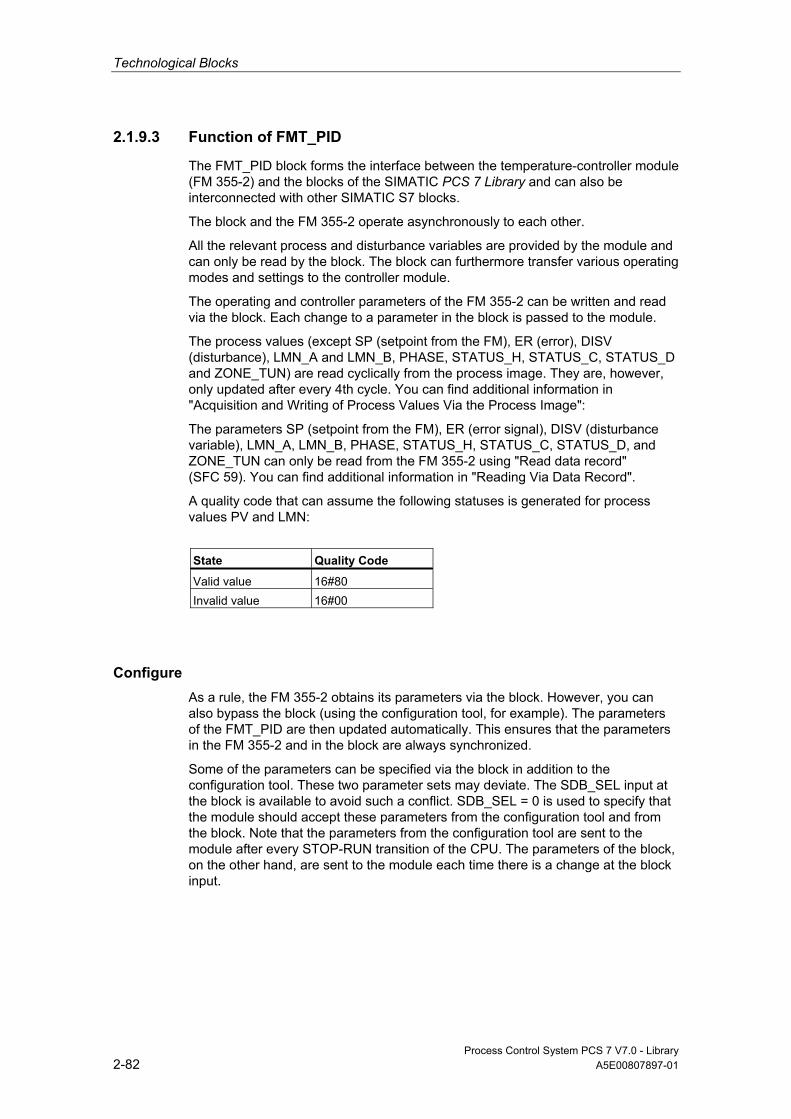
Technological Blocks
Process Control System PCS 7 V7.0 - Library 2-82 A5E00807897-01
2.1.9.3 Function of FMT_PID
The FMT_PID block forms the interface between the temperature-controller module (FM 355-2) and the blocks of the SIMATIC PCS 7 Library and can also be interconnected with other SIMATIC S7 blocks.
The block and the FM 355-2 operate asynchronously to each other.
All the relevant process and disturbance variables are provided by the module and can only be read by the block. The block can furthermore transfer various operating modes and settings to the controller module.
The operating and controller parameters of the FM 355-2 can be written and read via the block. Each change to a parameter in the block is passed to the module.
The process values (except SP (setpoint from the FM), ER (error), DISV (disturbance), LMN_A and LMN_B, PHASE, STATUS_H, STATUS_C, STATUS_D and ZONE_TUN) are read cyclically from the process image. They are, however, only updated after every 4th cycle. You can find additional information in "Acquisition and Writing of Process Values Via the Process Image":
The parameters SP (setpoint from the FM), ER (error signal), DISV (disturbance variable), LMN_A, LMN_B, PHASE, STATUS_H, STATUS_C, STATUS_D, and ZONE_TUN can only be read from the FM 355-2 using "Read data record" (SFC 59). You can find additional information in "Reading Via Data Record".
A quality code that can assume the following statuses is generated for process values PV and LMN:
State Quality Code
Valid value 16#80 Invalid value 16#00
Configure As a rule, the FM 355-2 obtains its parameters via the block. However, you can also bypass the block (using the configuration tool, for example). The parameters of the FMT_PID are then updated automatically. This ensures that the parameters in the FM 355-2 and in the block are always synchronized.
Some of the parameters can be specified via the block in addition to the configuration tool. These two parameter sets may deviate. The SDB_SEL input at the block is available to avoid such a conflict. SDB_SEL = 0 is used to specify that the module should accept these parameters from the configuration tool and from the block. Note that the parameters from the configuration tool are sent to the module after every STOP-RUN transition of the CPU. The parameters of the block, on the other hand, are sent to the module each time there is a change at the block input.

Technological Blocks
Process Control System PCS 7 V7.0 - Library A5E00807897-01 2-83
With SDB_SEL = 1 (not activated internally, however, because module firmware does not support this function), you can specify that the module should only accept these parameters from the function block and not from the configuration tool.
Note
After HW Config in Run (CiR) is downloaded, the block parameters are not adjusted to the active parameters on the module.
2.1.9.4 Acquisition and Writing of Process Values Via the Process Image
Reading Process Values The process values (except SP (setpoint from the FM), ER (error), DISV (disturbance), LMN_A and LMN_B, PHASE, STATUS_H, STATUS_C, STATUS_D and ZONE_TUN) are read cyclically from the process image. They are, however, only updated after every 4th cycle. In a normal situation, this takes place in the cyclic interrupt OB in which the FMT_PID is installed. To achieve higher accuracy, it is possible to install the FMT_PID in a second cyclic interrupt OB with a higher clock rate.
After a restart or when ACC_MODE is set to 1, the block determines the watchdog alarms used (up to 2 are permitted; you can find additional information in "Startup Behavior").
The following must be considered when selecting cyclic interrupts:
• The watchdog alarm OB in which the block is installed must not run slower than 30 s or faster than 25 ms.
Note: OB1 must not be used!
• The process image partition (TPA) in HW Config must be set for the faster OB.
• The read via process image for a block is complete after 4 block cycles (after 4 s in the example with OB32 [1,000 ms]) if the block cycle is longer than the cycle time of the module, otherwise after 4 module cycles.
• Example: With 4 processed analog inputs on the module, the cycle time of the module is typically 400 ms (see "Module parameters" button on the parameter assignment interface of the FM 355). If the block, is installed in OB32 (1,000 ms), for example, you can accelerate reading of the process image by means of an additional installation in OB33 (500 ms).

Technological Blocks
Process Control System PCS 7 V7.0 - Library 2-84 A5E00807897-01
Writing Process Values The following process values are written to the process image in every second cycle:
• Setpoint (automatic mode only)
• Manipulated value (manual mode only)
• SAFE_ON, LMNTRKON, LMN_REON, LMNRHSRE, LMNRLSRE
• LMNS_ON or TRUE if set by control signals
• LMNUP or LMNUP_OP
• LMNDN or LMNDN_OP
In the following cases, a restart must be performed or ACC_MODE must be set to 1 following a compile and download:
• if you have moved blocks to a different cycle
• if you have also installed blocks in a fast cycle
• if you have also deleted installed blocks.
2.1.9.5 Generation of Setpoints, Limits, Error Signals, and Manipulated Variables
Setpoint Generation by the FMT_PID Block Setpoint SP can be fetched from three different sources, depending on the SP_TRK_ON and SPEXTSEL_OP inputs. You can find additional information about the external/internal setpoint in "Mode Change":
SP_TRK_ON SPEXTSEL_OP SP= State
0 0 SP_OP Internal (operator controlled) setpoint
Irrelevant 1 SP_EXT External setpoint 1 0 PV ** Tracked setpoint ** in manual mode only and when SPBUMPON = 1
The effective setpoint is limited to the range (SP_LLM, SP_HLM).
When SP_TRK_ON is set the SP_OP setpoint will be tracked (for internal setpoint and when SPBUMPON = 1). This enables bumpless changeover from manual to auto mode.

Technological Blocks
Process Control System PCS 7 V7.0 - Library A5E00807897-01 2-85
Limit Generation Depending on the input MONERSEL, the controller module monitors either the process variable PV (MONERSEL = 0) or the error signal ER (MONERSEL = 1) for warning and alarm limits (L_WRN, H_WRN, L_ALM, H_ALM). Monitoring is carried out with the common hysteresis HYS.
The block makes the monitoring result available at the QL_WRN, QH_WRN, QL_ALM and QH_ALM outputs. While monitoring the actual value PV, the block signals any violation of the high and low limits, unless message suppression has been enabled.
Error signal The error signal is generated by the controller module, based on the active setpoint SP and the process variable PV and is made available at output ER of the block.
After the dead band DEADB_W has expired, the error signal is processed further in the PID algorithm. A disturbance variable is not added.
Manipulated-Variable Generation by the FMT_PID Block The manipulated value LMN is derived from various sources. If several control inputs are set to TRUE simultaneously, the priority is as follows:
Priority Control Input LMN State
1 LMNS_ON = 1 LMNUP or LMNDN Connected. Control signal for step controller:
2 SAFE_ON = 1 = LMN_SAFE Safety mode 3 TUN_ON = 1 ** = LMNalt + TUN_DLMN Optimization mode (PHASE = 2) 4 LMNTRKON = 1 = analog input on BG or 0.0 Following mode 5 Manual = LMN_OP Manual mode (QMAN_AUT=0) 6 LMN_REON = 1 = LMN_RE External manipulated variable 7 Automatic = PID algorithm Auto mode (QMAN_AUT=1)
** The optimization also has to be set by a setpoint step or TUN_ST/TUN_CST = 1 in Phase 2.
• If LIOP_MAN_SEL = 0, the AUT_ON_OP parameter is used to change over between manual and auto mode on the OS.
• If LIOP_MAN_SEL = 1, the AUT_L parameter is used to change over between manual and auto mode via an interconnection in the CFC.
In step controllers the manipulated variable is converted into control pulses (QLMNUP; QLMNDN) under consideration of the motor-specific parameters "Motor actuating time" (MOTOR_TM), Minimum pulse duration (PULSE_TM), Minimum break duration (BREAK_TM).
Technological Blocks
Process Control System PCS 7 V7.0 - Library 2-86 A5E00807897-01
2.1.9.6 Manual, Auto and Following Mode
Manual operation The manipulated variable is determined by operator control at input LMN_OP (stepping mode is also possible here). When changing over to automatic mode, the module takes over the manipulated variable set "manually" as the operating point.
"Manual mode" takes priority over "External Setpoint".
Manual mode for step controller:
Actuating commands can be used for direct control of the control signals for step controllers. Signal operation is enabled with LMNSOPON and the control signals are set with LMNUP_OP or LMNDN_OP. The valve is driven until the operation is disabled or the end position is achieved.
The control signal operation has priority over the manipulated value operation via LMN_OP.
The LMN_OP input cannot be controlled when step controllers without position feedback are used.
Auto Mode The manipulated variable is calculated by the PID or fuzzy algorithm of the module. The control parameters GAIN, TI, TD and TM_LAG can be interconnected.
The controller's direction of control can be reversed (rising error signal causes a falling manipulated variable) by setting a negative proportional GAIN.
The integral action can be disabled by setting TI = 0.
The operator-controllable manipulated-variable input LMN_OP is tracked to the LMN output so that bumpless changeover from automatic to manual mode is ensured.
External Setpoint (LMN_RE) The block transfers the value LMN_RE to the FM 355-2. The FM 355-2 uses the external manipulated variable LMN_RE as the manipulated variable LMN, if LNM_REON = 1 is set.
"External manipulated variable" mode takes priority over "Auto mode".
Following the Manipulated Variable In manipulated variable following mode (LMNTRKON = 1), the manipulated variable is tracked to an analog input of the module or to the value 0.0.
"Following" operating mode takes priority over "Manual mode".

Technological Blocks
Process Control System PCS 7 V7.0 - Library A5E00807897-01 2-87
Safety Mode (LMN_SAFE) The block transfers the value LMN_SAFE to the FM 355-2. The FM 355-2 accepts the safety manipulated variable LMN_SAFE as manipulated variable LMN, if SAFE_ON = 1.
"Safety mode" takes priority over all other operating modes.
Interconnectable Control-Signal Setting for the Step Controller The following mode using LMNS_ON with direct connection of the control signals over LMNUP and LMNDN has the highest priority of all modes. If LMNS_ON is set, the control signals can only be set via the inputs LMNUP or LMNDN. As long as LMNS_ON is set, all other influences on the control signals are suppressed.
2.1.9.7 Mode Change
This can be triggered either by operator control or via interconnected inputs. The operating mode is changed over by means of the operator-control blocks assigned to the operating modes.
External/Internal Setpoint Changeover is carried out between the external and internal setpoint by OS operation of the SPEXTSEL_OP input or interconnection of SPEXON_L. You must set the corresponding enable inputs SPINT_EN, SPEXT_EN or the selection input LIOP_INT_SEL to enable these changeovers.
SP_OP_ON must be set TRUE to enable operator control of the setpoint.
Enabling Changeover Between Internal and External Setpoint
QSPEXTEN = TRUE: SPEXTSEL_OP can be set from FALSE (internal setpoint) to TRUE (external setpoint).
QSPINTEN = TRUE: SPEXTSEL_OP can be set from TRUE (external setpoint) to FALSE (internal setpoint).
SPEXTSEL_OP is tracked or reset as required.

Technological Blocks
Process Control System PCS 7 V7.0 - Library 2-88 A5E00807897-01
Manual/Auto The operating mode is changed over by OS operation of the AUT_ON_OP input or interconnection of AUT_L. You must set the corresponding enable inputs MANOP_EN, AUTOP_EN or the selection input LIOP_MAN_SEL to enable this changeover.
LMNOP_ON must be set TRUE to enable manual control of the variable.
Enabling the Changeover Between Manual and Auto Mode
QAUTOP = TRUE: AUT_ON_OP can be set from FALSE (manual mode) to TRUE (auto mode).
QMANOP = TRUE: AUT_ON_OP can be set from TRUE (auto mode) to FALSE (manual mode).
AUT_ON_OP is tracked or reset as required.
Measures for Bumpless Changeover Special measures are applied for the modes listed below in order to ensure a bumpless changeover:
• Setpoint external/setpoint tracking: If SPBUMPON = TRUE, the internal setpoint SP_OP is set to the effective (external or tracked) setpoint.
• Automatic mode, safety mode, following mode or external manipulated variable LMN_RE: The manipulated value LMN_OP is tracked to the effective manipulated variable.
• Manual mode, safety mode, following mode or external manipulated variable LMN_RE: The integrator is tracked so that a bumpless changeover to auto mode is possible (not with a step controller). Using the configuration tool, you can disable the default bumpless changeover function, in order to allow a faster correction of the error signal.
Technological Blocks
Process Control System PCS 7 V7.0 - Library A5E00807897-01 2-89
2.1.9.8 Safety mode
The interconnectable input SAFE_ON is used to set safety mode. This is executed by the controller module with highest priority. In safety mode, the value present at the LMN_SAFE input of the block is output at the control output.
2.1.9.9 Download Parameters to the Module
The channel-specific controller and operating parameters are transferred to the controller module whenever a corresponding block parameter changes.
The download of controller and operating parameters to the controller module can require several block calls.
2.1.9.10 Read Data From the Module/Working With the Configuration Tool
The channel-specific process variables are read by the controller module. You can find additional information in "Function". The reading process can require several block calls, in particular in the case of decentralized operation.
You can also bypass the block using the configuration tool, for example. The parameters of the FMT_PID are then read and updated automatically by the module. This ensures that the parameters in the FM 355-2 and in the block are always synchronized.
Note
Proceed according to the following sequence:
• Use the menu command Upload to PG to align the data management of the configuration tool with the parameters that are effective in the module.
• In the configuration tool, click the "Download to module" command button. The parameters are written.
• Transfer the modified parameters to the offline data management of the CFC via Chart > Readback....

Technological Blocks
Process Control System PCS 7 V7.0 - Library 2-90 A5E00807897-01
2.1.9.11 Optimization (Overview)
Optimization Sequence The optimization sequence is as follows:
1. Create a stationary state
2. Set PID_ON = TRUE (if PID parameters are required)
3. Configure TUN_DLMN/TUN_CLMN
4. Set TUN_ON = TRUE (phase 1, ready for optimization)
5. Start the optimization using a setpoint step or by setting TUN_ST
If you have not made any configuration errors, the controller optimization is now in phase 2 and STATUS_H is 0.
6. When the point of inflection has been reached (PHASE >= 3), evaluate the diagnostics display at the STATUS_H parameter. Phase 0 is reached in a few cycles for process type I and the optimization is completely ended. For process types II and III, the optimization goes to Phase 7 (checking the process types). If STATUS_H > 20000, a valuation error has occurred or the point of inflection was not reached. In this case, repeat the procedure.
Result Once the optimization is completed, the parameters PFAC_SP, GAIN, TI, TD, D_F, CON_ZONE and CONZ_ON are updated (for both the module and at FMT_PID). The PI or PID parameter sets are saved on the FM 355-2.
More detailed information about the optimization procedure is available in the manual for the FM 355-2 temperature controller module.
Permanent Backup of Optimized Controller Parameters • Save, compile, and download the hardware configuration; the optimized
controller parameters are now in the system data block (SDB).
• Transfer the modified parameters to the offline data management of the CFC via Chart > Readback....

Technological Blocks
Process Control System PCS 7 V7.0 - Library A5E00807897-01 2-91
2.1.9.12 Switching Between Different PID Parameter Sets
Another parameter set is stored on the FM 355-2 in addition to the effective PID parameter set. The parameter set is saved using SAVE_PAR and reset using UNDO_PAR. This affects the following parameters:
PFAC_SP, GAIN, TI, TD, D_F, CON_ZONE, RATIOFAC, CONZ_ON, P_SEL
Following optimization both the PI and the PID parameters sets are saved on the FM 355-2. These parameter sets are loaded by setting LOAD_PID. If PID_ON = TRUE, the PID parameter set is copied to the effective controller parameters, otherwise the PI parameter set is loaded. This affects the following parameters:
GAIN, TI, TD, CON_ZONE
2.1.9.13 Error handling
Block FMT_PID does not communicate with the associated controller module if a higher-level error is pending. You can find additional information in "MOD_D1", MODE= 16#40xxxxxx. In this case QMODF = TRUE. Communication is possible after a channel error has occurred (MODE= 16#00xxxxxx).
The block supplies the following error displays:
Error Display Meaning
QOP_ERR = 1 Operator control error: If there is no new operator control error, QOP_ERR is reset in the next block cycle.
QPARF_FM = 1 • Error when assigning parameters directly to the controller module using the parameter assignment tool
• Invalid control channel number (CHANNEL) was set at the block. • Error when installing in OBs; you can find additional information in "Startup
Behavior". QCH_F = 1 Channel error. Due to a hardware fault the controller channel belonging to the instance
cannot return valid results. QMODF = 1 Controller module has been removed or is faulty. QPERAF = 1 I/O access error. The block could not access the controller module.

Technological Blocks
Process Control System PCS 7 V7.0 - Library 2-92 A5E00807897-01
2.1.9.14 Startup Behavior, Dynamic Response and Message response of FMT_PID
Startup Characteristics During CPU startup, startup of the FM or initial run of the block, the operating modes MANUAL and INTERNAL are set and the controller parameters are written from the block to the module.
In OB100, QDONE is set to 0.
After a CPU restart or when ACC_MODE is set to 1, the block is not operable for up to approximately 30 seconds.
The block uses the first 30 seconds after a restart (OB100) or after ACC_MODE is set to 1 to detect whether the block instance is installed in more than one OB. If you then move the blocks to another OB, a restart must be performed or ACC_MODE must be set to 1 after compiling and downloading (otherwise you will receive the error message QPARF_FM = 1, and the block will not provide any more data).
Note
The configuration tool can be configured in HW Config with Save/Compile and Download to the SDB (system data). These SDB parameters can deviate from the block parameters. When SDB_SEL = 0, the SDB parameters are sent to the module at every STOP-RUN transition of the CPU. The block parameters are written to the module, however, a few cycles later. With SDB_SEL = 1, the module does not load the SDB parameters at a STOP-RUN transition of the CPU. This avoids a jump in the manipulated variable when the SDB parameters deviate from the block parameters.
Dynamic Response n.a.
Assignment of the 32-Bit Status Word VSTATUS You can find additional information in "VSTATUS for FMT_PID".

Technological Blocks
Process Control System PCS 7 V7.0 - Library A5E00807897-01 2-93
Message response The FMT_PID block uses the ALARM_8P block for generating messages.
The following message triggers exist:
• the functions for monitoring the actual value/system deviation limits
• access errors on a module if no higher-level error exists
Messages regarding limit violation can be suppressed individually by setting the corresponding M_SUP_xx inputs. The process messages (not process control messages!) can be completely blocked with MSG_LOCK.
QMSG_SUP is set if the RUNUPCYC cycles have not expired yet since a restart and MSG_LOCK = TRUE or MSG_STAT = 21.
Monitoring of Process Values n.a.
2.1.9.15 Backup Mode of the FM 355-2
After a CPU failure or transition to STOP, the FM 355-2 switches to backup mode.
2.1.9.16 I/Os of FMT_PID
The factory setting of the block display in CFC is identified in the "I/O" column: I/O name in bold characters = I/O is visible; I/O name in standard characters = I/O is hidden.
You can find explanations of and information about the abbreviations used in "General Information About Block Description".
I/O (Parameter)
Meaning
Data Type
Default Type
Attr.
OCM Valid values
ACC_MODE SUBN1_ID, SUBN2_ID, RACK_NO, SLOT_NO and CHANNEL included in internal processing
BOOL 0 IO
AUT_L Interconnectable input for MANUAL/AUTO: 0 = Manual 1 = Auto
BOOL 0 I Q
AUT_ON_OP Mode input MANUAL/AUTO: 0 = Manual 1 = Auto
BOOL 0 IO C +
AUTOP_EN 1 = Enabled AUTO mode BOOL 1 I Q AUX_PRxx User-specific associated
process variable 6 … 10 ANY 0 IO
BA_EN Release by BATCH BOOL 0 I Q + BA_ID BATCH: Batch serial number DWORD 0 I Q +
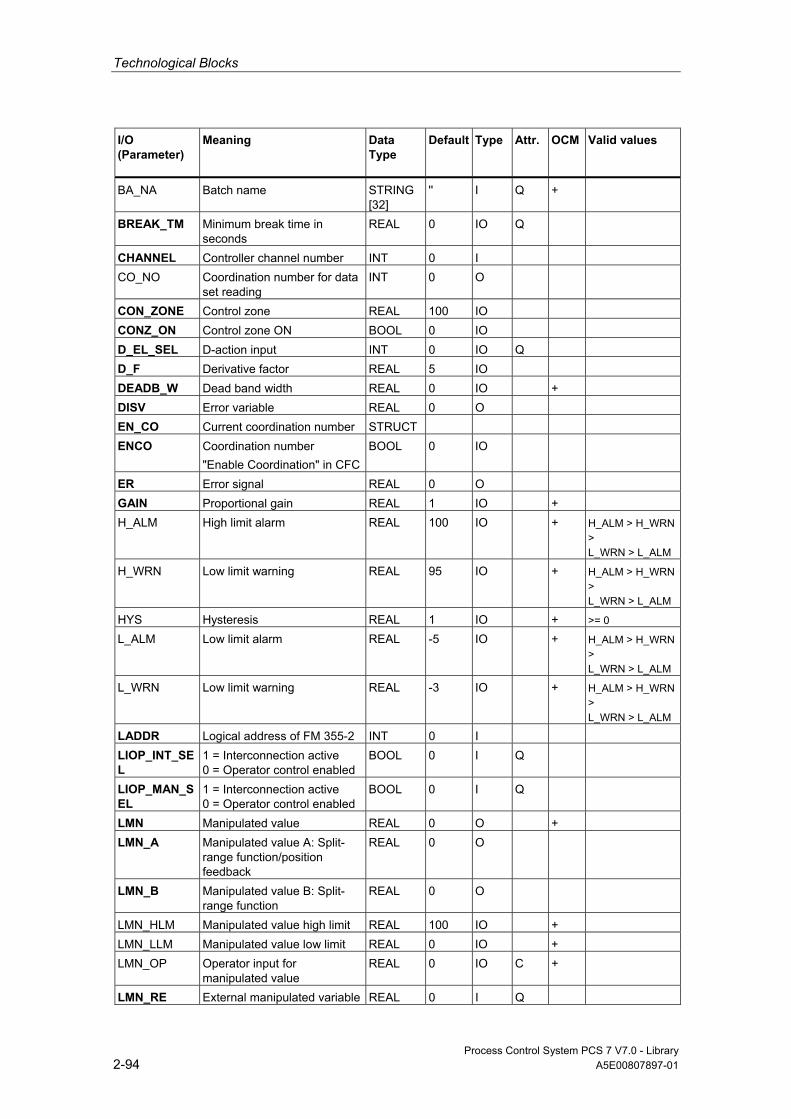
Technological Blocks
Process Control System PCS 7 V7.0 - Library 2-94 A5E00807897-01
I/O (Parameter)
Meaning
Data Type
Default Type
Attr.
OCM Valid values
BA_NA Batch name STRING[32]
'' I Q +
BREAK_TM Minimum break time in seconds
REAL 0 IO Q
CHANNEL Controller channel number INT 0 I CO_NO Coordination number for data
set reading INT 0 O
CON_ZONE Control zone REAL 100 IO CONZ_ON Control zone ON BOOL 0 IO D_EL_SEL D-action input INT 0 IO Q D_F Derivative factor REAL 5 IO DEADB_W Dead band width REAL 0 IO + DISV Error variable REAL 0 O EN_CO Current coordination number STRUCT ENCO Coordination number
"Enable Coordination" in CFCBOOL 0 IO
ER Error signal REAL 0 O GAIN Proportional gain REAL 1 IO + H_ALM High limit alarm REAL 100 IO + H_ALM > H_WRN
> L_WRN > L_ALM
H_WRN Low limit warning REAL 95 IO + H_ALM > H_WRN > L_WRN > L_ALM
HYS Hysteresis REAL 1 IO + >= 0
L_ALM Low limit alarm REAL -5 IO + H_ALM > H_WRN > L_WRN > L_ALM
L_WRN Low limit warning REAL -3 IO + H_ALM > H_WRN > L_WRN > L_ALM
LADDR Logical address of FM 355-2 INT 0 I
LIOP_INT_SEL
1 = Interconnection active 0 = Operator control enabled
BOOL 0 I Q
LIOP_MAN_SEL
1 = Interconnection active 0 = Operator control enabled
BOOL 0 I Q
LMN Manipulated value REAL 0 O + LMN_A Manipulated value A: Split-
range function/position feedback
REAL 0 O
LMN_B Manipulated value B: Split-range function
REAL 0 O
LMN_HLM Manipulated value high limit REAL 100 IO + LMN_LLM Manipulated value low limit REAL 0 IO + LMN_OP Operator input for
manipulated value REAL 0 IO C +
LMN_RE External manipulated variable REAL 0 I Q
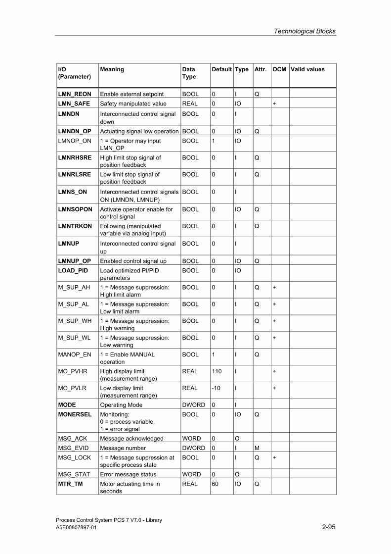
Technological Blocks
Process Control System PCS 7 V7.0 - Library A5E00807897-01 2-95
I/O (Parameter)
Meaning
Data Type
Default Type
Attr.
OCM Valid values
LMN_REON Enable external setpoint BOOL 0 I Q LMN_SAFE Safety manipulated value REAL 0 IO +
LMNDN Interconnected control signal down
BOOL 0 I
LMNDN_OP Actuating signal low operation BOOL 0 IO Q LMNOP_ON 1 = Operator may input
LMN_OP BOOL 1 IO
LMNRHSRE High limit stop signal of position feedback
BOOL 0 I Q
LMNRLSRE Low limit stop signal of position feedback
BOOL 0 I Q
LMNS_ON Interconnected control signals ON (LMNDN, LMNUP)
BOOL 0 I
LMNSOPON Activate operator enable for control signal
BOOL 0 IO Q
LMNTRKON Following (manipulated variable via analog input)
BOOL 0 I Q
LMNUP Interconnected control signal up
BOOL 0 I
LMNUP_OP Enabled control signal up BOOL 0 IO Q LOAD_PID Load optimized PI/PID
parameters BOOL 0 IO
M_SUP_AH 1 = Message suppression: High limit alarm
BOOL 0 I Q +
M_SUP_AL 1 = Message suppression: Low limit alarm
BOOL 0 I Q +
M_SUP_WH 1 = Message suppression: High warning
BOOL 0 I Q +
M_SUP_WL 1 = Message suppression: Low warning
BOOL 0 I Q +
MANOP_EN 1 = Enable MANUAL operation
BOOL 1 I Q
MO_PVHR High display limit (measurement range)
REAL 110 I +
MO_PVLR Low display limit (measurement range)
REAL -10 I +
MODE Operating Mode DWORD 0 I MONERSEL Monitoring:
0 = process variable, 1 = error signal
BOOL 0 IO Q
MSG_ACK Message acknowledged WORD 0 O MSG_EVID Message number DWORD 0 I M MSG_LOCK 1 = Message suppression at
specific process state BOOL 0 I Q +
MSG_STAT Error message status WORD 0 O MTR_TM Motor actuating time in
seconds REAL 60 IO Q

Technological Blocks
Process Control System PCS 7 V7.0 - Library 2-96 A5E00807897-01
I/O (Parameter)
Meaning
Data Type
Default Type
Attr.
OCM Valid values
OCCUPIED ID for occupied by BATCH BOOL 0 I Q + OOS Reserve BOOL 0 I + P_SEL Enable P-action BOOL 1 IO Q PFAC_SP Proportional gain REAL 1 IO PHASE Phase of auto-tuning (0..7) INT 0 O PID_ON 1 = Enable PID mode BOOL 0 IO PULSE_TM Minimum pulse time in
seconds REAL 0 IO
PV Process variable REAL 0 O + Q_SP_OP 1 = Enable setpoint operation BOOL 0 O + QAUTOP 1 = Enable AUTO operation BOOL 0 O + QC_LMN Quality Code for LMN BYTE 16#80 O QC_PV Quality Code for PV BYTE 16#80 O QCH_F Channel error BOOL 0 O QDNRLM Negative setpoint ramp limit
triggered BOOL 0 O
QDONE 1 = Parameter read BOOL 0 O QERR Inverted ENO BOOL 1 O QH_ALM High limit alarm triggered BOOL 0 O QH_WRN High limit warning triggered BOOL 0 O QL_ALM Low limit alarm triggered BOOL 0 O QL_WRN Low limit warning triggered BOOL 0 O QLMN_HLM Manipulated value: High limit
triggered BOOL 0 O
QLMN_LLM Manipulated value: Low limit triggered
BOOL 0 O
QLMN_RE 1 = External manipulated value enabled
BOOL 0 O
QLMNDN Manipulated value low BOOL 0 O QLMNOP 1 = Manipulated value
operation enabled BOOL 0 O +
QLMNR_HS High limit stop signal of position feedback
BOOL 0 O
QLMNR_LS Low limit stop signal of position feedback
BOOL 0 O
QLMNR_ON Position feedback enabled BOOL 0 O QLMNS_ON 1 = LMNS_ON active BOOL 0 O QLMNSAFE Safety mode BOOL 0 O QLMNSOP Output: Control signal
operation active BOOL 1 O +
QLMNTRK Following mode BOOL 0 O QLMNUP Manipulated variable signal
UP BOOL 0 O
QLMNVOP Operator enable for control signal LMN_OP activated
BOOL 1 O +
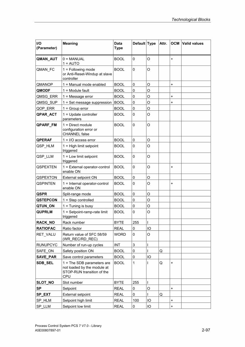
Technological Blocks
Process Control System PCS 7 V7.0 - Library A5E00807897-01 2-97
I/O (Parameter)
Meaning
Data Type
Default Type
Attr.
OCM Valid values
QMAN_AUT 0 = MANUAL 1 = AUTO
BOOL 0 O +
QMAN_FC 1 = Following mode or Anti-Reset-Windup at slave controller
BOOL 0 O
QMANOP 1 = Manual mode enabled BOOL 0 O + QMODF 1 = Module fault BOOL 0 O QMSG_ERR 1 = Message error BOOL 0 O + QMSG_SUP 1 = Set message suppression BOOL 0 O + QOP_ERR 1 = Group error BOOL 0 O QPAR_ACT 1 = Update controller
parameters BOOL 0 O
QPARF_FM 1 = Direct module configuration error or CHANNEL false
BOOL 0 O
QPERAF 1 = I/O access error BOOL 0 O QSP_HLM 1 = High limit setpoint
triggered BOOL 0 O
QSP_LLM 1 = Low limit setpoint triggered
BOOL 0 O
QSPEXTEN 1 = External operator-control enable ON
BOOL 0 O +
QSPEXTON External setpoint ON BOOL 0 O QSPINTEN 1 = Internal operator-control
enable ON BOOL 0 O +
QSPR Split-range mode BOOL 0 O QSTEPCON 1 = Step controlled BOOL 0 O QTUN_ON 1 = Tuning is busy BOOL 0 O QUPRLM 1 = Setpoint-ramp-rate limit
triggered BOOL 0 O
RACK_NO Rack number BYTE 255 I RATIOFAC Ratio factor REAL 0 IO RET_VALU Return value of SFC 58/59
(WR_REC/RD_REC) WORD 0 O
RUNUPCYC Number of run-up cycles INT 3 I SAFE_ON Safety position ON BOOL 0 I Q SAVE_PAR Save control parameters BOOL 0 IO SDB_SEL 1 = The SDB parameters are
not loaded by the module at STOP-RUN transition of the CPU
BOOL 1 I Q +
SLOT_NO Slot number BYTE 255 I SP Setpoint REAL 0 O + SP_EXT External setpoint REAL 0 I Q SP_HLM Setpoint high limit REAL 100 IO + SP_LLM Setpoint low limit REAL 0 IO +
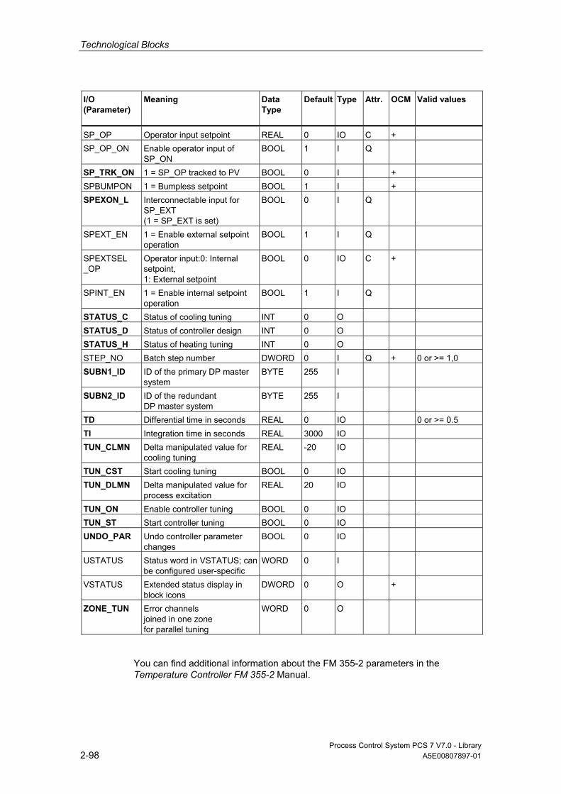
Technological Blocks
Process Control System PCS 7 V7.0 - Library 2-98 A5E00807897-01
I/O (Parameter)
Meaning
Data Type
Default Type
Attr.
OCM Valid values
SP_OP Operator input setpoint REAL 0 IO C + SP_OP_ON Enable operator input of
SP_ON BOOL 1 I Q
SP_TRK_ON 1 = SP_OP tracked to PV BOOL 0 I + SPBUMPON 1 = Bumpless setpoint BOOL 1 I + SPEXON_L Interconnectable input for
SP_EXT (1 = SP_EXT is set)
BOOL 0 I Q
SPEXT_EN 1 = Enable external setpoint operation
BOOL 1 I Q
SPEXTSEL _OP
Operator input:0: Internal setpoint, 1: External setpoint
BOOL 0 IO C +
SPINT_EN 1 = Enable internal setpoint operation
BOOL 1 I Q
STATUS_C Status of cooling tuning INT 0 O STATUS_D Status of controller design INT 0 O STATUS_H Status of heating tuning INT 0 O STEP_NO Batch step number DWORD 0 I Q + 0 or >= 1,0 SUBN1_ID ID of the primary DP master
system BYTE 255 I
SUBN2_ID ID of the redundant DP master system
BYTE 255 I
TD Differential time in seconds REAL 0 IO 0 or >= 0.5 TI Integration time in seconds REAL 3000 IO TUN_CLMN Delta manipulated value for
cooling tuning REAL -20 IO
TUN_CST Start cooling tuning BOOL 0 IO TUN_DLMN Delta manipulated value for
process excitation REAL 20 IO
TUN_ON Enable controller tuning BOOL 0 IO TUN_ST Start controller tuning BOOL 0 IO UNDO_PAR Undo controller parameter
changes BOOL 0 IO
USTATUS Status word in VSTATUS; can be configured user-specific
WORD 0 I
VSTATUS Extended status display in block icons
DWORD 0 O +
ZONE_TUN Error channels joined in one zone for parallel tuning
WORD 0 O
You can find additional information about the FM 355-2 parameters in the Temperature Controller FM 355-2 Manual.

Technological Blocks
Process Control System PCS 7 V7.0 - Library A5E00807897-01 2-99
2.1.9.17 Message Texts and Associated Values of FMT_PID
Assignment of Message Text and Message Class to the Block Parameters
Message No. Block Parameter Default Message Text Message Class Can be Suppressed By
1 QPERAF/QMODF @6%d@/@7%d@/@8%d@ controller channel error @5%d@
S -
2 QPARF_FM @6%d@/@7%d@/@8%d@ controller channel configuration error @5%d@
S -
3 no message - 4 no message - 5 QH_ALM $$BlockComment$$
alarm high AH M_SUP_AL,
MSG_LOCK, 6 QH_WRN $$BlockComment$$
warning high WH M_SUP_ER,
MSG_LOCK, 7 QL_WRN $$BlockComment$$
warning low WL M_SUP_ER,
MSG_LOCK, 8 QL_ALM $$BlockComment$$
alarm low AL M_SUP_AL,
MSG_LOCK
Assignment of Associated Values to the Block Parameters The first three of the associated values of the message block are assigned SIMATIC BATCH data, the fourth is reserved for the actual value and the fifth for the controller channel ID. The remaining associated values can be freely assigned by the user.
Associated Value Block Parameter
1 BA_NA 2 STEP_NO 3 BA_ID 4 PV 5 CHANNEL 6 SUBNET_ID 7 RACK_NO 8 SLOT_NO 9 AUX_PR09 10 AUX_PR10

Technological Blocks
Process Control System PCS 7 V7.0 - Library 2-100 A5E00807897-01
2.1.9.18 VSTATUS for FMT_PID
The 32-bit status word extends the status display in the block icons and faceplates. The 16 low bits (bits 0 - 15) are used by the block as follows:
Bit no.: 7 6 5 4 3 2 1 0
Parameters - - - QSPEXTON QMAN_AUT MSG_LOCK BA_EN OCCUPIED
Bit no.: 15 14 13 12 11 10 9 8
Parameters OOS QMSG_SUP - - - - - -
The 16-bit input USTATUS (data type WORD) uses the high bits (bits 16 - 31). You can use these bits as you wish.
2.1.9.19 Operating and Monitoring of FMT_PID
Additional information You can find additional information in the following sections:
• Block Icon FMT_PID
• Faceplate FMT PID
Note: Online help and the "PCS 7 FACEPLATES" Manual are only available if the "PCS 7 FACEPLATES" software package is installed!

Technological Blocks
Process Control System PCS 7 V7.0 - Library A5E00807897-01 2-101
2.1.10 INT_P: Integration
2.1.10.1 Description of INT_P
Object name (type + number) FB40
Function Forms the time integral of the connected input value:
v(s) = 1 / (TI * s) * u(s)
Operating principle Block INT_P functions by means of sum generation in accordance with the trapezoid rule per sampling interval (SAMPLE_T). The result, V internal, lies within the range V_HL - hyst to V_LL + hyst, as you can see in the figure. Subsequently the value is written to the output V after an additional limitation to between V_LL and V_HL.
Jump response of the INT_P
In addition, the internal result V internal is monitored for violation of the limits V_LL and V_HL and displayed via the Boolean outputs QVLL and QVHL, as you can see in the figure.

Technological Blocks
Process Control System PCS 7 V7.0 - Library 2-102 A5E00807897-01
Calling OBs This is the watchdog alarm OB into which you install the block (for example, OB32) and OB100.
Error handling Apart from the errors recognized by the operating system, the following configuration errors are also indicated by the block algorithm via ENO = 0 and QERR = 1:
• V_LL ≥ V_HL (V = 0)
• SAMPLE_T ≤ 0 (calculation is continued internally with the substitute value = 1)
• Hysteresis HYS < 0 (calculation is continued internally with the substitute value = 1)
If TI = 0 then V = 0, if the value is within the limits of V_LL and V_HL, otherwise V = limit value
Limit monitoring of the INT_P
Startup Characteristics If the input parameter RESET = TRUE, the internal historical process data as well as the output V are reset during startup. The historical process data is retained if RESET = FALSE. The block must therefore additionally be called from the startup OB (OB100).

Technological Blocks
Process Control System PCS 7 V7.0 - Library A5E00807897-01 2-103
Dynamic Response The block must be installed in a watchdog interrupt OB.
INT_P structure
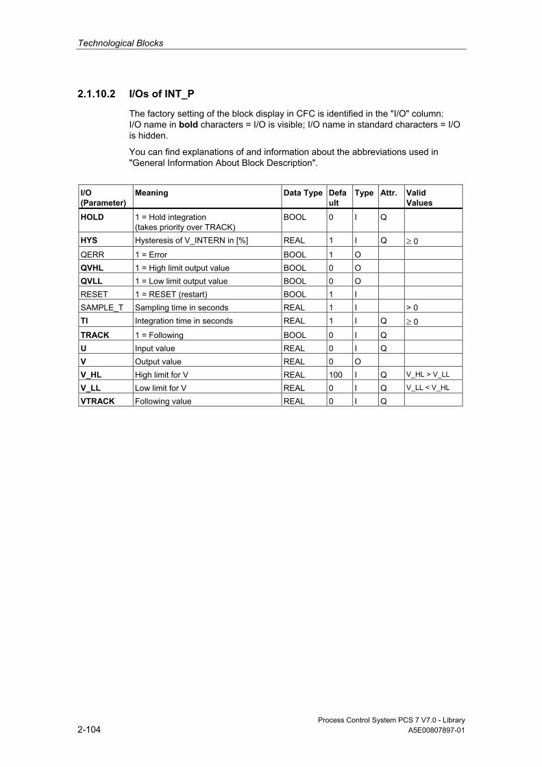
Technological Blocks
Process Control System PCS 7 V7.0 - Library 2-104 A5E00807897-01
2.1.10.2 I/Os of INT_P
The factory setting of the block display in CFC is identified in the "I/O" column: I/O name in bold characters = I/O is visible; I/O name in standard characters = I/O is hidden.
You can find explanations of and information about the abbreviations used in "General Information About Block Description".
I/O (Parameter)
Meaning
Data Type
Default
Type
Attr.
Valid Values
HOLD 1 = Hold integration (takes priority over TRACK)
BOOL 0 I Q
HYS Hysteresis of V_INTERN in [%] REAL 1 I Q ≥ 0 QERR 1 = Error BOOL 1 O QVHL 1 = High limit output value BOOL 0 O QVLL 1 = Low limit output value BOOL 0 O RESET 1 = RESET (restart) BOOL 1 I SAMPLE_T Sampling time in seconds REAL 1 I > 0 TI Integration time in seconds REAL 1 I Q ≥ 0 TRACK 1 = Following BOOL 0 I Q U Input value REAL 0 I Q V Output value REAL 0 O V_HL High limit for V REAL 100 I Q V_HL > V_LL
V_LL Low limit for V REAL 0 I Q V_LL < V_HL
VTRACK Following value REAL 0 I Q
Technological Blocks
Process Control System PCS 7 V7.0 - Library A5E00807897-01 2-105
2.1.11 MEANTM_P: Zeitliche Mittelwertbildung
2.1.11.1 Description of MEANTM_P
Object name (type + number) FB42
Function Block MEANTM_P is used to calculate a mean time value of an analog input signal across a configurable past time period, in accordance with the equation:
Vn = ( U1 + U2 +...+Un) / n
where U1...Un are the detected values used for averaging.
Operating principle During every execution of the block the arithmetic mean value is calculated from the current input value U and the values saved during the time T_WINDOW. This is then updated at the output V. The current input value then overwrites the oldest historical process data.
• The time window across which averaging is to be carried out is entered in the parameter T_WINDOW.
• The block determines the number n of values to be saved from the integer part of the quotient T_WINDOW / SAMPLE_T.
• The block can save a maximum of 20 historical process variables internally. A data reduction is carried out in case of a longer time window.
• The STOP_RES input has the following effect:
- If STOP_RES = "1", the calculation process is stopped. The output value remains unchanged for the period.
- The mean time value calculation is reset by a falling edge 1 → 0.
• If SAMPLE_T or T_WINDOW is changed, the mean time value is reset.
Note
T_WINDOW and SAMPLE_T must be parameterized in such a way that the quotient T_WINDOW / SAMPLE_T is not greater than 32748.

Technological Blocks
Process Control System PCS 7 V7.0 - Library 2-106 A5E00807897-01
Calling OBs This is the watchdog alarm OB into which you install the block (for example, OB32).
Error handling Only by means of the operating system.
Startup Characteristics n.a.
If the block was active before the CPU stop, and continues to calculate afterwards, the CPU out-time relative to T_WINDOW has to be taken into consideration. This allows you to decide whether the result can still be used or whether the calculation process has to be reset via the input STOP_RES.
Dynamic Response The block must be called from a watchdog interrupt OB.
2.1.11.2 I/Os of MEANTM_P
The factory setting of the block display in CFC is identified in the "I/O" column: I/O name in bold characters = I/O is visible; I/O name in standard characters = I/O is hidden.
You can find explanations of and information about the abbreviations used in "General Information About Block Description".
I/O (Parameter)
Meaning
Data Type
Default Type
Attr.
Valid Values
QERR 1 = error BOOL 1 O SAMPLE_T Sampling time in seconds REAL 1.0 I >0 STOP_RES Stop/reset mean value calculation BOOL 0 I Q T_WINDOW Size of the time window in seconds REAL 20 I U Input value REAL 0 I Q V Output value REAL 0 O

Technological Blocks
Process Control System PCS 7 V7.0 - Library A5E00807897-01 2-107
2.1.12 MEAS_MON: Measured-Value Monitoring
2.1.12.1 Description of MEAS_MON
Object name (type + number) FB65
*)
*)
*) Online help is only available if the "PCS 7 FACEPLATES" software package is installed!
Function Block MEAS_MON is used to monitor a measured value (analog signal) with regard to the limit pairs:
• warning limit (high/low)
• alarm limit (high/low)
Operating principle The block monitors the measured value at input U. The high or low transgression of a limit is indicated at a corresponding output and signaled if applicable. Further information is available in the "Message response" section.
Calling OBs The calling OB is in the same OB and after the block whose measured value is to be monitored, and also in OB100.
Error handling In the event of arithmetical errors the outputs ENO = 0 and QERR = 1 will be set.
Startup Characteristics After startup, the messages will be suppressed during the number of cycles set at RUNUPCYC.
Dynamic Response No dynamic response. The block is to run in the same runtime group (see CFC) with the measured-value producer.

Technological Blocks
Process Control System PCS 7 V7.0 - Library 2-108 A5E00807897-01
Assignment of the 32-Bit Status Word VSTATUS You can find additional information in "VSTATUS for MEAS_MON".
Message response The MEAS_MON block uses the ALARM_8P block to generate messages.
The following message triggers exist:
• the functions for monitoring the measured value limits
• the CSF signal, which is referenced as a control system error by interconnection
Messages regarding limit infringements can be suppressed individually via the corresponding M_SUP_xx inputs. The process messages (not process control messages!) can be completely blocked with MSG_LOCK.
QMSG_SUP is set if the RUNUPCYC cycles since restart have not yet elapsed or MSG_LOCK = TRUE or MSG_STAT = 21.
Monitoring of Process Values n.a.
Additional information Additional information is available in the sections:
I/Os of MEAS_MON
Message Texts and Associated Values of MEAS_MON
VSTATUS for MEAS_MON
Operating and Monitoring of MEAS_MON

Technological Blocks
Process Control System PCS 7 V7.0 - Library A5E00807897-01 2-109
2.1.12.2 I/Os of MEAS_MON
The factory setting of the block display in CFC is identified in the "I/O" column: I/O name in bold characters = I/O is visible; I/O name in standard characters = I/O is hidden.
You can find explanations of and information about the abbreviations used in "General Information About Block Description".
I/O (Parameter)
Meaning
Data Type
Default Type
Attr.
OCM Valid Values
AUX_PRx Associated value x ANY 0 IO Q BA_EN Release by BATCH BOOL 0 I Q + BA_ID BATCH: current batch number DWORD 0 I Q + BA_NA Batch name STRING
[32] 0 I Q +
CSF Control System Fault BOOL 0 I Q HYS Hysteresis REAL 5 I + ≥ 0 M_SUP_AH 1 = suppress HL alarm BOOL 0 I + M_SUP_AL 1 = suppress LL alarm BOOL 0 I + M_SUP_WH 1 = suppress HL warning BOOL 0 I + M_SUP_WL 1 = suppress LL warning BOOL 0 I + MO_PVHR High display limit
(measuring range) - only for OS REAL 110 I +
MO_PVLR Low display limit (measuring range) - only for OS
REAL -10 I +
MSG_ACK Message acknowledged WORD 0 O MSG_EVID Message number DWORD 0 I M MSG_LOCK 1 = Process messages locked BOOL 0 I Q + MSG_STAT Error message status WORD 0 O OCCUPIED ID for occupied by BATCH BOOL 0 I Q + OOS Reserve BOOL 0 I + QC_U Quality Code for U BYTE 16#80 I QERR 1 = Error output (inverted ENO) BOOL 1 O + QH_ALM 1 = HL alarm triggered BOOL 0 O QH_WRN 1 = HL warning triggered BOOL 0 O QL_ALM 1 = LL alarm triggered BOOL 0 O QL_WRN 1 = LL warning triggered BOOL 0 O QMSG_ERR 1 = Message error BOOL 0 O + QMSG_SUP 1 = Set message suppression BOOL 0 O + RUNUPCYC Number of run-up cycles INT 3 I STEP_NO Batch step number DWORD 0 I Q + U Analog input (measured value) REAL 0 I Q + U_AH HL alarm REAL 100 I + U_AH>U_
WH
U_AL LL alarm REAL 0 I + U_AL<U_WL

Technological Blocks
Process Control System PCS 7 V7.0 - Library 2-110 A5E00807897-01
I/O (Parameter)
Meaning
Data Type
Default Type
Attr.
OCM Valid Values
U_WH HL warning REAL 95 I + U_AH>U_WH > U_WL
U_WL LL warning REAL 5 I + U_WH>U_WL > U_AL
USTATUS Status word in VSTATUS; definable by user
WORD 0 I
VSTATUS Extended status display in block icons
DWORD 0 O +
2.1.12.3 Message Texts and Associated Values of MEAS_MON
Assignment of Message Text and Message Class to the Block Parameters
Message No.
Block Parameter
Default Message Text Message Class
Can Be Suppressed By
1 QH_ALM $$BlockComment$$ alarm high
AH M_SUP_AH, MSG_LOCK
2 QH_WRN $$BlockComment$$ warning high
WH M_SUP_WH, MSG_LOCK
3 QL_WRN $$BlockComment$$ warning low
WL M_SUP_WL, MSG_LOCK
4 QL_ALM $$BlockComment$$ alarm low
AL M_SUP_AL, MSG_LOCK
5 CSF $$BlockComment$$ External error
S -

Technological Blocks
Process Control System PCS 7 V7.0 - Library A5E00807897-01 2-111
Assignment of Associated Values to the Block Parameters The first three of the associated values of the message block are assigned SIMATIC BATCH data, the fourth is reserved for U and the remaining ones (AUX_PRx) can be freely assigned by the user.
Associated Value Block Parameter
1 BA_NA 2 STEP_NO 3 BA_ID 4 U 5 AUX_PR05 6 AUX_PR06 7 AUX_PR07 8 AUX_PR08 9 AUX_PR09 10 AUX_PR10
2.1.12.4 VSTATUS for MEAS_MON
The 32-bit status word extends the status display in the block icons and faceplates. The 16 low bits (bits 0 - 15) are used by the block as follows:
Bit no.: 7 6 5 4 3 2 1 0
Parameters - - - MSG_LOCK BA_EN OCCUPIED
Bit no.: 15 14 13 12 11 10 9 8
Parameters OOS QMSG_SUP - - - - - -
The 16-bit input USTATUS (data type WORD) uses the high bits (bits 16 - 31). You can use these bits as you wish.
2.1.12.5 Operating and Monitoring of MEAS_MON
Additional information You can find additional information in the following sections:
• Block Icon MEAS_MON
• Faceplate MEAS_MON
Note: Online help and the "PCS 7 FACEPLATES" Manual are only available if the "PCS 7 FACEPLATES" software package is installed!

Technological Blocks
Process Control System PCS 7 V7.0 - Library 2-112 A5E00807897-01
2.1.13 POLYG_P: Polygon with a maximum of 8 points
2.1.13.1 Description of POLYG_P
Object name (type + number) FC 271
Function An input U is converted to output V in accordance with a non-linear characteristic curve and with a maximum of 8 time slices.
Operating principle After the N time slices have been specified (pairs of coordinates Ui,Vi with i = 1...N in continuous sequence) and the configuration of the number N has been carried out, the block operates as follows:
• linear interpolation between points
• extrapolation outside the last two points on the basis of the first two or the last two points
Characteristic curve representation
Calling OBs The OB in which the block is installed.

Technological Blocks
Process Control System PCS 7 V7.0 - Library A5E00807897-01 2-113
Error handling ENO = 0 and V = U are output if the following conditions are met:
• the number of time slices N < 2 or N > 8
• Ui > Ui + 1 for i = 1,2...N - 1
2.1.13.2 I/Os of POLYG_P
The factory setting of the block display in CFC is identified in the "I/O" column: I/O name in bold characters = I/O is visible; I/O name in standard characters = I/O is hidden.
You can find explanations of and information about the abbreviations used in "General Information About Block Description".
I/O (Parameter)
Meaning
Data Type
Default Type Attr.
OCM
Valid Values
N Number of time slices INT 0 I 2 ≤ N ≤ 8 U Input REAL 0.0 I Q U1 U value of time slice 1 REAL 0.0 I Q U2 U value of time slice 2 REAL 0.0 I Q ... ... ... ... ... ... U8 U value of time slice 8 REAL 0.0 I Q V1 V value of time slice V 1 REAL 0.0 I Q V2 V value of time slice V 2 REAL 0.0 I Q ... ... ... ... ... ... V8 V value of time slice V 8 REAL 0.0 I Q V Output value REAL 0.0 O
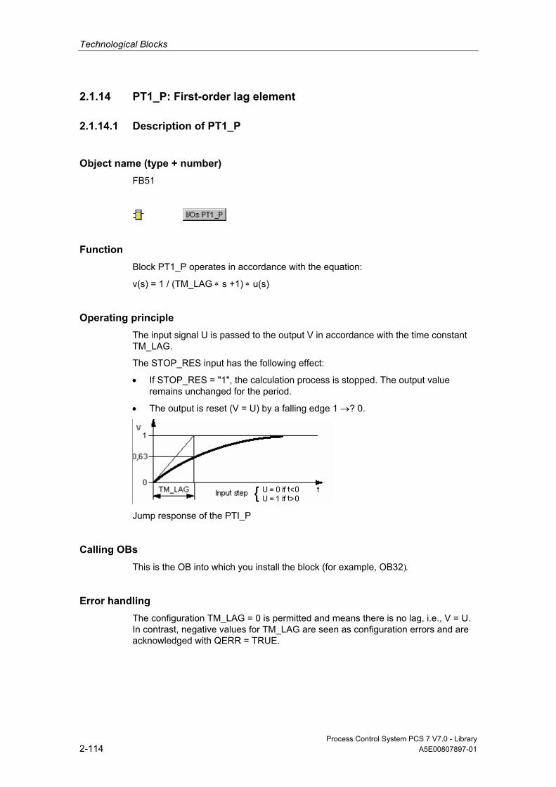
Technological Blocks
Process Control System PCS 7 V7.0 - Library 2-114 A5E00807897-01
2.1.14 PT1_P: First-order lag element
2.1.14.1 Description of PT1_P
Object name (type + number) FB51
Function Block PT1_P operates in accordance with the equation:
v(s) = 1 / (TM_LAG ∗ s +1) ∗ u(s)
Operating principle The input signal U is passed to the output V in accordance with the time constant TM_LAG.
The STOP_RES input has the following effect:
• If STOP_RES = "1", the calculation process is stopped. The output value remains unchanged for the period.
• The output is reset (V = U) by a falling edge 1 →? 0.
Jump response of the PTI_P
Calling OBs This is the OB into which you install the block (for example, OB32).
Error handling The configuration TM_LAG = 0 is permitted and means there is no lag, i.e., V = U. In contrast, negative values for TM_LAG are seen as configuration errors and are acknowledged with QERR = TRUE.

Technological Blocks
Process Control System PCS 7 V7.0 - Library A5E00807897-01 2-115
2.1.14.2 I/Os of PT1_P
The factory setting of the block display in CFC is identified in the "I/O" column: I/O name in bold characters = I/O is visible; I/O name in standard characters = I/O is hidden.
You can find explanations of and information about the abbreviations used in "General Information About Block Description".
I/O (Parameter)
Meaning
Data Type
Default Type
Attr.
Valid Values
QERR 1 = Error BOOL 1 O SAMPLE_T Sampling time in seconds REAL 1.0 I >0 STOP_RES Stop/Reset PT1 function BOOL 0 I Q TM_LAG Length of time constant REAL 0.0 I >0 U Input value REAL 0.0 I Q V Output value REAL 0.0 O
Technological Blocks
Process Control System PCS 7 V7.0 - Library 2-116 A5E00807897-01
2.1.15 RAMP_P: Ramp structure
2.1.15.1 Description of RAMP_P
Object name (type + number) FB52
Function Limitation of the ramp of an analog signal
Operating principle The block calculates the ramp of the input signal dU/dt and compares it with the two limits URLM for positive changes or DRLM for negative changes (refer to the table below).
• If the ramp (as a quantity) exceeds the respective maximum ramp (URLM or DRLM), the output V is only changed by the permitted rate and the corresponding limitation display QLIM_U or QLIM_D is set.
• If the ramp lies within the valid range, the input value is passed through (U = V) and the values QLIM_U and QLIM_D are reset.
• If the input RATE_OFF=1, the ramp generation is disabled, so that V = U and QLIM_U = QLIM_D = 0.
RATE_OFF dU/dt Meaning Output V QLIM_D QLIM_U
0 < - DRLM Input value drops too rapidly V-(DRLM * SAMPLE_T) 1 0 0 - DRLM to
URLM Change speed is permitted U 0 0
0 > URLM Input value U rises too rapidly
V+(URLM * SAMPLE_T) 0 1
1 No meaning Ramp disabled U 0 0
Calling OBs This is the watchdog alarm OB into which you install the block (for example, OB32) and OB100.
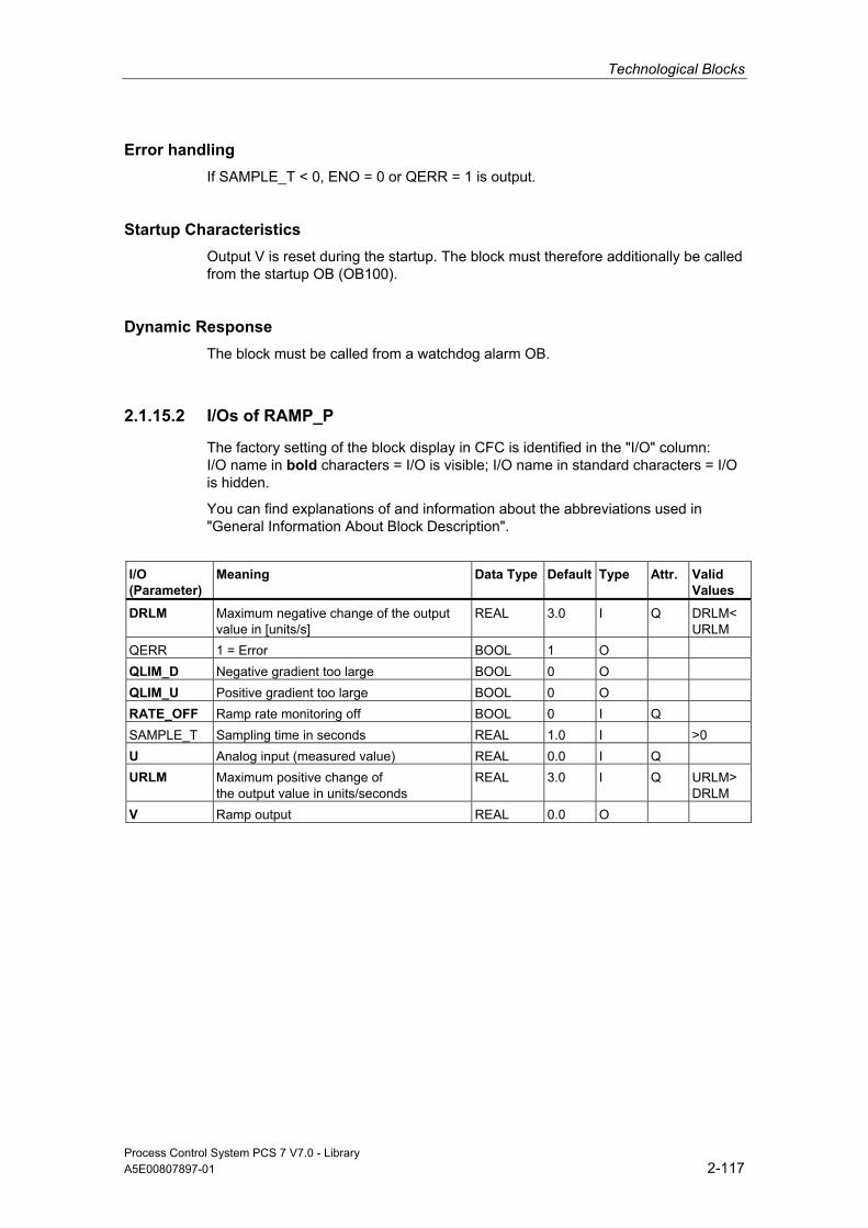
Technological Blocks
Process Control System PCS 7 V7.0 - Library A5E00807897-01 2-117
Error handling If SAMPLE_T < 0, ENO = 0 or QERR = 1 is output.
Startup Characteristics Output V is reset during the startup. The block must therefore additionally be called from the startup OB (OB100).
Dynamic Response The block must be called from a watchdog alarm OB.
2.1.15.2 I/Os of RAMP_P
The factory setting of the block display in CFC is identified in the "I/O" column: I/O name in bold characters = I/O is visible; I/O name in standard characters = I/O is hidden.
You can find explanations of and information about the abbreviations used in "General Information About Block Description".
I/O (Parameter)
Meaning
Data Type
Default Type
Attr.
Valid Values
DRLM Maximum negative change of the output value in [units/s]
REAL 3.0 I Q DRLM< URLM
QERR 1 = Error BOOL 1 O QLIM_D Negative gradient too large BOOL 0 O QLIM_U Positive gradient too large BOOL 0 O RATE_OFF Ramp rate monitoring off BOOL 0 I Q SAMPLE_T Sampling time in seconds REAL 1.0 I >0 U Analog input (measured value) REAL 0.0 I Q URLM Maximum positive change of
the output value in units/seconds REAL 3.0 I Q URLM>
DRLM V Ramp output REAL 0.0 O
Technological Blocks
Process Control System PCS 7 V7.0 - Library 2-118 A5E00807897-01
2.1.16 RATIO_P: Ratio control
2.1.16.1 Description of RATIO_P
Object name (type + number) FB70
*)
*)
*) Online help is only available if the "PCS 7 FACEPLATES" software package is installed!
Function The block is used to create a ratio, e.g., in a ratio control. It is also used to set elements (for example, synchronization control loop), or to influence the reference variable of a cascade.
Operating principle The RATIO_P block operates in accordance with the equation: V = U1 * U2 + BIAS U1 is derived by interconnection while U2 is selected dependent on the internal/external operating mode.
Internal/External Changeover The operating mode is selected by the following measures and indicated at the output QIN_EX:
• Operation of the input IN_EX, when L_IE_ON = 0 and the enable signals IN_OP_EN and EX_OP_EN are valid.
• interconnection of L_IN_EX, if L_IE_ON = 1
Internal: The parameter U2 in the formula is specified by operator control and, after limiting to (U2_LL, U2_HL), incorporated in the formula. Operator control must have been enabled at U2_OP_EN.
External: The parameter U2 is specified by interconnecting the input U2_EXT and, after limiting to (U2_LL, U2_HL), incorporated in the formula. The controllable input U2 is tracked to U2_EXT in order to enable smooth changeover to "internal".
Calling OBs Block RATIO_P is installed in the OB which contains the block that utilizes the result. Block RATIO_P must be installed upstream of this block (first calculate, then utilize).

Technological Blocks
Process Control System PCS 7 V7.0 - Library A5E00807897-01 2-119
Error handling Arithmetic errors are indicated by ENO = 0 or QERR = 1. Operator errors are displayed as a group at output QOP_ERR.
Startup Characteristics No special measures.
Dynamic Response If the result for the blocks with dynamic response is relevant (for example, ratio control, synchro control), the block should be installed in the same OB, upstream of these blocks.
Assignment of the 32-Bit Status Word VSTATUS You can find additional information in "VSTATUS for RATIO_P".
Message response n.a.
Monitoring of Process Values n.a.
Additional information Additional information is available in the sections:
I/Os of RATIO_P
VSTATUS for RATIO_P
Operating and Monitoring of RATIO_P
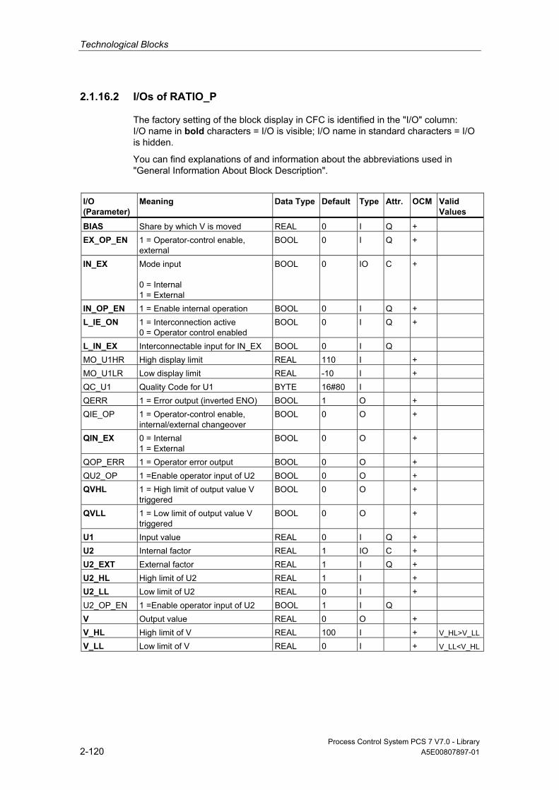
Technological Blocks
Process Control System PCS 7 V7.0 - Library 2-120 A5E00807897-01
2.1.16.2 I/Os of RATIO_P
The factory setting of the block display in CFC is identified in the "I/O" column: I/O name in bold characters = I/O is visible; I/O name in standard characters = I/O is hidden.
You can find explanations of and information about the abbreviations used in "General Information About Block Description".
I/O (Parameter)
Meaning Data Type
Default Type
Attr.
OCM Valid Values
BIAS Share by which V is moved REAL 0 I Q + EX_OP_EN 1 = Operator-control enable,
external BOOL 0 I Q +
IN_EX Mode input 0 = Internal 1 = External
BOOL 0 IO C +
IN_OP_EN 1 = Enable internal operation BOOL 0 I Q + L_IE_ON 1 = Interconnection active
0 = Operator control enabled BOOL 0 I Q +
L_IN_EX Interconnectable input for IN_EX BOOL 0 I Q MO_U1HR High display limit REAL 110 I + MO_U1LR Low display limit REAL -10 I + QC_U1 Quality Code for U1 BYTE 16#80 I QERR 1 = Error output (inverted ENO) BOOL 1 O + QIE_OP 1 = Operator-control enable,
internal/external changeover BOOL 0 O +
QIN_EX 0 = Internal 1 = External
BOOL 0 O +
QOP_ERR 1 = Operator error output BOOL 0 O + QU2_OP 1 =Enable operator input of U2 BOOL 0 O + QVHL 1 = High limit of output value V
triggered BOOL 0 O +
QVLL 1 = Low limit of output value V triggered
BOOL 0 O +
U1 Input value REAL 0 I Q + U2 Internal factor REAL 1 IO C + U2_EXT External factor REAL 1 I Q + U2_HL High limit of U2 REAL 1 I + U2_LL Low limit of U2 REAL 0 I + U2_OP_EN 1 =Enable operator input of U2 BOOL 1 I Q V Output value REAL 0 O + V_HL High limit of V REAL 100 I + V_HL>V_LL
V_LL Low limit of V REAL 0 I + V_LL<V_HL
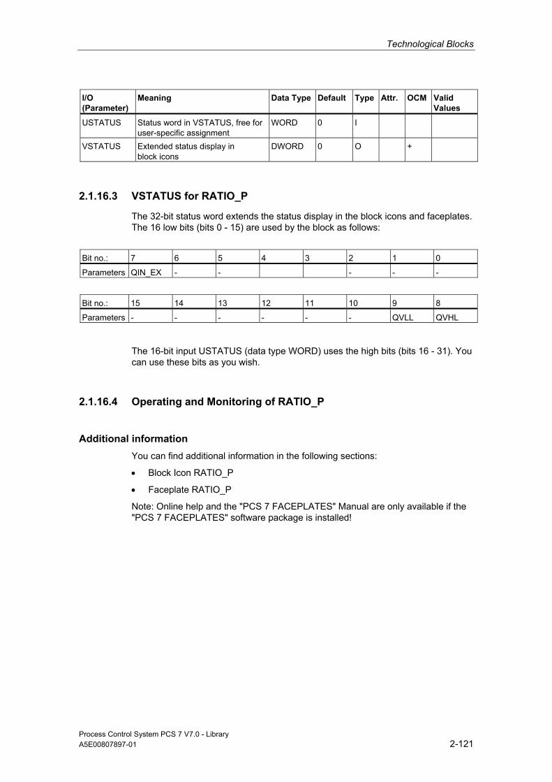
Technological Blocks
Process Control System PCS 7 V7.0 - Library A5E00807897-01 2-121
I/O (Parameter)
Meaning Data Type
Default Type
Attr.
OCM Valid Values
USTATUS Status word in VSTATUS, free for user-specific assignment
WORD 0 I
VSTATUS Extended status display in block icons
DWORD 0 O +
2.1.16.3 VSTATUS for RATIO_P
The 32-bit status word extends the status display in the block icons and faceplates. The 16 low bits (bits 0 - 15) are used by the block as follows:
Bit no.: 7 6 5 4 3 2 1 0
Parameters QIN_EX - - - - -
Bit no.: 15 14 13 12 11 10 9 8
Parameters - - - - - - QVLL QVHL
The 16-bit input USTATUS (data type WORD) uses the high bits (bits 16 - 31). You can use these bits as you wish.
2.1.16.4 Operating and Monitoring of RATIO_P
Additional information You can find additional information in the following sections:
• Block Icon RATIO_P
• Faceplate RATIO_P
Note: Online help and the "PCS 7 FACEPLATES" Manual are only available if the "PCS 7 FACEPLATES" software package is installed!

Technological Blocks
Process Control System PCS 7 V7.0 - Library 2-122 A5E00807897-01
2.1.17 READ355P: Read digital and analog inputs from FM 355
2.1.17.1 Description of READ355P
Object name (type + number) FB72
Function Block READ355P is used to read the digital and analog inputs of an FM 355 or FM355-2 module.
Dependencies Once the driver generator is complete, this block - along with blocks FMCS_PID and FMT_PID - is in a block chain controlled by FM_CO.
You can find additional information in the description of FM_CO.
Use in CFC When the CFC function "Generate module drivers" is used, the following occurs automatically:
• The parameter CO_NO is parameterized
• The input EN_CO is connected to the output EN_CO_x of the FM_CO block (x = number of the rack)
• The output ENCO is connected to the input ENCOx_yy of the FM_CO block (x = number of the rack, yy = coordination number)
Operating principle If the in/out parameter EN_CO.CO_ACT = CO_NO is set, the block begins to determine the following values by data set reading (SFC RED_REC):
• The CJ_TEMP parameter contains the cold junction temperature measured at the cold junction in degrees C or in degrees F (depending on the selected temperature unit). If no "thermocouple" sensor type was selected or if the set cold junction temperature was selected for all analog inputs with "thermocouple" sensor type, the CJ_TEMP parameter has the value "0.0".
• The parameters DI_0 through DI_7 indicate the actual status of the digital inputs 0 through 7.

Technological Blocks
Process Control System PCS 7 V7.0 - Library A5E00807897-01 2-123
• The parameters PV_PER_0 through PV_PER_3 indicate the value of the analog inputs 0 through 3 in the unit mA or mV.
• The parameters PV_PHY_0 through PV_PHY_3 indicate the preprocessed analog input value 0 through 3 in the physical unit mA or mV.
Startup Characteristics n.a.
Dynamic Response n.a.
Message response n.a.
Additional information Additional information is available in the sections:
Addressing
I/Os of READ355P
2.1.17.2 Addressing
You address the controller channel of an FM 355 belonging to the instance using the logical base address (set with HW Config, LADDR input).
The FM 355 module is monitored with the blocks of the PCS 7 Library. The input MODE is connected to the output OMODE of the block MOD_D1. Since the block communicates with the FM 355 only over read data record, the part of the measurement range coding in the low word of the OMODE output is irrelevant and is set to zero here.

Technological Blocks
Process Control System PCS 7 V7.0 - Library 2-124 A5E00807897-01
2.1.17.3 I/Os of READ355P
The factory setting of the block display in CFC is identified in the "I/O" column: I/O name in bold characters = I/O is visible; I/O name in standard characters = I/O is hidden.
You can find explanations of and information about the abbreviations used in "General Information About Block Description".
I/O (Parameter)
Meaning
Data Type
Default
Type
Attr.
OCM
Valid Values
CJ_TEMP Cold junction temperature measured at the cold junction
REAL 0 O
CO_NO Cold junction temperature measured at the cold junction
INT 0 O
DI_x Digital input (x = 0 through 7) BOOL 0 O EN_CO Current coordination number STRUCT ENCO Coordination number BOOL 0 IO LADDR Logical address FM 355 INT 0 I MODE Operating Mode DWORD 0 I PV_PER_x Analog input (x = 0 through 3) REAL 0 O PV_PHY_x Physical analog input (x = 0
through 3) REAL 0 O
QDONE 1 = Parameter read BOOL 0 O QMODF 1 = Module fault BOOL 0 O RET_VALU Return value SFC59 INT 0 O
2.1.18 SPLITR_P: Split Range
2.1.18.1 Description of SPLITR_P
Object name (type + number) FC 272
Function Together with a controller block the block is used to implement a split-range control.

Technological Blocks
Process Control System PCS 7 V7.0 - Library A5E00807897-01 2-125
Operating principle The block is installed in the run sequence downstream of the controller block. The controller output of the controller block is interconnected with the input U of the SPLITR_P block. The neutral position and the dead band zone are set by means of the corresponding parameters. V1 and V2 are adapted to the physical variable by configuring the high/low limits of V1 and V2. The transfer characteristics have the following appearance:
Transfer characteristics of the SPLITR_P
Calling OBs The OB in which the controller block runs whose manipulated variable is processed.
Error handling ENO = 0 is output at the following errors:
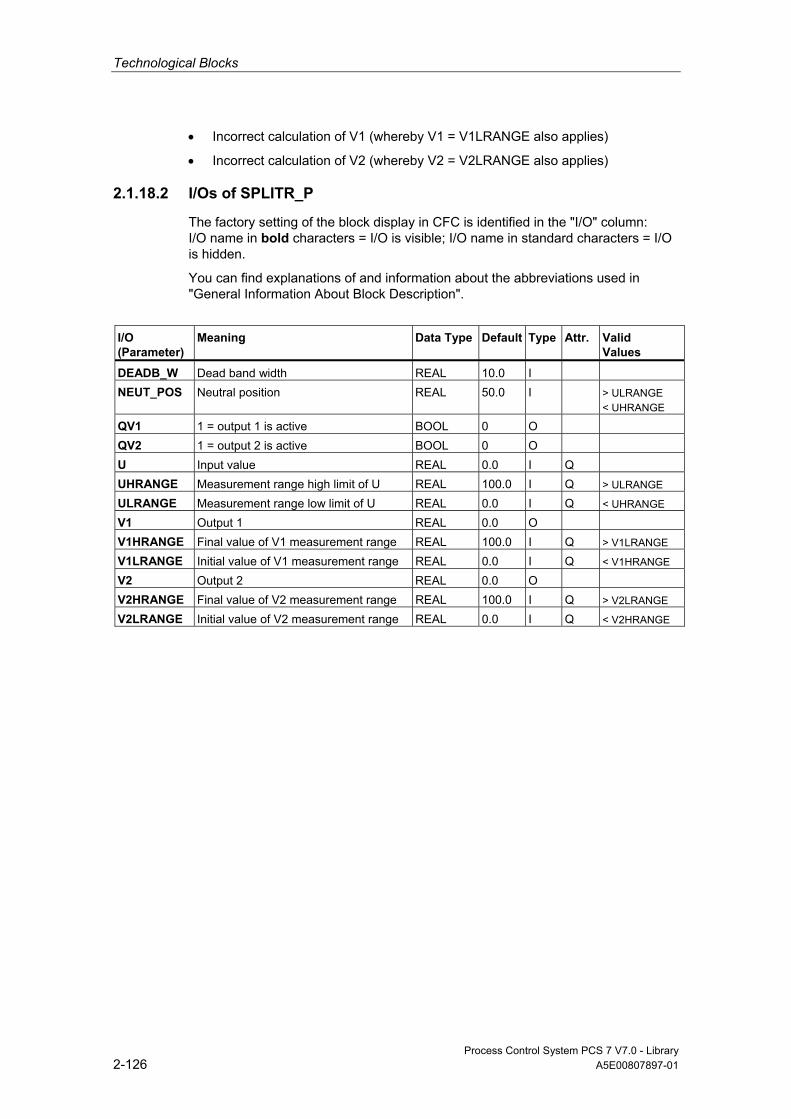
Technological Blocks
Process Control System PCS 7 V7.0 - Library 2-126 A5E00807897-01
• Incorrect calculation of V1 (whereby V1 = V1LRANGE also applies)
• Incorrect calculation of V2 (whereby V2 = V2LRANGE also applies)
2.1.18.2 I/Os of SPLITR_P
The factory setting of the block display in CFC is identified in the "I/O" column: I/O name in bold characters = I/O is visible; I/O name in standard characters = I/O is hidden.
You can find explanations of and information about the abbreviations used in "General Information About Block Description".
I/O (Parameter)
Meaning
Data Type
Default Type
Attr.
Valid Values
DEADB_W Dead band width REAL 10.0 I NEUT_POS Neutral position REAL 50.0 I > ULRANGE
< UHRANGE
QV1 1 = output 1 is active BOOL 0 O
QV2 1 = output 2 is active BOOL 0 O
U Input value REAL 0.0 I Q
UHRANGE Measurement range high limit of U REAL 100.0 I Q > ULRANGE
ULRANGE Measurement range low limit of U REAL 0.0 I Q < UHRANGE
V1 Output 1 REAL 0.0 O
V1HRANGE Final value of V1 measurement range REAL 100.0 I Q > V1LRANGE
V1LRANGE Initial value of V1 measurement range REAL 0.0 I Q < V1HRANGE
V2 Output 2 REAL 0.0 O
V2HRANGE Final value of V2 measurement range REAL 100.0 I Q > V2LRANGE
V2LRANGE Initial value of V2 measurement range REAL 0.0 I Q < V2HRANGE

Technological Blocks
Process Control System PCS 7 V7.0 - Library A5E00807897-01 2-127
2.2 Motor and Valve
2.2.1 MOT_REV: Reversing Motor
2.2.1.1 Description of MOT_REV
Object name (type + number) FB67
*)
*)
*) Online help is only available if the "PCS 7 FACEPLATES" software package is installed!
Function The block is used to drive motors with 2 directions of rotation (clockwise/counterclockwise). A maximum of 2 feedback signals, which are generated by auxiliary contactors, are monitored.
Caution
With the PCS 7 it is not intended that other blocks will be inserted between the plant block and the output driver.
If you deviate from this principle, ensure that when interconnecting the block, that from the outputs of the plant block until the output driver, that all blocks that form the output signal are installed in the same OBs.
Operating principle Various inputs are available for controlling the motor. They are implemented in a concrete hierarchical dependency to each other and to the motor states. In particular the interlock, the feedback or rotary direction monitoring and the motor protective circuit-breaker influence the control signals QSTART (1: on, 0: off) and QDIR (1: counterclockwise, 0: clockwise).
The allocation of priorities to individual input variables and events with regard to their influence on the control signals is shown in the following table. The subsequent sections provide further details.

Technological Blocks
Process Control System PCS 7 V7.0 - Library 2-128 A5E00807897-01
Priority: Event:
High Motor protection fault, if MSS_OFF = 1 ⇑ Waiting time at change of rotary direction LOCK = 1 LOCK_ON = 1 (with LOCK_DIR) ⇓ Monitoring error, if FAULT_OFF = 1 Low Automatic/Manual mode No effect Motor protection fault, if MSS_OFF = 0 Monitoring error, if FAULT_OFF = 0 Control system error, operator error
Manual/Auto This changeover is carried out either by means of OS operation of AUT_ON_OP or via the interconnection at input AUT_L, provided the functions required are enabled. The set mode is indicated at output QMAN_AUT (1 = Auto, 0 = Manual).
• Manual mode: This operating mode permits control either at the OS or via interconnectable inputs.
- OS operation (LINK_MAN = 0): Either the OS: FORW_ON inputs are set for clockwise, or REV_ON for counterclockwise direction, or MOT_OFF is used to switch off. The corresponding enable parameters FW_OP_EN, RV_OP_EN or OFFOP_EN must be set.
- Operation via interconnectable inputs (LINK_MAN = 1): The commands are set via the inputs L_FORW, L_REV and L_OFF. You can interconnect these inputs to allow tracking or local control, for example. Note that you must set the switches LINK_MAN, LIOP_SEL and AUT_L by means of a suitable logic.
• Auto mode: An automatic function block interconnection is used to set the inputs AUTO_ON (1 = on, 0 = off) or AUTO_DIR (1 = counterclockwise, 0 = clockwise).
Interlock The interlock function takes priority over all other control signals and errors - with the exception of the motor protective circuit-breaker when a corresponding enable signal is set (MSS_OFF = 1) and the time monitoring function during a reversal of the rotary direction. When LOCK is set, the motor is switched off directly. The motor is switched on directly when LOCK_ON is set, provided that LOCK is not also set. LOCK_DIR is used to set the desired rotary direction at LOCK_ON = 1.

Technological Blocks
Process Control System PCS 7 V7.0 - Library A5E00807897-01 2-129
Monitoring The monitoring logic monitors the agreement between the control commands QSTART or QDIR and the process variable feedbacks FB_ON or FB_DIR and outputs the actual status via QRUN and QSTOP. It sets a monitoring error (QMON_ERR = 1) if after the period TIME_MON no feedback corresponding to QSTART or QDIR has been set, or if it changes unexpectedly without a request by QSTART or QDIR.
If there is no feedback, either QSTART can be interconnected with FB_ON and QDIR with FB_DIR or monitoring can be disabled by setting MONITOR = 0.
The FAULT_OFF parameter determines the significance of a monitoring error. If FAULT_OFF = 1, the motor is switched off when a fault occurs. This error status does not affect the control outputs when FAULT_OFF = 0.
Motor Protection At the negative edge of the motor-protection signal MSS, the motor protection error is held and passed to output QMSS_ST. The parameter MSS_OFF is used to specify whether only to indicate the error status (MSS_OFF = 0), or whether the motor is to be limited irrespective of all other inputs and system states (MSS_OFF = 1).
Bumpless Changeover In order to ensure bumpless changeover to manual mode in all operating modes, the manual values FORW_ON, REV_ON and MOT_OFF are always corrected to the current values of QSTART and QDIR (exception: change in the direction of rotation).
Reversal of the Rotary Direction If reversal of the rotary direction is selected, the following occurs:
• The motor is stopped (QSTART = 0).
• The internal OFF monitor waits for the time period TIME_OFF to expire and then starts the motor in the reverse direction, provided the OFF monitor does not report an error. It should be noted here that the TIME_OFF parameter specifies the expected time to pass before the motor actually comes to a halt, thus allowing a reversal of the rotary direction without causing damage to the motor. The motor standstill message does not reduce this time, since this message is output by the contactor relay and does not provide any information on the physical state of the motor.
Calling OBs This is the watchdog alarm OB into which you install the block (for example, OB32) and OB100.

Technological Blocks
Process Control System PCS 7 V7.0 - Library 2-130 A5E00807897-01
Error handling The motor protection error (QMSS_ST = 1) and the monitoring error (QMON_ERR = 1) are reported to the OS and influence the block operating principle as described above. The operator can either reset these states via the RESET input, or automatically at the next positive edge at MSS by interconnecting L_RESET with a "1" signal. The control system fault CSF is merely reported to the OS and applied to the group error QGR_ERR alongside with the motor protection and monitoring errors. It does not have any further influence on the block algorithm.
Operator errors are indicated at output QOP_ERR without message.
Startup After an Error State After an error state, startup depends on the operating mode set during reset:
• In automatic mode, the motor can restart after the reset, provided a corresponding start signal is supplied by the automatic mode.
• In manual mode, the motor must be switched on explicitly since manual operation had been tracked to "OFF".
Startup Characteristics When the CPU starts, the MOTOR block is switched to manual mode and the OFF command is output. A prerequisite is that the block must be called in the startup OB. In CFC engineering, this is handled by the CFC. Using the basic STEP 7 tools, you must manually enter this call in the startup OB. After startup, the messages will be suppressed during the number of cycles set at RUNUPCYC.
The START_OFF input is used to specify whether the motor controls are to be switched off when the CPU is started (START_OFF = 1) or whether the last operating state is held.
Dynamic Response The block must be called via a watchdog interrupt OB. The sampling time of the block is set in parameter SAMPLE_T.
Assignment of the 32-Bit Status Word VSTATUS You can find additional information in "VSTATUS for MOT_REV".

Technological Blocks
Process Control System PCS 7 V7.0 - Library A5E00807897-01 2-131
Message response The MOT_REV block uses the ALARM_8P block to generate messages.
The following message triggers exist:
• Control System Fault
• Motor protective circuit-breaker signals and monitoring errors (runtime error)
• the CSF signal, which is referenced by interconnection
QMSG_SUP is set if the RUNUPCYC cycles have not expired since the restart or if MSG_STAT = 21.
Monitoring of Process Values n.a.
Additional information Additional information is available in the sections:
I/Os of MOT_REV
Message Texts and Associated Values of MOT_REV
VSTATUS for MOT_REV
Operating and Monitoring of MOT_REV
2.2.1.2 I/Os of MOT_REV
The factory setting of the block display in CFC is identified in the "I/O" column: I/O name in bold characters = I/O is visible; I/O name in standard characters = I/O is hidden.
You can find explanations of and information about the abbreviations used in "General Information About Block Description".
I/O (Parameter)
Meaning
Data Type
Default Type
Attr.
OCM
Valid Values
AUT_L Interconnectable input for MANUAL/AUTO 0 = Manual 1 = Auto
BOOL 0 I Q
AUT_ON_OP Mode input 0 = Manual 1 = Auto
BOOL 0 IO C +
AUTO_DIR AUTO mode rotary direction: 1 = Anticlockwise 0 = Clockwise
BOOL 0 I Q
AUTO_ON AUTO mode: 1 = ON 0 = OFF
BOOL 0 I Q
AUTOP_EN 1 = Enable AUTO mode BOOL 1 I Q

Technological Blocks
Process Control System PCS 7 V7.0 - Library 2-132 A5E00807897-01
I/O (Parameter)
Meaning
Data Type
Default Type
Attr.
OCM
Valid Values
AUX_PRx Associated value x ANY 0 IO Q BA_EN Release by BATCH BOOL 0 I Q + BA_ID BATCH: current batch number DWORD 0 I Q + BA_NA Batch name STRING
[32] 0 I Q +
CSF Control System Fault BOOL 0 I Q FAULT_OFF 1 = Motor OFF in case of fault BOOL 1 I Q FB_DIR Feedback of rotary direction:
1 = anticlockwise, 0 = clockwise BOOL 0 I Q
FB_ON Feedback: 1 = ON BOOL 0 I Q FORW_ON 1 = Set clockwise direction BOOL 0 IO C + FW_OP_EN 1 = Enable operator input of clockwise
direction BOOL 1 I Q
L_FORW AUTO mode: 1 = set clockwise direction
BOOL 0 I Q
L_OFF AUTO mode: 1 = Motor off BOOL 0 I Q L_RESET Interconnectable RESET input BOOL 0 I Q L_REV AUTO mode: 1 = Anticlockwise rotation
ON BOOL 0 I Q
LINK_MAN 0 = Operator input enabled 1 = Manual control via L_FORW, L_REV, L_OFF
BOOL 0 I Q
LIOP_SEL Interconnectable input for manual/auto changeover (AUT_L) 1 = Interconnection is active 0 = Operator control is active
BOOL 0 I Q
LOCK 1 = Lock (OFF) BOOL 0 I Q + LOCK_DIR 1=REV, 0=FORW
1 = Clockwise, 0 = Anticlockwise BOOL 0 I Q +
LOCK_ON 1 = Lock (ON) BOOL 0 I Q + MANOP_EN 1 = Enable manual mode BOOL 1 I MONITOR Monitoring: 1 = ON BOOL 1 I Q + MOT_OFF Mode input
1 = motor off BOOL 0 IO C +
MSG_ACK Message acknowledged WORD 0 O MSG_EVID Message number DWORD 0 I M MSG_STAT Error message status WORD 0 O MSS Motor protective circuit-breaker:
(active low, i.e., 0 = Error) BOOL 1 I Q
MSS_OFF 1 = In case of MSS fault: Motor stop BOOL 1 I Q OCCUPIED ID for occupied by BATCH BOOL 0 I Q + OFFOP_EN 1 = Motor OFF BOOL 1 I Q OOS Reserve BOOL 0 I + QAUTOP 1 = Enable AUTO mode BOOL 0 O + QC_FB_DIR Quality Code for FB_DIR BYTE 16#80 I QC_FB_ON Quality Code for FB_ON BYTE 16#80 I QC_QDIR Quality Code for QDIR BYTE 16#80 O QC_QDIR_I Quality Code for output QDIR BYTE 16#80 I

Technological Blocks
Process Control System PCS 7 V7.0 - Library A5E00807897-01 2-133
I/O (Parameter)
Meaning
Data Type
Default Type
Attr.
OCM
Valid Values
QC_QSTART Quality Code for QSTART BYTE 16#80 O QC_QSTART_I Quality Code for Output QSTART BYTE 16#80 I QDIR Direction control output:
1 = anticlockwise BOOL 0 O +
QERR 1 = Error output (Inverted ENO) BOOL 1 O + QFORW_OP 1 = Enable operator input of:
set clockwise direction BOOL 0 O +
QGR_ERR 1 = Group error BOOL 0 O QMAN_AUT 0 = MANUAL
1 = AUTO BOOL 0 O +
QMANOP 1 = Enable manual mode BOOL 0 O + QMON_ERR 1 = Monitoring error BOOL 0 O + QMSG_ERR 1 = ALARM_8P error BOOL 0 O + QMSG_SUP 1 = Message suppression BOOL 0 O + QMSS_ST Unacknowledged motor protective
circuit-breaker, 1 = Error
BOOL 0 O +
QOFF_OP 1 = Motor OFF BOOL 0 O + QOP_ERR 1 = Group error BOOL 0 O QREV_OP 1 = Enable operator input of:
set clockwise direction BOOL 0 O +
QRUN 1 = Motor is running BOOL 0 O + QSTART Control Output: 1 = ON BOOL 0 O + QSTOP 1 = Motor STOP BOOL 0 O + RESET Enabled input of error reset BOOL 0 IO C + REV_ON Mode input
1 = Anticlockwise rotation ON BOOL 0 IO C +
RUNUPCYC Number of run-up cycles INT 3 I RV_OP_EN 1 = Operator input of anticlockwise
direction BOOL 1 I Q
SAMPLE_T Sampling time in seconds REAL 1,0 I >0 START_OFF 1 = Startup with Motor OFF BOOL 1 I Q STEP_NO Batch step number DWORD 0 I Q + TIME_OFF Monitoring time for OFF in seconds REAL 3,0 I + ≥ 0 TIME_ON Monitoring time for ON in seconds REAL 3,0 I + ≥ 0 USTATUS Status word in VSTATUS; can be
configured user-specific WORD 0 I
VSTATUS Extended status display in block icons DWORD 0 O +

Technological Blocks
Process Control System PCS 7 V7.0 - Library 2-134 A5E00807897-01
2.2.1.3 Message Texts and Associated Values of MOT_REV
Assignment of Message Text and Message Class to the Block Parameters
Message No.
Block Parameter
Default Message Text Message Class
Can Be Suppressed By
1 QMSS_ST $$BlockComment$$ Motor protection
S -
2 QMON_ERR $$BlockComment$$ RUNTIME ERROR
S -
3 CSF $$BlockComment$$ External error
S -
Assignment of Associated Values to the Block Parameters The first three of the associated values of the message block are assigned SIMATIC BATCH data and the remaining ones (AUX_PRx) can be freely assigned by the user.
Associated Value
Block Parameter
1 BA_NA 2 STEP_NO 3 BA_ID 4 AUX_PR04 5 AUX_PR05 6 AUX_PR06 7 AUX_PR07 8 AUX_PR08 9 AUX_PR09 10 AUX_PR10

Technological Blocks
Process Control System PCS 7 V7.0 - Library A5E00807897-01 2-135
2.2.1.4 VSTATUS for MOT_REV
The 32-bit status word extends the status display in the block icons and faceplates. The 16 low bits (bits 0 - 15) are used by the block as follows:
Bit no.: 7 6 5 4 3 2 1 0
Parameters QMON_ERR - QMSS_ST QMAN_AUT - BA_EN OCCUPIED
Bit no.: 15 14 13 12 11 10 9 8
Parameters OOS QMSG_SUP - - QDIR QSTOP QRUN LOCK
The 16-bit input USTATUS (data type WORD) uses the high bits (bits 16 - 31). You can use these bits as you wish.
2.2.1.5 Operating and Monitoring of MOT_REV
Additional information You can find additional information in the following sections:
• Block Icon MOT_REV
• Faceplate MOT_REV
Note: Online help and the "PCS 7 FACEPLATES" Manual are only available if the "PCS 7 FACEPLATES" software package is installed!

Technological Blocks
Process Control System PCS 7 V7.0 - Library 2-136 A5E00807897-01
2.2.2 MOT_SPED: Two-Speed Motor
2.2.2.1 Description of MOT_SPED
Object name (type + number) FB68
*)
*)
*) Online help is only available if the "PCS 7 FACEPLATES" software package is installed!
Function Block MOT_SPED is used to control two-speed motors (slow/rapid). The two feedback signals output by the contactor relays can be monitored.
Caution
With the PCS 7 it is not intended that other blocks will be inserted between the plant block and the output driver.
If you deviate from this principle, ensure that when interconnecting the block, that from the outputs of the plant block until the output driver, that all blocks that form the output signal are installed in the same OBs.
Operating principle Various inputs are available for controlling the motor. They are implemented in a concrete hierarchical dependency to each other and to the motor states. In particular the interlock, the feedback monitoring and the motor protective circuit-breaker functions influence the control signals QSTART (1: on, 0: off) and QSPEED (1: rapid, 0: slow).
The allocation of priorities to individual input variables and events with regard to their influence on the control signals is shown in the following table. The subsequent sections provide further details.
Priority: Event:
High Motor protection fault, if MSS_OFF = 1 ⇑ LOCK = 1

Technological Blocks
Process Control System PCS 7 V7.0 - Library A5E00807897-01 2-137
Priority: Event:
LOCK_ON = 1 (with LOCK_SPD) ⇓ Monitoring error, if FAULT_OFF = 1 Low Automatic/Manual mode No effect Motor protection fault, if MSS_OFF = 0 Monitoring error, if FAULT_OFF = 0 Control system error, operator error
Note
Deceleration times during changeover from rapid speed to slow speed must be set by means of an external timer (on delay).
Manual/Auto The operating mode is changed over either by means of OS operation of AUT_ON_OP or via the interconnection at input AUT_L, provided the functions required are enabled. The set operating mode is indicated at output QMAN_AUT (1: Auto, 0: Manual).
• Manual mode: This operating mode permits control either at the OS or via interconnectable inputs.
- Operator control at the OS (LINK_MAN = 0): The following inputs can be operated at the OS: SP1_ON for slow speed, SP2_ON for rapid speed or MOT_OFF for switching off the motor. The appropriate parameters (S1_OP_EN, S2_OP_EN or OFFOP_EN) must be set accordingly.
- Operation via interconnectable inputs (LINK_MAN = 1): In this case the commands are input at L_SP1, L_SP2 and L_OFF. You can interconnect these inputs to allow tracking or local control, for example. Note that you must set the switches LINK_MAN, LIOP_SEL and AUT_L by means of a suitable logic.
• Auto mode: An automatic function block interconnection outputs the auto mode instructions to the inputs AUTO_ON (1: ON, 0: OFF) or AUTO_SPD (1: fast, 0: slow).
Interlock The interlock function takes priority over all other control signals and errors - with the exception of the motor protection when the corresponding enable signal is set (MSS_OFF = 1). When LOCK is set, the motor is switched off directly. The motor is switched on directly when LOCK_ON is set, provided that LOCK is not also set. LOCK_SPD is used to specify the desired speed for LOCK_ON = 1 (1: rapid, 0: slow).

Technological Blocks
Process Control System PCS 7 V7.0 - Library 2-138 A5E00807897-01
Monitoring The monitoring logic monitors consistency between the control commands QSTART or QSPEED and the actual-value feedback signals FB_ON or FB_SPEED and outputs the actual state via QRUN and QSTOP. It sets a monitoring error (QMON_ERR = 1) if after the period TIME_MON has expired no feedback corresponding to QSTART or QSPEED is set or if it changes unexpectedly without a request by QSTART or QSPEED.
If there is no feedback, either QSTART can be interconnected with FB_ON and QSPEED with FB_SPEED or monitoring can be disabled by setting MONITOR = 0.
The FAULT_OFF parameter determines the significance of a monitoring error. If FAULT_OFF = 1, the motor is switched off when a fault occurs. This error status does not affect the control outputs when FAULT_OFF = 0.
Motor Protection At the negative edge of the motor-protection signal MSS, the motor protection error is held and passed to output QMSS_ST. The parameter MSS_OFF is used to specify whether only to indicate the error status (MSS_OFF = 0), or whether the motor is to be limited irrespective of all other inputs and system states (MSS_OFF = 1).
Bumpless Changeover In order to ensure bumpless changeover to manual mode in all operating modes, the manual values SP1_ON, SP2_ON and MOT_OFF are always corrected to the current values of QSTART and QSPEED.
Error handling The motor protection error (QMSS_ST = 1) and the monitoring error (QMON_ERR = 1) are reported to the OS and influence the block operating principle as described above. The operator can either reset these states via the RESET input, or automatically at the next positive edge at MSS by interconnecting L_RESET with a "1" signal. The control system fault CSF is merely reported to the OS and applied to the group error QGR_ERR alongside with the motor protection and monitoring errors. It does not have any further influence on the block algorithm.
Operator errors are indicated at output QOP_ERR without message.
Calling OBs This is the watchdog alarm OB into which you install the block (for example, OB32) and OB100.
Technological Blocks
Process Control System PCS 7 V7.0 - Library A5E00807897-01 2-139
Startup After an Error State After an error state, startup depends on the operating mode set during reset:
• In automatic mode, the motor can restart after the reset, provided a corresponding start signal is supplied by the automatic mode.
• In manual mode, the motor must be switched on explicitly since manual operation had been tracked to "OFF".
Startup Characteristics When the CPU starts, the MOTOR block is switched to manual mode and the OFF command is output. The block must be called in the startup OB accordingly. In CFC engineering, this is handled by the CFC. Using the basic STEP 7 tools, you must manually enter this call in the startup OB. After startup, the messages will be suppressed during the number of cycles set at RUNUPCYC.
The START_OFF input is used to specify whether the motor controls are to be switched off when the CPU is started (START_OFF = 1) or whether the last operating state is held.
Dynamic Response The block must be called via a watchdog interrupt OB. The sampling time of the block is set in parameter SAMPLE_T.
Assignment of the 32-Bit Status Word VSTATUS You can find additional information in "VSTATUS for MOT_SPED".
Message response The MOT_SPED block uses the ALARM_8P block to generate messages.
The following message triggers exist:
• Control System Fault
• Motor protective circuit-breaker signals and monitoring errors (runtime error)
• the CSF signal, which is referenced by interconnection
QMSG_SUP is set if the RUNUPCYC cycles have not expired since the restart or if MSG_STAT = 21.
Monitoring of Process Values n.a.

Technological Blocks
Process Control System PCS 7 V7.0 - Library 2-140 A5E00807897-01
Additional information Additional information is available in the sections:
I/Os of MOT_SPED
Message Texts and Associated Values of MOD_SPED
VSTATUS for MOT_SPED
Operating and Monitoring of MOT_SPED
2.2.2.2 I/Os of MOT_SPED
The factory setting of the block display in CFC is identified in the "I/O" column: I/O name in bold characters = I/O is visible; I/O name in standard characters = I/O is hidden.
You can find explanations of and information about the abbreviations used in "General Information About Block Description".
I/O (Parameter)
Meaning
Data Type
Default Type
Attr.
OCM Valid Values
AUT_L Interconnectable input for MANUAL/AUTO 0 = Manual 1 = Auto
BOOL 0 I Q
AUT_ON_OP Mode input 0 = Manual 1 = Auto
BOOL 0 IO C +
AUTO_ON AUTO mode: 1 = ON, 0 = OFF BOOL 0 I Q AUTO_SPD Automatic speed value:
1 = rapid BOOL 0 I Q
AUTOP_EN 1 = Enable AUTO mode BOOL 1 I Q AUX_PRx Associated value x ANY 0 IO Q BA_EN Release by BATCH BOOL 0 I Q + BA_ID BATCH: current batch number DWORD 0 I Q + BA_NA Batch name STRING[32] 0 I Q + CSF Control System Fault BOOL 0 I Q FAULT_OFF 1 = Motor OFF in case of fault BOOL 1 I Q FB_ON Feedback: 1 = ON BOOL 0 I Q FB_SPEED Speed feedback:
1 = rapid BOOL 0 I Q
L_OFF AUTO mode: 1 = Motor off BOOL 0 I Q L_RESET Interconnectable RESET input BOOL 0 I Q L_SP1 AUTO mode: 1 = Clockwise rotation
ON BOOL 0 I Q
L_SP2 AUTO mode: 1 = Anticlockwise rotation ON
BOOL 0 I Q
LINK_MAN 0 = Operator input enabled, 1 = Manual control via L_SP1, L_SP2, L_MOTOFF
BOOL 0 I Q

Technological Blocks
Process Control System PCS 7 V7.0 - Library A5E00807897-01 2-141
I/O (Parameter)
Meaning
Data Type
Default Type
Attr.
OCM Valid Values
LIOP_SEL Interconnectable input for manual/automatic changeover (AUT_L) 1 = Interconnection is active 0 = Operator control is enabled
BOOL 0 I Q
LOCK 1 = Lock (OFF) BOOL 0 I Q + LOCK_ON 1 = Lock (ON) BOOL 0 I Q + LOCK_SPD Speed at LOCK_ON = 1
1 = rapid, 0 = slow BOOL 0 I Q +
MANOP_EN 1 = Enable manual mode BOOL 1 I Q MONITOR Monitoring: 1 = ON BOOL 1 I + MOT_OFF Mode input
1 = motor off BOOL 0 IO C +
MSG_ACK Message acknowledged WORD 0 O MSG_EVID Message number DWORD 0 I M MSG_STAT Error message status WORD 0 O MSS Motor protective circuit-breaker:
(active low, i.e., 0 = Error) BOOL 1 I Q
MSS_OFF 1 = Motor OFF in case of MSS error BOOL 1 I Q OCCUPIED ID for occupied by BATCH BOOL 0 I Q + OFFOP_EN 1 = Motor enable OFF BOOL 1 I Q OOS Reserve BOOL 0 I + QAUTOP 1 = Enable AUTO mode BOOL 0 O + QC_FB_ON Quality Code for FB_ON BYTE 16#80 I QC_FB_SPEED Quality Code for FB_SPEED BYTE 16#80 I QC_QSPEED Quality Code for QSPEED BYTE 16#80 O QC_QSPEED_I Quality Code for Output QSPEED BYTE 16#80 I QC_QSTART Quality Code for QSTART BYTE 16#80 O QC_QSTART_I Quality Code for Output QSTART BYTE 16#80 I QERR 1 = Error output (Inverted ENO) BOOL 1 O + QGR_ERR 1 = Group error BOOL 0 O QMAN_AUT 0 = MANUAL, 1 = AUTO BOOL 0 O + QMANOP 1 = Enable manual mode BOOL 0 O + QMON_ERR 1 = Monitoring error BOOL 0 O + QMSG_ERR 1 = Message error BOOL 0 O + QMSG_SUP 1 = Set message suppression BOOL 0 O + QMSS_ST Unacknowledged motor protection
signal BOOL 0 O +
QOFF_OP 1 = Motor enable OFF BOOL 0 O + QOP_ERR 1 = Group error BOOL 0 O QRUN 1 = Motor is running BOOL 0 O + QS1_OP 1 = Enable start speed 1 BOOL 0 O + QS2_OP 1 = Enable start speed 2 BOOL 0 O + QSPEED Speed control output:
1 = rapid BOOL 0 O +
QSTART Control Output: 1 = ON BOOL 0 O

Technological Blocks
Process Control System PCS 7 V7.0 - Library 2-142 A5E00807897-01
I/O (Parameter)
Meaning
Data Type
Default Type
Attr.
OCM Valid Values
QSTOP 1 = Motor STOP BOOL 0 O + QSTOPING Reserve message BOOL 0 O + QSTRTING Reserve message BOOL 0 O + RESET Enabled input of error reset BOOL 0 IO C + RUNUPCYC Number of run-up cycles INT 3 I S1_OP_EN 1 = Enable start speed 1 BOOL 1 I Q S2_OP_EN 1 = Enable start speed 2 BOOL 1 I Q SAMPLE_T Sampling time in seconds REAL 1,0 I > 0 SP1_ON Mode input
1 = Start speed 1 on BOOL 0 IO C +
SP2_ON Mode input 1 = Start speed 2 on
BOOL 0 IO C +
START_OFF 1 = Startup with Motor OFF BOOL 1 I Q STEP_NO Batch step number DWORD 0 I Q + TIME_MON Monitoring time in seconds REAL 3,0 I + ≥ 0
USTATUS Status word in VSTATUS; can be configured user-specific
WORD 0 I
VSTATUS Extended status display in block icons DWORD 0 O +
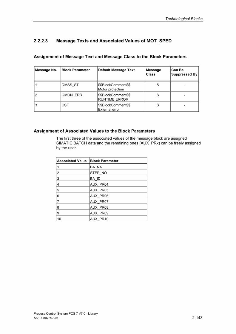
Technological Blocks
Process Control System PCS 7 V7.0 - Library A5E00807897-01 2-143
2.2.2.3 Message Texts and Associated Values of MOT_SPED
Assignment of Message Text and Message Class to the Block Parameters
Message No.
Block Parameter
Default Message Text Message Class
Can Be Suppressed By
1 QMSS_ST $$BlockComment$$ Motor protection
S -
2 QMON_ERR $$BlockComment$$ RUNTIME ERROR
S -
3 CSF $$BlockComment$$ External error
S -
Assignment of Associated Values to the Block Parameters The first three of the associated values of the message block are assigned SIMATIC BATCH data and the remaining ones (AUX_PRx) can be freely assigned by the user.
Associated Value Block Parameter
1 BA_NA 2 STEP_NO 3 BA_ID 4 AUX_PR04 5 AUX_PR05 6 AUX_PR06 7 AUX_PR07 8 AUX_PR08 9 AUX_PR09 10 AUX_PR10

Technological Blocks
Process Control System PCS 7 V7.0 - Library 2-144 A5E00807897-01
2.2.2.4 VSTATUS for MOT_SPED
The 32-bit status word extends the status display in the block icons and faceplates. The 16 low bits (bits 0 - 15) are used by the block as follows:
Bit no.: 7 6 5 4 3 2 1 0
Parameters QMON_ERR - QMSS_ST - QMAN_AUT - BA_EN OCCUPIED
Bit no.: 15 14 13 12 11 10 9 8
Parameters OOS QMSG_SUP QSTOPING QSTRTING QSPEED QSTOP QRUN LOCK
The 16-bit input USTATUS (data type WORD) uses the high bits (bits 16 - 31). You can use these bits as you wish.
2.2.2.5 Operating and Monitoring of MOT_SPED
Additional information You can find additional information in the following sections:
• Block Icon MOT_SPED
• Faceplate MOT_SPED
Note: Online help and the "PCS 7 FACEPLATES" Manual are only available if the "PCS 7 FACEPLATES" software package is installed!
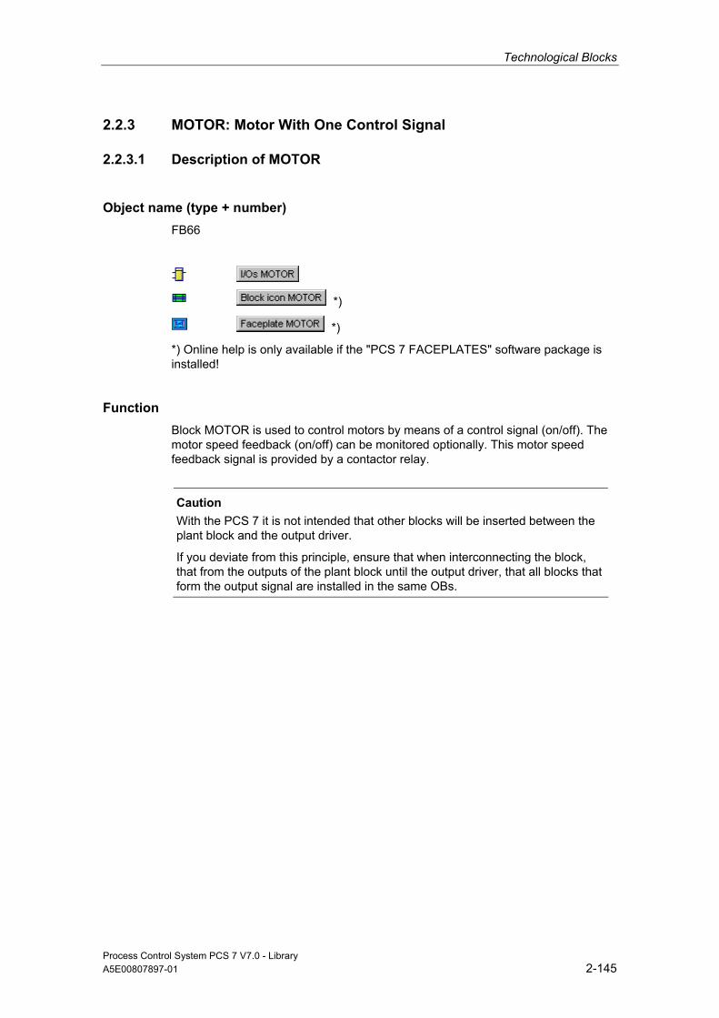
Technological Blocks
Process Control System PCS 7 V7.0 - Library A5E00807897-01 2-145
2.2.3 MOTOR: Motor With One Control Signal
2.2.3.1 Description of MOTOR
Object name (type + number) FB66
*)
*)
*) Online help is only available if the "PCS 7 FACEPLATES" software package is installed!
Function Block MOTOR is used to control motors by means of a control signal (on/off). The motor speed feedback (on/off) can be monitored optionally. This motor speed feedback signal is provided by a contactor relay.
Caution
With the PCS 7 it is not intended that other blocks will be inserted between the plant block and the output driver.
If you deviate from this principle, ensure that when interconnecting the block, that from the outputs of the plant block until the output driver, that all blocks that form the output signal are installed in the same OBs.
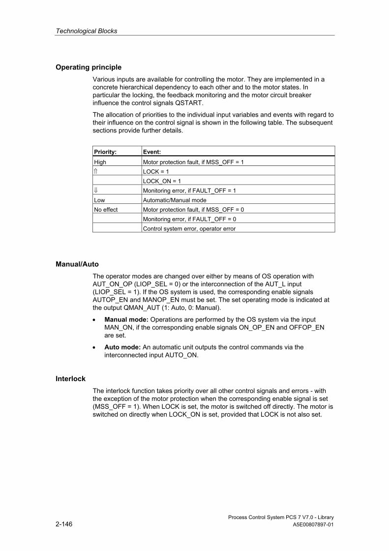
Technological Blocks
Process Control System PCS 7 V7.0 - Library 2-146 A5E00807897-01
Operating principle Various inputs are available for controlling the motor. They are implemented in a concrete hierarchical dependency to each other and to the motor states. In particular the locking, the feedback monitoring and the motor circuit breaker influence the control signals QSTART.
The allocation of priorities to the individual input variables and events with regard to their influence on the control signal is shown in the following table. The subsequent sections provide further details.
Priority: Event:
High Motor protection fault, if MSS_OFF = 1 ⇑ LOCK = 1 LOCK_ON = 1 ⇓ Monitoring error, if FAULT_OFF = 1 Low Automatic/Manual mode No effect Motor protection fault, if MSS_OFF = 0 Monitoring error, if FAULT_OFF = 0 Control system error, operator error
Manual/Auto The operator modes are changed over either by means of OS operation with AUT_ON_OP (LIOP_SEL = 0) or the interconnection of the AUT_L input (LIOP_SEL = 1). If the OS system is used, the corresponding enable signals AUTOP_EN and MANOP_EN must be set. The set operating mode is indicated at the output QMAN_AUT (1: Auto, 0: Manual).
• Manual mode: Operations are performed by the OS system via the input MAN_ON, if the corresponding enable signals ON_OP_EN and OFFOP_EN are set.
• Auto mode: An automatic unit outputs the control commands via the interconnected input AUTO_ON.
Interlock The interlock function takes priority over all other control signals and errors - with the exception of the motor protection when the corresponding enable signal is set (MSS_OFF = 1). When LOCK is set, the motor is switched off directly. The motor is switched on directly when LOCK_ON is set, provided that LOCK is not also set.

Technological Blocks
Process Control System PCS 7 V7.0 - Library A5E00807897-01 2-147
Monitoring The monitoring logic monitors consistency between the control command QSTART and the process variable feedback FB_ON and outputs the actual state via QRUN and QSTOP. It sets a monitoring error (QMON_ERR = 1) if after the period TIME_MON no feedback corresponding to QSTART has been set or if it changes unexpectedly without a request by QSTART.
If there is no feedback, either QSTART can be interconnected with FB_ON or monitoring can be disabled by setting MONITOR = 0.
The FAULT_OFF parameter determines the significance of a monitoring error. If FAULT_OFF = 1, the motor is switched off when a fault occurs. This error status does not affect the control outputs when FAULT_OFF = 0.
Motor Protection At the negative edge of the motor-protection signal MSS, the motor protection error is held and passed to output QMSS_ST. The parameter MSS_OFF is used to specify whether only to indicate the error status (MSS_OFF = 0), or whether the motor is to be limited irrespective of all other inputs and system states (MSS_OFF = 1).
Bumpless Changeover In order to ensure a bumpless changeover to manual mode, the manual value MAN_ON is always corrected to the current value of QSTART.
Error handling The motor protection error (QMSS_ST = 1) and the monitoring error (QMON_ERR = 1) are reported to the OS and influence the block operating principle as described above. The operator can either reset these states via the RESET input, or automatically at the next positive edge at MSS by interconnecting L_RESET with a "1" signal. The control system fault CSF is merely reported to the OS and applied to the group error QGR_ERR alongside with the motor protection and monitoring errors. It does not have any further influence on the block algorithm.
Operator errors are indicated at output QOP_ERR without message.
Calling OBs This is the watchdog alarm OB into which you install the block (for example, OB32) and OB100.
Technological Blocks
Process Control System PCS 7 V7.0 - Library 2-148 A5E00807897-01
Startup After an Error State After an error state, startup depends on the operating mode set during reset:
• In automatic mode, the motor can restart after the reset, provided a corresponding start signal is supplied by the automatic mode.
• Ιn manual mode, the motor must be explicitly switched on, because the manual operation was corrected to "OFF".
Startup Characteristics When the CPU starts, the MOTOR block is switched to manual mode and the OFF command is output. A prerequisite is that the block must be called in the startup OB. In CFC engineering, this is handled by the CFC. Using the basic STEP 7 tools, you must manually enter this call in the startup OB. After startup, the messages will be suppressed during the number of cycles set at RUNUPCYC.
The START_OFF input is used to specify whether the motor controls are to be switched off when the CPU is started (START_OFF = 1) or whether the last operating state is held.
Dynamic Response The block must be called via a watchdog interrupt OB. The sampling time of the block is set in parameter SAMPLE_T.
Assignment of the 32-Bit Status Word VSTATUS You can find additional information in "VSTATUS for MOTOR".
Message response The MOTOR block uses the ALARM_8P block for generating messages.
The following message triggers exist:
• Control System Fault
• The signals of the motor protective circuit-breaker and the monitoring error (runtime error)
• The CSF signal which is referenced as a control system error by interconnection.
QMSG_SUP is set if the RUNUPCYC cycles have not expired since the restart or if MSG_STAT = 21.
Monitoring of Process Values n.a.

Technological Blocks
Process Control System PCS 7 V7.0 - Library A5E00807897-01 2-149
Additional information Additional information is available in the sections:
I/Os of MOTOR
Message Texts and Associated Values of MOTOR
VSTATUS for MOTOR
Operating and Monitoring of MOTOR
2.2.3.2 I/Os of MOTOR
The factory setting of the block display in CFC is identified in the "I/O" column: I/O name in bold characters = I/O is visible; I/O name in standard characters = I/O is hidden.
You can find explanations of and information about the abbreviations used in "General Information About Block Description".
I/O (Parameter)
Meaning
Data Type
Default Type
Attr.
OCM Valid Values
AUT_L Interconnectable input for MANUAL/AUTO (0=Manual/1=Auto)
BOOL 0 I Q
AUT_ON_OP Mode input 0 = Manual 1 = Auto
BOOL 0 IO C +
AUTO_ON AUTO mode: 1 = ON 0 = OFF
BOOL 0 I Q
AUTOP_EN 1 = Enable AUTO mode BOOL 1 I Q AUX_PRx Associated value x ANY 0 IO Q BA_EN Release by BATCH BOOL 0 I Q + BA_ID BATCH: current batch number DWORD 0 I Q + BA_NA Batch name STRING
[32] 0 I Q +
CSF Control System Fault BOOL 0 I Q FAULT_OFF 1 = Motor OFF in case of fault BOOL 1 I Q FB_ON Feedback: 1 = ON BOOL 0 I Q L_RESET Interconnectable RESET input BOOL 0 I Q LIOP_SEL Interconnectable input for
manual/auto changeover (AUT_L) 1 = Interconnection is active 0 = Operator control is enabled
BOOL 0 I Q
LOCK 1 = Lock (OFF) BOOL 0 I Q + LOCK_ON 1 = Lock (ON) BOOL 0 I Q + MAN_ON Mode input
1 = ON, 0 = OFF BOOL 0 IO C +
MANOP_EN 1 = Enable manual mode BOOL 1 I Q MONITOR Monitoring: 1 = ON BOOL 1 I + MSG_ACK Message acknowledged WORD 0 O
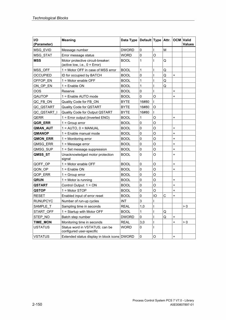
Technological Blocks
Process Control System PCS 7 V7.0 - Library 2-150 A5E00807897-01
I/O (Parameter)
Meaning
Data Type
Default Type
Attr.
OCM Valid Values
MSG_EVID Message number DWORD 0 I M MSG_STAT Error message status WORD 0 O MSS Motor protective circuit-breaker:
(active low, i.e., 0 = Error) BOOL 1 I Q
MSS_OFF 1 = Motor OFF in case of MSS error BOOL 1 I Q OCCUPIED ID for occupied by BATCH BOOL 0 I Q + OFFOP_EN 1 = Motor enable OFF BOOL 1 I Q ON_OP_EN 1 = Enable ON BOOL 1 I Q OOS Reserve BOOL 0 I + QAUTOP 1 = Enable AUTO mode BOOL 0 O + QC_FB_ON Quality Code for FB_ON BYTE 16#80 I QC_QSTART Quality Code for QSTART BYTE 16#80 O QC_QSTART_I Quality Code for Output QSTART BYTE 16#80 I QERR 1 = Error output (Inverted ENO) BOOL 1 O + QGR_ERR 1 = Group error BOOL 0 O QMAN_AUT 1 = AUTO, 0 = MANUAL BOOL 0 O + QMANOP 1 = Enable manual mode BOOL 0 O + QMON_ERR 1 = Monitoring error BOOL 0 O + QMSG_ERR 1 = Message error BOOL 0 O + QMSG_SUP 1 = Set message suppression BOOL 0 O + QMSS_ST Unacknowledged motor protection
signal BOOL 0 O +
QOFF_OP 1 = Motor enable OFF BOOL 0 O + QON_OP 1 = Enable ON BOOL 0 O + QOP_ERR 1 = Group error BOOL 0 O QRUN 1 = Motor is running BOOL 0 O + QSTART Control Output: 1 = ON BOOL 0 O + QSTOP 1 = Motor STOP BOOL 0 O + RESET Enabled input of error reset BOOL 0 IO C + RUNUPCYC Number of run-up cycles INT 3 I SAMPLE_T Sampling time in seconds REAL 1,0 I > 0 START_OFF 1 = Startup with Motor OFF BOOL 1 I Q STEP_NO Batch step number DWORD 0 I Q + TIME_MON Monitoring time in seconds REAL 3,0 I + > 0 USTATUS Status word in VSTATUS; can be
configured user-specific WORD 0 I
VSTATUS Extended status display in block icons DWORD 0 O +
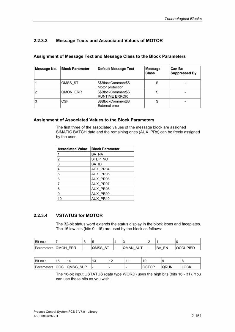
Technological Blocks
Process Control System PCS 7 V7.0 - Library A5E00807897-01 2-151
2.2.3.3 Message Texts and Associated Values of MOTOR
Assignment of Message Text and Message Class to the Block Parameters
Message No.
Block Parameter
Default Message Text Message Class
Can Be Suppressed By
1 QMSS_ST $$BlockComment$$ Motor protection
S -
2 QMON_ERR $$BlockComment$$ RUNTIME ERROR
S -
3 CSF $$BlockComment$$ External error
S -
Assignment of Associated Values to the Block Parameters The first three of the associated values of the message block are assigned SIMATIC BATCH data and the remaining ones (AUX_PRx) can be freely assigned by the user.
Associated Value Block Parameter 1 BA_NA 2 STEP_NO 3 BA_ID 4 AUX_PR04 5 AUX_PR05 6 AUX_PR06 7 AUX_PR07 8 AUX_PR08 9 AUX_PR09 10 AUX_PR10
2.2.3.4 VSTATUS for MOTOR
The 32-bit status word extends the status display in the block icons and faceplates. The 16 low bits (bits 0 - 15) are used by the block as follows:
Bit no.: 7 6 5 4 3 2 1 0
Parameters QMON_ERR - QMSS_ST - QMAN_AUT - BA_EN OCCUPIED
Bit no.: 15 14 13 12 11 10 9 8
Parameters OOS QMSG_SUP - - - QSTOP QRUN LOCK
The 16-bit input USTATUS (data type WORD) uses the high bits (bits 16 - 31). You can use these bits as you wish.
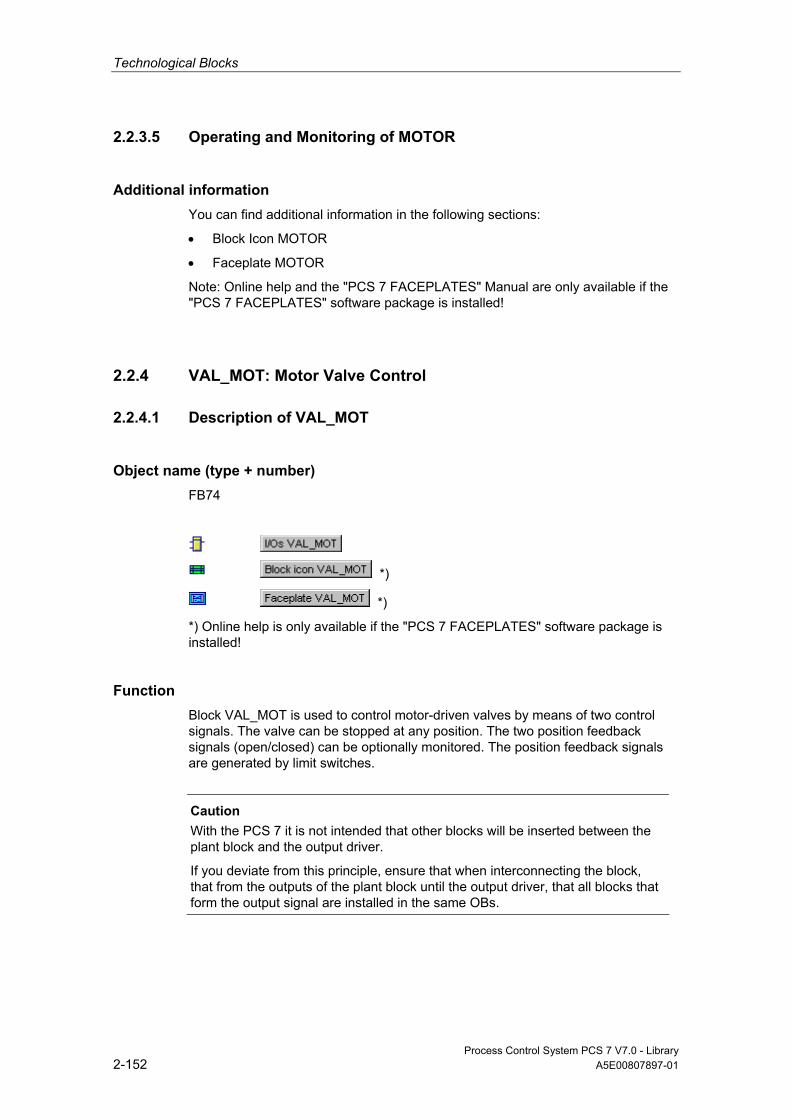
Technological Blocks
Process Control System PCS 7 V7.0 - Library 2-152 A5E00807897-01
2.2.3.5 Operating and Monitoring of MOTOR
Additional information You can find additional information in the following sections:
• Block Icon MOTOR
• Faceplate MOTOR
Note: Online help and the "PCS 7 FACEPLATES" Manual are only available if the "PCS 7 FACEPLATES" software package is installed!
2.2.4 VAL_MOT: Motor Valve Control
2.2.4.1 Description of VAL_MOT
Object name (type + number) FB74
*)
*)
*) Online help is only available if the "PCS 7 FACEPLATES" software package is installed!
Function Block VAL_MOT is used to control motor-driven valves by means of two control signals. The valve can be stopped at any position. The two position feedback signals (open/closed) can be optionally monitored. The position feedback signals are generated by limit switches.
Caution
With the PCS 7 it is not intended that other blocks will be inserted between the plant block and the output driver.
If you deviate from this principle, ensure that when interconnecting the block, that from the outputs of the plant block until the output driver, that all blocks that form the output signal are installed in the same OBs.
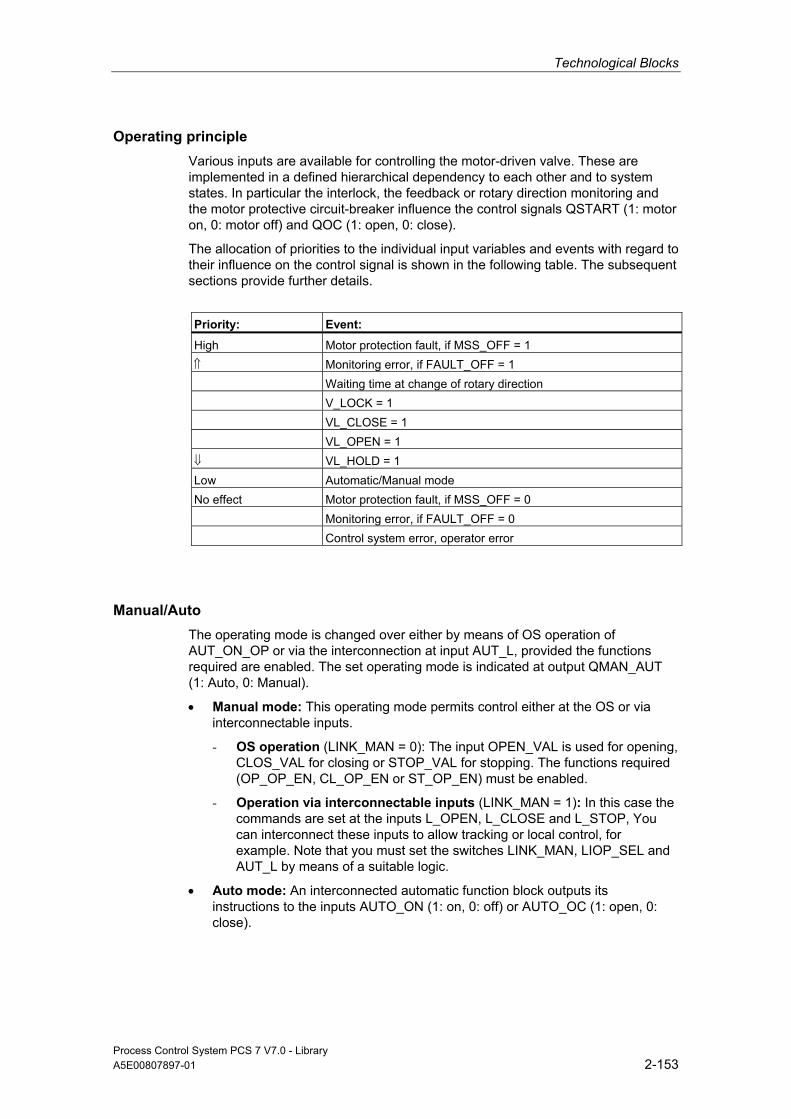
Technological Blocks
Process Control System PCS 7 V7.0 - Library A5E00807897-01 2-153
Operating principle Various inputs are available for controlling the motor-driven valve. These are implemented in a defined hierarchical dependency to each other and to system states. In particular the interlock, the feedback or rotary direction monitoring and the motor protective circuit-breaker influence the control signals QSTART (1: motor on, 0: motor off) and QOC (1: open, 0: close).
The allocation of priorities to the individual input variables and events with regard to their influence on the control signal is shown in the following table. The subsequent sections provide further details.
Priority: Event:
High Motor protection fault, if MSS_OFF = 1 ⇑ Monitoring error, if FAULT_OFF = 1 Waiting time at change of rotary direction V_LOCK = 1 VL_CLOSE = 1 VL_OPEN = 1 ⇓ VL_HOLD = 1 Low Automatic/Manual mode No effect Motor protection fault, if MSS_OFF = 0 Monitoring error, if FAULT_OFF = 0 Control system error, operator error
Manual/Auto The operating mode is changed over either by means of OS operation of AUT_ON_OP or via the interconnection at input AUT_L, provided the functions required are enabled. The set operating mode is indicated at output QMAN_AUT (1: Auto, 0: Manual).
• Manual mode: This operating mode permits control either at the OS or via interconnectable inputs.
- OS operation (LINK_MAN = 0): The input OPEN_VAL is used for opening, CLOS_VAL for closing or STOP_VAL for stopping. The functions required (OP_OP_EN, CL_OP_EN or ST_OP_EN) must be enabled.
- Operation via interconnectable inputs (LINK_MAN = 1): In this case the commands are set at the inputs L_OPEN, L_CLOSE and L_STOP, You can interconnect these inputs to allow tracking or local control, for example. Note that you must set the switches LINK_MAN, LIOP_SEL and AUT_L by means of a suitable logic.
• Auto mode: An interconnected automatic function block outputs its instructions to the inputs AUTO_ON (1: on, 0: off) or AUTO_OC (1: open, 0: close).
Technological Blocks
Process Control System PCS 7 V7.0 - Library 2-154 A5E00807897-01
Interlock The interlock function takes priority over all other control inputs and is only overridden by a motor protection fault or monitoring error if the relevant enable signals have been set (MSS_OFF = 1, FAULT_OFF = 1). If V_LOCK is set, the motor-driven valve is brought to its idle position, which is defined by SS_POS. It is opened or closed respectively by VL_OPEN or VL_CLOSE. VL_HOLD blocks the automatic and manual inputs and holds the last status request. The priorities of the individual interlock inputs are described in the "Operating Principle" section.
Monitoring The monitoring logic (enabled with MONITOR = 1) verifies consistency between the setpoint status (determined in QSTART and QOC) and the process variable feedback of the valve (provided by FB_OPEN and FB_CLOSE). If the setpoint status has not been reached after the monitoring time TIME_ON has expired, output QMON_ERR will be set. QMON_ERR is set immediately if the feedback changes without a reason (command). If no feedback signals are connected, a MONITOR = 0 signal must be output to the monitoring function. The monitor assumes in this case that the setpoint state of the valve has been reached within the time TIME_ON.
In error-free monitoring operation, the QOPENING and QCLOSING outputs indicate whether the valve is currently opening or closing, and the QOPENED and QCLOSED outputs indicate whether the valve has reached a final position. If the valve is stopped at an intermediate position, the direction of movement is indicated with QOPENING = 0 or QCLOSING = 0, while 0 will indicate the final positions.
The FAULT_OFF parameter determines the significance of a monitoring error. If FAULT_OFF = 1, the motor is switched off when a fault has been detected and the valve holds its current position. This fault status has no effect on the control outputs when FAULT_OFF = 0, and the block thus behaves as if the monitoring function were switched off and indicates the monitoring error only at the QMON_ERR output.
The TIME_OFF parameter determines the waiting time until the motor can be switched on again. QSTART = FALSE if the valve has reached the final position. A motor restart in reverse direction is not performed if QSTART = TRUE unless the set period TIME_OFF has expired. You can find additional information in "Reversing the Direction of Travel".
Motor Protection At the negative edge of the motor-protection signal MSS, the motor protection error is held and passed to output QMSS_ST. The MSS_OFF parameter determines only to indicate the error status (MSS_OFF = 0), or that the motor is switched off irrespective of all other inputs and system states (MSS_OFF = 1) and that the valve idles in its current position.
Technological Blocks
Process Control System PCS 7 V7.0 - Library A5E00807897-01 2-155
Bumpless Changeover In order to ensure bumpless changeover to manual mode in all operating modes, the manual values OPEN_VAL, CLOS_VAL and STOP_VAL are always tracked to the current values of QSTART and QDIR (exception: change in the direction of rotation).
Reversing the Direction of Travel If the direction of travel of the valve is reversed before it reaches its final position, the following steps are taken:
• The motor is stopped (QSTART = 0).
• The internal OFF monitor waits for the time period TIME_OFF to expire and then starts the motor in the reverse direction, provided the OFF monitor does not report an error.
Error handling The motor protection error (QMSS_ST = 1) and the monitoring error (QMON_ERR = 1) are reported to the OS and influence the block operating principle as described above. The operator can either reset these states via the RESET input, or automatically at the next positive edge at MSS by interconnecting L_RESET with a "1" signal. The control system fault CSF is merely reported to the OS and applied to the group error QGR_ERR alongside with the motor protection and monitoring errors. It does not have any further influence on the block algorithm.
Operator errors are indicated at output QOP_ERR without message.
Calling OBs This is the watchdog alarm OB into which you install the block (for example, OB32) and OB100.
Startup After an Error State After an error state, startup depends on the operating mode set during reset:
• In automatic mode, the motor valve cannot start up again unless the monitoring or motor protection error is reset and a corresponding start signal is output by the automation system.
• In manual mode the motor must be switched on explicitly, since manual operation had been tracked to "HOLD".

Technological Blocks
Process Control System PCS 7 V7.0 - Library 2-156 A5E00807897-01
Startup Characteristics When the CPU starts, the VAL_MOT block is switched to manual mode and the HOLD command is output. The block must be called in the startup OB accordingly. In CFC engineering, this is handled by the CFC. Using the basic STEP 7 tools, you must manually enter this call in the startup OB. After startup, the messages will be suppressed during the number of cycles set at RUNUPCYC.
Dynamic Response The block must be called via a watchdog interrupt OB. The sampling time of the block is set in parameter SAMPLE_T.
Assignment of the 32-Bit Status Word VSTATUS You can find additional information in "VSTATUS for VAL_MOT".
Message response The VAL_MOT block uses the ALARM_8P block to generate messages.
The following message triggers exist:
• Control System Fault
• Motor protective circuit-breaker signals and monitoring errors (runtime error)
• the CSF signal, which is referenced as a control system error by interconnection
QMSG_SUP is set if the RUNUPCYC cycles have not expired since the restart or if MSG_STAT = 21.
Monitoring of Process Values n.a.
Additional information Additional information is available in the sections:
I/Os of VAL_MOT
Message Texts and Associated Values of VAL_MOT
VSTATUS for VAL_MOT
Operating and Monitoring of VAL_MOT
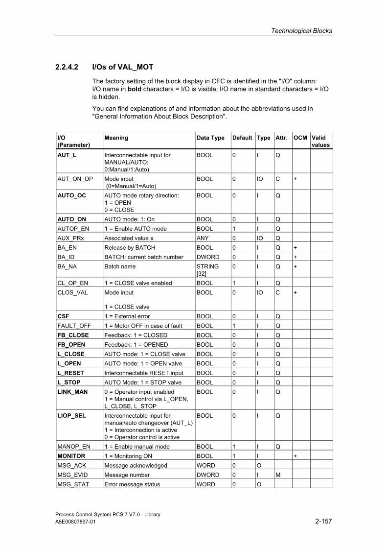
Technological Blocks
Process Control System PCS 7 V7.0 - Library A5E00807897-01 2-157
2.2.4.2 I/Os of VAL_MOT
The factory setting of the block display in CFC is identified in the "I/O" column: I/O name in bold characters = I/O is visible; I/O name in standard characters = I/O is hidden.
You can find explanations of and information about the abbreviations used in "General Information About Block Description".
I/O (Parameter)
Meaning
Data Type
Default Type
Attr.
OCM Valid values
AUT_L Interconnectable input for MANUAL/AUTO: 0:Manual/1:Auto)
BOOL 0 I Q
AUT_ON_OP Mode input (0=Manual/1=Auto)
BOOL 0 IO C +
AUTO_OC AUTO mode rotary direction: 1 = OPEN 0 = CLOSE
BOOL 0 I Q
AUTO_ON AUTO mode: 1: On BOOL 0 I Q AUTOP_EN 1 = Enable AUTO mode BOOL 1 I Q AUX_PRx Associated value x ANY 0 IO Q BA_EN Release by BATCH BOOL 0 I Q + BA_ID BATCH: current batch number DWORD 0 I Q + BA_NA Batch name STRING
[32] 0 I Q +
CL_OP_EN 1 = CLOSE valve enabled BOOL 1 I Q CLOS_VAL Mode input
1 = CLOSE valve
BOOL 0 IO C +
CSF 1 = External error BOOL 0 I Q FAULT_OFF 1 = Motor OFF in case of fault BOOL 1 I Q FB_CLOSE Feedback: 1 = CLOSED BOOL 0 I Q FB_OPEN Feedback: 1 = OPENED BOOL 0 I Q L_CLOSE AUTO mode: 1 = CLOSE valve BOOL 0 I Q L_OPEN AUTO mode: 1 = OPEN valve BOOL 0 I Q L_RESET Interconnectable RESET input BOOL 0 I Q L_STOP AUTO Mode: 1 = STOP valve BOOL 0 I Q LINK_MAN 0 = Operator input enabled
1 = Manual control via L_OPEN, L_CLOSE, L_STOP
BOOL 0 I Q
LIOP_SEL Interconnectable input for manual/auto changeover (AUT_L)1 = Interconnection is active 0 = Operator control is active
BOOL 0 I Q
MANOP_EN 1 = Enable manual mode BOOL 1 I Q MONITOR 1 = Monitoring ON BOOL 1 I + MSG_ACK Message acknowledged WORD 0 O MSG_EVID Message number DWORD 0 I M MSG_STAT Error message status WORD 0 O

Technological Blocks
Process Control System PCS 7 V7.0 - Library 2-158 A5E00807897-01
I/O (Parameter)
Meaning
Data Type
Default Type
Attr.
OCM Valid values
MSS Motor protective circuit-breaker: (active low, i.e., 0 = Error)
BOOL 0 I Q
MSS_OFF 1 = In case of MSS fault: Motor stop
BOOL 1 I Q
OCCUPIED ID for occupied by BATCH BOOL 0 I Q + OOS Reserve BOOL 0 I + OP_OP_EN 1 = Enable OPEN valve BOOL 1 I Q OPEN_VAL Mode input
1 = OPEN valve BOOL 0 IO C +
QAUTOP 1 = Enable AUTO mode BOOL 0 O + QC_FB_CLOSE Quality Code for FB_CLOSE BYTE 16#80 I QC_FB_OPEN Quality Code for FB_OPEN BYTE 16#80 I QC_QSTART Quality Code for QSTART BYTE 16#80 O QC_QSTART_I Quality Code for Output QSTART BYTE 16#80 I QC_QOC Quality Code for QOC BYTE 16#80 O QC_QOC_I Quality Code for Output QOC BYTE 16#80 I QCL_OP 1 = CLOSE valve enabled BOOL 0 0 + QCLOSED 1 = Valve is CLOSED BOOL 0 O + QCLOSING 1 = Valve is CLOSING BOOL 0 O + QERR 1 = Error output (inverted ENO) BOOL 1 O + QGR_ERR 1 = Group error BOOL 0 O QMAN_AUT 0 = MANUAL, 1 = AUTO BOOL 0 O + QMANOP 1 = Enable manual mode BOOL 0 O + QMON_ERR 1 = Monitoring error BOOL 0 O + QMSG_ERR 1 = Message error BOOL 0 O + QMSG_SUP 1 = Set message suppression BOOL 0 O + QMSS_ST Unacknowledged motor protection
signal BOOL 0 O +
QOC Direction control output: 1 = OPEN
BOOL 0 O
QOP_ERR 1 = Group error BOOL 0 O QOP_OP 1 = OPEN valve enabled BOOL 0 O + QOPENED 1 = Valve is OPENED BOOL 0 O + QOPENING 1 = Valve is OPENING BOOL 0 O + QST_OP 1 = enable operator input: STOP
valve BOOL 0 O +
QSTART Control Output: 1 = motor ON BOOL 0 O + RESET Enabled input of error reset BOOL 0 IO C + RUNUPCYC Number of run-up cycles INT 3 I SAMPLE_T Sampling time in seconds REAL 1,0 I >0 SS_POS 0 = idle position closed BOOL 0 I Q ST_OP_EN 1 = enable operator input: STOP
valve BOOL 1 I Q
STEP_NO Batch step number DWORD 0 I Q +

Technological Blocks
Process Control System PCS 7 V7.0 - Library A5E00807897-01 2-159
I/O (Parameter)
Meaning
Data Type
Default Type
Attr.
OCM Valid values
STOP_VAL Mode input 1 = STOP valve
BOOL 0 IO C +
TIME_OFF Motor OFF monitoring time in seconds
REAL 3,0 I + ≥ 0
TIME_ON Valve-runtime monitoring time in seconds
REAL 3,0 I + ≥ 0
V_LOCK 1 = Lock (SS_POS) BOOL 0 I Q + VL_CLOSE 1 = Lock (closed) BOOL 0 I Q + VL_HOLD 1 = Lock (hold/disabled) BOOL 0 I Q + VL_OPEN 1 = Lock (open) BOOL 0 I Q + USTATUS Status word in VSTATUS;
definable by user WORD 0 I
VSTATUS Extended status display in block icons
DWORD 0 O +
2.2.4.3 Message Texts and Associated Values of VAL_MOT
Assignment of Message Text and Message Class to the Block Parameters
Message No.
Block Parameter
Default Message Text Message Class
Can Be Suppressed By
1 QMSS_ST $$BlockComment$$ Motor protection
S -
2 QMON_ERR $$BlockComment$$ RUNTIME ERROR
S -
3 CSF $$BlockComment$$ External error
S -

Technological Blocks
Process Control System PCS 7 V7.0 - Library 2-160 A5E00807897-01
Assignment of Associated Values to the Block Parameters The first three of the associated values of the message block are assigned SIMATIC BATCH data and the remaining ones (AUX_PRx) can be freely assigned by the user.
Associated Value Block Parameter
1 BA_NA 2 STEP_NO 3 BA_ID 4 AUX_PR04 5 AUX_PR05 6 AUX_PR06 7 AUX_PR07 8 AUX_PR08 9 AUX_PR09 10 AUX_PR10
2.2.4.4 VSTATUS for VAL_MOT
The 32-bit status word extends the status display in the block icons and faceplates. The 16 low bits (bits 0 - 15) are used by the block as follows:
Bit no.: 7 6 5 4 3 2 1 0
Parameters QMON_ERR - QMSS_ST - QMAN_AUT - BA_EN OCCUPIED
Bit no.: 15 14 13 12 11 10 9 8
Parameters OOS QMSG_SUP - QCLOSING QOPENING QCLOSED QOPENED V_LOCK
The 16-bit input USTATUS (data type WORD) uses the high bits (bits 16 - 31). You can use these bits as you wish.
2.2.4.5 Operating and Monitoring of VAL_MOT
Additional information You can find additional information in the following sections:
• Block Icon VAL_MOT
• Faceplate VAL_MOT
Note: Online help and the "PCS 7 FACEPLATES" Manual are only available if the "PCS 7 FACEPLATES" software package is installed!
Technological Blocks
Process Control System PCS 7 V7.0 - Library A5E00807897-01 2-161
2.2.5 VALVE: Valve Control
2.2.5.1 Description of VALVE
Object name (type + number) FB73
*)
*)
*) Online help is only available if the "PCS 7 FACEPLATES" software package is installed!
Function Block VALVE is used to operate control valves (open/close fittings) by means of one control signal (open/close). The position of rest of the valve can be the closed or opened state. The two position feedback signals (open/closed) can be optionally monitored. The position feedback signals are generated by limit switches.
Caution
With the PCS 7 it is not intended that other blocks will be inserted between the plant block and the output driver.
If you deviate from this principle, ensure that when interconnecting the block, that from the outputs of the plant block until the output driver, that all blocks that form the output signal are installed in the same OBs.

Technological Blocks
Process Control System PCS 7 V7.0 - Library 2-162 A5E00807897-01
Operating principle Various inputs are available for controlling the valve. They are implemented in a defined hierarchical relationship to each other and to the valve states. In particular the locking and feedback monitoring influence the control signal QCONTROL.
The allocation of priorities to the individual input variables and events with regard to their influence on the control signal is shown in the following table. The subsequent sections provide further details.
Priority: Event:
High V_LOCK = 1 ⇑ VL_CLOSE = 1 VL_OPEN = 1 ⇓ Monitoring error, if FAULT_OFF = 1 Low Automatic/Manual mode No effect Monitoring error, if FAULT_OFF = 0 Control system error, operator error
Position of Rest The position of rest of the controlled valve is signaled at input SS_POS (1: open, 0: closed). This only affects the definition of the control output QCONTROL (0: rest position, valve terminated). The commands on input side remain unaffected (a "1" signal at the input always means "open").
Example: When SS_POS = 1 (valve in rest position "open"), control output QCONTROL = 1 signal actuates the "Close valve" command.
Manual/Auto The operating mode is changed over either by means of OS operation of AUT_ON_OP or via the interconnection at input AUT_L, provided the functions required are enabled. The set operating mode is indicated at output QMAN_AUT (1: Auto, 0: Manual).
• Manual mode: Input MAN_OC is operated via the OS. The corresponding enable parameters (OP_OP_EN or CL_OP_EN) must be set.
• Auto mode: The interconnection of the automation system outputs the control commands to input AUTO_OC (1: open, 0: close).
Interlock The interlock function takes priority over all other control signals and errors. If V_LOCK is set, the valve is set to its rest position (QCONTROL = 0). If V_LOCK is not set, a locking state (open/closed) can also be selected directly via the inputs VL_OPEN and VL_CLOSE. The signal VL_CLOSE locks VL_OPEN.

Technological Blocks
Process Control System PCS 7 V7.0 - Library A5E00807897-01 2-163
Monitoring The monitoring logic verifies consistency between the output control command QCONTROL and the process variable feedback of the valve (FB_OPEN, FB_CLOSE). If the end position has not been reached after the monitoring time TIME_MON has expired, output QMON_ERR will be set. QMON_ERR is set immediately if the feedback changes without a reason (command). and the valve will be de-energized. If no limit feedback is connected, the status of MONITOR must be set to "0" and be reported to the monitoring function, which then assumes that the limit of the valve has been reached within the time TIME_MON. Until then, QOPENING or QCLOSING is displayed.
When the monitor operates error-free, the outputs QOPENING and QCLOSING indicate whether the valve is opening or closing, while the outputs QOPENED and QCLOSED show whether the valve has reached the limit position.
The inputs NO_FB_xx and NOMON_xx are used to configure whether there is no feedback of the "open" and "closed" (NO_FB_xx = 1) states, or whether the existing feedback should not be evaluated (NOMON_xx = 1), for example due to the failure of the limit switch.
The parameter FAULT_SS defines the significance of the monitoring error. If FAULT_SS = 1, the motor is brought to the rest position defined in SS_POS in case of an error. The error has no effect on the control outputs if FAULT_SS = 0.
Bumpless Changeover In order to ensure a bumpless changeover to manual mode, the manual value MAN_OC is always tracked to the current value of QCONTROL.
Error handling The monitoring error (QMON_ERR = 1) is reported to the OS and influences the block operating principle as described above. It can be reset by operating RESET, or automatically by means of an interconnection with the positive edge of L_RESET. The control system fault CSF is merely reported to the OS and applied to the group error QGR_ERR along with monitoring. It does not have any further influence on the block algorithm.
Operator errors are indicated at output QOP_ERR without message.
Calling OBs This is the watchdog alarm OB into which you install the block (for example, OB32) and OB100.

Technological Blocks
Process Control System PCS 7 V7.0 - Library 2-164 A5E00807897-01
Startup After an Error State After an error state, startup depends on the operating mode set during reset:
• In automatic mode, the motor valve cannot start up again unless the monitoring or motor protection error is reset and a corresponding start signal is output by the automation system.
• In manual mode the motor must be switched on explicitly, since manual operation had been tracked to "HOLD".
Startup Characteristics During a CPU startup, the VALVE block is switched to manual mode and the QCONTROL= 0 (rest position) signal is output. The block must be called in the startup OB accordingly. In CFC engineering, this is handled by the CFC. Using the basic STEP 7 tools, you must manually enter this call in the startup OB. After startup, the messages will be suppressed during the number of cycles set at RUNUPCYC.
At the START_SS input parameter you can decide either to set the valve to safety state when the CPU is started (START_SS = 1) or to retain its last operating state.
Dynamic Response The block must be called via a watchdog interrupt OB. The sampling time of the block is set in parameter SAMPLE_T.
Assignment of the 32-Bit Status Word VSTATUS You can find additional information in "VSTATUS for VALVE".
Message response The VALVE block uses the ALARM_8P block for generating messages.
Messages are triggered by the following control system faults:
• the monitoring error (runtime error)
• the CSF signal, which is referenced as a control system error by interconnection
QMSG_SUP is set if the RUNUPCYC cycles have not expired since the restart or if MSG_STAT = 21.
Monitoring of Process Values n.a.

Technological Blocks
Process Control System PCS 7 V7.0 - Library A5E00807897-01 2-165
Additional information Additional information is available in the sections:
I/Os of VALVE
Message Texts and Associated Values of VALVE
VSTATUS for VALVE
Operating and Monitoring of VALVE
2.2.5.2 I/Os of VALVE
The factory setting of the block display in CFC is identified in the "I/O" column: I/O name in bold characters = I/O is visible; I/O name in standard characters = I/O is hidden.
You can find explanations of and information about the abbreviations used in "General Information About Block Description".
I/O (Parameter)
Meaning
Data Type
Default Type
Attr.
OCM Valid Values
AUT_L Interconnectable input for MANUAL/AUTO 0 = Manual 1 = Auto
BOOL 0 I Q
AUT_ON_OP Mode input (0=Manual/1=Auto)
BOOL 0 IO C +
AUTO_OC AUTO mode rotary direction: 1 = OPEN 0 = CLOSE
BOOL 0 I Q
AUTOP_EN 1 = Enable AUTO mode BOOL 1 I Q AUX_PRx Associated value x ANY 0 IO Q BA_EN Release by BATCH BOOL 0 I Q + BA_ID BATCH: current batch number DWORD 0 I Q + BA_NA Batch name STRING
[32] 0 I Q +
CL_OP_EN 1 = Enable CLOSE BOOL 1 I Q CSF 1 = External error BOOL 0 I Q FAULT_SS 1 = Safe state position
in case of error BOOL 1 I Q
FB_CLOSE Feedback: 1 = CLOSED BOOL 0 I Q FB_OPEN Feedback: 1 = OPENED BOOL 0 I Q L_RESET Interconnectable RESET input BOOL 0 I Q LIOP_SEL Interconnectable input for
MANUAL/AUTO changeover (AUT_L) 1 = Interconnection is active 0 = Operation enabled
BOOL 0 I Q
MAN_OC Mode input 1 = OPEN 0 = CLOSE
BOOL 0 IO C +

Technological Blocks
Process Control System PCS 7 V7.0 - Library 2-166 A5E00807897-01
I/O (Parameter)
Meaning
Data Type
Default Type
Attr.
OCM Valid Values
MANOP_EN 1 = Enable manual mode BOOL 1 I Q MONITOR 1 = Monitoring ON,
0 = Monitoring OFF BOOL 1 I +
MSG_ACK Message acknowledged WORD 0 O MSG_EVID Message number DWORD 0 I M MSG_STAT Error message status WORD 0 O NO_FB_CL 1 = No feedback "closed"
present BOOL 0 I Q
NO_FB_OP 1 = No feedback "opened" present
BOOL 0 I Q
NOMON_CL 1 = No monitoring of closing feedback
BOOL 0 I Q
NOMON_OP 1 = No monitoring of opening feedback
BOOL 0 I Q
OCCUPIED ID for occupied by BATCH BOOL 0 I Q + OOS Reserve BOOL 0 I + OP_OP_EN 1 = Enable OPEN operation BOOL 1 I Q QAUTOP 1 = Enabled AUTO mode BOOL 0 O + QC_FB_CLOSE Quality Code for FB_CLOSE BYTE 16#80 I QC_FB_OPEN Quality Code for FB_OPEN BYTE 16#80 I QC_QCONTROL Quality Code for QCONTROL BYTE 16#80 O QC_QCONTROL_I Quality Code for output
QCONTROL BYTE 16#80 I
QCL_OP 1 = Enable CLOSE operation BOOL 0 O + QCLOSED 1 = Valve is CLOSED BOOL 0 O + QCLOSING 1 = Valve is CLOSING BOOL 0 O + QCONTROL Control Output: 0 = rest
position BOOL 0 O
QERR 1 = Error output (inverted ENO)
BOOL 1 O +
QGR_ERR 1 = Group error BOOL 0 O QMAN_AUT 0 = MANUAL
1 = AUTO BOOL 0 O +
QMANOP 1 = Enable manual mode BOOL 0 O + QMON_ERR 1 = Monitoring error BOOL 0 O + QMSG_ERR 1 = Message error BOOL 0 O + QMSG_SUP 1 = Set message suppression BOOL 0 O + QOP_ERR 1 = Group error BOOL 0 O QOP_OP 1 = Enable OPEN operation BOOL 0 O + QOPENED 1 = Valve is OPENED BOOL 0 O + QOPENING 1 = Valve is OPENING BOOL 0 O + RESET Enabled input of error reset BOOL 0 IO C + RUNUPCYC Number of run-up cycles INT 3 I SAMPLE_T Sampling time in seconds REAL 1,0 I > 0

Technological Blocks
Process Control System PCS 7 V7.0 - Library A5E00807897-01 2-167
I/O (Parameter)
Meaning
Data Type
Default Type
Attr.
OCM Valid Values
SS_POS Rest position: 0 = CLOSED (type C) 1 = OPENED (type O)
BOOL 0 I Q
START_SS 1 = Startup in safe state and manual mode
BOOL 1 I Q
STEP_NO Batch step number DWORD 0 I Q + TIME_MON Monitoring time in seconds REAL 3,0 I + ≥ 0 V_LOCK 1 = Lock (SS_POS) BOOL 0 I Q + VL_CLOSE 1 = Lock (closed) BOOL 0 I Q + VL_OPEN 1 = Lock (open) BOOL 0 I Q +
USTATUS Status word in VSTATUS; definable by user
WORD 0 I
VSTATUS Extended status display in block icons
DWORD 0 O +
You can find explanations of and information about the abbreviations used in "General Information About Block Description".
2.2.5.3 Message Texts and Associated Values of VALVE
Assignment of Message Text and Message Class to the Block Parameters
Message No.
Block Parameter
Default Message Text Message Class
Can Be Suppressed By
1 QMON_ERR $$BlockComment$$ RUNTIME ERROR
S -
2 CSF $$BlockComment$$ External error
S -
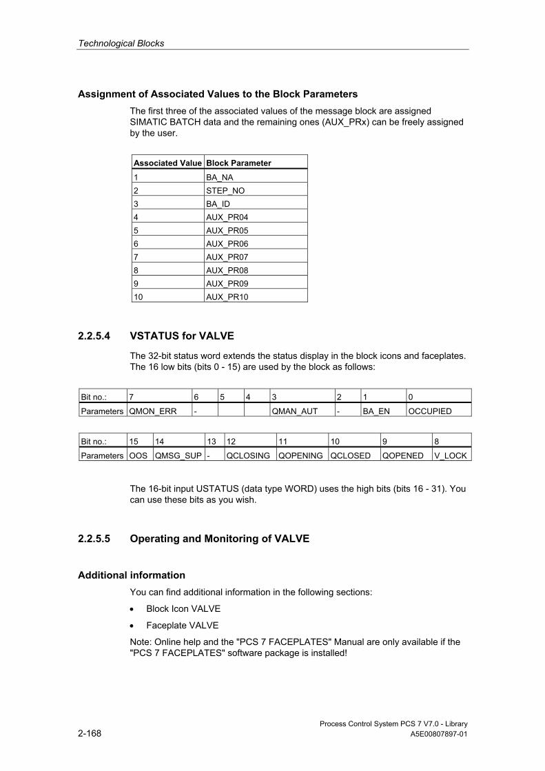
Technological Blocks
Process Control System PCS 7 V7.0 - Library 2-168 A5E00807897-01
Assignment of Associated Values to the Block Parameters The first three of the associated values of the message block are assigned SIMATIC BATCH data and the remaining ones (AUX_PRx) can be freely assigned by the user.
Associated Value Block Parameter
1 BA_NA 2 STEP_NO 3 BA_ID 4 AUX_PR04 5 AUX_PR05 6 AUX_PR06 7 AUX_PR07 8 AUX_PR08 9 AUX_PR09 10 AUX_PR10
2.2.5.4 VSTATUS for VALVE
The 32-bit status word extends the status display in the block icons and faceplates. The 16 low bits (bits 0 - 15) are used by the block as follows:
Bit no.: 7 6 5 4 3 2 1 0
Parameters QMON_ERR - QMAN_AUT - BA_EN OCCUPIED
Bit no.: 15 14 13 12 11 10 9 8
Parameters OOS QMSG_SUP - QCLOSING QOPENING QCLOSED QOPENED V_LOCK
The 16-bit input USTATUS (data type WORD) uses the high bits (bits 16 - 31). You can use these bits as you wish.
2.2.5.5 Operating and Monitoring of VALVE
Additional information You can find additional information in the following sections:
• Block Icon VALVE
• Faceplate VALVE
Note: Online help and the "PCS 7 FACEPLATES" Manual are only available if the "PCS 7 FACEPLATES" software package is installed!

Technological Blocks
Process Control System PCS 7 V7.0 - Library A5E00807897-01 2-169
2.3 Other Technological Blocks
2.3.1 ADD4_P: Adder for a Maximum of 4 Values
2.3.1.1 Description of ADD4_P
Object name (type + number) FC 256
Function Block ADD4_P calculates the sum of up to 4 values: V = U1+...+ Un (n ≤ 4)
Calling OBs The OB in which the block is installed is the calling OB.
Error handling In case of an overflow/underflow, the REAL value of the high/low limit is set in the result V. ENO will be set low and QERR high.
2.3.1.2 I/Os of ADD4_P
The factory setting of the block display in CFC is identified in the "I/O" column: I/O name in bold characters = I/O is visible; I/O name in standard characters = I/O is hidden.
You can find explanations of and information about the abbreviations used in "General Information About Block Description".
I/O (Parameter)
Meaning
Data Type
Default
Type
Attr.
U1 Addend 1 REAL 0.0 I Q U2 Addend 2 REAL 0.0 I Q U3 Addend 3 REAL 0.0 I Q U4 Addend 4 REAL 0.0 I Q V Result REAL 0.0 O
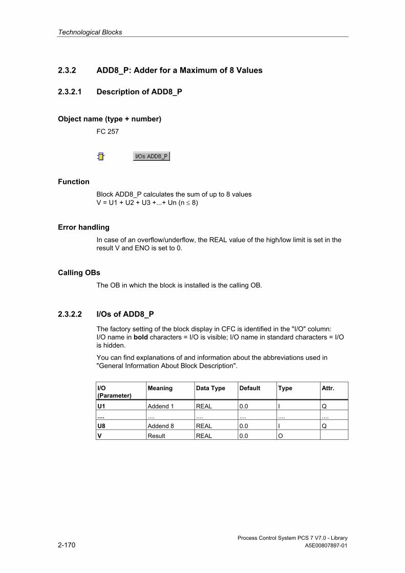
Technological Blocks
Process Control System PCS 7 V7.0 - Library 2-170 A5E00807897-01
2.3.2 ADD8_P: Adder for a Maximum of 8 Values
2.3.2.1 Description of ADD8_P
Object name (type + number) FC 257
Function Block ADD8_P calculates the sum of up to 8 values V = U1 + U2 + U3 +...+ Un (n ≤ 8)
Error handling In case of an overflow/underflow, the REAL value of the high/low limit is set in the result V and ENO is set to 0.
Calling OBs The OB in which the block is installed is the calling OB.
2.3.2.2 I/Os of ADD8_P
The factory setting of the block display in CFC is identified in the "I/O" column: I/O name in bold characters = I/O is visible; I/O name in standard characters = I/O is hidden.
You can find explanations of and information about the abbreviations used in "General Information About Block Description".
I/O (Parameter)
Meaning
Data Type
Default Type
Attr.
U1 Addend 1 REAL 0.0 I Q .... .... .... .... .... .... U8 Addend 8 REAL 0.0 I Q V Result REAL 0.0 O
Technological Blocks
Process Control System PCS 7 V7.0 - Library A5E00807897-01 2-171
2.3.3 AVER_P: Time Average
2.3.3.1 Description of AVER_P
Object name (type + number) FB 34
Function Block AVER_P calculates the mean time value of an active parameter based on the time which has passed since its start. The equation below is used:
V = (N ∗ Vold + U) / (N+1)
Explanations: • U = Applied parameter • V = Current mean • Vold = Mean of the cycles executed since the start • N = Number of cycles used for mean
Mode of operation Operating principle of the block: • Calculation is started with a positive edge at the RUN input. An existing result
V is overwritten by the input value U. You will find more information in "Startup Characteristics".
• In the subsequent cycles, the result is recalculated in output V and the cycle counter N is incremented.
• The calculation is terminated by resetting the RUN input and the actual values of the results V and N are saved.
Calling OBs This is the watchdog alarm OB into which you install the block (for example, OB 32) and OB 100.
Error handling Arithmetic errors are indicated by ENO = 0 or QERR = 1. Arithmetic errors occur when the range limits of the REAL data type exceed the results of the formula described above. The value of V from the previous cycle is retained in this case. If V takes the value = #+INF or #-INF because of the corresponding value of U, there is also an arithmetic error in the next cycle.
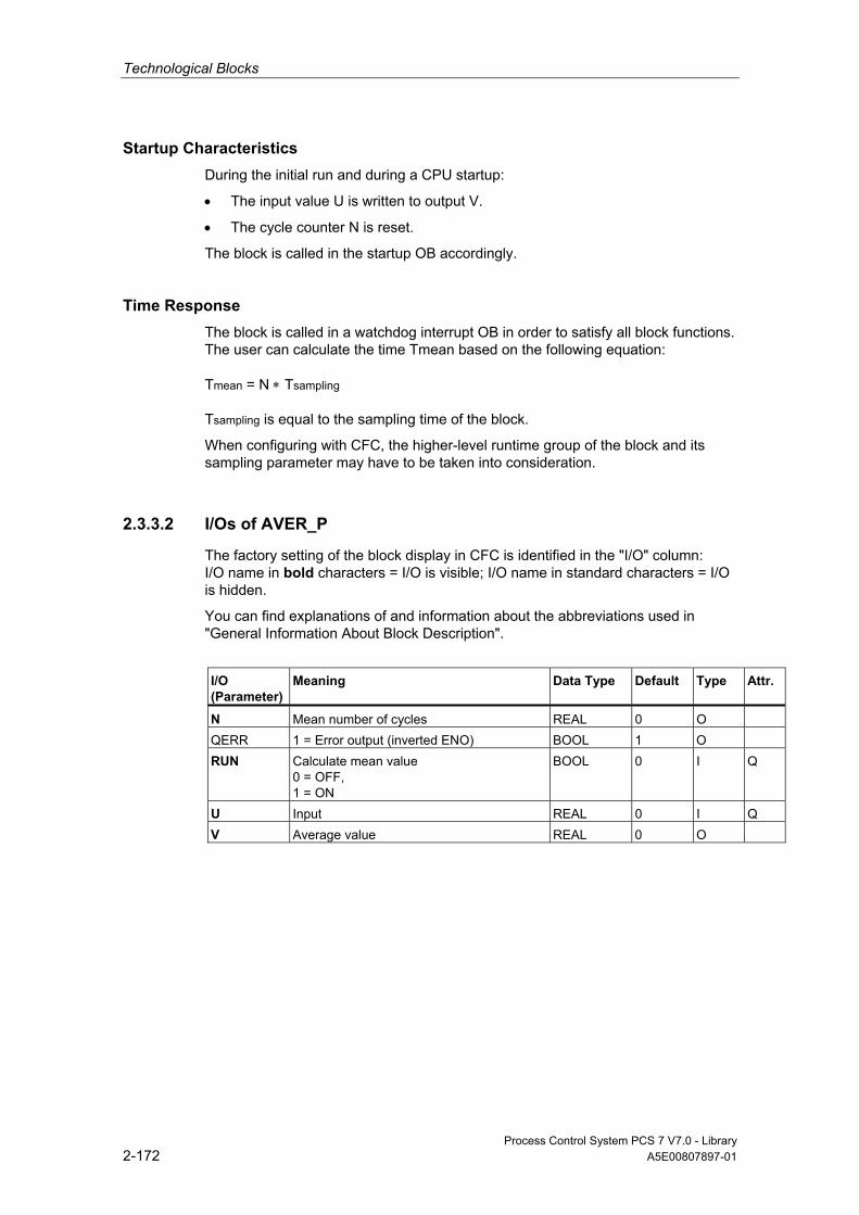
Technological Blocks
Process Control System PCS 7 V7.0 - Library 2-172 A5E00807897-01
Startup Characteristics During the initial run and during a CPU startup:
• The input value U is written to output V.
• The cycle counter N is reset.
The block is called in the startup OB accordingly.
Time Response The block is called in a watchdog interrupt OB in order to satisfy all block functions. The user can calculate the time Tmean based on the following equation: Tmean = N ∗ Tsampling Tsampling is equal to the sampling time of the block.
When configuring with CFC, the higher-level runtime group of the block and its sampling parameter may have to be taken into consideration.
2.3.3.2 I/Os of AVER_P
The factory setting of the block display in CFC is identified in the "I/O" column: I/O name in bold characters = I/O is visible; I/O name in standard characters = I/O is hidden.
You can find explanations of and information about the abbreviations used in "General Information About Block Description".
I/O (Parameter)
Meaning
Data Type
Default Type
Attr.
N Mean number of cycles REAL 0 O QERR 1 = Error output (inverted ENO) BOOL 1 O RUN Calculate mean value
0 = OFF, 1 = ON
BOOL 0 I Q
U Input REAL 0 I Q V Average value REAL 0 O

Technological Blocks
Process Control System PCS 7 V7.0 - Library A5E00807897-01 2-173
2.3.4 COUNT_P: Counter
2.3.4.1 Description of COUNT_P
Object name (type + number) FB 36
Function A positive edge of the binary input signal I0 increments or decrements the counter value V, according to the set mode.
Mode of operation Block COUNT_P operates according to the following principle:
• The mode can be set at the MODE parameter:
- MODE = 0 = Up counter
- MODE = 1 = Down counter
• Block operation as incremental counter:
- Every positive edge at the I0 input increments the counter.
- When the high limit V = V_HL is reached, the counter is not incremented further and output QVHL is set high.
- When the mode is reversed to "Down count", output V is decremented at the next positive edge of I0 and QVHL is reset.
- RESET = 1 sets V = V_LL, QVLL = 1, QVHL = 0, and the internal edge flag is corrected to the input value.
• Block operation as decremented counter:
- Every positive edge at the I0 input decrements the counter.
- When the lower limit V = V_LL has been reached, the counter is not decremented further and output QVLL is set high.
- When the mode is reversed to "Up count", the output V is incremented at the next positive edge of I0 and QVLL is reset.
- RESET = 1 sets V = V_HL, QVHL = 1, QVLL = 0, and the internal edge flag is corrected to the input value.

Technological Blocks
Process Control System PCS 7 V7.0 - Library 2-174 A5E00807897-01
Calling OBs This is only the OB into which you install the block (for example, OB 32).
Error handling Arithmetic errors are indicated by ENO = 0 or QERR = 1.
Startup Characteristics During the initial run and during a CPU startup, the block performs one RESET, according to the operating mode set. You can find additional information in "Operating Principle, RESET".
Time Response n.a. However, it is advisable to install the block in the OB that also contains the edge triggering block.
2.3.4.2 I/Os of COUNT_P
The factory setting of the block display in CFC is identified in the "I/O" column: I/O name in bold characters = I/O is visible; I/O name in standard characters = I/O is hidden.
You can find explanations of and information about the abbreviations used in "General Information About Block Description".
I/O (Parameter)
Meaning
Data Type
Default Type
Attr.
Valid Values
I0 Input BOOL 0 I Q MODE Counter operating mode
0 = up 1 = down
BOOL 0 I Q
QERR 1 = Error BOOL 1 O QVHL 1 = V > VHL BOOL 0 O QVLL 1 = V < VLL BOOL 0 O RESET 1 = Reset BOOL 0 I Q V Counter value DINT 0 O V_HL High limit of V DINT 100 I V_HL ≥ V_LL
V_LL Low limit of V DINT 0 I V_LL ≤ V_HL
Technological Blocks
Process Control System PCS 7 V7.0 - Library A5E00807897-01 2-175
2.3.5 DOSE: Dosing Process
2.3.5.1 Description of DOSE
Object name (type + number) FB 63
*)
*)
*) Online help is only available if the PCS 7 FACEPLATES software package is installed!
Function The DOSE block is used for upsizing or downsizing batches in single-component dosing with weighing devices and also for dosing using volumetric measuring devices. When flow meters are used, the integral flow value should be made available at input PV_IN. As long as dosing is active, output Q is set. This output makes it possible to control the equipment that allows dosing. At the end of dosing an automatic correction for dribbling can be made which will become active at the next dosing. The initial dribbling is specified at the input DRIBB. The dosing value is monitored against the setpoint for exceeding or falling below tolerance and the results supplied to two corresponding outputs at the end of the dosing process.
Operating Modes The internal/external modes can be set either with the operator input SPEXTSEL_OP or the switched input SPEXON_L. The switched input SPEXTON_L is only effective if the input SPEXT_ON = True. The result switches between the "internal setpoint" and "external setpoint":
• Internal. The setpoint is input by the operation of SP_OP and limited to SP_LLM / SP_HLM.
• External. The setpoint (SP) is obtained from SP_EXT and limited as described above.
Calling OBs This is the watchdog alarm OB into which you install the block (for example, OB 32) and OB 100.

Technological Blocks
Process Control System PCS 7 V7.0 - Library 2-176 A5E00807897-01
Start of Dosing Dosing starts as follows: • Dosing is started by operating the input START_OP or by the rising edge of the
interconnected signal L_START in the same block. • You have to wait until the scales stands still, i.e. STNDSTLL = 1. If there is no
standstill signal available, this input must be configured with 1. This is followed by tarring: in other words, the current process variable PV_IN is brought into the tare memory.
• Depending on whether batching is upward or downward (selected via REVERSE), the current dosing value PV_OUT is calculated as follows: - REVERSE = 0: PV_OUT = PV_IN - TARA (PV_IN rises) - REVERSE = 1: PV_OUT = TARA - PV_IN (PV_IN falls)
• Q, QSTRTDOS is set and QEND_DOS, QTOL_P, and QTOL_N reset. You can find additional information in "Component Change".
End of Dosing The final phase of dosing takes place in the following steps: • As soon as PV_OUT ≥ SP - DRIBB_F, Q is reset. If STNDSTLL = 1 is also set,
QSTRTDOS is also reset. • As soon as standstill is signaled (STNDSTLL = 1), a counter with the time [s]
specified under RELAXTME is loaded and then decremented cyclically by the sampling time SAMPLE_T. The settling time (QRELXING = 1) runs as long as the counter is > 0.
• Once the settling time has elapsed, an underdosing or overdosing will be evaluated in accordance with the configured tolerance limits TOL_N and TOL_P, and a dribbling correction will be carried out, provided DRIB_COR = 1.
• If the dosing quantity is within the tolerance band, the end of dosing (QEND_DOS = 1) is set.
Component Change If there is a component change, set COMP_CHG = 1 before you start dosing. When dosing is started (QSTRTDOS = 1), the dribbling value set at this point in DRIBB is passed to the output DRIBB_F.
Dribbling Correction If a dribbling correction is requested (DRIB_COR = 1), the dribbling value is calculated as follows:
DRIBB_F = DRIBB_F - ( SP - PV_OUT ) * DCF / 100
The following condition must be satisfied:
0 ≤ DRIBB_F ≤ DRIBBMAX
The correction factor DCF is limited internally to 0 - 100.
You can find additional information about the dribbling value in "Component Change".

Technological Blocks
Process Control System PCS 7 V7.0 - Library A5E00807897-01 2-177
Overdosing/Underdosing • When overdosing occurs (PV_OUT > SP + TOL_P), QTOL_P and
QEND_DOS are set.
• In the event of underdosing (PV_OUT < SP - TOL_N) only QTOL_N is set. It is possible to make it up by hand. As soon as this is terminated, the end of the dosing process is indicated (QEND_DOS = 1). The block outputs are not updated until the next dosing process is started.
Post Dosing Only when there has been underdosing is it possible to make the quantity up by hand, which is achieved via the operation of POSTDOSE or the interconnectable input L_PDOSE.
• Set DRIB_COR = 1
• With the rising edge of the signal, signal QSTRT_DOS for the start of dosing is set for the time PDOS_TME. This procedure can be repeated until either the setpoint has been exceeded or the end of the procedure has been acknowledged by operating the ACK_TOL_OP input or the interconnectable ACK_TOL.
• After acknowledgment, the end of dosing (QEND_DOS = 1) is displayed and no further updating of the outputs undertaken.
Pause • The dosing process is paused when needed with the PAUSE_OP command or
with the interconnectable input PAUSE. The interconnectable input PAUSE is only effective if the input LIOP_SEL = True. When overdosing occurs (PV_OUT > SP + TOL_P), QTOL_P and QEND_DOS are set.
• Pause "End" continues the dosing process. The pause must be ended when overdosing occurs in order to start a new dosing process.
Abort If necessary, the dosing procedure can be terminated prematurely by means of the CANCEL_OP instruction or via the interconnectable input CANCEL. After this a new dosing run can be started.

Technological Blocks
Process Control System PCS 7 V7.0 - Library 2-178 A5E00807897-01
Error handling Operator errors of the various operator control blocks which are detected will be OR-ed and routed to the group output QOP_ERR. In the event of arithmetical errors the status at the output ENO is set low and QERR is set high.
Startup Characteristics At CPU startup, "Abort dosing" will be simulated but without generating a message. The block must be called in the startup OB accordingly. In CFC engineering, this is handled by the CFC. Using the basic STEP 7 tools, you must manually enter this call in the startup OB. After startup, the messages will be suppressed during the number of cycles set at RUNUPCYC.
Time Response The block must be called via a watchdog interrupt OB. The sampling time of the block is set in parameter SAMPLE_T.
Assignment of the 32-Bit Status Word VSTATUS You can find additional information in "VSTATUS for DOSE".
Message Capability The DOSE block uses the ALARM8_P (MSG_EVID) block to generate messages. The message "Acknowledgement request" does not have to be acknowledged and is generated via NOTIFY (MSG_EVID1).
The following message triggers exist:
• the functions for monitoring the dosing value limits
• reaching of the dosing end or aborting of the dosing process
• the CSF signal, which is referenced as a control system error by interconnection
Messages regarding limit infringements can be suppressed individually via the corresponding M_SUP1 to 3 inputs. The process messages (not process control messages!) can be completely blocked with MSG_LOCK.
QMSG_SUP is set if the RUNUPCYC cycles have not expired yet since a restart and MSG_LOCK = TRUE or MSG_STAT = 21.
Monitoring of Process Values n.a.
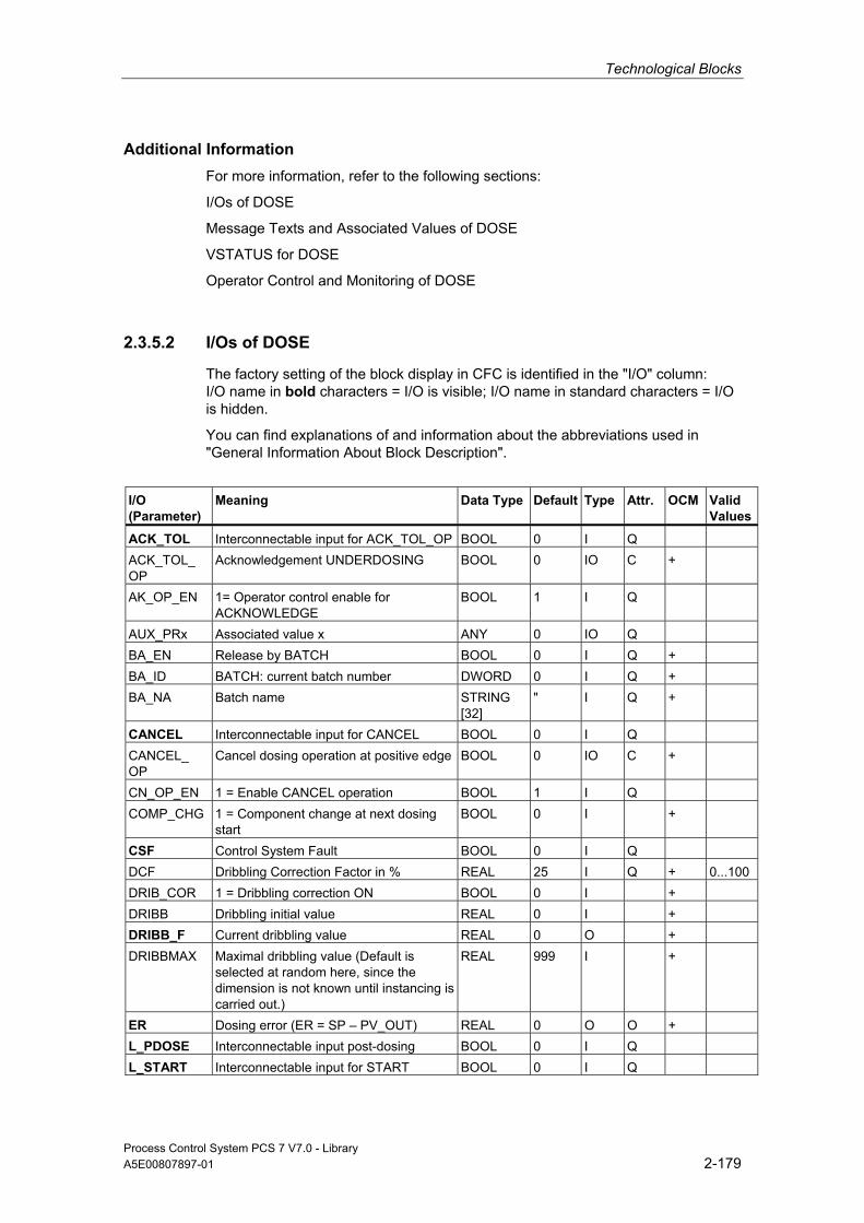
Technological Blocks
Process Control System PCS 7 V7.0 - Library A5E00807897-01 2-179
Additional Information For more information, refer to the following sections:
I/Os of DOSE
Message Texts and Associated Values of DOSE
VSTATUS for DOSE
Operator Control and Monitoring of DOSE
2.3.5.2 I/Os of DOSE
The factory setting of the block display in CFC is identified in the "I/O" column: I/O name in bold characters = I/O is visible; I/O name in standard characters = I/O is hidden.
You can find explanations of and information about the abbreviations used in "General Information About Block Description".
I/O (Parameter)
Meaning Data Type
Default Type
Attr. OCM Valid Values
ACK_TOL Interconnectable input for ACK_TOL_OP BOOL 0 I Q ACK_TOL_ OP
Acknowledgement UNDERDOSING BOOL 0 IO C +
AK_OP_EN 1= Operator control enable for ACKNOWLEDGE
BOOL 1 I Q
AUX_PRx Associated value x ANY 0 IO Q BA_EN Release by BATCH BOOL 0 I Q + BA_ID BATCH: current batch number DWORD 0 I Q + BA_NA Batch name STRING
[32] " I Q +
CANCEL Interconnectable input for CANCEL BOOL 0 I Q CANCEL_ OP
Cancel dosing operation at positive edge BOOL 0 IO C +
CN_OP_EN 1 = Enable CANCEL operation BOOL 1 I Q COMP_CHG 1 = Component change at next dosing
start BOOL 0 I +
CSF Control System Fault BOOL 0 I Q DCF Dribbling Correction Factor in % REAL 25 I Q + 0...100 DRIB_COR 1 = Dribbling correction ON BOOL 0 I + DRIBB Dribbling initial value REAL 0 I + DRIBB_F Current dribbling value REAL 0 O + DRIBBMAX Maximal dribbling value (Default is
selected at random here, since the dimension is not known until instancing is carried out.)
REAL 999 I +
ER Dosing error (ER = SP – PV_OUT) REAL 0 O O + L_PDOSE Interconnectable input post-dosing BOOL 0 I Q L_START Interconnectable input for START BOOL 0 I Q
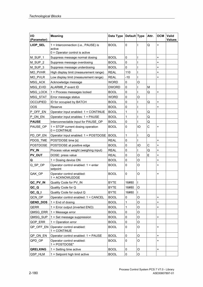
Technological Blocks
Process Control System PCS 7 V7.0 - Library 2-180 A5E00807897-01
I/O (Parameter)
Meaning Data Type
Default Type
Attr. OCM Valid Values
LIOP_SEL 1 = Interconnection (i.e., PAUSE) is active 0 = Operator control is active
BOOL 0 I Q +
M_SUP_1 Suppress message normal dosing BOOL 0 I + M_SUP_2 Suppress message overdosing BOOL 0 I + M_SUP_3 Suppress message underdosing BOOL 0 I + MO_PVHR High display limit (measurement range) REAL 110 I + MO_PVLR Low display limit (measurement range) REAL -10 I + MSG_ACK Acknowledge message WORD 0 O MSG_EVID ALARM8_P event ID DWORD 0 I M MSG_LOCK 1 = Process messages locked BOOL 0 I Q + MSG_STAT Error message status WORD 0 O OCCUPIED ID for occupied by BATCH BOOL 0 I Q + OOS Reserve BOOL 0 I + P_OFF_EN Operator input enabled: 1 = CONTINUE BOOL 1 I Q P_ON_EN Operator input enables: 1 = PAUSE BOOL 1 I Q PAUSE Interconnectable input for PAUSE_OP BOOL 0 I Q PAUSE_OP 1 = STOP current dosing operation
0 = CONTINUE BOOL 0 IO C +
PD_OP_EN Operator input enabled: 1 = POSTDOSE BOOL 1 I Q PDOS_TME POSTDOSE time [s] REAL 0 I + POSTDOSE POSTDOSE at positive edge BOOL 0 IO C + PV_IN Process value weight (weighing input) REAL 0 I Q + PV_OUT DOSE: press value REAL 0 O E + Q 1 = Dosing device ON BOOL 0 O + Q_SP_OP Operator control enabled: 1 = enter
setpoint BOOL 0 O +
QAK_OP Operator control enabled: 1 = ACKNOWLEDGE
BOOL 0 O +
QC_PV_IN Quality Code for PV_IN BYTE 16#80 I QC_Q Quality Code for Q BYTE 16#80 O QC_Q_I Quality Code for output Q BYTE 16#80 I QCN_OP Operator control enabled: 1 = CANCEL BOOL 0 O + QEND_DOS 1 = End of dosing BOOL 1 O + QERR 1 = Error output (inverted ENO) BOOL 1 O + QMSG_ERR 1 = Message error BOOL 0 O QMSG_SUP 1 = Set message suppression BOOL 0 O + QOP_ERR 1 = Operation error BOOL 0 O QP_OFF_EN Operator control enabled:
1 = CONTINUE BOOL 0 O +
QP_ON_EN Operator control enabled: 1 = PAUSE BOOL 0 O + QPD_OP Operator control enabled:
1 = POSTDOSE" BOOL 0 O +
QRELXING 1 = Setting time active BOOL 0 O + QSP_HLM 1 = Setpoint high limit active BOOL 0 O
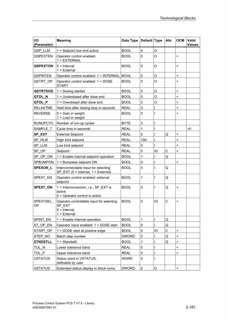
Technological Blocks
Process Control System PCS 7 V7.0 - Library A5E00807897-01 2-181
I/O (Parameter)
Meaning Data Type
Default Type
Attr. OCM Valid Values
QSP_LLM 1 = Setpoint low limit active BOOL 0 O QSPEXTEN Operator control enabled:
1 = EXTERNAL BOOL 0 O +
QSPEXTON 0 = Internal 1 = External
BOOL 0 O +
QSPINTEN Operator control enabled: 1 = INTERNAL BOOL 0 O + QSTRT_OP Operator control enabled: 1 = DOSE
START BOOL 0 O +
QSTRTDOS 1 = Dosing started BOOL 0 O + QTOL_N 1 = Underdosed after dose end BOOL 0 O + QTOL_P 1 = Overdosed after dose end BOOL 0 O + RELAXTME Wait time after dosing stop in seconds REAL 3 I + REVERSE 0 = Gain in weight
1 = Loss in weight BOOL 0 I +
RUNUPCYC Number of run-up cycles BYTE 3 I SAMPLE_T Cycle time in seconds REAL 1 I >0 SP_EXT External Setpoint REAL 0 I Q + SP_HLM High limit setpoint REAL 100 I + SP_LLM Low limit setpoint REAL 0 I + SP_OP Setpoint REAL 0 IO C + SP_OP_ON 1 = Enable internal setpoint operation BOOL 1 I Q SPBUMPON 1 = Bumpless setpoint ON BOOL 0 I + SPEXON_L Interconnectable input for selecting
SP_EXT (0 = Internal, 1 = External) BOOL 0 I Q
SPEXT_EN Operator control enabled: external setpoint
BOOL 1 I Q
SPEXT_ON 1 = Interconnection, i.e., SP_EXT is active 0 = Operator control is active
BOOL 0 I Q +
SPEXTSEL_ OP
Operator-controllable input for selecting SP_EXT 0 = Internal 1 = External
BOOL 0 IO C +
SPINT_EN 1 = Enable internal operation BOOL 1 I Q ST_OP_EN Operator input enabled: 1 = DOSE start BOOL 0 I Q START_OP 1 = DOSE start at positive edge BOOL 0 IO C + STEP_NO Batch step number DWORD 0 I Q + STNDSTLL 1 = Standstill BOOL 1 I Q + TOL_N Lower tolerance band REAL 0 I + TOL_P Upper tolerance band REAL 0 I + USTATUS Status word in VSTATUS;
definable by user WORD 0 I
VSTATUS Extended status display in block icons DWORD 0 O +
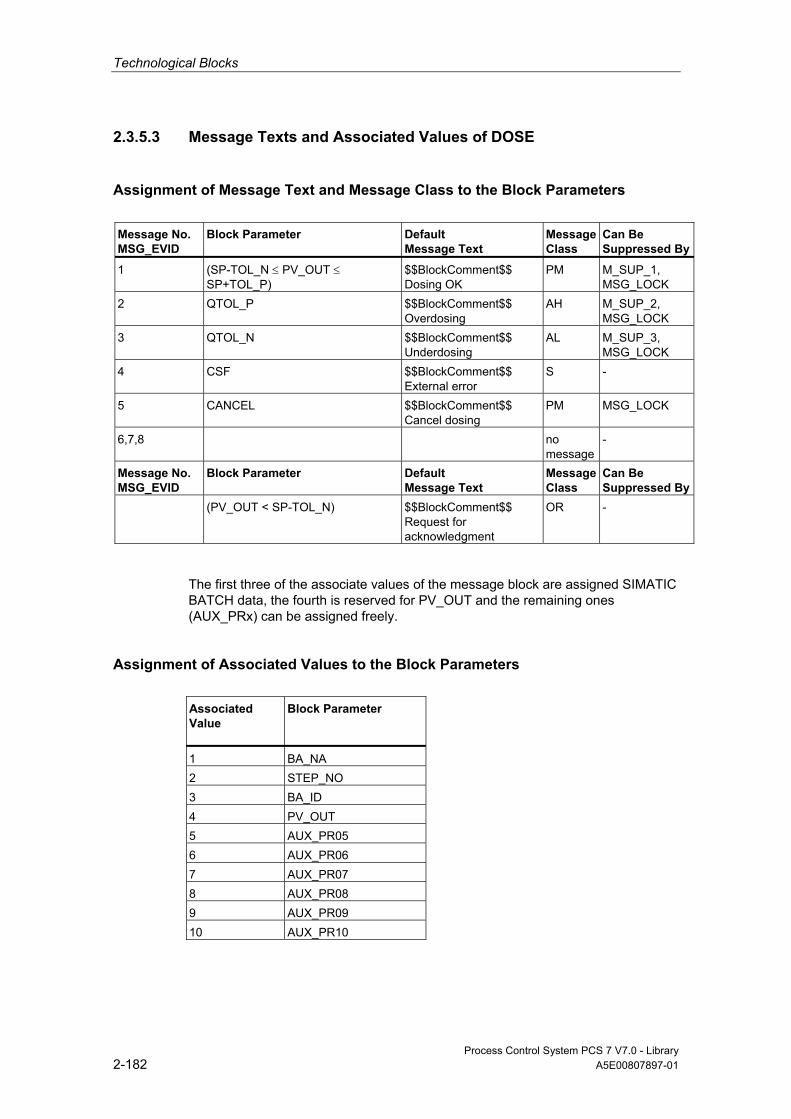
Technological Blocks
Process Control System PCS 7 V7.0 - Library 2-182 A5E00807897-01
2.3.5.3 Message Texts and Associated Values of DOSE
Assignment of Message Text and Message Class to the Block Parameters
Message No. MSG_EVID
Block Parameter
Default Message Text
Message Class
Can Be Suppressed By
1 (SP-TOL_N ≤ PV_OUT ≤ SP+TOL_P)
$$BlockComment$$ Dosing OK
PM M_SUP_1, MSG_LOCK
2 QTOL_P $$BlockComment$$ Overdosing
AH M_SUP_2, MSG_LOCK
3 QTOL_N $$BlockComment$$ Underdosing
AL M_SUP_3, MSG_LOCK
4 CSF $$BlockComment$$ External error
S -
5 CANCEL $$BlockComment$$ Cancel dosing
PM MSG_LOCK
6,7,8 no message
-
Message No. MSG_EVID
Block Parameter
Default Message Text
Message Class
Can Be Suppressed By
(PV_OUT < SP-TOL_N) $$BlockComment$$ Request for acknowledgment
OR -
The first three of the associate values of the message block are assigned SIMATIC BATCH data, the fourth is reserved for PV_OUT and the remaining ones (AUX_PRx) can be assigned freely.
Assignment of Associated Values to the Block Parameters Associated Value
Block Parameter
1 BA_NA 2 STEP_NO 3 BA_ID 4 PV_OUT 5 AUX_PR05 6 AUX_PR06 7 AUX_PR07 8 AUX_PR08 9 AUX_PR09 10 AUX_PR10

Technological Blocks
Process Control System PCS 7 V7.0 - Library A5E00807897-01 2-183
2.3.5.4 VSTATUS for DOSE
The 32-bit status word extends the status display in the block icons and faceplates. The 16 low bits (bits 0 - 15) are used by the block as follows:
Bit no.: 7 6 5 4 3 2 1 0
Parameters QSTRTDOS - QSPEXTON - MSG_LOCK BA_EN OCCUPIED
Bit no.: 15 14 13 12 11 10 9 8
Parameters OOS QMSG_SUP - - QTOL_N QTOL_P QEND_DOS QRELXING
The 16-bit input USTATUS (data type WORD) uses the high bits (bits 16 - 31). You can use these bits as you wish.
2.3.5.5 Operator Control and Monitoring of DOSE
Additional Information You can find additional information in the following sections:
• Block Icon DOSE
• Faceplate DOSE
Note: Online help and the PCS 7 FACEPLATES Manual are only available if the PCS 7 FACEPLATES software package is installed!
2.3.6 ELAP_CNT: Operating-Hours Counter
2.3.6.1 Description of ELAP_CNT
Object name (type + number) FB 64
*)
*)
*) Online help is only available if the PCS 7 FACEPLATES software package is installed!

Technological Blocks
Process Control System PCS 7 V7.0 - Library 2-184 A5E00807897-01
Function Block ELAP_CNT is used to measure the operating hours of units.
Mode of operation Block ELAP_CNT detects the time as long as the ON_OFF input = 1, meaning that the connected unit is operational. The value SAMPLE_T[s]/3600 is added to the value HOURS at every execution. The output HOURS thus specifies the number of operating hours.
Calling OBs This is the watchdog alarm OB into which you install the block (for example, OB 32) and OB 100.
Setting the Counter Under certain circumstances (for example, after maintenance or replacement of the unit), the initial value of the operating-hours counter has to be specified (as a rule, 0). At the OS, the operator sets the tracking value at the HOURS_OP input. This value is then passed to the HOURS output by via the TRACK_OP input or by interconnecting the TRACK input to the HOURS output.
Error handling Arithmetic errors are indicated by ENO = 0 or QERR = 1.
Startup Characteristics No special measures. After startup, the messages will be suppressed during the number of cycles set at RUNUPCYC.
Time Response The block function only makes sense in a watchdog interrupt OB. In order to ensure correct time acquisition, it should be installed (in CFC) in the runtime block of the control block of the monitored unit also.
Assignment of the 32-Bit Status Word VSTATUS You can find additional information in "VSTATUS for ELAP_CNT".

Technological Blocks
Process Control System PCS 7 V7.0 - Library A5E00807897-01 2-185
Message Capability The ELAP_CNT block uses the ALARM_8P block to generate messages.
Messages are triggered by the functions for monitoring the operating hour limits.
Messages regarding limit violation can be suppressed individually by setting the corresponding M_SUP_xx inputs. The process messages (not process control messages!) can be completely blocked with MSG_LOCK.
QMSG_SUP is set if the RUNUPCYC cycles have not expired yet since a restart and MSG_LOCK = TRUE or MSG_STAT = 21.
Monitoring of Process Values n.a.
Additional Information For more information, refer to the following sections:
I/Os of ELAP_CNT
Message Texts and Associated Values of ELAP_CNT
VSTATUS for ELAP_CNT
Operator Control and Monitoring of ELAP_CNT
2.3.6.2 I/Os of ELAP_CNT
The factory setting of the block display in CFC is identified in the "I/O" column: I/O name in bold characters = I/O is visible; I/O name in standard characters = I/O is hidden.
You can find explanations of and information about the abbreviations used in "General Information About Block Description".
I/O (Parameter)
Meaning Data Type
Default Type
Attr.
OCM
AUX_PRx Associated value x ANY 0 IO Q HOURS Duty period (hours) REAL 0 O + HOURS_AH Alarm high limit (hours) REAL 100 I + HOURS_OP Tracking value (hours) REAL 0 IO C + HOURS_WH Warning high limit (hours) REAL 95 I + M_SUP_AH 1 = Suppress HL alarm BOOL 0 I + M_SUP_WH 1 = Suppress HL warning BOOL 0 I + MO_HOUHR High display limit REAL 120 I + MO_HOULR Low display limit REAL 0 I + MSG_ACK Acknowledge message WORD 0 O MSG_EVID Message number DWORD 0 I M MSG_LOCK 1 = Process messages locked BOOL 0 I Q + MSG_STAT Error message status WORD 0 O

Technological Blocks
Process Control System PCS 7 V7.0 - Library 2-186 A5E00807897-01
I/O (Parameter)
Meaning Data Type
Default Type
Attr.
OCM
ON_OFF Unit status 1 = ON 0 = OFF
BOOL 0 I Q +
OOS Reserve BOOL 0 I + QC_ON_OFF Quality Code for ON_OFF BYTE 16#80 I QERR 1 = Error output (Inverted ENO) BOOL 1 O + QH_ALM 1 = HL alarm active BOOL 0 O QH_WRN 1 = HL warning active BOOL 0 O QMSG_ERR 1 = Message error BOOL 0 O + QMSG_SUP 1 = Message suppression BOOL 0 O + RUNUPCYC Number of run-up cycles BYTE 3 I SAMPLE_T Sampling time in seconds REAL 1 I TRACK Interconnectable input for TRACK BOOL 0 I Q TRACK_OP 1 = Set HOURS to HOURS_OP BOOL 0 IO C + USTATUS Status word in VSTATUS;
definable by user WORD 0 I
VSTATUS Extended status display in block icons DWORD 0 O +
2.3.6.3 Message Texts and Associated Values of ELAP_CNT
Assignment of Message Text and Message Class to the Block Parameters
Message No.
Block Parameter
Default Message Text Message Class
Can Be Suppressed By
1 QH_ALM $$BlockComment$$ alarm high
M M_SUP_AH, MSG_LOCK
2 QH_WRN $$BlockComment$$ warning high
M M_SUP_WH, MSG_LOCK
All associated values (AUX_PRx) of the message block can be freely assigned by the user.
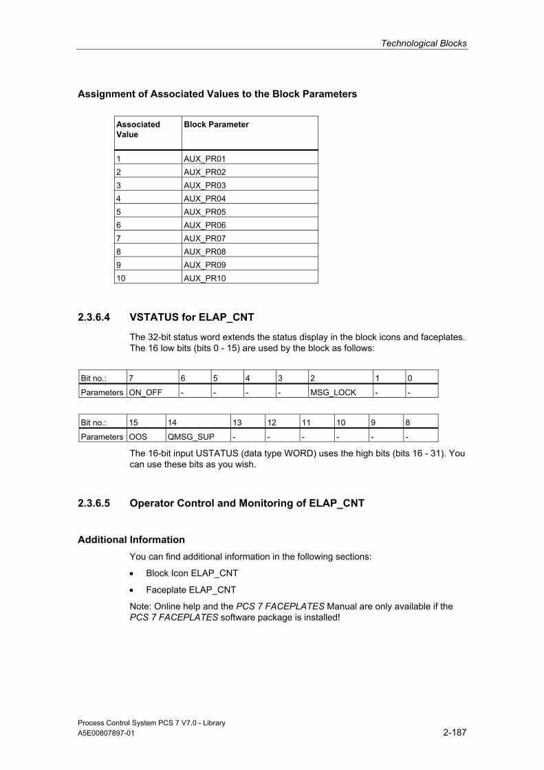
Technological Blocks
Process Control System PCS 7 V7.0 - Library A5E00807897-01 2-187
Assignment of Associated Values to the Block Parameters
Associated Value
Block Parameter
1 AUX_PR01 2 AUX_PR02 3 AUX_PR03 4 AUX_PR04 5 AUX_PR05 6 AUX_PR06 7 AUX_PR07 8 AUX_PR08 9 AUX_PR09 10 AUX_PR10
2.3.6.4 VSTATUS for ELAP_CNT
The 32-bit status word extends the status display in the block icons and faceplates. The 16 low bits (bits 0 - 15) are used by the block as follows:
Bit no.: 7 6 5 4 3 2 1 0
Parameters ON_OFF - - - - MSG_LOCK - -
Bit no.: 15 14 13 12 11 10 9 8
Parameters OOS QMSG_SUP - - - - - -
The 16-bit input USTATUS (data type WORD) uses the high bits (bits 16 - 31). You can use these bits as you wish.
2.3.6.5 Operator Control and Monitoring of ELAP_CNT
Additional Information You can find additional information in the following sections:
• Block Icon ELAP_CNT
• Faceplate ELAP_CNT
Note: Online help and the PCS 7 FACEPLATES Manual are only available if the PCS 7 FACEPLATES software package is installed!

Technological Blocks
Process Control System PCS 7 V7.0 - Library 2-188 A5E00807897-01
2.3.7 INTERLOK: Status Display Lock
2.3.7.1 Description of INTERLOK
Object name (type + number) FB 75
*)
*)
*) Online help is only available if the PCS 7 FACEPLATES software package is installed!
Function The INTERLOK block is used to implement a standardized status display lock, which can be called on the OS. The block can be assigned a maximum of 10 input signals, which can each be inverted as required.
Mode of operation The first five inputs I1_1 to I1_5 form a group. Each signal can be linked logically either directly or inverted by setting the corresponding inputs NEG1_1 to NEG1_5. The type of logic operation of the first group is set at the AND_OR1 parameter. NEGRES_1 = 1 inverts the result of Q1 used to form Q via AND_OR3. Output Q1, however is not inverted.
The same applies to the second group of five inputs. The two group results can be operated linked logically by an AND/OR operation.
With input OVERWRITE = 1 the output Q can be set to low when an interlock is active (Q = 1) and is only possible if OVERW_EN = 1. Input OVERWRITE = 0 if OVERW_EN = 0 or if the interlock condition is not satisfied. Q_OVERWR = 1 at the output indicates that output Q has been overwritten.
The following applies only if input CHECK_EN = TRUE: The output parameter FIRST_I contains the number (1 to 10) of the input Ix which was first TRUE or inverted FALSE. If several conditions are set simultaneously, the lowest number is entered in FIRST_I. A positive edge at input RESET sets FIRST_I equal to zero, if none of the above conditions are satisfied. Output Q is usually interconnected with RESET.
Technological Blocks
Process Control System PCS 7 V7.0 - Library A5E00807897-01 2-189
Calling OBs The calling OB is in the same OB and after the last block whose signals are to be displayed on the INTERLOK.
Error handling Only by means of the operating system.
Startup Characteristics No special measures are required.
Time Response The block does not have a time response.
Assignment of the 32-Bit Status Word VSTATUS You can find additional information in "VSTATUS for INTERLOK".
Message Capability n.a.
Monitoring of Process Values n.a.
Additional Information For more information, refer to the following sections:
I/Os of INTERLOK
VSTATUS for INTERLOK
Operator Control and Monitoring of INTERLOK

Technological Blocks
Process Control System PCS 7 V7.0 - Library 2-190 A5E00807897-01
2.3.7.2 I/Os of INTERLOK
The factory setting of the block display in CFC is identified in the "I/O" column: I/O name in bold characters = I/O is visible; I/O name in standard characters = I/O is hidden.
You can find explanations of and information about the abbreviations used in "General Information About Block Description".
I/O (Parameter)
Meaning
Data Type
Default Type
Attr.
OCM
AND_OR1 1 = AND 0 = OR, first group
BOOL 0 I Q +
AND_OR2 1 = AND 0 = OR, second group
BOOL 0 I Q +
AND_OR3 1 = AND 0 = OR, both groups
BOOL 0 I Q +
CHECK_EN 1 = FIRST_I Check Enable BOOL 0 I Q + FIRST_I First input signal that was TRUE (inverted
FALSE) BYTE 16#00 O +
I1_1 Input 1, first group BOOL 0 I Q + I1_2 Input 2, first group BOOL 0 I Q + I1_3 Input 3, first group BOOL 0 I Q + I1_4 Input 4, first group BOOL 0 I Q + I1_5 Input 5, first group BOOL 0 I Q + I2_1 Input 1, second group BOOL 0 I Q + I2_2 Input 2, second group BOOL 0 I Q + I2_3 Input 3, second group BOOL 0 I Q + I2_4 Input 4, second group BOOL 0 I Q + I2_5 Input 5, second group BOOL 0 I Q + NEG1_1 1 = I1_1 will be inverted BOOL 0 I Q + NEG1_2 1 = I1_2 will be inverted BOOL 0 I Q + NEG1_3 1 = I1_3 will be inverted BOOL 0 I Q + NEG1_4 1 = I1_4 will be inverted BOOL 0 I Q + NEG1_5 1 = I1_5 will be inverted BOOL 0 I Q + NEG2_1 1 = I2_1 will be inverted BOOL 0 I Q + NEG2_2 1 = I2_2 will be inverted BOOL 0 I Q + NEG2_3 1 = I2_3 will be inverted BOOL 0 I Q + NEG2_4 1 = I2_4 will be inverted BOOL 0 I Q + NEG2_5 1 = I2_5 will be inverted BOOL 0 I Q + NEGRES_1 1 = result of first group will be inverted BOOL 0 I Q + NEGRES_2 1 = result of second group will be inverted BOOL 0 I Q + OVERW_EN 1 = OVERWRITE enabled BOOL 0 I Q + OVERWRITE 1 = OVERWRITE BOOL 0 IO Q + Q Output signal BOOL 0 O + Q_OVERWR 1 = Q is overwritten BOOL 0 O + Q1 Interim result, first group BOOL 0 O + Q2 Interim result, second group BOOL 0 O +

Technological Blocks
Process Control System PCS 7 V7.0 - Library A5E00807897-01 2-191
I/O (Parameter)
Meaning
Data Type
Default Type
Attr.
OCM
QC_I1_1 Quality Code for I1_1 BYTE 16#80 I QC_I1_2 Quality Code for I1_2 BYTE 16#80 I QC_I1_3 Quality Code for I1_3 BYTE 16#80 I QC_I1_4 Quality Code for I1_4 BYTE 16#80 I QC_I1_5 Quality Code for I1_5 BYTE 16#80 I QC_I2_1 Quality Code for I2_1 BYTE 16#80 I QC_I2_2 Quality Code for I2_2 BYTE 16#80 I QC_I2_3 Quality Code for I2_3 BYTE 16#80 I QC_I2_4 Quality Code for I2_4 BYTE 16#80 I QC_I2_5 Quality Code for I2_5 BYTE 16#80 I QC_Q Quality Code for Q BYTE 16#80 O QC_Q_I Quality Code for output Q BYTE 16#80 I RESET Positive edge = reset FIRST_I BOOL 0 I Q + USTATUS Status word in VSTATUS;
definable by user WORD 0 I
VSTATUS Extended status display in block icons DWORD 0 O +
2.3.7.3 VSTATUS for INTERLOK
The 32-bit status word extends the status display in the block icons and faceplates. The 16 low bits (bits 0 - 15) are used by the block as follows:
Bit no.: 7 6 5 4 3 2 1 0
Parameters - - - I1_5 I1_4 I1_3 I1_2 I1_1
Bit no.: 15 14 13 12 11 10 9 8
Parameters - - Q I2_5 I2_4 I2_3 I2_2 I2_1
The 16-bit input USTATUS (data type WORD) uses the high bits (bits 16 - 31). You can use these bits as you wish.
Technological Blocks
Process Control System PCS 7 V7.0 - Library 2-192 A5E00807897-01
2.3.7.4 Operator Control and Monitoring of INTERLOK
Additional Information You can find additional information in the following sections:
• Block Icon INTERLOK
• Faceplate INTERLOK
Note: Online help and the PCS 7 FACEPLATES Manual are only available if the PCS 7 FACEPLATES software package is installed!
2.3.8 LIMITS_P: Limit
2.3.8.1 Description of LIMITS_P
Object name (type + number) FB 41
Function The LIMITS_P block is used to limit an analog variable to an adjustable range.
Mode of operation Block LIMITS_P passes the analog input value U to the output V as long as it lies within the set limits.
• If the value is outside the low limit, the low limit value is output. If the value is outside the high limit, the high limit value is output.
• The active limitation is indicated at the set binary outputs. A hysteresis can be set in order to avoid dithering of the display when the input value fluctuates around the limit.
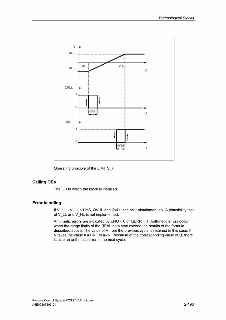
Technological Blocks
Process Control System PCS 7 V7.0 - Library A5E00807897-01 2-193
Operating principle of the LIMITS_P
Calling OBs The OB in which the block is installed.
Error handling If V_HL - V_LL ≤ HYS, QVHL and QVLL can be 1 simultaneously. A plausibility test of V_LL and V_HL is not implemented.
Arithmetic errors are indicated by ENO = 0 or QERR = 1. Arithmetic errors occur when the range limits of the REAL data type exceed the results of the formula described above. The value of V from the previous cycle is retained in this case. If V takes the value = #+INF or #-INF because of the corresponding value of U, there is also an arithmetic error in the next cycle.

Technological Blocks
Process Control System PCS 7 V7.0 - Library 2-194 A5E00807897-01
2.3.8.2 I/Os of LIMITS_P
The factory setting of the block display in CFC is identified in the "I/O" column: I/O name in bold characters = I/O is visible; I/O name in standard characters = I/O is hidden.
You can find explanations of and information about the abbreviations used in "General Information About Block Description".
I/O (Parameter)
Meaning
Data Type
Default Type
Attr.
HYS Hysteresis REAL 0.0 I Q QERR 1 = Error BOOL 1 O QVHL High limit alarm triggered BOOL 0 O QVLL Low limit alarm triggered BOOL 0 O U Input value REAL 0.0 I Q V Output value REAL 0.0 O V_HL High limit of V REAL 100.0 I Q V_LL Low limit of V REAL 0.0 I Q
2.3.9 MUL4_P: Multiplier for a Maximum of 4 Values
2.3.9.1 Description of MUL4_P
Object name (type + number) FC 262
Function Block MUL4_P multiplies up to 4 values
V:= U1∗...∗Un (n ≤ 4).
Parameter Value Type No. Meaning
MUL4_P FC 262 Multiplier with 4 inputs
Calling OBs The OB in which the block is installed.
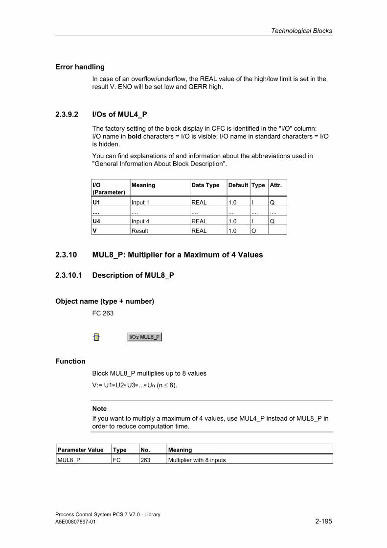
Technological Blocks
Process Control System PCS 7 V7.0 - Library A5E00807897-01 2-195
Error handling In case of an overflow/underflow, the REAL value of the high/low limit is set in the result V. ENO will be set low and QERR high.
2.3.9.2 I/Os of MUL4_P
The factory setting of the block display in CFC is identified in the "I/O" column: I/O name in bold characters = I/O is visible; I/O name in standard characters = I/O is hidden.
You can find explanations of and information about the abbreviations used in "General Information About Block Description".
I/O (Parameter)
Meaning
Data Type
Default Type
Attr.
U1 Input 1 REAL 1.0 I Q .... .... .... .... .... .... U4 Input 4 REAL 1.0 I Q V Result REAL 1.0 O
2.3.10 MUL8_P: Multiplier for a Maximum of 4 Values
2.3.10.1 Description of MUL8_P
Object name (type + number) FC 263
Function Block MUL8_P multiplies up to 8 values
V:= U1∗U2∗U3∗...∗Un (n ≤ 8).
Note
If you want to multiply a maximum of 4 values, use MUL4_P instead of MUL8_P in order to reduce computation time.
Parameter Value Type No. Meaning
MUL8_P FC 263 Multiplier with 8 inputs

Technological Blocks
Process Control System PCS 7 V7.0 - Library 2-196 A5E00807897-01
Calling OBs The OB in which the block is installed.
Error handling In case of an overflow/underflow, the REAL value of the high/low limit is set in the result V. ENO will be set low and QERR high.
2.3.10.2 I/Os of MUL8_P
The factory setting of the block display in CFC is identified in the "I/O" column: I/O name in bold characters = I/O is visible; I/O name in standard characters = I/O is hidden.
You can find explanations of and information about the abbreviations used in "General Information About Block Description".
I/O (Parameter)
Meaning
Data Type
Default Type
Attr.
U1 Input 1 REAL 1.0 I Q .... .... .... .... .... U8 Input 8 REAL 1.0 I Q V Result REAL 1.0 O
2.3.11 OB1_TIME: Determining the Degree of CPU Utilization
2.3.11.1 Description of OB1_TIME
Object name (type + number) FB 69
Function The OB1_TIME block provides information relating to the degree of CPU utilization.
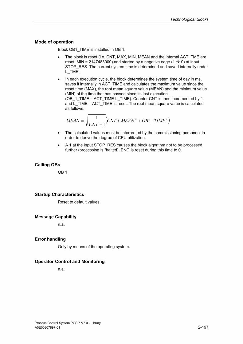
Technological Blocks
Process Control System PCS 7 V7.0 - Library A5E00807897-01 2-197
Mode of operation Block OB1_TIME is installed in OB 1.
• The block is reset (i.e. CNT, MAX, MIN, MEAN and the internal ACT_TME are reset, MIN = 2147483000) and started by a negative edge (1 0) at input STOP_RES. The current system time is determined and saved internally under L_TME.
• In each execution cycle, the block determines the system time of day in ms, saves it internally in ACT_TIME and calculates the maximum value since the reset time (MAX), the root mean square value (MEAN) and the minimum value (MIN) of the time that has passed since its last execution (OB_1_TIME = ACT_TIME-L_TIME). Counter CNT is then incremented by 1 and L_TIME = ACT_TIME is reset. The root mean square value is calculated as follows:
( )22 _11
1 TIMEOBMEANCNTCNT
MEAN +∗+
=
• The calculated values must be interpreted by the commissioning personnel in order to derive the degree of CPU utilization.
• A 1 at the input STOP_RES causes the block algorithm not to be processed further (processing is "halted). ENO is reset during this time to 0.
Calling OBs OB 1
Startup Characteristics Reset to default values.
Message Capability n.a.
Error handling Only by means of the operating system.
Operator Control and Monitoring n.a.

Technological Blocks
Process Control System PCS 7 V7.0 - Library 2-198 A5E00807897-01
2.3.11.2 I/Os of OB1_TIME
The factory setting of the block display in CFC is identified in the "I/O" column: I/O name in bold characters = I/O is visible; I/O name in standard characters = I/O is hidden.
You can find explanations of and information about the abbreviations used in "General Information About Block Description".
I/O (Parameter)
Meaning
Data Type
Default Type
Attr.
CNT Counter DINT 0 O MAX Maximum time value in milliseconds DINT 0 O MAX_CNT Maximum CNT value in milliseconds DINT 10000 I MEAN Quadratic mean value in milliseconds DINT 0 O MIN Minimum time value in milliseconds DINT 0 O OB1_TIME Cycle execution time ACT_TIME - L_TIME DINT 0 O QERR Inverted value of ENO BOOL 1 O STOP_MAX 1 = STOP if CNT = MAX_CNT BOOL 0 I Q STOP_RES STOP/RESET
1 = STOP 0 = Reset
BOOL 1 I Q
2.3.12 SWIT_CNT: Switching-Operation Counter
2.3.12.1 Description of SWIT_CNT
Object name (type + number) FB 71
*)
*)
*) Online help is only available if the PCS 7 FACEPLATES software package is installed!
Function Block SWIT_CNT is used to count unit switching operations.
Technological Blocks
Process Control System PCS 7 V7.0 - Library A5E00807897-01 2-199
Mode of operation Block SWIT_CNT counts the switching operations at a positive edge (0 1) at input ON_OFF and outputs the result at the output V. The maximum count value is limited to 2 high 31 switching operations, since it is of the data type DINT.
Calling OBs The calling OB is in the same OB and after the block which supplies switching signals, also in OB 100.
Tracking The counter output V can be tracked to the value VTRACK_OP by setting TRACK_OP via the OS or by interconnecting TRACK. VTRACK_OP can, in turn be controlled by the operator.
Monitor Limits A warning or alarm limit can be set at each of the inputs VWH and VAH. When these are exceeded, the count value V generates a display (at QH_WRN/QH_ALM) and, if necessary, a message. You can find additional information in "Message Capability".
Error handling Upon a counter overflow of V, the error output QERR is set for one cycle and a control system message is transmitted. The counter is then resumed at "0". Operator errors are displayed at output QOP_ERR.
Startup Characteristics During startup (OB 100), output V = 0 is set. After startup, the messages will be suppressed during the number of cycles set at RUNUPCYC.
Time Response The block must be executed in the same runtime group (for CFC planning) as the control block of the unit to be monitored and recognize the edges reliably.
Assignment of the 32-Bit Status Word VSTATUS You can find additional information in "VSTATUS for SWIT_CNT".
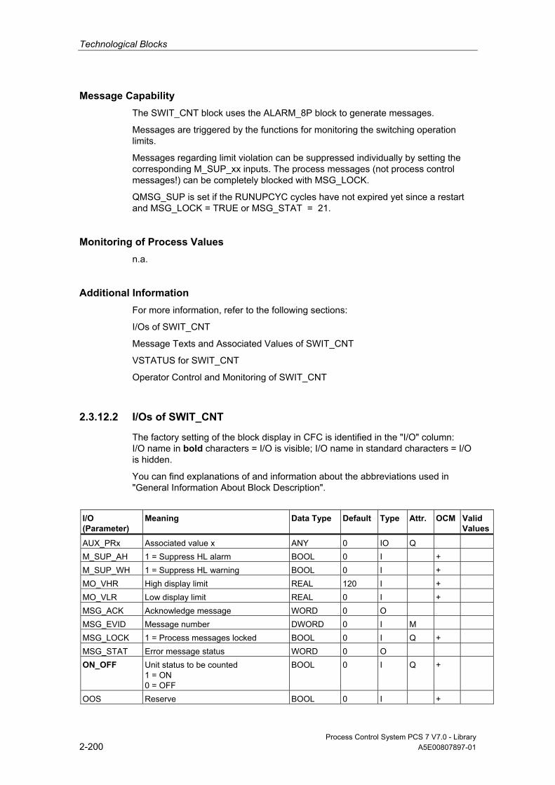
Technological Blocks
Process Control System PCS 7 V7.0 - Library 2-200 A5E00807897-01
Message Capability The SWIT_CNT block uses the ALARM_8P block to generate messages.
Messages are triggered by the functions for monitoring the switching operation limits.
Messages regarding limit violation can be suppressed individually by setting the corresponding M_SUP_xx inputs. The process messages (not process control messages!) can be completely blocked with MSG_LOCK.
QMSG_SUP is set if the RUNUPCYC cycles have not expired yet since a restart and MSG_LOCK = TRUE or MSG_STAT = 21.
Monitoring of Process Values n.a.
Additional Information For more information, refer to the following sections:
I/Os of SWIT_CNT
Message Texts and Associated Values of SWIT_CNT
VSTATUS for SWIT_CNT
Operator Control and Monitoring of SWIT_CNT
2.3.12.2 I/Os of SWIT_CNT
The factory setting of the block display in CFC is identified in the "I/O" column: I/O name in bold characters = I/O is visible; I/O name in standard characters = I/O is hidden.
You can find explanations of and information about the abbreviations used in "General Information About Block Description".
I/O (Parameter)
Meaning Data Type
Default Type
Attr.
OCM Valid Values
AUX_PRx Associated value x ANY 0 IO Q M_SUP_AH 1 = Suppress HL alarm BOOL 0 I + M_SUP_WH 1 = Suppress HL warning BOOL 0 I + MO_VHR High display limit REAL 120 I + MO_VLR Low display limit REAL 0 I + MSG_ACK Acknowledge message WORD 0 O MSG_EVID Message number DWORD 0 I M MSG_LOCK 1 = Process messages locked BOOL 0 I Q + MSG_STAT Error message status WORD 0 O ON_OFF Unit status to be counted
1 = ON 0 = OFF
BOOL 0 I Q +
OOS Reserve BOOL 0 I +

Technological Blocks
Process Control System PCS 7 V7.0 - Library A5E00807897-01 2-201
I/O (Parameter)
Meaning Data Type
Default Type
Attr.
OCM Valid Values
QC_ON_OFF Quality Code for ON_OFF BYTE 16#80 I QERR 1 = Error output (inverted ENO) BOOL 1 O + QH_ALM 1 = HL alarm triggered BOOL 0 O QH_WRN 1 = HL warning triggered BOOL 0 O QMSG_ERR 1 = ALARM_8P error BOOL 0 O + QMSG_SUP 1 = Message suppression BOOL 0 O + RUNUPCYC Number of run-up cycles INT 3 I TRACK Interconnectable input for TRACK BOOL 0 I Q TRACK_OP 1 = Follow V to VTRACK_OP BOOL 0 IO C + V Number of switching cycles DINT 0 O + VAH High limit alarm, count value DINT 100 I + VTRACK_OP Tracking value DINT 0 IO C + ≥ 0 VWH High warning alarm, count value DINT 95 I +
USTATUS Status word in VSTATUS; definable by user
WORD 0 I
VSTATUS Extended status display in block icons DWORD 0 O +
2.3.12.3 Message Texts and Associated Values of SWIT_CNT
Assignment of Message Text and Message Class to the Block Parameters
Message No.
Block Parameter
Default Message Text Message Class
Can Be Suppressed By
1 QAH $$BlockComment$$ alarm high
M M_SUP_AH, MSG_LOCK
2 QWH $$BlockComment$$ warning high
M M_SUP_WH, MSG_LOCK
All the associated values (AUX_PRx) of the message block can be freely assigned by the user.

Technological Blocks
Process Control System PCS 7 V7.0 - Library 2-202 A5E00807897-01
Assignment of Associated Values to the Block Parameters Associated Value
Block Parameter
1 AUX_PR01 2 AUX_PR02 3 AUX_PR03 4 AUX_PR04 5 AUX_PR05 6 AUX_PR06 7 AUX_PR07 8 AUX_PR08 9 AUX_PR09 10 AUX_PR10
2.3.12.4 VSTATUS for SWIT_CNT
The 32-bit status word extends the status display in the block icons and faceplates. The 16 low bits (bits 0 - 15) are used by the block as follows:
Bit no.: 7 6 5 4 3 2 1 0
Parameters ON_OFF - - - - MSG_LOCK - -
Bit no.: 15 14 13 12 11 10 9 8
Parameters OOS QMSG_SUP - - - - - -
The 16-bit input USTATUS (data type WORD) uses the high bits (bits 16 - 31). You can use these bits as you wish.
2.3.12.5 Operator Control and Monitoring of SWIT_CNT
Additional Information You can find additional information in the following sections:
• Block Icon SWIT_CNT
• Faceplate SWIT_CNT
Note: Online help and the PCS 7 FACEPLATES Manual are only available if the PCS 7 FACEPLATES software package is installed!

Technological Blocks
Process Control System PCS 7 V7.0 - Library A5E00807897-01 2-203
2.4 Conversion Blocks
2.4.1 General Information About Conversion Blocks
What Conversion Blocks Are Used For In CFC you can only connect block outputs (source type) to inputs (target type) of the same data type (for example, REAL output with REAL input). Conversion blocks must be used to allow the interconnection of different data types. The input and output data of the block are of a different type, and it thus converts the input data type according to the data type set at the output. The CFC block library ELEMENTA contains the conversion blocks required for these interconnections and an additional R_TO_DW block with expanded properties for process-engineering applications.
Calling OBs The conversion block must be installed in the OB upstream of the block that evaluates the conversion result.
2.4.2 R_TO_DW: Conversion
2.4.2.1 Description of R_TO_DW
Object name (type + number) FC 282
Function Block R_TO_DW converts a REAL number to a double word (DW). REAL numbers between 0 and 4294967000 are accepted.
Error handling If the values are outside the limits specified above, ENO = 0 and the low limit ( = 0) or high limit ( = 4294967000) will be set.

Technological Blocks
Process Control System PCS 7 V7.0 - Library 2-204 A5E00807897-01
2.4.2.2 I/Os of R_TO_DW
The factory setting of the block display in CFC is identified in the "I/O" column: I/O name in bold characters = I/O is visible; I/O name in standard characters = I/O is hidden.
You can find explanations of and information about the abbreviations used in "General Information About Block Description".
I/O (Parameter)
Meaning
Data Type
Default Type
U Value to convert REAL 0.0 I V Converted value DWORD 0 O
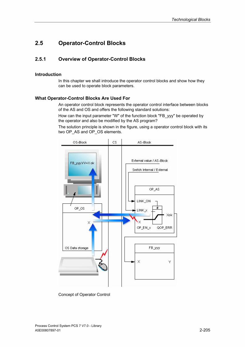
Technological Blocks
Process Control System PCS 7 V7.0 - Library A5E00807897-01 2-205
2.5 Operator-Control Blocks
2.5.1 Overview of Operator-Control Blocks
Introduction In this chapter we shall introduce the operator control blocks and show how they can be used to operate block parameters.
What Operator-Control Blocks Are Used For An operator control block represents the operator control interface between blocks of the AS and OS and offers the following standard solutions: How can the input parameter "W" of the function block "FB_yyy" be operated by the operator and also be modified by the AS program? The solution principle is shown in the figure, using a operator control block with its two OP_AS and OP_OS elements.
Concept of Operator Control
Technological Blocks
Process Control System PCS 7 V7.0 - Library 2-206 A5E00807897-01
Concept of Operator Control The operator-control block must be used at two locations simultaneously:
• In the AS (AS block, abbreviated as OP_AS)
• In the OS (OS block, abbreviated as OP_OS)
The valid value output at OP_AS can be based on two different sources:
• an external source, i.e., it is provided by another AS block (via the LINK_x input),
• an internal source, i.e., it is provided by the OP_OS block operated via the OS block.
General operating procedure:
• The OP_OS selected at the OS queries the values at OP_AS, or the enable/disable status of operator control. The display keeps the operator constantly informed of the current status of OP_AS. the result is displayed asynchronously to the OP_AS in an OS-specific runtime cycle.
• The operator controls/modifies an operator-controllable I/O of the OP_OS, whose algorithm checks the validity of input data:
- Invalid entries (block-specific) are corrected or rejected, depending on the situation. A corresponding message is output to the operator.
- The corrected or valid value is transferred to OP_AS and logged at the OS.
• The OP_AS receives the value and performs a validity check, since it could well be that the current AS status has changed since the last execution of OP_OS.
- Entries that are now invalid (block-specific) are corrected or rejected, depending on the situation. The OP_AS reports the result at the Boolean output QOP_ERR, i.e. it outputs a pulse of a width equal to the sampling time of OP_AS.
- The corrected or valid value, or the old valid value, is output for further use at the corresponding Xok output of the OP_AS.
Overview The table below provides an overview of the operator-control blocks. These are implemented as FBs that require an instance DB each for each application.
Block Name
Meaning
Operating Method
FB No.
OP_A Analog value operation 45 OP_A_LIM Analog value operation Limiting 46 OP_A_RJC Analog value operation Rejecting 47 OP_D Digital value operation, 2 pushbuttons 48 OP_D3 Digital value operation, 3 pushbuttons 49 OP_TRIG Digital value operation, pushbutton function 50

Technological Blocks
Process Control System PCS 7 V7.0 - Library A5E00807897-01 2-207
General I/Os The operator-control blocks (refer to the figure above) are assigned defined I/Os for the operation of binary and analog values. The significance of their I/Os is the same for all operator control blocks as well for operator control blocks that process only analog values (in the picture indicated by brackets).
The function of these I/Os is described briefly below.
Inputs • EN is used to set/reset the block algorithm.
- EN = 1: The block is called from the OB in which it is installed.
- EN = 0: The block call is skipped in the OB.
• X (representative identifier for the operator controlled input) is written as an IO type by the OS, sampled by the AS block and overwritten, if appropriate. This input is retroactive and may not be interconnected.
• X_HL and X_LL define the high and low operation limits of X (only for analog-value operation). Operating values which violate these limits will either be limited or rejected, depending on the type of the operator control block.
Structure of the operator control block (general)

Technological Blocks
Process Control System PCS 7 V7.0 - Library 2-208 A5E00807897-01
• LINK_x is interconnected with an external value and offers the external alternative to the input X that is supplied internally (by operator control) (also refer to LINK_ON).
• LINK_ON changes mode, which selects the value to be processed:
- LINK_ON = 1: The value at input LINK_x, which is usually received from another interconnected block, is handled as external default value.
- LINK_ON = 0: The value at input X, which is usually entered at the OS, is handled as an internal default value (output by its own OP_XX).
• BTRACK (if it exists) is used for bumpless changeover operations during the transition of LINK_ON = 1 to LINK_ON = 0.
- BTRACK = 1: When LINK_ON = 1, the algorithm tracks the operator controlled inputs X to the LINK_x inputs accordingly. The object of this operation is to ensure that the block does not process any old operating values of the X inputs and thus change active values (that have been output) during the changeover to manual mode (LINK_ON = 0).
- BTRACK = 0: When LINK_ON = 1, the operator controlled inputs X will not be overwritten. Hence, their value will usually remain different to the value at LINK_x. During the changeover LINK_ON = 0 these old values become valid again and lead to corresponding changes of the active Xok output values (referred to as bump).
• The OP_EN_x parameter is used to enable/disable operator control of the assigned input X:
- OP_EN_x = 1: Input X is enabled for operator controls.
- OP_EN_x = 0: Operator control is locked or rejected.
Outputs • ENO indicates the validity of the result Xok (1 = OK, 0 = invalid).
• QERR = Inverted ENO (stored in the block instance).
• A logic "1" at the QOP_ERR parameter indicates an operator control error. The output will be reset again at the next cycle (sampling time).
• Xok (representative identifier for the effective active output) contains the valid output value, depending on the operator-control-block type and operating mode. It is made available by means of an interconnection to the AS block whose input is to be operated. Depending on the operator-control block, the specific identifier is then V or Q_1, for example.
• QxHL and QxLL indicate violation of the high/low operation limits for X (analog-value operations only). Operating values violating these limits will either be limited or rejected, depending on the type of the operator-control block.
Technological Blocks
Process Control System PCS 7 V7.0 - Library A5E00807897-01 2-209
• QOP_ENx contains the output value, which is passed on according to OP_ENx. It can be queried by other AS blocks, and provides information on the current enable/disable status of operator control of OP_AS.
2.5.2 OP_A: Analog Value Operation
2.5.2.1 Description of OP_A
Object name (type + number) FB 45
. . *)
. . *)
*) Online help is available if the PCS 7 FACEPLATES software package is installed!
Function Block OP_A is a basic operator-control block for processing analog values of an AS block, without limit monitoring and operator enable functions.
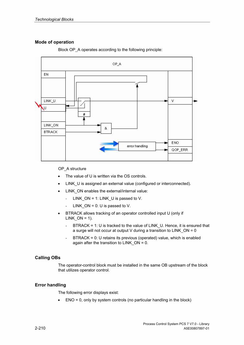
Technological Blocks
Process Control System PCS 7 V7.0 - Library 2-210 A5E00807897-01
Mode of operation Block OP_A operates according to the following principle:
OP_A structure
• The value of U is written via the OS controls.
• LINK_U is assigned an external value (configured or interconnected).
• LINK_ON enables the external/internal value:
- LINK_ON = 1: LINK_U is passed to V.
- LINK_ON = 0: U is passed to V.
• BTRACK allows tracking of an operator controlled input U (only if LINK_ON = 1).
- BTRACK = 1: U is tracked to the value of LINK_U. Hence, it is ensured that a surge will not occur at output V during a transition to LINK_ON = 0
- BTRACK = 0: U retains its previous (operated) value, which is enabled again after the transition to LINK_ON = 0.
Calling OBs The operator-control block must be installed in the same OB upstream of the block that utilizes operator control.
Error handling The following error displays exist:
• ENO = 0, only by system controls (no particular handling in the block)
Technological Blocks
Process Control System PCS 7 V7.0 - Library A5E00807897-01 2-211
• QOP_ERR = 1 is set for the duration of one cycle, if an operation is performed at input U while an active external value (LINK_ON = 1) is set. Input U retains its previous value (status prior to operator intervention).
Error Displays of the OP_A
ENO QOP_ERR Cause, if Applicable Reaction
0 X Errors detected by the system (no special handling routine in the block) 1 1 ( Π ) Operator control not permitted if LINK_ON=1. Input U retains its value.
Π: Pulse with sampling-time duration X: Random value
Time Response n.a.
Message Capability n.a. The output QOP_ERR can be interconnected with a message block in order to report operator errors. You can find additional information in "Message Blocks".
Additional Information For more information, refer to the following sections:
I/Os of OP_A
Operator Control and Monitoring of OP_A

Technological Blocks
Process Control System PCS 7 V7.0 - Library 2-212 A5E00807897-01
2.5.2.2 I/Os of OP_A
The factory setting of the block display in CFC is identified in the "I/O" column: I/O name in bold characters = I/O is visible; I/O name in standard characters = I/O is hidden.
You can find explanations of and information about the abbreviations used in "General Information About Block Description".
I/O (Parameter)
Meaning
Data Type
Default Type
Attrib.
OCM
Valid Values
BTRACK 1 = Bumpless changeover BOOL 1 I Q + LINK_ON 0 = Operator control enabled
1 = Interconnection active BOOL 0 I Q +
LINK_U Interconnectable input for U REAL 0.0 I Q QOP_ERR 1 = Operation error BOOL 1 O U Operator input, analog value REAL 0.0 IO C + V Analog value REAL 0.0 O +
2.5.2.3 Operator Control and Monitoring of OP_A
Additional Information You can find additional information in the following sections:
• Block Icon OP_A
• Faceplate OP_A
Note: Online help and the PCS 7 FACEPLATES Manual are only available if the PCS 7 FACEPLATES software package is installed!
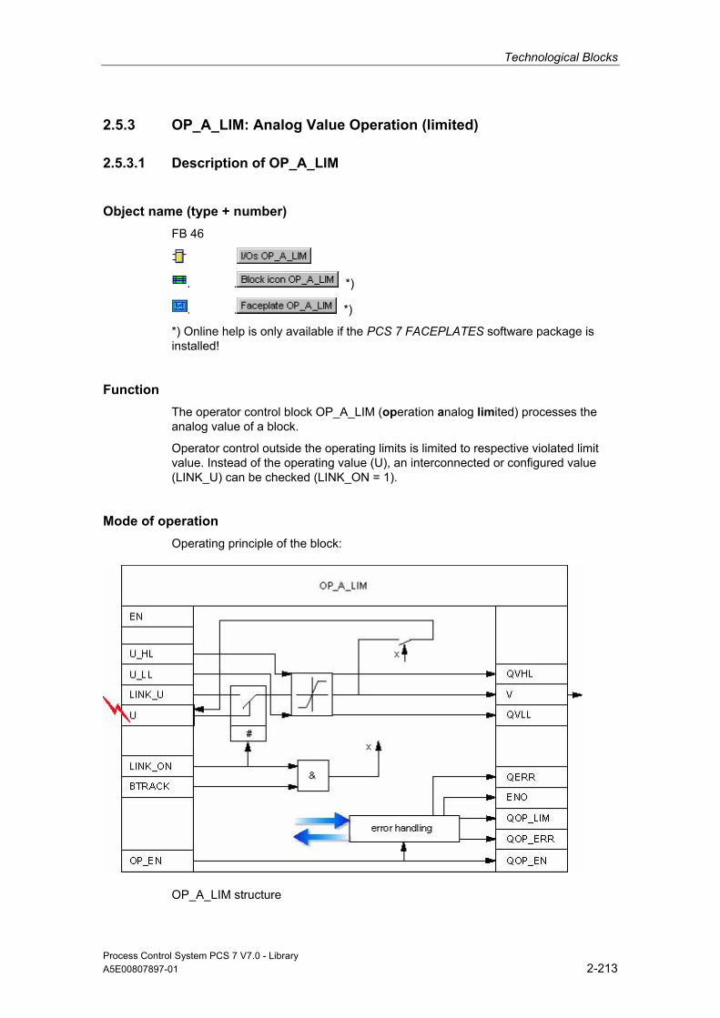
Technological Blocks
Process Control System PCS 7 V7.0 - Library A5E00807897-01 2-213
2.5.3 OP_A_LIM: Analog Value Operation (limited)
2.5.3.1 Description of OP_A_LIM
Object name (type + number) FB 46
. . *)
. . *)
*) Online help is only available if the PCS 7 FACEPLATES software package is installed!
Function The operator control block OP_A_LIM (operation analog limited) processes the analog value of a block.
Operator control outside the operating limits is limited to respective violated limit value. Instead of the operating value (U), an interconnected or configured value (LINK_U) can be checked (LINK_ON = 1).
Mode of operation Operating principle of the block:
OP_A_LIM structure

Technological Blocks
Process Control System PCS 7 V7.0 - Library 2-214 A5E00807897-01
• The value of U is written via the OS controls. The operator control is set as follows:
- enabled if OP_EN = 1,
- disabled if OP_EN = 0.
• LINK_U is assigned an external value (configured or interconnected).
• LINK_ON passes the limited external/internal value to U_LL or U_HL:
- LINK_ON = 1: The limited value LINK_U is passed to V.
- LINK_ON = 0: The limited value U is passed to V and written back to input U, i.e., input U may change due to a modification of the operation limits, without operator control.
• BTRACK allows tracking of the operator controlled input U (only if LINK_ON = 1)
- BTRACK = 1: The operator input U is tracked to the limited value LINK_U. Hence, it is ensured that a surge will not occur at output V during a transition to LINK_ON = 0
- BTRACK = 0: U retains its previous (operated) value, which is returned to output V after the transition to LINK_ON = 0.
Calling OBs The operator-control block must be installed in the same OB and upstream of the block that utilizes operator control.
Error handling The following errors are displayed:
ENO QOP_ERR QOP_LIM Cause, if Applicable Reaction
0 X X Errors recognized by the system 1 1 ( Π ) 0 Operator control not permitted if LINK_ON=1. Input U retains its
value. 1 1 ( Π ) 0 Operator input is enabled at the OS (OP_EN=1), but has been
disabled at the AS (OP_EN=0). 1 1 ( Π ) 1 ( Π ) Enabled operator control outside of limits.
Input U is limited.
Π: Pulse with sampling-time duration X: Random value

Technological Blocks
Process Control System PCS 7 V7.0 - Library A5E00807897-01 2-215
Error Displays of OP_A_LIM (Limitations)
QVLL QVHL Cause
1 0 Input value > U_HL (input value = U or LINK_U) 0 1 Input value > U_HL (input value = U or LINK_U)
Time Response n.a.
Message Capability n.a. Outputs QOP_ERR or QOP_LIM can be interconnected with a message block in order to report operator errors. You can find additional information in "Message Blocks".
Additional Information For more information, refer to the following sections:
I/Os of OP_A_LIM
Operator Control and Monitoring of OP_A_LIM
Message Blocks
2.5.3.2 I/Os OP_A_LIM
The factory setting of the block display in CFC is identified in the "I/O" column: I/O name in bold characters = I/O is visible; I/O name in standard characters = I/O is hidden.
You can find explanations of and information about the abbreviations used in "General Information About Block Description".
I/O (Parameter)
Meaning
Data Type
Default Type
Attrib.
OCM
Valid Values
BTRACK 1 = Bumpless changeover BOOL 1 I Q + LINK_ON 0 = Operator control enabled
1 = Interconnection active BOOL 0 I Q +
LINK_U Interconnectable input for U REAL 0.0 I Q OP_EN 1 = Operator-control enable BOOL 1 I Q QERR 1 = Error processing busy BOOL 1 O + QOP_EN 1 = Operator-control enable BOOL 0 O + QOP_ERR 1 = Operation error BOOL 0 O QOP_LIM 1 = Operator error, limiting BOOL 0 O QVHL 1 = High limit of V active BOOL 0 O QVLL 1 = Low limit of V active BOOL 0 O

Technological Blocks
Process Control System PCS 7 V7.0 - Library 2-216 A5E00807897-01
I/O (Parameter)
Meaning
Data Type
Default Type
Attrib.
OCM
Valid Values
U Operator input, analog value REAL 0.0 IO C + U_HL High limit REAL 100.0 I Q + U_LL Low limit REAL 0.0 I Q + V Analog value REAL 0.0 O +
2.5.3.3 Operator Control and Monitoring of OP_A_LIM
Additional Information You can find additional information in the following sections: • Block Icon OP_A_LIM • Faceplate OP_A_LIM Note: Online help and the PCS 7 FACEPLATES Manual are only available if the PCS 7 FACEPLATES software package is installed!
2.5.4 OP_A_RJC: Analog Value Operation (exclusive)
2.5.4.1 Description of OP_A_RJC
Object name (type + number) FB 47
*)
*)
*) Online help is only available if the PCS 7 FACEPLATES software package is installed!
Function The operator control block OP_A_RJC (operation analog rejected) processes the analog value of a block. Any operation outside the operating limits will be discarded. Instead of the operating value (U), an interconnected or configured value (LINK_U) can be checked (LINK_ON = 1). In this case the block limits the value according to OP_A_LIM.
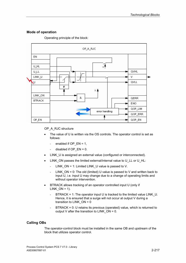
Technological Blocks
Process Control System PCS 7 V7.0 - Library A5E00807897-01 2-217
Mode of operation Operating principle of the block:
OP_A_RJC structure
• The value of U is written via the OS controls. The operator control is set as follows:
- enabled if OP_EN = 1,
- disabled if OP_EN = 0.
• LINK_U is assigned an external value (configured or interconnected).
• LINK_ON passes the limited external/internal value to U_LL or U_HL:
- LINK_ON = 1: Limited LINK_U value is passed to V.
- LINK_ON = 0: The old (limited) U value is passed to V and written back to input U, i.e. input U may change due to a change of operating limits and without operator intervention.
• BTRACK allows tracking of an operator controlled input U (only if LINK_ON = 1).
- BTRACK = 1: The operator input U is tracked to the limited value LINK_U. Hence, it is ensured that a surge will not occur at output V during a transition to LINK_ON = 0
- BTRACK = 0: U retains its previous (operated) value, which is returned to output V after the transition to LINK_ON = 0.
Calling OBs The operator-control block must be installed in the same OB and upstream of the block that utilizes operator control.

Technological Blocks
Process Control System PCS 7 V7.0 - Library 2-218 A5E00807897-01
Error handling The following errors are displayed:
ENO QOP_ERR QOP_RJC Cause, if Applicable Reaction
0 X X Errors recognized by the system 1 1 ( Π ) 0 Operator control not permitted if LINK_ON=1.
Input U retains its value. 1 1 ( Π ) 0 Operator input is enabled at the OS (OP_EN=1), but has been
disabled at the AS (OP_EN=0). 1 1 ( Π ) 1 ( Π ) Enabled operator control outside of limits.
Operated input is discarded.
Π: Pulse with sampling-time duration X: Random value
Error Displays of OP_A_RJC (Limitation Only if LINK_ON=1) QVLL QVHL Cause
1 0 Input value > U_LL (input value = LINK_U) 0 1 Input value > U_HL (input value = LINK_U)
Time Response n.a.
Message Capability n.a. Outputs QOP_ERR or QOP_RJC can be interconnected with a message block in order to report operator errors. You can find additional information in "Message Blocks".
Additional Information For more information, refer to the following sections:
I/Os of OP_A_RJC
Operator Control and Monitoring of OP_A_RJC
Message Blocks

Technological Blocks
Process Control System PCS 7 V7.0 - Library A5E00807897-01 2-219
2.5.4.2 I/Os of OP_A_RJC
The factory setting of the block display in CFC is identified in the "I/O" column: I/O name in bold characters = I/O is visible; I/O name in standard characters = I/O is hidden.
You can find explanations of and information about the abbreviations used in "General Information About Block Description".
I/O (Parameter)
Meaning
Data Type
Default Type
Attrib.
OCM
Valid Values
BTRACK 1 = Bumpless changeover BOOL 1 I Q + LINK_ON 0 = Operator control enabled
1 = Interconnection active BOOL 0 I Q +
LINK_U Interconnectable input for U REAL 0.0 I Q OP_EN 1 = Operator-control enable BOOL 1 I Q QERR 1 = Error processing busy BOOL 1 O + QOP_EN 1 = Operator-control enable BOOL 0 O + QOP_ERR 1 = Operator error, rejecting BOOL 0 O QOP_RJC 1 = Operator error, limiting BOOL 0 O QVHL 1 = High limit of V active BOOL 0 O QVLL 1 = Low limit of V active BOOL 0 O U Operator input, analog value REAL 0.0 IO C + U_HL High limit REAL 100.0 I Q + U_LL Low limit REAL 0.0 I Q + V Analog value REAL 0.0 O +
2.5.4.3 Operator Control and Monitoring of OP_A_RJC
Additional Information You can find additional information in the following sections:
• Block Icon OP_A_RJC
• Faceplate OP_A_RJC
Note: Online help and the PCS 7 FACEPLATES Manual are only available if the PCS 7 FACEPLATES software package is installed!
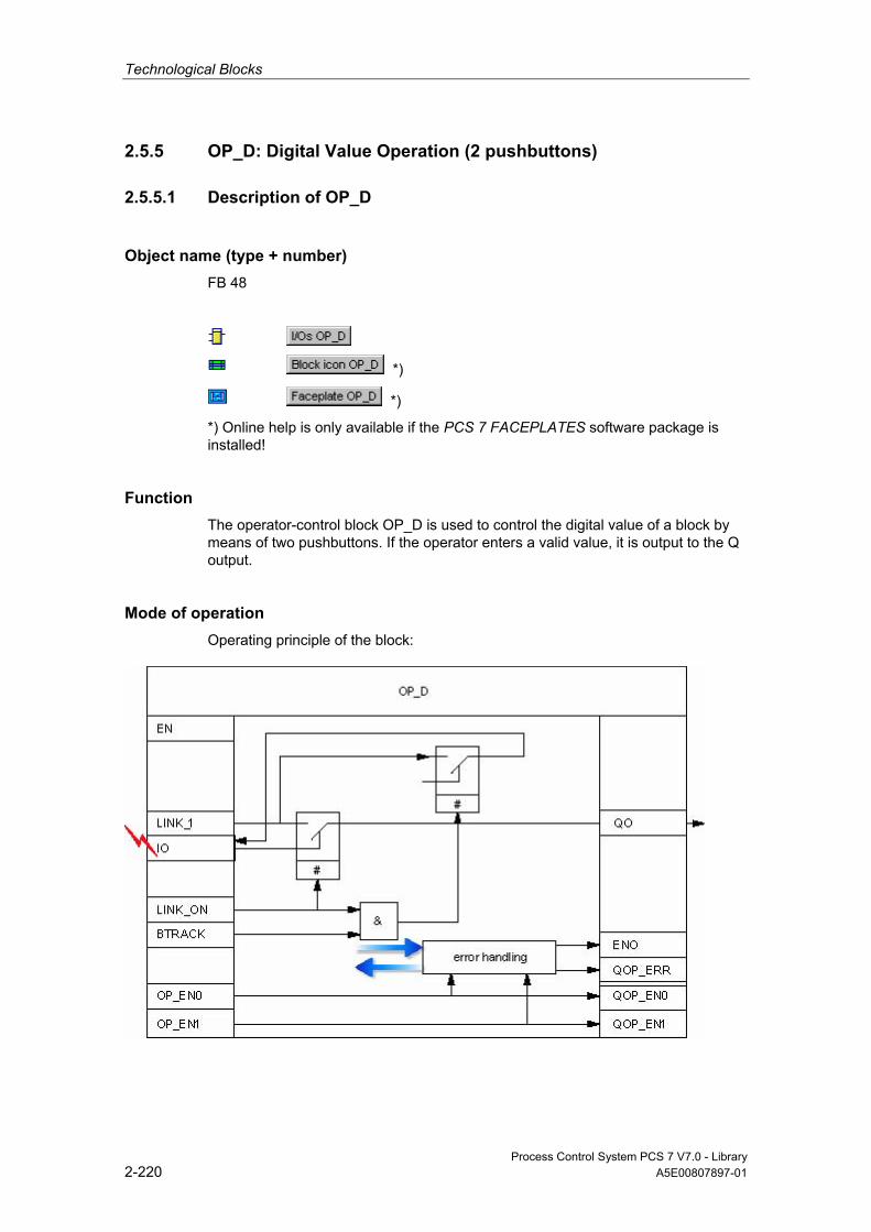
Technological Blocks
Process Control System PCS 7 V7.0 - Library 2-220 A5E00807897-01
2.5.5 OP_D: Digital Value Operation (2 pushbuttons)
2.5.5.1 Description of OP_D
Object name (type + number) FB 48
*)
*)
*) Online help is only available if the PCS 7 FACEPLATES software package is installed!
Function The operator-control block OP_D is used to control the digital value of a block by means of two pushbuttons. If the operator enters a valid value, it is output to the Q output.
Mode of operation Operating principle of the block:
Technological Blocks
Process Control System PCS 7 V7.0 - Library A5E00807897-01 2-221
OP_D structure
• I0 is written via the OS controls. Operator control is set at two separate inputs:
- OP_EN0 = 1 for "0" operation
- OP_EN1 = 1 for "1" operation
• LINK_I is assigned a configured or interconnected external value.
• LINK_ON enables the external/internal value:
- LINK_ON = 1: LINK_U is passed to Q0,
- LINK_ON = 0: The entered I0 value is passed to Q0.
• BTRACK allows tracking of the operator controlled input I0 (only if LINK_ON = 1).
- BTRACK = 1: The operator input I0 is tracked to LINK_I. In order to ensure that a surge does not occur at output Q0 during the transition of LINK_ON = 0.
- BTRACK = 0: I0 retains its last (entered) value, which is returned to output Q0 after the transition to LINK_ON = 0.
Calling OBs The operator-control block must be installed in the same OB and upstream of the block that utilizes operator control.
Error handling The following errors are displayed:
ENO QOP_ERR Cause, if Applicable Reaction
0 X Errors detected by the system (no special handling routine in the block) 1 1 ( Π ) Operator input was not enabled or performed while LINK_ON=1.
Input I0 remains unchanged.
Π: Pulse with sampling-time duration X: Random value
Time Response n.a.
Message Capability n.a. The output QOP_ERR can be interconnected with a message block in order to report operator errors. You can find additional information in "Message Blocks".

Technological Blocks
Process Control System PCS 7 V7.0 - Library 2-222 A5E00807897-01
Additional Information For more information, refer to the following sections:
I/Os of OP_D
Operator Control and Monitoring of OP_D
Message Blocks
2.5.5.2 I/Os of OP_D
The factory setting of the block display in CFC is identified in the "I/O" column: I/O name in bold characters = I/O is visible; I/O name in standard characters = I/O is hidden.
You can find explanations of and information about the abbreviations used in "General Information About Block Description".
I/O (Parameter)
Meaning
Data Type
Default
Type
Attrib.
OCM
Valid Values
BTRACK 1 = Bumpless changeover BOOL 1 I Q + I0 Operator input 0 BOOL 0 IO C + LINK_I Interconnectable input for I BOOL 0 I Q LINK_ON 0 = Operator control enabled
1 = Interconnection active BOOL 0 I Q +
OP_EN0 Operator controlled input = disabled BOOL 1 I Q OP_EN1 Operator controlled input = enabled BOOL 1 I Q Q0 Binary output BOOL 0 O + QOP_EN0 Operator controlled input = disabled BOOL 0 O + QOP_EN1 Operator controlled output = enabled BOOL 0 O + QOP_ERR 1 = Operation error BOOL 0 O
2.5.5.3 Operator Control and Monitoring of OP_D
Additional Information You can find additional information in the following sections:
• Block Icon OP_D
• Faceplate OP_D
Note: Online help and the PCS 7 FACEPLATES Manual are only available if the PCS 7 FACEPLATES software package is installed!
Technological Blocks
Process Control System PCS 7 V7.0 - Library A5E00807897-01 2-223
2.5.6 OP_D3: Digital Value Operation (3 pushbuttons)
2.5.6.1 Description of OP_D3
Object name (type + number) FB 49
*)
*)
*) Online help is only available if the PCS 7 FACEPLATES software package is installed!
Function The operator-control block OP_D3 is used to perform a logical one-of-three digital-value operation. If one of the three operator inputs I1, I2 or I3 is set, the corresponding output is set to 1 and the other outputs are reset, in as far as the operation is permissible.
Mode of operation The block operates according to the following principle: The expression x = 1..3 is used here as index for the respective three inputs/outputs:

Technological Blocks
Process Control System PCS 7 V7.0 - Library 2-224 A5E00807897-01
OP_D3 structure
• The OS control system sets the inputs I1, I2 and I3 simultaneously ("1" to the input to be enabled and "0" to the other two). Three separate inputs are used for enabling/disabling operator control:
- OP_EN_Ix = 1 : Enables operator control of input Ix
- OP_EN_Ix = 0 : Disables operator control of input Ix
• Each LINK_Ix is assigned an external configured or interconnected value.
• LINK_ON enables the external/internal values:
- LINK_ON = 1: LINK_Ix are processed and passed to Qx.
- LINK_ON = 0: Operator controlled Ix inputs are processed and passed to Qx.

Technological Blocks
Process Control System PCS 7 V7.0 - Library A5E00807897-01 2-225
• BTRACK allows tracking of the operator controlled inputs Ix (only if LINK_ON = 1).
- BTRACK = 1: The operator controlled inputs Ix are tracked to LINK_Ix, which ensures that a surge does not occur at output Qx during the transition of LINK_ON = 0.
- BTRACK = 0: Ix retains its last (operated) value, which is returned to output Qx after the transition to LINK_ON = 0.
• The selection logic applies the three input values (Ix or LINK_Ix) in the order x = 1, 2, 3 and memorizes the highest index "x" of the input with logical "1" status. The output Qx specified by the index will be set ("1"), while and the remaining two outputs Qx will be reset ("0"). If all three inputs I1 = I2 = I3 = 0, the outputs are not changed.
Calling OBs The operator-control block must be installed in the same OB and upstream of the block that utilizes operator control.
Error handling The following errors are displayed:
ENO QOP_ERR Cause, if Applicable Reaction
0 X Errors recognized by the system 0 0 All inputs are "0" or more than one input is "1". The output is set according to
the highest set input. You can find additional information in "Operating Principle" and "Selection Logic".
0 1 More than one input is "1". The output is set according to the highest set input. You can find additional information in "Operating Principle" and "Selection Logic". The error handling routine changes the inputs Ix in accordance with the rule: The input Ix with the highest index "x" remains set, the others will be reset".
Time Response n.a.
Message Capability n.a. The output QOP_ERR can be interconnected with a message block in order to report operator errors. You can find additional information in "Message Blocks".

Technological Blocks
Process Control System PCS 7 V7.0 - Library 2-226 A5E00807897-01
Additional Information For more information, refer to the following sections:
I/Os of OP_D3
Operator Control and Monitoring of OP_D3
Message Blocks
2.5.6.2 I/Os of OP_D3
The factory setting of the block display in CFC is identified in the "I/O" column: I/O name in bold characters = I/O is visible; I/O name in standard characters = I/O is hidden.
You can find explanations of and information about the abbreviations used in "General Information About Block Description".
I/O (Parameter)
Meaning
Data Type
Default Type
Attrib.
OCM
Valid Values
BTRACK 1 = Bumpless changeover BOOL 1 I Q + I1 Operator input 1 BOOL 0 IO C + I2 Operator input 2 BOOL 0 IO C + I3 Operator input 3 BOOL 1 IO C + LINK_I1 Interconnectable input for I1 BOOL 0 I Q LINK_I2 Interconnectable input for I2 BOOL 0 I Q LINK_I3 Interconnectable input for I3 BOOL 0 I Q LINK_ON 0 = Operator control enabled
1 = Interconnection active BOOL 0 I Q +
OP_EN_I1 Enable switch 1 BOOL 1 I Q OP_EN_I2 Enable switch 2 BOOL 1 I Q OP_EN_I3 Enable switch 3 BOOL 1 I Q Q1 Binary output, switch 1 BOOL 0 O + Q2 Binary output, switch 2 BOOL 0 O + Q3 Binary output, switch 3 BOOL 1 O + QERR 1 = Error processing busy BOOL 1 O + QOP_EN1 Enable output 1 BOOL 0 O + QOP_EN2 Enable output 2 BOOL 0 O + QOP_EN3 Enable output 3 BOOL 0 O + QOP_ERR 1 = Operation error BOOL 0 O

Technological Blocks
Process Control System PCS 7 V7.0 - Library A5E00807897-01 2-227
2.5.6.3 Operator Control and Monitoring of OP_D3
Additional Information You can find additional information in the following sections:
• Block Icon OP_D3
• Faceplate OP_D3
Note: Online help and the PCS 7 FACEPLATES Manual are only available if the PCS 7 FACEPLATES software package is installed!
2.5.7 OP_TRIG: Digital Value Operation (1 pushbutton)
2.5.7.1 Description of OP_TRIG
Object name (type + number) FB 50
*)
*)
*) Online help is only available if the PCS 7 FACEPLATES software package is installed!
Function Operator-control block OP_TRIG is used to implement single-pushbutton control (compare with RESET pushbutton).
Mode of operation Operating principle of the block:
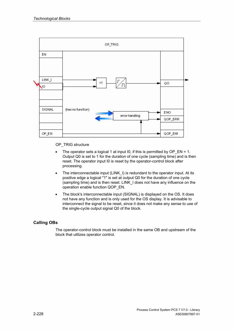
Technological Blocks
Process Control System PCS 7 V7.0 - Library 2-228 A5E00807897-01
OP_TRIG structure
• The operator sets a logical 1 at input I0, if this is permitted by OP_EN = 1. Output Q0 is set to 1 for the duration of one cycle (sampling time) and is then reset. The operator input I0 is reset by the operator-control block after processing.
• The interconnectable input (LINK_I) is redundant to the operator input. At its positive edge a logical "1" is set at output Q0 for the duration of one cycle (sampling time) and is then reset. LINK_I does not have any influence on the operation enable function QOP_EN.
• The block's interconnectable input (SIGNAL) is displayed on the OS. It does not have any function and is only used for the OS display. It is advisable to interconnect the signal to be reset, since it does not make any sense to use of the single-cycle output signal Q0 of the block.
Calling OBs The operator-control block must be installed in the same OB and upstream of the block that utilizes operator control.
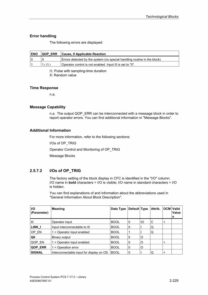
Technological Blocks
Process Control System PCS 7 V7.0 - Library A5E00807897-01 2-229
Error handling The following errors are displayed:
ENO QOP_ERR Cause, if Applicable Reaction
0 X Errors detected by the system (no special handling routine in the block) 1 1 ( Π ) Operator control is not enabled. Input I0 is set to "0".
Π: Pulse with sampling-time duration X: Random value
Time Response n.a.
Message Capability n.a. The output QOP_ERR can be interconnected with a message block in order to report operator errors. You can find additional information in "Message Blocks".
Additional Information For more information, refer to the following sections:
I/Os of OP_TRIG
Operator Control and Monitoring of OP_TRIG
Message Blocks
2.5.7.2 I/Os of OP_TRIG
The factory setting of the block display in CFC is identified in the "I/O" column: I/O name in bold characters = I/O is visible; I/O name in standard characters = I/O is hidden.
You can find explanations of and information about the abbreviations used in "General Information About Block Description".
I/O (Parameter)
Meaning Data Type
Default Type
Attrib.
OCM
ValidValues
I0 Operator input BOOL 0 IO C + LINK_I Input interconnectable to I0 BOOL 0 I Q OP_EN 1 = Operator input enabled BOOL 1 I Q Q0 Binary output BOOL 0 O QOP_EN 1 = Operator input enabled BOOL 0 O + QOP_ERR 1 = Operation error BOOL 0 O SIGNAL Interconnectable input for display on OS BOOL 0 I Q +

Technological Blocks
Process Control System PCS 7 V7.0 - Library 2-230 A5E00807897-01
2.5.7.3 Operator Control and Monitoring of OP_TRIG
Additional Information You can find additional information in the following sections:
• Block Icon OP_TRIG
• Faceplate OP_TRIG
Note: Online help and the PCS 7 FACEPLATES Manual are only available if the PCS 7 FACEPLATES software package is installed!
Technological Blocks
Process Control System PCS 7 V7.0 - Library A5E00807897-01 2-231
2.6 Message Blocks
2.6.1 Overview of Message Blocks
What Message Blocks Are Used For The operator may require information on events involving changes of a digital value or status in the AS. Due to the message blocks implemented in the AS, there is not need for the OS system to poll the AS in order to obtain this information. These blocks monitor the digital values and report changes to the OS (including additional and configurable information). The OS system can visualize, log and archive this information.
The table shows an overview of the message blocks, which are implemented as FBs.
Overview of Message Blocks
Object Name
Type Name Meaning Operation Method
43 MESSAGE Generation of configurable messages
SIMATIC Process Control - Standard
59 MSG_NACK Generation of user-specific messages which do not require acknowledgement
SIMATIC Process Control - Standard
The adaptation of messages for individual blocks is described under "Message Capability".
2.6.2 MSG_NACK: User-Specific Messages (Which do not require acknowledgment)
2.6.2.1 Description of MSG_NACK
Object name (type + number) FB 78
Technological Blocks
Process Control System PCS 7 V7.0 - Library 2-232 A5E00807897-01
Area of Application The message block MSG_NACK is used to generate user-specific messages, which do not require an acknowledgement (process messages).
Function The block can generate up to eight user-specific messages of this type.
Mode of operation Messages not requiring acknowledgement are output via NOTIFY_8P. The output of individual or all messages can be locked.
• I_1 to I_8: Changes at these monitored signals are reported. Each of these signals is assigned a configurable message text, which you can adapt and then use again in the OS configuration. Each change in these inputs triggers the output of a message to the OS, provided the message function is not locked.
• MSG_LOCK: Allows process-specific locking of messages output at this block. At the positive edge of the lock signal, all active process messages are reset, and thus reported outgoing to the OS.
• AUX_PR01 to AUX_PR10: These inputs can be interconnected to random values of any data type. These values are referred to as associated values, are limited to 16 characters and included in the message to the OS providing more detailed information on the event triggering the message.
• The operator can lock the messages of a process tag at the OS. The OS reports this status to the corresponding message block that returns a confirmation (via its NOTIFY_8P) to the OS. The message is then entered as acknowledgement and gone in the message event log of the OS.
• QMSG_SUP indicates that message suppression is enabled.
• The OS system evaluates MSG_STAT, QMSG_ERR and MSG_ACK.
Calling OBs The message block must be installed in the OB where reporting occurs (e.g., OB 35) and also in OB 100.
Error handling Error handling of block MSG_NACK is limited to the evaluation of the error information of ALARM_8P. You can find additional information in Manual System Software for S7-300/400 - System and Standard Functions.
You can find information about the error information of the MSG_STAT parameter in the online help under NOTIFY_8P; STATUS Parameter.
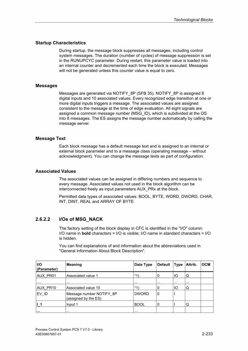
Technological Blocks
Process Control System PCS 7 V7.0 - Library A5E00807897-01 2-233
Startup Characteristics During startup, the message block suppresses all messages, including control system messages. The duration (number of cycles) of message suppression is set in the RUNUPCYC parameter. During restart, this parameter value is loaded into an internal counter and decremented each time the block is executed. Messages will not be generated unless this counter value is equal to zero.
Messages Messages are generated via NOTIFY_8P (SFB 35). NOTIFY_8P is assigned 8 digital inputs and 10 associated values. Every recognized edge transition at one or more digital inputs triggers a message. The associated values are assigned consistent to the message at the time of edge evaluation. All eight signals are assigned a common message number (MSG_ID), which is subdivided at the OS into 8 messages. The ES assigns the message number automatically by calling the message server.
Message Text Each block message has a default message text and is assigned to an internal or external block parameter and to a message class (operating message – without acknowledgment). You can change the message texts as part of configuration.
Associated Values The associated values can be assigned in differing numbers and sequence to every message. Associated values not used in the block algorithm can be interconnected freely as input parameters AUX_PRx at the block.
Permitted data types of associated values: BOOL, BYTE, WORD, DWORD, CHAR, INT, DINT, REAL and ARRAY OF BYTE
2.6.2.2 I/Os of MSG_NACK
The factory setting of the block display in CFC is identified in the "I/O" column: I/O name in bold characters = I/O is visible; I/O name in standard characters = I/O is hidden.
You can find explanations of and information about the abbreviations used in "General Information About Block Description".
I/O (Parameter)
Meaning
Data Type
Default Type
Attrib.
OCM
AUX_PR01 Associated value 1 *1) 0 IO Q .... ... ... ... ... ... AUX_PR10 Associated value 10 *1) 0 IO Q EV_ID Message number NOTIFY_8P
(assigned by the ES) DWORD 0 I
I_1 Input 1 BOOL 0 I Q ... ... ...

Technological Blocks
Process Control System PCS 7 V7.0 - Library 2-234 A5E00807897-01
I/O (Parameter)
Meaning
Data Type
Default Type
Attrib.
OCM
I_8 Input 8 BOOL 0 I Q EN_I_1 1 = Message 1 enabled BOOL 1 I ... ... ... ... ... ... EN_I_8 1 = Message 8 enabled BOOL 1 I MSG_LOCK Lock all process messages BOOL 0 I Q MSG_STAT STATUS output of NOTIFY_8P WORD 0 O OOS Reserve BOOL 0 I + QERR 1 = Error processing busy BOOL 1 O QMSG_ERR ERROR output of NOTIFY_8P BOOL 0 O QEN_I_1 1 = Message 1 enabled BOOL 0 O ... ... ... ... ... ... QEN_I_8 1 = Message 8 enabled BOOL 0 O QMSG_SUP Process message suppression via
operator control is enabled BOOL 0 O
RUNUPCYC Number of run-up cycles INT 3 I
*1) The associated values are assigned to NOTIFY_8P. Permitted data types of associated values: BOOL, BYTE, WORD, DWORD, CHAR, INT, DINT, REAL and ARRAY OF BYTE
2.6.3 MESSAGE: Message Block (Configurable messages)
2.6.3.1 Description of MESSAGE
Object name (type + number) FB 43
Function The MESSAGE block is used to generate configurable (requiring acknowledgement) messages and forms the interface between the block outputs whose changes are to be reported and the S7 block ALARM_8P.
Technological Blocks
Process Control System PCS 7 V7.0 - Library A5E00807897-01 2-235
Mode of operation The block inputs can be used to assign individual message to the monitored signals and also to enable or lock messages depending on the process status. • I_1 to I_8: Changes at these monitored signals are reported. Each of these
signals is assigned a configurable message text (24 characters), which you can adapt and then use again in the OS configuration. Each change in these inputs triggers the output of a message to the OS, provided the message function is not locked.
• I_1ISCSF to I_8ISCSF: By parameterizing with "1," the associated message within the block is handled like an I&C system message (CSF). With this parameter, you thereby specify whether the message of the corresponding input (I_1...I_8) is locked by the input parameter MSG_LOCK=1 (I_x = 0) or not locked (I_x = 1).
• MSG_LOCK: Allows process-specific locking of messages output at this block. At the positive edge of the lock signal, all active process messages (not control system messages) are reset, and thus reported outgoing to the OS.
• AUX_PR01 to AUX_PR10: These inputs can be interconnected to random values of any data type. These values are referred to as associated values, are limited to 16 characters and included in the message to the OS You can use this to describe the cause of the message in detail.
• The operator can lock the messages of a process tag at the OS. The OS reports this status to the corresponding message block that returns a confirmation (via its ALARM_8P) to the OS. The OS enters the message acknowledgement and reports it as gone in the message event log.
• QMSG_SUP indicates that the messages are being suppressed. • The OS system evaluates MSG_STAT, QMSG_ERR and MSG_ACK.
Calling OBs The block must be installed in the OB (e.g., OB 32) in which the events to be monitored are detected and also in OB 100.
Error handling Error handling of block MESSAGE is limited to the evaluation of the error information of ALARM_8P. You can find additional information in Manual System Software for S7-300/400 - System and Standard Functions.
You can find information about the error information of the MSG_STAT parameter in the online help under NOTIFY_8P; STATUS Parameter.
Startup Characteristics During startup, the message block suppresses all messages, including control system messages. The duration (number of cycles) of message suppression is set in the RUNUPCYC parameter. During restart, this parameter value is loaded into an internal counter and decremented each time the block is executed. Messages will not be generated unless this counter value is equal to zero.
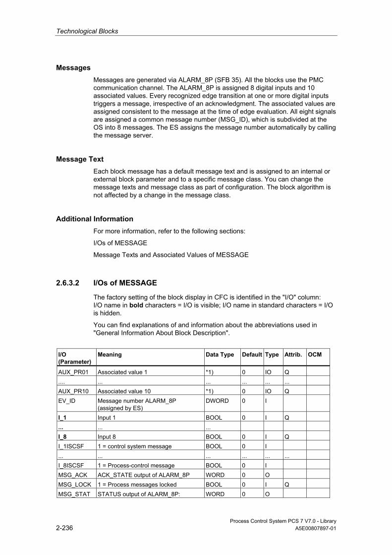
Technological Blocks
Process Control System PCS 7 V7.0 - Library 2-236 A5E00807897-01
Messages Messages are generated via ALARM_8P (SFB 35). All the blocks use the PMC communication channel. The ALARM_8P is assigned 8 digital inputs and 10 associated values. Every recognized edge transition at one or more digital inputs triggers a message, irrespective of an acknowledgment. The associated values are assigned consistent to the message at the time of edge evaluation. All eight signals are assigned a common message number (MSG_ID), which is subdivided at the OS into 8 messages. The ES assigns the message number automatically by calling the message server.
Message Text Each block message has a default message text and is assigned to an internal or external block parameter and to a specific message class. You can change the message texts and message class as part of configuration. The block algorithm is not affected by a change in the message class.
Additional Information For more information, refer to the following sections:
I/Os of MESSAGE
Message Texts and Associated Values of MESSAGE
2.6.3.2 I/Os of MESSAGE
The factory setting of the block display in CFC is identified in the "I/O" column: I/O name in bold characters = I/O is visible; I/O name in standard characters = I/O is hidden.
You can find explanations of and information about the abbreviations used in "General Information About Block Description".
I/O (Parameter)
Meaning
Data Type
Default Type
Attrib.
OCM
AUX_PR01 Associated value 1 *1) 0 IO Q .... ... ... ... ... ... AUX_PR10 Associated value 10 *1) 0 IO Q EV_ID Message number ALARM_8P
(assigned by ES) DWORD 0 I
I_1 Input 1 BOOL 0 I Q ... ... ... I_8 Input 8 BOOL 0 I Q I_1ISCSF 1 = control system message BOOL 0 I ... ... ... ... ... ... I_8ISCSF 1 = Process-control message BOOL 0 I MSG_ACK ACK_STATE output of ALARM_8P WORD 0 O MSG_LOCK 1 = Process messages locked BOOL 0 I Q MSG_STAT STATUS output of ALARM_8P: WORD 0 O

Technological Blocks
Process Control System PCS 7 V7.0 - Library A5E00807897-01 2-237
I/O (Parameter)
Meaning
Data Type
Default Type
Attrib.
OCM
OOS Reserve BOOL 0 I + QERR 1 = Error processing busy BOOL 1 O QMSG_ERR ERROR output of ALARM_8P: BOOL 0 O QMSG_SUP Process-message suppression via
operator control is enabled. BOOL 0 O
RUNUPCYC Number of run-up cycles INT 3 I
*1) The following data types of associated values are permitted: BOOL, BYTE, WORD, DWORD, CHAR, INT, DINT, REAL and ARRAY OF BYTE
2.6.3.3 Message Texts and Associated Values of MESSAGE
Assignment of Message Text and Message Class to the Block Parameters
Message No. Block Parameter Default Message Text Message Class
1 I1 TEXT 1 F : : : : 8 I8 TEXT 8 F
Associated Values The associated values can be assigned in differing numbers and sequence to every message. Associated values not used in the block algorithm can be interconnected freely as input parameters AUX_PRx at the block.
Permitted data types of associated values: BOOL, BYTE, WORD, DWORD, CHAR, INT, DINT, REAL and ARRAY OF BYTE

Technological Blocks
Process Control System PCS 7 V7.0 - Library 2-238 A5E00807897-01
2.7 Appendix
2.7.1 Technical Data, "Technological Blocks"
Overview The table below contains technical data relating to the technological blocks. The table columns have the following meanings:
• Block type name
The symbolic identifier in the symbol table of the library for the relevant FB or FC. Must be unique within the project.
• FB/FC no.
Block number
• Typical runtime
CPU runtime for processing the corresponding block program under normal circumstances (for example, for a driver, this is the execution time in the watchdog-alarm OB, without generation of a channel error message)
The table below shows the runtime of blocks in a 417-4 CPU. The block runtime on other CPUs depends on the CPU performance.
• Block length in load/work memory
Memory requirement of the program code, once for each block type
• Length of instance data in load/work memory
Memory requirement of an instance DB
• Temporary memory
The local-data memory required in a priority class when the block is called. This limit is CPU specific. When it is exceeded, you have to check the CPU configuration and, if necessary, distribute it amongst the OBs to meet the actual requirements.
• Multiple Instance Block
The blocks specified are used by the technological block, must be implemented in the user program They can be found in the same library.
Block (Type Name)
FB/FC No.
Typical Runtime CPU 417-4 (µs )
Block Length in Load/Work Memory (Bytes)
Instance-Data Length in Load/Work Memory (Bytes)
Temporary Memory (Bytes)
Multiple Instance Block
ADD4_P FC 256 6 194 / 122 - / - 2 ADD8_P FC 257 8 298 / 202 - / - 2 AVER_P FB 34 16 508 / 368 156 / 54 48 COUNT_P FB 36 16 484 / 340 166 / 54 44 CTRL_PID FB 61 178 7922 / 6502 1322 / 604 164 2 x FB46 +
SFB35

Technological Blocks
Process Control System PCS 7 V7.0 - Library A5E00807897-01 2-239
Block (Type Name)
FB/FC No.
Typical Runtime CPU 417-4 (µs )
Block Length in Load/Work Memory (Bytes)
Instance-Data Length in Load/Work Memory (Bytes)
Temporary Memory (Bytes)
Multiple Instance Block
CTRL_S FB 76 189 10386 / 8672 1496 / 644 198 2 x FB46 + SFB35
DEADT_P FB 37 20 908 / 704 252 / 126 48 DIF_P FB 38 21 710 / 518 208 / 72 56 DIG_MON FB 62 104 2078 / 1692 802 / 482 56 SFB35 +
SFB36 DOSE FB 63 127 5250 / 4312 1178 / 592 76 FB46 +
SFB35 + SFB36
ELAP_CNT FB 64 101 1434 / 1086 610 / 334 54 SFB 35 FM_CO FB 79 18 3132 / 1780 1732 / 566 46 FMCS_PID FB 114 143 9712 / 8112 1870 / 846 116 FB46 +
SFB35 FMT_PID FB 77 142 9422 / 8002 1856 / 894 82 FB46 +
SFB35 INT_P FB 40 24 1142 / 892 228 / 84 60 INTERLOK FB 75 27 1492 / 1154 300 / 78 46 LIMITS_P FB 41 6 308 / 216 124 / 58 6 MEANTM_P FB 42 53 1586 / 1306 264 / 154 20 MEAS_MON FB 65 108 1910 / 1486 690 / 376 56 SFB 35 MESSAGE FB 43 98 932 / 684 506 / 278 44 SFB 35 MOT_REV FB 67 125 4466 / 3770 828 / 382 70 SFB 35 MOT_SPED FB 68 122 4304 / 3618 824 / 382 66 SFB 35 MOTOR FB 66 114 2570 / 2108 714 / 364 54 SFB 35 MSG_NACK FB 78 99 998 / 732 520 / 274 44 SFB 31 MUL4_P FC 262 5 214 / 122 - / - 2 MUL8_P FC 263 9 334 / 202 - / - 2 OB1_TIME FB 69 57 2140 / 1822 216 / 70 84 OP_A FB 45 4 232 / 156 114 / 56 2 OP_A_LIM FB 46 8 486 / 358 160 / 68 6 OP_A_RJC FB 47 8 518 / 388 160 / 68 6 OP_D FB 48 6 376 / 286 112 / 44 2 OP_D3 FB 49 12 1354 / 1136 150 / 46 8 OP_TRIG FB 50 5 244 / 166 104 / 44 2 POLYG_P FC 271 6 1446 / 1176 - / - 24 PT1_P FB 51 7 446 / 330 136 / 66 2 R_TO_DW FC 282 6 344 / 262 - / - 10 RAMP_P FB 52 19 708 / 524 188 / 64 54 RATIO_P FB 70 19 742 / 526 316 / 134 12 FB46 +
SFB35 READ355P FB 72 18 984 / 784 258/ 94 94 REC_BO FB 208 69 3246 / 2356 992 / 128 2 REC_R FB 210 69 1838 / 1332 956 / 476 2

Technological Blocks
Process Control System PCS 7 V7.0 - Library 2-240 A5E00807897-01
Block (Type Name)
FB/FC No.
Typical Runtime CPU 417-4 (µs )
Block Length in Load/Work Memory (Bytes)
Instance-Data Length in Load/Work Memory (Bytes)
Temporary Memory (Bytes)
Multiple Instance Block
SEND_BO FB 207 163 2298 / 1668 718 / 110 2 SEND_R FB 209 195 4486 / 3886 908 / 478 2 SPLITR_P FC 272 17 832 / 644 - / - 10 SWIT_CNT FB 71 102 1332 / 988 606 / 316 92 SFB 35 VAL_MOT FB 74 127 4498 / 3782 828 / 382 70 SFB 35 VALVE FB 73 15 3280 / 2740 734 / 366 54 SFB 35

Process Control System PCS 7 V7.0 - Library A5E00807897-01 3-1
3 Driver blocks
3.1 Notes on Using Driver Blocks
General • The descriptions of the driver blocks specify the OBs in which the blocks are
installed. Please note that not all OBs listed will be generated for all CPUs. You can find additional information in the online help of the particular OB.
• If the driver generator uses the driver blocks of PCS 7 Library V6.0 or higher, you require a firmware version V3.1 or higher on the CPU.
• The CFC function "Generate module drivers" interconnects and configures the listed I/Os automatically. The function is called and executed if hardware modifications are detected when compiling the program.
Signal-Processing Blocks The driver blocks of the available PCS 7 Library offer three types of channel blocks for signal processing:
1. Standard channel blocks:: CH_AI, CH_AO, CH_DI, CH_DO These blocks are used only for processing the signals of S7-300/400 SM modules. Use these standard blocks if you want to optimize memory and runtime utilization and do not need to process any PA devices.
7. Universal channel blocks:: CH_U_AI, CH_U_AO, CH_U_DI, CH_U_DO These blocks are used for processing the signals of S7-300/400 SM modules or PA field devices. The advantage of these blocks is that you can create CFC charts irrespective of the hardware I/O to be used later. A disadvantage of universal blocks is that they make increased demands on memory and runtime. These blocks do not have Message response.
8. PA channel blocks: PA_AI, PA_AO, PA_DI, PA_DO, PA_TOT These blocks are designed especially for use with PA field devices. In particular, you should use these blocks if you want to make use of the special features of these devices. By contrast to CH blocks, the PA channel blocks process not only the signal itself, but also all variables according to the target device configuration selected in the hardware configuration.
Driver blocks
Process Control System PCS 7 V7.0 - Library 3-2 A5E00807897-01
9. FF channel blocks:: FF_A_AI, FF_A _AO, FF_A _DI, FF_A _DO These blocks are especially designed for use with FF field devices and the Profibus slave AB7000. The blocks are used similar to the corresponding PA channel blocks and are similar in terms of their functionality.
10. Special channel blocks CH_CNT, CH_CNT1, CH_MS These blocks are required for special applications such as controlling and reading the counter or frequency values of FM 350-1/-2 modules and 8-DI NAMUR modules of the ET 200iSP, as well as for signal preparation of ET 200S motor starter modules.

Driver blocks
Process Control System PCS 7 V7.0 - Library A5E00807897-01 3-3
3.2 Signal Blocks and Diagnostic Drivers
3.2.1 CH_AI: Analog Value Input
3.2.1.1 Description of CH_AI
Object name (type + number) FC275
Fields of application Block CH_AI is used for processing analog-input-value signals from S7-300/400 SM analog input modules.
Calling OBs The calling OB is watchdog interrupt OB3x into which you integrate the block (for example, OB32) and restart OB100.
Use in CFC When the CFC function "Generate module drivers" is used, the following occurs automatically:
• Input MODE input is interconnected with the corresponding OMODE_xx output of the MOD block.

Driver blocks
Process Control System PCS 7 V7.0 - Library 3-4 A5E00807897-01
Function and Operating Principle Block CH_AI processes all channel-specific signal functions of an analog input module cyclically.
The block reads a raw analog value from the process image (partition) and converts it to its physical value or calculates a percentage value based on this raw value. The MODE input is used to define the format of the raw value for processing. If the high byte at MODE input parameter = 16#40 (value status = higher priority error, QMOD_ERR = TRUE) the raw value is considered invalid.
The program generates a quality code of the resultant value which may assume the states shown below:
State Quality Code
Valid value 16#80 Simulation 16#60 Last valid value 16#44 Substitute Value 16#48 Invalid value 16#00
The quality code is derived from internal events, such as channel errors, higher priority errors or from simulation, and from a quality code that is directly returned from the device (QC parameter).
The quality code directly returned from the device may assume values from 16#00 – 16#FF in accordance with PROFIBUS requirements. These values can be mapped to the values listed above and can be viewed in the "QC_MS" table of the current LIB readme.
Addressing You must connect the symbol generated in HW Config (symbol table) for the analog input channel with the VALUE input parameter.
Raw value check The rated range of the analog input module determines the range for the conversion of the analog signals to a digital value (raw value), depending on the measurement type and range. This includes an overshoot/undershoot range within which an analog signal can still be converted. Values outside this range lead an overflow or underflow. The block indicates whether the raw value lies inside the rated range of the module. Output parameter QCHF_LL = TRUE if the value undershoots the ratedrange. Output parameter QCHF_HL = TRUE if the value overshoots the rated range. QCHF_LL or QCHF_HL remain set to TRUE if a channel error occurs due to the module diagnoses "Undershoot or overshoot of the measurement range". QBAD = TRUE (channel error) is also set when overflow or underflow is detected.

Driver blocks
Process Control System PCS 7 V7.0 - Library A5E00807897-01 3-5
Note The reaction of the modules to a wire break in the 4 mA to 20 mA signal range is not uniform. Either 16#7FFF (overflow) or 16#8000 (underflow) is written to the process image as a raw value, depending on the module. The CH_AI channel block outputs an overflow (QCHF_HL = TRUE) or an underflow (QCHF_LL = TRUE) as appropriate alongside with QBAD = TRUE. Exception: If you enabled "Diagnostics interrupt" at the analog input module in HW Config, only QBAD = TRUE will be set if a diagnostics interrupt is triggered when a "Channel error" is detected (for example, a wire break).
NAMUR limits check The NAMUR guidelines for analog signal processing define the following limits for Life Zero (4 mA to 20 mA) analog signals with active channel error:
3.6 mA = Analog signal = 21 mA
These NAMUR limits are set permanently for limit value monitoring. You can define other limits by setting input parameter CH_F_ON = TRUE, and by setting corresponding new limits in [mA] at the CH_F_HL and CH_F_LL input parameters. QBAD = TRUE if a Life Zero analog signal overshoots/undershoots the active limits.
Note
The selected hysteresis must lie within the overshoot and undershoot range of the module. Values outside the NAMUR range are also possible if the module does not automatically limit the measured values.
Normal Value The raw value is converted to its physical value based on the settings at input parameters VLRANGE, VHRANGE and MODE (for further information, refer to section "OMODE_xx"). These values are written to the OVLRANGE and OVHRANGE outputs in order to allow the interconnection of the VLRANGE and VHRANGE settings with other block parameters. The conversion algorithm is based on a linear input signal. The program returns a percentage value when VLRANGE = 0 and VHRANGE = 100. If VHRANGE = VLRANGE is set, the analog input module returns its input signal (for example, mA) according to the MODE setting. Set VLRANGE = 0 and VHRANGE = 1 if the raw value is already a physical value. The Quality Code is set to QUALITY = 16#80.
When operating in PTC measurement mode, the analog value contains an encoded binary signal. Output REAL output returns the following information:
• Measured resistance < response value Output = 0.0
• Measured resistance > response value Output ≠ 1.0.

Driver blocks
Process Control System PCS 7 V7.0 - Library 3-6 A5E00807897-01
This only applies to the settings VLRANGE = 0 and VHRANGE = 1 at the input parameters. You may only set 0 or 1 at the simulation and substitute values SIM_V and SUBS_V.
Note
The raw value derived from the measuring mode "External or internal comparison of thermocouples" is converted into the physical variable +/- 80 mV for the S7 300 modules. Determine the temperature using the corresponding conversion tables.
The physical equivalent in [mV] is returned by the module as raw value. Set VHRANGE and VLRANGE to +/- 80 mV.
Simulation The value of input parameter SIM_V input is output with quality code QUALITY = 16#60 when input parameter SIM_ON = TRUE. QBAD = TRUE: reset due to a higher priority error. You also need to set a valid mode of operation at the Low Word of input MODE when operating in simulation mode. QBAD = 1 is output otherwise. Simulation takes highest priority. The simulation value is converted into a raw value based on the operating mode and on the input parameters VHRANGE and VLRANGE. This value is verified similar to the raw value from the process image. This also allows simulation of the QBAD, QCHF_LL and QCHF_HL states. The status QBAD = TRUE cannot be simulated if VLRANGE > VHRANGE. The QCHF_LL and QCHF_HL outputs are set according to the value of SIM_V. QSIM = TRUE if the block is in simulation state.
Substitute value The program outputs the value of input parameter SUBS_V if input parameter SUBS_ON = TRUE, LAST_ON = FALSE and the raw value is invalid. The quality code is set to QUALITY = 16#48 and QBAD = 1.
Hold Last Value, V_DELTA parameter The program outputs the last or next to last valid output value (V_LAST, VLAST1) when input parameter LAST_ON = TRUE and SUBS_ON = FALSE, depending on the setting at the V_DELTA parameter. You can define a valid process value change at the V_DELTA parameter. The function is disabled by setting V_DELTA = 0. Rules:
Rules for invalid raw values and V_DELTA > 0:
• ABS (V - V_LAST) > V_DELTA: V = V_LAST1 (next to last valid output value), DELTA_ON = 1
• ABS (V - V_LAST) = V_DELTA: V = V_LAST (last valid output value), DELTA_ON = 0
• The Quality Code is set to QUALITY = 16#44, and QBAD = 1
Rule for valid raw values and V_DELTA > 0:
V_DELTA is also used to limit changes to the valid raw value. If the change to the value between two calls is greater than V_DELTA the last value (V_LAST) will be
Driver blocks
Process Control System PCS 7 V7.0 - Library A5E00807897-01 3-7
retained at output V for the duration of one cycle . The V_DELTA value should be selected with due care. If the value is too low the quality code may flutter between16#80 and 16#44, regardless whether or not raw value is OK.
• ABS (V - V_LAST) > V_DELTA: For the duration of one cycle V = V_LAST
• The quality code is set to QUALITY = 16#44, DELTA_ON=1 and QBAD = 0.
Output of an invalid value The program outputs any active invalid process value if both input parameters SUBS_ON and LAST_ON are FALSE or TRUE.
The quality code that is output is listed in the table "QC_MS" of the LIB readme. The program also sets QBAD = 1.
Delayed Value Acceptance After a restart or if the quality code changes from "BAD" to "GOOD", the quality code and value are not updated unless the number of cycles specified in CNT_LIM have expired. This function is disabled when CNT_LIM = 0 (default setting). During this delay time, the Quality Code = 16#00 and QBAD = 1 and the last value will be retained.
Error handling The input parameters are not validated. The raw value is considered invalid if an invalid operating mode is set at the low word of input parameter MODE.
Startup Characteristics The accept value delay is started when CNT_LIM is # 0.
Dynamic response n.a.
Message response n.a.

Driver blocks
Process Control System PCS 7 V7.0 - Library 3-8 A5E00807897-01
Operating and Monitoring The block has no faceplate.
Additional information Additional information is available in the section:
Notes on Using Driver Blocks
3.2.1.2 I/Os of CH_AI
The factory setting of the block representation in CFC is identified in the "I/O" column: I/O name in bold characters = I/O is visible; I/O name in standard characters = I/O is hidden.
You can find explanations of and information about the abbreviations used in "General Information About Block Description".
I/O (Parameter)
Meaning
Data Type
Default
Type
CH_F_HL Overshoot high limit of the input value (mA) REAL 0 IO CH_F_LL Undershoot low limit of the input value (mA) REAL 0 IO CH_F_ON 1 = Enable limit monitoring BOOL 0 IO CNT_LIM Limits of the startup counter INT 0 IO CNT_RES Startup counter INT 0 IO DELTA_ON Last delta process value exceeded BOOL 0 IO LAST_BAD Last QBAD BOOL 0 IO LAST_ON 1= Last valid value Enable injection BOOL 0 IO MODE Value status and operating mode DWORD 0 IO OVHRANGE High limit of the process value (copy) REAL 0 O OVLRANGE Low limit of the process value (copy) REAL 0 O QBAD 1 = Invalid process value BOOL 0 O QCHF_HL 1 = Overshoot of process value BOOL O
QCHF_LL 1 = Undershoot of process value BOOL O
QLAST 1= Last valid value Injection active BOOL 0 O QMOD_ERR 1 = Higher priority error BOOL O
QSIM 1 = Simulation enabled BOOL 0 O QSUBS 1 = Substitution enabled BOOL 0 O QUALITY Process-value status BYTE 0 O SIM_ON 1 = Enable simulation BOOL 0 IO SIM_V Simulation value REAL 0 IO SUBS_ON 1 = Enable substitution BOOL 0 IO SUBS_V Substitute Value REAL 0 IO V Process value REAL 0 O VALUE Input value WORD 0 IO VHRANGE High limit of the process value REAL 100 IO VLRANGE Low limit of the process value REAL 0 IO
Driver blocks
Process Control System PCS 7 V7.0 - Library A5E00807897-01 3-9
I/O (Parameter)
Meaning
Data Type
Default
Type
V_DELTA Delta of (V - V_LAST) the process value REAL 0 IO V_LAST Last valid process value REAL 0 IO V_LAST1 Second to last valid process value REAL 0 IO
3.2.2 CH_AO: Analog Value Output
3.2.2.1 Description of CH_AO
Object name (type + number) FC276
Fields of application Block CH_AO is used for processing analog-output-value signals from S7-300/400 SM analog output modules.
Calling OBs The calling OB is watchdog interrupt OB3x into which you integrate the block (for example, OB32) and restart OB100.
Caution
With the PCS 7 it is not intended that other blocks will be inserted between the plant block and the output driver.
If you deviate from this principle, ensure that when interconnecting the block, that from the outputs of the plant block until the output driver, that all blocks that form the output signal are installed in the same OBs.
Use in CFC When the CFC function "Generate module drivers" is used, the following occurs automatically:
• The MODE input is interconnected to the corresponding OMODE_xx output of the MOD block.
• The CH_AO block is installed downstream of the MOD block assigned to it in OB100.
Note If you do not use the CFC function "Generate module drivers", make sure the CH_AO block is installed downstream of its assigned MOD block in OB100.
Driver blocks
Process Control System PCS 7 V7.0 - Library 3-10 A5E00807897-01
Function and Operating Principle Block CH_AO processes all channel-specific signal functions cyclically.
The block writes the process value as analog non-linearized value to a process image (partition). The MODE input parameter determines in which form the non-linearized value is to be generated. If the high byte of input parameter MODE = 0 (value status), the non-linearized value is still written to the process image (partition), but with the quality code "invalid value".
The quality code can have the following states:
State Quality Code
Valid value 16#80 High range limited 16#56 Low range limited 16#55 Simulation 16#60 Invalid value 16#00
The quality code is formed from internal events, such as channel error, higher-level error or simulation and from a quality code that comes directly from the device (parameter QC).
The quality code that comes directly from the device can take on values from 16#00 – 16#FF in accordance with PROFIBUS requirements. The imaging of these values on the displayable values listed above is shown in the table "QC_MS" table of the current LIB readme.
Addressing The symbol (symbol table) generated in HW Config for the analog output channel must be interconnected to the VALUE output.

Driver blocks
Process Control System PCS 7 V7.0 - Library A5E00807897-01 3-11
Normal Value • Parameters ULRANGE and UHRANGE map the process value U to the non-
linearized VALUE (quantization steps) of the analog output module according to the MODE. Example: In operating mode 4 mA to 20 mA (16#0203), the non-linearized value for 4 mA is output if U = ULRANGE and the non-linearized value for 20 mA is output if U = UHRANGE.
• The block switches the parameters UHRNAGE and ULRANGE through to the outputs OVHRANGE and OVLRANGE. Setting value limits NM_LMNHR and NM_LMNLR of the controller CTRL_PID.
• PHYS_LIM can be used to set the limits for the non-linearized VALUE. The default setting of PHYS_LIM = 0 limits the value at output VALUE to the default limits of the module. According to the example above, the block calculates the non-linearized value for 20 mA if U > UHRANGE, and the non-linearized value for 4 mA if U < ULRANGE. As a result, the quality codes 16#56 (high value limited) and 16#55 (low value limited) are applied at the QUALITY output instead of 16#80 (valid value).
• If you want to output analog values outside the normalization limits up to the physical limits of the module, set PHYS_LIM = 1. The output values are limited only if, taking the example above, you exceed the module limit values by specifying U = 200 (36 mA) or U = -50 (-4 mA) when ULRANGE = 0 and UHRANGE = 100. The output values are then limited to the physical limits specified in the data sheets of the modules and the corresponding quality codes are output.
• The outputs QCHF_HL and QCHF_LL also provide information on whether output value limits have been set.
Simulation If the input parameter SIM_ON = TRUE is set, the value of SIM_V is output with quality code (QUALITY) = 16#60. QBAD = TRUE is reset. Simulation takes highest priority. If the block is in the simulation status, QSIM = TRUE.
I/O Fault If the high byte of the MODE input parameter is set to 0 (value status), the quality code QUALITY = 16#00 is set. The current non-linearized value is always written to the process image (partition).
Value Limiting You can limit very low or very high process values that would lead to an error (QBAD = TRUE) before they are entered in the process image (partition).
If the LIMIT_ON switch = TRUE, the process values (U) are limited as follows:
• to V_HL, if U > V_HL and
• to LL_V, if U < V_LL.
Driver blocks
Process Control System PCS 7 V7.0 - Library 3-12 A5E00807897-01
Error handling The input parameters are not validated. If an invalid operating mode was set in the low word of the MODE input, the digitized output value will be set to 0 and QUALITY = 16#00 is output.
Startup Characteristics The MOD blocks set the LSB in byte 2 of their OMODE_xx output parameters in OB100. If the block detects this code, it responds with an acknowledgement and:
If START_ON is not set, computes the process value U and writes the result to the process image. Otherwise, the non-linearized value corresponding to the START_U process value is written to the process image.
Dynamic response n.a.
Message response n.a.
Operating and Monitoring The block does not have a faceplate.
Additional Information Further information is available in the section::
Notes on Using Driver Blocks
Driver blocks
Process Control System PCS 7 V7.0 - Library A5E00807897-01 3-13
3.2.2.2 I/Os of CH_AO
The factory setting of the block display in CFC is identified in the "I/O" column: I/O name in bold characters = I/O is visible; I/O name in standard characters = I/O is hidden.
You can find explanations of and information about the abbreviations used in "General Information About Block Description".
I/O (Parameter)
Meaning
Data Type
Default Type
LIMIT_ON 1 = Enable limiting of the process value BOOL IO
LL_V Process value, if U < V_LL REAL IO
MODE Value status and operating mode DWORD IO
OVHRANGE High limit of the process value REAL O
OVLRANGE Low limit of the process value REAL O
PHYS_LIM 1 = Enable physical limit of the module BOOL IO
QBAD 1 = Invalid output value BOOL O
QCHF_HL 1 = Overshoot of process value BOOL O
QCHF_LL 1 = Undershoot of process value BOOL O
QMOD_ERR 1 = Higher priority error BOOL O
QSIM 1 = Simulation enabled BOOL O
QUALITY Value status of the output value BYTE O
SIM_ON 1 = Enable simulation BOOL IO
SIM_U Simulation value REAL IO
START_ON 1 = Enable startup substitution BOOL IO
START_U Substitution at startup REAL IO
U Process value REAL IO
UHRANGE High limit of the process value REAL IO
ULRANGE Low limit of the process value REAL IO
V_HL High limit REAL IO
V_LL Low limit REAL IO
VALUE PI output value WORD O

Driver blocks
Process Control System PCS 7 V7.0 - Library 3-14 A5E00807897-01
3.2.3 CH_CNT: Controlling and Reading FM 350 Modules
3.2.3.1 Description of CH_CNT
Object name (type + number) FB127
Fields of application The block CH_CNT is used for controlling and reading count or measured values of an FM 350-1 or FM 350-2 module.
Calling OBs Cyclic OB (recommendation 00 ms) in which the data will be received and received.
Use in CFC When the CFC function "Generate module drivers" is used, the following occurs automatically:
• The LADDR and CHANNEL inputs are configured.
• The MODE input is interconnected with the OMODEx output of the FM_CNT block.
• The FM_DATA structure is interconnected with the structure of the same name of the FM_CNT block.
Function and Operating Principle The communication interfaces of the FM 350-1 and FM 350-2 differ as follows:
• The block only communicates through the process image for the FM 350-1. The data is written and read continuously.
• The control and status information and the selected count and measured values are contained in the process image for the FM 350-2. The count and measured values can be read via data records. You can specify how to save the count and measured values in the process image in HW Config (User_Type1 and User_Type2). The parameters LOAD_VAL and CMP_VALx are loaded from the FM_CNT block using the data records in the FM 350-2. The writing of the parameters is first triggered in the subsequent cycle of the FM_CNT block.

Driver blocks
Process Control System PCS 7 V7.0 - Library A5E00807897-01 3-15
"FM 350" refers to the FM 350-1 and FM 350-2 modules in the following.
If an FM 350-2 module is being used, the block writes the LOAD_VALx (load count value immediately), PREP_VALx (load count value in preparation) or CMP_VALx (comparison value) parameters to the module (x = channel number) via data records. If in the block the parameter LOAD_DIR = TRUE is set then it writes LOAD_VALx. When LOAD_PRE = TRUE is set, it writes PREP_VALx. The CMP_VALx parameter is written after every change.
Über den Eingang MODE wird mitgeteilt, wie der Zähl- und/oder Messwert im Prozessabbild vorliegt. If the high word of the input parameter MODE = 16#40xxxx (value status = higher-level error, QMOD_ERR = TRUE), the count or measured value is treated as invalid.
Note
Status QCOMP1 (comparator 1), QCOMP2 (comparator 2), QZERO (zero crossing), QOFLW (overflow), and QUFLW (underflow) are automatically acknowledged. They are active for at least one cycle.
Note
The measured value is output as numeric value by the FM350. Additional information in this regard is available in the manual for the module.
Quality Code Under quality code signal states of the MODE input of the CH_CNT block are described.
The table below shows the quality code of the result and its possible statuses:
State Quality Code
Valid value 16#80 Simulation 16#60 Last valid value 16#44 Substitute Value 16#48 Invalid value 16#00
The quality code is formed from internal events, such as channel error, higher-level error or simulation and from a quality code that comes directly from the device (parameter QC).
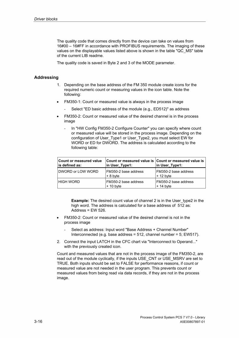
Driver blocks
Process Control System PCS 7 V7.0 - Library 3-16 A5E00807897-01
The quality code that comes directly from the device can take on values from 16#00 – 16#FF in accordance with PROFIBUS requirements. The imaging of these values on the displayable values listed above is shown in the table "QC_MS" table of the current LIB readme.
The quality code is saved in Byte 2 and 3 of the MODE parameter.
Addressing 1. Depending on the base address of the FM 350 module create icons for the
required numeric count or measuring values in the icon table. Note the following:
• FM350-1: Count or measured value is always in the process image
- Select "ED basic address of the module (e.g., ED512)" as address
• FM350-2: Count or measured value of the desired channel is in the process image
- In "HW Config FM350-2 Configure Counter" you can specify where count or measured value will be stored in the process image. Depending on the configuration of User_Type1 or User_Type2, you must select EW for WORD or ED for DWORD. The address is calculated according to the following table:
Count or measured value is defined as:
Count or measured value is in User_Type1:
Count or measured value is in User_Type1:
DWORD or LOW WORD FM350-2 base address + 8 byte
FM350-2 base address + 12 byte
HIGH WORD FM350-2 base address + 10 byte
FM350-2 base address + 14 byte
Example: The desired count value of channel 2 is in the User_type2 in the high word. The address is calculated for a base address of 512 as: Address = EW 526.
• FM350-2: Count or measured value of the desired channel is not in the process image
- Select as address: Input word "Base Address + Channel Number" Interconnected (e.g. base address = 512, channel number = 5; EW517).
2. Connect the input LATCH in the CFC chart via "Interconnect to Operand..." with the previously created icon.
Count and measured values that are not in the process image of the FM350-2, are read out of the module cyclically, if the inputs USE_CNT or USE_MSRV are set to TRUE. Both inputs should be set to FALSE for performance reasons, if count or measured value are not needed in the user program. This prevents count or measured values from being read via data records, if they are not in the process image.
Driver blocks
Process Control System PCS 7 V7.0 - Library A5E00807897-01 3-17
Note Even for non-set inputs USE_CNT or. USE_MSRV a read-out can be executed via data records, if at on a different instance of CH_CNT (other channel) of the associated FM350-2 the inputs USE_CNT or USE_MSRV are set.
Simulation If the input parameter SIM_ON = TRUE is set, the value of the input parameter SIM_V is output with quality code QUALITY = 16#60 and QBAD = FALSE is set. Simulation takes highest priority. If the block is in the simulation status, QSIM = TRUE.
Substitute Value If input parameter SUBS_ON = TRUE, then the value of input parameter SUBS_V is output as a substitute value, if the count or measured value is invalid. The quality code will be set to QUALITY = 16#48 and QBAD = 1.
Hold Last Value If input parameter LAST_ON = TRUE, then the last valid output value is output, if the counted value or measured value is invalid. The quality code will be set to QUALITY = 16#44 and QBAD = 1.
Output invalid value If the input parameter is SUBS_ON and LAST_ON = FALSE or both = TRUE, and an invalid process value is present, then this will be output.
The quality code that is output is listed in the table "QC_MS" of the LIB readme. In addition QBAD = 1 is set.
Redundancy In H systems, the upstream MOD_1 block evaluates redundancy of the DP master systems.
Error handling The input parameters are not validated.

Driver blocks
Process Control System PCS 7 V7.0 - Library 3-18 A5E00807897-01
Startup Characteristics During startup and restart, the parameters CMP_VAL0 and CMP_VAL1 (FM 350-1 only) (comparison value; CMP_VAL1,2,3 too for dosing (FM 350-2)) are sent to the FM 350 by the FM_CNT block.
Overload Behavior n.a.
Dynamic response n.a.
Message response n.a.
Operating and Monitoring The block has no faceplate.
Additional Information Further information is available in the section::
Notes on Using Driver Blocks
3.2.3.2 I/Os of CH_CNT
The factory setting of the block display in CFC is identified in the "I/O" column: I/O name in bold characters = I/O is visible; I/O name in standard characters = I/O is hidden.
You can find explanations of and information about the abbreviations used in "General Information About Block Description".
I/O (Parameter)
Meaning
Data Type
Default Type
ACT_CNTV Current load or LATCH value/current measured value DINT 0 O ACT_MSRV Current measured value DINT 0 O CHANNEL Channel FM 350 INT 0 I CMP_V0 New comparison value 1/high limit DINT 0 I CMP_V1 New comparison value 2/updating time DINT 0 I CMP_V2 New comparison value 3 (dosing operating mode) DINT 0 I CMP_V3 New comparison value 4 (dosing operating mode) DINT 0 I CTRL_DO0 1 = Enable digital output DO BOOL 0 I CTRL_DO1 1 = Enable digital output DO1
(FM_350-1 only or FM_350-2 dosing mode)) BOOL 0 I

Driver blocks
Process Control System PCS 7 V7.0 - Library A5E00807897-01 3-19
I/O (Parameter)
Meaning
Data Type
Default Type
CTRL_DO2 1 = Enable digital output DO2 (FM_350-2 dosing mode only)
BOOL 0 I
CTRL_DO3 1 = Enable digital output DO3 (FM_350-2 dosing mode only)
BOOL 0 I
ENSET_DN 1 = Enable for setting in backward direction BOOL 1 I ENSET_UP 1 = Enable for setting in forward direction BOOL 1 I FM_DATA Structure FM 350 data STRUCT IO GATE_STP 1 = General gate stop BOOL 0 I LADDR Logical address FM 350 INT 0 I LAST_ON 1= Last valid value Enable injection BOOL 0 IO LATCH Current count value ANY 0 I LOAD_DIR 1 = Load immediately BOOL 0 IO LOAD_PRE 1 = Load in preparation BOOL 0 IO LOAD_VAL New load value/low limit DINT 0 I MODE Channel operating mode DWORD 0 I QBAD 1 = Invalid values BOOL 0 O QCMP1 1= Comparison value 1 BOOL 0 O QCMP2 1= Comparison value 2 BOOL 0 O QCMP3 1= Comparison value 3 BOOL 0 O QCMP4 1= Comparison value 4 BOOL 0 O QCOMP1 1 = Saved status of comparator 1
(corresponds to STS_CMP of FM 350-2) BOOL 0 O
QCOMP2 1 = Saved status of comparator 2 (FM 350-1 only) or FM 350-2, dosing operating mode
BOOL 0 O
QCOMP3 1 = Saved status of comparator 2 (FM 350- 2 dosing mode only)
BOOL 0 O
QCOMP4 1 = Saved status of comparator 2 (FM 350- 2 dosing mode only)
BOOL 0 O
QDIR 1 = Status counter count direction BOOL 0 O QGATE 1 = Status internal gate BOOL 0 O QLAST 1= Last valid value Injection active BOOL 0 O QLATCH 1 = New LATCH value
(in clock-synchronous mode only) BOOL 0 O
QMOD_ERR 1 = Higher priority error BOOL 0 O QOFLW 1 = Status overflow BOOL 0 O QOP_ERR 1 = Operation error BOOL 0 O QRUN 1 = Status counter working BOOL 0 O QSET 1 = Status digital input DI set BOOL 0 O QSIM 1 = Simulation values BOOL 0 O QSTA 1 = Digital input DI start BOOL 0 O QSTP 1 = Status digital input DI stop BOOL 0 O QSUBS 1 = Error substitute values active BOOL 0 O QSW_G 1 = Status SW gate BOOL 0 O QSYNC 1 = Status counter synchronized BOOL 0 O QUALITY Process-value status BYTE 0 O QUFLW 1 = Status underflow BOOL 0 O QZERO 1 = Status zero crossing BOOL 0 O

Driver blocks
Process Control System PCS 7 V7.0 - Library 3-20 A5E00807897-01
I/O (Parameter)
Meaning
Data Type
Default Type
R_OP_ERR 1 = Operation error reset BOOL 0 IO RES_SYNC 1 = Reset synchronization BOOL 0 IO SET_DO0 1 = Open DO0 BOOL 0 I SET_DO1 1 = Open DO1
(FM_350-1 only or FM_350-2 dosing mode) BOOL 0 I
SET_DO2 1 = Open DO2 (FM_350-2 dosing mode only) BOOL 0 I SET_DO3 1 = Open DO3 (FM_350-2 dosing mode only) BOOL 0 I SIM_CNT Simulation count DINT 0 I SIM_MSRV Simulation measured value DINT 0 I SIM_ON 1 = Simulation active BOOL 0 I SUBS_CNT Count substitute value DINT 0 I SUBS_MSRV Measured substitute value DINT 0 I SUBS_ON 1 = Substitute value active BOOL 0 I SW_GATE 1 = Enable SW gate BOOL 0 I USE_CNT 1 = counted value reset BOOL 1 I USE_MSRV 1 = counted value reset BOOL 1 I
3.2.4 CH_CNT1: Controlling and Reading an 8-DI-NAMUR-Module of the ET 200iSP
3.2.4.1 Description of CH_CNT1
Object name (type + number) FB59
Fields of application Block CH_CNT1 is used to control and read a count or frequency value from an 8-DI NAMUR module of the ET 200iSP. The block supports the following configurations of the module:
• 2 counters or 1 counter cascaded
• 2 frequency measurements
Calling OBs Cyclic OB (recommendation 00 ms) in which the data will be received and received.

Driver blocks
Process Control System PCS 7 V7.0 - Library A5E00807897-01 3-21
Use in CFC When the CFC function "Generate module drivers" is used, the following occurs automatically:
• Inputs LADDR, LADDR1 and CHANNEL are configured.
• The MODE input is interconnected with the OMODEx output of the MOD_D1 block.
Function and Operating Principle Depending on the mode setting of the module in HW Config, the useful data of the module is stored in the process image. Block CH_CNT1 differentiates between the following operating modes:
MODE (Low Word)
Operating Mode HW Config Setting "Configuration"
HW Config Setting: "Channel (0 to 1) Operating Mode"
1 Counter (16 bits) without control function over digital signals
(Channel 0 to 1): COUNT (Channel 2 to 7): DI
Periodic or normal count functions (up or down counter)
2 Counter (32 bits) without control function over digital signals
(Channel 0 to 1): COUNT (Channel 2 to 7): DI
Cascade function (Channel 0 only) (down counter)
3 Counter (16 bits) with control function over digital signals
(Channel 0 to 1): COUNT (Channel 2 to 7): CONTROL
Periodic or normal count functions (up or down counter)
4 Counter (32 bits) with control function over digital signals
(Channel 0 to 1): COUNT (Channel 2 to 7): CONTROL
Cascade function (Channel 0 only) (down counter)
5 Frequency (16 bits) (Channel 0 to 1): TRACE (Channel 2 to 7): DI
-
The driver generator sets the module mode configured in HW Config at the MODE input of the MOD_D1 block on the appropriate channel. The input MODE (see above) contains the information as to how the counted or frequency value exists in the process image. If the high word of the input parameter MODE = 16#40xxxx (value status = higher-level error, QMOD_ERR = TRUE), the count or frequency value is treated as invalid.
Depending on the mode, either two independent counters (16 bits) or one counter (32 bits) exist in the process image. The CHANNEL input specifies the module counter for which the block is responsible.
The counter function can be controlled by signals that can be influenced both over the digital inputs of the module or over the user data of the process image.
Note
Please note that the signals of the digital inputs are ORed with the equivalent signals from the PIO in the module.
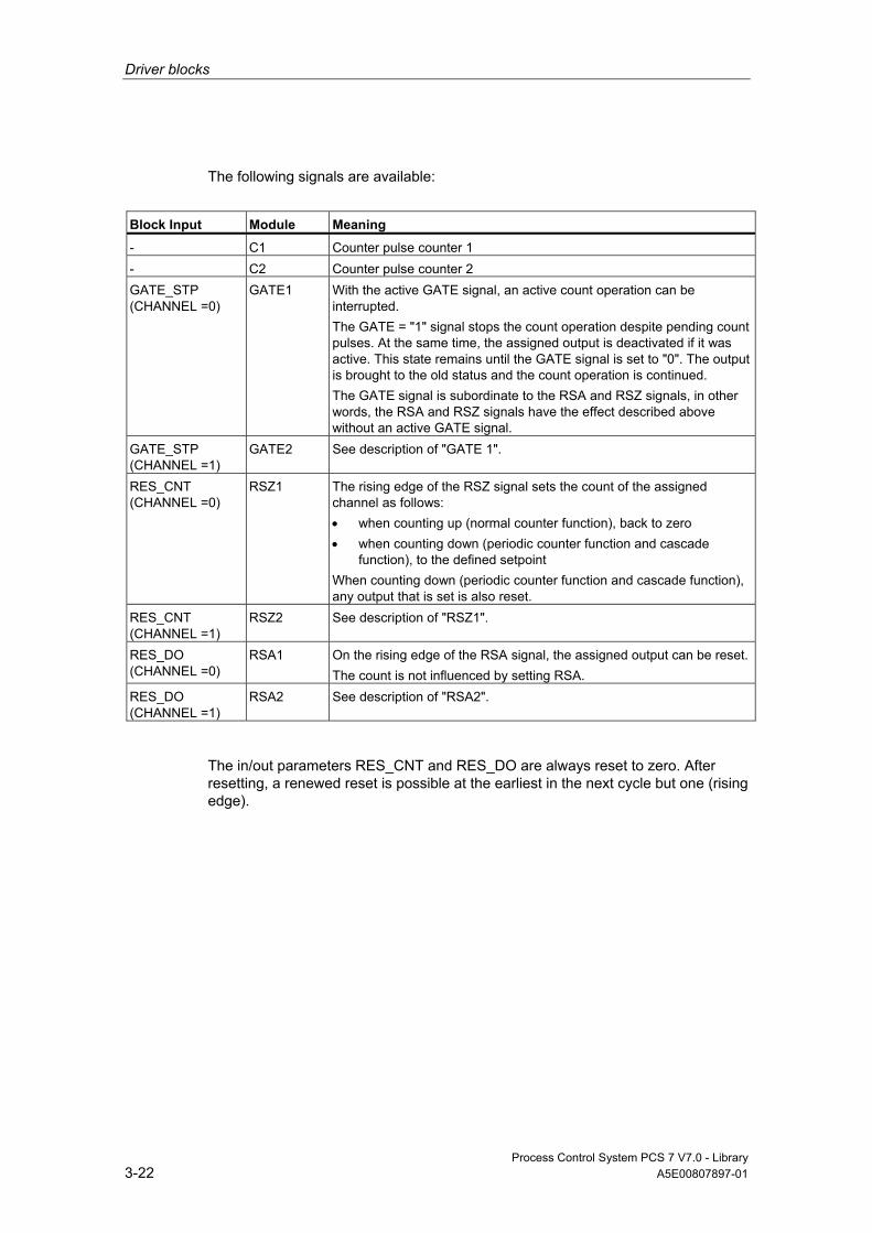
Driver blocks
Process Control System PCS 7 V7.0 - Library 3-22 A5E00807897-01
The following signals are available:
Block Input Module Meaning
- C1 Counter pulse counter 1 - C2 Counter pulse counter 2 GATE_STP (CHANNEL =0)
GATE1 With the active GATE signal, an active count operation can be interrupted. The GATE = "1" signal stops the count operation despite pending count pulses. At the same time, the assigned output is deactivated if it was active. This state remains until the GATE signal is set to "0". The output is brought to the old status and the count operation is continued. The GATE signal is subordinate to the RSA and RSZ signals, in other words, the RSA and RSZ signals have the effect described above without an active GATE signal.
GATE_STP (CHANNEL =1)
GATE2 See description of "GATE 1".
RES_CNT (CHANNEL =0)
RSZ1 The rising edge of the RSZ signal sets the count of the assigned channel as follows: • when counting up (normal counter function), back to zero • when counting down (periodic counter function and cascade
function), to the defined setpoint When counting down (periodic counter function and cascade function), any output that is set is also reset.
RES_CNT (CHANNEL =1)
RSZ2 See description of "RSZ1".
RES_DO (CHANNEL =0)
RSA1 On the rising edge of the RSA signal, the assigned output can be reset.The count is not influenced by setting RSA.
RES_DO (CHANNEL =1)
RSA2 See description of "RSA2".
The in/out parameters RES_CNT and RES_DO are always reset to zero. After resetting, a renewed reset is possible at the earliest in the next cycle but one (rising edge).
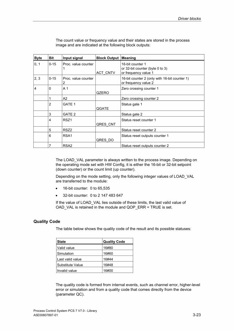
Driver blocks
Process Control System PCS 7 V7.0 - Library A5E00807897-01 3-23
The count value or frequency value and their states are stored in the process image and are indicated at the following block outputs:
Byte Bit Input signal Block Output Meaning
0, 1 0-15 Proc. value counter 1
ACT_CNTV
16-bit counter 1 or 32-bit counter (byte 0 to 3) or frequency value 1
2, 3 0-15 Proc. value counter 2
16-bit counter 2 (only with 16-bit counter 1) or frequency value 2
4 0 A 1 QZERO
Zero crossing counter 1
1 A2 Zero crossing counter 2 2 GATE 1
QGATE Status gate 1
3 GATE 2 Status gate 2 4 RSZ1
QRES_CNT Status reset counter 1
5 RSZ2 Status reset counter 2 6 RSA1
QRES_DO Status reset outputs counter 1
7 RSA2 Status reset outputs counter 2
The LOAD_VAL parameter is always written to the process image. Depending on the operating mode set with HW Config, it is either the 16-bit or 32-bit setpoint (down counter) or the count limit (up counter).
Depending on the mode setting, only the following integer values of LOAD_VAL are transferred to the module:
• 16-bit counter: 0 to 65,535
• 32-bit counter: 0 to 2 147 483 647
If the value of LOAD_VAL lies outside of these limits, the last valid value of OAD_VAL is retained in the module and QOP_ERR = TRUE is set.
Quality Code The table below shows the quality code of the result and its possible statuses:
State Quality Code
Valid value 16#80 Simulation 16#60 Last valid value 16#44 Substitute Value 16#48 Invalid value 16#00
The quality code is formed from internal events, such as channel error, higher-level error or simulation and from a quality code that comes directly from the device (parameter QC).

Driver blocks
Process Control System PCS 7 V7.0 - Library 3-24 A5E00807897-01
The quality code that comes directly from the device can take on values from 16#00 – 16#FF in accordance with PROFIBUS requirements. The imaging of these values on the displayable values listed above is shown in the table "QC_MS" table of the current LIB readme.
Note: In HW Config, it is possible to use only digital signals DI2 to DI7 of the module (HW Config channel 2 to 7 = DI) instead of the control signals GATE 1 to RSA2. In this configuration of the DI NAMUR module, the states of outputs QGATE, QZERO, QRES_CNT and QRES_DO are based on the inputs of the block.
When using the digital control signals GATE 1 to RSA2 of the module (HW Config channel 2 to 7 = CONTROL), conflicts with the block digital signals may arise depending on the signal state. In this case, the digital signals do not take effect. If you want control over the block, you must not assign the control signals in HW Config.
Example:
Module Block Has the Effect
GATE 1 = 1 GATE_STP = 0 GATE on GATE 1 = 0 GATE_STP = 1 GATE on GATE 1 = 0 GATE_STP = 0 GATE off
Addressing You must connect the symbol (from the symbol table) for the counted or frequency value with the VALUE input parameter.
Simulation If the input parameter SIM_ON = TRUE is set, the value of the input parameter SIM_V is output with quality code QUALITY = 16#60 and QBAD = FALSE is set. Simulation takes highest priority. If the block is in the simulation status, QSIM = TRUE is set.
Substitute Value If input parameter SUBS_ON = TRUE, then the value of input parameter SUBS_V is output as a substitute value, if the count or measured value is invalid. The quality code will be set to QUALITY = 16#48 and QBAD = 1.
Hold Last Value If input parameter LAST_ON = TRUE, then the last valid output value is output, if the counted value or measured value is invalid. The quality code will be set to QUALITY = 16#44 and QBAD = 1.
Driver blocks
Process Control System PCS 7 V7.0 - Library A5E00807897-01 3-25
Output invalid value If the input parameter is SUBS_ON and LAST_ON = FALSE or both = TRUE, and an invalid process value is present, then this will be output.
The quality code that is output is listed in the table "QC_MS" of the LIB readme. In addition QBAD = 1 is set.
Redundancy Higher-level block MOD_D1 evaluates the redundancy of DP master systems operating in an H system.
Error handling The input parameters are not validated. Exception: LOAD_VAL is checked for valid input values. You can find additional information in "Function and Operating Principle".
Startup Characteristics n.a.
Overload Behavior n.a.
Dynamic response n.a.
Message response n.a.
Operating and Monitoring The block has no faceplate.
Additional information Additional information is available in the section: Notes on Using Driver Blocks
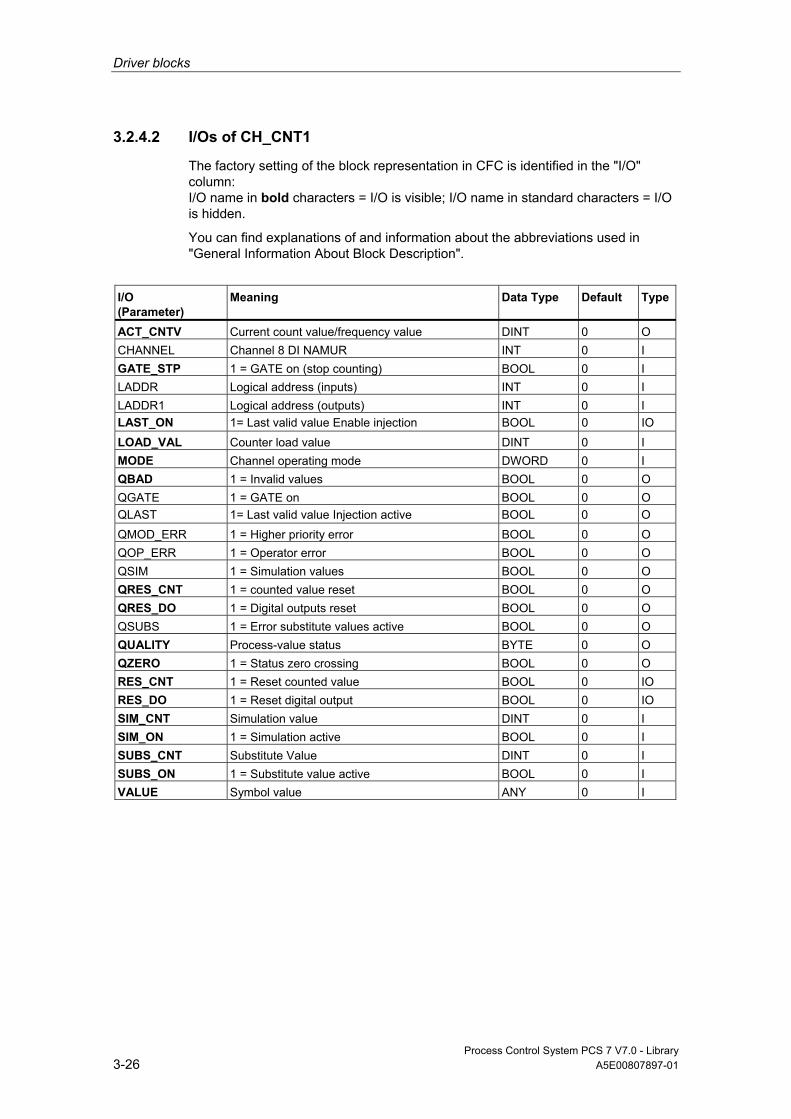
Driver blocks
Process Control System PCS 7 V7.0 - Library 3-26 A5E00807897-01
3.2.4.2 I/Os of CH_CNT1
The factory setting of the block representation in CFC is identified in the "I/O" column: I/O name in bold characters = I/O is visible; I/O name in standard characters = I/O is hidden.
You can find explanations of and information about the abbreviations used in "General Information About Block Description".
I/O (Parameter)
Meaning
Data Type
Default Type
ACT_CNTV Current count value/frequency value DINT 0 O CHANNEL Channel 8 DI NAMUR INT 0 I GATE_STP 1 = GATE on (stop counting) BOOL 0 I LADDR Logical address (inputs) INT 0 I LADDR1 Logical address (outputs) INT 0 I LAST_ON 1= Last valid value Enable injection BOOL 0 IO LOAD_VAL Counter load value DINT 0 I MODE Channel operating mode DWORD 0 I QBAD 1 = Invalid values BOOL 0 O QGATE 1 = GATE on BOOL 0 O QLAST 1= Last valid value Injection active BOOL 0 O QMOD_ERR 1 = Higher priority error BOOL 0 O QOP_ERR 1 = Operator error BOOL 0 O QSIM 1 = Simulation values BOOL 0 O QRES_CNT 1 = counted value reset BOOL 0 O QRES_DO 1 = Digital outputs reset BOOL 0 O QSUBS 1 = Error substitute values active BOOL 0 O QUALITY Process-value status BYTE 0 O QZERO 1 = Status zero crossing BOOL 0 O RES_CNT 1 = Reset counted value BOOL 0 IO RES_DO 1 = Reset digital output BOOL 0 IO SIM_CNT Simulation value DINT 0 I SIM_ON 1 = Simulation active BOOL 0 I SUBS_CNT Substitute Value DINT 0 I SUBS_ON 1 = Substitute value active BOOL 0 I VALUE Symbol value ANY 0 I

Driver blocks
Process Control System PCS 7 V7.0 - Library A5E00807897-01 3-27
3.2.5 CH_DI: Digital Value Input
3.2.5.1 Description of CH_DI
Object name (type + number) FC277
Fields of application Block CH_DI processes the digital input signals of S7-300/400 SM digital input modules.
Calling OBs The calling OB is the watchdog alarm OB3x into which you integrate the block (for example, OB32).
Use in CFC The CFC function "Generate module drivers" when used automatically interconnects the MODE input with the corresponding output OMODE_xx of the MOD block.
Function and Operating Principle Block CH_DI processes all channel-specific signal functions cyclically.
The block reads a digital value of the data type BOOL from the process image (partition). If the high byte of input parameter MODE = 16#40 (value status = higher-level error, QMOD_ERR = TRUE), the digital value is treated as invalid. If input parameter PQC = TRUE, it reads the value status of the digital value from the process image (partition).

Driver blocks
Process Control System PCS 7 V7.0 - Library 3-28 A5E00807897-01
Quality Code The program generates a quality code of the resultant value which may assume the states shown below:
State Quality Code
Valid value 16#80 Simulation 16#60 Last valid value 16#44 Substitute Value 16#48 Invalid value 16#00
The quality code is derived from internal events, such as channel errors, higher priority errors or from simulation, and from a quality code that is directly returned from the device (QC parameter).
The quality code directly returned from the device may assume values from 16#00 – 16#FF in accordance with PROFIBUS requirements. These values can be mapped to the values listed above and can be viewed in the "QC_MS" table of the current LIB readme.
Addressing The symbol generated in HW Config (symbol table) for the digital input channel must be interconnected with the VALUE input. If the process image (partition) also contains the value status of the digital input channel, you must interconnect the corresponding symbol with input VALUE_QC and set input PQC = TRUE.
Normal Value The digital value of the process image (partition) and the quality code QUALITY = 16#80 are returned to output Q.
Simulation If input parameter SIM_ON = TRUE, the value of input parameter SIM_I is output to the output parameter Q with quality code QUALITY = 16#60. QBAD = TRUE is reset. Simulation takes highest priority. If the block is in the simulation status, QSIM = TRUE is set.
Substitute value When input parameter SUBS_ON = TRUE and the digital value of the process image (partition) is invalid, the function outputs the signal QBAD = 1 and the value at input parameter SUBS_I with quality code QUALITY = 16#48 to output parameter Q.

Driver blocks
Process Control System PCS 7 V7.0 - Library A5E00807897-01 3-29
Hold Last Value If input parameter LAST_ON = TRUE and the count value or measured value are invalid, the last valid output value is output. The quality code is set to QUALITY = 16#44 and QBAD = 1.
Last valid output value = Q_LAST.
Output invalid value The program outputs any active invalid process value if both input parameters SUBS_ON and LAST_ON are FALSE or TRUE.
The quality code that is output is listed in the table "QC_MS" of the LIB readme. In addition QBAD = 1 is set.
Error handling The input parameters are not validated.
Startup Characteristics n.a.
Dynamic response n.a.
Message response n.a.
Operating and Monitoring The block has no faceplate.
Additional information Additional information is available in the section:
Notes on Using Driver Blocks
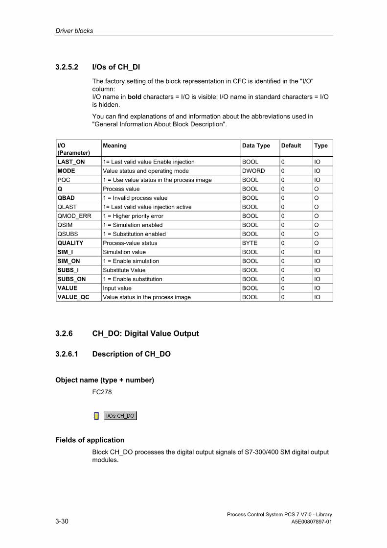
Driver blocks
Process Control System PCS 7 V7.0 - Library 3-30 A5E00807897-01
3.2.5.2 I/Os of CH_DI
The factory setting of the block representation in CFC is identified in the "I/O" column: I/O name in bold characters = I/O is visible; I/O name in standard characters = I/O is hidden.
You can find explanations of and information about the abbreviations used in "General Information About Block Description".
I/O (Parameter)
Meaning
Data Type
Default Type
LAST_ON 1= Last valid value Enable injection BOOL 0 IO MODE Value status and operating mode DWORD 0 IO PQC 1 = Use value status in the process image BOOL 0 IO Q Process value BOOL 0 O QBAD 1 = Invalid process value BOOL 0 O QLAST 1= Last valid value injection active BOOL 0 O QMOD_ERR 1 = Higher priority error BOOL 0 O QSIM 1 = Simulation enabled BOOL 0 O QSUBS 1 = Substitution enabled BOOL 0 O QUALITY Process-value status BYTE 0 O SIM_I Simulation value BOOL 0 IO SIM_ON 1 = Enable simulation BOOL 0 IO SUBS_I Substitute Value BOOL 0 IO SUBS_ON 1 = Enable substitution BOOL 0 IO VALUE Input value BOOL 0 IO VALUE_QC Value status in the process image BOOL 0 IO
3.2.6 CH_DO: Digital Value Output
3.2.6.1 Description of CH_DO
Object name (type + number) FC278
Fields of application Block CH_DO processes the digital output signals of S7-300/400 SM digital output modules.
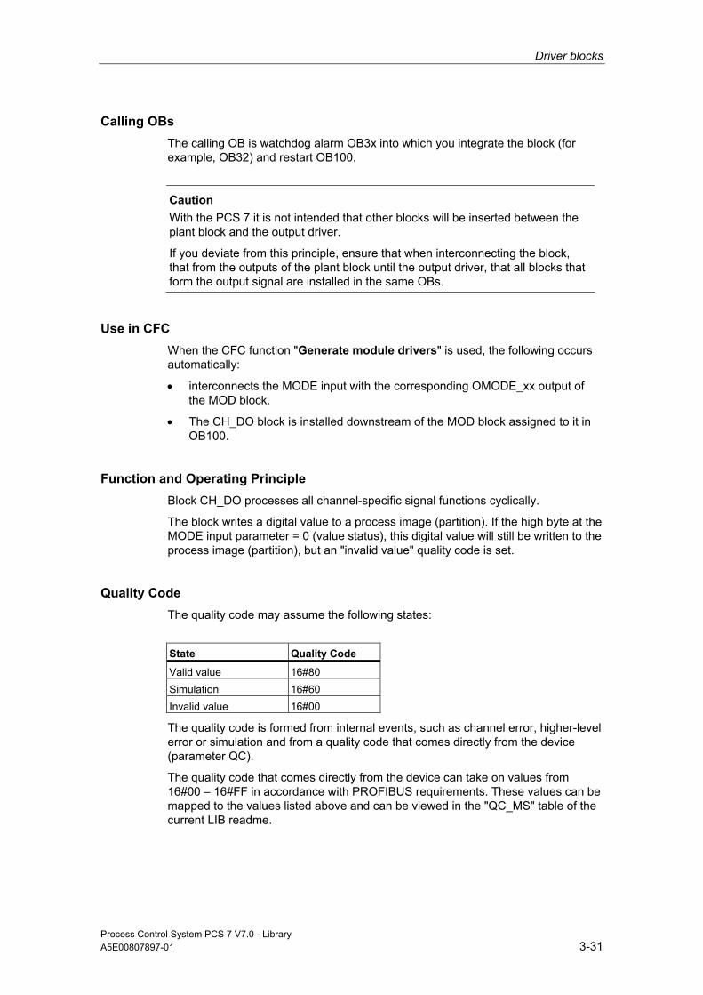
Driver blocks
Process Control System PCS 7 V7.0 - Library A5E00807897-01 3-31
Calling OBs The calling OB is watchdog alarm OB3x into which you integrate the block (for example, OB32) and restart OB100.
Caution
With the PCS 7 it is not intended that other blocks will be inserted between the plant block and the output driver.
If you deviate from this principle, ensure that when interconnecting the block, that from the outputs of the plant block until the output driver, that all blocks that form the output signal are installed in the same OBs.
Use in CFC When the CFC function "Generate module drivers" is used, the following occurs automatically:
• interconnects the MODE input with the corresponding OMODE_xx output of the MOD block.
• The CH_DO block is installed downstream of the MOD block assigned to it in OB100.
Function and Operating Principle Block CH_DO processes all channel-specific signal functions cyclically.
The block writes a digital value to a process image (partition). If the high byte at the MODE input parameter = 0 (value status), this digital value will still be written to the process image (partition), but an "invalid value" quality code is set.
Quality Code The quality code may assume the following states:
State Quality Code
Valid value 16#80 Simulation 16#60 Invalid value 16#00
The quality code is formed from internal events, such as channel error, higher-level error or simulation and from a quality code that comes directly from the device (parameter QC).
The quality code that comes directly from the device can take on values from 16#00 – 16#FF in accordance with PROFIBUS requirements. These values can be mapped to the values listed above and can be viewed in the "QC_MS" table of the current LIB readme.

Driver blocks
Process Control System PCS 7 V7.0 - Library 3-32 A5E00807897-01
Addressing The symbol generated with HW Config (symbol table) for the digital output channel must be interconnected to the VALUE input.
Normal Value The digital value is written to the process image (partition) and QC (QUALITY) = 16#80.
Simulation When input parameter SIM_ON = TRUE, the value of input parameter SIM_I will be written to the process image (partition) and quality code QUALITY = 16#60 is set. QBAD = TRUE is reset. Simulation takes highest priority. If the block is in the simulation status, QSIM = TRUE.
I/O Fault If the high byte of the MODE input parameter is set to 0 (value status), the quality code QUALITY = 16#00 is set. The function always writes the actual non-linearized value to the process image (partition).
Error handling The input parameters are not validated.
Startup Characteristics The MOD blocks set the LSB in byte 2 of their OMODE_xx output parameters in OB100. If the block detects this code, it responds with an acknowledgement and:
If START_ON is not set, it writes the process value I to the process image; otherwise it substitutes this process value with START_I.
Dynamic response n.a.
Message response n.a.
Operating and Monitoring The block has no faceplate.

Driver blocks
Process Control System PCS 7 V7.0 - Library A5E00807897-01 3-33
Additional information Additional information is available in the section:
Notes on Using Driver Blocks
3.2.6.2 I/Os of CH_DO
The factory setting of the block representation in CFC is identified in the "I/O" column: I/O name in bold characters = I/O is visible; I/O name in standard characters = I/O is hidden.
You can find explanations of and information about the abbreviations used in "General Information About Block Description".
I/O (Parameter)
Meaning
Data Type
Default Type
I Process value BOOL 0 IO MODE Value status and operating mode DWORD 0 IO QBAD 1 = Invalid output value BOOL 0 O QMOD_ERR 1 = Higher priority error BOOL 0 O QSIM 1 = Simulation enabled BOOL 0 O QUALITY Value status of the output value BYTE 0 O SIM_I Simulation value BOOL 0 IO SIM_ON 1 = Enable simulation BOOL 0 IO START_I Substitution at startup BOOL 0 IO START_ON 1 = Enable startup substitution BOOL 0 IO VALUE PI output value BOOL 0 O
3.2.7 CH_MS: Signal Processing of the ET 200S Motorstarter Module
3.2.7.1 Description of CH_MS
Object name (type + number) FB60
Fields of application Block CH_MS is used for processing the signals of an ET 200S motor-starter module.
Driver blocks
Process Control System PCS 7 V7.0 - Library 3-34 A5E00807897-01
Calling OBs Cyclic OB (recommendation 00 ms) in which the data will be received and received.
Use in CFC When the CFC function "Generate module drivers" is used, the following occurs automatically:
• The CH_MS block is installed downstream of the MOD block assigned to it in OB100.
• The MODE input is interconnected to the corresponding OMODE_xx output of the MOD block.
• Inputs IN_x and outputs OUT_x are interconnected with the motor-starter-module icons.

Driver blocks
Process Control System PCS 7 V7.0 - Library A5E00807897-01 3-35
Function and Operating Principle A motor starter module occupies the process image as follows:
The inputs shown in the schematic are acquired from the process image and applied individually to the output.
The 6-bit value supplied by the motor starter module specifies the motor-current ratio I cur/I rated (I rated = measurement operating current set in HW Config). The value is specified with one place before the decimal point (bit 5) and five places after the decimal point (bit 4 to bit 0). The maximum ratio for I cur/I rated is therefore 1.96875 (approx. 197 %).
I ratio = I rated x value (bit 5 to bit 0)
Bit 5 Bit 4 Bit 3 Bit 2 Bit 1 Bit 0 1 0,5 0,25 0,125 0,0625 0,03125 Total = 1.96875 0 0 0 0 0 0 I ratio = I rated x 0 1 0 0 0 0 0 I ratio = I rated x 1 1 0 1 1 0 0 I ratio = I rated x 1,375 1 1 1 1 1 1 I ratio = I rated x 1.96875
The bits for the "motor current" ratio are grouped and output as a REAL value.
If the high byte of the MODE input parameter = 16#40xxxxxx (value status = higher-level error, QMOD_ERR = TRUE), the digital values are treated as invalid.

Driver blocks
Process Control System PCS 7 V7.0 - Library 3-36 A5E00807897-01
Quality Code The table below shows the quality code of the result and its possible statuses:
State Quality Code
Valid value 16#80 Simulation 16#60 Last valid value 16#44 Invalid value 16#00
The quality code is formed from internal events, such as channel error, higher-level error or simulation and from a quality code that comes directly from the device (parameter QC).
The quality code that comes directly from the device can take on values from 16#00 – 16#FF in accordance with PROFIBUS requirements. The imaging of these values on the displayable values listed above is shown in the table "QC_MS" table of the current LIB readme.
The quality code is saved in Byte 2 and 3 of the MODE parameter.
Addressing You interconnect the first symbol of the symbols generated by HW Config (symbol table) for the inputs of the motor started module with the VALUE input.
Simulation If the input parameter SIM_ON = TRUE, the value of input parameter SIM_U (is encoded like the structure of the two bytes of the process input image) is output with quality code QUALITY = 16#60. QBAD = TRUE is reset. Simulation takes highest priority. If the block is in the simulation status, QSIM = TRUE is set.
Substitute Value No substitute value can be set.

Driver blocks
Process Control System PCS 7 V7.0 - Library A5E00807897-01 3-37
Hold Last Value If input parameter LAST_ON = TRUE, the last valid output value is output if the digital signals are invalid. The quality code will be set to QUALITY = 16#44 and QBAD = 1.
Output invalid value If the input parameter is LAST_ON = FALSE and an invalid process value is present, then this will be output.
The quality code that is output is listed in the table "QC_MS" of the LIB readme. In addition QBAD = 1 is set.
Redundancy The higher-level block evaluates the redundancy of DP master systems operating in an H system.
Error handling The input parameters are not validated.
Startup Characteristics During startup and the initial run, the current process values of the inputs are written to the process image.
Overload Behavior n.a.
Dynamic response n.a.
Message response n.a.
Operating and Monitoring The block has no faceplate.
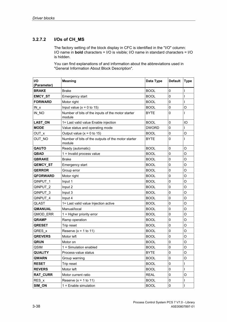
Driver blocks
Process Control System PCS 7 V7.0 - Library 3-38 A5E00807897-01
3.2.7.2 I/Os of CH_MS
The factory setting of the block display in CFC is identified in the "I/O" column: I/O name in bold characters = I/O is visible; I/O name in standard characters = I/O is hidden.
You can find explanations of and information about the abbreviations used in "General Information About Block Description".
I/O (Parameter)
Meaning
Data Type
Default Type
BRAKE Brake BOOL 0 I EMCY_ST Emergency start BOOL 0 I FORWARD Motor right BOOL 0 I IN_x Input value (x = 0 to 15) BOOL 0 O IN_NO Number of bits of the inputs of the motor starter
module BYTE 0 I
LAST_ON 1= Last valid value Enable injection BOOL 0 IO MODE Value status and operating mode DWORD 0 I OUT_x Output value (x = 0 to 15) BOOL 0 O OUT_NO Number of bits of the outputs of the motor starter
module BYTE 0 I
QAUTO Ready (automatic) BOOL 0 O QBAD 1 = Invalid process value BOOL 0 O QBRAKE Brake BOOL 0 O QEMCY_ST Emergency start BOOL 0 O QERROR Group error BOOL 0 O QFORWARD Motor right BOOL 0 O QINPUT_1 Input 1 BOOL 0 O QINPUT_2 Input 2 BOOL 0 O QINPUT_3 Input 3 BOOL 0 O QINPUT_4 Input 4 BOOL 0 O QLAST 1= Last valid value Injection active BOOL 0 O QMANUAL Manual/local BOOL 0 O QMOD_ERR 1 = Higher priority error BOOL 0 O QRAMP Ramp operation BOOL 0 O QRESET Trip reset BOOL 0 O QRES_x Reserve (x = 1 to 11) BOOL 0 O QREVERS Motor left BOOL 0 O QRUN Motor on BOOL 0 O QSIM 1 = Simulation enabled BOOL 0 O QUALITY Process-value status BYTE 0 O QWARN Group warning BOOL 0 O RESET Trip reset BOOL 0 I REVERS Motor left BOOL 0 I RAT_CURR Motor current ratio REAL 0 O RES_x Reserve (x = 1 to 11) BOOL 0 I SIM_ON 1 = Enable simulation BOOL 0 I
Driver blocks
Process Control System PCS 7 V7.0 - Library A5E00807897-01 3-39
I/O (Parameter)
Meaning
Data Type
Default Type
SIM_U Simulation value WORD 0 I VALUE Input value BOOL 0 I
3.2.8 CH_U_AI: Analog Value Input (Universal)
3.2.8.1 Description of CH_U_AI (Universal)
Object name (type + number) FC283
Fields of application Block CH_U_AI processes the analog input signals of S7-300/400 SM analog input modules of a PA field device (PA profile 3.0 Analog Input) or a HART field device (primary or secondary variables).
Calling OBs The calling OB is watchdog alarm OB3x into which you integrate the block (for example, OB32) and restart OB100.
Use in CFC When the CFC function "Generate module drivers" is used, the following occurs automatically:
• Input PA_ON is configured in accordance with the I/O devices used (S7 signal modules [= 0] or PA field devices or primary/secondary variables of a HART field device [= 1]).
• The icon for the quality code of the analog input channel is interconnected with input QC (for PA devices).
• Input MODE is interconnected with the corresponding output OMODE_xx of the MOD block (or of the PADP block).
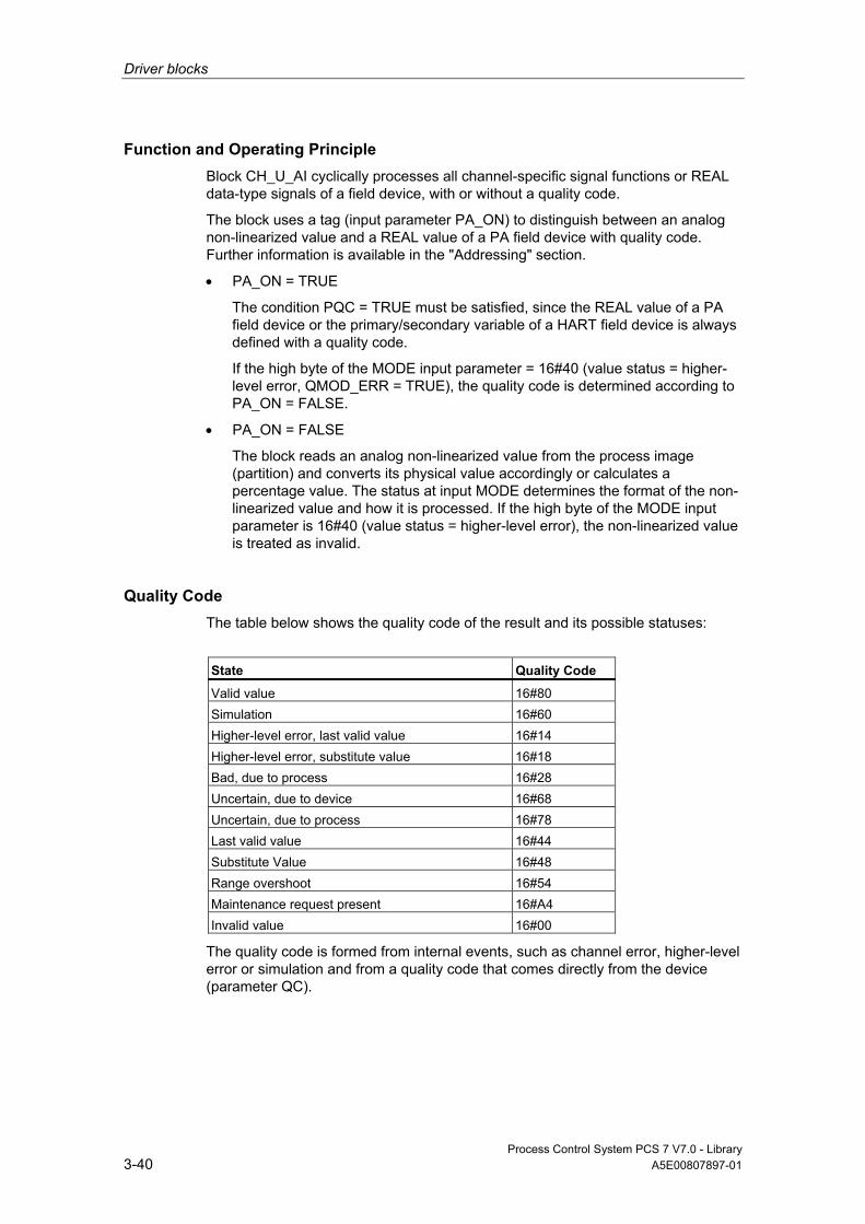
Driver blocks
Process Control System PCS 7 V7.0 - Library 3-40 A5E00807897-01
Function and Operating Principle Block CH_U_AI cyclically processes all channel-specific signal functions or REAL data-type signals of a field device, with or without a quality code.
The block uses a tag (input parameter PA_ON) to distinguish between an analog non-linearized value and a REAL value of a PA field device with quality code. Further information is available in the "Addressing" section.
• PA_ON = TRUE
The condition PQC = TRUE must be satisfied, since the REAL value of a PA field device or the primary/secondary variable of a HART field device is always defined with a quality code.
If the high byte of the MODE input parameter = 16#40 (value status = higher-level error, QMOD_ERR = TRUE), the quality code is determined according to PA_ON = FALSE.
• PA_ON = FALSE
The block reads an analog non-linearized value from the process image (partition) and converts its physical value accordingly or calculates a percentage value. The status at input MODE determines the format of the non-linearized value and how it is processed. If the high byte of the MODE input parameter is 16#40 (value status = higher-level error), the non-linearized value is treated as invalid.
Quality Code The table below shows the quality code of the result and its possible statuses:
State Quality Code
Valid value 16#80 Simulation 16#60 Higher-level error, last valid value 16#14 Higher-level error, substitute value 16#18 Bad, due to process 16#28 Uncertain, due to device 16#68 Uncertain, due to process 16#78 Last valid value 16#44 Substitute Value 16#48 Range overshoot 16#54 Maintenance request present 16#A4 Invalid value 16#00
The quality code is formed from internal events, such as channel error, higher-level error or simulation and from a quality code that comes directly from the device (parameter QC).

Driver blocks
Process Control System PCS 7 V7.0 - Library A5E00807897-01 3-41
The quality code that comes directly from the device can take on values from 16#00 – 16#FF in accordance with PROFIBUS requirements. The imaging of these values on the displayable values listed above is shown in the table "QC_MS" table of the current LIB readme.
Addressing The symbol generated in HW Config for the symbol table of the analog input channel has to be interconnected to the input parameter VALUE or (with PA_ON = TRUE) OUT (process value) and QC (Quality Code).
Raw value check Only if PA_ON = FALSE: Depending on the measurement type and range of the analog input module, the nominal range sets the range for converting analog signals into digital values (non-linearized values) and includes an overshoot/undershoot range within which an analog signal can still be converted. Values outside this range constitute an overflow or underflow. The block indicates whether the non-linearized value lies inside the nominal range of the module. Output parameter QCHF_LL = TRUE if the value is outside the nominal low range, output parameter QCHF_HL = TRUE if the value is outside the nominal high range. QCHF_LL/QCHF_HL remain set to TRUE if a channel error occurs due to the module diagnoses "below or above measuring range". QBAD = TRUE (channel error) is also set when a signal overflow or underflow error occurs.
Note
The reaction of the modules to a wire break in the 4 mA to 20 mA signal line is not uniform. Depending on the module either 16#7FFF (overflow) or 16#8000 (underflow) is written to the process image as a non-linearized value. Channel block CH_U_AI then correspondingly outputs either an overflow (QCHF_HL = TRUE) or an underflow (QCHF_LL = TRUE) signal, each together with QBAD = TRUE. Exception: If you have set the "Diagnostic alarm" of the analog input module in HW Config, only QBAD = TRUE will be set if a diagnostic alarm is triggered after a "Channel error" has occurred (e.g., due to a wire break).
NAMUR Limit Check Only if PA_ON = FALSE: The NAMUR guideline for analog signal processing defines limits for life zero (4 to 20 mA) analog signals which have a channel error:
3.6 mA = Analog signal = 21 mA
The above NAMUR limits are set as fixed defaults for limit value monitoring. If you want to set other limits, you have to set the CH_F_ON input parameter to TRUE and set corresponding new limits in mA at the CH_F_HL and CH_F_LL input parameters. QBAD = TRUE if a life zero analog signal is outside the current high or low limit range.
Driver blocks
Process Control System PCS 7 V7.0 - Library 3-42 A5E00807897-01
Note The limits that can be selected must lie within the overshoot and undershoot range of the module. Values outside the NAMUR range are also possible, if the module does not automatically limit the measured values.
Normal Value Only if PA_ON = FALSE: The non-linearized value is adjusted to its physical value based on the VLRANGE, VHRANGE and MODE input parameters (see also "OMODE_xx"). These values will be written to the outputs OVLRANGE and OVHRANGE to allow the interconnection of the settings of VLRANGE and VHRANGE to other block I/Os. The conversion algorithm depends on a linearized input signal. If VLRANGE = 0 and VHRANGE = 100, you obtain a percentage value. If VHRANGE = VLRANGE is set, you obtain the analog input module’s input signal (e.g., mA) according to the MODE setting. If the non-linearized value is already a physical value, set VLRANGE = 0 and VHRANGE = 1. The Quality Code is set to QUALITY = 16#80.
When operating in PTC measurement mode, the analog value contains an encoded binary signal and the REAL output provides the following information:
• Measured resistance < response value output = 0.0
• Measured resistance > response value output ≠ 0.0.
This only applies when you set the input parameters VLRANGE = 0 and VHRANGE = 1. You should only set 0 or 1 for the simulation and substitute values SIM_V and SUBS_V.
Note
In the measuring mode "External or internal comparison of thermocouple values", the physical unit is adapted to the +/- 80 mV range in S7 300 modules. You have to determine the temperature by means of the corresponding conversion tables.
If the physical equivalent in mV is delivered by the module as a non-linearized value, set VHRANGE and VLRANGE +/- 80 mV.
Simulation If the input parameter SIM_ON = TRUE, the value of the SIM_V input parameter is output with quality code QUALITY = 16#60. QBAD = TRUE: reset due to a higher-level error (QMOD_ERR = TRUE). A valid operating mode also has to be set in the low word of input MODE in simulation mode. Otherwise, QBAD = 1 is output. Simulation takes highest priority. The simulation value is converted into a non-linearized value, based on the operating mode and the input parameters VHRANGE and VLRANGE. This value is verified in the same as a non-linearized value from the process image, which also allows simulation of the QBAD, QCHF_LL and QCHF_HL states. If VLRANGE > VHRANGE, the status QBAD = TRUE can not be simulated. The QCHF_LL and QCHF_HL outputs are set according to the value of SIM_V.

Driver blocks
Process Control System PCS 7 V7.0 - Library A5E00807897-01 3-43
If PA_ON = TRUE, no conversion to a non-linearized value is performed. QBAD = FALSE is always set when SIM_ON = TRUE.
If the block is in the simulation status, QSIM = TRUE.
Substitute Value When input parameter SUBS_ON = TRUE and the non-linearized value is invalid, the value at input parameter SUBS_V will be output as a substitute. The quality code will be set to QUALITY = 16#48 and QBAD = 1.
Hold Last Value With input parameter LAST_ON = TRUE, the last valid output value (V_LAST) is output if the delta value is invalid. If V_DELTA > 0, the following applies:
• ABS (V - V_LAST) > V_DELTA: V = V_LAST1 (second to last valid output value)
• ABS (V - V_LAST) ≤ V_DELTA: V = V_LAST (last valid output value)
The quality code will be set to QUALITY = 16#44 and QBAD = 1.
If valid non-linearized values are available, V_DELTA > 0 and ABS (V - V_LAST) > V_DELTA, the last valid output value (V_LAST) with QUALITY = 16#44 (QBAD = 0) is held for the duration of one cycle.
Output invalid value If the input parameter is SUBS_ON and LAST_ON = FALSE or both = TRUE, and an invalid process value is present, then this will be output.
The quality code that is output is listed in the table "QC_MS" of the LIB readme. In addition QBAD = 1 is set.
Delayed Value Acceptance Only if PA_ON = FALSE: After a restart or if the Quality Code is changed from "BAD" to "GOOD", the quality code and value are not updated unless the number of cycles specified in CNT_LIM have expired. When CNT_LIM = 0 (default setting), this function is disabled. During this delay time, the Quality Code = 16#00 and QBAD = 1 and the last value will be retained.

Driver blocks
Process Control System PCS 7 V7.0 - Library 3-44 A5E00807897-01
Value Limiting When PA_ON = TRUE, you can set a limiting filter for process values of the process image (partition).
If the switch LIMIT_ON = TRUE, the process values (V) are limited as follows:
• To V_HL, if V > V_HL
• To LL_V, if V < V_LL
Error handling The input parameters are not validated. In case of invalid operating mode settings in the low word of input parameter MODE, it is assumed that the non-linearized value is invalid.
Startup Characteristics The accept value delay is started when CNT_LIM is # 0.
Dynamic response n.a.
Message response n.a.
Operating and Monitoring The block has no faceplate.
Additional Information Further information is available in the section:
Notes on Using Driver Blocks
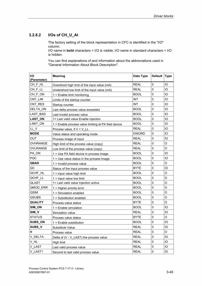
Driver blocks
Process Control System PCS 7 V7.0 - Library A5E00807897-01 3-45
3.2.8.2 I/Os of CH_U_AI
The factory setting of the block representation in CFC is identified in the "I/O" column: I/O name in bold characters = I/O is visible; I/O name in standard characters = I/O is hidden.
You can find explanations of and information about the abbreviations used in "General Information About Block Description".
I/O (Parameter)
Meaning
Data Type
Default Type
CH_F_HL Overshoot high limit of the input value (mA) REAL 0 IO CH_F_LL Undershoot low limit of the input value (mA) REAL 0 IO CH_F_ON 1 = Enable limit monitoring BOOL 0 IO CNT_LIM Limits of the startup counter INT 0 IO CNT_RES Startup counter INT 0 IO DELTA_ON Last delta process value exceeded BOOL 0 IO LAST_BAD Last invalid process value BOOL 0 IO LAST_ON 1= Last valid value Enable injection BOOL 0 IO LIMIT_ON 1 = Enable process value limiting at PA field device BOOL 0 IO LL_V Process value, if V < V_LL REAL 0 IO MODE Value status and operating mode DWORD 0 IO OUT Process image of input REAL 0 IO OVHRANGE High limit of the process value (copy) REAL 0 O OVLRANGE Low limit of the process value (copy) REAL 0 O PA_ON 1 = Use PA field device in process image BOOL 0 IO PQC 1 = Use value status in the process image BOOL 0 IO QBAD 1 = Invalid process value BOOL 0 O QC Status of the input process value BYTE 0 IO QCHF_HL 1 = input value high limit BOOL 0 O QCHF_LL 1 = input value low limit BOOL 0 O QLAST 1= Last valid value Injection active BOOL 0 O QMOD_ERR 1 = Higher priority error BOOL 0 O QSIM 1 = Simulation enabled BOOL 0 O QSUBS 1 = Substitution enabled BOOL 0 O QUALITY Process-value status BYTE 0 O SIM_ON 1 = Enable simulation BOOL 0 IO SIM_V Simulation value REAL 0 IO STATUS Process value status BYTE 0 O SUBS_ON 1 = Enable substitution BOOL 0 IO SUBS_V Substitute Value REAL 0 IO V Process value REAL 0 O V_DELTA Delta of (V - V_LAST) the process value REAL 0 IO V_HL High limit REAL 0 IO V_LAST Last valid process value REAL 0 IO V_LAST1 Second to last valid process value REAL 0 IO
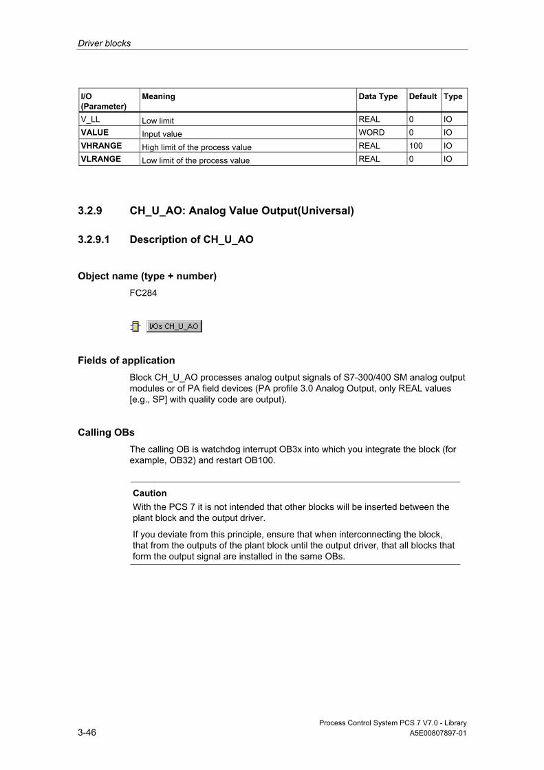
Driver blocks
Process Control System PCS 7 V7.0 - Library 3-46 A5E00807897-01
I/O (Parameter)
Meaning
Data Type
Default Type
V_LL Low limit REAL 0 IO VALUE Input value WORD 0 IO VHRANGE High limit of the process value REAL 100 IO VLRANGE Low limit of the process value REAL 0 IO
3.2.9 CH_U_AO: Analog Value Output(Universal)
3.2.9.1 Description of CH_U_AO
Object name (type + number) FC284
Fields of application Block CH_U_AO processes analog output signals of S7-300/400 SM analog output modules or of PA field devices (PA profile 3.0 Analog Output, only REAL values [e.g., SP] with quality code are output).
Calling OBs The calling OB is watchdog interrupt OB3x into which you integrate the block (for example, OB32) and restart OB100.
Caution
With the PCS 7 it is not intended that other blocks will be inserted between the plant block and the output driver.
If you deviate from this principle, ensure that when interconnecting the block, that from the outputs of the plant block until the output driver, that all blocks that form the output signal are installed in the same OBs.
Driver blocks
Process Control System PCS 7 V7.0 - Library A5E00807897-01 3-47
Use in CFC When the CFC function "Generate module drivers" is used, the following occurs automatically:
• The PA_ON input is configured in accordance with the I/O devices used (S7 signal modules [= 0] or PA field devices [= 1]).
• The icon for the quality code of the analog output channel is interconnected with the QC_SP output (for PA devices).
• Input MODE is interconnected with the corresponding output OMODE_xx of the MOD block (or of the PADP block).
• The CH_U_AO block is installed downstream of the MOD/PADP block that is assigned to it in OB100.
Note
If you do not use the CFC function "Generate module drivers", you have to ensure that the CH_U_AO block is installed downstream of the MOD/PADP block assigned to it in OB100.
Function and Operating Principle Block CH_U_AO cyclically processes all channel-specific signal functions/REAL values with quality code.
Block CH_U_AO uses a tag (input parameter PA_ON) to distinguish between an analog non-linearized value and a REAL value of a PA field device with quality code. Further information is available in the "Addressing" section.
• PA_ON = TRUE
The block writes the REAL value (SP) with quality code (ST_SP) of a PA field device to the process image (partition).
• PA_ON = FALSE
The block writes the process value as analog non-linearized value to a process image (partition). The MODE input parameter determines in which form the non-linearized value is to be generated. If the high byte of input parameter MODE = 0 (value status), the non-linearized value is still written to the process image (partition), but with the quality code "invalid value".

Driver blocks
Process Control System PCS 7 V7.0 - Library 3-48 A5E00807897-01
Quality Code The quality code may assume the following states:
State Quality Code
Valid value 16#80 Simulation 16#60 Higher-level error, last valid value 16#14 Higher-level error, substitute value 16#18 Bad, due to process 16#28 Uncertain, due to device 16#68 Uncertain, due to process 16#78 Last valid value 16#44 Substitute Value 16#48 Range overshoot 16#54 High range limited 16#56 Low range limited 16#55 Maintenance request present 16#A4 Invalid value 16#00
The quality code is formed from internal events, such as channel error, higher-level error or simulation and from a quality code that comes directly from the device (parameter QC).
The quality code that comes directly from the device can take on values from 16#00 – 16#FF in accordance with PROFIBUS requirements. The imaging of these values on the displayable values listed above is shown in the table "QC_MS" table of the current LIB readme.
Addressing The symbol (symbol table) generated in HW Config for the analog output channel must be interconnected to the VALUE output.
For PA field devices (PA_ON = TRUE), you must interconnect the icon for the REAL value with the O_SP output parameter.
Normal Value • Only if PA_ON = FALSE: The ULRANGE and UHRANGE parameters map the
process value U to the non-linearized VALUE (quantization steps) of the analog output module according to the MODE. For example, in operating mode 4 mA to 20 mA (16#0203), the non-linearized value for 4 mA is output if U = ULRANGE and the non-linearized value for 20mA is output if U = UHRANGE.
• The block switches the parameters UHRNAGE and ULRANGE through to the outputs OVHRANGE and OVLRANGE. Setting value limits NM_LMNHR and NM_LMNLR of the controller CTRL_PID.

Driver blocks
Process Control System PCS 7 V7.0 - Library A5E00807897-01 3-49
• PHYS_LIM can be used to set the limits for the non-linearized VALUE. The default setting of PHYS_LIM = 0 limits the value at output VALUE to the default limits of the module. In accordance with the above example, the block calculates the non-linearized value for 20 mA if U > UHRANGE and for 4mA if U < ULRANGE. The quality codes 16#56 (high value limited) and 16#55 (low value limited) are applied accordingly at the QUALITY output, instead of 16#80 (valid value).
• If you want to output analog values outside the normalization limits up to the physical limits of the module, set PHYS_LIM = 1. The output values are limited only if, taking the example above, you exceed the module limit values by specifying U = 200 (36 mA) or U = -50 (-4 mA) when ULRANGE = 0 and UHRANGE = 100. The output values are then limited to the physical limits specified in the data sheets of the modules and the corresponding quality codes are output.
• The QCHF_HL and QCHF_LL outputs also provide information on whether output-value limits have been set.
Simulation If the input parameter SIM_ON = TRUE is set, the value of SIM_V is output with quality code (QUALITY) = 16#60. Reset due to a higher-priority error (QMOD_ERR = TRUE). Simulation takes highest priority. If the block is in the simulation status, QSIM = TRUE.
I/O Fault If the high byte of the MODE input parameter is set to 0 (value status), the quality code QUALITY = 16#00 is set. The actual raw value is always written to the process image (partition).
Value Limiting Only if PA_ON = FALSE: You can limit very low or very high process values that would lead to an error (QBAD = TRUE) before they are entered in the process image (partition).
If the switch LIMIT_ON = TRUE, the process values (U) are limited as follows:
• to V_HL, if U > V_HL and
• to LL_V, if U < V_LL.
Error handling The input parameters are not validated. If an invalid operating mode was set in the low word of the MODE input parameter, the digitized output value will be set to 0 and QUALITY = 16#00 is output.
Driver blocks
Process Control System PCS 7 V7.0 - Library 3-50 A5E00807897-01
Startup Characteristics The MOD blocks set the LSB in byte 2 of their OMODE_xx output parameters in OB100. If the block detects this code, it responds with an acknowledgement and:
• If START_ON is not set, computes the process value U and writes the result to the process image.
If START_ON is set, the non-linearized value corresponding to the START_U process value is written to the process image.
• When PA field devices are enabled (PA_ON = TRUE), the actual REAL value with quality code is written to the process image.
Dynamic response n.a.
Message response n.a.
Operating and Monitoring The block has no faceplate.
Additional information Additional information is available in the section:
Notes on Using Driver Blocks

Driver blocks
Process Control System PCS 7 V7.0 - Library A5E00807897-01 3-51
3.2.9.2 I/Os of CH_U_AO
The factory setting of the block representation in CFC is identified in the "I/O" column: I/O name in bold characters = I/O is visible; I/O name in standard characters = I/O is hidden.
You can find explanations of and information about the abbreviations used in "General Information About Block Description".
I/O (Parameter)
Meaning
Data Type
Default Type
LIMIT_ON 1 = Enable limiting of the process value BOOL IO
LL_V Process value, if U < V_LL REAL IO
MODE Value status and operating mode DWORD IO
O_SP Process image setpoint REAL O
OVHRANGE High limit of the process value REAL O
OVLRANGE Low limit of the process value REAL O
PA_ON 1 = PA field device, 0 = signal module BOOL IO
PHYS_LIM 1 = Enable physical limit of the module BOOL IO
QBAD 1 = Invalid output value BOOL O
QCHF_HL 1 = Overshoot of process value BOOL O
QCHF_LL 1 = Undershoot of process value BOOL O
QC_SP Process image quality code setpoint BYTE O
QMOD_ERR 1 = Higher priority error BOOL O
QSIM 1 = Simulation enabled BOOL O
QUALITY Value status of the output value BYTE O
SIM_ON 1 = Enable simulation BOOL IO
SIM_U Simulation value REAL IO
START_ON 1 = Enable startup substitution BOOL IO
START_U Substitution at startup REAL IO
ST_SP Setpoint status BYTE IO
U Process value REAL IO
UHRANGE High limit of the process value REAL IO
ULRANGE Low limit of the process value REAL IO
V_HL High limit REAL IO
V_LL Low limit REAL IO
VALUE Output value WORD O

Driver blocks
Process Control System PCS 7 V7.0 - Library 3-52 A5E00807897-01
3.2.10 CH_U_DI: Digital Value Input (Universal)
3.2.10.1 Description of CH_U_DI (Universal)
Object name (type + number) FC285
Fields of application Block CH_U_DI processes digital input signals of S7-300/400 SM digital input modules or of PA field devices (PA profile 3.0 Discrete Input).
Calling OBs The calling OB is watchdog interrupt OB3x into which you integrate the block (for example, OB32).
Use in CFC When the CFC function "Generate module drivers" is used, the following occurs automatically:
• The PA_ON input is configured in accordance with the I/O devices used (S7 signal modules [= 0] or PA field devices [= 1]).
• The icon for the quality code of the digital input channel is interconnected with input QC (for PA devices).
• Input MODE is interconnected with the corresponding output OMODE_xx of the MOD block (or of the PADP block).

Driver blocks
Process Control System PCS 7 V7.0 - Library A5E00807897-01 3-53
Function and Operating Principle
Block CH_U_DI cyclically processes all channel-specific signal functions/process values with quality code of a PA field device.
The block uses a tag (PA_ON input parameter) to distinguish between a digital value with or without quality code of the data type BOOL and a digital value with quality code of the data type BYTE of a PA field device. Further information is available in the "Addressing" section.
• PA_ON = TRUE
The block cyclically reads the process value (OUT_D) and the status byte (QUALITY, see "Addressing") of the PROFIBUS PA field device (structure in accordance with the discrete input of the PA profiles) from the process image (partition). The status byte contains information about the measured value and the status of the PROFIBUS field device. The block transfers the process value to output Q as shown below:
- Q = FALSE, if the process value = 0
- Q = TRUE, if the process value <> 0 If the high byte of the MODE input parameter = 16#40 (value status = higher-level error), the process value and quality code are treated as if PA_ON = FALSE.
• PA_ON = FALSE
The block reads a digital value of the data type BOOL from the process image (partition). If the high byte of the MODE input parameter = 16#40 (value status = higher-level error, QMOD_ERR = TRUE), the digital value is treated as invalid. If input parameter PQC = TRUE, it reads the value status of the digital value from the process image (partition).
Quality Code The program generates a quality code of the resultant value which may assume the states shown below:
State Quality Code
Valid value 16#80 Simulation 16#60 Higher-level error, last valid value 16#14 Higher-level error, substitute value 16#18 Bad, due to process 16#28 Uncertain, due to device 16#68 Uncertain, due to process 16#78 Last valid value 16#44 Substitute Value 16#48 Range overshoot 16#54 Maintenance request present 16#A4 Invalid value 16#00

Driver blocks
Process Control System PCS 7 V7.0 - Library 3-54 A5E00807897-01
The quality code is formed from internal events, such as channel error, higher-level error or simulation and from a quality code that comes directly from the device (parameter QC).
The quality code that comes directly from the device can take on values from 16#00 – 16#FF in accordance with PROFIBUS requirements. The imaging of these values on the displayable values listed above is shown in the table "QC_MS" table of the current LIB readme.
Addressing The symbol generated in HW Config (symbol table) for the digital input channel must be interconnected to the VALUE input. If the process image (partition) also contains the value status of the digital input channel, you must interconnect the corresponding symbol with input VALUE_QC and set input PQC = TRUE.
When using PA field devices (PA_ON = TRUE), interconnect the symbol generated in HW Config (symbol table) for the digital input channel with input I_OUT_D.
Normal Value The digital value of the process image (partition) and the quality code QUALITY = 16#80 are returned to output Q.
Simulation If the SIM_ON input parameter = TRUE, the value of the SIM_I (PA_ON = FALSE) or SIM_OUT (PA_ON = TRUE) input parameter is output with quality code QUALITY = 16#60 to the output parameter Q. reset due to a higher-priority error (QMOD_ERR = TRUE). Simulation takes highest priority.
If the block is in the simulation status, QSIM = TRUE.
Substitute Value When input parameter SUBS_ON = TRUE and the digital value of the process image (partition) is invalid, the function outputs the signal QBAD = 1 and the value at input parameter SUBS_I with quality code QUALITY = 16#48 to output parameter Q.
Hold Last Value If the input parameter SUBS_ON = FALSE, the function outputs the last valid output value when the non-linearized value is invalid and sets QBAD = 1 and the quality code to QUALITY = 16#44.
Last valid output value = Q_LAST.

Driver blocks
Process Control System PCS 7 V7.0 - Library A5E00807897-01 3-55
Output of an invalid value If the input parameter is SUBS_ON and LAST_ON = FALSE or both = TRUE, and an invalid process value is present, then this will be output.
The quality code that is output is listed in the table "QC_MS" of the LIB readme. In addition QBAD = 1 is set.
Error handling The input parameters are not validated.
Startup Characteristics n.a.
Dynamic response n.a.
Message response n.a.
Operating and Monitoring The block has no faceplate.
Additional information Additional information is available in the section:
Notes on Using Driver Blocks

Driver blocks
Process Control System PCS 7 V7.0 - Library 3-56 A5E00807897-01
3.2.10.2 I/Os of CH_U_DI
The factory setting of the block representation in CFC is identified in the "I/O" column: I/O name in bold characters = I/O is visible; I/O name in standard characters = I/O is hidden.
You can find explanations of and information about the abbreviations used in "General Information About Block Description".
I/O (Parameter)
Meaning
Data Type
Default Type
I_OUT_D Input value of the process image BYTE 0 IO LAST_ON 1= Last valid value Enable injection BOOL 0 IO MODE Value status and operating mode DWORD 0 IO OUT_D Process value BYTE 0 O PA_ON 1 = PA field device BOOL 0 IO PQC 1 = Use value status in the process image BOOL 0 IO Q Process value BOOL 0 O Q_LAST Last valid process value BOOL 0 IO QBAD 1 = Invalid process value BOOL 0 O QC Value status in the process image (symbol) BYTE 0 IO QLAST 1= Last valid value Injection active BOOL 0 O QMOD_ERR 1 = Higher priority error BOOL 0 O QSIM 1 = Simulation enabled BOOL 0 O QSUBS 1 = Substitution enabled BOOL 0 O QUALITY Process-value status BYTE 0 O SIM_I Simulation value BOOL 0 IO SIM_ON 1 = Enable simulation BOOL 0 IO SIM_OUT Output simulation value BYTE 0 IO STATUS Process value status BYTE 0 O SUBS_I Substitute value BOOL 0 IO SUBS_ON 1 = Enable substitution BOOL 0 IO SUBS_OUT Output substitute value BYTE 0 IO V_LAST Last valid process value BYTE 0 IO VALUE Input value BOOL 0 IO VALUE_QC Value status in the process image BOOL 0 IO

Driver blocks
Process Control System PCS 7 V7.0 - Library A5E00807897-01 3-57
3.2.11 CH_U_DO: Digital Value Output(Universal)
3.2.11.1 Description of CH_U_DO (Universal)
Object name (type + number) FC286
Fields of application Block CH_U_DO process digital output signals of S7-300/400 SM digital output modules or of PA field devices (PA profile 3.0 Discrete Output = only SP or RCAS_IN).
Calling OBs The calling OB is watchdog interrupt OB3x into which you integrate the block (for example, OB32) and restart OB100.
Caution
With the PCS 7 it is not intended that other blocks will be inserted between the plant block and the output driver.
If you deviate from this principle, ensure that when interconnecting the block, that from the outputs of the plant block until the output driver, that all blocks that form the output signal are installed in the same OBs.
Use in CFC When the CFC function "Generate module drivers" is used, the following occurs automatically:
• The PA_ON input is configured in accordance with the I/O devices used (S7 signal modules [= 0] or PA field devices [= 1]).
• The icon for the quality code of the digital output channel is interconnected with the QC_SP output (for PA devices).
• The MODE input is interconnected with the corresponding OMODE_xx output of the MOD block (or of the PADP block).
• The CH_U_DO block is installed downstream of the MOD/PADP block that is assigned to it in OB100.

Driver blocks
Process Control System PCS 7 V7.0 - Library 3-58 A5E00807897-01
Note If you do not use the CFC function "Generate module drivers", you have to ensure that the CH_U_DO block is installed in OB100 after its assigned MOD-/PADP block.
Function and Operating Principle Block CH_U_DO cyclically processes all channel-specific signal functions/process values with quality code of a PA field device.
The block uses a tag (PA_ON input parameter) to distinguish between a digital output value without quality code of the data type BOOL and a digital output value with quality code of the data type BYTE of a PA field device. Further information is available in the "Addressing" section. • PA_ON = TRUE
The block writes the process value with QC to a process image (partition) [structure of the process value corresponds with the digital output of the PA Profile, 1 byte (SP) with 1 byte (ST_SP) QC]. The QC contains information on the process-value status. The coding of the quality codes is described in PROFIBUS 3.0 "General Requirements". If the high byte at the MODE input parameter = 16#40 (value status = higher-level error, QMOD_ERR = TRUE), the function continues to write the process value with QC to the process image (partition), but sets the quality code to "invalid value" at the QUALITY block output.
• PA_ON = FALSE The block writes a digital value to a process image (partition). If the high byte at the MODE input parameter = 0 (value status), this digital value will still be written to the process image (partition), but an "invalid value" quality code is set.
Quality Code The quality code may assume the following states:
State Quality Code
Valid value 16#80 Simulation 16#60 Higher-level error, last valid value 16#14 Higher-level error, substitute value 16#18 Bad, due to process 16#28 Uncertain, due to device 16#68 Uncertain, due to process 16#78 Last valid value 16#44 Substitute Value 16#48 Range overshoot 16#54 Maintenance request present 16#A4 Invalid value 16#00

Driver blocks
Process Control System PCS 7 V7.0 - Library A5E00807897-01 3-59
The quality code is formed from internal events, such as channel error, higher-level error or simulation and from a quality code that comes directly from the device (parameter QC).
The quality code that comes directly from the device can take on values from 16#00 – 16#FF in accordance with PROFIBUS requirements. The imaging of these values on the displayable values listed above is shown in the table "QC_MS" table of the current LIB readme.
Addressing The symbol generated with HW Config (symbol table) for the digital output channel must be interconnected to the VALUE input. When PA field devices (PA_ON = TRUE) are used, the symbol generated in the symbol table for the process value with QC must be interconnected to output variable O_SP.
Normal Value The digital value is written to the process image (partition) and QC (QUALITY) = 16#80.
Simulation If the SIM_ON input parameter = TRUE, the block writes the value of the SIM_I (PA_ON = FALSE) or SIM_SP (PA_ON = TRUE) input parameter to the process image (partition) and sets QC QUALITY = 16#60. QBAD = TRUE: QBAD is always reset. Simulation takes highest priority. If the block is in the simulation status, QSIM = TRUE.
I/O Fault If the high byte of the MODE input parameter is set to 0 (value status), the quality code QUALITY = 16#00 is set. The function always writes the actual non-linearized value to the process image (partition).
Error handling The input parameters are not validated.
Startup Characteristics The MOD blocks set the LSB in byte 2 of their OMODE_xx output parameters in OB100. If the block detects this code, it responds with an acknowledgement and: • If START_ON is not set, writes process value I to the process image. • Otherwise, START_I is used instead of process value I. When PA field devices (PA_ON = TRUE) are used, the actual BYTE value and the QC are written to the process image.

Driver blocks
Process Control System PCS 7 V7.0 - Library 3-60 A5E00807897-01
Dynamic response n.a.
Message response n.a.
Operating and Monitoring The block has no faceplate.
Additional information Additional information is available in the section:
Notes on Using Driver Blocks
3.2.11.2 I/Os of CH_U_DO
The factory setting of the block representation in CFC is identified in the "I/O" column: I/O name in bold characters = I/O is visible; I/O name in standard characters = I/O is hidden.
You can find explanations of and information about the abbreviations used in "General Information About Block Description".
I/O (Parameter)
Meaning
Data Type
Default Type
I Process value BOOL 0 IO MODE Value status and operating mode DWORD 0 IO O_SP Process image setpoint BYTE 0 O PA_ON 1 = PA field device BOOL 0 IO QBAD 1 = Invalid output value BOOL 0 O QC_SP Process image quality code setpoint BYTE 0 O QMOD_ERR 1 = Higher priority error BOOL 0 O QSIM 1 = Simulation enabled BOOL 0 O QUALITY Value status of the output value BYTE 0 O SIM_I Simulation value BOOL 0 IO SIM_ON 1 = Enable simulation BOOL 0 IO SIM_SP Simulation setpoint BYTE 0 IO SP Setpoint BYTE 0 IO ST_SP Setpoint status BYTE 0 IO START_I Substitution at startup BOOL 0 IO START_ON 1 = Enable startup substitution BOOL 0 IO VALUE Output value BOOL 0 O

Driver blocks
Process Control System PCS 7 V7.0 - Library A5E00807897-01 3-61
3.2.12 CONEC: Monitoring the Connection Status of the AS
3.2.12.1 Description of CONEC
Object name (type + number) FB88
Fields of application The CONEC block monitors the status of AS connections and reports the corresponding error events.
Calling OBs The block must be installed in the run sequence in the following OBs:
OB32 Cyclic program OB100 Restart (warm start)
Use in CFC When using the CFC function "Generate module drivers", the CONEC block is automatically installed in the OBs listed above.
Function and Operating Principle The CONEC block generates messages which are output at ALARM_8P to WinCC (see "Message response"). For connection diagnostics, SFC87 (C_DIAG) is called at intervals of 10 seconds in the cyclic interrupt OB (OB32). Up to 64 connections are monitored.
Note
The messages "Failure or loss of redundancy connection ID" are generated by each CPU of the two connected AS except when the CPU of an AS fails (or both H-CPUs). Whether or not a message is sent depends on the connection ID. If the connection ID >= 16#C00, no message is generated.
Driver blocks
Process Control System PCS 7 V7.0 - Library 3-62 A5E00807897-01
Generation of the maintenance status MS If any connection in the CONEC block is detected as failed then the maintenance status "Maintenance (MS): Alarm" will be output.
If any connection in the CONEC block is detected as redundancy loss, then the maintenance status "Maintenance (MS): Request" will be output.
If in the CONEC block the messages are disabled via the parameter EN_MSG, then the maintenance status "Unchecked / Unknown" will be output.
Error handling Error handling of the block is limited to the evaluation of the error information of ALARM_8P. You can find additional information in "Error Information of Output Parameter MSG_STAT".
Startup Characteristics The CONEC block initializes the messages of ALARM_8P.
If there is a CPU with SFC87, connection diagnostics is initialized. After this, there is a waiting time of approx. 1 minute in the cyclic interrupt OB before the connection diagnostics messages are generated.
Overload Behavior n.a.
Dynamic response You can find additional information in "Message response".
Message response The block generates the following messages in the OBs listed below:
OB Start Event Message
OB32 1 sec. cyclic interrupt or alternative cyclic interrupt OB
Failure connection ID: xx entering/exiting state Loss of redundancy connection ID: xx entering/exiting state
If EN_MSG = FALSE, messaging is disabled.

Driver blocks
Process Control System PCS 7 V7.0 - Library A5E00807897-01 3-63
Operating and Monitoring Note: If you have selected the "Enable operating and monitoring" option in the block object properties in the CFC, the variables transferred to the OS are identified under "I/Os of …" (OCM column, "+"). Default: option not selected.
If asset management is used in the project and the diagnostics pictures were generated, the faceplate can be opened using its icon.
• Asset Management block symbols
• Asset Management faceplates
Note: The Online help and the "PCS 7 FACEPLATES" Manual are only available if the "PCS 7 FACEPLATES" software package is installed!
Additional information Additional information is available in the sections: Message Texts and Associated Values of CONEC Maintenance Status MS Notes on Using Driver Blocks
3.2.12.2 I/Os of CONEC The factory setting of the block representation in CFC is identified in the "I/O" column: I/O name in bold characters = I/O is visible; I/O name in standard characters = I/O is hidden. You can find explanations of and information about the abbreviations used in "General Information About Block Description".
I/O (Parameter)
Meaning
Data Type
Default Type
OCM
EN_MSG 1 = Enable message BOOL 1 I EV_IDx Message number for ALARM_8P_x
(x = 1 - 16, assigned by ES) DWORD 0 I
MS Maintenance status DWORD 0 I +
MSGSTATx STATUS output of ALARM_8P_x (x = 1 - 16) WORD 0 O O_MS Maintenance status DWORD 0 O QMSGERx Error output of ALARM_8P_x (x = 1 - 16) BOOL 0 O SAMPLE_T Sampling time OB in seconds REAL 1.0 I
Additional information Additional information is available in the sections: Message Texts and Associated Values of CONEC Maintenance Status MS

Driver blocks
Process Control System PCS 7 V7.0 - Library 3-64 A5E00807897-01
3.2.12.3 Message Texts and Associated Values of CONEC
Assignment of Message Text and Message Class
Message Block ALARM_8P
Message No. Default Message Text
Message Class
EV_ID1 to EV_ID8 1 Failure connection ID: 16#@1%X@ S 2 Failure connection ID: 16#@2%X@ S 3 Failure connection ID: 16#@3%X@ S 4 Failure connection ID: 16#@4%X@ S 5 Failure connection ID: 16#@5%X@ S 6 Failure connection ID: 16#@6%X@ S 7 Failure connection ID: 16#@7%X@ S 8 Failure connection ID: 16#@8%X@ S EV_ID9 to EV_ID16 1 Loss of redundancy connection ID: 16#@1%X@ F 2 Loss of redundancy connection ID: 16#@2%X@ F 3 Loss of redundancy connection ID: 16#@3%X@ F 4 Loss of redundancy connection ID: 16#@4%X@ F 5 Loss of redundancy connection ID: 16#@5%X@ F 6 Loss of redundancy connection ID: 16#@6%X@ F 7 Loss of redundancy connection ID: 16#@7%X@ F 8 Loss of redundancy connection ID: 16#@8%X@ F
Assignment of Associated Values The process control messages are generated by ALARM_8P with EV_ID1 to EV_ID16 with 8 associated values. The table below shows how the associated values are assigned to the block parameters.
Message Block ALARM_8P
Associated Value
Block Parameter
Data Type
EV_ID1... EV_ID16 1 Connection_ID 1+x WORD 2 Connection_ID 2+x WORD 3 Connection_ID 3+x WORD 4 Connection_ID 4+x WORD 5 Connection_ID 5+x WORD 6 Connection_ID 6+x WORD 7 Connection_ID 7+x WORD 8 Connection_ID 8+x WORD
x = 0 for EV_ID1, x = 8 for EV_ID2, x = 16 for EV_ID3 etc. to x = 56 for EV_ID8 x = 0 for EV_ID9, x = 8 for EV_ID10, x = 16 for EV_ID11 etc. to x = 56 for EV_ID16

Driver blocks
Process Control System PCS 7 V7.0 - Library A5E00807897-01 3-65
3.2.13 DPDIAGV0: Monitoring the Connection Status of the ET 200S Modules as DP V0-Slave Downstream of a Y-Link
3.2.13.1 Description of DPDIAGV0
Object name (type + number) FB117
Fields of application Block DPDIAGV0 monitors the status of the modules of an ET 200S operating as a DPV0 slave (IM 151-1 High Feature) downstream of a Y link.
Calling OBs The block must be installed in the run sequence in the following OBs:
OB1 Cyclic program
OB82 Diagnostic interrupt OB83 Removal/insertion alarm OB85 Program runtime error OB86 Rack failure OB100 Restart (warm start)
Use in CFC When the CFC function "Generate module drivers" is used, the following occurs automatically: • The block is integrated in the run sequence downstream of block OB_DIAG1. • The following inputs are configured:
- SUBN_1ID (ID primary DP master system) - SUBN_2ID (ID secondary DP master system) - RACK_NO (rack/station number)
• The following I/Os are interconnected: - the OUT structures CPU_DIAG of the OB_BEGIN block and RAC_DIAG of
the RACK block with the DPDIAGV0-block INOUT structures of the same name
- EN_Mxx with EN of the OB_DIAG1 block and the DPDIAGV0 block at each ET 200S
- the DPA_M_xx outputs with the DPA_M input and EN_Mxx output with EN of a MOD_4 block.
Driver blocks
Process Control System PCS 7 V7.0 - Library 3-66 A5E00807897-01
Function and Operating Principle After having received a diagnostic alarm, DPDIAGV0 analyzes the ID-specific diagnostics data and the module status of an ET 200S operating in DPV0 mode downstream of a Y link.
The upstream OB_DIAG1 block detects the failure/restart of an ET 200S.
The AS addresses the devices via the link, i.e., indirectly. The topological structure of the DP bus is mapped in the flat structure of the slave interface. Up to 64 devices can be operated downstream of a Link. Each device can be assigned any number of virtual slots (max. 223) of the Link. In order to be able to assign the diagnostics data of an ET 200S, the block uses the following inputs of the data type BYTE with the meaning shown below:
• SUBN1_ID = Primary ID of the master system
• SUBN2_ID = Secondary ID of the master system
• RACK_NO = Station number (address) of the DP master system of the Link
• PADP_ADR = Station number (address) of the ET 200S
• SLAVE _NO = 1st module address of the ET 200S in the link
• SLAVE_SL = Number of slots at the ET 200S
The CFC function "Generate module drivers" fetches these data from HW Config.
The useful diagnostics data contain information about the ET 200S status.
The status of an ET 200S module is entered in byte DPA_M_xx. An ET 200S can have up to 64 slots (modules).
Bits 0 to 2 of DPA_M are defined as follows:
Status Bit 2 Status Bit 1 Status Bit 0 Meaning
0 0 0 Module x OK (valid user data) 0 1 0 Module x error (invalid user data) 0 0 1 Wrong module x (invalid user data) 0 1 1 No module x (invalid user data) 1 x x ET 200S failure (invalid user data)
If you do not wish to use the CFC function "Generate module drivers" for online editing of the inputs of the SUBNET block SUBN1_ID (connection to CPU 0) and SUBN2_ID (connection to CPU 1), set input ACC_ID = TRUE at the relevant block. This verifies the Link states and updates output values.
Driver blocks
Process Control System PCS 7 V7.0 - Library A5E00807897-01 3-67
Redundancy Downstream of a Y-Link you may only operate non-redundant devices.
Error handling The input parameters are not validated.
Startup Characteristics The system verifies that the ET 200S is available.
Overload Behavior Determined and carried out at the higher-ranking OB_DIAG1 block.
Dynamic response n.a.
Message response n.a.
Operating and Monitoring The block has no faceplate.
Additional information Additional information is available in the section:
Notes on Using Driver Blocks

Driver blocks
Process Control System PCS 7 V7.0 - Library 3-68 A5E00807897-01
3.2.13.2 I/Os of DPDIAGV0
The factory setting of the block representation in CFC is identified in the "I/O" column: I/O name in bold characters = I/O is visible; I/O name in standard characters = I/O is hidden.
You can find explanations of and information about the abbreviations used in "General Information About Block Description".
I/O (Parameter)
Meaning
Data Type
Default Type
ACC_ID 1 = Accept MODE settings BOOL 0 I/O CPU_DIAG CPU diagnostics (system structure) STRUCT I/O DADDR Diagnostics address of the Y-Link INT 0 I DPA_M_xx Status of the DP/PA slave (xx = 00 - 63) BYTE 0 O EN_Mxx 1 = Enable modules (xx = 00 - 63) BOOL 0 O PADP_ADR DP address ET 200S BYTE 255 I QRACKF 1 = ET 200S failure BOOL 0 O RAC_DIAG Rack diagnostics of the DP slaves downstream from
Y-Link (system structure) STRUCT IO
RACK_NO Rack/station number BYTE 0 I SLAVE_NO 1. Slot number of the slave in the Y-Link BYTE 0 I SLAVE_SL Number of ET 200S slots BYTE 0 I SUBN_TYP 1 = External DP interface BOOL 0 I SUBN1_ID ID of the primary DP master system BYTE 255 I SUBN2_ID ID of the redundant DP master system BYTE 255 I SUBNERR 1 = Y-Link failure BOOL 0 O
3.2.14 DREP: Diagnostic Repeater in the DP Master System
3.2.14.1 Description of DREP
Object name (type + number) FB113
Fields of application Block DREP evaluates diagnostic data output by a SIMATIC diagnostic repeater for PROFIBUS DP. This repeater must be connected to a DP master.

Driver blocks
Process Control System PCS 7 V7.0 - Library A5E00807897-01 3-69
Calling OBs OB1 Cyclic processing
OB82 Diagnostic interrupt OB86 Rack failure OB100 Restart (warm start) (startup, message initialization)
Use in CFC When the CFC function "Generate module drivers" is used, the following occurs automatically:
• Block OB_DIAG1 is installed in the run sequence upstream of the DREP block.
• The following addresses are configured:
- the diagnostic address DADDR of the diagnostics repeater
- the geographical address (SUBN_ID and PADP_ADR)
• The following I/Os are interconnected:
- the OUT structures CPU_DIAG of the OB_BEGIN block and RAC_DIAG of the OB_DIAG1 block with the INOUT structures of the same name of the DREP block
- the EN input with the output of an AND block
- the inputs of the AND block with the EN_SUBx outputs (x = number of the DP master system) of the OB_BEGIN block, with EN_Rxxx (xxx = rack/station number) of the SUBNET block and with EN_F of the OB_DIAG1 block
- EN_DIAG with the EN_DIAG output of the OB_DIAG1 block.
Function and Operating Principle The diagnostics repeater is assigned the following tasks:
• Diagnostics function for two PROFIBUS segments (DP2 and DP3):
The diagnostics function returns the location and cause of line errors, e.g. wire break or missing terminating resistors.
The error location is output, including a reference to the relevant nodes, e.g., "Short-circuit to shielding at signal line A, node 12 <-> 13".
• Repeater function for three PROFIBUS segments (DP1, DP2, DP3):
The diagnostics repeater amplifies data signals on the bus and interconnects the relevant RS485 segments.

Driver blocks
Process Control System PCS 7 V7.0 - Library 3-70 A5E00807897-01
• Galvanic/electrical isolation of the PG interface from other bus segments:
Even if the system is operating at higher transmission rates, interference due to the removal or connection of PG cables is not to be expected at the other PROFIBUS DP segments.
The Diagnostic Repeaters for PROFIBUS DP Manual contains information on the PG interface and on the structure of line error states at the DP1, DP2 and DP3 segments.
Block DREP reports only the diagnostic events at segments DP2 and DP3 of the diagnostic repeater.
Events of the DP1 segment are reported as general "Cable disturbance" group error.
The PG interface is not evaluated and does not result in a message.
Failure and return of the diagnostics repeater are detected by the interconnected block OB_DIAG1 and passed on to the block to report "DR failure".
If an error occurs, an incoming "line error" group message is generated for each segment (DP2 or DP3) when a diagnostic repeater detects the error event (bits in the diagnostic message frame indicating the cause of error):
Bit Description
A.0 1: Indefinite error location and cause (possibly electromagnetic interference) A.1 CPU redundancy loss A.2 1: - - A.3 1: Further measurement circuits at the segment, the other diagnostic repeater is connected with
its segment DP2 A.4 1: Further measurement circuits at the segment, the other diagnostic repeater is connected with
its segment DP3 A.5 1: - - A.6 1: 1 = Indefinite error cause A.7 1: 1 = Critical message frame error rate B.0 1:- -. B.1 1: - - B.2 1: - - B.3 1: - - B.4 1: - -. B.5 1: - - B.6 1: - -. B.7 1: - - C.0 1: 1 = Segment automatically switched off due to continuous zero level on the line. C.1 1: 1 = Segment automatically switched off due to dithering line level. C.2 1: - - C.3 1: - - C.4 1: More than 32 nodes connected to the measurement segment C.5 1: The distance of the node to the diagnostic repeater exceeds the permitted line length C.6 1: The maximum permitted number of diagnostic repeaters connected in series has been
exceeded C0.7 1: - -

Driver blocks
Process Control System PCS 7 V7.0 - Library A5E00807897-01 3-71
The outgoing message will be generated when all segment bits are equal to zero.
You must call HW Config in order to analyze details on events output by the diagnostic repeaters.
An appropriate incoming/outgoing message is going to be generated for the segments (DP2 or DP3) as a result of the following events recognized by a diagnostics repeater:
Bit Description
A.0 1: - A.1 1:- A.2 1: - A.3 1: - A.4 1: - A.5 1: - A.6 1: - A.7 1: B.0 1: 1 = Wire break at signal line A. B.1 1: 1 = Short-circuit to shielding at signal line B B.2 1: - B.3 1: 1 = Short-circuit to shielding at signal line A B.4 1: 1 = Wire break at signal line B. B.5 1: - B.6 1: 1 = Wire break at signal line A and/or B, or the terminating resistor is missing B.7 1: 1 = Short-circuit signal line A <-> B, or an additional terminating resistor has been installed C.0 1: - C.1 1: - C.2 1: - C.3 1: - C.4 1: - C.5 1: -. C.6 1: - C0.7 1: -

Driver blocks
Process Control System PCS 7 V7.0 - Library 3-72 A5E00807897-01
Events recognized by the diagnostics repeater are determined synchronously in OB82. Diagnostic event data are fetched via SFB54 in the OB_BEGIN block and written to the structure DINFO. The function always sets only one bit to indicate the cause of an incoming error. Bit C7 may also be set, e.g. if the diagnostics repeater has detected further errors. In this case, all previously reported events will be queued. DREP generates a corresponding group error message via ALARM_8P. Dithering messages which may develop especially due to error events A.0.1 and A.6.1 are suppressed as follows:
After an outgoing message, a new outgoing message will be delayed by the time in [s] set at the DELAY parameter. If a further error is queued, the outgoing message will not be generated until this error has been reported outgoing.
Error handling The block evaluates the error information of ALARM_8P and writes it to the corresponding output parameters. You can find additional information in "Error Information of Output Parameter MSG_STAT". The block reports a diagnostics error if an error occurs when it attempts to read access diagnostics data, or if any other disruption corrupts diagnostic data.
Startup Characteristics ALARM_8P messages are initialized by the DREP block that uses SFC13 (DPNRM_DG) to read current diagnostic information from the diagnostic repeater.
Overload Behavior The interconnected OB_DIAG1 locks the call of DREP for diagnostics if an overload has occurred.
Dynamic response: n.a.
Message response: The multiple instance ALARM_8P are only called if a message is to be output by this instance. It is only at this point that previously acknowledged messages are updated by the corresponding ALARM block. If the connection to WinCC is down, each ALARM_8P instance can hold up to two message statuses of its event ID (usually two messages maximum). Dithering messages can be suppressed via the DELAY input.

Driver blocks
Process Control System PCS 7 V7.0 - Library A5E00807897-01 3-73
The block generates the messages listed below:
OB No. Start Event Message
1 Cyclic processing Call of ALARM_8P due to incomplete transfer or unacknowledged message
82 Diagnostic interrupt Group error message 100 Restart: Initialization of ALARM_8P
Operating and Monitoring Note: If you have selected the "Enable operating and monitoring" option in the block object properties in the CFC, the variables transferred to the OS are identified under "I/Os of …" (OCM column, "+"). Default: option not selected.
If asset management is used in the project and the diagnostic screens have been generated, then the faceplate can be called via its icon.
• Asset Management block symbols
• Asset Management faceplates
Note: Online help and the "PCS 7 FACEPLATES" Manual are only available if the "PCS 7 FACEPLATES" software package is installed!
Additional information Additional information is available in the sections:
Message Texts and Associated Values of DREP
Maintenance Status MS
Notes on Using Driver Blocks

Driver blocks
Process Control System PCS 7 V7.0 - Library 3-74 A5E00807897-01
3.2.14.2 I/Os of DREP
The factory setting of the block representation in CFC is identified in the "I/O" column: I/O name in bold characters = I/O is visible; I/O name in standard characters = I/O is hidden.
You can find explanations of and information about the abbreviations used in "General Information About Block Description".
I/O (Parameter)
Meaning
Data Type
Default Type
OCM
ACC_MODE 1 = Accept MODE settings BOOL 0 IO CPU_DIAG CPU diagnostics STRUCT IO DADDR Diagnostic address of the diagnostics repeater INT 0 I DELAY Interrupt delay (s) INT 2 I DINFO Diagnostic information of the diagnostic repeater STRUCT O EN_DIAG 1 = Queued diagnostic event BOOL 0 I EN_MSG 1 = Enable message BOOL 1 I EV_IDx Message number DWORD 0 I MS Maintenance status DWORD 0 I + MSG_ACKx Message acknowledgement WORD 0 O MSG_STATx Error message status WORD 0 O O_MS Maintenance status DWORD 0 O PADP_ADR DP/PA address of the diagnostic repeater BYTE 255 I QDREPF 1 = Removed/faulty diagnostic repeater BOOL 0 O QERR 1 = Program runtime error BOOL 1 O RAC_DIAG OB_DIAG1 diagnostics STRUCT IO SUBN_ID DP master system ID BYTE 255 I
Additional information Additional information is available in the sections:
Message Texts and Associated Values of DREP
Maintenance Status MS
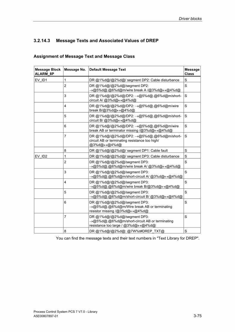
Driver blocks
Process Control System PCS 7 V7.0 - Library A5E00807897-01 3-75
3.2.14.3 Message Texts and Associated Values of DREP
Assignment of Message Text and Message Class
Message Block ALARM_8P
Message No.
Default Message Text
Message Class
EV_ID1 1 DR @1%d@/@2%d@/ segment DP2: Cable disturbance S 2 DR @1%d@/@2%d@/segment DP2:
→@5%d@.@6%d@m/wire break A /@3%d@↔@4%d@ S
3 DR @1%d@/@2%d@/DP2: →@5%d@.@6%d@m/short-circuit A/ @3%d@↔@4%d@
S
4 DR @1%d@/@2%d@/DP2: →@5%d@.@6%d@m/wire break B/@3%d@↔@4%d@
S
5 DR @1%d@/@2%d@/DP2: →@5%d@.@6%d@m/short-circuit B/ @3%d@↔@4%d@
S
6 DR @1%d@/@2%d@/DP2: →@5%d@.@6%d@m/wire break AB or terminator missing /@3%d@↔@4%d@
S
7 DR @1%d@/@2%d@/DP2: →@5%d@.@6%d@m/short-circuit AB or terminating resistance too high/ @3%d@↔@4%d@
S
8 DR @1%d@/@2%d@/ segment DP1: Cable fault S EV_ID2 1 DR @1%d@/@2%d@/ segment DP3: Cable disturbance S 2 DR @1%d@/@2%d@/segment DP3:
→@5%d@.@6%d@m/wire break A/ @3%d@↔@4%d@ S
3 DR @1%d@/@2%d@/segment DP3: →@5%d@.@6%d@m/short-circuit A/ @3%d@↔@4%d@
S
4 DR @1%d@/@2%d@/segment DP3: →@5%d@.@6%d@m/wire break B/@3%d@↔@4%d@
S
5 DR @1%d@/@2%d@/segment DP3: →@5%d@.@6%d@m/short-circuit B/ @3%d@↔@4%d@
S
6 DR @1%d@/@2%d@/segment DP3: →@5%d@.@6%d@m/Wire break AB or terminating resistor missing /@3%d@↔@4%d@
S
7 DR @1%d@/@2%d@/segment DP3: →@5%d@.@6%d@m/short-circuit AB or terminating resistance too large / @3%d@↔@4%d@
S
8 DR @1%d@/@2%d@: @7W%t#DREP_TXT@ S
You can find the message texts and their text numbers in "Text Library for DREP".

Driver blocks
Process Control System PCS 7 V7.0 - Library 3-76 A5E00807897-01
Assignment of Associated Values
Message Block ALARM_8P
Associated Value
Block Parameter
Meaning
EV_ID1 1 SUBN_ID DP master system ID (byte) 2 PADP_ADR Address of diagnostic repeater (byte) 3 Station x (segment DP2) 4 Station y (segment DP2) 5 Removal of diagnostic repeater (segment DP2) 6 Removal of diagnostic repeater (segment DP2) EV_ID2 1 SUBN_ID DP master system ID (byte) 2 PADP_ADR Address of diagnostic repeater (byte) 3 Station x (segment DP3) 4 Station y (segment DP3) 5 Removal of diagnostic repeater (segment DP3) 6 Removal of diagnostic repeater (segment DP3) 7 Text number (Message 1 - 2) of DREP_TXT
3.2.15 DREP_L: Diagnostic Repeater Downstream of a Y-Link
3.2.15.1 Description of DREP_L
Object name (type + number) FB125
Fields of application Block DREP_L evaluates diagnostic data output by a SIMATIC diagnostic repeater for PROFIBUS DP. The diagnostic repeater (after DPV0) must be connected downstream of a Y link (after DPV1).
Calling OBs OB1 Cyclic processing
OB82 Diagnostic interrupt OB86 Rack failure OB100 Restart (warm start) (startup, message initialization)

Driver blocks
Process Control System PCS 7 V7.0 - Library A5E00807897-01 3-77
Use in CFC When the CFC function "Generate module drivers" is used, the following occurs automatically:
• Block OB_DIAG1 is installed in the run sequence upstream of DREP_L.
• The following addresses are configured:
- the diagnostics address of the DP/PA link (DADDR) upstream of the diagnostic repeater
- the geographical address (SUBN1_ID, SUBN2_ID, RACK_NO and PADP_ADR)
• The following I/Os are interconnected:
- the OUT structures CPU_DIAG of the OB_BEGIN block and RAC_DIAG of the OB_DIAG1 block with the DREP_L INOUT structures of the same name
- The EN input is interconnected with the output of an AND block, the inputs of the AND block with the EN_SUBx outputs (x = number of the DP master system) of the OB_BEGIN block, with EN_Rxxx (xxx = rack/station number) of the SUBNET block and with EN_F of the OB_DIAG1 block
- EN_DIAG with the EN_DIAG output of the OB_DIAG1 block.
Function and Operating Principle The diagnostics repeater is assigned the following tasks:
• Diagnostics function for two PROFIBUS segments (DP2 and DP3):
The diagnostics function returns the location and cause of line errors, e.g. wire break or missing terminating resistors.
The error location is output, including a reference to the relevant nodes, e.g., "Short-circuit to shielding at signal line A, node 12 <-> 13".
• Repeater function for three PROFIBUS segments (DP1, DP2, DP3):
The diagnostics repeater amplifies data signals on the bus and interconnects the relevant RS485 segments.
• Galvanic/electrical isolation of the PG interface from other bus segments:
Even if the system is operating at higher transmission rates, interference due to the removal or connection of PG cables is not to be expected at the other PROFIBUS DP segments.
The Diagnostic Repeaters for PROFIBUS DP Manual contains information on the PG interface and on the structure of line error states at the DP1, DP2 and DP3 segments.
Block DREP_L reports only the diagnostic events at segments DP2 and DP3 of the diagnostic repeater.
Events of the DP1 segment are reported as general "Cable disturbance" group error.
The PG interface is not evaluated and does not result in a message.

Driver blocks
Process Control System PCS 7 V7.0 - Library 3-78 A5E00807897-01
Failure and return of the diagnostics repeater are detected by the interconnected block OB_DIAG1 and passed on to the block to report "DR failure".
If an error occurs, an incoming "line error" group message is generated for each segment (DP2 or DP3) when a diagnostic repeater detects the error event (bits in the diagnostic message frame indicating the cause of error):
Bit Description
A.0 1: Indefinite error location and cause (possibly electromagnetic interference) A.1 CPU redundancy loss A.2 1: - - A.3 1: Further measurement circuits at the segment, the other diagnostic repeater is connected with
its segment DP2 A.4 1: Further measurement circuits at the segment, the other diagnostic repeater is connected with
its segment DP3 A.5 1: - - A.6 1: 1 = Indefinite error cause A.7 1: 1 = Critical message frame error rate B.0 1: B.1 1: B.2 1: - - B.3 1: B.4 1: B.5 1: - - B.6 1: B.7 1: C.0 1: 1 = Segment automatically switched off due to continuous zero level on the line. C.1 1: 1 = Segment automatically switched off due to dithering line level. C.2 1: - - C.3 1: - - C.4 1: More than 32 nodes connected to the measurement segment C.5 1: The distance of the node to the diagnostic repeater exceeds the permitted line length C.6 1: The maximum permitted number of diagnostic repeaters connected in series has been
exceeded C0.7 1: - -
The outgoing message will be generated when all segment bits are equal to zero.
You must call HW Config in order to analyze details on events output by the diagnostic repeaters.

Driver blocks
Process Control System PCS 7 V7.0 - Library A5E00807897-01 3-79
An appropriate incoming/outgoing message is going to be generated for the segments (DP2 or DP3) as a result of the following events recognized by a diagnostics repeater:
Bit Description
A.0 1: - A.1 1:- A.2 1: - A.3 1: - A.4 1: - A.5 1: - A.6 1: - A.7 1: B.0 1: Wire break at signal line A B.1 1: Short-circuit to shielding at signal line B B.2 1: - B.3 1: Short-circuit to shielding at signal line A B.4 1: Wire break at signal line B B.5 1: - B.6 1: Wire break at signal line A and/or B, or the terminating resistor is missing B.7 1: Short-circuit signal line A <-> B, or an additional terminating resistor has been installed C.0 1: - C.1 1: - C.2 1: - C.3 1: - C.4 1: - C.5 1: -. C.6 1: - C0.7 1: -
Events recognized by the diagnostics repeater are determined synchronously in OB82. Events recognized by the diagnostics repeater are determined synchronously in OB82. Diagnostic event data are fetched via SFB54 in the OB_BEGIN block and written to the structure DINFO. The function always sets only one bit to indicate the cause of an incoming error. Bit C7 may also be set, e.g. if the diagnostics repeater has detected further errors. In this case, all previously reported events will be queued. DREP generates a corresponding group error message via ALARM_8P. Dithering messages which may develop especially due to error events A.0.1 and A.6.1 are suppressed as follows:
After an outgoing message, a new outgoing message will be delayed by the time in [s] set at the DELAY parameter. If a further error is queued, the outgoing message will not be generated until this error has been reported outgoing.
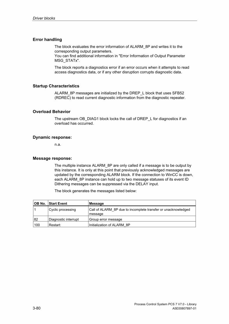
Driver blocks
Process Control System PCS 7 V7.0 - Library 3-80 A5E00807897-01
Error handling The block evaluates the error information of ALARM_8P and writes it to the corresponding output parameters. You can find additional information in "Error Information of Output Parameter MSG_STATx".
The block reports a diagnostics error if an error occurs when it attempts to read access diagnostics data, or if any other disruption corrupts diagnostic data.
Startup Characteristics ALARM_8P messages are initialized by the DREP_L block that uses SFB52 (RDREC) to read current diagnostic information from the diagnostic repeater.
Overload Behavior The upstream OB_DIAG1 block locks the call of DREP_L for diagnostics if an overload has occurred.
Dynamic response: n.a.
Message response: The multiple instance ALARM_8P are only called if a message is to be output by this instance. It is only at this point that previously acknowledged messages are updated by the corresponding ALARM block. If the connection to WinCC is down, each ALARM_8P instance can hold up to two message statuses of its event ID Dithering messages can be suppressed via the DELAY input.
The block generates the messages listed below:
OB No. Start Event Message
1 Cyclic processing Call of ALARM_8P due to incomplete transfer or unacknowledged message
82 Diagnostic interrupt Group error message 100 Restart: Initialization of ALARM_8P

Driver blocks
Process Control System PCS 7 V7.0 - Library A5E00807897-01 3-81
Operating and Monitoring Note: If you have selected the "Enable operating and monitoring" option in the block object properties in the CFC, the variables transferred to the OS are identified under "I/Os of …" (OCM column, "+"). Default: option not selected.
If asset management is used in the project and the diagnostic screens have been generated, then the faceplate can be called via its icon.
• Asset Management block symbols
• Asset Management faceplates
Note: Online help and the "PCS 7 FACEPLATES" Manual are only available if the "PCS 7 FACEPLATES" software package is installed!
Additional information Additional information is available in the sections:
Message Texts and Associated Values of DREP_L
Maintenance Status MS
Notes on Using Driver Blocks

Driver blocks
Process Control System PCS 7 V7.0 - Library 3-82 A5E00807897-01
3.2.15.2 I/Os of DREP_L The factory setting of the block representation in CFC is identified in the "I/O" column: I/O name in bold characters = I/O is visible; I/O name in standard characters = I/O is hidden.
You can find explanations of and information about the abbreviations used in "General Information About Block Description".
I/O (Parameter)
Meaning
Data Type
Default Type
OCM
ACC_MODE 1 = Accept MODE settings BOOL 0 IO CPU_DIAG CPU diagnostics STRUCT IO DADDR Diagnostic address of the diagnostics repeater INT 0 I DELAY Interrupt delay (s) INT 2 I DINFO Diagnostic information of the diagnostic repeater STRUCT O EN_DIAG 1 = Queued diagnostic event BOOL 0 I EN_MSG 1 = Enable message BOOL 1 I EV_IDx Message number DWORD 0 I MS Maintenance status DWORD 0 I + MSG_ACKx Message acknowledgement WORD 0 O MSG_STATx Error message status WORD 0 O O_MS Maintenance status DWORD 0 O PADP_ADR DP/PA address of the diagnostic repeater BYTE 255 I QDREPF 1 = Removed/faulty diagnostic repeater BOOL 0 O QERR 1 = Program runtime error BOOL 1 O RAC_DIAG OB_DIAG1 diagnostics STRUCT IO RACK_NO Rack number BYTE 255 I SUBN1_ID ID of the primary DP master system BYTE 255 I SUBN2_ID ID of the redundant DP master system BYTE 255 I
Additional information Additional information is available in the sections:
Message Texts and Associated Values of DREP_L
Maintenance Status MS
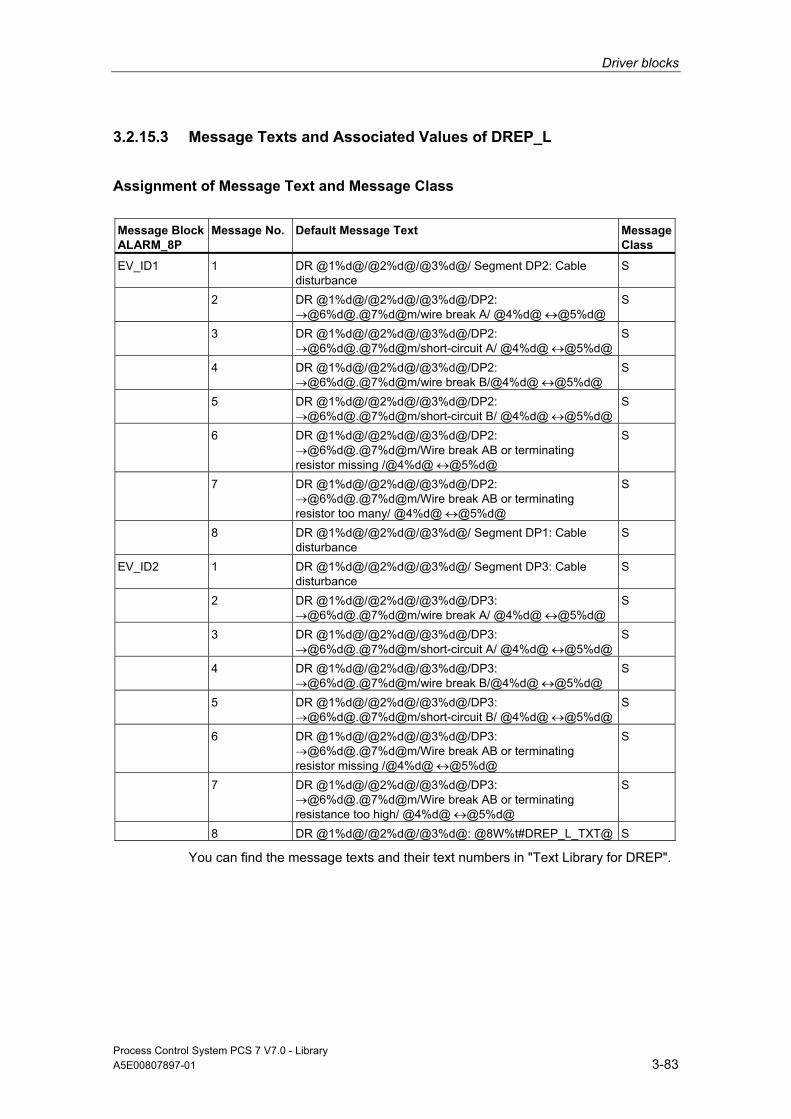
Driver blocks
Process Control System PCS 7 V7.0 - Library A5E00807897-01 3-83
3.2.15.3 Message Texts and Associated Values of DREP_L
Assignment of Message Text and Message Class
Message Block ALARM_8P
Message No.
Default Message Text
Message Class
EV_ID1 1 DR @1%d@/@2%d@/@3%d@/ Segment DP2: Cable disturbance
S
2 DR @1%d@/@2%d@/@3%d@/DP2: →@6%d@.@7%d@m/wire break A/ @4%d@ ↔@5%d@
S
3 DR @1%d@/@2%d@/@3%d@/DP2: →@6%d@.@7%d@m/short-circuit A/ @4%d@ ↔@5%d@
S
4 DR @1%d@/@2%d@/@3%d@/DP2: →@6%d@.@7%d@m/wire break B/@4%d@ ↔@5%d@
S
5 DR @1%d@/@2%d@/@3%d@/DP2: →@6%d@.@7%d@m/short-circuit B/ @4%d@ ↔@5%d@
S
6 DR @1%d@/@2%d@/@3%d@/DP2: →@6%d@.@7%d@m/Wire break AB or terminating resistor missing /@4%d@ ↔@5%d@
S
7 DR @1%d@/@2%d@/@3%d@/DP2: →@6%d@.@7%d@m/Wire break AB or terminating resistor too many/ @4%d@ ↔@5%d@
S
8 DR @1%d@/@2%d@/@3%d@/ Segment DP1: Cable disturbance
S
EV_ID2 1 DR @1%d@/@2%d@/@3%d@/ Segment DP3: Cable disturbance
S
2 DR @1%d@/@2%d@/@3%d@/DP3: →@6%d@.@7%d@m/wire break A/ @4%d@ ↔@5%d@
S
3 DR @1%d@/@2%d@/@3%d@/DP3: →@6%d@.@7%d@m/short-circuit A/ @4%d@ ↔@5%d@
S
4 DR @1%d@/@2%d@/@3%d@/DP3: →@6%d@.@7%d@m/wire break B/@4%d@ ↔@5%d@
S
5 DR @1%d@/@2%d@/@3%d@/DP3: →@6%d@.@7%d@m/short-circuit B/ @4%d@ ↔@5%d@
S
6 DR @1%d@/@2%d@/@3%d@/DP3: →@6%d@.@7%d@m/Wire break AB or terminating resistor missing /@4%d@ ↔@5%d@
S
7 DR @1%d@/@2%d@/@3%d@/DP3: →@6%d@.@7%d@m/Wire break AB or terminating resistance too high/ @4%d@ ↔@5%d@
S
8 DR @1%d@/@2%d@/@3%d@: @8W%t#DREP_L_TXT@ S
You can find the message texts and their text numbers in "Text Library for DREP".
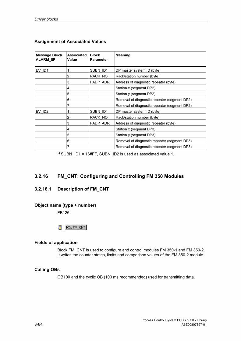
Driver blocks
Process Control System PCS 7 V7.0 - Library 3-84 A5E00807897-01
Assignment of Associated Values
Message Block ALARM_8P
Associated Value
Block Parameter
Meaning
EV_ID1 1 SUBN_ID1 DP master system ID (byte) 2 RACK_NO Rack/station number (byte) 3 PADP_ADR Address of diagnostic repeater (byte) 4 Station x (segment DP2) 5 Station y (segment DP2) 6 Removal of diagnostic repeater (segment DP2) 7 Removal of diagnostic repeater (segment DP2) EV_ID2 1 SUBN_ID1 DP master system ID (byte) 2 RACK_NO Rack/station number (byte) 3 PADP_ADR Address of diagnostic repeater (byte) 4 Station x (segment DP3) 5 Station y (segment DP3) 6 Removal of diagnostic repeater (segment DP3) 7 Removal of diagnostic repeater (segment DP3)
If SUBN_ID1 = 16#FF, SUBN_ID2 is used as associated value 1.
3.2.16 FM_CNT: Configuring and Controlling FM 350 Modules
3.2.16.1 Description of FM_CNT
Object name (type + number) FB126
Fields of application Block FM_CNT is used to configure and control modules FM 350-1 and FM 350-2. It writes the counter states, limits and comparison values of the FM 350-2 module.
Calling OBs OB100 and the cyclic OB (100 ms recommended) used for transmitting data.
Driver blocks
Process Control System PCS 7 V7.0 - Library A5E00807897-01 3-85
Use in CFC When the CFC function "Generate module drivers" is used, the following occurs automatically:
• The block is installed in the cyclic OB upstream of the CH_CNT blocks.
• The block runtime group is installed in OB100 downstream of MOD_D1.
• The LADDR, FM_MODE, RACK_NO, SUBN1_ID, SUBN2_ID, and SLOT_NO inputs are configured.
• MODEx inputs are interconnected with the OMODEx outputs of the MOD_D1 block.
• The FM_DATA output structure is interconnected with the structure of the same name of the CH_CNT block.
• The OMODEx output is interconnected with the MODE input of the CH_CNT block.
• The OUT structure CPU_DIAG of OB_BEGIN is interconnected with the INOUT structure of the same name of FM_CNT.
• The EN_CO input structure is interconnected with the EN_CO_x output structure of the FM_CO block (x = number of the rack).
• The output ENCO is connected to the input ENCOx_yy of the FM_CO block (x = number of the rack, yy = coordination number).
Addressing The logical base address of the module is entered in the LADDR connection by the CFC driver generator.
Redundancy Higher-level block MOD_D1 evaluates the redundancy of DP master systems operating in an H system. Redundancy for two FM 350-1 or FM 350-2 modules is not supported and must be controlled by the user outside of the block.

Driver blocks
Process Control System PCS 7 V7.0 - Library 3-86 A5E00807897-01
MODE Setting Signal states of the MODE_xx or QMODE_xx of the FM_CNT block are described under the MODE settings.
The MODE_xx input parameters are available for up to 8 signal channels. Their default setting is "Zero" (no signal). For each signal channel xx, the operating mode of the FM 350 module needs to be set at the MODE_xx input (the CFC driver generator takes care of this for you).
The module recognizes the following modes:
Designation Coding
MODE Description
Channel not used 16#0000 Channel of the FM 350 not used.
Continuous counting 16#xx01 The FM 350 counts continuously, starting with the current counter state, after the internal gate opens.
One-time counting 16#xx02 The FM 350 counts from the start value to the end value after the internal gate opens.
Periodic counting 16#xx03 The FM 350 counts between the start value and the end value after the internal gate opens.
Frequency measurement 16#xx04 The FM 350 determines the frequency pulse sequence at the input.
Speed measurement 16#xx05 The FM 350 determines the speed of the device connected to the input.
Period duration measurement
16#xx06 The FM 350 determines the duration of the pulse sequence at the input.
Dosing 16#xx07 Four channels of the FM 350-2 are used for dosing.
The count and measured values can be registered for the FM 350-2 module both through the process image and through "Read data record" (slower update). If the count and measured values of a channel are available in the process image, then they must be flush in the process image. The following variants are possible.
Designation Coding
MODE Description
Count and measured value are not in the process image
16#Cxxx Read count and measured values via data record
Only the count value is in the process image
16#8xxx Read measured value via data record and count value in the process image
Only the measured value is in the process image
16#4xxx Read count values via data record and measured value in the process image
Count and measured value are in the process image
16#0xxx Read count and measured value in the process image
Data type DWORD count and measured value
16#x0xx Count value before measured value, both from data type DWORD
Data type WORD count value 16#x1xx Count value from the data type WORD before measured value from data type DWORD
Data type WORD measured value 16#x2xx Count value from the data type DWORD before measured value from data type WORD
Driver blocks
Process Control System PCS 7 V7.0 - Library A5E00807897-01 3-87
Designation Coding MODE
Description
Data type WORD count and measured value
16#x3xx Count value before measured value, both from data type WORD
Data type DWORD count and measured value
16#x8xx Measured value before count value, both from data type DWORD
Data type WORD count value 16#x9xx Measured value from the data type DWORD before count value from data type WORD
Data type WORD measured value 16#xAxx Measured value from the data type WORD before count value from data type DWORD
Data type WORD count and measured value
16#xBx Measured value before count value, both from data type WORD
MODE is formed by the linking the operating mode code and the access type. Example: Count and measured value in "Dosing" mode from the data type DWORD is not in the process image MODE = 16#C007.
Error handling The input parameters are not validated.
Startup Characteristics Each time the system or FM 350-1/FM 350-2 starts up, the block performs a new-start coordination with the module. The CMP_VALx parameters are subsequently loading in the FM 350.
ALARM_8P is initialized.
Overload Behavior n.a.
Dynamic response n.a.
Message response The block reports operation and data errors for the FM 350-1 module and data errors for FM 350-2 using ALARM_8P. The message function can be disabled by setting EN_MSG = FALSE. The MOD_D1 block reports diagnostic alarms from the FM 350-1 or FM 350-2.

Driver blocks
Process Control System PCS 7 V7.0 - Library 3-88 A5E00807897-01
Operating and Monitoring The block has no faceplate.
Note: If you have selected the "Enable operating and monitoring" option in the block object properties in the CFC, the variables transferred to the OS are identified under "I/Os of …" (OCM column, "+"). Default: option not selected.
Additional Information Additional information is available in the sections:
Message Texts and Associated Values of FM_CNT
Notes on Using Driver Blocks
3.2.16.2 I/Os of FM_CNT
The factory setting of the block representation in CFC is identified in the "I/O" column: I/O name in bold characters = I/O is visible; I/O name in standard characters = I/O is hidden.
You can find explanations of and information about the abbreviations used in "General Information About Block Description".
I/O (Parameter)
Meaning
Data Type
Default Type
OCM
ACC_MODE 1 = Accept MODE settings BOOL 0 IO CO_NO Coordination number for data set reading INT 0 I EN_MSG 1 = Enable message BOOL 1 I EN_CO Current coordination number STRUCT IO ENCO Coordination number BYTE 0 IO EV_ID Message number DWORD 0 I CPU_DIAG CPU diagnostics (system structure) STRUCT IO FM_DATA Structure FM 350 data STRUCT O FM_MODE 0 = FM 350-1, >0 = FM 350-2 BYTE 0 I LADDR Logical address FM 350 INT 0 I MODEx Mode channel (x = 0 to 7) DWORD 0 I MSG_ACK Message acknowledgement WORD 0 O MSG_STAT Error message status WORD 0 O OMODEx Mode channel (x = 0 to 7) DWORD 0 O QDATA_ERR 1 = Data error BOOL 0 O QDONE 1 = Write new data BOOL 0 O QDONE_RD 1 = New data read BOOL 0 O QMODF 1 = Error FM 350 BOOL 0 O QPARF 1 = Module not configured BOOL 0 O QRD_ERR 1 = Error data reading BOOL 0 O QWR_ERR 1 = Error read data BOOL 0 O RACK_NO Rack number BYTE 0 I
Driver blocks
Process Control System PCS 7 V7.0 - Library A5E00807897-01 3-89
I/O (Parameter)
Meaning
Data Type
Default Type
OCM
SLOT_NO Slot number BYTE 0 I STATUS_RD Read status of data record DWORD 0 O STATUS_WR Write status of data record DWORD 0 O SUBN1_ID ID of the primary DP master system BYTE 255 I SUBN2_ID ID of the redundant DP master system BYTE 255 I
Additional information Additional information is available in the section:
Message Texts and Associated Values of FM_CNT
3.2.16.3 Message Texts and Associated Values of FM_CNT
Assignment of Message Text and Message Class Message Block ALARM_8P
Message No.
Default Message Text
Message Class
EV_ID 1 FM 350 @1%d@/@2%d@/@3%d @data error number@4%d@
S
2 FM 350 @1%d@/@2%d@/@3%d @operation error number@5%d@
S
3 no message 4 no message 5 no message 6 no message 7 no message 8 no message
Assignment of Associated Values
Message Block ALARM_8P
Associated Value
Block Parameter
Meaning
EV_ID 1 SUBN_ID DP master system ID (byte) 2 RACK_NO Rack/station number (byte) 3 SLOT_NO Slot number (byte) 4 DA_ERR_W Data error number 5 OT_ERR_B Operation error number

Driver blocks
Process Control System PCS 7 V7.0 - Library 3-90 A5E00807897-01
3.2.17 IM_DRV: Transferring Time-Stamped Process-Signal Changes
3.2.17.1 Description of IM_DRV
Object name (type + number) FB90
Fields of application Block IM_DRV is used to transfer changes in process signals with timestamps and events not specific to signals (special messages) to the OS.
Calling OBs The block must be installed in the run sequence in the following OBs:
OB1 Cyclic program
OB40 Process interrupt 0 OB100 Restart (warm start)
Alternatively to OB40, the block can be integrated into another process interrupt OB (OB41 to OB47).
Use in CFC When the CFC function "Generate module drivers" is used, the following occurs automatically:
• The IM_DRV block is installed in its runtime group downstream of the RACK-block runtime group in the above-mentioned OBs.
• The logical address LADDR is configured with the logical address of the IM (diagnostics address). If you operate the DP master system in DPV1 mode, the input address of the IM is entered.
• The S_CH_xxx inputs are configured.
• The RAC_DIAG structure of the RACK block is interconnected with the structure of the same name of the IM_DRV block.
Every signal provided with a time stamp by the IM has a unique assignment to its slot in connection with the corresponding channel number. There are 128 inputs of the WORD data type for 128 signals. The slot number of the affected digital input module is entered in the higher-priority byte and the channel number (signal of the digital input module) is entered into the lower-priority byte. The slot and signal number of the process signal are entered into the block input (S_CH_xxx) (hexadecimal format).
Driver blocks
Process Control System PCS 7 V7.0 - Library A5E00807897-01 3-91
Example:
In HW Config you have set digital signal 10 of a digital input module in slot 5 of an ET 200M to an exact 10 ms timestamp. The number 16#050A is entered at the first available input S_CH_xxx of the IM_DRV.
Description of Functions In an AS the block IM_DRV forms the link between an IM and the OS (WinCC). It fetches message data from IM message buffers (max. of 20 messages each) and transfers these to the corresponding OS by means of the message function ALARM_T. The ALARM_T function is an ALARM_8P block whose time stamps for its 8 messages are entered in the first associated value in a byte array.
Operating principle • Process interrupt: The IM generates a process interrupt for incoming
messages. The time-stamp status, including the number of the IM data record to be fetched and the number of messages in the data record, are fetched from the start information of the process interrupt OB and stored for cyclic processing. The interrupt stack can hold up to 17 process interrupts; If this maximum is exceeded, all new information will be lost.
• Cyclic processing: If any messages are queued in the stack, SFC59 (RD_REC, read data record) reads the respective data record (message buffer). If the stack contains several data records, it will fetch the record that contains the oldest messages (oldest process alarm). The block instance temporarily stores a maximum of 20 messages of a data record. The IM can enter new messages in a data record after it reads the record. If all data records are in use, the IM enters "buffer overflow error" (incoming) as the last message in the message buffer. It enters "(outgoing) buffer overflow error" as the first message in the next free record. Message data received within the interval between a buffer overflow and the enabling of a record will be lost. The function compares the slot/channel number of the stored messages with the input parameters of the slot-/channel-number block (S_CH_xxx). If identical, the message of the corresponding event ID (EV_ID_xxx) and signal number (1 to 8) of the ALARM_T block is assigned. and enters the message timestamp (8 bytes) in the ARRAY of byte (index corresponding to the signal number of the ALARM_T). After all the messages have been assigned, the block calls the ALARM_T blocks in order to transfer the new messages to the OS. Errors that may occur during data communication between the block and IM 153 are reported with an ALARM_8P block (for example, an I/O access error). The signals returned by the ALARM_T and ALARM_8P blocks (STAT_xx, M_ACK_xx) are available at the block output. If STAT_xx = 11 (the previous job is still busy), it calls the ALARM_T/ALARM_8P block again in the next cycle. Messages may be lost in all other situations. If no agreement can be found with the input parameters in a message, the QBPARF output is set to TRUE for the duration of one cycle (see "Error Handling"). The event will be reported (see "Message response").

Driver blocks
Process Control System PCS 7 V7.0 - Library 3-92 A5E00807897-01
Addressing See also Addressing.
The function writes the logical address of the IM (corresponds to the diagnostic address or the input address of the IM for the DP master system in DP V1 mode) determined in HW Config to the driver block input (LADDR). Any change to the LADDR block input will initiate a scan cycle, according to the startup characteristics of the block.
Process signals which require a timestamp and are detected via an IM must be configured accordingly in HW Config.
Error handling
I/O access error:
QPERAF The block could not access the IM. A data record could not be read. If this record is not stored in the IM, these messages are lost.
Block processing error:
QERR A block execution error has occurred.
Module configuration error:
QPARF Faulty block configuration: Incorrect logical basic address entered.
Configuration error:
QBPARF Faulty block configuration: The slot/channel number of an IM message does not agree with any slot/channel number of the block input parameters (message is lost).
Rack error:
QRACKF Failure of the IM rack, or IM failure

Driver blocks
Process Control System PCS 7 V7.0 - Library A5E00807897-01 3-93
IM Startup Behavior During startup/restart of the IM, the system will generate process interrupts once again for those records which were occupied prior to restart but had not been fetched.
The message "Startup data (incoming)" is entered as the first message of the first free data record. After restart, the system checks all monitored digital signals for changes, outputs a message if appropriate and finally generates the message "Startup data (outgoing)".
IM_DRV-Driver-Block Startup Behavior Initializes the ALARM_8P and the ALARM_T blocks, using the data stored prior to the CPU transition to STOP. During an initial startup, the initialization routing sets the signal status to "Zero".
During startup/initial startup, the driver block verifies the existence of an IM at its logical address set in LADDR. If the result is negative, the driver block sets the QPARF output to TRUE and does not access any I/O in its subsequent cycles. It enables QPARF = FALSE and I/O access only after the correct module has been inserted or new parameters have been assigned. Stored process interrupt data which were not computed before the restart will be deleted.
Redundancy Time stamping in H systems equipped with two IM units is redundant under the following conditions:
• both IM units communicate via the communication (K) bus,
• no error has occurred during the update of the active and passive IM.
The SUBNET and RACK blocks report loss of redundancy (failure of an IM), separately from the IM_DRV block.
Time stamping is interrupted for the duration of the changeover between the active <-> passive IM. This period of interrupt is indicated by the special message "Changeover at redundancy start/end".
The active IM usually reports the current I/O status to the passive IM. The message "Redundancy_Info_Loss" (incoming) will be output if this communication is disrupted. If the I/O statuses of the active and passive IM have been aligned, the message "Redundancy_Info_Loss" (outgoing) is output.
Dynamic response n.a.
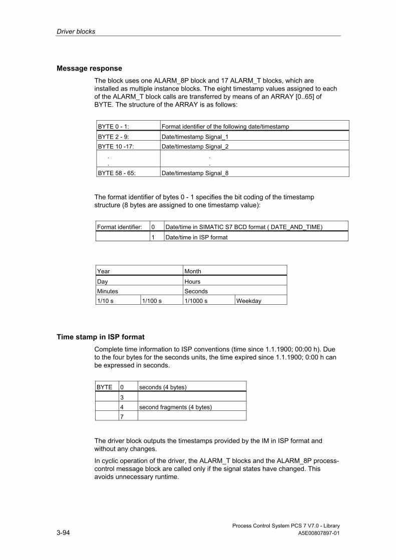
Driver blocks
Process Control System PCS 7 V7.0 - Library 3-94 A5E00807897-01
Message response The block uses one ALARM_8P block and 17 ALARM_T blocks, which are installed as multiple instance blocks. The eight timestamp values assigned to each of the ALARM_T block calls are transferred by means of an ARRAY [0..65] of BYTE. The structure of the ARRAY is as follows:
BYTE 0 - 1: Format identifier of the following date/timestamp
BYTE 2 - 9: Date/timestamp Signal_1 BYTE 10 -17: Date/timestamp Signal_2
.
. . .
BYTE 58 - 65: Date/timestamp Signal_8
The format identifier of bytes 0 - 1 specifies the bit coding of the timestamp structure (8 bytes are assigned to one timestamp value):
Format identifier: 0 Date/time in SIMATIC S7 BCD format ( DATE_AND_TIME)
1 Date/time in ISP format
Year Month
Day Hours Minutes Seconds 1/10 s 1/100 s 1/1000 s Weekday
Time stamp in ISP format Complete time information to ISP conventions (time since 1.1.1900; 00:00 h). Due to the four bytes for the seconds units, the time expired since 1.1.1900; 0:00 h can be expressed in seconds.
BYTE 0 seconds (4 bytes)
3 4 second fragments (4 bytes) 7
The driver block outputs the timestamps provided by the IM in ISP format and without any changes.
In cyclic operation of the driver, the ALARM_T blocks and the ALARM_8P process-control message block are called only if the signal states have changed. This avoids unnecessary runtime.
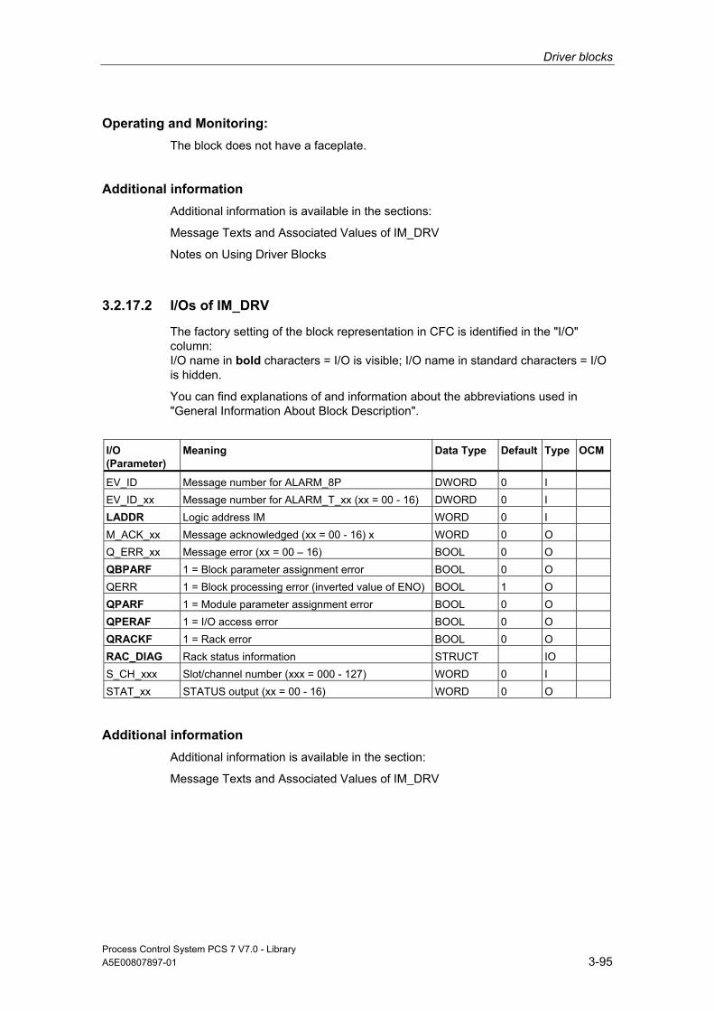
Driver blocks
Process Control System PCS 7 V7.0 - Library A5E00807897-01 3-95
Operating and Monitoring: The block does not have a faceplate.
Additional information Additional information is available in the sections:
Message Texts and Associated Values of IM_DRV
Notes on Using Driver Blocks
3.2.17.2 I/Os of IM_DRV
The factory setting of the block representation in CFC is identified in the "I/O" column: I/O name in bold characters = I/O is visible; I/O name in standard characters = I/O is hidden.
You can find explanations of and information about the abbreviations used in "General Information About Block Description".
I/O (Parameter)
Meaning
Data Type
Default Type
OCM
EV_ID Message number for ALARM_8P DWORD 0 I EV_ID_xx Message number for ALARM_T_xx (xx = 00 - 16) DWORD 0 I LADDR Logic address IM WORD 0 I M_ACK_xx Message acknowledged (xx = 00 - 16) x WORD 0 O Q_ERR_xx Message error (xx = 00 – 16) BOOL 0 O QBPARF 1 = Block parameter assignment error BOOL 0 O QERR 1 = Block processing error (inverted value of ENO) BOOL 1 O QPARF 1 = Module parameter assignment error BOOL 0 O QPERAF 1 = I/O access error BOOL 0 O QRACKF 1 = Rack error BOOL 0 O RAC_DIAG Rack status information STRUCT IO S_CH_xxx Slot/channel number (xxx = 000 - 127) WORD 0 I STAT_xx STATUS output (xx = 00 - 16) WORD 0 O
Additional information Additional information is available in the section:
Message Texts and Associated Values of IM_DRV

Driver blocks
Process Control System PCS 7 V7.0 - Library 3-96 A5E00807897-01
3.2.17.3 Message Texts and Associated Values of IM_DRV
Assignment of Message Text and Message Class to Signal/Special Messages An ALARM_8P block is used for the process-control messages shown in the following table. If an I/O access error has occurred, the block enters the geographic address of the IM in the associated values: 1 = slot number of the message, 2 = channel number of the message 3 = RET_VAL of the SFC59 (RD_REC).
ALARM_8P_L Message No.
Output Parameter
Default Message Text
Message Class
1 QBPARF Parameter assignment error S_CHxx: Slot=@1%d@ Channel=@2%d@
S
2 QPERAF I/O access error: Ret_Val@3%d@ S 3 QPARF Parameter assignment error LADDR S
Messages not based on signals are referred to as special messages. The message buffer may contain the following special messages that are generated with ALARM_8P_00 (multiple-instanced call of the ALARM_T). The function writes the format identifier and the eight timestamp values to the first associated value
ALARM_8P_00 Message No.
Default Message Text
Message Class
1 Startup data S 2 Time-of-day message error S 3 Sync signal error
(relevant only for resolution ≤ 1ms) S
4 Time difference between the message frame timestamp and the real-time clock may cause inaccuracy
S
5 STOP of the timestamp function S 6 Message loss at IM (buffer overflow) S 7 Redundant changeover S 8 Redundancy_info_loss error S
The ALARM_8P_01 to ALARM_8P_16 blocks (multiple-instance call of ALARM_T) can generate the following signal messages. The function writes the format identifier and the eight timestamp values to the first associated value
ALARM_8P_01 Message No.
Default Message Text Message Class
1 TEXT S_CH_000 S 2 TEXT S_CH_001 S 3 TEXT S_CH_002 S 4 TEXT S_CH_003 S

Driver blocks
Process Control System PCS 7 V7.0 - Library A5E00807897-01 3-97
ALARM_8P_01 Message No.
Default Message Text Message Class
5 TEXT S_CH_004 S 6 TEXT S_CH_005 S 7 TEXT S_CH_006 S 8 TEXT S_CH_007 S
ALARM_8P_16 Message No.
Default Message Text Message Class
1 TEXT S_CH_120 S 2 TEXT S_CH_121 S 3 TEXT S_CH_122 S 4 TEXT S_CH_123 S 5 TEXT S_CH_124 S 6 TEXT S_CH_125 S 7 TEXT S_CH_126 S 8 TEXT S_CH_127 S
3.2.18 MOD_1: Monitoring Up to 16 Channels of S7-300/400 SM Modules Without Diagnostic Functions
3.2.18.1 Description of MOD_1
Object name (type + number) FB91
Fields of application Block MOD_1 monitors up to 16 channels of S7-300/400 SM modules without diagnostic functions (no mixed modules). H systems support only the modules installed in switched racks.

Driver blocks
Process Control System PCS 7 V7.0 - Library 3-98 A5E00807897-01
Calling OBs The block must be installed in the run sequence in the following OBs:
OB1 Cyclic program
OB83 Removal/insertion alarm OB85 Program runtime error OB86 Rack failure OB100 Restart (warm start)
Use in CFC When the CFC function "Generate module drivers" is used, the following occurs automatically:
• The MOD_1 block is installed in its runtime group downstream of the RACK-block runtime group in the above-mentioned OBs.
• The MODE_xx inputs (mode of module channels xx) are configured.
• The logical basic address of the LADDR module is configured.
• The OUT structures CPU_DIAG of the OB_BEGIN block and RAC_DIAG of the RACK block are interconnected with the INOUT structures of the same name of MOD_1.
• The EN input is interconnected with the output of an AND block, whose inputs are interconnected with the outputs EN_SUBx (x = number of the DP Master system) of the OB_BEGIN block, with EN_Rxxx (xxx = Rack/station number) of the SUBNET block and with EN_Mxx (xx = Module number) of the RACK block.
Function Block MOD_1 analyzes all events affecting a module and its channels in non-cyclic mode and forms the channel-specific MODE and value status (quality code) for the signal processing blocks. ALARM_8P reports the events.
The block is enabled by the higher-level RACK block during runtime. The diagnostic event is entered in the CPU_DIAG start information of the OB_DIAG block. A MODE_xx input exists for each signal channel of the module, which is used for the input of module channel configuration data created in HW Config. The function writes MODE_xx to the low word of the OMODE_xx output parameter, but only during startup/initial startup or if you set ACC_MODE = TRUE. The actual channel value status is written to the most significant byte. If the result is positive, the system sets OMODE_xx = 16#80xxxxxx.
The following events will lead to the value status "invalid value due to higher-level error" (OMODE_xx = 16#40xxxxxx):
• Events evaluated by the RACK block:
Rack failure (OB86) (output parameter QRACKF = TRUE)

Driver blocks
Process Control System PCS 7 V7.0 - Library A5E00807897-01 3-99
• Events evaluated by the MOD block:
I/O access error (OB85) (output parameter QPERAF = TRUE)
Module removed (OB83) (output parameter QMODF = TRUE)
"Module removed" and "I/O access error" events are reported to the OS by means of ALARM_8P. The diagnostics interrupt function distinguishes between module and channel errors, whereby each channel is assigned a message ID.
The system verifies during startup that the module is available (plugged), reads the module status information provides these data as service output parameters (MOD_INF).
You can find additional information about the errors in Reference Manual System Software for S7-300/400 System and Standard Functions.
Redundancy The higher-level RACK block monitors the redundancy of DP master systems operating in an H system.
MODE Setting The MODE_xx input parameters are available for up to 16 signal channels. Their default setting is "Zero" (no signal). For each signal channel xx, you need to set the type and, if appropriate, the coding of the measuring range of an analog module at the MODE_xx input.
You can find additional information in "MODE Settings".
Note
If you make changes to the MODE_xx input configurations during runtime, they are not accepted at the outputs until you set the ACC_MODE input to 1.
OMODE Structure You can find additional information in "OMODE".

Driver blocks
Process Control System PCS 7 V7.0 - Library 3-100 A5E00807897-01
Display of the Valid Channels The existing channels of a module are displayed in the CH_EXIST output by setting a bit in the DWORD, starting at bit 0, for every existing channel. If the bit assigned to a channel is 0, the channel is not available.
Output CH_OK displays the valid channels of a module by setting a bit to TRUE for every valid channel, where bit 0 is assigned to channel 0, etc. If the bit assigned to a channel is 0, the channel is faulty. If there is a module error, all channels are disrupted.
Addressing You can find additional information in "Addressing".
Error handling The input parameters are not validated.
You can find additional information about error handling in "Error Information of Output Parameter MSG_STAT".
Service Information To analyze errors, read the module-status information entered during startup via the structured MOD_INF output parameter. You can find additional information in Reference Manual System Software for S7-300/400 System and Standard Functions; System-Status List, Module-Status Information.
Startup Characteristics After a restart/initial startup, the system verifies that the module is available under its logical base address. A restart (OB100) is reported via the LSB in byte 2 of the outputs OMODE_xx.
Dynamic response n.a.
Message response MOD_1 uses ALARM_8P to report module errors. The inputs DELAY1 and DELAY2 are used to delay the output of I/O access error messages. At DELAY1 you can specify which time in seconds the block waits for higher-priority errors (rack failure or removal/insertion) after an I/O access error (OB85 has occurred until it outputs the message. The message is output only under the condition that no higher-priority error is reported within this delay time. DELAY2 determines the number of seconds the block waits after the higher-priority error has been reported outgoing until it outputs the queued I/O access error as well. The default of both values is 2 seconds. The message function can be disabled by setting EN_MSG = FALSE.
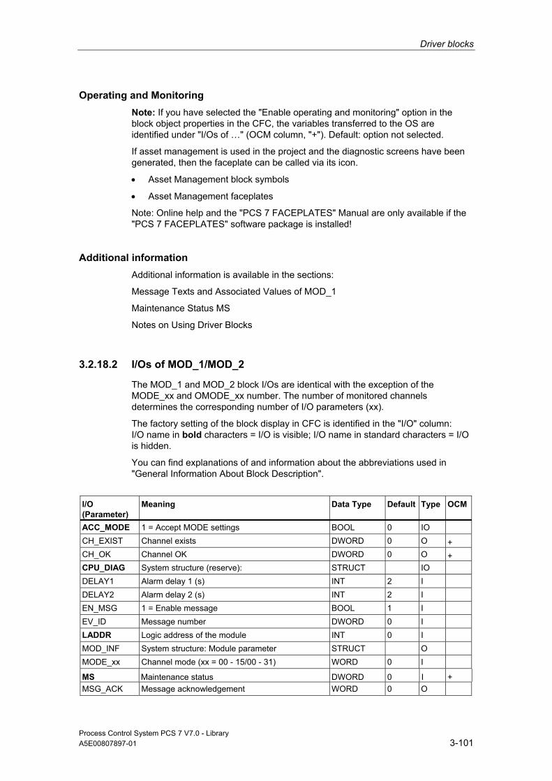
Driver blocks
Process Control System PCS 7 V7.0 - Library A5E00807897-01 3-101
Operating and Monitoring Note: If you have selected the "Enable operating and monitoring" option in the block object properties in the CFC, the variables transferred to the OS are identified under "I/Os of …" (OCM column, "+"). Default: option not selected.
If asset management is used in the project and the diagnostic screens have been generated, then the faceplate can be called via its icon.
• Asset Management block symbols
• Asset Management faceplates
Note: Online help and the "PCS 7 FACEPLATES" Manual are only available if the "PCS 7 FACEPLATES" software package is installed!
Additional information Additional information is available in the sections:
Message Texts and Associated Values of MOD_1
Maintenance Status MS
Notes on Using Driver Blocks
3.2.18.2 I/Os of MOD_1/MOD_2
The MOD_1 and MOD_2 block I/Os are identical with the exception of the MODE_xx and OMODE_xx number. The number of monitored channels determines the corresponding number of I/O parameters (xx).
The factory setting of the block display in CFC is identified in the "I/O" column: I/O name in bold characters = I/O is visible; I/O name in standard characters = I/O is hidden.
You can find explanations of and information about the abbreviations used in "General Information About Block Description".
I/O (Parameter)
Meaning
Data Type
Default Type
OCM
ACC_MODE 1 = Accept MODE settings BOOL 0 IO CH_EXIST Channel exists DWORD 0 O + CH_OK Channel OK DWORD 0 O + CPU_DIAG System structure (reserve): STRUCT IO DELAY1 Alarm delay 1 (s) INT 2 I DELAY2 Alarm delay 2 (s) INT 2 I EN_MSG 1 = Enable message BOOL 1 I EV_ID Message number DWORD 0 I LADDR Logic address of the module INT 0 I MOD_INF System structure: Module parameter STRUCT O MODE_xx Channel mode (xx = 00 - 15/00 - 31) WORD 0 I MS Maintenance status DWORD 0 I + MSG_ACK Message acknowledgement WORD 0 O
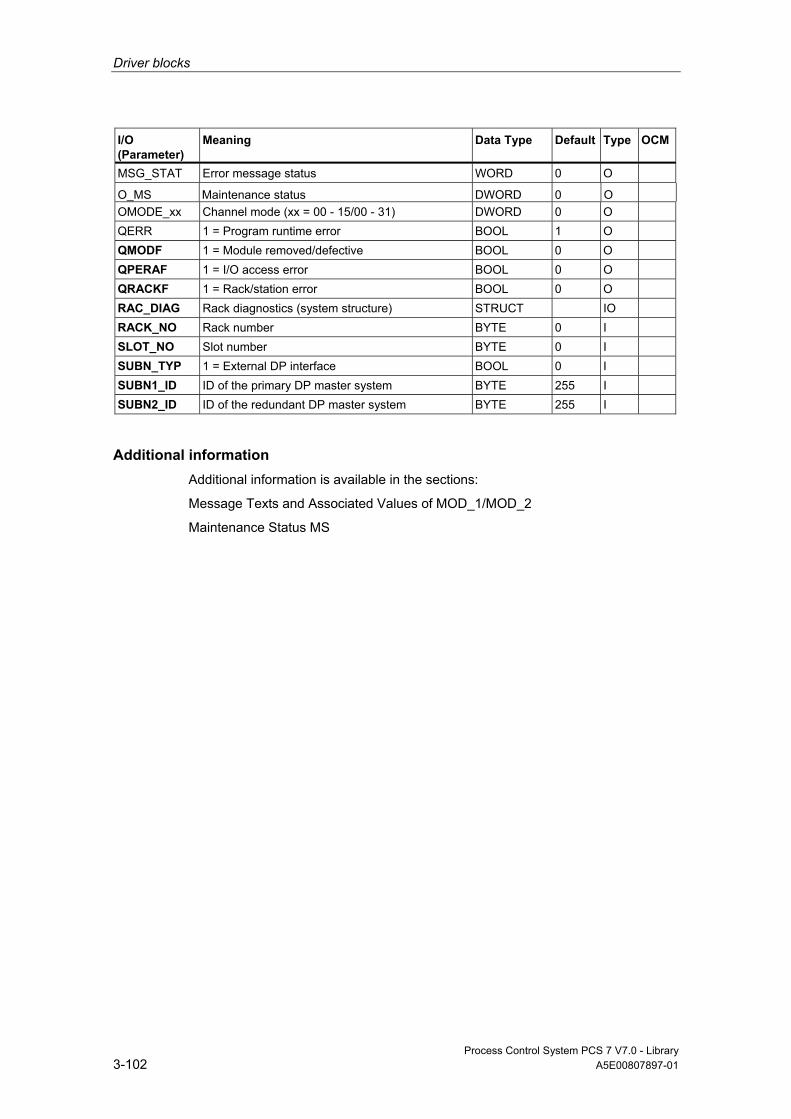
Driver blocks
Process Control System PCS 7 V7.0 - Library 3-102 A5E00807897-01
I/O (Parameter)
Meaning
Data Type
Default Type
OCM
MSG_STAT Error message status WORD 0 O O_MS Maintenance status DWORD 0 O OMODE_xx Channel mode (xx = 00 - 15/00 - 31) DWORD 0 O QERR 1 = Program runtime error BOOL 1 O QMODF 1 = Module removed/defective BOOL 0 O QPERAF 1 = I/O access error BOOL 0 O QRACKF 1 = Rack/station error BOOL 0 O RAC_DIAG Rack diagnostics (system structure) STRUCT IO RACK_NO Rack number BYTE 0 I SLOT_NO Slot number BYTE 0 I SUBN_TYP 1 = External DP interface BOOL 0 I SUBN1_ID ID of the primary DP master system BYTE 255 I SUBN2_ID ID of the redundant DP master system BYTE 255 I
Additional information Additional information is available in the sections:
Message Texts and Associated Values of MOD_1/MOD_2
Maintenance Status MS
Driver blocks
Process Control System PCS 7 V7.0 - Library A5E00807897-01 3-103
3.2.18.3 Message Texts and Associated Values of MOD_1/MOD_2/MOD_3
Assignment of Message Text and Message Class to the Block Parameters of MOD_1/MOD_2/MOD_3
Message Block ALARM_8P
Message No.
Block Parameter
Default Message Text
Message Class
EV_ID 1 Module @1%d@/ @2%d@/ @3%d@: Removed S 2 QPERAF Module @1%d@/ @2%d@/ @3%d@: I/O access
error S
3 QMODF Module @1%d@/ @2%d@/ @3%d@: @4W%t#MOD_n_TXT@ (n = 1 or 2)
S
4 QMODF Module @1%d@/ @2%d@/ @3%d@: @4W%t#MOD_n_TXT@ (n = 1 or 2)
S
Assignment of Associated Values to the Block Parameters of MOD_1/MOD_2/MOD_3
Message Block ALARM_8P
Associated Value
Block Parameter
Meaning
EV_ID 1 MOD_INF.SUBN_ID DP master system ID (byte) 2 MOD_INF.RACK_NO Rack/station number (byte) 3 MOD_INF.SLOT_NO Slot number (byte) 4 text number from MOD_n_TXT (n = 1,2 or 3)
(Message 1)
You can find the message texts and their text numbers in "Text Library for MOD_1, MOD_2, MOD_3".
3.2.19 MOD_2: Monitoring 32 Channels of S7-300/400 SM Modules Without Diagnostic Functions
3.2.19.1 Description of MOD_2
Object name (type + number) FB92
Driver blocks
Process Control System PCS 7 V7.0 - Library 3-104 A5E00807897-01
Fields of application Block MOD_2 monitors up to 32 channels of S7-300/400 SM modules without diagnostics functions (no mixed modules). H systems support only the modules installed in switched racks.
Calling OBs The block must be installed in the run sequence in the following OBs:
OB1 Cyclic program
OB83 Removal/insertion alarm OB85 Program runtime error OB86 Rack failure OB100 Restart (warm start)
Use in CFC When the CFC function "Generate module drivers" is used, the following occurs automatically:
• The MOD_2 block is installed in its runtime group downstream of the RACK-block runtime group in the above-mentioned OBs.
• The MODE_xx inputs (mode of module channels xx) are configured.
• The logical basic address of the LADDR module is configured.
• The OUT structures CPU_DIAG of the OB_BEGIN block and RAC_DIAG of the RACK block are interconnected with the INOUT structures of the same name of MOD_2.
• The EN input is interconnected with the output of an AND block, whose inputs are interconnected with the outputs EN_SUBx (x = number of the DP Master system) of the OB_BEGIN block, with EN_Rxxx (xxx = Rack/station number) of the SUBNET block and with EN_Mxx (xx = Module number) of the RACK block.

Driver blocks
Process Control System PCS 7 V7.0 - Library A5E00807897-01 3-105
Function Block MOD_2 analyzes all events affecting a module and its channels in non-cyclic mode and forms the channel-specific MODE and value status (quality code) for the signal processing blocks. ALARM_8P reports the events.
Runtime of the block is enabled by the RACK master block. The diagnostic event is entered in the CPU_DIAG start information of the OB_DIAG block. A MODE_xx input exists for each signal channel of the module, which is used for the input of module channel configuration data created in HW Config. The function writes MODE_xx to the low word of the OMODE_xx output parameter, but only during startup/initial startup or if you set ACC_MODE = TRUE. The actual channel value status is written to the most significant byte. If the result is positive, the system sets OMODE_xx = 16#80xxxxxx.
The following events will lead to the value status "invalid value due to higher-level error" (OMODE_xx = 16#40xxxxxx):
• Events evaluated by the RACK block:
Rack failure (OB86) (output parameter QRACKF = TRUE)
• Events evaluated by the MOD block:
I/O access error (OB85) (output parameter QPERAF = TRUE)
Module removed (OB83) (output parameter QMODF = TRUE)
"Module removed" and "I/O access error" events are reported to the OS by means of ALARM_8P. The diagnostics interrupt function distinguishes between module and channel errors, whereby each channel is assigned a message ID.
The system verifies during startup that the module is available (plugged), reads the module status information provides these data as service output parameters (MOD_INF).
You can find additional information about the errors in Reference Manual System Software for S7-300/40 System and Standard Functions.
Redundancy The higher-level RACK block monitors the redundancy of DP master systems operating in an H system.
MODE Setting The MODE_xx input parameters are available for up to 32 signal channels. Their default setting is "Zero" (no signal). For each signal channel xx, you need to set the type and, if appropriate, the coding of the measuring range of an analog module at the MODE_xx input.

Driver blocks
Process Control System PCS 7 V7.0 - Library 3-106 A5E00807897-01
You can find additional information in "MODE Settings".
Note
Modifications of parameters at the MODE_xx inputs during runtime are not accepted at the outputs until input ACC_MODE = 1.
OMODE Structure You can find additional information in "OMODE".
Display of the Valid Channels The existing channels of a module are displayed in the CH_EXIST output by setting a bit in the DWORD, starting at bit 0, for every existing channel. If the bit assigned to a channel is 0, the channel is not available.
Output CH_OK displays the valid channels of a module by setting a bit to TRUE for every valid channel, where bit 0 is assigned to channel 0, etc. If the bit assigned to a channel is 0, the channel is faulty. If there is a module error, all channels are disrupted.
Addressing You can find additional information in "Addressing".
Error handling The input parameters are not validated.
You can find additional information about error handling in "Error Information of Output Parameter MSG_STAT".
Service Information To analyze errors, read the module-status information entered during startup via the structured MOD_INF output parameter. You can find additional information in Reference Manual System Software for S7-300/400 System and Standard Functions; System-Status List, Module-Status Information.
Startup Characteristics After a restart/initial startup, the system verifies that the module is available under its logical base address. A restart (OB100) is reported via the LSB in byte 2 of the outputs OMODE_xx.
Dynamic response n.a.

Driver blocks
Process Control System PCS 7 V7.0 - Library A5E00807897-01 3-107
Message response MOD_1 uses ALARM_8P to report module errors. The inputs DELAY1 and DELAY2 are used to delay the output of I/O access error messages. At DELAY1 you can specify which time in seconds the block waits for higher-priority errors (rack failure or removal/insertion) after an I/O access error (OB85 has occurred until it outputs the message. The message is output only under the condition that no higher-priority error is reported within this delay time. DELAY2 determines the number of seconds the block waits after the higher-priority error has been reported outgoing until it outputs the queued I/O access error as well. The default of both values is 2 seconds. The message function can be disabled by setting EN_MSG = FALSE.
Operating and Monitoring Note: If you have selected the "Enable operating and monitoring" option in the block object properties in the CFC, the variables transferred to the OS are identified under "I/Os of …" (OCM column, "+"). Default: option not selected.
If asset management is used in the project and the diagnostic screens have been generated, then the faceplate can be called via its icon.
• Asset Management block symbols
• Asset Management faceplates
Note: Online help and the "PCS 7 FACEPLATES" Manual are only available if the "PCS 7 FACEPLATES" software package is installed!
Additional information Additional information is available in the sections:
Message Texts and Associated Values of MOD_2
Maintenance Status MS
Notes on Using Driver Blocks

Driver blocks
Process Control System PCS 7 V7.0 - Library 3-108 A5E00807897-01
3.2.20 MOD_3: Monitoring Up to 16 Channels of S7-200/300/400 SM Modules Without Diagnostic Functions
3.2.20.1 Description of MOD_3
Object name (type + number) FB95
Fields of application Block MOD_3 monitors up to 16 channels of S7-300/400 SM mixed (I/O) modules without diagnostics functions. H systems support only the modules installed in switched racks.
Calling OBs The block must be installed in the run sequence in the following OBs:
OB1 Cyclic program
OB83 Removal/insertion alarm OB85 Program runtime error OB86 Rack failure OB100 Restart (warm start)
Use in CFC When the CFC function "Generate module drivers" is used, the following occurs automatically:
• The MOD_3 block is installed in its runtime group downstream of the RACK-block runtime group in the above-mentioned OBs.
• The MODE_xx inputs are configured.
• The logical addresses LADDR and LADDR1 are configured.
• The structures CPU_DIAG of the OB_BEGIN block and RAC_DIAG of the RACK block are interconnected with the MOD_3 structures of the same name.
Driver blocks
Process Control System PCS 7 V7.0 - Library A5E00807897-01 3-109
Function Block MOD_3 cyclically analyzes all events affecting a module and forms the channel-specific MODE and value status (quality code) for the signal processing blocks. ALARM_8P reports the events. The message function can be disabled.
Runtime of the block is enabled by the RACK master block. The diagnostic event is entered in the CPU_DIAG start information of the OB_BEGIN block.
A MODE_xx input exists for each signal channel of the module, which is used for the input of module channel configuration data created in HW Config. Inputs available for channel encoding: MODE_00 … MODE_15 -> maximum of 16 input channels. MODE_16 … MODE_31 -> maximum of 16 output channels. The function writes MODE_xx to the low word of the OMODE_xx output parameter, but only during startup/initial startup or if you set ACC_MODE = TRUE. The actual channel value status is written to the most significant byte. If the result is positive, the system sets OMODE_xx = 16#80xxxxxx.
The following events will lead to the value status "invalid value due to higher-level error" (OMODE_xx = 16#40xxxxxx):
• Events evaluated by the RACK block:
Segment failure (OB86) (output parameter QRACKF = TRUE)
Rack failure (OB85) (output parameter QRACKF = TRUE)
• Events evaluated by the MOD block:
I/O access error (OB85) (output parameter QPERAF = TRUE)
Module removed (OB83) (output parameter QMODF = TRUE)
"Module removed" and "I/O access error" events are reported to the OS by means of ALARM_8P. The diagnostics interrupt function distinguishes between module and channel errors, whereby each channel is assigned a message ID.
The system verifies during startup that the module is available (plugged), reads the module status information provides these data as service output parameters (MOD_INF).
You can find additional information about the errors in Reference Manual System Software for S7-300/400 System and Standard Functions.

Driver blocks
Process Control System PCS 7 V7.0 - Library 3-110 A5E00807897-01
Redundancy Block MOD_3 supports chain redundancy of H systems operating with distributed I/O. If you want to use this function, you must configure the SUBN1_ID (connection to CPU 0) and SUBN2_ID (connection to CPU 1) inputs of the SUBNET block with the numbers of the redundant chains. If the segments are not redundant, the value 16#FF (default) must be set at the remaining input.
MODE Setting MODE_xx input parameters are available for a maximum of 2 x 16 signal channels. Their default setting is "Zero" (no signal). For each signal channel xx, you need to set the type and, if appropriate, the coding of the measuring range of an analog module at the MODE_xx input.
You can find additional information in "MODE Settings".
Note
Modifications of parameters at the MODE_xx inputs during runtime are not accepted at the outputs until input ACC_MODE = 1.
OMODE Structure You can find additional information in "OMODE".
Display of the Valid Channels The existing channels of a module are displayed in the CH_EXIST output by setting a bit in the DWORD, starting at bit 0, for every existing channel. If the bit assigned to a channel is 0, the channel is not available.
Output CH_OK displays the valid channels of a module by setting a bit to TRUE for every valid channel, where bit 0 is assigned to channel 0, etc. If the bit assigned to a channel is 0, the channel is faulty. If there is a module error, all channels are disrupted.
Addressing You can find additional information in "Addressing".
Error handling The input parameters are not validated.
You can find additional information about error handling in "Error Information of Output Parameter MSG_STAT".
Driver blocks
Process Control System PCS 7 V7.0 - Library A5E00807897-01 3-111
Service Information To analyze errors, read the module-status information entered during startup via the structured MOD_INF output parameter. You can find additional information in Reference Manual System Software for S7-300/400 System and Standard Functions; System-Status List, Module-Status Information.
Startup Characteristics After a restart/initial startup, the system verifies that the module is available under its logical base address. A restart (OB100) is reported via the LSB in byte 2 of the outputs OMODE_xx.
Dynamic response n.a.
Message response Block MOD_3 uses ALARM_8P to report module errors. The inputs DELAY1 and DELAY2 are used to delay the output of I/O access error messages. At DELAY1 you can specify which time in seconds the block waits for higher-priority errors (rack failure or removal/insertion) after an I/O access error (OB85 has occurred until it outputs the message. DELAY2 determines the number of seconds the block waits after the higher-priority error has been reported outgoing until it outputs the queued I/O access error as well. The default of both values is 2 seconds. The message function can be disabled by setting EN_MSG = FALSE.
Operating and Monitoring Note: If you have selected the "Enable operating and monitoring" option in the block object properties in the CFC, the variables transferred to the OS are identified under "I/Os of …" (OCM column, "+"). Default: option not selected.
If asset management is used in the project and the diagnostic screens have been generated, then the faceplate can be called via its icon.
• Asset Management block symbols
• Asset Management faceplates
Note: Online help and the "PCS 7 FACEPLATES" Manual are only available if the "PCS 7 FACEPLATES" software package is installed!
Additional information Additional information is available in the sections:
Message Texts and Associated Values of MOD_3
Maintenance Status MS
Notes on Using Driver Blocks

Driver blocks
Process Control System PCS 7 V7.0 - Library 3-112 A5E00807897-01
3.2.20.2 I/Os of MOD_3
The factory setting of the block representation in CFC is identified in the "I/O" column: I/O name in bold characters = I/O is visible; I/O name in standard characters = I/O is hidden.
You can find explanations of and information about the abbreviations used in "General Information About Block Description".
I/O (Parameter)
Meaning
Data Type
Default
Type
OCM
ACC_MODE 1 = Accept MODE settings BOOL 0 IO CH_EXIST Channel exists DWORD 0 O + CH_OK Channel OK DWORD 0 O + CPU_DIAG CPU diagnostics STRUCT IO DELAY1 Alarm delay 1 (s) INT 2 I DELAY2 Alarm delay 2 (s) INT 2 I EN_MSG 1 = Enable message BOOL 1 I EV_ID Message number DWORD 0 I LADDR Logical address of the input channels INT 0 I LADDR1 Logical address of the output channels INT 0 I MOD_INF Module parameter STRUCT O MODE_xx Mode channel xx WORD 0 I MS Maintenance status DWORD 0 I + MSG_ACK Message acknowledgement WORD 0 O MSG_STAT Error message status WORD 0 O O_MS Maintenance status DWORD 0 O OMODE_xx Mode channel xx DWORD 0 O QERR 1 = Program runtime error BOOL 1 O QMODF 1 = Module withdrawn/defective BOOL 0 O QPERAF 1 = I/O access error BOOL 0 O QRACKF 1 = Failure of the rack BOOL 0 O RAC_DIAG Rack diagnostics (system structure) STRUCT IO RACK_NO Rack number BYTE 0 I SLOT_NO Slot number BYTE 0 I SUBN_TYP 1 = External DP interface BOOL 0 I SUBN1_ID ID of the primary DP master system BYTE 255 I SUBN2_ID ID of the redundant DP master system BYTE 255 I

Driver blocks
Process Control System PCS 7 V7.0 - Library A5E00807897-01 3-113
Additional information Additional information is available in the sections:
Message Texts and Associated Values of MOD_3
Maintenance Status MS
3.2.21 MOD_4: Monitoring ET 200S Modules Downstream of a Y-Link
3.2.21.1 Description of MOD_4
Object name (type + number) FB119
Fields of application Block MOD_4 monitors modules (up to 16 channels) of an ET 200S operating as a DPV0 slave (IM 151-High Feature) downstream of a Y link.
Calling OBs The block must be installed in the run sequence in the following OBs:
OB1 Cyclic program
OB82 Diagnostics interrupt OB83 Removal/insertion alarm OB85 Program runtime error OB86 Rack failure OB100 Restart (warm start)
Use in CFC When the CFC function "Generate module drivers" is used, the following occurs automatically:
• Block MOD_4 is installed in its runtime group downstream of the OB_DIAG1 runtime group, which is used for the ET 200S downstream of a Y link, in the above-mentioned OBs.
• The MODE_xx inputs (mode of module channels xx) are configured.
• The logical basic address of the LADDR module is configured.

Driver blocks
Process Control System PCS 7 V7.0 - Library 3-114 A5E00807897-01
• The OUT structures CPU_DIAG of the OB_BEGIN block and RAC_DIAG of the OB_DIAG1 blocks (for DP slave downstream of a Y link, and for an OB_DIAG1 for each Y link) are interconnected with the INOUT structures RAC_DIAG (DP slave) and RAC_DIAG_L (Y link) of MOD_4.
• The EN input is interconnected with the output of an AND block, Its inputs are interconnected with EN_SUBx (x = number of the DP master system) outputs of the OB_BEGIN block, EN_Rxxx (xxx = rack/station number) of the SUBNET block, EN_F of the OB_DIAG1 block for the Y link, EN_F of the OB_DIAG1 block for the ET 200S downstream of the Y link, and EN_Mxx (xx = module slot number in the ET 200S) of the DPDIAGV0 block.
• The DPA_M input is interconnected with the DPA_Mxx (xx= module slot number in the ET 200S) output of the DPDIAGV0 block.
Function Block MOD_4 analyzes all events related to an ET 200S module acyclically. It forms the channel-specific MODE and the value status for the signal processing blocks. ALARM_8P reports events separately for each module.
The block runtime is enabled by the higher-ranking DPDIAGV0 block. The event to be evaluated is available at input DPA_M. possible byte assignments:
0000000 = Module OK
0000001 = Module error
0000010 = Wrong module
0000011 = Module missing
00001xx = ET 200S failure; x = irrelevant
A MODE_xx input exists for each signal channel of the module, which is used for the input of module channel configuration data created in HW Config. The function writes MODE_xx to the low word of the OMODE_xx output parameter, but only when the module status changes, during startup/initial startup, or if you set ACC_MODE = TRUE. The actual channel value status is written to the most significant byte. If the result is positive, the system sets OMODE_xx = 16#80xxxxxx.
The following events will lead to the value status "invalid value due to higher-level error" (OMODE_xx = 16#40xxxxxx):
• Events evaluated by the OB_DIAG1 block:
Rack failure (OB86,OB83) (output parameter QRACKF = TRUE)
• Events evaluated by the MOD block:

Driver blocks
Process Control System PCS 7 V7.0 - Library A5E00807897-01 3-115
Module diagnostics (OB82) (output parameter QMODF = TRUE)
ALARM_8P is used to report "Module error", "Wrong module" or "Module missing" events to the OS.
Redundancy You can not operate redundant DP slaves downstream of a Y-Link.
MODE Setting MODE_xx input parameters are available for a maximum of 2 x 16 signal channels. Their default setting is "Zero" (no signal). For each signal channel xx, you need to set the type and, if appropriate, the coding of the measuring range of an analog module at the MODE_xx input.
You can find additional information in "MODE Settings".
Note
Modifications of parameters at the MODE_xx inputs during runtime are not accepted at the outputs until input ACC_MODE = 1.
OMODE Structure You can find additional information in "OMODE".
Display of the Valid Channels The existing channels of a module are displayed in the CH_EXIST output by setting a bit in the DWORD, starting at bit 0, for every existing channel. If the bit assigned to a channel is 0, the channel is not available.
Output CH_OK displays the valid channels of a module by setting a bit to TRUE for every valid channel, where bit 0 is assigned to channel 0, etc. If the bit assigned to a channel is 0, the channel is faulty. If there is a module error, all channels are disrupted.
Addressing You can find additional information in "Addressing".
Error handling The input parameters are not validated. You can find additional information about the run sequence in "Error information of output parameter MSG_STAT".

Driver blocks
Process Control System PCS 7 V7.0 - Library 3-116 A5E00807897-01
Startup Characteristics A restart (OB100) is reported via the LSB in byte 2 of the outputs OMODE_xx.
Dynamic response n.a.
Message response MOD_4 uses ALARM_8P to report module errors. The message function can be disabled by setting EN_MSG = FALSE.
The block forms the maintenance status MS.
Operating and Monitoring Note: If you have selected the "Enable operating and monitoring" option in the block object properties in the CFC, the variables transferred to the OS are identified under "I/Os of …" (OCM column, "+"). Default: option not selected.
If asset management is used in the project and the diagnostic screens have been generated, then the faceplate can be called via its icon.
• Asset Management block symbols
• Asset Management faceplates
Note: Online help and the "PCS 7 FACEPLATES" Manual are only available if the "PCS 7 FACEPLATES" software package is installed!
Additional information Additional information is available in the sections:
Message Texts and Associated Values of MOD_4
Maintenance Status MS
Notes on Using Driver Blocks

Driver blocks
Process Control System PCS 7 V7.0 - Library A5E00807897-01 3-117
3.2.21.2 I/Os of MOD_4
The factory setting of the block representation in CFC is identified in the "I/O" column: I/O name in bold characters = I/O is visible; I/O name in standard characters = I/O is hidden.
You can find explanations of and information about the abbreviations used in "General Information About Block Description".
I/O (Parameter)
Meaning
Data Type
Default Type
OCM
ACC_MODE 1 = Accept MODE settings BOOL 0 IO CH_EXIST Channel exists DWORD 0 O + CH_OK Channel OK DWORD 0 O + CPU_DIAG CPU diagnostics (system structure) STRUCT IO DPA_M Module status BYTE 0 I EN_MSG 1 = Enable message BOOL 1 I EV_ID Message number DWORD 1 I LADDR Logic address of the module INT 0 I MODE_xx Mode channel (xx = 00 - 15) WORD 0 I MS Maintenance status DWORD 0 I + MSG_ACK Message acknowledgement WORD 0 O MSG_STAT Error message status WORD 0 O O_MS Maintenance status DWORD 0 O OMODE_xx Channel mode (xx = 00 - 15/00 - 31) DWORD 0 O PADP_ADR DP address of ET 200S BYTE 255 I QERR 1 = Program runtime error BOOL 1 O QMODF 1 = Module removed/defective BOOL 0 O QRACKF 1 = Rack/station error BOOL 0 O RAC_DIAG Rack diagnostics of the DP slaves downstream
from Y-Link (system structure) STRUCT IO
RAC_DIAG_L Rack diagnostics of the Y-Link (system structure)
STRUCT IO
RACK_NO Rack number (Y-Link) BYTE 0 I SLOT_NO Slot number BYTE 0 I SUBN_TYP 1 = External DP interface BOOL 0 I SUBN1_ID ID of the primary DP master system BYTE 255 I SUBN2_ID ID of the redundant DP master system BYTE 255 I
Additional information Additional information is available in the sections:
Message Texts and Associated Values of MOD_4
Maintenance Status MS

Driver blocks
Process Control System PCS 7 V7.0 - Library 3-118 A5E00807897-01
3.2.21.3 Message Texts and Associated Values of MOD_4
Assignment of Message Text and Message Class
Message Block ALARM_8P
Message No.
Default Message Text
Message Class
EV_ID 1 BG @1%d@/@2%d@/@3%d@/@4%d@: Error S 2 BG @1%d@/@2%d@/@3%d@/@4%d@: Wrong S 3 BG @1%d@/@2%d@/@3%d@/@4%d@: Missing S
Assignment of Associated Values
Message Block ALARM_8P
Associated Value
Block Parameter
Meaning
EV_ID 1 SUBN_ID DP master system ID (byte) 2 RACK_NO Rack/station number (byte) (Y-Link) 3 PADP_ADR DP address of ET 200S 4 SLOT_NO Slot number (byte)
3.2.22 MOD_CP: Diagnose CP 341/441
3.2.22.1 Description of MOD_CP
Object name (type + number) FB98
Fields of application Block MOD_CP monitors a CP 341 or CP 441 serial communication module. H systems only support modules in switched racks.

Driver blocks
Process Control System PCS 7 V7.0 - Library A5E00807897-01 3-119
Calling OBs The block must be installed in the run sequence in the following OBs:
OB1 Cyclic program
OB82 Diagnostic interrupt OB83 Removal/insertion alarm OB85 Program runtime error OB86 Rack failure OB100 Restart (warm start)
Use in CFC When the CFC function "Generate module drivers" is used, the following occurs automatically:
• The MOD_CP block is installed in its runtime group downstream of the RACK-block runtime group in the above-mentioned OBs.
• The SUBN1_ID, SUBN2_ID, SUBN_TYP, RACK_NO, and SLOT_NO inputs are configured.
• The logical basic address of the LADDR module is configured.
• The OUT structures CPU_DIAG of the OB_BEGIN block and RAC_DIAG of the RACK block are interconnected with the INOUT structures of the same name of MOD_CP.
• The EN input is interconnected with the output of an AND block, whose inputs are interconnected with the outputs EN_SUBx (x = number of the DP Master system) of the OB_BEGIN block, with EN_Rxxx (xxx = Rack/station number) of the SUBNET block and with EN_Mxx (xx = Module number) of the RACK block.
Function and Operating Principle Block MOD_CP analyzes all events affecting a module and its channels non-cyclic mode. and generates value status data for the serial communication blocks (e.g., RCV_341). ALARM_8P is used to report these events.
The master RACK block enables runtime of the MOD_CP block. The diagnostic event is stored in the CPU_DIAG start and diagnostic information of the OB_BEGIN block. A MODE_1 input is assigned to the communication channel of the module. Input MODE_2 is reserved for the second CP 441 communication channel, which can be used to input the communication-channel configuration data of HW Config. Since the driver generator currently cannot access those data, the SND_341 or RCV_341 blocks do not evaluate those data. If user-specific blocks are being employed, the user can define codes at the MODE input for use within these user-specific blocks. MODE_x will be written to the Low Word of output OMODE_xx, but only during startup/initial startup or if you set ACC_MODE = TRUE.
Driver blocks
Process Control System PCS 7 V7.0 - Library 3-120 A5E00807897-01
The actual value status of the communication channel is written to the most significant byte. If the result is positive, the system sets OMODE_xx = 16#80xxxxxx.
The following events will lead to the value status "invalid value due to higher-level error" (OMODE_xx = 16#40xxxxxx):
• Events evaluated by the RACK block:
Rack failure (OB86) (output parameter QRACKF = TRUE)
• Events evaluated by the MOD block:
I/O access error (OB85) (output parameter QPERAF = TRUE)
Module removed (OB83) (output parameter QMODF = TRUE) Diagnostic interrupt (OB82) Differentiation between module errors and channels errors
The Following Events Represent Module Errors (QMODF = TRUE Output Parameter):
ALARM_8P is used to report "Module removed", "I/O access error" and "Diagnostics interrupt" events to WinCC.
The system differentiates only at the CP 441 between module and channel errors after a diagnostic interrupt has been generated; two message numbers (parameter assignment error, line break) are here assigned to each channel.
Redundancy The higher-level RACK block monitors the redundancy of DP master systems operating in an H system.
Display of the Valid Channels The existing channels of a module are displayed in the CH_EXIST output by setting a bit in the DWORD, starting at bit 0, for every existing channel. If the bit assigned to a channel is 0, the channel is not available.
Output CH_OK displays the valid channels of a module by setting a bit to TRUE for every valid channel, where bit 0 is assigned to channel 0, etc. If the bit assigned to a channel is 0, the channel is faulty. If there is a module error, all channels are disrupted.
Error handling The input parameters are not validated.

Driver blocks
Process Control System PCS 7 V7.0 - Library A5E00807897-01 3-121
Startup Characteristics After a restart/initial startup, the system verifies that the module is available under its logical base address. A restart (OB100) is reported via the LSB in byte 2 of the outputs OMODE_xx.
Overload Behavior The MOD_CP block counts OB82 calls. The counter is reset in OB1. If more than five OB82 events occur in succession before the cycle control point is reached (OB1), these events are discarded and the message "OB82 DP master failure: x Rack: y Slot: z" is output.
Dynamic response n.a.
Message response MOD_CP uses ALARM_8P to report module errors. The inputs DELAY1 and DELAY2 are used to delay the output of I/O access error messages. At DELAY1 you can specify which time in seconds the block waits for higher-priority errors (rack failure or removal/insertion) after an I/O access error (OB85 has occurred until it outputs the message. The message is output only under the condition that no higher-priority error is reported within this delay time. DELAY2 determines the number of seconds the block waits after the higher-priority error has been reported outgoing until it outputs the queued I/O access error as well. The default of both values is 2 seconds. The message function can be disabled by setting EN_MSG = FALSE.
Operating and Monitoring Note: If you have selected the "Enable operating and monitoring" option in the block object properties in the CFC, the variables transferred to the OS are identified under "I/Os of …" (OCM column, "+"). Default: option not selected. If asset management is used in the project and the diagnostic screens have been generated, then the faceplate can be called via its icon. • Asset Management block symbols • Asset Management faceplates Note: Online help and the "PCS 7 FACEPLATES" Manual are only available if the "PCS 7 FACEPLATES" software package is installed!
Additional information Additional information is available in the sections: Message Texts and Associated Values of MOD_CP Maintenance Status MS Notes on Using Driver Blocks
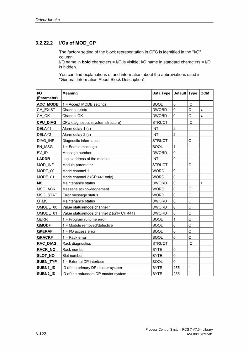
Driver blocks
Process Control System PCS 7 V7.0 - Library 3-122 A5E00807897-01
3.2.22.2 I/Os of MOD_CP
The factory setting of the block representation in CFC is identified in the "I/O" column: I/O name in bold characters = I/O is visible; I/O name in standard characters = I/O is hidden.
You can find explanations of and information about the abbreviations used in "General Information About Block Description".
I/O (Parameter)
Meaning
Data Type
Default Type
OCM
ACC_MODE 1 = Accept MODE settings BOOL 0 IO CH_EXIST Channel exists DWORD 0 O + CH_OK Channel OK DWORD 0 O + CPU_DIAG CPU diagnostics (system structure) STRUCT IO DELAY1 Alarm delay 1 (s) INT 2 I DELAY2 Alarm delay 2 (s) INT 2 I DIAG_INF Diagnostic information STRUCT O EN_MSG 1 = Enable message BOOL 1 I EV_ID Message number DWORD 0 I LADDR Logic address of the module INT 0 I MOD_INF Module parameter STRUCT O MODE_00 Mode channel 1 WORD 0 I MODE_01 Mode channel 2 (CP 441 only) WORD 0 I MS Maintenance status DWORD 0 I + MSG_ACK Message acknowledgement WORD 0 O MSG_STAT Error message status WORD 0 O O_MS Maintenance status DWORD 0 O OMODE_00 Value status/mode channel 1 DWORD 0 O OMODE_01 Value status/mode channel 2 (only CP 441) DWORD 0 O QERR 1 = Program runtime error BOOL 1 O QMODF 1 = Module removed/defective BOOL 0 O QPERAF 1 = I/O access error BOOL 0 O QRACKF 1 = Rack error BOOL 0 O RAC_DIAG Rack diagnostics STRUCT IO RACK_NO Rack number BYTE 0 I SLOT_NO Slot number BYTE 0 I SUBN_TYP 1 = External DP interface BOOL 0 I SUBN1_ID ID of the primary DP master system BYTE 255 I SUBN2_ID ID of the redundant DP master system BYTE 255 I

Driver blocks
Process Control System PCS 7 V7.0 - Library A5E00807897-01 3-123
Additional information Additional information is available in the sections:
Message Texts and Associated Values of MOD_CP
Maintenance Status MS
3.2.22.3 Message Texts and Associated Values of MOD_CP
Assignment of Message Text and Message Class
Message Block ALARM_8P
Message No.
Block Parameter
Default Message Text
Message Class
EV_ID 1 QMODF CP @1%d@/@2%d@/@3%d@: Removed S 2 QPERAF CP @1%d@/@2%d@/@3%d@: I/O access error S 3 CP @1%d@/@2%d@/@3%d@:
@4W%t#MOD_CP_TXT@ S
4 CP @1%d@/@2%d@/@3%d@: Wrong parameter S 5 CP @1%d@/@2%d@/@3%d@: Wire break S 6 CP @1%d@/@2%d@/@3%d@/2: Wrong
parameter S
7 CP @1%d@/@2%d@/@3%d@/2: Wire break S 8 CP @1%d@/@2%d@/@3%d@: Repeated
diagnostic interrupt S
You can find the message texts and their text numbers in "Text Library for MOD_CP".
Assignment of Associated Values
Message Block ALARM_8P
Associated Value
Block Parameter
Meaning
EV_ID 1 SUBN_ID DP master system ID (byte) 2 RACK_NO Rack/station number (byte) 3 SLOT_NO Slot number (byte)
SUBN_ID = SUBN1_ID. If SUBN1_ID = 16#FF, the associated value is substituted with SUBN2_ID.
Driver blocks
Process Control System PCS 7 V7.0 - Library 3-124 A5E00807897-01
3.2.23 MOD_D1: Monitoring Up to 16 Channels of S7-300/400 SM Modules With Diagnostic Functions
3.2.23.1 Description of MOD_D1
Object name (type + number) FB93
Fields of application The block MOD_D1 monitors diagnostics-capable, max. 16-channel S7-300/400 SM modules (no hybrid modules) and with redundant configuration of the power supplies of an ET 200iSP. H systems support only the modules installed in switched racks.
Calling OBs The block must be installed in the run sequence in the following OBs: OB1 Cyclic program
OB82 Diagnostic interrupt OB83 Removal/insertion alarm OB85 Program runtime error OB86 Rack failure OB100 Restart (warm start)
Use in CFC When the CFC function "Generate module drivers" is used, the following occurs automatically:
• The MOD_D1 block is installed in its runtime group downstream of the RACK-block runtime group in the above-mentioned OBs.
• The MODE_xx (mode of the channels xx of the module), SUBN1_ID, SUBN2_ID, and SUBN_TYP inputs are configured.
• The logical basic address of the LADDR module is configured.
• The OUT structures CPU_DIAG of the OB_BEGIN block and RAC_DIAG of the RACK block are interconnected with the INOUT structures of the same name of MOD_D1.
Driver blocks
Process Control System PCS 7 V7.0 - Library A5E00807897-01 3-125
• The EN input is interconnected with the output of an AND block, whose inputs are interconnected with the outputs EN_SUBx (x = number of the DP Master system) of the OB_BEGIN block, with EN_Rxxx (xxx = Rack/station number) of the SUBNET block and with EN_Mxx (xx = Module number) of the RACK block.
Function and Operating Principle Block MOD_D1 analyzes all events affecting a module and its channels non-cyclic mode. and forms the channel-specific MODE and value status (quality code) for the signal processing blocks. ALARM_8P is used to report these events.
MOD_D1 monitors the redundant power supplies for ET 200iSP and reports the failure of a power supply via the slot number of the interface module The maintenance status (MS) of the module shows, if the power supply fails "Maintenance: Requirement Moderate" an.
Block MOD_D1 is enabled by the higher-level RACK block during runtime. The diagnostic event is stored in the CPU_DIAG start and diagnostic information of the OB_BEGIN block. A MODE_xx input exists for each signal channel of the module, which is used for the input of module channel configuration data created in HW Config. The function writes MODE_xx to the low word of the OMODE_xx output parameter, but only during initial startup or if you set ACC_MODE = TRUE. The actual channel value status is written to the most significant byte. If the result is positive, the system sets OMODE_xx = 16#80xxxxxx.
The following events will lead to the value status "invalid value due to higher-level error" (OMODE_xx = 16#40xxxxxx):
• Events evaluated by the RACK block:
Rack failure (OB86) (output parameter QPERAF = TRUE)
• Events evaluated by the MOD block:
I/O access error (OB85) (output parameter QPERAF = TRUE)
Module removed (OB83) (output parameter QMODF = TRUE) Diagnostic interrupt (OB82) Differentiation between module errors and channels errors

Driver blocks
Process Control System PCS 7 V7.0 - Library 3-126 A5E00807897-01
The Following Events Represent Module Errors (QMODF = TRUE Output Parameter):
• External auxiliary voltage missing
• Front connector missing
• Module not configured
• Wrong parameter in module
• Wrong/missing module
• Communication error at a CPU module
• Timeout (watchdog)
• Loss of internal power at a module
• Rack failure
• CPU failure
• EPROM error
• RAM error
• ADC/DAC error
• Fuse tripped
• Power supply 1: Error
• Power supply 2: Error
The Following Events Represent Channel Errors (Value Status "Invalid Value", OMODE_xx = 16#00xxxx):
• Configuration/parameter assignment error
• Common-mode errors (only analog I/Os)
• Short-circuit to P
• Short circuit to M
• Interruption at the output transistor
• Cable break
• Reference channel error (only analog inputs)
• Measuring range underflow (only analog inputs)
• Measuring range overflow (only analog inputs)
• Missing load voltage (only analog and digital outputs)
• Missing sensor power supply (only digital outputs)
• Fuse tripped (only digital outputs)
• Mass error (only digital I/Os)
• Excess temperature (only digital outputs)
ALARM_8P is used to report "Module removed", "I/O access error" and "Diagnostics interrupt" events to WinCC.

Driver blocks
Process Control System PCS 7 V7.0 - Library A5E00807897-01 3-127
The diagnostics interrupt function distinguishes between module and channel errors, whereby each channel is assigned a message ID. Only one incoming/outgoing event can be reported for each channel. As long as an incoming message is queued at a channel, further messages on new events at this channel will be lost.
If the event is defined uniquely in the diagnostic information, the corresponding text will be entered in the message. If ambiguous entries exist, the text of the first set bit in the error byte of the diagnostic information will be displayed. When using modules assigned diagnostic functions and more than one error byte for diagnostic information, only the channel xx error text will be output if the error information is not displayed in the first error byte.
The system verifies during startup that the module is available (plugged), reads the module status information provides these data as service output parameters (MOD_INF).
Detailed information about the errors is entered in the DIAG_INF output parameter of data type STRUCT. You can find additional information in Reference Manual System Software for S7-300/400 System and Standard Functions; Diagnostic Data, Byte 0 to Byte 8, Structure of Channel-Specific Diagnostic Data.
Note
Even if you operate a HART module in the HART operating MODE =16#070C, possible HART protocol errors/configuration changes are masked by the MOD_D1 driver block and not signaled as channel error.
Redundancy The higher-level RACK block monitors the redundancy of DP master systems operating in an H system.
MODE Setting The MODE_xx input parameters are available for up to 16 signal channels. Their default setting is "Zero" (no signal). For each signal channel xx, you need to set the type and, if appropriate, the coding of the measuring range of an analog module at the MODE_xx input.
You can find additional information in "MODE Settings".
Note
Modifications of parameters at the MODE_xx inputs during runtime are not accepted at the outputs until input ACC_MODE = 1.
OMODE Structure You can find additional information in "OMODE".
Driver blocks
Process Control System PCS 7 V7.0 - Library 3-128 A5E00807897-01
Display of the Valid Channels The existing channels of a module are displayed in the CH_EXIST output by setting a bit in the DWORD, starting at bit 0, for every existing channel. If the bit assigned to a channel is 0, the channel is not available.
Output CH_OK displays the valid channels of a module by setting a bit to TRUE for every valid channel, where bit 0 is assigned to channel 0, etc. If the bit assigned to a channel is 0, the channel is faulty. If there is a module error, all channels are disrupted.
Addressing You can find additional information in "Addressing".
HART modules with read/write access to the process image are configured in the same way as input modules. The set I/O range must always be identical.
Example: SM332 AO 2x0/4..20mA HART 332-5TB00-0AB0:
Address Input Range (HW Config)
Address Output Range (HW Config)
LADDR (Decimal/Hex)
544 544 544 / 16#0220
Error handling The input parameters are not validated. You can find additional information about error handling in "Error Information of Output Parameter MSG_STAT".
Service Information To analyze errors, read the module-status information entered during startup via the structured MOD_INF output parameter. You can find additional information in Reference Manual System Software for S7-300/400 System and Standard Functions; System-Status List, Module-Status Information.
Following a diagnostic alarm, you will also find detailed module diagnostic information in the MODDIAG0 to MODDIAG8 output parameters. You can find additional information in Reference Manual System Software for S7-300/400 System and Standard Functions; Diagnostic Data, Byte 0 to Byte 8.
The CHDIAG00 to CHDIAG15 output parameters contain detailed channel-status information. You can find additional information in Reference Manual System Software for S7-300/400 System and Standard Functions; Structure of Channel-Specific Diagnostic Data.
The system resets this diagnostic information after a diagnostic alarm has been reported outgoing (no further channel or module errors are queued).
Driver blocks
Process Control System PCS 7 V7.0 - Library A5E00807897-01 3-129
Startup Characteristics After a restart/initial startup, the system verifies that the module is available under its logical base address. A restart (OB100) is reported at the LSB in byte 2 of the outputs OMODE_xx.
Overload Behavior The MOD_D1 block counts OB82 calls. The counter is reset in OB1. If more than two OB82 events occur in succession before the cycle control point (OB1) is reached, these are discarded and a message "Failure OB82 DP Master: x Rack: y Slot: z" is output.
Dynamic response n.a.
Message response MOD_CP uses ALARM_8P to report module errors. The function also calls ALARM_8P_2 and ALARM_8P_3, which are both relevant for channel-specific errors. The inputs DELAY1 and DELAY2 are used to delay the output of I/O access error messages. At DELAY1 you can specify which time in seconds the block waits for higher-priority errors (rack failure or removal/insertion) after an I/O access error (OB85 has occurred until it outputs the message. The message is output only under the condition that no higher-priority error is reported within this delay time. DELAY2 determines the number of seconds the block waits after the higher-priority error has been reported outgoing until it outputs the queued I/O access error as well. The default of both values is 2 seconds. The message function can be disabled by setting EN_MSG = FALSE.
Operating and Monitoring Note: If you have selected the "Enable operating and monitoring" option in the block object properties in the CFC, the variables transferred to the OS are identified under "I/Os of …" (OCM column, "+"). Default: option not selected.
If asset management is used in the project and the diagnostic screens have been generated, then the faceplate can be called via its icon.
• Asset Management block symbols
• Asset Management faceplates
Note: Online help and the "PCS 7 FACEPLATES" Manual are only available if the "PCS 7 FACEPLATES" software package is installed!

Driver blocks
Process Control System PCS 7 V7.0 - Library 3-130 A5E00807897-01
Additional information Additional information is available in the sections:
Message Texts and Associated Values of MOD_D1
Maintenance Status MS
Notes on Using Driver Blocks
3.2.23.2 I/Os of MOD_D1/MOD_D2
The I/Os are identical at both the MOD_D1 and the MOD_D2 block, with the exception of the number of MODE_xx and OMODE_xx. The number of monitored channels determines the corresponding number of I/O parameters (xx).
The factory setting of the block display in CFC is identified in the "I/O" column: I/O name in bold characters = I/O is visible; I/O name in standard characters = I/O is hidden.
You can find explanations of and information about the abbreviations used in "General Information About Block Description".
I/O (Parameter)
Meaning
Data Type
Default Type
OCM
ACC_MODE 1 = Accept MODE settings BOOL 0 IO CH_EXIST Channel exists DWORD 0 O + CH_OK Channel OK DWORD 0 O + CPU_DIAG CPU diagnostics (system structure) STRUCT IO DELAY1 Alarm delay 1 (s) INT 2 I DELAY2 Alarm delay 2 (s) INT 2 I DIAG_INF Diagnostic information STRUCT 0 O EN_MSG 1 = Enable message BOOL 1 I EV_IDx Message number (x = 1 - 3) DWORD 0 I LADDR Logic address of the module INT 0 I MOD_INF Module parameter STRUCT O MODE_xx Mode channel xx WORD 0 I MS Maintenance status DWORD 0 I + MSG_ACKx Message acknowledgment (x = 1 - 3) WORD 0 O MSGSTATx Message error information (x = 1 - 3) WORD 0 O O_MS Maintenance status DWORD 0 O OMODE_xx Channel mode (xx = 00 - 15/00 - 31) DWORD 0 O QERR 1 = Program runtime error BOOL 1 O QMODF 1 = Module removed/defective BOOL 0 O QPERAF 1 = I/O access error BOOL 0 O QRACKF 1 = Rack error BOOL 0 O RAC_DIAG Rack diagnostics STRUCT IO RACK_NO Rack number BYTE 0 I

Driver blocks
Process Control System PCS 7 V7.0 - Library A5E00807897-01 3-131
I/O (Parameter)
Meaning
Data Type
Default Type
OCM
SLOT_NO Slot number BYTE 0 I SUBN_TYP 1 = External DP interface BOOL 0 I SUBN1_ID ID of the primary DP master system BYTE 255 I SUBN2_ID ID of the redundant DP master system BYTE 255 I
Additional information Additional information is available in the sections: Message Texts and Associated Values of MOD_D1 Message Texts and Associated Values of MOD_D2 Maintenance Status MS
3.2.23.3 Message Texts and Associated Values of MOD_D1
Assignment of Message Text and Message Class
Message Block ALARM_8P
Message No.
Block Parameter
Default Message Text
Message Class
EV_ID1 1 QMODF Module @1%d@/ @2%d@/ @3%d@: Removed S 2 QPERAF Module @1%d@/ @2%d@/ @3%d@: I/O
access error S
3 QMODF Module @1%d@/ @2%d@/ @3%d@: @5W%t#MOD_D1_TXT@
S
4 Module @1%d@/@2%d@/@3%d@: Repeated diagnostic interrupt
S
5 Module @1%d@/ @2%d@/ @3%d@: @4W%t#MOD_D1_TXT@
S
6 Module @1%d@/ @2%d@/ @3%d@: @4W%t#MOD_D1_TXT@
S
7 Module @1%d@/ @2%d@/ @3%d@: @5W%t#MOD_D1_TXT@
F
8 - S EV_ID2 1 - Module @1%d@/ @2%d@/ @3%d@:
Error channel 00 @4W%t#MOD_D1_TXT S
... ...
... ...
...
... 7 - Module @1%d@/ @2%d@/ @3%d@:
Error channel 07 @4W%t#MOD_D1_TXT@ S
EV_ID3 1 - Module @1%d@/ @2%d@/ @3%d@: Error channel 08 @4W%t#MOD_D1_TXT@
S
... ...
... ...
...
... 7 - Module @1%d@/ @2%d@/ @3%d@:
Error channel 15 @4W%t#MOD_D1_TXT@ S

Driver blocks
Process Control System PCS 7 V7.0 - Library 3-132 A5E00807897-01
You can find the message texts and their text numbers in "Text Library for MOD_D1".
Assignment of Associated Values
Message Block ALARM_8P
Associated Value
Block Parameter
Meaning
EV_ID1 1 MOD_INF.SUBN_ID DP master system ID (byte) 2 MOD_INF.RACK_NO Rack/station number (byte) 3 MOD_INF.SLOT_NO Slot number (byte) 4 Text number (message 5) from MOD_D1_TXT 5 Text number (message 3) from MOD_D1_TXT EV_ID2 1 MOD_INF.SUBN_ID DP master system ID (byte) 2 MOD_INF.RACK_NO Rack/station number (byte) 3 MOD_INF.SLOT_NO Slot number (byte) 4 Text number (messages 1 - 8) from
MOD_D1_TXT EV_ID3 1 MOD_INF.SUBN_ID DP master system ID (byte) 2 MOD_INF.RACK_NO Rack/station number (byte) 3 MOD_INF.SLOT_NO Slot number (byte) 4 Text number (messages 1 - 8) from
MOD_D1_TXT
3.2.24 MOD_D2: Monitoring 32 Channels of S7-300/400 SM Modules With Diagnostic Functions
3.2.24.1 Description of MOD_D2
Object name (type + number) FB94
Fields of application Block MOD_D2 monitors up to 32 channels of S7-300/400 SM modules with diagnostics functions (no mixed modules). H systems support only the modules installed in switched racks.
Driver blocks
Process Control System PCS 7 V7.0 - Library A5E00807897-01 3-133
Calling OBs The block must be installed in the run sequence in the following OBs: OB1 Cyclic program
OB82 Diagnostic interrupt OB83 Removal/insertion alarm OB85 Program runtime error OB86 Rack failure OB100 Restart (warm start)
Use in CFC When the CFC function "Generate module drivers" is used, the following occurs automatically:
• The MOD_D2 block is installed in its runtime group downstream of the RACK-block runtime group in the above-mentioned OBs.
• The MODE_xx (mode of the channels xx of the module), SUBN1_ID, SUBN2_ID, and SUBN_TYP inputs are configured.
• The logical basic address of the LADDR module is configured.
• The OUT structures CPU_DIAG of the OB_BEGIN block and RAC_DIAG of the RACK block are interconnected with the INOUT structures of the same name of MOD_D2.
• The EN input is interconnected with the output of an AND block, whose inputs are interconnected with the outputs EN_SUBx (x = number of the DP Master system) of the OB_BEGIN block, with EN_Rxxx (xxx = Rack/station number) of the SUBNET block and with EN_Mxx (xx = Module number) of the RACK block.
Function and Operating Principle Block MOD_D2 analyzes all events affecting a module and its channels non-cyclic mode. and forms the channel-specific MODE and value status (quality code) for the signal processing blocks. ALARM_8P is used to report these events. The message function can be disabled.
The block is enabled by the higher-level RACK block during runtime. The diagnostic event is stored in the CPU_DIAG start and diagnostic information of the OB_BEGIN block. A MODE_xx input exists for each signal channel of the module, which is used for the input of module channel configuration data created in HW Config. The function writes MODE_xx to the low word of the OMODE_xx output parameter, but only during startup/initial startup or if you set ACC_MODE = TRUE. The actual channel value status is written to the most significant byte. If the result is positive, the system sets OMODE_xx = 16#80xxxxxx.
The following events will lead to the value status "invalid value due to higher-level error" (OMODE_xx = 16#40xxxxxx):
• Events evaluated by the RACK block:

Driver blocks
Process Control System PCS 7 V7.0 - Library 3-134 A5E00807897-01
Rack failure (OB86) (output parameter QRACKF = TRUE)
• Events evaluated by the MOD block:
I/O access error (OB85) (output parameter QPERAF = TRUE)
Module removed (OB83) (output parameter QMODF = TRUE) Diagnostic interrupt (OB82) Differentiation between module errors and channels errors
The Following Events Represent Module Errors (QMODF = TRUE Output Parameter):
• External auxiliary voltage missing
• Front connector missing
• Module not configured
• Wrong parameter in module
• Wrong/missing module
• Communication error at a CPU module
• Timeout (watchdog)
• Loss of internal power at a module
• Rack failure
• CPU failure
• EPROM error
• RAM error
• ADC/DAC error
• Fuse tripped
The Following Events Represent Channel Errors (Value Status "Invalid Value", OMODE_xx = 16#00xxxx):
• Configuration/parameter assignment error
• Common-mode errors (only analog I/Os)
• Short-circuit to P
• Short circuit to M
• Interruption at the output transistor
• Cable break
• Reference channel error (only analog inputs)
• Measuring range underflow (only analog inputs)
• Measuring range overflow (only analog inputs)

Driver blocks
Process Control System PCS 7 V7.0 - Library A5E00807897-01 3-135
• Missing load voltage (only analog and digital outputs)
• Missing sensor power supply (only digital outputs)
• Fuse tripped (only digital outputs)
• Mass error (only digital I/Os)
• Excess temperature (only digital outputs)
ALARM_8P is used to report "Module removed", "I/O access error" and "Diagnostics interrupt" events to WinCC.
The diagnostics interrupt function distinguishes between module and channel errors, whereby each channel is assigned a message ID. Only one incoming or outgoing event can be reported for each channel. As long as an incoming message is queued at a channel, further messages on new events at this channel will be lost.
If the event is defined uniquely in the diagnostic information, the corresponding text will be entered in the message. If ambiguous entries exist, the text of the first set bit in the error byte of the diagnostic information will be displayed. When using modules assigned diagnostic functions and more than one error byte for diagnostic information, only the channel xx error text will be output if the error information is not displayed in the first error byte.
The system verifies during startup that the module is available (plugged), reads the module status information provides these data as service output parameters (MOD_INF).
Detailed information about the errors is entered in the DIAG_INF output parameter of data type STRUCT. You can find additional information in Reference Manual System Software for S7-300/400 System and Standard Functions; Diagnostic Data, Byte 0 to Byte 8, Structure of Channel-Specific Diagnostic Data.
Redundancy The block supports segment redundancy of CPU 417H for distributed I/O. If you want to use this function, you must configure the SUBN1_ID (connection to CPU 0) and SUBN2_ID (connection to CPU 1) inputs with the numbers of the redundant chains. If segment redundancy doe not exist, the (default) value 16#FF must be set at the remaining input.
MODE Setting The MODE_xx input parameters are available for up to 32 signal channels. Their default setting is zero (no signal). For each signal channel xx, you need to set the type and, if appropriate, the coding of the measuring range of an analog module at the MODE_xx input.
You can find additional information in "MODE Settings".
Note
Modifications of parameters at the MODE_xx inputs during runtime are not accepted at the outputs until input ACC_MODE = 1.
Driver blocks
Process Control System PCS 7 V7.0 - Library 3-136 A5E00807897-01
OMODE Structure You can find additional information in "OMODE".
Display of the Valid Channels The existing channels of a module are displayed in the CH_EXIST output by setting a bit in the DWORD, starting at bit 0, for every existing channel. If the bit assigned to a channel is 0, the channel is not available.
Output CH_OK displays the valid channels of a module by setting a bit to TRUE for every valid channel, where bit 0 is assigned to channel 0, etc. If the bit assigned to a channel is 0, the channel is faulty. If there is a module error, all channels are disrupted.
Addressing You can find additional information in "Addressing".
Error handling The input parameters are not validated. You can find additional information about error handling in "Error Information of Output Parameter MSG_STAT".
Service Information To analyze errors, read the module-status information entered during startup via the structured MOD_INF output parameter. You can find additional information in Reference Manual System Software for S7-300/400 System and Standard Functions; System-Status List, Module-Status Information.
Following a diagnostic alarm, you will also find detailed module diagnostic information in the MODDIAG0 to MODDIAG10 output parameters. You can find additional information in Reference Manual System Software for S7-300/400 System and Standard Functions; Diagnostic Data, Byte 0 to Byte 10.
The CHDIAG00 to CHDIAG31 output parameters contain detailed channel-status information. You can find additional information in Reference Manual System Software for S7-300/400 System and Standard Functions; Structure of Channel-Specific Diagnostic Data.
The system resets this diagnostic information after a diagnostic alarm has been reported outgoing (no further channel or module errors are queued).
Startup Characteristics After a restart/initial startup, the system verifies that the module is available under its logical base address. A restart (OB100) is reported via the LSB in byte 2 of the outputs OMODE_xx.
Dynamic response n.a.
Driver blocks
Process Control System PCS 7 V7.0 - Library A5E00807897-01 3-137
Message response MOD_D2 uses ALARM_8P_1 to report module errors. In addition, the error blocks ALARM_8P_2, ALARM_8P_3, ALARM_8P_4 and ALARM_8P_5 are called. The inputs DELAY1 and DELAY2 are used to delay the output of I/O access error messages. At DELAY1 you can specify which time in seconds the block waits for higher-priority errors (rack failure or removal/insertion) after an I/O access error (OB85 has occurred until it outputs the message. The message is output only under the condition that no higher-priority error is reported within this delay time. DELAY2 determines the number of seconds the block waits after the higher-priority error has been reported outgoing until it outputs the queued I/O access error as well. The default of both values is 2 seconds. The message function can be disabled by setting EN_MSG = FALSE.
Operating and Monitoring Note: If you have selected the "Enable operating and monitoring" option in the block object properties in the CFC, the variables transferred to the OS are identified under "I/Os of …" (OCM column, "+"). Default: option not selected.
If asset management is used in the project and the diagnostic screens have been generated, then the faceplate can be called via its icon.
• Asset Management block symbols
• Asset Management faceplates
Note: Online help and the "PCS 7 FACEPLATES" Manual are only available if the "PCS 7 FACEPLATES" software package is installed!
Additional information Additional information is available in the sections:
Message Texts and Associated Values of MOD_D2
Maintenance Status MS
Notes on Using Driver Blocks
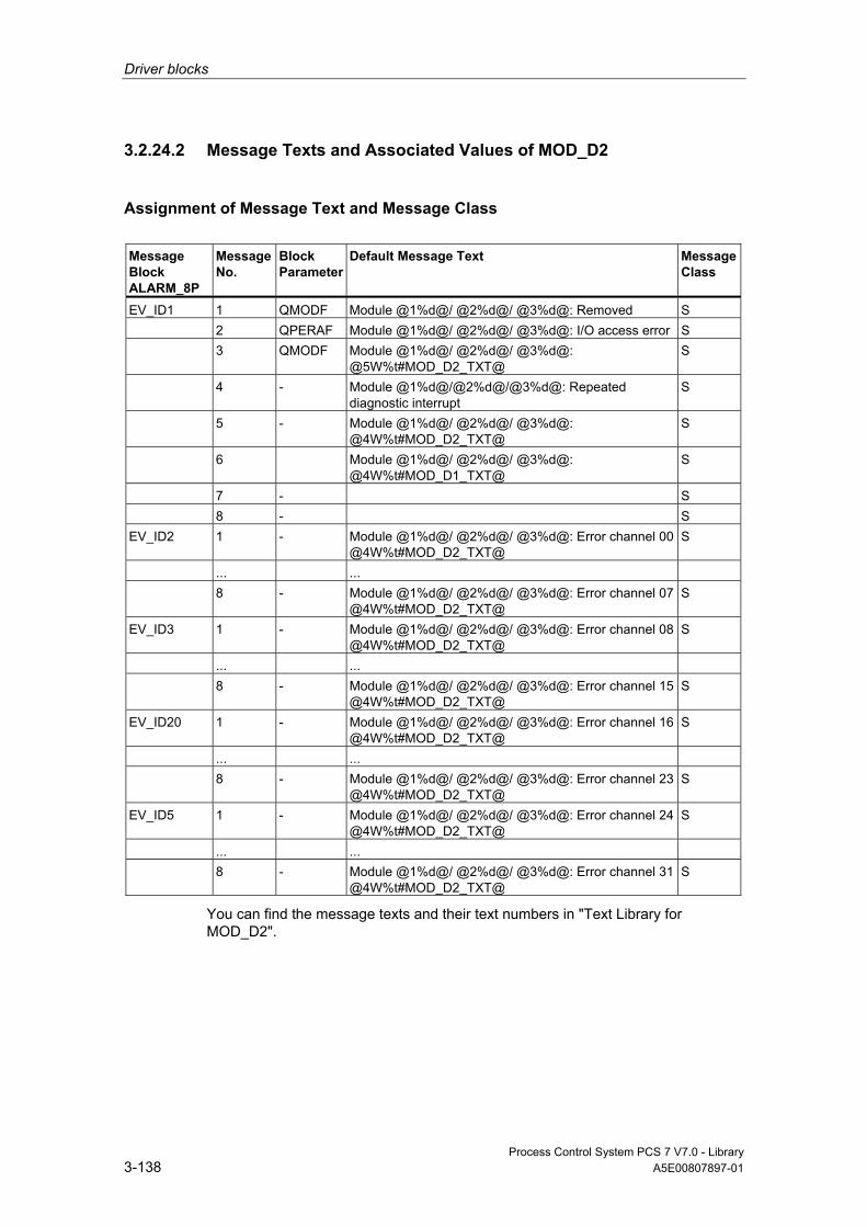
Driver blocks
Process Control System PCS 7 V7.0 - Library 3-138 A5E00807897-01
3.2.24.2 Message Texts and Associated Values of MOD_D2
Assignment of Message Text and Message Class
Message Block ALARM_8P
Message No.
Block Parameter
Default Message Text
Message Class
EV_ID1 1 QMODF Module @1%d@/ @2%d@/ @3%d@: Removed S 2 QPERAF Module @1%d@/ @2%d@/ @3%d@: I/O access error S 3 QMODF Module @1%d@/ @2%d@/ @3%d@:
@5W%t#MOD_D2_TXT@ S
4 - Module @1%d@/@2%d@/@3%d@: Repeated diagnostic interrupt
S
5 - Module @1%d@/ @2%d@/ @3%d@: @4W%t#MOD_D2_TXT@
S
6 Module @1%d@/ @2%d@/ @3%d@: @4W%t#MOD_D1_TXT@
S
7 - S 8 - S EV_ID2 1 - Module @1%d@/ @2%d@/ @3%d@: Error channel 00
@4W%t#MOD_D2_TXT@ S
... ... 8 - Module @1%d@/ @2%d@/ @3%d@: Error channel 07
@4W%t#MOD_D2_TXT@ S
EV_ID3 1 - Module @1%d@/ @2%d@/ @3%d@: Error channel 08 @4W%t#MOD_D2_TXT@
S
... ... 8 - Module @1%d@/ @2%d@/ @3%d@: Error channel 15
@4W%t#MOD_D2_TXT@ S
EV_ID20 1 - Module @1%d@/ @2%d@/ @3%d@: Error channel 16 @4W%t#MOD_D2_TXT@
S
... ... 8 - Module @1%d@/ @2%d@/ @3%d@: Error channel 23
@4W%t#MOD_D2_TXT@ S
EV_ID5 1 - Module @1%d@/ @2%d@/ @3%d@: Error channel 24 @4W%t#MOD_D2_TXT@
S
... ... 8 - Module @1%d@/ @2%d@/ @3%d@: Error channel 31
@4W%t#MOD_D2_TXT@ S
You can find the message texts and their text numbers in "Text Library for MOD_D2".

Driver blocks
Process Control System PCS 7 V7.0 - Library A5E00807897-01 3-139
Assignment of Associated Values
Message Block ALARM_8P
Associated Value
Block Parameter
Meaning
EV_ID1 1 MOD_INF.SUBN_ID DP master system ID (byte) 2 MOD_INF.RACK_NO Rack/station number (byte) 3 MOD_INF.SLOT_NO Slot number (byte) 4 - Text number (messages 1 -3) of MOD_D2_TXT EV_ID2 1 MOD_INF.SUBN_ID DP master system ID (byte) 2 MOD_INF.RACK_NO Rack/station number (byte) 3 MOD_INF.SLOT_NO Slot number (byte) 4 - Text number (message 5) of MOD_D2_TXT 5 - Text number (message 3) of MOD_D2_TXT EV_ID3 1 MOD_INF.SUBN_ID DP master system ID (byte) 2 MOD_INF.RACK_NO Rack/station number (byte) 3 MOD_INF.SLOT_NO Slot number (byte) 4 - Text number (messages 1 - 8) of MOD_D2_TXT EV_ID20 1 MOD_INF.SUBN_ID DP master system ID (byte) 2 MOD_INF.RACK_NO Rack/station number (byte) 3 MOD_INF.SLOT_NO Slot number (byte) 4 - Text number (messages 1 - 8) of MOD_D2_TXT EV_ID5 1 MOD_INF.SUBN_ID DP master system ID (byte) 2 MOD_INF.RACK_NO Rack/station number (byte) 3 MOD_INF.SLOT_NO Slot number (byte) 4 - Text number (messages 1 - 8) of MOD_D2_TXT
3.2.25 MOD_HA: Monitoring Device-Specific Diagnostics of HART Field Devices
3.2.25.1 Description of MOD_HA
Object name (type + number) FB97
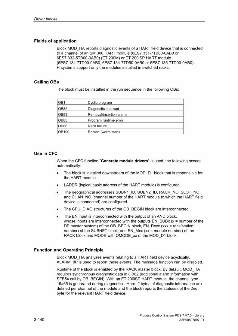
Driver blocks
Process Control System PCS 7 V7.0 - Library 3-140 A5E00807897-01
Fields of application Block MOD_HA reports diagnostic events of a HART field device that is connected to a channel of an SM 300 HART module (6ES7 331-7TB00-0AB0 or 6ES7 332-5TB00-0AB0) (ET 200M) or ET 200iSP HART module (6ES7 134-7TD00-0AB0, 6ES7 134-7TD50-0AB0 or 6ES7 135-7TD00-0AB0). H systems support only the modules installed in switched racks.
Calling OBs The block must be installed in the run sequence in the following OBs:
OB1 Cyclic program
OB82 Diagnostic interrupt OB83 Removal/insertion alarm OB85 Program runtime error OB86 Rack failure OB100 Restart (warm start)
Use in CFC When the CFC function "Generate module drivers" is used, the following occurs automatically:
• The block is installed downstream of the MOD_D1 block that is responsible for the HART module.
• LADDR (logical basic address of the HART module) is configured.
• The geographical addresses SUBN1_ID, SUBN2_ID, RACK_NO, SLOT_NO, and CHAN_NO (channel number of the HART module to which the HART field device is connected) are configured.
• The CPU_DIAG structures of the OB_BEGIN block are interconnected.
• The EN input is interconnected with the output of an AND block, whose inputs are interconnected with the outputs EN_SUBx (x = number of the DP master system) of the OB_BEGIN block, EN_Rxxx (xxx = rack/station number) of the SUBNET block, and EN_Mxx (xx = module number) of the RACK block and MODE with OMODE_xx of the MOD_D1 block.
Function and Operating Principle Block MOD_HA analyzes events relating to a HART field device acyclically. ALARM_8P is used to report these events. The message function can be disabled.
Runtime of the block is enabled by the RACK master block. By default, MOD_HA requires synchronous diagnostic data in OB82 (additional alarm information with SFB54 call by OB_BEGIN). With an ET 200iSP HART module, the channel type 16#65 is generated during diagnostics. Here, 2 bytes of diagnostic information are defined per channel of the module and the block reports the statuses of the 2nd byte for the relevant HART field device.

Driver blocks
Process Control System PCS 7 V7.0 - Library A5E00807897-01 3-141
Structure of byte 2 (ET 200iSP HART):
Bit Meaning
0 Primary variable out of limits (field device) 1 Non-primary variable out of limits (field device) 2 Analog output saturated (field device) 3 Analog output current specified (field device) 4 More statuses available (field device) 5 Reserved for maintenance alarm (field device) 6 Reassignment of parameter of the field device 7 Malfunction of the field device
With an ET 200M with two-channel HART modules, the channel type 16#61 or 16#63 is generated during diagnostics. Here, bit 5 in byte 8 for channel 0 and byte 9 for channel 1 in the additional alarm information means "HART channel error". If bit 5 = TRUE, the additional diagnostic data is read with SFB52 (RDREC) as follows:
• with data record 128 for channel 0
• with data record 129 for channel 1
The structures of the diagnostic data records 128 for channel 0 and 129 for channel 1 are identical and return detailed HART diagnostic information on the previous transfer. The table below shows the specific error messages/warnings. (Note: The table in the PCS 7 Library Manual is clearer and easier to read because it has table lines, in contrast to the online help.)
Byte/Bit No. 7 6 5 4 3 2 1 0
0: general 1 = module comm.
no. of the (triggering) client, if module comm. no. = 0
polling address (of the HART transducer), always 0 for monodrop
1: fault groups = group error
channel fault (L+, DrBr)
HART channel fault
HART slave commu- nication
HART commanderror
device status <> 0 (e.g. configu- ration changed)
more status
rejected command
0 = not used
the? bytes - 2 8 8 9 - - - 2: HART cf = "communi- cation faults" Field device to module
HART access not possible
parity error in response
overrun error in response
framing error in response
wrong checksum in response
wrong char timing
too many chars in response
wrong telegram timing

Driver blocks
Process Control System PCS 7 V7.0 - Library 3-142 A5E00807897-01
Byte/Bit No. 7 6 5 4 3 2 1 0 3 to 6: timestamp
Broadcast system time: milliseconds (10s and 100s digits), seconds, minutes and hours in two-digit BCD code respectively. If the timestamp function does not exist: Content = 0
7: HART/module
last HART or module command
8: HART ce 1 0
"Communication error bits" of the "slave", (first status byte) "Command response" list - no errors, but warnings
9: HART ds Device status bits (second status byte)
Two HART status bytes are reserved in the HART protocol for the indication of errors and warnings and are entered in the diagnostic data records 128 and 129 without changes: The meaning of the HART status bytes is defined in the HART Standard.
• First HART status byte (meaning depends on bit 7):
- Bit 7 = 1: Communication error during the transmission of a HART command to the field device
- Bit 7 = 0: Only a warning the field device transmits in return to a command
Bit 7/Bit No. 7 6 5 4 3 2 1 0
either Bit 7 = 1 : HART "Communi-cation error" from module to field device
1 parity error in command
overrun error in command
framing error in command
wrong checksumin command
reserved= 0
too many characters in command (rx buffer overflow)
(un- defined)
or Bit 7 = 0 : HART "Response to a command"
0 The messages in bits 0 - 6 are coded in integer: 0: No error in command 1: Undefined 2: Invalid section 3: Transferred parameter too large 4: Transferred parameter too small 5: Received insufficient number of data bytes 6: Device-specific command error (rarely used) 7: In write-protected mode 8-15: Diverse significance (see code commands) 16: Limited access 28 Diverse significance (see code commands) 32: Device is busy 64 Command not implemented

Driver blocks
Process Control System PCS 7 V7.0 - Library A5E00807897-01 3-143
Code Commands Alternative Meanings
8 *) 1,2,3,33,60,61,62, 110,34,55,64,48
Update error, set to next possible value, update in progress
9 35,65,36,37,43,52,45,46,67,68 Low limit too high, applied process too high, not in correct current mode (set to 4 mA or 20 mA)
10 6,35,65,36,37,43,52 Multidrop is not supported, low limit too low, applied process too low
11 35,65,40,45,46,66,67,68,53 High limit too high, in multidrop mode, faulty transmitter-variable code
12 35,65,53,66,67,68 High limit too low, faulty unit code
13 35,65,69 High/low limits out of range, faulty transfer function code
14 *) 35,36,65,37 Span too narrow, pushed high range limit out of range
15 65,66,67,68,69 Faulty code for the number of the analog output 28 65 Faulty range units code
• Second HART status byte: Device status of the HART field device after a communication error has occurred (otherwise, byte = 0)
Bit No. 7 6 5 4 3 2 1 0
HART device status: "field- device- status"
Faulty function of the field device
Configu- ration changed (CC)" "configu- ration changed (CC)"
Complete restart
"More status" available
Fixed analog output current
Saturatedanalog output
Non-primary variable out of range
Primary variable out of range
Process-control messages are generated when "communication errors" and HART-field-device errors (byte 9 <> 0) occur. System messages with acknowledgement attribute are generated, if bit 7 = 0 (byte 8) and the remaining bits <> 0. The last read data record 128 or 129 (depending on the channel number) will be written to the output structure DIAG_H.
Bytes 8 and 9 are evaluated and event messages generated in OB1. You can find additional information in "Message Texts and Associated Values of MOD_HA".
The MODE input is interconnected with the corresponding OMODE_xx output of the MOD_D1 block. The module channel configurations set in HW Config are reported at these locations.

Driver blocks
Process Control System PCS 7 V7.0 - Library 3-144 A5E00807897-01
MODE is written to the low word of output parameter OMODE, but only during initial startup/startup or if you set ACC_MODE = TRUE. The actual channel value status is written to the most significant byte. If valid, OMODE = 16#80xxxxxx. The MOD_D1 block contains the events that lead to the value status "invalid value due to higher-priority error" (OMODE = 16#40xxxxxx) or to channel error (OMODE = 16#00xxxxxx).
HART errors are output by the OMODE block as "channel error".
Redundancy The higher-level RACK block evaluates the redundancy of DP master systems operating in an H system. Redundant HART field devices are not supported.
Error handling The input parameters are not validated.
Startup Characteristics A restart (OB100) is reported via the LSB in byte 2 of OMODE.
ALARM_8P will be initialized.
Overload Behavior The MOD_HA block counts OB82 calls. The counter is reset in OB1. A diagnostic message will not be generated if more than five OB82 events occur before the cycle control point is reached (OB1). A "multiple diagnostic alarm" message will not be generated, since the MOD_D1 block takes over this action.
Dynamic response n.a.
Message response MOD_HA reports diagnostic information of a HART field device by means of ALARM_8P or NOTIFY_8P. The message function can be disabled by setting EN_MSG = FALSE.
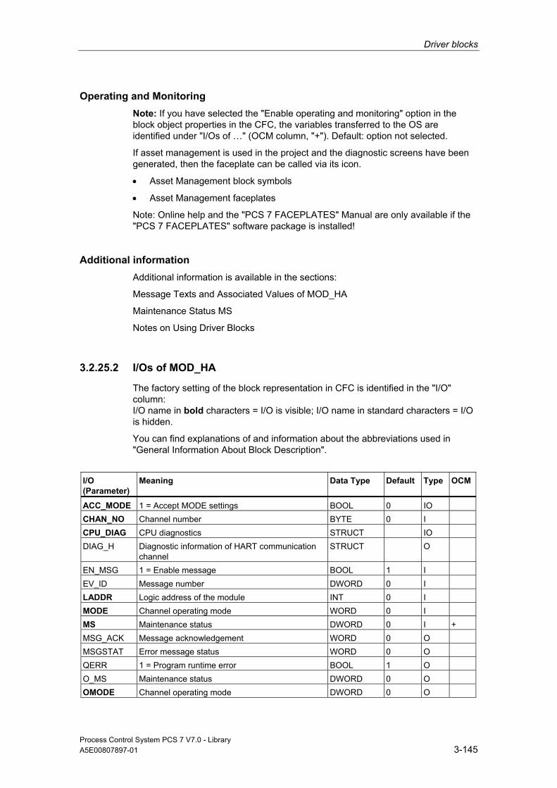
Driver blocks
Process Control System PCS 7 V7.0 - Library A5E00807897-01 3-145
Operating and Monitoring Note: If you have selected the "Enable operating and monitoring" option in the block object properties in the CFC, the variables transferred to the OS are identified under "I/Os of …" (OCM column, "+"). Default: option not selected.
If asset management is used in the project and the diagnostic screens have been generated, then the faceplate can be called via its icon.
• Asset Management block symbols
• Asset Management faceplates
Note: Online help and the "PCS 7 FACEPLATES" Manual are only available if the "PCS 7 FACEPLATES" software package is installed!
Additional information Additional information is available in the sections:
Message Texts and Associated Values of MOD_HA
Maintenance Status MS
Notes on Using Driver Blocks
3.2.25.2 I/Os of MOD_HA
The factory setting of the block representation in CFC is identified in the "I/O" column: I/O name in bold characters = I/O is visible; I/O name in standard characters = I/O is hidden.
You can find explanations of and information about the abbreviations used in "General Information About Block Description".
I/O (Parameter)
Meaning
Data Type
Default Type
OCM
ACC_MODE 1 = Accept MODE settings BOOL 0 IO CHAN_NO Channel number BYTE 0 I CPU_DIAG CPU diagnostics STRUCT IO DIAG_H Diagnostic information of HART communication
channel STRUCT O
EN_MSG 1 = Enable message BOOL 1 I EV_ID Message number DWORD 0 I LADDR Logic address of the module INT 0 I MODE Channel operating mode WORD 0 I MS Maintenance status DWORD 0 I + MSG_ACK Message acknowledgement WORD 0 O MSGSTAT Error message status WORD 0 O QERR 1 = Program runtime error BOOL 1 O O_MS Maintenance status DWORD 0 O OMODE Channel operating mode DWORD 0 O

Driver blocks
Process Control System PCS 7 V7.0 - Library 3-146 A5E00807897-01
I/O (Parameter)
Meaning
Data Type
Default Type
OCM
QPERAF 1 = I/O access error BOOL 0 O QREC_ERR 1 = Read diagnostic data error BOOL 0 O QREC_VAL 1 = Read diagnostic data BOOL 0 O RACK_NO Rack number BYTE 0 I SLOT_NO Slot number BYTE 0 I STATUS Read diagnostics status DWORD 0 O SUBN_TYP 1 = External DP interface BOOL 0 I SUBN1_ID ID of the primary DP master system BYTE 255 I SUBN2_ID ID of the redundant DP master system BYTE 255 I
Additional information Additional information is available in the sections:
Message Texts and Associated Values of MOD_HA
Maintenance Status MS
3.2.25.3 Message Texts and Associated Values of MOD_HA
Assignment of Message Text and Message Class
Message Block
Message No.
Default Message Text
Message Class
EV_ID (ALARM_8P)
1 HART field device @1%d@/@2%d@/@3%d@/@4%d @: Communication error
S
2 HART field device @1%d@/@2%d@/@3%d@/@4%d @: Error
S
3 HART field device @1%d@/@2%d@/@3%d@/@4%d @: Secondary var. outside range
F
4 HART field device @1%d@/@2%d@/@3%d@/@4%d @: Primary var. outside range
F
5 HART field device @1%d@/@2%d@/@3%d@/@4%d @: Analog value specified
S
6 HART field device @1%d@/@2%d@/@3%d@/@4%d @: Analog value saturated
S
7 HART field device @1%d@/@2%d@/@3%d@/@4%d @: Maintenance interrupt
S
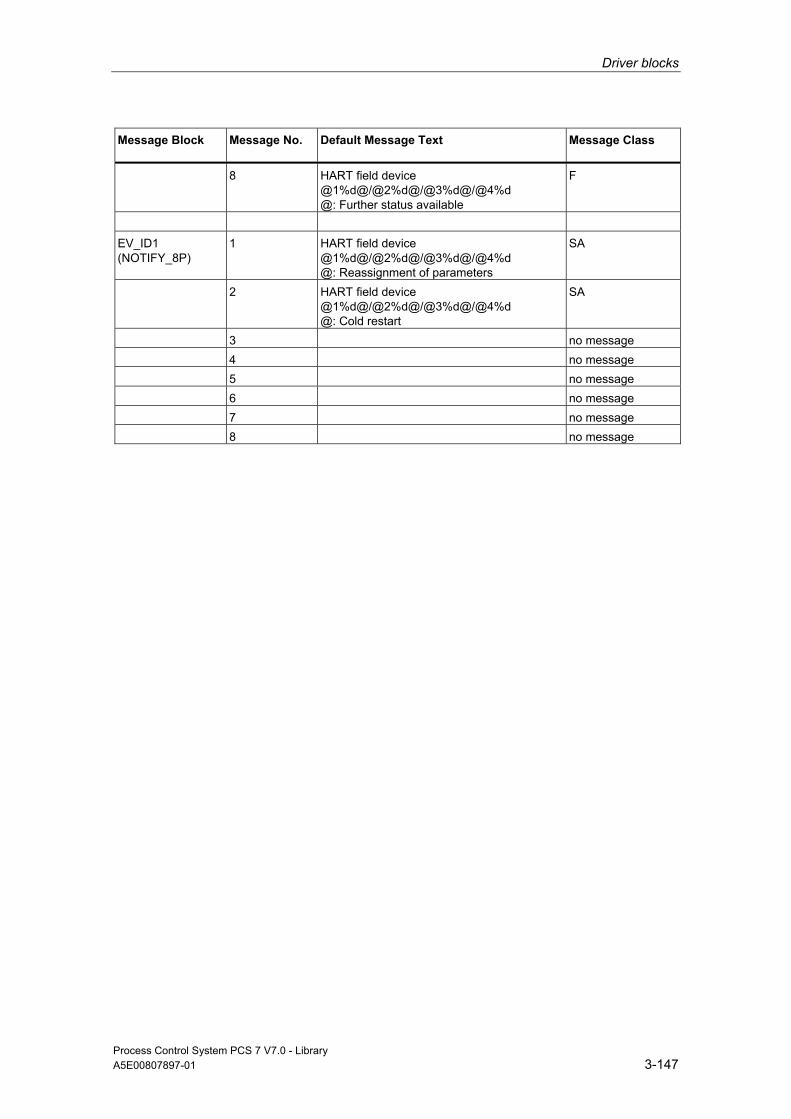
Driver blocks
Process Control System PCS 7 V7.0 - Library A5E00807897-01 3-147
Message Block
Message No.
Default Message Text
Message Class
8 HART field device @1%d@/@2%d@/@3%d@/@4%d @: Further status available
F
EV_ID1 (NOTIFY_8P)
1 HART field device @1%d@/@2%d@/@3%d@/@4%d @: Reassignment of parameters
SA
2 HART field device @1%d@/@2%d@/@3%d@/@4%d @: Cold restart
SA
3 no message 4 no message 5 no message 6 no message 7 no message 8 no message

Driver blocks
Process Control System PCS 7 V7.0 - Library 3-148 A5E00807897-01
Assignment of Associated Values
Message Block ALARM_8P
Associated Value
Block Parameter
Meaning
EV_ID 1 SUBN_ID DP master system ID (byte) 2 RACK_NO Rack/station number (byte) 3 SLOT_NO Slot number (byte) 4 CHAN_NO Channel error text number EV_ID1 1 SUBN_ID DP master system ID (byte) 2 RACK_NO Rack/station number 3 SLOT_NO 4 CHAN_NO
If SUBN1_ID = 16#FF, the associated value is substituted with SUBN2_ID.
3.2.26 MOD_MS: Monitoring Up to 16 Channels of ET200S/X Motor Starter Modules With Diagnostic Functions
3.2.26.1 Description of MOD_MS
Object name (type + number) FB96
Fields of application The block MOD_MS monitors the diagnostics-capable, max. 16-channel motor starter modules (ET 200S). H systems support only the modules installed in switched racks.
Calling OBs The block must be installed in the run sequence in the following OBs: OB1 Cyclic program
OB82 Diagnostic interrupt OB83 Removal/insertion alarm OB85 Program runtime error OB86 Rack failure OB100 Restart (warm start)
Driver blocks
Process Control System PCS 7 V7.0 - Library A5E00807897-01 3-149
Use in CFC When the CFC function "Generate module drivers" is used, the following occurs automatically:
• The MOD_MS block is installed in its runtime group downstream of the RACK-block runtime group in the above-mentioned OBs.
• The MODE_xx, SUBN1_ID, SUBN2_ID, and SUBN_TYP inputs are configured.
• The logical addresses LADDR and LADDR1 are configured.
• The OUT structures CPU_DIAG of the OB_BEGIN block and RAC_DIAG of the RACK block are interconnected with the INOUT structures of the same name of MOD_MS.
Function and Operating Principle Block MOD_MS analyzes all events affecting a module and its channels non-cyclic mode and forms the channel-specific MODE and value status (quality code) for the signal processing blocks. ALARM_8P is used to report these events. The message function can be disabled.
Runtime of the block is enabled by the RACK master block. The diagnostic event is stored in the CPU_DIAG start and diagnostic information of the OB_BEGIN block. A MODE_xx input exists for each signal channel of the module, which is used for the input of module channel configuration data created in HW Config. The function writes MODE_xx to the low word of the OMODE_xx output parameter, but only during startup/initial startup or if you set ACC_MODE = TRUE. The actual channel value status is written to the most significant byte. If the result is positive, the system sets OMODE_xx = 16#80xxxxxx.
The following events will lead to the value status "invalid value due to higher-level error" (OMODE_xx = 16#40xxxxxx):
• Events evaluated by the RACK block:
Segment failure (OB86) (output parameter QRACKF = TRUE)
Rack failure (OB85) (output parameter QRACKF = TRUE)
• Events evaluated by the MOD block:
I/O access error (OB85) (output parameter QPERAF = TRUE)
Module removed (OB83) (output parameter QMODF = TRUE) Diagnostic interrupt (OB82)
Driver blocks
Process Control System PCS 7 V7.0 - Library 3-150 A5E00807897-01
Distinguishes between module errors and channel errors. The following events (channel errors) are indicated with 16#40xxxxxx ("higher-priority error") in OMODE. At the same time, output parameter QMODF = TRUE:
• Configuration/parameter assignment error
• Overload
• Short-circuit
• Error
• Actuator OFF
• Wire break
• Safety-related shutdown
• High limit overshot
• Undershoot of low limit
• Supply voltage missing
• Switching element overload
• External error
ALARM_8P is used to report "module removed", "I/O access error" and the above "channel error" events to WinCC.
The system verifies during startup that the module is available (plugged), reads the module status information provides these data as service output parameters (MOD_INF).
Detailed information about the errors is entered in the DIAG_INF output parameter of data type STRUCT. You can find additional information in the "Service Information" section and in Reference Manual System Software for S7-300/400 System and Standard Functions; Diagnostic Data, Byte 0 to Byte 8, Structure of Channel-Specific Diagnostic Data.
Redundancy The block supports segment redundancy of CPU 417H for distributed I/O. If you want to use this function, you must configure the SUBN1_ID (connection to CPU 0) and SUBN2_ID (connection to CPU 1) inputs with the numbers of the redundant chains. If segment redundancy doe not exist, the (default) value 16#FF must be set at the remaining input.
MODE Setting The MODE_xx input parameters are available for up to 16 signal channels. Their default setting is zero (no signal). For each signal channel xx, you must define the type (digital input or digital output) of the motor-starter modules at the MODE_xx input.
You can find additional information in "MODE Settings".
Driver blocks
Process Control System PCS 7 V7.0 - Library A5E00807897-01 3-151
Note Modifications of parameters at the MODE_xx inputs during runtime are not accepted at the outputs until input ACC_MODE = 1.
OMODE Structure You can find additional information in "OMODE".
Display of the Valid Channels The existing channels of a module are displayed in the CH_EXIST output by setting a bit in the DWORD, starting at bit 0, for every existing channel. If the bit assigned to a channel is 0, the channel is not available.
Output CH_OK displays the valid channels of a module by setting a bit to TRUE for every valid channel, where bit 0 is assigned to channel 0, etc. If the bit assigned to a channel is 0, the channel is faulty. If there is a module error, all channels are disrupted.
Addressing You can find additional information in "Addressing".
Error handling The input parameters are not validated. You can find additional information in "Error Information of Output Parameter MSG_STAT".
Service Information To analyze errors, read the module-status information entered during startup via the structured MOD_INF output parameter. You can find additional information in Reference Manual System Software for S7-300/400 System and Standard Functions; System-Status List, Module-Status Information.
Following a diagnostic alarm, you will also find detailed module diagnostic information in the MODDIAG0 to MODDIAG8 output parameters. You can find additional information in Reference Manual System Software for S7-300/400 System and Standard Functions; Diagnostic Data, Byte 0 to Byte 10.
The CHDIAG00 to CHDIAG15 output parameters contain detailed channel-status information. You can find additional information in Reference Manual System Software for S7-300/400 System and Standard Functions; Structure of Channel-Specific Diagnostic Data.

Driver blocks
Process Control System PCS 7 V7.0 - Library 3-152 A5E00807897-01
Of the motor starter module channels, only channel 0 is assigned the diagnostic function. The error code is stored in CHDIAG00 to CHDIAG03. Further information on this can be found in the reference manual ET 200S, Motor Starter Safety Technology SIGUARD; Diagnostics and Monitoring by the user program.
The system resets this diagnostic information after a diagnostic alarm has been reported outgoing (no further channel or module errors are queued).
Startup Characteristics After a restart/initial startup, the system verifies that the module is available under its logical base address. A restart (OB100) is reported at the LSB in byte 2 of the outputs OMODE_xx.
Dynamic response n.a.
Message response MOD_MS reports module and motor-starter errors by means of ALARM_8P_1 and ALARM_8P_2. The DELAY1 and DELAY2 inputs are used to delay the I/O-access-error message. At DELAY1 you can specify which time in seconds the block waits for higher-priority errors (rack failure or removal/insertion) after an I/O access error (OB85 has occurred until it outputs the message. DELAY2 determines the number of seconds the block waits after the higher-priority error has been reported outgoing until it outputs the queued I/O access error as well. The default of both values is 2 seconds.
Operating and Monitoring Note: If you have selected the "Enable operating and monitoring" option in the block object properties in the CFC, the variables transferred to the OS are identified under "I/Os of …" (OCM column, "+"). Default: option not selected.
If asset management is used in the project and the diagnostic screens have been generated, then the faceplate can be called via its icon.
• Asset Management block symbols
• Asset Management faceplates
Note: Online help and the "PCS 7 FACEPLATES" Manual are only available if the "PCS 7 FACEPLATES" software package is installed!
Additional information Additional information is available in the sections:
Message Texts and Associated Values of MOD_MS
Maintenance StatusMS Notes on Using Driver Blocks

Driver blocks
Process Control System PCS 7 V7.0 - Library A5E00807897-01 3-153
3.2.26.2 I/Os of MOD_MS The factory setting of the block representation in CFC is identified in the "I/O" column: I/O name in bold characters = I/O is visible; I/O name in standard characters = I/O is hidden. You can find explanations of and information about the abbreviations used in "General Information About Block Description".
I/O (Parameter)
Meaning
Data Type
Default Type
OCM
ACC_MODE 1 = Accept MODE settings BOOL 0 IO CH_EXIST Channel exists DWORD 0 O + CH_OK Channel OK DWORD 0 O + CPU_DIAG CPU diagnostics STRUCT IO DELAY1 Alarm delay 1 (s) INT 2 I DELAY2 Alarm delay 2 (s) INT 2 I DIAG_INF Diagnostic information STRUCT O EN_MSG 1 = Enable message BOOL 1 I EV_IDx Message number x DWORD 0 I LADDR Logical address of the input channels INT 0 I LADDR1 Logical address of the output channels INT 0 I MOD_INF Module parameter STRUCT O MODE_xx Mode channel xx WORD 0 I MS Maintenance status DWORD 0 I + MSG_ACKx Message acknowledgment x WORD 0 O MSGSTATx Message error information WORD 0 O O_MS Maintenance status DWORD 0 O OMODE_xx Mode channel xx DWORD 0 O QERR 1 = Program runtime error BOOL 1 O QMODF 1 = Module withdrawn/defective BOOL 0 O QPERAF 1 = I/O access error BOOL 0 O QRACKF 1 = Failure of the rack BOOL 0 O RAC_DIAG Rack diagnostics STRUCT IO RACK_NO Rack number BYTE 0 I SLOT_NO Slot number BYTE 0 I SUBN_TYP 1 = External DP interface BOOL 0 I SUBN1_ID ID of the primary DP master system BYTE 255 I SUBN2_ID ID of the redundant DP master system BYTE 255 I
Additional information Additional information is available in the sections: Message Texts and Associated Values of MOD_MS Maintenance Status MS

Driver blocks
Process Control System PCS 7 V7.0 - Library 3-154 A5E00807897-01
3.2.26.3 Message Texts and Associated Values of MOD_MS
Assignment of Message Text and Message Class
Message Block ALARM_8P
Message No.
Block Parameter
Default Message Text
Message Class
EV_ID1 1 QMODF Module @1%d@/ @2%d@/ @3%d@: Removed
S
2 QPERAF Module @1%d@/ @2%d@/ @3%d@: I/O access error
S
3 Module @1%d@/ @2%d@/ @3%d@: @4W%t#MOD_MS_TXT@
S
4 - Module @1%d@/ @2%d@/ @3%d@: Repeated diagnostic interrupt
S
5 - Module @1%d@/ @2%d@/ @3%d@: @4W%t#MOD_MS_TXT@
S
6 - Module @1%d@/ @2%d@/ @3%d@: Short-circuit
S
7 - Module @1%d@/ @2%d@/ @3%d@: Overload
S
8 - Module @1%d@/ @2%d@/ @3%d@: Error
S
EV_ID2 1 Module @1%d@/ @2%d@/ @3%d@: Out of high limits
S
2 Module @1%d@/ @2%d@/ @3%d@: Out of low limits
S
3 Module @1%d@/ @2%d@/ @3%d@: Parameter assignment error
S
4 - Module @1%d@/ @2%d@/ @3%d@: Actuator OFF
S
5 - Module @1%d@/ @2%d@/ @3%d@: Emergency OFF
S
6 - Module @1%d@/ @2%d@/ @3%d@: External error
S
7 - Module @1%d@/ @2%d@/ @3%d@: Switching element overload
S
8 - Module @1%d@/ @2%d@/ @3%d@: Missing supply voltage
S
You can find the message texts and their text numbers in "Text Library for MOD_MS".
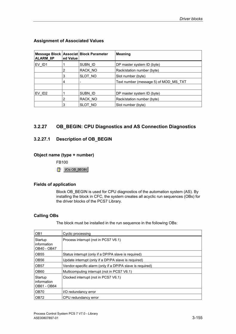
Driver blocks
Process Control System PCS 7 V7.0 - Library A5E00807897-01 3-155
Assignment of Associated Values
Message Block ALARM_8P
Associated Value
Block Parameter
Meaning
EV_ID1 1 SUBN_ID DP master system ID (byte) 2 RACK_NO Rack/station number (byte) 3 SLOT_NO Slot number (byte) 4 - Text number (message 5) of MOD_MS_TXT EV_ID2 1 SUBN_ID DP master system ID (byte) 2 RACK_NO Rack/station number (byte) 3 SLOT_NO Slot number (byte)
3.2.27 OB_BEGIN: CPU Diagnostics and AS Connection Diagnostics
3.2.27.1 Description of OB_BEGIN
Object name (type + number) FB100
Fields of application Block OB_BEGIN is used for CPU diagnostics of the automation system (AS). By installing the block in CFC, the system creates all acyclic run sequences (OBs) for the driver blocks of the PCS7 Library.
Calling OBs The block must be installed in the run sequence in the following OBs:
OB1 Cyclic processing
Startup information OB40 - OB47
Process interrupt (not in PCS7 V6.1)
OB55 Status interrupt (only if a DP/PA slave is required) OB56 Update interrupt (only if a DP/PA slave is required) OB57 Vendor-specific alarm (only if a DP/PA slave is required) OB60 Multicomputing interrupt (not in PCS7 V6.1) Startup information OB61 - OB64
Clocked interrupt (not in PCS7 V6.1)
OB70 I/O redundancy error OB72 CPU redundancy error

Driver blocks
Process Control System PCS 7 V7.0 - Library 3-156 A5E00807897-01
OB1 Cyclic processing
OB80 Timeout OB81 Power supply error OB82 Diagnostic interrupt OB83 Remove/insert interrupt OB84 CPU hardware error (only for CPU with this function) OB85 Program runtime error OB86 Rack failure OB88 Stop avoidance OB100 Restart: OB121 Programming error OB122 I/O access error
Use in CFC When the CFC function "Generate module drivers" is used, OB_BEGIN is installed automatically in the above-mentioned OBs.
Function and Operating Principle Block OB_BEGIN is used to report and display CPU events and statuses. It reads the start information of the tasks (OBs), diagnostic data of the I/O and enables the relevant blocks for processing on the basis of the start events.
OB_BEGIN reads the start information of SFC6 (RD_SINFO)/SFB54 (RALRM) to determine the OB in which it is currently running.
If this information is not available, the block reads the logical basic address from the start information and converts it into the geographic address, which is available at the relevant OBs of the output structure CPU_DIAG the lower-level blocks can also access. On the basis of the geographic address, OB_BEGIN enables the relevant SUBNET blocks for further evaluation of the start information.
In the case of a diagnostic event (OB82), the diagnostic data are simultaneously written to the CPU_DIAG.OB82 structure along with the start information, using SFB54. Diagnostic (alarm) information of a length exceeding 59 bytes must contain the call of the relevant driver blocks.
In H systems, the current status of the two H CPUs is read from the system status list 71 (SSL71) in OB100. A detailed description of the SSL71 is found in Reference Manual System Software for S7-300/400 System and Standard Functions. The statuses of SSL_71.MASTER_0/1 and SSL_71.CPU_ERR_0/1 are updated in OB72.
OB_BEGIN provides the diagnostic information of OB55, OB56 and OB57 in its output structure CPU_OB_5X to the downstream blocks.
The block reports diagnostic events of an OB88 block.
All OB88 events are incoming only. OB1 generates the relevant outgoing event message after a delay time of approximately 10 seconds in order to allow the reporting of a new event at OB88.
Driver blocks
Process Control System PCS 7 V7.0 - Library A5E00807897-01 3-157
Error handling Block OB_BEGIN evaluates error information from ALARM_8P and writes it to the relevant output parameters. You can find additional information in "Error Information of Output Parameter MSG_STAT".
If the block installation sequence OB_BEGIN, xx blocks, ..., OB_END is not observed in an OB, the message "OB_END installation error, no OB8x processing" is output and QERR = TRUE is set. In this case, the acyclic OBs do not evaluate the data and the downstream blocks will not be enabled.
Error information at output parameter STATUS of SFB54 (RALRM) is handled as follows
• The values 16#8096, 16#80A7,16#80C0, 16#80C2, 16#80C3 or 16#80C4 at STATUS[2] and STATUS[3] indicate temporary error events. STATUS[3] of the corresponding OB will be set in the structure CPU_DIAG = 16#C4. Downstream blocks can read access the diagnostic data asynchronously.
• After any other error event, SFC6 (RD_SINFO) reads the startup information once again and the message "OB_BEGIN diagnostic error RALRM STATUS = xxxxxxxx" will be output. OB1 generates the outgoing message after a delay time of approximately 10 seconds has expired.
Startup Characteristics Block OB_BEGIN initializes the messages of ALARM_8P. In H systems (CPU_DIAG.H_MODE = TRUE), the current status of the two H CPUs is determined by reading SSL71 (see "Function and Operating Principle").
Overload Behavior Outgoing messages of OB121, OB122 and OB88 are generated with a delay time of approximately 10 seconds. This on the one hand prevents blocking of the WinCC connection due to a high message transfer volume of these OBs, while OB events may be lost on the other.
Dynamic response n.a.

Driver blocks
Process Control System PCS 7 V7.0 - Library 3-158 A5E00807897-01
Message response ALARM_8P multiple instances are only called if OB_BEGIN is to output a message. It is only at this point that previously acknowledged messages are updated by the corresponding ALARM block. If the connection to WinCC is down, each ALARM_8P can hold up to two message statuses of its event ID
The CPU generates a programming error (OB121) only as incoming event. OB1 resets the relevant message to outgoing status. In order to avoid an excessive number of programming error messages, these will not be reported as outgoing until a delay time of 10 seconds has expired. The same applies to direct access errors (OB122) and OB88 events.
The block generates the following messages in the OBs listed below:
OB Start Event Message
OB1 Cyclic processing • Outgoing message with 10 s delay: Timeout (OB80) • Program runtime error (OB80) • Programming error (OB121) • Direct write access error (OB122) • Direct read access error (OB122) • Error code B#16#71: Nesting stack error (OB88) • Error code B#16#72: Master control relay stack error
(OB88) • Error code B#16#73: Synchronous error nesting depth
exceeded (OB88) • Error code B#16#74: U stack nesting depth exceeded in
priority class stack (OB88) • Error code B#16#75: B stack nesting depth exceeded in
priority class stack (OB88) • Error code B#16#76: Error when allocating local data
(OB88) • Error code B#16#78: Unknown opcode (OB88) • Error code B#16#7A: Code length error (OB88)
OB72 CPU redundancy loss CPU redundancy loss/return OB80 Timeout Incoming message on timeout:
• Cycle time exceeded • OB request: OBxx is busy • OB request: Overflow PRIOxx • TOD interrupt xx expired
OB84 CPU hardware error Incoming/outgoing interface error • Memory error detected and corrected by operating system. • Accumulation of detected and corrected memory errors • Error in PC operating system • Performance of an H-Sync coupling impaired • Multiple-bit memory error detected and corrected
OB85 Program runtime error Incoming message on program-execution error: • OBxx not loaded • Access-error error xx: ...

Driver blocks
Process Control System PCS 7 V7.0 - Library A5E00807897-01 3-159
OB Start Event Message
OB88 Stop avoidance Incoming message on OB88 events: • Error code B#16#71: Nested stack error • Error code B#16#72: Master control relay stack error • Error code B#16#73: Nesting depth exceeded on
synchronization errors • Error code B#16#74: U-stack nesting depth exceeded in the
priority class stack • Error code B#16#75: B-stack nesting depth exceeded in the
priority class stack • Error code B#16#76: Local data allocation error • Error code B#16#78: Unknown opcode • Error code B#16#7A: Code length error
OB100 Restart: Initialization of ALARM_8P OB121 Programming error Programming error incoming OB122 I/O access error • Direct read access, incoming
• Direct write access, incoming
Operating and Monitoring Note: If you have selected the "Enable operating and monitoring" option in the block object properties in the CFC, the variables transferred to the OS are identified under "I/Os of …" (OCM column, "+"). Default: option not selected.
If asset management is used in the project and the diagnostic screens have been generated, then the faceplate can be called via its icon.
• Asset Management block symbols
• Asset Management faceplates
Note: Online help and the "PCS 7 FACEPLATES" Manual are only available if the "PCS 7 FACEPLATES" software package is installed!
Additional information Additional information is available in the sections:
Message Texts and Associated Values of OB_BEGIN
Maintenance Status MS
Notes on Using Driver Blocks

Driver blocks
Process Control System PCS 7 V7.0 - Library 3-160 A5E00807897-01
3.2.27.2 I/Os of OB_BEGIN
The factory setting of the block representation in CFC is identified in the "I/O" column: I/O name in bold characters = I/O is visible; I/O name in standard characters = I/O is hidden.
You can find explanations of and information about the abbreviations used in "General Information About Block Description".
I/O (Parameter)
Meaning
Data Type
Default Type
OCM
CPU_DIAG CPU diagnostics (system structure) STRUCT O CPU_OB_4X Startup information OB40 - OB47 STRUCT O CPU_OB_5X Startup information OB55, OB56,
OB57 STRUCT O
CPU_OB_6X Startup information OB60 - OB64 STRUCT O CPUERR_0 1 = CPU error in rack 0 *) BOOL 0 O CPUERR_1 1 = CPU error in rack 1 *) BOOL 0 O EN_MSG 1 = Enable message BOOL 1 I EN_SUBx Enable SUBNET x (x = 0 - 14) BOOL 0 O EV_IDx Message number ALARM_8P_x
(x = 1 - 20) DWORD 0 I
MASTER_0 1 = Master CPU in rack 0 BOOL 0 O MASTER_1 1 = Master CPU in rack 1 BOOL 0 O MS Maintenance status DWORD 0 I + MSGSTATx STATUS output of ALARM_8P_x (x = 1 -4) WORD 0 O O_MS Maintenance status DWORD 0 O QERR 1 = Error processing busy BOOL 1 O QMSGERx Error output of ALARM_8P_x (x = 1 -4) BOOL 0 O SUB0IDxx DP master system 1 IDxx
(xx = 00 - 14) BYTE 255 I
SUB1IDxx DP master system 2 IDxx (xx = 00 - 14)
BYTE 255 I
SZL_71 System structure SSL71 STRUCT O
The structure of the CPU_DIAG is integrated as OUT in the OB_BEGIN block and in all other blocks with this I/O as IN_OUT (column: "Type").
*) You can find additional information in the CPU Manual.
Additional information Additional information is available in the sections:
Message Texts and Associated Values of OB_BEGIN
Maintenance Status MS
Driver blocks
Process Control System PCS 7 V7.0 - Library A5E00807897-01 3-161
3.2.27.3 Message Texts and Associated Values of OB_BEGIN
Assignment of Message Text and Message Class Process-Control Messages of ALARM_8P Are Assigned at EV_ID1 as Follows:
Message Block ALARM_8P
Message No.
OB No.
Default Message Text
Message Class
EV_ID1 1 OB85 OB @7%d@ not loaded S 2 no
message 3 OB84 Interface error S 4 - Faulty installation OB_BEGIN/OB_END:
No OB@10%d@ processing of the stack @9%d@
S
5 OB85 Access error @7%d@: @10%2s@@8%d@/@9%d@
S
6 OB122 I/O read access error: @4%2s@@5%d@ Address: @6%d@
S
7 OB122 I/O write access error: @4%2s@@5%d@ Address: @6%d@
S
8 no message
Messages 1, 4, 5, 6 and 7 are only incoming events. They are reset to "outgoing" status during the normal run sequence (OB1).
Associated Values of ALARM_8P With EV_ID1 Control system messages are generated with six associated values at EV_ID1 via ALARM_8P. The table below shows how the associated values are assigned to the block parameters.
Message Block ALARM_8P
Associated Value
Block Parameter
Data Type
EV_ID1 1 OB86 Subnet_ID BYTE 2 OB86 RACK_NO BYTE 3 CPU rack number BYTE 4 OB122_BLK_TYP WORD 5 OB122_BLK_NUM WORD 6 OB122_MEM_ADDR WORD 7 OB85_Supplementary_Info 1 WORD 8 OB85_HW_ supplementary info
2_3 WORD
9 OB85_LW_ supplementary info 2_3
WORD
10 OB85_DKZ2_3 WORD

Driver blocks
Process Control System PCS 7 V7.0 - Library 3-162 A5E00807897-01
Process-Control Messages of ALARM_8P Are Assigned at EV_ID2 as Follows:
Message Block ALARM_8P
Message No.
OB No.
Default Message Text
Message Class
EV_ID2 1 OB80 Net consumption of all OBs exceeds max. limit
M
2 OB80 Emergency operation, cyclic OBs are supported
S
3 OB80 Priorities of the cyclic OBs not PCS 7 conform
M
4 no message 5 no message 6 no message 7 OB121 Programming error
@1%d@: @2%2s@@5%d@ /@6%d@/@4%d@/@3%d@
S
8 no message
Messages 1 to 3 are generated in the CPU_RT and forwarded to the OB_BEGIN.
Message 7 is only an upcoming event. They are reset to "outgoing" status during the normal run sequence (OB1)
Message 7 is to be interpreted as follows, in accordance with the error code number before the colon:
OB121_BLK_TYP/OB121_BLK_NUM/OB121_PRG_ADDR/OB121_FLT_REG/OB121_RESERVED_1.
You can find a description in Reference Manual System Software for S7-300/400 System and Standard Functions. Example: 10.05.00 10:30:45 Programming error 35: FB44/1234/5/9

Driver blocks
Process Control System PCS 7 V7.0 - Library A5E00807897-01 3-163
Associated Values of ALARM_8P With EV_ID2 Control system messages are generated with six associated values at EV_ID2 via ALARM_8P. The table below shows how the associated values are assigned to the block parameters.
Message Block ALARM_8P
Associated Value
Block Parameter
Data Type
EV_ID2 1 OB121_SW_FLT BYTE 2 OB121_BLK_TYP WORD 3 OB121_RESERVED_1 BYTE 4 OB121_FLT_REG WORD 5 OB121_BLK_NUM WORD 6 OB121_PRG_ADDR WORD 7 OB82 SUBNET_ID BYTE 8 OB82 RACK_NO BYTE 9 OB82 SLOT_NO BYTE
Process-Control Messages of ALARM_8P Are Assigned at EV_ID3 as Follows:
Message Block ALARM_8P
Message No.
OB No.
Default Message Text
Message Class
EV_ID3 1 OB80 Cycle time exceeded: @1%d@ms OB@2%d@ S 2 OB80 OB request: OB@2%d@ still busy F 3 OB80 TOD interrupt OB @1%d@ expired (TOD jump) S 4 OB80 TOD interrupt OB @1%d@ expired (Stop/Run) S 5 OB80 OB request: Overflow PRIO @3%d S 6 OB80 Clocked interrupt timeout: OB@2%d@ PRIO
@3%d@ S
7 OB80 Interrupt lost: OB@2%d@ PRIO @3%d@ S 8 OB80 CiR synchronization time: @1%d@ ms S
Message 2 is generated in the CPU_RT and forwarded to the OB_BEGIN.
Messages 1 to 8 are only incoming events. They are reset to "outgoing" status during the normal run sequence (OB1).
Driver blocks
Process Control System PCS 7 V7.0 - Library 3-164 A5E00807897-01
Associated Values of ALARM_8P With EV_ID3 Control system messages are generated with seven associated values at EV_ID3 via ALARM_8P. The table below shows how the associated values are assigned to the block parameters.
Message Block ALARM_8P
Associated Value
Block Parameter
Data Type
EV_ID3 1 OB80_Supplementary_Info 1 WORD 2 OB80_1. Byte supplementary info
2_3 BYTE
3 OB80_2. Byte supplementary info 2_3
BYTE
Process-Control Messages for ALARM_8P Are Assigned at EV_ID4 as Follows:
Message Block ALARM_8P
Message No.
Default Message Text
Message Class
EV_ID_4 1 OB88(@6W%t#OB_BEGIN_TXT@): OB@1%d@ PRIO@2%d@ @3%2s@@4%d@ /@5%d@
S
2 OB_BEGIN: Diagnostics error RALRM STATUS = @7%8X@
S
3 no message 4 no message 5 no message 6 no message 7 no message 8 no message
Associated Values of ALARM_8P With EV_ID4 Message Block ALARM_8P
Associated Value
Meaning
EV_ID20 1 Triggering OB (M_OB88.FLT_OB) 2 Priority class (M_OB88.FLT_OB_PRIO) 3 Block type (M_OB88.BLK_TYP) 4 Block number (M_OB88.FLT_NUM) 5 Error triggering MC7 instruction
Relative address (M_OB88.FLT_ADDR) 6 Error ID in OB_BEGIN_TXT (M_OB88.T_OB88) 7 Status RALRM
You can find the message texts and their text numbers in "Text Library for OB_BEGIN".

Driver blocks
Process Control System PCS 7 V7.0 - Library A5E00807897-01 3-165
3.2.28 OB_DIAG: OB Diagnostics to Avoid CPU Stop
3.2.28.1 Description of OB_DIAG
Object name (type + number) FB124
Fields of application The block OB_DIAG is an interface block for linking DP V0 slaves, that are not supported by the PCS 7 driver blocks. The block is used to avoid a CPU stop if there is an defective DP slave. It detects a DP slave failure. It indicates the preferred channel of the active DP slave in an H system.
Calling OBs The block must be installed in the run sequence of the following OBs (carried out automatically in CFC):
OB1 Cyclic program
OB70 I/O redundancy error OB72 CPU redundancy error OB82 Diagnostic interrupt OB83 Removal/insertion alarm OB85 Program runtime error OB86 Rack failure OB100 Restart (warm start)
Use in CFC When the CFC function "Generate module drivers" is used, the following occurs automatically:
• The OB_DIAG block is installed downstream from the SUBNET block.
• The RACK_NO, DADDR, SUBN1_ID, SUBN2_ID, and SUBN_TYP inputs are configured.
• The EN input is interconnected with the output of an AND block, whose inputs will be interconnected with output EN_SUBx (x = DP master system ID) of the OB_BEGIN block and with output EN_Rxxx (xxx = rack/station number) of the SUBNET block.
Driver blocks
Process Control System PCS 7 V7.0 - Library 3-166 A5E00807897-01
• The CPU_DIAG OUT structure of the OB_BEGIN block and SUB_DIAG of the SUBNET block are interconnected with the INOUT structures of the same name of block OB_DIAG.
Function and Operating Principle The block counts the number of calls of an acyclic OB of a block instance before an OB1 can be executed.
The OB_DIAG indicates higher-level errors of the CPU, DP master/slave (QRACKF, SUBN1ERR, SUBN2ERR). It determines the preferred channel of active DP slaves (SUBN1ACT, SUBN2ACT). The group error message QRACKF indicates failure of the DP master or slave. Loss of redundancy at active slaves is indicate at one of the output parameters SUBN1ERR or SUBN2ERR = FALSE.
Start and diagnostic information is read from the CPU_DIAG structure, which is interconnected with the CPU_DIAG structure of the OB_BEGIN block.
The block evaluates error events and uses the diagnostic address DADDR of the DP slave to determine the currently active preferred channel (SUBN1ACT, SUBN2ACT) of redundant PROFIBUS DP interfaces.
If the DP slave is connected to DP master system that is operated in DP V1 mode, then V1 MODE = TRUE is set.
Overload Behavior Block OB_DIAG1 counts the frequency of the calls of the acyclic OB82, and OB86 blocks (not in the case of DP master-system failure, see SUBNET block). If the counter DIAG82_CNT is > 5 or if DIAG86_CNT is > 5, then EN_F = FALSE is set (disable function block). The counters are reset in OB1. In all other OBs the output EN_F = TRUE (enable function block) will be set.
If OB82 or OB86 fail, then OB_BEGIN reports in this failure in OB1, OB82 or OB86, including the geographical address of the DP slave.
Due to the disable OB82 or OB86 is not analyzed if there is overload. The outputs cannot correspond to the current slave status. After a wait time of approximately 1 minute in the case of OB86 failure the status of the DP slave is checked and the variable EN_86DIAG is set to TRUE. The DP slave status update may require several cycles.
If an OB82 failure is present, then the variable EN_82DIAG is set to TRUE. The interconnected DP slave block can then fetch the current diagnostic data of the slave.

Driver blocks
Process Control System PCS 7 V7.0 - Library A5E00807897-01 3-167
Redundancy The block supports redundant DP master systems in an H system (only distributed I/Os). If you want to use this function, you must configure the SUBN1_ID (connection to CPU 0) and SUBN2_ID (connection to CPU 1) inputs of the OB_DIAG1 block with the numbers of the redundant DP master systems. If the DP master systems are not redundant, the value 16#FF (default) must be set at the remaining input.
Startup Characteristics Availability of the slave is verified. In H systems the preferred channel of the slave is determined (active slaves only).
Error handling No plausibility checks are implemented as regards the input parameter.
Message response See OB_BEGIN block
Operating and Monitoring The block has no faceplate.
Note: If you have selected the "Enable operating and monitoring" option in the block object properties in the CFC, the variables transferred to the OS are identified under "I/Os of …" (OCM column, "+"). Default: option not selected.
Additional information Additional information is available in the section:
Notes on Using Driver Blocks
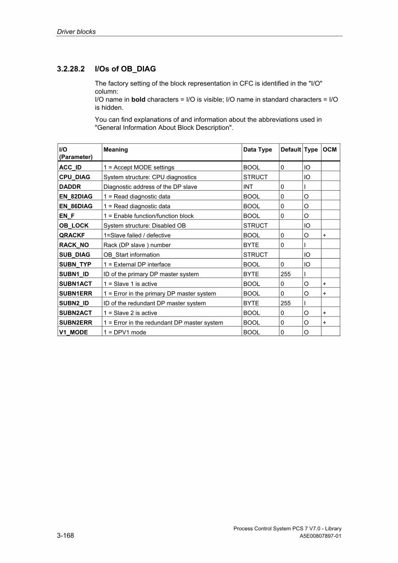
Driver blocks
Process Control System PCS 7 V7.0 - Library 3-168 A5E00807897-01
3.2.28.2 I/Os of OB_DIAG
The factory setting of the block representation in CFC is identified in the "I/O" column: I/O name in bold characters = I/O is visible; I/O name in standard characters = I/O is hidden.
You can find explanations of and information about the abbreviations used in "General Information About Block Description".
I/O (Parameter)
Meaning
Data Type
Default Type
OCM
ACC_ID 1 = Accept MODE settings BOOL 0 IO CPU_DIAG System structure: CPU diagnostics STRUCT IO DADDR Diagnostic address of the DP slave INT 0 I EN_82DIAG 1 = Read diagnostic data BOOL 0 O EN_86DIAG 1 = Read diagnostic data BOOL 0 O EN_F 1 = Enable function/function block BOOL 0 O OB_LOCK System structure: Disabled OB STRUCT IO QRACKF 1=Slave failed / defective BOOL 0 O + RACK_NO Rack (DP slave ) number BYTE 0 I SUB_DIAG OB_Start information STRUCT IO SUBN_TYP 1 = External DP interface BOOL 0 IO SUBN1_ID ID of the primary DP master system BYTE 255 I SUBN1ACT 1 = Slave 1 is active BOOL 0 O + SUBN1ERR 1 = Error in the primary DP master system BOOL 0 O + SUBN2_ID ID of the redundant DP master system BYTE 255 I SUBN2ACT 1 = Slave 2 is active BOOL 0 O + SUBN2ERR 1 = Error in the redundant DP master system BOOL 0 O + V1_MODE 1 = DPV1 mode BOOL 0 O
Driver blocks
Process Control System PCS 7 V7.0 - Library A5E00807897-01 3-169
3.2.29 OB_DIAG1: OB Diagnostics for Avoiding Stops in DP V1-Master Systems
3.2.29.1 Description of OB_DIAG1
Object name (type + number) FB118
Fields of application Block OB_DIAG1 monitors failure and return of DP or PA slaves (referred to as "slaves" hereafter). The slaves can be connected to a DP V0 or V1 DP master system, or to a DPV1 DP/PA Link (Y-Link). OB_DIAG1 locks further evaluation if a slave is defective (frequent producer) in order to avoid a CPU stop. It indicates the preferred channel of the active slave in an H system. The indicated preferred channel 1 (SUBN1ACT ) is always set TRUE if the active slave operates downstream from a DP/PA Link (Y-Link).
Calling OBs The block must be installed in the run sequence in the following OBs:
OB1 Cyclic program
OB70 I/O redundancy error OB72 CPU redundancy error OB82 Diagnostic interrupt OB83 Removal/insertion alarm OB85 Program runtime error OB86 Rack failure OB100 Restart (warm start) OB55 Status interrupt (only as required) OB56 Update interrupt (only as required) OB57 Manufacturer-specific alarms (only as required)
The driver generator only installs the block into OB55, OB56 and OB57 if diagnostics messages are to be expected from these locations; i.e., the OB5x are not entered in this block’s task list.

Driver blocks
Process Control System PCS 7 V7.0 - Library 3-170 A5E00807897-01
Use in CFC When the CFC function "Generate module drivers" is used, the following occurs automatically:
• Block OB_DIAG1 is installed downstream of the SUBNET/DPAY_V1 block (when used downstream of a DP/PA or Y link).
• The RACK_NO, LADDR, DADDR, EN_MSG_D, SUBN1_ID, SUBN2_ID, and SUBN_TYP inputs are configured.
• The EN input is interconnected with the output of an AND block, whose inputs will be interconnected with output EN_SUBx (x = DP master system ID) of the OB_BEGIN block and with output EN_Rxxx (xxx = rack/station number) of the SUBNET block.
• The CPU_DIAG OUT structure of the OB_BEGIN block and SUB_DIAG of the SUBNET block are interconnected with the INOUT structures of the same name of block OB_DIAG.
• RAC_DIAG is interconnected with its internal OUT structure RAC_DIAG when used in a DP master system.
• RAC_DIAG_I is interconnected with the OUT structure RAC_DIAG of the DPAY_V1 block when used downstream of a Y link
Function and Operating Principle The block input DPA_LINK receives information on the operational status of the slave, i.e. whether it is operated on a DP master system (DPA_LINK = FALSE) or downstream from a DP/PA Link (Y-Link). If the slave is connected to a DP master system, a failure is reported in OB86 and if and if connected downstream from a DP/PA Link (Y-Link), this is reported in OB83.
The block counts the number of calls of an acyclic OB of a block instance before an OB1 can be executed.
OB_DIAG1 indicates higher-level errors of the CPU, DP master/slave (QRACKF, SUBN1ERR, SUBN2ERR). It determines the preferred channel of active DP slaves (SUBN1ACT, SUBN2ACT). The group error message QRACKF indicates failure of the DP master or slave. Loss of redundancy at active slaves is indicate at one of the output parameters SUBN1ERR or SUBN2ERR = FALSE.
Start and diagnostic information is read from the CPU_DIAG structure, which is interconnected with the CPU_DIAG structure of the OB_BEGIN block.
The block evaluates error events and uses the diagnostic address DADDR of the slave (only at the DP master system) to determine the currently active preferred channel (SUBN1ACT, SUBN2ACT) of redundant PROFIBUS DP interfaces.
Slaves downstream from a DP/PA Link (Y-Link) are not always active. The diagnostic address DADDR is in this case the diagnostic address of the link. The active preferred channel (SUBN1ACT, SUBN2ACT) is displayed here by the DP/PA Link (Y-Link).

Driver blocks
Process Control System PCS 7 V7.0 - Library A5E00807897-01 3-171
The DP master systems or DP/PA Links (Y-Link) must be operated in DPV1 mode (V1-MODE = TRUE).
Failure and return of a slave are reported via ALARM_8P. The message function can be disabled with EN_MSG = FALSE.
The "Device failure" message can be disabled with EM_MSG_D = FALSE (see "Message response").
Overload Behavior Block OB_DIAG1 counts the frequency of the calls of the acyclic OB55, OB56, OB57, OB82, and OB86 blocks (not in the case of DP master-system failure, see SUBNET block). If the block is installed downstream of a DP/PA or Y l-Link, the calls will be counted in OB83, rather than in OB86. The following section deals only with OB86. Each OB is assigned a counter that is checked for the condition > 5. If this condition is satisfied, the block sets EN_F = FALSE (disable function block). The counters are reset in OB1. In all other OBs the output EN_F = TRUE (enable function block) will be set.
OB_DIAG1 reports failure of the blocks mentioned above in OB1, OB82 or OB86, including the geographical address of the slave.
The event is not evaluated in the downstream blocks, due to the locking of OB55, OB56, OB57 or OB82 on overload. The outputs cannot correspond to the current slave status. After a waiting time of approx. 1 minute, the slave status is verified and the outputs are updated after an OB86 failure. The slave status update may require several cycles.
The variable EN_DIAG is set TRUE after approx. 1 minute if an OB82 has failed. The interconnected DP slave block can then fetch the current diagnostic data of the slave and update its own database. The same goes for OB55, OB56 or OB57.
The "outgoing" message of the failure is generated when the OB lock is canceled and either a new event has occurred for this OB or the wait time has expired.
Redundancy The block supports redundant DP master systems in an H system (only distributed I/Os). If you want to use this function, you must configure the SUBN1_ID (connection to CPU 0) and SUBN2_ID (connection to CPU 1) inputs of the OB_DIAG1 block with the numbers of the redundant DP master systems. If the DP master systems are not redundant, the value 16#FF (default) must be set at the remaining input.
Driver blocks
Process Control System PCS 7 V7.0 - Library 3-172 A5E00807897-01
Startup Characteristics Availability of the slave is verified. In H systems the preferred channel of the slave is determined (active slaves only).
Error handling The block evaluates error information of ALARM_8P and writes it to the relevant output parameter. You can find additional information in "Error Information of Output Parameter MSG_STAT".
Message response The multiple instance ALARM_8P are only called if a message is to be output by this instance. It is only at this point that previously acknowledged messages are updated by the corresponding ALARM block. If the connection to WinCC is down, each ALARM_8P instance can hold up to two message statuses of its event ID (usually two messages maximum). The block generates the messages listed below:
OB No. Start Event Message
1 Cyclic processing Call of ALARM_8P due to incomplete transfer or unacknowledged message
72 CPU redundancy loss If no redundant diagnostic repeater is connected to the CPU, message "Slave" failure/return
70 Redundancy loss
If no redundant slave is connected to this DP master system, message "Device" failure/return, otherwise message "Slave" redundancy loss/return
83 Removal/insertion Message "Slave" failure/return 86 Rack failure Message "Slave" failure/return 100 Restart: Initialization of ALARM_8P
If the diagnostic blocks (e.g., MOD_PAL0) of a device also report the failure of a device, the "Device failure" message can be disabled with EN_MSG_D = FALSE (this is automatically performed by the driver generator).
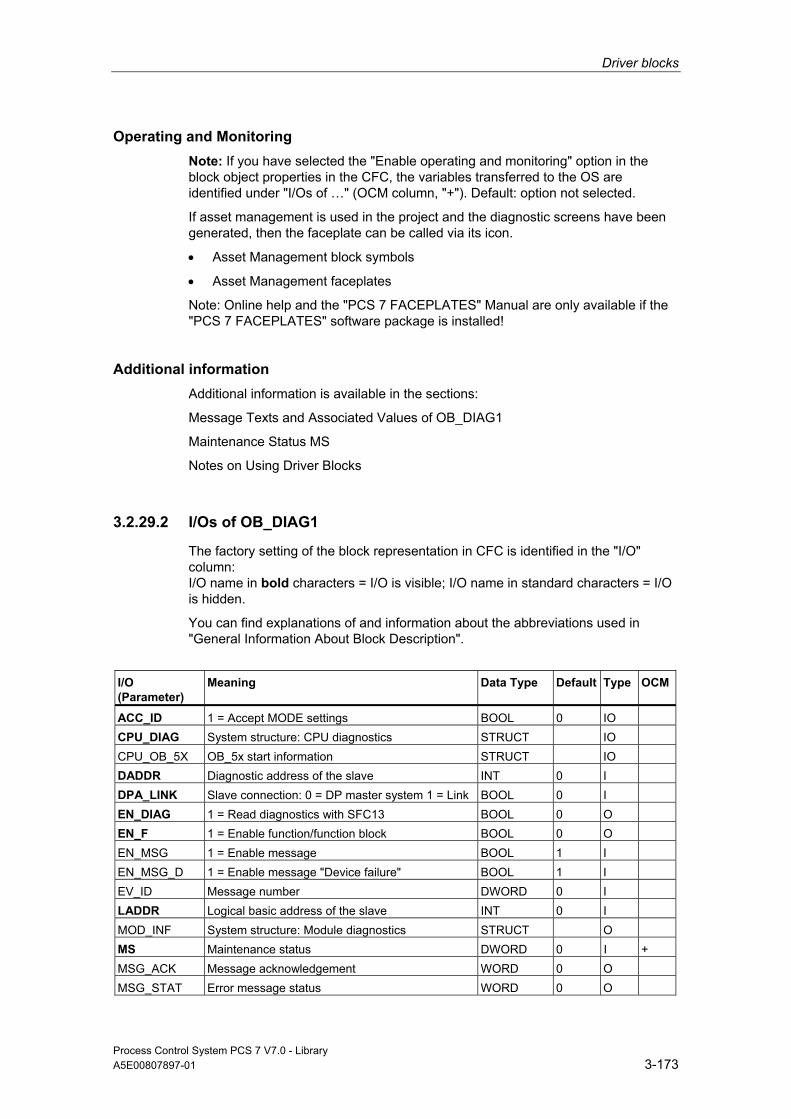
Driver blocks
Process Control System PCS 7 V7.0 - Library A5E00807897-01 3-173
Operating and Monitoring Note: If you have selected the "Enable operating and monitoring" option in the block object properties in the CFC, the variables transferred to the OS are identified under "I/Os of …" (OCM column, "+"). Default: option not selected.
If asset management is used in the project and the diagnostic screens have been generated, then the faceplate can be called via its icon.
• Asset Management block symbols
• Asset Management faceplates
Note: Online help and the "PCS 7 FACEPLATES" Manual are only available if the "PCS 7 FACEPLATES" software package is installed!
Additional information Additional information is available in the sections:
Message Texts and Associated Values of OB_DIAG1
Maintenance Status MS
Notes on Using Driver Blocks
3.2.29.2 I/Os of OB_DIAG1
The factory setting of the block representation in CFC is identified in the "I/O" column: I/O name in bold characters = I/O is visible; I/O name in standard characters = I/O is hidden.
You can find explanations of and information about the abbreviations used in "General Information About Block Description".
I/O (Parameter)
Meaning
Data Type
Default Type
OCM
ACC_ID 1 = Accept MODE settings BOOL 0 IO CPU_DIAG System structure: CPU diagnostics STRUCT IO CPU_OB_5X OB_5x start information STRUCT IO DADDR Diagnostic address of the slave INT 0 I DPA_LINK Slave connection: 0 = DP master system 1 = Link BOOL 0 I EN_DIAG 1 = Read diagnostics with SFC13 BOOL 0 O EN_F 1 = Enable function/function block BOOL 0 O EN_MSG 1 = Enable message BOOL 1 I EN_MSG_D 1 = Enable message "Device failure" BOOL 1 I EV_ID Message number DWORD 0 I LADDR Logical basic address of the slave INT 0 I MOD_INF System structure: Module diagnostics STRUCT O MS Maintenance status DWORD 0 I + MSG_ACK Message acknowledgement WORD 0 O MSG_STAT Error message status WORD 0 O

Driver blocks
Process Control System PCS 7 V7.0 - Library 3-174 A5E00807897-01
I/O (Parameter)
Meaning
Data Type
Default Type
OCM
O_MS Maintenance status DWORD 0 O PADP_ADR Address of the PA/DP slave BYTE 255 I QRACKF 1 = Slave failure/faulty BOOL 0 O RAC_DIAG System structure: RACK diagnostics STRUCT O RAC_DIAG_I System structure: RACK diagnostics STRUCT IO RACK_NO Rack number BYTE 0 I SLOT_NO Slot number 0 of the slave at the DP/PA Link BYTE 255 I SUB_DIAG System structure: SUBNET diagnostics STRUCT IO SUBN_TYP 1 = External DP interface BOOL 0 I SUBN1_ID ID of the primary DP master system BYTE 255 I SUBN1ACT 1 = Slave 1 is active BOOL 0 O SUBN1ERR 1 = Error in the primary DP master system BOOL 0 O SUBN2_ID ID of the redundant DP master system BYTE 255 I SUBN2ACT 1 = Slave 2 is active BOOL 0 O SUBN2ERR 1 = Error in the redundant DP master system BOOL 0 O V1_MODE 1 = DPV1 mode of the DP master system BOOL 0 O
Additional information Additional information is available in the sections:
Message Texts and Associated Values of OB_DIAG1
Maintenance Status MS
3.2.29.3 Message Texts and Associated Values of OB_DIAG1
Assignment of Message Text and Message Class
Message No. Default Message Text Message Class
1 DP slave @1%d@/ @2%d@: Redundancy loss S 2 DP slave @1%d@/ @2%d@: Failure S 3 DP slave @1%d@/ @2%d@/@3%d@ : Repeated failure S 4 Device @1%d@/ @2%d@/@3%d@: recursive Alarm (OB82) S 5 Device @1%d@/ @2%d@/@3%d@: recursive Alarm (OB55) S 6 Device @1%d@/ @2%d@/@3%d@: recursive Alarm (OB56) S 7 Device @1%d@/ @2%d@/@3%d@: recursive Alarm (OB57) S 8 Device @1%d@/ @2%d@/@3%d@: Failure S

Driver blocks
Process Control System PCS 7 V7.0 - Library A5E00807897-01 3-175
Assignment of Associated Values Associated Value
Block Parameter
1 DP master system ID (SUBN_ID) 2 Rack/station number (RACK_NO) 3 Slot number (SLOT_NO)
3.2.30 OB_END: Reset the OB_BEGIN Stack Pointer
3.2.30.1 Description of OB_END
Object name (type + number) FC280
Fields of application The OB_END block is used to reset the stack pointer of OB_BEGIN.
Calling OBs The OB_END block is the final entry in an OB that contains an OB_BEGIN block. OB_END must not be installed in OBs that do not contain an OB_BEGIN block.
OB1 Cyclic processing
OB55 Status interrupt (only as required) OB56 Update interrupt (only as required) OB57 Manufacturer-specific alarms (only as required) OB70 I/O redundancy error OB72 CPU redundancy error OB80 Timeout OB81 Power supply error OB82 Diagnostic interrupt OB83 Remove/insert interrupt OB84 CPU hardware error (only for CPU with this function) OB85 Program runtime error OB86 Rack failure OB88 Stop avoidance
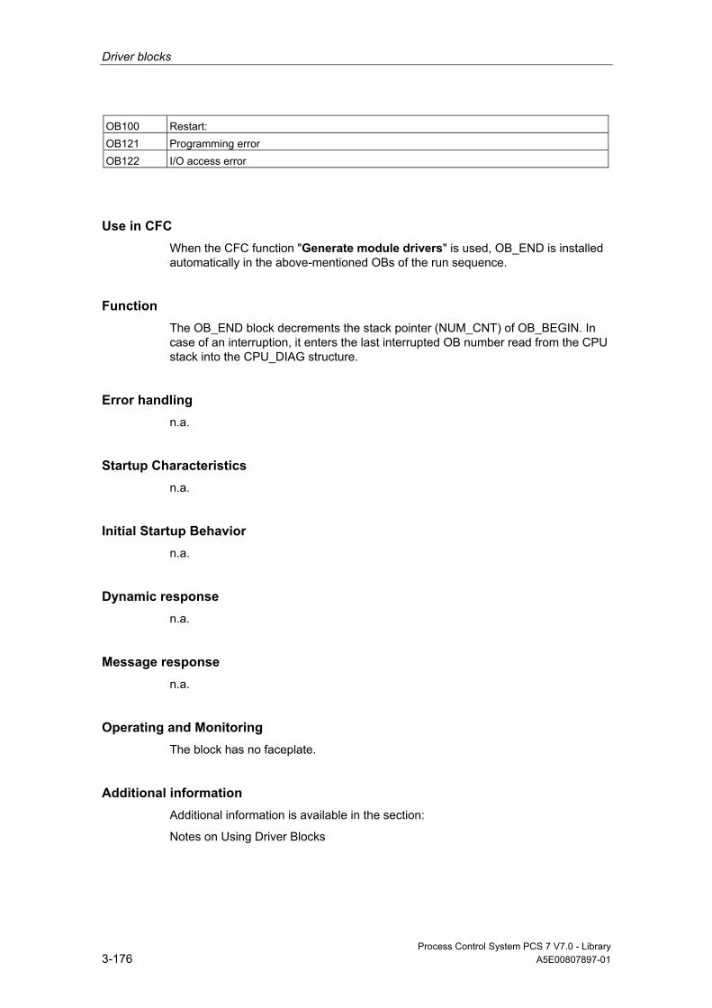
Driver blocks
Process Control System PCS 7 V7.0 - Library 3-176 A5E00807897-01
OB100 Restart: OB121 Programming error OB122 I/O access error
Use in CFC When the CFC function "Generate module drivers" is used, OB_END is installed automatically in the above-mentioned OBs of the run sequence.
Function The OB_END block decrements the stack pointer (NUM_CNT) of OB_BEGIN. In case of an interruption, it enters the last interrupted OB number read from the CPU stack into the CPU_DIAG structure.
Error handling n.a.
Startup Characteristics n.a.
Initial Startup Behavior n.a.
Dynamic response n.a.
Message response n.a.
Operating and Monitoring The block has no faceplate.
Additional information Additional information is available in the section:
Notes on Using Driver Blocks

Driver blocks
Process Control System PCS 7 V7.0 - Library A5E00807897-01 3-177
3.2.30.2 I/Os of OB_END
The factory setting of the block representation in CFC is identified in the "I/O" column: I/O name in bold characters = I/O is visible; I/O name in standard characters = I/O is hidden.
You can find explanations of and information about the abbreviations used in "General Information About Block Description".
I/O (Parameter)
Meaning
Data Type
Type
CPU_DIAG CPU diagnostics (system structure) STRUCT IO
3.2.31 OR_M_16: OR Value status of 2 Redundant Signal Modules, Maximum 16 Channels, Module Granular
3.2.31.1 Description of OR_M_16
Object name (type + number) FB81
Fields of application Block OR_M_16 is used to form a module-granular value status based on two redundant signal modules.
Calling OBs The block must be installed in OB100 and in the fastest OB before the channel block CH_x that is interconnected with OR_M_16.
Use in CFC When the CFC function "Generate module drivers" is used, the following occurs automatically:
• Block OR_M_16 is installed upstream of its interconnected CH_x channel blocks in their OB.
• MODE1_x inputs are interconnected with the OMODE_xx outputs of the MOD_x block in the primary module.

Driver blocks
Process Control System PCS 7 V7.0 - Library 3-178 A5E00807897-01
• MODE2_x inputs are interconnected with the OMODE_xx outputs of the MOD_x block in the redundant module.
• The MOD_INF1 input structure is interconnected with the MOD_INF output structure of the MOD_x block in the primary module.
• The MOD_INF2 input structure is interconnected with the MOD_INF output structure of the MOD_x block in the redundant module.
• The ACTIV_H and ACTIV_L inputs are interconnected with the outputs of the same name of the RED_STATUS block in the redundant module.
• The OMODE_xx outputs are interconnected with the relevant CH_x channel blocks.
• The OUT structure CPU_DIAG of the OB_BEGIN block is interconnected with the INOUT structures of the same name of block OR_M_16.
• The inputs RACKF1 and RACKF2 are interconnected with the outputs QRACKF1 and QRACKF2 of MOD_D1.
Function and Operating Principle The value statuses of a signal module and of a redundant signal module are ORed by the OR_M_16 block. Signal modules disabled by the system are considered invalid. For redundant digital input modules, when a signal discrepancy occurs, no module is set to passive after expiration of the discrepancy time. The module whose signal does not change is thereafter set to passive. The events "expiration of the discrepancy time", "redundancy loss" and "failure of the redundant I/O" are reported by ALARM_8P. The message function can be disabled.
When module signals are processed in different OB3x, it may happen under rare circumstances that a faulty signal value is processed in one cycle by one of the channel blocks configured to process the module signals after a process-control disturbance has occurred at the module. This can be avoided by processing all channel blocks of a module in the OB3x that also processes the process image partition assigned to this module.
For all OR Blocks:
For a passivated block or passivated channel when setting the DEPASS input the depassivation can be triggered. For this the function RED_DEPA FC451 is called internally.
Redundancy Redundancy of the modules in an H system is monitored in a higher priority RED_STATUS block.
Error handling The input parameters are not validated.
Driver blocks
Process Control System PCS 7 V7.0 - Library A5E00807897-01 3-179
Startup Characteristics The outputs OMODE_xx are updated when the "Startup" bit is set.
ALARM_8P will be initialized.
Message response OR_M_16 uses ALARM_8P for reporting. The message function can be disabled by setting EN_MSG = FALSE.
Operating and Monitoring Note: If you have selected the "Enable operating and monitoring" option in the block object properties in the CFC, the variables transferred to the OS are identified under "I/Os of …" (OCM column, "+"). Default: option not selected.
If asset management is used in the project and the diagnostic screens have been generated, then the faceplate can be called via its icon.
• Asset Management block symbols
• Asset Management faceplates
Note: Online help and the "PCS 7 FACEPLATES" Manual are only available if the "PCS 7 FACEPLATES" software package is installed!
Additional informationAdditional information is available in the sections:
Message Texts and Associated Values of OR_M_16/OR_M_32
Maintenance Status MS
Notes on Using Driver Blocks

Driver blocks
Process Control System PCS 7 V7.0 - Library 3-180 A5E00807897-01
3.2.31.2 I/Os of OR_M_16/OR_M_32
The OR_M_16 and OR_M_32 block I/Os are identical, save for the number of MODE_xx and OMODE_xx.
The factory setting of the block display in CFC is identified in the "I/O" column: I/O name in bold characters = I/O is visible; I/O name in standard characters = I/O is hidden.
You can find explanations of and information about the abbreviations used in "General Information About Block Description".
I/O (Parameter)
Meaning
Data Type
Default Type
OCM
ACTIV_H 1 = Module with high priority address is active
BOOL 0 I
ACTIV_L 1 = Module with low priority address is active
BOOL 0 I
CH_EXIST Channel exists DWORD 0 O + CH_OK Channel OK DWORD 0 O + CPU_DIAG CPU diagnostics (system structure) STRUCT IO DEPASS 1 = Depassivation BOOL 0 I + DEPASS_EN 1 = Enable depassivation BOOL 1 I EN_MSG 1 = Enable message BOOL 1 I EV_ID Message number DWORD 0 I EXT_INFO Supplemental info of RED_OUT INT 0 O MOD_INF1 Module parameters module 1 STRUCT IO MOD_INF2 Module parameters module 2 STRUCT IO MOD_STAT Module status word from RED_STATUS WORD 0 I MODE1_xx Channel mode (xx = 00 – 15/00 – 31) at
the primary module DWORD 0 I
MODE2_xx Channel mode (xx = 00 – 15/00 – 31) at the redundant module
DWORD 0 I
MS Maintenance status DWORD 0 I + MSG_ACK Message acknowledgement WORD 0 O MSG_STAT Error message status WORD 0 O O_MS Maintenance status DWORD 0 O OMODE_xx Channel mode (xx = 00 – 15/00 – 31) DWORD 0 O QDISCREP 1 = Discrepancy time expired BOOL 0 O QERR 1 = Program runtime error
(cannot determine module status) BOOL 1 O
QMODF1 1 = Error at module 1 BOOL 0 O QMODF2 1 = Error at module 2 BOOL 0 O QPASS 1 = at least one module is passivated. BOOL 0 O + RACKF1 1 = Error at rack 1 BOOL 0 I RACKF2 1 = Error at rack 2 BOOL 0 I RED_STAT Value returned by the RED_STATUS
block INT 0 I

Driver blocks
Process Control System PCS 7 V7.0 - Library A5E00807897-01 3-181
I/O (Parameter)
Meaning
Data Type
Default Type
OCM
RETURN_ VAL
Error information from RED_OUT INT 0 O
Additional information Additional information is available in the sections:
Message Texts and Associated Values of OR_M_16/OR_M_32
Maintenance Status MS
3.2.31.3 Message Texts and Associated Values of OR_M_16/OR_M_32
Assignment of Message Text and Message Class Message Block ALARM_8P
Message No.
Default Message Text
Message Class
EV_ID 1 Module @1%d@/ @2%d@/ @3%d@: Failure redundant pair
S
2 Module @1%d@/ @2%d@/ @3%d@: Redundancy loss
F
3 Module @1%d@/ @2%d@/ @3%d@: Cannot determine module status
S
4 Module @1%d@/ @2%d@/ @3%d@: Discrepancy time expired
S
Assignment of Associated Values
Message Block ALARM_8P
Associated Value
Block Parameter
Meaning
EV_ID 1 SUBN_ID DP master system ID (byte) 2 RACK_NO Rack/station number (byte) 3 SLOT_NO Slot number (byte)
On redundancy loss the geographical address of the failed module is entered dynamically.
The message text always shows the geographical address of the primary module when both modules have failed.

Driver blocks
Process Control System PCS 7 V7.0 - Library 3-182 A5E00807897-01
3.2.32 OR_M_16C: OR Value status of 2 Redundant Signal Modules, Maximum 16 Channels, Channel Granular
3.2.32.1 Description of OR_M_16
Object name (type + number) FB84
Block OR_M_16C corresponds to OR_M_8C, however with 16 channels instead of 8.
Additional Information Additional information is available in the sections:
Message texts and associated values of OR_M_16C
Maintenance Status MS
Notes on Using Driver Blocks
3.2.32.2 I/Os of OR_M_8C / OR_M_16C
The OR_M_8C and OR_M_16C block I/Os are identical, with the exception of the number of MODE1_xx and MODE2_xx and OMODE_xx.
The factory setting of the block display in CFC is identified in the "I/O" column: I/O name in bold characters = I/O is visible; I/O name in standard characters = I/O is hidden.
You can find explanations of and information about the abbreviations used in "General Information About Block Description".
I/O (Parameter)
Meaning
Data Type
Default Type
OCM
ACTIV_H 1 = Module with high priority address is active BOOL 0 I ACTIV_L 1 = Module with low priority address is active BOOL 0 I CH_ALM Channel failure Redundancy pair DWORD 0 O CH_EXIST Channel exists DWORD 0 O + CH_INF_H Status of the channels of the 1st module; Info on a
channel basis 0 = passivated, 1 = in service
DWORD 0 I
CH_INF_L Status of the channels of the 1st module; Info on a channel basis 0 = passivated, 1 = in service
DWORD 0 I
CH_OK Channel OK DWORD 0 O + CH_WRN Channel redundancy loss DWORD 0 O CPU_DIAG CPU diagnostics (system structure) STRUCT IO
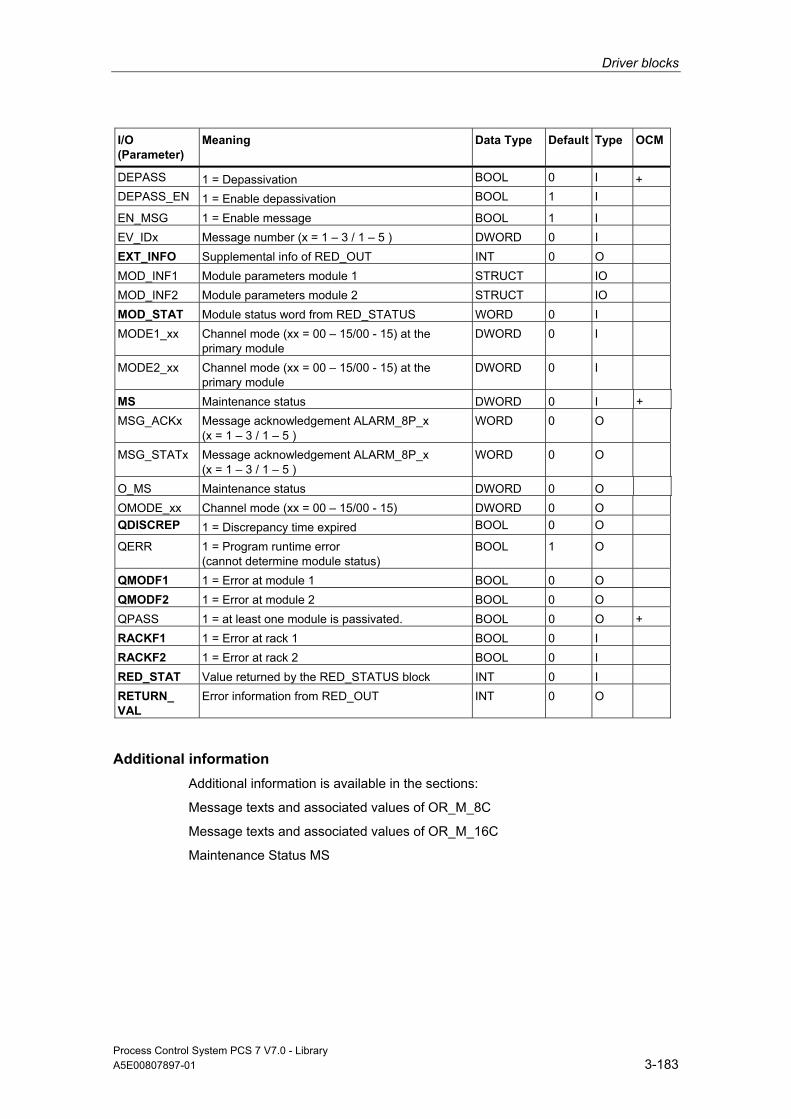
Driver blocks
Process Control System PCS 7 V7.0 - Library A5E00807897-01 3-183
I/O (Parameter)
Meaning
Data Type
Default Type
OCM
DEPASS 1 = Depassivation BOOL 0 I + DEPASS_EN 1 = Enable depassivation BOOL 1 I EN_MSG 1 = Enable message BOOL 1 I EV_IDx Message number (x = 1 – 3 / 1 – 5 ) DWORD 0 I EXT_INFO Supplemental info of RED_OUT INT 0 O MOD_INF1 Module parameters module 1 STRUCT IO MOD_INF2 Module parameters module 2 STRUCT IO MOD_STAT Module status word from RED_STATUS WORD 0 I MODE1_xx Channel mode (xx = 00 – 15/00 - 15) at the
primary module DWORD 0 I
MODE2_xx Channel mode (xx = 00 – 15/00 - 15) at the primary module
DWORD 0 I
MS Maintenance status DWORD 0 I + MSG_ACKx Message acknowledgement ALARM_8P_x
(x = 1 – 3 / 1 – 5 ) WORD 0 O
MSG_STATx Message acknowledgement ALARM_8P_x (x = 1 – 3 / 1 – 5 )
WORD 0 O
O_MS Maintenance status DWORD 0 O OMODE_xx Channel mode (xx = 00 – 15/00 - 15) DWORD 0 O QDISCREP 1 = Discrepancy time expired BOOL 0 O QERR 1 = Program runtime error
(cannot determine module status) BOOL 1 O
QMODF1 1 = Error at module 1 BOOL 0 O QMODF2 1 = Error at module 2 BOOL 0 O QPASS 1 = at least one module is passivated. BOOL 0 O + RACKF1 1 = Error at rack 1 BOOL 0 I RACKF2 1 = Error at rack 2 BOOL 0 I RED_STAT Value returned by the RED_STATUS block INT 0 I RETURN_ VAL
Error information from RED_OUT INT 0 O
Additional information Additional information is available in the sections:
Message texts and associated values of OR_M_8C
Message texts and associated values of OR_M_16C
Maintenance Status MS

Driver blocks
Process Control System PCS 7 V7.0 - Library 3-184 A5E00807897-01
3.2.32.3 Message texts and associated values of OR_M_16C
Assignment of Message Text and Message Class Message Block ALARM_8P
Message No. Default Message Text
Message Class
EV_ID1 1 Module @1%d@/ @2%d@/ @3%d@: Failure redundant module pair
S
2 Module @1%d@/ @2%d@/ @3%d@: Module redundancy loss
F
3 Module @1%d@/ @2%d@/ @3%d@: Cannot determine module status
S
4 Module @1%d@/ @2%d@/ @3%d@: Discrepancy time expired
M
EV_ID2 1 Module @1%d@/ @2%d@/ @3%d@: Failure redundancy pair channel 00
S
2 Module @1%d@/ @2%d@/ @3%d@: Failure redundancy pair channel 01
S
3 Module @1%d@/ @2%d@/ @3%d@: Failure redundancy pair channel 02
S
4 Module @1%d@/ @2%d@/ @3%d@: Failure redundancy pair channel 03
S
5 Module @1%d@/ @2%d@/ @3%d@: Failure redundancy pair channel 04
S
6 Module @1%d@/ @2%d@/ @3%d@: Failure redundancy pair channel 05
S
7 Module @1%d@/ @2%d@/ @3%d@: Failure redundancy pair channel 06
S
8 Module @1%d@/ @2%d@/ @3%d@: Failure redundancy pair channel 07
S
EV_ID3 1 Module @1%d@/ @2%d@/ @3%d@: Failure redundancy pair channel 08
S
2 Module @1%d@/ @2%d@/ @3%d@: Failure redundancy pair channel 09
S
3 Module @1%d@/ @2%d@/ @3%d@: Failure redundancy pair channel 10
S
4 Module @1%d@/ @2%d@/ @3%d@: Failure redundancy pair channel 11
S
5 Module @1%d@/ @2%d@/ @3%d@: Failure redundancy pair channel 12
S
6 Module @1%d@/ @2%d@/ @3%d@: Failure redundancy pair channel 13
S
7 Module @1%d@/ @2%d@/ @3%d@: Failure redundancy pair channel 14
S
8 Module @1%d@/ @2%d@/ @3%d@: Failure redundancy pair channel 15
S
EV_ID4 1 Module @1%d@/ @2%d@/ @3%d@: Channel 00 redundancy loss
F
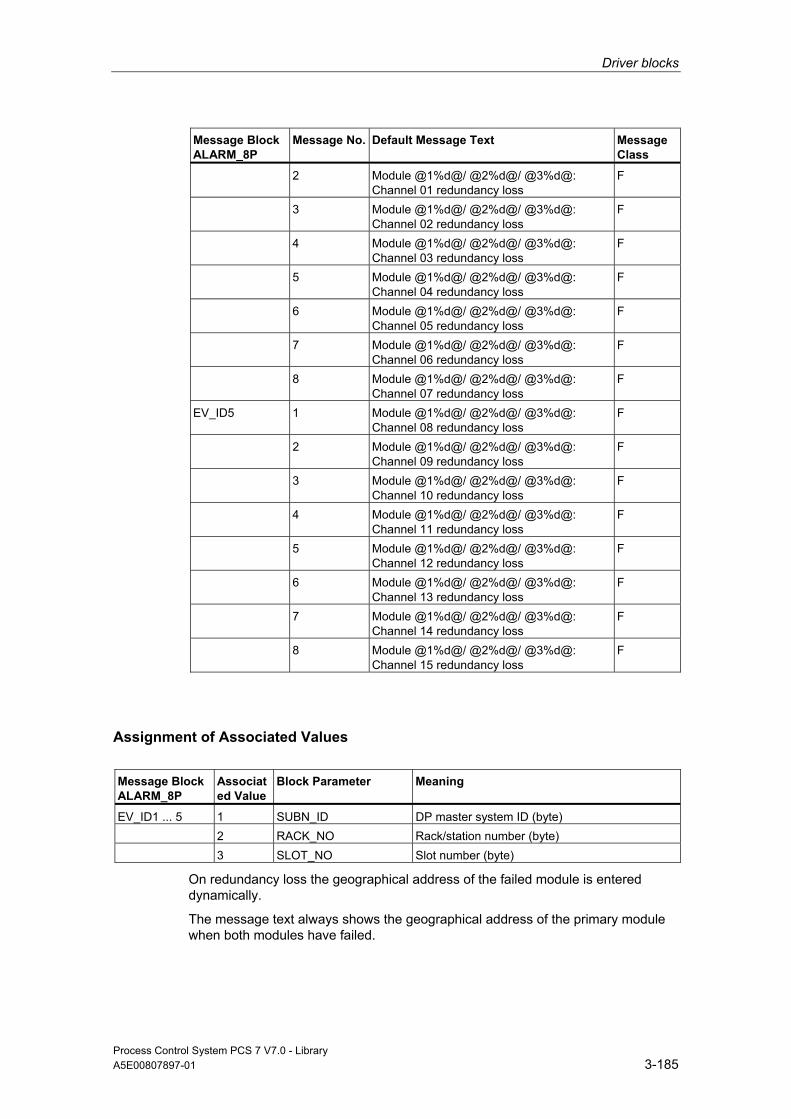
Driver blocks
Process Control System PCS 7 V7.0 - Library A5E00807897-01 3-185
Message Block ALARM_8P
Message No. Default Message Text
Message Class
2 Module @1%d@/ @2%d@/ @3%d@: Channel 01 redundancy loss
F
3 Module @1%d@/ @2%d@/ @3%d@: Channel 02 redundancy loss
F
4 Module @1%d@/ @2%d@/ @3%d@: Channel 03 redundancy loss
F
5 Module @1%d@/ @2%d@/ @3%d@: Channel 04 redundancy loss
F
6 Module @1%d@/ @2%d@/ @3%d@: Channel 05 redundancy loss
F
7 Module @1%d@/ @2%d@/ @3%d@: Channel 06 redundancy loss
F
8 Module @1%d@/ @2%d@/ @3%d@: Channel 07 redundancy loss
F
EV_ID5 1 Module @1%d@/ @2%d@/ @3%d@: Channel 08 redundancy loss
F
2 Module @1%d@/ @2%d@/ @3%d@: Channel 09 redundancy loss
F
3 Module @1%d@/ @2%d@/ @3%d@: Channel 10 redundancy loss
F
4 Module @1%d@/ @2%d@/ @3%d@: Channel 11 redundancy loss
F
5 Module @1%d@/ @2%d@/ @3%d@: Channel 12 redundancy loss
F
6 Module @1%d@/ @2%d@/ @3%d@: Channel 13 redundancy loss
F
7 Module @1%d@/ @2%d@/ @3%d@: Channel 14 redundancy loss
F
8 Module @1%d@/ @2%d@/ @3%d@: Channel 15 redundancy loss
F
Assignment of Associated Values
Message Block ALARM_8P
Associated Value
Block Parameter
Meaning
EV_ID1 ... 5 1 SUBN_ID DP master system ID (byte) 2 RACK_NO Rack/station number (byte) 3 SLOT_NO Slot number (byte)
On redundancy loss the geographical address of the failed module is entered dynamically.
The message text always shows the geographical address of the primary module when both modules have failed.

Driver blocks
Process Control System PCS 7 V7.0 - Library 3-186 A5E00807897-01
3.2.33 OR_M_32: OR Value status of 2 Redundant Signal Modules, Maximum 32 Channels, Module Granular
3.2.33.1 Description of OR_M_32
Object name (type + number) FB82
Block OR_M_32 corresponds to OR_M_16, but with 32 channels instead of 16.
Additional information Additional information is available in the sections:
Description of OR_M_16
Message Texts and Associated Values of OR_M_16/OR_M_32
Maintenance Status MS
Notes on Using Driver Blocks
3.2.34 OR_M_8C: OR Value status of 2 Redundant Signal Modules, Maximum 8 Channels, Channel Granular
3.2.34.1 Description of OR_M_8C
Object name (type + number) FB83
Fields of application Block OR_M_8C is used to form a channel-granular value status based on two redundant signal modules.
Calling OBs The block must be installed in OB100 and in the fastest OB before the channel block CH_x that is interconnected with OR_M_8C.
Driver blocks
Process Control System PCS 7 V7.0 - Library A5E00807897-01 3-187
Use in CFC When the CFC function "Generate module drivers" is used, the following occurs automatically:
• Block OR_M_8C is installed upstream of its interconnected CH_x channel blocks in their OB.
• MODE1_x inputs are interconnected with the OMODE_xx outputs of the MOD_x block in the primary module.
• MODE2_x inputs are interconnected with the OMODE_xx outputs of the MOD_x block in the redundant module.
• The MOD_INF1 input structure is interconnected with the MOD_INF output structure of the MOD_x block in the primary module.
• The MOD_INF2 input structure is interconnected with the MOD_INF output structure of the MOD_x block in the redundant module.
• The ACTIV_H and ACTIV_L inputs are interconnected with the outputs of the same name of the RED_STATUS block in the redundant module.
• The OMODE_xx outputs are interconnected with the relevant CH_x channel blocks.
• The OUT structure CPU_DIAG of the OB_BEGIN block is interconnected with the INOUT structures of the same name of block OR_M_8C.
• The inputs RACKF1 and RACKF2 are interconnected with the outputs QRACKF1 and QRACKF2 of MOD_D1.
• The inputs CH_INF_H and CH_INF_L are interconnected with the same name outputs of RED_STATUS.
Function and Operating Principle The value status of a signal module and of a redundant signal module are ORed by the OR_M_8C block. Signal modules or signal channels disabled by the system are considered invalid. For redundant digital input modules, when a signal discrepancy occurs, no module or channel is set to passive after expiration of the discrepancy time. The module or channel whose signal does not change is thereafter set to passive. The events "expiration of the discrepancy time", "redundancy loss" and "failure of the redundant I/O" are reported by ALARM_8P. The message function can be disabled.
When module signals are processed in different OB3x, it may happen under rare circumstances that a faulty signal value is processed in one cycle by one of the channel blocks configured to process the module signals after a process-control disturbance has occurred at the module. This can be avoided by processing all channel blocks of a module in the OB3x that also processes the process image partition assigned to this module.

Driver blocks
Process Control System PCS 7 V7.0 - Library 3-188 A5E00807897-01
For OR_M_Cxx blocks:
For channel-granular redundancy, in the event that a channel fails "Loss of Redundancy Channel x" or in the event of both channels failing "Failure Redundancy Pair Channel x" is reported. The message function can be disabled.
For all OR Blocks:
For a passivated block or passivated channel when setting the DEPASS input the depassivation can be triggered. For this the function RED_DEPA FC451 is called internally.
Redundancy Redundancy of the modules in an H system is monitored in a higher-level RED_STATUS block.
Error handling The input parameters are not validated.
Startup Characteristics The outputs OMODE_xx are updated when the "Startup" bit is set.
ALARM_8P will be initialized.
Message response OR_M_8C uses ALARM_8P for reporting. The message function can be disabled by setting EN_MSG = FALSE.
Operating and Monitoring Note: If you have selected the "Enable operating and monitoring" option in the block object properties in the CFC, the variables transferred to the OS are identified under "I/Os of …" (OCM column, "+"). Default: option not selected.
If asset management is used in the project and the diagnostic screens have been generated, then the faceplate can be called via its icon.
• Asset Management block symbols
• Asset Management faceplates
Note: Online help and the "PCS 7 FACEPLATES" Manual are only available if the "PCS 7 FACEPLATES" software package is installed!

Driver blocks
Process Control System PCS 7 V7.0 - Library A5E00807897-01 3-189
Additional information Additional information is available in the sections:
Message texts and associated values of OR_M_8C
Maintenance Status MS
Notes on Using Driver Blocks
3.2.34.2 Message texts and associated values of OR_M_8C
Assignment of Message Text and Message Class Message Block ALARM_8P
Message No.
Default Message Text
Message Class
EV_ID1 1 Module @1%d@/ @2%d@/ @3%d@: Failure redundant module pair
S
2 Module @1%d@/ @2%d@/ @3%d@: Module redundancy loss
F
3 Module @1%d@/ @2%d@/ @3%d@: Cannot determine module status
S
4 Module @1%d@/ @2%d@/ @3%d@: Discrepancy time expired
M
EV_ID2 1 Module @1%d@/ @2%d@/ @3%d@: Failure redundancy pair channel 00
S
2 Module @1%d@/ @2%d@/ @3%d@: Failure redundancy pair channel 01
S
3 Module @1%d@/ @2%d@/ @3%d@: Failure redundancy pair channel 02
S
4 Module @1%d@/ @2%d@/ @3%d@: Failure redundancy pair channel 03
S
5 Module @1%d@/ @2%d@/ @3%d@: Failure redundancy pair channel 04
S
6 Module @1%d@/ @2%d@/ @3%d@: Failure redundancy pair channel 05
S
7 Module @1%d@/ @2%d@/ @3%d@: Failure redundancy pair channel 06
S
8 Module @1%d@/ @2%d@/ @3%d@: Failure redundancy pair channel 07
S

Driver blocks
Process Control System PCS 7 V7.0 - Library 3-190 A5E00807897-01
Assignment of Associated Values
Message Block ALARM_8P
Associated Value
Block Parameter
Meaning
EV_ID1 / 2 / 3 1 SUBN_ID DP master system ID (byte) 2 RACK_NO Rack/station number (byte) 3 SLOT_NO Slot number (byte)
On redundancy loss the geographical address of the failed module is entered dynamically.
The message text always shows the geographical address of the primary module when both modules have failed.
3.2.35 PO_UPDAT: Output Process Image
3.2.35.1 PO_UPDAT: Output Process Image
Object name (type + number) FC279
Fields of application Block PO_UPDAT safeguards the functions "Hold last value" and "Apply substitute value" of the output modules when a CPU is restarted (OB100).
Run Sequence Block PO_UPDAT must be installed as the final element in OB100. When using the CFC function "Generate module drivers", the PO_UPDAT block is automatically installed in OB100.
Description of Functions When a CPU is restarted (OB100), the CH_DO and CH_AO blocks write the start values to the process image. The PO_UPDAT block sends all process image (partition)s to the modules at the end of OB100 in order for these values to be active immediately after the CPU transition to RUN. Output PO_MAP indicates the process image partitions which have been updated or are used in the system (BIT0: Process image 0, BIT15: Process image partition 15).
Additional information Additional information is available in the section: Notes on Using Driver Blocks

Driver blocks
Process Control System PCS 7 V7.0 - Library A5E00807897-01 3-191
3.2.36 PS: Monitoring of Power Supply
3.2.36.1 Description of PS
Object name (type + number) FB89
Fields of application Block PS monitors the status of a rack power supply and reports corresponding error events.
Calling OBs The PS block must be installed in the run sequence of the following OBs: OB1 Cyclic program
OB81 Power supply error OB83 Remove/insert interrupt OB100 Restart (warm start)
Use in CFC When the CFC function "Generate module drivers" is used, the following occurs automatically:
• The block is installed in the run sequence downstream of the RACK block.
• The SLOT_NO input (slot number of the power supply) is configured.
• The EN input is interconnected with the output of an AND block, Its inputs are interconnected with the output EN_SUBx of the OB_BEGIN block, the output EN_Rxxx of the SUBNET block and the output EN_Mxx of the RACK block.
• The OUT structure CPU_DIAG of the OB_BEGIN block and RAC_DIAG of the RACK block are interconnected with the INOUT structures of the same name of the PS block.

Driver blocks
Process Control System PCS 7 V7.0 - Library 3-192 A5E00807897-01
Function and Operating Principle The PS block reports events of the power-supply error OB81 and OB83 relating to the power-supply module. The module is installed for the power supply of the central rack and for each expansion rack.
Note
• If there is a battery failure, the battery must always be replaced with the power supply turned on. Then press the button "FMR". In all other situations, the block does not reset a reported error.
• For redundant power-supply modules in a rack with a standard CPU, a corresponding message is sent for both power-supply modules in the event of a battery error or power-supply error. You can tell which module is affected by its illuminated "BATTF" LED.
Redundancy In a redundant system, the block is also installed extra for the power supply of the redundant rack.
Error handling Error handling of the block is limited to the evaluation of the error information of ALARM_8P. You can find additional information about error handling in "Error Information of Output Parameter MSG_STAT".
Startup Characteristics The PS block initializes the messages of ALARM_8P.
Overload Behavior n.a.
Dynamic response You can find additional information in "Message response".

Driver blocks
Process Control System PCS 7 V7.0 - Library A5E00807897-01 3-193
Message response After OB81 or OB83 is called, the block analyzes the status of the power supply of the rack assigned to it. It generates the messages for "Backup battery failure", "Backup voltage failure" and "24 V supply failure" or "Module removed" or "Wrong or faulty module" with ALARM_8P. The message function can be disabled by setting EN_MSG = FALSE.
Operating and Monitoring Note: If you have selected the "Enable operating and monitoring" option in the block object properties in the CFC, the variables transferred to the OS are identified under "I/Os of …" (OCM column, "+"). Default: option not selected.
If asset management is used in the project and the diagnostic screens have been generated, then the faceplate can be called via its icon.
• Asset Management block symbols
• Asset Management faceplates
Note: Online help and the "PCS 7 FACEPLATES" Manual are only available if the "PCS 7 FACEPLATES" software package is installed!
Additional information Additional information is available in the sections:
Message Texts and Associated Values of PS
Maintenance Status MS
Notes on Using Driver Blocks

Driver blocks
Process Control System PCS 7 V7.0 - Library 3-194 A5E00807897-01
3.2.36.2 I/Os of PS The factory setting of the block representation in CFC is identified in the "I/O" column: I/O name in bold characters = I/O is visible; I/O name in standard characters = I/O is hidden.
You can find explanations of and information about the abbreviations used in "General Information About Block Description".
I/O (Parameter)
Meaning
Data Type
Default Type
OCM
CPU_DIAG CPU diagnostics (system structure) STRUCT IO EN_MSG 1 = Enable message BOOL 1 I EV_ID Message number DWORD 0 I MS Maintenance status DWORD 0 I + MSG_STAT Error message status WORD 0 O O_MS Maintenance status DWORD 0 O RAC_DIAG System structure (reserve): STRUCT IO SLOT_NO Slot number of the power supply BYTE 0 I
Additional information Additional information is available in the sections:
Message Texts and Associated Values of PS
Maintenance Status MS

Driver blocks
Process Control System PCS 7 V7.0 - Library A5E00807897-01 3-195
3.2.36.3 Message Texts and Associated Values of PS
Assignment of Message Text and Message Class
Message No. Default Message Text Message Class
1 @1%d@/ @2%d@/ @3%d@: Backup battery failure M 2 @1%d@/ @2%d@/ @3%d@: Backup voltage failure M 3 @1%d@/ @2%d@/ @3%d@: 24 V power supply failure M 4 Module @1%d@/ @2%d@/ @3%d@: Removed S 5 Module @1%d@/ @2%d@/ @3%d@: wrong or faulty S 6 no message 7 no message 8 no message
Assignment of Associated Values
Associated Value
Block Parameter
1 DP master system number of the rack of the power supply (RAC_DIAG.SUBN_ID) 2 Rack number of the power supply (RAC_DIAG.RACK_NO) 3 Slot number of the power supply (SLOT_NO)
3.2.37 RACK: Rack monitoring
3.2.37.1 Description of RACK
Object name (type + number) FB107
Fields of application The RACK block monitors the status of a rack and reports the corresponding error events.
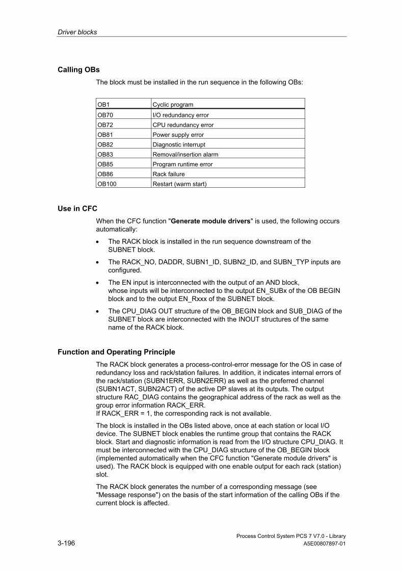
Driver blocks
Process Control System PCS 7 V7.0 - Library 3-196 A5E00807897-01
Calling OBs The block must be installed in the run sequence in the following OBs:
OB1 Cyclic program
OB70 I/O redundancy error OB72 CPU redundancy error OB81 Power supply error OB82 Diagnostic interrupt OB83 Removal/insertion alarm OB85 Program runtime error OB86 Rack failure OB100 Restart (warm start)
Use in CFC When the CFC function "Generate module drivers" is used, the following occurs automatically:
• The RACK block is installed in the run sequence downstream of the SUBNET block.
• The RACK_NO, DADDR, SUBN1_ID, SUBN2_ID, and SUBN_TYP inputs are configured.
• The EN input is interconnected with the output of an AND block, whose inputs will be interconnected to the output EN_SUBx of the OB BEGIN block and to the output EN_Rxxx of the SUBNET block.
• The CPU_DIAG OUT structure of the OB_BEGIN block and SUB_DIAG of the SUBNET block are interconnected with the INOUT structures of the same name of the RACK block.
Function and Operating Principle The RACK block generates a process-control-error message for the OS in case of redundancy loss and rack/station failures. In addition, it indicates internal errors of the rack/station (SUBN1ERR, SUBN2ERR) as well as the preferred channel (SUBN1ACT, SUBN2ACT) of the active DP slaves at its outputs. The output structure RAC_DIAG contains the geographical address of the rack as well as the group error information RACK_ERR. If RACK_ERR = 1, the corresponding rack is not available.
The block is installed in the OBs listed above, once at each station or local I/O device. The SUBNET block enables the runtime group that contains the RACK block. Start and diagnostic information is read from the I/O structure CPU_DIAG. It must be interconnected with the CPU_DIAG structure of the OB_BEGIN block (implemented automatically when the CFC function "Generate module drivers" is used). The RACK block is equipped with one enable output for each rack (station) slot.
The RACK block generates the number of a corresponding message (see "Message response") on the basis of the start information of the calling OBs if the current block is affected.

Driver blocks
Process Control System PCS 7 V7.0 - Library A5E00807897-01 3-197
The block evaluates error events and uses the diagnostic address DADDR of the DP slave to determine the currently active preferred channel (SUBN1ACT, SUBN2ACT) of redundant PROFIBUS DP interfaces.
If you want to modify the SUBN1_ID (connection to CPU 0) and SUBN2_ID (connection to CPU 1) inputs online without using the CFC function "Generate module drivers", you must set input ACC_ID = TRUE in order to update the output values.
Redundancy In H systems with distributed I/O devices, the RACK block supports redundancy of the DP Master systems. If you want to use this function, you must configure the SUBN1_ID (connection to CPU 0) and SUBN2_ID (connection to CPU 1) inputs of the RACK block with the numbers of the redundant DP master systems. If there is no redundancy, the remaining input must be assigned the value 16#FF (default).
Note
With redundant central racks, the two RACK blocks inserted in the system chart are only responsible for enabling lower-level block chains. Their maintenance status MS is therefore irrelevant. The "Good" and "Not redundant" state is always shown in the corresponding faceplate and block icon because the bits 0 to 16 of the MS are always "0" in this case.
Error handling Error handling of the block is limited to the evaluation of the error information of ALARM_8P. You can find additional information in "Error Information of Output Parameter MSG_STAT".
Startup Characteristics The RACK block initializes ALARM_8P messages. It checks availability of the station and, in H systems, determines the preferred channel of the station.
The structure SUB_DIAG.V1_MODE (0 = compatibility mode, 1 = DPV1 mode) will be transferred to the structure RAC_DIAG.V1_MODE.

Driver blocks
Process Control System PCS 7 V7.0 - Library 3-198 A5E00807897-01
Overload Behavior The RACK block counts the OB86 calls (exception: DP master-system failure, see SUBNET block). The counter is reset in OB1. If more than two OB86 events occur successively before the cycle control point (OB1) is reached, these will be discarded and a message "Failure OB86 DP Master:x " output. When an OB86 call is discarded, the rack (station) is registered as having failed.
Dynamic response See "Message characteristics"
Message response After its call by OB70, OB72, OB85 or OB86, the block analyzes the status of its assigned CPU, DP master and DP slaves. If the rack (station) loses redundancy or fails, the block outputs corresponding messages via ALARM_8P. The message function can be disabled by setting EN_MSG = FALSE.
The block generally reports only the events generated in the rack monitored it monitors. Redundancy loss and station failures which are caused by the failure of a DP masters or of a CPU, are initially neither signaled nor indicated at the outputs SUBN1ERR and SUBN2ERR.
The DELAY input is used to delay the output of error messages for outgoing higher-priority errors. This delay time is configurable. For example, when the RACK block recognizes an outgoing error at an interconnected DP master, it initially assumes that there is a faulty assigned DP slave in the rack it monitors and sets the corresponding output SUBNxERR. The error status is not reset until the DP slave returns (in this case: OB86, OB70). The RACK blocks delay error messages relevant to any slave failure states for a time in seconds as specified in DELAY, in order not to trigger the output of surge of messages from DP slaves which are not yet synchronized after the master has returned. An error message is not output to the OS unless the DP slave has reported its return before this delay time has expired.
Note: Do not set the value of DELAY too high, since messages reporting faulty DP slaves or their removal during a master failure will be output too late to the OS after the DP master returns.
The RACK block generates the following messages in the OBs listed below:
OB Start Event Message
OB1 Cyclic processing Repeat the update of ALARM_8P outputs/messages, if necessary
OB70 Redundancy loss Station redundancy loss/return OB81 Power supply error OB85 I/O access error Station failure, incoming/outgoing OB86 Rack monitoring Station failure, incoming/outgoing OB100 Restart: Initialization of ALARM_8P

Driver blocks
Process Control System PCS 7 V7.0 - Library A5E00807897-01 3-199
Operating and Monitoring Note: If you have selected the "Enable operating and monitoring" option in the block object properties in the CFC, the variables transferred to the OS are identified under "I/Os of …" (OCM column, "+"). Default: option not selected.
If asset management is used in the project and the diagnostic screens have been generated, then the faceplate can be called via its icon.
• Asset Management block symbols
• Asset Management faceplates
Note: Online help and the "PCS 7 FACEPLATES" Manual are only available if the "PCS 7 FACEPLATES" software package is installed!
Additional information Additional information is available in the sections:
Message Texts and Associated Values of RACK
Maintenance Status MS
Notes on Using Driver Blocks
3.2.37.2 I/Os of RACK
The factory setting of the block representation in CFC is identified in the "I/O" column: I/O name in bold characters = I/O is visible; I/O name in standard characters = I/O is hidden.
You can find explanations of and information about the abbreviations used in "General Information About Block Description".
I/O (Parameter)
Meaning
Data Type
Default Type
OCM
ACC_ID 1 = Accept MODE settings BOOL 0 IO CPU_DIAG CPU diagnostics (system structure) STRUCT IO DADDR Diagnostic address of the DP slave INT 0 I DELAY Interrupt delay (s) INT 15 I EN_MSG 1 = Enable message BOOL 1 I EN_Mxx 1 = Enable module xx (xx = 00 - 30) BOOL 0 O EV_ID Message number DWORD 0 I MS Maintenance status DWORD 0 I + MSG_STAT Error message status WORD 0 O O_MS Maintenance status DWORD 0 O RAC_DIAG System structure (reserve): STRUCT O RACK_NO Rack number BYTE 0 I SUB_DIAG OB_Start information STRUCT IO SUBN_TYP 1 = External DP interface BOOL 0 I SUBN1_ID ID of the primary DP master system BYTE 255 I

Driver blocks
Process Control System PCS 7 V7.0 - Library 3-200 A5E00807897-01
I/O (Parameter)
Meaning
Data Type
Default Type
OCM
SUBN1ACT 1 = Slave 1 is active BOOL 0 O SUBN1ERR 1 = Error in slave 1 BOOL 0 O SUBN2_ID ID of the redundant DP master system BYTE 255 I SUBN2ACT 1 = Slave 2 is active BOOL 0 O SUBN2ERR 1 = Error in slave 2 BOOL 0 O
Additional information Additional information is available in the sections:
Message Texts and Associated Values of RACK
Maintenance Status MS
3.2.37.3 Message Texts and Associated Values of RACK
Assignment of Message Text and Message Class
Message No. Default Message Text Message Class
1 DP slave @1%d@/ @3%d@: Redundancy loss F 2 DP slave @2%d@/ @3%d@: Redundancy loss F 3 Station @1%d@/ @3%d@: Failure S 4 Station @2%d@/ @3%d@: Failure S 5 no message 6 no message 7 no message 8 Station @1%d@/ @3%d@: Repeated failure S
Assignment of Associated Values
Associated Value Block Parameter
1 ID of the primary DP master system (SUBN1_ID) 2 ID of the redundant DP master system (SUBN2_ID) 3 Rack/station number (RACK_NO)
Driver blocks
Process Control System PCS 7 V7.0 - Library A5E00807897-01 3-201
3.2.38 RCV_341: Receiving Serial Data With CP 341
3.2.38.1 Description of RCV_341
Object name (type + number) FB121
Fields of application Block RCV_341 is used for receiving serial data via the CP 341 module.
Calling OBs OB100 and the cyclic OB (100 ms recommended) assigned to receive the data.
Use in CFC When the CFC function "Generate module drivers" is used, the following occurs automatically:
• The RACK_NO, SUBN1_ID, SUBN2_ID, and SLOT_NO inputs are configured.
• The MODE input is interconnected with the OMODE_00 output of the MOD_CP block.
Instructions for Creating a User Block for Receiving Serial Data Requirement: The optional package for configuring point-to-point connections (CP PtP Param) must be installed.
In HW Config you can set the following transmission types (protocols):
• DK 3964R
• RK 512
• ASCII
• MODBUS master
• MODBUS slave
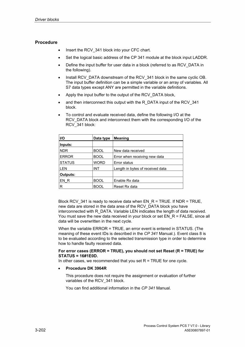
Driver blocks
Process Control System PCS 7 V7.0 - Library 3-202 A5E00807897-01
Procedure • Insert the RCV_341 block into your CFC chart.
• Set the logical basic address of the CP 341 module at the block input LADDR.
• Define the input buffer for user data in a block (referred to as RCV_DATA in the following).
• Install RCV_DATA downstream of the RCV_341 block in the same cyclic OB. The input buffer definition can be a simple variable or an array of variables. All S7 data types except ANY are permitted in the variable definitions.
• Apply the input buffer to the output of the RCV_DATA block,
• and then interconnect this output with the R_DATA input of the RCV_341 block.
• To control and evaluate received data, define the following I/O at the RCV_DATA block and interconnect them with the corresponding I/O of the RCV_341 block:
I/O Data type Meaning
Inputs: NDR BOOL New data received ERROR BOOL Error when receiving new data STATUS WORD Error status LEN INT Length in bytes of received data Outputs: EN_R BOOL Enable Rx data R BOOL Reset Rx data
Block RCV_341 is ready to receive data when EN_R = TRUE. If NDR = TRUE, new data are stored in the data area of the RCV_DATA block you have interconnected with R_DATA. Variable LEN indicates the length of data received. You must save the new data received in your block or set EN_R = FALSE, since all data will be overwritten in the next cycle.
When the variable ERROR = TRUE, an error event is entered in STATUS. (The meaning of these event IDs is described in the CP 341 Manual.). Event class 8 is to be evaluated according to the selected transmission type in order to determine how to handle faulty received data.
For error cases (ERROR = TRUE), you should not set Reset (R = TRUE) for STATUS = 16#1E0D. In other cases, we recommended that you set R = TRUE for one cycle.
• Procedure DK 3964R
This procedure does not require the assignment or evaluation of further variables of the RCV_341 block.
You can find additional information in the CP 341 Manual.

Driver blocks
Process Control System PCS 7 V7.0 - Library A5E00807897-01 3-203
• Remote coupler RK 512
The variables (hidden outputs) of the RCV_341 block indicate the origin of user data.
I/O Data type Meaning
L_TYP CHAR Area type on the remote CPU L_NO INT DB number of the remote CPU L_OFFSET INT DB offset of the remote CPU L_CF_BYT INT Comm. flag byte number, remote CPU L_CF_BIT INT Comm. flag bit number, remote CPU
You can find additional information in the CP 341 Manual. This manual also explains how to evaluate the variables if RCV_341 is to provide data for the communication partner (see "Provide data").
• ASCII driver
Does not require assignment or evaluation of further variables at the RCV_341 block.
You can find additional information in the CP 341 Manual. If you set the "Delimiter" operating mode in HW Config, please note that the following applies: Length of input buffer = user data + delimiter
• MODBUS master
Does not require assignment or evaluation of further variables at the RCV_341 block.
User data received from the partner will be entered at the input buffer according to the selected function code.
You can find additional information in Manual Loadable Drivers for Point-to-Point CPs MODBUS Protocol RTU Format; S7 is Master.
• MODBUS slave
In MODBUS SLAVE mode, the driver on the CP 341 module control data exchange. You can find additional information in Manual Loadable Drivers for Point-to-Point CPs MODBUS Protocol RTU Format; S7 is Slave.
You must set MODB_SL = TRUE at the RCV_341 block.
Driver blocks
Process Control System PCS 7 V7.0 - Library 3-204 A5E00807897-01
Function and Operating Principle The block receives data from a partner connected to a CP 341 by means of the P_RCV_RK (FB122) block that is identical to the P_RCV_RK (FB7) block of the CP PtP library. Diagnostic events detected by P_RCV_RK will be reported via ALARM_8P if no higher-level error is queued. The message function can be disabled.
• New data are received by setting output NDR = TRUE. NDR will be reset in the next cycle. Received data must be cleared by the user program during this cycle and are entered in the user program structure that is interconnected to input R_DATA.
• The data at the P_RCV_RK outputs are transferred 1:1 to the outputs of the RCV_341 block. ALARM_8P generates an error message if the receive operation was cancelled with error, provided there is no queued higher-level error (MODE = 16#40xxxxxx).
• In MODBUS slave operating mode, the MODB_341 (FB80) block controls data exchange between the CP 341 by operating as a MODBUS slave and a MODBUS master. MODB_341 is identical to MODB_341 of the MODBUS library.
Redundancy Higher-level block MOD_CP evaluates the redundancy of DP master systems operating in an H system. Redundant serial communication is not supported and must thus be controlled manually by the user, separately from this block.
Error handling The input parameters are not validated.
Startup Characteristics A restart (OB100) is reported via the LSB in byte 2 of output OMODE.
ALARM_8P will be initialized.
Overload Behavior n.a.
Dynamic response n.a.

Driver blocks
Process Control System PCS 7 V7.0 - Library A5E00807897-01 3-205
Message response The block uses ALARM_8P to report diagnostic information of P_RCV_RK. The message function can be disabled by setting EN_MSG = FALSE.
Operating and Monitoring The block has no faceplate.
Note: If you have selected the "Enable operating and monitoring" option in the block object properties in the CFC, the variables transferred to the OS are identified under "I/Os of …" (OCM column, "+"). Default: option not selected.
Additional information Additional information is available in the sections:
Message Texts and Associated Values of RCV_341
Notes on Using Driver Blocks
3.2.38.2 I/Os of RCV_341
The factory setting of the block representation in CFC is identified in the "I/O" column: I/O name in bold characters = I/O is visible; I/O name in standard characters = I/O is hidden.
You can find explanations of and information about the abbreviations used in "General Information About Block Description".
I/O (Parameter)
Meaning
Data Type
Default Type
OCM
ACC_MODE 1 = Accept MODE settings BOOL 1 IO EN_MSG 1 = Enable message BOOL 1 I EN_R Enable receive/fetch BOOL 0 I ERROR 1 = Error when receiving data BOOL 0 O EV_ID Message number DWORD 04 I L_CF_BIT Protocol RK512: Comm. flag bit number, remote
CPU INT 0 O
L_CF_BYT Protocol RK512: Comm. flag byte number, remote CPU
INT 255 O
L_NO Protocol RK512: DB number of the remote CPU INT 0 O L_OFFSET Protocol RK512: DB offset of the remote CPU INT 0 O L_TYP Protocol RK512: Area type on the remote CPU CHAR ‘ ‘ O LADDR Logic address CP 341 INT 0 I LEN Length of received data INT 0 O
MODB_SL 1 = MODBUS slave active BOOL 0 I MODE Module operating mode (xx = 00 - 06/00 - 15/00 -
31) DWORD 0 I
MSG_ACK Message acknowledgement WORD 0 O
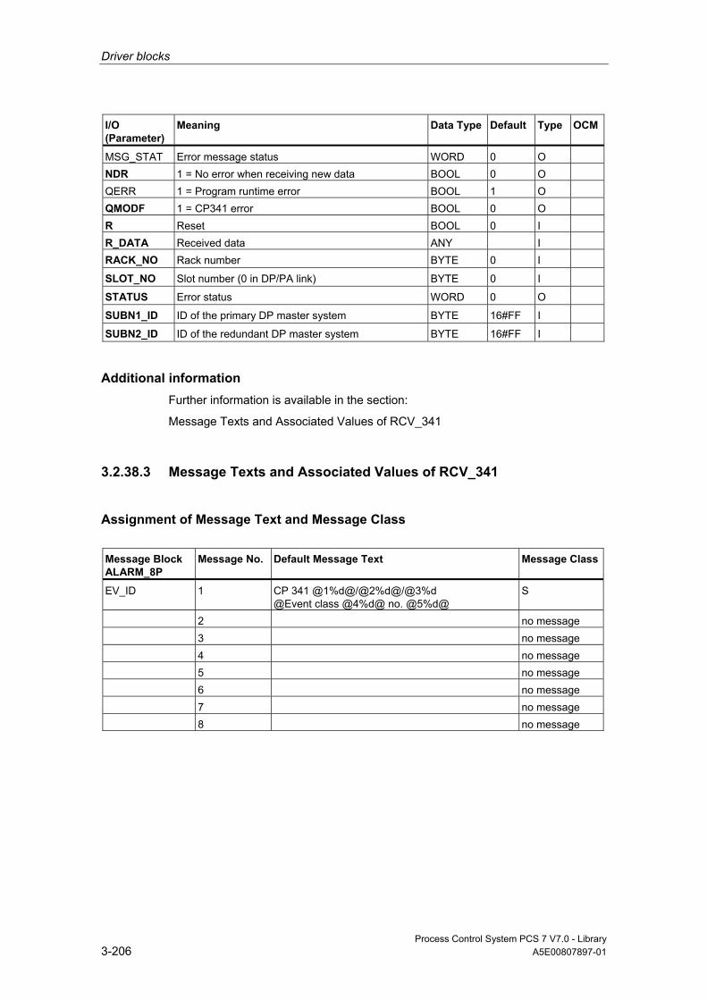
Driver blocks
Process Control System PCS 7 V7.0 - Library 3-206 A5E00807897-01
I/O (Parameter)
Meaning
Data Type
Default Type
OCM
MSG_STAT Error message status WORD 0 O NDR 1 = No error when receiving new data BOOL 0 O QERR 1 = Program runtime error BOOL 1 O QMODF 1 = CP341 error BOOL 0 O R Reset BOOL 0 I R_DATA Received data ANY I RACK_NO Rack number BYTE 0 I
SLOT_NO Slot number (0 in DP/PA link) BYTE 0 I
STATUS Error status WORD 0 O
SUBN1_ID ID of the primary DP master system BYTE 16#FF I
SUBN2_ID ID of the redundant DP master system BYTE 16#FF I
Additional information Further information is available in the section:
Message Texts and Associated Values of RCV_341
3.2.38.3 Message Texts and Associated Values of RCV_341
Assignment of Message Text and Message Class
Message Block ALARM_8P
Message No.
Default Message Text
Message Class
EV_ID 1 CP 341 @1%d@/@2%d@/@3%d @Event class @4%d@ no. @5%d@
S
2 no message 3 no message 4 no message 5 no message 6 no message 7 no message 8 no message

Driver blocks
Process Control System PCS 7 V7.0 - Library A5E00807897-01 3-207
Assignment of Associated Values
Message Block ALARM_8P
Associated Value
Block Parameter
Meaning
EV_ID 1 SUBN_ID DP master system ID (byte) 2 RACK_NO Rack/station number (byte) 3 SLOT_NO Slot number (byte) 4 STATUS(EV_CLAS) Event class 5 STATUS(EV_NO) Event number
3.2.39 SND_341: Sending Serial Data With CP 341
3.2.39.1 Description of SND_341
Object name (type + number) FB120
Fields of application Block SND_341 is used for transmitting serial data via the CP 341 module.
Calling OBs OB100 and the cyclic OB (100 ms recommended) used for transmitting data.
Use in CFC When the CFC function "Generate module drivers" is used, the following occurs automatically:
• The RACK_NO, SUBN1_ID, SUBN2_ID, and SLOT_NO inputs are configured.
• The MODE input is interconnected with the OMODE_00 output of the MOD_CP block.

Driver blocks
Process Control System PCS 7 V7.0 - Library 3-208 A5E00807897-01
How to create a user block for transmitting serial data Requirement: The optional package for configuring point-to-point connections (CP PtP Param) must be installed.
In HW Config you can set the following transmission types (protocols):
• DK 3964R
• RK 512
• ASCII
• MODBUS master
• MODBUS slave
Procedure • Install the SND_341 block into your CFC chart.
• Set the logical basic address of the CP 341 module at the block input LADDR.
• Define the send buffer for user data in a block (referred to as SND_DATA in the following).
• Install SND_DATA upstream of SND_341 in the same cyclic OB. The send buffer definition can be a variable or a structure of variables. All S7 data types except ANY are permitted in the variable definitions.
• Apply the send buffer to the output of the SND_DATA block
• and then interconnect this output with the S_DATA input of the SND_341 block. The length of the interconnected data structure determines the length of the protocol to be transmitted.
• To control and evaluate transmitted data, define the following I/O at SND_DATA and interconnect them with the corresponding I/O of SND_341:
I/O Data type Meaning
Inputs: DONE BOOL Send request end without error ERROR BOOL Send request end with error STATUS WORD Error status Outputs: REQ BOOL Initialize send request R BOOL Reset Tx data
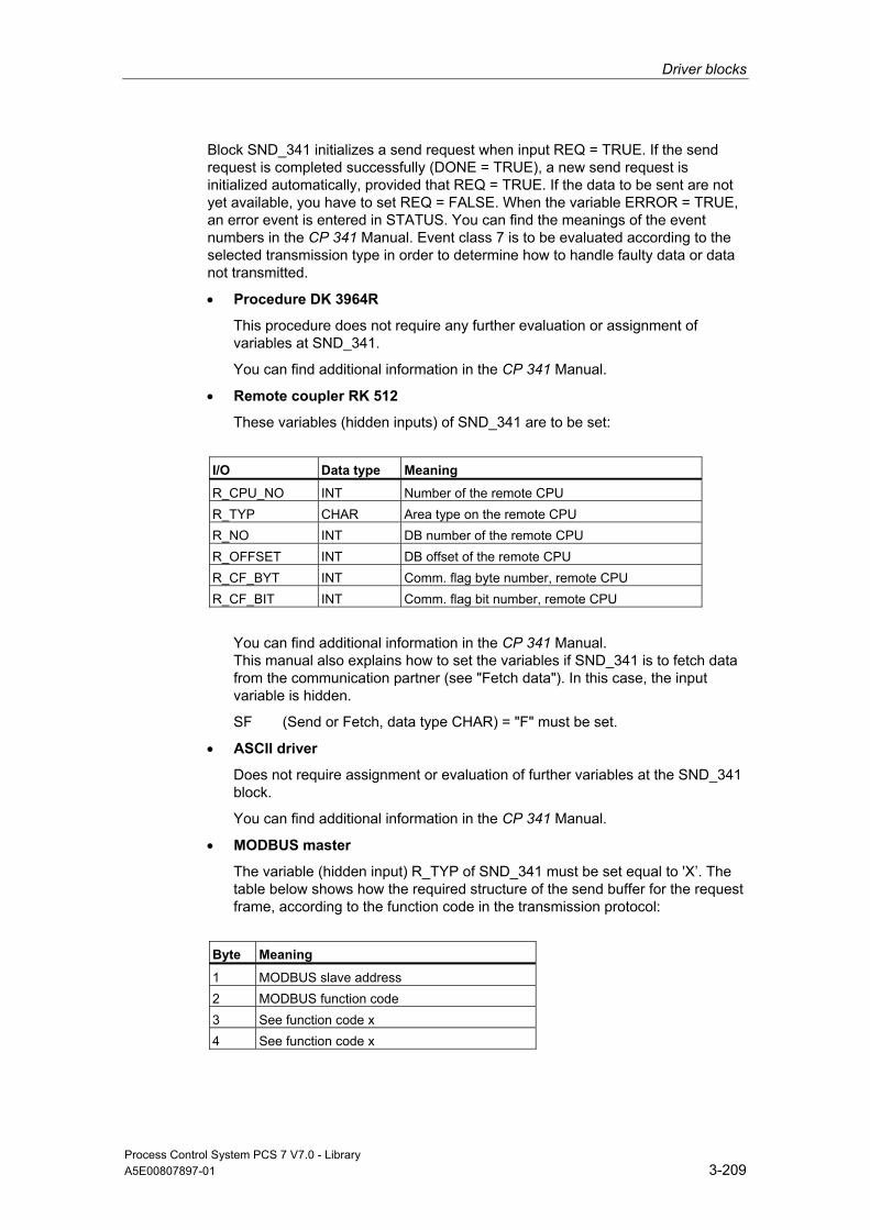
Driver blocks
Process Control System PCS 7 V7.0 - Library A5E00807897-01 3-209
Block SND_341 initializes a send request when input REQ = TRUE. If the send request is completed successfully (DONE = TRUE), a new send request is initialized automatically, provided that REQ = TRUE. If the data to be sent are not yet available, you have to set REQ = FALSE. When the variable ERROR = TRUE, an error event is entered in STATUS. You can find the meanings of the event numbers in the CP 341 Manual. Event class 7 is to be evaluated according to the selected transmission type in order to determine how to handle faulty data or data not transmitted.
• Procedure DK 3964R
This procedure does not require any further evaluation or assignment of variables at SND_341.
You can find additional information in the CP 341 Manual.
• Remote coupler RK 512
These variables (hidden inputs) of SND_341 are to be set:
I/O Data type Meaning
R_CPU_NO INT Number of the remote CPU R_TYP CHAR Area type on the remote CPU R_NO INT DB number of the remote CPU R_OFFSET INT DB offset of the remote CPU R_CF_BYT INT Comm. flag byte number, remote CPU R_CF_BIT INT Comm. flag bit number, remote CPU
You can find additional information in the CP 341 Manual. This manual also explains how to set the variables if SND_341 is to fetch data from the communication partner (see "Fetch data"). In this case, the input variable is hidden.
SF (Send or Fetch, data type CHAR) = "F" must be set.
• ASCII driver
Does not require assignment or evaluation of further variables at the SND_341 block.
You can find additional information in the CP 341 Manual.
• MODBUS master
The variable (hidden input) R_TYP of SND_341 must be set equal to 'X’. The table below shows how the required structure of the send buffer for the request frame, according to the function code in the transmission protocol:
Byte Meaning
1 MODBUS slave address 2 MODBUS function code 3 See function code x 4 See function code x

Driver blocks
Process Control System PCS 7 V7.0 - Library 3-210 A5E00807897-01
Byte Meaning
: x
CRC Check (message frame checksum) x+1
"Master-Slave" data transfer starts at the slave address, followed by the function code and the transfer of the data. The structure of the data field is determined by the function code used.
You can find additional information in Manual Loadable Drivers for Point-to-Point CPs MODBUS Protocol RTU Format; S7 is Master. The CRC check at the end of the message frame is formed by the MODBUS master driver on the CP341 module.
• MODBUS slave
In MODBUS SLAVE mode, the driver on the CP 341 module control data exchange. You can find additional information in Manual Loadable Drivers for Point-to-Point CPs MODBUS Protocol RTU Format; S7 is Slave.
You are not required to insert an SND_341 block into your chart.
You can find additional information in "RCV_341 MODBUS Slave".
Function and Operating Principle The block uses P_SND_RK (FB123) to transfer data to a communication partner that is connected to a CP 341. P_SND_RK is identical to P_SND_RK (FB8) of the CP PtP library. Diagnostic events detected by P_SND_RK are reported via ALARM_8P, if no higher-level error (MODE = 16#40xxxxxx) is queued. The message function can be disabled.
• Data transfer begins as soon as input REQ = TRUE. A new send request is only possible after DONE = TRUE or ERROR = TRUE has been set by P_SND_RK. Data at the outputs of P_SND_RK are transferred 1:1 to the outputs of SND_341.
• The length of Tx data is determined by the length of the Tx data structure in the user block, which is interconnected to the input S_DATA.
Redundancy Higher-level block MOD_CP evaluates the redundancy of DP master systems operating in an H system. Redundant serial communication is not supported and must thus be controlled manually by the user, separately from this block.

Driver blocks
Process Control System PCS 7 V7.0 - Library A5E00807897-01 3-211
Error handling The input parameters are not validated.
Startup Characteristics A restart (OB100) is reported via the LSB in byte 2 of OMODE.
ALARM_8P will be initialized.
Overload Behavior n.a.
Dynamic response n.a.
Message response The block uses ALARM_8P to report diagnostic information of P_SND_RK. The message function can be disabled by setting EN_MSG = FALSE.
Operating and Monitoring The block has no faceplate.
Note: If you have selected the "Enable operating and monitoring" option in the block object properties in the CFC, the variables transferred to the OS are identified under "I/Os of …" (OCM column, "+"). Default: option not selected.
Additional information Additional information is available in the sections:
Message Texts and Associated Values of SND_341
Notes on Using Driver Blocks
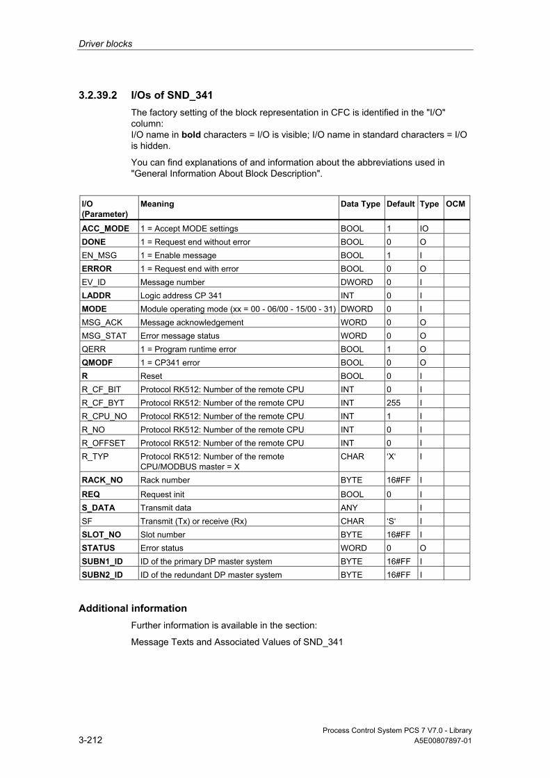
Driver blocks
Process Control System PCS 7 V7.0 - Library 3-212 A5E00807897-01
3.2.39.2 I/Os of SND_341 The factory setting of the block representation in CFC is identified in the "I/O" column: I/O name in bold characters = I/O is visible; I/O name in standard characters = I/O is hidden.
You can find explanations of and information about the abbreviations used in "General Information About Block Description".
I/O (Parameter)
Meaning
Data Type
Default Type
OCM
ACC_MODE 1 = Accept MODE settings BOOL 1 IO DONE 1 = Request end without error BOOL 0 O EN_MSG 1 = Enable message BOOL 1 I ERROR 1 = Request end with error BOOL 0 O EV_ID Message number DWORD 0 I LADDR Logic address CP 341 INT 0 I MODE Module operating mode (xx = 00 - 06/00 - 15/00 - 31) DWORD 0 I MSG_ACK Message acknowledgement WORD 0 O MSG_STAT Error message status WORD 0 O QERR 1 = Program runtime error BOOL 1 O QMODF 1 = CP341 error BOOL 0 O R Reset BOOL 0 I R_CF_BIT Protocol RK512: Number of the remote CPU INT 0 I R_CF_BYT Protocol RK512: Number of the remote CPU INT 255 I R_CPU_NO Protocol RK512: Number of the remote CPU INT 1 I R_NO Protocol RK512: Number of the remote CPU INT 0 I R_OFFSET Protocol RK512: Number of the remote CPU INT 0 I R_TYP Protocol RK512: Number of the remote
CPU/MODBUS master = X CHAR ‘X‘ I
RACK_NO Rack number BYTE 16#FF I
REQ Request init BOOL 0 I S_DATA Transmit data ANY I SF Transmit (Tx) or receive (Rx) CHAR ‘S‘ I SLOT_NO Slot number BYTE 16#FF I STATUS Error status WORD 0 O SUBN1_ID ID of the primary DP master system BYTE 16#FF I SUBN2_ID ID of the redundant DP master system BYTE 16#FF I
Additional information Further information is available in the section:
Message Texts and Associated Values of SND_341
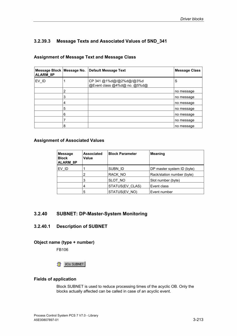
Driver blocks
Process Control System PCS 7 V7.0 - Library A5E00807897-01 3-213
3.2.39.3 Message Texts and Associated Values of SND_341
Assignment of Message Text and Message Class
Message Block ALARM_8P
Message No.
Default Message Text
Message Class
EV_ID 1 CP 341 @1%d@/@2%d@/@3%d @Event class @4%d@ no. @5%d@
S
2 no message 3 no message 4 no message 5 no message 6 no message 7 no message 8 no message
Assignment of Associated Values Message Block ALARM_8P
Associated Value
Block Parameter
Meaning
EV_ID 1 SUBN_ID DP master system ID (byte) 2 RACK_NO Rack/station number (byte) 3 SLOT_NO Slot number (byte) 4 STATUS(EV_CLAS) Event class 5 STATUS(EV_NO) Event number
3.2.40 SUBNET: DP-Master-System Monitoring
3.2.40.1 Description of SUBNET
Object name (type + number) FB106
Fields of application Block SUBNET is used to reduce processing times of the acyclic OB. Only the blocks actually affected can be called in case of an acyclic event.

Driver blocks
Process Control System PCS 7 V7.0 - Library 3-214 A5E00807897-01
Calling OBs Block SUBNET must be installed in the run sequence in the following OBs: OB1 Cyclic program
OB55 Status interrupt (only if a DP/PA slave is required) OB56 Update interrupt (only if a DP/PA slave is required) OB57 Vendor-specific alarm (only if a DP/PA slave is required) OB70 I/O redundancy error OB72 CPU redundancy error OB81 Power supply error OB82 Diagnostic interrupt OB83 Removal/insertion alarm OB85 Program runtime error OB86 Rack failure OB100 Restart (warm start)
Use in CFC When the CFC function "Generate module drivers" is used, the following occurs automatically:
• Runtime groups with driver blocks are created, organized by racks.
• The SUBN1_ID, SUBN2_ID and SUBN_TYP inputs are configured.
• EN_Rxxx outputs are interconnected with the relevant blocks (e.g., RACK).
• The INOUT structure CPU_DIAG is interconnected with the OUT structure of the OB_BEGIN block.
• The INOUT structure SZL_71 is interconnected with the OUT structure of the OB_BEGIN block.
• The OUT structure SUB_DIAG is interconnected with the INOUT structures of the relevant blocks (e.g., RACK).
Function and Operating Principle The SUBNET block monitors a DP master system and enables the blocks (e.g., RACK) for processing the connected DP slaves (for example, ET 200M). Corresponding messages are generated and the output variables SUBN1ERR and SUBN2ERR set on failure or redundancy loss at a DP master system. The output structure SUB_DIAG contains the geographical address of the DP Master system (and of DP Master system 2 in H systems), as well as the group error information SUBN0_ERR (for DP master system 1) and SUBN1_ERR (for DP master system 2). If SUBN0_ERR = 1 or SUBN1_ERR = 1, the corresponding DP Master system is not available.
The SUBNET block is installed in each connected DP master system or in the OBs listed above once for the local I/O devices. It is enabled by OB_BEGIN. Start and diagnostic information is read from the CPU_DIAG structure.
Driver blocks
Process Control System PCS 7 V7.0 - Library A5E00807897-01 3-215
It must be interconnected with the CPU_DIAG structure of OB_BEGIN (implemented automatically when the CFC function "Generate module drivers" is used). The SUBNET block is assigned one enable output for each connectable rack or DP Master system (for each expansion rack in the case of local I/O devices). By means of the start information of the calling OB, it determines whether the event reported has occurred at its DP master (or at the local I/O devices) and then sets the output for the relevant rack or DP master system (EN_Rxxx).
When redundant DP master systems are used (only for H CPUs), a rack (e.g., ET 200M) is connected to the two DP masters and is assigned the same station number at both. The SUBNET block provides two input parameters (SUBNx_ID) and the type identifier SUBN_TYP for this function. If the integrated interface of the CPU module is the DP master, SUBN_TYP = FALSE must be set. SUBN_TYP = TRUE is to be set otherwise.
The outputs MASTER_0 and MASTER_1 indicate which CPU is currently master.
If a DP master fails, the system sets all EN_Rxxx = TRUE and reports redundancy loss or failure. On return of redundancy or of the DP master, it reports this event after the failed DP slave has reestablished the connection.
The status of the DP master system as well as the set SUBNx_ID including the type identifier are saved in the output structure SUB_DIAG.
If a "power supply error" (OB81) occurs, the SUBNET block enables RACK blocks only if these represent expansion racks, which is indicated by SUBNx_ID = 0.
If you want to modify the SUBN1_ID (connection to CPU 0) and SUBN2_ID (connection to CPU 1) inputs online without using the CFC function "Generate module drivers", you must set input ACC_ID = TRUE in order to update the output values.
Redundancy The SUBNET block supports redundancy of DP master systems of the 414-H/417-H CPU when operating with distributed I/O. If you want to use this function, you must configure the SUBN1_ID (connection to CPU 0) and SUBN2_ID (connection to CPU 1) inputs with the numbers of the redundant DP master systems. If there is no redundancy, the remaining input must be assigned the value 16#FF (default).
Error handling The block handles only the error information of ALARM_8P. You can find additional information about error handling in "Error Information of Output Parameter MSG_STAT".
Driver blocks
Process Control System PCS 7 V7.0 - Library 3-216 A5E00807897-01
Startup/Initial Startup Behavior The SUBNET block initializes the messages of ALARM_8P.
The operating mode of the DP Master system is sampled and entered in the structure SUB_DIAG.V1_MODE with SSL 0X90H (0 = compatibility mode, 1 = DPV1 mode). If the DPV1 mode is active, the structure CPU_DIAG.MODE_V1 is also set to TRUE.
Overload Behavior The SUBNET block counts the OB86 calls (only failures). The counter is reset in OB1. If more than two OB86 failure events occur successively before the cycle control point (OB1) is reached, these are discarded and a message "Failure OB86 DP Master system:x" is output. If an OB86 call is rejected, the DP master system is registered as having failed.
Dynamic response n.a.
Message response After being called by an OB86, OB70 and OB72, the block analyzes the status of its assigned DP master system, generates corresponding messages relevant to redundancy loss or DP Master system failure and then outputs this message via an ALARM_8P. The message function can be disabled by setting EN_MSG = FALSE.
The SUBNET block generally reports only events triggered in the DP master system it monitors.
Exception: If there is a CPU failure in the H system, the following messages are generated:
• in a primary DP master system: message "DP master failure"
• in a redundant DP master system: message "DP master redundancy loss"
Operating and Monitoring Note: If you have selected the "Enable operating and monitoring" option in the block object properties in the CFC, the variables transferred to the OS are identified under "I/Os of …" (OCM column, "+"). Default: option not selected.
If asset management is used in the project and the diagnostic screens have been generated, then the faceplate can be called via its icon.
• Faceplate OB_BEGIN
Note: Online help and the "PCS 7 FACEPLATES" Manual are only available if the "PCS 7 FACEPLATES" software package is installed!
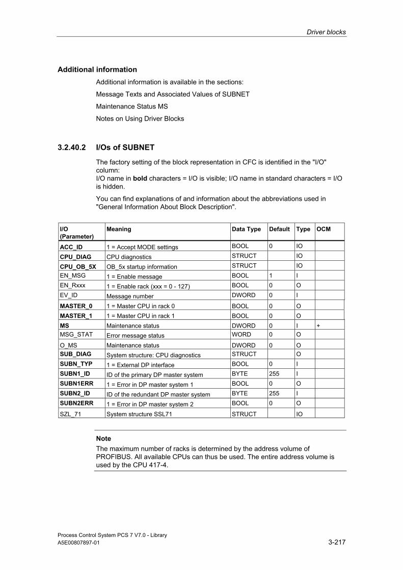
Driver blocks
Process Control System PCS 7 V7.0 - Library A5E00807897-01 3-217
Additional information Additional information is available in the sections:
Message Texts and Associated Values of SUBNET
Maintenance Status MS
Notes on Using Driver Blocks
3.2.40.2 I/Os of SUBNET
The factory setting of the block representation in CFC is identified in the "I/O" column: I/O name in bold characters = I/O is visible; I/O name in standard characters = I/O is hidden.
You can find explanations of and information about the abbreviations used in "General Information About Block Description".
I/O (Parameter)
Meaning
Data Type
Default Type OCM
ACC_ID 1 = Accept MODE settings BOOL 0 IO CPU_DIAG CPU diagnostics STRUCT IO CPU_OB_5X OB_5x startup information STRUCT IO EN_MSG 1 = Enable message BOOL 1 I EN_Rxxx 1 = Enable rack (xxx = 0 - 127) BOOL 0 O EV_ID Message number DWORD 0 I MASTER_0 1 = Master CPU in rack 0 BOOL 0 O MASTER_1 1 = Master CPU in rack 1 BOOL 0 O MS Maintenance status DWORD 0 I + MSG_STAT Error message status WORD 0 O O_MS Maintenance status DWORD 0 O SUB_DIAG System structure: CPU diagnostics STRUCT O SUBN_TYP 1 = External DP interface BOOL 0 I SUBN1_ID ID of the primary DP master system BYTE 255 I SUBN1ERR 1 = Error in DP master system 1 BOOL 0 O SUBN2_ID ID of the redundant DP master system BYTE 255 I SUBN2ERR 1 = Error in DP master system 2 BOOL 0 O SZL_71 System structure SSL71 STRUCT IO
Note
The maximum number of racks is determined by the address volume of PROFIBUS. All available CPUs can thus be used. The entire address volume is used by the CPU 417-4.

Driver blocks
Process Control System PCS 7 V7.0 - Library 3-218 A5E00807897-01
Additional information Additional information is available in the sections:
Message Texts and Associated Values of SUBNET
Maintenance Status MS
3.2.40.3 Message Texts and Associated Values of SUBNET
Assignment of Message Text and Message Class Message No. Default Message Text Message
Class
1 DP master @1%d@: Redundancy loss F 2 DP master @2%d@: Redundancy loss F 3 DP master @1%d@: Failure S 4 DP master @2%d@: Failure S 5 DP master @2%d@: Repeated failure S 6 CPU loss of redundancy in rack @4%d@ F
Assignment of Associated Values Associated Value
Block Parameter
1 ID of the primary DP master system (SUBN1_ID) 2 ID of the redundant DP master system (SUBN2_ID) 3 Multiple failure, ID of DP master system

Driver blocks
Process Control System PCS 7 V7.0 - Library A5E00807897-01 3-219
3.3 PROFIBUS PA Blocks
3.3.1 DIAG_AB: Evaluation of the Status Word AB7000
3.3.1.1 Description of DIAG_OB
Object name (type + number) FB 414
Area of Application The block DIAG_AB evaluates the status word of an AB7000 slave and acknowledges newly reported errors via the control word of the slave.
Calling OBs The cyclic OB and OB 100
Use in CFC When the CFC function "Generate module drivers" is used, the following occurs automatically:
• The block is installed in the run sequence in front of the block MOD_PAL0 or block MOD_PAX0 which are also installed by the driver wizard. The install is executed in the same cyclic OB as the associated signal processing blocks FF_A_xx.
• Parameters are assigned to the input LADDR_C with the address control word of the AB7000.
• Parameters are assigned to the input LADDR_S with the address control word of the AB7000.
• The OUT structure CPU_DIAG of the OB_BEGIN block is interconnected with the INOUT structures of the same name of DIAG_AB.
• The input mode of the DIAG_AB block is interconnected with the output OMODE_00 of the PADP_L10 or PADP_L01 block.
• The input PA_DIAG of the DIAG_AB block is interconnected with the output PA_DIAG of the PADP_L10 or PADP_L01 block.
• The output OMODE of the DIAG_AB block is interconnected with the input MODE_00 of the MOD_PAL0 or MOD_PAX0 block.
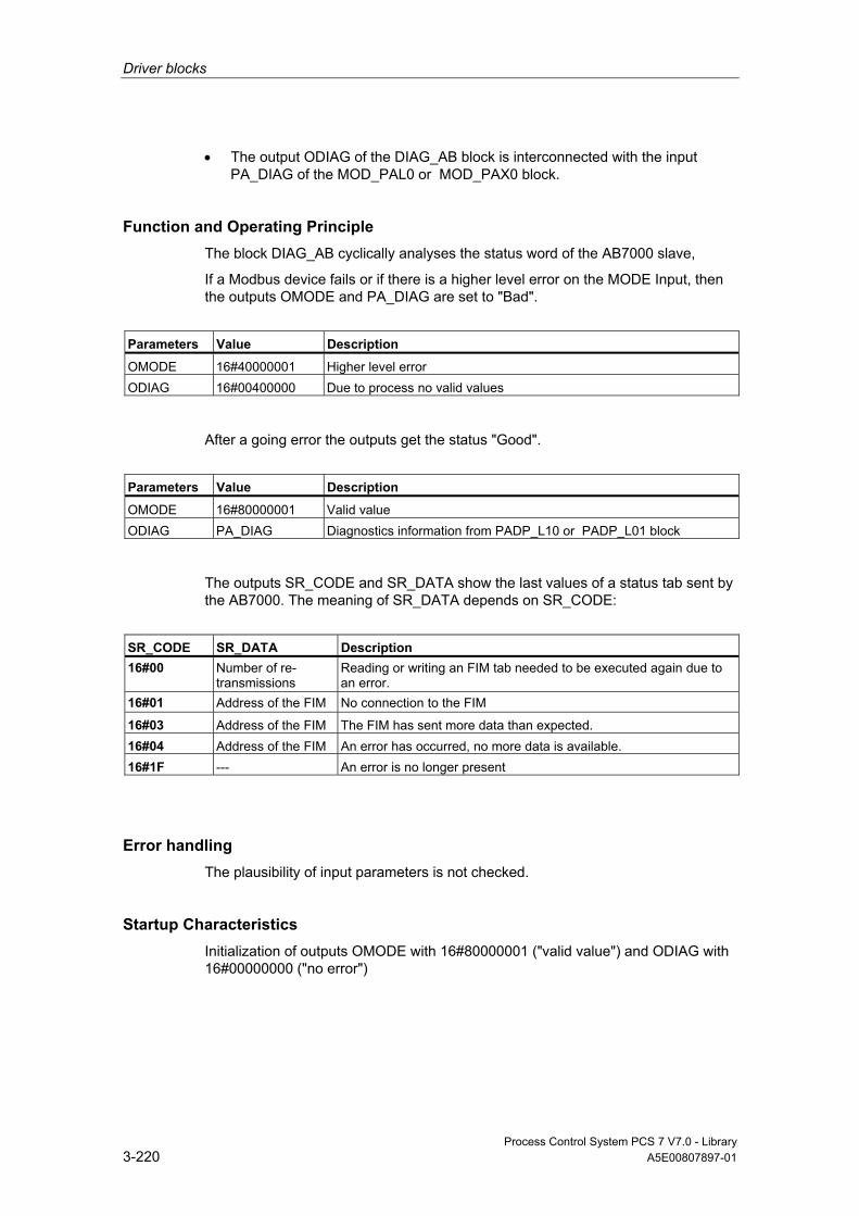
Driver blocks
Process Control System PCS 7 V7.0 - Library 3-220 A5E00807897-01
• The output ODIAG of the DIAG_AB block is interconnected with the input PA_DIAG of the MOD_PAL0 or MOD_PAX0 block.
Function and Operating Principle The block DIAG_AB cyclically analyses the status word of the AB7000 slave,
If a Modbus device fails or if there is a higher level error on the MODE Input, then the outputs OMODE and PA_DIAG are set to "Bad".
Parameters Value Description
OMODE 16#40000001 Higher level error ODIAG 16#00400000 Due to process no valid values
After a going error the outputs get the status "Good".
Parameters Value Description
OMODE 16#80000001 Valid value ODIAG PA_DIAG Diagnostics information from PADP_L10 or PADP_L01 block
The outputs SR_CODE and SR_DATA show the last values of a status tab sent by the AB7000. The meaning of SR_DATA depends on SR_CODE:
SR_CODE SR_DATA Description 16#00 Number of re-
transmissions Reading or writing an FIM tab needed to be executed again due to an error.
16#01 Address of the FIM No connection to the FIM
16#03 Address of the FIM The FIM has sent more data than expected. 16#04 Address of the FIM An error has occurred, no more data is available. 16#1F --- An error is no longer present
Error handling The plausibility of input parameters is not checked.
Startup Characteristics Initialization of outputs OMODE with 16#80000001 ("valid value") and ODIAG with 16#00000000 ("no error")

Driver blocks
Process Control System PCS 7 V7.0 - Library A5E00807897-01 3-221
Time Response n.a.
Message Capability n.a.
Operator Control and Monitoring n.a.
Additional Information For more information, refer to the section:
Notes on Using Driver Blocks
3.3.1.2 I/Os of DIAG_AB
The factory setting of the block display in CFC is identified in the "I/O" column: I/O name in bold characters = I/O is visible; I/O name in standard characters = I/O is hidden.
You can find explanations of and information about the abbreviations used in "General Information About Block Description".
I/O
Meaning
Data Type
Default Type
OCM
CPU_DIAG CPU diagnostics (system structure) STRUCT I/O LADDR_C Logical address of the control word INT 0 I LADDR_S Logical address of the control word INT 0 I MODE Value status DWORD 16#80 000 000 I ODIAG Field devices diagnostics information DWORD 0 O OMODE Value status of the slave DWORD 0 O PA_DIAG Diagnostic Information DWORD 0 I SR_CODE Code of the status tab BYTE 0 O SR_DATA Data of the status tab BYTE 0 O

Driver blocks
Process Control System PCS 7 V7.0 - Library 3-222 A5E00807897-01
3.3.2 DPAY_V0: Monitoring DP/PA-Link and Y-Link as V0 Slave
3.3.2.1 Description of DPAY_V0
Object name (type + number) FB 108
Area of Application Block DPAY_V0 monitors the status of a DP/PA or Y link as a V0 slave (IM 157) and reports the corresponding error events.
The DP/PA link operates as a PA master for the lower-level PA field devices and as a slave on the DP bus.
The Y link operates as a DP master for the lower-level DP field devices and as a slave on the higher-level DP bus.
Calling OBs The block must be installed in the run sequence in the following OBs: OB 1 Cyclic program
OB 70 I/O redundancy error OB 72 CPU redundancy error OB 82 Diagnostic interrupt OB 85 Program runtime error OB 86 Rack failure OB 100 Restart (warm start)
Use in CFC When the CFC function "Generate module drivers" is used, the following occurs automatically:
• The block is integrated in the run sequence downstream from the SUBNET block and upstream from the PADP_L0x block.
• RACK_NO (rack/station number) is configured.
• SUBN_TYP (internal/external Profibus interface) is parameterized.
• SUBN1_ID (ID of the master systems) is parameterized.
• SUBN2_ID (ID of the redundant master system) is parameterized.
• DADDR (diagnostic address of the DP/PA or Y link) is configured.

Driver blocks
Process Control System PCS 7 V7.0 - Library A5E00807897-01 3-223
• DPPA_xx (slave xx address), 1st module (slot) address of slave xx in the link, number of slots of the slave xx are configured.
• The CPU_DIAG OUT structures of the OB_BEGIN block and SUB_DIAG of the SUBNET block are interconnected with the INOUT structures of the same name of DPAY_V0.
• In the case of PA or DP field devices, they are interconnected with PADP_L0x.
Function and Operating Principle If redundancy losses and link failures occur, the DPAY_V0 block generates a control-system error message for the OS. The block also indicates error events at active links (SUBN1ERR, SUBN2ERR) and at the preferred channel (SUBN1ACT, SUBN2ACT) in the output status bar. The output structure RAC_DIAG contains the geographic address of the link as well as the group error information RACK_ERR. The corresponding link is not available if RACK_ERR = 1.
It requires a PROFIBUS DP interface, which can be integrated either in the CPU or provided by means of an external DP interface (CP). PROFIBUS DP is converted to PROFIBUS PA by means of a SIMATIC DP/PA-Link.
The field devices of a link are always addressed at the higher-level DP bus via the DP address of IM 157.
The AS addresses the field devices via the link, i.e., indirectly. The topological structure of the PA bus is mapped in the flat structure of the slave interface. A maximum of 64 field devices can be operated downstream from a link. Each field device can use any number of virtual slots at the link, up to 223 maximum.
In order to enable the assignment of diagnostic data to the field devices, the block provides each field device a DPPA_xx input structure consisting of 3 bytes with the following contents:
• Byte (SLAV_NO) = node number (address) of the field device at the PA/DP master system of the LINK
• Byte (SLOT_NO) = 1st module address of the field device in the link
• Byte (SLAV_SL) = number of slots of the field device
The CFC function "Generate module drivers" fetches these data from HW Config.
The startup information is read from the I/O structure CPU_DIAG. This structure must be interconnected to the CPU_DIAG structure of the OB_BEGIN block (carried out by the CFC function "Generate module drivers").
The block generates a corresponding message (see "Message Capability") on the basis of the startup information of calling OBs, if the current instance is affected.
When operating with redundant PROFIBUS DP interfaces, the block determines the currently active preferred channel (SUBN1ACT, SUBN2ACT) by evaluating the error events as well as via the diagnostic address DADDR of the link.
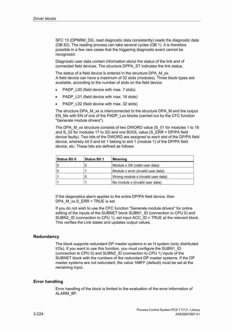
Driver blocks
Process Control System PCS 7 V7.0 - Library 3-224 A5E00807897-01
SFC 13 (DPNRM_DG, read diagnostic data consistently) reads the diagnostic data (OB 82). The reading process can take several cycles (OB 1). It is therefore possible in a few rare cases that the triggering diagnostic event cannot be recognized.
Diagnostic user data contain information about the status of the link and of connected field devices. The structure DPPA_ST indicates the link status.
The status of a field device is entered in the structure DPA_M_xx. A field device can have a maximum of 32 slots (modules). Three block types are available, according to the number of slots on the field device:
• PADP_L00 (field device with max. 7 slots)
• PADP_L01 (field device with max. 16 slots)
• PADP_L02 (field device with max. 32 slots)
The structure DPA_M_xx is interconnected to the structure DPA_M and the output EN_Mx with EN of one of the PADP_Lxx blocks (carried out by the CFC function "Generate module drivers").
The DPA_M_xx structure consists of two DWORD value (S_01 for modules 1 to 16 and S_02 for modules 17 to 32) and one BOOL value (S_ERR = DP/PA field device faulty). Two bits of the DWORD are assigned to each slot of the DP/PA field device, whereby bit 0 and bit 1 belong to slot 1 (module 1) of the DP/PA field device, etc. These bits are defined as follows:
Status Bit 0 Status Bit 1 Meaning
0 0 Module x OK (valid user data) 0 1 Module x error (invalid user data) 1 0 Wrong module x (invalid user data) 1 1 No module x (invalid user data)
If the diagnostics alarm applies to the entire DP/PA field device, then DPA_M_xx.S_ERR = TRUE is set.
If you do not wish to use the CFC function "Generate module drivers" for online editing of the inputs of the SUBNET block SUBN1_ID (connection to CPU 0) and SUBN2_ID (connection to CPU 1), set input ACC_ID = TRUE at the relevant block. This verifies the Link states and updates output values.
Redundancy The block supports redundant DP master systems in an H system (only distributed I/Os). If you want to use this function, you must configure the SUBN1_ID (connection to CPU 0) and SUBN2_ID (connection to CPU 1) inputs of the SUBNET block with the numbers of the redundant DP master systems. If the DP master systems are not redundant, the value 16#FF (default) must be set at the remaining input.
Error handling Error handling of the block is limited to the evaluation of the error information of ALARM_8P.

Driver blocks
Process Control System PCS 7 V7.0 - Library A5E00807897-01 3-225
You can find additional information in "Error Information of Output Parameter MSG_STAT".
Startup Characteristics The block initializes the messages of ALARM_8P. Availability of the link is verified. in H systems, determines the preferred channel of the link.
Overload Behavior The block counts OB 86 (no DP master system failure, see SUBNET block) and OB 82 calls. Both counters are reset in OB 1. If more than five OB 86 events occur in succession before the cycle control point is reached (OB 1), these events are discarded and the message ""DP-Link DP-Master:x Rack:y: Multiple failure" or the message "DP-Link Master:x Rack:y: recursive alarm (OB 82)" is output. 1 minute later the status of the link will be re-checked.
Time Response n.a.
Message Capability After its call by OB 70, OB 72, OB 85 or OB 86, the block analyzes the status of its assigned CPU, DP master and link If the link loses redundancy or fails, the block outputs corresponding messages via ALARM_8P.
The block generally reports only the events generated in the link that it monitors. Redundancy loss and link failures which are caused by the failure of a DP masters or of a CPU, are initially neither signaled nor indicated at the outputs SUBN1ERR and SUBN2ERR.
The DELAY input is used to delay the output of error messages for outgoing higher-priority errors. This delay time is configurable. When the block recognizes an outgoing error at an interconnected DP master, it initially assumes that there is a faulty assigned DP slave in the link it monitors and sets the corresponding output SUBNxERR. The error status is not reset until the DP slave returns (in this case: OB 86, OB 70). The blocks delay error messages relevant to any slave failure states for a time in seconds as specified in DELAY, in order not to trigger the output of surge of messages from DP slaves which are not yet synchronized after the master has returned. An error message is not output to the OS unless the DP slave has reported its return before this delay time has expired.
Do not set the value of DELAY too high, since messages reporting faulty DP slaves or their removal during a master failure will be output too late to the OS after the DP master returns.
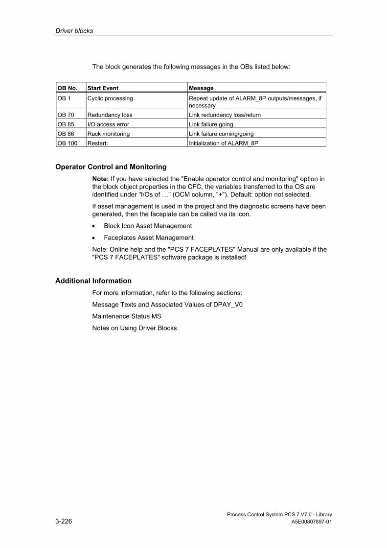
Driver blocks
Process Control System PCS 7 V7.0 - Library 3-226 A5E00807897-01
The block generates the following messages in the OBs listed below:
OB No. Start Event Message
OB 1 Cyclic processing Repeat update of ALARM_8P outputs/messages, if necessary
OB 70 Redundancy loss Link redundancy loss/return OB 85 I/O access error Link failure going OB 86 Rack monitoring Link failure coming/going OB 100 Restart: Initialization of ALARM_8P
Operator Control and Monitoring Note: If you have selected the "Enable operator control and monitoring" option in the block object properties in the CFC, the variables transferred to the OS are identified under "I/Os of …" (OCM column, "+"). Default: option not selected.
If asset management is used in the project and the diagnostic screens have been generated, then the faceplate can be called via its icon.
• Block Icon Asset Management
• Faceplates Asset Management
Note: Online help and the "PCS 7 FACEPLATES" Manual are only available if the "PCS 7 FACEPLATES" software package is installed!
Additional Information For more information, refer to the following sections:
Message Texts and Associated Values of DPAY_V0
Maintenance Status MS
Notes on Using Driver Blocks

Driver blocks
Process Control System PCS 7 V7.0 - Library A5E00807897-01 3-227
3.3.2.2 I/Os of DPAY_V0
The factory setting of the block display in CFC is identified in the "I/O" column: I/O name in bold characters = I/O is visible; I/O name in standard characters = I/O is hidden.
You can find explanations of and information about the abbreviations used in "General Information About Block Description".
I/O (Parameter)
Meaning
Data Type
Default Type
OCM
ACC_ID 1 = Accept MODE settings BOOL 0 I/O CPU_DIAG CPU diagnostics (system structure) STRUCT I/O DADDR Diagnostic address of the DP slave INT 0 I DELAY Interrupt delay (s) INT 15 I DPA_M_xx Status of the DP/PA slave (xx = 00 - 63) STRUCT O DPPA_ST DP/PA/Y-Link status STRUCT O DPPA_xx Information of the DP/PA slave (xx = 00 - 63) STRUCT I EN_MSG 1 = Enable message BOOL 1 I EN_Mxx 1 = Enable modules (xx = 00 - 63) BOOL 0 O EV_ID Message number DWORD 0 I MS Maintenance status DWORD 0 I + MSG_STAT Error message status WORD 0 O O_MS Maintenance status DWORD 0 O RAC_DIAG Rack diagnostics BOOL 0 O RACK_NO Rack/station number WORD 0 I SUB_DIAG OB startup information STRUCT I/O SUBN_TYP 1 = External DP interface BOOL 0 I SUBN1_ID ID of the primary DP master system BYTE 255 I SUBN1ACT 1 = Slave 1 is active BOOL 0 O SUBN1ERR 1 = Error in DP master system 1 BOOL 0 O SUBN2_ID ID of the redundant DP master system BYTE 255 I SUBN2ACT 1 = Slave 2 is active BOOL 0 O SUBN2ERR 1 = Error in DP master system 2 BOOL 0 O
Additional Information For more information, refer to the following sections:
Message Texts and Associated Values of DPAY_V0
Maintenance Status MS
Driver blocks
Process Control System PCS 7 V7.0 - Library 3-228 A5E00807897-01
3.3.2.3 Message Texts and Associated Values of DPAY_V0
Assignment of Message Text and Message Class Message No. Default Message Text Message
Class 1 DP Link @1%d@/ @3%d@: Redundancy loss S 2 DP Link @2%d@/ @3%d@: Redundancy loss S 3 DP Link @1%d@/ @3%d@: Failure S 4 DP Link @2%d@/ @3%d@: Failure S 5 - - 6 - - 7 DP LINK @1%d@/ @3%d@: Multiple alarm
(OB 82) S
8 DP LINK @1%d@/ @3%d@: Repeated failure S
Assignment of Associated Values Associated Value
Block Parameter
1 ID of the primary DP master system (SUBN1_ID) 2 ID of the redundant DP master system (SUBN2_ID) 3 Rack/station number (RACK_NO)
3.3.3 DPAY_V1: Enabling Blocks Downstream of a DP/PA-Link and Y-Link as V1 Slave
3.3.3.1 Description of DPAY_V1
Object name (type + number) FB 115
Area of Application Block DPAY_V1 enables field-device-specific blocks installed downstream of the DP/PA or Y links.
The DP/PA link operates as a PA master for the lower-level PA field devices and as a slave on the DP bus.
The Y link operates as a DP master for the lower-level DP field devices and as a slave on the higher-level DP bus.

Driver blocks
Process Control System PCS 7 V7.0 - Library A5E00807897-01 3-229
Calling OBs The block must be installed in the run sequence in the following OBs: OB 1 Cyclic program
OB 55 Status interrupt OB 56 Update interrupt OB 57 Manufacturer-specific alarm OB 70 I/O redundancy error OB 72 CPU redundancy error OB 82 Diagnostic interrupt OB 83 Removal/insertion alarm OB 85 Program runtime error OB 86 Rack failure OB 100 Restart (warm start)
Use in CFC When the CFC function "Generate module drivers" is used, the following occurs automatically:
• The block is integrated in the run sequence downstream of block OB_DIAG1.
• SUBN_1ID (ID of primary DP master system) is configured.
• SUBN_2ID (ID of secondary DP master system) is configured.
• RACK_NO (rack/station number) is configured.
• The OUT structure CPU_DIAG of the OB_BEGIN block is interconnected with the INOUT structures of the same name of DPAY_V1.
• The OUT structure CPU_OB_5X of the OB_BEGIN block is interconnected with the INOUT structures of the same name of DPAY_V1.
• EN_Mxx is interconnected with EN of OB_DIAG1 and PADP_L10 for each field device.
Function and Operating Principle The startup information is read from the I/O structure CPU_DIAG. The structure must be interconnected with the CPU_DIAG structure of OB_BEGIN (carried out by the CFC function "Generate module drivers"). The downstream blocks will be enabled according to the startup information.

Driver blocks
Process Control System PCS 7 V7.0 - Library 3-230 A5E00807897-01
OB5x characteristics Enables the output for the relevant field device.
Redundancy The redundancy is evaluated in OB_DIAG1.
Error handling The plausibility of input parameters is not checked.
Startup Characteristics The block initializes its outputs.
Overload Behavior OB_DIAG1 disables the block on overload.
Time Response n.a.
Message Capability n.a.
Operator Control and Monitoring The block has no faceplate.
Additional Information For more information, refer to the section:
Notes on Using Driver Blocks
3.3.3.2 I/Os of DPAY V1
The factory setting of the block display in CFC is identified in the "I/O" column: I/O name in bold characters = I/O is visible; I/O name in standard characters = I/O is hidden.
You can find explanations of and information about the abbreviations used in "General Information About Block Description".
Driver blocks
Process Control System PCS 7 V7.0 - Library A5E00807897-01 3-231
I/O (Parameter)
Meaning
Data Type
Default Type
CPU_DIAG CPU diagnostics (system structure) STRUCT I/O CPU_OB_5X OB_5x startup information STRUCT I/O DPPA_xx Information of the DP/PA slave (xx = 00 - 63) STRUCT I
EN_Mxx 1 = Enable slave (xx = 00 - 63) BOOL 0 O RACK_NO Rack/station number WORD 0 I SUBN1_ID ID of the primary DP master system BYTE 255 I SUBN2_ID ID of the redundant DP master system BYTE 255 I
3.3.4 FF_A_AI: Editing PA Profile Transmitter
3.3.4.1 Description of FF_A_AI
Object name (type + number) FB 410
Area of Application The block FF_A_AI processes (cyclic service) the PA profile "Transmitter" of an FF field device.
Calling OBs The calling OB is the watchdog alarm OB 3x into which you integrate the block (for example, OB 32).
Use in CFC When the CFC function "Generate module drivers" is used, the following occurs automatically:
• The icon for the quality code of the analog input channel is interconnected with input QC_W.
• The MODE input is interconnected with the OMODE_00 output of the MOD_PAL0 block or MOD_PAX0 block.

Driver blocks
Process Control System PCS 7 V7.0 - Library 3-232 A5E00807897-01
Function and Operating Principle The block FF_A_AI cyclically reads the process value (Quality Code) of the FF field device from the process image partition. The process variable is available in a physical unit. The status byte (STATUS) contains information about the status of the FF field device.
Linking in ASSET The block FF_A_AI can be linked in ASSET. Additional information is available in the section Linking FF Devices in ASSET.
Quality Code A quality code (QUALITY output) is generated for the result value that can adopt the following values:
State Quality Code
Valid value 16#80 Simulation 16#60 Higher-level error, last valid value 16#14 Higher-level error, substitute value 16#18 Bad, due to process 16#28 Uncertain, due to device 16#68 Uncertain, due to process 16#78 Last valid value 16#44 Substitute Value 16#48 Range overshoot 16#54 Maintenance request present 16#A4 Invalid value 16#00
The quality code is formed from internal events, such as channel error, higher-level error or simulation and from a quality code, that comes directly from the device (parameter QC-W).
The quality code that comes directly from the device can take on values from 16#00 – 16#FF. The imaging of these values on the displayable values listed above is shown in the table "QC_MS" table of the current LIB readme. The Quality Codes 16#84-16#87 and 16#90 – 16#93 of the FF field device are analyzed like the Quality Codes 16#80 – 16#83. If the Quality Code 16#80 (valid value) and a process value (input VALUE) with the bit pattern 16#7FFFFFFF (invalid value) from the FF device are transferred, then this is handled the same as Quality Code 16#00 (invalid value) by the FF field device.
In addition to the status byte and to improve interconnectability, the output interface provides further Boolean (BOOL) values, which contain important details. They conform to bit combinations specifications in PROFIBUS PA 3.0 "General Requirements".

Driver blocks
Process Control System PCS 7 V7.0 - Library A5E00807897-01 3-233
The block recognizes a higher-level error, for example, failure of a DP/PA link, via the MODE input parameter.
• If the MODE high byte = 16#80, then the values in the process image (partition) are valid.
• If the MODE high byte = 16#40 (value status = higher-level error), the analog value is treated as invalid.
The mode of the input parameter MODE_LW is not considered.
Addressing You must configure an icon for the analog input channel in the icon table and connect it with the input VALUE. The icon for the Quality Code of the analog input channel interconnects the CFC function "Generate Module Driver with the input parameter QC_W.
Simulation When input parameter SIM_ON = TRUE, the value of the input parameter SIM_V is output with Quality Code (QUALITY =) 16#60. Simulation takes highest priority. QBAD is always set to FALSE. If the block is in the simulation status, QSIM = TRUE is set.
Substitute Value If input parameter SUBS_ON = TRUE, the value of input parameter SUBS_V is output as a value if the values are invalid. The Quality Code (QUALITY) is set to 16#48 and QBAD = 1.
Output invalid value If the input parameter is SUBS_ON = FALSE and an invalid process value is present, then this will be output.
The quality code that is output is listed in the table "QC_MS" of the LIB readme. In addition QBAD = 1 is set.
Value Limiting You can limit the maximum low and high range of process variables in the process image (partition).
LIMIT_ON = TRUE limits process variables (V):
• To V_HL, if V > V_HL
• To LL_V, if V < V_LL
Error handling The plausibility of input parameters is not checked.

Driver blocks
Process Control System PCS 7 V7.0 - Library 3-234 A5E00807897-01
Startup Characteristics n.a.
Time Response n.a.
Message Capability n.a.
Operator Control and Monitoring The block has no faceplate.
Additional Information For more information, refer to the section:
Notes on Using Driver Blocks
3.3.4.2 I/Os of FF_A_AI
The factory setting of the block display in CFC is identified in the "I/O" column: I/O name in bold characters = I/O is visible; I/O name in standard characters = I/O is hidden.
You can find explanations of and information about the abbreviations used in "General Information About Block Description".
I/O (Parameter)
Meaning
Data Type
Default Type
LIMIT_ON 1 = Limit input value ON BOOL 0 I LL_V Value if V < V_LL REAL 0 I MODE Value status DWORD 0 I MODE_LW Operating Mode WORD 1 I QA_1 1 = Interrupt/warning 1 BOOL 0 O QA_2 1 = Interrupt/warning 2 BOOL 0 O QBAD 1 = Group event QBAD_X BOOL 0 O QBAD_0 1 = Non-specific BOOL 0 O QBAD_1 1 = Configuration error BOOL 0 O QBAD_2 1 = Not connected BOOL 0 O QBAD_3 1 = Device failure BOOL 0 O QBAD_4 1 = Sensor failure BOOL 0 O QBAD_5 1 = No communication (last usable value) BOOL 0 O QBAD_6 1 = No communication (last usable value) BOOL 0 O

Driver blocks
Process Control System PCS 7 V7.0 - Library A5E00807897-01 3-235
I/O (Parameter)
Meaning
Data Type
Default Type
QBAD_7 1 = Out of service BOOL 0 O QBAD_HL 1 = High limit of physical range of sensor has been
reached BOOL 0 O
QBAD_LL 1 = Low limit of physical range of sensor has been reached
BOOL 0 O
QC_W Status of the input process value WORD 0 I QCASCAD0 1 = OK (cascade) BOOL 0 O QCASCAD1 1 = Initialization acknowledged BOOL 0 O QCASCAD2 1 = Initialization request BOOL 0 O QCASCAD3 1 = Not required BOOL 0 O QCASCAD4 1 = Reserved BOOL 0 O QCASCAD5 1 = Do not select BOOL 0 O QCASCAD6 1 = Local overwrite BOOL 0 O QCASCAD7 1 = Reserved BOOL 0 O QCASCAD8 1 = Initiate fail-safe BOOL 0 O QCONST 1 = Constant BOOL 0 O QERR 1 = Output error (inverted value of ENO) BOOL 1 O QMOD_ERR 1 = Higher priority error BOOL 0 O QOUT_HHL 1 = Active critical alarm, high limit of OUT has been
exceeded BOOL 0 O
QOUT_HL 1 = Active warning, high limit of OUT has been exceeded
BOOL 0 O
QOUT_LL 1 = Active warning, low limit of OUT has been exceeded
BOOL 0 O
QOUT_LLL 1 = Active critical alarm, low limit of OUT has been exceeded
BOOL 0 O
QNONCAS0 1 = OK (non-cascade) BOOL 0 O QNONCAS1 1 = Update event BOOL 0 O QNONCAS2 1 = Active warning (priority <8) BOOL 0 O QNONCAS3 1 = Active critical alarm (priority >8) BOOL 0 O QNONCAS4 1 = Unacknowledged updated event BOOL 0 O QNONCAS5 1 = Unacknowledged warning BOOL 0 O QNONCAS6 1 = Unacknowledged critical alarm BOOL 0 O QNONCAS7 1 = Initiate fail-safe BOOL 0 O QNONCAS8 1 = Maintenance required BOOL 0 O QNONCAS9 1 = Function test/local overwrite; usable value BOOL 0 O QSIM 1 = Simulation enabled BOOL 0 O QSUBS 1 = Substitution enabled BOOL 0 O QUALITY Value status of the process variable BYTE 0 O QUNCERT 1 = Group message QUNCERTx BOOL 0 O QUNCERT0 1 = Non-specific BOOL 0 O QUNCERT1 1 = Last usable value BOOL 0 O QUNCERT2 1 = Substitute value set BOOL 0 O QUNCERT3 1 = Initial value BOOL 0 O QUNCERT4 1 = Unacknowledged updated event BOOL 0 O
Driver blocks
Process Control System PCS 7 V7.0 - Library 3-236 A5E00807897-01
I/O (Parameter)
Meaning
Data Type
Default Type
QUNCERT5 1 = Engineering unit violation (unit not in the valid set) BOOL 0 O QUNCERT6 1 = Under normal BOOL 0 O QUNCERT7 1 = Configuration error BOOL 0 O QUNCERT8 1 = Sensor calibration BOOL 0 O QUNCERT9 1 = Simulated value BOOL 0 O SIM_ON 1 = Enable simulation BOOL 0 I SIM_V Simulation value REAL 0 I STATUS Process value status BYTE 0 O SUBS_ON 1 = Enable substitution BOOL 0 I SUBS_V Substitute Value REAL 0 I V Process value REAL 0 O V_HL High limit input value REAL 0 I V_LL Low limit input value REAL 0 I VALUE Process Image Input Value REAL 0 I
3.3.5 FF_A_AO: Editing PA Profile Actuator
3.3.5.1 Description of FF_A_AI
Object name (type + number) FB 411
Area of Application The block FF_A_AO processes (cyclic service) the PA profile "Actuator" of an FF field device.
Calling OBs The calling OB is watchdog alarm OB 3x into which you integrate the block (for example, OB 32) and restart OB 100.
Use in CFC When the CFC function "Generate module drivers" is used, the following occurs automatically:
• The MODE input is interconnected with the OMODE_00 output of the MOD_PAL0 block or MOD_PAX0 block.
Driver blocks
Process Control System PCS 7 V7.0 - Library A5E00807897-01 3-237
Function and Operating Principle Depending on the selection (configuration of the input MODE_LW) of the user data configuration the block reads the user data from the partition process image and writes it in the partition process image.
The coding of the set user data configuration must be parameterized in the input variable MODE_LW according to the MODE for FF field devices. and specifies which variables are to be read and written in the process image (partition).
The block cyclically writes the setpoint (SP) with Quality Code (configuration of the setpoints and process values in accordance with the Analog Output of the PA profiles, REAL with 1 byte Quality Code) into the process image (partition). The PA profile contains the setpoint and other analog values as physical units. The Quality Code contains the information on the setpoint status. The coding of the quality codes is described in PROFIBUS 3.0 "General Requirements". The reference variable (RCAS_IN) can be transferred with the quality code to the process image (partition) in the same cycle.
Linking in ASSET The block FF_A_AO can be linked in ASSET. Additional information is available in the section Linking FF Devices in ASSET.
Quality Code A quality code (QUALITY output) is generated for the result value that can adopt the following values:
State Quality Code
Valid value 16#80 Simulation 16#60 Higher-level error, last valid value 16#14 Higher-level error, substitute value 16#18 Bad, due to process 16#28 Uncertain, due to device 16#68 Uncertain, due to process 16#78 Last valid value 16#44 Substitute Value 16#48 Range overshoot 16#54 Range overshoot low 16#55 Range overshoot high 16#56 Maintenance request present 16#A4 Invalid value 16#00
The quality code is formed from internal events, such as channel error, higher-level error or simulation and from a quality code, that comes directly from the device (parameter QC_POS_D_W, QC_RCAS_OUT_W, QC_READBACK_W).

Driver blocks
Process Control System PCS 7 V7.0 - Library 3-238 A5E00807897-01
The quality code that comes directly from the device can take on values from 16#00 – 16#FF. The imaging of these values on the displayable values listed above is shown in the table "QC_MS" table of the current LIB readme. The Quality Codes 16#84-16#87 and 16#90 – 16#93 of the FF field device are analyzed like the Quality Codes 16#80 – 16#83. If the Quality Code 16#80 (valid value) and an associated process value (inputs I_RCAS_OUT or I_READBACK) with the bit pattern 16#7FFFFFFF (invalid value) from the FF device are transferred, then this is handled the same as Quality Code 16#00 (invalid value) by the FF field device.
The data of the FF field device, as well as the process variable (READBACK) and the discrete position feedback (READBACK) are read cyclically from the process image (partition). Optionally you can also read the active reference variable (RCAS_OUT) and the detailed device information (CHECKBACK). The device information is available at the block output in bit segments. The data is read from the process image (partition). In order to improve the interconnectability, important detailed information is provided by the status bytes read (ST_READBACK) or ST_RCAS_OUT (if READBACK is not available) as Boolean (BOOL) values at the output interface. These conform to the bit combinations specified in PROFIBUS PA "General Requirements".
If a higher-level error has occurred (QMOD_ERR = TRUE), the data continue to be written to the process image (partition) and no data are read from the process image (partition). As long as the higher-priority error exists, the last values are held with QBAD = TRUE.
Note
The status byte of the reference variable (ST_RCAS_IN) is pre-defined with zero. The reference variable only becomes active in the FF field device if you set the quality code to 16#80.
Configuring the MODE_LW input In addition to the MODE input the MODE_LW (Mode Low Word) input must be configured according to the parameters used: Parameters used MODE_LW
SP 16#0100 SP, READBACK, POS_D 16#0103 SP, CHECK_BACK 16#0104 SP, READBACK, POS_D, CHECK_BACK 16#0105 RCAS_IN, RCAS_OUT 16#0206 RCAS_IN, RCAS_OUT, CHECK_BACK 16#0207 SP, RCAS_IN, READBACK, RCAS_OUT, POS_D, CHECK_BACK 16#0308
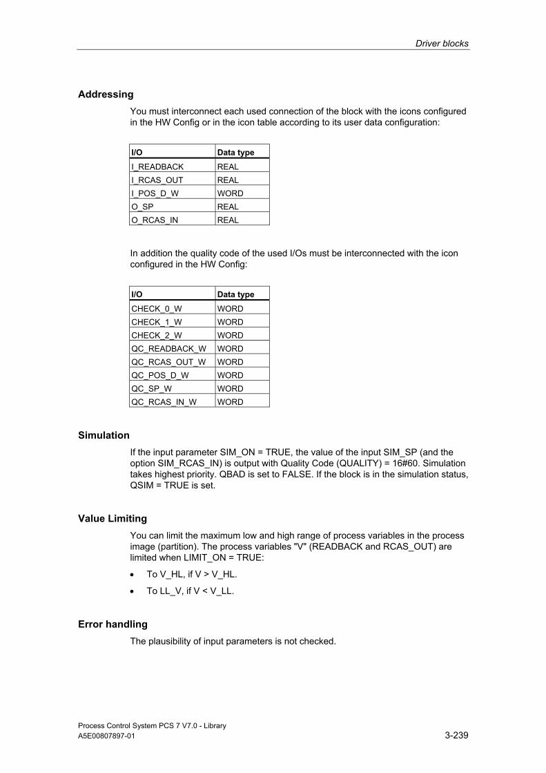
Driver blocks
Process Control System PCS 7 V7.0 - Library A5E00807897-01 3-239
Addressing You must interconnect each used connection of the block with the icons configured in the HW Config or in the icon table according to its user data configuration:
I/O Data type
I_READBACK REAL I_RCAS_OUT REAL I_POS_D_W WORD O_SP REAL O_RCAS_IN REAL
In addition the quality code of the used I/Os must be interconnected with the icon configured in the HW Config:
I/O Data type
CHECK_0_W WORD CHECK_1_W WORD CHECK_2_W WORD QC_READBACK_W WORD QC_RCAS_OUT_W WORD QC_POS_D_W WORD QC_SP_W WORD QC_RCAS_IN_W WORD
Simulation If the input parameter SIM_ON = TRUE, the value of the input SIM_SP (and the option SIM_RCAS_IN) is output with Quality Code (QUALITY) = 16#60. Simulation takes highest priority. QBAD is set to FALSE. If the block is in the simulation status, QSIM = TRUE is set.
Value Limiting You can limit the maximum low and high range of process variables in the process image (partition). The process variables "V" (READBACK and RCAS_OUT) are limited when LIMIT_ON = TRUE:
• To V_HL, if V > V_HL.
• To LL_V, if V < V_LL.
Error handling The plausibility of input parameters is not checked.

Driver blocks
Process Control System PCS 7 V7.0 - Library 3-240 A5E00807897-01
Startup Characteristics The block will run through one time in OB 100 at system start. The output and in/out parameters are calculated.
Time Response n.a.
Message Capability n.a.
Operator Control and Monitoring The block has no faceplate.
Additional Information For more information, refer to the section: Notes on Using Driver Blocks
3.3.5.2 I/Os of FF_A_AO
The factory setting of the block display in CFC is identified in the "I/O" column: I/O name in bold characters = I/O is visible; I/O name in standard characters = I/O is hidden.
You can find explanations of and information about the abbreviations used in "General Information About Block Description".
I/O (Parameter)
Meaning
Data Type
Default Type
CHECK_0_W Checkback field device WORD 0 I CHECK_1_W Checkback field device WORD 0 I CHECK_2_W Checkback field device WORD 0 I I_POS_D_W Current position of the valve (discrete) (icon) WORD 0 I I_RCAS_OUT Function block setpoint REAL 0 I I_READBACK Current position of the final control element during runtime
(between OPEN and CLOSE positions) in PV units (symbol)
REAL 0 I
LIMIT_ON 1 = Limit input value ON BOOL 0 I LL_V High limit input value.
Value if V < V_LL REAL 0 I
MODE Value status DWORD 0 I MODE_LW Operating Mode WORD 0 I

Driver blocks
Process Control System PCS 7 V7.0 - Library A5E00807897-01 3-241
I/O (Parameter)
Meaning
Data Type
Default Type
O_RCAS_IN Process image target setpoint provided by a monitoring host to the analog control or output block (symbol)
REAL 0 O
O_SP Setpoint (symbol) REAL 0 O POS_D Current position of the valve (discrete)
The coding of the POS bytes is as follows: 0 = Not initialized 1 = Closed 2 = Opened 3 = intermediate
BYTE 0 O
QA_1 1 = Interrupt/warning 1 BOOL 0 O QA_2 1 = Interrupt/warning 2 BOOL 0 O QBAD 1 = Group event QBAD_X BOOL 0 O QBAD_0 1 = Non-specific BOOL 0 O QBAD_1 1 = Configuration error BOOL 0 O QBAD_2 1 = Not connected BOOL 0 O QBAD_3 1 = Device failure BOOL 0 O QBAD_4 1 = Sensor failure BOOL 0 O QBAD_5 1 = No communication (last usable value) BOOL 0 O QBAD_6 1 = No communication (no usable value) BOOL 0 O QBAD_7 1 = Out of service BOOL 0 O QCASCAD0 1 = OK (cascade) BOOL 0 O QCASCAD1 1 = Initialization acknowledged BOOL 0 O QCASCAD2 1 = Initialization request BOOL 0 O QCASCAD3 1 = Not required BOOL 0 O QCASCAD4 1 = Reserved BOOL 0 O QCASCAD5 1 = Do not select BOOL 0 O QCASCAD6 1 = Local overwrite BOOL 0 O QCASCAD7 1 = Reserved BOOL 0 O QCASCAD8 1 = Initiate fail-safe BOOL 0 O QCB_0 1 = Field device in fail-safe position active BOOL 0 O QCB_1 1 = Request for local operation BOOL 0 O QCB_2 1 = Field device under local control, LOCKED OUT switch
is active. BOOL 0 O
QCB_3 1 = Emergency override active BOOL 0 O QCB_4 1 = Actual position feedback different from expected
position BOOL 0 O
QCB_5 1 = Torque limit in OPEN direction is exceeded BOOL 0 O QCB_6 1 = Torque limit in CLOSE direction is exceeded BOOL 0 O QCB_7 1 = Indicates status of travel monitoring equipment. If YES,
travel time for actuator has exceeded BOOL 0 O
QCB_8 1 = Actuator is moving towards open position BOOL 0 O QCB_9 1 = Actuator is moving towards close position BOOL 0 O QCB_10 1 = The interrupt generated by any change to the static
data (function and transducer block) BOOL 0 O
QCB_11 1 = Simulation of process values is enabled BOOL 0 O
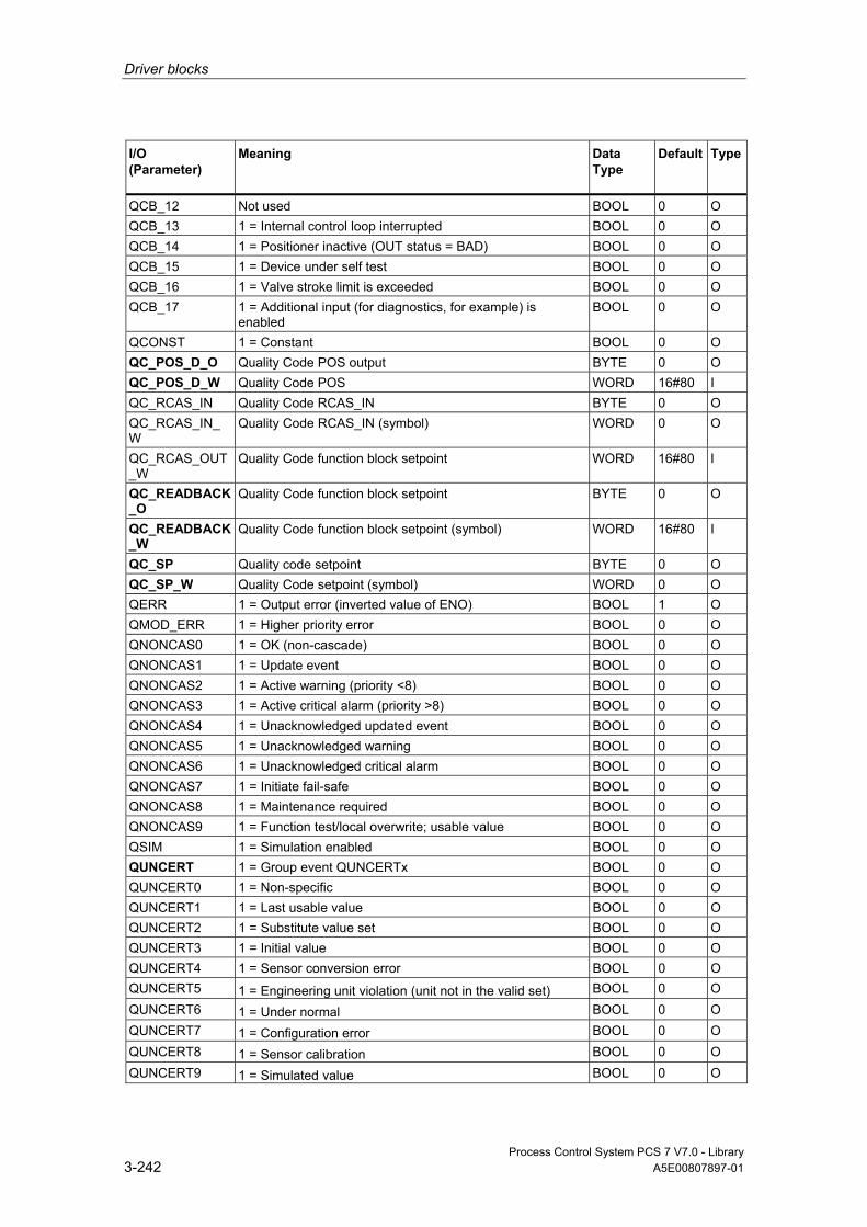
Driver blocks
Process Control System PCS 7 V7.0 - Library 3-242 A5E00807897-01
I/O (Parameter)
Meaning
Data Type
Default Type
QCB_12 Not used BOOL 0 O QCB_13 1 = Internal control loop interrupted BOOL 0 O QCB_14 1 = Positioner inactive (OUT status = BAD) BOOL 0 O QCB_15 1 = Device under self test BOOL 0 O QCB_16 1 = Valve stroke limit is exceeded BOOL 0 O QCB_17 1 = Additional input (for diagnostics, for example) is
enabled BOOL 0 O
QCONST 1 = Constant BOOL 0 O QC_POS_D_O Quality Code POS output BYTE 0 O QC_POS_D_W Quality Code POS WORD 16#80 I QC_RCAS_IN Quality Code RCAS_IN BYTE 0 O QC_RCAS_IN_W
Quality Code RCAS_IN (symbol) WORD 0 O
QC_RCAS_OUT_W
Quality Code function block setpoint WORD 16#80 I
QC_READBACK_O
Quality Code function block setpoint BYTE 0 O
QC_READBACK_W
Quality Code function block setpoint (symbol) WORD 16#80 I
QC_SP Quality code setpoint BYTE 0 O QC_SP_W Quality Code setpoint (symbol) WORD 0 O QERR 1 = Output error (inverted value of ENO) BOOL 1 O QMOD_ERR 1 = Higher priority error BOOL 0 O QNONCAS0 1 = OK (non-cascade) BOOL 0 O QNONCAS1 1 = Update event BOOL 0 O QNONCAS2 1 = Active warning (priority <8) BOOL 0 O QNONCAS3 1 = Active critical alarm (priority >8) BOOL 0 O QNONCAS4 1 = Unacknowledged updated event BOOL 0 O QNONCAS5 1 = Unacknowledged warning BOOL 0 O QNONCAS6 1 = Unacknowledged critical alarm BOOL 0 O QNONCAS7 1 = Initiate fail-safe BOOL 0 O QNONCAS8 1 = Maintenance required BOOL 0 O QNONCAS9 1 = Function test/local overwrite; usable value BOOL 0 O QSIM 1 = Simulation enabled BOOL 0 O QUNCERT 1 = Group event QUNCERTx BOOL 0 O QUNCERT0 1 = Non-specific BOOL 0 O QUNCERT1 1 = Last usable value BOOL 0 O QUNCERT2 1 = Substitute value set BOOL 0 O QUNCERT3 1 = Initial value BOOL 0 O QUNCERT4 1 = Sensor conversion error BOOL 0 O QUNCERT5 1 = Engineering unit violation (unit not in the valid set) BOOL 0 O QUNCERT6 1 = Under normal BOOL 0 O QUNCERT7 1 = Configuration error BOOL 0 O QUNCERT8 1 = Sensor calibration BOOL 0 O QUNCERT9 1 = Simulated value BOOL 0 O
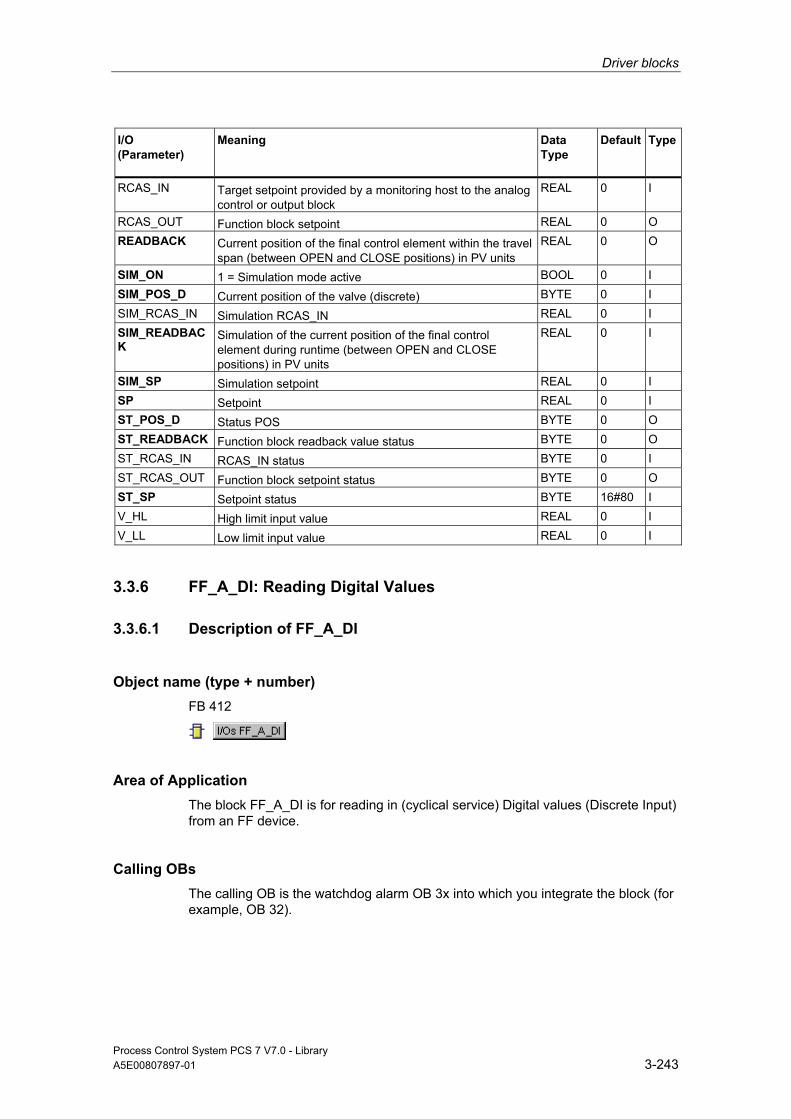
Driver blocks
Process Control System PCS 7 V7.0 - Library A5E00807897-01 3-243
I/O (Parameter)
Meaning
Data Type
Default Type
RCAS_IN Target setpoint provided by a monitoring host to the analog control or output block
REAL 0 I
RCAS_OUT Function block setpoint REAL 0 O READBACK Current position of the final control element within the travel
span (between OPEN and CLOSE positions) in PV units REAL 0 O
SIM_ON 1 = Simulation mode active BOOL 0 I SIM_POS_D Current position of the valve (discrete) BYTE 0 I SIM_RCAS_IN Simulation RCAS_IN REAL 0 I SIM_READBACK
Simulation of the current position of the final control element during runtime (between OPEN and CLOSE positions) in PV units
REAL 0 I
SIM_SP Simulation setpoint REAL 0 I SP Setpoint REAL 0 I ST_POS_D Status POS BYTE 0 O ST_READBACK Function block readback value status BYTE 0 O ST_RCAS_IN RCAS_IN status BYTE 0 I ST_RCAS_OUT Function block setpoint status BYTE 0 O ST_SP Setpoint status BYTE 16#80 I V_HL High limit input value REAL 0 I V_LL Low limit input value REAL 0 I
3.3.6 FF_A_DI: Reading Digital Values
3.3.6.1 Description of FF_A_DI
Object name (type + number) FB 412
Area of Application The block FF_A_DI is for reading in (cyclical service) Digital values (Discrete Input) from an FF device.
Calling OBs The calling OB is the watchdog alarm OB 3x into which you integrate the block (for example, OB 32).

Driver blocks
Process Control System PCS 7 V7.0 - Library 3-244 A5E00807897-01
Use in CFC When the CFC function "Generate module drivers" is used, the following occurs automatically:
• The symbol for the quality code of the digital input channel is interconnected with the input QC_W.
• The MODE input is interconnected with the appropriate OMODE_00 output of the MOD_PAL0 block or MOD_PAX0 block.
Function and Operating Principle Block FF_A_DI interfaces an FF field device and the blocks of the SIMATIC PCS 7 libraries and can also be interconnected with other SIMATIC S7 blocks.
The block cyclically reads the process value (I_OUT_D_W) with status byte of the FF field device (structure in accordance with the discrete input of the PA profiles). The status byte (STATUS) contains information about the status of the FF field device. The process value and important status byte information are made available bit-granular for better interconnectability on the output interface. These conform to the bit combinations specified in PROFIBUS "General Requirements".
Linking in ASSET The block FF_A_DI can be linked in ASSET. Additional information is available in the section Linking FF Devices in ASSET.
Quality Code A quality code (QUALITY output) is generated for the result value that can adopt the following values:
State Quality Code
Valid value 16#80 Simulation 16#60 Higher-level error, last valid value 16#14 Higher-level error, substitute value 16#18 Bad, due to process 16#28 Uncertain, due to device 16#68 Uncertain, due to process 16#78 Last valid value 16#44 Substitute Value 16#48 Range overshoot 16#54 Maintenance request present 16#A4 Invalid value 16#00

Driver blocks
Process Control System PCS 7 V7.0 - Library A5E00807897-01 3-245
The quality code is formed from internal events, such as channel error, higher-level error or simulation and from a quality code, that comes directly from the device (parameter QC-W).
The quality code that comes directly from the device can take on values from 16#00 – 16#FF. The imaging of these values on the displayable values listed above is shown in the table "QC_MS" table of the current LIB readme. The Quality Codes 16#84-16#87 and 16#90 – 16#93 of the FF field device are analyzed like the Quality Codes 16#80 – 16#83.
The block recognizes a higher-level error, for example, failure of a DP/PA link, via the MODE input parameter.
• If the MODE high byte = 16#80, then the values in the process image (partition) are valid.
• If the MODE high byte = 16#40 (value status = higher-level error, QMOD_ERR = TRUE), the process value is treated as invalid.
The mode of the input parameter MODE_LW is not considered.
Addressing In HW Config, you must configure an icon for the digital input channel and connect it with the input I_OUT_D_W. The CFC function "Generate module drivers" interconnects the icon for the quality code of the digital input channel with the input parameter QC_W.
Simulation When input parameter SIM_ON = TRUE, the value of input SIM_I is output with Quality Code (QUALITY =) 16#60. Simulation takes highest priority. QBAD is always set to FALSE. If the block is in the simulation status, QSIM = TRUE is set.
Substitute Value If input parameter SUBS_ON = TRUE, the value of input parameter SUBS_I is output as a value if the process values are invalid. The Quality Code (QUALITY) is set to 16#48 and QBAD = 1.
Output invalid value If the input parameter is SUBS_ON = FALSE and an invalid process value is present, then this will be output.
The quality code that is output is listed in the table "QC_MS" of the LIB readme. In addition QBAD = 1 is set.
Error handling The plausibility of input parameters is not checked.
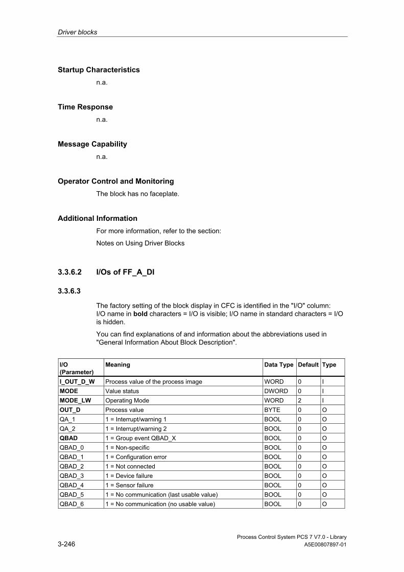
Driver blocks
Process Control System PCS 7 V7.0 - Library 3-246 A5E00807897-01
Startup Characteristics n.a.
Time Response n.a.
Message Capability n.a.
Operator Control and Monitoring The block has no faceplate.
Additional Information For more information, refer to the section:
Notes on Using Driver Blocks
3.3.6.2 I/Os of FF_A_DI
3.3.6.3
The factory setting of the block display in CFC is identified in the "I/O" column: I/O name in bold characters = I/O is visible; I/O name in standard characters = I/O is hidden.
You can find explanations of and information about the abbreviations used in "General Information About Block Description".
I/O (Parameter)
Meaning
Data Type
Default Type
I_OUT_D_W Process value of the process image WORD 0 I MODE Value status DWORD 0 I MODE_LW Operating Mode WORD 2 I OUT_D Process value BYTE 0 O QA_1 1 = Interrupt/warning 1 BOOL 0 O QA_2 1 = Interrupt/warning 2 BOOL 0 O QBAD 1 = Group event QBAD_X BOOL 0 O QBAD_0 1 = Non-specific BOOL 0 O QBAD_1 1 = Configuration error BOOL 0 O QBAD_2 1 = Not connected BOOL 0 O QBAD_3 1 = Device failure BOOL 0 O QBAD_4 1 = Sensor failure BOOL 0 O QBAD_5 1 = No communication (last usable value) BOOL 0 O QBAD_6 1 = No communication (no usable value) BOOL 0 O

Driver blocks
Process Control System PCS 7 V7.0 - Library A5E00807897-01 3-247
I/O (Parameter)
Meaning
Data Type
Default Type
QBAD_7 1 = Out of service BOOL 0 O QC_W Quality Code value of process image WORD 0 I QCONST 1 = Constant BOOL 0 O QERR 1 = Output error (inverted value of ENO) BOOL 1 O QMOD_ERR 1 = Higher priority error BOOL 0 O QNONCAS0 1 = OK (non-cascade) BOOL 0 O QNONCAS1 1 = Update event BOOL 0 O QNONCAS4 1 = Unacknowledged updated event BOOL 0 O QNONCAS7 1 = Initiate fail-safe BOOL 0 O QNONCAS8 1 = Maintenance required BOOL 0 O QNONCAS9 1 = Function test/local overwrite; usable value BOOL 0 O QSIM 1 = Simulation enabled BOOL 0 O QSUBS 1 = Substitution enabled BOOL 0 O QUALITY Value status of the process variable BYTE 0 O QUNCERT 1 = Group event QUNCERTx BOOL 0 O QUNCERT0 1 = Non-specific BOOL 0 O QUNCERT1 1 = Last usable value BOOL 0 O QUNCERT2 1 = Substitute value set BOOL 0 O QUNCERT3 1 = Initial value BOOL 0 O QUNCERT4 1 = Sensor conversion error BOOL 0 O QUNCERT5 1 = Engineering unit violation (unit not in the valid set) BOOL 0 O QUNCERT6 1 = Under normal BOOL 0 O QUNCERT7 1 = Configuration error BOOL 0 O QUNCERT8 1 = Sensor calibration BOOL 0 O QUNCERT9 1 = Simulated value BOOL 0 O Q0 Process value bit 0 BOOL 0 O Q1 .... Q7 Process value Bit 1 .... Process value Bit 7 BOOL 0 O SIM_I Simulation value BYTE 0 I SIM_ON 1 = Enable simulation BOOL 0 I STATUS Process value status BYTE 0 O SUBS_I Substitute Value BYTE 0 I SUBS_ON 1 = Substitution enabled BOOL 0 I

Driver blocks
Process Control System PCS 7 V7.0 - Library 3-248 A5E00807897-01
3.3.7 FF_A_DO: Outputting Digital Values
3.3.7.1 Description of FF_A_DO
Object name (type + number) FB 413
Area of Application Block FF_A_DO (cyclic service) is used for the output of digital values (SP or RCAS_IN, max. 8) via an FF field device.
Calling OBs The calling OB is watchdog alarm OB 3x into which you integrate the block (for example, OB 32) and restart OB 100.
Use in CFC When the CFC function "Generate module drivers" is used, the following occurs automatically:
• The MODE input is interconnected with the OMODE_00 output of the MOD_PAL0 block or MOD_PAX0 block.
Function and Operating Principle Depending on the selection (configuration of the input MODE_LW) of the user data configuration the block FF_A_DO reads the user data from the (partition) process image and writes it in the (partition) process image.
The coding of the set user data configuration must be parameterized in the input variable MODE_LW according to the MODE for FF field devices. This specifies which variables are to be read and written in the process image (partition).
The block writes the setpoint (O_SP_W) in the (partition) process image with quality code (QC_SP_W). The Quality Code contains the information about the status of the setpoint. The coding of the quality codes is described in PROFIBUS 3.0 "General Requirements". The setpoint in the RCAS (Remote Cascade) status (RCAS_IN) can be transferred with the quality code to the process image (partition) in the same cycle.
Linking in ASSET The block FF_A_AI can be linked in ASSET. Additional information is available in the section Linking FF Devices in ASSET.

Driver blocks
Process Control System PCS 7 V7.0 - Library A5E00807897-01 3-249
Quality Code A quality code (QUALITY output) is generated for the result value that can adopt the following values:
State Quality Code
Valid value 16#80 Simulation 16#60 Higher-level error, last valid value 16#14 Higher-level error, substitute value 16#18 Bad, due to process 16#28 Uncertain, due to device 16#68 Uncertain, due to process 16#78 Last valid value 16#44 Substitute Value 16#48 Range overshoot 16#54 Maintenance request present 16#A4 Invalid value 16#00
The quality code is formed from internal events, such as channel error, higher-level error or simulation and from a quality code, that comes directly from the device (parameter QC_READBACK_W, QC_RCAS_OUT_W).
The quality code that comes directly from the device can take on values from 16#00 – 16#FF. The imaging of these values on the displayable values listed above is shown in the table "QC_MS" table of the current LIB readme. The Quality Codes 16#84-16#87 and 16#90 – 16#93 of the FF field device are analyzed like the Quality Codes 16#80 – 16#83. The data of the FF field device, the status of the valve (READBACK), the process value of the valve setting in the state RCAS (RCAS_OUT), and the detailed device information (CHECKBACK) are read cyclically from the process image (partition) as an option. The device information is available at the block output in bit segments.
In order to improve the interconnectability, the output interface provides BOOL values that contain important details read from the status bytes. These conform to the bit combinations specified in PROFIBUS "General Requirements". If READBACK and RCAS_OUT exist simultaneously, the detailed information is derived from the READBACK status byte.
If a higher-level error has occurred (QMOD_ERR = TRUE), the data continue to be written to the process image (partition) and no data are read from the process image (partition). As long as the higher-priority error exists, the last values are held with QBAD = TRUE.

Driver blocks
Process Control System PCS 7 V7.0 - Library 3-250 A5E00807897-01
Note The default value of the setpoint status byte (ST_SP) and of the reference variable (ST_RCAS_IN) is zero. The setpoint and the reference variable become active in the PROFIBUS PA field device only if you set the corresponding status byte to 16#80.
Configuring the MODE_LW input In addition to the MODE input the MODE_LW (Mode Low Word) input must be configured according to the parameters used: Parameters used MODE_LW
SP_D 16#0400 SP_D, READBACK_D 16#0409 SP_D, CHECKBACK_D 16#040A SP_D, READBACK_D, CHECK_BACK_D 16#040B RCAS_IN_D, RCAS_OUT_D 16#050C RCAS_IN_D, RCAS_OUT_D, CHECK_BACK_D 16#0D05 SP_D, RCAS_IN_D , READBACK_D, RCAS_OUT_D, CHECK_BACK_D 16#0E06
Addressing You must interconnect each used connection of the block with the icons configured in the HW Config:
I/O Data type
I_READBACK_W WORD I_RCAS_OUT_W WORD O_SP_W WORD O_RCAS_IN_W WORD
In addition the quality code of the used I/Os must be interconnected with the icon configured in the HW Config:
I/O Data type
CHECK_0_W WORD CHECK_1_W WORD CHECK_2_W WORD QC_READBACK_W WORD QC_RCAS_OUT_W WORD QC_SP_W WORD QC_RCAS_IN_W WORD

Driver blocks
Process Control System PCS 7 V7.0 - Library A5E00807897-01 3-251
Simulation If the input parameter SIM_ON = TRUE, the value of the input parameter SIM_SP (and option SIM_RCAS_IN, if selected) is output with the quality code (QUALITY) = 16#60. Simulation takes highest priority. QBAD is set to FALSE. If the block is in the simulation status, QSIM = TRUE is set.
Error handling The plausibility of input parameters is not checked.
Startup Characteristics The block will run through one time in OB 100 at system start. The output and in/out parameters are calculated.
Time Response n.a.
Message Capability n.a.
Operator Control and Monitoring The block has no faceplate.
3.3.7.2 I/Os of FF_A_DO
The factory setting of the block display in CFC is identified in the "I/O" column: I/O name in bold characters = I/O is visible; I/O name in standard characters = I/O is hidden.
You can find explanations of and information about the abbreviations used in "General Information About Block Description".
I/O (Parameter)
Meaning
Data Type
Default
Type
CHECK_0_W Checkback field device WORD 0 I CHECK_1_W Checkback field device WORD 0 I CHECK_2_W Checkback field device WORD 0 I I_RCAS_OUT_W Function block setpoint WORD 0 I I_READBACK_W Process variable (READBACK) (symbol) WORD 0 I MODE Value status DWORD 0 I MODE_LW Operating Mode WORD 0 I

Driver blocks
Process Control System PCS 7 V7.0 - Library 3-252 A5E00807897-01
I/O (Parameter)
Meaning
Data Type
Default
Type
O_RCAS_IN_W Process image target setpoint provided by a monitoring host to the analog control or output block (symbol)
WORD 0 O
O_SP_W Setpoint (symbol) WORD 0 O QA_1 1 = Interrupt/warning 1 BOOL 0 O QA_2 1 = Interrupt/warning 2 BOOL 0 O QBAD 1 = Group event QBAD_X BOOL 0 O QBAD_0 1 = Non-specific BOOL 0 O QBAD_1 1 = Configuration error BOOL 0 O QBAD_2 1 = Not connected BOOL 0 O QBAD_3 1 = Device failure BOOL 0 O QBAD_4 1 = Sensor failure BOOL 0 O QBAD_5 1 = No communication (last usable value) BOOL 0 O QBAD_6 1 = No communication (no usable value) BOOL 0 O QBAD_7 1 = Out of service BOOL 0 O QCB_0 1 = Field device in fail-safe position BOOL 0 O QCB_1 1 = Request for manual operation at device BOOL 0 O QCB_2 1 = Field device under manual control BOOL 0 O QCB_3 1 = Emergency override active BOOL 0 O QCB_4 1 = The actuator left the final position it had already
reached BOOL 0 O
QCB_5 1 = Valve connection break BOOL 0 O QCB_6 1 = Indicates a short-circuit at the valve connection BOOL 0 O QCB_7 Not used BOOL 0 O QCB_8 1 = Actuator is moving towards open position BOOL 0 O QCB_9 1 = Actuator is moving towards close position BOOL 0 O QCB_10 1 = The interrupt generated by a change of static data of
FB and TB BOOL 0 O
QCB_11 1 = Simulation of process values is enabled BOOL 0 O QCB_12 Not used BOOL 0 O QCB_13 1 = Internal control loop interrupted BOOL 0 O QCB_14 1 = Valve inactive (status OUT_D bad) BOOL 0 O QCB_15 1 = Device under self test BOOL 0 O QCB_16 1 = Valve stroke limit is exceeded BOOL 0 O QCB_17 1 = Break time exceeded when changing from OPEN to
CLOSE BOOL 0 O
QCB_18 1 = Break time exceeded when changing from CLOSE to OPEN
BOOL 0 O
QCB_19 1 = Error occurred in the internal cycle test BOOL 0 O QCB_20 1 = Timeout during the transition from OPEN to CLOSE BOOL 0 O QCB_21 1 = Timeout during the transition from CLOSE to OPEN
exceeded BOOL 0 O
QCB_22 1 = Valve blocked mechanically BOOL 0 O QCB_23 Not used BOOL 0 O
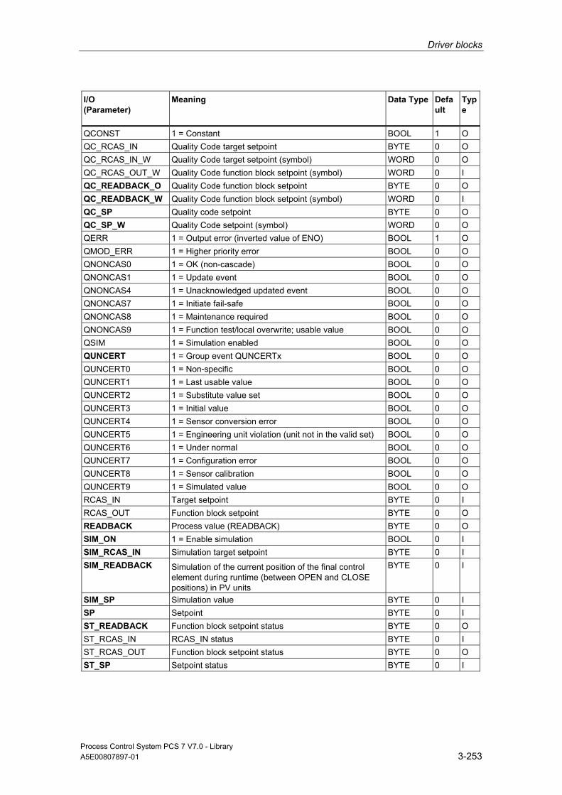
Driver blocks
Process Control System PCS 7 V7.0 - Library A5E00807897-01 3-253
I/O (Parameter)
Meaning
Data Type
Default
Type
QCONST 1 = Constant BOOL 1 O QC_RCAS_IN Quality Code target setpoint BYTE 0 O QC_RCAS_IN_W Quality Code target setpoint (symbol) WORD 0 O QC_RCAS_OUT_W Quality Code function block setpoint (symbol) WORD 0 I QC_READBACK_O Quality Code function block setpoint BYTE 0 O QC_READBACK_W Quality Code function block setpoint (symbol) WORD 0 I QC_SP Quality code setpoint BYTE 0 O QC_SP_W Quality Code setpoint (symbol) WORD 0 O QERR 1 = Output error (inverted value of ENO) BOOL 1 O QMOD_ERR 1 = Higher priority error BOOL 0 O QNONCAS0 1 = OK (non-cascade) BOOL 0 O QNONCAS1 1 = Update event BOOL 0 O QNONCAS4 1 = Unacknowledged updated event BOOL 0 O QNONCAS7 1 = Initiate fail-safe BOOL 0 O QNONCAS8 1 = Maintenance required BOOL 0 O QNONCAS9 1 = Function test/local overwrite; usable value BOOL 0 O QSIM 1 = Simulation enabled BOOL 0 O QUNCERT 1 = Group event QUNCERTx BOOL 0 O QUNCERT0 1 = Non-specific BOOL 0 O QUNCERT1 1 = Last usable value BOOL 0 O QUNCERT2 1 = Substitute value set BOOL 0 O QUNCERT3 1 = Initial value BOOL 0 O QUNCERT4 1 = Sensor conversion error BOOL 0 O QUNCERT5 1 = Engineering unit violation (unit not in the valid set) BOOL 0 O QUNCERT6 1 = Under normal BOOL 0 O QUNCERT7 1 = Configuration error BOOL 0 O QUNCERT8 1 = Sensor calibration BOOL 0 O QUNCERT9 1 = Simulated value BOOL 0 O RCAS_IN Target setpoint BYTE 0 I RCAS_OUT Function block setpoint BYTE 0 O READBACK Process value (READBACK) BYTE 0 O SIM_ON 1 = Enable simulation BOOL 0 I SIM_RCAS_IN Simulation target setpoint BYTE 0 I SIM_READBACK Simulation of the current position of the final control
element during runtime (between OPEN and CLOSE positions) in PV units
BYTE 0 I
SIM_SP Simulation value BYTE 0 I SP Setpoint BYTE 0 I ST_READBACK Function block setpoint status BYTE 0 O ST_RCAS_IN RCAS_IN status BYTE 0 I ST_RCAS_OUT Function block setpoint status BYTE 0 O ST_SP Setpoint status BYTE 0 I

Driver blocks
Process Control System PCS 7 V7.0 - Library 3-254 A5E00807897-01
3.3.8 MOD_PAL0: Diagnosing a DPV0 PA Slave (Via DP/PA Coupler Downstream of a DPV1 DP/PA-Link)
3.3.8.1 Description of MOD_PAL0
Object name (type + number) FB 99
Area of Application Block MOD_PAL0 reports the maintenance status of a PA field device that is operated as a DPV0 slave downstream of a DP/PA link DPV1. The PA field devices must conform to the PROFIBUS V3.0 profile.
Calling OBs The cyclic OB and OB 100
Use in CFC When the CFC function "Generate module drivers" is used, the following occurs automatically:
• The block is integrated in the run sequence upstream of block PA_x.
• The SUBN1_ID, SUBN2_ID, RACK_NO, SLOT_NO, PADP_ADR, PROF_V30 inputs are configured.
• The block inputs are interconnected with the following outputs:
- Output PA_DIAG of block PADP_L10
- Outputs OMODEx of block PADP_L10
- Outputs QMODF and QPERAF of block PADP_L10
- Output structure RAC_DIAG of block OB_DIAG1
- Input QC_x with PA-field-device-status icon
Note
The CFC function "Generate module drivers" can only be used if the PA field device belongs to slave family 12.

Driver blocks
Process Control System PCS 7 V7.0 - Library A5E00807897-01 3-255
Function and Operating Principle Block MOD_PAL0 analyzes all events relating to the status of a PA-field-device slot cyclically. With modular PA field devices, the statuses of the slots are combined to form one status. The acyclic diagnostic events of a PA field device are acquired by the PADP_L10 block. It then stores these in the PA_DIAG parameter. The PA-field-device status and the diagnostic information are evaluated and entered in the MS parameter. You can find additional information in "PA-Field-Device Status and Diagnostic Information".
The statuses are created with ALARM_8P for messages requiring acknowledgment and with NOTIFY_8P for those not requiring acknowledgment. The message function can be disabled.
Input PROF_V30 must be set to zero if the PA field device used does not conform to profile 3.0 (carried out by the CFC function "Generate module drivers").
In the case of a diagnostic event, the block reports "PA device uncertain diagnostics".
The failure of a PA field device is acquired in the upstream block OB_DIAG1 and announced over the RAC_DIAG structure. The message "Device @1%d@/ @2%d@/@3%d@: failure" is also generated.
Redundancy The higher-level block evaluates the redundancy of DP master systems operating in an H system.
Error handling The plausibility of input parameters is not checked.
Startup Characteristics Initialization of ALARM_8P and NOTIFY_8P.
Time Response n.a.
Message Capability The block reports by means of ALARM_8P and NOTIFY_8P. The block generates the following messages in the OBs listed below:
OB No. Start Event Message
x Cyclic processing When necessary run update ALARM_8P/NOTIFY_8P outputs/messages
100 Restart: Initialization of ALARM_8P

Driver blocks
Process Control System PCS 7 V7.0 - Library 3-256 A5E00807897-01
Operator Control and Monitoring Note: If you have selected the "Enable operator control and monitoring" option in the block object properties in the CFC, the variables transferred to the OS are identified under "I/Os of …" (OCM column, "+"). Default: option not selected.
If asset management is used in the project and the diagnostic screens have been generated, then the faceplate can be called via its icon.
• Block Icon Asset Management
• Faceplates Asset Management
Note: Online help and the "PCS 7 FACEPLATES" Manual are only available if the "PCS 7 FACEPLATES" software package is installed!
Additional Information For more information, refer to the following sections:
Message Texts and Associated Values of MOD_PAL0
Maintenance Status MS
Notes on Using Driver Blocks
3.3.8.2 I/Os of MOD_PAL0
The factory setting of the block display in CFC is identified in the "I/O" column: I/O name in bold characters = I/O is visible; I/O name in standard characters = I/O is hidden.
You can find explanations of and information about the abbreviations used in "General Information About Block Description".
I/O
Meaning
Data Type
Default Type
OCM
B_QC Σ status in bits (channel 0 through 15) of the PA field device
STRUCT O
CH_EXIST Channel exists DWORD 0 O + CH_OK Channel OK DWORD 0 O + EN_DIAG 1 = Queued diagnostic event BOOL 0 I EN_MSG 1 = Enable message BOOL 1 I EV_IDx Message number x DWORD 0 I MODE_x Value status PA field device (x = channel 0
through 15) DWORD 0 I
MODF 1 = PA slave error BOOL 0 I MS Maintenance status DWORD 0 I + MSG_ACKx Message acknowledgment x WORD 0 O MSGSTATx Message error information WORD 0 O

Driver blocks
Process Control System PCS 7 V7.0 - Library A5E00807897-01 3-257
I/O
Meaning
Data Type
Default Type
OCM
O_MS Maintenance status DWORD 0 O OMODE_x Value status PA field device (x = channel 0
through 15) DWORD 0 O
PA_DIAG PA-field-device diagnostic information DWORD 0 I PADP_ADR Address of the PA field device BYTE 0 I PERAF 1 = I/O access error BOOL 0 I PROF_V30 1 = PA slave profile V3.0 BOOL 0 I QC_x Status of PA field device (x = channel 0 through
15) BYTE 0 I
QERR 1 = Program runtime error BOOL 1 O QMODF 1 = PA slave error BOOL 0 O QPERAF 1 = I/O access error BOOL 0 O QRACKF 1 = PA slave/DP master error BOOL 0 O RAC_DIAG System structure: RACK diagnostics STRUCT 0 IO RACK_NO Number of the DP link BYTE 0 I SLOT_NO Slot number of the PA field device in the DP link BYTE 0 I SUBN1_ID ID of the primary DP master system BYTE 255 I SUBN2_ID ID of the redundant DP master system BYTE 255 I
Additional Information For more information, refer to the following sections:
Message Texts and Associated Values of MOD_PAL0
Maintenance Status MS
PA-Field-Device Status and Diagnostic Information
3.3.8.3 Message Texts and Associated Values of MOD_PAL0
Assignment of Message Text and Message Class
Message Block
Message No.
Block Parameter
Default Message Text
Message Class
EV_ID1 (ALARM_8P)
1 - Device @1%d@/ @2%d@/@3%d@: Bad, maintenance interrupt
S
2 - Device @1%d@/ @2%d@/@3%d@: Uncertain, maintenance request
F
3 - Device @1%d@/ @2%d@/@3%d@: Good, maintenance required
M
4 - Device @1%d@/ @2%d@/@3%d@: I/O access error
S

Driver blocks
Process Control System PCS 7 V7.0 - Library 3-258 A5E00807897-01
Message Block
Message No.
Block Parameter
Default Message Text
Message Class
5 - Device @1%d@/ @2%d@/@3%d@: Uncertain diagnostics
S
6 - Device @1%d@/ @2%d@/@3%d@: Failure
S
7 - no message 8 - no message EV_ID2 (NOTIFY_8P)
1 - Device @1%d@/ @2%d@/@3%d@: Good, changes to fail-safe position
SA
2 - Device @1%d@/ @2%d@/@3%d@: Good, configuration change made
SA
3 - Device @1%d@/ @2%d@/@3%d@: Uncertain, simulation
SA
4 - Device @1%d@/ @2%d@/@3%d@: Uncertain, due to process, no maintenance
SA
5 - Device @1%d@/ @2%d@/@3%d@: Bad, due to process, no maintenance
SA
6 - Device @1%d@/ @2%d@/@3%d@: Bad, local operation/function test
SA
7 - Device @1%d@/ @2%d@/@3%d@: Bad, out of service
SA
8 - Device @1%d@/ @2%d@/@3%d@: @4W%t#MOD_PAL0_TXT@
SA
Assignment of Associated Values
Message Block Associated Value
Block Parameter
Meaning
EV_ID1 (ALARM_8P)
1 SUBN_ID DP master system ID (byte)
2 RACK_NO Rack/station number (byte) 3 PADPADR PA field device address (byte) EV_ID2 (NOTIFY_8P)
1 SUBN_ID DP master system ID (byte)
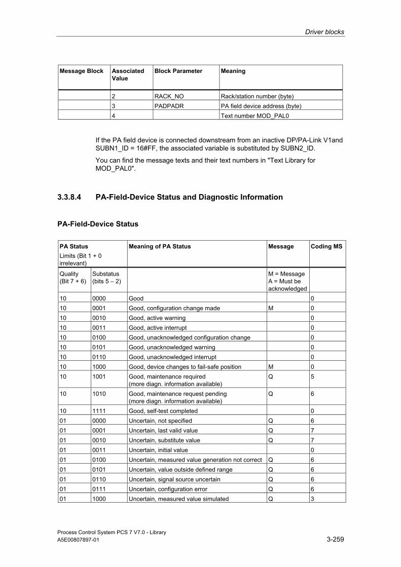
Driver blocks
Process Control System PCS 7 V7.0 - Library A5E00807897-01 3-259
Message Block Associated Value
Block Parameter
Meaning
2 RACK_NO Rack/station number (byte) 3 PADPADR PA field device address (byte) 4 Text number MOD_PAL0
If the PA field device is connected downstream from an inactive DP/PA-Link V1and SUBN1_ID = 16#FF, the associated variable is substituted by SUBN2_ID.
You can find the message texts and their text numbers in "Text Library for MOD_PAL0".
3.3.8.4 PA-Field-Device Status and Diagnostic Information
PA-Field-Device Status
PA Status Limits (Bit 1 + 0 irrelevant)
Meaning of PA Status Message Coding MS
Quality (Bit 7 + 6)
Substatus (bits 5 – 2)
M = Message A = Must be acknowledged
10 0000 Good 0 10 0001 Good, configuration change made M 0 10 0010 Good, active warning 0 10 0011 Good, active interrupt 0 10 0100 Good, unacknowledged configuration change 0 10 0101 Good, unacknowledged warning 0 10 0110 Good, unacknowledged interrupt 0 10 1000 Good, device changes to fail-safe position M 0 10 1001 Good, maintenance required
(more diagn. information available) Q 5
10 1010 Good, maintenance request pending (more diagn. information available)
Q 6
10 1111 Good, self-test completed 0 01 0000 Uncertain, not specified Q 6 01 0001 Uncertain, last valid value Q 7 01 0010 Uncertain, substitute value Q 7 01 0011 Uncertain, initial value 0 01 0100 Uncertain, measured value generation not correct Q 6 01 0101 Uncertain, value outside defined range Q 6 01 0110 Uncertain, signal source uncertain Q 6 01 0111 Uncertain, configuration error Q 6 01 1000 Uncertain, measured value simulated Q 3
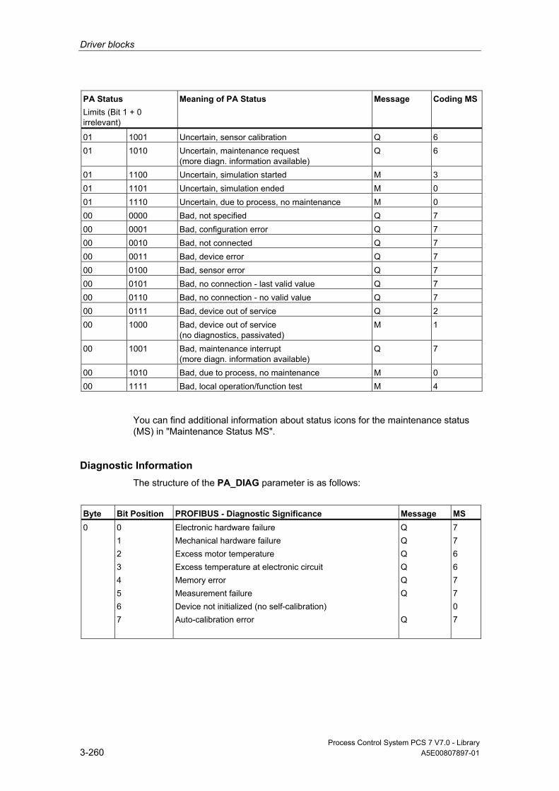
Driver blocks
Process Control System PCS 7 V7.0 - Library 3-260 A5E00807897-01
PA Status Limits (Bit 1 + 0 irrelevant)
Meaning of PA Status Message Coding MS
01 1001 Uncertain, sensor calibration Q 6 01 1010 Uncertain, maintenance request
(more diagn. information available) Q 6
01 1100 Uncertain, simulation started M 3 01 1101 Uncertain, simulation ended M 0 01 1110 Uncertain, due to process, no maintenance M 0 00 0000 Bad, not specified Q 7 00 0001 Bad, configuration error Q 7 00 0010 Bad, not connected Q 7 00 0011 Bad, device error Q 7 00 0100 Bad, sensor error Q 7 00 0101 Bad, no connection - last valid value Q 7 00 0110 Bad, no connection - no valid value Q 7 00 0111 Bad, device out of service Q 2 00 1000 Bad, device out of service
(no diagnostics, passivated) M 1
00 1001 Bad, maintenance interrupt (more diagn. information available)
Q 7
00 1010 Bad, due to process, no maintenance M 0 00 1111 Bad, local operation/function test M 4
You can find additional information about status icons for the maintenance status (MS) in "Maintenance Status MS".
Diagnostic Information The structure of the PA_DIAG parameter is as follows:
Byte Bit Position PROFIBUS - Diagnostic Significance Message MS 0 0
1 2 3 4 5 6 7
Electronic hardware failure Mechanical hardware failure Excess motor temperature Excess temperature at electronic circuit Memory error Measurement failure Device not initialized (no self-calibration) Auto-calibration error
Q Q Q Q Q Q Q
7 7 6 6 7 7 0 7

Driver blocks
Process Control System PCS 7 V7.0 - Library A5E00807897-01 3-261
Byte Bit Position PROFIBUS - Diagnostic Significance Message MS 1 0
1 2 3 4 5 6 7
Zero error (limit position) No power supply (electr. pneum.) Invalid configuration Restart (warm start) executed Restart (complete restart) executed Maintenance required Invalid identifier Invalid ID number
Q Q Q M M Q Q Q
6 7 7 0 0 5 7 7
2 0 1 2 3 4 - 7
Device error Maintenance requested Device is in function test or in simulation or is being operated locally (maintenance) The process conditions do not allow the return of valid values, set when the quality is "uncertain due to process, no maintenance" or "bad due to process, no maintenance". Reserved for PNO, default 0
Q Q
7 5 0 0
3 0-4 5 6 7
Reserved for PNO use = 0: for devices of the corresponding profile = 0: for devices of the corresponding profile = 0: no further information available = 1: Further diagnostic information available in DIAGNOSIS_EXTENSION
3.3.9 MOD_PAX0: Diagnosing a DPV0 PA Slave (Via DP/PA Coupler With Connection to a DP Master System)
3.3.9.1 Description of MOD_PAX0
Object name (type + number) FB 112
Area of Application Block MOD_PAX0 reports the maintenance status of a PA field device operated as a DPV0 slave in a DP master system. The PA field devices must conform to the PROFIBUS V3.0 profile.

Driver blocks
Process Control System PCS 7 V7.0 - Library 3-262 A5E00807897-01
Calling OBs The cyclic OB and OB 100
Use in CFC When the CFC function "Generate module drivers" is used, the following occurs automatically:
• The block is integrated in the run sequence upstream of the PA_x block.
• The SUBN1_ID, SUBN2_ID, SUBN_TYP, PADP_ADR, PROF_V30 inputs are configured.
• The inputs are interconnected with the following outputs:
- Output PA_DIAG of block PADP_L10
- Outputs OMODEx of block PADP_L10
- Outputs QMODF and QPERAF of block PADP_L10
- Output structure RAC_DIAG of block OB_DIAG1
• Input QC_x is interconnected with the PA-field-device-status icon.
• Output OMODExx is interconnected with the MODE input of the PA_x block.
Note
The CFC function "Generate module drivers" can only be used if the PA field device belongs to slave family 12.
Function and Operating Principle Block MOD_PAX0 analyzes all events relating to the status of a PA-field-device slot cyclically. With modular PA field devices, the statuses of the slots are combined to form one status. The acyclic diagnostic events of a PA field device are acquired by the PADP_L10 block. It then stores these in the PA_DIAG parameter. The PA-field-device status and the diagnostic information are evaluated and entered in the MS parameter. You can find additional information in "PA-Field-Device Status and Diagnostic Information".
Input PROF_V30 must be set to zero if the PA field device used does not conform to profile 3.0 (carried out by the CFC function "Generate module drivers").
In the case of a diagnostic event, the block reports "PA-field-device diagnostics".
An input (MODE_xx) exists for each slot (module) of a PA field device. that is used to read in HW Config data for the slots (modules).
The function writes MODE_xx to the low word of the OMODE_xx output parameter, but only during startup/initial startup or if you set ACC_MODE = TRUE. The actual slot value status is written to the most significant byte. If the result is positive, the system sets OMODE_xx = 16#80xxxxxx. The following events lead to the value status "Invalid value due to higher-priority error" (OMODE_xx = 16#40xxxxxx):
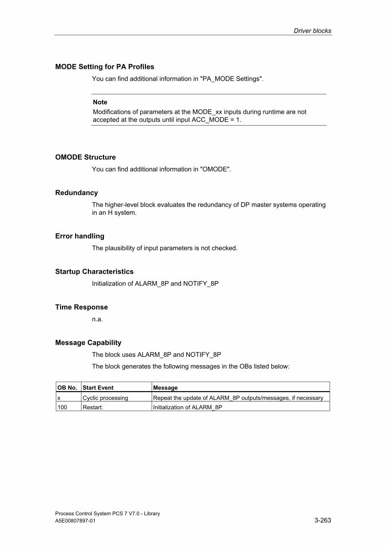
Driver blocks
Process Control System PCS 7 V7.0 - Library A5E00807897-01 3-263
MODE Setting for PA Profiles You can find additional information in "PA_MODE Settings".
Note
Modifications of parameters at the MODE_xx inputs during runtime are not accepted at the outputs until input ACC_MODE = 1.
OMODE Structure You can find additional information in "OMODE".
Redundancy The higher-level block evaluates the redundancy of DP master systems operating in an H system.
Error handling The plausibility of input parameters is not checked.
Startup Characteristics Initialization of ALARM_8P and NOTIFY_8P
Time Response n.a.
Message Capability The block uses ALARM_8P and NOTIFY_8P
The block generates the following messages in the OBs listed below:
OB No. Start Event Message
x Cyclic processing Repeat the update of ALARM_8P outputs/messages, if necessary 100 Restart: Initialization of ALARM_8P
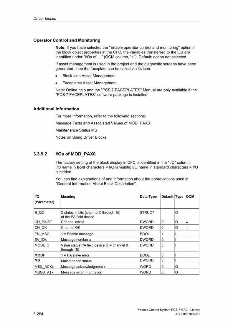
Driver blocks
Process Control System PCS 7 V7.0 - Library 3-264 A5E00807897-01
Operator Control and Monitoring Note: If you have selected the "Enable operator control and monitoring" option in the block object properties in the CFC, the variables transferred to the OS are identified under "I/Os of …" (OCM column, "+"). Default: option not selected.
If asset management is used in the project and the diagnostic screens have been generated, then the faceplate can be called via its icon.
• Block Icon Asset Management
• Faceplates Asset Management
Note: Online help and the "PCS 7 FACEPLATES" Manual are only available if the "PCS 7 FACEPLATES" software package is installed!
Additional Information For more information, refer to the following sections:
Message Texts and Associated Values of MOD_PAX0
Maintenance Status MS
Notes on Using Driver Blocks
3.3.9.2 I/Os of MOD_PAX0
The factory setting of the block display in CFC is identified in the "I/O" column: I/O name in bold characters = I/O is visible; I/O name in standard characters = I/O is hidden.
You can find explanations of and information about the abbreviations used in "General Information About Block Description".
I/O (Parameter)
Meaning
Data Type
Default Type
OCM
B_QC Σ status in bits (channel 0 through 15) of the PA field device
STRUCT O
CH_EXIST Channel exists DWORD 0 O + CH_OK Channel OK DWORD 0 O + EN_MSG 1 = Enable message BOOL 1 I EV_IDx Message number x DWORD 0 I MODE_x Value status PA field device (x = channel 0
through 15) DWORD 0 I
MODF 1 = PA slave error BOOL 0 I MS Maintenance status DWORD 0 I + MSG_ACKx Message acknowledgment x WORD 0 O MSGSTATx Message error information WORD 0 O

Driver blocks
Process Control System PCS 7 V7.0 - Library A5E00807897-01 3-265
I/O (Parameter)
Meaning
Data Type
Default Type
OCM
O_MS Maintenance status DWORD 0 O OMODE_x Value status PA field device (x = channel 0
through 15) DWORD 0 O
PA_DIAG PA-field-device diagnostic information DWORD 0 I PADP_ADR Address of the PA field device BYTE 0 I PERAF 1 = I/O access error BOOL 0 I PROF_V30 1 = PA slave profile V3.0 BOOL 0 I QC_x Status of PA field device (x = channel 0 through
15) BYTE 0 I
QERR 1 = Program runtime error BOOL 1 O QMODF 1 = PA slave error BOOL 0 O QPERAF 1 = I/O access error BOOL 0 O QRACKF 1 = PA slave/DP master error BOOL 0 O RAC_DIAG System structure: RACK diagnostics STRUCT 0 IO SUBN1_ID ID of the primary DP master system BYTE 255 I SUBN2_ID ID of the redundant DP master system BYTE 255 I
Additional Information For more information, refer to the following sections:
Message Texts and Associated Values of MOD_PAX0
Maintenance Status MS
PA-Field-Device Status and Diagnostic Information
3.3.9.3 Message Texts and Associated Values of MOD_PAX0
Assignment of Message Text and Message Class
Message Block Message No.
Block Parameter
Default Message Text
Message Class
EV_ID1 (ALARM_8P)
1 - Device @1%d@/ @2%d@:Bad, maintenance interrupt
S
2 - Device @1%d@/ @2%d@:Uncertain, maintenance request
F
3 - Device @1%d@/ @2%d@:Good, maintenance necessary
M
4 - Device @1%d@/ @2%d@:Access error S 5 - Device @1%d@/ @2%d@:Undefined
diagnostics S
6 - Device @1%d@/ @2%d@: Failure S 7 - no message

Driver blocks
Process Control System PCS 7 V7.0 - Library 3-266 A5E00807897-01
Message Block Message No.
Block Parameter
Default Message Text
Message Class
8 - no message EV_ID2 (NOTIFY_8P)
1 - Device @1%d@/ @2%d@:Good, changes to fail-safe position
SA
2 - Device @1%d@/ @2%d@:Good, configuration change made
SA
3 - Device @1%d@/ @2%d@:Uncertain, simulation
SA
4 - Device @1%d@/ @2%d@:Uncertain, due to process, no maintenance
SA
5 - Device @1%d@/ @2%d@:Bad, due to process, no maintenance
SA
6 - Device @1%d@/ @2%d@:Bad, local operation/function test
SA
7 - Device @1%d@/ @2%d@:Bad, out of service
SA
8 - Device @1%d@/ @2%d@:@3W%t#MOD_PAX0_TXT@
SA
Assignment of Associated Values
Message Block
Associated Value
Block Parameter
Meaning
EV_ID1 (ALARM_8P)
1 SUBN_ID DP master system ID (byte)
2 PADPADR PA field device address (byte) EV_ID2 (NOTIFY_8P)
1 SUBN_ID DP master system ID (byte)
2 PADPADR PA field device address (byte) 3 Text number MOD_PAXL0
If SUBN1_ID = 16#FF, the associated value is substituted with SUBN2_ID.
You can find the message texts and their text numbers in "Text Library for MOD_PAX0".

Driver blocks
Process Control System PCS 7 V7.0 - Library A5E00807897-01 3-267
3.3.10 PA_AI: PROFIBUS PA Analog-Value Input
3.3.10.1 Description of PA_AI
Object name (type + number) FB 101
Area of Application Block PA_AI processes (cyclic service) the "Transmitter" PA profile of a PROFIBUS 3.0 class A and B PA field device or a primary or secondary variable of a HART field device.
Calling OBs The calling OB is the watchdog alarm OB 3x into which you integrate the block (for example, OB 32).
Use in CFC When the CFC function "Generate module drivers" is used, the following occurs automatically:
• The icon for the quality code of the analog input channel is interconnected with input QC.
• The MODE input is interconnected with the corresponding output OMODE_xx of the PADP_L0x block.
Function and Operating Principle Block PA_AI reads the process value with status byte (QC) of the PROFIBUS PA or HART field device (structure in accordance with the analog input of the PA profiles) cyclically from the process image (partition). The process variable is available in a physical unit. The status byte (STATUS) contains information about the status of the FF field device.
Quality Code A quality code (QUALITY output) is generated for the result value that can adopt the following values:
State Quality Code
Valid value 16#80

Driver blocks
Process Control System PCS 7 V7.0 - Library 3-268 A5E00807897-01
State Quality Code
Simulation 16#60 Higher-level error, last valid value 16#14 Higher-level error, substitute value 16#18 Bad, due to process 16#28 Uncertain, due to device 16#68 Uncertain, due to process 16#78 Last valid value 16#44 Substitute Value 16#48 Range overshoot 16#54 Maintenance request present 16#A4 Invalid value 16#00
The quality code is formed from internal events, such as channel error, higher-level error or simulation and from a quality code that comes directly from the device (parameter QC). The quality code that comes directly from the device can take on values from 16#00 – 16#FF in accordance with PROFIBUS requirements. The imaging of these values on the displayable values listed above is shown in the table "QC_MS" table of the current LIB readme. In addition to the status byte and to improve interconnectability, the output interface provides further Boolean (BOOL) values, which contain important details. They conform to bit combinations specifications in PROFIBUS PA 3.0 "General Requirements". Device-specific process-control messages are generated via ALARM_8P on the basis of the QC. The block recognizes a higher-level error, for example, failure of a DP/PA link, via the MODE input parameter. • If the MODE high byte = 16#80, then the values in the process image
(partition) are valid. • If the MODE high byte = 16#40 (value status = higher-level error), the analog
value is treated as invalid. The operating mode set in the low word of the MODE input parameter will be ignored.
Addressing The symbol of the analog input channel is generated and entered in the symbol table via HW Config. You must interconnect it with the VALUE input. The QC icon for the analog input channel automatically interconnects the CFC function "Generate module drivers" with input parameter QC.
Simulation When input parameter SIM_ON = TRUE, the value of the input parameter SIM_V is output with Quality Code (QUALITY =) 16#60. Simulation takes highest priority. QBAD is always set to FALSE. If the block is in the simulation status, QSIM = TRUE is set.

Driver blocks
Process Control System PCS 7 V7.0 - Library A5E00807897-01 3-269
Substitute Value If input parameter SUBS_ON = TRUE, the value of input parameter SUBS_V is output as a value if the values are invalid. The Quality Code (QUALITY) is set to 16#48 and QBAD = 1.
Hold Last Value If input parameter LAST_ON = TRUE, the last valid output value is output if the process values are invalid. The Quality Code (QUALITY) is set to 16#44 and QBAD = 1.
Output invalid value If the input parameter is SUBS_ON and LAST_ON = FALSE or both = TRUE, and an invalid process value is present, then this will be output.
The quality code that is output is listed in the table "QC_MS" of the LIB readme. In addition QBAD = 1 is set.
Value Limiting You can limit the maximum low and high range of process variables in the process image (partition).
LIMIT_ON = TRUE limits process variables (V):
• To V_HL, if V > V_HL
• To LL_V, if V < V_LL
Error handling The plausibility of input parameters is not checked.
Startup Characteristics n.a.
Time Response n.a.
Message Capability n.a.
Operator Control and Monitoring The block has no faceplate.

Driver blocks
Process Control System PCS 7 V7.0 - Library 3-270 A5E00807897-01
Additional Information For more information, refer to the section:
Notes on Using Driver Blocks
3.3.10.2 I/Os of PA_AI
The factory setting of the block display in CFC is identified in the "I/O" column: I/O name in bold characters = I/O is visible; I/O name in standard characters = I/O is hidden.
You can find explanations of and information about the abbreviations used in "General Information About Block Description".
I/O (Parameter)
Meaning
Data Type
Default Type
LAST_ON 1= Last valid value Enable injection BOOL 0 IO LIMIT_ON 1 = Limit input value ON BOOL 0 I LL_V Value if V < V_LL REAL 0 I MODE Value status and operating mode DWORD 0 I QA_1 1 = Interrupt/warning 1 BOOL 0 O QA_2 1 = Interrupt/warning 2 BOOL 0 O QBAD 1 = Group event QBAD_X BOOL 0 O QBAD_0 1 = Non-specific BOOL 0 O QBAD_1 1 = Configuration error BOOL 0 O QBAD_2 1 = Not connected BOOL 0 O QBAD_3 1 = Device failure BOOL 0 O QBAD_4 1 = Sensor failure BOOL 0 O QBAD_5 1 = No communication (last usable value) BOOL 0 O QBAD_6 1 = No communication (last usable value) BOOL 0 O QBAD_7 1 = Out of service BOOL 0 O QBAD_HL 1 = High limit of physical range of sensor has been
reached BOOL 0 O
QBAD_LL 1 = Low limit of physical range of sensor has been reached
BOOL 0 O
QC Status of the input process value BYTE 0 I QCASCAD0 1 = OK (cascade) BOOL 0 O QCASCAD1 1 = Initialization acknowledged BOOL 0 O QCASCAD2 1 = Initialization request BOOL 0 O QCASCAD3 1 = Not required BOOL 0 O QCASCAD4 1 = Reserved BOOL 0 O QCASCAD5 1 = Do not select BOOL 0 O QCASCAD6 1 = Local overwrite BOOL 0 O QCASCAD7 1 = Reserved BOOL 0 O QCASCAD8 1 = Initiate fail-safe BOOL 0 O QCONST 1 = Constant BOOL 0 O QERR 1 = Output error (inverted value of ENO) BOOL 1 O

Driver blocks
Process Control System PCS 7 V7.0 - Library A5E00807897-01 3-271
I/O (Parameter)
Meaning
Data Type
Default Type
QLAST 1= Last valid value Injection active BOOL 0 O QMOD_ERR 1 = Higher priority error BOOL 0 O QOUT_HHL 1 = Active critical alarm, high limit of OUT has been
exceeded BOOL 0 O
QOUT_HL 1 = Active warning, high limit of OUT has been exceeded BOOL 0 O QOUT_LL 1 = Active warning, low limit of OUT has been exceeded BOOL 0 O QOUT_LLL 1 = Active critical alarm, low limit of OUT has been
exceeded BOOL 0 O
QNONCAS0 1 = OK (non-cascade) BOOL 0 O QNONCAS1 1 = Update event BOOL 0 O QNONCAS2 1 = Active warning (priority <8) BOOL 0 O QNONCAS3 1 = Active critical alarm (priority >8) BOOL 0 O QNONCAS4 1 = Unacknowledged updated event BOOL 0 O QNONCAS5 1 = Unacknowledged warning BOOL 0 O QNONCAS6 1 = Unacknowledged critical alarm BOOL 0 O QNONCAS7 1 = Initiate fail-safe BOOL 0 O QNONCAS8 1 = Maintenance required BOOL 0 O QNONCAS9 1 = Function test/local overwrite; usable value BOOL 0 O QSIM 1 = Simulation enabled BOOL 0 O QSUBS 1 = Substitution enabled BOOL 0 O QUALITY Value status of the process variable BYTE 0 O QUNCERT 1 = Group message QUNCERTx BOOL 0 O QUNCERT0 1 = Non-specific BOOL 0 O QUNCERT1 1 = Last usable value BOOL 0 O QUNCERT2 1 = Substitute value set BOOL 0 O QUNCERT3 1 = Initial value BOOL 0 O QUNCERT4 1 = Unacknowledged updated event BOOL 0 O QUNCERT5 1 = Engineering unit violation (unit not in the valid set) BOOL 0 O QUNCERT6 1 = Under normal BOOL 0 O QUNCERT7 1 = Configuration error BOOL 0 O QUNCERT8 1 = Sensor calibration BOOL 0 O QUNCERT9 1 = Simulated value BOOL 0 O SIM_ON 1 = Enable simulation BOOL 0 I SIM_V Simulation value REAL 0 I STATUS Process value status BYTE 0 O SUBS_ON 1 = Enable substitution BOOL 0 I SUBS_V Substitute Value REAL 0 I V Process value REAL 0 O V_HL High limit input value REAL 0 I V_LL Low limit input value REAL 0 I VALUE Process Image Input Value REAL 0 I

Driver blocks
Process Control System PCS 7 V7.0 - Library 3-272 A5E00807897-01
3.3.11 PA_AO: PROFIBUS PA Analog-Value Output
3.3.11.1 Description of PA_AO
Object name (type + number) FB 103
Area of Application Block PA_AO processes (cyclic service) the "Actuator" PA profile of a PROFIBUS PA 3.0 class A and B PA field device.
Calling OBs The calling OB is watchdog alarm OB 3x into which you integrate the block (for example, OB 32) and restart OB 100.
Use in CFC When the CFC function "Generate module drivers" is used, the following occurs automatically: • The icon for the quality code of the analog output channel O_SP is
interconnected with the output QC_SP and other selected options. • The MODE input is interconnected with the corresponding output OMODE_xx
of the PADP_L0x block.
Function and Operating Principle The block reads the user data from the process image (partition) and writes them to the process image (partition), depending on the selection (with HW Config or SIMATIC PDM) of the user-data configuration of the "Analog Output" PA profile in accordance with PROFIBUS PA 3.0.
The low word of the input variable MODE contains the coding of the user data configuration of the PROFIBUS PA 3.0 Profile "Analog Output" and specifies which variables are to be read and written in the process image (partition).
The block cyclically writes the setpoint (SP) with Quality Code (configuration of the setpoints and process values in accordance with the Analog Output of the PA profiles, REAL with 1 byte Quality Code) into the process image (partition). The PA profile contains the setpoint and other analog values as physical units. The Quality Code contains the information on the setpoint status. The coding of the quality codes is described in PROFIBUS 3.0 "General Requirements". The reference variable (RCAS_IN) can be transferred with the quality code to the process image (partition) in the same cycle.

Driver blocks
Process Control System PCS 7 V7.0 - Library A5E00807897-01 3-273
Quality Code A quality code (QUALITY output) is generated for the result value that can adopt the following values:
State Quality Code
Valid value 16#80 Simulation 16#60 Higher-level error, last valid value 16#14 Higher-level error, substitute value 16#18 Bad, due to process 16#28 Uncertain, due to device 16#68 Uncertain, due to process 16#78 Last valid value 16#44 Substitute Value 16#48 Range overshoot 16#54 Range overshoot low 16#55 Range overshoot high 16#56 Maintenance request present 16#A4 Invalid value 16#00
The quality code is formed from internal events, such as channel error, higher-level error or simulation and from a quality code that comes directly from the device (parameter QC_X, X = parameter name).
The quality code that comes directly from the device can take on values from 00 - FF in accordance with PROFIBUS requirements. The imaging of these values on the displayable values listed above is shown in the table "QC_MS" table of the current LIB readme.
The data of the PROFIBUS PA field device, as well as the process variable (READBACK) and the discrete position feedback (POS_D) are read cyclically from the process image (partition). Optionally you can also read the active reference variable (RCAS_OUT) and the detailed device information (CHECKBACK). The device information is available at the block output in bit segments. The data is read from the process image (partition). In order to improve the interconnectability, important detailed information is provided by the status bytes read (ST_READBACK) or ST_RCAS_OUT (if READBACK is not available) as Boolean (BOOL) values at the output interface. These conform to the bit combinations specified in PROFIBUS PA "General Requirements".
If a higher-level error has occurred (QMOD_ERR = TRUE), the data continue to be written to the process image (partition) and no data are read from the process image (partition). As long as the higher-priority error exists, the last values are held with QBAD = TRUE.

Driver blocks
Process Control System PCS 7 V7.0 - Library 3-274 A5E00807897-01
Note The status byte (ST_RCAS_IN) is pre-defined with zero. The reference variable only becomes active in the PROFIBUS field device if you set the quality code to 16#80.
Addressing You have to interconnect one of the icons configured using HW Config (for example, SP) for the analog output channel (PROFIBUS PA 3.0 profile "Analog Output") with the corresponding I/O:
I/O Data type
I_READBACK REAL I_RCAS_OUT REAL I_POS_D BYTE O_SP REAL O_RCAS_IN REAL
In CFC, the "Generate module drivers" function automatically interconnects the icon for the corresponding quality code of the I/O and the remaining configured icons of the analog output channel (with quality code).
Simulation If the input parameter SIM_ON = TRUE, the value of the input SIM_SP (and the option SIM_RCAS_IN) is output with Quality Code (QUALITY) = 16#60. Simulation takes highest priority. QBAD is set to FALSE. If the block is in the simulation status, QSIM = TRUE is set.
Value Limiting You can limit the maximum low and high range of process variables in the process image (partition). The process variables "V" (READBACK and RCAS_OUT) are limited when LIMIT_ON = TRUE: • To V_HL, if V > V_HL. • To LL_V, if V < V_LL.
Error handling The plausibility of input parameters is not checked.
Startup Characteristics The block will run through one time in OB 100 at system start. The output and in/out parameters are calculated.

Driver blocks
Process Control System PCS 7 V7.0 - Library A5E00807897-01 3-275
Time Response n.a.
Message Capability n.a.
Operator Control and Monitoring The block has no faceplate.
Additional Information For more information, refer to the section:
Notes on Using Driver Blocks
3.3.11.2 I/Os of PA_AO
The factory setting of the block display in CFC is identified in the "I/O" column: I/O name in bold characters = I/O is visible; I/O name in standard characters = I/O is hidden.
You can find explanations of and information about the abbreviations used in "General Information About Block Description".
I/O (Parameter)
Meaning
Data Type
Default Type
CHECK_0 Checkback field device BYTE 0 I CHECK_1 Checkback field device BYTE 0 I CHECK_2 Checkback field device BYTE 0 I I_POS_D Current position of the valve (discrete) (icon) BYTE 0 I I_RCAS_OUT Function block setpoint REAL 0 I I_READBACK Current position of the final control element during
runtime (between OPEN and CLOSE positions) in PV units (symbol)
REAL 0 I
LIMIT_ON 1 = Limit input value ON BOOL 0 I LL_V High limit input value.
Value if V < V_LL REAL I
MODE MODE input parameter DWORD 0 I O_RCAS_IN Process image target setpoint provided by a
monitoring host to the analog control or output block (symbol)
REAL 0 O
O_SP Setpoint (symbol) REAL 0 O
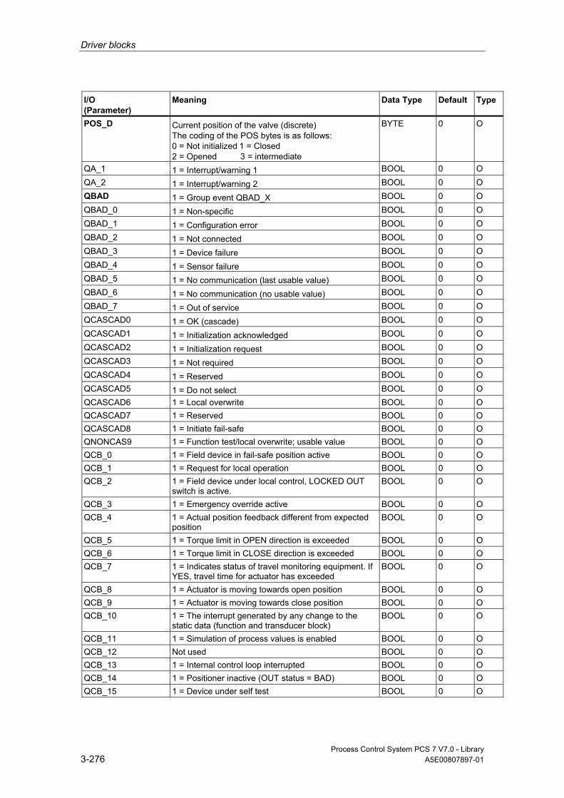
Driver blocks
Process Control System PCS 7 V7.0 - Library 3-276 A5E00807897-01
I/O (Parameter)
Meaning
Data Type
Default Type
POS_D Current position of the valve (discrete) The coding of the POS bytes is as follows: 0 = Not initialized 1 = Closed 2 = Opened 3 = intermediate
BYTE 0 O
QA_1 1 = Interrupt/warning 1 BOOL 0 O QA_2 1 = Interrupt/warning 2 BOOL 0 O QBAD 1 = Group event QBAD_X BOOL 0 O QBAD_0 1 = Non-specific BOOL 0 O QBAD_1 1 = Configuration error BOOL 0 O QBAD_2 1 = Not connected BOOL 0 O QBAD_3 1 = Device failure BOOL 0 O QBAD_4 1 = Sensor failure BOOL 0 O QBAD_5 1 = No communication (last usable value) BOOL 0 O QBAD_6 1 = No communication (no usable value) BOOL 0 O QBAD_7 1 = Out of service BOOL 0 O QCASCAD0 1 = OK (cascade) BOOL 0 O QCASCAD1 1 = Initialization acknowledged BOOL 0 O QCASCAD2 1 = Initialization request BOOL 0 O QCASCAD3 1 = Not required BOOL 0 O QCASCAD4 1 = Reserved BOOL 0 O QCASCAD5 1 = Do not select BOOL 0 O QCASCAD6 1 = Local overwrite BOOL 0 O QCASCAD7 1 = Reserved BOOL 0 O QCASCAD8 1 = Initiate fail-safe BOOL 0 O QNONCAS9 1 = Function test/local overwrite; usable value BOOL 0 O QCB_0 1 = Field device in fail-safe position active BOOL 0 O QCB_1 1 = Request for local operation BOOL 0 O QCB_2 1 = Field device under local control, LOCKED OUT
switch is active. BOOL 0 O
QCB_3 1 = Emergency override active BOOL 0 O QCB_4 1 = Actual position feedback different from expected
position BOOL 0 O
QCB_5 1 = Torque limit in OPEN direction is exceeded BOOL 0 O QCB_6 1 = Torque limit in CLOSE direction is exceeded BOOL 0 O QCB_7 1 = Indicates status of travel monitoring equipment. If
YES, travel time for actuator has exceeded BOOL 0 O
QCB_8 1 = Actuator is moving towards open position BOOL 0 O QCB_9 1 = Actuator is moving towards close position BOOL 0 O QCB_10 1 = The interrupt generated by any change to the
static data (function and transducer block) BOOL 0 O
QCB_11 1 = Simulation of process values is enabled BOOL 0 O QCB_12 Not used BOOL 0 O QCB_13 1 = Internal control loop interrupted BOOL 0 O QCB_14 1 = Positioner inactive (OUT status = BAD) BOOL 0 O QCB_15 1 = Device under self test BOOL 0 O

Driver blocks
Process Control System PCS 7 V7.0 - Library A5E00807897-01 3-277
I/O (Parameter)
Meaning
Data Type
Default Type
QCB_15 1 = Device under self test ( MODE = out of service) BOOL 0 O QCB_16 1 = Valve stroke limit is exceeded BOOL 0 O QCB_17 1 = Additional input (for diagnostics, for example) is
enabled BOOL 0 O
QCONST 1 = Constant BOOL 0 O QC_POS_D Quality Code POS BYTE 0 I QC_POS_D_O Quality Code POS output BYTE 0 O QC_RCAS_IN Quality Code RCAS_IN (symbol) BYTE 0 O QC_RCAS_OUT Quality Code function block setpoint BYTE 0 I QC_READBACK Quality Code function block setpoint (symbol) BYTE 0 I QC_READBACK_O Quality Code function block setpoint BYTE 0 O QC_SP Quality Code setpoint (symbol) BYTE 0 O QERR 1 = Output error (inverted value of ENO) BOOL 1 O QMOD_ERR 1 = Higher priority error BOOL 0 O QNONCAS0 1 = OK (non-cascade) BOOL 0 O QNONCAS1 1 = Update event BOOL 0 O QNONCAS2 1 = Active warning (priority <8) BOOL 0 O QNONCAS3 1 = Active critical alarm (priority >8) BOOL 0 O QNONCAS4 1 = Unacknowledged updated event BOOL 0 O QNONCAS5 1 = Unacknowledged warning BOOL 0 O QNONCAS6 1 = Unacknowledged critical alarm BOOL 0 O QNONCAS7 1 = Initiate fail-safe BOOL 0 O QNONCAS8 1 = Maintenance required BOOL 0 O QSIM 1 = Simulation enabled BOOL 0 O QUNCERT 1 = Group event QUNCERTx BOOL 0 O QUNCERT0 1 = Non-specific BOOL 0 O QUNCERT1 1 = Last usable value BOOL 0 O QUNCERT2 1 = Substitute value set BOOL 0 O QUNCERT3 1 = Initial value BOOL 0 O QUNCERT4 1 = Sensor conversion error BOOL 0 O QUNCERT5 1 = Engineering unit violation (unit not in the valid set) BOOL 0 O QUNCERT6 1 = Under normal BOOL 0 O QUNCERT7 1 = Configuration error BOOL 0 O QUNCERT8 1 = Sensor calibration BOOL 0 O QUNCERT9 1 = Simulated value BOOL 0 O RCAS_IN Target setpoint provided by a monitoring host to the
analog control or output block REAL 0 I
RCAS_OUT Function block setpoint REAL 0 O READBACK Current position of the final control element within the
travel span (between OPEN and CLOSE positions) in PV units
REAL 0 O
SIM_ON 1 = Simulation mode active BOOL 0 I SIM_POS_D Current position of the valve (discrete) BYTE 0 I
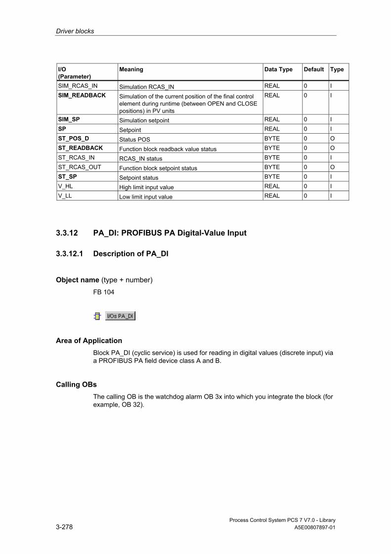
Driver blocks
Process Control System PCS 7 V7.0 - Library 3-278 A5E00807897-01
I/O (Parameter)
Meaning
Data Type
Default Type
SIM_RCAS_IN Simulation RCAS_IN REAL 0 I SIM_READBACK Simulation of the current position of the final control
element during runtime (between OPEN and CLOSE positions) in PV units
REAL 0 I
SIM_SP Simulation setpoint REAL 0 I SP Setpoint REAL 0 I ST_POS_D Status POS BYTE 0 O ST_READBACK Function block readback value status BYTE 0 O ST_RCAS_IN RCAS_IN status BYTE 0 I ST_RCAS_OUT Function block setpoint status BYTE 0 O ST_SP Setpoint status BYTE 0 I V_HL High limit input value REAL 0 I V_LL Low limit input value REAL 0 I
3.3.12 PA_DI: PROFIBUS PA Digital-Value Input
3.3.12.1 Description of PA_DI
Object name (type + number) FB 104
Area of Application Block PA_DI (cyclic service) is used for reading in digital values (discrete input) via a PROFIBUS PA field device class A and B.
Calling OBs The calling OB is the watchdog alarm OB 3x into which you integrate the block (for example, OB 32).
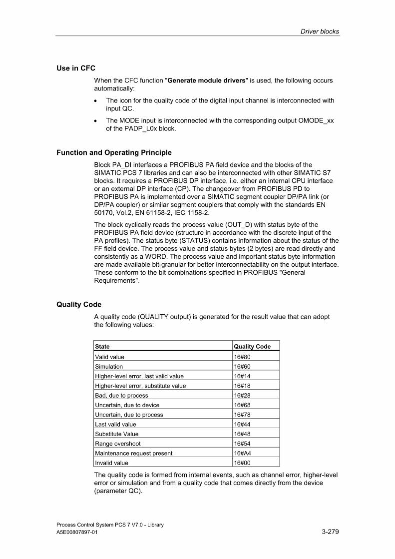
Driver blocks
Process Control System PCS 7 V7.0 - Library A5E00807897-01 3-279
Use in CFC When the CFC function "Generate module drivers" is used, the following occurs automatically:
• The icon for the quality code of the digital input channel is interconnected with input QC.
• The MODE input is interconnected with the corresponding output OMODE_xx of the PADP_L0x block.
Function and Operating Principle Block PA_DI interfaces a PROFIBUS PA field device and the blocks of the SIMATIC PCS 7 libraries and can also be interconnected with other SIMATIC S7 blocks. It requires a PROFIBUS DP interface, i.e. either an internal CPU interface or an external DP interface (CP). The changeover from PROFIBUS PD to PROFIBUS PA is implemented over a SIMATIC segment coupler DP/PA link (or DP/PA coupler) or similar segment couplers that comply with the standards EN 50170, Vol.2, EN 61158-2, IEC 1158-2.
The block cyclically reads the process value (OUT_D) with status byte of the PROFIBUS PA field device (structure in accordance with the discrete input of the PA profiles). The status byte (STATUS) contains information about the status of the FF field device. The process value and status bytes (2 bytes) are read directly and consistently as a WORD. The process value and important status byte information are made available bit-granular for better interconnectability on the output interface. These conform to the bit combinations specified in PROFIBUS "General Requirements".
Quality Code A quality code (QUALITY output) is generated for the result value that can adopt the following values:
State Quality Code
Valid value 16#80 Simulation 16#60 Higher-level error, last valid value 16#14 Higher-level error, substitute value 16#18 Bad, due to process 16#28 Uncertain, due to device 16#68 Uncertain, due to process 16#78 Last valid value 16#44 Substitute Value 16#48 Range overshoot 16#54 Maintenance request present 16#A4 Invalid value 16#00
The quality code is formed from internal events, such as channel error, higher-level error or simulation and from a quality code that comes directly from the device (parameter QC).

Driver blocks
Process Control System PCS 7 V7.0 - Library 3-280 A5E00807897-01
The quality code that comes directly from the device can take on values from 16#00 – 16#FF in accordance with PROFIBUS requirements. The imaging of these values on the displayable values listed above is shown in the table "QC_MS" table of the current LIB readme.
The block recognizes a higher-level error, for example, failure of a DP/PA link, via the MODE input parameter.
• If the MODE high byte = 16#80, then the values in the process image (partition) are valid.
• If the MODE high byte = 16#40 (value status = higher-level error, QMOD_ERR = TRUE), the process value is treated as invalid.
The operating mode set in the low word of the MODE input parameter will be ignored.
Addressing The symbol generated with HW Config in the symbol table for the digital input channel has to be interconnected to the I_OUT_D input. The CFC function "Generate module drivers" interconnects the icon for the quality code of the digital input channel with the input parameter QC.
Simulation When input parameter SIM_ON = TRUE, the value of input SIM_I is output with Quality Code (QUALITY =) 16#60. Simulation takes highest priority. QBAD is always set to FALSE. If the block is in the simulation status, QSIM = TRUE is set.
Substitute Value If input parameter SUBS_ON = TRUE, the value of input parameter SUBS_I is output as a value if the process values are invalid. The Quality Code (QUALITY) is set to 16#48 and QBAD = 1.
Hold Last Value If input parameter LAST_ON = TRUE, the last valid output value is output if the process values are invalid. and sets QBAD = 1 and the quality code to QUALITY = 16#44.
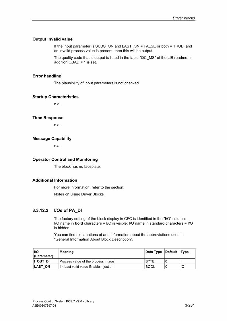
Driver blocks
Process Control System PCS 7 V7.0 - Library A5E00807897-01 3-281
Output invalid value If the input parameter is SUBS_ON and LAST_ON = FALSE or both = TRUE, and an invalid process value is present, then this will be output.
The quality code that is output is listed in the table "QC_MS" of the LIB readme. In addition QBAD = 1 is set.
Error handling The plausibility of input parameters is not checked.
Startup Characteristics n.a.
Time Response n.a.
Message Capability n.a.
Operator Control and Monitoring The block has no faceplate.
Additional Information For more information, refer to the section:
Notes on Using Driver Blocks
3.3.12.2 I/Os of PA_DI
The factory setting of the block display in CFC is identified in the "I/O" column: I/O name in bold characters = I/O is visible; I/O name in standard characters = I/O is hidden.
You can find explanations of and information about the abbreviations used in "General Information About Block Description".
I/O (Parameter)
Meaning
Data Type
Default Type
I_OUT_D Process value of the process image BYTE 0 I LAST_ON 1= Last valid value Enable injection BOOL 0 IO

Driver blocks
Process Control System PCS 7 V7.0 - Library 3-282 A5E00807897-01
I/O (Parameter)
Meaning
Data Type
Default Type
MODE MODE input parameter DWORD 0 I OUT_D Process value BYTE 0 O QA_1 1 = Interrupt/warning 1 BOOL 0 O QA_2 1 = Interrupt/warning 2 BOOL 0 O QBAD 1 = Group event QBAD_X BOOL 0 O QBAD_0 1 = Non-specific BOOL 0 O QBAD_1 1 = Configuration error BOOL 0 O QBAD_2 1 = Not connected BOOL 0 O QBAD_3 1 = Device failure BOOL 0 O QBAD_4 1 = Sensor failure BOOL 0 O QBAD_5 1 = No communication (last usable value) BOOL 0 O QBAD_6 1 = No communication (no usable value) BOOL 0 O QBAD_7 1 = Out of service BOOL 0 O QC Quality Code value of process image BYTE 0 I QCONST 1 = Constant BOOL 0 O QERR 1 = Output error (inverted value of ENO) BOOL 1 O QLAST 1= Last valid value Injection active BOOL 0 O QMOD_ERR 1 = Higher priority error BOOL 0 O QNONCAS0 1 = OK (non-cascade) BOOL 0 O QNONCAS1 1 = Update event BOOL 0 O QNONCAS4 1 = Unacknowledged updated event BOOL 0 O QNONCAS7 1 = Initiate fail-safe BOOL 0 O QNONCAS8 1 = Maintenance required BOOL 0 O QNONCAS9 1 = Function test/local overwrite; usable value BOOL 0 O QSIM 1 = Simulation enabled BOOL 0 O QSUBS 1 = Substitution enabled BOOL 0 O QUALITY Value status of the process variable BYTE 0 O QUNCERT 1 = Group event QUNCERTx BOOL 0 O QUNCERT0 1 = Non-specific BOOL 0 O QUNCERT1 1 = Last usable value BOOL 0 O QUNCERT2 1 = Substitute value set BOOL 0 O QUNCERT3 1 = Initial value BOOL 0 O QUNCERT4 1 = Sensor conversion error BOOL 0 O QUNCERT5 1 = Engineering unit violation (unit not in the valid set) BOOL 0 O QUNCERT6 1 = Under normal BOOL 0 O QUNCERT7 1 = Configuration error BOOL 0 O QUNCERT8 1 = Sensor calibration BOOL 0 O QUNCERT9 1 = Simulated value BOOL 0 O Q0 Process value bit 0 BOOL 0 O Q1 .... Q7 Process value Bit 1 .... Process value Bit 7 BOOL 0 O SIM_I Simulation value BYTE 0 I SIM_ON 1 = Enable simulation BOOL 0 I STATUS Process value status BYTE 0 O SUBS_I Substitute Value BYTE 0 I SUBS_ON 1 = Substitution enabled BOOL 0 I

Driver blocks
Process Control System PCS 7 V7.0 - Library A5E00807897-01 3-283
3.3.13 PA_DO: PROFIBUS PA Digital-Value Output
3.3.13.1 Description of PA_DO
Object name (type + number) FB 105
Area of Application Block PA_DO (cyclic service) is used for the output of digital values (SP/RCAS_IN, max. 8) to a PROFIBUS PA field device class A and B.
Calling OBs The calling OB is watchdog alarm OB 3x into which you integrate the block (for example, OB 32) and restart OB 100.
Use in CFC When the CFC function "Generate module drivers" is used, the following occurs automatically:
• The icon for the quality code of the digital output channel O_SP is interconnected with the output QC_SP and other selected options.
• The MODE input is interconnected with the corresponding output OMODE_xx of the PADP_L0x block.

Driver blocks
Process Control System PCS 7 V7.0 - Library 3-284 A5E00807897-01
Function and Operating Principle Block PA_DO reads the user data from the process image (partition) and writes them to the process image (partition), depending on the selection (with HW Config or SIMATIC PDM) of the user-data configuration of the "Digital Output" PA profile in accordance with PROFIBUS PA 3.0.
The low word of the input variable MODE contains the coding of the user data configuration of the PROFIBUS PA 3.0 Profile "Analog Output" This specifies which variables are to be read and written in the process image (partition).
The block writes the setpoint (SP) with Quality Code (configuration of the setpoints and process values in accordance with the Digital Output of the PA Profiles, 1 byte with 1 byte Quality Code) into the process image (partition). The Quality Code contains the information on the setpoint status. The coding of the quality codes is described in PROFIBUS 3.0 "General Requirements". The setpoint in the RCAS (Remote Cascade) status (RCAS_IN) can be transferred with the quality code to the process image (partition) in the same cycle.
Quality Code A quality code (QUALITY output) is generated for the result value that can adopt the following values:
State Quality Code
Valid value 16#80 Simulation 16#60 Higher-level error, last valid value 16#14 Higher-level error, substitute value 16#18 Bad, due to process 16#28 Uncertain, due to device 16#68 Uncertain, due to process 16#78 Last valid value 16#44 Substitute Value 16#48 Range overshoot 16#54 Maintenance request present 16#A4 Invalid value 16#00
The quality code is formed from internal events, such as channel error, higher-level error or simulation and from a quality code that comes directly from the device (parameter QC_X, X = parameter name).
The quality code that comes directly from the device can take on values from 16#00 – 16#FF in accordance with PROFIBUS requirements. The imaging of these values on the displayable values listed above is shown in the table "QC_MS" table of the current LIB readme.

Driver blocks
Process Control System PCS 7 V7.0 - Library A5E00807897-01 3-285
The data of the PROFIBUS field device, the status of the valve (READBACK), the process value of the valve setting in the state RCAS (RCAS_OUT), and the detailed device information (CHECKBACK) are read cyclically from the process image (partition) as an option. The device information is available at the block output in bit segments.
In order to improve the interconnectability, the output interface provides BOOL values that contain important details read from the status bytes. These conform to the bit combinations specified in PROFIBUS "General Requirements". If READBACK and RCAS_OUT exist simultaneously, the detailed information is derived from the READBACK status byte.
If a higher-level error has occurred (QMOD_ERR = TRUE), the data continue to be written to the process image (partition) and no data are read from the process image (partition). As long as the higher-priority error exists, the last values are held with QBAD = TRUE.
Note
The default value of the setpoint status byte (ST_SP) and of the reference variable (ST_RCAS_IN) is zero. The setpoint and the reference variable become active in the PROFIBUS PA field device only if you set the corresponding status byte to 16#80.
Addressing You have to interconnect one of the icons configured using HW Config (for example, SP) for the digital output channel (PROFIBUS PA 3.0 profile "Analog Output") with the corresponding I/O:
I/O Data type
I_READBACK BYTE I_RCAS_OUT BYTE O_SP BYTE O_RCAS_IN BYTE
In CFC the "Generate module drivers" function automatically interconnects the symbol for the corresponding Quality Code (if it exists) of the I/O with the remaining configured symbols of the digital output channel (with Quality Code).
Simulation If the input parameter SIM_ON = TRUE, the value of the input parameter SIM_SP (and option SIM_RCAS_IN, if selected) is output with the quality code (QUALITY) = 16#60. Simulation takes highest priority. QBAD is set to FALSE. If the block is in the simulation status, QSIM = TRUE is set.

Driver blocks
Process Control System PCS 7 V7.0 - Library 3-286 A5E00807897-01
Error handling The plausibility of input parameters is not checked.
Startup Characteristics The block will run through one time in OB 100 at system start. The output and in/out parameters are calculated.
Time Response n.a.
Message Capability n.a.
Operator Control and Monitoring The block has no faceplate.
Additional Information For more information, refer to the section:
Notes on Using Driver Blocks
3.3.13.2 I/Os of PA_DO
The factory setting of the block display in CFC is identified in the "I/O" column: I/O name in bold characters = I/O is visible; I/O name in standard characters = I/O is hidden.
You can find explanations of and information about the abbreviations used in "General Information About Block Description".
I/O (Parameter)
Meaning
Data Type
Default Type
CHECK_0 Checkback field device BYTE 0 I CHECK_1 Checkback field device BYTE 0 I CHECK_2 Checkback field device BYTE 0 I I_RCAS_OUT Function block setpoint BYTE 0 I I_READBACK Process variable (READBACK) (symbol) BYTE 0 I MODE MODE input parameter DWORD 0 I O_RCAS_IN Process image target setpoint provided by a
monitoring host to the analog control or output block (symbol)
BYTE 0 O
O_SP Setpoint (symbol) BYTE 0 OI QA_1 1 = Interrupt/warning 1 BOOL 0 O
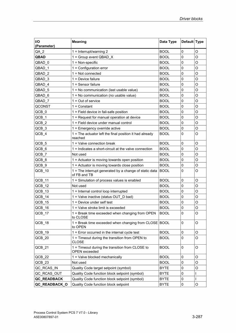
Driver blocks
Process Control System PCS 7 V7.0 - Library A5E00807897-01 3-287
I/O (Parameter)
Meaning
Data Type
Default Type
QA_2 1 = Interrupt/warning 2 BOOL 0 O QBAD 1 = Group event QBAD_X BOOL 0 O QBAD_0 1 = Non-specific BOOL 0 O QBAD_1 1 = Configuration error BOOL 0 O QBAD_2 1 = Not connected BOOL 0 O QBAD_3 1 = Device failure BOOL 0 O QBAD_4 1 = Sensor failure BOOL 0 O QBAD_5 1 = No communication (last usable value) BOOL 0 O QBAD_6 1 = No communication (no usable value) BOOL 0 O QBAD_7 1 = Out of service BOOL 0 O QCONST 1 = Constant BOOL 0 O QCB_0 1 = Field device in fail-safe position BOOL 0 O QCB_1 1 = Request for manual operation at device BOOL 0 O QCB_2 1 = Field device under manual control BOOL 0 O QCB_3 1 = Emergency override active BOOL 0 O QCB_4 1 = The actuator left the final position it had already
reached BOOL 0 O
QCB_5 1 = Valve connection break BOOL 0 O QCB_6 1 = Indicates a short-circuit at the valve connection BOOL 0 O QCB_7 Not used BOOL 0 O QCB_8 1 = Actuator is moving towards open position BOOL 0 O QCB_9 1 = Actuator is moving towards close position BOOL 0 O QCB_10 1 = The interrupt generated by a change of static data
of FB and TB BOOL 0 O
QCB_11 1 = Simulation of process values is enabled BOOL 0 O QCB_12 Not used BOOL 0 O QCB_13 1 = Internal control loop interrupted BOOL 0 O QCB_14 1 = Valve inactive (status OUT_D bad) BOOL 0 O QCB_15 1 = Device under self test BOOL 0 O QCB_16 1 = Valve stroke limit is exceeded BOOL 0 O QCB_17 1 = Break time exceeded when changing from OPEN
to CLOSE BOOL 0 O
QCB_18 1 = Break time exceeded when changing from CLOSE to OPEN
BOOL 0 O
QCB_19 1 = Error occurred in the internal cycle test BOOL 0 O QCB_20 1 = Timeout during the transition from OPEN to
CLOSE BOOL 0 O
QCB_21 1 = Timeout during the transition from CLOSE to OPEN exceeded
BOOL 0 O
QCB_22 1 = Valve blocked mechanically BOOL 0 O QCB_23 Not used BOOL 0 O QC_RCAS_IN Quality Code target setpoint (symbol) BYTE 0 O QC_RCAS_OUT Quality Code function block setpoint (symbol) BYTE 0 I QC_READBACK Quality Code function block setpoint (symbol) BYTE 0 I QC_READBACK_O Quality Code function block setpoint BYTE 0 O

Driver blocks
Process Control System PCS 7 V7.0 - Library 3-288 A5E00807897-01
I/O (Parameter)
Meaning
Data Type
Default Type
QC_SP Quality Code setpoint (symbol) BYTE 0 O QERR 1 = Output error (inverted value of ENO) BOOL 1 O QMOD_ERR 1 = Higher priority error BOOL 0 O QNONCAS0 1 = OK (non-cascade) BOOL 0 O QNONCAS1 1 = Update event BOOL 0 O QNONCAS4 1 = Unacknowledged updated event BOOL 0 O QNONCAS7 1 = Initiate fail-safe BOOL 0 O QNONCAS8 1 = Maintenance required BOOL 0 O QNONCAS9 1 = Function test/local overwrite; usable value BOOL 0 O QSIM 1 = Simulation enabled BOOL 0 O QSUBS 1 = Substitution enabled BOOL 0 O QUNCERT 1 = Group event QUNCERTx BOOL 0 O QUNCERT0 1 = Non-specific BOOL 0 O QUNCERT1 1 = Last usable value BOOL 0 O QUNCERT2 1 = Substitute value set BOOL 0 O QUNCERT3 1 = Initial value BOOL 0 O QUNCERT4 1 = Sensor conversion error BOOL 0 O QUNCERT5 1 = Engineering unit violation (unit not in the valid set) BOOL 0 O QUNCERT6 1 = Under normal BOOL 0 O QUNCERT7 1 = Configuration error BOOL 0 O QUNCERT8 1 = Sensor calibration BOOL 0 O QUNCERT9 1 = Simulated value BOOL 0 O RCAS_IN Target setpoint BYTE 0 I RCAS_OUT Function block setpoint BYTE 0 O READBACK Process value (READBACK) BYTE 0 O SIM_ON 1 = Enable simulation BOOL 0 I SIM_RCAS_IN Simulation target setpoint BYTE 0 I SIM_READBACK Simulation of the current position of the final control
element during runtime (between OPEN and CLOSE positions) in PV units
REAL 0 I
SIM_SP Simulation value BYTE 0 I SP Setpoint BYTE 0 I ST_READBACK Function block setpoint status BYTE 0 O ST_RCAS_IN RCAS_IN status BYTE 0 I ST_RCAS_OUT Function block setpoint status BYTE 0 O ST_SP Setpoint status BYTE 0 I V_HL High limit input value REAL 0 I V_LL Low limit input value REAL 0 I

Driver blocks
Process Control System PCS 7 V7.0 - Library A5E00807897-01 3-289
3.3.14 PA_TOT: Totalizer PROFIBUS PA
3.3.14.1 Description of PA_TOT
Object name (type + number) FB 102
Area of Application Block PA_TOT processes the cyclic parameters of the "Totalizer" PA profile of a PA field device, in accordance with PROFIBUS PA 3.0 class A and B.
Calling OBs The calling OB is the watchdog alarm OB 3x into which you integrate the block (for example, OB 32).
Use in CFC When the CFC function "Generate module drivers" is used, the following occurs automatically:
• The icon for the quality code of the analog input channel is interconnected with the input QC and other selected options.
• The MODE input is interconnected with the corresponding output OMODE_xx of the PADP_L0x block.
Function and Operating Principle Block PA_TOT reads the process variable (TOTAL) with the status byte (quality code) of the PROFIBUS PA field device (structure in accordance with the Totalizer of the PA profiles) cyclically from the process image (partition). The process variable is available in a physical unit. The status byte (STATUS) contains information about the status of the FF field device.
In addition to the status byte and to improve interconnectability, the output interface provides further Boolean (BOOL) values, which contain important details. They conform to bit combinations specifications in PROFIBUS PA 3.0 "General Requirements".
The input variables SET_TOT and MODE_TOT can also be written to the process image (partition).
The block recognizes a higher-level error, for example, failure of a DP/PA link, via the MODE input parameter.

Driver blocks
Process Control System PCS 7 V7.0 - Library 3-290 A5E00807897-01
• If the MODE high byte = 16#80, then the values in the process image (partition) are valid.
• If the MODE high byte = 16#40 (value status = higher-level error, QMOD_ERR = TRUE), the analog value is treated as invalid.
Quality Code A quality code (QUALITY output) is generated for the result value that can adopt the following values: State Quality Code
Valid value 16#80 Simulation 16#60 Higher-level error, last valid value 16#14 Higher-level error, substitute value 16#18 Bad, due to process 16#28 Uncertain, due to device 16#68 Uncertain, due to process 16#78 Last valid value 16#44 Substitute Value 16#48 Range overshoot 16#54 Maintenance request present 16#A4 Invalid value 16#00
The quality code is formed from internal events, such as channel error, higher-level error or simulation and from a quality code that comes directly from the device (parameter QC).
The quality code that comes directly from the device can take on values from 16#00 – 16#FF in accordance with PROFIBUS requirements. The imaging of these values on the displayable values listed above is shown in the table "QC_MS" table of the current LIB readme.
Addressing You must interconnect the symbol generated under HW Config in the symbol table for the analog input channel with the TOTAL input. The CFC function "Generate module drivers" automatically interconnects the QC icon of the analog input channel with input parameter QC and, if they exist, to output parameters O_SET_TOT and O_MODE_TOT.
Simulation If input parameter SIM_ON = TRUE, the value of input SIM_V is output with Quality Code (QUALITY =) 16#60. Simulation takes highest priority. QBAD is always set to FALSE. If the block is in the simulation status, QSIM = TRUE is set.
Driver blocks
Process Control System PCS 7 V7.0 - Library A5E00807897-01 3-291
Substitute Value If input parameter SUBS_ON = TRUE, the value of input parameter SUBS_V is output as a value if the values are invalid. The Quality Code (QUALITY) is set to 16#48 and QBAD = 1.
Hold Last Value If input parameter LAST_ON = TRUE, the last valid output value is output if the process values are invalid. The Quality Code (QUALITY) is set to 16#44 and QBAD = 1.
Output invalid value If the input parameter is SUBS_ON and LAST_ON = FALSE or both = TRUE, and an invalid process value is present, then this will be output.
The quality code that is output is listed in the table "QC_MS" of the LIB readme. In addition QBAD = 1 is set.
Value Limiting You can limit the maximum low and high range of process variables in the process image (partition).
LIMIT_ON = TRUE limits process variables (V):
• To V_HL, if V > V_HL
• To LL_V, if V < V_LL
Error handling The plausibility of input parameters is not checked.
Startup Characteristics n.a.
Time Response n.a.
Message Capability n.a.
Operator Control and Monitoring The block has no faceplate.
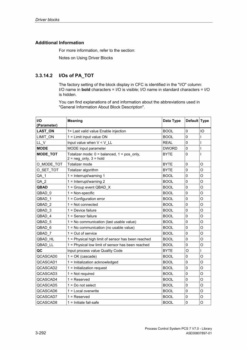
Driver blocks
Process Control System PCS 7 V7.0 - Library 3-292 A5E00807897-01
Additional Information For more information, refer to the section:
Notes on Using Driver Blocks
3.3.14.2 I/Os of PA_TOT
The factory setting of the block display in CFC is identified in the "I/O" column: I/O name in bold characters = I/O is visible; I/O name in standard characters = I/O is hidden.
You can find explanations of and information about the abbreviations used in "General Information About Block Description".
I/O (Parameter)
Meaning
Data Type
Default Type
LAST_ON 1= Last valid value Enable injection BOOL 0 IO LIMIT_ON 1 = Limit input value ON BOOL 0 I LL_V Input value when V < V_LL REAL 0 I MODE MODE input parameter DWORD 0 I MODE_TOT Totalizer mode: 0 = balanced, 1 = pos_only,
2 = neg_only, 3 = hold BYTE 0 I
O_MODE_TOT Totalizer mode BYTE 0 O O_SET_TOT Totalizer algorithm BYTE 0 O QA_1 1 = Interrupt/warning 1 BOOL 0 O QA_2 1 = Interrupt/warning 2 BOOL 0 O QBAD 1 = Group event QBAD_X BOOL 0 O QBAD_0 1 = Non-specific BOOL 0 O QBAD_1 1 = Configuration error BOOL 0 O QBAD_2 1 = Not connected BOOL 0 O QBAD_3 1 = Device failure BOOL 0 O QBAD_4 1 = Sensor failure BOOL 0 O QBAD_5 1 = No communication (last usable value) BOOL 0 O QBAD_6 1 = No communication (no usable value) BOOL 0 O QBAD_7 1 = Out of service BOOL 0 O QBAD_HL 1 = Physical high limit of sensor has been reached BOOL 0 O QBAD_LL 1 = Physical low limit of sensor has been reached BOOL 0 O QC Input process value Quality Code BYTE O I QCASCAD0 1 = OK (cascade) BOOL 0 O QCASCAD1 1 = Initialization acknowledged BOOL 0 O QCASCAD2 1 = Initialization request BOOL 0 O QCASCAD3 1 = Not required BOOL 0 O QCASCAD4 1 = Reserved BOOL 0 O QCASCAD5 1 = Do not select BOOL 0 O QCASCAD6 1 = Local overwrite BOOL 0 O QCASCAD7 1 = Reserved BOOL 0 O QCASCAD8 1 = Initiate fail-safe BOOL 0 O
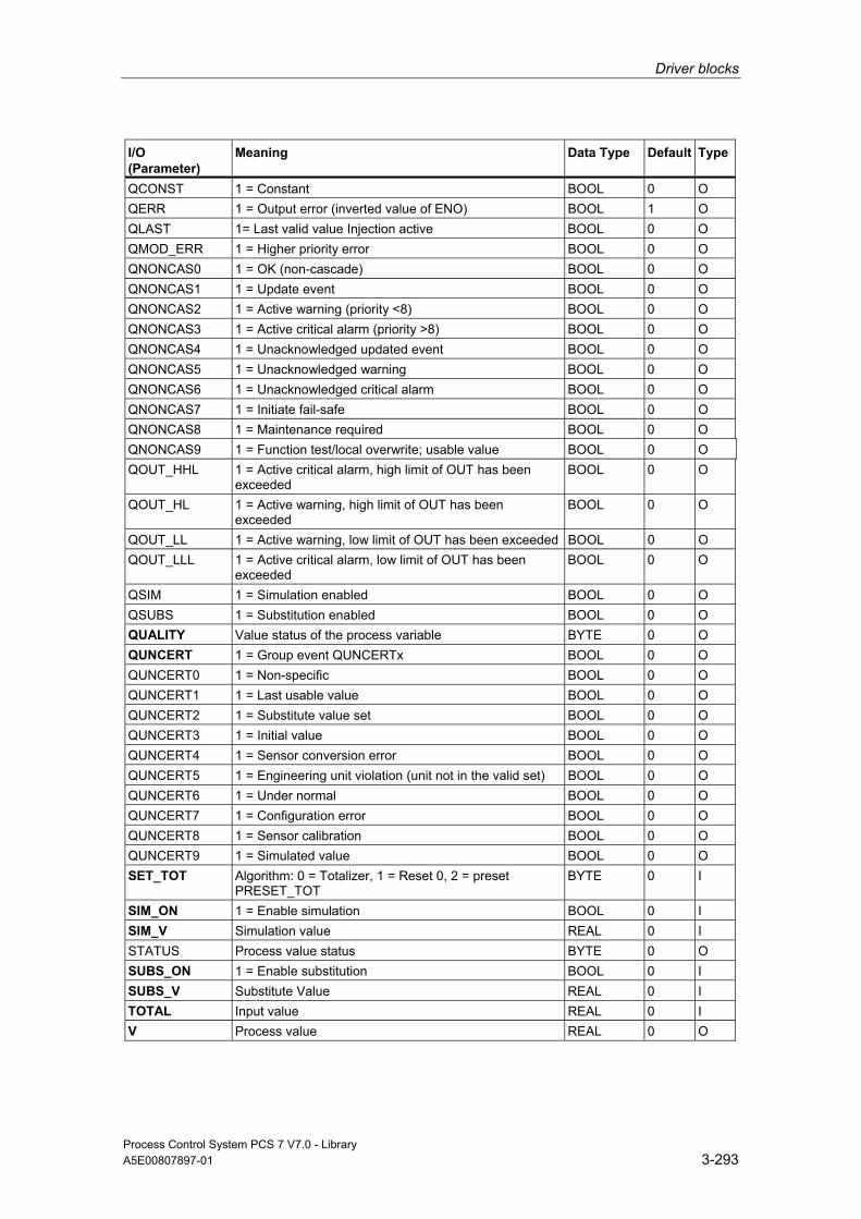
Driver blocks
Process Control System PCS 7 V7.0 - Library A5E00807897-01 3-293
I/O (Parameter)
Meaning
Data Type
Default Type
QCONST 1 = Constant BOOL 0 O QERR 1 = Output error (inverted value of ENO) BOOL 1 O QLAST 1= Last valid value Injection active BOOL 0 O QMOD_ERR 1 = Higher priority error BOOL 0 O QNONCAS0 1 = OK (non-cascade) BOOL 0 O QNONCAS1 1 = Update event BOOL 0 O QNONCAS2 1 = Active warning (priority <8) BOOL 0 O QNONCAS3 1 = Active critical alarm (priority >8) BOOL 0 O QNONCAS4 1 = Unacknowledged updated event BOOL 0 O QNONCAS5 1 = Unacknowledged warning BOOL 0 O QNONCAS6 1 = Unacknowledged critical alarm BOOL 0 O QNONCAS7 1 = Initiate fail-safe BOOL 0 O QNONCAS8 1 = Maintenance required BOOL 0 O QNONCAS9 1 = Function test/local overwrite; usable value BOOL 0 O QOUT_HHL 1 = Active critical alarm, high limit of OUT has been
exceeded BOOL 0 O
QOUT_HL 1 = Active warning, high limit of OUT has been exceeded
BOOL 0 O
QOUT_LL 1 = Active warning, low limit of OUT has been exceeded BOOL 0 O QOUT_LLL 1 = Active critical alarm, low limit of OUT has been
exceeded BOOL 0 O
QSIM 1 = Simulation enabled BOOL 0 O QSUBS 1 = Substitution enabled BOOL 0 O QUALITY Value status of the process variable BYTE 0 O QUNCERT 1 = Group event QUNCERTx BOOL 0 O QUNCERT0 1 = Non-specific BOOL 0 O QUNCERT1 1 = Last usable value BOOL 0 O QUNCERT2 1 = Substitute value set BOOL 0 O QUNCERT3 1 = Initial value BOOL 0 O QUNCERT4 1 = Sensor conversion error BOOL 0 O QUNCERT5 1 = Engineering unit violation (unit not in the valid set) BOOL 0 O QUNCERT6 1 = Under normal BOOL 0 O QUNCERT7 1 = Configuration error BOOL 0 O QUNCERT8 1 = Sensor calibration BOOL 0 O QUNCERT9 1 = Simulated value BOOL 0 O SET_TOT Algorithm: 0 = Totalizer, 1 = Reset 0, 2 = preset
PRESET_TOT BYTE 0 I
SIM_ON 1 = Enable simulation BOOL 0 I SIM_V Simulation value REAL 0 I STATUS Process value status BYTE 0 O SUBS_ON 1 = Enable substitution BOOL 0 I SUBS_V Substitute Value REAL 0 I TOTAL Input value REAL 0 I V Process value REAL 0 O
Driver blocks
Process Control System PCS 7 V7.0 - Library 3-294 A5E00807897-01
I/O (Parameter)
Meaning
Data Type
Default Type
V_HL High limit input value REAL 0 I V_LL Low limit input value REAL 0 I
3.3.15 PADP_L0x: Monitoring DP/PA Slaves
3.3.15.1 Description of PADP_L00
Object name (type + number) FB 109
Area of Application Block PADP_L00 monitors DP/PA field devices operating as DPV0 or DPV1 slaves downstream of a DP/PA or Y link that is operated as a DPV0 slave. The PA field devices must conform to the PROFIBUS V3.0 profile. Individual blocks must be available for the diagnostic and signal processing functions of DP field devices. H systems support only the PA field devices connected to an active DP/PA link.
Calling OBs The block must be installed in the run sequence in the following OBs: OB 1 Cyclic program
OB 82 Diagnostic interrupt OB 85 Program runtime error OB 86 Rack failure OB 100 Restart (warm start)
Use in CFC When the CFC function "Generate module drivers" is used, the following occurs automatically:
• Block PADP_L00 is integrated in the run sequence downstream of block DPAY_V0.
• The MODE_xx input (mode of slot xx of a field device) is configured.

Driver blocks
Process Control System PCS 7 V7.0 - Library A5E00807897-01 3-295
• The PADP_ADR input (DP/PA slave address downstream of a DP/PA or Y link) is configured.
• The input DPA_M is interconnected with the output DPA_M_xx of the block DPAY_V0.
• The CPU_DIAG OUT structure of OB_BEGIN and RAC_DIAG of the DPAY_V0 block are interconnected with the INOUT structures of the same name of the PADP_L00 block.
• The outputs QMODF and PA_DIAG are interconnected with the MOD_PAL0 block.
Note
The CFC function "Generate module drivers" can only be used if the PA field device belongs to slave family 12.
Function and Operating Principle Block PADP_L00 analyzes all events affecting a DP or PA field device and its slots acyclically. It forms the corresponding DP_MODE or PA_MODE and value status for the DP or PA signal processing blocks for each individual slot. The permissible PA_MODE is already defined for the PA signal processing blocks, while DP_MODE has to be defined individually for the blocks of the DP field devices. ALARM_8P is used to report these events. The message function can be disabled.
The higher-level DPAY_V0 block enables runtime of the block. The diagnostic is entered in the start information (CPU_DIAG) of the OB_DIAG block.
Diagnostic data are already evaluated by the Link block (DPAY_V0). The diagnostic data affecting the PA field device are stored in the structure DPA_M. The structure consists of two DWORD (S_01 for modules 1 to 16 and S_02 for modules 17 to 32) and one BOOL (S_ERR = DP/PA field device faulty) variables. Two bits of the DWORD are assigned to each slot of the DP/PA field device, whereby bit 0 and bit 1 belong to slot 1 of the DP/PA field device, etc. Slots 1 to 7 are evaluated. The bit states are defined as follows:
Status Bit 0 Status Bit 1 Meaning
0 0 Module x OK (valid user data) 0 1 Module x error (invalid user data) 1 0 Wrong module x (invalid user data) 1 1 No module x (invalid user data)
An input (MODE_xx) exists for each slot (module) of the DP/PA field device that is used to read in HW Config data for the slots (modules).
At DP field devices the user must enter his code manually at the MODE input.

Driver blocks
Process Control System PCS 7 V7.0 - Library 3-296 A5E00807897-01
The function writes MODE_xx to the low word of the OMODE_xx output parameter, but only during startup/initial startup or if you set ACC_MODE = TRUE. The actual slot value status is written to the most significant byte. If the result is positive, the system sets OMODE_xx = 16#80xxxxxx. The following events are evaluated by block DPAY_V0 and lead to the value status "Invalid value" due to a higher-level error (OMODE_xx = 16#40xxxxxx):
• Rack failure (OB 86) (output parameter QRACKF = TRUE) • Diagnostic interrupt concerning a
complete field device (OB82) (output parameter QMODF = TRUE, if DPA_M.S_ERR = TRUE)
• Diagnostic alarm slot xx concerning a field device (OB 82):
(output parameter OMODE_xx = Module-(slot-)error specific DPA_M)
In the event of a diagnostic alarm, the block reports field-device-specifically to WinCC by means of ALARM_8P. It distinguishes between the field device and its slots, and assigns a message number to each slot.
The "Device failure" message can be disabled with EM_MSG_D = FALSE.
Redundancy Higher-level block DPAY_V0 evaluates the redundancy of DP master systems operating in an H system.
MODE Setting for PA Profiles You can find additional information in "PA_MODE Settings".
Note
Modifications of parameters at the MODE_xx inputs during runtime are not accepted at the outputs until input ACC_MODE = 1.
OMODE Structure You can find additional information in "OMODE".
Error handling The plausibility of input parameters is not checked.
Startup Characteristics After a restart or an initial start the system verifies that the PA field device is available under its logical base address. A restart (OB 100) is reported via the LSB in byte 2 of the outputs OMODE_xx.
Driver blocks
Process Control System PCS 7 V7.0 - Library A5E00807897-01 3-297
Time Response n.a.
Message Capability The block uses ALARM_8P to report field device errors and generates the following messages in the OBs listed below:
OB No. Start Event Message
OB 1 Cyclic processing Repeat update of ALARM_8P outputs/messages, if necessary OB 82 Diagnostic interrupt Device error incoming/outgoing
Device module xx error incoming/outgoing Device module xx incorrect incoming/outgoing Device module xx missing incoming/outgoing
OB 100 Restart: Initialization of ALARM_8P
Operator Control and Monitoring The block has no faceplate.
Note: If you have selected the "Enable operator control and monitoring" option in the block object properties in the CFC, the variables transferred to the OS are identified under "I/Os of …" (OCM column, "+"). Default: option not selected.
Additional Information For more information, refer to the following sections:
Message Texts and Associated Values of PADP_L00
Notes on Using Driver Blocks
3.3.15.2 I/Os of PADP_L0x
The I/Os of the PADP_L00, PADP_L01 and PADP_L02 blocks are identical save for the number of MODE_xx and OMODE_xx. The number of monitored slots determines the number of corresponding I/O parameters.
The factory setting of the block display in CFC is identified in the "I/O" column: I/O name in bold characters = I/O is visible; I/O name in standard characters = I/O is hidden.
You can find explanations of and information about the abbreviations used in "General Information About Block Description".

Driver blocks
Process Control System PCS 7 V7.0 - Library 3-298 A5E00807897-01
I/O (Parameter)
Meaning
Data Type
Default Type
OCM
ACC_MODE 1 = Accept MODE settings BOOL 0 I/O CPU_DIAG CPU diagnostics STRUCT I/O DPA_M Status modules of DP/PA slave STRUCT I EN_MSG 1 = Enable message BOOL 1 I EN_MSG_D 1 = Message enable "Device failure" BOOL 1 I EV_ID Message number DWORD 0 I MODE_xx Module operating mode (xx = 00 - 06/00 - 15/00 -
31) WORD 0 I
MSG_ACK Message acknowledgement WORD 0 O MSGSTAT Error message status WORD 0 O OMODE_xx Module operating mode (xx = 00 - 06/00 - 15/00 -
31) DWORD 0 O +
PA_DIAG PA-field-device diagnostic information DWORD 0 O PADP_ADR Address of the DP/PA field device BYTE 0 I QERR 1 = Program runtime error BOOL 1 O QMODF 1 = Module withdrawn/defective BOOL 0 O + QRACKF 1 = Rack/station error BOOL 0 O RAC_DIAG 1 = DPV1 mode STRUCT I/O
Additional Information For more information, refer to the following sections:
Message Texts and Associated Values of PADP_L00
Message Texts and Associated Values of PADP_L01
Message Texts and Associated Values of PADP_L02
3.3.15.3 Message Texts and Associated Values of PADP_L00
Assignment of Message Text and Message Class
Message Block ALARM_8P
Message No.
Block Parameter
Default Message Text
Message Class
EV_ID 1 QMODF Device @1%d@/ @2%d@/@3%d@: Failure S 2 - Device @1%d@/ @2%d@/@3%d@:
Module 00 @4W%t#PADP_L00_TXT@ S
... ... 8 - Device @1%d@/ @2%d@/@3%d@:
Module 06 @10W%t#PADP_L00_TXT@ S
You can find the message texts and their text numbers in "Text Library for PADP_L00".

Driver blocks
Process Control System PCS 7 V7.0 - Library A5E00807897-01 3-299
Assignment of Associated Values
Message Block ALARM_8P
Associated Value
Block Parameter
Meaning
EV_ID 1 SUBN_ID DP master system ID (byte) 2 RACK_NO Rack/station number (byte) 3 PADP_ADR DP/PA device address (byte) 4 - 10 - Text number (messages 2 - 8) from PADP_L00_TXT
At PA field device is connected downstream from an inactive DP/PA-Link V0 and SUBN1_ID = 16#FF, the SUBN2_ID will be entered as associated variable.
3.3.15.4 Description of PADP_L01
Object name (type + number) FB 110
Area of Application Block PADP_L01 monitors DP/PA field devices operating as DPV0 or DPV1 slaves downstream of a DP/PA or Y link that is operated as a DPV0 slave. The PA field devices must conform to the PROFIBUS V3.0 profile. Individual blocks must be available for the diagnostic and signal processing functions of DP field devices. H systems support only the PA field devices connected to an active DP/PA link.
Calling OBs The block must be installed in the run sequence of the following OBs (carried out automatically in CFC): OB 1 Cyclic program
OB 82 Diagnostic interrupt OB 85 Program runtime error OB 86 Rack failure OB 100 Restart (warm start)
Use in CFC When the CFC function "Generate module drivers" is used, the following occurs automatically:

Driver blocks
Process Control System PCS 7 V7.0 - Library 3-300 A5E00807897-01
• Block PADP_L01 is integrated in the run sequence downstream of block DPAY_V0.
• The MODE_xx input (mode of slot xx of a field device) is configured.
• The PADP_ADR input (DP/PA slave address downstream of a DP/PA or Y link) is configured.
• The input DPA_M is interconnected with the output DPA_M_xx of the block DPAY_V0.
• The CPU_DIAG OUT structure of OB_BEGIN and RAC_DIAG of the DPAY_V0 block are interconnected with the INOUT structures of the same name of the PADP_L01 block.
• The outputs QMODF and PA_DIAG are interconnected with the MOD_PAL0 block.
Note
The CFC function "Generate module drivers" can only be used if the PA field device belongs to slave family 12.
Function and Operating Principle Block PADP_L01 analyzes all events affecting a DP or PA field device and its slots acyclically. It forms the corresponding DP_MODE or PA_MODE and value status for the DP or PA signal processing blocks for each individual slot. The permissible PA_MODE is already defined for the PA signal processing blocks, while DP_MODE has to be defined individually for the blocks of the DP field devices. ALARM_8P is used to report these events. The message function can be disabled.
The higher-level DPAY_V0 block enables runtime of the block. The diagnostic is entered in the start information (CPU_DIAG) of the OB_DIAG block.
Diagnostic data are already evaluated by the Link block (DPAY_V0). The diagnostic data affecting the PA field device are stored in the structure DPA_M. The structure consists of two DWORD (S_01 for modules 1 to 16 and S_02 for modules 17 to 32) and one BOOL (S_ERR = DP/PA field device faulty) variables. Two bits of the DWORD are assigned to each slot of the DP/PA field device, whereby bit 0 and bit 1 belong to slot 1 of the DP/PA field device, etc. Slots 1 to 16 are evaluated. The bit states are defined as follows:
Status Bit 0 Status Bit 1 Meaning
0 0 Module x OK (valid user data) 0 1 Module x error (invalid user data) 1 0 Wrong module x (invalid user data) 1 1 No module x (invalid user data)

Driver blocks
Process Control System PCS 7 V7.0 - Library A5E00807897-01 3-301
An input (MODE _xx) exists for each slot (module) of the DP/PA field device. that is used to read in HW Config data for the slots (modules).
At DP field devices the user must enter his code manually at the MODE input.
The function writes MODE_xx to the low word of the OMODE_xx output parameter, but only during startup/initial startup or if you set ACC_MODE = TRUE. The actual slot value status is written to the most significant byte. If the result is positive, the system sets OMODE_xx = 16#80xxxxxx. The following events are evaluated by block DPAY_V0 and lead to the value status "Invalid value" due to a higher-level error (OMODE_xx = 16#40xxxxxx):
• Rack failure (OB 86) (output parameter QRACKF = TRUE) • Diagnostic interrupt concerning
a complete field device (OB82) (output parameter QMODF = TRUE, if DPA_M.S_ERR = TRUE)
• Diagnostic alarm slot xx concerning a field device (OB 82):
(output parameter OMODE_xx = Module-(slot-)error specific DPA_M)
The block uses ALARM_8P to report diagnostic interrupts specific to a field device to WinCC. It distinguishes between the field device and its slots, and assigns a message number to each slot.
The "Device failure" message can be disabled with EM_MSG_D = FALSE.
Redundancy Higher-level block DPAY_V0 evaluates the redundancy of DP master systems operating in an H system.
MODE Setting for PA Profiles You can find additional information in "PA_MODE Settings".
Note
Modifications of parameters at the MODE_xx inputs during runtime are not accepted at the outputs until input ACC_MODE = 1.
OMODE Structure You can find additional information in "OMODE".
Error handling The plausibility of input parameters is not checked.

Driver blocks
Process Control System PCS 7 V7.0 - Library 3-302 A5E00807897-01
Startup Characteristics After a restart or an initial start the system verifies that the PA field device is available under its logical base address. A restart (OB 100) is reported via the LSB in byte 2 of the outputs OMODE_xx.
Time Response n.a.
Message Capability The block uses ALARM_8P to report field device errors and generates the following messages in the OBs listed below:
OB No. Start Event Message
OB 1 Cyclic processing Repeat update of ALARM_8P outputs/messages, if necessary OB 82 Diagnostic interrupt Device error incoming/outgoing
Device module xx error incoming/outgoing Device module xx incorrect incoming/outgoing Device module xx missing incoming/outgoing
OB 100 Restart: Initialization of ALARM_8P
Operator Control and Monitoring The block has no faceplate.
Note: If you have selected the "Enable operator control and monitoring" option in the block object properties in the CFC, the variables transferred to the OS are identified under "I/Os of …" (OCM column, "+"). Default: option not selected.
Additional Information For more information, refer to the following sections:
Message Texts and Associated Values of PADP_L01
Notes on Using Driver Blocks

Driver blocks
Process Control System PCS 7 V7.0 - Library A5E00807897-01 3-303
3.3.15.5 Message Texts and Associated Values of PADP_L01
Assignment of Message Text and Message Class
Message Block ALARM_8P
Message No.
Block Parameter
Default Message Text
Message Class
EV_ID1 1 QMODF Device @1%d@/ @2%d@/@3%d@: Failure
S
2 - Device @1%d@/ @2%d@/@3%d@: Module 07 @4W%t#PADP_L01_TXT@
S
3 - Device @1%d@/ @2%d@/@3%d@: Module 15 @5W%t#PADP_L01_TXT@
S
EV_ID2 1 - Device @1%d@/ @2%d@/@3%d@: Module 00 @4W%t#PADP_L01_TXT@
S
... ... 7 - Device @1%d@/ @2%d@/@3%d@:
Module 06 @10W%t#PADP_L01_TXT@ S
EV_ID3 1 - Device @1%d@/ @2%d@/@3%d@: Module 08 @4W%t#PADP_L01_TXT@
S
... ... 7 - Device @1%d@/ @2%d@/@3%d@:
Module 14 @10W%t#PADP_L01_TXT@ S
You can find the message texts and their text numbers in "Text Library for PADP_L01".
Assignment of Associated Values
Message Block ALARM_8P
Associated Value
Block Parameter
Meaning
EV_ID1 1 SUBN_ID DP master system ID (byte) 2 RACK_NO Rack/station number (byte) 3 PADP_ADR DP/PA device address (byte) 4 - 5 - Text number (message 2 - 3) from PADP_L01_TXT EV_ID2 1 SUBN_ID DP master system ID (byte) 2 RACK_NO Rack/station number (byte) 3 PADP_ADR DP/PA device address (byte) 4 - 10 - Text number (message 1 - 7) from PADP_L01_TXT EV_ID3 1 SUBN_ID DP master system ID (byte) 2 RACK_NO Rack/station number (byte) 3 PADP_ADR DP/PA device address (byte) 4 - 10 - Text number (message 1 - 7) from PADP_L01_TXT

Driver blocks
Process Control System PCS 7 V7.0 - Library 3-304 A5E00807897-01
At PA field device is connected downstream from an inactive DP/PA-Link V0 and SUBN1_ID = 16#FF, the SUBN2_ID will be entered as associated variable.
3.3.15.6 Description of PADP_L02
Object name (type + number) FB 111
Area of Application Block PADP_L02 monitors DP/PA field devices operating as DPV0 or DPV1 slaves downstream of a DP/PA or Y link that is operated as a DPV0 slave. The PA field devices must conform to the PROFIBUS V3.0 profile. Individual blocks must be available for the diagnostic and signal processing functions of DP field devices. H systems support only the PA field devices at an active DP/PA-Link.
Calling OBs Block PADP_L02 must be installed in the run sequence in the following OBs: OB 1 Cyclic program
OB 82 Diagnostic interrupt OB 85 Program runtime error OB 86 Rack failure OB 100 Restart (warm start)
Use in CFC When the CFC function "Generate module drivers" is used, the following occurs automatically:
• Block PADP_L02 is installed in the run sequence downstream of DPAY_V0.
• The MODE_xx input (mode of slot xx of a field device) is configured.
• The PADP_ADR input (DP/PA slave address downstream of a DP/PA or Y link) is configured.
• The input DPA_M is interconnected with the output DPA_M_xx of the block DPAY_V0.

Driver blocks
Process Control System PCS 7 V7.0 - Library A5E00807897-01 3-305
• The CPU_DIAG OUT structure of OB_BEGIN and RAC_DIAG of the DPAY_V0 block are interconnected with the INOUT structures of the same name of the PADP_L02 block.
• The outputs QMODF and PA_DIAG are interconnected with the MOD_PAL0 block.
Function and Operating Principle Block PADP_L02 analyzes all events affecting a DP or PA field device and its slots acyclically. It forms the corresponding DP_MODE or PA_MODE and value status for the DP or PA signal processing blocks for each individual slot. The permissible PA_MODE is already defined for the PA signal processing blocks, while DP_MODE has to be defined individually for the blocks of the DP field devices. ALARM_8P is used to report these events. The message function can be disabled.
The higher-level DPAY_V0 block enables runtime of the block. The event to be evaluated is entered in the start information (CPU_DIAG) of OB_BEGIN.
Diagnostic data are already evaluated by the Link block (DPAY_V0). The diagnostic data affecting the PA field device are stored in the structure DPA_M. The structure consists of two DWORD (S_01 for modules 1 to 16 and S_02 for modules 17 to 32) and one BOOL (S_ERR = DP/PA field device faulty) variables. Two bits of the DWORD are assigned to each slot of the DP/PA field device, whereby bit 0 and bit 1 belong to slot 1 of the DP/PA field device, etc. Slots 1 to 32 are evaluated. The bit states are defined as follows:
Status Bit 0 Status Bit 1 Meaning
0 0 Module x OK (valid user data) 0 1 Module x error (invalid user data) 1 0 Wrong module x (invalid user data) 1 1 No module x (invalid user data)
An input (MODE_xx) exists for each slot (module) of the DP/PA field device that is used to read in HW Config data for the slots (modules).
At DP field devices the user must enter his code manually at the MODE input.
Driver blocks
Process Control System PCS 7 V7.0 - Library 3-306 A5E00807897-01
The function writes MODE_xx to the low word of the OMODE_xx output parameter, but only during startup/initial startup or if you set ACC_MODE = TRUE. The actual slot value status is written to the most significant byte. If the result is positive, the system sets OMODE_xx = 16#80xxxxxx. The following events are evaluated by block DPAY_V0 and lead to the value status "Invalid value" due to a higher-level error (OMODE_xx = 16#40xxxxxx):
• Rack failure (OB 86) (output parameter QRACKF = TRUE) • Diagnostic interrupt concerning a
complete field device (OB82) (output parameter QMODF = TRUE, if DPA_M.S_ERR = TRUE)
• Diagnostic alarm slot xx concerning a field device (OB 82):
(output parameter OMODE_xx = Module-(slot-)error specific DPA_M)
The block ALARM_8P to report diagnostic interrupts specific to a field device to WinCC. It distinguishes between the field device and its slots, and assigns a message number to each slot.
The "Device failure" message can be disabled with EM_MSG_D = FALSE.
Redundancy Higher-level block DPAY_V0 evaluates the redundancy of DP master systems operating in an H system.
MODE Setting for PA Profiles You can find additional information in "PA_MODE Settings".
Note
Modifications of parameters at the MODE_xx inputs during runtime are not accepted at the outputs until input ACC_MODE = 1.
OMODE Structure You can find additional information in "OMODE".
Error handling The plausibility of input parameters is not checked.
Startup Characteristics After a restart or an initial start the system verifies that the PA field device is available under its logical base address. A restart (OB 100) is reported via the LSB in byte 2 of the outputs OMODE_xx.
Time Response n.a.

Driver blocks
Process Control System PCS 7 V7.0 - Library A5E00807897-01 3-307
Message Capability The block uses ALARM_8P to report field device errors and generates the following messages in the OBs listed below:
OB No. Start Event Message
OB 1 Cyclic processing Repeat update of ALARM_8P outputs/messages, if necessary OB 82 Diagnostic interrupt Device error incoming/outgoing
Device module xx error incoming/outgoing Device module xx incorrect incoming/outgoing Device module xx missing incoming/outgoing
OB 100 Restart: Initialization of ALARM_8P
Operator Control and Monitoring The block has no faceplate.
Note: If you have selected the "Enable operator control and monitoring" option in the block object properties in the CFC, the variables transferred to the OS are identified under "I/Os of …" (OCM column, "+"). Default: option not selected.
Additional Information For more information, refer to the following sections:
Message Texts and Associated Values of PADP_L02
Notes on Using Driver Blocks

Driver blocks
Process Control System PCS 7 V7.0 - Library 3-308 A5E00807897-01
3.3.15.7 Message Texts and Associated Values of PADP_L02
Assignment of Message Text and Message Class
Message Block ALARM_8P
Message No.
Block Parameter
Default Message Text
Message Class
EV_ID1 1 QMODF Device @1%d@/ @2%d@/@3%d@: Failure
S
2 - Device @1%d@/ @2%d@/@3%d@: Module 07@4W%t#PADP_L02_TXT@
S
3 - Device @1%d@/ @2%d@/@3%d@: Module 15@5W%t#PADP_L02_TXT@
S
4 - Device @1%d@/ @2%d@/@3%d@: Module 23@6W%t#PADP_L02_TXT@
S
5 - Device @1%d@/ @2%d@/@3%d@: Module 31 @7W%t#PADP_L02_TXT@
S
EV_ID2 1 - Device @1%d@/ @2%d@/@3%d@: Module 00 @4W%t#PADP_L02_TXT@
S
... ... 7 - Device @1%d@/ @2%d@/@3%d@:
Module 06 @10W%t#PADP_L02_TXT@ S
EV_ID3 1 - Device @1%d@/ @2%d@/@3%d@: Module 08 @4W%t#PADP_L02_TXT@
S
... ... 7 - Device @1%d@/ @2%d@/@3%d@:
Module 14 @10W%t#PADP_L02_TXT@ S
EV_ID20 1 - Device @1%d@/ @2%d@/@3%d@: Module 16 @4W%t#PADP_L02_TXT@
S
... ... - Device @1%d@/ @2%d@/@3%d@:
Module 22 @10W%t#PADP_L02_TXT@ S
EV_ID5 1 - Device @1%d@/ @2%d@/@3%d@: Module 24 @4W%t#PADP_L02_TXT@
S
... ... 7 - Device @1%d@/ @2%d@/@3%d@:
Module 30 @10W%t#PADP_L02_TXT@ S
You can find the message texts and their text numbers in "Text Library for PADP_L02".
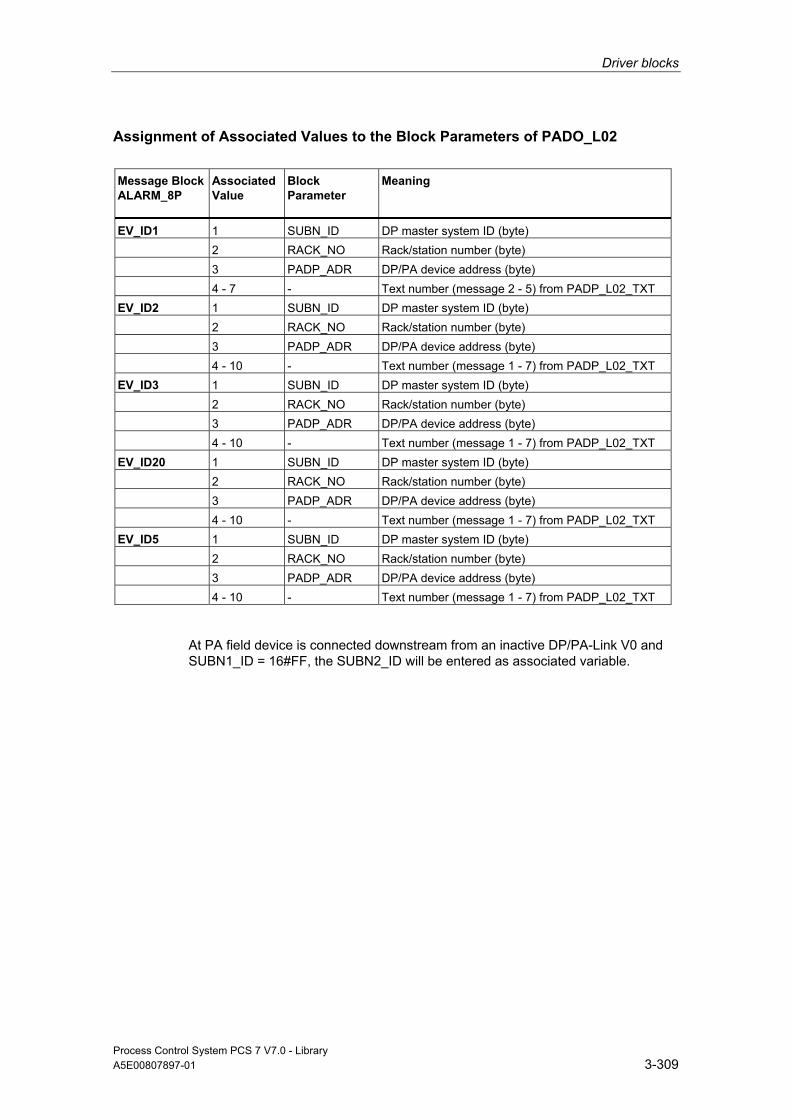
Driver blocks
Process Control System PCS 7 V7.0 - Library A5E00807897-01 3-309
Assignment of Associated Values to the Block Parameters of PADO_L02
Message Block ALARM_8P
Associated Value
Block Parameter
Meaning
EV_ID1 1 SUBN_ID DP master system ID (byte) 2 RACK_NO Rack/station number (byte) 3 PADP_ADR DP/PA device address (byte) 4 - 7 - Text number (message 2 - 5) from PADP_L02_TXT EV_ID2 1 SUBN_ID DP master system ID (byte) 2 RACK_NO Rack/station number (byte) 3 PADP_ADR DP/PA device address (byte) 4 - 10 - Text number (message 1 - 7) from PADP_L02_TXT EV_ID3 1 SUBN_ID DP master system ID (byte) 2 RACK_NO Rack/station number (byte) 3 PADP_ADR DP/PA device address (byte) 4 - 10 - Text number (message 1 - 7) from PADP_L02_TXT EV_ID20 1 SUBN_ID DP master system ID (byte) 2 RACK_NO Rack/station number (byte) 3 PADP_ADR DP/PA device address (byte) 4 - 10 - Text number (message 1 - 7) from PADP_L02_TXT EV_ID5 1 SUBN_ID DP master system ID (byte) 2 RACK_NO Rack/station number (byte) 3 PADP_ADR DP/PA device address (byte) 4 - 10 - Text number (message 1 - 7) from PADP_L02_TXT
At PA field device is connected downstream from an inactive DP/PA-Link V0 and SUBN1_ID = 16#FF, the SUBN2_ID will be entered as associated variable.
Driver blocks
Process Control System PCS 7 V7.0 - Library 3-310 A5E00807897-01
3.3.16 PADP_L10: Monitoring PA Slaves According to DP V0 With a Maximum of 16 Slots
3.3.16.1 Description of PADP_L10
Object name (type + number) FB 116
Area of Application Block PADP_L10 monitors DPV0 PA field devices with a maximum of 16 slots, which are operated as DPV0 slaves on a DP master system directly or via a DP/PA coupler. The DP/PA coupler is connected downstream of a DPV1 DP/PA link. The PA field devices must conform to the PROFIBUS V3.0 profile. H systems support only the PA field devices at an active DP/PA-Link.
Calling OBs The block must be installed in the run sequence downstream from the OB_DIAG1 block in the following OBs (carried out automatically in CFC):
OB 1 Cyclic program
OB 55 Status interrupt (only if a PA slave is required) OB 56 Update interrupt (only if a PA slave is required) OB 57 Update interrupt (only if a PA slave is required) OB 82 Diagnostic interrupt OB 83 Removal/insertion alarm (failure/return of a field device) OB 85 Program runtime error OB 86 Rack failure OB 100 Restart (warm start)
Use in CFC When the CFC function "Generate module drivers" is used, the following occurs automatically:
• Block OB_DIAG1 is installed in the run sequence upstream of PADP_L10.
Driver blocks
Process Control System PCS 7 V7.0 - Library A5E00807897-01 3-311
• The following are configured, depending on whether the PA field device is connected directly to a DP master system or downstream of a DP/PA link:
- the diagnostic address of the PA field device or of the DADDR DP/PA link
- the geographical address (SUBN1_ID, SUBN2_ID, RACK_NO of the PA address of the PA field device or the DP/PA link)
- SLOT_NO = 0 or the geographical address of the PA field device in the DP/PA link (SLOT0_NO = Slot 0 no. for the PA field device, SLOTS_NO = number of slots of the PA field device)
- SLOTS_NO = number of slots of the PA field device
- the PA address of the PA field device (PADP_ADR)
- MODE_xx (mode of slots xx of a PA field device)
• The CPU_DIAG and CPU_OB_5X OUT structures of OB_BEGIN and RAC_DIAG of OB_DIAG1 are interconnected with the INOUT structures of the same name of PADP_L10.
• The EN input is interconnected with the output of an AND block, whose inputs are interconnected with the outputs EN_SUBx (x = number of the DP master system) of the OB_BEGIN block, EN_Rxxx (xxx = rack/station number) of the SUBNET block, EN_Mx (x= number of the PA device) of the DPAY_V1 block, and EN_F of the OB_DIAG1 block.
• EN_DIAG is interconnected with output EN_DIAG of OB_DIAG1.
• Output QPERAF is interconnected with input PERAF of MOD_PAX0 or MOD_PAL0.
• Output QMODF is interconnected with input MODF of MOD_PAX0 or MOD_PAL0.
• Output PA_DIAG is interconnected with input PA_DIAG of MOD_PAX0 or MOD_PAL0.
Note
The CFC function "Generate module drivers" can only be used if the PA field device belongs to slave family 12.
Description of Functions Block PADP_L10 analyzes all events affecting a PA field device acyclically. It forms the slot-specific MODE (PA_MODE) and the value status for signal processing blocks. The permissible PA_MODE is defined for PA field devices.
When operating with modular PA field devices (DPV0), the next block (MOD_PAX0/MOD_PAL0) always reports the events in slot 0 of the PA field device in the DP/PA link. The affected MOD_PAX0/MOD_PAL0 block is enabled.
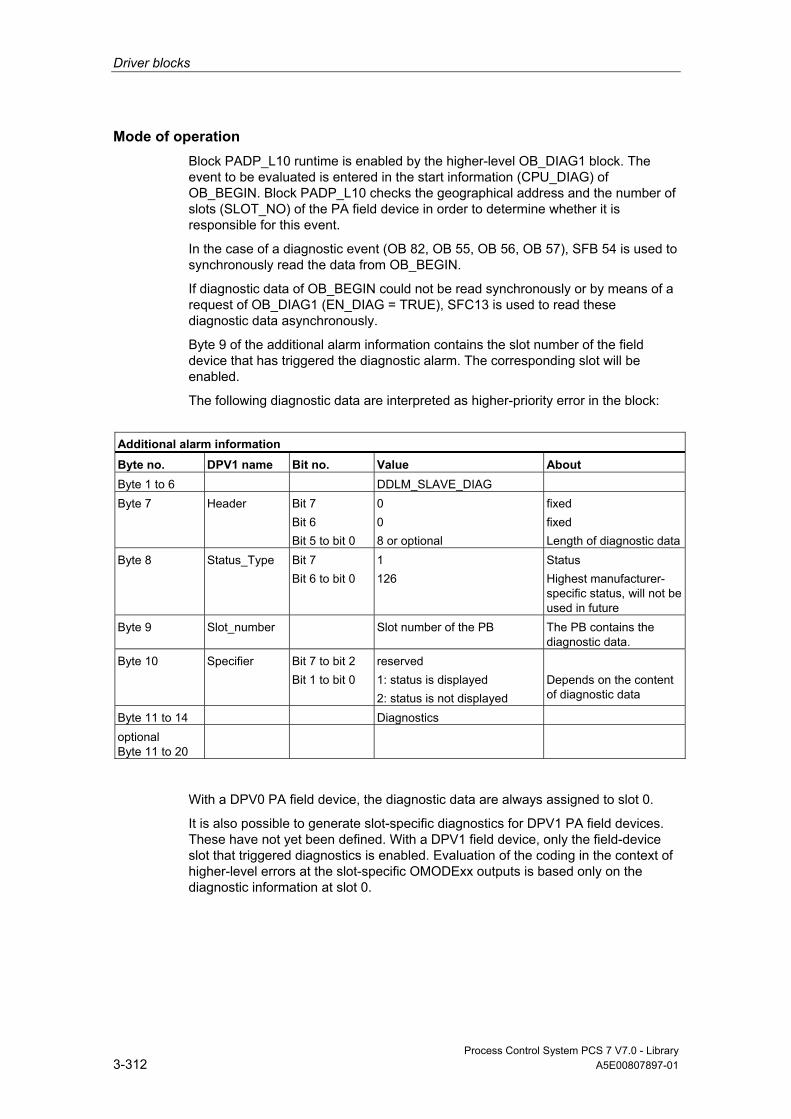
Driver blocks
Process Control System PCS 7 V7.0 - Library 3-312 A5E00807897-01
Mode of operation Block PADP_L10 runtime is enabled by the higher-level OB_DIAG1 block. The event to be evaluated is entered in the start information (CPU_DIAG) of OB_BEGIN. Block PADP_L10 checks the geographical address and the number of slots (SLOT_NO) of the PA field device in order to determine whether it is responsible for this event.
In the case of a diagnostic event (OB 82, OB 55, OB 56, OB 57), SFB 54 is used to synchronously read the data from OB_BEGIN.
If diagnostic data of OB_BEGIN could not be read synchronously or by means of a request of OB_DIAG1 (EN_DIAG = TRUE), SFC13 is used to read these diagnostic data asynchronously.
Byte 9 of the additional alarm information contains the slot number of the field device that has triggered the diagnostic alarm. The corresponding slot will be enabled.
The following diagnostic data are interpreted as higher-priority error in the block:
Additional alarm information Byte no. DPV1 name Bit no. Value About Byte 1 to 6 DDLM_SLAVE_DIAG Byte 7 Header Bit 7
Bit 6 Bit 5 to bit 0
0 0 8 or optional
fixed fixed Length of diagnostic data
Byte 8 Status_Type Bit 7 Bit 6 to bit 0
1 126
Status Highest manufacturer-specific status, will not be used in future
Byte 9 Slot_number Slot number of the PB The PB contains the diagnostic data.
Byte 10 Specifier Bit 7 to bit 2 Bit 1 to bit 0
reserved 1: status is displayed 2: status is not displayed
Depends on the content of diagnostic data
Byte 11 to 14 Diagnostics optional Byte 11 to 20
With a DPV0 PA field device, the diagnostic data are always assigned to slot 0.
It is also possible to generate slot-specific diagnostics for DPV1 PA field devices. These have not yet been defined. With a DPV1 field device, only the field-device slot that triggered diagnostics is enabled. Evaluation of the coding in the context of higher-level errors at the slot-specific OMODExx outputs is based only on the diagnostic information at slot 0.
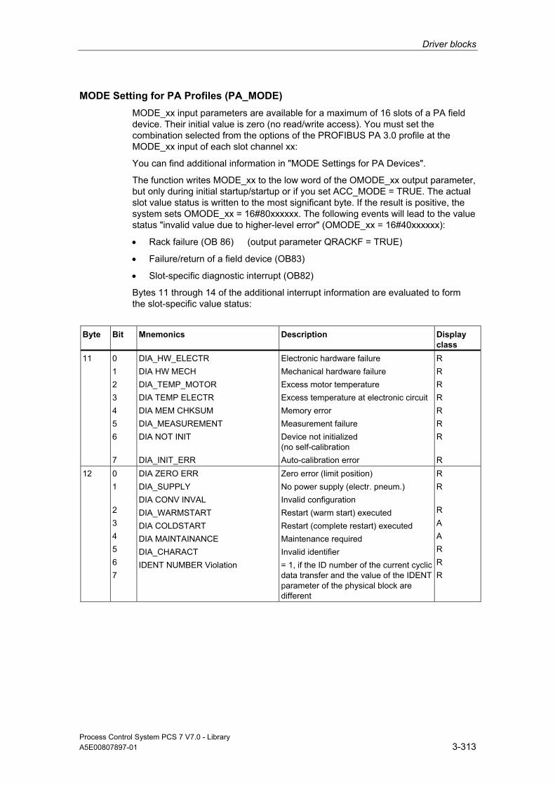
Driver blocks
Process Control System PCS 7 V7.0 - Library A5E00807897-01 3-313
MODE Setting for PA Profiles (PA_MODE) MODE_xx input parameters are available for a maximum of 16 slots of a PA field device. Their initial value is zero (no read/write access). You must set the combination selected from the options of the PROFIBUS PA 3.0 profile at the MODE_xx input of each slot channel xx:
You can find additional information in "MODE Settings for PA Devices".
The function writes MODE_xx to the low word of the OMODE_xx output parameter, but only during initial startup/startup or if you set ACC_MODE = TRUE. The actual slot value status is written to the most significant byte. If the result is positive, the system sets OMODE_xx = 16#80xxxxxx. The following events will lead to the value status "invalid value due to higher-level error" (OMODE_xx = 16#40xxxxxx):
• Rack failure (OB 86) (output parameter QRACKF = TRUE)
• Failure/return of a field device (OB83)
• Slot-specific diagnostic interrupt (OB82)
Bytes 11 through 14 of the additional interrupt information are evaluated to form the slot-specific value status:
Byte Bit Mnemonics Description Display
class 11 0
1 2 3 4 5 6 7
DIA_HW_ELECTR DIA HW MECH DIA_TEMP_MOTOR DIA TEMP ELECTR DIA MEM CHKSUM DIA_MEASUREMENT DIA NOT INIT DIA_INIT_ERR
Electronic hardware failure Mechanical hardware failure Excess motor temperature Excess temperature at electronic circuit Memory error Measurement failure Device not initialized (no self-calibration Auto-calibration error
R R R R R R R R
12 0 1 2 3 4 5 6 7
DIA ZERO ERR DIA_SUPPLY DIA CONV INVAL DIA_WARMSTART DIA COLDSTART DIA MAINTAINANCE DIA_CHARACT IDENT NUMBER Violation
Zero error (limit position) No power supply (electr. pneum.) Invalid configuration Restart (warm start) executed Restart (complete restart) executed Maintenance required Invalid identifier = 1, if the ID number of the current cyclic data transfer and the value of the IDENT parameter of the physical block are different
R R R A A R R R
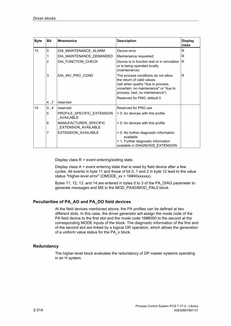
Driver blocks
Process Control System PCS 7 V7.0 - Library 3-314 A5E00807897-01
Byte Bit Mnemonics Description Display class
13 0 1 2 3 4...7
DIA_MAINTENANCE_ALARM DIA_MAINTENANCE_DEMANDED DIA_FUNCTION_CHECK DIA_INV_PRO_COND reserved
Device error Maintenance requested Device is in function test or in simulation or is being operated locally (maintenance) The process conditions do not allow the return of valid values. (set when quality "due to process, uncertain, no maintenance" or "due to process, bad, no maintenance") Reserved for PNO, default 0
R R R R
14 0...4 5 6 7
reserved PROFILE_SPECIFIC_EXTENSION_AVAILABLE MANUFACTURER_SPECIFIC _EXTENSION_AVAILABLE EXTENSION_AVAILABLE
Reserved for PNO use = 0: for devices with this profile = 0: for devices with this profile = 0: No further diagnostic information available = 1: Further diagnostic information available in DIAGNOSIS_EXTENSION
Display class R = event entering/exiting state.
Display class A = event entering state that is reset by field device after a few cycles. All events in byte 11 and those of bit 0, 1 and 2 in byte 12 lead to the value status "Higher-level error" (OMODE_xx = 16#40xxxxxx).
Bytes 11, 12, 13, and 14 are entered in bytes 0 to 3 of the PA_DIAG parameter to generate messages and MS in the MOD_PAX0/MOD_PAL0 block.
Peculiarities of PA_AO and PA_DO field devices At the field devices mentioned above, the PA profiles can be defined at two different slots. In this case, the driver generator will assign the mode code of the PA field device to the first slot and the mode code 16#8000 to the second at the corresponding MODE inputs of the block. The diagnostic information of the first and of the second slot are linked by a logical OR operation, which allows the generation of a uniform value status for the PA_x block.
Redundancy The higher-level block evaluates the redundancy of DP master systems operating in an H system.

Driver blocks
Process Control System PCS 7 V7.0 - Library A5E00807897-01 3-315
OMODE Structure You can find additional information in "OMODE".
Addressing You can find additional information in "Addressing".
Error handling The plausibility of input parameters is not checked.
Startup Characteristics A restart (OB 100) is reported via the LSB in byte 2 of the outputs OMODE_xx.
Time Response n.a.
Message Capability n.a.
Operator Control and Monitoring The block has no faceplate.
Additional Information For more information, refer to the section:
Notes on Using Driver Blocks
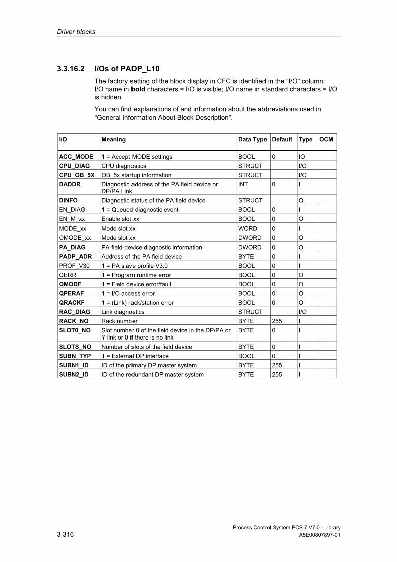
Driver blocks
Process Control System PCS 7 V7.0 - Library 3-316 A5E00807897-01
3.3.16.2 I/Os of PADP_L10 The factory setting of the block display in CFC is identified in the "I/O" column: I/O name in bold characters = I/O is visible; I/O name in standard characters = I/O is hidden.
You can find explanations of and information about the abbreviations used in "General Information About Block Description".
I/O
Meaning
Data Type
Default Type
OCM
ACC_MODE 1 = Accept MODE settings BOOL 0 IO CPU_DIAG CPU diagnostics STRUCT I/O CPU_OB_5X OB_5x startup information STRUCT I/O DADDR Diagnostic address of the PA field device or
DP/PA Link INT 0 I
DINFO Diagnostic status of the PA field device STRUCT O EN_DIAG 1 = Queued diagnostic event BOOL 0 I EN_M_xx Enable slot xx BOOL 0 O MODE_xx Mode slot xx WORD 0 I OMODE_xx Mode slot xx DWORD 0 O PA_DIAG PA-field-device diagnostic information DWORD 0 O PADP_ADR Address of the PA field device BYTE 0 I PROF_V30 1 = PA slave profile V3.0 BOOL 0 I QERR 1 = Program runtime error BOOL 0 O QMODF 1 = Field device error/fault BOOL 0 O QPERAF 1 = I/O access error BOOL 0 O QRACKF 1 = (Link) rack/station error BOOL 0 O RAC_DIAG Link diagnostics STRUCT I/O RACK_NO Rack number BYTE 255 I SLOT0_NO Slot number 0 of the field device in the DP/PA or
Y link or 0 if there is no link BYTE 0 I
SLOTS_NO Number of slots of the field device BYTE 0 I SUBN_TYP 1 = External DP interface BOOL 0 I SUBN1_ID ID of the primary DP master system BYTE 255 I SUBN2_ID ID of the redundant DP master system BYTE 255 I

Driver blocks
Process Control System PCS 7 V7.0 - Library A5E00807897-01 3-317
3.4 Appendix
3.4.1 Addressing
Rules If you do not use the CFC function "Generate module drivers", you must set the logical basic address of the module created with HW Config at the LADDR input parameter. If input SUBN_TYP = FALSE, the RACK of the module is connected to an integrated DP interface (distributed I/O device interface) of the CPU module by means of a line. Otherwise, you must set SUBN_TYP = TRUE.
The following points are generally to be observed for all SM and PA modules:
• The basic address of modules equipped only with inputs, i.e., modules which write data only to the input area of the CPU process image, can be fetched directly from HW Config. For example: the module SM331 AI 8x12Bit 331-7KF01-0AB0:
Address Input Range (HW Config)
Address Output Range (HW Config)
LADDR (Decimal/Hex)
512 - 512 / 16#0200
• The MSB (most significant bit) must be set in the basic address fetched from HW Config for modules equipped only with outputs, i.e., modules which read data only from the output area of the CPU process image. For example, module SM 332 AO 4x12Bit 6ES7 332-5HD01-0AB0:
Address Input Range (HW Config)
Address Output Range (HW Config)
LADDR (Decimal/Hex)
- 512 -32256 / 16#8200
• The basic address of the input range must be set at input LADDR and the basic address of the output range from HW Config must be set at input LADDR1 for mixed modules, i.e., modules which write data to the input area and read data from the output area of the CPU process image; for example, module SM 323 DI/O 8x24V/05A 6ES7 323-1BH81-0AA0:
Address Input Range (HW Config)
Address Output Range (HW Config)
LADDR (Decimal/Hex)
LADDR1 (decimal/hex)
12 12 12/16# 000C 12/16# 000C
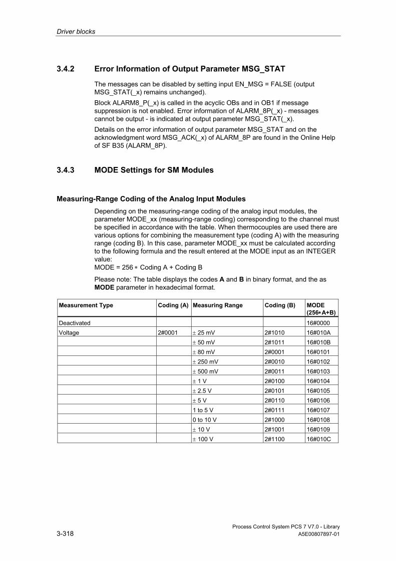
Driver blocks
Process Control System PCS 7 V7.0 - Library 3-318 A5E00807897-01
3.4.2 Error Information of Output Parameter MSG_STAT
The messages can be disabled by setting input EN_MSG = FALSE (output MSG_STAT(_x) remains unchanged). Block ALARM8_P(_x) is called in the acyclic OBs and in OB1 if message suppression is not enabled. Error information of ALARM_8P(_x) - messages cannot be output - is indicated at output parameter MSG_STAT(_x). Details on the error information of output parameter MSG_STAT and on the acknowledgment word MSG_ACK(_x) of ALARM_8P are found in the Online Help of SF B35 (ALARM_8P).
3.4.3 MODE Settings for SM Modules
Measuring-Range Coding of the Analog Input Modules Depending on the measuring-range coding of the analog input modules, the parameter MODE_xx (measuring-range coding) corresponding to the channel must be specified in accordance with the table. When thermocouples are used there are various options for combining the measurement type (coding A) with the measuring range (coding B). In this case, parameter MODE_xx must be calculated according to the following formula and the result entered at the MODE input as an INTEGER value: MODE = 256 ∗ Coding A + Coding B
Please note: The table displays the codes A and B in binary format, and the as MODE parameter in hexadecimal format.
Measurement Type Coding (A) Measuring Range Coding (B) MODE (256∗A+B)
Deactivated 16#0000 Voltage 2#0001 ± 25 mV 2#1010 16#010A ± 50 mV 2#1011 16#010B ± 80 mV 2#0001 16#0101 ± 250 mV 2#0010 16#0102 ± 500 mV 2#0011 16#0103 ± 1 V 2#0100 16#0104 ± 2.5 V 2#0101 16#0105 ± 5 V 2#0110 16#0106 1 to 5 V 2#0111 16#0107 0 to 10 V 2#1000 16#0108 ± 10 V 2#1001 16#0109 ± 100 V 2#1100 16#010C

Driver blocks
Process Control System PCS 7 V7.0 - Library A5E00807897-01 3-319
Measurement Type Coding (A) Measuring Range Coding (B) MODE (256∗A+B)
4-wire measuring transducer 2#0010 ± 3.2 mA 2#0000 16#0200 ± 5 mA 2#0101 16#0205 ± 10 mA 2#0001 16#0201 0 mA to 20 mA 2#0010 16#0202 4 mA to 20 mA 2#0011 16#0203 ± 20 mA 2#0100 16#0204 HART interface
2#0111
4 mA to 20 mA
2#1100
16#070C
2-wire measuring transducer
2#0011
4 mA to 20 mA
2#0011
16#0303
Resistor 4-wire connection
2#0100
48 Ω
2#0000
16#0400
150 Ω 2#0010 16#0402 300 Ω 2#0100 16#0404 600 Ω 2#0110 16#0406 3000 Ω 2#0111 16#0407 6000 Ω 2#1000 16#0408 PTC 2#1111 16#040F Resistor 3-wire connection
2#0101
48 Ω
2#0000
16#0500
150 Ω 2#0010 16#0502 300 Ω 2#0100 16#0504 600 Ω 2#0110 16#0506 3000 Ω 2#0111 16#0507 6000 Ω 2#1000 16#0508 PTC 2#1111 16#050F Resistor 2-wire connection
2#0110
48 Ω
2#0000
16#0600
150 Ω 2#0010 16#0602 300 Ω 2#0100 16#0604 600 Ω 2#0110 16#0606 3000 Ω 2#0111 16#0607 6000 Ω 2#1000 16#0608 PTC 2#1111 16#060F Resistive thermocouple + linearization 4-wire connection
2#1000
Pt 100 climate range
2#0000
16#0800
Pt 200 climate range 2#0111 16#0807 Pt 500 climate range 2#1000 16#0808 Pt 1000 climate range 2#1001 16#0809

Driver blocks
Process Control System PCS 7 V7.0 - Library 3-320 A5E00807897-01
Measurement Type Coding (A) Measuring Range Coding (B) MODE (256∗A+B)
Ni 100 climate range 2#0001 16#0801 Ni 1000 climate range 2#1010 16#080A Pt 100 standard range 2#0010 16#0802 Pt 200 standard range 2#0011 16#0803 Pt 500 standard range 2#0100 16#0804 Pt 1000 standard range 2#0101 16#0805 Ni 100 standard range 2#1011 16#080B Ni 1000 standard range 2#0110 16#0806 Ni 120 standard range 2#1100 16#080C Ni 120 climate range 2#1101 16#080D Cu 10 climate range 2#1110 16#080E Cu 10 standard range 2#1111 16#080F Ni 200 standard range 2#10000 16#0810 Ni 200 climate range 2#10001 16#0811 Ni 500 standard range 2#10010 16#0812 Ni 500 climate range 2#10011 16#0813 Pt 10 GOST climatic 2#10100 16#0814 Pt 10 GOST Standard
(TK = 3910) 2#10101 16#0815
Pt 50 GOST climatic 2#10110 16#0816 Pt 50 GOST Standard
(TK = 3910) 2#10111 16#0817
Pt 100 GOST climatic 2#11000 16#0818 Pt 100 GOST Standard
(TK = 3910) 2#11001 16#0819
Pt 500 GOST climatic 2#11010 16#081A Pt 500 GOST Standard
(TK = 3910) 2#11011 16#081B
Pt 10 GOST climatic 2#11100 16#081C Cu 10 GOST Standard
(TK = 426) 2#11101 16#081D
Pt 50 GOST climatic 2#11110 16#081E Cu 50 GOST Standard
(TK = 426) 2#11111 16#081F
Pt 100 GOST climatic 2#100000 16#0820 Cu 100 GOST Standard
(TK = 426) 2#100001 16#0821
Pt 100 GOST climatic 2#100010 16#0822 Ni 100 GOST Standard 2#100011 16#0823
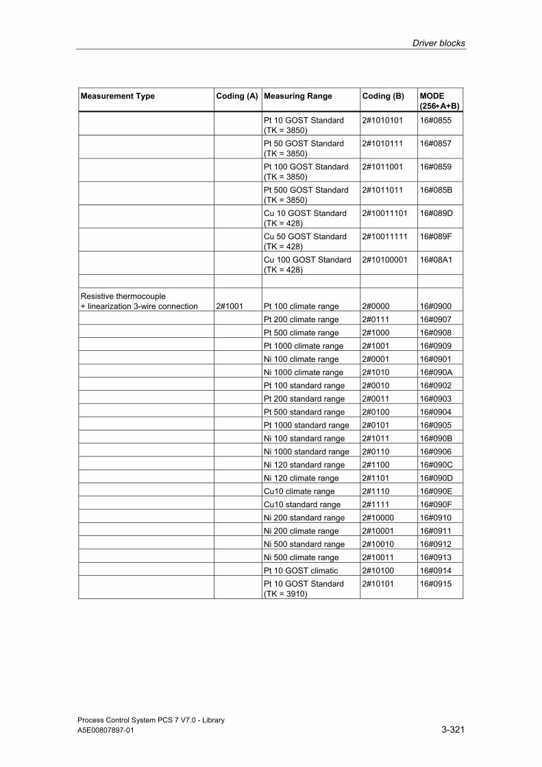
Driver blocks
Process Control System PCS 7 V7.0 - Library A5E00807897-01 3-321
Measurement Type Coding (A) Measuring Range Coding (B) MODE (256∗A+B)
Pt 10 GOST Standard (TK = 3850)
2#1010101 16#0855
Pt 50 GOST Standard (TK = 3850)
2#1010111 16#0857
Pt 100 GOST Standard (TK = 3850)
2#1011001 16#0859
Pt 500 GOST Standard (TK = 3850)
2#1011011 16#085B
Cu 10 GOST Standard (TK = 428)
2#10011101 16#089D
Cu 50 GOST Standard (TK = 428)
2#10011111 16#089F
Cu 100 GOST Standard (TK = 428)
2#10100001 16#08A1
Resistive thermocouple + linearization 3-wire connection
2#1001
Pt 100 climate range
2#0000
16#0900
Pt 200 climate range 2#0111 16#0907 Pt 500 climate range 2#1000 16#0908 Pt 1000 climate range 2#1001 16#0909 Ni 100 climate range 2#0001 16#0901 Ni 1000 climate range 2#1010 16#090A Pt 100 standard range 2#0010 16#0902 Pt 200 standard range 2#0011 16#0903 Pt 500 standard range 2#0100 16#0904 Pt 1000 standard range 2#0101 16#0905 Ni 100 standard range 2#1011 16#090B Ni 1000 standard range 2#0110 16#0906 Ni 120 standard range 2#1100 16#090C Ni 120 climate range 2#1101 16#090D Cu10 climate range 2#1110 16#090E Cu10 standard range 2#1111 16#090F Ni 200 standard range 2#10000 16#0910 Ni 200 climate range 2#10001 16#0911 Ni 500 standard range 2#10010 16#0912 Ni 500 climate range 2#10011 16#0913 Pt 10 GOST climatic 2#10100 16#0914 Pt 10 GOST Standard
(TK = 3910) 2#10101 16#0915
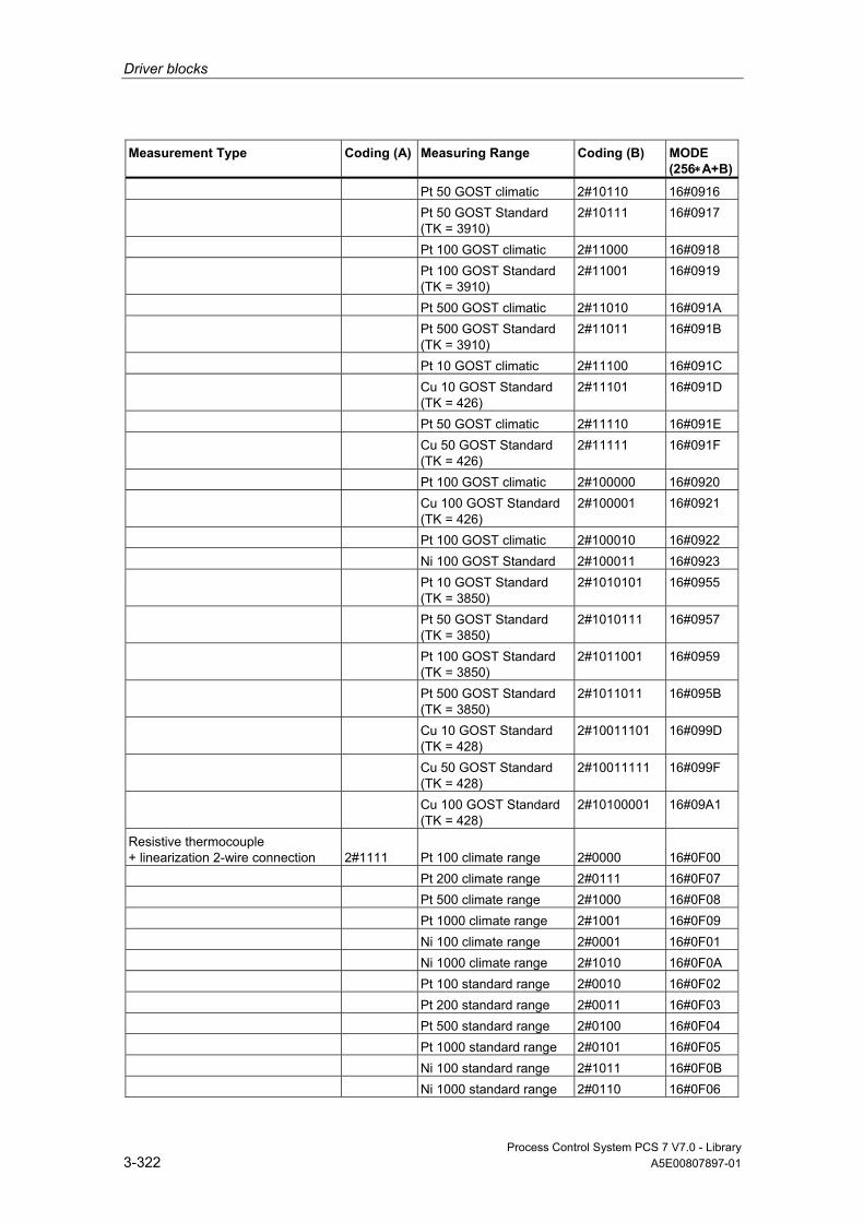
Driver blocks
Process Control System PCS 7 V7.0 - Library 3-322 A5E00807897-01
Measurement Type Coding (A) Measuring Range Coding (B) MODE (256∗A+B)
Pt 50 GOST climatic 2#10110 16#0916 Pt 50 GOST Standard
(TK = 3910) 2#10111 16#0917
Pt 100 GOST climatic 2#11000 16#0918 Pt 100 GOST Standard
(TK = 3910) 2#11001 16#0919
Pt 500 GOST climatic 2#11010 16#091A Pt 500 GOST Standard
(TK = 3910) 2#11011 16#091B
Pt 10 GOST climatic 2#11100 16#091C Cu 10 GOST Standard
(TK = 426) 2#11101 16#091D
Pt 50 GOST climatic 2#11110 16#091E Cu 50 GOST Standard
(TK = 426) 2#11111 16#091F
Pt 100 GOST climatic 2#100000 16#0920 Cu 100 GOST Standard
(TK = 426) 2#100001 16#0921
Pt 100 GOST climatic 2#100010 16#0922 Ni 100 GOST Standard 2#100011 16#0923 Pt 10 GOST Standard
(TK = 3850) 2#1010101 16#0955
Pt 50 GOST Standard (TK = 3850)
2#1010111 16#0957
Pt 100 GOST Standard (TK = 3850)
2#1011001 16#0959
Pt 500 GOST Standard (TK = 3850)
2#1011011 16#095B
Cu 10 GOST Standard (TK = 428)
2#10011101 16#099D
Cu 50 GOST Standard (TK = 428)
2#10011111 16#099F
Cu 100 GOST Standard (TK = 428)
2#10100001 16#09A1
Resistive thermocouple + linearization 2-wire connection
2#1111
Pt 100 climate range
2#0000
16#0F00
Pt 200 climate range 2#0111 16#0F07 Pt 500 climate range 2#1000 16#0F08 Pt 1000 climate range 2#1001 16#0F09 Ni 100 climate range 2#0001 16#0F01 Ni 1000 climate range 2#1010 16#0F0A Pt 100 standard range 2#0010 16#0F02 Pt 200 standard range 2#0011 16#0F03 Pt 500 standard range 2#0100 16#0F04 Pt 1000 standard range 2#0101 16#0F05 Ni 100 standard range 2#1011 16#0F0B Ni 1000 standard range 2#0110 16#0F06
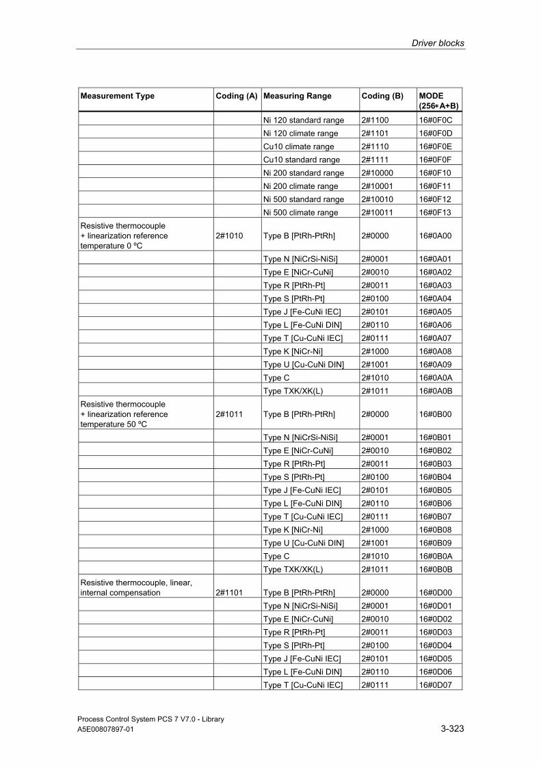
Driver blocks
Process Control System PCS 7 V7.0 - Library A5E00807897-01 3-323
Measurement Type Coding (A) Measuring Range Coding (B) MODE (256∗A+B)
Ni 120 standard range 2#1100 16#0F0C Ni 120 climate range 2#1101 16#0F0D Cu10 climate range 2#1110 16#0F0E Cu10 standard range 2#1111 16#0F0F Ni 200 standard range 2#10000 16#0F10 Ni 200 climate range 2#10001 16#0F11 Ni 500 standard range 2#10010 16#0F12 Ni 500 climate range 2#10011 16#0F13 Resistive thermocouple + linearization reference temperature 0 ºC
2#1010
Type B [PtRh-PtRh]
2#0000
16#0A00
Type N [NiCrSi-NiSi] 2#0001 16#0A01 Type E [NiCr-CuNi] 2#0010 16#0A02 Type R [PtRh-Pt] 2#0011 16#0A03 Type S [PtRh-Pt] 2#0100 16#0A04 Type J [Fe-CuNi IEC] 2#0101 16#0A05 Type L [Fe-CuNi DIN] 2#0110 16#0A06 Type T [Cu-CuNi IEC] 2#0111 16#0A07 Type K [NiCr-Ni] 2#1000 16#0A08 Type U [Cu-CuNi DIN] 2#1001 16#0A09 Type C 2#1010 16#0A0A Type TXK/XK(L) 2#1011 16#0A0B Resistive thermocouple + linearization reference temperature 50 ºC
2#1011
Type B [PtRh-PtRh]
2#0000
16#0B00
Type N [NiCrSi-NiSi] 2#0001 16#0B01 Type E [NiCr-CuNi] 2#0010 16#0B02 Type R [PtRh-Pt] 2#0011 16#0B03 Type S [PtRh-Pt] 2#0100 16#0B04 Type J [Fe-CuNi IEC] 2#0101 16#0B05 Type L [Fe-CuNi DIN] 2#0110 16#0B06 Type T [Cu-CuNi IEC] 2#0111 16#0B07 Type K [NiCr-Ni] 2#1000 16#0B08 Type U [Cu-CuNi DIN] 2#1001 16#0B09 Type C 2#1010 16#0B0A Type TXK/XK(L) 2#1011 16#0B0B Resistive thermocouple, linear, internal compensation
2#1101
Type B [PtRh-PtRh]
2#0000
16#0D00
Type N [NiCrSi-NiSi] 2#0001 16#0D01 Type E [NiCr-CuNi] 2#0010 16#0D02 Type R [PtRh-Pt] 2#0011 16#0D03 Type S [PtRh-Pt] 2#0100 16#0D04 Type J [Fe-CuNi IEC] 2#0101 16#0D05 Type L [Fe-CuNi DIN] 2#0110 16#0D06 Type T [Cu-CuNi IEC] 2#0111 16#0D07

Driver blocks
Process Control System PCS 7 V7.0 - Library 3-324 A5E00807897-01
Measurement Type Coding (A) Measuring Range Coding (B) MODE (256∗A+B)
Type K [NiCr-Ni] 2#1000 16#0D08 Type U [Cu-CuNi DIN] 2#1001 16#0D09 Type C 2#1010 16#0D0A Type TXK/XK(L) 2#1011 16#0D0B Resistive thermocouple, linear, external compensation
2#1110
Type B [PtRh-PtRh]
2#0000
16#0E00
Type N [NiCrSi-NiSi] 2#0001 16#0E01 Type E [NiCr-CuNi] 2#0010 16#0E02 Type R [PtRh-Pt] 2#0011 16#0E03 Type S [PtRh-Pt] 2#0100 16#0E04 Type J [Fe-CuNi IEC] 2#0101 16#0E05 Type L [Fe-CuNi DIN] 2#0110 16#0E06 Type T [Cu-CuNi IEC] 2#0111 16#0E07 Type K [NiCr-Ni] 2#1000 16#0E08 Type U [Cu-CuNi DIN] 2#1001 16#0E09 Type C 2#1010 16#0E0A Type TXK/XK(L) 2#1011 16#0E0B
Note
The mode settings for external and internal thermocouple compare is adapted to the behavior of the S7-300 modules. Additional information in this regard is available in the description for Block CH_AI .
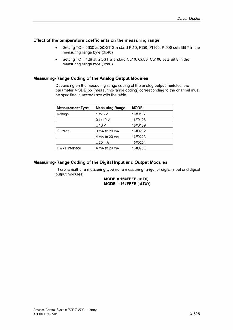
Driver blocks
Process Control System PCS 7 V7.0 - Library A5E00807897-01 3-325
Effect of the temperature coefficients on the measuring range • Setting TC = 3850 at GOST Standard Pt10, Pt50, Pt100, Pt500 sets Bit 7 in the
measuring range byte (0x40)
• Setting TC = 428 at GOST Standard Cu10, Cu50, Cu100 sets Bit 8 in the measuring range byte (0x80)
Measuring-Range Coding of the Analog Output Modules Depending on the measuring-range coding of the analog output modules, the parameter MODE_xx (measuring-range coding) corresponding to the channel must be specified in accordance with the table.
Measurement Type Measuring Range MODE
Voltage 1 to 5 V 16#0107 0 to 10 V 16#0108 ± 10 V 16#0109 Current 0 mA to 20 mA 16#0202 4 mA to 20 mA 16#0203 ± 20 mA 16#0204 HART interface 4 mA to 20 mA 16#070C
Measuring-Range Coding of the Digital Input and Output Modules There is neither a measuring type nor a measuring range for digital input and digital output modules: MODE = 16#FFFF (at DI) MODE = 16#FFFE (at DO)
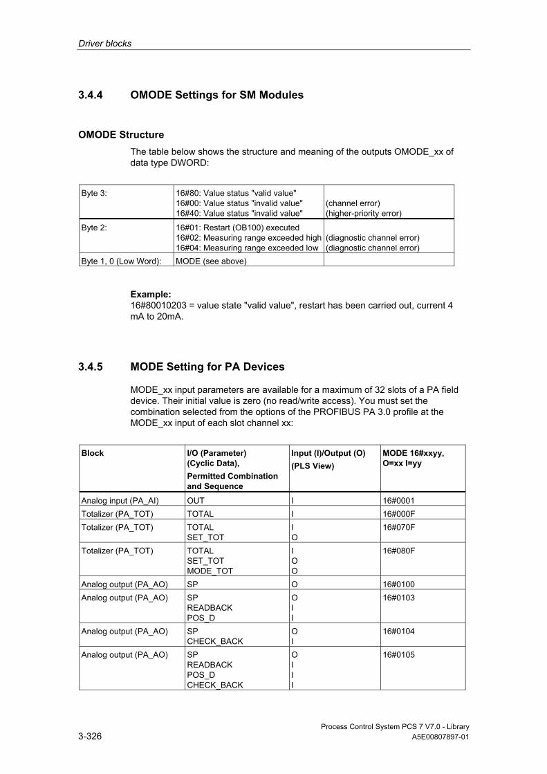
Driver blocks
Process Control System PCS 7 V7.0 - Library 3-326 A5E00807897-01
3.4.4 OMODE Settings for SM Modules
OMODE Structure The table below shows the structure and meaning of the outputs OMODE_xx of data type DWORD:
Byte 3: 16#80: Value status "valid value"
16#00: Value status "invalid value" 16#40: Value status "invalid value"
(channel error) (higher-priority error)
Byte 2: 16#01: Restart (OB100) executed 16#02: Measuring range exceeded high16#04: Measuring range exceeded low
(diagnostic channel error) (diagnostic channel error)
Byte 1, 0 (Low Word): MODE (see above)
Example: 16#80010203 = value state "valid value", restart has been carried out, current 4 mA to 20mA.
3.4.5 MODE Setting for PA Devices
MODE_xx input parameters are available for a maximum of 32 slots of a PA field device. Their initial value is zero (no read/write access). You must set the combination selected from the options of the PROFIBUS PA 3.0 profile at the MODE_xx input of each slot channel xx:
Block I/O (Parameter)
(Cyclic Data), Permitted Combination and Sequence
Input (I)/Output (O) (PLS View)
MODE 16#xxyy, O=xx I=yy
Analog input (PA_AI) OUT I 16#0001 Totalizer (PA_TOT) TOTAL I 16#000F Totalizer (PA_TOT) TOTAL
SET_TOT I O
16#070F
Totalizer (PA_TOT) TOTAL SET_TOT MODE_TOT
I O O
16#080F
Analog output (PA_AO) SP O 16#0100 Analog output (PA_AO) SP
READBACK POS_D
O I I
16#0103
Analog output (PA_AO) SP CHECK_BACK
O I
16#0104
Analog output (PA_AO) SP READBACK POS_D CHECK_BACK
O I I I
16#0105
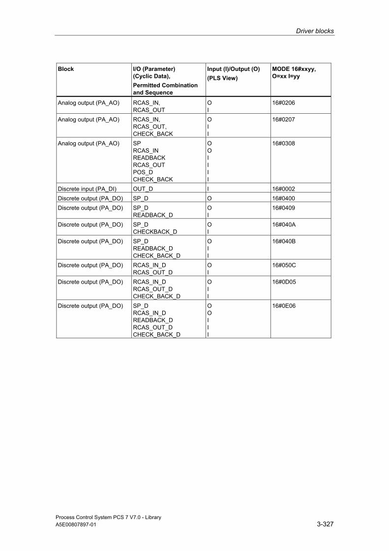
Driver blocks
Process Control System PCS 7 V7.0 - Library A5E00807897-01 3-327
Block I/O (Parameter) (Cyclic Data), Permitted Combination and Sequence
Input (I)/Output (O) (PLS View)
MODE 16#xxyy, O=xx I=yy
Analog output (PA_AO) RCAS_IN, RCAS_OUT
O I
16#0206
Analog output (PA_AO) RCAS_IN, RCAS_OUT, CHECK_BACK
O I I
16#0207
Analog output (PA_AO) SP RCAS_IN READBACK RCAS_OUT POS_D CHECK_BACK
O O I I I I
16#0308
Discrete input (PA_DI) OUT_D I 16#0002 Discrete output (PA_DO) SP_D O 16#0400 Discrete output (PA_DO) SP_D
READBACK_D O I
16#0409
Discrete output (PA_DO) SP_D CHECKBACK_D
O I
16#040A
Discrete output (PA_DO) SP_D READBACK_D CHECK_BACK_D
O I I
16#040B
Discrete output (PA_DO) RCAS_IN_D RCAS_OUT_D
O I
16#050C
Discrete output (PA_DO) RCAS_IN_D RCAS_OUT_D CHECK_BACK_D
O I I
16#0D05
Discrete output (PA_DO) SP_D RCAS_IN_D READBACK_D RCAS_OUT_D CHECK_BACK_D
O O I I I
16#0E06

Driver blocks
Process Control System PCS 7 V7.0 - Library 3-328 A5E00807897-01
3.4.6 Customizing MODE_LW for FF devices
Block I/O (Parameter)
(Cyclic Data), Permitted Combination and Sequence
Input (I)/Output (O) (PLS View)
MODE 16#xxyy, O=xx I=yy
Analog Input (FF_A_AI) OUT I 16#0001 Discrete Input (FF_A_DI) OUT_D I 16#0002 Analog Output (FF_A_AO) SP O 16#0100 Analog Output (FF_A_AO) SP
READBACK POS_D
O I I
16#0103
Analog Output (FF_A_AO) SP CHECK_BACK
O I
16#0104
Analog Output (FF_A_AO) SP READBACK POS_D CHECK_BACK
O I I I
16#0105
Analog Output (FF_A_AO) RCAS_IN RCAS_OUT
O I
16#0206
Analog Output (FF_A_AO) RCAS_IN RCAS_OUT CHECK_BACK
O I I
16#0207
Analog Output (FF_A_AO) SP RCAS_IN READBACK RCAS_OUT POS_D CHECK_BACK
O O I I I I
16#0308
Discrete Output (FF_A_DO)
SP_D I 16#0400
Discrete Output (FF_A_DO)
SP_D READBACK_D
O I
16#0409
Discrete Output (FF_A_DO)
SP_D CHECK_BACK_D
O I
16#040A
Discrete Output (FF_A_DO)
SP_D READBACK_D CHECK_BACK_D
O I I
16#040B
Discrete Output (FF_A_DO)
RCAS_IN_D RCAS_OUT_D
O I
16#050C
Discrete Output (FF_A_DO)
RCAS_IN_D RCAS_OUT_D CHECK_BACK_D
O I I
16#0D05
Discrete Output (FF_A_DO)
SP_D RCAS_IN_D READBACK_D RCAS_OUT _D CHECK_BACK_D
O O I I I
16#0E06

Driver blocks
Process Control System PCS 7 V7.0 - Library A5E00807897-01 3-329
3.4.7 Linking FF devices in ASSET
FF devices can be linked in ASSET in the following manner:
Key
Signal processing driver blocks of the FF field device [FF_A_xx], xx = AI, DI, AO, DO
Summarized for one field device [ST_MUX]
Representative for one field device [Assetmon]
Summarized for a function unit [MS_MUX]
Representative for one functional unit [Assetmon]

Driver blocks
Process Control System PCS 7 V7.0 - Library 3-330 A5E00807897-01
3.4.8 Text Libraries of the Blocks
You will find a description of the text libraries for individual blocks in the following sections:
Text Library for MOD_1, MOD_2, MOD_3, MOD_D2, MOD_CP
Text Library for MOD_D1
Text Library for MOD_MS
Text Library for MOD_PAL0, MOD_PAX0
Text Library for OB_BEGIN
Text Library for DREP, DREP_L
Text Library for PADP_L00, PADP_L01, PADP_L02
3.4.9 Technical Data, "Driver Blocks"
Overview The table below contains technical data relating to the driver blocks. The table columns have the following meanings:
• Block type name
The symbolic identifier in the symbol table of the library for the relevant FB or FC. Must be unique within the project.
• Object name
Consists of the block type (FB, FC) and number.
• Typical runtime
CPU runtime for processing the corresponding block program under normal circumstances (for example, for a driver, this is the execution time in the watchdog-alarm OB (OB 3x), without generation of a channel error message)
The table below shows the runtime of blocks in a 417-4 CPU. The block runtime on other CPUs depends on the CPU performance.
• Block length in load/work memory
Memory requirements of the program code, once for each block type.
• Length of instance data in load/work memory
Memory requirement of an instance DB.

Driver blocks
Process Control System PCS 7 V7.0 - Library A5E00807897-01 3-331
• Temporary memory
The local-data memory required in a priority class when the block is called. This limit is CPU specific. When it is exceeded, you have to check the CPU configuration in the local-data memory and, if necessary, distribute it amongst the OBs to meet the actual requirements.
• Multiple Instance Block
The specified blocks are used by the driver block and must exist in the user program. They can be found in the same library.
Block (Type Name)
FB/FC No.
Typical Runtime CPU 417-4 (µs )
Block Length in Load/Work Memory (Byte)
Instance-Data Length in Load/Work Memory (Byte)
Temporary Memory (Bytes)
Multiple Instance Block
CH_AI FC 275 36 6254 / 5414 - / - 28 CH_AO FC 276 30 1782 / 1510 - / - 34 CH_CNT FB 127 33 6466 / 5928 452 / 124 70 CH_CNT1 FB 59 16 1342 / 1152 214 / 92 36 CH_DI FC 277 14 502 / 392 - / - 4 CH_DO FC 278 11 358 / 274 - / - 2 CH_MS FB 60 22 1676 / 1362 20 CH_U_AI FC 283 46 8826 / 7688 - / - 28 CH_U_AO FC 284 31 2674 / 2302 - / - 34 CH_U_DI FC 285 20 3064 / 2666 - / - 6 CH_U_DO FC 286 13 1268 / 1080 - / - 2 CONEC FB 88 98 10266 / 8642 1186 / 340 84 16 x SFB 35 DPAY_V0 FB 108 159 1792 / 1202 542 / 70 22 DPAY_V1 FB 115 155 11206 / 8506 3588 / 1388 136 SFB 35 DPDIAGV0 FB 117 115 3980 / 2184 1800 / 194 66 DREP FB 113 19 4202 / 3038 1296 / 366 124 DREP_L FB 125 20 6578 / 5358 1406 / 486 52 2 x SFB 35 FF_A_AI FB 410 38 6882 / 5618 1470 / 516 50 2 x SFB 35 FF_A_AO FB 411 56 1174 / 814 492 / 154 14 FF_A_DI FB 412 32 1976 / 1438 740 / 252 20 FF_A_DO FB 413 49 926 / 634 364 / 90 8 FM_CNT FB 126 36 1496 / 1060 546 / 140 10 IM_DRV FB 90 98 9290 / 7950 1482 / 586 132 SFB 35
SFB 52 SFB 53
MOD_1 FB 91 91 13202/ 10498 5946 / 4060 116 16 x SFB 35 MOD_2 FB 92 91 4912 / 3862 1120 / 346 68 SFB 35 MOD_3 FB 95 91 4984 / 3868 1280 / 442 66 SFB 35 MOD_4 FB 119 16 4988 / 3872 1288 / 448 66 SFB 35 MOD_CP FB 98 104 3496 / 2540 1108 / 346 52 SFB 35 MOD_D1 FB 93 96 6850 / 5622 1186 / 340 80 SFB 35 MOD_D2 FB 94 97 12552 / 10752 1818 / 700 86 3 x SFB 35
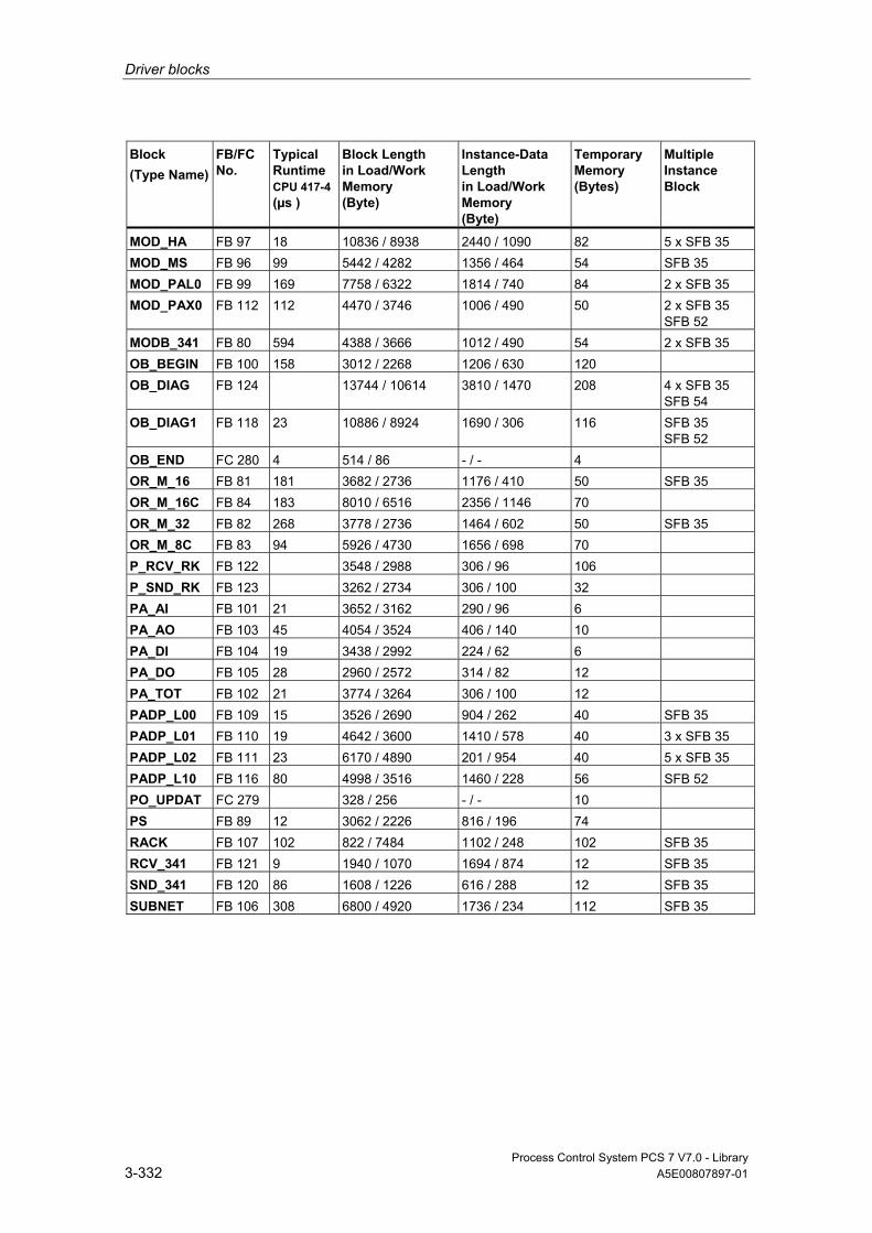
Driver blocks
Process Control System PCS 7 V7.0 - Library 3-332 A5E00807897-01
Block (Type Name)
FB/FC No.
Typical Runtime CPU 417-4 (µs )
Block Length in Load/Work Memory (Byte)
Instance-Data Length in Load/Work Memory (Byte)
Temporary Memory (Bytes)
Multiple Instance Block
MOD_HA FB 97 18 10836 / 8938 2440 / 1090 82 5 x SFB 35 MOD_MS FB 96 99 5442 / 4282 1356 / 464 54 SFB 35 MOD_PAL0 FB 99 169 7758 / 6322 1814 / 740 84 2 x SFB 35 MOD_PAX0 FB 112 112 4470 / 3746 1006 / 490 50 2 x SFB 35
SFB 52 MODB_341 FB 80 594 4388 / 3666 1012 / 490 54 2 x SFB 35 OB_BEGIN FB 100 158 3012 / 2268 1206 / 630 120 OB_DIAG FB 124 13744 / 10614 3810 / 1470 208 4 x SFB 35
SFB 54 OB_DIAG1 FB 118 23 10886 / 8924 1690 / 306 116 SFB 35
SFB 52 OB_END FC 280 4 514 / 86 - / - 4 OR_M_16 FB 81 181 3682 / 2736 1176 / 410 50 SFB 35 OR_M_16C FB 84 183 8010 / 6516 2356 / 1146 70 OR_M_32 FB 82 268 3778 / 2736 1464 / 602 50 SFB 35 OR_M_8C FB 83 94 5926 / 4730 1656 / 698 70 P_RCV_RK FB 122 3548 / 2988 306 / 96 106 P_SND_RK FB 123 3262 / 2734 306 / 100 32 PA_AI FB 101 21 3652 / 3162 290 / 96 6 PA_AO FB 103 45 4054 / 3524 406 / 140 10 PA_DI FB 104 19 3438 / 2992 224 / 62 6 PA_DO FB 105 28 2960 / 2572 314 / 82 12 PA_TOT FB 102 21 3774 / 3264 306 / 100 12 PADP_L00 FB 109 15 3526 / 2690 904 / 262 40 SFB 35 PADP_L01 FB 110 19 4642 / 3600 1410 / 578 40 3 x SFB 35 PADP_L02 FB 111 23 6170 / 4890 201 / 954 40 5 x SFB 35 PADP_L10 FB 116 80 4998 / 3516 1460 / 228 56 SFB 52 PO_UPDAT FC 279 328 / 256 - / - 10 PS FB 89 12 3062 / 2226 816 / 196 74 RACK FB 107 102 822 / 7484 1102 / 248 102 SFB 35 RCV_341 FB 121 9 1940 / 1070 1694 / 874 12 SFB 35 SND_341 FB 120 86 1608 / 1226 616 / 288 12 SFB 35 SUBNET FB 106 308 6800 / 4920 1736 / 234 112 SFB 35
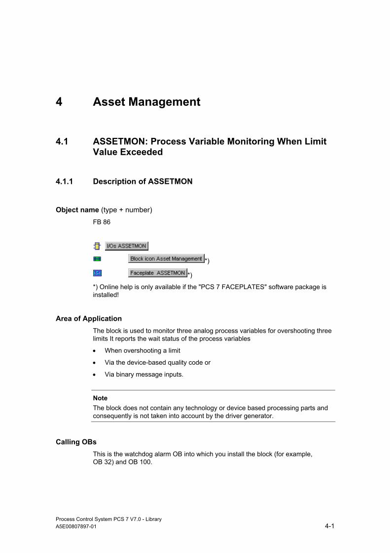
Process Control System PCS 7 V7.0 - Library A5E00807897-01 4-1
4 Asset Management
4.1 ASSETMON: Process Variable Monitoring When Limit Value Exceeded
4.1.1 Description of ASSETMON
Object name (type + number) FB 86
*)
*)
*) Online help is only available if the "PCS 7 FACEPLATES" software package is installed!
Area of Application The block is used to monitor three analog process variables for overshooting three limits It reports the wait status of the process variables
• When overshooting a limit
• Via the device-based quality code or
• Via binary message inputs.
Note
The block does not contain any technology or device based processing parts and consequently is not taken into account by the driver generator.
Calling OBs This is the watchdog alarm OB into which you install the block (for example, OB 32) and OB 100.
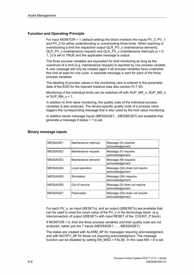
Asset Management
Process Control System PCS 7 V7.0 - Library 4-2 A5E00807897-01
Function and Operating Principle For input MONITOR = 1 (default setting) the block monitors the inputs PV_0, PV_1 and PV_2 for either undershooting or overshooting three limits. When reaching or overshooting a limit the respective output QLR_PV_x (maintenance demand), QLD_PV_x (maintenance request) and QLA_PV_x (maintenance interrupt) (x = 0, 1, 2) is set to TRUE and the applicable message is output.
The three process variables are equivalent for limit monitoring as long as the overshoot of a limit (e.g. maintenance request) is reported by one process variable. A new message will only be created again if all process variables have undershot this limit at least for one cycle. A separate message is sent for each of the three process variables.
The labeling of process values in the monitoring view is entered in the parameter data of the EDD for the relevant instance (see also section PLT ID).
Monitoring of the individual limits can be switched off with SUP_MR_x, SUP_MD_x or SUP_MA_x = 1.
In addition to limit value monitoring, the quality code of the individual process variables is also analyzed. The device-specific quality code of a process value triggers the corresponding message that is also used by the limit value monitoring.
In addition seven message inputs (MESSAGE1,..,MESSEGE7) are available that generate a message if status = 1 is set.
Binary message inputs MESSAGE1 Maintenance interrupt Message (S) requires
acknowledgement
MESSAGE2 Maintenance request Message (F) requires acknowledgement
MESSAGE3 Maintenance demand Message (M) requires acknowledgement
MESSAGE4 Local operation Message (SA) does not require acknowledgement
MESSAGE5 Simulation Message (SA) requires acknowledgement
MESSAGE6 Out of service Message (S) does not require acknowledgement
MESSAGE7 Passivated Message (SA) does not require acknowledgement
For each PV_x, an input (RESETx), and an output (QRESETx) are available that can be used to reset the count value of the PV_x in the technology block (e.g. interconnection of output QRESETx with input RESET of the COUNT_P block).
If MONITOR = 0, then the three process variables and their quality code are not analyzed, rather just the 7 inputs (MESSAGE1, ... , MESSAGE7).
The states are created with ALARM_8P for messages requiring acknowledgment, and with NOTIFY_8P for those not requiring acknowledgment. The message function can be disabled by setting EN_MSG = FALSE. In this case MS = 8 is set.
Asset Management
Process Control System PCS 7 V7.0 - Library A5E00807897-01 4-3
The detail diagnostics are shown in the diagnostics view of the faceplate via the Boolean inputs DIAG1 to DIAG16.
If one of the inputs is set to 1, then the status display is shown in front of the corresponding text.
The tests for the relevant inputs DIAG1 through DIAG16 are entered in the parameter data of the EDD for the relevant instance (see also section PLT ID).
If one of the inputs DIAG1 to DIAG16 is set to TRUE, then if an internal alarm is triggered through PV_0, PV_1 or PV_2, the message, the explanatory text "Additional status available" is output.
PLT-ID Die PLT-ID is a connection parameter between a PDM object (parameter data EDD) and the faceplate in the maintenance station. The PLT-ID is linked to the PDM object. The PDM object is generated in the SIMATIC Manager as follows:
1. Select View > Process Device Plant View in the SIMATIC Manager.
2. Select Insert > SIMATIC PDM > TAG.
3. Highlight the inserted TAG object and select in the context menu SIMATIC PDM > Device Selection...
4. In the tree structure CFC > DATA_OBJECTS > CFC >, select AssetMon and close the dialog with "OK".
5. In the context menu select Open Object and enter all necessary data in the parameterization screen form.
6. Select File > Save. The parameterization screen form will close.
7. Highlight the TAG object and select Tools > SIMATIC PDM > Create PLT-ID.
You can then assign parameters for the generated PLT-ID at the associated parameter "PLT_ID".
Note
The PLT-IDs cannot be changed or deleted individually.

Asset Management
Process Control System PCS 7 V7.0 - Library 4-4 A5E00807897-01
Creating the maintenance status (MS) MS depends on:
• The quality code inputs QC_0, QC_1 and QC_2. The process-relevant errors do not have an effect, only the device-based errors are effective.
• The limit value monitoring of PV_0, PV_1 and PV_2.
• The binary message inputs (external MS).
• The interconnectable input MS_IN (external MaintenanceState).
• The interconnectable input STATUS (non-changed quality code of a device)
Of all these events the highest priority event will be displayed in the MS.
The 16 DIAGx do not have any influence on the MS, rather they are used only for visualization of the detail diagnostics in the diagnostics view of the faceplate.
Possible Quality Codes for Creating the Maintenance Status (MS)
Note The table applies exclusively for the MS and not for the quality code displays of the individual process values, these are created exclusively by the QC_x parameters.
Note
The priority is analogous to the MS coding, Consequently the following applies: The greater the value of the MS the higher the priority. Please see the QC_MS_STAT table in the LIB readme for the priorities.
Signal Signal Detail Quality
Code MS
PV_x QualityCode Input Bad device 0x00 7 PV_x QualityCode Input Bad device 0x14 7 PV_x QualityCode Input Bad device 0x18 7 PV_x QualityCode Input Uncertain device 0x44 7 PV_x QualityCode Input Uncertain device 0x48 7 PV_x QualityCode Input Uncertain device 0x68 6 PV_x QualityCode Input Uncertain device 0x54 6 PV_x QualityCode Input Maintenance request 0xA4 5 PV_x QualityCode Input Simulated value 0x60 3 PV_x HighLimit exceeded Maintenance alarm 0x24 7 PV_x HighLimit exceeded Maintenance demand 0xA8 6 PV_x HighLimit exceeded Maintenance request 0xA4 5 MESSAGE1 Maintenance alarm 0x24 7 MESSAGE2 Maintenance demand 0xA8 6 MESSAGE3 Maintenance request 0xA4 5 MESSAGE4 Passivated 0x23 1 MESSAGE5 Out of service 0x1C 2

Asset Management
Process Control System PCS 7 V7.0 - Library A5E00807897-01 4-5
Signal Signal Detail Quality Code
MS
MESSAGE6 Local operation 0x3C 4 MESSAGE7 Simulation 0x60 3 Messages disabled 8 MS_IN External maintenance state 0 – 9 STATUS All Quality Codes from 0 to 255 are
possible, MS creation according to QC_MS_STAT table
0x00 … 0xFF 0 – 9
Error handling In the event of arithmetical errors the outputs ENO = 0 and QERR = 1 will be set.
Startup Characteristics After startup, the messages will be suppressed during the number of cycles set at RUNUPCYC.
Time Response n.a.
Message Capability The block reports by means of ALARM_8P and NOTIFY_8P.
Additional Information You will find more information on this subject in the following sections:
Operator Control and Monitoring of ASSETMON
Message Texts and Associated Values of ASSETMON
Maintenance Status MS
PA Field Device Status and Diagnostic Information
Notes on Using Driver Blocks

Asset Management
Process Control System PCS 7 V7.0 - Library 4-6 A5E00807897-01
4.1.2 I/Os of ASSETMON
The factory setting of the block display in CFC is identified in the "I/O" column: I/O name in bold characters = I/O is visible; I/O name in standard characters = I/O is hidden.
You can find explanations of and information about the abbreviations used in "General Information About Block Description".
I/O
Meaning
Data Type
Default Type
OCM
DIAGx Asset detail diagnoses (x = 1 to 16) BOOL 0 I + DIFFALMx Differential value to the next expected alarm
(x = 0, 1, 2) REAL 0 O +
EN_MSG 1 = Enable message BOOL 1 I EV_IDx Message number (x = 1, 2, 3) DWORD 0 I LA_PV_x Limit PV_x (x = 0, 1, 2) maintenance interrupt REAL 100 i + LD_PV_x Limit PV_x (x = 0, 1, 2) maintenance request REAL 100 i + LR_PV_x Limit PV_x (x = 0, 1, 2) maintenance demand REAL 100 i + MESSAGE1 1 = message Bad, maintenance interrupt BOOL 0 I MESSAGE2 1 = message Uncertain, maintenance request BOOL 0 I MESSAGE3 1 = message Good, maintenance required BOOL 0 I MESSAGE4 1 = message Passivated BOOL 0 I MESSAGE5 1 = message Bad, out of service BOOL 0 I MESSAGE6 1 = message Bad, local operation/function test BOOL 0 I MESSAGE7 1 = message Uncertain, simulation BOOL 0 I MONITOR 1 = monitor PV_x (x = 0, 1, 2) switched on BOOL 0 I MS Maintenance status DWORD 0 I + MS_IN External interconnected MS DWORD 0 I STATUS Unchanged QC of a device BYTE 16#8
0 I
MSG_ACKx Message acknowledgement (x = 1, 2) WORD 0 O MSGSTATx Message error information (x = 1 - 3) WORD 0 O O_MS Maintenance status DWORD 0 O + PLT_ID Asset ID of EDD DWORD 0 I + PV_x Process value PV_x (x = 0, 1, 2) REAL 0 I + QC_x Quality Code PV_x (x = 0, 1, 2) BYTE 16#8
0 I
QERR 1 = Program runtime error BOOL 1 O QLA_PV_x 1 = limit PV_x (x = 0, 1, 2)
Maintenance alarm overshot BOOL 0 O +
QLD_PV_x 1 = limit PV_x (x = 0, 1, 2) Maintenance request overshot
BOOL 0 O +
QLR_PV_x 1 = limit PV_x (x = 0, 1, 2) Maintenance demand overshot
BOOL 0 O +
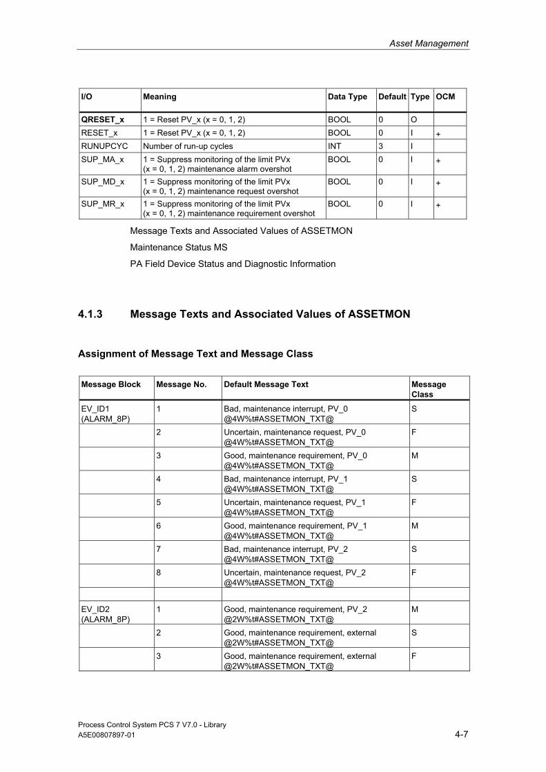
Asset Management
Process Control System PCS 7 V7.0 - Library A5E00807897-01 4-7
I/O
Meaning
Data Type
Default Type
OCM
QRESET_x 1 = Reset PV_x (x = 0, 1, 2) BOOL 0 O RESET_x 1 = Reset PV_x (x = 0, 1, 2) BOOL 0 I + RUNUPCYC Number of run-up cycles INT 3 I SUP_MA_x 1 = Suppress monitoring of the limit PVx
(x = 0, 1, 2) maintenance alarm overshot BOOL 0 I +
SUP_MD_x 1 = Suppress monitoring of the limit PVx (x = 0, 1, 2) maintenance request overshot
BOOL 0 I +
SUP_MR_x 1 = Suppress monitoring of the limit PVx (x = 0, 1, 2) maintenance requirement overshot
BOOL 0 I +
Message Texts and Associated Values of ASSETMON
Maintenance Status MS
PA Field Device Status and Diagnostic Information
4.1.3 Message Texts and Associated Values of ASSETMON
Assignment of Message Text and Message Class
Message Block
Message No.
Default Message Text
Message Class
EV_ID1 (ALARM_8P)
1 Bad, maintenance interrupt, PV_0 @4W%t#ASSETMON_TXT@
S
2 Uncertain, maintenance request, PV_0 @4W%t#ASSETMON_TXT@
F
3 Good, maintenance requirement, PV_0 @4W%t#ASSETMON_TXT@
M
4 Bad, maintenance interrupt, PV_1 @4W%t#ASSETMON_TXT@
S
5 Uncertain, maintenance request, PV_1 @4W%t#ASSETMON_TXT@
F
6 Good, maintenance requirement, PV_1 @4W%t#ASSETMON_TXT@
M
7 Bad, maintenance interrupt, PV_2 @4W%t#ASSETMON_TXT@
S
8 Uncertain, maintenance request, PV_2 @4W%t#ASSETMON_TXT@
F
EV_ID2 (ALARM_8P)
1 Good, maintenance requirement, PV_2 @2W%t#ASSETMON_TXT@
M
2 Good, maintenance requirement, external @2W%t#ASSETMON_TXT@
S
3 Good, maintenance requirement, external @2W%t#ASSETMON_TXT@
F
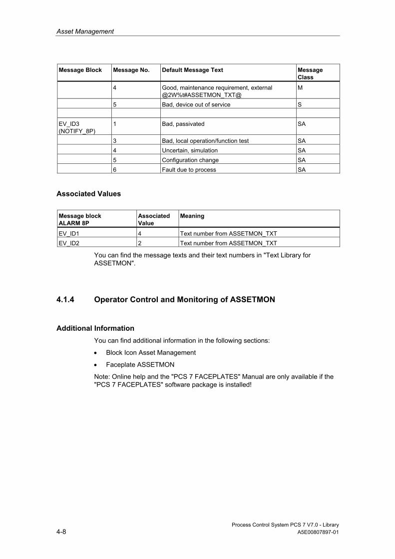
Asset Management
Process Control System PCS 7 V7.0 - Library 4-8 A5E00807897-01
Message Block
Message No.
Default Message Text
Message Class
4 Good, maintenance requirement, external @2W%t#ASSETMON_TXT@
M
5 Bad, device out of service S EV_ID3 (NOTIFY_8P)
1 Bad, passivated SA
3 Bad, local operation/function test SA 4 Uncertain, simulation SA 5 Configuration change SA 6 Fault due to process SA
Associated Values
Message block ALARM 8P
Associated Value
Meaning
EV_ID1 4 Text number from ASSETMON_TXT EV_ID2 2 Text number from ASSETMON_TXT
You can find the message texts and their text numbers in "Text Library for ASSETMON".
4.1.4 Operator Control and Monitoring of ASSETMON
Additional Information You can find additional information in the following sections:
• Block Icon Asset Management
• Faceplate ASSETMON
Note: Online help and the "PCS 7 FACEPLATES" Manual are only available if the "PCS 7 FACEPLATES" software package is installed!

Asset Management
Process Control System PCS 7 V7.0 - Library A5E00807897-01 4-9
4.2 CPU_RT: Runtime Determination of the OBs
4.2.1 Description of CPU_RT
Object name (type + number) FB 128
*)
*)
*) Online help is only available if the PCS 7 FACEPLATES software package is installed!
Area of Application The block CPU_RT is installed by the CFC in the OB 100, OB 1, in all OB 3x as well as OB 8x, if this is used by the user program.
The CPU_RT determines the runtime of the individual OBs and their participation in the cycle time. It executes suitable actions for which parameters have been assigned by the user in limits to ensure operability of the AS.
This situation is designated as emergency operation and is made clearly visible by a process control message. In addition buffered start events (OB 3x still in process) are detected and displayed. The loss of start events is reported as error.
Use in CFC When compiling a CFC a chart is automatically created with the designation @CPU_RT. The CPU_RT block is then already contained herein.
Note
Never attempt to insert the CPU_RT block in a different block because this is a system block.
Function and Operating Principle At CPU restart and when downloading changes the slowest OB 3x is determined with SZL ID822 (data records of all assigned alarms of an alarm class).
Note: For the slowest cyclic OB 3x (slowest OB) the lowest priority must also have been set so that a useful analysis can be executed.
Asset Management
Process Control System PCS 7 V7.0 - Library 4-10 A5E00807897-01
In the OB-BEGIN for implausible settings a message EV_ID2 signal 3 "Priorities of the cyclic OBs not PCS 7-conformant" is output and the maintenance status (MS is set to "Maintenance demand" = 16#00000005.
SFC 78 is used to determine the OB runtimes. If it is not present then no warn limit will be output as message.
Note
Older CPUs do not support the SFC 78. Use the SZL112 to check whether the SFC 78 is available.
Note
The status of the CPU_RT is reset when downloading.
Behavior at higher CPU load If the average value of all net runtimes (in % of OB3x, OB8x + OB1) overshoots the value MAX_LIM, then in OB_BEGIN, the message EV_ID2- signal 1 "Net time consumption of all OBs overshoots max limit" is output.
The maintenance status MS is set in OB_BEGIN to "Maintenance demand" = 16#00000005.
The message and MS goes with a value less than MAX_LIM – HYS.
Behavior in the event of OB request errors If a parameter-assigned number of these OB 3x events has been overshot, or if an OB 1 event is detected, without an OB 1 having been processed, then in OB_BEGIN the message EV_ID3 - Signal 2" OB 3x request error" (x = 0...8) will be output. The number of OB 3x events can be set at the output "N_REG_ERR"; the default value = 4.
The maintenance status MS is set in the OB_BEGIN to "Uncertain maintenance request" = 16#00000006.
If subsequently an OB 1 is run through again, then the MS will be reset and this process control message will be marked as "going".
In the faceplate of the OB_BEGIN there is a display of the request error for each OB 3x. The first occurrence of a request error will be displayed. These displays can be reset with the reset key.

Asset Management
Process Control System PCS 7 V7.0 - Library A5E00807897-01 4-11
Behavior when overshooting the maximum cycle time If the maximum cycle time is overshot then a message EV_ID3 – Signal 1 "Cycle time overshot: @1d@ OB@2d@" will be output.
The maintenance status MS is set in the OB_BEGIN to "Bad or maintenance alarm" = 16#00000007.
If subsequently an OB 1 is run through again, then the MS will be reset and this process control message will be marked as "going".
Behavior to prevent stop If the cycle time has been overshot two times without an OB 1 having been processed then this results in Emergency Operation with switched on stop avoidance. The process control message EV_ID1 – Signal 3 "Emergency operation, cycl. OBs will be reduced" will be output.
The maintenance status MS is set to "Bad or maintenance alarm" = 16#00000007.
If the CPU resumes to normal operation after the fault has been resolved, then the MS is reset and this process control message is marked as "going".
Behavior when downloading The status of the CPU_RT is reset when downloading.
Measures for Stop Avoidance When the CPU is overloaded you can prevent the CPU from becoming inoperable by "load shedding". Load shedding is achieved by interrupting the cyclic levels and is an emergency operation. In this process the user can still exclude individual OBs for the first escalation stage, e.g. the level with the F-drivers.
To avoid a CPU stop the CPU_RT executes the following measures in the OB 80 when reaching a cycle overrun.
• Cycle time monitoring is triggered with a call of the SFC 43, to prevent a CPU stop.
• A flag is set to detect the next immediate call of the OB 80 within an OB1 call, so that if necessary measures can be initiated that prevent an overload of the AS.
In the OB 80 the measures to prevent the overload are initiated and they reversed in the slowest OB.
Parameters can be assigned for two escalation stages:
1. Stage: Of the used OB 3x all will not be processed for a cycle, if they have not been excluded by the user (OB3x_ATTN = FALSE).
Asset Management
Process Control System PCS 7 V7.0 - Library 4-12 A5E00807897-01
2. Stage: Now all previously excluded OB 3x will likewise not be processed for a cycle. If this does not have a steadying effect all OB 3x will be interrupted after each processing one more time.
Assign the parameters at CPU_RT for each OB 3x on the following inputs:
OB3x_ATTN = TRUE The OB participates in the measures to prevent the overload. Preset is
"TRUE".
Parameters can be assigned for the maximum number of SFC 43 calls at the input MAX_RTRG. If the maximum number x is overshot then the CPU goes into stop.
The number x is reset if an OB 1 call takes place again.
If you assign parameter MAX_RTRG = 0 then the function "Stop avoidance at overload" is switched off.
When the measures are effective, i.e. OB 1 is run through again, then the calculation is made at that point, as to whether a reversal of the measures would again result in overload. If yes the measures remain intact. Only if safe operation would be possible will these measures be reversed in stages.
Reversal of the measures for stop avoidance To initiate a reversal the percentage sum of the cyclic OBs calculated back to a lower reduction stage, must be less than full CPU utilization.
Use the parameter MAX_VAL to set the value that corresponds to full CPU utilization. The value "95" is preset.
The calculation occurs according to the following formula:
((NET30PERint * (OB30_N_START+1) / OB30_N_START)+ (NET31PERint * (OB31_N_START+1) / OB31_N_START)+ (NET32PERint * (OB32_N_START+1) / OB32_N_START)+ (NET33PERint * (OB33_N_START+1) / OB33_N_START)+ (NET34PERint * (OB34_N_START+1) / OB34_N_START)+ (NET35PERint * (OB35_N_START+1) / OB35_N_START)+ (NET36PERint * (OB36_N_START+1) / OB36_N_START)+ (NET37PERint * (OB37_N_START+1) / OB37_N_START)+ (NET38PERint * (OB38_N_START+1) / OB38_N_START)+ NET01PER)< MAX_VAL
NETxxPERint is the percentage share of a cyclic OB in the total runtime as mean value and (OB30_N_START+1) is the current reducing factor of the OB.
The net percentage values are also means values, because in case of reduction, the values must be strictly determined.
For the calculation a separate mean value generation was used that has a separate sample factor (SAMPLE_RE).
If the condition is satisfied then after a number of cycles in the slowest OB (parameter "UndoCycle") the reduction factor is decremented by 1 for all OBs.

Asset Management
Process Control System PCS 7 V7.0 - Library A5E00807897-01 4-13
If thereafter the total sum of the OBs is still below MAX_VAL, then after a number of cycles in the slowest OB (UndoCycle), it will continue to be decremented until the used cyclic OBs have reached the reduction factor 1.
Thereafter for the OBs (OB3x_ATTN = FALSE) excluded by the user, the reduction will be set to 0.
Finally for all other cyclic OBs the reductions will be set to 0.
If no SFC 78 is present, then the time at which reversal of the stop avoidance measures can be triggered cannot be calculated.
The reversal of reductions is triggered when the slowest OB has again processed a number of cycles.
The value of the UndoCycle in this case should not be too low, to avoid a frequent oscillation between stop avoidance measures and normal operation.
For reduction in the CFC two parameters are available at the CPU_RT block for each cyclic OB.
OB3x_N_START The start value for reduction is specified by the input OB3x_N of the CPU_RT and
also in OB3x_N_CNT.
OB3x_N_CNT The counter is lowered at each OB call for the sequence in the CFC For OB3x_N_CNT <= 0 there is complete OB processing and OB3x_N_START will be re-entered in OB3x_N_CNT.
The CPU block is also called in case of reduction so that in emergency operation an evaluation of the averaged cycle time is possible.
Utilization display with SFC 78 When processing the block the calling OB is determined. It reads for each OB with the system function SFC 78, the net runtime, LAST_RTxx, and the gross runtime LAST_Etxx, of the last excluded OB processing. The absolute times are specified in milliseconds.
The mean value is generated for each OB (OB 3x and OB 8x) according to the formula
Mean value = mean value + (new value – mean value ) / sample_AV
SAMPLE_AV is a parameter that is calculated separately for each OB 3x, OB 8x. If needed you can adapt the precision of the mean value with this parameter, which is based on the number of measuring cycles, or on the influence of the new value.
The preset of SAMPLE_AV = 25 cycles, based on the slowest cyclic OB.
The actual sample factor for specific OBs is determined according to the following formula.

Asset Management
Process Control System PCS 7 V7.0 - Library 4-14 A5E00807897-01
Sample OB3x = Sample * execution frequency of the slowest OB / execution frequency of the OB3x
This ensures temporal equally-weighted mean value generation for all cyclic OBs.
The sample factor for the total mean value of OB 1, and for OB 8x, is set to = sample, because the basis for these values is also the execution frequency of the slowest OB.
Use the reset key on the faceplate of OB_BEGIN to reset mean value generation.
After the reset the divisor "Sample" of 1 per cycle is incremented by 1.
This means that with the reset mean value generation is initially imprecise and it becomes more precise through the factor "sample". The influence of the new value on the mean value initially is significant and diminishes as the factor "sample" becomes greater.
Resetting the data can mount a fresh measuring cycle at anytime.
The reset of all mean values takes place in OB 1. Mean value generation does not take place during this time.
Error handling If the read-out of data from the cyclic OB fails for the CPU_RT block, then ERR_NUM = 1 is set and the CPU_RT block is not further processed, because this data is the basic prerequisite for practical processing.
Startup Characteristics Calculations with the SFC 78 are restarted only after a number of cycles (RunUpCyc) after restart. The RunUpCyles are counted down in the slowest cyclic OB.
Time Response n.a.
Message Capability The block reports via the OB_BEGIN

Asset Management
Process Control System PCS 7 V7.0 - Library A5E00807897-01 4-15
Operator Control and Monitoring: Note: If you have selected the "Enable operator control and monitoring" option in the block object properties in the CFC, the variables transferred to the OS are identified under "I/Os of …" (OCM column, "+"). Default: option not selected.
If Asset Management is used in the project and the diagnostic images have been generated, then the faceplate can be called via the block icon of the AS.
• Faceplate OB_BEGIN
Note
Online help and the "PCS 7 FACEPLATES" Manual are only available if the "PCS 7 FACEPLATES" software package is installed!
Additional Information You will find more information on this subject in the following sections:
Message Texts and Associated Values of OB_BEGIN
Maintenance Status MS
4.2.2 I/Os of CPU_RT
The factory setting of the block display in CFC is identified in the "I/O" column: I/O name in bold characters = I/O is visible; I/O name in standard characters = I/O is hidden.
You can find explanations of and information about the abbreviations used in "General Information About Block Description".
I/O
Meaning
Data Type
Default Type
OCM
CPU_RT_DATA System structure: Performance data STRUCT
O
DAT_PLAU 1 = slowest OB 3x has the lowest priority BOOL 0 O DELTA_L Flag for change compile BOOL 1 I EN_MSG 1 = Enable message BOOL 1 I ERR_NUM 1 = occurrence of an error INT O EV_ID1 Message number DWORD 0 I EXC_FR3x (x = 0 – 8) execution cycle (in ms) of the OB 3x INT 0 O + GRO3xAV (x = 0 – 8) gross mean value REAL 0 O + GRO3xCUR (x = 0 – 8) gross current value REAL 0 O + GRO3xMAX (x = 0 – 8) gross maximum value REAL 0 O + GRO3xMIN (x = 0 – 8) gross minimum value REAL 0 O + GRO3xPER (x = 0 – 8) gross mean value (in %) REAL 0 O +
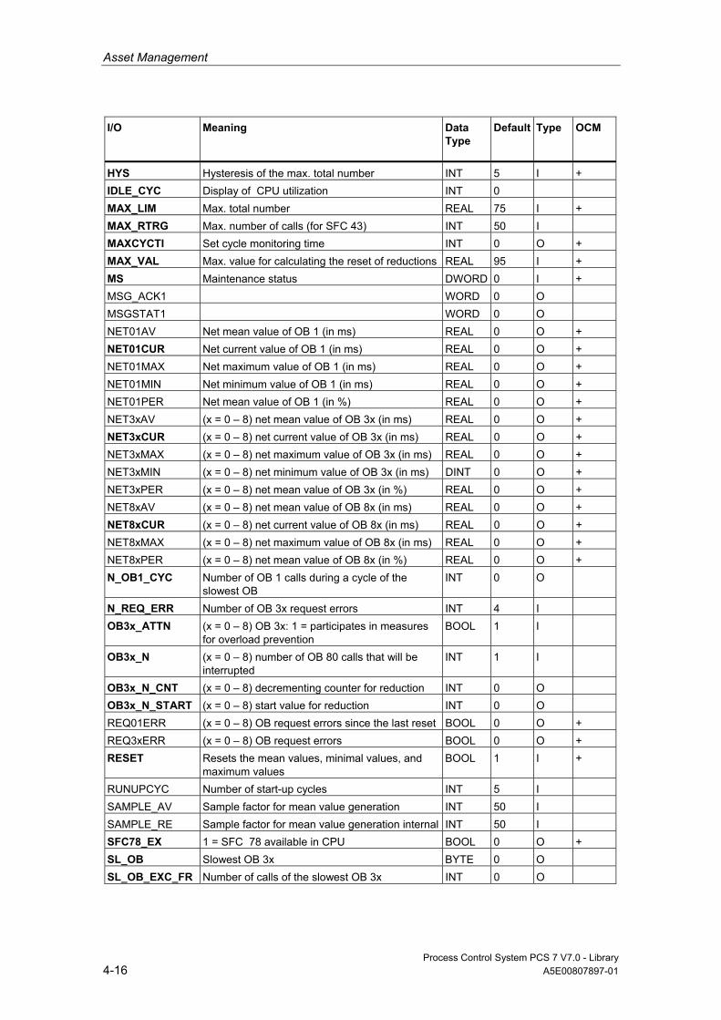
Asset Management
Process Control System PCS 7 V7.0 - Library 4-16 A5E00807897-01
I/O
Meaning
Data Type
Default Type
OCM
HYS Hysteresis of the max. total number INT 5 I + IDLE_CYC Display of CPU utilization INT 0 MAX_LIM Max. total number REAL 75 I + MAX_RTRG Max. number of calls (for SFC 43) INT 50 I MAXCYCTI Set cycle monitoring time INT 0 O + MAX_VAL Max. value for calculating the reset of reductions REAL 95 I + MS Maintenance status DWORD 0 I + MSG_ACK1 WORD 0 O MSGSTAT1 WORD 0 O NET01AV Net mean value of OB 1 (in ms) REAL 0 O + NET01CUR Net current value of OB 1 (in ms) REAL 0 O + NET01MAX Net maximum value of OB 1 (in ms) REAL 0 O + NET01MIN Net minimum value of OB 1 (in ms) REAL 0 O + NET01PER Net mean value of OB 1 (in %) REAL 0 O + NET3xAV (x = 0 – 8) net mean value of OB 3x (in ms) REAL 0 O + NET3xCUR (x = 0 – 8) net current value of OB 3x (in ms) REAL 0 O + NET3xMAX (x = 0 – 8) net maximum value of OB 3x (in ms) REAL 0 O + NET3xMIN (x = 0 – 8) net minimum value of OB 3x (in ms) DINT 0 O + NET3xPER (x = 0 – 8) net mean value of OB 3x (in %) REAL 0 O + NET8xAV (x = 0 – 8) net mean value of OB 8x (in ms) REAL 0 O + NET8xCUR (x = 0 – 8) net current value of OB 8x (in ms) REAL 0 O + NET8xMAX (x = 0 – 8) net maximum value of OB 8x (in ms) REAL 0 O + NET8xPER (x = 0 – 8) net mean value of OB 8x (in %) REAL 0 O + N_OB1_CYC Number of OB 1 calls during a cycle of the
slowest OB INT 0 O
N_REQ_ERR Number of OB 3x request errors INT 4 I OB3x_ATTN (x = 0 – 8) OB 3x: 1 = participates in measures
for overload prevention BOOL 1 I
OB3x_N (x = 0 – 8) number of OB 80 calls that will be interrupted
INT 1 I
OB3x_N_CNT (x = 0 – 8) decrementing counter for reduction INT 0 O OB3x_N_START (x = 0 – 8) start value for reduction INT 0 O REQ01ERR (x = 0 – 8) OB request errors since the last reset BOOL 0 O + REQ3xERR (x = 0 – 8) OB request errors BOOL 0 O + RESET Resets the mean values, minimal values, and
maximum values BOOL 1 I +
RUNUPCYC Number of start-up cycles INT 5 I SAMPLE_AV Sample factor for mean value generation INT 50 I SAMPLE_RE Sample factor for mean value generation internal INT 50 I SFC78_EX 1 = SFC 78 available in CPU BOOL 0 O + SL_OB Slowest OB 3x BYTE 0 O SL_OB_EXC_FR Number of calls of the slowest OB 3x INT 0 O
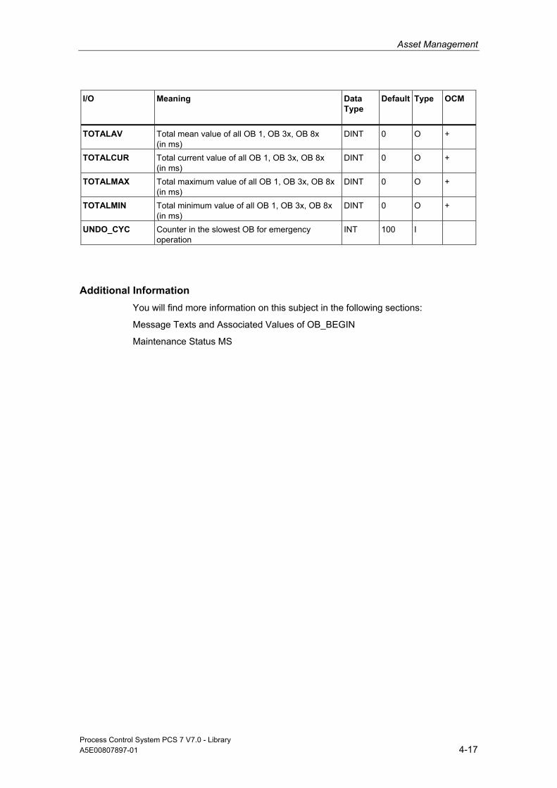
Asset Management
Process Control System PCS 7 V7.0 - Library A5E00807897-01 4-17
I/O
Meaning
Data Type
Default Type
OCM
TOTALAV Total mean value of all OB 1, OB 3x, OB 8x (in ms)
DINT 0 O +
TOTALCUR Total current value of all OB 1, OB 3x, OB 8x (in ms)
DINT 0 O +
TOTALMAX Total maximum value of all OB 1, OB 3x, OB 8x (in ms)
DINT 0 O +
TOTALMIN Total minimum value of all OB 1, OB 3x, OB 8x (in ms)
DINT 0 O +
UNDO_CYC Counter in the slowest OB for emergency operation
INT 100 I
Additional Information You will find more information on this subject in the following sections:
Message Texts and Associated Values of OB_BEGIN
Maintenance Status MS
Asset Management
Process Control System PCS 7 V7.0 - Library 4-18 A5E00807897-01
4.3 MS_MUX: Determining the Worst Single Status
4.3.1 Description of MS_MUX
Object name (type + number) FC 288
Area of Application The block MS_MUX determines the maintenance status (MS) of a functional unit consisting of multiple FF field devices, by selecting the worst individual status of the FF field devices.
Calling OBs The calling OB is the watchdog alarm OB 3x into which you integrate the block (for example, OB 32).
Function and Operating Principle The inputs MS_x (0<=x <= 9) are interconnected with the outputs Q_MS of ASSETMON blocks that each represent an FF field device.
Among the inputs MS_x the worst maintenance status (MS) is determined and made available at the output QMS for further interconnection with the input MS_IN of an ASSETMON block of a functional unit.
The priority of the maintenance status (MS) is listed in a table of the current LIB readme.
Installation in ASSET Information on installing the block MS_MUX is available in the section Integrating FF devices in ASSET.
Startup Characteristics n.a.
Time Response n.a.

Asset Management
Process Control System PCS 7 V7.0 - Library A5E00807897-01 4-19
Message Capability n.a.
Operator Control and Monitoring n.a.
4.3.2 I/Os of MS_MUX
The factory setting of the block display in CFC is identified in the "I/O" column: I/O name in bold characters = I/O is visible; I/O name in standard characters = I/O is hidden.
You can find explanations of and information about the abbreviations used in "General Information About Block Description".
I/O
Meaning
Data Type
Default Type
OCM
MS_x Maintenance State _x (x = 0- 3) DWORD 0 I MS_x Maintenance State _x (x = 4- 9) DWORD 0 I QMS Worst Maintenance State DWORD 0 O

Asset Management
Process Control System PCS 7 V7.0 - Library 4-20 A5E00807897-01
4.4 STATEREP: Status Display of Block Groups
4.4.1 Description of STATEREP
Object name (type + number) FB 87
Area of Application The block STATEREP is used for status display of a module that is designed for automatic hiding of messages.
Function and Operating Principle The block has 32 BOOL inputs that describe defined states. Depending on which status is set, it will be output at the INT output.
Error handling If more than one parameter is set, then the block outputs the messages QSTATE=0 as well as QERR=1.
Startup Characteristics n.a.
Time Response n.a.
Message Capability n.a.

Asset Management
Process Control System PCS 7 V7.0 - Library A5E00807897-01 4-21
4.4.2 I/Os of STATEREP
The factory setting of the block display in CFC is identified in the "I/O" column: I/O name in bold characters = I/O is visible; I/O name in standard characters = I/O is hidden.
You can find explanations of and information about the abbreviations used in "General Information About Block Description".
I/O
Meaning
Data Type
Default Type
OCM
State1 .. 10 Process status 1 – 10 BOOL 0 I State11 .. 32 Process status 11 – 32 BOOL 0 I QERR 1 = error more than one status is active BOOL 1 O QSTATE Process status INT 0 O +
Asset Management
Process Control System PCS 7 V7.0 - Library 4-22 A5E00807897-01
4.5 ST_MUX: Determining the Status Value for FF_Field Devices
4.5.1 Description of ST_MUX
Object name (type + number) FC 287
Area of Application The block ST_MUX determines the status of an FF field device by selecting the worst of the signal processing blocks FF_A_DI, FF_A_AI, FF_A_DO and FF_A_AO of the field device.
Calling OBs The calling OB is the watchdog alarm OB 3x into which you integrate the block (for example, OB 32).
Function and Operating Principle The inputs ST_x (0<=x <= 9) are interconnected with the outputs STATUS (FF_A_DI and FF_A_AI) or ST_xx or QC_xx (FF_A_DO and FF_A_AO) of all signal processing blocks of an FF field device. Among the inputs ST_x the ST_MUX determines the worst status and makes it available at the output QST for further interconnection with an ASSETMON component.
If different states with highest priority are present then the value of the first ST_x input is used.
The priority of the states (MS) is listed in a table of the current LIB readme.
Installation in ASSET Information on installing the block ST_MUX is available in the section Integrating FF devices in ASSET.
Startup Characteristics n.a.

Asset Management
Process Control System PCS 7 V7.0 - Library A5E00807897-01 4-23
Time Response n.a.
Message Capability n.a.
Operator Control and Monitoring n.a.
4.5.2 I/Os of ST_MUX
The factory setting of the block display in CFC is identified in the "I/O" column: I/O name in bold characters = I/O is visible; I/O name in standard characters = I/O is hidden.
You can find explanations of and information about the abbreviations used in "General Information About Block Description".
I/O
Meaning
Data Type
Default Type
OCM
QST Worst status BYTE 16#80 O ST_x Status_x (x = 0- 3) BYTE 16#80 I ST_X Status_x (x = 4- 9) BYTE 16#80 I

Asset Management
Process Control System PCS 7 V7.0 - Library 4-24 A5E00807897-01
4.6 Appendix
4.6.1 Technical data "Asset Blocks"
Overview The table below contains technical data relating to the driver blocks. The table columns have the following meanings:
• Block type name
The symbolic identifier in the symbol table of the library for the relevant FB or FC. Must be unique within the project.
• Object name
Consists of the block type (FB, FC) and number.
• Typical runtime
CPU runtime for processing the corresponding block program under normal circumstances (for example, for a driver, this is the execution time in the watchdog-alarm OB (OB 3x), without generation of a channel error message)
The table below shows the runtime of blocks in a 417-4 CPU. The block runtime on other CPUs depends on the CPU performance.
• Block length in load/work memory
Memory requirements of the program code, once for each block type.
• Length of instance data in load/work memory
Memory requirement of an instance DB.
• Temporary memory
The local-data memory required in a priority class when the block is called. This limit is CPU specific. When it is exceeded, you have to check the CPU configuration in the local-data memory and, if necessary, distribute it amongst the OBs to meet the actual requirements.

Asset Management
Process Control System PCS 7 V7.0 - Library A5E00807897-01 4-25
• Multiple Instance Block
The specified blocks are used by the driver block and must exist in the user program. They can be found in the same library.
Block (Type Name)
FB/FC No.
Typical Runtime CPU 417-4 (µs )
Block Length in Load/Work Memory (Byte)
Instance-Data Length in Load/Work Memory (Byte)
Temporary Memory (Bytes)
Multiple Instance Block
ASSETMON FB 86 84 6474 / 5486 1102 / 546 90 SFB31, 2 x SFB35
CPU_RT FB 128 67 31434 / 27370 2800 / 1784 86 MS_MUX FC 288 9 382 / 288 - 6 SFB54,
SFB35 ST_MUX FC 287 114 1612 / 1408 - 20 STATEREP FB 87 15 1900 / 1574 182 / 58 4

Asset Management
Process Control System PCS 7 V7.0 - Library 4-26 A5E00807897-01

Process Control System PCS 7 V7.0 - Library A5E00807897-01 5-1
5 Communication Blocks
5.1 REC_BO: 128 BOOL Values Received with BRCV
5.1.1 Description of REC_BO
Object name (type + number) FB 208
Area of Application The REC_BO block represents a simple user interface to SFB 13 "BRCV".
It receives 128 BOOL values via an MPI, PROFIBUS or Ethernet connection from another S7 CPU. This CPU needs to call the function-block type "SEND_BO" (FB 207) of the PCS 7 Library in order to send data. In STEP 7, a homogeneous connection must be configured for both communication partners and downloaded to the AS.
Data are only available after the job is completed, and after a 0 -> 1 transition of the signal at output NDR.
Calling OBs This is the watchdog alarm OB into which you install the block (for example, OB 35).
Mode of operation The internal SFB 13 "BRCV" allows a maximum of 128 Boolean values to be exchanged between communication partners. Data are received by the operating system of the CPU and entered in the instance DB of the receive FB (REC_BO). Before new data can be received, the operating system must transmit an internal acknowledgment of data received.
Data are entered in the data block asynchronously to user-program execution. After "REC_BO" has been called, instance-DB data may not be computed as long as the current job is busy (NDR = 0). If the job is completed without error, output NDR = 1 for the duration of one cycle. In the next cycle, the FB automatically outputs the receive enable signal to the CPU operating system (NDR is reset to 0 as of this call).
Communication Blocks
Process Control System PCS 7 V7.0 - Library 5-2 A5E00807897-01
The receive enable signal can be effective prior to the first incoming receive job. In this case, the receive enable signal is stored by the operating system.
The ID parameter represents the I/O number specified in your I/O configuration. and is applied only at the first call after a cold restart.
The R_ID parameter is a random number (suggestion: message frame ID). However, it must be identical at the corresponding send and receive blocks and is applied only at the first call after a cold restart.
The "REC_BO" block must be called for each ID/R_ID pair and in each program cycle (cyclically or also via timeout alarm). Each message frame requires two calls of "REC_BO".
The outputs ERR (error) and STAT (status) indicate specific error information relevant to SFB 13 (see "Error Handling").
If an error occurs, substitute values can be output as received data.
Error handling Error handling of block REC_BO is restricted to the error information of the lower-level SFB 13, "BRCV". You can find additional information in Manual System Software for S7-300/400 - System and Standard Functions. for information on the outputs ERR and STAT).
If input SUBS_ON = TRUE, substitute values will be output to REC_MON (number of cycles) if receive errors occur or if new data are not received.
Startup Characteristics n.a.
Time Response n.a.
Message Capability n.a.

Communication Blocks
Process Control System PCS 7 V7.0 - Library A5E00807897-01 5-3
Operator Control and Monitoring n.a.
5.1.2 I/Os of REC_BO
The factory setting of the block display in CFC is identified in the "I/O" column: I/O name in bold characters = I/O is visible; I/O name in standard characters = I/O is hidden.
You can find explanations of and information about the abbreviations used in "General Information About Block Description".
I/O (Parameter)
Meaning Data type Default Type
ERR 1 = Error (for error type see STAT) BOOL 0 O ID Connection ID WORD 0 I NDR 1 = New data received BOOL 0 O QNO_REC 1 = No data received BOOL 0 I QSUBS_ON 1 = Substitute values BOOL 0 I R_ID Message frame ID DWORD 0 I RD_BO_00 Received value 00 BOOL 0 O ... ... RD_BO_15 Received value 15 BOOL 0 O RD_BO_16 Received value 16 BOOL 0 O ... ... RD_BO_127 Received value 127 BOOL 0 O REC_MON Reception monitoring (value = number of block
calls) INT 3 I
STAT Error ID WORD 0 O SUBBO_00 Substitute value 00 BOOL 0 I ... ... SUBBO_15 Substitute value 15 BOOL 0 I SUBBO_16 Substitute value 16 BOOL 0 I ... SUBBO127 Substitute value 127 BOOL 0 I SUBS_ON 1 = Substitute values on by error BOOL 0 I
Communication Blocks
Process Control System PCS 7 V7.0 - Library 5-4 A5E00807897-01
5.2 REC_R: 32 BOOL and 32 REAL Values Received with BRCV
5.2.1 Description of REC_R
Object name (type + number) FB 210
Area of Application The REC_R block represents a simple user interface to SFB 13 "BRCV".
It receives 32 BOOL and 32 REAL values via an MPI, PROFIBUS or Ethernet connection from another S7 CPU. This CPU needs to call the function-block type "SEND_R" (FB 209) of the PCS 7 Library in order to send data. In STEP 7, a homogeneous connection must be configured for both communication partners and downloaded to the AS.
Data are only available after the job is completed, and after a 0 -> 1 transition of the signal at output NDR.
Calling OBs This is the watchdog alarm OB into which you install the block (for example, OB 35).
Mode of operation The internal SFB 13 "BRCV" allows a maximum of 32 BOOL and 32 REAL values to be exchanged between communication partners. Data are received by the CPU operating system and entered in the instance DB of the receive FB (REC_R). Before new data can be received, the operating system must transmit an internal acknowledgment of data received.
Data are entered in the instance DB asynchronously to user-program execution. After "REC_R" has been called, instance-DB data may not be computed as long as the current job is busy (NDR = 0). If the job is completed without error, output NDR = 1 for the duration of one cycle. In the next cycle, the FB automatically outputs the receive enable signal to the CPU operating system (NDR is reset to 0 as of this call).
The receive enable signal can be effective prior to the first incoming receive job. In this case, the receive enable signal is stored by the operating system.
The ID parameter represents the I/O number specified in your I/O configuration. and is applied only at the first call after a cold restart.
Communication Blocks
Process Control System PCS 7 V7.0 - Library A5E00807897-01 5-5
The R_ID parameter is a random number (suggestion: message frame ID). However, it must be identical at the corresponding send and receive blocks and is applied only at the first call after a cold restart.
The "REC_R" block must be called for each ID/R_ID pair and in each program cycle (cyclically or also via timeout alarm). Each message frame requires two calls of REC_R.
The outputs ERR (error) and STAT (status) indicate specific error information relevant to SFB 13 (see "Error Handling").
If an error occurs, substitute values can be output as received data.
Error handling Error handling of block REC_R is restricted to the error information of the lower-level SFB 13, "BRCV". You can find additional information in Manual System Software for S7-300/400 - System and Standard Functions. for information on the outputs ERR and STAT).
If input SUBS_ON = TRUE, substitute values will be output to REC_MON (number of cycles) if receive errors occur or if new data are not received.
Startup Characteristics n.a.
Time Response n.a.
Message Capability n.a.
Operator Control and Monitoring n.a.
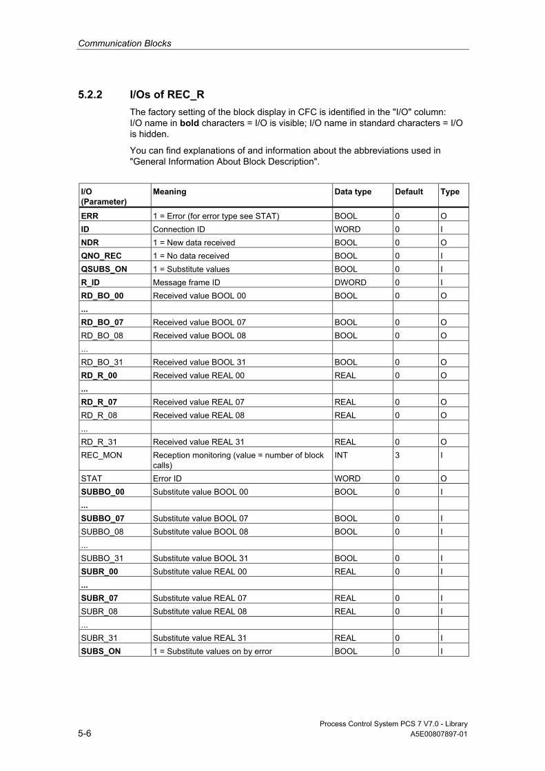
Communication Blocks
Process Control System PCS 7 V7.0 - Library 5-6 A5E00807897-01
5.2.2 I/Os of REC_R The factory setting of the block display in CFC is identified in the "I/O" column: I/O name in bold characters = I/O is visible; I/O name in standard characters = I/O is hidden.
You can find explanations of and information about the abbreviations used in "General Information About Block Description".
I/O (Parameter)
Meaning Data type Default Type
ERR 1 = Error (for error type see STAT) BOOL 0 O ID Connection ID WORD 0 I NDR 1 = New data received BOOL 0 O QNO_REC 1 = No data received BOOL 0 I QSUBS_ON 1 = Substitute values BOOL 0 I R_ID Message frame ID DWORD 0 I RD_BO_00 Received value BOOL 00 BOOL 0 O ... RD_BO_07 Received value BOOL 07 BOOL 0 O RD_BO_08 Received value BOOL 08 BOOL 0 O ... RD_BO_31 Received value BOOL 31 BOOL 0 O RD_R_00 Received value REAL 00 REAL 0 O ... RD_R_07 Received value REAL 07 REAL 0 O RD_R_08 Received value REAL 08 REAL 0 O ... RD_R_31 Received value REAL 31 REAL 0 O REC_MON Reception monitoring (value = number of block
calls) INT 3 I
STAT Error ID WORD 0 O SUBBO_00 Substitute value BOOL 00 BOOL 0 I ... SUBBO_07 Substitute value BOOL 07 BOOL 0 I SUBBO_08 Substitute value BOOL 08 BOOL 0 I ... SUBBO_31 Substitute value BOOL 31 BOOL 0 I SUBR_00 Substitute value REAL 00 REAL 0 I ... SUBR_07 Substitute value REAL 07 REAL 0 I SUBR_08 Substitute value REAL 08 REAL 0 I ... SUBR_31 Substitute value REAL 31 REAL 0 I SUBS_ON 1 = Substitute values on by error BOOL 0 I
Communication Blocks
Process Control System PCS 7 V7.0 - Library A5E00807897-01 5-7
5.3 SEND_BO: 128 BOOL Values Sent with BSEND
5.3.1 Description of SEND_BO
Object name (type + number) FB 207
Area of Application The SEND_BO block represents a simple user interface to SFB 12 "BSEND".
It sends up to 128 BOOL values via an MPI, PROFIBUS or Industrial Ethernet connection to another S7 CPU. This CPU needs to call the function-block type "REC_BO" (FB 208) of the PCS 7 Library in order to receive data.
Data are only consistently available at "REC_BO" once the job has been completed (i.e., after the acknowledgment DONE = TRUE has been received). This acknowledgment is indicated by the signal at output CIW changing to 0.
If parameter FAST = 1, the FB enables the transmission of one message frame with each FB call, since it calls SFB 12 "BSEND" twice internally (a positive at control input REQ is required in order to enable SFB 12). However, such periodic send requests should only be initiated if sufficient time is available between two FB calls.
Calling OBs This is the watchdog alarm OB into which you install the block (for example, OB 35).
Mode of operation The internal SFB 12 "BSEND" allows the exchange of 128 BOOL values between the communication partners. The CPU operating system sends those data to the communication partner and writes them automatically to the instance DB of the receiving FB (REC_BO). Before any new 128 BOOL values are sent, the system waits for the operating system to transfer an internal acknowledgment for the values that have just been sent.

Communication Blocks
Process Control System PCS 7 V7.0 - Library 5-8 A5E00807897-01
Data transfer is initiated if control input COM = 1 when the block is called. The block must be called at least once (regardless of the cycle) in order to transfer all data. It transfers the job to the CPU operating system for complete processing of the job. Further calls of the block with the same ID and R_ID during data transfer are permitted; however, they do not have any function, i.e., the block can be called only once in each cycle. Instead, the value 11 is output at STAT. Data are read from the user memory asynchronously to user-program execution. CIW = 0 if the job was completed without errors. (if an error has occurred, ERR = 1. The request will be resumed automatically until all data have been transferred). If input COM = 0, data transfer will be aborted and not resumed, and CIW = 0.
The ID parameter represents the I/O number specified in your I/O configuration. and is applied only at the first call after a cold restart.
The R_ID parameter is a random number (suggestion: message frame ID). However, it must be identical at the corresponding send and receive blocks and is applied only at the first call after a cold restart.
If parameter FAST = 1, a new message frame can be transferred with each call of the FB. In this case the FB internally calls SFB 12 "BSEND" twice, since a positive edge at control input REQ is required to enable SFB 12. When the FB is called in each cycle, one message frame can be transferred per cycle. However, such frequent send requests are only advisable in the following situations:
• There is sufficient time between two FB calls to transfer the message frame.
• The call of the "REC_BO" in the receiving CPU is faster than that of the "SEND_BO" in the sending CPU (the receiving CPU requires two calls (= 2 cycles) of "REC_BO" for each message frame).
If parameter FAST = 0, a new send request can be initiated only at every second FB call.
Error handling Error handling of the block is restricted to the error information of the lower-level SFB 12, "BSEND". You can find additional information in Manual System Software for S7-300/400 - System and Standard Functions. for information on the outputs ERR and STAT).
(If an error has occurred, the request will be repeated automatically until data have been transferred).
Startup Characteristics n.a.

Communication Blocks
Process Control System PCS 7 V7.0 - Library A5E00807897-01 5-9
Time Response n.a.
Message Capability n.a.
Operator Control and Monitoring n.a.
5.3.2 I/Os of SEND_BO
The factory setting of the block display in CFC is identified in the "I/O" column: I/O name in bold characters = I/O is visible; I/O name in standard characters = I/O is hidden.
You can find explanations of and information about the abbreviations used in "General Information About Block Description".
I/O (Parameter)
Meaning Data type Default Type
BO_00 Input 00 BOOL 0 I ... ... BO_15 Input 15 BOOL 0 I BO_16 Input 16 BOOL 0 I ... ... ... ... BO_127 Input 127 BOOL 0 I CIW 1 = Job is busy BOOL 0 O COM 1 = Send continuously, 0 = Do not send BOOL 1 I DONE Job is completed BOOL 0 O ERR Error (for error type see STAT) BOOL 0 O FAST Transfer mode:
1 = One message frame can be transferred per FB call 0 = One message frame can be transferred with two FB calls
BOOL 0 I
ID Connection ID WORD 0 I R_ID Message frame ID DWORD 0 I STAT Error ID WORD 0 O

Communication Blocks
Process Control System PCS 7 V7.0 - Library 5-10 A5E00807897-01
5.4 SEND_R: 32 BOOL and 32 REAL Values Driven By Changes, Sent with BSEND
5.4.1 Description of SEND_R
Object name (type + number) FB 209
Area of Application The SEND_R block represents a simple user interface to SFB 12 "BSEND".
It is driven by changes and sends up to 32 BOOL and 32 REAL values via an MPI, PROFIBUS or Industrial Ethernet connection to another S7 CPU. This CPU needs to call the function-block type "REC_R" (FB 210) of the PCS 7 Library in order to receive data.
Data are only consistently available at "REC_R" once the job has been completed (i.e., after the acknowledgment DONE = TRUE has been received). This acknowledgment is indicated by the signal at output CIW changing to 0.
If parameter FAST = 1, the FB enables the transmission of one message frame with each FB call, since it calls SFB 12 "BSEND" twice internally (a positive at control input REQ is required in order to enable SFB 12). However, such periodic send requests should only be initiated if sufficient time is available between two FB calls.
Calling OBs This is the watchdog alarm OB into which you install the block (for example, OB 35).
Mode of operation The block monitors the data at 32 BOOL and 32 REAL inputs in order to detect changes to previously received data. A hysteresis HYS_R_xx (absolute value) is set for REAL values (R_xx) in every monitoring cycle. The default value for HYS_R_xx is zero (no hysteresis). Data transfer can be locked or forced via the EDC_MIN and EDC_MAX parameters.
At EDC_MIN, you set the number of cycles to wait until the next send request, regardless of any changes in data.
At EDC_MAX, you set the number of cycles to wait after the last valid data transfer until the next transfer of actual input data, regardless of any changes in data or whether changes of REAL values are within the set hysteresis.
The theoretical time based on the set number of cycles cannot be guaranteed due to the asynchronous data transfer between "SEND_R" and "REC_R" (see below).

Communication Blocks
Process Control System PCS 7 V7.0 - Library A5E00807897-01 5-11
The internal SFB 12 "BSEND" can be used to exchange 32 BOOL values between the communication partners. They are sent to the partner by The CPU operating system transfers the data to the communication partner and writes the data automatically to the instance DB of the receiving FB (REC_R) by the operating system. Before the new values are sent, the system waits for the operating system to transfer an internal acknowledgment for the values that have just been sent.
Data transfer is initiated if control input COM = 1 when the block is called. The block must be called at least once (regardless of the cycle) in order to transfer all data. It transfers the job to the CPU operating system for complete processing of the job. Further calls of the block with the same ID and R_ID during data transfer are permitted; however, they do not have any function, i.e., the block can be called once in each cycle. Instead, the value 11 is output at STAT. Data are read from the user memory asynchronously to user-program execution. CIW = 0 if the job was completed without errors. (if an error has occurred, ERR = 1. The request will be resumed automatically until all data have been transferred). If input COM = 0, all incomplete data transfers will be aborted and not resumed and CIW = 0.
The ID parameter represents the I/O number specified in your I/O configuration. The parameter is assigned only at the first call after a cold restart.
The R_ID parameter is a random number (suggestion: message frame ID). However, it must be identical at the corresponding send and receive blocks and is applied only at the first call after a cold restart.
If parameter FAST = 1, a new message frame can be transferred with each call of the FB. In this case the FB internally calls SFB 12 "BSEND" twice, since a positive edge at control input REQ is required to enable SFB 12. When the FB is called in each cycle, one message frame can be transferred per cycle.
However, such frequent send requests are only advisable in the following situations:
• There is sufficient time between two FB calls to transfer the message frame.
• The call of the "REC_R" in the receiving CPU is faster than that of the "SEND_R" in the sending CPU (the receiving CPU requires two calls (= 2 cycles) of "REC_R" for each message frame).
If parameter FAST = 0, a new send request can be initiated only at every second FB call.
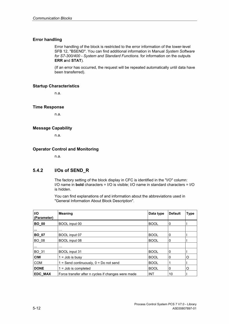
Communication Blocks
Process Control System PCS 7 V7.0 - Library 5-12 A5E00807897-01
Error handling Error handling of the block is restricted to the error information of the lower-level SFB 12, "BSEND". You can find additional information in Manual System Software for S7-300/400 - System and Standard Functions. for information on the outputs ERR and STAT).
(If an error has occurred, the request will be repeated automatically until data have been transferred).
Startup Characteristics n.a.
Time Response n.a.
Message Capability n.a.
Operator Control and Monitoring n.a.
5.4.2 I/Os of SEND_R
The factory setting of the block display in CFC is identified in the "I/O" column: I/O name in bold characters = I/O is visible; I/O name in standard characters = I/O is hidden.
You can find explanations of and information about the abbreviations used in "General Information About Block Description".
I/O (Parameter)
Meaning Data type Default Type
BO_00 BOOL input 00 BOOL 0 I ... … BO_07 BOOL input 07 BOOL 0 I BO_08 BOOL input 08 BOOL 0 I ... … BO_31 BOOL input 31 BOOL 0 I CIW 1 = Job is busy BOOL 0 O COM 1 = Send continuously, 0 = Do not send BOOL 1 I DONE 1 = Job is completed BOOL 0 O EDC_MAX Force transfer after n cycles if changes were made INT 10 I
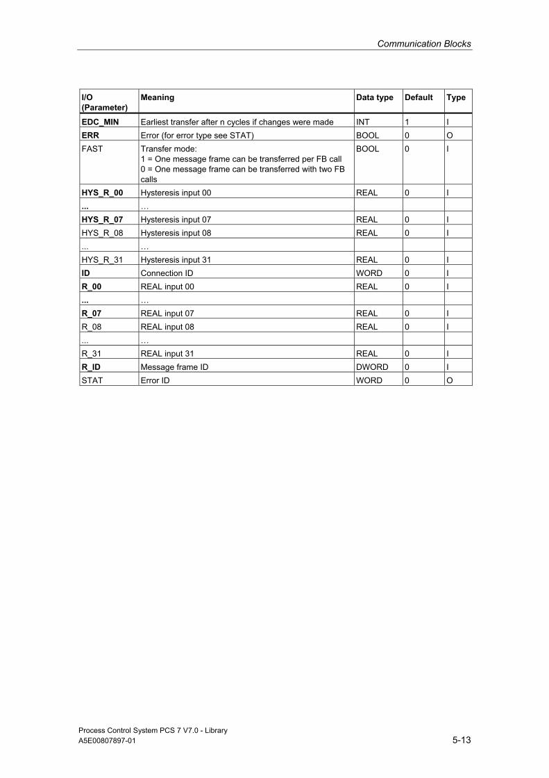
Communication Blocks
Process Control System PCS 7 V7.0 - Library A5E00807897-01 5-13
I/O (Parameter)
Meaning Data type Default Type
EDC_MIN Earliest transfer after n cycles if changes were made INT 1 I ERR Error (for error type see STAT) BOOL 0 O FAST Transfer mode:
1 = One message frame can be transferred per FB call 0 = One message frame can be transferred with two FB calls
BOOL 0 I
HYS_R_00 Hysteresis input 00 REAL 0 I ... … HYS_R_07 Hysteresis input 07 REAL 0 I HYS_R_08 Hysteresis input 08 REAL 0 I ... … HYS_R_31 Hysteresis input 31 REAL 0 I ID Connection ID WORD 0 I R_00 REAL input 00 REAL 0 I ... … R_07 REAL input 07 REAL 0 I R_08 REAL input 08 REAL 0 I ... … R_31 REAL input 31 REAL 0 I R_ID Message frame ID DWORD 0 I STAT Error ID WORD 0 O

Communication Blocks
Process Control System PCS 7 V7.0 - Library 5-14 A5E00807897-01
5.5 Appendix
5.5.1 Technical data "Communication blocks"
Overview In the following table, you will find the technical data for the communication blocks. The table columns have the following meanings:
• Block type name
The symbolic identifier in the symbol table of the library for the relevant FB. Must be unique within the project.
• Object Name
Block number
• Typical runtime
CPU runtime for processing the corresponding block program under normal circumstances (for example, for a driver, this is the execution time in the watchdog-alarm OB, without generation of a channel error message)
The table below shows the runtime of blocks in a 417-4 CPU. The block runtime on other CPUs depends on the CPU performance.
• Block length in load/work memory
Memory requirement of the program code, once for each block type
• Length of instance data in load/work memory
Memory requirement of an instance DB
• Temporary memory
The local-data memory required in a priority class when the block is called. This limit is CPU specific. When it is exceeded, you have to check the CPU configuration and distribute it amongst the OBs to meet the actual requirements.

Communication Blocks
Process Control System PCS 7 V7.0 - Library A5E00807897-01 5-15
• Multiple Instance Block
The specified blocks are used by the communication block and must exist in the user program. They can be found in the same library.
Block (Type Name)
FB No.
Typical runtime CPU 417-4 ( µs )
Block Length in Load/User Memory (Byte)
Instance-Data Length in Load/User Memory (Byte)
Temporary Memory (Bytes)
Multiple Instance Block
REC_BO FB 208 69 3246 / 2356 992 / 128 2 SFB 13 REC_R FB 210 69 1838 / 1332 956 / 476 2 SFB 13 SEND_BO FB 207 163 2298 / 1668 718 / 110 2 SFB 12 SEND_R FB 209 195 4486 / 3886 908 / 478 2 SFB 12

Communication Blocks
Process Control System PCS 7 V7.0 - Library 5-16 A5E00807897-01

Process Control System PCS 7 V7.0 - Library A5E00807897-01 Glossary-1
Glossary
Aspect Attributes of a block with regard to its application in the AS (FB, FC), ES (display in the library or in CFC, display for testing and commissioning) and OS (texts for messages and operations, corresponding faceplate for visualization in the OS).
Block Object of a library or block structure, subdivided into function blocks (executable on an automation system) and faceplates (executable on an OS). The block has aspects for AS, OS and ES, which are defined by their attributes. Both block types are configured in ES. The library contains the block type. ES is used to create an instance data block and to configure it further.
Block Body Section of the block type with function-specific information (for example, values in data blocks, program code of functions).
Block Header Section of the block type with management information on its assignment (for example, type name, block name, etc.).
Block Library Software package that contains block types with common features. Installation via ES.
Block Type Library object, which transfers its object properties to the corresponding instance data block when used in a block structure. The block type (method, database and aspect definition) is stored in the ES.
CS Bus system for data exchange between components.
Data Block Used for storing data which are processed by programs or functions.
Glossary
Process Control System PCS 7 V7.0 - Library Glossary-2 A5E00807897-01
Driver Block Block for reading/writing AS values to/from a module. It forms the software interface to the field process, converts physical values into process variables (and vice versa) and provides additional information with regard to the availability of the hardware addressed.
Enable Input Used to enable/disable processing of an FB (only exists in CFC display mode).
Faceplate Block which is executable on the OS and used to operate and monitor the corresponding AS block. It is supplied for certain block types in the libraries. Included in the faceplate function is the verification of manipulated values.
Fetch Principle The value which is interconnected to an input of a block is only updated (fetched) by the method associated with the block of the interconnected input - and not earlier. If this block is not processed, the input will not have an updated value.
Function Defined in IEC 1131-3 as a software unit, which when executed delivers a single result (which can also be a complex data type) and which does not have the capability of saving data (memory).
The essential difference between an FC and an FB is the lack of a database (instance DB). The result of the FC call must therefore either be saved explicitly by the user or be used immediately. The ES (CFC chart) displays the FC similarly to an FB.
Function Block IEC TC65/WG6 draft standard of May 1995 defines this term as follows:
A function block (FB instance) is a functional software unit, which consists of a designated individual copy of the data structure defined by the function block type and retains its data structure for the duration of one call of the function block.
The main features of the FB instance are as follows:
• Type and instance identifier
• I/O events, which use algorithms of the OB in which the FB instance is processed or are used by these algorithms.
• I/O variables, which are read or changed respectively by the FB algorithm.
• Functional features, which are defined by the type description and are generally implemented via the FB algorithm.

Glossary
Process Control System PCS 7 V7.0 - Library A5E00807897-01 Glossary-3
Initial Startup In the context of blocks, the term refers to the initial block execution after has been instantiated. This routine sets a defined state of the block parameters and operating modes.
Install Process by means of which a block (FB or FC) in an OB is logged in for processing. Usually an existing processing sequence must be observed, which is why the term "install" is used.
Instance DB Data block derived from a block type. Serves as storage unit for a defined application of this type. In a project, for example the "control" block type is represented by several instances (instance DBs) in order to be able to save the respective setpoint value, operating mode, parameters, etc. for each control task.
Limit Reference value for an analog variable. Triggers a reaction when the value is reached or exceeded.
LSB Least Significant Bit/Byte = Bit/Byte in a word or double word with the lowest value
Message Classes Classification of messages based on their cause. The following message classes are used in the SIMATIC process control system:
1. Process messages; triggered when process-specific monitoring values (for example, alarms, warnings, high/low tolerances, general process messages) are reached or exceeded.
2. Process-control messages; output by the control system (system messages) or the I/O units (errors in the field), or for preventive maintenance.
3. Requests for operator input which, in the case of certain operation sequences, draw the operator's attention to the necessity of an operator intervention (for example, request to acknowledge a stepping operation manually in order to enable transition) or operation logs.
Monitoring Part of the tasks of an OS, which allows visualization of process parameters and states in various forms (numerical, graphical).
MSB Most Significant Bit/Byte = Bit/Byte in a word or double word with the highest value

Glossary
Process Control System PCS 7 V7.0 - Library Glossary-4 A5E00807897-01
Multiple Instance Block We speak of multiple instances in cases where additional function blocks are called by one block using its own (i.e., without an additional) instance DB.
Prerequisite is, that FBs to be called are registered as static variables in the variable declaration of the calling FB.
A multiple instance block achieves a concentration of instance data in one instance data block, i.e., it improves utilization of the number of DBs available.
Operating Mode Characteristic of a block, which marks a certain application-specific processing phase of block program execution in various situations. MANUAL operating mode at a controller block signifies a program sequence in which the controller algorithm is not executed and the output (manipulated) variable is set manually by operator control, for example.
Operator Control Operator control of values or states at a block. Changes are usually entered on the OS, verified and transferred via the CS to the operator control block in the automation system. The AS finally verifies received data before they are assigned to the block, since process conditions may have changed during the data transfer.
Operator Text Text which is assigned to a block input and used for picture display or for logging operations on the OS.
Operator-Control Block This block verifies operator input at the OS and, if valid, transfers it to its interconnected block input in the automation system. It also allows acknowledgement of this input at the operator station.
Picture Element Object of the faceplate. Corresponds to a specific I/O element of a block type.
Redundancy Redundancy may be defined as the use of multiple components so that the same task can be carried out by a different component, should the need arise (for example, in case of errors or faults).
Sampling time Time interval between two consecutive block execution cycles in a processing class with a constant cycle time (e.g., watchdog alarm OB). The sampling time is determined by the ES on the basis of the configured runtime group.

Glossary
Process Control System PCS 7 V7.0 - Library A5E00807897-01 Glossary-5
Standard Block/Faceplate Generic term for all objects in standard libraries which are supplied by Siemens.
Start-up CPU transition from STOP (internal STOP, i.e. CPU is ready) to RUN (e.g. user program execution) mode. The following startup modes can be distinguished on the basis of the organization blocks (CPU-specific):
• Cold restart; results and statuses are ignored during an interrupt (OB 100).
• Restart; results and states of the user program at the interrupt are taken into account.
Startup Characteristics Transition of a block into a defined state after its execution in a startup OB. In this library only a cold restart is relevant (OB 100).
Table of Possible Message Classes and their Meaning Message Class Meaning
AH Alarm high (high limit alarm) AL Alarm low (low limit alarm) WH Warning high (high alarm) WL Warning low (low alarm) TH Tolerance high TL Tolerance low F AS control system message (error) S AS control system message (fault) S* OS control system message (fault) M Preventive maintenance PM Process message - Operation message OR Operator request OM *1) Operation message SA Status AS SO Status OS
*1) If the block is used for operation messages, the inputs I_1, ... have to be supplied with pulses. Assignment of the static value "1" would lead to multiple messages.
Tracking Executable status of a block, during which the block program overwrites a (tracked) parameter with the value of another parameter (tracking value), i.e., the user can force a defined parameter value which is usually determined by a process or program.
Glossary
Process Control System PCS 7 V7.0 - Library Glossary-6 A5E00807897-01
User Block/Faceplate Generic term for all user objects (customer, engineering office, department engineering a project for a customer or a project) in user-specific libraries.
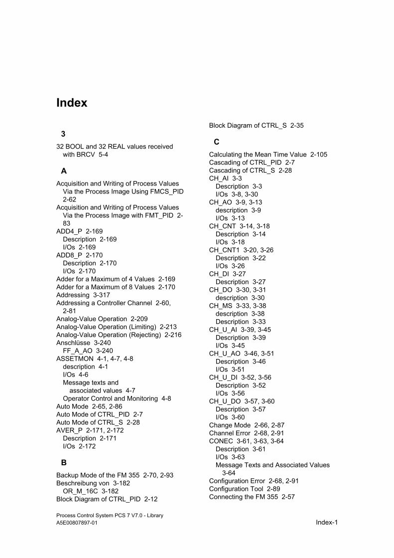
Process Control System PCS 7 V7.0 - Library A5E00807897-01 Index-1
Index
3 32 BOOL and 32 REAL values received
with BRCV 5-4
A Acquisition and Writing of Process Values
Via the Process Image Using FMCS_PID 2-62
Acquisition and Writing of Process Values Via the Process Image with FMT_PID 2-83
ADD4_P 2-169 Description 2-169 I/Os 2-169
ADD8_P 2-170 Description 2-170 I/Os 2-170
Adder for a Maximum of 4 Values 2-169 Adder for a Maximum of 8 Values 2-170 Addressing 3-317 Addressing a Controller Channel 2-60,
2-81 Analog-Value Operation 2-209 Analog-Value Operation (Limiting) 2-213 Analog-Value Operation (Rejecting) 2-216 Anschlüsse 3-240
FF_A_AO 3-240 ASSETMON 4-1, 4-7, 4-8
description 4-1 I/Os 4-6 Message texts and
associated values 4-7 Operator Control and Monitoring 4-8
Auto Mode 2-65, 2-86 Auto Mode of CTRL_PID 2-7 Auto Mode of CTRL_S 2-28 AVER_P 2-171, 2-172
Description 2-171 I/Os 2-172
B Backup Mode of the FM 355 2-70, 2-93 Beschreibung von 3-182
OR_M_16C 3-182 Block Diagram of CTRL_PID 2-12
Block Diagram of CTRL_S 2-35
C Calculating the Mean Time Value 2-105 Cascading of CTRL_PID 2-7 Cascading of CTRL_S 2-28 CH_AI 3-3
Description 3-3 I/Os 3-8, 3-30
CH_AO 3-9, 3-13 description 3-9 I/Os 3-13
CH_CNT 3-14, 3-18 Description 3-14 I/Os 3-18
CH_CNT1 3-20, 3-26 Description 3-22 I/Os 3-26
CH_DI 3-27 Description 3-27
CH_DO 3-30, 3-31 description 3-30
CH_MS 3-33, 3-38 description 3-38 Description 3-33
CH_U_AI 3-39, 3-45 Description 3-39 I/Os 3-45
CH_U_AO 3-46, 3-51 Description 3-46 I/Os 3-51
CH_U_DI 3-52, 3-56 Description 3-52 I/Os 3-56
CH_U_DO 3-57, 3-60 Description 3-57 I/Os 3-60
Change Mode 2-66, 2-87 Channel Error 2-68, 2-91 CONEC 3-61, 3-63, 3-64
Description 3-61 I/Os 3-63 Message Texts and Associated Values
3-64 Configuration Error 2-68, 2-91 Configuration Tool 2-89 Connecting the FM 355 2-57
Index
Process Control System PCS 7 V7.0 - Library Index-2 A5E00807897-01
Connections 3-221, 3-234 DIAG_AB 3-221 FF_A_AI 3-234
Connections of 3-230 DPAY V1 3-230
Controller 2-2 Controller Block 2-58 Controller Optimization 2-1
PID Tuner 2-1 Conversion blocks 2-203 Coordination of FMCS_PID/FMT_PID 2-55 COUNT_P 2-173, 2-174
Description 2-173 I/Os 2-174
Counter 2-173 CPU_RT 4-9, 4-15
Description 4-9 I/Os 4-15
CTRL_PID 2-2, 2-3, 2-6, 2-12, 2-14, 2-18, 2-20 Block Diagram 2-12 Description 2-2 Error handling 2-11 Generation of Manipulated Variables 2-6 Generation of Setpoint Limit and Error Signal 2-4 I/Os 2-14 Manual Auto and Following Mode 2-7 Message Texts and Associated Values
2-18 Mode Change 2-9 Operating and Monitoring 2-20 Startup Behavior Dynamic Response and Message
response 2-12 VSTATUS 2-19
CTRL_PID VSTATUS 2-19 CTRL_PID Mode Change 2-9 CTRL_S 2-20, 2-22, 2-23, 2-25, 2-28, 2-31,
2-33, 2-34, 2-35, 2-36, 2-37, 2-38, 2-44, 2-45 Block Diagram 2-35, 2-36, 2-37 Description 2-20 Dynamic Response 2-34 Error Handling 2-33 Generation of Control Signals 2-25 I/Os 2-38 Manual Auto and Following Mode 2-28 Message response 2-35 Message Texts and Associated Values
2-44 Mode Change 2-31 Operating and Monitoring 2-45
Signal Processing 2-23 Startup Behavior 2-34 VSTATUS 2-45
CTRL_S Mode Change 2-31 Customizing MODE_LW 3-328
FF-devices 3-328
D Data 2-68, 2-89
Read 2-68, 2-89 DEADT_P 2-46, 2-47
Description 2-46 I/Os 2-47
Dead-Time Element 2-46 Description 3-220, 3-231, 3-236, 3-243,
3-248, 4-18, 4-22 DIAG_AB 3-219 FF_A_AI 3-231 FF_A_AO 3-236 FF_A_DI 3-243, 3-244 FF_A_DO 3-248 ST_MUX 4-22
Description MS_MUX 4-18
Description of 2-2, 2-20, 2-46, 2-48, 2-50, 2-55, 2-57, 2-79, 2-101, 2-105, 2-107, 2-112, 2-114, 2-116, 2-118, 2-122, 2-124, 2-127, 2-136, 2-145, 2-152, 2-161, 2-169, 2-170, 2-171, 2-173, 2-175, 2-183, 2-188, 2-192, 2-194, 2-195, 2-198, 2-203, 2-209, 2-213, 2-216, 2-220, 2-223, 2-227, 2-231, 2-234, 3-3, 3-9, 3-14, 3-22, 3-27, 3-30, 3-33, 3-38, 3-39, 3-46, 3-52, 3-57, 3-61, 3-65, 3-68, 3-76, 3-84, 3-91, 3-97, 3-103, 3-108, 3-113, 3-118, 3-124, 3-132, 3-139, 3-148, 3-156, 3-165, 3-169, 3-175, 3-177, 3-186, 3-190, 3-191, 3-195, 3-201, 3-207, 3-213, 3-228, 3-254, 3-261, 3-267, 3-272, 3-278, 3-283, 3-289, 3-294, 3-299, 3-304, 3-311, 4-9, 4-20, 5-1, 5-4, 5-7, 5-10 ADD4_P 2-169 ADD8_P 2-170 ASSETMON 4-3, 4-5 AVER_P 2-171 CH_AI 3-3, 3-4, 3-5 CH_AO 3-9, 3-10 CH_CNT 3-14, 3-15, 3-17 CH_CNT1 3-20, 3-21 CH_DI 3-27 CH_DO 3-30 CH_MS 3-33, 3-34, 3-38 CH_U_AI 3-39, 3-40, 3-41 CH_U_AO 3-46, 3-47 CH_U_DI 3-52, 3-53
Index
Process Control System PCS 7 V7.0 - Library A5E00807897-01 Index-3
CH_U_DO 3-57, 3-58 CONEC 3-61, 3-62 COUNT_P 2-173 CPU_RT 4-9, 4-10, 4-11, 4-12, 4-13,
4-14 CTRL_PID 2-2 CTRL_S 2-20 DEADT_P 2-46 DIF_P 2-48 DIG_MON 2-50, 2-51 DOSE 2-175 DPAY_V1 3-228, 3-229 DPDIAGV0 3-65, 3-66 DREP 3-68, 3-69, 3-70, 3-72 DREP_L 3-76, 3-77, 3-80 ELAP_CNT 2-183 FM_CNT 3-84, 3-85, 3-86 FM_CO 2-55, 2-56 FMCS_PID 2-57 FMT_PID 2-79 IM_DRV 3-90, 3-91, 3-93 INT_P 2-101, 2-102, 2-103 INTERLOK 2-188 LIMITS_P 2-192, 2-193 MEANTM_P 2-105 MEAS_MON 2-107, 2-108 MESSAGE 2-234, 2-235, 2-236 MOD_1 3-97, 3-98, 3-100 MOD_2 3-104, 3-105 MOD_3 3-108, 3-109, 3-110, 3-111 MOD_4 3-113, 3-114, 3-116 MOD_CP 3-118, 3-119, 3-121 MOD_D1 3-124, 3-125, 3-127, 3-129 MOD_D2 3-132, 3-133, 3-137 MOD_HA 3-140, 3-144 MOD_MS 3-148, 3-149, 3-152 MOD_PAL0 3-254 MOD_PAX0 3-261, 3-262 MOT_REV 2-131 MOT_SPED 2-136, 2-139 MOTOR 2-145, 2-146, 2-147, 2-148 MSG_NACK 2-232 MUL4_P 2-194 MUL8_P 2-195 OB_BEGIN 3-155 OB_DIAG 3-165, 3-166 OB_DIAG1 3-169 OB_END 3-175, 3-176 OP_A 2-209, 2-210, 2-211 OP_A_LIM 2-213 OP_A_RJC 2-216 OP_D 2-220, 2-221 OP_D3 2-223, 2-224 OP_TRIG 2-227, 2-228 OR_M_16 3-177, 3-178, 3-179
OR_M_32 3-186 OR_M_8C 3-186, 3-187, 3-188 PA_AI 3-267 PA_AO 3-272 PA_DI 3-278, 3-279 PA_DO 3-283, 3-284 PA_TOT 3-289 PADP_L00 3-294 PADP_L01 3-299 PADP_L02 3-304 PADP_L10 3-310 PO_UPDAT 3-190 POLYG_P 2-112 PS 3-191, 3-192 PT1_P 2-114 R_TO_DW 2-203 RACK 3-195, 3-196, 3-197, 3-198 RAMP_P 2-116 RATIO_P 2-118 RCV_341 3-201, 3-202, 3-203, 3-204 READ355P 2-122 REC_BO 5-1, 5-2 REC_R 5-4 SEND_BO 5-7 SEND_R 5-10 SND_341 3-207, 3-208, 3-209, 3-210 SPLITR_P 2-124 STATEREP 4-20 SUBNET 3-213, 3-214, 3-215, 3-216 SWIT_CNT 2-198 VAL_MOT 2-152, 2-156 VALVE 2-161, 2-162, 2-163, 2-164
Description of OB1_TIME 2-196 DIAG_AB 3-219, 3-220, 3-221
Connections 3-221 Description 3-219
DIF_P 2-48, 2-49 Description 2-48 I/Os 2-49
Differentiation 2-48 DIG_MON 2-50, 2-52, 2-53, 2-54
Description 2-50 I/Os 2-52 Message Texts and Associated Values
2-53 Operating and Monitoring 2-54
DIG_MON VSTATUS 2-54 Digital-Value Monitoring 2-50 Digital-Value Operation
(1 Pushbutton) 2-227 Digital-Value Operation
(2 Pushbuttons) 2-220 Digital-Value Operation
(3 Pushbuttons) 2-223 DOSE 2-175, 2-178, 2-181, 2-182, 2-183

Index
Process Control System PCS 7 V7.0 - Library Index-4 A5E00807897-01
Description 2-175 I/Os 2-179 Message texts and
Associated Values 2-182 Operator Control and Monitoring 2-183 VSTATUS 2-183
Dosing Process 2-175, 2-177, 2-178 Download Parameters to the Module 2-68,
2-89 DPAY V1 3-230
Connections 3-230 DPAY_V0 3-222, 3-223, 3-227, 3-228
I/Os 3-227 Message Texts and Associated Values
3-228 DPAY_V1 3-228
description 3-228 DPDIAGV0 3-65, 3-68
Description 3-65 I/Os 3-68
DREP 3-68, 3-74, 3-75 Description 3-70, 3-71 I/Os 3-74 Message Texts and Associated Values
3-75 DREP_L 3-76, 3-82, 3-83
Description 3-78, 3-79 I/Os 3-82 Message Texts and Associated Values
3-83 Dynamic Response of CTRL_PID 2-12 Dynamic Response of FMCS_PID 2-69 Dynamic Response of FMT_PID 2-92
E ELAP_CNT 2-184, 2-185, 2-186, 2-187
Description 2-183 I/Os 2-185 Message Texts and Associated Values
2-186 Operator Control and Monitoring 2-187
Error 2-68, 2-91 Error Handling 2-68, 2-91 Error Handling of CTRL_PID 2-11 Error Handling of CTRL_S 2-33 Error Information of Output Parameter
MSG_STAT 3-318
F FF devices 3-329
including in ASSET 3-329 FF_A_AI 3-231, 3-232, 3-234
Connections 3-234
Description 3-231 FF_A_AO 3-236, 3-237, 3-240
Anschlüsse 3-240 Description 3-236
FF_A_DI 3-243, 3-246 Description 3-243 I/Os 3-246
FF_A_DO 3-248, 3-251 Description 3-248 I/Os 3-251
FF-devices 3-328 customizing MODE_LW 3-328
First-Order Lag Element 2-114 FM 355 2-70, 2-93
Backup Mode 2-70, 2-93 FM 355 Module 2-122 FM_CNT 3-84, 3-88, 3-89
Description 3-86 I/Os 3-88 Message Texts and Associated Values
3-89 FM_CO 2-55, 2-57
Description 2-55 I/Os 2-57
FMCS_PID 2-58, 2-60, 2-61, 2-62, 2-69, 2-70, 2-71, 2-77, 2-78 Acquisition and Writing of Process
Values Via the Process Image 2-62 Description 2-57 FMCS_PID VSTATUS 2-78 Functions 2-60 I/Os 2-71 Message Texts and Associated Values
2-77 Operating and Monitoring 2-78 Startup Behavior Dynamic Response and Message
response 2-69 VSTATUS 2-78
FMT_PID 2-79, 2-82, 2-83, 2-93, 2-99, 2-100 Acquisition and Writing of Process
Values Via the Process Image 2-83 FMT_PID VSTATUS 2-100 Function 2-82 Function 2-82 I/Os 2-93 Message Texts and Associated Values
2-99 Operating and Monitoring 2-100 Startup Behavior Dynamic Response and Message
response 2-92

Index
Process Control System PCS 7 V7.0 - Library A5E00807897-01 Index-5
VSTATUS 2-100 Following Mode 2-65, 2-66, 2-86, 2-87 Following Mode of CTRL_PID 2-7 Following Mode of CTRL_S 2-28 Function of FMCS_PID 2-60
G General Information About Block
Description 1-1 Generation of Control Signals for CTRL_S
2-25 Generation of Error Signals 2-63, 2-84 Generation of Limits 2-63, 2-84 Generation of Manipulated Variables 2-63,
2-84 Generation of Manipulated Variables for
CTRL_PID 2-6 Generation of Setpoints 2-63, 2-84
I I/O-Access Error 2-68, 2-91 I/Os 3-246, 3-251, 4-19, 4-23
FF_A_DI 3-246 FF_A_DO 3-251 MS_MUX 4-19 ST_MUX 4-23
I/Os of 2-14, 2-38, 2-47, 2-49, 2-52, 2-57, 2-71, 2-93, 2-104, 2-106, 2-109, 2-113, 2-115, 2-117, 2-120, 2-124, 2-126, 2-131, 2-140, 2-149, 2-157, 2-165, 2-169, 2-170, 2-172, 2-174, 2-179, 2-185, 2-190, 2-194, 2-195, 2-196, 2-198, 2-200, 2-204, 2-212, 2-215, 2-219, 2-222, 2-226, 2-229, 2-233, 2-236, 3-13, 3-18, 3-26, 3-33, 3-45, 3-51, 3-56, 3-60, 3-63, 3-68, 3-74, 3-82, 3-88, 3-95, 3-101, 3-112, 3-117, 3-122, 3-130, 3-145, 3-153, 3-160, 3-168, 3-173, 3-177, 3-180, 3-182, 3-194, 3-199, 3-205, 3-212, 3-217, 3-227, 3-256, 3-264, 3-270, 3-275, 3-281, 3-286, 3-292, 3-297, 3-316, 4-6, 4-15, 4-21, 5-3, 5-6, 5-9, 5-12 ADD4_P 2-169 ADD8_P 2-170 ASSETMON 4-6 AVER_P 2-172 CH_AI 3-8, 3-30 CH_AO 3-13 CH_CNT 3-18 CH_CNT1 3-26 CH_U_AI 3-45 CH_U_AO 3-51 CH_U_DI 3-56 CH_U_DO 3-60
CONEC 3-63 COUNT_P 2-174 CPU_RT 4-15 CTRL_PID 2-14 CTRL_S 2-38 DEADT_P 2-47 DIF_P 2-49 DIG_MON 2-52 DOSE 2-179 DPAY_V0 3-227 DPDIAGV0 3-68 DREP 3-74 DREP_L 3-82 ELAP_CNT 2-185 FM_CNT 3-88 FM_CO 2-57 FMCS_PID 2-71 FMT_PID 2-93 IM_DRV 3-95 INT_P 2-104 INTERLOK 2-190 LIMITS_P 2-194 MEANTM_P 2-106 MEAS_MON 2-109 MESSAGE 2-236 MOD_1 3-101 MOD_2 3-101 MOD_3 3-112 MOD_4 3-117 MOD_CP 3-122 MOD_D1 3-130 MOD_D2 3-130 MOD_HA 3-145 MOD_MS 3-153 MOD_PAL0 3-256 MOD_PAX0 3-264 MOT_REV 2-131 MOT_SPED 2-140 MOTOR 2-149, 2-150 MSG_NACK 2-233 MUL4_P 2-195 MUL8_P 2-196 OB_BEGIN 3-160 OB_DIAG 3-168 OB_DIAG1 3-173 OB_END 3-177 OB1_TIME 2-198 OP_A 2-212 OP_A_LIM 2-215 OP_A_RJC 2-219 OP_D 2-222 OP_D3 2-226 OP_TRIG 2-229 OR_M_16 3-180 OR_M_16C 3-182
Index
Process Control System PCS 7 V7.0 - Library Index-6 A5E00807897-01
OR_M_32 3-180 OR_M_8C 3-182 PA_AI 3-270 PA_AO 3-275 PA_DI 3-281 PA_DO 3-286 PA_TOT 3-292 PADP_L00/L01/L02 3-297 PADP_L10 3-316 POLYG_P 2-113 PS 3-194 PT1_P 2-115 R_TO_DW 2-204 RACK 3-199 RAMP_P 2-117 RATIO_P 2-120 RCV_341 3-205 READ355P 2-124 REC_R 3-33, 5-6 SEND_BO 5-9 SEND_R 5-12 SND_341 3-212 SPLITR_P 2-126 STATEREP 4-21 SUBNET 3-217 SWIT_CNT 2-200 VAL_MOT 2-157 VALVE 2-166
I/Os of CH_AI 3-8, 3-30 I/Os of REC_BO 5-3 IM_DRV 3-90, 3-95
Description 3-91 I/Os 3-95 Message Texts and Associated Values
3-96 Including FF devices in ASSET 3-329 INT_P 2-101, 2-104
Description 2-101 I/Os 2-104
Integration 2-101 INTERLOK 2-188, 2-189, 2-190, 2-192
Description 2-188 I/Os 2-190 Operator Control and Monitoring 2-192
L Limits 2-193 LIMITS_P 2-192, 2-194
Description 2-192 I/Os 2-194
M Manual
Auto and Following Mode 2-65, 2-86 Manual Mode 2-65, 2-86 Manual Mode of CTRL_PID 2-7 Manual Mode of CTRL_S 2-28 Mean Time Value 2-171 MEANTM_P 2-105, 2-106
Description 2-105 I/Os 2-106
MEAS_MON 2-107, 2-109, 2-110, 2-111 Description 2-107 I/Os 2-109 Message Texts and Associated Values
2-110 Operating and Monitoring 2-111 VSTATUS 2-111
Measured-Value Monitoring 2-107 MESSAGE 2-234, 2-236, 2-237
Description 2-234 I/Os 2-236 Message Texts and Associated Values
2-237 Message Block (Configurable Messages)
2-231, 2-234 Message Blocks 2-231
Overview 2-231 Message response of CTRL_PID 2-12 Message response of FMCS_PID 2-69 Message response of FMT_PID 2-92 Message texts and associated values from
4-7 ASSETMON 4-7
Message texts and associated values of 3-184, 3-189 OR_M_16C 3-184 OR_M_8C 3-189
Message Texts and Associated Values of 2-18, 2-44, 2-53, 2-77, 2-99, 2-110, 2-134, 2-143, 2-151, 2-159, 2-167, 2-182, 2-186, 2-201, 2-237, 3-64, 3-75, 3-83, 3-89, 3-96, 3-103, 3-118, 3-123, 3-131, 3-138, 3-146, 3-154, 3-161, 3-174, 3-181, 3-195, 3-200, 3-206, 3-213, 3-218, 3-228, 3-257, 3-265, 3-298, 3-303, 3-308 CONEC 3-64 CTRL_PID 2-18 CTRL_S 2-44 DIG_MON 2-53 DOSE 2-182 DPAY_V0 3-228 DREP 3-75 DREP_L 3-83 ELAP_CNT 2-186 FM_CNT 3-89 FMCS_PID 2-77 FMT_PID 2-99

Index
Process Control System PCS 7 V7.0 - Library A5E00807897-01 Index-7
IM_DRV 3-96 MEAS_MON 2-110 MESSAGE 2-237 MOD_1 3-103 MOD_2 3-103 MOD_3 3-103 MOD_4 3-118 MOD_CP 3-123 MOD_D1 3-131 MOD_D2 3-138 MOD_HA 3-146 MOD_MS 3-154 MOD_PAL0 3-259 MOD_PAX0 3-265 MOT_REV 2-134 MOT_SPED 2-143 MOTOR 2-151 OB_BEGIN 3-162, 3-163 OB_DIAG1 3-174 OR_M_16 3-181 OR_M_32 3-181 PADP_L00 3-298 PADP_L01 3-303 PADP_L02 3-308 PS 3-195 RACK 3-200 RCV_341 3-206 SND_341 3-213 SUBNET 3-218 SWIT_CNT 2-201 VAL_MOT 2-159 VALVE 2-167
MOD_1 3-97, 3-101, 3-103 Description 3-97 I/Os 3-101 Message Texts and Associated Values
3-103 MOD_2 3-101, 3-103
Description 3-103 I/Os 3-101 Message Texts and Associated Values
3-103 MOD_3 3-103, 3-108, 3-112
Description 3-108 I/Os 3-112 Message Texts and Associated Values
3-103 MOD_4 3-113, 3-117
Description 3-113 I/Os 3-117 Message Texts and Associated Values
3-118 MOD_CP 3-118, 3-122, 3-123
Description 3-118 I/Os 3-122
Message Texts and Associated Values 3-123
MOD_D1 3-124, 3-130, 3-131 Description 3-124 I/Os 3-130 Message Texts and Associated Values
3-131 MOD_D2 3-130, 3-132, 3-138
Description 3-132 I/Os 3-130 Message Texts and Associated Values
3-138 MOD_HA 3-139, 3-145, 3-146
Description 3-139 I/Os 3-145 Message Texts and Associated Values
3-146 MOD_MS 3-148, 3-153, 3-154
Description 3-148 I/Os 3-153 Message Texts and Associated Values
3-154 MOD_PAL0 3-254, 3-255, 3-256, 3-257
description 3-254 I/Os 3-256 Message Texts and Associated Values
3-257 MOD_PAX0 3-261, 3-264, 3-265
description 3-261 I/Os 3-264 Message Texts and Associated Values
3-265 MODE 3-318, 3-324, 3-325 MODE Setting for PA Devices 3-326 MODE Settings for SM Modules 3-318 MOT_REV 2-127, 2-131, 2-134, 2-135
Description 2-127 I/Os 2-131 Message Texts and Associated Values
2-134 Operating and Monitoring 2-135 VSTATUS 2-135 VSTATUS 2-135
MOT_SPED 2-136, 2-140, 2-143, 2-144 Description 2-136 I/Os 2-140 Message Texts and Associated Values
2-143 Operating and Monitoring 2-144 VSTATUS 2-144 VSTATUS 2-144
MOTOR 2-145, 2-149, 2-151, 2-152 Description 2-145 I/Os 2-149

Index
Process Control System PCS 7 V7.0 - Library Index-8 A5E00807897-01
Message Texts and Associated Values 2-151
Operating and Monitoring 2-152 VSTATUS 2-151 VSTATUS 2-151
Motor Valve Control 2-152 Motor With One Control Signal 2-145 MS_MUX 4-18, 4-19
Description 4-18 I/Os 4-19
MSG_NACK 2-231, 2-233 Description 2-231 I/Os 2-233
MSG_STAT 3-318 MUL4_P 2-194, 2-195
Description 2-194 I/Os 2-195
MUL8_P 2-195, 2-196 Description 2-195 I/Os 2-196
Multiplier for a Maximum of 4 Values 2-194 Multiplier for a Maximum of 8 values 2-195
N Notes on Using Driver Blocks 3-1
O OB_BEGIN 3-155, 3-156, 3-157, 3-158,
3-160, 3-161 Description 3-156 I/Os 3-160 Message Texts and Associated Values
3-161 OB_DIAG 3-165, 3-168
Description 3-165 I/Os 3-168
OB_DIAG1 3-169, 3-170, 3-171, 3-173, 3-174 Description 3-169 I/Os 3-173 Message Texts and Associated Values
3-174 OB_END 3-175, 3-177
Description 3-175 I/Os 3-177
OB1_TIME 2-198 I/Os 2-198
OMODE Settings for SM Modules 3-326 OP_A 2-212
Description 2-209 I/Os 2-212 Operator Control and Monitoring 2-212
OP_A_LIM 2-213, 2-215, 2-216
Description 2-213 I/Os 2-215 Operator Control and Monitoring 2-216
OP_A_RJC 2-216, 2-217, 2-218, 2-219 Description 2-216 I/Os 2-219 Operator Control and Monitoring 2-219
OP_D 2-220, 2-222 Description 2-220 I/Os 2-222 Operator Control and Monitoring 2-222
OP_D3 2-223, 2-226, 2-227 Description 2-223 I/Os 2-226 Operator Control and Monitoring 2-227
OP_TRIG 2-227, 2-229, 2-230 Description 2-227 I/Os 2-229 Operator Control and Monitoring 2-230
Operating and Monitoring of 2-20, 2-45, 2-54, 2-78, 2-100, 2-111, 2-121, 2-135, 2-144, 2-152, 2-160, 2-168 CTRL_PID 2-20 CTRL_S 2-45 DIG_MON 2-54 FMCS_PID 2-78 FMT_PID 2-100 MEAS_MON 2-111 MOT_REV 2-135 MOT_SPED 2-144 MOTOR 2-152 RATIO_P 2-121 VAL_MOT 2-160 VALVE 2-168
Operating-Hours Counter 2-184 Operator Control and Monitoring 4-8 Operator Control and Monitoring of 2-183,
2-187, 2-192, 2-202, 2-212, 2-216, 2-219, 2-222, 2-227, 2-230 ASSETMON 4-8 DOSE 2-183 ELAP_CNT 2-187 INTERLOK 2-192 OP_A 2-212 OP_A_LIM 2-216 OP_A_RJC 2-219 OP_D 2-222 OP_D3 2-227 OP_TRIG 2-230 SWIT_CNT 2-202
Operator Error 2-68, 2-91 Operator-Control Blocks 2-205, 2-206,
2-207 Overview 2-206
OR_M_16 3-177, 3-180, 3-181

Index
Process Control System PCS 7 V7.0 - Library A5E00807897-01 Index-9
Description 3-177 I/Os 3-180 Message Texts and Associated Values
3-181 OR_M_16C 3-182, 3-184
Beschreibung 3-182 I/Os 3-182 Message texts and
associated values 3-184 OR_M_32 3-180, 3-181, 3-186
Description 3-186 I/Os 3-180 Message Texts and Associated Values
3-181 OR_M_8C 3-182, 3-186, 3-189
Description 3-186 I/Os 3-182 Message texts and
associated values 3-189 Overview of Message Blocks 2-231 Overview of Operator-Control Blocks 2-205
P PA_AI 3-267, 3-270
Description 3-267 I/Os 3-270
PA_AO 3-272, 3-275 Description 3-272 I/Os 3-275
PA_DI 3-278, 3-281 Description 3-278 I/Os 3-281
PA_DO 3-283, 3-286 Description 3-283 I/Os 3-286
PA_MODE 3-326 Settings 3-326
PA_TOT 3-289, 3-292 Description 3-289 I/Os 3-292
PADP_L00 3-294, 3-295, 3-298 description 3-294 Message Texts and Associated Values
3-298 PADP_L00/ L01/ L02 3-297
I/Os 3-297 PADP_L01 3-299, 3-300, 3-303
Description 3-299 Message Texts and Associated Values
3-303 PADP_L02 3-304, 3-305, 3-308
description 3-304 Message Texts and Associated Values
3-308
PADP_L10 3-310, 3-311, 3-312, 3-316 description 3-311, 3-313 I/Os 3-316
PA-Field-Device Status and Diagnostic Information 3-259
Parameters 2-68, 2-89 Download 2-68, 2-89
PID Controller 2-2, 2-3 PID Controller Block 2-2 PID Tuner 2-1
Controller Optimization 2-1 PO_UPDAT 3-190
Description 3-190 POLYG_P 2-112, 2-113
Description 2-112 I/Os 2-113
Polygon With a Maximum of 8 Points 2-112 PS 3-191, 3-194, 3-195
Description 3-191 I/Os 3-194 Message Texts and Associated Values
3-195 PT1_P 2-114, 2-115
Description 2-114 I/Os 2-115
R R_TO_DW 2-203, 2-204
Description 2-203 I/Os 2-204
RACK 3-195, 3-199, 3-200 Description 3-195 I/Os 3-199 Message Texts and Associated Values
3-200 Rack Failure 2-68, 2-91 Ramp Generation 2-116 RAMP_P 2-116, 2-117
Description 2-116 I/Os 2-117
Ratio Control 2-118, 2-119 RATIO_P 2-118, 2-120, 2-121
Description 2-118 I/Os 2-120 Operating and Monitoring 2-121 VSTATUS 2-121 VSTATUS 2-121
RCV_341 3-201, 3-205, 3-206 Description 3-201 I/Os 3-205 Message Texts and Associated Values
3-206 Read Data From the Module 2-68, 2-89 READ355P 2-122, 2-124
Index
Process Control System PCS 7 V7.0 - Library Index-10 A5E00807897-01
Description 2-122 I/Os 2-124
REC_BO 5-1, 5-3 description 5-1 I/Os 5-3
REC_R 3-33, 5-4, 5-5, 5-6 description 5-4 I/Os 3-33, 5-6
Receive 128 BOOL values with BRCV (REC_BO) 5-1
Reversing Motor 2-127
S Safety mode 2-68, 2-89 Send 128 BOOL Values With BSEND
(SEND_BO) 5-7 Send 32 BOOL and 32 REAL Values With
BSEND Driven By Changes 5-10
SEND_BO 5-7, 5-9 Description 5-7 I/Os 5-9
SEND_R 5-10, 5-12 Description 5-10 I/Os 5-12
Signal Processing in the Setpoint and Actual-Value Branches of CTRL_PID 2-4
Signal Processing in the Setpoint and Actual-Value Branches of CTRL_S 2-23
SND_341 3-207, 3-212, 3-213 Description 3-207 I/Os 3-212 Message Texts and Associated Values
3-213 Split Range 2-124 SPLITR_P 2-125, 2-126
Description 2-124 I/Os 2-126
ST_MUX 4-22, 4-23 Description 4-22 I/Os 4-23
Startup Behavior Dynamic Response and Message
response of CTRL_S 2-34 Startup Behavior of CTRL_PID 2-12 Startup Behavior of FMCS_PID 2-69 Startup Behavior of FMT_PID 2-92 STATEREP 4-20, 4-21
Description 4-20 I/Os 4-21
Status Display Lock 2-188 SUBNET 3-213, 3-217, 3-218
Description 3-213
I/Os 3-217 Message Texts and Associated Values
3-218 SWIT_CNT 2-198, 2-199, 2-200, 2-201,
2-202 Description 2-198 I/Os 2-200 Message Texts and Associated Values
2-201 Operator Control and Monitoring 2-202 SWIT_CNT VSTATUS 2-202
Switching-Operation Counter 2-198
T Technical data 5-14
Communication blocks 5-14 Technical Data 2-238, 3-330, 4-24
Asset Blocks 4-24 Driver Blocks 3-330 Technological Blocks 2-238
Temperature-Controller Block 2-79 Text Libraries of the Blocks 3-330 Track Manipulated Variable 2-66, 2-87 Track Setpoint 2-66, 2-87 Two-Speed Motor 2-136
V VAL_MOT 2-152, 2-157, 2-159, 2-160
Description 2-152 I/Os 2-157 Message Texts and Associated Values
2-159 Operating and Monitoring 2-160 VSTATUS 2-160 VSTATUS 2-160
VALVE 2-161, 2-165, 2-167, 2-168 Description 2-161 I/Os 2-165 Message Texts and Associated Values
2-167 Operating and Monitoring 2-168 VSTATUS 2-168 VSTATUS 2-168
Valve Control 2-161 VSTATUS
DIG_MON 2-54 DOSE 2-183 ELAP_CNT 2-187 INTERLOK 2-191 MEAS_MON 2-111 SWIT_CNT 2-202