process and apparatus for collecting blood from a body cavity for
TRANSCRIPT


4,781,707 Page 2
OTHER PUBLICATIONS Halkey Medical advertisement for Luer Style Syringe Check Valve. Davol Inc. instructions for Chest Drainage Unit. Howmedica, Inc., instructions for Pleur-Evac Chest Drainage Unit. Ohio Medical Products brochure for Thoracic Drain age System.
Becton-Dickinson brochure for Suction Collection Canister. Deknatel brochure for Pleur-Evac ® Autotransfusion System Insert. Deknatel brochure for Pleur-Evac® A-4000 Adul t-Pediatric System. Thoratec Medical Incorporated operating instructions for Bloodstat TM Autotransfusion System.

US. Patent Nov. 1,1988 Sheet 1 0f 12 4,781,707


U.S.Patent Nov. 1,1988 Sheet 3 0f 12 4,781,707

US. Patent Nov. 1,1988 Sheet 4 0f 12 4,781,707
290 288 286
FROM '
PATiENT
//_///////// / ///// / ////// / /
1.1

US. Patent Nov. 1,1988- Sheet 5 0f 12 4,781,707
298 296 / 286 90 ' 29¢ Z84 .
' L __ FROM
292 / ' PATIENT
Zl 288 ) 35
5o , 1;- ~ A

US. Patent Nov. 1, 1988 Sheet 6 0f 12 4,781,707
2 6 4
4 /4 2 6
\ xxd.
///// A/A/ ///// ///// /// /// / /

US. Patent Nov. 1, 1988 Sheet 7 of 12 4,781,707
298/ 29s 7 284 2/86 290
' / 294 \ ‘ “ ! 282 88 \
9 9 FROM % 5. 292 . PATIENT / 32 >
99 4“ 5 4%
524 . 2 M5731! 4/52 [a
\\\ \\\\\\\\\ \ \\\\\\\\\§ : $ / g, "f a?

US. Patent Nov. 1,1988 Sheet 8 0f 12 4,781,707

US. Patent Nov. 1, 1988 Sheet 9 of 12 4,781,707
/ ///////// /////Z a /
m ‘I. ??/ /////////////// //////A?
/// / /////// ///// a //
/ / /
/ / /
l / /
/ / / / / /
/ / .
/ /
E
48
F’! .I/
/////// / / /////./ TILY.
9 6
US. Patent Nov. 1, 1988 Sheet 10 70f 12 4,781,707
.IZv

US. Patent Nov. 1, 1988 Sheet 11 0112 4,781,707
282
280 274
8 6 2
0 5 2
8 2 w %
\\\ \ \, \\\ \ \w. ///A////////////////~ Fi_.l3
390
/ FROM Z \ PATIENT 39
SUCTION \ /

US. Patent Nov. 1, 1988 Sheet 12 0f 12 4,781,707
4 5 2 /
106%
725”
A A a/ I / 4/4’ \7/ /////
250/
Ti .16

4,781,707 1
PROCESS AND APPARATUS FOR COLLECTING BLOOD FROM A BODY CAVITY FOR
AUTOTRANSFUSION
CROSS-REFERENCE TO RELATED APPLICATION
This is a continuation-in-part of US. patent applica tion Ser. No. 830,577, ?led Feb. 18, 1986, by John R. Boehringer, John Karpowicz and Steven T. Sutter, and assigned to a common assignee.
BACKGROUND OF THE INVENTION
1. Field of the Invention This invention relates to a process and apparatus for
collecting shed blood from body cavities during surgi cal procedures and the like, and more particularly this invention relates a process and an apparatus for collect ing shed blood for autotransfusion.
2. Brief Description of the Prior Art Self-contained, disposable systems for the collection,
anti-coagulation, ?ltration and reinfusion of blood shed into body cavities are known. Autotransfusion permits a patient’s own shed blood to be recycled during the course of an operation. Autotransfusion is especially useful when appropriate banked blood is unavailable or when the patient’s religious convictions, technical com plications, or other factors dictate than banked blood not be used.
Prior art autotransfusion processes and apparatus often require that blood collected at a surgical site be stored in a ?rst blood reservoir nad subsequently trans ferred to a second blood reservoir or blood bag, and also often require complicated priming and blood trans fer procedures. These complicated procedures require expensive apparatus and increase the risk of error caus ing harm to the patient. Other types of drainage units or devices for collect
ing fluids from body cavities are also known in the art. Initially, such devices comprised a plurality of bottles connected by hoses. One such bottle would form the collection chamber for matter being drawn from a body cavity and another bottle would form a water seal through which gases from the collection chamber would be bubbled and to which a source of suction would be connected. A third bottle could be employed as a manometer for monitoring and controlling the amount of vacuum, or negative pressure of the system, to a given pressure corresponding to a predetermined height of a column of water. These systems have gradu ally developed into disposable, single unit systems in which a plurality of internally connected chambers functioned as collection chambers, water seals and ma nometers.
In addition, it is known to employ such unitary drain age devices as sources of suction of collection of blood into specially adapted blood bags which are externally supported against collapse during blood collection. An example of an externally supported blood bag for col lecting shed blood by suction is provided in U.S. Pat. No. 4,443,220 which discloses a collapsible sterilizable collection bag in combination with a special stent adapted to hold the bag in distended form as blood is collected in the presence of a vacuum in the bag. How ever, this system suffers from a major de?ciency in that the vacuum in the interior of the bag must be released after blood collection in order to dislodge the bag from the stent. This release of vacuum could conceivably
15
20
25
35
40
45
50
55
60
65
2 introduce ambient air into the interior of the bag. The ambient air may contain dangerous microorganisms which may contaminate the collected blood and render it un?t for transfusion back into the patient’s body. There is a clear need for an autotransfusion process
and device which takes advantage of the simplicity and economy of unitary drainage devices as sources of suc tion for blood collection vessels which are releasably V supported against pressure differential-induced collapse during blood collection, but which employ support means which are readily disengageable without requir ing prior venting of the interior of the blood collection vessel to the atmosphere.
In other types of disposable devices for collecting body ?uids, such as disclosed in US. Pat. Nos, 3,680,560, 3,685,517, and 3,866,608, a rigid cannister envelops an inner receiver formed from a rigid cap for the cannister sealed to a ?exible liner for the cannister. Provision is made to actively exert a suction on the volume between the liner and the cannister to prevent the liner from collapsing when suction is applied within the liner to draw ?uid into the liner. Providing means to create the countervailing suction increases the complex ity and cost of manufacture of the device. Further, unless a separate port and suction line are provided for the countervailing suction, releasing suction to disas semble the device requires admitting air into the liner, thus increasing the risk of contamination of blood col lected therein. 0n the other hand, using a separate port and suction line to provide a countervailing suction increases the complexity and cost of the apparatus, and further increases the complexity of operation of the device. There is a need for an apparatus and process which simplify the blood collection process, decreasing the complexity of the procedures required to collect blood for optional blood reuse and reducing the likeli hood of operator error associated with prior art collec tion devices and procedures.
SUMMARY OF THE INVENTION
The present invention is directed toward providing a novel process and apparatus directed toward overcom ing the above de?ciencies in prior art autotransfusion processes and devices, as well as offering additional improvements. ‘
It is a primary object of this invention to provide a simple, inexpensive apparatus and a simple associated process for the collection of blood for transfusion back into the body from which the blood was obtained.
It is a further object of this invention to provide a process for autotransfusion of blood employing a dis posable, easy-to-use apparatus having reduced likeli hood of blood contamination in comparison with prior art processes and apparatus. Yet another object of this invention is to provide a
disposable apparatus for blood collection requiring sim pler, more economical fabrication techniques than prior art devices.
It is also an object of the present invention to provide a simpli?ed process for collecting blood for optional later blood reuse, the process requiring fewer steps than prior art processes and consequently reducing the likeli hood of operator error. Another object of this invention is to provide an
economical apparatus for the collection of blood for optional later blood reuse which provides means for collecting over?ow from the primary collection vessel

4,781,707 3
so that blood collection need not be interrupted to sub stitute collection vessels when a ?rst vessel has been ?lled to capacity. This provides the operator with addi tional ?exibility and provides the option of deferring the substitution of a new collection vessel should the operator be required to attend to other matters during blood collection. Another object of this invention is to provide an
improved apparatus for blood collection wherein, in case of accidental upset of the device, ?ow back from other portions of the apparatus into the primary blood collection vessel is avoided. A still further object of the present invention is to
provide an improved apparatus for blood collection for optional later blood reuse having a blood collection vessel which is releasably supported against pressure differential-induced collapse during blood collection, but which employs support means which are readily disengageable without requiring prior venting of the interior of the blood collection vessel to the atmo sphere.
It is another object of the present invention to pro vide a blood collection apparatus having a sealing means for trapping air-borne contamination when the device is disconnected from a source of suction. Another object of the present invention is to provide
a blood collection apparatus having pressure control means which permits an operator to control the magni tude of suction provide to the apparatus from an exter nal source of suction. A further object of the present invention is to provide
a blood collection apparatus which permits sampling of collected blood from the collection vessel for diagnostic testing and the like. Another object of the present invention is to provide
a blood collection apparatus having a plurality of blood collection vessels which may be ?lled sequentially with out interrupting the ?ow of blood to the apparatus. A still further object of the present invention is to
provide an improved autotransfusion blood collection apparatus having a disposable blood collection vessel which may be used with standard infusion sets to de liver blood to a patient. Another object of the present invention is to provide
an improved blood collection apparatus which may be quickly and easily ?tted with a detachable blood collec tion vessel which, when ?lled, can be quickly replaced with an empty vessel. The process of the present invention requires a con
trollable ?ow conduit having an inlet and an outlet. The inlet of the controllable ?ow conduit is placed in a body cavity from which blood is to be withdrawn. The outlet of the controllable ?ow conduit is connected to the inlet of a blood collection apparatus to place the body cavity in ?uid communication with the blood collection appa ratus. The blood collection apparatus includes an apparatus
body having a ?rst opening therein for connection to a source of suction and a blood collection means for col lection and storing blood from the body cavity. The apparatus further includes a gas-transmitting sealing means having a ?rst and second side, the ?rst side being in fluid communication with the ?rst opening. Air is drawn through the sealing means from the second side to the ?rst side, thereby creating a partial vacuum proxi mate the second side of the sealing means. Suitable apparatus bodies including sealing means are disclosed in US. patent application Ser. No. 830,577, now pend
15
25
35
40
45
55
60
65
4 .
ing, ?led Feb. 18, 1986, which is incorporated herein by reference. The apparatus of the present invention in a ?rst pres
ently preferred embodiment includes blood collection means including at least one autotransfusion collector for collecting and storing blood for optional blood re use. The autotransfusion collector includes an outer receptacle and an inner receptacle, the inner receptacle being positioned substantially within the outer recepta cle. The inner receptacle includes at least one interior cavity and at least one substantially ?exible wall at least partially enclosing the interior cavity. The apparatus further includes means for placing the second side of the sealing means in fluid communication with the interior cavity of the autotransfusion collector for drawing a vacuum thereon. The autotransfusion collector further includes an inlet conduit means in ?uid communication with the interior cavity of the inner receptacle. The inlet conduit is adapted for communication with the body cavity for carrying blood therefrom to the inner receptacle when suction is applied to the ?rst opening in the apparatus body. The process employing - this apparatus further in
cludes the steps of applying suction to the ?rst opening in the apparatus body and subsequently opening the ?rst control means in the controllable ?ow conduit to permit blood to flow from the body cavity, through the con trollable ?ow conduit, and into the inner cavity of the inner receptacle. Blood which has been collected in the autotransfu
sion collector can be subsequently used for transfusion back into the patient from which it was obtained.
In the ?rst presently preferred embodiment, the outer receptacle of the autotransfusion collector is substan tially rigid and the autotransfusion collector further includes at least one intermediate cavity between the outer receptacle and the inner receptacle. The interme diate cavity is sealed against ?uid communication with the atmosphere, thus maintaining the inner receptacle in a substantially uncollapsed condition during collection of blood therein.
Other objects and advantages of the present invention will be readily understood from a reading of the forego ing as well as the description of the drawings, as well as other explanation of the invention as will appear herein after.
BRIEF DESCRIPTION OF THE DRAWINGS
FIG. 1 is a front elevation view of a ?rst embodiment of the blood collection apparatus of the present inven tion. FIG. 2 is a vertical sectional view a blood collection
apparatus of the present invention illustrating an alter native means of mounting the autotransfusion collector to the apparatus body. FIG. 3 is a cross-sectional view of the apparatus of
FIG. 1, taken generally along the line III-III of FIG. 1. FIG. 4 is a fragmentary vertical sectional view of a
second embodiment of the apparatus of the present invention taken generally along the line IV-IV of FIG. 5. FIG. 4 is a fragmentary cross-sectional view of the
apparatus of FIG. 4 taken generally along the line V-—V of FIG. 4. FIG. 5 is a fragmentary front elevational view of a
third embodiment of the apparatus of the present inven tion. '

4,781,707 5
FIG. 7 is a fragmentary vertical sectional view of the apparatus of FIG. 6 taken generally along the line VII —VII of FIG. 8. FIG. 8 is a fragmentary cross-sectional view of the
apparatus of FIGS. 6 and 7 taken generally along the line VIII-VIII of FIGS. 6 and 7. FIG. 9 is a fragmentary vertical sectional view of a
fourth embodiment of the apparatus of the present in vention. FIG. 10 is a fragmentary perspective view of the
autotransfusion collector of FIGS. 1-3 shown deliver ing blood to a patient. FIG. 11 is a fragmentary front elevational view of an
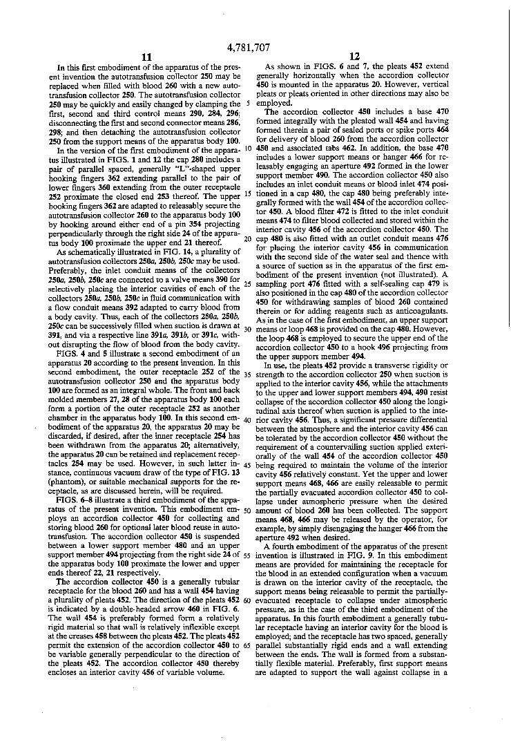
apparatus body of the present invention having plural manometer chambers. FIG. 12 is an expanded, exploded fragmentary per
spective view of the apparatus of FIG. 1. FIG. 13 is an expanded, fragmentary vertical sec
tional view of an apparatus of the present invention showing a sealing gasket between an inner receptacle and an outer receptacle. FIG. 14 is a partial schematic illustration of an appa
ratus of the present invention having plural autotransfu sion collectors. FIG. 15 is a schematic illustration of another embodi
ment of a collection apparatus of this invention. FIG. 16 is a fragmentary schematic illustration of an
interconnect unit with apparatus of this invention for optimal use with collectors in accordance with the em bodiments of this invention.
DETAILED DESCRIPTION OF THE PREFERRED EMBODIMENTS
Referring now to the drawings in detail, reference is ?rst made to FIG. 1, wherein the ?rst presently pre ferred embodiment of an apparatus according to the present invention, generally designated by the numeral 20, is shown in vertical or upstanding disposition. The apparatus includes an apparatus body 100 to which is detachably connected an autotransfusion collector 250. The apparatus body 100 can be a drainage device for
collecting liquids from a body cavity such as that dis closed in the commonly assigned US patent applica tion Ser. No. 830,577 now pending ?led Feb. 18, 1986 and discussed in detail therein. In the present embodi ment the apparatus body 100 has upper and lower ends 21, 22 and left and tight ends 23, 24 as illustrated in FIG. 1. The apparatus body can be constructed of various materials and formed in various ways, such as by vac uum forming, injection molding or blow molding of a thermally formable plastic material or the like. In the present embodiment the principal components of the apparatus body 100 include front and back molded members 27, 28 (FIG. 3) and an additional molded member 30 at the upper left corner of FIG. 1. These members are secured together along various ?anges such as, but not limited to those 31, 32, 33 by means of suitable heat sealing, adhesive, and/or solvent sealing techniques generally known in the art. Preferably, at least one of the front and back molded members 27, 28 is formed from a transparent or ‘translucent material permitting the interior of the apparatus body 100 to be viewed by an observer. The apparatus body 100 in cludes a removable base 125 which securely supports the upstanding apparatus 100 against accidental falling forward or backward or tipping over. The apparatus body 100 includes a plurality of cham
bers formed between the molded members 27, 28, 30.
15
25
30
35
45
55
60
65
6 The chambers include a water seal chamber 42, ?rst, second and third over?ow chambers 115, 116, 117 and a manometer chamber 69. The function, construction and use of the various chambers in the apparatus body 100 are described in detail in US patent application Ser. No. 830,577. However, the structure and function of each of these chambers are also described brie?y below. The apparatus body 100 includes a ?rst opening 40
formed therein for connection to a source of suction (not illustrated) through a vacuum line 38. The vacuum line 38 will generally be connected to a customary hos pital supply, provided through a regulated wall outlet or the like, and adjusted to 90-100 mm. Hg. of vacuum, or any other suitable vacuum. In addition, a second opening 41 to the atmosphere is formed in the apparatus body 100 for drawing ambient air from the atmosphere into the apparatus body 100 as needed as described below. A gas-transmitting sealing means includes water con
tained within a water seal chamber 42. The water seal chamber 42 is provided at the lower end of the appara tus body 100 between generally vertically disposed conduits 43, 44 which respectively include ?rst and second sides of the sealing means. The water level in the water seal chamber 42 will generally be at the level shown by the dotted line 45 (FIG. 2), which corre sponds to the level of the “O” designation shown in FIG. 1, to allow about 2 cm. of distance “D” for air or other gases to pass through the water seal means. Air or gas drawn through the water seal means travels in the direction indicated by the arrow 46, along conduit 44, around the lower end 48 of separation wall 47 between the conduits 43 and 44, and up conduit 43 and into conduit zone 50, into interconnecting conduit 52 (FIG. 1) formed by the wall 53 of the additional molded mem ber 30 sealingly disposed against front wall member 27 , into air/gas withdrawal zone 55 and out through ?rst opening 40. As best seen in FIG. 2, air/gas is drawn into the
apparatus body 100 through a third aperture or inlet opening 37 ?tted with a conduit 35 formed from ?exible tubing. The inlet opening 37 and the conduit 35 are adapted for placing the second side of the sealing means in ?uid communication with the autotransfusion collec tor 250 as described below. The inlet opening 37 opens into a ?rst over?ow chamber 115. The ?rst, second and third over?ow chambers 115, 116, 117 together com prise a collection chamber 36 for blood which over ?ows into the apparatus body 100. The collection chamber 36 is in ?uid communication through a cham ber 61 (FIG. 1) formed in the additional molded mem .ber 30 with the second water seal vertical conduit 44 (FIG. 2) through a zone 60. Thus, the apparatus body 100 includes means for placing the second side of the sealing means in ?uid communication with the inlet opening 37 through a series of internal chambers formed in the apparatus body 100. As best seen in FIG. 2, the apparatus body 100 in
cludes a Ushaped manometer chamber 69 having two legs or chambers 68, 70 and ?lled with a manometer liquid 72 such as water. A ?rst leg or chamber 70 of the manometer chamber 69 is in ?uid communication with the atmosphere through the second opening 41 in the apparatus body 100. The second leg or chamber 68 is in ?uid communication through chamber 52 (FIG. 1) formed in the additional molded member 30 with the air/ gas withdrawal zone 55 (FIG. 2) and through ?rst

4,781,707 7
opening 40 with the source of suction. By drawing vacuum through conduit 38, the low pressure created in the air/ gas withdrawal zone 55 relative to atmospheric pressure outside the second opening 41 maintains a desired predetermined water level 72 in the manometer chamber 71, which can be visually determined relative to a predetermined desired water pressure, by reference to the numbered chart at the left end of the apparatus body 100 illustrated in FIG. 1. Generally, a level 72 at least half way up the chamber 69 is desired. The level of water in the manometer chamber 69 thus determines the amount of control for the suction provided by the vac uum source, to a predetermined height of water pres sure, such as 20 cm. of water pressure, or the like. With reference to FIG. 2, it will be noted that the
manometer chamber 69 is provided with a bubble breaker 86 shown seated in a molded seat 87 at the lower end thereof, disposed at a predetermined distance “T” above the bottom of chamber 69 such that air bub bles entering the liquid in the manometer chamber 69 below the level “L” have a short distance to travel (approximately 1 cm.) upwardly after passing along the lower end of manometer separation 89, such distance “T” being sufficient to enable the bubbles to attain enough velocity to break when they strike against the bubble breaker 86. The ?rst leg 68 is initially ?lled through a water inlet
opening 77 sealed by a cap 78. Fine adjustments in the water level may be made through access opening or port 90 using an appropriate tool, such as a needleless syringe. Similarly, the water seal chamber 42 can be ?lled through an opening 65 formed above the ?rst water seal vertical conduit 43 which can thereafter be sealed with a stopper 64 or cap (not illustrated). In addition, ?ne adjustments in the level of ?uid in the water seal chamber 42 can be affected through a second sealing port 91. As shown in FIG. 11, the apparatus body 100 can
include a plurality of manometer chambers 69, 69a con nected in series so that elevated levels of suction may be easily and reliably controlled with an apparatus body 100 having a predetermined height. In this case, the second leg 70 of the ?rst manometer chamber 69 is in communication with the ?rst leg 68a of the second manometer chamber 690. and not with the atmosphere. However, the second leg 70a of the second manometer chamber 69a is in communication with the atmosphere (not shown). As shown in FIG. 1 in the ?rst preferred embodiment
of the apparatus of the present invention, the apparatus 20 includes an autotransfusion collector 250 detachably connected to the apparatus body 100. The autotransfu sion collector 250 comprises blood collection means for collecting and storing blood from a body cavity for optional blood reuse. FIGS. 1, 3, and 12 show one man ner of releasably securing the autotransfusion collector 250 to the apparatus body, while FIG. 2 illustrates a slightly different attachment means. , The autotransfusion collector 250 includes a gener
ally tubular outer receptacle 252 having a closed end 253 and formed from a substantially rigid and generally transparent or translucent material. Preferably, the outer receptacle 252 is formed from a rigid, breakage resistant thermoplastic material. The inner receptacle preferably includes a scale 251 molded therein, printed thereon, or otherwise af?xed thereto to gauge the liquid contained within the autotransfusion collector 250 as it is ?lled. A convenient writing strip can be provided
10
20
35
45
55
60
65
8 near the scale on the outer receptacle 252 for noting start time, quantity per unit time, and other information relating to blood collection (not shown). The outer receptacle 242 further includes a pair of
parallel, spaced, generally horizontally projecting lower ?ngers 360 (FIGS. 1 and 12) to aid in attaching the autotransfusion collector 250 to the apparatus body 100 as described below. Alternatively, as shown in FIG. 2 in a slightly modi?ed version of the embodiment of FIGS. 1, 3, and 12, the outer receptacle 252 can include a generally annular vertically extending ?ange 350 hav ing a plurality of slots 356 formed therein for mounting the autotransfusion collector 250 on a corresponding support ?ange 352 formed on the right side 24 of the apparatus body 100. The support ?ange 352 has a plu rality of pins 354 projecting perpendicularly from the support ?ange 352 and positioned to correspond to the slots 356, as illustrated in FIG. 2. The autotransfusion collector 250 further includes an
inner receptacle or blood bag 254. The inner receptacle 254 is positioned substantially within the outer recepta cle 252 and includes an interior cavity 256 for collecting and storing blood 260. An intermediate cavity 270 is formed between the inner receptacle 254 and the outer receptacle 252. The inner receptacle 254 includes a substantially ?exible wall 258 closing the interior cavity 256. The wall 258 can be formed from a standard blood bag of the type used to bank blood, such as a multi-port blood bag formed from polyvinyl chloride or the like. As best seen in FIG. 3, in this embodiment the cross-sec tion of the wall 258 is generally elliptical. The wall 258 has a sealed end 255 and an expanded end 257. The inner receptacle 254 includes a plurality of sealed
ports or spike ports 264 and associated tabs 262 for transfusion of collected blood 260 back into a body cavity of the patient from which the blood 260 has been obtained as described below. In addition, the sealed end 25 includes a hanger 266 such as is conventionally pro vided on ?exible blood bags.
In addition, the inner receptacle 254 includes a sub stantially rigid cap 280 to which the wall 258 is sealed at the bottom of the cap 280 proximate the periphery of the cap 280. The cap 280 is releasably sealed in a her metic air-tight manner to the outer receptacle 252 by receptacle sealing means or seal 268 (best seen in FIG. 2) which surrounds a portion of the periphery of the cap 280 and a portion of the exterior of the upper end of the outer receptacle 252. The seal 268 may be formed of any suitable material such as a heat-shrinkable thermoplastic material, and can include an adhesive bonding material to af?x the seal 268 to the cap 280 and the outer recepta cle 252.
Preferably, the autotransfusion collector 250 is formed to minimize the volume of the intermediate cavity or cavities 270 formed between the ?exible wall 258 of the inner receptacle and the outer receptacle 252. To this end, the closed end 253 of the outer receptacle 252 can be formed to closely conform to the exterior topology of the sealed end 255 of the wall 258 of the inner receptacle 254 (not illustrated). Alternatively, portions of the interior cavity 256 may be ?lled with an inert space-?lling material preferably having a transpar ent or translucent character to further reduce the effec tive volume of the intermediate cavity 270. For exam ple, portions of the interior cavity 270 can be ?lled with glass microballoons, transparent plastic pellets, or the like (not illustrated). In any case, it is preferable to mini mize the ratio of the gas volume of the intermediate

4,781,707 9
cavity 270 to the interior cavity 256 of the inner recep tacle 254. Alternatively, or in addition, the intermediate cavity 270 can be at least partially evacuated during manufacture of the autotransfusion collector 250. In this case, both the outer receptacle 252 and the inner recep tacle 254 are preferably formed from materials having low gas permeability so that the partial vacuum in the intermediate cavity 270 is maintained during storage of the apparatus 20 prior to use. '
In addition to the seal 268, which can be a pressure sensitive tear strip adapted to be easily removed by an operator, the receptacle sealing means can include a gasket 358 such as an “O”-ring formed from a ?uoro elastomer positioned in confronting grooves between the cap 280 of the inner receptacle 254 and the outer receptacle 252 as shown in FIG. 13, a ring seal formed in the outer periphery of the cap 280 (not illustrated), or the like. Optionally, a vent port 259 can be provided to vent the zone or intermediate cavity 270 to atmosphere, upon removal of seal 261. An an additional option, a vacuum communication line 263 is shown in phantom in FIG. 13 for drawing a vacuum between the collection receptacle 254 and the intermediate cavity or zone 270, in the manner of US. Pat. No. 3,704,709 to Sorenson, the complete disclosure of which is herein incorporated by reference, in instances where it is not desired to maintain a hermetic seal between zone 270 and the interior of inner receptacle 254. Alternatively, when the autotransfusion collector 250 is integral with an adja cent chamber, such as shown in FIG. 4, the vent port 259 may facilitate the continuous vacuum draw from the upper end of the adjacent chamber, preferably through a hydrophobic seal. As a further option, FIG. 13 schematically illustrates in phantom the use of a one-way-?ow check valve 267, with flow in the direc tion of arrow 269 only, in the line 263, in series with a hydrophobic ?lter 265 (similar to hydrophobic ?lter from our patent application Ser. No. 830,577), the ?lter allowing an air ?ow but not liquid flow from the zone 270 to outlet 276. Additionally, if desired, a hydropho bic ?lter 271 may prevent blood or other liquids from cavity 256 from ?owing into outlet 276 upon upset. Similarly, with reference to FIG. 4, a hydrophobic ?lter 273 may allow air to be drawn through it, but may prevent liquid ?ow from other chambers to interior cavity 256 upon upset. The autotransfusion collector 250 further includes an
inlet conduit or blood inlet 274 formed in the cap 280 and adapted for communication with a body cavity for carrying blood therefrom to the inner receptacle 254 when suction is applied to the ?rst opening 40 in the apparatus body 100. A controllable ?ow conduit ex tends between the body cavity and the inlet of the blood collection apparatus 20. The controllable ?ow conduit includes at least one section of ?exible wall tubing 288, and is provided with a ?rst control means or ?rst clamp ing means 290. The controllable ?ow conduit is termi nated at one end with a ?rst portion 286a of a ?rst connecting means 286. A mating, detachable second portion 286b of the ?rst connecting means 286 termi~ nates the inlet to the blood collection apparatus 20, which also includes a second section of ?exible tubing 282, and second control means or second clamping means 284. The ?rst control means 290 is adapted to control the
?ow of blood through the ?rst ?exible tubing section or delivery tube 288 from the body cavity to the ?rst con necting means 286. The second control means 284 is
25
30
40
45
50
55
60
65
10 adapted to control the ?ow of blood through the second ?exible tubing section or inlet tube 282 linking the ?rst connector means 286 and the inlet conduit means 274 to the inner receptacle 254. If desired, the control means 284, 290 can be adjusted to clamp the corresponding sections of ?exible tubing 282, 288 shut to prevent ?uid ?ow therethrough. The end of the inlet conduit means 274 inside the
inner receptacle 254 is ?tted with a ?lter 272 of conven tional construction to strain foreign matter and the like from the blood 260 ?owing into and being collected within the autotransfusion collector 250. The apparatus 20 of the present invention further
includes means for placing the second side of the sealing means in ?uid communication with the interior cavity 256 of the autotransfusion collection 250. As best seen in FIG. 2, an outlet conduit means 276 is formed in the cap 280 to which is attached an outlet tube 294 in the form of a section of flexible tubing. A check valve 277 is preferably ?tted within the outlet conduit means 276 to prevent back?ow of blood from the apparatus body 100 to the autotransfusion collector 250. However, the check valve 277 permits suction to be applied to the interior cavity 256 and also permits over?ow of blood 260 from the interior cavity 256 of the inner receptacle 254 to the over?ow chamber 36 in the apparatus body 100. A detachable second connector means 298 is ?tted to
the other end of the outlet tube 294 and a third control means or third clamping means 296 is positioned on the outlet tube 294 intermediate the second connector means 298 and the outlet conduit means 276 for control ling ?ow through the outlet tube 294. Yet another sec tion of ?exible tubing comprises the inlet conduit 35 to the apparatus body 100 and extends between the second connector means 298 and the inlet opening 37 through the apparatus body 100. Each of the sections of ?exible tubing 282, 294, 35 extending from the cap 280 of the autotransfusion collector 250 or the apparatus body 100 is preferably ?tted with an antikinking means or exte rior spring 292 which is adapted to prevent accidental clamping or sealing of the ?exible tubing by bending thereof. The cap 280 is also preferably ?tted with a sampling
port 278 having a self-rescaling cap 279 adapted for permitting samples of the blood 260 to be withdrawn from within the interior cavity 256 without interrupting the blood collection process or for the addition of rea gents or treatment liquid such a anti-coagulant solution to the blood 260 through the ?lter 272 contained within the inner receptacle 254. A loop 281 extends between the inlet conduit means
274 and the outlet conduit means 276 and is securely af?xed thereto. The loop 281 is adapted to suspend the autotransfusion collector 250 from a conventional IV stand or other suspension means when the blood 260 is being transfused into a body cavity. As shown in FIG. 3, the cross-sectional shape of the
outer receptacle 252 is preferably adapted to conform to the shape assumed by the wall of the inner receptacle 254. For example, when a conventional blood bag of the type used to store blood in blood banks is used in con structing the inner receptacle 254, the wall 258 has the cross-sectional shape of a ?attened tube or generally elliptical shape. Preferably, the long axis of the gener ally elliptical shape is oriented parallel to the longitudi nal axis of the apparatus body 100 to minimize the ?oor space required by the apparatus 20.