proceedings of the third vienna talk on music acoustics ... clarinet can be roughly divided into a...
TRANSCRIPT
LBM SIMULATION OF THE QUASI-STATIC FLOW IN A CLARINET
Yong Shi1), Andrey R. da Silva2), Gary P. Scavone1)
1) Computational Acoustic Modeling Laboratory,Centre for Interdisciplinary Research in Music Media and Technology,
Schulich School of Music, McGill University,Montreal, Quebec, Canada.
[email protected], [email protected]
2) Laboratory of Vibrations and Acoustics, Department of Mechanical Engineering,Federal University of Santa Catarina, Florianpolis - SC - Brazil.
ABSTRACT
This paper investigates the nonlinear characteristics of themouthpiece-reed system of a clarinet using the lattice Boltz-mann method (LBM) in a two dimensional domain. The mouth-piece has been investigated for cases of both a fixed reed anda moving reed, with the outlet of the mouthpiece being re-placed by an absorbing boundary to thwart possible acousticoscillations. The influence of the geometry of reed channel hasbeen investigated. Numerical results are compared to the quasi-stationary model based on a simplified memoryless reed and theBernoulli flow.
1. INTRODUCTION
A clarinet can be roughly divided into a non-linear active com-ponent (the mouthpiece-reed system) and a linear passive com-ponent (the instrument’s resonant bore). The sound productionof a clarinet depends on flow-induced vibrations, with the reedmodulating the air flow entering into the instrument by openingand closing a narrow channel defined between the reed tip andthe lay of the mouthpiece.
Previous studies on the resonator components have pro-duced many useful discoveries and satisfactory models. Onthe other hand, studies on the non-linear mouthpiece-reed sys-tem have been relatively less reported. The characteristic ofthe mouthpiece-reed system is defined as the non-linear rela-tionship of the volume flow and the pressure difference acrossthe reed channel. Since the pioneering work of Backus [1], thenon-linear function of single-reed woodwind instruments hasbeen investigated experimentally and theoretically by a numberof authors ([2], [3], [4], [5], [6], [7], [8], [9], [10]).
Besides traditional experimental and theoretical ap-proaches, computational simulations have become popular inthe field of musical acoustics thanks to the development of newnumerical algorithms and inexpensive computers. Numericalsimulations have advantages related to precise parametric con-trol, as well as in certain situations where experimental mea-surements and theoretical modeling are either very difficult orimpossible.
The present paper provides a numerical investigation of thenonlinear element and the physical phenomena involved usinga relatively new computational fluid dynamic (CFD) tool calledthe lattice Boltzmann method (LBM). Compared to other tra-ditional CFD techniques, the main advantage of LBM is rep-
resented by its simplicity in simulating the interactions of themoving reed, the air flow and the acoustic field directly andsimultaneously. Also, LBM is well suited for parallel computa-tion, which is advantageous for problems involving complicatedgeometries and long simulation times.
To obtain the complete characteristics of the reed, the vol-ume flow must be measured in a quasi-static condition, i.e., theair flow is free to pass through the reed channel and the trans-fer of momentum between the fluid and the reed is neglected.For a fixed reed, it is easy to obtain a quasi-static condition inthe simulations. But for the case of a freely moving reed, atiny initial disturbance of the reed might be reinforced by theacoustic feedback from the mouthpiece chamber as well as theresonator. Dalmont used an orifice as a non-linear acoustic ab-sorber to thwart possible acoustic oscillations in the experimen-tal measurement [9]. In this study, the open end of the resonatoris replaced by an absorbing boundary condition (ABC) that isused as a pressure-reducing element and a nonlinear absorberthat suppresses possible standing waves in the mouthpiece. Onthe other hand, the inside boundaries of the mouth cavity arealso equipped with an ABC prescribed with non-zero pressureand velocity, functioning as both the flow source and an acous-tical absorber.
The objectives of this paper are to obtain the complete non-linear characteristic curve including both the increasing and de-creasing stage of mouth pressure to compare the flow behaviorfor cases corresponding to both fixed reed and moving reed andto verify the validity of the quasi-stationary model.
2. PREVIOUS WORK
The first result of experimentally measured characteristics of asingle-reed instrument under steady flow conditions was givenby Backus [1]. He fit his experimental results by a non-linearexpression relating the volume flow U and the pressure differ-ence ∆p and the opening h, given as U = 37∆p2/3h4/3. How-ever, Backus’ empirical formula has not been verified by otherresearchers.
Assuming no pressure recovery from the reed channel tothe air column input, most flow models describe the relationshipbetween the volume flow and the pressure difference across thereed channel by means of the stationary Bernoulli equation ([2],[4], [3]), given as:
Proceedings of the Third Vienna Talk on Music Acoustics, 16–19 Sept. 2015, University of Music and Performing Arts Vienna
peer reviewed urn:nbn:at:at-ubmw-20151022111715373-1495789-0 35
U = Sj
√2∆p
ρ, (1)
where ρ is the density of the air, Sj = wh is the effective crosssection of the jet, w is the effective width of the reed channeland h is the reed opening.
Then assuming the reed opening is linearly related to thepressure difference by its stiffness, the volume flow U can bedescribed by the elementary model:
U =
wh(
1 − ∆pPM
)√2∆pρ, if ∆p ≤ PM
0, if ∆p > PM(2)
where PM is the closing pressure of the reed channel. Since theBernoulli equation is only valid for inviscid flow, the elemen-tary model only holds for the case of relatively high Reynoldsnumber (Re = U/wν), where w is the width of the reed usedas the characteristic length, and ν is the kinematic viscosity ofthe fluid.
Hirschberg et al. [11] proposed a more complex flow modelusing numerical simulations which takes the effect of flow sep-aration and friction into account. This model is improved andverified based on experimental results by Van Zon et al. ([12]).Depending on the geometry of the flow channel, which is char-acterized by L/h, where L and h are the length and the heightof the flow channel respectively, there are two types of flows.
For short channels (L/h ≤ 1), the flow is estimated by acontracted uniform flow
U = αwh
√2∆p
ρsgn(∆p), (3)
where α is the dimensionless contraction parameter, typicallyfound in the range of [0.5, 0.611] in Van Zon’s measurement.
For long channels (l/h ≥ 4), the flow is given by
U = Ω[1 −
√1 − h4(24c−1)∆p
72ρν2(L−lr)2(1−δ∗)2
]Ω = 12ν w(L−lr)(1−δ∗)2
h(24c−1)
(4)
where ρ is the undisturbed density of the fluid, δ∗ = 0.2688 isa generalization of the boundary layer thickness for an arbitraryh, and c = 0.0159.
Dalmont et al. [9] measured the flow behavior using an arti-ficial mouth-lip system and a real clarinet mouthpiece and founda flow behavior similar to that described by the quasi-stationaryflow model. Interestingly, Almeida et al. [10] measured double-reed woodwind instruments and found that the normalized pres-sure flow characteristics of a bassoon and an oboe are similarto that of a clarinet and can be well described by the quasi-stationary model.
Da Silva [13] simulated the flow into a clarinet mouthpieceof different geometries using the lattice Boltzmann method forcases of both static and free oscillating reed. Da Silva’s resultsagree well with Van Zon’s model for both short and long reedchannels in terms of vena contracta factor as a function of re-duced Reynolds number as well as the volume flow as a func-tion of pressure difference. However, the characteristic given in[13] is not complete because only a discrete number of valuesof mouth pressure were tested. Also, the simulation was lessrealistic because the flow was generated by a negative pressuresource at the left end of the mouthpiece.
To obtain the complete curve of flow characteristics, themouth pressure should continuously increases from zero to amaximum value until the reed reaches the lay such that the reed
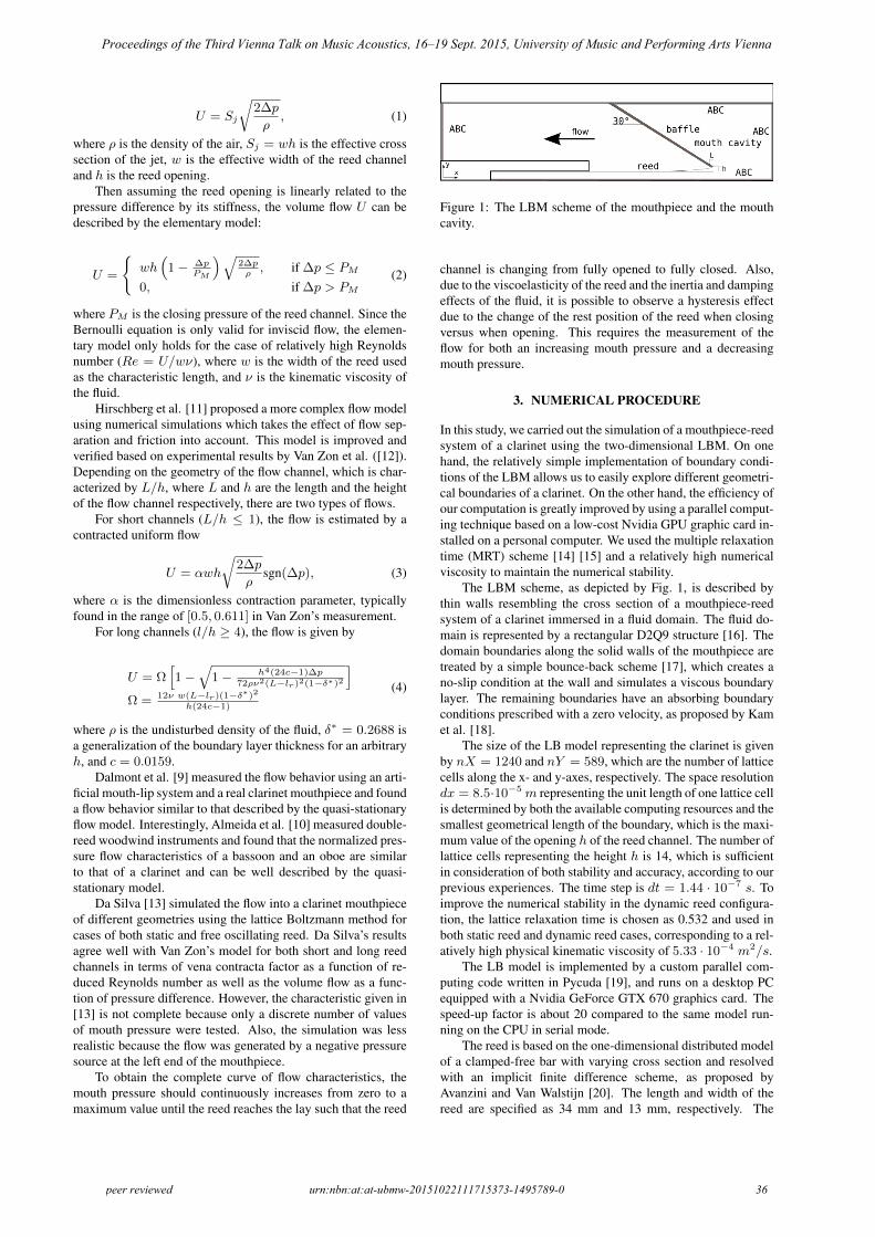
Figure 1: The LBM scheme of the mouthpiece and the mouthcavity.
channel is changing from fully opened to fully closed. Also,due to the viscoelasticity of the reed and the inertia and dampingeffects of the fluid, it is possible to observe a hysteresis effectdue to the change of the rest position of the reed when closingversus when opening. This requires the measurement of theflow for both an increasing mouth pressure and a decreasingmouth pressure.
3. NUMERICAL PROCEDURE
In this study, we carried out the simulation of a mouthpiece-reedsystem of a clarinet using the two-dimensional LBM. On onehand, the relatively simple implementation of boundary condi-tions of the LBM allows us to easily explore different geometri-cal boundaries of a clarinet. On the other hand, the efficiency ofour computation is greatly improved by using a parallel comput-ing technique based on a low-cost Nvidia GPU graphic card in-stalled on a personal computer. We used the multiple relaxationtime (MRT) scheme [14] [15] and a relatively high numericalviscosity to maintain the numerical stability.
The LBM scheme, as depicted by Fig. 1, is described bythin walls resembling the cross section of a mouthpiece-reedsystem of a clarinet immersed in a fluid domain. The fluid do-main is represented by a rectangular D2Q9 structure [16]. Thedomain boundaries along the solid walls of the mouthpiece aretreated by a simple bounce-back scheme [17], which creates ano-slip condition at the wall and simulates a viscous boundarylayer. The remaining boundaries have an absorbing boundaryconditions prescribed with a zero velocity, as proposed by Kamet al. [18].
The size of the LB model representing the clarinet is givenby nX = 1240 and nY = 589, which are the number of latticecells along the x- and y-axes, respectively. The space resolutiondx = 8.5·10−5 m representing the unit length of one lattice cellis determined by both the available computing resources and thesmallest geometrical length of the boundary, which is the maxi-mum value of the opening h of the reed channel. The number oflattice cells representing the height h is 14, which is sufficientin consideration of both stability and accuracy, according to ourprevious experiences. The time step is dt = 1.44 · 10−7 s. Toimprove the numerical stability in the dynamic reed configura-tion, the lattice relaxation time is chosen as 0.532 and used inboth static reed and dynamic reed cases, corresponding to a rel-atively high physical kinematic viscosity of 5.33 · 10−4 m2/s.
The LB model is implemented by a custom parallel com-puting code written in Pycuda [19], and runs on a desktop PCequipped with a Nvidia GeForce GTX 670 graphics card. Thespeed-up factor is about 20 compared to the same model run-ning on the CPU in serial mode.
The reed is based on the one-dimensional distributed modelof a clamped-free bar with varying cross section and resolvedwith an implicit finite difference scheme, as proposed byAvanzini and Van Walstijn [20]. The length and width of thereed are specified as 34 mm and 13 mm, respectively. The
Proceedings of the Third Vienna Talk on Music Acoustics, 16–19 Sept. 2015, University of Music and Performing Arts Vienna
peer reviewed urn:nbn:at:at-ubmw-20151022111715373-1495789-0 36
equilibrium tip opening is 1.2 mm. The external force com-ponent applied on the reed’s surface is calculated from the pres-sure field around the reed in each iteration, where the torsionaland longitudinal modes are neglected. The interaction betweenthe reed and the mouthpiece lay is considered to be inelastic, asdiscussed and justified in [20].
The problem of a moving curved boundary associated withthe moving reed is solved by using an extrapolation scheme pro-posed by Guo et al [21]. This technique represents the no-slipcondition and the transfer of momentum from the reed to theflow with an accuracy of second order. The displacement andthe velocity of the reed is updated by the reed model based onthe aerodynamic force upon the reed’s surface in each iteration,and the curved boundary is updated accordingly.
To eliminate the acoustic oscillation of the reed caused bythe acoustic coupling of the chamber in the mouthpiece, an ab-sorbing boundary scheme prescribed with a zero velocity, asproposed by Kam et al. [18], is placed along the cross-sectionat the left open end.
The source flow in the mouth is implemented using a vari-ation of the absorbing boundary scheme, where the pressureof a non-zero target flow is prescribed with a customized pro-file. The pressure in the mouth cavity (pm) and in the mouth-piece chamber (pa), as well as the volume flow in the mouth-piece chamber (U ) are measured, averaged and saved duringthe simulation. The pressure difference dp is calculated asdp = pm − pa. A typical duration of such a simulation isabout 68 ms, or 500,000 iterations.
Two geometries of reed channel have been used in the sim-ulation, namely the short channel (L/h=1) and the long channel(L/h=4), as depicted in Fig. 2.
(a) (b)
Figure 2: Two geometries of the reed channels: (a) short chan-nel (L/h=1), (b) long channel (L/h=4).
Also, we conducted the simulation for both a static reed(stationary simulation) and a moving reed (dynamic simula-tion), respectively. There are two main differences between thepresent study and the previous work [13]. For the case of astatic reed, the complete characteristic is measured continuallyfor both increasing mouth pressure and decreasing mouth pres-sure. For the case of a moving reed, the disturbance of acousticoscillations is minimized by using two approaches. One ap-proach is to use a relatively slow change rate of the mouth pres-sure. Another approach is to use a higher fluid damping coef-ficient in Avanzini and Van Walstijn’s reed model, keeping keymechanical parameters such as Young’s modulus of elasticityand visco-elastic constant unchanged such that the mechanicalcharacteristic of the reed is not affected.
4. RESULTS
4.1. Static Reed
The results of the stationary simulations for the cases of shortchannel and long channel (depicted in Fig. 2) are shown in Figs.3 and 4, respectively.
Figures 3(a) and 4(a) depict the time history of the tar-get pressure pmt prescribed on the absorbing boundary in themouth cavity, the measured mouth pressure pm, the averagepressure in the mouthpiece chamber pa and the pressure dif-ference across the reed channel dp = pm − pa. In a typicalsimulation, the target pressure pmt increases linearly from zeroto the highest value 9.5 kPa in a duration of about 28.87 ms(200,000 iterations, marked as Stage I) and holds for about 7.22ms (50,000 iterations), then decreases linearly to zero in the du-ration of about 28.87 ms (marked as Stage II), and holds therefor about 7.22 ms until the simulation is finished. The mouthpressure follows the pattern of pmt though at a reduced level.Since the reed is fixed, the reed channel is fully open during thecourse of the simulation and the mouth pressure never reachesthe prescribed pressure due to the non-zero flow passing throughthe mouthpiece.
The measured flow U is compared to the Bernoulli flow Uband the theoretical flow Uz calculated from Van Zon’s modelfor both short channel and long channel, as shown in Fig. 3(b)and 4(b), respectively. Since the opening and the width of thereed is fixed, the Bernoulli flow is only related to the measuredpressure difference dp. Figures 3(c) and 4(c) represent the sameflow data as a function of pressure difference, where U(1) andUz(1) are the flows associated with Stage I, and U(2), Uz(2)are the flows associated with Stage II. The contraction parame-ter of Van Zon’s model for short channel is 0.7. In general, themeasured flow is lower than the Bernoulli flow due to the flowseparation occurring at the entrance of the reed channel. Forthe short channel, the measured flow is in good agreement withVan Zon’s model for most of the duration. However, for the longchannel, the measured flow is significantly lower than the the-oretical flow, which is only a little bit lower than the Bernoulliflow.
The phenomena of flow contraction, caused by the bound-ary layer effects on the walls of the lay and the reed and the flowseparation at the entrance, can be quantitatively described by thevena contracta factors vcf = U/Ub, as depicted in Figs. 3(d)and 4(d), where vcf(1) is associated to Stage I and vcf(2) isassociated to Stage II. The vena contracta factors of Van Zon’smodel, noted as vcfz(1) and vcfz(2), corresponding to Stage Iand Stage II respectively, are depicted in parallel.
In the case of the short channel, the measured vcf is in goodagreement with theoretical vcfz for most of the duration. Inthe case of the long channel, the measured vcf is significantlylower than the theoretical vcfz . Also, the vcf corresponding tothe long channel is lower than that of the short channel, whichmight be explained by the relatively higher damping in the longchannel that is caused by friction from the flow and the walls.
A slight hysteresis effect can be observed in the region oflow pressure difference for both geometries, i.e., dp < 0.5 forshort channel and dp < 1 for long channel. Since the reedis fixed, the hysteresis phenomena cannot be caused by the vis-coelasticity of the reed, rather, it is more likely due to the inertiaof the air flow. We notice the variation of vcf is very small inabout 80% of the duration of the simulation for both geome-tries, which suggests that a constant vcf used in the quasi-staticmodel is a reasonable approximation for the case of a fixed reed.
4.2. Dynamic Reed
Throughout the dynamic simulations, the reed is moving as thepressure difference across the reed changes. The results corre-sponding to the short channel and the long channel are depictedin Figs. 5 and 6, respectively.
Figures 5(a) and 6(a) depict the time history of the tar-
Proceedings of the Third Vienna Talk on Music Acoustics, 16–19 Sept. 2015, University of Music and Performing Arts Vienna
peer reviewed urn:nbn:at:at-ubmw-20151022111715373-1495789-0 37

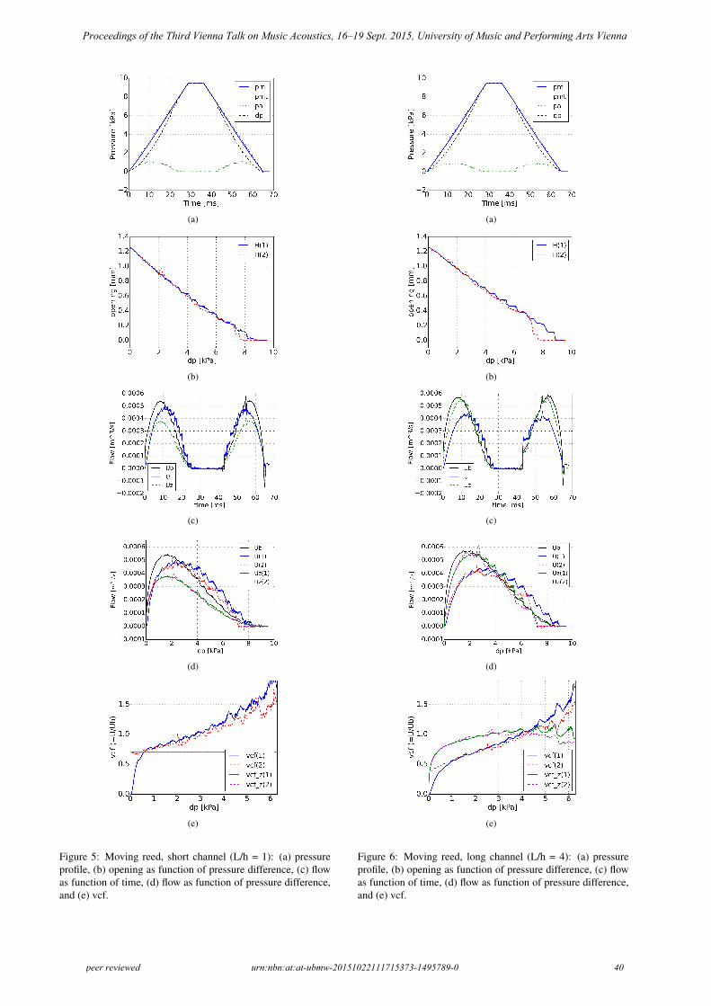
get pressure pmt prescribed on the absorbing boundary in themouth cavity, the measured mouth pressure pm, the averagepressure in the mouthpiece chamber pa and the pressure differ-ence across the reed channel dp = pm−pa. The target pressureis prescribed in the same way as in the simulations of the fixedreed, i.e., pmt increases linearly from zero to the highest valueof 9.5 kPa, holds, and then decreases linearly and holds at zerountil the simulation is finished.
Before the reed closes in Stage I, the mouth pressure in-crease along with pmt, though at a reduced level. The pres-sure in the mouthpiece pa increases and reaches a peak valuein about 9 (short channel) to 12 ms (long channel), then de-creases because the amount of flow entering into the mouthpiecechamber is reduced due to a smaller opening of the reed chan-nel. When the reed is completely closed at the closing pressure,which is about 8783 Pa for the short channel and 8939 Pa for thelong channel, there is almost no flow entering into the mouth-piece chamber, and pa drops to zero. In Stage II, pa starts toincrease when the decreasing mouth pressure is lower than theclosing threshold. The threshold of the closing pressure in StageII is lower than that in Stage I. This phenomenon is explainedby the bifurcation delay, which is discussed in [22].
Figures 5(b) and 6(b) depict the reed channel opening as afunction of dp for the case of short channel and long channel,respectively. For the most part, the opening is almost linearlyrelated to dp. A hysteresis effect is found in the region of dpthat is higher than about 7 kPa. There is a sudden drop and in-crease of opening when the mouth pressure reaches the closingpressure in Stage I and Stage II, respectively.
Figures 5(c) and 6(c) depict the Bernoulli flowUb, the mea-sured flow U and the theoretical flow Uz calculated from VanZon’s model as a function of time. Figures 5(c) and 6(c) rep-resent the same flow data as a function of pressure difference,where U(1), Uz(1) and U(2), Uz(2) are the flow associatedwith Stage I and Stage II, respectively. The contraction param-eter of Van Zon’s model for short channel is 0.7.
The measured flow in the case of the moving reed showssome differences to the quasi-stationary model. The measuredflow shows hysteresis for cases of both short channel and longchannel. The quasi-stationary model, on the other hand, onlyshows hysteresis for the long channel because the displacementof reed is taken into account. For the short channel, the mea-sured flow U is higher than the Bernoulli flow Ub and theoret-ical flow Uz of the quasi-stationary model in the region wheredp is more than about 3 kPa. Similarly, for the long channel, Uis higher than Ub and Uz in the region where dp is more thanabout 4 kPa. It can also be observed in Figures 5(e) and 6(e)that the vena contracta factor shows a value larger than unity inthe region of higher dp. This phenomenon might be explainedby the discussion in [9], where the quasi-stationary models as-sumes the reed channel with a fixed separation point and a uni-form height, which is questionable in the case of a more realisticclarinet mouthpiece. The discrepancies might also be related tothe flows of low Reynolds number that cannot be described bythe Bernoulli’s equation. The measured vcf associated with theregion of dp > 6.5 kPa is questionable and is discarded dueto the dramatical change of both U and Ub, as depicted in theregion around about 43 ms in Figures 5(c) and 6(c).
5. DISCUSSIONS AND CONCLUSIONS
The staircase-like ripples found in the measured flow and open-ing for the cases of moving reed (Figs. 5 and 6) might be stud-ied from two aspects. The first influence comes from the me-chanical oscillation of the reed initiated by the relatively quick
changing rate of the mouth pressure, especially in the decreas-ing stage of the pm curve. A slower changing rate can reducethe likelihood of acoustic oscillations at the cost of a prolongedsimulation time. The measurements times reported in [9] arebetween 50 to 100 seconds, but this time scale is not practicalin the current model even using parallel GPU computation. An-other factor is related to the low spatial resolution. When thereed channel is nearly closed, the cells can be very few and in-sufficient to represent the flow crossing the reed channel andthe boundary layer effect. This problem cannot be immediatelysolved by simply using an extremely large lattice because ofthe limited computation and memory resources allowed by theGPU device. An adaptive grid refinement technique [23] mightbe helpful but is not implemented in the current model yet. Nev-ertheless, a low-discretized lattice can still capture reasonablewell global parameters such as the averaged volume flow.
Due to the relatively higher numerical viscosity, theReynolds number in the numerical simulation is lower thanthe realistic one. In the situation of static reed, the highestReynolds number is 140, which is much lower than the realisticReynolds number 4762 (assuming the same volume velocity).Consequently, the measured flow is not exactly the same as theBernoulli flow and the quasi-stationary model, which is basedon the assumption of inviscid flow. A low numerical viscosity isnot practical for the dynamic reed case because, apart from theissue of numerical stability, there is the difficulty of eliminatingthe noise caused by acoustic oscillations when the viscosity isvery low. Nevertheless, useful results can still be obtained fromthe current model.
As already noted in Fig. 4(b), the predicted volume flowrate deviates largely from Van Zon’s model for the long channelcase. We attempted to investigate this discrepancy by estimat-ing the boundary layer thickness from the spatial distributionand evolution of the jet. Figures 7(a) and 8(a) visualize the ve-locity field (u =
√u2x + u2
y) for the cases of static short andlong reed channels respectively, from which we can observe thatthe flow is passing through the reed channel and is dissipated inthe mouthpiece chamber. Figures 7(b) and 8(b) depict the ve-locity profile of the jet passing through the short and long reedchannel, respectively. In the short channel, a flow separationcan be observed at the entrance and the total critical thicknessof the boundary layers on both top and bottom walls is about 7cells, corresponding to an averaged dimensionless thickness of0.2333 for one wall, which is slightly lower than the thicknessof 0.2688 used in Van Zon’s model. For the case of long chan-nel, a reattachment of the flow occurs after a distance on theorder of the reed channel height, and a Poiseuille flow is devel-oped after a transition zone. The averaged dimensionless thick-ness of the boundary layer is about 0.3 (9 cells in total). Thelower volume flow for the long channel case might be causedby the boundary layer thickness which is slightly higher thanthat used in Van Zon’s model, But it could also be influenced bythe flow pattern characterized by a low Reynolds number, be-cause the boundary layer thickness estimated from the velocityprofile is not very accurate due to the low-discretization. In adynamic situation, though, the flow profile would certainly notmatch Van Zon’s assumption. The flow detachments at the reedtip can be better observed in Fig. 7(c) and 8(c), where the veloc-ity profiles in the neighboring area of reed tip are depicted in alarger scale. The magnitude of the counter-flow at the reed wallis much lower than that of the maximum flow velocity but stillcan be observed.
The current LBM scheme is limited by its 2D nature, whichis not fully capable of representing the 3D behavior of the realflow. Further, the flow measured from the mouthpiece-reed sys-
Proceedings of the Third Vienna Talk on Music Acoustics, 16–19 Sept. 2015, University of Music and Performing Arts Vienna
peer reviewed urn:nbn:at:at-ubmw-20151022111715373-1495789-0 38

tem with a fully coupled acoustic resonator will be more realis-tic. This will be investigated in our next research project.
AcknowledgmentsThe authors wish to acknowledge funding from the Fondsquebecois de la recherche sur la nature et les technologies(FQRNT), the Natural Sciences and Engineering ResearchCouncil of Canada (NSERC), and the Centre for Interdisci-plinary Research in Music Media and Technology.
(a)
(b)
(c)
(d)
Figure 3: Static reed, short channel (L/h = 1): (a) pressure pro-file, (b) flow as function of time, (c) flow as function of pressuredifference, and (d) vcf as function of pressure difference.
(a)
(b)
(c)
(d)
Figure 4: Static reed, long channel (L/h = 4): (a) pressure pro-file, (b) flow as function of time, (c) flow as function of pressuredifference, and (d) vcf as function of pressure difference.
Proceedings of the Third Vienna Talk on Music Acoustics, 16–19 Sept. 2015, University of Music and Performing Arts Vienna
peer reviewed urn:nbn:at:at-ubmw-20151022111715373-1495789-0 39
(a)
(b)
(c)
(d)
(e)
Figure 5: Moving reed, short channel (L/h = 1): (a) pressureprofile, (b) opening as function of pressure difference, (c) flowas function of time, (d) flow as function of pressure difference,and (e) vcf.
(a)
(b)
(c)
(d)
(e)
Figure 6: Moving reed, long channel (L/h = 4): (a) pressureprofile, (b) opening as function of pressure difference, (c) flowas function of time, (d) flow as function of pressure difference,and (e) vcf.
Proceedings of the Third Vienna Talk on Music Acoustics, 16–19 Sept. 2015, University of Music and Performing Arts Vienna
peer reviewed urn:nbn:at:at-ubmw-20151022111715373-1495789-0 40

(a)
(b)
(c)
Figure 7: Velocity field, static short reed channel: (a) absolutevelocity, (b) velocity profile of the jet passing through the reedchannel, (c) velocity profile depicted in a larger scale.
(a)
(b)
(c)
Figure 8: Velocity field, static long reed channel: (a) absolutevelocity, (b) velocity profile of the jet passing through the reedchannel, (c) velocity profile depicted in a larger scale.
Proceedings of the Third Vienna Talk on Music Acoustics, 16–19 Sept. 2015, University of Music and Performing Arts Vienna
peer reviewed urn:nbn:at:at-ubmw-20151022111715373-1495789-0 41
6. REFERENCES
[1] John Backus, “Small-vibration theory of the clarinet,” TheJournal of the Acoustical Society of America, vol. 35, no.3, pp. 305–313, 1963.
[2] Theodore A Wilson and Gordon S Beavers, “Operatingmodes of the clarinet,” The Journal of the Acoustical So-ciety of America, vol. 56, no. 2, pp. 653–658, 1974.
[3] Junich Saneyoshi, H Teramura, and S Yoshikawa, “Feed-back oscillations in reed woodwind and brasswind instru-ments,” Acta Acustica united with Acustica, vol. 62, no. 3,pp. 194–210, 1987.
[4] Neville H Fletcher, “Autonomous vibration of simplepressure-controlled valves in gas flows,” The Journalof the Acoustical Society of America, vol. 93, no. 4, pp.2172–2180, 1993.
[5] Jean Kergomard, “Elementary considerations onreed-instrument oscillations,” Courses and lectures-international centre for mechanical sciences, pp. 229–290, 1995.
[6] Jean Kergomard, Sebastien Ollivier, and Joel Gilbert,“Calculation of the spectrum of self-sustained oscillatorsusing a variable truncation method: Application to cylin-drical reed instruments,” Acta Acustica united with Acus-tica, vol. 86, no. 4, pp. 685–703, 2000.
[7] S Ollivier, J-P Dalmont, and J Kergomard, “Idealizedmodels of reed woodwinds. part i: Analogy with thebowed string,” Acta acustica united with acustica, vol.90, no. 6, pp. 1192–1203, 2004.
[8] S Ollivier, Jean Kergomard, and Jean-Pierre Dalmont,“Idealized models of reed woodwinds. part ii: On the sta-bility of,” Acta acustica united with acustica, vol. 91, no.1, pp. 166–179, 2005.
[9] Jean-Pierre Dalmont, Joel Gilbert, and Sebastien Ol-livier, “Nonlinear characteristics of single-reed instru-ments: Quasistatic volume flow and reed opening mea-surements,” The Journal of the Acoustical Society ofAmerica, vol. 114, no. 4, pp. 2253–2262, 2003.
[10] Andre Almeida, Christophe Vergez, and Rene Causse,“Quasistatic nonlinear characteristics of double-reed in-struments,” The Journal of the Acoustical Society of Amer-ica, vol. 121, no. 1, pp. 536–546, 2007.
[11] A. Hirschberg, R. W. A. van de Laar, J. P. Marrou-Mauriere, A. P. J. Wijnands, H. J. Dane, S. G. Kruijswijk,and A. J. M Houtsma, “A quasi-stationary model of airflow in the reed channel of single-reed wind instruments,”Acustica, vol. 70, 1990.
[12] J. Van Zon, A. Hirschberg, J. Gilbert, and A. P. J. Wij-nands, “Flow through the reed channel of a single reedinstrument,” in J. Phys., Paris, Colloq. 54, C2 821824,1990.
[13] A. R. da Silva, Numerical Studies of Aeroacoustic As-pects of Wind Instruments, Ph.D. thesis, McGill Univer-sity, Montreal, Canada, 2008.
[14] Dominique d’Humieres, “Generalized lattice-boltzmannequations,” Rarefied gas dynamics- Theory and simula-tions, pp. 450–458, 1994.
[15] Zhaoli Guo and Chang Shu, Lattice Boltzmann Methodand Its Applications in Engineering, World Scientific Pub-lishing, 2013.
[16] Y.H. Qian, D. d’Humieres, and P. Lallemand, “LatticeBGK models for Navier-Stokes equation,” EurophysicsLetters, vol. 17, no. 6, pp. 479–484, 1992.
[17] S. Succi, The lattice Boltzmann equation for fluid dynam-ics and beyond, Oxford University Press, 2001.
[18] E.W.S. Kam, R.M.C. So, and R.C.K. Leung, “Non-reflecting boundary conditions for one-step LBM sim-ulation of aeroacoustics,” in 27th AIAA AeroacousticsConference, 8-10 May 2006, Cambridge, Massachusetts,2006.
[19] Andreas Klockner, Nicolas Pinto, Yunsup Lee, BryanCatanzaro, Paul Ivanov, Ahmed Fasih, AD Sarma,D Nanongkai, G Pandurangan, P Tetali, et al., “Pycuda:Gpu run-time code generation for high-performance com-puting,” Arxiv preprint arXiv, vol. 911, 2009.
[20] Federico Avanzini and Maarten van Walstijn, “Modellingthe mechanical response of the reed-mouthpiece-lip sys-tem of a clarinet. part i. a one-dimensional distributedmodel,” Acta Acustica united with Acustica, vol. 90, no.3, pp. 537–547, 2004.
[21] Zhaoli Guo, Chuguang Zheng, and Baochang Shi, “Anextrapolation method for boundary conditions in latticeboltzmann method,” Physics of Fluids (1994-present),vol. 14, no. 6, pp. 2007–2010, 2002.
[22] Baptiste Bergeot, Andre Almeida, Bruno Gazengel,Christophe Vergez, and Didier Ferrand, “Response ofan artificially blown clarinet to different blowing pressureprofiles,” The Journal of the Acoustical Society of Amer-ica, vol. 135, no. 1, pp. 479–490, 2014.
[23] M. Rohde, D. Kandhai, J. J. Derksen, and H. E. A. van denAkker, “A generic, mass conservative local grid refine-ment technique for lattice-boltzmann schemes,” Interna-tional Journal for Numerical Methods in Fluids, vol. 51,no. 4, pp. 439–468, 2006.
Proceedings of the Third Vienna Talk on Music Acoustics, 16–19 Sept. 2015, University of Music and Performing Arts Vienna
peer reviewed urn:nbn:at:at-ubmw-20151022111715373-1495789-0 42