procedures manual for stream sediment reconnaissance sampling78).pdf · procedures manual for...
TRANSCRIPT

PROCEDURES MANUAL FOR STREAM SEDIMENT
RECONNAISSANCE SAMPLING
URANIUM RESOURCE EVALUATION PROJECT
May 8,1978
OAK RIDGE GASEOUS DIFFUSION PLAN OAK RIDGE. TENNESSEE
prepared for the U.S. DEPARTMENT OF ENERGY under U.S. GOVERNMENT Contract W-7405eng 26

Reference to a company or product name doer not imply approval or r~ommendation of the product by Union Carbide Corporation or the U. S. Department of Energy to the exclusion of others that may meet specifications.
This report was prepared as an account of work sponsored by an agency of the United State. Government. Neither the United States Government or any agency thereof, nor any of their employees, nor any of their contractors, subcontractors. or their employees, makes any warranty, express or implied, nor assumes any legal liability or responsibility for any third party's use or the results of such use of any information, apparatus, product or process disclosed in this report, nor represents that its use by such third party would not infringe privately owned rights. ,

Grand Junction Office FOR IMMEDIATE RELEASE P.O. Box 2567, Grand Junction, CO 81501 July 5 , 1978
DOE ISSUES PROCEOURES MANUAL FOR GEOCHEMICAL SAMPLING OF URANIUM
The Grand Junction, Colorado, Office, U.S. Department of Energy (DOE), has issued a report en t i t l ed "Procedures Manual for Stream Sediment
-Reconnaissance Sampling," as pa r t of the National Urani um Resource Eva1 uation (NURE).
The report , prepared by the Oak Ridge Gaseous Diffusion Plant (ORGDP), Oak Ridge, Tennessee, presents sampling procedures used in reconnaissance surveys, including s i t e selection c r i t e r i a , sample collection and f i e l d measurement procederec, data recording guidelines, assignment of surface geologic uni t codes, evaluation of contaminants, and guidelines f o r data control .
NURE i s a program of D O E ' S Grand Junction Office t o acquire and compile geologic and ct'ner 7nformation w i t h which to assess the magnitude and d is t r ibu t ion of uracium resources -and to determine areas favorable f o r the'dcciirrenceof urani um i n t h e Unfted States: O R G D P , .operated. f o r D O E ' S Oak Ridge Operations Office by the Nuclear Division of Union CarDi.de Corporation, j s. res ponsi bl-e forcompl e t ing. a .water,:.and s t ream- sediment survey o f the central U.S.
The 56-page report , GJBX-84(78) [ORGDP NO. K/uR-131, dated May 8, 1978, has been placed on open f i l e a t the following locations:
NO. 78-65 News Media Contact: Peter ' ~ y ~ a t t , 3031242-8621, Ex t . 293 To order microfiche: Contact Library, E x t . 278

GRAND JUNCTION. CO: Temniu l library. Grand Junction Oflice. oq lanmn, Of mPrW
ALBUOUEROUE. NM: Gwemrnenf Pubiicsiionn Semion. Zimmaman Lhrary, Univsrery of New Mexico
ANCHORAGE. AX: Diwiuon ol Geological b GooMy$ul Survey%. 3Z3 E. 4th Avenue
ATLANTA. GA: Oepanment of Ensrgy. Suite 428. 1355 Psachlr- S t m
AUSTIN. TX: Bureau 01 Economic Gedogy. Geology Building. Univerriv of Texas
BUITE. MT: Monl- Bureau of M i n a and blw. Montana Cdlege of MinerslSciClce and Technology
CAMBRIDGE. MA: M a r r a s h u r n lnllitvte of Tnhnology, Lindgran Library, 14E.210
CASPER. WY: ~ a t r o n a covnw public tibnry
COLLEGE. AK: DNirion of Geological and Geophypkal Surveys, - COLUMBIA. SC: Wivbbn of Geology. South Camlina State Deuelopmsni Board
CORPUS CHRISTI. TX: Corpus Chrirli State UniuePhy. 63m Ocsan D 6 s
DENVER. CO: Colorado Gedogiul Suivsy. Dspanrnmt of Natural ~ a o u r c a , State Cin:annial ~ldg. . 1313 Sherman st.. ~ m . 715
GOLDEN. CO: U.S. GeoIogica Survay Libraw 1573 Cole Blud.. l W a t Col- fax and Hawhomel
HARTFORD. CN. S r a l ~ Geolwlkt (t Dir. of National R s o u r m Comer. State Onics Building. Rm 561. 155 Capitol Ave.
LARAMIE. WY: Wwming Gaoiogieai Survsy. P.O. Box 3008. Univerriw station
LAWRENCE. KS: Kansr Geological Survey. 1930 Amnue " A . Campus War. i h e univeniw of K ~ S .
LINCOLN. NE: Conrewafie, and Surrey Diuirion. University riNsbrarka
LUBBOCK. TX: Dmumsntr Library. Twar T s h Universiw
MADISON. W1: Geaiwkai b Naur.4 Hblory Survey. University of Wircon- sin-Exmiion. 1815 Univerrm ~ u s n u e
MENLO PARK. CA. U.S. Geolwical Survey. Library. 245 Middlefield Road
NORMAN. OW. Oklahana Geologral Survw, The Uniuemiry 01 Oklahoma. SU Van Y1-t Oval. Rm. 163
OAKLAND. CA: Dewmnmt of Enngy. Libraw. Wells Faigo Bldg.. 1311 Broadway
PHOENIX. AZ: Stat- of Arizona. Depl. of Mineral Resaurcm. M i n e d Bldg., Fai<grounds
PITTSBURGH. PA: Dwanmenl of Energy, Suils Zl. 9 Parkway Cemer. 875 Greontrae Road
P O R U N D . OR: Depa-mf of Geology and Mineral bdunties. 1069 Slaw Oflice Building
RALEIGH. NC: Office of Esnh Resourcm. Dspafl-t of Nalvral and Economic R e ~ l u m m
RENO. NV: Nevada Bureau. of M i n a and G e o ~ a , Mackw School ot Miner. Univsniw of Nsvada
RESTON. VA: US. Geubgical Survey Library. Gfir 6 Exchange Unit. National Cenler
SALT l A K E CITY. UT; Domment% Divisian. Mar+?! Liirary. UnivaSiy of Utah
SALT LAKE cm. ur: U U ~ G ~ U I ~ ~ C ~ I survey. ex slack nawk way
SOCORRO, NM: N a r Mexico Bureau of Mina. Carious Slalbn
SPOKANE. WA: U.S. ~eaiogical surrey ~ibraw. U.S. CDvn HO-. Rm. 578
TUCSON. AZ: Geolagical Survay Branch. Arhons Bursau d Minsr. WS Pan Avenua
WASHINGTON. D.C.: Depamnsnt of Energy. Library. 20 Marrachuram Avenue. NVJ
This repon will be ava i lab le on microfiche from the Grand Junction Office. DOE, for $3.00. Prepaid o r d e r s should be sent to: Bendix Field Engineeiing Corporation, Technical Library, P.O. Box 1569, Grand Junction, Colorado 81501. Checks or money orde;s should be made outto Eendix FieldEngineering Corporation, t h e operating contractor for DOE'S G r a n d
Junction Office.

Date of Issue: May 8, 1978 Report Number: K/UR-13
PROCEDURES MANUAL FOR STREAM SEDIMENT RECONNAISSANCE SAMPLING
Uranium Resource Evaluation Project
Union Carbide Corporation, Nuclear Division Oak Ridge Gaseous Diffusion Plant
Oak Ridge, Tennessee
Prepared for the U. S. Department of Energy Under U. S. Government Contract W-7405 eng 26

John W. Arendt - Project Manager Uranium Resource Evaluation Project Oak Ridge Gaseous Diffusion Plant P. 0. Box P, Mail Stop 246 Oak Ridge, Tennessee 37830
Telephone: (615) 483-8611, Ext . 3-9463
Todd R. Butz - Geology and Geochemistry Steven C. Minkin - Field Geology Operations
Gordon W. Cagle -Analytical Chemistry and Reports
Victor E. Kane - Geostatistics and Data Management Chester E. Nichols - Staff Geologist

5
TABLE OF CONTENTS
INTRODUCTION 7 . . . . . . . . . . . National Uranium Resource Evaluation Project 7 . . . . . . . . . . . . . . . . . Uranium Resource Evaluation Project 8 . . . . . . . . . . . . . . . . . . . . . . . . . Program Concept 8 . . . . . . . . . . . . . . . . . . . . . . Field Geology Program Planning and Organization
9 . . . . . . . . . . . . . . . . . . . . 11 . . . . . . . . . . . . . . . . . . . . . . . . . . Presentp lans 1 4
FIELD OPERATIONS . . . . . . . . . . . . . . . . . . . . Logistics . . . . . . . . . . . . . . . . Public i ty Program . . . . . . . . . . . . . . . . . Gaining Access
Liaison with the URE Project Contract Supervisor S i t e Selection and Sampling Procedures . . . . . .
. . . . . . . . . . . . . . . . Sampling Density . . . . . . . . . . . . . . . . . S i t e Selection . . . . . . . . . . . . . . . . Sample Collection . . . . . . . . . . . . . . . . . Data Recording
Shipping Procedures . . . . . . . . . . . . . . . . . . . . . . . . . . . . . . . . . . . . . Samples
. . . . . . . . . . . . . . . . . . . Field Forms Maps . . . . . . . . . . . . . . . . . . . . . . Receiving Packages from the URE Project Office .
. . . . . . . . . . . . . . . . . . . . . APPENDIX A . SITE SELECTION A-1
. . . . . . . . APPENDIX B . SAMPLE COLLECTION AND FIELD MEEISURWT ~.1 . . . . . . . . . . . . . . . . . . . . . . . . . SamplingRoutine ~ . 3 . . . . . . . . . . . . . . . . . . . . . . Guidelines for Sampling ~ . 3 . . . . . . . . . . . . . . . . . . . . . . . . General Guidelines ~ . 3
SampleCollection . . . . . . . . . . . . . . . . . . . . . . . . ~ . 4 Recommended Field Pack Contents . . . . . . . . . . . . . . . . . ~ . 5 . . . . . . . . . . . . . . . . . . . . . . . . . . . . Field Test B-5
APPENDIX C . DATA RECORDING . . . . . . . . . . . . . . . . . . . . . C-1 The Oak Ridge Geochemical Sampling Form . . . . . . . . . . . . . C-3 . . . . . . . . . . . . . . . . . . . . . . . General Guidelines C-3 . . . . . . . . . . . . . . . . . . . . Card 1. General S i t e Data C-6 . . . . . . . . . . . . . . . . Card 2 . Stream or Lake Sediment .c-1 3 . . . . . . . . . . . . . . . . . . . . . . . . . Card 4. Remarks C-14
. . . . . . . . . . . . . . . . . . . . . . . . . . DigitizerMaps c.15 . . . . . . . . . . . . . . . . . . . . . . . . . . CompositeMaps c.16
APPENDIX D . ASSIGNMENT OF SURFACE GEOLOGIC U N I T CODES . . . . . . . ~ - 1 . . . . . . . . . . . . . . . . . . . . . . . . . . . . . . Furpose D-3 . . . . . . . . . . . . . . . . . . . . . . . . . . . . . Procedure D-3

APPENDIX E. EVALUATION OF CONTAMINATION . . . . . . . . . . . . . . E-1
APPENDIX F. GENERAL GUIDELINES FOR DATA CONTROL . . . . . . . . . . F-1

PROCEDURES MANUAL FOR STFXAM SEDIMENT RECONNAISSANCE SAMPLING
INTRODUCTION
NATIONAL URANIUM RESOURCE EVALUATION PROGRAM
The National Uranium Resource Evaluation (NURE) Program was established in 1973 by the U. S. Atomic Energy Commission (AEC) which later became the U. S. Energy Research and Development Administration (EKDA) and is now funded by the United States Department of Energy (DOE). The prin- cipal objectives of the NURE Program are as follows:
1. To complete a comprehensive assessment of the uranium reserves of the United States as rapidly as possible,
2. To identify areas favorable for uranium resources, and
3. To develop new and improved technologies.
The DOE Grand Junction, Colorado Office (GJO) is responsible for adminis- tering and coordinating efforts to meet these objectives. Input to the NURE Program comes from DOE prime contractors, DOE-sponsored research and development, the uranium industry, U. S. Geological Survey, U. S. Bureau of Mines, and other governmental agencies and independent sources.
The NURE Program consists of five parts:
1. Hydrogeochemical and Stream Sediment Reconnaissance Survey,
2. Aerial Radiometric and Magnetic Survey,
3. Surface Geologic Investigations,
4. Drilling for Geologic Information, and
5. Geophysical Technology Development.
To ensure a standard reporting format, data from all five phases of the NURE Program will be combined within the lo x 2' National Topographic Map Service (NTMS) quadrangle boundaries and will form the basis on which uranium reserve calculations will be made.
In 1975, ERDA assigned the Nuclear Division of Union Carbide Corporation (UCC-ND) , Uranium Resource Evaluation (URE) Project located at the Oak Ridge Gaseous Diffusion Plant (ORGDP), Oak Ridge, Tennessee, the respon- sibility for hydrogeochemical and stream sediment reconnaissance in an area covering the states of Texas, Oklahoma, Kansas, Nebraska, South Dakota, North Dakota, Michigan, Minnesota, Wisconsin, Iowa, Indiana, Illinois, and parts of Missouri, Arkansas, and New Mexico. The objec- tive of this portion of the program is to accomplish a systematic

determination of the distribution of uranium and associated elements in surface and underground waters and in stream sediments. The significance of the distribution of uranium in natural waters and stream sediments will be assessed as an indicator of areas favorable for the identifi- cation of uranium provinces and districts.
Because the UCC-ND URE Project is a portion of the NlTRE Program and is being conducted with public funds, contractors participating in the URE Project have an obligation to hold all information as Business Confi- dentiaZ. All samples, duplicates, data, field form observations, site locations, equipment, and other information obtained during the course of operation under a contract to participate in the UCC-ND URE Project are to be provided only to the UCC-ND URE Project. Nothing is to be retained for private use nor is any information to be communicated to others without prior written consent of the URE Project Manager and DOE. The DOE-GJO will time-release data, and reports on each lo x Z0 quad- rangle simultaneously in a number of predesignated sites across the country as soon as these reports are made available by the URE Project. At that time, any information presented in the report is available for public use.
Landowners, who require that the Project provide results of analyses of samples collected on their property before giving permission to sample, are provided the information after the data have been open filed. The landowners' names and addresses are recorded on the field form at the time the samples are collected and then stored in the URE data base. After the data have been open filed by DOE, a computerized system prints a letter containing the analytical results and an address label for mailing.
URANIUM RESOURCE EVALUATION PROJECT
Program Concept
Geochemical sampling is considered to be a valuable technique by the exploration industry. The program, which is used for the entire area to be surveyed by the UCC-ND URE Project, is based on the concept that geochemical techniques can identify promising uranium-bearing areas at virtually any scale. Concentrations of uranium increase as a mineralized area is approached. Figure 1 shows an increase in the log uranium concentration versus aerial extent. As will be noted, the largest area is background where uranium concentrations are relatively low. The province may be of the order of 260 km2 (100 mi2 ) to 2600 km2 (1000 mi2 ) , and the uranium concentration an order of magnitude greater in the province. Similarly, for a district, the area is 26 km2 (10 mi2) to 260 km2 (100 mi2) with a corresponding increase of uranium content. At the deposit scale, uranium content increases to ore grade. The objective of the URE Project is to define the aerial extent of uranium provinces and districts using geochemical exploration techniques.

t LOG
URANIUN
BACKGROUND
LO6 Km2 - Figure 1
CONCEPT OF GEOCHEMICAL TWESBOLDS

The URE Project of UCC-ND consists of pilot surveys followed by geochemi- cal reconnaissance with samples of stream sediment, stream water, and well water collected, depending on the results of pilot surveys. Samples are analyzed for uranium and other trace elements which more completely describe geochemical patterns. This allows collection of fewer samples than if analyses were for uranium only.
Pilot surveys are intended to provide information on the following:
1. Trace elements indicative of uranium mineralization, 2. Relationship between sample types and relative importance of
each, 3. Range of geochemical concentrations from mineralized to
background areas, 4. Adequacy of laboratory sensitivity, 5. Types of treatments to be given samples, 6. Area to which pilot survey applies, and 7. Adequacy of sample spacing.
In the reconnaissance program, samples are collected from wells at a grid spacing of 5.1 km (3.2 mi) giving an average density of one well per 26 l a2 (10 mi2). Stream sediment or stream water samples are collected from basins that range from 5.2 to 52 km2 with supplemental coverage in areas where basins of the specified size range are not available. The result is an average sampling density for drainage basins of one sample per 26 Ian2 (10 mi2). Samples of well water and those collected from drainage basins provide geochemical data on both surface and subsurface conditions that serve as a basis for defining areas of uranium favorability.
Field Geology Program
The objectives of the field geology program are to:
1. Obtain necessary coverage of a geographic area, 2. Obtain the most representative samples possible, 3. Accurately evaluate and describe the environment from which
the samples were taken, and 4. Complete coverage on schedule.
The sample types collected depend on the results of pilot surveys and may include:
1. Stream water, 2. Stream sediment composite, and 3. Well water.

Stream sediments are collected as composite samples generally parallel to the axis of the stream over a 15- to 50-m interval. The samples are placed in paper envelopes and sent to the URE Project Laboratory for disaggregation, sieving to ~149 p (100 mesh), dissolution, and analysis.
Water samples are collected directly in 250-ml polyethylene bottles with no field treatment. Stream water samples are ~ollected at the point of maximum flow. Groundwater samples are collected from wells at the point nearest the well head. Measurements for water which are routinely made in the field include: temperature, conductivity, pH, dissolved oxygen, and alkalinity. Water samples are shipped to Oak Ridge for filtration and analysis.
Some botanical samples (tree branches) have been collected in pilot surveys to determine their potential usefulness but are not currently being collected in reconnaissance surveying.
Planning and Organization
Detailed project planning is an essential element being employed to carry out an innovative and cost-effective hydrogeochemical and stream sediment survey. The URE Project office is located at ORGDP. The expertise and capabilities of the Y-12 Plant and the Oak Ridge National Laboratory (ORNL) are also available to provide essential services to the project. In addition, the facilities and expertise of the Paducah Gaseous Diffusion Plant (PGDP) are also available for use in the project, if required. Functional support services provided within the Nuclear Division are shown in Figure 2, and URE support organizations in Figure 3.
Many of the time-proven production procedures being used by UCC-ND were directly applicable to the URE Project. An example of this activity is the Y-12 Plant production control system which was used in the design of the URE sample storage and retrieval system. Samples collected during the program are optimally scheduled, controlled, and placed in retrievable storage for additional tests, if required.
Project plans include the maximum use of automated equipment to minimize costs and potential errors. Automated equipment is included in the analytical laboratories and data management activity. Automatic digi- tizers are also used to determine accurate latitudes and longitudes of sample sites on field maps.
Sampling is scheduled on a year-to-year basis and some considerations include: (1) uranium favorability, (2) funds available, (3) coordination with other DOE/- Program activities, and (4) weather. Basin sampling is scheduled during time of low runoff, but not during normal periods of freezing.

QUALITY CONTROL
CONTROLS AND STANDARDS
0 ANALYTICAL MEASUREMENTS
ANALYTICAL SERVICES DATA MANAGEMENT
SAMPLING METHODOLOGY DATA PROCESSING . INSTRUMENTATION AND PROCEDURE
INFORMATION SYSTEM DEVELOPMENT
STATISTICAL SERVICES URE PROJECT
GEOLOGY AND GEOCHEMISTRY . ANALYTICAL CHEMISTRY
0 MANAGEMENT AND PLANNING
ALIMINISTRATIVE SERVICES . LEGAL ASSISTANCE . PUBLIC RELATIONS
Figure 2
FUNCTIONAL REQUIREMENTS OF THE UF&'UUM RFSOURCE EVALUATION PROJECT

QUALITY CONTROL
LABORATORY DlVlSlON TECHNICAL OlVlSlON
OPERATIONS ANALYSIS AN0 PLANNING DEVELOPMENT DIVISION PRODUCT CERTIFICATION DlVlSlON
URE PROJECT OFFICE
COMPUTER SCIENCES DlVlSlON ANALYTICAL CHEMISTRY DlVlSlON ENVIRONMENTAL SCIENCES OlVlSlON
LABORATORY DIVISION ENERGY DIVISION
CHEMICAL TECHNOLOGY DlVlSlON INFORMATION DlVlSlON
DATA HANDLING
URANIUM RESOURCE ETALUATION PROJECT SUPPORT ORGANIZATIONS

Present Plans
The URE Project's area of responsibility is equivalent to approximately 2,600,000 km2 (1,000,000 m i 2 ) and is contained on 154 maps of the lo x 2O national topographic map series. Initial reconnaissance will be conducted only in geologically favorable areas assigned the highest priority by DOE. The remainder of the area will be sampled after completion of the favorable quadrangles. Reports for individual lo x 2O quadrangles will be open filed as soon as possible after sampling, analysis, and data verification have been accomplished.

1 5
FIELD OPERATIONS
LOGISTICS
Publ ic i ty Program
Pamphlets explaining the NURE Program and the responsibi l i ty of the URE Project may be provided t o personnel col lect ing samples for the purpose of increasing public awareness and cooperatjon. A t a contractor ' s request , t he URE Project w i l l provide a short f i lms t r ip t o l o c a l t e l e - vision s ta t ions t o increase public awareness of t he NURE Program.
Gaining Access
Pr ivate Property. Most samples w i l l be collected on pr ivate property. A l l r i g h t s of the property owner should be respected and care must be taken t o avoid any damage. Most landowners w i l l be happy t o cooperate and may volunteer much useful information; however, i f a landowner prohibi ts a sample from being taken or withdraws permission once a sample has been collected, re turn the sample and leave. Do not argue.
Forest Service Lands. Forest Service Lands of the U. S. Department of Agriculture cons t i tu te a s ignif icant land area i n many of the quad- rangles t o be sampled. The NURE Program has been assured of the cooperation of t he Forest Service as long as the a c t i v i t i e s are not detrimental t o the fo re s t environment or resources. The URE Project w i l l attempt t o provide contractors with l i s t s of the appropriate personnel t o contact i n each fo re s t area. In general, each Forest Supervisor should be consulted i n advance of f i e l d operations and must be no t i f ied a t l e a s t a week i n advance of actual sampling. The URE Project should receive a copy of any correspondence between a contractor and Forest Service personnel. The contractor ' s f i e l d supervisor must contact D i s t r i c t Rangers when sampling teams actual ly a r r ive and before sampling is begun.
Commercial exploration on Forest Service land requires t he issuance of a mineral exploration permit. The Forest Service has agreed t o waive t h i s requirement for the NLTRE Program, so care should be taken t o respect Forest Service requests.
Indian Reservations, Parks, Wildlife Refuges, e tc . The contractor 's f i e l d supervisor should arrange contact with the loca l agent, t r i b a l representative, ranger, warden, or other o f f i c i a l i n charge several weeks p r io r t o anticipated sampling. In general, good public re la t ions w i l l gain access. The URE Project should receive a copy of any corre- spondence between the contractor and agencies or individuals contacted.

Military Bases. Government of each military base is left to the discre- tion of the Base Commander and access to any installation is dependent on permission given only by the Base Commander. The contractor's field supervisor must attempt to contact this individual well in advance of any planned sampling on the base. Problems in gaining access should be reported to the URE Project. The URE Project should receive copies of any correspondence between the contractor and the Base Comander or a designated representative.
Liaison with the LJRE Project Contract Supervisor
The contractor's field supervisor will contact the URE Project's contract supervisor at least weekly by telephone. A motel address and telephone number where this supervisor can be contacted at URE Project initiative during any 24-hr period will be provided. The supervisor will also provide monthly progress reports due on the last week of each month on lo x 2O quadrangle maps showing the areas sampled and the total number of samples collected.
The contractor's field supervisor is expected to be abreast of team activities at all times. Under normal circumstances, the URE Project will communicate with field teams only through the contractor's field supervisor.
Routine maintenance of equipment is the responsibility of the contractor's field supervisor. The URE Project will perfom major repairs or replace- ment of equipment, but the turnaround time may be several weeks. The contractor's field supervisor should try to detect failing instruments and anticipate needed repairs. It is suggested that a daily log of instrument calibrations be kept to aid in identifying failing equipment.
The contractor's field supervisor should also anticipate the need for resupply far enough in advance to allow time for shipping. The URF Project will process requests for supplies made through the URE Project's contract supervisor once per week and turnaround time on such request can be expected to be at least two weeks.
SITE SELECTION AND SAMPLING PROCEDURES
Sampling Density
Pilot surveys have indicated the average sampling density necessary to define most geologic features. The sampling density to be used in each lo x 2' quadrangle has been specified in the contract. It is the responsibility of the contractor to identify sites to maintain the specified density. When it is apparent that sites are not available to be sampled at the specified density, it is the responsibility of the contractor to inform the URE Project contract supervisor of the situation.
Site Selection
The procedure suggested for site selection is given in Appendix A.

Sample Collection
Detailed instructions for sample collection are given i n Appendix B.
Data Recording
Detailed instructions f o r completing the Oak Ridge Geochemical Sampling Form and entering s i t e s on d i g i t i z e r maps are given i n Appendix C.
SHIPPING PROCEDURES
Samples
Mail a l l samples within a week of collection, preferably on Friday or Saturday. Pr ior t o mailing, check the t o t a l number of samples versus t h e t o t a l number of f i e l d forms completed, and make sure t h a t a l l sample l abe l s a r e legible . Assemble a packing box tha t has been provided and tape securely. Samples should be packed snugly so t h a t they cannot move around i n the box. It may require using newspapers as a packing material t o make sure t h a t the f i t i s snug. Sediment samples should be dry enough so t h a t they do not cause the box t o become wet during shipping. When samples are placed i n boxes, they must be kept i n sequence within t h e boxes shipped. I f several bags of sediment were collected a t a s i t e , they should be taped together so they are not separated i n t he box. Attach one of the address labels provided t o the inside f lap of t h e box. Place another on the outside and also indicate the Oak Ridge address as t he return address. The labe ls for the sample boxes are provided, and an example is shown below.
Union Carbide Corporation Nuclear Division Attent ion: Mr. L . E. White P . 0. Box Y Building 9720-6, M . S . 002 Oak Ridge, Tennessee 37830
On the outside of t he box, record the sample number range included i n t h e box. Two bags of the sane sample number should not be s p l i t between two boxes. Also, on the outside of the box, write the map code of the lo x 2' quadrangle from which the samples have been collected (See Figure 5 for map codes); and indicate which box of how many are shipped on t h a t day (example: box 1 of 4, box 2 of 4, box 3 of 4, box 4 of 4 ) . A t t he post o f f ice , insure the box of samples for a minimum amount and mail P a r c e l P o s t R e g u b . Indicate a t the post o f f ice t ha t the contents a r e geologic samples.

The contractor's field supervisor shall inform the URE Project's field supervisor at the end of each month how many samples have been mailed during that month.
Field Forms
Mail the corresponding Oak Ridge Geochemical Sampling Forms to the URE Project office on the same day the samples are shipped. Field forms are to be placed in an envelope and the seams of the envelope are to be sealed with masking tape. The field forms are to be mailed C e r t i f i e d MaiZ, No Return Rece ip t Requested. The label for the field form enve- lopes is shown below. Note that this address is not the same as that to which samples are shipped.
J. W. Arendt Union Carbide Corporation Nuclear Division P. 0. Box P, Mail Stop 246 Oak Ridge, TN 37830
Maps that are to be digitized ( d i g i t i z e r maps), with sample locations identified and numbered, are to be mailed to the URE Project office no more than two weeks after sampling has been completed for the area covered by that map. These maps shall remain unfolded and rolled in protective nap tubes. Map tubes are to be mailed to the same address as field forms. The address is given below.
J. W. Arendt Union Carbide Corporation Nuclear Division P. 0. Box P, Mail Stop 246 Oak Ridge, TN 37830

The contractor ' s f i e l d supervisor i s responsible for reporting t o t he URE Project ' s contract supervisor a t the end of each month the number of maps sent t o Oak Ridge t o be digi t ized. It i s important t o note t h a t many sample locations are present on an individual base map; and without t he sample information from a base map, the actual sample and f i e l d form data are worthless.
Receiving Packages from the URE Project Office
Packages w i l l be sent t o t he f i e l d addressed t o the contractor 's f i e l d supervisor, i n care of e i t he r t he contractor ' s off ice or General Delivery a t a par t icu la r post o f f ice . The post o f f ice w i l l usually hold t h i s type of package for t en days. If it i s not possible t o pick up the package, c a l l t he post o f f ice t o have the package held for a longer period or t o have it forwarded.
When a package from the URE Project i s received, t h i s information should be reported t o t he URE Project ' s contract supervisor.

APPrnIX A
SITE SELECTION

APPENDIX A
SITE SELECTION
The site selection procedure described herein was developed for areas which are being sampled at an average density qf one site per 10 m i 2 with basins averaging between 2 and 20 m i 2 in area. The spacing to be used in a particular area is specified in the contract for individual quadrangles. This procedure should be used to serve as a guideline to ensure a degree of uniformity in site selection. It should be kept in mind that when selecting alternate sites, the primary objective is to obtain coverage that is uniform, complete, and representative of surface geology.
Sites to be sampled by contractors will be marked on maps supplied by the LIRE Project with site numbers and sampling phase (either 2 or G ) preassigned. These maps will normally be black-and-white, electrostatic copies of USGS topographic maps, either of 1:24,000 scale ( 7 112' series) or 1:62,500 scale (15' series). Where topographic map coverage is not available, sites to be sampled will be indicated on either county maps or aerial photographs. All sites indicated on the maps supplied by the URE Project that sample basins of 2 and 20 m i 2 in area will be designated as Phase 2 sampling sites. Those basins falling outside that range will be indicated as Phase G (See Appendix C, Card I, Genera2 Site Data, Block 31).
When planning basins to be sampled by contractors, consideration has been given to accessibility of sampling sites, as well as evidence of contamination indicated on the base maps. Based on previous experience, it is assumed that circumstances exist that will prevent collection of some samples from predesignated sites. Examples of these circumstances include: refusal of landowners to grant permission, difficult terrain preventing access, or extensive contamination which invalidates the quality of the sample from that site. When valid reasons exist for not collecting a sample at the predesignated site, an alternate site will be chosen by the contractor according to the following guidelines:
1. Alternate sites must sample basins that represent the same geologic formation or formations as the original designated site.
2. Alternate sites must be selected either above the junction of drainage or sufficiently below junctions to allow mixing of the ream water and stream sediments from tributaries so the composite
sample represents all of the upstream basin area.
3. Alternate sites must be located on the upstream side of roads, bridges, or man-induced contamination.
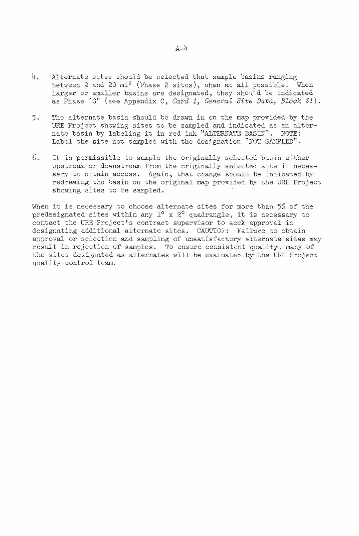
Alternate s i t e s should be selected tha t sample basins ranging between 2 and 20 mi2 (Phase 2 s i t e s ) , when a t a l l possible. When la rger or smaller basins are designated, they should be indicated a s Phase "G" (see Appendix C , Card 1, General Site Data, Block 3 1 ) .
The a l te rna te basin should be drawn i n on the map provided by the LIRE Project showing s i t e s t o be sampled and indicated as an a l t e r - nate basin by labeling it i n red ink "AL!l%XNATE BASIN". NOTE: Label t he s i t e not sampled with the designation "NOT SWLFD".
It i s permissible t o sample the or iginal ly selected basin e i t he r upstream or downstream from t h e or iginal ly selected s i t e i f neces- sary t o obtain access. Again, t h a t change should be indicated by redrawing the basin on the or ig ina l map provided by the LIRE Project showing s i t e s t o be sampled.
When it i s necessary t o choose a l te rna te s i t e s f o r more than 5% of the predesignated s i t e s within any lo x 2' quadrangle, it i s necessary t o contact t he URE Project ' s contract supervisor t o seek approval i n designating addit ional a l te rna te s i t e s . CAUTION: Failure t o obtain approval o r selection and sampling of unsatisfactory a l te rna te s i t e s may r e s u l t i n re ject ion of samples. To snsure consistent qua l i ty , many of t he s i t e s designated as a l te rna tes w i l l be evaluated by the URF Project qua l i ty control team.

APPENDIX B
SAMPLE COLLECTION AND FIELD MEASUFZN3NT

SAMPLE COLLECTION AND FIELD MEASURFMENT
SAMPLING ROUTINE
Drive t o t he location marked on the m a p showing s i t e s t o be sampled, and ver i fy t h a t you are a t t ha t location.
Secure permission t o sample (it may be necessary t o conduct t h i s s t ep p r io r t o arr iving a t the s i t e ) .
Observe the area of t he proposed sample s i t e by walking upstream i n t h e basin looking for sources of contamination. Check t o see whether t he stream i s i n flood stage. Samples should not be col lected during periods of flood conditions.
After walking upstream a t l e a s t 100 m , se lect a representative sampling in te rva l f ree from sources of contamination.
Examine the sediment careful ly t o determine the composition of the material t o be collected.
Collect a composite sediment sample.
Label t he sample bag(s) and a f i e l d form using the s t i ck on sample labe ls .
Complete t he f i e l d form according t o the guidelines i n Appendix C.
Enter t he sample location and sample numbers on the d i g i t i z e r map.
10. Review both the f i e l d form and map data for accuracy.
GUIDELINES FOR SAMPLING
General Guideline
1. Sampling the preselected s i t e s i s important. Do your utmost t o gain access and obtain permission.
2. Attempt t o determine whether there i s contamination present i n the basin above the sampling s i t e by walking a t l e a s t 100 m upstream from the access point (see Appendix C , Evaluation of contamination).
3. Walk back downstream select ing the sampling in te rva l so tha t it is upstream from vis ib le sigrls of contamination, such as t r a sh i n the stream, culver ts , or slumping bank material around newly constructed bridges.

4. If you are sampling a basin that is a tributary to a major stream, make sure that the sediment sampling interval is not in flood plain alluvium. If necessary, move the sampling interval further upstream to avoid the flood plains sediments.
5. The sampling interval should be selected either above the junction of drainage or sufficiently below junctions to allow the mixing of stream water and sediments from the tributaries so that the sample represents all of the upstream basin area.
Sample Collection
After walking upstream 100 m, select a sampling inteval at least 25 m upstream from any manmade contamination. Make every effort within reason to obtain a good sediment sample that is typical of the active stream sediment in the stream bed.
Clean the sediment scoop in the active stream sediment that will be sampled.
Collect sediment samples from the active portion of the stream. Bear in mind that the stream sediment is the sampling target, not dirt from nearby banks. Sample only the active portion of the stream.
To take the necessary composite sample, collect at least six scoops of sediment material taken 2 to 3 m apart over a 15- to 20-m interval. A very heterogeneous sediment will necessitate collection of up to 15 scoops of material over a 50-m interval.
Remove windblown debris and organic material from the sediment surface at the site of each scoop. Dig down 1 t o 2 in. with the scoop and if heavy minerals are present, include them in the com- posite.
Collect enough material to make up approximately 25 g of clay to silt-sized sediment. If the sediment grade is coarse, it may be necessary to take several s q l e s bags full. When clay or silt material is collected, only one bag is required. The objective is to have at least 25 g of -100 mesh sediment after sieving. If there is any doubt about the composition of the sediment, examine it with a hand lenseto determine the composition.
Fill the sediment b3g(s) two-thirds full. Overfilling will often cause the bag to break and broken bags will constitute a legitimate basis for rejecting samples.

Drain any water from the sample bag. Do not touch the sample or t h e inside of t he bag with bare hands i n order t o minimize chances of contamination.
Fold the top of t he bag over as indicated on the pat tern imprinted on the bag and sea l t ha t end of the bag with a t l e a s t three turns of vinyl tape.
After the composite sediment sample bas been collected and the bag(s) are sealed, a t tach a sample labe l t o the bag ( s ) and the f i e l d form tha t i s t o be f i l l e d out. The sample numbers should be iden t ica l for a l l bags of sediment taken from an individual s i t e and the same as tha t attached t o the f i e l d form.
I f more than one bag of sediment i s collected a t a s i t e , the number of bags having the same sample number must be indicated on each bag by writing the number of bags i n marking pen just below the base of t he sample labe l . If three bags were collected, for example, each would have a "3" entered below the sample label . After labeling, numbering, and sealing, a l l bags should be taped i n a bundle so they do not become separated during packing and shipping. Be carefu l not t o tape over t he sample labels . The vinyl tape used t o s ea l the sediment bags should be used t o tape the bundle together.
Recommended Field-Pack Contents
1. Sediment scoop, 2. Five sample bags (contained i n a p l a s t i c bag t o prevent contam-
inat ion) , 3. One inch wide vinyl tape, 4. Notebook with f i e l d forms, sample labe ls , geologic map, and
geologic u n i t code l i s t , and 5. Tiio thermometers.
If it i s necessary t o hike t o a location which i s out of sight of t he sample vehicle, carry a map for navigational purposes. Remember t o keep the pack well-supplied, because a t r i p back t o the sampling vehicle wastes valuable time.
FIELD TEST
Measure t he a i r temperature a t t he time of sample collection by hanging a mercury thermometer i n a shady area adjacent t o the sampling s i t e . Let t he thermometer s tab l ize for several minutes before reading t o the nearest t en th of the degree. Make sure tha t no gaps are present i n the mercury column tha t w i l l cause f a l s e readings.

APPENDIX C
DATA RECORDING

APPENDIX C
DATA RECORDING
THE OAK RIDGE GEOCHE%fICAL SAMPLING FORM
All f i e l d data are recorded on the Oak Ridge Geochemical Sampling Form (See Figure 4) which i s a form designed for all sample types collected i n t he URE Project . It i s subaivided in to four keypunch cards which approximate grouping of information. Card 1, Genera2 S i t e Data, iden- t i f i e s data needed f o r all samples. Card 2 i s completed for plant , stream sediment, and general water data. Card 3 i s completed for well water and lake water samples. Card 4, the Remarks Sect ion a t the end of t he f i e l d form, i s reserved for specif ic information otherwise not recorded, such as t he specif ic location of t he sediment composite, unusual contamination, e tc .
General Guidelines
1. Use red ink t o complete the f i e l d form. A fine-point accounting pen i s bes t . Legibi l i ty i s essen t ia l t o accurate data trans- cr ipt ion. To maintain l e g i b i l i t y , upper case, readable block l e t t e r s must be used. No lower case l e t t e r s a r e allowed. When a l l blocks are not f i l l e d , a l l en t r ies must be r igh t jus t i f ied . When choices are t o be indicated, do so by placing an 7, !, X i n t he box t h a t corresponds t o the desired choice.
2. When decimal points are provided i n the boxes, do not enter another decimal point i n a blank box. Where decimal points a r e not f ixed and one i s required, enter a decimal point i n a blank box making sure t h a t t he numbers are r i gh t j u s t i f i ed . Be aware of s ignif icant d ig i t s . A zero t o the l e f t of a decimal point i s not s ignif icant but may be used i f desired. A zero t o t he r igh t of a decimal point i s a s ignif icant d ig i t . Record a zero t o the r i gh t of a decimal point only when the zero is an exact measurement. Never use . O O as an entry. I f a measurement i s lower than .01, then use a . O 1 and explain i n t h e Remarks Sect ion t h a t the number i s l e s s than .01.
3. Use fl for t h e l e t t e r 0 except when writing i n the Remarks Sec t ion (example : P@Q f o r the Quartemaster orm mat ion) .

C-4
OAK RIDGE GEOCHEMICAL S A M P L I N G F O R M
GENERAL SITE DATA Anach Identical Sample Number Here 1
Site Number
Map Code
Sample Type
Sneam Sediment Lake Sediment
Stream Water
Well Water
Spring Water
Lake Watw Boo Water
Plant
Sail (Use Remarks)
1 Replicate Letter I L Z I
Fi;:iieel Slatus Carection Voiding
Can01 Sample Sediment. High U Sediment. LowU Water, High U Water, LowU
Air Temperature l°C1
Surtsce Geolqlis Unit Code
UCN-I3992 11 5.77,
T y p of Vaaetatlm (Within 1 Km Upstream) Conifer Conifer & Deciduous Deciduous Brush Grass MOSS Lichen Other
Density of Vegetat ia (Within 1 Km Upstream1 Barren Sparse Moderate Dense Very Dense
Local Rslief (Within 1 Km Upstream)
12-15ml Gentle 115-6hn) Moderate i 6 0 J M m ) High ( ' 3 0 h i Other
Weather
Calm Lt Wind Windy v. windy Gale
Clear Pt Cldy Owrc r t Rainy Snowy
Classes of Cmtaminants
Nane Mining (Use Remarks) Agriculture Oil Field Industry Sewage Power Plant Urban Other T
Average Swam Velocity hhacl m N = No Visible Movement P = Stagnant P w l
ml Water Width lml
Water Level
Dry Pw ls Law
Daninsnt Bed Material
Boulder C&le Pebble Sand Si l t Clay None [Use Remarks)
Figure 4
Normal High Flood
V V L t PK Pink L Light RD Red M Medium GN Green D Dark BU Blue
CL Clear BN Brwm
WH White GY Gray BK Black
YL Yellow QT Other
Ddor af Sanplad Maferisl None H2S Other
Results Request l u r e Remarks)
PLANT SAMPLE ' 8 1 9 Number of Plants Sampled
INurnber of grabs for moss1
Tmnk Diameter (ml
(1 m a b v e gmund)
(Average of Plants Sampledl
Name of Tree, Deciduous
Alto Verde Locust Ash Maple Beech Mesquite Birch Oak. Other Box Elder Olive Cherry Conanwaod Sycamore Eim Salt Cedar Hackberry Walnut Hickory Willow Huisache Other Live Oak
Nane of Tree. Conifer
Fir Spruce
Juniper
Name of Bush
Alder Witch Hazel B l u e k r y Yew Pussy Willow Othw
Brown Other
OAK RIDGE GEOCHEMICAL SAPFLING FORM

STREAM OR LAKE SEDIMENT
Sample Trsamnt
Sieved Other
m $4 Orpnic Material (Field Estimate)
GENERAL WATER SAMPLES Water Sample TreamXMt
Filtered Only Acidifled Only Acidified and Filtered Other
Depm of Visibility [ml 1-
T a d Alkalinity (ppn)
P Alkalinity (ppn)
Appearance of Water
Clear Murky Algal Omer
Discharge ( I m r s h i n )
REMARKS [Card 41
l d e n t i f i m i ~ n of Rcduoing Horizon IGeoiogic Unit Codel
Cmfidencs of Rodvcing Hrxizon ldentificatim
Hlgh Degree Pmbable Po~sible
Source of Rcducing Hrxiron Idwnificatim
Geologic Inference Other
1 I WELL WATER
Pmver Classification 1 AResian Fiw, Elecvic Gasoline Wind Hand Other
Casing
None (Below Water Table] Steel Galvanized
P Plastic U Unknown 0 I Pipe C a n m i t i o n 5th-
Steel Galvanized Cower Plastic Unknown Other
Type of Well
Smpls Location
Meters from Weii Head H = Holding Tank (Use Remarks)
Whsre Sanpie Taken wim Respect To Pressure Tank -
Drilled Drive Point
DUO Unknown Other
- 18
Na Pressure Tank From Pressure Tank (Use Remarks1
- 0 -- P -- G U -- la
Used Well
-
Mvnicipsi Household Stock Irrigation A i l of above H and S H and 1 S and I None Other
hasuency of Pumping 1 Constant (hourly) Frequent (daily] infrequent (weekly1 Rare [no merit use)
Depm to mp of Pmdvcing Horizon
[T I (Meters)
Confidence of Raduciw Dew
Swrse of Pmducing Depm Infonation
Publication Owner User Geologic Inference Omer
Confidence of Total
High Robable Possible
SDurce of Total Depth Informstion
Publications
Geolq ic lderence
LAKE WATER Tvw of Lake
Lake Area
Isq kml
Figure 4 (cont'd)
OAK RIDGE GEOCHEMICAL SAMPLING FORM

4. Anytime Other i s marlred as a choice, explain the observation i n the Remarks Section. Entries are made i n the Remarks Section by indicating the card and the block number t o which the remarks apply an& then writing out the remark (Example: 1-78 followed by a name and address for Results Request).
5. If it i s necessary t o void a f igure because an error has been made, mark through the or iginal f igure and draw another box with i t s number next t o the printed box, and place the correct entry i n the sketched box.
Card 1, General S i t e Data
Blocks 2-7
Sample Number Here
Blocks 8-11
Attach the sample number labe l iden t ica l t o t h a t attached t o the sample bo t t l e s over Blocks 2-7. I f the labe l t o be used on the f i e l d form is ruined or l o s t ,
Enter the assigned s i t e number i n Blocks m] sate Number 8 . Each location of sample collection (stream) i s tiefined as a s i t e . Each s i t e w i l l have a unique number within any lo x 2' quadrangle ( s t a r t i n g with 1).
I I l l I I I
Blocks 12-17
record the numbers legibly on the f i e l d
Enter the map code i n Blocks 12-17. Each Mapcode lo x 2O quadrangle has a unique map code
(see Figure 5 a t the end of the appendix for the appropriate code).
form. Note tha t multiple bags of sediment collected a t each s i t e are iden t i f ied by ident ica l sample labe ls .
Block 18
Sample Type
Stream Sediment Lake Sediment
Stream Water
Well Water
Indicate the smple type i n Block 18 by placing an "X" i n t he box for Stream Sediment.
Spring Water
Lake Water
Bog Water
Plant
Sol1 (Use Remarks) Rock
Other I

lo x 2' QUADWGLE MAP CODES

a Replicate Lener (A-Zl
Blocks 20-27
Hour I Day I hilonth I Year 2 0 121 122 ( 23 124 125 125 1 27
Blocks 28-30
Block 31
f Phase (P. 1, 2, or G)
Block 32
Field Sheet Status Original Correction Voiding
Block 33
CmUOl Sample Sediment. High U Sediment. LowU Water. High U Water, LowU
Leave Block 19 blank.
Enter the time t o the nearest hour t h a t the sample was collected i n Blocks 20-27. Use the mil i tary 24-hour system of t e l l i n g time (example: 1:00 p.m. should be recorded as 13 ) .
Enter the sample.collectorls three i n i t i a l s i n Blocks 28-30 (or those designated for t h e i r use).
I n Block 31, enter t he phase. If the basin area above the s i t e is between 2 and 20 m i 2 enter "2" . I f l a rger or smaller, enter "G" . The s i t e locat ion map given t o the contractor w i l l indicate the phase t o be entered for a l l preselected s i t e s t h a t are sampled.
Enter the Field Sheet Status i n Block 32. A l l new forms are originazs and should be so designated. Forms submitted l a t e r t o correct errors on forms previously sub- mitted should be marked Correction.
Leave Block 33 blank.

Blocks 34-37
Enter the a i r temperature i n Blocks 34-37. Air Temperature (OC) Measure the a i r temperature by hanging the
mercury thermometer i n the shade. Let t he thermometer s t ab i l i ze for several minutes before reading and record the temperature t o t he nearest tenth of a degree.
Blocks 38-50 Location
Leave Blocks 38-50 blank. The Latitude and Longitude are obtained from the e lectronic d ig i t i ze r i n Oak Ridge.
Blocks 51-54
Enter the surface geologic uni t code for Surface Geolagic t he dominant surface formation present i n unn Code the basin i n Blocks 51-54. Procedures for
determining the surface geologic un i t code a r e described i n Appendix D, Assignment of Sur$ace Geologic Unit Codes. Prior t o leaving the of f ice , obtain a geologic code l i s t for the quadrangle and be absolutely sure t h a t the l i s t i s the most recent.
Block 55
~ y p e of Vegetation Enter the type of vegetation present (hithin 1 ~ r n Upstream) within 1 km of the sample s i t e i n Block Conifer Conifer & Deciduous
55. I f conifer and deciduous are mixed by
Deciduous more than 10% of the other type, then mark Brush Conifer and Deciduous. Inspect the Grass sampling s i t e for vegetation type as the Moss Lichen
s i t e i s entered while driving or on foot. Other
Block 56
Density of Vegetation (wimin 1 ' ~ m Barren Sparse Moderate Dense Very Dense
Enter the density of vegetation within 1 Upstream) krn of the s i t e i n Block 56. Barren means
no vegetation. Sparse indicates a def in i te lack of vegetation where grass, brush, e tc . are present but the s o i l i s uncovered between patches of grass. Moderate i s the normal vegetative cover. Dense indicates a growth so thick tha t movement through it i s d i f f i c u l t . Very Dense would be a jungle or ra in forest . A pasture may appear as a sparse s i tua t ion but i f covered with grass, it would be c lass i f ied as Moderate.

Block 57
Local Relief (Within 1 Km Upstream)
Flat (:2ml Law (2-15m1 Gentle (15-60m) Moderate (60-300m) High (>300m) Other
Blocks 58-59
Weather
Calm Lt Wind Windy V. Windy Gale
Clear P i Cldy Overcst Rainy Snowy
Classes of Contaminants - None Mining ( I Agriculture Oil Field Industry Sewage Power Plant Urban Other
Jse Remarks)
I
Enter the loca l r e l i e f i n Block 57. The categories of loca l r e l i e f are defined by the difference i n elevation from the sample s i t e t o the highest point within a half kilometer radius of the sampling s i t e . Relief i s best estimated while driving or hiking t o the s i t e . These numbers are most accurately determined from a topographic map.
Enter the appropriate choices for weather i n both Blocks 58 and 59. There i s a difference between Windy and Veery Windy. When the wind makes it d i f f i c u l t t o handle papers or equipment, it i s defined as Very Windy. I f more than 10% of the sky i s covered by clouds, then mark PartZy CZoudy.
Enter any type of contamination near the s i t e i n Block 60 ( ~ e f e r t o Appendix D, EvaZuation of Contamination). For a l l categories except None, an explanation must be included i n the Remarks Section of t he f i e l d form. This includes a specif ic description of the s i t ua t ion , including the posi t ion of the potent ia l source of contami- nation with respect t o the s i t e . I n the case of Mininc, the description should include the s ize of the area disturbed i n t he surrounding area and the type of material mined. In t he case of AgricuZture, include the type of crop, s ize of cu l t i - vated f i e l d , and information t h a t might be helpful i n evaluating the type of f e r t i - l i z e r used. The presence of cows i n a f i e l d i s not of i t s e l f considered evidence of agr icul tural contamination. The categories of Industry, Pmer PZants, and Urban are included t o give an indication of the par t icular t race elements which are most l i ke ly t o be present.
Average Stream Velocity (mhecl
N = No Visible Movement P = Stagnant Pool
Blocks 64-66
Blocks 67-69
] Average Devh (.I
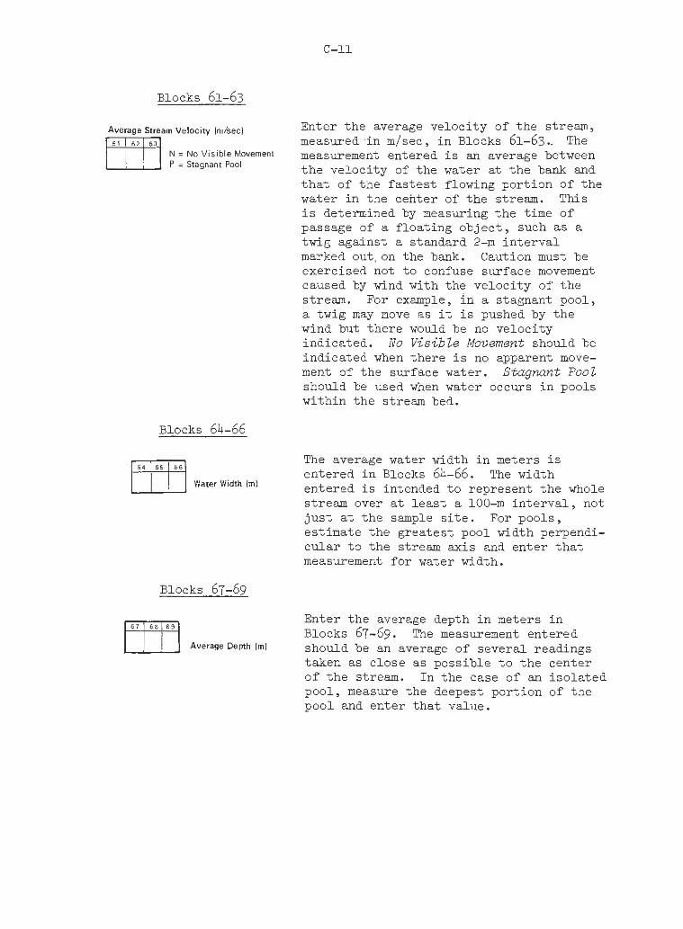
Enter the average velocity of the stream, measured i n m/sec, i n Blocks 61-63.. The measurement entered i s an average between the velocity of the water a t t he bank and t h a t of the f a s t e s t flowing portion of the water i n the center of the stream. This i s determined by measuring the time of passage of a f loating object , such as a twig against a standard 2-m in te rva l marked out.on the bank. Caution must be exercised not t o confuse surface movement caused by wind with the velocity of the stream. For example, i n a stagnant pool, a twig may move as it i s pushed by the wind but there would be no velocity indicated. No Visible Movement should be indicated when there i s no apparent move- ment of the surface water. S t a g m t Pool should be used when water occurs i n pools within the stream bed.
The average water width i n meters is entered i n Blocks 64-66. The width entered i s intended t o represent the whole stream over a t l e a s t a 100-m in t e rva l , not jus t a t the sample s i t e . For pools, estimate the greatest pool width perpendi- cular t o the stream axis and enter t h a t measurement for water width.
Enter the average depth i n meters i n Blocks 67-69. The measurement entered should be an average of several readings taken as close as possible t o the center of the stream. I n the case of an i so la ted pool, measure the deepest portion of the pool and enter t ha t value.
Block 70
Water Level
@, Dry Norm1 Pools High Low Flood
Block 71
Dominant Bed Matwial
Boulder Cobble Pebble Sand S i l t Clay None (Use Remarks)
Blocks 72-76
Sample Color [Except Plants) m/ V V L t PK Pink L Light RD Red M Medium GN Green D Dark BU Blue '
BN Brown CL Clear IVH White
GY Gray BK Black
YL Yellow OR Orange
QT Other
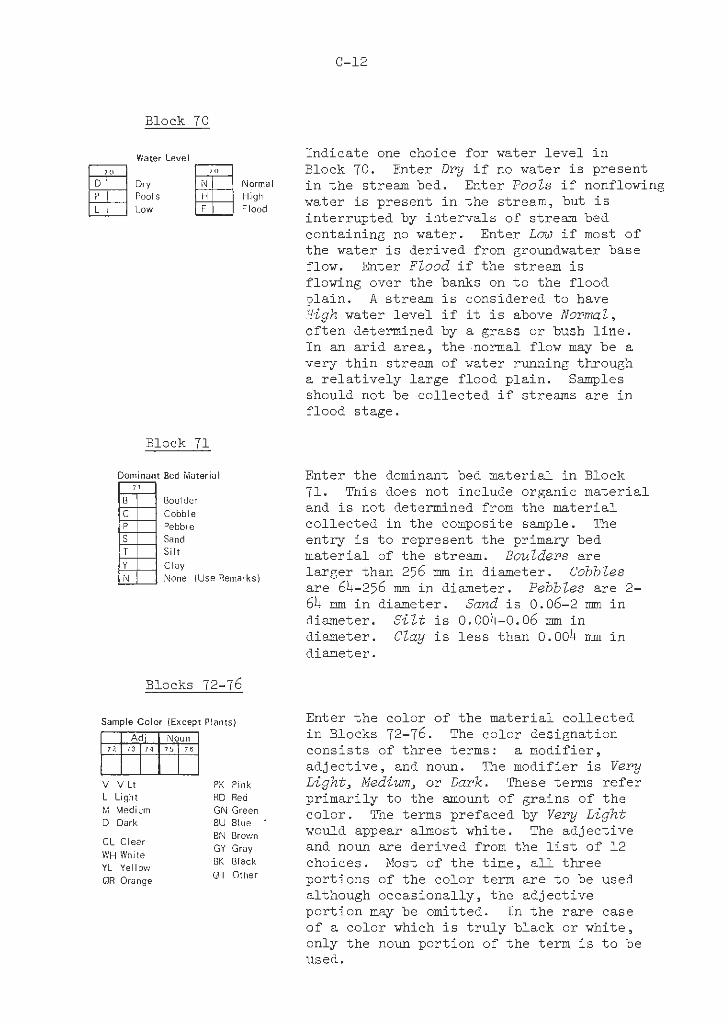
Indicate one choice for water l eve l i n Block 70. Enter D r y i f no water i s present i n the stream bed. Enter Pools i f nonflowing water i s present i n the stream, but i s interrupted by intervals of stream bed containing no water. Enter Low i f most of the water i s derived from groundwater base flow. Enter Flood i f the stream i s flowing over the banks on t o the flood plain . A stream i s considered t o have High water leve l i f it i s above Nomnal, often determined by a grass or bush l i n e . In an a r id area, the normal flow may be a very th in stream of water running through a r e l a t i ve ly large flood plain. Samples should not be collected i f streams are i n flood stage.
Enter the dominant bed material i n Block 71. This does not include organic material and is not determined from the material collected i n the composite sample. The entry i s t o represent the primary bed material of the stream. Boulders are la rger than 256 mm i n diameter. Cobbles are 64-256 m i n diameter. Pebbles are 2- 64 mm i n diameter. Sand i s 0.06-2 m i n diameter. S i l t i s 0.004-0.06 mm i n diameter. Clay i s l e s s than 0.004 mm i n diameter.
Enter the color of the material collected i n Blocks 72-76. The color designation consis ts of three terms: a modifier, adject ive, and noun. The modifier i s Very Light, Medium, or Dark. These terms re fe r primarily t o the amount of grains of t he color. The terms prefaced by Very Light would appear almost white. The adjective and noun are derived from the l i s t of 12 choices. Most of the time, a l l three portions of the color term are t o be used although occasionally, the adjective portion may be omitted. I n the ra re case of a color which i s t r u l y black or white, only the noun portion of the term i s t o be used.
Block 77
Sampled Materid
Other
Block 78
Results Request (Use Remarks)
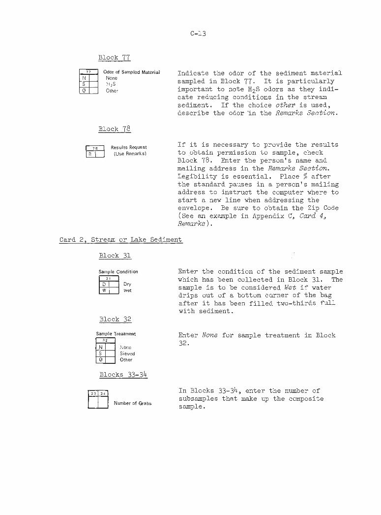
Indicate the odor of the sediment material sampled in Block 77. It is particularly important to note H2S odors as they indi- cate reducing conditions in the stream sediment. If the choice other is used, describe the odor 'in the Remarks Section.
If it is necessary to provide the results to obtain permission to sample, check Block 78. Enter the person's name and mailing address in the Remarks Section. Legibility is essential. Place % after the standard pauses in a person's mailing address to instruct the computer where to start a new line when addressing the envelope. Be sure to obtain the Zip Code (See an example in Appendix C, Card 4, Remarks ) .
Card 2, Stream or Lake Sediment
Block 31
Sample Condition
2 Enter the condition of the sediment sample which has been collected in Block 31. The sample is to be considered Wet if water drips out of a bottom carner of the bag after it has been filled two-thirds Pd1 with sediment.
Block 32
Sample Treatment Enter None for sample treatment in Block 32.
Sieved Other
Blocks 33-34
In Blocks 33-34, enter the number of
Number of Grabs subsamples that make up the composite sample.

Enter an estimate of the percent organic SC Organic Material (Field Estimate] material i n Blocks 35-36. Often, the
color of the sediment material sample i s re la ted t o the organic content. Thus, t he darker the sample, the higher the organic content. Make your entry from the fol- lowing choices: 0, 5 , 10, 25, 50, or 100%.
Card 4, Remarks
1. Pr in t a l l remarks i n upper case block l e t t e r s . Be neat t o assure accurate t ranscr ipt ion.
2 . S t a r t each remark with the card and block number tha t per ta in t o the remark. End each remark with a colon ( : ) and s t a r t the next remark (Example: 1-60 POSSIBLE CONTAMINATION FROM RECENT FERTILIZER APPLICATION: 1-77 SEDINCNT HAS ODOR OF AMMONIA: ) .
3. The f i r s t entry i n the Remarks Sect ion should be the exact locat ion from which the sample was obtained. The information required i n the description includes ( a ) t he name of the d i g i t i z e r map on which the sample i s entered, (b ) an exact description of the location of the sample s i t e and sample in te rva l . I f possible, use a landmark t o help describe the s i t e location. EXAMPLE:
1-38 JACKSON HILL 7.5 MINUTE MAP. SAMPLX COLLECTED I N THE CENTER OF THE STREAM OVER A 1 6 M INTERVAL GOING UPSTREAM STARTING 62 M UPSTREAM FROM THE LOW WATER BRIDGE. THE SAMPLING INTERVAL STARTS 3 M DOWNSTREAM FROM A LARGE WALNlTT TREE THAT HANGS OVER THE WEST BANK OF THE STREAM:
4. If re su l t s a r e requested by the property owner a t any s i t e , use the following format ( i n addition t o the well location format ) .
5. If keying a remark t o two or more different categories (boxes), use t he following format.
1-60 #I-77 STRONG ODOR OF AMMONIA INDICATES THE SITE MAY BE CONTAMINATED BY RECENT APPLICATION OF FERTILIZER:
6. Record a l l information i n the Remarks Sec t ion t ha t helps describe the sample and sampling s i t e . It should be br ief but accurate. Small items tha t seem unimportqt a t the s i t e may be very s ignif icant i n interpret ing geochemical data.

7. Be neat when crossing out any entry i n which an e r ror has been made i n t he Remarks Section.
DIGITIZER MAPS
The accurate location of s i t e s t ha t have been sampled must be done a f t e r t he samples have been collected. S i t e locations a r e plotted on clean unfolded copies of 7-l/Z1 or 1 5 ' topographic maps or , i f necessary, on county highway maps. The maps prepared by the URE Project for s i t e select ion may be used for navigation and other purposes. The f i n a l maps t h a t are t o be d ig i t i zed must be so indicated by writing "DIGITIZER MAP" i n the lower r igh t hand corner and by aff ixing the labels which a r e provided. An example i s shown below.
TYPE MAP DATE
QUADRANGLE NAME AND NUMBER
PHASE NO. OF S ITES
PHASE NO. OF SITES
Once a sample has been collected, determine the location of t h e sample s i t e on the digitizer map a s accurately as possible. Using a red pen, put a dot over t he s i t e location and then c i r c l e the dot. Next t o the sample s i t e location, a t tach a small sample labe l t ha t i s provided along with t he labe ls for t he sample containers. In some cases, t he s m a l l l abe l s w i l l not be usable, and the six-digit sample nwnber w i l l have t o be printed neatly next t o t he sample location. The sample s i t e location and sample number should be accented using a yellow marking pen i f sample number labe ls a r e not used.
When a l l sampling has been completed on e i ther a 7-112' or 1 5 ' topo- graphic map o r on a county highway map, t he information must be completed on t h e l a b e l which has been affixeil i n the margin. "Sampler Name(s)" r e f e r s t o t he i n i t i a l s of a l l samplers tha t collected samples from s i t e s iden t i f ied on the digitizer map. "Type Map" re fe rs t o whether t he map is a 7 1/2 ' , 1 5 ' , o r county map. a ate" re fe rs t o the date sampling was completed for the digitizer map. "Quadrangle name and number" re fe r t o t he name and map code of the lo x 2' quadrangle t o which the digitizer map i s associated. "Phase" re fe rs t o basins designated e i ther Phase "2" o r Phase "G". "No. of Sites" re fe rs t o the number of smple s i t e s sampled i n each phase tha t are shown on the digitizer m p . The unfolded digitizer map should be returned t o Oak Ridge t o the address indicated i n t he procedure for shipping maps.

COMPOSITE MAPS
Sample s i t e locations actually sampled should be entered on an overlay t o the 1:250,000 sca le , lo x 2' NTMS topographic map each day. Accom- panying the accurately positioned sample s i t e location w i l l be the sample number and s i t e number. This map must be kept up t o date so t h a t it can be used t o report monthly progress t o the URE Project contract supervisor as well as t o correct any discrepancies tha t may occur on digitizer m a p s .

A P P r n I X D
ASSIGNMENT OF SURFACE GEOLOGIC UNIT CODES

APPENDIX D
ASSIGNMENT OF SURFACE GEOLOGIC UNIT CODES
PURPOSE
Geologic formations for each lo x 2' quadrangle are assigned 3 or 4 letter codes which are entered on the field form on Card 1, Blocks 51-54. The formation is chosen to be representative of the geology of the basin. The purpose of designating a code for stream sediment is to identify the dominant geologic unit which most influences the geochemical concentrations in the sample. The laboratory analyzes the -100 mesh fraction of stream sediments so the geologic code may not apply to the coarser fractions of these samples.
In terms of presenting data in a report, the geologic code of the dominant formation is used as a fundamental basis for statistical summaries of the results. Summarizing data by formation serves as a basis for determining whether background and anomalous values are comparable between geologic units and which units might comprise a geochemical provinke.
In general, one should avoid sampling the Quaternary alluvium found on large flood plains. Small alluvial deposits along the axis of the 10 mi2 basins can usually be disregarded in the selection of a dominant geologic code.
PROCEDURE
Two methods of assigning geologic codes are given below. Paragraph A takes precedence when applicable.
A. Look closely at the sediment to see whether you can judge the probable geologic origin of the -100 mesh fraction. In the absence of adequate evidence from the sediment itself, use your understanding of the geomorphic processes operating in the area to assign a geologic code. For example, the source unit may be assigned to a formation cropping out in the portion of the basin which is being eroded most rapidly as in the case of a formation which crops out in the steepest slopes of an arid region. As another example, the choice might be between a limestone and a shale where the limestone tends to dissolve leaving chert nodules not represented in the -100 mesh fraction while the shale erodes to form clay.
B. Where the proper geologic code is not evident after considering the guidelines above, choose the unit which dominates the area of the basin. This may be the geologic unit which occupies at least 60 or 70% of the surface area of the basin.

Where sediment l i thology o r basin geomorphology i s t h e basis for assigning t h e dominant geologic code, enter a b r ie f explanation i n the Remarks Section. No explanation i s needed for how the dominant geologic code i s chosen when the select ion i s obvious such as when only one uni t crops out i n t he basin or when a second formation i s too insignificant i n area o r posi t ion t o be seriously considered.

A P P D I X E
EVALUATION OF CONTAMINATION

APPENDIX E
EVALUATION OF CONTAMINATION
Listed below are t he sources of contamination most l i ke ly t o be encoun- tered. Avoid these circumstances i f possible by e i the r moving upstream of t h e condition or i f necessary, by designating a new basin t o be sampled nearby. Always record possible/certain contaminants i n t h e Remarks Section.
1. Agricultural Contamination
Agricultural contamination i s generally r e s t r i c t ed t o appli- cation of f e r t i l i z e r . As the midcontinental region of t h e United S ta tes contains 70% of America's agr icu l tura l produc- t i on , t h i s i s of major importance. Phosphate f e r t i l i z e r s are widely used and contain concentrations of uranium tha t may poten t ia l ly contaminate surface s i t e s . Due t o the large t r a c t s of land f e r t i l i z e d , a sampler can rarely move upstream t o avoid the problem but should always note t h i s type of contamination i n t he Remarks Section.
2. Road Material
Road building gravel, f i l l d i r t , e tc . , commonly wash i n t o streams and s e t t l e near bridges. Try t o recognize t h i s type of sediment. I n addit ion, the area near a road may contain high values for lead derived from gasoline additives. Do not sample downstream from road beds constructed of mine t a i l i n g s . When col lect ing a sample, the s i t e should be located a t l e a s t 25 m upstream from a bridge or 1 irm downstream from a bridge. I f it i s not possible t o sample upstream, the f ac t t h a t t he sample has been taken downstream from a road or bridge should be noted i n the Remarks Section.
Any metal objects found i n a stream bed should be noted and avoided by moving upstrem. Trash i s defined t o include auto pa r t s , ba t t e r i e s , construction materials, garbage, or dumps.
4. S o i l o r Slump Material from Channel 'Banks
Slump material or s o i l i s not representative of the act ive stream sediment material t ha t i s t o be collected. Under no circumstances should s o i l or slump material be collected. Always sample the act ive stream sediment.

5. Mining ~ c t i v i t i e s
Any mining a c t i v i t y upstream wi th in a basin represents a source of contamination. The con t rac to r ' s supervisor should conduct a reconnaissance of areas i n advance of sampling t o i d e n t i f y mining areas. Be observant of streams which have been supplemented by water pumped out of mines. Haul roads from mines t h a t pass through bas ins a r e a l s o sources of contamination by l o s s of ma te r i a l from t rucks o r t r a i n s . A drainage bas in containing hal f t h e recommended area with no contamination i s b e t t e r than a bas in of t h e prescribed a r e a wi th mining upstream from t h e c o l l e c t i o n point .
6. I n d u s t r i a l Contamination
I n d u s t r i a l contanination has t h r e e major methods of t r a n s p o r t : wind, water , and man. Contamination halos a r e of ten seen downwind from smoke s t acks , smel ters , r e f i n e r i e s , s e t t l i n g ponds, e t c . Effluents from mineral processing p lan t s and sewage treatment p l a n t s contain s i g n i f i c a n t t r a c e element concentrat ions t h a t w i l l contaminate surface sampling s i t e s . D i r t o r rock t ranspor ted by man f o r building purposes can a f fec t t h e geochemistry of drainage waters and sediments. When poss ib le , it i s important t o move upstream, upwind, o r as f a r as poss ib le from i n d u s t r i a l contamination while s t i l l r e t a i n i n g t h e i n t e g r i t y of coverage.
Dams a r e not t r u e sources of contamination unless they a r e b u i l t of mine t a i l i n g s . However, dams do cause t h e s e t t l i n g out of f i n e stream sediments upstream from t h e dam and may i n d i c a t e r e s t r i c t e d samples t h a t a r e not representa t ive of a n a t u r a l drainage basin. The presence of dams upstream from sample s i t e s should be indica ted as Other i n Block 60 of t h e f i e l d form and discussed i n t h e Remarks Section.
Random resampling and resampling of s i t e s with unusual analyses w i l l be conducted on a regular bas i s by t h e URE Projec t i n order t o determine t h e accuracy of information provided by t h e cont rac tor . Fa i lu re t o i d e n t i f y contaminated s i t e s o r t o c o l l e c t samples from contaminated s i t e s where a l t e r n a t e s i t e s could have been chosen t o minimize t h e contamination w i l l c o n s t i t u t e a l eg i t ima te r e f l e c t i o n of t h e performance of t h e cont rac tor and w i l l be s t rongly considered i n t h e evaluat ion of t h e c o n t r a c t o r ' s performatice.

APPENDIX F
GENERAL GUIDELINES FOR DATA CONTROL

F-3
APPENDIX F
GENER TIDELINES FOR DAT A CONTF
S i t e numbers are unique within any lo x 2' quadrangle, s t a r t i ng a t 0001 and progressing t o 9999 (however, t ha t many samples are never collected within an individual quadrangle ) . ' Potent ia l sample s i t e s have been ident i f ied and located on 7 1/2 ' or 15 ' topographic or county highway maps, and assigned a s i t e number and phase of sampling by the URE Project.
S i t e numbers should be consecutive, i f possible, within any indi- vidual base map and should not be repeated within t ha t lo x 2' quadrangle.
When samples are col lected, the actual sample s i t e should be entered i n red ink on a new, clean, unfolded map (not the map showing s i t e s t o be sampled), cal led a d i g i t i z e r m a p , using a "00" rapidograph pen. The sample number l abe l should be attached next t o the accurately located sample s i t e as shown below:
The d i g i t i z e r map must not be folded because it i s the one t h a t goes t o the e lectronic d ig i t i ze r i n Oak Ridge. Folding w i l l d i s t o r t the posi t ion of s i t e locations with respect t o coordinates of the maps.
If a s i t e cannot be sampled, an a l te rna te s i t e must be selected. The new s i t e should be assigned the s i t e number of the one not sampled. On the or ig ina l map showing s i t e s t o be sampled, l abe l t he s i t e i n red ink t h a t was not sampled with the designation "NOT SAMPLED". Enter t he new s i t e on the d i g i t i z e r map.
When a l l sampling has been completed for a par t icu la r d i g i t i z e r m a p , complete a labe l and place it on the lower r i gh t corner of the map. The l abe l t o be used i s shown below:
SAMPLER NAME(S) -
TYPE MAP DATE
QUADRANGLE NAME AND NUMBER
PHASE NO. OF S ITES
PHASE NO. OF S I T E S

7. Maintain a lo x 2' composite map for each quadrangle being sampled, keeping progress up-to-date on a daily basis. The map should indicate site location, sample number, and site number. After sampling is complete in a quadrangle, the map must be turned in to the URE Project's contract supervisor.
8. Ship samples, field forms, and maps to Oak Ridge in the specified manner ( See Sump Ze Shipment Procedures ) .
9. Keep a monthly inventory of all boxes, sets of field forms, and d i g i t i z e r maps sent to Oak Ridge including inclusive sample and site ranges, total samples collected as well as dates for each mailing. This inventory should be kept by the contractor's field supervisor. A master copy of the shipping inventory for all personnel must be available for the U R F Project's contract super- visor as requested.
