procedures for type certificationatis.casa.go.kr/acs/document4/tc_tcv_od_en.pdfarticle 18 (develop...
TRANSCRIPT

Procedures for Type Certification
November 22, 2011
The Minister of MLTM (KOCA)
Note) This English version of document is provided solely for the reference
purposes of FAA. It may contain the mistranslated contents and therefore,
please refer to the Korean version of document to understand more exactly
or if found any ambiguity or conflict in the procedure.
OD 2011-760 November 22, 2011
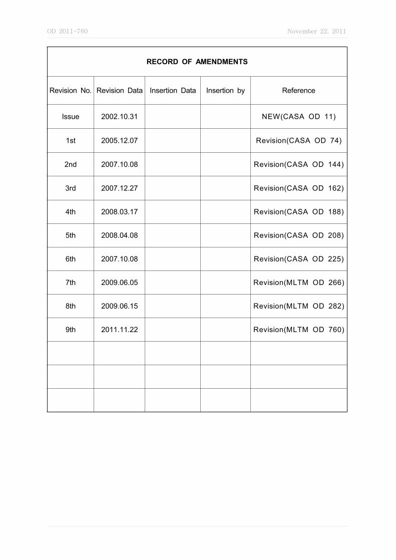
RECORD OF AMENDMENTS
Revision No. Revision Data Insertion Data Insertion by Reference
Issue 2002.10.31 NEW(CASA OD 11)
1st 2005.12.07 Revision(CASA OD 74)
2nd 2007.10.08 Revision(CASA OD 144)
3rd 2007.12.27 Revision(CASA OD 162)
4th 2008.03.17 Revision(CASA OD 188)
5th 2008.04.08 Revision(CASA OD 208)
6th 2007.10.08 Revision(CASA OD 225)
7th 2009.06.05 Revision(MLTM OD 266)
8th 2009.06.15 Revision(MLTM OD 282)
9th 2011.11.22 Revision(MLTM OD 760)
OD 2011-760 November 22, 2011
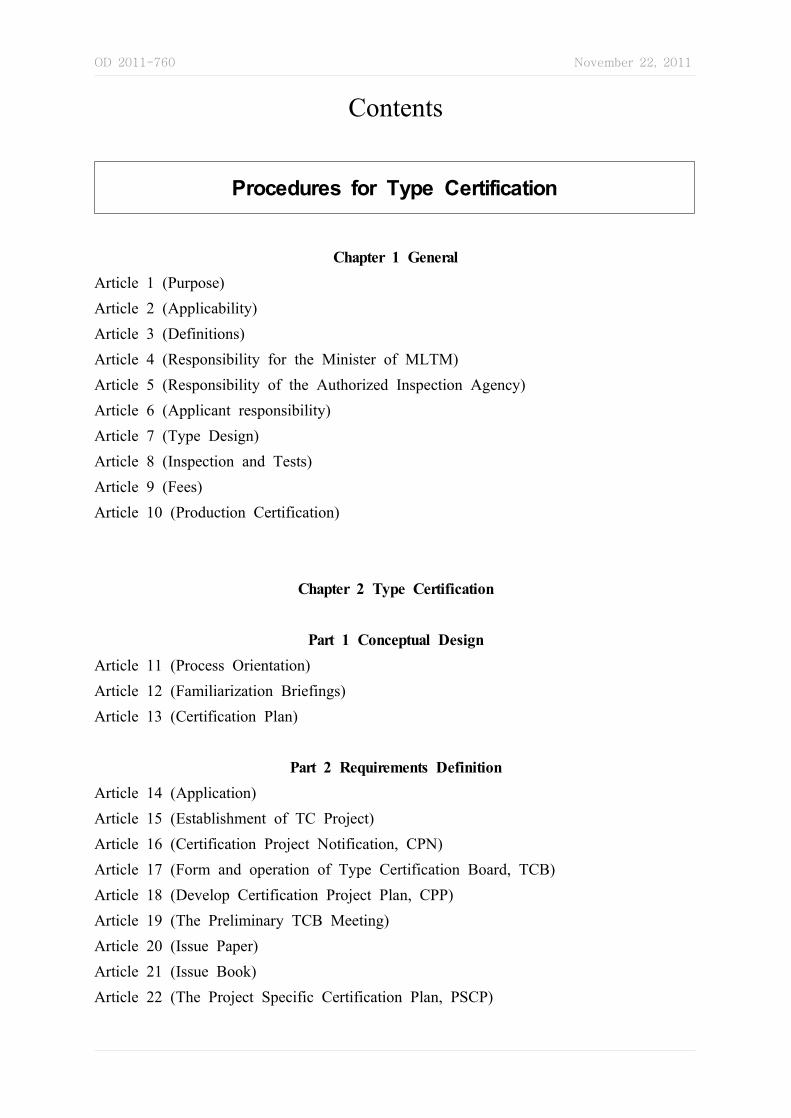
Contents
Procedures for Type Certification
Chapter 1 GeneralArticle 1 (Purpose)Article 2 (Applicability) Article 3 (Definitions)Article 4 (Responsibility for the Minister of MLTM) Article 5 (Responsibility of the Authorized Inspection Agency)Article 6 (Applicant responsibility)Article 7 (Type Design)Article 8 (Inspection and Tests)Article 9 (Fees)Article 10 (Production Certification)
Chapter 2 Type Certification
Part 1 Conceptual DesignArticle 11 (Process Orientation)Article 12 (Familiarization Briefings)Article 13 (Certification Plan)
Part 2 Requirements DefinitionArticle 14 (Application)Article 15 (Establishment of TC Project)Article 16 (Certification Project Notification, CPN)Article 17 (Form and operation of Type Certification Board, TCB)Article 18 (Develop Certification Project Plan, CPP)Article 19 (The Preliminary TCB Meeting)Article 20 (Issue Paper)Article 21 (Issue Book)Article 22 (The Project Specific Certification Plan, PSCP)

OD 2011-760 November 22, 2011
Article 23 (Certification Basis)Article 24 (Interim TCB Meeting for Certification Basis)
Part 3 Compliance PlanningArticle 25 (Delegation of Conformity Inspections activities)Article 26 (Conformity for Engineering Purposes)Article 27 (Completed Certification Plan/Project Specific Certification Plan)Article 28 (Interim TCB Meeting for Certification Plan / PSCP Completion)
Part 4 Implementation4-1. Compliance Data GenerationArticle 29 (Conformity Inspection)Article 30 (Applicant Test Plan and MLTM Approval) Article 31 (Before Witnessing Engineering and Flight Tests)Article 32 (Engineering Certification Tests for substantiating compliance)Article 33 (Engineering Compliance by Inspection)Article 34 (Analysis)Article 35 (Experimental Airworthiness Certificate)Article 36 (Applicant's Flight Tests)
4-2. Compliance SubstantiationArticle 37 (Compliance Substantiation - General)Article 38 (Data Submitted for Approval)Article 39 (Submit of Applicant Flight Tests Data and Report)Article 40 (Compliance Reports)
4-3. Compliance FindingArticle 41 (MLTM Review of Compliance Data)Article 42 (Review of Applicant's Flight Test Results)Article 43 (Flight Test Risk Management Process)Article 44 (Pre-flight TCB Meeting)Article 45 (Type Inspection Authorization, TIA)Article 46 (Flight Test Conformity Inspections)Article 47 (Certification Flight Test)Article 48 (Certification Flight Test Pilot)Article 49 (Operational and Maintenance Evaluations)

OD 2011-760 November 22, 2011
Article 50 (Instructions for Continued Airworthiness, ICA)Article 51 (Function and Reliability (F&R) Flight Testing)
Article 52 (Aircraft Flight Manual, AFM)
Article 53 (Final TCB Meeting)
Part 5 Post Certification Activities
Article 54 (Certification Summary Report)
Article 55 (Type Inspection Report, TIR)
Article 56 (Continued Airworthiness)
Article 57 (Procedures for Changes and Distribution to Instructions for Continued
Airworthiness, ICA)
Article 58 (Post-Certification Evaluations)
Article 59 (Data Retention)
Article 60 (Required Documents)
Chapter 3 Procedures for Type CertificatesArticle 61 (Issuing a TC)Article 62 (Amendment to a TC)Article 63 (Transferring a TC)Article 64 (Cancellation or suspension of a Type Certificate)Article 64-2 (Surrender of a Type Certificate)
Chapter 4 Changes in Type DesignArticle 65 (Change to Type Certificates)
Chapter 5 Manufacturing and Engineering Responsibilities and Functions relative to
Inspection, Test, and Flight Test.
Article 66 (Manufacturing and engineering - General)
Article 67 (Manufacturing Inspectors)
Article 68 (Request for Conformity and Type Inspection Authorization, TIA)
Article 69 (Process Specification Review)

OD 2011-760 November 22, 2011
Article 70 (Requests for Conformity Inspection from Foreign CAAs)
Article 71 (Conformity Inspection Record Reporting)
Article 72 (Test Articles –General)
Article 73 (Witnessing Official Test)
Article 74 (Structural Test Articles –Aircraft)
Article 75 (Prototype Flight Test Articles - Aircraft)
Article 76 (Endurance Test Articles - Engines and Propellers)
Article 77 (Teardown Inspection)
Article 78 (Ground Inspection – Aircraft)
Article 79 (Using Engineering Data)
Article 80 (Airworthiness Certification of Prototype Products)
Article 81 (Accounting for Engineering)
Article 82 (Flight Test)
Article 83 (Functional and Reliability Testing)
Chapter 6 Noise CertificationArticle 84 (Noise Certification)
Article 85 (Noise Certification Basis)
Article 86 (Acceptable Means of Compliance to the Noise Certification)
Article 87 (Witness Tests for Noise Certification)
Article 88 (Correction Procedures for Noise Evaluation)
Article 89 (Noise related Type Certification Requirements)
Article 90 (Changes to the Noise Characteristics due to Type Design Change)
Article 91 (Supplemental Type Certificates)
Chapter 7 Flight Test Pilot Qualification
Article 92 (Establishment of Training Program)
Article 93 (Initial Training)
Article 94 (Recurrent Training)
Article 95 (Recurrent Flight Training)
Article 96 (Flight Test Pilot Currency)

OD 2011-760 November 22, 2011
Chapter 8 TC Validation
[Appendix List][Appendix 1] Instruction for TCDS Preparation[Appendix 2] Certification Plan Composition[Appendix 3] Flight Manual Composition[Appendix 4] Significant Change v.s. Significant Project[Appendix 5] PSCP Composition[Appendix 6] Test Plan Composition[Appendix 7] Sample for Engineering Compliance Inspection[Appendix 8] Data Retention Requirements[Appendix 9] Type Inspection Report Composition[Appendix 10] Conformity Inspection Witness Consideration
[Form List][Form No. 1] Application for Type Certificate[Form No. 2] Application for Supplemental Type Certificate[Form No. 3] Type Certificate[Form No. 4] Supplemental Type Certificate[Form No. 5] Type Design Change Application[Form No. 6] Aircraft TCDS Form[Form No. 7] Engine TCDS Form[Form No. 8] Propeller TCDS Form[Form No. 9] Sample of Aircraft TCDS [Form No. 10] Sample of Engine TCDS[Form No. 11] Sample of Propeller TCDS [Form No. 12] Statement of Conformity[Form No. 13] Project Notification Form[Form No. 14] Issue Paper[Form No. 15] Request for Conformity[Form No. 16] Statement of Compliance with Airworthiness Requirements[Form No. 17] Conformity Inspection Record[Form No. 18] Airworthiness Approval Tag[Form No. 19] Type Inspection Authorization

OD 2011-760 November 22, 2011
[Form No. 20] Conformity Completion Report[Form No. 21] Type Inspection Report, Airplane[Form No. 22] Type Inspection Report, Rotorcraft

OD 2011-760 November 22, 2011
- 1 -
Procedures for Type Certification
Issued on Oct. 31, 2002(CASA OD 11)Revised on Dec. 7, 2005(CASA OD 74)
Revised on Oct. 8, 2007(CASA OD 144)Revised on Dec. 27, 2007(CASA OD 162)Revised on Mar. 17, 2008(CASA OD 188)
Revised on Apr. 8, 2008(CASA OD 208)Revised on Apr. 25, 2008(CASA OD 225)Revised on Jun. 5, 2009(MLTM OD 266)
Revised on Jun. 15, 2009(MLTM OD 282)Revised on Nov. 22, 2011(MLTM OD 760)
Chapter 1 General
Article 1 (Purpose) The purpose of this order is to carry out the works with respect to type certification of the aircraft and promote safety of flight by establishing the procedures and mean of compliance for Type Certification (TC), Supplemental Type Certification (STC) and Type Certificate Validation (TCV) for aircraft, engine and propeller (hereinafter called "product") pursuant to the provision of article 17 and 17-2 of Aviation Act.
Article 2 (Applicability) ① This order prescribes procedural requirements for the issue of Amended TC, STC, Amended STC, TCV for product and rules governing the holders of those certificates.
② If the Minister of MLTM determine that some of the steps or procedures in this order may not be needed due to the design features of the proposed product or the design features of the proposed change to the product, some of the stems or procedures may not apply to all certification project. However, if an official flight test was required, then all steps and procedures related to issuance and closure of a TIA are necessary and cannot be omitted.
Article 3 (Definitions) 1. Amended TC – an approval for a change to a TC, made by the TC holder. Only the
holder of the TC may apply for an amended TC.2. Certification Plan (CP) - the applicant's intended means for showing that a product
complies with the applicable regulations.3. Certification Project Plan (CPP) – a living document used to coordinate schedules,
OD 2011-760 November 22, 2011
- 2 -
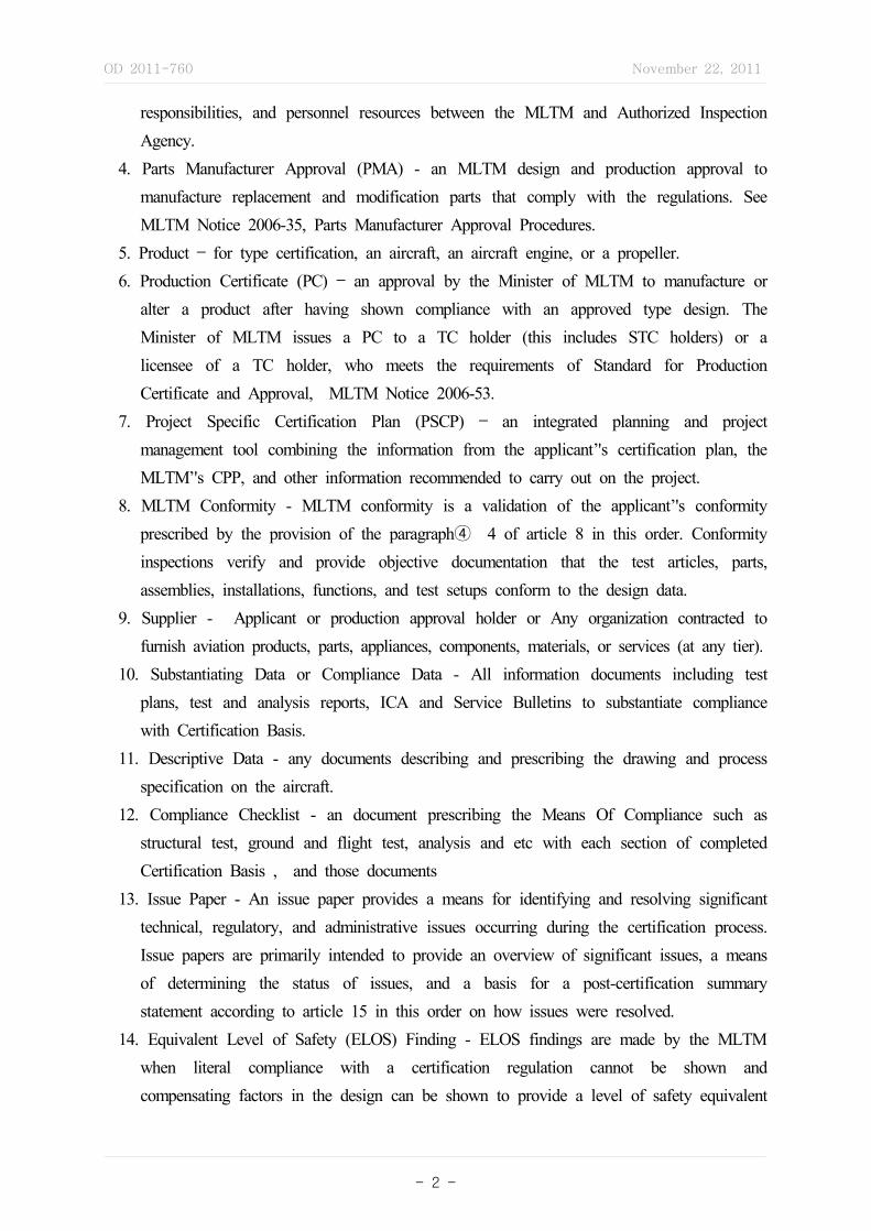
responsibilities, and personnel resources between the MLTM and Authorized Inspection Agency.
4. Parts Manufacturer Approval (PMA) - an MLTM design and production approval to manufacture replacement and modification parts that comply with the regulations. See MLTM Notice 2006-35, Parts Manufacturer Approval Procedures.
5. Product – for type certification, an aircraft, an aircraft engine, or a propeller.6. Production Certificate (PC) – an approval by the Minister of MLTM to manufacture or
alter a product after having shown compliance with an approved type design. The Minister of MLTM issues a PC to a TC holder (this includes STC holders) or a licensee of a TC holder, who meets the requirements of Standard for Production Certificate and Approval, MLTM Notice 2006-53.
7. Project Specific Certification Plan (PSCP) – an integrated planning and project management tool combining the information from the applicant’'s certification plan, the MLTM’'s CPP, and other information recommended to carry out on the project.
8. MLTM Conformity - MLTM conformity is a validation of the applicant’'s conformity prescribed by the provision of the paragraph④ 4 of article 8 in this order. Conformity inspections verify and provide objective documentation that the test articles, parts, assemblies, installations, functions, and test setups conform to the design data.
9. Supplier - Applicant or production approval holder or Any organization contracted to furnish aviation products, parts, appliances, components, materials, or services (at any tier).
10. Substantiating Data or Compliance Data - All information documents including test plans, test and analysis reports, ICA and Service Bulletins to substantiate compliance with Certification Basis.
11. Descriptive Data - any documents describing and prescribing the drawing and process specification on the aircraft.
12. Compliance Checklist - an document prescribing the Means Of Compliance such as structural test, ground and flight test, analysis and etc with each section of completed Certification Basis , and those documents
13. Issue Paper - An issue paper provides a means for identifying and resolving significant technical, regulatory, and administrative issues occurring during the certification process. Issue papers are primarily intended to provide an overview of significant issues, a means of determining the status of issues, and a basis for a post-certification summary statement according to article 15 in this order on how issues were resolved.
14. Equivalent Level of Safety (ELOS) Finding - ELOS findings are made by the MLTM when literal compliance with a certification regulation cannot be shown and compensating factors in the design can be shown to provide a level of safety equivalent

OD 2011-760 November 22, 2011
- 3 -
to that established by the airworthiness standards.15. Partnership for Safety Plan (PSP) – an agreement between a design approval applicant
and the Minister of MLTM describing how they will work together to certify and maintain integrity of the design approvals.
16. Type Certification Validation - the process most commonly used to establish the compliance of an imported product to the importing state's applicable airworthiness standards.
Article 4(Responsibility for the Minister of MLTM) The Minister of MLTM is responsible for:1. Providing guidance to an applicant in the certification process;2. Coordinating and accepting the Applicant's Certification Plan3. Establishing the certification basis4. Establishing special conditions5. Determining the applicability of the exemptions request and processing petitions for exemptions6. Determination of Equivalent Levels of Safety7. Approving drawings, reports, data, test plans, and flight manuals8. Performing type inspection authorization (TIA) inspections and tests needed to verify
compliance with the Korea Airworthiness Standards, applicable regulations and conformity with the type design
9. Preparing the type inspection report Type Inspection Report (TIR) and the Type Certificate Data Sheet (TCDS)
10. Issuing certificates; and11. Developing the Flight Standard & Operation Evaluation Board(FSOEB) and Maintenance
Review Board (MRB)
Article 5 (Responsibility of the Authorized Inspection Agency) Authorized Inspection Agency is delegated by the Minister of MLTM as prescribed in paragraph 2 of Article 154 of Aviation Act (hereinafter called "the Act") and Article 60 of Aviation Act Presidential Decree (hereinafter called "Presidential Decree") so as to carry out inspection services such as compliance determination, reviewing and evaluating of test and analysis, conformity inspections, etc.
Article 6 (Applicant responsibility) ① Applicants are responsible for complying with the regulation that apply to the specific product or those product operation.
② They must submit the necessary type design and substantiating data to show the product
OD 2011-760 November 22, 2011
- 4 -
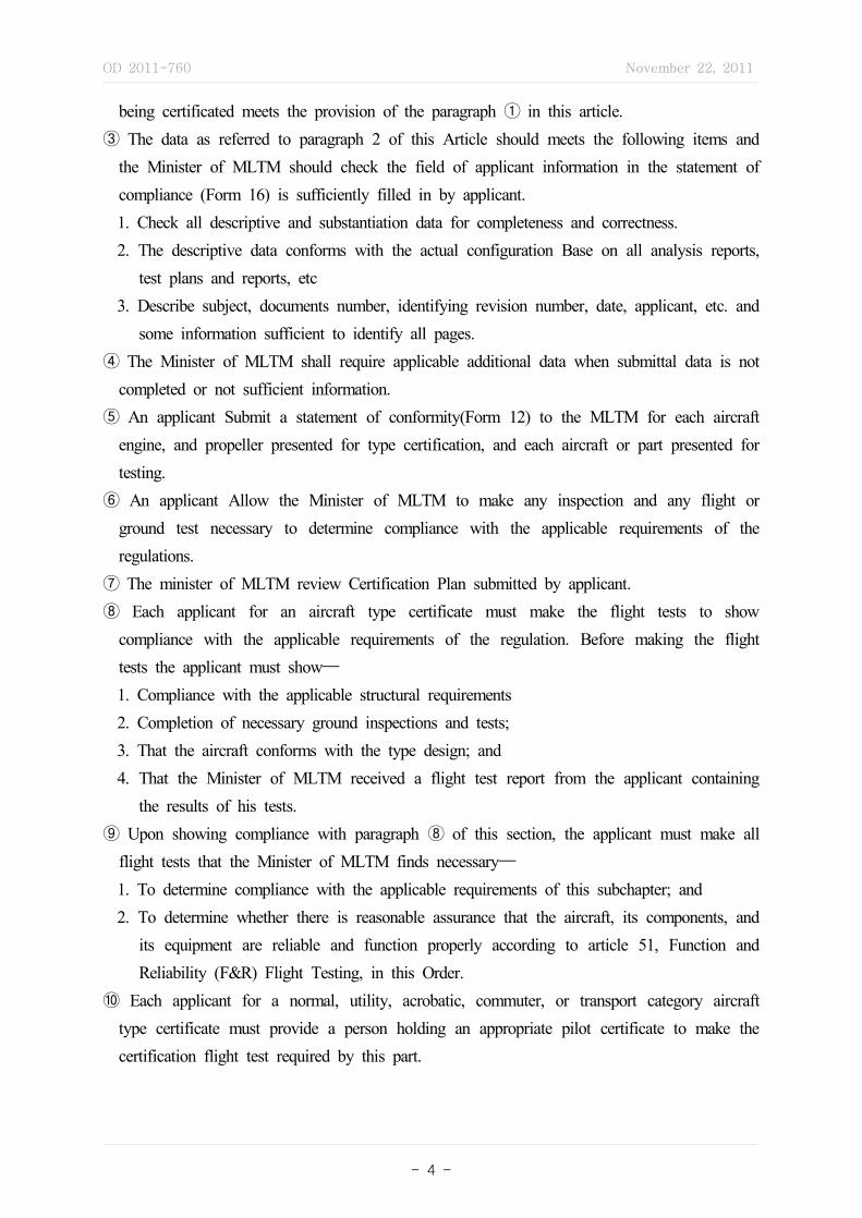
being certificated meets the provision of the paragraph ① in this article.③ The data as referred to paragraph 2 of this Article should meets the following items and
the Minister of MLTM should check the field of applicant information in the statement of compliance (Form 16) is sufficiently filled in by applicant.1. Check all descriptive and substantiation data for completeness and correctness.2. The descriptive data conforms with the actual configuration Base on all analysis reports,
test plans and reports, etc3. Describe subject, documents number, identifying revision number, date, applicant, etc. and
some information sufficient to identify all pages.④ The Minister of MLTM shall require applicable additional data when submittal data is not
completed or not sufficient information.⑤ An applicant Submit a statement of conformity(Form 12) to the MLTM for each aircraft
engine, and propeller presented for type certification, and each aircraft or part presented for testing.
⑥ An applicant Allow the Minister of MLTM to make any inspection and any flight or ground test necessary to determine compliance with the applicable requirements of the regulations.
⑦ The minister of MLTM review Certification Plan submitted by applicant.⑧ Each applicant for an aircraft type certificate must make the flight tests to show
compliance with the applicable requirements of the regulation. Before making the flight tests the applicant must show—
1. Compliance with the applicable structural requirements2. Completion of necessary ground inspections and tests;3. That the aircraft conforms with the type design; and4. That the Minister of MLTM received a flight test report from the applicant containing
the results of his tests.⑨ Upon showing compliance with paragraph ⑧ of this section, the applicant must make all
flight tests that the Minister of MLTM finds necessary—1. To determine compliance with the applicable requirements of this subchapter; and2. To determine whether there is reasonable assurance that the aircraft, its components, and
its equipment are reliable and function properly according to article 51, Function and Reliability (F&R) Flight Testing, in this Order.
⑩ Each applicant for a normal, utility, acrobatic, commuter, or transport category aircraft type certificate must provide a person holding an appropriate pilot certificate to make the certification flight test required by this part.
OD 2011-760 November 22, 2011
- 5 -
Article 7 (Type Design) The type design consists of the following as prescribed in the provision of paragraph 1 of article 32 of Aviation Act Ministerial Decree. (hereinafter called "Ministerial Decree").1. Drawings, specifications and those lists describing the configuration and design features
for the product.2. Dimension, material, and process data necessary to define the structural strength 3. Airworthiness limitations and Instruction for Continued Airworthiness4. Data to determine compliance with Fuel Venting and Exhaust emission standards.5. Other data to describe the product design to determine the airworthiness.
Article 8 (Inspection and Tests) ① Each applicant must allow the director of Authorized Inspection Agency or the Minister of MLTM to make any inspection and any flight and ground test necessary to determine compliance with the applicable requirements of Article 23, Certification Basis.
② No aircraft, aircraft engine, propeller, or part thereof may be presented to the director of Authorized Inspection Agency or the Minister of MLTM for inspection and test unless compliance with paragraphs ④-2 through ④-4 of this section has been shown for that aircraft, aircraft engine, propeller, or part thereof; and
③ No change may be made to an aircraft, aircraft engine, propeller, or part thereof between the time that compliance with paragraphs ④-2 through ④-4 of this section is shown for that aircraft, aircraft engine, propeller, or part thereof and the time that it is presented to the director of Authorized Inspection Agency or the Minister of MLTM for test.
④ Each applicant must make all inspections and tests that the director of Authorized Inspection Agency or the Minister of MLTM determines—1. Compliance with the applicable airworthiness, fuel venting, and exhaust emission
requirements;2. That materials and products conform to the specifications in the type design;3. That parts of the products conform to the drawings in the type design; and4. That the manufacturing processes, construction and assembly conform to those specified
in the type design.
Article 9 (Fees) ① The Minister of MLTM shall receive the application fee in accordance with Article 5 of Implementation Regulation of Aviation Act from applicant.
② The Minister of MLTM shall receive the travel expenses when on-site evaluation is required in accordance with the Public Officer Travel Fee Instruction.
③ Each applicant must pay the certification costs associated with the involvement of the
OD 2011-760 November 22, 2011
- 6 -
Authorised Inspection Agency to cover the services provided under the Article 60 of Presidential Decree of Aviation Act. The certification costs covers any costs incurred by compliance determination, technical review of design data, reviewing and evaluating of test and analysis, conformity inspections, its related travel expenses, etc. The certification costs is calculated according to the KCA documents, approved by the Minister of MLTM.
Article 10 (Production Certification) ① Application for a PC may be made at the same time application is made for a TC, an amended TC, STC, or an amended STC.
② The Production Certificates may be issued by the Minister of MLTM according to Procedures for Production Certificate and Production Approval However, the applicant cannot get a PC before a TC or STC is issued.
Chapter 2 Type Certification
Part 1 Conceptual Design
Article 11 (Process Orientation) ① An applicant seeking a TC approval is encouraged to contact the Minister or MLTM for discussing the project before submitting a TC application.
② In case of initial contact under paragraphs ①, the Minister of MLTM should discuss and/or assess the following items.1. Type of requested approval with the applicant2. The applicant's Knowledge of certification system and procedures.
③ The project manager needs to conduct a process orientation for applicants who are unfamiliar with certification. The process orientation provides applicant with the following -1. Need for certification2. Overview of certification process3. MLTM's role4. Applicant's responsibility5. Guidance described in The MLTM and Industry Guide to Product Certification
Article 12 (Familiarization Briefings) ① Familiarization Briefings may be held on by the Minister of MLTM, when it is need to give potential applicants an opportunity describing project before application.

OD 2011-760 November 22, 2011
- 7 -
② During the familiarization briefings, an applicant must provide the following - 1. Technical issues and unique or novel features2. The intended operation type3. A major suppliers and unusual vendor relationships4. Reliance on approved equipment5. Project schedule
Article 13 (Certification Plan) ① The Minister of MLTM shall receive the certification plan(draft) prepared by Appendix 2 with TC application form. Conformity inspection plan may be prepared according to Article 27 of this procedure.
② The Minister of MLTM may receive final certification plan if the certification project is considered as simple.
③ The Minister of MLTM may request applicant to update the certification plan as required if the certification project is considered as complicated
④ The Minister of MLTM shall receive the final certification plan in advance of implementation phase if the applicant submitted the incomplete certification plan.
⑤ The Minister of MLTM may request applicant to re-prepare detailed plan if he determines that it dose not contain sufficient information in accordance with paragraphs ② through ③. When the certification plan does not give the Minister of MLTM assurance to the understanding of the certification project, the Minister of MLTM may reject the application.
Part 2 Requirements Definition
Article 14 (Application) ① According to Aviation Act Ministerial Decree article 31, any person who may apply for Type certificate should submit Application for Type Certificate to the Minister of MLTM (Form 1)
② An aircraft TC application must be accompanied by - 1. Certification Plan2. a three-view drawing of the aircraft3. available basic data
③ An Engine TC application must be accompanied by - 1. The engine design features2. Operating characteristics3. The proposed operating limitations
OD 2011-760 November 22, 2011
- 8 -
Article 15 (Establishment of TC Project) If An applicant apply for TC, the Minister of MLTM assigns a project number, a project officer in the airworthiness division as required and Notify the certification project to the director of Authorized Inspection Agency and the applicant. The project numbering system is "x TC yy nn" and it means the follows.1. X : One alpha digits to identify the type of product (A : Aircraft, E : Engine, P :
Propeller)2. TC : alpha to identify the type of project, TC means new type certificate (in case of
Amended Type Certificate, ATC)3. yy : two number digits to identify the date of application.4. nn : two number digits to assigned automatically
② An applicant, the MLTM and Authorized Inspection Agency must use the assigned project number in all correspondence(Fax, Email), reports, and other documents pertaining to the project.
③ If the project is either canceled or closed before completion, the Minister of MLTM must close or cancel the assigned project number.
④ When there is the project assigned as prescribed in paragraph ①, the director of Authorized Inspection Agency assigns project manager(hereinafter called "Project Manager") for TC and the officers of each technical area and submits CPP according to this Order Article 18 to the Minister of MLTM. If necessary.
⑤ Duties of the Project Manager according to paragraph ④ is the following items.1. plans, reviews, evaluates, and coordinates for processing the project2. The project manager initiates the CPP and coordinates with the project officer, if necessary.
⑥ The project Manager normally consists the project team as the following. 1. A project manager2. Engineers or technical specialists3. Flight test pilots and flight test engineers4. Manufacturing inspectors5. A project officer and other persons at the discretion of the accountable directorate.
⑦ Duties of Pilots and Engineer is as follows.1. evaluating the adequacy of the type design and substantiation data related to their
assigned disciplines.2. contribution to the preparation of Type Inspection Authorizations (TIA), requesting
conformity inspection, and coordination with MLTM inspectors.⑧ Duties of the Project Officer is as follows.
1. Establishing the policy with respect to the project.2. Ensuring that the project team is using current policy and guidance.

OD 2011-760 November 22, 2011
- 9 -
3. Providing special conditions and exemptions and policy (for example, acceptable means of compliance, ELOS, and certification basis) to the project team.
Article 16 (Certification Project Notification, CPN) The Minister of MLTM notifies the director of Authorized Inspection Agency and applicant of each project by completing a CPN form as shown Form 13.
Article 17 (Form and operation of Type Certification Board, TCB) ① A Type Certification Board(TCB) is established only for projects of a certain magnitude by the Minister of MLTM as following.1. Aircraft and aircraft engine projects that involves new type certification, and2. Variable pitch propeller projects.3. Projects involving major changes to the type design4. Significant projects such as Amended TC, STC, Amended STC related to the Table 4
② The Airworthiness Division manager serves as chairman of the TCB and the vice-chairman is designated by the chairman.
③ The members of a TCB include :1. The Airworthiness Division manager,2. Certification engineer or project officer,3. Project manger, and4. other members including the managers, supervisors, or senior personnel from the
appropriate engineering disciplines; and flight test, manufacturing inspection, and assigned Aircraft Evaluation Group(AEG) personnel.
④ The chairman of the TCB may request other participants, such as those listed below1. engineers, flight test pilots, and manufacturing inspectors2. Technical Advisor, if necessary3. The personnel of AEG, Flight Standards and Aviation safety Division, Regional Aviation
Administration related to that project.4. The applicant and its representatives.
⑤ The function of TCB Is as bellow.1. To acquaint the applicant and the certification team with the certification project2. To identify and resolve significant problems, 3. establish milestones and schedules for the overall accomplishment of the type certification
project, 4. review the applicant's certification plan, 5. review the proposed certification basis, and 6. ensure all outstanding certification issues are resolved.
OD 2011-760 November 22, 2011
- 10 -
⑥ TCB Meetings (TCBM) (for example, preliminary, interim, pre-flight, final) are held with the chairman throughout the project.
⑦ The chairman convenes the TCB as necessary and notifies the appropriate representatives with the time, date, and location of the meetings.
⑧ Members, with concurrence of the chairman, may designate an alternate as their representative at TCB meetings.
⑨ The meeting minutes should include the following information:1. TCB meeting type: familiarization briefing, preliminary, interim, pre-flight, or final,2. Manufacturer,3. Model and project number,4. Location and date of meeting,5. Personnel present at meeting,6. Purpose of meeting,7. Discussion of agenda items, and8. Specialty items: Major problems and actions to take.
⑩ Each items or subjects discussed regarding items 7 and 8 of paragraph ⑧ should be identified and summarized under a separate heading. These items should include -1. a discussion2. action item (assignments and a schedule for completing any action items)3. a conclusion, Individuals participating in discussions should be identified by titles only.4. a work position of participants
Article 18 (Develop Certification Project Plan, CPP) ① The project manager coordinates CPP with the project officer and submits the CPP to the Minister of MLTM
② Project manager may revise CPP and should submit the CPP to the Minister of MLTM if necessary.
③ As prescribed in paragraph ①, the CPP includes the follows.1. Project No. Revision No, Revision date 2. Model designation: 3. Applicant: 4. Address: 5. Date of application: 6. Type of the project7. Project officer (telephone No.)8. Project Manager (telephone No.)9. General description
OD 2011-760 November 22, 2011
- 11 -
10. Significant features11. Proposed certification basis12. Exemptions needed: yes, no13. Special conditions needed: yes, no 14. Proposed schedule:
a. Preliminary type boardb. Preflight type board c. Other type boards d. TIA issuance e. Certificate issue/amend
15. Authorized Inspection Agency personnel16. The date of CP approval17. The name and signature of the Airworthiness Division manager
④ Table 4 uses only for the provision of the paragraph 3 item 10.
Article 19 (The Preliminary TCB Meeting) The chairman in the Preliminary TCBM carrys out the following item.1. Update and further acquaint MLTM and KCA personnel with the project,2. establishing the certification basis,3. Open discussion of design details and possible problem areas with specialists,4. Identify areas needing the formation of special compliance teams to attain the earliest
possible resolution of potential problems,5. Identify novel or unique design features, materials, or processes, and6 Establishing a schedule for the certification project.
Article 20 (Issue Paper) ① The following items will be considered significant issues on major projects, requiring the development of issue papers;1. Type Certification Basis (G-01) – designates the applicable airworthiness and
environmental regulations (noise and environmental findings), including special conditions, as applicable.
2. Determination of Compliance (G-02) – provides a statement of the MLTM procedural requirements, including those that define the responsibilities of the applicable exporting CAAs and applicant for showing compliance.
3. Environmental Consideration (G-03) – designates the applicable environmental regulations, that is, the regulations establishing standards for aircraft noise and for fuel venting and exhaust emissions for turbine engine powered airplanes.
OD 2011-760 November 22, 2011
- 12 -
4. Export (Import) Requirements –Country (G-04) – For exported products, the G-4 issue paper cites the extent of MLTM findings of compliance with the country’ airworthiness requirements on the exporting CAA’ behalf.
5. Rulemaking Actions (G-05) –For issuance of special conditions.6. Equivalent level of Safety Findings - proposed or made under the authority of the
airworthiness standards.7. Unsafe Situations - characteristics or features that could preclude certification as defined
in the airworthiness standards.8. Changes in Interpretation - New interpretation/ policy of existing regulations using
precedent-setting new technology should be included in an issue paper at the early stages of the certification project.
9. Application of novel or unusual design - do not require a Special Condition but may require the development of an acceptable means of compliance with existing regulations that would set a national precedent.
10. Items Requiring Use of a Special Certification Review team for resolution11. All other issues that become controversial or may otherwise require TCB action to resolve.
② New Issue Papers with respect to the items of the paragraph ① may be proposed to the TCB at any time during the certification process prior to final type certificate
③ When issues are identified in accordance with paragraph ①, draft Issue Papers should be developed by the applicant or project team members using the Form 14 for the significant issue as early in the program as practicable and be submitted to the project manager. When the applicant make an request for an ELOS findings with respect to the item 6 of the paragraph ①, the applicant must complete Blocks "Regulatory Reference", "Statement of Issue" and "Background", and describing Compensating factors to the compliance requirements in Block "Applicant's Position" in Issue Paper development template of Form 14 and submit it to the project manager.
④ The project manager assigns and notify Issue Paper No. to the applicant and project team. The Issue paper no. system is "X-NN" and it means the follows.1. The first digit is an alphabetic identification of the technical area - of prime concern
using :a. G : General, G series G-01 through G-05 according to the paragraph ① of the Article 20
b. A : Airframe
c. S : System and Equipment
d. P : Powerplant
e. E: External Environmental Threats, Lightning, High-Intensity Radiated Fields(HIRF), and
so forth

OD 2011-760 November 22, 2011
- 13 -
f. EE : ETOPS
g. N : Noise
h. F : Flight Test
i. C : Crashworthiness/Interiors
j. Q : Quality assurance or article conformity
k. O : Operational
l. M : Maintenance
2. NN : two number digits to assigned automatically⑤ The project manager describes final MLTM comment and submits the issue paper
including the comments to the Minister of MLTM through project officer.⑥ The processing status of the issue paper is closed, when MLTM Determination and
signature is made by the Minister of MLTM.
Article 21 (Issue Book) ① The project manager assembles issue papers and publishes them in the form of an issues book for distribution to the TCB members, project team members, applicant.
② The Issues Book will be revised to add new issue papers or update existing issue papers without holding a formal TCBM, provided the new or updated issue papers can be cleared through the applicant and project team by routine coordination.
Article 22 (The Project Specific Certification Plan, PSCP) ① The MLTM and the applicant's certification teams begin developing the PSCP when they have collected the information needed in the applicant's certification plan and the CPP.
② Table 5 includes means of developing the PSCP③ The project manager and applicant may revise the PSCP to manage the certification
process efficiently.④ The Authorized Inspection Agency and applicant comply with the follow items, when they
develop the PSCP and additional conformity plan.1. Remain within the authority of the signatories,2. Are consistent with MLTM regulations or policy,3. Do not redefine certificate eligibility (for example, agreeing to a fixed certification date)4. Can be met even in circumstances less than ideal, and5. Consider obligations made to other projects and applicants.
Article 23 (Certification Basis) ① The Minister of MLTM should establishes applicable
OD 2011-760 November 22, 2011
- 14 -
requirements to the following item of products for a TC and review compliance for those products.1. Airworthiness Standards2. Special Condition (as applicable)3. Fuel venting and exhaust emission(as applicable)4. other operating condition necessary to review airworthiness by the Minister of MLTM
② The Minister of MLTM may apply newly revised regulatory relative to the Act, regulations or airworthiness standards, etc. to the TC project for safety of products.
③ If special aircraft, engine installed in the aircraft, and propeller are not included in this article paragraph ① or ② of this article specified by KAS(A part of Notice of MLTM). The Minister of MLTM may apply one of KAS part 22, 23, 25, 27, 29, 30, 33, 35 and 36 to the aircraft, engine, and propeller as feasible or a level of safety equivalent to that established by the existing airworthiness standards.
④ an aircraft is classified as transport(T) category according to Aircraft Airworthiness Standards(hereinafter called "airworthiness standards") is effective on 5 years for application and other aircraft categories are effective on 3 year.
⑤ An applicant may apply for the extension of duration for design, development and test, etc, in accordance with paragraph④, if necessary.
⑥ If an application for TC is not completed until the effective date specified in paragraph ⑤, the applicant must extend duration for the application. in this case, the applicant must show compliance with airworthiness standards applicable to the specific date. the specific date is after duration to original application for TC.
⑦ The Minister of MLTM may establish newly or revised special condition, when existing requirements do meet compliance with airworthiness standards to nobel or unusual features of the product.
⑧ Special Condition must ensure requirements to airworthiness standards and a level of equivalent safety specified in Aviation Act and Aviation Act Implementation Regulations.
⑨ The Minister of MLTM should comply with procedures for new or revised according to regulations specified in Procedures for Product Airworthiness Standards Management, when new special condition with respect to paragraph ⑧ is necessary for the aircraft.
⑩ The Minister of MLTM make the project manager submits the proposals for special condition described with full particulars and justification to him in accordance with paragraph ⑦ or ⑨, if necessary, new or revised. The basis and content of special conditions are generally developed via the issue paper process. The following information should be included:1. The complete certification basis, indicated in a manner similar to what would be shown
OD 2011-760 November 22, 2011
- 15 -
on the TCDS,2. A general description of the product, such as (for an airplane): the location of the
wings, number and type of engines, maximum weights, speeds, seating capacity, and so forth,
3. A description of features requiring the issuance of special conditions,4. For an amended TC or an STC, a statement of the extent and features of the
modification,5. The exact nature of the novel or unusual design feature, including, if appropriate, an
evaluation that the design feature would produce an unsafe condition unless the proposed special conditions were applied,
6. The relationship between the design feature and the applicable regulations indicating how the standard is inadequate or inappropriate, and
7. An evaluation stating the proposed special condition establishes a level of safety that neither raises nor lowers the standard set in the applicable regulations.
⑪ Special conditions that are used on one certification project may apply to other projects using the same design feature. Pending adoption of amendments to the airworthiness standards, the Minister of MLTM may apply a special condition proposed by an applicant to any subsequent design case for which the criteria would be appropriate.
⑫ The Minster of MLTM may require an applicant who must show additional compliance with airworthiness standards revised after application for TC to identify indirect or direct requirements of amendments.
⑬ The revised aircraft airworthiness standards are involve in certification plan or standards for certification for application according to paragraph ⑫.
⑭ Any applicant who want to show compliance via ELOS findings must submit Issue Paper developed by each issue to the project manager of Authorized Inspection Agency.
⑮ The Minister of MLTM should determine ELOS finding through process in developing and reviewing Issue Paper according to airticle 20, if required by applicant.
⑯ The Minister of MLTM allows A petition for exemption that is applicable anyone, and do provide with petition procedures for exemption only if ensuring ELOS finding specified in Aviation Act and regulatory.
Article 24 (Interim TCB Meeting for Certification Basis) ① The chairman may hold on interim TCB Meeting to expedite the resolution of certification basis issues.
② If the meeting does not result in an established certification basis, it should establish a clear understanding of the actions needed to resolve the issues and assignments of those action to the responsible people.
OD 2011-760 November 22, 2011
- 16 -
③ If applicant proceeds the project without a complete definition of the certification requirements, the chairman notify applicant of the certification risk such as project schedule delay, redesign, and retest
④ If The chairman determine that the project couldn't be proceeded for further step regarding to establishing plans for substantiating compliance of the section 3, An additional TCB Meeting is held for establishing certification basis by the Minister of MLTM.
Part 3 Compliance Planning
Article 25 (Delegation of Conformity Inspections activities) The Minister of MLTM allow Authorized Inspection Agency to carry out involvement in certification activities as prescribed in the provision of the Article 5 to enhance authority and efficiency in Type Certificate process.
Article 26 (Conformity for Engineering Purposes) ① The specific procedures with respect to Conformity Inspection are addressed in this order article 5 regarding to the duty and roles of manufacturing and engineering with inspection, test, and flight test.
② An applicant's duties for assuring the conformity to engineering are as follows.1. Identifying the test articles as prescribed in the provision of the paragraph 4 of the article 8,
that will be used to generate compliance data In certification plan, and 2. Conducting 100 percent applicant conformity of those test articles as required in paragraph ①
③ The project team develops conformity validation plan by reviewing conformity plan submitted as part of the applicant CP
④ Duties of the project team engineer in conformity inspection activities are the following items.1. identifying features, characteristic, components that may affect the test results2. An applicant request the project team inspector to carry out conformity inspection for that test
articles submitted as required by the Article 8 paragraph ②. Inspection and Test, that will be used to generate compliance data In certification plan, and
⑤ Duties of the project team inspector for assuring conformity is the following items.1. During the inspection, manufacturing inspectors base the depth of their assessment on
such as quality of the applicant's conformity paperwork, comparison of inspection results, and magnitude and complexity of the inspection.
2. The project team inspector is responsible for determining what conformity inspections will be necessary for processing production approvals.
⑥ Because of a part's approval by TSO or PMA, a part conformity may not be necessary

OD 2011-760 November 22, 2011
- 17 -
for its use in a certification project. But, the project team engineer may request the inspector to conduct conformity inspection by describing the following items in the Special Instructions of the Request for Conformity using Form 15.1. If MLTM engineering consider whether the testing to be accomplished requires a test
article definition more specific than the "Form, Fit, or Function" of the part provided by the TSO or PMA.
2. If MLTM engineering wants to ensure the part does not have a bias that may affect the outcome of the test, the engineer may ask the inspector to review any MRB action for deviations to the test article referencing the characteristic the engineer identifies. Here, Deviation means Non-conformance confirmed and accepted by activities of MRB actions or Authorized Inspection Agency's technical assessment.
⑦ After the responsible project engineer review of the substantiating data, the assigned project team inspector performs installation conformity inspection to the parts related to the paragraph ⑥. (The installation conformity inspection means inspections to be performed to verify the installation was accomplished in accordance with the approved data, and to note all or any discrepancies found during installation) The project team inspector should verify the article's TSO number, part number, serial number, software part number (including version), etc. and record the inspected items on Form 17 "Conformity Inspection Record".
Article 27 (Completed certification plan/project specific certification plan) ① By this point in the project, the details of the applicant’s plan for showing compliance, including the remaining elements outlined in Article 28 above should be captured in the certification plan or PSCP.
② From this information, the certification team should be able to determine that, if the plan was successfully executed, its results would show compliance. The amount of detail necessary to avoid ambiguity will be determined from finding to finding, but, it decreases when the applicant chooses common means of compliance such as those described in FAA Adcisory Circular(AC).
③ The certification team should find the plan agreeable according to paragraph ② before the following items.1. conformity request2. approving test plan3. witnessing or observing certification test4. performing any other certification project activities
Article 28 (Interim TCB Meeting for Certification Plan / PSCP Completion) ① During

OD 2011-760 November 22, 2011
- 18 -
this meeting, use the PSCP (or the certification plan and CPP) to assess the certification risks of proceeding into the actions of showing and finding compliance and Obtain mutual agreement to the adequacy of the plan and acceptance of the risks before proceeding with implementation of the section 4.
② The project team may hold one main Interim TCB Meeting to reach agreement on how the project will be conducted, followed by splinter meetings to address the certification activities required for the various systems, technical area, or components of the aircraft design by the team. When dividing the TCBM this way, the project-level agreement of the certification plan must include a realistic schedule for splinter meetings.
Part 4 Implementation
4-1 Compliance Data Generation
Article 29 (Conformity Inspection) ① An MLTM conformity inspection must be successfully accomplished before any official MLTM tests (ground or flight) are conducted. For the Requesting of Conformity inspection for ground test, A MLTM Request For Conformity using Form 15 is used, and For flight test, A MLTM Type Inspection Approval(Form 19) is used.
② Because of the complex nature of the conformity process and the necessity for parts conformity inspections early in the certification program, the responsible MLTM office should be consulted early in the program. This will ensure that necessary inspections are requested and scheduled at appropriate times.
③ The project manager must let the applicant submit signed Form 12 "Statement of Conformity", attesting that the test article and test setup used for the substantiation data generation are in conformity with the proposed design. The project team inspector should receive these forms from the applicant before conducting any MLTM conformity inspections.
④ When conformity inspections are required, the project team engineer should forward completed RFC Form with conformity inspection control number on it and together with proper data, then request the project team inspector to perform the required conformity inspections.
⑤ The project team inspector is responsible for determining that the product conforms with drawings, processes and special processes.
⑥ The project team performing each conformity inspection with respect to the paragraph① is to complete a MLTM Conformity Inspection Record using Form 17, and notify any items

OD 2011-760 November 22, 2011
- 19 -
found unsatisfactory, and return these to the Program Manager reordering Conformity/TIA Completion Report using Form 20.
Article 30 (Applicant Test Plan and MLTM Approval) ① An applicant's own testing for development does not require approval by the Minister of MLTM. However, type certification credit cannot be granted for these tests according to article 8 unless arrangements are made and agreed prior to the testing.
② The applicant must prepare a test plan(Table 6) complying with the provision of the paragraph② of the article 6 when testing is necessary to show compliance to the regulations.
③ The applicant should also submit the test plan early enough to allow the MLTM time to review and approve the test plan before the start of the test unless specifying on PSCP with respect to the paragraph ②.
④ The project team engineer or flight test pilot should approve the test plans, when the test plans submitted by applicant comply with the provision of paragraph ②.
⑤ they request an MLTM conformity inspection of the test article and test setup to ensure conformance to the engineering drawings and test plan, to the project team inspector.
Article 31 (Before Witnessing Engineering and Flight Tests) ① When witnessing official tests, the MLTM-authorized witness will verify that the test procedures described in the applicant's MLTM-approved test plan are followed and that any data captured by test instrumentation appears to be valid data for the test in question.
② If the test is lengthy according to the paragraph ①, witness at least the most appropriate or critical portions of the tests and conduct a post-test examination to not witnessing test.
③ If the project team engineer or pilot will not be able to witness the test, they will authorize another qualified project team engineer, MLTM pilot, or project team inspector. See chapter 5 of this order for a discussion of the inspectors witnessing tests.
④ The minimum participants for witnessing the test is the following items. But there are some cases such as flight tests of certain single-seat aircraft where the minimum number of participants can only be one person, the MLTM flight test pilot or his designated flight test pilot. 1. Project team engineer, flight test pilot or inspector(hereinafter on this article, called "the
MLTM-authorized witness")2. The applicant's knowledgeable representative who is capable of performing the test.
⑤ After the test, the MLTM-authorized witness must sign a record including the following items to show the results were obtained by properly following the approved test plan.
OD 2011-760 November 22, 2011
- 20 -
1. Identifying the test2. The results obtained3. The decisions reached4. Any recommendations made to the applicant
⑥ The Minister of MLTM must let the applicant to submit test reports together with completed Form 16 "Statement of Compliance" according to the paragraph 2 of Article 6.
⑦ If the project team inspector is to be the witness, the project team engineer or pilot will provide them with the appropriate instructions and a reference to the applicant's test plan.
⑧ a person who witness the test According to the paragraph ③ should coordinate the test with the project team engineer or pilot before witnessing the test.
Article 32 (Engineering Certification Tests for substantiating compliance) ① Engineering Certification Tests are used by applicants to demonstrate compliance with a requirement, or to collect qualifiable product or component data necessary for showing compliance. A few examples of engineering certification tests include part qualification, system function, iron bird, fatigue, flammability, landing gear drop test, ground vibration, and Electro Magnetic compatibility(EMC)/Electro Magnetic Interference(EMI) tests.
② Each applicant test must be accomplished successfully before conducting any MLTM certification flight test to validate an applicant's showing compliance of Completion of necessary ground inspections and tests as prescribed in the provision of the paragraph ⑨-2 of the article 6. For certain flight tests the Minister of MLTM may choose to conduct certification flight testing concurrently with the applicant (see section 5 of this order for plan for flight test).
③ To show compliance with a type certification requirement, the conformity of the test article, test setup, and test procedures used, and the validity of the test results according to article 29 or article 31 must be established for each certification test conducted.
Article 33 (Engineering Compliance by Inspection) ① An engineering compliance inspection should be done for any aspect of product design and installation where compliance with the certification requirements cannot be determined through the review of drawings or reports. An engineering compliance inspection provides an opportunity to review an installation and its relationship to other technical area on a product. This inspection ensures systems and components are compatible with each other and meet the applicable requirements of the airworthiness and operational standards.
② The project team should conform document the findings for the applicant followed by the provision of the paragraph ① to include as the substantiating data.
③ An representative example for engineering compliance inspection is addressed in Table 7.
OD 2011-760 November 22, 2011
- 21 -
Article 34 (Analysis) ① When the applicant determines to show compliance with specific requirements for Type Certification by an engineering analysis, the Minister of MLTM must let the applicant submit analysis data.
② The Minister of MLTM holds no list of analytical technique, acceptable analysis tools, computer programs, or standard formulas, etc., because use of a well established analysis technique is not enough to guarantee the validity of the result.
③ The project team engineer is responsible for finding the data accurate, and applicable, and that the analysis does not violate the assumptions of the problem.
Article 35 (Experimental Airworthiness Certificate) With certain exceptions, the applicant must get a special airworthiness certificate before conducting research or development flight tests on test aircraft or conducting flight tests to show compliance according to the article 15 of the Act and the article 20 of the Ministerial Decree.
Article 36 (Applicant's Flight Tests) ① The Minister of MLTM shall ensure the the applicant conducts flight tests and inspections before the TIA for research and development.
② The Minister of MLTM would not accept the applicant's research and development flight tests results as a part of the authority's certification flight test. Unless the Minister of MLTM agrees to conduct concurrent testing with the applicant and issues a TIA for the test.
③ The Minister of MLTM shall ensure the applicant conducted tests and inspections to demonstrate the test article is submitted for authority's certification ground and flight tests and it meets the minimum requirements for quality, conforms to the design data, and is safe for the planned tests.
④ The Minister of MLTM receives the applicant generated development test data and reviews acceptability of the data.
⑤ The Minister of MLTM shall ensure the validity of flight test data, which is generated with test articles by the applicant, is represent the type design through the applicant's configuration controls and conformity records of the test article for each flight.
4-2 Compliance Substantiation
Article 37 (Compliance Substantiation - General) ① An applicant must submit
compliance substantiating data to the Minister of MLTM before certification flight test according to the Paragraph ⑨ of the article 6 or 8. The submittal and approval
OD 2011-760 November 22, 2011
- 22 -
processes for the applicant's flight test data and report are followed by the article 39. ② The Minister of MLTM must let the applicant submit the necessary data, reports and
compliance reports according to the article 38 thru 40 after completing applicant flight tests prior to certification flight tests.
③ In the event the Minister of MLTM agrees to conduct a part of flight testing concurrently with the applicant, it is understood that the report will not contain compliance substantiation for those specific tests.
④ In either case, the applicant has the following responsibilities as prescribed in the article 6.
Article 38 (Data Submitted for Approval) ① During this period of activity, the TC applicant is submitting to the Minister of MLTM the necessary design data, test reports, and computations to show that the product to be certificated meets the applicable airworthiness, noise, and emission requirements of airworthiness standards and any special conditions identified by the Minister of MLTM.
② The applicant should submit the compliance data as soon as the data are complete and in a logical format for review, so review of the Minister of MLTM can be accomplished during the normal course of a certification project.
③ The procedures for data approval and administrative action according to the paragraph ① are followed by the article 41.
④ The Minister of MLTM must not release proprietary information (descriptive, design, and substantiating data received from applicants) to any party who does not have written permission from the applicant (or the certificate holder). The certification basis information consisting of Type Certification Data Sheet not proprietary data, because it is a part of the TC.
⑤ The Minister of MLTM may use the applicant's or certificate holder's data for reference or evaluation of any subsequent applicant's submitted data if the information is used solely for that purpose.
⑥ The Minister of MLTM will not question the source or the method by which an applicant for a design approval obtains the data submitted by an applicant.
⑦ An applicant showing compliance to the applicable requirements may obtain certification credit for previously approved data without showing further compliance if the applicant:1. Provides sufficient evidence that the presented data were, in fact, approved by the
Minister of MLTM. The applicant does not need to submit the data if they were obtained with the consent of the original approval holder.
2. Establishes that the previously approved data are applicable to the applicant's design to

OD 2011-760 November 22, 2011
- 23 -
the extent that any design deviations will have no effect on the design's airworthiness or on showing compliance with the applicable regulations.
3. Provides sufficient substantiation and descriptive data of its own modification so that the Minister of MLTM can make a finding of compliance.
4. Has sufficient engineering data necessary to provide continued airworthiness information should the modification be the subject of a Service Difficulty Report(SDR) or an Airworthinee Direction(AD).
5. Has sufficient descriptive data to produce detail parts and installations if multiple STC approval is requested.
⑧ While needless duplication of testing and data gathering should be avoided, the primary responsibility of the Minister of MLTM is to determine the airworthiness of the aircraft with the modification. The Minister of MLTM will not supply a subsequent applicant with information submitted by a previous applicant, either directly or indirectly. If the Minister of MLTM minimizes or waives the need for an applicant to provide substantiating data for specific requirements based on prior MLTM knowledge, a brief rationale explaining these findings will be made by the Minister of MLTM and included in the project file. Substantiating data from a previous project file will not be copied and put in the subsequent project file.
Article 39 (Submit of Applicant Flight Tests Data and Report) ① The Minister of MLTM shall receive and review the development flight test report that contains the applicant collected and analyzed flight test data from the applicant.
② The flight test report specified by paragraph ①, it shall be described the detailing of the data with an explanation of the calculations in accordance with KAS 21.39(a) for authority's review.
③ The flight test report specified by paragraph ①, it shall show compliance to other appropriate flight regulations such as FSRs(Flight Safety Regulations)
④ If the aircraft will be certificated under KAS part 25, the flight test report should be signed by the applicant’s test pilot.
Article 40 (Compliance Reports) ① The Adequate compliance reports present appropriate evidence to convince the Minister of MLTM of the overwhelming likelihood of the claim.
② The substantiation case presents and explains the inter-relationship of the evidence in a logical order leading from the requirement to the claim.
③ Evidence is certification data collected from -1. MLTM publications

OD 2011-760 November 22, 2011
- 24 -
2. Certification testing3. Analysis4. Engineering examinations5. Similarity 6. Software design assurance, and 7. Any other data deemed acceptable by the Minister of MLTM
④ The Minister of MLTM should determine the applicant's substantiation case to the airworthiness requirements has been satisfied sufficiently or not.
4-3. Compliance Finding
Article 41 (MLTM Review of Compliance Data) ① During this review, the Minister of MLTM finds compliance through data submitted by applicant with specific article 37 through 40 of the applicable airworthiness standards, and aircraft noise and emissions requirements.
② According to the paragraph①, The data are approved after all inspections, analyses, and necessary tests are accomplished with satisfactory results.
③ The TCB will notify the applicant by letter when it becomes necessary to discontinue official MLTM type certification inspections or tests, for any reason.
④ The letter should cite the applicable regulations and advise the applicant to notify the MLTM when the cause of the discontinuance has been corrected and a resumption of the type certification testing is desired.
⑤ The TCB notifies the applicant (in writing) when a non-compliant item is found during MLTM ground or flight tests and it does not necessitate discontinuing the type certification tests.
⑥ The applicant must satisfactorily resolve all noncompliances before the MLTM issues the TC.
Article 42 (Review of Applicant's Flight Test Results) ① The Minister of MLTM shall review the applicant flight test report to determine that the airplane conforms with the type design, and identifies the specific flight tests that will be reevaluated by the authority’s flight test pilot.
② The Minister of MLTM may proceed the project further after a satisfactory examination of the applicant’s technical data according to paragraph ①.
Article 43 (Flight Test Risk Management Process) ① Risk management processes should

OD 2011-760 November 22, 2011
- 25 -
be appled to all certification flight tests to be conducted by the Minister of MLTM to ensure the associated flight test risks are acceptable. Result of risk assessment should be reflected on the TIA.
② The risk management process specified by paragraph ① shall be contained the Items below;1. Hazards identification.2. Assessment of the risks involved.3. Establishing mitigating procedures to reduce or eliminate the risks.4. conscious decision at the appropriate level to accept residual risks.
Article 44 (Pre-flight TCB Meeting) ① The TCB chairperson would be held the pre-flight TCB meeting to discuss and clarify the Items below. For engine and propeller certification projects, the pre-flight TCB meeting is referred to as the pre type inspection authorization (pre-TIA) meeting.1. Clarify any questions the applicant may have about the authority's certification flight
testing of the aircraft. 2. Identify any outstanding conformity inspection issues and engineering compliance
determinations.② The TCB chairperson may issues the TIA after all issues are resolved.
Article 45 (Type Inspection Authorization, TIA)① Type Inspection Authorization authorizes official conformity, airworthiness inspections, and
ground and flight tests necessary to fulfill TC certification requirements. if there are operational and airworthiness requirements to be addressed, include AEG operational evaluations in the TIA.
② The TIA(Form 19) is not prepared until coordination is accomplished with each appropriate engineering discipline and, when appropriate, the AEG, so that all required information for each disciplines portion of the inspection or authorization is included.
③ The TIA may be issued by the chairman of TCB when the examination of the technical data required for type certification is completed or has reached a point where it appears the aircraft or component being examined is expected to meet the applicable regulations.
④ If a TIA is issued, the project manager should provide the applicant with a copy of the TIA as prescribe in article 44.
Article 46 (Flight Test Conformity Inspections) ① The project team inspector shall conduct conformity inspection (means ground inspection) physically before certification flight
OD 2011-760 November 22, 2011
- 26 -
test to verify that the aircraft submitted for flight test meets the minimum requirements for quality, conforms with the technical data, and is safe for the intended ground and flight tests in accordance with Article 47.
② The procedure of conformity inspection to the aircraft for the certification flight test is specified in Chapter 5 of this Order.
Article 47 (Certification Flight Test) ① The Minister of MLTM shall verify applicant flight test result through certification flight test. When the Minister of MLTM agrees the certification flight testing is conducted concurrently with the applicant flight testing in accordance with Article 36 paragraph ②, obtaining and verifying compliance data for flight testing is able to conduct concurrently with the applicant.
② Certification flight tests are conducted under the TIA and may include flight, ground, and Functional and Reliability(F&R) testing.
③ The detailed procedures of flight testing are specified in Chapter 5 of this Order.
Article 48 (Certification Flight Test Pilot) ① The certification flight test pilot shall hold appropriate pilot certificate in accordance with Aviation Act Article 26 to the applicable aircraft type, category and rating In accordance with Aviation Act Article 28 and Aviation Act Implementation Regulations Article 71, and the first class medical certificate in accordance with Aviation Act Article 31. Also the flight test pilot shall complete the appropriate training for flight test of applicable aircraft specified in Chapter 7. Unless the Minister of MLTM determines the qualification and experience of the certification flight test pilot is equivalent to this qualification requirements.
② The applicant must pay the certification fee such as pilot employment or contract to carry out the certification flight test to the authorized inspection agency is delegated by the Minister of MLTM.
③ The Minister of MLTM may perform certification flight tests under the applicant's expense using certification flight test pilots either recruited in the authorized inspection agency as full-time staff or hired as contract workers.
④ The certification flight test pilot must have an appropriate pilot certificate with the category, class and type of aircraft prescribed in Aviation Act Article 28 and Ministerial Regulations Article 71.
Article 49 (Operational and Maintenance Evaluations) ① If the Minister of MLTM determine that Aircraft Evaluation Group(AEG), Flight Standard & Operation Evaluation Board(FSOEB) and Maintenance Review Board(MRB) are necessary to accomplish type

OD 2011-760 November 22, 2011
- 27 -
certification successfully considering extent, level, and complexity of the project, may consist of these groups.
② The Minister of MLTM may comprise AEG team member as a inspector being responsible for operation and maintenance for considering features of the aircraft in processing type certification.
③ The AEGs perform the following functions related to certification. but, not to be limited.1. Participate in compliance and TIA testing to evaluate the operational suitability of the
aircraft and its systems2. Review ICA and Develop the MRB report per Flight Standards policy by MLTM3. Review aircraft flight manuals (AFM) and revisions4. Review and issue MMELs5. Establish type rating requirements6. Participate in crew complement determinations7. Participate in emergency evacuation demonstrations8. Determine the acceptability of flight crew sleeping quarters and flight deck observer seats9. Establish any unique or special training requirements10. Participate in function and reliability testing11. Manage the FSOEB and MRB12. Serve as a member of the TCB and FSOEB
④ The AEG team members meet with the applicant's technical publications department as often as necessary to monitor the progression of the ICA publications. They also meet to advise the applicant on any noncompliance with the airworthiness standards and appendixes. These efforts should be coordinated with the project manager.
⑤ The AEG team members report the status of the ICA and AFMs to the project manager during the regular MLTM internal meetings and whenever there is a need or awareness of concerns. The AEG team members should also provide a status briefing on the ICA and AFMs at each formal TCB meeting.
⑥ The Minister of MLTM may comprise FSOEM team member as following items.1. A board chairperson or vice-chairperson from AEG-Operations2. Operations inspectors3. Personnel with ATC4. Airworthiness Inspectors5. A flight test pilot6. Personnel in airworthiness division
⑦ The FSOEB perform the following functions related to certification. but, not to be limited.1. Determines the operational suitability of the aircraft and its systems

OD 2011-760 November 22, 2011
- 28 -
2. Determines requirements for flight crew training aids; 3. Determine type rating requirements for pilots;4. Determine any unique or special training requirements5. Determine jump seat, flight crew rest, and sleeping quarters suitability6. Determine emergency evacuation capability7. the closure of flight standards issue papers8. Developing the MMEL9. accomplishes an operational evaluation of the aircraft. 10. other tasks as appropriate.
⑧ If the project is to the aircraft that will be certificated under KAS part 25 for air carrier use, the Minister of MLTM apply the the following guidelines to Standards for managing MRB specified by the Minister of MLTM.1. a maximum certificated takeoff weight of 12,500 pounds or less, not applicable but, only
by the Minister of MLTM.2. a maximum certificated takeoff weight of more than 12,500 pounds but not more than
33,000 pounds, applicable if necessary.3. more than 33,000 pounds maximum certificated takeoff weight, applicable normally.
⑨ An MRB is comprised of 1. Flight Standards inspectors, 2. the project manager, 3. the project engineering personnel
⑩ The project team engineers assigned to the MRB with respect to the paragraph ⑨-3 in managing the procedures for MRB will -1. attend MRB meetings, if invited by the MRB chairperson. 2. review working group meeting minutes and provide comments to the MRB chairperson,
when appropriate. This review encompass an assessment of the engineering aspects of working group activities and include a notification of any potential problem areas.
3. provide the MRB with the appropriate engineering expertise with regard to design, inherent reliability, and required function information.
4. enlist expert engineering assistance for the MRB for specialized topics such as: the aging aircraft program and the associated specific AD and KAS requirements, the corrosion prevention and control program (CPCP) and the associated specific AD and KAS requirements.
Article 50 (Instructions for Continued Airworthiness, ICA) ① The holder of a design approval,
including either the type certificate or supplemental type certificate for an aircraft, aircraft

OD 2011-760 November 22, 2011
- 29 -
engine, or propeller shall furnish at least one set of complete Instructions(hereinafter called "Maintenance Manual") for Continued Airworthiness, to the owner of each type aircraft, aircraft engine, or propeller upon its delivery, or upon issuance of the first standard airworthiness certificate for the affected aircraft, whichever occurs later.
② The Maintenance Manual must be prepared in accordance with §§23.1529, 25.1529, 27.1529, 29.1529, 33.4, or 35.4 26 as specified in the applicable airworthiness criteria as applicable.
③ The Minister of MLTM may approve applicant's maintenance manual or Airworthiness Limitations Section of ICA after reviewing these instructions, If appropriate.
④ AEG and the project engineer review the ICA.1. the acceptability of ICA for operational and maintenance requirements.2. The AEG assists the project engineer establish the adequacy of the ICA and determine
compliance with the regulations.⑤ For the aircraft under KAS part 25, Certification Maintenance Requirements is described
as a part of Airworthiness Limitations Section of ICA
Article 51 (Function and Reliability (F&R) Flight Testing) ① The Minister of MLTM determine whether there is reasonable assurance that the aircraft, its components, and its equipment are reliable and function properly. For except gliders and except airplanes of 6,000 lbs. or less maximum certificated weight that are to be certificated under KAS Part 23.
② The reliable and function flight tests prescribed in paragraph ① of this article must include-1. For aircraft incorporating turbine engines of a type not previously used in a type
certificated aircraft, at least 300 hours of operation with a full complement of engines that conform to a type certificate; and
2. For all other aircraft, at least 150 hours of operation.③ Each applicant for an aircraft type certificate must make the function and reliability flight
tests Before making the tests the applicant must show-1. Compliance with the applicable structural requirements of this article2. Completion of necessary ground inspections and tests3. That the aircraft conforms with the type design4. That the Administrator received a flight test report from the applicant containing the
results of his tests.④ FAA ACs 23-8, 25-7, 27-1, and 29-2 maybe referred for guidance for function and reliability testing.
Article 52 (Aircraft Flight Manual, AFM) ① The Minister of MLTM shall be submitted AFM for each aircraft. These AFMs shall contain information on the operating limitations
OD 2011-760 November 22, 2011
- 30 -
and procedures, performance, and loading information.② The Minister of MLTM may approve Airplane Flight Manual(AFM) and/or AFM
Supplement when determines the each items specified below are appropriate.1. The flight test pilot, flight test engineer, AEG operations specialist, and appropriate
project team engineers concur with the operational limitations and normal and abnormal emergency procedures sections.
2. The authority's flight test engineer recommends approval of the performance section.3. The AEG reviews and accepts the AFM in its entirety.
③ The Minister of MLTM makes to the TC holder applying paragraph ② when intends changing AFM.
④ For the changed AFM under paragraph ③, each revised page should bear a revision date or symbol so that required revisions may be properly identified.
⑤ Changes to AFMs submitted by someone other than the TC holder must be accomplished by using the flight manual supplement. AFM supplement approval process shall be applied in accordance with paragraph ②
Article 53 (Final TCB Meeting) ① The final TCB meeting is held when the chairman of TCB determines the applicant has demonstrated compliance with all applicable airworthiness standards in the certification basis. The final TCB meeting is held to do the following and the items as below are be reported to the Minister of MLTM.1. Review all outstanding items, the AFM, ICA, and items where there may be some
question of compliance with the established airworthiness standard2. Determine the status of any outstanding technical data3. Formalize the decision to issue the TC and TCDS
② The meeting is also held to issue the TC(Form 3) and TCDS, which are signed when the Minister of MLTM concur that all items are resolved through reports in accordance with paragraph ①.
Part 5 Post Certification Activities
Article 54 (Certification Summary Report) ① For the certification project such as the following items, the project manager prepares the Certification Summary Report that is descriptive main issues and process its resolution. Summary reports should generally be prepared for the following:1. All new airplane models over 75,000 pounds maximum gross weight and new transport
category rotorcraft (and their significant modifications),
OD 2011-760 November 22, 2011
- 31 -
2. Aircraft which involve significant technology issues, aircraft with unusual or novel features, or aircraft that are of controversial design, or
3. Projects with the potential for unusual public interest.② The report should be used as a means for retaining corporate knowledge and lessons
learned that could be beneficial for future type certification projects involving the same or similar type design. also, it serves as a useful tool for the TCV process
③ The proposal for certification summary report should be prepared and submitted to the Minister of MLTM form before when the TC is issued.
④ The Certification Summary Report should be tailored to the complexity and significance of the project and should be an executive summary containing a high-level description of major issues and their resolution. The report should be used as a means for retaining corporate knowledge and lessons learned that could be beneficial for future type certification projects involving the same or similar type design.
Article 55 (Type Inspection Report, TIR) ① The project team inspector, flight test engineer and flight test pilot should complete the TIR, which provides a record of the inspections and ground and flight tests conducted as authorized on the TIA.
② When the project team inspector and flight test pilot complete the TIR in accordance with paragraph ①, the TIR should:1. Be completed within 90 days after certificate issuance2. Contain all the TIA inspection and test results3. Contain a chronological list of all changes made to the prototype product during the test
program and identified as "made by the applicant" or "required by MLTM as a result of type certification tests showing noncompliance"
4. Be approved by appropriate supervisors,5. Be provided to the certificate holder (courtesy copy).
③ The inspection personnel prepare the TIR(Form 19), Part I, Ground Inspection. 1. Complete Part I of the TIR as soon as possible after all TIA inspections are
accomplished and maintain in the project file.2. Type Inspection Report of Engines or Propellers is completed as soon as possible after
finishing the endurance testing and teardown inspections. Also, include the conformity inspection records, teardown inspection results, and copies of the memoranda about the inspections in the TIR.
3. Complete the record of the inspection and test results conducted on modified products presented for supplemental type certification in the TIR.
④ The certification flight test personnel should complete a 2 copy of the TIR with applicant

OD 2011-760 November 22, 2011
- 32 -
fight test personnel.⑤ The project team engineer and flight test pilot should review the adequacy of the TIR
completed in accordance with paragraph ④.⑥ To ensure a detailed and comprehensive report, The project team inspector and flight test
pilot should, in addition to following the instructions in accordance with paragraph② or ④
for the TIR package, complete:1. Conformity Inspections Record. The inspector should initiate an Conformity Inspection
Record, listing for each inspection. Unsatisfactory items listed on Form 19 should be resolved between the project team inspector before completing the TIR and action items must be completed in the TIR as appropriate data.
2. The project team should attach Statement of conformity to the TIR Recording the TIA project number in the top margin.
3. Request for Conformity. The Request for Conformity issued before the TIA and the reporting data for the request becomes a part of the TIA. If a Conformity Inspection Request is issued after the TIA for the same project, the originals become an attachment to the TIR as "other inspections deemed necessary."
4. The project team inspector signs "Prepared By" Block. If more than one inspector is involved in the completion of the TIR, additional inspectors should initial next to their responses in the body of the TIR.
5. The project team inspector should attach copies of all other supporting data, such as weight and balance reports.
Article 56 (Continued Airworthiness) ① Continued airworthiness is the preservation of the product's level of safety as defined at the time of certification (or its approved altered condition) through the end of the product life cycle. It is applied to the product design/production and its operation, maintenance, modification, and repair.
② The Minister of MLTM is responsible for overseeing the design approval holder and production approval holder (PAH) to preserve the safety of the approved product, part, or appliance and preserving safety by identifying and evaluating safety concerns, and developing and implementing corrective action.
Article 57 (Procedures for Changes and Distribution to Instructions for Continued Airworthiness, ICA) ① The Minister of MLTM should determine ICA changes to be made available to any person who must comply with them and an applicant should provide the person these changes according to a plan that was accepted by the Minister of MLTM.
② The changes should be formatted to directly supplement the original ICA and should
OD 2011-760 November 22, 2011
- 33 -
clearly say what's being changed.
Article 58 (Post-Certification Evaluations) ① The Minister of MLTM may accomplish An Special Certification Review (SCR) to evaluate the type certification project and potentially unsafe design features on previously approved products.
② Potential safety problem areas for which an SCR may be appropriate include:1. Complex or unique design features,2. Advanced state-of-the-art concepts in design and manufacturing3. Potentially unsafe features used on similar previous designs requiring further analysis and
evaluation4. Compliance areas critical to safety and operational suitability that require evaluations5. Unsafe operational or maintainability characteristics6. ELOS determinations with potential major effects on safety7. Complicated interrelationships of unusual features.
③ The Minister of MLTM may allow the officer with An expert delegated by him to accomplish the SCR accordance with paragraph③ of Aviation Act Implementation Regulations Article 153 "Reporting" to ensure aviation safety and effective works with respect to the inspection, etc. by evaluating the type certification project and potentially unsafe design.
Article 59 (Data Retention) ① The Minister of MLTM should maintain the project file for each type certification project. The project file must contain documents showing a decision or action taken by the MLTM on the project.
② Type design records, including all substantiating data, are permanent and must not be destroyed by the Minister of MLTM
③ The holder of type certificate or type certificate approval provide the data specified in paragraph②
with the Minister of MLTM for Aviation Accident Investigation or technical verification, If necessary.
Article 60 (Required Documents) The holder of a TC or STC, or the licensee of a TC, must supply the following documents at the time of aircraft delivery:1. A current approved Airplane or Rotorcraft Flight Manual2. A current weight and balance statement3. ICA4. compliance status of ADs 5. Other appropriate documents as necessary.
① The Minister of MLTM should determine ICA changes to be made available to any
OD 2011-760 November 22, 2011
- 34 -
person who must comply with them and an applicant should provide the person these changes according to a plan that was accepted by the Minister of MLTM.
Chapter 3. Procedures for Type Certificates
Article 61 (Issuing a TC) ① In accordance with chapter 2 in this order, the Minister of MLTM should inspect, whether the design and manufacture of the aircraft and condition for operation and flight performance of the aircraft, meet airworthiness standards before issuing a TC.
② The TC numbering system is "TC x yyyy nn" and it means the follows.1. TC : alpha to identify the type of project, TC means new type certificate (in case of
Amended Type Certificate, ATC)2. X : One alpha digits to identify the type of product (A : Aircraft, E : Engine, P : Propeller)3. yyyy : four number digits to identify the date of issuance4. nn : two number digits to assigned automatically
③ The TCDs is completed in a form as prescribe in TCDs of Product (Table 1) accordance with paragraph②
Article 62 (Amendment to a TC) ① A TC holder who wants to change type design of aircraft, etc. may apply for either STC or an amendment of the original TC to the minster of MLTM. Any other applicant must apply for an STC.
② Some design changes such as the following items may not require alteration of the TC or TCDS.
③ The Minister of MLTM may issue completed amendment to the applicant and publish the revised TCDS as soon as possible provided that the requirements for an amendment to a TC has been met.
Article 63 (Transferring a TC) ① Any person who transfer a TC must submit the plans
for transfer and transferee to the Minister of MLTM previous to transfer.② After receiving a TC through a transfer, the TC holder agrees to all privileges of a TC
holder as authorized in airworthiness standards. The TC holder also agrees to all responsibilities, including the continued airworthiness responsibilities for all aircraft produced under that TC, inclusive of those aircraft produced by previous TC/ PC holders.
③ When a TC holder transfers a TC within the Korea, the Minister of MLTM must let the transferrer return the original TC, than reissue the changed TC to transferee provided that the Minister of MLTM determined that all TC data including type design data and

OD 2011-760 November 22, 2011
- 35 -
certification data are transferred to the transferee from the transferrer, and that the transferee is knowledgeable on and capable of maintaining type design data and certification data, etc. necessary to maintain the continued airworthiness.
④ When a TC holder transfers a TC to a Foreign holder, the Minister of MLTM require special coordination with foreign CAA for TC transfer between Korea and other country's Authority.
⑤ The Minister of MLTM must let the transferrer return the original TC, than reissue the
TC to transferee, provided that it is determined that the TC is transferred properly. ⑥ For a Holder's Name Change, the Minister of MLTM may reissue the TC upon the
application for reissuance.
Article 64 (Cancellation or suspension of a Type Certificate) ① A TC is effective until canceled or suspended by the Minister of MLTM.
② The Minister of MLTM will cancel a TC when the TC holder is unwilling or unable to ensure the continued airworthiness of the product. The cancelation or suspension of a TC may be a basis for invalidating the airworthiness certificates of all the products certificated under that TC.
③ When the Minister of MLTM begins the process to cancel a TC, it should request from the TC holder all data used to substantiate the basis for issuing the TC and all data used to substantiate the associated changes to the product made by the TC holder.
④ The procedures for cancelation or suspension of a TC is as follow.1. Upon cancelation or suspension of a TC, the holder must provide the original TC to the
Minister of MLTM.2. If The Minister of MLTM cancels the TC, the word "Canceled" is stamped or typed on
the body of the original TC, and signs and dates the TC.3. The "Canceled" original TC is then returned to the holder. The Minister of MLTM
manager also records the TC cancellation on the MLTM file copy of the TC. 4. For suspended TCs, when the suspension ends, the TC should be reissued to the holder.5. A note is added to the TCDS documenting the cancellation date of the TC, stating this
TCDS is not valid for aircraft manufactured after the cancellation date. ⑤ In the event the Minister of MLTM revokes or suspends a TC of a product for which
the MLTM is the authority of the State of Design, the MLTM should inform related foreign CAA of the event and carry out any necessary action.
⑥ In case TC holders go out of business without proper transfer or the Minister of MLTM cannot find a potential successor for other reasons, the Minister of MLTM must decide how to handle the TC, and its related approval records and design data.
OD 2011-760 November 22, 2011
- 36 -
Article 64-2 (Surrender of a Type Certificate) ① When the TC holder relinquishes the TC and its associated privileges as specified in paragraph ① of the article 64, the TC is not valid
② For the Surrender of the TC by the TC Holder, the Minister of MLTM should take following actions; 1. The Minister of MLTM must end additional production of the product covered by the
TC. It does not affect the eligibility of the airworthiness certification for products produced before the surrender.
2. The Minister of MLTM must let the holder to send all the type design data and all the substantiating data according to KAS 21.41 to the Minister of MLTM for the certificate being surrendered. All the technical data including the type design, the operating limitations, the certificate data sheet, the applicable regulations, any other conditions or limitations prescribed for the product will be used for public interest and maintaining the continued airworthiness of products as long as products of that type remain in service.
③ When the TC Holder surrenders the TC, the Minister of MLTM must let the holder send the Type Certificates together with all type design and substantiation data according to the following procedures; 1. The Minister of MLTM must ask the TC holder to surrender the TC and its property
rights to the data in writing and document the TC holder's decision. 2. When the property rights have been surrendered, a potential successor can assume
continued airworthiness responsibilities for existing aircraft, as they would in the case of a TC transfer in accordance with Article 63.
④ The procedures for surrendering of a TC is as follows; 1. The original TC holder must return the original TC to the Minister of MLTM. 2. Upon surrender of a TC, the Minister of MLTM stamps or types the word
"Surrendered" on the body of the original TC, and signs and dates the TC. 3. The Minister of MLTM retruns "surrendered" original TC to the holder and keep the
copy of the TC on the MLTM project file. 4. The Minister of MLTM must add following information to the TCDS:
a. Existing and potential aircraft operators. Future unsafe condition occurring to the product will result in the cancellation of the airworthiness certificates of the product if there is no entity to comply with KAS 21.99 (a), required design changes.
b. Owners or operators. Replacement parts will not be available in the future

OD 2011-760 November 22, 2011
- 37 -
c. The date of TC surrender d. Note
Only airplanes manufactured before the date of surrender of the TC are eligible for airworthiness certification.
⑤ When the TC Holder surrenders the TC, the Minister of MLTM becomes the custodian for a surrendered TC. The Minister of MLTM must carry out all actions necessary to ensure continued airworthiness of the product until such time as:
(a) The TC, as appropriate, is reissued to a new holder when that new holder demonstrates competence to fulfill the necessary obligations regarding continuing airworthiness;
(b) The Minister of MLTM shall terminate the existing TC. When the Minister of MLTM revokes a TC of a product for which the foreign CAA is the importing authority, the Minister of MLTM should inform the foreign CAA prior to termination.
Chapter 4. Changes in Type Design
Article 65 (Change to Type Certificates) ① Any person who wishes to change the type design shall follow change to type design pursuant to paragraph ① of the Article 17 of the Act, the Article 32 of the Aviation Act Ministerial regulations or Supplemental Type Certificates pursuant to paragraph ④ of the Article 17 of the Act, the Article 33-2 of the Aviation Act Ministerial regulations.
② In accordance with paragraph①, the person submit an Application for Change to Type Design (Form 5), which be accompanied by the Type Certificate and documents prescribed in paragraph ② of the Article 31 of this Aviation Act Implementation Regulations to the Minister of MLTM.
③ Any person may obtain a supplemental type certificate who changes the type design of aircraft, etc. in order to install another type of equipment or part, which has previously been issued a type certificate validation pursuant to Article 17-2 of this Act must comply with Procedures for Supplemental Type Certificate, MLTM Order 2009-271.
Chapter 5. Manufacturing and Engineering Responsibilities and Functions relative to Inspection, Test, and Flight Test.
Article 66 (Manufacturing and engineering - General) ① This chapter describes the procedures
OD 2011-760 November 22, 2011
- 38 -
must follow during a certification project.② The applicant must conduct all (100 percent) of the inspections and tests necessary to
determine whether the item conforms to the proposed type design data. The project team inspector should verify that the applicant’ conformity is accurate and complete and the applicant complies with paragraph④ of article 8.
③ The project team inspector also should coordinate tests and evaluations when the project team engineer requests them.
④ The project team inspector should determine the product can be consistently produced according to the type design data.
Article 67 (Manufacturing Inspectors) ① The project team inspectors should be alert for any design feature that does not appear to comply with the type design data. They should pay particular attention to -1. fits2. tolerances3. clearance4. interference5. ventilation6. drainage7. compatibility with other installations8. servicing9. maintenance requirements of the product
② The project team inspectors determines whether the applicant satisfactorily shows the final product conforms to the type design and is in a condition for safe operation.
③ The project team inspectors should coordinate with the project team engineer about questionable design features and airworthiness considerations as soon as possible.
④ When the project team engineer asks the project team inspector to witness conformity inspections, the engineer must provide necessary instructions following the procedures in this chapter.
Article 68 (Request for Conformity and Type Inspection Authorization, TIA) ① The project team inspectors will not conduct a conformity inspection before approval for type design.
② The project team inspectors must determine whether a Statement of Conformity including signature of applicant or manager of applicant's manufacturing directorate should be submitted to the Minister of MLTM before the MLTM begins its conformity inspections.

OD 2011-760 November 22, 2011
- 39 -
Except for parts buried in assemblies, and so forth.③ The project team inspectors should discuss how they will handle in-process inspections
during the conformity planning.④ When the conformity inspection is conducted away from the applicant’ manufacturing
facility, the project team inspectors should verify that the applicant's Statement of Conformity is properly completed by using one of the following procedures. The applicant may send an authorized representative to the manufacturer’ facility to inspect the prototype article and sign the statement of conformity; or the applicant may delegate, in writing, a representative at the supplier to complete the Statement of Conformity.
⑤ The applicant’ policies, quality control procedures, experience, inspection personnel, equipment, and facilities dictate the degree of witnessing and the level of scrutiny an project team inspector must determine when verifying the applicant’ conformity inspections. The inspector should adjust the conformity plan to fit the differences between applicants. For example:1. When applicants are inexperienced, the inspectors do not know their abilities. They may
need to conduct several conformity inspection verifications until they are confident that they can safely rely on the company inspectors. inspectors may then gradually reduce their own level of involvement.
2. Some applicants subject experimental and prototype parts through inspection channels that are distinct from the normal quality control system for production articles. In these cases, the applicant should provide the inspector with detailed information on this inspection system, an explanation of how it ensures conformity, and (to maintain configuration control) documentation of the prototype configuration as design changes are incorporated. This information is essential and it helps the inspector develop a conformity plan with the proper level of involvement.
3. The product’ complexity and effect on air safety are used to determine how much the inspector needs to inspect and evaluate an item. The inspector considers, for example, product designs using relatively new materials or methods of construction, manufacturing technologies, and destructive and nondestructive inspection techniques. In these cases, because there may not be well-established or industrywide recognized standards for ensuring process and quality control, the conformity plan accordingly.
⑥ Based on the aforementioned circumstances, the project team inspector should develop an appropriate conformity plan. The plan should focus on the following: 1. Verifying the conformity of the critical and major characteristics of materials, parts, and
assemblies.
OD 2011-760 November 22, 2011
- 40 -
2. Evaluating process controls to ensure production of consistent and uniform products. The applicant may use statistical quality control methods for process evaluation including the records of such activity and completing descriptions of such statistical methods.
3. Observing tests of important functional parameters of systems, modules, components, and completed products.
⑦ Regardless of the applicant’ experience, the project team inspectors are responsible for determining that the applicant performed a complete conformity inspection. They also are responsible for determining the results of the inspections are properly recorded and reported. the inspectors should comply with the concerns of Table 10 in Observing tests.
Article 69 (Process Specification Review) ① Design regulations require fabrication methods that will consistently produce conforming parts. To attain this objective, approved process specifications must cover all methods requiring close control. The applicant should identify all such process specifications on the related drawings. The inspector and engineer should thoroughly evaluate these specifications.
② Process specifications should be orderly and complete. Use the following as a checklist of the content of a typical process specification:1. Scope.2. Applicable documents.3. Quality requirements.4. Materials used in the process.5. Manufacturing:
a. Manufacturing operation,b. Manufacturing controls,c. Test specimen (construction),d. Tooling qualifications, ande. Tooling control.
6. Inspection:a. Process inspection,b. Inspection records,c. Inspection test, andd. Inspection controls.
③ The project team inspectors should Make sure the data submitted in any process for approval do not contain terms that are subject to interpretation, such as adequate, as necessary, as required, room temperature, periodically. Also, make sure the applicant defined any tolerances that are required to control the process.
OD 2011-760 November 22, 2011
- 41 -
④ Because the use of process specifications varies greatly in the industry, the project team inspector should note those operations in processes requiring surveillance during conformity checks. The inspector should evaluate the process controls to ensure the quality of the articles being produced is within the type design limits. Any deviations in these areas should be approved before they are used in processing articles.
⑤ In evaluating processes, the inspector should evaluate performance and conformity considering the following items.1. Process conformity(to determine that they are being processed per the process
specification and that the called-for materials, tools, and equipment are being used) is determined by checking the articles being processed . Since the end results depend on closely following the process instructions, correct any deviation or discrepancy on the initial runs. The inspector recommends using statistical data to determine process capability.
2. Determine product conformity by inspecting the processed articles. The applicant should determine whether the process cane whsistently produce articles ine whformity with the design requirements. The method for determining product conformity should be measurable and required by the process specification.
⑥ The project manager should encourage applicants to submit their process specifications considered by following items.1. At type certification board meetings, the ACO project manager encourages applicants to
develop and submit their process specifications for approval early in the program. Also, the project manager should remind them that the Minister of MLTM cannot issue the TC until all processes are reviewed.
2. Applicants can submit process specifications, called for in the type design data, on a separate listing for approval by the appropriate engineering section.
3. The project team engineer and inspector should carefully evaluate major changes, amendments, and so forth, to the process. This evaluation should help determine how major changes, amendments, and so forth, could affect the quality of the end products before the inspector approve the products. Sometimes, this may require a re-inspection of the operations depending on the extent of the changes.
⑦ The project team engineer and inspector can recommend approval or rejection of the process after the five phases that follow have been completed:1. Phase I. The project team engineer and inspector should evaluate the basic information
of the process. It is important to see that the process information is orderly and complete. Otherwise, it may lead to misinterpretation and confusion, causing the end article to exceed type design limits. In this case, An action must be taken by applicant.

OD 2011-760 November 22, 2011
- 42 -
2. Phase II. The project team engineer and inspector should review the actual process and the process specification. During the review, they should look for the variables that must be controlled to ensure a conforming and consistent product. Some variables that may affect product quality are:
a. Raw materials and equipment used to make the part,b. Production facilities and environment,c. Inspection and test equipment, andd. Production operators.
3. Phase III. The project team engineer and inspector should verify that the process specification identifies ways to control the variables. These controls should establish:
a. The unit of measure and acceptance limits,b. A description of the measurement techniques, andc. Actions to take when the actual measurement does not meet acceptance standards.
4. Phase IV. inspectors should verify that the articles are being processed following the process specification. They should also verify the material, methods, tools, and equipment called for in the specification are being used. Since the end results depend on closely following the process instructions, correct any deviation or discrepancy on the initial runs.
5. Phase V. Since the inspection of the processed articles is the main point of any process evaluation, the project team inspector should determine whether the process can consistently produce articles in conformity with the type design requirements. The applicant should describe this process in the quality plan. When the process is followed, all parts produced should be of equal quality.
⑧ The procedure for evaluating a nondestructive inspection (NDI) method is similar to the procedure in paragraph⑦ above. However, the applicant should show the following.1. The NDI method can detect the allowable defect size and location specified by the
engineering drawing,2. The inspection results are repeatable, and3. Instruments required to perform the inspection meet the procedural acceptability
requirements.
Article 70 (Requests for Conformity Inspection from Foreign CAAs) ① When a Bilateral Aviation Safety Agreement includes provisions for the Korea acceptance of conformity certifications, the Minister of MLTM may send a request for conformity to a foreign CAA.
② Request for conformity inspection or other technical assistance under a bilateral agreement must be forwarded by the The Minister of MLTM and cannot be delegated to another

OD 2011-760 November 22, 2011
- 43 -
organization.③ To request the conformity inspection, the Minister of MLTM should send the foreign
CAA a short cover letter including contact with phone and fax numbers and attach. On the Request for Conformity, the Minister of MLTM should identify the company, location, part number, drawing and revision level, and other necessary data to conduct the inspection. The Minister of MLTM must also show the name of an project manager to contact for project questions. The request should include any special instructions or items of special emphasis that the CAA should consider while performing any conformity inspections. For example, the Minister of MLTM may ask the CAA to verify -1. critical drawing dimensional 2. interface dimensional requirements, 3. plating, 4. heating treating, 5. welding, and so forth.
④ After completing all conformity inspections on behalf of the requesting authority under the Bilateral agreement, the Minister or the foreign CAA will complete and return all documentation to the requesting authority, as notified.
⑤ On the conformity certification for the particular part, the foreign CAA of the country in which the supplier is located will note all deviations from the requirements notified by the design approval applicant’ airworthiness authority. Any nonconformity described as a deviation should be brought to the attention of the Minister of MLTM or the foreign CAA for evaluation and disposition of its effect on safety and the validity of the test under consideration.
⑥ The Minister of MLTM or the foreign CAA should receive a report stating the disposition required on each deviation before issuing an Airworthiness Approval Tags of the foreign equivalent form.
Article 71 (Conformity Inspection Record Reporting) ① The project team inspectors should report all conformity inspections they conducted or tests they witnessed using a Conformity Inspection Record. the Conformity Inspection Record should include all discrepancies, nonconformities, and corrective actions.
② If the project team inspectors find discrepancies, they can request a complete re-inspection by the applicant.
③ The project team inspector should witness the applicant’ inspection of critical characteristics previously identified. inspectors may witness inspection of large assemblies and subassemblies on a progressive basis. This ensures that they witness inspection of

OD 2011-760 November 22, 2011
- 44 -
critical areas before final assembly.④ If the project team inspectors find nonconformities or discrepancies, the project team
engineer should determine disposition any nonconformities found by the inspector during the conformity inspection.
⑤ The applicant must resolve all discrepancies by correction, MRB action, or engineering change. The applicant should provide copies of MRB and engineering activity to the project team inspector to clear the MRB condition on the inspection record.
⑥ When quick action is necessary to conclude the project, the project team inspectors should notify the project team engineer verbally that they have completed a satisfactory inspection. They should enter the date of the verbal notification on a Conformity Inspection Record.
⑦ The project team inspector should receive a report stating the disposition of, or corrective action required for, each irregularity reported on a Conformity Inspection Record. If a CAA identifies an unsatisfactory condition in a conformity inspection that has been delegated, the Minister of MLTM must disposition and reply to the CAA to resolve the situation.
⑧ The project team inspector should determine that the applicant has satisfactorily resolved all unsatisfactory or nonconformity items before coordinating on the final approval document.
Article 72 (Test Articles –General) ① Before inspecting the conformity of test articles, the applicant, the project team engineer, and the inspectors must clearly understand the test article configuration, test equipment configuration, and expected results. Consider the type of test being conducted and the calibration expiration date of the test equipment.
② The applicant may need to recalibrate the test equipment to ensure the equipment is within its calibration expiration date when testing begins. The applicant should submit this information to the engineer in test proposal reports.
③ The project team engineer may issue an Request for Conformity referencing these reports.
Article 73 (Witnessing Official Test) ① The project team inspectors may witness official MLTM tests such as static, endurance, operational, pressure, and environmental tests as requested by the project team engineer.
② In all cases, the project team engineer should give the project team inspector the appropriate instructions and a reference to the applicant’ test proposal report.
③ The manufacturing inspector should not witness any test without prior coordination with the project team engineer.
④ When witnessing official tests delegated by the project team engineer, the project team inspector should determine whether the applicant followed the instructions and test schedule
OD 2011-760 November 22, 2011
- 45 -
described in the applicant’ test proposal report and report the results as prescribed in paragraph ⑤ of Article 31.
⑤ The project team inspector must add a copy of this record to the test report accordance with paragraph ④.
⑥ They should send a copy of the applicant’ test log or report, and the completed Conformity Inspection Record to the project team engineer.
Article 74 (Structural Test Articles –Aircraft) ① Determining conformity of structural test articles is an essential part of type certification. While witnessing these inspections, the project team inspectors should detect and report any nonconformities on an Conformity Inspection Record.
② The project team inspectors require the applicant to allow them to perform conformity inspections on structural test articles while making and assembling the articles.
③ The applicant must submit an Statement of Conformity to the Minister of MLTM before testing.
④ The project team inspector should determine whether the final design submitted for MLTM approval include all changes found necessary as a result of the test. The configuration control system must also ensure that the applicant included all changes in the production drawings.
⑤ The project team Engineer must disposition any nonconformities found as a result of the conformity inspection.
⑥ Because nonconformities affect structural test articles differently than they affect flight articles, the MLTM strongly recommends the applicant clearly identify parts and assemblies destined for official structural testing. This should be necessary only when the applicant is manufacturing structural test articles concurrently with prototype flight articles.
⑦ It is important that, once the project team inspectors subject parts and assemblies to structural testing beyond limit load testing, they should clearly and permanently identify the parts and assemblies. This prevents their use in production products.
Article 75 (Prototype Flight Test Articles - Aircraft) ① The project team inspector shall begin determining the conformity of prototype flight test articles, including system checks.
② The project team inspector shall verify that flight test articles are conform to the data in the TIA and the applicant’s statement of conformity.
③ The project team inspector shall make the applicant submits applicant’s statement of conformity before the applicant releases prototype flight articles for the authority's certification flight test in accordance with Article 8.

OD 2011-760 November 22, 2011
- 46 -
④ The project team inspector shall alert the project team engineer about any nonconformities described under deviations, so the project team engineer can evaluate the nonconformities and decide how they affect safety and the validity of the test under consideration.
⑤ The project team inspector shall ensure the applicant has provided specific aircraft identifier and performance information to MLTM air traffic control.
Article 76 (Endurance Test Articles - Engines and Propellers) ① As in the case of aircraft, determining the conformity status of test engines and propellers is an important part of the type certification project. Normally, only parts subject to distortion, fatigue, and wear are inspected for conformity and witnessed by the project team inspector before and after the endurance test.
② Before the endurance test, the project team inspector should coordinate with the project team engineer to identify the parts subject to inspection.
③ An applicant must submit a Statement of Conformity to the project team before official test.
④ The project team inspector should note the condition of all surfaces subject to distortion, fatigue, and wear, and record the actual dimensions.
⑤ Also, these and other critical parts should be serialized or otherwise positively identified for pre-test and post-test comparison by the applicant before the start of MLTM test.
⑥ Inspection. When the endurance test and teardown inspection ends, the project team inspector should spot-check conformity of major and critical parts. They do this by witnessing the applicant’ inspection, giving particular attention to critical characteristics.
Article 77 (Teardown Inspection) ① The project team inspectors or a project team engineer may need to witness teardown inspection of test articles after structural testing. Teardown inspection of test articles after endurance testing is a specific requirement of KAS parts 33 and 35.
② The applicant should not clean or disassemble the test article until the authorized inspector is present.
③ The applicant’ inspections should be conducted as follows: 1. Step 1 – The project team inspector should verify the applicant carefully notes the
appearance of subassemblies during the teardown and before complete disassembly. The applicant should specifically note:
a. Any abnormal leakage in valves, seals, fittings, and so forth,b. Signs of excessive, or lack of, lubrication,c. Excessive coking,

OD 2011-760 November 22, 2011
- 47 -
d. Metal or foreign particles in the oil screens or passages,e. Parts that stick or break,f. Lack of freedom of moving parts,g. Breakaway torques, andh. Any other condition that may not be noticeable after complete disassembly and cleaning.
2. Step 2 – The project team inspectors should:a. Verify all parts are thoroughly clean and visually inspected for signs of galling,
metallic pickup, corrosion, distortion, interference between moving parts, and cracks,b. Check highly finished surfaces for condition and discoloration due to excessive heat
and lack of lubrication,c. Pay special attention to bearings, gears, and seals, and d. Carefully inspect engine pistons, cylinder heads, and turbine assemblies for signs of
cracking or burning.3. Step 3 – Per the test plan, the project team inspector should verify both ferrous and
nonferrous stressed parts are inspected for incipient failures by suitable nondestructive testing methods. Examples of nondestructive methods are magnetic particle inspection, x ray, penetration, and ultrasonics.
4. Step 4 – The project team inspectors should verify that all parts subject to wear or distortion are dimensionally inspected to determine the extent of change during the test. To do this, they may compare pre-test and post-test dimensions. The applicant should record the results.
5. Step 5 – After completing steps (1) through (4), the project team inspector verifies the applicant’ inspection report and submits it to the project team engineer as an attachment to Conformity Inspection Record. This report should contain the results of the inspection, giving a comprehensive description of all defects, failures, wear, or other unsatisfactory conditions including photographs.
6. Step 6 – The project team inspector should also ensure that the applicant identified questionable parts and kept them in safe storage for review by the project team engineer.
Article 78 (Ground Inspection – Aircraft) ① The basic purpose of the ground inspection is physically to verify the aircraft submitted for MLTM flight test meets the minimum requirements for quality, conforms to the technical data, and is safe for the intended flight tests.
② The project team inspector records the results with any other data requested by the engineer and flight test personnel.

OD 2011-760 November 22, 2011
- 48 -
③ The ground inspection is normally a progressive inspection performed in three phases, depending on the project’ complexity.1. Phase I – Preliminary Ground Inspection. This phase includes all inspections that can be
performed satisfactorily during development and construction of the prototype. The applicant should arrange to notify the inspector promptly whenever they change components, systems, or installations previously cleared through the manufacturing inspector. The project team inspector should then witness these re-inspections as necessary. When reinspection creates undue duplication of effort because of numerous development changes, go to Phase II if practicable.
2. Phase II –Official Ground Inspection. This is the final inspection of the complete prototype and should be performed just before the MLTM flight test. As far in advance as possible, the project team inspectors should work out detailed procedures for conducting inspections and testing for both phases. They should also coordinate these procedures with the applicant to avoid unnecessary delays and duplication of effort. This also ensures that all required inspections and tests are properly accomplished. To notify the project team inspector that their aircraft is ready for inspection, applicants submit an Statement of conformity. This is the applicant’ commitment that the aircraft is ready for MLTM inspection and flight test.
a. To give MLTM flight test personnel enough time to prepare for the flight test, the project team inspector should notify them when Phase II of the Official Ground Inspection starts.
b. The applicant should prepare the aircraft for inspection by providing all necessary assistance, equipment, and data essential for the inspection. The applicant should perform no work on the aircraft after completion of the Phase II inspection, unless the manufacturing inspector agrees. also, the project team engineer or the project team inspector are not authorized to perform any mechanical work on the aircraft.
c. The manufacturing inspector can witness the inspection using the TIR, KAS and regulations, and Applicable TIA instructions.
d. If the inspection reveals unsatisfactory conditions, the project team inspector should discuss them with the applicant’ representatives. The project team inspector should make every reasonable effort to communicate and coordinate with the applicant and the MLTM. The project team inspector should witness all ground operable systems as required by the TIA. the project team inspectors should also witness the weighing of the aircraft and verify scale accuracy as required by the TIA. During each flight test, they should verify equipment installed, including test equipment, to determine flight loadings. They should also verify the weight and balance report. The report should
OD 2011-760 November 22, 2011
- 49 -
show the actual empty weight center of gravity and the list of equipment installed. The project team inspector and flight test engineer should keep a copy of the report. During this phase, it may be necessary to verify weights and moment arms of equipment items.
e. Almost invariably there will be inspection items left over that cannot be determined at this time, such as instrument markings, placards, unusable fuel, and so forth. These inspections can be completed during Phase III when an opportunity arises and before type certification.
3. Phase III –Coordinated Ground-Flight Inspection.a. Return to Flight Status. When the aircraft has been returned to flight status after
completing Phase II, the project team inspector must ensure that the aircraft is airworthy and ready for flight testing. the project team inspectors must also determine that the applicant corrected all unsatisfactory items before the MLTM flight test. They also should coordinate all nonconformities with the engineer before releasing the aircraft for the MLTM flight test. It is important that the assigned inspector be knowledgeable of the TIA requirements and the operation of the aircraft and its systems. This ensures the safe completion of the TIA-mandated flight test. The project manager determines that the inspector has the appropriate knowledge, experience, skills, and proficiency to assess the aircraft’ condition before flight testing. Initially the inspectors decide if the test aircraft is ready for MLTM flight testing. They base their decision on whether they find the aircraft is in a condition for safe operation and for the testing to be conducted. The inspector and the flight test pilot should mutually agree on a system for informing the engineer of daily changes to the aircraft and any problems encountered during flight test. Cooperation between the assigned inspector and flight test pilot is crucial to the safe and professional completion of flight testing. The MLTM flight test pilot should not fly a test aircraft without coordinating with the assigned the inspector or the engineer. This ensures that the inspector or engineer released the aircraft for flight. This should not prohibit multiple flights, so long as the assigned manufacturing inspector has Reviewed all planned aircraft configurations for the desired test, Conducted any necessary inspections, and Coordinated this information with the MLTM flight test pilot. The MLTM flight test pilot makes the final acceptance of the test aircraft for flight, as it relates to the operation of the aircraft and the integrity of the test. In this phase, coordination with the inspector is emphasized.
b. Instrumentation. A qualified agency should calibrate instruments, gauges, recording devices, and so forth, which are used in official flight test. Applicants should provide
OD 2011-760 November 22, 2011
- 50 -
affidavits signed by the qualified agency. The qualified agency should give copies of the affidavits to the flight test pilot before flight. Also, the inspector must determine that the equipment is properly installed and safe for operation. Additional functional test may be required after installation.
c. Flight Loadings. The inspector should determine if the applicant carried out the various loading conditions specified by the flight test specialist. This includes a determination that the ballast used is accurately weighed, located, and safely secured.
d. Periodic Safety Checks. Throughout the MLTM flight test program, the inspector should determine that the applicant has a plan to ensure that the aircraft is given adequate inspection. The inspection should reveal any unsafe conditions that may develop. The applicant must correct those conditions before further MLTM flight test participation. The applicant should coordinate the frequency and extent of such checks with the inspector. The inspector should participate in the checks whenever practicable to determine compliance. The inspector and flight test specialist should have a system for informing each other of daily changes to the airplane and problems encountered during flight test.
Article 79 (Using Engineering Data) ① For conformity inspection purposes only, the project team inspector encourages applicants to submit drawings that they can readily expand into final production drawings. The inspector realizes that this may not always be practical during product development and that it may be necessary for the inspector to inspect engineering layouts or even sketches.
② When this happens, the project team inspectors should advise the applicant that, before they will approve the TC or STC, the inspector may need to conduct a complete conformity inspection on the first production article using not only approved production drawings, but also original sketches and layouts.
③ As an alternative, if applicants can show that they included the original sketches and layouts in the production drawings, then the project team inspector will not require this double conformity inspection before approving the type design. The inspector may require additional validation when the applicant submits products for airworthiness certification or approval to ensure that the products represent the test articles.
Article 80 (Airworthiness Certification of Prototype Products) ① An applicant who need for Airworthiness Certificates for an Aircraft which is manufactured in Korea must apply before design and manufacturing.1. When a potential type certification project becomes known, the project manager should
determine whether the applicant intends to seek an airworthiness certificate for the
OD 2011-760 November 22, 2011
- 51 -
prototype product. If so, applicants should seek MLTM conformity inspection when they start making the parts. The manager should inform applicants that applicable requirements are required to include in the prototype all changes found necessary as a result of the test program and also, inform the applicant their product must completely conform to the type design.
2. If this is not done progressively, the project manager may inform the applicant that extensive disassembly, modification, and inspection may be necessary before airworthiness approval.
② For Airworthiness Certificates, the project team inspectors should process the airworthiness certification of an aircraft following the requirements of KAS and the order as specified by Minister of MLTM. They should ensure applicants satisfactorily include all required changes in the prototype. Also, they should get a final Statement of Conformity from the applicant. When applicable, the inspector should review the final TCB report to determine whether the applicant resolved all outstanding items recorded in the report. inspectors should handle airworthiness approval of prototype engines and propellers in a similar manner. Before testing, they must get a final Statement of Conformity for each product.③ For requirements for Engines and Propellers, comply with the following items.1. An applicants may need to modify engines or propellers that are not yet type certificated
and that they supply for use on experimental aircraft. They may need to do this, so these aircraft conform to their approved type design and applicants can properly identify them per KAS. Under these circumstances, the project team inspectors at the engine or propeller manufacturer’ plant should be fully aware of the approval status of the engines or propellers originally supplied. They should also be aware of the modifications necessary to bring the engines and propellers up to fully approved status.
2. Also, applicants should attach an Airworthiness Certificates Tag to any replacement or newly designed parts they give to the aircraft manufacturer. A representative of the engine or propeller manufacturer should perform or personally supervise the modification. If manufacturers will modify the aircraft at their plant, they should give a list of the modifications to the inspector responsible for certificating the aircraft (with copies to the MLTM offices concerned). The modification list should bear a statement signed by the manufacturer. The statement should certify that:
a. The applicant modified the engine or propeller originally supplied following the manufacturer’ instructions,
b. The inspector has satisfactorily inspected the engine or propeller, andc. The engine or propeller conforms to the type design.
Article 81 (Accounting for Engineering) ① The project manager determine whether the
OD 2011-760 November 22, 2011
- 52 -
applicant establish a procedure to inform the project team inspector of all changes made to parts, assemblies, or complete products during type certification.
② When checking changes to previously inspected items for conformity, the manufacturing inspector should report changes on an Conformity Inspection Record(CIR).
③ When checking changes during a ground inspection, the project team inspector should report the results on the TIR if changes will affect the TIR. For example, if the previously inspected TIR items were originally unsatisfactory and change makes them satisfactory or unsatisfactory, the inspector should report that fact with a suitable explanation of the condition.
④ Also, they should determine satisfactory procedures are in effect for ensuring the applicant included in production drawings all changes required in the test and prototype articles.
Article 82 (Flight Test) ① The certification flight test personnel has a responsibility accomplishing flight tests and evaluate engineering data on all new or modified aircraft pertaining to performance, flight characteristics, operational qualities, equipment operations, and operational limitations, procedures, and information. Certification flight test pilot shall pay particular attention to the entire system of the aircraft that plans to operate. The system includes not only the pilot and the aircraft, but airports, air navigation facilities, the air traffic system, the safety rules, operating procedures, and environmental factors and weather.
② The certification flight test personnel should conduct the items below;1. Review the applicant’s flight test report2. Review the applicant’s objectives for the flight test to ensure that the test will help
determine if the aircraft complies.3. Determine if test instrumentation, other required equipment including flight crew safety
equipment and emergency egress provisions, and aircraft test configuration are acceptable for the proposed flight tests.
4. Determine flight test tasks delegation5. Conduct the preflight briefing to obtain final agreement on test procedures, test cards,
and test sequence. This ensures the aircraft is ready for flight testing and helps determine the test environment including weather considerations are satisfactory for flight test.
6. Conduct and direct flight tests according to the TIA7. Participate in the post-flight debriefing8. Analyze and approve the flight test data.9. Review, coordinate, and approve the AFM or revisions to the AFM10. Prepare and coordinate the TIR.
OD 2011-760 November 22, 2011
- 53 -
11. Serve as a member of an FSOEB, when requested.12. Ensure that a flight test risk management system is adequately established and managed.
③ The certification flight test personnel shall consider the items below when ensure the specific qualifications.1. Pilot qualification on test aircraft. The project manager shall request to provide the
necessary first pilot checkout qualification flight time for the authority's flight test pilots. The certification flight test pilot shall agreed upon checkout prior to conduct the certification flight test begins
2. Familiarization flight time on new models. If an additional flight test pilot, who is not designated as a certification flight test on the project, requires familiarization flight to conduct verifying of the prototype or production type aircraft, the applicant shall arrange familiarization flight.
3. Flight crew rating qualification during TC/STC tests. Each TC project involving a new design or any major STC project that significantly modifies the flight characteristics or procedures (such as change from reciprocating engine to turboprop) will include those flight crew competency tests and maneuvers to determine how the aircraft will perform in the operations and atmospheric conditions for which it will be approved.
4. Flight crew competency maneuvers. Develop the airman competency maneuvers and minimum crew evaluation with the assigned AEG inspector during the type certification program. This ensures satisfactory determinations of speeds, handling characteristics, procedures, and systems operations for such maneuvers and the adequacy of the proposed minimum flight crew.
5. Initial type rating. If a test aircraft requires a new type rating, the project’s flight test pilot should obtain a type rating on that aircraft as soon as possible.
6. Additional type ratings. The certification flight test pilots must receive additional certificate or type rating flight checks in the subject aircraft, if required.
④ The project team shall conduct the activities specified below prior to official type tests.1. Official flight test. Official flight tests will not be started until a TIA has been issued.2. Conformity of test article with type design. Before starting any official flight tests, the
certification flight test pilot and flight test personnel for the project and ground inspection personnel should verify that a conformity inspection has been conducted to ensure that the aircraft is in conformity with the design data appropriate for accomplishing the tests and the aircraft is determined to be safe for the flight intended. The manufacturing inspector must have documented any nonconformities. Flight tests should not start until the appropriate TIA issuing office issues a release and notifies the flight test personnel.

OD 2011-760 November 22, 2011
- 54 -
3. Checkout on test aircraft. The certification flight test pilots shall complete an adequate checkout with the applicant’s in the applicant’s aircraft.
4. Pilot-in-Command. The certification flight test pilot shall emphasize the pilot-in-command responsibility as part of the pre-flight briefing. The pilot-in-command is the applicant’s pilot (except for single place aircraft).
5. Spin recovery parachutes.a. The Minister of MLTM shall require to install on all aircraft requiring spin testing for
certification. Also, the Minister of MLTM may require these installations for other high-angle-ofattack tests on aircraft where inadvertent spins or deep stalls are likely during testing.
b. The Minister of MLTM may consider other types of spin recovery devices such as anti-spin rockets, when the applicant proposes them.
c. The project team engineer must carefully evaluate a spin recovery system installation to determine its structural integrity, reliability, susceptibility to inadvertent or unwanted deployment or jettison, and adequate or redundant jettison ability.
6. Emergency provisions. The certification flight test pilot should make sure all necessary safety equipment is provided and that all crew members know and are briefed on how to use this equipment. The certification flight test pilot should anticipate the possible emergencies that could happen during a particular test phase and outline crew duties during emergencies.
7. Aircraft characteristics for air traffic control. The certification flight test pilot should ensure that the applicant has provided the specific aircraft identifier and performance information required in this order.
8. Risk management process. The signed TIA should reflect adherence with the Flight Test Risk Management Process.
⑤ Certification flight test plan. The certification flight test plan shall be established prior to actual flight. The authority's flight test personnel and the applicant should document the test subjects and schedule during the test. This written document shall be applicable the appropriate regulations to which the flight tests are being conducted.
⑥ Hazardous flight tests. The authority's flight test personnel are not authorized to participate in or conduct potentially hazardous flight tests until the applicant completes development flight test and submit written report.
⑦ Certification flight hours means the flight hours that specified the items below;1. The flight test crew (pilot and/or engineer) records certification flight test time as part of
the TIR. The TIR should include all flights during which the authority's flight test crew member is conducting required evaluations, including flight to and from local test
OD 2011-760 November 22, 2011
- 55 -
areas, flight in the traffic pattern, and so forth. Also, the TIR includes time required to conduct or witness systems evaluations and other certification tests, regardless of whether the authority's flight test pilot is at the controls. Initial pilot familiarization may be considered official test time even though no specific tests are conducted.
2. Certification flight time does not include ferrying to remote areas or tests conducted for purposes other than for determining compliance, regardless of whether the authority's flight test pilot is at the controls.
Article 83 (Functional and Reliability Testing) ① All technical specialties on the TCB may have some involvement in the function and reliability testing program.
② The manufacturing inspector monitors the functioning of all cabin installations, evaluation of maintenance, and refueling at each stop. The manufacturing inspector should:1. Check critical parts and components at each landing.2. Ensure the accuracy of the weight and balance, and the loading schedule.3. Ensure conformity of the test article to the approved data.4. Perform other duties and inspections assigned by the TCB.5. Maintain a record of all demonstrations witnessed and all inspections conducted and
obtain records from the applicant of all maintenance performed.6. Report all information obtained during function and reliability testing on the applicable
TIR, and provide a copy to the authority's flight test engineer for inclusion in the consolidated report of the test.
7. Advise the authority's flight test pilot/specialist or the alternate of any special inspections or observations that are to be made.
Chapter 7. Noise Certification
Article 84 (Noise Certification) Noise certification to the applicable noise certification basis fot the applicable type of aircraft shall be complete prior to its Type Certificate issued.
Article 85 (Noise Certification Basis) The noise certification basis shall be applied the valid KAS Part 36 at the time of type certificate application.
Article 86 (Acceptable Means of Compliance to the Noise Certification) ①The Minister of MLTM shall require the demonstration of compliance must be made by the set of specified procedures under KAS part 36 or the Minister of MLTM approved equivalent procedure to

OD 2011-760 November 22, 2011
- 56 -
the applicant. When the applicant intends to show the compliance by the equivalent procedure, the applicant may propose the appropriate specification and its means of compliance to the Minister of MLTM for approval. Also, when the applicant propose the equivalent procedure, the maximum noise level shall not be exceeded the level specified in KAS part 36.
② If the applicant propose the equivalent procedures to KAS part 36, the Minister of MLTM shall require the proposed procedures shown to yield the same noise levels as if the applicant fully performed specified KAS part 36 tests or analyses as prescribed.
③ If the applicant propose the equivalent procedures to KAS part 36, the The Minister of MLTM shall not approve prior to ensure the noise level in the proposed procedures is equivalent to the noise level in KAS part 36. And the applicant shall apply these equivalent procedures after approval.
④ When the Minister of MLTM receives an application of noise certification, MLTM shall guide noise certification processes to make the applicant understands noise certification processes and acceptable means of compliance so that the applicant may be appropriately scheduled for the noise certification.
Article 87 (Witness Tests for Noise Certification) The project team engineer shall witness all the noise certification related tests. The project team engineer shall approve the calculated noise level after verifying the applicant's noise analysis methods and software.
Article 88 (Correction Procedures for Noise Evaluation) The Minister of MLTM shall require that the applicant shall submit the calibration results of the noise measurement and data processing methods to the project team engineer which is to be used for noise evaluation.
Article 89 (Noise related Type Certification Requirements) The Minister of MLTM shall require that the applicant shall show the compliance to the applicable requirement of KAS part 36. Also, the Minister of MLTM shall issue the type certificate to the applicable type when the type design meets the applicable noise standards and airworthiness standards.
Article 90 (Changes to the Noise Characteristics due to Type Design Change) Any voluntary change in type design that may increase an aircraft’s noise levels to the original type certified aircraft as specified below, the Minister of MLTM shall require that the

OD 2011-760 November 22, 2011
- 57 -
applicant shall show compliance to the KAS part 36.1. Transport category large airplanes.2. Turbine-powered airplanes (regardless of category). Acoustical changes do not include
changes in type design that are limited to one of the following:a. Gear down flight with one or more retractable landing gears down during the entire
flightb. Spare engine and nacelle carriage external to the skin of the airplane
3. Helicopters, except those that applicants designate only for agricultural aircraft operations, for dispensing fire fighting materials, for carrying external loads, or for installing or removing external equipment
4. Propeller-driven commuter category and small airplanes in the primary, normal, utility, acrobatic, transport (less than 75,000 lbs(34,020kg)), and restricted categories except the following:
a. Airplanes designated for agricultural operations or for dispensing fire fighting materials.b. Land-configured airplanes reconfigured with floats or skis.
Article 91 (Supplemental Type Certificates) For any aircraft for STC application applied, if it has changes to noise characteristics, the Minister of MLTM shall require to the applicant that shows compliance to the KAS part 36.
Chapter 7. Flight Test Pilot Qualification
Article 92 (Establishment of Training Program) The Minister of MLTM should establish and implement the training program in order to meet the requirements necessary for the training of certification flight test personnel.
Article 93 (Initial Training) The Minister of MLTM shall provide a formal flight test training program listed below, coupled with OJT(On the job training) to each newly hired flight test pilot or flight test engineer within 2 years after employment. However, if the Minister of MLTM agrees that the flight test pilot or flight test engineer has equivalent experience to the listed training program, then the Minister of MLTM may require a portion of the training program that listed below.1. Introduction to aircraft certification course or equivalent course within 6 months after
employment2. Initial Flight Test Pilot/Flight Test Engineer Course or equivalent course within 1 year

OD 2011-760 November 22, 2011
- 58 -
after employment3. CRM-Crew Resource Management Training Course or equivalent course within 1 year
after employment4. Complete the training courses below within 2 years after employment
a. Core Job Functions Course or equivalentb. Part 21 Course or equivalent
5. Aviation physiological training course and survival course if required
Article 94 (Recurrent Training) The flight test pilot shall compete the recurrent training listed below;1. Recurrent flight test pilot course for every 4 years2. Recurrent physiological training for every 4 years and altitude chamber training for every
8 years if high altitude flight test is required3. Survival training for every 4 years if required4. CRM-Crew resource management training course for every 3 years
Article 95 (Recurrent Flight Training) The flight test pilot shall complete a recurrent training course annually in the class of aircraft appropriate to their expected workload, unless scheduled for initial qualification training in another type of aircraft in the same year.
Article 96 (Flight Test Pilot Currency) The flight test pilot shall maintain at least 100 flight hours annually. However, if the Minister of MLTM determines that the flight test pilot has equivalent proficiency to the annual flight hour requirement through the training, then the flight test pilot currency may be valid.
Chapter 8. Type Certificates Validation(Not Shown)
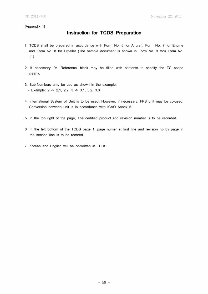
OD 2011-760 November 22, 2011
- 59 -
[Appendix 1]
Instruction for TCDS Preparation
1. TCDS shall be prepared in accordance with Form No. 6 for Aircraft, Form No. 7 for Engine and Form No. 8 for Prpeller (The sample document is shown in Form No. 9 thru Form No. 11)
2. If necessary, 'V. Reference' block may be filled with contents to specify the TC scope clearly.
3. Sub-Numbers amy be use as shown in the example; - Example: 2 -> 2.1, 2.2, 3 -> 3.1, 3.2, 3.3
4. International System of Unit is to be used. However, if necessary, FPS unit may be co-used. Conversion between unit is in accordance with ICAO Annex 5.
5. In the top right of the page, The certified product and revision number is to be recorded.
6. In the left bottom of the TCDS page 1, page numer at first line and revision no by page in the second line is to be recored.
7. Korean and English will be co-written in TCDS.

OD 2011-760 November 22, 2011
- 60 -
(1) General information including applicant identification, application date, model designation, and so forth.
(2) A description of the proposed design or design change including sketches and schematics.
(3) The intended regulatory operating environment. This should identify the kinds of operations for which the product will be used, and the kind of program under which the product will be maintained.
(4) The proposed certification basis including applicable regulation paragraphs and subparagraphs with amendment levels, exemptions, ELOS findings, and special conditions.
(5) A description of how compliance will be shown (ground test, flight test, analysis, similarity, or other acceptable means of compliance). The description of the means of compliance should be sufficient to determine that all necessary MLTM data will be collected and all findings can be made.
(6) A list of documentation that will be submitted to show compliance with the applicable certification basis, and how the applicant will ensure that all showings have been made. This can be accomplished using a compliance checklist addressing each section of the regulations applicable to the product.
(7) A list of test articles and test set-up to be used to generate compliance data. Identify any features or attributes for which special instructions to the manufacturing inspector will be necessary to ensure the test article meets the requirements of its tests (for example, dimensions at one or the other end of a tolerance band).
(8) A description of how the continued operational safety requirements will be met after the TC is issued.
(9) A project schedule including major milestones, such as system safety analysis(SSA) submittal dates, substantiating data submittal dates, conformity and testing completion dates(dates and locations for parts conformity inspections and installation conformity inspections, dates and locations for testing etc.), and expected date of final certification.
NOTE: The applicant is responsible for meeting their milestones in the schedule contained in the certification plan. Any slippage in the milestone dates may result in a delay in the final certification.
(10) Use of Designees (Reserved.)
(11) Conformity plan on the test article and schedule data to assure the conformity of test articles and the flight test prototypes to be used in the certification tests.
(Note) Applicants should consider the conformity requirements elsewhere in this and other orders and present a plan that supports their showing of compliance for a TC and the MLTM's finding of compliance for the TC and PC.
[Appendix 2]
Certification Plan Composition
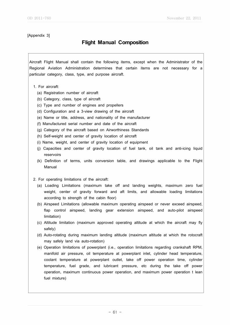
OD 2011-760 November 22, 2011
- 61 -
Aircraft Flight Manual shall contain the following items, except when the Administrator of the Regional Aviation Administration determines that certain items are not necessary for a particular category, class, type, and purpose aircraft.
1. For aircraft: (a) Registration number of aircraft (b) Category, class, type of aircraft (c) Type and number of engines and propellers (d) Configuration and a 3-view drawing of the aircraft (e) Name or title, address, and nationality of the manufacturer (f) Manufactured serial number and date of the aircraft (g) Category of the aircraft based on Airworthiness Standards (h) Self-weight and center of gravity location of aircraft (i) Name, weight, and center of gravity location of equipment (j) Capacities and center of gravity location of fuel tank, oil tank and anti-icing liquid
reservoirs (k) Definition of terms, units conversion table, and drawings applicable to the Flight
Manual
2. For operating limitations of the aircraft: (a) Loading Limitations (maximum take off and landing weights, maximum zero fuel
weight, center of gravity forward and aft limits, and allowable loading limitations according to strength of the cabin floor)
(b) Airspeed Limitations (allowable maximum operating airspeed or never exceed airspeed, flap control airspeed, landing gear extension airspeed, and auto-pilot airspeed limitation)
(c) Altitude limitation (maximum approved operating altitude at which the aircraft may fly safely)
(d) Auto-rotating during maximum landing altitude (maximum altitude at which the rotocraft may safely land via auto-rotation)
(e) Operation limitations of powerplant (i.e., operation limitations regarding crankshaft RPM, manifold air pressure, oil temperature at powerplant inlet, cylinder head temperature, coolant temperature at powerplant outlet, take off power operation time, cylinder temperature, fuel grade, and lubricant pressure, etc during the take off power operation, maximum continuous power operation, and maximum power operation t lean fuel mixture)
[Appendix 3]
Flight Manual Composition

OD 2011-760 November 22, 2011
- 62 -
(f) Maximum RPM of rotor blade (g) Air temperature limitation at which engine can effectively operate. (h) Cross wind velocity limitations at takeoff and landing (i) Water condition limitations (wind velocity during taxi, take off, or landing of seaplane on
water surface including operating limitations concerning water surface conditions) (j) Occupant limitation (maximum number of persons that can be boarded on aircraft) (k) Flight maneuvering limitation (prohibiting flight maneuvering of the aircraft) (l) Towing method (operation limitation for towing method by which a glider may be safely
towed) (m) Operation limitation for equipment (operation limitation for use of component or other
specific of aircraft) (n) Other operation limitations (restrictions concerning takeoff and landing distance
limitations; limit load factor limitations; electrical system operation limitations; autopilot limitations; limitations of instrument, flight controls, and other equipment; smoking prohibited area; and locations for dangerous goods, etc.)
3. For the performance of the aircraft: (a) Relationship between takeoff operation and takeoff airspeed (b) Relationship between takeoff weight, altitude, and air temperature at takeoff location (c) Takeoff climb angle (d) Takeoff distance (e) Actual takeoff climb flight path (f) Cruise performance (g) Relationship between landing operation and takeoff airspeed (h) Relationship between landing weight, altitude, and air temperature at landing location (i) Balked landing operation and/or condition (j) Landing distance (k) Stall performance (l) Other performance limitations necessary fir handing and controlling the aircraft
4. For operating procedures during normal operations
5. For operating procedures during emergencies

OD 2011-760 November 22, 2011
- 63 -
Significant Change Significant Project
KAR 21.19 Designation of applicable regulations
Change in design, power, thrust, or weight is so extensive that substantially complete investigation of compliance with the applicable regulations is required.
(1) New TC application(2) ATC, STC, or ASTC application for: (a) Special conditions exemptions or
equivalent safety findings. (b) Unusual methods of construction. (c) Flight control or rotordrive system
changes. (d) Substantially altered flight characteristics. (e) Areas of major service difficulty. (f) Change from reciprocating to
turboprop/jet or engine/prop change. (g) Affected load-bearing structures. (h) New state-of-the-art systems or
components. (i) Controversial or visible issues. (j) General Aviation
For a small airplane with seating capacity of six (6) or more with a reasonable potential for use in 14 CFR part 135 operation and include proposed changes that affect operational aspects of the airplane such as those which would require flight testing and/or revisions to the Airplane Flight Manual (AFM) or Maintenance Manual.
KAR 21.19 Designation of applicable regulations-1 Significant change requiring compliance to latest applicable regulations.Change is significant if: (i) General configuration or principles of construction are not retained. (ii) Assumptions used for certification of the product to be changed do not remain valid.
[Appendix 4]
Significant Change v.s. Significant Project

OD 2011-760 November 22, 2011
- 64 -
[Appendix 5]
PSCP Composition
1. Purpose
2. Effectivity
3. Product Certification
3.1 Project Description
3.2. Project Schedule
3.3 Certification Basis
3.4. Means Of Compliance
3.5. Communication and Coordination
3.6. Delegation - Reserved
3.7 Testing Plan
3.7.1 General
3.7.2 Flight Test
3.7.3 Conformity
3.8. Compliance Documentation
4. Production Certification4.1 Conformity Inspection Plan
4.2 (Conformity for Production Certification
5. Post Certification Requirements
5.1 Compliance Summary Document
5.2 Instructions For Continued Airworthiness (ICA)
5.3 Continued Airworthiness Management
6. Project Issues Planning
7. Continuous Improvement
7.1 General
7.2 Performance Measures
7.2.1 General
7.2.2 Operating Norms
7.2.3 Phase Evaluation Checklists
8. Signatories

OD 2011-760 November 22, 2011
- 65 -
(1) A description of the items to be tested
(2) A list of all equipment necessary to conduct the test
(3) A description of how the equipment is to be calibrated (when calibration is required) and approved before the test
(4) Required conformities of the test article and test setup
(5) A list of the specific airworthiness standards, a description of how compliance is expected to be shown and a description of how compliance is expected to be shown
(6) A test procedure written in a step-by-step format with defined pass/fail criteria.
[Appendix 6]
Test Plan Composition
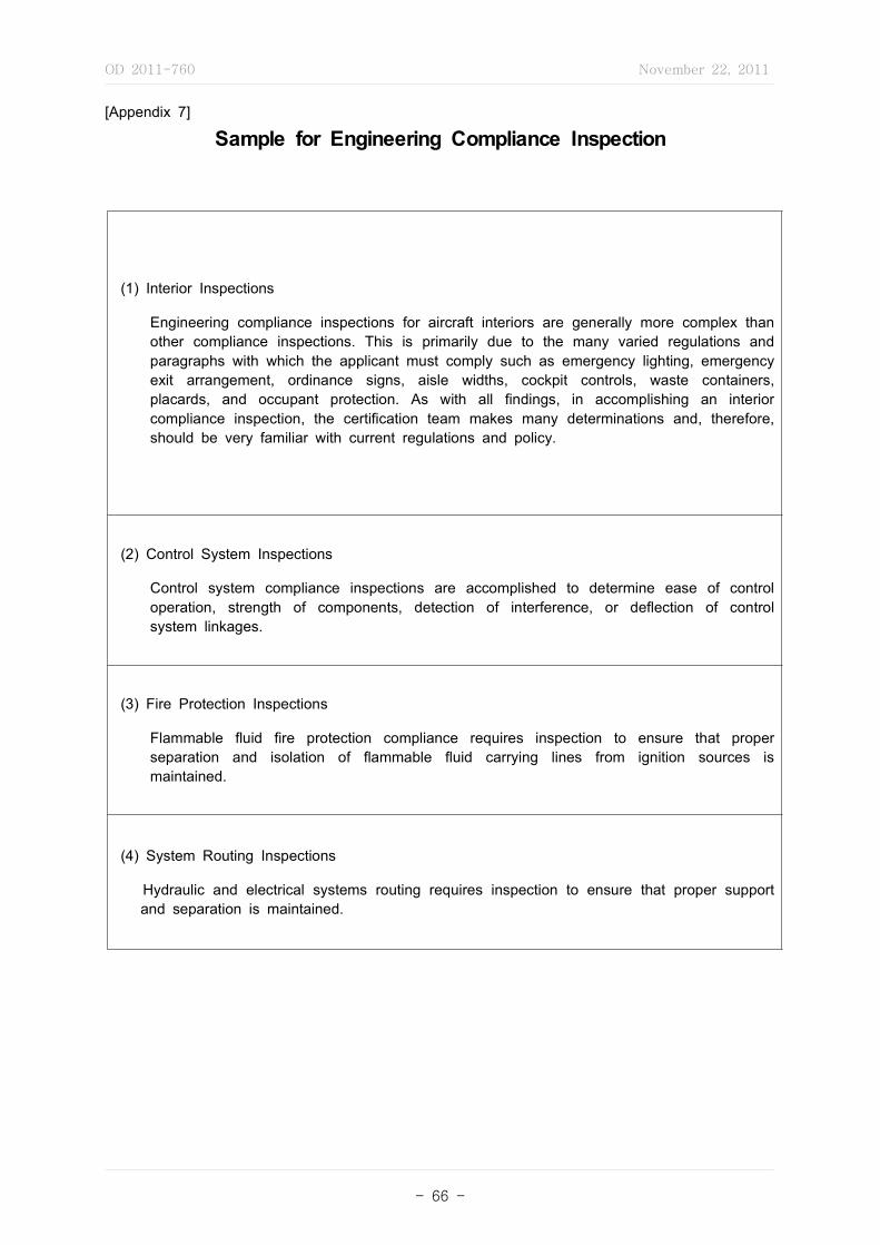
OD 2011-760 November 22, 2011
- 66 -
(1) Interior Inspections
Engineering compliance inspections for aircraft interiors are generally more complex than other compliance inspections. This is primarily due to the many varied regulations and paragraphs with which the applicant must comply such as emergency lighting, emergency exit arrangement, ordinance signs, aisle widths, cockpit controls, waste containers, placards, and occupant protection. As with all findings, in accomplishing an interior compliance inspection, the certification team makes many determinations and, therefore, should be very familiar with current regulations and policy.
(2) Control System Inspections
Control system compliance inspections are accomplished to determine ease of control operation, strength of components, detection of interference, or deflection of control system linkages.
(3) Fire Protection Inspections
Flammable fluid fire protection compliance requires inspection to ensure that proper separation and isolation of flammable fluid carrying lines from ignition sources is maintained.
(4) System Routing Inspections
Hydraulic and electrical systems routing requires inspection to ensure that proper support and separation is maintained.
[Appendix 7]
Sample for Engineering Compliance Inspection
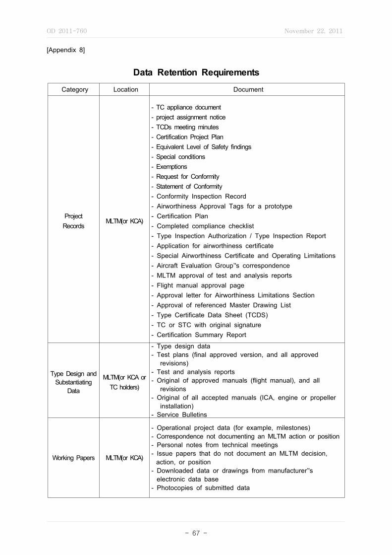
OD 2011-760 November 22, 2011
- 67 -
Category Location Document
ProjectRecords
MLTM(or KCA)
- TC appliance document- project assignment notice- TCDs meeting minutes- Certification Project Plan- Equivalent Level of Safety findings- Special conditions- Exemptions- Request for Conformity- Statement of Conformity- Conformity Inspection Record- Airworthiness Approval Tags for a prototype- Certification Plan- Completed compliance checklist- Type Inspection Authorization / Type Inspection Report- Application for airworthiness certificate- Special Airworthiness Certificate and Operating Limitations- Aircraft Evaluation Group’'s correspondence- MLTM approval of test and analysis reports- Flight manual approval page- Approval letter for Airworthiness Limitations Section- Approval of referenced Master Drawing List- Type Certificate Data Sheet (TCDS)- TC or STC with original signature- Certification Summary Report
Type Design and Substantiating
Data
MLTM(or KCA or TC holders)
- Type design data- Test plans (final approved version, and all approved
revisions)- Test and analysis reports- Original of approved manuals (flight manual), and all
revisions- Original of all accepted manuals (ICA, engine or propeller
installation)- Service Bulletins
Working Papers MLTM(or KCA)
- Operational project data (for example, milestones)- Correspondence not documenting an MLTM action or position- Personal notes from technical meetings- Issue papers that do not document an MLTM decision,
action, or position- Downloaded data or drawings from manufacturer’'s
electronic data base- Photocopies of submitted data
[Appendix 8]
Data Retention Requirements
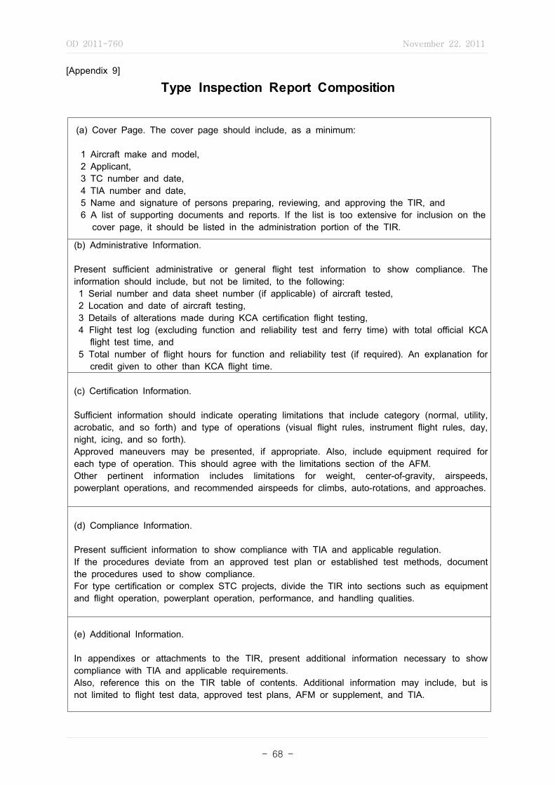
OD 2011-760 November 22, 2011
- 68 -
[Appendix 9]
Type Inspection Report Composition
(a) Cover Page. The cover page should include, as a minimum:
1 Aircraft make and model, 2 Applicant, 3 TC number and date, 4 TIA number and date, 5 Name and signature of persons preparing, reviewing, and approving the TIR, and 6 A list of supporting documents and reports. If the list is too extensive for inclusion on the
cover page, it should be listed in the administration portion of the TIR.
(b) Administrative Information.
Present sufficient administrative or general flight test information to show compliance. The information should include, but not be limited, to the following: 1 Serial number and data sheet number (if applicable) of aircraft tested, 2 Location and date of aircraft testing, 3 Details of alterations made during KCA certification flight testing, 4 Flight test log (excluding function and reliability test and ferry time) with total official KCA
flight test time, and 5 Total number of flight hours for function and reliability test (if required). An explanation for
credit given to other than KCA flight time.
(c) Certification Information.
Sufficient information should indicate operating limitations that include category (normal, utility, acrobatic, and so forth) and type of operations (visual flight rules, instrument flight rules, day, night, icing, and so forth). Approved maneuvers may be presented, if appropriate. Also, include equipment required for each type of operation. This should agree with the limitations section of the AFM. Other pertinent information includes limitations for weight, center-of-gravity, airspeeds, powerplant operations, and recommended airspeeds for climbs, auto-rotations, and approaches.
(d) Compliance Information. Present sufficient information to show compliance with TIA and applicable regulation. If the procedures deviate from an approved test plan or established test methods, document the procedures used to show compliance. For type certification or complex STC projects, divide the TIR into sections such as equipment and flight operation, powerplant operation, performance, and handling qualities.
(e) Additional Information.
In appendixes or attachments to the TIR, present additional information necessary to show compliance with TIA and applicable requirements. Also, reference this on the TIR table of contents. Additional information may include, but is not limited to flight test data, approved test plans, AFM or supplement, and TIA.

OD 2011-760 November 22, 2011
- 69 -
(1) Materials
(a) Were raw materials used in the fabrication process in conformity with the design data? (b) Is evidence available to ensure the chemical and physical properties were identified and
checked as appropriate? (c) Is there documented evidence to show traceability from the raw material to the
prototype part? (d) Are there any part or process deviations recorded against the submitted design data
(including material review dispositions)?
(2) Processes and Processing
(a) Is there a process specification for each special process? (b) Has the applicant submitted the process specification for MLTM engineering review? (c) Does a check of the processed articles show the process produces consistent parts that
meet the type design? Is there statistical or other evidence to show this? (d) Is the process being operated following the process specification? Are any deviations
recorded?
(3) Critical and Major Characteristics
(a) Has the applicant identified and inspected all critical and major characteristics? (b) Does the applicant have a record of these inspections? (c) Does witnessing the re-inspection and surveillance show the above inspections were
accurate and adequate? (d) Are there any deviations recorded against the submitted design data (including material
review disposition)?(4) Workmanship
(a) Does the workmanship add to the quality of the product? (b) Could the workmanship be duplicated during production? (c) Has the applicant set criteria to identify workmanship practices?
(5) Adequacy of Drawings and Related Change Records
(a) Can the part be produced and inspected using the information on the drawing? (b) Are drawing tolerances practicable and attainable during production? What evidence
supports this? (c) Has the applicant included all changes in the drawing submitted for MLTM approval
(including one-time only deviations in the prototype article submitted for MLTM testing)? (d) What procedure does the applicant use to ensure an engineering change is included in
the production part and on the drawing? (e) Did the drawing include all information needed to inspect the part, the material to be
used, the treatment of the material (such as hardness, finish, and any special process specifications)?
(f) Did the drawing include applicable test specifications? Did the ACO engineer review these test specifications?
[Appendix 10]
Conformity Inspection Witness Consideration
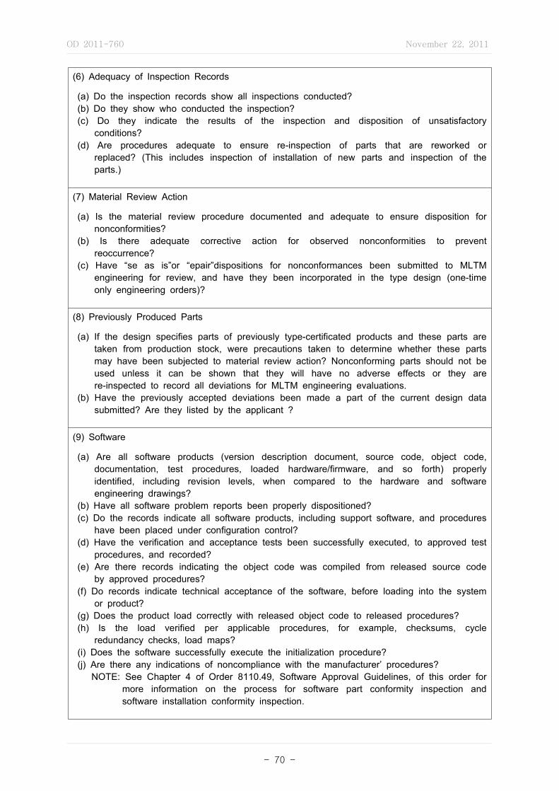
OD 2011-760 November 22, 2011
- 70 -
(6) Adequacy of Inspection Records
(a) Do the inspection records show all inspections conducted? (b) Do they show who conducted the inspection? (c) Do they indicate the results of the inspection and disposition of unsatisfactory
conditions? (d) Are procedures adequate to ensure re-inspection of parts that are reworked or
replaced? (This includes inspection of installation of new parts and inspection of the parts.)
(7) Material Review Action
(a) Is the material review procedure documented and adequate to ensure disposition for nonconformities?
(b) Is there adequate corrective action for observed nonconformities to prevent reoccurrence?
(c) Have “se as is”or “epair”dispositions for nonconformances been submitted to MLTM engineering for review, and have they been incorporated in the type design (one-time only engineering orders)?
(8) Previously Produced Parts
(a) If the design specifies parts of previously type-certificated products and these parts are taken from production stock, were precautions taken to determine whether these parts may have been subjected to material review action? Nonconforming parts should not be used unless it can be shown that they will have no adverse effects or they are re-inspected to record all deviations for MLTM engineering evaluations.
(b) Have the previously accepted deviations been made a part of the current design data submitted? Are they listed by the applicant ?
(9) Software
(a) Are all software products (version description document, source code, object code, documentation, test procedures, loaded hardware/firmware, and so forth) properly identified, including revision levels, when compared to the hardware and software engineering drawings?
(b) Have all software problem reports been properly dispositioned? (c) Do the records indicate all software products, including support software, and procedures
have been placed under configuration control? (d) Have the verification and acceptance tests been successfully executed, to approved test
procedures, and recorded? (e) Are there records indicating the object code was compiled from released source code
by approved procedures? (f) Do records indicate technical acceptance of the software, before loading into the system
or product? (g) Does the product load correctly with released object code to released procedures? (h) Is the load verified per applicable procedures, for example, checksums, cycle
redundancy checks, load maps? (i) Does the software successfully execute the initialization procedure? (j) Are there any indications of noncompliance with the manufacturer’ procedures? NOTE: See Chapter 4 of Order 8110.49, Software Approval Guidelines, of this order for
more information on the process for software part conformity inspection and software installation conformity inspection.
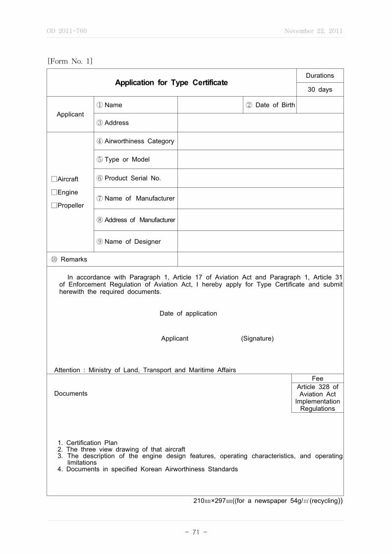
OD 2011-760 November 22, 2011
- 71 -
[Form No. 1]
Application for Type CertificateDurations
30 days
Applicant① Name ② Date of Birth
③ Address
□Aircraft
□Engine
□Propeller
④ Airworthiness Category
⑤ Type or Model
⑥ Product Serial No.
⑦ Name of Manufacturer
⑧ Address of Manufacturer
⑨ Name of Designer
⑩ Remarks
In accordance with Paragraph 1, Article 17 of Aviation Act and Paragraph 1, Article 31 of Enforcement Regulation of Aviation Act, I hereby apply for Type Certificate and submit herewith the required documents.
Date of application
Applicant (Signature)
Attention : Ministry of Land, Transport and Maritime Affairs
Documents
FeeArticle 328 of Aviation Act
Implementation Regulations
1. Certification Plan 2. The three view drawing of that aircraft 3. The description of the engine design features, operating characteristics, and operating
limitations 4. Documents in specified Korean Airworthiness Standards
210㎜×297㎜((for a newspaper 54g/㎥(recycling))

OD 2011-760 November 22, 2011
- 72 -
[Form No. 2]
Application for Supplemental Type CertificateDuration
30 days
Applicant① Name ② Date of Birth
③ Address
④ Airworthiness category
□Aircraft
□Engine
□Propeller
⑤ Type or Model
⑥ Product Serial No.
⑦ Name of Manufacturer
⑧ Address of Manufacturer
⑨ Name of Designer
⑩ Description of Modification
⑪ Intent to sell the Parts
⑫ Remarks
In accordance with Paragraph 4, Article 17 of Aviation Act and Paragraph 1, Article 32-2 of Enforcement Regulation of Aviation Act, I hereby apply for Supplemental Type Certificate and Submit herewith the required documents.
Date of application
Applicant (Signature) Attention : Ministry of Land, Transport and Maritime Affairs
Documents
Fee
Article 328 of Aviation Act
Implementation Regulations
1. Copy of Supplemental Type Certificate Plan 2. Copy of Design Drawings and Drawings List 3. Copy of Parts List and Specifications 4. Copy of Reference Documents
210㎜×297㎜((for a newspaper 54g/㎥(recycling))

OD 2011-760 November 22, 2011
- 73 -
[Form No. 3]
Certificate No. :
The Republic of KoreaMinistry of Land, Transport and Maritime Affairs
Type Certificate
1. Classification
2. Type or Model
3. Name of Designer
4. Address of Designer
5. Airworthiness Category
6. Type Certificate Date Sheet No.
In accordance with Paragraph 2, Article 17 of Aviation Act and Paragraph 1, Article 34 of Enforcement Regulation of Aviation Act, the Minister of the Ministry of Land, Transport and Maritime Affairs hereby certifies that the abovementioned [aircraft, engine, propeller] type design meets airworthiness requirements of Aviation Act.
Date of issuance
Ministry of Land, Transport and Maritime Affairs
210㎜×297㎜((for a newspaper 54g/㎥(recycling))
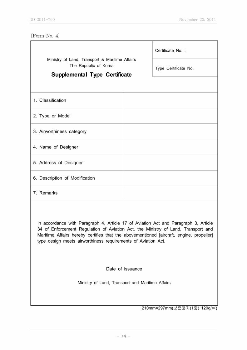
OD 2011-760 November 22, 2011
- 74 -
[Form No. 4]
Ministry of Land, Transport & Maritime AffairsThe Republic of Korea
Supplemental Type Certificate
Certificate No. :
Type Certificate No.
1. Classification
2. Type or Model
3. Airworthiness category
4. Name of Designer
5. Address of Designer
6. Description of Modification
7. Remarks
In accordance with Paragraph 4, Article 17 of Aviation Act and Paragraph 3, Article 34 of Enforcement Regulation of Aviation Act, the Ministry of Land, Transport and Maritime Affairs hereby certifies that the abovementioned [aircraft, engine, propeller] type design meets airworthiness requirements of Aviation Act.
Date of issuance
Ministry of Land, Transport and Maritime Affairs
210mm×297mm(보존용지(1종) 120g/㎡)
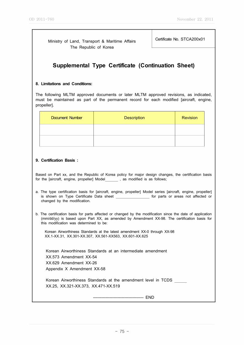
OD 2011-760 November 22, 2011
- 75 -
Ministry of Land, Transport & Maritime AffairsThe Republic of Korea
Certificate No. STCA200x01
Supplemental Type Certificate (Continuation Sheet)
Document Number Description Revision
8. Limitations and Conditions:
The following MLTM approved documents or later MLTM approved revisions, as indicated, must be maintained as part of the permanent record for each modified [aircraft, engine, propeller].
9. Certification Basis :
Based on Part xx, and the Republic of Korea policy for major design changes, the certification basis for the [aircraft, engine, propeller] Model , as modified is as follows;
a. The type certification basis for [aircraft, engine, propeller] Model series [aircraft, engine, propeller] is shown on Type Certificate Data sheet for parts or areas not affected or changed by the modification.
b. The certification basis for parts affected or changed by the modification since the date of application (mm/dd/yy) is based upon Part XX, as amended by Amendment XX-98. The certification basis for this modification was determined to be:
Korean Airworthiness Standards at the latest amendment XX-0 through XX-98 XX.1-XX.31, XX.301-XX.307, XX.561-XX563, XX.601-XX.625
Korean Airworthiness Standards at an intermediate amendment XX.573 Amendment XX-54 XX.629 Amendment XX-26 Appendix X Amendment XX-58
Korean Airworthiness Standards at the amendment level in TCDS XX.25, XX.321-XX.373, XX.471-XX.519
------------------------------------- END

OD 2011-760 November 22, 2011
- 76 -
[Form No. 5]
Application for Change to Type Designdurations
30 days
□Aircraft
□Engine
□Propeller
① Classification
② Type or Model ③ TC No.
④ Name of Designer ⑤ Manufacture serial No.
⑥ Address of Manufacturer
⑧Airworthiness Certificate No. (only aircraft)
⑨Effective date of Airworthiness Certificate (only aircraft)
⑩ Description of changes
⑪ Remarks
In accordance with Paragraph 2. Article 35 of Implementation Regulations of Aviation Act. I hereby apply for change to Type Design and submit herewith the required documents.
Date of application
Applicant (Signature)
Attention : Ministry of Land, Transport and Maritime Affairs
feeArticle 328 of Aviation Act
Implementation Regulations
Documents
1. Copy of Type Certificate 2. Certification Plan 3. The three view drawing of that aircraft 4. The description of the engine design features, operating characteristics, and operating
limitations 5. Copy of Reference Documents
210㎜×297㎜((for a newspaper 54g/㎥(recycling))
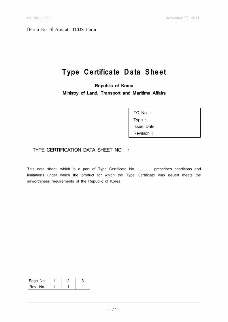
OD 2011-760 November 22, 2011
- 77 -
[Form No. 6] Aircraft TCDS Form
Type C ertificate D ata S heetRepublic of Korea
Ministry of Land, Transport and Maritime Affairs
TC No. :
Type : Issue Date : Revision :
TYPE CERTIFICATION DATA SHEET NO. :
This data sheet, which is a part of Type Certificate No. ______, prescribes conditions and limitations under which the product for which the Type Certificate was issued meets the airworthiness requirements of the Republic of Korea.
Page No. 1 2 3Rev. No. 1 1 1
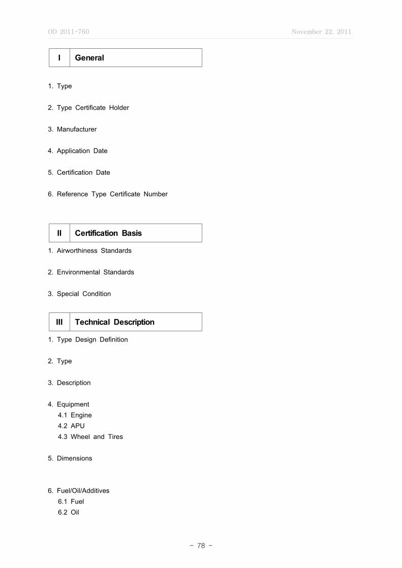
OD 2011-760 November 22, 2011
- 78 -
I General
1. Type
2. Type Certificate Holder
3. Manufacturer
4. Application Date
5. Certification Date
6. Reference Type Certificate Number
II Certification Basis
1. Airworthiness Standards 2. Environmental Standards 3. Special Condition
III Technical Description
1. Type Design Definition 2. Type 3. Description 4. Equipment 4.1 Engine 4.2 APU 4.3 Wheel and Tires
5. Dimensions
6. Fuel/Oil/Additives 6.1 Fuel 6.2 Oil

OD 2011-760 November 22, 2011
- 79 -
IV Operational Limits
The following declared limitations and ratings shall apply.
1. Temperature Limits
2. Pressure Limits 2.1 Engine Limits
Conditions Thrust(lbs)
RPM %TGT(℃) Time Limit
HP LP
Maximum take-off
Maximum continuous
Starting and relight
Maximum over speed
Maximum over temp.
2.2 APU Limits
Conditions Maximum RPM Maximum TGT(℃)
Start
Transient 10 seconds
Sustained
3. Speed Limits
4. Maximum Operating Altitude
5. Weather Capacity
6. Maximum Certification weight
Taxi
Take-off
Landing
Empty Weight
7. Center of Gravity
8. Minimum Flight Crew
OD 2011-760 November 22, 2011
- 80 -
9. Maximum Boarding Passenger
10. Exits
11. Maximum Baggage
V Notes
Note 1. Operating and Service Manual

OD 2011-760 November 22, 2011
- 81 -
[Form No. 7] Engine TCDS Form
Type C ertificate D ata S heetRepublic of Korea
Ministry of Land, Transport and Maritime Affairs
TC No. :
Type : Issue Date : Revision :
TYPE CERTIFICATION DATA SHEET NO. :
This data sheet, which is a part of Type Certificate No. ______, prescribes conditions and limitations under which the product for which the Type Certificate was issued meets the airworthiness requirements of the Republic of Korea.
Page No. 1 2 3Rev. No. 1 1 1
OD 2011-760 November 22, 2011
- 82 -
I General
1. Type
2. Type Certificate Holder
3. Manufacturer
4. Application Date
5. Certification Date
6. Reference Type Certificate Number
II Certification Basis
1. Airworthiness Standards
2. Environmental Standards
3. Special Condition
III Technical Description
1. Type Design Definition2. Type3. Description4. Equipment5. Dimensions
Overall Length mm (inches)
Overall Width mm (inches)
Overall Height mm (inches)
6. Ratings
ThrustkW(lb)
Take-off 5 minutesMaximum Continuous
Rating Ambient Temperature ℃(℉ )Take-off 5 minutes
Maximum Continuous
OD 2011-760 November 22, 2011
- 83 -
7. Control System
8. Fuel/Oil/Additives
9. Aircraft Accessory Drives
Rotation Facing Gearbox
Gear Ratio to Core Speed
HorsepowerContinuousPad Rating
kW(HP)
Shear Torque(**)Nm(in-lb)
MaximumOverhungMomentNm(in-lb)
IDG
Hydraulic PumpVSCF/PMGGenerator
IDG Overload LimitsVSFC/PMG
Overload Limits
10. Maximum Permissible Air Bleed Extraction
IV Operational Limits
The following declared limitations and ratings shall apply.
1. Temperature Limits
Exhaust Gas Temperature Temp. ℃℉
Takeoff (5minutes)
60 seconds maxumum transient
Maximum Continuous
Starting (Maximum on Ground)
Starting (Maximum in Flight)
Oil Temperature
Continuous Operation
Transient(Max. 15 minutes)
2. Pressure Limits
3. Speed Limits

OD 2011-760 November 22, 2011
- 84 -
Take-offRPM(%)
Low Pressure Rotor(N1)
High Pressure Rotor(N2)
Maximum ContinuousRPM (%)
Low Pressure Rotor(N1)
High Pressure Rotor(N2)
V Notes
Note 1. Operating and Service Manual

OD 2011-760 November 22, 2011
- 85 -
[Form No. 8] Propeller TCDS Form
Type C ertificate D ata S heetRepublic of Korea
Ministry of Land, Transport and Maritime Affairs
TC No. :
Type : Issue Date : Revision :
TYPE CERTIFICATION DATA SHEET NO. :
This data sheet, which is a part of Type Certificate No. ______, prescribes conditions and limitations under which the product for which the Type Certificate was issued meets the airworthiness requirements of the Republic of Korea.
Page No. 1 2 3Rev. No. 1 1 1

OD 2011-760 November 22, 2011
- 86 -
I General
1. Type
2. Type Certificate Holder
3. Manufacturer
4. Application Date
5. Certification Date
6. Reference Type Certificate Number
II Certification Basis
1. Airworthiness Standards
2. Environmental Standards
3. Special Condition
III Technical Description
1. Type Design Definition
2. Type
3. Description
4. Equipment
5. Dimension

OD 2011-760 November 22, 2011
- 87 -
IV Operational Limits
The following declared limitations and ratings shall apply.
1. Temperature Limits
2. Speed Limits
3. Propeller Pitch Angle
V Notes
Note 1. Operating and Service Manual
OD 2011-760 November 22, 2011
- 88 -
[Form No. 9] sample of Aircraft TCDS
Type C ertificate D ata S heetRepublic of Korea
Ministry of Land, Transport and Maritime Affairs
TC No. : ACTC-0905
Type : KX-500
Issue Date : 4. May. 2009 Revision : 1
TYPE CERTIFICATION DATA SHEET NO. : ACTC-0905
This data sheet, which is a part of Type Certificate No. ACTC-0905, prescribes conditions and limitations under which the product for which the Type Certificate was issued meets the airworthiness requirements of the Republic of Korea.
Page No. 1 2 3Rev. No. 1 1 1

OD 2011-760 November 22, 2011
- 89 -
I General
1. Type : KX-500
2. Type Certificate Holder KAI, 664-942, Kyung Nam, Sa Cheon, Sanam Myeon, Youchon Li 802
3. Manufacturer KAI, 664-942, Kyung Nam, Sa Cheon, Sanam Myeon, Youchon Li 802
4. Application Date 5. May. 2006
5. Certification Date 4. May. 2009
6. Reference Type Certificate Number FAA 9AN50 EASA A.198
II Certification Basis
1. Airworthiness Standards 1.1 Korean Airworthiness Standard Part 25 (Effective 6. July 2006) Reference - Korea Airworthiness Standard Part 25 is established on 24. August. 1993.
Now, Amendment 4 to KAS part 25 is established and The project number "ACTC-0905" apply to amendment 4.
1.2 Federal Aviation Regulation FAR Part 25, Amendment 15 (Effective 02. Jun. 2001) 1.3 EASA JAR-25, Change 15 (Effective 01. Oct. 2000)
2. Environmental Standards ICAO Annex 16 Volume I, 4th Edition (Effective 24. Nov. 2005) ICAO Annex 16 Volume II, 2nd Edition (Effective 24. Nov. 2005)
3. Special Condition None
OD 2011-760 November 22, 2011
- 90 -
III Technical Description
1. Type Design Definition Drawings are defined in the KX-500 System List No. 700-0, KX-500 Master Equipment No.
700-1, KX-500 Drawings No. 700s50 through 700s150 2. Type KX-500
3. Description Low wing jet transport with a T tail unit configuration. Powered by two high bypass turbofan
engines mounted on pylons beneath the wings. The structure is conventional with an aluminum-ally fuselage, wing, and tail; while ailerons, flaps, spoilers, elevator, and rudder are of composite material. The landing gear is retractable tricycle type, and carbon main landing gear wheel brakes.
4. Equipment 4.1 Engine Two General Electric CF34-10E5, CF34-10E5A1, CF34-10E6, CF34-10E6A1 Turbofan engines. (see Note 2)
4.2 APU Hamilton Sundstrand APS 2300
4.3 Wheel and Tires WIA KX-500 series wheel A 24 X 7.7 Kumho KX-500 series tire A 17.5 X 6.26 5. Dimensions
Length m (inches) 36.24 (118.83)
Span m (inches) 28.72 (94.25)
Height mm (inches) 10.57 (34.67)
Wing Area m ft 92.53 (996)
6. Fuel/Oil/Additives 6.1 Fuel Jet A, Jet A-1, Jet B (ASTM D-1655), JP 4, JP 5 (MIL-T-5624), JP-8 (MIL-T-83133D), CIS fuels RT and TS-1 (GOST 10227), Jet TH (STAS 5639-88). All aviation gas turbine
fuels conforming to the GE Jet Fuel Specification NO. D50TF2

OD 2011-760 November 22, 2011
- 91 -
Location Volume WeightLiters US Gal kg lb
Left Wing 1610 425 1290 2845Right Wing 1610 425 1290 2845
Total Usable 3220 850 2580 5690
Reference - Fuel weight based upon fuel density 0.802kg/l (6.7lb/US Gal) Maximum pressure for pressure fuelling is 345kPa (50psi)
6.2 Oil See KX-500 Flight manual and GE operating instructions.

OD 2011-760 November 22, 2011
- 92 -
IV Operational Limits
The following declared limitations and ratings shall apply.
1. Temperature Limits Refer approved flight manual and engine manual (see Note 1.)
2. Pressure Limits 2.1 Engine Limits
Conditions Thrust (lbs)RPM %
TGT(℃) Time LimitHP LP
Maximum take-offMaximum continuousStarting and relightMaximum over speedMaximum over temp.
2.2 APU Limits
Conditions Maximum RPM Maximum TGT(℃)
Start
Transient 10 seconds
Sustained
3. Speed Limits Refer approved flight manual and engine manual (see Note 1.)
4. Maximum Operating Altitude 7620m (25000ft) Pressure Altitude 7620m (25000ft)
5. Weather Capacity CAT II
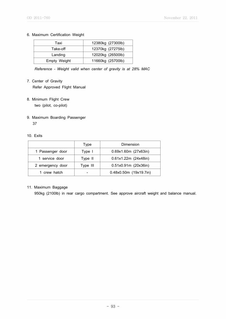
OD 2011-760 November 22, 2011
- 93 -
6. Maximum Certification Weight
Taxi 12380kg (27300lb)Take-off 12370kg (27275lb)Landing 12020kg (26500lb)
Empty Weight 11660kg (25700lb)
Reference - Weight valid when center of gravity is at 28% MAC
7. Center of Gravity Refer Approved Flight Manual
8. Minimum Flight Crew two (pilot, co-pilot)
9. Maximum Boarding Passenger 37
10. Exits
Type Dimension
1 Passenger door Type I 0.69x1.60m (27x63in)
1 service door Type II 0.61x1.22m (24x48in)
2 emergency door Type III 0.51x0.91m (20x36in)
1 crew hatch - 0.48x0.50m (19x19.7in)
11. Maximum Baggage 950kg (2100lb) in rear cargo compartment. See approve aircraft weight and balance manual.
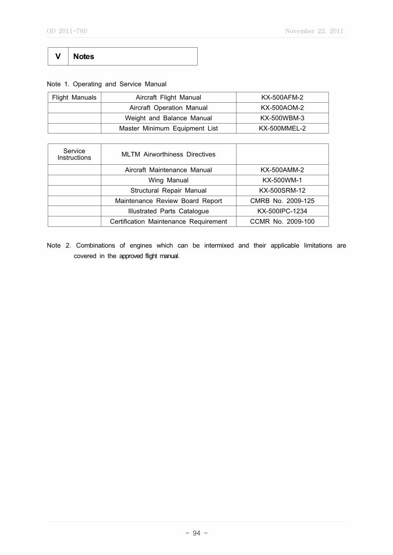
OD 2011-760 November 22, 2011
- 94 -
V Notes
Note 1. Operating and Service Manual
Flight Manuals Aircraft Flight Manual KX-500AFM-2Aircraft Operation Manual KX-500AOM-2
Weight and Balance Manual KX-500WBM-3Master Minimum Equipment List KX-500MMEL-2
Service Instructions MLTM Airworthiness Directives
Aircraft Maintenance Manual KX-500AMM-2Wing Manual KX-500WM-1
Structural Repair Manual KX-500SRM-12Maintenance Review Board Report CMRB No. 2009-125
Illustrated Parts Catalogue KX-500IPC-1234Certification Maintenance Requirement CCMR No. 2009-100
Note 2. Combinations of engines which can be intermixed and their applicable limitations are covered in the approved flight manual.
OD 2011-760 November 22, 2011
- 95 -
[Form No. 10] Sample of Engine TCDS
Type C ertificate D ata S heetRepublic of Korea
Ministry of Land, Transport and Maritime Affairs
TC No. : ECTC-0905
Type : KX-500
Issue Date : 2009년 5월 4일
Revision : 1
TYPE CERTIFICATION DATA SHEET NO. : ECTC-0905
This data sheet, which is a part of Type Certificate No. ECTC-0905, prescribes conditions and limitations under which the product for which the Type Certificate was issued meets the airworthiness requirements of the Republic of Korea.
Page No. 1 2 3
Rev. No. 1 1 1

OD 2011-760 November 22, 2011
- 96 -
I General
1. Type : KX-50A-T
2. Type Certificate Holder KAI, 664-942, Kyung Nam, Sa Cheon, Sanam Myeon, Youchon Li 802
3. Manufacturer KAI, 664-942, Kyung Nam, Sa Cheon, Sanam Myeon, Youchon Li 802
4. Application Date KX-50A-T : 4. November. 2009
5. Certification Date KX-50A-T : 4. May. 2009
6. Reference Type Certificate Number FAA 7EN8 EASA E.122 TCCA 5ET48
II Certification Basis
1. Airworthiness Standards 1.1 Korean Airworthiness Standard Part 33 (Effective 6. September 2006) Reference 1 - Korea Airworthiness Standard Part 33 is established on 24. August. 1993.
Now, Amendment 4 to KAS part 33 is established and The project number "ECTC-0905" apply to amendment 4.
Reference 2 - The requirements of KAS Part 33 is a equivalent level to Amdt 15, JAR-E, and Change 9.
1.2 Federal Aviation Regulation FAR Part 33, Amendment 15 1.3 EASA JAR-E, Change 9

OD 2011-760 November 22, 2011
- 97 -
2. Environmental Standards ICAO Annex 16 Volume II, 2nd Edition (See Note 4.) Reference 1 - Korea Airworthiness Standard Part 34 is established on 30. June. 2007. Reference 2 - The requirements of KAS Part 34 is a equivalent level toICAO Annex 16
Volume II (2rd Edition).
3. Special Condition None
III Technical Description
1. Type Design Definition a design of KX-50A-T is defined as approved design and part lists.
2. Type KX-50A-T
3. Description Turbofan, axial 16 stage compressor, annular combustion chamber, 6 stage turbine
4. Equipment Approved equipment are included item III. 1. Type Design Definition.
5. Dimensions
Overall Length mm (inches) 7283 (286.9)
Overall Width mm (inches) 3871 (152.4)
Overall Height mm (inches) 3952 (155.6)
6. Ratings
Thrust kW(lb)Take-off 5 minutes 360,617 (81070)
Maximum Continuous 335,529 (75430)
Rating Ambient Temperature ℃(℉ )Take-off 5 minutes 32.8 (91)
Maximum Continuous 25 (77)
Reference - The engine ratings are based on dry sea level static ICAO standard atmospheric conditions, with no external accessory loads and no air-bleed. The quoted ratings are obtainable on a test stand with the specified fuel and oil, without intake ducting and using the exhaust port defined in the installation manual.
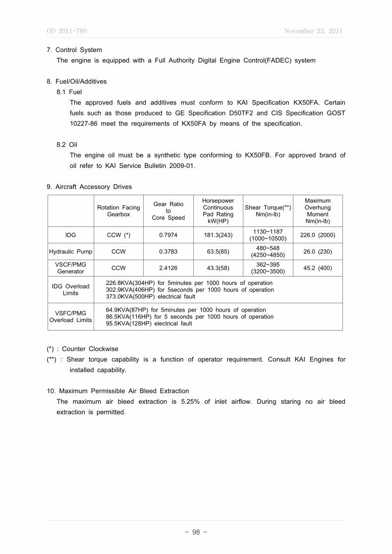
OD 2011-760 November 22, 2011
- 98 -
7. Control System The engine is equipped with a Full Authority Digital Engine Control(FADEC) system
8. Fuel/Oil/Additives 8.1 Fuel The approved fuels and additives must conform to KAI Specification KX50FA. Certain
fuels such as those produced to GE Specification D50TF2 and CIS Specification GOST 10227-86 meet the requirements of KX50FA by means of the specification.
8.2 Oil The engine oil must be a synthetic type conforming to KX50FB. For approved brand of
oil refer to KAI Service Bulletin 2009-01.
9. Aircraft Accessory Drives
Rotation Facing Gearbox
Gear Ratioto
Core Speed
HorsepowerContinuousPad Rating
kW(HP)
Shear Torque(**)Nm(in-lb)
MaximumOverhungMomentNm(in-lb)
IDG CCW (*) 0.7974 181.3(243) 1130~1187(1000~10500) 226.0 (2000)
Hydraulic Pump CCW 0.3783 63.5(85) 480~548(4250~4850) 26.0 (230)
VSCF/PMGGenerator CCW 2.4126 43.3(58) 362~395
(3200~3500) 45.2 (400)
IDG Overload Limits
226.8KVA(304HP) for 5minutes per 1000 hours of operation302.9KVA(406HP) for 5seconds per 1000 hours of operation373.0KVA(500HP) electrical fault
VSFC/PMGOverload Limits
64.9KVA(87HP) for 5minutes per 1000 hours of operation86.5KVA(116HP) for 5 seconds per 1000 hours of operation95.5KVA(128HP) electrical fault
(*) : Counter Clockwise(**) : Shear torque capability is a function of operator requirement. Consult KAI Engines for
installed capability.
10. Maximum Permissible Air Bleed Extraction The maximum air bleed extraction is 5.25% of inlet airflow. During staring no air bleed
extraction is permitted.
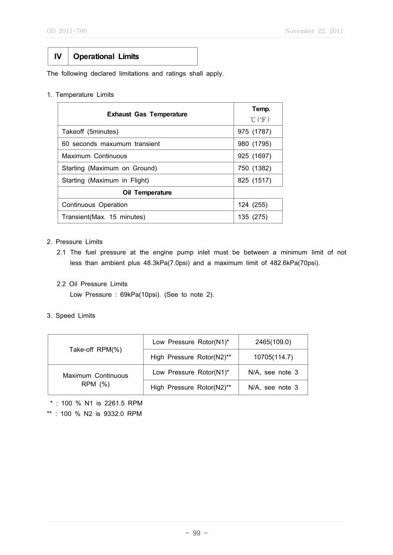
OD 2011-760 November 22, 2011
- 99 -
IV Operational Limits
The following declared limitations and ratings shall apply.
1. Temperature Limits
Exhaust Gas Temperature Temp. ℃℉
Takeoff (5minutes) 975 (1787)
60 seconds maxumum transient 980 (1795)
Maximum Continuous 925 (1697)
Starting (Maximum on Ground) 750 (1382)
Starting (Maximum in Flight) 825 (1517)
Oil Temperature
Continuous Operation 124 (255)
Transient(Max. 15 minutes) 135 (275)
2. Pressure Limits 2.1 The fuel pressure at the engine pump inlet must be between a minimum limit of not
less than ambient plus 48.3kPa(7.0psi) and a maximum limit of 482.6kPa(70psi).
2.2 Oil Pressure Limits Low Pressure : 69kPa(10psi). (See to note 2). 3. Speed Limits
Take-off RPM(%)Low Pressure Rotor(N1)* 2465(109.0)
High Pressure Rotor(N2)** 10705(114.7)
Maximum ContinuousRPM (%)
Low Pressure Rotor(N1)* N/A, see note 3
High Pressure Rotor(N2)** N/A, see note 3
* : 100 % N1 is 2261.5 RPM** : 100 % N2 is 9332.0 RPM
OD 2011-760 November 22, 2011
- 100 -
V Notes
Note 1. Operating and Service Manual Operation and Installation Manual : No. KX50 issued 7.Jun. 2007 (*) Overhaul Manual : No. KX50A issued 6.Nov. 2007 (*) Part List : No. KX50A issued 6.Nov. 2007 (*) Service Bulletins (*) : or later approved revision
Note 2. - During negative-g operation only, it is permissible to operate below minimum oil pressure (69kPa, 10psi) for maximum of 15 seconds. See KAI KX-50A-T operating instruction. K50A-100703, section 8.
Note 3. KX-50A-T model have no limits for maximum continuous N1 and N2 speeds. For information only, the values demonstrated during the FAR 33.87 test were N1 = 2390 RPM and N2 = 10590 RPM.
OD 2011-760 November 22, 2011
- 101 -
[Form No. 11] Sample of Propeller TCDS
Type C ertificate D ata S heetRepublic of Korea
Ministry of Land, Transport and Maritime Affairs
TC No. : PCTC-0905
Type : KX-500 Issue Date : 4. May. 2009 Revision : 1
TYPE CERTIFICATION DATA SHEET NO. : PCTC-0905
This data sheet, which is a part of Type Certificate No. PCTC-0905, prescribes conditions and limitations under which the product for which the Type Certificate was issued meets the airworthiness requirements of the Republic of Korea.
Page No. 1 2 3
Rev. No. 1 1 1
OD 2011-760 November 22, 2011
- 102 -
I General
1. Type KX-50A-01, KX-50A-02, KX-50B-0102
2. Type Certificate Holder KAI, 664-942, Kyung Nam, Sa Cheon, Sanam Myeon, Youchon Li 802
3. Manufacturer KAI, 664-942, Kyung Nam, Sa Cheon, Sanam Myeon, Youchon Li 802
4. Application Date KX-50A-01 : 4. Nov. 2006 KX-50A-02 : 4. Nov. 2007 KX-50B-0102 : 4. Nov. 2008
5. Certification Date KX-50A-01 : 4. May. 2007 KX-50A-02 : 4. May. 2008 KX-50B-0102 : 4. May. 2009
6. Reference Type Certificate Number FAA 4EN5 EASA P.098
II Certification Basis
1. Airworthiness Standards 1.1 Korean Airworthiness Standard Standard Part 35 (Effective 6. sept. 2006) Reference - Korea Airworthiness Standard Part 35 is established on 24. August. 1993.
Now, Amendment 4 to KAS part 35 is established and The project number "PCTC-0905" apply to amendment 4.
1.2 Federal Aviation Regulation FAR Part 35, Amendment 15 1.3 EASA JAR-P, Change 9
2. Environmental Standards none
3. Special Condition none

OD 2011-760 November 22, 2011
- 103 -
III Technical Description
1. Type Design Definition KX-50A series propeller is defined by a main assembly drawing and associated parts list:
KX-50A-01 KX-50A-02 KX-50B-0102
Drawing No. 50-MA 60-MA 70-MA
Parts List No. 50-PL 60-PL 70-PL
Approved date 2007년 7월 1일 2008년 7월 1일 2009년 2월 4일
2. Type KX-50A-01 : constant speed, feather, 2 blades KX-50A-02 : constant speed, feather, 2 blades KX-50B-0102 : constant, feather, 2 blades
3. Description 2-blade variable pitch propeller with a hydraulically operated blade pitch change mechanism
providing the operation mode "constant speed", "feather".
4. Equipment Spinner : Refer to KAI KX-50 Series SB 14 Governor : Refer to KAI KX-50 Series SB 15
5. Dimension Propeller Diameter : 170 cm ~ 200 cm
IV Operational Limits
The following declared limitations and ratings shall apply.
1. Temperature Limits The propeller is not operated with oil temperature below -18℃.
2. Speed Limits 2.1 Maximum Take Off Power and Speed Maximum Take Off Power : 224 KW Maximum Take Off Speed : 1200 RPM
2.2 Maximum Continuous Power and Speed Maximum Continuous Power : 224 KW Maximum Continuous Speed : 1200 RPM

OD 2011-760 November 22, 2011
- 104 -
3. Propeller Pitch Angle From -20° to +86° measured at 75% radius station
V Notes
Note 1. Operating and Service Manual Operation and Installation Manual : No. E501 issued 7.Jun. 2007 (*) Overhaul Manual : No. E500 issued 6.Nov. 2007 (*) Part List : No. E503 issued 6.Nov. 2007 (*) Service Bulletins (*) : or later approved revision
Note 2. Material Blade : Steel Hub : Aluminum Alloy
Note 3. Hub and Blade Combination
Hub Blade
KX-50A -01, -02
KX-50B -01, -02
Note 4. Model and Number system KX-50B-0102 KX : KAI 50B : model designation 0102 : Blade size
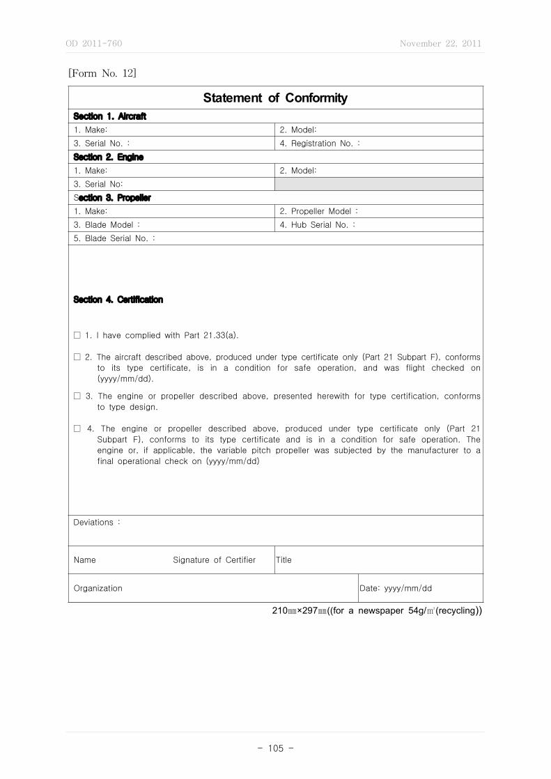
OD 2011-760 November 22, 2011
- 105 -
Statement of Conformity Section 1. Aircraft
1. Make: 2. Model:
3. Serial No. : 4. Registration No. :
Section 2. Engine
1. Make: 2. Model:
3. Serial No:
Section 3. Propeller
1. Make: 2. Propeller Model :
3. Blade Model : 4. Hub Serial No. :
5. Blade Serial No. :
Section 4. Certification
□ 1. I have complied with Part 21.33(a).
□ 2. The aircraft described above, produced under type certificate only (Part 21 Subpart F), conforms
to its type certificate, is in a condition for safe operation, and was flight checked on
(yyyy/mm/dd).
□ 3. The engine or propeller described above, presented herewith for type certification, conforms
to type design.
□ 4. The engine or propeller described above, produced under type certificate only (Part 21
Subpart F), conforms to its type certificate and is in a condition for safe operation. The
engine or, if applicable, the variable pitch propeller was subjected by the manufacturer to a
final operational check on (yyyy/mm/dd)
Deviations :
Name Signature of Certifier Title
Organization Date: yyyy/mm/dd
210㎜×297㎜((for a newspaper 54g/㎥(recycling))
[Form No. 12]
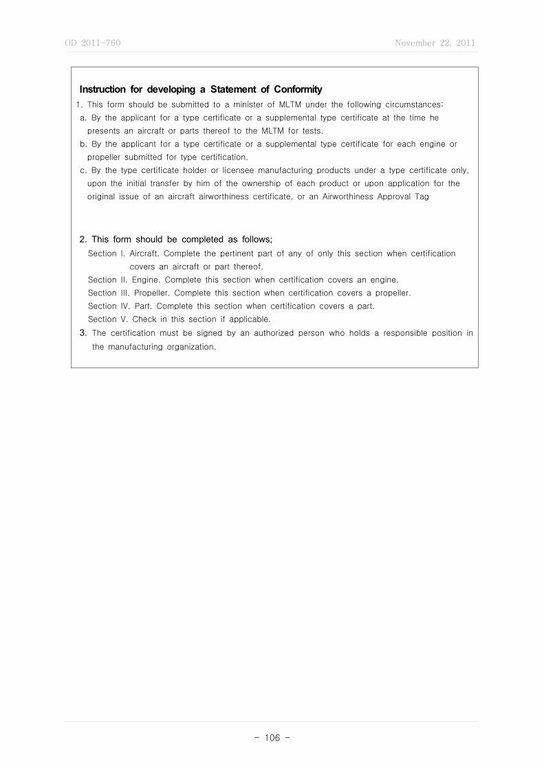
OD 2011-760 November 22, 2011
- 106 -
Instruction for developing a Statement of Conformity1. This form should be submitted to a minister of MLTM under the following circumstances:
a. By the applicant for a type certificate or a supplemental type certificate at the time he
presents an aircraft or parts thereof to the MLTM for tests.
b. By the applicant for a type certificate or a supplemental type certificate for each engine or
propeller submitted for type certification.
c. By the type certificate holder or licensee manufacturing products under a type certificate only,
upon the initial transfer by him of the ownership of each product or upon application for the
original issue of an aircraft airworthiness certificate, or an Airworthiness Approval Tag
2. This form should be completed as follows; Section I. Aircraft. Complete the pertinent part of any of only this section when certification
covers an aircraft or part thereof.
Section II. Engine. Complete this section when certification covers an engine.
Section III. Propeller. Complete this section when certification covers a propeller.
Section IV. Part. Complete this section when certification covers a part.
Section V. Check in this section if applicable.
3. The certification must be signed by an authorized person who holds a responsible position in
the manufacturing organization.

OD 2011-760 November 22, 2011
- 107 -
[Form No. 13]
Project Notification
1. Project No.
2. Model Designation
3. Applicant
4. Address
5. Date of application
6. Type of project □ TC □ ATC □ STC □ ASTC
7. Expected completion date
8. Authorized Inspection Agency Project Manager
Name
Phone
9. Description10. Technical Advisors □ Required □ Not Required □ Not Determined
11. Aircraft Evaluation Group □ Required □ Not Required □ Not Determined
12. Project Officer
Name
Phone
210㎜×297㎜((for a newspaper 54g/㎥(recycling))

OD 2011-760 November 22, 2011
- 108 -
[Form No. 14]
Issue Paper
1. Project. 2.Project No. 3. Issue Paper No.
4. Issue Title : □ ELOS Finding □ Potential Noncompliance □ Others_______________________________
5. Prepared Date: ______/___/___
6. Regulatory Reference
7. Nature of the issue or proposal
8. MLTM Comment
9. MLTM Determination
10. signature of Airworthiness Division, Land, Transport and Maritime Affairs
Completed Date: ______/___/___
110. Status (marking V ) □ Open □ Closed
210㎜×297㎜((for a newspaper 54g/㎥(recycling))
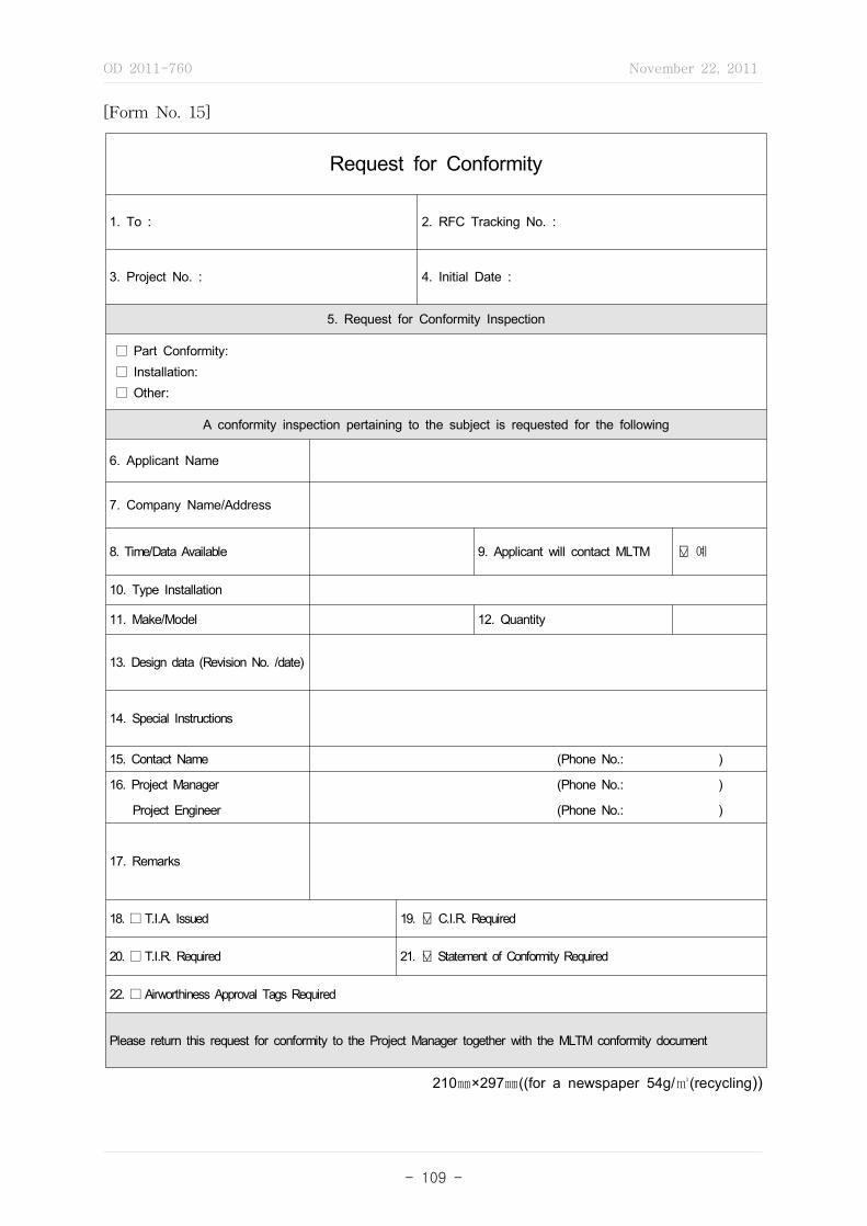
OD 2011-760 November 22, 2011
- 109 -
[Form No. 15]
Request for Conformity
1. To : 2. RFC Tracking No. :
3. Project No. : 4. Initial Date :
5. Request for Conformity Inspection
□ Part Conformity: □ Installation: □ Other:
A conformity inspection pertaining to the subject is requested for the following
6. Applicant Name
7. Company Name/Address
8. Time/Data Available 9. Applicant will contact MLTM ⍌ 예10. Type Installation
11. Make/Model 12. Quantity
13. Design data (Revision No. /date)
14. Special Instructions
15. Contact Name (Phone No.: )
16. Project Manager (Phone No.: )
Project Engineer (Phone No.: )
17. Remarks
18. □ T.I.A. Issued 19. ⍌ C.I.R. Required
20. □ T.I.R. Required 21. ⍌ Statement of Conformity Required
22. □ Airworthiness Approval Tags Required
Please return this request for conformity to the Project Manager together with the MLTM conformity document
210㎜×297㎜((for a newspaper 54g/㎥(recycling))
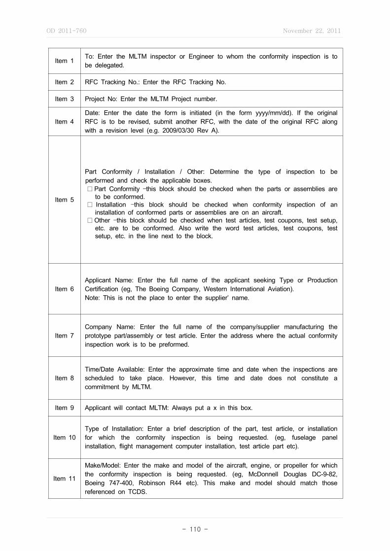
OD 2011-760 November 22, 2011
- 110 -
Item 1 To: Enter the MLTM inspector or Engineer to whom the conformity inspection is to be delegated.
Item 2 RFC Tracking No.: Enter the RFC Tracking No.
Item 3 Project No: Enter the MLTM Project number.
Item 4Date: Enter the date the form is initiated (in the form yyyy/mm/dd). If the original RFC is to be revised, submit another RFC, with the date of the original RFC along with a revision level (e.g. 2009/03/30 Rev A).
Item 5
Part Conformity / Installation / Other: Determine the type of inspection to be performed and check the applicable boxes. □ Part Conformity –this block should be checked when the parts or assemblies are
to be conformed. □ Installation –this block should be checked when conformity inspection of an
installation of conformed parts or assemblies are on an aircraft. □ Other –this block should be checked when test articles, test coupons, test setup,
etc. are to be conformed. Also write the word test articles, test coupons, test setup, etc. in the line next to the block.
Item 6Applicant Name: Enter the full name of the applicant seeking Type or Production Certification (eg, The Boeing Company, Western International Aviation). Note: This is not the place to enter the supplier’ name.
Item 7Company Name: Enter the full name of the company/supplier manufacturing the prototype part/assembly or test article. Enter the address where the actual conformity inspection work is to be preformed.
Item 8Time/Date Available: Enter the approximate time and date when the inspections are scheduled to take place. However, this time and date does not constitute a commitment by MLTM.
Item 9 Applicant will contact MLTM: Always put a x in this box.
Item 10Type of Installation: Enter a brief description of the part, test article, or installation for which the conformity inspection is being requested. (eg, fuselage panel installation, flight management computer installation, test article part etc).
Item 11
Make/Model: Enter the make and model of the aircraft, engine, or propeller for which the conformity inspection is being requested. (eg, McDonnell Douglas DC-9-82, Boeing 747-400, Robinson R44 etc). This make and model should match those referenced on TCDS.
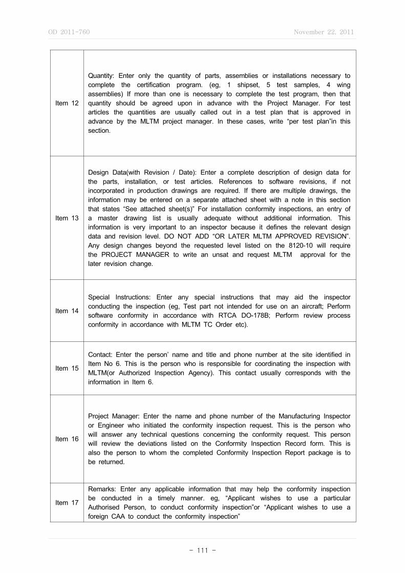
OD 2011-760 November 22, 2011
- 111 -
Item 12
Quantity: Enter only the quantity of parts, assemblies or installations necessary to complete the certification program. (eg, 1 shipset, 5 test samples, 4 wing assemblies) If more than one is necessary to complete the test program, then that quantity should be agreed upon in advance with the Project Manager. For test articles the quantities are usually called out in a test plan that is approved in advance by the MLTM project manager. In these cases, write “per test plan”in this section.
Item 13
Design Data(with Revision / Date): Enter a complete description of design data for the parts, installation, or test articles. References to software revisions, if not incorporated in production drawings are required. If there are multiple drawings, the information may be entered on a separate attached sheet with a note in this section that states “See attached sheet(s)” For installation conformity inspections, an entry of a master drawing list is usually adequate without additional information. This information is very important to an inspector because it defines the relevant design data and revision level. DO NOT ADD “OR LATER MLTM APPROVED REVISION”. Any design changes beyond the requested level listed on the 8120-10 will require the PROJECT MANAGER to write an unsat and request MLTM approval for the later revision change.
Item 14
Special Instructions: Enter any special instructions that may aid the inspector conducting the inspection (eg, Test part not intended for use on an aircraft; Perform software conformity in accordance with RTCA DO-178B; Perform review process conformity in accordance with MLTM TC Order etc).
Item 15
Contact: Enter the person’ name and title and phone number at the site identified in Item No 6. This is the person who is responsible for coordinating the inspection with MLTM(or Authorized Inspection Agency). This contact usually corresponds with the information in Item 6.
Item 16
Project Manager: Enter the name and phone number of the Manufacturing Inspector or Engineer who initiated the conformity inspection request. This is the person who will answer any technical questions concerning the conformity request. This person will review the deviations listed on the Conformity Inspection Record form. This is also the person to whom the completed Conformity Inspection Report package is to be returned.
Item 17
Remarks: Enter any applicable information that may help the conformity inspection be conducted in a timely manner. eg, “Applicant wishes to use a particular Authorised Person, to conduct conformity inspection”or “Applicant wishes to use a foreign CAA to conduct the conformity inspection”

OD 2011-760 November 22, 2011
- 112 -
Item 18TIA Issued: Check this block when the request is being utilized to supplement a TIA.
Item 19TIR Required: Check this block to have this conformity request and conformity inspection report placed in the TIR when a TIA has been issued.
Item 20
Airworthiness Approval Tags Required: Check this box when the inspection articles will be moved or shipped from one location to another and evidence of the conformed article is desired. Also check this box when it is desired to have evidence of a conformed article prior to an on-site test.
Item 21 C.I.R. Required: Check this box ⍌ with every request.
Item 22 Statement of Conformity Required: Check this box ⍌ with every request.
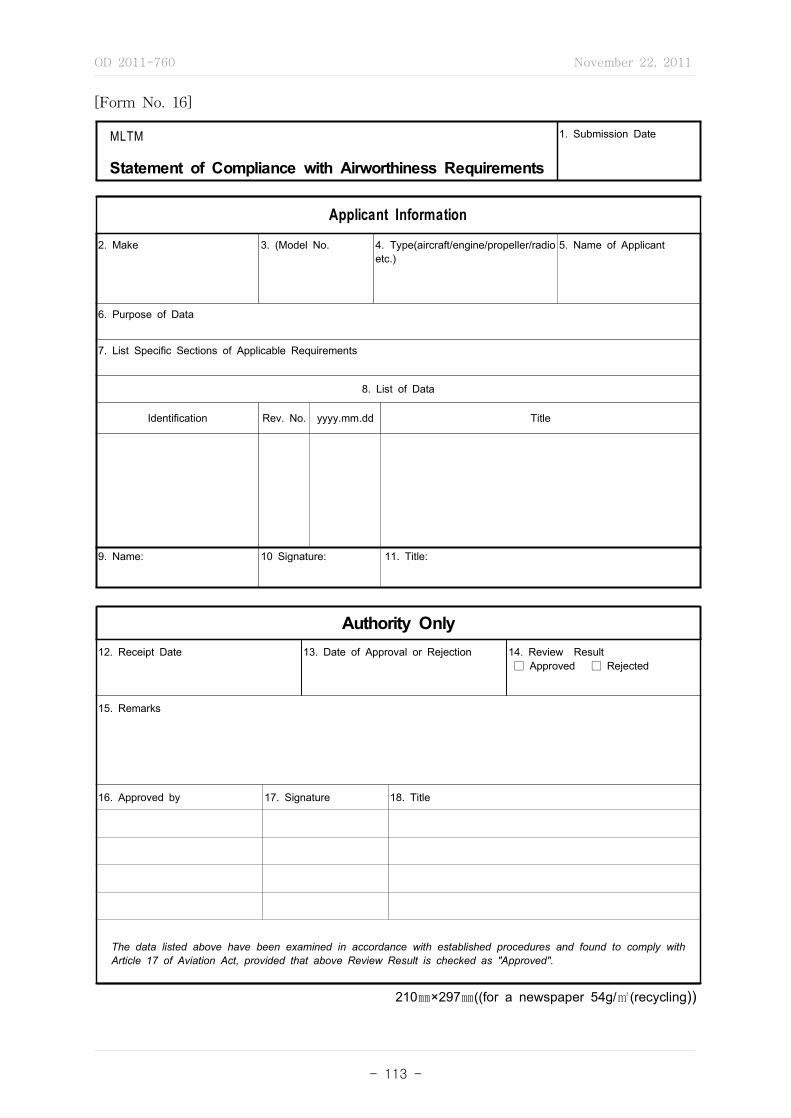
OD 2011-760 November 22, 2011
- 113 -
[Form No. 16]
MLTM
Statement of Compliance with Airworthiness Requirements
1. Submission Date
Applicant Information
2. Make 3. (Model No. 4. Type(aircraft/engine/propeller/radio etc.)
5. Name of Applicant
6. Purpose of Data
7. List Specific Sections of Applicable Requirements
8. List of Data
Identification Rev. No. yyyy.mm.dd Title
9. Name: 10 Signature: 11. Title:
Authority Only12. Receipt Date 13. Date of Approval or Rejection 14. Review Result
□ Approved □ Rejected
15. Remarks
16. Approved by 17. Signature 18. Title
The data listed above have been examined in accordance with established procedures and found to comply with Article 17 of Aviation Act, provided that above Review Result is checked as "Approved".
210㎜×297㎜((for a newspaper 54g/㎥(recycling))

OD 2011-760 November 22, 2011
- 114 -
[Form No. 17]
Conformity Inspection Record
1. Project No., TIA/Request Date 2.Sheet / Sheets
3. Applicant/Manufacturer /
4. Beginning Date 5. Ending Date
6. Model or Part Description and No. 7. Inspector
8.Item No.
9. Nomenclature of Item Inspected 10 Dwg. Doc., Spec. etc. 11. Rev. No./Date
12. Number of Items determined
13. Comments
SAT. UNSAT.
210㎜×297㎜((for a newspaper 54g/㎥(recycling))

OD 2011-760 November 22, 2011
- 115 -
Block 1Project No., TIA/Request Date : List the MLTM assigned project number along with date of Type Inspection Authorization(TIA) or Request for Conformity(RFC), as applicable.
Block 2 Sheet / Sheets: List the number of this sheet and the total number of sheets.
Block 3Applicant/Manufacturer: List the applicant or the manufacturer, or both. (The applicant name is obtained from the RFC or TIA. The manufacturer may be the party producing or responsible for the product.)
Block 4 Beginning Date: List the date the inspection began.
Block 5 Ending Date: List the date the inspection ended.
Block 6Model or Part Description and No.: If inspecting an aircraft, list the make, model, registration-number, and serial number. For an engine or propeller, list the make, model, and serial number.
Block 7Inspector: MLTM airworthiness inspectors must type or print and sign their name, and enter the office identification. Inspector of Authorized Inspection Agency must type or print and sign their name, and list their identification number.
Block 8 Item No.: Assign consecutive numbers for each item inspected.
Block 9Nomenclature of Item Inspected: List the name or description of the part, appliance, assembly, drawing, document, specification, or name of the process being evaluated/inspected.
Block 10Dwg. Doc., Spec. etc.: List the technical data that describes the item listed in Block 9. (e.g. drawing number, document number, process specification number, etc.)
Block 11Rev. No./Date: List the revision level and date of the technical data described in Block 10.
Block 12
Number of Items determined: List the number of items that were determined satisfactory or unsatisfactory. Do not record individual characteristics. Once an UNSAT item is disposition or found SAT then draw an arrow from SAT to UNSAT. This helps in expedite the review process.
(NOTE: An item is a single article, part or unit containing one or more dimensional characteristics or features.)
Block 13
Comments: Enter comments in this block that will support any information given in Blocks 8 through 12. Such as, Satisfactory and unsatisfactory conditions, corrective actions taken, reference to other item numbers listed, serial numbers, restrictions, type of inspection accomplished(visual inspection, review, process evaluation, material verification, dimensional inspection, finish check, compliance check, etc.), destination of exported products, buyer furnished equipment, parts processed through manufacturer’ maintenance facility, part new or newly overhauled, condition of part or assembly, etc.
(NOTE: These comments should be brief and clear, avoid the use of acronyms or abbreviations, this information is the objective evidence of the action(s) taken by the inspector in determining compliance of the article to the type design / airworthiness).
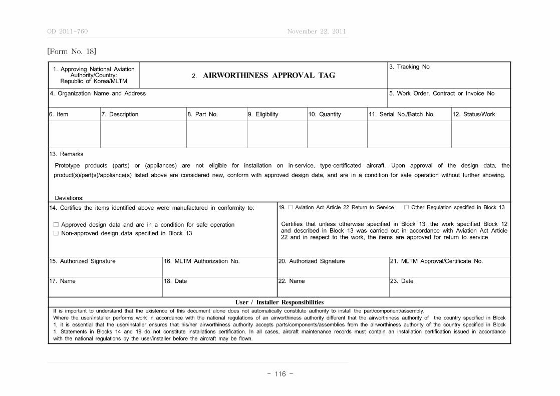
OD 2011-760 November 22, 2011
- 116 -
[Form No. 18]
1. Approving National Aviation Authority/Country:
Republic of Korea/MLTM2. AIRWORTHINESS APPROVAL TAG
3. Tracking No
4. Organization Name and Address 5. Work Order, Contract or Invoice No
6. Item 7. Description 8. Part No. 9. Eligibility 10. Quantity 11. Serial No./Batch No. 12. Status/Work
13. Remarks
Prototype products (parts) or (appliances) are not eligible for installation on in-service, type-certificated aircraft. Upon approval of the design data, the product(s)/part(s)/appliance(s) listed above are considered new, conform with approved design data, and are in a condition for safe operation without further showing.
Deviations: 14. Certifies the items identified above were manufactured in conformity to:
□ Approved design data and are in a condition for safe operation□ Non-approved design data specified in Block 13
19. □ Aviation Act Article 22 Return to Service □ Other Regulation specified in Block 13
Certifies that unless otherwise specified in Block 13, the work specified Block 12 and described in Block 13 was carried out in accordance with Aviation Act Article 22 and in respect to the work, the items are approved for return to service
15. Authorized Signature 16. MLTM Authorization No. 20. Authorized Signature 21. MLTM Approval/Certificate No.
17. Name 18. Date 22. Name 23. Date
User / Installer ResponsibilitiesIt is important to understand that the existence of this document alone does not automatically constitute authority to install the part/component/assembly.Where the user/installer performs work in accordance with the national regulations of an airworthiness authority different that the airworthiness authority of the country specified in Block 1, it is essential that the user/installer ensures that his/her airworthiness authority accepts parts/components/assemblies from the airworthiness authority of the country specified in Block 1. Statements in Blocks 14 and 19 do not constitute installations certification. In all cases, aircraft maintenance records must contain an installation certification issued in accordance with the national regulations by the user/installer before the aircraft may be flown.
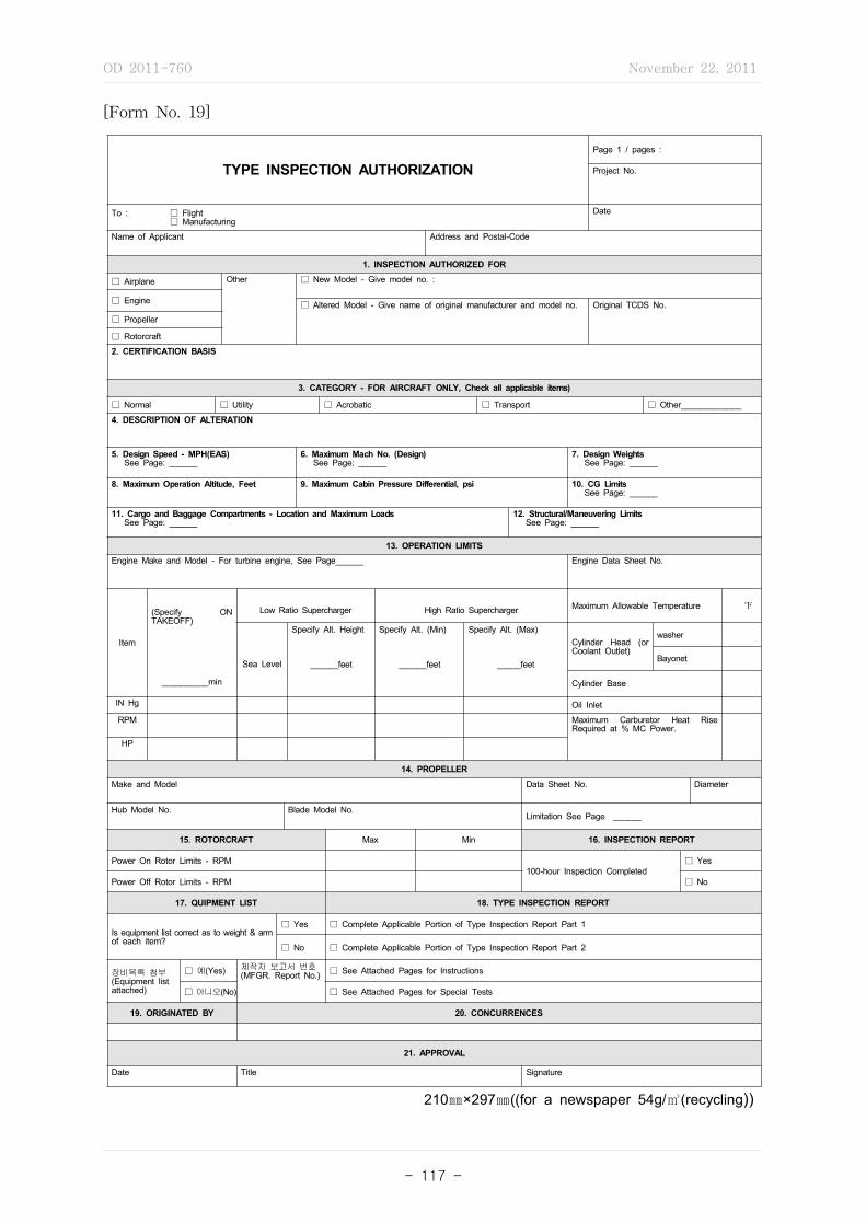
OD 2011-760 November 22, 2011
- 117 -
[Form No. 19]
TYPE INSPECTION AUTHORIZATIONPage 1 / pages :
Project No.
To : ☐ Flight ☐ Manufacturing
Date
Name of Applicant Address and Postal-Code
1. INSPECTION AUTHORIZED FOR
☐ Airplane Other ☐ New Model - Give model no. :
☐ Engine ☐ Altered Model - Give name of original manufacturer and model no. Original TCDS No.☐ Propeller
☐ Rotorcraft
2. CERTIFICATION BASIS
3. CATEGORY - FOR AIRCRAFT ONLY, Check all applicable items)
☐ Normal ☐ Utility ☐ Acrobatic ☐ Transport ☐ Other_____________
4. DESCRIPTION OF ALTERATION
5. Design Speed - MPH(EAS) See Page: ______
6. Maximum Mach No. (Design) See Page: ______
7. Design Weights See Page: ______
8. Maximum Operation Altitude, Feet 9. Maximum Cabin Pressure Differential, psi 10. CG Limits See Page: ______
11. Cargo and Baggage Compartments - Location and Maximum Loads See Page: ______
12. Structural/Maneuvering Limits See Page: ______
13. OPERATION LIMITSEngine Make and Model - For turbine engine, See Page______ Engine Data Sheet No.
Item
(Specify ON TAKEOFF)
__________min
Low Ratio Supercharger High Ratio Supercharger Maximum Allowable Temperature ℉
Sea Level
Specify Alt. Height
______feet
Specify Alt. (Min)
______feet
Specify Alt. (Max)
_____feet
Cylinder Head (or Coolant Outlet)
washer
Bayonet
Cylinder Base
IN Hg Oil Inlet
RPM Maximum Carburetor Heat Rise Required at % MC Power.
HP
14. PROPELLERMake and Model Data Sheet No. Diameter
Hub Model No. Blade Model No.Limitation See Page ______
15. ROTORCRAFT Max Min 16. INSPECTION REPORT
Power On Rotor Limits - RPM100-hour Inspection Completed
☐ Yes
Power Off Rotor Limits - RPM ☐ No
17. QUIPMENT LIST 18. TYPE INSPECTION REPORT
Is equipment list correct as to weight & arm of each item?
☐ Yes ☐ Complete Applicable Portion of Type Inspection Report Part 1
☐ No ☐ Complete Applicable Portion of Type Inspection Report Part 2
장비목록 첨부(Equipment list attached)
☐ 예(Yes) 제작자 보고서 번호(MFGR. Report No.) ☐ See Attached Pages for Instructions
☐ 아니오(No) ☐ See Attached Pages for Special Tests
19. ORIGINATED BY 20. CONCURRENCES
21. APPROVAL
Date Title Signature
210㎜×297㎜((for a newspaper 54g/㎥(recycling))

OD 2011-760 November 22, 2011
- 118 -
Block- General
- Enter the MLTM flight test and/or manufacturing office that is requested to perform the flight test and/or ground inspection.
- Enter the MLTM project number established for the project. - Enter the current date. - As shown on the project application.
Block 1 - Identify type of product, whether new or altered, and if altered, the original type
certificate number.
Block 2 - List the complete certification basis for the project. A reference may be made to
additional pages as required.
Block 3 - CATEGORY - FOR AIRCRAFT ONLY, Check all applicable items
Block 4 - For alteration, include a complete description of the alteration being made. A
reference may be made to additional pages as required.
Block 5~
Block 10
Reference page that identifies approved limitations or reference to approved flight manual.
- Design Speed - MPH(EAS) - Maximum Mach No. (Design) - Design Weights - Maximum Operation Altitude, Feet - Maximum Cabin Pressure Differential, psi - CG Limits
Block 11 - Cargo and Baggage Compartments - Location and Maximum Loads: Identify location and maximum loads of cargo and baggage compartments.
Block 12 - Structural/Maneuvering Limits: Identify Structural/Maneuvering Limits
Block 13
- Identify engine information and operating limitations and type certificate data sheet number. For turbine engine operating limitations, reference supplemental page that identifies approved limitations or reference to approved flight manual or engine operating instructions.
Block 14 - Identify propeller information and type certificate data sheet number. Reference
supplemental page that identifies approved limitations or reference to approved flight manual.

OD 2011-760 November 22, 2011
- 119 -
Block 15 - ROTORCRAFT: For rotorcraft, identify rotor rpm limits.
Block 16 - INSPECTION REPORT): Identify if 100-hour inspection has been completed.
Block 17
- EQUIPMENT LIST: Identify if equipment list has been verified for correct weight and moment arm of
each item of installed equipment. Indicate if equipment list is attached and identify the manufacturer's report number if appropriate.
Block 18- Part 1
- Indicate if the manufacturing inspector is requested to accomplish ground inspection in support of Type Inspection Report - Part 1. Identify on supplemental page the specific instructions for inspections to be accomplished. Include the following information at the beginning of Block 18:
Point of contact at conformity site): ______________________ Phone number of point of contact): ____-_____________________ Location of aircraft/conformity site:): _________________
Block 18- Part 2
- Indicate if the flight test office is requested to accomplish flight test in support of Type Inspection Report - Part 2. Identify on supplemental page the specific instructions for tests to be accomplished.
Block 18- Special
- The TIA may contain a section titled "Operational and Maintenance Requirements" that provides for certain other operational evaluations identified by the AEG.
Block 19 - ORIGINATED BY: Indicate the project office name as "Airworthiness Division"
Block 20 - CONCURRENCES: Identify the office name of all participating offices.
Block 21 - APPROVAL: Identify date and title of approval authority. This may be the TCB
chairman, or their representative.
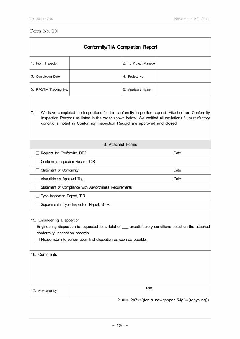
OD 2011-760 November 22, 2011
- 120 -
[Form No. 20]
Conformity/TIA Completion Report
1. From Inspector 2. To Project Manager
3. Completion Date 4. Project No.
5. RFC/TIA Tracking No. 6. Applicant Name
7. □ We have completed the Inspections for this conformity inspection request. Attached are Conformity Inspection Records as listed in the order shown below. We verified all deviations / unsatisfactory conditions noted in Conformity Inspection Record are approved and closed
8. Attached Forms
□ Request for Conformity, RFC Date:
□ Conformity Inspection Record, CIR
□ Statement of Conformity Date:
□ Airworthiness Approval Tag Date:
□ Statement of Compliance with Airworthiness Requirements
□ Type Inspection Report, TIR
□ Supplemental Type Inspection Report, STIR
15. Engineering Disposition Engineering disposition is requested for a total of ___ unsatisfactory conditions noted on the attached
conformity inspection records. □ Please return to sender upon final disposition as soon as possible.
16. Comments
17. Reviewed byDate:
210㎜×297㎜((for a newspaper 54g/㎥(recycling))

OD 2011-760 November 22, 2011
- 121 -
Block 1 From Inspector: Enter name of Inspector who completed the CIR
Block 2To Project Manager: Enter the MLTM project manager’'s name that is listed in Item #16 on the Request For Conformity
Block 3 Completion Date: Enter the date when the CIR was completed.
Block 4Project No. : Enter the MLTM project number that is listed in item #3 on the Request For Conformity.
Block 5RFC/TIA Tracking No. : Enter the tracking number that is listed in item #2 on the Request For Conformity.
Block 6Applicant Name: Enter the applicant’'s name that is listed in item # 6 on the Request For Conformity.
Block 7We have completed the Inspections. : Deviations/ Unsat Check this block when the inspection are completed and all deviations and unsats are approved by MLTM engineering.
Block 8Attached Forms: Check the applicable blocks for each form that is attached in the report.
Block 15
Engineering Disposition : Check this block when MLTM Engineering disposition is being requested and an Conformity Inspection Record is marked with the unsat condition. Engineering will review unsat conditions noted in Conformity Inspection Record and accept or reject it and sign the Conformity Inspection Record.
Block 16 Comments: Enter any applicable information that will help in processing the report.
Block 17Reviewed/Accepted by: The advising Inspector will sign here when the report has been reviewed and found satisfactory.

OD 2011-760 November 22, 2011
- 122 -
A. This form is to be used to record the results of conformity inspections and investigations of prototype or modified airplane presented for type certification. Many inspections and tests will be witnessed or participated in which are not covered by questions listed herein. All such inspections and tests and changes to the product and/or type design data resulting therefrom must be recorded and made a part of this report.
B. This Report includes references to applicable KAS. Some sections are interrelated, and future KAS revision may modify the requirement of an item. It is essential that the specific KAS’s applicable to the airplane involved be reviewed to insure a complete and effective inspection.
C. All entries must be clear, concise, and self‐explanatory. Answer questions in this report by checking the appropriate “YES” or “NO” column. When action is required to render the item acceptable, check “ACTION REQ.” Use additional pages to list the unsatisfactory conditions found during the inspection with reference to any communication or conformity inspection reports relative to the item. Number the pages with the page number on which the question appears plus a letter, i.e., 10a, 10b, etc. Identify the unsatisfactory condition by using the related item number as it appears on the form; list numerically with sufficient space between each entry to note the corrective action taken. When the item has been reinspected, cross out the previous “NO” answer and enter the new answer. This will be done for each inspection until the item is acceptable and will serve as a record of the number of times the item was inspected prior to acceptance.
When a question is not applicable to the product being inspected, enter “NA” across the “YES” and “NO” columns denoting not applicable. Pages containing only inapplicable questions may be omitted. Indicate by page numbers in the space provided on page 1, the pages submitted (or pages omitted if more convenient) in this report.
D. When more than one inspector participates in completing a report, each will enter his signature and title on page 1. He/She will also insert his initials adjacent to the answers and determinations he/she provides within the report.
E. The applicant’s weight and balance report may be used in lieu of the weight and dimensional page of this form provided it contains all the information requested. An equipment list with enough copies for each copy of the type inspection report submitted, setting forth, where pertinent, the make, model, and serial number of each item, must be attached as part of the report. When any part of the list is part of the weight and balance report, the weight of each item and the horizontal distance from the datum line will be shown. This list should include only significant items or accessories; i.e., those of a type that could have an adverse effect on the airworthiness or operational characteristics of the airplane if replaced by other items the acceptability of which have not been determined. For example, this list should include, but not necessarily be limited to, seats, safety belts, fire extinguishers, electronic equipment, electric motors, instruments, wheels and brakes, tires, skis, floats, superchargers, heaters, engines, starters, generators, etc. When concerned with alteration of airplane under the supplemental type certification program, it is especially important to consider this list.
EXAMPLE: Yes No Action Req.X XX
XN A
[Form No. 21] TYPE INSPECTION REPORT, Airplane
Part 1 - Airplane Ground Inspection
(GENERAL INSTRUCTIONS)
DO NOT SUBMIT THIS PAGE WITH REPORT
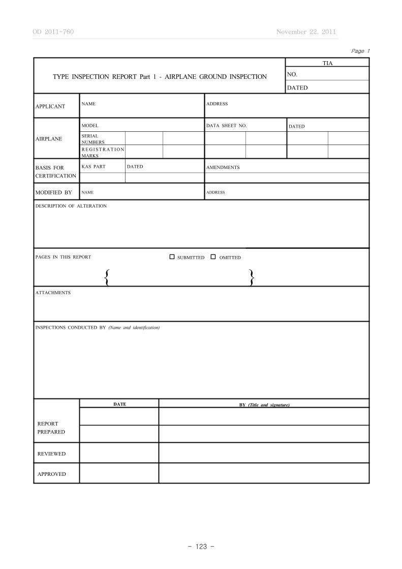
OD 2011-760 November 22, 2011
- 123 -
Page 1
TYPE INSPECTION REPORT Part 1 - AIRPLANE GROUND INSPECTION
TIA
NO.
DATED
APPLICANT NAME ADDRESS
AIRPLANE
MODEL DATA SHEET NO. DATED
SERIALNUMBERS
R E G I S T R A T I O N MARKS
BASIS FOR CERTIFICATION
KAS PART DATED AMENDMENTS
MODIFIED BY NAME ADDRESS
DESCRIPTION OF ALTERATION
PAGES IN THIS REPORT o SUBMITTED o OMITTED
{ }ATTACHMENTS
INSPECTIONS CONDUCTED BY (Name and identification)
REPORTPREPARED
DATE BY (Title and signature)
REVIEWED
APPROVED

OD 2011-760 November 22, 2011
- 124 -
Page 2
TABLE OF CONTENTS
ITEM TITLE
COVER SHEET ········································································································································ 1
TABLE OF CONTENTS ························································································································· 2
ADMINISTRATIVE DATA ···················································································································· 31.0 EMPTY WEIGHT AND C.G. LOCATION ············································································································· 42.0 FABRICATION PROCESSES ···································································································································· 53.0 INSPECTION - GENERAL ········································································································································ 64.0 AIRFRAME ··································································································································································· 7
4.1 GENERAL ································································································································································ 7 4.2 FUSELAGE ······························································································································································· 7 4.3 WINGS ······································································································································································ 8 4.4 EMPENNAGE ·························································································································································· 95.0 FLIGHT CONTROL SYSTEM ··································································································································· 10‐126.0 LANDING GEAR ························································································································································ 13 6.1 GENERAL ································································································································································ 13 6.2 LANDING GEAR INSTALLATION ····················································································································· 13 6.3 SKI INSTALLATION ············································································································································· 13 6.4 FLOAT INSTALLATION ······································································································································· 137.0 PERSONNEL AND CARGO ACCOMMODATIONS ····························································································· 14‐168.0 VENTILATION, HEATING AND PRESSURIZATION ·························································································· 17
9.0 FIRE PROTECTION - COMPARTMENT INTERIOR ··························································································· 1810.0 POWERPLANT INSTALLATION ··························································································································· 19 10.1 GENERAL ······························································································································································ 19 10.2 FUEL SYSTEM ····················································································································································· 19‐21 10.3 OIL SYSTEM ························································································································································ 21‐22 10.4 INDUCTION SYSTEM ········································································································································· 22 10.5 EXHAUST SYSTEM ············································································································································ 22 10.6 POWERPLANT CONTROLS AND ACCESSORIES ······················································································· 23 10.7 POWERPLANT FIRE PROTECTION ················································································································ 23‐2411.0 EQUIPMENT ······························································································································································ 25‐2712.0 ELECTRICAL SYSTEM AND EQUIPMENT ······································································································· 2813.0 SAFETY EQUIPMENT ············································································································································· 28
14.0 MISCELLANEOUS EQUIPMENT ··························································································································· 29 14.1 ELECTRONIC SYSTEM ······································································································································ 29 14.2 HYDRAULIC - PNEUMATIC - VACUUM SYSTEMS ················································································· 29 14.3 OXYGEN SYSTEM ·············································································································································· 30 14.4 MISCELLANEOUS FLUID DRAINS ················································································································· 3115.0 AIRCRAFT IDENTIFICATION AND MARKING ································································································ 31
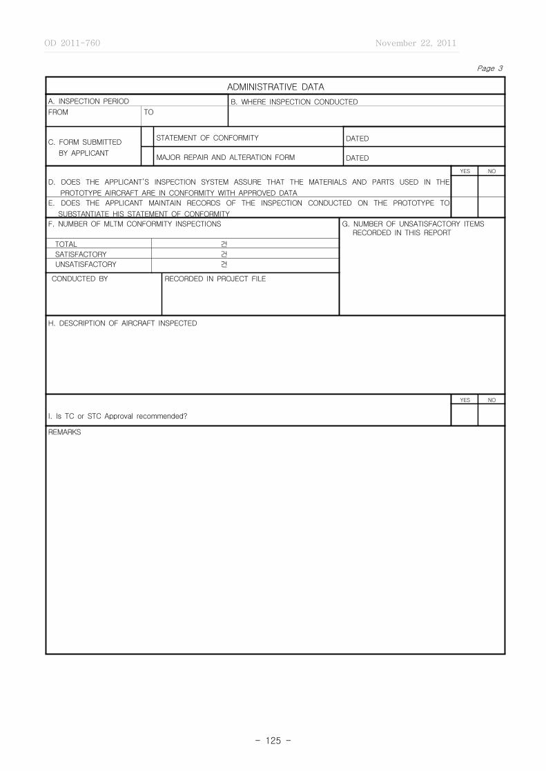
OD 2011-760 November 22, 2011
- 125 -
Page 3
ADMINISTRATIVE DATA
A. INSPECTION PERIOD B. WHERE INSPECTION CONDUCTED
FROM TO
C. FORM SUBMITTED
BY APPLICANT
STATEMENT OF CONFORMITY DATED
MAJOR REPAIR AND ALTERATION FORM DATED
YES NO
D. DOES THE APPLICANT’S INSPECTION SYSTEM ASSURE THAT THE MATERIALS AND PARTS USED IN THE
PROTOTYPE AIRCRAFT ARE IN CONFORMITY WITH APPROVED DATA
E. DOES THE APPLICANT MAINTAIN RECORDS OF THE INSPECTION CONDUCTED ON THE PROTOTYPE TO
SUBSTANTIATE HIS STATEMENT OF CONFORMITY
F. NUMBER OF MLTM CONFORMITY INSPECTIONS G. NUMBER OF UNSATISFACTORY ITEMS RECORDED IN THIS REPORT
TOTAL 건
SATISFACTORY 건
UNSATISFACTORY 건
CONDUCTED BY RECORDED IN PROJECT FILE
H. DESCRIPTION OF AIRCRAFT INSPECTED
YES NO
I. Is TC or STC Approval recommended?
REMARKS
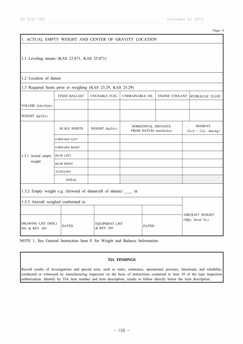
OD 2011-760 November 22, 2011
- 126 -
Page 4
1. ACTUAL EMPTY WEIGHT AND CENTER OF GRAVITY LOCATION
1.1 Leveling means (KAS 23.871, KAS 25.871)
1.2 Location of datum
1.3 Required Items prior to weighing (KAS 23.29, KAS 25.29)
VOLUME (Liter/Gals.)
FIXED BALLAST UNUSABLE FUEL UNDRAINABLE OIL ENGINE COOLANT HYDRAULIC FLUID
WEIGHT (kg/Lbs.)
1.3.1 Actual emptyweight
SCALE POINTS WEIGHT (kg/Lbs.)HORIZONTAL DISTANCE
FROM DATUM (mm/Inches)MOMENT
(Inch - Lbs. /mm-kg)
FORWARD LEFT
FORWARD RIGHT
REAR LEFT
REAR RIGHT
AUXILIARY
TOTAL
1.3.2 Empty weight c.g. (forward of datum/aft of datum) ____ in
1.3.3 Aircraft weighed conformed to
AIRCRAFT WEIGHT(Mfgs. Serial No.)
DRAWING LIST (MDL) NO. & REV. NO
DATEDEQUIPMENT LIST & REV. NO
DATED
NOTE 1. See General Instruction Item E for Weight and Balance Information
TIA FINDINGS
Record results of investigations and special tests, such as static, endurance, operational, pressure, functional, and reliability, conducted or witnessed by manufacturing inspectors on the basis of instructions contained in item 18 of the type inspection authorization. Identify by TIA item number and item description; results to follow directly below the item description.
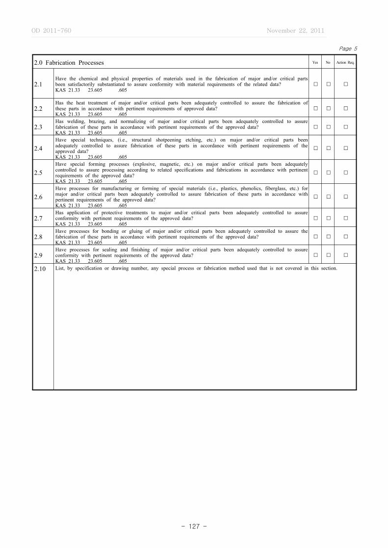
OD 2011-760 November 22, 2011
- 127 -
2.0 Fabrication Processes Yes No Action Req.
2.1Have the chemical and physical properties of materials used in the fabrication of major and/or critical parts been satisfactorily substantiated to assure conformity with material requirements of the related data?KAS 21.33 23.605 .605
� � �
2.2Has the heat treatment of major and/or critical parts been adequately controlled to assure the fabrication of these parts in accordance with pertinent requirements of approved data?KAS 21.33 23.605 .605
� � �
2.3Has welding, brazing, and normalizing of major and/or critical parts been adequately controlled to assure fabrication of these parts in accordance with pertinent requirements of the approved data?KAS 21.33 23.605 .605
� � �
2.4Have special techniques, (i.e., structural shotpeening etching, etc.) on major and/or critical parts been adequately controlled to assure fabrication of these parts in accordance with pertinent requirements of the approved data?KAS 21.33 23.605 .605
� � �
2.5Have special forming processes (explosive, magnetic, etc.) on major and/or critical parts been adequately controlled to assure processing according to related specifications and fabrications in accordance with pertinent requirements of the approved data?KAS 21.33 23.605 .605
� � �
2.6Have processes for manufacturing or forming of special materials (i.e., plastics, phenolics, fiberglass, etc.) for major and/or critical parts been adequately controlled to assure fabrication of these parts in accordance with pertinent requirements of the approved data?KAS 21.33 23.605 .605
� � �
2.7Has application of protective treatments to major and/or critical parts been adequately controlled to assure conformity with pertinent requirements of the approved data?KAS 21.33 23.605 .605
� � �
2.8Have processes for bonding or gluing of major and/or critical parts been adequately controlled to assure the fabrication of these parts in accordance with pertinent requirements of the approved data?KAS 21.33 23.605 .605
� � �
2.9Have processes for sealing and finishing of major and/or critical parts been adequately controlled to assure conformity with pertinent requirements of the approved data?KAS 21.33 23.605 .605
� � �
2.10 List, by specification or drawing number, any special process or fabrication method used that is not covered in this section.
Page 5

OD 2011-760 November 22, 2011
- 128 -
Page 6
3.0 INSPECTION ‐ GENERAL Yes No Action Req.
3.1Are drawings, specifications, equipment lists and other type design data available for inspection of the prototype product?KAS 21.33 23.605 .605
� � �
3.2 Has a method been established to update these data to show the latest type design changes?KAS 21.33 23.605 .605 � � �
3.3Has a method been established to show the status of these changes relative to the prototype article and parts thereof?KAS 21.33 23.605 .605
� � �
3.4 Are deviations from the type design data being recorded?KAS 21.33 23.605 .605 � � �
3.5Are parts and assemblies properly stamped, marked or otherwise identified to indicate the inspection status during various stages of fabrication? KAS 21.33 23.605 .605
� � �
3.6Does inspection of procured items show that they are in conformity with the vendor’s drawings and/or the applicant’s specification drawings? KAS 21.33 23.605 .605
� � �
3.7Have critical castings received 100 percent inspection by visual, radiographic, and magnetic particular or penetrant inspection or approved equivalent nondestructive inspection methods?KAS 23.621 25.621
� � �
3.8 Have noncritical castings been inspected in accordance with the following table:KAS 23.621 .621
CASTING FACTOR INSPECTION
(a) 2.0 or more 100 percent visual � � �
(b) Less than 2.0 but More than 1.5
100 percent visual and magnetic particle or penetrant or equivalent nondestructive inspection methods � � �
(c) 1.25 through 1.50 100 percent visual, magnetic particle or penetrant, and radiographic or approved equivalent nondestructive inspection methods � � �
REMARKS

OD 2011-760 November 22, 2011
- 129 -
Page 7
4.0 AIRFRAME Yes No Action Req.
4.1 GENERAL� � �
4.1.1 Are nonmetallic external components protected against erosion?KAS 23.609 .609
4.1.2Have adequate drainage provisions been provided to prevent the accumulation of fuel, water, hydraulic oil, etc?KAS 23.609 .609
� � �
4.1.3 Have adequate ventilation provisions been provided to prevent the accumulation of fumes, smoke, gases, etc?KAS 23.609 .609 � � �
4.1.4Have all members of the structure been suitably protected against deterioration or loss of strength in service due to weathering, corrosion, abrasion, etc?KAS 23.609 .609
� � �
4.1.5Have adequate inspection openings, doors, and access panels been provided to allow close examination of each part requiring recurring inspection, adjustments for proper alignment and function, or lubrication?KAS 23.611 .611
� � �
4.2 FUSELAGE� � �
4.2.1 Have rivets been driven in accordance with acceptable standards?KAS 23.603, .605 25.605
4.2.2Have bolts been installed in accordance with acceptable standards with respect to proper length, washers, nuts, hole size, finish, etc.?KAS 23.603, .605 25.605
� � �
4.2.3 Are self‐locking nuts used on any bolt subject to rotation during aircraft operation?KAS 23.607 .607 � � �
4.2.4 Do detail parts fit into subassemblies without being forced or sprung?KAS 23.603, .605 25.605 � � �
4.2.5 Do subassemblies fit the fuselage assembly without being forced or sprung?KAS 23.603, .605 25.605 � � �
4.2.6Are major attachment points of the wing, empennage, landing gear, powerplant, etc., adequately controlled to insure proper alignment when mated?KAS 23.603, .605 25.605
� � �
4.2.7Are structural panels such as bulkhead, spar and beam webs, and outside skin panel covering, free from buckles or wrinkles?KAS 23.603, .605 25.605
� � �
4.2.8 Do doors, hatches, etc., fit and operate properly?KAS 23.603, .605 25.605 � � �
4.2.9 Are there any questionable design items?KAS 23.601 .601 � � �

OD 2011-760 November 22, 2011
- 130 -
Page 8
4.0 AIRFRAME (Continued) Yes No Action Req.
4.3 WINGS� � �4.3.1 Have rivets been driven in accordance with acceptable standards?
KAS 23.603, .605 .605
4.3.2Have bolts been installed in accordance with acceptable standards with respect to proper length, washers, nut, hole size, finish, etc.?KAS 23.603, .605 .605
� � �
4.3.3 Are self‐locking nuts used on any bolt subject to rotation during aircraft operationKAS 23.607 25.607 � � �
4.3.4 Do detail parts fit into subassemblies without being forced or sprung?KAS 23.603, .605 .605 � � �
4.3.5 Do subassemblies fit the wing assembly without being forced or sprung?KAS 23.603, .605 .605 � � �
4.3.6Are major attachment points of tabs, flaps, ailerons, slats, spoilers, landing gear and fuselage adequately controlled to insure proper alignment when assembled to corresponding structure?KAS 23.603, .605 .605
� � �
4.3.7 Are structural panels such as spar webs, rib webs, and skin panels, free from buckles or wrinkles?KAS 23.603, .605 .605 � � �
4.3.8Are adequate inspection openings, doors or access panels been provided to allow close examination of each part requiring recurring inspection, adjustments for proper alignment and function, or lubrication?KAS 23.61125.611
� � �
4.3.9 Has wing alignment been properly controlled?KAS 23.603, .605 .605 � � �
4.3.10 Do the hinge lines of the ailerons, spoilers, slats, flaps, tabs, etc., match properly when installed?KAS 23.603, .605 .605 � � �
4.3.11 Is there positive clearance between the wing and all moveable surfaces throughout their range of operation?KAS 23.683 .683 � � �
4.3.12Are the flight control surface operating means (i.e.. bell cranks, push‐pull tubes, chains, cables, operating cylinders, jackscrews, etc.) free from binding and interference?KAS 23.683 .685
� � �
4.3.13 Are positive stops provided to limit the range of motion of the flight control surfaces?KAS 23.675 .675 � � �
4.3.14Are adequate ventilation and drainage provisions provided for the wing and all control surfaces or lift augmentation devices?KAS 23.609 .609
� � �
4.3.15 Are there any questionable design items?KAS 23.601 .601 � � �
4.3.16 Is the balance of all control surfaces within the drawing tolerances?KAS 23.671 .671 � � �

OD 2011-760 November 22, 2011
- 131 -
Page 9
4.0 AIRFRAME (Continued) Yes No Action Req.
4.4 EMPENNAGE� � �
4.4.1 Have rivets been driven in accordance with acceptable standards?KAS 23.605 25.605
4.4.2Have bolts been installed in accordance with acceptable standards with respect to proper length, washers, nuts, hole size, finish, etc.?KAS 23.605 25.605
� � �
4.4.3 Are self‐locking nuts used on any bolt subject to rotation during aircraft operation?KAS 23.607 25.607
� � �
4.4.4 Do Detail parts fit into subassemblies without being forced or sprung?KAS 23.603, .605 .605
� � �
4.4.5 Do subassemblies fit the empennage assembly without being forced or sprung?KAS 23.603, .605 .605
� � �
4.4.6Are major attachment points of tabs, elevator, rudder, horizontal and vertical stabilizer adequately controlled to insure proper alignment when assembled to corresponding structure?KAS 23.603, .605 .605
� � �
4.4.7 Are structural panels such as spar webs, rib webs, skin panels, etc., free from buckles or wrinkles?KAS 23.603, .605 .605
� � �
4.4.8Are adequate inspection opening, doors, and/or access panels provided to allow close examination of each part requiring recurring inspection, adjustments for proper alignment and function, or lubrication?KAS 23.611 25.611
� � �
4.4.9 Has horizontal and vertical stabilizer alignment been properly controlled?KAS 23.603, .605 .605
� � �
4.4.10 Do the hinge lines of the elevator, rudder and tabs match properly when installed?KAS 23.603, .605 .605
� � �
4.4.11Is there positive clearance between the vertical or horizontal stabilizer, and all movable surfaces throughout their range of operation?KAS 3.683 25.683
� � �
4.4.12Are the flight control surface operating means (i.e.., bell cranks, push‐pull tabs, chains, cables, operating cylinders, jackscrews, etc.) free from binding and interference?KAS 23.685 25.685
� � �
4.4.13Are positive stops provided to limit the range of motion of the rudder, elevator and stabilizer (when an adjustable stabilizer is employed)?KAS 23.675 25.675
� � �
4.4.14 Are adequate drainage provisions provided for the empennage?KAS 23.609 25.609
� � �
4.4.15 Are there any questionable design items?KAS 27.601 29.601
� � �
4.4.16 Is the balance of all control surfaces within the drawing tolerances?KAS 23.671 25.671
� � �

OD 2011-760 November 22, 2011
- 132 -
Page 10
5.0 FLIGHT CONTROL SYSTEM Yes No Action Req.
5.1 Do all flight controls operate with ease, smoothness and positiveness throughout their maximum limits?KAS 23.671 25.671 � � �
5.2Do all flight control surfaces move in the correct direction of travel in response to operation of the cockpit controls?KAS 23.779, 23.671 25.779, 25.671
� � �
5.3Are stops provided for all flight control surfaces and is there positive engagement to limit the control surface travel?KAS 23.675 25.675
� � �
5.4Is each element of each flight control system designed, or distinctively and permanently marked, to minimize the probability of incorrect assembly that could result in the malfunctioning of the system? KAS 23.685 25.685
� � �
5.5Where cable systems are used, are provisions provided for the visual inspection of fairleads, pulleys, terminals and turnbuckles?KAS 23.689 25.689
� � �
5.6 Is there a means provided, adjacent to the trim control, to indicate the direction of the airplane motions?KAS 23.677 25.677 � � �
5.7Is there provided a clearly visible means to indicate the position of the trim device with respect to the range of adjustment?KAS 23.677 25.677
� � �
5.8Where irreversible trim tab control systems are used, is the part from the tab to the attachment of the irreversible unit to the airplane structure rigid?KAS 23.677 25.677
� � �
5.9 Does a functional check show that the control system locks operate as placarded or marked?KAS 23.679 25.679 � � �
5.10 Has a means been provided to prevent the control system lock from engaging in flight?KAS 23.679 25.679 � � �
5.11Is the flight control system free from jamming, excessive friction and excessive deflection when the controls are operated from the pilot compartment with: � � �
(a) The system loaded to correspond to 80 percent of the limit load specified for the systemKAS 25.683
(b) The system loaded to correspond to the limit airloads on the appropriate surfacesKAS 23.683 � � �
5.12 Is the control system protected from jamming, chafing and interference by cargo, passengers, or loose objects?KAS 23.685 25.685 � � �
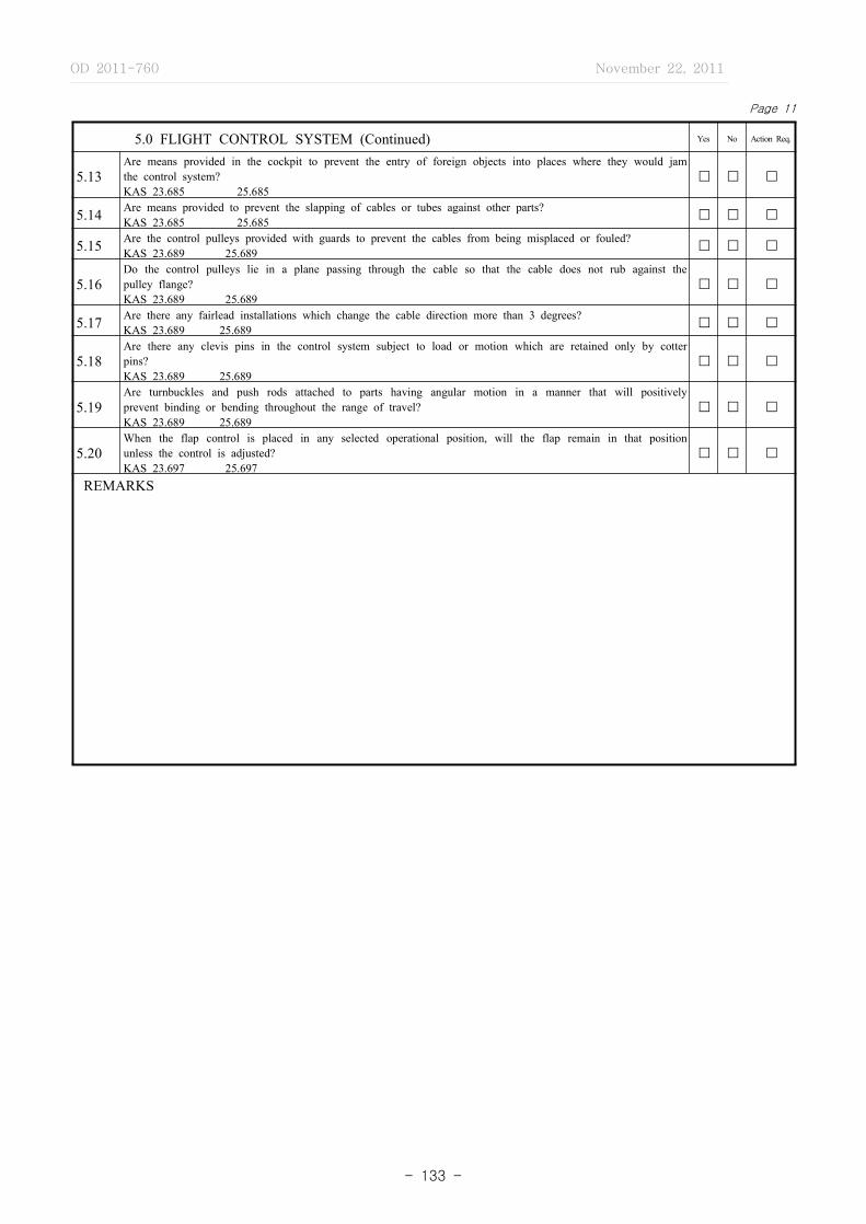
OD 2011-760 November 22, 2011
- 133 -
Page 11
5.0 FLIGHT CONTROL SYSTEM (Continued) Yes No Action Req.
5.13Are means provided in the cockpit to prevent the entry of foreign objects into places where they would jam the control system?KAS 23.685 25.685
� � �
5.14 Are means provided to prevent the slapping of cables or tubes against other parts?KAS 23.685 25.685 � � �
5.15 Are the control pulleys provided with guards to prevent the cables from being misplaced or fouled?KAS 23.689 25.689 � � �
5.16Do the control pulleys lie in a plane passing through the cable so that the cable does not rub against the pulley flange?KAS 23.689 25.689
� � �
5.17 Are there any fairlead installations which change the cable direction more than 3 degrees?KAS 23.689 25.689 � � �
5.18Are there any clevis pins in the control system subject to load or motion which are retained only by cotter pins?KAS 23.689 25.689
� � �
5.19Are turnbuckles and push rods attached to parts having angular motion in a manner that will positively prevent binding or bending throughout the range of travel?KAS 23.689 25.689
� � �
5.20When the flap control is placed in any selected operational position, will the flap remain in that position unless the control is adjusted?KAS 23.697 25.697
� � �
REMARKS
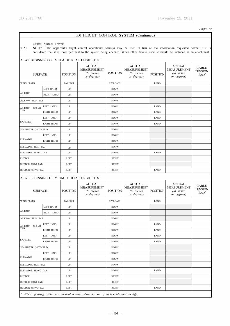
OD 2011-760 November 22, 2011
- 134 -
Page 12
5.0 FLIGHT CONTROL SYSTEM (Continued)
5.21Control Surface TravelsNOTE: The applicant’s flight control operational form(s) may be used in lieu of the information requested below if it is considered that it is more pertinent to the system being checked. When other data is used, it should be included as an attachment.
A. AT BEGINNING OF MLTM OFFICIAL FLIGHT TEST
SURFACE POSITION
ACTUALMEASUREMENT
(In inches or degrees)
POSITION
ACTUALMEASUREMENT
(In inchesor degrees) POSITION
ACTUALMEASUREMENT
(In inchesor degrees)
CABLETENSION
(Lbs.)1
WING FLAPS TAKEOFF APPROACH LAND
AILERON
LEFT HAND UP DOWN
RIGHT HAND UP DOWN
AILERON TRIM TAB UP DOWN
AILERON SERVO TAB
LEFT HAND UP DOWN LAND
RIGHT HAND UP DOWN LAND
SPOILERS
LEFT HAND UP DOWN LAND
RIGHT HAND UP DOWN LAND
STABILIZER (MOVABLE) UP DOWN
ELEVATOR
LEFT HAND UP DOWN
RIGHT HAND UP DOWN
ELEVATOR TRIM TAB UP DOWN
ELEVATOR SERVO TAB UP DOWN LAND
RUDDER LEFT RIGHT
RUDDER TRIM TAB LEFT RIGHT
RUDDER SERVO TAB LEFT RIGHT LAND
A. AT BEGINNING OF MLTM OFFICIAL FLIGHT TEST
SURFACE POSITION
ACTUALMEASUREMENT
(In inches or degrees)
POSITION
ACTUALMEASUREMENT
(In inchesor degrees)
POSITION
ACTUALMEASUREMENT
(In inchesor degrees)
CABLETENSION
(Lbs.)1
WING FLAPS TAKEOFF APPROACH LAND
AILERON
LEFT HAND UP DOWN
RIGHT HAND UP DOWN
AILERON TRIM TAB UP DOWN
AILERON SERVO TAB
LEFT HAND UP DOWN LAND
RIGHT HAND UP DOWN LAND
SPOILERS
LEFT HAND UP DOWN LAND
RIGHT HAND UP DOWN LAND
STABILIZER (MOVABLE) UP DOWN
ELEVATOR
LEFT HAND UP DOWN
RIGHT HAND UP DOWN
ELEVATOR TRIM TAB UP DOWN
ELEVATOR SERVO TAB UP DOWN LAND
RUDDER LEFT RIGHT
RUDDER TRIM TAB LEFT RIGHT
RUDDER SERVO TAB LEFT RIGHT LAND
1. When opposing cables are unequal tension, show tension of each cable and identify.
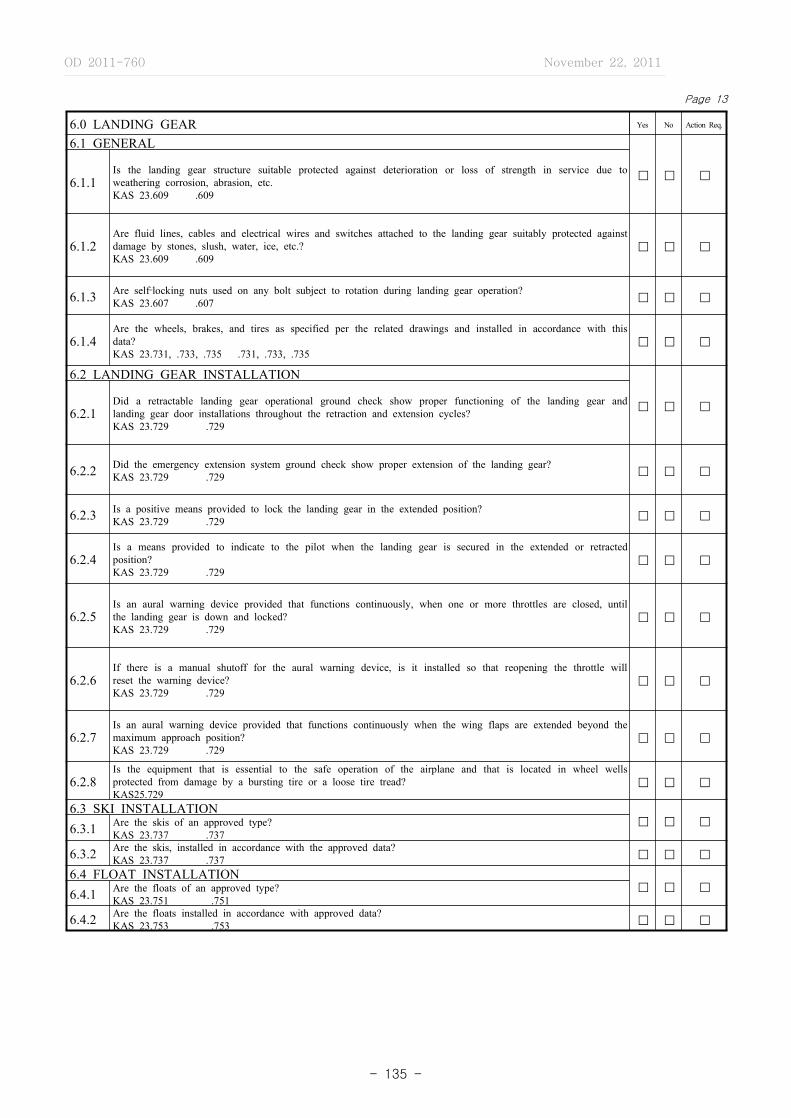
OD 2011-760 November 22, 2011
- 135 -
Page 13
6.0 LANDING GEAR Yes No Action Req.
6.1 GENERAL
� � �6.1.1Is the landing gear structure suitable protected against deterioration or loss of strength in service due to weathering corrosion, abrasion, etc.KAS 23.609 .609
6.1.2Are fluid lines, cables and electrical wires and switches attached to the landing gear suitably protected against damage by stones, slush, water, ice, etc.?KAS 23.609 .609
� � �
6.1.3 Are self‐locking nuts used on any bolt subject to rotation during landing gear operation?KAS 23.607 .607 � � �
6.1.4Are the wheels, brakes, and tires as specified per the related drawings and installed in accordance with this data?KAS 23.731, .733, .735 .731, .733, .735
� � �
6.2 LANDING GEAR INSTALLATION
� � �6.2.1Did a retractable landing gear operational ground check show proper functioning of the landing gear and landing gear door installations throughout the retraction and extension cycles?KAS 23.729 .729
6.2.2 Did the emergency extension system ground check show proper extension of the landing gear?KAS 23.729 .729 � � �
6.2.3 Is a positive means provided to lock the landing gear in the extended position?KAS 23.729 .729 � � �
6.2.4Is a means provided to indicate to the pilot when the landing gear is secured in the extended or retracted position?KAS 23.729 .729
� � �
6.2.5Is an aural warning device provided that functions continuously, when one or more throttles are closed, until the landing gear is down and locked?KAS 23.729 .729
� � �
6.2.6If there is a manual shutoff for the aural warning device, is it installed so that reopening the throttle will reset the warning device?KAS 23.729 .729
� � �
6.2.7Is an aural warning device provided that functions continuously when the wing flaps are extended beyond the maximum approach position?KAS 23.729 .729
� � �
6.2.8Is the equipment that is essential to the safe operation of the airplane and that is located in wheel wells protected from damage by a bursting tire or a loose tire tread?KAS25.729
� � �
6.3 SKI INSTALLATION� � �6.3.1 Are the skis of an approved type?
KAS 23.737 .737
6.3.2 Are the skis, installed in accordance with the approved data?KAS 23.737 .737 � � �
6.4 FLOAT INSTALLATION� � �6.4.1 Are the floats of an approved type?
KAS 23.751 .751
6.4.2 Are the floats installed in accordance with approved data?KAS 23.753 .753 � � �

OD 2011-760 November 22, 2011
- 136 -
Page 14
7.0 PERSONNEL AND CARGO ACCOMMODATIONS Yes No Action Req.
7.1 Are the windshield and window panels in the pilot compartment clear and free of distortionsKAS 23.773 25.773 � � �
7.2 Are internal glass panes of a nonsplintering safety glassKAS 23.775 25.775 � � �
7.3Does the windshield and side windows forward of the pilots back when he/she is seated in the normal flight position have a luminous transmittance value of not less than 70 percentKAS 23.775
� � �
7.4
Are controls and instrument markings, instructions, and placards in conformance with pertinent specifications and approved data
KAS 23.777 through 23.781 25.777 through 25.781 � � �
KAS 23.1541 through 23.1567 25.1541 through 25.1567 � � �
7.5 Is there a door between the pilot and passenger compartmentsKAS 25.771 � � �
7.6Does the door, between the pilot and passenger compartment, have a locking means to prevent passengers from opening it without the pilots permissionKAS 25.771
� � �
7.7Is there a means to lock and safeguard each external door against inadvertent opening either by persons or as a result of mechanical failureKAS 25.783
� � �
7.8Where inward opening external doors are used, is there a means provided to prevent occupant’s from crowding against the door and interfering with the opening of the doorKAS 25.783
� � �
7.9 Can the external doors be readily unlocked and opened from the inside or outsideKAS 25.783 � � �
7.10Is the means of opening the external doors simple, obvious, and so arranged and marked that they can be readily located and operated, even in darknessKAS 25.783
� � �
7.11Are direct visual inspection means provided to determine whether external doors, for which the initial opening movement is outward, are fully lockedKAS 25.783
� � �
7.12Is a visual means provided to signal to appropriate crewmembers when normally used external doors are closed and fully lockedKAS 25.783
� � �
7.13 Is each seat and berth in accordance with approved dataKAS 25.783 � � �
7.14Is each projected object, that would injure persons seated or moving about the airplane in normal flight, paddedKAS 25.785
� � �

OD 2011-760 November 22, 2011
- 137 -
Page 15
7.0 PERSONNEL AND CARGO ACCOMMODATIONS (Continued) Yes No Action Req.
7.15 Does each berth have an approved safety beltKAS 25.785 � � �
7.16Is there a means provided along each aisle to enable occupants to steady themselves while using the aisles in moderately rough air, such as a hand grip or rail along each aisle or a firm hand hold on each seat backKAS 25.785
� � �
7.17 Is each crew member seat at flight deck stations provided with provisions for a shoulder harnessKAS 25.785 � � �
7.18 Are cargo and baggage compartments placarded in accordance with approved dataKAS 23.787 25.787 � � �
7.19 Are emergency exits openable from the inside and outside of the cabin without undue effortKAS 25.809 � � �
7.20Is there a means to lock each emergency exit and to safeguard against its opening in flight, either inadvertently by persons or as a result of mechanical failureKAS 25.809
� � �
7.21Is there a means for direct visual inspection of the locking mechanism to determine that each emergency exit, for which the initial opening movement is outward, is fully lockedKAS 25.809
� � �
7.22Is each landplane emergency exit that is more than six feet from the ground with the landing gear extended and each over‐the‐wing emergency exit provided with an approved means to assist the occupants in descending to the groundKAS 25.809
� � �
7.23 Is each passenger emergency exit, its means of access and its means of opening, conspicuously markedKAS 23.807 25.811 � � �
7.24Is the identity and location of each emergency exit recognizable from a distance equal to the width of the cabinKAS 25.811
� � �
7.25Is the location of each emergency exit operating handle and the instructions for opening marked on or adjacent to the emergency exitKAS 23.807 25.811
� � �
7.26 Are these markings and instructions required by item 7.25 readable from a distance of 30 inchesKAS 25.811 � � �
7.27Is a source of light, independent of the main lighting system, installed to illuminate each passenger emergency exit markingKAS 25.811
� � �
OD 2011-760 November 22, 2011
- 138 -
Page 16
7.0 PERSONNEL AND CARGO ACCOMMODATIONS (Continued) Yes No Action Req.
7.28Is each emergency exit that is required to be openable from the outside, and its means of opening, marked on the outside of the airplaneKAS 25.811
� � �
7.29 Are main aisles and emergency access passageways in accordance with approve dataKAS 23.807 25.815, 25.813 � � �
7.30 Are the decompression features of personnel and cargo compartments in accordance with approved dataKAS 25.841 � � �
7.31 Is there any feature or characteristic which may prevent the satisfactory decompression of a compartmentKAS 25.841 � � �
REMARKS

OD 2011-760 November 22, 2011
- 139 -
Page 17
8.0 VENTILATION, HEATING AND PRESSURIZATION Yes No Action Req.
8.1 Is the installation of the heating and ventilation system in accordance with related approved data?KAS 21.22 23.831 25.831 � � �
8.2 Are the heating and ventilation controls placarded and marked in accordance with approved data?KAS 23.1541, 23.1555 25.1541, 25.1555 � � �
8.3 Is the installation of the pressurization system in accordance with related approved data?KAS 21.33 23.841 25.841 � � �
8.4Do the pressure relief valves automatically limit the positive pressure differential to the limits established by the approved data?KAS 23.841 25.841
� � �
8.5Do the reverse pressure differential relief valves limit the negative pressure differential to the limits established by the approved data?KAS 23.841 25.841
� � �
8.6Is the regulator for maintaining the required internal pressures and airflow rates installed and placarded in accordance with the approved data?KAS 23.841 25.841
� � �
8.7Are the instruments to indicate to the pilot the pressure differential, the absolute pressure in the cabin and the rate of change of the absolute pressure marked and placarded in accordance with the approved data?KAS 23.841, 23.1543 25.841, 25.1543
� � �
8.8Are warning devices and placards provided to indicate when the approved pressure differential and absolute cabin pressure limits are exceeded?KAS 23.841 25.841
� � �
8.9 Are all pressurization system warning placards in accordance with approved data?KAS 23.841 25.841 � � �
8.10 Does each door and emergency exit operate properly after the pressurization flight test have been completed?KAS 23.843 25.843 � � �
8.11 Are combustion heaters of an approved type and installed in accordance with approved data?KAS 23.859 25.859 � � �
8.12 Are engine exhaust heaters installed in accordance with approved data?KAS 23.1125 25.833, 25.1125 � � �
OD 2011-760 November 22, 2011
- 140 -
Page 18
9.0 FIRE PROTECTION - COMPARTMENT INTERIOR Yes No Action Req.
9.1 Are the materials used for compartment interiors in accordance with approved data?KAS 23.853 25.853 � � �
9.2 Does each towel, paper, and waste receptacle have a means for containing possible fires?KAS 25.853 � � �
9.3 Is there at least one hand fire extinguisher for use by the flight crew members?KAS 25.853 � � �
9.4 Are the required number of hand fire extinguishers located in the passenger compartments?KAS 25.853 � � �
9.5 Is the location of each hand fire extinguisher plainly marked?KAS 23.1561 25.1561 � � �
9.6 Are compartments where smoking is to be prohibited so placarded?KAS 25.853 � � �
9.7Are controls, wiring, fluid lines, equipment or accessories whose damage or failure would affect safe operation, protected so that they cannot be damaged by cargo or baggage, and that their breakage or failure will not create a fire hazard?KAS 25.855
� � �
9.8Has a means been provided to prevent cargo or baggage from interfering with the functioning of the fire‐protective installation for the compartments?KAS 25.855
� � �
9.9Are the sources of heat within the compartment shielded and insulated to prevent igniting the cargo or baggage?KAS 25.855
� � �
9.10 Are the combustion heater fire zones protected from fire?KAS 23.859 25.859 � � �
9.11Are the ventilating and combustion air ducts, adjacent to the heater of fire proof material installed in accordance with approved data?KAS 25.859
� � �
9.12 Do the heater installation fuel drains permit safe drainage clear of the aircraft?KAS 25.859 � � �
9.13Is a means provided to prevent the ignition, by any equipment, of flammable fluids or vapors resulting from the leakage of fluid systems or to control any fire resulting from the ignition?KAS 25.863
� � �
REMARKS
OD 2011-760 November 22, 2011
- 141 -
Page 19
10.0 POWERPLANT INSTALLATIONS Yes No Action Req.
10.1 GENERAL
10.1.1 Is (are) the engine(s) type certificatedKAS 23.903 .903
TYPE CERTIFICATE NO.
� � �
10.1.2 Is (are) the propeller(s) type certificatedKAS 23.905 .905
TYPE CERTIFICATE NO.
� � �
10.1.3 Are the powerplant components and accessories installed in accordance with approved dataKAS 23.901 .901 � � �
10.1.4Does a ground operational test show that all powerplant components and accessories are operating satisfactorilyKAS 23.901 .901
� � �
10.1.5Is a means provided to allow the close examination of each part requiring recurring inspection, adjustments for proper alignment and function, or lubrication KAS 23.611, .901 .611, .901
� � �
10.1.6 Are major components of the powerplant installation electrically bonded to other parts of the airplaneKAS .901 � � �
10.1.7 Are any self‐locking nuts used on any bolt, subject to rotation in operationKAS 23.607 25.607 � � �
10.1.8 Is the radial clearance between the propeller tip and the aircraft structure at least one inchKAS 23.925 25.925 � � �
10.1.9Is the longitudinal clearance between the propeller blades or cuffs and stationary part of the aircraft at least one‐half inchKAS 23.925 25.925
� � �
10.1.10 Are propeller deicing provisions installed in accordance with approved dataKAS 23.901 25.901, .929 � � �
10.1.11 Are propeller deicing controls identified and marked with respect to their operationKAS 23.155525.1555 � � �
10.2 FUEL SYSTEM� � �
10.2.1 Is the fuel system installed in accordance with approved dataKAS 23.951 25.951
10.2.2 Does a ground operational test indicate that the fuel system operates satisfactorilyKAS 23.951 25.951 � � �
10.2.3 Are the fuel tanks constructed, installed and sealed in accordance with approved dataKAS 23.963 25.963 � � �
10.2.4 Are the spaces adjacent to the fuel tanks ventilated and provided with drain holesKAS 23.967 25.967 � � �
OD 2011-760 November 22, 2011
- 142 -
Page 20
10.0 POWERPLANT INSTALLATIONS (Continued) Yes No Action Req.
10.2 FUEL SYSTEM (Continued)� � �
10.2.5 Does each tank have a positive locking drain that allows the complete drainage of the fuel tank sumpKAS .971
10.2.6 Does the fuel tank sump drain discharge clear of the airplaneKAS .971 � � �
10.2.7Does the fuel system have a chamber or sediment bowl located so that water will drain to it from all parts of the fuel tankKAS 23.97
� � �
10.2.8 Can the fuel tank expansion space be filled with the airplane in the normal ground attitudeKAS 23.969 25.969 � � �
10.2.9 Is the chamber or sediment bowl accessible for drainageKAS 23.971 � � �
10.2.10Is each fuel tank filler connection installed in a manner which will prevent the entrance of fuel into any part of the airplane other than the tankKAS 23.973 25.973
� � �
10.2.11Is each recessed fuel tank filler connection that can retain any appreciable quantity of fuel, provided with a drain that discharges clear of the airplaneKAS 23.973 25.973
� � �
10.2.12Is each fuel filler cover marked on or near, with the word “fuel,” the minimum fuel grade or designation approved for the engines and the usable fuel tank capacityKAS 23.973,.1557 .973,.1557
� � �
10.2.13 Does each filler cap provide a fuel tight sealKAS 23.973 25.973 � � �
10.2.14Is there any point in any fuel vent line where moisture can accumulate with the airplane in the ground attitude or level flight attitudeKAS 23.975 25.975
� � �
10.2.15Are the vent and drain line outlets located in a position where the discharge of fuel or fumes would not constitute a fire hazard or allow fumes to enter personnel compartmentsKAS 23.975 25.975
� � �
10.2.16 Are the fuel strainers accessible for inspection and cleaningKAS 23.977 25.977 � � �
10.2.17 Does an operational check of each pressure fueling connection show it to be operating satisfactorilyKAS .979 � � �
10.2.18 Do the emergency or auxiliary fuel pumps function in accordance with the placards located at the controlsKAS 23.991 25.911 � � �

OD 2011-760 November 22, 2011
- 143 -
Page 21
10.0 POWERPLANT INSTALLATIONS (Continued) Yes No Action Req.
10.2 FUEL SYSTEM (Continued)
� � �10.2.19
Are the fuel lines installed and supported to prevent excessive vibration and motion due to fuel pressure and accelerated flight conditionsKAS 23.993 .993
10.2.20Do fuel lines, connected to components of the airplane between which relative motion could exist, have provisions for flexibilityKAS 23.993 .993
� � �
10.2.21 Does each fuel valve have positive stops or suitable index provisions in the “on” and “off” positionsKAS 23.995 .995 � � �
10.2.22Can the drainage of the fuel system be accomplished by the use of fuel strainer and fuel tank sump drains with the airplane in the normal ground attitudeKAS 23.999 .999
� � �
10.2.23 Does a ground operational test indicate that the fuel jettisoning system operates satisfactorilyKAS .1001 � � �
10.3 OIL SYSTEM� � �
10.3.1 Is the oil system installed in accordance with the approved dataKAS 23.1011 .1011
10.3.2 Can the oil tank expansion space be filled with the airplane in the normal ground attitudeKAS 23.1013 .1013 � � �
10.3.3Is each recessed oil tank filler connection that can retain any appreciable quantity of oil have a drain that discharges clear of the airplaneKAS 23.1013 .1013
� � �
10.3.4 Is each oil tank filler marked with the word “oil” and the oil capacityKAS 23.1013,.1577 25.1013,.1557 � � �
10.3.5 Does each filler cap provide an oil‐tight sealKAS 23.1013 .1013 � � �
10.3.6Are the oil lines and oil tank vents routed so that condensed water vapor that might freeze and obstruct the line, cannot accumulate at any pointKAS 23.1013,.1017 25.1013, .1017
� � �
10.3.7Are the oil lines installed and supported to prevent excessive vibration and motion due to oil pressure and accelerated flight conditionsKAS 23.1017 .1017
� � �
10.3.8Do oil lines, connected to components of the airplane between which relative motion could exist, have provisions for flexibilityKAS 23.1017 .1017
� � �
10.3.9Is there at least one accessible oil drain which allows the safe drainage of the entire oil system, and is provided with a positive locking means in the closed positionKAS 23.1021 .1021
� � �

OD 2011-760 November 22, 2011
- 144 -
Page 22
10.0 POWERPLANT INSTALLATIONS (Continued) Yes No Action Req.
10.3 OIL SYSTEM (Continued)
10.3.10 Does each oil valve have positive stops or suitable index provisions in the “on” and “off” positionsKAS 25.1025 � � �
10.3.11Does a ground operational test show that propeller feathering can be accomplished with the amount of trapped oil in the oil tankKAS 23.1027 .1027
� � �
10.4 INDUCTION SYSTEM� � �
10.4.1Are all units of the engine air induction system, including icing protection and induction system screens, fabricated and installed in accordance with approved dataKAS 23.1091 .1091
10.4.2Does the carburetor air preheater installation allow the inspection of exhaust manifold parts that it surrounds, and the critical parts of preheater itselfKAS 23.1101 .1101
� � �
10.4.3Are drains for induction system ducts installed in accordance with approved data, and do they discharge in a location which will not cause a fire hazardKAS 23.1103 .1103
� � �
10.5 EXHAUST SYSTEM� � �
10.5.1 Are exhaust system components constructed and installed in accordance with approved dataKAS 23.1121 .1121
10.5.2Are there parts of the airplane that hot exhaust gases could strike or that could be subjected to high temperatures from exhaust system parts constructed of fireproof material or shielded by a fireproof materialKAS 23.1121 .1121
� � �
10.5.3 Are exhaust gases discharged near any flammable fluid vent or drainKAS 23.1121 .1121 � � �
10.5.4Is each exhaust manifold supported to withstand any vibration and inertia load to which it may be subjectedKAS 23.1123 .1123
� � �
10.5.5 Has a means been provided for the inspection of critical parts of the exhaust heat exchangersKAS 23.1125 .1125 � � �
10.5.6 Are the exhaust driven turbosupercharger installations in accordance with approved dataKAS 23.1127 .1127 � � �
10.5.7 Have adequate provisions been made for the inspection, maintenance, and servicing of the turbosuperchargerKAS 23.1127 .1127 � � �
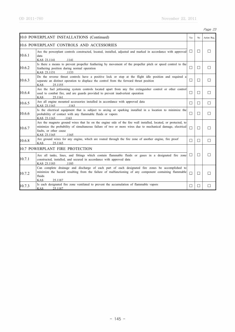
OD 2011-760 November 22, 2011
- 145 -
Page 23
10.0 POWERPLANT INSTALLATIONS (Continued) Yes No Action Req.
10.6 POWERPLANT CONTROLS AND ACCESSORIES� � �
10.6.1Are the powerplant controls constructed, located, installed, adjusted and marked in accordance with approved dataKAS 23.1141 .1141
10.6.2Is there a means to prevent propeller feathering by movement of the propeller pitch or speed control to the feathering position during normal operationKAS 23.1151 .1153
� � �
10.6.3Do the reverse thrust controls have a positive lock or stop at the flight idle position and required a separate an distinct operation to displace the control from the forward thrust positionKAS 25.1155
� � �
10.6.4Are the fuel jettisoning system controls located apart from any fire extinguisher control or other control used to combat fire, and are guards provided to prevent inadvertent operationKAS 25.1161
� � �
10.6.5 Are all engine mounted accessories installed in accordance with approved dataKAS 23.1163 .1163
� � �
10.6.6Is the electrical equipment that is subject to arcing or sparking installed in a location to minimize the probability of contact with any flammable fluids or vaporsKAS 23.1163 .1163
� � �
10.6.7Are the magneto ground wires that lie on the engine side of the fire wall installed, located, or protected, to minimize the probability of simultaneous failure of two or more wires due to mechanical damage, electrical faults, or other causeKAS 23.1165 .1165
� � �
10.6.8 Are ground wires for any engine, which are routed through the fire zone of another engine, fire proofKAS 25.1165
� � �
10.7 POWERPLANT FIRE PROTECTION� � �
10.7.1Are all tanks, lines, and fittings which contain flammable fluids or gases in a designated fire zone constructed, installed, and secured in accordance with approved dataKAS 23.1183 .1185
10.7.2Can complete drainage and discharge of each part of each designated fire zones be accomplished to minimize the hazard resulting from the failure of malfunctioning of any component containing flammable fluidsKAS 25.1187
� � �
10.7.3 Is each designated fire zone ventilated to prevent the accumulation of flammable vaporsKAS 25.1187
� � �
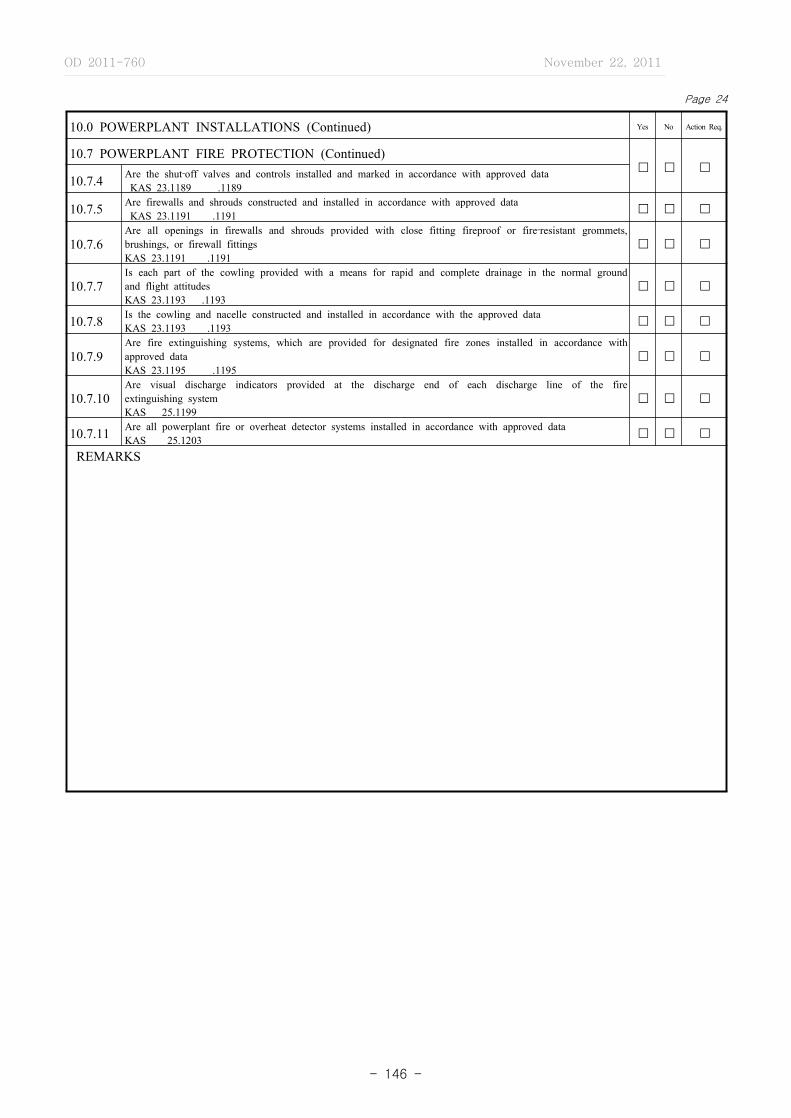
OD 2011-760 November 22, 2011
- 146 -
Page 24
10.0 POWERPLANT INSTALLATIONS (Continued) Yes No Action Req.
10.7 POWERPLANT FIRE PROTECTION (Continued)� � �
10.7.4 Are the shut‐off valves and controls installed and marked in accordance with approved data KAS 23.1189 .1189
10.7.5 Are firewalls and shrouds constructed and installed in accordance with approved data KAS 23.1191 .1191 � � �
10.7.6Are all openings in firewalls and shrouds provided with close fitting fireproof or fire‐resistant grommets, brushings, or firewall fittingsKAS 23.1191 .1191
� � �
10.7.7Is each part of the cowling provided with a means for rapid and complete drainage in the normal ground and flight attitudesKAS 23.1193 .1193
� � �
10.7.8 Is the cowling and nacelle constructed and installed in accordance with the approved dataKAS 23.1193 .1193 � � �
10.7.9Are fire extinguishing systems, which are provided for designated fire zones installed in accordance with approved dataKAS 23.1195 .1195
� � �
10.7.10Are visual discharge indicators provided at the discharge end of each discharge line of the fire extinguishing systemKAS 25.1199
� � �
10.7.11 Are all powerplant fire or overheat detector systems installed in accordance with approved data KAS 25.1203 � � �
REMARKS

OD 2011-760 November 22, 2011
- 147 -
Page 25
11.0 EQUIPMENT
GenearalDue to the differences in the minimum equipment requirements of KAS 23 and 25, the following list of instruments and equipment items is provided as a means of recording the inspection of these items. The KAS requiring the particular item is indicated beside the item in the applicable KAS column. The answers to the following questions should be noted in the appropriate column.
A. Is the item installed and marked in accordance with approved data?KAS 23.1301, .1541 .1301, .1541B. Does a ground operational check show that the item operates satisfactorily?KAS 23.1301, .1309 .1301, .1309C. Is action required as a result of this inspection?
11.1 FLIGHT AND NAVIGATIONAL INSTRUMENTS - KAS 23.1303 25.1303
ITEMKAS
A. B. C.23 25
A. Airspeed indicator X X
B. Altimeter X
C. Altimeter (Sensitive or precision) X
D. Clock (Sweep second pointer) X
E. Free air temperature indicator X
F. Rate‐of‐turn indicator (Gyroscopically with integral bank or slip indicator) X
G. Bank and pitch indicator (Gyroscopically stabilized)
H. Magnetic direction indicator X X
I. Rate of climb X
J. Gyroscopic direction indicator (Directional gyro or equivalent) X
K. Machmeter X
L. Speed warning device X
M. Oxygen quantity indicator X
N. Hydraulic pressure indicator X
O. Electrical power indicators X X
P. Landing gear position indicator X X
Q. Wing flap position indicator X X
R. Trim position indicator X X
S. Differential pressure indicator X
T. Cabin absolute pressure indicator X
U. Rate‐of‐change of cabin absolute pressure X
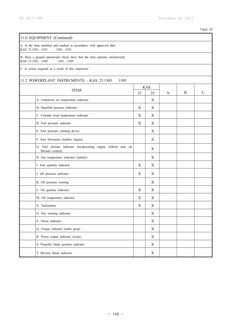
OD 2011-760 November 22, 2011
- 148 -
Page 26
11.0 EQUIPMENT (Continued)
A. Is the item installed and marked in accordance with approved dataKAS 23.1301, .1541 .1301, .1541
B. Does a ground operational check show that the item operates satisfactorilyKAS 23.1301, .1309 .1301, .1309
C. Is action required as a result of this inspection
11.2 POWERPLANT INSTRUMENTS - KAS 23.1305 .1305
ITEMKAS
A. B. C.23 25
A. Carburetor air temperature indicator X
B. Manifold pressure indicator X X
C. Cylinder head temperature indicator X X
D. Fuel pressure indicator X X
E. Fuel pressure warning device X
F. Fuel flowmeter (turbine engine) X
G. Fuel mixture indicator (reciprocating engine without auto alt. Mixture control) X
H. Gas temperature indicator (turbine) X
I. Fuel quantity indicator X X
J. Oil pressure indicator X X
K. Oil pressure warning X
L. Oil quantity indicator X X
M. Oil temperature indicator X X
N. Tachometer X X
O. Fire warning indicator X
P. Thrust indicator X
Q. Torque indicator (turbo prop) X
R. Power output indicator (recip.) X
S. Propeller blade position indicator X
T. Reverse thrust indicator X

OD 2011-760 November 22, 2011
- 149 -
Page 27
11.0 EQUIPMENT (Continued)
A. Is the item installed and marked in accordance with approved dataKAS 23.1301, .1541 .1301, .1541
B. Does a ground operational check show that the item operates satisfactorilyKAS 23.1301, .1309 .1301, .1309
C. Is action required as a result of this inspection
11.3 MISCELLANEOUS EQUIPMENT - KAS 23.1307 .1307
ITEMKAS
A. B. C.23 25
A. Approved seat for each occupant X
B. Approved safety belt for each occupant X X
C. Adequate electrical energy source X X
D. Two‐way radio communication X
E. Radio navigation system X
F. Windshield wiper or equivalent X
G. Ignition switch(es) X X
H. Portable fire extinguisher X
I. Master switch X X
J. Anti‐Collision light X7 X7
K. Electric protective devices X X
REMARKS
7 Night operational requirement

OD 2011-760 November 22, 2011
- 150 -
Page 28
12.0 ELECTRICAL SYSTEM Yes No Action Req.
12.1 Is the electrical system installed in accordance with approved dataKAS 23.1351 25.1351,.1309
� � �
12.2 Does a ground operational test show that the electrical system adequately performs its intended functionKAS 23.1351 25.1351,.1309
� � �
12.3Is the electrical system protected from fuel, oil, water, other detrimental substances and mechanical damageKAS 23.1351 25.1351
� � �
12.4Are all electrical control devices operated by a crew member marked or placarded in accordance with approved dateKAS 23.1351,.1555 25.1351,.1555
� � �
12.5Are electrical system components located in wheel wells protected to prevent a malfunction or failure due to water, slush, ice, or any material which may be thrown by a tireKAS 23.1351 25.1351
� � �
12.6Is the battery installation provided with adequate drainage and ventilation, and enclosed so that no corrosive fluids or gases may damage the surrounding structure or essential equipmentKAS 23.1353 25.1353
� � �
12.7 Are instrument lights installed in accordance with approved dataKAS 23.1381 25.1381
� � �
12.8 Are landing lights installed in accordance with approved dataKAS 23.1383 25.1383
� � �
12.9 Are the position lights installed in accordance with approved dataKAS 23.1385 through .1297 25.1383 through .1297
� � �
12.10 Is the riding light installation in accordance with approved dataKAS 23.1399 25.1399
� � �
12.11 Is the anticollision light installation in accordance with approved dataKAS 23.1401 25.1401
� � �
12.12 Are parts which are electrically insulated from the basic airframe connected to it through lightning arrestorsKAS 25.1369
� � �
13.0 SAFETY EQUIPMENT
� � �13.1 Are the safety equipment release controls, such as automatic liferaft release readily accessible to the crew
KAS 23.1411 25.1411
13.2 Are the emergency equipment items located in an obvious location which is readily accessibleKAS 23.1411 25.1411
� � �
13.3 Are the emergency equipment items stowed in a manner that provides protection from inadvertent damageKAS 23.1411 25.1411
� � �
13.4 Are liferafts installed in accordance with approved dataKAS 23.1411 25.1411
� � �
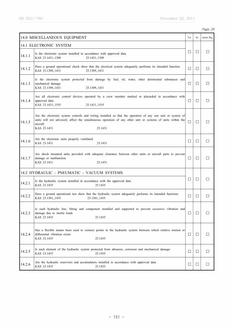
OD 2011-760 November 22, 2011
- 151 -
Page 29
14.0 MISCELLANEOUS EQUIPMENT Yes No Action Req.
14.1 ELECTRONIC SYSTEM
� � �14.1.1 Is the electronic system installed in accordance with approved data
KAS 23.1431,.1309 25.1431,.1309
14.1.2 Does a ground operational check show that the electrical system adequately performs its intended functionKAS 23.1309,.1431 25.1309,.1431 � � �
14.1.3Is the electronic system protected from damage by fuel, oil, water, other detrimental substances and mechanical damageKAS 23.1309,.1431 25.1309,.1431
� � �
14.1.4Are all electronic control devices operated by a crew member marked or placarded in accordance with approved dataKAS 23.1431,.1555 25.1431,.1555
� � �
14.1.5
Are the electronic system controls and wiring installed so that the operation of any one unit or system of units will not adversely affect the simultaneous operation of any other unit or systems of units within the aircraftKAS 23.1431 25.1431
� � �
14.1.6 Are the electronic units properly ventilatedKAS 23.1431 25.1431 � � �
14.1.7Are shock mounted units provided with adequate clearance between other units or aircraft parts to prevent damage or malfunctionKAS 23.1431 25.1431
� � �
14.2 HYDRAULIC - PNEUMATIC - VACUUM SYSTEMS
� � �14.2.1 Is the hydraulic system installed in accordance with the approved data
KAS 23.1435 25.1435
14.2.2 Does a ground operational test show that the hydraulic system adequately performs its intended functionsKAS 23.1301,.1435 25.1301,.1435 � � �
14.2.3Is each hydraulic line, fitting and component installed and supported to prevent excessive vibration and damage due to inertia loadsKAS 23.1435 25.1435
� � �
14.2.4Has a flexible means been used to connect points in the hydraulic system between which relative motion or differential vibration existsKAS 23.1435 25.1435
� � �
14.2.5 Is each element of the hydraulic system protected from abrasion, corrosion and mechanical damageKAS 23.1435 25.1435 � � �
14.2.6 Are the hydraulic reservoirs and accumulators installed in accordance with approved dataKAS 23.1435 25.1435 � � �

OD 2011-760 November 22, 2011
- 152 -
Page 30
14.0 MISCELLANEOUS EQUIPMENT (Continued) Yes No Action Req.
14.2 HYDRAULIC - PNEUMATIC - VACUUM SYSTEMS (Continued)
14.2.7Are the hydraulic system controls and components labeled as to their identification, function or operating limitations, or any applicable combination of these factors KAS 23.1309 25.1309
� � �
14.2.8 Is the pneumatic system installed in accordance with approved dataKAS 23.1309 25.1309 � � �
14.2.9 Does a ground operation test show that the pneumatic system adequately performs its intended functionKAS 23.1309 25.1309 � � �
14.2.10Is each pneumatic system line, fitting and component installed and supported to prevent excessive vibration and damage due to inertia loadsKAS 23.1309 25.1309
� � �
14.2.11 Is each element of the pneumatic system protected from abrasion, corrosion and mechanical damageKAS 23.1309 25.1309 � � �
14.2.12Are the pneumatic system controls and components labeled as to their identification, function or operating limitations or any applicable combination of these factorsKAS 23.1301,.1309 25.1301,.1309
� � �
14.2.13Are the vacuum air system units, components lines and connections installed in accordance with approved dataKAS 25.1433
� � �
14.3 OXYGEN SYSTEM
� � �14.3.1 Is the oxygen system installed in accordance with approved data
KAS 25.1441
14.3.2 Does a ground operational test show that the oxygen system adequately performs its intended functionKAS 25.1441 � � �
14.3.3 Are any oxygen equipment or lines located within a designated fire zoneKAS 25.1451 � � �
14.3.4Are oxygen lines and equipment protected from heat that may be generated in, or escape from, any designated fire zoneKAS 25.1451
� � �
14.3.5
Are the oxygen system components and lines installed so that escaping oxygen cannot cause ignition of grease, fluids, or vapor accumulations that are present in normal operation or as a result of failure or malfunction of any system KAS 25.1451
� � �
14.3.6Are the oxygen system controls and components labeled as to their identification , function or operating limitations or any applicable combination of these factors KAS 23.1301 25.1301
� � �
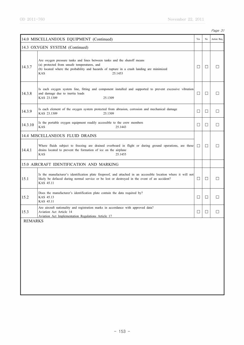
OD 2011-760 November 22, 2011
- 153 -
14.0 MISCELLANEOUS EQUIPMENT (Continued) Yes No Action Req.
14.3 OXYGEN SYSTEM (Continued)
14.3.7
Are oxygen pressure tanks and lines between tanks and the shutoff means(a) protected from unsafe temperatures, and (b) located where the probability and hazards of rupture in a crash landing are minimizedKAS 25.1453
� � �
14.3.8Is each oxygen system line, fitting and component installed and supported to prevent excessive vibration and damage due to inertia loadsKAS 23.1309 25.1309
� � �
14.3.9 Is each element of the oxygen system protected from abrasion, corrosion and mechanical damageKAS 23.1309 25.1309 � � �
14.3.10 Is the portable oxygen equipment readily accessible to the crew membersKAS 25.1443 � � �
14.4 MISCELLANEOUS FLUID DRAINS
� � �14.4.1
Where fluids subject to freezing are drained overboard in flight or during ground operations, are these drains located to prevent the formation of ice on the airplaneKAS 25.1455
15.0 AIRCRAFT IDENTIFICATION AND MARKING
15.1Is the manufacturer’s identification plate fireproof, and attached in an accessible location where it will not likely be defaced during normal service or be lost or destroyed in the event of an accident?KAS 45.11
� � �
15.2Does the manufacturer’s identification plate contain the data required by?KAS 45.13KAS 45.11
� � �
15.3Are aircraft nationality and registration marks in accordance with approved data?Aviation Act Article 14 Aviation Act Implementation Regulations Article 17
� � �
REMARKS
Page 31

OD 2011-760 November 22, 2011
- 154 -
A. This report provides a means whereby manufacturing inspectors, as part of their type certification responsibilities, may record the results of investigations of prototype or modified rotorcraft presented for type certification. The questions contained herein are intended as a guide in determining:
1. That the rotorcraft conforms to the approved type design data furnished by the applicant2. The suitability of fabrication and inspection methods exercised on the rotorcraft by the applicant3. That design features or characteristics which cannot be readily evaluated from technical data are sage for the
category in which certification is requested.4. The suitability of provisions for accessibility to inspect and service the rotorcraft5. The preflight inspection program to be conducted prior to the release of a rotorcraft for MLTM flight test
evaluation
The manufacturing inspector will conduct those inspections required by Type Inspection Authorization, and such other inspections as are considered necessary to establish that the rotorcraft conforms to the approved type design and is safe for operation.
B. The items which are recorded within this report may be referred to at a future date to determine the inspections conducted, the results of these inspections, corrective action, etc. for a particular item; therefore, it is essential that all entries in this report be clear, concise and self‐ explanatory.
C. The results of investigations and special tests, such as static, endurance, operational, pressure, functional and reliability, conducted or witnessed by manufacturing inspectors on the basis of instructions contained in Item 18 of the type inspection authorization and/or other written requests, will be recorded on page 8 titled “TIA Comments”. The TIA item number and item description will be listed directly below the TIA item description.
D. Each question itemized in this report should be answered with an appropriate “yes” or “no”, entered on the line provided. When the answer to a question denotes that an action is required to render the item acceptable, the line following the “yes” - “no” line will be checked. When an action is required, an additional page (s) will be used to list the unsatisfactory conditions found during inspection, with reference to any letters or conformity inspection reports relative to the item. The page(s) will be numbered with the page number on which the question appears plus a letter, i.e., 10a,10b, etc. The item number will be used as a heading and the unsatisfactory conditions will be numerically listed with sufficient space between each entry to note the corrective action taken. When the item has been reinspected, the previous answer to the question will be crossed out and the new answer entered above it; i.e., yes/no. This will be done for each inspection until the item is acceptable to the product being inspected, the abbreviation “NA”, denoting “not applicable”, will be entered on the line provided for the answer to the question. Pages containing only inapplicable questions may be omitted, and the page numbers that are submitted in this report (pages omitted may be listed if more convenient) will be indicated in the space provided on page one.
E. The applicant’s weight and balance report may be used in lieu of the weight and dimensional page of this form, provided it contains all of the information requested. An equipment list with enough duplicates for each copy of the TIR Part 1 submitted, setting forth where pertinent, the make, model, serial number and a notation to identify the equipment as either “required” or “optional” for each item. A copy of this list shall be affixed as an attachment to this report. When any part of this list is part of the weight and balance report, the weight of each item and the horizontal distance from the datum line should likewise be shown. This list should include only significant items or accessories; i.e., those of a type that could have an adverse effect on the airworthiness or operational characteristics of the rotorcraft if replaced by other items; the
[Form No. 22] TYPE INSPECTION REPORT, RotorcraftPart 1 - Rotorcraft Ground Inspection
GENERAL INSTRUCTIONS

OD 2011-760 November 22, 2011
- 155 -
acceptability of which have not been determined. For example, this list shall include, but not necessarily be limited to seats, safety belts, fire extinguishers, electronic equipment, electric motors, instruments, wheels and brakes, tires, skis, floats, superchargers, heaters, engines, starters, generators, etc. When concerned with alteration of rotorcraft under the supplemental type certification program, it is especially important to consider this list.
F. This report is prepared in a form which includes manufacturing inspection items and a reference to the applicable KAS. Some sections are interrelated, and future KAS revisions may modify the requirements of an item. It is essential that the specific KAS, applicable to the rotorcraft involved, be reviewed to insure a complete and effective inspection.
G. TIR Part 1 has been prepared for use on rotorcraft and rotorcraft systems as a guideline for conformity and compliance inspection. Many inspections and tests will be witnessed or participated in which are not covered by questions listed here. It is, therefore, important that all inspections and all changes to the rotorcraft and/or type design data resulting from these inspections be recorded and made a part of this report.
H. The section provided on page one for signatures shall be signed by the responsible persons with their title noted below the line provided. When more than one inspector participates in completing this report, they shall all enter their signatures and titles on page one. The individual inspector shall also insert his initials along with those answers or determinations that he provides within the report.
EXAMPLE: Yes No Action Req.X XX
XN A
DO NOT SUBMIT THIS PAGE WITH REPORT
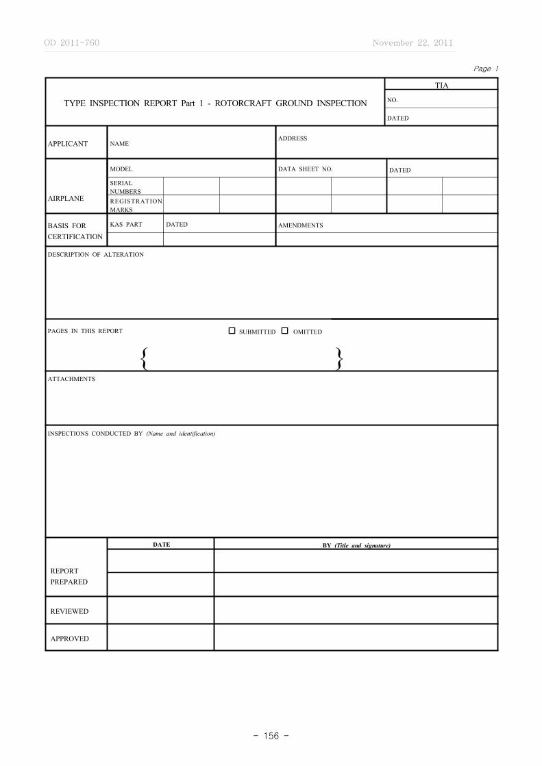
OD 2011-760 November 22, 2011
- 156 -
Page 1
TYPE INSPECTION REPORT Part 1 - ROTORCRAFT GROUND INSPECTION
TIA
NO.
DATED
APPLICANT NAMEADDRESS
AIRPLANE
MODEL DATA SHEET NO. DATED
SERIALNUMBERS REGISTRATION MARKS
BASIS FOR CERTIFICATION
KAS PART DATED AMENDMENTS
DESCRIPTION OF ALTERATION
PAGES IN THIS REPORT o SUBMITTED o OMITTED
{ }ATTACHMENTS
INSPECTIONS CONDUCTED BY (Name and identification)
REPORTPREPARED
DATE BY (Title and signature)
REVIEWED
APPROVED

OD 2011-760 November 22, 2011
- 157 -
Page 2
TABLE OF CONTENTS
ITEM TITLE
COVER SHEET ········································································································································································· 1 TABLE OF CONTENTS ··························································································································································· 2 ADMINISTRATIVE DATA ······················································································································································ 3
1.0 EMPTY WEIGHT AND C.G. LOCATION ····························································································································· 4
2.0 FABRICATION PROCESSES ··················································································································································· 5
3.0 INSPECTION - GENERAL ······················································································································································· 6
4.0 AIRFRAME ·················································································································································································· 7 4.1 GENERAL ················································································································································································ 7 4.2 FUSELAGE ·············································································································································································· 7 4.3 WINGS ····················································································································································································· 8 4.4 STABILIZERS ········································································································································································· 8 4.5 ROTOR BLADES ··································································································································································· 95.0 FLIGHT CONTROL SYSTEM ·················································································································································· 10
6.0 LANDING GEAR ······································································································································································· 12
6.1 GENERAL ················································································································································································ 12
6.2 LANDING GEAR INSTALLATION ···································································································································· 12
6.3 SKI INSTALLATION ····························································································································································· 12
6.4 FLOAT INSTALLATION ······················································································································································ 12
7.0 PERSONNEL AND CARGO ACCOMMODATIONS ············································································································ 138.0 VENTILATION AND HEATING ············································································································································· 159.0 FIRE PROTECTION - COMPARTMENT INTERIORS ········································································································ 1610.0 POWERPLANT ········································································································································································· 17 10.1 GENERAL ·············································································································································································· 17 10.2 ROTOR DRIVE SYSTEM ··················································································································································· 17 10.3 FUEL SYSTEM ····································································································································································· 17 10.4 OIL SYSTEM ········································································································································································ 19 10.5 INDUCTION SYSTEM ························································································································································ 20 10.6 EXHAUST SYSTEM ···························································································································································· 20 10.7 POWERPLANT CONTROLS AND ACCESSORIES ······································································································· 21 10.8 FIRE PROTECTION ····························································································································································· 2111.0 EQUIPMENT ············································································································································································· 2312.0 ELECTRICAL SYSTEM ·························································································································································· 2613.0 SAFETY EQUIPMENT ···························································································································································· 2614.0 MISCELLANEOUS EQUIPMENT ·········································································································································· 27 14.1 ELECTRONIC SYSTEM ······················································································································································ 27 14.2 HYDRAULIC‐PNEUMATIC‐VACUUM SYSTEMS ·········································································································· 2715.0 ROTORCRAFT IDENTIFICATION DATA ··························································································································· 28

OD 2011-760 November 22, 2011
- 158 -
Page 3
ADMINISTRATIVE DATA
A. INSPECTION PERIOD B. WHERE INSPECTION CONDUCTED
FROM TO
C. FORM SUBMITTED
BY APPLICANT
STATEMENT OF CONFORMITY DATED
MAJOR REPAIR AND ALTERATION FORM DATED
YES NO
D. DOES THE APPLICANT’S INSPECTION SYSTEM ASSURE THAT THE MATERIALS AND PARTS USED IN THE
PROTOTYPE AIRCRAFT ARE IN CONFORMITY WITH APPROVED DATA
E. DOES THE APPLICANT MAINTAIN RECORDS OF THE INSPECTION CONDUCTED ON THE PROTOTYPE TO
SUBSTANTIATE HIS STATEMENT OF CONFORMITY
F. NUMBER OF MLTM CONFORMITY INSPECTIONS G. NUMBER OF UNSATISFACTORY ITEMS RECORDED IN THIS REPORT
TOTAL 건
SATISFACTORY 건
UNSATISFACTORY 건
CONDUCTED BY RECORDED IN PROJECT FILE
H. DESCRIPTION OF AIRCRAFT INSPECTED
YES NO
I. Is TC or STC Approval recommended?
REMARKS
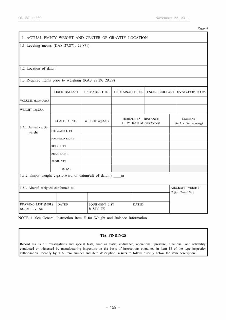
OD 2011-760 November 22, 2011
- 159 -
Page 4
1. ACTUAL EMPTY WEIGHT AND CENTER OF GRAVITY LOCATION
1.1 Leveling means (KAS 27.871, 29.871)
1.2 Location of datum
1.3 Required Items prior to weighing (KAS 27.29, 29.29)
VOLUME (Liter/Gals.)
FIXED BALLAST UNUSABLE FUEL UNDRAINABLE OIL ENGINE COOLANT HYDRAULIC FLUID
WEIGHT (kg/Lbs.)
1.3.1 Actual emptyweight
SCALE POINTS WEIGHT (kg/Lbs.) HORIZONTAL DISTANCEFROM DATUM (mm/Inches)
MOMENT (Inch - Lbs. /mm-kg)
FORWARD LEFT
FORWARD RIGHT
REAR LEFT
REAR RIGHT
AUXILIARY
TOTAL
1.3.2 Empty weight c.g.(forward of datum/aft of datum) ____in
1.3.3 Aircraft weighed conformed to AIRCRAFT WEIGHT(Mfgs. Serial No.)
DRAWING LIST (MDL) NO. & REV. NO
DATED EQUIPMENT LIST & REV. NO
DATED
NOTE 1. See General Instruction Item E for Weight and Balance Information
TIA FINDINGS
Record results of investigations and special tests, such as static, endurance, operational, pressure, functional, and reliability, conducted or witnessed by manufacturing inspectors on the basis of instructions contained in item 18 of the type inspection authorization. Identify by TIA item number and item description; results to follow directly below the item description.
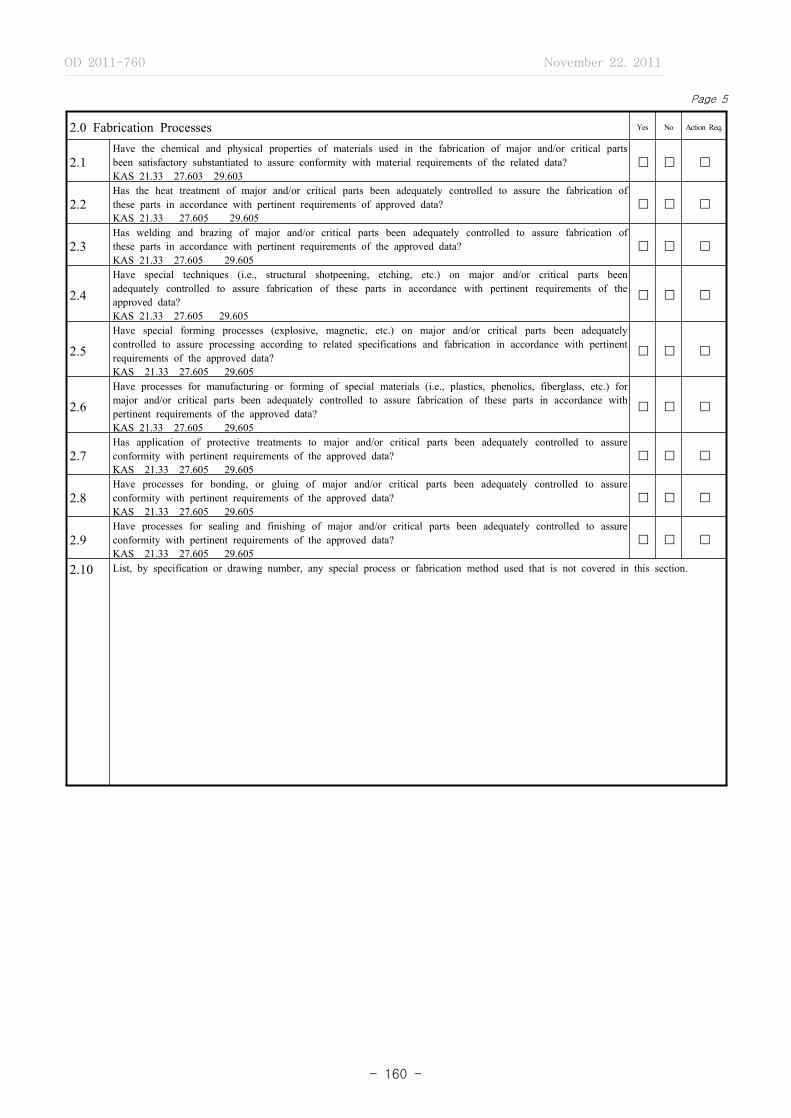
OD 2011-760 November 22, 2011
- 160 -
Page 5
2.0 Fabrication Processes Yes No Action Req.
2.1Have the chemical and physical properties of materials used in the fabrication of major and/or critical parts been satisfactory substantiated to assure conformity with material requirements of the related data?KAS 21.33 27.603 29.603
� � �
2.2Has the heat treatment of major and/or critical parts been adequately controlled to assure the fabrication of these parts in accordance with pertinent requirements of approved data?KAS 21.33 27.605 29.605
� � �
2.3Has welding and brazing of major and/or critical parts been adequately controlled to assure fabrication of these parts in accordance with pertinent requirements of the approved data?KAS 21.33 27.605 29.605
� � �
2.4Have special techniques (i.e., structural shotpeening, etching, etc.) on major and/or critical parts been adequately controlled to assure fabrication of these parts in accordance with pertinent requirements of the approved data?KAS 21.33 27.605 29.605
� � �
2.5Have special forming processes (explosive, magnetic, etc.) on major and/or critical parts been adequately controlled to assure processing according to related specifications and fabrication in accordance with pertinent requirements of the approved data?KAS 21.33 27.605 29.605
� � �
2.6Have processes for manufacturing or forming of special materials (i.e., plastics, phenolics, fiberglass, etc.) for major and/or critical parts been adequately controlled to assure fabrication of these parts in accordance with pertinent requirements of the approved data?KAS 21.33 27.605 29.605
� � �
2.7Has application of protective treatments to major and/or critical parts been adequately controlled to assure conformity with pertinent requirements of the approved data?KAS 21.33 27.605 29.605
� � �
2.8Have processes for bonding, or gluing of major and/or critical parts been adequately controlled to assure conformity with pertinent requirements of the approved data?KAS 21.33 27.605 29.605
� � �
2.9Have processes for sealing and finishing of major and/or critical parts been adequately controlled to assure conformity with pertinent requirements of the approved data?KAS 21.33 27.605 29.605
� � �
2.10 List, by specification or drawing number, any special process or fabrication method used that is not covered in this section.

OD 2011-760 November 22, 2011
- 161 -
Page 6
3.0 INSPECTION ‐ GENERAL Yes No Action Req.
3.1Are drawings, specifications, equipment, lists, and other type design available for inspection of the prototype product?KAS 21.33 27.605 29.605
� � �
3.2 Has a method been established to update these data to show the latest type design changes?KAS 21.33 27.605 29.605 � � �
3.3Has a method been established to show the status of these changes relative to the prototype article and parts thereof?KAS 21.33 27.605 29.605
� � �
3.4 Are deviations from the type design being recorded?KAS 21.33 27.605 29.605 � � �
3.5Are parts and assemblies properly stamped, marked or otherwise identified to indicate the inspection status during various stages of fabrication?KAS 21.33 27.605 29.605
� � �
3.6Are major components, for which a service life or retirement period has or will be established, identified by serial number or equivalent means?KAS 27.1529 29.1529
� � �
3.7Does inspection of procured items show that they are in conformity with the vendor’s drawings and/or the applicant’s specification drawings?KAS 27.621 29.621
� � �
3.8Have critical castings received 100 percent inspection by visual, radiographic, and magnetic particle or penetrate inspection or approved equivalent nondestructive inspection methods?KAS 27.621 29.621
� � �
3.9 Have noncritical castings been inspected in accordance with the following table:
CASTING FACTOR INSPECTION
(a) 2.0 or more 100 percent visual � � �
(b) Less than 2.0 but More than 1.5
100 percent visual and magnetic particle or penetrant or equivalent nondestructive inspection methods � � �
(c) 1.25 through 1.50100 percent visual, magnetic particle or penetrant, and radiographic or approved equivalent nondestructive inspection methods � � �
REMARKS

OD 2011-760 November 22, 2011
- 162 -
Page 7
4.0 AIRFRAME Yes No Action Req.
4.1 GENERAL� � �4.1.1 Are nonmetallic external components protected against erosion?
KAS 27.609 29.609
4.1.2Have adequate drainage provisions been provided to prevent the accumulation of fuel, water, hydraulic oil, etc.?KAS 27.609 29.609
� � �
4.1.3 Have adequate ventilation provisions been provided to prevent the accumulation of fumes, smoke, gasses, etc.?KAS 27.609 29.609 � � �
4.1.4Have all members of the structures been suitably protected against deterioration or loss of strength in service due to weathering, corrosion, and abrasion?KAS 27.609 29.609
� � �
4.1.5Have adequate inspection openings, doors, and access panels been provided to allow close examination of and access to, each part requiring recurring inspection, adjustments for proper alignment and function or lubrication?KAS 27.611 29.609
� � �
4.2 FUSELAGE
� � �4.2.1Have rivets been driven in accordance with acceptable standards?KAS 27.603 29.603 27.605 29.605
4.2.2Have bolts been installed in accordance with acceptable standards with respect to proper length, washer, nuts, fits, finish, etc.?KAS 27.603 29.603 27.605 29.605
� � �
4.2.3 Are self‐locking nuts used on any bolt subject to rotation during aircraft operation?KAS 27.607 29.607 � � �
4.2.4Do detail parts fit into subassemblies without being forced or sprung?KAS 27.603 29.603 27.605 29.605
� � �
4.2.5Do subassemblies fit the fuselage assembly without being forced or sprung?KAS 27.603 29.603 27.603 29.605
� � �
4.2.6Are major attachment points of the wing, empennage, landing gear, power plant, etc., adequately controlled to insure proper alignment when mated?KAS 27.603 29.603 27.605 29.605
� � �
4.2.7Ate structural panels such as bulkhead, spar and beam webs and outside skin panels, free from buckles or wrinkles?KAS 27.603 29.603 27.605 29.605
� � �
4.2.8Do access doors, hatches, etc., fit and operate properly?KAS 27.603 29.603 27.605 29.605
� � �
4.2.9 Are there any questionable design items?KAS 27.601 29.601 � � �

OD 2011-760 November 22, 2011
- 163 -
4.0 AIRFRAME (Continued) Yes No Action Req.
4.3 WINGS� � �4.3.1 Have rivets been driven in accordance with acceptable standards?
KAS 27.605 29.605
4.3.2Have bolts been installed in accordance with acceptable standards with respect to proper length, washer, nut, hole size, finish, etc.?KAS 27.605 29.605
� � �
4.3.3 Are self‐locking nuts used on any bolt subject to rotation during rotorcraft operation?KAS 27.607 29.607 � � �
4.3.4 Do detail parts fit into subassemblies without being forced or sprung?KAS 27.605 29.605 � � �
4.3.5 Do subassemblies fit the wing assembly without being forced or sprung?KAS 27.605 29.605 � � �
4.3.6Are major attachment points of fuselage landing gear, etc., adequately controlled to insure proper alignment when assembled to corresponding structures?KAS 27.605 29.605
� � �
4.3.7 Are structural panels such as spar webs, rib webs, and skin panels free from buckles or wrinkles?KAS 27.605 29.605 � � �
4.3.8Are adequate inspection openings, doors, or access panels being provided to allow close examination of each part requiring recurring inspection, adjustments for proper alignment and function or lubrication?KAS 27.611 29.611
� � �
4.3.9 Has wing alignment been properly controlled?KAS 27.603, .605 29.605 � � �
4.3.10 Are adequate ventilation and drainage provisions being provided?KAS 27.609 29.609 � � �
4.3.11 Are there any questionable design items?KAS 27.605 29.605 � � �
4.4 STABILIZERS� � �4.4.1 Have rivets been driven in accordance with acceptable standards?
KAS 27.605 29.605
4.4.2Have bolts been installed in accordance with acceptable standards with respect to proper length, washers, nuts, hole size, finish, etc.?KAS 27.605 29.605
� � �
4.4.3 Are self‐locking nuts used on any bolt subject to rotation during rotorcraft operations?KAS 27.607 29.607 � � �
4.4.4 Do detail parts fit into subassemblies without being forced or sprung?KAS 27.605 29.605 � � �
4.4.5 Do assemblies fit the stabilizer assemblies without being forced or sprung? KAS 27.605 29.605 � � �
4.4.6Are major attachment points of the stabilizers adequately controlled to insure proper alignment when assembled to corresponding structure?KAS 27.605 29.605
� � �
Page 8
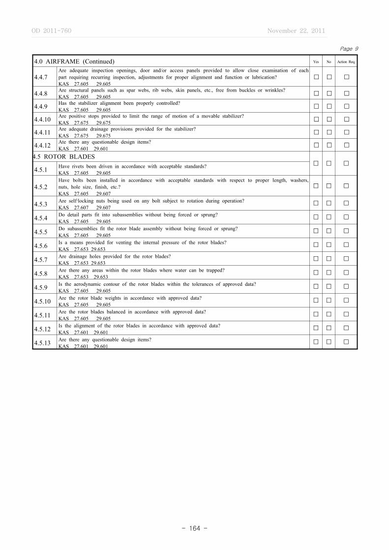
OD 2011-760 November 22, 2011
- 164 -
Page 9
4.0 AIRFRAME (Continued) Yes No Action Req.
4.4.7Are adequate inspection openings, door and/or access panels provided to allow close examination of each part requiring recurring inspection, adjustments for proper alignment and function or lubrication?KAS 27.605 29.605
� � �
4.4.8 Are structural panels such as spar webs, rib webs, skin panels, etc., free from buckles or wrinkles?KAS 27.605 29.605 � � �
4.4.9 Has the stabilizer alignment been properly controlled?KAS 27.605 29.605 � � �
4.4.10 Are positive stops provided to limit the range of motion of a movable stabilizer?KAS 27.675 29.675 � � �
4.4.11 Are adequate drainage provisions provided for the stabilizer?KAS 27.675 29.675 � � �
4.4.12 Ate there any questionable design items?KAS 27.601 29.601 � � �
4.5 ROTOR BLADES� � �
4.5.1 Have rivets been driven in accordance with acceptable standards?KAS 27.605 29.605
4.5.2Have bolts been installed in accordance with acceptable standards with respect to proper length, washers, nuts, hole size, finish, etc.?KAS 27.605 29.607
� � �
4.5.3 Are self‐locking nuts being used on any bolt subject to rotation during operation?KAS 27.607 29.607
� � �
4.5.4 Do detail parts fit into subassemblies without being forced or sprung?KAS 27.605 29.605
� � �
4.5.5 Do subassemblies fit the rotor blade assembly without being forced or sprung?KAS 27.605 29.605
� � �
4.5.6 Is a means provided for venting the internal pressure of the rotor blades?KAS 27.653 29.653
� � �
4.5.7 Are drainage holes provided for the rotor blades?KAS 27.653 29.653
� � �
4.5.8 Are there any areas within the rotor blades where water can be trapped?KAS 27.653 29.653
� � �
4.5.9 Is the aerodynamic contour of the rotor blades within the tolerances of approved data?KAS 27.605 29.605
� � �
4.5.10 Are the rotor blade weights in accordance with approved data?KAS 27.605 29.605
� � �
4.5.11 Are the rotor blades balanced in accordance with approved data?KAS 27.605 29.605
� � �
4.5.12 Is the alignment of the rotor blades in accordance with approved data?KAS 27.601 29.601
� � �
4.5.13 Are there any questionable design items?KAS 27.601 29.601
� � �
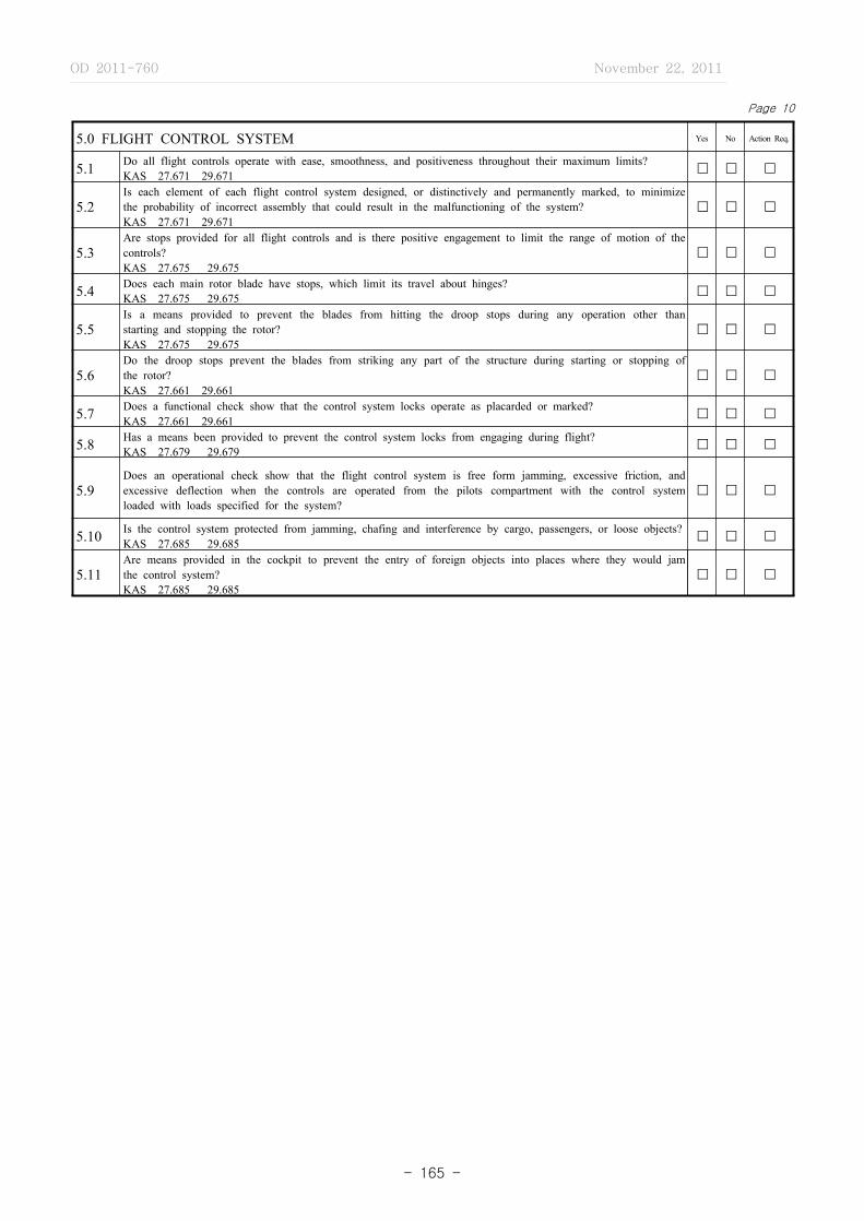
OD 2011-760 November 22, 2011
- 165 -
Page 10
5.0 FLIGHT CONTROL SYSTEM Yes No Action Req.
5.1 Do all flight controls operate with ease, smoothness, and positiveness throughout their maximum limits?KAS 27.671 29.671 � � �
5.2Is each element of each flight control system designed, or distinctively and permanently marked, to minimize the probability of incorrect assembly that could result in the malfunctioning of the system?KAS 27.671 29.671
� � �
5.3Are stops provided for all flight controls and is there positive engagement to limit the range of motion of the controls?KAS 27.675 29.675
� � �
5.4 Does each main rotor blade have stops, which limit its travel about hinges?KAS 27.675 29.675 � � �
5.5Is a means provided to prevent the blades from hitting the droop stops during any operation other than starting and stopping the rotor?KAS 27.675 29.675
� � �
5.6Do the droop stops prevent the blades from striking any part of the structure during starting or stopping of the rotor?KAS 27.661 29.661
� � �
5.7 Does a functional check show that the control system locks operate as placarded or marked?KAS 27.661 29.661 � � �
5.8 Has a means been provided to prevent the control system locks from engaging during flight?KAS 27.679 29.679 � � �
5.9Does an operational check show that the flight control system is free form jamming, excessive friction, and excessive deflection when the controls are operated from the pilots compartment with the control system loaded with loads specified for the system?
� � �
5.10 Is the control system protected from jamming, chafing and interference by cargo, passengers, or loose objects?KAS 27.685 29.685 � � �
5.11Are means provided in the cockpit to prevent the entry of foreign objects into places where they would jam the control system?KAS 27.685 29.685
� � �

OD 2011-760 November 22, 2011
- 166 -
Page 11
5.0 FLIGHT CONTROL SYSTEM (Continued) Yes No Action Req.
5.12 Are means provided to prevent the slapping of cables or tubes against other parts?KAS 27.685 29.685 � � �
5.13 Are the control pulleys provided with guards to prevent the cables from being misplaced or fouled?KAS 27.685 29.685 � � �
5.14Do the control pulleys lie in a plane passing through the cable so that the cable does not rub against the pulley flange?KAS 27.685 29.685
� � �
5.15 Are there ant fairlead installation which change the cable direction more than 3 degrees?KAS 27.685 29.685 � � �
5.16Are there any clevis pins in the control system subject to load or motion which are retained only by cotter pins?KAS 27.685 29.685
� � �
5.17Are turnbuckles and push rods attached to parts having angular in a manner that will positively prevent binding or bending throughout the range of travel?KAS 27.685 29.685
� � �
5.18Where cable systems are used, are provisions provided for the visual inspection of fairleads, pulleys, terminals, and turnbuckles?KAS 27.611 29.611
� � �
5.19 Are there any questionable design items?KAS 27.601 29.601 � � �
REMARKS

OD 2011-760 November 22, 2011
- 167 -
Page 12
6.0 LANDING GEAR Yes No Action Req.
6.1 GENERAL� �
�6.1.1
Is the landing gear suitability protected against deterioration or loss of strength in service due to weathering, corrosion, abrasion, etc.?KAS 27.609 29.609
6.1.2Are fluid lines, cables and electrical lines attached to the landing gear suitability protected against damage by stones, slush, water, ice, etc.?KAS 27.609 29.609
� � �
6.1.3 Are self‐locking nuts being used on any bolt subject to rotation during landing gear operation?KAS 27.607 29.607 � � �
6.1.4Are the wheels, tires and brakes as specified per the related drawings and installed in accordance with this data?KAS 27.731 through 735 & 29.731 through 735
� � �
6.2 LANDING GEAR INSTALLATION�
� �6.2.1
Did the retractable landing gear operational tests demonstrate proper functioning of the landing gear and landing gear door installations throughout the retraction and extension cycles?KAS 29.729
6.2.2 Did the emergency extension system ground tests demonstrate proper extension of the landing gear?KAS 29.729
�� �
6.2.3 Is a positive means provided to lock the landing gear in the extended position?KAS 29.729
�� �
6.2.4Is a means provided to indicate, to the pilot, when the landing is secured in the extended or retracted position?KAS 29.729
�� �
6.3 SKI INSTALLATION� � �
6.3.1 Are the skis fabricated and installed in accordance with approved data?KAS 27.737 29.737
6.3.2 Are the stabilizing means adjusted to maintain the skis in an appropriate position during flight?KAS 27.737 29.737 � � �
6.4 FLOAT INSTALLATION� � �
6.4.1 Are the floats fabricated and installed in accordance with approved data?KAS 27.751 29.751
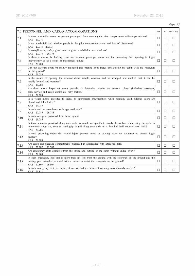
OD 2011-760 November 22, 2011
- 168 -
Page 13
7.0 PERSONNEL AND CARGO ACCOMMODATIONS Yes No Action Req.
7.1 Is there a suitable means to prevent passengers form entering the pilot compartment without permission?KAS 29.771 � � �
7.2 Is the windshield and window panels in the pilot compartment clear and free of distortions?KAS 27.773 29.773 � � �
7.3 Is nonsplintering safety glass used in glass windshields and windows?KAS 27.775 29.775 � � �
7.4Is there a means for locking crew and external passenger doors and for preventing their opening in flight inadvertently or as a result of mechanical failure?KAS 29.783
� � �
7.5Can the external doors be readily unlocked and opened from inside and outside the cabin with the rotorcraft on the ground?KAS 29.783
� � �
7.6Is the means of opening the external doors simple, obvious, and so arranged and marked that it can be readily located and operated?KAS 29.783
� � �
7.7Are direct visual inspection means provided to determine whether the external doors (including passenger, crew service and cargo doors) are fully locked?KAS 29.783
� � �
7.8Is a visual means provided to signal to appropriate crewmembers when normally used external doors are closed and fully locked?KAS 29.783
� � �
7.9 Is each seat in accordance with approved data?KAS 27.785 29.785 � � �
7.10 Is each occupant protected from head injury?KAS 29.785 � � �
7.11Is there a means provided along each aisle to enable occupant’s to steady themselves while using the aisle in moderately rough air, such as hand grip or rail along each aisle or a firm had hold on each seat back?KAS 29.785
� � �
7.12Is each projecting object that would injure persons seated or moving about the rotorcraft on normal flight padded?KAS 29.785
� � �
7.13 Are cargo and baggage compartments placarded in accordance with approved data?KAS 27.787 29.787 � � �
7.14 Are emergency exits openable from the inside and outside of the cabin without undue effort?KAS 29.809 � � �
7.15In each emergency exit that is more than six feet from the ground with the rotorcraft on the ground and the landing gear extended provided with a means to assist the occupants to the ground?KAS 27.807 29.809
� � �
7.16 Is each emergency exit, its means of access, and its means of opening conspicuously marked? KAS 29.811 � � �
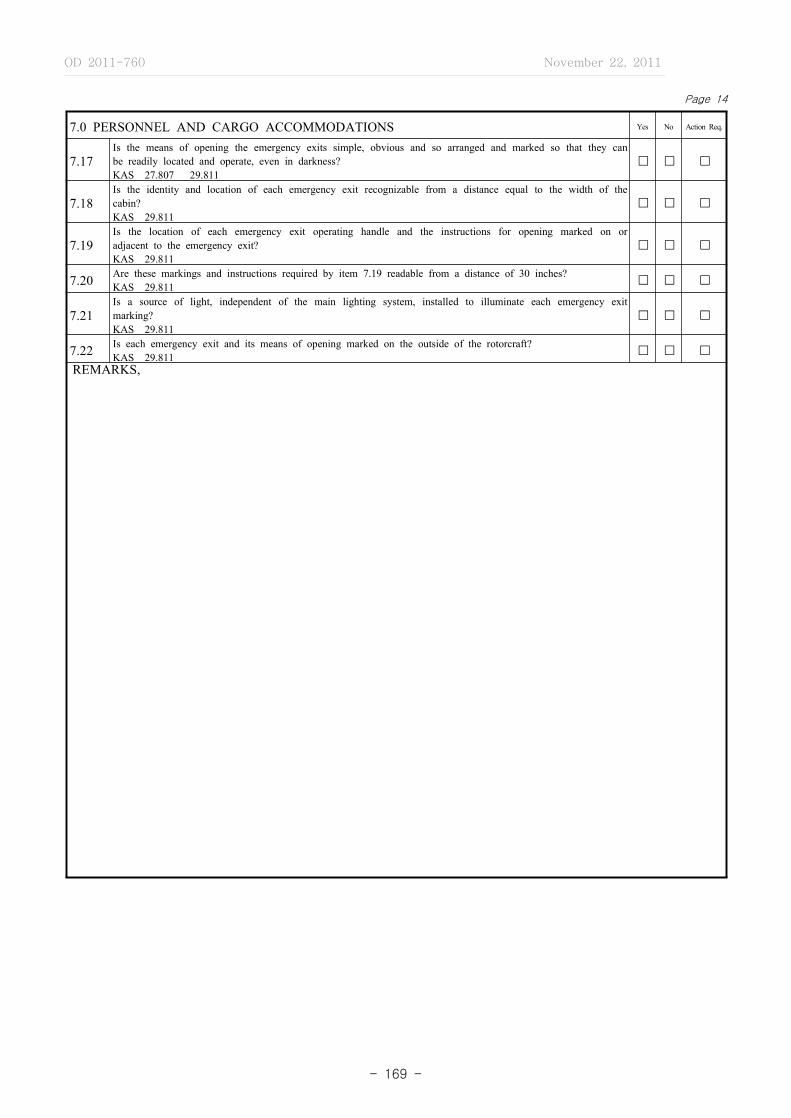
OD 2011-760 November 22, 2011
- 169 -
Page 14
7.0 PERSONNEL AND CARGO ACCOMMODATIONS Yes No Action Req.
7.17Is the means of opening the emergency exits simple, obvious and so arranged and marked so that they can be readily located and operate, even in darkness?KAS 27.807 29.811
� � �
7.18Is the identity and location of each emergency exit recognizable from a distance equal to the width of the cabin?KAS 29.811
� � �
7.19Is the location of each emergency exit operating handle and the instructions for opening marked on or adjacent to the emergency exit?KAS 29.811
� � �
7.20 Are these markings and instructions required by item 7.19 readable from a distance of 30 inches?KAS 29.811 � � �
7.21Is a source of light, independent of the main lighting system, installed to illuminate each emergency exit marking?KAS 29.811
� � �
7.22 Is each emergency exit and its means of opening marked on the outside of the rotorcraft?KAS 29.811 � � �
REMARKS,

OD 2011-760 November 22, 2011
- 170 -
Page 15
8.0 VENTILATION, HEATING AND PRESSURIZATION Yes No Action Req.
8.1 Is the installation of the ventilation and heating system in accordance with approved data?KAS 27.831 29.831 � � �
8.2 Are the ventilation and heating controls placarded and marked in accordance with approved data?KAS 27.1555 29.1555 � � �
8.3 Is each combustion heater approved and installed in accordance with the approved data?KAS 29.833 � � �
REMARKS
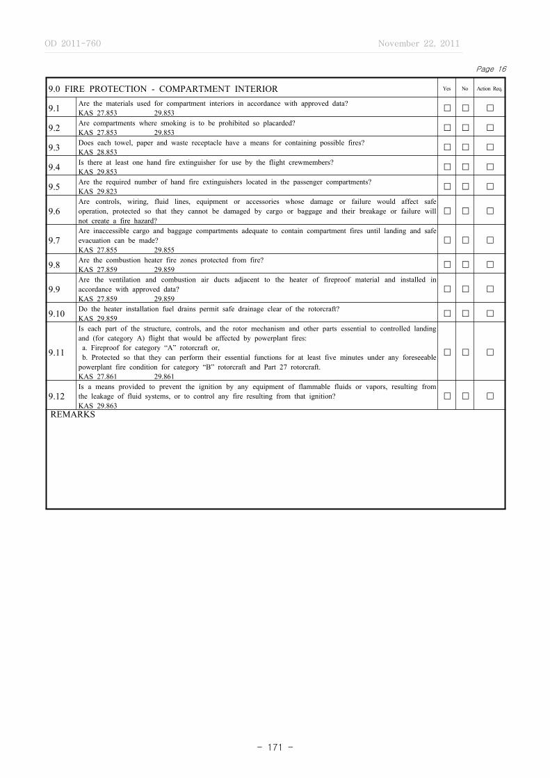
OD 2011-760 November 22, 2011
- 171 -
Page 16
9.0 FIRE PROTECTION - COMPARTMENT INTERIOR Yes No Action Req.
9.1 Are the materials used for compartment interiors in accordance with approved data?KAS 27.853 29.853 � � �
9.2 Are compartments where smoking is to be prohibited so placarded?KAS 27.853 29.853 � � �
9.3 Does each towel, paper and waste receptacle have a means for containing possible fires?KAS 28.853 � � �
9.4 Is there at least one hand fire extinguisher for use by the flight crewmembers?KAS 29.853 � � �
9.5 Are the required number of hand fire extinguishers located in the passenger compartments?KAS 29.823 � � �
9.6Are controls, wiring, fluid lines, equipment or accessories whose damage or failure would affect safe operation, protected so that they cannot be damaged by cargo or baggage and their breakage or failure will not create a fire hazard?
� � �
9.7Are inaccessible cargo and baggage compartments adequate to contain compartment fires until landing and safe evacuation can be made?KAS 27.855 29.855
� � �
9.8 Are the combustion heater fire zones protected from fire?KAS 27.859 29.859 � � �
9.9Are the ventilation and combustion air ducts adjacent to the heater of fireproof material and installed in accordance with approved data?KAS 27.859 29.859
� � �
9.10 Do the heater installation fuel drains permit safe drainage clear of the rotorcraft?KAS 29.859 � � �
9.11
Is each part of the structure, controls, and the rotor mechanism and other parts essential to controlled landing and (for category A) flight that would be affected by powerplant fires: a. Fireproof for category “A” rotorcraft or, b. Protected so that they can perform their essential functions for at least five minutes under any foreseeable powerplant fire condition for category “B” rotorcraft and Part 27 rotorcraft.KAS 27.861 29.861
� � �
9.12Is a means provided to prevent the ignition by any equipment of flammable fluids or vapors, resulting from the leakage of fluid systems, or to control any fire resulting from that ignition?KAS 29.863
� � �
REMARKS

OD 2011-760 November 22, 2011
- 172 -
Page 17
10.0 POWERPLANT INSTALLATIONS Yes No Action Req.
10.1 GENERAL
10.1.1 Is (Are) the engines(s) type certificated?KAS 27.903 29.903
TYPE CERTIFICATE NO.
� � �
10.1.2 Is (Are) the propeller(s) type certificated?KAS
TYPE CERTIFICATE NO.
� � �
10.1.3 Are the powerplant components and accessories installed in accordance with approved data?KAS 27.901 29.901 � � �
10.1.4Is a means provided to allow the close examination of each part requiring inspection, adjustments for proper alignment and function or lubrication?KAS 27.611 29.611 27.901 29.901
� � �
10.1.5 Are major components of the powerplant installation electrically bonded to other parts of the rotorcraft?KAS 27.901 29.901 � � �
10.1.6 Are any self‐locking nuts used on any bolt subject to rotation in operation?KAS 27.607 29.607 � � �
10.1.7Does a ground operational test show that all powerplant components and accessories are operating successfully?KAS 27.901 29.901
� � �
10.2 ROTOR DRIVE SYSTEM� � �
10.2.1 Is the rotor drive systems installed in accordance with approved data?KAS 27.917 29.917
10.2.2Is a means provided to allow the close examination of each rotor drive part requiring recurring inspection, adjustment for proper alignment and function or lubrication?KAS 27.611 29.611
� � �
10.2.3 Is the rotor brake control adequately placarded and provided with a guard to prevent inadvertent operation?KAS 27.921 29.921 � � �
10.3 FUEL SYSTEM� � �10.3.1 Is the fuel systems installed in accordance with approved data?
KAS 27.951 29.951
10.3.2 Does a ground operational check indicate that the fuel system operates satisfactorily?KAS 27.951 29.951 � � �
10.3.3 Is a means provided to warn the crew before overflow through the vents occurs?KAS 29.957 � � �
10.3.4 Are the fuel tanks constructed, installed, and sealed in accordance with approved data?KAS 27.963 29.963 29.967 � � �
10.3.5 Is there at least one‐half inch of clearance between any fuel tank and any firewall?KAS 27.963 29.963 � � �
10.3.6 Are the spaces adjacent to the surfaces of fuel tanks ventilated?KAS 27.963 29.967 � � �
10.3.7 Can the fuel tank expansion space be filled with the rotorcraft in the normal ground attitude?KAS 27.969 29.969 � � �
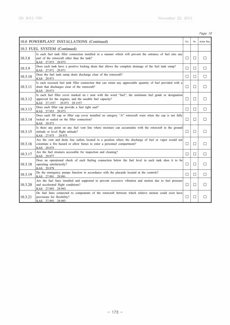
OD 2011-760 November 22, 2011
- 173 -
Page 18
10.0 POWERPLANT INSTALLATIONS (Continued) Yes No Action Req.
10.3 FUEL SYSTEM (Continued)
10.3.8Is each fuel tank filler connection installed in a manner which will prevent the entrance of fuel into any part of the rotorcraft other than the tank?KAS 27.973 29.973
� � �
10.3.9 Does each tank have a positive locking drain that allows the complete drainage of the fuel tank sump?KAS 27.971 29.971 � � �
10.3.10 Does the fuel tank sump drain discharge clear of the rotorcraft?KAS 29.971 � � �
10.3.11Is each recessed fuel tank filler connection that can retain any appreciable quantity of fuel provided with a drain that discharges clear of the rotorcraft?KAS 29.973
� � �
10.3.12Is each fuel filler cover marked on r near with the word “fuel”, the minimum fuel grade or designation approved for the engines, and the useable fuel capacity?KAS 27.1557 29.973 29.1557
� � �
10.3.13 Does each filler cap provide a fuel tight seal?KAS 27.953 29.973 � � �
10.3.14Does each fill cap or filler cap cover installed on category “A” rotorcraft warn when the cap is not fully locked or sealed on the filler connection?KAS 29.973
� � �
10.3.15Is there any point on any fuel vent line where moisture can accumulate with the rotorcraft in the ground attitude or level flight attitude?KAS 27.975 29.975
� � �
10.3.16Are the vent and drain line outlets located in a position where the discharge of fuel or vapor would not constitute a fire hazard or allow fumes to enter a personnel compartment?KAS 29.975
� � �
10.3.17 Are the fuel strainers accessible for inspection and cleaning?KAS 29.977 � � �
10.3.18Does an operational check of each fueling connection below the fuel level in each tank shoe it to be operating satisfactorily?KAS 29.979
� � �
10.3.19 Do the emergency pumps function in accordance with the placards located at the controls?KAS 27.991 29.991 � � �
10.3.20Are the fuel lines installed and supported to prevent excessive vibration and motion due to fuel pressure and accelerated flight conditions?KAS 27.993 29.993
� � �
10.3.21Do fuel lines connected to components of the rotorcraft between which relative motion could exist have provisions for flexibility?KAS 27.993 29.993
� � �

OD 2011-760 November 22, 2011
- 174 -
Page 19
10.0 POWERPLANT INSTALLATIONS (Continued) Yes No Action Req.
10.3 FUEL SYSTEM (Continued)� � �
10.3.22 Does each fuel valve have positive stops or suitable index provisions in the “on” and “off” positions?KAS 27.995 29.995
10.3.23Can drainage of the fuel system be accomplished by the use of fuel strainer and fuel tank sump drains with the rotorcraft in the normal ground attitude?KAS 29.999
� � �
10.3.24Is there at least one accessible positive locking drain at the lowest point in each fuel system to completely drain the system with the rotorcraft in the normal ground attitude?KAS 27.999
� � �
10.3.25 Do the fuel system drain provisions discharge clear of the entire rotorcraft?KAS 27.999 29.999 � � �
10.4 OIL SYSTEM� � �
10.4.1 Is the oil system installed in accordance with the approved data?KAS 27.1011 29.1011
10.4.2 Can the oil tank expansion space be filled with the rotorcraft in the normal ground attitude?KAS 27.1013 29.1013 � � �
10.4.3Is each recessed oil tank filler connection that can retain any appreciable quantity of oil have a drain that discharges clear of the rotorcraft?KAS 29.1013
� � �
10.4.4 Is each oil tank filler marked with the word “oil” and the oil capacity?KAS 27.1557 29.1013 29.1017 � � �
10.4.5 Does each filler cap provide an oil‐tight seal?KAS 29.1013 � � �
10.4.6Are the oil lines and oil tank vents routed so that condensed water that might freeze and obstruct the line cannot accumulate at any point?KAS 29.993 29.1017
� � �
10.4.7Are the oil lines installed and supported to prevent excessive vibration and motion due to oil pressure and accelerated flight conditions?KAS 27.1017 29.993 29.1017
� � �
10.4.8Do oil lines connected to components of the rotorcraft between which relative motion could exist have provisions for flexibility?KAS 27.1017 29.993 29.1017
� � �
10.4.9Is there at least one accessible oil drain which allows the safe drainage of the entire oil system and is provided with a positive locking means in the closed position?KAS 27.1021 29.1021
� � �

OD 2011-760 November 22, 2011
- 175 -
Page 20
10.0 POWERPLANT INSTALLATIONS (Continued) Yes No Action Req.
10.4 OIL SYSTEM (Continued)
10.4.10 Does each oil valve have positive stops or suitable index provisions in the “on” and “off” positions?KAS 29.1025 � � �
10.5 INDUCTION SYSTEM
� � �10.5.1Are all units of the engine air induction system, including icing protection and induction system screens, fabricated and installed in accordance with approved data?KAS 27.1091 29.1091
10.5.2Does the carburetor air preheater installation allow the inspection of exhaust manifold parts that it surrounds and the critical parts of the preheater itself?KAS 29.1101
� � �
10.5.3Are drains for induction system ducts installed in accordance with approved data and do they discharge in a location which will not cause a fire hazard?KAS 29.1103
� � �
10.6 EXHAUST SYSTEM� � �
10.6.1 Are the exhaust system components constructed and installed in accordance with the approved data?KAS 27.1121 19.1121
10.6.2Are the parts of the rotorcraft upon which hot exhaust gases could impinge or that could be subjected to high temperatures from exhaust system parts constructed of fireproof material or shielded by fireproof material?KAS 29.1121
� � �
10.6.3 Are exhaust gases discharged near any flammable fluid vent or drain?KAS 27.1121 29.1121 � � �
10.6.4Is each exhaust manifold supported to withstand any vibration and inertia loads to which it may be subjected?KAS 29.1123
� � �
10.6.5 Has a means been provided for the inspection of critical parts of the exhaust heat exchangers?KAS 29.1125 � � �
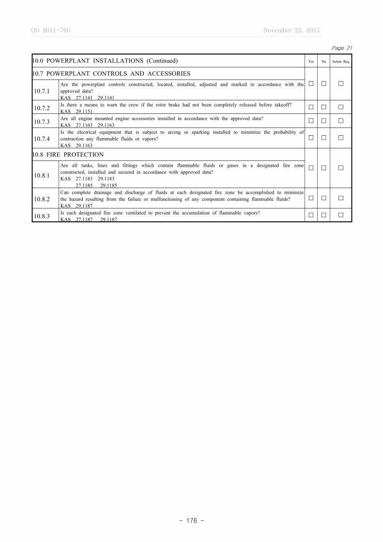
OD 2011-760 November 22, 2011
- 176 -
Page 21
10.0 POWERPLANT INSTALLATIONS (Continued) Yes No Action Req.
10.7 POWERPLANT CONTROLS AND ACCESSORIES� � �
10.7.1Are the powerplant controls constructed, located, installed, adjusted and marked in accordance with the approved data?KAS 27.1141 29.1141
10.7.2 Is there a means to warn the crew if the rotor brake had not been completely released before takeoff?KAS 29.1151
� � �
10.7.3 Are all engine mounted engine accessories installed in accordance with the approved data?KAS 27.1163 29.1163
� � �
10.7.4Is the electrical equipment that is subject to arcing or sparking installed to minimize the probability of contraction any flammable fluids or vapors?KAS 29.1163
� � �
10.8 FIRE PROTECTION
� � �10.8.1
Are all tanks, lines and fittings which contain flammable fluids or gases in a designated fire zone constructed, installed and secured in accordance with approved data?KAS 27.1183 29.1183 27.1185 29.1185
10.8.2Can complete drainage and discharge of fluids at each designated fire zone be accomplished to minimize the hazard resulting from the failure or malfunctioning of any component containing flammable fluids?KAS 29.1187
� � �
10.8.3 Is each designated fire zone ventilated to prevent the accumulation of flammable vapors?KAS 27.1187 29.1187
� � �

OD 2011-760 November 22, 2011
- 177 -
Page 22
10.0 POWERPLANT INSTALLATIONS (Continued) Yes No Action Req.
10.8 FIRE PROTECTION (Continued)� � �
10.8.4 Are the shutoff valves and controls installed and marked in accordance with approved data?KAS 27.1189 29.1189
10.8.5 Are firewalls and shrouds constructed and installed in accordance with approved data?KAS 27.1191 29.1191 � � �
10.8.6Are all openings in firewalls and shrouds provided with close fitting fireproof grommets, bushings, or firewall fittings?KAS 27.1193 29.1193
� � �
10.8.7Is each part of the cowling provided with a means for rapid and complete drainage in the normal, ground and flight attitudes?KAS 27.1193 29.1193
� � �
10.8.8 Is the cowling and engine compartment constructed and installed in accordance with approved data?KAS 27.1193 29.1193 � � �
10.8.9Are fire extinguishing systems which are provided for designated fire zones installed in accordance with approved data?KAS 29.1195
� � �
10.8.10Are visual discharge indicators provided at the discharge end of each discharge line of the fire extinguishing system?KAS 29.1203
� � �
10.8.11 Are all powerplant fire or overheat detector systems installed in accordance with approved data?KAS 29.1203 � � �
REMARKS

OD 2011-760 November 22, 2011
- 178 -
Page 23
11.0 EQUIPMENT
11.1 GeneralDue to the differences on the minimum equipment requirements of KAS 27 and 29, the following list of instructions and equipment items is provided as a means of recording the inspection of these items. The KAS which requires the particular item is noted for reference purposes only.11.2. The answers to the following questions should be noted in the appropriate column.11.2.1 Is the item installed and marked in accordance with approved data?KAS 27.1301 29.1301 27.1541 29.1541 11.2.2 Does a ground operational check show that the item operates satisfactorily?KAS 27.1309 29.1309
11.2.3 Is action required as a result of this inspection?
11.2.4 FLIGHT AND NAVIGATIONAL INSTRUMENTS - KAS 27.1303 29.1303
ITEMKAS
11.2.1 11.2.2 11.2.327 29
a. Airspeed Indicator X X
b. Altimeter X
c. Altimeter (sensitive) X
d. Magnetic Direction Indicator X X
e. Clock (sweep‐second) X
f. Free Air Temp. Indicator X
g. Non‐tumbling gyroscopic and pitch indicator X
h. Gyroscopic rate‐of‐turn indicator with bank indicator X
i. Gyroscopic Direction Indicator X
j. Rate‐of‐climb (vertical speed) Indicator X
k. Electrical Power Indicators X X
l. Hydraulic Pressure Indicator X
m. Landing Gear Position Indicator X X
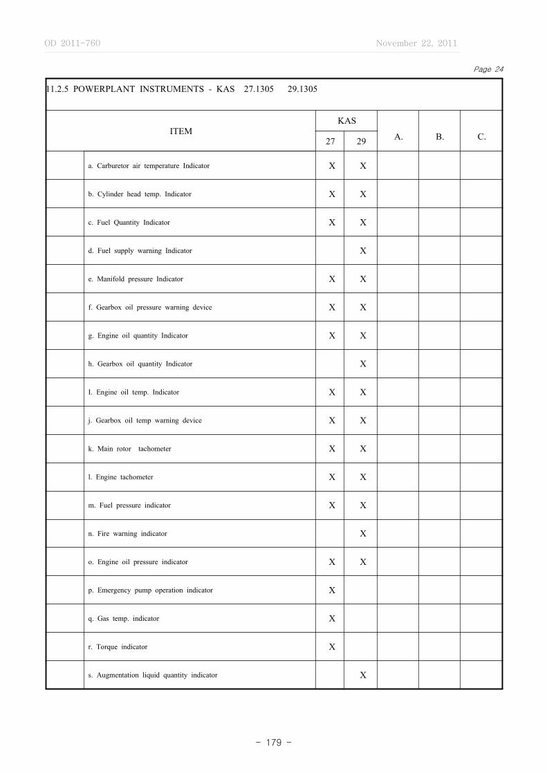
OD 2011-760 November 22, 2011
- 179 -
Page 24
11.2.5 POWERPLANT INSTRUMENTS - KAS 27.1305 29.1305
ITEMKAS
A. B. C.27 29
a. Carburetor air temperature Indicator X X
b. Cylinder head temp. Indicator X X
c. Fuel Quantity Indicator X X
d. Fuel supply warning Indicator X
e. Manifold pressure Indicator X X
f. Gearbox oil pressure warning device X X
g. Engine oil quantity Indicator X X
h. Gearbox oil quantity Indicator X
I. Engine oil temp. Indicator X X
j. Gearbox oil temp warning device X X
k. Main rotor tachometer X X
l. Engine tachometer X X
m. Fuel pressure indicator X X
n. Fire warning indicator X
o. Engine oil pressure indicator X X
p. Emergency pump operation indicator X
q. Gas temp. indicator X
r. Torque indicator X
s. Augmentation liquid quantity indicator X

OD 2011-760 November 22, 2011
- 180 -
Page 25
11.3 MISCELLANEOUS EQUIPMENT - KAS 27.1307 29.1307
ITEMKAS
A. B. C.27 29
a. Approved seat (each occupant) X X
b. Approved safety belt (each occupant) X X
c. Electrical master switch X X
d. Electrical protective devices X X
e. Windshield wiper or equivalent X
f. Two‐way radio equipment X
g. Hand fire extinguisher X
h. Ignition switch X X
i. Adequate electrical energy source X X
REMARKS
OD 2011-760 November 22, 2011
- 181 -
Page 26
12.0 ELECTRICAL SYSTEM Yes No Action Req.
12.1Is the electrical system installed in accordance with approved data?KAS 27.1309 29.1309 27.1351 29.1351
� � �
12.2Does a ground operational test show that the electrical system adequately performs its intended function?KAS 27.1309 29.1309 27.1351 29.1351
� � �
12.3 Is the electrical system protected from fuel, oil, water, other detrimental substances and mechanical damage?KAS 27.1351 29.1351 � � �
12.4
Are all electrical control devices operated by a crewmember, marked or placarded in accordance with approved?KAS 27.1351 29.1351 29.130127.1541 29.1541
� � �
12.5Are electrical cables, terminals, and equipment in designated fire zones that are used in emergency procedures, fire restraint?KAS 29.1359
� � �
12.6Is the battery installation provided with adequate drainage and ventilation and enclosed so that no corrosive fluids or gases may damage the surrounding structure or essential equipment?KAS 27.1353 29.1353
� � �
12.7 Are instrument lights installed in accordance with approved data?KAS 27.1381 29.1381 � � �
12.8 Are the landing lights installed in accordance with approved data?KAS 27.1383 29.1383 � � �
12.9 Are position lights installed in accordance with approved data?KAS 27.1401 29.1401 � � �
13.0 SAFETY EQUIPMENT
� � �13.1
Are the safety equipment release controls, such as flares and automatic life raft releases readily accessible to the crew?KAS 27.1411 29.1411
13.2 Is each life raft and life preserver installed so that it is readily available to the crew and passengers?KAS 27.1411 29.1411 � � �
13.3 Are the life rafts and life preserver in accordance with approved data?KAS 27.1415 29.1415 � � �
OD 2011-760 November 22, 2011
- 182 -
Page 27
14.0 MISCELLANEOUS EQUIPMENT Yes No Action Req.
14.1 ELECTRONIC SYSTEM� � �
14.1.1 Is the electronic system installed in accordance with approved data?KAS 27.1309 29.1309 29.1431
14.1.2 Does a ground operational check show that the electronic system adequately performs its intended function?KAS 27.1309 29.1309 29.1431 � � �
14.1.3Is the electronic system protected from damage by fuel, oil, water, other detrimental substances and mechanical damage?KAS 27.1309 29.1309 29.1431
� � �
14.1.4Are the electronic system controls and wiring installed so that the operation of any one unit or system of units will not adversely affect the simultaneous operation of any other unit or system of units within the aircraft?KAS 27.1309 29.1431
� � �
14.1.5 Are the electronic units properly ventilated?KAS 27.1309 29.1309 29.1431 � � �
14.1.6Are shock‐mounted units provided with adequate clearance between other units or aircraft parts to prevent damage or malfunction?KAS 27.1309 29.1309 29.1431
� � �
14.2 HYDRAULIC‐PNEUMATIC‐VACUUM SYSTEMS� � �
14.2.1 Is the hydraulic system installed in accordance with approved data?KAS 27.1309 29.1309 27.1435 29.1435
14.2.2 Does a ground operational test show that the hydraulic system adequately performs its intended function?KAS 27.1309 29.1309 27.1435 29.1435 � � �
14.2.3Is each hydraulic line, fitting and component installed and supported to prevent excessive vibration and damage due to inertia loads?KAS 27.1309 29.1309 27.1435 29.1435
� � �
14.2.4Has a flexible means been used to connect points in the hydraulic system between which relative motion or differential vibration exists?KAS 27.1309 29.1435 27.1435
� � �
14.2.5 Is each element of the hydraulic system protected from abrasion, corrosion and mechanical damage?KAS 27.1309 29.1435 27.1435 � � �
14.2.6 Are the hydraulic reservoirs and accumulators installed in accordance with approved data?KAS 27.1309 29.1309 27.1435 29.1435 � � �
14.2.7 Are the vacuum air system components in designated fire zones at least fire resistant?KAS 27.1309 29.1433 � � �
OD 2011-760 November 22, 2011
- 183 -
Page 28
14.0 MISCELLANEOUS EQUIPMENT (Continued) Yes No Action Req.
14.2 HYDRAULIC‐PNEUMATIC‐VACUUM SYSTEMS (Continued)
14.2.7Are the hydraulic system controls and components labeled as to their identification, function or operating limitations, or any applicable combination of these factors KAS 23.1309 25.1309
� � �
14.2.8 Is the pneumatic system installed in accordance with approved data KAS 23.1309 25.1309 � � �
14.2.9 Does a ground operation test show that the pneumatic system adequately performs its intended function KAS 23.1309 25.1309 � � �
14.2.10Is each pneumatic system line, fitting and component installed and supported to prevent excessive vibration and damage due to inertia loads KAS 23.1309 25.1309
� � �
14.2.11 Is each element of the pneumatic system protected from abrasion, corrosion and mechanical damage KAS 23.1309 25.1309 � � �
14.2.12Are the pneumatic system controls and components labeled as to their identification, function or operating limitations or any applicable combination of these factors KAS 23.1301,.1309 25.1301,.1309
� � �
14.2.13Are the vacuum air system units, components lines and connections installed in accordance with approved data KAS 25.1433
� � �
15.0 ROTORCRAFT IDENTIFICATION DATA
15.1Is the manufacturer’s identification plate fireproof and attached in an accessible location where it will not likely be defaced during normal service or be lost or destroyed in the event of an accident?KAS 45.11
� � �
15.2Does the manufacturer’s identification plate contain the data required by?KAS 45.13KAS 45.11
� � �
15.3Are aircraft nationality and registration marks in accordance with approved data?Aviation Act Article 14 Aviation Act Implementation Regulations Article 17
� � �
REMARKS