procedural random generation of building models … · procedural random generation of building...
TRANSCRIPT
175
Procedural Random Generation of Building Models Based Geobasis Data and of the Urban Development
with the Software CityEngine
Christiane RADIES
1 Introduction
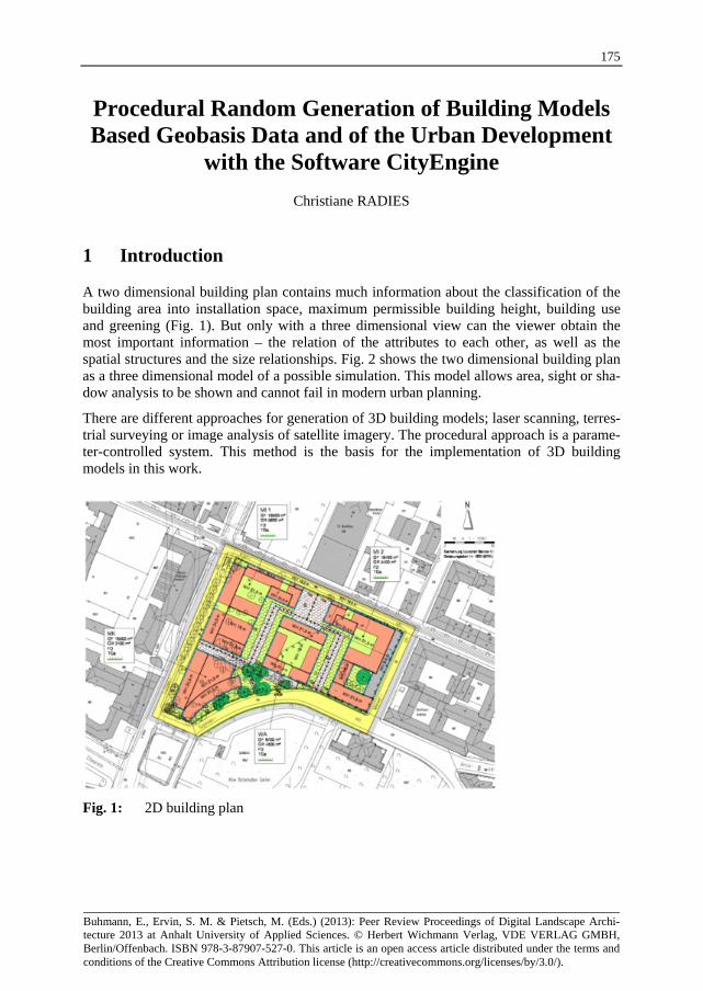
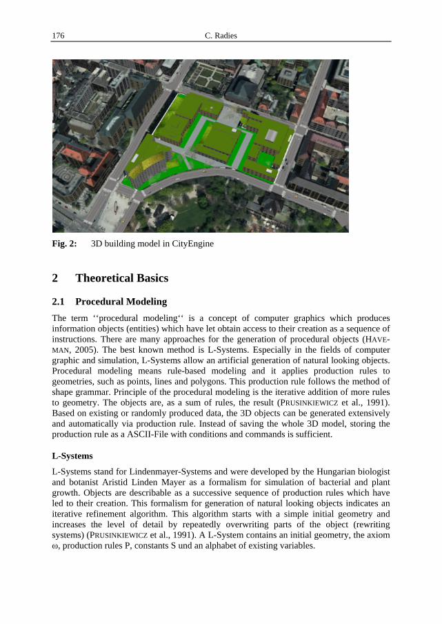
A two dimensional building plan contains much information about the classification of the building area into installation space, maximum permissible building height, building use and greening (Fig. 1). But only with a three dimensional view can the viewer obtain the most important information – the relation of the attributes to each other, as well as the spatial structures and the size relationships. Fig. 2 shows the two dimensional building plan as a three dimensional model of a possible simulation. This model allows area, sight or sha-dow analysis to be shown and cannot fail in modern urban planning.
There are different approaches for generation of 3D building models; laser scanning, terres-trial surveying or image analysis of satellite imagery. The procedural approach is a parame-ter-controlled system. This method is the basis for the implementation of 3D building models in this work.
Fig. 1: 2D building plan
Buhmann, E., Ervin, S. M. & Pietsch, M. (Eds.) (2013): Peer Review Proceedings of Digital Landscape Archi-tecture 2013 at Anhalt University of Applied Sciences. © Herbert Wichmann Verlag, VDE VERLAG GMBH,Berlin/Offenbach. ISBN 978-3-87907-527-0. This article is an open access article distributed under the terms andconditions of the Creative Commons Attribution license (http://creativecommons.org/licenses/by/3.0/).
C. Radies 176
Fig. 2: 3D building model in CityEngine
2 Theoretical Basics
2.1 Procedural Modeling
The term ‘‘procedural modeling‘‘ is a concept of computer graphics which produces information objects (entities) which have let obtain access to their creation as a sequence of instructions. There are many approaches for the generation of procedural objects (HAVE-MAN, 2005). The best known method is L-Systems. Especially in the fields of computer graphic and simulation, L-Systems allow an artificial generation of natural looking objects. Procedural modeling means rule-based modeling and it applies production rules to geometries, such as points, lines and polygons. This production rule follows the method of shape grammar. Principle of the procedural modeling is the iterative addition of more rules to geometry. The objects are, as a sum of rules, the result (PRUSINKIEWICZ et al., 1991). Based on existing or randomly produced data, the 3D objects can be generated extensively and automatically via production rule. Instead of saving the whole 3D model, storing the production rule as a ASCII-File with conditions and commands is sufficient.
L-Systems
L-Systems stand for Lindenmayer-Systems and were developed by the Hungarian biologist and botanist Aristid Linden Mayer as a formalism for simulation of bacterial and plant growth. Objects are describable as a successive sequence of production rules which have led to their creation. This formalism for generation of natural looking objects indicates an iterative refinement algorithm. This algorithm starts with a simple initial geometry and increases the level of detail by repeatedly overwriting parts of the object (rewriting systems) (PRUSINKIEWICZ et al., 1991). A L-System contains an initial geometry, the axiom ω, production rules P, constants S und an alphabet of existing variables.
Procedural Random Generation of Building Models 177
The single elements are described with sign chains (string). On the basis of the initial geometry, the instructions are performed (LINDENMAYER, 1968).
2.2 CityEngine
CityEngine is a stand-alone software for efficient, extensive and fast generation of 3D building models based on data similar building outlines.
2.2.1 Operation
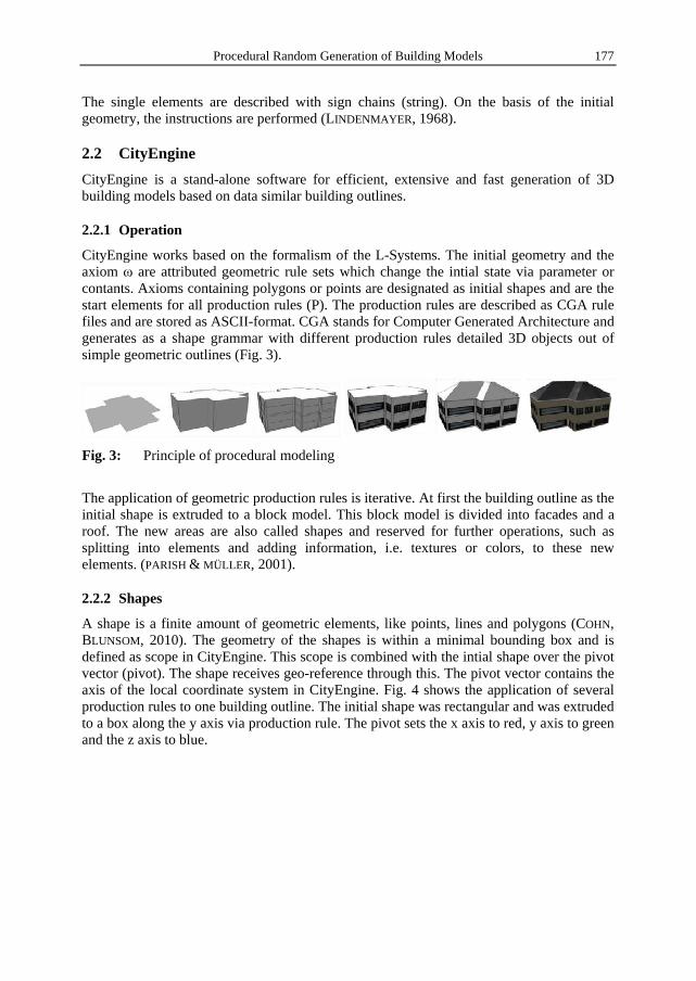
CityEngine works based on the formalism of the L-Systems. The initial geometry and the axiom ω are attributed geometric rule sets which change the intial state via parameter or contants. Axioms containing polygons or points are designated as initial shapes and are the start elements for all production rules (P). The production rules are described as CGA rule files and are stored as ASCII-format. CGA stands for Computer Generated Architecture and generates as a shape grammar with different production rules detailed 3D objects out of simple geometric outlines (Fig. 3).
Fig. 3: Principle of procedural modeling
The application of geometric production rules is iterative. At first the building outline as the initial shape is extruded to a block model. This block model is divided into facades and a roof. The new areas are also called shapes and reserved for further operations, such as splitting into elements and adding information, i.e. textures or colors, to these new elements. (PARISH & MÜLLER, 2001).
2.2.2 Shapes
A shape is a finite amount of geometric elements, like points, lines and polygons (COHN, BLUNSOM, 2010). The geometry of the shapes is within a minimal bounding box and is defined as scope in CityEngine. This scope is combined with the intial shape over the pivot vector (pivot). The shape receives geo-reference through this. The pivot vector contains the axis of the local coordinate system in CityEngine. Fig. 4 shows the application of several production rules to one building outline. The initial shape was rectangular and was extruded to a box along the y axis via production rule. The pivot sets the x axis to red, y axis to green and the z axis to blue.

C. Radies 178
Fig. 4: Shape with Scope in CityEngine
The sides of the box are divided into shapes, and rules can be applied again. Through repeated generation of following shapes (successor) out of previous shapes (predecessor) a tree structure grows. The visualized rule shows this structure in Fig. 5. The initial shape is Lot within the orange box. Successors and predecessors are marked in the blue boxes.
Fig. 5: Tree structure of the shapes within procedural process
Door and Window in the green boxes of Fig. 5 define the Leaf-Shapes. Those can be set with textures or colors and are the visual result of the object.
CGA-Rule-File
The rule set bases on the descriptive programming language computer generated archi-tecture CGA shape grammar. Shape grammars are applied to two dimensional spacial sha-

Procedural Random Generation of Building Models 179
pes (GIPS, 1999). The CGA shape grammar is a shape grammar especially for modeling architectural models (MÜLLER et al., 2006). This grammar contains several predefined op-erations. For example, operations for generation of roof types with transfer of the corre-sponding roof angle. Via repeated application of these rules, sets to shapes complex object models can be generated. Through the addition of details, the level of complexity grows. Fig. 6 shows the principle of CGA shape grammar.
Fig. 6: Principle of adding details iteratively
A start rule is applied to the initial shape (parent) and divides it into two facade components. The facade itself is split into elements such as wall or window (child). These elements are complemented with attributes such as color or texture.
3 Material and Methods
3.1 Data foundation
The geo-basis data comes from the Munich city surveying office. The data of urban development comes from the planning unit Munich and contains the following data with the coordinate system DHDN/3-Degree Gauß-Krüger Zone 4:
A digital elevation model (DEM) as a triangulated irregular network (TIN) with a mesh size of 20 metres. The geographical extent includes 25 x 20 kilometres of the city border of Munich.
An aerial view as a true-orthophoto mosaik with a longitudinal and transversal overlap of 80 percent. The orthogonal projection provided a digital surface model. It contains a data volume of 2 GB a spacial extent of 30000 x 20000 pixel. Ground resolution of one pixel is about 10 cm.
A zoning plan no. 1937 for the region called „Lenbachgärten“ near Munich central station with the format Computer Aided Design (CAD). Including a legend as statutory text.

C. Radies 180
3.2 Modelling approach
This chapter explains the approach of the procedural random generation of a three dimensional building scenario and the necessary data preprocessing of the urban planning data. Each polygon has to contain the corresponding attributes and geometry information. This information is used in the CityEngine to visualize as close to reality as possible. The main issue of this work is to provide maximum space and floor use for each polygon according to the defined values for building use. Furthermore, the result should be a dynamic model within the regulations of the legal framework of the Bavarian building regulations. This work gives evidence if it is possible to generate a procedural random building simulation within the given framework with the software CityEngine.
3.2.1 Clarification of the building plan’s framework
Fig. 7 shows the legal framework of the zoning plan like floor and space ratio, maximum permitted height, type of building use, possible civil engineering for basement and building borders in blue boxes. Maximum of permitted height is marked by wall height (WH) within the corresponding polygons. The following architektonisch work is shown by red polygons.
Fig. 7: Zoning plan no 1937
A simulation of development makes sense after defining the legal framework but prior to the following architectural draft. It is not the aim to model the already planned draft (red). Instead, the use of the random simulation achieves new building drafts within the blue building borders based on the legal framework. In the following work, the possibilities of construction are explained which are regulated in the statutory text and contain develop-ment of buildings, greening and basement garages.
Procedural Random Generation of Building Models 181
3.2.2 Data pre-processing in ArcGIS
CityEngine supports an import of CAD files but without access to the attributes. Because of the necessary access to all information, a transformation from CAD to shape in ArcGIS is used, followed by a semantic classification between geometry and attributes. The geome-tries are stored as polygons, the attributes (heights, floor and ground area) as points. Result is a join of geometry and attribute, as well as the creation of separate object classes like development, greening and basement garage. Later, those object classes can be switched on and off in the CityEngine.
3.2.3 Random procedural generation
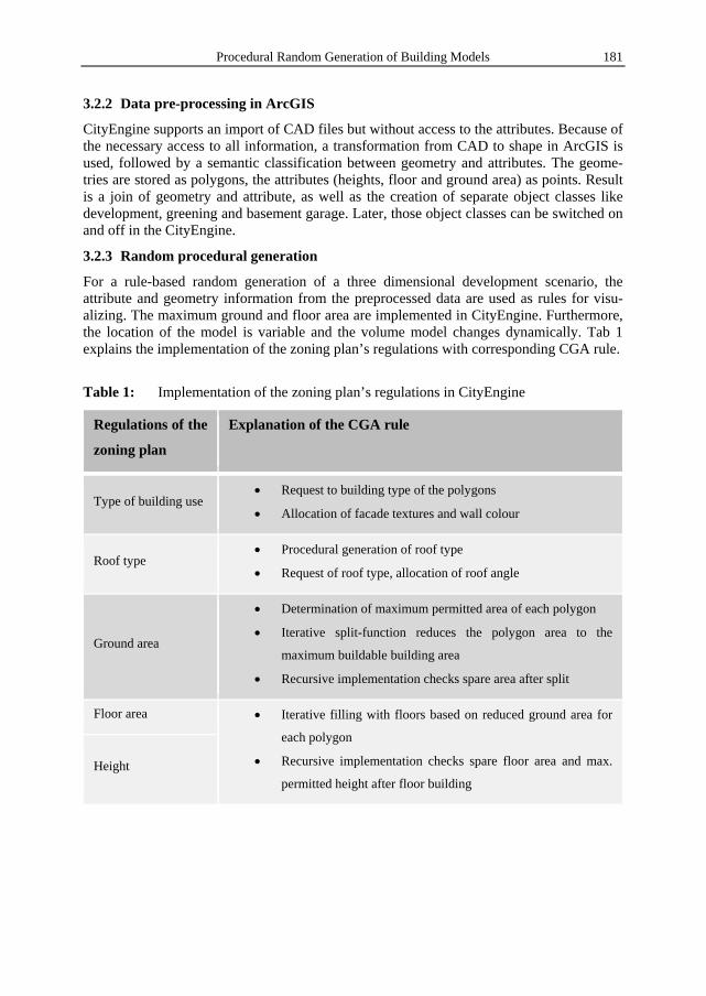
For a rule-based random generation of a three dimensional development scenario, the attribute and geometry information from the preprocessed data are used as rules for visu-alizing. The maximum ground and floor area are implemented in CityEngine. Furthermore, the location of the model is variable and the volume model changes dynamically. Tab 1 explains the implementation of the zoning plan’s regulations with corresponding CGA rule.
Table 1: Implementation of the zoning plan’s regulations in CityEngine
Regulations of the
zoning plan
Explanation of the CGA rule
Type of building use Request to building type of the polygons
Allocation of facade textures and wall colour
Roof type Procedural generation of roof type
Request of roof type, allocation of roof angle
Ground area
Determination of maximum permitted area of each polygon
Iterative split-function reduces the polygon area to the
maximum buildable building area
Recursive implementation checks spare area after split
Floor area Iterative filling with floors based on reduced ground area for
each polygon
Recursive implementation checks spare floor area and max.
permitted height after floor building Height
C. Radies 182
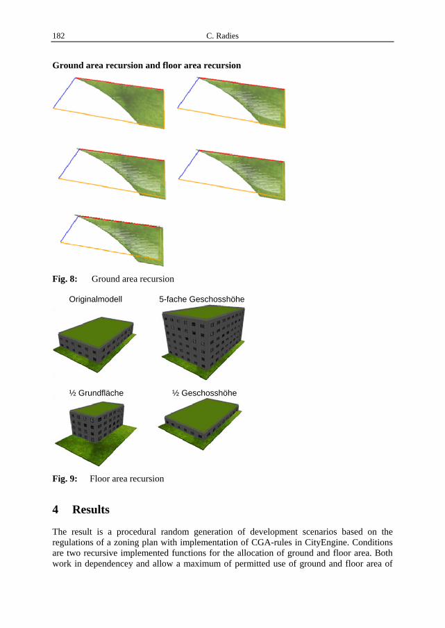
Ground area recursion and floor area recursion
Fig. 8: Ground area recursion
Fig. 9: Floor area recursion
4 Results
The result is a procedural random generation of development scenarios based on the regulations of a zoning plan with implementation of CGA-rules in CityEngine. Conditions are two recursive implemented functions for the allocation of ground and floor area. Both work in dependencey and allow a maximum of permitted use of ground and floor area of
½ Grundfläche ½ Geschosshöhe
Originalmodell 5-fache Geschosshöhe
Procedural Random Generation of Building Models 183
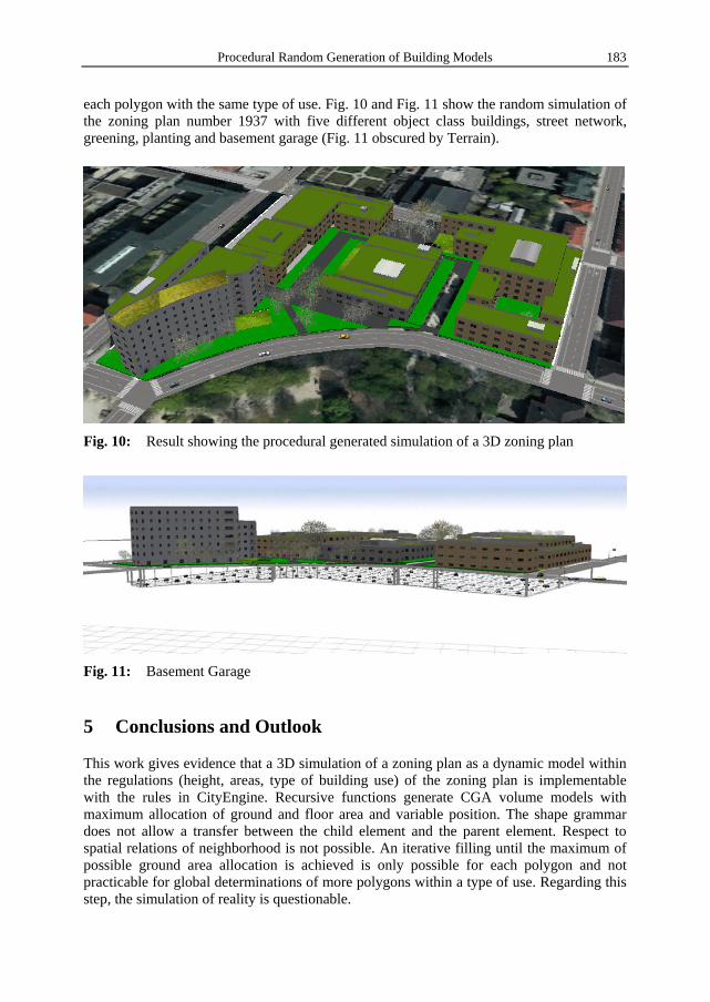
each polygon with the same type of use. Fig. 10 and Fig. 11 show the random simulation of the zoning plan number 1937 with five different object class buildings, street network, greening, planting and basement garage (Fig. 11 obscured by Terrain).
Fig. 10: Result showing the procedural generated simulation of a 3D zoning plan
Fig. 11: Basement Garage
5 Conclusions and Outlook
This work gives evidence that a 3D simulation of a zoning plan as a dynamic model within the regulations (height, areas, type of building use) of the zoning plan is implementable with the rules in CityEngine. Recursive functions generate CGA volume models with maximum allocation of ground and floor area and variable position. The shape grammar does not allow a transfer between the child element and the parent element. Respect to spatial relations of neighborhood is not possible. An iterative filling until the maximum of possible ground area allocation is achieved is only possible for each polygon and not practicable for global determinations of more polygons within a type of use. Regarding this step, the simulation of reality is questionable.

C. Radies 184
The data of urban planning consists of a zoning plan in CAD and statutory text. After data preprocessing every geometry consists of regulation of the zoning plan in the form of attributes in the attribute table.
For the first time, data in urban planning found application in the procedural modeling with CGA rules.
The result is a dynamic model where regulations can be changed in manual ways in CityEngine. Furthermore, additional elements like basement garage can be modeled.
CityEngine stands in contrast to established approaches and does not fit into well-known workflows of modeling tools. With respect to automatic fast and efficient generation of 3D building models, CityEngine cannot fail in modern urban planning.
The manual work of data preprocessing can be minimized by the standard format for urban planning data XPlanung. E-Government Projekt XPlanung follows this approach with the development of an object oriented data exchange format XPlanGML. This enables an exchange of planning data without losses as a standard for Germany (IAI, 2013). Standard attribut tables with standard column names would make a generation of procedural models easier.
More attribute information, such as building year, type of facade, situation, or information about renovation of each of the building geometries, could generate more detailed models. The depth of detail is dependent upon extra information in the form of attributes to the building polygons.
References
Cohn, T. & Blunsom, P. (2010), A Bayesian Model of Syntax-Directed Tree to String. Grammar Introduction. School of Informatics. University of Edinburgh EH8 9AB. Scotland, United Kingdom.
Gips, J. (1999), Computer Implementation of Shape Grammars. Boston College, Computer Science Department.
Haveman, S. (2005), Generative Mesh Modeling. PhD thesis. Technical University Braunschweig.
Lindenmayer, A. (1968), Mathematical Models for Cellular interactions. Parts I and II. In: Journal of Theoretical Biology, 18, 280-315.
Mueller, P., Wonka, P., Haegler, S., Ulmer, A. & Van Gool, L. (2006), Modeling of Buildings. A Shape Grammar for CGA Architecture.
Parish, Y. I. H. & Müller, P. (2001), Procedural Modeling of Cities. In: ACM SIGGRAPH 2001, ACM Press, E. Fiume (Ed.), 301-308.
Prusinkiewicz, P. & Lindenmayer, A. (1996), The algorithmic beauty of plants. New York, USA, Springer Verlag New York, Inc.
Wonka, P., Wimmer, M., Sillion, F., & Ribarsky, W. (2003), Instant Architecture. In: ACM Transactions of Graphics, 22 (3), 669-677.