problem solving through innovation! user manual s3 shoulder cpm... · 2 optiflex s user manual...
TRANSCRIPT

User Manual
ProblemSolvingThroughInnovation!
OPTIFLEX S USER MANUAL 1
TABLE OF CONTENTSPrecautionary Instructions . . . . . . . . . . . . . . . . . . . . . . . . . . . . . . . . . . . . . . . . . . . . 2Safety Instructions . . . . . . . . . . . . . . . . . . . . . . . . . . . . . . . . . . . . . . . . . . . . . . . . . . 3Foreword . . . . . . . . . . . . . . . . . . . . . . . . . . . . . . . . . . . . . . . . . . . . . . . . . . . . . . . . . . 5Package Contents . . . . . . . . . . . . . . . . . . . . . . . . . . . . . . . . . . . . . . . . . . . . . . . . . . . 5Product Description . . . . . . . . . . . . . . . . . . . . . . . . . . . . . . . . . . . . . . . . . . . . . . . . . 6Indications . . . . . . . . . . . . . . . . . . . . . . . . . . . . . . . . . . . . . . . . . . . . . . . . . . . . . . . . 7Adjusting the OptiFlex® S . . . . . . . . . . . . . . . . . . . . . . . . . . . . . . . . . . . . . . . . . . . . . 8Pendant Nomenclature . . . . . . . . . . . . . . . . . . . . . . . . . . . . . . . . . . . . . . . . . . . . . . 10Programming the OptiFlex® S . . . . . . . . . . . . . . . . . . . . . . . . . . . . . . . . . . . . . . . . . 11Converting the OptiFlex® S . . . . . . . . . . . . . . . . . . . . . . . . . . . . . . . . . . . . . . . . . . . 19Transporting the OptiFlex® S . . . . . . . . . . . . . . . . . . . . . . . . . . . . . . . . . . . . . . . . . . 20Maintenance . . . . . . . . . . . . . . . . . . . . . . . . . . . . . . . . . . . . . . . . . . . . . . . . . . . . . . 20Technical Specifications . . . . . . . . . . . . . . . . . . . . . . . . . . . . . . . . . . . . . . . . . . . . . 21Parts Description . . . . . . . . . . . . . . . . . . . . . . . . . . . . . . . . . . . . . . . . . . . . . . . . . . . 22Warranty . . . . . . . . . . . . . . . . . . . . . . . . . . . . . . . . . . . . . . . . . . . . . . . . . . . . . . . . . 24Replacement Parts List . . . . . . . . . . . . . . . . . . . . . . . . . . . . . . . . . . . . . . . . . . . . . .26
OPTIFLEX® S

OPTIFLEX S USER MANUAL 2
PRECAUTIONARY INSTRUCTIONS
WARNING – The following precautions should be taken in order to reduce the risk of fire, electrical shock, injury to persons or damage to the OptiFlex® S:
• Read this manual before assembling or using OptiFlex S.• Only use OptiFlex S on solid, flat surfaces.• Extreme caution should be taken when in use around children.• Use OptiFlex S only as described in this manual.• Keep hair, loose clothing, fingers and all parts of body away from
moving parts of OptiFlex S. • DO NOT use OptiFlex S outdoors or on wet surfaces. • Materials may become flammable or combustible if exposed to a
source of ignition.• Disconnect electrical supply before servicing or cleaning. Failure to
do so could result in electrical shock or personal injury.• DO NOT use OptiFlex S while smoking or around open flame.• Exercise caution when using accessories and auxiliary devices such
as muscle stimulators, ColPaCs and other modalities.• Turn power off before unplugging.• Unplug the power supply by grasping the plug not the cord.• Damage may occur to OptiFlex S if not transported and stored
between 0 and 140°F (-18 to 60°C).• Unplug from power supply when not in use.• DO NOT use if cord or plug is damaged.• Use extra care when touching metal of OptiFlex S after exposure to
cold or heat.• DO NOT handle any electrical apparatus with wet hands.• DO NOT use OptiFlex S as a toy.• Condensation could result and damage OptiFlex S if unit is subjected
to periods of low temperatures followed by periods of hightemperatures.
• DO NOT use on unstable surfaces.• Precautionary measures should be taken when any type of liquid
comes in contact with an electrical apparatus.• OptiFlex S is made from high impact materials. However, structural
failure or hidden damage can be caused by shock, impact or droppingthe unit. Use care when transporting and storing unit to avoidequipment damage.
• To isolate the unit from the power source, disconnect the power cordat the wall outlet.
• OptiFlex S should only be used after the operator has thoroughlyread and understands this manual.
• Rapid increases in ROM can cause complications.• OptiFlex S is not to be used in the presence of flammable anesthetic
mixture with air or with oxygen or nitrous oxide.• Meets IEC/EN 60601-1-2 Electromagnetic Compatibility/interference
safety standard. (Care must be taken when operating this equipmentaround other equipment. Potential electromagnetic or otherinterference could occur to this or to the other equipment. Try tominimize this interference by not using other equipment inconjunction with it.)

OPTIFLEX S USER MANUAL 3
CAUTION – These instructions must be read beforestarting the device!
• The OptiFlex® S may only be used under the supervision, or by theorder of a physician or other licensed healthcare practitioner.
• Only the original OptiCard™ chip card should be used.• Make sure that the patient is positioned in an anatomically correct
way. Check the following settings:1. Anti/retroversions (Horizontal abduction/adduction)2. Height adjustment3. Upper arm length adjustment4. Elbow angle adjustment5. Lower arm length adjustment
• Changes may only be made to the settings (numbers 1-5, above) without thepatient’s arm in place. Always review settings prior to patient’s use.
• If necessary, large ranges of motion can be set with the OptiFlex S.Make sure that the CPM device is set so that there is enough spacebetween the patient’s body and the motion element to ensure safety.This is especially true in the case of patients who are obese, verylarge or very small.
Important! – Unless otherwise prescribed by the supervising doctor, themovements should be programmed in the following order: adduction, internal
rotation, abduction, external rotation.
CAUTION – Before treatment, a test run involving several movement cycles should be carried out. Run these testswithout patient first.
• When in doubt regarding the correct setting and programming,interrupt therapy immediately. Check the device and contactChattanooga Group Customer Service if necessary.
• The programming unit should be explained to the patient and mustbe located within the patient’s reach (usually in the storage areaprovided) so therapy can be interrupted if necessary.
• The OptiCard should be labeled with the patient’s name and mayonly be used for this patient.
• Pay careful attention to pressure points in cases where patients areobese, very large or very small.
• Movement must always be free of pain and irritation.• The patient must be fully conscious during instruction and when
using the device.• In the case of patients who cannot operate the pendant due to
paralysis or shoulder operations on both sides, treatment must becontinuously supervised by specialist staff.
• The doctor or therapist must decide on a case-by-case basis whetherthe device can be used with each particular patient.
• Make sure the characteristic values of your power supply correspondto the voltage and frequency data indicated on the ID plate.
• Only connect the OptiFlex S to correctly installed safety sockets.• Repair and maintenance work may only be carried out by authorized
personnel, or else all warranty services and liabilities will be void.• Perform regular checks on all components for possible damage or
loose connections.• Maximum weight capacity for the OptiFlex S is 330 lbs. (150 kg).
CAUTION – This device should not be used for patient transport.
OPTIFLEX S USER MANUAL
SAFETY INSTRUCTIONS

OPTIFLEX S USER MANUAL 5
FOREWORDThis manual has been written for the owners and operators of the OptiFlex® Scontinuous passive motion machine. It contains general instructions on operation,precautionary practices, maintenance and parts information. In order to maximizeuse, efficiency and the life of your OptiFlex S, please read this manual thoroughlyand become familiar with the controls as well as the accessories before operatingthe unit.
Specifications put forth in this manual were in effect at the time of publication.However, owing to Chattanooga Group's policy of continual improvement, changesto these specifications may be made at any time without obligation on the part ofChattanooga Group.
PACKAGE CONTENTS• OptiFlex S unit• 5 OptiCard™ chip cards• 1 Pen for OptiCard• 1 Operator's Manual• 1 Patient Kit
OPTIFLEX S USER MANUAL
OPTIFLEX S USER MANUAL 6
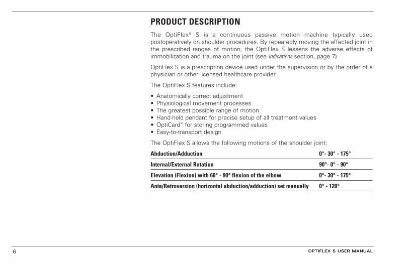
PRODUCT DESCRIPTIONThe OptiFlex® S is a continuous passive motion machine typically usedpostoperatively on shoulder procedures. By repeatedly moving the affected joint inthe prescribed ranges of motion, the OptiFlex S lessens the adverse effects ofimmobilization and trauma on the joint (see Indications section, page 7).
OptiFlex S is a prescription device used under the supervision or by the order of aphysician or other licensed healthcare provider.
The OptiFlex S features include:
• Anatomically correct adjustment• Physiological movement processes• The greatest possible range of motion• Hand-held pendant for precise setup of all treatment values• OptiCard™ for storing programmed values• Easy-to-transport design
The OptiFlex S allows the following motions of the shoulder joint:
Abduction/Adduction 0°- 30° - 175°
Internal/External Rotation 90°- 0° - 90°
Elevation (Flexion) with 60° - 90° flexion of the elbow 0°- 30° - 175°
Ante/Retroversion (horizontal abduction/adduction) set manually 0° - 120°
OPTIFLEX S USER MANUAL

OPTIFLEX S USER MANUAL 7
INDICATIONSClinical Advantages
OptiFlex® S has been shown to aid the rehabilitation of patients post-operatively by:
• Providing early motion• Achieving functional ROM earlier• Achieving greater ultimate ROM• Decreasing post-operative pain and swelling• Possible increase in fluid dynamics• Decreasing hospital stays
Clinical Indications
OptiFlex S may benefit patients who have undergone:
• Shoulder arthroplasty• Revision total joint arthroplasty• Manipulation of elbow or shoulder• Synovectomies• Fractures of radius, ulna and humerus fixation• Intra-articular fractures of elbow or shoulder• Abrasion arthroplasty of elbow or shoulder• Osteotomies (post fixation and healing)• Septic joints• Allographs• Acromioplasty• Operations on soft tissue in the shoulder area• Pseudosthosis and inversion operations
OPTIFLEX S USER MANUAL

OPTIFLEX S USER MANUAL 8
CAUTION!
When you press the START key, the device automatically entersthe programmed movement range. The device stops when itreaches the preprogrammed range of motion. To start treatment,program the device if necessary (see Programming the Devicesection, page 11), then restart.
ADJUSTING THE OPTIFLEX® S
Numbers in parenthesis are for assistance with parts identification. References canbe found in the chapter entitled Parts Description, on pages 22 and 23 of this manual.
1. First connect the plug to a safety socket and switch the Main Switch (7) on.
2. Insert an original OptiCard™ (2) into the pendant (1).
3. Activate the programming mode by pressing the AB/ADDUCTION and STOPbuttons at the same time, or hold down the STOP button for five seconds.
4. Move the arm support into a position comfortable for the patient (abduction,adduction, internal/external rotation or ante/retroversion).
5. Carry out setting from steps number one through five (see numbering on device).
Ante/Retroversion (Horizontal Abduction/Adduction) (Figure A)
Ante/retroversion is adjusted manually. The aim of the adjustment is to find the mostcomfortable position for the patient.
Carry out this adjustment using the Adjustment Knob (11). Tighten the AdjustmentKnob securely after adjustment.
Height Adjustment (Figures B and C )
1. Secure the arm support at the outer tube for upper arm strength (16).
2. Loosen wing screw (13). Align the axis of Motor A (15) on the patient’s shoulderjoint pivot (see Figure C1). Make sure the patient is in a straight, upright position.
3. The pivot of Motor A (15) must correspond to the pivot of the patient’s shoulderjoint (see Figure C2).
4. Tighten the wing screw (13) securely.
A B
C
OPTIFLEX S USER MANUAL
C1
C2
CAUTION!
Make sure that the rotating axis of the device (Motor B) and therotating axes of the shoulder joint correspond forabduction/adduction and rotation (see Figure C).NOTE: The plugs for the mobility element can only be connected inone direction (see figure D). Also, make sure that the mobilityelement’s connector is always locked on using the safety hinge.
D

OPTIFLEX S USER MANUAL 9
CAUTION! – Elbow AngleChanging the elbow setting to less or more than 90° flexioncauses the setting for the upper arm length to change.
Adjusting the Upper Arm Length (Figure E)
1. Grasp the motion element on Motor B (20) and loosen the Eccentric Lever (17).
2. Make sure that the Internal Tube (18) does not jam.
3. Adjust the length and close the Eccentric Lever (17) again.
Adjusting the Elbow Angle (Figure F)
As a rule, the elbow is set to 90° - 60° flexion. For this, loosen the wing screw (19).For easier adjustment, lift Motor B (20) slightly. After correct adjustment is made,tighten the wing screw (19).
Setting the Lower Arm Length (Figure G)
Open the Eccentric Lever (25). Pull out the hand support until the lower arm of thepatient rests comfortably between it and the elbow support. Close the EccentricLever (25).
Adjusting the Backrest (Figure H)
1. Loosen the wing Screw (10).
2. Push the backrest upright and tighten the wing screw (10).
3. This upright position allows you to twist the motion element to 0°ante/retroversion.
4. Adjust the angle of the backrest in all other ante/retroversion settings in orderto optimize the correspondence between Motor A (15) and the rotating axis ofthe patient’s shoulder joint.
E F
G H
OPTIFLEX S USER MANUAL

OPTIFLEX S USER MANUAL 10
PENDANT NOMENCLATURE
AB/ADDUCTION
ROTATION
PAUSE
MOTOR ON/OFF
SPEED
TIMER
LED DISPLAY
STOP
START
SPECIALFUNCTIONS
SET
“+”
“-”
OPTIFLEX S USER MANUAL

OPTIFLEX S USER MANUAL 11
PROGRAMMING THE OPTIFLEX® SThe following treatment values can be set using the Pendant:
• Abduction/Adduction (Flexion/Elevation)• Internal/External Rotation• Pause for Adduction/Internal Rotation• Pause for Abduction/External Rotation• Motor A/B On/Off• Speed• Timer
In addition, SPECIAL FUNCTIONS can be programmed or called up (see ProgrammingSpecial Functions, page 14). It is only possible to program the device with theOptiCard™ inserted. Only original OptiCards may be used. Note: Always place theOptiCard in holder underneath armrest after patient use.
Programming Steps
1. Press the AB/ADDUCTION and STOP buttons simultaneously for one second orhold down the STOP button for five seconds to switch to programming mode.
2. Select the treatment values in succession by pressing parameter buttons. In thecase of buttons with dual assignment, press the buttons again in order to setthe second treatment value.
3. Use the +/- buttons to change the relevant value. You can run through the valuesquickly by holding down the + or - button.
4. Continue programming (see Information on the Treatment Values Programming[page 12] and Special Functions [page 14] subheadings in this chapter) until you haveentered all the values required.
CAUTION!
When using a programmed OptiCard™, press the STARTbutton after inserting the card without the patient in place.The OptiFlex® S moves to the set ranges of motion andstops. Press START again to start the treatment.
OPTIFLEX S USER MANUAL
OPTIFLEX S USER MANUAL 12
Programming Steps, Continued
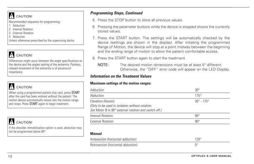
5. Press the STOP button to store all previous values.
6 Pressing the parameter buttons while the device is stopped shows the currentlystored values.
7. Press the START button. The settings will be automatically checked by thedevice (settings are shown in the display). After initiating the programmedRange of Motion, the device will stop at a point midway between the beginningand the ending range of motion to allow the patient comfortable access.
8. Press the START button again to start the treatment.
NNOOTTEE:: The desired motion dimensions must be at least 5° different. Otherwise, the “DIFF” error code will appear on the LED Display.
Information on the Treatment Values
Maximum settings of the motion ranges:
Adduction 30°Abduction 175°Elevation (flexion) 30° - 175°(Only to be used in isolation without rotation. Set Motor B in 90° external rotation and switch off.)Internal Rotation 90°External Rotation 90°
ManualAnteversion (horizontal adduction) 120°Retroversion (horizontal abduction) 0°
CAUTION!
Recommended sequence for programming:1. Adduction2. Internal Rotation3. External Rotation4. AbductionUnless otherwise prescribed by the supervising doctor.
CAUTION!
Differences might occur between the angle specifications onthe device and the angles setting of the extremity. Painless,relaxed movement of the extremity is of paramountimportance.
OPTIFLEX S USER MANUAL
CAUTION!
When using a programmed patient chip card, press SSTTAARRTTafter the card has been entered without the patient. Themotion device automatically moves into the motion rangeand stops. Press SSTTAARRTT again to begin treatment.
CAUTION!
If the shoulder immobilization option is used, abduction maynot be programmed above 80°.

OPTIFLEX S USER MANUAL 13
Setting the Pauses
The pauses occur at the limit positions of Motors A and B and can be set separately.The settable value for pauses is 0 - 30 seconds.
Motors ON/OFF
Motors A and B can be used together or separately.
NNOOTTEE:: Make sure that at least one motor is always switched on. If this is not thecase, the “MOTOR A/B: OFF!” error code will appear on the LED display.
Setting the Timer
1. The settable values for the timer for therapy time are 1-300 minutes or Continuous.
2. The device will stop at the midpoint of the treatment range automatically whenthe therapy time is complete.
3. In Continuous mode, the treatment is terminated by pressing the STOP button.
OPTIFLEX S USER MANUAL

OPTIFLEX S USER MANUAL 14
Programming the Special Functions
Possible Special Functions:
• New Patient• Warm-up Program• Asynchronous• Reverse-on-load• Therapy Duration• Display Contrast• Service Menu
To program the Special Functions:
1. Switch to Programming mode.
2. Press the FUNC button.
3. Select a special function using the + or - button.
4. Follow the directions on the LED Display.
5. Terminate with the STOP button.
New Patient
When this special function is activated, the OptiFlex® S is reset to the factory setting.All previously programmed values are deleted.
OPTIFLEX S USER MANUAL

OPTIFLEX S USER MANUAL 15
The following comprise the factory settings:
Adduction 89°Abduction 90°Internal Rotation -1°External Rotation 1°Pauses 0 secondsMotors A/B ONSpeed 100%Timer Continuous Mode
Reverse-on-load set to Maximum 25
All special functions are deactivated
Motors run synchronously
1. Press the FUNC button in Programming mode.
2. Select the “Factory Settings” function with the + or - button.
3. Activate the function with the SET button.
4. Press the START button.
5. The device enters the factory setting and stops automatically.
OPTIFLEX S USER MANUAL

OPTIFLEX S USER MANUAL 16
Warm-up Program
The OptiFlex® S has a warm-up mode as a special function. After the warm-up modeis activated, the OptiFlex S begins the movement in the center between theprogrammed values for abduction/adduction, elevation or internal/external rotation.
The extent of movement is increased by 3° in each direction for every motion cycleuntil the set values are reached. The device then moves between the programmedvalues.
After the therapy time has elapsed and the device is started again, treatment beginswith the warm-up mode unless it is deactivated.
Asynchronous
Motors A and B can be operated synchronously or asynchronously.
In synchronous use, Motors A and B execute a synchronous motion in terms ofadduction-internal rotation and abduction-external rotation.
In asynchronous use, the two motors operate independently in the relevant range ofmotion. This mode requires particular care and attention on the part of the operatorto ensure that the OptiFlex S is used without any risks to the patient.
CAUTION!
It is generally recommended that the OptiFlex® S beoperated synchronously. The use of asynchronous operatingmode must be medically or therapeutically indicated.
OPTIFLEX S USER MANUAL
OPTIFLEX S USER MANUAL 17
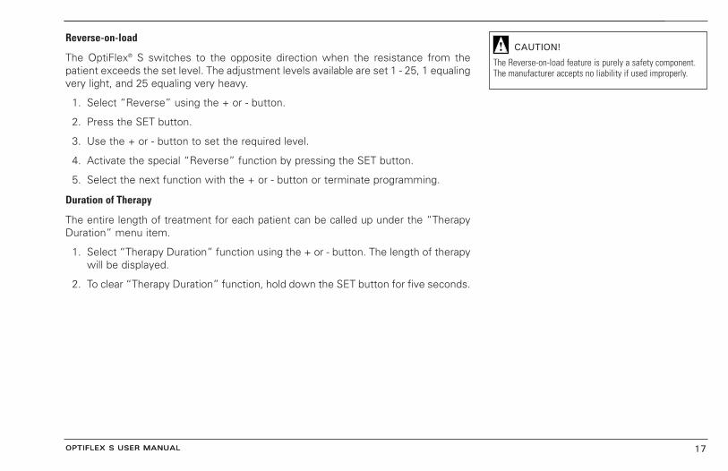
Reverse-on-load
The OptiFlex® S switches to the opposite direction when the resistance from thepatient exceeds the set level. The adjustment levels available are set 1 - 25, 1 equalingvery light, and 25 equaling very heavy.
1. Select “Reverse” using the + or - button.
2. Press the SET button.
3. Use the + or - button to set the required level.
4. Activate the special “Reverse” function by pressing the SET button.
5. Select the next function with the + or - button or terminate programming.
Duration of Therapy
The entire length of treatment for each patient can be called up under the “TherapyDuration” menu item.
1. Select “Therapy Duration” function using the + or - button. The length of therapywill be displayed.
2. To clear “Therapy Duration” function, hold down the SET button for five seconds.
CAUTION!
The Reverse-on-load feature is purely a safety component.The manufacturer accepts no liability if used improperly.
OPTIFLEX S USER MANUAL

OPTIFLEX S USER MANUAL 18
Display Contrast
This special function adjusts the contrast of the display field.
Press SET and use +/- keys to set the desired contrast on the display between 0 - 100%. To set this value, press SET again.
Service Menu
This is intended for certified service personnel only. See service manual.
Save Data
To save the programmed special functions, press the STOP button.
CAUTION!
Before treatment, a test run involving several movementcycles should be carried out first without and then with thepatient.
OPTIFLEX S USER MANUAL

OPTIFLEX S USER MANUAL 19OPTIFLEX S USER MANUAL
CONVERTING THE OPTIFLEX® SThe OptiFlex S is easily converted. See the Parts Description on page 22 to helplocate any parts.
Programming Steps
1. Set ante/retroversion to 90° (1).
2. Set Motor A to 90° and Motor B to 0°.
3. Loosen the wing screw and draw out the armrest for the healthy side. Place thearmrest on the seat (1a).
4. Hold the arm support at the upper arm tube. Loosen the wing screw, pull outthe arm support and insert it into the receiving tube on the opposite side.Tighten the wing screw (1b/1c).
5. Loosen the wing screw at the elbow joint and turn the lower armrest by 180°.Tighten the wing screw (2).
6. Hold the lower armrest and loosen the wing screw for the swivel mechanism.Swivel the lower armrest around Motor B to the other side. Tighten the wingscrew (3).
7. Insert the armrest for the healthy side into the receiving tube and tighten thewing screw.
1 2
3

OPTIFLEX S USER MANUAL 20
TRANSPORTING THE OPTIFLEX® SNumbers in parenthesis are for assistance with parts identification. References can befound in the chapter entitled Parts Description, on page 22 of this manual.
1. Set motor A to 35° and motor B to 0°.
2. Switch the device off.
3. Remove the armrest (4) and the assembly (14) that contains the motors andsupports from the outer tube (12).
4. Pull out the connectors for the motors, pendent, and power supply cord. Thearmrest and motion element are transported separately.
5. Set ante/retroversion to 0° (adjusting control 11).
6. Loosen the wing screw (10) and push the backrest fully forward. DO NOTTIGHTEN THE SCREW. The OptiFlex S should always be shipped with the backrestwing screw loose to avoid damage to the backrest.
7. Remove the two safety bolts and pins located on the underside of the seat. Pullthe chair’s legs out and reinsert them on the other side. Reinsert the safety bolts.
Before starting the OptiFlex S, make sure that it is at room temperature. If the unit isexposed to temperatures below freezing during transport, the device MUST BEALLOWED TO STAND AT ROOM TEMPERATURE FOR ABOUT TWO HOURS in orderto avoid condensation. The OptiFlex S can only be operated in dry rooms.
MAINTENANCE• Always unplug the device before cleaning.• The OptiFlex S can be wiped clean with disinfectant and therefore complies with the
required hygienic standards for medical equipment.• The housing and detachable arm supports can be cleaned using commonly available
disinfectants and mild household detergents.• DO NOT SPRAY DISINFECTANT STRAIGHT ONTO OPTIFLEX® S. Wipe clean with a
damp cloth.• Protect the device from excessive exposure to sunlight.
WARNING!
To avoid transport damage, always ship the OptiFlex® S inits original packaging.
CAUTION!
Never allow liquids to get inside the housing orprogramming unit.
CAUTION! - Changing Fuses
Pull out the Main plug before opening the fuse cover. Onlyuse fuses listed in the Technical Specifications section ofthis manual.
CAUTION!
Repairs may only be carried out by authorized personnel.Please call Chattanooga Group or your Chattanooga GroupDealer for assistance.
OPTIFLEX S USER MANUAL
OPTIFLEX S USER MANUAL 21
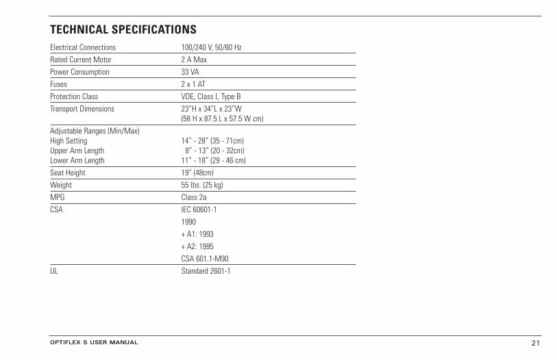
TECHNICAL SPECIFICATIONSElectrical Connections 100/240 V, 50/60 HzRated Current Motor 2 A MaxPower Consumption 33 VAFuses 2 x 1 ATProtection Class VDE, Class I, Type BTransport Dimensions 23”H x 34”L x 23”W
(58 H x 87.5 L x 57.5 W cm)Adjustable Ranges (Min/Max)High Setting 14” - 28” (35 - 71cm)Upper Arm Length 8” - 13” (20 - 32cm)Lower Arm Length 11” - 18” (29 - 46 cm)Seat Height 19” (48cm)Weight 55 lbs. (25 kg)MPG Class 2aCSA IEC 60601-1
1990+ A1: 1993+ A2: 1995CSA 601.1-M90
UL Standard 2601-1
OPTIFLEX S USER MANUAL

OPTIFLEX S USER MANUAL 22
PARTS DESCRIPTION1. Pendant2. OptiCard™
3. Storage for pendant4. Armrest for healthy arm5. Wheels6. Main plug7. Main switch8. Fuse9. Connector for motor assembly
10. Wing screw for backrest11. Adjusting knob for ante/retroversion (horizontal abduction/adduction)12. Outer tube for height adjustment13. Wing screw for height adjustment14. Internal tube for height adjustment15. Motor A16. Outer tube for adjusting the upper arm length17. Eccentric lever for adjusting the upper arm length18. Internal tube for adjusting the upper arm length19. Wing screw for adjusting the elbow angle20. Motor B21. Elbow support22. Lower arm support23. Lower arm support belt24. Outer tube for adjusting the lower arm length25. Eccentric lever for adjusting the lower arm length26. Inner tube for adjusting the lower arm length27. Wing Screw for swivel mechanism28 Hand Support
OPTIFLEX S USER MANUAL

OPTIFLEX S USER MANUAL 23
2
OPTIFLEX S USER MANUAL
12
5
5
6
14 13
118
16
15
1110
417
3
IInnsseett ooff BBaacckk
7
89
19
20
2122
23
2425 2627
28

OPTIFLEX S USER MANUAL 24
WARRANTYOptiFlex® SChattanooga Group (“Company”) warrants that the OptiFlex® S (“Product”) is free ofdefects in material and workmanship for the amount of one (1) year from the date ofthe original consumer purchase of this product. This warranty extends to any ownerof the Product during the warranty period. If this Product fails to function during thewarranty period because of defect in material or workmanship, Company or theselling dealer will replace or repair this Product without charge within a period of 30days from the date on which the defective Product is returned to the Company or thedealer. Company or the dealer will ship the replacement or the repaired Product to theconsumer's facility.
All repairs must be performed by a service center authorized by Chattanooga Group.Any modifications or repairs performed by unauthorized centers or groups will voidthis warranty. To participate in warranty coverage, this Product's warranty registrationcard (included with Product) must be filled out and returned to Chattanooga Group bythe original owner within ten (10) business days of purchase.
Soft Goods KitCompany warrants the Soft Goods Kit is free of defects in materials andworkmanship. This warranty shall remain in effect for thirty (30) days.
This Warranty Does Not Cover1. Replacement parts or labor furnished by anyone other than the Company, the
dealer or an approved Company service agent. 2. Defects or damage caused by labor furnished by someone other than Company,
the dealer or an approved Company service agent.
OPTIFLEX S USER MANUAL

OPTIFLEX S USER MANUAL 25
3. Any malfunction or failure in the Product while it is in the possession of theowner during the warranty period if the malfunction or failure is not caused by adefect in material or workmanship, or if the malfunction or failure is caused byunreasonable use, including the failure to provide reasonable and necessarymaintenance.
Company Shall Not Be Liable for Incidental or Consequential Damages to Property or BusinessSome states do not allow the exclusion or limitation of incidental or consequentialdamages, so the above limitation or exclusion may not apply to you.
TO OBTAIN SERVICE from Company or the selling dealer under this warranty, theowner must do or abide by the following:
1. A written claim must be made within the warranty period to the Company or theselling dealer. If the claim is made to the Company, written claim should be sent to:
4717 Adams RoadP.O. Box 489 Hixson, TN 37343 USA Phone: 423-870-7200
2. The Product must be returned to the Company or the selling dealer by the owner.
This warranty gives you specific legal rights and you may also have other rights whichvary from state to state.
The Company does not authorize any person or representative to create for it anyother obligation or liability in connection with the sale of the Product. Anyrepresentation or agreement not contained in the warranty shall be void and of noeffect.
OPTIFLEX S USER MANUAL

OPTIFLEX S USER MANUAL 26
REPLACEMENT PARTS LISTPart No. Qty. Product Description
20666 1 Electronic Assembly20689 1 Pendant Assembly20668 1 Armrest Assembly20690 1 Motor Assembly20670 1 Lower Arm Support20671 1 Lower Arm Support Belt20672 1 Elbow Support Pad20673 2 Eccentric Lever Assembly20674 4 Wing Screw20675 1 Wing Nut20676 1 Scale Left20677 1 Scale Right20678 1 Seat20679 1 Backrest20680 2 Wheel Assembly20681 2 Tube Cap20686 2 Rubber Glide20687 1 OptiCard™ Holder
OptiFlex® S Accessories
20660 – Patient Softgoods Kit20661 – OptiCard Chip cards (5 Pack)20664 – OptiCard Pen

Achiever™Supports
Adapta®
Treatment TablesA.E.R.® Boot and Compression
Auto Edema Reduction BootCambion®
Shock Dampening Foot Care ProductsCarpal-Trac™
Carpal Traction AccessoryCervical Traction System
Clinical Cervical TractionColPaC®
Chilling Units and Reusable Cold Therapy ProductsConductor™ Gel
Highly Conductive Ultrasound GelContracture Products
Contracture Management Orthotic Products
CTS®
Carpal Tunnel Stretching Device
DURA-STICK® ElectrodesSelf-Adhesive Electrodes
EMG Retrainer® & EMG Retrainer® IRDual Channel Surface EMG
Flexi-PAC® I and IIReusable Hot and Cold Compresses
Fluidotherapy®
Dry Heat Whirlpool Therapy UnitsGel Medex™
Gel Mattress OverlayHANDISIZER™
Hand ExersiserHydrocollator®
Heating Units and HotPacs™
Intelect ® LegendUltrasound and Electrotherapy Products
Measurement InstrumentsDynamometers, Goniometers, etc.
Myossage®
Massage LotionNylatex®
Elastic Wraps
OptiFlex® and OptiFlex® SContinuous Passive Motion
Opti-Ice™Cold Therapy System
Para-Care®
Paraffin Wax UnitPillow Perfect™
Cervical Pillow LinePivotal Therapy System™
Orthotics for the SpinePR™ and PR II™
Pressure Reduction Wheelchair CushionsProPower Pillow™
Power Massage PillowPresSsion®
Intermittent CompressionPron Pillo®
Positioning PillowSensaFlex™
Hot and Cold CompressSPORT-PAC™
Soccer Ball Shaped Cold PackTheratherm™
Digital Moist Heating PadTherma-Wrap™
Hot and Cold CompressionTriton®
Treatment and Traction EquipmentTX®
Treatment and Traction EquipmentVectra™ Series
Electrotherapy productsVersa Bath Seat™
Aid to Daily LivingWellness 1st™
Back SupportWomen’s Contour Back Support
Back Support
More Trusted Products from Chattanooga Group
ISO 13485 CERTIFIED
4717 Adams RoadP.O. Box 489Hixson, TN 37343 U.S.A.
1-423-870-22811-800-592-7329 U.S.A.
1-800-361-6661 CANADA
+1- 423-870-7200 Outside U.S.A.
+ 1-423-870-2046 Outside U.S.A. FAX
www.chattgroup.com
© 2004 Encore Medical20659C